network address translation - tele.sj.ifsc.edu.brtele.sj.ifsc.edu.br/~msobral/rmu/sip-nat.pdf ·...
TRANSCRIPT

235
10 Network Address TranslationThis chapter introduces Network Address Translation (NAT) and looks at the is-sues and challenges involved in making SIP and other Internet communications protocols work through them. The motivations for, advantages, and disadvan-tages of NAT are discussed. NAT classification terminology is introduced. Tech-niques for NAT traversal such as hole punching and protocols such as STUN, ICE, and TURN are introduced. SIP and SDP extensions enabling NAT tra-versal are discussed.
First, here is a word about terminology, which can be a bit confusing in this chapter. While NAT usually stands for network address translation, the function of converting or mapping an inside IP address and port to an outside IP address and port, it also has another meaning as a network address translator, the device which performs this function. Which meaning is used can usually be determined by context. In this chapter, I will mainly use the abbreviation for the function, but there are times when it is common terminology to use it for the device. NAT is also sometimes used as a verb, that is, to NAT is to change the IP address and ports of packets on packets as they pass on the wire. This is also known as NAT-ting. An address which has been changed by a NAT is also known as a NATed address. In this chapter, two other protocols also have an abbreviation used to represent two different things—both STUN and TURN protocols have two dif-ferent meanings.
10.1 Introduction to NAT
Network address translation (NAT) is used to interconnect IP networks that use different IP address types. For example, in Chapter 1, the concept of private ad-dress spaces was introduced. Typically, NAT is used to map an inside address to an outside address. NAT operates at Layer 3 in the Internet protocol stack. Net-

236 SIP: Understanding the Session Initiation Protocol
work address and port translation (NAPT) also change the port number in IP packets, operating at Layers 3 and 4. Typically most NAT also perform NAPT, but are still referred to simply as NAT. The reasons for implementing NAT will be discussed in the following sections, but the main reason has to do with the shortage of IPv4 addresses.
The earliest discussion of NAT in the IETF is RFC 1631 [1], which dis-cusses the pros and cons of using NAT. The need for private IP address spaces resulted in the publication of RFC 1918 [2] in 1996 by the IETF, which reserved three IPv4 address blocks. These addresses are not routable on the public Inter-net—they only have meaning within a private network. RFC 2663 [3] defi ned NAT for the first time. Recently, serious discussions have started about the stan-dardization of NAT and the architectural implications of NAT been held in the IETF. In 2004, a working group was formed to develop terminology for NAT, define requirements, and define protocols for the testing and probing of NATs. This working group, known obtusely as BEHAVE (Behavioral Engineering for Hindrance Avoidance) [4] has made excellent progress over the past few years and has published a number of documents discussed in this chapter. This chapter will make use of some this new terminology and definitions. The next sections cover the advantages and the problem with NAT as discussed in RFC 2993 [5].
10.2 Advantages of NAT
A number of factors led to the development of NAT, and only a few of them re-late to the shortage of IPv4 addresses. Many of them are aspects of management. For example, a network can avoid having to renumber IP addresses when chang-ing internet service providers. The management of IP addresses can be simplifi ed if a network must use a number of small individual address blocks. The use of a single private address range is easier to manage in the end devices, with the complexity of the small address blocks being centralized in the NAT. Networks can also use the basic filtering properties of NAT to provide some fi rewall se-curity. Any host that does not initiate outbound connections to the Internet is not reachable by a host on the Internet. Hosts that do initiate connections are limited by the filtering rules of the NAT in receiving incoming packets.
For Internet service providers (ISPs), NAT can allow an ISP to conserve the number of IP addresses it needs. The number of IP addresses needed is only the maximum number of concurrent connected users rather than the total number of users. Each user can be assigned a private address and will only be assigned a public address when they connect. NAT also allows an ISP to segment their network for management purposes.

Network Address Translation 237
10.3 Disadvantages of NAT
There are many problems with NAT. The biggest problem is that they break the end-to-end model of the Internet. The reachability of any Internet host by any other Internet host was part of the Internet from the beginning, and many assumptions about reachability are included in Internet protocols. NAT also breaks the transitive reachability of hosts (e.g., host A can reach host B, host B can reach host C, but host C cannot reach host A). NAT creates a single point of failure in the Internet where fates are shared. For example, in a connection without NAT between host A and host B, as long as both hosts have Internet connectivity they can exchange packets and communicate. Any of the routers and connections between them can fail and the connection can be maintained, possibly with some lost packets. However, if A and B connect through a NAT, the failure of that NAT will cause the connection to fail with no guarantee that either A or B can re-establish it. For example, many failures experienced during Web browsing are not failures of either the Web browser or the Web server, but of a NAT in between. When the NAT fails, the bindings are lost and the con-nection stalls. This continues until the user hits the refresh button on the Web browser which closes all the TCP connections and opens new ones, creating new bindings, which allow browsing to continue. The use of NAT also complicates multihoming in a site, since a response must route back through the same NAT that processed the request. NAT also inhibits the implementation of security at the IP layer.
There are cases where NAT will not prevent IP address renumbering. For example, when networks that use the same private address range are combined, the address overlap will require renumbering. NAT with port mapping com-plicates offering services that use well-known port numbers. For example, Web servers typically use port 80 which can only be allocated once by NAT for a particular public address. If multiple SIP clients are behind the same NAT and share a public IP address, only one of them can be allocated the well-known SIP port of 5060, which can result in routing failures.
NATs that operate at both layer 3 and layer 4 must understand all transport protocols used through it. While this is not a problem for the common TCP and UDP, it is a major problem for newer transport protocols such as the Data-gram Congestion Control Protocol (DCCP), Stream Control Transport Protocol (SCCP), and Host Identity Protocol (HIP). As a result NATs are an impediment to new transport protocols.
Unfortunately, NAT usage is widespread on the Internet today. As a result, all protocols must be aware of NAT operation and be able to overcome their limitations. The next section will discuss how NAT works.

238 SIP: Understanding the Session Initiation Protocol
10.4 How NAT Works
NAT operates at the IP Layer 3 as shown in Figure 1.1. NAPT operates at both the IP and transport layers 3 and 4. NAT creates mappings between inside and outside addresses and ports. These mappings are sometimes called bindings. Mappings are temporary, and expire either after a TCP connection is closed with a FIN or after inactivity with UDP transport. There are multiple types of NAT depending on the rules used for mapping and filtering. Older NAT terminology classified NAT in terms of full cone, restricted cone, and symmetric. However, in this chapter, we will use more modern terminology developed by the BEHAVE working group. Some major types of NAT are endpoint address independent, endpoint address dependent, and endpoint address and port dependent. There are also several behavioral options as well.
Table 10.1 lists the parts of the IPv4 and UDP/TCP header field that are modified by NAT. When a request is received on the inside of a NAT and for-warded to the outside, the source address and source port are rewritten. If this is the first packet in a flow, a new mapping will be created to be used for routing responses. If this is not the first packet, an existing mapping will be used. The UDP checksum must also be rewritten. When a response packet is received from the outside of the NAT and forwarded to the inside, the destination address and destination port are rewritten to the inside address and port for this mapping. Again, the UDP checksum must be rewritten.
Note that the fact that NAT operates at Layer 4 with TCP does not mean that the resulting TCP session is no longer end-to-end—the TCP connection is still end-to-end. NAT never maintains a transmission control block or maps sequence numbers. NAT also never performs retransmissions or acknowledge-ments. As a result, TCP still operates with end-to-end flow control and reliability through NAT.
An example of NAT operation is shown in Figure 10.1. In this example, a SIP client on a host sends a SIP request through a NAT, two routers, and an Ethernet switch. The Ethernet switch operates only at the link and physical layer while the routers operate at the IP, link, and physical layers. These de-vices only forward the packet without making any changes to the packet. The
Table 10.1
Parts of an IPv4 and UDP/TCP Header Field Modifi ed by NAT
IP header checksum
Source address
Destination address
Source port
Desitnation port
UDP checksum

Network Address Translation 239
NAT, however, creates a new mapping between the source inside private ad-dress 10.0.0.1 port 42723 and the outside public address 172.34.5.1 port 34123and rewrites the IP and transport layers with this information. When the SIP response comes back, the NAT uses the mapping created to rewrite the IP and transport layers with this information. As a result, the SIP server thinks the SIP client it is communicating with it at the address 172.34.5.1:34123 while the SIP client thinks it is using the address 10.0.0.1:42723. Since we have seen how SIP imbeds IP addresses and ports into SIP and SDP messages, clearly this will be problematic.
10.5 Types of NAT
NAT can be characterized by the type of address and port mapping they do, as well as the type of filtering they employ. To see the different types of NAT, we will use the notation shown in Figure 10.2 from RFC 4787 [6]. This fi gure shows a host X behind a NAT communicating with two different hosts, host 1 and host 2. Packets sent by X have a source address and port of X:x and a des-tination address and port of Y:y. The NAT has a number of IP addresses to use for mapping, and they are shown as X1, X2, ... (some NATs only have a single IP address to use for mapping such as a home NAT). Packets sent from device X to host 1 are sent by X to Y1:y1 from X;x. As received by Y1, the packets appear
Figure 10.1 NAT example.

240 SIP: Understanding the Session Initiation Protocol
to have been received from X1’:x1’. Packets sent by X to Y2 from the same source port x are received by Y2 and appear to have been received from X2’:x2’. That the packets sent to Y2 are sent from the same IP address and port as Y2 is essential for this classification method. The resulting relationship between X1’:x1’ and X2’:x2’ determines the type of NAT mapping.
Note that NAT classification is not precise, and many NATs change be-havior over time and under differing conditions. As a result, trying to predict future NAT behavior based on past behavior is problematic. However, a good understanding of NAT behavior is still essential to understanding how to make SIP and Internet communications traverse NAT.
10.5.1 Endpoint Independent Mapping NAT
Endpoint independent mapping (EIM) NAT is where X1’:x1’ = X2’:x2’ for all Y;y (Y1:y1 and Y2:y2 as shown in Figure 10.2). That is, the mapping used is dependent only on the source address and port (X;x), independent of the destina-tion address and port. This type of mapping is known as endpoint independent mapping (EIM). It is important to note that x1’ does not equal x1, which means that a NAPT can be an endpoint independent NAT. This type of NAT is best for SIP and RTP traversal as we shall see in the next sections.
10.5.2 Address Dependent Mapping NAT
An address dependent mapping (ADM) NAT is where X1’:x1’ = X2’:x2’ if and only if Y2 = Y1 in Figure 10.2. That is, the mapping is dependent on the destina-
Figure 10.2 NAT mapping classifications.
Network Address Translation 241
tion IP address of the packet as well as the source address and port. As a result, packets sent by X to different hosts will appear to come from different IP ad-dresses and/or port numbers. This type of NAT is bad for SIP and RTP traversal as we shall see in the following sections.
10.5.3 Address and Port Dependent Mapping NAT
An address and port dependent mapping (ADPM) NAT is where X1’:x1’ = X2’:x2’ if and only if Y2:y2 = Y1:y1 as shown in Figure 10.2. That is, the map-ping is dependent on both the destination address and port as well as the source address and port. As a result, packets sent by X to different ports on the same host will appear to come from different IP addresses and/or port numbers. This type of NAT is the most problematic for SIP and RTP traversal.
10.5.4 Hairpinning Support
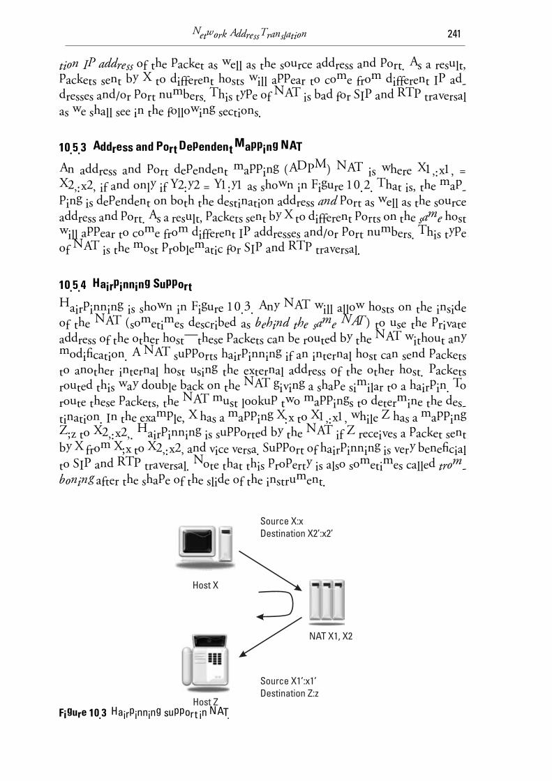
Hairpinning is shown in Figure 10.3. Any NAT will allow hosts on the inside of the NAT (sometimes described as behind the same NAT) to use the private address of the other host—these packets can be routed by the NAT without any modification. A NAT supports hairpinning if an internal host can send packets to another internal host using the external address of the other host. Packets routed this way double back on the NAT giving a shape similar to a hairpin. To route these packets, the NAT must lookup two mappings to determine the des-tination. In the example, X has a mapping X:x to X1’:x1’ while Z has a mapping Z;z to X2’:x2’. Hairpinning is supported by the NAT if Z receives a packet sent by X from X;x to X2’:x2’ and vice versa. Support of hairpinning is very benefi cial to SIP and RTP traversal. Note that this property is also sometimes called trom-boning after the shape of the slide of the instrument.
Figure 10.3 Hairpinning support in NAT.

242 SIP: Understanding the Session Initiation Protocol
10.5.5 IP Address Pooling Options
NATs that have a number of external or public IP addresses available for map-ping have options in the way they allocate from this pool of IP addresses. Having multiple IP addresses is common in large service provider or enterprise NATs and is uncommon in small residential NATs. One pooling policy is known as paired IP address pooling. This policy means that only one external IP address is used for an internal IP address. As a result, all packets sent by this host will appear to come from the same IP address to hosts external to the NAT. This property is very good for SIP and RTP traversal. Another policy is known as arbitrary IP address pooling, which means there could be multiple external IP addresses mapped to an internal IP address. This property is very bad for SIP and RTP transport.
10.5.6 Port Assignment Options
While only NATs that have multiple external IP addresses have address pooling options, every NAT has port assignment options. There are a number of behav-iors that are part of implemented NATs. Port preservation means the NAT tries to keep the external port the same as the internal source port. This port assign-ment approach generally only works if the NAT has a large pool of IP addresses. Otherwise, only one inside host can use a particular port. If a NAT implement-ing port preservation runs out of a particular port to allocate, it can use one of two strategies. One is to switch to a nonport preservation mode. The other is to do port overloading in which the same port can be used more than once on the inside and outside. Port overloading is very bad for the SIP and RTP transport because it leads to nondeterministic behavior. Another port assignment option is port parity, which preserves the oddness or evenness of ports. This is useful for media transport where the RTP media must be an even port while the RTCP control must use an odd port number. Port contiguity is when the NAT attempts to keep sequential inside ports mapped to sequential outside ports. This can help when an RTCP port is inferred to be one higher than the RTP port. For SIP and RTP traversal, the most important property is that the port assignment mode does not change. Since port preservation always runs the risk of having to switch modes or do port overloading, it is not recommended. Switching port mapping modes makes troubleshooting diffi cult.
10.5.7 Mapping Refresh
Each time a NAT creates a mapping it uses up memory resources in storing the information. It also uses up addressing resources since the external mapped IP address and port cannot be reused for another endpoint. As a result, a NAT must

Network Address Translation 243
have behavior to ensure that old mappings are expired and all resources freed up into the pool.
TCP mappings can be created and removed based on TCP signaling. For example, the exchange of SYN messages tells the NAT to create a new mapping for the connection. The exchange of FIN messages tells the NAT the connection is no longer needed and can be safely closed and the mapping state discarded. UDP, however, has no signaling, so the NAT must infer the creation and destruc-tion of a UDP session. Usually, this is done using an inactivity timer. If no packet is received before this timer expires, the connection is considered terminated and the mapping removed. The recommended value is 5 minutes [6] although in practice some NATs use values as short as 30 seconds. Theoretically, a packet from either the inside or outside host can refresh the mapping, although it is usu-ally a good security policy to only allow packets generated internally to refresh the mapping. Otherwise, an outside host could keep the mapping alive by send-ing refresh packets even after the inside host wants the connection closed.
10.5.8 Filtering Modes
By their basic function, NATs provide filtering functions. If a mapping between an external address and an internal address is not present, packets cannot be sent to that internal host. When a mapping is active, the NAT has options on what additional filtering it can provide. Essentially, these filtering rules control who is permitted to use the mapping. One filtering mode is known as End-point Independent Filtering. In this mode, any external endpoint is permitted to send packets to the internal host once the mapping is created. Another mode is called address dependent filtering. This mode allows only external hosts that have received a packet from the internal host to send a packet using the binding. A single packet sent to the external host “opens the latch” and will allow any number of packets to flow in the opposite direction. This filtering mode provides some firewall-like security. Another mode is called address and port dependent filtering. This mode only allows an external endpoint to send packets from the same external IP address and port to which the internal host has sent a packet. Endpoint independent filtering is best for SIP and RTP, while address dependent and address and port dependent filtering make things diffi cult. This information is summarized in Table 10.2.
Table 10.2
NAT Filtering Mode Summary
Endpoint independent fi ltering
Address dependent fi ltering
Address and port dependent fi ltering

244 SIP: Understanding the Session Initiation Protocol
10.6 NAT Mapping Examples
Figure 10.4 shows an example of a NAT. The packet sent from 192.168.0.1:1234to 2.73.3.2:5678 appears to host 1 to have come from 23.3.2.8:4219. The packet sent from 192.168.0.1:1234 to 62.3.9.9:5678 appears to host 1 to have also come from 23.3.2.8:4219. Since these two mapped addresses are the same, this indi-cates the NAT is an endpoint independent mapping NAT. Since the internal and external port numbers are different, no port preservation is used. Since the even internal port maps to an odd external port, port parity is also not used by this NAT.
Figure 10.5 shows another example of a NAT, which has two IP address-es assigned to it, 23.3.2.8 and 23.3.2.9. A packet sent from 192.168.0.1:1234 to 2.73.3.2:5678 appears to host 1 to have come from 23.3.2.9:4219. The packet sent from 192.168.0.1:1234 to 62.3.9.9:5678 appears to host 1 to have come from 23.3.2.9:2194. Since this is a different mapped address, this indicates an address dependent mapping NAT.
Figure 10.6 shows another example. The packet sent from 192.168.0.1:1234to 2.73.3.2:5678 appears to host 1 to have come from 23.3.2.8:4219. The packet sent from 192.168.0.1:1234 to 2.73.3.2:9101 appears to host 1 to have come from 23.3.3.7:6421. Since the mapping is different despite the destination being the same address, this indicates an address and port dependent mapping NAT.
Figure 10.7 shows another example NAT. In this example, the packet sent from 192.168.0.1:1234 to 2.73.3.2:5678 appears to host 1 to have come from 23.3.2.8:4219. The packet sent from 192.168.0.1:1235 to 2.73.3.2:5679 appears to host 1 to have come from 23.3.2.8:2170. Since these two packets are not sent from the same source address and port, these data provide no information about
Figure 10.4 Example of endpoint independent mapping NAT.

Network Address Translation 245
the type of mapping used by the NAT. However, this indicates paired IP address pooling. No port preservation is used. No port parity or port contiguity is used.
10.7 NATs and SIP
Now that we have an understanding of what NAT is and how it works, we can look at its impact on applications and protocols such as SIP and RTP. Over-
Figure 10.5 Example of address dependent mapping NAT.
Figure 10.6 Example of address and port dependent mapping NAT.

246 SIP: Understanding the Session Initiation Protocol
all, NATs work reasonably well with unencrypted client/server protocols such as Web browsing, e-mail, and so forth. However, they can cause problems with IPSec VPNs, which can fail signature checks if the signature includes address and port information. Many NATs have application layer gateways (ALGs) for common applications such as FTP (File Transfer Protocol). However, NAT does cause problems for peer-to-peer protocols such as SIP. NATs also cause problems for protocols that carry imbedded IP addresses and port numbers, such as SIP.
Guidelines for NAT-friendly protocol design were published in 2002 in RFC 3235 [7]. However, this was much too late to be helpful for SIP. The main recommendations were as follows:
Limit peer-to-peer applications and approaches in favor of client/server • applications.
Don’t rely on end-to-end IPSec security.•
Use DNS names not IP addresses.•
Multicast is problematic.•
Avoid session bundles (e.g., one session controlling/establishing another • session).
Use TCP instead of UDP.•
Unfortunately, SIP violates most of these recommendations.Early work on SIP essentially ignored NAT or assumed that IPv6 deploy-
ments would cause them to go away. Many properties of SIP assume refl exive routability, which is often not present with NAT. The reality of SIP deployments
Figure 10.7 Example of paired IP address pooling NAT.

Network Address Translation 247
was that while most servers (proxies, registrars, and so forth) had public IP ad-dresses, most UAs were behind NAT and hence had nonroutable private IP ad-dresses. Since the SIP servers provided rendezvous service, typically the SIP ex-change would work while the RTP media session would fail.
Early solutions that were examined included application layer gateways (ALGs) which would effectively make NAT SIP-aware. Another early solution was a simple discovery approach in which a UA would send test packets to de-termine if it was behind a NAT, and to discover mapped addresses. This protocol was STUN [8], which initially stood for simple traversal of UDP through NAT. A STUN client sent test packets (essentially pings) to a STUN server, which responds with the mapped address and port the packet appeared to be received from. STUN will be described in Section 10.9. Using the mapped addresses discovered using STUN, UAs tried to fix the IP addresses and ports in their SIP messages. Unfortunately, this did not work under all scenarios and with all types of NAT. Instead, a back-to-back user agent (B2BUA) approach has developed in the industry to ensure both SIP and RTP traverse NAT.
To overcome the deficiencies of STUN, the IETF developed the Interactive Communications Establishment (ICE) [9], which runs a series of end-to-end tests using STUN between the two UAs attempting to establish communication. This protocol used an approach known as hole punching which was developed by peer-to-peer gamers to establish gaming connections.
10.8 Properties of a Friendly NAT or How a NAT Should BEHAVE
The basic properties of a NAT, which is friendly towards SIP and RTP, is sum-marized in Table 10.3. The NAT should have endpoint independent mapping, and paired IP address pooling. The port assignment should not do port preser-vation or port overloading. Port parity preservation and contiguity is good but not essential. The NAT should use endpoint independent or address dependent filtering. The UDP refresh timer should be 5 minutes.
Table 10.3
How a NAT Should BEHAVE
Endpoint independent mapping
Address independent or address dependent fi ltering
Pair IP address pooling
Not port preservation
Not port overloading
Port parity preservation is helpful
UDP refresh timer 5 minutes

248 SIP: Understanding the Session Initiation Protocol
10.9 STUN Protocol
STUN was first published as RFC 3489 [8] as Simple Traversal of UDP through NAT. It has been significantly updated and revised and published as RFC 5389 with a new acronym expansion, Session Traversal Utilities for NAT [16]. The basic operation is shown in Figure 10.8. The main function of STUN is for a STUN client to request a mapping request from a STUN server. The STUN packet sent by the client traverses any number of NATs before reaching the STUN server. The STUN server returns the mapped address in a response. Note that this mapped address is just the one of the outer NATs —there may be many mappings happening, but only the outermost one is visible to the STUN server. The address must be hidden from ALGs in NATs in this response packet or the NAT might try to fix the address and replace it. This is done by an exclusive OR-ing (XOR), the mapped IP address in the response.
There are four main usages of STUN. The first is for basic mapping dis-covery. The second is to perform a connectivity check with a server or a peer UA. (This is the usage for ICE.) The third is for media relay usage. The extensions are known as TURN and described in Section 10.14. The fourth is as a keep-alive to refresh NAT mappings for UDP. This is used in the SIP outbound extensions. Another usage of STUN is NAT behavior discovery. This relatively new usage is described in [10]. This creative usage of STUN allows:
NAT address mapping;•
NAT fi ltering behavior;•
Discovery of the mapping lifetime;•
Discovery of support for hairpinning;•
Determination of fragmentation handling;•
Figure 10.8 STUN: session traversal utilities for NAT.

Network Address Translation 249
Detecting generic ALGs, which rewrite IP addresses.•
This new usage defines a number of minor extensions to STUN and will shortly be standardized. Note that this usage of STUN has some limitations in that it can only characterize a NAT for a particular address at a particular time. Since a NAT can change its behavior for different addresses and at a later time, care must be taken in using the information derived from these tests.
10.10 UNSAF Requirements
With a number of peer-to-peer protocols such as SIP attempting to fix and work around NAT problems, the Internet Architecture Board (IAB) published RFC 3424 [11] setting the requirements and limitations on IETF solutions to deal with NAT. These approaches are known as Unilateral Self-Address Fixing or UNSAF approaches, the acronym being chosen to highlight the fact that these approaches could, if not done correctly, make the NAT problem worse. Each protocol that tries to work around NATs must clearly scope the problem and describe the exit strategy and transition plan. The approach must discuss specifi c issues that might make the approach “brittle” or likely to fail. The approach must also discuss known practical issues encountered with real NAT in deployments.
10.11 SIP Problems with NAT
Consider the typical example of a SIP UA behind a NAT trying to communicate with a SIP server outside the NAT. Since SIP has some client/server properties, some SIP operations will work as long as the requests are originated by the UA. Requests originated by the SIP server may be blocked by lack of mappings or filtering rules. One approach used in practice is to use frequent SIP registrations to create the mapping and then reuse the mapping for incoming requests to the UA. However, this approach doesn’t quite work without some SIP extensions as we shall see. Media negotiated using SIP offer answer is a big problem as the SDP offer and answer will contain private addresses and ports in the c= and m=lines. An example SIP message sent from behind a NAT is shown here:
INVITE sip:[email protected] SIP/2.0Via: SIP/2.0/UDP 10.1.1.221:5060;branch=z9hG4bKhjhFrom: TheBigGuy <sip:[email protected]>;tag=343kdw2To: TheLittleGuy <sip:[email protected]>Max-Forwards: 70Call-ID: 123456349fijoewrCSeq: 1 INVITESubject: Wow! It Works...Contact: <sip:[email protected]>

250 SIP: Understanding the Session Initiation Protocol
Content-Type: application/sdpContent-Length: ...
v=0o=UserA 2890844526 2890844526 IN IP4 UserA.customer.coms=-t=0 0c=IN IP4 10.1.1.221m=audio 49170 RTP/AVP 0
a=rtpmap:0 PCMU/8000
There are three main problems with this message. The Via header fi eld contains a private IP address (10.1.1.221) and the listening port (5060) may not have an active mapping or fi lter rule. The Contact URI is unroutable due to the private IP address. Finally, the SDP information in the c= and m= lines will not work behind the NAT.
Via already has a partial solution for the response routing. The use of the received parameter will record the mapped public IP address, which is then used for routing the response. However, this will only work for a port preserva-tion NAT (which is not recommended NAT behavior). A normal NAT that also changes the port will not work. The Contact URI problem is even more serious. If the request is a REGISTER, the AOR binding will not work since the URI is unroutable. If the request is an INVITE, the ACK and all subsequent requests such as BYE will also fail to route.
There are three main solutions to these problems: symmetric SIP, connec-tion reuse, and SIP outbound. Each of these will be discussed in the following sections.
10.11.1 Symmetric SIP
Symmetric SIP operation uses the rport extension defined in RFC 3581 [12]. Just as the received Via parameter saves the mapped address, the rport pa-rameter saves the mapped port number for use in routing responses. A SIP UA indicates support for this extension by including the rport parameter (without the “=” and an address which is not known) in the SIP request. This tells the next hop proxy that the UA will be listening for the response on the same address and port number that the request was sent from, instead of the address and port listed in the Via. When the proxy receives the request, it stores the mapped port in the rport parameter and then uses this for routing any responses back. The use of rport is shown in Figure 10.1.
10.11.2 Connection Reuse
Connection reuse is a method in SIP to reuse existing TCP connections. It is defined in [13]. Once a connection is opened, UAs can reuse the connection for subsequent connections. If a NAT traversal approach such as ICE is used, con-

Network Address Translation 251
nection reuse will reduce the number of times it has to be run. Connection reuse is mainly defined between proxy servers. The usage of connection reuse com-bined with registration is defined for UAs as SIP outbound in the next section.
10.11.3 SIP Outbound
SIP outbound is a mechanism that combines connection reuse, registration through multiple proxies, and keep alives. It solves many of the existing prob-lems with SIP NAT traversal, although it requires both UAs and registrars sup-port the extension. SIP outbound is currently being finalized by the IETF as [14]. The basic configuration is shown in Figure 10.9. UAs have an instance-id, which uniquely identifies them. Multiple registrations by the UA through different proxy servers will have different reg-id. STUN keep alive messages are used between the UA and the proxy to monitor the fl ow and keep the NAT mappings active. If the STUN checks reveal the flow has failed (perhaps due to a failure in the UA, the NAT, or the registrar), the UA registers again using the same instance-id but a new flow-id. This is shown in Figure 10.10.
10.12 Media NAT Traversal Solutions
There are a number of methods used for media traversal of NAT, which will be discussed in the following sections. These solutions involve getting RTP and RTCP negotiated using SIP to work.
10.12.1 Symmetric RTP
Symmetric RTP involves sending RTP from the same port that it is listening for RTP. This results in a UDP connection that the NAT will understand and allow
Figure 10.9 SIP outbound.

252 SIP: Understanding the Session Initiation Protocol
Fig
ure
10.
10S
IP o
utb
ou
nd
ca
ll fl
ow
.

Network Address Translation 253
mapping and filtering to work. However, this is only useful if the media fl ow is bidirectional and if at least one side can get through initially. Symmetric RTP effectively means ignoring address and port information in the SDP, since it will be different from the mapped addresses and ports.
10.12.2 RTCP Attribute
The normal assumption that the RTCP port is one higher than the RTP port only works through NATs that support port contiguity. For most NATs, the RTCP will not work even when RTP does work. A solution to this is to ex-plicitly signal the RTCP port and address using the a=rtcp attribute defi ned in RFC 3605 [15]. If the mapped RTCP port can be discovered, using STUN, for example, then this approach can work.
10.12.3 Self-Fixing Approach
This approach uses NAT mapping information discovered using STUN, which is then put into the SDP offer or answer to fix the addresses. This works with some NAT such as endpoint independent mapping NATs, but will fail to work for address or port dependent mapping NATs.
The best solution for media NAT traversal is to use hole punching (and a protocol such as ICE) with a backup such as a media relay like TURN as de-scribed in the following sections.
10.13 Hole Punching
Hole punching is a probing approach used to discover and actually create NAT mappings and filtering rules. Hole punching will work in many situations that other approaches will fail, although it will not work in every situation—some combinations of NAT properties just will not permit direct exchange of packets between some hosts. Hole punching uses two clients and a rendezvous server. In SIP, the clients are UAs and a proxy server can be the rendezvous server.
In hole punching, two clients simultaneously probe using at least two sets of address, the private address and a discovered public address. The public ad-dress could be discovered using a STUN server or with the help of a rendezvous server. The rendezvous server has a public IP address and is reachable by both clients. The rendezvous server helps the two clients exchange address candidate lists. The clients repeatedly try both addresses until one or more work. At that point, they utilize this working address.
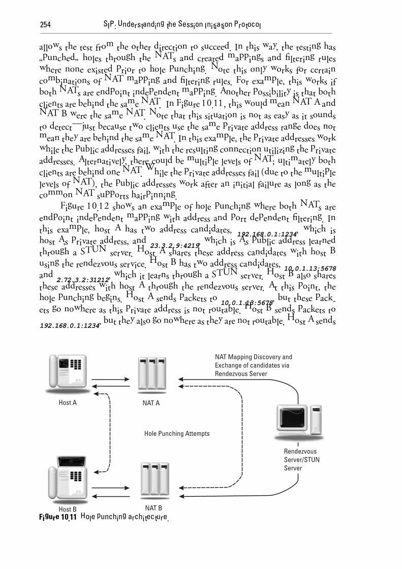
Figure 10.11 shows hole punching when the clients are behind different NATs. The private addresses fail since they are not behind the same NAT. The initial test of the public address fails; however, it creates a filtering rule, which
254 SIP: Understanding the Session Initiation Protocol
allows the test from the other direction to succeed. In this way, the testing has “punched” holes through the NATs and created mappings and fi ltering rules where none existed prior to hole punching. Note this only works for certain combinations of NAT mapping and filtering rules. For example, this works if both NATs are endpoint independent mapping. Another possibility is that both clients are behind the same NAT. In Figure 10.11, this would mean NAT A and NAT B were the same NAT. Note that this situation is not as easy as it sounds to detect—just because two clients use the same private address range does not mean they are behind the same NAT. In this example, the private addresses work while the public addresses fail, with the resulting connection utilizing the private addresses. Alternatively, there could be multiple levels of NAT; ultimately both clients are behind one NAT. While the private addresses fail (due to the multiple levels of NAT), the public addresses work after an initial failure as long as the common NAT supports hairpinning.
Figure 10.12 shows an example of hole punching where both NATs are endpoint independent mapping with address and port dependent fi ltering. In this example, host A has two address candidates, 192.168.0.1:1234, which is host A’s private address, and 23.3.2.9:4219, which is A’s public address learned through a STUN server. Host A shares these address candidates with host B using the rendezvous service. Host B has two address candidates, 10.0.1.13:5678and 2.72.3.2:31212, which it learns through a STUN server. Host B also shares these addresses with host A through the rendezvous server. At this point, the hole punching begins. Host A sends packets to 10.0.1.13:5678, but these pack-ets go nowhere as this private address is not routable. Host B sends packets to 192.168.0.1:1234, but they also go nowhere as they are not routable. Host A sends
Figure 10.11 Hole punching architecture.

Network Address Translation 255
a packet to 2.73.3.2:3122. Since NAT A is endpoint independent mapping, the existing mapping is used, so this packet is forwarded to NAT B with a source address of 23.3.2.9:4219. This creates a filter rule in NAT A that allows packets to be received from 2.73.3.2:31212 to be forwarded to 23.3.2.9:4219. This packet arrives at NAT B but is dropped by NAT B since there is no filter rule allow-ing packets from 23.3.2.8:4219 to be received by 2.73.3.2:31212. Host B then sends a packet from 10.0.1.13:5678 to 23.3.2.9:4219. This reuses the mapping of 10.0.1.13:5678 to 2.73.3.2:31212 and creates a filter rule that allows packets from 23.3.2.9:4219 to be forwarded to 2.73.3.2:31212. The packet is forwarded to NAT A. At NAT A, there is an active mapping for 23.73.3.2:31212 and also a fi lter rule that allows packets to be received from 2.73.3.2:31212. As a result, the packet is forwarded to host A and the hole punching has succeeded. Note that without the failed packet sent by host A, which created this filter rule, this packet would have been blocked. Now host A can send to host B at 2.73.3.2:31212 using the two mappings and two fi lter rules in place. Note that hole punching also works if Host B sends a packet first, which fails, then Host A sends a packet, which then succeeds.
Figure 10.13 shows another example of hole punching. In this example, NAT A is endpoint independent mapping NAT with endpoint independent filtering, while NAT B is address and port dependent mapping with address and port dependent filtering. A packet sent from host A 192.168.0.1:1234 creates a mapping of 23.3.2.9:4219.
Figure 10.12 Hole punching example.

256 SIP: Understanding the Session Initiation Protocol
A packet sent from host B 10.0.1.13:5678 creates a mapping of 2.73.3.2:31212. A packet sent from host A 192.168.0.1:1234 to 2.73.3.2:31212 creates a fi ltering rule in NAT A. The packet reaches NAT B but is dropped due to fi ltering. A packet sent from host B 10.0.1.13:5678 to 23.3.2.9:4219 creates a new mapping to 2.73.4.1:5732 and creates a new filtering rule in NAT B. The packet reaches NAT A. Since NAT A has endpoint independent filtering, the packet is forwarded and host A receives packet. Host A then sends a packet to 2.73.4.1:5732, which reaches host B due to the two mapping and filtering rules. Hole punching works in this case despite the address and port dependent mapping and fi ltering in NAT B since NAT A has endpoint independent fi ltering.
Figure 10.14 shows an example where hole punching fails. NAT A is ad-dress and port dependent mapping with address dependent filtering while NAT B is address and port dependent mapping with address dependent fi ltering. A packet sent from host A 192.168.0.1:1234 creates a mapping of 23.3.2.9:4219. A packet sent from host B 10.0.1.13:5678 creates a mapping of 2.73.3.2:31212. A packet sent from A 192.168.0.1:1234 to 2.73.3.2:31212 creates a new mapping of 23.3.3.2:7876 and creates a new filtering rule in NAT A. The packet reaches NAT B but is dropped due to filtering. A packet sent from host B 10.0.1.13:5678 to 23.3.2.9:4219 creates a new mapping of 2.73.4.1:5732 and creates a new fi ltering rule in NAT B. The packet reaches NAT A but is dropped due to fi ltering.
Additional packets sent will also fail due to filtering, and hole punching fails for this confi guration.
Figure 10.13 Hole punching example.

Network Address Translation 257
Typically hole punching will fail due to a combination of address or port mapping and address or port dependent filtering, such as that shown in Figure 10.14. When hole punching fails, a media relay must be used that is in the pub-lic Internet and reachable by both hosts. TURN is a protocol used by a UA to acquire a media relay transport address to use as a fall back when hole punching fails.
10.14 TURN: Traversal Using Relays Around NAT
TURN is a protocol extension of STUN used for acquiring and configuring a re-mote relay. TURN has been in development in the IETF for many years. Earlier versions were quite different, and even had a different title: traversal using relay NAT. The current version is [16] and will soon be published as an RFC.
A server operating as a TURN relay uses significant resources on the server. For one thing, each media stream relayed uses up double the bandwidth of the stream (incoming bandwidth + outgoing bandwidth). Also, the relay must pro-cess and forward each packet. Media relays also introduce delay (latency) and add extra IP routing hops, which increase the chance of packet loss. As a result, the use of TURN should be minimized for an efficient Internet communication or VoIP system.
Figure 10.14 Hole punching example.

258 SIP: Understanding the Session Initiation Protocol
10.15 ICE: Interactive Connectivity Establishment
Interactive connectivity establishment (ICE) is the solution to the problem of when to use hole punching and when to use a media relay. ICE is an IETF protocol that standardizes hole punching and is an optimal methodology. Users of ICE gather as many transport addresses as they can (the private and public address pairs in the previous section on hole punching are only a minimum). They are listed in the order so the most preferred are tested first. A media relay (TURN) address is included as the lowest priority address. After the candidate addresses are exchanged using a SIP offer answer exchange, both sides begin hole punching and noting successes and failures at the end. Both sides choose the highest priority working transport pairs. In the worst case, this might be the media relay address if the NATs in the path make hole punching fail. The basic call flow is shown in Figure 10.15.
The following is an example set of address candidates in SDP. You can see the two candidate addresses used by Host A in the previous hole punching examples.
v=0o=hosta 2890844526 2890842807 IN IP4 192.168.0.1s=-c=IN IP4 23.3.2.9
Figure 10.15 ICE call flow.

Network Address Translation 259
t=0 0a=ice-pwd:a8fgdfpdd777uzjYhagZga=ice-ufrag:88fgdhhYm=audio 4219 RTP/AVP 0a=rtpmap:0 PCMU/8000a=candidate:1 1 UDP 13d0706431 192.168.0.1 1234 typ hosta=candidate:2 1 UDP 69d4498152 23.3.2.9 4219 typ srflx raddr 192.168.0.1 rport 1234
Besides NAT traversal, ICE has other benefits. For example, address candi-dates can include both IPv4 and IPv6 addresses for dual stack UAs. As such, ICE can help in the transition between IPv4 and IPv6. ICE also includes keep alives to ensure that UDP mappings do not expire through NATs. ICE also provides a level of media authorization. When both UAs use ICE, media will only fl owafter a successful ICE check exchange. This ensures that both UAs are willing to send and receive media. Compare this to the case without ICE where a UA will start sending media to the address listed in the SDP without any check or verification. For example, a denial of service packet flood could be introduced by sending a high definition video server an INVITE and include the address of the target. The target will then receive the video stream without the ability to stop or understand.
10.16 Conclusion
This chapter has looked at the history, justification, and operation of Network Address Translation. The effect of NAT on SIP and RTP has also been discussed. Various approaches to the traversal of SIP and RTP through NAT have been covered including hole punching, relays, STUN, TURN, and ICE. These are summarized in Table 10.4. For more examples of SIP NAT traversal, see the Best Current Practices for SIP NAT Traversal document [17].
Table 10.4
Summary of SIP and RTP NAT Traversal
SIP Symmetric Routing (rport)
Symmetric RTP
Outbound
STUN
ICE
TURN
RTCP port attribute

260 SIP: Understanding the Session Initiation Protocol
10.17 Questions
Q10.1 In a few paragraphs, explain how NATs came to be and why they are popular today.
Q10.2 Explain the operation of an address and port dependent mapping NAT that has two IP addresses (19.34.2.1 and 19.34.2.2) assigned to it. Use three examples of UDP packets sent from 192.168.1.101 port 42194 to 204.32.44.21 port 413, 31.32.56.5 port 443, and 204.32.44.21 port 9753. Use port parity preservation in your examples.
Q10.3 Is an endpoint independent mapping NAT or an address dependent mapping NAT more friendly to Internet communica-
tions? Why?
Q10.4 Deduce as many properties of the NAT below as you can based on the information in the following tables.
X = 10.0.100.1
X1 =�73.42.4.1
X2 = 73.42.4.8
Y1 = 118.3.4.2
Y2 = 65.65.4.3
Active NAT Mapping Table
10.0.100.1:8080 maps to 73.42.4.1:3420
10.0.100.1:4343 maps to 73.42.4.1:7433
10.0.100.1:8080 maps to 73.42.4.8:3212
Filtering Table
73.42.4.8:3212 ⇔ 118.3.4.2:*
73.42.4.8:7433 ⇔ 118.3.4.2:*
73.42.4.1:3420 ⇔ 65.65.4.3:*
Q10.5 Explain the advantages and disadvantages of a SIP user agent supporting ICE.
Q10.6 For the packets of Question Q10.2, assume that each UDP packet contains a SIP OPTIONS request. Show the Via header fi eld in each of the three 200 OK responses, assuming that the user agent has implemented appropriate SIP NAT traversal extensions.
Q10.7 Consider the hole punching scenario shown next.

Network Address Translation 261
NAT B is endpoint independent mapping NAT with endpoint dependent fi ltering.NAT A is address and port dependent mapping with endpoint independent fi ltering.
Packet sent from A 192.168.0.1:1234 to a STUN server at 15.1.2.3 creates a mapping of 23.3.2.8:4219Packet sent from B 10.0.1.13:5678 to a STUN server at 15.1.2.3 creates a mapping of 2.73.3.2:31212
Assume NAT A has only a single IP address. Assume NAT A and B do not implement port preservation.
Show the filter rules created as A and B begin hole punching. Will hole punching succeed?
Q10.8 Repeat Question Q10.7 with everything the same except:
NAT B is address dependent mapping NAT with endpoint dependent fi ltering.NAT A is address and port dependent mapping with endpoint dependent fi ltering.
Show the filter rules created as A and B begin hole punching. Will hole punching succeed?
Q10.9 For a SIP message sent by host A (hostname of hosta.
mappings.org) to host Y1 in Question Q10.4, show the Via header in the response assuming the rport extension is used.
Q10.10 Explain the relationship between hole punching and ICE.
References
Egevang, K., and P. Francis, “The IP Network Address Translator (NAT),” RFC 1631, May [1] 1994.
Rekhter, Y., et al., “Address Allocation for Private Internets,” BCP 5, RFC 1918, February [2] 1996.
Srisuresh, P., and M. Holdrege, “IP Network Address Translator (NAT) Terminology and [3] Considerations,” RFC 2663, August 1999.
http://www.ietf.org/html.charters/behave-charter.html. [4]
Hain, T., “Architectural Implications of NAT,” RFC 2993, November 2000. [5]
Audet, F., and C. Jennings, “Network Address Translation (NAT) Behavioral Requirements [6] for Unicast UDP,” BCP 127, RFC 4787, January 2007.
Senie, D., “Network Address Translator (NAT)-Friendly Application Design Guidelines,” [7] RFC 3235, January 2002.

262 SIP: Understanding the Session Initiation Protocol
Rosenberg, J., et al., “STUN—Simple Traversal of User Datagram Protocol (UDP) Through [8] Network Address Translators (NATs),” RFC 3489, March 2003.
Rosenberg, J., “Interactive Connectivity Establishment (ICE): A Protocol for Network Ad- [9] dress Translator (NAT) Traversal for Offer/Answer Protocols,” draft-ietf-mmusic-ice-19 (work in progress), October 2007.
MacDonald, D., and B. Lowekamp, “NAT Behavior Discovery Using STUN,” draft-ietf- [10] behave-nat-behavior-discovery-05 (work in progress), November 2008.
Daigle, L., and IAB, “IAB Considerations for Unilateral Self-Address Fixing (UNSAF) [11] Across Network Address Translation,” RFC 3424, November 2002.
Rosenberg, J., and H. Schulzrinne, “An Extension to the Session Initiation Protocol (SIP) [12] for Symmetric Response Routing,” RFC 3581, August 2003.
Gurbani, V., R. Mahy, and B. Tate, “Connection Reuse in the Session Initiation Protocol [13] (SIP),” draft-ietf-sip-connect-reuse-14 (work in progress), August 2009.
Jennings, C., and R. Mahy, “Managing Client Initiated Connections in the Session Initiation [14] Protocol (SIP),” draft-ietf-sip-outbound-16 (work in progress), October 2008.
Huitema, C., “Real Time Control Protocol (RTCP) Attribute in Session Description [15] Protocol (SDP),” RFC 3605, October 2003.
Rosenberg, J., R. Mahy, and P. Matthews, “Traversal Using Relays Around NAT (TURN): [16] Relay Extensions to Session Traversal Utilities for NAT (STUN),” RFC 5389, October 2008.
Boulton, C., et al., “Best Current Practices for NAT Traversal for Client-Server SIP,” [17] Internet Draft draft-ietf-sipping-nat-scenarios-09 (work in progress), September 2008.