network configuration example junos os nat … · 6 copyright©2014,junipernetworks,inc....
TRANSCRIPT
Network Configuration Example
Junos OS NAT Configuration Examples forScreenOS Users
Published: 2014-01-10
Copyright © 2014, Juniper Networks, Inc.
Juniper Networks, Inc.1194 North Mathilda AvenueSunnyvale, California 94089USA408-745-2000www.juniper.net
Juniper Networks, Junos, Steel-Belted Radius, NetScreen, and ScreenOS are registered trademarks of Juniper Networks, Inc. in the UnitedStates and other countries. The Juniper Networks Logo, the Junos logo, and JunosE are trademarks of Juniper Networks, Inc. All othertrademarks, service marks, registered trademarks, or registered service marks are the property of their respective owners.
Juniper Networks assumes no responsibility for any inaccuracies in this document. Juniper Networks reserves the right to change, modify,transfer, or otherwise revise this publication without notice.
Network Configuration Example Junos OS NAT Configuration Examples for ScreenOS UsersNCE0073Copyright © 2014, Juniper Networks, Inc.All rights reserved.
The information in this document is current as of the date on the title page.
YEAR 2000 NOTICE
Juniper Networks hardware and software products are Year 2000 compliant. Junos OS has no known time-related limitations through theyear 2038. However, the NTP application is known to have some difficulty in the year 2036.
ENDUSER LICENSE AGREEMENT
The Juniper Networks product that is the subject of this technical documentation consists of (or is intended for use with) Juniper Networkssoftware. Use of such software is subject to the terms and conditions of the End User License Agreement (“EULA”) posted athttp://www.juniper.net/support/eula.html. By downloading, installing or using such software, you agree to the terms and conditions ofthat EULA.
Copyright © 2014, Juniper Networks, Inc.ii
Table of Contents
Introduction . . . . . . . . . . . . . . . . . . . . . . . . . . . . . . . . . . . . . . . . . . . . . . . . . . . . . . . . . 1
Advantages of Using Junos OS SRX Series and J Series Devices . . . . . . . . . . . . . . . 1
Understanding NAT on SRX Series and J Series Devices . . . . . . . . . . . . . . . . . . . . . 2
Example: Configuring NAT on SRX Series and J Series Devices . . . . . . . . . . . . . . . . 3
iiiCopyright © 2014, Juniper Networks, Inc.

Copyright © 2014, Juniper Networks, Inc.iv
Junos OS NAT Configuration Examples for ScreenOS Users
Introduction
This document describes how to configure the Network Address Translation (NAT)
functionality on Juniper Networks®SRX Series or J Series devices using the Junos
®
operating system (Junos OS) command-line interface (CLI).
The instructions in this document will help ScreenOS users to migrate ScreenOS®
Software on an SSG 300M-series or SSG 500M-series security device to Junos OS
Software on an SRX Series Services Gateway or J Series Services Router.
Because of the extensive Junos OS feature set, the command sequence required to
configure NAT is different from the ScreenOS equivalent.
The examples provided in this document compare several common ScreenOS NAT CLI
commandsequenceswith the JunosOSequivalents. Theseexamplesareastartingpoint
for ScreenOS users planning to migrate to Junos OS. For more information about Junos
OS NAT for SRX Series Services Gateways and J Series Services Routers, see Network
Address Translation for Security Devices.
Thisdocument isdesigned for anyonewho is familiarwithNAT,ScreenOS,and thevarious
NAT options available in ScreenOS.
Advantages of Using Junos OS SRX Series and J Series Devices
JunosOS is a reliable, high-performancenetwork operating system for routing, switching,
and security. It reduces the time required to deploy new services and decreases network
operation costs.
Running Junos OS in a network improves the reliability, performance, and security of
existingapplications. It automatesnetworkoperationsonastreamlinedsystem,allowing
more time to focusondeployingnewapplicationsandservices. JunosOS ishighly scalable
software that keeps upwith changing needs, which, in turn,means amore cost-effective
solution for your business.
The SRX Series Services Gateways based on Junos OS are high-performance security,
routing, and network solutions for enterprise and service providers. SRX Series services
gateways pack high port-density, advanced security, and flexible connectivity into a
single, easily managed platform that supports fast, secure, and highly-available data
center and branch operations.
NAT is a process to translate IP addresses. NAT configuration on SRX Series and J Series
devices provides the following benefits:
• Enables multiple hosts on a private network to access the Internet using one shared
globally routable IP address.
• Enhances security by shielding details about your network from the outside world.
• Supports network load sharing and traffic redirection.
• Simplifies network migration by letting you change your network topology without
coordinating those changes with external networks.
1Copyright © 2014, Juniper Networks, Inc.
RelatedDocumentation
Example: Configuring NAT on SRX Series and J Series Devices on page 3•
• Understanding NAT on SRX Series and J Series Devices on page 2
Understanding NAT on SRX Series and J Series Devices
NAT is a technique for modifying or translating network address information, such as
source or destination IP addresses or port numbers, in packet headers transparently as
the packets enter or leave your protected network.
NAT is described in RFC 3022 to solve IP (version 4) address depletion problems. Since
then, NAT has been found to be a useful tool for firewalls, traffic redirects, load sharing,
network migrations, and so on.
The following types of NAT are supported on Juniper Networks devices:
• Static NAT
• Destination NAT
• Source NAT
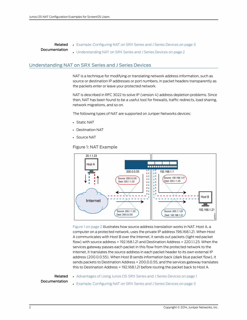
Figure 1: NAT Example
20.1.1.23
192.168.1.21
Host A
Host B
200.0.0.55 192.168.1.1
Source: 200.0.0.55Dest: 220.1.1.23
Source: 220.1.1.23Dest: 200.0.0.55
Source: 220.1.1.23
Dest: 192.168.1.21
Internet
Dest: 220.1.1.23Source: 192.168.1.21
g033
241
Figure 1 on page 2 illustrates how source address translation works in NAT. Host A, a
computer on a protected network, uses the private IP address 196.168.1.21. When Host
A communicates with Host B over the Internet, it sends out packets (light red packet
flow) with source address = 192.168.1.21 and Destination Address = 220.1.1.23. When the
services gateway passes each packet in this flow from the protected network to the
Internet, it translates the source address in each packet header to its own external IP
address (200.0.0.55). When Host B sends information back (dark blue packet flow), it
sends packets to Destination Address = 200.0.0.55, and the services gateway translates
this to Destination Address = 192.168.1.21 before routing the packet back to Host A.
RelatedDocumentation
Advantages of Using Junos OS SRX Series and J Series Devices on page 1•
• Example: Configuring NAT on SRX Series and J Series Devices on page 3
Copyright © 2014, Juniper Networks, Inc.2
Junos OS NAT Configuration Examples for ScreenOS Users
Example: Configuring NAT on SRX Series and J Series Devices
This example shows how to configure NAT on SRX Series and J Series devices using the
CLI.
This example compares the steps used to configure NAT on ScreenOS and provides
equivalent steps required to configure NAT on Junos OS.
This topic includes the following sections:
• Requirements on page 3
• Network Topology on page 4
• Source NAT Egress Interface Translation on page 4
• Source NATWith IP Pool (Dynamic Internet Protocol Address Pool With Port
Translation) on page 6
• Source NATwith IP Address Shifting on page 11
• Source NATwith Loopback Group and Dynamic Internet Protocol on page 14
• Static NAT to a Single Host on page 17
• Static NAT to a Subnet on page 20
• Destination NAT Pool for Virtual IP Addresses on page 23
• Destination Address Translation for Subnet Translation on page 27
• Destination Address and Port Translation to a Single Host on page 30
• Destination Address Translation to a Single Host on page 33
Requirements
This example uses the following hardware and software components:
• J2320, J2350, J4350, and J6350 Services Routers
• SRX Series Services Gateways
• Junos OS Release 9.2 or later for all SRX Series Services Gateways (a more recent
version might be required for all SRX Series Services Gateways released after 9.2)
• Junos OS Release 9.5 or later for all J Series Services Routers
NOTE: Thisconfigurationexamplehasbeentestedusing thesoftware releaselisted and is assumed to work on all later releases.
In addition, youmust do the following before configuring NAT:
• Configure network interfaces on the device
• Create security zones and assign interfaces to them
3Copyright © 2014, Juniper Networks, Inc.
Network Topology
Youmust configure NAT before allowing a private network to connect to the Internet on
anSRXSeriesServicesGatewayor JSeriesServicesRouter. Procedures in theseexamples
describe configuration of source NAT, destination NAT, and static NAT.
Source NAT Egress Interface Translation
Source NAT is the translation of the source IP address of a packet leaving the Juniper
Networks device. Source NAT is used to allow hosts with private IP addresses to access
a public network.
This example describes how to configure a source NATmapping of a single private
address to a public address.
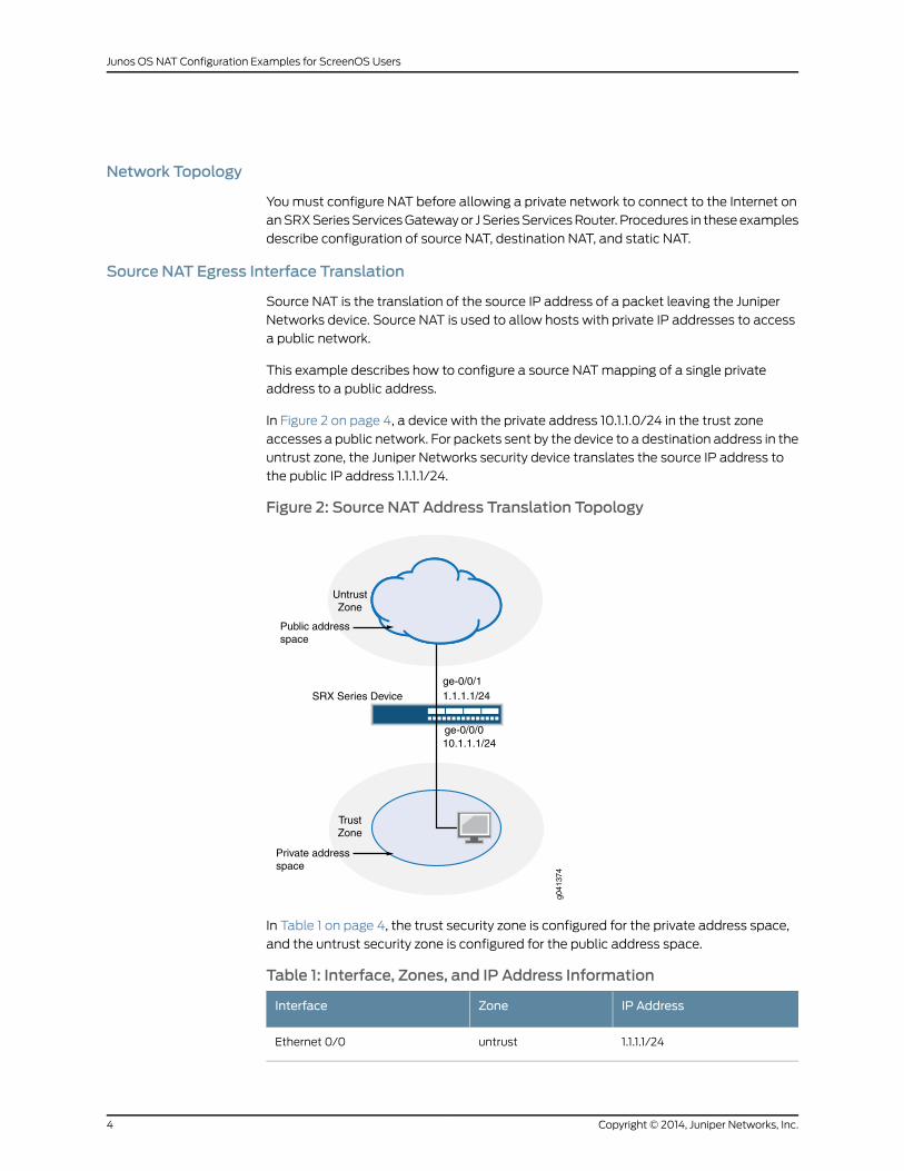
In Figure 2 on page 4, a device with the private address 10.1.1.0/24 in the trust zone
accesses a public network. For packets sent by the device to a destination address in the
untrust zone, the Juniper Networks security device translates the source IP address to
the public IP address 1.1.1.1/24.
Figure 2: Source NAT Address Translation Topology
10.1.1.1/24
1.1.1.1/24
Internet
TrustZone
UntrustZone
SRX Series Device
Public addressspace
Private addressspace
g041
374
ge-0/0/0
ge-0/0/1
In Table 1 on page 4, the trust security zone is configured for the private address space,
and the untrust security zone is configured for the public address space.
Table 1: Interface, Zones, and IP Address Information
IP AddressZoneInterface
1.1.1.1/24untrustEthernet 0/0
Copyright © 2014, Juniper Networks, Inc.4
Junos OS NAT Configuration Examples for ScreenOS Users
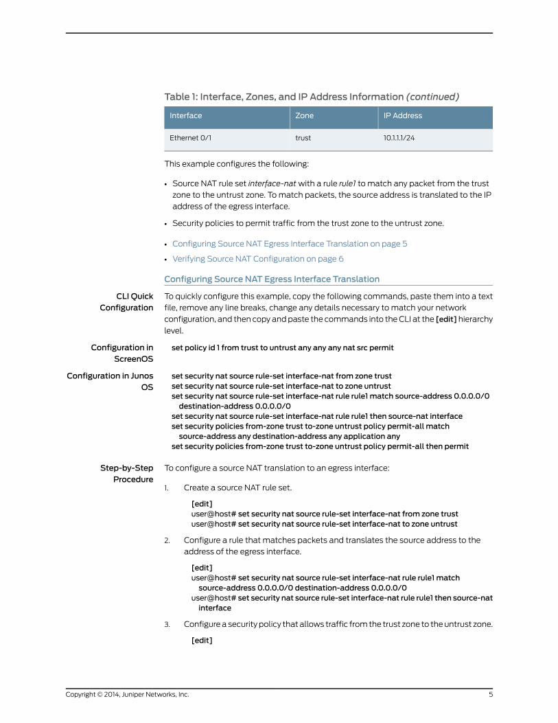
Table 1: Interface, Zones, and IP Address Information (continued)
IP AddressZoneInterface
10.1.1.1/24trustEthernet 0/1
This example configures the following:
• Source NAT rule set interface-natwith a rule rule1 to match any packet from the trust
zone to the untrust zone. Tomatch packets, the source address is translated to the IP
address of the egress interface.
• Security policies to permit traffic from the trust zone to the untrust zone.
• Configuring Source NAT Egress Interface Translation on page 5
• Verifying Source NAT Configuration on page 6
Configuring Source NAT Egress Interface Translation
CLI QuickConfiguration
To quickly configure this example, copy the following commands, paste them into a text
file, remove any line breaks, change any details necessary to match your network
configuration, and then copy andpaste the commands into theCLI at the [edit]hierarchy
level.
Configuration inScreenOS
set policy id 1 from trust to untrust any any any nat src permit
Configuration in JunosOS
set security nat source rule-set interface-nat from zone trustset security nat source rule-set interface-nat to zone untrustset security nat source rule-set interface-nat rule rule1 match source-address 0.0.0.0/0destination-address 0.0.0.0/0
set security nat source rule-set interface-nat rule rule1 then source-nat interfaceset security policies from-zone trust to-zone untrust policy permit-all matchsource-address any destination-address any application any
set security policies from-zone trust to-zone untrust policy permit-all then permit
Step-by-StepProcedure
To configure a source NAT translation to an egress interface:
Create a source NAT rule set.1.
[edit]user@host# set security nat source rule-set interface-nat from zone trustuser@host# set security nat source rule-set interface-nat to zone untrust
2. Configure a rule that matches packets and translates the source address to the
address of the egress interface.
[edit]user@host# set security nat source rule-set interface-nat rule rule1 matchsource-address 0.0.0.0/0 destination-address 0.0.0.0/0
user@host# set security nat source rule-set interface-nat rule rule1 then source-natinterface
3. Configurea security policy that allows traffic fromthe trust zone to theuntrust zone.
[edit]
5Copyright © 2014, Juniper Networks, Inc.
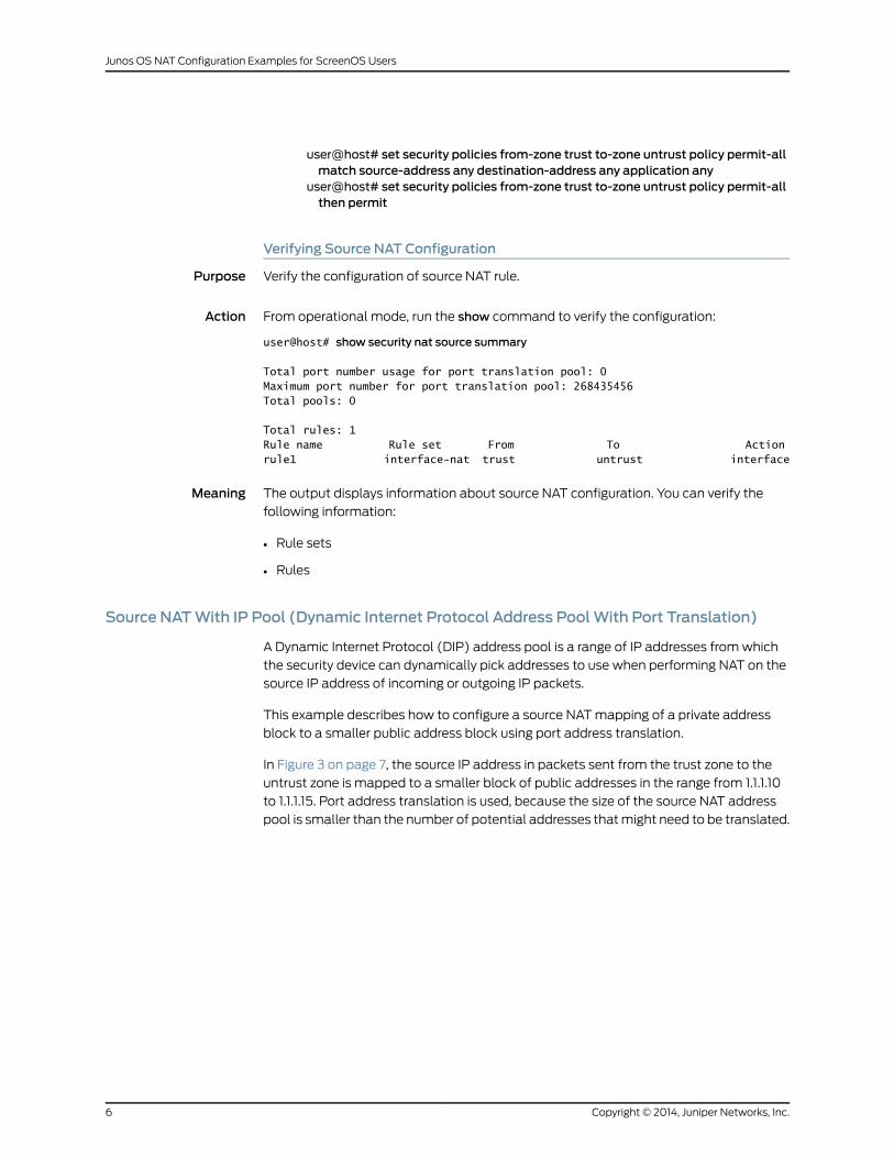
user@host# set security policies from-zone trust to-zone untrust policy permit-allmatch source-address any destination-address any application any
user@host# set security policies from-zone trust to-zone untrust policy permit-allthen permit
Verifying Source NAT Configuration
Purpose Verify the configuration of source NAT rule.
Action From operational mode, run the show command to verify the configuration:
user@host# show security nat source summary
Total port number usage for port translation pool: 0Maximum port number for port translation pool: 268435456Total pools: 0
Total rules: 1Rule name Rule set From To Actionrule1 interface-nat trust untrust interface
Meaning The output displays information about source NAT configuration. You can verify the
following information:
• Rule sets
• Rules
Source NATWith IP Pool (Dynamic Internet Protocol Address PoolWith Port Translation)
A Dynamic Internet Protocol (DIP) address pool is a range of IP addresses fromwhich
the security device can dynamically pick addresses to use when performing NAT on the
source IP address of incoming or outgoing IP packets.
This example describes how to configure a source NATmapping of a private address
block to a smaller public address block using port address translation.
In Figure 3 on page 7, the source IP address in packets sent from the trust zone to the
untrust zone is mapped to a smaller block of public addresses in the range from 1.1.1.10
to 1.1.1.15. Port address translation is used, because the size of the source NAT address
pool is smaller than the number of potential addresses thatmight need to be translated.
Copyright © 2014, Juniper Networks, Inc.6
Junos OS NAT Configuration Examples for ScreenOS Users
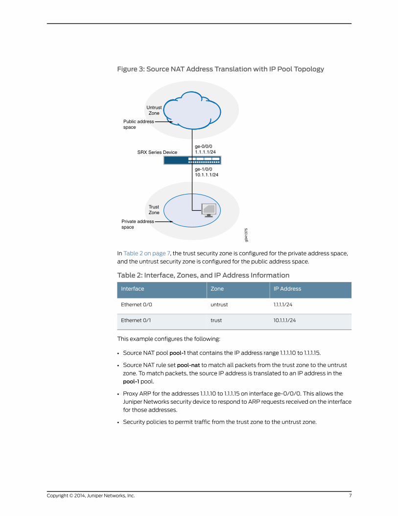
Figure 3: Source NAT Address Translation with IP Pool Topology
ge-1/0/010.1.1.1/24
ge-0/0/01.1.1.1/24
Internet
TrustZone
UntrustZone
SRX Series Device
Public addressspace
Private addressspace
g041
375
In Table 2 on page 7, the trust security zone is configured for the private address space,
and the untrust security zone is configured for the public address space.
Table 2: Interface, Zones, and IP Address Information
IP AddressZoneInterface
1.1.1.1/24untrustEthernet 0/0
10.1.1.1/24trustEthernet 0/1
This example configures the following:
• Source NAT pool pool-1 that contains the IP address range 1.1.1.10 to 1.1.1.15.
• Source NAT rule set pool-nat to match all packets from the trust zone to the untrust
zone. Tomatch packets, the source IP address is translated to an IP address in the
pool-1 pool.
• Proxy ARP for the addresses 1.1.1.10 to 1.1.1.15 on interface ge-0/0/0. This allows the
Juniper Networks security device to respond to ARP requests received on the interface
for those addresses.
• Security policies to permit traffic from the trust zone to the untrust zone.
7Copyright © 2014, Juniper Networks, Inc.
This topic includes the following sections:
• Configuring Source NATWith IP Pool (Dynamic Internet Protocol Address Pool With
Port Translation) on page 8
• Verifying Source NATWith IP Pool (With Port Translation) Configuration on page 9
• ConfiguringSourceNATWith IPPool (Dynamic InternetProtocolAddressPoolWithout
Port Translation) on page 9
• VerifyingSourceNATWith IPPool (Without Port Translation) Configuration onpage 10
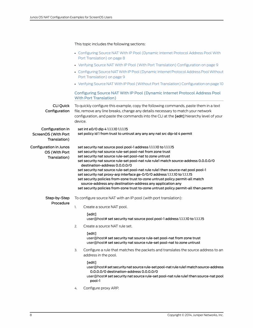
Configuring Source NATWith IP Pool (Dynamic Internet Protocol Address PoolWith Port Translation)
CLI QuickConfiguration
To quickly configure this example, copy the following commands, paste them in a text
file, remove any line breaks, change any details necessary to match your network
configuration, and paste the commands into the CLI at the [edit] hierarchy level of your
device.
Configuration inScreenOS (With Port
Translation)
set int e0/0 dip 4 1.1.1.10 1.1.1.15set policy id 1 from trust to untrust any any any nat src dip-id 4 permit
Configuration in JunosOS (With PortTranslation)
set security nat source pool pool-1 address 1.1.1.10 to 1.1.1.15set security nat source rule-set pool-nat from zone trustset security nat source rule-set pool-nat to zone untrustset security nat source rule-set pool-nat rule rule1 match source-address 0.0.0.0/0destination-address 0.0.0.0/0
set security nat source rule-set pool-nat rule rule1 then source-nat pool pool-1set security nat proxy-arp interface ge-0/0/0 address 1.1.1.10 to 1.1.1.15set security policies from-zone trust to-zone untrust policy permit-all matchsource-address any destination-address any application any
set security policies from-zone trust to-zone untrust policy permit-all then permit
Step-by-StepProcedure
To configure source NATwith an IP pool (with port translation):
Create a source NAT pool.1.
[edit]user@host# set security nat source pool pool-1 address 1.1.1.10 to 1.1.1.15
2. Create a source NAT rule set.
[edit]user@host# set security nat source rule-set pool-nat from zone trustuser@host# set security nat source rule-set pool-nat to zone untrust
3. Configure a rule that matches the packets and translates the source address to an
address in the pool.
[edit]user@host#setsecuritynatsource rule-setpool-nat rule rule1matchsource-address0.0.0.0/0 destination-address 0.0.0.0/0
user@host# set security nat source rule-set pool-nat rule rule1 then source-natpoolpool-1
4. Configure proxy ARP.
Copyright © 2014, Juniper Networks, Inc.8
Junos OS NAT Configuration Examples for ScreenOS Users
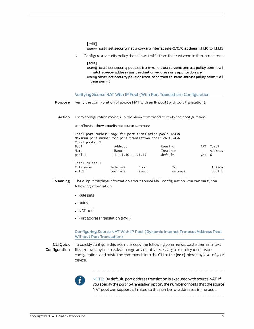
[edit]user@host# set security nat proxy-arp interface ge-0/0/0 address 1.1.1.10 to 1.1.1.15
5. Configurea security policy that allows traffic fromthe trust zone to theuntrust zone.
[edit]user@host# set security policies from-zone trust to-zone untrust policy permit-allmatch source-address any destination-address any application any
user@host# set security policies from-zone trust to-zone untrust policy permit-allthen permit
Verifying Source NATWith IP Pool (With Port Translation) Configuration
Purpose Verify the configuration of source NATwith an IP pool (with port translation).
Action From configuration mode, run the show command to verify the configuration:
user@host> show security nat source summary
Total port number usage for port translation pool: 18438Maximum port number for port translation pool: 268435456Total pools: 1Pool Address Routing PAT Total Name Range Instance Addresspool-1 1.1.1.10-1.1.1.15 default yes 6
Total rules: 1Rule name Rule set From To Actionrule1 pool-nat trust untrust pool-1
Meaning The output displays information about source NAT configuration. You can verify the
following information:
• Rule sets
• Rules
• NAT pool
• Port address translation (PAT)
Configuring Source NATWith IP Pool (Dynamic Internet Protocol Address PoolWithout Port Translation)
CLI QuickConfiguration
To quickly configure this example, copy the following commands, paste them in a text
file, remove any line breaks, change any details necessary to match your network
configuration, and paste the commands into the CLI at the [edit] hierarchy level of your
device.
NOTE: By default, port address translation is executed with source NAT. Ifyouspecify theportno-translationoption, thenumberofhosts that thesource
NAT pool can support is limited to the number of addresses in the pool.
9Copyright © 2014, Juniper Networks, Inc.
Configuration inScreenOS (Without
Port Translation)
set int e0/0 dip 4 1.1.1.10 1.1.1.15set policy id 1 from trust to untrust any any any nat src dip-id 4 permit
Configuration in JunosOS (Without Port
Translation)
set security nat source pool pool-1 address 1.1.1.10 to 1.1.1.15set security nat source pool pool-1 port no-translationset security nat source rule-set pool-nat from zone trustset security nat source rule-set pool-nat to zone untrustset security nat source rule-set pool-nat rule rule1 match source-address 10.1.1.1/24destination-address 0.0.0.0/0
set security nat source rule-set pool-nat rule rule1 then source-nat pool pool-1set security nat proxy-arp interface ge-0/0/0 address 1.1.1.10 to 1.1.1.15set security policies from-zone trust to-zone untrust policy permit-all matchsource-address any destination-address any application any
set security policies from-zone trust to-zone untrust policy permit-all then permit
Step-by-StepProcedure
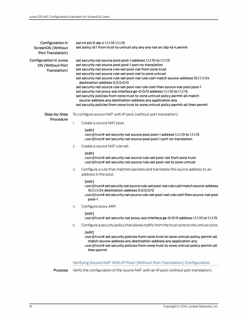
To configure source NATwith IP pool (without port translation):
Create a source NAT pool.1.
[edit]user@host# set security nat source pool pool-1 address 1.1.1.10 to 1.1.1.15user@host# set security nat source pool pool-1 port no-translation
2. Create a source NAT rule set.
[edit]user@host# set security nat source rule-set pool-nat from zone trustuser@host# set security nat source rule-set pool-nat to zone untrust
3. Configure a rule that matches packets and translates the source address to an
address in the pool.
[edit]user@host#setsecuritynatsource rule-setpool-nat rule rule1matchsource-address10.1.1.1/24 destination-address 0.0.0.0/0
user@host# set security nat source rule-set pool-nat rule rule1 then source-natpoolpool-1
4. Configure proxy ARP.
[edit]user@host# set security nat proxy-arp interface ge-0/0/0 address 1.1.1.10 to 1.1.1.15
5. Configurea security policy that allows traffic fromthe trust zone to theuntrust zone.
[edit]user@host# set security policies from-zone trust to-zone untrust policy permit-allmatch source-address any destination-address any application any
user@host# set security policies from-zone trust to-zone untrust policy permit-allthen permit
Verifying Source NATWith IP Pool (Without Port Translation) Configuration
Purpose Verify the configuration of the source NATwith an IP pool (without port translation).
Copyright © 2014, Juniper Networks, Inc.10
Junos OS NAT Configuration Examples for ScreenOS Users
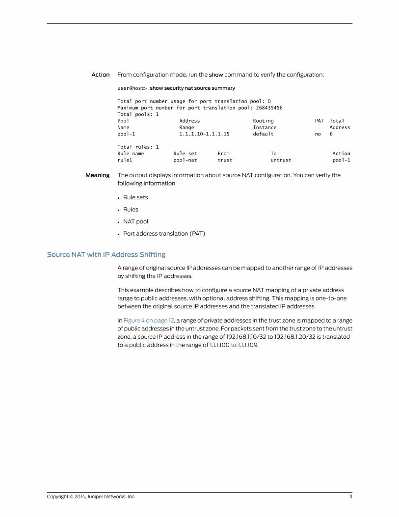
Action From configuration mode, run the show command to verify the configuration:
user@host> show security nat source summary
Total port number usage for port translation pool: 0Maximum port number for port translation pool: 268435456Total pools: 1Pool Address Routing PAT Total Name Range Instance Addresspool-1 1.1.1.10-1.1.1.15 default no 6
Total rules: 1Rule name Rule set From To Actionrule1 pool-nat trust untrust pool-1
Meaning The output displays information about source NAT configuration. You can verify the
following information:
• Rule sets
• Rules
• NAT pool
• Port address translation (PAT)
Source NATwith IP Address Shifting
A range of original source IP addresses can bemapped to another range of IP addresses
by shifting the IP addresses.
This example describes how to configure a source NATmapping of a private address
range to public addresses, with optional address shifting. This mapping is one-to-one
between the original source IP addresses and the translated IP addresses.
In Figure 4 on page 12, a range of private addresses in the trust zone ismapped to a range
ofpublic addresses in theuntrust zone. For packets sent fromthe trust zone to theuntrust
zone, a source IP address in the range of 192.168.1.10/32 to 192.168.1.20/32 is translated
to a public address in the range of 1.1.1.100 to 1.1.1.109.
11Copyright © 2014, Juniper Networks, Inc.
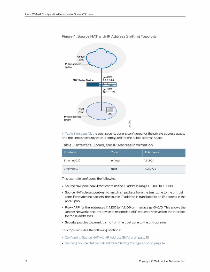
Figure 4: Source NATwith IP Address Shifting Topology
ge-1/0/010.1.1.1/24
ge-0/0/01.1.1.1/24
Internet
TrustZone
UntrustZone
SRX Series Device
Public addressspace
Private addressspace
g041
375
In Table 3 on page 12, the trust security zone is configured for the private address space,
and the untrust security zone is configured for the public address space.
Table 3: Interface, Zones, and IP Address Information
IP AddressZoneInterface
1.1.1.1/24untrustEthernet 0/0
10.1.1.1/24trustEthernet 0/1
This example configures the following:
• Source NAT pool pool-1 that contains the IP address range 1.1.1.100 to 1.1.1.109.
• Source NAT rule set pool-nat to match all packets from the trust zone to the untrust
zone. For matching packets, the source IP address is translated to an IP address in the
pool-1 pool.
• Proxy ARP for the addresses 1.1.1.100 to 1.1.1.109 on interface ge-0/0/0. This allows the
Juniper Networks security device to respond to ARP requests received on the interface
for those addresses.
• Security policies to permit traffic from the trust zone to the untrust zone.
This topic includes the following sections:
• Configuring Source NATwith IP Address Shifting on page 13
• Verifying Source NATwith IP Address Shifting Configuration on page 14
Copyright © 2014, Juniper Networks, Inc.12
Junos OS NAT Configuration Examples for ScreenOS Users
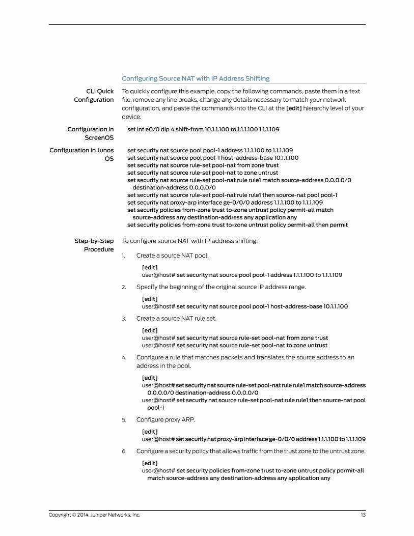
Configuring Source NATwith IP Address Shifting
CLI QuickConfiguration
To quickly configure this example, copy the following commands, paste them in a text
file, remove any line breaks, change any details necessary to match your network
configuration, and paste the commands into the CLI at the [edit] hierarchy level of your
device.
Configuration inScreenOS
set int e0/0 dip 4 shift-from 10.1.1.100 to 1.1.1.100 1.1.1.109
Configuration in JunosOS
set security nat source pool pool-1 address 1.1.1.100 to 1.1.1.109set security nat source pool pool-1 host-address-base 10.1.1.100set security nat source rule-set pool-nat from zone trustset security nat source rule-set pool-nat to zone untrustset security nat source rule-set pool-nat rule rule1 match source-address 0.0.0.0/0destination-address 0.0.0.0/0
set security nat source rule-set pool-nat rule rule1 then source-nat pool pool-1set security nat proxy-arp interface ge-0/0/0 address 1.1.1.100 to 1.1.1.109set security policies from-zone trust to-zone untrust policy permit-all matchsource-address any destination-address any application any
set security policies from-zone trust to-zone untrust policy permit-all then permit
Step-by-StepProcedure
To configure source NATwith IP address shifting:
Create a source NAT pool.1.
[edit]user@host# set security nat source pool pool-1 address 1.1.1.100 to 1.1.1.109
2. Specify the beginning of the original source IP address range.
[edit]user@host# set security nat source pool pool-1 host-address-base 10.1.1.100
3. Create a source NAT rule set.
[edit]user@host# set security nat source rule-set pool-nat from zone trustuser@host# set security nat source rule-set pool-nat to zone untrust
4. Configure a rule that matches packets and translates the source address to an
address in the pool.
[edit]user@host#setsecuritynatsource rule-setpool-nat rule rule1matchsource-address0.0.0.0/0 destination-address 0.0.0.0/0
user@host# set security nat source rule-set pool-nat rule rule1 then source-natpoolpool-1
5. Configure proxy ARP.
[edit]user@host#setsecuritynatproxy-arp interfacege-0/0/0address 1.1.1.100to 1.1.1.109
6. Configurea security policy that allows traffic fromthe trust zone to theuntrust zone.
[edit]user@host# set security policies from-zone trust to-zone untrust policy permit-allmatch source-address any destination-address any application any
13Copyright © 2014, Juniper Networks, Inc.
user@host# set security policies from-zone trust to-zone untrust policy permit-allthen permit
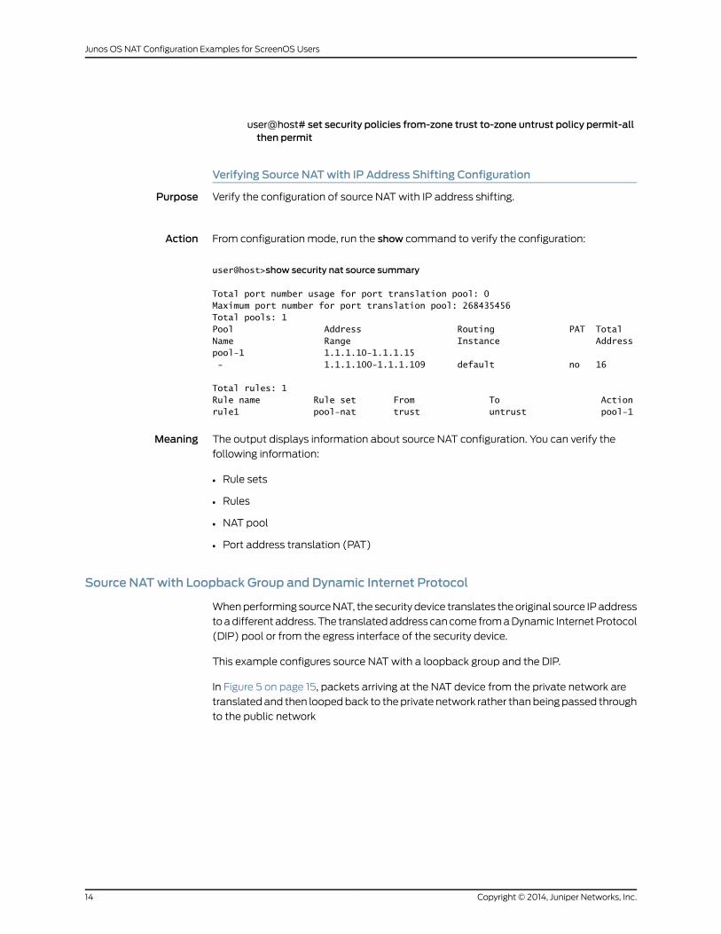
Verifying Source NATwith IP Address Shifting Configuration
Purpose Verify the configuration of source NATwith IP address shifting.
Action From configuration mode, run the show command to verify the configuration:
user@host>show security nat source summary
Total port number usage for port translation pool: 0Maximum port number for port translation pool: 268435456Total pools: 1Pool Address Routing PAT Total Name Range Instance Addresspool-1 1.1.1.10-1.1.1.15 - 1.1.1.100-1.1.1.109 default no 16
Total rules: 1Rule name Rule set From To Actionrule1 pool-nat trust untrust pool-1
Meaning The output displays information about source NAT configuration. You can verify the
following information:
• Rule sets
• Rules
• NAT pool
• Port address translation (PAT)
Source NATwith Loopback Group and Dynamic Internet Protocol
Whenperforming sourceNAT, the security device translates theoriginal source IPaddress
toadifferentaddress. The translatedaddress cancome fromaDynamic InternetProtocol
(DIP) pool or from the egress interface of the security device.
This example configures source NATwith a loopback group and the DIP.
In Figure 5 on page 15, packets arriving at the NAT device from the private network are
translatedand then loopedback to theprivate network rather thanbeingpassed through
to the public network
Copyright © 2014, Juniper Networks, Inc.14
Junos OS NAT Configuration Examples for ScreenOS Users
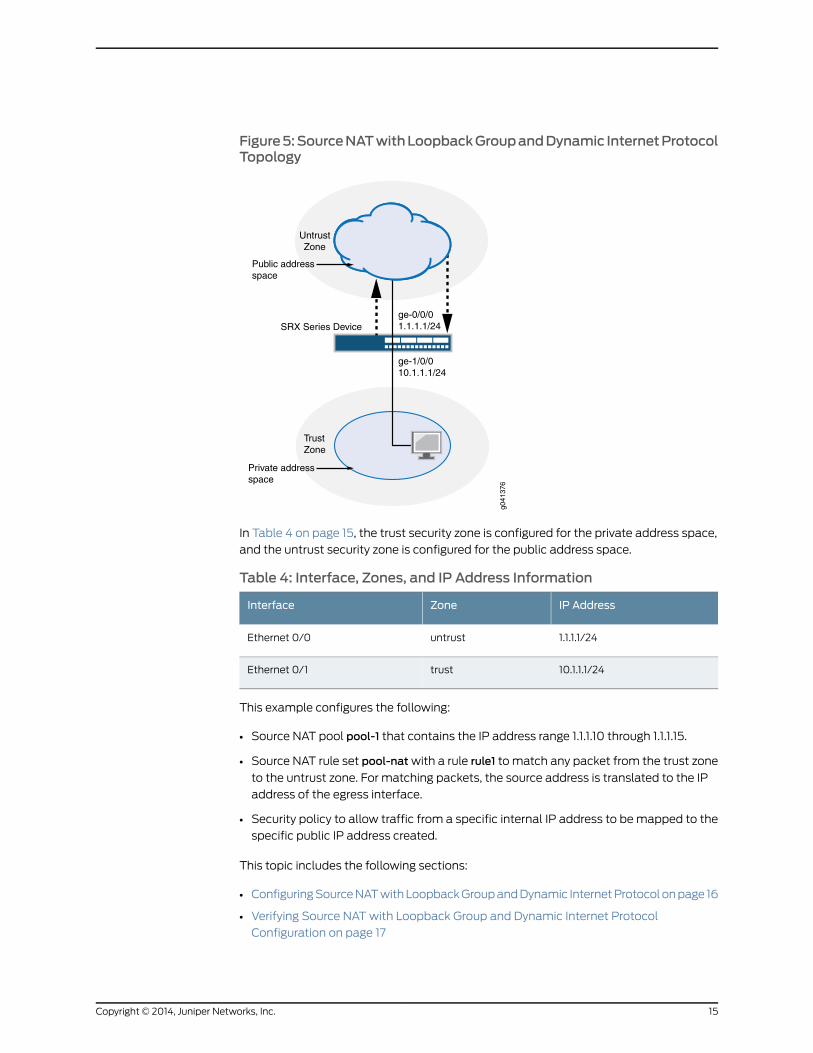
Figure5:SourceNATwithLoopbackGroupandDynamic InternetProtocolTopology
ge-1/0/010.1.1.1/24
ge-0/0/01.1.1.1/24
Internet
TrustZone
UntrustZone
SRX Series Device
Public addressspace
Private addressspace
g041
376
In Table 4 on page 15, the trust security zone is configured for the private address space,
and the untrust security zone is configured for the public address space.
Table 4: Interface, Zones, and IP Address Information
IP AddressZoneInterface
1.1.1.1/24untrustEthernet 0/0
10.1.1.1/24trustEthernet 0/1
This example configures the following:
• Source NAT pool pool-1 that contains the IP address range 1.1.1.10 through 1.1.1.15.
• Source NAT rule set pool-natwith a rule rule1 to match any packet from the trust zone
to the untrust zone. For matching packets, the source address is translated to the IP
address of the egress interface.
• Security policy to allow traffic from a specific internal IP address to bemapped to the
specific public IP address created.
This topic includes the following sections:
• ConfiguringSourceNATwithLoopbackGroupandDynamic InternetProtocolonpage 16
• Verifying Source NATwith Loopback Group and Dynamic Internet Protocol
Configuration on page 17
15Copyright © 2014, Juniper Networks, Inc.
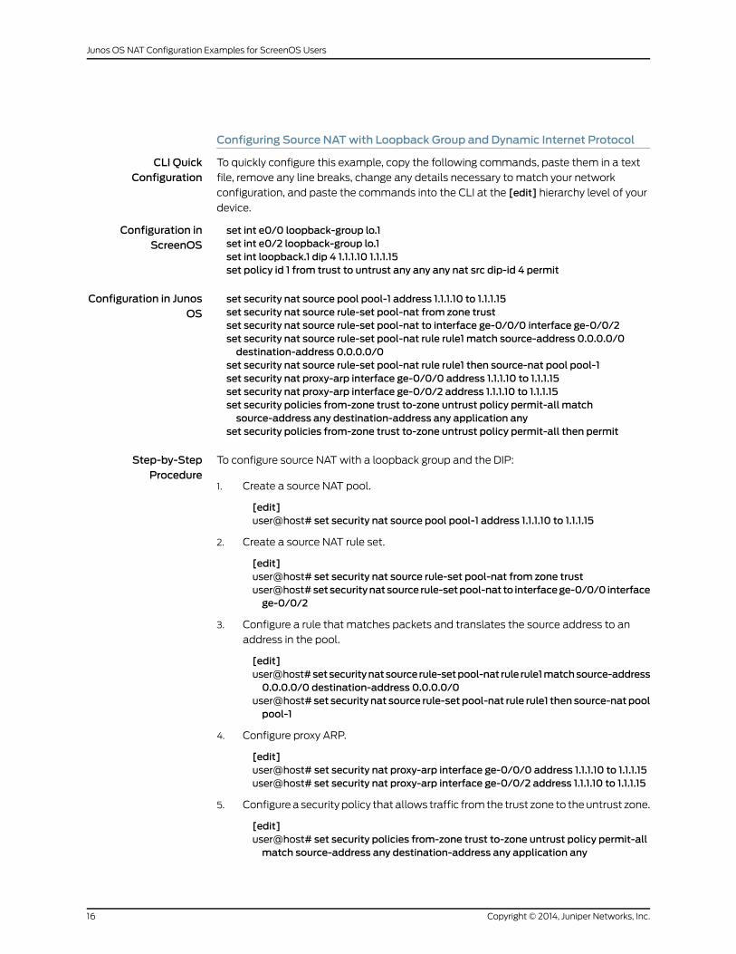
Configuring Source NATwith Loopback Group and Dynamic Internet Protocol
CLI QuickConfiguration
To quickly configure this example, copy the following commands, paste them in a text
file, remove any line breaks, change any details necessary to match your network
configuration, and paste the commands into the CLI at the [edit] hierarchy level of your
device.
Configuration inScreenOS
set int e0/0 loopback-group lo.1set int e0/2 loopback-group lo.1set int loopback.1 dip 4 1.1.1.10 1.1.1.15set policy id 1 from trust to untrust any any any nat src dip-id 4 permit
Configuration in JunosOS
set security nat source pool pool-1 address 1.1.1.10 to 1.1.1.15set security nat source rule-set pool-nat from zone trustset security nat source rule-set pool-nat to interface ge-0/0/0 interface ge-0/0/2set security nat source rule-set pool-nat rule rule1 match source-address 0.0.0.0/0destination-address 0.0.0.0/0
set security nat source rule-set pool-nat rule rule1 then source-nat pool pool-1set security nat proxy-arp interface ge-0/0/0 address 1.1.1.10 to 1.1.1.15set security nat proxy-arp interface ge-0/0/2 address 1.1.1.10 to 1.1.1.15set security policies from-zone trust to-zone untrust policy permit-all matchsource-address any destination-address any application any
set security policies from-zone trust to-zone untrust policy permit-all then permit
Step-by-StepProcedure
To configure source NATwith a loopback group and the DIP:
Create a source NAT pool.1.
[edit]user@host# set security nat source pool pool-1 address 1.1.1.10 to 1.1.1.15
2. Create a source NAT rule set.
[edit]user@host# set security nat source rule-set pool-nat from zone trustuser@host#setsecuritynatsource rule-setpool-nat to interfacege-0/0/0 interfacege-0/0/2
3. Configure a rule that matches packets and translates the source address to an
address in the pool.
[edit]user@host#setsecuritynatsource rule-setpool-nat rule rule1matchsource-address0.0.0.0/0 destination-address 0.0.0.0/0
user@host# set security nat source rule-set pool-nat rule rule1 then source-natpoolpool-1
4. Configure proxy ARP.
[edit]user@host# set security nat proxy-arp interface ge-0/0/0 address 1.1.1.10 to 1.1.1.15user@host# set security nat proxy-arp interface ge-0/0/2 address 1.1.1.10 to 1.1.1.15
5. Configurea security policy that allows traffic fromthe trust zone to theuntrust zone.
[edit]user@host# set security policies from-zone trust to-zone untrust policy permit-allmatch source-address any destination-address any application any
Copyright © 2014, Juniper Networks, Inc.16
Junos OS NAT Configuration Examples for ScreenOS Users
user@host# set security policies from-zone trust to-zone untrust policy permit-allthen permit
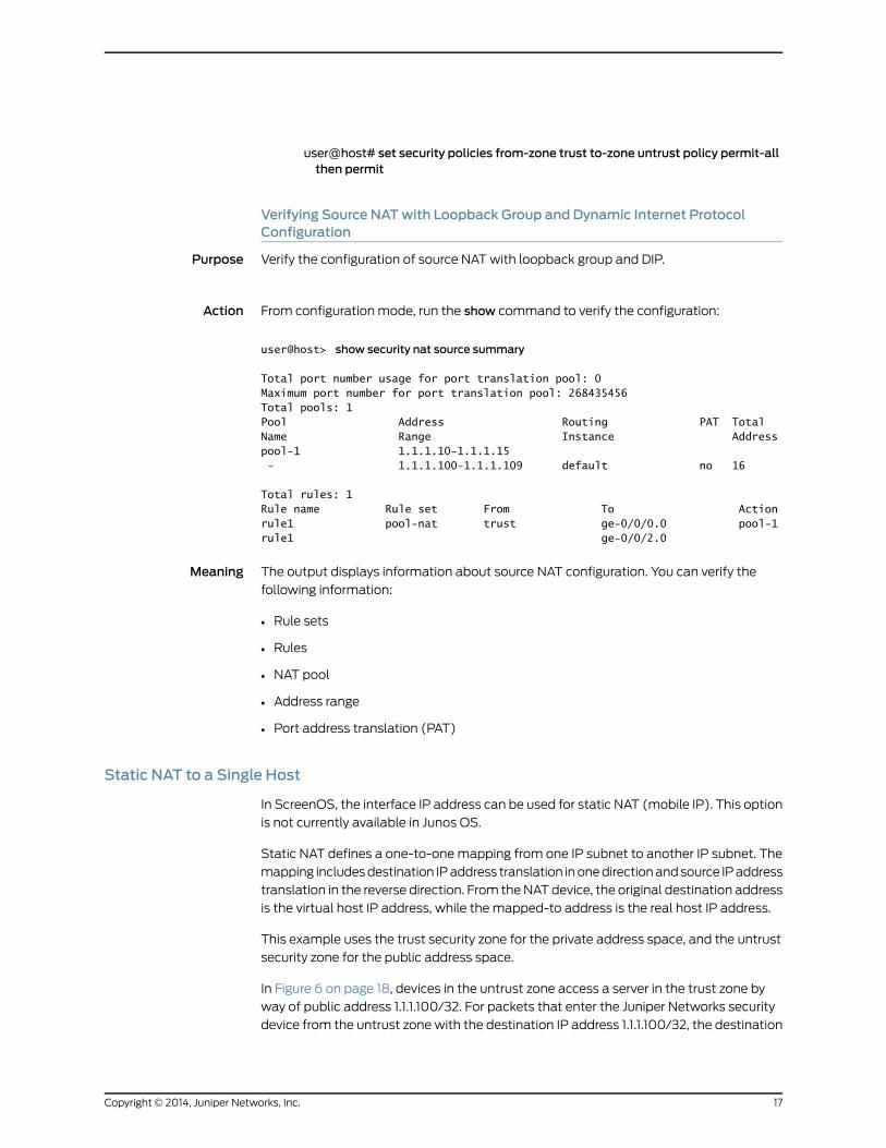
Verifying Source NATwith Loopback Group and Dynamic Internet ProtocolConfiguration
Purpose Verify the configuration of source NATwith loopback group and DIP.
Action From configuration mode, run the show command to verify the configuration:
user@host> show security nat source summary
Total port number usage for port translation pool: 0Maximum port number for port translation pool: 268435456Total pools: 1Pool Address Routing PAT Total Name Range Instance Addresspool-1 1.1.1.10-1.1.1.15 - 1.1.1.100-1.1.1.109 default no 16
Total rules: 1Rule name Rule set From To Actionrule1 pool-nat trust ge-0/0/0.0 pool-1rule1 ge-0/0/2.0
Meaning The output displays information about source NAT configuration. You can verify the
following information:
• Rule sets
• Rules
• NAT pool
• Address range
• Port address translation (PAT)
Static NAT to a Single Host
In ScreenOS, the interface IP address can be used for static NAT (mobile IP). This option
is not currently available in Junos OS.
Static NAT defines a one-to-onemapping from one IP subnet to another IP subnet. The
mapping includesdestination IPaddress translation inonedirectionandsource IPaddress
translation in the reverse direction. From theNATdevice, the original destination address
is the virtual host IP address, while the mapped-to address is the real host IP address.
This example uses the trust security zone for the private address space, and the untrust
security zone for the public address space.
In Figure 6 on page 18, devices in the untrust zone access a server in the trust zone by
way of public address 1.1.1.100/32. For packets that enter the Juniper Networks security
device from the untrust zonewith the destination IP address 1.1.1.100/32, the destination
17Copyright © 2014, Juniper Networks, Inc.
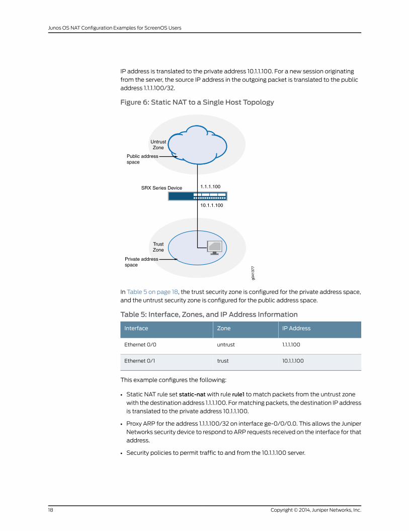
IP address is translated to the private address 10.1.1.100. For a new session originating
from the server, the source IP address in the outgoing packet is translated to the public
address 1.1.1.100/32.
Figure 6: Static NAT to a Single Host Topology
10.1.1.100
1.1.1.100
Internet
TrustZone
UntrustZone
SRX Series Device
Public addressspace
Private addressspace
g041
377
In Table 5 on page 18, the trust security zone is configured for the private address space,
and the untrust security zone is configured for the public address space.
Table 5: Interface, Zones, and IP Address Information
IP AddressZoneInterface
1.1.1.100untrustEthernet 0/0
10.1.1.100trustEthernet 0/1
This example configures the following:
• Static NAT rule set static-natwith rule rule1 to match packets from the untrust zone
with the destination address 1.1.1.100. Formatching packets, the destination IP address
is translated to the private address 10.1.1.100.
• Proxy ARP for the address 1.1.1.100/32 on interface ge-0/0/0.0. This allows the Juniper
Networks security device to respond to ARP requests received on the interface for that
address.
• Security policies to permit traffic to and from the 10.1.1.100 server.
Copyright © 2014, Juniper Networks, Inc.18
Junos OS NAT Configuration Examples for ScreenOS Users
This topic includes the following sections:
• Configuring Static NAT to a Single Host on page 19
• Verifying Static NAT to a Single Host Configuration on page 20
Configuring Static NAT to a Single Host
CLI QuickConfiguration
To quickly configure this example, copy the following commands, paste them in a text
file, remove any line breaks, change any details necessary to match your network
configuration, and paste the commands into the CLI at the [edit] hierarchy level of your
device.
Configuration inScreenOS
set int e0/0mip 1.1.1.100 host 10.1.1.100set pol from untrust to trust anymip(1.1.1.100) http permit
Configuration in JunosOS
set security nat proxy-arp interface ge-0/0/0 address 1.1.1.100/32set security nat static rule-set static-nat from zone untrustset security nat static rule-set static-nat rule rule1 match destination-address 1.1.1.100set security nat static rule-set static-nat rule rule1 then static-nat prefix 10.1.1.100set security zones security-zone trust address-book address webserver 10.1.1.100set security policies from-zone untrust to-zone trust policy static-natmatchsource-address any destination-address webserver application junos-http
set security policies from-zone untrust to-zone trust policy static-nat then permit
Step-by-StepProcedure
To configure static NAT to a single host configuration:
Configure proxy ARP.1.
[edit]user@host# set security nat proxy-arp interface ge-0/0/0 address 1.1.1.100/32
2. Create a static NAT rule set.
[edit]user@host# set security nat static rule-set static-nat from zone untrust
3. Configure a rule that matches packets and translates the destination address in
the packets to a private address.
[edit]user@host# set security nat static rule-set static-nat rule rule1 matchdestination-address 1.1.1.100
user@host# set securitynat static rule-set static-nat rule rule1 thenstatic-natprefix10.1.1.100
4. Configure an address in the global address book.
[edit]user@host#setsecurityzonessecurity-zonetrustaddress-bookaddresswebserver10.1.1.100
5. Configure a security policy that allows traffic from the untrust zone to the server in
the trust zone.
[edit]user@host# set security policies from-zone untrust to-zone trust policy static-natmatchsource-addressanydestination-addresswebserverapplication junos-http
19Copyright © 2014, Juniper Networks, Inc.
user@host# set security policies from-zone untrust to-zone trust policy static-natthen permit
Verifying Static NAT to a Single Host Configuration
Purpose Verify the configuration of static NAT to a single host.
Action From configuration mode, run the show command to verify the configuration:
user@host> show security nat static rule all
Total static-nat rules: 1Total referenced IPv4/IPv6 ip-prefixes: 2/0
Static NAT rule: rule1 Rule-set: static-nat Rule-Id : 1 Rule position : 1 From zone : untrust Destination addresses : 1.1.1.100 Host addresses : 10.1.1.100 Netmask : 32 Host routing-instance : N/A Translation hits : 0
Meaning The output displays information about static NAT configuration. You can verify the
following information:
• Rule sets
• Rules
• Address range
Static NAT to a Subnet
This example uses the trust security zone for the private address space, and the untrust
security zone for the public address space.
NOTE: In ScreenOS, the interface IP address can be used for static NAT(mobile IP). This option is not currently available in Junos OS.
In Figure 7 on page 21, devices in the untrust zone access devices in the trust zone byway
of public subnet address 1.1.1.0/28. For packets that enter the Juniper Networks security
device from the untrust zone with a destination IP address in the 1.1.1.0/28 subnet, the
destination IP address is translated to a private address on the 10.1.1.0/28 subnet. For
new sessions originating from the 10.1.1.0/28 subnet, the source IP address in outgoing
packets is translated to an address on the public 1.1.1.0/28 subnet.
Copyright © 2014, Juniper Networks, Inc.20
Junos OS NAT Configuration Examples for ScreenOS Users
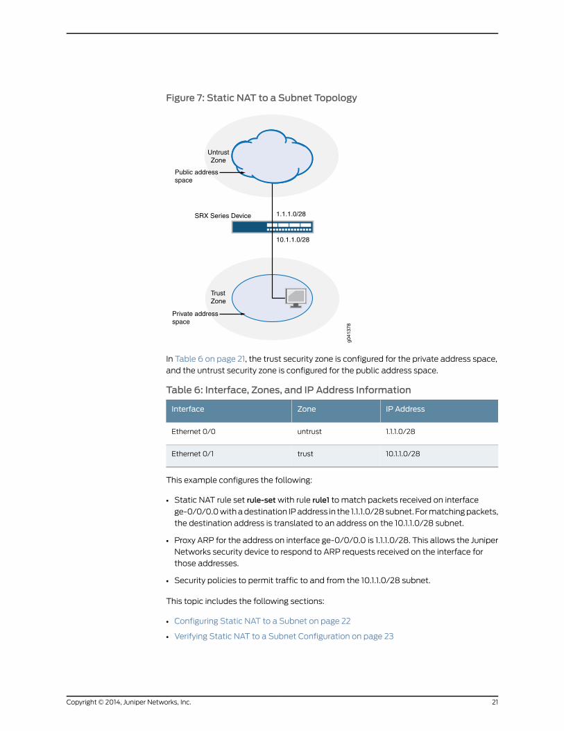
Figure 7: Static NAT to a Subnet Topology
10.1.1.0/28
1.1.1.0/28
Internet
TrustZone
UntrustZone
SRX Series Device
Public addressspace
Private addressspace
g041
378
In Table 6 on page 21, the trust security zone is configured for the private address space,
and the untrust security zone is configured for the public address space.
Table 6: Interface, Zones, and IP Address Information
IP AddressZoneInterface
1.1.1.0/28untrustEthernet 0/0
10.1.1.0/28trustEthernet 0/1
This example configures the following:
• Static NAT rule set rule-setwith rule rule1 to match packets received on interface
ge-0/0/0.0withadestination IPaddress in the 1.1.1.0/28subnet. Formatchingpackets,
the destination address is translated to an address on the 10.1.1.0/28 subnet.
• Proxy ARP for the address on interface ge-0/0/0.0 is 1.1.1.0/28. This allows the Juniper
Networks security device to respond to ARP requests received on the interface for
those addresses.
• Security policies to permit traffic to and from the 10.1.1.0/28 subnet.
This topic includes the following sections:
• Configuring Static NAT to a Subnet on page 22
• Verifying Static NAT to a Subnet Configuration on page 23
21Copyright © 2014, Juniper Networks, Inc.
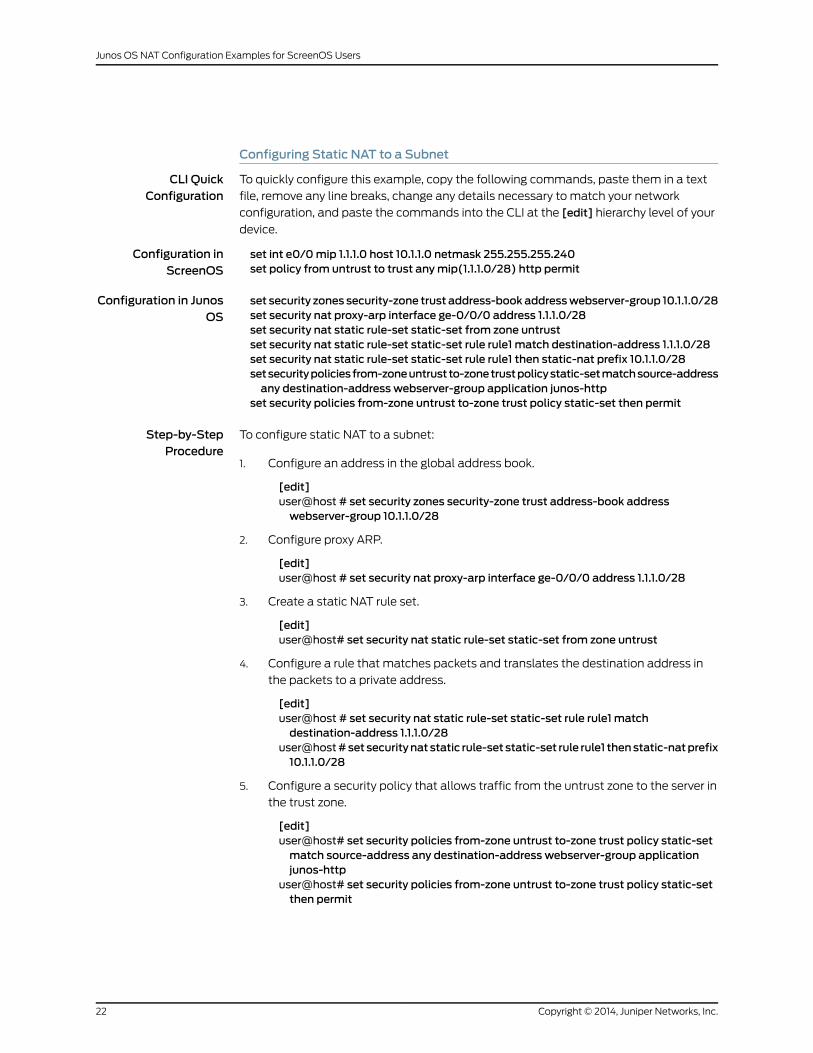
Configuring Static NAT to a Subnet
CLI QuickConfiguration
To quickly configure this example, copy the following commands, paste them in a text
file, remove any line breaks, change any details necessary to match your network
configuration, and paste the commands into the CLI at the [edit] hierarchy level of your
device.
Configuration inScreenOS
set int e0/0mip 1.1.1.0 host 10.1.1.0 netmask 255.255.255.240set policy from untrust to trust anymip(1.1.1.0/28) http permit
Configuration in JunosOS
set security zones security-zone trust address-bookaddresswebserver-group 10.1.1.0/28set security nat proxy-arp interface ge-0/0/0 address 1.1.1.0/28set security nat static rule-set static-set from zone untrustset security nat static rule-set static-set rule rule1 match destination-address 1.1.1.0/28set security nat static rule-set static-set rule rule1 then static-nat prefix 10.1.1.0/28setsecuritypoliciesfrom-zoneuntrustto-zonetrustpolicystatic-setmatchsource-addressany destination-address webserver-group application junos-http
set security policies from-zone untrust to-zone trust policy static-set then permit
Step-by-StepProcedure
To configure static NAT to a subnet:
Configure an address in the global address book.1.
[edit]user@host # set security zones security-zone trust address-book addresswebserver-group 10.1.1.0/28
2. Configure proxy ARP.
[edit]user@host # set security nat proxy-arp interface ge-0/0/0 address 1.1.1.0/28
3. Create a static NAT rule set.
[edit]user@host# set security nat static rule-set static-set from zone untrust
4. Configure a rule that matches packets and translates the destination address in
the packets to a private address.
[edit]user@host # set security nat static rule-set static-set rule rule1 matchdestination-address 1.1.1.0/28
user@host#setsecuritynatstatic rule-set static-set rule rule1 thenstatic-natprefix10.1.1.0/28
5. Configure a security policy that allows traffic from the untrust zone to the server in
the trust zone.
[edit]user@host# set security policies from-zone untrust to-zone trust policy static-setmatch source-address any destination-address webserver-group applicationjunos-http
user@host# set security policies from-zone untrust to-zone trust policy static-setthen permit
Copyright © 2014, Juniper Networks, Inc.22
Junos OS NAT Configuration Examples for ScreenOS Users
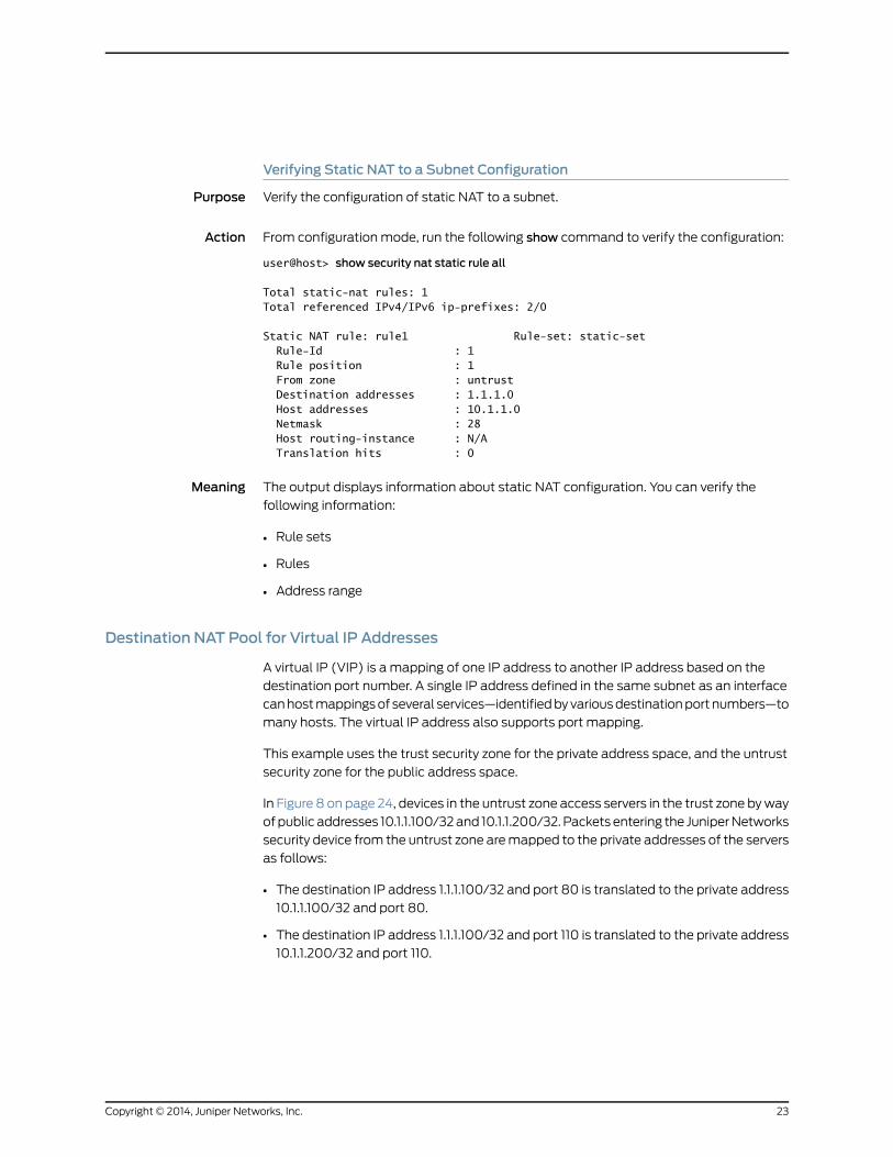
Verifying Static NAT to a Subnet Configuration
Purpose Verify the configuration of static NAT to a subnet.
Action From configuration mode, run the following show command to verify the configuration:
user@host> show security nat static rule all
Total static-nat rules: 1Total referenced IPv4/IPv6 ip-prefixes: 2/0
Static NAT rule: rule1 Rule-set: static-set Rule-Id : 1 Rule position : 1 From zone : untrust Destination addresses : 1.1.1.0 Host addresses : 10.1.1.0 Netmask : 28 Host routing-instance : N/A Translation hits : 0
Meaning The output displays information about static NAT configuration. You can verify the
following information:
• Rule sets
• Rules
• Address range
Destination NAT Pool for Virtual IP Addresses
A virtual IP (VIP) is a mapping of one IP address to another IP address based on the
destination port number. A single IP address defined in the same subnet as an interface
canhostmappingsof several services—identifiedbyvariousdestinationportnumbers—to
many hosts. The virtual IP address also supports port mapping.
This example uses the trust security zone for the private address space, and the untrust
security zone for the public address space.
In Figure 8 on page 24, devices in the untrust zone access servers in the trust zone byway
ofpublic addresses 10.1.1.100/32and 10.1.1.200/32. Packets entering the JuniperNetworks
security device from the untrust zone aremapped to the private addresses of the servers
as follows:
• The destination IP address 1.1.1.100/32 and port 80 is translated to the private address
10.1.1.100/32 and port 80.
• The destination IP address 1.1.1.100/32 and port 110 is translated to the private address
10.1.1.200/32 and port 110.
23Copyright © 2014, Juniper Networks, Inc.
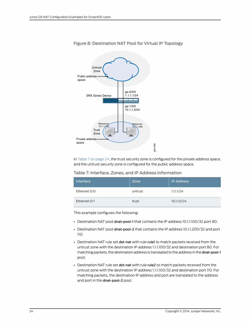
Figure 8: Destination NAT Pool for Virtual IP Topology
ge-1/0/010.1.1.0/24
ge-0/0/01.1.1.1/24
Internet
TrustZone
UntrustZone
SRX Series Device
Public addressspace
Private addressspace
g041
380
Webserver10.1.1.100
Mailserver10.1.1.200
In Table 7 on page 24, the trust security zone is configured for the private address space,
and the untrust security zone is configured for the public address space.
Table 7: Interface, Zones, and IP Address Information
IP AddressZoneInterface
1.1.1.1/24untrustEthernet 0/0
10.1.1.0/24trustEthernet 0/1
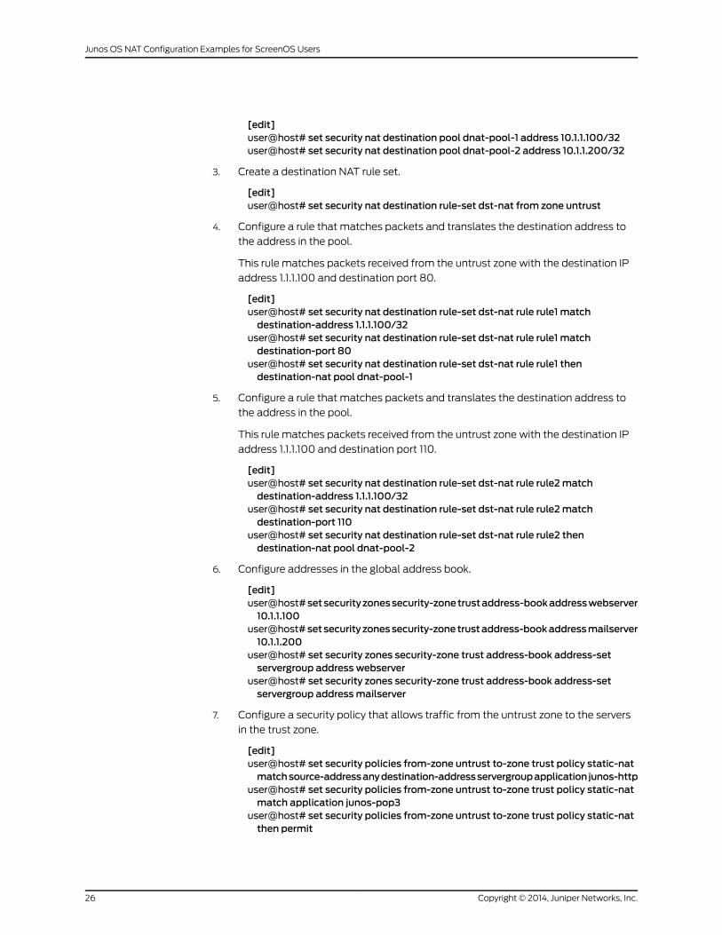
This example configures the following:
• Destination NAT pool dnat-pool-1 that contains the IP address 10.1.1.100/32 port 80.
• Destination NAT pool dnat-pool-2 that contains the IP address 10.1.1.200/32 and port
110.
• Destination NAT rule set dst-natwith rule rule1 to match packets received from the
untrust zone with the destination IP address 1.1.1.100/32 and destination port 80. For
matchingpackets, thedestinationaddress is translated to theaddress in thednat-pool-1
pool.
• Destination NAT rule set dst-natwith rule rule2 to match packets received from the
untrust zone with the destination IP address 1.1.1.100/32 and destination port 110. For
matching packets, the destination IP address and port are translated to the address
and port in the dnat-pool-2 pool.
Copyright © 2014, Juniper Networks, Inc.24
Junos OS NAT Configuration Examples for ScreenOS Users
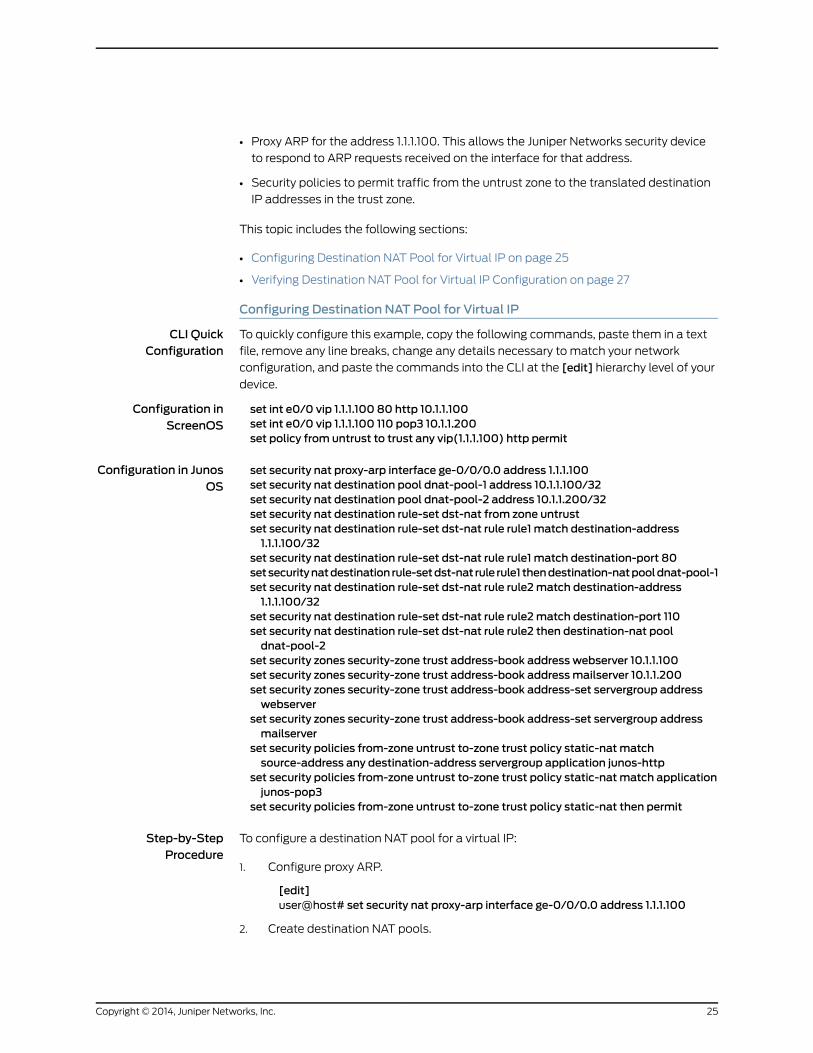
• Proxy ARP for the address 1.1.1.100. This allows the Juniper Networks security device
to respond to ARP requests received on the interface for that address.
• Security policies to permit traffic from the untrust zone to the translated destination
IP addresses in the trust zone.
This topic includes the following sections:
• Configuring Destination NAT Pool for Virtual IP on page 25
• Verifying Destination NAT Pool for Virtual IP Configuration on page 27
Configuring Destination NAT Pool for Virtual IP
CLI QuickConfiguration
To quickly configure this example, copy the following commands, paste them in a text
file, remove any line breaks, change any details necessary to match your network
configuration, and paste the commands into the CLI at the [edit] hierarchy level of your
device.
Configuration inScreenOS
set int e0/0 vip 1.1.1.100 80 http 10.1.1.100set int e0/0 vip 1.1.1.100 110 pop3 10.1.1.200set policy from untrust to trust any vip(1.1.1.100) http permit
Configuration in JunosOS
set security nat proxy-arp interface ge-0/0/0.0 address 1.1.1.100set security nat destination pool dnat-pool-1 address 10.1.1.100/32set security nat destination pool dnat-pool-2 address 10.1.1.200/32set security nat destination rule-set dst-nat from zone untrustset security nat destination rule-set dst-nat rule rule1 match destination-address1.1.1.100/32
set security nat destination rule-set dst-nat rule rule1 match destination-port 80setsecuritynatdestination rule-setdst-nat rule rule1 thendestination-natpooldnat-pool-1set security nat destination rule-set dst-nat rule rule2match destination-address1.1.1.100/32
set security nat destination rule-set dst-nat rule rule2match destination-port 110set security nat destination rule-set dst-nat rule rule2 then destination-nat pooldnat-pool-2
set security zones security-zone trust address-book address webserver 10.1.1.100set security zones security-zone trust address-book addressmailserver 10.1.1.200set security zones security-zone trust address-book address-set servergroup addresswebserver
set security zones security-zone trust address-book address-set servergroup addressmailserver
set security policies from-zone untrust to-zone trust policy static-natmatchsource-address any destination-address servergroup application junos-http
set security policies from-zone untrust to-zone trust policy static-natmatch applicationjunos-pop3
set security policies from-zone untrust to-zone trust policy static-nat then permit
Step-by-StepProcedure
To configure a destination NAT pool for a virtual IP:
Configure proxy ARP.1.
[edit]user@host# set security nat proxy-arp interface ge-0/0/0.0 address 1.1.1.100
2. Create destination NAT pools.
25Copyright © 2014, Juniper Networks, Inc.
[edit]user@host# set security nat destination pool dnat-pool-1 address 10.1.1.100/32user@host# set security nat destination pool dnat-pool-2 address 10.1.1.200/32
3. Create a destination NAT rule set.
[edit]user@host# set security nat destination rule-set dst-nat from zone untrust
4. Configure a rule that matches packets and translates the destination address to
the address in the pool.
This rule matches packets received from the untrust zone with the destination IP
address 1.1.1.100 and destination port 80.
[edit]user@host# set security nat destination rule-set dst-nat rule rule1 matchdestination-address 1.1.1.100/32
user@host# set security nat destination rule-set dst-nat rule rule1 matchdestination-port 80
user@host# set security nat destination rule-set dst-nat rule rule1 thendestination-nat pool dnat-pool-1
5. Configure a rule that matches packets and translates the destination address to
the address in the pool.
This rule matches packets received from the untrust zone with the destination IP
address 1.1.1.100 and destination port 110.
[edit]user@host# set security nat destination rule-set dst-nat rule rule2matchdestination-address 1.1.1.100/32
user@host# set security nat destination rule-set dst-nat rule rule2matchdestination-port 110
user@host# set security nat destination rule-set dst-nat rule rule2 thendestination-nat pool dnat-pool-2
6. Configure addresses in the global address book.
[edit]user@host#setsecurityzonessecurity-zonetrustaddress-bookaddresswebserver10.1.1.100
user@host#setsecurity zonessecurity-zone trustaddress-bookaddressmailserver10.1.1.200
user@host# set security zones security-zone trust address-book address-setservergroup address webserver
user@host# set security zones security-zone trust address-book address-setservergroup addressmailserver
7. Configure a security policy that allows traffic from the untrust zone to the servers
in the trust zone.
[edit]user@host# set security policies from-zone untrust to-zone trust policy static-natmatchsource-addressanydestination-addressservergroupapplication junos-http
user@host# set security policies from-zone untrust to-zone trust policy static-natmatch application junos-pop3
user@host# set security policies from-zone untrust to-zone trust policy static-natthen permit
Copyright © 2014, Juniper Networks, Inc.26
Junos OS NAT Configuration Examples for ScreenOS Users
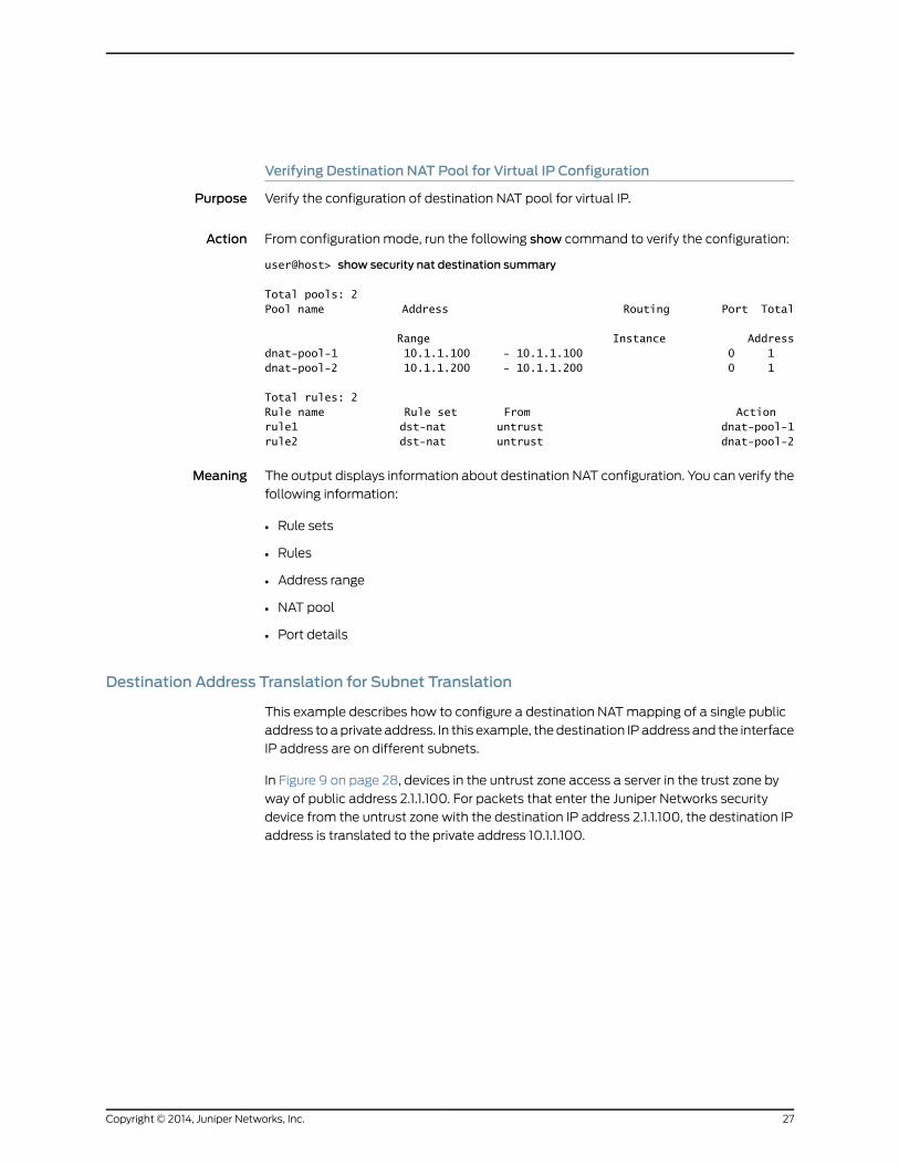
Verifying Destination NAT Pool for Virtual IP Configuration
Purpose Verify the configuration of destination NAT pool for virtual IP.
Action From configuration mode, run the following show command to verify the configuration:
user@host> show security nat destination summary
Total pools: 2Pool name Address Routing Port Total
Range Instance Addressdnat-pool-1 10.1.1.100 - 10.1.1.100 0 1 dnat-pool-2 10.1.1.200 - 10.1.1.200 0 1
Total rules: 2Rule name Rule set From Actionrule1 dst-nat untrust dnat-pool-1rule2 dst-nat untrust dnat-pool-2
Meaning The output displays information about destination NAT configuration. You can verify the
following information:
• Rule sets
• Rules
• Address range
• NAT pool
• Port details
Destination Address Translation for Subnet Translation
This example describes how to configure a destination NATmapping of a single public
address to aprivate address. In this example, thedestination IPaddress and the interface
IP address are on different subnets.
In Figure 9 on page 28, devices in the untrust zone access a server in the trust zone by
way of public address 2.1.1.100. For packets that enter the Juniper Networks security
device from the untrust zone with the destination IP address 2.1.1.100, the destination IP
address is translated to the private address 10.1.1.100.
27Copyright © 2014, Juniper Networks, Inc.
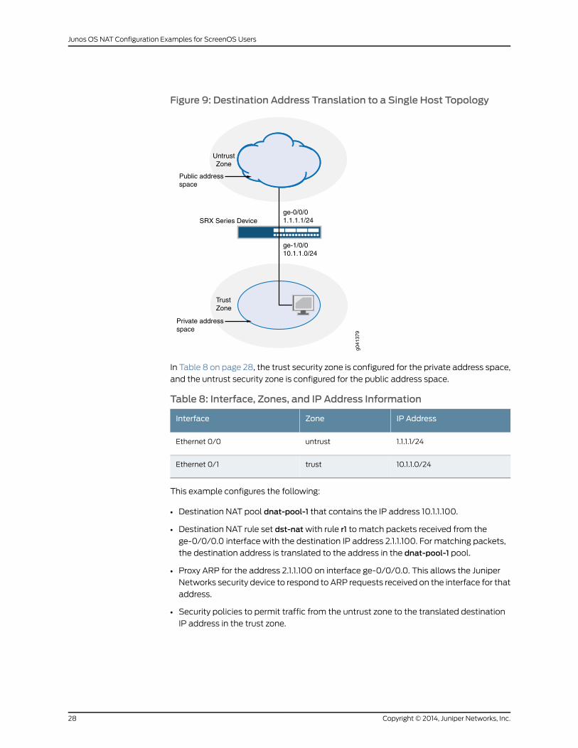
Figure 9: Destination Address Translation to a Single Host Topology
ge-1/0/010.1.1.0/24
ge-0/0/01.1.1.1/24
Internet
TrustZone
UntrustZone
SRX Series Device
Public addressspace
Private addressspace
g041
379
In Table 8 on page 28, the trust security zone is configured for the private address space,
and the untrust security zone is configured for the public address space.
Table 8: Interface, Zones, and IP Address Information
IP AddressZoneInterface
1.1.1.1/24untrustEthernet 0/0
10.1.1.0/24trustEthernet 0/1
This example configures the following:
• Destination NAT pool dnat-pool-1 that contains the IP address 10.1.1.100.
• Destination NAT rule set dst-natwith rule r1 to match packets received from the
ge-0/0/0.0 interface with the destination IP address 2.1.1.100. For matching packets,
the destination address is translated to the address in the dnat-pool-1 pool.
• Proxy ARP for the address 2.1.1.100 on interface ge-0/0/0.0. This allows the Juniper
Networks security device to respond to ARP requests received on the interface for that
address.
• Security policies to permit traffic from the untrust zone to the translated destination
IP address in the trust zone.
Copyright © 2014, Juniper Networks, Inc.28
Junos OS NAT Configuration Examples for ScreenOS Users
This topic includes the following sections:
• Configuring Destination Address Translation to a Single Host on page 29
• Verifying Destination Address Translation to a Single Host Configuration on page 30
Configuring Destination Address Translation to a Single Host
CLI QuickConfiguration
To quickly configure this example, copy the following commands, paste them in a text
file, remove any line breaks, change any details necessary to match your network
configuration, and paste the commands into the CLI at the [edit] hierarchy level of your
device.
Configuration inScreenOS
set route 2.1.1.100/32 int e0/1set address trust webserver 2.1.1.100/32set pol from untrust to trust any webserver http nat dst ip 10.1.1.100 permit
Configuration in JunosOS
set security nat proxy-arp interface ge-0/0/0.0 address 2.1.1.100set security nat destination pool dnat-pool-1 address 10.1.1.100set security nat destination rule-set dst-nat from zone untrustset security nat destination rule-set dst-nat rule r1 match destination-address 2.1.1.100set security nat destination rule-set dst-nat rule r1 then destination-nat pool dnat-pool-1set security zones security-zone trust address-book address webserver 10.1.1.100setsecuritypolicies from-zoneuntrust to-zonetrustpolicydst-natmatchsource-addressany destination-address webserver application junos-http
set security policies from-zone untrust to-zone trust policy dst-nat then permit
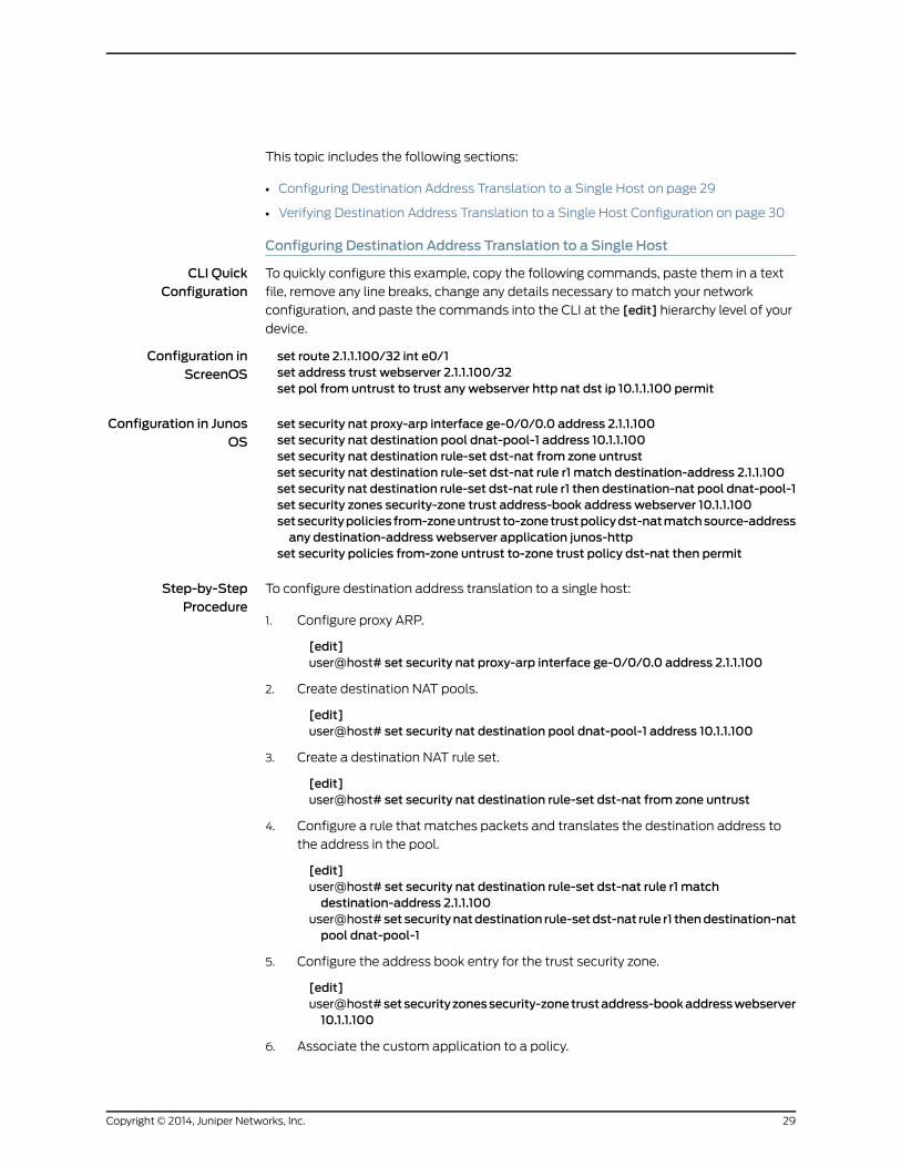
Step-by-StepProcedure
To configure destination address translation to a single host:
Configure proxy ARP.1.
[edit]user@host# set security nat proxy-arp interface ge-0/0/0.0 address 2.1.1.100
2. Create destination NAT pools.
[edit]user@host# set security nat destination pool dnat-pool-1 address 10.1.1.100
3. Create a destination NAT rule set.
[edit]user@host# set security nat destination rule-set dst-nat from zone untrust
4. Configure a rule that matches packets and translates the destination address to
the address in the pool.
[edit]user@host# set security nat destination rule-set dst-nat rule r1 matchdestination-address 2.1.1.100
user@host# set securitynatdestination rule-setdst-nat rule r1 thendestination-natpool dnat-pool-1
5. Configure the address book entry for the trust security zone.
[edit]user@host#setsecurityzonessecurity-zonetrustaddress-bookaddresswebserver10.1.1.100
6. Associate the custom application to a policy.
29Copyright © 2014, Juniper Networks, Inc.
[edit]user@host# set security policies from-zone untrust to-zone trust policy dst-natmatchsource-addressanydestination-addresswebserverapplication junos-http
user@host#setsecuritypolicies from-zoneuntrust to-zone trustpolicydst-nat thenpermit
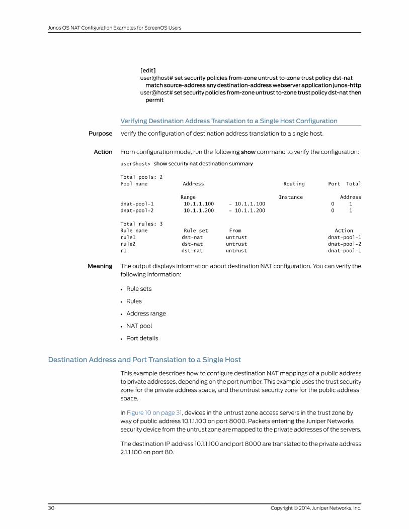
Verifying Destination Address Translation to a Single Host Configuration
Purpose Verify the configuration of destination address translation to a single host.
Action From configuration mode, run the following show command to verify the configuration:
user@host> show security nat destination summary
Total pools: 2Pool name Address Routing Port Total
Range Instance Addressdnat-pool-1 10.1.1.100 - 10.1.1.100 0 1 dnat-pool-2 10.1.1.200 - 10.1.1.200 0 1
Total rules: 3Rule name Rule set From Actionrule1 dst-nat untrust dnat-pool-1rule2 dst-nat untrust dnat-pool-2r1 dst-nat untrust dnat-pool-1
Meaning The output displays information about destination NAT configuration. You can verify the
following information:
• Rule sets
• Rules
• Address range
• NAT pool
• Port details
Destination Address and Port Translation to a Single Host
This example describes how to configure destination NATmappings of a public address
to private addresses, depending on the port number. This example uses the trust security
zone for the private address space, and the untrust security zone for the public address
space.
In Figure 10 on page 31, devices in the untrust zone access servers in the trust zone by
way of public address 10.1.1.100 on port 8000. Packets entering the Juniper Networks
security device from the untrust zone aremapped to the private addresses of the servers.
The destination IP address 10.1.1.100 and port 8000 are translated to the private address
2.1.1.100 on port 80.
Copyright © 2014, Juniper Networks, Inc.30
Junos OS NAT Configuration Examples for ScreenOS Users
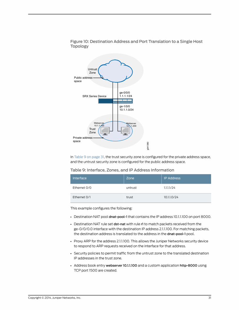
Figure 10: Destination Address and Port Translation to a Single HostTopology
ge-1/0/010.1.1.0/24
ge-0/0/01.1.1.1/24
Internet
TrustZone
UntrustZone
SRX Series Device
Public addressspace
Private addressspace
g041
380
Webserver10.1.1.100
Mailserver10.1.1.200
In Table 9 on page 31, the trust security zone is configured for the private address space,
and the untrust security zone is configured for the public address space.
Table 9: Interface, Zones, and IP Address Information
IP AddressZoneInterface
1.1.1.1/24untrustEthernet 0/0
10.1.1.0/24trustEthernet 0/1
This example configures the following:
• Destination NAT pool dnat-pool-1 that contains the IP address 10.1.1.100 on port 8000.
• Destination NAT rule set dst-natwith rule r1 to match packets received from the
ge-0/0/0.0 interface with the destination IP address 2.1.1.100. For matching packets,
the destination address is translated to the address in the dnat-pool-1 pool.
• Proxy ARP for the address 2.1.1.100. This allows the Juniper Networks security device
to respond to ARP requests received on the interface for that address.
• Security policies to permit traffic from the untrust zone to the translated destination
IP addresses in the trust zone.
• Address book entrywebserver 10.1.1.100 and a custom application http-8000 using
TCP port 1500 are created.
31Copyright © 2014, Juniper Networks, Inc.
This topic includes the following sections:
• Configuring Destination Address and Port Translation to a Single Host on page 32
• Verifying Destination Address and Port Translation to a Single Host
Configuration on page 33
Configuring Destination Address and Port Translation to a Single Host
CLI QuickConfiguration
To quickly configure this example, copy the following commands, paste them in a text
file, remove any line breaks, change any details necessary to match your network
configuration, and paste the commands into the CLI at the [edit] hierarchy level of your
device.
Configuration inScreenOS
set route 2.1.1.100/32 int e0/1set address trust webserver 2.1.1.100/32set policy from untrust to trust any webserver http nat dst ip 10.1.1.100 port 8000 permit
Configuration in JunosOS
set security nat proxy-arp interface ge-0/0/0.0 address 2.1.1.100set security nat destination pool dnat-pool-1 address 10.1.1.100 port 8000set security nat destination rule-set dst-nat from zone untrustset security nat destination rule-set dst-nat rule r1 match destination-address 2.1.1.100set security nat destination rule-set dst-nat rule r1 then destination-nat pool dnat-pool-1set security zones security-zone trust address-book address webserver 10.1.1.100set applications application http-8000 protocol tcp destination-port 8000setsecuritypolicies from-zoneuntrust to-zonetrustpolicydst-natmatchsource-addressany destination-address webserver application http-8000
set security policies from-zone untrust to-zone trust policy dst-nat then permit
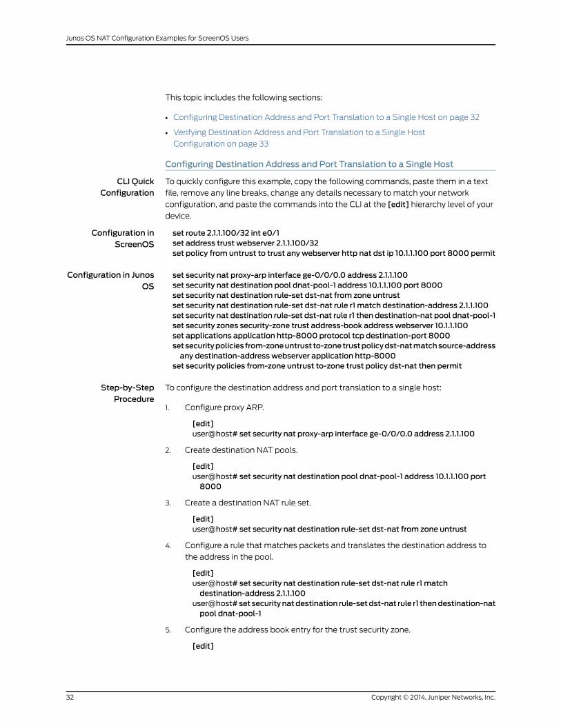
Step-by-StepProcedure
To configure the destination address and port translation to a single host:
Configure proxy ARP.1.
[edit]user@host# set security nat proxy-arp interface ge-0/0/0.0 address 2.1.1.100
2. Create destination NAT pools.
[edit]user@host# set security nat destination pool dnat-pool-1 address 10.1.1.100 port8000
3. Create a destination NAT rule set.
[edit]user@host# set security nat destination rule-set dst-nat from zone untrust
4. Configure a rule that matches packets and translates the destination address to
the address in the pool.
[edit]user@host# set security nat destination rule-set dst-nat rule r1 matchdestination-address 2.1.1.100
user@host# set securitynatdestination rule-setdst-nat rule r1 thendestination-natpool dnat-pool-1
5. Configure the address book entry for the trust security zone.
[edit]
Copyright © 2014, Juniper Networks, Inc.32
Junos OS NAT Configuration Examples for ScreenOS Users
user@host#setsecurityzonessecurity-zonetrustaddress-bookaddresswebserver10.1.1.100
6. Configure a custom application.
[edit]user@host# set applications application http-8000 protocol tcp destination-port8000
7. Associate the custom application to a policy.
[edit]user@host# set security policies from-zone untrust to-zone trust policy dst-natmatchsource-addressanydestination-addresswebserverapplicationhttp-8000
user@host#setsecuritypolicies from-zoneuntrust to-zone trustpolicydst-nat thenpermit
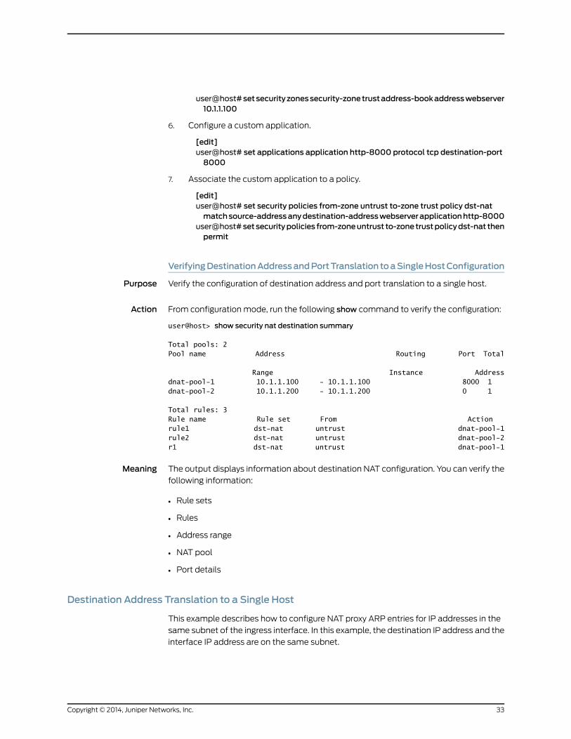
VerifyingDestinationAddressandPortTranslation toaSingleHostConfiguration
Purpose Verify the configuration of destination address and port translation to a single host.
Action From configuration mode, run the following show command to verify the configuration:
user@host> show security nat destination summary
Total pools: 2Pool name Address Routing Port Total
Range Instance Addressdnat-pool-1 10.1.1.100 - 10.1.1.100 8000 1 dnat-pool-2 10.1.1.200 - 10.1.1.200 0 1
Total rules: 3Rule name Rule set From Actionrule1 dst-nat untrust dnat-pool-1rule2 dst-nat untrust dnat-pool-2r1 dst-nat untrust dnat-pool-1
Meaning The output displays information about destination NAT configuration. You can verify the
following information:
• Rule sets
• Rules
• Address range
• NAT pool
• Port details
Destination Address Translation to a Single Host
This example describes how to configure NAT proxy ARP entries for IP addresses in the
same subnet of the ingress interface. In this example, the destination IP address and the
interface IP address are on the same subnet.
33Copyright © 2014, Juniper Networks, Inc.
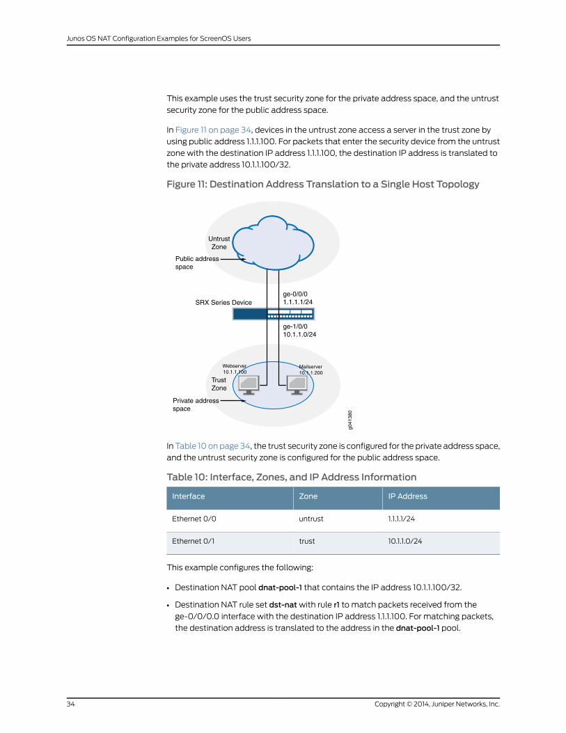
This example uses the trust security zone for the private address space, and the untrust
security zone for the public address space.
In Figure 11 on page 34, devices in the untrust zone access a server in the trust zone by
using public address 1.1.1.100. For packets that enter the security device from the untrust
zone with the destination IP address 1.1.1.100, the destination IP address is translated to
the private address 10.1.1.100/32.
Figure 11: Destination Address Translation to a Single Host Topology
ge-1/0/010.1.1.0/24
ge-0/0/01.1.1.1/24
Internet
TrustZone
UntrustZone
SRX Series Device
Public addressspace
Private addressspace
g041
380
Webserver10.1.1.100
Mailserver10.1.1.200
In Table 10 on page 34, the trust security zone is configured for the private address space,
and the untrust security zone is configured for the public address space.
Table 10: Interface, Zones, and IP Address Information
IP AddressZoneInterface
1.1.1.1/24untrustEthernet 0/0
10.1.1.0/24trustEthernet 0/1
This example configures the following:
• Destination NAT pool dnat-pool-1 that contains the IP address 10.1.1.100/32.
• Destination NAT rule set dst-natwith rule r1 to match packets received from the
ge-0/0/0.0 interface with the destination IP address 1.1.1.100. For matching packets,
the destination address is translated to the address in the dnat-pool-1 pool.
Copyright © 2014, Juniper Networks, Inc.34
Junos OS NAT Configuration Examples for ScreenOS Users
• Proxy ARP for the address 1.1.1.100 on interface ge-0/0/0.0. This allows the Juniper
Networks security device to respond to ARP requests received on the interface for that
address.
• Security policies to permit traffic from the untrust zone to the translated destination
IP address in the trust zone.
This topic includes the following sections:
• Configuring Destination Address Translation to a Single Host on page 35
• Verifying Destination Address Translation to a Single Host Configuration on page 36
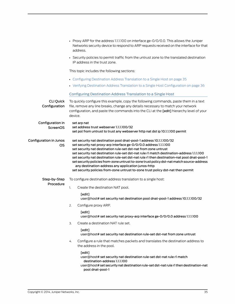
Configuring Destination Address Translation to a Single Host
CLI QuickConfiguration
To quickly configure this example, copy the following commands, paste them in a text
file, remove any line breaks, change any details necessary to match your network
configuration, and paste the commands into the CLI at the [edit] hierarchy level of your
device.
Configuration inScreenOS
set arp natset address trust webserver 1.1.1.100/32set pol from untrust to trust any webserver http nat dst ip 10.1.1.100 permit
Configuration in JunosOS
set security nat destination pool dnat-pool-1 address 10.1.1.100/32set security nat proxy-arp interface ge-0/0/0.0 address 1.1.1.100set security nat destination rule-set dst-nat from zone untrustset security nat destination rule-set dst-nat rule r1 match destination-address 1.1.1.100set security nat destination rule-set dst-nat rule r1 then destination-nat pool dnat-pool-1setsecuritypolicies from-zoneuntrust to-zonetrustpolicydst-natmatchsource-addressany destination-address any application junos-http
set security policies from-zone untrust to-zone trust policy dst-nat then permit
Step-by-StepProcedure
To configure destination address translation to a single host:
Create the destination NAT pool.1.
[edit]user@host# set security nat destination pool dnat-pool-1 address 10.1.1.100/32
2. Configure proxy ARP.
[edit]user@host# set security nat proxy-arp interface ge-0/0/0.0 address 1.1.1.100
3. Create a destination NAT rule set.
[edit]user@host# set security nat destination rule-set dst-nat from zone untrust
4. Configure a rule that matches packets and translates the destination address to
the address in the pool.
[edit]user@host# set security nat destination rule-set dst-nat rule r1 matchdestination-address 1.1.1.100
user@host# set securitynatdestination rule-setdst-nat rule r1 thendestination-natpool dnat-pool-1
35Copyright © 2014, Juniper Networks, Inc.
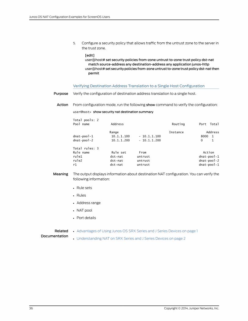
5. Configure a security policy that allows traffic from the untrust zone to the server in
the trust zone.
[edit]user@host# set security policies from-zone untrust to-zone trust policy dst-natmatch source-address any destination-address any application junos-http
user@host#setsecuritypolicies from-zoneuntrust to-zone trustpolicydst-nat thenpermit
Verifying Destination Address Translation to a Single Host Configuration
Purpose Verify the configuration of destination address translation to a single host.
Action From configuration mode, run the following show command to verify the configuration:
user@host> show security nat destination summary
Total pools: 2Pool name Address Routing Port Total
Range Instance Addressdnat-pool-1 10.1.1.100 - 10.1.1.100 8000 1 dnat-pool-2 10.1.1.200 - 10.1.1.200 0 1
Total rules: 3Rule name Rule set From Actionrule1 dst-nat untrust dnat-pool-1rule2 dst-nat untrust dnat-pool-2r1 dst-nat untrust dnat-pool-1
Meaning The output displays information about destination NAT configuration. You can verify the
following information:
• Rule sets
• Rules
• Address range
• NAT pool
• Port details
RelatedDocumentation
• Advantages of Using Junos OS SRX Series and J Series Devices on page 1
• Understanding NAT on SRX Series and J Series Devices on page 2
Copyright © 2014, Juniper Networks, Inc.36
Junos OS NAT Configuration Examples for ScreenOS Users