network convergence looking forward · •no difference from a client (user) ... • esnet science...
TRANSCRIPT

Network ConvergenceLooking Forward
Networking Research Challenges WorkshopSeptember 28, 2008Seattle, Washington
Tom LehmanInformation Sciences Institute EastUniversity of Southern California

Overview
• Next Generation and Emerging NetworkArchitectures - Hybrid Networks
• Hybrid Networks - Where are today?• Relationship/Differences between R&E
and Commercial network spaces• Vision for R&E network research and
development moving forward
Emerging Network Architectures
• There has been significant activity andprogress in development and deploymentof hybrid network architectures over thelast couple of years
• Network technologies, elements, featurescontinue to evolve
• R&E communities use and deployment ofthese capabilities continues to evolve
Multi-Domain, Multi-Layer HybridNetworks• Hybrid networks are intended to provide a flexible mix of
IP routed service and dedicated capacity “circuits”• The “Multi-Layer” is meant to identify several items
regarding how hybrid networks may be built. In thiscontext it includes the following:• Multi-Technology - MPLS, Ethernet, Ethernet PBB-
TE, SONET, NG-SONET, T-MPLS, WDM• Multi-Level - domains or network regions may
operate in different routing areas/regions, and maybebe presented in an abstracted manner acrossarea/region boundaries
• Multi-Domain indicates that we want to allow hybridnetwork service instantiation across multiple domains
• But there are other "Multi-" parameters as well
Multi-Domain, Multi-Layer HybridNetworks• Multi-Service: This refers to the client experience when
they connect to the edge of a dynamic network. Typicalservice definitions are characterized by the combinationof the physical port type (e.g. Ethernet, SONET/SDH,Fibre Channel, etc), the network transport instance (e.g.IP Routed, Ethernet VLAN, SONET), and performancecharacteristics (e.g. bandwidth, QoS specifications).
• Multi-Vendor: This is a reflection that advancednetworks will be constructed based on technologies frommultiple vendors. A key challenge will be to developtechnologies and mechanisms which allow integratedcontrol and service provisioning in this multi-vendorenvironment.
• Multi-Policy: Access to and use of various networkcomponents, regions, or topologies may vary by userand/or community due to provider policies.
• Multi-X environment
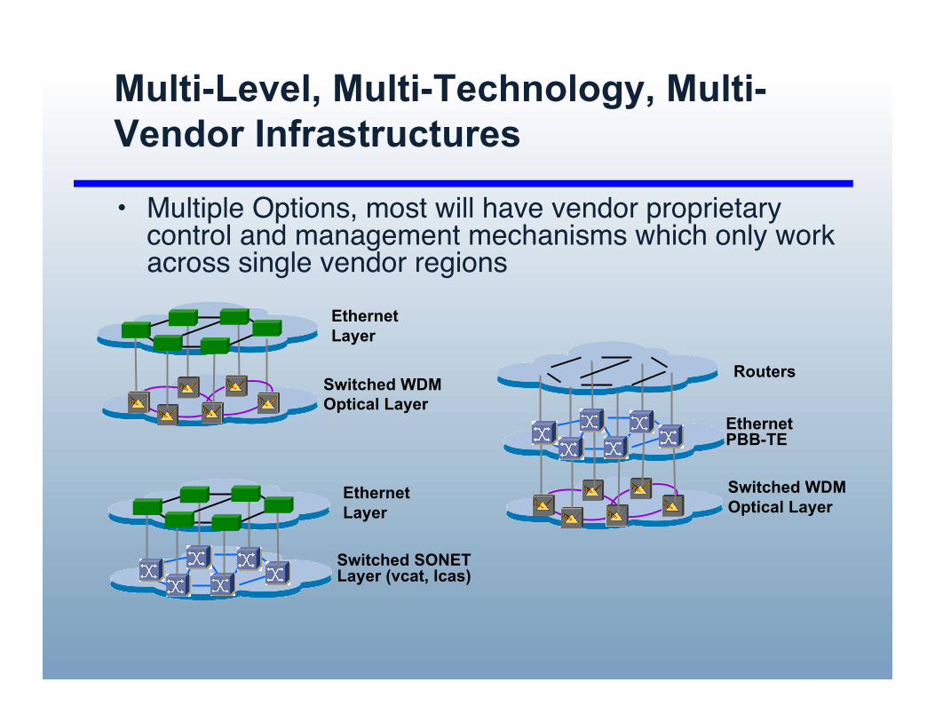
Multi-Level, Multi-Technology, Multi-Vendor Infrastructures
• Multiple Options, most will have vendor proprietarycontrol and management mechanisms which only workacross single vendor regions
Routers
Switched WDMOptical Layer
EthernetPBB-TE
EthernetLayer
Switched WDMOptical Layer
EthernetLayer
Switched SONETLayer (vcat, lcas)
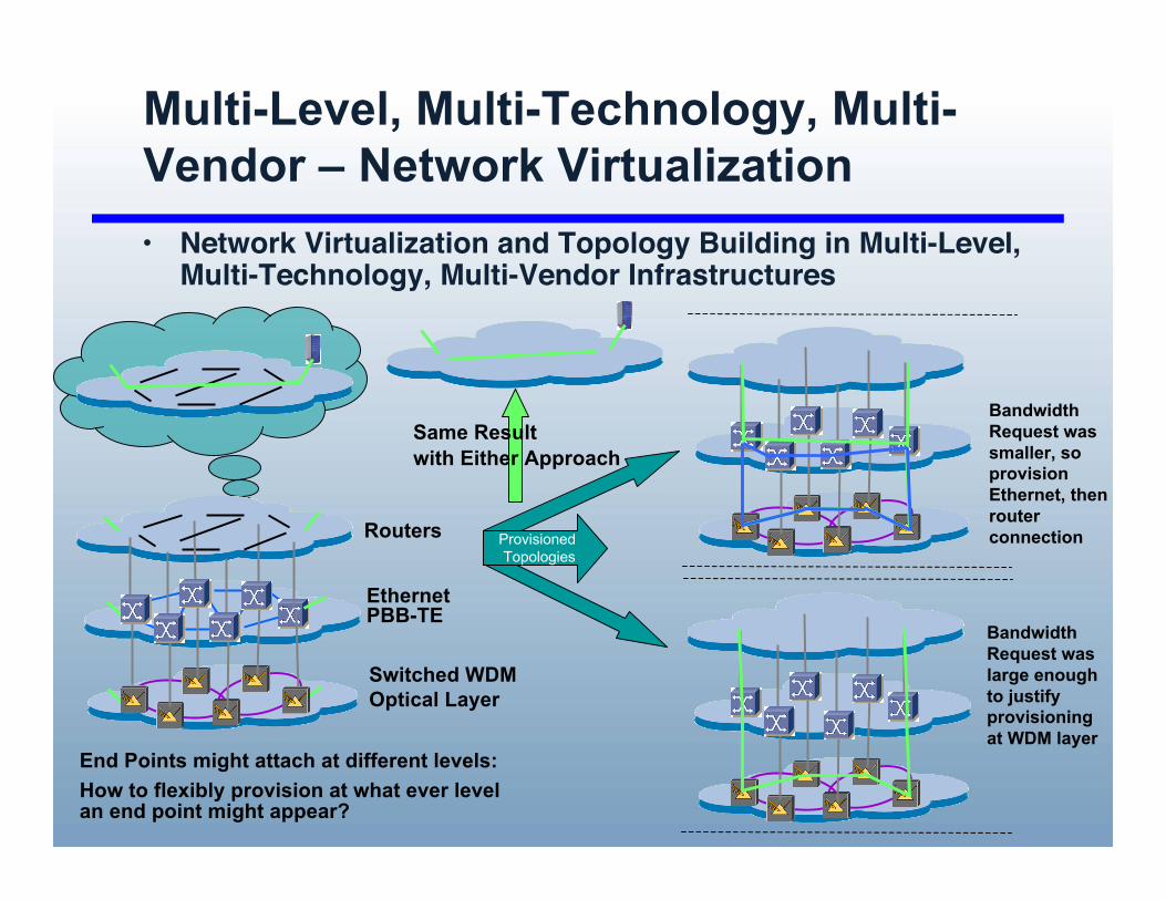
Multi-Level, Multi-Technology, Multi-Vendor – Network Virtualization• Network Virtualization and Topology Building in Multi-Level,
Multi-Technology, Multi-Vendor Infrastructures
BandwidthRequest waslarge enoughto justifyprovisioningat WDM layer
BandwidthRequest wassmaller, soprovisionEthernet, thenrouterconnectionProvisioned
TopologiesRouters
Switched WDMOptical Layer
EthernetPBB-TE
Same Resultwith Either Approach
End Points might attach at different levels:How to flexibly provision at what ever levelan end point might appear?
Multi-Level, Multi-Technology, Multi-Vendor Infrastructures
• Current dynamic provisioning environment can bedescribed as:
Static Topology, Dynamic Provisioning
• Next we want to enable:
Dynamic Topology, Dynamic Provisioning

Multi-X, Multi-Domain Control PlaneWhat can we do today?
• Dynamic provision of end to end (circuits)across multiple domains.
• Specify a few basic parameters regardinga single circuit request: edgetechnology/configuration, bandwidth, endpoints, domain sequence, specificstart/stop times
• There are multiple projects/efforts/activitiesaround the world working on these types ofissues from a multi-domain perspective

InterDomain MessagingAgreements in place
• Web Service Definitions• Originally developed in DICE• Dante, Internet2, CANARIE, ESNet• now includes other organizations as well
• wsdl - web service definition of messagetypes and formats
• xsd – definition of schemas used for networktopology descriptions and path definitions

InterDomain ProtocolStandardization Activities
• Standardization process and increasing communityinvolvement continues
• GLIF• Control Plane Subgroup working on normalizing between various
interdomain protocols (IDCP, G-Lambda GNS-WSI, PhosphorusAPI)
• Open Grid Forum (OGF)• Network Service Interface Working Group (NSI-WG)
• Co-chairs:– Tomohiro Kudoh [email protected]– Guy Roberts [email protected]– Inder Monga [email protected]
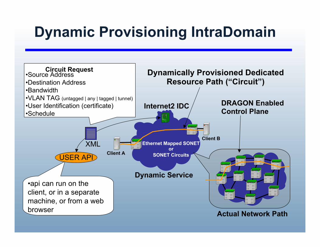
Dynamic Provisioning IntraDomain
•Source Address•Destination Address•Bandwidth•VLAN TAG (untagged | any | tagged | tunnel)•User Identification (certificate)•Schedule
Client A
Client B
Circuit Request
Ethernet Mapped SONETor
SONET Circuits
Dynamically Provisioned DedicatedResource Path (“Circuit”)
Dynamic Service
Internet2 IDC
•api can run on theclient, or in a separatemachine, or from a webbrowser
XML
USER API
Actual Network Path
DRAGON EnabledControl Plane

Dynamic Provisioning InterDomain
• No difference from a client (user) perspectivefor InterDomain vs IntraDomain
RON Dynamic InfrastructureEthernet VLAN
RON Dynamic InfrastructureEthernet VLAN
Internet2 DCNEthernet Mapped SONET
1. Client Service Request2. Resource Scheduling5. Service Instantiation (as a result of Signaling)
A. Abstracted topology exchange
AA2
21
USER API
XML
Multi-Domain DynamicallyProvisioned Circuit

IDC - Web Service Based Definition
• Four Primary Web Services Areas:• Topology Exchange, Resource Scheduling, Signaling, User Request
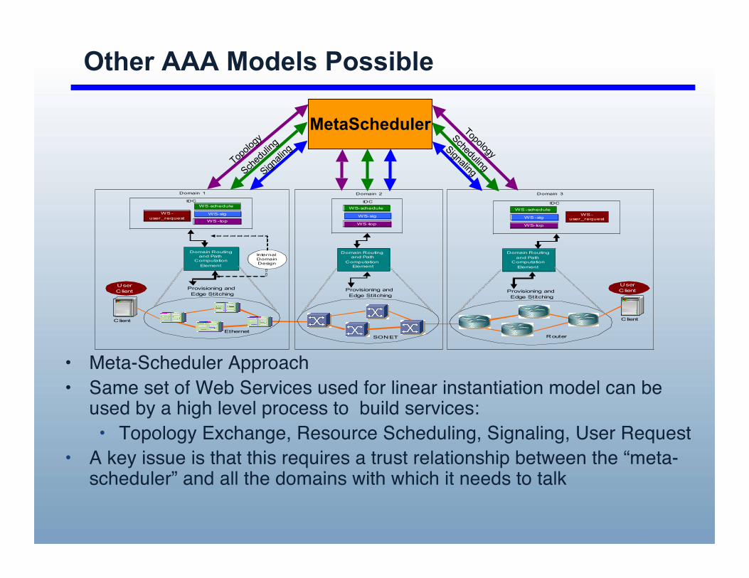
Other AAA Models Possible
• Meta-Scheduler Approach• Same set of Web Services used for linear instantiation model can be
used by a high level process to build services:• Topology Exchange, Resource Scheduling, Signaling, User Request
• A key issue is that this requires a trust relationship between the “meta-scheduler” and all the domains with which it needs to talk
Domain Routing and Path
Computation Element
WS-schedule
Client Client
User Client
Domain Routing and Path
Computation Element
Domain Routing and Path
Computation Element
Domain 2 Domain 3
User ClientProvisioning and
Edge Stitching
Provisioning and Edge Stitching
Provisioning and Edge Stitching
EthernetSONET Router
Domain 1
InternalDomainDesign
WS-top
WS-sigWS-user_request
IDC
WS-schedule
WS-sig
WS-top
WS-schedule
WS-sig
WS-top
WS-user_request
IDCIDC
MetaScheduler
Topolo
gy
Signali
ng
Sched
uling
Topology
Scheduling
Signaling

Global Dynamic Circuit Network

InterDomain Controller (IDC) Protocol(IDCP)
• The following organizations have implemented/deployed systems which arecompatible with this IDCP• Internet2 Dynamic Circuit Network (DCN)• ESNet Science Data Network (SDN)• GÉANT2 AutoBahn System• Nortel (via a wrapper on top of their commercial DRAC System)• Surfnet (via use of above Nortel solution)• LHCNet (use of I2 DCN Software Suite)• Nysernet (use of I2 DCN Software Suite)• LEARN (use of I2 DCN Software Suite)• LONI (use of I2 DCN Software Suite)• Northrop Grumman (use of I2 DCN Software Suite)• University of Amsterdam (use of I2 DCN Software Suite)• DRAGON Network
• The following "higher level service applications" have adapted their existingsystems to communicate via the user request side of the IDCP:• LambdaStation (FermiLab)• TeraPaths (Brookhaven)• Phoebus
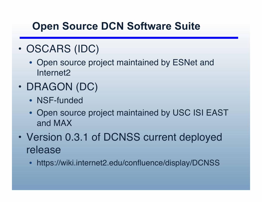
Open Source DCN Software Suite
• OSCARS (IDC)• Open source project maintained by ESNet and
Internet2• DRAGON (DC)• NSF-funded• Open source project maintained by USC ISI EAST
and MAX• Version 0.3.1 of DCNSS current deployed
release• https://wiki.internet2.edu/confluence/display/DCNSS

Architecture DefinitionKey Control Plane Features
• Routing• distribution of "data" between networks. The data that needs to
be distributed includes reachability information, resource usages,etc
• Path computation• the processing of information received via routing data to
determine how to provision an end-to-end path.• Signaling
• the exchange of messages to instantiate specific provisioningrequests based upon the above routing and path computationfunctions.
• Architecture definition document under development• Addresses tradeoffs and decisions with respect to these issues
and others.

Architecture DefinitionKey Control Plane Features
• Routing• Topology Exchange, Domain Abstraction• Link State based with varying levels of dynamic
information (practically no dynamic information sharedin initial implementations/deployments)
• Path Computation• Multi-Domain, multi-stage path computation
techniques (includes a Scheduling and AAAcomponents)
• Signaling• path setup, service instantiation
• Architecture would allow for web service or traditionalprotocol types of exchanges• web service mechanisms are the current choice• future may see a mix of both

Key Control Plane Key CapabilitiesIntraDomain• InterDomain Architecture Definition and Agreements are
the most important issue to be resolved amongstexternal organizations.
• However, there are many important IntraDomain issuesas well• multi-layer, multi-vendor, multi-technology path computation
control and provisioning• use of control plane protocols, management systems, or a
combination of both• path computation and resource management which includes
AAA and scheduling information• developing abstract view of your network for sharing with
external domains• use of hierarchical techniques. Provision a circuit at one layer,
then treat it as a resource at another layer. (i.e., ForwardAdjacency concept)
• These are individual domain design decisions, but bestpractices and architectures will emerge

Circuit Provisioning or NetworkVirtualization?
1-A-5-1-11-A-6-1-1
1-A-6-1-1

OSCARS Project
• On-demand Secure Circuits and AdvanceReservation System (OSCARS)
• DOE Office of Science and ESnet project• Co-development with Internet2• Web Service based provisioning
infrastructure, which includes scheduling,AAA architecture using X.509 certificates
• Extended to include the DICE IDCP• http://www.es.net/oscars/index.html
DOEOffice ofScience

DRAGON Project• Dynamic Resource Allocation via GMPLS
Optical Networks (DRAGON)• Developed control plane for multi-technology
hybrid networks• Deployed on Internet2 HOPI and DCN• NSF Funded Project• originally funded by CISE/ANIR• Program Manager, Kevin Thompson, OCI
• Collaborative project: USC/ISI, UMD/MAX, GMU• http://dragon.east.isi.edu
DRAGON

Hybrid Multi-Layer Network ControlProject (Hybrid-MLN)
• Investigating issues associated with Multi-Layer, Multi-Domain Hybrid Networks from anarchitecture, data plane, and control planeperspective• Architecture Development• Design, analysis, modeling, simulation• Experimentation and data collection
• USC/ISI, UNM, ESNet, ORNL, Internet2• Funded by DOE Office of Science• Dr. Thomas D. Ndousse, Program Manager
• http://hybrid.east.isi.edu
DRAGON
Hybrid MLNDOE Office of Science
DRAGONDRAGON
Commercial multi-layer networkactivities
• Standards bodies, vendors, commercialnetwork deployments are working onmulti-layer networks
• How do the R&E activities relate toCommercial multi-layer activities?

Standards Bodies Progress and Status• Several standards bodies working in this space:
• ITU-T ASON• OIF• IETF (CCAMP, L1VPN, L2VPN)• MEF
• UNI, I-NNI, E-NNI, BGP Extensions are some the key topics ofdiscussion in these groups
• Vendor implementations are also following• The work that the R&E community needs to leverage this work, but it
needs to go further (and faster) then what is occurring in thesestandards bodies and associated vendor implementations. Inparticular, the standards bodies:• Have not converged on Inter-AS interdomain E-NNI routing or signaling
protocols• Not working on multi-layer path computation details• Completed very little work on application of an Authentication, Authorization,
Accounting (AAA) model to the control plane• Completed very little work on scheduling of provisioned services• Not addressing scalability and security to the degree required for the R&E
community• This is an opportunity for the R&E community to lead via early
research, design, deployment of advanced multi-layer, multi-domainnetworks which provide real benefits to real users
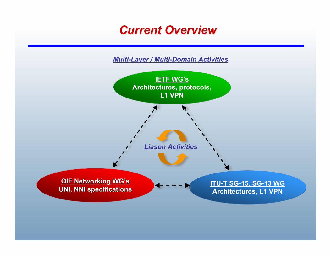
Current OverviewCurrent Overview
OIF Networking OIF Networking WGWG’’ssUNI, NNI specificationsUNI, NNI specifications
ITU-T SG-15, SG-13 WGArchitectures, L1 VPN
IETF WG’sArchitectures, protocols,
L1 VPN
Multi-Layer / Multi-Domain Activities
LiasonLiason Activities Activities

R&E Network Research andDevelopment Moving Forward

Emerging Network Architectures
• I believe we are in the middle of a majorevolution/transformation/revolution ofnetwork architectures
• This revolves around viewing the networkas “multi-layer, multi-technology” construct• with different switching types like PSC, L2SC,
TDM, LSC, FSC,• reflected in new technologies ethernet PBB-
TE, NG-SONET, OTN, NG WDM

Emerging Network ArchitecturesSome Key Questions
• how do we use these layers to build the IProuted network?
• how do we use these layers to trafficengineer the IP routed network? withsome humans in the loop and a couple ofdays of planning? in real time by“management” computers? or by thenetwork itself?
• how do we use these layers to build totallynew “network services”

Emerging Network ArchitecturesSome Key Questions
• the first two applications are most obvious and will provideimmediate benefits
• the last item is where a new network paradigm is waiting tobe developed
• Service Oriented Networks• networks go beyond just providing IP routed service to
also providing lower layer services directly to“applications”
• networks provide “value added service embedded in thenetwork itself” such as high performance data backup,content distribution systems, providing virtual networktopologies with flexible levels of isolation, deterministicperformance, dedicated resources, user perceivedperformance.

Emerging Network ArchitecturesSome Key Questions
• Network operators of the future may need touse the power of their networks to providevalue added services that can only beconstructed by tight coupling with networkinfrastructure and capabilities.
• So the future may not be so much “networkconvergence” as it will be “network servicesconvergence”
• so we will find a way to use a veryheterogeneous set of network technologiesto provide a rich set of network services
R&E Community Network Research
• The R&E community is uniquely positionedto make contributions in the development offuture network architectures
• Commercial networks are built to supportthe applications (profiles) they want theircustomers will use• hope the users do not disturb the network in
unexpected ways with unexpected applications• they have a much bigger scale dimension to
address

R&E Community Network Research
• R&E community is building networks toencourage/enable domain experts todevelop the applications they can imagine.• design networks to allow application
communities to innovate, and subsequentlydrive the network design and requirements
• R&E networks should really view as theirmission to enable/encourage applicationdomain experts to be able to create andinnovate in their domain space.
R&E Community Network Research
• This is difficult, because innovating andcreating is always hard, and it is not realisticto just ask the application domain experts totell us what they want from a nextgeneration network. They are not networkexperts
• The network community needs to takeresponsibility for integrating deep enoughinto the domain areas to allow innovation tohappen, and build networks to support thatinnovation
Summary
• Future Network architectures are likely to bebased on exploiting the multi-layer topologyof networks
• Networks should evolve to providing services• Exploit and encourage the natural feedback
loop between vendors, standards bodies,commercial users, commercial networks,R&E networks, R&E user.
• The future may not be so much “networkconvergence” as it will be “network servicesconvergence"
Thank You
• Questions,Comments?• Tom Lehman• tlehman at east.isi.edu
Extra Slides

IntraDomain Network Control
• A key requirement for the architecture is to be able tohandle the reality that the underlying networks will bevery heterogeneous in terms of technology, controlmechanisms, and vendors.
• In the current architecture this is abstracted out by theDC to IDC interface.
• Four types of underlying domain types have beenidentified in terms of how the DC interacts with them:• GMPLS (I2 DCN is an example, regional networks based on
ethernet switch dynamic provisioning is another example)• MPLS (ESNet SDN is an example)• Management Plane Controlled (USN is an example)• Vendor Control Plane (I2 DCN also has a component of this)

Dealing with Heterogeneous NetworkTechnologies and Vendor Equipment
• Adding regions of new technologies and vendors is not too difficultfrom the provisioning perspective
• The difficult issue is in terms of the routing exchange between/from thetechnology/vendor regions and path computation (intra and multi-domain) with multiple constraints.
GMPLS MPLSManagement Plane
IDCDC
IDCDC
IDCDC
DRAGONDRAGON GMPLS
Control Plane
CoreDirector
Ciena Region
uni, tl1
CD_a CD_z
uni, tl1
CoreDirector
subnet signaling flow
IDC
• As an Example, DRAGON is used as the DOMAIN Controller for I2 DCN CienaCore Directors
GMPLS toother domains
GMPLS toother domains
to otherdomain IDCs
to otherdomain IDCs
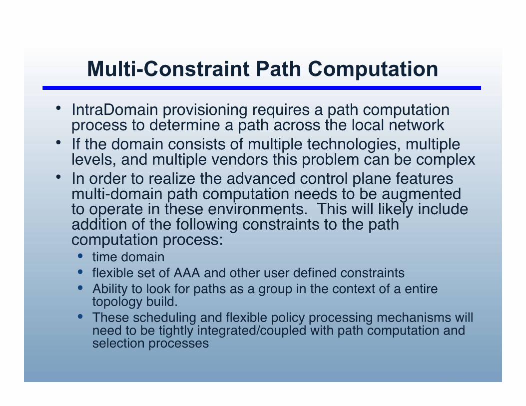
Multi-Constraint Path Computation
• IntraDomain provisioning requires a path computationprocess to determine a path across the local network
• If the domain consists of multiple technologies, multiplelevels, and multiple vendors this problem can be complex
• In order to realize the advanced control plane featuresmulti-domain path computation needs to be augmentedto operate in these environments. This will likely includeaddition of the following constraints to the pathcomputation process:• time domain• flexible set of AAA and other user defined constraints• Ability to look for paths as a group in the context of a entire
topology build.• These scheduling and flexible policy processing mechanisms will
need to be tightly integrated/coupled with path computation andselection processes

Flexible and Policy Based Multiple ConstraintPath Computation with Filtering/PruningProcesses
!"#$%&'(&)* +++$%(,&)
-./,&
-012
34&56$7(*
+88&5*9:;
%(,&)
<)&=$">&5989&?
%(,&)
+++
%(,&
@9,*&=
%(,&$#.=)&=
%(,&$#.=)&=
-9A&
B9:?CD
@9,*&=
<)&=$"54&?(,&$3C:)*=.9:*)
%&?(5&?$-C>C,C;E
3"#@$%C(*9:;
+,;C=9*4A
!"#$#.*4
!"#
"54&?(,&
0F9)*9:;
%&)C(=5&
%&)&=G.*9C:)
H&*DC=6$.:?$1CA.9:
#C,959&)
Data source (raw linkstates from intra- andinter-domain flooding)and 3D constraints
Snapshot oftopology reducedby policy filters
Constraint basedpath computationalgorithm - CSPFheuristics

Path Computation with MultipleDimensions
• Resource dimension• Link availability, bandwidth
capability & resourceinterdependence
• TE constraints, e.g. switching cap.• AAA policy dimension
• User privileges• App. specific requirements (SLA)• Administration policies
• Time schedule dimension
Resources
AAA Rules
T im e
Schedule
Solution Space
Feasible Solution (LSP)
• Integrate and translate network resource states and policies intoshared control plane intelligence.
• Synergize AAA policy decision with TE based provisioningdecision, resulting in fast, precise and simplified control process.
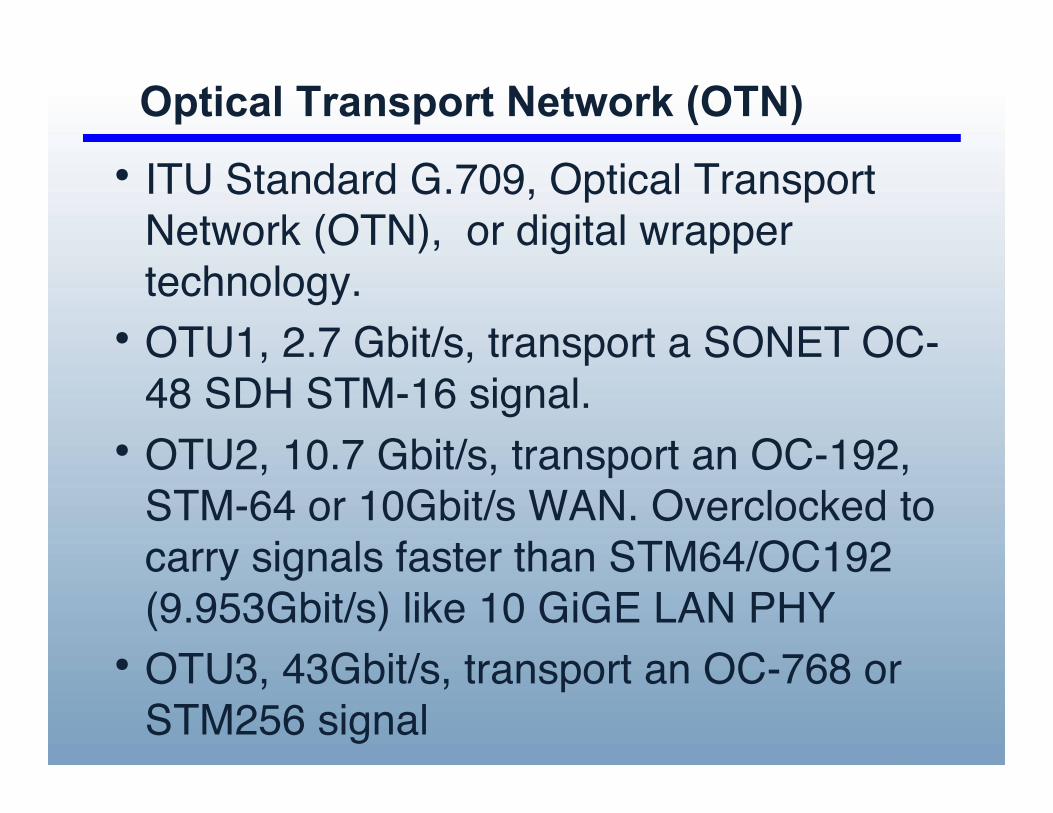
Optical Transport Network (OTN)
• ITU Standard G.709, Optical TransportNetwork (OTN), or digital wrappertechnology.
• OTU1, 2.7 Gbit/s, transport a SONET OC-48 SDH STM-16 signal.
• OTU2, 10.7 Gbit/s, transport an OC-192,STM-64 or 10Gbit/s WAN. Overclocked tocarry signals faster than STM64/OC192(9.953Gbit/s) like 10 GiGE LAN PHY
• OTU3, 43Gbit/s, transport an OC-768 orSTM256 signal

Provide BackBone BridgingTraffic Engineering (PBB-TE)
• 802.1q, VLANS• 802.1ad, Provider Bridges, QinQ• 802.1ah, PBB• connection oriented operation enabled by
disabling flooding, learning, spanning tree• use a control plane to establish paths thru
network• 24 bit service ID, eliminates scaling issue within
the PBB domain• only switches at the edge of the PBB network
need this capability, rest can be providerbridges

Internet Engineering TaskforceInternet Engineering Taskforce
CCAMP working group (GMPLS)• GMPLS control for SONET/SDH (RFC 4257)• GFP/LCAS interface discovery (OSPF-TE, RSVP-TE implications)• Multi-layer/multi-region (MRN) networks drafts:
Interface switching capability (ISC), unified TE database• Drafts on multi-domain routing (OSPF-TE, O-BGP), no temporal state• Other drafts on multi-domain/AS signaling & recovery: Crankback, inter-AS exclude routes, etc
Path computation element (PCE) working group (TE)• Path composition for TE-LSP paths: Centralized / distributed, loose-domain / hop-by-hop• Inter-area / AS / layer considerations (virtual topology management)• New PCEP signaling protocol, possibly one for PCE discovery• No PCE considerations for advance scheduling• Various requirements drafts (2004-5), no RFC yet
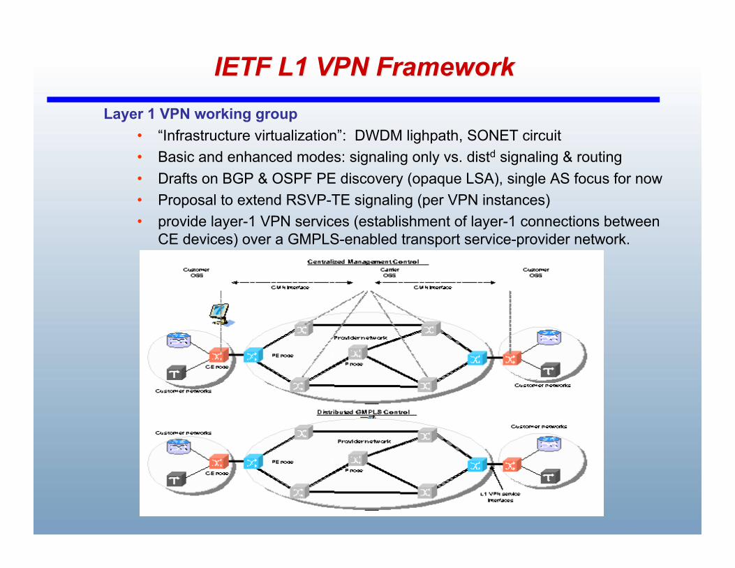
IETF L1 VPN FrameworkIETF L1 VPN FrameworkLayer 1 VPN working group
• “Infrastructure virtualization”: DWDM lighpath, SONET circuit• Basic and enhanced modes: signaling only vs. distd signaling & routing• Drafts on BGP & OSPF PE discovery (opaque LSA), single AS focus for now• Proposal to extend RSVP-TE signaling (per VPN instances)• provide layer-1 VPN services (establishment of layer-1 connections between
CE devices) over a GMPLS-enabled transport service-provider network.
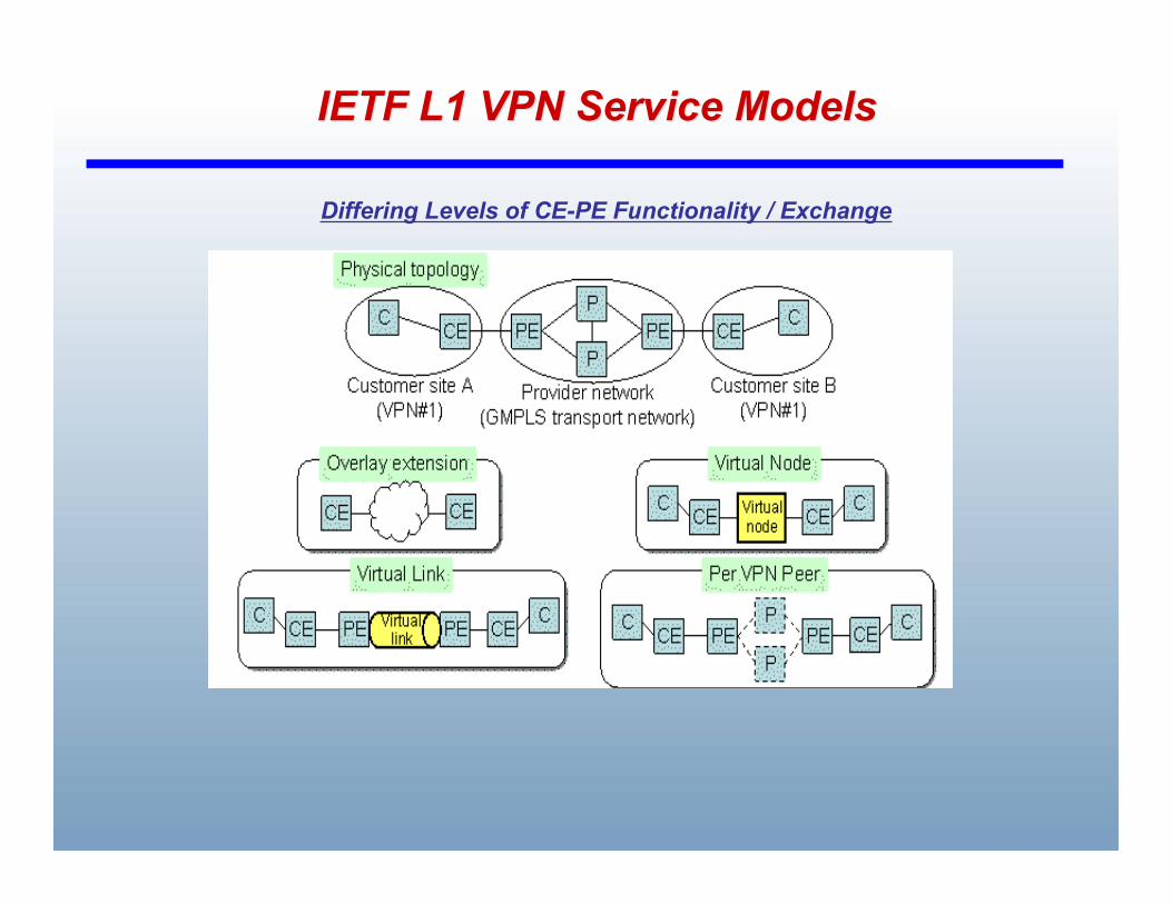
IETF L1 VPN Service ModelsIETF L1 VPN Service Models
Differing Levels of CE-PE Functionality / Exchange

Optical Internetworking ForumOptical Internetworking Forum
User Network Interface (UNI) 2.0• Multi-vendor interoperable client provisioning
Automated end-pt & service discovery, signaling (parameters)• Improved resiliency, control security, Eth support (IETF, ITU-T inputs)• UNI-N side supports multi-layer call/connections (VCAT)
Network to Node Interface (Internal – NNI, External - NNI)• Decouple intra & inter-domain mechanisms (protocols, algorithms)• Signaling protocol: parameter negotiation, protection/diversity• Hierarchical routing: topology / resource discovery (DDRP mixed
review)• Generally lacks provisions for advance scheduling
IEC Supercomm interoperability trials• Interim UNI 1.0 (2001): End-pt discovery, setup/teardown, full λrates• UNI 2.0, E-NNI 1.0 (2005):
13 vendors, 7 service providers (focus on EoS services)

International Telecom Union (ITU-T)International Telecom Union (ITU-T)
Automatically-Switched Optical Network (SG - 15, G.8080)• Multi-level hierarchical link-state routing (G.7715.x):
Horizontal (areas), vertical (leaders), inter-level state exchange• Distd call / connection management (G.7713.x, SN controllers):
Recently addressing protection/restoration, no crankback yet
Layer 1 VPN (SG - 13)• Req & architecture documents (Y.1312 / 2003, Y.1313 / 2004)• Close liason w. IETF (routing area) on suitability of IETF protocols
Other liason activities to evolve “ASON compliant” protocols• Signaling:
IETF RSVP-TE drafts for ASON, OIF UNI 2.0 & NNI 1.0 alignment• Link-state routing:
- Reqs RFC 4258, OSPF-TE and IS-IS drafts for ASON (G.7715.1) - OIF NNI 1.0 routing

Accelerate “carrier-class” Ethernet• Service focus, layered network decomposition: Applications, Eth services, metro Eth network (MEN)• Agnostic to MEN technology (SONET, DWDM, MPLS)• UNI spec for client-MEN boundary (UNI-C, UNI-N), NNI
Metro Ethernet ForumMetro Ethernet Forum
MEN
UNI
E-LAN Service, MEF 4 (2004)
• Multipoint-to-multipoint (broadcast) EVC Best-effort or QoS between UNI’s• Similar service attributes• Support address learning over UNI
VLAN , TLS
UNI
UNI
UNI
E-Line Service, MEF 4 (2004)
• Point-to-point (unicast) Ethernet VC (EVC)• Service attributes (at UNI): Interfaces, BW profiles, service performance, frame delivery, service multiplexing, L2 control tunneling/discard, etc• UNI multiplexing (EVPL service)
MENUNI
CE PE
UNI
PE CEEVC