network exchange 2.0 protocol · the exchange network protocol version 2.1 defines the set of rules...
TRANSCRIPT

Exchange Network
Protocol Version 2.1
Revised Date: July 20, 2011

Abstract
The Exchange Network Protocol version 2.1 defines the set of rules intended to govern the generation and use of valid service requests and responses on the Environmental Information Exchange Network (Exchange Network). This Protocol document is intended for use by node implementers to embed data content standards (defined in Schemas) in service requests and responses. The protocol described in this document can also be used to confirm or establish the validity of network service requests and responses.

i
Revision History
Change Record
Version Number
Description of Change Change
Effective Date Change
Entered By
2.0 June 2, 2008 Dr. Yunhao Zhang
2.1 Changed message encoding to all MTOM (Section 4.3.1).
Modified transaction status and descriptions in Section 5.2.3) based on the ADMIN IPT recommendations.
Updated all UML sequence diagrams with correct parameters.
Removed sections on UDDI. The Exchange Network Discovery Services are now filling the role of UDDI for the Network.
June 16, 2011 Dr. Yunhao Zhang

ii
Table of Contents
1 Introduction and Terminology .............................................................................. 1
1.1 Introduction ..................................................................................................... 1
1.2 Terminology .................................................................................................... 1
2 Background ............................................................................................................ 3
2.1 Principles, Assumptions and Constraints .................................................... 3
2.1.1 Principles ................................................................................................... 3
2.1.2 Assumptions .............................................................................................. 3
2.2 Requirements .................................................................................................. 4
2.3 Out of Scope.................................................................................................... 4
3 Network Web Services Architecture..................................................................... 5
3.1 A Basic Web Services Architecture .............................................................. 5
3.2 Extending the Basic Web Services Architecture for the Network .............. 6
3.2.1 Additional Components of the Network...................................................... 6
3.2.2 Setup of the Network ................................................................................. 7
3.2.3 Operation of the Network ........................................................................... 8
3.3 Network Registries and Repositories ........................................................... 9
3.4 Network Web Services Protocol Stack ....................................................... 10
3.4.1 Security.................................................................................................... 10
3.4.2 Transport ................................................................................................. 10
3.4.3 XML Messaging ....................................................................................... 10
3.4.4 Service Description.................................................................................. 10
3.4.5 Service Discovery .................................................................................... 11
3.5 Web Services Standards .............................................................................. 11
3.5.1 Secure Socket Layer (SSL) ..................................................................... 11
3.5.2 Hypertext Transfer Protocol (HTTP) ........................................................ 11
3.5.3 Simple Object Access Protocol (SOAP)................................................... 11
3.5.4 Extensible Markup Language (XML)........................................................ 11
3.5.5 Web Services Description Language (WSDL) ......................................... 12
3.5.6 Universal Description, Discovery, and Integration (UDDI) ....................... 12
4 Network Message Structure ................................................................................ 13

iii
4.1 HTTP Transport Protocol ............................................................................. 13
4.2 SOAP Messaging .......................................................................................... 13
4.2.1 SOAP Envelope....................................................................................... 14
4.2.2 SOAP Header .......................................................................................... 15
4.2.2.1 MustUnderstand Attribute ................................................................................ 15
4.2.3 SOAP Body.............................................................................................. 15
4.2.3.1 Encoding ........................................................................................................... 15
4.2.4 SOAP Fault.............................................................................................. 15
4.2.4.1 SOAP Fault Codes ............................................................................................ 15
4.2.4.2 SOAP Fault Detail Codes ................................................................................. 16
4.3 XML Payloads................................................................................................ 18
4.3.1 Payload Location ..................................................................................... 18
4.3.2 Payload Validation ................................................................................... 18
4.3.3 Payload Compression.............................................................................. 18
4.3.4 SOAP Message Compression ................................................................. 19
5 Network Services ................................................................................................. 20
5.1 Conversation Structure ................................................................................ 20
5.2 Basic Network Service Interactions ............................................................ 20
5.2.1 Authenticate............................................................................................. 21
5.2.2 Submit...................................................................................................... 21
5.2.3 GetStatus................................................................................................. 22
5.2.4 Query ....................................................................................................... 25
5.2.5 Solicit ....................................................................................................... 25
5.2.6 Execute.................................................................................................... 25
5.2.7 Notify........................................................................................................ 26
5.2.7.1 Document Notification...................................................................................... 27
5.2.7.2 Event Notification............................................................................................. 27
5.2.7.3 Status Notification ............................................................................................ 28
5.2.8 Download................................................................................................. 28
5.2.9 NodePing ................................................................................................. 29
5.2.10 GetServices ............................................................................................. 29
5.3 Exchange Network Business Processes .................................................... 29

iv
5.3.1 Simple Document Submission ................................................................. 30
5.3.2 Notified Document Download .................................................................. 32
5.3.3 Sending Network Events.......................................................................... 35
5.3.4 Broadcasting Network Events.................................................................. 36
5.3.5 Retrieving Information Using Query......................................................... 37
5.3.6 Executing predefined Procedures............................................................ 39
5.3.7 Performing Asynchronous Operations ..................................................... 40
5.3.7.1 Network Configuration ..................................................................................... 40
5.3.7.2 Procedures of Asynchronous Exchanges .......................................................... 40
5.3.8 Using Network Authentication and Authorization Services (NAAS) ......... 42
5.3.8.1 Network Authentication.................................................................................... 43
5.3.8.2 Network Authorization ..................................................................................... 44
6 Extended Business Exchange Scenarios .......................................................... 46
6.1 Large Payload Exchanges............................................................................ 46
6.2 Automated Data Retrieval ............................................................................ 46
6.3 Point-to-Point Exchanges ............................................................................ 47
6.4 Data Flow with Notification and Delivery .................................................... 48
6.5 Ad Hoc Data Flows ....................................................................................... 49
6.6 Supporting Small Devices............................................................................ 49
6.7 Using External Web Services....................................................................... 50
7 Describing Network Services.............................................................................. 51
8 Security................................................................................................................. 52
8.1 Applicable Security Protocols ..................................................................... 52
8.1.1 HTTP Security ......................................................................................... 52
8.1.2 SSL.......................................................................................................... 52
8.1.3 PKI........................................................................................................... 53
8.2 Security Levels.............................................................................................. 53
8.2.1 Public Access .......................................................................................... 53
8.2.2 SSL with Client Authentication................................................................. 53
8.2.3 SSL with Dual-Authentication .................................................................. 53
8.2.4 Digital Signature ...................................................................................... 53
8.3 Authentication and Authorization ............................................................... 54

v
8.4 Central and Federated Authentications ...................................................... 55
8.5 Message Confidentiality ............................................................................... 57
8.6 Message Integrity and Non-Repudiation..................................................... 57
9 References............................................................................................................ 60

vi
Table of Figures
Figure 1 – Basic Components of the Network Web Services Architecture ...................... 6
Figure 2 – Setup of the Network...................................................................................... 7
Figure 3 – Operation of the Network ............................................................................... 8
Figure 4 – Network Protocol Message Structure........................................................... 13
Figure 5 – Network SOAP Message Structure .............................................................. 14
Figure 6 – Exchange Network Conversation Structure.................................................. 20
Figure 7 – State Transition Diagram for Document Submissions.................................. 24
Figure 8 – Bi-directional Flow Diagram with Submit and Download .............................. 29
Figure 9 – UML Activity Diagram for Simple Submissions ............................................ 31
Figure 10 – UML Sequence Diagram for Document Submissions ................................ 32
Figure 11 – UML Activity Diagram for Solicited Operations........................................... 33
Figure 12 – UML Sequence Diagram for Download Operations ................................... 35
Figure 13 – UML Activity Diagram for Event Notifications. ............................................ 36
Figure 14 – UML Activity Diagram for Event Broadcasting............................................ 37
Figure 15 – UML Activity Diagram for Simple SQL Queries .......................................... 38
Figure 16 – UML Sequence Diagram for Query Operations.......................................... 39
Figure 17 – UML Sequence Diagram for the Execute Operation .................................. 40
Figure 18 – UML Sequence Diagram............................................................................ 41
Figure 19 – UML Sequence Diagram for Requester and Provider ................................ 42
Figure 20 – Single Sign on Configuration...................................................................... 56

1
1 Introduction and Terminology
1.1 Introduction
The Exchange Network Protocol (v2.1) is a lightweight Protocol for the exchange of structured data, unstructured data, and relational data among network nodes across a wide area of networks. The Protocol defines a framework where data exchanges can take place independent of hardware/software platforms, development tools, and programming languages used.
1.2 Terminology
Term Definition/Clarification
CSM Central Security Management
DBMS Database Management System
DIME Direct Internet Message Encapsulation
EPA Environmental Protection Agency
Exchange Network
Environmental Information Exchange Network
FCD Flow Configuration Document
HTTP Hypertext Transfer Protocol
MTOM Message Transmission Optimization Mechanism
XOP XML-binary Optimization Packaging
NAAS Network Authentication and Authorization Services. This is a set of centralized security services shared by all network nodes.
Node Client
QA
A Node that uses Exchange Network Protocol v2.1 but does not provide services. Quality Assurance
RBAC Role-Based Access Control
RPC Remote Procedure Call
Requester A node that initiates SOAP request messages.
SAML Security Assertion Markup Language
Service Provider
A node that accepts SOAP messages and executes methods defined by this Protocol.
SMTP Simple Mail Transport Protocol
SOAP Simple Object Access Protocol

2
Term Definition/Clarification
SQL Structured Query Language
SSL Secure Sockets Layer
SSO Single Sign-on
Target Node
The ultimate destination of a dataflow, a target node may or may not implement the Exchange Network Protocol v2.1.
tModel tModel, or Technical Model, is used in UDDI to represent unique concepts or constructs. They provide a structure that allows re-use and, thus, standardization within a software framework. Interfaces defined by the Exchange Network V1.0 and v2.1 Protocol will be registered as tModels in a private UDDI registry.
NTG Network Technology Group.
UDDI Universal Description, Discovery and Integration.
UML Unified Modeling Language is the industry-standard language for specifying, visualizing, constructing, and documenting the artifacts of software systems.
W3C World Wide Web Consortium.
WSDL Web Service Definition Language. XML
Schema XML Schemas express shared vocabularies and allow machines to carry out rules made by people. They provide a means for defining the structure, content and semantics of XML documents. A Schema is also a type of DET.

3
2 Background
2.1 Principles, Assumptions and Constraints
Principles are rules or maxims that guide subsequent decisions. They consist of a list of criteria involving business direction and good practice to help guide the architecture and design.
Assumptions are givens or expectations that form a basis for decisions, and if proven false may have a major impact on the project. They identify key characteristics of the future that are assumptions for the architecture and design, but are not constraints.
Constraints are restrictions that limit options. They are typically things that must or must not be done in designing an application. They identify key characteristics of the future that are accepted as constraints to architecture and design.
The principles, assumptions, and constraints for the Exchange Network Protocol v2.1 are as follows:
2.1.1 Principles
1. The Exchange Network Protocol v2.1 should be kept as simple as possible, even if doing so means it will be unable to meet a small number of identified, but advanced needs.
2. The Exchange Network Protocol v2.1 should formalize the Network use cases and provide detailed information about interfacing with nodes. The Protocol will be used by both network flow designers and network users and should address the needs of these two (2) primary groups of users.
3. The Exchange Network Protocol v2.1 should address how to design the requests and responses (i.e., the web services) that network flows should support. Note that the design of the requests and responses will always be driven first and foremost by the immediate needs of those building the flow. Flow designers, however, should provide end users with the maximum flexibility for data use by keeping the services simple and generic. Designers are encouraged to not focus solely on services that support machine-to-machine flows between existing systems, but to supplement and extend these with simple services that could be used to support more interactive uses.
2.1.2 Assumptions
1. The Exchange Network Protocol v2.1 will rely on existing standards (e.g., SOAP, WSDL and UDDI).
2. Network Node v1.1 and Network Node v2.1 are not compatible from the protocol level due to incompatibility between SOAP v1.1 and SOAP v1.2.
3. The Protocol will be used by both network flow designers and network users.

4
2.2 Requirements
These requirements describe the technical and functional capabilities that will be delivered as part of the Exchange Network Protocol v2.1. The Exchange Network Protocol v2.1 shall:
1. Support all critical requirements for network flows including the ability to support processing instructions/transaction type information, such as:
The ability to initiate appropriate network security (See Section 8, Security).
The ability to handle different network uses (See Section 5.3, Exchange Network Business Processes).
2. Use HTTP/HTTPS, WSDL, and SOAP, and be as consistent as possible in their application with emerging industry standards.
3. Able to be implemented using the most common middleware configurations in use by node implementers, without a high degree of customization.
4. Be both human and machine readable.
5. Character support identification. All network transactions will be governed by UTF – 8.
6. Support the following message exchange functions:
a. Synchronous and Asynchronous communication.
b. Acknowledgement.
c. Time stamping.
2.3 Out of Scope
The Exchange Network Protocol v2.1 does not govern the following functionality:
Defining and handling the common types of missing, unavailable, or inapplicable data. This is an important function but falls outside the scope of the Exchange Network Protocol v2.1.
Specification of the format of the message payloads.
Internationalization. There will not be international language support. The standard is English.
5
3 Network Web Services Architecture
The Exchange Network Protocol v2.1 will be used within the larger context of the network Web services architecture. A software system’s architecture defines the overall structure of the system. It partitions the system into components, allocates responsibilities among those components, and defines both how the components collaborate and how control flows through the system.
3.1 A Basic Web Services Architecture
Service Provider – This is the provider of the web service. The service provider implements the service, publishes its availability, makes it available on the Internet, and processes requests for services.
Service Requester – This is any consumer of the web service. The service requester discovers an existing web service, retrieves its description, and then utilizes the web service by opening a network connection and sending an Extensible Markup Language (XML) request conforming to its interface description.
Service Registry – This is a logically centralized directory of web services. The service registry provides a central place where service providers can publish new web services and service requesters can find existing ones.
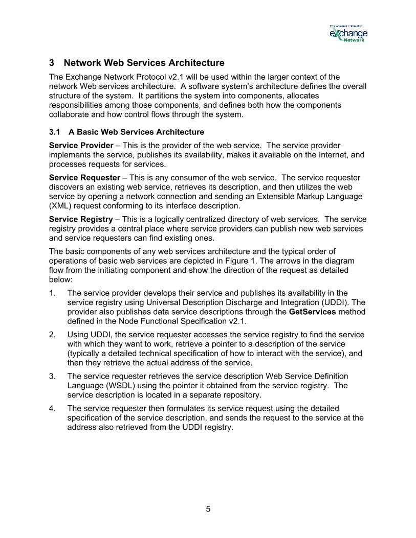
The basic components of any web services architecture and the typical order of operations of basic web services are depicted in Figure 1. The arrows in the diagram flow from the initiating component and show the direction of the request as detailed below:
1. The service provider develops their service and publishes its availability in the service registry using Universal Description Discharge and Integration (UDDI). The provider also publishes data service descriptions through the GetServices method defined in the Node Functional Specification v2.1.
2. Using UDDI, the service requester accesses the service registry to find the service with which they want to work, retrieve a pointer to a description of the service (typically a detailed technical specification of how to interact with the service), and then they retrieve the actual address of the service.
3. The service requester retrieves the service description Web Service Definition Language (WSDL) using the pointer it obtained from the service registry. The service description is located in a separate repository.
4. The service requester then formulates its service request using the detailed specification of the service description, and sends the request to the service at the address also retrieved from the UDDI registry.

6
ServiceRegistry
ServiceProvider
ServiceRequestor
1.PublishService
2.DiscoverService 3.
RetrieveService
Description
4.InvokeService
Figure 1 – Basic Components of the Network Web Services Architecture
3.2 Extending the Basic Web Services Architecture for the Network
The basic web services architecture described above will be extended to implement the network. This will require additional components and result in a more complex flow of operations.
The components and the flow of operations of the network web services architecture is best depicted in the two separate diagrams below. Figure 2 depicts the configuration of the network, while Figure 3 depicts the operation of the network once it is set up.
3.2.1 Additional Components of the Network
The additional components of the network web services architecture depicted in the figures are as follows:
XML Schema Registry – This is a logically centralized directory of XML Schemas. The XML Schemas describe the various payloads (data files) that may be exchanged across the network. The XML Schema Registry provides a central place where the exchange network partners can publish data standards.
Flow Configuration Document (FCD) Registry – This is a logically centralized directory of Flow Configuration Documents. The FCD defines the business rules and parameters that will be in effect between a given service requester and service provider. The FCD registry provides a central place where network participants can publish new FCDs. FCDs have traditionally been paper documents signed by the parties to the agreement. However, they can also exist in executable form supplying needed information to help automate business transactions that occur within the scope of the agreement.
Service Description Repository – This is a logically centralized storage location for the Service Descriptions, also called WSDL files. The service description repository provides a central place where the parties to a trading partner agreement can store new service descriptions for subsequent retrieval.

7
Exchange Network Discovery Services (ENDS) – The ENDS is a supplementary service to UDDI for detailed descriptions about data service requests, parameter definitions and other Exchange Network specific information.
Network Authentication and Authorization Services (NAAS) – NAAS provide centralized security services for the Exchange Network. These services include user authentication, authorization, identity management, and policy management.
3.2.2 Setup of the Network
Setup of the network will be an ongoing process as new services are added, and older services are updated or retired. The setup of the network web services architecture as depicted in Figure 2 is as follows:
1. The Network Technology Group (NTG), which is responsible for administering the XML schema definitions for each exchange payload that moves across the network, defines an official version of the XML schema definition and stores it in the XML schema repository.
2. The NTG then publishes the official version of the XML schema definition in the XML schema registry.
3. The service provider develops their service, creates a service description using the WSDL, and stores the service description in the service description repository.
4. The service provider then stores the availability of their web service in the service registries (UDDI and ENDS).
App
rova
l
Figure 2 – Setup of the Network
8
3.2.3 Operation of the Network
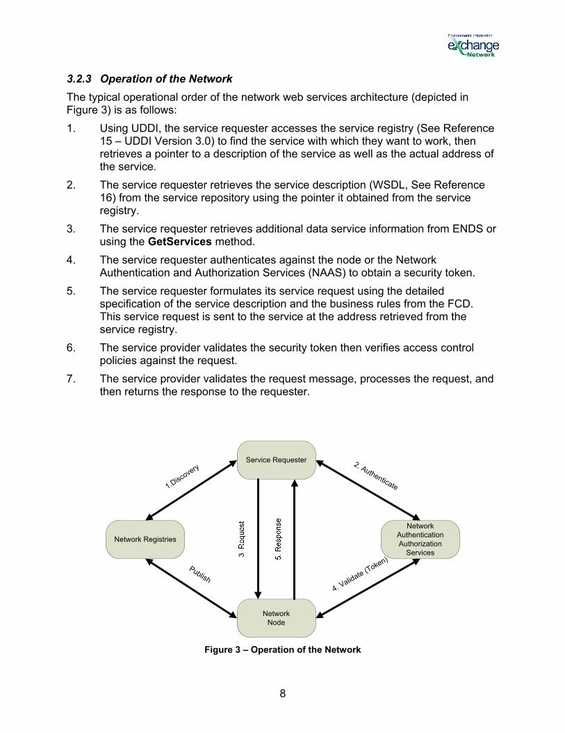
The typical operational order of the network web services architecture (depicted in Figure 3) is as follows:
1. Using UDDI, the service requester accesses the service registry (See Reference 15 – UDDI Version 3.0) to find the service with which they want to work, then retrieves a pointer to a description of the service as well as the actual address of the service.
2. The service requester retrieves the service description (WSDL, See Reference 16) from the service repository using the pointer it obtained from the service registry.
3. The service requester retrieves additional data service information from ENDS or using the GetServices method.
4. The service requester authenticates against the node or the Network Authentication and Authorization Services (NAAS) to obtain a security token.
5. The service requester formulates its service request using the detailed specification of the service description and the business rules from the FCD. This service request is sent to the service at the address retrieved from the service registry.
6. The service provider validates the security token then verifies access control policies against the request.
7. The service provider validates the request message, processes the request, and then returns the response to the requester.
Service Requester
Network Registries
NetworkNode
Network Authentication Authorization
Services
1.Discovery
2. Authenticate
4. Validate (T
oken)Publish
Figure 3 – Operation of the Network

9
3.3 Network Registries and Repositories
The network registries and repositories may be housed in the same physical location and use the same general access services; however, each of these registries and repositories must be treated as logically separate entities.
In addition, any or all of the three possible Network Registries, as well as the service registry, may utilize a “Registrar” service (not pictured in Figure 2). The registrar provides UDDI registration services on behalf of a customer (e.g. a web service provider). It is responsible for handling additions of entries to the registry as well as updates or deletions of registered entries in the registry. A registrar can be totally automated or it can be a website that provides a human interface to the customer and then employs the API for accessing the registry.

10
3.4 Network Web Services Protocol Stack
The Exchange Network Protocol can be visualized as a stack of several layers of capability with various standards applicable to each layer:
Discovery UDDI, ENDS
Description WSDL, Node Service Descriptions
XML Messaging SOAP, XML
Transport HTTP/HTTPS
Security SSL/TLS, WS-Security, NAAS, XML Firewalls
Each layer is independent from the layers above and below it. Each has its own job that provides greater flexibility allowing the connection of all forms of disparate systems and network technologies to support distributed processing over the Internet.
3.4.1 Security
This layer insulates the application from unwanted intrusion and unauthorized access. It can employ a number of different security protocols; however, the approach that must be supported by the network at this time is Secure Sockets Layer (SSL) plus service level user authentication and authorization.).
3.4.2 Transport
This layer is responsible for transporting messages between applications. It can also employ a number of different Protocols. All Exchange Network nodes must support the Hypertext Transfer Protocol HTTP/HTTPS V1.1.
3.4.3 XML Messaging
This layer is responsible for encoding messages in a common XML format so that the messages can be understood at either end. The approaches that must be supported by the network at this time are:
a) Simple Object Access Protocol (SOAP) v1.2 for the encoding of the message structure.
b) XML Schema for the encoding of the message payload.
3.4.4 Service Description
This layer is responsible for describing the interface to a specific web service. The approach that must be supported by the network at this time is WSDL / 1.1(WSDL, See Reference 16). The Exchange Network defines additional constructs for describing

11
lower level services such as data services published through the Query or Solicit method, or other web services accessible through the Execute method.
3.4.5 Service Discovery
This layer is responsible for centralizing services into a common registry.. The current approach for providing this functionality is UDDI (UDDI, See Reference 15). The Exchange Network Discovery Services provides supplemental descriptions of fine grained data services and other callable services through the Query and Execute methods.
3.5 Web Services Standards
At each layer of the web services protocol stack there are one or more applicable standards that must be understood and addressed.
3.5.1 Secure Socket Layer (SSL)
SSL is a Protocol originally designed to encrypt messages sent across the Internet using HTTP. SSL ensures that no one can easily intercept the messages and read them, thus providing a significant degree of privacy in Internet communications. SSL is a separate layer that sits below HTTP and above TCP and IP. HTTP over SSL has a default port of 443, as opposed to HTTP’s default port of 80. This means that many applications will have two (2) default ports: 80 and 443.
All network nodes must support SSL 3.0 and TLS 1.0 for all node operations.
3.5.2 Hypertext Transfer Protocol (HTTP)
Hypertext Transfer Protocol (HTTP) was designed make communications between computers easy by specifying a set of rules of conversation. It requires the presence of applications which follow different rules in the conversation and act as either clients or servers. Clients always initiate the contact and start the conversation, while servers can only respond to requests from clients. The client makes a request and the server responds in a stateless transaction.
3.5.3 Simple Object Access Protocol (SOAP)
The Network Node v2.1 must be implemented using SOAP 1.2, and the encoding style is changed from the SOAP/RPC encoding in the previous version to the document/literal encoding in the current version. SOAP 1.2 is a messaging framework for transferring information in XML Infoset format from the sender to the ultimate receiver. Although SOAP 1.2 allows one-way messaging and supports other transport bindings, the main focus of the Exchange Network is on request/response exchanges over HTTP/HTTPS.
3.5.4 Extensible Markup Language (XML)
Using XML a user can create a tag-based markup language for the representation of information about almost any topic possible. The structure and content of the markup language is typically at a more detailed level through an XML Schema (itself specified through XML). An instance of information in the markup language encoded/marked-up according to one of these specifications is called an XML document, which contains tags identifying the content by a series of elements and attributes associated with the

12
content in the order and format specified. The formal specifications can be used to automatically validate an XML document using a validating XML parser.
There are two versions of XML specifications: XML 1.0, which was first issued in 1998 and has undergone several revisions, and XML 1.1 (Second Edition) which was published by W3C as a recommendation on August 16, 2006. All SOAP messages must be in XML 1.0 format. However, XML payload carried by the Exchange Network may either be in XML 1.0 or 1.1. The XML version should be defined in the Flow Configuration Document (FCD) by the Integrated Project Team (IPT).
3.5.5 Web Services Description Language (WSDL)
The Web Service Description Language (see Reference 16) is an XML-based language specification defining how to describe a web service in computer readable form. For a given web service, its WSDL file describes four (4) key pieces of data:
1. Operation – information describing all available functions/methods.
2. Data type – information for all message requests and message responses.
3. Binding – information about the transport protocol to be used.
4. Address – information for locating the specified service.
WSDL represents the contract between the service requester and the service provider. Using WSDL, a client can locate a web service and invoke any of its available functions. With WSDL aware tools, you can automate this process.
There are two versions of WSDL specifications: WSDL 1.1 and WSDL 2.0. Although just a W3C Note, WSDL 1.1 has been widely implemented in various toolkits. The original Network Node Specification 2.0 will be described in WSDL 1.1. A WSDL 2.0 description of the node services will also be made available in the future.
3.5.6 Universal Description, Discovery, and Integration (UDDI)
UDDI (UDDI, see reference 15) is a technical specification that provides a programmatic way for people to find and use certain web services. UDDI is a critical part of web services Protocol stack. It enables organizations to both publish and discover web services.
EPA has established a UDDI v3.0 server as a shared resource for the Exchange Network. It currently hosts most of the version 1.1 node information and WSDL files, but will be expanded to support version 2.1 nodes as well.

13
4 Network Message Structure
All network messages will utilize the basic HTTP request/response structure. Within this basic transport layer structure, all messages will be encoded using the SOAP envelope/header/body structure, in which header is optional. Inside the body of the SOAP message, the payload will be encoded using XML (XML Schema). The payload will typically be a simple request, a document response or an error response (called a fault), and the response will be an answer to the request. This basic structure is depicted in Figure 4.
Transport Protocol (HTTP)
XML Messaging (SOAP)
Payload (XML Schema)
Figure 4 – Network Protocol Message Structure
The three primary components of the message structure that need to be discussed are the transport protocol (HTTP); the XML messaging Protocol (SOAP); and the payload encoded according to an XML schema. Because SOAP is being used over HTTP, it imposes some constraints on what must or must not be included in the HTTP message structure. Also, because XML payloads are being used in the SOAP messages, the XML is imposing certain constraints on the SOAP message structure.
4.1 HTTP Transport Protocol
Currently, the only supported transport mechanism approved as part of the Exchange Network Protocol v2.1 is HTTP/HTTPS.
HTTP is a two-message system of communication. There is a request HTTP structure and a response HTTP structure. All network messages will utilize the basic HTTP request/response structure. SOAP requests are sent via an HTTP request and SOAP responses are returned within the content of an HTTP response.
SSL (Secure Socket Layer) support is mandatory in all node version 2.1 implementations. All service requests and responses must be sent through SSL v3.0 or TLS (Transport Layer Security) in the production environment.
4.2 SOAP Messaging
All network transactions must be SOAP messages. SOAP is bound to HTTP, as the Exchange Network Protocol v2.1 does not currently support SOAP binding to other transport mechanisms. All nodes must support SOAP V1.2 as defined by the W3C. SOAP messages are composed of a mandatory envelope element, an optional header

14
element, a mandatory body element and an optional fault element. All network payloads are carried in the body of the SOAP message or as an attachment to the envelope. This basic structure is depicted in Figure 5.
SOAP Envelope(required)
SOAP Header(optional)
SOAP Body(required)
SOAP Fault(optional)
Figure 5 – Network SOAP Message Structure
The Exchange Network Protocol v2.1 does not govern payload issues; however, it is expected that the SOAP XML message structure for all SOAP messages will be validated with the network SOAP schema located in the network registry.
4.2.1 SOAP Envelope
The envelope element is the root element of the SOAP message. The rest of the SOAP message must be contained within the envelope start and end tags. The envelope element must be prefixed with an indicator of the namespace that defines the SOAP version that is applicable. The version is indicated by the namespace attribute, xmlns, included in the envelope element start tag. The namespace prefix could be any valid XML namespace string, but the convention usually adopted is as follows:
<SOAP-ENV:Envelope
xmlns:SOAP-ENV=” http://www.w3.org/2003/05/soap-envelope”>
The namespace name SOAP-ENV is really a symbol for http://www.w3.org/2003/05/soap-envelope. Although it can be any NCName (an XML Name, minus the ":"), the URL section must be exactly as specified. A different URL represents a different version of SOAP, and must cause the VersionMismatch fault (see Section 4.2.4 for definition).

15
4.2.2 SOAP Header
The Header element is used to provide a mechanism for extending a SOAP message. SOAP header processing must be processed; however, defining messages inside the Header is beyond the scope of this document.
4.2.2.1 MustUnderstand Attribute
All Network Nodes must process the MustUnderstand attribute in the SOAP header. A Fault should be given if MustUnderstand is “true” and the node doesn’t support the message.
4.2.3 SOAP Body
The Body element is used to provide information about the message.
4.2.3.1 Encoding
All version 2.1 nodes must use document/literal encoding for request and response messages. This literal encoding style allows arbitrary XML elements to be sent in a SOAP message. It has been a common practice to set the encoding style attribute to empty in such a situation.
SOAP messages of literal encoding are often governed by XML schema rather than encoding styles.
4.2.4 SOAP Fault
4.2.4.1 SOAP Fault Codes
The SOAP V1.2 Protocol defines four fault codes that must be used in all SOAP fault messages. They are referenced in Table 4.
Table 4 – SOAP Fault Code
Fault Code Meaning
VersionMismatch The SOAP envelope namespace is wrong
MustUnderstand A header with mustUnderstand set to 1 could not be processed (understood) by the receiver
DataEncodingUnknown The request message contains an encodingStyle that is not supported by the receiver
Sender Request message is invalid or could not be processed
Receiver A fault caused by a receiver-side error

16
4.2.4.2 SOAP Fault Detail Codes
All SOAP fault messages must confirm to the SOAP V1.2 specification and use the predefined SOAP fault codes. In addition, all SOAP fault messages must contain a fault detail element, with Exchange Network specific error codes and error descriptions, when processing of a SOAP request fails.
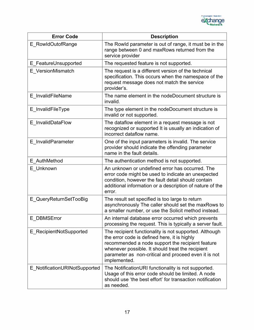
Common error codes for the Exchange Network Protocol v2.1 are listed in Table 5.
Table 5 – Exchange Network Error Code
Error Code Description
E_UnknownUser The user could not be found in the specified domain. The error occurs when the user is not registered in the domain or the user ID is incorrect.
E_InvalidCredential The user credential is invalid. The error occurs when the security system could not verify user supplied password or digital certificate.
E_TransactionId The supplied transaction ID could not be found. In methods such as GetStatus or Download, a transaction ID might be required and it must match a previous transaction.
E_UnknownMethod The requested method is not supported. This indicates that the name of the web method is not defined in the Node Functional Specification.
E_ServiceUnavailable The requested data service or web service is undefined or not supported The service provider returns this error when the request element in Query or Solicit, or the webMethod element in the Execute call is not recognized.
E_AccessDenied The operation could not be performed due to insufficient privileges. The user must be authorized by the node administrator or dataflow administrator in order to access the service.
E_InvalidToken The security token is invalid or not issued by a trusted security provider
E_TokenExpired The security token has expired. A security token has a lifespan, and it must be used within the time period.
E_FileNotFound The requested file could not be located.
E_ValidationFailed XML schema or schematron validation error. This could occur when validation of request message or payload failed.
E_ServerBusy The service is too busy to handle the request at this time, please try later.
17
Error Code Description
E_RowIdOutofRange The RowId parameter is out of range, it must be in the range between 0 and maxRows returned from the service provider
E_FeatureUnsupported The requested feature is not supported.
E_VersionMismatch The request is a different version of the technical specification. This occurs when the namespace of the request message does not match the service provider’s.
E_InvalidFileName The name element in the nodeDocument structure is invalid.
E_InvalidFileType The type element in the nodeDocument structure is invalid or not supported.
E_InvalidDataFlow The dataflow element in a request message is not recognized or supported It is usually an indication of incorrect dataflow name.
E_InvalidParameter One of the input parameters is invalid. The service provider should indicate the offending parameter name in the fault details.
E_AuthMethod The authentication method is not supported.
E_Unknown An unknown or undefined error has occurred. The error code might be used to indicate an unexpected condition, however the fault detail should contain additional information or a description of nature of the error.
E_QueryReturnSetTooBig The result set specified is too large to return asynchronously The caller should set the maxRows to a smaller number, or use the Solicit method instead.
E_DBMSError An internal database error occurred which prevents processing the request. This is typically a server fault.
E_RecipientNotSupported The recipient functionality is not supported. Although the error code is defined here, it is highly recommended a node support the recipient feature whenever possible. It should treat the recipient parameter as non-critical and proceed even it is not implemented.
E_NotificationURINotSupported The NotificationURI functionality is not supported. Usage of this error code should be limited. A node should use ‘the best effort’ for transaction notification as needed.
18
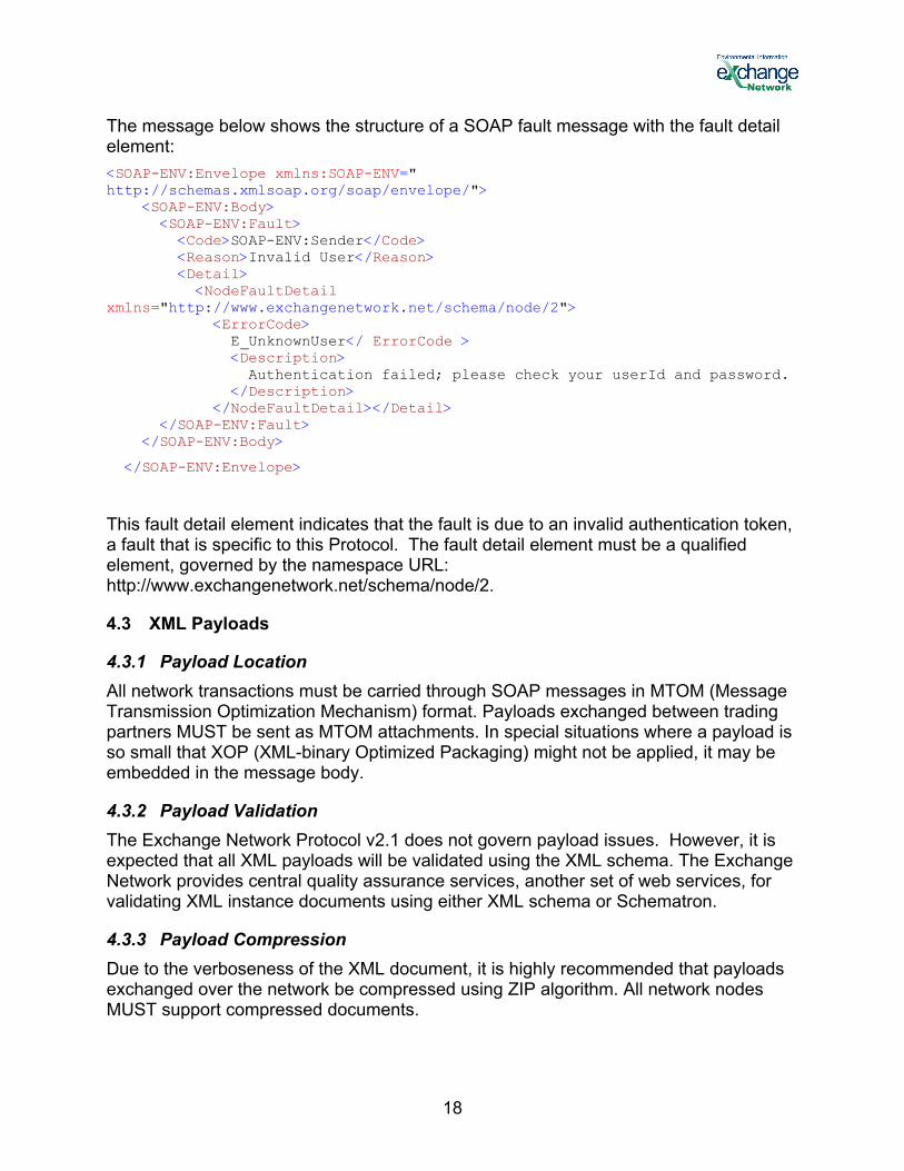
The message below shows the structure of a SOAP fault message with the fault detail element:
<SOAP-ENV:Envelope xmlns:SOAP-ENV=" http://schemas.xmlsoap.org/soap/envelope/"> <SOAP-ENV:Body> <SOAP-ENV:Fault> <Code>SOAP-ENV:Sender</Code> <Reason>Invalid User</Reason> <Detail> <NodeFaultDetail xmlns="http://www.exchangenetwork.net/schema/node/2"> <ErrorCode> E_UnknownUser</ ErrorCode > <Description> Authentication failed; please check your userId and password. </Description> </NodeFaultDetail></Detail> </SOAP-ENV:Fault> </SOAP-ENV:Body>
</SOAP-ENV:Envelope>
This fault detail element indicates that the fault is due to an invalid authentication token, a fault that is specific to this Protocol. The fault detail element must be a qualified element, governed by the namespace URL: http://www.exchangenetwork.net/schema/node/2.
4.3 XML Payloads
4.3.1 Payload Location
All network transactions must be carried through SOAP messages in MTOM (Message Transmission Optimization Mechanism) format. Payloads exchanged between trading partners MUST be sent as MTOM attachments. In special situations where a payload is so small that XOP (XML-binary Optimized Packaging) might not be applied, it may be embedded in the message body.
4.3.2 Payload Validation
The Exchange Network Protocol v2.1 does not govern payload issues. However, it is expected that all XML payloads will be validated using the XML schema. The Exchange Network provides central quality assurance services, another set of web services, for validating XML instance documents using either XML schema or Schematron.
4.3.3 Payload Compression
Due to the verboseness of the XML document, it is highly recommended that payloads exchanged over the network be compressed using ZIP algorithm. All network nodes MUST support compressed documents.

19
4.3.4 SOAP Message Compression
SOAP message compression can be handled on the HTTP level using the gzip content encoding. When sending a request, a node client MAY choose to compress the entire message and indicate the message is compressed in the HTTP header as shown below:
POST / HTTP/1.1 Host: www.exchangenetwork.net User-Agent: SQLData Web Client 3.6 Accept: text/xml,application/xml,application/xhtml+xml
Content-Encoding: gzip
Accept-Encoding: gzip, deflate Keep-Alive: 300 Connection: keep-alive
The Content-Encoding header informs the receiver the message body is compressed using gzip. In addition, it has an Accept-Encoding header which indicates that the client is willing to accept a gzip compressed response. Most of the common HTTP/SOAP servers support gzip compression at this time. However, a node SHOULD compress the response message only if the request header contains Accept-Encoding with gzip,deflate. This is due to the fact that HTTP capability of node client software is largely unknown or undefined.

20
5 Network Services
A Protocol defines the structure of an interaction that will take place among two or more parties. It defines the rules that must be followed by each of the parties in order for them to successfully fulfill their role in the interaction.
The Exchange Network Protocol v2.1 will involve a series of interactions or conversations among the various network trading partners and business components. These conversations will generally consist of service requesters (i.e. other nodes or simple clients) requesting services of service providers (nodes). The service requests will primarily involve requests for information from a web service, which will then typically respond with the requested information or a fault message of some type. All service requests will utilize the message structure defined above. All requests and responses will be encoded using SOAP 1.2.
The conversations between network parties, however, can be much more complex than simple request/response, with different parties initiating the conversation or taking up requests and responses at different points in the process to accomplish different objectives.
5.1 Conversation Structure
The conversations moving across the network will be composed as depicted in Figure 6. All messages will be built on a basic set of operational primitives. These primitives will be used to construct the basic exchange service interactions. These service interactions will then be strung together to implement entire business processes associated with the exchange of environmental data. For example, the process of one state collecting weekly water monitoring results from a neighboring state’s node is an Exchange Business Process, as would be EPA collection of monthly activity reports for a delegated program.
Exchange Business Processes
Basic Service Interactions
Operational Primitives
Figure 6 – Exchange Network Conversation Structure
Note that the Protocol and Specification focus on the two lower layers of this conversation.
5.2 Basic Network Service Interactions
The Exchange Network is a services oriented architecture. As the name implies, the network is made up of basic services that interact to fulfill business exchanges. This protocol uses the term “Basic Network Service Interactions” to describe how the sets of

21
messages, configured in one of the four ways described above, get something done. These service interactions are the heart of the Exchange Network Protocol and the operation of the network itself. These service interactions are described below: (Note: this section does not cover message structures and functional details of the service interactions. For that information, see the Network Node Functional Specification.)
The following are the Exchange Network service operations:
Authenticate
Submit
GetStatus
Query
Solicit
Notify
Download
NodePing
GetServices
Execute
5.2.1 Authenticate
Authenticate is the first method a client calls in order to gain access to the Exchange Network service. Users must supply identification and a credential; the service provider returns, upon a successful authentication, a ticket, known as the securityToken. The securityToken is required for all subsequent network service interactions. The topic of using securityToken for access control is further discussed in the Security section. Authenticate is a request/response message configuration.
5.2.2 Submit
The Submit method allows a client to send documents (of various formats) to the network service (typically a partner node). The document in the request message is formally defined, using XML schema, as:
<complexType name="NodeDocumentType"> <sequence> <element name="documentName" type="xsd:string"/> <element name="documentType" type="typens:DocumentType"/> <element name="documentContent" type="typens:AttachmentType"/> </sequence> <attribute name="documentId" type="xsd:ID" use="optional" /> </complexType>
As can be seen in the schema segment, each document has a name, a type (XML file, Flat text, etc), and contents.

22
The request message, as noted previously, must contain a securityToken issued by the node or an authentication server. It must also include a predefined dataflow identifier. The request message is defined in the Node 2.1 WSDL segment as follows:
<element name="Submit"> <complexType> <sequence> <element name="securityToken" type="xsd:string"/> <element name="transactionId" type="xsd:string"/> <element name="dataflow" type="xsd:NCName"/> <element name="flowOperation" type="xsd:string" /> <element name="recipient" type="xsd:string" minOccurs="0" maxOccurs="unbounded"/> <element name="notificationURI" type="typens:NotificationURIType" minOccurs="0" maxOccurs="unbounded"/> <element name="documents" type="typens:NodeDocumentType" minOccurs="1" maxOccurs="unbounded"/> </sequence> </complexType> </element>
The documents element in the request message is an array of NodeDocumentType.
Once a preliminary process is completed successfully, the service provider returns a transaction ID, which can be used to track the status of the submission.
The whole transaction fails if any one of the documents could not be processed successfully. The service provider should return a SOAP fault detail indicating the name of the failed document, but the message should be interpreted as the failure of the whole submission.
5.2.3 GetStatus
This method is used to query the status of a previous transaction. The requester sends the message along with a transaction ID obtained from a network node.
The Exchange Protocol 2.1 list of status responses is:
Received: The transaction has been received by the Node but has not yet been processed or scheduled for processing.
Processing: The transaction is currently being processed.
Pending: Processing of the documents has not begun, but is either scheduled to be processed at a later time or is awaiting approval
Approved: The submission has been approved or certified if it needs approval. However, the documents have not been delivered to the receiver yet.
Processed: The request/submission has been processed at the node. However, any payload associated with the transaction has yet to be delivered to the final recipient, usually a backend process.

23
Completed: The transaction has completed, no further action will be taken on the request/submission.
Failed: The transaction has failed, no further action will be taken on the request/submission. The requester should reinitiate the transaction after the problem is fixed.
Canceled: The transaction has been canceled by the node administrator or an approver.
Unknown: The status of the transaction cannot be determined at this time.
This list may be expanded as needed.
A dataflow may have program-specific statuses understandable by submitters. The following diagram shows a general state transition of status for a typical document submission:

24
Pending
Recieved
Processed
FailedCompleted
Approved
Is submissionSuccessful?
Is approval required?
Submission Approved?
Document DeliveredSuccessfully?
No
No
No
NoYes
Yes
Yes
Figure 7 – State Transition Diagram for Document Submissions

25
5.2.4 Query
The method provides a capability to query data on a partner node and receive back XML encoded data. It has the following parameters:
<element name="Query"> <complexType> <sequence> <element name="securityToken" type="xsd:string"/> <element name="dataflow" type="xsd:string" /> <element name="request" type="xsd:string" /> <element name="rowId" type="xsd:integer"/> <element name="maxRows" type="xsd:integer"/> <element name="parameter" type="typens:ParameterType" minOccurs="0" maxOccurs="unbounded"/> </sequence> </complexType> </element>
<element name="QueryResponse" type="typens:ResultSetType"/>
securityToken (required): An authentication token previously returned by the Authenticate method.
dataflow: The dataflow identifier for the data request.
request (required): The database logic to be processed it contains the name of a service request or a stored procedure.
parameters (optional): An array of parameter values.
rowId: The starting row for the result set, it is a zero based index to the current result set.
maxRows: The maximum number of rows to be returned.
The service provider returns a result set, bound by a schema associated with data, when successful.
5.2.5 Solicit
The Solicit method is designed for facilitating asynchronous Query operations. When a Query request takes long time to execute, the method allows a requester to trigger the operation and to download the result later when ready.
Asynchronous operation using the Solicit method is further discussed in Section 5.3.7.
5.2.6 Execute
The method provides the capability to extend the node functionality. It can also serve as a proxy to other internal or external web services. The request message is defined as:
<element name="Execute"> <complexType> <sequence> <element name="securityToken" type="xsd:string"/>
26
<element name="interfaceName" type="xsd:string"/> <element name="methodName" type="xsd:string" /> <element name="parameters" type="typens:ParameterType" minOccurs="0" maxOccurs="unbounded"/> </sequence> </complexType> </element>
securityToken: An authentication token previously returned by the Authenticate method.
interfaceName: The name of the bind-able interface. It normally map to the WSDL file where the method is defined.
methodName: The name of the web method.
parameters: An array of parameter values for the request.
When invoking external web services, the node is acting like a web service proxy behind the scene. There are two ways to bind a web service: static binding and dynamic binding. In static binding, the node generates code given a WSDL file, and compiles the generated code into the node implementation. In dynamic binding, however, the node generates messages using definitions in the WSDL file without generating any code.
While static binding is supported in all programming environments, implementers are encouraged to create generic web proxies with dynamic binding.
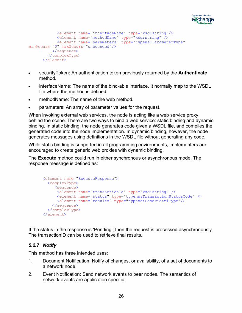
The Execute method could run in either synchronous or asynchronous mode. The response message is defined as:
<element name="ExecuteResponse"> <complexType> <sequence> <element name="transactionId" type="xsd:string" /> <element name="status" type="typens:TransactionStatusCode" /> <element name="results" type="typens:GenericXmlType"/> </sequence> </complexType> </element>
If the status in the response is ‘Pending’, then the request is processed asynchronously. The transactionID can be used to retrieve final results.
5.2.7 Notify
This method has three intended uses:
1. Document Notification: Notify of changes, or availability, of a set of documents to a network node.
2. Event Notification: Send network events to peer nodes. The semantics of network events are application specific.

27
3. Status Report: Notify the processing status of a previous service interaction to a requester.
5.2.7.1 Document Notification
The Notify method is different from Submit in that there are no document contents or attachments in the request message. The message simply informs a network node that some documents are ready to be retrieved; the service provider can, at its own convenience, download them at any time.
The format of the message is defined by the following WSDL segment:
<element name="Notify"> <complexType> <sequence> <element name="securityToken" type="xsd:string"/> <element name="nodeAddress" type="xsd:string"/> <element name="dataflow" type="xsd:NCName"/> <element name="messages" type="typens:NotificationMessageType" minOccurs="1" maxOccurs="unbounded"/> </sequence> </complexType>
</element>
For document notification, ‘messages.messageCategory’ element should be set to ‘Document’.
In addition to a transaction ID, which is returned immediately, the service provider is required to send an acknowledgement to the requester through email or a client provided callback method when the documents are downloaded, be it successful or not.
It is highly recommended that service providers use a quality control strategy to detect transmission errors early, and retry multiple times when necessary. Nodes are required to provide detailed transaction logs that contain all transaction records, either succeeded or failed. It is also recommended that activity logs be provided so that problem tracking and debugging are possible.
Partners may also use Notify to alert internal nodes (i.e. destination systems) that a document has been successfully received, scanned, and archived and is ready for loading. EPA’s CDX is considering this approach to alert its program system customers that documents are ready for loading.
5.2.7.2 Event Notification
The Notify method can also be used for sending event notifications. The following message indicates that a node has some planned outage time.
<typens:messages ObjectId="_307c5169-80b1-4231-a3ae-9dc6ed70d4f1"> <typens:messageCategory>Event</typens: messageCategory > <typens:messageName>NodeStatus</typens:messageName> <typens:status>Down</typens:status>

28
<typens:statusDetail>The REF Node is down between 2008-03-12 17:30:00 to 2008-03-12 18:00:00 for system for maintanence.</typens:statusDetail>
</typens:messages>
Note that the messageCategory is ‘Event’ in this case, which indicates that the event occurred at a node named REF.
5.2.7.3 Status Notification
A service provider may notify a requester of process status, i.e., file submission status, using the same notification message. A notification is a status notification if the messageCategory is ‘Status’. The ObjectId attribute should be the transaction ID for which the status is associated with.
Status notification is a complement of the GetStatus operation in that submission (or operation) status information can flow both ways. In some situations when documents have to go through a lengthy process, an impatient submitter may call GetStatus many times with no expected result. With status notification, however, the submitter is notified when the status of the submission changes. Active status notification can, in many situations, reduce network traffic and improve the quality of services.
5.2.8 Download
This method allows user to retrieve documents from a node. After being notified of the availability of a set of documents (through either the Notify method or other means) or per a pre-established schedule, the service provider needs to download and process the updated files.
Note that pulling can, depending on the nature of dataflow, be on demand or scheduled. Download operation can take place without prior notification in some exchange scenarios where document location and availability are predefined.
The Download method is a complement of Submit in that it facilitates bi-directional dataflows between nodes. In other words, a network node can be a sender at one time, but a receiver at another. With Download and Submit, the Exchange Network becomes symmetrical from the dataflow point of view. The following dataflow diagram shows a symmetrical network with three participating nodes. The Download data flows inbound from the requester point of view; the Submit data flows outbound.

29
Figure 8 – Bi-directional Flow Diagram with Submit and Download
5.2.9 NodePing
The NodePing method is designed for checking the availability of a network node. A network node is not available if:
A connection to the node cannot be established. The NodePing method on the client side would generally produce a network exception. There will be no response from the method call.
The response message is a SOAP fault, with a status code 500 for HTTP transport. This indicates that, although the server is up and running, it is not ready for Exchange Network services at this time.
5.2.10 GetServices
The GetServices method provides a means for nodes to describe its functionalities and publishing new services. From the consumer point of view, it is a discovery function for examining the capability of a node. Due to the dispersed nature of the network, a node may elect to support additional services, such as data services or web services callable using Query or Execute. The GetServices method allows a node to publish any type of service meta-information governed by an XML schema. However, a node must support the GetServices schema defined separately.
5.3 Exchange Network Business Processes
Partners will establish Exchange Network Business Processes by combining network service interactions (e.g. Authenticate and then Download). The following scenarios outlines typical ways services can be combined. They document who requests what of whom, and what kind of responses can be expected.

30
Example Scenario Example Usage
Simple Document Submission A state node transmits monthly report to EPA CDX.
Requested Download A State node notifies EPA/CDX of the availability of a monthly report for download.
Sending Network Events A node notifies a trading partner that it is going down.
Broadcasting Network Events A node notifies multiple trading partners that it is going down.
Retrieving Information using Query
A client application queries a node for “drill down” information on one monitoring location.
Executing external web services
A client application retrieves census data from a proxy node.
Performing Asynchronous Operations
One partner routinely requests a large or complex query from a partner node, which the partner services as resources permit.
Note in the scenario examples described below, the process of token validation is omitted for brevity. While all flows with EPA use the Network Authentication and Authorization Service (NAAS) for token validation, network partners can use the NAAS for other flows and/or may establish their own local security servers.
5.3.1 Simple Document Submission
In a simple document submission operation, a client wants to send an array of documents (i.e., one or more) for a specific dataflow to a network node. The procedure is outlined below:
1. The client sends an Authenticate message, with user ID and credential, to the node; the service provider returns a securityToken after successful authentication.
2. The client invokes the Submit method with a set of documents. If successful, the service provider returns a transaction ID for status tracking.
3. Optional. The client queries submission status using GetStatus, and resubmits if failed.
The whole process is represented in the following Unified Modeling Language (UML) activity diagram (Figure 9):

31
Authenticate
Submit
GetStatus
/ Accepted
/ Failed
/ Fault
/ Fault
Stop
Figure 9 – UML Activity Diagram for Simple Submissions
The diagram indicates that the client can resubmit the document if the submission failed during flow specific processing.
Note that if the client invokes the GetStatus method at a time when the securityToken has expired, it must call the Authenticate method again to obtain a valid securityToken.
Although a node would typically process the document in asynchronous mode, it could also elect to do it immediately, and return the status in the response message of Submit. A client should check the transaction status in the response and determine the proper next step.
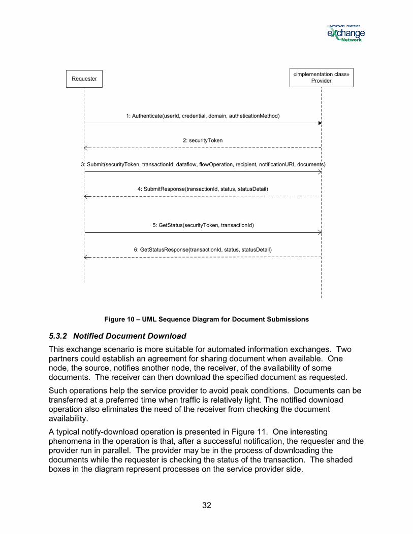
Figure 10 shows a UML sequence diagram for simple document submissions. The requester and the service provider are in synchronized operation mode using the request/response exchange model.
32
Requester«implementation class»
Provider
1: Authenticate(userId, credential, domain, autheticationMethod)
2: securityToken
3: Submit(securityToken, transactionId, dataflow, flowOperation, recipient, notificationURI, documents)
4: SubmitResponse(transactionId, status, statusDetail)
5: GetStatus(securityToken, transactionId)
6: GetStatusResponse(transactionId, status, statusDetail)
Figure 10 – UML Sequence Diagram for Document Submissions
5.3.2 Notified Document Download
This exchange scenario is more suitable for automated information exchanges. Two partners could establish an agreement for sharing document when available. One node, the source, notifies another node, the receiver, of the availability of some documents. The receiver can then download the specified document as requested.
Such operations help the service provider to avoid peak conditions. Documents can be transferred at a preferred time when traffic is relatively light. The notified download operation also eliminates the need of the receiver from checking the document availability.
A typical notify-download operation is presented in Figure 11. One interesting phenomena in the operation is that, after a successful notification, the requester and the provider run in parallel. The provider may be in the process of downloading the documents while the requester is checking the status of the transaction. The shaded boxes in the diagram represent processes on the service provider side.

33
Authenticate
Notify
GetStatus
/ Failed
/ Accepted
/ Fault
/ Fault
Download / Fault
A transition fork -Client and server run in parallel
A transition join -Download and GetStatusmust both be successful.
Figure 11 – UML Activity Diagram for Solicited Operations.
The sequence of Download operation is further illustrated in Figure 12. The process is outlined below:
1. Node A sends an Authenticate message to Node B.
2. Node B returns a securityToken if authentication is successful.

34
3. Node A invokes the Notify method and informs Node B about availability of a set of documents.
4. Node B acknowledges the notification and returns a transaction ID for status tracking.
5. Sometime later, perhaps when Node B has idle time, it initiates a download operation by authenticating itself with Node A.
6. Node A returns a securityToken, granting access to Node B.
7. Node B sends a Download message to Node A, asking for the documents.
8. Node A embeds or attaches the documents in the response message, and sends it.
9. To verify transaction status, Node A may call the GetStatus method to check the status of the submission.
10. Node B delivers the status string in the response message.

35
Requester«implementation class»
Provider
1: Authenticate(userId, credential, domain, autheticationMethod)
2: securityToken
4: NotifyResponse(transactionId, status, statusDetail)
9: GetStatus(securityToken, transactionId)
10: GetStatusResponse(transactionId, status, statusDetail)
3: Notify(securityToken, nodeAddress, dataflow, documents)
7: Download(securityToken, dataflow, transactionId, documents)
5: Authenticate(userId, cretdential, authenticationMethod, domain)
8: DownloadResponse(documents)
6: securityToken
Some time later...
Some time later...
Figure 12 – UML Sequence Diagram for Download Operations
5.3.3 Sending Network Events
Sending a network event is different from other operations in that the sender does not care about receiving a response, (i.e., it is typically a one-way operation.) If the underlying transport is HTTP/HTTPS, however, the receiver must send a response for it to be successful. This is because HTTP is a request-response protocol in which lack of
36
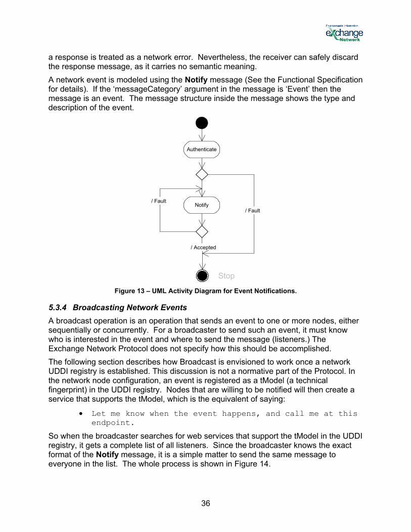
a response is treated as a network error. Nevertheless, the receiver can safely discard the response message, as it carries no semantic meaning.
A network event is modeled using the Notify message (See the Functional Specification for details). If the ‘messageCategory’ argument in the message is ‘Event’ then the message is an event. The message structure inside the message shows the type and description of the event.
Authenticate
Notify
/ Accepted
/ Fault
/ Fault
Stop Figure 13 – UML Activity Diagram for Event Notifications.
5.3.4 Broadcasting Network Events
A broadcast operation is an operation that sends an event to one or more nodes, either sequentially or concurrently. For a broadcaster to send such an event, it must know who is interested in the event and where to send the message (listeners.) The Exchange Network Protocol does not specify how this should be accomplished.
The following section describes how Broadcast is envisioned to work once a network UDDI registry is established. This discussion is not a normative part of the Protocol. In the network node configuration, an event is registered as a tModel (a technical fingerprint) in the UDDI registry. Nodes that are willing to be notified will then create a service that supports the tModel, which is the equivalent of saying:
Let me know when the event happens, and call me at this endpoint.
So when the broadcaster searches for web services that support the tModel in the UDDI registry, it gets a complete list of all listeners. Since the broadcaster knows the exact format of the Notify message, it is a simple matter to send the same message to everyone in the list. The whole process is shown in Figure 14.

37
Figure 14 – UML Activity Diagram for Event Broadcasting.
5.3.5 Retrieving Information Using Query
The Node Functional Specification defines a simple method, Query, for all data service requests. In a typical operation, a service provider would create named reports, or predefined information requests on the database server. The client sends a Query request message, including associated parameters, indicating which data service request or procedure to execute. A response with selected records is returned.
Given the generic database query capability, it is entirely possible to move relational data from one node to another. For instance, Node A may query daily updated records on Node B and insert, after mapping to its own data elements, the updated records into another table. The operations can all be conducted automatically, either by schedule or by a triggering event.
Figure 15 is a simple activity diagram for the Query operation. The diagram assumes that the requester knows what statements or procedures the provider supports. Given the discussion above, this may not be true in all situations due to the dynamic nature of web services. A node may suspend support for certain queries at one time, or add more queries at another. The Network Node Functional Specification defines a method, GetServices, for querying currently available data requests at a node. When invoked with Query as a parameter, the method returns a complete list of all requests available at that time.

38
Authenticate
Query/ Fault
/ Fault
Stop Figure 15 – UML Activity Diagram for Simple SQL Queries
Figure 16 shows a sequence diagram for the Query operation. The requester, in this case, asks the provider for a list of available queries. The requester node then sends a Query message using one of the queries from the list, and gets a result set back.
The requester should use paging capability (if supported) of the node by specifying the proper values of rowId and MaxRows parameters. For an interactive client, the maximum number of records should be about 2-3 screens of data. Using paging or chunking could improve the response time and system performance. It is also the mechanism for large amount of data exchanges.

39
Figure 16 – UML Sequence Diagram for Query Operations
5.3.6 Executing predefined Procedures
The Execute method is designed for accessing additional web services offered by a node or external service providers.
The procedure for executing an executable web service is outlined below:
1. The client sends an Authenticate message to log on to the network.
2. The client invokes the Execute method, passing all data to the service provider.
3. The service provider processes the requested procedure and returns a status of the execution.
The procedure is shown in the sequence diagram in Figure 17.

40
Figure 17 – UML Sequence Diagram for the Execute Operation
5.3.7 Performing Asynchronous Operations
This section discusses some of the basic configurations and scenarios for asynchronous operation using the Solicit method.
5.3.7.1 Network Configuration
Asynchronous data exchanges can take place in different ways based on the network configuration:
1. Pure Client: In this scenario, a requester (a client application) wants to conduct an asynchronous operation with a network node. Because the client can’t receive unrequested messages, it is the client’s responsibility to check the status of the transaction and download the document when available. The sequence of operations in this case is Solicit-GetStatus-Download.
2. Network Node: This is the case where one node, say Node A, (or a requester at the node) asks another node, Node B, to perform an asynchronous operation. After the operation is completed, Node B submits the result set to Node A. The sequence of operations in this case is Solicit-Submit. Since Node B is in the best position to know when the operation is done, it can send the result to the target node as soon as possible.
5.3.7.2 Procedures of Asynchronous Exchanges
5.3.7.2.1 Pure Client Interactions
Figure 18, UML sequence diagram shows a typical exchange under such situations:

41
Figure 18 – UML Sequence Diagram
The procedure is outlined as follows:
1. The requester sends a Solicit message to the provider, specifying the stored procedure to be executed and its parameters. The return URL parameter is set to empty because there is no node implementation at the requester side.
2. The provider marks the transaction as pending and returns a transaction ID immediately.
3. The provider processes the transaction some time later, and set the status of the transaction to either Completed or Failed based on the final result.
4. Meanwhile, the requester may occasionally check the status of the transaction by invoking the GetStatus method.
5. The requester downloads the document when the transaction is completed successfully. It may retry the whole procedure if failed.
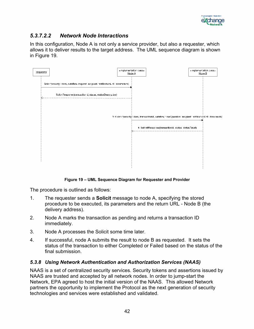
42
5.3.7.2.2 Network Node Interactions
In this configuration, Node A is not only a service provider, but also a requester, which allows it to deliver results to the target address. The UML sequence diagram is shown in Figure 19.
Figure 19 – UML Sequence Diagram for Requester and Provider
The procedure is outlined as follows:
1. The requester sends a Solicit message to node A, specifying the stored procedure to be executed, its parameters and the return URL - Node B (the delivery address).
2. Node A marks the transaction as pending and returns a transaction ID immediately.
3. Node A processes the Solicit some time later.
4. If successful, node A submits the result to node B as requested. It sets the status of the transaction to either Completed or Failed based on the status of the final submission.
5.3.8 Using Network Authentication and Authorization Services (NAAS)
NAAS is a set of centralized security services. Security tokens and assertions issued by NAAS are trusted and accepted by all network nodes. In order to jump-start the Network, EPA agreed to host the initial version of the NAAS. This allowed Network partners the opportunity to implement the Protocol as the next generation of security technologies and services were established and validated.

43
NAAS provides a set of standard web services across the Network, which can be easily accessed by Network users and services providers. All operations defined in NAAS must be conducted over a secure SSL channel using 128-bit encryption.
5.3.8.1 Network Authentication
5.3.8.1.1 Direct Authentication
Under direct authentication, the requester sends an Authenticate message to the NAAS and obtains a security token. Steps of direct authentication are outlined as follows:
1. The client sends an Authenticate message to NAAS, and obtains a security token when successful.
2. The client then sends a request to a network node (Node A, for instance) along with the security token.
3. Node A sends the security token to NAAS for validation and authorization.
4. The NAAS service verifies the security token. It returns a SOAP Fault message when validation fails and a positive response when validation succeeds.
5. Node A performs the operation only when the NAAS response is positive.
5.3.8.1.2 Delegated Authentication
In this application scenario, the requester sends an authentication message to a network node. The node then delegates the authentication request to the NAAS for processing.
This model simplifies client interactions with a network node because the client can perform all tasks at a single entry point (with a single WSDL file, perhaps). However, a small performance impact is expected because the overhead of routing the message to NAAS.
The following UML sequence diagram (Figure 20) shows interactions between the requester, the network node and the NAAS.

44
Requester«implementation class»
Network Node«metaclass»
Central Auth Service
Authenticate(userId, credential, domain, autheticationMethod)
securityToken
AnyOperation
AnyOperationResponse()
Validate(userId, credential, domain, securityToken, clientIp, resourceURI)
Authentication(userId, credential, domain, authenticationMethod)
securityToken
CentralAuth(userId, credential, domain, authenticationMethod, clientIp, resourceURI)
Authenticate(userId, credential, domain, autheticationMethod)
ValidateResponse()
AnyOperation()
AnyOperationResponse()
Validate(userId, credential, domain, securityToken, clientIp, resourceURI)
ValidateResponse()
Direct Authentication
Delegated Authentication
Figure 20 - Using the Network Authentication and Authorization Service
5.3.8.2 Network Authorization
Authorization is a process of granting access to resources to a user based on a certain access control policy. Given the authenticated user identity (the subject) and the security policy of a network resource (the object), the central authorization server would determine whether or not to grant access. The authorization service answers the following question:
Is operation X by principal Y on resource Z permitted?

45
NAAS performs the entitlement checking operations using a web method – Validate. The request message of the method is defined as follows:
<element name="Validate"> <complexType> <sequence> <element name="userId" type="xsd:string"/> <element name="credential" type="typens:PasswordType"/> <element name="domain" type="typens:DomainTypeCode"/> <element name="securityToken" type="xsd:string"/> <element name="clientIp" type="xsd:string"/> <element name="resourceURI" type="xsd:string"/> </sequence> </complexType> </element>
The service returns an OK message when the subject is authorized, a SOAP fault message otherwise.
Additional details of use of the NAAS for authorization can be found in the NAAS Security Specification.

46
6 Extended Business Exchange Scenarios
Network Node Functional Specification v2.1 allows more complex and advanced exchange patterns that were not available in versions prior to 2.0. This section discusses the exchange scenarios that could expand the scope of v2.1 services to meet much wider application requirements.
6.1 Large Payload Exchanges
In certain applications, a network node A may need to exchange large amount of data with another node (node B). Sending such data as a single payload could either exceed network capability or go beyond the resource limitation on the servers.
The paging (positioned fetching) feature in the Query method could be used to reliably stream data in small packets from one node to another in an extended period of time. For this to happen, the source node of the data would provide a service request that supports paging using rowId and maxRows. The data exchange is outlined as follows:
1. The destination node B initiates a request to node A using the predefined services request. The maxRows parameter is set to a moderate value, and the rowId is initialized to 0.
2. Node A executes the service request and returns a result set if successful. It may return less than the requested number of rows based on configuration, but should not exceed the number.
3. Node B processes the result set and loads it into the database. It then checks the lastSet flag, it adds the rowCount to the rowId parameter and goes back to step 1 to repeat the process until the lastSet flag is true.
Depending on how long it takes to transfer all records, there might be records changed during the data exchange. This can be dealt by re-synchronizing the datasets if necessary. The issue can be eliminated by performing the operation during weekend or after business hours, or using the Solicit method to collect the entire result set.
6.2 Automated Data Retrieval
In the data submission process using Submit, it typically involves a user manually logging in to a node and delivering the data online. The entire process can be automated if the source of the data and the destination are both network nodes.
The two parties may establish an agreement in which the destination node, such as CDX, is responsible for collecting the data proactively on a scheduled basis. The data exchange process is outlined below:
1. The data collector node triggers the process by invoking the Solicit method on the source node where the data resides. The requestor provides the collector’s node address in the ‘recipients’ parameter, indicating where the results should be delivered.
2. The source node responds with a transaction ID which will be recorded by the requestor with a status ‘Pending’.

47
3. The source node runs the requests asynchronously and constructs the XML instance document. If successful, it submits the document to the specified recipient address; otherwise, it notifies the recipient the transaction was not successful with a status code and the reason of the failure.
4. The data collector node receives the XML document and processes it as needed.
To improve reliability, the data collector may retry failed attempts several times before declaring operation failure.
Note that for the entire process to be successful the data collector must be authorized by the source node to perform the Solicit operation; and the source node must be authorized by the data collector to do data submissions. The access control policies can be established on NAAS.
6.3 Point-to-Point Exchanges
In older versions of the Exchange Network Protocol, information exchanges typically occurred between a user (consumer) and a machine (service provider). Versions 2.0 and higher expand the exchange scope to point to point, or user to user.
The point-to-point exchange is made possible through the recipient parameter in the Submit method, which imposes a delivery mandate to the service provider for sending the document to intended receiver. The recipient could be another node, a user, or even a service provider outside of the Exchange Network.
The user-to-user data exchange scenario can be roughly outlined as follows:
1. A user (sender) submits a document to a node, indicating the destination by specifying the recipient email address.
2. The node returns a transaction ID to the sender and marks the transaction as pending.
3. The node processes the document as needed, such as validating and transforming the document. It then sends an email message, with transaction ID and other necessary information, to the receiver, notifying the availability of the document.
4. The recipient authenticates against the node and invokes the Download method to retrieve the document.
5. The node checks the validity of the receiver’s credential and performs necessary access control. It sends the document to the recipient and marks the transaction as ‘Complete’.
6. The node sends a notification email to the sender, informing the final delivery of the document.
One of the important features in such exchanges is that the document is exchanged through a very secure channel. The document is encrypted over SSL and both the sender and receiver are authenticated by the network security services.

48
To further tighten access control over such exchanges, the node should give a special dataflow identifier, and then use NAAS access control policies to regulate who can send and who can receive.
6.4 Data Flow with Notification and Delivery
This exchange pattern is very similar to the point-to-point exchange except that the exchange is conducted machine to machine.
There are three nodes that are involved in the data exchanges:
Source Node: This is the node that owns the data to be exchanged. In order to conduct automated exchanges, it may have a timer or scheduler that triggers the process.
Proxy Node: This is the broker or delegator between the source node and target node. It typically has a more complex business process (dataflow process). From the source node point of view, it is the only way to reach the target node.
Target Node: This is the receiver node. It typically sits behind firewalls and does not respond to other requests except from the Proxy Node. This node may be responsible for loading information into a database system.
This is the network configuration that is very common in the state to federal government data exchanges. In many regulated environmental information exchanges, the Source Node is a state node, the Proxy Node is the CDX and the Target Node is the backend node for a program office.
The data exchange is through the Submit method and it is described below:
1. A timer or scheduler triggers an automatic submission process. The source node constructs an XML instance document for a configured dataflow, and then submits to the proxy node. The ‘recipient’ parameter is the address of the target node and the ‘notificationURI’ contains the source node address for receiving status notification.
2. The proxy node receives the document and returns a transaction ID and current status to the source node. The source node creates a transaction associated with the submission using the transaction ID.
3. The proxy node processes the transaction according to business requirements, and delivers the document to the target node through a special security arrangement. The transaction ID is provided to the target for transaction management and tracking.
4. The target node processes the data and sends a report to the proxy, indicating the status of the transaction, and any error messages if the transaction failed.
5. The proxy node invokes the Notify method with the transaction status, and detailed description of error should the transaction fail.

49
Note that user authentication is omitted for clarity here. All nodes are required to be authenticated using their own credential. It is recommended that Secure Authentication Keys (SAK) be used, which ties credentials to an account ID and an IP address.
6.5 Ad Hoc Data Flows
Unlike regular dataflows which have a steady stream of data and lasts for long period of time, ad hoc dataflows deal with situations where there are sudden requirements for data exchanges in a relative short period of time. This is especially useful in certain emergency situations.
Ad Hoc dataflows lasts for only a specific period of time and will typically abandoned afterwards. The only way to deal with such exchanges is through configuration, not dataflow design and development due to time constraints. The Node 2.1 specification provides a mechanism where such exchanges can happen.
In this case, the data destination could be either a node or a user; and the source of the data is from multiple users:
1. The submitters send data to a node using the Submit method to a network node, indicating the final destination in the recipient parameter – either an email address or a node address.
2. The node processes the data submission and returns a transaction Id to the submitter. It then notifies the recipient the availability of the data, either through email (to a user) or through the Notify method (to a node).
3. The recipient downloads the data using the provided transaction ID.
The network node should configure a new dataflow identifier for the dataflow with minimal business process such as virus scanning, data validation and recipient notification. The dataflow could be removed at the end of the flow cycle.
Since the flow is ad hoc, there may not be XML schema available for incoming documents, so document validation could be optional. The ad hoc flow process is much simpler in such situations. The node can be understood as a secure conduit between the sender and receiver.
Ad hoc dataflow is really a special case of point-to-point exchanges, excepting that the ‘recipient’ is a single fixed point, and the transaction lifespan is much shorter.
6.6 Supporting Small Devices
Small devices such as handheld computers or smart phones could also be used in exchanging data with a network node. Due to limited capability and memory spaces, such devices can only exchange small, simple packets of data.
Data Submission: Small devices can only handle very limited data submissions, typically form-based data that collected from the fields. For those handheld devices that support web services, the data can be easily submitted to network nodes. However, the node must support synchronous process and return final transaction status immediately. This is possible because the amount of data is

50
very limited. It is also possible to build an HTML form to support data collection efforts where an HTTP server acts as a proxy for a network node.
Data Request: Data requests from small devices also need special handling. There are two approaches to reduce the size of data. The first approach is to create services that always return limited data, such as air quality data in a zip code region, or facility information in a small area. The second approach is to support query result paging where a device will only ask for a limit number of rows.
There are potentially many types of small devices not used directly by human beings, such as smart data sensors or environmental monitoring devices, which could send streams of data to a node in a fixed time interval.
6.7 Using External Web Services
The Network Node Functional Specification v2.1 provides avenues for accessing external web services through the node interface. A network node may act as a generic web service proxy and publish other web services through the Execute method.
A node client application, on the other hand, can perform dynamic binding to the external web services and pass required parameters to the Execute method. At runtime, the node would invoke the remote services and return a response message back to the client.
One of the key advantages of such web service invocations is that the client application does not need to generate or develop any new code in order to access external web services.
The process of invoking external web services can be outlined below:
1. The requester calls the GetServices method to retrieve a list of web services that can be invoked using the Execute method.
2. The node responds with a service description list which contains all binding information such as interface names, web method names and parameters.
3. The requester calls the Execute method based on the description, indicating the web method to be invoked and passing all required parameter values.
4. The node binds the parameter to the external method and calls the remote web services. It returns a transaction ID, status and results, which contains the response from the remote service.
5. The requester processes the response message from the node. If the status is pending, the request was processed asynchronously, and the results can be downloaded later when ready. If the status is complete or finished, the results element contains the response from the remote web services.
Note: if the remote service invocation failed, the node should forward the SOAP fault message to the original requestor.

51
7 Describing Network Services
Ultimately, the Exchange Network is a dynamically expanding set of environmental information services. This vision will require a sophisticated and machine-readable process for the description of services so that clients can use them immediately.
There are two basic languages for describing network node services: Web Service Description Language (WSDL) and Node Service Description Language (NSDL).
WSDL is a W3C specification that is widely adopted as the standard for describing web services. There are two versions of WSDL specifications, version 1.1 and version 2.0. At the time of this writing, WSDL 2.0 is still not widely implemented in all platforms. Therefore, the Network Node 2.0 WSDL file is based on WSDL 1.1.
The NSDL is a supplemental language that describes low-level details about service requests. Descriptions for the Query, Solicit and Execute method in the WSDL file are insufficient for service request invocation and parameter binding because they are defined as very generic web service operations.
NSDL contains three basic elements:
Node Description: The element contains node name, address, version, deployment environment and technical contact information.
Service Description: The element defines service name, type, dataflow and parameters.
Parameter Description: The element includes parameter name, type, occurrence and other restrictions.
There are two mechanisms where data services and other executable services can be published: The GetServices method and the Exchange Network Discovery Services (ENDS). All network nodes must support the GetServices, which returns an XML instance document of NSDL. The document should contain all services a node supports along with parameter definitions.
The ENDS, on the other hand, contains service descriptions of all network nodes. The detailed technical specification of ENDS is out of scope of this document. ENDS is a set of services hosted on a special Network Node, and service descriptions can be obtained through the Query method.
For applications that interact with only a single node, the GetServices method of the node should be used for discovery purposes. For applications that target multiple nodes, the Exchange Network Discovery Services should be used instead.
In order to reduce unnecessary network traffic, it is a best practice to cache NSDL documents locally for a period of time. The cache may be refreshed either manually or on a scheduled basis.

52
8 Security
A major requirement of the Protocol is that it facilitates and participates in establishing and maintaining secure communications. There are three parts to security: prevention, detection and response. The Network is responsible for providing for prevention through the mechanisms discussed below. The individual trading partners are responsible for providing for detection of and response to security breaches within their purview.
SOAP and web services have proven to be a powerful framework for creating distributed computing networks and for conducting large scale information exchanges. They are, at the same time, a big challenge to information security. Due to the nature of SOAP transports, which are based on public information exchange protocols for the Internet, web services open the doors for direct and indirect attacks from hackers and enemies alike. Web services without security measures are very vulnerable.
This section discusses available technologies for securing web services, and addresses security issues from three major areas: Authentication/Authorization, Confidentiality and Integrity.
8.1 Applicable Security Protocols
8.1.1 HTTP Security
HTTP offers some basic authentication services on the transport level. The HTTP Specification (RFC 2616 and RFC 2617) defines an authentication mechanism known as "Basic" authentication. A client is challenged to provide identification information if authentication is required. The client then sends user name and password in the Authentication header. At this time, the user credentials can be passed to the web service for verification.
A more secure but less popular HTTP authentication scheme is the Digest Auth. Instead of sending user passwords through the wire, Digest Auth sends an MD5 hash (a one-way hash algorithm that produces a "fingerprint" of the given data) of the user name, password, and other security elements to the server.
HTTP authentication schemes are considered weak in term of confidentiality. Information exchanges between client and server are clear text, which are subject to attacks. Therefore, HTTP authentication is not recommended for securing node operations.
8.1.2 SSL
Basic network security will be provided through SSL. Since its introduction in 1995, SSL has become the de facto way to secure communications between HTTP requesters and HTTP servers. It provides adequate confidentiality at the session layer, where data is encrypted by the senders and decrypted by the recipient using public key technologies. SSL, however, does not always provide a suitable method of authentication. Unlike B2C applications where the identity of a service provider is the main concern (client-side risk), client identities become the focus for web services

53
(server-side risk). Client side authentication through SSL, although possible, is always questionable due to the complexity of certificate management and the relatively high cost.
8.1.3 PKI
Public-key infrastructure (PKI) is the combination of software, encryption technologies, and services that verify and authenticate the validity of each party. PKIs integrate digital certificates, public-key cryptography, and certificate authorities into a network security architecture.
While PKI provides an effective, robust means of securing electronic communications and transactions, deploying and managing the technology remains a daunting challenge to many organizations, especially in a large-scale deployment.
8.2 Security Levels
There are four levels of security supported by the Exchange Network Protocol v2.1. All message structures will incorporate (be surrounded by and encoded in) the various security protocols associated with that security level.
8.2.1 Public Access
Public information requires no authentication or certification of integrity.
8.2.2 SSL with Client Authentication
Information requires some additional level of authentication and a higher level of integrity protection. It is protected through SSL plus application level client authentication (username and PIN). The Exchange Network Protocol v2.1 requires that this level of security must be implemented by all nodes participating in the network information exchange.
8.2.3 SSL with Dual-Authentication
Information requires bi-directional authentication and a higher level of confidentiality. It is often protected using SSL with dual authentication. SSL with dual-authentication will be required depending on the dataflow, but is not mandatory for all network transactions.
8.2.4 Digital Signature
Information requires non-repudiation and integrity protection in addition to privacy and authentication. Digital signature may be required by some dataflows. When required, it is strongly recommended that XML-Signature be used for digitally signing the documents, and the signature be inserted into the SOAP header part of the message under such situations.

54
8.3 Authentication and Authorization
All operations, except NodePing, in the Exchange Network Protocol v2.1 are restricted to registered users only. The restriction requires a user to be authenticated successfully before any other operations can be conducted.
Authentication is a process of establishing trust (i.e., who the remote party is and what kind of privilege it has). Authorization relies on a good authentication scheme to protect network resources.
Authentication is also necessary for establishing security policies based on users or user groups. It is also important for creating trusted relationships among network nodes (trusted peer relationship), so that highly confidential message exchanges, such as intrusion notifications, are possible between peers.
Authorization is a process of establishing entitlement of a subject. A user, although authenticated, may not be allowed to access certain network services based on a security policy. Given the authenticated user identity (the subject) and the security policy of a network resource (the object), a network node can determine whether or not to grant access. Authorization typically is a more complicate process than authentication; it is discussed further in the Network Node Security Guideline and Recommendations document.
To gain access to web services provided by network nodes, a user must first send an Authenticate message similar to the following:
<SOAP-ENV:Envelope xmlns:SOAP-ENV=" http://www.w3.org/2003/05/soap-envelope" xmlns:xsd="http://www.w3.org/2001/XMLSchema" xmlns:soap12="http://schemas.xmlsoap.org/wsdl/soap12/" xmlns:xsi="http://www.w3.org/2001/XMLSchema-instance" > <SOAP-ENV:Body> <typens:Authenticate xmlns:typens="http://www.exchangenetwork.net/schema/node/2"> <typens:userId>[email protected]</typens:userId> <typens:credential>********</typens:credential> <typens:domain>galaxy</typens:domain> <typens:authenticationMethod>digest</typens:authenticationMethod> </typens:Authenticate> </SOAP-ENV:Body> </SOAP-ENV:Envelope>
The Authenticate message contains four elements:
userId: User Id
credential: a password, a secure key value, or even a digital fingerprint, issued by the network node operator
domain: The domain of user identities. The Exchange Network users are in the ‘default’ domain.
55
authenticationMethod: The mechanism for verifying user account. The default authentication method is password. Please refer the Network Security Specification for other authentication methods.
Upon successful authentication, the network node returns a security token, otherwise known as the digital ticket that will expire after a predefined time period. The user then includes the security token in all subsequent request messages as a proof of identity.
A SOAP Fault message - Unknown User - is returned if authentication fails.
A securityToken is an opaque string that is meaningful only to its issuer. It is usually an encrypted string that contains information useful for the validation of the ticket, and incomprehensible to its holder. To prevent replay attack, it must contain a timestamp so that token expiration can be enforced.
A simple securityToken may contain the requester’s IP address, the user Id or profile name, a session ID for state tracking, and a timestamp for expiration. The result string is then encrypted and encoded using some secret algorithms.
A properly constructed securityToken can be highly secure. The issuer may validate the requester, the requester’s machine and the timestamp. A stolen ticket has to be used on the same host within a very limited time window in order to cause a security breach.
This authentication process is based on the assumption that user registration and authentication are system specific, and beyond the scope of this document.
8.4 Central and Federated Authentications
A securityToken may, ideally, be issued through a central authentication server or a central security management (CSM) service. This approach, based on the NAAS was proposed by the Node 1.1 group for initial network flows and it is also recommended for Network Node 2.1 by the Network Technologies Group (NTG).
This model has numerous advantages in several areas:
1. Simplified Implementation: Using CSM, state nodes can simply delegate all security related tasks to the CSM service. For instance, the implementation of the Authenticate method and validation of authentication token become simple SOAP service requests.
2. Enhanced Security: With central security services, security risks shift from distributed nodes to one CSM system. Defending the network services is much easier from one point than from many points.
3. Cost Effectiveness: Security systems and related products are costly. A CSM service can dramatically reduce acquisitions of such product at state nodes.
4. Highly Extensible: Upgrading security system to new technologies, e.g., from username/password to a PKI-based authentication using certificates, can be done relatively easily with the CSM system.

56
5. Single Sign-On (SSO): Since authentication and validation take place at a single node, the security token issued by CSM is applicable to all nodes in the network.
6. Security Monitoring: With CSM, it is possible to monitor all activities of the overall network from a single location. This is essential for intrusion detection and vulnerability management.
The tokens issued by CSM are recognized and honored by all participating network nodes in a trusted relationship. A central authentication server facilitates single sign-on. Users need only register or login once in order to access services provided by all network nodes.
In a federated authentication scheme, however, each node owns and manages a set of user identities locally, and each node is authorized to issue securityTokens. The securityTokens are recognized and honored by other nodes in a trusted group. A federated authentication scheme is a distributed authentication system where network nodes are autonomous, in that they have authoritative control over user identities registered at their site.
Single sign-on (SSO) can be achieved relatively easily in a centralized authentication environment. Figure 20 shows a simplified single sign-on configuration.
Figure 20 – Single Sign on Configuration

57
The process of SSO is outlined below:
1. The client sends a name and credential to the authentication server. The server returns a securityToken when successful.
2. The client then invokes a remote method on a network node, using the securityToken.
3. The node sends the securityToken to the authentication sever for verification.
4. The authentication server checks the securityToken, and returns either a positive or negative answer.
5. The node processes the request if the securityToken is valid.
Standards for establishing distributed trust relationships are currently under development. The Exchange Network Protocol v2.1 should incorporate such standards when available. Until then, a simple solution would be the use of a shared secret among network peers. The authentication node, Node A for instance, generates a session key using the secret, and then encrypts the securityToken using the session key. When the user presents the securityToken to Node B, the node can generate the same session key using the given secret, and decrypt the token.
This discussion is provided to illustrate the extensibility of security approach described in this protocol. It is expected, that in the first 12-18 months of node implementations, that the NAAS approach will suffice for state/tribal/EPA flows. Partners will likely extend this approach locally for flows with regulated entities and others.
Note the following sections provide additional discussion of security issues but are not normative parts of the Exchange Network Protocol v2.1.
8.5 Message Confidentiality
Confidentiality is assured in most situations where messages are delivered through HTTPS transport. There are several situations; however, message may be compromised during transaction if not encrypted:
1. Use of transports such as SMTP or FTP.
2. Use of WS-Routing when messages travel over intermediaries.
It is strongly recommended that messages be encrypted using XML-Encryption under such application scenarios.
8.6 Message Integrity and Non-Repudiation
SOAP message integrity can be protected using digital signatures, which assures that contents of a document were not tampered with during transition. Contrary to the popular belief that digital signature offers more protection than encryption, signature and encryption are actually integral parts of one thing: information security. Encryption only hides contents of a document; the contents can still be altered during transition. On the other hand, a digitally signed document without encryption is similar to sending an open letter without sealing it.

58
Another very important aspect of digital signature is non-repudiation. Some documents may require a digital signature to be considered valid by certain dataflows from a legal point of view. Digital signature is no longer an optional feature in such situations.
The WS-Security specification, proposed by IBM and Microsoft, defines a set of processes and rules that applications must follow in order to be compliant and interoperable. It is desirable that the SOAP stack provider supplies an implementation of WS-Security as part of the SOAP toolkit.
For messages with attachments, calculation of digest should include all attached files. In other words, both the SOAP main message part and attachments should be protected by signing a combined digest of all parts.
An alternative approach is to generate a signature for each individual part, body and attachments, and insert multiple signatures in the SOAP message header. The approach adds extra processing in the SOAP header, but allows more flexible signature verification. Signatures, when present in a SOAP header, must have the mustUnderstand attribute set to true. Validation of signatures is mandatory on the receiver end.
The following SOAP header shows a dynamically generated digital signature:
<SOAP-ENV:Header>
<SOAP-SEC:Signature xmlns:SOAP-SEC="http://schemas.xmlsoap.org/soap/security/2000-12" SOAP-ENV:mustUnderstand="1">
<Signature xmlns="http://www.w3.org/2000/09/xmldsig#">
<SignedInfo>
<CanonicalizationMethod Algorithm="http://www.w3.org/TR/2001/REC-xml-c14n-20010315"/>
<SignatureMethod Algorithm="http://www.w3.org/2000/09/xmldsig#rsa-sha1"/>
<Reference URI="#Body">
<Transforms><Transform Algorithm="http://www.w3.org/TR/2001/REC-xml-c14n-20010315"/></Transforms>
<DigestMethod Algorithm="http://www.w3.org/2000/09/xmldsig#sha1"/><DigestValue>9r1eQL2syybnZXfx5wOECvl5nrs=
</DigestValue></Reference>
</SignedInfo>
<SignatureValue>MIIHbAYJKoZIhvcNAQcCoIIHXTCCB1kCAQExCzAJBgUrDgMCGgUAMIIByQYJKoZI
jUVNX7rDA=
</SignatureValue>
<KeyInfo>
<KeyName>soapclient.com</KeyName>

59
<KeyValue>BgIAAACkAABSU0ExAAQAAAEAAQBHednVT1COLGAohJZqB8R1qRUptRQbpWRhSZKG
GMmTU3s5m5TNe4iY4oP1/NxrjXCE7PjRX062y7mAKdkj55FcvDMhTcVLF5O5xJTO
SVY5j8tcVpkTFKFKS3UXcJ1nyx+9UvwzGNzhKMgF8GIDHT58ZGz3yjbzb3VmwmmW
0cdJvw==
</KeyValue>
</KeyInfo>
</Signature>
</SOAP-SEC:Signature>
</SOAP-ENV:Header>
The signature value is truncated for clarity. In this digital signature, the signer provided not only a signature value encrypted using a private key, but also a public key (in the KeyValue element) for decrypting the signature. The document is thus self-contained, verifiable by anyone who knows how to process a signature.

60
9 References
1. Exchange Network Functional Specification, Prepared for EPA by CSC, March 14, 2003.
2. Advanced SOAP for Web Development, Dan Livingston, Copyright 2002, Prentice Hall PTR, Upper Saddle River, NJ, 07458.
3. Web Services Essentials, Ethan Cerami, Copyright 2002, O’Reilly & Associates, Sebastopol, CA, 95472.
4. Programming Web Services with SOAP, James Snell, Doug Tidwell, Paul Kulchenko, Copyright 2002, O’Reilly & Associates, Sebastopol, CA, 95472.
5. XML Boot Camp Training Manual, TRG/Node 1.0 XML BOOT CAMP, June 10-11, 2002, SAIC, LMI, enfoTech, Philadelphia, PA.
6. Message Service Specification, Version 2.0 rev C, OASIS ebXML Messaging Services Technical Committee, February 2002.
7. W3C Node "Simple Object Access Protocol (SOAP) 1.1", May 22, 2000. (See http://www.w3.org/TR/2000/NOTE-SOAP-20000508/).
8. WS-Security, version 1.0. April 5, 2002.
9. W3C Working Draft "SOAP Version 1.2 Part 1: Messaging Framework", Martin Gudgin, Marc Hadley, Jean-Jacques Moreau, Henrik Frystyk Nielsen, 26 June 2002 (See http://www.w3.org/TR/2002/WD-soap12-part1-20020626.)
10. W3C Working Draft "SOAP Version 1.2 Part 2: Adjuncts", Martin Gudgin, Marc Hadley, Jean-Jacques Moreau, Henrik Frystyk Nielsen, 26 June 2002 (See http://www.w3.org/TR/2002/WD-soap12-part2-20020626.)
11. W3C Recommendation "Namespaces in XML", Tim Bray, Dave Hollander, Andrew Layman, 14 January 1999. (See http://www.w3.org/TR/1999/REC-xml-names-19990114/.)
12. W3C Node "SOAP Messages with Attachments", John J. Barton.
13. Satish Thatte, Henrik Frystyk Nielsen, December 11, 2000.
14. Internet Draft " Direct Internet Message Encapsulation (DIME)”, Henrik Frystyk Nielsen, Henry Sanders, Russell Butek, Simon Nash, June 17, 2002.
15. UDDI Version 3 Specification - http://uddi.org/pubs/uddi-v3.00-published-20020719.htm, July 19, 2002.
16. W3C Node “Web Services Description Language (WSDL) 1.1”, Erik Christensen, Francisco Curbera,Greg Meredith, Sanjiva Weerawarana, March 15, 2001 (See http://www.w3.org/TR/wsdl).