network interface card user’s...
TRANSCRIPT

Network Interface Card User’s Manual
SL4M™ and T4M™ RFID Smart Label and Thermal Printer

READ THIS SOFTWARE LICENSE AGREEMENT BEFORE USING THIS PRINTER
Software License AgreementCAREFULLY READ THE FOLLOWING TERMS AND CONDITIONS BEFORE USING THIS PRINTER. USING THIS PRINTER INDICATES YOUR ACCEPTANCE OF THESE TERMS AND CONDITIONS. IF YOU DO NOT AGREE TO THESE TERMS AND CONDITIONS, PROMPTLY RETURN THE PRINTER AND ALL ACCOMPANYING HARDWARE AND WRITTEN MATERIALS TO THE PLACE YOU OBTAINED THEM, AND YOUR MONEY WILL BE REFUNDED.Definitions“Software” shall mean the digitally encoded, machine-readable data and program. The term “Software Product” includes the Software resident in the printer and its documentation. The Software Product is licensed (not sold) to you, and Printronix, Inc. either owns or licenses from other vendors who own, all copyright, trade secret, patent and other proprietary rights in the Software Product.License1. Authorized Use. You agree to accept a non-exclusive licenseto use the Software resident in the printer solely for your own customary business or personal purposes.
2. Restrictions. a. To protect the proprietary rights of Printronix, Inc., you
agree to maintain the Software Product and other proprietary information concerning the typefaces in strict confidence.
b. You agree not to duplicate or copy the Software Product.
c. You shall not sublicense, sell, lease, or otherwise transfer all or any portion of the Software Product separate from the printer, without the prior written consent of Printronix, Inc.
d. You may not modify or prepare derivative works of the Software Product.
e. You may not transmit the Software Product over a network, by telephone, or electronically using any means; or reverse engineer, decompile or disassemble the Software.
f. You agree to keep confidential and use your best efforts to prevent and protect the contents of the Software Product from unauthorized disclosure or use.
3. Transfer. You may transfer the Software Product with the printer, but only if the recipient agrees to accept the terms and conditions of this Agreement. Your license is automatically terminated if you transfer the Software Product and printer.
Limited Software Product WarrantyPrintronix, Inc. warrants that for ninety (90) days after delivery, the Software will perform in accordance with specifications published by Printronix, Inc. Printronix, Inc. does not warrant that the Software is free from all bugs, errors and omissions.RemedyYour exclusive remedy and the sole liability of Printronix, Inc. in connection with the Software is replacement of defective software with a copy of the same version and revision level.
D1
2
3
4
5TTtPaWodUUrC(drAYABBCABPT
isclaimer of Warranties and Limitation of Remedies. THE PARTIES AGREE THAT ALL OTHER WARRANTIES,
EXPRESS OR IMPLIED, INCLUDING WARRANTIES OF FITNESS FOR A PARTICULAR PURPOSE AND MERCHANTABILITY ARE EXCLUDED. Printronix, Inc. does not warrant that the functions contained in the Software will meet your requirements or that the operation of the Software will be uninterrupted or error free. Printronix, Inc. reserves the right to make changes and/or improvements in the Software without notice at any time.
. IN NO EVENT WILL PRINTRONIX, INC. BE LIABLE FOR LOST PROFITS, LOST DATA, BUSINESS INTERRUPTIONS, OR ANY OTHER DIRECT, INDIRECT, INCIDENTAL OR CONSEQUENTIAL DAMAGES ARISING OUT OF THE USE OF OR INABILITY TO USE THIS PRODUCT, EVEN IF HAS BEEN ADVISED OF THE POSSIBILITY OF SUCH DAMAGES, OR ANY DAMAGES CAUSED BY THE ABUSE OR MANIPULATION OF THE SOFTWARE. SOME STATES DO NOT ALLOW THE EXCLUSION OR LIMITATION OF LIABILITY FOR CONSEQUENTIAL OR INCIDENTAL DAMAGES, SO THE ABOVE LIMITATION MAY NOT APPLY TO YOU.
. Printronix, Inc. will not be liable for any loss or damage caused by delay in furnishing a Software Product or any other performance under this Agreement.
. Our entire liability and your exclusive remedies for our liability of any kind (including liability for negligence except liability for personal injury caused solely by our negligence) for the Software Product covered by this Agreement and all other performance or nonperformance by us under or related to this Agreement are limited to the remedies specified by this Agreement.
. California law governs this Agreement.ermination of License Agreementhis License shall continue until terminated. This license may be
erminated by agreement between you and Printronix, Inc. or by rintronix, Inc. if you fail to comply with the terms of this License nd such failure is not corrected within thirty (30) days after notice. hen this License is terminated, you shall return to the place you
btained them, the printer and all copies of the Software and ocumentation..S. Government Restricted Rightsse, duplication or disclosure by the Government is subject to
estrictions as set forth in the Rights in Technical Data and omputer Software clause at FAR 242.227-7013, subdivision (b)
3) (ii) or subparagraph (c) (1) (ii), as appropriate. Further use, uplication or disclosure is subject to restrictions applicable to estricted rights software as set forth in FAR 52.227-19 (c) (2).cknowledgement of Terms and ConditionsOU ACKNOWLEDGE THAT YOU HAVE READ THIS GREEMENT, UNDERSTAND IT, AND AGREE TO BE BOUND Y ITS TERMS AND CONDITIONS. NEITHER PARTY SHALL BE OUND BY ANY STATEMENT OR REPRESENTATION NOT ONTAINED IN THIS AGREEMENT. NO CHANGE IN THIS GREEMENT IS EFFECTIVE UNLESS WRITTEN AND SIGNED Y PROPERLY AUTHORIZED REPRESENTATIVES OF EACH ARTY. BY USING THIS PRINTER, YOU AGREE TO ACCEPT HE TERMS AND CONDITIONS OF THIS AGREEMENT.

Network Interface Card User’s Manual SL4M™ and T4M™ RFID Smart Label and Thermal Printer

This document contains proprietary information protected by copyright. No part of this document may be reproduced, copied, translated or incorporated in any other material in any form or by any means, whether manual, graphic, electronic, mechanical or otherwise, without the prior written consent of Printronix®.
Printronix makes no representations or warranties of any kind regarding this material, including, but not limited to, implied warranties of merchantability and fitness for a particular purpose. Printronix shall not be held responsible for errors contained herein or any omissions from this material or for any damages, whether direct or indirect, incidental or consequential, in connection with the furnishing, distribution, performance, or use of this material. The information in this manual is subject to change without notice.
Copyright 2008, 2013 Printronix, Inc. All rights reserved.

Trademark AcknowledgementsPortions of this manual used by permission of Wyndham Technologies, Inc. Copyright 1991-1999 Wyndham Technologies Inc.
SL4M/T4M are trademarks of Printronix, Inc.
IGP, LinePrinter Plus, PGL, Network Interface Card, and Printronix are registered trademarks of Printronix, Inc.
AIX, AS/400, NetView, and OS/2 are registered trademarks, and AFP, Intelligent Printer Data Stream, IPDS, Print Services Facility, and PSF are trademarks of International Business Machines Corporation.
Netscape, Netscape Navigator, and the Netscape Communications logo are trademarks of Netscape Communications Corporation.
Code V is a trademark of Quality Micro Systems, Inc.
Unix is a registered trademark of X/Open Company Limited.
Microsoft, MS-DOS, Windows, Windows 95, Windows 98, Windows Me, WIndows NT, Windows 2000 and Windows Vista are registered trademarks of Microsoft Corporation.
Novell and NetWare are registered trademarks of Novell, Inc.
PostScript is a registered trademark of Adobe Systems Inc.
FTP Software and OnNet are trademarks or registered trademarks of FTP Software, Inc.
NetManage and Chameleon are trademarks or registered trademarks of NetManage, Inc.
Frontier Technologies and SuperTCP are trademarks or registered trademarks of Frontier Technologies Corporation.
Solaris is a registered trademark of Sun Microsystems, Inc.
HP-UX is a registered trademark of Hewlett-Packard Company.
DG/UX is a registered trademark of Data General Corporation.
LINUX is a registered trademark of Linus Torvalds.
Ultrix is a registered trademark of Digital Equipment Corporation.
IRIX is a registered trademark of Silicon Graphics, Inc.


Table of Contents
1 Introduction .............................................. 13Overview ...............................................................................13
What Is The NIC?.............................................................13What Special Features Are Available?.............................14
Logical Printer Architecture ...................................................15Destinations/Queues........................................................17Models..............................................................................17Speed Setting for 10/100Base-T......................................19
Conventions Used In This Manual ........................................20Notes And Notices.................................................................21
2 Installation And Configuration .................. 23Installation .............................................................................23
Connecting To The Network ............................................23Configuration Tools ...............................................................23
Configuration Using The Control Panel............................24NIC Verification ................................................................26Wireless NIC Configuration Using The Control Panel ............................................................27HTML Forms ....................................................................32Telnet ...............................................................................35Remote Shell....................................................................35Setup Through Data Stream ............................................36Printer Setup Wizard ........................................................36
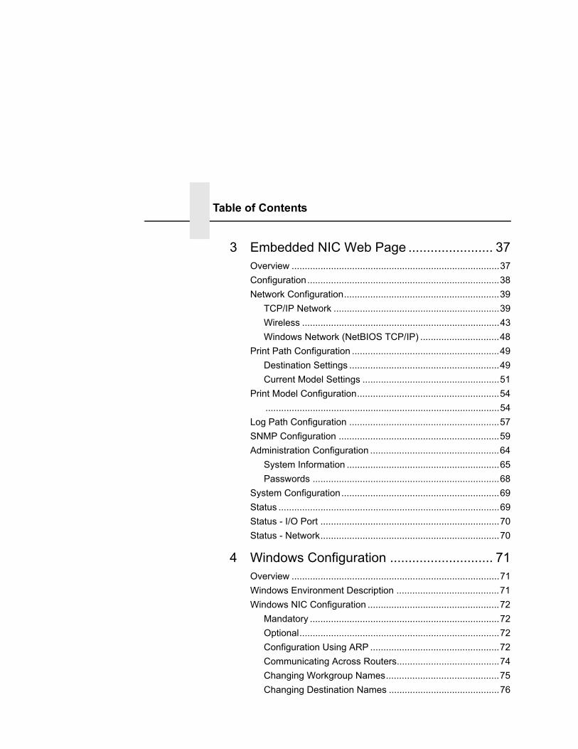
Table of Contents
3 Embedded NIC Web Page ....................... 37Overview ...............................................................................37Configuration.........................................................................38Network Configuration...........................................................39
TCP/IP Network ...............................................................39Wireless ...........................................................................43Windows Network (NetBIOS TCP/IP) ..............................48
Print Path Configuration ........................................................49Destination Settings .........................................................49Current Model Settings ....................................................51
Print Model Configuration......................................................54.........................................................................................54
Log Path Configuration .........................................................57SNMP Configuration .............................................................59Administration Configuration .................................................64
System Information ..........................................................65Passwords .......................................................................68
System Configuration............................................................69Status ....................................................................................69Status - I/O Port ....................................................................70Status - Network....................................................................70
4 Windows Configuration ............................ 71Overview ...............................................................................71Windows Environment Description .......................................71Windows NIC Configuration ..................................................72
Mandatory ........................................................................72Optional............................................................................72Configuration Using ARP .................................................72Communicating Across Routers.......................................74Changing Workgroup Names...........................................75Changing Destination Names ..........................................76

Table of Contents
Windows Host Configuration .................................................78Printer Driver Setup Wizard .............................................78
5 Unix Configuration.................................... 83Overview ...............................................................................83Unix Environment Description ...............................................83Unix NIC Configuration..........................................................84
Mandatory ........................................................................84Optional............................................................................84Using ARP........................................................................84Using RARP.....................................................................86Using BOOTP ..................................................................87Communicating Across Routers.......................................88
Unix Host Configuration ........................................................89Manual System V Host Setup ..........................................89
NIC Installation on HP-UX.....................................................90Solaris 2.6 – 7 NIC Setup......................................................91
Manual LPR/LPD Host Setup...........................................92NIC Configuration for AIX 4..............................................93AIX Remote Queue Time–Out Setting .............................95Printing From AIX.............................................................95Printing With FTP .............................................................96Direct Socket Printing.......................................................97
6 AS/400 Configuration, ASCII Printer ........ 99Overview ...............................................................................99Configuring AS/400 For ASCII Using TCP/IP......................101
Configuring With ADDTCPIFC .......................................101Configuring A Router Definition With ADDTCPRTE ......103Configuring A Local Domain And Hostname..................103Configuring A TCP/IP Host Table Entry .........................103
Configuring The AS/400 For Printing ..................................104Setting Up Printing For ASCII Files................................104
Verify Printing On AS/400 ...................................................110
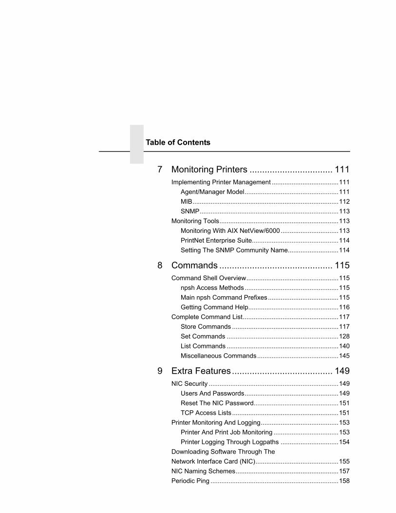
Table of Contents
7 Monitoring Printers ................................. 111Implementing Printer Management .....................................111
Agent/Manager Model....................................................111MIB.................................................................................112SNMP.............................................................................113
Monitoring Tools..................................................................113Monitoring With AIX NetView/6000................................113PrintNet Enterprise Suite................................................114Setting The SNMP Community Name............................114
8 Commands ............................................. 115Command Shell Overview...................................................115
npsh Access Methods....................................................115Main npsh Command Prefixes.......................................115Getting Command Help..................................................116
Complete Command List.....................................................117Store Commands ...........................................................117Set Commands ..............................................................128List Commands ..............................................................140Miscellaneous Commands.............................................145
9 Extra Features........................................ 149NIC Security ........................................................................149
Users And Passwords....................................................149Reset The NIC Password...............................................151TCP Access Lists ...........................................................151
Printer Monitoring And Logging...........................................153Printer And Print Job Monitoring ....................................153Printer Logging Through Logpaths ................................154
Downloading Software Through The Network Interface Card (NIC)..............................................155NIC Naming Schemes.........................................................157Periodic Ping .......................................................................158
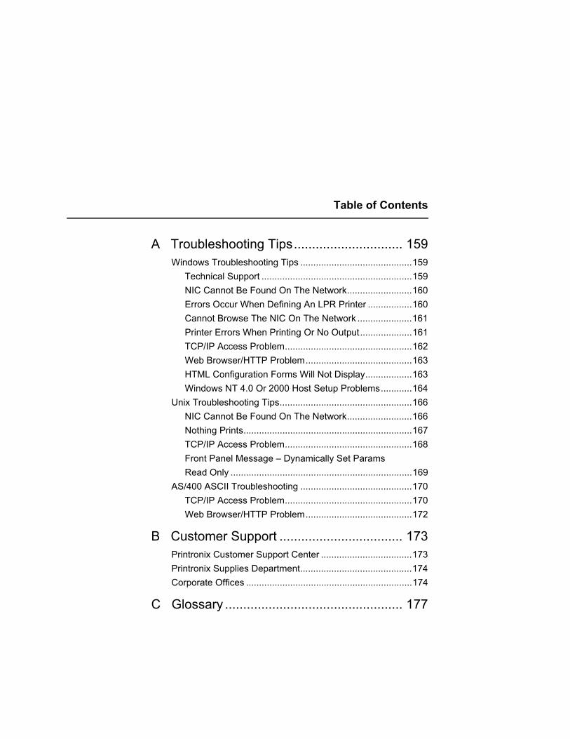
Table of Contents
A Troubleshooting Tips.............................. 159Windows Troubleshooting Tips ...........................................159
Technical Support ..........................................................159NIC Cannot Be Found On The Network.........................160Errors Occur When Defining An LPR Printer .................160Cannot Browse The NIC On The Network .....................161Printer Errors When Printing Or No Output....................161TCP/IP Access Problem.................................................162Web Browser/HTTP Problem.........................................163HTML Configuration Forms Will Not Display..................163Windows NT 4.0 Or 2000 Host Setup Problems............164
Unix Troubleshooting Tips...................................................166NIC Cannot Be Found On The Network.........................166Nothing Prints.................................................................167TCP/IP Access Problem.................................................168Front Panel Message – Dynamically Set Params Read Only ......................................................................169
AS/400 ASCII Troubleshooting ...........................................170TCP/IP Access Problem.................................................170Web Browser/HTTP Problem.........................................172
B Customer Support .................................. 173Printronix Customer Support Center ...................................173Printronix Supplies Department...........................................174Corporate Offices ................................................................174
C Glossary ................................................. 177

Table of Contents

1 Introduction
OverviewThis chapter introduces you to the Network Interface Card (NIC) architecture and special features, as well as providing information on installation and configuration tools.
What Is The NIC?The NIC allows you to attach printers on a local area network (LAN) rather than attaching them directly to a host system. Following simple configuration steps, these peripherals can be simultaneously shared with users on the network whether you are using TCP/IP or NetBIOS over TCP/IP.
The NIC package contains an Ethernet Interface to attach itself and the printer to the network. The NIC is supplied in one of two forms:
• an integrated Ethernet card
• an integrated wireless Ethernet card.
13

Chapter 1 Overview
What Special Features Are Available?The NIC offers an extensive list of features including:
• built-in HTML forms for easy cross-platform configuration
• availability of PrintNet Enterprise Suite (PNE), a remote management software utility
• a detailed and easy-to-use command shell built-in to the firmware
• multi-level configuration security through passwords, permission levels, and access lists
• WAN-wide communication access
• numerous printer logging methods (e.g., automatic email) to record printer errors and usage
• remote management through HTML forms, Telnet sessions, rsh/rcmd/remsh commands, SNMP, and pre-defined log methods
• extensive built-in troubleshooting tools
• built-in telnet and ping clients
• enable/disable protocols and destination services
• multiple destinations/queues for versatile printer manipulation and distinct print setups
• header and trailer strings to instruct printers on font, pitch, printing, etc.
• flexible naming conventions
• automatic network connection and frame type sensing
• simultaneous printing across all I/O ports and all supported protocols
• multiple network protocol support
14

Logical Printer ArchitectureThe NIC implements a logical printer architecture which gives the system administrator the ability to configure the print server to handle and act upon the print data in several ways. When a print job passes through the print server, there is a certain logical print path that it follows before it gets to the printer. Each logical print path consists of a sequence of logical steps where additional processing may be performed on the print data before it is sent to the printer. This ability to preprocess the print data before it is sent to the printer allows elimination of certain printing problems, or implementation of printer enhancements that may be difficult and time consuming to solve or introduce at the system, spool or queue level. The preprocessing ability is also simplistic to perform at the print server level.
The logical print path for a print job going through NIC consists of three different phases:
• Phase 1 - the host sends the job to a destination or queue on NIC (e.g. d1prn).
• Phase 2 - the print job passes through the associated “model” (e.g. model “m1”) on NIC for any extra processing associated with the model.
• Phase 3 - the processed print job is directed to the printer for output.
15

Chapter 1 Logical Printer Architecture
Phase 1 Phase 2 Phase 3
Host
Destination 4(d4prn)
Destination 2(d2prn)
Destination 3(d3prn)
Destination 1(d1prn)
Model 1(m1)
Model 2(m2)
Model 3(m3)
Model 4(m4)
Printer
Destination 8(d8prn)
Destination 6 (d6prn)
Destination 7(d7prn)
Destination 5(d5prn)
Model 5(m5)
Model 6(m6)
Model 7(m7)
Model 8(m8)
Figure 1. Print Path
16

Destinations/Queues
Destinations/QueuesFor every I/O port on NIC, there is at least one pre-defined logical print queue or destination to accept print jobs destined for it. This includes print jobs that are sent directly to the I/O port, such as port 9100. These queue or destination names are pre-defined but can be changed by the user.
ModelsFor every destination or queue, there is a pre-defined model associated with it. The model defines how the print job will be processed as it passes through to the printer. Models are a set of mini filters that can be used to modify the print data stream. The functions available for each model are as follows:
1. Insert carriage return after line feed
2. Insert a banner page before or after each print job
3. Insert header strings to
• specify form width
• specify form length
• print in landscape mode
• print in portrait mode
4. Insert trailer strings to
• reset the printer once the print job completes
• force the end of the job
• perform a form feed at the end of the data
17

Chapter 1 Logical Printer Architecture
5. Log one or all of the following information as each print job passes through the model.
• Job ID and username
• User ID and three messages per job about the start and finish
• Checksum value of the data transferred
• Miscellaneous messages from the printer
• Status of the printer based on the port interface signals
6. Load a specific printer configuration before processing a print job.
• Specify a printer configuration to be associated with a print queue.
• When a job is set to that print queue, the associated printer configuration will be loaded before the job is processed.
• Feature allows you to define up to eight unique and independent printer personalities in a single printer.
• Allows you to effectively have eight different printers in one.
Integrated NIC Card LED:
Table 1. Integrated NIC LED Indicator
STAT NET Indication Description
ON flashes Indicates activity
ON constant Indicates that the link is good at 10 Mbps
ON constant Indicates that the link is good at 100 Mbps
18

Speed Setting for 10/100Base-T
Speed Setting for 10/100Base-TWhen the router is set to auto-negotiation enable, the following is the correct behavior of the NIC with each setting:
1. 10mbps Half Duplex
Use parallel detection because the NIC is using force mode and thus has auto-negotiation disabled.
PORs to 10mbps Half Duplex. Resets to 10mbps Half Duplex. Reconnection at switch maintains 10mbps Half Duplex.
2. 10mbps Full Duplex
Use parallel detection because the NIC is using force mode and thus has auto-negotiation disabled.
PORs to 10mbps Full Duplex. Resets to 10mbps Full Duplex. Reconnection at switch maintains 10mbps Full Duplex.
3. 100mbps Half Duplex
Use parallel detection because the NIC is using force mode and thus has auto-negotiation disabled.
PORs to 100mbps Half Duplex. Resets to 100mbps Half Duplex. Reconnection at switch results in 100mbps Half Duplex.
4. 100mbps Full Duplex
Use parallel detection because the NIC is using force mode and thus has auto-negotiation disabled.
PORs to 100mbps Full Duplex. Resets to 100mbps Full Duplex. Reconnection at switch results in 100mbps Full Duplex.
5. NIC in Auto mode in 100mbps Full Duplex environment
Use auto-negotiation to the highest common local and remote capability, i.e. 100mbps Full Duplex in this case.
PORs to 100mbps Full Duplex. Resets to 100mbps Full Duplex. Reconnection at switch remains 100mbps Full Duplex.
19
Chapter 1 Conventions Used In This Manual
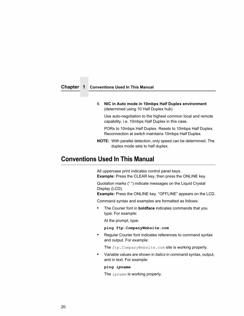
6. NIC in Auto mode in 10mbps Half Duplex environment (determined using 10 Half Duplex hub)
Use auto-negotiation to the highest common local and remote capability, i.e. 10mbps Half Duplex in this case.
PORs to 10mbps Half Duplex. Resets to 10mbps Half Duplex. Reconnection at switch maintains 10mbps Half Duplex.
NOTE: With parallel detection, only speed can be determined. The duplex mode sets to half duplex.
Conventions Used In This ManualAll uppercase print indicates control panel keys. Example: Press the CLEAR key, then press the ONLINE key.
Quotation marks (“ “) indicate messages on the Liquid Crystal Display (LCD). Example: Press the ONLINE key. “OFFLINE” appears on the LCD.
Command syntax and examples are formatted as follows:
• The Courier font in boldface indicates commands that you type. For example:
At the prompt, type:
ping ftp.CompanyWebsite.com
• Regular Courier font indicates references to command syntax and output. For example:
The ftp.CompanyWebsite.com site is working properly.
• Variable values are shown in italics in command syntax, output, and in text. For example:
ping ipname
The ipname is working properly.
20

Notes And NoticesFor your safety and to protect valuable equipment, read and comply with the notes included in this manual. A description follows:
NOTE: A Note gives you helpful information and tips about printer operation and maintenance.
21

Chapter 1 Notes And Notices
22

2 Installation And Configuration
InstallationThe NIC provides an RJ-45 connector for 10/100Base-T (UTP) networks.
Connecting To The NetworkTo attach the NIC to a network, plug the network cable into the NIC connector.
Configuration Tools
There are two parts to a NIC setup:
• Configuring the NIC so it can be seen on the network. This involves network-related settings (e.g., an IP address within TCP/IP environments) configured through the built-in command shell, npsh, or from the control panel.
• Configuring a host with a new printer so it knows how to send data to the NIC. Just being able to see the printer on the network does not mean you can automatically print to it. A host has to be told where to send the data.
NOTE: Some network environments do not require any network settings to be configured on the NIC. However, all network setups require configuration on the host end.
23

Chapter 2 Configuration Tools
The following methods are available for configuring the NIC:
• via the control panel (wired and wireless)
• HTML forms
• Telnet
• Remote Shell
• PTX_Setup
• Printer Setup Wizard, a host based wizard to simplify NIC configuration. This tool can be found on the CD supplied with the printer.
Configuration Using The Control PanelYou can set NIC settings from the printer control panel.
CAUTION When the printer is first powered on, the message “ETHERNET INITIALIZING” displays on the control panel. To prevent a loss of NIC configuration information, do not change the NIC settings before the message “ETHERNET READY” displays.
1. Power on the printer. The message “ETHERNET INITIALIZING” appears when the printer is powered on. Configuration can be done after the “ETHERNET READY” message appears.
2. Always print an ETHERNET test page before performing any updates or network configuration using the following steps:
a. Take the printer offline. When the printer LCD reads “OFFLINE,” press the Down Arrow and and ↵ (Enter) keys at the same time to unlcok the control panel.
b. Press the (Menu) key to enter Menu mode.
c. Press the Right Arrow key until DIAGNOSTICS appears.
d. Press ↵ (Enter) to enter the DIAGNOSTICS menu. The Printer Tests submenu is selected (highlighted).
e. Press the Right Arrow key until Ethernet Test appears and then press ↵ (Enter).
24
Configuration Using The Control Panel
3. From the front panel, navigate to the IP Address, Netmask (Subnet Mask), and Gateway Address menu options and enter the appropriate values. Refer to the User’s Manual on setting the network configuration.
4. After entering the desired settings, put the printer online and wait for the “ETHERNET READY” message to display on the front panel.
NOTE: If you do not put the printer online, the setting you just entered will not take effect. Do not turn the printer off until you see the “ETHERNET READY” message. If you turn the printer off before the new values are written to memory in the NIC, you will need to repower the printer and repeat steps 4 and 5 above immediately.
Placing the printer online triggers the printer to cycle power. All network settings take effect after the printer is back online and ETHERNET READY displays on the LCD.
NOTE: When the printer is moved from one network to another, the software cannot find the printer. To solve this problem, reset the NIC. After resetting the NIC, the software can find the printer, and the IP address can also be set in the NIC.
25

Chapter 2 Configuration Tools
NIC VerificationBefore performing the verification, you must connect the NIC to the network.
1. Print an Ethernet test page (following the steps on page 24) to verify the settings you made.
2. Verify the Netmask is correct in two locations on the E-NET test page:
• NETWORK INTERFACES
• TCP/IP ROUTING TABLE
The Netmask must be the same in both locations. For example, if the Netmask is listed as 255.255.255.0 in NETWORK INTERFACES and is listed as 255.255.255.255 in the TCP/IP ROUTING TABLE, they do not match and you must correct it for the Gateway. Also, if a Gateway Address was entered, verify that “xxx.xxx.xxx.xxx is alive” is printed under the Default Gateway Ping Test, where xxx.xxx.xxx.xxx is the Gateway Address. If a Gateway Address was not entered, the Default Gateway Ping test is not required and will not display on the page.
If the Netmask does not match, complete the following steps:
a. Place the printer offline.
b. Using the front panel, modify the Gateway value to 0.0.0.0. (non-configured).
c. Place the printer online and wait for the “ETHERNET READY” message to display.
d. Place the printer offline and enter the Gateway Address you desire.
e. Place the printer online and wait for the “ETHERNET READY” message. This saves the new Gateway Address.
Your NIC is now configured and connected to your network.
26

Wireless NIC Configuration Using The Control Panel
Wireless NIC Configuration Using The Control PanelNOTE: The Access Point must be configured according to the
manufacturer's installation guide. If applicable, the Access Point must also be configured to broadcast the country code to correctly configure the Wireless NIC.
To configure Wireless NIC card, configure the wireless IP address so they can be seen on the network. This includes several network related settings (e.g., an IP address within TCP/IP environments) configured through the built-in command shell, npsh, or from the control panel.
IP Address ConfigurationYou can set the wireless NIC IP settings from the printer control panel.
CAUTION When the printer is first powered on, the message “ETHERNET INITIALIZING” displays on the control panel. To prevent a loss of NIC configuration information, do not change the NIC settings before the message “ETHERNET READY” displays.
You need to set both the ethernet and wireless network IP addresses according to the TCP/IP environment that the printer is connected to. There are five parameters accessed from the printer control panel that are IP address related. These parameters are located in the "ETHERNET SETTING" menu and the "WLAN SETTING" menu:
• IP Address
This is the IP address of the NIC. It displays in four segments separated by periods, each of which can be set to any value in the range of 0 to 255.
• Subnet Mask
This is the subnet mask for the host IP. It displays in four segments separated by periods, each of which can be set to any value in the range of of 0 to 255.
27

Chapter 2 Configuration Tools
• Gateway Address
This is the gateway IP address of the NIC. It displays in four segments separated by periods, each of which can be set to any value in the range of of 0 to 255.
• IP Assignment
The IP Assignment menu contains the DHCP and BootP settings which are used to configure the NIC for either static or dynamic IP address assignment.
• DHCP
The DHCP option allows the NIC to obtain IP addresses when powering onto the network. The DHCP option can be configured to:
Enable – each time the NIC powers on, the host server automatically assigns the NIC a different address (if the IP address has not been previously assigned). The IP address will be displayed under Ethernet Setting and IP Address. Users will be prompted with Dynamic Address if attempting to change the value.
Disable – You choose the NIC IP address. After the selection, the IP Address remains fixed even after you reboot.
• BootP
The BootP option allows the NIC to obtain IP addresses from a BootP server. The BootP server can also provide additional information such as the default router/gateway address. The BootP option can be enabled or disabled similar to the DHCP option.
28

Wireless NIC Configuration Using The Control Panel
Wireless Parameter ConfigurationCertain parameters under WLAN SETTING must be configured to match the Access Point settings:
• Signal Strength
This menu displays the strength of the wireless signal.
NOTE: This is a display value only and cannot be changed.
• SSID Name
This is the Service Set Identifier which must be identical to the Access Point's SSID name. The SSID name can be configured to a maximum of 32 alphanumeric characters. The SSID name and alphanumeric characters are divided into three parts in the control panel menu as "SSID Name (01-15)", "SSID Name (16-30)" and "SSID Name (31-32)".
NOTE: When two or more consecutive space characters are used in the SSID, enclose it in a double quoted string;otherwise upon resetting the NIC, the SSID Name wil be saved in the Wireless NIC with only one space.
• Min Xfer Rate
Allows you to set the minimum speed at which the Wireless Option will accept a connection (in million bits per second).
This is the wireless transfer rate, and can be set to either “enable” or “disable.” It is set to “enable” when the operation mode is "Infrastructure" so that the NIC can automatically detect the optimal transfer rate. If the operation mode is "Ad Hoc" and the transfer rate is known, the user can enable or disable the corresponding transfer rate in the menus "Xfer Rate 1Mb", "Xfer Rate 2Mb", "Xfer Rate 5.5Mb" or "Xfer Rate 11Mb".
• Antenna
This is used to select the antenna for communication. It is recommended to set to Primary for the NIC to detect for optimal communication. It can also be set to Auxiliary. This setting must match the physical antenna connection attached to the Wireless NIC.
29

Chapter 2 Configuration Tools
• Power Mgmt
This option allows you to set power-save mode and sleep time. A value specifying the sleep time in milliseconds will be provided. If set to zero, power-save mode will be disabled.
• Transmit Power
This option allows you to specify the power level used by the wireless card to send network packets to the access point. Transmit power is specified as a percentage of full pwer (0 – 100%).
• Internat. Mode
When enabled, the Wireless option adapts to international frequency requirements in Europe.
• Auth Method
This feature allows the user to select the authentication method used for the wireless network interface. The options include Open, and Shared.
• Default WEP Key
The default key must match the Access Point's configuration. If the Access Point is configured to use "Open System", the default key should be set to 0. If the Access Point is configured to use 40-bit or 128-bit WEP encryption key, the encryption key must be set to the same setting as the Access Point's setting. See the following section on how to set up the encryption key. In addition, there are four keys (1-4) that an Access Point can use. If the Access Point is set to use key 1, the default key must be set to 1 to correspond to the Access Point's setting.
30
Wireless NIC Configuration Using The Control Panel
Encryption Key ConfigurationAs previously mentioned, there are four encryption keys that can be configured through the control panel. For each encryption key x (where x can be 1 to 4), the WEP Key x menus can be used to configure each key. The following submenus are under each WEP Key x menu:
• Key Format
This is the format of the key. It can be set to either ASCII or Hexadecimal.
• Key Width
This is the number of bits used for encryption. This can be set to either 40 Bits or 128 Bits and must match the Access Point's configuration.
• Byte 1...Byte 5 or Byte 1...Byte 13
These are the bytes that define the key value. If the "WEP Key x Width" is set to 40 Bits, the key values can be entered in the following 5 sub menus (BYTE 1, …, BYTE 5). If the "WEP Key x Width" is set to 128 Bits, the key values can be entered in the following 13 sub menus (BYTE 1, …, BYTE 13). The key values must configure to match the corresponding key in the Access Point's key configuration.
Equivalent Wireless NIC Configuration Using The Telnet Commandstore ifc 2 wlan ssid <network-name>
store ifc 2 wlan speed auto|(1 2 5 11 6 9 12 18 24 36 48 54)
store ifc 2 wlan antenna diverse|primary|aux
store ifc 2 wlan pmm on|off
store ifc 2 wlan txpwr (0-100)
store ifc 2 wlan opts [[-]intnl]
store ifc 2 wlan defkey disable|(1-4)
store ifc 2 wlan key <key-num> <key-sequence>
31

Chapter 2 Configuration Tools
store ifc 2 wlan auth open|shared
store ifc 2 wlan user <AUTH-USER-NAME>
store ifc 2 wlan pass <AUTH-PASSWORD>
store ifc 2 wlan profile <WIFI-PROFILE> <0...6>
The profile values that can be set are as follows:
0: 802.11b operation only 1: mixed 802.11b and 802.11g operation 2: mixed 802.11b and 802.11g operation without support for 5.5 and 11 Mbps basic rates 3: 802.11g only operation 4: test 802.11g operation 5: 802.11b only operation without support for 5.5 and 11 Mbps basic rates 6: mixed 802.11b and 802.11g operation with support for 5.5 and 11 Mbps basic rates
store ifc <IFNUM> wlan wpa disable | personal | enterprise
store ifc <IFNUM> wlan eap none | leap | peap | ttls
store ifc <IFNUM> wlan cipher disable | tkip | aes | tkip+aes
store ifc <IFNUM> wlan passphrase <WPA Pre-shared Key>
store ifc <IFNUM> wlan country <COUNTRY-CODE>
Refer to page 117 for the complete command set.
HTML FormsThe NIC settings can be configured over TCP/IP through a standard Web browser. The NIC Web pages provide a way to access some of the commands built into the print server.
NOTE: If a router is used, make sure a Gateway value is configured.
To access the NIC home page:
1. Make sure the print server has an IP address and Subnet Mask so it is recognizable on your TCP/IP network.
32
HTML Forms
2. Make sure your network station can successfully ping the NIC over the network.
3. Direct your Web browser to the URL: http://IPaddress (e.g., http://192.75.11.9) where IPaddress is the IP address of your NIC.
NOTE: If you cannot access the web page, refer to “Web Browser/HTTP Problem” on page 163.
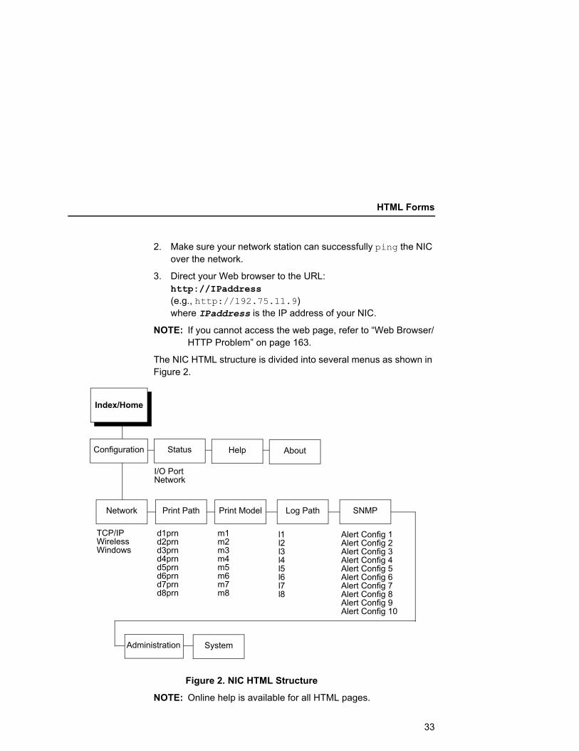
The NIC HTML structure is divided into several menus as shown in Figure 2.
Index/Home
Configuration
I/O Port Network
TCP/IP Wireless Windows
d1prn d2prn d3prn d4prn d5prn d6prn d7prn d8prn
m1 m2 m3 m4 m5 m6 m7 m8
Alert Config 1 Alert Config 2 Alert Config 3 Alert Config 4 Alert Config 5 Alert Config 6 Alert Config 7 Alert Config 8 Alert Config 9 Alert Config 10
Status Help About
Administration
SNMPPrint ModelPrint PathNetwork Log Path
l1 l2 l3 l4 l5 l6 l7 l8
System
Figure 2. NIC HTML Structure
NOTE: Online help is available for all HTML pages.
33

Chapter 2 Configuration Tools
Printer Status ScreenUsing the printer IP Address and any standard Web browser, you can check the status of the printer. Figure 3 shows the exact state of the printer by showing the printer LCD message. (This screen automatically refreshes every minute.)
Figure 3. Printer Status Screen
34
Telnet
Besides the HTML forms and software provided, the NIC internal command shell, npsh, can also be reached using Telnet, Remote Shell, and FTP:
TelnetA TCP/IP command that helps configure NIC settings remotely. A TCP/IP host starts a Telnet session with the print server and logs into the device command shell to alter and view settings.
Example:telnet 192.75.11.9
NOTE: The default User ID is root. There is no password by default, just press ENTER. If you have changed the default User ID and password, use the current User ID and the associated password instead of the defaults. For more information on setting passwords, refer to “NIC Security” on page 149.
Remote ShellA TCP/IP command that helps configure print server settings remotely. A TCP/IP host uses this command to remotely execute a single command on the NIC.
Example:rsh spike list prn
This command remotely executes the npsh command list prn on the NIC named spike.
35
Chapter 2 Configuration Tools
Setup Through Data StreamThe PTX_SETUP command can also be used to configure NIC settings through a printer data port (serial, parallel, etc.). This is done by creating a text file containing the PTX_SETUP command and NIC internal command shell (npsh) commands. The text file is then sent to the printer through a data port to perform the NIC configuration. The following is an example of a PTX_SETUP file that can be used to configure the NIC:!PTX_SETUP NIC_SETUP store net 1 addr 190.168.2.11 store ifc 2 wlan ssid “SomeLongString” store ifc 2 wlan defkey 2 END_NIC_SETUP PTX_END
Printer Setup WizardThis tool can be found on the CD that is included with the printer. Follow the instructions on the CD to install the wizard.
The wizard allows you to configure all wired and wireless NIC parameters via an easy-to-use graphical user interface.
After the NIC is configured, the wizard also allows you to configure other printer parameters as well.
36

3 Embedded NIC Web Page
OverviewThe NIC comes with a printer management tool that allows you to monitor, configure, and manage both the printer and its print job. The NIC comes with an embedded web server that allows System Administrators and users access to its printer management capabilities from a standard web browser.
The NIC printer’s IP address is used as a URL, similar to the URL of an Internet web page. When a web browser is activated and the printer’s IP address is entered, the printer’s embedded web server displays its home page, with links to the printer’s status and configuration settings.
All of NIC's configuration settings are protected by a password so unauthorized users cannot make changes. When you try to open any of the NIC 's configuration pages, you are asked for your user name and password.
NOTE: The default User ID is root. There is no password by default, just press ENTER. If you have changed the default User ID and password, use the current User ID and the associated password instead of the defaults. For more information on setting passwords, refer to “NIC Security” on page 149.
37

Chapter 3 Configuration
After you configure the NIC settings, and click the SUBMIT button on the related form, re-power the NIC to ensure the latest settings are in use. To reset the NIC, go to the System form under the Configuration Menu and click the REBOOT button.
The embedded NIC Web server gives you the ability to configure the network adapter, monitor printer status, and to manage print jobs. The NIC Web page structure is divided into several menus, as shown in Figure 2 on page 33
ConfigurationThe Configuration menu items allow you to configure the settings for the following items:
• Network - this menu item allows you to change the network setting for each protocol: TCP/IP, wireless, NetBIOS over TCP/IP.
• Print Path - this menu item allows you to change the name of the destination queues, and define how the print job will be preprocessed before printing. It allows you to select what information to log, and to specify the SMTP server’s IP address.
• Print Model - this menu item allows you to specify the printer name and model. It also allows you to select banner page types, filters, header and trailer strings, and printer configurations.
• Log Path - this menu item allows you to specify the logpath name, type, and port.
• SNMP - this menu item allows you to configure the SNMP trap manager settings. It also allows you to define the printer event types to monitor, and the e-mail address that should receive alert notifications.
• Administration - this menu item allows you to define or change the printer name, location, description, etc.. It also allows you to change the root and guest user passwords.
38

TCP/IP Network
• System - this menu item allows you to reboot the NIC, or restore its settings to the factory default.
Network ConfigurationThe network configuration allows you to specify the setting for each network protocol. Beside each protocol name is a checkbox which allows you to enable or disable each protocol depending on your network printing needs.
NOTE: TCP/IP is the only supported protocol which is always enabled.
TCP/IP Network
Figure 4. TCP/IP Network Configuration for Wired Ethernet
39

Chapter 3 Network Configuration
Figure 5. TCP/IP Network Configuration for Wireless Ethernet
InterfaceThe two edit fields contain the NIC's IP address and subnet mask. The check boxes enable the RARP, BOOTP, DHCP, DNS, and Persistent DHCP protocols, which are alternate methods of assigning IP addresses. On most networks, you want to enter a permanent IP address and subnet mask and disable RARP, BOOTP, and DHCP. However, if your network requires one of these, you should clear the IP address (and possibly the subnet mask) fields and ensure that the appropriate check box is selected.
Figure 6. Defining a Gateway Address for Wired Ethernet Routing
40

TCP/IP Network
Figure 7. Defining a Gateway Address for Wireless Ethernet Routing
Figure 8. TCP/IP Static Routes
41
Chapter 3 Network Configuration
RoutingThe routing table tells the NIC which router or gateway to use to access other subnets or hosts. In most situations, you can simply add your router's IP address as the default router. All packets destined for other subnets will be forwarded to the default router for delivery to the destination host. If you have more complex routing requirements, add static routing entries for specific hosts or networks in the remaining Routing rows. Packets with IP addresses that match a given Destination and Mask (from the first two fields in a Routing row) will be routed to the router/gateway named in the third field. Packets which do not match any of the listed Destinations and Masks will be routed to the default router if one is set.
42

Wireless
Wireless
Figure 9. Wireless Network Configuration, 802.11b/g
43

Chapter 3 Network Configuration
Network NameEnter the wireless network name. Maximum length of 32 characters.
ModeNOTE: For 802.11b only radio.
Set the mode of operation for the wireless device. Pseudo, Adhoc, and Managed are the available settings.
Speed TypeChange the selected bit-rates. Choosing "auto" will select auto settings even if some or all of the checkboxes are selected. To manually choose bit-rates, change speed option to "user" and check the appropriate checkboxes. If "user" is selected, and no checkboxes are checked, then the automatic setting is used.
SpeedCheckmark the appropriate checkboxes to manually choose the bit-rates.
NOTE: The Speed Type must be set to “user”. If "user" is selected, and no checkboxes are checked, then the automatic setting is used.
ChannelNOTE: For 802.11b only radio.
This is the frequency used for wireless communication. The 2.4GHz band spectrum is divided into different channels (1-15). It is set to "Default" so that the NIC can detect the correct channel to communicate with the Access Point in infrastructure mode. If the operation mode is "Ad Hoc" and the channel is known, the user can set the corresponding channel in this menu.
44

Wireless
AntennaChoose the antenna type. Diverse, Primary, and Aux are the available settings.
PreambleNOTE: For 802.11b radio only.
This is the preamble used in the wireless packets. It is recommended to set to "Default" so that the NIC can detect the correct preamble. The preamble is approximately 8 bytes of the packet header generated by the AP is and attached to the packet prior to transmission. The preamble length is transmission data rate dependent. The "short" preamble is 50% shorter than the "long" preamble. Transmit power is 0–100%. It must match the Access Point's preamble configuration.
Power Mgmt ModeChange the power management mode and adjust the power-save sleep time (milliseconds). Selecting "Off" will turn the Power Management Mode off and set the power-save sleep time to zero.
Transmit PowerAdjust RF transmit power in percent of full power.
International ModeSet the International Mode option.
45
Chapter 3 Network Configuration
ProfileNOTE: For 802.11b/g radio only.
Select the 802.11g Wireless (Wi-Fi) mode in which to operate. Available options include:
• 802.11b operation only
• mixed 802.11b and 802.11g operation
• mixed 802.11b and 802.11g operation without support for 5.5 and 11 Mbps basic rates
• 802.11g only operation
• test 802.11g operation
• 802.11b only operation without support for 5.5 and 11 Mbps basic rates
• mixed 802.11b and 802.11g operation with support for 5.5 and 11 Mbps basic rates
WPA ModeNOTE: For 802.11b/g radio only.
Select the WPA wireless security mode. Disabled, Personal, and Enterprise are the available settings.
WPA CipherNOTE: For 802.11b/g radio only.
Select the WPA Cipher setting. Disabled, TKIP, AES, and TKIP + AES are the available settings.
WPA PassphraseNOTE: For 802.11b/g radio only.
Enter the WPA wireless security passphrase used to communicate with an access point. The passphrase entered must be between 8 and 63 characters long.
46

Wireless
EAP ModeNOTE: For 802.11b/g radio only.
Select the EAP authentication mode. None, LEAP, PEAP, and TTLS are the available settings.
Key SelectionChange the key used for WEP encryption. Ascii-Hex Format. Ex: 01234-56789-abcd-ef01-2345-6789
Key Value TypeSelect the type of WEP encryption key, either Hex or String.
Key Value (Hex)Enter the key value in Hex format.
Key Value (String)Enter the key value in string format.
Key Length (Optional)Select the key length, 5 or 13.
Default KeyChange the default key number used for WEP encryption.
Authentication MethodSelect the desired authentication method to be used when communicating with an access point.
EAP UserNOTE: For 802.11b/g radio only.
Enter the EAP user name to be used when authenticating with an access point. Currently only used for EAP authentication.
47

Chapter 3 Network Configuration
EAP PasswordNOTE: For 802.11b/g radio only.
Enter the EAP password to be used when authenticating with an access point. Currently only used for EAP authentication.
Windows Network (NetBIOS TCP/IP)TCP/IP is used for Windows (i.e. Windows NT, Windows 95, and Windows for Workgroups) printing unless another protocol like IPX is available. Therefore, mandatory TCP/IP settings (i.e. IP address and subnet mask) are necessary on the NIC. Go to "TCP/IP Network" on this form to fill in these settings if you haven't done so already.
Figure 10. Setting Windows Protocol
Workgroup NameThis name specifies which Windows workgroup the NIC will reside in.
48

Destination Settings
Print Path ConfigurationThe NIC print path is the path a print job takes when it reaches the network adapter. First the job goes to a destination/queue (e.g. d1prn) where it then passes through an associated model (e.g. m1) for extra processing and logpath (e.g. l1) for job and printer logging. Finally the job reaches the NIC's I/O port (e.g. PRN) where it passes through to the attached printer. The "Print Path" form displays one destination's settings at a time. From here, you can then select another destination or you can go directly to an I/O port to configure port settings.
Destination Settings
Figure 11. Print Path Configuration, Destination Settings
49

Chapter 3 Print Path Configuration
NameName of the destination. The default destination queue names are d1prn, d2prn, d3prn, d4prn, d5prn, d6prn, d7prn, and d8prn.
Back ChannelI/O port to receive printer feedback when a print job passes through this destination. By default, the backchannel for all print queues is enabled.
ServicesDefine what type(s) of print services the destination will support. By default all services enabled.
Parameter
socket Printing to a TCP port number (e.g. 9100) on the NIC
lpd Remote printing using the Line Printer Daemon
lpsched System V printing using the "lp" command
netbios Printing from Windows stations relying on NetBIOS over TCP/IP
ftpd printing using the File Transfer Protocol (FTP)
Selected ModelDefines the model configuration that is to be associated with the current destination. The default model names are m1, m2, m3, m4, m5, m6, m7, and m8.
50

Current Model Settings
Current Model Settings
Figure 12. Print Path Configuration, Current Model Settings, Model Type
Model TypeThe option is available on the Print Model web page. For a description, see page 54.
51
Chapter 3 Print Path Configuration
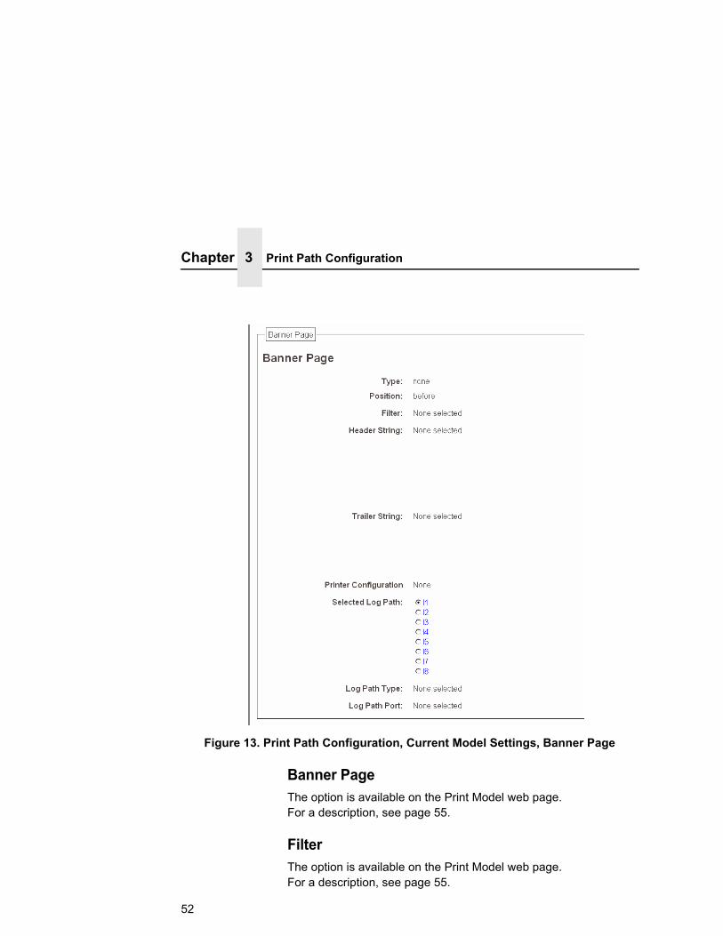
Figure 13. Print Path Configuration, Current Model Settings, Banner Page
Banner PageThe option is available on the Print Model web page. For a description, see page 55.
FilterThe option is available on the Print Model web page. For a description, see page 55.
52
Current Model Settings
Header StringThe option is available on the Print Model web page. For a description, see page 55.
Trailer StringThe option is available on the on the Print Model web page. For a description, see page 56.
Printer ConfigurationThe option is available on the Print Model web page. For a description, see page 56.
Selected Log PathThis option defines the log path configuration that is to be associated with the current destination.
Log Path TypeThe option is available on the Log Path web page. For a description, see page 57.
Log Path PortThe option is available on the Log Path web page. For a description, see page 58.
53

Chapter 3 Print Model Configuration
Print Model Configuration
Figure 14. Print Model Configuration, Model Settings
NameName of the model. The default model names are m1, m2, m3, m4, m5, m6, m7, and m8.
Model TypeDefine what processing (if any) will be performed on print jobs passing through the associated destination. If set to "raw", the job will not be touched by the network adapter.
54

Banner PageTells the Ethernet Interface to produce a banner page with each print job. The type of banner page data can be text. You can also specify whether the banner page should come at the front or the end of a print job.
NOTE: PPI emulations will not print a banner page unless “Auto Pass Thru” is selected under the PPI menu.
FilterSpecify whether the Ethernet Interface is to add carriage returns to print jobs passing through that contain solitary linefeeds. This is common with Unix text jobs resulting in stair-stepped output.
Header StringDefine an escape sequence to be sent to the printer before each print job. For example, you may want to send a sequence to print the job in landscape mode or to a certain tray on the printer. You can specify up to four separate sequences per header string. The Ethernet Interface will execute them in order from top to bottom. If specifying fewer than four sequences, be sure to start at the top leaving undefined fields at the bottom.
NOTE: You can specify up to four separate sequences per header string. The Integrated PrintNet Enterprise will execute them in order from top to bottom. If specifying fewer than four sequences, be sure to start at the top leaving undefined fields at the bottom.
55
Chapter 3 Print Model Configuration
Trailer StringDefine an escape sequence to be sent to the printer after each print job. For example, you may want to send a sequence to add a formfeed so you don't have to manually press the formfeed button on the printer. You may also want to tell the printer to reset itself in case you have set a header string which tells the printer to do something special with the job. You can specify up to three separate sequences per trailer string. The Ethernet Interface executes them in order from top to bottom. If specifying fewer than four sequences, be sure to start at the top leaving undefined fields at the bottom.
The most common sequence is listed on the form:
• Formfeed - tells the printer to do a formfeed at the end of the data.
Printer ConfigurationSpecify a printer configuration number to be loaded before processing the print job. This ability to associate a printer configuration to a logical printer model allows you to define up to eight unique and independent printer personalities in a single printer. Using this feature, you effectively have eight different printers in one.
To associate a printer configuration to the currently selected destination queue, just select the desired printer configuration number from the drop down list. Once a printer configuration has been associated with a destination queue, any print job sent to that destination queue name will cause the printer to load the associated printer configuration before processing the print job.
56

Log Path Configuration
Figure 15. Log Path Settings
NameName of the log path. The default names are l1, l2, l3, l4, l5, l6, l7, and l8.
Logpath TypeDefine what type of log information will be tracked for each print job passing through the associated destination. The types are:
• job - job ID, username, etc.
• user - user ID and three messages per job about the start and finish
• checksum - value used when troubleshooting integrity of data transferred
• printer - miscellaneous messages from the printer
• i/o port - status of the printer based on the port interface signals.
57
Chapter 3 Log Path Configuration
Logpath PortDefine where logging information for print jobs passing through the associated destination will be reported. The choices are:
• prn - reported to the PRN port
• none - don't report any logging information
• TCP/IP port - to a TCP port number (specified in the edit field)
• syslog - to a host (specified by the IP address in the edit field) running a SYSLOG daemon
• email - to an e-mail address (specified by the e-mail address and the SMTP server IP address edit fields). You can set the option on the Administration web page.
Default: no logging turned on.
58
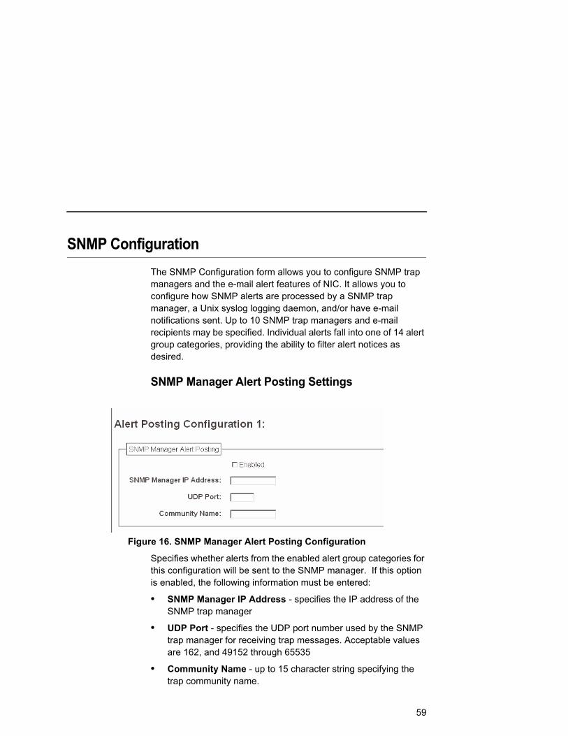
SNMP ConfigurationThe SNMP Configuration form allows you to configure SNMP trap managers and the e-mail alert features of NIC. It allows you to configure how SNMP alerts are processed by a SNMP trap manager, a Unix syslog logging daemon, and/or have e-mail notifications sent. Up to 10 SNMP trap managers and e-mail recipients may be specified. Individual alerts fall into one of 14 alert group categories, providing the ability to filter alert notices as desired.
SNMP Manager Alert Posting Settings
Figure 16. SNMP Manager Alert Posting Configuration
Specifies whether alerts from the enabled alert group categories for this configuration will be sent to the SNMP manager. If this option is enabled, the following information must be entered:
• SNMP Manager IP Address - specifies the IP address of the SNMP trap manager
• UDP Port - specifies the UDP port number used by the SNMP trap manager for receiving trap messages. Acceptable values are 162, and 49152 through 65535
• Community Name - up to 15 character string specifying the trap community name.
59
Chapter 3 SNMP Configuration
Syslog Alert Posting Settings
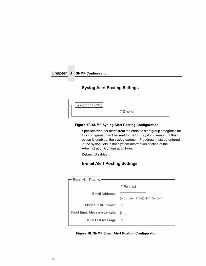
Figure 17. SNMP Syslog Alert Posting Configuration
Specifies whether alerts from the enabled alert group categories for this configuration will be sent to the Unix syslog daemon. If this option is enabled, the syslog daemon IP address must be entered in the syslog field in the System Information section of the Administration Configuration form.
Default: Disabled
E-mail Alert Posting Settings
Figure 18. SNMP Email Alert Posting Configuration
60

Specifies whether alerts from the enabled alert group categories for this configuration will be sent to the specified e-mail address. If this option is enabled, the following information must be entered:
• E-mail Address - specifies an e-mail address to which alert information will be sent
• Short E-mail Format - specifies whether a short (15-80 character) alert e-mail message should be sent.
If enabled, the message will contain the alert description, the severity level, device description, and device name (unless the length of the message exceeds the Short E-mail Message Length, in which case the message will be truncated).
If disabled, the message will contain additional information including the device description, device name and location, alert description, alert group, alert severity level, and printer status.
Default: Disabled
• Short E-mail Message Length - Specifies the maximum size of the short e-mail message. Acceptable values are 15 to 80 characters.
Default: 80 characters
• Send Test Message - Provides a way to test the validity of the e-mail address/SMTP server address. If checked, a test message will be sent to the specified e-mail address when the submit button is pressed.
Default: All alert groups are disabled by default.
If the alert message is to be sent to a cellular phone or pager, the Short E-mail Format option should be enabled. Once this option is enabled, you may specify the maximum e-mail message length (15-80 characters). When enabled, the message will contain the alert description, the severity level, device description, and device name (unless the length of the message exceeds the Short E-mail Message Length, in which case the message will be truncated).
61

Chapter 3 SNMP Configuration
If the Short E-mail format is disabled, the message will contain additional information including the device name and location, alert description, alert group, alert severity level, and printer status.
To test the validity of the e-mail address and the SMTP server address, enable the Send Test Message option. If the Send Test Message box is checked, a test message will be sent to the specified e-mail address when the submit button is pressed.
Alert Groups
Figure 19. SNMP Alert Groups Configuration
62

Specifies which alert groups are enabled for reporting for this configuration. When an alert occurs that is contained in one of the enabled alert groups, it will be posted to the specified SNMP manager, Unix syslog daemon, and/or e-mail address. The following table describes which printer events belongs to which Alert Group.
Default: All alert groups are enabled by default.
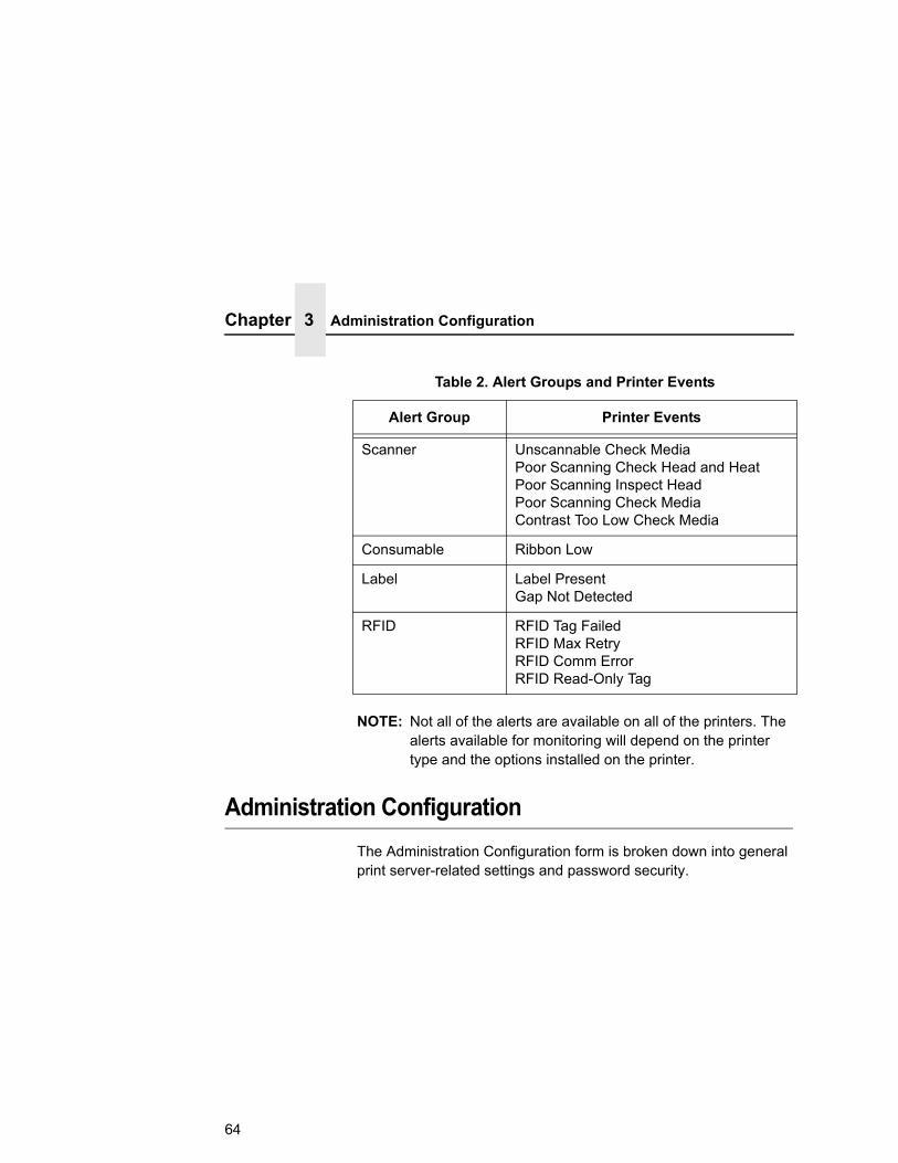
Table 2. Alert Groups and Printer Events
Alert Group Printer Events
Offline Printer is Offline
Warning File System Full File Exist Hex Dump Mode Printer Warm Print Head Warm
Media Input Load Paper
Media Path Clear Paper Jam
Marker Ribbon Stall Ribbon Fault Ribbon Detected Print Head Up Ribbon Broken Ribbon Load Bad Ribbon Take-up Full
Cutter Cutter Fault Cutter Fail
Barcode Barcode Fail Specification Barcode Quiet Zone Too Small Barcode Improper Data Format
63
Chapter 3 Administration Configuration
NOTE: Not all of the alerts are available on all of the printers. The alerts available for monitoring will depend on the printer type and the options installed on the printer.
Administration ConfigurationThe Administration Configuration form is broken down into general print server-related settings and password security.
Scanner Unscannable Check Media Poor Scanning Check Head and Heat Poor Scanning Inspect Head Poor Scanning Check Media Contrast Too Low Check Media
Consumable Ribbon Low
Label Label Present Gap Not Detected
RFID RFID Tag Failed RFID Max Retry RFID Comm Error RFID Read-Only Tag
Table 2. Alert Groups and Printer Events
Alert Group Printer Events
64
System Information
System Information
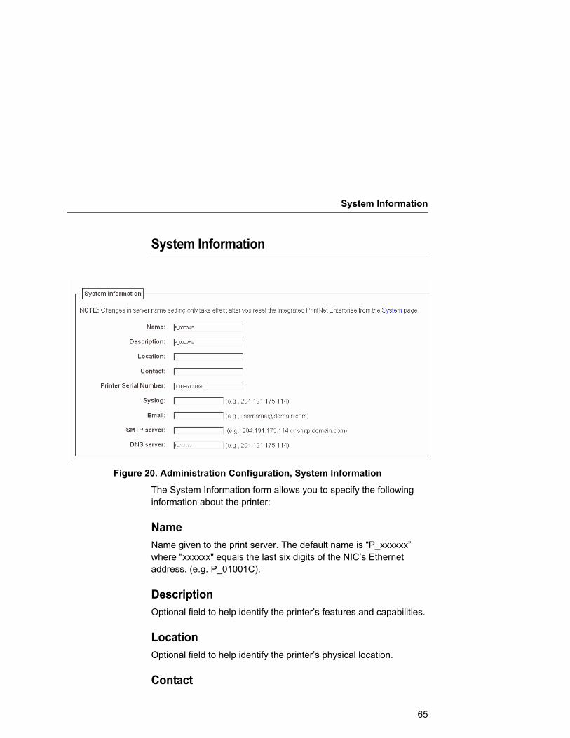
Figure 20. Administration Configuration, System Information
The System Information form allows you to specify the following information about the printer:
NameName given to the print server. The default name is “P_xxxxxx” where "xxxxxx" equals the last six digits of the NIC’s Ethernet address. (e.g. P_01001C).
DescriptionOptional field to help identify the printer’s features and capabilities.
LocationOptional field to help identify the printer’s physical location.
Contact
65

Chapter 3 Administration Configuration
Optional field to help identify the individual or group responsible for the printer.
Printer Serial NumberAllows the user to enter the printer serial number. By default, the field uses the device’s Ethernet Address.
NOTE: If the user has not entered a serial number through one of the NICs, depending on the printer type, the printer may use its internal serial number from EEPROM. If EEPROM is blank, i.e. no serial number on the board, it will use the MAC address of the embedded NIC, or embedded wireless NIC, respectively, as the printer’s serial number.
SyslogSpecifies the IP address of a host running the SYSLOG daemon. NIC debugging or printer logging information can be sent to the IP address.
66

System Information
EmailDefines the user email address to receive printer and job logging information from log paths on the NIC.
Default: Unconfigured (empty).
SMTP ServerSpecifies the IP address or domain name of the SMTP server to be used for processing email messages generated by the NIC.
Default: Unconfigured (empty).
DNS ServerSpecifies the IP address of the domain name server to be used for resolving host names (e.g. host.domain.com) to IP addresses (e.g. 192.168.0.42).
Default: Unconfigured (empty).
NOTE: If the DNS server field is initially blank, the NIC will automatically use the IP address of the DNS server and enter it in the DNS server field when DHCP is enabled.
67
Chapter 3 Administration Configuration
Passwords
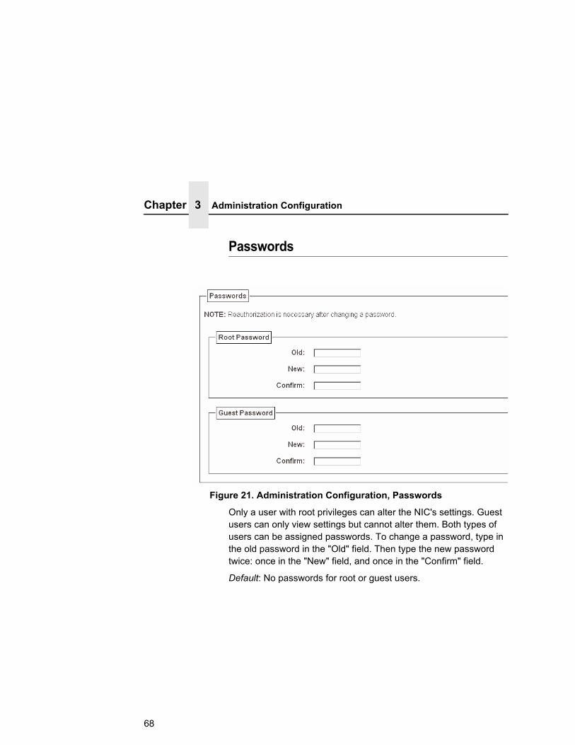
Figure 21. Administration Configuration, Passwords
Only a user with root privileges can alter the NIC's settings. Guest users can only view settings but cannot alter them. Both types of users can be assigned passwords. To change a password, type in the old password in the "Old" field. Then type the new password twice: once in the "New" field, and once in the "Confirm" field.
Default: No passwords for root or guest users.
68

System Configuration
Figure 22. System Configuration
The System Configuration form allows you to change the NIC 's operation mode. Select "Reboot" to re-power the print server. Select "Default" to reset the print server and have it come up with factory default settings.
StatusThe Status menu items allow you to view the current status of both the printer and the network. The submenu items available are as follows:
• I/O Port - this menu item allows you to view the current status of the printer, including the print jobs that are queued or are currently active.
• Network - this menu item allows you to view the current status of the network connection.
69

Chapter 3 Status - I/O Port
Status - I/O PortThe I/O Port Status form allows you to remotely see what is happening on the NIC I/O port. The port's status and a list of active and queued jobs will be displayed. You can cancel a job (as long as you have permission) by clicking the Cancel icon beside the desired job. If you see "waiting" in the "Status" line, this indicates the network adapter is either waiting for data from the host or for feedback from the printer. If you see "blocked" in this line, this indicates the printer is not allowing the NIC to send any more data. The printer could be busy processing data it has already received or it could be in an error state.
The printer status display is automatically refreshed every minute.
NOTE: The printer’s buffer size may not allow you to monitor the real time status of the printer and the print job at the same time. The status feedback to the host usually reads “printer idle” unless the print job is significantly large.
Status - NetworkThis form allows you to view the current status of the network. The statistical data provided is broken down by network protocol. You can use this form to troubleshoot network-related problems.
70

4 Windows Configuration
OverviewThis chapter details a complete Windows configuration setup including:
• Identifying the NIC on the network using TCP/IP as the underlying protocol
• Configuring the NIC with its mandatory TCP/IP settings (IP address and subnet mask)
• Configuring a new printer on the Windows station
Windows Environment DescriptionThe NIC supports network printing under Windows environments by using TCP/IP. In a Windows NT®/Vista® setup, pure TCP/IP is used as the network protocol whereas with Windows 95/98®, Windows Me®, NetBIOS is used over TCP/IP.
71
Chapter 4 Windows NIC Configuration
Windows NIC ConfigurationThe IP address and subnet mask are mandatory TCP/IP settings and are needed before the print server can be detected on the network. There are also additional optional settings. This section offers alternative methods for configuring your NIC in a Windows environment and describes some of the more common optional settings available.
MandatorySince TCP/IP is used for Windows printing, the NIC must be configured with a minimum of an IP address and subnet mask before it can be seen on the network.
OptionalAdditional settings, like routing entries, can be configured. This allows communication across subnets when no other router exists.
You can configure the NIC done from the printer control panel, Web browser, host commands, or other Printronix utility software. To configure these options, see “Configuration Tools” on page 23.
Configuration Using ARPTo configure the NIC with its IP settings using a manual arp command:
1. Log on to a Windows station with TCP/IP loaded and located on the same subnet as the NIC.
2. Find the Ethernet address for the NIC on the configuration printout. It must be entered as part of this procedure.
72

Configuration Using ARP
3. Use the arp command to add an entry into the Windows station ARP table for the NIC. This is the most common syntax for this command:
Syntax:arp -s ipaddress ethernetaddress
Example for Microsoft® TCP stacks:arp -s 192.75.11.9 00-08-96-07-00-60
This example specifies a NIC using IP address 192.75.11.9 and Ethernet address 00-08-96-07-00-60.
4. Check if the ARP entry was accepted.arp -a
You should see an entry in the listed ARP table with the IP address and Ethernet address specified in Step 3.
5. Ping this IP address to see if the NIC can be seen on your network.
At this point, you should be able to communicate with the NIC from your local Windows station. This means the print server knows about an IP address and subnet mask and has these settings in its current memory. However, if the NIC is power cycled, these settings will disappear unless you store them into flash memory. To do this:
a. Load a Web browser on your Windows station and direct it to the URL: http://NICIPaddress/networkConf.html (e.g., http://192.75.11.9/networkConf.html).
NOTE:If prompted for a “User ID” and password first, type root for the ID and press ENTER at the password prompt (since there is no password by default).
b. At the “Network Configuration” HTML form that displays, click in the field below the “IP Address” heading and type in the IP address for the NIC.
73
Chapter 4 Windows NIC Configuration
c. Under the “Subnet Mask” heading, enter the NIC subnet mask.
NOTE:If you would like to communicate with the NIC from across routers, you will need to fill in an entry within the “Routing” section. Please see “Communicating Across Routers” on page 74 for more details.
6. Click on the SUBMIT button when done and physically repower the printer to make the new settings take effect.
Communicating Across RoutersSince Windows environments rely on TCP/IP to communicate with the NIC, crossing routers becomes an issue.
After you have followed one of the NIC configuration methods mentioned, most likely you will only be able to communicate with the print server from the same subnet. This means any hosts across a router will not be able to see your NIC. In order for hosts across a router to see your NIC, store a default router/gateway within the print server so that any packets destined for another subnet get forwarded to this router automatically. The router (or series of routers) can then take over, ensuring the packets get to their final destination on another subnet on your network.
To configure a default router/gateway within the NIC:
1. Load a Web browser on your Windows station and direct it to the URL: http://NICIPaddress/networkConf.html (e.g., http://192.75.11.9/networkConf.html).
NOTE: If prompted for a “User ID” and password first, type in root for the ID and press ENTER at the password prompt (since there is no password by default).
2. At the “Network Configuration” HTML form that displays, click in the first field below the “Gateway” heading and type in the IP address of the default router/gateway for the NIC subnet.
74

Changing Workgroup Names
3. Click on the SUBMIT button when done and physically repower the print server to make the new settings take effect.
Changing Workgroup NamesWindows environments define groups of related computers as “workgroups.” By default, “WORKGROUP” is the name that is assigned to the NIC workgroup. However, you may want to change this to suit your network better. To do this:
1. Load a Web browser on your Windows station and direct it to the URL: http://NICIPaddress/networkConf.html (e.g., http://192.75.11.9/networkConf.html).
NOTE: If prompted for a “User ID” and password first, type in root for the ID and press ENTER at the password prompt (since there is no password by default).
2. At the “Network Configuration” HTML form that displays, search for the “Windows (NetBIOS TCP/IP)” section and highlight the “Workgroup Name” field.
3. Type in the new workgroup name for the NIC.
4. Click on the SUBMIT button when done and physically repower the print server to make the new settings take effect.
75

Chapter 4 Windows NIC Configuration
Figure 23. Windows NT Print Setup Dialogue Box
The first field requires the IP address for the NIC, and the second field must be filled in with a valid destination from the print server (e.g., d1prn). Otherwise, LPR will not be able to access the printer. Table 3 outlines the default destinations to choose from.
Table 3. NIC Default Destinations
Destination Mapped I/O Port
d1prn PRN
d2prn PRN
d3prn PRN
d4prn PRN
d5prn PRN
d6prn PRN
d7prn PRN
d8prn PRN
Changing Destination NamesWhen defining some printers within Windows environments, the NIC requires that you specify a predefined destination rather than any name you would like. For example, when creating a new printer under Windows NT, a screen similar to Figure 23 displays.
76

Changing Destination Names
This name can be changed to something more meaningful using the built-in HTML forms. To do this:
1. Load a Web browser on your Windows station and direct it to the URL: http://NICIPaddress/destConf.html (e.g., http://192.75.11.9/networkConf.html).
NOTE: If prompted for a “User ID” and password first, type in root for the ID and press ENTER at the password prompt (since there is no password by default).
2. At the “Print Path Configuration” HTML form that displays, select a destination link from the top of the page to bring up the appropriate destination form. By default, you should see a line near the top of the form showing the destinations listed in Table 3.
3. Once the desired destination HTML form displays, highlight the “Name” field and type in the new name for this destination.
4. Click on the SUBMIT button when done and physically repower the print server to make the new setting take effect.
77

Chapter 4 Windows Host Configuration
Windows Host ConfigurationThis section covers Windows Vista, XP, 2000, and 2003 Server printer setup.
This installation procedure assumes that the Ethernet adapter is configured with the correct IP address, subnet mask and gateway (if required). In addition, the administrator can “ping” and Telnet to the Ethernet adapter from the server console. If this is not the case, use the printer front panel to configure the Ethernet adapter before proceeding.
Printer Driver Setup Wizard1. Select Windows Drivers from the CD. The Printer Driver Setup
Wizard window displays.
Figure 24. Setting Up the Printronix Printer Driver
2. Click Next. The Welcome to the Add Printer Wizard window displays.
3. Click Next.
78
Printer Driver Setup Wizard
4. Select the type of printer to set up and click Next. For this example, select Local printer attached to this computer.
Figure 25. Selecting a Printer Port
5. Select a port for the printer to use and click Next. For this example, select LPT1:(Recommended printer Port).
6. Select the Printronix printer driver and click Next.
79

Chapter 4 Windows Host Configuration
Figure 26. Selecting a Printer Driver
7. Select the Printronix printer driver and click Next.
8. Enter a printer name and specify whether to have this printer set up as the default printer, then click Next. For this example, select No. By default the printer you selected in the previous step is entered.
9. Select Do not share this printer and click Next. You are prompted to print a test page.
10. Select No and click Next.
80

Printer Driver Setup Wizard
Figure 27. Printer Driver Installation Completion
11. Click Finish to complete the add printer wizard.
12. Click Finish. You have successfully installed your printer driver. Next the printer setup wizard will guide you through basic printer setup.
81

Chapter 4 Windows Host Configuration
82

5 Unix Configuration
OverviewThis chapter details a complete Unix setup including:
• Configuring the NIC with its mandatory TCP/IP settings (e.g., IP address and subnet mask).
• Configuring the Unix host station with a new printer.
Unix Environment DescriptionThe NIC supports network printing under various TCP/IP environments including all variations of Unix. Printing can come from multiple hosts directly or through central spooling machines.
83

Chapter 5 Unix NIC Configuration
Unix NIC ConfigurationThere are mandatory settings needed before the print server can be detected on the network, as well as some additional optional settings. This section offers alternative methods for configuring your NIC and mentions some of the more common optional settings available.
MandatorySince TCP/IP is used, the NIC must be configured with a minimum of an IP address and subnet mask before it can be seen on the network. To configure these options, see “Configuration Tools” on page 23.
OptionalAdditional settings, like routing entries, can be configured allowing for communication across subnets.
Configuration of the NIC can be done from the control panel or through host commands. To configure these options, see “Configuration Tools” on page 23.
Using ARPTo configure the Ethernet Interface with its TCP/IP settings using a manual arp command, the syntax is:arp -s ipaddress ethernetaddress
For the aix command, the syntax is:aix -s ether ipaddress Mac_address
To use either of these commands:
1. Log on to a Unix station as superuser or root. This station must be located on the same subnet as the NIC since ARP is limited to subnets.
84
Using ARP
2. Find the Ethernet address for the NIC by printing a configuration or reading it from the control panel. It must be entered as part of this procedure.
3. Use the arp command to add an entry into the Unix station ARP table for this NIC. Here is the most common syntax for this command:arp -s ipaddress ethernetaddress
Example for Microsoft TCP stacks:arp -s 192.75.11.9 00:08:96:20:00:60
This example specifies a NIC using IP address 192.75.11.9 and Ethernet address 00:08:96:20:00:60.
4. Verify that the ARP entry was properly applied.arp -a
You should see an entry in the listed ARP table with the IP address and Ethernet address specified in step 3.
5. Try to ping this IP address to see if the NIC can be seen on your network.
At this point, you should be able to communicate with the NIC from your local Unix station. This means the printer knows about an IP address and subnet mask and has these settings in its current memory. However, if the NIC is shut off, these settings will be lost unless you store them in flash memory, as follows:
1. Load a Web browser on your Windows station and direct it to the URL: http://NICIPaddress/networkConf.html (e.g., http://192.75.11.9/networkConf.html).
NOTE: If prompted for a “User ID” and password first, type in root for the ID and press ENTER at the password prompt (since there is no default password).
2. At the “Network Configuration” HTML form that displays, click in the field below the “IP Address” heading and type in the IP address for the NIC.
85

Chapter 5 Unix NIC Configuration
3. Under the Subnet Mask heading, enter the NIC subnet mask.
NOTE: If you would like to communicate with the NIC from across routers, you will need to fill in an entry within the “Routing” section. Please see “Communicating Across Routers” on page 88 for further details.
4. Click the Submit button when done and physically repower the print server to make sure the new settings are in effect.
Using RARPRARP allows you to dynamically assign an IP address to the NIC upon bootup. To configure the NIC with its TCP/IP settings using RARP:
1. On your RARP server, make an entry in the /etc/ethers file for the NIC.
Syntax:ethernetaddress NICIPaddress
Example:00:08:96:20:00:60 192.75.11.9
2. Start the RARP daemon on the RARP server if not already running. If it is running, send an HUP signal to it with the kill command:
Syntax:kill -HUP pid
where pid is the process ID of the RARP daemon.
3. Power on the NIC so that it immediately sends out an RARP request. Wait one minute to allow the address assignment process to complete. You should see the STAT LED on the NIC interface slow down, indicating it knows about an IP address to use.
86
Using BOOTP
4. Try to ping the NIC IP address from a local Unix station to see if it can be seen on your network.
NOTE: You will only be able to communicate with the NIC from a network station on the same subnet as the print server. The NIC needs to be told about a default router/gateway so any packets that come in from a different subnet can be returned via this gateway. Please see “Communicating Across Routers” on page 88 to set this up.
Using BOOTPBOOTP allows you to dynamically assign an IP address to the NIC upon bootup. In addition, the BOOTP server can provide additional details like a default router/gateway address. To configure the NIC with its TCP/IP settings using BOOTP:
1. On your BOOTP server, make an entry in the /etc/bootptab file for the NIC.
Syntax:NICIPname:\ :sm=netmask:\ :hd=homedirectory:\ :bf=null:\ :gw=defaultgateway:\ :ht=ethernet:\ :ha=ethernetaddress:\ :ip=ipaddress:\ :ts=timeserver:\ :to=timezone:
Example:spike:\ :sm=255.255.255.0:\ :hd=/usr/null:\ :bf=null:\ :gw=192.75.11.1:\ :ht=ethernet:\ :ha=000896200060:\ :ip=192.75.11.9:\ :ts=192.75.11.7:\ :to=25200:
87

Chapter 5 Unix NIC Configuration
2. Turn the NIC on so that it immediately sends out a BOOTP request. Wait one minute to allow the IP address assignment process to complete. You should see the STAT LED (on the NIC interface) slow down, indicating it knows about an IP address to use.
3. Try to ping the NIC IP address from a network station to see if it can be seen on your network.
NOTE: You will be able to communicate with the NIC from network stations on different subnets if the print server has been told about its default router/gateway in the BOOTP response from the BOOTP server.
Communicating Across RoutersSince Unix environments rely on TCP/IP to communicate with the NIC, crossing routers becomes an issue.
After you have followed one of the NIC configuration methods mentioned (other than the BOOTP method), most likely, you will only be able to communicate with the print server from the same subnet. This means any host across a router will not be able to see your NIC. In order to communicate across a router, store a default router/gateway within the print server so that any packets destined for another subnet get forwarded to this router automatically. The router (or series of routers) can then take over the process of ensuring the packets get to their final destination on another subnet on your network.
To configure a default router/gateway within the NIC:
1. Load a Web browser on your Windows station and direct it to the URL: http://NICIPaddress/networkConf.html (e.g., http://192.75.11.9/networkConf.html).
NOTE: If prompted for a User ID and password first, type in root for the ID and press ENTER at the password prompt (since there is no default password).
88

Manual System V Host Setup
2. At the Network Configuration HTML form that displays, click the first field below Gateway and type in the IP address of the default router/gateway for the NIC subnet.
3. Click Submit when done and physically repower the print server to make sure the new setting is in effect.
Unix Host ConfigurationThere may be times when you would prefer or have to perform the manual setup steps for a new printer definition. There may also be times when you require a less common print solution such as direct socket capabilities. This section covers these additional setups.
Manual System V Host SetupThis setup involves any Unix operating system using System V print spooling (e.g., SCO, Solaris®, HP-UX®, DG/UX®, etc.). This means an interface file is used for each defined printer and, in the case of any System V print setup involving a NIC, the RSHD protocol is used to transfer data from the host to the print server.
To manually configure a new System V printer on a Unix station, create a dummy device file that acts as a locking mechanism between contending print jobs.
Syntax:touch /dev/NICname.portname
where NICname is the host or IP name of the print server and portname is one of its four I/O ports.
Example:touch /dev/spike.prn
89

Chapter 5 NIC Installation on HP-UX
NIC Installation on HP-UXLPR is supported in HP/UX Version 9.0 and greater. To configure a print queue using LPR, issue the following commands.
NOTE: Requires root privilege. The default BSD interface file “rmodel” will be used.
Syntax:lpshutlpadmin -pqueue_name -mrmodel -v/dev/null -orm[printer_ip] -orpd1prn -ob3lpschedaccept queue_nameenable queue_name
queue_name = any unique printer name
[printer_ip] = IP address of the printer or the DNS name (without brackets)
d1prn = NIC remote printer name*
Explanation of command line:
-m indicates the model rmodel
-v indicates the use of /dev/null as a file interlock to avoid contention
-orm is the name of remote Print Server
-orp is the name of the remote printer on the remote Print Server
-ob3 declares that the remote Print Server is a BSD type
NOTE: The “lpshut” command stops the HP spooling system; do not perform when print jobs are active.
The default NIC destination name is d1prn, however, this name can be changed. To verify the queue name, print an Ethernet Test Page or telnet to the adapter and run a “list dest” command.
To print to this queue, use normal lp syntax:# lp -dqueue_name filename
90

Solaris 2.6 – 7 NIC SetupNOTE: Requires Superuser privilege in the borne shell. Assume
that you can ping and Telnet to the adapter.
The IP address of the NIC must be placed in the /etc/hosts file.
Syntax:lpadmin -p [queue_name] -v /dev/nulllpadmin -p [queue_name] -i /usr/lib/lp/model/netstandardlpadmin -p [queue_name] -o dest=[host_name] -o protocol=bsd -o timeout=60lpadmin -p [queue_name] -s [host_name]!d1prn -I anyenable {queue_name]accept [queue_name]
where
[queue _name] = any name, but not the name in the etc/hosts file or d1prn
[host_name] = name in etc/hosts file
TroubleshootingThis installation procedure assumes that the NIC is configured with the correct IP address, subnet mask, and gateway (if required). You can also ping and telnet to the NIC.
Print an Ethernet Test Page to verify the Ethernet settings. See “Configuration Using The Control Panel”, step 2 on page 24.
The default NIC queue name is d1prn, however, the name can be changed. To verify the queue name, print an Ethernet Test Page or telnet to the adapter and run a “list dest” command.
NOTE: Depending on the shell, preceed the ! character with a \ to avoid shell script errors.
91

Chapter 5 Solaris 2.6 – 7 NIC Setup
Manual LPR/LPD Host SetupThe NIC also supports Unix operating systems which follow a BSD print system (e.g., SunOS 4.1.x). This means a printcap file is used to define all printers available on the host, and interface scripts are not commonly used. Instead, LPR/LPD printers are defined.
To manually configure an LPR/LPD printer on a BSD Unix system:
1. Define an entry for this new printer within the printcap file, /etc/printcap.
Syntax:printername: :sh:pw#80:mx#0:\ :rm=NICname:\ :rp=NICdestination:\ :lp=:\ :sd=/usr/spool/lpd/printername:\ :lf=/usr/spool/lpd/printername/log:\ :af=/usr/spool/lpd/printername/acct:
where printername is any name you would like to give to this new printer, NICname is the host or IP name of the print server, and NICdestination is one of the pre-defined destinations/queues on the device.
Example:SL4M/T4M: :sh:pw#80:mx#0:\ :rm=spike:\ :rp=d1prn:\ :lp=:\ :sd=/usr/spool/lpd/ SL4M/T4M:\ :lf=/usr/spool/lpd/ SL4M/T4M/log:\ :af=/usr/spool/lpd/ SL4M/T4M/acct:
2. Create the spool directory specified by the sd= entry in the printcap entry for this printer.
Example:touch /usr/spool/lpd/ SL4M/T4M
3. Create the log and account files specified by the lf= and af= entries in the printcap entry for this printer.
92

NIC Configuration for AIX 4
Example:touch /usr/spool/lpd/SL4M/T4M/logtouch /usr/spool/lpd/SL4M/T4M/acct
4. Change permissions and ownership on the spool directory and everything within it.
Example:chmod -R g+rwX,o+rX /usr/spool/lpd/ SL4M/T4Mchmod -R daemon.daemon /usr/spool/lpd/ SL4M/T4M
5. Start the printer daemon for this new printer.
Example:lpc start SL4M/T4M
You now have a new printer which relies on LPR/LPD to print to a NIC printer. Use the following command to test printing:
Syntax:lpr -P printername filename
Example:lpr -P SL4M/T4M /etc/hosts
NIC Configuration for AIX 4Before you set up the printer, it is good to know the ways a print job can be filtered.
1. Standard processing. Filtering is done on the printer with no processing on the host.
2. Local Filtering. Filtering is done on the host. Be sure to specify the printer model during install.
Standard Processing1. Enter SMIT select devices.
2. Select Printer/Plotter.
3. Select Print Spooling.
4. Add a Remote Print Queue.
5. Set the type of Remote Printing to Standard processing.
93
Chapter 5 Solaris 2.6 – 7 NIC Setup
6. Enter the following Remote printer settings:
Name of queue any_name, user selectable
Host Name of Remote Server name in /etc/hosts file or the NIC IP address
Name of Queue on Remote Server
d1prn
Type of Print Spooler BSD (Press the list button and choose BSD)
Troubleshooting
This installation procedure assumes that the NIC is configured with the correct IP address, subnet mask, and gateway (if required). In addition you can also ping and telnet to the NIC.
Print an Ethernet Test Page to verify the Ethernet settings. See “Configuration Using The Control Panel”, step 2 on page 24.
The default NIC queue name is d1prn (in lower case), however the name can be changed. To verify the queue name, print an E-Net Test Page or telnet to the adapter and do a “list dest” command.
94
AIX Remote Queue Time–Out Setting
AIX Remote Queue Time–Out SettingSymptoms: Print jobs restart or queue goes down.
If the queue is set up for standard processing (not local filtering), add -T50 flag to rembak to the queue device stanza for the queue in /etc/qconfig
backend = /usr/lib/lpd/rembak -T50
If the queue was set up for local filtering edit the file /usr/lib/lpd/pio/etc/piorlfb and change the line;
typeset piorlfb_rbflags=’’’’
to
typeset priorlfb_rbflags=”-T50”
Printing From AIXVersion 4.0 and higher of AIX® offers LPR/LPD support for network printing. This means, to set up a new printer under this operating system, you only need to define these two parameters:
1. NIC IP address. The IP address or host name of the print server to which you want to print.
2. NIC destination/queue. A pre-defined name on the print server telling the device to which I/O port to send the jobs. Most likely, you will use d1prn for the PRN.
95
Chapter 5 Solaris 2.6 – 7 NIC Setup
Printing With FTPPrint jobs can also be sent to the NIC using the File Transfer Protocol (FTP). To do this:
1. On your network station, change to the directory containing the file you want to print.
2. Open an FTP session with the NIC.
Syntax:ftp NICIPaddress
3. Log in as root.
4. At the password prompt, press ENTER (since there is no default password).
5. Change to the dest directory.
Syntax:cd dest
6. List the contents of this directory using the dir command and determine which destination/queue you would like to send the print job through. Most likely, you will select d1prn for the PRN port.
7. Change to this destination directory.
Example:cd d1prn
8. Change the mode to correspond with the type of file you are going to print. By default, ASCII is set for text-only files, but if you need to print both text and graphics, select binary using the bin command.
9. Place the file to be printed within this directory on the NIC, so it can be spooled and printed.
Syntax:put filename
96

Direct Socket Printing
10. Close the FTP session, unless you have more jobs to print.
Syntax:quit
Direct Socket PrintingWithin TCP/IP environments, there are some setups which require the host to print directly to a TCP port number on the NIC, bypassing all of the higher level destination/queue names. If you run into a setup which requires this, you will need to define two parameters for a new print setup:
1. NIC IP address. The IP address or host name of the print server to which you want to print.
2. NIC TCP port number. A pre-defined number for the I/O port on the print server. 9100 is the default port number.
Though the host will be sending directly to a TCP port number on the NIC, the port numbers are still mapped to destinations/queues in case there is some type of special processing or logging to be done to the job. However, the destination name is of no concern in this type of printer definition. Only the two parameters mentioned above need to be defined for printing to work.
97

Chapter 5 Solaris 2.6 – 7 NIC Setup
98
6 AS/400 Configuration, ASCII Printer
OverviewThis chapter details a complete AS/400 configuration setup including:
• Developing Line Descriptions with CRTLINETH
• Configuring the AS/400 for TCP/IP
• Configuring the AS/400 for Printing
• Verifying Printing from the AS/400
This document assumes no AS/400 printer configuration has been done. If any configuration has been done, please follow the procedure to the point at which continued configuration is required.
Developing Line Descriptions With CRTLINETHFor each LAN adapter on the AS/400, a line description needs to be created for the NIC. This is required for Release V3R2 and V3R7.
If a line description already exists, make sure the SSAP list includes default options “AA” and “12.” You must also know the LAN speed for the AS/400 LAN adapter.
NOTE: To change a line description, you need to vary the line off before making the change. After making the change, you need to vary the line back on.
To change an existing line description, use the CHGLINETH command. To create a line description, use CRTLINETH.
99
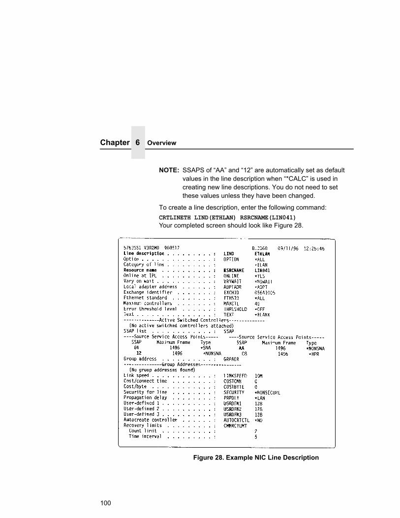
Chapter 6 Overview
Figure 28. Example NIC Line Description
NOTE: SSAPS of “AA” and “12” are automatically set as default values in the line description when “*CALC” is used in creating new line descriptions. You do not need to set these values unless they have been changed.
To create a line description, enter the following command:CRTLINETH LIND(ETHLAN) RSRCNAME(LIN041)Your completed screen should look like Figure 28.
100

Configuring With ADDTCPIFC
The following three parameters must be specified:
Line Description (LIND)
The line description name is the user's name for the AS/400 adapter. This name must be identical to the name entered when the TCP/IP is configured on the AS/400.
Resource Name (RSRCNAME)
The system-assigned name for the interface (for example, LIN041).
SSAP
When *CALC is used, the values of “12” and “AA” are entered automatically as defaults. Verify that those SSAP values have not been changed.
Configuring AS/400 For ASCII Using TCP/IPThe next step is to configure the interface on the AS/400 for TCP/IP.
NOTE: The AS/400 interface is not the NIC. Do not set the AS/400 interface address to the same address as the NIC IP address. Also, do not add the NIC to the AS/400 TCP/IP interface list.
Configuring With ADDTCPIFCADDTCPIFC is used to add a TCP/IP interface to the AS/400. This step configures the AS/400 for attachments to a TCP/IP network.
At the AS/400 command line, enter the following command:ADDTCPIFC INTNETADR ('9.99.15.188') LIND(ETHLAN) SUBNETMASK('255.255.255.0')
Your completed screen should look like Figure 29.
101
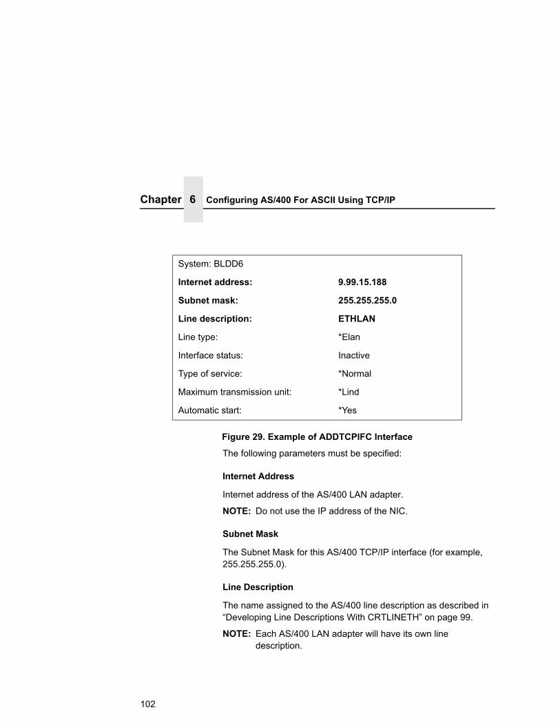
Chapter 6 Configuring AS/400 For ASCII Using TCP/IP
System: BLDD6
Internet address: 9.99.15.188
Subnet mask: 255.255.255.0
Line description: ETHLAN
Line type: *Elan
Interface status: Inactive
Type of service: *Normal
Maximum transmission unit: *Lind
Automatic start: *Yes
Figure 29. Example of ADDTCPIFC Interface
The following parameters must be specified:
Internet Address
Internet address of the AS/400 LAN adapter.
NOTE: Do not use the IP address of the NIC.
Subnet Mask
The Subnet Mask for this AS/400 TCP/IP interface (for example, 255.255.255.0).
Line Description
The name assigned to the AS/400 line description as described in “Developing Line Descriptions With CRTLINETH” on page 99.
NOTE: Each AS/400 LAN adapter will have its own line description.
102

Configuring A Router Definition With ADDTCPRTE
Configuring A Router Definition With ADDTCPRTEIf necessary, use the ADDTCPRTE command to create a route definition. This is required if the printer is somewhere other than on a local segment and must cross bridges.
Configuring A Local Domain And HostnameThe AS/400 print commands, described in “Setting Up Printing For ASCII Files” on page 104, require a local name and hostname. If you have already configured LAN attached TCP/IP printers on the AS/400 system, you will have a local domain name and hostname configured on the system.
NOTE: If you already have a local domain name and hostname configured on the system, do not change your setup.
If the local domain name and hostname file is empty, the file must be set up. This control file information is used to determine if a print request comes from an authorized host.
To configure the local domain and hostname, you will run the CFGTCP command and select Option “12” from the menu. Enter a local domain name, such as city.company.com. Enter a local hostname, such as as400-01. This is the name of your AS/400 system and must match the hostname for your system in the host entry table. Refer to “Configuring A TCP/IP Host Table Entry” for more information.
NOTE: If the printer and AS/400 are not on the same local LAN segment, use CFGTCP Option 2 to verify that there is a route defined in the TCP/IP route list.
Configuring A TCP/IP Host Table EntryAlthough creating a TCP/IP host table entry is optional, it is a good idea to take this step. Add the AS/400 name and the IP address of the LAN adapter to the “Host Table Entries.”
103

Chapter 6 Configuring The AS/400 For Printing
Configuring The AS/400 For PrintingTo configure an AS/400 for printing, you must:
• set up the printing capability, and
• verify the setup with a print job.
You will need the following information:
Remote Printer Queue nameSet to ‘d1prn’ through ‘d8prn’.
NOTE: The Remote Printer Queue name must be in lowercase letters. Do not use “PASS.”
NOTE: When the IPDS feature is installed, the queue name ‘d4prn’ is not available.
IP AddressThe IP address for the NIC.
Setting Up Printing For ASCII FilesThe next step is to set up the remote printing capability. There are two ways to do this: you can either specify the LPR parameters manually each time you send a file to the printer, or use Remote Writer and a remote output queue for automatic printing to the printer.
To Use LPR Manually1. Start TCP/IP, if it is not already running, by entering the
command STRTCP.
2. At the AS/400 command line, enter LPR.
3. Figure 30 displays in bold the parameters you need to specify.
104

Setting Up Printing For ASCII Files
Send TCP/IP Spooled File (LPR)
Type choices, press Enter.
Remote system RMTSYS > *INTNETADR
Printer queue PRTQ > ‘d1prn’
Job name JOB *
User
Number
Spooled file number SPLNMBR *ONLY
Destination type DESTTYP *OTHER
Transform SCS to ASCII TRANSFORM *YES
Manufacturer type and model MFRTYPMDL > *WSCST
Workstation Customizing Object WSCST QWPDEFAULT
Internet address Library INTNETADR > ‘9.99.2.3’ > QSYS
Figure 30. ASCII LPR Parameters
The following parameter values are required:
Remote System
Enter the hostname of your printer or *INTNETADR, which then prompts you to specify the IP address of your printer.
Printer Queue (PRTQ)
Set to ‘d1prn’ through ‘d8prn’. The remote printer queue name must be in lowercase letters, entered in single quotes.
NOTE: When the IPDS feature is installed, queue name ‘d4prn’ is not available.
105

Chapter 6 Configuring The AS/400 For Printing
Destination Type (DESTTYP)
Specify *OTHER for the DESTTYP parameter.
Transform (TRANSFORM)
Specify *YES.
Manufacturer Type and Model (MFRTYPMDL)
Select a manufacturer type and model. This is the name of the WSCO. Select *WSCST.
Internet Address (INTNETADR)
The IP address of the NIC.
NOTE: You may specify either *INTNETADR (and the NIC IP address) or the hostname for the NIC (if you added the printer to the host table entry as directed in “Configuring A TCP/IP Host Table Entry” on page 103).
To Create An Automatic Remote Output Queue1. From the AS/400 command line, enter CRTOUTQ.
2. Figure 31 displays in bold the parameters you need to specify.
Send TCP/IP Spooled File (LPR)
Type choices, press Enter.
Output queue OUTQ > USERNAME
Library *CURLIB
Maximum spooled file size: MAXPAGES
Number of pages *NONE
Staring time
Ending time
106
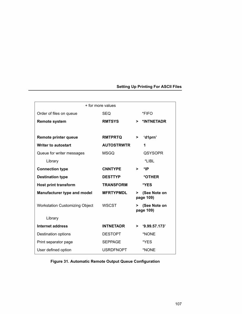
Setting Up Printing For ASCII Files
Figure 31. Automatic Remote Output Queue Configuration
+ for more values
Order of files on queue SEQ *FIFO
Remote system RMTSYS > *INTNETADR
Remote printer queue RMTPRTQ > ‘d1prn’
Writer to autostart AUTOSTRWTR 1
Queue for writer messages MSGQ QSYSOPR
Library *LIBL
Connection type CNNTYPE > *IP
Destination type DESTTYP *OTHER
Host print transform TRANSFORM *YES
Manufacturer type and model MFRTYPMDL > (See Note on page 109)
Workstation Customizing Object WSCST > (See Note on page 109)
Library
Internet address INTNETADR > ‘9.99.57.173’
Destination options DESTOPT *NONE
Print separator page SEPPAGE *YES
User defined option USRDFNOPT *NONE
107

Chapter 6 Configuring The AS/400 For Printing
3. Enter values for the following parameters:
Output Queue (OUTQ)
The name of the AS/400 output queue. The name can be anything you would like. This name is not the same as the printer internal queue name, ‘d1prn’.
Remote System (RMTSYS)
Internet address of the NIC on the printer (*INTNETADR prompts you for this) or the hostname of the NIC.
Remote Printer Queue (RMTPRTQ)
Default name of the network printer. Set for any of ‘d1prn’ through ‘d8prn’. The remote printer queue name must be lowercase, entered in single quotes.
NOTE:When the IPDS feature is installed, queue name ‘d4prn’ is not available.
Writer to Autostart (AUTOSRTWTR)
Set the value to 1. This will start the Remote Writer when the queue is created, and it automatically starts the Remote Writer after each IPL of the AS/400 and whenever STRTCP is started.
Connection Type (CNNTYPE)
Specify this value as *IP.
Destination Type (DESTTYP)
Specify *OTHER. *OTHER is a performance enhancement, in which data is not required to be transformed again if the connection is interrupted and allows printing of multiple copies.
Transform (TRANSFORM)
Specify this value as *YES.
108

Setting Up Printing For ASCII Files
Manufacturer Type (MFRTYPMDL)
Select a manufacturer type and model. This is the name of the WSCO.
NOTE: Select the Manufacturer Type Model based on the data type.
Manufacturer Type Model = *WSCST Workstation Customizing Object = QWPDEFAULT Library = QSYS
This selects a generic object that passes the data unchanged without any escape codes to the printer. Text files will print in the currently selected printer configuration, cpi, lpi, and form length. OS/400 versions below V3R7 may not have this selection and may require manual creation of a generic WSCST. Please contact Printronix Technical Support for assistance.
NOTE: For occasional text reports, create a printer configuration for each report and use the [Job Select] key to select a report configuration.
TroubleshootingThis installation procedure assumes that the NIC is configured with the correct IP address, subnet mask, and gateway (if required). In addition you can also ping and telnet to the NIC.
Print an Ethernet Test Page to verify the Ethernet settings. See “Configuration Using The Control Panel”, step 2 on page 24.
The default NIC queue name is d1prn, however, the name can be changed. Substitute the changed name for the RMTPRTQ parameter. To verify the queue name, print an E-Net Test Page or telnet to the adapter and perform a “list dest” command.
Internet address (INTNETADR)
Specify the IP address of the printer.
109
Chapter 6 Verify Printing On AS/400
Verify Printing On AS/400This section verifies that the printer is capable of printing ASCII files and that the printer can be pinged on the network.
To test ASCII printing:
1. Start TCP/IP, if it is not already running, by entering the command STRTCP.
2. Verify that the AS/400 TCP/IP interface is active.
3. Ping the printer from an AS/400 workstation with the command: ping ip_address.
Where ip_address is the Internet address of the remote system printer (the NIC) or the hostname of the printer (if you put the hostname in the host entry table as directed in “Configuring A TCP/IP Host Table Entry” on page 103).
4. If the printer cannot be pinged, proceed to “AS/400 ASCII Troubleshooting” on page 170.
5. Use one of the following methods to send a spooled file to the printer:
• Enter the LPR command on the AS/400 command line with the appropriate parameters. See “To Use LPR Manually” on page -104.
• Enter STRRMTWTR name on the AS/400 command line, where name is the name of the AS/400 remote output queue (not the printer Internet queue, as described on “To Create An Automatic Remote Output Queue” on page 106).
• Use the WRKOUTQ command to send jobs.
110

7 Monitoring Printers
Implementing Printer ManagementPrinter management includes the following tasks:
• Monitoring the status of network printers
• Responding to alarms
• Gathering statistics on printer operations
The three elements of network printer monitoring and management are:
• Agent/manager model
• The management information database (MIB)
• SNMP, the protocol used to get management information
Agent/Manager ModelThe elements of a monitoring system, MIB and SNMP, are implemented in an agent/manager model:
• The MANAGER is a console, workstation, or server on working hubs or routers which has a global knowledge of NICs and printers.
• AGENTS are utilities that reside on devices, such as a NIC, that respond through SNMP to management requests for information. The information is stored in an MIB.
111

Chapter 7 Implementing Printer Management
MIBAn MIB contains information a device makes available through SNMP. The MIB is a management information base that describes information about actual objects to be managed and controlled.
Standards Of Network Printer MIBsThe Printer MIB is based on the following standards:
• System and Interfaces Group MIB (RFC 1213 of March 1991)
• Host Resource MIB (RFC 1514 of September 1993)
• Printer MIB (RFC 1759 of March 1995)
• NIC contains the Standard Printer MIB per RFC 1759, available from www.ietf.org.
Information Provided By The MIBThe printer MIB contains the following types of information about network printers:
Descriptions. Printer configuration, location, and contact.
Status. Current operating status of printers.
Alerts. Reportable events from printers.
General Information About MIBsFor further information on SNMP and MIB, refer to the following:
• RFC 1155 — Structure and Identification of Management Information for TCP/IP-based Internets (SMI)
• RFC 1156 — Management Information Base for Management of TCP/IP Internets (MIB)
• RFC 1157 — A Simple Network Management Protocol (SNMP)
• The Simple Book: An Introduction to Management of TCP/IP-based Internets
112
SNMP
Getting The Latest MIB InformationThe latest copy of these and other RFCs can be obtained from the Internet Engineering Task Force (IETF) at http://www.ietf.org
SNMPSNMP is the protocol used to communicate between manager and agent. Managers request information, usually through automated polling at specified intervals, and agents respond.
SNMP is a standard by which a network manager can get statistics and configuration information from the NICs and other devices on the network. This is done through a Network Management Station (NMS) such as NetView®.
Monitoring ToolsMany tools can be used to monitor printers with SNMP agents. One of these tools is NetView. There are also other MIB browsers which are not described here.
Monitoring With AIX NetView/6000The AIX NetView/6000 program can manage any IP-addressable device with an SNMP agent.
NetView/6000 can be used to set a network topology, monitor a network, diagnose problems, and measure network performance.
Through its MIB Browser, information about the resources affecting an event (such as an alarm) can be obtained.
113

Chapter 7 Monitoring Tools
PrintNet Enterprise SuitePrintNet Enterprise Suite (PNE) is a versatile remote management software utility. It allows you to organize all of the printers in your office remotely in a single database, download software and printer settings from a host computer with a single mouse click, and use a virtual operator's panel to configure printers in the same room or on the other side of the world. Refer to the PrintNet Enterprise Suite User’s Manual or www.Printronix.com for more details on this tool.
Setting The SNMP Community NameThe default SNMP read-only community name is “public” and cannot be changed.
Change the SNMP R/W community name with the command: set user passwd snmp com_name save where com_name is the new SNMP R/W community name.
The default is no R/W community name.
NOTE: Changing SNMP community names or access rights may hinder or disable applications that are monitoring your printers.
114

8 Commands
Command Shell OverviewThe NIC comes with an in-depth command shell called npsh. It allows you to manipulate objects like destinations, I/O ports, and models and provides monitoring and troubleshooting capabilities.
npsh Access MethodsThere are many ways this command shell can be accessed:
• built in HTML forms
• a Telnet session from a TCP/IP host to the NIC
• a single remote shell command (e.g., rsh, rcmd, remsh) from a TCP/IP host
• a PTX_SETUP command file containing one or more npsh commands sent through a printer data port (serial, parallel, etc.)
Main npsh Command PrefixesAll configurable commands either start with store or set, and view commands start with list.
NOTE: If the store prefix is used, the NIC must be repowered to make the changes take effect. Since store affects flash memory settings only, the print server must reset and read the new settings now in flash memory.
115
Chapter 8 Command Shell Overview
NOTE: If the set prefix is used, a save command must be executed as well so that the new settings are retained after power cycles. Since set only affects the settings in memory, they will be lost after a power cycle unless they are saved to flash memory.
Getting Command HelpThe NIC command shell provides several online help tools, including:
“?” CommandTyping “?” when logged in to the command shell will produce a full list of all available commands.
Command PrefixesTyping in the first portion of a command will produce an error message showing the correct syntax. For example, typing in store tcpip will produce a list of all commands that start with this prefix.
116

Store Commands
Complete Command ListThis section outlines the entire NIC command set including the command syntax, a description, and in most cases, an example for each command listed.
NOTE: If you see the word ifnum in any npsh commands, you should substitute a 1 or 2 unless told otherwise. The 1 represents the one network interface (e.g., Ethernet) supported. The 2 represents the wireless network interface if it exists in the system.
Store CommandsThese commands change the settings stored in flash memory and do not affect the current or working settings in memory. A power cycle is needed before the stored settings become current.store ftpc addr <IPADDRESS>
Example: store ftpc addr 192.169.10.1
Set the ftp server IP address. This IP address allows the printer ftp client to connect during printer power-up if ftpc is enabled.
store ftpc user <USER-NAME>
Set the ftp server user name. This user name allows the printer ftp client to log into the ftp server when ftpc is enabled.
store ftpc passwd <PASSWORD>
Set the ftp server password. This password allows the printer ftp client to log into the ftp server when ftpc is enabled.
store ftpc file <FTP SERVER SUBPATH><FILENAME>
<FTP SERVER SUBPATH> is the directory under ftp server where the file is stored. <FILENAME> is the name of the file that is stored at the ftp server. The filename is in 8.3 format. When the ftpc is enabled and the printer is powering up, the printer logs into the ftp server of the specified IP address with the login ID and password provided. Navigate to the directory and retrieve the file given in this command. If a directory is not provided, the printer will retrieve the file from the root directory.
117

Chapter 8 Complete Command List
To reset ftpc process, use ‘load ptrfw all’ command. The printer will clear its internal ftp client records and reboot itself at the time the command is received.
store ifc ifnum utp [-]li [-]rxExample: store ifc 1 utp li
Modify the physical UTP interface properties where li enables link integrity and rx enables the increased receive threshold.
store ifc from default
Set all UTP settings back to factory defaults. store ifc from current
Store all current UTP settings to flash memory so they are retained after a power cycle. This ensures all current settings match what is stored in flash memory.
store ifc default <IFNUM>|<0> (0 for no default)
Store the specified interface as the default interface. The other interface is no longer active after power cycle. The 0 allows for both interfaces to be active.
store ifc <IFNUM> mode auto|10half|10full|100half|100full
Store the specified interface mode as automatic, 10mbps half duplex, 10mbps full duplex, 100mbps half duplex, 100mbps full duplex. See page 19.
Defines the wireless authentication scheme:store ifc <IFNUM> wlan auth <AUTH-METHOD> (eg. open, shared)
• “Open” system authentication allows all devices that have the authentication algorithm number for open system to authenticate.
• “Shared” key authentication involves a four step process using secure or encrypted text by means of WEP.
Set the wireless network name (SSID):store ifc <IFNUM> wlan ssid <NETWORK-NAME>
<ifnum> is the interface number for the WLAN interface.<network-name> is a 1 to 32 ASCII character string.
118
Store Commands
Set wireless transfer rate (speed):store ifc <IFNUM> wlan speed auto|<2 4 11 22 18 24 36 48 72 96 108>
<ifnum> is the interface number for the WLAN device. <speed-flags> are the speeds being selected. They are entered as a list of integers, separated by 'space' characters. The following rates are supported: 2 for 1Mbps, 4 for 2Mbps, 11 for 5.5Mbps, and 22 for 11Mbps. Using the word "auto" instead of any number will set the card to use automatic negotiation.
Set wireless antenna type:store ifc <IFNUM> wlan antenna diverse|primary|aux <ANTENNA-TYPE>
<ifnum> is the interface number for the WLAN device. <antenna-type> is the type of antenna to be used: "primary" and "aux" (auxiliary or external).
Set wireless power management mode:store ifc <IFNUM> wlan pmm on|off
<ifnum> is the interface number for the WLAN device. The string "off" disables power-save mode. "on" enables power-save mode with a default sleep-time of 100ms.
Set wireless transmit power:store ifc <IFNUM> wlan txpwr <0-100>
<ifnum> is the interface number for the WLAN device. <0-100> the power level as a percentage of full power .
Set options:store ifc <IFNUM> wlan opts [[-]intnl]
<ifnum> is the interface number for the WLAN device. An option is enabled by including it in the list and disabled by preceding it with a '-' character in the list. Supported option is "intnl", for international mode.
119

Chapter 8 Complete Command List
Set the wireless default key for WLAN encryption:store ifc <IFNUM> wlan defkey disable|<1-4>
<ifnum> is the interface number for the WLAN device. <1-4> is the number identifying one of the four keys (1-4). A value of zero or the word "disable" disables encryption.
Set the wireless key to a given value:store ifc <IFNUM> wlan key <KEY-NUM> <KEY-VALUE>|<$<STRING-KEY>{<LENGTH>]>
<ifnum> is the interface number for the WLAN interface. <key-num> is the number identifying one of the four keys (1-4). <key-value> is the encryption key value for <key-num>. The value must consist of 5 or 13 double- or quad-digit HEX numbers, separated by colon (':') or dash ('-') characters for readability (e.g. D1C2-B3A4-9586-7768-594A-3B2C-1D). Alpha characters are NOT case sensitive. All zero disables encryption for <key-num>. If '$' is the first character the remainder of the argument is treated as a literal string with all alpha-numeric characters allowed except spaces). Key length is inferred from the length of key-value so leading zeroes of longer keys must be entered (not blanked).
Set 802.11g profile:store ifc <IFNUM> wlan profile <WIFI-PROFILE>
<ifnum> is the interface number for the WLAN device. <WIFI-profile> is a value that specifies the Wi-Fi mode in which to operate. The values that can be set are as follows:
0: 802.11b operation only 1: mixed 802.11b and 802.11g operation 2: mixed 802.11b and 802.11g operation without support for 5.5 and 11 Mbps basic rates 3: 802.11g only operation 4: test 802.11g operation 5: 802.11b only operation without support for 5.5 and 11 Mbps basic rates 6: mixed 802.11b and 802.11g operation with support for 5.5 and 11 Mbps basic rates
120
Store Commands
store ifc <IFNUM> wlan profile <WIFI-PROFILE>
<ifnum> is the interface number for the wireless interface.
<WIFI-PROFILE> is a value in the range of 0 to 6, where:
0 = 802.11 b only 1 = mixed 802.11g,b 2 = mixed 802.11b,g without 5.5, 11 Mbps 3 = 802.11g only 4 = test 802.11g only 5 = 802.11b only without 5.5, 11 Mbps 6 = mixed 802.11b,g with 5.5, 11 Mbps
The default profile value is 1.
Selects the 802.11 g wireless (Wi-Fi) mode in which to operate.store ifc <IFNUM> wlan wpa disable|personal|enterprise
<ifnum> is the interface number for the wireless interface.
Selects the WPA wireless security mode. The options are disable (default), personal, and enterprise. Select personal mode for WPA/WPA2 authentication methods. Select enterprise mode for EAP authentication methods.
store ifc <IFNUM> wlan eap none|leap|peap|ttls
<ifnum> is the interface number for the wireless interface.
Selects the EAP authentication method. Select leap for Cisco LEAP authentication. The ttls option is reserved for future use. Select peap to use PEAP authentication.
store ifc <IFNUM> wlan cipher disable|tkip|aes|tkip+aes
<ifnum> is the interface number for the wireless interface.
Selects the WPA wireless security cipher setting. Disable, TKIP, AES, and TKIP+AES are the available settings. TKIP is the default setting when WPA is enabled.
store ifc <IFNUM> wlan passphrase <WPA PRE-SHARED KEY>
<ifnum> is the interface number for the wireless interface.
<WPA Pre-Shared Key> is the passphrase used to communicate with an access point. The passphrase entered must be between 8 and 63 ASCII characters long.
121

Chapter 8 Complete Command List
store ifc <IFNUM> wlan country <COUNTRY-CODE>
<ifnum> is the interface number for the wireless interface.
<COUNTRY-CODE> can be one of the following 2 or 3 character strings:
US or USI (for USA, USA Indoor operation, respectively), GB or GBI (for Great Britain, Great Britain Indoor operation), NL or NLI (for Netherlands, Netherlands Indoor), FR or FRI (for France, France Indoor), DE or DEI (for Germany, Germany Indoor), IT or ITI (for Italy, Italy Indoor)
The default country code is US.
This command is used to select the country and corresponding valid channel settings with which the 802.11g wireless NIC can use to communicate with an access point.
store pping opts [-]enableExample: store pping opts enable
Store the state of periodic ping flag. If the periodic ping flag is enabled the NIC periodic ping client will attempt to ping its default gateway on its active NIC interfaces. Default: disabled
store pping packet <NUMBER OF PACKETS>Example: store pping packet 1
Store the value of the packet. It is the number of ICMP Echo Request packets that will be sent by the periodic ping client on each period. Default: 1
store pping period <MINUTES>Example: store pping period 5
Store the value of the period. <minutes> is the amount of time from 1 to 5 minutes defines the periodic ping sequence will be repeated. Default: 5
122
Store Commands
store pping from defaultExample: store pping from default
Store all the periodic ping default settings to flash memory so taht they are retained after power up.
store pserver nameExample: store pserver name NIC1234
Command to change the print server name.store pserver opts [[-]jobsecurity] [jobtimeout <SECONDS>] [jobcontrol[off|standard|enhanced]] [[-]multcp]Example: store pserver opts jobcontrol [off|standard|enhanced]
jobcontrol is used to have different levels of secure printing. This is available as a performance enhancement for LPR, TCP socket printing etc. When jobcontrol is set to enhanced all jobs will be supported with job flow control.
NOTE: When jobcontrol is disabled, dynamic config loading on a model change is also disabled.
• off. No job control; the NIC does not monitor the printer operation. The printer prints faster in off mode. Although this setting provides performance improvement, the printer reports job complete once the NIC receives all the data.
• standard (the default). All data are guaranteed to be received by the printer before the job is released.
• enhanced. All data are guaranteed to be processed before the job is released. The printer job takes longer in enhanced mode.
To monitor the printer, use the telnet command “lpstat.” The status reported does not reflect the state of the print job once it has been sent from the NIC to the printer.
The new line at the bottom of the lpstate response labeled “printer job:” can report one of two status values:
a. In Progress. A job in the printer is not yet finished.
b. Done. There are no jobs in the printer. All previous jobs are finished.
123

Chapter 8 Complete Command List
Example: store pserver opts jobsecurity jobtimeout 5If jobsecurity is disabled, any user can cancel queued jobs on the NIC including guest users. If jobtimeout is set to some value other than 0, the NIC will only wait this amount of seconds when getting printer feedback. This is only used if you have a logpath port and type set on a particular destination.
The multcp option determines how many concurrent socket connections are allowed.Example: store pserver opts -multcp
When multcp is disable, only a single socket connection is allowed at a time. The default is multcp enabled.
store pserver tcpsocket <TCP-PORT> port <NEW-TCP-PORT>Example: store pserver tcpsocket 4000 port 5000
Change a pre-defined TCP port number (<tcp-port>) on the NIC to a new TCP port number (<new-tcp-port>). The default number is 9100 for prn.
store pserver tcpsocket <TCP-PORT> dest <DEST>Example: store pserver tcpsocket 5000 dest d1prn
Assign a pre-defined TCP port number (<tcp-port>) to a particular destination (<dest>) on the NIC. Therefore, if you are using a print method that sends jobs directly to a TCP port number, you still have the option to process the job data through this destination setting.
store pserver tcpsocket add <TCP-PORT> dest <DEST>Example: store pserver tcpsocket add 9101 dest d2prn
Maps the port number to a destination.store pserver tcpsocket del <TCP-PORT> dest <DEST>Example: store pserver tcpsocket del 9101 dest d2prn
Deletes a mapped port number destination already defined by listed commands.
store pserver smb workgrp <WORKGROUP>Example: store pserver smb workgrp eng
Define a different Windows workgroup as defined by <workgroup> for the NIC to be visible within (should be 14 characters or less). By default, the print server only comes up within the group called “WORKGROUP.”
124

Store Commands
store pserver lpd [-]dest1defaultExample: store pserver lpd dest1default
If dest1default is disabled and upon verification, the printer name supplied by the LPR protocol and the destination name do not match, then an error message is returned and the service is refused. If dest1default is enabled and upon verification, the printer name supplied by the LPR protocol and the destination name do not match, then the job is automatically routed to the first destination and the service is accepted.
Default: enabledstore pserver from default
Set all general print server settings back to factory defaults.store pserver from current
Store all current general print server settings to flash memory so they are retained after a power cycle. This ensures all current settings match what is stored in flash memory.
store ptrmgmt pne <PNE PORT NUMBER>
Change the port number to communicate with Printnet Enterprise.
Default: 9001store ptrmgmt status <STATUS PORT NUMBER>
Receives printer status, print job status, and/or emulation verification data. The data sent through this port is defined by the printer code.
Default: 9002store ptrmgmt mgmt <MGMT PORT NUMBER>
Used in PXML operation.
Default:9007Example: store ptrmgmt status 1025store tcpip <IFNUM> addr <ADDRESS>Example: store tcpip 1 addr 192.75.11.9
Store the IP address for the NIC.
125

Chapter 8 Complete Command List
store tcpip <IFNUM> mask <MASK>Example: store tcpip 1 mask 255.255.255.0
Store the subnet mask for the NIC.store tcpip <IFNUM> opts [[-]rarp] [[-]bootp] [[-]dhcp] [[-]persistdhcp] [[-]dns]Example: store tcpip 1 opts -rarp -bootp -dhcp
Enable or disable the automatic RARP, BOOTP, DHCP, DNS, or persistent DHCP requests for IP addresses upon bootup. If you are storing the NIC TCP/IP network settings within the device, you will not need to rely on RARP, BOOTP, DHCP, or DNS for new settings.
store tcpip ifnum frametype [[-]ethernet2] [[-]802.2snap]Example: store tcpip 1 frametype ethernet2 802.2snap
Control which frame type(s) is supported with the TCP/IP protocol. By default, both Ethernet 2 and 802.2snap are enabled, but normal TCP/IP communications rely on Ethernet 2. This setting has no affect on other supported network protocols (e.g., Novell).
store tcpip route add default[1|2] <ROUTER> <IFNUM> [<METRIC>]Example: store tcpip route add default1 192.75.11.1 1
Store a default router/gateway defined by router IP Address (<router> <ifnum>) so the NIC knows where to direct packets destined for another subnet. It is easier to store one default entry rather than an entry per remote host or network as in the previous command.
NOTE: “default1” is for ETHERNET device and “default2” is for WLAN device.
store tcpip del default [1|2]Example: store tcpip route del default1 192.75.11.1 1
Delete a default router/gateway defined by router IP Address (<router> <ifnum>) so the NIC knows where to direct packets destined for another subnet.
126
Store Commands
store tcpip route add [host|net] <NETWORK> [/mask>] <ROUTER> <IFNUM> [<METRIC>]Example: store tcpip route add net 192.75.12.0 1
Add a static route to a particular TCP/IP host or subnet specified by <network> so the NIC knows how to communicate with it. Normally one entry for a default router/gateway is all that is needed for communications between different subnets. Please see the next command for details.
store tcpip route del [host|net] <NETWORK>Example: store tcpip route add net 192.75.12.0 1
Delete a static route to a particular TCP/IP host or subnet specified by <network> so the NIC knows how to communicate with it. Normally one entry for a default router/gateway is all that is needed for communications between different subnets. Please see the next command for details.
store tcpip tcp rxwin <PACKETS>Example: store tcpip tcp rxwin 2
Determine the receive window size for the NIC. Usually the packets value ranges from 2 to 8, with the lower number allowing for more simultaneous TCP connections with the print server.
store tcpip tcp opts [-]keepalive [-]zeroIPArp [-]keepalivedataExample: store tcpip tcp opts keepalive
Control whether the NIC maintains a connection with a host when data cannot be accepted into its buffer. Normally the keepalive feature is enabled so when the printer cannot accept data, the print job connection is maintained and continued once the situation clears. The keepalivedata option controls whether the keepalive packet contains a data byte for hosts that require it.
If zeroIPArp is disabled then a NIC with an IP address of 0.0.0.0 will not allow IP access until the IP address is configured. If zeroIPArp is enabled on a NIC with an IP address of 0.0.0.0 then any attempted access with a valid IP address is assumed for this NIC and an Arp lookup is performed.
Default: enabled
127
Chapter 8 Complete Command List
store tcpip tcp access [root] add|del <NETWORK> [<NETMASK>]Example: store tcpip tcp access add 192.75.11.25
Add or remove an entry from the NIC TCP access list defined by <network>. If the list has an entry, only this host can print to and remotely interact with the print server.
store tcpip from default|current Example: store tcpip from default
Set all TCP/IP network settings back to factory defaults. Example: store tcpip from current
Store all current TCP/IP network settings to flash memory so they are retained after a power cycle. This ensures all current settings match what is stored in flash memory.
Set CommandsThese settings alter the current or working settings in memory only. Therefore, they will be lost if the NIC is power cycled. To ensure this does not happen, issue a save command so the current settings get written to flash memory.set dest <DEST> name <NEW_NAME>Example: set dest d1prn name laser
Change the current name of the <dest> to a new name as indicated by <new_name>. These names are case sensitive.
set dest <DEST> backchannel [prn]Example: set dest d1prn backchannel prn
Establish a return path for printer feedback for a given destination (<dest>). The NIC I/O port is bi-directional, however, you will most likely use the same I/O port to which the destination is currently sending jobs.
set dest <DEST> alternate [<ALT_DEST>]Example: set dest d1prn alternate d4prn
Sets an alternate destination for a queue other than itself.
128

Set Commands
set dest <DEST> model <MODEL>Example: set dest d1prn model m4
Associate a model with a destination. Jobs sent to the named destination (<dest>) are processed according to the options defined in the named model.
set dest <DEST> logpath <LOGPATH>Example: set dest d1prn logpath l4
Associate a logpath with a destination. Jobs sent to the named destination (<dest>) are logged according to the settings defined in the named logpath.
set dest <DEST> service [[-]socket][[-]lpd] [[-]lpsched] [[-]netbios] [[-]ftpd]Example: set dest d1prn service -netbios
Set the destination (<dest>) to handle only certain print services. To add a service, specify the service name. To disable a service, use “-” before the name. The available services are described in the following table.
Services
socket Direct socket printing via TCP/IP.
lpd LPR printing with TCP/IP, including LPR clients on any platform.
lpsched LP or System V printing with TCP/IP.
netbios Windows 95 and Windows for Workgroups printing.
ftpd Printing using the File Transfer Protocol (FTP) via TCP/IP.
set dest from default
Set all destination settings back to factory defaults.set dest from stored
Set all current destination settings to the values stored in flash memory.
129

Chapter 8 Complete Command List
set ifcExample: set ifc <IFNUM> up|down
Set state of the specified network physical interface up or down. <ifnum> is the interface number for the NIC device.
set logpath <LOGPATH> name <NEW_NAME>Example: set logpath l1 name pagecount
Change the current name of the logpath (<logpath>) to a new name as indicated by <new_name>. These names are case sensitive.
set logpath <LOGPATH> type [[-]job] [[-]user] [[-]cksum] [[-]printer] [[-]ioport]Example: set logpath l2 type job user printer pgcnt
Establish the type of printer and print job logging to be done within this <logpath>. The options are:
job Job ID, username, etc.
user User ID along with three messages per job about start and finish.
cksum 16-bit checksum value to confirm integrity of data printed.
printer For special printer feedback.
ioport Printer error messages determined through the parallel port pins.
set logpath <LOGPATH> port <TCP-PORT>|email|syslogExample: set logpath l3 port 2000
Determine where the log information should be sent for a print job or attached printer. The choices are:
TCP-port TCP port number ranging from 1024 to 65000.
email Particular user's email address. This address is set using the set sysinfo email emailname@IPaddress or [email protected] command.
130
Set Commands
syslog A central TCP/IP host running the SYSLOG daemon. This host is set using the set sysinfo syslog IPaddress command.
set logpath from default
Set all logpath settings back to factory defaults.set logpath from stored
Set all current logpath settings to the values stored in flash memory.
set lpd [-]bytecountExample: set lpd -bytecount
Set the job control on the file size of a Line Printer Daemon (LPD). If bytecount is enabled, the printer does not allow the LPD client to send a job with an unconventional file size. Usually the unrecognized numeric operand in the LPD Receive Data File command attributes to this behavior. The print job stream is canceled and its TCP connection is closed.
Default: Disabled.set lpd [-]offlinedata
The offlinedata flag helps minimize host disconnects when the printer goes offline for an extended time. Enable this option if you experience host disconnects when the printer goes offline.
set model <MODEL> name <NEW_NAME>Example: set model m1 name landscape
Change the current name of the model (<model>) to a new name as indicated by <new_name>. These names are case sensitive.
set model <MODEL> type rawExample: set model m2 type raw
Set the model type to raw so that it does not process the data passing through it in any way.
131

Chapter 8 Complete Command List
set model <MODEL> banner [text][after]Example: set model m2 banner text
Determine whether a banner page should be added for print jobs passing through the <model> mapped destination/queue. By default, banner pages are added to the front of the job. If after is set, the banner page will come at the end.
set model <MODEL> stty [[-]onlcr] [[-]descramble] [xtab <1-16>|none]Example: set model m3 stty onlcr
Control extra job processing done by the <model>. The processing options are:
onlcr Carriage return insertion for Unix text jobs. Adds carriage returns to text jobs with solitary linefeeds. This will prevent stair-stepped output or output running off the right side of the page.
descramble Automatic descrambling of print jobs passing through which have been scrambled using Printronix proprietary Unix scramble utility, npscramble. This is not supported.
xtab Tab expansion from 1 to 16 spaces.set model <MODEL> header [<STRING>]Example: set model m1 header 0x20
Set a header string to be sent to the printer at the start of any print jobs passing through this <model>. The headerstring (<string>) can consist of up to nine elements. An example element is a hexadecimal code (e.g., 0x04) or a pre-defined variable on the print server (e.g., $FF for a formfeed). Use list var to see all available variables. To erase the header, send the command with no headerstring value; for example ‘set model m1 header’.
132
Set Commands
set model <MODEL> trailer [<STRING>]Example: set model m7 trailer $FF
Set a trailer string to be sent to the printer at the end of any print jobs passing through this <model> . The trailerstring (<string>) can consist of up to nine elements. An example element is a hexadecimal code (e.g., 0x04) or a pre-defined variable on the print server (e.g., $FF for a formfeed). Use list var to see all available variables. To erase the trailer, send the command with no trailerstring value; for example ‘set model m1 trailer’.
set model <MODEL> config [config_num]
Set a printer configuration number config_num to be loaded prior to printing a job on the specified model. If the command is sent with config_num set to 0, the factory configuration is loaded before the job prints. If config_num is in the range 1 through 8, the corresponding configuration number is loaded before the job prints. To return to the default state where no configuration is loaded, send the command with no config_num value; for example ‘set model m1 config’. When no new configuration is loaded, the current configuration settings will be in effect for any jobs sent to model <model>. To see which configuration, if any, will be loaded at the start of a job, use the command ‘list model’ or ‘list model <model>’.
set model from default
Set all model settings back to factory defaults.set model from stored
Set all current model settings to the values stored in flash memory.
set snmp
To add a user named snmp with root privileges, follow the steps below:
a. Login to the NIC as a root user.
b. Add a user named snmp: set user add snmp
c. Set the user type to root: set user type snmp root
133

Chapter 8 Complete Command List
d. Set the password for the snmp user: set user passwd snmp snmppassword
e. Save the changes: save
The user snmp is now created and snmppassword is the only community string which will allow write access.
set snmp community <name>
This command disables SNMP community default names. SNMP has a list of default community names. It creates internet vulnerability that someone can get to the printer using the default names. When the user sets its own community name, the default names will not be active.
The private community name can be cleared by the following comands.
‘set snmp community’
‘set user from default’set snmp manager <INDEX> <IPADDRESS> <TRAP-COMMUNITY>
The NIC continuously generates traps. To set the NIC to send traps to a particular SNMP manager, use this command to add an SNMP manager to the trap table.
<index> is the index number of the trap table. <ipaddress is the IP address of the SNMP manager receiving traps. <trap-community> is the community string sent along with the trap information.
set snmp trapport <INDEX> <UDP_PORT>
Set the UDP port number in the SNMP trap manager table. This value should correspond to the port number monitored by the SNMP manager application running on the host at the IP address specified in the ‘set snmp manager’ command.
<index> is the index number of the SNMP trap manager table. <udp_port> is the desired UDP port number. Acceptable values are 162, and 49152 through 65535.
set snmp trap <INDEX> [-]active
Enable or disable an SNMP trap manager table entry.
134

Set Commands
The index is the index number of the SNMP trap manager table. “active” enables the table entry, “-active” disables the entry.
set snmp emailaddr <INDEX> <EMAILADDRESS>
The NIC can also send SNMP alert messages to a desired e-mail address. To specify an e-mail address to send alert messages to, use this command to add the e-mail address to the SNMP alert table.
<index> is the index number of the SNMP trap manager table. The emailaddress is the desired e-mail address of the form [email protected].
set snmp emailformat <INDEX> [-]short
Enable or disable the short e-mail message format for an SNMP alert table entry. When enabled, the short e-mail format can be used when messages will be viewed on devices having a limited display size (a cellular phone or pager, for example).
<index> is the index number of the SNMP alert table. “short” enables the short e-mail format, “-short” disables it.
set snmp shortmsglen <INDEX> <LENGTH>
Specify the length of the short e-mail message format for an SNMP alert table entry. This command is effective only when the short e-mail message format for an SNMP alert table entry is enabled.
<index> is the index number of the SNMP alert table. “length” specifies the length of the short e-mail message, and has an acceptable range of 15 to 80 characters.
set snmp email <INDEX> [-]active
Enable or disable sending e-mail alert messages for an SNMP alert table entry.
<index> is the index number of the SNMP alert table. “active” enables sending e-mail alert mesages, “-active” disables it.
set snmp alerts <INDEX> [-]all | [[-]warning] [[-]offline] [[-]mediainput] [[-]mediaoutput] [[-]mediapath] [[-]marker] [[-]cutter] [[-]barcode] [[-]scanner] [[-]intervention] [[-]consumable] [[-]label][[-]powercart] [[-]rfid]
135
Chapter 8 Complete Command List
Example: set snmp alerts 1 warning -cutter]
Specifies which alert groups are enabled for reporting via an SNMP manager, e-mail alert message, and/or Unix syslog daemon. See Table 2 on page 63 for a description of specific printer events belonging to each group.
The index is the index number of the SNMP manager/alert table.
“-all” disables and “all” enables reporting of alerts in all alert groups. Individual alert groups can be selectively enabled or disabled via combinations of alert group switches. For example, to enable warning alerts and disable cutter alerts for SNMP table entry 1, enter the following:
set snmp alerts 1 warning -cutterset snmp syslog <INDEX> [-]active
The NIC can also log SNMP alert messages to the defined SYSLOG host (see the ‘set sysinfo syslog’ command description). Use this command to enable or disable logging of alert messages for an SNMP alert table entry.
<index> is the index number of the SNMP alert table. “active” enables alert message logging, “-active” disables it.
set sysinfo label|name [<STRING>]Example: set sysinfo name salesprinter
Set a descriptive name defined by <string> for NIC identification purposes. This is not used in the operation of the print server in any way.
set sysinfo contact [<STRING>]Example: set sysinfo contact Paul_Harris
Set a person or department to contact in case of print server trouble.
set sysinfo location [<STRING>]Example: set sysinfo location salesdept
Set the physical location of the NIC. This is for identification purposes and is not used in the operation of the print server in any way.
set sysinfo prnserial [<STRING>]
136

Set Commands
Example: set sysinfo prnserial 000123456789Sets the printer serial number.
set sysinfo loginfo [-]sys | [-]tcp |Example: set sysinfo loginfo -sys tcp
Set the NIC debugging information type. Usually this information includes unexpected errors or exceptions from the print server divided into these groups:
sys General system messages
tcp TCP stack messages
NOTE: This is not printer or job logging information.set sysinfo logport null|prn|syslogExample: set sysinfo logport null
Define to where the debugging information should be sent. This can be sent to an output device off of the NIC I/O port or to a central TCP/IP host running a SYSLOG daemon. To set this host, use the command set sysinfo syslog hostIPaddress.
set sysinfo smtp <IPADDRESS> [port <PORTNUM>]Example: set sysinfo smtp 192.75.11.5 port 25
Define the SMTP (Simple Mail Transfer Protocol) server IP address or domain name and port number where the mail is stored on your network.
Default: Unconfigured, 25set sysinfo email <EMAIL>Example: set sysinfo email [email protected]
Define the user email address to receive printer and job logging information from a particular logpath on the NIC. Email name is the host or IP name of the user.
Default: Unconfiguredset sysinfo email emailname@domainExample: set sysinfo email [email protected]
Define the user email address to receive printer and job logging information from a particular logpath on the NIC.
137

Chapter 8 Complete Command List
set sysinfo syslog hostIPaddressExample: set sysinfo syslog 192.75.11.30
Set the IP address of the host running the SYSLOG daemon. NIC debugging or print job and printer logging information can be sent to that IP address.
set sysinfo dns <IPADDRESS>Example: set sysinfo dns 192.75.11.2
Set your DNS server IP address so the NIC can resolve host names when used with its built-in Telnet and ping clients.
set sysinfo domain <NAME>Example: set sysinfo domain printronix.com
Sets the domain name for the NIC, which when combined with the print server name, forms the fully qualified domain name of the NIC.
set sysinfo descramblekey <HEXVAL>Example: set sysinfo descramblekey 1234
Set the key value used for descrambling print jobs that have passed through Printronix npscramble utility on a TCP/IP host. This key is a four-digit hexadecimal value obtained from the host software, npscramble. Within the npscramble source code, there is a variable called SR_KEY which contains the default key value. This can be changed to any four-digit value you would like. This is not supported.
set sysinfo module [[-]netbios]Example: set sysinfo module -netbios
Enable and disable certain network protocol stacks within the NIC. Sometimes it helps to disable any protocols you are not using on your network.
set user add|del <NAME>Example: set user add eng
Add or remove a user on the NIC defined by <name>.
IMPORTANT Do not delete the root user, or you will be unable to configure any further settings on the print server. You will have to go back to factory defaults to correct this problem.
138

Set Commands
set user passwd <NAME> [<PASSWORD>]Example: set user passwd eng mplex1
Assign a password to a defined user on the NIC.set user type <NAME> root|guestExample: set user type eng root
Assign root or guest privileges to a particular user defined by username. Guest permissions allow viewing of settings only. Root permissions allow complete control of the NIC.
set user from default
Set all user settings back to factory defaults.set user from stored
Set all current user settings to the values stored in flash memory.
set user passwd snmp <COM_NAME>
Set the new SNMP R/W community name as the <com_name> value.
set var <VAR> [<VARIABLE-STRING>]Example: set var LANDSCAPE 0x1b 0x26 0x6c 0x31 0x4f
Define a new variable to be used in header, trailer, or switch strings on the NIC and call it <variable-string>. <variable-string> can be a space-separated list of words, hexadecimal numbers (e.g., 0x04), or references to other pre-defined variables. It is easiest to make up the <variable-string> with hexadecimal values, as shown in the example.
NOTE: One variable counts as one element within header and trailer strings.
Defined variables are referenced in strings by placing a “$” before the variable name (e.g., set model m1 trailer $FF).
set var from default
Set all variable settings back to factory defaults.set var from stored
Set all current variable settings to the values stored in flash memory.
139

Chapter 8 Complete Command List
List CommandsThese commands list the current or working settings for a particular section within the command shell. To view stored settings in flash memory, insert stored after list. For example, list prn shows the current printer settings but list stored prn shows the settings in flash memory. Normally these should match. To view default settings in flash memory, insert default after list.list all
Lists all current settings.list arp
List the current ARP table that the NIC adheres to in a TCP/IP network.
list dest [destination]
List the current destination settings (e.g., names and mapped I/O ports, models, and logpaths).
list diff
List the differences between the current settings and the stored settings in flash memory. Normally, you want these values to match, so issue a save command followed by a reset command.
list ftpc
List the ftp client settings.list ifc
Lists the current UTP interface settings (e.g., link integrity).
140

List Commands
WLAN For the wireless NIC, the WLAN interface settings will also be included. The WLAN parameters are displayed in the following manner, after the interface list has been displayed:
WLAN
ifnum = <ifnum>
radio ID = <wireless-card-id>
ssid = <network name>
antenna = <antenna-type>
speed = <speed-flags>
pmm = <sleep-time>
defkey = <key-num>
auth = <auth-method>
user = <auth-user-name>
pass = <auth-password>
txpwr = <power>
opts = <option-list>
profile = <WIFI-profile>
wpa = <wpa-mode>
eap = <eap-mode>
encryption = <wpa-cipher>
passphrase = <wpa-passphrase>
country = <country-code>
Status = <status>
Quality = <comms-quality>
Where:
<ifnum> is the interface number for the WLAN device.
<wireless-card-id> is a read only character string identifying the wireless card installed.
<network name> is a 1 to 32 ASCII character string.
141
Chapter 8 Complete Command List
<antenna-type> is the type of antenna ("Primary" or "Auxiliary").
<speed-flags> is the speeds being used for communication ([1 2 5 11 6 9 12 18 24 36 48 54], or "auto").
<sleep-time> indicates the power-save sleep-time in milliseconds.
If power-save is disabled (time is set to zero), "normal (power-save off)" displayd.
<key-num> is the number identifying one of the four encryption keys, starting from one. Encryption is disabled if "Encryption disabled" displayd.
<auth-method> is the authentication method e.g. open, shared.
<auth-user-name> is the authentication method user name.
<auth-password> is the authentication method password.
<power> is a percentage indicating the approximate fraction of fullpower.
<option-list> is a list of options that are enabled (disabled options are not shown).
<WIFI-profile> is a value that specifies the Wi-Fi mode in which to operate.
<wpa-mode> is the WPA wireless mode selected.
<eap-mode> is the wireless EAP authentication mode selected.
<wpa-cipher> is the selected WPA cipher setting.
<wpa-passphrase> is the WPA passphrase represented as * characters if configured.
<country-code> is the currently configured country setting that is used to determine valid channel settings with which the 802.11g wireless NIC is used to communicate with an access point.
<status> is the current access point association status (“disassociated” or “associated with <MAC address>”)
<comms-quality> indicates the strength or quality (in percent) of the wireless signal.
NOTE: The "list stored ifc" command does not display the "Status" or "Quality" lines.
142

List Commands
list key
List the license details and license key number.list logins
List any active user logins on the NIC.list logpath [logpath]
List the current logpath settings (e.g., names and mapped destinations).
list model [model]
List the current model settings (e.g., names and mapped destinations). With no model parameter, a table of values for name, type, banner, config and the size in bytes of header and trailer are shown for all models m1 through m8. When the model parameter is supplied, the specific bytes used in the header and trailer are shown, along with the banner type, data type and configuration number for that specific model.
list ptrcfg
List the current printer configuration.list ptrmgmt
List the PNE port number, Status port number, and Management port number.
list net
List all current TCP/IP network settings (e.g., IP address and subnet mask).
list pping
List all the current periodic ping setting.list pserver
List the current general print server settings (e.g., print server name).
list snmp
List the Trap Table containing SNMP Managers.list sysinfo
List the current NIC system information (e.g., contact name and protocol stacks enabled).
143

Chapter 8 Complete Command List
list tcpip
List all current TCP/IP network settings (e.g., IP address and subnet mask).
list test
List the status of output tests on the I/O ports.list uptime
Lists how long the NIC has been up and running from the last reset.
list ptrcfg
List the current printer configurationlist ptrmgmt
List the current printer management port numbers.list user
List the current user definitions (e.g., user names and types).list var
List all pre-defined variables including any newly created ones. Any of these defined variables can be referenced in a string by placing a “$” before the variable name (e.g., set model m1 trailer $FF).
list dhcp
List all DHCP information for the NIC provided that DHCP is enabled.
list lpd
List the Line Printer Daemon (LPD) information, such as whether the bytecount is enabled or disabled.
144
Miscellaneous Commands
Miscellaneous CommandsThese commands do not fall under any specific section of the command shell, but they are used quite frequently. save [default]
Save the current settings to flash memory so they are available after power cycles. Sysinfo, destination, model, logpath, variable, user, and I/O port settings will be saved. If default is specified as well, factory settings will be saved, overwriting any new settings you have configured.
reboot
Perform a warm boot or hardware reset to simulate a power-on reset. This restores current settings to those stored in flash memory, since the flash memory settings will be read and loaded into memory upon bootup.
reset
Perform a warm boot or hardware reset to simulate a power-on reset. This restores current settings to those stored in flash memory, since the flash memory settings will be read and loaded into memory upon bootup.
load [default]
Load the settings stored in flash memory and use them as the current or working settings. If default is specified as well, factory settings will be loaded.
lpstat [ioport] [jobID]Example: lpstat prn
Display active and queued jobs and I/O port status for a given ioport or jobID. Specifying one of these parameters will shorten the output and focus on the particular I/O port or print job specified.
145

Chapter 8 Complete Command List
cancel jobIDExample: cancel d1prn-10
Remove a job from an I/O port queue. Use lpstat to find a particular job ID first.
start fox|tts|loopb prnExample: start fox prn
Begin a debugging test on one of the I/O ports on the NIC. The tests available are:
fox A continuous stream of text sent to the attached printer. This is a good test for troubleshooting hardware as long as the attached printer supports text output.
tts A continuous stream of Gandalf 400C TTS-compatible text sent to the attached printer.
loopb Loopback test. Any input characters from the device attached to the I/O port is echoed back.
stop all|prn
Stop an output test on an I/O port.disable ioport|destination|ftpc|ftp|telnetExample: disable destination
Disable an I/O port so that queued jobs are not printed, or disable a destination so jobs cannot be queued to it. This command can also disable ftpc, ftp, or telnet protocol.
enable ioport|destination|printermgr|ftpc|ftp|telnetExample: enable printermgr
Enables the printer debug port to allow remote printer management software to function. This command can also enable ftpc, ftp, or telnet protocol.
146

Miscellaneous Commands
close tcp TCPindexnumberExample: close tcp 3
Close the a TCP/IP connection between a TCP/IP host and the NIC. The TCPindexnumber can be retrieved from “debug tcp” output.
ping [-s] hostIPaddress [datasize [packetnumber]]Example: ping 192.75.11.30
ping another TCP/IP host specified by hostIPaddress on the NIC network. datasize is the datagram packet size which defaults to 64 bytes if no size is included in the syntax and packetnumber is the number of requests to be sent.
NOTE: To use a host or IP name instead of the address, you must have set the DNS server on the NIC. Use the command set sysinfo dns... to do this.
telnet hostIPaddress [escapecharacter]Example: telnet 192.75.11.35
Start a Telnet session with another TCP/IP host specified by hostIPaddress on the NIC network. If escapecharacter is used, it resets the key sequence used to exit the Telnet session. It will return you to the telnet> prompt where you can execute quit. Use the keycode command to find out exact escape characters if needed. The default character is CTRL ].
NOTE: To use a host or IP name instead of the address, you must have set the DNS server on the NIC. Use the command set sysinfo dns... to do this.
chr <STRING>
Echo < string> or redirect <string> to an I/O port using the chr <string> ioport.
keycode
Determine the hexadecimal value for a key to be used as the escape character with the NIC built-in telnet command.
? (Help)Lists all available commands.
147

Chapter 8 Complete Command List
148

9 Extra Features
NIC SecurityThere are TCP access lists available to restrict host connections with the device.
Users And PasswordsThe NIC supports two user types:
root Access to everything within the print server including all configurable settings.
guest Ability to list settings only.
Passwords can be set for each user type. However, most often you will just set a password for the root user to protect the NIC configuration. Guest users cannot alter the print server configuration in any way.
To configure a root password on your NIC:
1. Load a Web browser on a network station that can communicate with the print server over TCP/IP. The commands to set a root password are:
Syntax:set user passwd username passwordsave
Example:set user passwd root your_password_for_rootsave
149
Chapter 9 NIC Security
2. Direct your Web browser to URL: http://NICIPaddress/adminConf.html (e.g., http://192.75.11.9/adminConf.html).
NOTE: If prompted for a “User ID” and password first, type in root for the user ID and press ENTER at the password prompt (since there is no password by default).
3. At the “Administration Configuration” HTML form that displays, scroll down to the “Passwords” section.
4. Click within the “Old” field beside the “Root Password” heading and enter the existing root password. By default, there is no root password, so you can go to the next step without typing anything in this field.
5. Within the “Root Password” section, click within the “New” field and enter the new root password.
6. Within the “Root Password” section, click within the “Confirm” field and enter the new root password again. Remember this is case sensitive.
7. Click on the SUBMIT button when done and physically repower the print server to make the new setting take effect.
From this point on, anytime you log in to the NIC as root, you will need to specify this password or your login attempt will fail.
NOTE: To clear this password or change it, use the same “Administration Configuration” HTML form. Just enter the appropriate “Old” password and put in the new one (or nothing if you do not want a root password any longer). The commands directly on the NIC are:set user from defaultsave
150

Reset The NIC Password
Reset The NIC PasswordOccassionally a user will set a root user password on the NIC and then forget it. This is the procedure to reset the root password back to the default (no password).
1. Turn the printer on.
2. Take the printer offline and unlock the front panel by pressing the Down Arrow and ↵ keys at the same time.
3. Press all four arrow keys (up, down, prev, next) at the same time, and release.
4. Press the Down Arrow key and then the Right Arrow key until “E-NET To DEFAULT” appears.
5. Press Enter.
6. Re-program the IP address information from the front panel.
NOTE: Steps 1 – 5 also clears the IP address information and sets the adapter back to the factory default.
TCP Access ListsWithin TCP/IP environments, the NIC can restrict host access to destinations/queues and remote command (e.g., rsh, rcmd, remsh, and telnet) execution services. This is done using an access list similar in function to the Unix .rhosts file.
NOTE: Access list settings are not configurable through the HTML forms provided with the NIC.
To view the current access list on the print server:
1. Start a Telnet session with the NIC.
Syntax:telnet NICIPaddress
2. Log in as root and press ENTER at the password prompt since there is no password by default (or your password for your home set).
151

Chapter 9 NIC Security
3. List the current access list.
Syntax:list tcpip
If the list is empty, all hosts have access to the NIC services. If there are entries in the list, only those hosts specified have access to printing and remote command execution.
To add and delete access list entries, the commands are:
Syntax:store tcpip tcp access add|del hostIPaddress|networkaddressreset
where hostIPaddress is the IP address of a TCP/IP host on your network and networkaddress is the address of a subnet on your network.
Example:store tcpip tcp access add 192.75.11.25store tcpip tcp access add 192.75.12.0store tcpip tcp access del 192.75.11.25reset
NOTE: Although the maximum number of entries in the access list is 10, each entry can refer to a network rather than a specific host. This allows all hosts on that specified network and any individual hosts specified in the list to have access.
152
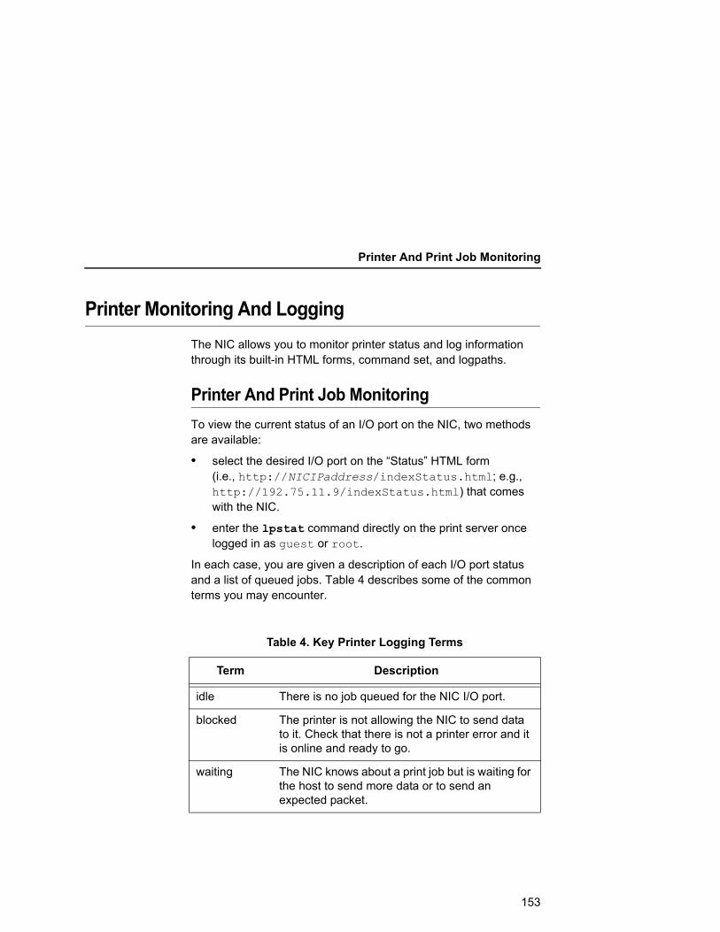
Printer And Print Job Monitoring
Printer Monitoring And LoggingThe NIC allows you to monitor printer status and log information through its built-in HTML forms, command set, and logpaths.
Printer And Print Job MonitoringTo view the current status of an I/O port on the NIC, two methods are available:
• select the desired I/O port on the “Status” HTML form (i.e., http://NICIPaddress/indexStatus.html; e.g., http://192.75.11.9/indexStatus.html) that comes with the NIC.
• enter the lpstat command directly on the print server once logged in as guest or root.
In each case, you are given a description of each I/O port status and a list of queued jobs. Table 4 describes some of the common terms you may encounter.
Table 4. Key Printer Logging Terms
Term Description
idle There is no job queued for the NIC I/O port.
blocked The printer is not allowing the NIC to send data to it. Check that there is not a printer error and it is online and ready to go.
waiting The NIC knows about a print job but is waiting for the host to send more data or to send an expected packet.
153
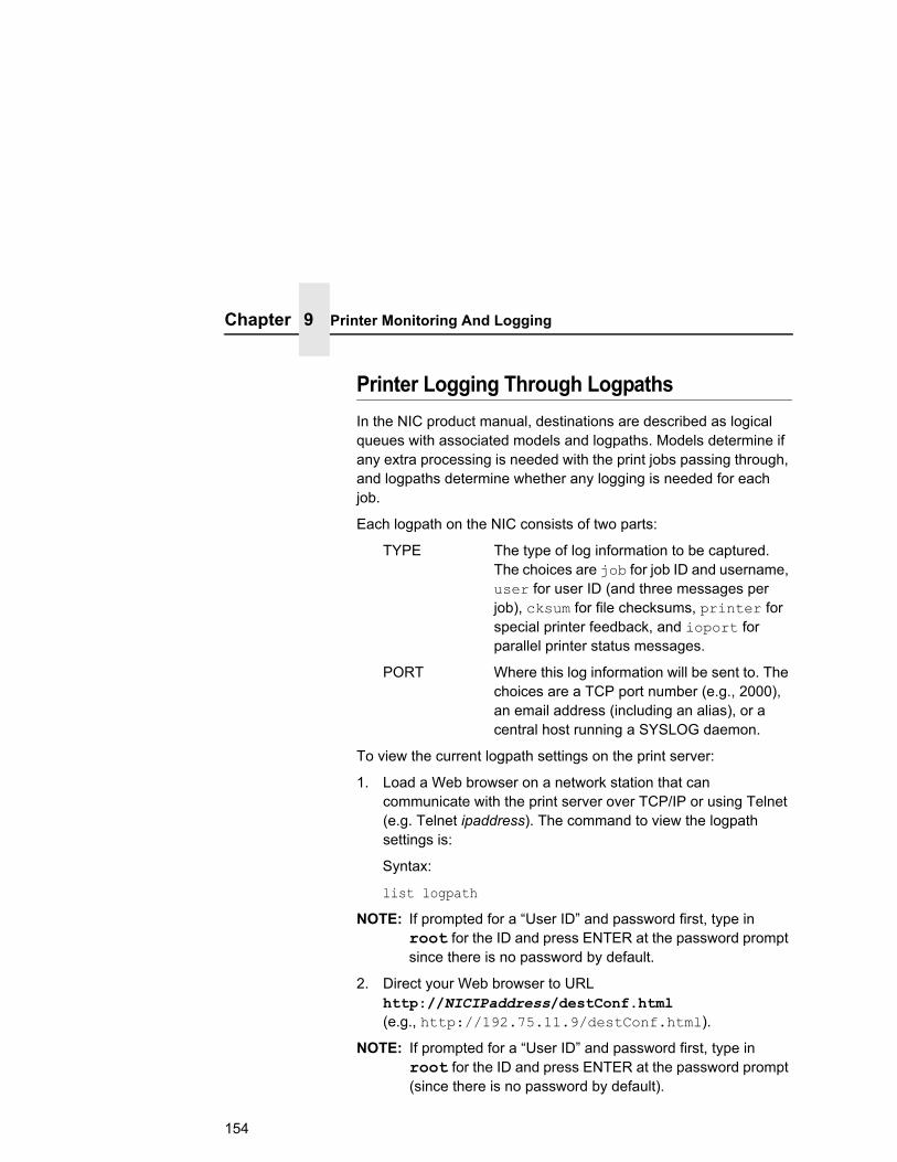
Chapter 9 Printer Monitoring And Logging
Printer Logging Through LogpathsIn the NIC product manual, destinations are described as logical queues with associated models and logpaths. Models determine if any extra processing is needed with the print jobs passing through, and logpaths determine whether any logging is needed for each job.
Each logpath on the NIC consists of two parts:
TYPE The type of log information to be captured. The choices are job for job ID and username, user for user ID (and three messages per job), cksum for file checksums, printer for special printer feedback, and ioport for parallel printer status messages.
PORT Where this log information will be sent to. The choices are a TCP port number (e.g., 2000), an email address (including an alias), or a central host running a SYSLOG daemon.
To view the current logpath settings on the print server:
1. Load a Web browser on a network station that can communicate with the print server over TCP/IP or using Telnet (e.g. Telnet ipaddress). The command to view the logpath settings is:
Syntax:
list logpath
NOTE: If prompted for a “User ID” and password first, type in root for the ID and press ENTER at the password prompt since there is no password by default.
2. Direct your Web browser to URL http://NICIPaddress/destConf.html (e.g., http://192.75.11.9/destConf.html).
NOTE: If prompted for a “User ID” and password first, type in root for the ID and press ENTER at the password prompt (since there is no password by default).
154
Printer Logging Through Logpaths
3. At the “Print Path Configuration” HTML form that displays, select a destination link (e.g., d1prn) from the top of the page to bring up the appropriate destination form.
4. Once the desired destination HTML form displays, scroll down to the “Logpath Type” and “Logpath Port” sections to view the current logpath settings for this particular destination.
At this point, you can alter any of these settings and then click on the SUBMIT button to store them into the NIC. Remember to repower the NIC to make the settings take effect.
Downloading Software Through The Network Interface Card (NIC)
1. Make a printout of all saved configurations. (Installing new software erases all saved configurations. You will use the printouts to restore the printer configurations.)
2. Set the printer power switch to O (Off).
3. On the printer panel, press and hold down the ↵ (Enter) and (Cancel) keys.
Without releasing the keys, power the printer on, and continue holding the keys down until you see “TESTING HARDWARE PLEASE WAIT” on the LCD. You may then release the keys.
4. Wait until you see “STATUS:FIRMWARE DOWNLOAD MODE” on the LCD before proceeding. This can take up to 30 seconds to appear, depending on the emulations and interfaces installed in the printer.
5. Using Windows Explorer, create a directory named download at the root level of your C: hard drive.
6. Insert the printer emulation software CD into your computer.
7. Using Windows Explorer, navigate to the appropriate file on the CD (using the Unzipped directory) based on the printer type, and desired emulation, e.g., Unzipped T4M IGP.
155

Chapter 9 Downloading Software Through The Network Interface Card (NIC)
IMPORTANT You must use the Unzipped directory, since this contains the uncompressed files necessary for NIC download.
8. Make note of the file name, which is a six digit number plus .prg, e.g., 123456.prg. This is the file you will download into the NIC.
9. Copy the file to the download directory.
10. Start a command prompt session. (The Start Menu icon is usually labeled MS-DOS Prompt or Command Prompt.)
11. At the command prompt type:
C:<Enter> cd \download<Enter>
12. Start the FTP protocol by typing:
ftp xxx.xxx.xxx.xxx<Enter> (where xxx.xxx.xxx.xxx represents the IP Address of the printer.)
13. Log in to the printer by typing:
root<Enter>
You are given a password prompt.
NOTE: The default is no password. If the FTP program requires a password, contact your system administrator.
14. At the password prompt, press <Enter>.
15. Once logged in, type the following sequence at the command prompt to download the filename.prg file to the printer:
cd dest<Enter> cd d1prn<Enter> bin<Enter> put filename.prg<Enter> (where filename.prg is the file name you noted in step 8.)
CAUTION Do not interrupt the downloading process once it has started. Interrupting a download will damage the flash memory on the controller board and NIC card.
156
Printer Logging Through Logpaths
16. As the file downloads, the FTP program shows the progress as a percentage. Once the download is complete, exit out of the FTP program by typing:
quit<Enter>
17. When the new program has successfully loaded into flash memory and the printer has reset itself, set the printer power switch to O (off).
18. Unplug the AC power cord from the printer.
19. Remove the CD from the host computer and store it with the printer.
20. Using the configuration printout(s), reconfigure the printer and reload any optional font files.
NIC Naming SchemesA single I/O Port destination can be configured with a variety of model and logpath combinations. For instance, once you set the parameters for m1 and l1, you can assign the model and logpath to more than one I/O port destination such as d1prn, d2prn, and d8prn. You may now use the same set of model and logpath parameters more than once without having to redefine those parameters each time for another I/O Port destination.
157

Chapter 9 Periodic Ping
Periodic PingThis feature when enabled executes background ping from the print server to its default gateway. The operation is executed on every user defined period. This mechanism has no TCP traffic from the print server to anything on the network to keep route information alive. Since every member in the VLAN is subject to aging from bridging cache, a switch or bridge in between may be forgotten in the table at which port the printer was connected. If one ping is run from printer server to its default gateway through the switch, the switch learns again and the route is seen. The problem will not be seen with TCP since the ACKs keep the bridge relearning in a switch. Periodically send ICMP Echo Request between a print server and its gateway that is typically situated in the same VLAN and connected with the same switch or bridge.
The printer server allows a periodic group of ping packets [1 – 5] to be issued by a set time [1– 5] minutes, to the gateway value the NIC has from its routing table. This feature can be enabled or disabled. The default is disable.
This periodic ping is different from the normal ping process. The purpose of this ping is not an attempt at dead gateway detection. There is no ping client created in the print server and the ICMP Echo Reply packets received from the gateway are deleted without being processed by the ping client. This reduces the processing load on the print server. The data size of ICMP Echo Request Message is set to 16 bytes such that the Ethernet frame is set to 64 bytes to minimize the impact of bandwidth on the network. This process applies to all the active NIC interfaces.
158
A Troubleshooting Tips
Windows Troubleshooting TipsThis section provides information on possible solutions to some standard Windows and NIC configuration errors.
Technical SupportIf you require technical support, please have the following information available when you call:
1. What level of software are you running?
2. What type of attachment do you have?
3. What is your host operating system?
4. Give a detailed description of the problem.
5. How often, and when, does the problem occur?
6. Give a detailed description of your network and the components attached.
159
Appendix A Windows Troubleshooting Tips
NIC Cannot Be Found On The NetworkPlease follow these tips to determine what the problem may be with your NIC configuration.
• Have you assigned the NIC a unique and valid IP address which corresponds with the other IP addresses on your network? For example, are you sure no other device is using this IP address?
• Are you sure you are trying to talk to the NIC from a Windows station on the same subnet? Currently, the print server can only be seen locally unless you configured a routing entry earlier.
• Have you confirmed that the network connection to the NIC is working correctly? Trying different network cables and locations will help narrow down the problem.
• For wireless NIC, is the SSID correct? Is the operation mode correct?
Errors Occur When Defining An LPR Printer• Can you ping the NIC from your Windows NT station? If not,
please refer to “NIC Cannot Be Found On The Network” on page 160.
• Did you specify the correct IP address or host name for the NIC in the first field of the “Add LPR Compatible Printer” box?
• Did you specify a valid destination/queue on the NIC in the second field of the “Add LPR Compatible Printer” dialogue box? If so, did you also enter it in lowercase letters?
160

Cannot Browse The NIC On The Network
Cannot Browse The NIC On The Network• Have you looked under the right Windows workgroup? By
default, the NIC will be found under “WORKGROUP.”
• Are you able to browse other Windows stations and devices on the network from this same station?
• Has this Windows station been given enough time to update its registry so it can see this newly added workgroup device? Sometimes Windows stations can take considerable time, depending on the size of the network.
Printer Errors When Printing Or No Output• Is there a large job currently printing which is taking up all of the
printer resources? Usually when printing from Windows 95/98 stations, a busy printer can cause Windows to display a printer error message. This is because it demands immediate printer attention rather than holding the data until the printer is ready again. The best way around this is to use a central spooling station like an NT server.
• Have you tried restarting the spooler under “Control Panel:Services”? Sometimes this is needed to get printing started.
NOTE: As a last resort, you may want to reboot the Windows station. Sometimes this is the only option to completely clear this situation. The NIC usually has nothing to do with this problem.
161

Appendix A Windows Troubleshooting Tips
TCP/IP Access ProblemIf you can ping the printer from a workstation, but you cannot Web browse, Telnet, or print to the printer through the NIC, there may be an incorrect entry in the TCP access list. In order for this workstation to use the NIC interface in this case, one of two things must happen.
• The TCP list must have an entry added to grant access to this workstation, or
• All entries must be deleted from the TCP list to grant all workstations/hosts access to the above TCP services.
To view the current access list, use the printer control panel to access the configuration menu (see the User's Manual for configuration menu information). From the DIAGNOSTICS/Printer Tests menu choose the E-Net Test Page. When the page prints, look under the “TCP ACCESS TABLE” section for the TCP access list entries.
To add/delete a TCP access list entry, refer to “TCP Access Lists” on page 151.
NOTE: When the following procedure is used, the TCP access list will be cleared, but all IP addresses will need to be entered again after the procedure is complete.
To reset all Integrated NIC TCP/IP values to the factory defaults when access is impossible, contact your Printronix service representative for assistance.
162

Web Browser/HTTP Problem
Web Browser/HTTP ProblemIn some cases, you may not be able to browse the printer Web page simply because the NIC HTTP may be turned off.
If you cannot ping the NIC IP address, make sure the IP Address, subnet mask, and default gateway are set correctly by checking the Ethernet Parameters menu from the operator panel. See the User's Manual for configuration menu information.
If you can ping the NIC IP address but cannot access the Web pages, perform the following procedure to verify the NIC HTTP is turned on.
1. Telnet into the NIC and log in as root. There is no password by default.
2. At the system prompt, enter the following commands:config http onsavereset
3. After approximately 30 seconds, point your browser to the NIC IP address. The printer Web pages should now be accessible.
If you are still experiencing difficulty accessing or browsing the printer, contact the Customer Solutions Center for further assistance.
HTML Configuration Forms Will Not Display• Can you ping NIC from the Windows station? If not, refer to
“NIC Cannot Be Found On The Network” on page 160.
• Have you used the correct URL for the NIC home page? It should be http://NICIPaddress (e.g., http://192.75.11.9).
• Is HTTP support enabled? If not, refer to “Web Browser/HTTP Problem” on page 163.
163

Appendix A Windows Troubleshooting Tips
Windows NT 4.0 Or 2000 Host Setup ProblemsThe installation procedure covered earlier in this chapter assumes that the NIC is configured with the correct IP address, subnet mask and gateway (if required), and that the administrator can ping and telnet to the NIC from the server console. If this is not the case, use the printer front panel to configure the NIC before proceeding.
Installing Microsoft TCP/IP PrintingThe NIC installation for Windows NT 4.0/2000 also requires the “Microsoft TCP/IP Printing” service on the server. To install this service, click the Network icon in the Control Panel and click the Services tab. Click Add Service and select Microsoft TCP/IP printing.
• Do you have administrative privileges?
This installation requires administrator privileges.
The Ethernet cable is not plugged in or the printer is not turned on. This message is a communication failure between the NT/2000 server and the NIC. Check cabling, IP address settings, gateway, etc.
164
Windows NT 4.0 Or 2000 Host Setup Problems
• Test page does not print or prints incorrectly:
1.Is the printer online? Re-send test page.
2.The Printronix NT print driver requires P-Series emulation active on the printer. The Generic/Text driver should print in any printer emulation.
3.Delete then re-install the Microsoft TCP/IP Print service on the server.
If you are still experiencing difficulty accessing or browsing the printer, contact the Customer Solutions Center for further assistance.
165

Appendix A Unix Troubleshooting Tips
Unix Troubleshooting TipsThis section provides information on possible solutions to some standard configuration errors. If you require technical support, please have as much of the following information available when you call:
1. What level of software are you running?
2. What type of attachment do you have?
3. What is your host operating system?
4. How often, and when, does the problem occur?
5. Give a detailed description of the problem.
6. Give a detailed description of your network and the components attached.
NIC Cannot Be Found On The Network• Have you configured the NIC with a unique and valid IP
address which corresponds with the other IP addresses on your network? For example, are you sure no other device is using this IP address?
• Are you sure you are trying to talk to the NIC from a Unix station on the same subnet? Currently, the print server can only be seen locally unless you configured it with a routing entry.
• If you look at the back of the printer, is the STAT LED flashing once a second or is it quicker than that? A slower, once-a-second rate tells you that the print server is in fact configured with an IP address. A faster rate indicates it knows nothing about this, so you may need to try the configuration process again.
• Have you confirmed that the network connection to the NIC is working correctly? Trying different network cables and locations will help narrow down the problem.
166

Nothing Prints
Nothing Prints• Can you ping the NIC from your Unix station? If not, please
refer to “NIC Cannot Be Found On The Network” shown above.
• Is the NIC able to communicate with the attached printer? To test this, you can:
a. Telnet to the print server (e.g., telnet 192.75.11.9) and log in as root.
b. Enter the command start fox prn.
c. Execute stop prn right after starting the test.
d. This test will send the same text line over and over to the attached printer.
• Is the job getting stuck in the Unix host queue? If so, check that the printer is online. If it is, there is a configuration error on the Unix station, so creating a new print setup may be needed.
• Is the control panel showing any activity to indicate it is receiving data? If so, but there is nothing printing, check if a manual form feed is needed. Also, ensure that the printer can support the type of job coming through.
• Do all jobs fail or just certain ones? For example, is it possible that jobs from a certain application are the only ones to fail? If so, check the type of data it sends to make sure it matches the printer emulation. Check the application printer configuration for mistakes.
• If you are using System V, was the spooler restarted?
167

Appendix A Unix Troubleshooting Tips
TCP/IP Access ProblemIf you can ping the printer from a workstation, but you cannot Web browse, Telnet, or print to the printer through the NIC, there may be an incorrect entry in the TCP access list. In order for this workstation to use the NIC in this case, one of two things must happen:
• the TCP list must have an entry added to grant access to this workstation, or
• all entries must be deleted from the TCP list to grant all workstations/hosts access to the above TCP services.
To view the current access list, use the printer control panel to access the configuration menu (see the User's Manual for configuration menu information). Print an Ethernet Test Page to verify the Ethernet settings. See “Configuration Using The Control Panel”, step 2 on page 24.
When the page prints, look under the TCP Access Table section for the TCP access list entries.
To add/delete a TCP access list entry, refer to “TCP Access Lists” on page 151.
NOTE: When the following procedure is used, the TCP access list will be cleared, but all IP addresses will need to be entered again after the procedure is complete.
168

Front Panel Message – Dynamically Set Params Read Only
Front Panel Message – Dynamically Set Params Read OnlyThis is not an error. It is an informational message warning that the IP address has been dynamically set by either dhcp, rarp, or bootp.
To assign a static IP address, turn off the rarp, bootp, and dhcp on the adapter. Use the following procedure:
1. Telnet to the adapter. Login = root, password = (Enter key)
Telnet commands are:store tcpip 1 opts -rarp -bootp -dhcpsavereset
Wait two minutes for the adapter to reset.
2. Program the IP address, Subnet Mask and Gateway (if required) from the front panel.
169

Appendix A AS/400 ASCII Troubleshooting
AS/400 ASCII TroubleshootingDuring power up, the printer performs an interface hardware test. The presence of the ETHERNET PARAMS menu selection at the printer control panel indicates that the NIC hardware is functioning properly. See the User's Manual for configuration menu information.
If you have trouble pinging the printer:
1. Verify the configuration of the AS/400, including the printer and any intervening devices such as routers and bridges.
2. Verify that the AS/400 line description is varied on and the printer is turned on and displays an ONLINE status.
3. Verify that the AS/400 TCP/IP is active.
TCP/IP Access ProblemIf you can ping the printer from a workstation, but you cannot Web browse, Telnet, or print to the printer through the NIC, there may be an incorrect entry in the TCP access list. So that the workstation can use the NIC in this case, one of two things must happen:
• the TCP list must have an entry added to grant access to this workstation, or
• all entries must be deleted from the TCP list to grant all workstations/hosts access to the above TCP services.
To view the current access list, use the printer control panel to access the menu. See the User's Manual for configuration menu information. From the Operator Print Test menu, choose the Ethernet Test Page. When the page prints, look under the “TCP ACCESS TABLE” section for the TCP access list entries.
To add/delete a TCP access list entry, refer to “TCP Access Lists” on page 151.
NOTE: When the following procedure is used, the TCP access list will be cleared, but all IP addresses will need to be entered again after the procedure is complete.
170

TCP/IP Access Problem
1. From a workstation attached to this network segment, create an ARP entry. The NIC IP address and hardware or MAC address are needed. At the workstation, enter: arp -s <ipaddress> <MACaddress> ping <ipaddress>
2. Try to ping this IP address to see if the NIC can be seen on your network. If the interface does not respond, verify you are on the same network segment as the printer and that the ARP entry was created.
3. Telnet into the NIC using the same IP address as above. Log in as root with no password.
4. At system prompt, enter: store tcpip from default config http on reset
NOTE: This will reset all TCP/IP settings to factory default and reset the NIC.
5. Wait for the NIC to reset.
6. Power the printer off and then back on.
7. Wait for the “ETHERNET READY” message to display.
8. Set the IP address, subnet mask, and default gateway parameters to the desired values. (See “Configuration Tools” on page 23.)
171

Appendix A AS/400 ASCII Troubleshooting
Web Browser/HTTP ProblemIn some cases you may not be able to browse the printer Web page simply because the NIC HTTP may be turned off.
If you cannot ping the NIC IP address, make sure the IP address, subnet mask, and default gateway are set correctly by checking the ETHERNET PARAMS menu from the control panel. See the User's Manual for configuration menu information.
If you can ping the NIC IP address but cannot access the Web pages, perform the following procedure to verify the NIC HTTP is turned on:
1. Telnet into the NIC and log in as root with no password.
2. At the system prompt, enter the following commands:config http onsavereset
3. After approximately 5 minutes, point your browser to the NIC IP address. The printer Web pages should now be accessible.
If you still experience difficulty accessing or browsing the printer, contact the Customer Solutions Center for further assistance.
172

B Customer Support
Printronix Customer Support CenterIMPORTANT Please have the following information available prior to calling
the Printronix Customer Support Center:
• Model number
• Serial number (located on the back of the printer)
• Installed options (i.e., interface and host type if applicable to the problem)
• Configuration printout:
See “Printing A Configuration” in the User’s Manual.
• Is the problem with a new install or an existing printer?
• Description of the problem (be specific)
• Good and bad samples that clearly show the problem (faxing or emailing of these samples may be required)
Americas (714) 368-2686
Europe, Middle East, and Africa (31) 24 6489 311
Asia Pacific (65) 6548 4114
China (86) 800-999-6836
http://www.printronix.com/support.aspx
173
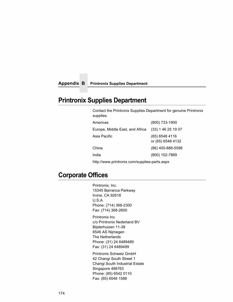
Appendix B Printronix Supplies Department
Printronix Supplies DepartmentContact the Printronix Supplies Department for genuine Printronix supplies.
Americas (800) 733-1900
Europe, Middle East, and Africa (33) 1 46 25 19 07
Asia Pacific (65) 6548 4116 or (65) 6548 4132
China (86) 400-886-5598
India (800) 102-7869
http://www.printronix.com/supplies-parts.aspx
Corporate OfficesPrintronix, Inc. 15345 Barranca Parkway Irvine, CA 92618 U.S.A. Phone: (714) 368-2300 Fax: (714) 368-2600
Printronix Inc. c/o Printronix Nederland BV Bijsterhuizen 11-38 6546 AS Nijmegen The Netherlands Phone: (31) 24 6489489 Fax: (31) 24 6489499
Printronix Schweiz GmbH 42 Changi South Street 1 Changi South Industrial Estate Singapore 486763 Phone: (65) 6542 0110 Fax: (65) 6546 1588
174

Printronix Commercial (Shanghai) Co. Ltd 22F, Eton Building East No.555, Pudong Av. Shanghai City, 200120, P R China Phone: (86) 400 886 5598 Fax: (86-21) 5138 0564
Visit the Printronix web site at www.printronix.com
175

Appendix B Corporate Offices
176

C Glossary
ARP Address Resolution Protocol. Associates a selected IP address with a network device Ethernet address.
bps Bits per second.
Centronics Parallel port interface standard found on most printers.
daemon A continuously running process that handles system-wide functions like print spooling.
default router Local device that forwards any IP packets destined for another subnet.
destination Logical print queue on the NIC to which hosts send their print jobs. There are eight destinations by default.
DHCP Dynamic Host Configuration Protocol. Allows a network device to discover its IP address dynamically upon bootup. The IP address does not need to be stored within the device itself permanently.
Download Mode Refers to the condition of the NIC when in a startup condition, downloading configuration information.
DNS Domain Name Server. Host providing responses to queries for a given host name IP address.
177

EEPROM Electrically Erasable/Programmable Read-Only Memory.
factory defaults Settings shipped with the NIC.
Factory Settings S2 jumper position stating all factory default settings are to be used while the NIC is up and running.
Firmware Panic Unrecoverable errors detected by the NIC firmware force the Print Server into Firmware Panic mode. Manually reset the NIC to resume operation.
Flash Stores firmware code and configurable settings. Allows for upgrades without replacing hardware inside the NIC.
FTP File Transfer Protocol. Used for transferring files from one TCP/IP host to another and used in the upgrade process.
gateway Hardware device that translates data between two incompatible networks.
gateway address The IP address of a gateway.
Hardware Exception Bus errors, address errors, and illegal instructions force the NIC into this NIC non-operational mode.
HTML HyperText Markup Language. Format used for documents viewable on the World Wide Web.
ifnum Interface Number. Represents the network interface. With a NIC, this will always be “1” for Ethernet.
interface script Unix host filter file that processes the print job before it is sent over the network to the NIC.
I/O port Port for attaching peripherals to. The NIC provides four: PRN1, PRN2, COM1, COM2.
178
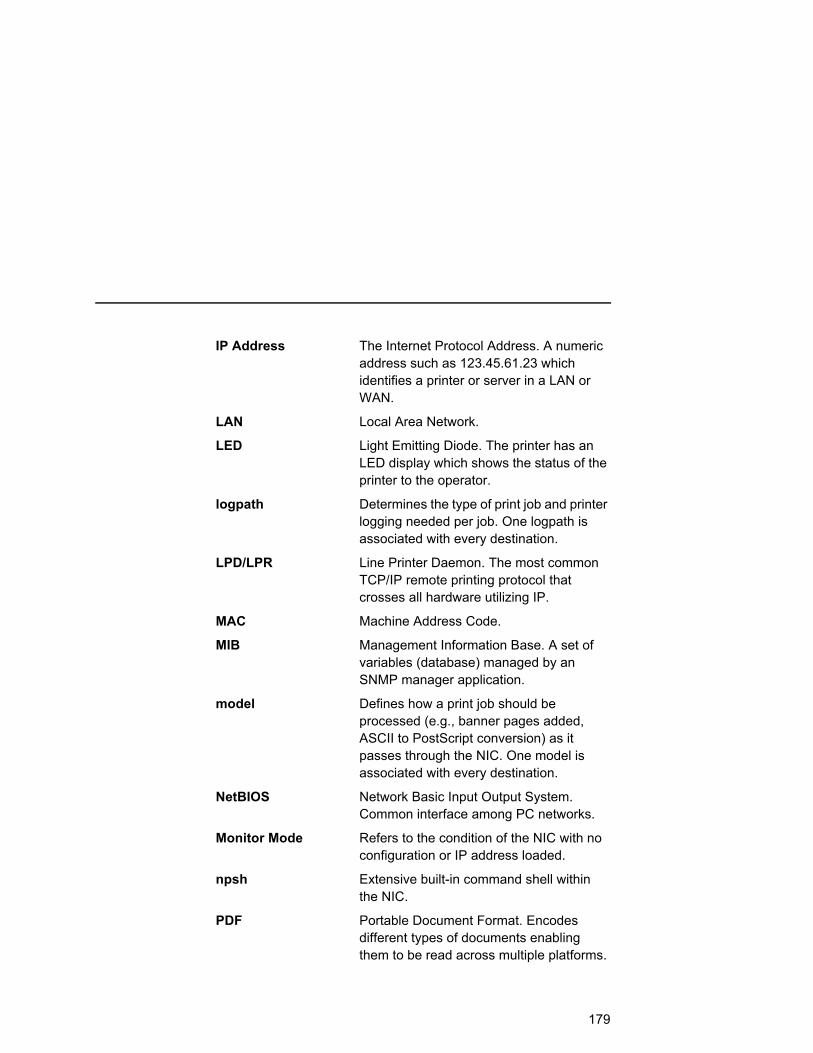
IP Address The Internet Protocol Address. A numeric address such as 123.45.61.23 which identifies a printer or server in a LAN or WAN.
LAN Local Area Network.
LED Light Emitting Diode. The printer has an LED display which shows the status of the printer to the operator.
logpath Determines the type of print job and printer logging needed per job. One logpath is associated with every destination.
LPD/LPR Line Printer Daemon. The most common TCP/IP remote printing protocol that crosses all hardware utilizing IP.
MAC Machine Address Code.
MIB Management Information Base. A set of variables (database) managed by an SNMP manager application.
model Defines how a print job should be processed (e.g., banner pages added, ASCII to PostScript conversion) as it passes through the NIC. One model is associated with every destination.
NetBIOS Network Basic Input Output System. Common interface among PC networks.
Monitor Mode Refers to the condition of the NIC with no configuration or IP address loaded.
npsh Extensive built-in command shell within the NIC.
PDF Portable Document Format. Encodes different types of documents enabling them to be read across multiple platforms.
179

Persistent DHCP When this option is enabled, the IP Address, Gateway, and Subnet Mask obtained through DHSP is saved. If the DHCP server does not provide an address, the device will use the previously saved DHCP IP address. This option only works when DHCP is enabled. The default disable.
ping Standard command to test a TCP/IP connection. (e.g., ping 192.75.11.9)
print path Three-stage path a print job takes when it is sent from a host to a printer through the NIC.
protocol A set of rules or conventions governing the exchange of information between computer systems or between a printer and a host computer. For computer printers, a protocol is the coding convention used to convey and print data. A printer protocol includes codes for printing text and graphics, as well as codes instructing the printer to perform special operations and machine-to-machine communication codes.
PSERVER Print Server. A Novell print method where the NIC continuously polls the Novell file server print queue looking for print jobs.
RAM Random Access Memory. Volatile memory within the NIC that contains current/working settings. Settings are lost once the power is removed.
RARP Reverse Address Resolution Protocol. Allows a network device to discover its IP address dynamically upon bootup. The IP address does not need to be stored within the device itself permanently.
180
ROM Read-Only Memory.
router A device that forwards IP packets to their destination. Also called a gateway.
RPRINTER Remote Printer. A Novell print method where the NIC waits for jobs to be sent to it from a defined PSERVER.
SNMP Simple Network Management Protocol. A standard protocol used to monitor network devices called “SNMP agents.”
socket TCP connection between two hosts consisting of a source and destination TCP port number at each end.
subnet mask A binary value used to divide IP networks into smaller sub-networks or subnets. This mask is used to help determine whether IP packets need to be forwarded to other subnets.
TCP/IP Transmission Control Protocol/Internet Protocol. Suite of protocols that act as the base protocol for the Internet.
TCP port A logical connection point in the software of a TCP host or device. When two IP devices talk, they establish a socket which consists of a source and destination TCP port number on both ends.
telnet Command and protocol to establish a terminal connection between two hosts on an IP network.
UTP Unshielded Twisted Pair. A cable used for telephone and computer-to-computer connections.
WAN Wide Area Network.
181

182

Index
Symbols? command, 116
Numerics10/100Base-T, speed setting, 192003 Server, Host setup, 78
AAccess lists, TCP, 151Access methods, npsh, 115ADDTCPIFC, configuring with, 101ADDTCPRTE, router definition, 103Administration, configuration, 64Agent model, printer monitoring, 111AIX 4, NIC configuration, 93AIX NetView/6000, monitoring, 113AIX printing, 95AIX, remote queue time-out setting, 95Alert groups, 62Antenna, Preamble, 45Antenna, Wireless, 45ARP, Unix, 84AS/400
automatic remote output queue, 106configuring for ASCII, 101configuring for printing, 104CRTLINETH, 99hostname, 103local domain, 103remote printer queue name, 104
A
A
AAA
BBBBB
CCC
C
C
TCP/IP access problem, 170TCP/IP host table entry, 103verify printing, 110
S/400 ASCIIHTTP problem, 172troubleshooting, 170
SCIIconfiguring AS/400, 101setting up for printing, 104
uthentication Method, Wireless, 47utomatic remote output queue, S/400, 106
Back Channel, Print Path, 50anner Page, 55anner Page, Print Path, 52OOTP, Unix, 87rowse NIC, troubleshooting, 161
Change destination names, NIC, 76hannel, Speed, 44ommand prefixes, 116
npsh, 115ommand Shell, 115
ways to access, 32ommands
?, 116complete list, 117
183

Index
getting help, 116list, 140miscellaneous, 145set, 128store, 117
Communcation routers, Windows, 74Configuration
administration, 64control panel, 24Encryption Key, 31Equivalent Wireless NIC, 31IP Address, 27Log Path, 57network, 39NIC for AIX 4, 93Print Model, 54Print Path, 49SNMP, 59System, 69wireless NIC, 27Wireless Parameter, 29
Configuration menu, NIC, 38Configuration tools, 23Connecting to the network, 23Control panel message, Dynamically Set Params Read Only, 169Control panel, configuration, 24CRTLINETH, line descriptions, 99Customer Support Center, 173
DDDDDD
DDDm
EE
EEEEE
FFF
GG
184
Default Key, Wireless, 47efault Password, 35, 37, 96, 163efault Username, 35, 37, 96, 163efine LPR printer, error, 160estination settings, Print Path, 49estinations
models, 17NIC, 17
irect socket printing, 97ocument conventions, 20ynamically Set Params Read Only essage, 169
EAP Mode, Wireless, 47AP Password
Wireless, 48AP User, Wireless, 47-mail alert posting, 60ncryption Key Configuration, 31quivalent Wireless NIC Configuration, 31rrors, defining LPR printer, 160
Filter, Print Model, 55ilter, Print Path, 52TP printing, 96
Getting Help command, 116uest user, NIC, 149
Index
HHeader String, Print Model, 55Header String, Print Path, 53Help command, getting, 116Home page, URL, 33Host configuration, Unix, 89Host setup
2003 Server, 78Printer Driver Setup Wizard, 78Windows 2000, 78Windows Vista, 78Windows XP, 78
HP-UX, 90HTML forms, 32HTML, NIC structure, 33HTTP, troubleshooting, 163
II/O Port, status, 70Installation
HP-UX, 90Solaris 2.6, 91
Installation Solaris 7, 91Installation, NIC, 23Interface, TCP/IP Network, 40International Mode, Wireless, 45IP Address Configuration, 27
KKey Length (Optional), Wireless, 47Key Value (Hex), Wireless, 47Key Value (String), Wireless, 47
KK
LLL
LLLLLLLL
MM
MMMMMMMM
ey Value Type, Wireless, 47ey, Wireless, 47
Line descriptions, CRTLINETH, 99ist commands, 140og Path
configuration, 57Logpath Port, 58Logpath Type, 57Name, 57
og Path Port, Print Path, 53og Path Type, Print Path, 53ogging, printer, 153ogical printer architecture, 15ogpath Port, Log Path, 58ogpath Type, Log Path, 57ogpaths, printer logging, 154PR/LPD Host setup, 92
Manager model, printer monitoring, 111anual
notes, 21notices, 21
anual LPR/LPD Host setup, 92anual system, V Host setup, 89IB, 112icrosoft TCP/IP printing, 164iscellaneous commands, 145ode, Wireless, 44odel Type, Print Model, 54odel Type, Print Path, 51
185

Index
Models, 17Monitoring
print job, 153printer, 153
NName
Log Path, 57Print Model, 54Print Path, 50
Naming schemes, NIC, 157NetBIOS TCP/IP, Windows Network, 48Network
configuration, 39connection, 23NIC cannot be found, 160status, 70TCP/IP, 39
Network Interface Card, 13Network Name, Wireless, 44NIC, 13
cannot be found, 160cannot be found on network,
troubleshooting, 166change destination names, 76configuration for AIX 4, 93configuration menu, 38configuration, Windows, 72destinations, 17guest user, 149HTML structure, 33installation, 23naming schemes, 157
NNN
PP
PPPPPPP
186
passwords, 149queues, 17reset password, 151root user, 149security, 149special features, 14users, 149verification, 26
otes, 21otices, 21psh
access methods, 115command prefixes, 115
Password, default, 35, 37, 96, 163asswords, 68
NIC, 149reset, 151
eriodic Ping, 158NE, 114ower Mgmt Mode, Wireless, 45reamble, Antenna, 45refixes, command, 116rint job monitoring, 153rint Model, 55
Banner Page, 55configuration, 54Filter, 55Header String, 55Model Type, 54Name, 54

Index
Printer Configuration, 56Trailer String, 56
Print PathBack Channel, 50Banner Page, 52configuration, 49destination settings, 49Filter, 52Header String, 53Log Path Port, 53Log Path Type, 53Model Type, 51Name, 50Printer Configuration, 53Selected Log Path, 53Selected Model, 50Services, 50Trailer String, 53
Printererrors, 161logging, 153logging through logpaths, 154monitoring, 153status screen, 34
Printer ConfigurationPrint Model, 56Print Path, 53
Printer Driver Setup Wizard, 78Printer management implementation, 111
P
P
PP
P
Q
RRRRR
rinter monitoringAgent model, 111Manager model, 111MIB, 112SNMP, 113tools, 113
rintingAIX, 95ASCII, 104configuration, AS/400, 104direct socket, 97FTP, 96troubleshooting, 167verification, AS/400, 110
rintNet Enterprise Suite, 114roblem
AS/400 ASCII HTTP, 172AS/400 ASCII Web browser, 172
rofile, Wireless, 46
Queues
models, 17NIC, 17
RARP, Unix, 86emote shell, 35oot user, NIC, 149outers, Unix, 88outing, TCP/IP Network, 42
187

Index
SSecurity, NIC, 149Selected Log Path, Print Path, 53Selected Model, Print Path, 50Services, Print Path, 50Set commands, 128Shell, command, 115SNMP, 113
community name, 114configuration, 59manager alert posting, 59
Solaris 2.6, 91Solaris 7, 91Special features, NIC, 14Speed setting, 10/100Base-T, 19Speed Type, Wireless, 44Speed, Channel, 44Speed, Wireless, 44Status
I/O Port, 70menu, 69Network, 70
Status screen, printer, 34Store commands, 117Supplies Department, 174Syslog alert posting, 60System
configuration, 69information, 65
TT
T
T
TTTT
TT
188
TCP access lists, 151CP/IP
access, troubleshooting, 162configuring AS/400 for ASCII, 101
CP/IP access problemAS/400, 170Unix, 168
CP/IP Network, 39Interface, 40Routing, 42
echnical support, 159elnet, 35ools, printer monitoring, 113railer String
Print Model, 56Print Path, 53
ransmit Power, Wireless, 45roubleshooting
AS/400 ASCII, 170cannot browse NIC on Network, 161defining LPR printer, 160HTML configuration forms, 163HTTP, 163NIC cannot be found, 160NIC cannot be found on Network, 166printer errors, 161printing, 167TCP/IP access problem, 162Unix, 166Web browser, 163Windows, 159
Index
Windows 2000 Host setup, 164Windows NT 4.0 Host setup, 164
UUnix
crossing routers, 88environment, 83Host configuration, 89manual system V Host setup, 89NIC configuration, 84TCP/IP access problem, 168troubleshooting, 166using ARP, 84using BOOTP, 87using RARP, 86
Unix troubleshootingDynamically Set Params Read Only
message, 169URL, home page, 33Username, default, 35, 37, 96, 163Users, NIC, 149Using ARP, Windows, 72
VV Host setup, manual system, 89Verification, NIC, 26
WWeb browser
problem, 172troubleshooting, 163
Web server, overview, 37
W
W
W
WtWWW
indowscommunication routers, 74configuration, 71environment, description, 71mandatory configuration, 72NIC configuration, 72optional configuration, 72troubleshooting, 159using ARP, 72
indows 2000Host setup, 78Host setup troubleshooting, 164
indows Network (NetBIOS TCP/IP), 48Workgroup Name, 48
indows NT 4.0, Host setup roubleshooting, 164
indows Vista, Host setup, 78indows XP, Host setup, 78ireless, 43
Antenna, 45Authentication Method, 47Default Key, 47EAP Mode, 47EAP Password, 48EAP User, 47International Mode, 45Key, 47Key Length (Optional), 47Key Value (Hex), 47Key Value (String), 47Key Value Type, 47Mode, 44
189

Index
Network Name, 44Power Mgmt Mode, 45Profile, 46Speed, 44Speed Type, 44Transmit Power, 45WPA Cipher, 46WPA Mode, 46WPA Passphrase, 46
Wireless NIC Configuration, 27Wireless Parameter Configuration, 29Workgroup Name, Windows Network (NetBIOS TCP/IP), 48WPA Cipher, Wireless, 46WPA Mode, Wireless, 46WPA Passphrase, Wireless, 46
190


251765-001G*251765-001*