network management card 2 user guide - apc.com · user guide ups network management card 2 ap9630,...
TRANSCRIPT

User GuideUPS Network Management Card 2
AP9630, AP9631, AP9635 990-3402J-00102/2018

Schneider Electric Legal DisclaimerThe information presented in this manual is not warranted by Schneider Electric to be authoritative, error free, or complete. This publication is not meant to be a substitute for a detailed operational and site specific development plan. Therefore, Schneider Electric assumes no liability for damages, violations of codes, improper installation, system failures, or any other problems that could arise based on the use of this Publication.
The information contained in this Publication is provided as is and has been prepared solely for the purpose of evaluating data center design and construction. This Publication has been compiled in good faith by Schneider Electric. However, no representation is made or warranty given, either express or implied, as to the completeness or accuracy of the information this Publication contains.
IN NO EVENT SHALL SCHNEIDER ELECTRIC, OR ANY PARENT, AFFILIATE OR SUBSIDIARY COMPANY OF SCHNEIDER ELECTRIC OR THEIR RESPECTIVE OFFICERS, DIRECTORS, OR EMPLOYEES BE LIABLE FOR ANY DIRECT, INDIRECT, CONSEQUENTIAL, PUNITIVE, SPECIAL, OR INCIDENTAL DAMAGES (INCLUDING, WITHOUT LIMITATION, DAMAGES FOR LOSS OF BUSINESS, CONTRACT, REVENUE, DATA, INFORMATION, OR BUSINESS INTERRUPTION) RESULTING FROM, ARISING OUT, OR IN CONNECTION WITH THE USE OF, OR INABILITY TO USE THIS PUBLICATION OR THE CONTENT, EVEN IF SCHNEIDER ELECTRIC HAS BEEN EXPRESSLY ADVISED OF THE POSSIBILITY OF SUCH DAMAGES. SCHNEIDER ELECTRIC RESERVES THE RIGHT TO MAKE CHANGES OR UPDATES WITH RESPECT TO OR IN THE CONTENT OF THE PUBLICATION OR THE FORMAT THEREOF AT ANY TIME WITHOUT NOTICE.
Copyright, intellectual, and all other proprietary rights in the content (including but not limited to software, audio, video, text, and photographs) rests with Schneider Electric or its licensors. All rights in the content not expressly granted herein are reserved. No rights of any kind are licensed or assigned or shall otherwise pass to persons accessing this information.
This Publication shall not be for resale in whole or in part.
Contents
Introduction ..................................................................... 1Product Description . . . . . . . . . . . . . . . . . . . . . . . . . . . . . . . . . . . . . . . 1
Features . . . . . . . . . . . . . . . . . . . . . . . . . . . . . . . . . . . . . . . . . . . . . . . . 1Devices in which you can install the NMC 2 . . . . . . . . . . . . . . . . . . 2IPv4 initial setup . . . . . . . . . . . . . . . . . . . . . . . . . . . . . . . . . . . . . . . . . 2IPv6 initial setup . . . . . . . . . . . . . . . . . . . . . . . . . . . . . . . . . . . . . . . . . 3Network management with Other Applications . . . . . . . . . . . . . . . . 3
Internal Management Features . . . . . . . . . . . . . . . . . . . . . . . . . . . . . . 4Overview . . . . . . . . . . . . . . . . . . . . . . . . . . . . . . . . . . . . . . . . . . . . . . . 4Access priority for logging on . . . . . . . . . . . . . . . . . . . . . . . . . . . . . . 4Types of user accounts . . . . . . . . . . . . . . . . . . . . . . . . . . . . . . . . . . . 4
How to Recover from a Lost Password . . . . . . . . . . . . . . . . . . . . . . . 5
Front Panel (AP9630) . . . . . . . . . . . . . . . . . . . . . . . . . . . . . . . . . . . . . . 6
Front Panel (AP9631) . . . . . . . . . . . . . . . . . . . . . . . . . . . . . . . . . . . . . . 6
Front Panel (AP9635) . . . . . . . . . . . . . . . . . . . . . . . . . . . . . . . . . . . . . . 7
LED Descriptions . . . . . . . . . . . . . . . . . . . . . . . . . . . . . . . . . . . . . . . . . 8Status LED . . . . . . . . . . . . . . . . . . . . . . . . . . . . . . . . . . . . . . . . . . . . . . 8Link-RX/TX (10/100) LED . . . . . . . . . . . . . . . . . . . . . . . . . . . . . . . . . . 8
Watchdog Features. . . . . . . . . . . . . . . . . . . . . . . . . . . . . . . . . . . . . . . . 9Overview . . . . . . . . . . . . . . . . . . . . . . . . . . . . . . . . . . . . . . . . . . . . . . . 9Network interface watchdog mechanism . . . . . . . . . . . . . . . . . . . . . 9Resetting the network timer . . . . . . . . . . . . . . . . . . . . . . . . . . . . . . . 9Automatic Logout . . . . . . . . . . . . . . . . . . . . . . . . . . . . . . . . . . . . . . . . 9
Web User Interface........................................................ 10Introduction . . . . . . . . . . . . . . . . . . . . . . . . . . . . . . . . . . . . . . . . . . . . . 10
Overview . . . . . . . . . . . . . . . . . . . . . . . . . . . . . . . . . . . . . . . . . . . . . . 10Supported Web browsers . . . . . . . . . . . . . . . . . . . . . . . . . . . . . . . . 10
How to Log On. . . . . . . . . . . . . . . . . . . . . . . . . . . . . . . . . . . . . . . . . . . 10Overview . . . . . . . . . . . . . . . . . . . . . . . . . . . . . . . . . . . . . . . . . . . . . . 10URL address formats . . . . . . . . . . . . . . . . . . . . . . . . . . . . . . . . . . . . 11
UPS Network Management Card 2 User Guide i
Home Screen. . . . . . . . . . . . . . . . . . . . . . . . . . . . . . . . . . . . . . . . . . . . 12Overview . . . . . . . . . . . . . . . . . . . . . . . . . . . . . . . . . . . . . . . . . . . . . . . 12Icons and Links . . . . . . . . . . . . . . . . . . . . . . . . . . . . . . . . . . . . . . . . . 12
Monitoring the UPS: Status menu ............................... 13UPS on Status menu . . . . . . . . . . . . . . . . . . . . . . . . . . . . . . . . . . . . . 13
Outlet Groups on Status menu . . . . . . . . . . . . . . . . . . . . . . . . . . . . . 15
Battery System on Status menu . . . . . . . . . . . . . . . . . . . . . . . . . . . . 15
Universal I/O on Status menu . . . . . . . . . . . . . . . . . . . . . . . . . . . . . . 16
Network on Status menu . . . . . . . . . . . . . . . . . . . . . . . . . . . . . . . . . . 17
Controlling the UPS....................................................... 18UPS on Control menu. . . . . . . . . . . . . . . . . . . . . . . . . . . . . . . . . . . . . 18
Outlet Groups on Control menu . . . . . . . . . . . . . . . . . . . . . . . . . . . . 20
Security on Control menu . . . . . . . . . . . . . . . . . . . . . . . . . . . . . . . . . 21
Network on Control menu . . . . . . . . . . . . . . . . . . . . . . . . . . . . . . . . . 22
Configuring your Settings: 1 ........................................ 23Outlet Groups on Configuration menu. . . . . . . . . . . . . . . . . . . . . . . 23
What are Outlet Groups? . . . . . . . . . . . . . . . . . . . . . . . . . . . . . . . . . 23Configuring your Outlet Groups . . . . . . . . . . . . . . . . . . . . . . . . . . . 24
Power Settings on Configuration menu . . . . . . . . . . . . . . . . . . . . . . 25
Shutdown on Configuration menu . . . . . . . . . . . . . . . . . . . . . . . . . . 26Start of Shutdown . . . . . . . . . . . . . . . . . . . . . . . . . . . . . . . . . . . . . . . 26Duration of Shutdown . . . . . . . . . . . . . . . . . . . . . . . . . . . . . . . . . . . . 27PowerChute Shutdown Parameters . . . . . . . . . . . . . . . . . . . . . . . . . 28
UPS General screen . . . . . . . . . . . . . . . . . . . . . . . . . . . . . . . . . . . . . . 30
Self-Test Schedule screen. . . . . . . . . . . . . . . . . . . . . . . . . . . . . . . . . 31
Shutdown Scheduling . . . . . . . . . . . . . . . . . . . . . . . . . . . . . . . . . . . . 31For both the UPS and outlet group options . . . . . . . . . . . . . . . . . . 32
UPS Network Management Card 2 User Guideii
Firmware Update screen. . . . . . . . . . . . . . . . . . . . . . . . . . . . . . . . . . .32Update the UPS firmware from a USB drive (AP9631 or AP9635 only) . . . . . . . . . . . . . . . . . . . . . . . . . . . . . . . . . . 33Using FTP to update the UPS firmware . . . . . . . . . . . . . . . . . . . . . . 33
PowerChute Network Shutdown clients . . . . . . . . . . . . . . . . . . . . . .34
Third Party Support screen . . . . . . . . . . . . . . . . . . . . . . . . . . . . . . . .34
Universal I/O screens . . . . . . . . . . . . . . . . . . . . . . . . . . . . . . . . . . . . .36Temperature and Humidity screen . . . . . . . . . . . . . . . . . . . . . . . . . . 36Input Contacts screen . . . . . . . . . . . . . . . . . . . . . . . . . . . . . . . . . . . . 36Output Relay screen . . . . . . . . . . . . . . . . . . . . . . . . . . . . . . . . . . . . . 37Configuring the Control Policy . . . . . . . . . . . . . . . . . . . . . . . . . . . . . 37
Security menu . . . . . . . . . . . . . . . . . . . . . . . . . . . . . . . . . . . . . . . . . . .38Session Management screen . . . . . . . . . . . . . . . . . . . . . . . . . . . . . . 38Ping Response . . . . . . . . . . . . . . . . . . . . . . . . . . . . . . . . . . . . . . . . . . 38Local Users . . . . . . . . . . . . . . . . . . . . . . . . . . . . . . . . . . . . . . . . . . . . . 39Remote Users authentication . . . . . . . . . . . . . . . . . . . . . . . . . . . . . . 40RADIUS screen . . . . . . . . . . . . . . . . . . . . . . . . . . . . . . . . . . . . . . . . . . 40Configuring the RADIUS Server . . . . . . . . . . . . . . . . . . . . . . . . . . . . 41Firewall screens . . . . . . . . . . . . . . . . . . . . . . . . . . . . . . . . . . . . . . . . . 42
Configuring your Settings: 2 ........................................45Network on Configuration menu . . . . . . . . . . . . . . . . . . . . . . . . . . . .45
TCP/IP settings for IPv4 screen . . . . . . . . . . . . . . . . . . . . . . . . . . . . 45TCP/IP settings for IPv6 screen . . . . . . . . . . . . . . . . . . . . . . . . . . . . 46DHCP response options . . . . . . . . . . . . . . . . . . . . . . . . . . . . . . . . . . 47Port Speed screen . . . . . . . . . . . . . . . . . . . . . . . . . . . . . . . . . . . . . . . 48DNS screen . . . . . . . . . . . . . . . . . . . . . . . . . . . . . . . . . . . . . . . . . . . . . 48Testing DNS screen . . . . . . . . . . . . . . . . . . . . . . . . . . . . . . . . . . . . . . 49Web access screen . . . . . . . . . . . . . . . . . . . . . . . . . . . . . . . . . . . . . . 49Web SSL Certificate screen . . . . . . . . . . . . . . . . . . . . . . . . . . . . . . . 50Console screen . . . . . . . . . . . . . . . . . . . . . . . . . . . . . . . . . . . . . . . . . 50SNMP screens . . . . . . . . . . . . . . . . . . . . . . . . . . . . . . . . . . . . . . . . . . 51Modbus screens . . . . . . . . . . . . . . . . . . . . . . . . . . . . . . . . . . . . . . . . . 53BACnet screen . . . . . . . . . . . . . . . . . . . . . . . . . . . . . . . . . . . . . . . . . . 54FTP Server screen . . . . . . . . . . . . . . . . . . . . . . . . . . . . . . . . . . . . . . . 56
UPS Network Management Card 2 User Guide iii
Notification menu . . . . . . . . . . . . . . . . . . . . . . . . . . . . . . . . . . . . . . . . 57Types of notification . . . . . . . . . . . . . . . . . . . . . . . . . . . . . . . . . . . . . 57Configuring event actions . . . . . . . . . . . . . . . . . . . . . . . . . . . . . . . . 58E-mail notification screens . . . . . . . . . . . . . . . . . . . . . . . . . . . . . . . . 59SNMP Trap Receivers screen . . . . . . . . . . . . . . . . . . . . . . . . . . . . . . 61SNMP Traps test screen . . . . . . . . . . . . . . . . . . . . . . . . . . . . . . . . . . 62Paging (AP9635 only) . . . . . . . . . . . . . . . . . . . . . . . . . . . . . . . . . . . . 63Remote Monitoring Service . . . . . . . . . . . . . . . . . . . . . . . . . . . . . . . 66
General menu . . . . . . . . . . . . . . . . . . . . . . . . . . . . . . . . . . . . . . . . . . . 67Identification screen . . . . . . . . . . . . . . . . . . . . . . . . . . . . . . . . . . . . . 67Date/ Time screen . . . . . . . . . . . . . . . . . . . . . . . . . . . . . . . . . . . . . . . 67Creating and Importing settings with the config file . . . . . . . . . . . 68Configure Links screen . . . . . . . . . . . . . . . . . . . . . . . . . . . . . . . . . . . 68
Logs on Configuration menu. . . . . . . . . . . . . . . . . . . . . . . . . . . . . . . 69Identifying Syslog servers . . . . . . . . . . . . . . . . . . . . . . . . . . . . . . . . 69Syslog settings . . . . . . . . . . . . . . . . . . . . . . . . . . . . . . . . . . . . . . . . . 69Syslog test and format example . . . . . . . . . . . . . . . . . . . . . . . . . . . 70
Tests menu..................................................................... 71Testing and calibrating . . . . . . . . . . . . . . . . . . . . . . . . . . . . . . . . . . . 71
Setting the NMC LED lights to blink . . . . . . . . . . . . . . . . . . . . . . . . . 71
Logs and About menus................................................. 72Using the Event and Data Logs. . . . . . . . . . . . . . . . . . . . . . . . . . . . . 72
Event log . . . . . . . . . . . . . . . . . . . . . . . . . . . . . . . . . . . . . . . . . . . . . . 72Data log . . . . . . . . . . . . . . . . . . . . . . . . . . . . . . . . . . . . . . . . . . . . . . . 73How to use FTP or SCP to retrieve log files . . . . . . . . . . . . . . . . . . 74
UPS Log. . . . . . . . . . . . . . . . . . . . . . . . . . . . . . . . . . . . . . . . . . . . . . . . 75
Energy Usage . . . . . . . . . . . . . . . . . . . . . . . . . . . . . . . . . . . . . . . . . . . 76
Firewall Log. . . . . . . . . . . . . . . . . . . . . . . . . . . . . . . . . . . . . . . . . . . . . 76
About the Network Management Card 2. . . . . . . . . . . . . . . . . . . . . . 77About the UPS device . . . . . . . . . . . . . . . . . . . . . . . . . . . . . . . . . . . . 77About the NMC and the firmware modules . . . . . . . . . . . . . . . . . . . 77Support screen . . . . . . . . . . . . . . . . . . . . . . . . . . . . . . . . . . . . . . . . . 78
UPS Network Management Card 2 User Guideiv
Device IP Configuration Utility .....................................79Capabilities, Requirements, and Installation . . . . . . . . . . . . . . . . . .79
System requirements . . . . . . . . . . . . . . . . . . . . . . . . . . . . . . . . . . . . 79Installation . . . . . . . . . . . . . . . . . . . . . . . . . . . . . . . . . . . . . . . . . . . . . 79
How to Export Configuration Settings.........................80Retrieving and Exporting the .ini File . . . . . . . . . . . . . . . . . . . . . . . .80
Summary of the procedure . . . . . . . . . . . . . . . . . . . . . . . . . . . . . . . . 80Contents of the .ini file . . . . . . . . . . . . . . . . . . . . . . . . . . . . . . . . . . . 80Detailed procedures . . . . . . . . . . . . . . . . . . . . . . . . . . . . . . . . . . . . . 80
The Upload Event and Error Messages. . . . . . . . . . . . . . . . . . . . . . .82The event and its error messages . . . . . . . . . . . . . . . . . . . . . . . . . . 82Messages in config.ini . . . . . . . . . . . . . . . . . . . . . . . . . . . . . . . . . . . . 82Errors generated by overridden values . . . . . . . . . . . . . . . . . . . . . . 82
Related Topics. . . . . . . . . . . . . . . . . . . . . . . . . . . . . . . . . . . . . . . . . . .83
File Transfers .................................................................84Upgrading Firmware . . . . . . . . . . . . . . . . . . . . . . . . . . . . . . . . . . . . . .84
Firmware module files (Network Management Card 2) . . . . . . . . . 84
Firmware File Transfer Methods . . . . . . . . . . . . . . . . . . . . . . . . . . . .84Using the Firmware Upgrade Utility . . . . . . . . . . . . . . . . . . . . . . . . . 85Use FTP or SCP to upgrade one Network Management Card . . . . 85Use XMODEM to upgrade one NMC . . . . . . . . . . . . . . . . . . . . . . . . . 86Use a USB drive to transfer and upgrade the files (AP9631 and AP9635 only) . . . . . . . . . . . . . . . . . . . . . . . . . . . . . . . . 87Upgrading the firmware on multiple Network Management Cards . . . . . . . . . . . . . . . . . . . . . . . . . . . . . . . 87
Verifying Upgrades . . . . . . . . . . . . . . . . . . . . . . . . . . . . . . . . . . . . . . .88Verify the success of the transfer . . . . . . . . . . . . . . . . . . . . . . . . . . 88Last Transfer Result codes . . . . . . . . . . . . . . . . . . . . . . . . . . . . . . . . 88Verify the version numbers of installed firmware . . . . . . . . . . . . . . 88
Adding and Changing Language Packs . . . . . . . . . . . . . . . . . . . . . .89Updating the language pack using FTP . . . . . . . . . . . . . . . . . . . . . . 89Updating the language pack using SCP . . . . . . . . . . . . . . . . . . . . . 89Updating the language pack using the Firmware Upgrade Utility . . . . . . . . . . . . . . . . . . . . . . . . . . . . . . . . . 90
UPS Network Management Card 2 User Guide v
Troubleshooting ............................................................ 91Network Management Card Access Problems . . . . . . . . . . . . . . . . 91
SNMP Issues . . . . . . . . . . . . . . . . . . . . . . . . . . . . . . . . . . . . . . . . . . . . 92
Modbus Problems. . . . . . . . . . . . . . . . . . . . . . . . . . . . . . . . . . . . . . . . 92
Two-Year Factory Warranty . . . . . . . . . . . . . . . . . . . . . . . . . . . . . . . . 93Terms of warranty . . . . . . . . . . . . . . . . . . . . . . . . . . . . . . . . . . . . . . . 93Non-transferable warranty . . . . . . . . . . . . . . . . . . . . . . . . . . . . . . . . 93Exclusions . . . . . . . . . . . . . . . . . . . . . . . . . . . . . . . . . . . . . . . . . . . . . 93Warranty claims . . . . . . . . . . . . . . . . . . . . . . . . . . . . . . . . . . . . . . . . . 94
APC Worldwide Customer Support ............................ 98
UPS Network Management Card 2 User Guidevi
Introduction
Product DescriptionFeatures
The AP9630 Network Management Card:
• Provides UPS control and self-test scheduling features.• Provides data and event logs.• Enables you to set up notifications through event logging, e-mail, Syslog and SNMP traps.• Provides support for PowerChute® Network Shutdown.• Supports using a Dynamic Host Configuration Protocol (DHCP) or BOOTstrap Protocol (BOOTP)
server to provide the network (TCP/IP) values of the NMC.• Supports using the Schneider Electric Remote Monitoring Service (RMS).• Provides the ability to export a user configuration (.ini) file from a configured card to one or more
unconfigured cards without converting the file to a binary file.• Provides a selection of security protocols for authentication and encryption.• Communicates with StruxureWare Data Center Expert or StruxureWare Operations.• Supports Modbus TCP/IP.• Supports BACnet/IP.
The AP9631 Network Management Card includes all AP9630 Network Management Card features and the following:
• Provides two USB ports, which support upgrading the NMC and UPS firmware from a USB flash drive.• Supports two universal input/output ports, to which you can connect:
– Temperature (AP9335T) or temperature/humidity sensors (AP9335TH)– Relay input/output connectors that support two input contacts and one output relay (using the
AP9810 Dry Contact I/O Accessory, which is an optional add-on)
The Schneider Electric UPS Network Management Cards (NMC) mentioned below are Web-based, IPv6 Ready products. Devices with the NMC installed can be managed using multiple open standards such as:
Hypertext Transfer Protocol (HTTP) Secure SHell (SSH)Simple Network Management Protocol versions 1, 2c and 3
Hypertext Transfer Protocol over Secure Sockets Layer (HTTPS)
File Transfer Protocol (FTP) Secure Copy (SCP)Telnet SyslogRADIUS ModbusBuilding Automation and Control Networks Protocol (BACnet)
1UPS Network Management Card 2 User Guide
The AP9635 Network Management Card includes all AP9630 Network Management Card features and the following:
• Provides two USB ports, which support upgrading the NMC and UPS firmware from a USB flash drive.• Supports one universal input/output port, to which you can connect:
– Temperature (AP9335T) or temperature/humidity sensors (AP9335TH)– Relay input/output connectors that support two input contacts and one output relay (using the
AP9810 Dry Contact I/O Accessory, which is an optional add-on).• Supports Out of Band Management, with dial-in access via modem to the Management Card’s Console
Interface.• Supports Modbus RTU via the serial RS485 port, in addition to Modbus TCP/IP.
Devices in which you can install the NMC 2
The Network Management Card 2 can be installed in any compatible device that has a Smart Slot, including:
• Any Smart-UPS® UPS • Any Symmetra® UPS - the Symmetra PX 250 or Symmetra PX 500 UPS are compatible with AP9635
only.• MGE® Galaxy® 3500• Expansion Chassis (AP9600)*
• Triple Expansion Chassis (AP9604)*
The Single or Triple expansion Chassis are only compatible with UPS that have a DB9 serial port. They are only compatible with following UPS models: SURT, SURTA, Symmetra Power Array/RM/LX/PX (excluding PX 250/500), SU, SUA, and SUM.
To view the full list of compatible UPS in which an NMC 2 can be installed, see Knowledge Base article FA237786 on the APC website.
IPv4 initial setup
You must define the following TCP/IP settings for the NMC 2 before it can operate on the network:
• the IP address of the NMC• the subnet mask of the NMC• the IP address of the default gateway (only needed if you are going off segment)
NOTE: If a default gateway is unavailable, use the IP address of a computer that is located on the same subnet as the NMC and that is usually running. The NMC uses the default gateway to test the network when traffic is very light.
NOTE: The Network Management Card has a MAC address prefix of 00:C0:B7 or 28:29:86. To check the MAC address of your NMC, go to About > Network You can use this MAC address prefix to configure your DHCP service.
NOTE: Do not use the loopback address (127.0.0.1) as the default gateway. Doing so disables the card. You must then log on using a serial connection and reset the TCP/IP settings to their defaults.
2UPS Network Management Card 2 User Guide
To configure the TCP/IP settings, see the Network Management Card Installation Manual, available on the Network Management Card Utility CD, on the APC website and in printed form.
For detailed information on how to use a DHCP server to configure the TCP/IP settings at an NMC, see “DHCP response options”.
IPv6 initial setup
IPv6 network configuration provides flexibility to accommodate your requirements. IPv6 can be used anywhere an IP address is entered on this interface. You can configure manually, automatically, or using DHCP, see the “TCP/IP settings for IPv6 screen”.
Network management with Other Applications
These applications, utilities and resources work with a UPS that connects to the network through an NMC 2.
• PowerChute Network Shutdown — Provide unattended remote graceful shutdown of computers that are connected to UPS devices
• APC PowerNet® MIB — Discover how to access UPS devices via SNMP.• StruxureWare Data Center Expert — Provide enterprise-level power management and management of
SNMP agents such as networked UPS devices and environmental sensors. • EcoStruxure IT Gateway — Cloud-based monitoring software with which you can monitor your UPS
devices via SNMP and Modbus.• Device IP Configuration Utility — Configure the basic settings of one or more NMCs over the network,
see “Device IP Configuration Utility”• Security Wizard — Assists in creating or importing Transport Layer Security (TLS) server certificates
and Secure SHell (SSH) host keys, which help to protect the integrity and confidentiality of communication with the NMC.
3UPS Network Management Card 2 User Guide
Internal Management FeaturesOverview
Use the Web user interface (UI) or the command line interface (CLI) to view the status of the UPS and to manage the UPS and the NMC. You can also use SNMP to monitor the status of the UPS.
For more information about the UIs, see “Web User Interface” and the Command Line Interface (CLI) guide on the Network Management Card Utility CD and the APC website. See “SNMP screens” for information about how SNMP access to the NMC is controlled.
Access priority for logging on
You can enable more than one user to log on at the same time, where each user has equal access. See “Session Management screen”.
Types of user accounts
The NMC has various levels of access — Super User, Administrator, Device User, Read-Only User and Network-only User:
• A Super User can use all of the menus in the UI and all of the commands in the command line interface. The Super User can also define additional user accounts, and set variables for the additional users. The default user name and password are both apc, but it is recommended that a non-default password is set.Note: The Super User cannot be renamed or deleted, but it can be disabled. It is recommended that the Super User account is disabled once any additional Administrator accounts are created. Make sure that there is at least one Administrator account enabled before the Super User account is disabled.
• An Administrator can use all of the menus in the UI and all of the commands in the command line interface. The default user name and password are both apc.
• A Device User has read and write access to device-related screens. Administrative functions like session management under the Security menu and Firewall under Logs are greyed out.The default user name is device, and the default password is apc.
• A Read-Only User has the following restricted access:– Access through the UI only.– Access to the same menus as a Device User above, but without the capability to change
configurations, control devices, delete data, or use file transfer options. Links to configuration options are visible but disabled. (The Event and Data Logs display no button for this user to clear the log).
The default user name is readonly and the default password is apc.• A Network-only User can only log on using the Web user interface (UI) and CLI (Telnet/SSH, not
serial). There is no default name and password.
Set your own user name and passwords for user accounts. The default user name and passwords are known and documented, and provide no security.
To set User Name and Password values for Administrator, Device User and Read-only account types, see “Local Users”.
4UPS Network Management Card 2 User Guide
How to Recover from a Lost PasswordYou can use a local computer that connects to the NMC 2 through the serial port to access the command line interface.
1. Select a serial port at the local computer, and disable any service that uses that port.2. Connect the provided serial cable (part number 940-0299) to the selected port at the computer and to
the configuration port at the NMC 2. 3. Run a terminal program (such as HyperTerminal, Tera Term or PuTTY) and configure the selected port
for 9600 bps, 8 data bits, no parity, 1 stop bit, and no flow control.4. Press ENTER, repeatedly if necessary, to display the User Name prompt. If you are unable to display
the User Name prompt, verify the following:– The serial port is not in use by another application.– The terminal settings are correct as specified in step 3.– The correct cable is being used as specified in step 2.
5. Press the Reset button. The Status LED will flash alternately orange and green. Press the Reset button a second time immediately while the LED is flashing to reset the user name and password to their defaults temporarily.
6. Press ENTER, repeatedly if necessary, to display the User Name prompt again, then use the default, apc, for the user name and password. (If you take longer than 30 seconds to log on after the User Name prompt is redisplayed, you must repeat step 5 and log on again.)
7. At the command line interface, use the following commands to change the Password setting, which is apc at this stage:
user -n <user name> -pw <user password>
For example, to change a password to XYZ, type:user -n apc -pw XYZ
For a Super User, you must also specify the current password:user -n <user name> -cp <current password> -pw <user password>
For example, for a Super User, to change the password to XYZ (from the default user name and password of apc):
user -n apc -cp apc -pw XYZ
For security reasons, it is possible to disable the Super User account. To verify that the Super User account is enabled, type:user -n <user name>
If Access: Disabled is returned, you can re-enable the Super User by typinguser -n <user name> -e enable
8. Type quit or exit to log off, reconnect any serial cable you disconnected, and restart any service you disabled.
5UPS Network Management Card 2 User Guide
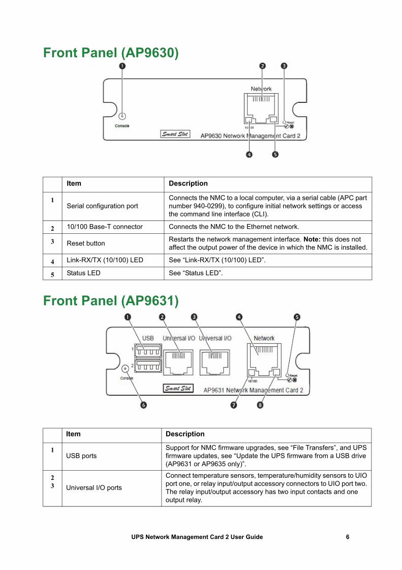
Front Panel (AP9630)
Front Panel (AP9631)
Item Description
1Serial configuration port
Connects the NMC to a local computer, via a serial cable (APC part number 940-0299), to configure initial network settings or access the command line interface (CLI).
2 10/100 Base-T connector Connects the NMC to the Ethernet network.
3 Reset button Restarts the network management interface. Note: this does not affect the output power of the device in which the NMC is installed.
4 Link-RX/TX (10/100) LED See “Link-RX/TX (10/100) LED”.
5 Status LED See “Status LED”.
Item Description
1USB ports
Support for NMC firmware upgrades, see “File Transfers”, and UPS firmware updates, see “Update the UPS firmware from a USB drive (AP9631 or AP9635 only)”.
23 Universal I/O ports
Connect temperature sensors, temperature/humidity sensors to UIO port one, or relay input/output accessory connectors to UIO port two. The relay input/output accessory has two input contacts and one output relay.
6UPS Network Management Card 2 User Guide
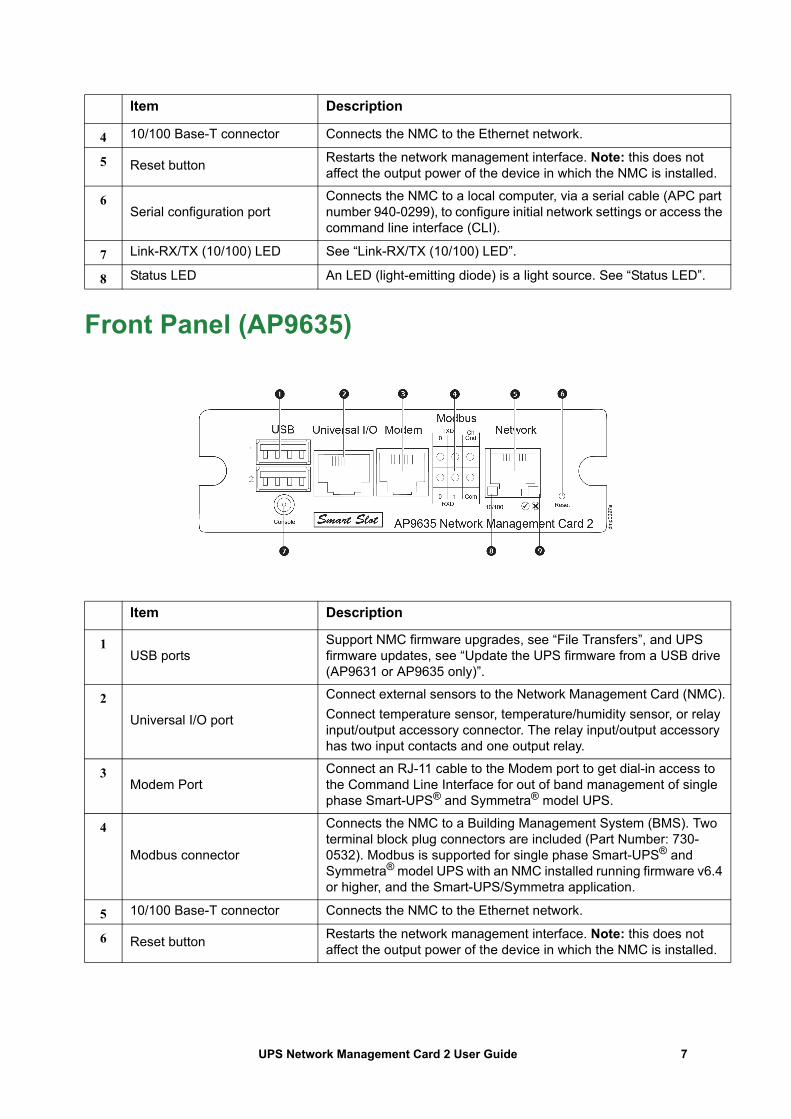
Front Panel (AP9635)
4 10/100 Base-T connector Connects the NMC to the Ethernet network.
5 Reset button Restarts the network management interface. Note: this does not affect the output power of the device in which the NMC is installed.
6Serial configuration port
Connects the NMC to a local computer, via a serial cable (APC part number 940-0299), to configure initial network settings or access the command line interface (CLI).
7 Link-RX/TX (10/100) LED See “Link-RX/TX (10/100) LED”.
8 Status LED An LED (light-emitting diode) is a light source. See “Status LED”.
Item Description
1USB ports
Support NMC firmware upgrades, see “File Transfers”, and UPS firmware updates, see “Update the UPS firmware from a USB drive (AP9631 or AP9635 only)”.
2Universal I/O port
Connect external sensors to the Network Management Card (NMC).Connect temperature sensor, temperature/humidity sensor, or relay input/output accessory connector. The relay input/output accessory has two input contacts and one output relay.
3Modem Port
Connect an RJ-11 cable to the Modem port to get dial-in access to the Command Line Interface for out of band management of single phase Smart-UPS® and Symmetra® model UPS.
4
Modbus connector
Connects the NMC to a Building Management System (BMS). Two terminal block plug connectors are included (Part Number: 730-0532). Modbus is supported for single phase Smart-UPS® and Symmetra® model UPS with an NMC installed running firmware v6.4 or higher, and the Smart-UPS/Symmetra application.
5 10/100 Base-T connector Connects the NMC to the Ethernet network.
6 Reset button Restarts the network management interface. Note: this does not affect the output power of the device in which the NMC is installed.
Item Description
7UPS Network Management Card 2 User Guide
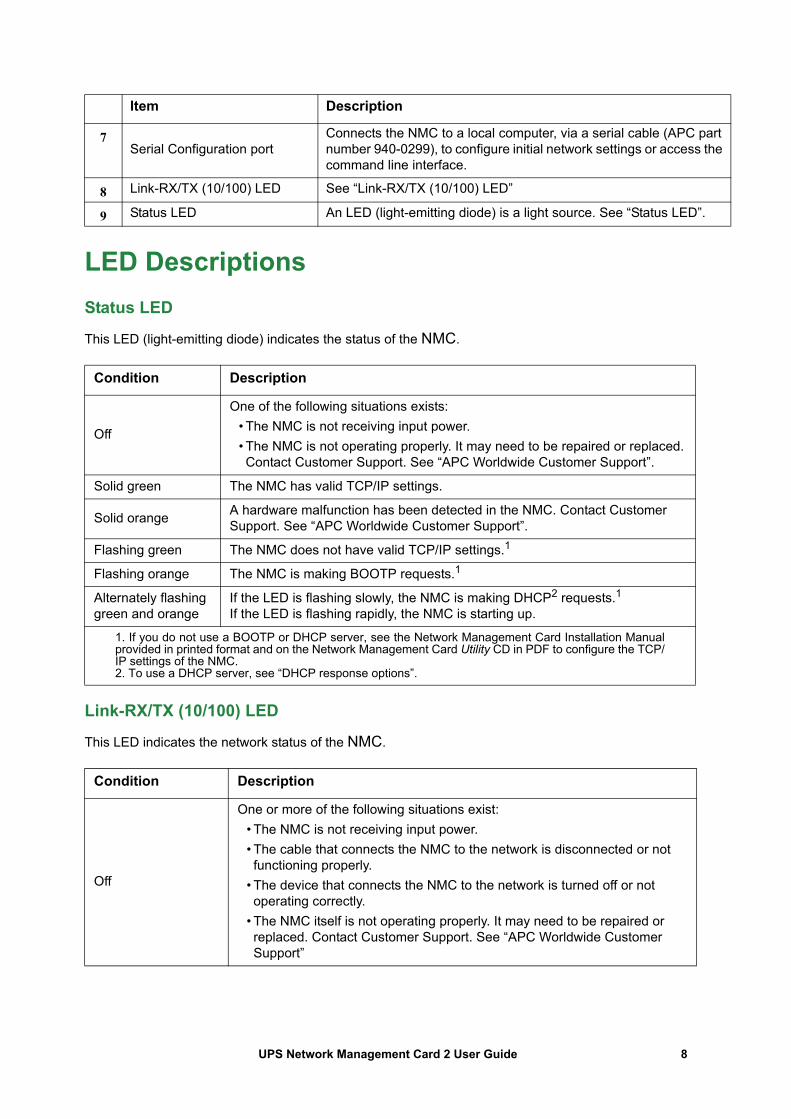
LED DescriptionsStatus LED
This LED (light-emitting diode) indicates the status of the NMC.
Link-RX/TX (10/100) LED
This LED indicates the network status of the NMC.
7Serial Configuration port
Connects the NMC to a local computer, via a serial cable (APC part number 940-0299), to configure initial network settings or access the command line interface.
8 Link-RX/TX (10/100) LED See “Link-RX/TX (10/100) LED”
9 Status LED An LED (light-emitting diode) is a light source. See “Status LED”.
Condition Description
Off
One of the following situations exists:• The NMC is not receiving input power.• The NMC is not operating properly. It may need to be repaired or replaced. Contact Customer Support. See “APC Worldwide Customer Support”.
Solid green The NMC has valid TCP/IP settings.
Solid orange A hardware malfunction has been detected in the NMC. Contact Customer Support. See “APC Worldwide Customer Support”.
Flashing green The NMC does not have valid TCP/IP settings.1
Flashing orange The NMC is making BOOTP requests.1
Alternately flashing green and orange
If the LED is flashing slowly, the NMC is making DHCP2 requests.1If the LED is flashing rapidly, the NMC is starting up.
1. If you do not use a BOOTP or DHCP server, see the Network Management Card Installation Manualprovided in printed format and on the Network Management Card Utility CD in PDF to configure the TCP/IP settings of the NMC. 2. To use a DHCP server, see “DHCP response options”.
Condition Description
Off
One or more of the following situations exist:• The NMC is not receiving input power.• The cable that connects the NMC to the network is disconnected or not functioning properly.
• The device that connects the NMC to the network is turned off or not operating correctly.
• The NMC itself is not operating properly. It may need to be repaired or replaced. Contact Customer Support. See “APC Worldwide Customer Support”
Item Description
8UPS Network Management Card 2 User Guide
Watchdog FeaturesOverview
To detect internal problems and recover from unanticipated inputs, the NMC 2 uses internal, system-wide watchdog mechanisms. When it restarts to recover from an internal problem, a System: Network Interface restarted event is recorded in the event log.
Network interface watchdog mechanism
The NMC 2 implements internal watchdog mechanisms to protect itself from becoming inaccessible over the network. For example, if the NMC 2 does not receive any network traffic for 9.5 minutes (either direct traffic, such as SNMP, or broadcast traffic, such as an Address Resolution Protocol [ARP] request), it assumes that there is a problem with its network interface and restarts.
Resetting the network timer
To ensure that the NMC 2 does not restart if the network is quiet for 9.5 minutes, the NMC 2 attempts to contact the default gateway every 4.5 minutes. If the gateway is present, it responds to the NMC 2, and that response restarts the 9.5-minute timer. If your application does not require or have a gateway, specify the IP address of a computer that is running on the network and is on the same subnet. The network traffic of that computer will restart the 9.5-minute timer frequently enough to prevent the NMC 2 from restarting.
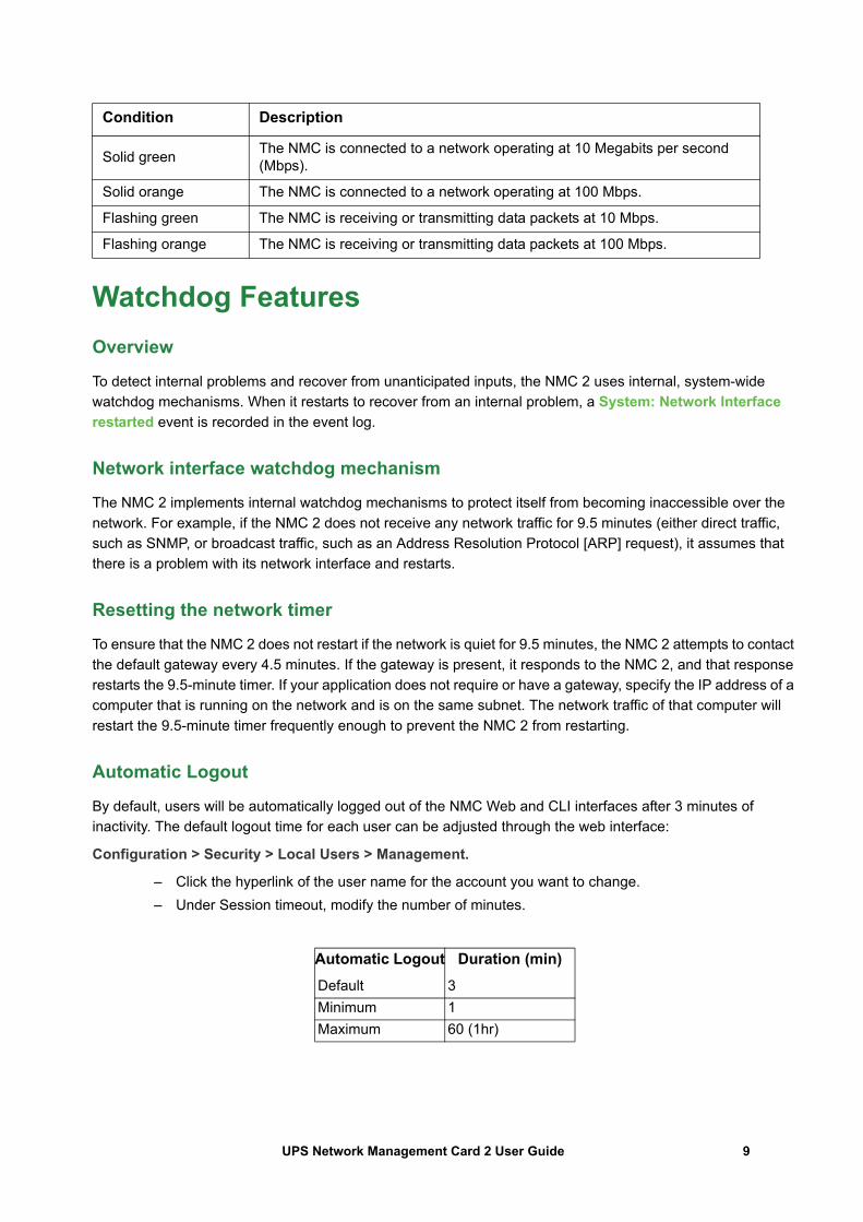
Automatic Logout
By default, users will be automatically logged out of the NMC Web and CLI interfaces after 3 minutes of inactivity. The default logout time for each user can be adjusted through the web interface:
Configuration > Security > Local Users > Management.
– Click the hyperlink of the user name for the account you want to change.– Under Session timeout, modify the number of minutes.
Solid green The NMC is connected to a network operating at 10 Megabits per second (Mbps).
Solid orange The NMC is connected to a network operating at 100 Mbps.
Flashing green The NMC is receiving or transmitting data packets at 10 Mbps.
Flashing orange The NMC is receiving or transmitting data packets at 100 Mbps.
Automatic Logout Duration (min)Default 3Minimum 1Maximum 60 (1hr)
Condition Description
9UPS Network Management Card 2 User Guide
Web User Interface
IntroductionOverview
The Web user interface (UI) provides options to manage the UPS and the UPS Network Management Card 2 (NMC 2) and to view the status of the UPS.
See “Web access screen” for information on how to select, enable, and disable the protocols that control access to the UI and to define the Web-server ports for the protocols.
Supported Web browsers
The NMC 2 Web UI is compatible with:
• Windows® operating systems:– Microsoft® Internet Explorer® (IE) 8.x or higher, with compatibility view turned on.– The latest release of Microsoft® Edge®
Note: To view the UPS Firmware Update screen with Internet Explorer®, use version 10 or higher, with compatibility view turned off. The UPS Firmware Update screen is not compatible with the Edge® browser. See “Firmware Update screen” on page 32.
• All operating systems:– The latest releases of Mozilla® Firefox® or Google® Chrome®
Other commonly available browsers might work but have not been fully tested.
The NMC cannot work with a proxy server. Before you can use a browser to access the UI of the NMC, you must do one of the following:
• Configure the browser to disable the use of a proxy server for the NMC.• Configure the proxy server so that it does not proxy the specific IP address of the NMC.
How to Log OnOverview
You can use the DNS name or the System IP address of the NMC for the URL address of the UI. Use your case-sensitive user name and password to log on. The default user name differs by account type:
• apc for Administrator or Super User• device for a Device User• readonly for a Read-Only User
The default password is apc for these account types. There is no default for a Network-only account type. See also “Types of user accounts”.
You can set your UI language as you log on by choosing a language from the Language drop-down box. See “Adding and Changing Language Packs”.
10UPS Network Management Card 2 User Guide
When HTTPS is enabled, the NMC generates its own certificate. This certificate negotiates encryption methods with your browser. Refer to the Security Guide on the CD or on the www.apc.com website for more details.
URL address formats
Type the DNS name or IP address of the NMC in the Web browser’s URL address field and press ENTER. When you specify a non-default Web server port in Internet Explorer, you must include http:// or https:// in the URL.
Common browser error messages at log-on.
URL format examples. See also “TCP/IP settings for IPv6 screen”.
Error Message Browser Cause of the Error
“This page cannot be displayed.” Internet Explorer Web access is disabled, or the URL was not correct.“Unable to connect.” Firefox, Chrome
Example and Access Mode URL Format
DNS name of Web1
HTTP http://Web1
HTTPS https://Web1
System IP address of 139.225.6.133 and a default Web server port (80)
HTTP http://139.225.6.133
HTTPS https://139.225.6.133
System IP address of 139.225.6.133 and a non-default Web server port (5000)
HTTP http://139.225.6.133:5000
HTTPS http://139.225.6.133:5000
System IPv6 address of 2001:db8:1::2c0:b7ff:fe00:1100 and a non-default Web server port (5000)
HTTP http://[2001:db8:1::2c0:b7ff:fe00:1100]:5000
11UPS Network Management Card 2 User Guide
Home ScreenOverview
Path: Home
On the Home screen of the interface, you can view active alarms and the most recent events recorded in the Event Log.
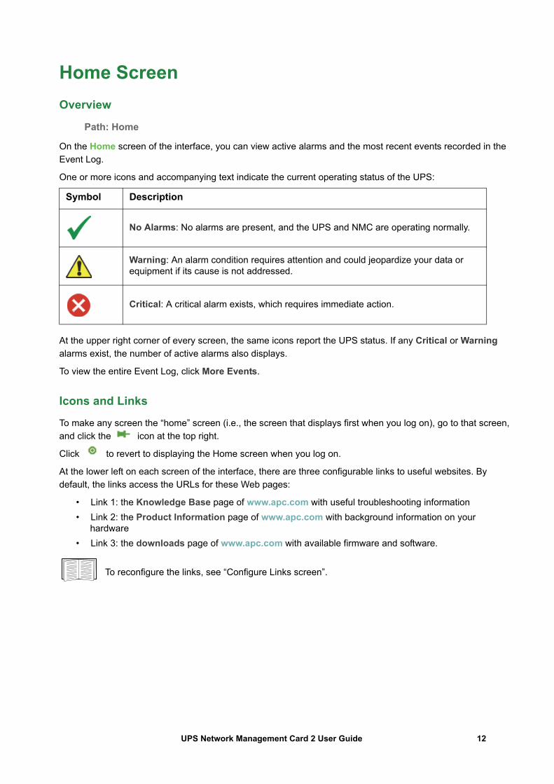
One or more icons and accompanying text indicate the current operating status of the UPS:
At the upper right corner of every screen, the same icons report the UPS status. If any Critical or Warning alarms exist, the number of active alarms also displays.
To view the entire Event Log, click More Events.
Icons and Links
To make any screen the “home” screen (i.e., the screen that displays first when you log on), go to that screen, and click the icon at the top right.
Click to revert to displaying the Home screen when you log on.
At the lower left on each screen of the interface, there are three configurable links to useful websites. By default, the links access the URLs for these Web pages:
• Link 1: the Knowledge Base page of www.apc.com with useful troubleshooting information• Link 2: the Product Information page of www.apc.com with background information on your
hardware• Link 3: the downloads page of www.apc.com with available firmware and software.
To reconfigure the links, see “Configure Links screen”.
Symbol Description
No Alarms: No alarms are present, and the UPS and NMC are operating normally.
Warning: An alarm condition requires attention and could jeopardize your data or equipment if its cause is not addressed.
Critical: A critical alarm exists, which requires immediate action.
12UPS Network Management Card 2 User Guide
Monitoring the UPS: Status menuThe Status menu options report on the current state of your UPS and network.
You can configure your UPS and network using the Configuration menu options, see “Configuring your Settings: 1” and “Configuring your Settings: 2”.
See the following sections:
• “UPS on Status menu”• “Outlet Groups on Status menu”• “Battery System on Status menu”• “Universal I/O on Status menu”• “Network on Status menu”
UPS on Status menuPath: Status > UPS
This shows you the UPS load, battery charge, voltage, and other useful information.
Field Description
Last Battery Transfer The cause of the last switch to battery operation. Excludes Self-Test.
Internal Temperature The temperature inside the UPS
Runtime Remaining How long the UPS can use battery power to support its present load.
UPS Input
Input Voltage The AC voltage (VAC) being received by the UPS.
Bypass Input Voltage The AC voltage (VAC) used when the UPS is in bypass mode.This option is not available for all UPS devices.
UPS Output
Output Voltage The AC voltage (VAC) that the UPS is supplying to its load.
Load Current The current, in Amps, supplied by the input voltage.
Output Load The load placed on each phase by the attached equipment, in kVA.
Output Percent Load The load placed on each phase by the attached equipment, as a percentage of the kVA available with no redundancy.
Output Percent Power
The load placed on each phase by the attached equipment, as a percentage of the available kVA.
Output Watts The UPS load as a percentage of available Watts.
Output VA The UPS load as a percentage of available VA.
Output Efficiency The percentage of the input power going directly out to the load. Input power not going to the load is consumed by the UPS.
Output Energy Usage The energy used by the load, starting from when the UPS was last reset to defaults.
13UPS Network Management Card 2 User Guide
The options below are not available for all UPS devices.
Battery Status
Battery Capacity The percentage of the UPS battery capacity that is available to support the attached equipment.
Battery Voltage The DC voltage of the batteries.
External Batteries The number of batteries connected to the UPS, excluding any internal batteries.
Field Description
Nominal Battery Voltage
The rated voltage capacity of the UPS batteries; the DC voltage that the batteries are rated to supply when the UPS uses its battery for output power.
Actual Battery Bus Voltage The available DC power.
External Battery Cabinet Rating The battery cabinet Amp-Hour rating of an external battery source.
Batteries The total number of batteries (both internal and external) that the UPS has.
Bad Batteries The number of “bad” batteries (the batteries that need to be replaced).
Battery Current The current being output from the battery.
Next Battery Replacement Date
Among the installed UPS battery cartridges, this is the earliest recommended date for replacing your batteries.
Intelligence Module Information about the Intelligence Module. You may be asked for this information (Firmware Revision, Manufacture Date, Serial Number, and Hardware Revision) when seeking assistance from APC Customer Support.
Input Voltage The AC voltage (VAC) being received by the UPS.
Bypass Input Voltage The AC voltage (VAC) used when the UPS is in bypass mode.
Input Frequency The frequency in Hertz (Hz) of the voltage being received by the UPS.
Frequency The frequency in Hertz (Hz) shared by the input voltage and output voltage.
Bypass Frequency The frequency in Hertz (Hz) of the voltage used when the UPS is in bypass mode.
Output Current The current, in Amps, applied to the load.
Output Frequency The frequency in Hertz (Hz) of the output voltage.
Load Power The UPS load as a percentage of available Watts.
Apparent Load Power The UPS load as a percentage of available VA.
Modules Information about the modules installed in the UPS. You may be asked for this information (Firmware Revision, Manufacture Date, Serial Number, and Hardware Revision) when seeking assistance from APC Customer Support.
Power Module Information about the power module installed in the UPS. You may be asked for this information when seeking assistance from APC Customer Support.
Field Description
14UPS Network Management Card 2 User Guide
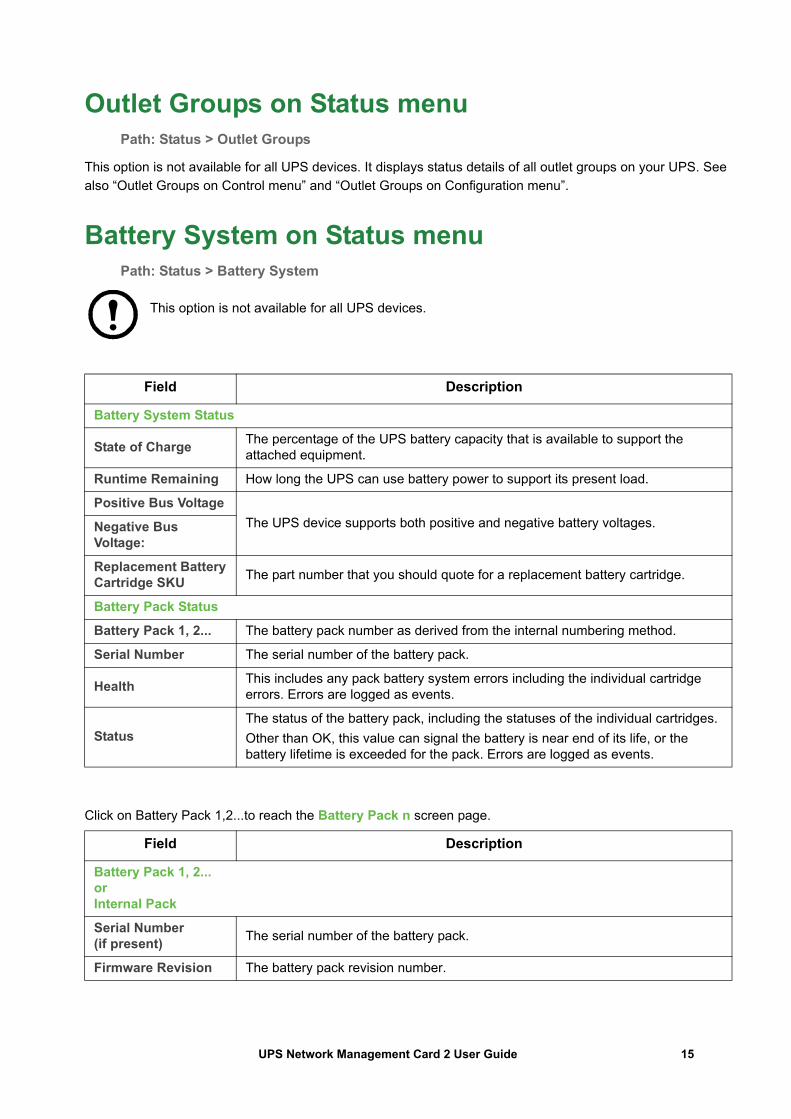
Outlet Groups on Status menuPath: Status > Outlet Groups
This option is not available for all UPS devices. It displays status details of all outlet groups on your UPS. See also “Outlet Groups on Control menu” and “Outlet Groups on Configuration menu”.
Battery System on Status menuPath: Status > Battery System
This option is not available for all UPS devices.
Click on Battery Pack 1,2...to reach the Battery Pack n screen page.
Field Description
Battery System Status
State of Charge The percentage of the UPS battery capacity that is available to support the attached equipment.
Runtime Remaining How long the UPS can use battery power to support its present load.
Positive Bus VoltageThe UPS device supports both positive and negative battery voltages. Negative Bus
Voltage:
Replacement Battery Cartridge SKU The part number that you should quote for a replacement battery cartridge.
Battery Pack Status
Battery Pack 1, 2... The battery pack number as derived from the internal numbering method.
Serial Number The serial number of the battery pack.
Health This includes any pack battery system errors including the individual cartridge errors. Errors are logged as events.
StatusThe status of the battery pack, including the statuses of the individual cartridges.Other than OK, this value can signal the battery is near end of its life, or the battery lifetime is exceeded for the pack. Errors are logged as events.
Field Description
Battery Pack 1, 2...orInternal Pack
Serial Number (if present) The serial number of the battery pack.
Firmware Revision The battery pack revision number.
15UPS Network Management Card 2 User Guide
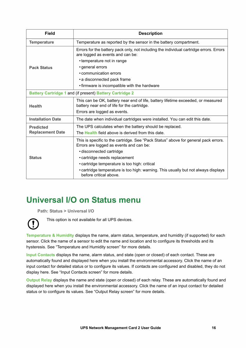
Universal I/O on Status menuPath: Status > Universal I/O
This option is not available for all UPS devices.
Temperature & Humidity displays the name, alarm status, temperature, and humidity (if supported) for each sensor. Click the name of a sensor to edit the name and location and to configure its thresholds and its hysteresis. See “Temperature and Humidity screen” for more details.
Input Contacts displays the name, alarm status, and state (open or closed) of each contact. These are automatically found and displayed here when you install the environmental accessory. Click the name of an input contact for detailed status or to configure its values. If contacts are configured and disabled, they do not display here. See “Input Contacts screen” for more details.
Output Relay displays the name and state (open or closed) of each relay. These are automatically found and displayed here when you install the environmental accessory. Click the name of an input contact for detailed status or to configure its values. See “Output Relay screen” for more details.
Temperature Temperature as reported by the sensor in the battery compartment.
Pack Status
Errors for the battery pack only, not including the individual cartridge errors. Errors are logged as events and can be:
• temperature not in range• general errors• communication errors• a disconnected pack frame• firmware is incompatible with the hardware
Battery Cartridge 1 and (if present) Battery Cartridge 2
HealthThis can be OK, battery near end of life, battery lifetime exceeded, or measured battery near end of life for the cartridge. Errors are logged as events.
Installation Date The date when individual cartridges were installed. You can edit this date.
Predicted Replacement Date
The UPS calculates when the battery should be replaced.The Health field above is derived from this date.
Status
This is specific to the cartridge. See “Pack Status” above for general pack errors. Errors are logged as events and can be:
• disconnected cartridge• cartridge needs replacement• cartridge temperature is too high: critical• cartridge temperature is too high: warning. This usually but not always displays before critical above.
Field Description
16UPS Network Management Card 2 User Guide

Recent Environmental Events displays events that are related to your environmental monitoring, for example a temperature threshold violation or a warning message about an environmental monitor input contact. Click the More Events link to see a full list of recent events.
Network on Status menuPath: Status > Network
The Network screen gives you your IP, domain name, and ethernet port settings. See “Network on Configuration menu”for background details on the fields.
17UPS Network Management Card 2 User Guide
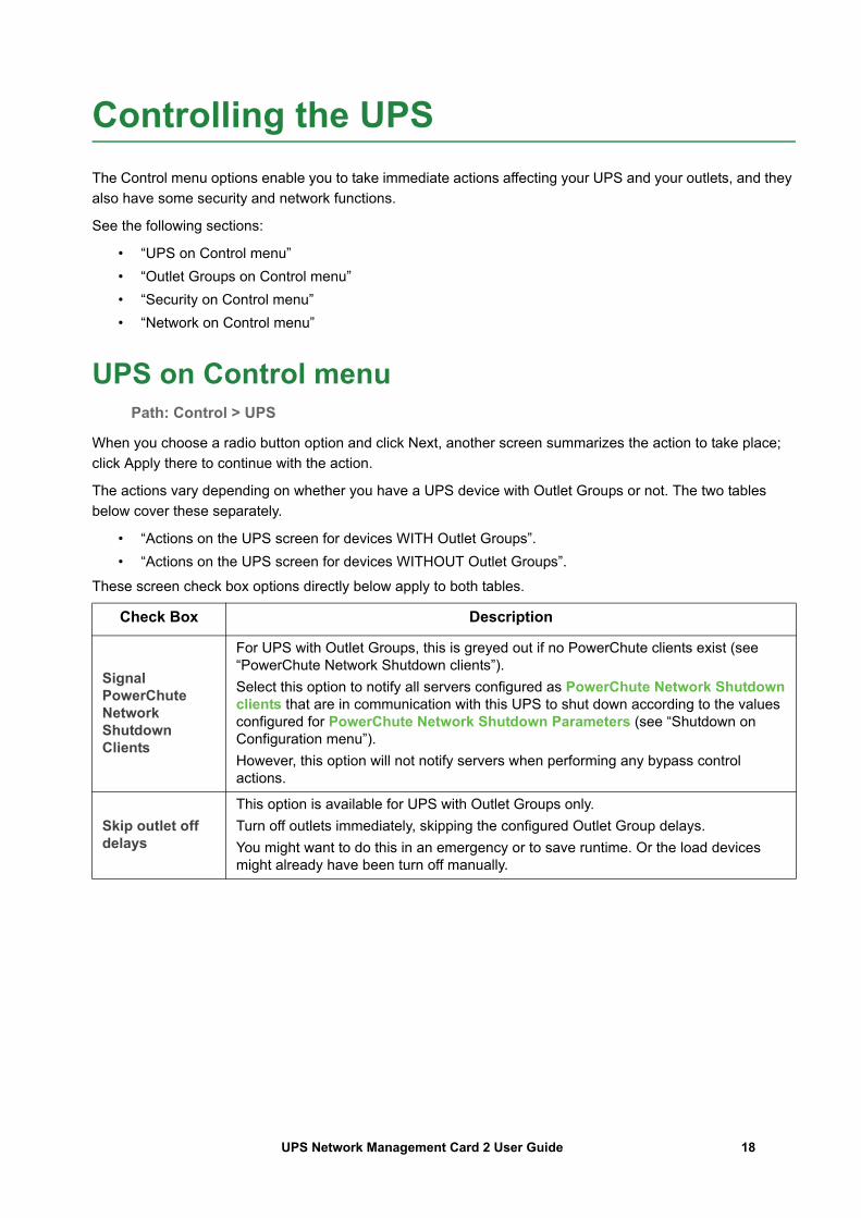
Controlling the UPSThe Control menu options enable you to take immediate actions affecting your UPS and your outlets, and they also have some security and network functions.
See the following sections:
• “UPS on Control menu”• “Outlet Groups on Control menu”• “Security on Control menu”• “Network on Control menu”
UPS on Control menuPath: Control > UPS
When you choose a radio button option and click Next, another screen summarizes the action to take place; click Apply there to continue with the action.
The actions vary depending on whether you have a UPS device with Outlet Groups or not. The two tables below cover these separately.
• “Actions on the UPS screen for devices WITH Outlet Groups”.• “Actions on the UPS screen for devices WITHOUT Outlet Groups”.
These screen check box options directly below apply to both tables.
Check Box Description
Signal PowerChute Network Shutdown Clients
For UPS with Outlet Groups, this is greyed out if no PowerChute clients exist (see “PowerChute Network Shutdown clients”).Select this option to notify all servers configured as PowerChute Network Shutdown clients that are in communication with this UPS to shut down according to the values configured for PowerChute Network Shutdown Parameters (see “Shutdown on Configuration menu”).However, this option will not notify servers when performing any bypass control actions.
Skip outlet off delays
This option is available for UPS with Outlet Groups only.Turn off outlets immediately, skipping the configured Outlet Group delays. You might want to do this in an emergency or to save runtime. Or the load devices might already have been turn off manually.
18UPS Network Management Card 2 User Guide
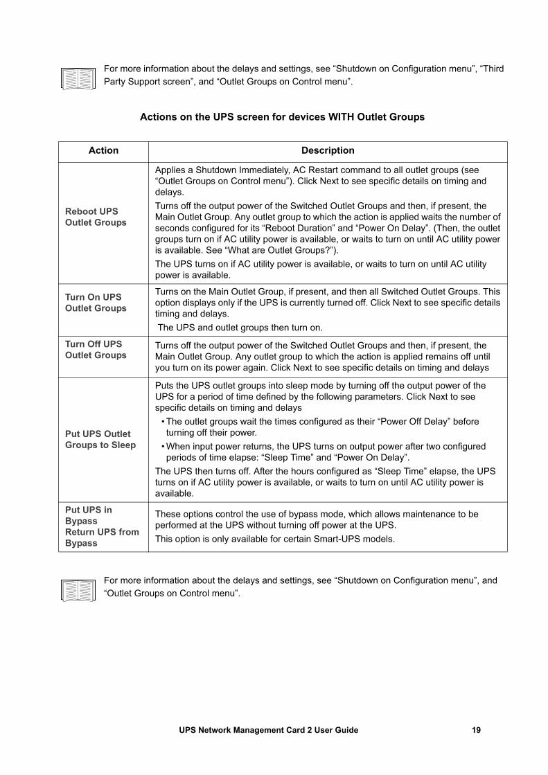
For more information about the delays and settings, see “Shutdown on Configuration menu”, “Third Party Support screen”, and “Outlet Groups on Control menu”.
Actions on the UPS screen for devices WITH Outlet Groups
For more information about the delays and settings, see “Shutdown on Configuration menu”, and “Outlet Groups on Control menu”.
Action Description
Reboot UPS Outlet Groups
Applies a Shutdown Immediately, AC Restart command to all outlet groups (see “Outlet Groups on Control menu”). Click Next to see specific details on timing and delays.Turns off the output power of the Switched Outlet Groups and then, if present, the Main Outlet Group. Any outlet group to which the action is applied waits the number of seconds configured for its “Reboot Duration” and “Power On Delay”. (Then, the outlet groups turn on if AC utility power is available, or waits to turn on until AC utility power is available. See “What are Outlet Groups?”).The UPS turns on if AC utility power is available, or waits to turn on until AC utility power is available.
Turn On UPS Outlet Groups
Turns on the Main Outlet Group, if present, and then all Switched Outlet Groups. This option displays only if the UPS is currently turned off. Click Next to see specific details timing and delays. The UPS and outlet groups then turn on.
Turn Off UPS Outlet Groups
Turns off the output power of the Switched Outlet Groups and then, if present, the Main Outlet Group. Any outlet group to which the action is applied remains off until you turn on its power again. Click Next to see specific details on timing and delays
Put UPS Outlet Groups to Sleep
Puts the UPS outlet groups into sleep mode by turning off the output power of the UPS for a period of time defined by the following parameters. Click Next to see specific details on timing and delays
• The outlet groups wait the times configured as their “Power Off Delay” before turning off their power.
• When input power returns, the UPS turns on output power after two configured periods of time elapse: “Sleep Time” and “Power On Delay”.
The UPS then turns off. After the hours configured as “Sleep Time” elapse, the UPS turns on if AC utility power is available, or waits to turn on until AC utility power is available.
Put UPS in BypassReturn UPS from Bypass
These options control the use of bypass mode, which allows maintenance to be performed at the UPS without turning off power at the UPS.This option is only available for certain Smart-UPS models.
19UPS Network Management Card 2 User Guide
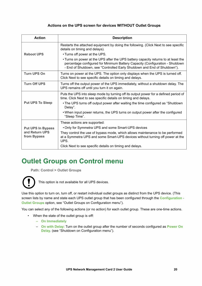
Actions on the UPS screen for devices WITHOUT Outlet Groups
Outlet Groups on Control menuPath: Control > Outlet Groups
This option is not available for all UPS devices.
Use this option to turn on, turn off, or restart individual outlet groups as distinct from the UPS device. (This screen lists by name and state each UPS outlet group that has been configured through the Configuration - Outlet Groups option, see “Outlet Groups on Configuration menu”).
You can select any of the following actions (or no action) for each outlet group. These are one-time actions.
• When the state of the outlet group is off: – On Immediately– On with Delay: Turn on the outlet group after the number of seconds configured as Power On
Delay. (see “Shutdown on Configuration menu”).
Action Description
Reboot UPS
Restarts the attached equipment by doing the following. (Click Next to see specific details on timing and delays).
• Turns off power at the UPS.• Turns on power at the UPS after the UPS battery capacity returns to at least the percentage configured for Minimum Battery Capacity (Configuration - Shutdown - End of Shutdown, see “Controlled Early Shutdown and End of Shutdown”).
Turn UPS On Turns on power at the UPS. The option only displays when the UPS is turned off. Click Next to see specific details on timing and delays.
Turn Off UPS Turns off the output power of the UPS immediately, without a shutdown delay. The UPS remains off until you turn it on again.
Put UPS To Sleep
Puts the UPS into sleep mode by turning off its output power for a defined period of time. Click Next to see specific details on timing and delays.
• The UPS turns off output power after waiting the time configured as “Shutdown Delay”.
• When input power returns, the UPS turns on output power after the configured “Sleep Time”.
Put UPS In Bypass and Return UPS from Bypass
These actions are supported:• Only for Symmetra UPS and some Smart-UPS devices
They control the use of bypass mode, which allows maintenance to be performed at a Symmetra UPS and some Smart-UPS devices without turning off power at the UPS.Click Next to see specific details on timing and delays.
20UPS Network Management Card 2 User Guide
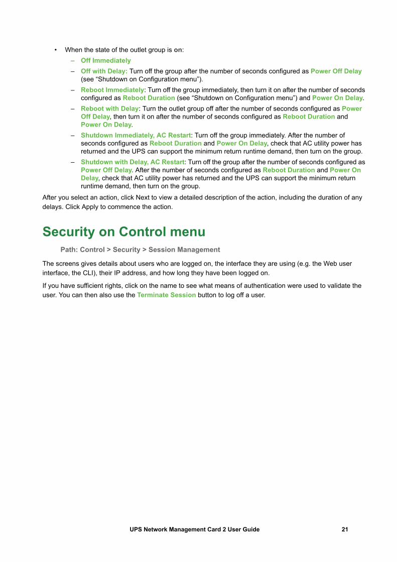
• When the state of the outlet group is on: – Off Immediately– Off with Delay: Turn off the group after the number of seconds configured as Power Off Delay
(see “Shutdown on Configuration menu”).– Reboot Immediately: Turn off the group immediately, then turn it on after the number of seconds
configured as Reboot Duration (see “Shutdown on Configuration menu”) and Power On Delay.– Reboot with Delay: Turn the outlet group off after the number of seconds configured as Power
Off Delay, then turn it on after the number of seconds configured as Reboot Duration and Power On Delay.
– Shutdown Immediately, AC Restart: Turn off the group immediately. After the number of seconds configured as Reboot Duration and Power On Delay, check that AC utility power has returned and the UPS can support the minimum return runtime demand, then turn on the group.
– Shutdown with Delay, AC Restart: Turn off the group after the number of seconds configured as Power Off Delay. After the number of seconds configured as Reboot Duration and Power On Delay, check that AC utility power has returned and the UPS can support the minimum return runtime demand, then turn on the group.
After you select an action, click Next to view a detailed description of the action, including the duration of any delays. Click Apply to commence the action.
Security on Control menuPath: Control > Security > Session Management
The screens gives details about users who are logged on, the interface they are using (e.g. the Web user interface, the CLI), their IP address, and how long they have been logged on.
If you have sufficient rights, click on the name to see what means of authentication were used to validate the user. You can then also use the Terminate Session button to log off a user.
21UPS Network Management Card 2 User Guide
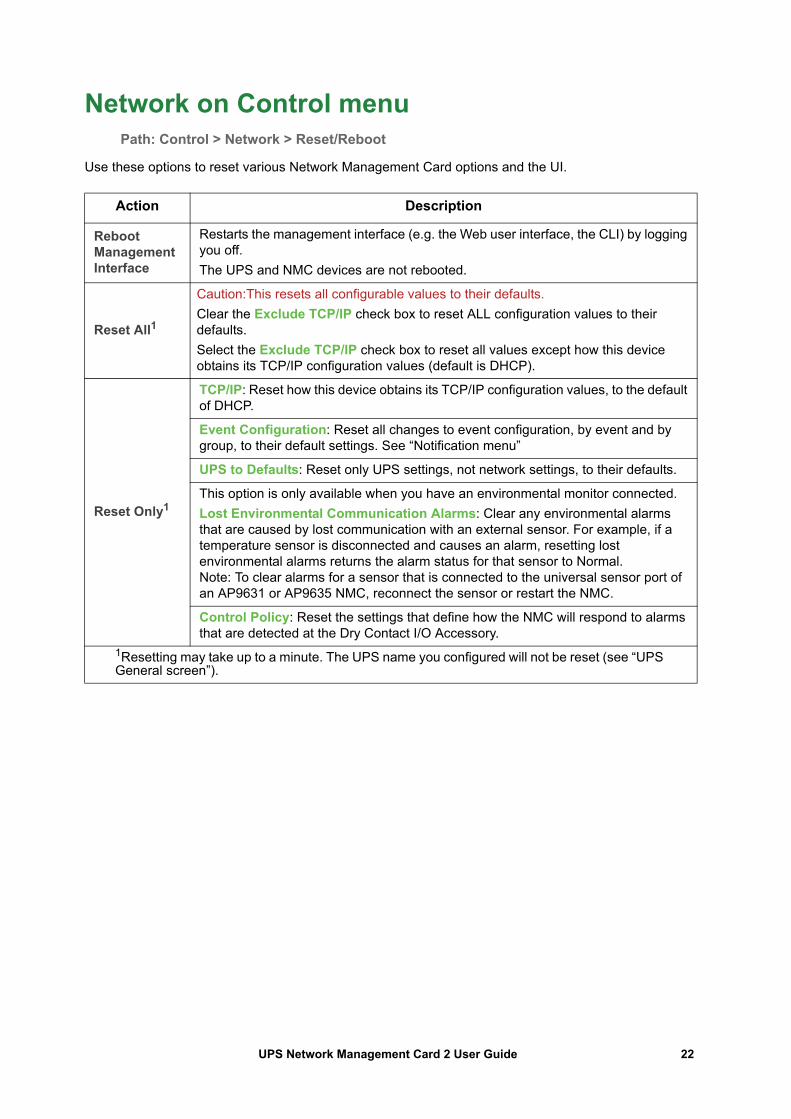
Network on Control menuPath: Control > Network > Reset/Reboot
Use these options to reset various Network Management Card options and the UI.
Action Description
Reboot Management Interface
Restarts the management interface (e.g. the Web user interface, the CLI) by logging you off.The UPS and NMC devices are not rebooted.
Reset All1
Caution:This resets all configurable values to their defaults.Clear the Exclude TCP/IP check box to reset ALL configuration values to their defaults.Select the Exclude TCP/IP check box to reset all values except how this device obtains its TCP/IP configuration values (default is DHCP).
Reset Only1
TCP/IP: Reset how this device obtains its TCP/IP configuration values, to the default of DHCP.
Event Configuration: Reset all changes to event configuration, by event and by group, to their default settings. See “Notification menu”
UPS to Defaults: Reset only UPS settings, not network settings, to their defaults.
This option is only available when you have an environmental monitor connected.Lost Environmental Communication Alarms: Clear any environmental alarms that are caused by lost communication with an external sensor. For example, if a temperature sensor is disconnected and causes an alarm, resetting lost environmental alarms returns the alarm status for that sensor to Normal. Note: To clear alarms for a sensor that is connected to the universal sensor port of an AP9631 or AP9635 NMC, reconnect the sensor or restart the NMC.
Control Policy: Reset the settings that define how the NMC will respond to alarms that are detected at the Dry Contact I/O Accessory.
1Resetting may take up to a minute. The UPS name you configured will not be reset (see “UPS General screen”).
22UPS Network Management Card 2 User Guide
Configuring your Settings: 1With the Configuration menu options, you can set fundamental operational values for your UPS and NMC.
See the sections below and also “Configuring your Settings: 2”.
• “Outlet Groups on Configuration menu”• “Power Settings on Configuration menu”• “Shutdown on Configuration menu”• “UPS General screen”• “Self-Test Schedule screen”• “Shutdown Scheduling”• “Firmware Update screen”• “PowerChute Network Shutdown clients”• “Third Party Support screen”• “Universal I/O screens”• “Security menu”
Outlet Groups on Configuration menuPath: Configuration > Outlet Groups
This option is not available with all UPS devices. With it, you can display and configure your outlet and sequencing delays.
See also “Outlet Groups on Status menu”, “Outlet Groups on Control menu”, and “Shutdown on Configuration menu”.
What are Outlet Groups?
Outlet grouping is available on some UPS devices only. To determine whether your UPS device supports outlet groups, see your UPS documentation.
The available settings differ based on the UPS device.
Main Outlet Groups . Some UPS devices provide AC utility power to one Main Outlet Group. The Main Outlet Group controls the distribution of power to all Switched Outlet Groups (if present) for the UPS.
• If the Main Outlet Group is off, the Switched Outlet Groups cannot be turned on.• If you turn off the Main Outlet Group, the UPS turns off the Switched Outlet Groups before it turns off
the Main Outlet Group.• To turn on a Switched Outlet Group, the UPS must turn on the Main Outlet Group first.
Switched Outlet Groups .
• Each Switched Outlet can perform actions independently. You can start or stop these outlets in sequence and also restart devices plugged into these outlets.
23UPS Network Management Card 2 User Guide
Configuring your Outlet Groups
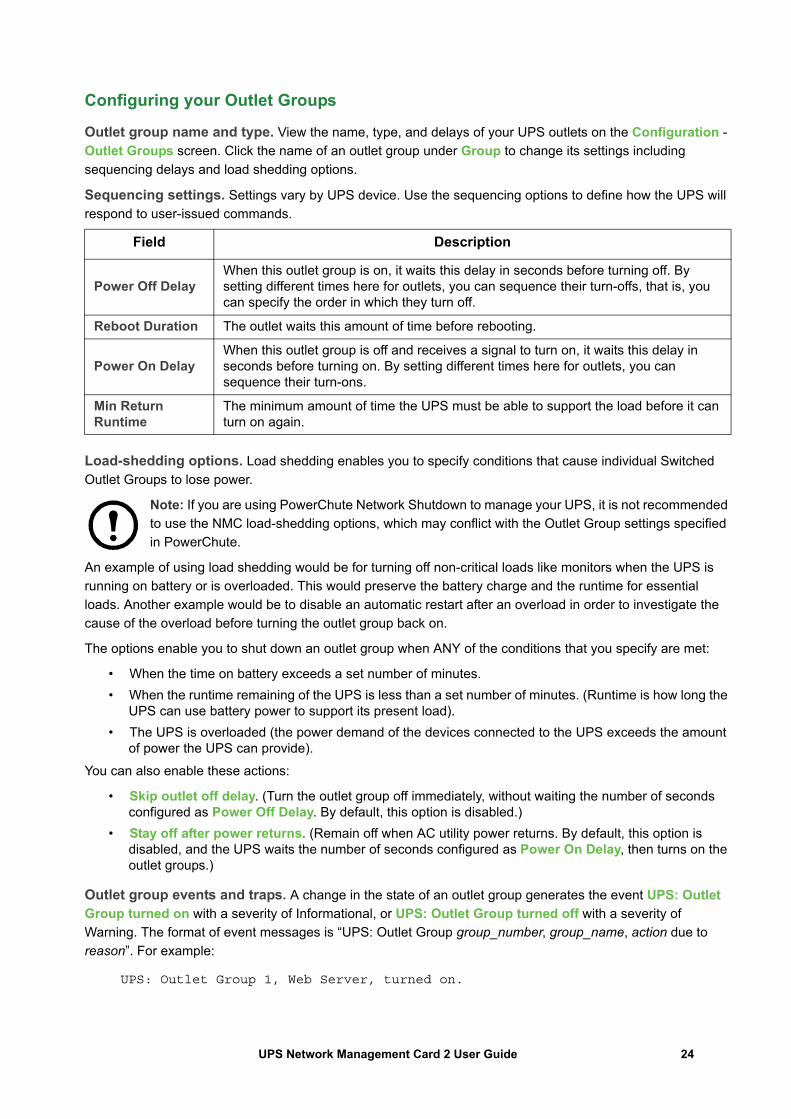
Outlet group name and type. View the name, type, and delays of your UPS outlets on the Configuration - Outlet Groups screen. Click the name of an outlet group under Group to change its settings including sequencing delays and load shedding options.
Sequencing settings. Settings vary by UPS device. Use the sequencing options to define how the UPS will respond to user-issued commands.
Load-shedding options. Load shedding enables you to specify conditions that cause individual Switched Outlet Groups to lose power.
Note: If you are using PowerChute Network Shutdown to manage your UPS, it is not recommended to use the NMC load-shedding options, which may conflict with the Outlet Group settings specified in PowerChute.
An example of using load shedding would be for turning off non-critical loads like monitors when the UPS is running on battery or is overloaded. This would preserve the battery charge and the runtime for essential loads. Another example would be to disable an automatic restart after an overload in order to investigate the cause of the overload before turning the outlet group back on.
The options enable you to shut down an outlet group when ANY of the conditions that you specify are met:
• When the time on battery exceeds a set number of minutes.• When the runtime remaining of the UPS is less than a set number of minutes. (Runtime is how long the
UPS can use battery power to support its present load).• The UPS is overloaded (the power demand of the devices connected to the UPS exceeds the amount
of power the UPS can provide).You can also enable these actions:
• Skip outlet off delay. (Turn the outlet group off immediately, without waiting the number of seconds configured as Power Off Delay. By default, this option is disabled.)
• Stay off after power returns. (Remain off when AC utility power returns. By default, this option is disabled, and the UPS waits the number of seconds configured as Power On Delay, then turns on the outlet groups.)
Outlet group events and traps. A change in the state of an outlet group generates the event UPS: Outlet Group turned on with a severity of Informational, or UPS: Outlet Group turned off with a severity of Warning. The format of event messages is “UPS: Outlet Group group_number, group_name, action due to reason”. For example:
UPS: Outlet Group 1, Web Server, turned on.
Field Description
Power Off DelayWhen this outlet group is on, it waits this delay in seconds before turning off. By setting different times here for outlets, you can sequence their turn-offs, that is, you can specify the order in which they turn off.
Reboot Duration The outlet waits this amount of time before rebooting.
Power On DelayWhen this outlet group is off and receives a signal to turn on, it waits this delay in seconds before turning on. By setting different times here for outlets, you can sequence their turn-ons.
Min Return Runtime
The minimum amount of time the UPS must be able to support the load before it can turn on again.
24UPS Network Management Card 2 User Guide
UPS: Outlet Group 3, Printer, turned off.
By default, the event generates an Event Log entry, e-mail, and a Syslog message.
If you configure trap receivers for the events, trap 298 is generated when an outlet group turns on, and trap 299 is generated when an outlet group turns off. The event message is the trap argument. The default severity level is the same as for the event.
Power Settings on Configuration menuPath: Configuration > Power Settings
The available settings differ based on the UPS device.
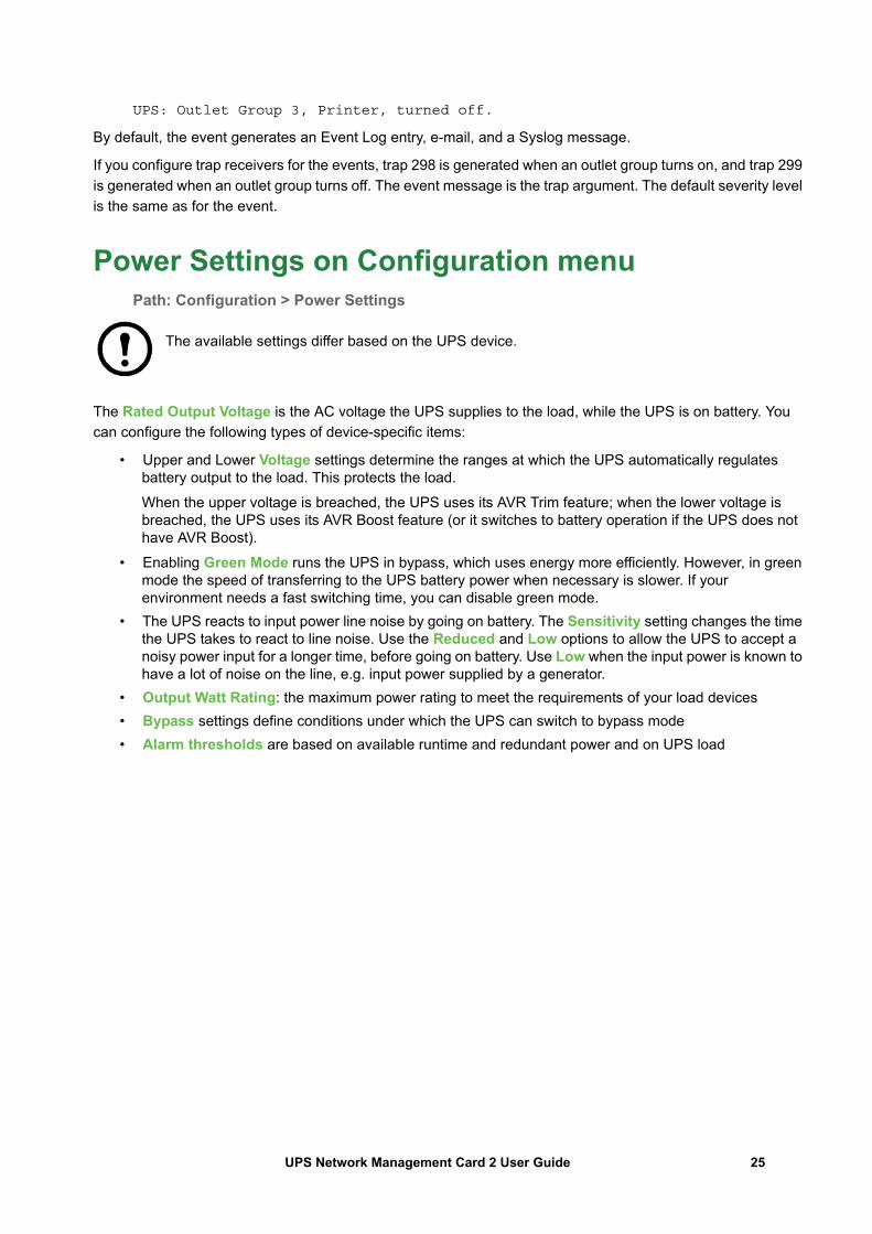
The Rated Output Voltage is the AC voltage the UPS supplies to the load, while the UPS is on battery. You can configure the following types of device-specific items:
• Upper and Lower Voltage settings determine the ranges at which the UPS automatically regulates battery output to the load. This protects the load.When the upper voltage is breached, the UPS uses its AVR Trim feature; when the lower voltage is breached, the UPS uses its AVR Boost feature (or it switches to battery operation if the UPS does not have AVR Boost).
• Enabling Green Mode runs the UPS in bypass, which uses energy more efficiently. However, in green mode the speed of transferring to the UPS battery power when necessary is slower. If your environment needs a fast switching time, you can disable green mode.
• The UPS reacts to input power line noise by going on battery. The Sensitivity setting changes the time the UPS takes to react to line noise. Use the Reduced and Low options to allow the UPS to accept a noisy power input for a longer time, before going on battery. Use Low when the input power is known to have a lot of noise on the line, e.g. input power supplied by a generator.
• Output Watt Rating: the maximum power rating to meet the requirements of your load devices • Bypass settings define conditions under which the UPS can switch to bypass mode• Alarm thresholds are based on available runtime and redundant power and on UPS load
25UPS Network Management Card 2 User Guide
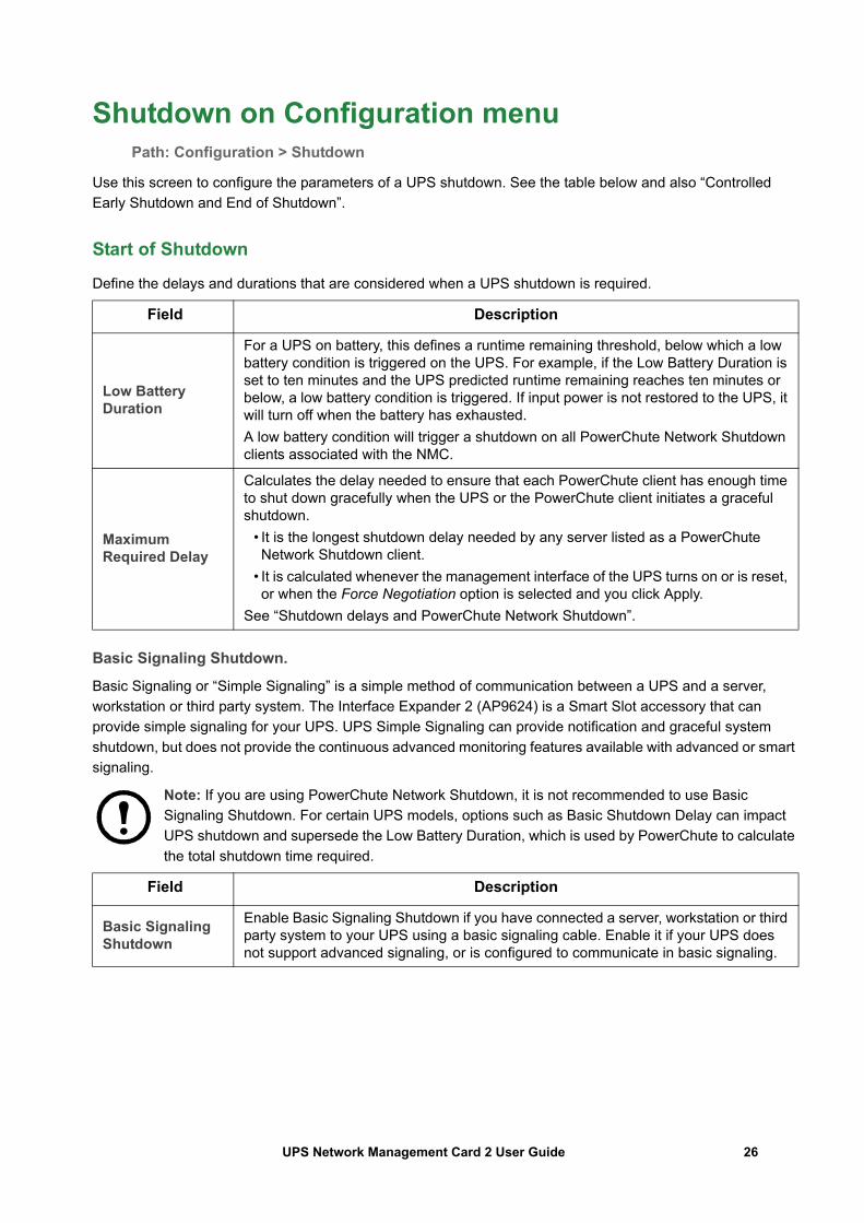
Shutdown on Configuration menuPath: Configuration > Shutdown
Use this screen to configure the parameters of a UPS shutdown. See the table below and also “Controlled Early Shutdown and End of Shutdown”.
Start of Shutdown
Define the delays and durations that are considered when a UPS shutdown is required.
Basic Signaling Shutdown.
Basic Signaling or “Simple Signaling” is a simple method of communication between a UPS and a server, workstation or third party system. The Interface Expander 2 (AP9624) is a Smart Slot accessory that can provide simple signaling for your UPS. UPS Simple Signaling can provide notification and graceful system shutdown, but does not provide the continuous advanced monitoring features available with advanced or smart signaling.
Note: If you are using PowerChute Network Shutdown, it is not recommended to use Basic Signaling Shutdown. For certain UPS models, options such as Basic Shutdown Delay can impact UPS shutdown and supersede the Low Battery Duration, which is used by PowerChute to calculate the total shutdown time required.
Field Description
Low Battery Duration
For a UPS on battery, this defines a runtime remaining threshold, below which a low battery condition is triggered on the UPS. For example, if the Low Battery Duration is set to ten minutes and the UPS predicted runtime remaining reaches ten minutes or below, a low battery condition is triggered. If input power is not restored to the UPS, it will turn off when the battery has exhausted. A low battery condition will trigger a shutdown on all PowerChute Network Shutdown clients associated with the NMC.
Maximum Required Delay
Calculates the delay needed to ensure that each PowerChute client has enough time to shut down gracefully when the UPS or the PowerChute client initiates a graceful shutdown.
• It is the longest shutdown delay needed by any server listed as a PowerChute Network Shutdown client.
• It is calculated whenever the management interface of the UPS turns on or is reset, or when the Force Negotiation option is selected and you click Apply.
See “Shutdown delays and PowerChute Network Shutdown”.
Field Description
Basic Signaling Shutdown
Enable Basic Signaling Shutdown if you have connected a server, workstation or third party system to your UPS using a basic signaling cable. Enable it if your UPS does not support advanced signaling, or is configured to communicate in basic signaling.
26UPS Network Management Card 2 User Guide
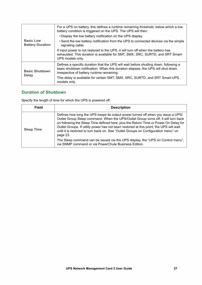
Duration of Shutdown
Specify the length of time for which the UPS is powered off.
Basic Low Battery Duration
For a UPS on battery, this defines a runtime remaining threshold, below which a low battery condition is triggered on the UPS. The UPS will then:
• Display the low battery notification on the UPS display.• Send the low battery notification from the UPS to connected devices via the simple signaling cable.
If input power is not restored to the UPS, it will turn off when the battery has exhausted. This duration is available for SMT, SMX, SRC, SURTD, and SRT Smart-UPS models only.
Basic Shutdown Delay
Defines a specific duration that the UPS will wait before shutting down, following a basic shutdown notification. When this duration elapses, the UPS will shut down, irrespective of battery runtime remaining. This delay is available for certain SMT, SMX, SRC, SURTD, and SRT Smart-UPS models only.
Field Description
Sleep Time
Defines how long the UPS keeps its output power turned off when you issue a UPS/Outlet Group Sleep command. When the UPS/Outlet Group turns off, it will turn back on following the Sleep Time defined here, plus the Return Time or Power On Delay for Outlet Groups. If utility power has not been restored at this point, the UPS will wait until it is restored to turn back on. See “Outlet Groups on Configuration menu” on page 23. The Sleep command can be issued via the UPS display, the “UPS on Control menu”, via SNMP command or via PowerChute Business Edition.
27UPS Network Management Card 2 User Guide
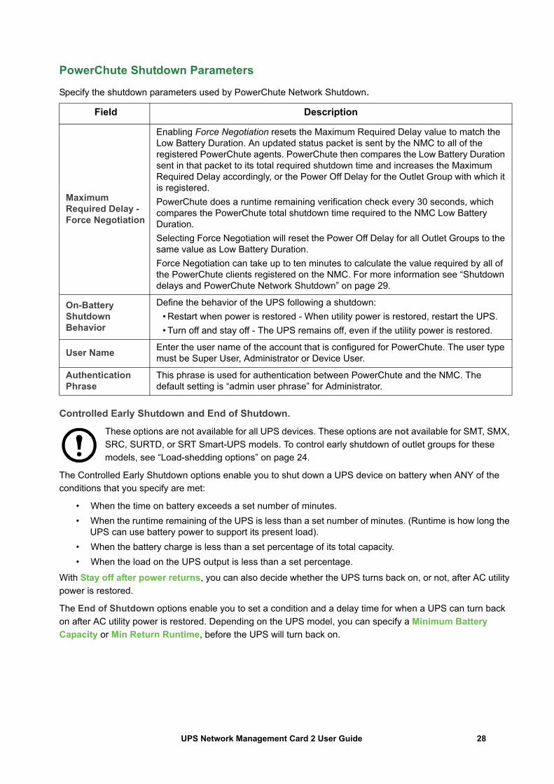
PowerChute Shutdown Parameters
Specify the shutdown parameters used by PowerChute Network Shutdown.
Controlled Early Shutdown and End of Shutdown.
These options are not available for all UPS devices. These options are not available for SMT, SMX, SRC, SURTD, or SRT Smart-UPS models. To control early shutdown of outlet groups for these models, see “Load-shedding options” on page 24.
The Controlled Early Shutdown options enable you to shut down a UPS device on battery when ANY of the conditions that you specify are met:
• When the time on battery exceeds a set number of minutes.• When the runtime remaining of the UPS is less than a set number of minutes. (Runtime is how long the
UPS can use battery power to support its present load).• When the battery charge is less than a set percentage of its total capacity.• When the load on the UPS output is less than a set percentage.
With Stay off after power returns, you can also decide whether the UPS turns back on, or not, after AC utility power is restored.
The End of Shutdown options enable you to set a condition and a delay time for when a UPS can turn back on after AC utility power is restored. Depending on the UPS model, you can specify a Minimum Battery Capacity or Min Return Runtime, before the UPS will turn back on.
Field Description
Maximum Required Delay - Force Negotiation
Enabling Force Negotiation resets the Maximum Required Delay value to match the Low Battery Duration. An updated status packet is sent by the NMC to all of the registered PowerChute agents. PowerChute then compares the Low Battery Duration sent in that packet to its total required shutdown time and increases the Maximum Required Delay accordingly, or the Power Off Delay for the Outlet Group with which it is registered.PowerChute does a runtime remaining verification check every 30 seconds, which compares the PowerChute total shutdown time required to the NMC Low Battery Duration. Selecting Force Negotiation will reset the Power Off Delay for all Outlet Groups to the same value as Low Battery Duration.Force Negotiation can take up to ten minutes to calculate the value required by all of the PowerChute clients registered on the NMC. For more information see “Shutdown delays and PowerChute Network Shutdown” on page 29.
On-Battery Shutdown Behavior
Define the behavior of the UPS following a shutdown:• Restart when power is restored - When utility power is restored, restart the UPS.• Turn off and stay off - The UPS remains off, even if the utility power is restored.
User Name Enter the user name of the account that is configured for PowerChute. The user type must be Super User, Administrator or Device User.
Authentication Phrase
This phrase is used for authentication between PowerChute and the NMC. The default setting is “admin user phrase” for Administrator.
28UPS Network Management Card 2 User Guide
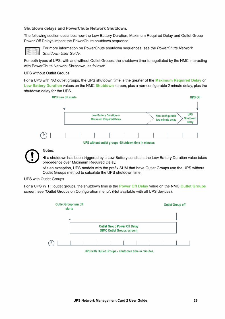
Shutdown delays and PowerChute Network Shutdown.
The following section describes how the Low Battery Duration, Maximum Required Delay and Outlet Group Power Off Delays impact the PowerChute shutdown sequence.
For more information on PowerChute shutdown sequences, see the PowerChute Network Shutdown User Guide.
For both types of UPS, with and without Outlet Groups, the shutdown time is negotiated by the NMC interacting with PowerChute Network Shutdown, as follows:
UPS without Outlet Groups
For a UPS with NO outlet groups, the UPS shutdown time is the greater of the Maximum Required Delay or Low Battery Duration values on the NMC Shutdown screen, plus a non-configurable 2 minute delay, plus the shutdown delay for the UPS.
Notes:
•If a shutdown has been triggered by a Low Battery condition, the Low Battery Duration value takes precedence over Maximum Required Delay.•As an exception, UPS models with the prefix SUM that have Outlet Groups use the UPS without Outlet Groups method to calculate the UPS shutdown time.
UPS with Outlet Groups
For a UPS WITH outlet groups, the shutdown time is the Power Off Delay value on the NMC Outlet Groups screen, see “Outlet Groups on Configuration menu”. (Not available with all UPS devices).
UPS without outlet groups -Shutdown time in minutes
Low Battery Duration orMaximum Required Delay
Non-configurabletwo minute delay
UPSShutdown
Delay
UPS OffUPS turn off starts
Outlet Group Power Off Delay(NMC Outlet Groups screen)
UPS with Outlet Groups - shutdown time in minutes
Outlet Group turn off starts
Outlet Group off
29UPS Network Management Card 2 User Guide
Notes:
For more information on PowerChute shutdown sequences, see “Sample Shutdown Scenarios” in the PowerChute Network Shutdown User Guide on the APC website.
During the comparison of the PowerChute Required Shutdown time and the NMC Maximum Required Delay/Outlet Group Power Off Delay, the largest value is used. For example, if the PowerChute client command line shutdown duration is set to 8 minutes, but the UPS Low Battery Duration is 10 minutes, the NMC will use the larger value of 10 minutes for the Maximum Required Delay.
In Forced Negotiation, the NMC polls the PowerChute Clients to get their required shutdown time. As a result it can take up to ten minutes for the Maximum Required Delay/Outlet Group Power Off delay values to update.
PowerChute never changes the NMC Low Battery Duration field value.
With PowerChute Network Shutdown v3.x or higher, the Maximum Required Delay value is never used by the NMC for a UPS with outlet groups.
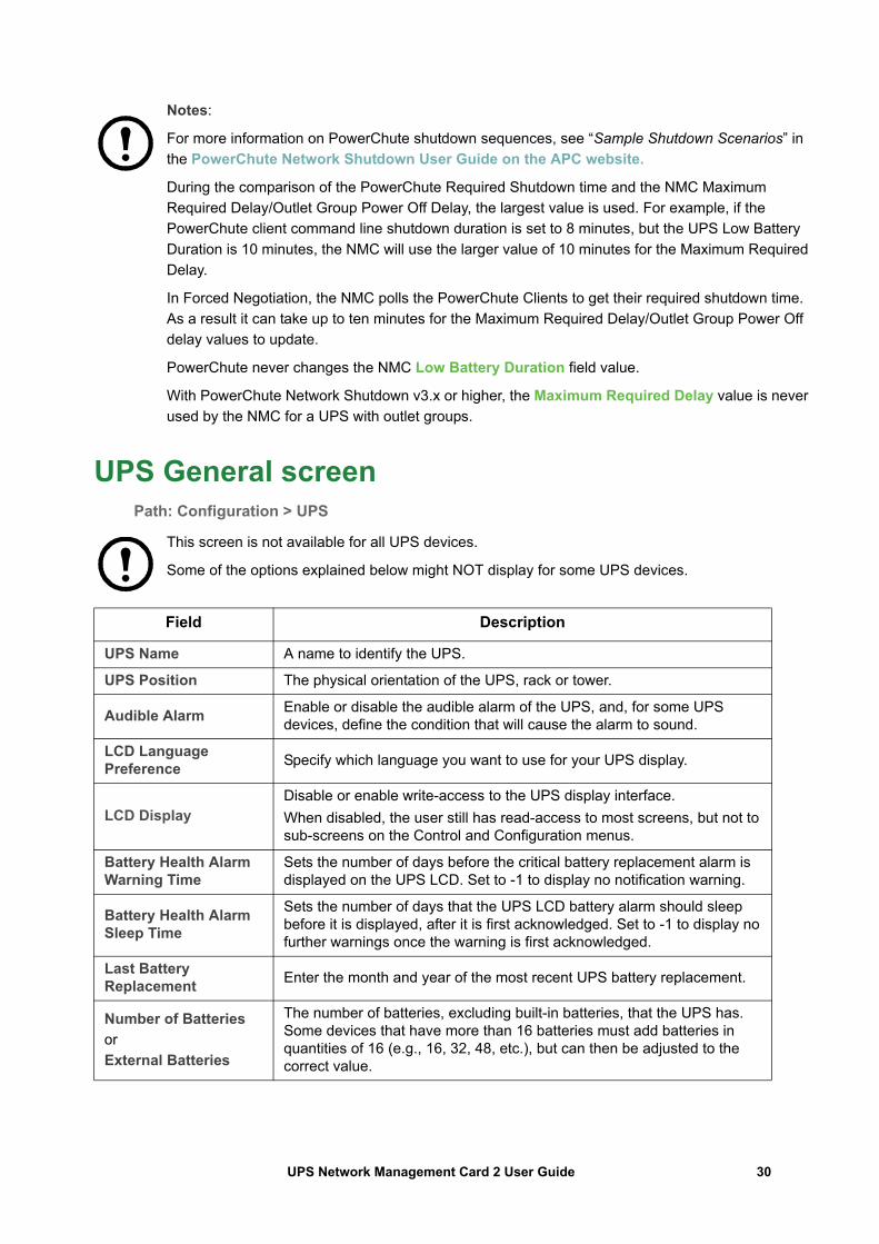
UPS General screenPath: Configuration > UPS
This screen is not available for all UPS devices.
Some of the options explained below might NOT display for some UPS devices.
Field Description
UPS Name A name to identify the UPS.
UPS Position The physical orientation of the UPS, rack or tower.
Audible Alarm Enable or disable the audible alarm of the UPS, and, for some UPS devices, define the condition that will cause the alarm to sound.
LCD Language Preference Specify which language you want to use for your UPS display.
LCD DisplayDisable or enable write-access to the UPS display interface. When disabled, the user still has read-access to most screens, but not to sub-screens on the Control and Configuration menus.
Battery Health Alarm Warning Time
Sets the number of days before the critical battery replacement alarm is displayed on the UPS LCD. Set to -1 to display no notification warning.
Battery Health Alarm Sleep Time
Sets the number of days that the UPS LCD battery alarm should sleep before it is displayed, after it is first acknowledged. Set to -1 to display no further warnings once the warning is first acknowledged.
Last Battery Replacement Enter the month and year of the most recent UPS battery replacement.
Number of Batteries orExternal Batteries
The number of batteries, excluding built-in batteries, that the UPS has. Some devices that have more than 16 batteries must add batteries in quantities of 16 (e.g., 16, 32, 48, etc.), but can then be adjusted to the correct value.
30UPS Network Management Card 2 User Guide
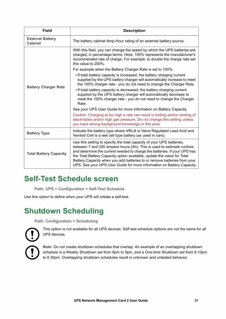
Self-Test Schedule screenPath: UPS > Configuration > Self-Test Schedule
Use this option to define when your UPS will initiate a self-test.
Shutdown SchedulingPath: Configuration > Scheduling
This option is not available for all UPS devices. Self test schedule options are not the same for all UPS devices.
Note: Do not create shutdown schedules that overlap. An example of an overlapping shutdown schedule is a Weekly Shutdown set from 8pm to 9pm, and a One-time Shutdown set from 8.10pm to 8.30pm. Overlapping shutdown schedules result in unknown and untested behavior.
External Battery Cabinet The battery cabinet Amp-Hour rating of an external battery source.
Battery Charger Rate
With this field, you can change the speed by which the UPS batteries are charged, in percentage terms. Here, 100% represents the manufacturer's recommended rate of charge. For example, to double the charge rate set this value to 200%. For example when the Battery Charger Rate is set to 100%:
• If total battery capacity is increased, the battery charging current supplied by the UPS battery charger will automatically increase to meet the 100% charger rate - you do not need to change the Charger Rate.
• If total battery capacity is decreased, the battery charging current supplied by the UPS battery charger will automatically decrease to meet the 100% charger rate - you do not need to change the Charger Rate.
See your UPS User Guide for more information on Battery Capacity.Caution: Charging at too high a rate can result in boiling and/or venting of electrolytes and/or high gas pressure. Do not change this setting unless you have strong background knowledge in this area.
Battery Type Indicate the battery type where VRLA is Valve Regulated Lead Acid and Vented Cell is a wet cell type battery (as used in cars).
Total Battery Capacity
Use this setting to specify the total capacity of your UPS batteries, between 7 and 200 ampere hours (Ah). This is used to estimate runtime and determine the current needed to charge the batteries. If your UPS has the Total Battery Capacity option available, update the value for Total Battery Capacity when you add batteries to or remove batteries from your UPS. See your UPS User Guide for more information on Battery Capacity.
Field Description
31UPS Network Management Card 2 User Guide
For both the UPS and outlet group options
You can schedule a shutdown for a UPS device under UPS or for an individual Switched Outlet Group (if applicable) under outlet groups.
Any configured shutdown schedules display along the top of the screen when you select UPS or outlet groups, with relevant details, including whether they are currently enabled or disabled.
Edit, Enable, Disable, or Delete a Scheduled Shutdown. Click the schedule name in the list of schedules along the top of either the UPS or outlet groups screen. This displays the complete details where you can edit the parameters. This includes disabling it temporarily by clearing the Enable check box, or deleting it permanently.
Creating a UPS or a Switched Outlet Group shutdown schedule.
1. Under Scheduling, select either UPS or outlet group. 2. Use the radio buttons to select the type of shutdown to schedule, One-time Shutdown, Daily
Shutdown, or Weekly Shutdown, and click the Next button.3. To disable a schedule temporarily, clear the Enable checkbox.4. Specify a name, and a schedule date and time.
For a weekly shutdown, specify the frequency using the drop-down box.5. Specify whether the device or outlet group should turn back on after the shutdown:
Turn back on: Specify whether the UPS will turn on at a specific day and time, Never (the UPS must be turned on manually), or Immediately (the UPS will turn on after waiting 6 minutes).
For an outlet group only, specify the group to shut down by selecting the appropriate button.
Signal PowerChute Network Shutdown Clients: Specify whether to notify PowerChute clients, see “PowerChute Network Shutdown clients”.
This option enables you to use the PowerChute Network Shutdown utility to shut down a maximum of 50 servers on the network that use a client version of the utility.
Firmware Update screenPath: UPS > Configuration > Firmware Update
This option is not available for all UPS devices.
The update here refers to the firmware on the UPS. Don’t confuse this with an NMC firmware upgrade (see “File Transfers”).
Note: To upgrade the firmware on an SRT model UPS, you must first upgrade the NMC firmware to v6.2.1 AOS or higher. Not doing so may render the UPS non-operational.
Follow the instructions on the Firmware Update screen to determine if the output of your UPS needs to be turned off in advance of a firmware update. This is specific to the UPS model.
Note: To view the Firmware Update screen with Internet Explorer®, use version 10 or higher, with compatibility view turned off. The Firmware Update screen is not compatible with the Edge® browser.
32UPS Network Management Card 2 User Guide
Follow these steps to update the firmware. (See also “Update the UPS firmware from a USB drive (AP9631 or AP9635 only)” and “Using FTP to update the UPS firmware” for alternative ways).
1. See the Knowledge Base article IDs FA164737 and FA170679 on the APC website for information on obtaining a firmware update file and further instructions.
2. Choose Configuration > Firmware Update.3. Click on the button to locate the downloaded update file on your computer.4. Click the Update UPS button to update the UPS firmware.5. When the update finishes, check the status under Last Update Result and Current Version, or in the
Event Log.
Update the UPS firmware from a USB drive (AP9631 or AP9635 only)
Before updating the UPS firmware, make sure the USB drive supports USB v1.1, and is in FAT, FAT16 or FAT32 format.
1. Insert a USB drive into the USB port on your computer.2. Visit the Knowledge Base article IDs FA164737 and FA170679 on the APC website to download the
correct firmware update file for your UPS, and save the file to the root of the USB drive, or to a /upsfw/ directory on the USB drive.
3. Eject the USB drive containing the firmware file from your computer, and insert it into the USB port of the NMC.
4. Open the NMC web interface and go to Configuration > Firmware Update.5. Select the firmware file from the dropdown list under the Update from USB drive pane.6. Click the Update UPS button to update the UPS firmware.
Note: Firmware update can take a few minutes. Do not remove the USB drive from the NMC until the UPS firmware update has completed. If you remove the USB drive before completion, the firmware update will not be successful.
7. When the update finishes, check the status under Last Update Result or in the Event Log.
Using FTP to update the UPS firmware
If you have updates to make on many UPS devices, it can be quicker to use FTP. The steps below show an example of how to do this. This is an alternative to updating from the “Firmware Update screen”.
1. See the Knowledge Base article IDs FA164737 and FA170679 on the APC website for information on obtaining a firmware update file and further instructions.
2. FTP the update file onto the card’s upsfw directory to start the firmware update process. The FTP firmware transfer might be aborted if the update file is corrupted or not applicable to the UPS. Here's an example of loading an update file using the DOS FTP command:
$ ftp <NMC Network Address Here>
Connected to <NMC Network Address>. 220 AP9631 Network Management Card AOS vX.Y.Z FTP server ready. User (<NMC Network Address>:(none)): apc 331 User name okay, need password. Password: 230 User logged in, proceed.
ftp> bin
33UPS Network Management Card 2 User Guide
200 TYPE Command okay.
ftp> hash
Hash mark printing On ftp:(2048 bytes/hash mark). ftp> cd upsfw 250 CWD requested file action okay, completed. ftp> put “<Path to UPS Firmware File>” 200 PORT Command okay. 150 File status okay; about to open data connection. 226 Closing data connection. ftp: 121984 bytes sent in 1.39Seconds 87.70Kbytes/sec. ftp> quit 221 Goodbye.
3. When the update finishes, check the status under Last Update Result on the firmware update page of the web interface or in the Event Log.
PowerChute Network Shutdown clientsPath: UPS > Configuration > PowerChute
PowerChute Network Shutdown can shut down your UPS devices remotely.
When you install a PowerChute Network Shutdown client on your network, it is added to this list automatically. When you uninstall a PowerChute Network Shutdown client, it is removed automatically.
Click Add Client to enter the IP address of a new PowerChute Network Shutdown client. To delete a client, click the IP address of that client in the list, and then click Delete Client. The list can contain the IP addresses of up to 50 clients.
With outlet groups, you also have to specify which outlet group is supplying power to the PowerChute client.
Third Party Support screenPath: Configuration > Third Party Support > EnergyWise
Cisco® EnergyWise™ enables the measurement and management of the power consumption of network devices. It can be used to reduce the consumption, and associated costs, of your UPS and its attached devices.
The EnergyWise screen on this NMC user interface facilitates the use of a Cisco EnergyWise switch to monitor and control your UPS and its devices. This includes turning off the UPS and individual Switched Outlets (if your UPS has them).
The EnergyWise functionality in the NMC can ONLY be used in conjunction with a Cisco EnergyWise switch. Use this NMC EnergyWise screen to configure the communications between the devices (including the UPS) and the Cisco EnergyWise switch.
Any reporting, analysis, and controlling (like turning off an outlet) is done using the Cisco switch.
Select EnergyWise from the NMC Configuration menu option. Use the initial EnergyWise Configuration screen to set the communication parameters with the Cisco switch. The domain name and shared secret password (if used) must be the same as those used on the switch.
34UPS Network Management Card 2 User Guide
When you have set the parameters, click Apply and the Cisco switch polls the domain and finds your UPS and any attached devices, including those attached using Switched Outlet Groups.
The lower half of this screen shows your devices and categorizes them under Parent and Child (if relevant).
The Parent is always your UPS. If you have devices attached to Switched Outlet Groups, they display under the Child Configuration heading.
The associated fields, Name, Role, Keywords, and Importance can be edited by clicking on the Name link or you can accept the defaults. It is mandatory to have values in Name and Importance.
The values in Role, Keywords, Importance, must use standard specification values from Cisco EnergyWise. They enable the querying of the state of your devices.
Field Description
VersionThe current toolkit version of EnergyWise on the NMC.This must be the same as the version on your Cisco EnergyWise switch.
EnergyWise This option is disabled by default. Select it to enable EnergyWise communication.
Port Specify the network port which the NMC will use to communicate with EnergyWise (43440 by default). The range is 1–65535.
Domain Name Specify the name of the domain shared between the NMC and the Cisco EnergyWise switch.
Secure Mode Select this check box to enable secure mode for communication between the NMC and the switch. This is optional.
Shared Secret If you select the Secure Mode check box, you must then enter the secret shared password used between your devices and the switch.
Field Description
Name The Name used to identify the parent and associated children of the UPS.
Role
This is a search category available to the Cisco switch.The role defines the device’s job or function within the network.The parent role default value is “Uninterruptible Power Supply”. The child role’s default value is “Outlet Group”, if supported.
Keywords
This is a search category available to the Cisco switch.Keywords are a way of grouping the parent and associated children devices. This enables the filtering of search results and reporting.The default value of a parent is “apc,ups,smartups”. The default of each child is “apc,ups,smartups,outlet”.
ImportanceUse the Importance field to rate or prioritize a device.The value can be an integer number from 1 to 100 where 1 is the least important and 100 is the most important. The default value of both the parent and each child is 1.
35UPS Network Management Card 2 User Guide
Universal I/O screensThe Universal I/O menu is relevant when you have installed the temperature and humidity sensors (AP9335T/ TH) or the Dry Contact I/O Accessory (AP9810). Using these is often referred to as environmental monitoring.
Temperature and Humidity screen
Path: Universal I/O > Temp & Humidity
This displays the name, alarm status, temperature, and humidity (if supported) for each sensor. Click the name of a sensor to edit the name and location and to configure its thresholds and its hysteresis.
Thresholds. For each sensor, you set the thresholds for temperature and (if supported) humidity measured at the sensor. When a threshold is breached, the alarm signals.
High and Low are warning messages. Maximum and Minimum are critical, they must be dealt with.
Hysteresis. Use the Hysteresis value to avoid getting alarms repeatedly for the same violation of the temperature or humidity threshold.
When the temperature or humidity that causes a violation tends to waver slightly up and down, it can repeatedly trigger the alarm. A greater hysteresis value can prevent this.
If the hysteresis value is not great enough, the wavering can first cause a threshold violation and then clear it, meaning the alarm can be triggered several times. See the examples below, after noting the following.
• For maximum and high threshold violations, the clearing point for the alarm is the threshold minus the hysteresis value you input.
• For minimum and low threshold violations, the clearing point is the threshold plus the hysteresis value.
Example of rising but wavering humidity: Say the maximum humidity threshold is 65%, and the humidity hysteresis is 10%. Then, the humidity rises above 65%, causing an alarm. It then wavers down to 60% and up to 70% repeatedly, but — because of the 10% hysteresis value — the alarm is not cleared and therefore no new alarm occurs. For the existing alarm to clear, the humidity would have to drop below 55% (which is 65% minus 10%).
Example of falling but wavering temperature: Say the minimum temperature threshold is 12°C, and the temperature hysteresis is 2°C. Then the temperature drops below 12°C, causing an alarm. It then wavers back up to 13°C and then down to 11°C repeatedly, but — because of the 2°C hysteresis value — the alarm is not cleared and therefore no new alarm occurs. For the existing alarm to clear, the temperature would have to rise above 14°C (which is 12°C plus 2°C).
Input Contacts screen
Path: Universal I/O > Input Contacts
Input Contacts displays the name, alarm status, and state (open or closed) of each contact. These are automatically found and displayed here when you install the environmental accessory.
36UPS Network Management Card 2 User Guide
Click the name of an input contact for detailed status or to configure its values. When disabled, the contact generates no alarm even when it is in the abnormal position. Other fields are discussed below:
Output Relay screen
Path: Universal I/O > Output Relay
Output Relay displays the name and state (open or closed) of each relay. These are automatically found and displayed here when you install the environmental accessory.
Click the name of an input contact for detailed status or to configure its values. The fields are discussed below:
Configuring the Control Policy
Path: Universal I/O > Control Policy
On an AP9631 or AP9635 NMC with up to two connected Dry Contact I/O Accessories (AP9810), you can:
• configure output relays to open or close based on UPS events and input contacts, see “Configuring an output to respond to an event”
• configure the UPS to take action based on input contacts, see “Configuring the UPS or output to respond to an input alarm”
Not all UPS devices can be configured to respond to input contacts.
Field Description
Alarm Status
Normal if this input contact is not reporting an alarm, or the severity of the alarm if this input contact is reporting an alarm. If not enabled for a contact, it displays Disabled.
State The present state of this input contact: Closed or Open.
Normal State The normal (non-alarm) state of this input contact: Closed or Open.
Severity The severity of the alarm that the abnormal state of this input contact generates: Warning or Critical.
Field Description
State The current state of this output relay: Closed or Open.
Normal State The normal (non-alarm) state of this output relay: Closed or Open.
Control To change the current state of this output relay, select this check box and click Apply.
Delay
The number of seconds a selected alarm condition must exist before the output relay is activated. Use this setting to avoid activating an alarm for brief transient conditions. If additional mapped alarms occur after the delay begins, the delay does not restart but continues counting down until the output relay is activated.
Hold
The minimum number of seconds the output relay remains activated after the alarm occurs.Even if the activating alarm condition is corrected, the output relay remains activated until this time period expires.
37UPS Network Management Card 2 User Guide
Configuring an output to respond to an event.
1. From the Configuration menu, select Universal I/O and Control Policy.2. Click the Add Policy button.3. Click a category or sub-category name to view corresponding events.4. To configure, click an event name, select the output relay check box that will change state when this
event occurs, and click Save Policy.
Configuring the UPS or output to respond to an input alarm.
1. From the Configuration menu, select Universal I/O and Control Policy.2. Click the Add Policy button.3. Click the I/O Contact sub-category.4. Choose the event with the same severity as the input contact. For example, if the severity of the input
contact is critical, then choose the critical event.The NMC supports up to four inputs. You must specify the input that will be associated with this event.
5. In the Port drop-down list, select the Universal Sensor Port number (1 or 2) to which the Dry Contact I/O Accessory is installed.
6. In the Zone drop-down list, select the zone letter (A or B) of the contact to which the input is installed.7. Define the action the UPS will perform (if any) when the input changes state.8. Select the output that will open or close (if any).9. Click Save Policy.
The action you configure occurs once.
If you restore the output to its normal state before the alarm condition clears, the output will not open or close again unless the alarm condition clears and then reoccurs.
Security menuSession Management screen
Path: Configuration > Security > Session Management
Enabling Allow Concurrent Logins means that two or more users can log on at the same time. Each user has equal access and each interface (HTTP, FTP, telnet console, serial console (CLI), etc.) counts as a logged-in user. Allow Concurrent Logins allows a maximum of eight users logged into the web interface, five users logged into the CLI and one user logged into the serial console at the same time.
Remote Authentication Override: The NMC supports Radius storage of passwords on a server. However, if you enable this override, the NMC will allow a local user to log on using the password for the NMC that is stored locally on the NMC. See also “Local Users” and “Remote Users authentication”.
Ping Response
Path: Configuration > Security > Ping Response
Enable the IPv4 Ping Response check box to allow the Network Management Card 2 to respond to network pings. This does not apply to IPv6.
38UPS Network Management Card 2 User Guide
Local UsersUse these menu options to view, and to set up access and individual preferences (like displayed date format), to the NMC user interfaces. This applies to users as defined by their logon name.
Path: Configuration > Security > Local Users > Management
Setting user access. With this option an administrator or super user can list and configure the users allowed access to the UI. Click on the name link to view details, and to edit or delete a user.
Click on Add User to add a user. On the resulting User Configuration screen, you can add a user and withhold access by clearing the Access check box. The maximum length for both the name and password is 64 bytes, with less for multi-byte characters. You have to enter a password.
Values greater than 64 bytes in Name and Password might get truncated.To change an administrator/ super user setting, you must enter all three password fields.
Create a password using a combination of lower and uppercase characters, numbers and special characters. Passwords can be no longer than 64 ASCII characters.
Use Session Timeout to configure the time that this UI waits before logging off this user (three minutes by default). If you change this value, you must log off for the change to take effect.
Serial Remote Authentication Override: By selecting this, you can bypass RADIUS by using the serial console (CLI) connection. This screen enables it for the selected user, but it must also be enabled globally to work, through “Session Management screen”.
See also “Configuration > Security > Local Users > Default Settings” below. For background information on accounts see “Types of user accounts”.
User Preferences. Select the Event Log Color Coding check box to enable color-coding of alarm text recorded in the Event Log. (System-event entries and configuration-change entries do not change color).
Export Log Format: Exported log files can be formatted using CSV (comma-separate values), or tabs. See “To display the Event Log”.
Select the temperature scale for measurements in this UI. US Customary corresponds to Fahrenheit and Metric corresponds to Celsius.
You can specify the default language for the UI with the Language field. This can be set when you log on also.
Text Color Alarm Severity
Red Critical: A critical alarm exists, which requires immediate action.
Orange Warning: An alarm condition requires attention and could jeopardize your data or equipment if its cause is not addressed.
Green Alarm Cleared: The conditions that caused the alarm have improved.
Black Normal: No alarms are present. The Network Management Card and all connected devices are operating normally.
Blue Informational: An alarm to provide information. The Network Management Card and all connected devices are operating normally.
39UPS Network Management Card 2 User Guide
You can also specify different languages for e-mail recipients and SNMP trap receivers. See “E-mail recipients” and “Trap Receivers”.
Path: Configuration > Security > Local Users > Default Settings
Setting up defaults can make adding users quicker. Use this option to set defaults for the many options on the Management screen, see “Configuration > Security > Local Users > Management” above.
Remote Users authentication
Path: Configuration > Security > Remote Users > authentication
Authentication. Specify how you want users to be authenticated at logon.
For information about local authentication (not using the centralized authentication of a RADIUS server), see the Security Handbook, available on the Utility CD and on the www.apc.com website.
The following authentication and authorization functions of RADIUS (Remote Authentication Dial-In User Service) are supported:
• When a user accesses the NMC or other network-enabled device that has RADIUS enabled, an authentication request is sent to the RADIUS server to determine the user’s permission level.
• RADIUS user names are limited to 32 characters with the NMC.Select one of the following:
• Local Authentication Only: RADIUS is disabled. See “Local Users”.• RADIUS, then Local Authentication: Both are enabled. Authentication is requested from the RADIUS
server first. If the RADIUS server does not respond, local authentication is used.• RADIUS Only: There is no local authentication.
If RADIUS Only is selected, and the RADIUS server is unavailable, improperly identified, or improperly configured, remote access is unavailable to all users. To regain access, you must use a serial connection to the command line interface and change the access setting to local or radiusLocal. For example, the command to change the access setting to local would be: radius -a local
See also “RADIUS screen” below and “Configuring the RADIUS Server”.
RADIUS screen
Path: Configuration > Security > Remote Users > RADIUS
You can use a RADIUS server to authenticate remote users.Use this option to do the following:
• List the RADIUS servers (a maximum of two) available to the NMC and the time-out period for each.• Configure the authentication parameters for a new or existing RADIUS server by clicking on a Radius
Server link.
40UPS Network Management Card 2 User Guide
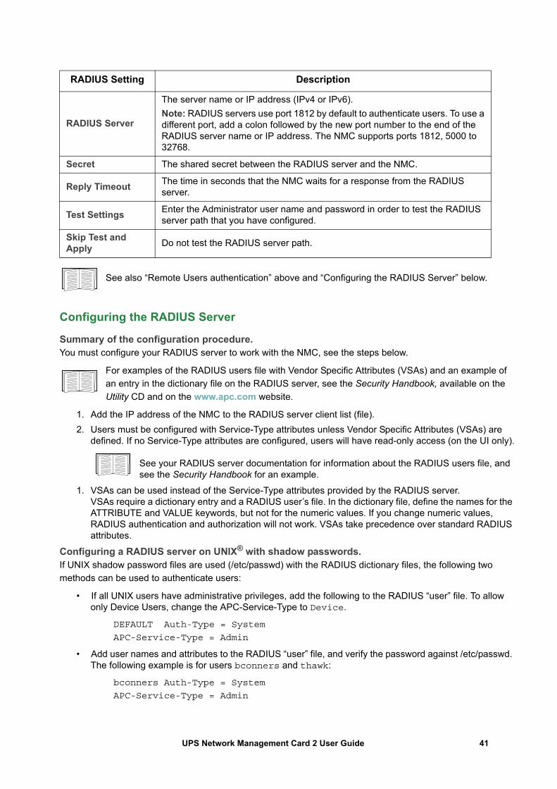
See also “Remote Users authentication” above and “Configuring the RADIUS Server” below.
Configuring the RADIUS Server
Summary of the configuration procedure. You must configure your RADIUS server to work with the NMC, see the steps below.
For examples of the RADIUS users file with Vendor Specific Attributes (VSAs) and an example of an entry in the dictionary file on the RADIUS server, see the Security Handbook, available on the Utility CD and on the www.apc.com website.
1. Add the IP address of the NMC to the RADIUS server client list (file).2. Users must be configured with Service-Type attributes unless Vendor Specific Attributes (VSAs) are
defined. If no Service-Type attributes are configured, users will have read-only access (on the UI only).
See your RADIUS server documentation for information about the RADIUS users file, and see the Security Handbook for an example.
1. VSAs can be used instead of the Service-Type attributes provided by the RADIUS server. VSAs require a dictionary entry and a RADIUS user’s file. In the dictionary file, define the names for the ATTRIBUTE and VALUE keywords, but not for the numeric values. If you change numeric values, RADIUS authentication and authorization will not work. VSAs take precedence over standard RADIUS attributes.
Configuring a RADIUS server on UNIX® with shadow passwords. If UNIX shadow password files are used (/etc/passwd) with the RADIUS dictionary files, the following two methods can be used to authenticate users:
• If all UNIX users have administrative privileges, add the following to the RADIUS “user” file. To allow only Device Users, change the APC-Service-Type to Device.
DEFAULT Auth-Type = System
APC-Service-Type = Admin
• Add user names and attributes to the RADIUS “user” file, and verify the password against /etc/passwd. The following example is for users bconners and thawk:
bconners Auth-Type = System
APC-Service-Type = Admin
RADIUS Setting Description
RADIUS Server
The server name or IP address (IPv4 or IPv6).Note: RADIUS servers use port 1812 by default to authenticate users. To use a different port, add a colon followed by the new port number to the end of the RADIUS server name or IP address. The NMC supports ports 1812, 5000 to 32768.
Secret The shared secret between the RADIUS server and the NMC.
Reply Timeout The time in seconds that the NMC waits for a response from the RADIUS server.
Test Settings Enter the Administrator user name and password in order to test the RADIUS server path that you have configured.
Skip Test and Apply Do not test the RADIUS server path.
41UPS Network Management Card 2 User Guide
thawk Auth-Type = System
APC-Service-Type = Device
Supported RADIUS servers. FreeRADIUS v1.x and v2.x, and Microsoft Server 2008 and 2012 Network policy Server (NPS) are supported. Other commonly available RADIUS applications may work, but may not have been fully tested.
Firewall screens
Path: Configuration > Security > Firewall > Configuration
Enable or disable the firewall functionality. The configured policy is listed by default. Select the Enable checkbox to enable the firewall. The check box is un-checked by default.
• Click Apply to confirm a firewall policy you have selected to enable. The Firewall Confirmation page will open.
– The Confirmation page contains a recommendation to test the firewall before enabling. It is not mandatory.
– The first hyperlink goes to the Firewall Policy page.– The second hyperlink goes to the Firewall Test page.– Click on Apply to enable the firewall and return to the Configuration page.– Click on Cancel to return to the Configuration page without enabling the Firewall.
• Click Cancel: No new selection will be enabled. You stay on the Configuration page.
Path: Configuration > Security > Firewall > Active Policy
Select an active policy from the Available Policies drop-down list, and view the validity of that policy. The current active policy is displayed by default; you can select another from the list.
• Click Apply to enable your changes. If a different firewall was selected and enabled, the change is effective immediately. If a newly configured firewall policy has been selected, it is recommended that you test the new firewall before enabling it. (See Configuration above.)
• Click Cancel to restore the original active policy and stay on the Active Policy page.
Path: Configuration > Security > Firewall > Active Rules
When a firewall is enabled, this read-only page lists the individual rules that are being enforced by a current active policy. See the Create/Edit Policy section for descriptions of the fields (Priority, Destination, Source, Protocol, Action, and Log).
Path: Configuration > Security > Firewall > Create/Edit Policy
Create a new policy; delete or edit an existing policy:
Note: While deleting an active enabled firewall policy cannot be done, editing a running policy can be done but is not recommended as changes are applied immediately. Instead, disable the firewall, edit the policy, test it, and then re-enable the policy.
42UPS Network Management Card 2 User Guide
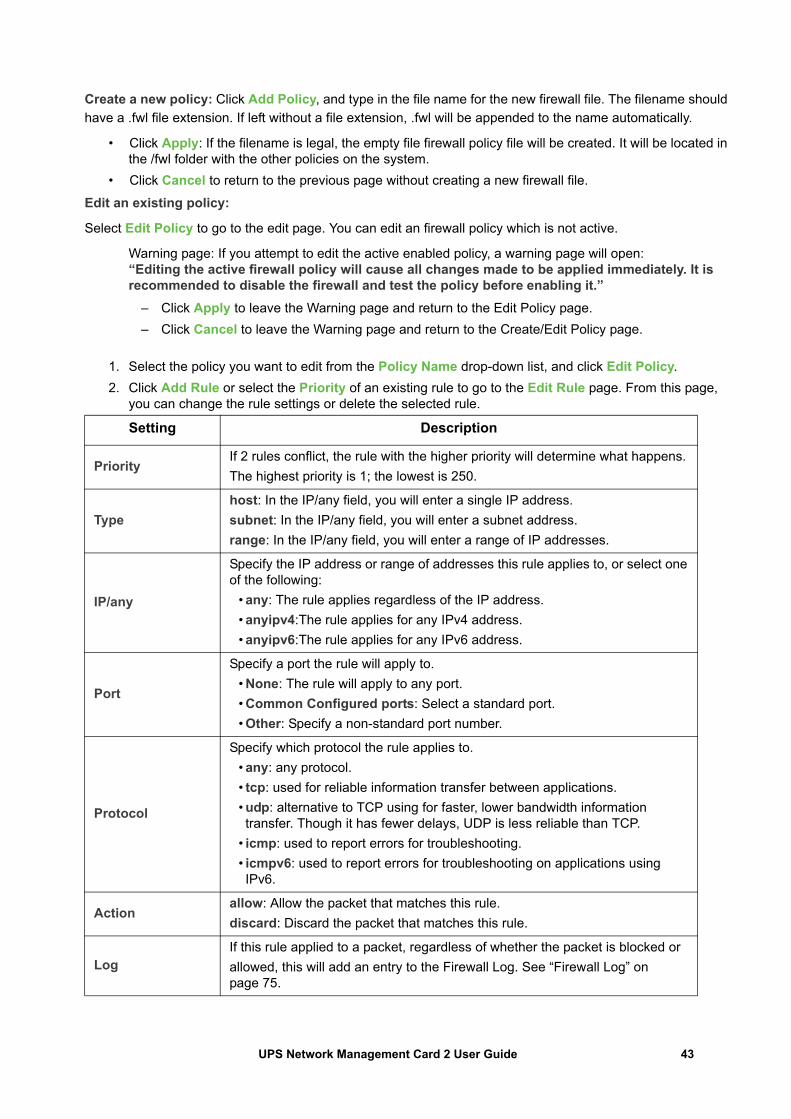
Create a new policy: Click Add Policy, and type in the file name for the new firewall file. The filename should have a .fwl file extension. If left without a file extension, .fwl will be appended to the name automatically.
• Click Apply: If the filename is legal, the empty file firewall policy file will be created. It will be located in the /fwl folder with the other policies on the system.
• Click Cancel to return to the previous page without creating a new firewall file.Edit an existing policy:
Select Edit Policy to go to the edit page. You can edit an firewall policy which is not active.
Warning page: If you attempt to edit the active enabled policy, a warning page will open:“Editing the active firewall policy will cause all changes made to be applied immediately. It is recommended to disable the firewall and test the policy before enabling it.”
– Click Apply to leave the Warning page and return to the Edit Policy page.– Click Cancel to leave the Warning page and return to the Create/Edit Policy page.
1. Select the policy you want to edit from the Policy Name drop-down list, and click Edit Policy.2. Click Add Rule or select the Priority of an existing rule to go to the Edit Rule page. From this page,
you can change the rule settings or delete the selected rule.
Setting Description
PriorityIf 2 rules conflict, the rule with the higher priority will determine what happens.The highest priority is 1; the lowest is 250.
Typehost: In the IP/any field, you will enter a single IP address.subnet: In the IP/any field, you will enter a subnet address.range: In the IP/any field, you will enter a range of IP addresses.
IP/any
Specify the IP address or range of addresses this rule applies to, or select one of the following:
• any: The rule applies regardless of the IP address.• anyipv4:The rule applies for any IPv4 address.• anyipv6:The rule applies for any IPv6 address.
Port
Specify a port the rule will apply to.• None: The rule will apply to any port.• Common Configured ports: Select a standard port.• Other: Specify a non-standard port number.
Protocol
Specify which protocol the rule applies to.• any: any protocol.• tcp: used for reliable information transfer between applications.• udp: alternative to TCP using for faster, lower bandwidth information transfer. Though it has fewer delays, UDP is less reliable than TCP.
• icmp: used to report errors for troubleshooting.• icmpv6: used to report errors for troubleshooting on applications using IPv6.
Actionallow: Allow the packet that matches this rule.discard: Discard the packet that matches this rule.
LogIf this rule applied to a packet, regardless of whether the packet is blocked orallowed, this will add an entry to the Firewall Log. See “Firewall Log” on page 75.
43UPS Network Management Card 2 User Guide
It is recommended that you add one of the following as the lowest priority rule in your firewall policy:
• To use the firewall as a white list, add250 Dest any / Source any / protocol any / discard
• To use the firewall as a black list, add250 Dest any / Source any / protocol any / allow
Delete a policy:
Select Delete Policy to open the Confirm Deletion page.
Click Apply to confirm, and the selected firewall file is removed from the file system.
Path: Configuration > Security > Firewall > Load Policy
Upload a policy (with the .fwl suffix) from a source external to this device.
Path: Configuration > Security > Firewall > Test
Temporarily enforce the rules of a chosen policy for a time that you specify.
44UPS Network Management Card 2 User Guide
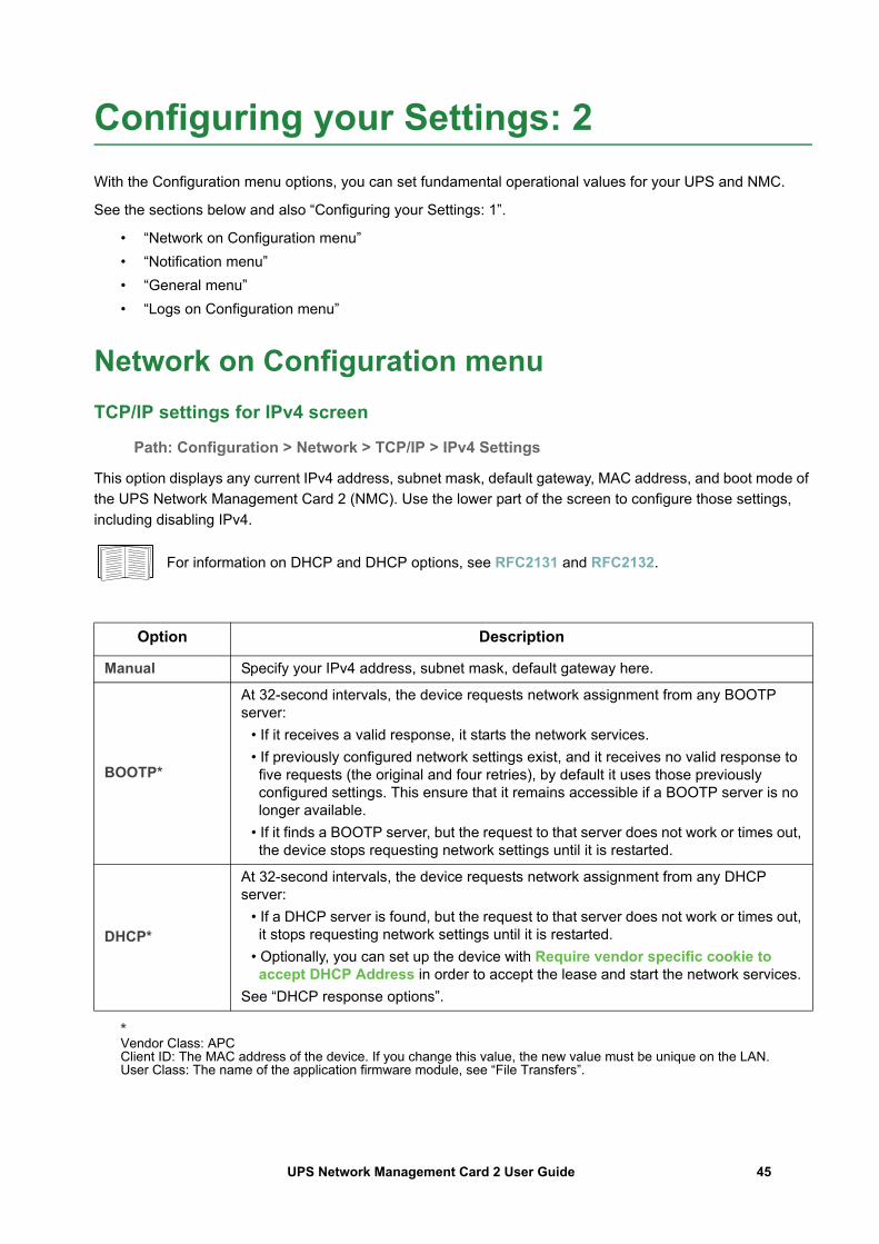
Configuring your Settings: 2With the Configuration menu options, you can set fundamental operational values for your UPS and NMC.
See the sections below and also “Configuring your Settings: 1”.
• “Network on Configuration menu”• “Notification menu”• “General menu”• “Logs on Configuration menu”
Network on Configuration menuTCP/IP settings for IPv4 screen
Path: Configuration > Network > TCP/IP > IPv4 Settings
This option displays any current IPv4 address, subnet mask, default gateway, MAC address, and boot mode of the UPS Network Management Card 2 (NMC). Use the lower part of the screen to configure those settings, including disabling IPv4.
For information on DHCP and DHCP options, see RFC2131 and RFC2132.
*Vendor Class: APCClient ID: The MAC address of the device. If you change this value, the new value must be unique on the LAN. User Class: The name of the application firmware module, see “File Transfers”.
Option Description
Manual Specify your IPv4 address, subnet mask, default gateway here.
BOOTP*
At 32-second intervals, the device requests network assignment from any BOOTP server:
• If it receives a valid response, it starts the network services. • If previously configured network settings exist, and it receives no valid response to five requests (the original and four retries), by default it uses those previously configured settings. This ensure that it remains accessible if a BOOTP server is no longer available.
• If it finds a BOOTP server, but the request to that server does not work or times out, the device stops requesting network settings until it is restarted.
DHCP*
At 32-second intervals, the device requests network assignment from any DHCP server:
• If a DHCP server is found, but the request to that server does not work or times out, it stops requesting network settings until it is restarted.
• Optionally, you can set up the device with Require vendor specific cookie to accept DHCP Address in order to accept the lease and start the network services.
See “DHCP response options”.
45UPS Network Management Card 2 User Guide
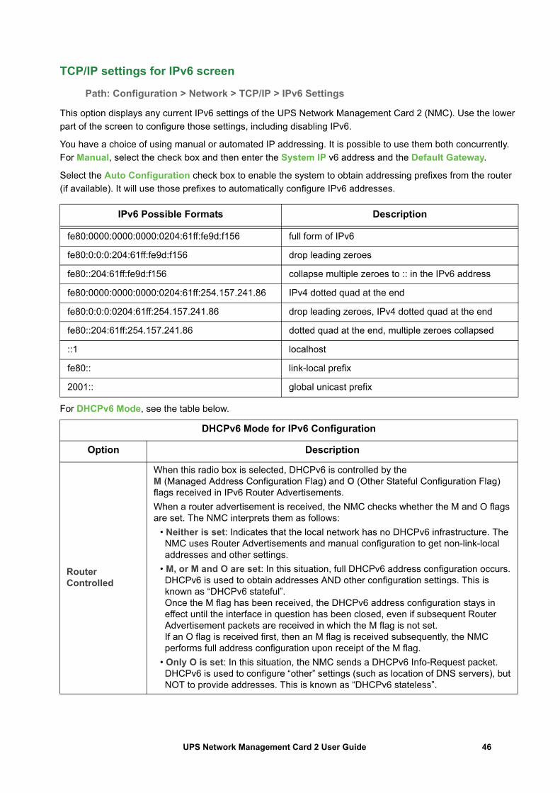
TCP/IP settings for IPv6 screen
Path: Configuration > Network > TCP/IP > IPv6 Settings
This option displays any current IPv6 settings of the UPS Network Management Card 2 (NMC). Use the lower part of the screen to configure those settings, including disabling IPv6.
You have a choice of using manual or automated IP addressing. It is possible to use them both concurrently. For Manual, select the check box and then enter the System IP v6 address and the Default Gateway.
Select the Auto Configuration check box to enable the system to obtain addressing prefixes from the router (if available). It will use those prefixes to automatically configure IPv6 addresses.
For DHCPv6 Mode, see the table below.
IPv6 Possible Formats Description
fe80:0000:0000:0000:0204:61ff:fe9d:f156 full form of IPv6
fe80:0:0:0:204:61ff:fe9d:f156 drop leading zeroes
fe80::204:61ff:fe9d:f156 collapse multiple zeroes to :: in the IPv6 address
fe80:0000:0000:0000:0204:61ff:254.157.241.86 IPv4 dotted quad at the end
fe80:0:0:0:0204:61ff:254.157.241.86 drop leading zeroes, IPv4 dotted quad at the end
fe80::204:61ff:254.157.241.86 dotted quad at the end, multiple zeroes collapsed
::1 localhost
fe80:: link-local prefix
2001:: global unicast prefix
DHCPv6 Mode for IPv6 Configuration
Option Description
Router Controlled
When this radio box is selected, DHCPv6 is controlled by the M (Managed Address Configuration Flag) and O (Other Stateful Configuration Flag) flags received in IPv6 Router Advertisements.When a router advertisement is received, the NMC checks whether the M and O flags are set. The NMC interprets them as follows:
• Neither is set: Indicates that the local network has no DHCPv6 infrastructure. The NMC uses Router Advertisements and manual configuration to get non-link-local addresses and other settings.
• M, or M and O are set: In this situation, full DHCPv6 address configuration occurs. DHCPv6 is used to obtain addresses AND other configuration settings. This is known as “DHCPv6 stateful”. Once the M flag has been received, the DHCPv6 address configuration stays in effect until the interface in question has been closed, even if subsequent Router Advertisement packets are received in which the M flag is not set. If an O flag is received first, then an M flag is received subsequently, the NMC performs full address configuration upon receipt of the M flag.
• Only O is set: In this situation, the NMC sends a DHCPv6 Info-Request packet. DHCPv6 is used to configure “other” settings (such as location of DNS servers), but NOT to provide addresses. This is known as “DHCPv6 stateless”.
46UPS Network Management Card 2 User Guide
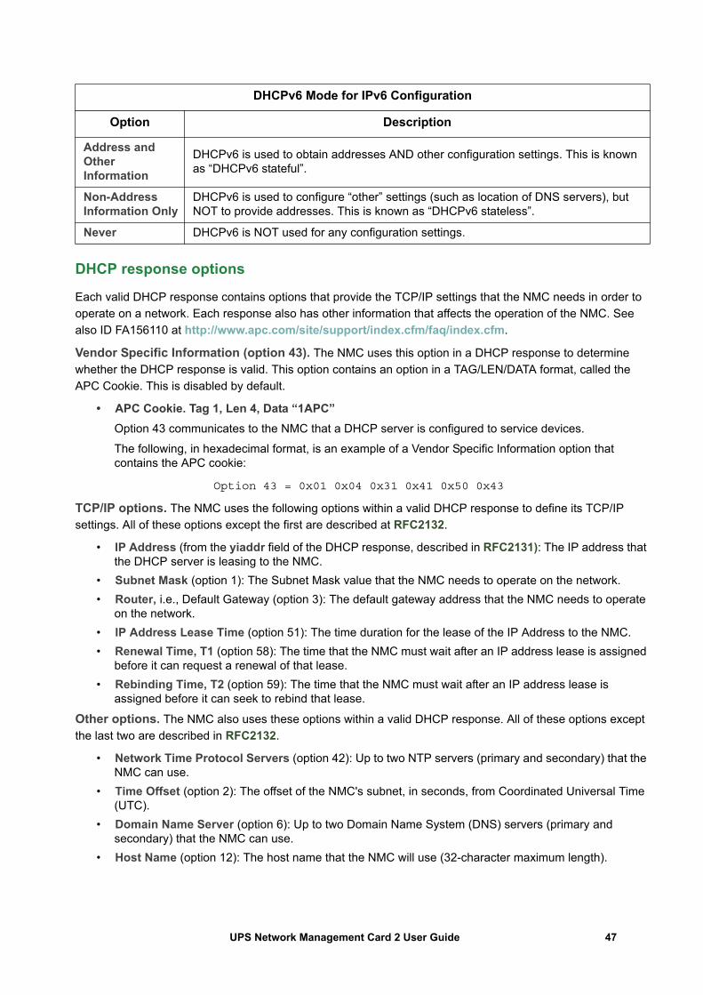
DHCP response options
Each valid DHCP response contains options that provide the TCP/IP settings that the NMC needs in order to operate on a network. Each response also has other information that affects the operation of the NMC. See also ID FA156110 at http://www.apc.com/site/support/index.cfm/faq/index.cfm.
Vendor Specific Information (option 43). The NMC uses this option in a DHCP response to determine whether the DHCP response is valid. This option contains an option in a TAG/LEN/DATA format, called the APC Cookie. This is disabled by default.
• APC Cookie. Tag 1, Len 4, Data “1APC” Option 43 communicates to the NMC that a DHCP server is configured to service devices.
The following, in hexadecimal format, is an example of a Vendor Specific Information option that contains the APC cookie:
Option 43 = 0x01 0x04 0x31 0x41 0x50 0x43
TCP/IP options. The NMC uses the following options within a valid DHCP response to define its TCP/IP settings. All of these options except the first are described at RFC2132.
• IP Address (from the yiaddr field of the DHCP response, described in RFC2131): The IP address that the DHCP server is leasing to the NMC.
• Subnet Mask (option 1): The Subnet Mask value that the NMC needs to operate on the network.• Router, i.e., Default Gateway (option 3): The default gateway address that the NMC needs to operate
on the network.• IP Address Lease Time (option 51): The time duration for the lease of the IP Address to the NMC.• Renewal Time, T1 (option 58): The time that the NMC must wait after an IP address lease is assigned
before it can request a renewal of that lease.• Rebinding Time, T2 (option 59): The time that the NMC must wait after an IP address lease is
assigned before it can seek to rebind that lease.
Other options. The NMC also uses these options within a valid DHCP response. All of these options except the last two are described in RFC2132.
• Network Time Protocol Servers (option 42): Up to two NTP servers (primary and secondary) that the NMC can use.
• Time Offset (option 2): The offset of the NMC's subnet, in seconds, from Coordinated Universal Time (UTC).
• Domain Name Server (option 6): Up to two Domain Name System (DNS) servers (primary and secondary) that the NMC can use.
• Host Name (option 12): The host name that the NMC will use (32-character maximum length).
Address and Other Information
DHCPv6 is used to obtain addresses AND other configuration settings. This is known as “DHCPv6 stateful”.
Non-Address Information Only
DHCPv6 is used to configure “other” settings (such as location of DNS servers), but NOT to provide addresses. This is known as “DHCPv6 stateless”.
Never DHCPv6 is NOT used for any configuration settings.
DHCPv6 Mode for IPv6 Configuration
Option Description
47UPS Network Management Card 2 User Guide
• Domain Name (option 15): The domain name that the NMC will use (64-character maximum length).• Boot File Name (from the file field of the DHCP response, described in RFC2131): The fully qualified
directory-path to a user configuration file (.ini file) to download. The siaddr field of the DHCP response specifies the IP address of the server from which the NMC will download the .ini file. After the download, the NMC uses the .ini file as a boot file to reconfigure its settings.
• Fully Qualified Domain Name (FQDN, option 81): The fully qualified domain name of the NMC.
Port Speed screen
Path: Configuration > Network > Port Speed
The Port Speed setting defines the communication speed of the Ethernet network port. Your current setting is displayed in Current Speed.
You can change the setting by choosing a radio button under Port Speed:
• For Auto-negotiation (the default), network devices negotiate to transmit at the highest possible speed, but if the supported speeds of two devices are not matched, the slower speed is used.
• Alternatively, you can choose 10 Mbps or 100 Mbps, each with the option of:– half-duplex (communication in only one direction at a time) or – full-duplex (communication in both directions on the same channel simultaneously).
DNS screen
Path: Configuration > Network > DNS > Configuration
The values under Domain Name System Status list your current status and setup.
Use the options under Manual Domain Name System Settings to configure he Domain Name System (DNS):
• Enabling the Override Manual DNS Settings means that configuration data from other sources like DHCP take precedence over the manual configurations here.
• Specify the Primary DNS Server and, optionally, the Secondary DNS Server with IPv4 or IPv6 addresses. For the NMC to send e-mail, you must at least define the IP address of the primary DNS server.
– The NMC waits up to 15 seconds for a response from the primary DNS server or the secondary DNS server. If the NMC does not receive a response within that time, e-mail cannot be sent. Use DNS servers on the same segment as the NMC or on a nearby segment, but not across a wide-area network (WAN).
– After you define the IP addresses of the DNS servers, test it, see “Testing DNS screen”. • System Name Synchronization: Enabling this synchronizes the DNS hostname with the NMC
System Name. Click on the System Name link to define it.If the DNS hostname and the NMC System Name are synchronized, the System Name is limited to a certain number of characters, based on DNS RFC. If they are not synchronized, the system name is limited to 255 characters.• Host Name: After you configure a host name here and a domain name in the Domain
Name field, users can enter a host name in any field in the NMC interface (except e-mail addresses) that accepts a domain name.
48UPS Network Management Card 2 User Guide
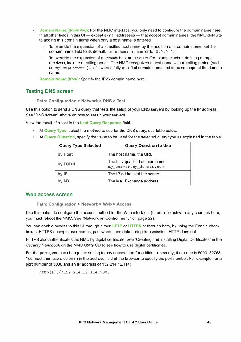
• Domain Name (IPv4/IPv6): For the NMC interface, you only need to configure the domain name here. In all other fields in this UI — except e-mail addresses — that accept domain names, the NMC defaults to adding this domain name when only a host name is entered.
– To override the expansion of a specified host name by the addition of a domain name, set this domain name field to its default, somedomain.com or to 0.0.0.0.
– To override the expansion of a specific host name entry (for example, when defining a trap receiver), include a trailing period. The NMC recognizes a host name with a trailing period (such as mySnmpServer.) as if it were a fully-qualified domain name and does not append the domain name.
• Domain Name (IPv6): Specify the IPv6 domain name here.
Testing DNS screen
Path: Configuration > Network > DNS > Test
Use this option to send a DNS query that tests the setup of your DNS servers by looking up the IP address. See “DNS screen” above on how to set up your servers.
View the result of a test in the Last Query Response field.
• At Query Type, select the method to use for the DNS query, see table below.• At Query Question, specify the value to be used for the selected query type as explained in the table.
Web access screen
Path: Configuration > Network > Web > Access
Use this option to configure the access method for the Web interface. (In order to activate any changes here, you must reboot the NMC. See “Network on Control menu” on page 22).
You can enable access to this UI through either HTTP or HTTPS or through both, by using the Enable check boxes. HTTPS encrypts user names, passwords, and data during transmission; HTTP does not.
HTTPS also authenticates the NMC by digital certificate. See “Creating and Installing Digital Certificates” in the Security Handbook on the NMC Utility CD to see how to use digital certificates.
For the ports, you can change the setting to any unused port for additional security; the range is 5000–32768. You must then use a colon (:) in the address field of the browser to specify the port number. For example, for a port number of 5000 and an IP address of 152.214.12.114:
http(s)://152.214.12.114:5000
Query Type Selected Query Question to Use
by Host The host name, the URL
by FQDN The fully-qualified domain name, my_server.my_domain.com
by IP The IP address of the server.
by MX The Mail Exchange address.
49UPS Network Management Card 2 User Guide
Web SSL Certificate screen
Path: Configuration > Network > Web > SSL Certificate
Add, replace, or remove a security certificate. SSL (Secure Socket Layer) is a protocol used to encrypt data between your browser and the web server.
The Status can be:
• Valid certificate: A valid certificate was installed or was generated by the NMC. Click on this link to view the contents of the certificate.
• Certificate not installed: A certificate is not installed, or was installed by FTP or SCP to an incorrect location. Using Add or Replace Certificate File installs the certificate to the correct location: /ssl on the NMC.
• Generating: The NMC is generating a certificate because no valid certificate was found.• Loading: A certificate is being activated on the NMC.
If you install an invalid certificate, or if no certificate is loaded while SSL is enabled, the NMC generates a default certificate, a process which delays access to the interface for up to one minute. You can use the default certificate for basic encryption-based security, but a security alert message displays whenever you log on.
Add or Replace Certificate File: Browse to the certificate file created with the Security Wizard. See “Creating and Installing Digital Certificates” in the Security Handbook on the Network Management Card Utility CD to see how to use digital certificates created by the Security Wizard or generated by the NMC.
Remove: Delete the certificate. See screen text also.
Console screen
Path: Configuration > Network > Console > Access
Path: Configuration > Network > Console > SSH Host Key
Console access. You need to enable console access in order to update your UPS firmware, see “Firmware Update screen”. Console access enables use of the command line interface (CLI).
You can enable access to the CLI through either Telnet or SSH or through both, by using the Enable check boxes. Telnet does not encrypt user names, passwords, and data during transmission whereas SSH does.
Note: If you enable SSH, SCP (SeCureCoPy) is also enabled, for secure file transfer. See “File Transfers” for more information on the use of SCP.
For the ports to be used to communicate with the NMC, you can change the setting to any unused port from 5000 to 32768 for additional security.
• Telnet Port: This is 23 by default. You must then use a colon (:) or a space to specify the non-default port, as required by your Telnet client program.
For example, for port 5000 and an IP address of 152.214.12.114, your Telnet client requires one of the these commands: telnet 152.214.12.114:5000 or telnet 152.214.12.114 5000
• SSH Port: This is 22 by default. See the documentation for your SSH client for the command line format required to specify a non-default port. See also “SSH Host Key” below.
SSH Host Key. If you’re using SSH (Secure Shell Protocol) for console (CLI) access, you can add, replace, or remove the host key on the SSL Host Key screen.
50UPS Network Management Card 2 User Guide
Status indicates whether the host key (private key) is valid. The Status can be:
• SSH Disabled: No host key in use.• Generating: The NMC is creating a host key because no valid host key was found.• Loading: A host key is being activated on the NMC.• Valid: One of the following valid host keys is in the /ssh directory (the required location on the Network
Management Card): – A 1024-bit or 2048-bit host key created by the Security Wizard– A 2048-bit RSA host key generated by the Network Management Card
Add or Replace Host Key: Upload a host key file created by the Security Wizard. To use the Security Wizard, see the Security Handbook on the Network Management Card Utility CD. To use an externally created host key, load the host key before you enable SSH (with “Console access” above).
Note: To reduce the time required to enable SSH, create and upload a host key in advance. If you enable SSH with no host key loaded, the NMC takes up to one minute to create a host key, and the SSH server is not accessible during that time.
Remove: Delete the host key. See screen text also.
To use SSH, you must have an SSH client installed. Most Linux and other UNIX platforms include an SSH client, but Microsoft Windows operating systems do not. Clients for Windows are available from various vendors, such as PuTTY which is available from www.putty.org.
SNMP screens
All user names, passwords, and community names for SNMP are transferred over the network as plain text.If your network requires the high security of encryption, disable SNMP access or set the access for each community to Read. (A community with Read access can receive status information and use SNMP traps.)
When using StruxureWare Data Center Expert to manage a UPS on the public network of an StruxureWare system, you must have SNMPv1 or SNMPv3 enabled in the NMC interface (SNMPv1 is enabled by default). Read access will allow the StruxureWare device to receive traps from the NMC, but Write access is required while you use the NMC user interface to set the StruxureWare device as a trap receiver.
For detailed information on enhancing and managing the security of your system, see the Security Handbook, available on the Network Management Card Utility CD or from the website, www.apc.com.
SNMPv1.
Path: Configuration > Network > SNMPv1 > Access and Access control
Use Access to enable or disable SNMP version 1 as a method of communication with the NMC.
Use of SNMPv2c is supported by the SNMPv1 options.
Access Control. You can configure up to four access control entries to specify which Network Management Systems (NMSs) have access to the NMC. To edit, click a community name.
51UPS Network Management Card 2 User Guide
By default one entry is assigned to each of the four available SNMPv1 communities. You can edit these settings to apply more than one entry to any one community to grant access by several specific IPv4 and IPv6 addresses, host names, or IP address masks.
• By default, a community has access to the NMC from any location on the network. • If you configure multiple access control entries for any one community name, it means that one or more
of the other communities have no access to the device.Community Name: The name that a Network Management Station (NMS) must use to access the community. The maximum length is 15 ASCII characters, and the default names are public, private, public2, and private2.
NMS IP/Host Name: The IPv4 or IPv6 address, IP address mask, or host name that controls access by NMSs. A host name or a specific IP address (for example, 149.225.12.1) allows access only by the NMS at that location. IP addresses that contain 255 restrict access as follows:
• 149.225.12.255: Access only by an NMS on the 149.225.12 segment.• 149.225.255.255: Access only by an NMS on the 149.225 segment. • 149.255.255.255: Access only by an NMS on the 149 segment.• 0.0.0.0 (the default setting) which can also be expressed as 255.255.255.255: Access by any NMS on
any segment.
Access Type: The actions an NMS can perform through the community.
• Read: GETS only, at any time • Write: GETS at any time, and SETS when no user is logged onto the UI or command line interface.• Write+: GETS and SETS at any time. • Disable: No GETS or SETS at any time.
SNMPv3.
Path: Configuration > Network > SNMPv3 > Access, User Profiles, and Access Control
For GETs, SETs, and trap receivers, SNMPv3 uses a system of user profiles to identify users. An SNMPv3 user must have a user profile assigned in the MIB software program to perform GETs and SETs, to browse the MIB, and to receive traps.
To use SNMPv3, you must have a MIB program that supports SNMPv3.
The NMC supports SHA or MD5 authentication and AES or DES encryption.
Enable SNMPv3 access under access enables this method of communication with this device.
User Profiles. By default, lists the settings of four user profiles, configured with the user names apc snmp profile1 through apc snmp profile4, with no authentication and no privacy (no encryption). To edit the following settings for a user profile, click a user name in the list.
• User Name: The identifier of the user profile. SNMP version 3 maps GETs, SETs, and traps to a user profile by matching the user name of the profile to the user name in the data packet being transmitted. A user name can have up to 32 ASCII characters.
• Authentication Passphrase: A phrase of 15 to 32 ASCII characters (apc auth passphrase, by default) that verifies that the NMS communicating with this device through SNMPv3 is the NMS it claims to be. It also verifies that the message has not been changed during transmission, and that the message was
52UPS Network Management Card 2 User Guide
communicated in a timely manner. This indicates that it was not delayed and that it was not copied and sent again later at an inappropriate time.
• Privacy Passphrase: A phrase of 15 to 32 ASCII characters (apc crypt passphrase, by default) that ensures the privacy of the data that an NMS is sending to or receiving from this device through SNMPv3, by using encryption.
• Authentication Protocol: The implementation of SNMPv3 supports SHA and MD5 authentication. One of these must be selected.
• Privacy Protocol: The implementation of SNMPv3 supports AES and DES as the protocols for encrypting and decrypting data. You must use both a privacy protocol and a privacy password, otherwise the SNMP request is not encrypted.In turn, you cannot select the privacy protocol if no authentication protocol is selected.
Access Control. You can configure up to four access control entries to specify which Network Management Systems (NMSs) have access to the NMC. To edit, click a user name.
By default one entry is assigned to each of the four user profiles. You can edit these settings to apply more than one entry to any one user profile to grant access by several specific IP addresses, host names, or IP address masks.
• By default, all NMSs that use that profile have access to this device. • If you configure multiple access control entries for one user profile, it means that one or more of the
other user profiles must have no access to this device.
User Name: From the drop-down list, select the user profile to which this access control entry will apply. The choices available are the four user names that you configure through the “User Profiles” option.
NMS IP/Host Name: The IP address, IP address mask, or host name that controls access by the NMS. A host name or a specific IP address (for example, 149.225.12.1) allows access only by the NMS at that location. An IP address mask that contains 255 restricts access as follows:
• 149.225.12.255: Access only by an NMS on the 149.225.12 segment.• 149.225.255.255: Access only by an NMS on the 149.225 segment.• 149.255.255.255: Access only by an NMS on the 149 segment.• 0.0.0.0 (the default setting) which can also be expressed as 255.255.255.255: Access by any NMS on
any segment.
Modbus screens
Use the Modbus options to configure your NMC to use the Modbus protocol, to connect to a Building Management System (BMS).
For more information on the Modbus implementation on your UPS, see the Modbus Documentation Addendum available on the Network Management Card Utility CD, and Modbus Register Maps available on the APC website www.apc.com.
See Application Note # 168 for more information on Modbus Installation and Troubleshooting for the AP9635 Network Management Card, on the APC website www.apc.com.
For more information on Switched Outlet Group Management with Modbus for Smart-UPS models with prefix SMT, SMX, SURTD, SRC and SRT, see Application Note # 177 on the APC website, www.apc.com.
Note: Temperature and humidity sensors attached to the UIO port(s) of the AP9631 and AP9635 NMC are not supported via Modbus.
53UPS Network Management Card 2 User Guide
Modbus Serial (AP9635 only).
Path: Configuration > Network > Modbus > Serial
1. Use Access to enable or disable Modbus Serial as a method of communication with the NMC.2. Set the connection parameters for the Modbus Serial connection:
– Baud Rate is the data rate in bits per second. It can be set to 9600 (default) or 19200.– Parity Bit is the check bit and can be set to Even, Odd or None.– Target Unique ID is the unique ID of the target device. It can be set to a value between 1 and
247.3. Click Apply to save your changes.
Modbus TCP.
Path: Configuration > Network > Modbus > TCP
1. Use Access to enable or disable Modbus TCP as a method of communication with the NMC.2. Set the Port number for the TCP connection. It can be set to 502 (default) or to a value between 5000
and 32768.3. Click Apply to save your changes.
BACnet screen
Use the BACnet options to configure your NMC to use the BACnet protocol, and to make UPS data available to building automation and control networks.
For more information on the UPS data points made available via BACnet, see the BACnet Application Maps available on the APC website, www.apc.com.
BACnet Configuration
Option Description
Access Select the checkbox to enable BACnet. If this is not enabled, the NMC cannot be accessed via BACnet. BACnet is disabled by default.
Device ID A unique identifier for this BACnet device, used for addressing the device. Acceptable range: 0–4194303.
Device Name
A name for this BACnet device, which must be unique on the BACnet network. The default device name is “BACn”+ the last eight digits of the NMC MAC address. The minimum length is 1, the maximum length is 150 characters, and special characters are permitted.
Network ProtocolSelect the protocol to be used:
• BACnet/IP
APDU Timeout The number of milliseconds the NMC will wait for a response to a BACnet request. Acceptable range: 1000-30000. The default value is 6000.
APDU Retries The number of BACnet requests attempts that the NMC will make before aborting the request. Acceptable range: 1–10. The default value is 3.
54UPS Network Management Card 2 User Guide
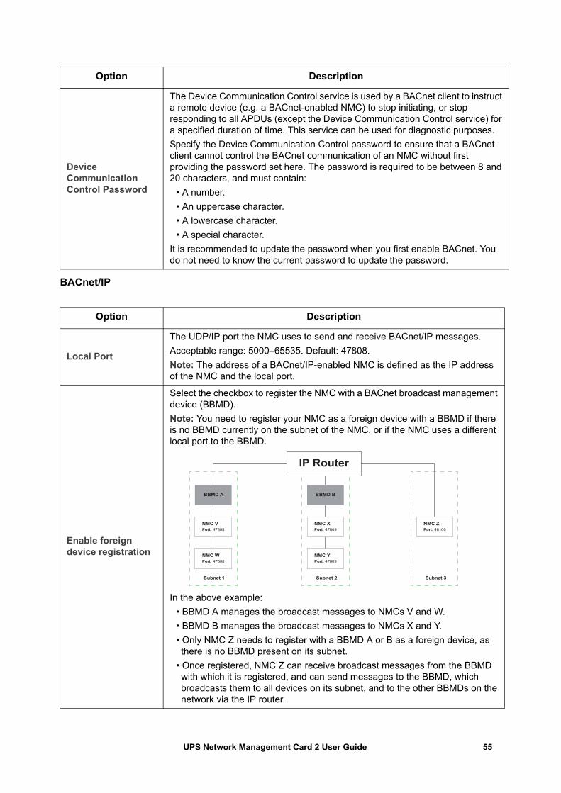
BACnet/IP
Device Communication Control Password
The Device Communication Control service is used by a BACnet client to instruct a remote device (e.g. a BACnet-enabled NMC) to stop initiating, or stop responding to all APDUs (except the Device Communication Control service) for a specified duration of time. This service can be used for diagnostic purposes.Specify the Device Communication Control password to ensure that a BACnet client cannot control the BACnet communication of an NMC without first providing the password set here. The password is required to be between 8 and 20 characters, and must contain:
• A number.• An uppercase character.• A lowercase character.• A special character.
It is recommended to update the password when you first enable BACnet. You do not need to know the current password to update the password.
Option Description
Local Port
The UDP/IP port the NMC uses to send and receive BACnet/IP messages.Acceptable range: 5000–65535. Default: 47808.Note: The address of a BACnet/IP-enabled NMC is defined as the IP address of the NMC and the local port.
Enable foreign device registration
Select the checkbox to register the NMC with a BACnet broadcast management device (BBMD). Note: You need to register your NMC as a foreign device with a BBMD if there is no BBMD currently on the subnet of the NMC, or if the NMC uses a different local port to the BBMD.
In the above example:• BBMD A manages the broadcast messages to NMCs V and W.• BBMD B manages the broadcast messages to NMCs X and Y.• Only NMC Z needs to register with a BBMD A or B as a foreign device, asthere is no BBMD present on its subnet.
• Once registered, NMC Z can receive broadcast messages from the BBMDwith which it is registered, and can send messages to the BBMD, whichbroadcasts them to all devices on its subnet, and to the other BBMDs on thenetwork via the IP router.
Option Description
Subnet 1 Subnet 2 Subnet 3
BBMD A BBMD B
NMC VPort: 47808
NMC WPort: 47808
NMC YPort: 47809
NMC XPort: 47809
NMC ZPort: 48100
IP Router
55UPS Network Management Card 2 User Guide
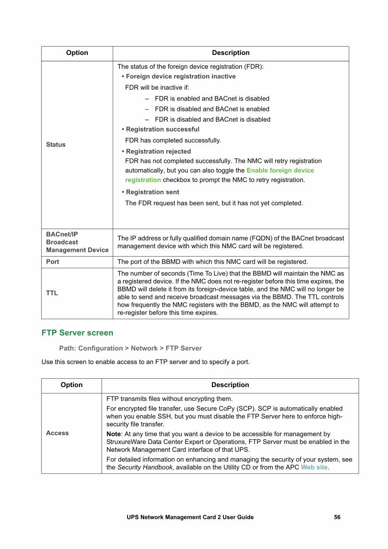
FTP Server screen
Path: Configuration > Network > FTP Server
Use this screen to enable access to an FTP server and to specify a port.
Status
The status of the foreign device registration (FDR):• Foreign device registration inactiveFDR will be inactive if:
– FDR is enabled and BACnet is disabled– FDR is disabled and BACnet is enabled– FDR is disabled and BACnet is disabled
• Registration successfulFDR has completed successfully.
• Registration rejectedFDR has not completed successfully. The NMC will retry registration automatically, but you can also toggle the Enable foreign device registration checkbox to prompt the NMC to retry registration.
• Registration sentThe FDR request has been sent, but it has not yet completed.
BACnet/IP Broadcast Management Device
The IP address or fully qualified domain name (FQDN) of the BACnet broadcast management device with which this NMC card will be registered.
Port The port of the BBMD with which this NMC card will be registered.
TTL
The number of seconds (Time To Live) that the BBMD will maintain the NMC as a registered device. If the NMC does not re-register before this time expires, the BBMD will delete it from its foreign-device table, and the NMC will no longer be able to send and receive broadcast messages via the BBMD. The TTL controls how frequently the NMC registers with the BBMD, as the NMC will attempt to re-register before this time expires.
Option Description
Access
FTP transmits files without encrypting them. For encrypted file transfer, use Secure CoPy (SCP). SCP is automatically enabled when you enable SSH, but you must disable the FTP Server here to enforce high-security file transfer. Note: At any time that you want a device to be accessible for management by StruxureWare Data Center Expert or Operations, FTP Server must be enabled in the Network Management Card interface of that UPS.For detailed information on enhancing and managing the security of your system, see the Security Handbook, available on the Utility CD or from the APC Web site.
Option Description
56UPS Network Management Card 2 User Guide
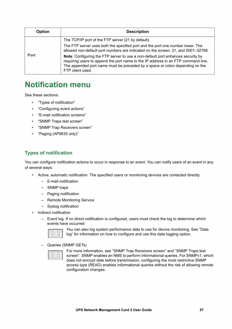
Notification menuSee these sections:
• “Types of notification”• “Configuring event actions”• “E-mail notification screens”• “SNMP Traps test screen”• “SNMP Trap Receivers screen”• “Paging (AP9635 only)”
Types of notification
You can configure notification actions to occur in response to an event. You can notify users of an event in any of several ways:
• Active, automatic notification. The specified users or monitoring devices are contacted directly.– E-mail notification– SNMP traps– Paging notification– Remote Monitoring Service– Syslog notification
• Indirect notification– Event log. If no direct notification is configured, users must check the log to determine which
events have occurredYou can also log system performance data to use for device monitoring. See “Data log” for information on how to configure and use this data logging option.
– Queries (SNMP GETs)For more information, see “SNMP Trap Receivers screen” and “SNMP Traps test screen”. SNMP enables an NMS to perform informational queries. For SNMPv1, which does not encrypt data before transmission, configuring the most restrictive SNMP access type (READ) enables informational queries without the risk of allowing remote configuration changes.
Port
The TCP/IP port of the FTP server (21 by default).The FTP server uses both the specified port and the port one number lower. The allowed non-default port numbers are indicated on the screen: 21, and 5001–32768.Note: Configuring the FTP server to use a non-default port enhances security by requiring users to append the port name to the IP address in an FTP command line. The appended port name must be preceded by a space or colon depending on the FTP client used.
Option Description
57UPS Network Management Card 2 User Guide
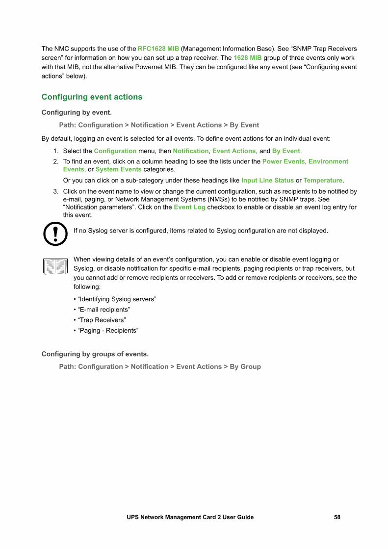
The NMC supports the use of the RFC1628 MIB (Management Information Base). See “SNMP Trap Receivers screen” for information on how you can set up a trap receiver. The 1628 MIB group of three events only work with that MIB, not the alternative Powernet MIB. They can be configured like any event (see “Configuring event actions” below).
Configuring event actions
Configuring by event.
Path: Configuration > Notification > Event Actions > By Event
By default, logging an event is selected for all events. To define event actions for an individual event:
1. Select the Configuration menu, then Notification, Event Actions, and By Event.2. To find an event, click on a column heading to see the lists under the Power Events, Environment
Events, or System Events categories.Or you can click on a sub-category under these headings like Input Line Status or Temperature.
3. Click on the event name to view or change the current configuration, such as recipients to be notified by e-mail, paging, or Network Management Systems (NMSs) to be notified by SNMP traps. See “Notification parameters”. Click on the Event Log checkbox to enable or disable an event log entry for this event.
If no Syslog server is configured, items related to Syslog configuration are not displayed.
When viewing details of an event’s configuration, you can enable or disable event logging or Syslog, or disable notification for specific e-mail recipients, paging recipients or trap receivers, but you cannot add or remove recipients or receivers. To add or remove recipients or receivers, see the following:
• “Identifying Syslog servers”• “E-mail recipients”• “Trap Receivers”• “Paging - Recipients”
Configuring by groups of events.
Path: Configuration > Notification > Event Actions > By Group
58UPS Network Management Card 2 User Guide
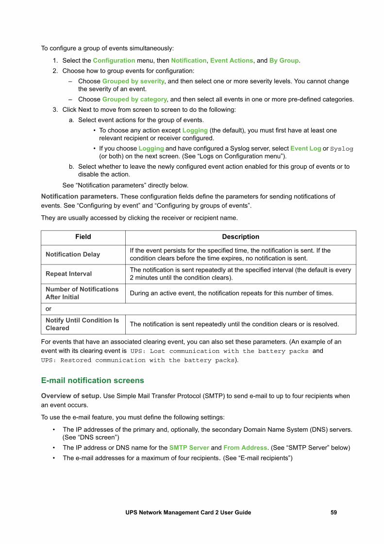
To configure a group of events simultaneously:
1. Select the Configuration menu, then Notification, Event Actions, and By Group.2. Choose how to group events for configuration:
– Choose Grouped by severity, and then select one or more severity levels. You cannot change the severity of an event.
– Choose Grouped by category, and then select all events in one or more pre-defined categories.3. Click Next to move from screen to screen to do the following:
a. Select event actions for the group of events. • To choose any action except Logging (the default), you must first have at least one
relevant recipient or receiver configured.• If you choose Logging and have configured a Syslog server, select Event Log or Syslog
(or both) on the next screen. (See “Logs on Configuration menu”).b. Select whether to leave the newly configured event action enabled for this group of events or to
disable the action.
See “Notification parameters” directly below.
Notification parameters. These configuration fields define the parameters for sending notifications of events. See “Configuring by event” and “Configuring by groups of events”.
They are usually accessed by clicking the receiver or recipient name.
For events that have an associated clearing event, you can also set these parameters. (An example of an event with its clearing event is UPS: Lost communication with the battery packs and UPS: Restored communication with the battery packs).
E-mail notification screens
Overview of setup. Use Simple Mail Transfer Protocol (SMTP) to send e-mail to up to four recipients when an event occurs.
To use the e-mail feature, you must define the following settings:
• The IP addresses of the primary and, optionally, the secondary Domain Name System (DNS) servers. (See “DNS screen”)
• The IP address or DNS name for the SMTP Server and From Address. (See “SMTP Server” below)• The e-mail addresses for a maximum of four recipients. (See “E-mail recipients”)
Field Description
Notification Delay If the event persists for the specified time, the notification is sent. If the condition clears before the time expires, no notification is sent.
Repeat Interval The notification is sent repeatedly at the specified interval (the default is every 2 minutes until the condition clears).
Number of Notifications After Initial During an active event, the notification repeats for this number of times.
or
Notify Until Condition Is Cleared The notification is sent repeatedly until the condition clears or is resolved.
59UPS Network Management Card 2 User Guide
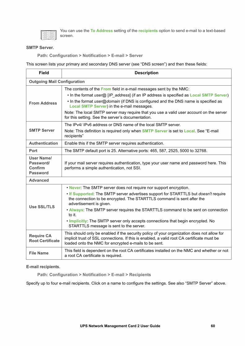
You can use the To Address setting of the recipients option to send e-mail to a text-based screen.
SMTP Server.
Path: Configuration > Notification > E-mail > Server
This screen lists your primary and secondary DNS server (see “DNS screen”) and then these fields:
E-mail recipients.
Path: Configuration > Notification > E-mail > Recipients
Specify up to four e-mail recipients. Click on a name to configure the settings. See also “SMTP Server” above.
Field Description
Outgoing Mail Configuration
From Address
The contents of the From field in e-mail messages sent by the NMC:• In the format user@ [IP_address] (if an IP address is specified as Local SMTP Server)• In the format user@domain (if DNS is configured and the DNS name is specified as Local SMTP Server) in the e-mail messages.
Note: The local SMTP server may require that you use a valid user account on the server for this setting. See the server’s documentation.
SMTP ServerThe IPv4/ IPv6 address or DNS name of the local SMTP server.Note: This definition is required only when SMTP Server is set to Local. See “E-mail recipients”
Authentication Enable this if the SMTP server requires authentication.
Port The SMTP default port is 25. Alternative ports: 465, 587, 2525, 5000 to 32768.
User Name/Password/Confirm Password
If your mail server requires authentication, type your user name and password here. This performs a simple authentication, not SSI.
Advanced
Use SSL/TLS
• Never: The SMTP server does not require nor support encryption.• If Supported: The SMTP server advertises support for STARTTLS but doesn't require the connection to be encrypted. The STARTTLS command is sent after the advertisement is given.
• Always: The SMTP server requires the STARTTLS command to be sent on connection to it.
• Implicitly: The SMTP server only accepts connections that begin encrypted. No STARTTLS message is sent to the server.
Require CA Root Certificate
This should only be enabled if the security policy of your organization does not allow for implicit trust of SSL connections. If this is enabled, a valid root CA certificate must be loaded onto the NMC for encrypted e-mails to be sent.
File Name This field is dependent on the root CA certificates installed on the NMC and whether or not a root CA certificate is required.
60UPS Network Management Card 2 User Guide
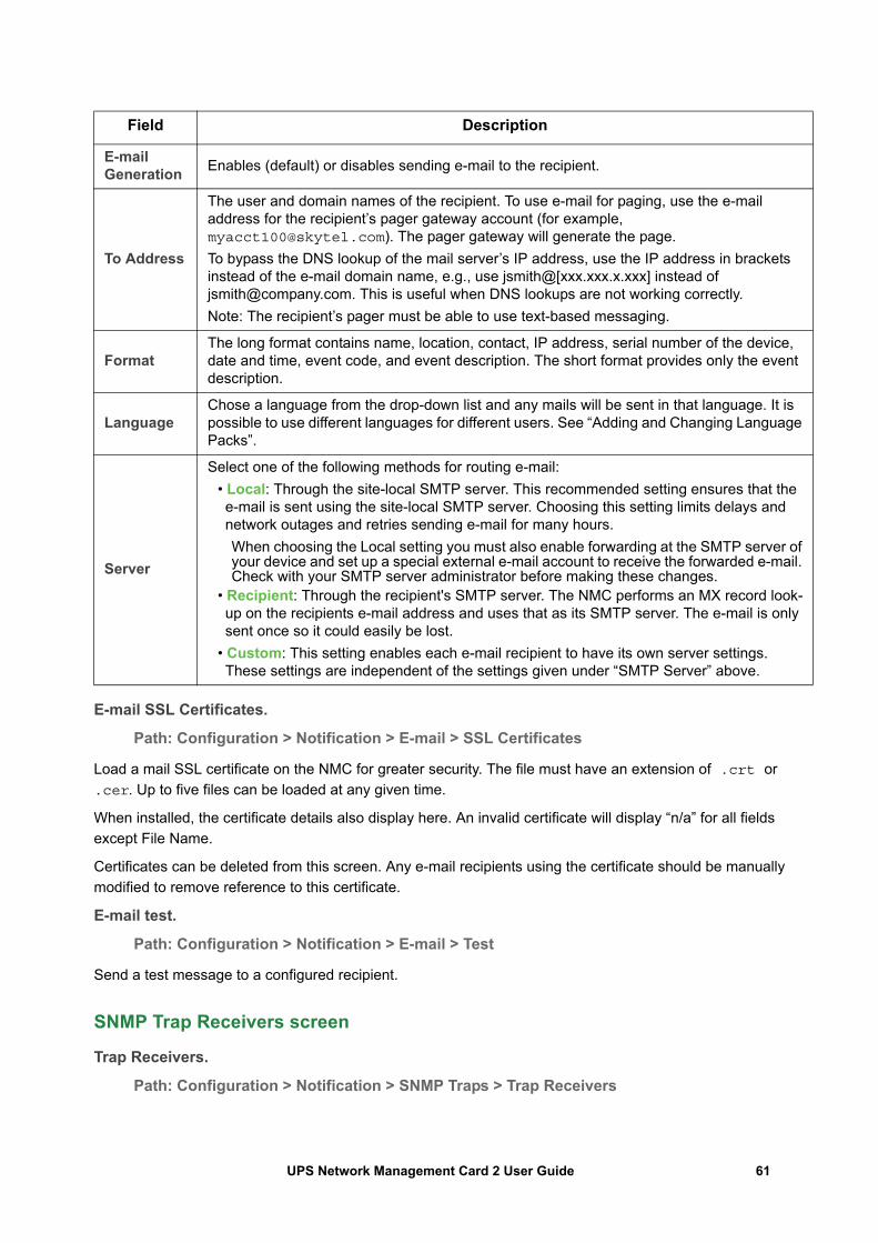
E-mail SSL Certificates.
Path: Configuration > Notification > E-mail > SSL Certificates
Load a mail SSL certificate on the NMC for greater security. The file must have an extension of .crt or .cer. Up to five files can be loaded at any given time.
When installed, the certificate details also display here. An invalid certificate will display “n/a” for all fields except File Name.
Certificates can be deleted from this screen. Any e-mail recipients using the certificate should be manually modified to remove reference to this certificate.
E-mail test.
Path: Configuration > Notification > E-mail > Test
Send a test message to a configured recipient.
SNMP Trap Receivers screen
Trap Receivers.
Path: Configuration > Notification > SNMP Traps > Trap Receivers
Field Description
E-mail Generation Enables (default) or disables sending e-mail to the recipient.
To Address
The user and domain names of the recipient. To use e-mail for paging, use the e-mail address for the recipient’s pager gateway account (for example, [email protected]). The pager gateway will generate the page.To bypass the DNS lookup of the mail server’s IP address, use the IP address in brackets instead of the e-mail domain name, e.g., use jsmith@[xxx.xxx.x.xxx] instead of [email protected]. This is useful when DNS lookups are not working correctly.Note: The recipient’s pager must be able to use text-based messaging.
FormatThe long format contains name, location, contact, IP address, serial number of the device, date and time, event code, and event description. The short format provides only the event description.
LanguageChose a language from the drop-down list and any mails will be sent in that language. It is possible to use different languages for different users. See “Adding and Changing Language Packs”.
Server
Select one of the following methods for routing e-mail:• Local: Through the site-local SMTP server. This recommended setting ensures that the e-mail is sent using the site-local SMTP server. Choosing this setting limits delays and network outages and retries sending e-mail for many hours. When choosing the Local setting you must also enable forwarding at the SMTP server of your device and set up a special external e-mail account to receive the forwarded e-mail. Check with your SMTP server administrator before making these changes.
• Recipient: Through the recipient's SMTP server. The NMC performs an MX record look-up on the recipients e-mail address and uses that as its SMTP server. The e-mail is only sent once so it could easily be lost.
• Custom: This setting enables each e-mail recipient to have its own server settings. These settings are independent of the settings given under “SMTP Server” above.
61UPS Network Management Card 2 User Guide
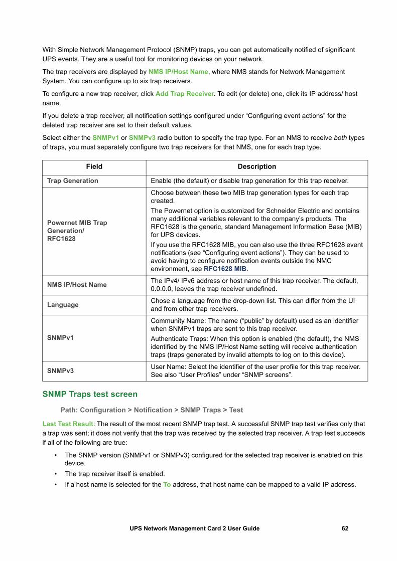
With Simple Network Management Protocol (SNMP) traps, you can get automatically notified of significant UPS events. They are a useful tool for monitoring devices on your network.
The trap receivers are displayed by NMS IP/Host Name, where NMS stands for Network Management System. You can configure up to six trap receivers.
To configure a new trap receiver, click Add Trap Receiver. To edit (or delete) one, click its IP address/ host name.
If you delete a trap receiver, all notification settings configured under “Configuring event actions” for the deleted trap receiver are set to their default values.
Select either the SNMPv1 or SNMPv3 radio button to specify the trap type. For an NMS to receive both types of traps, you must separately configure two trap receivers for that NMS, one for each trap type.
SNMP Traps test screen
Path: Configuration > Notification > SNMP Traps > Test
Last Test Result: The result of the most recent SNMP trap test. A successful SNMP trap test verifies only that a trap was sent; it does not verify that the trap was received by the selected trap receiver. A trap test succeeds if all of the following are true:
• The SNMP version (SNMPv1 or SNMPv3) configured for the selected trap receiver is enabled on this device.
• The trap receiver itself is enabled.• If a host name is selected for the To address, that host name can be mapped to a valid IP address.
Field Description
Trap Generation Enable (the default) or disable trap generation for this trap receiver.
Powernet MIB Trap Generation/RFC1628
Choose between these two MIB trap generation types for each trap created.The Powernet option is customized for Schneider Electric and contains many additional variables relevant to the company’s products. The RFC1628 is the generic, standard Management Information Base (MIB) for UPS devices.If you use the RFC1628 MIB, you can also use the three RFC1628 event notifications (see “Configuring event actions”). They can be used to avoid having to configure notification events outside the NMC environment, see RFC1628 MIB.
NMS IP/Host Name The IPv4/ IPv6 address or host name of this trap receiver. The default, 0.0.0.0, leaves the trap receiver undefined.
Language Chose a language from the drop-down list. This can differ from the UI and from other trap receivers.
SNMPv1
Community Name: The name (“public” by default) used as an identifier when SNMPv1 traps are sent to this trap receiver.Authenticate Traps: When this option is enabled (the default), the NMS identified by the NMS IP/Host Name setting will receive authentication traps (traps generated by invalid attempts to log on to this device).
SNMPv3 User Name: Select the identifier of the user profile for this trap receiver. See also “User Profiles” under “SNMP screens”.
62UPS Network Management Card 2 User Guide
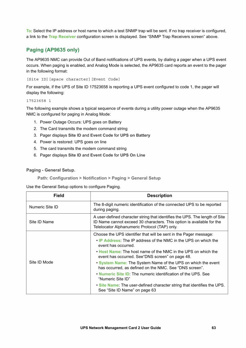
To: Select the IP address or host name to which a test SNMP trap will be sent. If no trap receiver is configured, a link to the Trap Receiver configuration screen is displayed. See “SNMP Trap Receivers screen” above.
Paging (AP9635 only)
The AP9635 NMC can provide Out of Band notifications of UPS events, by dialing a pager when a UPS event occurs. When paging is enabled, and Analog Mode is selected, the AP9635 card reports an event to the pager in the following format:
[Site ID][space character][Event Code]
For example, if the UPS of Site ID 17523658 is reporting a UPS event configured to code 1, the pager will display the following:
17523658 1
The following example shows a typical sequence of events during a utility power outage when the AP9635 NMC is configured for paging in Analog Mode:
1. Power Outage Occurs: UPS goes on Battery2. The Card transmits the modem command string3. Pager displays Site ID and Event Code for UPS on Battery4. Power is restored: UPS goes on line5. The card transmits the modem command string6. Pager displays Site ID and Event Code for UPS On Line
Paging - General Setup.
Path: Configuration > Notification > Paging > General Setup
Use the General Setup options to configure Paging.
Field Description
Numeric Site ID The 8-digit numeric identification of the connected UPS to be reported during paging.
Site ID NameA user-defined character string that identifies the UPS. The length of Site ID Name cannot exceed 30 characters. This option is available for the Telelocator Alphanumeric Protocol (TAP) only.
Site ID Mode
Choose the UPS identifier that will be sent in the Pager message:• IP Address: The IP address of the NMC in the UPS on which the event has occurred.
• Host Name: The host name of the NMC in the UPS on which the event has occurred. See“DNS screen” on page 48.
• System Name: The System Name of the UPS on which the event has occurred, as defined on the NMC. See “DNS screen”.
• Numeric Site ID: The numeric identification of the UPS. See “Numeric Site ID”
• Site Name: The user-defined character string that identifies the UPS. See “Site ID Name” on page 63
63UPS Network Management Card 2 User Guide
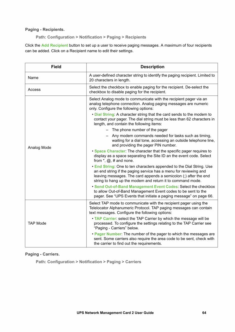
Paging - Recipients.
Path: Configuration > Notification > Paging > Recipients
Click the Add Recipient button to set up a user to receive paging messages. A maximum of four recipients can be added. Click on a Recipient name to edit their settings.
Paging - Carriers.
Path: Configuration > Notification > Paging > Carriers
Field Description
Name A user-defined character string to identify the paging recipient. Limited to 20 characters in length.
Access Select the checkbox to enable paging for the recipient. De-select the checkbox to disable paging for the recipient.
Analog Mode
Select Analog mode to communicate with the recipient pager via an analog telephone connection. Analog paging messages are numeric only. Configure the following options:
• Dial String: A character string that the card sends to the modem to contact your pager. The dial string must be less than 62 characters in length, and contain the following items:
– The phone number of the pager– Any modem commands needed for tasks such as timing,
waiting for a dial tone, accessing an outside telephone line, and providing the pager PIN number.
• Space Character: The character that the specific pager requires to display as a space separating the Site ID an the event code. Select from *, @, # and none.
• End String: One to ten characters appended to the Dial String. Use an end string if the paging service has a menu for reviewing and leaving messages. The card appends a semicolon (;) after the end string to hang up the modem and return it to command mode.
• Send Out-of-Band Management Event Codes: Select the checkbox to allow Out-of-Band Management Event codes to be sent to the pager. See “UPS Events that initiate a paging message” on page 66.
TAP Mode
Select TAP mode to communicate with the recipient pager using the Telelocator Alphanumeric Protocol. TAP paging messages can contain text messages. Configure the following options:
• TAP Carrier: select the TAP Carrier by which the message will be processed. To configure the settings relating to the TAP Carrier see “Paging - Carriers” below.
• Pager Number: The number of the pager to which the messages are sent. Some carriers also require the area code to be sent, check with the carrier to find out the requirements.
64UPS Network Management Card 2 User Guide
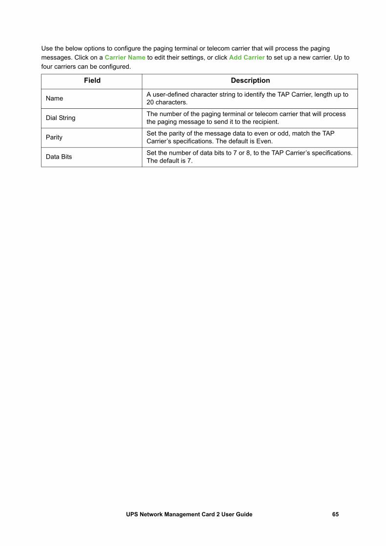
Use the below options to configure the paging terminal or telecom carrier that will process the paging messages. Click on a Carrier Name to edit their settings, or click Add Carrier to set up a new carrier. Up to four carriers can be configured.
Field Description
Name A user-defined character string to identify the TAP Carrier, length up to 20 characters.
Dial String The number of the paging terminal or telecom carrier that will process the paging message to send it to the recipient.
Parity Set the parity of the message data to even or odd, match the TAP Carrier’s specifications. The default is Even.
Data Bits Set the number of data bits to 7 or 8, to the TAP Carrier’s specifications. The default is 7.
65UPS Network Management Card 2 User Guide
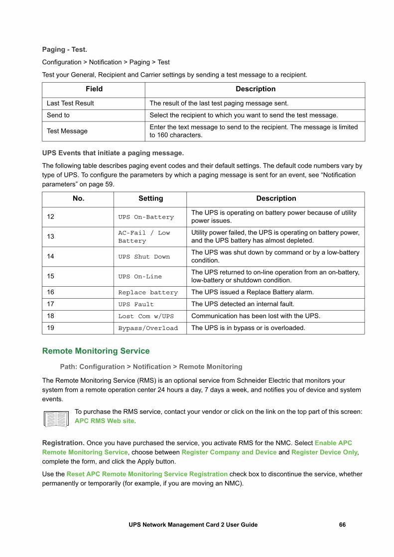
Paging - Test.
Configuration > Notification > Paging > Test
Test your General, Recipient and Carrier settings by sending a test message to a recipient.
UPS Events that initiate a paging message.
The following table describes paging event codes and their default settings. The default code numbers vary by type of UPS. To configure the parameters by which a paging message is sent for an event, see “Notification parameters” on page 59.
Remote Monitoring Service
Path: Configuration > Notification > Remote Monitoring
The Remote Monitoring Service (RMS) is an optional service from Schneider Electric that monitors your system from a remote operation center 24 hours a day, 7 days a week, and notifies you of device and system events.
To purchase the RMS service, contact your vendor or click on the link on the top part of this screen: APC RMS Web site.
Registration. Once you have purchased the service, you activate RMS for the NMC. Select Enable APC Remote Monitoring Service, choose between Register Company and Device and Register Device Only, complete the form, and click the Apply button.
Use the Reset APC Remote Monitoring Service Registration check box to discontinue the service, whether permanently or temporarily (for example, if you are moving an NMC).
Field Description
Last Test Result The result of the last test paging message sent.
Send to Select the recipient to which you want to send the test message.
Test Message Enter the text message to send to the recipient. The message is limited to 160 characters.
No. Setting Description
12 UPS On-BatteryThe UPS is operating on battery power because of utility power issues.
13 AC-Fail / Low Battery
Utility power failed, the UPS is operating on battery power, and the UPS battery has almost depleted.
14 UPS Shut DownThe UPS was shut down by command or by a low-battery condition.
15 UPS On-LineThe UPS returned to on-line operation from an on-battery, low-battery or shutdown condition.
16 Replace battery The UPS issued a Replace Battery alarm.
17 UPS Fault The UPS detected an internal fault.
18 Lost Com w/UPS Communication has been lost with the UPS.
19 Bypass/Overload The UPS is in bypass or is overloaded.
66UPS Network Management Card 2 User Guide
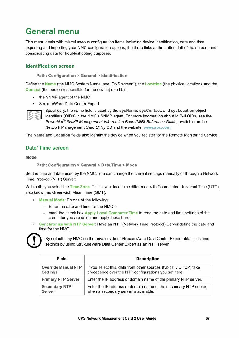
General menuThis menu deals with miscellaneous configuration items including device identification, date and time, exporting and importing your NMC configuration options, the three links at the bottom left of the screen, and consolidating data for troubleshooting purposes.
Identification screen
Path: Configuration > General > Identification
Define the Name (the NMC System Name, see “DNS screen”), the Location (the physical location), and the Contact (the person responsible for the device) used by:
• the SNMP agent of the NMC• StruxureWare Data Center Expert
Specifically, the name field is used by the sysName, sysContact, and sysLocation object identifiers (OIDs) in the NMC’s SNMP agent. For more information about MIB-II OIDs, see the PowerNet® SNMP Management Information Base (MIB) Reference Guide, available on the Network Management Card Utility CD and the website, www.apc.com.
The Name and Location fields also identify the device when you register for the Remote Monitoring Service.
Date/ Time screen
Mode.
Path: Configuration > General > Date/Time > Mode
Set the time and date used by the NMC. You can change the current settings manually or through a Network Time Protocol (NTP) Server:
With both, you select the Time Zone. This is your local time difference with Coordinated Universal Time (UTC), also known as Greenwich Mean Time (GMT).
• Manual Mode: Do one of the following: – Enter the date and time for the NMC or– mark the check box Apply Local Computer Time to read the date and time settings of the
computer you are using and apply those here.• Synchronize with NTP Server: Have an NTP (Network Time Protocol) Server define the date and
time for the NMC.
By default, any NMC on the private side of StruxureWare Data Center Expert obtains its time settings by using StruxureWare Data Center Expert as an NTP server.
Field Description
Override Manual NTP Settings
If you select this, data from other sources (typically DHCP) take precedence over the NTP configurations you set here.
Primary NTP Server Enter the IP address or domain name of the primary NTP server.
Secondary NTP Server
Enter the IP address or domain name of the secondary NTP server, when a secondary server is available.
67UPS Network Management Card 2 User Guide
Daylight saving.
Path: Configuration > General > Date /Time > Daylight Savings
Daylight Saving Time (DST) is disabled by default. You can enable traditional United States DST, or enable and configure a customized daylight saving time to match how Daylight Saving Time is implemented in your local area.
When customizing DST, the system puts the clock forward by an hour when the time and date you specify under Start is reached and puts the clock back an hour when the time and date you specify under End is reached.
• If your local DST always starts or ends on the fourth occurrence of a specific weekday of a month (e.g, the fourth Sunday), choose Fourth/Last. If a fifth Sunday occurs in that month, you should still choose Fourth/Last.
• If your local DST always starts or ends on the last occurrence of a specific weekday of a month, whether it is the fourth or the fifth occurrence, choose Fifth/Last.
Creating and Importing settings with the config file
Path: Configuration > General > User Config File
You can speed up and simplify the configuration of new devices by re-using the existing configuration settings with this option. Use Upload to transfer configuration data to this interface and Download to transfer from this interface (and then use the file to configure another interface). The default name of the file is config.ini.
To retrieve and customize the file of a configured NMC, see “How to Export Configuration Settings”.
Configure Links screen
Path: Configuration > General > Quick Links
Use this option to view and change the URL links displayed at the bottom left of each screen of the interface.
To reconfigure a link, click the link name in the Name column. You can reset the links to their defaults at any time by clicking on Reset to Defaults there.
Update Interval Define, in hours, how often the NMC accesses the NTP Server for an update. Minimum: 1; Maximum: 8760 (1 year).
Update Using NTP Now Initiate an immediate update of the date and time by the NTP Server.
Field Description
68UPS Network Management Card 2 User Guide
Logs on Configuration menuPath: Configuration > Logs > Syslog > options
The NMC can send messages to up to four Syslog servers when an event occurs. The Syslog servers record events that occur at network devices in a log that provides a centralized record of events.
This user’s guide does not describe Syslog or its configuration values in detail. See RFC3164 for more information about Syslog.
Identifying Syslog servers
Path: Configuration > Logs > Syslog > Servers
Syslog settings
Path: Configuration > Logs > Syslog > Settings
Field Description
Syslog Server
Uses IPv4/ IPv6 addresses or host names to identify from one to four servers to receive Syslog messages sent by the NMC.
Port The user datagram protocol (UDP) port that the NMC will use to send Syslog messages. The default is 514, the UDP port assigned to Syslog.
Language Choose the language for any Syslog messages.
Protocol Choose between UDP and TCP.
Field Description
Message Generation
Enable the generation and the logging of Syslog messages for events that have Syslog configured as a notification method. See “Configuring event actions”.
Facility Code
Selects the facility code assigned to the NMC’s Syslog messages (User, by default).Note: User best defines the Syslog messages sent by the NMC. Do not change this selection unless advised to do so by the Syslog network or system administrator.
69UPS Network Management Card 2 User Guide
Syslog test and format example
Path: Logs > Syslog > Test
Send a test message to the Syslog servers (configured through the “Identifying Syslog servers” option above). The result will be sent to all configured Syslog servers.
Select a severity to assign to the test message and then define the test message. Format the message to consist of the event type (APC, System, or Device, for example) followed by a colon, a space, and the event text. The message can have a maximum of 50 characters.
• The priority (PRI): the Syslog priority assigned to the message’s event, and the facility code of messages sent by the NMC.
• The Header: a time stamp and the IP address of the NMC.• The message (MSG) part:
– The TAG field, followed by a colon and space, identifies the event type.– The CONTENT field is the event text, followed (optionally) by a space and the event code.
Example: APC: Test Syslog is valid.
Severity Mapping
Maps each severity level of NMC or Environment events to available Syslog priorities. The local options are Critical, Warning, and Informational. You should not need to change the mappings.The following definitions are from RFC3164:
• Emergency: The system is unusable• Alert: Action must be taken immediately• Critical: Critical conditions• Error: Error conditions• Warning: Warning conditions• Notice: Normal but significant conditions• Informational: Informational messages• Debug: Debug-level messages
Following are the default settings for the Local Priority settings:• Severe is mapped to Critical• Warning is mapped to Warning• Informational is mapped to Info
Note: To disable Syslog messages, see “Configuring event actions”.
Field Description
70UPS Network Management Card 2 User Guide
70UPS Network Management Card 2 User Guide
Tests menu
Testing and calibratingPath: Tests > UPS
This option is not available for all UPS devices.
With some UPS devices, you can run a self-test, an alarm test, or a runtime calibration for your UPS. The Self-Test and Calibration fields display the results of the most recent test and calibration.
A runtime calibration causes the UPS to recalculate its available runtime capacity based on its current load. This ensures that the runtime reported is more accurate. Because a calibration temporarily depletes the UPS batteries, you can perform a calibration only if battery capacity is at 100%. The load on your UPS must be at least 15% without fluctuating to guarantee that a calibration will be accepted.
Caution - Runtime calibrations deeply discharge UPS batteries, which can leave a UPS temporarily unable to support its attached load if a power outage occurs.
Frequent calibrations reduce the life of batteries.
Perform a calibration whenever you significantly increase the load that the UPS is supporting.
The alarm test for a UPS is device-specific and might not be available for your UPS. To enable the alarm, see “UPS General screen”.
• When you select UPS Alarm Test, the UPS beeps for four seconds and the LEDs illuminate.• When you select UPS Alarm Test - Continuous, the UPS beeps and illuminates the LEDs until you
cancel the test. A separate bullet displays on this screen, Cancel Continuous Alarm Test. To cancel the test, select this and click Apply. Alternatively you press any key on the LED display interface of the UPS. This test is useful for locating a UPS.
Setting the NMC LED lights to blinkPath: Tests > Network > LED Blink
If you are having trouble finding your UPS device, enter a number of minutes in the LED Blink Duration field, click Apply, and your NMC LED lights will start flashing. This can assist in locating the physical device.
Logs and About menus
Using the Event and Data LogsThe Event Log records individual occurrences. The Data Log, by contrast, provides you with a snapshot of your system by recording values at regular time intervals.
Event log
Path: Logs > Events > available options
By default, the log displays all events recorded during the last two days, starting with the latest events. See “Configuring by event”.
In addition, the log records: i) Any event that sends an SNMP trap, except SNMP authentication failures. ii) Abnormal internal system events.
You can enable event color coding for through “Local Users” on the Configuration menu.
To display the Event Log.
Path: Logs > Events > Log
By default, the Event Log displays the most recent events first. To see the events listed together on a Web page, click the Launch Log in New Window button. JavaScript must be enabled in your browser to do this.
To open the log in a text file or to save the log to disk, click on the floppy disk icon, , in the same line as the Event Log heading.
You can also use FTP or Secure CoPy (SCP) to view the Event Log. See “How to use FTP or SCP to retrieve log files”.
To filter the Event Log. Use filtering to omit information you don’t want to display.
Important points on filtering:
• Events are processed through the filter using OR logic. If you apply a filter, it works regardless of the other filters.
• Events that you cleared in the Filter By Severity list never display in the filtered Event Log, even if selected in the Filter by Category list.
• Similarly, events that you clear in the Filter by Category list never display in the filtered Event Log.
To delete the Event Log. To delete all events, click Clear Log. Deleted events cannot be retrieved.
Filtering the log by date or time
Use the Last or From radio buttons. (The filter configuration is saved until the NMC restarts).
Filtering the log by event severity or category
Click Filter Log. Clear a check box to remove it from view. After you click Apply text at the upper right corner of the Event Log page indicates that a filter is active. The filter is active until you clear it or until the NMC restarts. To remove an active filter, click Filter Log, then Clear Filter (Show All). As Administrator, click Save As Default to save this filter as the new default log view for all users.
71UPS Network Management Card 2 User Guide
To disable the logging of events based on their assigned severity level or their event category, see “Configuring by groups of events”.
To configure reverse lookup:
Path: Logs > Events > Reverse Lookup
With reverse lookup enabled, when a network-related event occurs, both the IP address and the domain name for the networked device with the event are logged in the Event Log. If no domain name entry exists for the device, only its IP address is logged with the event.
Since domain names generally change less frequently than IP addresses, enabling reverse lookup can improve the ability to identify addresses of networked devices that are causing events.
Reverse lookup is disabled by default. You should not need to enable it if you have no DNS server configured or have poor network performance because of heavy network traffic.
To resize the Event Log.
Path: Logs > Events > Size
Use Event Log Size to specify the maximum number of log entries.
Caution: When you resize the Event Log in order to specify a maximum size, all existing log entries are deleted. To avoid losing log data, use FTP or SCP to retrieve the log first, see “How to use FTP or SCP to retrieve log files”. When the log subsequently reaches the maximum size, the older entries are deleted.
Data log
Path: Logs > Data > options
Use the Data Log to display measurements about the UPS, the power input to the UPS, and the ambient temperature of the UPS and batteries.
The steps to display and resize the Data Log are the same as for the Event Log, except that you use menu options under Data instead of Events. See “To display the Event Log” and “To resize the Event Log”.
To filter the Data Log by date or time, use the Last or From radio buttons. (The filter configuration is saved until the NMC restarts).To delete all data recorded in the Data Log, click Clear Data Log. Deleted data cannot be retrieved.
To set the data collection interval (Logs > Data > Interval): Define, in the Log Interval setting, how frequently data is searched for and stored in the Data Log. When you click Apply, the number of possible storage days is recalculated and display at the top of the screen.
When the log is full, the oldest entries are deleted. To avoid automatic deletion of older data, see “To configure Data Log rotation (Logs > Data > Rotation):” directly below.
Note: Because the interval specifies how often the data is recorded, the smaller the interval, the more times the data is recorded and the larger the log file.
To configure Data Log rotation (Logs > Data > Rotation): Rotation causes the contents of the Data Log to be appended to the file you specify by name and location. This means you can store the data before it is deleted, see “To set the data collection interval (Logs > Data > Interval):” directly above.
Use this option to set up password-protection and other parameters.
72UPS Network Management Card 2 User Guide
How to use FTP or SCP to retrieve log files
An Administrator or Device User can use FTP or SCP to retrieve a tab-delineated Event Log file (event.txt) or Data Log file (data.txt) and import it into a spreadsheet. Both reside on the NMC.
• The file reports all events or data recorded since the log was last deleted, or truncated because it reached maximum size.
• The file includes information that the Event Log or Data Log does not display.– The NMC AOS and Application version– The date and time the file was retrieved– The Name, Contact, and Location values and IP address of the NMC– The name of the UPS Model (data.txt file only)– The unique Event Code for each recorded event (event.txt file only)– The NMC uses a four-digit year for log entries. You may need to select a four-digit date format in
your spreadsheet application to display all four digits.
If you are using the encryption-based security protocols, see “To use SCP to retrieve the files”. If you are using unencrypted authentication methods for security, see “To use FTP to retrieve the files”.
See the Security Handbook, available on the Network Management Card Utility CD and on the website (www.apc.com) for information on available protocols and methods for setting up the type of security you need.
To use SCP to retrieve the files. Enable SSH on the NMC, see “Console access”.
To retrieve the event.txt file, use the following command:
Field Description
FTP Server The IP address or host name of the server where the file will reside.
User NamePassword
The user name with password required to send data to the repository file. This user must also be configured to have read and write access to the data repository file and the directory (folder) in which it is stored.
File Path The path to the repository file.
FilenameThe name of the repository file (an ASCII text file), e.g. datalog.txt. Any new data is appended to this file, it does not overwrite it.
Unique Filename
Select this check box to save the log as mmddyyyy_<filename>.txt, where filename is what you specified in the Filename field above.Any new data is appended to the file but each day has its own file.
Delay n hours between uploads.
The number of hours between uploads of data to the file (max. 24 hours).
Upon failure, try uploading every n minutes
The number of minutes between attempts to upload data to the file after an upload does not work.
up to n times The maximum number of times the upload will be attempted after it does not work initially.
until upload succeeds Attempt to upload the file until the transfer is completed.
73UPS Network Management Card 2 User Guide
scp <username@hostname> or <ip_address>:event.txt./event.txt
To retrieve the data.txt file, use the following command:
scp <username@hostname> or <ip_address>:data.txt./data.txt
To use FTP to retrieve the files. To use FTP to retrieve the event.txt or data.txt file:
1. At a command prompt, type ftp and the IP address of the NMC, and press ENTER.If the Port setting for the FTP Server option (see “FTP Server”) has been changed from its default (21), you must use the non-default value in the FTP command. For Windows FTP clients, use the following command, including spaces. (For some FTP clients, you must use a colon instead of a space between the IP address and the port number.)
ftp>open ip_address port_number
To set a non-default port value to enhance security for the FTP Server, see “FTP Server”. You can specify any port from 5001 to 32768.
2. Use the case-sensitive User Name and Password for Administrator or Device User to log on. For Administrator, apc is the default for the user name and password. For the Device User, the defaults are device for user name and apc for password.
3. To set the file transfer mode to binary, type:ftp>bin
To show a progress bar during file transfer, type:
ftp>hash
4. Use the get command to transmit the text of a log to your local drive.
ftp>get event.txt
or
ftp>get data.txt
5. You can use the del command to clear the contents of either log.ftp>del event.txt
orftp>del data.txt
You will not be asked to confirm the deletion.
– If you clear the Data Log, the Event Log records a deleted-log event.– If you clear the Event Log, a new event.txt file records the event.
6. Type quit at the ftp> prompt to exit from FTP.
UPS LogPath: Logs > UPS
This menu option is not available for all UPS devices.
This information is derived from your UPS device and is separate from your NMC logs. (It is not directly related to or a subset of the NMC “Event log”).
The information can be useful to help the technical support team solve problems.
74UPS Network Management Card 2 User Guide
UPS Transfer Logs Displays a table of the UPS stored transfer events, including transfers to battery and transfers to bypass.
UPS Fault Logs Displays a table of the UPS stored faults.
Energy UsagePath: Logs > Energy Usage
This menu option is not available for all UPS devices.
The cumulative energy usage figures for your UPS device display at the top of the screen, with a week-by-week breakdown in the table at the bottom of the screen.
Costs and CO2 emissions vary greatly by energy source and distribution network. You can obtain a rough estimate by choosing your country from the Location drop-down box, or use the “(edit)” link to input your own cost and emissions data.
Editing a location creates a custom location and does not alter the default figures for that location. For example, if you choose IE-Ireland from the drop-down list and subsequently use edit to change data, then an entry called Custom (IE-Ireland) is created at the top of the drop-down list.
Firewall LogPath: Logs > Firewall
If you create a firewall policy, firewall events will be logged here. For more information on implementing a policy, see “Firewall screens”.
The information can be useful to help the technical support team solve problems.
Log entries contain information about the traffic and the rules action (allowed, discarded). When logged here, these events are not logged in the main Event Log. See “Event log”.
A firewall log contains up to 50 of the most recent events. The firewall log is cleared when the NMC reboots.
Field Description
Energy Usage The amount of energy, in kilowatt-hours, consumed thus far by your UPS. For example, a UPS providing power to a 350 W light bulb for 1000 hours consumes 350 kWh of energy.
Total Cost The estimated total cost of energy used thus far. For example, a light bulb consuming 350kWh of energy over 1000 hours with a price of $0.10 per kWh costs $35 over that period of time.
CO2 Emissions The estimated quantity of CO2 released by the AC utility company into the environment to provide the energy used thus far.
75UPS Network Management Card 2 User Guide
About the Network Management Card 2About the UPS device
Path: About > UPS
The information displayed under UPS varies according to the device used.
About the NMC and the firmware modules
Path: About > Network
Hardware Factory: This hardware information is useful for troubleshooting problems with your NMC device. Management Uptime refers to the length of time this management interface has been running continuously; that is, the length of time since the NMC has been warm or cold started.
Field Description
Model/ SKU/Serial Number
These fields identify your UPS device.
Manufacture Date The date your UPS was manufactured.
Firmware Revision The revision numbers of the firmware modules currently installed on the UPS
Firmware Revision2 The second revision number of the firmware currently installed on the UPS. This is used when multiple processors require different versions.
Apparent Power Rating
The total VA capability of the UPS.
Real Power Rating The total load capability (in Watts) of the UPS.
Apparent Power Rating/Phase
The VA capability of each UPS phase.More technically, it is the present apparent power for each phase in Volt-Amps (VA). Apparent power is the product of RMS (root mean square) volts and RMS amperes.
Real Power Rating/Phase
The total load capability (in Watts) of the UPS.The present active bypass power for each phase in watts (W). Active power is the time average of the instantaneous product of voltage and current.
About UPS Monitoring Software
Contains various information about software directly monitoring the UPS serially or over USB.
Internal Battery SKU/External Battery SKU
These fields identify the part numbers for your batteries. This can be useful when troubleshooting problems.
76UPS Network Management Card 2 User Guide
Application Module, APC OS (AOS), and Boot Monitor: This information is useful for troubleshooting, and for determining if updated firmware is available, www.apcc.com/tools/download.
See also “Verify the version numbers of installed firmware”.
Support screen
Path: About > Support
With this option, you can consolidate various data in this interface into a single zipped file for troubleshooting purposes and customer support. The data includes the event and data logs, the configuration file (see “Creating and Importing settings with the config file”) and complex debugging information.
Click Generate Logs to create the file and then Download. You are asked whether you want to view or save the zipped file.
Field Label Description
Name
The name of the firmware module. The Application Module name differs according to the UPS device type, e.g. sumx applies to Smart-UPS devices, sy to Symmetra devices.The APC AOS module is always named aos, and the boot monitor module is always named bootmon.
Version
The version number of the firmware module. Version numbers of the modules may differ, but compatible modules are released together. Never combine application modules and AOS modules from different releases. Note: If the boot monitor module must be updated, a boot monitor module is included in the firmware release. Otherwise, the boot monitor module that is installed on the card is compatible with the firmware update.See “Upgrading Firmware”.
Date/ Time The date and time at which the firmware module was loaded.
77UPS Network Management Card 2 User Guide
78UPS Network Management Card 2 User Guide
Device IP Configuration Utility
Capabilities, Requirements, and InstallationThe Device IP Configuration Utility can discover Network Management Cards (NMC) that do not have an IP address assigned. Once discovered, you can configure the IP address settings for the cards.
You can also search for devices already on the network by entering an IP range to define the search. The Utility scans the IP addresses in the defined range and discovers cards that already have a DHCP-assigned IP address.
For detailed information on the Utility, see the Knowledge Base on the support page of the www.apc.com website and search for FA156064 (the ID of the relevant article).
Knowledge Base ID FA156064 also details the use of DHCP Option 12 (AOS 5.1.5 or higher).
System requirements
The Utility runs on Microsoft Windows 2000, Windows Server® 2003, Windows Server 2012 and on both 32- and 64-bit versions of Windows XP, Windows Vista, Windows 2008, Windows 7, Windows 8 and Windows 10 operating systems.
This utility supports cards that have firmware version 3.0.x or higher and is for IPv4 only.
Installation
To install the Utility from the Utility CD:
1. If autorun is enabled, the user interface of the CD starts when you insert the CD. Otherwise, open the file contents.htm on the CD.
2. Click Device IP Configuration Utility and follow the instructions.To install the Utility from a downloaded executable file:
1. Go to www.apc.com/tools/download.2. Download the Device IP Configuration Utility.3. Run the executable file in the folder to which you downloaded it.
When installed, the Utility is available through the Windows menu options.
How to Export Configuration Settings
Retrieving and Exporting the .ini FileSummary of the procedure
An Administrator can retrieve the .ini file of a UPS Network Management Card 2 (NMC) and export it to another NMC or to multiple NMCs. The steps are below, see details in the sections following.
1. Configure an NMC with the desired settings and export them, see “Creating and Importing settings with the config file”.
2. Retrieve the .ini file from that NMC.3. Customize the file to change the TCP/IP settings at least.4. Use a file transfer protocol supported by the NMC to transfer a copy to one or more other NMCs. For a
transfer to multiple NMCs, use an FTP or SCP script or the .ini file utility.
Each receiving NMC uses the file to reconfigure its own settings and then deletes it.
Contents of the .ini file
The config.ini file you retrieve from an NMC contains the following:
• section headings and keywords (only those supported for the particular UPS/ NMC device from which you retrieve the file): Section headings are category names enclosed in brackets ([ ]). Keywords, under each section heading, are labels describing specific NMC settings. Each keyword is followed by an equals sign and a value (either the default or a configured value).
• The Override keyword: With its default value, this keyword prevents the exporting of one or more keywords and their device-specific values. For example, in the [NetworkTCP/IP] section, the default value for Override (the MAC address of the NMC) blocks the exporting of values for the SystemIP, SubnetMask, DefaultGateway, and BootMode.
Detailed procedures
Retrieving. To set up and retrieve an .ini file to export:
1. If possible, use the interface of an NMC to configure it with the settings to export. (Directly editing the .ini file risks introducing errors).
2. To use FTP to retrieve config.ini from the configured NMC:a. Open a connection to the NMC, using its IP address:
ftp> ip_address b. Log on using the Administrator user name and password.c. To set the file transfer mode to binary, type:
ftp> bin
To show a progress bar during file transfer, type:ftp> hash
d. Retrieve the config.ini file containing the NMC’s settings:ftp> get config.ini
The file is written to the folder from which you launched FTP.
79UPS Network Management Card 2 User Guide
To retrieve configuration settings from multiple NMCs and export them to other NMCs, see Release Notes: ini File Utility, available on the Network Management Card Utility CD and at www.apc.com. Or see KBase article FA156117 at http://www.apc.com/support.
Customizing. You must customize the file before you transfer it to another NMC.
1. Use a text editor to customize the file. – Section headings, keywords, and pre-defined values are not case-sensitive, but string values that
you define are case-sensitive.– Use adjacent quotation marks to indicate no value. For example, LinkURL1="" indicates that the
URL is intentionally undefined.– Enclose in quotation marks any values that contain leading or trailing spaces or are already
enclosed in quotation marks.– To export scheduled events, configure the values directly in the .ini file.– To export a system time with the greatest accuracy, if the receiving NMCs can access a Network
Time Protocol server, configure enabled for NTPEnable:NTPEnable=enabled
Alternatively, reduce transmission time by exporting the [SystemDate/Time] section as a separate .ini file.
– To add comments, start each comment line with a semicolon (;).2. Copy the customized file to another file name in the same folder:
– The file name can have up to 64 characters and must have the .ini suffix.– Retain the original customized file for future use. The file that you retain is the only record of your
comments.
Transferring the file to a single NMC. To transfer the .ini file to another Network Management Card, do either of the following:
• From the user interface of the receiving NMC, select Configuration - General - User Config File. Enter the full path of the file, or use Browse on your local PC.
• Use any file transfer protocol supported by Network Management Cards, i.e., FTP, FTP Client, SCP, or TFTP. The following example uses FTP:
a. From the folder containing the copy of the customized .ini file, use FTP to log in to the NMC to which you are exporting the .ini file: ftp> open ip_address
b. To set the file transfer mode to binary, type:ftp> bin
To show a progress bar during file transfer, type:ftp> hash
c. Export the copy of the customized .ini file to the root directory of the receiving NMC:ftp> put filename.ini
Transferring the file to multiple NMCs. Follow these steps:
• Use FTP or SCP, but write a script that incorporates and repeats the steps used for exporting the file to a single NMC.
• Use a batch processing file and the .ini file utility.To create the batch file and use the utility, see Release Notes: ini File Utility, available on the Network Management Card Utility CD and at www.apc.com. Or see KBase article FA156117 at http://www.apc.com/support.
80UPS Network Management Card 2 User Guide
The Upload Event and Error MessagesThe event and its error messages
The following event occurs when the receiving Network Management Card completes using the .ini file to update its settings:
Configuration file upload complete, with number valid values
If a keyword, section name, or value is invalid, the upload by the receiving NMC succeeds, and additional event text states the error.
Messages in config.ini
A device associated with the NMC from which you download the config.ini file must be discovered successfully in order for its configuration to be included. If the device (such as a UPS) is not present or is not discovered, the config.ini file contains a message under the appropriate section name, instead of keywords and values. For example:
UPS not discovered
IEM not discovered
If you did not intend to export the configuration of the device as part of the .ini file import, ignore these messages.
Errors generated by overridden values
The Override keyword and its value will generate error messages in the Event Log when it blocks the exporting of values.
See “Contents of the .ini file” for information about which values are overridden.
Because the overridden values are device-specific and not appropriate to export to other NMCs, ignore these error messages. To prevent these error messages, delete the lines that contain the Override keyword and the lines that contain the values that they override. Do not delete or change the line containing the section heading.
Event text Description
Configuration file warning: Invalid keyword on line number. Configuration file warning: Invalid value on line number.
A line with an invalid keyword or value is ignored.
Configuration file warning: Invalid section on line number.
If a section name is invalid, all keyword/value pairs in that section are ignored.
Configuration file warning: Keyword found outside of a section on line number.
A keyword entered at the beginning of the file (i.e., before any section headings) is ignored.
Configuration file warning: Configuration file exceeds maximum size.
If the file is too large, an incomplete upload occurs. Reduce the size of the file, or divide it into two files, and try uploading again.
81UPS Network Management Card 2 User Guide
Related TopicsOn Windows operating systems, instead of transferring .ini files, you can use the Device IP Configuration Utility to update the basic TCP/IP settings of the NMC and configure other settings through its user interface.
See “Device IP Configuration Utility”.
82UPS Network Management Card 2 User Guide
File Transfers
Upgrading FirmwareWhen you upgrade the firmware on the UPS Network Management Card 2 (NMC), you obtain the latest new features, performance improvements, and bug fixes. For UPS firmware, see “Firmware Update screen”.
Upgrading here means simply placing the module files on the NMC, there is no installation as such. Check regularly on www.apc.com/tools/download for any new upgrades.
Firmware module files (Network Management Card 2)
A firmware version has three modules, and they must be upgraded (that is, placed on the NMC) in this order:
(Each module contains one or more Cyclical Redundancy Checks (CRCs) to protect its data from corruption).
The boot monitor module, the AOS, and the application file names share the same basic format:
apc_hardware-version_type_firmware-version.bin
• apc: Indicates the context.• hardware-version: hw0n where n identifies the hardware version on which you can use this file.• type: Identifies which module.• version: The version number of the file.• bin: Indicates that this is a binary file.
Firmware File Transfer MethodsUpgrade the bootmon module first, then the AOS module, and finally, the application module by placing them on the NMC in that order.
Obtain the free, latest firmware version from www.apcc.com/tools/download. To upgrade the firmware of one or more NMCs, use one of these five methods:
• On a Windows operating system, use the Firmware Upgrade Utility downloaded from the www.apc.com website. See “Using the Firmware Upgrade Utility”.
• On any supported operating system, use FTP or SCP to transfer the individual AOS and application firmware modules. See “Use FTP or SCP to upgrade one Network Management Card”.
• For a Network Management Card that is NOT on your network, use XMODEM through a serial connection to transfer the individual firmware modules from your computer to the NMC. See “Use XMODEM to upgrade one NMC”.
Module Description
1 boot monitor (bootmon) Roughly equivalent to the BIOS of a PC
2 American Power Conversion Operating System (AOS) Can be thought of as the NMC operating system
3 application Specific to the UPS device type, e.g. the Smart-UPS model, the Symmetra model
83UPS Network Management Card 2 User Guide
• Use a USB drive to transfer the individual firmware modules from your computer (AP9631 and AP9635 only). See “Use a USB drive to transfer and upgrade the files (AP9631 and AP9635 only)”.
• For upgrades to multiple NMCs, see “Upgrading the firmware on multiple Network Management Cards” and “Using the Firmware Upgrade Utility for multiple upgrades on Windows”.
Using the Firmware Upgrade Utility
This Firmware Upgrade Utility is part of the firmware upgrade package available on the www.apc.com website. (Never use an Upgrade Utility designated for one product to upgrade the firmware of another product).
Using the Utility for upgrades on Windows systems. On any supported Windows operating system, the Firmware Upgrade Utility automates the transferring of the firmware modules, in the correct module order.
Unzip the downloaded firmware upgrade file and double-click the .exe file. Then enter the IP address, the user name, and the password in the dialog fields and click Upgrade Now. You can use the Ping button to test your entered details. See also “Using the Firmware Upgrade Utility for multiple upgrades on Windows”.
Using the Utility for manual upgrades, primarily on Linux. On non-Windows operating systems, the Firmware Upgrade Utility extracts the individual firmware modules, but does not upgrade the NMC. See “Firmware File Transfer Methods” for the different upgrade methods after extraction.
To extract the firmware files:
1. After obtaining the files from the downloaded firmware upgrade file, run the Firmware Upgrade Utility (the .exe file).
2. At the prompts, click Next >, then specify the directory location to which the files will be extracted.3. When the Extraction Complete message displays, close the dialog box.
Use FTP or SCP to upgrade one Network Management Card
FTP. To use FTP to upgrade an NMC over the network:
• The NMC must be on the network, with its system IP, subnet mask, and default gateway configured.• The FTP server must be enabled at the NMC, see “FTP Server”.
To transfer the files, perform these steps (this procedure assumes bootmon does not need upgrading, it is always necessary to upgrade the other two though):
1. The firmware module files must be extracted, see “To extract the firmware files:”.2. At a computer on the network, open a command prompt window. Go to the directory that contains the
firmware files, and list the files:
C:\>cd apcC:\apc>dir
For file information, see “Firmware module files (Network Management Card 2)”.3. Open an FTP client session:
84UPS Network Management Card 2 User Guide
C:\apc>ftp 4. Type open with the IP address of the NMC, and press ENTER. If the port setting for the FTP Server
has changed from its default of 21, you must use the non-default value in the FTP command.• For Windows FTP clients, separate a non-default port number from the IP address by a
space. For example (showing a space before 21000):ftp> open 150.250.6.10 21000
• Some FTP clients require a colon instead before the port number.5. Log on as Administrator (apc is the default user name and password).6. Upgrade the AOS. (Always upgrade the AOS before the application module).
ftp> binftp> put apc_hw05_aos_nnn.bin (where nnn is the firmware version number)
7. When FTP confirms the transfer, type quit to close the session.8. After 20 seconds, repeat step 3 through step 7, using the application module file name at step 6.
SCP. To use Secure CoPy (SCP) to upgrade firmware for the NMC, follow these steps (this procedure assumes bootmon does not need upgrading, it is always necessary to upgrade the other two though):
1. Locate the firmware modules, see “Using the Utility for manual upgrades, primarily on Linux.”.2. Use an SCP command line to transfer the AOS firmware module to the NMC. The following example
uses nnn to represent the version number of the AOS module:scp apc_hw05_aos_nnn.bin [email protected]:apc_hw05_aos_nnn.bin
3. Use a similar SCP command line, with the name of the application module, to transfer the application firmware module to the NMC. (Always upgrade the AOS before the application module).
Note: To use SCP, SSH must be enabled. See “Console screen” to enable SSH.
Use XMODEM to upgrade one NMC
To use XMODEM to upgrade one NMC that is not on the network, you must extract the firmware files with the Firmware Upgrade Utility (see “To extract the firmware files:”).
To transfer the files (this procedure assumes bootmon does not need upgrading, it is always necessary to upgrade the other two though):
1. Select a serial port at the local computer and disable any service that uses the port.2. Connect the provided serial configuration cable (part number 940-0299) to the selected port and to the
serial port at the NMC.3. Run a terminal program, such as HyperTerminal or Tera Term, and configure the selected port for
57600 bps, 8 data bits, no parity, 1 stop bit, and no flow control.4. Press the Reset button on the NMC, then immediately press the Enter key twice, or until the Boot
Monitor prompt displays: BM>5. Type XMODEM, then press ENTER.6. From the terminal program’s menu, select XMODEM, then select the binary AOS firmware file to
transfer using XMODEM. After the XMODEM transfer is complete, the Boot Monitor prompt returns.(Always upgrade the AOS before the application module).
7. To install the application module, repeat step 5 and step 6. In step 6, use the application module file name.
8. Type reset or press the Reset button to restart the NMC.For information about the format used for firmware modules, see “Firmware module files (Network Management Card 2)”.
85UPS Network Management Card 2 User Guide
Use a USB drive to transfer and upgrade the files (AP9631 and AP9635 only)
Before starting the transfer, make sure the USB drive is formatted in FAT, FAT16 or FAT32.
1. Download the firmware upgrade files and unzip them.2. Create a folder named apcfirm on the USB flash drive.3. Place the extracted module files in the apcfirm directory.4. Use a text editor to create a file named upload.rcf. (The file extension must be .rcf, not .txt for
example.)5. In upload.rcf, add a line for each firmware module that you want to upgrade.
For example, to upgrade to bootmon version 1.0.8, AOS v6.5.6 and Smart-UPS application version v6.5.6, type:BM=apc_hw05_bootmon_108.bin AOS=apc_hw05_aos_656.bin APP=apc_hw05_sumx_656.bin
To upgrade to bootmon version 1.0.8, AOS v6.5.6 and Symmetra application version v6.5.6 type:
BM=apc_hw05_bootmon_108.bin AOS=apc_hw05_aos_656.bin APP=apc_hw05_sy_656.bin
6. Place upload.rcf in the apcfirm folder on the flash drive.7. Insert the flash drive into a USB port on your NMC, see “Front Panel (AP9631)” or “Front Panel
(AP9635)”.8. Reset the NMC and wait for the card to reboot fully.9. Check that the upgrade was completed successfully using the procedures in “Verifying Upgrades”.
Upgrading the firmware on multiple Network Management Cards
Use one of these three methods:
• NMC2 Firmware Upgrade Utility on Windows. See “Using the Firmware Upgrade Utility for multipleupgrades on Windows”.
• Use FTP or SCP. To upgrade multiple NMCs using an FTP client or using SCP, write a script whichautomatically performs the procedure.
• Export configuration settings. You can create batch files and use a utility to retrieve configurationsettings from multiple NMCs and export them to other NMCs.
See Release Notes: ini File Utility, available on the Network Management Card Utility CD and in the KBase, http://www.apc.com/site/support/.
86UPS Network Management Card 2 User Guide
Using the Firmware Upgrade Utility for multiple upgrades on Windows. After downloading the Upgrade Utility from the NMC downloads page on the www.apc.com website, double click on the exe file to run the utility (which ONLY works with IPv4) and follow these steps to upgrade your NMC firmware:
1. In the utility dialog, type in an IP address, a user name, and a password, and choose the Ping button if you need to verify the IP address.
2. Choose the Device List button to open the iplist.txt file. Open and modify this file with a text editor to enter the necessary information, for each UPS device to be upgraded:
– SystemIP: The IPv4 or IPv6 address of the device.– SystemUserName: The username of an Administrator, enabled on the NMC.– SystemPassword: The password of an Administrator, enabled on the NMC.– AllowDowngrade: To prohibit a downgrade, enter 0. To allow a downgrade, enter 1.
Remove all comments and semicolons from iplist.txt, and save your changes.For example: SystemIP=192.168.0.1SystemUserName=apcSystemPassword=apcAllowDowngrade=0You can use an existing iplist.txt file if it already exists.
3. Select the Upgrade From Device List check box to use the iplist.txt file. 4. Choose the Upgrade Now button to start the firmware version upgrade(s).5. Choose View Log to verify any upgrade.
Verifying UpgradesVerify the success of the transfer
To verify whether a firmware upgrade succeeded, you can use the xferStatus command in the command line interface to view the last transfer result. Alternatively, you can use an SNMP GET to the mfiletransferStatusLastTransferResult OID.
Last Transfer Result codes
Possible transfer errors include the TFTP or FTP server not being found, or the server refusing access, the server not finding or not recognizing the transfer file, or a corrupt transfer file.
Verify the version numbers of installed firmware
Path: About - Network
Use the Web UI to verify the versions of the upgraded firmware modules. You could also use an SNMP GET to the MIB II sysDescr OID. In the command line interface, use the about command.
87UPS Network Management Card 2 User Guide
Adding and Changing Language PacksUsing the Network Management Card 2 language pack files you can display the user interface (UI) in different languages. Each individual language pack contains up to five languages (this is why the Language drop-down box has five languages to choose from when you log on). Other NMC 2 applications may support a different number of languages.
The UI has nine languages available: French, Italian, German, Spanish, Brazilian Portuguese, Russian, Korean, Japanese, and Simplified Chinese.
The language pack files are available on the Network Management Card firmware download area on the website, www.apc.com. The language packs are included in the firmware upgrade package.
The downloaded files all have an .lpk extension and the file naming convention is:<app name>_<app version>_<language codes>.lpk
For example, for a Symmetra application, the filename would be something like:
sy_646_esEszhCnjaJaptBrkoKo.lpk where esEszhCnjaJaptBrkoKorepresents Spanish, Chinese, Japanese, Portuguese Brazilian, and Korean.
You might want to change the UI language to one that is not currently available to you. To do this, download the language pack from the website, and update the language pack on the NMC by FTP, SCP or using the Firmware Upgrade Utility.
Any current language pack on the card is deleted before the new pack is transferred. Any problem with the pack transfer leaves the NMC with no language pack. Only English is available in that circumstance. If this happens, try re-loading the new language pack.
Updating the language pack using FTP
1. Connect to your NMC using FTP.2. Change to the lang folder of the NMC:
cd lang
3. Transfer the required language pack to the NMC: put <full path/language pack name>.lpk
4. When the file finishes the transfer, log off FTP and the NMC will reboot.5. When the reboot is complete, the new language pack is ready for use.
Updating the language pack using SCP
To use SCP, SSH must be enabled on the NMC. To enable SSH, see “Console screen” on page 50.
To upload the language pack, use the following command:
scp <language pack filename.lpk>@<NMC ip address>:lang/<language pack
filename.lpk>
For example, to upload the language pack sy_646_esEszhCnjaJaptBrkoKo.lpk to NMC IP address 10.179.230.62, the command is:
scp [email protected]:lang/
sy_646_esEszhCnjaJaptBrkoKo.lpk
88UPS Network Management Card 2 User Guide

Updating the language pack using the Firmware Upgrade Utility
On any supported Windows operating system, the Firmware Upgrade Utility automates the update of the language pack on the NMC.
1. Unzip the firmware upgrade file downloaded from the APC website, www.apc.com. See “Using the Firmware Upgrade Utility” on page 84.
2. Enter the IP address of the NMC, and your User name and Password for the NMC.3. In the Language Pack field, select a language pack from the drop-down menu.4. Click Upgrade Now to upgrade the language pack.
89UPS Network Management Card 2 User Guide
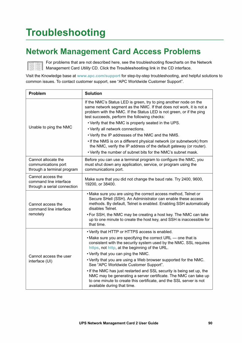
Troubleshooting
Network Management Card Access ProblemsFor problems that are not described here, see the troubleshooting flowcharts on the Network Management Card Utility CD. Click the Troubleshooting link in the CD interface.
Visit the Knowledge base at www.apc.com/support for step-by-step troubleshooting, and helpful solutions to common issues. To contact customer support, see “APC Worldwide Customer Support”.
Problem Solution
Unable to ping the NMC
If the NMC’s Status LED is green, try to ping another node on the same network segment as the NMC. If that does not work, it is not a problem with the NMC. If the Status LED is not green, or if the ping test succeeds, perform the following checks:
• Verify that the NMC is properly seated in the UPS.• Verify all network connections.• Verify the IP addresses of the NMC and the NMS.• If the NMS is on a different physical network (or subnetwork) from the NMC, verify the IP address of the default gateway (or router).
• Verify the number of subnet bits for the NMC’s subnet mask.
Cannot allocate the communications port through a terminal program
Before you can use a terminal program to configure the NMC, you must shut down any application, service, or program using the communications port.
Cannot access the command line interface through a serial connection
Make sure that you did not change the baud rate. Try 2400, 9600, 19200, or 38400.
Cannot access the command line interface remotely
• Make sure you are using the correct access method, Telnet or Secure SHell (SSH). An Administrator can enable these access methods. By default, Telnet is enabled. Enabling SSH automatically disables Telnet.
• For SSH, the NMC may be creating a host key. The NMC can take up to one minute to create the host key, and SSH is inaccessible for that time.
Cannot access the user interface (UI)
• Verify that HTTP or HTTPS access is enabled.• Make sure you are specifying the correct URL — one that is consistent with the security system used by the NMC. SSL requires https, not http, at the beginning of the URL.
• Verify that you can ping the NMC.• Verify that you are using a Web browser supported for the NMC. See “APC Worldwide Customer Support”.
• If the NMC has just restarted and SSL security is being set up, the NMC may be generating a server certificate. The NMC can take up to one minute to create this certificate, and the SSL server is not available during that time.
90UPS Network Management Card 2 User Guide
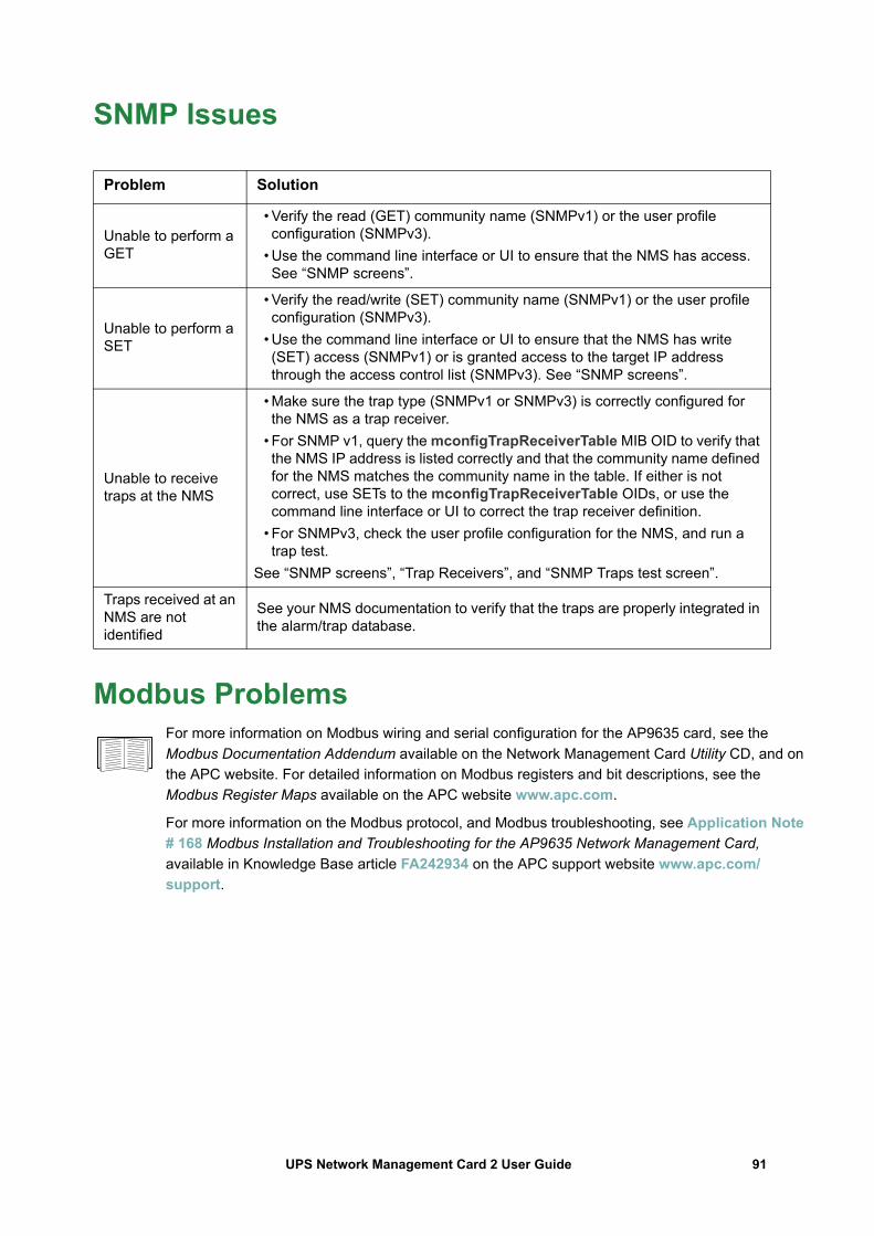
SNMP Issues
Modbus ProblemsFor more information on Modbus wiring and serial configuration for the AP9635 card, see the Modbus Documentation Addendum available on the Network Management Card Utility CD, and on the APC website. For detailed information on Modbus registers and bit descriptions, see the Modbus Register Maps available on the APC website www.apc.com.
For more information on the Modbus protocol, and Modbus troubleshooting, see Application Note # 168 Modbus Installation and Troubleshooting for the AP9635 Network Management Card, available in Knowledge Base article FA242934 on the APC support website www.apc.com/support.
Problem Solution
Unable to perform a GET
• Verify the read (GET) community name (SNMPv1) or the user profile configuration (SNMPv3).
• Use the command line interface or UI to ensure that the NMS has access. See “SNMP screens”.
Unable to perform a SET
• Verify the read/write (SET) community name (SNMPv1) or the user profile configuration (SNMPv3).
• Use the command line interface or UI to ensure that the NMS has write (SET) access (SNMPv1) or is granted access to the target IP address through the access control list (SNMPv3). See “SNMP screens”.
Unable to receive traps at the NMS
• Make sure the trap type (SNMPv1 or SNMPv3) is correctly configured for the NMS as a trap receiver.
• For SNMP v1, query the mconfigTrapReceiverTable MIB OID to verify that the NMS IP address is listed correctly and that the community name defined for the NMS matches the community name in the table. If either is not correct, use SETs to the mconfigTrapReceiverTable OIDs, or use the command line interface or UI to correct the trap receiver definition.
• For SNMPv3, check the user profile configuration for the NMS, and run a trap test.
See “SNMP screens”, “Trap Receivers”, and “SNMP Traps test screen”.
Traps received at an NMS are not identified
See your NMS documentation to verify that the traps are properly integrated in the alarm/trap database.
91UPS Network Management Card 2 User Guide
Two-Year Factory WarrantyThis warranty applies only to the products you purchase for your use in accordance with this manual.
Terms of warranty
APC warrants its products to be free from defects in materials and workmanship for a period of two years from the date of purchase. APC will repair or replace defective products covered by this warranty. This warranty does not apply to equipment that has been damaged by accident, negligence or misapplication or has been altered or modified in any way. Repair or replacement of a defective product or part thereof does not extend the original warranty period. Any parts furnished under this warranty may be new or factory-remanufactured.
Non-transferable warranty
This warranty extends only to the original purchaser who must have properly registered the product. The product may be registered at the APC Web site, www.apc.com.
Exclusions
APC shall not be liable under the warranty if its testing and examination disclose that the alleged defect in the product does not exist or was caused by end user’s or any third person’s misuse, negligence, improper installation or testing. Further, APC shall not be liable under the warranty for unauthorized attempts to repair or modify wrong or inadequate electrical voltage or connection, inappropriate on-site operation conditions, corrosive atmosphere, repair, installation, exposure to the elements, Acts of God, fire, theft, or installation contrary to APC recommendations or specifications or in any event if the APC serial number has been altered, defaced, or removed, or any other cause beyond the range of the intended use.
THERE ARE NO WARRANTIES, EXPRESS OR IMPLIED, BY OPERATION OF LAW OR OTHERWISE, OF PRODUCTS SOLD, SERVICED OR FURNISHED UNDER THIS AGREEMENT OR IN CONNECTION HEREWITH. APC DISCLAIMS ALL IMPLIED WARRANTIES OF MERCHANTABILITY, SATISFACTION AND FITNESS FOR A PARTICULAR PURPOSE. APC EXPRESS WARRANTIES WILL NOT BE ENLARGED, DIMINISHED, OR AFFECTED BY AND NO OBLIGATION OR LIABILITY WILL ARISE OUT OF, APC RENDERING OF TECHNICAL OR OTHER ADVICE OR SERVICE IN CONNECTION WITH THE PRODUCTS. THE FOREGOING WARRANTIES AND REMEDIES ARE EXCLUSIVE AND IN LIEU OF ALL OTHER WARRANTIES AND REMEDIES. THE WARRANTIES SET FORTH ABOVE CONSTITUTE APC’S SOLE LIABILITY AND PURCHASER’S EXCLUSIVE REMEDY FOR ANY BREACH OF SUCH WARRANTIES. APC WARRANTIES EXTEND ONLY TO PURCHASER AND ARE NOT EXTENDED TO ANY THIRD PARTIES. IN NO EVENT SHALL APC, ITS OFFICERS, DIRECTORS, AFFILIATES OR EMPLOYEES BE LIABLE FOR ANY FORM OF INDIRECT, SPECIAL, CONSEQUENTIAL OR PUNITIVE DAMAGES, ARISING OUT OF THE USE, SERVICE OR INSTALLATION, OF THE PRODUCTS, WHETHER SUCH DAMAGES ARISE IN CONTRACT OR TORT, IRRESPECTIVE OF FAULT, NEGLIGENCE OR STRICT LIABILITY OR WHETHER APC HAS BEEN ADVISED IN ADVANCE OF THE POSSIBILITY OF SUCH DAMAGES. SPECIFICALLY, APC IS NOT LIABLE FOR ANY COSTS, SUCH AS LOST PROFITS OR REVENUE, LOSS OF EQUIPMENT, LOSS OF USE OF EQUIPMENT, LOSS OF SOFTWARE, LOSS OF DATA, COSTS OF SUBSTITUENTS, CLAIMS BY THIRD PARTIES, OR OTHERWISE.NO SALESMAN, EMPLOYEE OR AGENT OF APC IS AUTHORIZED TO ADD TO OR VARY THE TERMS OF THIS WARRANTY. WARRANTY TERMS MAY BE MODIFIED, IF AT ALL, ONLY IN WRITING SIGNED BY AN APC OFFICER AND LEGAL DEPARTMENT.
92UPS Network Management Card 2 User Guide

Warranty claims
Customers with warranty claims issues may access the APC customer support network through the Support page of the APC Web site, www.apc.com/support. Select your country from the country selection pull-down menu at the top of the Web page. Select the Support tab to obtain contact information for customer support in your region.
93UPS Network Management Card 2 User Guide
cryptlib copyright Digital Data Security New Zealand Ltd 1998.Copyright © 1990, 1993, 1994 The Regents of the University of California. All rights reserved.
This code is derived from software contributed to Berkeley by Mike Olson.Redistribution and use in source and binary forms, with or without modification, are permitted provided that the following conditions are met:
1. Redistributions of source code must retain the above copyright notice, this list of conditions and the following disclaimer.
2. Redistributions in binary form must reproduce the above copyright notice, this list of conditions and the following disclaimer in the documentation and/or other materials provided with the distribution.
3. All advertising materials mentioning features or use of this software must display the following acknowledgment:
This product includes software developed by the University of California, Berkeley and its contributors.
4. Neither the name of the University nor the names of its contributors may be used to endorse or promote products derived from this software without specific prior written permission.
THIS SOFTWARE IS PROVIDED BY THE REGENTS AND CONTRIBUTORS “AS IS” AND ANY EXPRESS OR IMPLIED WARRANTIES, INCLUDING, BUT NOT LIMITED TO, THE IMPLIED WARRANTIES OF MERCHANTABILITY AND FITNESS FOR A PARTICULAR PURPOSE ARE DISCLAIMED. IN NO EVENT SHALL THE REGENTS OR CONTRIBUTORS BE LIABLE FOR ANY DIRECT, INDIRECT, INCIDENTAL, SPECIAL, EXEMPLARY, OR CONSEQUENTIAL DAMAGES (INCLUDING, BUT NOT LIMITED TO, PROCUREMENT OF SUBSTITUTE GOODS OR SERVICES; LOSS OF USE, DATA, OR PROFITS; OR BUSINESS INTERRUPTION) HOWEVER CAUSED AND ON ANY THEORY OF LIABILITY, WHETHER IN CONTRACT, STRICT LIABILITY, OR TORT (INCLUDING NEGLIGENCE OR OTHERWISE) ARISING IN ANY WAY OUT OF THE USE OF THIS SOFTWARE, EVEN IF ADVISED OF THE POSSIBILITY OF SUCH DAMAGE.
94UPS Network Management Card 2 User Guide
Radio Frequency InterferenceChanges or modifications to this unit not expressly approved by the party responsible for compliance could void the user’s authority to operate this equipment.
USA—FCC
This equipment has been tested and found to comply with the limits for a Class A digital device, pursuant to part 15 of the FCC Rules. These limits are designed to provide reasonable protection against harmful interference when the equipment is operated in a commercial environment. This equipment generates, uses, and can radiate radio frequency energy and, if not installed and used in accordance with this user manual, may cause harmful interference to radio communications. Operation of this equipment in a residential area is likely to cause harmful interference. The user will bear sole responsibility for correcting such interference.
Canada—ICES
This Class A digital apparatus complies with Canadian ICES-003.
Cet appareil numérique de la classe A est conforme à la norme NMB-003 du Canada.
Japan—VCCI
This is a Class A product based on the standard of the Voluntary Control Council for Interference by Information Technology Equipment (VCCI). If this equipment is used in a domestic environment, radio disturbance may occur, in which case, the user may be required to take corrective actions.
この装置は、情報処理装置等電波障害自主規制協議会(VCCI)の基準に基づくクラス A 情報技術装置です。この装置を家庭環境で使用すると、電波
妨害を引き起こすことがあります。この場合には、使用者が適切な対策を講ずるように要求されることがあります
Taiwan—BSMI
警告使用者 :這是甲類的資訊產品 , 在居住的環境中使用時 ,可能會造成射頻干擾 , 在這種情況下 ,使用者會被要求採取某些適當的對策。

Australia and New Zealand
Attention: This is a Class A product. In a domestic environment this product may cause radio interference in which case the user may be required to take adequate measures.
European Union
This product is in conformity with the protection requirements of EU Council Directive 2004/108/EC on the approximation of the laws of the Member States relating to electromagnetic compatibility. APC cannot accept responsibility for any failure to satisfy the protection requirements resulting from an unapproved modification of the product.This product has been tested and found to comply with the limits for Class A Information Technology Equipment according to CISPR 22/European Standard EN 55022. The limits for Class A equipment were derived for commercial and industrial environments to provide a reasonable protection against interference with licensed communication equipment.Attention: This is a Class A product. In a domestic environment this product may cause radio interference in which case the user may be required to take adequate measures.
Korean 한국A급 기기 ( 업무용 방송통신기기 )
이 기기는 업무용 (A 급 ) 으로 전자파적합등록을 한 기기이오니판매자 또는 사용자는 이 점을 주의하시기 바라며 , 가정외의지역에서 사용하는 것을 목적으로 합니다 .
02/2018
© 2018 Schneider Electric. All rights reserved. APC and the APC logo are owned by Schneider Electric Industries S.A.S., American Power Conversion Corporation, or their affiliated companies.
All other trademarks are property of their respective owners.
990-3402J-001
APC Worldwide Customer SupportCustomer support for this or any other product is available at no charge in any of the following ways:
• Visit the APC Web site to access documents in the APC Knowledge Base and to submitcustomer support requests.– www.apc.com (Corporate Headquarters)
Connect to localized APC Web sites for specific countries, each of which provides customersupport information.
– www.apc.com/support/Global support searching APC Knowledge Base and using e-support.
• Contact the APC Customer Support Center by telephone or e-mail.– Local, country-specific centers: go to www.apc.com/support/contact for contact information.
For information on how to obtain local customer support, contact the representative or other distributors from whom you purchased your product.