network models - الجامعة التكنولوجية 2014/saman networks fundamentals... · 2.9...
TRANSCRIPT

2.1
Network Models

2.2
2-1 LAYERED TASKS
We use the concept of layers in our daily life. As an
example, let us consider two friends who communicate
through postal mail. The process of sending a letter to a
friend would be complex if there were no services
available from the post office.
Sender, Receiver, and Carrier
Hierarchy
Topics discussed in this section:

2.3
A protocol is a rule or a set of rules and standards for communicating that
computers use when they send data back and forth. Both the sender and receiver
involved in data transfer must recognize and observe the same protocols
What Are Protocols?
To exchange data, the sending and the receiving computers, also called hosts,
must agree on what the data will look like. When one host is sending another
host a whole bunch of 1s and 0s, both hosts have to agree on the meaning and
placement of each 1 and each 0. Part of the information that is sent represents
addresses and part is data—each host has a unique address, just as you have a
unique address on your street. And just like a letter being delivered to your
address, data is delivered to the appropriate host based on its address. The hosts
that send the information must understand how to find the correct address
among the data so that the data can be routed to its destination.

2.4
Tasks involved in sending a letter

2.5
Layer ArchitectureLayer architecture simplifies the network design.
It is easy to debug network applications in a layeredarchitecture network.
The network management is easier due to thelayered architecture.
Network layers follow a set of rules, called protocol.
The protocol defines the format of the data beingexchanged, and the control and timing for thehandshake between layers.
2.6
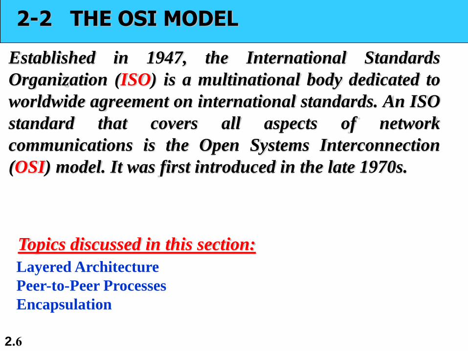
2-2 THE OSI MODEL
Established in 1947, the International Standards
Organization (ISO) is a multinational body dedicated to
worldwide agreement on international standards. An ISO
standard that covers all aspects of network
communications is the Open Systems Interconnection
(OSI) model. It was first introduced in the late 1970s.
Layered Architecture
Peer-to-Peer Processes
Encapsulation
Topics discussed in this section:

2.7
ISO is the organization.
OSI is the model.
Note

2.8
OSI Reference Model: 7 Layers

2.9
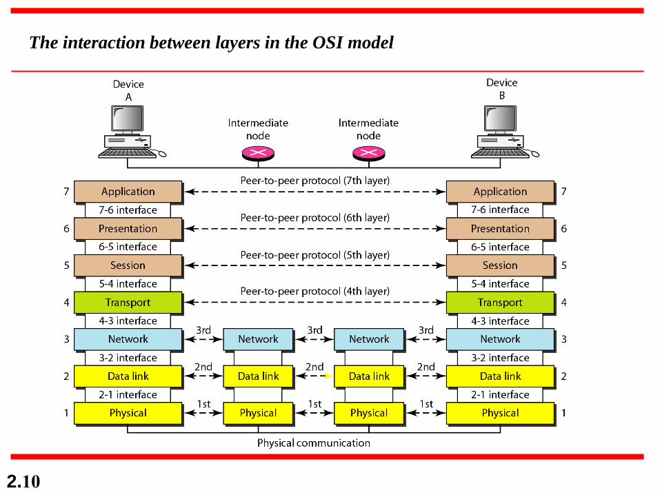
OSI: A Layered Network ModelThe process of breaking up the functions or tasks ofnetworking into layers reduces complexity.
Each layer provides a service to the layer above it inthe protocol specification.
Each layer communicates with the same layer’ssoftware or hardware on other computers.
The lower 4 layers (transport, network, data link andphysical —Layers 4, 3, 2, and 1) are concerned withthe flow of data from end to end through the network.
The upper four layers of the OSI model (application,presentation and session—Layers 7, 6 and 5) areorientated more toward services to the applications.
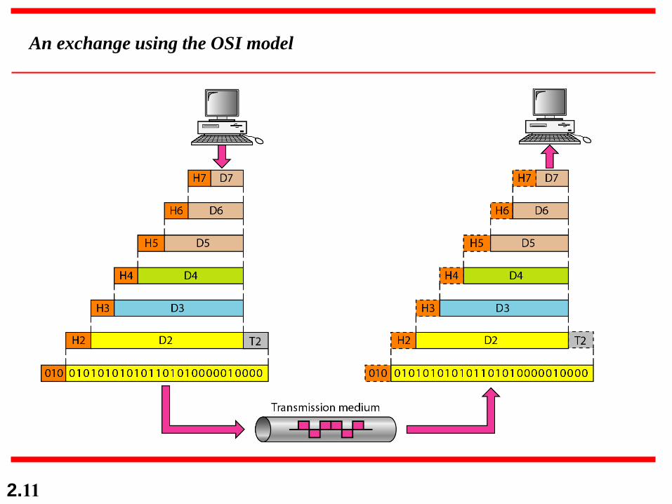
Data is Encapsulated with the necessary protocolinformation as it moves down the layers beforenetwork transit.
2.10
The interaction between layers in the OSI model
2.11
An exchange using the OSI model

2.12
2-3 LAYERS IN THE OSI MODEL
In this section we briefly describe the functions of each
layer in the OSI model.
Physical Layer
Data Link Layer
Network Layer
Transport Layer
Session Layer
Presentation Layer
Application Layer
Topics discussed in this section:
2.13
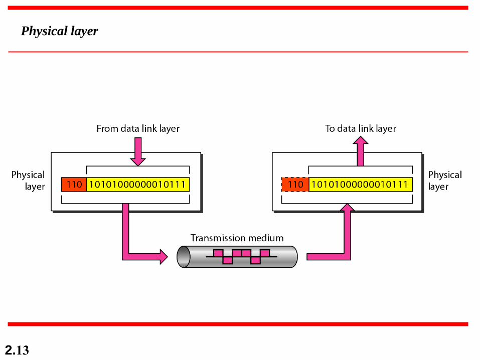
Physical layer
2.14
The physical layer is responsible for movements of
individual bits from one hop (node) to the next.
Note
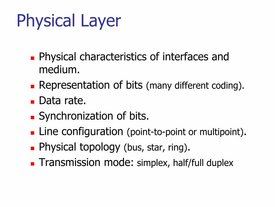
Physical Layer
Physical characteristics of interfaces and medium.
Representation of bits (many different coding).
Data rate.
Synchronization of bits.
Line configuration (point-to-point or multipoint).
Physical topology (bus, star, ring).
Transmission mode: simplex, half/full duplex

2.16
The physical layer is concerned with the following:
o Physical characteristics of interfaces and medium. The physical layer defines the characteristics
of the interface between the devices and the transmission medium. It also defines the type of
transmission medium.
o Representation of bits. The physical layer data consists of a stream of bits (sequence of Os or 1s)
with no interpretation. To be transmitted, bits must be encoded into signals--electrical or optical. The
physical layer defines the type of encoding (how Os and I s are changed to signals).
o Data rate. The transmission rate-the number of bits sent each second-is also defined by the physical
layer. In other words, the physical layer defines the duration of a bit, which is how long it lasts.
o Synchronization of bits. The sender and receiver not only must use the same bit rate but also must
be synchronized at the bit level. In other words, the sender and the receiver clocks must be
synchronized.
o Line configuration. The physical layer is concerned with the connection of devices to the media. In
a point-to-point configuration, two devices are connected through a dedicated link. In a multipoint
configuration, a link is shared among several devices.
o Physical topology. The physical topology defines how devices are connected to make a network.
Devices can be connected by using a mesh topology (every device is connected to every other device),
a star topology (devices are connected through a central device), a ring topology (each device is
connected to the next, forming a ring), a bus topology (every device is on a common link), or a hybrid
topology (this is a combination of two or more topologies).
o Transmission mode. The physical layer also defines the direction of transmission between two
devices: simplex, half-duplex, or full-duplex. In simplex mode, only one device can send; the other can
only receive. The simplex mode is a one-way communication. In the half-duplex mode, two devices
can send and receive, but not at the same time. In a full-duplex (or simply duplex) mode, two devices
can send and receive at the same time.
2.17
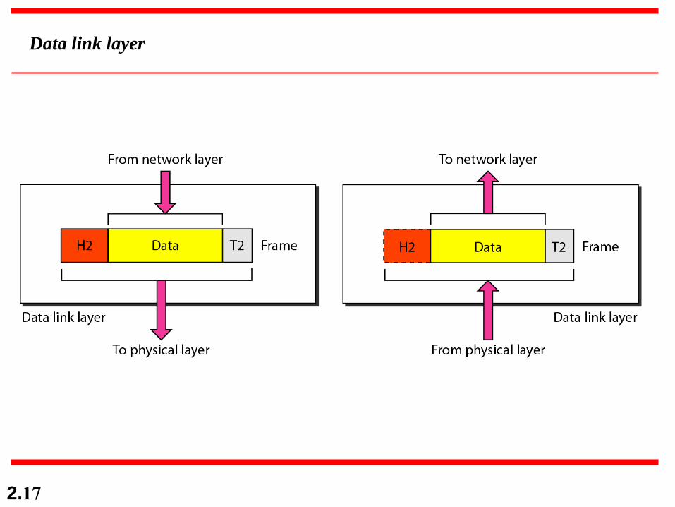
Data link layer

2.18
The data link layer is responsible for moving
frames from one hop (node) to the next.
Note
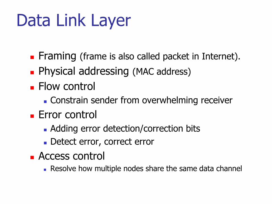
Data Link Layer
Framing (frame is also called packet in Internet).
Physical addressing (MAC address)
Flow control
Constrain sender from overwhelming receiver
Error control
Adding error detection/correction bits
Detect error, correct error
Access control Resolve how multiple nodes share the same data channel
2.20
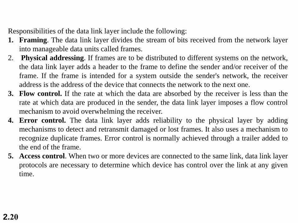
Responsibilities of the data link layer include the following:
1. Framing. The data link layer divides the stream of bits received from the network layer
into manageable data units called frames.
2. Physical addressing. If frames are to be distributed to different systems on the network,
the data link layer adds a header to the frame to define the sender and/or receiver of the
frame. If the frame is intended for a system outside the sender's network, the receiver
address is the address of the device that connects the network to the next one.
3. Flow control. If the rate at which the data are absorbed by the receiver is less than the
rate at which data are produced in the sender, the data link layer imposes a flow control
mechanism to avoid overwhelming the receiver.
4. Error control. The data link layer adds reliability to the physical layer by adding
mechanisms to detect and retransmit damaged or lost frames. It also uses a mechanism to
recognize duplicate frames. Error control is normally achieved through a trailer added to
the end of the frame.
5. Access control. When two or more devices are connected to the same link, data link layer
protocols are necessary to determine which device has control over the link at any given
time.

2.21
Hop-to-hop delivery for data link layer
Example device:
Ethernet switch/hub
WiFi access point
2.22
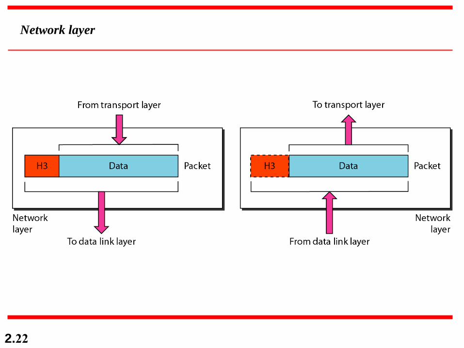
Network layer
2.23
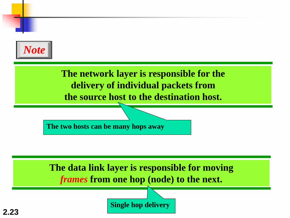
The network layer is responsible for the
delivery of individual packets from
the source host to the destination host.
Note
The data link layer is responsible for moving
frames from one hop (node) to the next.
The two hosts can be many hops away
Single hop delivery
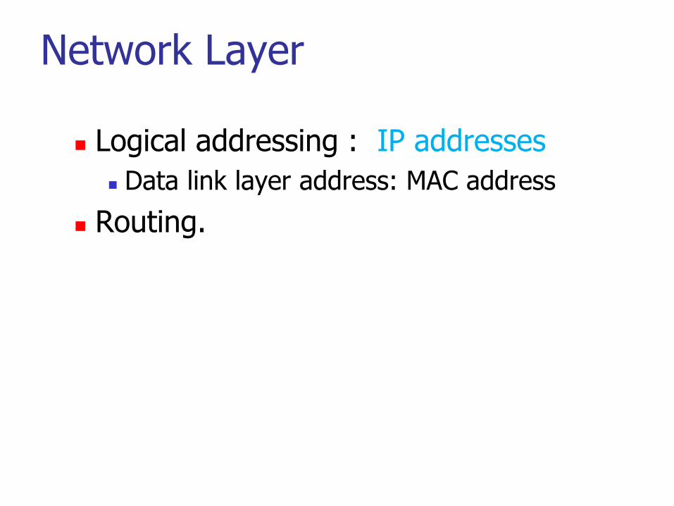
Network Layer
Logical addressing : IP addresses
Data link layer address: MAC address
Routing.

2.25
responsibilities of the network layer include the following:
o Logical addressing. The physical addressing implemented by the
data link layer handles the addressing problem locally. If a packet
passes the network boundary, we need another addressing system to
help distinguish the source and destination systems. The network
layer adds a header to the packet coming from the upper layer that,
among other things, includes the logical addresses of the sender and
receiver. We discuss logical addresses later in this chapter.
o Routing. When independent networks or links are connected to
create internetworks (network of networks) or a large network, the
connecting devices (called routers or switches) route or switch the
packets to their final destination. One of the functions of the
network layer is to provide this mechanism.

2.26
Source-to-destination delivery
Example device:
Routers
2.27
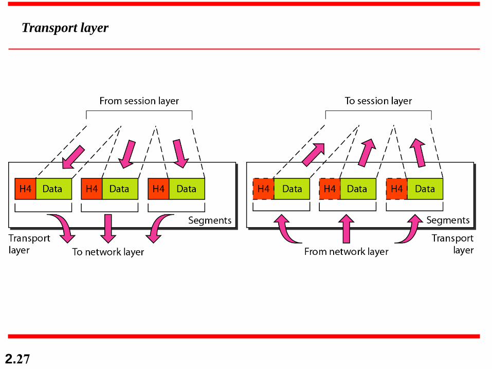
Transport layer
2.28
The transport layer is responsible for the delivery
of a message from one process to another.
Note

Transport Layer
Service point addressing: service port number
Segmentation and reassembly.
Message break into sequence of packets
Reconstruct message at the receiver
Connection control.
Connectionless (UDP), connection-oriented (TCP)
Flow control.
Error control.

responsibilities of the transport layer include the following:
Service-point addressing. Computers often run several programs at the same time. For this
reason, source-to-destination delivery means delivery not only from one computer to the next but
also from a specific process (running program) on one computer to a specific process (running
program) on the other. The transport layer header must therefore include a type of address called
a service-point address (or port address). The network layer gets each packet to the correct
computer; the transport layer gets the entire message to the correct process on that computer.
o Segmentation and reassembly. A message is divided into transmittable segments, with each
segment containing a sequence number. These numbers enable the transport layer to reassemble
the message correctly upon arriving at the destination and to identify and replace packets that
were lost in transmission.
o Connection control. The transport layer can be either connectionless or connection oriented. A
connectionless transport layer treats each segment as an independent packet and delivers it to the
transport layer at the destination machine. A connection oriented transport layer makes a
connection with the transport layer at the destination machine first before delivering the packets.
After all the data are transferred, the connection is terminated.
o Flow control. Like the data link layer, the transport layer is responsible for flow control.
However, flow control at this layer is performed end to end rather than across a single link.
o Error control. Like the data link layer, the transport layer is responsible for error control.
However, error control at this layer is performed process-to process rather than across a single
link. The sending transport layer makes sure that the entire message arrives at the receiving
transport layer without error (damage, loss, or duplication). Error correction is usually achieved
through retransmission.

2.31
Reliable process-to-process delivery of a message

2.32
Session layer

Specific responsibilities of the session layer include the
following:
o Dialog control. The session layer allows two systems to enter
into a dialog. It allows the communication between two
processes to take place in either half duplex (one way at a time)
or full-duplex (two ways at a time) mode.
o Synchronization. The session layer allows a process to add
checkpoints, or synchronization points, to a stream of data. For
example, if a system is sending a file of 2000 pages, it is
advisable to insert checkpoints after every 100 pages to ensure
that each 100-page unit is received and acknowledged
independently. In this case, if a crash happens during the
transmission of page 523, the only pages that need to be resent
after system recovery are pages 501 to 523. Pages previous to
501 need not be resent.

2.34
Presentation layer
Specific responsibilities of the presentation layer include the following:
o Translation. The processes (running programs) in two systems are usually exchanging
information in the form of character strings, numbers, and so on. The information must be
changed to bit streams before being transmitted. Because different computers use different
encoding systems, the presentation layer is responsible for interoperability between these
different encoding methods. The presentation layer at the sender changes the information
from its sender-dependent format into a common format. The presentation layer at the
receiving machine changes the common format into its receiver-dependent format.
o Encryption. To carry sensitive information, a system must be able to ensure privacy.
Encryption means that the sender transforms the original information to
another form and sends the resulting message out over the network. Decryption reverses
the original process to transform the message back to its original form.
o Compression. Data compression reduces the number of bits contained in the
information. Data compression becomes particularly important in the transmission of
multimedia such as text, audio, and video.
2.36
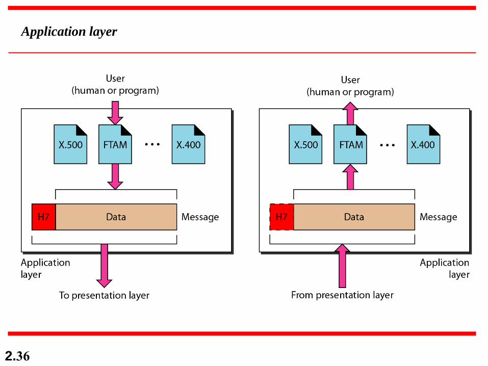
Application layer
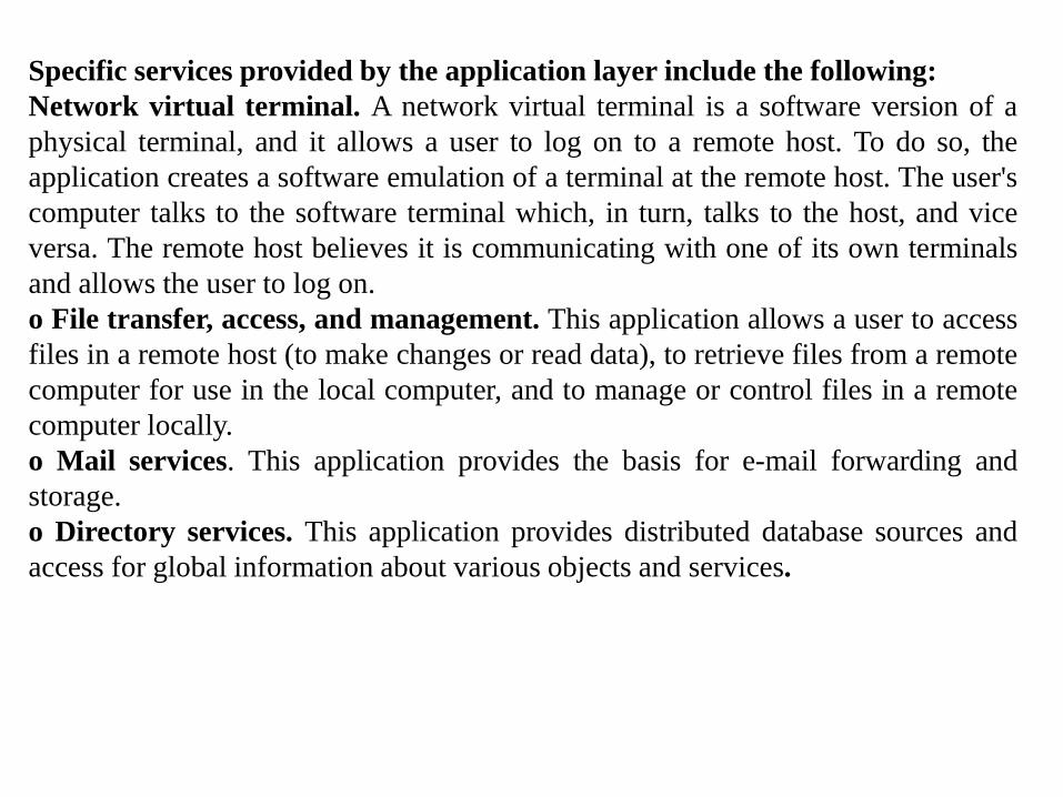
Specific services provided by the application layer include the following:
Network virtual terminal. A network virtual terminal is a software version of a
physical terminal, and it allows a user to log on to a remote host. To do so, the
application creates a software emulation of a terminal at the remote host. The user's
computer talks to the software terminal which, in turn, talks to the host, and vice
versa. The remote host believes it is communicating with one of its own terminals
and allows the user to log on.
o File transfer, access, and management. This application allows a user to access
files in a remote host (to make changes or read data), to retrieve files from a remote
computer for use in the local computer, and to manage or control files in a remote
computer locally.
o Mail services. This application provides the basis for e-mail forwarding and
storage.
o Directory services. This application provides distributed database sources and
access for global information about various objects and services.

2.38
Summary of layers

2.39
Seven layers of the OSI model
Called “Application
Layer “ in many
other networking books
TCP/UDP
IP
Ethernet, WiFi

2.40
2-4 TCP/IP PROTOCOL SUITE
The layers in the TCP/IP protocol suite do not exactly
match those in the OSI model. The original TCP/IP
protocol suite was defined as having four layers: host-to-
network, internet, transport, and application. However,
when TCP/IP is compared to OSI, we can say that the
TCP/IP protocol suite is made of five layers: physical,
data link, network, transport, and application.
Physical and Data Link Layers
Network Layer
Transport Layer
Application Layer
Topics discussed in this section:
2.41
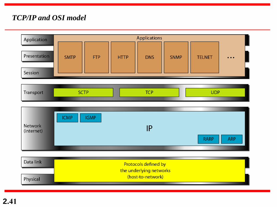
TCP/IP and OSI model

2.42
Physical and Data Link Layers
At the physical and data link layers, TCPIIP does not define any specific protocol. It supports
all the standard and proprietary protocols. A network in a TCPIIP internetwork can be a
local-area network or a wide-area network.
Network Layer
At the network layer (or, more accurately, the internetwork layer), TCP/IP supports the
Internetworking Protocol. IP, in turn, uses four supporting protocols: ARP, RARP, ICMP, and
IGMP. Each of these protocols is described in greater detail in later chapters.
Transport Layer
Traditionally the transport layer was represented in TCP/IP by two protocols: TCP and UDP.
IP is a host-to-host protocol, meaning that it can deliver a packet from one physical device to
another. UDP and TCP are transport level protocols responsible for delivery of a message
from a process (running program) to another process. A new transport layer protocol, SCTP,
has been devised to meet the needs of some newer applications.
Application Layer
The application layer in TCPIIP is equivalent to the combined session, presentation, and
application layers in the OSI model. Many protocols are defined at this layer.
2.43
2-5 ADDRESSING
Four levels of addresses are used in an internet employing
the TCP/IP protocols: physical, logical, port, and specific.
Physical Addresses
Logical Addresses
Port Addresses
Specific Addresses
Topics discussed in this section:

2.44
Addresses in TCP/IP

2.45
Relationship of layers and addresses in TCP/IP

2.46
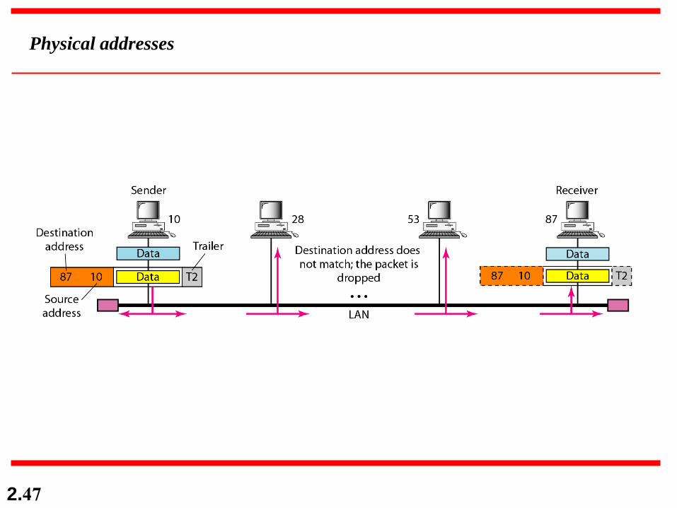
In Figure 2.19 a node with physical address 10 sends a
frame to a node with physical address 87. The two nodes
are connected by a link (bus topology LAN). As the
figure shows, the computer with physical address 10 is
the sender, and the computer with physical address 87 is
the receiver.
Example 2.1
2.47
Physical addresses
2.48
As we will see, most local-area networks use a 48-bit (6-
byte) physical address written as 12 hexadecimal digits;
every byte (2 hexadecimal digits) is separated by a colon,
as shown below:
Example 2.2
07:01:02:01:2C:4B
A 6-byte (12 hexadecimal digits) physical address.
2.49
Figure 2.20 shows a part of an internet with two routers
connecting three LANs. Each device (computer or
router) has a pair of addresses (logical and physical) for
each connection. In this case, each computer is
connected to only one link and therefore has only one
pair of addresses. Each router, however, is connected to
three networks (only two are shown in the figure). So
each router has three pairs of addresses, one for each
connection.
Example 2.3

2.50
IP addresses (‘A’ : IP address; ‘10’ : MAC address)
The router has 3 IP
addresses, 3 MAC addresses
2.51
Figure 2.21 shows two computers communicating via the
Internet. The sending computer is running three
processes at this time with port addresses a, b, and c. The
receiving computer is running two processes at this time
with port addresses j and k. Process a in the sending
computer needs to communicate with process j in the
receiving computer. Note that although physical
addresses change from hop to hop, logical and port
addresses remain the same from the source to
destination.
Example 2.4

2.52
Port addresses

2.53
The physical addresses will change from hop to hop,
but the logical addresses usually remain the same.
Note
2.54
Example 2.5
As we will see, a port address is a 16-bit address
represented by one decimal number as shown.
753
A 16-bit port address represented
as one single number.

2.55
The physical addresses change from hop to hop,
but the logical and port addresses usually remain the same.
Note
Specific Addresses
Some applications have user-friendly addresses that are designed for that specific
address. Examples include the e-mail address (for example, [email protected])
and the Universal Resource Locator (URL) (for example, www.mhhe.com). The first
defines the recipient of an e-mail (see Chapter 26); the second is used to find a
document on the World Wide Web (see Chapter 27). These addresses, however, get
changed to the corresponding port and logical addresses by the sending computer,
as we will see in Chapter 25.
2.56
SUMMARY
o The International Standards Organization created a model called the Open Systems Interconnection, which allows
diverse systems to communicate.
o The seven-layer OSI model provides guidelines for the development of universally compatible networking
protocols.
o The physical, data link, and network layers are the network support layers.
o The session, presentation, and application layers are the user support layers.
o The transport layer links the network support layers and the user support layers.
o The physical layer coordinates the functions required to transmit a bit stream over a physical medium.
o The data link layer is responsible for delivering data units from one station to the next without errors.
o The network layer is responsible for the source-to-destination delivery of a packet across multiple network links.
o The transport layer is responsible for the process-to-process delivery of the entire message.
o The session layer establishes, maintains, and synchronizes the interactions between communicating devices.
o The presentation layer ensures interoperability between communicating devices through transformation of data into
a mutually agreed upon format.
o The application layer enables the users to access the network.
o TCP/IP is a five-layer hierarchical protocol suite developed before the OSI model.
o The TCP/IP application layer is equivalent to the combined session, presentation, and application layers of the OSI
model.
o Four levels of addresses are used in an internet following the TCP/IP protocols: physical (link) addresses, logical
(IP) addresses, port addresses, and specific addresses.
o The physical address, also known as the link address, is the address of a node as defined by its LAN or WAN.
o The IP address uniquely defines a host on the Internet.
o The port address identifies a process on a host.
o A specific address is a user-friendly address.

2.57
PRACTICE SET
Review Questions
I. List the layers of the Internet model.
2. Which layers in the Internet model are the network support layers?
3. Which layer in the Internet model is the user support layer?
4. What is the difference between network layer delivery and transport layer delivery?
5. What is a peer-to-peer process?
6. How does information get passed from one layer to the next in the Internet
model?
7. What are headers and trailers, and how do they get added and removed?
X. What are the concerns of the physical layer in the Internet model?
9. What are the responsibilities of the data link layer in the Internet model?
10. What are the responsibilities of the network layer in the Internet model?
II. What are the responsibilities of the transport layer in the Internet model?
12. What is the difference between a port address, a logical address, and a physical
address?
13. Name some services provided by the application layer in the Internet model.
14. How do the layers of the Internet model correlate to the layers of the OSI model?
2.58
Exercises
15. How are OSI and ISO related to each other?
16. Match the following to one or more layers of the OSI model:
a. Route determination
b. Flow control
c. Interface to transmission media
d. Provides access for the end user
I 7. Match the following to one or more layers of the OSI model:
a. Reliable process-to-process message delivery
b. Route selection
c. Defines frames
d. Provides user services such as e-mail and file transfer
e. Transmission of bit stream across physical medium
18. Match the following to one or more layers of the OSI model:
a. Communicates directly with user's application program
b. Error correction and retransmission
c. Mechanical, electrical, and functional interface
d. Responsibility for carrying frames between adjacent nodes
I 9. Match the following to one or more layers of the OSI model:
a. Format and code conversion services
b. Establishes, manages, and terminates sessions
c. Ensures reliable transmission of data
d. Log-in and log-out procedures
e. Provides independence from differences in data representation
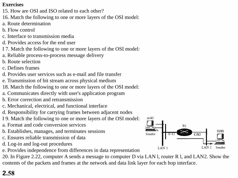
20. In Figure 2.22, computer A sends a message to computer D via LAN l, router R l, and LAN2. Show the
contents of the packets and frames at the network and data link layer for each hop interface.
2.59
21. In Figure 2.22, assume that the communication is between a process running at
computer A with port address i and a process running at computer D with port address
j. Show the contents of packets and frames at the network, data link, and transport
layer for each hop.
22. Suppose a computer sends a frame to another computer on a bus topology LAN.
The physical destination address of the frame is corrupted during the transmission.
What happens to the frame? How can the sender be informed about the situation?
23. Suppose a computer sends a packet at the network layer to another computer
somewhere in the Internet. The logical destination address of the packet is corrupted.
What happens to the packet? How can the source computer be informed of the
situation?
24. Suppose a computer sends a packet at the transport layer to another computer
somewhere in the Internet. There is no process with the destination port address
running at the destination computer. What will happen?
25. If the data link layer can detect errors between hops, why do you think we need
another checking mechanism at the transport layer?