network os administrator's guide, 3.0.0 - brocade
TRANSCRIPT

53-1002561-0201 October 2012
®
Network OSAdministrator’s Guide
Supporting Network OS v3.0.0
Copyright © 2010-2012 Brocade Communications Systems, Inc. All Rights Reserved.
Brocade, Brocade Assurance, the B-wing symbol, BigIron, DCX, Fabric OS, FastIron, MLX, NetIron, SAN Health, ServerIron, TurboIron, VCS, and VDX are registered trademarks, and AnyIO, Brocade One, CloudPlex, Effortless Networking, ICX, NET Health, OpenScript, and The Effortless Network are trademarks of Brocade Communications Systems, Inc., in the United States and/or in other countries. Other brands, products, or service names mentioned may be trademarks of their respective owners.
Notice: This document is for informational purposes only and does not set forth any warranty, expressed or implied, concerning any equipment, equipment feature, or service offered or to be offered by Brocade. Brocade reserves the right to make changes to this document at any time, without notice, and assumes no responsibility for its use. This informational document describes features that may not be currently available. Contact a Brocade sales office for information on feature and product availability. Export of technical data contained in this document may require an export license from the United States government.
The authors and Brocade Communications Systems, Inc. shall have no liability or responsibility to any person or entity with respect to any loss, cost, liability, or damages arising from the information contained in this book or the computer programs that accompany it.
The product described by this document may contain “open source” software covered by the GNU General Public License or other open source license agreements. To find out which open source software is included in Brocade products, view the licensing terms applicable to the open source software, and obtain a copy of the programming source code, please visit http://www.brocade.com/support/oscd.
Brocade Communications Systems, Incorporated
Document History
Corporate and Latin American HeadquartersBrocade Communications Systems, Inc.130 Holger WaySan Jose, CA 95134 Tel: 1-408-333-8000 Fax: 1-408-333-8101 E-mail: [email protected]
Asia-Pacific HeadquartersBrocade Communications Systems China HK, Ltd.No. 1 Guanghua RoadChao Yang DistrictUnits 2718 and 2818Beijing 100020, ChinaTel: +8610 6588 8888Fax: +8610 6588 9999E-mail: [email protected]
European HeadquartersBrocade Communications Switzerland SàrlCentre SwissairTour B - 4ème étage29, Route de l'AéroportCase Postale 105CH-1215 Genève 15Switzerland Tel: +41 22 799 5640Fax: +41 22 799 5641E-mail: [email protected]
Asia-Pacific HeadquartersBrocade Communications Systems Co., Ltd. (Shenzhen WFOE)Citic PlazaNo. 233 Tian He Road NorthUnit 1308 – 13th FloorGuangzhou, ChinaTel: +8620 3891 2000Fax: +8620 3891 2111E-mail: [email protected]
Title Publication number Summary of changes Date
Network OS Administrator’s Guide 53-1002080-01 New document December 2010
Network OS Administrator’s Guide 53-1002339-01 Updated for Network OS v2.1.0 September 2011
Network OS Administrator’s Guide 53-1002491-01 Updated for Network OS v2.1.1 December 2011
Network OS Administrator’s Guide 53-1002561-01 Updated for Network OS 3.0.0 September 2012
Network OS Administrator’s Guide 53-1002561-02 Corrections for Network OS 3.0.0 October 2012

Network OS Administrator’s Guideiii53-1002561-02

ivNetwork OS Administrator’s Guide53-1002561-02

Contents (High Level)
Section I Network OS Administration
Chapter 1 Introduction to Network OS and Brocade VCS Fabric Technology . . . . . . 3
Chapter 2 Using the Network OS CLI . . . . . . . . . . . . . . . . . . . . . . . . . . . . . . . . . . . 17
Chapter 3 Basic Switch Management . . . . . . . . . . . . . . . . . . . . . . . . . . . . . . . . . .25
Chapter 4 Network Time Protocol . . . . . . . . . . . . . . . . . . . . . . . . . . . . . . . . . . . . . . 47
Chapter 5 Configuration Management . . . . . . . . . . . . . . . . . . . . . . . . . . . . . . . . . . 51
Chapter 6 Installing and Maintaining Firmware . . . . . . . . . . . . . . . . . . . . . . . . . . . 61
Chapter 7 Administering Licenses . . . . . . . . . . . . . . . . . . . . . . . . . . . . . . . . . . . . . 71
Chapter 8 SNMP . . . . . . . . . . . . . . . . . . . . . . . . . . . . . . . . . . . . . . . . . . . . . . . . . . . 87
Chapter 9 Fabric . . . . . . . . . . . . . . . . . . . . . . . . . . . . . . . . . . . . . . . . . . . . . . . . . . . 91
Chapter 10 Administering Zones . . . . . . . . . . . . . . . . . . . . . . . . . . . . . . . . . . . . . .103
Chapter 11 Configuring Fibre Channel Ports . . . . . . . . . . . . . . . . . . . . . . . . . . . . .139
Chapter 12 System Monitor . . . . . . . . . . . . . . . . . . . . . . . . . . . . . . . . . . . . . . . . . .149
Chapter 13 VMware vCenter . . . . . . . . . . . . . . . . . . . . . . . . . . . . . . . . . . . . . . . . . .165
Section II Network OS Security Configuration
Chapter 14 Managing User Accounts . . . . . . . . . . . . . . . . . . . . . . . . . . . . . . . . . . .173
Chapter 15 External AAA server authentication . . . . . . . . . . . . . . . . . . . . . . . . . . .191
Chapter 16 FIPS Support . . . . . . . . . . . . . . . . . . . . . . . . . . . . . . . . . . . . . . . . . . . .215
Chapter 17 Fabric Authentication. . . . . . . . . . . . . . . . . . . . . . . . . . . . . . . . . . . . . .229
Section III Network OS Layer 2 Switch Features
Chapter 18 Administering Edge-Loop Detection . . . . . . . . . . . . . . . . . . . . . . . . . .239
Chapter 19 Configuring AMPP . . . . . . . . . . . . . . . . . . . . . . . . . . . . . . . . . . . . . . . . 247
Chapter 20 Configuring FCoE Interfaces. . . . . . . . . . . . . . . . . . . . . . . . . . . . . . . . .259
Chapter 21 Configuring VLANs . . . . . . . . . . . . . . . . . . . . . . . . . . . . . . . . . . . . . . . .277
Chapter 22 Configuring STP-Type Protocols . . . . . . . . . . . . . . . . . . . . . . . . . . . . . .289
Network OS Administrator’s Guide v53-1002561-02

Chapter 23 Configuring Link Aggregation. . . . . . . . . . . . . . . . . . . . . . . . . . . . . . . .315
Chapter 24 Configuring LLDP . . . . . . . . . . . . . . . . . . . . . . . . . . . . . . . . . . . . . . . . .327
Chapter 25 Configuring ACLs . . . . . . . . . . . . . . . . . . . . . . . . . . . . . . . . . . . . . . . . .339
Chapter 26 Configuring QoS . . . . . . . . . . . . . . . . . . . . . . . . . . . . . . . . . . . . . . . . . .349
Chapter 27 Configuring 802.1x Port Authentication . . . . . . . . . . . . . . . . . . . . . . .393
Chapter 28 Configuring sFlow. . . . . . . . . . . . . . . . . . . . . . . . . . . . . . . . . . . . . . . . .401
Chapter 29 Configuring Switched Port Analyzer . . . . . . . . . . . . . . . . . . . . . . . . . . .407
Section IV Network OS Layer 3 Routing Features
Chapter 30 In-band Management . . . . . . . . . . . . . . . . . . . . . . . . . . . . . . . . . . . . .413
Chapter 31 IP Route Policy . . . . . . . . . . . . . . . . . . . . . . . . . . . . . . . . . . . . . . . . . . .423
Chapter 32 IP Route Management . . . . . . . . . . . . . . . . . . . . . . . . . . . . . . . . . . . . .427
Chapter 33 Configuring OSPF . . . . . . . . . . . . . . . . . . . . . . . . . . . . . . . . . . . . . . . . .431
Chapter 34 Configuring VRRP . . . . . . . . . . . . . . . . . . . . . . . . . . . . . . . . . . . . . . . . .445
Chapter 35 Configuring Remote Monitoring . . . . . . . . . . . . . . . . . . . . . . . . . . . . . .459
Chapter 36 Configuring IGMP . . . . . . . . . . . . . . . . . . . . . . . . . . . . . . . . . . . . . . . . .463
Section V Troubleshooting
Chapter 37 Using the Chassis ID (CID) Recovery Tool. . . . . . . . . . . . . . . . . . . . . . . 471
Chapter 38 Troubleshooting . . . . . . . . . . . . . . . . . . . . . . . . . . . . . . . . . . . . . . . . . .475
Appendix A TACACS+ Accounting Exceptions . . . . . . . . . . . . . . . . . . . . . . . . . . . . .525
Appendix B Supported time zones and regions . . . . . . . . . . . . . . . . . . . . . . . . . . .529
vi Network OS Administrator’s Guide53-1002561-02

Contents (Detailed)
About This Document
Supported hardware and software xxxiii
What’s new in this document xxxiv
Document conventions xxxivText formatting xxxivCommand syntax conventions xxxivCommand examples xxxvNotes, cautions, and warnings xxxvKey terms xxxv
Notice to the reader xxxvi
Additional information xxxviBrocade resources xxxviOther industry resources xxxvi
Getting technical help xxxvii
Document feedback xxxvii
Section I Network OS Administration
Chapter 1 Introduction to Network OS and Brocade VCS Fabric Technology
Introduction to Brocade Network OS . . . . . . . . . . . . . . . . . . . . . . . . . . . . . 3Brocade VCS Fabric terminology. . . . . . . . . . . . . . . . . . . . . . . . . . . . . 4
Introduction to Brocade VCS Fabric technology . . . . . . . . . . . . . . . . . . . . 5Automation . . . . . . . . . . . . . . . . . . . . . . . . . . . . . . . . . . . . . . . . . . . . . . 6Distributed intelligence . . . . . . . . . . . . . . . . . . . . . . . . . . . . . . . . . . . . 7Logical chassis . . . . . . . . . . . . . . . . . . . . . . . . . . . . . . . . . . . . . . . . . . . 8Ethernet fabric formation . . . . . . . . . . . . . . . . . . . . . . . . . . . . . . . . . . 8
Brocade VCS Fabric technology use cases . . . . . . . . . . . . . . . . . . . . . . . . 9Classic Ethernet Access and Aggregation use case . . . . . . . . . . . . 10Large scale server virtualization use case. . . . . . . . . . . . . . . . . . . . 11Brocade VCS Fabric connectivity with Fibre Channel SAN . . . . . . . 11
Topology and scaling. . . . . . . . . . . . . . . . . . . . . . . . . . . . . . . . . . . . . . . . . 12Core-edge topology . . . . . . . . . . . . . . . . . . . . . . . . . . . . . . . . . . . . . . 13Ring topology . . . . . . . . . . . . . . . . . . . . . . . . . . . . . . . . . . . . . . . . . . . 14Full mesh topology . . . . . . . . . . . . . . . . . . . . . . . . . . . . . . . . . . . . . . . 14
Chapter 2 Using the Network OS CLI
DCB command line interface . . . . . . . . . . . . . . . . . . . . . . . . . . . . . . . . . . 17
Network OS Administrator’s Guide vii53-1002561-02

Saving your configuration changes . . . . . . . . . . . . . . . . . . . . . . . . . . . . . 17
Network OS CLI RBAC permissions . . . . . . . . . . . . . . . . . . . . . . . . . . . . . 18
Default roles . . . . . . . . . . . . . . . . . . . . . . . . . . . . . . . . . . . . . . . . . . . . . . . 18
Accessing the Network OS CLI through Telnet . . . . . . . . . . . . . . . . . . . . 18
Network OS CLI command modes . . . . . . . . . . . . . . . . . . . . . . . . . . . . . . 18
Network OS CLI keyboard shortcuts . . . . . . . . . . . . . . . . . . . . . . . . . . . . 21
Using the do command as a shortcut . . . . . . . . . . . . . . . . . . . . . . . . . . . 21
Displaying Network OS CLI commands and command syntax. . . . . . . . 22
Network OS CLI command completion . . . . . . . . . . . . . . . . . . . . . . . . . . 23
Network OS CLI command output modifiers . . . . . . . . . . . . . . . . . . . . . . 23
Chapter 3 Basic Switch Management
Connecting to the switch . . . . . . . . . . . . . . . . . . . . . . . . . . . . . . . . . . . . . 25Connecting through a Telnet or SSH session. . . . . . . . . . . . . . . . . . 25
Switch attributes . . . . . . . . . . . . . . . . . . . . . . . . . . . . . . . . . . . . . . . . . . . . 26Setting and displaying the host name . . . . . . . . . . . . . . . . . . . . . . . 26Setting and displaying the chassis name. . . . . . . . . . . . . . . . . . . . . 27
Switch types. . . . . . . . . . . . . . . . . . . . . . . . . . . . . . . . . . . . . . . . . . . . . . . . 28
Disabling and enabling a chassis . . . . . . . . . . . . . . . . . . . . . . . . . . . . . . 28
Rebooting a Brocade switch. . . . . . . . . . . . . . . . . . . . . . . . . . . . . . . . . . . 29Rebooting a compact switch . . . . . . . . . . . . . . . . . . . . . . . . . . . . . . . 29Rebooting a modular chassis . . . . . . . . . . . . . . . . . . . . . . . . . . . . . . 29Operational modes . . . . . . . . . . . . . . . . . . . . . . . . . . . . . . . . . . . . . . 30
Configuring the Ethernet management interface . . . . . . . . . . . . . . . . . . 31Ethernet interfaces . . . . . . . . . . . . . . . . . . . . . . . . . . . . . . . . . . . . . . 31Configuring a static IP address . . . . . . . . . . . . . . . . . . . . . . . . . . . . . 31Configuring an IP address with DHCP . . . . . . . . . . . . . . . . . . . . . . . 33Stateless IPv6 autoconfiguration . . . . . . . . . . . . . . . . . . . . . . . . . . . 34Setting IPv6 autoconfiguration . . . . . . . . . . . . . . . . . . . . . . . . . . . . . 34Displaying the network interface . . . . . . . . . . . . . . . . . . . . . . . . . . . 35Configuring the management interface speed . . . . . . . . . . . . . . . . 35
Outbound Telnet and SSH . . . . . . . . . . . . . . . . . . . . . . . . . . . . . . . . . . . . 36Establishing a Telnet connection . . . . . . . . . . . . . . . . . . . . . . . . . . . 36SSH supported features . . . . . . . . . . . . . . . . . . . . . . . . . . . . . . . . . . 37Establishing an SSH connection . . . . . . . . . . . . . . . . . . . . . . . . . . . . 37
Modular platform basics. . . . . . . . . . . . . . . . . . . . . . . . . . . . . . . . . . . . . . 38Management module . . . . . . . . . . . . . . . . . . . . . . . . . . . . . . . . . . . . 38Switch fabric modules . . . . . . . . . . . . . . . . . . . . . . . . . . . . . . . . . . . . 39Interface modules . . . . . . . . . . . . . . . . . . . . . . . . . . . . . . . . . . . . . . . 39Supported interface modes . . . . . . . . . . . . . . . . . . . . . . . . . . . . . . . 39Displaying the interfaces . . . . . . . . . . . . . . . . . . . . . . . . . . . . . . . . . . 39Slot numbering. . . . . . . . . . . . . . . . . . . . . . . . . . . . . . . . . . . . . . . . . . 41Slot configuration. . . . . . . . . . . . . . . . . . . . . . . . . . . . . . . . . . . . . . . . 41Replacing an interface module . . . . . . . . . . . . . . . . . . . . . . . . . . . . . 42High availability . . . . . . . . . . . . . . . . . . . . . . . . . . . . . . . . . . . . . . . . . 43
viii Network OS Administrator’s Guide53-1002561-02
Configuring a switch banner. . . . . . . . . . . . . . . . . . . . . . . . . . . . . . . . . . . 44Setting and displaying a banner . . . . . . . . . . . . . . . . . . . . . . . . . . . . 44
supportSave data . . . . . . . . . . . . . . . . . . . . . . . . . . . . . . . . . . . . . . . . . . . 44Uploading supportSave data to an external host . . . . . . . . . . . . . . 44Saving supportSave data to an attached USB device . . . . . . . . . . . 45Displaying the status of a supportSave operation. . . . . . . . . . . . . . 45Configuring autoupload of supportSave data . . . . . . . . . . . . . . . . . 45Displaying the autoupload configuration . . . . . . . . . . . . . . . . . . . . . 46Additional supportSave commands . . . . . . . . . . . . . . . . . . . . . . . . . 46
Message logging . . . . . . . . . . . . . . . . . . . . . . . . . . . . . . . . . . . . . . . . . . . . 46
Chapter 4 Network Time Protocol
Date and time settings . . . . . . . . . . . . . . . . . . . . . . . . . . . . . . . . . . . . . . . 47Setting the date and time . . . . . . . . . . . . . . . . . . . . . . . . . . . . . . . . . 47
Time zone settings . . . . . . . . . . . . . . . . . . . . . . . . . . . . . . . . . . . . . . . . . . 48Setting the time zone. . . . . . . . . . . . . . . . . . . . . . . . . . . . . . . . . . . . . 48Displaying the current local clock and time zone . . . . . . . . . . . . . . 48Removing the time zone setting . . . . . . . . . . . . . . . . . . . . . . . . . . . . 48
Network Time Protocol . . . . . . . . . . . . . . . . . . . . . . . . . . . . . . . . . . . . . . . 49Synchronizing the local time with an external source . . . . . . . . . . . 49Displaying the active NTP server. . . . . . . . . . . . . . . . . . . . . . . . . . . . 49Removing an NTP server IP address . . . . . . . . . . . . . . . . . . . . . . . . 50
Chapter 5 Configuration Management
Switch configuration overview . . . . . . . . . . . . . . . . . . . . . . . . . . . . . . . . . 51
Flash file management . . . . . . . . . . . . . . . . . . . . . . . . . . . . . . . . . . . . . . . 51Listing the contents of the flash memory. . . . . . . . . . . . . . . . . . . . . 52Deleting a file from the flash memory . . . . . . . . . . . . . . . . . . . . . . . 52Renaming a file . . . . . . . . . . . . . . . . . . . . . . . . . . . . . . . . . . . . . . . . . 52Viewing the contents of a file in the flash memory . . . . . . . . . . . . . 52
Configuration file types. . . . . . . . . . . . . . . . . . . . . . . . . . . . . . . . . . . . . . . 53Default configuration . . . . . . . . . . . . . . . . . . . . . . . . . . . . . . . . . . . . . 53Startup configuration. . . . . . . . . . . . . . . . . . . . . . . . . . . . . . . . . . . . . 54Running configuration . . . . . . . . . . . . . . . . . . . . . . . . . . . . . . . . . . . . 54
Saving configuration changes . . . . . . . . . . . . . . . . . . . . . . . . . . . . . . . . . 54Saving the running configuration . . . . . . . . . . . . . . . . . . . . . . . . . . . 55Saving the running configuration to a file . . . . . . . . . . . . . . . . . . . . 55Applying previously saved configuration changes . . . . . . . . . . . . . . 55
Configuration backup . . . . . . . . . . . . . . . . . . . . . . . . . . . . . . . . . . . . . . . . 56Uploading the startup configuration to an external host . . . . . . . . 56Backing up the startup configuration to a USB device . . . . . . . . . . 56
Configuration restoration . . . . . . . . . . . . . . . . . . . . . . . . . . . . . . . . . . . . . 56Restoring a previous startup configuration from backup . . . . . . . . 57Restoring the default configuration . . . . . . . . . . . . . . . . . . . . . . . . . 57
Network OS Administrator’s Guide ix53-1002561-02

Configuration management on a modular chassis. . . . . . . . . . . . . . . . . 58Configuration management on interface modules . . . . . . . . . . . . . 58Configuration management in redundant management modules. 58
Configuration management in Brocade VCS Fabric mode. . . . . . . . . . . 59Downloading a configuration to multiple switches . . . . . . . . . . . . . 59Automatic distribution of configuration parameters . . . . . . . . . . . . 60
Chapter 6 Installing and Maintaining Firmware
Firmware upgrade overview . . . . . . . . . . . . . . . . . . . . . . . . . . . . . . . . . . . 61Upgrading firmware on a compact switch . . . . . . . . . . . . . . . . . . . . 62Upgrading firmware on a modular chassis. . . . . . . . . . . . . . . . . . . . 62Upgrading and downgrading firmware . . . . . . . . . . . . . . . . . . . . . . . 63
Preparing for a firmware download . . . . . . . . . . . . . . . . . . . . . . . . . . . . . 64Obtaining the firmware version. . . . . . . . . . . . . . . . . . . . . . . . . . . . . 64Obtaining and decompressing firmware . . . . . . . . . . . . . . . . . . . . . 65Connecting to the switch . . . . . . . . . . . . . . . . . . . . . . . . . . . . . . . . . . 65
Downloading the firmware from a remote server . . . . . . . . . . . . . . . . . . 66
Downloading firmware from a USB device . . . . . . . . . . . . . . . . . . . . . . . 67
Evaluating a firmware upgrade . . . . . . . . . . . . . . . . . . . . . . . . . . . . . . . . 68Downloading firmware to a single partition . . . . . . . . . . . . . . . . . . . 68Committing the firmware upgrade . . . . . . . . . . . . . . . . . . . . . . . . . . 69Restoring the previous firmware version . . . . . . . . . . . . . . . . . . . . . 69
Firmware upgrade in Brocade VCS Fabric mode. . . . . . . . . . . . . . . . . . . 70
Error handling . . . . . . . . . . . . . . . . . . . . . . . . . . . . . . . . . . . . . . . . . . . . . . 70
Chapter 7 Administering Licenses
Licensing overview . . . . . . . . . . . . . . . . . . . . . . . . . . . . . . . . . . . . . . . . . . 71
Permanent licenses . . . . . . . . . . . . . . . . . . . . . . . . . . . . . . . . . . . . . . . . . 73
Temporary licenses . . . . . . . . . . . . . . . . . . . . . . . . . . . . . . . . . . . . . . . . . . 73Individual time-based licenses . . . . . . . . . . . . . . . . . . . . . . . . . . . . . .74Universal time-based licenses . . . . . . . . . . . . . . . . . . . . . . . . . . . . . .74License expiration . . . . . . . . . . . . . . . . . . . . . . . . . . . . . . . . . . . . . . . .74Extending a license . . . . . . . . . . . . . . . . . . . . . . . . . . . . . . . . . . . . . . .74Usage restrictions . . . . . . . . . . . . . . . . . . . . . . . . . . . . . . . . . . . . . . . .74
Managing licenses . . . . . . . . . . . . . . . . . . . . . . . . . . . . . . . . . . . . . . . . . . 75Displaying the switch license ID . . . . . . . . . . . . . . . . . . . . . . . . . . . . 75Obtaining a license key . . . . . . . . . . . . . . . . . . . . . . . . . . . . . . . . . . . 75Installing a license . . . . . . . . . . . . . . . . . . . . . . . . . . . . . . . . . . . . . . . 75License Removal . . . . . . . . . . . . . . . . . . . . . . . . . . . . . . . . . . . . . . . . 78
Dynamic Ports on Demand. . . . . . . . . . . . . . . . . . . . . . . . . . . . . . . . . . . . 80Automatic POD port assignments. . . . . . . . . . . . . . . . . . . . . . . . . . . 81Mapping port assignments to a POD port set . . . . . . . . . . . . . . . . . 81Activating the Dynamic POD feature. . . . . . . . . . . . . . . . . . . . . . . . . 81Displaying the Dynamic POD assignments . . . . . . . . . . . . . . . . . . . 82Overriding Dynamic POD assignments . . . . . . . . . . . . . . . . . . . . . . . 83
x Network OS Administrator’s Guide53-1002561-02
Upgrade and downgrade considerations. . . . . . . . . . . . . . . . . . . . . . . . . 85
Configuration management considerations . . . . . . . . . . . . . . . . . . . . . . 85
Chapter 8 SNMP
SNMP overview . . . . . . . . . . . . . . . . . . . . . . . . . . . . . . . . . . . . . . . . . . . . . 87
SNMP community strings . . . . . . . . . . . . . . . . . . . . . . . . . . . . . . . . . . . . . 87Adding an SNMP community string . . . . . . . . . . . . . . . . . . . . . . . . . 88Changing the access of a read-only community string . . . . . . . . . . 88Removing an SNMP community string . . . . . . . . . . . . . . . . . . . . . . . 88Displaying the SNMP community strings . . . . . . . . . . . . . . . . . . . . . 88
SNMP server hosts . . . . . . . . . . . . . . . . . . . . . . . . . . . . . . . . . . . . . . . . . . 89Setting the SNMP server host . . . . . . . . . . . . . . . . . . . . . . . . . . . . . . 89Removing the SNMP server host . . . . . . . . . . . . . . . . . . . . . . . . . . . 90Setting the SNMP server contact . . . . . . . . . . . . . . . . . . . . . . . . . . . 90Removing the SNMP server contact . . . . . . . . . . . . . . . . . . . . . . . . . 90Setting the SNMP server location. . . . . . . . . . . . . . . . . . . . . . . . . . . 90Displaying SNMP configurations. . . . . . . . . . . . . . . . . . . . . . . . . . . . 90
Chapter 9 Fabric
TRILL . . . . . . . . . . . . . . . . . . . . . . . . . . . . . . . . . . . . . . . . . . . . . . . . . . . . . 91
Brocade VCS Fabric formation . . . . . . . . . . . . . . . . . . . . . . . . . . . . . . . . . 91How RBridges work . . . . . . . . . . . . . . . . . . . . . . . . . . . . . . . . . . . . . . 92Neighbor discovery . . . . . . . . . . . . . . . . . . . . . . . . . . . . . . . . . . . . . . 93Brocade trunks. . . . . . . . . . . . . . . . . . . . . . . . . . . . . . . . . . . . . . . . . . 93Fabric formation. . . . . . . . . . . . . . . . . . . . . . . . . . . . . . . . . . . . . . . . . 93Fabric routing protocol. . . . . . . . . . . . . . . . . . . . . . . . . . . . . . . . . . . . 94
Brocade VCS Fabric configuration management . . . . . . . . . . . . . . . . . . 94Brocade VCS Fabric configuration tasks . . . . . . . . . . . . . . . . . . . . . 95
Fabric interface configuration management. . . . . . . . . . . . . . . . . . . . . . 95Enabling a Fabric ISL . . . . . . . . . . . . . . . . . . . . . . . . . . . . . . . . . . . . . 95Configuring a long distance ISL port . . . . . . . . . . . . . . . . . . . . . . . . 96Disabling a Fabric ISL . . . . . . . . . . . . . . . . . . . . . . . . . . . . . . . . . . . . 96Enabling a Fabric trunk . . . . . . . . . . . . . . . . . . . . . . . . . . . . . . . . . . . 96Disabling a Fabric trunk. . . . . . . . . . . . . . . . . . . . . . . . . . . . . . . . . . . 96Broadcast, Unknown Unicast, and Multicast Forwarding . . . . . . . . 97Priorities . . . . . . . . . . . . . . . . . . . . . . . . . . . . . . . . . . . . . . . . . . . . . . . 97Displaying the running configuration . . . . . . . . . . . . . . . . . . . . . . . . 97VCS Virtual IP address configuration . . . . . . . . . . . . . . . . . . . . . . . . 98Fabric ECMP load balancing . . . . . . . . . . . . . . . . . . . . . . . . . . . . . . 100
Chapter 10 Administering Zones
Zoning overview. . . . . . . . . . . . . . . . . . . . . . . . . . . . . . . . . . . . . . . . . . . . 103Approaches to zoning . . . . . . . . . . . . . . . . . . . . . . . . . . . . . . . . . . . 105Zone objects. . . . . . . . . . . . . . . . . . . . . . . . . . . . . . . . . . . . . . . . . . . 106Zoning enforcement. . . . . . . . . . . . . . . . . . . . . . . . . . . . . . . . . . . . . 108Considerations for zoning architecture . . . . . . . . . . . . . . . . . . . . . 108
Network OS Administrator’s Guide xi53-1002561-02
Operational considerations . . . . . . . . . . . . . . . . . . . . . . . . . . . . . . . . . . 108Supported modes . . . . . . . . . . . . . . . . . . . . . . . . . . . . . . . . . . . . . . 108Supported firmware . . . . . . . . . . . . . . . . . . . . . . . . . . . . . . . . . . . . . 108Firmware downgrade and upgrade considerations . . . . . . . . . . . . 109Zone configuration management . . . . . . . . . . . . . . . . . . . . . . . . . . 109
Default zoning access modes . . . . . . . . . . . . . . . . . . . . . . . . . . . . . . . . 110Setting the default zoning mode. . . . . . . . . . . . . . . . . . . . . . . . . . . 111
Zone database size. . . . . . . . . . . . . . . . . . . . . . . . . . . . . . . . . . . . . . . . . 111Viewing database size information. . . . . . . . . . . . . . . . . . . . . . . . . 112
Zone aliases . . . . . . . . . . . . . . . . . . . . . . . . . . . . . . . . . . . . . . . . . . . . . . 112Creating an alias . . . . . . . . . . . . . . . . . . . . . . . . . . . . . . . . . . . . . . . 112Adding additional members to an existing alias . . . . . . . . . . . . . . 113Removing a member from an alias. . . . . . . . . . . . . . . . . . . . . . . . . 114Deleting an alias . . . . . . . . . . . . . . . . . . . . . . . . . . . . . . . . . . . . . . . 114
Zone creation and management . . . . . . . . . . . . . . . . . . . . . . . . . . . . . . 115Creating a zone . . . . . . . . . . . . . . . . . . . . . . . . . . . . . . . . . . . . . . . . 115Adding a member to a zone . . . . . . . . . . . . . . . . . . . . . . . . . . . . . . 116Removing a member from a zone. . . . . . . . . . . . . . . . . . . . . . . . . . 117Deleting a zone . . . . . . . . . . . . . . . . . . . . . . . . . . . . . . . . . . . . . . . . 117
Zone configuration management. . . . . . . . . . . . . . . . . . . . . . . . . . . . . . 118Viewing the defined configuration . . . . . . . . . . . . . . . . . . . . . . . . . 118Viewing the enabled configuration . . . . . . . . . . . . . . . . . . . . . . . . . 119Creating a zone configuration . . . . . . . . . . . . . . . . . . . . . . . . . . . . . 120Adding a zone to a zone configuration . . . . . . . . . . . . . . . . . . . . . . 121Removing a zone from a zone configuration . . . . . . . . . . . . . . . . . 121Enabling a zone configuration . . . . . . . . . . . . . . . . . . . . . . . . . . . . 122Disabling a zone configuration . . . . . . . . . . . . . . . . . . . . . . . . . . . . 123Deleting a zone configuration . . . . . . . . . . . . . . . . . . . . . . . . . . . . . 123Clearing changes to a zone configuration . . . . . . . . . . . . . . . . . . . 124Clearing all zone configurations . . . . . . . . . . . . . . . . . . . . . . . . . . . 124Backing up the zone configuration . . . . . . . . . . . . . . . . . . . . . . . . . 124Restoring a configuration from backup . . . . . . . . . . . . . . . . . . . . . 125
Zone configuration scenario. . . . . . . . . . . . . . . . . . . . . . . . . . . . . . . . . . 126
Zone merging. . . . . . . . . . . . . . . . . . . . . . . . . . . . . . . . . . . . . . . . . . . . . . 127Fabric segmentation and zoning. . . . . . . . . . . . . . . . . . . . . . . . . . . 129Zone merging scenarios . . . . . . . . . . . . . . . . . . . . . . . . . . . . . . . . . 129
LSAN Zones . . . . . . . . . . . . . . . . . . . . . . . . . . . . . . . . . . . . . . . . . . . . . . . 133LSAN naming . . . . . . . . . . . . . . . . . . . . . . . . . . . . . . . . . . . . . . . . . . 133Managing domain IDs . . . . . . . . . . . . . . . . . . . . . . . . . . . . . . . . . . . 134Configuring LSAN zones—device sharing example . . . . . . . . . . . . 134
Chapter 11 Configuring Fibre Channel Ports
Fibre Channel ports overview. . . . . . . . . . . . . . . . . . . . . . . . . . . . . . . . . 139
Fibre Channel port activation and deactivation . . . . . . . . . . . . . . . . . . 140Enabling a Fibre Channel port . . . . . . . . . . . . . . . . . . . . . . . . . . . . 141Disabling a Fibre Channel port . . . . . . . . . . . . . . . . . . . . . . . . . . . . 141
Fibre Channel port attributes . . . . . . . . . . . . . . . . . . . . . . . . . . . . . . . . . 141
xii Network OS Administrator’s Guide53-1002561-02

Viewing Fibre Channel port attributes . . . . . . . . . . . . . . . . . . . . . . . . . . 142
Setting Fibre Channel port speed . . . . . . . . . . . . . . . . . . . . . . . . . . . . . 143
Long distance operation . . . . . . . . . . . . . . . . . . . . . . . . . . . . . . . . . . . . . 143Configuring for long distance operation . . . . . . . . . . . . . . . . . . . . . 144
Configuring a Fibre Channel port for trunking. . . . . . . . . . . . . . . . . . . . 145
Monitoring Fibre Channel ports . . . . . . . . . . . . . . . . . . . . . . . . . . . . . . . 145
Chapter 12 System Monitor
System Monitor overview . . . . . . . . . . . . . . . . . . . . . . . . . . . . . . . . . . . . 149Switch health monitoring. . . . . . . . . . . . . . . . . . . . . . . . . . . . . . . . . 149FRU monitoring. . . . . . . . . . . . . . . . . . . . . . . . . . . . . . . . . . . . . . . . . 150Setting system thresholds. . . . . . . . . . . . . . . . . . . . . . . . . . . . . . . . 151Setting FRU state alerts. . . . . . . . . . . . . . . . . . . . . . . . . . . . . . . . . . 152Setting FRU alert actions. . . . . . . . . . . . . . . . . . . . . . . . . . . . . . . . . 152Displaying the switch health status . . . . . . . . . . . . . . . . . . . . . . . . 152Displaying the system monitoring configuration . . . . . . . . . . . . . . 152
Alert notifications . . . . . . . . . . . . . . . . . . . . . . . . . . . . . . . . . . . . . . . . . . 153Configuring e-mail alerts . . . . . . . . . . . . . . . . . . . . . . . . . . . . . . . . . 153Forwarding e-mail messages to a relay server. . . . . . . . . . . . . . . . 153
Resource monitoring. . . . . . . . . . . . . . . . . . . . . . . . . . . . . . . . . . . . . . . . 153Configuring memory monitoring . . . . . . . . . . . . . . . . . . . . . . . . . . . 154Configuring CPU monitoring . . . . . . . . . . . . . . . . . . . . . . . . . . . . . . 155Displaying the threshold monitoring configuration . . . . . . . . . . . . 155
SFP monitoring . . . . . . . . . . . . . . . . . . . . . . . . . . . . . . . . . . . . . . . . . . . . 155SFP thresholds . . . . . . . . . . . . . . . . . . . . . . . . . . . . . . . . . . . . . . . . . 156Threshold values . . . . . . . . . . . . . . . . . . . . . . . . . . . . . . . . . . . . . . . 157SFP defaults . . . . . . . . . . . . . . . . . . . . . . . . . . . . . . . . . . . . . . . . . . . 157Configuring SFP monitoring. . . . . . . . . . . . . . . . . . . . . . . . . . . . . . . 158Pausing SFP monitoring . . . . . . . . . . . . . . . . . . . . . . . . . . . . . . . . . 158Continuing SFP monitoring . . . . . . . . . . . . . . . . . . . . . . . . . . . . . . . 159
Security monitoring . . . . . . . . . . . . . . . . . . . . . . . . . . . . . . . . . . . . . . . . . 159Security defaults . . . . . . . . . . . . . . . . . . . . . . . . . . . . . . . . . . . . . . . 159Configuring security monitoring . . . . . . . . . . . . . . . . . . . . . . . . . . . 159
Interface monitoring . . . . . . . . . . . . . . . . . . . . . . . . . . . . . . . . . . . . . . . . 160Interface error types . . . . . . . . . . . . . . . . . . . . . . . . . . . . . . . . . . . . 160Port fencing . . . . . . . . . . . . . . . . . . . . . . . . . . . . . . . . . . . . . . . . . . . 161Interface defaults. . . . . . . . . . . . . . . . . . . . . . . . . . . . . . . . . . . . . . . 161Configuring interface monitoring . . . . . . . . . . . . . . . . . . . . . . . . . . 161
Chapter 13 VMware vCenter
vCenter and Network OS integration . . . . . . . . . . . . . . . . . . . . . . . . . . . 165vCenter properties . . . . . . . . . . . . . . . . . . . . . . . . . . . . . . . . . . . . . . 165vCenter guidelines and restrictions . . . . . . . . . . . . . . . . . . . . . . . . 166
vCenter discovery . . . . . . . . . . . . . . . . . . . . . . . . . . . . . . . . . . . . . . . . . . 166
Network OS Administrator’s Guide xiii53-1002561-02

vCenter configuration . . . . . . . . . . . . . . . . . . . . . . . . . . . . . . . . . . . . . . . 167Step 1. Enabling CDP. . . . . . . . . . . . . . . . . . . . . . . . . . . . . . . . . . . . 167Step 2: Adding and Activating vCenter . . . . . . . . . . . . . . . . . . . . . . 167Discovery timer interval . . . . . . . . . . . . . . . . . . . . . . . . . . . . . . . . . . 168User-triggered vCenter discovery . . . . . . . . . . . . . . . . . . . . . . . . . . 168Viewing the discovered virtual assets . . . . . . . . . . . . . . . . . . . . . . 169
Section II Network OS Security Configuration
Chapter 14 Managing User Accounts
User accounts . . . . . . . . . . . . . . . . . . . . . . . . . . . . . . . . . . . . . . . . . . . . . 173Default accounts in the local switch user database . . . . . . . . . . . 173Creating and modifying a user account . . . . . . . . . . . . . . . . . . . . . 174
Role-based access control (RBAC) . . . . . . . . . . . . . . . . . . . . . . . . . . . . . 177Default roles . . . . . . . . . . . . . . . . . . . . . . . . . . . . . . . . . . . . . . . . . . . 177User-define Roles. . . . . . . . . . . . . . . . . . . . . . . . . . . . . . . . . . . . . . . 177Creating a user-defined role . . . . . . . . . . . . . . . . . . . . . . . . . . . . . . 178
Command Access rules . . . . . . . . . . . . . . . . . . . . . . . . . . . . . . . . . . . . . 179Configuration examples. . . . . . . . . . . . . . . . . . . . . . . . . . . . . . . . . . 184
Password policies . . . . . . . . . . . . . . . . . . . . . . . . . . . . . . . . . . . . . . . . . . 185Password strength policy. . . . . . . . . . . . . . . . . . . . . . . . . . . . . . . . . 185Password encryption policy . . . . . . . . . . . . . . . . . . . . . . . . . . . . . . . 186Account lockout policy . . . . . . . . . . . . . . . . . . . . . . . . . . . . . . . . . . . 187Password interaction with remote AAA servers . . . . . . . . . . . . . . . 187Managing password policies . . . . . . . . . . . . . . . . . . . . . . . . . . . . . . 188
Security event logging. . . . . . . . . . . . . . . . . . . . . . . . . . . . . . . . . . . . . . . 189
Chapter 15 External AAA server authentication
Remote server authentication overview . . . . . . . . . . . . . . . . . . . . . . . . 191
Login authentication mode. . . . . . . . . . . . . . . . . . . . . . . . . . . . . . . . . . . 192Conditions for conformance . . . . . . . . . . . . . . . . . . . . . . . . . . . . . . 192
RADIUS. . . . . . . . . . . . . . . . . . . . . . . . . . . . . . . . . . . . . . . . . . . . . . . . . . . 194Authentication and accounting . . . . . . . . . . . . . . . . . . . . . . . . . . . . 194Authorization . . . . . . . . . . . . . . . . . . . . . . . . . . . . . . . . . . . . . . . . . . 194Account password changes. . . . . . . . . . . . . . . . . . . . . . . . . . . . . . . 194RADIUS authentication through management interfaces. . . . . . . 195Client-side RADIUS server configuration . . . . . . . . . . . . . . . . . . . . 195Server-side RADIUS configuration. . . . . . . . . . . . . . . . . . . . . . . . . . 197
TACACS+. . . . . . . . . . . . . . . . . . . . . . . . . . . . . . . . . . . . . . . . . . . . . . . . . . 199Authorization . . . . . . . . . . . . . . . . . . . . . . . . . . . . . . . . . . . . . . . . . . 199TACACS+ authentication through management interfaces. . . . . . 200Supported packages and protocols . . . . . . . . . . . . . . . . . . . . . . . . 200Client-side TACACS+ server configuration . . . . . . . . . . . . . . . . . . . 200
xiv Network OS Administrator’s Guide53-1002561-02

TACACS+ accounting . . . . . . . . . . . . . . . . . . . . . . . . . . . . . . . . . . . . . . . . 202Conditions for conformance . . . . . . . . . . . . . . . . . . . . . . . . . . . . . . 203Configuring TACACS+ accounting on the client . . . . . . . . . . . . . . . 203Viewing the TACACS+ accounting logs . . . . . . . . . . . . . . . . . . . . . . 204Firmware downgrade considerations . . . . . . . . . . . . . . . . . . . . . . . 205
TACACS+ server-side configuration . . . . . . . . . . . . . . . . . . . . . . . . . . . . 205Configuring TACACS+ for a mixed vendor environment. . . . . . . . . 207
LDAP. . . . . . . . . . . . . . . . . . . . . . . . . . . . . . . . . . . . . . . . . . . . . . . . . . . . . 208User authentication . . . . . . . . . . . . . . . . . . . . . . . . . . . . . . . . . . . . . 208Server authentication . . . . . . . . . . . . . . . . . . . . . . . . . . . . . . . . . . . 208Authorization . . . . . . . . . . . . . . . . . . . . . . . . . . . . . . . . . . . . . . . . . . 209FIPS compliance. . . . . . . . . . . . . . . . . . . . . . . . . . . . . . . . . . . . . . . . 210Client-side Active Directory server configuration . . . . . . . . . . . . . . 210Active Directory groups . . . . . . . . . . . . . . . . . . . . . . . . . . . . . . . . . . 211Server-side Active Directory Configuration. . . . . . . . . . . . . . . . . . . 212
Chapter 16 FIPS Support
FIPS overview . . . . . . . . . . . . . . . . . . . . . . . . . . . . . . . . . . . . . . . . . . . . . 215
Zeroization functions . . . . . . . . . . . . . . . . . . . . . . . . . . . . . . . . . . . . . . . 216Power-on self-tests. . . . . . . . . . . . . . . . . . . . . . . . . . . . . . . . . . . . . . 216Conditional tests . . . . . . . . . . . . . . . . . . . . . . . . . . . . . . . . . . . . . . . 217
FIPS-compliant state configuration . . . . . . . . . . . . . . . . . . . . . . . . . . . . 217
Preparing the switch for FIPS . . . . . . . . . . . . . . . . . . . . . . . . . . . . . . . . . 218FIPS preparation overview. . . . . . . . . . . . . . . . . . . . . . . . . . . . . . . . 218Enabling FIPS-compliant state . . . . . . . . . . . . . . . . . . . . . . . . . . . . 219
Zeroizing for FIPS . . . . . . . . . . . . . . . . . . . . . . . . . . . . . . . . . . . . . . . . . . 225
LDAP in FIPS-compliant state . . . . . . . . . . . . . . . . . . . . . . . . . . . . . . . . . 225Setting up LDAP for FIPS-compliant state . . . . . . . . . . . . . . . . . . . 226Importing an LDAP switch certificate . . . . . . . . . . . . . . . . . . . . . . . 227Deleting an LDAP switch certificate . . . . . . . . . . . . . . . . . . . . . . . . 227Verifying LDAP CA certificates . . . . . . . . . . . . . . . . . . . . . . . . . . . . . 227
Chapter 17 Fabric Authentication
Fabric authentication overview . . . . . . . . . . . . . . . . . . . . . . . . . . . . . . . 229DH-CHAP . . . . . . . . . . . . . . . . . . . . . . . . . . . . . . . . . . . . . . . . . . . . . . 229Shared secret keys . . . . . . . . . . . . . . . . . . . . . . . . . . . . . . . . . . . . . 230Authentication Policy configuration . . . . . . . . . . . . . . . . . . . . . . . . 231Configuring device authentication . . . . . . . . . . . . . . . . . . . . . . . . . 232
Switch connection control (SCC) policy . . . . . . . . . . . . . . . . . . . . . . . . . 233Defined and active SCC policy sets . . . . . . . . . . . . . . . . . . . . . . . . 233
Section III Network OS Layer 2 Switch Features
Chapter 18 Administering Edge-Loop Detection
Edge-loop detection overview. . . . . . . . . . . . . . . . . . . . . . . . . . . . . . . . . 239
Network OS Administrator’s Guide xv53-1002561-02

How ELD detects loops . . . . . . . . . . . . . . . . . . . . . . . . . . . . . . . . . . . . . . 241
Configuring edge-loop detection . . . . . . . . . . . . . . . . . . . . . . . . . . . . . . 243Setting global ELD parameters for a Brocade VCS Fabric cluster 243Setting interface parameters on a port . . . . . . . . . . . . . . . . . . . . . 244
Edge-loop troubleshooting . . . . . . . . . . . . . . . . . . . . . . . . . . . . . . . . . . . 244
Chapter 19 Configuring AMPP
AMPP overview . . . . . . . . . . . . . . . . . . . . . . . . . . . . . . . . . . . . . . . . . . . . 247AMPP over vLAG . . . . . . . . . . . . . . . . . . . . . . . . . . . . . . . . . . . . . . . . 248AMPP and Switched Port Analyzer . . . . . . . . . . . . . . . . . . . . . . . . . 249Scalability . . . . . . . . . . . . . . . . . . . . . . . . . . . . . . . . . . . . . . . . . . . . . 249
Configuring AMPP port-profiles . . . . . . . . . . . . . . . . . . . . . . . . . . . . . . . 250Life of a port-profile . . . . . . . . . . . . . . . . . . . . . . . . . . . . . . . . . . . . . 250Configuring a new port-profile. . . . . . . . . . . . . . . . . . . . . . . . . . . . . 252Configuring VLAN profiles . . . . . . . . . . . . . . . . . . . . . . . . . . . . . . . . 252Configuring FCoE profiles . . . . . . . . . . . . . . . . . . . . . . . . . . . . . . . . 253Configuring QoS profiles . . . . . . . . . . . . . . . . . . . . . . . . . . . . . . . . . 254Configuring security profiles . . . . . . . . . . . . . . . . . . . . . . . . . . . . . . 255Deleting a port-profile-port . . . . . . . . . . . . . . . . . . . . . . . . . . . . . . . 256Deleting a port-profile . . . . . . . . . . . . . . . . . . . . . . . . . . . . . . . . . . . 256Deleting a sub-profile. . . . . . . . . . . . . . . . . . . . . . . . . . . . . . . . . . . . 256
Monitoring AMPP profiles . . . . . . . . . . . . . . . . . . . . . . . . . . . . . . . . . . . . 257
Chapter 20 Configuring FCoE Interfaces
FCoE overview . . . . . . . . . . . . . . . . . . . . . . . . . . . . . . . . . . . . . . . . . . . . . 259FCoE terminology . . . . . . . . . . . . . . . . . . . . . . . . . . . . . . . . . . . . . . . 260
End-to-end FCoE . . . . . . . . . . . . . . . . . . . . . . . . . . . . . . . . . . . . . . . . . . . 260FCoE operations. . . . . . . . . . . . . . . . . . . . . . . . . . . . . . . . . . . . . . . . 260FCoE end-to-end forwarding . . . . . . . . . . . . . . . . . . . . . . . . . . . . . . 260
Layer 2 Ethernet overview . . . . . . . . . . . . . . . . . . . . . . . . . . . . . . . . . . . 263Layer 2 forwarding . . . . . . . . . . . . . . . . . . . . . . . . . . . . . . . . . . . . . . 263VLAN tagging . . . . . . . . . . . . . . . . . . . . . . . . . . . . . . . . . . . . . . . . . . 264Frame classification (incoming) . . . . . . . . . . . . . . . . . . . . . . . . . . . 265Congestion control and queuing . . . . . . . . . . . . . . . . . . . . . . . . . . . 265Access control . . . . . . . . . . . . . . . . . . . . . . . . . . . . . . . . . . . . . . . . . 267Trunking . . . . . . . . . . . . . . . . . . . . . . . . . . . . . . . . . . . . . . . . . . . . . . 267Flow control . . . . . . . . . . . . . . . . . . . . . . . . . . . . . . . . . . . . . . . . . . . 268
FCoE Initialization Protocol . . . . . . . . . . . . . . . . . . . . . . . . . . . . . . . . . . 268FIP discovery . . . . . . . . . . . . . . . . . . . . . . . . . . . . . . . . . . . . . . . . . . 268FIP login . . . . . . . . . . . . . . . . . . . . . . . . . . . . . . . . . . . . . . . . . . . . . . 269FIP logout . . . . . . . . . . . . . . . . . . . . . . . . . . . . . . . . . . . . . . . . . . . . . 269Name server. . . . . . . . . . . . . . . . . . . . . . . . . . . . . . . . . . . . . . . . . . . 270Registered State Change Notification . . . . . . . . . . . . . . . . . . . . . . 270
FCoE queuing . . . . . . . . . . . . . . . . . . . . . . . . . . . . . . . . . . . . . . . . . . . . . 270
Configuring FCoE interfaces . . . . . . . . . . . . . . . . . . . . . . . . . . . . . . . . . . 271Assigning an FCoE map onto an interface . . . . . . . . . . . . . . . . . . . 271Assigning an FCoE map onto a LAG member. . . . . . . . . . . . . . . . . 272
xvi Network OS Administrator’s Guide53-1002561-02

FCoE over LAG . . . . . . . . . . . . . . . . . . . . . . . . . . . . . . . . . . . . . . . . . . . . . 273Configuration guidelines and restrictions . . . . . . . . . . . . . . . . . . . 273FCoE provisioning on LAGs . . . . . . . . . . . . . . . . . . . . . . . . . . . . . . . 274Logical FCoE ports . . . . . . . . . . . . . . . . . . . . . . . . . . . . . . . . . . . . . . 274xSTP reconvergence. . . . . . . . . . . . . . . . . . . . . . . . . . . . . . . . . . . . . 275
Chapter 21 Configuring VLANs
VLAN overview . . . . . . . . . . . . . . . . . . . . . . . . . . . . . . . . . . . . . . . . . . . . . 277
Ingress VLAN filtering . . . . . . . . . . . . . . . . . . . . . . . . . . . . . . . . . . . . . . . 277
VLAN configuration guidelines and restrictions . . . . . . . . . . . . . . . . . . 279
Default VLAN configuration . . . . . . . . . . . . . . . . . . . . . . . . . . . . . . . . . . 279
VLAN configuration and management. . . . . . . . . . . . . . . . . . . . . . . . . . 280Enabling and disabling an interface port . . . . . . . . . . . . . . . . . . . . 280Configuring the MTU on an interface port . . . . . . . . . . . . . . . . . . . 280Creating a VLAN . . . . . . . . . . . . . . . . . . . . . . . . . . . . . . . . . . . . . . . . 281Enabling STP on a VLAN . . . . . . . . . . . . . . . . . . . . . . . . . . . . . . . . . 281Disabling STP on a VLAN . . . . . . . . . . . . . . . . . . . . . . . . . . . . . . . . . 282Configuring an interface port as a Layer 2 switch port . . . . . . . . . 283Configuring an interface port as an access interface . . . . . . . . . . 283Configuring an interface port as a trunk interface . . . . . . . . . . . . 284Disabling a VLAN on a trunk interface . . . . . . . . . . . . . . . . . . . . . . 284
Configuring protocol-based VLAN classifier rules . . . . . . . . . . . . . . . . . 285Configuring a VLAN classifier rule. . . . . . . . . . . . . . . . . . . . . . . . . . 285Configuring MAC address-based VLAN classifier rules . . . . . . . . . 286Deleting a VLAN classifier rule . . . . . . . . . . . . . . . . . . . . . . . . . . . . 286Creating a VLAN classifier group and adding rules . . . . . . . . . . . . 286Activating a VLAN classifier group with an interface port . . . . . . . 286Displaying VLAN information . . . . . . . . . . . . . . . . . . . . . . . . . . . . . . 287
Configuring the MAC address table . . . . . . . . . . . . . . . . . . . . . . . . . . . . 287Specifying or disabling the aging time for MAC addresses . . . . . . 287Adding static addresses to the MAC address table . . . . . . . . . . . . 288
Chapter 22 Configuring STP-Type Protocols
STP overview . . . . . . . . . . . . . . . . . . . . . . . . . . . . . . . . . . . . . . . . . . . . . . 289Configuring STP . . . . . . . . . . . . . . . . . . . . . . . . . . . . . . . . . . . . . . . . 290
Configuration guidelines and restrictions . . . . . . . . . . . . . . . . . . . . . . . 292
RSTP overview . . . . . . . . . . . . . . . . . . . . . . . . . . . . . . . . . . . . . . . . . . . . . 292Configuring RSTP . . . . . . . . . . . . . . . . . . . . . . . . . . . . . . . . . . . . . . . 293
MSTP overview . . . . . . . . . . . . . . . . . . . . . . . . . . . . . . . . . . . . . . . . . . . . 295Configuring MSTP. . . . . . . . . . . . . . . . . . . . . . . . . . . . . . . . . . . . . . . 296
Overview of PVST+ and Rapid PVST+ . . . . . . . . . . . . . . . . . . . . . . . . . . 297PVST+ and R-PVST+ guidelines and restrictions . . . . . . . . . . . . . . 297
Default Spanning Tree configuration . . . . . . . . . . . . . . . . . . . . . . . . . . . 298
Network OS Administrator’s Guide xvii53-1002561-02
Spanning Tree configuration and management . . . . . . . . . . . . . . . . . . 299Enabling STP, RSTP, MSTP, R-PVST+ or PVST+. . . . . . . . . . . . . . . . 299Disabling STP, RSTP, or MSTP . . . . . . . . . . . . . . . . . . . . . . . . . . . . . 299Shutting down STP, RSTP, or MSTP globally . . . . . . . . . . . . . . . . . . 300Specifying the bridge priority. . . . . . . . . . . . . . . . . . . . . . . . . . . . . . 300Specifying the bridge forward delay . . . . . . . . . . . . . . . . . . . . . . . . 301Specifying the bridge maximum aging time. . . . . . . . . . . . . . . . . . 301Enabling the error disable timeout timer . . . . . . . . . . . . . . . . . . . . 302Specifying the error disable timeout interval . . . . . . . . . . . . . . . . . 302Specifying the port-channel path cost . . . . . . . . . . . . . . . . . . . . . . 302Specifying the bridge hello time . . . . . . . . . . . . . . . . . . . . . . . . . . . 303Specifying the transmit hold count (RSTP, MSTP, and R-PVST+) . 304Enabling Cisco interoperability (MSTP). . . . . . . . . . . . . . . . . . . . . . 304Disabling Cisco interoperability (MSTP) . . . . . . . . . . . . . . . . . . . . . 304Mapping a VLAN to an MSTP instance . . . . . . . . . . . . . . . . . . . . . . 305Specifying the maximum number of hops for a BPDU (MSTP) . . . 305Specifying a name for an MSTP region. . . . . . . . . . . . . . . . . . . . . . 305Specifying a revision number for MSTP configuration. . . . . . . . . . 306Clearing spanning tree counters. . . . . . . . . . . . . . . . . . . . . . . . . . . 306Clearing spanning tree-detected protocols . . . . . . . . . . . . . . . . . . 307Displaying STP-related information. . . . . . . . . . . . . . . . . . . . . . . . . 307
Configuring STP, RSTP, or MSTP on DCB interface ports . . . . . . . . . . . 307Enabling automatic edge detection . . . . . . . . . . . . . . . . . . . . . . . . 307Configuring the path cost . . . . . . . . . . . . . . . . . . . . . . . . . . . . . . . . 308Enabling a port (interface) as an edge port . . . . . . . . . . . . . . . . . . 309Enabling the guard root . . . . . . . . . . . . . . . . . . . . . . . . . . . . . . . . . . 309Specifying the MSTP hello time. . . . . . . . . . . . . . . . . . . . . . . . . . . . 310Specifying restrictions for an MSTP instance . . . . . . . . . . . . . . . . 311Specifying a link type . . . . . . . . . . . . . . . . . . . . . . . . . . . . . . . . . . . . 311Enabling port fast (STP). . . . . . . . . . . . . . . . . . . . . . . . . . . . . . . . . . 312Specifying the port priority . . . . . . . . . . . . . . . . . . . . . . . . . . . . . . . 312Restricting the port from becoming a root port . . . . . . . . . . . . . . . 313Restricting the topology change notification . . . . . . . . . . . . . . . . . 313Enabling spanning tree . . . . . . . . . . . . . . . . . . . . . . . . . . . . . . . . . . 314Disabling spanning tree. . . . . . . . . . . . . . . . . . . . . . . . . . . . . . . . . . 314
Chapter 23 Configuring Link Aggregation
Link aggregation overview . . . . . . . . . . . . . . . . . . . . . . . . . . . . . . . . . . . 315Link Aggregation Group configuration . . . . . . . . . . . . . . . . . . . . . . 316Link Aggregation Control Protocol. . . . . . . . . . . . . . . . . . . . . . . . . . 316Dynamic link aggregation . . . . . . . . . . . . . . . . . . . . . . . . . . . . . . . . 316Static link aggregation. . . . . . . . . . . . . . . . . . . . . . . . . . . . . . . . . . . 317Brocade-proprietary aggregation . . . . . . . . . . . . . . . . . . . . . . . . . . 317LAG distribution process . . . . . . . . . . . . . . . . . . . . . . . . . . . . . . . . . 317
Virtual LAG overview . . . . . . . . . . . . . . . . . . . . . . . . . . . . . . . . . . . . . . . . 317Configuring the vLAG . . . . . . . . . . . . . . . . . . . . . . . . . . . . . . . . . . . . 318Configuring the vLAG ignore split . . . . . . . . . . . . . . . . . . . . . . . . . . 319Configuring load balancing on a remote Rbridge . . . . . . . . . . . . . 321
LACP configuration guidelines and restrictions . . . . . . . . . . . . . . . . . . 322
Default LACP configuration. . . . . . . . . . . . . . . . . . . . . . . . . . . . . . . . . . . 322
xviii Network OS Administrator’s Guide53-1002561-02

LACP configuration and management . . . . . . . . . . . . . . . . . . . . . . . . . . 322Enabling LACP on a DCB interface . . . . . . . . . . . . . . . . . . . . . . . . . 322Configuring the LACP system priority . . . . . . . . . . . . . . . . . . . . . . . 323Configuring the LACP timeout period on a DCB interface. . . . . . . 323Clearing LACP counter statistics on a LAG . . . . . . . . . . . . . . . . . . . 323Clearing LACP counter statistics on all LAG groups. . . . . . . . . . . . 323Displaying LACP information . . . . . . . . . . . . . . . . . . . . . . . . . . . . . . 324
LACP troubleshooting tips. . . . . . . . . . . . . . . . . . . . . . . . . . . . . . . . . . . . 324
Chapter 24 Configuring LLDP
LLDP overview . . . . . . . . . . . . . . . . . . . . . . . . . . . . . . . . . . . . . . . . . . . . . 327
Layer 2 topology mapping. . . . . . . . . . . . . . . . . . . . . . . . . . . . . . . . . . . . 328
DCBX overview. . . . . . . . . . . . . . . . . . . . . . . . . . . . . . . . . . . . . . . . . . . . . 329Enhanced Transmission Selection . . . . . . . . . . . . . . . . . . . . . . . . . 330Priority Flow Control . . . . . . . . . . . . . . . . . . . . . . . . . . . . . . . . . . . . . 330
LLDP configuration guidelines and restrictions . . . . . . . . . . . . . . . . . . 331
Default LLDP configuration . . . . . . . . . . . . . . . . . . . . . . . . . . . . . . . . . . 331
LLDP configuration and management. . . . . . . . . . . . . . . . . . . . . . . . . . 331Enabling LLDP globally . . . . . . . . . . . . . . . . . . . . . . . . . . . . . . . . . . 331Disabling and resetting LLDP globally . . . . . . . . . . . . . . . . . . . . . . 332Configuring LLDP global command options . . . . . . . . . . . . . . . . . . 332Configuring LLDP interface-level command options . . . . . . . . . . . 337Clearing LLDP-related information . . . . . . . . . . . . . . . . . . . . . . . . . 338Displaying LLDP-related information . . . . . . . . . . . . . . . . . . . . . . . 338
Chapter 25 Configuring ACLs
ACL overview . . . . . . . . . . . . . . . . . . . . . . . . . . . . . . . . . . . . . . . . . . . . . . 339
Default ACL configuration. . . . . . . . . . . . . . . . . . . . . . . . . . . . . . . . . . . . 340
ACL configuration guidelines and restrictions. . . . . . . . . . . . . . . . . . . . 340
ACL configuration and management . . . . . . . . . . . . . . . . . . . . . . . . . . . 340Creating a standard MAC ACL and adding rules . . . . . . . . . . . . . . 341Creating an extended MAC ACL and adding rules . . . . . . . . . . . . . 341Applying a MAC ACL to a DCB interface . . . . . . . . . . . . . . . . . . . . . 342Applying a MAC ACL to a VLAN interface . . . . . . . . . . . . . . . . . . . . 343Modifying MAC ACL rules. . . . . . . . . . . . . . . . . . . . . . . . . . . . . . . . . 344Removing a MAC ACL. . . . . . . . . . . . . . . . . . . . . . . . . . . . . . . . . . . . 345Reordering the sequence numbers in a MAC ACL . . . . . . . . . . . . . 345
IP ACL . . . . . . . . . . . . . . . . . . . . . . . . . . . . . . . . . . . . . . . . . . . . . . . . . . . . 345IP ACL parameters . . . . . . . . . . . . . . . . . . . . . . . . . . . . . . . . . . . . . . 346Creating a standard IP ACL . . . . . . . . . . . . . . . . . . . . . . . . . . . . . . . 347Creating an extended IP ACL . . . . . . . . . . . . . . . . . . . . . . . . . . . . . . 347Applying an IP ACL to a management interface. . . . . . . . . . . . . . . 348Displaying the IP ACL configuration . . . . . . . . . . . . . . . . . . . . . . . . 348
Network OS Administrator’s Guide xix53-1002561-02

Chapter 26 Configuring QoS
Standalone QoS . . . . . . . . . . . . . . . . . . . . . . . . . . . . . . . . . . . . . . . . . . . 349
Rewriting . . . . . . . . . . . . . . . . . . . . . . . . . . . . . . . . . . . . . . . . . . . . . . . . . 350
Queueing . . . . . . . . . . . . . . . . . . . . . . . . . . . . . . . . . . . . . . . . . . . . . . . . . 350User-priority mapping. . . . . . . . . . . . . . . . . . . . . . . . . . . . . . . . . . . . 350Traffic class mapping. . . . . . . . . . . . . . . . . . . . . . . . . . . . . . . . . . . . 358
Congestion control . . . . . . . . . . . . . . . . . . . . . . . . . . . . . . . . . . . . . . . . . 364Tail drop . . . . . . . . . . . . . . . . . . . . . . . . . . . . . . . . . . . . . . . . . . . . . . 364Configuring CoS thresholds. . . . . . . . . . . . . . . . . . . . . . . . . . . . . . . 365Random Early Discard . . . . . . . . . . . . . . . . . . . . . . . . . . . . . . . . . . . 366Ethernet Pause. . . . . . . . . . . . . . . . . . . . . . . . . . . . . . . . . . . . . . . . . 368Ethernet Priority Flow Control . . . . . . . . . . . . . . . . . . . . . . . . . . . . . 369
Multicast rate limiting . . . . . . . . . . . . . . . . . . . . . . . . . . . . . . . . . . . . . . . 370Creating a receive queue multicast rate-limit . . . . . . . . . . . . . . . . 371
BUM storm control . . . . . . . . . . . . . . . . . . . . . . . . . . . . . . . . . . . . . . . . . 371Considerations . . . . . . . . . . . . . . . . . . . . . . . . . . . . . . . . . . . . . . . . . 371Configuring BUM storm control . . . . . . . . . . . . . . . . . . . . . . . . . . . . 372
Scheduling . . . . . . . . . . . . . . . . . . . . . . . . . . . . . . . . . . . . . . . . . . . . . . . . 372Strict priority scheduling . . . . . . . . . . . . . . . . . . . . . . . . . . . . . . . . . 372Deficit weighted round robin scheduling . . . . . . . . . . . . . . . . . . . . 373Traffic class scheduling policy. . . . . . . . . . . . . . . . . . . . . . . . . . . . . 373Multicast queue scheduling . . . . . . . . . . . . . . . . . . . . . . . . . . . . . . 375
Data Center Bridging map configuration. . . . . . . . . . . . . . . . . . . . . . . . 375Creating a DCB map . . . . . . . . . . . . . . . . . . . . . . . . . . . . . . . . . . . . 377Defining a priority group table. . . . . . . . . . . . . . . . . . . . . . . . . . . . . 377Defining a priority-table map. . . . . . . . . . . . . . . . . . . . . . . . . . . . . . 378Applying a DCB provisioning map to an interface . . . . . . . . . . . . . 378Verifying the DCB maps . . . . . . . . . . . . . . . . . . . . . . . . . . . . . . . . . . 379
Brocade VCS Fabric QoS. . . . . . . . . . . . . . . . . . . . . . . . . . . . . . . . . . . . . 379Configuring Brocade VCS Fabric QoS . . . . . . . . . . . . . . . . . . . . . . . 379
Restrictions for Layer 3 features in VCS mode . . . . . . . . . . . . . . . . . . . 380
Port-Based Policer. . . . . . . . . . . . . . . . . . . . . . . . . . . . . . . . . . . . . . . . . . 380Configuring a class map . . . . . . . . . . . . . . . . . . . . . . . . . . . . . . . . . 381Configuring a police priority-map . . . . . . . . . . . . . . . . . . . . . . . . . . 382Configuring the policy-map . . . . . . . . . . . . . . . . . . . . . . . . . . . . . . . 383Binding the policy-map to an interface. . . . . . . . . . . . . . . . . . . . . . 386Policing parameters . . . . . . . . . . . . . . . . . . . . . . . . . . . . . . . . . . . . . 387Displaying policing settings and policy-maps. . . . . . . . . . . . . . . . . 388Considerations and limitations . . . . . . . . . . . . . . . . . . . . . . . . . . . . 390
Chapter 27 Configuring 802.1x Port Authentication
802.1x protocol overview . . . . . . . . . . . . . . . . . . . . . . . . . . . . . . . . . . . . 393
802.1x configuration guidelines and restrictions . . . . . . . . . . . . . . . . . 393
802.1x authentication configuration tasks . . . . . . . . . . . . . . . . . . . . . . 394Configuring authentication between the switch and CNA or NIC . 394
xx Network OS Administrator’s Guide53-1002561-02

Interface-specific administrative tasks for 802.1x . . . . . . . . . . . . . . . . 394802.1x readiness check . . . . . . . . . . . . . . . . . . . . . . . . . . . . . . . . . 395Configuring 802.1x on specific interface ports . . . . . . . . . . . . . . . 395Configuring 802.1x timeouts on specific interface ports . . . . . . . 396Configuring 802.1x re-authentication on specific interface ports 396Configuring 802.1x port-control on specific interface ports . . . . . 397Re-authenticating specific interface ports . . . . . . . . . . . . . . . . . . . 397Disabling 802.1x on specific interface ports . . . . . . . . . . . . . . . . . 398Disabling 802.1x globally . . . . . . . . . . . . . . . . . . . . . . . . . . . . . . . . 398Checking 802.1x configurations . . . . . . . . . . . . . . . . . . . . . . . . . . . 398
Chapter 28 Configuring sFlow
sFlow protocol overview . . . . . . . . . . . . . . . . . . . . . . . . . . . . . . . . . . . . . 401Interface flow samples . . . . . . . . . . . . . . . . . . . . . . . . . . . . . . . . . . 401Packet counter samples . . . . . . . . . . . . . . . . . . . . . . . . . . . . . . . . . 402
Configuring the sFlow protocol globally . . . . . . . . . . . . . . . . . . . . . . . . . 402
Interface-specific administrative tasks for sFlow . . . . . . . . . . . . . . . . . 403Enabling and customizing sFlow on specific interfaces . . . . . . . . 403Disabling sFlow on specific interfaces . . . . . . . . . . . . . . . . . . . . . . 403
Hardware support matrix for sFlow . . . . . . . . . . . . . . . . . . . . . . . . . . . . 404
Chapter 29 Configuring Switched Port Analyzer
Switched Port Analyzer protocol overview . . . . . . . . . . . . . . . . . . . . . . . 407SPAN guidelines and limitations . . . . . . . . . . . . . . . . . . . . . . . . . . . 407
Configuring ingress SPAN . . . . . . . . . . . . . . . . . . . . . . . . . . . . . . . . . . . . 408
Configuring egress SPAN . . . . . . . . . . . . . . . . . . . . . . . . . . . . . . . . . . . . 409
Configuring bidirectional SPAN . . . . . . . . . . . . . . . . . . . . . . . . . . . . . . . 409
Deleting a SPAN connection from a session . . . . . . . . . . . . . . . . . . . . . 410
Deleting a SPAN session. . . . . . . . . . . . . . . . . . . . . . . . . . . . . . . . . . . . . 410
Section IV Network OS Layer 3 Routing Features
Chapter 30 In-band Management
In-band management overview . . . . . . . . . . . . . . . . . . . . . . . . . . . . . . . 413Prerequisites . . . . . . . . . . . . . . . . . . . . . . . . . . . . . . . . . . . . . . . . . . 413Supported interfaces. . . . . . . . . . . . . . . . . . . . . . . . . . . . . . . . . . . . 414
Configuring a standalone in-band management interface . . . . . . . . . 415Provisioning an in-band management interface in standalone mode .
415
Configuring an in-band management interface using OSPF . . . . . . . . 416
Base configuration for a standalone in-band management interface 417Base configuration in VCS Fabric mode . . . . . . . . . . . . . . . . . . . . . 418
Network OS Administrator’s Guide xxi53-1002561-02

Chapter 31 IP Route Policy
About IP route policy . . . . . . . . . . . . . . . . . . . . . . . . . . . . . . . . . . . . . . . . 423IP prefix-list . . . . . . . . . . . . . . . . . . . . . . . . . . . . . . . . . . . . . . . . . . . . 423Route-map . . . . . . . . . . . . . . . . . . . . . . . . . . . . . . . . . . . . . . . . . . . . 423
Configuring IP route policy . . . . . . . . . . . . . . . . . . . . . . . . . . . . . . . . . . . 424
Chapter 32 IP Route Management
Overview of IP Route Management . . . . . . . . . . . . . . . . . . . . . . . . . . . . 427
How IP route management determines best route. . . . . . . . . . . . . . . . 427
Configuring static routes. . . . . . . . . . . . . . . . . . . . . . . . . . . . . . . . . . . . . 428Specifying the next-hop gateway. . . . . . . . . . . . . . . . . . . . . . . . . . . 428Specifying the egress interface. . . . . . . . . . . . . . . . . . . . . . . . . . . . 428Configuring the default route . . . . . . . . . . . . . . . . . . . . . . . . . . . . . 428
Other Routing Commands . . . . . . . . . . . . . . . . . . . . . . . . . . . . . . . . . . . 429
Chapter 33 Configuring OSPF
Overview of OSPF . . . . . . . . . . . . . . . . . . . . . . . . . . . . . . . . . . . . . . . . . . 431
OSPF in a VCS environment . . . . . . . . . . . . . . . . . . . . . . . . . . . . . . . . . . 433
Using Designated Routers . . . . . . . . . . . . . . . . . . . . . . . . . . . . . . . . . . . 435
Performing Basic OSPF Configuration . . . . . . . . . . . . . . . . . . . . . . . . . . 436Configuration rules . . . . . . . . . . . . . . . . . . . . . . . . . . . . . . . . . . . . . 436Enabling or Disabling OSPF on the router . . . . . . . . . . . . . . . . . . . 436Assigning OSPF areas . . . . . . . . . . . . . . . . . . . . . . . . . . . . . . . . . . . 437Assigning interfaces to an area . . . . . . . . . . . . . . . . . . . . . . . . . . . 441Assigning virtual links . . . . . . . . . . . . . . . . . . . . . . . . . . . . . . . . . . . 441
Changing Other Settings. . . . . . . . . . . . . . . . . . . . . . . . . . . . . . . . . . . . . 443
Chapter 34 Configuring VRRP
Overview of virtual routers . . . . . . . . . . . . . . . . . . . . . . . . . . . . . . . . . . . 445
Guidelines . . . . . . . . . . . . . . . . . . . . . . . . . . . . . . . . . . . . . . . . . . . . . . . . 447
VRRP/VRRP-E Packet Behavior . . . . . . . . . . . . . . . . . . . . . . . . . . . . . . . 448Gratuitous ARP . . . . . . . . . . . . . . . . . . . . . . . . . . . . . . . . . . . . . . . . . 448VRRP control packets . . . . . . . . . . . . . . . . . . . . . . . . . . . . . . . . . . . 448Source MAC in VRRP Control Packets . . . . . . . . . . . . . . . . . . . . . . 448
VRRP basic configuration example . . . . . . . . . . . . . . . . . . . . . . . . . . . . 448Configuring Router 1 as Master for VRRP . . . . . . . . . . . . . . . . . . . 448Configuring Router 2 as Backup for VRRP . . . . . . . . . . . . . . . . . . . 449VRRP-E differences for basic configuration . . . . . . . . . . . . . . . . . . 450
Enabling preemption. . . . . . . . . . . . . . . . . . . . . . . . . . . . . . . . . . . . . . . . 450
Using track ports and track priority with VRRP and VRRP-E . . . . . . . . 450Rules . . . . . . . . . . . . . . . . . . . . . . . . . . . . . . . . . . . . . . . . . . . . . . . . . 450Track Priority Example . . . . . . . . . . . . . . . . . . . . . . . . . . . . . . . . . . . 451
xxii Network OS Administrator’s Guide53-1002561-02

Using Short-path forwarding (VRRP-E only) . . . . . . . . . . . . . . . . . . . . . . 451Enabling Short-Path Forwarding . . . . . . . . . . . . . . . . . . . . . . . . . . . 453Packet routing with short-path forwarding (VRRP-E only) . . . . . . . 453
Multigroup Configuration for VRRP/VRRP-E . . . . . . . . . . . . . . . . . . . . . 454Configuring a multi-group virtual router cluster . . . . . . . . . . . . . . . 455Configuring Router 1 as master for first virtual router group . . . . 455Configuring Router 1 as backup for second virtual router group . 456Configuring Router 2 as backup for first virtual router group . . . . 456Configuring Router 2 as master for second virtual router group . 457
Chapter 35 Configuring Remote Monitoring
RMON overview . . . . . . . . . . . . . . . . . . . . . . . . . . . . . . . . . . . . . . . . . . . . 459
RMON configuration and management. . . . . . . . . . . . . . . . . . . . . . . . . 459Default RMON configuration . . . . . . . . . . . . . . . . . . . . . . . . . . . . . . 459Configuring RMON events . . . . . . . . . . . . . . . . . . . . . . . . . . . . . . . . 459Configuring RMON Ethernet group statistics collection . . . . . . . . 460Configuring RMON alarm settings . . . . . . . . . . . . . . . . . . . . . . . . . 460
Chapter 36 Configuring IGMP
IGMP overview. . . . . . . . . . . . . . . . . . . . . . . . . . . . . . . . . . . . . . . . . . . . . 463Active IGMP snooping . . . . . . . . . . . . . . . . . . . . . . . . . . . . . . . . . . . 463Multicast routing . . . . . . . . . . . . . . . . . . . . . . . . . . . . . . . . . . . . . . . 464vLAG and LAG primary port . . . . . . . . . . . . . . . . . . . . . . . . . . . . . . . 464
Configuring IGMP snooping . . . . . . . . . . . . . . . . . . . . . . . . . . . . . . . . . . 465
Configuring IGMP snooping querier . . . . . . . . . . . . . . . . . . . . . . . . . . . . 466
Monitoring IGMP snooping . . . . . . . . . . . . . . . . . . . . . . . . . . . . . . . . . . . 466
IGMP scalabilty . . . . . . . . . . . . . . . . . . . . . . . . . . . . . . . . . . . . . . . . . . . . 467Standalone mode. . . . . . . . . . . . . . . . . . . . . . . . . . . . . . . . . . . . . . . 468Brocade VCS Fabric cluster mode. . . . . . . . . . . . . . . . . . . . . . . . . . 468
Section V Troubleshooting
Chapter 37 Using the Chassis ID (CID) Recovery Tool
Chassis ID card usage . . . . . . . . . . . . . . . . . . . . . . . . . . . . . . . . . . . . . . 471Critical SEEPROM data . . . . . . . . . . . . . . . . . . . . . . . . . . . . . . . . . . 471Non-Critical SEEPROM data . . . . . . . . . . . . . . . . . . . . . . . . . . . . . . 472
Automatic auditing and verification of CID card data. . . . . . . . . . . . . . 472
Running the CID recovery tool . . . . . . . . . . . . . . . . . . . . . . . . . . . . . . . . 472Data corruption or mismatches . . . . . . . . . . . . . . . . . . . . . . . . . . . 472CID card failure . . . . . . . . . . . . . . . . . . . . . . . . . . . . . . . . . . . . . . . . 473
Chapter 38 Troubleshooting
Troubleshooting overview . . . . . . . . . . . . . . . . . . . . . . . . . . . . . . . . . . . . 475
Network OS Administrator’s Guide xxiii53-1002561-02

Gathering troubleshooting information . . . . . . . . . . . . . . . . . . . . . . . . . 475Capturing supportsave data . . . . . . . . . . . . . . . . . . . . . . . . . . . . . . 475An approach to troubleshooting . . . . . . . . . . . . . . . . . . . . . . . . . . . 476
Understanding troubleshooting hotspots . . . . . . . . . . . . . . . . . . . . . . . 477Licensing. . . . . . . . . . . . . . . . . . . . . . . . . . . . . . . . . . . . . . . . . . . . . . 478STP interoperability with Brocade MLX or other vendor switches 478Load balancing distribution. . . . . . . . . . . . . . . . . . . . . . . . . . . . . . . 479Static assignment of the routing bridge ID . . . . . . . . . . . . . . . . . . 479FSPF route change. . . . . . . . . . . . . . . . . . . . . . . . . . . . . . . . . . . . . . 479VCS Fabric mode and standalone mode . . . . . . . . . . . . . . . . . . . . 480vLAG . . . . . . . . . . . . . . . . . . . . . . . . . . . . . . . . . . . . . . . . . . . . . . . . . 480Principal routing bridge availability. . . . . . . . . . . . . . . . . . . . . . . . . 482Brocade trunks. . . . . . . . . . . . . . . . . . . . . . . . . . . . . . . . . . . . . . . . . 482NIC teaming with vLAG . . . . . . . . . . . . . . . . . . . . . . . . . . . . . . . . . . 483Selecting the MTU . . . . . . . . . . . . . . . . . . . . . . . . . . . . . . . . . . . . . . 483Avoiding oversubscription . . . . . . . . . . . . . . . . . . . . . . . . . . . . . . . . 484ACL limits issues . . . . . . . . . . . . . . . . . . . . . . . . . . . . . . . . . . . . . . . 485
Troubleshooting procedures. . . . . . . . . . . . . . . . . . . . . . . . . . . . . . . . . . 485AMPP is not working . . . . . . . . . . . . . . . . . . . . . . . . . . . . . . . . . . . . 486Continuous panic reboots . . . . . . . . . . . . . . . . . . . . . . . . . . . . . . . . 489Corrupted CID card . . . . . . . . . . . . . . . . . . . . . . . . . . . . . . . . . . . . . 490CPU use is unexpectedly high . . . . . . . . . . . . . . . . . . . . . . . . . . . . . 491ECMP not load balancing as expected . . . . . . . . . . . . . . . . . . . . . . 491ENS functionality check. . . . . . . . . . . . . . . . . . . . . . . . . . . . . . . . . . 492FCoE devices unable to log in . . . . . . . . . . . . . . . . . . . . . . . . . . . . . 493General debugging for traffic forwarding . . . . . . . . . . . . . . . . . . . . 494ISL does not come up on some ports. . . . . . . . . . . . . . . . . . . . . . . 495License not properly installed . . . . . . . . . . . . . . . . . . . . . . . . . . . . . 498Packets dropped in hardware . . . . . . . . . . . . . . . . . . . . . . . . . . . . . 500Ping failure . . . . . . . . . . . . . . . . . . . . . . . . . . . . . . . . . . . . . . . . . . . . 505QoS configuration causes tail drops. . . . . . . . . . . . . . . . . . . . . . . . 505QoS is not marking or treating packets correctly. . . . . . . . . . . . . . 506Routing bridge ID is duplicated. . . . . . . . . . . . . . . . . . . . . . . . . . . . 506SNMP MIBs report incorrect values . . . . . . . . . . . . . . . . . . . . . . . . 506SNMP traps are missing . . . . . . . . . . . . . . . . . . . . . . . . . . . . . . . . . 507Telnet operation into the switch fails . . . . . . . . . . . . . . . . . . . . . . . 507Trunk member not used . . . . . . . . . . . . . . . . . . . . . . . . . . . . . . . . . 508Upgrade failure. . . . . . . . . . . . . . . . . . . . . . . . . . . . . . . . . . . . . . . . . 509VCS Fabric cannot be formed . . . . . . . . . . . . . . . . . . . . . . . . . . . . . 510vLAG cannot be formed . . . . . . . . . . . . . . . . . . . . . . . . . . . . . . . . . . 511Zone does not form correctly . . . . . . . . . . . . . . . . . . . . . . . . . . . . . 513
Troubleshooting and diagnostic tools . . . . . . . . . . . . . . . . . . . . . . . . . . 515Layer 2 traceroute . . . . . . . . . . . . . . . . . . . . . . . . . . . . . . . . . . . . . . 516Show commands . . . . . . . . . . . . . . . . . . . . . . . . . . . . . . . . . . . . . . . 520Debug commands . . . . . . . . . . . . . . . . . . . . . . . . . . . . . . . . . . . . . . 521SPAN port and traffic mirroring. . . . . . . . . . . . . . . . . . . . . . . . . . . . 522Hardware diagnostics . . . . . . . . . . . . . . . . . . . . . . . . . . . . . . . . . . . 523Viewing routing information with the
‘show fabric
xxiv Network OS Administrator’s Guide53-1002561-02

route pathinfo’co
mmand524
Appendix A TACACS+ Accounting Exceptions
Command accounting limitations . . . . . . . . . . . . . . . . . . . . . . . . . . . . . 525
Appendix B Supported time zones and regions
Africa . . . . . . . . . . . . . . . . . . . . . . . . . . . . . . . . . . . . . . . . . . . . . . . . . . . . 529
America . . . . . . . . . . . . . . . . . . . . . . . . . . . . . . . . . . . . . . . . . . . . . . . . . . 530
Antarctica. . . . . . . . . . . . . . . . . . . . . . . . . . . . . . . . . . . . . . . . . . . . . . . . . 531
Arctic . . . . . . . . . . . . . . . . . . . . . . . . . . . . . . . . . . . . . . . . . . . . . . . . . . . . 531
Asia. . . . . . . . . . . . . . . . . . . . . . . . . . . . . . . . . . . . . . . . . . . . . . . . . . . . . . 531
Atlantic . . . . . . . . . . . . . . . . . . . . . . . . . . . . . . . . . . . . . . . . . . . . . . . . . . . 532
Australia . . . . . . . . . . . . . . . . . . . . . . . . . . . . . . . . . . . . . . . . . . . . . . . . . . 532
Europe . . . . . . . . . . . . . . . . . . . . . . . . . . . . . . . . . . . . . . . . . . . . . . . . . . . 532
Indian . . . . . . . . . . . . . . . . . . . . . . . . . . . . . . . . . . . . . . . . . . . . . . . . . . . . 533
Pacific. . . . . . . . . . . . . . . . . . . . . . . . . . . . . . . . . . . . . . . . . . . . . . . . . . . . 533
Index
Network OS Administrator’s Guide xxv53-1002561-02

xxvi Network OS Administrator’s Guide53-1002561-02

Figures
Figure 1 Comparison of classic Ethernet and Brocade VCS Fabric architectures . . . . . . . 5
Figure 2 Ethernet fabric with multiple paths . . . . . . . . . . . . . . . . . . . . . . . . . . . . . . . . . . . . . 6
Figure 3 Distributed intelligence in an Ethernet fabric . . . . . . . . . . . . . . . . . . . . . . . . . . . . . 7
Figure 4 Logical chassis in Ethernet fabric . . . . . . . . . . . . . . . . . . . . . . . . . . . . . . . . . . . . . . 8
Figure 5 Pair of Brocade VDX switches at the top of each server rack . . . . . . . . . . . . . . . 10
Figure 6 Collapsed, flat Layer 3 networks enabling Virtual Machine mobility . . . . . . . . . 11
Figure 7 Brocade VDX 6730 switches deployed as access-level switches . . . . . . . . . . . . 12
Figure 8 Core-edge topology . . . . . . . . . . . . . . . . . . . . . . . . . . . . . . . . . . . . . . . . . . . . . . . . . 13
Figure 9 Ring topology. . . . . . . . . . . . . . . . . . . . . . . . . . . . . . . . . . . . . . . . . . . . . . . . . . . . . . 14
Figure 10 Full mesh topology . . . . . . . . . . . . . . . . . . . . . . . . . . . . . . . . . . . . . . . . . . . . . . . . . 14
Figure 11 Zoning . . . . . . . . . . . . . . . . . . . . . . . . . . . . . . . . . . . . . . . . . . . . . . . . . . . . . . . . . . 104
Figure 12 LSAN zoning . . . . . . . . . . . . . . . . . . . . . . . . . . . . . . . . . . . . . . . . . . . . . . . . . . . . . 105
Figure 13 Zone configuration example . . . . . . . . . . . . . . . . . . . . . . . . . . . . . . . . . . . . . . . . 126
Figure 14 LSAN zones example . . . . . . . . . . . . . . . . . . . . . . . . . . . . . . . . . . . . . . . . . . . . . . 135
Figure 15 FC connection between Network OS fabric and a Fibre Channel SAN . . . . . . . 140
Figure 16 Windows server VSA configuration. . . . . . . . . . . . . . . . . . . . . . . . . . . . . . . . . . . 199
Figure 17 DH-CHAP authentication . . . . . . . . . . . . . . . . . . . . . . . . . . . . . . . . . . . . . . . . . . . 230
Figure 18 Missing LAG causes loop . . . . . . . . . . . . . . . . . . . . . . . . . . . . . . . . . . . . . . . . . . . 240
Figure 19 Interconnected Brocade VCS Fabric clusters cause loop . . . . . . . . . . . . . . . . . 241
Figure 20 Interconnected Brocade VCS Fabric clusters with ELD enabled. . . . . . . . . . . . 242
Figure 21 Port-profile contents . . . . . . . . . . . . . . . . . . . . . . . . . . . . . . . . . . . . . . . . . . . . . . . 250
Figure 22 FCoE end-to-end header process . . . . . . . . . . . . . . . . . . . . . . . . . . . . . . . . . . . . 261
Figure 23 Multiple switch fabric configuration . . . . . . . . . . . . . . . . . . . . . . . . . . . . . . . . . . 263
Figure 24 Ingress VLAN filtering . . . . . . . . . . . . . . . . . . . . . . . . . . . . . . . . . . . . . . . . . . . . . . 278
Figure 25 vLAG configuration of the ignore split . . . . . . . . . . . . . . . . . . . . . . . . . . . . . . . . . 320
Figure 26 Queue depth . . . . . . . . . . . . . . . . . . . . . . . . . . . . . . . . . . . . . . . . . . . . . . . . . . . . . 364
Figure 27 Strict priority schedule — two queues . . . . . . . . . . . . . . . . . . . . . . . . . . . . . . . . . 373
Figure 28 WRR schedule — two queues. . . . . . . . . . . . . . . . . . . . . . . . . . . . . . . . . . . . . . . . 373
Figure 29 Strict priority and Weighted Round Robin scheduler . . . . . . . . . . . . . . . . . . . . . 374
Figure 30 A management station communicating with a networked device in standalone mode. 415
Figure 31 In-band management in a VCS fabric configured with dynamic routes (OSPF) . . . . . . . . . . . . . . . . . . . . . . . . . . . . . . . . . . . . . . . . . 417
Figure 32 OSPF operating in a network . . . . . . . . . . . . . . . . . . . . . . . . . . . . . . . . . . . . . . . . 432
Figure 33 OSPF example in VCS environment. . . . . . . . . . . . . . . . . . . . . . . . . . . . . . . . . . . 433
Figure 34 Designated and backup router election . . . . . . . . . . . . . . . . . . . . . . . . . . . . . . . 435
Network OS Administrator’s Guide xxvii53-1002561-02

Figure 35 OSPF network containing an NSSA . . . . . . . . . . . . . . . . . . . . . . . . . . . . . . . . . . . 439
Figure 36 Defining OSPF virtual links within a network. . . . . . . . . . . . . . . . . . . . . . . . . . . . 442
Figure 37 Basic VRRP setup . . . . . . . . . . . . . . . . . . . . . . . . . . . . . . . . . . . . . . . . . . . . . . . . . 446
Figure 38 Short Path Forwarding . . . . . . . . . . . . . . . . . . . . . . . . . . . . . . . . . . . . . . . . . . . . . 452
Figure 39 Router 1 and Router 2 are configured to provide dual redundant network access for the host . . . . . . . . . . . . . . . . . . . . . . . . . . . . . . . . . . . . . . . . . . . . . . . . . . . . . . . . . 454
Figure 40 IGMP snooping in Brocade VCS Fabric mode . . . . . . . . . . . . . . . . . . . . . . . . . . . 465
Figure 41 Normal Layer 2 packet traversing a VCS fabric . . . . . . . . . . . . . . . . . . . . . . . . . 516
Figure 42 Verifying path continuity with immediate neighbor . . . . . . . . . . . . . . . . . . . . . . 517
Figure 43 Verifying path continuity—second hop. . . . . . . . . . . . . . . . . . . . . . . . . . . . . . . . . 518
xxviii Network OS Administrator’s Guide53-1002561-02

Tables
Table 1 Network OS CLI command modes. . . . . . . . . . . . . . . . . . . . . . . . . . . . . . . . . . . . . 19
Table 2 Network OS CLI keyboard shortcuts . . . . . . . . . . . . . . . . . . . . . . . . . . . . . . . . . . . 21
Table 3 CEE CLI command output modifiers . . . . . . . . . . . . . . . . . . . . . . . . . . . . . . . . . . . 23
Table 4 Mapping switchType to Brocade product names . . . . . . . . . . . . . . . . . . . . . . . . . 28
Table 5 Modules supported on the Brocade VDX 8770 platform . . . . . . . . . . . . . . . . . . 38
Table 6 Standard switch configuration files. . . . . . . . . . . . . . . . . . . . . . . . . . . . . . . . . . . . 53
Table 7 Network OS firmware support by platform . . . . . . . . . . . . . . . . . . . . . . . . . . . . . . 63
Table 8 Licenses requirements by platform. . . . . . . . . . . . . . . . . . . . . . . . . . . . . . . . . . . . 71
Table 9 Brocade licenses for optional Network OS features . . . . . . . . . . . . . . . . . . . . . . 72
Table 10 Requirements for activating a license after installation . . . . . . . . . . . . . . . . . . . 76
Table 11 Requirements for deactivating a license after removal. . . . . . . . . . . . . . . . . . . . 78
Table 12 List of available ports when implementing PODs. . . . . . . . . . . . . . . . . . . . . . . . . 80
Table 13 Brocade VCS Fabric configuration task examples . . . . . . . . . . . . . . . . . . . . . . . . 95
Table 14 Virtual IP address configuration scenarios . . . . . . . . . . . . . . . . . . . . . . . . . . . . . . 99
Table 15 ECMP load balancing operands. . . . . . . . . . . . . . . . . . . . . . . . . . . . . . . . . . . . . . 100
Table 16 Approaches to fabric-based zoning . . . . . . . . . . . . . . . . . . . . . . . . . . . . . . . . . . . 105
Table 17 Considerations for zoning architecture . . . . . . . . . . . . . . . . . . . . . . . . . . . . . . . . 108
Table 18 Zone merging scenarios: Defined and enabled configurations. . . . . . . . . . . . . 129
Table 19 Zone merging scenarios: Different content . . . . . . . . . . . . . . . . . . . . . . . . . . . . 131
Table 20 Zone merging scenarios: Different names . . . . . . . . . . . . . . . . . . . . . . . . . . . . . 132
Table 21 Zone merging scenarios: Default access mode . . . . . . . . . . . . . . . . . . . . . . . . . 132
Table 22 Hardware platform default settings . . . . . . . . . . . . . . . . . . . . . . . . . . . . . . . . . . 150
Table 23 Factory defaults for CPU and memory threshold monitoring . . . . . . . . . . . . . . 154
Table 24 SFP parameter descriptions . . . . . . . . . . . . . . . . . . . . . . . . . . . . . . . . . . . . . . . . 155
Table 25 Factory thresholds for SFP types and areas . . . . . . . . . . . . . . . . . . . . . . . . . . . . 156
Table 26 Interface errors monitored by System Monitor. . . . . . . . . . . . . . . . . . . . . . . . . . 160
Table 27 User account attributes . . . . . . . . . . . . . . . . . . . . . . . . . . . . . . . . . . . . . . . . . . . . 174
Table 28 Role attributes . . . . . . . . . . . . . . . . . . . . . . . . . . . . . . . . . . . . . . . . . . . . . . . . . . . 178
Table 29 Rule attributes . . . . . . . . . . . . . . . . . . . . . . . . . . . . . . . . . . . . . . . . . . . . . . . . . . . 179
Table 30 Password policy parameters . . . . . . . . . . . . . . . . . . . . . . . . . . . . . . . . . . . . . . . . 185
Table 31 RADIUS server parameters . . . . . . . . . . . . . . . . . . . . . . . . . . . . . . . . . . . . . . . . . 195
Table 32 dictionary.brocade file entries . . . . . . . . . . . . . . . . . . . . . . . . . . . . . . . . . . . . . . . 197
Table 33 TACACS+ server parameters . . . . . . . . . . . . . . . . . . . . . . . . . . . . . . . . . . . . . . . . 200
Table 34 AD parameters . . . . . . . . . . . . . . . . . . . . . . . . . . . . . . . . . . . . . . . . . . . . . . . . . . . 210
Table 35 Zeroization behavior . . . . . . . . . . . . . . . . . . . . . . . . . . . . . . . . . . . . . . . . . . . . . . . 216
Table 36 FIPS-compliant state restrictions. . . . . . . . . . . . . . . . . . . . . . . . . . . . . . . . . . . . . 217
Network OS Administrator’s Guide xxix53-1002561-02

Table 37 FIPS-compliant and non-FIPS-compliant states of operation . . . . . . . . . . . . . . 225
Table 39 Default Ex-Port configuration . . . . . . . . . . . . . . . . . . . . . . . . . . . . . . . . . . . . . . . . 230
Table 40 User account attributes . . . . . . . . . . . . . . . . . . . . . . . . . . . . . . . . . . . . . . . . . . . . 231
Table 41 AMPP scalability values . . . . . . . . . . . . . . . . . . . . . . . . . . . . . . . . . . . . . . . . . . . . 249
Table 42 AMPP behavior and failure descriptions . . . . . . . . . . . . . . . . . . . . . . . . . . . . . . . 251
Table 43 FCoE terminology . . . . . . . . . . . . . . . . . . . . . . . . . . . . . . . . . . . . . . . . . . . . . . . . . 260
Table 44 Number of FCoE ports per platform . . . . . . . . . . . . . . . . . . . . . . . . . . . . . . . . . . 274
Table 45 Default VLAN configuration . . . . . . . . . . . . . . . . . . . . . . . . . . . . . . . . . . . . . . . . . 279
Table 46 STP versus RSTP state comparison. . . . . . . . . . . . . . . . . . . . . . . . . . . . . . . . . . . 293
Table 47 Default Spanning Tree configuration . . . . . . . . . . . . . . . . . . . . . . . . . . . . . . . . . 298
Table 48 Default MSTP configuration . . . . . . . . . . . . . . . . . . . . . . . . . . . . . . . . . . . . . . . . . 298
Table 49 Default 10-Gigabit Ethernet DCB interface-specific configuration . . . . . . . . . . 298
Table 50 Load balance flavors . . . . . . . . . . . . . . . . . . . . . . . . . . . . . . . . . . . . . . . . . . . . . . 321
Table 51 Default LACP configuration . . . . . . . . . . . . . . . . . . . . . . . . . . . . . . . . . . . . . . . . . 322
Table 52 ETS priority grouping of IPC, LAN, and SAN traffic . . . . . . . . . . . . . . . . . . . . . . . 330
Table 53 Default LLDP configuration . . . . . . . . . . . . . . . . . . . . . . . . . . . . . . . . . . . . . . . . . 331
Table 54 IP ACL parameters . . . . . . . . . . . . . . . . . . . . . . . . . . . . . . . . . . . . . . . . . . . . . . . . 346
Table 55 Default priority value of untrusted interfaces. . . . . . . . . . . . . . . . . . . . . . . . . . . 351
Table 56 IEEE 802.1Q default priority mapping. . . . . . . . . . . . . . . . . . . . . . . . . . . . . . . . . 351
Table 57 Default DSCP priority mapping . . . . . . . . . . . . . . . . . . . . . . . . . . . . . . . . . . . . . . 354
Table 58 Default user priority for unicast traffic class mapping. . . . . . . . . . . . . . . . . . . . 359
Table 59 Default user priority for multicast traffic class mapping . . . . . . . . . . . . . . . . . . 359
Table 60 Pause negotiation results . . . . . . . . . . . . . . . . . . . . . . . . . . . . . . . . . . . . . . . . . . 368
Table 61 Supported scheduling configurations . . . . . . . . . . . . . . . . . . . . . . . . . . . . . . . . . 374
Table 62 Multicast traffic class equivalence mapping . . . . . . . . . . . . . . . . . . . . . . . . . . . 375
Table 63 Default DCB Priority Group Table configuration . . . . . . . . . . . . . . . . . . . . . . . . . 376
Table 64 Default DCB priority table. . . . . . . . . . . . . . . . . . . . . . . . . . . . . . . . . . . . . . . . . . . 377
Table 65 Policing behavior for L2 and L3 control packets . . . . . . . . . . . . . . . . . . . . . . . . 391
Table 66 sFlow feature support. . . . . . . . . . . . . . . . . . . . . . . . . . . . . . . . . . . . . . . . . . . . . . 404
Table 67 Supported applications for in-band management . . . . . . . . . . . . . . . . . . . . . . . 413
Table 68 Ports configurable for in-band management . . . . . . . . . . . . . . . . . . . . . . . . . . . 414
Table 69 Standalone mode metrics . . . . . . . . . . . . . . . . . . . . . . . . . . . . . . . . . . . . . . . . . . 468
Table 70 Four node cluster metrics . . . . . . . . . . . . . . . . . . . . . . . . . . . . . . . . . . . . . . . . . . 468
Table 71 Twenty node cluster metrics . . . . . . . . . . . . . . . . . . . . . . . . . . . . . . . . . . . . . . . . 468
Table 72 Load balancing algorithms. . . . . . . . . . . . . . . . . . . . . . . . . . . . . . . . . . . . . . . . . . 479
Table 73 Port groups . . . . . . . . . . . . . . . . . . . . . . . . . . . . . . . . . . . . . . . . . . . . . . . . . . . . . . 482
Table 74 ACL limits. . . . . . . . . . . . . . . . . . . . . . . . . . . . . . . . . . . . . . . . . . . . . . . . . . . . . . . . 485
Table 75 Packet header details—Layer 2 packer traverses VCS fabric . . . . . . . . . . . . . . 517
Table 76 Packet header details with Layer 2 traceroute—first hop . . . . . . . . . . . . . . . . . 518
Table 77 Packet header details with Layer 2 traceroute—second hop . . . . . . . . . . . . . . 519
Table 78 Show commands used for troubleshooting . . . . . . . . . . . . . . . . . . . . . . . . . . . . 520
Table 79 ASICs and ports. . . . . . . . . . . . . . . . . . . . . . . . . . . . . . . . . . . . . . . . . . . . . . . . . . . 522
xxx Network OS Administrator’s Guide53-1002561-02

Table 80 Offline diagnostic commands . . . . . . . . . . . . . . . . . . . . . . . . . . . . . . . . . . . . . . . 523
Table 81 Offline diagnostic show commands . . . . . . . . . . . . . . . . . . . . . . . . . . . . . . . . . . 523
Table 82 Unsupported commands in privileged EXEC mode . . . . . . . . . . . . . . . . . . . . . . 525
Table 83 Unsupported commands in global configuration mode. . . . . . . . . . . . . . . . . . . 527
Table 84 Region/city time zones in Africa . . . . . . . . . . . . . . . . . . . . . . . . . . . . . . . . . . . . . 529
Table 85 Region/city time zones in America . . . . . . . . . . . . . . . . . . . . . . . . . . . . . . . . . . . 530
Table 86 Region/city time zones in Antarctica. . . . . . . . . . . . . . . . . . . . . . . . . . . . . . . . . . 531
Table 87 Region/city time zone in Arctic . . . . . . . . . . . . . . . . . . . . . . . . . . . . . . . . . . . . . . 531
Table 88 Region/city time zones in Asia. . . . . . . . . . . . . . . . . . . . . . . . . . . . . . . . . . . . . . . 531
Table 89 Region/city time zones in Atlantic . . . . . . . . . . . . . . . . . . . . . . . . . . . . . . . . . . . . 532
Table 90 Region/city time zones in Australia. . . . . . . . . . . . . . . . . . . . . . . . . . . . . . . . . . . 532
Table 91 Region/city time zones in Europe . . . . . . . . . . . . . . . . . . . . . . . . . . . . . . . . . . . . 532
Table 92 Region/city time zones in India . . . . . . . . . . . . . . . . . . . . . . . . . . . . . . . . . . . . . . 533
Table 93 Region/city time zones in Pacific. . . . . . . . . . . . . . . . . . . . . . . . . . . . . . . . . . . . . 533
Network OS Administrator’s Guide xxxi53-1002561-02

xxxii Network OS Administrator’s Guide53-1002561-02
About This Document
In this chapter•Supported hardware and software. . . . . . . . . . . . . . . . . . . . . . . . . . . . . . . xxxiii
•What’s new in this document . . . . . . . . . . . . . . . . . . . . . . . . . . . . . . . . . . . xxxiv
•Document conventions . . . . . . . . . . . . . . . . . . . . . . . . . . . . . . . . . . . . . . . . xxxiv
•Notice to the reader . . . . . . . . . . . . . . . . . . . . . . . . . . . . . . . . . . . . . . . . . . xxxvi
•Additional information. . . . . . . . . . . . . . . . . . . . . . . . . . . . . . . . . . . . . . . . . xxxvi
•Getting technical help . . . . . . . . . . . . . . . . . . . . . . . . . . . . . . . . . . . . . . . . . xxxvii
•Document feedback . . . . . . . . . . . . . . . . . . . . . . . . . . . . . . . . . . . . . . . . . . xxxvii
Supported hardware and software
In those instances in which procedures or parts of procedures documented here apply to some switches but not to others, this guide identifies exactly which switches are supported and which are not.
Although many different software and hardware configurations are tested and supported by Brocade Communications Systems, Inc. for Network OS 3.0.0, documenting all possible configurations and scenarios is beyond the scope of this document.
The following hardware platforms are supported by this release of Network OS:
• Brocade VDX 6710-54
• Brocade VDX 6720
- Brocade VDX 6720-24
- Brocade VDX 6720-60
• Brocade VDX 6730
- Brocade VDX 6730-32
- Brocade VDX 6730-76
• Brocade VDX 8770
- Brocade VDX 8770-4
- Brocade VDX 8770-8
To obtain information about an OS version other than Network OS v3.0.0, refer to the documentation specific to that OS version.
Network OS Administrator’s Guide xxxiii53-1002561-02

What’s new in this document
This version has been updated to support Network OS v3.0.0.
For complete information, refer to the Release Notes.
The information on long distance ISL ports has been corrected.
Document conventions
This section describes text formatting conventions and important notice formats used in this document.
Text formattingThe narrative-text formatting conventions that are used are as follows:
bold text Identifies command namesIdentifies the names of user-manipulated GUI elementsIdentifies keywords and operandsIdentifies text to enter at the GUI or CLI
italic text Provides emphasisIdentifies variablesIdentifies paths and Internet addressesIdentifies document titles
code text Identifies CLI outputIdentifies command syntax examples
For readability, command names in the narrative portions of this guide are presented in mixed lettercase: for example, switchShow. In actual examples, command lettercase is all lowercase.
Command syntax conventionsCommand syntax in this manual follows these conventions:
Convention Description
[ ] Keywords or arguments that appear within square brackets are optional.
{ x | y | z } A choice of required keywords appears in braces separated by vertical bars. You must select one.
screen font Examples of information displayed on the screen.
< > Nonprinting characters, for example, passwords, appear in angle brackets.
[ ] Default responses to system prompts appear in square brackets.
italic text Identifies variables.
bold text Identifies literal command options.
xxxiv Network OS Administrator’s Guide53-1002561-02

NOTEIn standalone mode, interfaces are identified using slot/port notation. In Brocade VCS Fabric mode, interfaces are identified using rbridge-id/slot/port notation.
Command examplesThis book describes how to perform configuration tasks using the Network OS command line interface, but does not describe the commands in detail. For complete descriptions of all Network OS commands, including syntax, operand description, and sample output, see the Network OS Command Reference.
Notes, cautions, and warningsThe following notices and statements are used in this manual. They are listed below in order of increasing severity of potential hazards.
NOTEA note provides a tip, guidance, or advice, emphasizes important information, or provides a reference to related information.
ATTENTIONAn Attention statement indicates potential damage to hardware or data.
CAUTION
A Caution statement alerts you to situations that can be potentially hazardous to you or cause damage to hardware, firmware, software, or data.
DANGER
A Danger statement indicates conditions or situations that can be potentially lethal or extremely hazardous to you. Safety labels are also attached directly to products to warn of these conditions or situations.
Key termsFor definitions specific to Brocade and Fibre Channel, see the technical glossaries on MyBrocade. See “Brocade resources” on page xxxvi for instructions on accessing MyBrocade.
For definitions of SAN-specific terms, visit the Storage Networking Industry Association online dictionary at:
http://www.snia.org/education/dictionary
Network OS Administrator’s Guide xxxv53-1002561-02

Notice to the reader
This document may contain references to the trademarks of the following corporations. These trademarks are the properties of their respective companies and corporations.
These references are made for informational purposes only.
Additional information
This section lists additional Brocade and industry-specific documentation that you might find helpful.
Brocade resourcesTo get up-to-the-minute information, go to http://my.brocade.com to register at no cost for a user ID and password.
White papers, online demonstrations, and data sheets are available through the Brocade website at:
http://www.brocade.com/products-solutions/products/index.page
For additional Brocade documentation, visit the Brocade website:
http://www.brocade.com
Release notes are available on the MyBrocade website.
Other industry resourcesFor additional resource information, visit the Technical Committee T11 website. This website provides interface standards for high-performance and mass storage applications for Fibre Channel, storage management, and other applications:
http://www.t11.org
For information about the Fibre Channel industry, visit the Fibre Channel Industry Association website:
http://www.fibrechannel.org
Corporation Referenced Trademarks and Products
Microsoft Corporation Windows, Windows NT, Internet Explorer
Oracle Corporation Oracle, Java
Red Hat, Inc. Red Hat, Red Hat Network, Maximum RPM, Linux Undercover
xxxvi Network OS Administrator’s Guide53-1002561-02
Getting technical help
Contact your switch support supplier for hardware, firmware, and software support, including product repairs and part ordering. To expedite your call, have the following information available:
1. General Information
• Switch model
• Switch operating system version
• Software name and software version, if applicable
• Error numbers and messages received
• Detailed description of the problem, including the switch or fabric behavior immediately following the problem, and specific questions
• Description of any troubleshooting steps already performed and the results
• Serial console and Telnet session logs
• syslog message logs
2. Switch Serial Number
The switch serial number and corresponding bar code are provided on the serial number label, as illustrated below:
The serial number label is located on the switch ID pull-out tab located on the bottom of the port side of the switch.
3. World Wide Name (WWN)
Use the show license id command to display the WWN of the chassis.
If you cannot use the show license id command because the switch is inoperable, you can get the WWN from the same place as the serial number.
Document feedback
Quality is our first concern at Brocade and we have made every effort to ensure the accuracy and completeness of this document. However, if you find an error or an omission, or you think that a topic needs further development, we want to hear from you. Forward your feedback to:
Provide the title and version number of the document and as much detail as possible about your comment, including the topic heading and page number and your suggestions for improvement.
Network OS Administrator’s Guide xxxvii53-1002561-02

xxxviii Network OS Administrator’s Guide53-1002561-02

Network OS Administrator’s Guide53-1002561-02
Section
I
Network OS AdministrationThis section describes basic Network OS administration features, and includes the following chapters:
•Introduction to Network OS and Brocade VCS Fabric Technology . . . . . . . . . 3
•Using the Network OS CLI . . . . . . . . . . . . . . . . . . . . . . . . . . . . . . . . . . . . . . . . 17
•Basic Switch Management . . . . . . . . . . . . . . . . . . . . . . . . . . . . . . . . . . . . . . . 25
•Network Time Protocol . . . . . . . . . . . . . . . . . . . . . . . . . . . . . . . . . . . . . . . . . . 47
•Configuration Management . . . . . . . . . . . . . . . . . . . . . . . . . . . . . . . . . . . . . . 51
•Installing and Maintaining Firmware . . . . . . . . . . . . . . . . . . . . . . . . . . . . . . . 61
•Administering Licenses . . . . . . . . . . . . . . . . . . . . . . . . . . . . . . . . . . . . . . . . . . 71
•SNMP . . . . . . . . . . . . . . . . . . . . . . . . . . . . . . . . . . . . . . . . . . . . . . . . . . . . . . . . 87
•Fabric . . . . . . . . . . . . . . . . . . . . . . . . . . . . . . . . . . . . . . . . . . . . . . . . . . . . . . . . 91
•Administering Zones . . . . . . . . . . . . . . . . . . . . . . . . . . . . . . . . . . . . . . . . . . . 103
•Configuring Fibre Channel Ports. . . . . . . . . . . . . . . . . . . . . . . . . . . . . . . . . . 139
•System Monitor . . . . . . . . . . . . . . . . . . . . . . . . . . . . . . . . . . . . . . . . . . . . . . . 149
•VMware vCenter. . . . . . . . . . . . . . . . . . . . . . . . . . . . . . . . . . . . . . . . . . . . . . . 165
1

2 Network OS Administrator’s Guide53-1002561-02

Network OS Administrator’s Guide53-1002561-02
Chapter
1
Introduction to Network OS and Brocade VCS Fabric TechnologyIn this chapter•Introduction to Brocade Network OS . . . . . . . . . . . . . . . . . . . . . . . . . . . . . . . . 3
•Introduction to Brocade VCS Fabric technology . . . . . . . . . . . . . . . . . . . . . . . 5
•Brocade VCS Fabric technology use cases . . . . . . . . . . . . . . . . . . . . . . . . . . . 9
•Topology and scaling . . . . . . . . . . . . . . . . . . . . . . . . . . . . . . . . . . . . . . . . . . . . 12
Introduction to Brocade Network OSBrocade Network OS (NOS) is a scalable network operating system available for the Brocade data center switching portfolio products, including the VDX product line. Purpose-built for mission-critical, next generation data centers, Network OS supports the following capabilities:
• Simplified network management
Brocade VCS fabrics are self-forming and self-healing, providing an operationally scalable foundation for very large or dynamic cloud deployments. Multi-node fabrics can be managed as a single logical element, and fabrics can be deployed and easily re-deployed in a variety of configurations optimized to the needs of particular workloads.
Refer to “Introduction to Brocade VCS Fabric technology” on page 5 for an overview and Chapter 9, “Fabric,” for detailed information on Brocade VCS Fabric technology.
• High resiliency
Brocade VCS fabrics use hardware-based ISL Trunking to provide automatic link failover without traffic interruption.
• Improved network utilization
Transparent Interconnection of Lots of Links (TRILL)-based Layer 2 routing service provides equal-cost multipaths in the network, resulting in improved network utilitzation. Brocade VCS Fabric technology also delivers multiple active, fully load-balanced Layer 3 gateways to remove constraints on Layer 2 domain growth, eliminate traffic tomboning, and enable inter-VLAN routing within the fabric.
Virtual Router Redundancy Protocol (VRRP) eliminates a single point of failure in a static, default-route environment by dynamically assigning virtual IP routers to participating hosts. The interfaces of all routers in a virtual router must belong to the same IP subnet. There is no restriction against reusing a virtual router ID (VRID) with a different address mapping on different LANs.
Refer to “TRILL” on page 91 for additional information about TRILL.
Refer to “Overview of virtual routers” on page 445 for additional information on VRRP/VRRP-E.
3

Introduction to Brocade Network OS1
• Server virtualization
Automatic Migration of Port Profile (AMPP) functionality provides fabric-wide configuration of network policies, achieves per-port profile forwarding, and enables network-level features to support Virtual Machine (VM) mobility.
Refer to Chapter 19, “Configuring AMPP” for more information about AMPP.
• Network convergence
Data Center Bridging (DCB)-based lossless Ethernet service provides isolation between IP and storage traffic over a unified network infrastructure. Multi-hop Fibre Channel over Ethernet (FCoE) allows an FCoE initiator to communicate with an FCoE target that is a number of hops away.
Refer to “End-to-end FCoE” on page 260 for more information about multi-hop FCoE.
In Network OS, all features are configured through a single, industry-standard command line interface (CLI). Refer to the Network OS Command Reference for an alphabetical listing and detailed description of all the Network OS commands.
Brocade VCS Fabric terminologyThe following terms are used in this document.
Edge ports In an Ethernet fabric, all switch ports used to connect external equipment, including end stations, switches, and routers.
Ethernet fabric A topologically flat network of Ethernet switches with shared intelligence, such as the Brocade VCS Fabric.
Fabric ports The ports on either end of an interswitch link (ISL) in an Ethernet fabric.
Interswitch link (ISL) An interface connected between switches in a VCS fabric. The ports on either end of the interface are called ISL ports or Fabric ports. The ISL can be a single link or a bundle of links forming a Brocade trunk. This trunk can either be created as a proprietary Brocade trunk, or a standard IEEE 802.3ad based link aggregation.
RBridge A physical switch in a VCS fabric.
RBridge ID A unique identifier for an RBridge, each switch has a unique RBridge ID. In commands, the RBridge ID is used in referencing all interfaces in the VCS fabric. Refer to “Brocade VCS Fabric configuration management” on page 94 for information about setting the RBridge ID.
VCS ID A unique identifier for a VCS fabric. The factory default VCS ID is 1. All switches in a VCS fabric must have the same VCS ID.
WWN World Wide Name. A globally unique ID that is burned into the switch at the factory.
4 Network OS Administrator’s Guide53-1002561-02

Introduction to Brocade VCS Fabric technology 1
Introduction to Brocade VCS Fabric technologyBrocade VCS Fabric technology is an Ethernet technology that allows you to create flatter, virtualized, and converged data center networks. Brocade VCS Fabric technology is elastic, permitting you to start small, typically at the access layer, and expand your network at your own pace.
Brocade VCS Fabric technology is built upon three core design principles:
• Automation
• Resilience
• Evolutionary design
When two or more Brocade VCS Fabric switches are connected together, they form an Ethernet fabric and exchange information among each other using distributed intelligence. To the rest of the network, the Ethernet fabric appears as a single logical chassis.
Figure 1 shows an example of a data center with a classic hierarchical Ethernet architecture and the same data center with a Brocade VCS Fabric architecture. The Brocade VCS Fabric architecture provides a simpler core-edge topology and is easily scalable as you add more server racks.
FIGURE 1 Comparison of classic Ethernet and Brocade VCS Fabric architectures
Network OS Administrator’s Guide 553-1002561-02

Introduction to Brocade VCS Fabric technology1
AutomationResilience is a foundational attribute of Brocade Fibre Channel storage networks and resilience is also a requirement in modern data centers with clustered applications and demanding compute Service-Level Agreements (SLAs). In developing its VCS Fabric technology, Brocade naturally carried over this core characteristic to its Ethernet fabric design.
In traditional Ethernet networks running STP, only 50 percent of the links are active; the rest (shown as dotted lines in Figure 2) act as backups in case the primary connection fails.
When you connect two or more Brocade VCS Fabric mode-enabled switches they form an Ethernet fabric (provided the two switches have a unique RBridgeID and same VCS ID), as shown in Figure 2.
FIGURE 2 Ethernet fabric with multiple paths
The Ethernet fabric has the following characteristics:
• It is a switched network. The Ethernet fabric utilizes an emerging standard called Transparent Interconnection of Lots of Links (TRILL) as the underlying technology.
• All switches automatically know about each other and all connected physical and logical devices.
• All paths in the fabric are available. Traffic is always distributed across equal-cost paths. As shown in Figure 2, traffic from the source to the destination can travel across two paths.
• Traffic travels across the shortest path.
• If a single link fails, traffic is automatically rerouted to other available paths. In Figure 2, if one of the links in Active Path #1 goes down, traffic is seamlessly rerouted across Active Path #2.
Active Path #1
Source
Active Path #2
Destination
6 Network OS Administrator’s Guide53-1002561-02
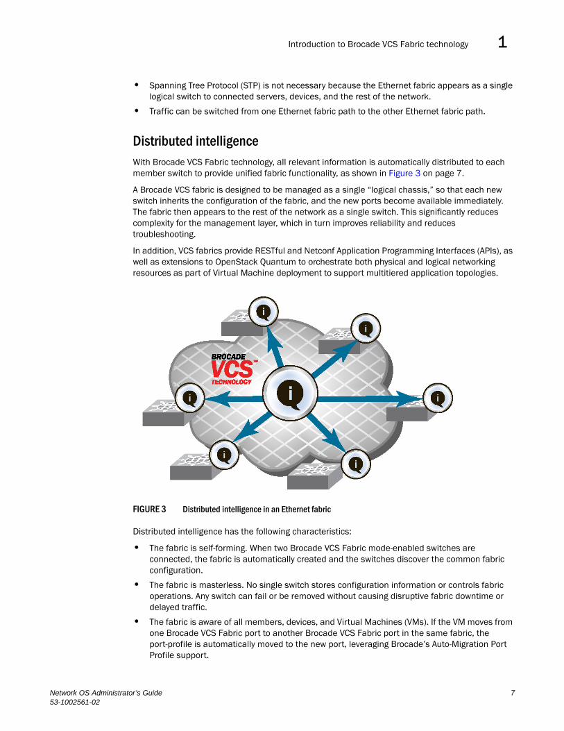
Introduction to Brocade VCS Fabric technology 1
• Spanning Tree Protocol (STP) is not necessary because the Ethernet fabric appears as a single logical switch to connected servers, devices, and the rest of the network.
• Traffic can be switched from one Ethernet fabric path to the other Ethernet fabric path.
Distributed intelligenceWith Brocade VCS Fabric technology, all relevant information is automatically distributed to each member switch to provide unified fabric functionality, as shown in Figure 3 on page 7.
A Brocade VCS fabric is designed to be managed as a single “logical chassis,” so that each new switch inherits the configuration of the fabric, and the new ports become available immediately. The fabric then appears to the rest of the network as a single switch. This significantly reduces complexity for the management layer, which in turn improves reliability and reduces troubleshooting.
In addition, VCS fabrics provide RESTful and Netconf Application Programming Interfaces (APIs), as well as extensions to OpenStack Quantum to orchestrate both physical and logical networking resources as part of Virtual Machine deployment to support multitiered application topologies.
FIGURE 3 Distributed intelligence in an Ethernet fabric
Distributed intelligence has the following characteristics:
• The fabric is self-forming. When two Brocade VCS Fabric mode-enabled switches are connected, the fabric is automatically created and the switches discover the common fabric configuration.
• The fabric is masterless. No single switch stores configuration information or controls fabric operations. Any switch can fail or be removed without causing disruptive fabric downtime or delayed traffic.
• The fabric is aware of all members, devices, and Virtual Machines (VMs). If the VM moves from one Brocade VCS Fabric port to another Brocade VCS Fabric port in the same fabric, the port-profile is automatically moved to the new port, leveraging Brocade’s Auto-Migration Port Profile support.
Network OS Administrator’s Guide 753-1002561-02

Introduction to Brocade VCS Fabric technology1
Logical chassisAll switches in an Ethernet fabric are managed as if they were a single logical chassis. To the rest of the network, the fabric looks no different than any other Layer 2 switch. Figure 4 shows an Ethernet fabric with two switches. The rest of the network is aware of only the edge ports in the fabric, and is unaware of the connections within the fabric.
FIGURE 4 Logical chassis in Ethernet fabric
Each physical switch in the fabric is managed as if it were a blade in a chassis. When a Brocade VCS Fabric mode-enabled switch is connected to the fabric, it inherits the configuration of the fabric and the new ports become available immediately.
Ethernet fabric formationBrocade VCS Fabric protocols are designed to aid the formation of an Ethernet fabric with minimal user configuration. Refer to “Brocade VCS Fabric formation” on page 91 for detailed information about the Ethernet fabric formation process.
Edge Ports
Server Server
Physical View Logical View
Fabric Ports
Externalnon-VCS
Switch
Externalnon-VCS
Switch
8 Network OS Administrator’s Guide53-1002561-02

Brocade VCS Fabric technology use cases 1
All supported switches are shipped with Brocade VCS Fabric mode disabled. Refer to “Brocade VCS Fabric configuration management” on page 94 for information about disabling and enabling Brocade VCS Fabric mode on your switches.
Automatic neighbor discovery
When you connect a switch to a Brocade VCS Fabric mode-enabled switch, the Brocade VCS Fabric mode-enabled switch determines if the neighbor also has Brocade VCS Fabric mode enabled. If the switch has Brocade VCS Fabric mode enabled and the VCS IDs match, the switch joins the Ethernet fabric.
Refer to “Brocade VCS Fabric configuration management” on page 94 for information about changing the VCS ID.
Automatic ISL formation and hardware-based trunking
When a switch joins an Ethernet fabric, ISLs automatically form between directly connected switches within the fabric.
If more than one ISL exists between two switches, then Brocade ISL trunks can automatically form. All ISLs connected to the same neighboring Brocade switch attempt to form a trunk. The trunks are formed only when the ports belong to the same port group. No user intervention is necessary to form these trunks.
Refer to “Fabric interface configuration management” on page 95 for information about enabling and disabling ISLs and trunks.
Principal RBridge election
The RBridge with the lowest WWN in the Ethernet fabric is elected as the principal RBridge.
The role of the principal RBridge is to decide whether a new RBridge joining the fabric conflicts with any of the RBridge IDs already present in the fabric. If a conflict arises, the principal RBridge keeps the joining RBridge segmented.
Refer to “Brocade VCS Fabric configuration management” on page 94 for information about setting the RBridge ID.
Brocade VCS Fabric technology use casesThis section describes the following use cases for Brocade VCS Fabric technology:
• Classic Ethernet
• Large scale server virtualization
Network OS Administrator’s Guide 953-1002561-02

Brocade VCS Fabric technology use cases1
Classic Ethernet Access and Aggregation use caseBrocade VCS Fabric can be deployed in the same fashion as existing top-of-rack switches, as shown in Figure 5. In the rightmost two server racks, a two-switch Ethernet fabric replaces the Ethernet switch at the top of each rack.
FIGURE 5 Pair of Brocade VDX switches at the top of each server rack
The servers see a single top-of-rack switch, allowing for active/active connections, end-to-end.
Brocade VCS Fabric technology in this use case provides the following advantages:
• Multiple active-active connections, with increased effective bandwidth
• Preserves existing architecture
• Works with existing core and aggregation networking products
• Co-exists with existing access switches
• Supports 1 and 10 Gbps server connectivity
• Works with server racks or blade servers
10 Network OS Administrator’s Guide53-1002561-02

Brocade VCS Fabric technology use cases 1
Large scale server virtualization use caseFigure 6 shows a logical two-tier architecture with Brocade VCS fabrics at the edge. Each Brocade VCS fabric appears as a single virtual switch to the switches outside the fabric, which results in flattening the network.
FIGURE 6 Collapsed, flat Layer 3 networks enabling Virtual Machine mobility
Brocade VCS Fabric technology in this use case provides the following advantages:
• Optimizes the multipath network (all paths and Layer 3 gateways are active, no single point of failure, and STP is not necessary)
• Increases sphere of Virtual Machine (VM) mobility
Brocade VCS Fabric connectivity with Fibre Channel SANBeginning with the Network OS v2.1.1 release, Fibre Channel ports on the Brocade VDX 6730 provide support for connecting a Brocade VCS Fabric to a Fibre Channel SAN. Fibre Channel routers provide the connectivity, which provides access to Fibre Channel devices while preserving isolation between the fabrics. Brocade zoning allows you to determine which FCoE devices can access which storage devices on the Fibre Channel SAN.
Network OS Administrator’s Guide 1153-1002561-02

Topology and scaling1
Brocade VDX 6730 switches can be deployed into your Brocade VCS Fabric as access-level switches, aggregation-level switches, or as a means of attachment to Brocade VCS Fabric aggregation-level switches. Brocade recommends deployment as access-level switches to minimize congestion issues for storage traffic and isolating FCoE traffic from non-FCoE traffic. Figure 7 shows such a deployment.
FIGURE 7 Brocade VDX 6730 switches deployed as access-level switches
Topology and scalingUp to 24 switches can exist in a Brocade VCS Fabric. Although you can use any network topology to build your Brocade VCS Fabric, the following topics discuss the scaling, performance, and availability considerations of topologies more commonly found in data centers:
• Core-edge topology
• Ring topology
• Full mesh topology
VCSEthernet
fabric
FC SAN
FC router
FC router
Fabric OSswitch
Fabric OSswitch
VDX 6720 orVDX8770
VDX 6730
1/10 Gbps servers
Storage SAN Storage
VLAG
Core switches
FC
TRILL
Ethernet
12 Network OS Administrator’s Guide53-1002561-02

Topology and scaling 1
Core-edge topologyCore-edge topology, devices connect to edge switches which are connected to each other through core switches. The example shown in Figure 8 uses three core switches. You could use more or fewer switches in the core, depending on whether you need higher availably and greater throughput, or a more efficient use of links and ports.
FIGURE 8 Core-edge topology
This topology is reliable, fast, and scales well. It is reliable because it has multiple core switches. If a core switch or a link to a core switch fails, an alternate path is available. As you increase the number of core switches, you also increase the number of link or core switch failures your cluster can tolerate.
High performance and low latency are assured because throughput is high and the hop count is low. Throughput is high because multiple core switches share the load. Two hops gets you from any edge switch to any other edge switch. If you need greater throughput, simply add another core switch.
Scaling the topology also requires additional core switches and links. However, the number of additional links you need is typically not as great as with, for example, a full mesh topology.
Core switch
Edge switch
Network OS Administrator’s Guide 1353-1002561-02

Topology and scaling1
Ring topologyRing topology connects each node to exactly two other nodes, forming a single continuous pathway. Data travels from node to node, with each node along the path handling every packet of the data. Figure 9 shows a ring topology.
FIGURE 9 Ring topology
This topology is highly scalable, yet susceptible to failures and traffic congestion. It is highly scalable because of its efficient use of interswitch links and ports; an additional node requires only two ports to connect to the ring. It is susceptible to failures since it provides only one path between any two nodes. Throughput of the fabric is limited by the slowest link or node. Latency can be high because of the potentially high number of hops it takes to communicates between two given switches. This topology is useful where economy of port use is critical, but availability and throughput are less critical.
Full mesh topologyFull mesh topology connects each node to all other cluster nodes. Figure 10 shows a full mesh topology.
FIGURE 10 Full mesh topology
14 Network OS Administrator’s Guide53-1002561-02

Topology and scaling 1
This topology is highly reliable and fast, but does not scale well. It is reliable because it provides many paths through the fabric in case of cable or node failure. It is fast with low latency because you can get to any node in the fabric in just one hop. It does not scale well because each additional node increases the number of fabric links and switch ports exponentially. This topology is suitable for smaller fabrics only.
Network OS Administrator’s Guide 1553-1002561-02

Topology and scaling1
16 Network OS Administrator’s Guide53-1002561-02

Network OS Administrator’s Guide53-1002561-02
Chapter
2
Using the Network OS CLIIn this chapter
•DCB command line interface . . . . . . . . . . . . . . . . . . . . . . . . . . . . . . . . . . . . . 17
•Saving your configuration changes . . . . . . . . . . . . . . . . . . . . . . . . . . . . . . . . 17
•Network OS CLI RBAC permissions . . . . . . . . . . . . . . . . . . . . . . . . . . . . . . . . 18
•Default roles. . . . . . . . . . . . . . . . . . . . . . . . . . . . . . . . . . . . . . . . . . . . . . . . . . . 18
•Accessing the Network OS CLI through Telnet. . . . . . . . . . . . . . . . . . . . . . . . 18
•Network OS CLI command modes . . . . . . . . . . . . . . . . . . . . . . . . . . . . . . . . . 18
•Network OS CLI keyboard shortcuts. . . . . . . . . . . . . . . . . . . . . . . . . . . . . . . . 21
•Using the do command as a shortcut . . . . . . . . . . . . . . . . . . . . . . . . . . . . . . 21
•Displaying Network OS CLI commands and command syntax . . . . . . . . . . . 22
•Network OS CLI command completion . . . . . . . . . . . . . . . . . . . . . . . . . . . . . 23
•Network OS CLI command output modifiers . . . . . . . . . . . . . . . . . . . . . . . . . 23
DCB command line interfaceThe Brocade Data Center Bridging (DCB) CLI is designed to support the management of DCB and Layer 2 Ethernet switching functionality. The Network OS CLI uses an industry-standard hierarchical shell familiar to Ethernet/IP networking administrators.
The system starts up with the default Network OS configuration and the DCB startup configuration. After logging in, you are in the Network OS shell. For information on accessing the DCB commands from the Network OS shell, see “Network OS CLI command modes” on page 18.
Saving your configuration changesAny configuration changes made to the switch are written into the running-config file. This is a dynamic file that is lost when the switch reboots. During the boot sequence, the switch resets all configuration settings to the values in the startup-config file.
To make your changes permanent, use the copy command to commit the running-config file to the startup-config file, as shown below.
Example of committing the running-config in privileged EXEC mode.
switch#copy running-config startup-config
17

Network OS CLI RBAC permissions2
Network OS CLI RBAC permissions Role-Based Action Control (RBAC) defines the capabilities that a user account has based on the role the account has been assigned.
A role is an entity that defines the access privileges of the user accounts on the switch. A user is associated with one role. Refer to “Role-based access control (RBAC)” on page 177 for information about RBAC.
Default rolesAttributes of default roles cannot be modified; however, the default roles can be assigned to non-default user accounts. The following roles are default roles:
• The admin role has the highest privileges. All CLIs are accessible to the user associated with the admin role. By default, the admin role has read and write access.
• The user role has limited privileges that are mostly restricted to show commands in the Privileged EXEC mode. User accounts associated with the user role cannot access configuration CLIs that are in the global configuration mode. By default, the user role has read-only access.
Accessing the Network OS CLI through Telnet
NOTEWhile this example uses the admin role to log in to the switch, both roles can be used.
The procedure to access the Network OS CLI is the same through either the console interface or through a Telnet session; both access methods bring you to the login prompt.
switch login: adminPassword:**********switch#
NOTEMultiple users can open Telnet sessions and issue commands using the privileged EXEC mode. Network OS v3.0.0 supports up to 32 Telnet sessions with the admin login.
Network OS CLI command modesTable 1 lists the Network OS CLI command modes and describes how to access them.
18 Network OS Administrator’s Guide53-1002561-02

Network OS CLI command modes 2
NOTEUse the pwd command to view the mode of the current working directory. This command functions in global configuration mode and the modes accessed from global configuration mode.
TABLE 1 Network OS CLI command modes
Command mode
Prompt How to access the command mode Description
Privileged EXEC
switch# This is the default mode for the switch.
Display and change system parameters. Note that this is the administrative mode and includes the basic configuration commands.
Global configuration
switch(config)# From the privileged EXEC mode, enter the configure terminal command.
Configure features that affect the entire switch.
Interface configuration
Port-channel:switch(config-Port-channel-63)#
10-Gigabit Ethernet (DCB port):switch(conf-if-te-0/1)#
VLAN:switch(config-Vlan-1)#
From the global configuration mode, specify an interface by entering one of the following commands:• interface port-channel• interface tengigabitethernet• interface VE
Access and configure individual interfaces.
Protocol configuration
LLDP:switch(conf-lldp)#
Spanning-tree:switch(config-mstp)#switch(config-rstp)#switch(config-stp)#switch(config-pvst)#switch(config-rpvst)#
From the global configuration mode, specify a protocol by entering one of the following commands:• protocol lldp• protocol spanning-tree mstp• protocol spanning-tree rstp• protocol spanning-tree stp• protocol spanning-tree pvst • protocol spanning-tree rapid-pvst
Access and configure protocols.
FCoE configuration
FCoE:switch(config-fcoe)#
FCoE fabric-map sub-mode:switch(config-fcoe-fabric-map)#
FCoE map sub-mode:switch(config-fcoe-map)#
From the global configuration mode, use the fcoe command to enter FCoE configuration mode.
From the FCoE configuration mode, specify an FCoE sub-mode by entering one of the following commands:• fabric-map default• map default
Access and configure FCoE features.
Network OS Administrator’s Guide 1953-1002561-02

Network OS CLI command modes2
AMPP port-profile mode
AMPP port-profile:switch(config-port-profile-name)#
VLAN-profile sub-mode:switch(config-vlan-profile)#
QoS-profile sub-mode:switch(config-qos-profile)#
FCoE-profile sub-mode:switch(config-fcoe-profile)#
Security-profile sub-mode:switch(config-security-profile)#
From the global configuration mode, enter the port-profile command to enter port-profile configuration mode.
From the port-profile configuration mode, specify an AMPP sub-mode by entering one of the following commands:• vlan-profile • qos-profile • fcoe-profile• security-profile
Access and configure AMPP features.
Feature configuration
CEE map:switch(config-cee-map-default)#
Standard ACL:switch(conf-macl-std)#
Extended ACL:switch(conf-macl-ext)#
From the global configuration mode, specify a DCB feature by entering one of the following commands:• cee-map default• mac access-list standard• mac access-list extended
Access and configure CEE map features.
DSCP mutation mapping
DSCP Mutation Map:switch(dscp-mutation-mapname)#
From the global configuration mode, remap incoming DSCP values using the following command:qos map dscp-mutation mapname
DSCP to CoS priority mapping
DSCP to CoS Map:switch(dscp-cos-mapname)#
From the global configuration mode, create a DSCP to CoS priority map using the following command:qos map dscp-cos mapname
DSCP to traffic class mapping
DSCP to Traffic Class Map:switch(dscp-traffic-class-mapname)#
From the global configuration mode, create a DSCP to traffic class map using the following command:qos map dscp-traffic-class mapname
QoS Policer configuration
Police Priority Mapswitch(config-policemap)#
Class Map:switch(config-classmap)
Policy Map:switch(config-policymap)
Policy-class-map submodeswitch(config-policymap-class)
Policy-class-map-policer attributes submodeswitch(config-policymap-class-police)
From the global configuration mode, specify a Policer configuration mode by entering one of these command:• police-priority-map mapname• class-map mapname• policy-map mapname
To enter the pollicy-class-map sub-mode from the policy-map mode, enter class classmap nameTo enter the policy-class-map-policer attributes sub-mode from the policy-map-class mode, enter police followed by policing attributes.
TABLE 1 Network OS CLI command modes (Continued)
Command mode
Prompt How to access the command mode Description
20 Network OS Administrator’s Guide53-1002561-02
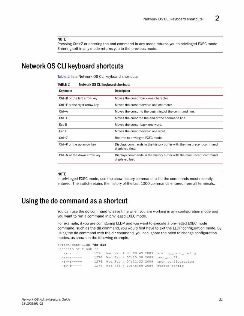
Network OS CLI keyboard shortcuts 2
NOTEPressing Ctrl+Z or entering the end command in any mode returns you to privileged EXEC mode. Entering exit in any mode returns you to the previous mode.
Network OS CLI keyboard shortcutsTable 2 lists Network OS CLI keyboard shortcuts.
NOTEIn privileged EXEC mode, use the show history command to list the commands most recently entered. The switch retains the history of the last 1000 commands entered from all terminals.
Using the do command as a shortcutYou can use the do command to save time when you are working in any configuration mode and you want to run a command in privileged EXEC mode.
For example, if you are configuring LLDP and you want to execute a privileged EXEC mode command, such as the dir command, you would first have to exit the LLDP configuration mode. By using the do command with the dir command, you can ignore the need to change configuration modes, as shown in the following example.
switch(conf-lldp)#do dirContents of flash://
-rw-r----- 1276 Wed Feb 4 07:08:49 2009 startup_rmon_config-rw-r----- 1276 Wed Feb 4 07:10:30 2009 rmon_config-rw-r----- 1276 Wed Feb 4 07:12:33 2009 rmon_configuration-rw-r----- 1276 Wed Feb 4 10:48:59 2009 starup-config
TABLE 2 Network OS CLI keyboard shortcuts
Keystroke Description
Ctrl+B or the left arrow key Moves the cursor back one character.
Ctrl+F or the right arrow key Moves the cursor forward one character.
Ctrl+A Moves the cursor to the beginning of the command line.
Ctrl+E Moves the cursor to the end of the command line.
Esc B Moves the cursor back one word.
Esc F Moves the cursor forward one word.
Ctrl+Z Returns to privileged EXEC mode.
Ctrl+P or the up arrow key Displays commands in the history buffer with the most recent command displayed first.
Ctrl+N or the down arrow key Displays commands in the history buffer with the most recent command displayed last.
Network OS Administrator’s Guide 2153-1002561-02
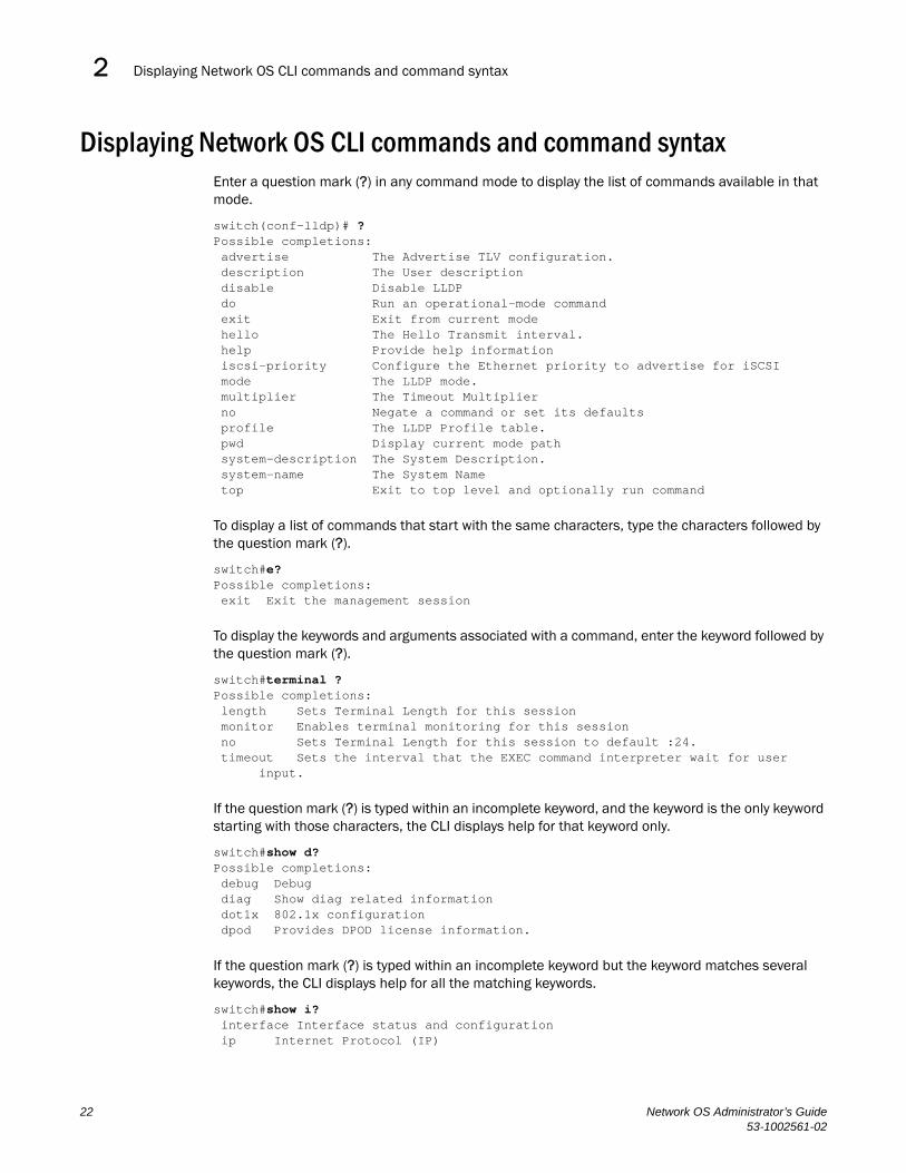
Displaying Network OS CLI commands and command syntax2
Displaying Network OS CLI commands and command syntaxEnter a question mark (?) in any command mode to display the list of commands available in that mode.
switch(conf-lldp)# ?Possible completions:advertise The Advertise TLV configuration.description The User descriptiondisable Disable LLDPdo Run an operational-mode commandexit Exit from current modehello The Hello Transmit interval.help Provide help informationiscsi-priority Configure the Ethernet priority to advertise for iSCSImode The LLDP mode.multiplier The Timeout Multiplierno Negate a command or set its defaultsprofile The LLDP Profile table.pwd Display current mode pathsystem-description The System Description.system-name The System Nametop Exit to top level and optionally run command
To display a list of commands that start with the same characters, type the characters followed by the question mark (?).
switch#e?Possible completions:exit Exit the management session
To display the keywords and arguments associated with a command, enter the keyword followed by the question mark (?).
switch#terminal ?Possible completions:length Sets Terminal Length for this sessionmonitor Enables terminal monitoring for this sessionno Sets Terminal Length for this session to default :24.timeout Sets the interval that the EXEC command interpreter wait for user
input.
If the question mark (?) is typed within an incomplete keyword, and the keyword is the only keyword starting with those characters, the CLI displays help for that keyword only.
switch#show d?Possible completions:debug Debugdiag Show diag related informationdot1x 802.1x configurationdpod Provides DPOD license information.
If the question mark (?) is typed within an incomplete keyword but the keyword matches several keywords, the CLI displays help for all the matching keywords.
switch#show i?interface Interface status and configurationip Internet Protocol (IP)
22 Network OS Administrator’s Guide53-1002561-02

Network OS CLI command completion 2
The Network OS CLI accepts abbreviations for commands. This example is the abbreviation for the show qos interface all command.
switch#sh q i a
If the switch does not recognize a command after Enter is pressed, an error message displays.
switch#hookup^
syntax error: unknown argument.
If an incomplete command is entered, an error message displays.
switch#show^
syntax error: unknown argument.
Network OS CLI command completionTo automatically complete the spelling of commands or keywords, begin typing the command or keyword and then press Tab. For example, at the CLI command prompt, type te and press Tab:
switch#te
The CLI displays the following command.
switch#terminal
If there is more than one command or keyword associated with the characters typed, the Network OS CLI displays all choices. For example, at the CLI command prompt, type show l and press Tab:
switch#show l
The CLI displays the following command.
Possible completions:lacp LACP commandslicense Display license keys installed on the switch.lldp Link Layer Discovery Protocol(LLDP).logging Show logging
Network OS CLI command output modifiersYou can filter the output of the CEE CLI show commands using the output modifiers described in Table 3.
TABLE 3 CEE CLI command output modifiers
Output modifier Description
append Appends the output to a file.
redirect Redirects the command output to the specified file.
include Displays the command output that includes the specified expression.
exclude Displays the command output that excludes the specified expression.
Network OS Administrator’s Guide 2353-1002561-02

Network OS CLI command output modifiers2
append Appends the command output to the specified file.
begin Displays the command output that begins with the specified expression.
last Displays only the last few lines of the command output.
tee Redirects the command output to the specified file. Note that this modifier also displays the command output.
until string Ends the output when the output text matches the string.
count Counts the number of lines in the output.
linnum Enumerates the lines in the output.
more Paginates the output.
nomore Suppresses the pagination of the output.
FLASH Redirects the output to flash memory.
TABLE 3 CEE CLI command output modifiers (Continued)
Output modifier Description
24 Network OS Administrator’s Guide53-1002561-02

Network OS Administrator’s Guide53-1002561-02
Chapter
3
Basic Switch ManagementIn this chapter•Connecting to the switch. . . . . . . . . . . . . . . . . . . . . . . . . . . . . . . . . . . . . . . . . 25
•Switch attributes . . . . . . . . . . . . . . . . . . . . . . . . . . . . . . . . . . . . . . . . . . . . . . . 26
•Switch types . . . . . . . . . . . . . . . . . . . . . . . . . . . . . . . . . . . . . . . . . . . . . . . . . . . 28
•Disabling and enabling a chassis. . . . . . . . . . . . . . . . . . . . . . . . . . . . . . . . . . 28
•Rebooting a Brocade switch . . . . . . . . . . . . . . . . . . . . . . . . . . . . . . . . . . . . . . 29
•Configuring the Ethernet management interface . . . . . . . . . . . . . . . . . . . . . 31
•Outbound Telnet and SSH. . . . . . . . . . . . . . . . . . . . . . . . . . . . . . . . . . . . . . . . 36
•Modular platform basics . . . . . . . . . . . . . . . . . . . . . . . . . . . . . . . . . . . . . . . . . 38
•Configuring a switch banner . . . . . . . . . . . . . . . . . . . . . . . . . . . . . . . . . . . . . . 44
•supportSave data . . . . . . . . . . . . . . . . . . . . . . . . . . . . . . . . . . . . . . . . . . . . . . 44
•Message logging . . . . . . . . . . . . . . . . . . . . . . . . . . . . . . . . . . . . . . . . . . . . . . . 46
Connecting to the switchYou can connect to your switch through a console session on the serial port, or through a Telnet or Secure Shell (SSH) connection to the management port. You can use any account login present in the local switch database or on a configured authentication, authorization, and accounting (AAA) server for authentication. For initial setup procedures, use the preconfigured administrative account that is part of the default switch configuration.
The switch must be physically connected to the network. If the switch network interface is not configured or the switch has been disconnected from the network, use a console session on the serial port.
• Refer to the Brocade VDX Hardware Reference Manuals for information on connecting through the serial port.
• Refer to “Configuring the Ethernet management interface” on page 31 for information on configuring the network interface.
Connecting through a Telnet or SSH session1. Connect through a serial port to the switch.
2. Verify that the switch’s network interface is configured and that it is connected to the IP network through the RJ-45 Ethernet port.
3. Log off the switch’s serial port.
25

Switch attributes3
4. From a management station, open a Telnet or SSH connection using the management IP address of the switch to which you want to connect.
For more information on setting the management IP address, refer to “Configuring the Ethernet management interface” on page 31.
5. Enter the password.
Brocade recommends that you change the default account password when you log in for the first time. For more information on changing the default password, refer to the Brocade VDX Hardware Reference Manuals.
6. Verify that the login was successful.
The prompt displays the host name followed by a pound sign (#).
login as: [email protected]'s password:******
----------------------------------------------------WARNING: The default password of 'admin' and 'user' accounts have not been changed.Welcome to the Brocade Network Operating System Softwareadmin connected from 10.110.100.92 using ssh on VDX 6720-24
Switch attributesA switch can be identified by its IP address, World Wide Name (WWN), switch ID or RBridge ID, or by its host name and chassis name. You can customize the host name and chassis name with the switch-attributes command.
• A host name can be from 1 through 30 characters long. It must begin with a letter, and can contain letters, numbers, and underscore characters. The default host name is “sw0.” The host name is displayed at the system prompt.
• Brocade recommends that you customize the chassis name for each platform. Some system logs identify the switch by its chassis name; if you assign a meaningful chassis name, logs are more useful. A chassis name can be from 1 through 30 characters long, must begin with a letter, and can contain letters, numbers, and underscore characters. The default chassis name is VDX 6710, VDX 6720-24, VDX 6720-60, VDX 6730-32, or VDX 6730-76, VDX 8770-4, or VDX 8770-8 depending on the switch model.
Setting and displaying the host name1. In privileged EXEC mode, issue the configure terminal command to enter global configuration
mode.
2. If Telnet is not activated on the switch, enter the no telnet server disable to activate Telnet.
3. Enter the switch-attributes command, followed by a question mark to determine the local RBridge ID.
4. Enter the switch-attributes command, followed by the RBridge ID.
5. Enter the host-name operand, followed by the host name.
6. Save the configuration changes using the do copy running-config startup-config command.
26 Network OS Administrator’s Guide53-1002561-02

Switch attributes 3
7. Verify the configuration with the do show running-config switch-attributes rbridge-id command.
switch# configure terminalEntering configuration mode terminalswitch(config)# no telnet server disableswitch(config)# switch-attributes ?Possible completions:<NUMBER:1-239> Specify the rbridge-id 1
switch(config)# switch-attributes 1switch(config-switch-attributes-1)# host-name lab1_vdx0023switch(config-switch-attributes-1)# exitswitch(config)# do copy running-config startup-configswitch(config)# do show running-config switch-attributes 1switch-attributes 1 chassis-name VDX 6720-24 host-name lab1_vdx0023
Setting and displaying the chassis name1. In privileged EXEC mode, issue the configure terminal command to enter global configuration
mode.
2. Enter the switch-attributes command, followed by a question mark to determine the local RBridge ID.
3. Enter the switch-attributes command, followed by the RBridge ID.
4. Enter the chassis-name operand, followed by the chassis name.
5. Save the configuration changes using the do copy running-config startup-config command
6. Verify the configuration changes with the do show running-config startup-config rbridge-id command.
switch# configure terminalEntering configuration mode terminalswitch(config)# switch-attributes ?Possible completions:<NUMBER:1-239> Specify the rbridge-id 1
switch(config)# switch-attributes 1switch(config-switch-attributes-1# chassis-name lab1_vdx0023switch(config)# do copy running-config startup-configswitch(config)# do show running-config switch-attributes 1switch-attributes 1 chassis-name lab1_vdx0023 host-name lab1_vdx0023
Network OS Administrator’s Guide 2753-1002561-02

Switch types3
Switch typesThe switchType attribute is a unique device model identifier that is displayed when you issue the show chassis command. When you are gathering information for your switch support provider, you may be asked for the Brocade product name. Use Table 4 to convert the switchType identifier to a Brocade product name.
switch# show chassis
Chassis Family: VDX 87xxChassis Backplane Revision: 1
switchType: 1000 <=== Use table to convert this parameter(output truncated)
In the example, the number 1000 is the value of the switchType attribute. An optional number (.x) indicates the revision of the motherboard.
Disabling and enabling a chassisThe chassis is enabled after power is turned on and diagnostics and switch initialization routines have finished. All interfaces are online. You can disable and re-enable the chassis as necessary.
• Use the chassis disable command if you want to take all interfaces offline. If the switch was part of an Ethernet fabric, the fabric reconfigures.
• Use the chassis enable command to bring the interfaces back online. All interfaces that were enabled before the chassis was disabled are expected to come back online. If the switch was part of an Ethernet fabric, it rejoins the fabric.
NOTEDisabling the chassis is a disruptive operation. Use the shutdown command to disable or enable a few selected interfaces only. Refer to the Network OS Command Reference for more information on this command.
TABLE 4 Mapping switchType to Brocade product names
switchType Brocade product name ASIC Description
95.1 - 95.2 VDX 6720-24 eAnvil2 24 1/10 GbE SFP+ ports
96.2 VDX 6730-32 eAnvil2/Condor2 24 1/10 GbE SFP+ ports and 8 8 Gbps FC ports
97.4 VDX 6720-60 eAnvil2 60 1/10 GbE SFP+ ports
107.x VDX 6730-76 eAnvil2/Condor2 60 1/10 GbE SFP+ ports and 16 8 Gbps FC ports
116.2 VDX 6710-54 eAnvil2 48 1 GbE copper and 6 1/10 GbE SFP+ ports
1000.x VDX 8770-4 Wolverine/Hawk/Condor3
4 I/O slot chassis supporting 48x10 GbE, or 12x40 GbE interface modules
1001.x VDX 8770-8 Wolverine/Hawk/Condor3
8 I/O slot chassis supporting 48x10 GbE, 72x1 GbE, or 12x40 GbE interface modules
28 Network OS Administrator’s Guide53-1002561-02

Rebooting a Brocade switch 3
Rebooting a Brocade switchNetwork OS provides several commands to reboot your system: reload, fastboot, and ha chassisreboot
NOTEAll reboot operations are disruptive, and the commands prompt for confirmation before executing. When you reboot a switch connected to a fabric, all traffic to and from that switch stops. All ports on that switch remain inactive until the switch comes back online.
Rebooting a compact switch• The reload command performs a “cold reboot” (power off and restart) of the control processor
(CP). If the power-on self-test (POST) is enabled, POST is executed when the system comes back up.
• The fastboot command performs a “cold reboot” (power off and restart) of the control processor (CP), bypassing POST when the system comes back up. Bypassing POST can reduce boot time significantly.
CAUTION
Do not perform a reload command between a chassis disable command and a chassis enable command. Your ports will be closed.
Rebooting a modular chassis• On a modular chassis, the reboot and the fastboot commands only reboot the management
module on which the command is executed. If you log in to the switch IP address and execute one of these commands, only the active management module reboots and POST is bypassed..
• The ha chassisreboot command performs a “cold reboot” (power off and restart) of the entire chassis. If the power-on self-test (POST) is enabled, POST is executed when the system comes back up.
A chassis reboot brings up the system in sequential phases. First, software services are launched on the management modules and brought up to the active state. Then, the interface modules are powered on and initialized. Software services are launched on the interface modules and brought up to the active state. When the interface module initialization reaches the final state, the chassis is ready to accept user commands from the CLI interface.
During the boot process system initialization, configuration data (default or user-defined) are applied to the switch through configuration replay. For more information, refer to “Configuration management in redundant management modules” in Chapter 5, “Configuration Management”.
Network OS Administrator’s Guide 2953-1002561-02

Rebooting a Brocade switch3
Operational modesNetwork OS supports two operational modes for Brocade VDX switches, standalone mode and Brocade VCS fabric mode. When a switch boots up, it goes into one of these modes by default.
VCS mode
By default, all modular platforms (Brocade VDX 8770-4 and Brocade VDX 8770-8) boot up in VCS mode and will attempt to form interswitch links. If the chassis is not connected to another switch, it will form a “single node VCS fabric.” This means the chassis operates as a standalone system, but the operational mode is always VCS-enabled. You cannot disable the VCS mode on a modular switch.
When you issue the show vcs command to display the VCS configuration for the chassis, the command output shows a single-node VCS with a VCS ID of 1 and an RBridge ID of 1. Use the vcs command to change the default values.
switch# show vcsConfig Mode : Local-OnlyVCS ID : 1Total Number of Nodes : 2Rbridge-Id WWN Management IP Status HostName-----------------------------------------------------------------------------1 10:00:00:05:33:15:DE:CC 10.24.82.120 Online dutA1-sw0
fd00:60:69bc:64:205:33ff:fe15:decc
Standalone mode
All Brocade VDX compact switches (VDX 6710, VDX 6720, and VDX 6730) boot up in standalone mode. In this restricted mode, the switch supports only legacy features that were available in Network OS v2.1.1, with the exception of IP static routes and in-band management. All other Layer 3 features, or any other features introduced in Network OS v3.0.0, are not available in standalone mode.
NOTEThe Brocade VDX 8770 does not support standalone mode.
When you display the VCS configuration for a compact switch in default mode, it shows that VCS mode is disabled. Use the vcs enable command to enable VCS mode on a compact switch. The switch reboots and comes up in VCS mode.
switch# show vcsstate: Disabled
NOTEThe configuration mode for all switches running Network OS v3.0.0 is always “Local-Only,” regardless of whether the switch is in standalone mode or in VCS mode. The configuration mode parameter in the show vcs output indicates that configurations made to the switch are local and are not automatically distributed to other switches in the fabric. For exceptions, refer to “Automatic distribution of configuration parameters” in Chapter 5, “Configuration Management”.
30 Network OS Administrator’s Guide53-1002561-02

Configuring the Ethernet management interface 3
Configuring the Ethernet management interfaceThe Ethernet network interface provides management access, including direct access to the Network OS CLI. You must configure at least one IP address using a serial connection to the CLI before you can manage the system with other management interfaces. You can either configure static IP addresses, or you can use a Dynamic Host Configuration Protocol (DHCP) client to acquire IP addresses automatically. For IPv6 addresses, both static IPv6 and stateless IPv6 autoconfiguration are supported.
Setting static IP addresses and using DHCP are mutually exclusive. If DHCP is enabled, remove the DHCP client before you configure a static IP address.
NOTEYou must connect through the serial port to set the IP address if the network interface is not configured already. Refer to the Brocade VDX Hardware Reference Manual for your specific product for information on connecting through the serial port.
Ethernet interfacesThe Brocade VDX compact switches have a single configurable Ethernet Interface, Eth0, which can be configured as a management interface.
The modular chassis, the Brocade VDX 8770-8 and the Brocade VDX 8770-4, have two redundant management modules, MM1 and MM2. Each management module can communicate with each of the interface modules (line cards) through an Ethernet connection. Each management module has two Ethernet interfaces, Eth0 and Eth2.
Eth0 is the management interface and can be configured with an IP address. Eth2 provides connectivity to the other management module and the interface modules in the chassis. The Eth2 IP addressing scheme uses default IP addresses to communicate between the modules; these addresses are not user-configurable.
Configuring a static IP addressUse static Ethernet network interface addresses in environments where the DHCP service is not available. To configure a static IPv4 or IPv6 address, you must first disable DHCP. Refer to “Configuring an IP address with DHCP” on page 33 for more information.
Configuring a static IP v4 Ethernet address
1. Connect to the switch through the serial console.
2. In privileged EXEC mode, issue the configure terminal command to enter global configuration mode.
3. Enter the interface Management rbridge-id/port command to configure the management port.
This command enters a management interface configuration mode where you can choose configuration parameters for IPv4 and IPv6 addresses.
• A compact switch has a single management port, and the port number for the management port is always 0.
Network OS Administrator’s Guide 3153-1002561-02

Configuring the Ethernet management interface3
• On a modular switch with two redundant management modules, you can configure two management ports. The port numbers are 1 and 2.
4. Enter the no ip address dhcp command to disable DHCP.
5. Enter the ip address IPv4_address/prefix_length command.
6. Enter the ip gateway-address IP_address command to configure the gateway address.
7. Verify the configuration with the do show running-config interface Management command.
NOTESpecifying an IPv4 address with a subnet mask is not supported. Instead, enter a prefix number. To enter a prefix number for a network mask, type a forward slash ( / ) and the number of bits in the mask immediately after the IP address. For example, enter, “209.157.22.99/24” for an IP address that has a network mask with 24 significant (“mask”) bits.
switch# configure terminalEntering configuration mode terminalswitch(config)# interface Management 1/0switch(config-Management-1/0)# no ip address dhcpswitch(config-Management-1/0)# ip address 10.24.85.81/20switch(config-Management-1/0)# ip gateway-address 10.24.80.1switch(config-Management-1/0)# do show running-config interface Managementinterface Management 1/0 no ip address dhcp ip address 10.24.85.81/20 ip gateway-address 10.24.80.1 no ipv6 address autoconfig!
Configuring a static IPv6 Ethernet address
1. In privileged EXEC mode, issue the configure terminal command to enter global configuration mode.
2. Enter the interface Management rbridge-id/port command.
This command enters a management interface configuration mode where you can choose configuration parameters for IPv4 and IPv6 addresses.
• A compact switch has a single management port, and the port number for the management port is always 0.
• On a modular switches with two redundant management modules, you can configure two management ports. The port numbers are 1 and 2.
3. Enter the ipv6 address IPv6_addresss/prefix_length command.
switch# configure terminalEntering configuration mode terminalswitch(config)# interface Management 1/0switch(config-Management-1/0)# ipv6 address fd00:60:69bc:832:e61f:13ff:fe67:4b94/64
32 Network OS Administrator’s Guide53-1002561-02

Configuring the Ethernet management interface 3
Configuring an IP address with DHCP
NOTEDHCP is not supported for IPv6 addresses.
By default, DHCP is disabled. You must explicitly enable the service. Use the ip address dhcp command to enable DHCP for IPv4 addresses, and the ipv6 address dhcp command to enable DHCP for IPv6 addresses. The Network OS DHCP clients support the following parameters:
• External Ethernet port IP addresses and prefix length
• Default gateway IP address
When you connect the DHCP-enabled switch to the network and power on the switch, the switch automatically obtains the Ethernet IP address, prefix length, and default gateway address from the DHCP server. The DHCP client can only connect to a DHCP server on the same subnet as the switch. Do not enable DHCP if the DHCP server is not on the same subnet as the switch.
The following example enables DHCP for IPv4 addresses.
switch(config)# interface Management 1/1switch(config-Management-1/1)# ip address dhcp
Network OS Administrator’s Guide 3353-1002561-02

Configuring the Ethernet management interface3
The following example enables DHCP for IPv6 addresses.
switch(config)# interface Management 1/1switch(config-Management-1/1)# ipv6 address dhcp
The show running-config interface Management command indicates whether DHCP is enabled. The following example shows a switch with DHCP enabled for IPv4 addresses.
switch# show running-config interface Managementinterface Management 2/0ip address dhcpip address 10.24.73.170/20ip gateway-address 10.24.64.1no ipv6 address autoconfig !
NOTEEnabling DHCP removes all configured static IP addresses.
Stateless IPv6 autoconfigurationIPv6 allows assignment of multiple IP addresses to each network interface. Each interface is configured with a link local address in almost all cases, but this address is only accessible from other hosts on the same network. To provide for wider accessibility, interfaces are typically configured with at least one additional global scope IPv6 address. IPv6 autoconfiguration allows more IPv6 addresses, the number of which is dependent on the number of routers serving the local network and the number of prefixes they advertise.
When IPv6 autoconfiguration is enabled, the platform will engage in stateless IPv6 autoconfiguration. When IPv6 autoconfiguration is disabled, the platform will relinquish usage of any autoconfigured IPv6 addresses that it may have acquired while IPv6 autoconfiguration was enabled. This same enabled and disabled state also enables or disables the usage of a link local address for each managed entity (though a link local address will continue to be generated for each switch) because those link local addresses are required for router discovery.
The enabled or disabled state of autoconfiguration does not affect any static IPv6 addresses that may have been configured. Stateless IPv6 autoconfiguration and static IPv6 addresses can coexist.
Setting IPv6 autoconfiguration 1. In privileged EXEC mode, issue the configure terminal command to enter global configuration
mode.
2. Take the appropriate action based on whether you want to enable or disable IPv6 autoconfiguration.
• Enter the ipv6 address autoconfig command to enable IPv6 autoconfiguration for all managed entities on the target platform.
• Enter the no ipv6 address autoconfig command to disable IPv6 autoconfiguration for all managed entities on the target platform.
NOTEOn the Brocade VDX 8770, the autoconfig command can be issued only on the interface rbridge-id/1. However, this operation enables auto-configuration for the entire chassis.
34 Network OS Administrator’s Guide53-1002561-02
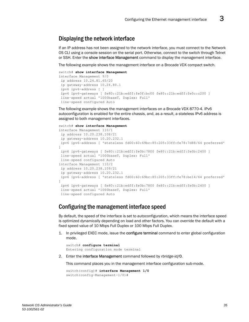
Configuring the Ethernet management interface 3
Displaying the network interfaceIf an IP address has not been assigned to the network interface, you must connect to the Network OS CLI using a console session on the serial port. Otherwise, connect to the switch through Telnet or SSH. Enter the show interface Management command to display the management interface.
The following example shows the management interface on a Brocade VDX compact switch.
switch# show interface Managementinterface Management 9/0 ip address 10.24.81.65/20 ip gateway-address 10.24.80.1 ipv6 ipv6-address [ ] ipv6 ipv6-gateways [ fe80::21b:edff:fe0f:bc00 fe80::21b:edff:fe0c:c200 ] line-speed actual "1000baseT, Duplex: Full" line-speed configured Auto
The following example shows the management interfaces on a Brocade VDX 8770-4. IPv6 autoconfiguration is enabled for the entire chassis, and, as a result, a stateless IPv6 address is assigned to both management interfaces.
switch# show interface Managementinterface Management 110/1 ip address 10.20.238.108/21 ip gateway-address 10.20.232.1 ipv6 ipv6-address [ "stateless fd00:60:69bc:85:205:33ff:fe78:7d88/64 preferred" ] ipv6 ipv6-gateways [ fe80::21b:edff:fe0b:7800 fe80::21b:edff:fe0b:2400 ] line-speed actual "1000baseT, Duplex: Full" line-speed configured Autointerface Management 110/2 ip address 10.20.238.109/21 ip gateway-address 10.20.232.1 ipv6 ipv6-address [ "stateless fd00:60:69bc:85:205:33ff:fe78:be14/64 preferred" ] ipv6 ipv6-gateways [ fe80::21b:edff:fe0b:7800 fe80::21b:edff:fe0b:2400 ] line-speed actual "1000baseT, Duplex: Full" line-speed configured Auto
Configuring the management interface speedBy default, the speed of the interface is set to autoconfiguration, which means the interface speed is optimized dynamically depending on load and other factors. You can override the default with a fixed speed value of 10 Mbps Full Duplex or 100 Mbps Full Duplex.
1. In privileged EXEC mode, issue the configure terminal command to enter global configuration mode.
switch# configure terminalEntering configuration mode terminal
2. Enter the interface Management command followed by rbridge-id/0.
This command places you in the management interface configuration sub-mode.
switch(config)# interface Management 1/0switch(config-Management-1/0)#
Network OS Administrator’s Guide 3553-1002561-02

Outbound Telnet and SSH3
3. Enter the speed command with the selected speed parameter. The valid values are 10, 100, and auto.
switch(config-Management-1/0)# speed auto
4. Enter the do show interface Management command followed by rbridge-id/0 to display the new settings.
switch(config-Management-1/0# do show interface Management 1/0interface Management 1/0
ip address 10.24.81.65/20 ip gateway-address 10.24.80.1 ipv6 ipv6-address [ ] ipv6 ipv6-gateways [ fe80::21b:edff:fe0f:bc00 fe80::21b:edff:fe0c:c200 ] line-speed actual "1000baseT, Duplex: Full" line-speed configured Auto
5. Save the configuration changes using the copy running-config startup-config command.
switch(config-Management-1/0# do copy running-config startup-config
Outbound Telnet and SSHSecure Shell (SSH) and Telnet are mechanisms for allowing secure access to management functions on a remote networking device. SSH provides a function similar to Telnet, but unlike Telnet, which offers no security, SSH provides a secure, encrypted connection to the device.
SSH and Telnet support is available in privileged EXEC mode on all Brocade VDX platforms. IPv4 and IPv6 addresses are supported.
Establishing a Telnet connectionTo establish a Telnet session, you can use the default settings.
switch# telnet 10.17.37.157Trying 10.17.37.157...Connected to 10.17.37.157.Escape character is '^]'.
Network OS (sw0)sw0 login:
Telnet connects on port 23. You can override the default port using the telnet ip_address command with the optional port operand (range 0-65535). However, the device must be listening on that port for the connection to succeed.
The following example overrides the default port.
switch# telnet 10.17.37.157 87Trying 10.17.37.157...Connected to 10.17.37.157.Escape character is '^]'.
Network OS (sw0)sw0 login:
36 Network OS Administrator’s Guide53-1002561-02

Outbound Telnet and SSH 3
The following features are not supported with Telnet:
• Displaying Telnet sessions
• Terminating hung Telnet sessions
SSH supported featuresSSHv2 is the supported version of SSH, but not all features typically available with SSHv2 are supported on the Brocade VDX family of switches.
The following encryption algorithms are supported:
• 3des Triple-DES (default)
• aes256-cbc: AES in CBC mode with 256-bit key
• aes192-cbc: AES in CBC mode with 192-bit key
• aes128-cbc: AES in CBC mode with 128-bit key
The following HMAC (Hash-based Message Authentication Code) message authentication algorithms are supported:
• hmac-md5: MD5 encryption algorithm with 128-bit key (default).
• hmac-md5-96: MD5 encryption algorithm with 96-bit key.
• hmac-sha1: SHA1 encryption algorithm with 160-bit key.
• hmac-sha1-96: SHA1 encryption algorithm with 96-bit key.
SSH user authentication is performed with passwords stored on the device or on an external authentication, authorization, and accounting (AAA) server.
The following features are not supported with SSH:
• Displaying SSH sessions
• Deleting stale SSH keys
Establishing an SSH connectionIn privileged EXEC mode, enter the ssh -l username ip_address command to establish an SSH connection with default parameters. Use the -m and -c options to override the default encryption and hash algorithms. The following example overrides the default settings.
switch# ssh -l admin -m hmac-md5 -c aes128-cbc 10.20.51.68The authenticity of host '10.20.51.68 (10.20.51.68)' can't be established.RSA key fingerprint is ea:32:38:f7:76:b7:7d:23:dd:a7:25:99:e7:50:87:d0.Are you sure you want to continue connecting (yes/no)? yesWarning: Permanently added '10.20.51.68' (RSA) to the list of known [email protected]'s password:********
WARNING: The default password of 'admin' and 'user' accounts have not been changed.
Welcome to the Brocade Network Operating System Softwareadmin connected from 10.20.51.66 using ssh on C60_68F
Network OS Administrator’s Guide 3753-1002561-02

Modular platform basics3
Modular platform basicsThe Brocade VDX 8770 platform features two redundant management modules, three or six switch fabric modules, and four or eight interface modules depending on the switch model. The Brocade VDX 8770-4 supports four interface modules and the Brocade VDX 8770-8 supports eight interface modules.
Table 5 shows the modules supported on each platform.
Management moduleTwo management modules provide redundancy and act as the main controller on the Brocade VDX 8770-4 and VDX 8770-8 chassis. The management modules host the distributed Network OS that provides the overall control plane management for the chassis. You can install a redundant management module in slot M1 or M2 in any of the Brocade VDX 8770 chassis. By default, the system considers the module in slot M1 the active management module and the module in slot M2 the redundant, or standby, management module. If the active module becomes unavailable, the standby module automatically takes over management of the system.
Each management module maintains its own copy of the configuration database. The startup configuration is automatically synchronized with the other management module.
Brocade recommends that each management module (primary and secondary partition) should maintain the same firmware version. For more information on maintaining firmware, refer to Chapter 6, “Installing and Maintaining Firmware”.
Each management module has two Ethernet interfaces, Eth0 and Eth2. Eth0 is the management interface and can be configured with an IP address. For more information on configuring the management interface, refer to “Configuring the Ethernet management interface” on page 31.
TABLE 5 Modules supported on the Brocade VDX 8770 platform
Type Module ID Slot numbersVDX 8770-4
Slot numbersVDX 8770-8
Description
MM 0x70 = 112 M1, M2 M1, M2 Management module (an 8-core 1.5 GHz Control Processor)
SFM 0x71 = 113 S1 - S3 S1 - S6 Switch fabric module (core blade)
LC48X10G 0x72 = 114 L1 - L4 L1 - L8 48-port 10 GbE interface module
LC12X40G 0x7F = 127 L1 - L4 L1 - L8 12-port 40 GbE interface module
LC48X1G 0x83 = 131 L1 - L4 L1 - L8 48-port 1 GbE interface module
38 Network OS Administrator’s Guide53-1002561-02

Modular platform basics 3
Switch fabric modulesThe switch fabric modules play a dual role in the fabric connectivity between interface modules, providing both the data-plane connectivity and the control-plane connectivity needed for end-to-end credit management in each of the interface modules.
In each chassis model, two slots are designated for supporting the control-plane connectivity. In the Brocade VDX 8770-4, the slots S1 and S2 are the designated control-plane slots. In the Brocade VDX 8770-8, the slots S3 and S4 are the designated control-plane slots. At least one of the control-plane slots must be populated to maintain operation. If you remove the switch fabric modules from both the control-plane slots, all interface modules will be faulted and the chassis is no longer operational.
Interface modulesThree types of interface modules provide I/O ports for network Ethernet protocols, the Brocade LC48x10G, the Brocade LC48x1G, and the Brocade LC12x40G. All models feature six Wolverine ASICs and three Hawk ASICs. The Hawk ASICs provide fabric connectivity over the backplane to other interface modules through the switch fabric modules.
The Brocade LC48x1G provides 48 1 GbE/10 GbE SFP+ front ports. The Brocade LC48x10G interface modules provide 48 1 GbE/10 GbE SFP+ front ports.
• The 10 GbE SFP+ interfaces are named "TenGigabitEthernet" or "TE".
• The 1 GbE SFP+ interfaces are named "GigabitEthernet" or "GE".
The Brocade LC12x40G interface module provides 12 40 GbE QSFP front ports.
• The 40 GbE QSFP interfaces are named "FortyGigabitEthernet" or "FO".
Supported interface modesAll interfaces in the Brocade VDX 8770 chassis come online as Fabric interswitch links (“Fabric ISLs”) by default and will attempt to form a Brocade VCS fabric. If the ISL formation fails, the interfaces come up as "Edge ports".
NOTEThe Brocade VDX 8770 chassis always comes up in VCS mode. Standalone mode is not supported on Brocade VDX 8770 platform.
Displaying the interfacesInterfaces on the VDX 8770 platform are identified by the RBridge ID, slot number, and port number, separated by forward slashes (/). For example, the notation 9/2/8 indicates port 8 located in slot 2 on a chassis with the RBridge ID of 9.
Enter the show running-config interface interface_type command to display the interfaces and their status.
switch# show running-config interface TenGigabitEthernetinterface TenGigabitEthernet 1/1/1
fabric isl enablefabric trunk enableno shutdown
Network OS Administrator’s Guide 3953-1002561-02

Modular platform basics3
!interface TenGigabitEthernet 1/1/2
fabric isl enablefabric trunk enableno shutdown
!interface TenGigabitEthernet 1/1/3
fabric isl enablefabric trunk enableno shutdown
!interface TenGigabitEthernet 1/1/4
fabric isl enablefabric trunk enableno shutdown
!interface TenGigabitEthernet 1/1/5
fabric isl enablefabric trunk enableno shutdown
!interface TenGigabitEthernet 1/1/6
fabric isl enablefabric trunk enableno shutdown
Enter the show interface interface_type rbridge_id/slot/port command to display the configuration details for the specified interface.
switch# show interface TenGigabitEthernet 1/1/9TenGigabitEthernet 1/1/9 is up, line protocol is up (connected)Hardware is Ethernet, address is 0005.3315.df5a
Current address is 0005.3315.df5aPluggable media presentInterface index (ifindex) is 4702109825MTU 9216 bytesLineSpeed Actual : 10000 MbitLineSpeed Configured : Auto, Duplex: FullFlowcontrol rx: off, tx: offPriority Tag disableLast clearing of show interface counters: 04:12:03Queueing strategy: fifoReceive Statistics:
1580 packets, 140248 bytesUnicasts: 0, Multicasts: 1580, Broadcasts: 064-byte pkts: 0, Over 64-byte pkts: 1561, Over 127-byte pkts: 17Over 255-byte pkts: 2, Over 511-byte pkts: 0, Over 1023-byte pkts: 0Over 1518-byte pkts(Jumbo): 0Runts: 0, Jabbers: 0, CRC: 0, Overruns: 0Errors: 0, Discards: 0, TrillportCtrlFrames: 1564
Transmit Statistics:1583 packets, 140120 bytesUnicasts: 0, Multicasts: 1583, Broadcasts: 0Underruns: 0Errors: 0, Discards: 0, TrillportCtrlFrames: 1583
Rate info (interval 299 seconds):Input 0.000000 Mbits/sec, 0 packets/sec, 0.00% of line-rateOutput 0.000000 Mbits/sec, 0 packets/sec, 0.00% of line-rate
Time since last interface status change: 00:15:53
40 Network OS Administrator’s Guide53-1002561-02

Modular platform basics 3
Slot numberingThe slot numbering on the Brocade VDX 8770 chassis is based on the module type. The slot numbers for the interface module are numbered L1 through L4 on the Brocade VDX 8770-4 and L1 through L8 on the Brocade VDX 8770-8. The slots for the management modules are numbered M1 and M2. The slots for the switch fabric modules are numbered S1 through S3 on the Brocade VDX 8770-4 and S1 through S6 on the Brocade VDX 8770-8.
Displaying slots and module status information
Use the show slots command to display information for all slots in the chassis. The following example shows slot information for the Brocade VDX 8770-8.
switch# show slots
Slot Type Description ID Status---------------------------------------------------------------------------M1 MM Management Module 112 ENABLEDM2 MM Management Module 112 ENABLEDS1 SFM Switch Fabric Module 113 ENABLEDS2 VACANT@S3 SFM Switch Fabric Module 113 ENABLED#S4 SFM Switch Fabric Module 113 ENABLED#S5 SFM Switch Fabric Module 113 ENABLEDS6 SFM Switch Fabric Module 113 ENABLEDL1 VACANTL2 VACANTL3 LC48X10G 48-port 10GE card 114 DIAG RUNNING POST1L4 LC48X10G 48-port 10GE card 114 ENABLEDL5 VACANTL6 VACANTL7 LC48X1G 48-port 1GE card 114 ENABLEDL7 VACANTL8 VACANT# = At least one enabled SFM in these slots is required.@ = The SFM Optical Switch is open.
Alternately, you can use the following commands to display slots per module type:
• Use the show mm command to display information for the management modules.
• Use the show sfm command to display information for the switch fabric modules.
• Use the show linecard command to display information for the interface modules.
Slot configurationInterface modules are registered with the system by type, and the slot must be configured with the correct type before you can install an interface module in that slot. When you install a new interface module, the system checks whether or not a previous configuration is associated with the slot. The following rules apply when you install or replace an interface module:
• When you install an interface module and boot it up to an online state in a slot that was never occupied or configured, the module type information is automatically detected and saved to the database. No special configuration is required.
Network OS Administrator’s Guide 4153-1002561-02
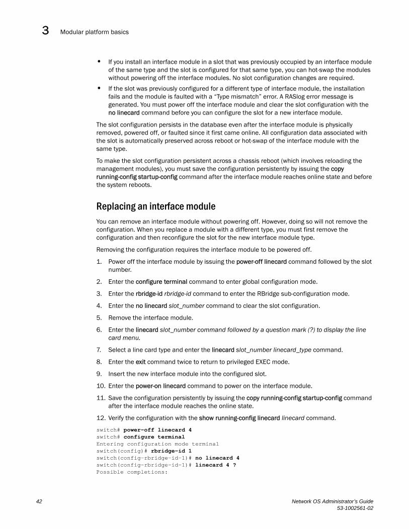
Modular platform basics3
• If you install an interface module in a slot that was previously occupied by an interface module of the same type and the slot is configured for that same type, you can hot-swap the modules without powering off the interface modules. No slot configuration changes are required.
• If the slot was previously configured for a different type of interface module, the installation fails and the module is faulted with a “Type mismatch” error. A RASlog error message is generated. You must power off the interface module and clear the slot configuration with the no linecard command before you can configure the slot for a new interface module.
The slot configuration persists in the database even after the interface module is physically removed, powered off, or faulted since it first came online. All configuration data associated with the slot is automatically preserved across reboot or hot-swap of the interface module with the same type.
To make the slot configuration persistent across a chassis reboot (which involves reloading the management modules), you must save the configuration persistently by issuing the copy running-config startup-config command after the interface module reaches online state and before the system reboots.
Replacing an interface module You can remove an interface module without powering off. However, doing so will not remove the configuration. When you replace a module with a different type, you must first remove the configuration and then reconfigure the slot for the new interface module type.
Removing the configuration requires the interface module to be powered off.
1. Power off the interface module by issuing the power-off linecard command followed by the slot number.
2. Enter the configure terminal command to enter global configuration mode.
3. Enter the rbridge-id rbridge-id command to enter the RBridge sub-configuration mode.
4. Enter the no linecard slot_number command to clear the slot configuration.
5. Remove the interface module.
6. Enter the linecard slot_number command followed by a question mark (?) to display the line card menu.
7. Select a line card type and enter the linecard slot_number linecard_type command.
8. Enter the exit command twice to return to privileged EXEC mode.
9. Insert the new interface module into the configured slot.
10. Enter the power-on linecard command to power on the interface module.
11. Save the configuration persistently by issuing the copy running-config startup-config command after the interface module reaches the online state.
12. Verify the configuration with the show running-config linecard linecard command.
switch# power-off linecard 4switch# configure terminalEntering configuration mode terminalswitch(config)# rbridge-id 1switch(config-rbridge-id-1)# no linecard 4switch(config-rbridge-id-1)# linecard 4 ?Possible completions:
42 Network OS Administrator’s Guide53-1002561-02

Modular platform basics 3
LC12x40G 12X40G linecardLC48x1G 48X1G linecardLC48x10G 48X10G linecardLC72x1G 72X1G linecard
switch(config-rbridge-id-1)# linecard 4 LC48x10GCreating new linecard configuration was successful.switch(config-rbridge-id-1)# exitswitch(config)# exitswitch# copy running-config startup-configswitch# show running-config rbridge-id 4 linecardrbridge-id 1
linecard 1 LC48x10Glinecard 4 LC48x10G
High availabilityHigh availability support in Network OS v3.0.0 is limited to configuration synchronization between redundant management modules alone. All system and protocol configurations are synchronized between the active and the standby management module.
Failover
If the chassis has two management modules and both are operating in redundant mode (that is, running the same firmware version), the standby management module takes over the control of the system in the event that the active management module should fail.
When the active management module fails over, the standby management module takes over as the active management module and goes through a cold recovery, during which all system components are reset and recovered. All switch fabric modules and interface modules are reset as well, resulting in traffic disruption.
At the end of the system initialization, all committed configurations are played back and the chassis becomes functional again.
If the chassis is part of a Brocade VCS Fabric and the active management module acts as the principal switch, a management module failover causes the principal switch to fail over as well and another node in the fabric will become the principal switch.
High availability commands
Non-disruptive failover is not supported in the Network OS v3.0.0 release and all recovery is cold recovery. The ha commands are provided for consistency and future expansion only. These commands are available on the switch in privileged EXEC mode.
• Use the show ha command to display the management module status.
switch# show ha Local (M2): Active, Cold RecoveredRemote (M1): Standby, HealthyHA enabled, Heartbeat Up, HA State synchronized
• Use the ha enable command to enable high availability on the switch. The ha disable command disables the feature.
• Use the ha failover command to force the active management module to fail over. The standby management module will take over as the active management module.
Network OS Administrator’s Guide 4353-1002561-02
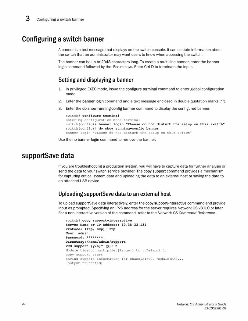
Configuring a switch banner3
Configuring a switch bannerA banner is a text message that displays on the switch console. It can contain information about the switch that an administrator may want users to know when accessing the switch.
The banner can be up to 2048 characters long. To create a multi-line banner, enter the banner login command followed by the Esc-m keys. Enter Ctrl-D to terminate the input.
Setting and displaying a banner1. In privileged EXEC mode, issue the configure terminal command to enter global configuration
mode.
2. Enter the banner login command and a text message enclosed in double quotation marks (“”).
3. Enter the do show running-config banner command to display the configured banner.
switch# configure terminalEntering configuration mode terminalswitch(config)# banner login “PLease do not disturb the setup on this switch”switch(config)# do show running-config bannerbanner login “PLease do not disturb the setup on this switch”
Use the no banner login command to remove the banner.
supportSave dataIf you are troubleshooting a production system, you will have to capture data for further analysis or send the data to your switch service provider. The copy support command provides a mechanism for capturing critical system data and uploading the data to an external host or saving the data to an attached USB device.
Uploading supportSave data to an external hostTo upload supportSave data interactively, enter the copy support-interactive command and provide input as prompted. Specifying an IPv6 address for the server requires Network OS v3.0.0 or later. For a non-interactive version of the command, refer to the Network OS Command Reference.
switch# copy support-interactiveServer Name or IP Address: 10.38.33.131Protocol (ftp, scp): ftpUser: adminPassword: ********Directory:/home/admin/supportVCS support [y/n]? (y): nModule timeout multiplier[Range:1 to 5.Default:1]: copy support startSaving support information for chassis:sw0, module:RAS...(output truncated)
44 Network OS Administrator’s Guide53-1002561-02

supportSave data 3
Saving supportSave data to an attached USB deviceYou can use a Brocade-branded USB device to save the support data. The Brocade-branded USB device comes with factory-configured default directories and interacts with the Network OS CLI.
1. Enter the usb on command to enable the USB device.
2. Enter the usb dir command to display the default directories.
3. Enter the copy support usb directory command.
switch# usb onUSB storage enabledswitch# usb dir firmwarekey\ 0B 2010 Aug 15 15:13support\ 106MB 2010 Aug 24 05:36support1034\ 105MB 2010 Aug 23 06:11config\ 0B 2010 Aug 15 15:13firmware\ 380MB 2010 Aug 15 15:13Available space on usbstorage 74%
switch# copy support usb directory support
Displaying the status of a supportSave operationEnter the show copy-support status command.
switch# show copy-support status
Slot Name SS type Completion Percentage######################################################M1 NORMAL [100%]L1/0 NORMAL [100%]L1/1 NORMAL [100%]L2/0 NORMAL [100%]L2/1 NORMAL [100%]L4/0 NORMAL [100%]L4/1 NORMAL [100%]
Configuring autoupload of supportSave dataYou can configure a switch to upload first-fault data capture (FFDC) and trace data files automatically to a remote server that is specifically set up for collecting supportSave information. To enable this feature, you must configure a dedicated server. As shown in the example, you use the autoupload enable command to configure a server and enable the feature with a single command.
switch# autoupload enable host 10.31.2.27 user supportadmin directory /users/support/ffdc_autoupload password *******Support auto file transfer enabled.
Network OS Administrator’s Guide 4553-1002561-02
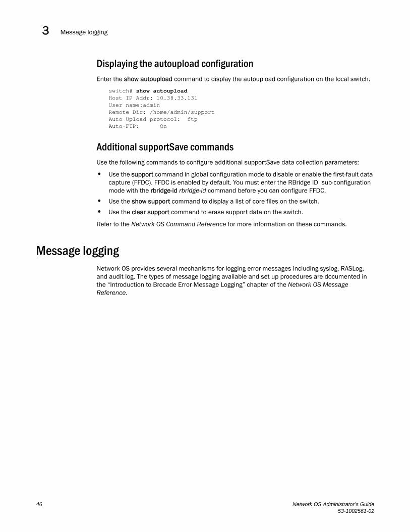
Message logging3
Displaying the autoupload configurationEnter the show autoupload command to display the autoupload configuration on the local switch.
switch# show autouploadHost IP Addr: 10.38.33.131 User name:adminRemote Dir: /home/admin/supportAuto Upload protocol: ftpAuto-FTP: On
Additional supportSave commandsUse the following commands to configure additional supportSave data collection parameters:
• Use the support command in global configuration mode to disable or enable the first-fault data capture (FFDC). FFDC is enabled by default. You must enter the RBridge ID sub-configuration mode with the rbridge-id rbridge-id command before you can configure FFDC.
• Use the show support command to display a list of core files on the switch.
• Use the clear support command to erase support data on the switch.
Refer to the Network OS Command Reference for more information on these commands.
Message loggingNetwork OS provides several mechanisms for logging error messages including syslog, RASLog, and audit log. The types of message logging available and set up procedures are documented in the “Introduction to Brocade Error Message Logging” chapter of the Network OS Message Reference.
46 Network OS Administrator’s Guide53-1002561-02

Network OS Administrator’s Guide53-1002561-02
Chapter
4
Network Time ProtocolIn this chapter•Date and time settings . . . . . . . . . . . . . . . . . . . . . . . . . . . . . . . . . . . . . . . . . . 47
•Time zone settings. . . . . . . . . . . . . . . . . . . . . . . . . . . . . . . . . . . . . . . . . . . . . . 48
•Network Time Protocol . . . . . . . . . . . . . . . . . . . . . . . . . . . . . . . . . . . . . . . . . . 49
Date and time settingsBrocade switches maintain the current date and time inside a battery-backed real-time clock (RTC) circuit. Date and time are used for logging events. Switch operation does not depend on the date and time; a switch with incorrect date and time settings can functions correctly. However, because the date and time are used for logging, error detection, and troubleshooting, you should set them correctly.
Setting the date and timeThe clock set command sets the local clock date and time. Valid date and time values must be in the range between January 1, 1970 and January 19, 2038. If a time zone is not configured, the time zone defaults to Greenwich Mean Time (GMT). If an active NTP server is configured for the switch, it overrides the local time settings.
Enter the clock set CCYY-MM-DDTHH:MM:SS command.
The variables represent the following values:
• CCYY specifies the year; the valid range is 1970 through 2038.
• MM specifies the month; the valid range is 01 through 12.
• DD specifies the day; the valid range is 01 through 31.
• HH specifies the hour; the valid range is 00 through 23.
• MM specifies the minutes; the valid range is 00 through 59.
• SS specifies the seconds; the valid range is 00 through 59.
Example of setting and displaying the date and time
switch# clock set 2011-09-17T12:15:00switch# show clockrbridge-id 1: 2012-05-04 16:01:51 Etc/GMT+0
47

Time zone settings4
Time zone settingsYou can set the time zone by specifying a geographic region and city by name. You can choose one of the following the regions: Africa, America, Pacific, Europe, Antarctica, Arctic, Asia, Australia, Atlantic, and Indian.
The time zone setting has the following characteristics:
• The setting automatically adjusts for Daylight Savings Time.
• Changing the time zone on a switch updates the local time zone setup and is reflected in local time calculations.
• By default, all switches are in the Greenwich Mean Time (GMT) time zone (0,0). If all switches in a fabric are in one time zone, it is possible for you to keep the time zone setup at the default setting.
• System services that have already started will reflect the time zone changes only after the next reboot.
• Time zone settings persist across failover for high availability.
• Time zone settings are not affected by NTP server synchronization.
Setting the time zoneUse the clock timezone command to set the time zone for a switch. You must use the command for all switches for which a time zone must be set. However, you only need to set the time zone once on each switch because the value is written to nonvolatile memory.
Refer to refer to Appendix B, “Supported time zones and regions” for a complete list of configurable regions and cities.
Enter the clock timezone region/city command.
switch# clock timezone America/Los_Angeles
NOTEAfter upgrading your switch firmware, you may need to reconfigure the time zone information.
Displaying the current local clock and time zoneThe show clock command returns the local time, date, and time zone.
NOTEThis command is currently supported on the local switch
Enter the show clock command.
switch# show clockrbridge-id 1: 2012-05-04 16:01:51 America/Los Angeles
Removing the time zone settingUse the no clock timezone command to remove the time zone setting for the local clock. This operation returns the local time zone to the default value (GMT).
48 Network OS Administrator’s Guide53-1002561-02

Network Time Protocol 4
Enter the no clock timezone command.
switch# no clock timezone
Network Time Protocol Network Time Protocol (NTP) maintains uniform time across all switches in a network. The NTP commands support the configuration of an external time server to maintain synchronization between all local clocks in a network.
To keep the time in your network current, it is recommended that each switch have its time synchronized with at least one external NTP server. External NTP servers should be synchronized among themselves in order to maintain fabric-wide time synchronization.
All switches in the fabric maintain the current clock server value in nonvolatile memory. By default, this value is the local clock server of the switch.
NOTENetwork Time Protocol (NTP) commands must be configured on each individual switch. Network time synchronization is guaranteed only when a common external time server is used by all switches.
The ntp server command accepts up to five server addresses in IPv4 or IPv6 format. When you configure multiple NTP server addresses, the ntp server command sets the first obtainable address as the active NTP server. If there are no reachable time servers, then the local switch time is the default time until a new active time server is configured.
Synchronizing the local time with an external sourceUse the ntp server command to synchronize the local switch time with an NTP server. You can configure up to five IP address. At least one IP address in the list must be a reachable, configured NTP server or the request will fail.
Enter the ntp server ip_address command.
switch(config)# ntp server 192.168.10.1
Displaying the active NTP server Use the show ntp status command to display the current active NTP server IP address. If an NTP server is not configured are or the server is unreachable, the command displays LOCL (for local switch time. The command displays the local NTP server configuration only.
NOTESpecifying all returns only local information.
Enter the show ntp status command.
switch# show ntp status active ntp server is 192.168.10.1
Network OS Administrator’s Guide 4953-1002561-02
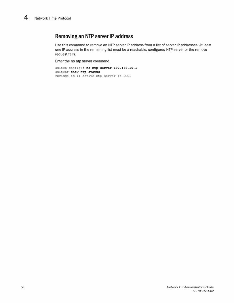
Network Time Protocol4
Removing an NTP server IP addressUse this command to remove an NTP server IP address from a list of server IP addresses. At least one IP address in the remaining list must be a reachable, configured NTP server or the remove request fails.
Enter the no ntp server command.
switch(config)# no ntp server 192.168.10.1switch# show ntp statusrbridge-id 1: active ntp server is LOCL
50 Network OS Administrator’s Guide53-1002561-02

Network OS Administrator’s Guide53-1002561-02
Chapter
5
Configuration ManagementIn this chapter•Switch configuration overview . . . . . . . . . . . . . . . . . . . . . . . . . . . . . . . . . . . . 51
•Flash file management . . . . . . . . . . . . . . . . . . . . . . . . . . . . . . . . . . . . . . . . . . 51
•Configuration file types . . . . . . . . . . . . . . . . . . . . . . . . . . . . . . . . . . . . . . . . . . 53
•Saving configuration changes . . . . . . . . . . . . . . . . . . . . . . . . . . . . . . . . . . . . 54
•Configuration backup . . . . . . . . . . . . . . . . . . . . . . . . . . . . . . . . . . . . . . . . . . . 56
•Configuration restoration . . . . . . . . . . . . . . . . . . . . . . . . . . . . . . . . . . . . . . . . 56
•Configuration management on a modular chassis . . . . . . . . . . . . . . . . . . . . 58
•Configuration management in Brocade VCS Fabric mode . . . . . . . . . . . . . . 59
Switch configuration overviewMaintaining consistent configuration settings among switches in the same fabric is an important part of switch management and minimizes fabric disruptions. As part of standard maintenance procedures, it is recommended that you back up all important configuration data for every switch on an external host for emergency reference.
Typical configuration management tasks include the following actions:
• Saving the running configuration to the startup configuration file (“Saving configuration changes” on page 54).
• Uploading the configuration files to a remote location (“Configuration backup” on page 56).
• Restoring a configuration file from a remote archive (“Configuration restoration” on page 56).
• Archiving configuration files for all your switches to a remote location (“Configuration management in Brocade VCS Fabric mode” on page 59).
• Downloading a configuration file from a remote location to multiple switches (“Configuration management in Brocade VCS Fabric mode” on page 59).
Flash file managementBrocade Network OS provides a set of tools for removing, renaming, and displaying files you create in the switch flash memory. You can use the display commands with any file, including the system configuration files. The rename and delete commands only apply to copies of configuration files you create in the flash memory. You cannot rename or delete any of the system configuration files.
51

Flash file management5
Listing the contents of the flash memoryTo list the contents of the flash memory, enter the dir command in the privileged EXEC mode.
switch# dirdrwxr-xr-x 2 root sys 4096 Feb 13 00:39 .drwxr-xr-x 3 root root 4096 Jan 1 1970 ..-rwxr-xr-x 1 root sys 417 Oct 12 2010 defaultconfig.novcs-rwxr-xr-x 1 root sys 697 Oct 12 2010 defaultconfig.vcs-rw-r--r-- 1 root root 6800 Feb 13 00:37 startup-config
Deleting a file from the flash memoryTo delete a file from the flash memory, enter the delete file command in the privileged EXEC mode.
switch# delete myconfig
Renaming a fileTo rename a file in the flash memory, enter the rename source_file destination_file command in the privileged EXEC mode.
switch# rename myconfig myconfig_20101010
Viewing the contents of a file in the flash memoryTo investigate the contents of a file in the flash memory, enter the show file file command in the privileged EXEC mode
switch# show file defaultconfig.novcs!no protocol spanning-tree!vlan dot1q tag native!
cee-map defaultremap fabric-priority priority 0remap lossless-priority priority 0priority-group-table 1 weight 40 pfc onpriority-group-table 2 weight 60 pfc offpriority-group-table 15.0 pfc offpriority-table 2 2 2 1 2 2 2 15.0
!interface Vlan 1shutdown!port-profile defaultvlan-profileswitchportswitchport mode trunkswitchport trunk allowed vlan all
!protocol lldp!end!
52 Network OS Administrator’s Guide53-1002561-02
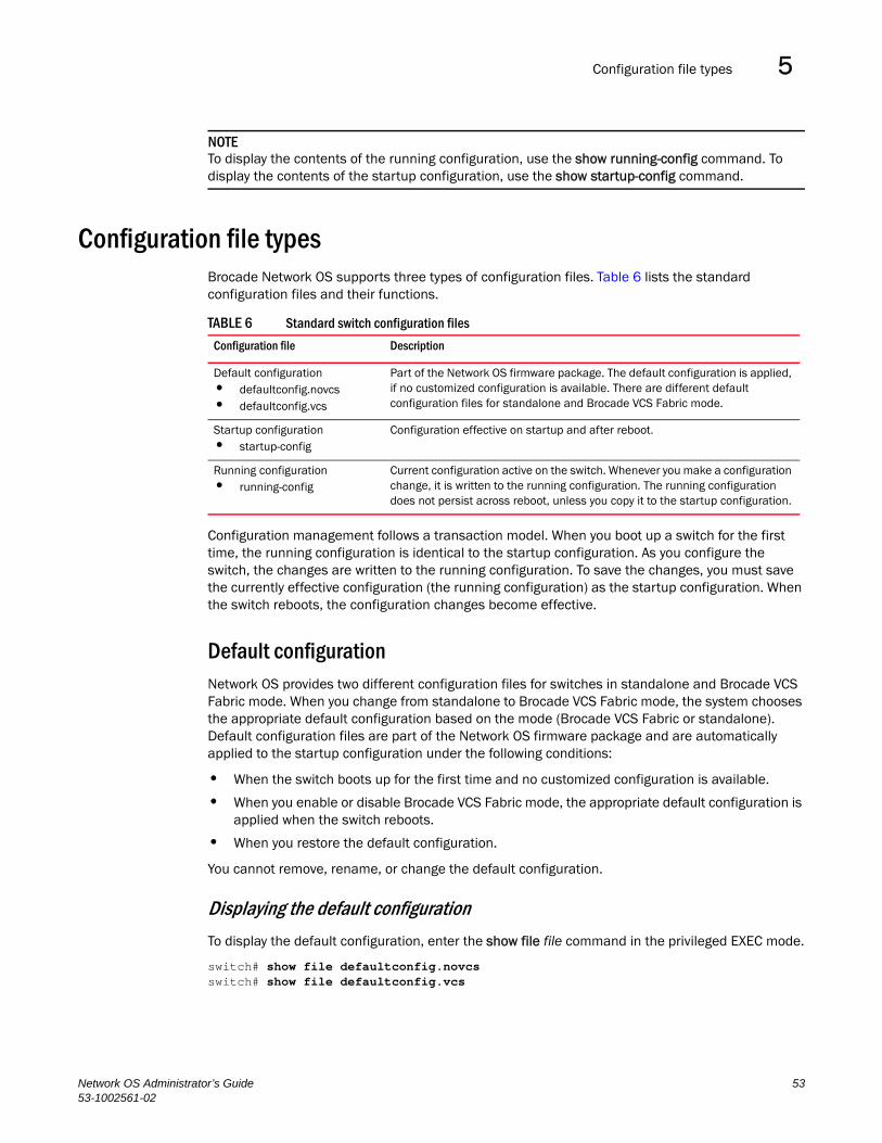
Configuration file types 5
NOTETo display the contents of the running configuration, use the show running-config command. To display the contents of the startup configuration, use the show startup-config command.
Configuration file typesBrocade Network OS supports three types of configuration files. Table 6 lists the standard configuration files and their functions.
Configuration management follows a transaction model. When you boot up a switch for the first time, the running configuration is identical to the startup configuration. As you configure the switch, the changes are written to the running configuration. To save the changes, you must save the currently effective configuration (the running configuration) as the startup configuration. When the switch reboots, the configuration changes become effective.
Default configurationNetwork OS provides two different configuration files for switches in standalone and Brocade VCS Fabric mode. When you change from standalone to Brocade VCS Fabric mode, the system chooses the appropriate default configuration based on the mode (Brocade VCS Fabric or standalone). Default configuration files are part of the Network OS firmware package and are automatically applied to the startup configuration under the following conditions:
• When the switch boots up for the first time and no customized configuration is available.
• When you enable or disable Brocade VCS Fabric mode, the appropriate default configuration is applied when the switch reboots.
• When you restore the default configuration.
You cannot remove, rename, or change the default configuration.
Displaying the default configuration
To display the default configuration, enter the show file file command in the privileged EXEC mode.
switch# show file defaultconfig.novcsswitch# show file defaultconfig.vcs
TABLE 6 Standard switch configuration files
Configuration file Description
Default configuration• defaultconfig.novcs• defaultconfig.vcs
Part of the Network OS firmware package. The default configuration is applied, if no customized configuration is available. There are different default configuration files for standalone and Brocade VCS Fabric mode.
Startup configuration• startup-config
Configuration effective on startup and after reboot.
Running configuration• running-config
Current configuration active on the switch. Whenever you make a configuration change, it is written to the running configuration. The running configuration does not persist across reboot, unless you copy it to the startup configuration.
Network OS Administrator’s Guide 5353-1002561-02

Saving configuration changes5
Startup configurationThe startup configuration is persistent. It is applied when the system reboots.
• When the switch boots up for the first time, the switch uses the default configuration as the startup configuration, depending on the mode.
• The startup configuration always matches the current Brocade VCS Fabric mode. It is deleted when you change modes, unless you make a backup copy.
• When you make configuration changes to the running configuration and save the changes to the startup configuration with the copy command, the running configuration becomes the startup configuration.
Displaying the startup configuration
To display the contents of the startup configuration, enter the show startup-config command in the privileged EXEC mode.
switch# show startup-config
Running configurationThe configuration currently effective on the switch is referred to as the running configuration. Any configuration change you make while the switch is online is made to the running configuration.
• The running configuration is nonpersistent.
• To save configuration changes, you must copy the running configuration to the startup configuration. If you are not sure about the changes, you can copy the changes to a file, and apply the changes later.
Displaying the running configuration
To display the contents of the running configuration, enter the show running-config command in the privileged EXEC mode.
switch# show running-config
Saving configuration changesConfiguration changes are nonpersistent and are lost on reboot unless you save them permanently. You have two options for saving configuration changes:
• Copy the running configuration to the startup configuration. The changes become effective upon reboot.
• Copy the running configuration to a file, and apply it at some later date.
NOTEAlways make a backup copy of your running configuration before you upgrade or downgrade the firmware.
54 Network OS Administrator’s Guide53-1002561-02

Saving configuration changes 5
Saving the running configurationTo save the configuration changes you made, copy the running configuration to the startup configuration. The next time the switch reboots, it uses the startup configuration and the changes you made earlier become effective.
Enter the copy running-config startup-config command in the privileged EXEC mode.
switch# copy running-config startup-configcopy running-config startup-configThis operation will modify your startup configuration. Do you want to continue? [Y/N]: y
Saving the running configuration to a fileIf you want to save the changes you made to the configuration, but you do not want the changes to take effect when the switch reboots, you can save the running configuration to a file. You can apply the changes at some later time.
1. Enter the copy running-config file command in the privileged EXEC mode. Specify the file name as the file URL.
switch# copy running-config flash://myconfig
2. Verify the transaction by listing the directory contents.
switch# dirtotal 32drwxr-xr-x 2 root sys 4096 Feb 17 17:50 .drwxr-xr-x 3 root root 4096 Jan 1 1970 ..-rwxr-xr-x 1 root sys 417 Oct 12 2010 defaultconfig.novcs-rwxr-xr-x 1 root sys 697 Oct 12 2010 defaultconfig.vcs-rw-r--r-- 1 root root 6777 Feb 17 17:50 myconfig-rw-r--r-- 1 root root 6800 Feb 13 00:37 startup-config
Applying previously saved configuration changesWhen you are ready to apply the configuration changes you previously saved to a file, copy the file (myconfig in the example) to the startup configuration. The changes take effect after the switch reboots.
Enter the copy file startup-config command in the privileged EXEC mode. Specify the file name as the file URL.
switch# copy flash://myconfig startup-configThis operation will modify your startup configuration. Do you want to continue? [Y/N]: y
Network OS Administrator’s Guide 5553-1002561-02

Configuration backup5
Configuration backupAlways keep a backup copy of your configuration files, so you can restore the configuration in the event the configuration is lost or you make unintentional changes. The following recommendations apply:
• Keep backup copies of the startup configuration for all switches in the fabric.
• Upload the configuration backup copies to an external host or to an attached Brocade-branded USB device.
• Avoid copying configuration files from one switch to another. Instead restore the switch configuration files from the backup copy.
Uploading the startup configuration to an external hostEnter the copy startup-config destination_file command in the privileged EXEC mode.
In the following example, the startup configuration is copied to a file on a remote server using FTP.
switch# copy startup-config ftp://admin:******@122.34.98.133//archive/startup-config_vdx24-08_20101010
Backing up the startup configuration to a USB deviceWhen you make a backup copy of a configuration file on an attached USB device, the destination file is the file URL on the USB device. You do not need to specify the target directory. The file is automatically recognized as a configuration file and stored in the default configuration directory.
1. Enable the USB device.
switch# usb onUSB storage enabled
2. Enter the copy startup-config destination_file command in the privileged EXEC mode.
switch# copy startup-config usb://startup-config_vdx24-08_20101010
Configuration restorationRestoring a configuration involves overwriting a given configuration file on the switch by downloading an archived backup copy from an external host or from an attached USB device. There are two typical scenarios.
• “Restoring a previous startup configuration from backup” on page 57.
• “Restoring the default configuration” on page 57.
NOTEConfiguration files that were created using Brocade Network OS 2.x should not be loaded onto a system running Brocade Network OS 3.x. The ACL and VLAN configuration information has changed in Brocade Network OS 3.x, and the affected lines of configuration are skipped when loading a Brocade Network OS 2.x configuration file.
56 Network OS Administrator’s Guide53-1002561-02

Configuration restoration 5
Restoring a previous startup configuration from backup• You want to back out of configuration changes you made earlier by overwriting the startup
configuration with a modified running configuration.
• You want to take the switch from Brocade VCS Fabric mode back to standalone mode and reapply your original standalone startup configuration.
1. Disable Brocade VCS Fabric mode and reboot the switch.
The startup configuration associated with Brocade VCS Fabric mode is automatically deleted. The switch boots up in standalone mode and loads the corresponding default configuration.
2. Copy the archived startup configuration file from an FTP server or from an attached USB device to the running configuration.
3. Reboot the switch.
switch# no vcs enable
The switch automatically reboots at this point.
switch# copy ftp://admin:******@122.34.98.133//archive/\ startup-config_vdx24-08_20101010 running-configswitch# copy running-config startup-config
ATTENTIONMake sure that the configuration file you are downloading is the one that belongs to the switch you want to restore. It is a good idea to identify archived configuration files by switch name and date.
Restoring the default configurationThis restoration procedure resets the configuration to the factory defaults. The default configuration files for Brocade VCS Fabric and standalone mode are always present on the switch and can be restored with the copy command.
To restore the default configuration, perform the following procedure in privileged EXEC mode
1. Enter the copy source_file destination_file command to overwrite the startup configuration with the default configuration.
switch# copy flash://default-config.novcs startup-configThis operation will modify your startup configuration. Do you want to continue? [Y/N]: y
2. Reboot the switch:
switch# reload
The configuration restoration operation behaves differently depending on whether the switch is in standalone mode or part of a Brocade VCS Fabric.
In standalone mode, all interfaces are shut down. When the switch comes back up, the restored default configuration is used. The following parameters are unaffected by this command:
• Interface management IP address
• Software feature licenses installed on the switch
Network OS Administrator’s Guide 5753-1002561-02
Configuration management on a modular chassis5
In VCS Fabric mode, all interfaces remain online. The following parameters are unaffected by this command:
• Interface management IP address
• Software feature licenses installed on the switch
• Virtual IP address
Configuration management on a modular chassisThe configuration data on a modular chassis is managed in a distributed fashion. The Brocade VDX 8770-4 and VDX 8770-8 chassis maintain two types of configuration data, global configuration parameters and slot configuration parameters. The global configuration, such as the VLAN configuration, applies to the entire chassis. The slot configuration includes specific parameters that apply only to the interface modules.
The startup configuration is maintained at the chassis level and includes both chassis-wide and slot-specific configuration parameters.
Configuration management on interface modulesWhen an interface module (line card) boots up in a slot which was never occupied previously or is not configured, the module type is automatically saved in the configuration database. The type configuration associated with a given slot persists in the database even after the interface module is physically removed, powered off, or faulted. This mechanism ensures that all configuration data associated with a given slot is automatically preserved across reboots or hot swaps with the same type of interface module.
If you insert an interface module in a slot that was previously occupied by a module of a different type, the interface module will be faulted with a “type mismatch” error. Before you replace an interface module with a different type, you must clear the existing type configuration from the database. Refer to “Replacing an interface module” in Chapter 3, “Basic Switch Management” for more information.
NOTEThe interface module configuration is non-persistent. You must issue the copy running-config startup-config command after the interface module comes online. Otherwise, all configuration data associated with the slot along with line module type will be lost after a chassis reboot.
Configuration management in redundant management modulesIn modular switches with redundant management modules, the VCS configuration, the startup configuration, and the startup database are synchronized and shared between the two management modules. The initial configuration synchronization occurs when the system boots up. After the initial synchronization has been completed successfully, synchronization can be triggered during the following events:
• When a failover occurs from the active management module to the standby management module. Unsaved configuration changes made on the active management module are lost after a failover. Issue the copy running-config startup-config command on the active management module to preserve the running configuration across a management module failover.
58 Network OS Administrator’s Guide53-1002561-02

Configuration management in Brocade VCS Fabric mode 5
• When you insert a standby management module into a chassis after the active management module is already fully initialized.
• When you change the startup configuration by issuing the copy running-config startup-config command on the active management module.
• When you restore the default configuration by issuing the copy default-config startup-config command on the active management module.
• When you change the VCS configuration (VCS mode, RBridge ID, or VCS ID), the configuration change is synchronized with the standby management module and saved persistently. This event triggers a chassis reboot after the synchronization is complete.
• When you initiate a firmware download. Refer to Chapter 6, “Installing and Maintaining Firmware” for more information.
Configuration management in Brocade VCS Fabric modeWith the exception of a few parameters, configuration changes you make to a single switch in a Brocade VCS Fabric are not automatically distributed. When configuring Ethernet fabric parameters and software features on multiple switches, you must configure each switch individually. To simplify the procedure, you can upload a configuration file from one switch and download it to the other switches in the fabric, provided the switches are of the same type.
NOTEThe switches must be of the same model to share a configuration file. For example, downloading a configuration file from a Brocade VDX 6720-24 to a Brocade VDX 6720-60 or to a switch with a different firmware version may cause the switch to misapply the configuration and lead to unpredictable behavior.
To determine the switch type, issue the show system command. To map the switch type to the Brocade switch model name, refer to “Switch types”in Chapter 3, “Basic Switch Management”.
If you need to reset affected switches, restore the default configuration as described in “Restoring the default configuration” on page 57.
Downloading a configuration to multiple switches1. Configure one switch.
2. Copy the running configuration to the startup configuration as described in “Saving the running configuration” on page 55.
3. Upload the configuration to an external host (“Uploading the startup configuration to an external host” on page 56) or to an attached USB device as described in “Backing up the startup configuration to a USB device” on page 56.
4. Download the configuration file to each of the target switches. Refer to “Configuration restoration” on page 56 for more information.
Network OS Administrator’s Guide 5953-1002561-02

Configuration management in Brocade VCS Fabric mode5
Automatic distribution of configuration parametersA few configuration parameters are fabric-wide. This means they are automatically distributed to all switches in a VCS Fabric when you configure one or more of these parameters on a single RBridge that is part of a VCS fabric. These parameters include the following:
• Zoning configuration
• vCenter parameters
• Virtual IP address
The show running configuration command displays the same configuration for these features on all RBridge in the VCS fabric. Copy operations from any RBridge include all fabric-wide configuration parameters.
60 Network OS Administrator’s Guide53-1002561-02
Network OS Administrator’s Guide53-1002561-02
Chapter
6
Installing and Maintaining FirmwareIn this chapter•Firmware upgrade overview . . . . . . . . . . . . . . . . . . . . . . . . . . . . . . . . . . . . . . 61
•Preparing for a firmware download . . . . . . . . . . . . . . . . . . . . . . . . . . . . . . . . 64
•Downloading the firmware from a remote server . . . . . . . . . . . . . . . . . . . . . 66
•Downloading firmware from a USB device. . . . . . . . . . . . . . . . . . . . . . . . . . . 67
•Evaluating a firmware upgrade. . . . . . . . . . . . . . . . . . . . . . . . . . . . . . . . . . . . 68
•Firmware upgrade in Brocade VCS Fabric mode. . . . . . . . . . . . . . . . . . . . . . 70
•Error handling . . . . . . . . . . . . . . . . . . . . . . . . . . . . . . . . . . . . . . . . . . . . . . . . . 70
Firmware upgrade overviewBrocade firmware upgrades consist of multiple firmware packages listed in a .plist file. The .plist file contains specific firmware information (time stamp, platform code, version, and so forth) and the names of the firmware packages to be downloaded. These packages are made available periodically to add features or to remedy defects in the firmware.
Starting with Network OS 3.0.0, firmware upgrade is performed incrementally. The firmware download command compares the new firmware packages against the current installation and only downloads the packages that contain new features or have been modified.
You can download the firmware from a remote server using the File Transfer Protocol (FTP) or the Secure Copy Protocol (SCP), or you can download the firmware from an attached Brocade-branded USB device.
Brocade Network OS provides a single command line interface (CLI) to download firmware to a compact switch with a single control processor or to a modular chassis with two management modules. If the firmware download process is interrupted by an unexpected reboot, Network OS will make an attempt to recover the previously installed firmware. Success depends on the state of the firmware download. You must wait for the recovery to complete before initiating another firmware download.
ATTENTIONInstalling Network OS is disruptive to services and any unsaved running configuration will be lost during the installation.
61

Firmware upgrade overview6
Upgrading firmware on a compact switchAll Brocade compact switches maintain two partitions of nonvolatile storage areas, a primary and a secondary, to store two firmware images. The following steps describe the default behavior after you enter the firmware download command (without options) on a compact switch with a single control processor. The procedure applies to all Brocade VDX compact switches.
1. The Network OS downloads the firmware to the secondary partition.
2. The switch swaps partitions and performs a reboot. After the system comes back up, the former secondary partition is the primary partition.
3. The system copies the firmware from the primary to the secondary partition and commits the new firmware.
The upgrade process first downloads and then commits the firmware. Use the show firmwaredownloadstatus command to monitor the upgrade progress.
Upgrading firmware on a modular chassisWhen you initiate a firmware download on a modular chassis, Network OS upgrades the firmware image on both management modules and automatically propagates the firmware to each interface module (line card). This process is referred to as auto-leveling. At the end of the auto-leveling process, the active management module and the interface modules run the same version of the firmware and the firmware is committed.
The following steps describe the default behavior of the firmware download command on a Brocade VDX 8770 chassis with two redundant management modules.
1. The standby management module downloads the firmware to its secondary partition.
2. The active management module synchronizes its secondary partition with the secondary partition of the standby management module.
3. The management modules swap partitions so that the new firmware can be activated during a subsequent reboot.
4. The standby management module reboots. When it comes back up, the secondary partition becomes the primary partition and activates the new image.
5. The active management module synchronizes its state with the standby management module.
6. The active management module forces a failover and reboots, and the standby management module takes over as the new active management module. The failover involves a “cold” reboot of the management modules and is disruptive.
7. The new active management module starts the auto-leveling process, which loads the firmware on each of the interface modules. Each of the interface modules reboots during this process.
8. The new active management module synchronizes its state with the new standby management module.
9. The firmware is automatically committed on both management modules.
During a firmware upgrade, the auto-leveling process takes place on all interface modules in parallel. The same process takes place when you hot-swap an interface module. The system automatically upgrades the firmware if it detects a different firmware on the newly inserted interface module.
62 Network OS Administrator’s Guide53-1002561-02

Firmware upgrade overview 6
Automatic firmware synchronization
When you replace a management module or insert a second management module into a chassis, the active management module automatically synchronizes the hot-plugged standby management module with the same firmware version. The standby management module reboots with the upgraded firmware. The automatic firmware synchronization takes place only if all of the following conditions are met:
• The standby management module is inserted while the chassis is up (hot-plugged insert).
• There was no firmware download process running when the standby management module was inserted.
Upgrading and downgrading firmwareIn most cases, you will be upgrading firmware by installing a more recent firmware version than the one you are currently running. However, some circumstances may require that you downgrade the firmware to an earlier version. The procedures described in the following section assume that you are upgrading firmware, but they work for downgrading as well, provided that the firmware version you are downgrading to is compatible with the version you are currently running. Table 7 displays supported firmware versions by platform..
Brocade does not support upgrades from more than one previous release. For example, upgrading from Network OS v2.1.0 to v3.0.0 is supported, but upgrading from Network OS v2.0.0 directly to v3.0.0 is not supported, because there is another release between the two. In other words, upgrading a switch from Network OS v2.0.0 to v3.0.0 is a two-step process; you must first upgrade from v2.0.0 to v2.1.0 and then to v3.0.0. When upgrading, to the next patch release, choose the latest patch available for that release (for example, v2.1.0c).
Always refer to the release notes for compatibility information and take note of restrictions that may exist regarding upgrades and downgrades under particular circumstances.
TABLE 7 Network OS firmware support by platform
Platform NOS v2.0.0 NOS v2.1.0 NOS v2.1.1 NOS v3.0.0
Brocade VDX 6710 no yes yes yes
Brocade VDX 6720 yes yes yes yes
Brocade VDX 6730 no yes yes yes
Brocade VDX 8770 no no no yes
Network OS Administrator’s Guide 6353-1002561-02

Preparing for a firmware download6
Preparing for a firmware downloadTo prepare for a firmware download, perform the tasks listed in this section. In the unlikely event of a failure or timeout, you will be able to provide your switch support provider the information required to troubleshoot the firmware download.
NOTEFor standalone switches , the inband management using ‘interface vlan’ is no longer supported in Brocade NOS v3.0.0 or higher. Instead, the VE interface needs to be configured the switch is upgraded. If the vlan interface is cuurently being used, Brocade recommends you upgrade using a console connection OR out-of-band connection, and then change the configuration to use VE interface for inband management at a later time. For more information, refer to “Configuring a standalone in-band management interface” on page 415.
1. Verify the current firmware version. Refer to “Obtaining the firmware version” on page 64 for details.
2. Decide on a migration path. Check the connected devices to ensure firmware compatibility and that any older versions are supported. Refer to the Network OS Compatibility section of the Brocade Network OS Release Notes for the recommended firmware version.
3. Back up your switch configuration prior to the firmware download. Refer to Chapter 5, “Configuration Management” for details.
4. Optional: For additional support, connect the switch to a computer with a serial console cable. Ensure that all serial consoles and any open network connection sessions, such as Telnet, are logged and included with any trouble reports.
5. Enter the copy support command to collect all current core files prior to executing the firmware download. This information helps to troubleshoot the firmware download process in the event of a problem.
6. Optional: Enter the clear logging raslog command to erase all existing messages in addition to internal messages.
ATTENTIONIn the Network OS 3.0.0 release, the firmware download command is supported on the local switch only. To upgrade all switches in the fabric, refer to “Firmware upgrade in Brocade VCS Fabric mode” on page 70.
Obtaining the firmware versionEnter the show version command with the all-partitions option to obtain the firmware version for both primary and secondary partitions of each module.
switch# show version all-partitions
Network Operating System SoftwareNetwork Operating System Version: 3.0.0Copyright (c) 1995-2012 Brocade Communications Systems, Inc.Firmware name: NOS_v3.0.0Build Time: 16:33:57 Jan 31, 2012Install Time: 10:44:48 Feb 2, 2012Kernel: 2.6.34.6BootProm: 1.0.0
64 Network OS Administrator’s Guide53-1002561-02

Preparing for a firmware download 6
Control Processor: e500mc with 7168 MB of memory
Slot Name Primary/Secondary Versions Status---------------------------------------------------------------------------M1 NOS NOS_v3.0.0 ACTIVE*
NOS_v3.0.0M2 NOS NOS_v3.0.0 STANDBY
NOS_v3.0.0L1/0 NOS NOS_v3.0.0 ACTIVE
NOS_v3.0.0L1/1 NOS NOS_v3.0.0 STANDBY
NOS_v3.0.0
Obtaining and decompressing firmwareFirmware upgrades are available for customers with support service contracts and for partners on the Brocade website at http://www.mybrocade.com.
You must download the firmware package either to an FTP server or to a USB device and decompress the package before you can use the firmware download command to upgrade the firmware on your equipment. Use the UNIX tar command for .tar files, the gunzip command for all .gz files, or a Windows unzip program for all .zip files.
When you unpack the downloaded firmware, it expands into a directory that is named according to the firmware version. When issued with the path to the directory where the firmware is stored, the firmware download command performs an automatic search for the correct package file type associated with the device.
Connecting to the switchWhen you upgrade firmware in default mode, you connect to the switch through the management IP address. Modular switches have one management IP address for the chassis and separate IP addresses for each management module. To upgrade both management modules, you can either connect to the chassis management IP address or to the IP address of the active management module. If you want to upgrade a single management module only, you must connect to the IP address of that management module and run the firmware download command in manual mode. In manual mode, only the local management module is upgraded.
Use the show system command to display the management IP address for the chassis.
switch# show systemStack MAC : 00:05:33:15:FA:70
-- UNIT 0 --Unit Name : sw0Switch Status : OnlineHardware Rev : 1000.0TengigabitEthernet Port(s) : 56Up Time : up 8:38Current Time : 16:39:56 GMTNOS Version : 3.0.0Jumbo Capable : yesBurned In MAC : 00:05:33:15:FA:70Management IP : 10.24.73.131 <== Chassis Management IP addressManagement Port Status : UP
Network OS Administrator’s Guide 6553-1002561-02

Downloading the firmware from a remote server6
Use the show interface Management command to display the IP addresses for the management modules.
switch# show interface Managementinterface Management 10/1 ip address 10.24.73.130/20 ip gateway-address 10.24.64.1 ipv6 ipv6-address [ ] ipv6 ipv6-gateways [ ] line-speed actual "1000baseT, Duplex: Full" line-speed configured Autointerface Management 10/2 ip address 10.24.74.23/20 ip gateway-address 10.24.64.1 ipv6 ipv6-address [ ] ipv6 ipv6-gateways [ ] line-speed actual "1000baseT, Duplex: Full" line-speed configured Auto
Downloading the firmware from a remote serverUnder normal circumstances, Brocade recommends you run the firmware download command in default mode. Do not disable the auto-commit mode unless you want to evaluate a firmware upgrade before committing to it. Refer to “Evaluating a firmware upgrade” on page 68 for details about overriding the auto-commit mode.
CAUTION
Do not interrupt the firmware download process. If you encounter a problem, wait for the timeout (30 minutes for network problems) before issuing the firmware download command again. Disrupting the process (for example, by disconnecting the switch from the power source) can render the switch inoperable and may require you to seek help from your switch service provider.
When upgrading multiple switches, complete the following steps on each switch before you upgrade the next one.
1. Perform the steps described in “Preparing for a firmware download” on page 64.
2. Verify that the FTP or SSH server is running on the remote server and that you have a valid user ID and password on that server.
3. Download the firmware package from the Brocade website to an FTP server.
To download the firmware from an attached USB device, refer to “Downloading firmware from a USB device” on page 67.
4. Decompress the firmware archive.
5. Connect to the switch or management module you are upgrading.
Refer to “Connecting to the switch” on page 65 for more information.
6. Issue the show version command to determine the current firmware version.
7. Enter the firmware download interactive command to download the firmware interactively. When promoted for input, choose defaults whenever possible.
66 Network OS Administrator’s Guide53-1002561-02

Downloading firmware from a USB device 6
NOTETo be able to mention the FTP server by name, a Domain Name System (DNS) entry must exist for the server.
8. At the “Do you want to continue [y/n]:” prompt, enter y.
9. While the upgrade is proceeding, you can start a separate CLI session on the switch and use the show firmwaredownloadstatus command to monitor the upgrade progress.
10. After the switch reboots, enter the show version command to verify the firmware upgrade.
The following example downloads firmware interactively on a modular switch using default options.
switch# firmware download interactiveServer name or IP address: 10.31.2.25File name: /users/home40/Builds/NOS_v3.0.0Protocol (ftp, scp): ftpUser: fvtPassword: **********Do manual download [y/n]: n
System sanity check passed.
Do you want to continue? [y/n]:y
Downloading firmware from a USB deviceThe Brocade VDX 6710, VDX 6720, and VDX 6730 switches, as well as the Brocade VDX 8770, support firmware download from a Brocade-branded USB device. You cannot use a third-party USB device. Before you can access the USB device, you must enable the device and mount it as a file system. The firmware images to be downloaded must be stored in the factory-configured firmware directory. Multiple images can be stored under this directory.
1. Ensure that the USB device is connected to the switch.
2. Enter the usb on command in privileged EXEC mode.
switch# usb onTrying to enable USB device. Please wait...USB storage enabled
3. Optional: Enter the usb dir command.
switch# usb dir firmwarekey\ 0B 2010 Aug 15 15:13support\ 106MB 2010 Aug 24 05:36config\ 0B 2010 Aug 15 15:13firmware\ 380MB 2010 Aug 15 15:13NOS_v3.0.0\ 379MB 2010 Aug 15 15:31Available space on usbstorage 74%
4. Enter the firmware download usb command followed by the relative path to the firmware directory.
switch# firmware download usb directory NOS_v3.0.0
5. Optional: Unmount the USB storage device.
switch# usb offTrying to disable USB device. Please wait...
Network OS Administrator’s Guide 6753-1002561-02

Evaluating a firmware upgrade6
USB storage disabled.
Evaluating a firmware upgrade
CAUTION
Because of potential compatibility issues, Brocade does not recommend restoring Network OS v2.1.x after you upgraded to Network OS v3.0.0.
You can restore a previous firmware version after downloading and evaluating a newer (or older) version by downloading the firmware to a single partition only. The previous version is preserved on the secondary partition and you can restore it with the firmware restore command.
• To enable firmware restoration on a compact switch, you run the firmware download command with the nocommit option. This option prevents the firmware download command from copying the firmware to both partitions and committing the upgrade.
• To enable firmware restoration on a modular switch with two management modules, you update the firmware on each of the management modules separately by issuing the firmware download command with both the manual option and the nocommit option. This command sequence preserves the previous firmware on the secondary partitions of all system components and ensures that you will be able to restore the previous firmware version.
ATTENTIONWhen you evaluate a firmware upgrade, make sure you disable all features that are supported only by the upgraded firmware before restoring the original version.
Downloading firmware to a single partitionThe following procedure applies to a compact switch or to single management module.
1. Verify that the FTP or SSH server is running on the host server and that you have a user ID on that server.
2. Obtain the firmware file from the Brocade website at http://www.mybrocade.com or from your switch support provider and store the file on the FTP or SSH server.
3. Unpack the compressed firmware archive.
4. Enter the show version command to view the current firmware version.
5. Enter the firmware download interactive command and respond to the prompts.
6. At the “Do Auto-Commit after Reboot [y/n]:” prompt, enter n.
switch# firmware download interactiveServer name or IP address: 10.31.2.25File name: /users/home40/Builds/hydra_plat_dev01Protocol (ftp, scp): ftpUser: fvtPassword: **********Do manual download [y/n]: yReboot system after download? [y/n]:yDo Auto-Commit after Reboot? [y/n]:n
68 Network OS Administrator’s Guide53-1002561-02

Evaluating a firmware upgrade 6
System sanity check passed.
You are running firmware download on dual MM system with 'manual' option. This will upgrade the firmware only on the local MM.
This command will cause a cold/disruptive reboot and will require that existing telnet, secure telnet or SSH sessions be restarted.
Do you want to continue? [y/n]:y(output truncated)
The switch performs a reboot and comes up with the new firmware. Your current CLI session will automatically disconnect.
7. Enter the show version all-partitions command to confirm that the primary partitions of the switch contain the new firmware.
You are now ready to evaluate the new version of firmware.
ATTENTIONIf you want to restore the firmware, stop here and refer to “Restoring the previous firmware version” on page 69; otherwise, continue to “Committing the firmware upgrade” on page 69 to complete the firmware download process.
Committing the firmware upgradeIf you decide to keep the firmware upgrade, use the firmware commit command to update the secondary partitions with the new firmware. On modular switches, you must run the firmware commit command on both management modules. It may take several minutes to complete the commit operation.
1. Enter the firmware commit command in the privileged EXEC mode.
switch# firmware commitValidating primary partition...Doing firmwarecommit now.Please wait ...Replicating kernel image...............FirmwareCommit completes successfully.
2. Enter the show version command with the all-partitions option.
Both partitions on the switch or on the modules should contain the new firmware.
Restoring the previous firmware versionUse the firmware restore command to back out of a firmware upgrade. This option works only if auto-commit mode was disabled during the firmware download. On modular switches, you must run the firmware restore command on both management modules.
NOTEThe firmware restore command is disruptive and reboots the management modules.
1. Enter the firmware restore command.
The switch swaps partitions, reboots, and comes up with the original firmware.
Network OS Administrator’s Guide 6953-1002561-02

Firmware upgrade in Brocade VCS Fabric mode6
The firmware commit operation copies the original firmware from the primary partition to the secondary partition. When the process completes, both partitions will have the original firmware. It may take several minutes to complete the operation.
2. Wait until all processes have completed and the switch is fully up and operational.
3. Enter the show version all partitions command and verify that all partitions on the switch have the original firmware.
Firmware upgrade in Brocade VCS Fabric modeThe firmware download command supports local switch upgrades only. To upgrade all switches in a VCS fabric, you must execute the firmware download command on each switch separately. For each switch in the fabric, complete the firmware download on the current switch before initiating a firmware download on another switch. This process minimizes traffic disruption.
Enter the show firmwaredownloadstatus command to verify that the download process is complete, and then move on to the next switch.
Error handlingIf the firmware download command fails while a management module is upgraded, the process aborts and the previous firmware is repaired on all modules and partitions.
If the firmware download command fails while an interface module is upgraded, the interface module is faulted, but the firmware download continues on the remaining interface modules.
If an interface module (line card) is faulted during a firmware download, issue the power-off linecard command followed by the power-on linecard command to power cycle the module. When the interface module comes back up, auto-leveling begins to upgrade the firmware.
When you insert an interface module into a chassis, the active management module checks the firmware version of the newly inserted module. If the interface module runs an older firmware version, the active management module initiates auto-leveling to upgrade the firmware on the newly inserted interface module.
70 Network OS Administrator’s Guide53-1002561-02

Network OS Administrator’s Guide53-1002561-02
Chapter
7
Administering LicensesIn this chapter•Licensing overview. . . . . . . . . . . . . . . . . . . . . . . . . . . . . . . . . . . . . . . . . . . . . . 71
•Permanent licenses. . . . . . . . . . . . . . . . . . . . . . . . . . . . . . . . . . . . . . . . . . . . . 73
•Temporary licenses . . . . . . . . . . . . . . . . . . . . . . . . . . . . . . . . . . . . . . . . . . . . . 73
•Managing licenses. . . . . . . . . . . . . . . . . . . . . . . . . . . . . . . . . . . . . . . . . . . . . . 75
•Dynamic Ports on Demand . . . . . . . . . . . . . . . . . . . . . . . . . . . . . . . . . . . . . . . 80
•Upgrade and downgrade considerations . . . . . . . . . . . . . . . . . . . . . . . . . . . . 85
Licensing overviewThe Brocade Network Operating System (Network OS) includes platform support in standalone and Brocade VCS Fabric modes as well as optional features that are enabled by license keys. You can purchase Brocade licenses per product or per feature. Each switch in a fabric must have its own licenses, but universal licenses for multiple switches are available for trial purposes along with individual trial licenses. Licenses may be part of the licensed paperpack supplied with your switch software, or you can purchase them separately from your switch vendor. Table 8 lists the license requirements by platform..
TABLE 8 Licenses requirements by platform
Platform 40Gb DCB ports
10Gb DCB ports
1Gb DCBports
8G FC ports
License type POD sets and sizes
Notes
Brocade VDX 6720-24
N/A 24 N/A N/A POD1, FCoE, VCS Fabric
16 + 8 Enabling VCS Fabric mode no longer requires a full POD licenses. Layer 3 features do not require a license.Brocade
VDX 6720-60N/A 60 N/A N/A POD1, POD2,
FCoE, VCS Fabric40 + 10 + 10
Brocade VDX 6710
N/A 6 48 N/A VCS Fabric N/A No POD license is required to enable DCB ports. FCoE licensees are not supported on this platform. Layer 3 features do not require a license.
Brocade VDX 6730-32
N/A 24 N/A 8 POD1, FCoE, VCS Fabric
16 + 8 (CEE ports)
FC ports require an FCoE license to be enabled (FC ports are not POD-controlled). Layer 3 features do not require a license.Brocade
VDX 6730-76N/A 60 N/A 16 POD1, POD2,
FCoE, VCS Fabric, Layer 3
40 + 10 + 10 (CEE ports)
71

Licensing overview7
Table 9 provides descriptive details for each license type.
Brocade VDX 8770-4
48 192 288 N/A FCoE, VCS Fabric, Layer 3, Advanced Services
N/A There are no POD-enabled ports on the VDX 8770 chassis.
Brocade VDX 8770-8
96 384 576 N/A FCoE, VCS Fabric, Layer 3, Advanced Services
N/A There are no POD-enabled ports on the VDX 8770 chassis.
TABLE 9 Brocade licenses for optional Network OS features
License Description
Dynamic Ports on Demand:• PORTS_ON_DEMAND_1• PORTS_ON_DEMAND_2
A Dynamic POD license allows you to instantly scale the fabric by provisioning additional Ethernet ports on the Brocade VDX 6720 and VDX 6730 platforms. Licenses are assigned dynamically from a pool of resources based on either auto-detection of active links or explicit port reservation by the user.
Brocade VCS Fabric• VCS_FABRIC
A Brocade VCS Fabric license allows you to provision a Brocade VCS Fabric with up to 24 nodes. You must install a Brocade VCS Fabric license on each node.A Brocade VCS Fabric license is required if your Brocade VCS Fabric includes more than two nodes. A switch with a Brocade VCS Fabric license cannot connect to a switch without such a license. In a two-node VCS, both switches must either have a VCS license, or no VCS license.FC router links do not affect Brocade VCS Fabric licensing. You can connect a switch to an FC router with or without a Brocade VCS Fabric license. FC router links and domains do not count against the two-switch limit for provisioning a VCS Fabric without a Brocade VCS Fabric license.
FCoE • FCOE_BASE
A Brocade FCoE license is required to enable Fibre Channel over Ethernet functionality. You can use this license on a single a switch, but the FCoE capabilities will be limited to that node only. In order to support multi-hop FCoE traffic, you must enable VCS Fabric mode and install a Brocade FCoE license on each node. A VCS fabric in excess of two nodes requires a VCS Fabric license in addition to the FCoE license to allow FCoE traffic traverse all nodes in the fabric. Without an FCoE license, FCoE logins are not permitted, FCoE traffic does not transit the switch, and most FCoE commands return an error of “No FCoE license present” when executed.Brocade VDX 6730 switches must be in Brocade VCS Fabric mode and have the FCoE license installed to enable the FC ports. FC ports are not POD controlled.The FCoE license is not available on the Brocade VDX 6710. Directly attached FCoE devices are not supported on this platform.
TABLE 8 Licenses requirements by platform (Continued)
Platform 40Gb DCB ports
10Gb DCB ports
1Gb DCBports
8G FC ports
License type POD sets and sizes
Notes
72 Network OS Administrator’s Guide53-1002561-02

Permanent licenses 7
Brocade offers three different models for the Network OS licensed features. They include permanent licenses and two types of temporary trial licenses: individual time-based licenses and universal time-based licenses.
Permanent licensesA permanent license (also referred to as a chassis-wide license) has no expiration date and is locked to a single switch identified by the switch license ID. The switch license ID is initially the same as the switch World Wide Name (WWN). The switch WWN may change through configuration changes on the product, but the switch license ID remains unchanged. Use only the switch license ID to obtain licenses. Refer to “Displaying the switch license ID” on page 75 for instructions on how to obtain the license ID of your switch.
Temporary licensesA temporary license (also known as a time-based license) allows you to evaluate a feature for a limited time prior to buying a permanent license. Brocade offers two types of temporary licenses: individual time-based licenses and universal time-based licenses.
Layer 3• LAYER_3
On all Brocade VDX compact switches, Layer 3 features are automatically enabled and do not require a license. On modular switches (Brocade VDX 8770-4 and Brocade 8770-8) you must install a license to activate the following Layer 3 features:• OSFP• VRRP• PIM-SIM• Route-maps• Prefix-ListNo license is required for the following Layer 3 features:• IGMP Snooping• L3 ACL• L3 QoS• RTM/Static Routes• Interface IP Address• ARP• IP Services (ping/Telnet/FTP)Brocade Layer 3 licenses are independent of any other licenses or operating modes in the fabric. Brocade Layer 3 licenses are required only on modular switches, and only on those switches in the fabric that have interfaces attached that will use the additional licensed L3 features. Any intermediate switches in the fabric between interfaces do not require the license to be installed. Layer 3 features are only supported in VCS mode.
• Advanced ServicesADVANCED_SERVICES
For the Brocade VDX 8770 platforms, you have the option of purchasing and installing a single license key that will activate FCoE, Layer 3, and VCS features in one convenient bundle. You may also purchase and install each license separately.
TABLE 9 Brocade licenses for optional Network OS features (Continued)
License Description
Network OS Administrator’s Guide 7353-1002561-02

Temporary licenses7
Individual time-based licensesAn individual time-based license is locked to a single switch and has a fixed expiration date. You cannot install this license on multiple switches.
Universal time-based licensesA universal time-based license allows you to use a given feature for a limited trial period defined in days, for example, 30, 60, or 90 days from the date you install the license key on the switch. Each universal license key is valid for a single feature and can be used on any product that supports the feature. In addition, each universal time-based license has an absolute shelf life after which it expires. You cannot install a license with an expired shelf life.
The expiration date is based on the system time at the installation of the license plus the number of days that the universal time-based license is valid. For this reason, you cannot remove and reinstall a universal time-based license.
License expirationWhen a time-based license expires, the feature continues to work while generating warning messages until the switch reboots. Configuration options that require a license will also fail after the license has expired. After the next reboot, the feature will no longer work.
You can display expired licenses with the show license command. Expired licenses display a “License has expired” message. RASlog warning messages are generated every hour for licenses that have expired or will expire in the next five days.
Extending a licenseYou extend a time-based license by adding another temporary license or by installing a permanent license. Re-installing a temporary license that has expired is not permitted. When you replace an expired license, the warning messages cease.
Usage restrictionsThe following restrictions apply to all time-based licenses:
• Time-based licenses are always retained in the license database and cannot be deleted.
• Once you have installed a time-based license, you cannot change the system date or time.
NOTEOther mechanisms for changing date and time, such as Network Time Protocol (NTP), are not blocked. If you are using NTP to synchronize the time between your network devices, including switches or enterprise-class platforms, do not attempt to change the system date and time when a time-based license is installed.
74 Network OS Administrator’s Guide53-1002561-02

Managing licenses 7
Managing licensesThe following management tasks and associated commands apply to both permanent and temporary licenses.
NOTELicense management in Network OS v3.0.0 is supported only on the local RBridge. You cannot configure or display licenses on remote nodes in the fabric.
Displaying the switch license IDThe switch license ID identifies the switch for which the license is valid. You will need the switch license ID when you activate a license key.
To display the switch license ID, enter the show license id command in the privileged ECEC mode.
switch# show license idRbridge-Id License ID===============================================2 10:00:00:05:33:54:C6:3E
Obtaining a license keyLicense upgrade orders are fulfilled either through a license activation paperpack, or by an e-mail message containing a transaction key and a link to the Brocade software portal. A device-specific license file is generated in the software portal when you enter the transaction key along with the switch license ID. Use the show license id command to obtain the switch license ID.
Follow the instructions in the paperpack or the e-mail message as described for your platform and license type. The transaction key is case-sensitive; you must enter the key exactly as it appears in the paperpack. To lessen the chance of an error, copy and paste the transaction key when you install the license on your switch.
You will receive an e-mail message with the software license keys embedded in an XML file along with installation instructions.
NOTEStore the license key in a safe place for future reference. The show license command does not print out the license key.
Installing a license1. Open the e-mail message that contains the license key and extract the license key from the
XML file. The license key is printed between the XML start <licKey> and end </licKey> tags. Be sure to copy the entire string, including spaces and non-alphanumeric characters.
2. Enter the license add licstr command followed by the license key and, optionally, an RBridge-ID if you are installing the license on a remote switch. If the license key includes spaces, you must enclose the entire string in double quotation marks.
3. Verify that you added the license by entering the show license command. The command lists all licensed features currently installed on the switch. If the feature is not listed, enter the license add licstr command again.
Network OS Administrator’s Guide 7553-1002561-02

Managing licenses7
Depending on the license type, you may be prompted to reload the switch or to disable and re-enable the chassis or specific ports. Table 10 indicates the minimal steps you may need to take to makes the installed features fully functional after the license add operation is complete. Take the appropriate action as indicated by the command output.
Adding a Dynamic POD license
The following example adds a second Dynamic POD license on the local switch and verifies the transaction. The command prompts for disabling and then re-enabling the port or the switch.
switch# license add licstr "*B slSETgzTgeVGUDeQR4WIfRx7mmXODdSwENoRGEnAmX3Ca3uHeZgXK0b,jzxyzfzKLrMsPN8ClSxvDQRRT8VyuULyyKTO0ryU6qm4s1jjiSAeV,COoedzCx1v6ycQgnYMeSVp#"
License Added [*B slSETgzTgeVGUDeQR4WIfRx7mmXODdSwENoRGEnAmX3Ca3uHeZgXK0b,jzxyzfzKLrMsPN8ClSxvDQRRT8VyuULyyKTO0ryU6qm4s1jjiSAeV,COoedzCx1v6ycQgnYMeSVp#]
For license change to take effect, please disable/enable port or switch...switch# chassis disableswitch# chassis enableswitch# show licenseRbridge-Id: 2xxxxxxxxxxxxxxxxxxxxxxxxxxxxxxxxxxxxxxxx
First Ports on Demand license - additional 10 port upgrade licenseFeature name:PORTS_ON_DEMAND_1
xxxxxxxxxxxxxxxxxxxxxxxxxxxxxxxxxxxxxxxxSecond Ports on Demand license - additional 10 port upgrade licenseFeature name:PORTS_ON_DEMAND_2
NOTEYou must install all licenses on the local switch. Remote management of licenses is not supported in Network OS v3.0.0.
TABLE 10 Requirements for activating a license after installation
License Description
PORTS_ON_DEMAND_1PORTS_ON_DEMAND_2
One of the following actions may be required depending on the configuration:• Enabling the ports or the chassis.• Disabling and then re-enabling the ports or the chassis.
VCS_FABRIC One of the following actions may be required depending on the configuration:• Enabling the ports or the chassis.• Disabling and then re-enabling the ports or the chassis.
FCOE_BASE You must enable any Fibre Channel (FC) ports that you wish to use (applicable only if the product includes FC ports).
LAYER_3 One of the following actions may be required depending on the configuration:• Enabling the ports or the chassis• Disabling and then re-enabling the ports or the chassis
ADVANCED_SERVICES Combines requirements for FCoE, Layer 3, and VCS licenses.
76 Network OS Administrator’s Guide53-1002561-02

Managing licenses 7
Adding a Brocade VCS Fabric license
The following example adds a Brocade VCS Fabric license on the local Brocade VDX 6720 switch and verifies the transaction. The license takes effect immediately after the command is executed. No further action is required.
switch# license add licstr "*B r84pNRtHKdRZujmwAUT63GORXIpBhBZK0ckRq6Bvvl3Strvw1:fUjANF av5W:gWx3hH2:9RsMv3BHfeCRFM2gj9NlkrdIiBPBOa4xfSD2jf,Xx1RwksliX8fH6gpx7,73t#"
Adding license [*B r84pNRtHKdRZujmwAUT63GORXIpBhBZK0ckRq6Bvvl3Strvw1:fUjANF av5W:gWx3hH2:9RsMv3BHfeCRFM2gSLj9NlkrdIiBPBOa4xfSD2jf,Xx1RwksliX8fH6gpx7,73t#]switch# show licenseRbridge-Id: 2xxxxxxxxxxxxxxxxxxxxxxxxxxxxxxxxxxxxxxxx
First Ports on Demand license - additional 10 port upgrade licenseFeature name:PORTS_ON_DEMAND_1
xxxxxxxxxxxxxxxxxxxxxxxxxxxxxxxxxxxxxxxxSecond Ports on Demand license - additional 10 port upgrade licenseFeature name:PORTS_ON_DEMAND_2
xxxxxxxxxxxxxxxxxxxxxxxxxxxxxxxxxxxxxxxxVCS Fabric licenseFeature name:VCS_FABRIC
Adding an FCoE license
The following example adds an FCoE license on the local switch and verifies the transaction.
switch# license add licstr "*B :YFGuJSHxbhlWVwBHjmjfAO20R6QzolkyVR4oqJAU0fqhJRCTioav1A:HMah2E7uL4d8px4ySTAWSg809etcLwfpLjgXZ1lvWiiKEWcfcZMefx#"
License Added [*B :YFGuJSHxbhlWVwBHjmjfAO20R6QzolkyVR4oqJAU0fqhJRCTioav1A:HMah2E7uL4d8px4ySTAWSg809etcLwfpLjgXZ1lvWiiKEWcfcZMefx#]
switch# show licenseRbridge-Id: 2xxxxxxxxxxxxxxxxxxxxxxxxxxxxxxxxxxxxxxxx
First Ports on Demand license - additional 10 port upgrade licenseFeature name:PORTS_ON_DEMAND_1
xxxxxxxxxxxxxxxxxxxxxxxxxxxxxxxxxxxxxxxxSecond Ports on Demand license - additional 10 port upgrade licenseFeature name:PORTS_ON_DEMAND_2
xxxxxxxxxxxxxxxxxxxxxxxxxxxxxxxxxxxxxxxxVCS Fabric licenseFeature name:VCS_FABRIC
xxxxxxxxxxxxxxxxxxxxxxxxxxxxxxxxxxxxxxxxFCoE Base licenseFeature name:FCOE_BASE
Displaying a license
You display installed licenses with the show license command.
The following example displays a Brocade VDX 8770 licensed for a Layer 3 VCS fabric. This configuration does not include FCoE features.
Network OS Administrator’s Guide 7753-1002561-02

Managing licenses7
switch# show licenserbridge-id: 60xxxxxxxxxxxxxxxxxxxxxxxxxxxxxxxxxxxxxxxx
Layer 3 licenseFeature name:LAYER_3
xxxxxxxxxxxxxxxxxxxxxxxxxxxxxxxxxxxxxxxxVCS Fabric licenseFeature name:VCS_FABRIC
The following example displays a Brocade VDX 8770 licensed for Advanced Services. This configuration enables the use of Layer 3, FCoE, and VCS features.
switch# show licenserbridge-id: 60xxxxxxxxxxxxxxxxxxxxxxxxxxxxxxxxxxxxxxxx
Advanced Services licenseFeature name:ADVANCED_SERVICES
License RemovalDepending on the license type, you may be prompted to clear license-dependent configurations, reload the switch, or disable and re-enable the chassis or specific ports. Table 11 indicates the minimal steps you may need to take to remove specific licenses. Take the appropriate action as indicated by the command output.
For some licensed features, you must clear all configurations related to a the feature before you can remove the license for that feature. Some features may require that you reboot the switch and others require you to disable and re-enable selected ports or the entire switch.
For example, removing an FCoE license requires both explicit reset to default of FCoE settings that depend on the license, as well as disabling all FC ports on the platform; all FC ports must be set to a “shut” interface configuration state before the license can be removed.
Refer to the console output for other specific requirements.
TABLE 11 Requirements for deactivating a license after removal
License Description
PORTS_ON_DEMAND_1PORTS_ON_DEMAND_2
One of the following actions may be required after removing the license:• Enabling the ports or the chassis.• Disabling and then re-enabling the ports the chassis.
VCS_FABRIC Disabling the chassis is required before you can remove the license.
FCOE_BASE Disabling all Fibre Channel (FC) ports is required before you can remove the license (applicable only if the product includes FC ports).
LAYER_3 Clearing of Layer 3 configurations on all ports is required before you can remove the license.
ADVANCED_SERVICES Combines requirements for FCoE, Layer 3,and VCS licenses.
78 Network OS Administrator’s Guide53-1002561-02
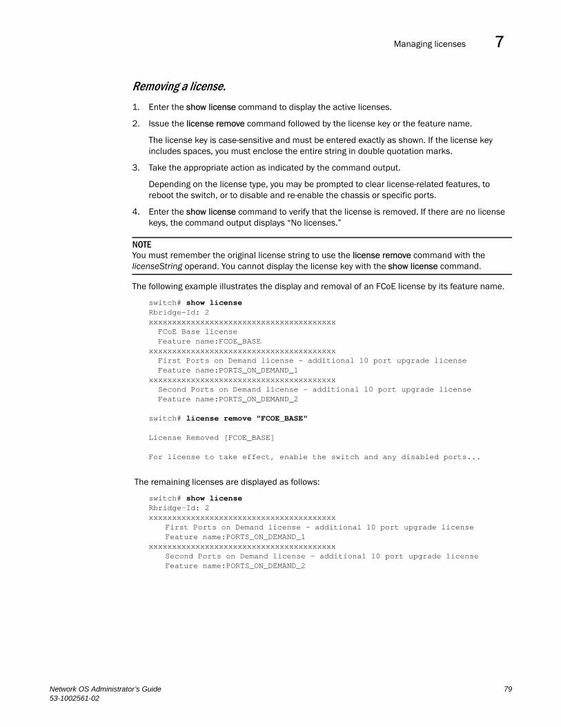
Managing licenses 7
Removing a license.
1. Enter the show license command to display the active licenses.
2. Issue the license remove command followed by the license key or the feature name.
The license key is case-sensitive and must be entered exactly as shown. If the license key includes spaces, you must enclose the entire string in double quotation marks.
3. Take the appropriate action as indicated by the command output.
Depending on the license type, you may be prompted to clear license-related features, to reboot the switch, or to disable and re-enable the chassis or specific ports.
4. Enter the show license command to verify that the license is removed. If there are no license keys, the command output displays “No licenses.”
NOTEYou must remember the original license string to use the license remove command with the licenseString operand. You cannot display the license key with the show license command.
The following example illustrates the display and removal of an FCoE license by its feature name.
switch# show licenseRbridge-Id: 2xxxxxxxxxxxxxxxxxxxxxxxxxxxxxxxxxxxxxxxx
FCoE Base licenseFeature name:FCOE_BASE
xxxxxxxxxxxxxxxxxxxxxxxxxxxxxxxxxxxxxxxxFirst Ports on Demand license - additional 10 port upgrade licenseFeature name:PORTS_ON_DEMAND_1
xxxxxxxxxxxxxxxxxxxxxxxxxxxxxxxxxxxxxxxxSecond Ports on Demand license - additional 10 port upgrade licenseFeature name:PORTS_ON_DEMAND_2
switch# license remove "FCOE_BASE"
License Removed [FCOE_BASE]
For license to take effect, enable the switch and any disabled ports...
The remaining licenses are displayed as follows:
switch# show licenseRbridge-Id: 2xxxxxxxxxxxxxxxxxxxxxxxxxxxxxxxxxxxxxxxx
First Ports on Demand license - additional 10 port upgrade licenseFeature name:PORTS_ON_DEMAND_1
xxxxxxxxxxxxxxxxxxxxxxxxxxxxxxxxxxxxxxxxSecond Ports on Demand license - additional 10 port upgrade licenseFeature name:PORTS_ON_DEMAND_2
Network OS Administrator’s Guide 7953-1002561-02
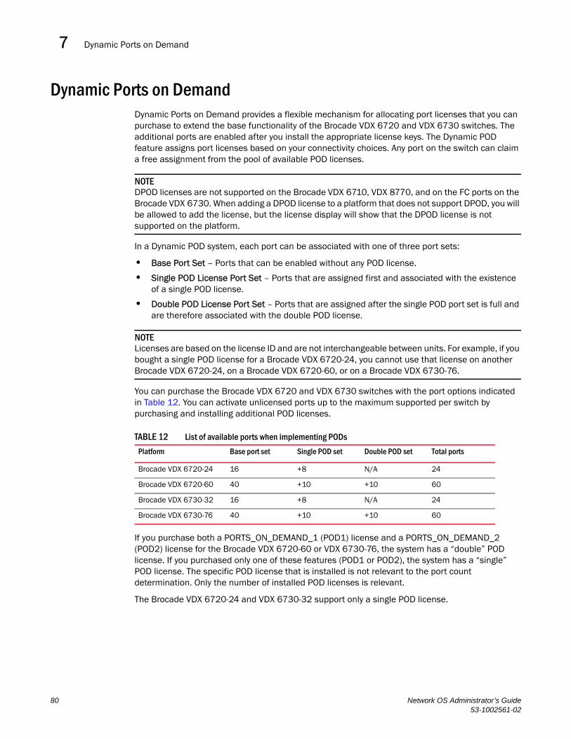
Dynamic Ports on Demand7
Dynamic Ports on DemandDynamic Ports on Demand provides a flexible mechanism for allocating port licenses that you can purchase to extend the base functionality of the Brocade VDX 6720 and VDX 6730 switches. The additional ports are enabled after you install the appropriate license keys. The Dynamic POD feature assigns port licenses based on your connectivity choices. Any port on the switch can claim a free assignment from the pool of available POD licenses.
NOTEDPOD licenses are not supported on the Brocade VDX 6710, VDX 8770, and on the FC ports on the Brocade VDX 6730. When adding a DPOD license to a platform that does not support DPOD, you will be allowed to add the license, but the license display will show that the DPOD license is not supported on the platform.
In a Dynamic POD system, each port can be associated with one of three port sets:
• Base Port Set – Ports that can be enabled without any POD license.
• Single POD License Port Set – Ports that are assigned first and associated with the existence of a single POD license.
• Double POD License Port Set – Ports that are assigned after the single POD port set is full and are therefore associated with the double POD license.
NOTELicenses are based on the license ID and are not interchangeable between units. For example, if you bought a single POD license for a Brocade VDX 6720-24, you cannot use that license on another Brocade VDX 6720-24, on a Brocade VDX 6720-60, or on a Brocade VDX 6730-76.
You can purchase the Brocade VDX 6720 and VDX 6730 switches with the port options indicated in Table 12. You can activate unlicensed ports up to the maximum supported per switch by purchasing and installing additional POD licenses.
If you purchase both a PORTS_ON_DEMAND_1 (POD1) license and a PORTS_ON_DEMAND_2 (POD2) license for the Brocade VDX 6720-60 or VDX 6730-76, the system has a “double” POD license. If you purchased only one of these features (POD1 or POD2), the system has a “single” POD license. The specific POD license that is installed is not relevant to the port count determination. Only the number of installed POD licenses is relevant.
The Brocade VDX 6720-24 and VDX 6730-32 support only a single POD license.
TABLE 12 List of available ports when implementing PODs
Platform Base port set Single POD set Double POD set Total ports
Brocade VDX 6720-24 16 +8 N/A 24
Brocade VDX 6720-60 40 +10 +10 60
Brocade VDX 6730-32 16 +8 N/A 24
Brocade VDX 6730-76 40 +10 +10 60
80 Network OS Administrator’s Guide53-1002561-02

Dynamic Ports on Demand 7
Automatic POD port assignmentsWith the Dynamic POD feature, you can use the base port set plus the number of additional ports you purchased. All ports that do not receive a POD assignment and are trying to come online will go offline. The show ip interface brief and show interface tengigabitethernet rbridge-id/slot/port commands display the reason for the port disabled status as related to POD licensing.
The Dynamic POD mechanism detects the ports that have active links, and it makes assignments based on the remaining pool of vacancies:
• If the count of assigned ports is below the number of ports in the purchased POD set, additional dynamic assignments can be made at a later time as new links are established. If a port comes online, that port can get assigned if you still have vacancies in your POD set.
• If the number of detected active links is greater than the number of ports in the purchased POD set, port assignments are made in the order in which the ports come online. Because the time it takes for each port to come online varies, the order in which ports are assigned to a given POD set cannot be guaranteed.
If the given assignment order does not align with your intended use of the ports, you can make adjustments using the dpod rbridge-id/slot/port reserve or the dpod rbridge-id/slot/port release commands. Refer to “Overriding Dynamic POD assignments” on page 83 for more information.
Mapping port assignments to a POD port setPorts are associated with the single or double POD license in the order in which they come online and automatically receive a license assignment from the pool of unassigned ports in the POD set. The first ports that receive a POD assignment are associated with the base port set. When all ports in the base port set are assigned, the next ports that come online receive assignments from the single POD license port set. When this set is full, the remaining port assignments are associated with the double POD license port set.
The association of a specific port to a POD set matters only when you want to remove a POD license from the system. Ports assigned to the double POD license port set will be disabled first. The last-assigned licenses will be released first when you remove POD licenses. Refer to “Releasing a port from a POD set” on page 84 for more information.
Activating the Dynamic POD feature1. Verify the current states of the ports with the show ip interface brief command.
The command output indicates whether a port is licensed.
2. Install the Brocade Dynamic POD license.
For instructions on how to install a license, refer to “Installing a license” on page 75.
3. Use the shutdown and no shutdown commands to disable and re-enable the ports.
Alternatively, you can disable and re-enable the chassis to activate ports.
4. Use the show ip interface brief command to verify the newly activated ports.
5. Use the show interface tengigabitethernet rbridge-id/slot/port command to display port details.
Network OS Administrator’s Guide 8153-1002561-02

Dynamic Ports on Demand7
The following example shows a Brocade VDX 6720-24 without a Dynamic POD license installed. The 16 ports in the base port set are online and assigned. The remaining 8 ports are unassigned and are down.
switch# show ip interface briefInterface IP-Address Status Protocol========= ========== ====== ========TengigabitEthernet 5/0/1 unassigned up upTengigabitEthernet 5/0/2 unassigned up upTengigabitEthernet 5/0/3 unassigned up upTengigabitEthernet 5/0/4 unassigned up upTengigabitEthernet 5/0/5 unassigned up upTengigabitEthernet 5/0/6 unassigned administratively down down(No DPOD
License)TengigabitEthernet 5/0/7 unassigned administratively down down(No DPOD
License)TengigabitEthernet 5/0/8 unassigned up upTengigabitEthernet 5/0/9 unassigned up upTengigabitEthernet 5/0/10 unassigned up upTengigabitEthernet 5/0/11 unassigned administratively down down(No DPOD
License)TengigabitEthernet 5/0/12 unassigned administratively down down(No DPOD
License)TengigabitEthernet 5/0/13 unassigned up upTengigabitEthernet 5/0/14 unassigned up upTengigabitEthernet 5/0/15 unassigned up upTengigabitEthernet 5/0/16 unassigned up upTengigabitEthernet 5/0/17 unassigned administratively down down(No DPOD
License)TengigabitEthernet 5/0/18 unassigned administratively down down(No DPOD
License)TengigabitEthernet 5/0/19 unassigned administratively down down(No DPOD
License)TengigabitEthernet 5/0/20 unassigned administratively down down(No DPOD
License)TengigabitEthernet 5/0/21 unassigned up upTengigabitEthernet 5/0/22 unassigned up upTengigabitEthernet 5/0/23 unassigned up upTengigabitEthernet 5/0/24 unassigned up up
The following example displays details for a single port that is offline because it does not have a Dynamic POD license.
switch# show interface tengigabitethernet 5/0/6TengigabitEthernet 5/0/6 is down, line protocol is down (No DPOD License)Hardware is Ethernet, address is 0005.1eb6.0a25Current address is 0005.1eb6.0a25Tracking status: DisabledTracked interfaces: NonePluggable media present, Media type is sfpInterface index (ifindex) is 1744896001MTU 2500 bytesLineSpeed: Auto - 10000 Mbit, Duplex: FullFlowcontrol rx: on, tx: on
Displaying the Dynamic POD assignmentsTo display the Dynamic POD assignments, enter the show dpod command.
82 Network OS Administrator’s Guide53-1002561-02

Dynamic Ports on Demand 7
The show dpod command provides a summary of POD license status and POD license assignments.
In the following example, all 24 ports are licensed and potentially available. The three unassigned ports are currently persistently disabled and therefore are not assigned to any Dynamic POD license port set.
switch# show dpodrbridge-id: 124 ports are available in this switch
1 POD license is installedDynamic POD method is in use
24 port assignments are provisioned for use in this switch:16 port assignments are provisioned by the base switch license8 port assignments are provisioned by the first POD license
* 0 more assignments are added if the second POD license is installed21 ports are assigned to installed licenses:
16 ports are assigned to the base switch license5 ports are assigned to the first POD license
Ports assigned to the base switch license:Te 1/0/1, Te 1/0/10, Te 1/0/11, Te 1/0/12, Te 1/0/13, Te 1/0/14, Te 1/0/15, Te
1/0/16, Te 1/0/17, Te 1/0/18, Te 1/0/19, Te 1/0/20, Te 1/0/21, Te 1/0/22, Te 1/0/23, Te 1/0/24Ports assigned to the first POD license:
Te 1/0/5, Te 1/0/6, Te 1/0/7, Te 1/0/8, Te 1/0/9Ports assigned to the second POD license:
NonePorts not assigned to a license:
Te 1/0/2, Te 1/0/3, Te 1/0/4
3 license reservations are still available for use by unassigned ports
Overriding Dynamic POD assignmentsYou can override the automatic port license assignments by releasing Dynamic POD assignments from a port and by reserving an assignment for a specific port.
Reserving a port assignment
Reserving an assignment for a port assigns that port to a POD license regardless of whether the port is online or offline. Reserving assignments allocates the POD license to specified ports. This operation overrides automatic port assignments. The reserved assignment will not be available to other ports that come online. To reserve an assignment for a port, a free assignment must be available.
1. Enter the show dpod command to determine the unassigned ports.
If all ports are assigned, select a port to release its POD assignment. Follow the instructions in “Releasing a port from a POD set” on page 84 to release a port from its POD assignment. Once the port is released, you can reuse the assignment for another port.
2. Enter the global configuration mode by issuing the configure terminal command.
3. Select the port for which you want to reserve an assignment and enter the dpod reserve command.
4. Enter the exit command to return to the global configuration mode before you reserve another port.
Network OS Administrator’s Guide 8353-1002561-02

Dynamic Ports on Demand7
switch# configure terminalEntering configuration mode terminalswitch(config)# dpod 5/0/10 reserveswitch(config-dpod-5/0/10)# exitswitch(config)# dpod 5/0/11 reserveswitch0(config-dpod-5/0/11)# exit
NOTELicense reservations or removals do not persist across switch reboots and power cycles. To make them persistent, save the configuration changes by issuing the use copy running-config startup-config command before you reboot the switch.
5. Save the configuration changes.
switch# copy running-config startup-config
6. Reboot the switch.
7. Enter the show running-config dpod command to verify the port is reserved.
switch# show running-config dpod 5/0/10dpod 5/0/10reserve
!switch# show running-config dpod 5/0/11dpod 5/0/11reserve
!
Releasing a port from a POD set
Once a port has been assigned to a Dynamic POD license port set, it remains licensed (or “reserved”) until you remove the port from the port set. You remove a port from the port set by releasing the port with the dpod release command. Releasing a port removes it from the Dynamic POD license port set; the port appears as unassigned until it comes back online.
To prevent a port from coming back online and taking a POD assignment, disable the port and save the running configuration. This action will disable the port persistently.
A port POD assignment can only be released if the port is currently offline. Use the shutdown command to disable the port or use the chassis disable command to disable the switch if you plan to release multiple ports.
1. Enter the global configuration mode by issuing the configure terminal command.
2. Select the interface for the port that you wish to disable using the interface rbridge-id/slot/port command.
3. Enter the shutdown command to take the port offline.
4. Enter the exit command to return to the global configuration mode before you release the port.
5. Enter the dpod release command to remove the port from the POD license.
6. Enter the exit command to return to the global configuration mode before you reserve another port.
switch# configure terminalEntering configuration mode terminalswitch(config)# interface 1/0/10switch(conf-if-te-1/0/10)# shutdown
84 Network OS Administrator’s Guide53-1002561-02

Upgrade and downgrade considerations 7
switch(conf-if-te-1/0/10)# exitswitch(config)# dpod 1/0/10 releaseswitch(config-dpod-1/0/10)# exit
7. Enter exit to return to the privileged EXEC mode.
8. Enter the show dpod command to verify that the port is no longer assigned to a POD set.
9. Enter the enable chassis command to bring the switch back online.
10. Save the configuration changes.
switch# copy running-config startup-config
NOTEDo not release a port unless you plan to disconnect the optical link or disable the port persistently. If you leave the link in a state where the port could be brought online, the POD mechanism will detect this unassigned port and attempt to reassign it to a port set.
Upgrade and downgrade considerationsDowngrading from Network OS v.3.0.0 to a previous version is applicable only to the Brocade VDX 6710, VDX 6720, and VDX 6730, The VDX 8770 chassis only supports Network OS v.3.0.0. There are no downgrade pre-install requirements for any of the licensed features in Network OS v.3.0.0.
You cannot downgrade to Network OS v2.x when the switch is in Brocade VCS Fabric mode without full POD licenses installed. Network OS v2.x requires full POD licenses to be installed when the switch is in Brocade VCS Fabric mode.
If Dynamic POD reserve port configuration data is stored in the running-config file before you downgrade to Network OS v2.x, restoring that running-config file after downgrade does not restore the Dynamic POD reserve port information.
Configuration management considerationsLicenses are independent of configuration files and are therefore not affected when you make changes to a configuration file or restore the default configuration. The only exceptions are Dynamic POD configurations. When you download a configuration from another switch or you restore the default configuration, the DPOD configuration is moderated and restricted by whatever POD licenses are present on the switch.
For example, if you download a configuration file from a switch that has POD assignments beyond the base number of allowed DPOD ports and there is no POD license installed, then the additional ports beyond the number of ports in the Base DPOD set won't be allowed. When the configuration is played back as part of the copy (or reboot) operation, the licenses are checked for each additional DPOD port that attempts to be assigned a reservation.
Network OS Administrator’s Guide 8553-1002561-02

Configuration management considerations7
86 Network OS Administrator’s Guide53-1002561-02

Network OS Administrator’s Guide53-1002561-02
Chapter
8
SNMPIn this chapter
•SNMP community strings . . . . . . . . . . . . . . . . . . . . . . . . . . . . . . . . . . . . . . . . 87
•SNMP server hosts . . . . . . . . . . . . . . . . . . . . . . . . . . . . . . . . . . . . . . . . . . . . . 89
SNMP overviewSimple Network Management Protocol (SNMP) is a standard method for monitoring and managing network devices. Every Brocade switch carries an SNMP agent and Management Information Base (MIB).
SNMP is a set of protocols for managing complex networks. SNMP sends messages, called protocol data units (PDUs), to different parts of a network. SNMP-compliant devices, called agents, store data about themselves in Management Information Bases (MIBs) and return this data to the SNMP requesters.
Restricting SNMP access using ACL, VLAN, or a specific IP address constitute the first level of defense when the packet arrives at a Brocade device. The next level uses community string matches for SNMP versions 1 and 2c.
For details on Brocade MIB files, naming conventions, loading instructions, and information about using the Brocade SNMP agent, refer to the Network OS Message Reference.
For information on SNMPv3 commands, refer to the Network OS Command Reference. For information about supported traps, refer to the Network OS MIB Reference.
SNMP community stringsSNMP versions 1 and 2c use community strings to restrict SNMP access. There are six default community strings configured for the user: three read-write strings and three read-only strings.
NOTEYou can specify one of the six default community strings when the system first comes up. If you create a new community string, you must delete one of the six default strings to make space for the new one.
The following community strings are read-write:
• Secret Code
• OrigEquipMfr
• private
87

SNMP community strings8
The following community strings are read-only:
• public
• common
• ConvergedNetwork
Adding an SNMP community stringThe snmp-server community command sets the community string and read-write or read-only access for each community. Use this command to manage the configuration of the SNMP agent in the switch. The configuration includes SNMPv1 and SNMPv2c configuration settings. You can execute SNMP server commands in global configuration mode.
1. Enter the configure terminal command.
2. Enter the snmp-server community string [ro |rw] command.
switch(config)# snmp-server community private rw
• The string variable specifies the community string name. The string can be from 2 to 16 characters long.
• The ro or rw option specifies whether the string is read-only (ro) or read-write (rw).
The command in the example adds the read-write SNMP community string “private” with read-write access.
Changing the access of a read-only community string This example changes the access of “user123” from read-only to read-write.
1. Enter the configure terminal command.
2. Enter the snmp-server community string rw command.
switch(config)# snmp-server community user123 rw
Removing an SNMP community stringThis example removes the community string “private”.
1. Enter the configure terminal command.
2. Enter the no snmp-server community string [ro | rw] command.
switch(config)# no snmp-server community private
Displaying the SNMP community stringsTo display the configured community strings, enter the show running-config snmp-server command.
switch# show running-config snmp-server
88 Network OS Administrator’s Guide53-1002561-02

SNMP server hosts 8
SNMP server hostsThe snmp-server host command sets the trap destination IP addresses, SNMP version, community string for SNMP version 1 and 2c, the destination port for the SNMP server host, and the severity level.
To configure SNMP trap hosts associated with community strings, you must create the community string using the snmp-server community command before configuring the host.
The SNMP agent supports six communities and their associated trap recipients and trap recipient severity levels. The default value for the trap recipient of each community is 0.0.0.0. The length of the community string must be from 2 through 16 characters. The community strings have the following default values:
• common—read-only
• public—read-only
• ConvergedNetwork—read-only
• OrigEquipMfr—read-write
• private—read-write
• Secret Code—read-write
NOTETo add a new community string for SNMPv1 or v2c under one of the read-only or read-write groups, delete one of the entries from the appropriate group.
Setting the SNMP server hostYou can execute SNMP server commands in global configuration mode.
1. Enter the configure terminal command.
2. Enter the snmp-server host ipv4_host | ipv6_host | dns_host community-string [version {1|2c} ] [udp-port port] [severity-level {none | debug | info | warning | error | critical}] command.
• The ipv4_host | ipv6_host | dns_host variable specifies the IP address of the host.
• The community-string variable sets the community string.
• The version option selects SNMPv1- or SNMPv2c-related configuration parameters. These parameters include the community string. The default SNMP version is 1.
• The udp-port port option specifies the UDP port where SNMP traps will be received. The default port is 162. The acceptable range of ports is from 0 through 65535.
• The severity sev_level option provides the ability to filter traps based on severity level on both the host and the v3host. Only RASlog (swEvent) traps can be filtered based on severity level. If the severity level of None is specified, all traps are filtered and no RASLOG traps are received. If the severity level of Critical is specified, no traps are filtered and all traps are received by the host.
Severity level options include None, Debug, Info, Warning, Error, and Critical.
Network OS Administrator’s Guide 8953-1002561-02

SNMP server hosts8
The following example sets up “commaccess” as a read-only user and sets 10.32.147.6 as a trap recipient with SNMP version 2c on target port 162.
switch(config)# snmp-server host 10.32.147.6 commaccess version 2c udp-port 162 severity warning
Removing the SNMP server hostThe no snmp-server host host community-string string version 2c command brings version 2c down to version 1.
The no snmp-server host host community-string string command removes the SNMP server host from the switch configuration altogether.
Setting the SNMP server contactUse the snmp-server contact command to set the SNMP server contact string. The default contact string is “Field Support.”
1. Enter the configure terminal command.
2. Enter the snmp-server contact string command.
switch(config)# snmp-server contact “Operator 12345”
The example changes the default contact string to “Operator 12345.” You must enclose the text in double quotes if the text contains spaces.
Removing the SNMP server contactThe no snmp-server contact string command removes the SNMP server contact from the switch configuration.
Setting the SNMP server locationUse the snmp-server location command to set the SNMP server location string. The default SNMP server location string is “End User Premise.”
1. Enter the configure terminal command.
2. Enter the snmp-server location string command.
switch(config)# snmp-server location “Building 3 Room 214”
The example changes the default location string to “Building 3 Room 214.” You must enclose the text in double quotes if the text contains spaces.
Displaying SNMP configurationsUse the show running-config snmp-server command to display the current SNMP configurations for the SNMP host, community string, contact, and location. There are no default configurations for this command. This command can only be executed in Privileged EXEC command mode.
Enter the show running-config snmp-server command.
switch# show running-config snmp-server
90 Network OS Administrator’s Guide53-1002561-02

Network OS Administrator’s Guide53-1002561-02
Chapter
9
FabricIn this chapter
•TRILL. . . . . . . . . . . . . . . . . . . . . . . . . . . . . . . . . . . . . . . . . . . . . . . . . . . . . . . . . 91
•Brocade VCS Fabric formation . . . . . . . . . . . . . . . . . . . . . . . . . . . . . . . . . . . . 91
•Brocade VCS Fabric configuration management . . . . . . . . . . . . . . . . . . . . . 94
•Fabric interface configuration management . . . . . . . . . . . . . . . . . . . . . . . . . 95
TRILLThe Brocade VCS Fabric Ethernet fabric is defined as a group of switches that exchange information between each other to implement distributed intelligence. The Brocade Ethernet fabric uses Transparent Interconnection of Lots of Links (TRILL) protocol, designed for the sole purpose of scaling Ethernet networks by allowing a set of devices, called routing bridges (RBridges), to connect with each other.
A link state dynamic routing protocol, rather than Spanning Tree Protocol, determines how the traffic is forwarded between the inter-connected RBridges. Link state routing in Brocade VCS Fabric-based TRILL networks is performed using Fabric Shortest Path First (FSPF) protocol.
TRILL enables Layer 2 networks to behave like routed Layer 3/IP networks. TRILL also defines native support for forwarding both unicast and multicast traffic, and therefore unifies support for both of these different classes of applications over a single transport.
Brocade VCS Fabric formationBrocade VCS Fabric technology uses RBridge identifiers (IDs) to discover fabric creation problems, such as duplicate IDs. The RBridge ID of a cluster unit is equal to the domain ID of an FC switch. RBridge ID assignment is implemented by leveraging the domain ID assignment protocols in the FC SANs. Request for Domain ID (RDI) and Domain ID Assignment (DIA) protocols ensure that a single switch (the principal switch) is centrally allocating the domain IDs for every RBridge in the fabric and detecting any domain ID conflicts in the fabric. In case of conflict, the conflicting node is segmented from the fabric. You must take action to resolve the conflict
NOTENetwork OS v3.0.0-based fabrics can have a maximum of 239 RBridges in a single Brocade VCS Fabric. However, Brocade recommends using only 24 RBridges per fabric.
The following sequence of events describes the Brocade VCS Fabric formation process:
• Each Brocade VCS Fabric is identified by a VCS ID.
• All Brocade VCS Fabric-capable switches are configured with a factory default VCS ID of 1.
91

Brocade VCS Fabric formation9
• The switch software searches for the “VCS enable” attribute.
NOTEIf the software cannot locate the “VCS enable” attribute, the switch goes into standalone mode and operates like a regular 802.1x switch.
• Assuming the switch is Brocade VCS Fabric-enabled, the switch software invokes a series of protocols:
- Brocade Link Discovery Protocol (BLDP) attempts to discover if a Brocade VCS Fabric-capable switch is connected to any of the edge ports. See “Neighbor discovery” on page 93 for more information.
- BLDP attempts to merge the adjacent Brocade switch into the Brocade VCS Fabric environment at the link level.
• A series of FC fabric formation protocols (RDI, DIA, and FSPF) are initiated once a link level relationship has been established between two neighbor switches. See “Fabric formation” on page 93 for more information.
• Merge and Join Protocol invokes a merge of switch configuration between the cluster units once the fabric has successfully formed.
How RBridges workRBridges find each other by exchanging FSPF Hello frames. Like all TRILL IS-IS frames, Hello frames are transparently forwarded by RBridges and are processed by RBridge ISL ports. Using the information exchanged in the Hello frames, the RBridges on each link elect the designated RBridge for that link.
The RBridge link state includes information such as VLAN connectivity, multicast listeners, and multicast router attachment, claimed nicknames, and supported ingress-to-egress options. The designated RBridge specifies the appointed forwarder for each VLAN on the link (which could be itself) and the designated VLAN for inter-RBridge communication. The appointed forwarder handles native frames to and from that link in that VLAN.
The Ingress RBridge function encapsulates frames from the link into a TRILL data frame. The Egress RBridge function decapsulates native frames destined for the link from the TRILL data frames. TRILL data frames with known unicast destinations are forwarded by Rbridge next hop. Multi-destination frames (broadcast, unknown unicast, and multicast) are forwarded on a tree rooted at the multicast root RBridge.
• Unicast forwarding is handled by combining domain routing generated by FSPF and MAC-to-RBridge learning generated by MAC learning and a distributed MAC database.
• Multicast forwarding usually uses one tree that is rooted at the RBridge with the lowest RBridge ID. However, there are several rules for Multicast root tree selection. It is not always the lowest RBridge ID.
If a duplicated RBridge-id is found while the links are still coming up, the links are segmented. Both sides recognize the error and segment the link. If the RBridge-id overlap cannot be found at ISL link bringup time (in the case where a new switch is brought from an offline state into the fabric) it will be found during the fabric build and the conflicting switch is isolated.
92 Network OS Administrator’s Guide53-1002561-02

Brocade VCS Fabric formation 9
An RBridge requests a specific RBridge IDfrom the coordinator switch. If the coordinator switch detects that this RBridge ID is already used, it returns the next unused RBridge ID. The requesting RBridge is not allowed to take another RBridge ID and it segments itself from the fabric. In this case, you cannot boot the ISLs. The ISLs have to be explicitly disabled and then enabled again in order for the RBridge with the overlapping RBridge ID to be removed.
Neighbor discoveryBrocade VCS Fabric-capable neighbor discovery involves the following steps:
• Discover whether the neighbor is a Brocade switch.
• Discover whether the Brocade neighbor switch is Brocade VCS Fabric-capable.
Only Brocade VCS Fabric-capable switches with the same VCS ID can form a virtual cluster switch. The default settings for Brocade Network OS switches are Brocade VCS Fabric capable and a VCS ID of “1.”
Brocade trunksThe Network OS v3.0.0 supports Brocade trunks (hardware-based link aggregation groups, or LAGs). These LAGs are dynamically formed between two adjacent switches. The trunk formation is controlled by the same FC Trunking protocol that controls the trunk formation on FC switches. As such, it does not require user intervention or configuration except enabling or disabling, which instructs the switch software to form a trunk at the global level or not. See “Enabling a Fabric trunk” on page 96 for instructions.
NOTEAll ISL ports connected to the same neighbor Brocade switch are attempted to form a trunk. For a successful trunk formation, all ports on the local switch must be part of the same port group and must be configured at the same speed. Rules for these trunks are similar to trunks on Brocade FC switches: eight ports are allowed per trunk group and the trunk is turned on by default.
Fabric formationBrocade VCS Fabric technology leverages proven FC Fabric protocols to build a TRILL fabric. The main functions of the fabric formation protocols are to:
• Assign the Brocade VCS Fabric-wide unique RBridge IDs (Domain ID Assignment)
• Create the network topology database using link state routing protocol (Fabric Shortest Path First, or FSPF). FSPF calculates the shortest path routes to a destination RBridge.
• Distribute fabric multicast traffic.
Principal switch selection
Every Brocade VCS Fabric-enabled switch, upon boot-up and after the Fabric port formation, declares itself to be a principal switch and advertises this intent on all fabric ports. The intent includes a priority and its switch WWN. If all switches boot up at the same time, the default priority is the same and all switches will compare their mutual intents. The switch with the lowest Switch WWN becomes the principal switch. The WWN is an industry-standard burnt-in switch identifier, similar to the Bridge-MAC except it is 8 bytes. The role of the principal switch is to decide whether a new RBridge joining the fabric conflicts with any of the RBridge IDs already present in the fabric.
Network OS Administrator’s Guide 9353-1002561-02
Brocade VCS Fabric configuration management9
NOTEBrocade VDX Data Center switches are shipped with factory-programmed world wide names (WWNs) and are unique.
At the end of the principal switch selection process, all the switches in the cluster have formed a tree with the principal switch at the root.
RBridge ID allocation
RBridge ID assignment is implemented by leveraging proven Domain ID assignment protocols from FC SANs. Request for Domain ID (RDI) and Domain ID Assignment (DIA) protocols ensure that a single switch (the principal switch) centrally allocates the domain IDs for every RBridge in the fabric and detects and resolves any domain ID collisions in the fabric. Brocade VCS Fabric supports up to 24 RBridge IDs.
Only the principal switch can allocate RBridge IDs (domain IDs) for all other switches in the fabric. The principal switch starts the allocation process by allocating an RBridge ID for itself (using the ID value supplied by the user), and initiates the DIA messages on all ports.
Other switches, which are now in subordinate mode, upon receiving the DIA frames respond with an RDI message towards the principal switch. The process continues until all the switches in the fabric have been allocated a unique ID.
Fabric routing protocol After a RBridge ID is assigned to a switch, the Fabric Shortest Path First (FSPF) link state routing protocol begins to form adjacencies and collects topology and inter-connectivity information with its neighbors. Brocade VCS Fabric uses FSPF to calculate and elect a loop-free multicast tree rooted at the multicast root RBridge. The multicast tree is calculated after the unicast routes are computed.
Brocade VCS Fabric configuration managementComplete the following configuration steps to add a new switch into a fabric.
1. Connect to the switch and log in using an account assigned to the admin role.
2. Enter the vcs rbridge-id id enable command.
The switch remembers its RBridge ID once it has been assigned. The vcs rbridge-id id enable command also sets the insistent RBridge ID property on the switch.
3. Reboot the system.
After the required reboot, the switch participates in the RBridge ID allocation protocol which insists that the same value that was manually configured prior to reboot be allocated after reboot.
The switch is not allowed into the fabric if there is a conflict; for example, if another switch with the same ID exists and is operational in the fabric. You have the opportunity to select a new RBridge ID using the same CLI.
Once an ID has been assigned by the fabric protocol, these IDs are then numerically equated to RBridge IDs and are treated as such after that.
94 Network OS Administrator’s Guide53-1002561-02

Fabric interface configuration management 9
Use the vcs command to configure the Brocade VCS Fabric parameters, VCS ID, and the switch RBridge ID, and to enable Brocade VCS Fabric mode. You can set the Brocade VCS Fabric parameters and enable Brocade VCS Fabric mode at the same time, or you can enable Brocade VCS Fabric and then perform the ID assignments separately. Refer to Table 13 for details.
After configuring the Brocade VCS Fabric parameters, the switch applies the changes and reboots.
The switch disable is not saved across a reboot, so if the switch was disabled prior to the reboot, the switch returns to the enabled state when it finishes the boot cycle.
Brocade VCS Fabric configuration tasksTable 13 lists additional commands you can enter to set up your Brocade VCS Fabric environment.
Fabric interface configuration managementA physical interface in a virtual switch cluster can either be an edge port or a fabric port, but not both. Similar to a switch-port configuration on a physical interface, you can also change a fabric-port configuration on its physical interface by using the fabric ISL enable and fabric trunk enable commands, described below.
Enabling a Fabric ISLThe fabric ISL enable command controls whether an ISL should be formed between two cluster members. With the default setting of ISL discovery to auto and the ISL formation mode to enable, an ISL automatically forms between two cluster switches.
Performing a fabric isl enable command on an operational ISL has no effect. However, performing a no fabric isl enable command on an interface toggles its link status and subsequently disables ISL formation. In addition, the no fabric isl enable command triggers the switch to inform its neighbor that the local interface is ISL disabled. Upon receiving such information, a neighbor switch stops its ISL formation activity regardless of its current interface state.
TABLE 13 Brocade VCS Fabric configuration task examples
Brocade VCS Fabric configuration task Brocade VCS Fabric command example
Disable the switch, set the RBridge ID, and enable Brocade VCS Fabric mode at the same time
switch# vcs rbridge-id 3 enable
Disable the switch, set the VCS ID and the RBridge ID, and enable Brocade VCS Fabric mode
switch# vcs rbridge-id 3 vcs-id 1 enable
Disable the switch and set the RBridge ID and VCS ID separately.
switch# vcs rbridge-id 3 enableswitch# vcs vcs-id 1
Switch from Fabric Cluster mode to Standalone mode(Setting the RBridge ID to 1 and the VCS ID to 0)
switch# no vcs enable
Replace the designated switch in the Fabric Cluster with the current switch.
switch# vcs rbridge-id 5
Network OS Administrator’s Guide 9553-1002561-02

Fabric interface configuration management9
NOTEAfter you repair any segmented or disabled ISL ports, toggle the fabric ISL in order to propogate the changes.
NOTEA shutdown command on an operating ISL interface not only brings down the physical link but also its FSPF adjacency. The main difference between a shutdown command and a no fabric isl enable command is that the link stays up after a no fabric isl enable, while the link stays down after a shutdown.
NOTEUpon fabric reconvergence due to topology change involving ECMP fabric-isl path,there may be sub-second flooding of known unicast traffic.
Configuring a long distance ISL port An ISL port with PFC supports up to 10Km distance on eAnvil-based platforms. Up to 10Km links are lossless. You can have eight 1Km links forming a brocade trunk. You can also have mixed length cables forming the ISL. For ECMP purposes, you can have eight 8-link ECMP trunks.
To configure a long distance ISL port, use the long-distance-isl command in interface configuration mode. Refer to the Network OS Command Reference for complete details. The following example sets port 1/0/2 to support long distance ISL up to 30 km.
Example
switch(conf-if-te-1/0/2)# long-distance-isl 10000
Disabling a Fabric ISLThe no fabric isl enable command takes this interface out of the trunk group if this interface happens to be currently part of the trunk. If you know and would like to fix the edge and fabric port assignments on a switch, then this command allows you to completely turn off ISL formation logic and shorten any link bring-up delays on edge ports.
1. Connect to the switch and log in using an account assigned to the admin role.
2. Enter the no fabric isl enable command.
Enabling a Fabric trunk1. Connect to the switch and log in using an account assigned to the admin role.
2. Enter the fabric trunk enable command.
Disabling a Fabric trunkFabric trunking is enabled by default. Enter the no fabric trunk enable command to revert the ISL back to a standalone adjacency between two Brocade VCS Fabric switch.
96 Network OS Administrator’s Guide53-1002561-02

Fabric interface configuration management 9
Broadcast, Unknown Unicast, and Multicast ForwardingAll switches in a Brocade VCS Fabric cluster share a single multicast tree rooted at the RBridge with the lowest RBridge ID (domain ID). All broadcast, unknown unicast, and multicast traffic between two edge RBridges is forwarded on this multicast tree inside the Brocade VCS Fabric. The multicast tree includes all RBridges in the Brocade VCS Fabric fabric.
Multicast distribution tree-root selection
Network OS v3.0.0 software supports the following distribution tree behaviors.
• The root of the distribution tree is the switch with the lowest RBridge ID. The automated selection process does not require any user intervention.
• Each switch in the cluster optionally carries a multicast root priority. This priority setting overrides the automatically-selected multicast root. In deployments where a multicast root is required to be a specific switch that does not have the lowest RBridge ID, then the priority setting on that switch can override the root selection. If there are two switches with the same priority, then the switch with the lower RBridge ID prevails.
• A back-up multicast root is pre-selected, which is the switch with the next lowest RBridge ID. The back-up multicast root is automatically selected by all switches should the current multicast root fail.
PrioritiesAs stated above, the root of the tree is auto-selected as the switch with the lowest RBridge ID. For example, if you had a cluster with RBridge IDs 5, 6, 7, and 8, then 5 would be the root. If you then added rbridge-id 1 to this fabric, the tree would be re-calculated with 1 as the root.
In order to avoid this behavior, you can set a priority (default is 1). The highest priority overrides the lowest RBridge ID and becomes the root.
For example, to build a fabric with RBridge ID 7 or 8 as the root, set their priority to something higher than 1 (priority values are 1 through 255). If there is a tie in priority, the lower RBridge is still chosen. If RBridge ID 7 and 8 are both set to priority 1, 7 becomes the root.
Changing the priority
1. Connect to the switch and log in using an account assigned to the admin role.
2. Enter the fabric route mcast rbridge-id command.
Example of changing an RBridge multicast priority:
switch(config)# fabric route mcast rbridge-id 12 priority 10
Displaying the running configurationThe show running-config fabric route mcast command allows you to display fabric route multicast configuration information. The configuration currently effective on the switch is referred to as the running configuration. Any configuration change you make while the switch is online is made to the running configuration. The running configuration is nonpersistent.
Network OS Administrator’s Guide 9753-1002561-02

Fabric interface configuration management9
98 Network OS Administrator’s Guide53-1002561-02
NOTETo save configuration changes, you must save the running-config file to a file, or you can apply the changes by copying the running configuration to the startup configuration.
1. Connect to the switch and log in using an account assigned to the admin role.
2. Enter the show running-config fabric route mcast command.
switch# show running-config fabric route mcast priority fabric route mcast rbridge-id 12 priority 10
VCS Virtual IP address configurationA Virtual IP address is assigned for each VCS cluster. This virtual IP address is tied to the principal switch in the cluster. The management interface of the principal switch can be accessed using this virtual IP address. Since the Virtual IP address is the property of Fabric Cluster and Management Cluster, In the event that the principal switch goes down, the next principal switch is assigned this address.
Virtual IP address can be configured by using the vcs virtual ip address command:
switch(config)# vcs virtual ip address 10.0.0.23
This command can be used in Management Cluster and Fabric Cluster modes only. When the Virtual IP address is configured for the first time, the current principal switch in the cluster is assigned this IP address.
Virtual IP configuration is global in nature. All the nodes in the cluster are configured with the same virtual IP address, but address will be bound to the current Principal switch only. Make sure that the assigned Virtual IP address is not a duplicate of an address assigned to any other management port in the cluster or network.
Brocade recommends that you use the same subnet as the IP address of management interface. To see the currently configured Virtual IP address, use the show vcs command:
switch# show vcs virtual-ip Virtual IP : 10.21.87.2/20Associated rbridge-id : 2
To remove the currently configured Virtual IP address, use the no vcs virtual ip address command.
switch(config)# no vcs virtual ip addressswitch# show running-config vcs virtual ip address% No entries found.
NOTEYou should not use the no vcs virtual ip address command when logged onto the switch using the Virtual IP address. Use the management port IP address of the principal switch, or the serial console connection of the Principal switch.
If you wish to rebind this Virtual IP address to this management interface, remove the currently configured Virtual IP address and reconfigure it. This situation can arise when the Virtual IP address was not bound to management interface of the principal switch due to duplicate address detection.
A separate gateway cannot be configured for Virtual IP address. The default gateway is the same as the gateway address for the management port of the same switch.

Fabric interface configuration management 9
Virtual IP address configuration scenarios
Virtual IP address may be assigned to a switch whenever it is the Principal switch in the cluster. The configuration scenarios that may occur are described in Table 14.
TABLE 14 Virtual IP address configuration scenarios
Scenario Description
First time cluster formation When the cluster is first being formed, and if the Virtual IP address is already configured, the principal switch is assigned the Virtual IP address. If no Virtual IP configuration exists, then the principal switch can be access using the Management port IP address.
Virtual IP Configuration When you configure the Virtual IP address for a cluster the first time, Virtual IP address is bound the management interface of the Principal switch.
Principal switch failover If the principal switch becomes a secondary switch while the Virtual IP address is assinged to its management interface, then the Virtual IP address is reassigned to the new principal switch.
Principal Switch goes down When the principal switch in the cluster goes down, the Virtual IP address is released from its management interface. The Virtual IP address will be assigned to the next switch that becomes the principal switch.
Principal Switch chassis is disabled When the chassis disable command is executed on the principal switch, the Virtual IP address is released from its management interface. The Virtual IP address will be assigned to the next switch that becomes the principal switch.
Virtual IP removal If you remove the Virtual IP address from the configuration, then the Virtual IP address is unbound from management interface of the principal switch. In this case, the principal switch can still be accessed using the management ports IP address.
Trivial merge In the event that two clusters merge together, theglobal configuration of the smaller cluster (cluster A) is overwritten by the larger cluster (cluster B). During this time, the Virtual IP address is unbound from the principal switch of cluster A. The Virtual IP address of Cluster B can now be used to access the principal of new merged cluster. If the Virtual IP address of cluster B is not configured, there will not be a Virtual IP address in the merged cluster.
Cluster Reboot WHen the cluster reboots, the virtual IP address is persistent and is bound to the new principal switch.
Cluster Islanding If the ISL link goes down between two or more clusters that are forming, the principal switch in the original cluster retains the Virtual IP address. The new principal switch in the second cluster will perform a check to confirm that the Virtual IP address is not in use. If it is in use, then the address is not assigned to the switch and an error is logged in RASlog.
Standalone node behavior A Virtual IP address cannot be configured on a Standalone node in VCS mode.
Virtual MAC address Virtual Mac address are not supported by Virtual IPaddresses.
Management port primary ipv4 address
For a Virtual IP address to work correctly, the management port’s ipv4 address should be assigned and functional.
Network OS Administrator’s Guide 9953-1002561-02

Fabric interface configuration management9
Fabric ECMP load balancingTraffic towards ECMP paths are load-balanced using following eight fields as the Key; VlanID, MAC DA/SA, L3_ULP, L3 DA/SA, L4 Dst/Src. For some pattern of streams, most of the traffic falls into one ECMP path, and rest of the ECMP paths are underutilized. This results in loss of data traffic, even though more ECMP paths are available to offload the traffic. You can configure the ECMP path selection method within the fabric using the fabric ecmp load-balance command. The operands for this command are listed in Table 15.
Additionally, you can choose to swap adjacent bits of the hash key using the fabric ecmp load-balance-hash-swap command. This is useful in cases where a choice of any of the hash key combinations causes the distribution of traffic to not be uniform.
The fabric ecmp load-balance-hash-swap command is used to configure the swapping of the input fields before feeding them to the hash function. The integer is interpreted as a bitwise control of the 212-bit key. Each bit controls whether the two adjacent bits of the key are to be swapped. This 32-bit control value is written to all four hash swap control registers. This value is replicated in 32-bit block to form a 106-bit value. A value of 0x0 does not swap any input fields while a value of 0xffffffff swaps all 106 input bit-pairs.
To configure the ECMP load balancing feature, perform the following steps in global configuration mode.
1. Enter RbridgeID configuration mode.
switch(config)#rbridge-id 2switch(config-rbridge-id-2)#
2. Execute the fabric ecmp load-balance command for the stream you want to favor.
This example uses the Destination MAC address and VID-based load balancing flavor.
switch(config-rbridge-id-2)# fabric ecmp load-balance dst-mac-vid
3. Optional: Use the fabric ecmp load-balance-hash-swap command to swap the input fields before feeding them to the hash function.
switch(config-rbridge-id-2)# fabric ecmp load-balance-hash-swap 0x4
4. Use the show fabric ecmp load-balance command to display the current configuration of hash field selection and hash swap.
switch# show fabric ecmp load-balanceFabric Ecmp Load Balance Information------------------------------------Rbridge-Id : 2
TABLE 15 ECMP load balancing operands
Operand Description
dst-mac-vid Destination MAC address and VID-based load balancing
src-dst-ip Source and Destination IP address-based load balancing
src-dst-ip-mac-vid Source and Destination IP and MAC address and VID-based load balancing
src-dst-ip-mac-vid-port Source and Destination IP, MAC address, VID and TCP/UDP port based load balancing
src-dst-ip-port Source and Destination IP and TCP/UDP port-based load balancing
src-dst-mac-vid Source and Destination MAC address and VID-based load balancing
src-mac-vid Source MAC address and VID-based load balancing
100 Network OS Administrator’s Guide53-1002561-02

Fabric interface configuration management 9
Ecmp-Load-Balance Flavor : Destination MAC address and VID based load balancingEcmp-Load-Balance HashSwap : 0x4
Network OS Administrator’s Guide 10153-1002561-02

Fabric interface configuration management9
102 Network OS Administrator’s Guide53-1002561-02

Network OS Administrator’s Guide53-1002561-02
Chapter
10
Administering ZonesIn this chapter•Zoning overview . . . . . . . . . . . . . . . . . . . . . . . . . . . . . . . . . . . . . . . . . . . . . . . 103
•Operational considerations. . . . . . . . . . . . . . . . . . . . . . . . . . . . . . . . . . . . . . 108
•Default zoning access modes. . . . . . . . . . . . . . . . . . . . . . . . . . . . . . . . . . . . 110
•Zone database size . . . . . . . . . . . . . . . . . . . . . . . . . . . . . . . . . . . . . . . . . . . . 111
•Zone aliases. . . . . . . . . . . . . . . . . . . . . . . . . . . . . . . . . . . . . . . . . . . . . . . . . . 112
•Zone creation and management . . . . . . . . . . . . . . . . . . . . . . . . . . . . . . . . . 115
•Zone configuration management . . . . . . . . . . . . . . . . . . . . . . . . . . . . . . . . . 118
•Zone configuration scenario . . . . . . . . . . . . . . . . . . . . . . . . . . . . . . . . . . . . . 126
•Zone merging . . . . . . . . . . . . . . . . . . . . . . . . . . . . . . . . . . . . . . . . . . . . . . . . . 127
•LSAN Zones . . . . . . . . . . . . . . . . . . . . . . . . . . . . . . . . . . . . . . . . . . . . . . . . . . 133
Zoning overviewZoning is a fabric-based service that enables you to partition your network into logical groups of devices that can access each other and prevent access from outside the group. Grouping devices into zones in this manner not only provides security, but also relieves the network from Registered State Change Notification (RSCN) storms that occur when too many native FCoE devices attempt to communicate with one another.
You can use zoning to partition your network in many ways. For example, you can partition your network into two zones, winzone and unixzone, so that your Windows servers and storage do not interact with your UNIX servers and storage. You can use zones to logically consolidate equipment for efficiency or to facilitate time-sensitive functions; for example, you can create a temporary zone to back up nonmember devices.
A device in a zone can communicate only with other devices connected to the fabric within the same zone. A device not included in the zone is not available to members of that zone. When zoning is enabled, devices that are not included in any zone configuration are inaccessible to all other devices in the fabric.
Zones can be configured dynamically. They can vary in size, depending on the number of fabric-connected devices, and devices can belong to more than one zone.
Consider Figure 11, which shows configured zones, Red, Green, and Blue.
• Server 1 can communicate only with the Storage 1 device.
• Server 2 can communicate only with the RAID and Storage 2 devices.
• Server 3 can communicate with the RAID and Storage 1 devices.
103

Zoning overview10
• The Storage 3 is not assigned to a zone; no other zoned fabric device can access it.
FIGURE 11 Zoning
Red Zone
Server 1
Server 2
Storage 1
Storage 3
Storage 2
Server 3
RAID
Green Zone
Blue Zone
104 Network OS Administrator’s Guide53-1002561-02

Zoning overview 10
Connecting to another network through a Fibre Channel (FC) router, you can create an LSAN zone to include zone objects on other fabrics, including Fabric OS networks. No merging takes place across the FC router when you create an LSAN zone. Figure 12 shows an example in which server1, which is connected to switch in a Brocade VCS Fabric cluster, has access to local storage and to RAID storage on a Fabric OS fabric.
FIGURE 12 LSAN zoning
NOTE: Zoning in Network OS 3.0.0 and later has the following restrictions:
• Zone objects based on physical port number or port ID (D,I ports) are not supported.
• You cannot access a target on a Network OS fabric from a server on the Fabric OS fabric.
Approaches to zoningTable 16 lists the various approaches you can take when implementing zoning in a Network OS fabric.
TABLE 16 Approaches to fabric-based zoning
Zoning approach Description
Recommended approach
Single HBA Zoning by single HBA most closely re-creates the original SCSI bus. Each zone created has only one HBA (initiator) in the zone; each of the target devices is added to the zone. Typically, a zone is created for the HBA and the disk storage ports are added. If the HBA also accesses tape devices, a second zone is created with the HBA and associated tape devices in it. In the case of clustered systems, it could be appropriate to have an HBA from each of the cluster members included in the zone; this zoning is equivalent to having a shared SCSI bus between the cluster members and assumes that the clustering software can manage access to the shared devices.In a large fabric, zoning by single HBA requires the creation of possibly hundreds of zones; however, each zone contains only a few members. Zone changes affect the smallest possible number of devices, minimizing the impact of an incorrect zone change. This zoning philosophy is the preferred method.
VCS fabric
FC router
Fabric OS fabric
Server 1
Storage 1
LSAN zoneRAID
Network OS Administrator’s Guide 10553-1002561-02

Zoning overview10
Zone objectsA zone object can be one of the following types: a zone, a zone member, an alias for one or more zone members, or a zoning configuration.
Zones
A zone is made up of one or more zone members. Each zone member can be a device, a port, or an alias. If the zone member is a device, it must be identified by its Node World Wide Name (node WWN). If it is a port, it must be identified by its Port World Wide Name (port WWN). Port WWNs and node WWNs can be mixed in the same zone. For LSAN zones, only port WWNs can be used.
World Wide Names are specified as 8-byte (16-digit) hexadecimal numbers, separated by colons (:) for example, 10:00:00:90:69:00:00:8a. When a zone object is the node WWN, only the specified device is in the zone. When a zone object is the port WWN name, only the single port is in the zone.
Up to 255 zone member objects are supported for each zone. For LSAN zones, this number is further restricted by the FC router which can parse up to 128 entries for each LSAN zone.
Alternative approaches
Application Zoning by application typically requires zoning multiple, perhaps incompatible, operating systems into the same zones. This method of zoning creates the possibility that a minor server in the application suite could disrupt a major server (such as a Web server disrupting a data warehouse server). Zoning by application can also result in a zone with a large number of members, meaning that more notifications, such as RSCNs, or errors, go out to a larger group than necessary.
Operating system
Zoning by operating system has issues similar to zoning by application. In a large site, this type of zone can become very large and complex. When zone changes are made, they typically involve applications rather than a particular server type. If members of different operating system clusters can see storage assigned to another cluster, they might attempt to own the other cluster’s storage and compromise the stability of the clusters.
Port allocation Avoid zoning by port allocation unless the administration team has very rigidly enforced processes for port and device allocation in the fabric. It does, however, provide some positive features. For instance, when a storage port, server HBA, or tape drive is replaced, the change of WWN for the new device is of no consequence. As long as the new device is connected to the original port, it continues to have the same access rights. The ports on the edge switches can be pre-associated to storage ports, and control of the fan-in ratio (the ratio of the input port to output port) can be established. With this pre-assigning technique, the administrative team cannot overload any one storage port by associating too many servers with it.
Not recommended
No zoning Using no zoning is the least desirable zoning option because it allows devices to have unrestricted access on the fabric and causes RSCN storms. Additionally, any device attached to the fabric, intentionally or maliciously, likewise has unrestricted access to the fabric. This form of zoning should be used only in a small and tightly controlled environment, such as when host-based zoning or LUN masking is deployed.
TABLE 16 Approaches to fabric-based zoning (Continued)
Zoning approach Description
106 Network OS Administrator’s Guide53-1002561-02

Zoning overview 10
Zone aliases
A zone alias is a name assigned to a device or a group of devices. By creating an alias, you can assign a familiar name to one or more devices and refer to these devices by that name. Aliases simplify cumbersome data entry by allowing you to create an intuitive naming structure (such as using “NT_Hosts” to define all NT hosts in the fabric).
As a shortcut for zone members, zone aliases simplify the entry and tracking of zone objects that are defined by their WWNs. For example, you can use the name “Eng” as an alias for “10:00:00:80:33:3f:aa:11”.
Naming zones for the initiator they contain can also be useful. For example, if you use the alias SRV_MAILSERVER_SLT5 to designate a mail server in PCI slot 5, then the alias for the associated zone is ZNE_MAILSERVER_SLT5. This kind of naming strategy clearly identifies the server host bus adapter (HBA associated with the zone).
Zone configurations
A zone configuration is a group of one or more zones. A zone can be included in more than one zone configuration. When a zone configuration is enabled, all zones that are members of that configuration are enabled.
Several zone configurations can reside on a switch at once, and you can quickly alternate between them. For example, you might want to have one configuration enabled during the business hours and another enabled overnight. However, only one zone configuration can be enabled at a time.
The different types of zone configurations are:
• Defined Configuration
The complete set of all zone objects defined in the fabric.
• Enabled Configuration
A single zone configuration that is currently in effect. The enabled configuration is built when you enable a specified zone configuration.
If you disable the enabled configuration, zoning is disabled on the fabric, and default zoning takes effect. When default zoning takes effect, either all devices within the fabric can communicate with all other devices, or no device communicate with any other device, depending on how default zoning is configured. Disabling the configuration does not mean that the zone database is deleted, however, only that no configuration is active in the fabric.
On power-up, the switch automatically reloads the saved configuration. If a configuration was active when it was saved, the same configuration is reinstated on the local switch.
Naming conventions
Naming zones and zone configurations is flexible. You can devise prefixes to differentiate between zones used for production, backup, recovery, or testing. One configuration should be named PROD_fabricname, where fabricname is the name that the fabric has been assigned. The purpose of the PROD configuration is to easily identify the configuration that can be implemented and provide the most generic services. If you want to use other configurations for specific purposes, you can use names such as “BACKUP_A,” “RECOVERY_2,” and “TEST_18jun02”.
Network OS Administrator’s Guide 10753-1002561-02
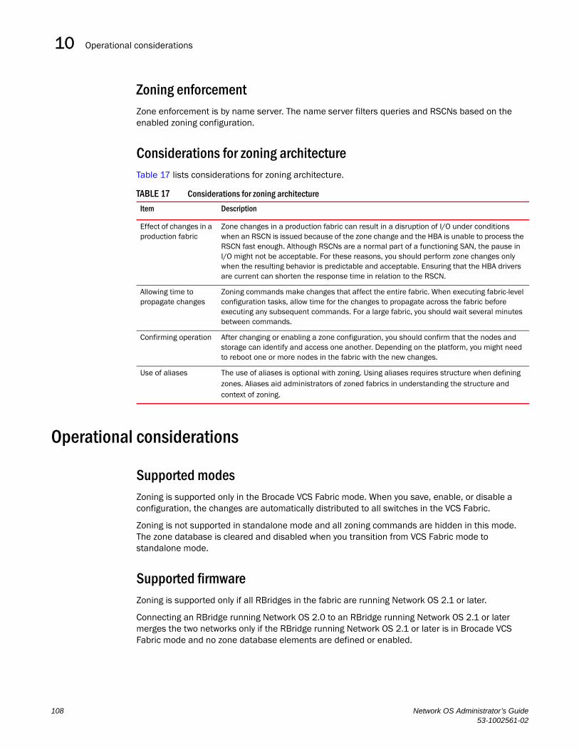
Operational considerations10
Zoning enforcementZone enforcement is by name server. The name server filters queries and RSCNs based on the enabled zoning configuration.
Considerations for zoning architectureTable 17 lists considerations for zoning architecture.
Operational considerations
Supported modesZoning is supported only in the Brocade VCS Fabric mode. When you save, enable, or disable a configuration, the changes are automatically distributed to all switches in the VCS Fabric.
Zoning is not supported in standalone mode and all zoning commands are hidden in this mode. The zone database is cleared and disabled when you transition from VCS Fabric mode to standalone mode.
Supported firmwareZoning is supported only if all RBridges in the fabric are running Network OS 2.1 or later.
Connecting an RBridge running Network OS 2.0 to an RBridge running Network OS 2.1 or later merges the two networks only if the RBridge running Network OS 2.1 or later is in Brocade VCS Fabric mode and no zone database elements are defined or enabled.
TABLE 17 Considerations for zoning architecture
Item Description
Effect of changes in a production fabric
Zone changes in a production fabric can result in a disruption of I/O under conditions when an RSCN is issued because of the zone change and the HBA is unable to process the RSCN fast enough. Although RSCNs are a normal part of a functioning SAN, the pause in I/O might not be acceptable. For these reasons, you should perform zone changes only when the resulting behavior is predictable and acceptable. Ensuring that the HBA drivers are current can shorten the response time in relation to the RSCN.
Allowing time to propagate changes
Zoning commands make changes that affect the entire fabric. When executing fabric-level configuration tasks, allow time for the changes to propagate across the fabric before executing any subsequent commands. For a large fabric, you should wait several minutes between commands.
Confirming operation After changing or enabling a zone configuration, you should confirm that the nodes and storage can identify and access one another. Depending on the platform, you might need to reboot one or more nodes in the fabric with the new changes.
Use of aliases The use of aliases is optional with zoning. Using aliases requires structure when definingzones. Aliases aid administrators of zoned fabrics in understanding the structure andcontext of zoning.
108 Network OS Administrator’s Guide53-1002561-02

Operational considerations 10
A switch running Network OS v3.0.0 will segment if it is attached to a switch running Network OS v2.0.0 regardless of zoning configuration. A switch running Network OS v3.0.0 will join the fabric with a 2.1.x switch and zones will be merged, but the cluster will not form, so no further zoning commands will be allowed until all switches are upgraded to the same firmware version and the cluster has formed.
The interswitch links (ISLs) connecting the two RBridges will segment if the RBridge running Network OS 2.1 or later has any zone defined or enabled, or the default zone is set to No Access. Any such configuration requires automatic distribution of zoning configuration data, which is not compatible with RBridges running Network OS 2.0.
Firmware downgrade and upgrade considerationsA firmware downgrade from Network OS v3.x to v2.1.x is not permitted under the following conditions:
1. One or more zone Aliases are configured on the switch. You must remove all references to zone aliases prior to a firmware downgrade. Use the no zoning defined-configuration alias command to delete all zone alias objects. Then issue the zoning enabled-configuration cfg-action {cfg-save | cfg-disable} command or the zoning enabled-configuration cfg-name cfgName command to commit the operation before re-attempting a firmware download.
2. An open zone transaction in progress. You must either commit or abort the current open transaction before re-attempting a firmware download. Use the zoning enabled-configuration cfg-action {cfg-save | cfg-disable} command or the zoning enabled-configuration cfg-name cfgName command to commit the current open transaction. Alternately, use the zoning enabled-configuration cfg-action cfg-transaction-abort command to abort the open transaction.
You cannot downgrade any switch in a Brocade VCS Fabric to Network OS v2.0 if any zone definition exists in the defined configuration. Any attempt to do so will fail while attempting to download the v2.0 firmware. For the downgrade to succeed, you must clear the defined configuration, disable any active configuration, set the default zoning mode to All Access, and then try again to download the firmware.
When you upgrade from Network OS v2.1.0 to v2.1.1 or v3.0.0, the zone database is cleared.
CAUTION
Clearing the defined configuration clears the zoning database for the entire fabric. If you want to downgrade just one switch without affecting the rest of the fabric, disconnect the switch from the fabric before deleting the defined configuration.
Zone configuration managementYou can perform zoning operations on any RBridge in the VCS Fabric, but they are always executed on the principal RBridge. Automatic distribution of the zoning configuration ensures that the effects of these operations are shared and instantly visible on all switches in the VCS Fabric. However, these operations are not permanent until a transaction commit operation saves them to nonvolatile memory, which holds the master copy of the zoning database. Any user can commit the transaction on any switch, and the commit operation saves the operations performed by all users. Once the zoning configuration is saved in permanent memory, it persists across reboot operations.
Network OS Administrator’s Guide 10953-1002561-02

Default zoning access modes10
A transaction commit occurs when you or another user initiates any of the following zoning operations:
• Saving the database to nonvolatile memory with the zoning enabled-configuration cfg-action cfg-save command.
• Enable a specific zone configuration with the zoning enabled-configuration cfg-name command.
• Disabling the currently enabled zone configuration with the no zoning enabled-configuration cfg-name command.
• Aborting the current transaction with the zoning enabled-configuration cfg-action cfg-transaction-abort command. This operation rolls back all zoning operations performed by any user since the last committed transaction.
If the principal RRridge reboots or goes down, Network OS selects a new principal and any pending zoning transaction is rolled back to the last committed transaction, which is the effective zoning configuration saved in nonvolatile memory. Any changes made to the effective configuration prior to an abort operation must be re-entered.
If an RBridge other than the principal reboots or goes down, the ongoing transaction is not backed out. Any zoning operations initiated by the RBridge are still part of the global transaction maintained on the principal RBridge.
If a fabric segments, the newly elected principal RBridge determines whether transaction data is retained. If a segment retains the original principal, it also retains ongoing transaction data. If a segment elects a new principal, the transaction is aborted.
The zone startup configuration is always equal to the running configuration. The running configuration will always be overwritten by the information from the master copy of the zoning database in nonvolatile memory at startup, so you always start up with the previous running configuration. It is not necessary to copy the running configuration to the startup configuration explicitly.
You can save a snapshot of the current running configuration using the copy running-config file command. You can add configuration entries from a saved configuration using the copy file running-config command. When saving the snapshot you must ensure that the saved running configuration contains no zoning transaction data, otherwise failures will occur when you attempt to restore configuration entries from the saved file. Any transaction data would cause such a failure, including empty configuration definitions or empty zones.
When restoring the running configuration, Brocade recommends copying the file to the running configuration in the absence of any other command line input.
NOTEWhen you restore a configuration using the copy command, the contents of the file are added to the defined configuration; they do not replace the defined configuration. The result is cumulative, is as if the input came from the command line.
Default zoning access modesThe default zoning mode controls device access if zoning is not implemented or if there is no enabled zone configuration. Default zoning has two access modes:
• All Access—All devices within the fabric can communicate with all other devices.
110 Network OS Administrator’s Guide53-1002561-02

Zone database size 10
• No Access—Devices in the fabric cannot access any other device in the fabric.
The default setting is All Access. Changing the default access mode requires committing the ongoing transaction for the change to take effect.
The default zoning mode takes effect when you disable the effective zone configuration. If your default zone has a large number of devices, to prevent RSCN storms from overloading those devices, you should set the default zoning mode to No Access before attempting to disable the zone configuration. If your default zone includes more than 300 devices, the zoning software prevents you from disabling the zoning configuration if the default zoning mode is All Access.
Setting the default zoning mode1. In the privileged EXEC mode, enter the configure terminal command to enter the global
configuration mode.
2. Enter one of the following commands, depending on the default access mode you want to configure:
• To set the default access mode to All Access, enter zoning enabled-configuration default-zone-access allaccess.
• To set the default access mode to No Access, enter zoning enabled-configuration default-zone-access noaccess.
3. Enter the zoning enabled-configuration cfg-action cfg-save or zoning enabled-configuration cfg-name command to commit the ongoing transaction and save the access mode change to nonvolatile memory.
4. Enter the show running-config zoning enabled-configuration command to verify the access mode change.
Example of setting the default zoning mode to no access
switch# configure terminalEntering configuration mode terminalswitch(config)# zoning enabled-configuration default-zone-access noaccessswitch(config)# zoning enabled-configuration cfg-action cfg-saveswitch(config)# do show running-config zoning enabled-configurationzoning enabled-configuration cfg-name "cfg1 *"zoning enabled-configuration default-zone-access noaccesszoning enabled-configuration cfg-action cfg-savezoning enabled-configuration enabled-zone zone1 member-entry 10:00:00:00:00:00:00:01 member-entry 10:00:00:00:00:00:00:02!zoning enabled-configuration enabled-zone zone3 member-entry 10:00:00:00:00:00:00:03 member-entry 10:00:00:00:00:00:00:04
Zone database sizeThe maximum size of a zone database is the upper limit for the defined configuration, and it is determined by the amount of memory available for storing the master copy of the defined configuration in flash memory.
Network OS Administrator’s Guide 11153-1002561-02

Zone aliases10
Use the following information displayed by the show zoning operation-info command to determine whether there is enough space to complete outstanding transactions:
• db-max—Theoretical maximum size of the zoning database kept in nonvolatile memory
• db-avail—Theoretical amount of free space available
• db-committed—The size of the defined configuration currently stored in nonvolatile memory
• db-transaction—The amount of memory required to commit the current transaction
The supported maximum zone database size is 100 KB. If the outstanding transaction data (db-transaction field) is less than the remaining supported space (100 KB - db-committed), enough space exists to commit the transaction.
Note that the db-max field shows a theoretical zone database limit of about 1MB. However, performance might become unacceptable if the zoning database exceeds 150 KB.
Viewing database size informationIn the privileged EXEC mode, enter the show zoning operation-info command.
Database and transaction size information is displayed in bytes.
switch# show zoning operation-infodb-max 1045274db-avail 1043895db-committed 367db-transaction 373transaction-token 1last-zone-changed-timestamp 2011-11-16 16:54:31 GMT-7:00last-zone-committed-timestamp 2011-11-16 16:23:44 GMT-7:00
Zone aliasesA zone alias is user-defined name for a logical group of ports or WWNs. You can simplify the process of creating and managing zones by first specifying aliases for zone members. Aliases facilitate tracking and eliminate the need for long lists of individual zone member names. An alias can be a member of a zone, but it cannot be a member of a zoning configuration.
Creating an alias1. In the privileged EXEC mode, enter the show name-server detail command to list the WWNs of
devices and targets available in the Brocade VCS Fabric.
2. Enter the configure terminal command to enter the global configuration mode.
3. Enter the zoning defined-configuration alias command followed by a name for the alias.
A sub-configuration mode prompt appears.
4. Enter the sub-configuration mode member-entry command to specify at least one member entry.
The member entry must be specified as a port WWN or a node WWN.
You can add multiple members in one operation by separating each member entry with a semicolon (;). No spaces are allowed after the semicolon.
112 Network OS Administrator’s Guide53-1002561-02

Zone aliases 10
5. Enter the exit command to return to the global configuration mode.
6. Enter the zoning enabled-configuration cfg-action cfg-save command to save the configuration to nonvolatile memory.
Example of creating an alias with one member node WWN:
switch# show name-server detailPID: 013100Port Name: 20:00:00:00:00:00:00:01Node Name: 10:00:00:00:00:00:00:01(output truncated)
switch# configure terminalEntering configuration mode terminalswitch(config)# zoning defined-configuration alias alias1switch(config-alias-alias1)# member-entry 10:00:00:00:00:00:00:01switch(config-alias-alias1)# exitswitch(config)# zoning enabled-configuration cfg-action cfg-saveswitch(config)#
Adding additional members to an existing alias1. In the privileged EXEC mode, enter the show name-server detail command to list the WWNs of
devices and targets available in the Brocade VCS Fabric.
2. Enter the configure terminal command to enter the global configuration mode.
3. Enter the zoning defined-configuration alias command followed the name of an existing zone alias.
A sub-configuration mode prompt appears.
4. Enter the sub-configuration mode member-entry command to specify at least one member entry.
The member entry must be specified as a port WWN or a node WWN.
You can add multiple members in one operation by separating each member entry with a semicolon (;). No spaces are allowed after the semicolon.
5. Enter the exit command to return to the global configuration mode.
6. Enter the zoning enabled-configuration cfg-action cfg-save command to save the configuration to nonvolatile memory.
Example of adding two member node WWNs to an existing alias
switch# show name-server detailPID: 013200Port Name: 20:00:00:00:00:00:00:02Node Name: 10:00:00:00:00:00:00:02(output truncated)PID: 013300Port Name: 20:00:00:00:00:00:00:03Node Name: 10:00:00:00:00:00:00:03(output truncated)
switch# configure terminalEntering configuration mode terminalswitch(config)# zoning defined-configuration alias alias1
Network OS Administrator’s Guide 11353-1002561-02

Zone aliases10
switch(config-alias-alias1)# member-entry 10:00:00:00:00:00:00:02;10:00:00:00:00:00:00:02switch(config-alias-alias1)# exitswitch(config)# zoning enabled-configuration cfg-action cfg-saveswitch(config)#
Removing a member from an alias1. In the privileged EXEC mode, enter the show running-config zoning command to display the
alias and its member WWNS.
2. Enter the configure terminal command to enter the global configuration mode.
3. Enter the zoning defined-configuration alias command followed the name of an existing zone alias.
A sub-configuration mode prompt appears.
4. Enter the sub-configuration mode no member-entry command to specify the WWN to be removed from the zone alias.
You can only remove one member at a time.
5. Enter the exit command to return to the global configuration mode.
6. Enter the zoning enabled-configuration cfg-action cfg-save command to save the configuration to nonvolatile memory.
Example of removing two members from an alias
switch# show running-config zoningzoning defined-configuration alias alias1 member-entry 10:00:00:00:00:00:00:01 member-entry 10:00:00:00:00:00:00:02 member-entry 10:00:00:00:00:00:00:03(output truncated)switch# configure terminalEntering configuration mode terminalswitch(config)# zoning defined-configuration alias alias1switch(config-alias-alias1)# no member-entry 10:00:00:00:00:00:00:02switch(config-alias-alias1)# no member-entry 10:00:00:00:00:00:00:03switch(config-alias-alias1)# exitswitch(config)# zoning enabled-configuration cfg-action cfg-save
Deleting an alias1. In the privileged EXEC mode, enter the show running-config zoning command to display the
alias and its member WWNS.
2. Enter the configure terminal command to enter the global configuration mode.
3. Enter the no zoning defined-configuration alias command followed the name of the alias you want to delete.
4. Enter the show running-config zoning command to verify the change in the defined configuration (optional).
5. Enter the zoning enabled-configuration cfg-action cfg-save command to save the configuration to nonvolatile memory.
114 Network OS Administrator’s Guide53-1002561-02

Zone creation and management 10
Example of deleting an alias
switch# show running-config zoningzoning defined-configuration alias alias1 member-entry 10:00:00:00:00:00:00:01!zoning enabled-configuration cfg-name ""zoning enabled-configuration default-zone-access allaccesszoning enabled-configuration cfg-action cfg-noneswitch# configure terminalEntering configuration mode terminalswitch(config)# no zoning defined-configuration alias alias1switch(config)# do show running-config zoningzoning enabled-configuration cfg-name ""zoning enabled-configuration default-zone-access allaccesszoning enabled-configuration cfg-action cfg-noneswitch(config)# zoning enabled-configuration cfg-action cfg-saveswitch(config)#
Zone creation and management
Creating a zoneA zone cannot persist without any zone members. When you create a new zone, the zoning defined-configuration zone command places you in a command sub-configuration mode where you can add the first zone member entry. You can specify multiple members by separating each member from the next by a semicolon (;).
NOTEZones without any zone members cannot exist in volatile memory. They are deleted when the transaction commits successfully.
The following procedure adds a new zone to the defined configuration.
1. In the privileged EXEC mode, enter the show name-server detail command to obtain the WWNs of servers and targets available in the Brocade VCS Fabric.
2. Enter the configure terminal command to enter the global configuration mode.
3. Enter the zoning defined-configuration zone command and enter a new zone name to add a new zone.
A sub-configuration mode prompt appears.
4. Enter the sub-configuration mode member-entry command to specify at least one member entry.
The member entry must be specified as a port WWN, a node WWN, or an alias. You can mix WWNs and aliases.
Add multiple members in one operation by separating each member entry with a semicolon (;). No spaces are allowed after the semicolon.
5. Enter the exit command to return to the global configuration mode.
6. Enter the zoning enabled-configuration cfg-action cfg-save command to save the modified configuration to nonvolatile memory.
Network OS Administrator’s Guide 11553-1002561-02

Zone creation and management10
Example of creating a zone with two members, a WWN and an alias
switch# show name-server detailPID: 012100Port Name: 10:00:00:05:1E:ED:95:38Node Name: 20:00:00:05:1E:ED:95:38(output truncated)
switch# configure terminalEntering configuration mode terminalswitch(config)# zoning defined-configuration zone zone1switch(config-zone-zone1)# member-entry 20:00:00:05:1E:ED:95:38;alias2switch(config-zone-zone1)# exitswitch(config)# zoning enabled-configuration cfg-action cfg-saveswitch(config)#
Adding a member to a zone1. In the privileged EXEC mode, enter the show name-server detail command to list the WWNs of
devices and targets available on the Brocade VCS Fabric cluster.
2. Enter the configure terminal command to enter the global configuration mode.
3. Enter the zoning defined-configuration zone command and enter the name of an existing zone.
A sub-configuration mode prompt appears.
4. Enter the sub-configuration mode member-entry command and specify the member you want to add.
The new member can be specified by a port WWN, a node WWN, or a zone alias.
Add multiple members in one operation by separating each member with a semicolon (;).
5. Enter the exit command to return to the global configuration mode.
6. Enter the zoning enabled-configuration cfg-action cfg-save command to save the modified configuration to nonvolatile memory.
Example of adding three members to a zone, two node WWNs and an alias
switch# show name-server detailPID: 012100Port Name: 50:05:07:61:00:1b:62:edNode Name: 50:05:07:61:00:1b:62:ed(output truncated)PID: 012200Port Name: 50:05:07:61:00:09:20:b4Node Name: 50:05:07:61:00:09:20:b4(output truncated)
switch# configure terminalEntering configuration mode terminalswitch(config)# zoning defined-configuration zone zone1 switch(config-zone-zone1)# member-entry 50:05:07:61:00:1b:62:ed;50:05:07:61:00:09:20:b4;alias3switch(config-zone-zone1)# exitswitch(config)# zoning enabled-configuration cfg-action cfg-saveswitch(config)#
116 Network OS Administrator’s Guide53-1002561-02

Zone creation and management 10
Removing a member from a zone1. In the privileged EXEC mode, enter the configure terminal command to enter the global
configuration mode.
2. Enter the zoning defined-configuration zone command and enter the name of the zone from which you want to remove a member.
A sub-configuration mode prompt appears.
3. Enter the sub-configuration mode no member-entry parameter and specify the WWN or the alias of the member you want to remove.
You can remove only one member at a time. To remove more than one member, you must issue the no member-entry command for each member you want to remove.
4. Enter the exit command to return to the global configuration mode.
5. Enter the zoning enabled-configuration cfg-action cfg-save command to save the modified configuration to nonvolatile memory.
NOTESaving the configuration to nonvolatile memory also deletes the zone if the member you are removing is the last member in the zone.
Example of removing more than one member from a zone
switch# configure terminalEntering configuration mode terminalswitch(config)# zoning defined-configuration zone zone1 switch(config-zone-zone1)# no member-entry 50:05:07:61:00:09:20:b4switch(config-zone-zone1)# no member-entry alias3switch(config-zone-zone1)# exitswitch(config)# zoning enabled-configuration cfg-action cfg-saveswitch(config)#
Deleting a zoneBefore deleting a zone, ensure that the zone is not a member of any zone configuration. Although the deletion will proceed in RAM, you will not be able to save the configuration to nonvolatile memory if a defined zone configuration has the deleted zone as a member.
1. In the privileged EXEC mode, enter the show running-config zoning defined-configuration command and verify that the zone you want to delete is not a member of an existing zone configuration. If the zone is a member of an existing zone configuration, remove it.
2. Enter the configure terminal command to enter the global configuration mode.
3. Enter the no zoning defined-configuration zone command and enter the name of the zone you want to delete.
4. Enter the zoning enabled-configuration cfg-action cfg-save command to save the modified configuration to nonvolatile memory.
NOTESaving the configuration to nonvolatile memory also deletes the zone configuration if the zone you are removing is the last member zone in the configuration.
Network OS Administrator’s Guide 11753-1002561-02

Zone configuration management10
Example of removing a zone from the defined configuration
switch# show running-config zoning defined-configurationswitch# configure terminalEntering configuration mode terminalswitch(config)# no zoning defined-configuration zone zone2switch(config)# zoning enabled-configuration cfg-action cfg-saveswitch(config)#
Zone configuration management
Viewing the defined configurationTo view the defined configuration, in the privileged EXEC mode, enter the show running-config zoning defined-configuration command.
For each configuration, the command lists each member zone. For each zone, the command lists the WWN of each member.
switch# show running-config zoning defined-configuration zoning defined-configuration cfg cfg0 member-zone zone_0_1 member-zone zone_0_2 member-zone zone_0_3 member-zone zone_0_4 member-zone zone_same!zoning defined-configuration cfg cfg1 member-zone zone_1_1 member-zone zone_1_2 member-zone zone_1_3 member-zone zone_1_4 member-zone zone_same!zoning defined-configuration cfg cfg2 member-zone zone_2_1 member-zone zone_2_2 member-zone zone_2_3 member-zone zone_2_4 member-zone zone_same!zoning defined-configuration cfg cfg4 member-zone zone2 member-zone zone3!zoning defined-configuration zone zone0 member-entry 11:22:33:44:55:66:77:80 member-entry 11:22:33:44:55:66:77:81 member-entry 11:22:33:44:55:66:77:82 member-entry 11:22:33:44:55:66:77:83 member-entry 11:22:33:44:55:66:77:84!zoning defined-configuration zone zone1 member-entry 11:22:33:44:55:66:77:80 member-entry 11:22:33:44:55:66:77:81 member-entry 11:22:33:44:55:66:77:82 member-entry 11:22:33:44:55:66:77:83
118 Network OS Administrator’s Guide53-1002561-02

Zone configuration management 10
member-entry 11:22:33:44:55:66:77:84!zoning defined-configuration zone zone2 member-entry 11:22:33:44:55:66:77:80 member-entry 11:22:33:44:55:66:77:81 member-entry 11:22:33:44:55:66:77:82 member-entry 11:22:33:44:55:66:77:83 member-entry 11:22:33:44:55:66:77:84!(output truncated)
Viewing the enabled configurationTo view the enabled configuration, in the privileged EXEC mode, enter the show running-config zoning enabled-configuration command. The following information about the enabled configuration is displayed:
• The name of the configuration
• The configuration action
• The mode of the default zone--The mode that will be active if you disable the enabled configuration
• A list of WWN member names for each effective zone in the enabled configuration
The configuration name has an asterisk (*) appended to it if an outstanding transaction exists; the asterisk is not present if no outstanding transaction exists. Similarly, the configuration action is flagged as “cfg-save” if no outstanding transaction exists; “cfg-none” indicates that an outstanding transaction exists. A CFG_MARKER flag is appended to the configuration if the enabled configuration does not exactly match the defined configuration. This scenario occurs when you have an enabled configuration and make changes to the defined-configuration, and then, instead of enabling the defined configuration, you issue the cfg-save command.
switch# show running-config zoning enabled-configuration zoning enabled-configuration cfg-name cfg1zoning enabled-configuration default-zone-access allaccesszoning enabled-configuration cfg-action cfg-savezoning enabled-configuration enabled-zone zone0member-entry 11:22:33:44:55:66:77:80 member-entry 11:22:33:44:55:66:77:81!zoning enabled-configuration enabled-zone zone1 member-entry 11:22:33:44:55:66:77:80 member-entry 11:22:33:44:55:66:77:81!zoning enabled-configuration enabled-zone zone2 member-entry 11:22:33:44:55:66:77:80 member-entry 11:22:33:44:55:66:77:81
Issue the show running-config zoning command without any parameters to view both the defined enabled and the enabled configuration.
Network OS Administrator’s Guide 11953-1002561-02

Zone configuration management10
Creating a zone configurationA zone configuration cannot persist without any member zones. When creating a new zone configuration, the zoning defined-configuration cfg command places you in a command sub-configuration mode where you must add at least one member zone. While zone configurations without any member zones can exist in volatile memory, they are deleted when the transaction commits successfully.
The following procedure adds a new zone configuration to the defined configuration.
1. In the privileged EXEC mode, enter the configure terminal command to enter the global configuration mode.
2. Enter the zoning defined-configuration cfg command and enter a new configuration name.
A sub-configuration mode prompt appears.
3. Enter the member-zone sub-configuration mode command and specify the name of at least one zone.
Add multiple zones in one operation by separating each zone name with a semicolon (;).
4. Enter the exit command to return to the global configuration mode.
5. Enter the zoning enabled-configuration cfg-action cfg-save command to save the modified configuration to nonvolatile memory.
Example of creates a zone configuration with one member zone.
switch# configure terminalEntering configuration mode terminalswitch(config)# zoning defined-configuration cfg config1switch(config-cfg-config1)# member-zone zone1switch(config-cfg-config1)# exitswitch(config)# zoning enabled-configuration cfg-action cfg-saveswitch(config)#
NOTEZone aliases are not valid zone configuration members. Adding an alias to an existing zone configuration will not be blocked. However, the attempt to enable a zone configuration that contains aliases will fail with an appropriate error message.
120 Network OS Administrator’s Guide53-1002561-02

Zone configuration management 10
Adding a zone to a zone configuration1. In the privileged EXEC mode, enter the configure terminal command to enter the global
configuration mode.
2. Enter the zoning defined-configuration cfg command and enter the name of the configuration to which you want to add zones.
The command prompt changes to indicate a sub-configuration mode.
3. Enter the member-zone sub-configuration mode command and specify the name of at least one member zone.
Add multiple zones in one operation by separating each zone name with a semicolon (;).
4. Enter the exit command to return to the global configuration mode.
5. Enter the zoning enabled-configuration cfg-action cfg-save command to save the modified configuration to nonvolatile memory.
Example of adding two zones to config1.
switch# configure terminalEntering configuration mode terminalswitch(config)# zoning defined-configuration cfg config1switch(config-cfg-config1)# member-zone zone2;zone3switch(config-cfg-config1)# exitswitch(config)# zoning enabled-configuration cfg-action cfg-saveswitch(config)#
NOTEZone aliases are not valid zone configuration members. Adding an alias to an existing zone configuration will not be blocked. However, the attempt to enable a zone configuration that contains aliases will fail with an appropriate error message.
Removing a zone from a zone configuration1. In the privileged EXEC mode, enter the configure terminal command to enter the global
configuration mode.
2. Enter the zoning defined-configuration cfg command and enter the name of the configuration from which you want to remove a zone.
The command prompt changes to indicate a sub-configuration mode.
3. Enter the no member-zone sub-configuration mode command and specify the name of the zone you want to remove from the configuration.
You can remove only one member at a time. To remove more than one member, you must issue the no member-zone command for each member you want to remove.
4. Enter the exit command to return to the global configuration mode.
5. Enter the zoning enabled-configuration cfg-action cfg-save command to save the modified configuration to nonvolatile memory.
NOTESaving the configuration to nonvolatile memory deletes the configuration if the zone you are removing is the last member in the configuration.
Network OS Administrator’s Guide 12153-1002561-02

Zone configuration management10
Example of removing two zones config1.
switch# configure terminalEntering configuration mode terminalswitch(config)# zoning defined-configuration cfg config1switch(config-cfg-config1)# no member-zone zone2switch(config-cfg-config1)# no member-zone zone3switch(config-cfg-config1)# exitswitch(config)# zoning enabled-configuration cfg-action cfg-saveswitch(config)#
Enabling a zone configurationOnly one zone configuration can be enabled in a VCS Fabric. The following procedure selects a configuration from the defined configuration and makes it the enabled configuration. If a zone configuration is currently enabled, the newly enabled configuration replaces the previously enabled configuration.
1. In the privileged EXEC mode, enter the configure terminal command to enter the global configuration mode.
2. Enter the zoning enabled-configuration cfg-name command with the name of the configuration you want to enable.
In addition to enabling the specified configuration, this command also saves any changes made to the zoning database in volatile memory to nonvolatile memory. The saved configuration is persistent.
If the configuration refers to a nonexistent zone or a zone with no members assigned to it, the operation fails and the command returns an error message. The following example enables config1.
Example of enabling a zone configuration
switch# configure terminalEntering configuration mode terminalswitch(config)# zoning enabled-configuration cfg-name config1switch(config)#
Example of a failed enable operation
The enable operation fails because the configuration contains a zone without members.
switch(config)# do show running-config zoningzoning defined-configuration cfg cfg1member-zone-zone1member-zone zone2!zoning defined-configuration zone zone1 <------------Zone with no member!zoning defined-configuration zone zone2member-entry 20:03:00:11:0d:bc:76:09!zoning enabled-configuration cfg-name ""zoning enabled-configuration default-zone-access allaccesszoning enabled-configuration cfg-action cfg-none
switch(config)# zoning enabled-configuration cfg-name cfg1% Error: Command Failed. Cfg contains empty zone object "zone1"
122 Network OS Administrator’s Guide53-1002561-02
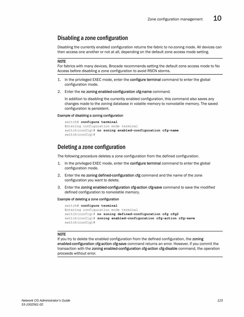
Zone configuration management 10
Disabling a zone configurationDisabling the currently enabled configuration returns the fabric to no-zoning mode. All devices can then access one another or not at all, depending on the default zone access mode setting.
NOTEFor fabrics with many devices, Brocade recommends setting the default zone access mode to No Access before disabling a zone configuration to avoid RSCN storms.
1. In the privileged EXEC mode, enter the configure terminal command to enter the global configuration mode.
2. Enter the no zoning enabled-configuration cfg-name command.
In addition to disabling the currently enabled configuration, this command also saves any changes made to the zoning database in volatile memory to nonvolatile memory. The saved configuration is persistent.
Example of disabling a zoning configuration
switch# configure terminalEntering configuration mode terminalswitch(config)# no zoning enabled-configuration cfg-name switch(config)#
Deleting a zone configurationThe following procedure deletes a zone configuration from the defined configuration.
1. In the privileged EXEC mode, enter the configure terminal command to enter the global configuration mode.
2. Enter the no zoning defined-configuration cfg command and the name of the zone configuration you want to delete.
3. Enter the zoning enabled-configuration cfg-action cfg-save command to save the modified defined configuration to nonvolatile memory.
Example of deleting a zone configuration
switch# configure terminalEntering configuration mode terminalswitch(config)# no zoning defined-configuration cfg cfg2switch(config)# zoning enabled-configuration cfg-action cfg-saveswitch(config)#
NOTEIf you try to delete the enabled configuration from the defined configuration, the zoning enabled-configuration cfg-action cfg-save command returns an error. However, if you commit the transaction with the zoning enabled-configuration cfg-action cfg-disable command, the operation proceeds without error.
Network OS Administrator’s Guide 12353-1002561-02

Zone configuration management10
Clearing changes to a zone configurationThe following procedure aborts all pending transactions and removes all uncommitted operations from the database. It returns the configuration in volatile memory to the state it was in when a zoning enabled-configuration cfg-action cfg-save or zoning enabled-configuration cfg-name command was last executed successfully.
1. In the privileged EXEC mode, enter the configure terminal command to enter the global configuration mode.
2. Enter the zoning enabled-configuration cfg-action cfg-transaction-abort command.
Example of aborting a transaction
switch# configure terminalEntering configuration mode terminalswitch(config)# zoning enabled-configuration cfg-action cfg-transaction-abortswitch(config)#
Clearing all zone configurationsThe following procedure clears all zone configurations from the defined configuration and enables the default zone.
NOTEFor fabrics with many devices, Brocade recommends setting the default access mode to No Access before clearing all zone configurations to avoid RSCN storms.
1. In the privileged EXEC mode, enter the configure terminal command to enter the global configuration mode.
2. Enter the zoning enabled-configuration cfg-action cfg-clear command.
3. Enter one of the following commands, depending on whether an enabled zone configuration exists:
• If no enabled zone configuration exists, enter the zoning enabled-configuration cfg-action cfg-save command.
• If an enabled zone configuration exists, enter the no zoning enabled-configuration cfg-name command to disable and clear the zone configuration in nonvolatile memory for all switches in the fabric.
switch# configure terminalEntering configuration mode terminalswitch(config)# zoning enabled-configuration cfg-action cfg-clearswitch(config)# no zoning enabled-configuration cfg-nameswitch(config)#
Backing up the zone configurationTo backup your zoning configuration you copy it to a file and store it on a server or on an attached USB device. You can use the copy to restore the configuration if needed.
124 Network OS Administrator’s Guide53-1002561-02

Zone configuration management 10
NOTEEnsure that no transaction is pending before you perform the copy operation, otherwise failures will occur when you attempt to restore configuration entries from the saved file. Any transaction data would cause such a failure, including empty configuration definitions or empty zones.
1. In privileged EXEC mode, enter the configure terminal command to enter the global configuration mode.
2. Empty the transaction buffer by either committing the transaction to nonvolatile memory or aborting the transaction.
• To commit the transaction, enter the zoning enabled-configuration cfg-action cfg-save command, the zoning enabled configuration cfg-name command, or the zoning enabled-configuration cfg-action cfg-disable command.
• To abort the transaction, enter the zoning enabled-configuration cfg-action cfg-transaction-abort command.
3. Enter the exit command to return to privileged EXEC mode.
4. Enter the copy command. For the source file, use running-config. For the destination file, use the file name you want the configuration copied to.
Example Example of making a backup copy on a USB device
switch# configure terminalEntering configuration mode terminalswitch(config)# zoning enabled-configuration cfg-action cfg-saveswitch(config)# exitswitch# copy running-config usb://myconfig
Restoring a configuration from backupWhen you restore a configuration from backup and add to the running configuration, the zone configuration identified in the backup copy as the enabled configuration becomes the new enabled configuration.
In the privileged EXEC mode, enter the copy command. For the source file use the file where the saved configuration is stored. For the destination file, use running-config.
This operation updates the defined configuration in RAM.
NOTEThe copy command adds to the defined configuration. It does not replace the defined configuration.
The following example adds the configuration in the file named myconfig on the attached USB device to the defined configuration.
switch# copy usb://myconfig running-config
Network OS Administrator’s Guide 12553-1002561-02

Zone configuration scenario10
Zone configuration scenario
FIGURE 13 Zone configuration example
The following example creates the zone configuration shown in Figure 13. The example assumes that two hosts need access to the same storage device, while each host needs private storage of its own. You create two zones: ZoneA contains Host1, its private storage device, and the shared storage device; ZoneB contains Host2, its private storage device, and the shared storage device. In addition, you create two zone configurations: Cfg1 in which only ZoneA is effective; Cfg2, in which both zones are effective.
1. Log in to any switch in the Brocade VCS Fabric.
2. Enter the show name-server detail command to list the available WWNs,
3. Enter the configure terminal command to enter the global configuration mode.
4. Enter the zoning defined-configuration zone command to create ZoneA.
5. Enter the zoning defined-configuration zone command to create ZoneB.
6. Enter the zoning defined-configuration cfg command to create the configuration cfg1 with ZoneA as its only member.
7. Enter the zoning defined-configuration cfg command to create the configuration cfg2 with ZoneA and Zone B as its members.
8. Enter the zoning running-config defined-configuration command to view the defined zone configuration.
9. Enter the zoning enabled-configuration cfg-name command to enable cfg2.
Private StorageWWN 50:05:07:61:00:09:20:b4
Private StorageWWN 50:05:07:61:00:22:18:9b
Shared StorageWWN 50:05:07:61:00:1b:62:ed
Host 1WWN 20:00:00:05:1e:ed:95:38
Host 2WWN 20:00:00:05:1e:ed:18:c3
Zone A
Zone B
126 Network OS Administrator’s Guide53-1002561-02
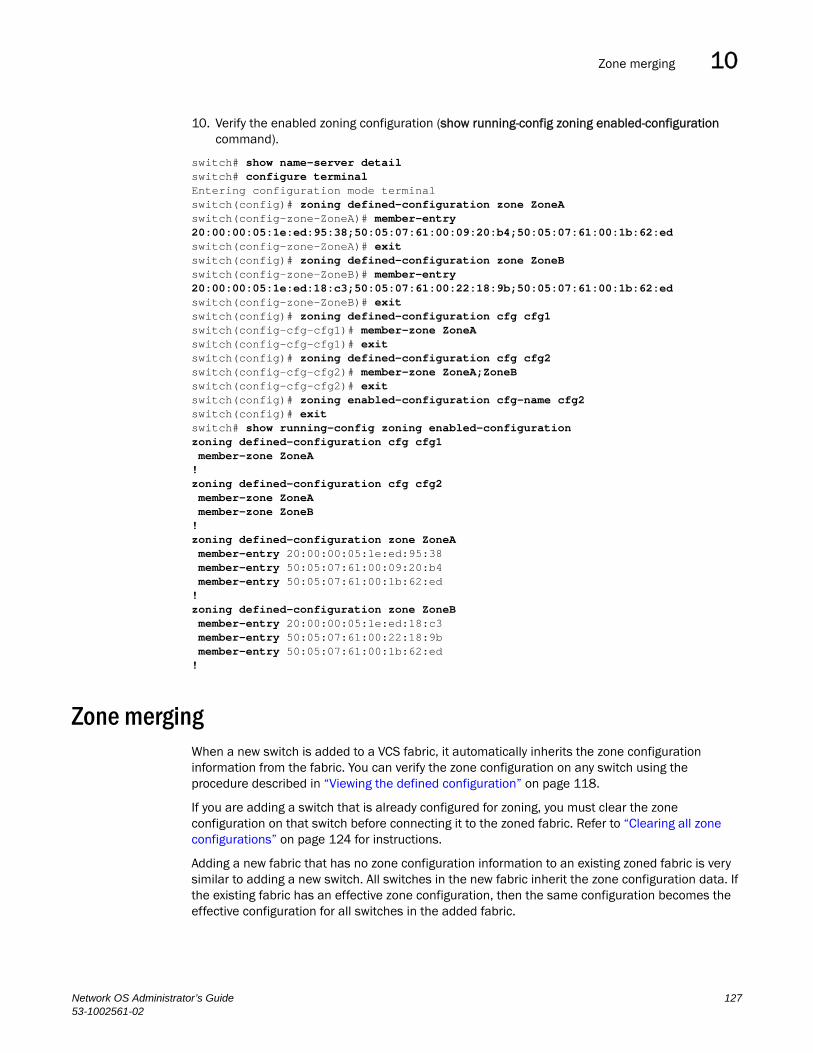
Zone merging 10
10. Verify the enabled zoning configuration (show running-config zoning enabled-configuration command).
switch# show name-server detailswitch# configure terminalEntering configuration mode terminalswitch(config)# zoning defined-configuration zone ZoneAswitch(config-zone-ZoneA)# member-entry 20:00:00:05:1e:ed:95:38;50:05:07:61:00:09:20:b4;50:05:07:61:00:1b:62:edswitch(config-zone-ZoneA)# exitswitch(config)# zoning defined-configuration zone ZoneBswitch(config-zone-ZoneB)# member-entry 20:00:00:05:1e:ed:18:c3;50:05:07:61:00:22:18:9b;50:05:07:61:00:1b:62:edswitch(config-zone-ZoneB)# exitswitch(config)# zoning defined-configuration cfg cfg1switch(config-cfg-cfg1)# member-zone ZoneAswitch(config-cfg-cfg1)# exitswitch(config)# zoning defined-configuration cfg cfg2switch(config-cfg-cfg2)# member-zone ZoneA;ZoneBswitch(config-cfg-cfg2)# exitswitch(config)# zoning enabled-configuration cfg-name cfg2switch(config)# exitswitch# show running-config zoning enabled-configurationzoning defined-configuration cfg cfg1 member-zone ZoneA! zoning defined-configuration cfg cfg2 member-zone ZoneA member-zone ZoneB!zoning defined-configuration zone ZoneA member-entry 20:00:00:05:1e:ed:95:38 member-entry 50:05:07:61:00:09:20:b4 member-entry 50:05:07:61:00:1b:62:ed!zoning defined-configuration zone ZoneB member-entry 20:00:00:05:1e:ed:18:c3 member-entry 50:05:07:61:00:22:18:9b member-entry 50:05:07:61:00:1b:62:ed!
Zone mergingWhen a new switch is added to a VCS fabric, it automatically inherits the zone configuration information from the fabric. You can verify the zone configuration on any switch using the procedure described in “Viewing the defined configuration” on page 118.
If you are adding a switch that is already configured for zoning, you must clear the zone configuration on that switch before connecting it to the zoned fabric. Refer to “Clearing all zone configurations” on page 124 for instructions.
Adding a new fabric that has no zone configuration information to an existing zoned fabric is very similar to adding a new switch. All switches in the new fabric inherit the zone configuration data. If the existing fabric has an effective zone configuration, then the same configuration becomes the effective configuration for all switches in the added fabric.
Network OS Administrator’s Guide 12753-1002561-02

Zone merging10
NOTETo prevent an unwanted zone merge, use the no fabric isl enable command on ISL interfaces instead of the shutdown command on tengigabitethernet ports.
Before the new fabric can merge successfully, it must satisfy the following criteria:
• Before merging
- Ensure that all switches adhere to the default zone merge rules as described in “Zone merging scenarios” on page 129.
- Ensure that the enabled and defined zone configurations match. If they do not match and you merge with another switch, the merge might be successful, but unpredictable zoning and routing behavior can occur.
• Merging and segmentation
The system checks each port as it comes online to determine whether the ports should be segmented. E_Ports come online on power up, enabling a switch, or adding a new switch, and the system checks the zone database to see if the two database that can be merged safely.
If you have implemented default zoning you must set the switch you are adding into the fabric to the same default zone mode setting as the rest of the fabric to avoid segmentation.
• Merging rules
Observe these rules when merging zones:
- Local and adjacent configurations: If the local and adjacent zone database configurations are the same, they will remain unchanged after the merge.
- Enabled configurations: If there is an enabled configuration between two switches, the enabled zone configurations must match.
- Zone membership: If a zoning object has the same name in both the local and adjacent defined configurations, the content and order of the members are important.
- Objects in adjacent configurations: If a zoning object appears in an adjacent defined configuration, but not in the local defined configuration, the zoning object is added to the local defined configuration. The modified zone database must fit in the nonvolatile memory area allotted for the zone database.
- Local configuration modification: If a local defined configuration is modified because of a merge, the new zone database is propagated to the other switches within the merge request.
• Merging two fabrics
If both fabrics have identical zones and configurations enabled, including the default zone mode, the two fabrics will join to make one larger fabric with the same zone configuration across the newly created fabric.
If the two fabrics have conflicting zone configurations, they will not merge. If the two fabrics cannot join, the ISLs between the switches will segment.
The transaction state after the merge depends on which switch is elected as the principal RBridge. The newly elected principal RBridge retains the same transaction information it had before the merge. Transaction data is discarded from any switch that lost its principal status during the merge.
• Merge conflicts
When a merge conflict is present, a merge does not take place and the ISLs will segment.
128 Network OS Administrator’s Guide53-1002561-02

Zone merging 10
If the fabrics have different zone configuration data, the system attempts to merge the two sets of zone configuration data. If the zones cannot merge, the ISLs will be segmented.
A merge is not possible under any of the following conditions:
- Configuration mismatch: Zoning is enabled in both fabrics and the zone configurations that are enabled are different in each fabric.
- Zone Database Size: The zone database size exceeds the maximum limit of another switch.
NOTEIf the zone members on two switches are not listed in the same order, the configuration is considered a mismatch, and the switches will segment from the fabric. For example: cfg1 = z1; z2 is different from cfg1 = z2; z1, even though the members of the configuration are the same. If zone members on two switches have the same names defined in the configuration, make sure the zone members are listed in the same order.
Fabric segmentation and zoningIf the connections between two fabrics are no longer available, the fabric segments into two separate fabrics. Each new fabric retains the previous zone configuration.
If the connections between two fabrics are replaced and no changes have been made to the zone configuration in either of the two fabrics, the two fabrics can merge back into one single fabric. If any changes that cause a conflict have been made to either zone configuration, a fabric merge may fail.
Zone merging scenariosThe following tables provide information on merging zones and the expected results.
• Table 18 on page 129: Defined and enabled configurations
• Table 19 on page 131: Different content
• Table 20 on page 132: Different names
• Table 21 on page 132: Default access mode
TABLE 18 Zone merging scenarios: Defined and enabled configurations
Description Switch A Switch B Expected results
Switch A has a defined configuration.Switch B does not have a defined configuration.
defined:cfg1: zone1: 10:00:00:90:69:00:00:8a; 10:00:00:90:69:00:00:8benabled: none
defined: none enabled: none
Configuration from Switch A propagates throughout the fabric in an inactive state, because the configuration is not enabled.
Switch A has a defined and enabled configuration. Switch B has a defined configuration but no enabled configuration.
defined: cfg1zone1: 10:00:00:90:69:00:00:8a; 10:00:00:90:69:00:00:8b enabled: cfg1:
defined: cfg1zone1: 10:00:00:90:69:00:00:8a; 10:00:00:90:69:00:00:8b enabled: none
Configuration from Switch A propagates throughout the fabric. The configuration is enabled after the merge in the fabric.
Network OS Administrator’s Guide 12953-1002561-02

Zone merging10
Switch A and Switch B have the same defined configuration. Neither have an enabled configuration.
defined: cfg1zone1: 10:00:00:90:69:00:00:8a; 10:00:00:90:69:00:00:8b enabled: none
defined: cfg1zone1: 10:00:00:90:69:00:00:8a; 10:00:00:90:69:00:00:8benabled: none
No change (clean merge).
Switch A and Switch B have the same defined and enabled configuration.
defined: cfg1zone1: 10:00:00:90:69:00:00:8a; 10:00:00:90:69:00:00:8benabled: cfg1:
defined: cfg1zone1: 10:00:00:90:69:00:00:8a; 10:00:00:90:69:00:00:8b enabled: cfg1:
No change (clean merge).
Switch A does not have a defined configuration.Switch B has a defined configuration.
defined: noneenabled: none
defined:cfg1zone1: 10:00:00:90:69:00:00:8a; 10:00:00:90:69:00:00:8b enabled: none
Switch A absorbs the configuration from the fabric.
Switch A does not have a defined configuration.Switch B has a defined and enabled configuration.
defined: noneenabled: none
defined:cfg1zone1: 10:00:00:90:69:00:00:8a; 10:00:00:90:69:00:00:8benabled: cfg1
Switch A absorbs the configuration from the fabric, with cfg1 as the enabled configuration.
Switch A and Switch B have the same defined configuration. Only Switch B has an enabled configuration.
defined: cfg1zone1: 10:00:00:90:69:00:00:8a; 10:00:00:90:69:00:00:8benabled: none
defined: cfg1zone1: 10:00:00:90:69:00:00:8a; 10:00:00:90:69:00:00:8benabled: cfg1
Clean merge, with cfg1 as the enabled configuration.
Switch A and Switch B have different defined configurations. Neither have an enabled configuration.
defined: cfg2zone2: 10:00:00:90:69:00:00:8c; 10:00:00:90:69:00:00:8d enabled: none
defined: cfg1zone1: 10:00:00:90:69:00:00:8a; 10:00:00:90:69:00:00:8benabled: none
Clean merge. The new configuration will be a composite of the two.defined: cfg1
zone1: 10:00:00:90:69:00:00:8a; 10:00:00:90:69:00:00:8b cfg2:
zone2: 10:00:00:90:69:00:00:8c; 10:00:00:90:69:00:00:8d enabled: none
TABLE 18 Zone merging scenarios: Defined and enabled configurations (Continued)
Description Switch A Switch B Expected results
130 Network OS Administrator’s Guide53-1002561-02

Zone merging 10
Switch A and Switch B have different defined configurations. Switch B has an enabled configuration.
defined: cfg2zone2: 10:00:00:90:69:00:00:8c; 10:00:00:90:69:00:00:8denabled: none
defined: cfg1zone1: 10:00:00:90:69:00:00:8a; 10:00:00:90:69:00:00:8benabled: cfg1
Clean merge. The new configuration is a composite of both, with cfg1 as the enabled configuration.
Switch A does not have a defined configuration. Switch B has a defined configuration and an enabled configuration, but the enabled configuration is different from the defined configuration.
defined: noneenabled: none
defined: cfg1zone1: 10:00:00:90:69:00:00:8a; 10:00:00:90:69:00:00:8b
effective: cfg1zone1: 10:00:00:90:69:00:00:8a; 10:00:00:90:69:00:00:8bzone2: 10:00:00:90:69:00:00:8c, 10:00:00:90:69:00:00:8d
Clean merge. Switch A absorbs the defined configuration from the fabric, with cfg1 as the effective configuration. In this case, however, the effective configurations for Switch A and Switch B are different. You should issue a zoning enabled-configuration cfg-name command from the switch with the proper effective configuration.
TABLE 18 Zone merging scenarios: Defined and enabled configurations (Continued)
Description Switch A Switch B Expected results
TABLE 19 Zone merging scenarios: Different content
Description Switch A Switch B Expected results
Enabled configuration mismatch. defined: cfg1 zone1: 10:00:00:90:69:00:00:8a; 10:00:00:90:69:00:00:8benabled: cfg1 zone1: 10:00:00:90:69:00:00:8a; 10:00:00:90:69:00:00:8b
defined: cfg2 zone2: 10:00:00:90:69:00:00:8c; 10:00:00:90:69:00:00:8d enabled: cfg2 zone2: 10:00:00:90:69:00:00:8c; 10:00:00:90:69:00:00:8d
Fabric segments due to mismatching zone configurations
Configuration content mismatch. defined: cfg1 zone1: 10:00:00:90:69:00:00:8a; 10:00:00:90:69:00:00:8benabled: irrelevant
defined: cfg1 zone1: 10:00:00:90:69:00:00:8c; 10:00:00:90:69:00:00:8d enabled: irrelevant
Fabric segments due to mismatching zone content
Network OS Administrator’s Guide 13153-1002561-02

Zone merging10
TABLE 20 Zone merging scenarios: Different names
Description Switch A Switch B Expected results
Same content, different enabled configuration name.
defined: cfg1 zone1: 10:00:00:90:69:00:00:8a; 10:00:00:90:69:00:00:8b enabled: cfg1 zone1: 10:00:00:90:69:00:00:8a; 10:00:00:90:69:00:00:8b
defined:cfg2 zone1: 10:00:00:90:69:00:00:8a; 10:00:00:90:69:00:00:8b enabled: cfg2 zone1: 10:00:00:90:69:00:00:8a; 10:00:00:90:69:00:00:8b
Fabric segments due to mismatching zone configurations
Same content, different zone name.
defined: cfg1 zone1: 10:00:00:90:69:00:00:8a; 10:00:00:90:69:00:00:8b enabled: irrelevant
defined: cfg1 zone2: 10:00:00:90:69:00:00:8a; 10:00:00:90:69:00:00:8b enabled: irrelevant
Fabric segments due to mismatching zone content
Same name, same content, different order.
defined: cfg1zone1: 10:00:00:90:69:00:00:8a; 10:00:00:90:69:00:00:8b; 10:00:00:90:69:00:00:8cenabled: irrelevant
defined: cfg1zone1: 10:00:00:90:69:00:00:8b; 10:00:00:90:69:00:00:8c; 10:00:00:90:69:00:00:8aenabled: irrelevant
Fabric segments due to mismatching zone content
Same name, different types. effective: zone1: MARKETING
enabled: cfg1: MARKETING
Fabric segments due to mismatching types
TABLE 21 Zone merging scenarios: Default access mode
Description Switch A Switch B Expected results
Different default zone access mode settings.
default zone: All Access default zone: No Access Clean merge — No Access takes precedence and default zone configuration from Switch B propagates to fabric.default zone: No Access
Same default zone access mode settings.
default zone: All Access default zone: All Access Clean merge — default zone configuration is All Access in the fabric.
Same default zone access mode settings.
default zone: No Access default zone: No Access Clean merge — default zone configuration is No Access in the fabric.
Enabled zone configuration. No enabled configuration.default zone = All Access
enabled: cfg2default zone: All Access or No Access
Clean merge — enabled zone configuration and default zone mode from Switch B propagates to fabric.
Enabled zone configuration. No enabled configuration.default zone = No Access
enabled: cfg2 Fabric segments because Switch A has a hidden zone configuration (No Access) activated and Switch B has an explicit zone configuration activated.
132 Network OS Administrator’s Guide53-1002561-02

LSAN Zones 10
LSAN Zones A Logical SAN (LSAN) consists of zones in two or more edge or backbone fabrics that contain the same devices. LSANs essentially provide selective device connectivity between fabrics without forcing you to merge those fabrics. FC routers provide multiple mechanisms to manage inter-fabric device connectivity through extensions to existing switch management interfaces. For details of this FC-FC routing service, refer to the Fabric OS Administrator’s Guide.
NOTEA backbone fabric consists of one or more FC switches with configured EX_Ports. These EX_Ports in the backbone connect to edge fabric switches through E_Ports. This type of EX_Port-to-E_Port connectivity is called an "Inter-Fabric Link (IFL)".
The Brocade VCS Fabric connection to the FC router is an ISL that connects an FC port on a Brocade VDX 6730 to an EX_Port on the FC router. Similarly, an FC port on the Fabric OS fabric connects to an EX_Port on the FC router.
You can define and manage LSANs using the same zone management tools as for regular zones. The FC router makes LSAN zoning possible by importing devices in effective zones. For example, consider two devices:
• 11:22:33:44:55:66:77:99 is connected to a switch in a Brocade VCS Fabric cluster.
• 11:22:33:44:55:66:77:88 is connected to a switch in a Fabric OS fabric.
The FC-FC routing service on the FC router that connects the two fabrics presents 11:22:33:44:55:66:77:88 as a phantom device to the Brocade VCS Fabric and also presents 11:22:33:44:55:66:77:99 as a phantom device to the Fabric OS fabric. You can then use the regular zone management tools on the Brocade VCS Fabric cluster to incorporate 11:22:33:44:55:66:77:99 into an LSAN zone on the Brocade VCS Fabric. Similarly, you can use the regular zone management tools in Fabric OS to incorporate 11:22:33:44:55:66:77:88 into an LSAN zone in the Fabric OS fabric. Once both the Brocade VCS Fabric zone and the Fabric OS zone are enabled, the FC router imports devices common to both zones and makes them available to the zones in each fabric.
NOTEEach phantom device counts against the maximum supported size of the Brocade VCS Fabric (24 devices).
LSAN namingZones that contain hosts and targets that are shared between the two fabrics need to be explicitly coordinated. To share devices between any two fabrics, you must create an LSAN zone in both fabrics containing the WWNs of the devices to be shared. Although an LSAN zone is managed using the same tools as any other zone on the edge fabric, two behaviors distinguish an LSAN zone from a conventional zone:
• A required naming convention. The name of an LSAN zone begins with the prefix “LSAN_”. The LSAN name is case-insensitive; for example, lsan_ is equivalent to LSAN_, Lsan_, and so on.
• LSAN zone members in all fabrics must be identified by their WWN. You cannot use the port IDs that are supported only in Fabric OS fabrics.
Network OS Administrator’s Guide 13353-1002561-02

LSAN Zones10
NOTEThe "LSAN_" prefix must appear at the beginning of the zone name.
To enable device sharing across multiple fabrics, you must create LSAN zones on the edge fabrics (and optionally on the backbone fabric as well), using normal zoning operations to create zones with names that begin with the special prefix “LSAN_”, and adding host and target port WWNs from both local and remote fabrics to each local zone as desired. Zones on the backbone and on multiple edge fabrics that share a common set of devices will be recognized as constituting a single multi-fabric LSAN zone, and the devices that they have in common will be able to communicate with each other across fabric boundaries.
Managing domain IDsFCoE connectivity across the Fibre Channel link between Brocade VCS Fabric clusters and FC routers uses domain IDs to identify switches. Within a Brocade VCS Fabric cluster, a domain ID is the same as a routing bridge ID. When you connect to a Fibre Channel router, the FC fabric FC router service emulates virtual phantom FC domains in the FCoE fabric. Each FCR enabled switch emulates a single “front” phantom domain and each FC fabric is represented by a translate phantom domain.
It is important to ensure that front domain IDs and translate domain IDs presented by the FC router do not overlap routing bridge IDs in the FCoE fabric, otherwise the connectivity will fail and the Network OS switch with the overlapping routing bridge ID becomes isolated from the fabric. To prevent potential overlap, use the portCfgExport -d Fabric OS command on the FC router to apply a unique front domain ID—one that will not be used in the FCoE fabric. Similarly, use the fcrXlateConfig importedFID exportedFID preferredDomainID Fabric OS command to set the translate domain ID to a unique value that is also not used as a routing bridge ID.
Refer to the Fabric OS Command Reference Manual for details about the portCfgExport and fcrXlateConfig commands.
Configuring LSAN zones—device sharing exampleThe following example shows LSANs sharing devices in separate fabrics. The procedure illustrates the creation of two LSAN zones (called lsan_zone_fabric_02 and lsan_zone_fabric_01), which involve the following devices and connections:
• RBridge1 and the host in a Network OS fabric named fabric_01.
• Switch2, Target A, and Target B in a Fabric OS fabric named fabric_02.
• RBridge1 is connected by one of its FC_Ports to an EX_Port on the FC router.
• Switch2 is connected to the FC router using another EX_Port or VEX_Port.
• Host has WWN 10:00:00:00:c9:2b:c9:0c (connected to RBridge1).
• Target A has WWN 50:05:07:61:00:5b:62:ed (connected to switch2).
• Target B has WWN 50:05:07:61:00:49:20:b4 (connected to switch2).
134 Network OS Administrator’s Guide53-1002561-02

LSAN Zones 10
Figure 14 shows the connectivity.
FIGURE 14 LSAN zones example
Obtain the host WWN in fabric_01:
1. Log in to any switch in fabric_01.
2. On the fabric_01 switch, enter the show name-server detail command to list the WWN of the host (10:00:00:00:c9:2b:c9:0c).
NOTEThe show name-server detail output displays both the port WWN and node WWN; the port WWN must be used for LSANs.
switch# show name-server detailPID: 012100Port Name: 10:00:00:00:c9:2b:c9:0cNode Name: 20:00:00:00:c9:2b:c9:0cSCR: 3FC4s: FCPPortSymb: [27] "Brocade-1020|2.3.0.0|localhost.localdomain|Red HatEnterprise Linux Server release 5.5"NodeSymb: NULLFabric Port Name: 20:21:00:05:1E:CD:79:7APermanent Port Name: 10:00:00:00:c9:2b:c9:0cDevice type: Physical InitiatorInterface: Fcoe 1/1/9Physical Interface: Te 1/0/9Share Area: NoRedirect: No
Obtain the target WWNS in fabric_02:
3. Log in as admin on switch2 in fabric_02.
4. On fabric_02, enter the nsShow command to list Target A (50:05:07:61:00:5b:62:ed) and Target B (50:05:07:61:00:49:20:b4).
fabricNOS
FC router
fabricFOS
HostWWN 10:00:00:00:c9:2b:c9:0c
WWN 50:05:07:61:00:5b:62:ed WWN 50:05:07:61:00:49:20:b4
Switch 2
Target A Target B
R Bridge 1
EX_Port
FC_PortFC_Port
EX_Port
LSAN_zone_fabric_01
LSAN_zone_fabric_02
Network OS Administrator’s Guide 13553-1002561-02

LSAN Zones10
switch:admin> nsshow{ Type Pid COS PortName NodeName TTL(sec) NL 0508e8; 3; 50:05:07:61:00:5b:62:ed; 50:05:07:61:00:1b:62:ed; na
FC4s: FCP [IBM DNEF-309170 F90F]Fabric Port Name: 20:08:00:05:1e:34:11:e5 Permanent Port Name: 50:05:07:61:00:5b:62:ed
NL 0508ef; 3; 50:05:07:61:00:49:20:b4; 50:05:07:61:00:09:20:b4; naFC4s: FCP [IBM DNEF-309170 F90F]Fabric Port Name: 20:08:00:05:1e:34:11:e5 Permanent Port Name: 50:05:07:61:00:49:20:b4
The Local Name Server has 2 entries }
Create an LSAN zone in the NOS fabric (fabric_01)
5. In fabric_01, enter the zoning defined-configuration zone command to create the LSAN lsan_zone_fabric_01, and include the host.
switch# config terminalswitch(config)# zoning defined-configuration zone lsan_zone_fabric_01switch(config-zone-lsan_zone_fabric_01)# member-entry 10:00:00:00:c9:2b:c9:0c
6. In fabric_01, add Target A to the LSAN.
switch(config-zone-lsan_zone_fabric_01)# member-entry 50:05:07:61:00:5b:62:edswitch(config-zone-lsan_zone_fabric_01)# exit
7. In fabric_01, enter the zoning defined-configuration cfg and zoning enabled-configuration cfg-name commands to add and enable the LSAN configuration.
switch(config)# zoning defined-configuration cfg zone_cfgswitch(config-cfg-zone_cfg)# member-zone lsan_zone_fabric_01switch(config-cfg-zone_cfg)# exitswitch(config)# zoning enabled-configuration cfg_name zone_cfg
Create an LSAN zone in the FOS fabric (fabric_02)
8. On switch2 (fabric_02), enter the zoneCreate command to create the LSAN lsan_zone_fabric2, which includes the host (10:00:00:00:c9:2b:c9:0c), Target A (50:05:07:61:00:5b:62:ed), and Target B (50:05:07:61:00:49:20:b4).
switch:admin> zonecreate "lsan_zone_fabric_02", "10:00:00:00:c9:2b:c9:0c;50:05:07:61:00:5b:62:ed;50:05:07:61:00:49:20:b4"
9. On switch2 (fabric_02), enter the cfgShow command to verify that the zones are correct.
switch:admin> cfgshowDefined configuration: zone: lsan_zone_fabric_02
10:00:00:00:c9:2b:c9:0c; 50:05:07:61:00:5b:62:ed; 50:05:07:61:00:49:20:b4
Effective configuration: no configuration in effect
10. On switch2 (fabric_02), enter the cfgAdd and cfgEnable commands to create and enable the LSAN configuration.
switch:admin> cfgadd "zone_cfg", "lsan_zone_fabric_02" switch:admin> cfgenable "zone_cfg"You are about to enable a new zoning configuration.This action will replace the old zoning configuration with thecurrent configuration selected.Do you want to enable 'zone_cfg' configuration (yes, y, no, n): [no] yzone config "zone_cfg" is in effect
136 Network OS Administrator’s Guide53-1002561-02

LSAN Zones 10
Updating flash ...
Display the configuration on the FC router:
11. Log in as an admin and connect to the FC router.
12. On the FC router, enter the following commands to display information about the LSANs.
• lsanZoneShow -s shows the LSAN.
switch:admin> lsanzoneshow -sFabric ID: 2 Zone Name: lsan_zone_fabric_02
10:00:00:00:c9:2b:c9:0c Imported50:05:07:61:00:5b:62:ed EXIST50:05:07:61:00:49:20:b4 EXIST
Fabric ID: 75 Zone Name: lsan_zone_fabric_0110:00:00:00:c9:2b:c9:0c EXIST50:05:07:61:00:5b:62:ed Imported
• fcrPhyDevShow shows the physical devices in the LSAN.
switch:admin> fcrphydevshowDevice WWN PhysicalExists PIDin Fabric--------------------------------------------75 10:00:00:00:c9:2b:c9:0c c700002 50:05:07:61:00:49:20:b4 0100ef2 50:05:07:61:00:5b:62:ed 0100e8
Total devices displayed: 3
• fcrProxyDevShow shows the proxy devices in the LSAN.
switch:admin> fcrproxydevshow Proxy WWN Proxy Device Physical StateCreated PID Exists PIDin Fabric in Fabric
------------------------------------------------------------75 50:05:07:61:00:5b:62:ed 01f001 2 0100e8 Imported2 10:00:00:00:c9:2b:c9:0c 02f000 75 c70000 Imported
Total devices displayed: 2
On the FC router, the host and Target A are imported, because both are defined by lsan_zone_fabric_02 and lsan_zone_fabric_01. However, target B is defined by lsan_zone_fabric_02 and is not imported because lsan_zone_fabric_01 does not allow it.
Network OS Administrator’s Guide 13753-1002561-02

LSAN Zones10
138 Network OS Administrator’s Guide53-1002561-02

Network OS Administrator’s Guide53-1002561-02
Chapter
11
Configuring Fibre Channel PortsIn this chapter•Fibre Channel ports overview . . . . . . . . . . . . . . . . . . . . . . . . . . . . . . . . . . . . 139
•Fibre Channel port activation and deactivation . . . . . . . . . . . . . . . . . . . . . 140
•Fibre Channel port attributes . . . . . . . . . . . . . . . . . . . . . . . . . . . . . . . . . . . . 141
•Viewing Fibre Channel port attributes . . . . . . . . . . . . . . . . . . . . . . . . . . . . . 142
•Setting Fibre Channel port speed. . . . . . . . . . . . . . . . . . . . . . . . . . . . . . . . . 143
•Long distance operation . . . . . . . . . . . . . . . . . . . . . . . . . . . . . . . . . . . . . . . . 143
•Configuring a Fibre Channel port for trunking . . . . . . . . . . . . . . . . . . . . . . . 145
•Monitoring Fibre Channel ports . . . . . . . . . . . . . . . . . . . . . . . . . . . . . . . . . . 145
Fibre Channel ports overviewFibre Channel ports provide the ability to connect a Brocade VCS Fabric cluster to a Fabric OS network. These connections provide support for zoning across Network OS and Fabric OS fabric types, which can enable FCoE devices on the Brocade VCS Fabric cluster to access SAN storage and services. See Chapter 10, “Administering Zones” for information on how to create LSAN zones.
Interswitch Links (ISLs) connect Fibre Channel ports on the Network OS switch to EX_Ports on an FC router, which in turn connects to the Fabric OS network as shown in Figure 15 on page 140.
These connections can be regular or long distance. Currently, E_Ports are the only supported port type on Network OS Fibre Channel ports. For details of Fibre Channel routing concepts, refer to the Fabric OS Administrator’s Guide.
NOTEFibre Channel ports connect only to EX_Ports on FC routers. You cannot attach a Fibre Channel device directly to a Fibre Channel port on a Network OS switch. Neither can you connect two Network OS switches using Fibre Channel ports.
139

Fibre Channel port activation and deactivation11
The Brocade VDX 6730-32 and VDX 6730-76 switches are the only Network OS switches that support Fibre Channel ports. The Brocade VDX 6730-32 switch provides eight 8Gbps Fibre Channel ports. The Brocade VDX 6730-76 provides sixteen 8Gbps Fibre Channel ports.
FIGURE 15 FC connection between Network OS fabric and a Fibre Channel SAN
Network OS software provides the following commands for managing Fibre Channel ports:
• interface FibreChannel—Global configuration mode command that allows you to enter the interface Fibre Channel configuration submode where you can enter commands to activate and deactivate a Fibre Channel port (no shutdown and shutdown commands) and to set port attributes (desire-distance, fill-word, isl-r_rdy, long-distance, speed, trunk-enable, and vc-link-init commands).
• show running-config interface FibreChannel—A privileged EXEC mode command that displays Fibre Channel port configuration information.
• show interface FibreChannel—A privileged EXEC mode command that displays hardware counters that monitor activity and status of a Fibre Channel port.
Fibre Channel port activation and deactivationAn FCoE license must be installed on a Brocade VDX 6730 switch to allow Fibre Channel port activation. Brocade VCS Fabric mode must be enabled. Once the FCoE license is installed, all Fibre Channel ports are activated by default. Refer to Chapter 7, “Administering Licenses,” for details about installing the FCoE license.
Use the no shutdown command to activate a Fibre Channel port. Use the shutdown command to deactivate a port.
StorageStorage
Server
Server
VDX6720
VDX6720
VDX6730
Server
RAID
FC router
FC Port
EX_PortEX_Port
ISL
FabricOS edge
switch
Network OS fabric
FC SAN
FC port
FC
TRILL
Ethernet
140 Network OS Administrator’s Guide53-1002561-02

Fibre Channel port attributes 11
Enabling a Fibre Channel port1. In privileged EXEC mode, enter the configure terminal command to enter the global
configuration mode.
2. Enter the interface FibreChannel rbridge-id/slot/port command for the Fibre Channel port you want to enable.
A configuration submode prompt appears.
3. Enter the no shutdown command.
The following example enables port 1 on routing bridge 8.
switch# configure terminalEntering configuration mode terminalswitch(config)# interface FibreChannel 8/0/1switch(config-FibreChannel-8/0/1)# no shutdown
Disabling a Fibre Channel port1. In privileged EXEC mode, enter the configure terminal command to enter the global
configuration mode.
2. Enter the interface FibreChannel rbridge-id/slot/port command for the Fibre Channel port you want to disable.
A configuration submode prompt appears.
3. Enter the shutdown command.
The following example disables port 1 on routing bridge 8.
switch# configure terminalEntering configuration mode terminalswitch(config)# interface FibreChannel 8/0/1switch(conf-FibreChannel-8/0/1)# shutdown
Fibre Channel port attributesNetwork OS v2.1.1 allows you to configure and display the following Fibre Channel port attributes for an E_Port:
• Port speed—Enter the interface Fibre Channel configuration submode speed command to set the speed of a Fibre Channel port.
• Fill word—Enter the interface Fibre Channel configuration submode fill-word command to configure the link initialization and fill word primitives for an 8-GB Fibre Channel port.
• Long distance mode—Enter the interface Fibre Channel configuration submode long-distance command to configure the port for long distance operations.
• VC link init—Enter the interface Fibre Channel configuration submode vc-link-init command to configure the fill word for long distance operation.
• Desired distance—Enter the interface Fibre Channel configuration submode desire-distance command to configure manually the distance for a long distance connection.
• Trunk port—Enter the interface Fibre Channel configuration submode trunk-enable command to configure the port for trunking.
Network OS Administrator’s Guide 14153-1002561-02

Viewing Fibre Channel port attributes11
• Buffer credit control—Enter the interface Fibre Channel configuration submode isl-r_r-rdy command to enable interswitch link receiver-ready (ISL R_RDY) mode on the port. Enter the interface Fibre Channel configuration submode no isl-r_r-rdy command to disable ISL R_RDY mode on the port. If ISL R_RDY is not set, then interswitch link Virtual Channel ready (ISL VC_RDY) mode is set by default. We recommend you do not set ISL R_RDY.
The following Fibre Channel port attributes are not supported by Network OS version 2.1.1:
Viewing Fibre Channel port attributesTo view the Fibre Channel port attributes for a single port, in privileged EXEC mode, enter the show running-config interface FibreChannel rbridge-id/slot/port command for the port you want to view. To view the Fibre Channel port attributes for all Fibre Channel ports in the fabric, enter the show running-config interface FibreChannel command without any additional parameters.
Whether you view attributes for a single port or for all ports, the settings for the desire-distance, isl-r_rdy, trunk-enable, and shutdown attributes are always displayed. The speed, long-distance, vc-link-init, and fill-word attributes are displayed only if they are set to nondefault values.
The following example displays the Fibre Channel port attributes for a single port. In this case, the speed, long-distance, and vc-link-init attributes appear because they have been set to values other than their default values.
switch# show running-config interface FibreChannel 8/0/1interface FibreChannel 8/0/1speed 8gbpslong-distance ldvc-link-init arbdesire-distance 0no isl-r_rdytrunk-enableshutdown
!
The following example shows Fibre Channel attributes for all Fibre Channel ports. In this case, the speed, long-distance, vc-link-init, and fill-word attributes are set to their default values for all of the interfaces shown.
switch# show running-config interface FibreChannelinterface FibreChannel 3/0/1 desire-distance 0 no isl-r_rdy trunk-enable no shutdown!interface FibreChannel 3/0/2
AL_PA offset 13CompressionCredit RecoveryCSCTL modeD-Port modeDisabled E_PortEncryptionEX_Port
F_Port buffersFault DelayFECFrame shooter portLocked G_PortLocked L_PortLOS TOV enableMirror Port
NPIV capabilityNPIV PP LimitPersistent DisablePort Auto DisableQoS E_PortRate limitRSCN suppressed
142 Network OS Administrator’s Guide53-1002561-02

Setting Fibre Channel port speed 11
desire-distance 0 no isl-r_rdy trunk-enable no shutdown!interface FibreChannel 3/0/3 desire-distance 0 no isl-r_rdy trunk-enable no shutdown!(output truncated)
To view the setting of a single attribute on a specific port, regardless of whether the attribute is set to its default value, enter the show running-config interface FibreChannel rbridge-id/slot/port attribute command.
The following example shows the setting of the speed attribute for port 66/0/1:
switch# show running-config interface FibreChannel 66/0/1 speedinterface FibreChannel 66/0/1 speed auto!
Setting Fibre Channel port speedThis procedure sets the ports speed to 1, 2, 4, or 8 Gbps, or to autonegotiate (the default value).
1. In privileged EXEC mode, enter the configure terminal command to enter the global configuration mode.
2. Enter the interface FibreChannel rbridge-id/slot/port command for the port on which you want to set the speed.
A configuration submode prompt appears.
3. Enter the speed command and the desired speed in Gbps.
The following example sets the port speed to 4 Gbps.
switch# configure terminalEntering configuration mode terminalswitch(config)# interface FibreChannel 8/0/1switch(config-FibreChannel-8/0/1)# speed 4
Long distance operationUse the interface FibreChannel long-distance command to support long distance links and to allocate enough full-size frame buffers on a specific port. Changes made by this command are persistent across switch reboots and power cycles. This command supports the following long distance link modes:
• Normal mode (LO) - L0 is the normal (default) mode for a port. It configures the port as a regular port. A total of 20 full-size frame buffers are reserved for data traffic, regardless of the port operating speed. The maximum supported link distance is up to 5 km at 2 Gbps, up to 2 km at 4 Gbps, and up to 1 km at 8 Gbps.
Network OS Administrator’s Guide 14353-1002561-02

Long distance operation11
• Extended mode (LE) - LE configures an E_Port distance greater than 5 km and up to 10 km. The baseline for the calculation is one credit per km at 2 Gbps, which yields the following values for 10 km:
- 5 credits per port at 1 Gbps
- 10 credits per port at 2 Gbps
- 20 credits per port at 4 Gbps
- 40 credits per port at 8 Gbps
• Dynamic Long-Distance mode (LD) - LD calculates buffer-to-buffer (BB) credits based on the distance measured during port initialization. Brocade switches use a proprietary algorithm to estimate distance across an ISL. The estimated distance is used to determine the BB credits required in LD extended link mode based on a maximum Fibre Channel payload size of 2,112. You can place an upper limit on the calculation by providing a desired distance value (desire-distance command). Network OS confines user entries to no larger than what it has estimated the distance to be. When the measured distance is more than the specified desired distance, the specified desired distance (the smaller value) is used in the calculation.
• Static Long-Distance mode (LS) - LS calculates a static number of BB credits based only on a user-defined desired distance value set using the desire-distance command. LS also assumes that all Fibre Channel payloads are 2,112 bytes. Specify LS to configure a static long distance link with a fixed buffer allocation greater than 10 km. Up to a total of 1,452 full-size frame buffers are reserved for data traffic, depending on the specified desired distance value.
Configuring for long distance operationBefore configuring an extended ISL, ensure that the following conditions are met:
• The ports on both ends of the ISL are operating at the same port speed, and can be configured at the same distance level without compromising local switch performance.
• Only qualified Brocade SFP transceivers are used. Only Brocade-branded or certain Brocade-qualified SFPs are supported.
To configure a Fibre Channel port for long distance operation, follow these steps:
1. In privileged EXEC mode, enter the configure terminal command to enter the global configuration mode.
2. Enter the interface FibreChannel rbridge-id/slot/port command for the Fibre Channel port you want to configure.
A configuration submode prompt appears.
3. For 8 Gbps only, enter the fill-word command to set the fill word to the same value as for the remote port.
4. Enter the long-distance command to set the long distance mode.
5. For LD and LS modes only, enter the desire-distance command to set the desired distance.
6. For 8 Gbps only, enter the vc-link-init command to set the fill word for the long distance link to the same value as the fill word for the remote port.
7. On the Fabric OS end of the ISL, configure the Fibre Channel port with the same values set in step 3 through step 4 using the Fabric OS portCfgFillWord and portCfgLongDistance commands.
144 Network OS Administrator’s Guide53-1002561-02
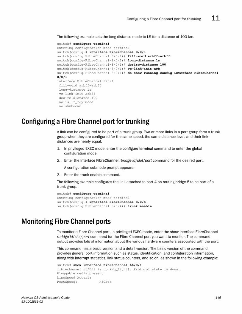
Configuring a Fibre Channel port for trunking 11
The following example sets the long distance mode to LS for a distance of 100 km.
switch# configure terminalEntering configuration mode terminalswitch(config)# interface FibreChannel 8/0/1switch(config-FibreChannel-8/0/1)# fill-word arbff-arbffswitch(config-FibreChannel-8/0/1)# long-distance lsswitch(config-FibreChannel-8/0/1)# desire-distance 100switch(config-FibreChannel-8/0/1)# vc-link-init arbswitch(config-FibreChannel-8/0/1)# do show running-config interface FibreChannel 8/0/1interface FibreChannel 8/0/1fill-word arbff-arbfflong-distance lsvc-link-init arbffdesire-distance 100no isl-r_rdy-modeno shutdown
Configuring a Fibre Channel port for trunkingA link can be configured to be part of a trunk group. Two or more links in a port group form a trunk group when they are configured for the same speed, the same distance level, and their link distances are nearly equal.
1. In privileged EXEC mode, enter the configure terminal command to enter the global configuration mode.
2. Enter the interface FibreChannel rbridge-id/slot/port command for the desired port.
A configuration submode prompt appears.
3. Enter the trunk-enable command.
The following example configures the link attached to port 4 on routing bridge 8 to be part of a trunk group.
switch# configure terminalEntering configuration mode terminalswitch(config)# interface FibreChannel 8/0/4switch(config-FibreChannel-8/0/4)# trunk-enable
Monitoring Fibre Channel portsTo monitor a Fibre Channel port, in privileged EXEC mode, enter the show interface FibreChannel rbridge-id/slot/port command for the Fibre Channel port you want to monitor. The command output provides lots of information about the various hardware counters associated with the port.
This command has a basic version and a detail version. The basic version of the command provides general port information such as status, identification, and configuration information, along with interrupt statistics, link status counters, and so on, as shown in the following example:
switch# show interface FibreChannel 66/0/1 fibrechannel 66/0/1 is up (No_Light). Protocol state is down.Pluggable media presentLineSpeed Actual:PortSpeed: N8Gbps
Network OS Administrator’s Guide 14553-1002561-02

Monitoring Fibre Channel ports11
portDisableReason: NonePortId: 427900PortIfId: 4302303fPortWwn: 20:79:00:05:33:67:26:78Distance: normal
Last clearing of show interface counters: 00:00:00Interrupts: 0 Link_failure: 0 Frjt: 0Unknown: 0 Loss_of_sync: 0 Fbsy: 0Lli: 2 Loss_of_sig: 2Proc_rqrd: 0 Protocol_err: 0Timed_out: 0 Invalid_word: 0Rx_flushed: 0 Invalid_crc: 0Tx_unavail: 0 Delim_err: 0Free_buffer: 0 Address_err: 0Overrun: 0 Lr_in: 0Suspended: 0 Lr_out: 0Parity_err: 0 Ols_in: 02_parity_err: 0 Ols_out: 0
Rate info:Bandwidth: 8.00GTx performance: 0 B/secRx performance: 0 B/sec
The detail version of the command tells you how much traffic has been transmitted or received, and how many times certain error conditions have occurred. Specifically, the tim_txcrd_z counters tell you how many times the port was unable to transmit frames because the transmit BB credit was zero. A number greater than zero indicates either congestion on the port or that a device is affected by latency. A bigger number indicates a bigger problem. A sample is taken every 2.5 microseconds.
switch# show interface FibreChannel 66/0/1 detail fibrechannel 66/0/1 is up. Protocol state is up (connected)Pluggable media presentLineSpeed Actual: 400,800_MB/sportSpeed: N8GbpsportDisableReason: NoneportId 423100portIfId: 43020026portWwn: 20:31:00:05:33:6f:27:57Distance normal Last clearing of show interface counters: 00:00:00Rx Statistics:
stat_wrx 118 4-byte words receivedstat_frx 4 Frames receivedstat_c2_frx 0 Class 2 frames receivedstat_c3_frx 0 Class 3 frames receivedstat_lc_rx 2 Link control frames receivedstat_mc_rx 0 Multicast frames received
Tx Statistics:stat_wtx 282 4-byte words transmittedstat_ftx 12 Frames transmittedstat_mc_tx 0 Multicast frames transmittedtim_txcrd_z 2881 Time TX Credit Zero (2.5Us ticks)tim_txcrd_z_vc 0- 3: 2881 0 0 0tim_txcrd_z_vc 4- 7: 0 0 0 0tim_txcrd_z_vc 8-11: 0 0 0 0
146 Network OS Administrator’s Guide53-1002561-02

Monitoring Fibre Channel ports 11
tim_txcrd_z_vc 12-15: 0 0 0 0Error Statistics
er_enc_in 0 Encoding errors inside of frameser_crc 0 Frames with CRC errorser_trunc 0 Frames shorter than minimumer_toolong 0 Frames longer than maximumer_bad_eof 0 Frames with bad end-of-frameer_enc_out 0 Encoding error outside of frameser_bad_os 1 Invalid ordered seter_rx_c3_timeout 0 Class 3 receive frames discarded due to timeouter_tx_c3_timeout 0 Class 3 transmit frames discarded due to timeouter_c3_dest_unreach 0 Class 3 frames discarded due to destination
unreachableer_other_discard 0 Other discardser_type1_miss 0 frames with FTB type 1 misser_type2_miss 0 frames with FTB type 2 misser_type6_miss 0 frames with FTB type 6 misser_zone_miss 0 frames with hard zoning misser_lun_zone_miss 0 frames with LUN zoning misser_crc_good_eof 0 Crc error with good eofer_inv_arb 0 Invalid ARB
Port Error Info:
Loss_of_sync:1Loss_of_sig:2Frjt:0Fbsy:0
Buffer Information: Lx Max/Resv Buffer Needed Link Remaining Mode Buffers Usage Buffers Distance Buffers================================================================= - 8 0 0 - 924
Rate info:Bandwidth: 8.00GTx performance: 0 B/secRx performance: 0 B/sec
Network OS Administrator’s Guide 14753-1002561-02

Monitoring Fibre Channel ports11
148 Network OS Administrator’s Guide53-1002561-02

Network OS Administrator’s Guide53-1002561-02
Chapter
12
System MonitorIn this chapter
•System Monitor overview . . . . . . . . . . . . . . . . . . . . . . . . . . . . . . . . . . . . . . . 149
•Alert notifications . . . . . . . . . . . . . . . . . . . . . . . . . . . . . . . . . . . . . . . . . . . . . 153
•Resource monitoring . . . . . . . . . . . . . . . . . . . . . . . . . . . . . . . . . . . . . . . . . . . 153
•SFP monitoring . . . . . . . . . . . . . . . . . . . . . . . . . . . . . . . . . . . . . . . . . . . . . . . 155
•Security monitoring . . . . . . . . . . . . . . . . . . . . . . . . . . . . . . . . . . . . . . . . . . . . 159
•Interface monitoring . . . . . . . . . . . . . . . . . . . . . . . . . . . . . . . . . . . . . . . . . . . 160
System Monitor overviewSystem Monitor provides customizable monitoring thresholds, which allow you to monitor the health of each component of the switch. Whenever the switch component exceeds the thresholds, System Monitor automatically provides notification using e-mail or RASlog messages, depending on the configuration. Threshold and notification configuration procedures are described in the following sections.
Switch health monitoringMonitored FRUs on supported switches, as shown in Table 22, are as follows:
• Fan—Configures fan settings.
• Power supply—Configures power supply settings.
• Temperature sensor—Displays the threshold for the temperature sensor component.
• CID-card—Displays the threshold for the CID card component.
• SFP—Displays the threshold for the small form factor pluggable (SFP) device.
• Compact-flash—Displays the threshold for the compact flash device.
• MM—Displays the threshold for the management module.
• LineCard—Displays the threshold for the line card.
• SFM—Displays the threshold for the switch fabric module.
NOTECID cards can be faulted and removed. The system continues to operate normally as long as one CID card is installed. If both CID cards are missing or faulted, the switch will not operate.
149
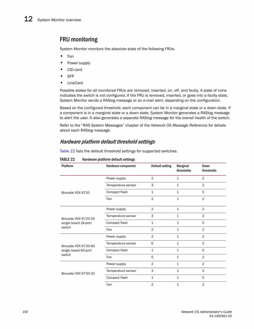
System Monitor overview12
FRU monitoringSystem Monitor monitors the absolute state of the following FRUs.
• Fan
• Power supply
• CID-card
• SFP
• LineCard
Possible states for all monitored FRUs are removed, inserted, on, off, and faulty. A state of none indicates the switch is not configured. If the FRU is removed, inserted, or goes into a faulty state, System Monitor sends a RASlog message or an e-mail alert, depending on the configuration.
Based on the configured threshold, each component can be in a marginal state or a down state. If a component is in a marginal state or a down state, System Monitor generates a RASlog message to alert the user. It also generates a separate RASlog message for the overall health of the switch.
Refer to the “RAS System Messages” chapter of the Network OS Message Reference for details about each RASlog message.
Hardware platform default threshold settings
Table 22 lists the default threshold settings for supported switches.
TABLE 22 Hardware platform default settings
Platform Hardware component Default setting Marginal thresholds
Down thresholds
Brocade VDX 6710
Power supply 2 1 2
Temperature sensor 3 1 2
Compact flash 1 1 0
Fan 2 1 2
Brocade VDX 6720-24 single board 24-portswitch
Power supply 2 1 2
Temperature sensor 3 1 2
Compact flash 1 1 0
Fan 2 1 2
Brocade VDX 6720-60 single board 60-portswitch
Power supply 2 1 2
Temperature sensor 6 1 2
Compact flash 1 1 0
Fan 5 1 2
Brocade VDX 6730-32
Power supply 2 1 2
Temperature sensor 3 1 2
Compact flash 1 1 0
Fan 2 1 2
150 Network OS Administrator’s Guide53-1002561-02
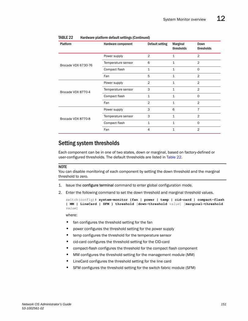
System Monitor overview 12
Setting system thresholdsEach component can be in one of two states, down or marginal, based on factory-defined or user-configured thresholds. The default thresholds are listed in Table 22.
NOTEYou can disable monitoring of each component by setting the down threshold and the marginal threshold to zero.
1. Issue the configure terminal command to enter global configuration mode.
2. Enter the following command to set the down threshold and marginal threshold values.
switch(config)# system-monitor {fan | power | temp | cid-card | compact-flash | MM | LineCard | SFM } threshold [down-threshold value] [marginal-threshold value]
where:
• fan configures the threshold setting for the fan
• power configures the threshold setting for the power supply
• temp configures the threshold for the temperature sensor
• cid-card configures the threshold setting for the CID-card
• compact-flash configures the threshold for the compact flash component
• MM configures the threshold setting for the management module (MM)
• LineCard configures the threshold setting for the line card
• SFM configures the threshold setting for the switch fabric module (SFM)
Brocade VDX 6730-76
Power supply 2 1 2
Temperature sensor 6 1 2
Compact flash 1 1 0
Fan 5 1 2
Brocade VDX 8770-4
Power supply 2 1 2
Temperature sensor 3 1 2
Compact flash 1 1 0
Fan 2 1 2
Brocade VDX 8770-8
Power supply 3 6 7
Temperature sensor 3 1 2
Compact flash 1 1 0
Fan 4 1 2
TABLE 22 Hardware platform default settings (Continued)
Platform Hardware component Default setting Marginal thresholds
Down thresholds
Network OS Administrator’s Guide 15153-1002561-02

System Monitor overview12
Setting FRU state alertsUse the system-monitor alert state command to configure field-replaceable unit (FRU) state alerts. Based on these configuration settings, System Monitor generates an alert when there is a change in the FRU state.
1. Issue the configure terminal command to enter global configuration mode.
2. Enter the following command to set the FRU state alerts.
switch(config)# system-monitor { fan | power | cid-card | sfp | LineCard } alert state [removed] [inserted] [on] [faulty] [all] [none]
where:
• fan configures the alert setting for the fan
• power configures the alert setting for the power supply
• cid-card configures the alert setting for the CID-card
• sfp configures the alert setting for the SFP
• LineCard configures the alert setting for the line card
Setting FRU alert actionsUse the system-monitor alert action command to configure field-replaceable unit (FRU) alert actions. The FRU alert action is triggered when there is a change in the FRU state.
1. Issue the configure terminal command to enter global configuration mode.
2. Enter the following command to set the FRU alert actions.
switch(config)# system-monitor { fan | power | temp | cid-card | sfp | compact-flash | MM | LineCard | SFM } alert action [email] [raslog] [all] [none]
Displaying the switch health statusThe show system monitor command is issued at the Privileged EXEC level.
Enter the following command to display the switch health status.
switch# show system monitor
Displaying the system monitoring configurationThe show running-config system-monitoring command is issued at the Privileged EXEC level.
Enter the following command to display the system monitoring configuration.
switch# show running-config system-monitor
152 Network OS Administrator’s Guide53-1002561-02

Alert notifications 12
Alert notifications
Configuring e-mail alertsUse the system-monitor-mail fru command to configure e-mail alerts on the switch. For an e-mail alert to function correctly, add the IP addresses and host names to the domain name server (DNS) in addition to configuring the domain name and name servers.
1. Issue the configure terminal command to enter global configuration mode.
2. Enter the following command to enable e-mail alerts and to configure the e-mail address.
switch(config)# system-monitor-mail fru enable email-id
Forwarding e-mail messages to a relay serverThe following system-monitor-mail relay host commands allow the sendmail agent on the switch to resolve the domain name and forward all e-mail messages to a relay server.
To create a mapping:
switch(config)# system-monitor-mail relay ip-address 1.2.3.4 domain-name domain_name1.brocade.com
To delete the mapping:
switch(config)# no system-monitor-mail relay ip-address 1.2.3.4 domain-name domain_name1.brocade.com
To change the domain name:
NOTEYou must delete the first domain name before you can change it to a new domain name.
switch(config)# system-monitor-mail relay ip-address 1.2.3.4 domain-name domain_name2.brocade.com
To delete the domain name and return to the default.
switch(config)# no system-monitor-mail relay ip-address 1.2.3.4 domain-name domain_name2.brocade.com
Resource monitoringSystem Monitor monitors CPU and memory usage of the system and alerts the user when configured thresholds are exceeded.
When configuring CPU monitoring, specify a value in the 1-100 range. When the CPU usage exceeds the limit, a system monitor alert is triggered. The default CPU limit is 75 percent. When configuring memory, the limit specifies a usage limit as a percentage of available resources.
Network OS Administrator’s Guide 15353-1002561-02

Resource monitoring12
When used to configure memory, monitoring the limit value must be greater than the low limit and smaller than the high limit. Three thresholds are supported for memory monitoring:
• High_limit—Specifies an upper usage limit for memory as percentage of available memory. This value must be greater than the value set by the -limit parameter. The maximum is 90 percent. When memory usage exceeds this limit, System Monitor generates a CRITICAL RASlog message. The default is 80 percent.
• Limit—Specifies the default CPU limit. When the limit is exceeded, System Monitor sends out a RASlog WARNING message. When usage returns below the limit, System Monitor sends a RASlog INFO message. Valid values are range between 0 to 80 percent and the default value is different for different systems.
• Low_limit—Specifies a lower usage limit for memory as percentage of available memory. This value must be smaller than the value set by the -limit parameter. When memory usage exceeds or falls below this limit, System Monitor generates an INFO RASlog message. The default for all platforms is 50 percent.
NOTEFor Memory and CPU thresholds, the low limit must be the lowest value and the high limit must be the highest value.
Table 23 lists the factory defaults for CPU and memory thresholds
Configuring memory monitoring
NOTEE-mail is not a supported action for threshold monitoring.
1. Issue the configure terminal command to enter global configuration mode.
2. Specify the rbridge-id at the switch(config)# prompt.
3. Enter the threshold-monitor memory command using the following parameters:
switch(config-rbridge-id-1)# threshold-monitor memory ?
where:
• actions—the specified action the system monitor triggers when a threshold is crossed.
• high-limit—the upper usage limit for memory as a percentage (0-80) of available memory.
• limit—the usage limit as a percentage (0-80) of available resources.
• low-limit—the lower usage limit for memory as a percentage (0-80) of available memory.
TABLE 23 Factory defaults for CPU and memory threshold monitoring
Operand Memory CPU
Low-limit 40% N/A
Limit 60% 75%
High-limit 70% N/A
Poll 120 seconds 120 seconds
Retry 3 3
Action None None
154 Network OS Administrator’s Guide53-1002561-02

SFP monitoring 12
• poll—the polling interval, in seconds, after which the system monitor will poll the resource usage.
• retry—the number of retries (0-100) that the system monitor takes before triggering an action.
Configuring CPU monitoring1. Issue the configure terminal command to enter global configuration mode.
2. Specify the rbridge-id at the switch(config)# prompt.
3. Enter the threshold-monitor memory command using the following parameters:
switch(config-rbridge-id-1)# threshold-monitor cpu ?
where:
• poll—the polling interval, in seconds, after which the system monitor will poll the resource usage.
• retry—the number of retries (0-100) that the system monitor takes before triggering an action.
• limit—the usage limit as a percentage (0-80) of available resources.
Displaying the threshold monitoring configurationEnter the show running-config threshold-monitor command using the following parameters:
switch# show running-config rbridge-id 1 threshold-monitor
SFP monitoringSystem Monitor monitors the SFP parameters shown in Table 24.
TABLE 24 SFP parameter descriptions
SFP parameter Description Suggested SFP impact
Temperature Measures the physical temperature of the SFP, in degrees Celsius.
High temperature suggests the SFP might be damaged.
Receive Power (RXP) Measures the amount of incoming laser, in uWatts.
Describes the condition of the SFP. If this parameter exceeds the threshold, the SFP is deteriorating.
Transmit Power (TXP) Measures the amount of outgoing laser, in uWatts.
Describes the condition of the SFP. If this parameter exceeds the threshold, the SFP is deteriorating.
Current Measures the amount of supplied current to the SFP transceiver.
Indicates hardware failures.
Voltage Measures the amount of voltage supplied to the SFP.
A value higher than the threshold indicates the SFP is deteriorating.
Network OS Administrator’s Guide 15553-1002561-02

SFP monitoring12
SFP thresholdsYou can customize SFP thresholds or actions using the threshold-monitor sfp command, which enables you to perform the following tasks.
• Customize SFP configurations or accept SFP defaults.
• Manage the actions and thresholds for the Current, Voltage, RXP, TXP, and Temperature areas of the SFP or QSFP.
• Suspend SFP and QSFP monitoring using the pause and continue feature.
If you do not provide the SFP type parameters, the existing thresholds and actions of the SFP class are changed to the default. SFP types for the 16 Gbps and QSFP SFPs are listed in Table 25.
TABLE 25 Factory thresholds for SFP types and areas
SfpType Area Default Value
1 GSR Temperature (Centigrade) 100 -40
Voltage (mVoltage) 3600 3000
RXP (uW) 1122 8
TXP (uW) 1000 60
Current (mAmp) 12 2
1 GLR Temperature (Centigrade) 90 -45
Voltage (mVoltage) 3700 2900
RXP (uW) 501 6
TXP (uW) 794 71
Current (mAmp) 45 1
10 GSR Temperature (Centigrade) 90 -5
Voltage (mVoltage) 3600 3000
RXP (uW) 1000 32
TXP (uW) 794 251
Current (mAmp) 11 4
10 GLR Temperature (Centigrade) 88 -5
Voltage (mVoltage) 3600 2970
RXP (uW) 1995 16
TXP (uW) 1585 158
Current (mAmp) 85 15
10GUSR Temperature (Centigrade) 100 -5
Voltage (mVoltage) 3600 2970
RXP (uW) 2000 32
TXP (uW) 2000 126
Current (mAmp) 11 3
156 Network OS Administrator’s Guide53-1002561-02

SFP monitoring 12
Threshold valuesHigh and low threshold values are the values at which potential problems might occur. For example, in configuring a temperature threshold for SFP, you can select the temperatures at which a potential problem can occur because of overheating or freezing.
A combination of high and low threshold settings can cause the following actions to occur:
• Above high threshold—System Monitor takes this action when the current value is above the high threshold.
• Below high threshold—System Monitor takes this action when the current value is between the high and low threshold. This replaces the previous “in-between” action, which no longer exists
• Below low threshold—System Monitor takes this action when the current value is below the low threshold.
NOTEAbove low threshold is not supported.
SFP defaultsTo display the default values of SFP threshold and alert options, enter the show threshold defaults sfp type command using the following parameters.
switch# show defaults threshold sfp type <1 GSR|1GLR|10GSR|10GLR|10GUSR|QSFP> area <Current|RXP|TXP|Temperature|Voltage>
For example:
switch:show threshold defaults sfp type 10GLR area CurrentType: 10GLRArea: CurrentHigh:Value: 85Above Action: raslogBelow Action: noneLow:Value: 15Below Action: raslogBuffer:Value: 0
QSFP Temperature (Centigrade) 75 -5
Voltage (mVoltage) 3600 2970
RXP (uW) 1995 40
TXP (uW) 0 0
Current (mAmp) 10 1
TABLE 25 Factory thresholds for SFP types and areas (Continued)
SfpType Area Default Value
Network OS Administrator’s Guide 15753-1002561-02
SFP monitoring12
Configuring SFP monitoringFor a Fabric Cluster configuration, you must first identify the routing bridge with the rbridge-ID.
1. Issue the configure terminal command to enter global configuration mode.
2. Specify the rbridge-id at the switch(config)# prompt.
3. Enter the threshold-monitor sfp command using the following parameters for a Fabric Cluster configuration.
switch(config-rbridge-id-1)# threshold-monitor sfp policy policy_type type type area SFP_area action [alert [above highthresh-action] [below highthresh-action] [below lowthresh-action]] buffer buffer_value
where:
• Policy—Specifies whether the system will monitor SFP parameters using the default configuration or custom settings.
• Type—Specifies one of the following SFP types:
- SFP type 1GLR
- SFP type 1GSR
- SFP type 10GLR
- SFP type 10GSR
- SFP type 10GUSR
- SFP type QSFP
• Area—Specifies one of the following SFP areas to be monitored.
- RXP measures the amount of incoming laser, in uWatts.
- TXP measures the amount of outgoing laser, in uWatts.
- Temperature measures the physical temperature of the SFP, in degrees Celsius.
- Current measures the amount of supplied current to the SFP transceiver.
- Voltage measures the amount of voltage supplied to the SFP.
• Action—Specifies the threshold values:
- above high
- high
- below high
- low
- below low
• Buffer—Specifies the buffer value for in-range behavior.
Pausing SFP monitoringBy default, SFP monitoring is enabled.
Enter the threshold-monitor sfp pause command.
158 Network OS Administrator’s Guide53-1002561-02

Security monitoring 12
Continuing SFP monitoringEnter the no threshold-monitor sfp pause command.
Security monitoringSystem Monitor monitors all attempts to breach your SAN security, helping you fine-tune your security measures. If there is a security breach, System Monitor sends a RASlog alert. The following Security areas are monitored:
• Telnet Violation, which occurs when a Telnet connection request reaches a secure switch from an unauthorized IP address.
• Login Violation, which occurs when a secure fabric detects a login failure.
Security defaultsTo display the default values of Security threshold and alert options, enter the show defaults security area command using the following parameters.
switch# show defaults security area login-violation | telnet-violation
Configuring security monitoringFor a Fabric Cluster configuration, you must first identify the routing bridge with the rbridge-ID.
1. Issue the configure terminal command to enter global configuration mode.
2. Specify the rbridge-id at the switch(config)# prompt.
3. Enter the threshold-monitor security command using the following parameters for a Fabric Cluster configuration.
switch(config-rbridge-id-1)# threshold-monitor security policy policy_name area [telnet-violation | login-violation] alert [above [highthresh-action all | raslog | none] [below [highthresh-action all | raslog | none] [lowthresh-action all |raslog|none]]]
where:
• Policy—Specifies whether the system will monitor security parameters using the default configuration or custom settings.
• Action—Specifies the threshold values:
- above highthresh
- highthresh
- below highthresh
- lowthresh
- below lowthresh
• Buffer—Specifies the buffer value for in-range behavior.
• Timebase—Determines if the allotted amount of time has passed since the previous reading. Polling values are taken at different intervals depending on the configured time base.
Network OS Administrator’s Guide 15953-1002561-02

Interface monitoring12
Applying security monitoring policies
The threshold-monitor security apply command allows you to toggle between default settings and saved custom configuration settings and to apply actions and thresholds separately. For example, you can choose to use default threshold settings together with a customized subset of available actions, or you can modify some of the threshold settings and use the default action settings.
NOTEDefault values are not displayed under the show running-config threshold-monitor security command. Only custom values are displayed when a user applies a policy.
Enter the threshold-monitor security command using the following parameters:
switch(config)# threshold-monitor security apply custom
Interface monitoringSystem Monitor monitors error statistics on all external Gigabit Ethernet interfaces: 1 Gb, 10 Gb, and 40 Gb. When any monitored error crosses the configured high or low threshold, an alert is generated.
Interface error typesTable 26 describes the interface counters that System Monitor monitors on external interfaces.
NOTEThe default settings for above high threshold, above low threshold, below high threshold, and below low threshold actions are None.
TABLE 26 Interface errors monitored by System Monitor
Interface area Description Port Fence support
Threshold defaults
MissingTerminationCharacter The number of frames that terminated by anything other than the Terminate character; this includes termination due to the Error character.
No Low 12Buffer 0High 300
CRCAlignErrors The total number of frames received that had a length (excluding framing bits but including Frame Check Sequence (FCS) octets) of between 64 and 1518 octets. The error indicates either a bad FCS with an integral number of octets (an FCS error) or a bad FCS with a non-integral number of octets (an Alignment error).
No Low 12Buffer 0High 300
IFG A minimum-length interframe gap (IFG) between successive frames is violated. A typical IFG is 12 bytes.
Yes Low 5Buffer 0High 100
SymbolErrors The interface detects an undefined (invalid) symbol received. Large symbol errors indicate a bad device, cable, or hardware.
No Low 0Buffer 0High 5
160 Network OS Administrator’s Guide53-1002561-02

Interface monitoring 12
Port fencingA port that is consistently unstable can harm the responsiveness and stability of the entire fabric and diminish the ability of the management platform to control and monitor the switches within the fabric. Port Fencing is not enabled by default; it disables the interface if a user-defined high threshold is exceeded. When a port that has exceeded its user-defined high threshold is fenced by software, the port is placed in Disabled state and held offline. After a port is disabled, user intervention is required for frame traffic to resume on the port.
NOTEPort Fencing is supported for the RX IFG Violated error only.
Interface defaultsTo display the default values of Interface threshold and alert options, enter the show threshold defaults interface type command using the following parameters.
switch# show defaults interface type Ethernet area MissingTerminationCharacter | CRCAlignErrors | IFG | SymbolErrors
Configuring interface monitoringFor a Fabric Cluster configuration, you must first identify the routing bridge with the rbridge-ID.
1. Issue the configure terminal command to enter global configuration mode.
2. Specify the rbridge-id at the switch(config)# prompt.
3. Enter the threshold-monitor interface command using the following parameters for a Fabric Cluster configuration.
switch(config-rbridge-id-1)# threshold-monitor area interface policy policy_name type interface type [threshold [high-threshold | low_threshold | buffer] [above [highthresh-action raslog | fence | both | none] [below [highthresh-action raslog | fence | both | none] [[above [lowthresh-action raslog | fence | both | none] [below [lowthresh-action raslog | fence | both | none]] timebase [day|hour|minute|none] value
NOTEYou must explicitly apply custom policies using the threshold-monitor-interface apply command. Refer to “Applying interface monitoring policies” on page 162.
where:
• policy—Specifies whether the system will monitor SFP parameters using the default configuration or custom settings.
Network OS Administrator’s Guide 16153-1002561-02
Interface monitoring12
• type—Specifies the Interface type. Interface types are as follows:
- CRCAlignErrors—The total number of frames received with either a bad Frame Check Sequence (FCS) or an alignment error.
- SymbolErrors—The number of words received as an unknown (invalid) symbol. Large symbol errors indicate a bad device, cable, or hardware.
- IFG—The minimum-length interframe gap (IFG) between successive frames is violated. The typical minimum IFG is 12 bytes.
- Missing Termination Character—The number of frames that terminated by anything other than the Terminate character.
• Action—Specifies the alert notification method:
- RASlog
- Port Fence
- Both
- None
• Threshold—Specifies the values for high, low, and buffer threshold values. These values are used as thresholds to trigger different alerts.
- High threshold specifies the high limit for Interface errors.
- Low threshold specifies the low limit for Interface errors.
- Above high threshold specifies the action for crossing the high threshold.
- Above low threshold specifies the action for crossing the low threshold.
- Below high threshold specifies the action for interface errors to be below the high threshold.
- Below low threshold specifies the action for interface errors to be below the low threshold.
- In-Range specifies the value of an error on a configured interface that is in the buffer range. The buffer value cannot exceed the average of the high and low threshold value.
• Timebase—Determines if the allotted amount of time has passed since the previous reading. Polling values are taken at different intervals depending on the configured time base.
Applying interface monitoring policies
The threshold-monitor interface apply command allows you to toggle between default settings and saved custom configuration settings and to apply actions and thresholds separately. For example, you can choose to use default threshold settings together with a customized subset of available actions, or you can modify some of the threshold settings and use the default action settings.
NOTEDefault values are not displayed under the show running-config threshold-monitor interface command. Only custom values are displayed when a user applies a policy.
Enter the threshold-monitor interface command using the following parameters:
switch(config)# threshold-monitor interface apply custom
Pausing interface monitoring
To pause the monitoring of all ports with the ability to monitor the ports at a later time, enter the threshold-monitor interface pause command. By default, interface monitoring is enabled.
162 Network OS Administrator’s Guide53-1002561-02

Interface monitoring 12
Continuing interface monitoring
The no form of the threshold-monitor interface pause command can be used to continue the port monitoring.
switch(config)# no threshold-monitor interface pause
Network OS Administrator’s Guide 16353-1002561-02

Interface monitoring12
164 Network OS Administrator’s Guide53-1002561-02

Network OS Administrator’s Guide53-1002561-02
Chapter
13
VMware vCenterIn this chapter
•vCenter and Network OS integration . . . . . . . . . . . . . . . . . . . . . . . . . . . . . . 165
•vCenter discovery . . . . . . . . . . . . . . . . . . . . . . . . . . . . . . . . . . . . . . . . . . . . . 166
vCenter and Network OS integrationThe VMware vCenter Server allows for the management of multiple ESX /ESXi servers and virtual machines (VMs) from different ESX servers through a single graphical user interface (GUI). It provides unified management of all the hosts and VMs in the data center, from a single console with an aggregate performance monitoring of clusters, hosts and VMs.
The VMware vCenter and Brocade Network OS integration, supported in Brocade VCS Fabric mode and non-VCS (standalone switch) mode, enables you to discover VMware ESX servers managed by a vCenter server. VMware’s server hosts (ESX servers) are connected directly to the physical switches through the switch ports (edge ports in Brocade VCS Fabric mode). The server hosts implement a virtual switch (vSwitch), which is used to provide connections to the VMs. The fundamental requirement for the vCenter and Network OS integration is the IP-level management connectivity of the vCenter Server 4.0 version and later with the Brocade VDX switches.
NOTEThe Network OS integration with vCenter requires vCenter version 4.0, 4.1, and 5.0.
You can view virtual switches and virtual machines, their associated MAC addresses, and network policies using the Network OS command line interface (CLI). Refer to the Brocade Network OS Command Reference for details about the vcenter and vnetwork commands.
vCenter propertiesThe vCenter manages the VMware ESX/ESXi hosts. The vCenter user interface is provided through a vSphere client on the same management network as the vCenter, and virtual machines (VMs) are created using the vSphere client user interface. In addition to creating the VMs, the server administrator associates the VMs with distributed virtual switches, distributed virtual port groups, standard virtual switches (vSwitches) and standard port groups.
The vCenter automatically generates some of the VM properties (such as the MAC address), and some properties must be configured (such as the VLAN properties). Most of the VM configuration, including network policies, is done using the vCenter’s vSphere user interface and is beyond the scope of this document.
For VMWare configuration information, visit the VMware documentation site.
165
vCenter discovery13
vCenter guidelines and restrictionsFollow these guidelines and restrictions when configuring vCenter:
• Special characters in the port group names are replaced with the URL-encoded values.
• Standard port groups with the same name that reside in different ESX/ESXi hosts must have identical VLAN settings across all hosts.
• NOS automatically creates a port profile with an “auto” prefix for all the vCenter port groups. User editing of these auto-port groups is not supported.
• NOS supports up to 255 port groups in the vCenter.
• CDP-receiving interface ports must not have any conflicting configurations (such as switch port and FCoE port configurations) on the interface that prevent them from being a port-profiled mode.
• Before configuring a vCenter in the fabric, remove all the manually created port profiles that have vCenter inventory MAC associations.
• For NOS 3.0.0 versions, only one data center configuration in vCenter is supported.
• Duplicate vCenter asset values are not supported; for example, duplicate MAC addresses and duplicate Host names.
vCenter discoveryThe Brocade VDX switch connected to VMware ESX/ESXi hosts and virtual machines must be aware of network policies in order to allow or disallow traffic, which requires a discovery process by the VDX switch. During VDX switch configuration, relevant vCenters that exist in its environment and the discovery of virtual assets from the vCenter occurs in the following circumstances:
• When a switch boots up
• When a new vCenter is configured on the VDX switch and activated (activation turns on the timer processing, set to 180-second intervals)
• When the discovery is explictly initiated with the CLI
The following assets are discovered from the vCenter:
• Hosts associated with the vCenter
• Virtual machines (VMs) that have been created on the hosts
• Standard port groups
• Standard virtual switches
• Distributed virtual switches
• Distributed virtual port groups
166 Network OS Administrator’s Guide53-1002561-02
vCenter configuration 13
vCenter configuration
Step 1. Enabling CDP In order for an Ethernet Fabric to detect the ESX/ESXi hosts, you must first enable Cisco Discovery Protocol (CDP) on all the virtual switches (vSwitches) and distributed vSwitches (dvSwitches) in the vCenter Inventory.
For more information, refer to the VMware KB article 1003885.
Enabling CDP on vSwitches
Complete the following steps to enable CDP on virtual switches (vSwitches).
1. Login as root to the ESX/ESXi Host.
2. Use the following command to verify the current CDP settings.
[root@server root]# esxcfg-vswitch -b vSwitch1
3. Use the following command to enable CDP for a given virtual switch. Possible values here are advertise or both.
[root@server root]# esxcfg-vswitch -B both vSwitch1
Enabling CDP on dvSwitches
Complete the following steps to enable CDP on distributed virtual switches (dvSwitches).
1. Connect to the vCenter server using the vSphere Client.
2. In the vCenter Server home page, click Networking.
3. Right-click the distributed virtual switches (dvSwitches) and click Edit Settings.
4. Select Advanced under Properties.
5. Use the check box and the dropdown list to change the CDP settings.
Step 2: Adding and Activating vCenterAfter enabling CDP on all the vSwitches and dvSwitches in the vCenter, the NOS-side configuration is a two step process: adding the vCenter and activating the vCenter.
Adding the vCenter
You must add the vCenter before initiating any discovery transactions. To authenticate with a specific vCenter, you must first configure the URL, login, and password properties on the VDX switch.
NOTEBy default, the vCenter server only accepts https connection requests.
Enter the vcenter MYVC command.
switch(config)# vcenter MYVC url https://10.2.2.2 username user password pass
Network OS Administrator’s Guide 16753-1002561-02

vCenter configuration13
Activating the vCenter
After adding the vCenter, you must activate the configured vCenter instance.
NOTEIn Fabric Cluster (FC) mode, you can configure the vCenter using any node. Discovery is initiated by the primary node.
1. Enter the config command.
2. Enter the vcenter MYVC command.
switch(config)# vcenter MYVC activate
Immediately following first-time vCenter activation, the Network OS (NOS) starts the virtual asset discovery process. Use the show vnetwork vcenter status command to display the vnetwork status. For example:
switch# show vnetwork vcenter statusvCenter Start Elapsed (sec) Status================ ==================== ================ =============MYVC 2011-09-07 14:08:42 10 In progress
When the discovery process completes, the status displays as “Success.” NOS has performed all the necessary configurations needed for the vCenter Server. NOS is now ready for CDP transmissions from the virtual switches to identify which ESX/ESXi host is connected to which physical interface in the Ethernet Fabric.
Discovery timer interval By default, NOS queries the vCenter updates every three minutes. If any virtual assets are modified (for example, adding or deleting virtual machines (VMs), or changing VLANs), NOS detects those changes and automatically reconfigures the Ethernet Fabric during the next periodic rediscovery attempt.
Use the vcenter MYVC interval command to manually change the default timer interval value to suit the individual environment needs.
switch(config)# vcenter MYVC interval ?Possible completions:<NUMBER:0-1440> Timer Interval in Minutes (default = 3)
NOTEBest practice is to keep the discovery timer interval value at default. A value of 0 disables the periodic vCenter discovery.
User-triggered vCenter discoveryUse the vnetwork vcenter command to to manually trigger a vCenter discovery.
switch# vnetwork vcenter MYVC discover
168 Network OS Administrator’s Guide53-1002561-02

vCenter configuration 13
Viewing the discovered virtual assetsEnter one of the following show vnetwork asset commands:
switch# show vnetwork dvpgsswitch# show vnetwork dvsswitch# show vnetwork hostsswitch# show vnetwork pgsswitch# show vnetwork vcenter statusswitch# show vnetwork vmpolicy switch# show vnetwork vmsswitch# show vnetwork vss
where:
• dvpgs—Displays discovered distributed virtual port groups.
• dvs—Displays discovered distributed virtual switches.
• hosts—Displays discovered hosts.
• pgs—Displays discovered standard port groups.
• vcenter status—Displays configured vCenter status.
• vmpolicy—Displays the following network policies on the Brocade VDX switch: associated media access control (MAC) address, virtual machine, (dv) port group, and the associated port profile.
• vms—Displays discovered virtual machines (VMs).
• vss—Displays discovered standard virtual switches.
Refer to the Network OS Command Reference for detailed information about the show vnetwork command.
Network OS Administrator’s Guide 16953-1002561-02

vCenter configuration13
170 Network OS Administrator’s Guide53-1002561-02

Network OS Administrator’s Guide53-1002561-02
Section
II
Network OS Security ConfigurationThis section describes security features, and includes the following chapters:
•Managing User Accounts . . . . . . . . . . . . . . . . . . . . . . . . . . . . . . . . . . . . . . . 173
•External AAA server authentication . . . . . . . . . . . . . . . . . . . . . . . . . . . . . . . 191
•FIPS Support . . . . . . . . . . . . . . . . . . . . . . . . . . . . . . . . . . . . . . . . . . . . . . . . . 215
•Fabric Authentication . . . . . . . . . . . . . . . . . . . . . . . . . . . . . . . . . . . . . . . . . . 229
171

172 Network OS Administrator’s Guide53-1002561-02

Network OS Administrator’s Guide53-1002561-02
Chapter
14
Managing User AccountsIn this chapter
•User accounts . . . . . . . . . . . . . . . . . . . . . . . . . . . . . . . . . . . . . . . . . . . . . . . . 173
•Role-based access control (RBAC) . . . . . . . . . . . . . . . . . . . . . . . . . . . . . . . . 177
•Command Access rules. . . . . . . . . . . . . . . . . . . . . . . . . . . . . . . . . . . . . . . . . 179
•Password policies . . . . . . . . . . . . . . . . . . . . . . . . . . . . . . . . . . . . . . . . . . . . . 185
•Security event logging . . . . . . . . . . . . . . . . . . . . . . . . . . . . . . . . . . . . . . . . . . 189
User accountsA user account allows authorized user access to the switch CLI. A user account must be assigned a role to specify the account’s access privileges. A user account can be disabled at any point, preventing the user from logging into the switch. A user can only be unlocked when the account is auto-locked because the user exceeded the configured threshold for failed login attempts. Only an authorized user can create, change, unlock or delete user accounts.
Default accounts in the local switch user databaseNetwork OS comes with two predefined user accounts that are part of the factory-default settings. Brocade recommends that you change the password for all default accounts during the initial installation and configuration for each switch.
The default user accounts are “admin” and “user”, and these accounts are associated with the corresponding admin” and “user” roles in the switch-local user database. Only the “admin” and “user” users can access the CLI and, except for the account password, no other attributes can be changed for the default users “admin” and “user.”
By default, all account information is stored in the switch-local user database. User authentication and tracking of logins into the switch is local by default.
NOTEThe maximum number of user accounts, including the default accounts, is 64. The maximum number of roles, including the default roles is 64. For any environment requiring more than 64 users, you should adopt an authentication, authorization, and accounting (AAA) service for user management. Refer to Chapter 15, “External AAA server authentication” for more information. The maximum number of active Telnet or CLI sessions supported per switch is 32.
173

User accounts14
Creating and modifying a user accountWhen you create a user account you must specify three mandatory attributes: an account login name, a role, and a password. The remaining attributes are optional.
Creating a user account
The following example creates a new user account with the minimally required attributes: name, role, and password. The account name “brcdUser” has the default user privilege of accessing commands in the privileged EXEC mode
1. In the privileged EXEC mode, use the configure terminal command to enter the global configuration mode.
2. Enter username command with the specified parameters.
switch# configure terminalEntering configuration mode terminalswitch(config)# username brcdUser role user password welcome
Displaying user account informationThe user account information is saved in switch configuration file.
• Use the show running-config username command in the privileged EXEC mode to display all configured users.
switch# show running-config usernameusername admin password "BwrsDbB+tABWGWpINOVKoQ==\n" encryption-level 7 role admin desc Administratorusername user password "BwrsDbB+tABWGWpINOVKoQ==\n" encryption-level 7 role user desc User
TABLE 27 User account attributes
Parameter Description
name The name of the account. The user account name is case-sensitive, must not exceed 40 characters, and must begin with a letter. The text string can contain letters, numbers, underscore (__), and periods (.). If the user name specified already exists, the username command modifies the existing role.
role The role assigned to the user defines the RBAC access privileges for the account.
password The account password must satisfy all currently enforced password rules. Refer to the section “Password policies” on page 185 for more information.
encryption-level The password encryption level. You can choose to encrypt the password (7) or leave it in clear text (0). If you do not specify an encryption level, the default, clear text (0), is the default.
desc A description of the account. The description can be up to 64 characters long, and can include any printable ASCII character, except for the following characters: single quotation marks (‘), double quotation marks(“), exclamation point (!), colon (:), and semi-colon (;). If the description contains spaces. you must enclose the text in double quotation marks.
enable true | false Indicates whether the account is enabled or disabled. A user whose account is disabled cannot login. The default account status is enabled
174 Network OS Administrator’s Guide53-1002561-02

User accounts 14
• Use the show running-config username username command in the privileged EXEC mode to display a single user.
switch# show running-config username adminusername admin password "BwrsDbB+tABWGWpINOVKoQ==\n" encryption-level 7 role admin desc Administrator
• Use the show running-config username username enable command in the privileged EXEC mode to display whether the account is enabled or disabled.
switch# show running-config username admin enableusername admin enable true
Modifying an existing user account
The syntax for the account create and modify operations looks alike. The difference is that there are no mandatory parameters for modifying an existing account. The system internally recognizes whether a new account is created or an existing account is modified operation by checking whether the user account is already present in the configuration database.
The following example adds a description to the previously created “brcdUser” account.
1. In the privileged EXEC mode, use the configure terminal command to enter the global configuration mode.
2. Enter username command with the specified parameters.
switch# configure terminalEntering configuration mode terminalswitch(config)# username brcdUserswitch(config-username-brcdUser)# desc "Brocade guest account"
The following example changes the password for the account “testUser”. All active login sessions of a user are terminated if the user’s password or role is changed.
1. In the privileged EXEC mode, use the configure terminal command to enter the global configuration mode.
2. Enter username command with the specified parameters.
switch# configure terminalEntering configuration mode terminalswitch(config)# username testUserswitch(config-username-testUser)# password hellothere
Disabling a user account
You can disable a user account by setting the enable parameter to “false”. All active login sessions for a user are terminated when a user account is disabled.
1. In the privileged EXEC mode, use the configure terminal command to enter the global configuration mode.
2. Enter username command with the specified parameters.
switch# configure terminalEntering configuration mode terminalswitch(config)# username testUser enable false
Network OS Administrator’s Guide 17553-1002561-02

User accounts14
Deleting a user account
1. In the privileged EXEC mode, use the configure terminal command to enter the global configuration mode.
2. Enter the no username command.
switch# configure terminalEntering configuration mode terminalswitch(config)# no username testUser enable false
.All active login sessions for a user are terminated when a user account is deleted.
Unlocking a user account
A user account is automatically locked by the system when the configured threshold for repeated failed login attempts has been reached. The account lockout threshold is a configurable parameter. Refer to the section “Account lockout policy” on page 187 for more information.
NOTEWhile the username and no username commands are global configuration commands, the unlock username command is a privileged EXEC command.
1. Enter the show users command in the privileged EXEC mode to display currently active sessions and locked out users.
2. Enter the unlock username command in the privileged EXEC mode to unlock the locked user account.
3. Verify that the user has been unlocked. The show users command should display “no locked users”.
switch# show users**USER SESSIONS**RBridgeID Username Host Ip Device Time Logged In2 user 10.70.4.105 vty/0 2012-04-30 01:59:351 user 10.70.4.105 vty/0 2012-04-30 01:57:411 admin 10.70.4.105 vty/2 2012-04-30 01:58:411 user 10.70.4.105 vty/3 2012-09-30 02:04:42**LOCKED USERS**RBridgeID username1 testUserswitch# unlock username testUserResult: Unlocking the user account is successfulswitch# show users**USER SESSIONS**RBridgeID Username Host Ip Device Time Logged In2 user 10.70.4.105 vty/0 2012-04-30 01:59:351 user 10.70.4.105 vty/0 2012-04-30 01:57:411 admin 10.70.4.105 vty/2 2012-04-30 01:58:411 user 10.70.4.105 vty/3 2012-09-30 02:04:42**LOCKED USERS**RBridgeID usernameno locked users
176 Network OS Administrator’s Guide53-1002561-02

Role-based access control (RBAC) 14
Role-based access control (RBAC)Network OS uses role-based access control (RBAC) as the authorization mechanism. You can create roles dynamically and associate them with rules to define the permissions applicable to a particular role. Every user account must be associated with a role and only a single role can be associated with any given account.
RBAC specifies access rights to resources. When a user executes a command, privileges are evaluated to determine access to the command based on the role of the user.
Default rolesAll Brocade VDX switches support two default roles, “user” and “admin.” You cannot modify the attributes of default roles; however, you can assign the default roles to non-default user accounts. The default roles have the following access privileges:
• The user role has limited privileges that are restricted to executing show commands in the Privileged EXEC mode as well as the following operational commands: ping, ping6, ssh, telnet, and, traceroute. . User accounts associated with the user role cannot access configuration commands that are available only in global configuration mode.
• The admin role has the highest privileges. All commands available in Privileged EXEC mode and in global configuration mode are accessible to the user associated with the admin role.
With a new switch, only the admin user account has access to perform user and role management operations. The admin user can create any roles and configure those roles for access to user and role management operations.
User-define RolesIn addition to the default roles, Network OS supports the creation of user-define roles. A user-defined role starts from a basic set of privileges which are then refined by adding special rules. When you have created a role, you can assign a name to the role and then associate the role to one or more user accounts. The following tools are available for managing user defined roles:
• The role command defines new roles and deletes user-defined roles,
• The rule command allows you to specify access rules for specific operations and assign these rules to a given role.
• The username command associates a given user-defined role with a specific user account.
Network OS Administrator’s Guide 17753-1002561-02

Role-based access control (RBAC)14
Creating a user-defined roleA user-defined role has a mandatory name and an optional description as shown in Table 28.
The operation of creating a role must satisfy the following criteria to succeed:
• The maximum number of roles supported on a chassis is 64.
• The command must be run from an account authorized for the operation.
• The role command is available in the global configuration mode.
• If the role specified already exists, the role command modifies the existing role.
Creating or modifying a role
1. In the privileged EXEC mode, use the configure terminal command to enter the global configuration mode.
2. Enter the role command with the specified parameters.
switch# configure terminalEntering configuration mode terminalswitch(config)# role name VLANAdmin desc “Manages security CLIs”switch(config-name-VLANAdmin)#
Displaying a role
In the privileged EXEC mode, enter the show running-config role command.
switch# show running-config role
role name VLANAdmin desc “Manages security CLIs”role name NetworkAdmin desc “Manages Network CLIs”role name ClusterAdmin desc “Manages Cluster CLIs”
Deleting a role
1. In the privileged EXEC mode, use the configure terminal command to enter the global configuration mode.
2. Enter the no role command with the specified parameters.
switch# configure terminalEntering configuration mode terminalswitch(config)# no role name VLANAdmin
TABLE 28 Role attributes
Parameter Description
name The role name must be unique, begin with a letter, and can contain alphanumeric characters and underscores. The length of the role name should be between 4 and 32 characters. The name cannot be same as that of an existing user, an existing default role, or an existing user-defined role.
desc An optional description of the role. The description can be up to 64 characters and can include any printable ASCII character, except for the following characters: single quotation marks (‘), double quotation marks(“), exclamation point (!), colon (:), and semi-colon (;). If the description contains spaces, you must enclose the text in double quotation marks. if the description contains spaces
178 Network OS Administrator’s Guide53-1002561-02
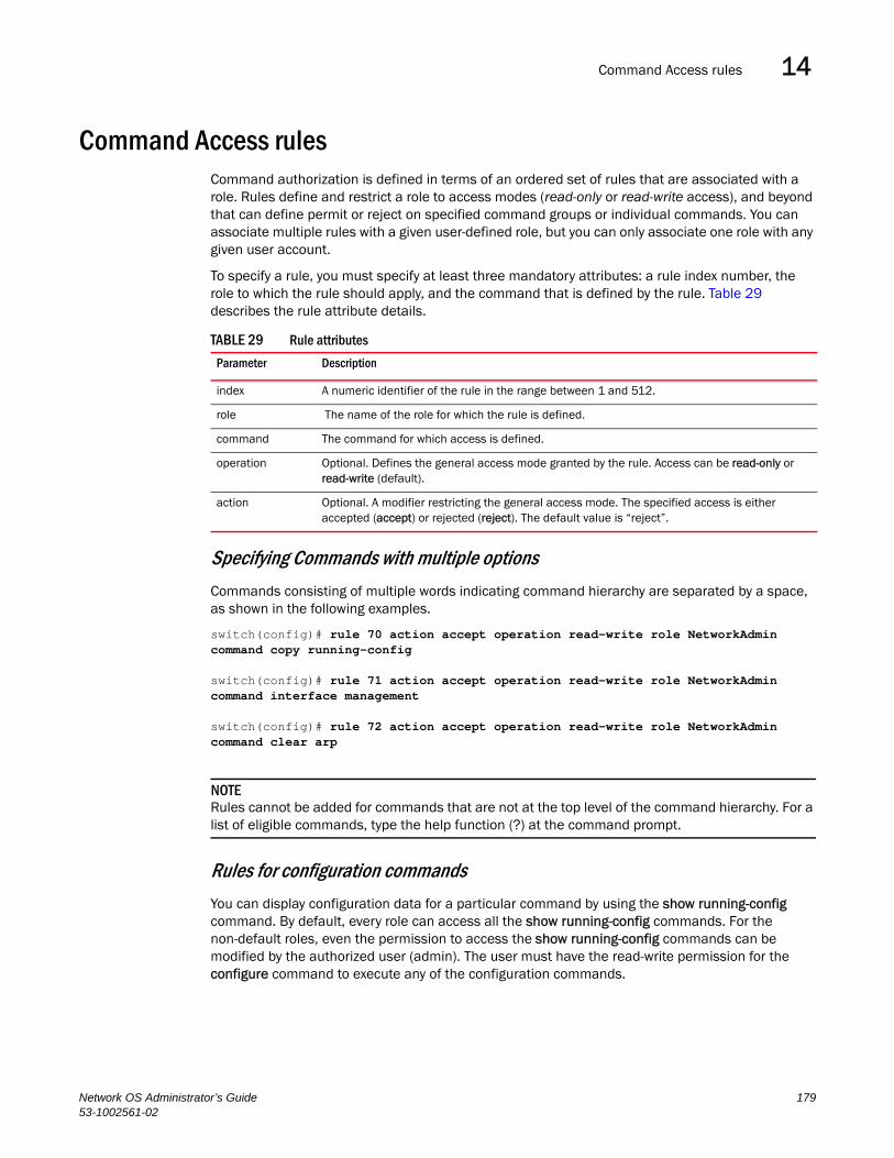
Command Access rules 14
Command Access rulesCommand authorization is defined in terms of an ordered set of rules that are associated with a role. Rules define and restrict a role to access modes (read-only or read-write access), and beyond that can define permit or reject on specified command groups or individual commands. You can associate multiple rules with a given user-defined role, but you can only associate one role with any given user account.
To specify a rule, you must specify at least three mandatory attributes: a rule index number, the role to which the rule should apply, and the command that is defined by the rule. Table 29 describes the rule attribute details.
Specifying Commands with multiple options
Commands consisting of multiple words indicating command hierarchy are separated by a space, as shown in the following examples.
switch(config)# rule 70 action accept operation read-write role NetworkAdmin command copy running-config
switch(config)# rule 71 action accept operation read-write role NetworkAdmin command interface management
switch(config)# rule 72 action accept operation read-write role NetworkAdmin command clear arp
NOTERules cannot be added for commands that are not at the top level of the command hierarchy. For a list of eligible commands, type the help function (?) at the command prompt.
Rules for configuration commands
You can display configuration data for a particular command by using the show running-config command. By default, every role can access all the show running-config commands. For the non-default roles, even the permission to access the show running-config commands can be modified by the authorized user (admin). The user must have the read-write permission for the configure command to execute any of the configuration commands.
TABLE 29 Rule attributes
Parameter Description
index A numeric identifier of the rule in the range between 1 and 512.
role The name of the role for which the rule is defined.
command The command for which access is defined.
operation Optional. Defines the general access mode granted by the rule. Access can be read-only or read-write (default).
action Optional. A modifier restricting the general access mode. The specified access is either accepted (accept) or rejected (reject). The default value is “reject”.
Network OS Administrator’s Guide 17953-1002561-02

Command Access rules14
The following rules govern configuration commands:
• If a role has a rule with a read-write operation and the accept action for a configuration command, the user associated with this role can execute the command and read the configuration data.
• If a role has a rule with a read-only operation and the accept action for a configuration command, the user associated with this role can only read the configuration data of the command.
• If a role has a rule with a read-only or read-write operation and the reject action for a configuration command, the user associated with this role cannot execute the command and can read the configuration data of the command.
Rules for operational commands
Rules can be created for the specified operational commands. By default, every role can display all the operational commands but cannot execute them. The show commands can be accessed by all the roles.
The following rules govern operational commands:
• If a role has a rule with a read-write operation and the accept action for an operational command, the user associated with this role can execute the command.
• If a role has a rule with a read-only operation and the accept action for an operational command, the user associated with this role can access but cannot execute the command.
• If a role has a rule with a read-only or read-write operation and the reject action for an operational command, the user associated with this role can neither access nor execute the command.
Rules for interface key-based commands
By default, every role has the permission to read the configuration data related to all the instances of the interfaces using the show running-config interface interface_name rbridge-id/slot/port command.
Rules can be created for a specific instance of the interface-related configuration commands.
The following rules govern interface key-based commands:
• If a role has a rule with a read-write operation and the accept action for only a particular instance of the interface, the user associated with this role can only modify the attributes of that instance.
• If a role has a rule with a read-only operation and the accept action for only a particular instance of the interface, the user associated with this role can only read (using the show running-config command) the data related to that instance of the interface.
• If a role has a rule with a read-write operation and the reject action for only a particular instance of the interface, the user associated with this role cannot execute and read the configuration data for that interface instance.
180 Network OS Administrator’s Guide53-1002561-02

Command Access rules 14
In the following example, the rules are applicable only to a particular instance of the specified interface.
switch(config)# rule 60 action accept operation read-write role NetworkAdmin command interface tengigabitethernet 0/4
switch(config)# rule 65 action accept operation read-write role NetworkAdmin command interface fcoe 0/4
switch(config)# rule 68 role NetworkAdmin action reject command interface fortygigabitethernet 1/2/4
• If a role has a rule with a read-only or read-write operation and the reject action for an interface or an instance of the interface, the user associated with this role cannot perform clear and show operations related to those interfaces or interface instances. To perform clear and show operations, the user’s role must have at least read-only and the accept permission. By default, every role has the read-only, accept permission for all interface instances.
In the following example, the user associated with the NetworkAdmin role cannot perform clear and show operations related to all tengigabitethernet instances.
switch(config)# rule 30 action accept operation read-write role NetworkAdmin command interface tengigabitethernet
• The dot1x option under the interface instance sub-mode can only be configured if the role has the read-write and accept permissions for both the dot1x command and interface instances.
In the following example, the user associated with the CfgAdmin role can access and execute the dot1x command in the specified tengigabitethernet instance
switch(config)# rule 16 action accept operation read-write role cfgadmin command interface tengigabitethernetswitch(config)# rule 17 action accept operation read-write role cfgadmin command dot1x
• To execute the no vlan, and no spanning-tree commands under the sub-mode of interface tengigabitethernet instances, a user must have read-write and accept permission for both the vlan and the protocol spanning-tree commands. If a user has read-write and accept permission the vlan, and spanning-tree commands and read-write and accept permission for at least one interface instance, the user can perform the no vlan, and no spanning-tree operations on the other interface instances for which the user has only default permissions (read-only and accept).
Configuring a placeholder rule
A rule created with the no-operation command does not enforce any authorization rules. Instead, you can use the no-operation instance as a placeholder for a valid command that is added later, as shown in the following example.
1. In the privileged EXEC mode, use the configure terminal command to enter the global configuration mode.
2. Enter the rule command with the specified parameters and the no-operation placeholder
Network OS Administrator’s Guide 18153-1002561-02

Command Access rules14
3. Enter the rule command with the specified command to replace the placeholder.
switch# configure terminalEntering configuration mode terminalswitch(config)# rule 75 action reject operation read-write role NetworkAdmin command no-operationswitch(config)# rule 75 command firmware
Rule Processing
When a user executes a command, rules are searched in ascending order by index for a match and the action of the first matching rule is applied. If none of the rules match, command execution is blocked. If there are conflicting permissions for a role in different indices, the rule with lowest index number is applied.
The following exceptions apply:
• When a match is found for a rule with the read-only operation, and the accept action, the system seeks to determine if there are any rules with the read-write operation and the accept action. If such rules are found, the rule with the read-write permission is applied.
In the following example, two rules with action accept are present and rule 11 is applied.
switch(config)# rule 9 operation read-only action accept role NetworkAdmin command aaaswitch(config)# rule 11 operation read-write action accept role NetworkAdmin command aaa
Adding a rule
You add a rule to a role by entering the rule command with appropriate options. Any updates to the authorization rules will not apply to the active sessions of the users. The changes will be applied only when users logout from the current session and login to a new session.
The following example creates the rules that authorize the security administrator role to create and manage user accounts:
1. In the privileged EXEC mode, use the configure terminal command to enter the global configuration mode.
2. Create a rule specifying read-write access to the global configuration mode.
3. Create a second rule specifying read-write access to the username command. Enter the rule command with the specified parameters
switch#configure terminalEntering configuration mode terminalswitch(config)# rule 150 action accept operation read-write role SecAdminUser command configswitch(config)# rule 155 action accept operation read-write role SecAdminUser command username
4. After creating the rules, the user of the SecAdminUser account can log in to the switch and create or modify the user accounts p with the username command.
switch login: SecAdminUserPassword:******Welcome to the ConfD CLISecAdminUser connected from 127.0.0.1 using console on switch
182 Network OS Administrator’s Guide53-1002561-02

Command Access rules 14
switch# configure terminalEntering configuration mode terminalCurrent configuration users:admin console (cli from 127.0.0.1) on since 2010-08-16 18:35:05 terminal modeswitch(config)# username testuser role user password (<string>): ********
Changing a rule
The following example changes the previously created rule (index number 155) so that the command “username” is replaced by “role”.
1. In the privileged EXEC mode, use the configure terminal command to enter the global configuration mode.
2. Enter the rule command specifying an existing rule (index 155) and changing the command attribute to the role command.
switch# configure terminalEntering configuration mode terminalswitch(config)# rule 150switch(config)# rule 155 command role
After changing the rule 155, SecAdminUser can log in to the switch and execute the role command and not the username command.
switch login: SecAdminUserPassword:Welcome to the ConfD CLISecAdminUser connected from 127.0.0.1 using console on sw0switch# configure terminalEntering configuration mode terminalCurrent configuration users:admin console (cli from 127.0.0.1) on since 2010-08-16 18:35:05 terminal modeswitch(config)# role name NetworkAdmin
Deleting a rule
1. In the privileged EXEC mode, use the configure terminal command to enter the global configuration mode.
2. Enter the no rule command followed by the index number of the rule you wish to delete.
switch# configure terminalEntering configuration mode terminalswitch(config)# no rule 155
After you deleted rule 155, the SecAdminUser can no longer access the role command.
Displaying a rule
Enter the show running-config rule command in the privileged EXEC mode to display all configured rules. You can filter the output by using the command with additional parameters.
switch# show running-config rulerule 30 action accept operation read-write role NetworkSecurityAdminrule 30 command role
rule 31 action accept operation read-write role NetworkSecurityAdminrule 31 command rule
rule 32 action accept operation read-write role NetworkSecurityAdmin
Network OS Administrator’s Guide 18353-1002561-02

Command Access rules14
rule 32 command username
rule 33 action accept operation read-write role NetworkSecurityAdminrule 33 command aaa
rule 34 action accept operation read-write role NetworkSecurityAdminrule 34 command radius-server
rule 35 action accept operation read-write role NetworkSecurityAdminrule 35 command configure
rule 40 action accept operation read-write role FCOEAdminrule 40 command "interface fcoe"
Configuration examplesThe following example illustrates the step-by-step configuration of two frequently used administrative accounts: Brocade VCS Fabric security administrator, and FCoE Fabric administrator.
Configuring a Brocade VCS Fabric security administrator account
1. Create a role for a Brocade VCS Fabric security administrator
switch(config)# role name NetworkSecurityAdmin desc “Manages security CLIs”
2. Create a user account associated with the newly created role.
switch(config)# username SecAdminUser role NetworkSecurityAdmin password testpassword
3. Create the rules to specify the RBAC permissions for the NetworkSecurityAdmin role.
switch(config)# rule 30 action accept operation read-write role NetworkSecurityAdmin command roleswitch(config-rule-30)# exitswitch(config)# rule 31 action accept operation read-write role NetworkSecurityAdmin command ruleswitch(config-rule-31)# exitswitch(config)# rule 32 action accept operation read-write role NetworkSecurityAdmin command usernameswitch(config-rule-32)# exitswitch(config)# rule 33 action accept operation read-write role NetworkSecurityAdmin command aaaswitch(config-rule-33)# exitswitch(config)# rule 34 action accept operation read-write role NetworkSecurityAdmin command radius-serverswitch(config-rule-34)# exitswitch(config)# rule 35 action accept operation read-write role NetworkSecurityAdmin command configswitch(config-rule-35)# exit
The SecAdminUser account has been granted operational access to the configuration-level commands role, rule, username, aaa, and radius-server. Any account associated with the NetworkSecurityAdmin role can now create and modify user accounts, manage roles, and define rules. In addition, the role permits configuring a RADIUS server and set the login sequence.
184 Network OS Administrator’s Guide53-1002561-02

Password policies 14
Configuring a Brocade FCoE administrator account
1. Create an FCoE administrator role.
switch(config)# role name FCOEAdmin desc "Manages FCOE"
2. Create an FCoE admin user account.
switch(config)# username FCOEAdmUser role FCOEAdmin password testpassword
3. Create the rules defining the access permissions for the FCoE administrator role.
switch(config)# rule 40 action accept operation read-write role FCOEAdmin command interface fcoe
The FCOEAdmUser account that is associated with the FCoEAdmin role can now perform the FCoE operations.
Password policiesPassword policies define and enforce a set of rules that make passwords more secure by subjecting all new passwords to global restrictions. The password policies described in this section apply to the switch-local user database only. Configured password policies (and all user account attribute and password state information) are synchronized across management modules and remain unchanged after an HA failover. Following is a list of the configurable password policies:
• Password strength policy
• Password encryption policy
• Account lockout policy
Password strength policyTable 30 lists configurable password policy parameters.
TABLE 30 Password policy parameters
Parameter Description
character-restriction lower
Specifies the minimum number of lowercase alphabetic characters that must occur in the password. The maximum value must be less than or equal to the minimum length value. The default value is zero, which means there is no restriction of lowercase characters.
character-restriction upper
Specifies the minimum number of uppercase alphabetic characters that must occur in the password. The maximum value must be less than or equal to the Minimum Length value. The default value is zero, which means there is no restriction of uppercase characters.
character-restriction numeric
Specifies the minimum number of numeric characters that must occur in the password. The maximum value must be less than or equal to the Minimum Length value. The default value is zero, which means there is no restriction of numeric characters.
character-restriction special-char
Specifies the minimum number of punctuation characters that must occur in the password. All printable, non-alphanumeric punctuation characters except the colon (:) are allowed. The value must be less than or equal to the Minimum Length value. The default value is zero, which means there is no restriction of punctuation characters.
Network OS Administrator’s Guide 18553-1002561-02

Password policies14
Password encryption policyNetwork OS supports encrypting the passwords of all existing user accounts by enabling password encryption at the switch level. By default, the encryption service is disabled and passwords are stored in clear-text. Use the no service password-encryption command to enable or disable password encryption. The following rules apply to password encryption:
• When you enable password encryption, all existing clear-text passwords will be encrypted, and any password that are added subsequently in clear-text will be stored in encrypted format
In the following example, the testuser account password is created in clear-text after password encryption has been enabled. The global encryption policy overrides command-level encryption settings The password is stored as encrypted.
switch(config)# service password-encryptionswitch(config)# do show running-config service password-encryptionservice password-encryptionswitch(config)# username testuser role testrole desc "Test User"encryption-level 0 password hellothereswitch(config)# do show running-config usernameusername admin password "BwrsDbB+tABWGWpINOVKoQ==\n" encryptionlevel7 role admin desc Administratorusername testuser password "cONW1RQ0nTV9Az42/9uCQg==\n"encryption-level 7 role testrole desc "Test User"username user password "BwrsDbB+tABWGWpINOVKoQ==\n" encryptionlevel7 role user desc User
• When you disable the password encryption service, any new passwords added in clear-text will be stored as clear-text on the switch. Existing encrypted passwords remain encrypted.
In the following example, the testuser account password is stored in clear-text after password encryption has been disabled. The default accounts, “user” and admin” remain encrypted.
switch(config)# no service password-encryptionswitch(config)# do show running-config service password-encryptionno service password-encryptionswitch(config)# username testuser role testrole desc "Test User"encryption-level 0 password hellothere enable true.switch(config)# do show running-config usernameusername admin password "BwrsDbB+tABWGWpINOVKoQ==\n" encryptionlevel7 role admin desc Administratorusername testuser password hellothere encryption-level 0 roletestrole desc "Test User"username user password "BwrsDbB+tABWGWpINOVKoQ==\n" encryptionlevel7 role user desc User
min-length Specifies the minimum length of the password. Passwords must be from 8 through 32 characters in length. The default value is 8. The total of the previous four parameters (lowercase, uppercase, digits, and punctuation) must be less than or equal to the Minimum Length value.
max-retry Specifies the number of failed password logins permitted before a user is locked out. The lockout threshold can range from 0 through 16. The default value is 0. When a password fails more than one of the strength attributes, an error is reported for only one of the attributes at a time.
TABLE 30 Password policy parameters (Continued)
Parameter Description
186 Network OS Administrator’s Guide53-1002561-02

Password policies 14
Account lockout policyThe account lockout policy disables a user account when the user exceeds a configurable number of failed login attempts. A user whose account has been locked cannot log in. SSH login attempts using locked user credentials are denied without notifying the user of the reason for denial.
The account remains locked until explicit administrative action is taken to unlock the account. A user account cannot be locked manually. An account not locked cannot be unlocked.
Failed login attempts are tracked on the local switch only. in VCS mode, the user account is locked only on the switch where the lockout occurred; the same user can still try to log in on another switch in the VCS fabric.
The account lockout policy is enforced across all user accounts except for the root account and accounts with the admin role.
Denial of service implications
The account lockout mechanism may be used to create a denial of service condition by repeatedly attempting to login to an account using an incorrect password. Selected privileged accounts, such as root and admin are exempted from the account lockout policy to prevent them from being locked out by a denial of service attack. However these privileged accounts may then become the target of password guessing attacks. Brocade advises that you periodically examine the Security Audit logs to determine if such attacks are attempted. For information on security audit logging refer to the Network OS Message Reference.
Configuring the account lockout threshold
You can configure the lockout threshold with the password-attributes max-retry maxretry command. The value of the maxretry specifies the number of times a user can attempt to log in with an incorrect password before the account is locked. The number of failed login attempts is counted from the last successful login. The maxretry can be set to a value from 0 through 16. A value of 0 disables the lockout mechanism (default).
The following example sets the lockout threshold to 5.
1. In the privileged EXEC mode, use the configure terminal command to enter the global configuration mode.
2. Enter the password-attributes command with the specified parameter.
switch# configure terminalEntering configuration mode terminalswitch(config)# password-attributes max-retry 4
When a user account is locked, it can be unlocked using the procedure described in “Unlocking a user account” on page 176.
Password interaction with remote AAA serversThe password policies apply to local switch authentication only. External AAA servers such as RADIUS, TACACS+, or LDAP provide server-specific password-enforcement mechanisms. The Network OS password management commands operate on the switch-local password database only, even when the switch is configured to use an external AAA service for authentication. When so configured, authentication through remote servers is applied to login only.
Network OS Administrator’s Guide 18753-1002561-02

Password policies14
When remote AAA server authentication is enabled, an administrator can still perform user and password management functions on the local password database.
For more information on remote AAA server authentication, refer to Chapter 15, “External AAA server authentication”.
Managing password policiesUse the password-attributes with specified parameters to define or modify existing password policies.
Creating a password policy
The following example defines a password policy that places restrictions on minimum length and enforces character restrictions and account lockout.
1. In the privileged EXEC mode, use the configure terminal command to enter the global configuration mode.
2. Enter the password-attributes command with the specified parameters.
switch# configure terminalEntering configuration mode terminalswitch(config)# password-attributes min-length 8 max-retry 4 character-restriction lower 2 upper 1 numeric 1 special-char 1
Restoring the default password policy
The no form of the password-attributes command resets all password attributes to their default values. When used without operands, the command resets all password attributes.
1. In the privileged EXEC mode, use the configure terminal command to enter the global configuration mode.
2. Enter the password-attributes command with the specified parameters.
switch# configure terminalEntering configuration mode terminalswitch(config)# no password-attributes min-lengthswitch(config)# password-attributes max-retry 4switch(config)# no password-attributes
Displaying password attributes
In the privileged EXEC mode, enter the show running-config password-attributes command to display configured password attributes:
switch(config)# password-attributes max-retry 4switch(config)# password-attributes character-restriction lower 2switch(config)# password-attributes character-restriction upper 1 numeric 1 special-char 1switch(config)# exitswitch# show running-config password-attributespassword-attributes max-retry 4password-attributes character-restriction upper 1password-attributes character-restriction lower 2password-attributes character-restriction numeric 1password-attributes character-restriction special-char 1
188 Network OS Administrator’s Guide53-1002561-02

Security event logging 14
switch# configure terminalswitch(config)# no password-attributes character-restriction lowerswitch(config)# no password-attributes character-restriction upperswitch(config)# exitswitch# show running-config password-attributespassword-attributes max-retry 4password-attributes character-restriction numeric 1password-attributes character-restriction special-char 1switch# configure terminalswitch(config)# no password-attributesswitch(config)# exitswitch# show running-config password-attributes% No entries found.
Security event loggingSecurity event logging utilizes the RASLog audit infrastructure to record security-related audit events. Any user-initiated security event generates an auditable event. Audited events are generated for all Management interfaces. In Brocade VCS Fabric mode, for cluster-wide events, the audit is generated on all switches of the cluster. Refer to the Network OS Message Reference for information on how to configure and monitor security Audit logging.
Network OS Administrator’s Guide 18953-1002561-02

Security event logging14
190 Network OS Administrator’s Guide53-1002561-02

Network OS Administrator’s Guide53-1002561-02
Chapter
15
External AAA server authenticationIn this chapter
•Remote server authentication overview . . . . . . . . . . . . . . . . . . . . . . . . . . . 191
•Login authentication mode. . . . . . . . . . . . . . . . . . . . . . . . . . . . . . . . . . . . . . 192
•RADIUS . . . . . . . . . . . . . . . . . . . . . . . . . . . . . . . . . . . . . . . . . . . . . . . . . . . . . . 194
•TACACS+ . . . . . . . . . . . . . . . . . . . . . . . . . . . . . . . . . . . . . . . . . . . . . . . . . . . . . 199
•TACACS+ accounting . . . . . . . . . . . . . . . . . . . . . . . . . . . . . . . . . . . . . . . . . . . 202
•TACACS+ server-side configuration . . . . . . . . . . . . . . . . . . . . . . . . . . . . . . . 205
•LDAP . . . . . . . . . . . . . . . . . . . . . . . . . . . . . . . . . . . . . . . . . . . . . . . . . . . . . . . . 208
Remote server authentication overviewNetwork OS supports various protocols to provide external Authentication, Authorization, and Accounting (AAA) services for Brocade devices. Supported protocols include the following:
• RADIUS - Remote authentication dial-in user service
• LDAP/AD - Lightweight directory access protocol using Microsoft Active Directory (AD) in Windows
• TACACS+ - Terminal access controller access-control system plus
When configured to use a remote AAA service, the switch acts as a network access server (NAS) client. The switch sends all authentication, authorization, and accounting (AAA) service requests to the remote RADIUS, LDAP, or TACACS+ server. The remote AAA server receives the request, validates the request, and sends a response back to the switch.
The supported management access channels that integrate with RADIUS, TACACS+, or LDAP include serial port, Telnet, or SSH.
When configured to use a remote RADIUS, TACAC+, or LDAP server for authentication, a switch becomes a RADIUS, TACAC+, or LDAP client. In either of these configurations, authentication records are stored in the remote host server database. Login and logout account name, assigned permissions, and time-accounting records are also stored on the AAA server for each user.
Brocade recommends that you configure at least two remote AAA servers to provide redundancy in the event of failure. For each of the supported AAA protocols, you can configure up to five external servers on the switch. Each switch maintains its own server configuration.
191
Login authentication mode15
Login authentication modeThe authentication mode is defined as the order in which AAA services are used on the switch for user authentication during the login process. Network OS supports two sources of authentication: primary and secondary. The secondary source of authentication is used in the event of primary source failover and is optional for configuration. You can configure four possible sources for authentication:
• Local - Use the default switch-local database (default)
• RADIUS- Use an external RADIUS server
• LDAP - Use an external LDAP server
• TACACS+ -Use an external TACACS+ server
By default, external AAA services are disabled, and AAA services default to the switch-local user database.
When the authentication, authorization, and accounting (AAA) mode is changed, an appropriate message is broadcast to all logged-in users and the active login sessions end. If the primary source is set to an external AAA service (RADIUS, LDAP, or TACACS+) and the secondary source is not configured, the following events occur:
• For Telnet-based and SSH connections-based logins, the login authentication fails if none of the configured (primary source) AAA servers respond or if an AAA server rejects the login.
• For a serial port (console) connection-based login, if a user’s login fails for any reason with the primary source, failover occurs and the same user credentials are used for login through the local source. This failover is not explicit.
• If the primary source is set to an external AAA service, and the secondary source is configured to be local (for example, aaa authentication login radius local), then, if login fails through the primary source either because none of the configured servers are responding or the login is rejected by a server, failover occurs and authentication occurs again through the secondary source (local).
Conditions for conformanceIf the first source is specified as default, do not specify a second source. A second source signals a request to set the login authentication mode to its default value, which is local. If the first source is local, the second source cannot be set to any value, because the failover will never occur.
The source of authentication (except local) and the corresponding server type configuration are dependent on each other. Therefore, there should be at least one server configured before that server type can be specified as a source.
If the source is configured to be a server type, you cannot delete a server of that type if it is the only server in the list. For example, if there are no entries in the TACACS+ server list, the authentication mode cannot be set to tacacs+ or tacacs+ local. Similarly, when the authentication mode is radius or radius local, a RADIUS server cannot be deleted if it is the only one in the list.
192 Network OS Administrator’s Guide53-1002561-02

Login authentication mode 15
Setting and verifying the login authentication mode
The following procedure configures TACACS+ as the primary source of authentication and the switch-local user database as the secondary source.
1. In the privileged EXEC mode, use the configure terminal command to enter the global configuration mode.
2. Enter aaa authentication login command with the specified parameters.
switch# configure terminalEntering configuration mode terminalswitch(config)# aaa authentication login tacacs+ local Broadcast message from root (pts/0) Tue Apr 5 16:34:12 2011...AAA Server Configuration Change: all accounts will be logged out
3. Enter the do show running-config aaa command to display the configuration.
switch(config)# do show running-config aaaaaa authentication login tacacs+ local
4. Login to the switch using an account with TACACS+ only credentials to verify that TACACS+ is being used to authenticate the user.
Resetting the login authentication mode
1. In the privileged EXEC mode, use the configure terminal command to enter the global configuration mode.
2. Enter the no aaa authentication login command to remove the configured authentication sequence and to restore the default value (Local only).
switch# configure terminalEntering configuration mode terminalswitch(config)# no aaa authentication login
3. Verify the configuration with the do show running-config aaa command.
switch(config)# do show running-config aaaaaa authentication login local
4. Login to the switch using an account with TACACS+ only credentials. The login should fail with an “access denied” error.
5. Login to the switch using an account with local only credentials. The login should succeed.
Changing the login authentication mode
You can set the authentication mode with the aaa authentication login command, but you cannot change or delete an existing authentication mode with the same command. You can only reset the configuration to the default value using the no aaa authentication login command and then reconfigure the authentication sequence to the correct value.
1. Enter the no aaa authentication login command to reset the configuration to the default value
2. Enter the aaa authentication login command and specify the desired authentication mode.
3. Verify the configuration with the do show running-config aaa command.
switch# configure terminalEntering configuration mode terminalswitch(config)# no aaa authentication login tacacs+ local
Network OS Administrator’s Guide 19353-1002561-02

RADIUS15
switch(config)# aaa authentication login radius localBroadcast message from root (pts/0) Tue Apr 5 16:34:12 2011...
AAA Server Configuration Change: all accounts will be logged outswitch(config)# do show running-config aaaaaa authentication login radius local
4. Log into the switch using an account with TACACS+ credentials. The login should fail with an “access denied” error.
5. Log into the switch using an account with RADIUS credentials. The login should succeed.
RADIUSThe remote authentication dial-in user service (RADIUS) protocol manages authentication, authorization, and accounting (AAA) services centrally. The supported management access channels that integrate with RADIUS are serial port, Telnet, and SSH.
Authentication and accountingWhen a Brocade switch is configured with a set of RADIUS servers to be used for authentication, the switch also sends accounting data to the RADIUS server implicitly. The only accounting events supported on Brocade VDX switches configured to use RADUS are successful login and logout of the RADIUS user.
During the user authentication process, the switch sends its IP address. When the switch also has a Virtual IP address (in Brocade VCS Fabric mode), it still sends only its unique IP address to the RADIUS server.
NOTEIf the RADIUS server is not configured to support accounting, the accounting events sent by the switch to the server are dropped.
AuthorizationUser authorization through the RADIUS protocol is not supported. The access control of RADIUS users is enforced by the Brocade role-based access control (RBAC) protocol at the switch level. A RADIUS user should therefore be assigned a role that is present on the switch using the Vendor Specific Attribute (VSA) “Brocade-Auth-Role.” After the successful authentication of the RADIUS user, the role of the user configured on the server is obtained. If the role cannot be obtained or if the obtained role is not present on the switch, the user will assigned “user” role and a session is granted to the user with “user” authorization.
Account password changesAll existing mechanisms for managing switch-local user accounts and passwords remain functional when the switch is configured to use RADIUS. Changes made to the switch-local database do not propagate to the RADIUS server, nor do the changes affect any account on the RADIUS server; therefore, changes to a RADIUS user password must be done on the RADIUS server.
194 Network OS Administrator’s Guide53-1002561-02

RADIUS 15
RADIUS authentication through management interfacesYou can access the switch through Telnet or SSH from either the Management interface or the data ports (TE interface or in-band). The switch goes through the same RADIUS-based authentication with either access method.
Client-side RADIUS server configurationEach Brocade switch client must be individually configured to use RADIUS servers. You use the radius-server command to specify the server IP address, authentication protocols, and other parameters. You can configure a maximum of five RADIUS servers on a Brocade switch for AAA service.
The parameters in Table 31 are associated with a RADIUS server that is configured on the switch.
NOTEIf you do not configure the key attribute, the authentication session will not be encrypted. The value of the key attribute must match the value configured in the RADIUS configuration file; otherwise, the communication between the server and the switch fails.
Adding a RADIUS server to the client server list
You must configure the Domain Name System (DNS) server on the switch prior to adding the RADIUS server with a domain name or a host name. Without the DNS server, name resolution of the RADIUS server fails and therefore the add operation fails. Use the ip dns command to configure the DNS server.
NOTEWhen a list of servers is configured on the switch, failover from one server to another server happens only if a RADIUS server fails to respond; it does not happen when user authentication fails.
1. In the privileged EXEC mode, use the configure terminal command to enter the global configuration mode.
2. Enter radius-server command with the specified parameters.
TABLE 31 RADIUS server parameters
Parameter Description
host IP address (IPv4 or IPv6) or host name of the RADIUS server. Host name requires prior DNS configuration. The maximum supported length for the host name is 40 characters.
auth-port The user datagram protocol (UDP) port used to connect the RADIUS server for authentication. The port range is 0 through 65535; the default port is 1812.
protocol The authentication protocol to be used. Options include CHAP, PAP, and PEAP. The default protocol is CHAP. IPv6 hosts are not supported if PEAP is the configured protocol.
key The shared secret between the switch and the RADIUS server. The default value is “sharedsecret.” The key cannot contain spaces and must be from 8 through 40 characters in length. Empty keys are not supported.
retransmit The number of attempts permitted to connect to a RADIUS server. The range is 0 through 100, and the default value is 5.
Network OS Administrator’s Guide 19553-1002561-02

RADIUS15
Upon execution of the command you are placed into the AAA server configuration sub-mode where you can specify additional parameters.
3. Enter the exit command to return to the global configuration mode.
4. Enter the do show running-config radius-server host command to verify the configuration.
switch# configure terminalEntering configuration mode terminalswitch(config)# radius-server host 10.38.37.180 protocol pap key “new#virgo*secret” timeout 10switch(config-host-10.38.37.180)#exitswitch# show running-config radius-server host 10.38.37.180 radius-server host 10.38.37.180protocol pap key “new#virgo*secret”timeout 10
Modifying the RADIUS server configuration
1. In the privileged EXEC mode, use the configure terminal command to enter the global configuration mode.
2. Enter radius-server host command with the help option (?) to display the configured RADIUS servers.
3. Enter the radius-server host command with the IP address of the server you want to modify.
Upon execution of the command you are placed into the radius-server configuration sub-mode where you can specify the parameters you want to modify.
4. Enter the parameters and values you want to change.
5. Enter the do show running-config radius-server command to verify the configuration.
This command does not display default values.
switch# configure terminalEntering configuration mode terminalswitch(config)# radius-server ?Possible completions:<hostname: IP Address or Hostname of this RADIUS server>10.38.37.18010.24.65.6switch(config)# radius-server host 10.38.37.180 switch(config-host-10.38.37.180 )# key “changedsec”switch(config-host-10.38.37.180 )# timeout 3switch(config)# do show running-config radius-server host 10.24.65.6radius-server host 10.24.65.6protocol pap key changedsec timeout 3
The no radius-server host command removes the server configuration from the list of configured RADIUS servers. When used with a specified parameter, the command sets the default value of that parameter.
196 Network OS Administrator’s Guide53-1002561-02
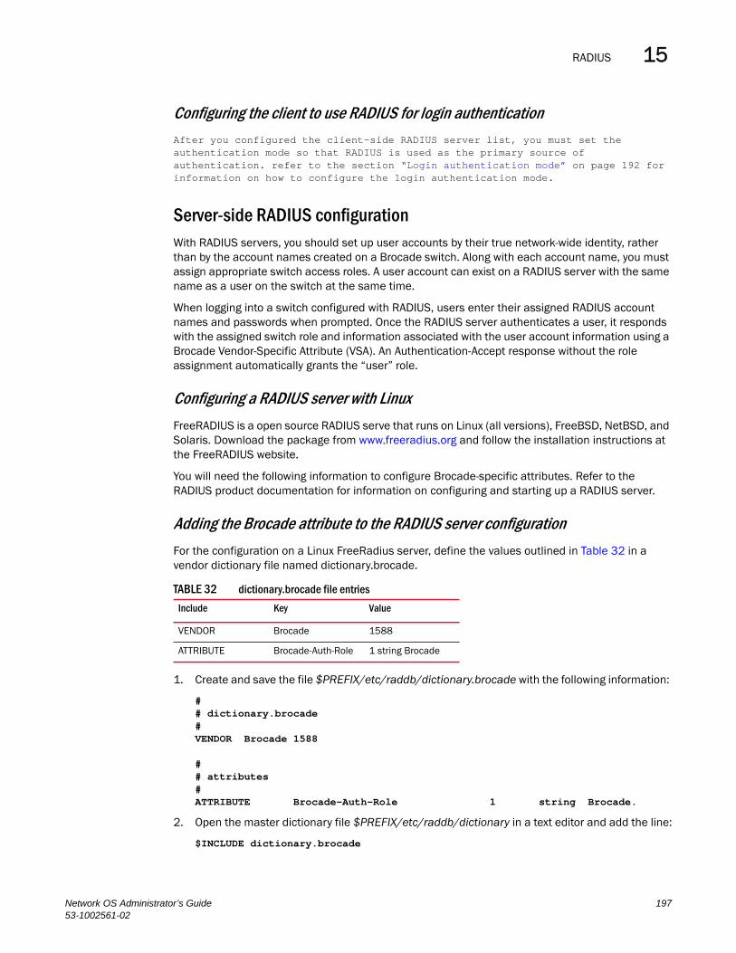
RADIUS 15
Configuring the client to use RADIUS for login authenticationAfter you configured the client-side RADIUS server list, you must set the authentication mode so that RADIUS is used as the primary source of authentication. refer to the section “Login authentication mode” on page 192 for information on how to configure the login authentication mode.
Server-side RADIUS configurationWith RADIUS servers, you should set up user accounts by their true network-wide identity, rather than by the account names created on a Brocade switch. Along with each account name, you must assign appropriate switch access roles. A user account can exist on a RADIUS server with the same name as a user on the switch at the same time.
When logging into a switch configured with RADIUS, users enter their assigned RADIUS account names and passwords when prompted. Once the RADIUS server authenticates a user, it responds with the assigned switch role and information associated with the user account information using a Brocade Vendor-Specific Attribute (VSA). An Authentication-Accept response without the role assignment automatically grants the “user” role.
Configuring a RADIUS server with Linux
FreeRADIUS is a open source RADIUS serve that runs on Linux (all versions), FreeBSD, NetBSD, and Solaris. Download the package from www.freeradius.org and follow the installation instructions at the FreeRADIUS website.
You will need the following information to configure Brocade-specific attributes. Refer to the RADIUS product documentation for information on configuring and starting up a RADIUS server.
Adding the Brocade attribute to the RADIUS server configuration
For the configuration on a Linux FreeRadius server, define the values outlined in Table 32 in a vendor dictionary file named dictionary.brocade.
1. Create and save the file $PREFIX/etc/raddb/dictionary.brocade with the following information:
## dictionary.brocade#VENDOR Brocade 1588
## attributes#ATTRIBUTE Brocade-Auth-Role 1 string Brocade.
2. Open the master dictionary file $PREFIX/etc/raddb/dictionary in a text editor and add the line:
$INCLUDE dictionary.brocade
TABLE 32 dictionary.brocade file entries
Include Key Value
VENDOR Brocade 1588
ATTRIBUTE Brocade-Auth-Role 1 string Brocade
Network OS Administrator’s Guide 19753-1002561-02

RADIUS15
As a result, the file dictionary.brocade is located in the RADIUS master configuration directory and loaded for use by the RADIUS server.
Configuring a Brocade user account
1. Open the $PREFIX/etc/raddb/users file in a text editor.
2. Add the user name and associated the permissions.
The user will log in using the permissions specified with Brocade-Auth-Role. The valid permissions include “user” and “admin”. You must use double quotation marks around “the password and role.
The following example configures an account called “jsmith” with admin permissions and a password “jspassword”.
jsmith Auth-Type := Local, User-Password == "jspassword", Brocade-Auth-Role = "admin"
When you use network information service (NIS) for authentication, the only way to enable authentication with the password file is to force the Brocade switch to authenticate using password authentication protocol (PAP); this requires the setting the pap option with the radius-server host command.
Configuring RADIUS server support with Windows server
Step-by-step instructions for installing and configuring Internet Authentication Service (IAS) with Microsoft Windows server 2008 (or earlier versions, Windows 2003 or 2000) can be obtained from www.microsoft.com or your Microsoft documentation. Confer with your system or network administrator prior to configuration for any special needs your network environment may have.
Use the following information to configure the Internet Authentication Service for a Brocade switch. This is not a complete presentation of steps.
• In the New RADIUS Client window choose RADIUS Standard from the Client-Vendor menu.
• Configure the Dial-in Profile window as follows:
1. Select the Advanced tab.
2. Scroll to the bottom of the RADIUS Standard list, select Vendor-Specific, and click Add.
The Multivalued Attribute Information dialog appears.
3. Click Add in the Multivalued Attribute Information window.
The Vendor-Specific Attribute Information dialog appears.
4. Enter the Brocade vendor code value of 1588.
5. Select the Yes. It conforms radio button and then click Configure Attribute.
The Configure VSA (RFC compliant) dialog appears.
6. In the Configure VSA (RFC compliant) window, enter the following values and click OK.
Vendor-assigned attribute number—Enter the value 1.
Attribute format—Enter String.
Attribute value—Enter the login role (admin or user).
198 Network OS Administrator’s Guide53-1002561-02

TACACS+ 15
FIGURE 16 Windows server VSA configuration
TACACS+The Terminal Access Controller Access-Control System Plus (TACACS+) is an AAA server protocol that uses a centralized authentication server and multiple Network Access Servers (NASs) or clients. With TACACS+ support, management of Brocade switches seamlessly integrates into these environments. Once configured to use TACACS+, a Brocade switch becomes a Network Access Server (NAS).
AuthorizationThe TACACS+ server is used only for authentication and accounting. Authorization is enforced by the Brocade role-based access control (RBAC) protocol at the switch level. The same role should be assigned to a user configured on the TACACS+ server and configured on the switch. If the switch fails to get the user’s role from the TACACS+ server after successful authentication, or if the role does not match any of the roles present on the switch, the user role is assigned by default. Thereafter, the role obtained from the TACACS+ server (or the defaulted role) is used for RBAC.
Network OS Administrator’s Guide 19953-1002561-02

TACACS+15
TACACS+ authentication through management interfacesYou can access the switch through the serial port, or through Telnet or SSH from either the management interface or the data ports (TE interface or in-band). The switch goes through the same TACACS+-based authentication with either access method.
Supported packages and protocolsBrocade supports the following TACACS+ packages for running the TACACS+ daemon on remote AAA servers.
• Free TACACS+ daemon (tacacs-plus 4.0.4.23-3). You can download this package from http://www.shrubbery.net/tac_plus/
• ACS 5.3
• ACS 4.2
The TACACS+ protocol v1.78 is used for AAA services between the Brocade switch client and the TACACS+ server.
The authentication protocols supported for user authentication are Password Authentication Protocol (PAP) and Challenge Handshake Authentication Protocol (CHAP).
Client-side TACACS+ server configurationEach Brocade switch client must be individually configured to use TACACS+ servers. You use the tacacs-server command to specify the server IP address, authentication protocols, and other parameters. You can configure a maximum of five TACACS+ servers on a Brocade switch for AAA service.
The parameters in Table 33 are associated with a TACACS+ server that is configured on the switch.
TABLE 33 TACACS+ server parameters
Parameter Description
host IP address (IPv4 or IPv6) or domain/host name of the TACACS+ server. Host name requires prior DNS configuration. The maximum supported length for the host name is 40 characters.
port The TCP port used to connect the TACACS+ server for authentication. The port range is 1 through 65535; the default port is 49.
protocol The authentication protocol to be used. Options include CHAP and PAP. The default protocol is CHAP.
key The shared secret between the switch and the RADIUS server. The default value is “sharedsecret.” The key cannot contain spaces and must be from 8 through 40 characters in length. Empty keys are not supported.
retries The number of attempts permitted to connect to a RADIUS server. The range is 0 through 100, and the default value is 5.
timeout The maximum amount of time to wait for a server to respond. Options are from 1 through 60 seconds, and the default value is 5 seconds.
200 Network OS Administrator’s Guide53-1002561-02

TACACS+ 15
NOTEIf you do not configure the key attribute, the authentication session will not be encrypted. The value of key must match with the value configured in the TACACS+ configuration file; otherwise, the communication between the server and the switch fails.
Adding a TACACS+ server to the client server list
You must configure the Domain Name System (DNS) server on the switch prior to adding the TACACS+ server with a domain name or a host name. Without the DNS server, name resolution of the TACACS+ server fails and therefore the add operation fails. Use the ip dns command to configure the DNS server.
NOTEWhen a list of servers is configured, failover from one server to another server happens only if a TACACS+ server fails to respond; it does not happen when user authentication fails.
The following procedure adds a TACACS+ server host in IPv6 format.
1. In the privileged EXEC mode, use the configure terminal command to enter the global configuration mode.
2. Enter tacacs-server command and specify the server IP address.
Upon execution of the command you are placed into the tacacs-server configuration sub-mode where you can specify additional parameters.
3. Enter the do show running-config tacacs+-server host command to verify the configuration.
switch# configure terminalEntering configuration mode terminalswitch(config)# tacacs-server host fec0:60:69bc:94:211:25ff:fec4:6010switch(config-tacacs-server-fec0:60:69bc:94:211:25ff:fec4:6010)# protocol \
chap key “new#hercules*secret” switch(config-tacacs-server-fec0:60:69bc:94:211:25ff:fec4:6010)# exitswitch(config)# do show running-config tacacs-server \
fec0:60:69bc:94:211:25ff:fec4:6010tacacs-server host fec0:60:69bc:94:211:25ff:fec4:6010key new#Hercules*secret!
Modifying the TACACS+ server configuration
1. In the privileged EXEC mode, use the configure terminal command to enter the global configuration mode.
2. Enter tacacs-server host command with the help option (?) to display the configured server IP addresses.
3. Enter tacacs-server host command with the IP address of the server you wish to modify.
Upon execution of the command you are placed into the tacacs-server configuration sub-mode where you can specify the parameters you want to modify.
4. Enter the exit command to return to the global configuration mode.
5. Enter the do show running-config tacacs-server host command to verify the configuration.
Network OS Administrator’s Guide 20153-1002561-02

TACACS+ accounting15
This command does not display default values.
switch# configure terminalEntering configuration mode terminalswitch(config)# tacacs-server host ?fec0:60:69bc:94:211:25ff:fec4:6010switch(config)# tacacs-server host fec0:60:69bc:94:211:25ff:fec4:6010switch(config-tacacs-server-fec0:60:69bc:94:211:25ff:fec4:6010)# key \
“changedsec” retries 100switch(config-tacacs-server-fec0:60:69bc:94:211:25ff:fec4:6010)# exitswitch(config)# do show running-config tacacs-server \
fec0:60:69bc:94:211:25ff:fec4:6010tacacs-server host fec0:60:69bc:94:211:25ff:fec4:6010key changedescretries 100!
The no tacacs-server host command removes the server configuration from the list of configured RADIUS servers. If the tacacs-server being deleted is the last one in the list and authentication mode is set to tacacs+, deletion of the server from the switch configuration is denied. When used with a specified parameter, the command sets the default value of that parameter
Configuring the client to use TACACS+ for login authenticationAfter you configured the client-side TACACS+ server list, you must set the authentication mode so that TACACS+ is used as the primary source of authentication. refer to the section “Login authentication mode” on page 192 for information on how to configure the login authentication mode.
TACACS+ accountingThe TACACS+ protocol supports accounting as a function distinctly separate from authentication. You can use TACACS+ for authentication only, for accounting only, or for both. With a TACACS+ server you can track user logins and the commands users execute during a login session by enabling login accounting, command accounting, or both.
• When login accounting is enabled, the switch sends a TACACS+ start accounting packet with relevant attributes to the configured TACACS+ server when the user logs in, and a stop accounting packet when the session terminates.
• When command accounting is enabled, the switch sends a TACACS+ stop accounting packet to the server when the command execution completes. No TACACS+ start accounting packet is sent for command accounting. Most configuration commands, show commands and non-configuration commands such as firmware download will be tracked. For a listing of commands that are not accounted for, refer to Appendix A, “TACACS+ Accounting Exceptions”
If a TACACS+ server is used for both authentication and accounting, the switch first attempts to connect to the TACACS+ server that was successfully used for authentication when sending accounting packets to the server. If the TACACS+ server cannot be reached, the switch attempts to send the packets to the next server on the list. Note that there is no fail back in this case. When the first TACACS+ server becomes reachable again, the accounting packets continue to be sent to the second TACACS+ server.
202 Network OS Administrator’s Guide53-1002561-02

TACACS+ accounting 15
If authentication is performed through some other mechanism, such as the switch-local database, a RADIUS, or an LDAP server, the switch will attempt to send the accounting packets to the first configured TACACS+ server. If that server is unreachable, the switch will attempt to send the accounting packets to subsequent servers in the order in which they are configured.
Conditions for conformance• Only login and command accounting is supported. System event accounting is not supported.
• You can use a TACACS+ server for accounting regardless of whether authentication is performed through RADIUS, LDAP, TACACS+, or the switch-local user database. The only precondition is the presence of one or more TACACS+ servers configured on the switch.
• No accounting can be performed if authentication fails.
• In command accounting, commands with partial timestamp cannot be logged. For example, a firmware download command issued with the reboot option will not be accounted for, because there is no timestamp available for completion of this command.
Configuring TACACS+ accounting on the clientBy default, accounting is disabled on the TACACS+ client (the switch) and you must explicitly enable the feature. Enabling command accounting and login accounting on the TACACS+ client are two distinct operations. To enable login or command accounting, at least one TACACS+ server must be configured. Similarly, if either login or command accounting is enabled, you cannot remove a TACACS+ server, if it is the only server in the list.
Enabling login accounting
The following procedure enables login accounting on a switch where accounting is disabled.
1. In the privileged EXEC mode, use the configure terminal command to enter the global configuration mode.
2. Enter the aaa accounting default exec start-stop tacacs+ command to enable login accounting.
3. Enter the do show running-config aaa accounting command to verify the configuration.
switch# configure terminalEntering configuration mode terminalswitch(config)# aaa accounting exec default start-stop tacacs+switch(config)# do show running-config aaa accountingaaa accounting exec default start-stop tacacs+aaa accounting commands default start-stop tacacs+
Enabling command accounting
The following procedure enables login accounting on a switch where login accounting is enabled and command accounting is disabled.
1. In the privileged EXEC mode, use the configure terminal command to enter the global configuration mode.
2. Enter the aaa accounting default command start-stop tacacs+ command to enable command accounting.
Network OS Administrator’s Guide 20353-1002561-02

TACACS+ accounting15
3. Enter the do show running-config aaa accounting command to verify the configuration.
switch# configure terminalEntering configuration mode terminalswitch(config)# aaa accounting command default start-stop tacacs+switch(config)# show running-config aaa accountingaaa accounting exec default start-stopaaa accounting commands default start-stop tacacs+
Disabling accounting
You have two options to disable accounting, either by using the aaa accounting command, with the none option or by using the no form of the command. Both variants are functionally equivalent. You must perform the disable operation separately for login accounting and for command accounting. The operation is performed in the global configuration mode.
The following examples show two ways of disabling command accounting. The commands are executed in the global configuration mode.
switch(config)# aaa accounting commands default start-stop noneswitch(config)# no aaa accounting commands default start-stop
The following examples show two ways of disabling login accounting.
switch(config)# aaa accounting exec default start-stop noneswitch(config)# no aaa accounting exec default start-stop
Viewing the TACACS+ accounting logsThe following excerpts from TACACS+ accounting logs exemplify typical success and failure cases for command and login accounting. These examples were taken from the free TACACS+ server. The order of the attributes may vary depending on the server package, but the values are the same. The location of the accounting logs depend on the server configuration.
Command accounting
The following record shows the successful execution of the username command by the admin user.
<102> 2012-04-09 15:21:43 4/9/2012 3:21:43 PM NAS_IP=10.17.37.150 Port=0 rem_addr=Console User=admin Flags=Stop task_id=1 timezone=Etc/GMT+0 service=shell priv-lvl=0 Cmd=username Stop_time=Mon Apr 9 09:43:56 2012 Status=Succeeded
The following record shows the failed execution of the radius-server command by the admin user due to an invalid host name or server IP address.
<102> 2012-04-09 14:19:42 4/9/2012 2:19:42 PM NAS_IP=10.17.37.150 Port=0 rem_addr=Console User=admin Flags=Stop task_id=1 timezone=Etc/GMT+0 service=shell priv-lvl=0 Cmd=radius-server Stop_time=Mon Apr 9 08:41:56 2012 Status=%% Error: Invalid host name or IP address
204 Network OS Administrator’s Guide53-1002561-02

TACACS+ server-side configuration 15
Login (EXEC) accounting
The following record shows the successful login of the trial user.
<102> 2012-05-14 11:47:49 5/14/2012 11:47:49 AM NAS_IP=10.17.46.42 Port=/dev/ttyS0 rem_addr=Console User=trial Flags=Start task_id=1 timezone=Asia/Kolkata service=shell
The following record shows the successful logout of the trial user.
<102>2012-05-14 11:49:52 5/14/2012 11:49:52 AM NAS_IP=10.17.46.42 Port=/dev/ttyS0 rem_addr=console User=trial Flags=Stop task_id=1 timezone=Asia/Kolkata service=shell elapsed_time=123 reason=admin reset
Firmware downgrade considerationsBefore downgrading to a version that does not support TACACS+ accounting, you must disable both login and command accounting or the firmware download will fail with an appropriate error message.
TACACS+ server-side configurationStep-by-step instructions for installing and configuring can be obtained from www.cisco.com. Confer with your system or network administrator prior to configuration for any special needs your network environment may have.
User account administration
With TACACS+ servers, you should set up user accounts by their true network-wide identity, rather than by the account names created on a Brocade switch. Along with each account name, you must assign appropriate switch access roles. A user account can exist on TACACS+ server with the same name as a user on the switch at the same time.
When logging in to a switch configured with a TACACS+ server, users enter their assigned TACACS+ account names and passwords when prompted. Once the TACACS+ server authenticates a user, it responds with the assigned switch role and information associated with the user account information using a Brocade Vendor-Specific Attribute (VSA). An Authentication-Accept response without the role assignment automatically grants the “user” role.
User accounts, protocols passwords, and related settings are configured by editing the server configuration files. The following configuration examples are based on the documentation provided by Cisco for its TACACS+ daemon users.
Configuring a user account
The following example assigns the user “Mary” the Brocade role of “vlanadmin” and different passwords depending on whether the CHAP or the PAP protocol is used. In the following example, the brcd-role attribute is mandatory, which works in a Brocade-only environment. In a mixed vendor environment, the brcd-role attribute most be set to optional. Refer to “Configuring TACACS+ for a mixed vendor environment” on page 207 for more information.
user = Mary {chap = cleartext "chap password"pap = cleartext "pap password"
Network OS Administrator’s Guide 20553-1002561-02

TACACS+ server-side configuration15
service = exec {brcd-role = vlanadmin;}}
The following example assigns the user “Agnes” a single password for all types of login authentication.
user = Agnes {global = cleartext "Agnes global password"}
Alternatively, a user can be authenticated using the /etc/passwd file. Configure the account as shown in the following example.
user = fred {login = file /etc/passwd}
Changing a TACACS+ account password
The change of password for TACACS+ user is done on the server by editing the TACACS+ server configuration file.
Setting an account expiration date
You can set an expiration date for an account by using the “expires” attribute in the TACACS+ server configuration file. The expiration date has the format “MMM DD YYYY”
user = Brocade {member = adminexpires = "Jan 1 2011"pap = cleartext "pap password"}
TACACS+ Server key
The TACACS+ Server key is the shared secret used to secure the messages exchanged between the Brocade switch and the TACACS+ server. The TACACS+ Server key must be configured on both the TACACS+ server and the client (Brocade switch). Only one key is defined per server in the TACACS+ server configuration file. The key is defined as follows:
key = "vcs shared secret"
Defining a TACACS+ group
A TACACS+ group or role can contain the same attributes as the users. By inference, all the attributes of a group can be assigned to any user to whom the group is assigned. The TACACS+ group, while functionally similar to the Brocade role concept, has no relation with the value of “brcd-role” attribute.
The following example defines a TACACS+ group.
group = admin {# group admin has a cleartext password which all members share# unless they have their own password definedchap = cleartext “my$parent$chap$password”}
206 Network OS Administrator’s Guide53-1002561-02

TACACS+ server-side configuration 15
The following example assigns the user “Brocade” with the group “admin”.
user = Brocade {member = adminpap = cleartext "pap password"}
Configuring TACACS+ for a mixed vendor environmentNetwork OS uses Role Based Access Control (RBAC) to authorize access to system objects by authenticated users. In AAA environments users may need to be authorized across Brocade and non-Brocade platforms. You can use TACACS+ to provide centralized AAA services to multiple Network Access Servers (NAS) or clients. To use TACACS+ services in multi-vendor environments, you must configure the Attribute-Value Pair (AVP) argument to be optional as shown in the example.
brcd-role*admin
The Network OS device sends the optional argument ‘brcd-role’ in the authorization request to the TACACS+ service. Most TACACS+ servers are programmed to return the same argument in response to the authorization request, If ‘brcd-role’ is configured as an optional argument, it is sent in the authorization request and Network OS users are able to successfully authorize with all TACACS+ services in a mixed-vendor environment.
Configuring optional arguments in tac_plus
The following is a specific example for tac_plus package. Syntac for other packages may differ.
In the example, the mandatory attribute priv-lvl=15 is set to allow Cisco to authenticate. The optional brcd-role = admin argument is added to the tac_plus.conf file and allows Brocade VDX switches to authenticate.
The following example configures a user with the optional attribute value pair, brcd-role = admin. A Brocade user must match both the username and usergroup to authenticate successfully.
user = <username> {default service = permitservice = exec {priv-lvl=15
optional brcd-role = admin}
}Orgroup = <usergroup> {
default service = permitservice = exec {priv-lvl=15optional brcd-role = admin
}}
user = <username> {Member = <usergroup>}
Network OS Administrator’s Guide 20753-1002561-02
LDAP15
LDAPLightweight Directory Access Protocol (LDAP) is an open-source protocol for accessing distributed directory services that act in accordance with X.500 data and service models. The LDAP protocol assumes that one or more servers jointly provide access to a Directory Information Tree (DIT) where data is stored and organized as entries in a hierarchical fashion. Each entry has a name called the distinguished name that uniquely identifies it.
The LDAP protocol can also be used for centralized authentication through directory service.
Active Directory (AD) is a directory service which supports a number of standardized protocols such as LDAP, Kerberos authentication, and DNS, to provide various network services. AD uses a structured data store as the basis for a logical, hierarchical organization of directory information. AD includes user profiles and groups as the part of directory information, so it can be used as a centralized database for authenticating the third party resources.
User authenticationA Brocade switch can be configured as an LDAP client for authentication with an AD server, supporting authentication with a clear text password over the transport Layer Security (TLS) channel. Optionally, it supports server authentication during the TLS handshake. Only the user principal name from the AD server is supported for LDAP authentication on the Brocade switch. The Common Name-based authentication is not supported. When you login from the switch, the complete user principal name, including domain, should be entered (for example, “[email protected]”).
LDAP supports alternative user principal names, such as:
• username
Network OS supports LDAP authentication with the following AD servers:
• Windows 2000
• Windows 2003
• Windows 2008 AD
A Brocade switch configured to perform LDAP-based authentication supports its access through a serial port, Telnet, and SSH. These access channels require that you know the switch IP address or name to connect to the switches.
Server authenticationAs a part of user authentication using LDAP, the Brocade switch can be configured to support server certificate authentication. To enable server authentication (server certificate verification), follow these guidelines:
• While configuring the LDAP server, the Fully Qualified Domain Name (FQDN) of the AD server should be added as the host parameter, instead of the IP address. A FQDN is needed to validate the server identity as mentioned in the common name of the server certificate.
208 Network OS Administrator’s Guide53-1002561-02

LDAP 15
• The DNS server must be configured on the switch prior to adding AD server with a domain name or a hostname. Without a DNS server, the name resolution of the server fails, and then the add operation fails. Use the ip dns command to configure DNS.
• The CA certificate of the AD server’s certificate should be installed on the switch. Currently, only PEM-formatted CA certificates can be imported into the switch.
If more than one server is configured, and LDAP CA certificate is imported for one server on the switch, the switch performs the server certificate verification on all servers. So CA certificates for all the servers should be imported, or CA certificates should not be imported for any of the servers. Once the CA certificate is imported, it is retained even if the switch is set back to its default configuration. If the CA certificate is not required, you should explicitly delete it.
Importing an LDAP CA certificate
The following example imports the LDAP CA certificate from a remote server to a Brocade switch using secure copy (SCP).
1. In the privileged EXEC mode, use the configure terminal command to enter the global configuration mode.
2. Enter the certutil import ldapca command with the specified parameters.
3. Verify the import with the show cert-util ldapcacert command.
switch# configure terminalEntering configuration mode terminalswitch# certutil import ldapca directory /usr/ldapcacert file cacert.pem protocol SCP host 10.23.24.56 user admin password *****switch# show cert-util ldapcacert List of ldap ca certificate files:
swLdapca.pem
Deleting CA certificates
The no certutil ldapca deletes the LDAP CA certificates of all Active Directory servers.
switch# no certutil ldapca Do you want to delete LDAP CA certificate? [y/n]:y
AuthorizationThe AD server is used only for authentication. Command authorization of the AD users is not supported in the AD server. Instead the access control of AD users is enforced locally by RBAC on the switch.
A user on an AD server should be assigned a non-primary group, and that group name should be either matched or mapped to one of the existing roles on the switch. After successful authentication, the switch receives the non-primary group of the user from the AD server, and finds the corresponding user role for group based on the matched or mapped roles.
If the switch fails to get the group from AD server, or the LDAP user is not a member of any matching AD group, the user authentication fails. Groups that match with the existing switch roles have higher priority than the groups that are mapped with the switch roles. Thereafter, the role obtained from AD server (or default role) is used for RBAC.
Network OS Administrator’s Guide 20953-1002561-02

LDAP15
FIPS complianceTo support FIPS compliance, the CA certificate of the AD server’s certificate should be installed on the switch, and the FIPS-compliant TLS ciphers for LDAP should be used.
Client-side Active Directory server configurationEach Brocade switch client must be individually configured to use AD servers. You use the ldap-server command to specify the host server, authentication protocols, and other parameters. You can configure a maximum of five AD servers on a Brocade switch for AAA service.
The parameters in Table 34 are associated with an AD server that is configured on the switch.
A maximum of five LDAP/AD servers can be configured on a Brocade switch for authentication service.
Adding an LDAP server to the client server list
The following procedure configures an LDAP server on an ADAP client (Brocade switch).
1. In the privileged EXEC mode, use the configure terminal command to enter global configuration mode
2. Use the ldap-server-host command to set the parameters for the LDAP server.
This command places you into the ldap-server configuration sub-mode where you can modify the server default settings.
switch# configure terminalEntering configuration mode terminalswitch(config)#ldap-server host 10.24.65.6 basedn sec.brocade.com port 3890switch(config-ldap-server-10.24.65.6)#
3. Modify any settings, such as the domain name or retry limit, in this configuration mode (refer to Table 34).
switch(config-ldap-server 10.24.65.6)# basedn security.brocade.com switch(config-ldap-server 10.24.65.6)# timeout 8switch(config-host-10.24.65.6)# retries 3
4. Confirm the LDAP settings with the do show command.
TABLE 34 AD parameters
Parameter Description
host IP address (v4) or Fully Qualified Domain name of the AD server. IPv6 is supported for Windows 2008 AD server only.The maximum supported length for the host name is 40 characters.
port TCP port used to connect the AD server for authentication. The valid port range is 1024 through 65535. The default port is 389.
timeout Time to wait for a server to respond. The range is 1 through 60 seconds. The default value is 5 seconds.
retries Number of unsuccessful attempts to be made to connect to an AD server before quitting. The valid range is 1 through 100. The default value is 5.
domain Base domain name
210 Network OS Administrator’s Guide53-1002561-02

LDAP 15
Attributes holding default values are not displayed.
switch(config-ldap-server-10.24.65.6)# do show running-config ldap-server host 10.24.65.6 ldap-server host 10.24.65.6 port 3890 basedn security.brocade.com retries 3 timeout 8!
5. Optional: Use the no ldap-server command option to set an attribute back to the default value.
switch(config-ldap-server-10.24.65.6)# exit switch(config)# no ldap-server host 10.24.65.6 retries
Removing an LDAP server
The following example deletes an LDAP server entry from the switch LDAP server list.
1. In the privileged EXEC mode, use the configure terminal command to enter global configuration mode
2. Use the no ldap-server command to delete the LDAP server.
switch# configure terminalEntering configuration mode terminalswitch(config)# no ldap-server host 10.24.65.6
Active Directory groupsAn Active Directory group defines access permissions for the LDAP server similar to Brocade roles. You can map an Active Directory group to a Brocade role with the ldap-server map-role command. The command confers all access privileges defined by the Active directory group to the Brocade role to which it is mapped.
A user on AD server should be assigned a non-primary group, and that group name should be either matched or mapped to one of the existing roles on the switch
After successful authentication, the user is assigned a role from a non-primary group (defined on the AD server) based on the matched or mapped switch role.
A user logging into the switch that is configured to uses LDAP and has a valid LDAP user name and password will be assigned LDAP user privileges if the user is not assigned with any non-primary group.
Mapping an Active Directory group to a switch role
In the following example, a Brocade user with the admin role inherits all privileges associated with the Active Directory Administrator group.
1. In the privileged EXEC mode, use the configure terminal command to enter global configuration mode
switch# config terminalEntering configuration mode terminal
2. Use the ldap-server command to set the group information.
Network OS Administrator’s Guide 21153-1002561-02

LDAP15
A maximum of 16 AD groups can be mapped to the switch roles.
switch(config)# ldap-server maprole group Administrator role admin
Removing the mapping of an Active Directory to a switch role
The following example removes the mapping between the Brocade admin role and the Active Directory Administrator group. A Brocade user with the admin role can no longer perform the operations associated with the Active Directory Administrator group,
To un-map an AD group to a switch role, perform the following steps from privileged EXEC mode.
1. Use the configure terminal command to enter global configuration mode
switch# config terminalEntering configuration mode terminal
2. Use the no ldap-server command to set the group information.
switch(config)# no ldap-server maprole group Administrator
Configuring the client to use LDAP/AD for login authenticationAfter you configured the switch LDAP server list, you must set the authentication mode so that ALDAP is used as the primary source of authentication. refer to “Login authentication mode” on page 192 for information on how to configure the login authentication mode.
Server-side Active Directory ConfigurationThen following high-level overview of server-side configuration for LDAP/AD servers indicates the steps needed to set up a user account. This overview is provided for your convenience only. All instructions involving Microsoft Active Directory can be obtained from www.microsoft.com or from your Microsoft documentation. Confer with your system or network administrator prior to configuration for any special needs your network environment may have.
Creating a user account on an LDAP/AD server
1. Create a user on the Microsoft Active Directory server.
2. Create a group. The group should either match with the user’s Brocade switch role or you can map the role to the Brocade switch role with the ldap--server maprole command.
3. Associate the user with the group by adding the user to the group.
The user account configuration is complete
Verifying the user account on the switch
4. Log into the switch as a user with admin privileges
5. Verify that the LDAP/AD server has an entry in the switch LDAP server list.
switch# show running-config ldap-server
6. Set the login authentication mode on the switch to use LDAP only and verify the change.
switch# configure terminalEntering configuration mode terminal
212 Network OS Administrator’s Guide53-1002561-02

LDAP 15
switch(config)# no aaa authentication loginswitch(config)# aaa authentication login ldapswitch(config)# do show running-config aaaaaa authentication login ldap
7. Login to the switch using an account with valid LDAP/AD only credentials to verify that LDAP/AD is being used to authenticate the user.
8. Login to the switch using an account with switch-local only credentials. The login should fail with an Access denied message.
Network OS Administrator’s Guide 21353-1002561-02

LDAP15
214 Network OS Administrator’s Guide53-1002561-02
Network OS Administrator’s Guide53-1002561-02
Chapter
16
FIPS SupportIn this chapter•FIPS overview. . . . . . . . . . . . . . . . . . . . . . . . . . . . . . . . . . . . . . . . . . . . . . . . . 215
•Zeroization functions. . . . . . . . . . . . . . . . . . . . . . . . . . . . . . . . . . . . . . . . . . . 216
•FIPS-compliant state configuration . . . . . . . . . . . . . . . . . . . . . . . . . . . . . . . 217
•Preparing the switch for FIPS . . . . . . . . . . . . . . . . . . . . . . . . . . . . . . . . . . . . 218
•Zeroizing for FIPS. . . . . . . . . . . . . . . . . . . . . . . . . . . . . . . . . . . . . . . . . . . . . . 225
•LDAP in FIPS-compliant state . . . . . . . . . . . . . . . . . . . . . . . . . . . . . . . . . . . . 225
FIPS overviewFederal Information Processing Standards (FIPS) specify the security standards to be satisfied by a cryptographic module utilized in Network OS v3.0.0 to protect sensitive information in the switch. As part of FIPS 140-2 level 2 compliance passwords, shared secrets, and the private keys used in SSL, TLS, and system login must be cleared out or zeroized.
Before enabling the FIPS-compliant state, a power-on self-test (POST) is executed when the switch is powered on to check for the consistency of the algorithms implemented in the switch. Known-answer tests (KATs) are used to exercise various features of the algorithm and their results are displayed on the console for your reference. Conditional tests are performed whenever an RSA key pair is generated. These tests verify the randomness of the deterministic random number generator (DRNG) and non-deterministic random number generator (non-DRNG). They also verify the consistency of RSA keys with regard to signing and verification and encryption and decryption. These conditional tests also verify that the downloaded firmware is signed.
ATTENTIONOnce enabled, the FIPS-compliant state cannot be disabled.
FIPS compliance can be applied to switches in Standalone and VCS fabric mode.
215

Zeroization functions16
Zeroization functionsExplicit zeroization can be done at the discretion of the security administrator. These functions clear the passwords and the shared secrets. Table 35 lists the various keys used in the system that will be zeroized in a FIPS-compliant Network OS switch.
Power-on self-testsA power-on self-test (POST) is invoked by powering on the switch in the FIPS-compliant state. It does not require any operator intervention. If any KATs fail, the switch goes into a FIPS Error state, which reboots the system to start the test again. If the switch continues to fail the FIPS POST, you will need to return your switch to your switch service provider for repair.
TABLE 35 Zeroization behavior
Keys Zeroization CLI Description
FCSP CHAP secrets fips zeroize Automatically zeroized on session termination. All the SFTP sessions gets terminated on zeroization.
Passwords fips zeroize The fips zeroize command removes user-defined accounts in addition to default passwords for the root, factory, admin, and user default accounts. Only the admin role has permissions for this command which, in addition to removing user accounts and resetting passwords, performs the complete zeroization of the system, and reboots the switch.
RADIUS secret fips zeroize The fips zeroize command zeroizes the secret and deletes a configured server.
RNG seed key No command required /dev/urandom is used as the initial source of seed for RNG. The RNG seed key is zeroized on every random number generation.
SFTP session keys No command required Automatically zeroized on session termination. All SFTP sessions are terminated on zeroization.
SSH DH private keys No command required Keys will be zeroized within code before they are released from memory.
SSH host keys No command required Automatically zeroized on session termination. All the SFTP sessions gets terminated on zeroization.
SSH session key No command required This key is generated for each SSH session that is established with the host. It automatically zeroizes on session termination. All SSH sessions terminate on zeroization.
TLS authentication key No command required Automatically zeroized on session termination.
TLS pre-master secret No command required Automatically zeroized on session termination.
TLS private keys fips zeroize Only RSA keys of size 1024 or 2048 are allowed.
TLS session key No command required Automatically zeroized on session termination.
216 Network OS Administrator’s Guide53-1002561-02
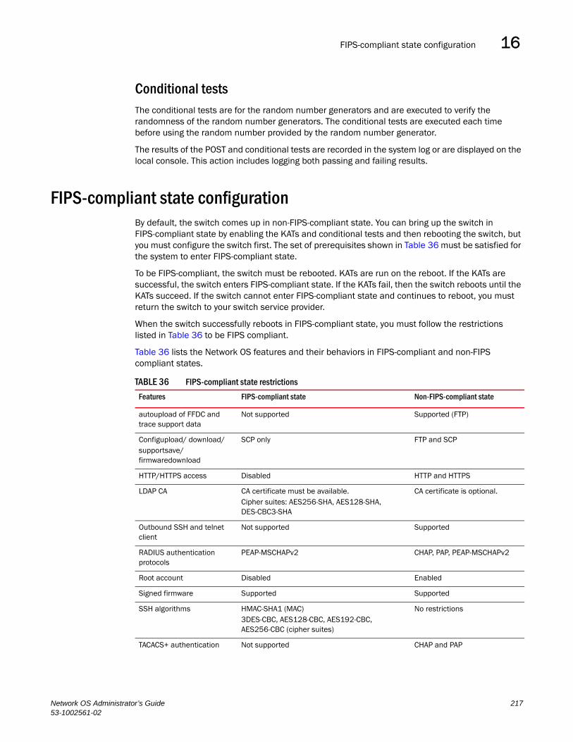
FIPS-compliant state configuration 16
Conditional testsThe conditional tests are for the random number generators and are executed to verify the randomness of the random number generators. The conditional tests are executed each time before using the random number provided by the random number generator.
The results of the POST and conditional tests are recorded in the system log or are displayed on the local console. This action includes logging both passing and failing results.
FIPS-compliant state configurationBy default, the switch comes up in non-FIPS-compliant state. You can bring up the switch in FIPS-compliant state by enabling the KATs and conditional tests and then rebooting the switch, but you must configure the switch first. The set of prerequisites shown in Table 36 must be satisfied for the system to enter FIPS-compliant state.
To be FIPS-compliant, the switch must be rebooted. KATs are run on the reboot. If the KATs are successful, the switch enters FIPS-compliant state. If the KATs fail, then the switch reboots until the KATs succeed. If the switch cannot enter FIPS-compliant state and continues to reboot, you must return the switch to your switch service provider.
When the switch successfully reboots in FIPS-compliant state, you must follow the restrictions listed in Table 36 to be FIPS compliant.
Table 36 lists the Network OS features and their behaviors in FIPS-compliant and non-FIPS compliant states.
TABLE 36 FIPS-compliant state restrictions
Features FIPS-compliant state Non-FIPS-compliant state
autoupload of FFDC and trace support data
Not supported Supported (FTP)
Configupload/ download/supportsave/ firmwaredownload
SCP only FTP and SCP
HTTP/HTTPS access Disabled HTTP and HTTPS
LDAP CA CA certificate must be available.Cipher suites: AES256-SHA, AES128-SHA, DES-CBC3-SHA
CA certificate is optional.
Outbound SSH and telnet client
Not supported Supported
RADIUS authentication protocols
PEAP-MSCHAPv2 CHAP, PAP, PEAP-MSCHAPv2
Root account Disabled Enabled
Signed firmware Supported Supported
SSH algorithms HMAC-SHA1 (MAC)3DES-CBC, AES128-CBC, AES192-CBC, AES256-CBC (cipher suites)
No restrictions
TACACS+ authentication Not supported CHAP and PAP
Network OS Administrator’s Guide 21753-1002561-02

Preparing the switch for FIPS16
NOTEAlthough SNMP is not considered to be FIPS-compliant, it is not blocked. SNMP is considered to have a plain text interface without any cryptographic content. The few write operations that are supported do not affect the security of the switch. OSPF is considered a plain text interface, and no protection is claimed for protocol data exchange.
Preparing the switch for FIPSIt is important to prepare the switch for the following restrictions that exist in FIPS-compliant state:
• The root account and all root-only functions are not available.
• Access to the Boot PROM is not available.
• HTTP, HTTPS, Telnet, and SNMP must be disabled. Once these ports are blocked, you cannot use them to read or write data from and to the switch.
• For USB interfaces, an authorized operator is required to maintain the physical possession (at all times) of the USB token and shall not provide access to unauthorized individuals or entities.
See Table 36 on page 217 for a complete list of restrictions between FIPS-compliant and non-FIPS-compliant states.
ATTENTIONYou need the admin role permissions to prepare the switch for the FIPS-compliant state.
Preparing a switch for FIPS-compliant state operation removes all critical security parameters from the switch. As a consequence, some parameters needed to operate the switch must be applied after enabling FIPS-compliant state, including the following parameters:
• IP ACL rules used to block HTTP, HTTPS, and Telnet access
• Secret strings used in RADIUS server configuration
• CA certificates used in LDAP authentication
These parameters must be reconfigured after each zeroization of the switch.
FIPS preparation overview1. Disable Boot PROM access.
2. Optional: Configure an LDAP server for authentication and configure FIPS-compliant ciphers for LDAP.
3. Configure FIPS-compliant ciphers for SSH.
4. Disable root access.
5. Removed configurations of unsupported features Vcenter and Tacacs+ and disable Dot1x.
Telnet/SSH access Only SSH Telnet and SSH
vCenter Not supported Supported
TABLE 36 FIPS-compliant state restrictions (Continued)
Features FIPS-compliant state Non-FIPS-compliant state
218 Network OS Administrator’s Guide53-1002561-02

Preparing the switch for FIPS 16
6. If any FC-SP authentication policy attributes have been configured, configure all DH-group 0 configuration to groups 1 to 4.
7. Disable autoupload.
8. Enable the KATs and the conditional tests.
9. Zeroize and reboot the switch into FIPS-compliant state.
10. Disable telnet server.
11. Configure IP ACLS to block HTTP, HTTPS, and Telnet ports.
12. Optional: For authentication by RADIUS server, configure a RADIUS server. For authentication by a Microsoft Active Directory server, import and install the LDCAP CA certificate for LDAP authentication.
Enabling FIPS-compliant state1. Log in to the switch using an account with the admin role.
2. To enable in standalone mode, enter the no vcs enable command in privileged EXEC mode to enable the standalone mode.
In VCS mode, use vcs [rbridge-id rbridge-id] [vcsId ID] [enable ID] command to configure the node.
3. Enter the unhide command to provide access to hidden commands. To execute this command, you must enter the password “fibranne”.
This step is necessary to gain access to the prom-access, fips root disable, fips selftests, and fips zeroize commands.
switch# unhide fipsPassword: *****
CAUTION
Once access to the Boot PROM has been disabled, you cannot re-enable it.
4. Check the status of prom-access by executing these commands.
switch# unhide built-in-self-testPassword: ********switch#switch# show prom-accessPROM access Disabled
If prom-access is enabled, disable it by running following command, proceed to step 5.
5. Enter the prom-access disable command to disable access to the Boot PROM.
switch# prom-access disableYou are disabling PROM access. Do you want to continue? [yes/no] (no): yesPROM access Disabled
6. If LDAP will be used for authentication:
a. Configure FIPS-compliant LDAP ciphers (AES256-SHA, AES128-SHA, DES-CBC3-SHA):
switch# cipherset ldapLDAP cipher list configured successfully.
Network OS Administrator’s Guide 21953-1002561-02
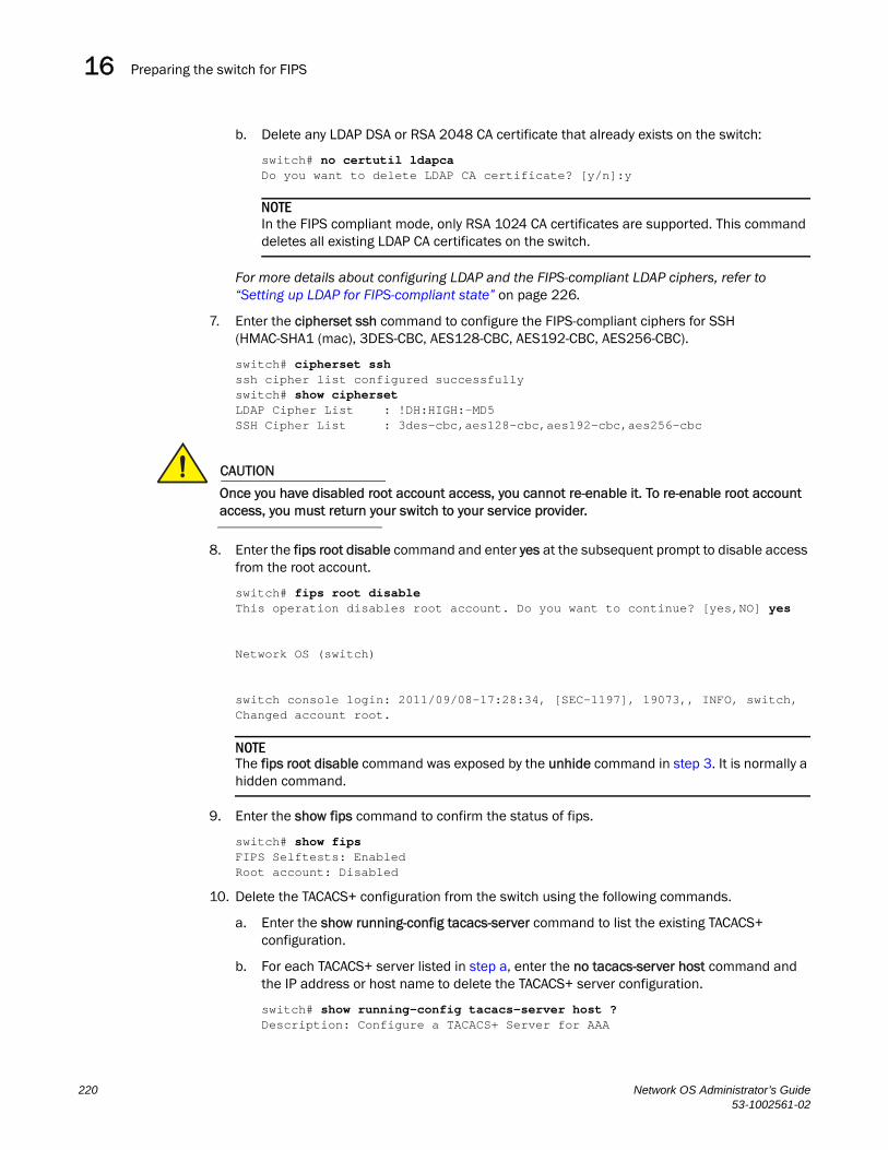
Preparing the switch for FIPS16
b. Delete any LDAP DSA or RSA 2048 CA certificate that already exists on the switch:
switch# no certutil ldapcaDo you want to delete LDAP CA certificate? [y/n]:y
NOTEIn the FIPS compliant mode, only RSA 1024 CA certificates are supported. This command deletes all existing LDAP CA certificates on the switch.
For more details about configuring LDAP and the FIPS-compliant LDAP ciphers, refer to “Setting up LDAP for FIPS-compliant state” on page 226.
7. Enter the cipherset ssh command to configure the FIPS-compliant ciphers for SSH (HMAC-SHA1 (mac), 3DES-CBC, AES128-CBC, AES192-CBC, AES256-CBC).
switch# cipherset sshssh cipher list configured successfullyswitch# show ciphersetLDAP Cipher List : !DH:HIGH:-MD5SSH Cipher List : 3des-cbc,aes128-cbc,aes192-cbc,aes256-cbc
CAUTION
Once you have disabled root account access, you cannot re-enable it. To re-enable root account access, you must return your switch to your service provider.
8. Enter the fips root disable command and enter yes at the subsequent prompt to disable access from the root account.
switch# fips root disableThis operation disables root account. Do you want to continue? [yes,NO] yes
Network OS (switch)
switch console login: 2011/09/08-17:28:34, [SEC-1197], 19073,, INFO, switch, Changed account root.
NOTEThe fips root disable command was exposed by the unhide command in step 3. It is normally a hidden command.
9. Enter the show fips command to confirm the status of fips.
switch# show fipsFIPS Selftests: EnabledRoot account: Disabled
10. Delete the TACACS+ configuration from the switch using the following commands.
a. Enter the show running-config tacacs-server command to list the existing TACACS+ configuration.
b. For each TACACS+ server listed in step a, enter the no tacacs-server host command and the IP address or host name to delete the TACACS+ server configuration.
switch# show running-config tacacs-server host ?Description: Configure a TACACS+ Server for AAA
220 Network OS Administrator’s Guide53-1002561-02

Preparing the switch for FIPS 16
Possible completions:10.20.57.13 INETADDRESS;;Domain name or IP Address of this TACACS+
server| Output modifiers<cr>
Possible match completions:port TCP Port for Authentication (default=49)protocol Authentication protocol to be used (default=CHAP)key Secret shared with this server (default='sharedsecret')retries Number of retries for this server connection (default=5)timeout Wait time for this server to respond (default=5 sec)
switch# configure terminalEntering configuration mode terminalswitch(config)# no tacacs-server host 10.10.20.57.13
11. Enter the no dot1x enable command to disable 802.1x globally.
switch# configure terminalEntering configuration mode terminalswitch(config)# no dot1x enableswitch(config)# exit
12. If Vcenter is configured, remove the configuration using the following CLI:
switch(config)# no vcenter <name>
13. DH group 0 is not supported in the fips compliance state of the switch. If DH group 0 or ‘*’ is configured, execute the following CLI to configure a different group between 1 to 4 (key sizes from 1024 to 2048 bits).
switch(config)# fcsp auth group <NUMBER:1-4>
14. If autoupload is enabled, disable it.
switch# autoupload disable.
CAUTION
Once FIPS self-tests are enabled, you cannot disable them. These tests will run on the next reboot and, if successful, will place the switch into FIPS-compliant state.
15. Enter the fips selftests command to enable the FIPS KAT and conditional tests.
switch# fips selftestsswitch# self tests enabled
NOTEThe fips selftests command was exposed by the unhide command in step 3. It is normally a hidden command.
16. Enter the fips zeroize command and enter yes at the subsequent prompt to clear all passwords and secrets.
The switch reboots and comes up in FIPS-compliant mode.
switch# fips zeroize
Network OS Administrator’s Guide 22153-1002561-02

Preparing the switch for FIPS16
This operation erases all passwords, shared secrets, private keys etc. on the switch . Do you want to continue? [yes,NO] yes
NOTEThe fips zeroize command was exposed by the unhide command in step 3. It is normally a hidden command. When the switch reboots, the FIPS commands will be hidden again
On reboot, the switch performs the KATs and conditional tests enabled in step 15. The following sample output indicates successful completion of these tests, after which the switch comes up in FIPS compliant mode.
FIPS-mode test application1. Non-Approved cryptographic operation test...a. Excluded algorithm (MD5)...successfulb. Included algorithm (D-H)...successful2. Automatic power-up self test...successful3. AES-128 CBC encryption/decryption...successful4. RSA key generation and encryption/decryption...successful5. TDES-CBC encryption/decryption...successful6. DSA key generation and signature validation...successful7a. SHA-1 hash...successful7b. SHA-256 hash...successful7c. SHA-512 hash...successful7d. SHA-1 hash...successful7e. SHA-224 hash...successful7f. SHA-256 hash...successful7g. SHA-384 hash...successful7h. SHA-512 hash...successful8. Non-Approved cryptographic operation test...a. Excluded algorithm (MD5)...Not executedb. Included algorithm (D-H)...successful as expected
NOTEIf the output shows errors, the switch reboots. If the errors persist, you must return the switch to your service provider for repair.
17. Use IP ACLs to block the HTTP, HTTPS, Telnet, and Brocade internal ports. Enter the following commands for IPv4 and IPv6.
a. Enter the ip access-list extended command and a name for the IP ACL.
b. Enter a seq deny command to create a rule for blocking the HTTP port (80).
c. Enter a seq deny command to create a rule for blocking the HTTPS port (443).
d. Enter a seq deny command to create a rule for blocking the Telnet port (23).
e. Enter seq deny commands to create rules for blocking the Brocade internal server ports 3016, 4565, 5016, 7013, 7110, 7710, 9013, 9110, 9710, and 9910 through 10110.
f. If SSH access is required, enter seq permit commands to allow access on ports 22 and 830.
g. If remote access is required, such as through SCP or LDAP, enter seq permit commands to allow UDP and TCP traffic on ports 1024 through 65535.Enter the interface management rbridge-id/port command to enter the interface management sub-configuration mode.
h. Enter the ip access-list command with the ACL name created in step a to apply the ACL to the management interface.
222 Network OS Administrator’s Guide53-1002561-02

Preparing the switch for FIPS 16
These commands also disable the non-FIPS-compliant vCenter feature.
For IPv4:
switch(conf-ip-ext)# seq 1 deny tcp any any eq www switch(conf-ip-ext)# seq 2 deny tcp any any eq 443 switch(conf-ip-ext)# seq 3 deny tcp any any eq telnet switch(conf-ip-ext)# seq 4 deny tcp any any eq 2301 switch(conf-ip-ext)# seq 5 deny tcp any any eq 2401 switch(conf-ip-ext)# seq 6 deny tcp any any eq 3016 switch(conf-ip-ext)# seq 7 deny tcp any any eq 3516 switch(conf-ip-ext)# seq 8 deny tcp any any eq 4516 switch(conf-ip-ext)# seq 9 deny tcp any any eq 5016 switch(conf-ip-ext)# seq 10 deny tcp any any eq 7013 switch(conf-ip-ext)# seq 11 deny tcp any any eq 7110 switch(conf-ip-ext)# seq 12 deny tcp any any eq 7710 switch(conf-ip-ext)# seq 13 deny tcp any any eq 9013 switch(conf-ip-ext)# seq 14 deny tcp any any eq 9110 switch(conf-ip-ext)# seq 15 deny tcp any any eq 9710 switch(conf-ip-ext)# seq 16 deny tcp any any range 9910 10110 switch(conf-ip-ext)# seq 17 deny udp any any eq 33351 switch(conf-ip-ext)# seq 18 deny udp any any eq 36851 switch(conf-ip-ext)# seq 19 deny udp any any eq 37731 switch(conf-ip-ext)# seq 20 deny udp any any eq 50690 switch(conf-ip-ext)# seq 21 permit tcp any any range 1024 65535 switch(conf-ip-ext)# seq 22 permit udp any any range 1024 65534 switch(conf-ip-ext)# seq 23 permit udp any any eq 65535 switch(conf-ip-ext)# seq 100 permit tcp any any eq 22 switch(conf-ip-ext)# seq 101 permit tcp any any eq 830switch(conf-ip-ext)# exitswitch(config)#
For IPv6:
switch(conf-ip-ext)# seq 1 deny tcp any any eq 80switch(conf-ip-ext)# seq 2 deny tcp any any eq 443switch(conf-ip-ext)# seq 3 deny tcp any any eq 23switch(conf-ip-ext)# seq 4 deny tcp any any eq 2301switch(conf-ip-ext)# seq 5 deny tcp any any eq 2401switch(conf-ip-ext)# seq 6 deny tcp any any eq 3016switch(conf-ip-ext)# seq 7 deny tcp any any eq 3516switch(conf-ip-ext)# seq 8 deny tcp any any eq 4516switch(conf-ip-ext)# seq 9 deny tcp any any eq 5016 switch(conf-ip-ext)# seq 10 deny tcp any any eq 7013switch(conf-ip-ext)# seq 11 deny tcp any any eq 7110switch(conf-ip-ext)# seq 12 deny tcp any any eq 7710switch(conf-ip-ext)# seq 13 deny tcp any any eq 9013 switch(conf-ip-ext)# seq 14 deny tcp any any eq 9110 switch(conf-ip-ext)# seq 15 deny tcp any any eq 9710switch(conf-ip-ext)# seq 16 deny tcp any any range 9910 10110switch(conf-ip-ext)# seq 17 deny udp any any eq 33351switch(conf-ip-ext)# seq 18 deny udp any any eq 36851switch(conf-ip-ext)# seq 19 deny udp any any eq 37731switch(conf-ip-ext)# seq 20 deny udp any any eq 50690 switch(conf-ip-ext)# seq 21 permit tcp any any range 1024 65535 switch(conf-ip-ext)# seq 22 permit udp any any range 1024 65534switch(conf-ip-ext)# seq 23 permit udp any any eq 65535switch(conf-ip-ext)# seq 100 permit tcp any any eq 22switch(conf-ip-ext)# seq 101 permit tcp any any eq 830switch(conf-ip-ext)# exit
Network OS Administrator’s Guide 22353-1002561-02

Preparing the switch for FIPS16
switch(config)#
For inband management IPv4 ports please use the following rules:
switch(conf-ip-ext)# seq 5 hard-drop tcp any any eq 80switch(conf-ip-ext)# seq 10 hard-drop tcp any any eq 443switch(conf-ip-ext)# seq 15 hard-drop tcp any any eq 23switch(conf-ip-ext)# seq 20 hard-drop tcp any any eq 2301switch(conf-ip-ext)# seq 25 hard-drop tcp any any eq 2401switch(conf-ip-ext)# seq 30 hard-drop tcp any any eq 3016 switch(conf-ip-ext)# seq 35 hard-drop tcp any any eq 3516switch(conf-ip-ext)# seq 40 hard-drop tcp any any eq 4516 switch(conf-ip-ext)# seq 45 hard-drop tcp any any eq 5016 switch(conf-ip-ext)# seq 50 hard-drop tcp any any eq 7013switch(conf-ip-ext)# seq 55 hard-drop tcp any any eq 7110switch(conf-ip-ext)# seq 60 hard-drop tcp any any eq 7710 switch(conf-ip-ext)# seq 65 hard-drop tcp any any eq 9013 switch(conf-ip-ext)# seq 70 hard-drop tcp any any eq 9110 switch(conf-ip-ext)# seq 75 hard-drop tcp any any eq 9710switch(conf-ip-ext)# seq 80 hard-drop tcp any any range 9910 10110 switch(conf-ip-ext)# seq 85 hard-drop udp any any eq 33351switch(conf-ip-ext)# seq 90 hard-drop udp any any eq 36851switch(conf-ip-ext)# seq 95 hard-drop udp any any eq 37731switch(conf-ip-ext)# seq 100 hard-drop udp any any eq 50690switch(conf-ip-ext)# seq 105 permit tcp any any range 1024 65535 switch(conf-ip-ext)# seq 110 permit udp any any range 1024 65534switch(conf-ip-ext)# seq 115 permit udp any any eq 65535switch(conf-ip-ext)# seq 120 permit tcp any any eq 22switch(conf-ip-ext)# seq 125 permit tcp any any eq 830switch(conf-ip-ext)# exitswitch(config)#
NOTEFor the switch to remain FIPS-compliant, the HTTP, HTTPS, telnet, and Brocade internal server ports (80, 443, 23, 2301, 2401, 3016, 3516, 4516, 5016, 7013, 7110, 7710, 9013, 9110, 9710, 9910 through 10110, 33351, 36851, 37731, and 50690) must be blocked after every zeroization operation.
18. Disable telnet server.
switch(config)# telnet server shutdownswitch(config)#
19. If LDAP authentication is required, in the global configuration mode, enter the following command syntax to import the LDAP CA certificate:
certutil import ldapca directory ca-certificate-directory file filename protocol {FTP|SCP} host remote-ip-address user user-account password password
20. Specify SCP for the protocol.
switch# certutil import ldapca directory /usr/ldapcacert file cacert.pem protocol SCP host 10.23.24.56 user jane password ******
21. If RADIUS authentication is required, in the global configuration mode, enter the radius-server host command with the specified parameters to add RADIUS servers that use only PEAP-MSCHAPv2 ciphers.
224 Network OS Administrator’s Guide53-1002561-02

Zeroizing for FIPS 16
switch(config)# radius-server host 10.38.37.180 protocol peap-mschap key “new#Hercules*secret” timeout 10switch(config-host-10.38.37.180)#
22. Enter the copy running-config startup-config command to save all settings to the startup configuration file.
switch# copy running-config startup-config
NOTEAfter the switch is in the FIPS compliant state, do not use any non-fips compliant algorithms such as FTP, DHCHAP, MD5. With regards to SCP client on the switch, the remote SCP server must employ RSA host keys with a minimum length of 1024 bits.
Zeroizing for FIPS1. Log in to the switch using an account with admin role permissions.
2. In privileged EXEC mode, enter the fips zeroize command.
The switch reboots automatically. If the KATs and conditional tests are enabled, then the switch will reboot in FIPS-compliant state. If the tests are not enabled, the switch comes up in non-FIPS-compliant state.
NOTEFor the switch to remain FIPS-compliant, the HTTP, HTTPS, telnet, and Brocade internal server ports (3016, 4565, 5016, 7013, 7110, 7710, 9013, 9110, 9710, and 9910 through 10110) must be blocked after every zeroization operation.
LDAP in FIPS-compliant stateYou can configure your Microsoft Active Directory server to use the Lightweight Directory Access Protocol (LDAP) while in FIPS-compliant state.
Table 37 lists the differences between FIPS-compliant and non-FIPS-compliant states of operation.
TABLE 37 FIPS-compliant and non-FIPS-compliant states of operation
FIPS-compliant state non-FIPS-compliant state
The certificate for the CA that issued the Microsoft Active Directory server certificate must be installed on the switch.
There is no mandatory CA certificate installation on the switch.
Configure FIPS-compliant TLS ciphers [TDES-168, SHA1, and RSA-1024] on the Microsoft Active Directory server. The host needs a reboot for the changes to take effect.
On the Microsoft Active Directory server, there is no configuration of the FIPS-compliant TLS ciphers.
The switch uses FIPS-compliant ciphers regardless of the Microsoft Active Directory server configuration. If the Microsoft Active Directory server is not configured for FIPS ciphers, authentication will still succeed.
The Microsoft Active Directory server certificate is validated if the CA certificate is found on the switch.
The Microsoft Active Directory server certificate is validated by the LDAP client. If the CA certificate is not present on the switch then user authentication will fail.
If the Microsoft Active Directory server is configured for FIPS ciphers and the switch is in non-FIPS-compliant state, then user authentication will succeed.
Network OS Administrator’s Guide 22553-1002561-02
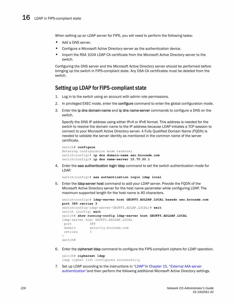
LDAP in FIPS-compliant state16
When setting up an LDAP server for FIPS, you will need to perform the following tasks:
• Add a DNS server.
• Configure a Microsoft Active Directory server as the authentication device.
• Import the RSA 1024 LDAP CA certificate from the Microsoft Active Directory server to the switch.
Configuring the DNS server and the Microsoft Active Directory server should be performed before bringing up the switch in FIPS-compliant state. Any DSA CA certificates must be deleted from the switch.
Setting up LDAP for FIPS-compliant state1. Log in to the switch using an account with admin role permissions.
2. In privileged EXEC mode, enter the configure command to enter the global configuration mode.
3. Enter the ip dns domain-name and ip dns name-server commands to configure a DNS on the switch.
Specify the DNS IP address using either IPv4 or IPv6 format. This address is needed for the switch to resolve the domain name to the IP address because LDAP initiates a TCP session to connect to your Microsoft Active Directory server. A Fully Qualified Domain Name (FQDN) is needed to validate the server identity as mentioned in the common name of the server certificate.
switch# configureEntering configuration mode terminalswitch(config)# ip dns domain-name sec.brocade.comswitch(config)# ip dns name-server 10.70.20.1
4. Enter the aaa authentication login ldap command to set the switch authentication mode for LDAP.
switch(config)# aaa authentication login ldap local
5. Enter the ldap-server host command to add your LDAP server. Provide the FQDN of the Microsoft Active Directory server for the host name parameter while configuring LDAP. The maximum supported length for the host name is 40 characters.
switch(config)# ldap-server host GEOFF5.ADLDAP.LOCAL basedn sec.brocade.com port 389 retries 3switch(config-ldap-server-GEOFF5.ADLAP.LOCAL)# exitswitch (config) exitswitch# show running-config ldap-server host GEOFF5.ADLDAP.LOCAL ldap-server host GEOFF5.ADLDAP.LOCAL port 389 domain security.brocade.com retries 3 !switch#
6. Enter the cipherset ldap command to configure the FIPS-compliant ciphers for LDAP operation.
switch# cipherset ldapldap cipher list configured successfully
7. Set up LDAP according to the instructions in “LDAP”in Chapter 15, “External AAA server authentication”and then perform the following additional Microsoft Active Directory settings.
226 Network OS Administrator’s Guide53-1002561-02

LDAP in FIPS-compliant state 16
a. To support FIPS-compliant TLS cipher suites on the Microsoft Active Directory server, allow the SCHANNEL settings listed in Table 38.
b. Enable the FIPS algorithm policy on the Microsoft Active Directory.
Importing an LDAP switch certificateThis procedure imports the LDAP CA certificate from the remote host to the switch.
1. Connect to the switch and log in using an account with admin role permissions.
2. In privileged EXEC mode, enter the certutil import ldapca command. Include the full path to the certificate on the host, specify SCP as the protocol, and include the IP address of the host.
switch# certutil import ldapca directory /usr/ldapcacert file cacert.pem protocol SCP host 10.23.24.56 user jane password ******
Deleting an LDAP switch certificateThis procedure deletes the LDAP CA certificates of all attached Microsoft Active Directory servers from the switch.
1. Connect to the switch and log in using an account with admin role permissions.
2. In privileged EXEC mode, enter the no certutil ldapca command.
switch# no certutil ldapcaDo you want to delete LDAP CA certificate? [y/n]:y
Verifying LDAP CA certificatesTo test whether an LDAP CA certificate has been imported on the switch, in privileged EXEC mode, enter the no certutil ldapca command and examine the message returned by the system. The command returns an error if there is no LDAP CA certificate on the switch. If an LDAP CA certificate exists on the switch, it prompts you to delete it. Enter no to retain the certificate.
When no LDAP CA certificate is present:
switch# show cert-util ldapcacert% Error: LDAP CA certificate does not exist.
When an LDAP CA certificate exists on the switch:
switch# show cert-util ldapcacertList of swLdapca.pem files:
swLdapca.pem
TABLE 38 Active Directory keys to modify
Key Sub-key
Ciphers 3DES
Hashes SHA1
Key exchange algorithm PKCS
Protocols TLSv1.0
Network OS Administrator’s Guide 22753-1002561-02

LDAP in FIPS-compliant state16
228 Network OS Administrator’s Guide53-1002561-02

Network OS Administrator’s Guide53-1002561-02
Chapter
17
Fabric AuthenticationIn this chapter
•Fabric authentication overview. . . . . . . . . . . . . . . . . . . . . . . . . . . . . . . . . . . 229
•Switch connection control (SCC) policy . . . . . . . . . . . . . . . . . . . . . . . . . . . . 233
Fabric authentication overviewWhen you connect a Brocade VCS Fabric to a Fabric OS fabric, the Network OS Fibre Channel E_Ports on the Brocade VDX 6730 connect through Interswitch links (ISL) to EX_Ports on an FC router, which in turn connects to the Fabric OS network as shown in Chapter 13, “Configuring Fibre Channel Ports”, Figure 17.
To ensure that no unauthorized devices can access the fabric, Network OS provides support for security policies and protocols capable of authenticating Network OS devices (E_Ports) to the EX_Ports on the FC router (FCR) that provides access to the SAN storage and services.
DH-CHAPNetwork OS use the Diffie Hellman - Challenge Handshake Authentication Protocol (DH-CHAP) to control access between devices. DH-CHAP is a password-based, key exchange authentication protocol that negotiates hash algorithms and Diffie Hellman (DH) groups before performing authentication. It supports both MD5 and SHA-1 hash algorithm-based authentication.
The Fibre Channel Security Protocol (FC-SP) defines the DH groups supported in the DH-CHAP protocol. Following current FC-SP standards, Network OS supports the following DH groups:
• 00 – DH Null option
• 01 – 1024 bit key
• 02 – 1280 bit key
• 03 - 1536 bit key
• 04 – 2048 bit key
To configure DH-CHAP authentication between Network OS switches (E_Ports) and FC routers (EX_Ports) you must apply a matching configuration to both sides of the connection. Each device must be configured locally.
NOTEThe Brocade VDX 6730-32 and VDX 6730-76 are the only platforms that can connect to an FC router providing access to a SAN network of Fabric OS switches.
229
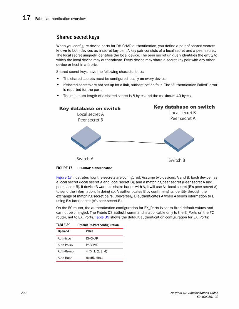
Fabric authentication overview17
Shared secret keysWhen you configure device ports for DH-CHAP authentication, you define a pair of shared secrets known to both devices as a secret key pair. A key pair consists of a local secret and a peer secret. The local secret uniquely identifies the local device. The peer secret uniquely identifies the entity to which the local device may authenticate. Every device may share a secret key pair with any other device or host in a fabric.
Shared secret keys have the following characteristics:
• The shared secrets must be configured locally on every device.
• If shared secrets are not set up for a link, authentication fails. The “Authentication Failed” error is reported for the port.
• The minimum length of a shared secret is 8 bytes and the maximum 40 bytes.
FIGURE 17 DH-CHAP authentication
Figure 17 illustrates how the secrets are configured. Assume two devices, A and B. Each device has a local secret (local secret A and local secret B), and a matching peer secret (Peer secret A and peer secret B). If device B wants to shake hands with A, it will use A’s local secret (B's peer secret A) to send the information. In doing so, A authenticates B by confirming its identity through the exchange of matching secret pairs. Conversely, B authenticates A when A sends information to B using B's local secret (A's peer secret B).
On the FC router, the authentication configuration for EX_Ports is set to fixed default values and cannot be changed. The Fabric OS authutil command is applicable only to the E_Ports on the FC router, not to EX_Ports. Table 39 shows the default authentication configuration for EX_Ports:
TABLE 39 Default Ex-Port configuration
Operand Value
Auth-type DHCHAP
Auth-Policy PASSIVE
Auth-Group * (0, 1, 2, 3, 4)
Auth-Hash msd5, sha1
Switch A Switch B
Key database on switch Local secret A Peer secret B
Key database on switch Local secret B Peer secret A
230 Network OS Administrator’s Guide53-1002561-02

Fabric authentication overview 17
Authentication Policy configurationThe switch authentication (AUTH) policy initiates DH-CHAP authentication on all E_Ports. This policy is persistent across reboots, which means authentication will be initiated automatically on ports or switches brought online if the policy is active. You must configure the he AUTH policy on all connected fabric entities.
By default the policy is set to PASSIVE and you can change the policy. All changes to the AUTH policy take effect during the next authentication request. This includes starting authentication on all E_Ports on the local switch if the policy is changed to ON or ACTIVE, and clearing the authentication requirement if the policy is changed to OFF.
You can set the authentication policy to any of the following values:
role, and a password. The remaining attributes are optional.
The behavior of the policy between two adjacent switches is defined as follows:
• If the policy is ON or ACTIVE, the switch will send an Authentication Negotiation request to the connecting device.
• If the connecting device does not support authentication or the policy is OFF, the request is rejected.
• Once the authentication negotiation succeeds, the DH-CHAP authentication is initiated. If DH-CHAP authentication fails, the port is disabled, regardless of the policy settings.
The policy defines the responses of the host if the connecting switch does not support authentication. By default, the policy is set to PASSIVE and you can change the policy with the fcsp auth command. This includes starting authentication on all E_Ports if the policy is changed to ON or ACTIVE, and clearing the authentication if the policy is changed to OFF. Before enabling the policy, you must install the DH-CHAP shared secrets. Refer to “Configuring DH-CHAP shared secrets” on page 232.
TABLE 40 User account attributes
Setting Description
ON Strict authentication is enforced on all E_Ports. During switch initialization, authentication is initiated on all E_Ports automatically. The authentication handshaking is completed before the switches exchange the fabric parameters (EFP) for E_Port bring-up. If the connecting switch does not support the authentication or the policy is turned off, all ports are disabled and the ISL goes down.
ACTIVE A switch with an ACTIVE policy is more tolerant and can connect to a device with any type of policy. During switch initialization, authentication is initiated on all E_Ports, but the port is not disabled if the connecting switch does not support authentication, or if the authentication policy is turned off.
PASSIVE (default)
The switch does not initiate authentication, but participates in authentication if the connecting switch initiates authentication. The switch does not start authentication on E_Ports, but accepts the incoming authentication requests, and will not be disabled if the connecting switch does not support authentication or the policy is turned off.
OFF The switch does not support authentication, and rejects any authentication negotiation request from a neighbor switch or device. A switch with the policy set to OFF should not be connected to a switch with a policy set to ON. A policy set to ON policy is strict and disables the port if a peer rejects the authentication. DH CHAP shared secrets must be configured on both sides of the connection before you can change the policy from an OFF state to an ON state.
Network OS Administrator’s Guide 23153-1002561-02

Fabric authentication overview17
Configuring device authentication Configuring a Brocade VDX 6730 switch to access a SAN fabric connected through an FC Router involves the following steps:
1. Configure the matching shared secret pairs on the VDX 6730 and on the FC router.
2. Configure the authentication policy on the VDX 6730 switch (The FC router configuration is fixed).
3. Activate the authentication policy.
Setting up secret keys can quickly become an administrative challenge as your fabric size increases. As a minimum, key pairs need to be installed on all connected fabric entities. However, when connections change, you must install new key pairs to accommodate these changes. If you anticipate this situation, you may install key pairs for all possible connections up front, thus enabling links to change arbitrarily while still maintaining a valid key pair for any new connection.
Configuring DH-CHAP shared secrets
To configure the DH-CHAP shared secrets, execute the fcsp auth-secret command in privileged EXEC mode. Provide the following information as shown in the example:
• The world wide name (WWN) of the peer.
• The secret of the peer that authenticates the peer to the local switch.
• The local secret that authenticates the local switch to the peer.
NOTEOnly the following non-alphanumeric characters are valid for the secret key:@ $ % ^ & * ( ) _ + - < > { } [ ] ; ' :
switch# fcsp auth-secret dh-chap node 10:00:00:05:1e:7a:c3:00 peer-secret 12345678 local-secret 87654321 Shared secret is configured successfully.
To display the device (WWN) for which the shared secret is configured, use the show fcsp auth-secret dh-chap command in privileged EXEC mode.
switch# show fcsp auth-secret dh-chap 10:00:00:05:1e:7a:c3:00
To remove the shared secrets, use the no fcsp auth-secret command in privileged EXEC mode.
switch# no fcsp auth-secret dh-chap node 10:00:00:05:1e:7a:c3:00Shared secret successfully removed
Setting the authentication policy parameters
The following procedure configures an authentication policy auth-type DH-CHAP (only option), a DH group of 2, and a hash type of md5. The switch policy is set to OFF until you are ready to explicitly activate the policy.
1. In the privileged EXEC mode, use the configure terminal command to enter the global configuration mode.
2. Enter the fcsp auth command with the specified parameters.
3. Enter the do show running-config fcsp auth command to verify the configuration.
232 Network OS Administrator’s Guide53-1002561-02

Switch connection control (SCC) policy 17
switch# configure terminalEntering configuration mode terminalswitch(config)# fcsp auth auth-type dh-chap hash md5 group 2 switch policy offswitch(config)# do show running-config fcsp authfcsp auth group 2 fcsp auth hash md5fcsp auth policy switch off
Activating the authentication policy
1. In the privileged EXEC mode, issue the configure terminal command to enter the global configuration mode.
2. Enter the fcsp auth policy active command to change the policy state from OFF to ON.
3. Enter the do show running-config fcsp auth command to verify the configuration.
switch# configure terminalEntering configuration mode terminalswitch(config)# fcsp auth auth-type switch policy onswitch(config)# do show running-config fcsp authfcsp auth group 2 fcsp auth hash md5fcsp auth policy switch on
Switch connection control (SCC) policyThe Switch Connection Control (SCC) policy controls access between neighboring devices. The policy defines and restricts which devices can join the fabric. Each time an E_Port-to-EX_Port connection is attempted, the devices are checked against the policy and the connection is either accepted or rejected depending on whether the connecting device is listed in the policy. The policy is named SCC_POLICY and accepts members listed as world wide names (WWNs).
A device configured with an active SCC policy reviews its database whenever a neighboring device tries to establish a connection. If the WWN of the connecting device is found in the SCC active policy database, the connecting device is allowed to join the fabric. If the neighboring device is not specified in the SCC policy active list, both devices are segmented.
By default, any device is allowed to join the fabric; the SCC policy is not enforced until it is created and activated. Creating a policy without any entries blocks access from all devices. The local switch is not required to be included in a switch-local SCC policy
NOTEThe configuration is applicable only to E_Ports on the Brocade VDX 6730 platforms. All configurations are local to the switch and are not automatically distributed across the fabric
Defined and active SCC policy setsThe SCC policy maintains two versions, active, and defined, and creating a policy includes two distinct operations
1. Creating the defined SCC policy set
2. Activating the SCC policy
Network OS Administrator’s Guide 23353-1002561-02

Switch connection control (SCC) policy17
The defined policy includes a list of WWN members and it is configurable. You can create the SCC policy along with its members using a single command, secpolicy defined-policy SCC_POLICY. Or you can create the SCC policy first and add the members later. You can modify the defined policy at any time thereafter.
When you create the SCC policy and its defined member set, it remains inactive until you explicitly activate the policy with the secpolicy activate command. The SCC policy is enforced on the E_Ports only after you activate the policy. When the policy is active, only the members included in the activated policy can communicate with each other. If you add additional devices to the defined policy, they remain inactive and access is blocked until you active the defined policy again.
Follow these guidelines and restrictions when configuring SCC policy:
• During the configuration replay operation, the defined and active policies are replayed and the E_Ports are enabled or disabled based on the SCC policy entries in the active policy list.
• During copy file running-config command execution, only the defined policy in the switch is updated with the config file entries; the active policy entries remain unchanged. In this case, you must use the secpolicy activate command to activate the defined policy list.
Creating a defined SCC Policy
The following procedure creates an SCC policy, adds two members, and verifies the configuration.
1. In the privileged EXEC mode, issue the configure terminal command to enter the global configuration mode.
2. Enter the secpolicy defined-policy SCC_POLICY command.
This command places you into the defined SCC configuration mode where you can add policy member WWNs.
3. Specify a policy member with the member-entry WWN command.
4. Specify a second policy member with the member-entry WWN command.
5. Exit the defined SCC configuration mode.
6. Enter the do show running-config secpolicy defined-policy command to verify the configuration.
switch# configure terminal Entering configuration mode terminal switch(config)# secpolicy defined-policy SCC_POLICY switch(config-defined-policy-SCC_POLICY)# member-entry \ 10:00:00:05:1e:00:69:00 switch(config-defined-policy-SCC_POLICY)# member-entry \ 10:00:00:08:2f:00:79:00 switch(config-defined-policy-SCC_POLICY)# exit switch(config)# do show running-config secpolicy defined-policy secpolicy defined-policy SCC_POLICY member-entry 10:00:00:05:1e:00:69:00 ! member-entry 10:00:00:08:2f:00:79:00 !
234 Network OS Administrator’s Guide53-1002561-02

Switch connection control (SCC) policy 17
Modifying the SCC policy
The same command sequence that creates the SCC policy adds additional members. The defined SCC member entries are cumulative. Use the “no” form of the command to remove members from the policy.
The following example adds a member and subsequently removes the same added member:
switch# configure terminal Entering configuration mode terminalswitch(config)# secpolicy defined-policy SCC_POLICY switch(config-defined-policy-SCC_POLICY)# member-entry \ 22:22:22:22:22:22:22:22 switch(config-defined-policy-SCC_POLICY)# no member-entry \ 22:22:22:22:22:22:22:22 switch(config-defined-policy-SCC_POLICY)# exit switch(config)# do show running-config secpolicy defined-policy secpolicy defined-policy SCC_POLICY member-entry 10:00:00:05:1e:00:69:00 ! member-entry 10:00:00:08:2f:00:79:00 !
Activating the SCC policy
1. Define a SCC policy as shown in section “Creating a defined SCC Policy” on page 234.
2. Enter the secpolicy activate in privileged EXEC mode.
3. Enter the do show running-config secpolicy active -policy command to verify the configuration.
switch# secpolicy activateswitch# do show running-config secpolicy active-policysecpolicy active-policy SCC_POLICY member-entry 10:00:00:05:1e:00:69:00 ! member-entry 10:00:00:08:2f:00:79:00 !
Removing the SCC Policy
1. In the privileged EXEC mode, issue the configure terminal command to enter the global configuration mode.
2. Enter the secpolicy no defined-policy SCC_POLICY command.
3. Exit the global configuration mode.
4. Activate the SCC policy to save the defined policy configuration to the active configuration.
5. Enter the do show running-config secpolicy active -policy command to verify that the policy is empty.
switch# configure terminalswitch(config# no secpolicy defined-policy SCC_POLICYswitch(config)#exitswitch# secpolicy activateswitch# do show running-config secpolicy active-policy% No entries found.
Network OS Administrator’s Guide 23553-1002561-02

Switch connection control (SCC) policy17
236 Network OS Administrator’s Guide53-1002561-02

Network OS Administrator’s Guide53-1002561-02
Section
III
Network OS Layer 2 Switch FeaturesThis section describes the Layer 2 features of Network OS, and includes the following chapters:
•Administering Edge-Loop Detection . . . . . . . . . . . . . . . . . . . . . . . . . . . . . . . 239
•Configuring AMPP . . . . . . . . . . . . . . . . . . . . . . . . . . . . . . . . . . . . . . . . . . . . . 247
•Configuring FCoE Interfaces . . . . . . . . . . . . . . . . . . . . . . . . . . . . . . . . . . . . . 259
•Configuring VLANs . . . . . . . . . . . . . . . . . . . . . . . . . . . . . . . . . . . . . . . . . . . . . 277
•Configuring STP-Type Protocols. . . . . . . . . . . . . . . . . . . . . . . . . . . . . . . . . . . 289
•Configuring Link Aggregation . . . . . . . . . . . . . . . . . . . . . . . . . . . . . . . . . . . . 315
•Configuring LLDP . . . . . . . . . . . . . . . . . . . . . . . . . . . . . . . . . . . . . . . . . . . . . . 327
•Configuring ACLs . . . . . . . . . . . . . . . . . . . . . . . . . . . . . . . . . . . . . . . . . . . . . . 339
•Configuring QoS . . . . . . . . . . . . . . . . . . . . . . . . . . . . . . . . . . . . . . . . . . . . . . . 349
•Configuring 802.1x Port Authentication. . . . . . . . . . . . . . . . . . . . . . . . . . . . 393
•Configuring sFlow . . . . . . . . . . . . . . . . . . . . . . . . . . . . . . . . . . . . . . . . . . . . . 401
•Configuring Switched Port Analyzer . . . . . . . . . . . . . . . . . . . . . . . . . . . . . . . 407
237

238 Network OS Administrator’s Guide53-1002561-02

Network OS Administrator’s Guide53-1002561-02
Chapter
18
Administering Edge-Loop DetectionIn this chapter•Edge-loop detection overview . . . . . . . . . . . . . . . . . . . . . . . . . . . . . . . . . . . . 239
•How ELD detects loops . . . . . . . . . . . . . . . . . . . . . . . . . . . . . . . . . . . . . . . . . 241
•Configuring edge-loop detection. . . . . . . . . . . . . . . . . . . . . . . . . . . . . . . . . . 243
•Edge-loop troubleshooting . . . . . . . . . . . . . . . . . . . . . . . . . . . . . . . . . . . . . . 244
Edge-loop detection overviewEdge-loop detection (ELD) detects and disables Layer 2 loops that would cause broadcast storms. Typically, these loops are caused by misconfigurations.
ELD is configured and enabled on Brocade VCS Fabric clusters. Any topology that includes one or more Brocade VCS Fabric clusters use ELD to detect Layer 2 loops and prevent broadcast storms. Standalone switches can be included in such a cluster, but loop detection takes place on the Brocade VCS Fabric cluster, and not on the standalone switch. You cannot use ELD in a network consisting of standalone switches only.
Specifically, ELD can be used to prevent broadcast storms caused by Layer 2 loops in the following topologies:
• A Brocade VCS Fabric cluster connects to a standalone switch.
• A Brocade VCS Fabric cluster connects to a multiple node network.
• A Brocade VCS Fabric cluster connects to other Brocade VCS Fabric clusters.
239

Edge-loop detection overview18
Figure 18 shows an example of a misconfiguration between a Brocade VCS Fabric cluster and a standalone switch that could cause a Layer 2 loop. In this case, a VLAG is configured on the edge devices of the Brocade VCS Fabric cluster for the two ISLs that connect the Brocade VCS Fabric cluster to the standalone switch. In this case, a LAG has not been created on the standalone switch at the other end of the ISLs. ELD detects and breaks this potential Layer 2 loop.
FIGURE 18 Missing LAG causes loop
VCS cluster
vLAG
RB1
SW
RB2
RB4 RB
3
LAG not configured
240 Network OS Administrator’s Guide53-1002561-02

Ne53
How ELD detects loops 18
Figure 19 shows another example for which ELD could be used to detect and break a Layer 2 loop. In this case, multiple Brocade VCS Fabric clusters are interconnected in a manner that creates a Layer 2 loop.
FIGURE 19 Interconnected Brocade VCS Fabric clusters cause loop
How ELD detects loopsELD works by multicasting Protocol Data Unit (PDU) packets on edge ports. A device recognizes a loop when it receives a PDU that it initiated. Once the device recognizes that a Layer 2 loop exists, it can take action to disable a port and break the Layer 2 loop.
To minimize the number of disabled ports, ELD assigns a priority to each port and a unique receive limit (pdu-rx-limit) to each Brocade VCS Fabric cluster. The port priority determines whether the sending or receiving edge port of the cluster is disabled. The pdu-rx-limit determines on which Brocade VCS Fabric the action takes place. Without these configured values, it is possible that a Layer 2 loop could be detected in multiple clusters at the same time. As a result, multiple ports would be disabled, stopping traffic among the Brocade VCS Fabric clusters.
RBa1
RBb1
RBb3
RBa2
RBb2
RBc1
RBc3
RBc2
RBa4
RBa3
twork OS Administrator’s Guide 241-1002561-02

How ELD detects loops18
Figure 20 shows the same interconnections as Figure 19 on page 241, but with ELD enabled on each edge port, and with port priorities and receive limits assigned.
FIGURE 20 Interconnected Brocade VCS Fabric clusters with ELD enabled
With all ELD enabled edge ports sending PDUs at the same rate, VCS1 reaches its pdu-rx-limit first. Port 2/0/1 has a lower priority (higher priority number) than port 1/0/1, and is therefore selected to be disabled. If both ports have the same priority, the port with the higher port-ID is disabled.
If the port being shutdown by ELD is part of a LAG, all member ports of the LAG are also shutdown. If the port being shutdown is part of a vLAG, all member ports of the vLAG on that RBridge are also shutdown.
Once ELD disables a port, normal operation is for the port to remain disabled until any misconfiguration is repaired. Once the repair is finished, the port can be re-enabled manually.
NOTEWhen ELD disables a port, the port is operationally down, but administratively still up.
If a port is disabled by STP or some other L2 protocol, ELD does not process PDUs for that port.
VCS 1pdu-rx-limit=2
1/0/1priority=5
1/0/1priority=10
port disabled
2/0/1priority=15
2/0/1priority=10
VCS 2pdu-rx-limit=4
VCS 3pdu-rx-limit=5
RBa1
RBb1
RBb3
RBa2
RBb2
RBc1
RBc3
RBc2
RBa4
RBa3
2/0/1priority=15
1/0/1priority=5
242 Network OS Administrator’s Guide53-1002561-02

Configuring edge-loop detection 18
Configuring edge-loop detectionEdge-loop detection requires configuration at the global level and at the interface level. For global level configuration, you need to set the number of PDUs that the Brocade VCS Fabric cluster receives on any port before determining that a loop exists. This value is the pdu-rx-limit. You must also set the interval between sending PDUs by using the the hello-interval command The combination of pdu-rx-limit and hello-interval timer determines the time it takes for ELD to detect and break a Layer 2 loop.
At the interface level, you must enable ELD on each port you want it to run on and set the port priority. You should also specify a VLAN on which ELD is enabled
Enter the pdu-rx-limit command to set the limit to a different number on each Brocade VCS Fabric cluster so that only one Brocade VCS Fabric cluster disables a port. We recommend setting this value in the increment of two to prevent race conditions which might disable ports on two Brocade VCS Fabric clusters that are incrementally only one apart.
Enter the hello-interval command to set the interval between PDUs. This interval must be set to the same value on all Brocade VCS Fabric clusters for which ELD is configured, otherwise the results of edge-loop detection become unpredictable.
Optionally, enter the shutdown-time command to configure ports to be re-enabled after a specified period of time (range 10 minutes to 24 hours). A typical use for this feature is in environments in which reconfiguration is common, such as in a typical lab environment. Typical use is to allow the default value of zero, which does not allow ports to be re-enabled automatically.
NOTEAny change to shutdown-time only takes effect for the ports that are disabled by ELD after the configuration change. Any ports that were already disabled by ELD before the shutdown-time change continues to follow the old shutdown-time value. These ports start to follow the new shutdown time after the currently running timer expires and ELD still detects the loop and shuts down the port again.
For each interface on which ELD runs, enter the edge-loop detection command to enable ELD. You must also enter the edge-loop-detection port-priority command to specify the ELD-port priority.
Setting global ELD parameters for a Brocade VCS Fabric cluster Perform this procedure on every Brocade VCS Fabric cluster where you configure ELD.
1. Log in to any switch in a Brocade VCS Fabric cluster.
2. In the global configuration mode, enter the protocol edge-loop-detection command to enter the edge-loop detection configuration mode.
3. Enter the pdu-rx-limit number command to set the number of PDUs that will be received before breaking the Layer 2 loop.
The number operand must be a value in the range1 through 5. The default value is 1.
4. Enter the hello-interval number command to set the interval between PDUs.
The number operand has a unit of 1 ms. It must be in the range from 100 ms to 5000 ms. The default value is 1000 ms.
5. Optional: Enter the edge-loop-detection shutdown-time number command to set the number of minutes after which the shutdown port is re-enabled.
Network OS Administrator’s Guide 24353-1002561-02

Edge-loop troubleshooting18
The number operand must be in the range 10 through 1440 (10 minutes through 24 hours). The default value is 0, indicating that the port is not automatically re-enabled.
Example
This example configures the Brocade VCS Fabric cluster to detect and break loops on receipt of 5 PDUs. Because the PDU interval is set to 2000 ms (2 seconds), any loop breaks after 10 seconds. The selected port will remain disabled for 24 hours, after which it is automatically re-enabled.
(config)# protocol edge-loop-detection (config-eld)# edge-loop-detection pdu-rx-limit 5 (config-eld)# hello-interval 2000(config-eld)# edge-loop-detection shutdown-time 1440
Setting interface parameters on a portPerform this procedure for every port you want to be monitored by ELD.
1. Log in to any switch in a Brocade VCS Fabric cluster.
2. In the global configuration mode, enter the interface command to select the RBridge/slot/port for which you want to enable edge-loop detection.
3. In the interface configuration mode, enter the edge-loop-detection vlan command to specify the VLAN you want ELD to monitor on this port.
If you do not specify a VLAN, the command fails.
4. Enter the edge-loop-detection port-priority command to specify the ELD port priority of the specified port for the selected VLAN. However, enabling switching is not mandatory for assigning a port-priority.
NOTEThe priority range of values is from 0 through 255. A port with priority 0 means that shutdown for this port is disabled. The default value port priority is 128
Example
This example sets the ELD port priority on two port/VLAN pairs: port 1/0/7 VLAN 10 and port 4/0/6 VLAN 10. If both these ports are detected in the same loop, ELD shuts down port 4/0/6 when the pdu-rx-limit for the Brocade VCS Fabric cluster is reached. Port 4/0/6 is chosen for shut down because it has been assigned the lower priority (higher number) then port 1/0/7.
(config)# interface TenGigabitEthernet 1/0/7 (conf-if-te-1/0/7)# edge-loop-detection vlan 10(conf-if-te-1/0/7)# edge-loop-detection port-priority 5(conf-if-te-1/0/7)# top(config)# interface TenGigabitEthernet 4/0/6(conf-if-te-1/0/7)# edge-loop-detection vlan 10(conf-if-te-1/0/7)# edge-loop-detection port-priority 7
Edge-loop troubleshootingUse the edge-loop detection commands to view and correct misconfigurations
244 Network OS Administrator’s Guide53-1002561-02

Edge-loop troubleshooting 18
1. Log in to any switch in a Brocade VCS Fabric cluster.
2. In the global configuration mode, enter the show edge-loop-detection command to display edge-loop detection statistics for the Brocade VCS Fabric cluster.
The command output shows ports disabled by ELD.
3. Correct any misconfigurations detected in step 2.
4. Perform one of the following operations in the global configuration mode:
• To re-enable one port that was disabled by ELD
a. Enter the shutdown command on the port disabled by ELD.
b. Enter the no shutdown command on the port disabled by ELD.
NOTEIf an edge-port becomes an ISL port because a remote port's VCS ID was changed, a port that was already shutdown by ELD must be cycled with the shutdown and no shutdown command to be detected as an ISL port.
• To re-enable all ports disabled by ELD, enter the clear edge-loop-detection command.
Network OS Administrator’s Guide 24553-1002561-02

Edge-loop troubleshooting18
246 Network OS Administrator’s Guide53-1002561-02

Network OS Administrator’s Guide53-1002561-02
Chapter
19
Configuring AMPPIn this chapter
•AMPP overview. . . . . . . . . . . . . . . . . . . . . . . . . . . . . . . . . . . . . . . . . . . . . . . . 247
•Configuring AMPP port-profiles. . . . . . . . . . . . . . . . . . . . . . . . . . . . . . . . . . . 250
•Monitoring AMPP profiles . . . . . . . . . . . . . . . . . . . . . . . . . . . . . . . . . . . . . . . 257
AMPP overviewServer virtualization infrastructure associates a server-side Virtual Ethernet Bridge (VEB) port-profile to each Ethernet MAC address used by a Virtual Machine (VM) to access the network through a VEB port.
If the VM is migrated from one physical server to another, the VEB’s port-profile migrates with it, providing automated port-profile migration of the server’s VEB ports that are associated with the VM.
For environments where the server’s virtualization infrastructure provides sufficient controls, automated port-profile migration approaches are fine. An example of such an environment is a high performance cluster that uses a Layer 2 network which is isolated from external networks through firewalls and security appliances.
However, there is a gap between the access and Quality of Service (QoS) controls supported in external Layer 2 switches and the server virtualization infrastructure. External Layer 2 switches have more advanced controls compared to server VEB implementations.
Some environments prefer the more advanced controls provided by external network switches. An example of such an environment is a multi-tier data center that has several types of applications, each with differing advanced network controls, running over the same Layer 2 network. In this type of environment, the network administrator often prefers the use of advanced access controls available in external switches.
Layer 2 networks do not provide a mechanism for automatically migrating switch access and traffic controls associated with an end-point device when that device migrates from one switch to another. The migration may be physical, such as an operating system image (such as an application, middleware, operating system, and associated state) that is running BareMetal OS on one system and is migrated to another system.The migration may be also be virtual, such as an operating system image that is running over Hypervisor VMware on one system and is migrated to run over Hypervisor VMware on another system.
The Brocade Auto Migrating Port Profile (AMPP) feature provides these advanced controls for maintaining and migrating these port-profile associations when a VM migrates across physical servers.
247

AMPP overview19
AMPP over vLAG Virtual Link Aggregation Group (vLAG) is the name for Brocade proprietary LAG in which the links to the Brocade VCS Fabric can be connected to one or more physical switches or servers. For redundancy and greater bandwidth, vLAG is a vital component of Brocade VCS Fabric technology. AMPP is supported on vLAG and standard LAG in a manner similar to physical port.
FCoE capability on all port-profiled interfaces can be activated using the fcoe-port configuration in the default port-profile (refer to “Configuring FCoE profiles” on page 253). This configuration enforces FCoE capability only on physical interfaces, not on the port-channel (LAG/vLAG). Member links of the LAG/vLAG must be explicitly configured for FCoE capability.
For complete information on vLAG, refer to Chapter 23, “Configuring Link Aggregation”.
The italic text in the following example highlights the vLAG information in the port profile:
switch# show port-profile statusPort-Profile PPID Activated Associated MAC Interfaceauto-dvPortGroup 1 Yes None Noneauto-dvPortGroup2 2 Yes None Noneauto-dvPortGroup3 3 Yes None Noneauto-dvPortGroup_4_0 4 Yes 0050.567e.98b0 Noneauto-dvPortGroup_vlag 5 Yes 0050.5678.eaed Noneauto-for_iscsi 6 Yes 0050.5673.85f9 None
0050.5673.fc6d None0050.5674.f772 None0050.5675.d6e0 Te 234/0/540050.567a.4288 None
auto-VM_Network 9 Yes 000c.2915.4bdc None0050.56a0.000d None0050.56a0.000e None0050.56a0.000f None0050.56a0.0010 Po 53 0050.56a0.0011 Po 53 0050.56a0.0012 Po 53 0050.56a0.0013 None0050.56a0.0025 None0050.56a0.0026 None0050.56a0.0027 None0050.56a0.0028 None0050.56a0.0029 Po 530050.56a0.002a Po 530050.56a0.002b Po 530050.56a0.002c None0050.56a0.002d None0050.56a0.002e None0050.56a0.002f None0050.56b3.0001 Po 530050.56b3.0002 Po 530050.56b3.0004 Po 530050.56b3.0005 None
auto-VM_kernel 10 Yes 0050.5671.4d06 None0050.5672.862f Po 530050.5678.37ea None0050.567a.ddc3 None
auto-VM_NW_1G 11 Yes 0050.56b3.0000 None0050.56b3.0003 Po 82 0050.56b3.0007 None0050.56b3.0008 Po 82 0050.56b3.0009 Po 82
248 Network OS Administrator’s Guide53-1002561-02
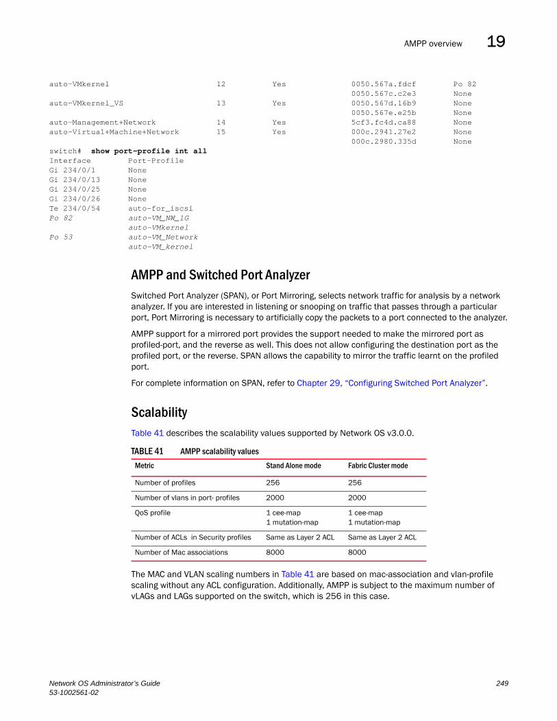
AMPP overview 19
auto-VMkernel 12 Yes 0050.567a.fdcf Po 820050.567c.c2e3 None
auto-VMkernel_VS 13 Yes 0050.567d.16b9 None0050.567e.e25b None
auto-Management+Network 14 Yes 5cf3.fc4d.ca88 Noneauto-Virtual+Machine+Network 15 Yes 000c.2941.27e2 None
000c.2980.335d Noneswitch# show port-profile int allInterface Port-ProfileGi 234/0/1 NoneGi 234/0/13 NoneGi 234/0/25 NoneGi 234/0/26 NoneTe 234/0/54 auto-for_iscsiPo 82 auto-VM_NW_1G
auto-VMkernelPo 53 auto-VM_Network
auto-VM_kernel
AMPP and Switched Port Analyzer Switched Port Analyzer (SPAN), or Port Mirroring, selects network traffic for analysis by a network analyzer. If you are interested in listening or snooping on traffic that passes through a particular port, Port Mirroring is necessary to artificially copy the packets to a port connected to the analyzer.
AMPP support for a mirrored port provides the support needed to make the mirrored port as profiled-port, and the reverse as well. This does not allow configuring the destination port as the profiled port, or the reverse. SPAN allows the capability to mirror the traffic learnt on the profiled port.
For complete information on SPAN, refer to Chapter 29, “Configuring Switched Port Analyzer”.
ScalabilityTable 41 describes the scalability values supported by Network OS v3.0.0.
The MAC and VLAN scaling numbers in Table 41 are based on mac-association and vlan-profile scaling without any ACL configuration. Additionally, AMPP is subject to the maximum number of vLAGs and LAGs supported on the switch, which is 256 in this case.
TABLE 41 AMPP scalability values
Metric Stand Alone mode Fabric Cluster mode
Number of profiles 256 256
Number of vlans in port- profiles 2000 2000
QoS profile 1 cee-map 1 mutation-map
1 cee-map1 mutation-map
Number of ACLs in Security profiles Same as Layer 2 ACL Same as Layer 2 ACL
Number of Mac associations 8000 8000
Network OS Administrator’s Guide 24953-1002561-02

Configuring AMPP port-profiles19
Configuring AMPP port-profilesAs shown in Figure 21, the default port-profile contains the entire configuration needed for a VM to get access to the LAN and SAN.
FIGURE 21 Port-profile contents
In addition, all the combinations can be mixed up with some security rules grouped under a security-profile.
NOTEA port-profile does not contain some of the interface level configurations, such as LLDP, SPAN, LAG, and so on.
A port-profile operates as a self-contained configuration container. In other words, if a port-profile is applied on a completely new switch without any configuration, it is capable of configuring the interface’s local configuration and starting to carry traffic. Any changes to the policies are immediately applied to the data plane.
Security profiles are applied to the ACLs based on the profile or PolicyID. Therefore, multiple security profiles can be applied to the same profiled port.
NOTEThe fcoe-profile is only available on the default profile. User-defined port-profiles do not have access to the fcoe-profile. See “Configuring FCoE profiles” on page 253 for details.
However, editing of the port-profile is not allowed once the port-profile is activated. Activation of the port-profile is mandatory when it is applied to a port.
Life of a port-profileA port-profile during creation will go through multiple states. The states of a port-profile are:
• Created—This state specifies that a port-profile is created or modified, but may not be complete.
• Activated—This state specifies that a port-profile is activated and is available for MAC->port-profile association. If the port-profile created is not complete then the activation fails; you must resolve any conflicts or dependencies and reactivate the port-profile.
QoS-profile
Port-profile
vlan-profilefcoe-profile Security-profile
250 Network OS Administrator’s Guide53-1002561-02

Configuring AMPP port-profiles 19
• Associated—This state specifies that one or more MAC addresses have been associated to this port-profile within the fabric.
• Applied—This state indicates that the port-profile is applied on the profiled port where the associated MAC address appeared. In the absence of any signaling protocol, the system snoops the packet to detect if the associated MAC address has appeared on the profiled port. Configuration of two different port-profiles can co-exist on a profiled port, but if there is a conflict then the application of the later port-profile fails.
Table 42 describes the AMPP events and the applicable failure behaviors.
TABLE 42 AMPP behavior and failure descriptions
AMPP event Applicable behavior and failures
Create port-profile • If the port-profile does not exist, then it is created. If it exists, then it is available for modification (if it is not yet activated).
Activate port-profile • If the port-profile configuration is not complete, activation fails. Unless the port-profile is activated, it is not applied on any switch port.
• If all the dependency validations succeed, the port-profile is in the ACTIVE state and is ready for association.
• A vlan-profile is mandatory for all port-profile.
De-activate port-profile • This event removes the applied port-profile configuration from all the profiled-ports.
• De-activation is allowed even if there are MAC addresses associated with the port-profile.
Modify port-profile • Port-profile can be edited only in the pre-activation stage.• The port-profile is set to the INACTIVE state if any conflicting attributes are
configured, or some dependent configuration is not completed.• Port-profile state is set as INACTIVE and any attempt to associate the port-profile
to a MAC address may not be allowed.
Associate MAC addresses to a port-profile
• If mapping already exists with another port-profile, AMPP does not allow a MAC address to be mapped to multiple port-profiles.
• If mapping does not exist, the port is configured to allow the MAC address with all the policies specified in the port-profile applied to that MAC address on that port or switch.
De-associate MAC addresses from a port-profile
• If mapping exists, all the policies configured for a specific MAC address are removed from that port or switch.
Deleting a port-profile • An IN USE error is generated if the port-profile is in an activated state. AMPP forces you to de-activate the profile before deleting.
• If the port-profile is in an inactive state, then deletion of profile removes all the MAC associations as well.
Modifying port-profile content when in an associated state
• An IN USE error is generated if the port-profile is already activated.
Moving the VM MAC and notifying the fabric
• All policies associated to the port-profile ID are mapped on the MAC address and applied to the new port in the fabric.
Unused port-profile • You must manually remove the MAC address mapping to remove any MAC association.
Network OS Administrator’s Guide 25153-1002561-02
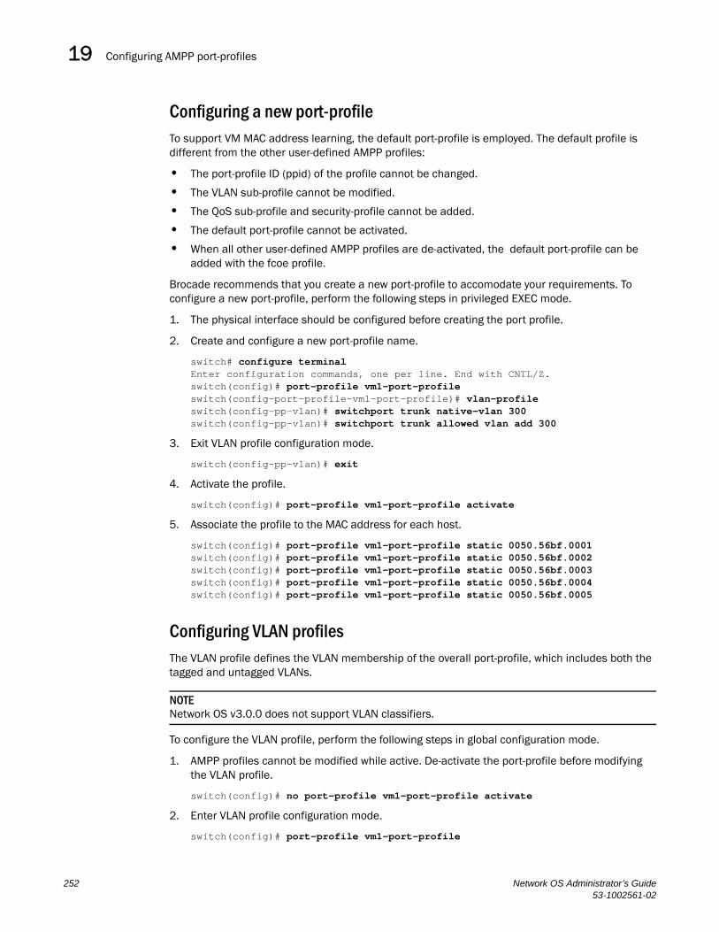
Configuring AMPP port-profiles19
Configuring a new port-profileTo support VM MAC address learning, the default port-profile is employed. The default profile is different from the other user-defined AMPP profiles:
• The port-profile ID (ppid) of the profile cannot be changed.
• The VLAN sub-profile cannot be modified.
• The QoS sub-profile and security-profile cannot be added.
• The default port-profile cannot be activated.
• When all other user-defined AMPP profiles are de-activated, the default port-profile can be added with the fcoe profile.
Brocade recommends that you create a new port-profile to accomodate your requirements. To configure a new port-profile, perform the following steps in privileged EXEC mode.
1. The physical interface should be configured before creating the port profile.
2. Create and configure a new port-profile name.
switch# configure terminalEnter configuration commands, one per line. End with CNTL/Z.switch(config)# port-profile vm1-port-profileswitch(config-port-profile-vm1-port-profile)# vlan-profileswitch(config-pp-vlan)# switchport trunk native-vlan 300switch(config-pp-vlan)# switchport trunk allowed vlan add 300
3. Exit VLAN profile configuration mode.
switch(config-pp-vlan)# exit
4. Activate the profile.
switch(config)# port-profile vm1-port-profile activate
5. Associate the profile to the MAC address for each host.
switch(config)# port-profile vm1-port-profile static 0050.56bf.0001switch(config)# port-profile vm1-port-profile static 0050.56bf.0002switch(config)# port-profile vm1-port-profile static 0050.56bf.0003switch(config)# port-profile vm1-port-profile static 0050.56bf.0004switch(config)# port-profile vm1-port-profile static 0050.56bf.0005
Configuring VLAN profilesThe VLAN profile defines the VLAN membership of the overall port-profile, which includes both the tagged and untagged VLANs.
NOTENetwork OS v3.0.0 does not support VLAN classifiers.
To configure the VLAN profile, perform the following steps in global configuration mode.
1. AMPP profiles cannot be modified while active. De-activate the port-profile before modifying the VLAN profile.
switch(config)# no port-profile vm1-port-profile activate
2. Enter VLAN profile configuration mode.
switch(config)# port-profile vm1-port-profile
252 Network OS Administrator’s Guide53-1002561-02
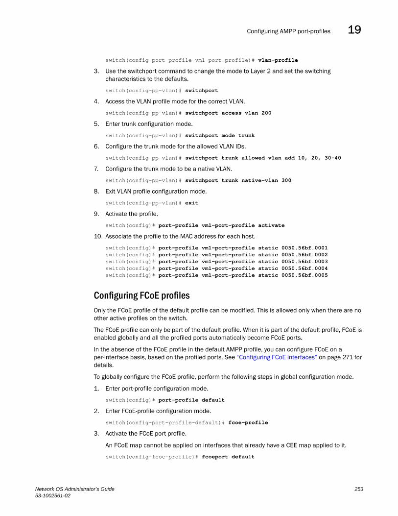
Configuring AMPP port-profiles 19
switch(config-port-profile-vm1-port-profile)# vlan-profile
3. Use the switchport command to change the mode to Layer 2 and set the switching characteristics to the defaults.
switch(config-pp-vlan)# switchport
4. Access the VLAN profile mode for the correct VLAN.
switch(config-pp-vlan)# switchport access vlan 200
5. Enter trunk configuration mode.
switch(config-pp-vlan)# switchport mode trunk
6. Configure the trunk mode for the allowed VLAN IDs.
switch(config-pp-vlan)# switchport trunk allowed vlan add 10, 20, 30-40
7. Configure the trunk mode to be a native VLAN.
switch(config-pp-vlan)# switchport trunk native-vlan 300
8. Exit VLAN profile configuration mode.
switch(config-pp-vlan)# exit
9. Activate the profile.
switch(config)# port-profile vm1-port-profile activate
10. Associate the profile to the MAC address for each host.
switch(config)# port-profile vm1-port-profile static 0050.56bf.0001switch(config)# port-profile vm1-port-profile static 0050.56bf.0002switch(config)# port-profile vm1-port-profile static 0050.56bf.0003switch(config)# port-profile vm1-port-profile static 0050.56bf.0004switch(config)# port-profile vm1-port-profile static 0050.56bf.0005
Configuring FCoE profilesOnly the FCoE profile of the default profile can be modified. This is allowed only when there are no other active profiles on the switch.
The FCoE profile can only be part of the default profile. When it is part of the default profile, FCoE is enabled globally and all the profiled ports automatically become FCoE ports.
In the absence of the FCoE profile in the default AMPP profile, you can configure FCoE on a per-interface basis, based on the profiled ports. See “Configuring FCoE interfaces” on page 271 for details.
To globally configure the FCoE profile, perform the following steps in global configuration mode.
1. Enter port-profile configuration mode.
switch(config)# port-profile default
2. Enter FCoE-profile configuration mode.
switch(config-port-profile-default)# fcoe-profile
3. Activate the FCoE port profile.
An FCoE map cannot be applied on interfaces that already have a CEE map applied to it.
switch(config-fcoe-profile)# fcoeport default
Network OS Administrator’s Guide 25353-1002561-02

Configuring AMPP port-profiles19
Configuring QoS profilesQoS profiles define the following values:
• Incoming 802.1p priority is set to internal queue priority. If the port is in QoS untrusted mode, all incoming priorities will be mapped to default best effort priority.
• Incoming priority is set to outgoing priority.
• Mapping of incoming priorities is set to strict or WRR traffic classes.
• Enabling of flow control on a strict or a WRR traffic class.
The QoS profile has two flavors: CEE QoS and Ethernet QoS. The QoS profile may contain either CEE QoS or Ethernet QoS. Server side ports typically are carrying converged traffic.
To configure the QoS profile, perform the following steps in global configuration mode.
1. AMPP profiles cannot be modified while active. Deactivate the port-profile before modifying the VLAN profile.
switch(config)# no port-profile vm1-port-profile activate
2. Enter QoS profile mode.
switch(config)# port-profile vm1-port-profileswitch(config-port-profile-vm1-port-profile)# qos-profileswitch(config-qos-profile)#
3. Apply the CEE map.
switch(config-qos-profile)# cee default
4. Set the default CoS value.
switch(config-qos-profile)# qos cos 7
5. Set the QoS trust attribute for CoS
switch(config-qos-profile)# qos trust cos
6. Apply a map to the profile. You may either:
• Apply the existing CoS-to-CoS mutation map.
switch(config-qos-profile)# qos cos-mutation vm1-cos2cos-map
• Apply the existing CoS-to-Traffic-Class map.
switch(config-qos-profile)# qos cos-traffic-class vm1-cos2traffic-map
7. Enable pause generation either:
• Without PFC.
switch(config-qos-profile)# qos flowcontrol tx on rx on
• With PFC for each CoS.
switch(config-qos-profile)# qos flowcontrol pfc 1 tx on rx onswitch(config-qos-profile)# qos flowcontrol pfc 2 tx on rx on
8. Exit QoSprofile mode.
switch(config-qos-profile)# exit
9. Activate the profile.
switch(config)# port-profile vm1-port-profile activate
254 Network OS Administrator’s Guide53-1002561-02

Configuring AMPP port-profiles 19
10. Associate the profile to the MAC address for each host.
switch(config)# port-profile vm1-port-profile static 0050.56bf.0001switch(config)# port-profile vm1-port-profile static 0050.56bf.0002switch(config)# port-profile vm1-port-profile static 0050.56bf.0003switch(config)# port-profile vm1-port-profile static 0050.56bf.0004switch(config)# port-profile vm1-port-profile static 0050.56bf.0005
Configuring security profilesA security profile defines all the security rules needed for the server port. A typical security profile contains attributes for MAC-based standard and extended ACLs. Security profiles are applied to the ACLs based on the profile or PolicyID. Therefore, multiple security profiles can be applied to the same profiled port.
To configure the security profile, perform the following steps in global configuration mode.
1. AMPP profiles cannot be modified while active. Deactivate the port-profile before modifying the security profile.
switch(config)# no port-profile vm1-port-profile activate
2. Enter security profile configuration mode.
switch(config)# port-profile vm1-port-profileswitch(config-pp)# security-profileswitch(config-pp-security)#
3. Modify the ACL security attributes.
See Chapter 25, “Configuring ACLs” for details.
4. Apply the ACL to the security profile.
switch(config-pp-security)# mac access-group vm1-acl in
5. Exit security profile configuration mode.
switch(config-pp-security)# exit
6. Activate the profile.
switch(config)# port-profile vm1-port-profile activate
7. Associate the profile to the MAC address for each host.
switch(config)# port-profile vm1-port-profile static 0050.56bf.0001switch(config)# port-profile vm1-port-profile static 0050.56bf.0002switch(config)# port-profile vm1-port-profile static 0050.56bf.0003switch(config)# port-profile vm1-port-profile static 0050.56bf.0004switch(config)# port-profile vm1-port-profile static 0050.56bf.0005
8. Deassociate the profile to the MAC address for each host.
switch(config)# no port-profile vm1-port-profile static 0050.56bf.0001switch(config)# no port-profile vm1-port-profile static 0050.56bf.0002switch(config)# no port-profile vm1-port-profile static 0050.56bf.0003switch(config)# no port-profile vm1-port-profile static 0050.56bf.0004switch(config)# no port-profile vm1-port-profile static 0050.56bf.0005
9. Activate the interface configuration mode for the interface you wish to modify.
The following example activates the mode for the 10 Gigabit Ethernet interface in slot 0/port 0.
switch(config)# interface tengigabitethernet 1/0/1
Network OS Administrator’s Guide 25553-1002561-02

Configuring AMPP port-profiles19
10. Configure port-profile-port on the physical interface
switch(conf-int-te-1/0/1)# port-profile-portswitch(conf-if-te-0/1)#
Deleting a port-profile-port To delete a port-profile-port, perform the following steps in global configuration mode.
1. Activate the interface configuration mode for the interface you wish to modify.
The following example activates the mode for the 10 Gigabit Ethernet interface in slot 0/port 0.
switch(config)# interface tengigabitethernet 1/0/1
2. Unconfigure port-profile-port on the physical interface
switch(conf-int-te-1/0/1)# no port-profile-port
Deleting a port-profileTo delete a port-profile, perform the following steps in privileged EXEC mode.
1. Enter global configuration mode.
switch# configure terminalEnter configuration commands, one per line. End with CNTL/Z.switch(config)#
2. Deactivate the port-profile.
switch(config)# no port-profile vm1-port-profile activateswitch(config)# no port-profile vm1-port-profile
3. Use the no version of the port-profile command to delete the custom profile.
You cannot delete the default port-profile.
switch(config)# no port-profile vm1-port-profile
Deleting a sub-profileTo delete a sub-profile,perform the following steps in privileged EXEC mode.
1. Enter global configuration mode
switch# configure terminalEnter configuration commands, one per line. End with CNTL/Z.switch(config)#
2. Deactivate the port-profile.
switch(config)# no port-profile vm1-port-profile activate
3. Enter port-profile mode.
switch(conf-vm1-port-profile)# port-profile vm1-port-profile
4. To delete vlan sub-profile:
switch(conf-vm1-port-profile)# no vlan-profile
256 Network OS Administrator’s Guide53-1002561-02

Monitoring AMPP profiles 19
5. To delete security sub-profile:
switch(conf-vm1-port-profile)# no security-profile
6. To delete fcoe sub-profile under default profile:
switch(conf-pp-default)# no fcoe-profile
7. To delete qos sub-profile:
switch(conf-vm1-port-profile)# no qos-profile
Monitoring AMPP profilesTo monitor the AMPP profiles, perform the following steps in privileged EXEC mode.
1. Use the show command to display the current MAC details.
switch# show mac-address-table port-profileLegend: Untagged(U), Tagged (T), Not Forwardable(NF) and Conflict(C)VlanId Mac-address Type State Port-Profile Ports1 0050.5679.5351 Dynamic Active Profiled(U) Te 111/0/101 0050.567b.7030 Dynamic Active Profiled(U) Te 111/0/121 005a.8402.0000 Dynamic Active Profiled(T) Te 111/0/241 005a.8402.0001 Dynamic Active Profiled(NF) Te 111/0/241 005a.8402.0002 Dynamic Active Not Profiled Te 111/0/241 005a.8402.0003 Dynamic Active Not Profiled Te 111/0/241 005a.8402.0004 Dynamic Active Not Profiled Te 111/0/241 005a.8402.0005 Dynamic Active Profiled(NF) Te 111/0/241 005a.8402.0006 Dynamic Active Not Profiled Te 111/0/241 005a.8402.0007 Dynamic Active Profiled(T) Te 111/0/241 005b.8402.0001 Dynamic Active Profiled(T) Te 111/0/241 005c.8402.0001 Dynamic Active Profiled(T) Te 111/0/24100 005a.8402.0000 Dynamic Active Profiled Te 111/0/24100 005a.8402.0001 Dynamic Active Profiled(NF) Te 111/0/24100 005a.8402.0003 Dynamic Active Not Profiled Te 111/0/24100 005a.8402.0005 Dynamic Active Profiled(NF) Te 111/0/24100 005a.8402.0007 Dynamic Active Profiled Te 111/0/24Total MAC addresses : 17
2. Use the show running-config command to display all the available port-profile configurations.
switch# show running-config port-profileport-profile default vlan-profileswitchportswitchport mode trunkswitchport trunk allowed vlan all
!!port-profile vm_kernel vlan-profileswitchportswitchport mode accessswitchport access vlan 1
3. Use the show port-profile command to display the current port-profile configuration.
switch# show port-profileport-profile defaultppid 0
Network OS Administrator’s Guide 25753-1002561-02
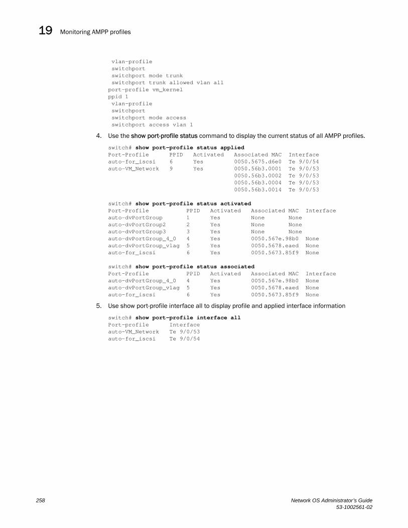
Monitoring AMPP profiles19
vlan-profileswitchportswitchport mode trunkswitchport trunk allowed vlan all
port-profile vm_kernelppid 1 vlan-profileswitchportswitchport mode accessswitchport access vlan 1
4. Use the show port-profile status command to display the current status of all AMPP profiles.
switch# show port-profile status appliedPort-Profile PPID Activated Associated MAC Interfaceauto-for_iscsi 6 Yes 0050.5675.d6e0 Te 9/0/54auto-VM_Network 9 Yes 0050.56b3.0001 Te 9/0/53
0050.56b3.0002 Te 9/0/530050.56b3.0004 Te 9/0/530050.56b3.0014 Te 9/0/53
switch# show port-profile status activatedPort-Profile PPID Activated Associated MAC Interfaceauto-dvPortGroup 1 Yes None Noneauto-dvPortGroup2 2 Yes None Noneauto-dvPortGroup3 3 Yes None Noneauto-dvPortGroup_4_0 4 Yes 0050.567e.98b0 Noneauto-dvPortGroup_vlag 5 Yes 0050.5678.eaed Noneauto-for_iscsi 6 Yes 0050.5673.85f9 None
switch# show port-profile status associatedPort-Profile PPID Activated Associated MAC Interfaceauto-dvPortGroup_4_0 4 Yes 0050.567e.98b0 Noneauto-dvPortGroup_vlag 5 Yes 0050.5678.eaed Noneauto-for_iscsi 6 Yes 0050.5673.85f9 None
5. Use show port-profile interface all to display profile and applied interface information
switch# show port-profile interface allPort-profile Interfaceauto-VM_Network Te 9/0/53auto-for_iscsi Te 9/0/54
258 Network OS Administrator’s Guide53-1002561-02
Network OS Administrator’s Guide53-1002561-02
Chapter
20
Configuring FCoE InterfacesIn this chapter
•FCoE overview . . . . . . . . . . . . . . . . . . . . . . . . . . . . . . . . . . . . . . . . . . . . . . . . 259
•End-to-end FCoE . . . . . . . . . . . . . . . . . . . . . . . . . . . . . . . . . . . . . . . . . . . . . . 260
•Layer 2 Ethernet overview. . . . . . . . . . . . . . . . . . . . . . . . . . . . . . . . . . . . . . . 263
•FCoE Initialization Protocol . . . . . . . . . . . . . . . . . . . . . . . . . . . . . . . . . . . . . . 268
•FCoE queuing. . . . . . . . . . . . . . . . . . . . . . . . . . . . . . . . . . . . . . . . . . . . . . . . . 270
•Configuring FCoE interfaces . . . . . . . . . . . . . . . . . . . . . . . . . . . . . . . . . . . . . 271
•FCoE over LAG . . . . . . . . . . . . . . . . . . . . . . . . . . . . . . . . . . . . . . . . . . . . . . . . 273
FCoE overviewFibre Channel over Ethernet (FCoE) enables you to transport FC protocols and frames over Data Center Bridging (DCB) networks. DCB is an enhanced Ethernet network that enables the convergence of various applications in data centers (LAN, SAN, and HPC) onto a single interconnect technology.
FCoE provides a method of encapsulating the Fibre Channel (FC) traffic over a physical Ethernet link. FCoE frames use a unique EtherType that enables FCoE SAN traffic and legacy LAN Ethernet traffic to be carried on the same link. FC frames are encapsulated in an Ethernet frame and sent from one FCoE-aware device across an Ethernet network to a second FCoE-aware device. The FCoE-aware devices may be FCoE end nodes (ENodes) such as servers, storage arrays, or tape drives on one end and FCoE Forwarders on the other end. FCoE Forwarders (FCFs) are switches providing SAN fabric services and may also provide FCoE-to-FC bridging.
The motivation behind using DCB networks as a transport mechanism for FC arises from the desire to simplify host protocol stacks and consolidate network interfaces in data center environments. FC standards allow for building highly reliable, high-performance fabrics for shared storage, and these characteristics are what DCB brings to data centers. Therefore, it is logical to consider transporting FC protocols over a reliable DCB network in such a way that it is completely transparent to the applications. The underlying DCB fabric is highly reliable and high performing, the same as the FC SAN.
In FCoE, ENodes discover FCFs and initialize the FCoE connection through the FCoE Initialization Protocol (FIP). The FIP has a separate EtherType from FCoE. The FIP includes a discovery phase in which ENodes discover VLANs supporting FCoE, solicit FCFs on those VLANs, and FCFs respond to the solicitations with advertisements of their own. At this point, the ENodes know enough about the FCFs to log in to them. The virtual link establishment and fabric login (FLOGI/FDISC) for VN-to-VF port connections is also part of the FIP.
259

End-to-end FCoE20
FCoE terminologyTable 43 lists and describes the FCoE terminology used in this document.
End-to-end FCoEThe Brocade VCS Fabric is a convergence-ready fabric. This means it is capable of providing lossless service and other features expected of a CEE-capable network. Network OS v3.0.0 supports multi-hop FCoE, where an FCoE initiator can communicate with an FCoE target that is a number of hops away.
FCoE operationsEach switch in the Brocade VCS Fabric cluster acts as a fully functional FCoE Forwarder (FCF). All Fibre Channel (FC) services required to support a Virtual Network (VN) must run on every Brocade VCS Fabric cluster switch, and each switch in the fabric acts as if it were a separate domain in an FC SAN.
For all practical purposes, a Brocade VCS Fabric operates similarly to an FC fabric because all the FCoE initiators and targets are connected to the Brocade VCS Fabric. Each switch in the cluster gets a domain ID, and once the fabric forms, all the FC services (such as Name Server, Login Controller, Domain Controller) are available on each individual cluster switch.
Network OS v3.0.0 supports FCR/LSAN zoning. Network OS v2.1.0 supports only open zoning for FCoE initiators. The fabric device limitation is set to 3000 FCoE devices in a Brocade VCS Fabric cluster, because open zoning floods all the State Change Notifications (SCNs) to every FCoE device. FCoE traffic forwarding across the fabric follows the same equal-cost multi-path (ECMP) routing rules as LAN traffic forwarding.
FCoE end-to-end forwardingFCoE frame forwarding between two FCoE devices attached to the Brocade VCS Fabric works similarly to Layer 3 IP routing. The end-node talks to the default gateway’s MAC address and the Layer 2 headers are modified hop-by-hop until the frame reaches its final destination. Forwarding decisions are based on the contents of the IP header in the case of IP routing, and the IP header is untouched along the path. FCoE forwarding works the same way.
Figure 22 on page 261 illustrates this process. Assume that VN1 (an FCoE initiator) is trying to access VN2 (an FCoE target).
TABLE 43 FCoE terminology
Term Description
FCoE Fibre Channel over Ethernet
DCB Data Center Bridging
VN_port FCoE equivalent of an FC N_port
VF_port FCoE equivalent of an FC F_port
ENode An FCoE device that supports FCoE VN_ports (servers and target devices)
260 Network OS Administrator’s Guide53-1002561-02

End-to-end FCoE 20
1. VN1 and VN2 discover VF1 and VF2 through FIP Discovery Protocol and perform a Fabric Login (FLOGI) to their respective VF ports. That is, VN1 performs an FIP FLOGI to VF1 and VN2 performs an FLOGI to VF2. This works like IP in that all communication between the end-station and the network happens to the router’s MAC address at Layer 2. This means VN1 is always communicating with VF1 at Layer 2.
2. In a Brocade VCS Fabric implementation, all FC services are available on every cluster unit. This means there is Fibre Channel Network Switch (FCNS) available on both FCF1 and FCF2. The FCNS service functions identically as it does in an FC SAN. As a result, VN1 discovers VN2.
3. VN1 attempts an N_port Login (PLOGI) to VN2, with the frame information shown at point 1 in Figure 22. The Layer 2 header contains VF1 as the destination MAC address. The Layer 3 header (in this case, the FC header) contains the actual DID and SID of the initiator and the target respectively.
In this example, because VN1 is connected to the FCF with a Domain ID of 1, its PID is 010100. Similarly, because VN2 is connected to FCF3, its FC address is 030100.
FIGURE 22 FCoE end-to-end header process
4. When FCF-A receives the frame on VF1, it performs a Layer 3 lookup. It looks up the DID in the FC header and determines that the frame is destined to a non-local domain. FCF-A decodes the next hop needed to reach the destination domain of 3, based on Fabric Shortest Path First (FSPF). It is at this point that it does something different than a normal IP router.
DA=VF1
VN1
VF1 VF2
Fa Fb Fc Fd
VN2
FCoE Initiator FCoE Target
MAC addresses of the ISL end-points:Fa, Fb, Fc, Fd
SA=VN1
Etype=FCoE
FCoE Hdr
FCS
DA=Fb
SA=Fa
Etype=TRILLDST-RBridge=3
SRC-RBridge=1
DA=FCFc
SA=FCFA
Etype=FCoEFCoE Hdr
DID=030100SID=010100
FC CRCFCS’
DA=Fd
SA=Fc
Etype=TRILLDST-RBridge=3
SRC-RBridge=1
DA=FCFc
SA=FCFA
Etype=FCoEFCoE Hdr
DID=030100SID=010100
FC CRCFCS’’
DA=VN2
SA=VF2
Etype=FCoE
FCoE HdrDID=030100SID=010100
FC CRCFCS’’’
Eth Hdr
TRILL
FCoE
FC
Domain ID:1FCF-MAC: A
Domain ID:2FCF-MAC: B
Domain ID:3FCF-MAC: C
1
1
2 3
4
4
2 3
DID=030100SID=010100
FC CRC
Network OS Administrator’s Guide 26153-1002561-02

End-to-end FCoE20
5. FCF-A now knows that it needs to reach FCF-C. Each FCF in the Brocade VCS Fabric is assigned an FCF MAC address. FCF-A constructs the Layer 2 header based on this information. So, the original MAC header is now transformed as follows: the DA is changed from VF1 to FCF-C and the SA is changed from VN1 to FCF-A. This occurs at point 2 in Figure 22.
6. The frame gets a Transparent Interconnection of Lots of Links (TRILL) header and traverses across the fabric to reach FCF-C. The TRILL header indicates that the source is RBridge 1 and the destination is RBridge 3. This occurs at point 2 in Figure 22.
7. The outer MAC header is a link level header that gets the frame from FCF-A to FCF-B. FCF-B receives the frame. FCF-B scans the TRILL header, decodes the destination RBridge ID in the frame, and forwards the frame. FCF-B only modifies the Layer 2 header. It neither looks up nor modifies anything in the FC header or the inner MAC header. This occurs at point 3 in Figure 22.
8. FCF-C receives the frame. FCF-C scans the TRILL header and decodes the destination RBridge ID. FCF-C promotes the frame to Layer 3 lookup, because the FCF-C is the DA in the inner MAC header. FCF-C then scans the FC header and does something similar to an area route lookup in FC SAN. This lookup yields the MAC address of VN2 and the VF interface (in this case, VF2) information that it needs to use to forward the frame to VN2. This is occurs at point 4 in Figure 22.
9. VN2 receives the PLOGI. The PLOGI response from VN2 traverses back to VN1 in similar fashion.
NOTEIt is assumed that both VN1 and VN2 are configured to be in the same FCoE VLAN, and FCoE forwarding is enabled on this VLAN in the Brocade VCS Fabric. Network OS v3.0.0 supports only one FCoE VLAN for all FCoE devices connected to the fabric.
262 Network OS Administrator’s Guide53-1002561-02
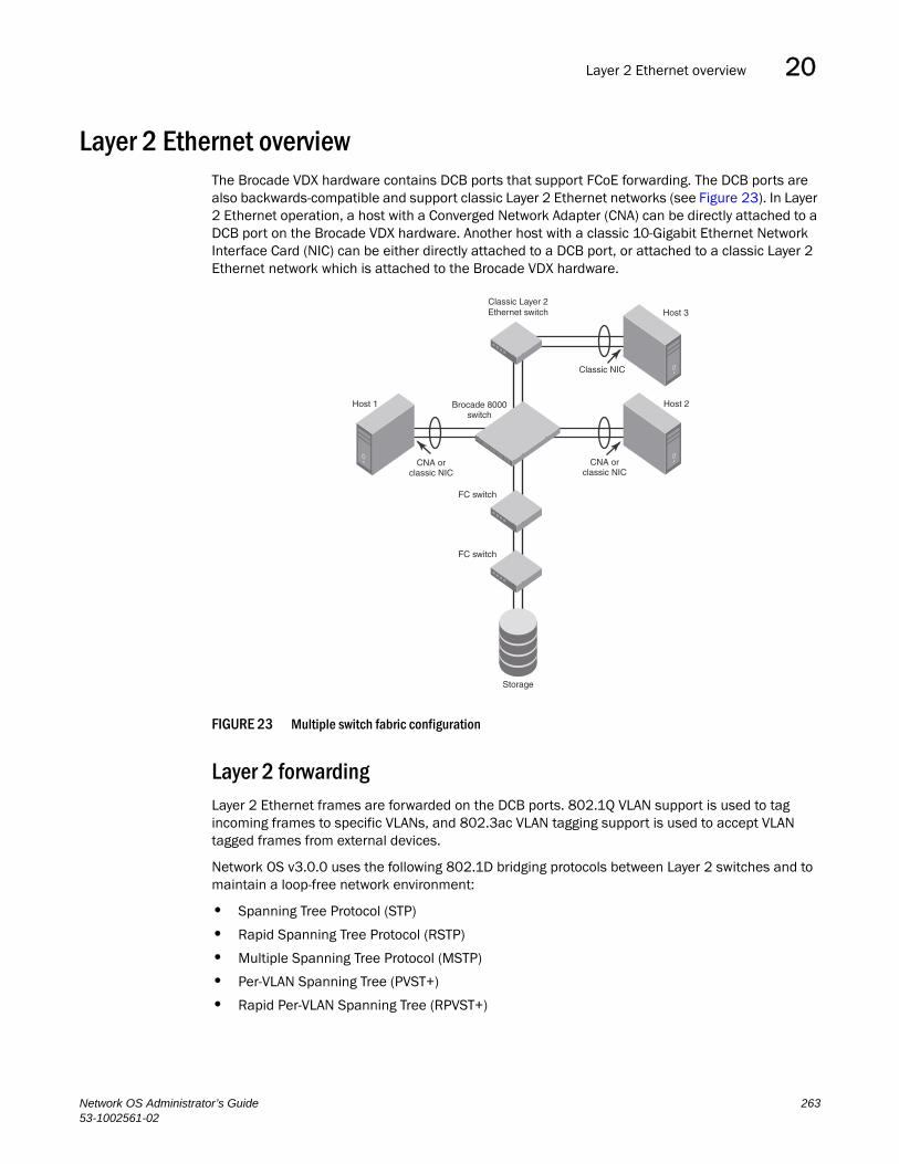
Layer 2 Ethernet overview 20
Layer 2 Ethernet overviewThe Brocade VDX hardware contains DCB ports that support FCoE forwarding. The DCB ports are also backwards-compatible and support classic Layer 2 Ethernet networks (see Figure 23). In Layer 2 Ethernet operation, a host with a Converged Network Adapter (CNA) can be directly attached to a DCB port on the Brocade VDX hardware. Another host with a classic 10-Gigabit Ethernet Network Interface Card (NIC) can be either directly attached to a DCB port, or attached to a classic Layer 2 Ethernet network which is attached to the Brocade VDX hardware.
FIGURE 23 Multiple switch fabric configuration
Layer 2 forwardingLayer 2 Ethernet frames are forwarded on the DCB ports. 802.1Q VLAN support is used to tag incoming frames to specific VLANs, and 802.3ac VLAN tagging support is used to accept VLAN tagged frames from external devices.
Network OS v3.0.0 uses the following 802.1D bridging protocols between Layer 2 switches and to maintain a loop-free network environment:
• Spanning Tree Protocol (STP)
• Rapid Spanning Tree Protocol (RSTP)
• Multiple Spanning Tree Protocol (MSTP)
• Per-VLAN Spanning Tree (PVST+)
• Rapid Per-VLAN Spanning Tree (RPVST+)
Classic Layer 2Ethernet switch
FC switch
FC switch
Storage
Host 1 Host 2
Host 3
Brocade 8000switch
CNA orclassic NIC
CNA orclassic NIC
Classic NIC
Network OS Administrator’s Guide 26353-1002561-02

Layer 2 Ethernet overview20
For detailed information on configuring these protocols, refer to Chapter 22, “Configuring STP-Type Protocols”.
The Brocade VDX hardware handles Ethernet frames as follows:
• When the destination MAC address is not in the lookup table, the frame is flooded on all ports in the same VLAN, except the ingress port.
• When the destination MAC address is present in the lookup table, the frame is switched only to the correct egress port.
• When the destination MAC address is present in the lookup table, and the egress port is the same as the ingress port, the frame is dropped.
• If the Ethernet Frame Check Sequence (FCS) is incorrect, because the switch is in cut-through mode, a correctly formatted Ethernet frame is sent out with an incorrect FCS.
• If the Ethernet frame is too short, the frame is discarded and the error counter is incremented.
• If the Ethernet frame is too long, the frame is truncated and the error counter is incremented. The truncated frame is sent out with an incorrect FCS.
• Frames sent to a broadcast destination MAC address are flooded on all ports in the same VLAN, except the ingress port.
• When MAC address entries in the lookup table time out, they are removed. In this event, frame forwarding changes from unicast to flood.
• An existing MAC address entry in the lookup table is discarded when a device is moved to a new location. When a device is moved, the ingress frame from the new port causes the old lookup table entry to be discarded and the new entry to be inserted into the lookup table. Frame forwarding remains unicast to the new port.
• When the lookup table is full, new entries replace the oldest MAC addresses after the oldest MAC addresses reach a certain age and time out. MAC addresses that still have traffic running are not timed out.
NOTENew entries start replacing older entries when the lookup table reaches 90 percent of its 32K capacity.
VLAN taggingThe Layer 2 switch always tags an incoming frame with a VLAN ID. If the incoming frame is untagged, then a tag is added according to the port configuration. A port can classify untagged traffic to a single VLAN or to multiple VLANs. If the incoming frame is already tagged, then the port will either forward or discard the frame according to allowed VLAN rules in the port configuration.
These are three examples of VLAN tagging:
• If the DCB port is configured to tag incoming frames with a single VLAN ID, then incoming frames that are untagged are tagged with the VLAN ID.
• If the DCB port is configured to tag incoming frames with multiple VLAN IDs, then incoming frames that are untagged are tagged with the correct VLAN ID based on the port setting.
• If the DCB port is configured to accept externally tagged frames, then incoming frames that are tagged with a VLAN ID are passed through unchanged.
264 Network OS Administrator’s Guide53-1002561-02

Layer 2 Ethernet overview 20
NOTEOnly a single switch-wide VLAN is capable of forwarding FCoE traffic.
For detailed information on configuring VLANs, refer to Chapter 21, “Configuring VLANs”.
Frame classification (incoming)The Brocade VDX hardware is capable of classifying incoming Ethernet frames based on the following criteria:
• Port number
• Protocol
• MAC address
The classified frames can be tagged with a VLAN ID or with 802.1p Ethernet priority. The 802.1p Ethernet priority tagging is done using the Layer 2 Class of Service (CoS). The 802.1p Ethernet priority is used to tag frames in a VLAN with a Layer 2 CoS to prioritize traffic in the VLAN. The Brocade VDX hardware also accepts frames that have been tagged by an external device.
Frame classification options are as follows:
• VLAN ID and Layer 2 CoS by physical port number—With this option, the port is set to classify incoming frames to a preset VLAN ID and the Layer 2 CoS on a physical port on the Brocade VDX hardware.
• VLAN ID and Layer 2 CoS by LAG virtual port number—With this option, the port is set to classify incoming frames to a preset VLAN ID and Layer 2 CoS on a Link Aggregation Group (LAG) virtual port.
• Layer 2 CoS mutation—With this option, the port is set to change the Layer 2 CoS setting by enabling the QoS mutation feature.
• Layer 2 CoS trust—With this option, the port is set to accept the Layer 2 CoS of incoming frames by enabling the QoS trust feature.
For detailed information on configuring QoS, refer to Chapter 26, “Configuring QoS”.
Congestion control and queuingThe Brocade VDX hardware supports several congestion control and queuing strategies. As an output queue approaches congestion, Random Early Detection (RED) is used to selectively and proactively drop frames to maintain maximum link utilization. Incoming frames are classified into priority queues based on the Layer 2 CoS setting of the incoming frame, or the possible rewriting of the Layer 2 CoS field based on the settings of the DCB port or VLAN.
The Brocade VDX hardware supports a combination of two scheduling strategies to queue frames to the egress ports: Priority queuing, which is also referred to as strict priority, and Deficit Weighted Round Robin (DWRR) queuing.
The scheduling algorithms work on the eight traffic classes as specified in 802.1Qaz Enhanced Transmission Selection (ETS).
Queuing features are described as follows:
Network OS Administrator’s Guide 26553-1002561-02

Layer 2 Ethernet overview20
• RED—RED increases link utilization. When multiple inbound TCP traffic streams are switched to the same outbound port, and some traffic streams send small frames while other traffic streams send large frames, link utilization will not be able to reach 100 percent. When RED is enabled, link utilization approaches 100 percent.
• Classification—Setting user priority.
- Inbound frames are tagged with the user priority set for the inbound port. The tag is visible when examining the frames on the outbound port. By default, all frames are tagged to priority zero.
- Externally tagged Layer 2 frames—When the port is set to accept externally tagged Layer 2 frames, the user priority is set to the Layer 2 CoS of the inbound frames.
• Queuing
- Input queuing—Input queuing optimizes the traffic flow in the following way. A DCB port has inbound traffic that is tagged with several priority values, and traffic from different priority settings is switched to different outbound ports. Some outbound ports are already congested with background traffic while others are uncongested. With input queuing, the traffic rate of the traffic streams switched to uncongested ports should remain high.
- Output queuing—Output queuing optimizes the traffic flow in the following way. Several ports carry inbound traffic with different priority settings. Traffic from all ports is switched to the same outbound port. If the inbound ports have different traffic rates, some outbound priority groups will be congested while others can remain uncongested. With output queuing, the traffic rate of the traffic streams that are uncongested should remain high.
- Multicast rate limit—A typical multicast rate limiting example is where several ports carry multicast inbound traffic that is tagged with several priority values. Traffic with different priority settings is switched to different outbound ports. The multicast rate limit is set so that the total multicast traffic rate on output ports is less than the specified set rate limit.
- Multicast input queuing—A typical multicast input queuing example is where several ports carry multicast inbound traffic that is tagged with several priority values. Traffic with different priority settings is switched to different outbound ports. Some outbound ports are already congested with background traffic while others are uncongested. The traffic rate of the traffic streams switched to the uncongested ports should remain high. All outbound ports should carry some multicast frames from all inbound ports. This enables multicast traffic distribution relative to the set threshold values.
- Multicast output queuing—A typical multicast output queuing example is where several ports carry multicast inbound traffic. Each port has a different priority setting. Traffic from all ports is switched to the same outbound port. If the inbound ports have varying traffic rates, some outbound priority groups will be congested while others remain uncongested. The traffic rate of the traffic streams that are uncongested remains high. The outbound ports should carry some multicast frames from all the inbound ports.
• Scheduling—A typical example of scheduling policy (using Strict Priority 0 and Strict Priority 1 modes) is where ports 0 through 7 carry inbound traffic, each port has a unique priority level, port 0 has priority 0, port 1 has priority 1, and so on. All traffic is switched to the same outbound port. In Strict Priority 0 mode, all ports have DWRR scheduling; therefore, the frames-per-second (FPS) on all ports should correspond to the DWRR settings. In Strict Priority 1 mode, priority 7 traffic uses Strict Priority; therefore, priority 7 can achieve a higher FPS. Frames from input ports with the same priority level should be scheduled in a round robin manner to the output port.
266 Network OS Administrator’s Guide53-1002561-02

Layer 2 Ethernet overview 20
When setting the scheduling policy, each priority group that is using DWRR scheduling can be set to use a percentage of the total bandwidth by setting the PG_Percentage parameter.
For detailed information on configuring QoS, refer to Chapter 26, “Configuring QoS”.
Access controlAccess Control Lists (ACLs) are used for Layer 2 switching security. Standard ACLs inspect the source address for the inbound ports. Extended ACLs provide filtering by source and destination addresses and protocol. ACLs can be applied to the DCB ports or to VLANs.
ACLs function as follows:
• A standard Ethernet ACL configured on a physical port is used to permit or deny frames based on the source MAC address. The default is to permit all frames.
• An extended Ethernet ACL configured on a physical port is used to permit or deny frames based on the source MAC address, destination MAC address, and EtherType. The default is to permit all frames.
• A standard Ethernet ACL configured on a LAG virtual port is used to permit or deny frames based on the source MAC address. The default is to permit all frames. LAG ACLs apply to all ports in the LAG.
• An extended Ethernet ACL configured on a LAG virtual port is used to permit or deny frames based on the source MAC address, destination MAC address, and EtherType. The default is to permit all frames. LAG ACLs apply to all ports in the LAG.
• A standard Ethernet ACL configured on a VLAN is used to permit or deny frames based on the source MAC address. The default is to permit all frames. VLAN ACLs apply to the Switch Vertical Interface (SVI) for the VLAN.
• An extended Ethernet ACL configured on a VLAN is used to permit or deny frames based on the source MAC address, destination MAC address, and EtherType. The default is to permit all frames. VLAN ACLs apply to the Switch Vertical Interface (SVI) for the VLAN.
For detailed information on configuring ACLs, refer to Chapter 25, “Configuring ACLs”.
Trunking
NOTEThe term “trunking” in an Ethernet network refers to the use of multiple network links (ports) in parallel to increase the link speed beyond the limits of any one single link or port, and to increase the redundancy for higher availability.
802.1ab Link Layer Discovery Protocol (LLDP) is used to detect links to connected switches or hosts. Trunks can then be configured between an adjacent switch or host and the Brocade VDX hardware.
The Data Center Bridging Capability Exchange Protocol (DCBX) extension is used to identify a DCB-capable port on an adjacent switch or host. For detailed information on configuring LLDP and DCBX, refer to Chapter 24, “Configuring LLDP”.
The 802.3ad Link Aggregation Control Protocol (LACP) is used to combine multiple links to create a trunk with the combined bandwidth of all the individual links. For detailed information on configuring LACP, refer to Chapter 23, “Configuring Link Aggregation”.
Network OS Administrator’s Guide 26753-1002561-02
FCoE Initialization Protocol20
NOTEThe Brocade software supports a maximum of 24 LAG interfaces.
Flow control802.3x Ethernet pause and Ethernet Priority-based Flow Control (PFC) are used to prevent dropped frames by slowing traffic at the source end of a link. When a port on a switch or host is not ready to receive more traffic from the source, perhaps due to congestion, it sends pause frames to the source to pause the traffic flow. When the congestion has been cleared, it stops requesting the source to pause traffic flow, and traffic resumes without any frame drop.
When Ethernet pause is enabled, pause frames are sent to the traffic source. Similarly, when PFC is enabled, there is no frame drop; pause frames are sent to the source switch.
For detailed information on configuring Ethernet pause and PFC, refer to Chapter 26, “Configuring QoS”.
FCoE Initialization Protocol The FCoE Initialization Protocol (FIP) discovers and establishes virtual links between FCoE-capable entities connected to an Ethernet cloud through a dedicated EtherType, 0x8914, in the Ethernet frame.
FIP discovery
NOTEThis software version supports ANSI INCITS 462-2010 Fibre Channel – Backbone – 5 (FC-BB-5) / 13-May-2010.
The Brocade VDX hardware FIP discovery phase operates as follows:
• The Brocade VDX hardware uses the FCoE Initialization Protocol (FIP). ENodes discover VLANs supporting FCoE, FCFs, and then initialize the FCoE connection through the FIP.
• VF_port configuration—An FCoE port accepts ENode requests when it is configured as a VF_port and enabled. An FCoE port does not accept ENode requests when disabled.
• Solicited advertisements—A typical scenario is where a Brocade VDX hardware receives a FIP solicitation from an ENode. Replies to the original FIP solicitation are sent to the MAC address embedded in the original FIP solicitation. After being accepted, the ENode is added to the VN_port table.
• VLAN 1—The Brocade VDX hardware should not forward FIP frames on VLAN 1 because it is reserved for management traffic only.
• A fabric-provided MAC address is supported. A server-provided MAC address is not supported in the Network OS v3.0.0 release.
NOTEIn the fabric-provided MAC address format, VN_port MAC addresses are based on a 24-bit fabric-supplied value. The first three bytes of this value are referred to as the FCMAP. The next three bytes are the FC ID, which is assigned by the switch when the ENode logs in to the switch.
268 Network OS Administrator’s Guide53-1002561-02
FCoE Initialization Protocol 20
FIP loginFIP login operates as follows:
• ENodes can log in to the Brocade VDX hardware using FIP. Fabric login (FLOGI) and fabric discovery (FDISC) are accepted. Brocade VDX hardware in the fabric maintains the MAC address, World Wide Name (WWN), and PID mappings per login. Each ENode port should have a unique MAC address and WWN.
• FIP FLOGI—The Brocade VDX hardware accepts the FIP FLOGI from the ENode. The FIP FLOGI acceptance (ACC) is sent to the ENode if the ENode MAC address or WWN matches the VN_port table on the Brocade VDX hardware. The FIP FLOGI request is rejected if the ENode MAC address or WWN does not match. The ENode login is added to the VN_port table. Fabric Provided MAC Addressing (FPMA) is supported.
• FIP FDISC—The Brocade VDX hardware accepts FIP FDISC from the ENode. FIP FDISC acceptance (ACC) is sent to the ENode if the ENode MAC address or WWN matches the VN_port table on the Brocade VDX hardware. The FIP FDISC request is rejected if the ENode MAC address or WWN does not match. The ENode login is added to the VN_port table. FPMA is supported.
• Maximum logins per VF_port—The Brocade VDX hardware supports a maximum of 255 logins per VF_port. The VF_port rejects further logins after the maximum is reached.
• Maximum logins per switch—The Brocade VDX hardware accepts a maximum of 64 logins per switch.
FIP logoutFIP logout operates as follows:
• ENodes and VN_ports can log out from the Brocade VDX hardware using FIP. The Brocade VDX hardware in the fabric updates the MAC address, WWN, and PID mappings upon logout. The Brocade VDX hardware also handles scenarios of implicit logout where the ENode has left the fabric without explicitly logging out.
• FIP logout (LOGO)—The Brocade VDX hardware accepts a FIP LOGO from the ENode. The FIP LOGO acceptence (ACC) should be sent to the ENode if the ENode MAC address and the VN_port MAC address matches the VN_port table data on the switch. The LOGO is ignored (not rejected) if the ENode MAC address does not match. The ENode logout is updated in the VN_port table.
• Implicit logout—With the ENode directly connected to a DCB port, if the port that the ENode is attached to goes offline, the Brocade VDX hardware implicitly logs out that ENode. ENode logout is updated in the VN_port table. The Brocade VDX hardware sends an FIP Clear Virtual Links (CVL) to the ENode.
The FIP Virtual Link Maintenance protocols provide a mechanism to detect reachability loss to an Enode or any VN_port instantiated on that ENode. This is accomplished by the periodic transmission of FIP Keep-Alive (FKA) messages from the ENode.
If FKA timeouts are enabled on the switch, all VN_ports associated with an ENode will be implicitly logged out in the event of an ENode FKA timeout.
If FKA timeouts are enabled on the switch, the VN_port will be implicitly logged out in the event of a VN_port FKA timeout.
Network OS Administrator’s Guide 26953-1002561-02

FCoE queuing20
Name serverThe Brocade VDX hardware name server function operates as follows:
• ENode login and logout to and from the Brocade VDX hardware updates the name server in the FC fabric. The Brocade VDX hardware maintains the MAC address to WWN and PID mappings.
• ENode login and logout—When an ENode login occurs through any means (FIP FLOGI, FIP FDISC, FCoE FLOGI, or FCoE FDISC), an entry is added to the name server. When an ENode logout occurs through any means (FIP LOGO, FCoE LOGO, or implicit logout), the entry is removed from the name server.
• ENode data—The Brocade VDX hardware maintains a VN_port table. The table tracks the ENode MAC address, FIP login parameters for each login from the same ENode, and WWN and PID mappings on the FC side. You can display the VN_port table with the show fcoe login command.
Registered State Change NotificationThe Brocade VDX hardware Registered State Change Notification (RSCN) function operates as follows:
• RSCN events generated in the FC fabric are forwarded to the ENodes. RSCN events generated on the FCoE side are forwarded to the FC devices. DCB is not aware of RSCN events.
• Device RSCN—An RSCN is generated to all registered and affected members when an ENode either logs in or logs out of an FCF through any means. An RSCN is generated when an FC N_port device either logs in or logs out of the FC fabric.
NOTEWhen transmitting an RSCN, zoning rules still apply for FCoE devices as the devices are treated as regular FC N_ports.
• VF_port RSCN—An RSCN is generated to all registered members when a VF_port goes online or offline, causing ENode or FC devices to be added or removed.
• Domain RSCN—An RSCN is generated to all registered and affected members when an FC switch port goes online or offline, causing ENode or FC devices to be added or removed. An RSCN is generated when two FC switches merge or segment, causing ENode or FC devices to be added or removed. When FC switches merge or segment, an RSCN is propagated to ENodes.
• Zoning RSCN—An RSCN is generated to all registered and affected members when a zoning exchange occurs in the FC fabric.
FCoE queuingThe QoS configuration controls the FCoE traffic distribution. Note that changing these settings requires changes on both the Brocade VDX hardware and the Converged Network Adapter (CNA); therefore, the link must be taken offline and put back online after a change is made. Traffic scheduler configuration changes affect FCoE traffic distribution as follows:
• Changing the priority group for a port causes the FCoE traffic distribution to be updated. The priority group and bandwidth are updated.
270 Network OS Administrator’s Guide53-1002561-02

Configuring FCoE interfaces 20
• Changing the priority table for a port causes the FCoE traffic distribution to be updated. The CoS-to-priority group mapping is updated.
• Changing the class map for a port causes the FCoE traffic distribution to be updated.
• Changing the policy map for a port causes FCoE traffic distribution to be updated.
• Changing the DCB map for a port causes the FCoE traffic distribution to be updated.
• The FCMAP-to-VLAN mapping determines the FCoE VLAN allowed for the FCoE session. Modifying this mapping causes the existing sessions to terminate.
NOTEOnly one FCoE VLAN is supported in the Network OS v3.0.0 release.
Configuring FCoE interfacesFCoE maps are used to configure FCoE properties on interfaces. An FCoE map is a placeholder for an FCoE VLAN and a CEE map. You will assign FCoE maps on to physical interfaces using the fcoeport command. Once the FCoE map is assigned onto an interface:
• The corresponding FCoE VLAN 1002 is applied to the interface.
• The corresponding CEE map is applied to the interface.
• The FCoE/FIP vlan classifiers are applied to the interface.
In short, the interface becomes capable of carrying FCoE traffic. The FCoE map can be applied on an interface only if the FCoE map is complete in all aspects. That is, it should have an FCoE VLAN and a CEE map associated with it.
NOTEBrocade does not support non-FCoE traffic over the FCoE VLAN. The FCoE VLAN should not carry any mixed traffic.
Only a single FCoE map is allowed, which is created automatically with the name “default.” You are not able to delete or rename this map. By default, the FCoE VLAN associated to the FCoE map is FCoE VLAN (1002) and the CEE map associated is the default CEE map (also called “default”).
Assigning an FCoE map onto an interfaceThe FCoE map cannot be edited if it is associated with any interfaces.
The FCoE map can be applied, irrespective of whether or not the interface is in ‘switchport’ mode. But the FCoE map cannot be applied on an interface if the same interface already has a CEE map assigned to it.
To assign the FCoE map onto an interface, perform the following steps in global configuration mode.
1. Activate the interface configuration mode for the interface you wish to modify.
The following example activates the mode for the 10 Gigabit Ethernet interface in slot 0/port 0.
switch(config)#interface tengigabitethernet 1/0/1switch(conf-if-te-0/1)#
Network OS Administrator’s Guide 27153-1002561-02
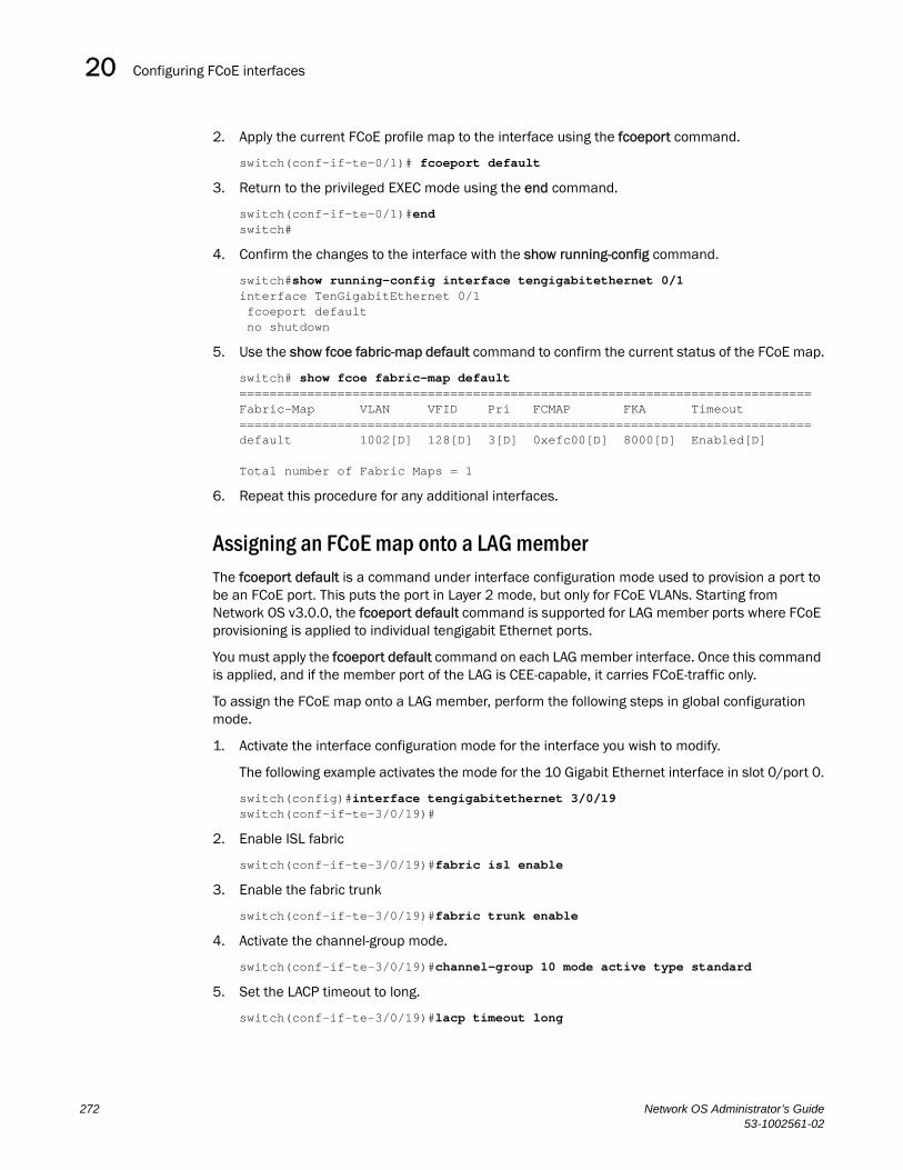
Configuring FCoE interfaces20
2. Apply the current FCoE profile map to the interface using the fcoeport command.
switch(conf-if-te-0/1)# fcoeport default
3. Return to the privileged EXEC mode using the end command.
switch(conf-if-te-0/1)#endswitch#
4. Confirm the changes to the interface with the show running-config command.
switch#show running-config interface tengigabitethernet 0/1interface TenGigabitEthernet 0/1 fcoeport default no shutdown
5. Use the show fcoe fabric-map default command to confirm the current status of the FCoE map.
switch# show fcoe fabric-map default============================================================================Fabric-Map VLAN VFID Pri FCMAP FKA Timeout============================================================================default 1002[D] 128[D] 3[D] 0xefc00[D] 8000[D] Enabled[D]
Total number of Fabric Maps = 1
6. Repeat this procedure for any additional interfaces.
Assigning an FCoE map onto a LAG member The fcoeport default is a command under interface configuration mode used to provision a port to be an FCoE port. This puts the port in Layer 2 mode, but only for FCoE VLANs. Starting from Network OS v3.0.0, the fcoeport default command is supported for LAG member ports where FCoE provisioning is applied to individual tengigabit Ethernet ports.
You must apply the fcoeport default command on each LAG member interface. Once this command is applied, and if the member port of the LAG is CEE-capable, it carries FCoE-traffic only.
To assign the FCoE map onto a LAG member, perform the following steps in global configuration mode.
1. Activate the interface configuration mode for the interface you wish to modify.
The following example activates the mode for the 10 Gigabit Ethernet interface in slot 0/port 0.
switch(config)#interface tengigabitethernet 3/0/19switch(conf-if-te-3/0/19)#
2. Enable ISL fabric
switch(conf-if-te-3/0/19)#fabric isl enable
3. Enable the fabric trunk
switch(conf-if-te-3/0/19)#fabric trunk enable
4. Activate the channel-group mode.
switch(conf-if-te-3/0/19)#channel-group 10 mode active type standard
5. Set the LACP timeout to long.
switch(conf-if-te-3/0/19)#lacp timeout long
272 Network OS Administrator’s Guide53-1002561-02

FCoE over LAG 20
6. Apply the current FCoE profile map to the interface using the fcoeport command.
switch(conf-if-te-3/0/19)# fcoeport default
7. Return to the privileged EXEC mode using the end command.
switch(conf-if-te-3/0/19)#end
8. Confirm the changes to the interface with the show running-config command.
switch#show running-config interface tengigabitethernet 3/0/19interface TenGigabitEthernet 3/0/19
fcoeport defaultshutdown
9. Use the show fcoe interface brief command to confirm the current status of the FCoE map.
switch# show fcoe interface brief
10. Repeat this procedure for any additional interfaces.
FCoE over LAGNetwork OS v3.0.0 supports FCoE over LAGs. These are LAGs between the FCoE Forwarder (FCF) and a DCB capable switch. The entire LAG is provisioned for FCoE, so that all member ports are used for FCoE traffic. FCoE traffic is broadcasted on all the member links of the LAG.
NOTEFCoE over LAG supports standard LAGs only. vLAGs are not supported.
Additionally, Network OS v3.0.0 supports multiple logins per port. This feature allows multiple Enodes to login to a single tengigabitethernet port or a LAG.
Configuration guidelines and restrictionsFollow these configuration guidelines and restrictions when configuring FCoE over LAG:
1. The intermediate switches may or may not be an FSB.
2. All ACLs and FCoE forwarding entries will continue to be on the FCF’s ingress ports.
3. It is assumed that the intermediate switch works in “Willing” mode towards the FCF in the DCBX exchange, and accepts the configuration from the FCF and propagates it downstream.
4. The CEE/DCBX configuration is expected to identical on both FCF and the intermediate switch.
5. Irrespective of item 3 or item 4, the PFC/No-drop behavior from the FCF perspective will be guaranteed only on the links between the FCF and first hop switch. There is no provision in the standard to guarantee this requirement on all paths leading to the Enode.
6. FSBs may or may not be able to forward the FCoE LLS TLV to the Enodes. Hence this TLV may not be present in the LLDP packets sent to the Enodes. The FCF continues to send this TLV in its LLDP packets destined to the intermediate switch.
Network OS Administrator’s Guide 27353-1002561-02

FCoE over LAG20
FCoE provisioning on LAGsThe existing fcoeport default command is extended to the LAG interfaces to support the new feature, as shown in the example below.
switch# configureEntering configuration mode terminalswitch(config)# interface Port-channel 10switch(config-Port-channel-10)# fcoeport defaultswitch(config-Port-channel-10)#
This provisions all the member ports of Port-channel 10 for FCoE.
Logical FCoE portsWhen the switch boots, a pool of 384 FCoE ports are created. These ports are not bound to any physical ports. The binding are created when an FLOGI is received on the switch. Any free port that is available from the pool is selected and bound to the physical port where the FLOGI is received. The default number of logical ports is 256, and the range of valid values is from 256 though 1000.
When the FCoE logical port is automatically bound to a tengigabitethernet LAG port, it is referred to as dynamic binding. This binding is valid only until the FLOGI session is valid. The binding is automatically removed when CNA logs out. If you want to create a persistent binding between the llogical FCoE port and the tengigabit or LAG port, use the bind command. This is stored in the configuration and retained across reboots.
NOTEOnly one type of binding can be used for each physical port, so the tengigabit or LAG binding configuration will overwrite each other.
To create additional logical FCoE ports, perform the following steps in global configuration mode.
1. Enter FCoE configuration mode.
switch(config)# fcoe
2. Enter fabric-map configuration mode.
switch(config-fcoe)#fabric-map default
3. Enter the max-enodes command to set the maximum number of logins allowed on the switch.
switch(config-fcoe)#max-enodes 384 Optional: Bind the logical port to a physcial port.
TABLE 44 Number of FCoE ports per platform
Platform Number of FCoE ports
Brocade VDX 6720-24 256
Brocade VDX 6720-60 256
Brocade VDX 6710 256
Brocade VDX 8770-4 256
Brocade VDX 8770-8 256
Brocade VDX 8770-16 256
274 Network OS Administrator’s Guide53-1002561-02

FCoE over LAG 20
4. Exit FCoE configuration mode.
switch(config-fcoe)#exit
5. Enter interface configuration mode.
switch(config)# interface fcoe 1/1/55
6. Bind the logical port to the phyical port.
switch(config-Fcoe-1/1/55)# bind tengigabitethernet 1/0/1
xSTP reconvergenceFor topologies that have redundant LAGs between the intermediate-switch and the VCS (same or different FCFs), one of the LAGs will be in a xSTP-Blocked state. If one LAG fails for some reason, xSTP unblocks the other LAG to restore Layer 2 connectivity.
After a LAG failure, all Enodes are expected to logout and login back again if they discover an alternate path to the FCF. The availability of an alternate path depends on whether the second LAG is configured for FCoE or not. Also, this determines the time-taken for the logout of the Enodes during LAG failures.
If the alternate LAG is not configured for FCoE, the system responds as if the LAG does not exist.
If the alternate LAG is configured for FCoE, then the Unsolicited-advertisements continue to be sent by the FCF and the Enode keep-alives continue to reach the FCF. However, the FCF does not have any login sessions associated with the Enode. So a CVL is sent to the Enode as soon as the first keep-alive is received by the FCF. This clears the login session in the Enode and forces a re-login. For the default configuration, this happens within one FKA interval, about eight seconds. It may be slightly higher for faster configurations, as some packets (both RX and TX) are lost until STP unblocks the port.
If the two LAGs are connected to different FCFs in the same VCS then the Enodes login to a different domain and the PIDs are updated to reflect the change.
NOTEBrocade recommends that for faster recovery both the LAGs connecting the intermediate switch and the VCS be configured for FCoE, although only one of them will be operational. It is also recommended to configure faster advertisement intervals, in order to speed up the recovery process.
For additional information on xSTP, refer to Chapter 22, “Configuring STP-Type Protocols”.
Network OS Administrator’s Guide 27553-1002561-02

FCoE over LAG20
276 Network OS Administrator’s Guide53-1002561-02

Network OS Administrator’s Guide53-1002561-02
Chapter
21
Configuring VLANsIn this chapter
•VLAN overview . . . . . . . . . . . . . . . . . . . . . . . . . . . . . . . . . . . . . . . . . . . . . . . . 277
•Ingress VLAN filtering . . . . . . . . . . . . . . . . . . . . . . . . . . . . . . . . . . . . . . . . . . 277
•VLAN configuration guidelines and restrictions . . . . . . . . . . . . . . . . . . . . . 279
•Default VLAN configuration. . . . . . . . . . . . . . . . . . . . . . . . . . . . . . . . . . . . . . 279
•VLAN configuration and management . . . . . . . . . . . . . . . . . . . . . . . . . . . . . 280
•Configuring protocol-based VLAN classifier rules . . . . . . . . . . . . . . . . . . . . 285
•Configuring the MAC address table . . . . . . . . . . . . . . . . . . . . . . . . . . . . . . . 287
VLAN overviewIEEE 802.1Q Virtual LANs (VLANs) provide the capability to overlay the physical network with multiple virtual networks. VLANs allow you to isolate network traffic between virtual networks and reduce the size of administrative and broadcast domains.
A VLAN contains end stations that have a common set of requirements that are independent of physical location. You can group end stations in a VLAN even if they are not physically located in the same LAN segment. VLANs are typically associated with IP subnetworks and all the end stations in a particular IP subnet belong to the same VLAN. Traffic between VLANs must be routed. VLAN membership is configurable on a per interface basis.
The VLAN used for carrying FCoE traffic needs to be explicitly designated as the FCoE VLAN. FCoE VLANs are configured through the Network OS CLI (see “Configuring an interface port as a Layer 2 switch port” on page 283).
NOTECurrently only one VLAN can be configured as the FCoE VLAN.
Ingress VLAN filteringA frame arriving at Brocade VDX hardware is either associated with a specific port or with a VLAN, based on whether the frame is tagged or untagged:
• Admit tagged frames only—The port the frame came in on is assigned to a single VLAN or to multiple VLANs depending on the VLAN ID in the frame’s VLAN tag. This is called trunk mode.
• Admit untagged frames only—These frames are assigned the port VLAN ID (PVID) assigned to the port the frame came in on. This is called access mode.
277

Ingress VLAN filtering21
• Admit VLAN tagged and untagged frames—All tagged and untagged frames would be processed as follows:
- All untagged frames are classified into native VLANs.
- If the tengigabitethernet interface port is configured as an fcoeport and is in access mode, untagged Layer 2 or priority-tagged frames are forwarded by the egress port as untagged frames, unless you enable priority-tagging on the tengigabitethernet interface. By default, priority-tagging is disabled.
- Any tagged frames coming with a VLAN tag equal to the configured native VLAN are processed.
- For ingress and egress, non-native VLAN tagged frames are processed according to the allowed VLAN user specifications. This is called trunk mode.
NOTEIngress VLAN filtering is enabled by default on all Layer 2 interfaces. This ensures that VLANs are filtered on the incoming port (depending on the user configuration).
Figure 24 displays the frame processing logic for an incoming frame.
FIGURE 24 Ingress VLAN filtering
There are important facts you should know about Ingress VLAN filtering:
• Ingress VLAN filtering is based on port VLAN membership.
• Port VLAN membership is configured through the Network OS CLI.
• Dynamic VLAN registration is not supported.
• The Brocade VDX hardware does VLAN filtering at both the ingress and egress ports.
Is the porta trunk?
Assign theframe to the
classified VLAN
Assign theframe to the
configured PVID
Drop frame
Drop frame
Is the VLAN IDan allowed VLAN?
Assign the frame to theVLAN present in the VLAN IDfield of the Ethernet header
Incoming frameon an interface
No
No
No
Yes
Yes
Is the port anaccess interface?
No
Yes
Yes
Does the frame match anyof the configured VLAN classifiers
(MAC address based andprotocol based)?
278 Network OS Administrator’s Guide53-1002561-02

VLAN configuration guidelines and restrictions 21
• The VLAN filtering behavior on logical Layer 2 interfaces such as LAG interfaces is the same as on port interfaces.
• The VLAN filtering database (FDB) determines the forwarding of an incoming frame.
Additionally, there are important facts you should know about the VLAN FDB:
• The VLAN FDB contains information that helps determine the forwarding of an arriving frame based on MAC address and VLAN ID data. The FDB contains both statically configured data and dynamic data that is learned by the switch.
• The dynamic updating of FDB entries using learning is supported (if the port state permits).
• Dynamic FDB entries are not created for multicast group addresses.
• Dynamic FDB entries are aged out based on the aging time configured per Brocade VDX hardware. The aging time is between 60 and 1000000 seconds. The default is 300 seconds.
• You can add static MAC address entries specifying a VLAN ID. Static entries are not aged out.
• A static FDB entry overwrites an existing dynamically learned FDB entry and disables learning of the entry going forward.
NOTEFor more information on frame handling for Brocade VDX hardware, see “Layer 2 Ethernet overview” on page 263.
VLAN configuration guidelines and restrictionsFollow these guidelines and restrictions when configuring VLANs:
• In an active topology, MAC addresses can be learned, per VLAN, using Independent VLAN Learning (IVL) only.
• A MAC address ACL always overrides a static MAC address entry. In this case, the MAC address is the forwarding address and the forwarding entry can be overwritten by the ACL.
• The Brocade DCB switch supports Ethernet DIX frames and 802.2 LLC SNAP encapsulated frames only.
• You must configure the same native VLAN on both ends of an 802.1q trunk link. Failure to do so can cause bridging loops and VLAN leaks.
• All switches in a Brocade VCS Fabric cluster must be configured with the same VLAN number.
Default VLAN configurationTable 45 lists the default VLAN configuration.
TABLE 45 Default VLAN configuration
Parameter Default setting
Default VLAN VLAN 1
Interface VLAN assignment All interfaces assigned to VLAN 1
Network OS Administrator’s Guide 27953-1002561-02

VLAN configuration and management21
VLAN configuration and management
NOTEEnter the copy running-config startup-config command to save your configuration changes.
Enabling and disabling an interface port
NOTEDCB interfaces are disabled by default in standalone mode, but enabled by default in Brocade VCS Fabric mode.
NOTEDCB interfaces do not support auto-negotiation of Ethernet link speeds. The DCB interfaces support 10-Gigabit Ethernet and Gigabit Ethernet.
To enable and disable an interface port, perform the following steps from privileged EXEC mode.
1. Enter the configure terminal command to access global configuration mode.
2. Enter the interface command to specify the DCB interface type and slot/port number.
The gigabitethernet rbridge-id/slot/port operand is used only for the Brocade VDX 6710, Brocade VDX 8770-4, and Brocade VDX 8770-8 in VCS mode. The prompt for these ports is in the format: switch(config-if-gi-22/0/1)#
switch(config)#interface tengigabitethernet 0/1
3. Enter the shutdown command to toggle the availability of the interface.
To enable the DCB interface:
switch(conf-if-te-0/1)#no shutdown
To disable the DCB interface:
switch(conf-if-te-0/1)#shutdown
Configuring the MTU on an interface port
NOTEThe entire fabric acts like a single switch. Therefore, MTU is applicable only on the edge-ports, and not on ISL.
To configure the maximum transmission unit (MTU) on an interface port, perform the following steps from privileged EXEC mode.
VLAN state Active
MTU size 2500 bytes
TABLE 45 Default VLAN configuration (Continued)
Parameter Default setting
280 Network OS Administrator’s Guide53-1002561-02

VLAN configuration and management 21
1. Enter the configure terminal command to access global configuration mode.
2. Enter the interface command to specify the interface port type and slot/port number.
The gigabitethernet rbridge-id/slot/port operand is used only for the Brocade VDX 6710, Brocade VDX 8770-4, and Brocade VDX 8770-8 in VCS mode. The prompt for these ports is in the format: switch(config-if-gi-22/0/1)#
switch(config)#interface tengigabitethernet 0/1
3. Enter the no shutdown command to enable the interface port.
4. Enter the mtu command to specify the MTU value on the interface port.
switch(conf-if-te-0/1)#mtu 4200
Creating a VLAN On Brocade VDX hardware, VLANs are treated as interfaces from a configuration point of view.
By default all the DCB ports are assigned to VLAN 1 (VLAN ID equals 1). The vlan_ID value can be 1 through 3963. VLAN IDs 3964 through 4090 are internally-reserved VLAN IDs. However, the reserved-vlan command can modify this range. VLANs above 4090 are not configurable. Refer to the Network OS Command Reference.
To create a VLAN interface, perform the following steps from privileged EXEC mode.
1. Enter the configure terminal command to access global configuration mode.
2. Enter the interface vlan command to assign the VLAN interface number.
switch(config)#interface vlan 1010
Enabling STP on a VLANOnce all of the interface ports have been configured for a VLAN, you can enable Spanning Tree Protocol (STP) for all members of the VLAN with a single command. Whichever protocol is currently selected is used by the VLAN. Only one type of STP can be active at a time.
A physical interface port can be a member of multiple VLANs. For example, a physical port can be a member of VLAN 1002 and VLAN 55 simultaneously. In addition, VLAN 1002 can have STP enabled and VLAN 55 can have STP disabled simultaneously.
To enable STP for a VLAN, perform the following steps from privileged EXEC mode.
1. Enter the configure terminal command to access global configuration mode.
2. Enter the protocol spanning tree command to select the type of STP for the VLAN.
switch(config)#protocol spanning tree mstp
3. Enter the interface command to select the VLAN interface number.
switch(config)#interface vlan 1002
4. Enter the no spanning-tree shutdown command to enable spanning tree on VLAN 1002.
switch(conf-if-vl-1002)#no spanning-tree shutdown
Network OS Administrator’s Guide 28153-1002561-02
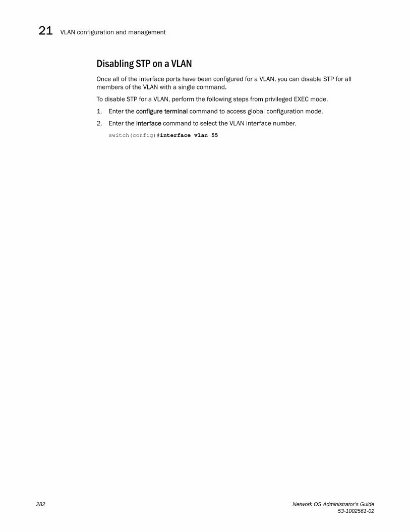
VLAN configuration and management21
Disabling STP on a VLANOnce all of the interface ports have been configured for a VLAN, you can disable STP for all members of the VLAN with a single command.
To disable STP for a VLAN, perform the following steps from privileged EXEC mode.
1. Enter the configure terminal command to access global configuration mode.
2. Enter the interface command to select the VLAN interface number.
switch(config)#interface vlan 55
282 Network OS Administrator’s Guide53-1002561-02

VLAN configuration and management 21
3. Enter the spanning-tree shutdown command to disable spanning tree on VLAN 1002.
switch(conf-if-vl-55)#spanning-tree shutdown
Configuring an interface port as a Layer 2 switch portTo configure the interface as a Layer 2 switch port, perform the following steps from privileged EXEC mode.
1. Enter the configure terminal command to access global configuration mode.
2. Enter the interface command to specify the DCB interface type and slot/port number.
The gigabitethernet rbridge-id/slot/port operand is used only for the Brocade VDX 6710, Brocade VDX 8770-4, and Brocade VDX 8770-8 in VCS mode. The prompt for these ports is in the format: switch(config-if-gi-22/0/1)#
switch(config)#interface tengigabitethernet 0/1
3. Enter the no shutdown command to enable the DCB interface.
4. Enter the switchport command to configure the interface as a Layer 2 switch port.
5. Enter the do show command to confirm the status of the DCB interface. For example
switch(conf-if-te-0/1)#do show interface tengigabitethernet 0/1
6. Enter the do show command to confirm the status of the DCB interface running configuration.
switch(conf-if-te-0/1)#do show running-config interface tengigabitethernet 0/1
Configuring an interface port as an access interface Each DCB interface port supports admission policies based on whether the frames are untagged or tagged. Access mode admits only untagged and priority-tagged frames.
To configure the interface as an access interface, perform the following steps from privileged EXEC mode.
1. Enter the configure terminal command to access global configuration mode.
2. Enter the interface command to specify the DCB interface type and slot/port number.
The gigabitethernet rbridge-id/slot/port operand is used only for the Brocade VDX 6710, Brocade VDX 8770-4, and Brocade VDX 8770-8 in VCS mode. The prompt for these ports is in the format: switch(config-if-gi-22/0/1)#
switch(config)#interface tengigabitethernet 0/1
3. Enter the no shutdown command to enable the DCB interface.
4. Enter the switchport command to make the interface a Layer 2 switch port.
switch(conf-if-te-0/1)# switchport
5. Enter the switchport command again to configure the DCB interface as a VLAN.
switch(conf-if-te-0/1)#switchport access vlan 20
Network OS Administrator’s Guide 28353-1002561-02

VLAN configuration and management21
Configuring an interface port as a trunk interfaceEach DCB interface port supports admission policies based on whether the frames are untagged or tagged. Trunk mode admits only VLAN-tagged frames.
To configure the interface as a trunk interface, perform the following steps from privileged EXEC mode.
1. Enter the configure terminal command to access global configuration mode.
2. Enter the interface command to specify the DCB interface type and slot/port number.
The gigabitethernet rbridge-id/slot/port operand is used only for the Brocade VDX 6710, Brocade VDX 8770-4, and Brocade VDX 8770-8 in VCS mode. The prompt for these ports is in the format: switch(config-if-gi-22/0/1)#
switch(config)#interface tengigabitethernet 0/19
3. Enter the no shutdown command to enable the DCB interface.
4. Enter the switchport command to place the DCB interface into trunk mode.
switch(conf-if-te-0/19)#switchport mode trunk
5. Specify whether all, one, or none of the VLAN interfaces are allowed to transmit and receive through the DCB interface. Enter the following command that is appropriate for your needs.
• This example allows the VLAN numbered as 30 to transmit/receive through the DCB interface:
switch(conf-if-te-0/19)#switchport trunk allowed vlan add 30
• To allow all VLANs to transmit/receive through the DCB interface:
switch(conf-if-te-0/19)#switchport trunk allowed vlan all
• This example allows all except VLAN 11 to transmit/receive through the DCB interface:
switch(conf-if-te-0/19)#switchport trunk allowed vlan except 11
• To allow none of the VLANs to transmit/receive through the DCB interface:
switch(conf-if-te-0/19)#switchport trunk allowed vlan none
Disabling a VLAN on a trunk interfaceTo disable a VLAN on a trunk interface, perform the following steps from privileged EXEC mode.
1. Enter the configure terminal command to access global configuration mode.
2. Enter the interface command to specify the DCB interface type and slot/port number.
The gigabitethernet rbridge-id/slot/port operand is used only for the Brocade VDX 6710, Brocade VDX 8770-4, and Brocade VDX 8770-8 in VCS mode. The prompt for these ports is in the format: switch(config-if-gi-22/0/1)#
switch(config)#interface tengigabitethernet 0/10
3. Enter the no shutdown command to enable the DCB interface.
4. Enter the switchport command to place the DCB interface into trunk mode.
switch(conf-if-te-0/10)#switchport mode trunk none
5. Enter the switchport command again to remove the VLAN ranges from the trunk port.
284 Network OS Administrator’s Guide53-1002561-02

Configuring protocol-based VLAN classifier rules 21
switch(conf-if-te-0/10)# switchport trunk allowed vlan remove 30
Configuring protocol-based VLAN classifier rulesYou can configure VLAN classifier rules to define specific rules for classifying frames to selected VLANs based on protocol and MAC addresses. Sets of rules can be grouped into VLAN classifier groups (see “Creating a VLAN classifier group and adding rules” on page 286).
VLAN classifier rules (1 through 256) are a set of configurable rules that reside in one of these categories:
• 802.1Q protocol-based classifier rules
• Source MAC address-based classifier rules
• Encapsulated Ethernet classifier rules
NOTEMultiple VLAN classifier rules can be applied per interface provided the resulting VLAN IDs are unique for the different rules.
802.1Q protocol-based VLANs apply only to untagged frames, or frames with priority tagging.
With both Ethernet-II and 802.2 SNAP encapsulated frames, the following protocol types are supported:
• Ethernet hexadecimal (0x0000 through 0xffff)
• Address Resolution Protocol (ARP)
• Fibre Channel over Ethernet (FCoE)
• FCoE Initialization Protocol (FIP)
• IP version 6 (IPv6)
NOTEFor complete information on all available VLAN classifier rule options, see the Converged Enhanced Ethernet Command Reference.
Configuring a VLAN classifier ruleTo configure a ARP protocol-based VLAN classifier rule, perform the following steps from privileged EXEC mode.
1. Enter the configure terminal command to access global configuration mode.
2. Enter the vlan classifier rule command to configure a protocol-based VLAN classifier rule.
switch(config)#vlan classifier rule 1 proto ARP encap ethv2
NOTESee the Converged Enhanced Ethernet Command Reference for complete information on all the protocols available for the vlan classifier rule command.
Network OS Administrator’s Guide 28553-1002561-02

Configuring protocol-based VLAN classifier rules21
Configuring MAC address-based VLAN classifier rulesTo configure a MAC address-based VLAN classifier rule, perform the following steps from privileged EXEC mode.
1. Enter the configure terminal command to access global configuration mode.
2. Enter the vlan classifier rule command to configure a MAC address-based VLAN classifier rule.
switch(config)#vlan classifier rule 5 mac 0008.744c.7fid
Deleting a VLAN classifier ruleVLAN classifier groups (1 through 16) can contain any number of VLAN classifier rules.
To configure a VLAN classifier group and remove a VLAN classifier rule, perform the following steps from privileged EXEC mode.
1. Enter the configure terminal command to access global configuration mode.
2. Specify a VLAN classifier group and delete a rule.
switch(config)#vlan classifier group 1 delete rule 1
Creating a VLAN classifier group and adding rulesVLAN classifier groups (1 through 16) can contain any number of VLAN classifier rules.
To configure a VLAN classifier group and add a VLAN classifier rule, perform the following steps from privileged EXEC mode.
1. Enter the configure terminal command to access global configuration mode.
2. Create a VLAN classifier group and add a rule.
switch(config)#vlan classifier group 1 add rule 1
Activating a VLAN classifier group with an interface portTo associate a VLAN classifier group with an interface port, perform the following steps from privileged EXEC mode.
1. Enter the configure terminal command to access global configuration mode.
2. Enter the interface command to specify the DCB interface type and slot/port number.
The gigabitethernet rbridge-id/slot/port operand is used only for the Brocade VDX 6710, Brocade VDX 8770-4, and Brocade VDX 8770-8 in VCS mode. The prompt for these ports is in the format: switch(config-if-gi-22/0/1)#
switch(config)#interface tengigabitethernet 0/10
3. Enter the no shutdown command to enable the DCB interface.
4. Enter the vlan classifier command to activate and associate it with a VLAN interface (group 1 and VLAN 2 are used in this example).
switch(conf-if-te-0/10)#vlan classifier activate group 1 vlan 2
286 Network OS Administrator’s Guide53-1002561-02

Configuring the MAC address table 21
NOTEThis example assumes that VLAN 2 was already created.
Displaying VLAN informationTo display VLAN information, perform the following steps from privileged EXEC mode.
1. Enter the show interface command to display the configuration and status of the specified interface.
The gigabitethernet rbridge-id/slot/port operand is used only for the Brocade VDX 6710, Brocade VDX 8770-4, and Brocade VDX 8770-8 in VCS mode. The prompt for these ports is in the format: switch(config-if-gi-22/0/1)#
switch#show interface tengigabitethernet 0/10 port-channel 10 switchport
2. Enter the show vlan command to display the specified VLAN information. For example, this syntax displays the status of VLAN 20 for all interfaces, including static and dynamic:
switch#show vlan 20
Configuring the MAC address tableEach DCB port has a MAC address table. The MAC address table stores a number of unicast and multicast address entries without flooding any frames. Brocade VDX hardware has a configurable aging timer. If a MAC address remains inactive for a specified number of seconds, it is removed from the address table. For detailed information on how the switch handles MAC addresses in a Layer 2 Ethernet environment, see “Layer 2 Ethernet overview” on page 263.
Specifying or disabling the aging time for MAC addressesYou can set the length of time that a dynamic entry remains in the MAC address table after the entry is used or updated. Static address entries are never aged or removed from the table. You can also disable the aging time. The default is 300 seconds.
NOTETo disable the aging time for MAC addresses, enter an aging time value of 0.
To specify an aging time or disable the aging time for MAC addresses, perform the following steps from privileged EXEC mode.
1. Enter the configure terminal command to access global configuration mode.
2. Enter the appropriate command based on whether you want to specify an aging time or disable the aging time for MAC addresses:
switch(config)#mac-address-table aging-time 600
Network OS Administrator’s Guide 28753-1002561-02

Configuring the MAC address table21
Adding static addresses to the MAC address tableTo add a static address to the MAC address table, perform the following steps from privileged EXEC mode.
1. Enter the configure terminal command to access global configuration mode.
2. Add the static address 0011.2222.3333 to the MAC address table with a packet received on VLAN 100:
switch(config)#mac-address-table static 0011.2222.3333 forward tengigabitethernet 0/1 vlan 100
288 Network OS Administrator’s Guide53-1002561-02
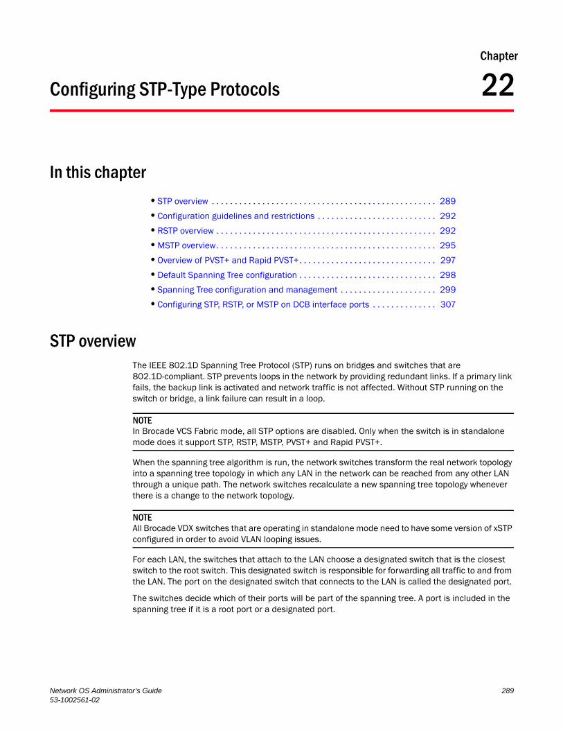
Network OS Administrator’s Guide53-1002561-02
Chapter
22
Configuring STP-Type ProtocolsIn this chapter
•STP overview . . . . . . . . . . . . . . . . . . . . . . . . . . . . . . . . . . . . . . . . . . . . . . . . . 289
•Configuration guidelines and restrictions . . . . . . . . . . . . . . . . . . . . . . . . . . 292
•RSTP overview . . . . . . . . . . . . . . . . . . . . . . . . . . . . . . . . . . . . . . . . . . . . . . . . 292
•MSTP overview. . . . . . . . . . . . . . . . . . . . . . . . . . . . . . . . . . . . . . . . . . . . . . . . 295
•Overview of PVST+ and Rapid PVST+. . . . . . . . . . . . . . . . . . . . . . . . . . . . . . 297
•Default Spanning Tree configuration . . . . . . . . . . . . . . . . . . . . . . . . . . . . . . 298
•Spanning Tree configuration and management . . . . . . . . . . . . . . . . . . . . . 299
•Configuring STP, RSTP, or MSTP on DCB interface ports . . . . . . . . . . . . . . 307
STP overviewThe IEEE 802.1D Spanning Tree Protocol (STP) runs on bridges and switches that are 802.1D-compliant. STP prevents loops in the network by providing redundant links. If a primary link fails, the backup link is activated and network traffic is not affected. Without STP running on the switch or bridge, a link failure can result in a loop.
NOTEIn Brocade VCS Fabric mode, all STP options are disabled. Only when the switch is in standalone mode does it support STP, RSTP, MSTP, PVST+ and Rapid PVST+.
When the spanning tree algorithm is run, the network switches transform the real network topology into a spanning tree topology in which any LAN in the network can be reached from any other LAN through a unique path. The network switches recalculate a new spanning tree topology whenever there is a change to the network topology.
NOTEAll Brocade VDX switches that are operating in standalone mode need to have some version of xSTP configured in order to avoid VLAN looping issues.
For each LAN, the switches that attach to the LAN choose a designated switch that is the closest switch to the root switch. This designated switch is responsible for forwarding all traffic to and from the LAN. The port on the designated switch that connects to the LAN is called the designated port.
The switches decide which of their ports will be part of the spanning tree. A port is included in the spanning tree if it is a root port or a designated port.
289

STP overview22
With STP, data traffic is allowed only on those ports that are part of the spanning tree topology. Ports that are not part of the spanning tree topology are automatically changed to a blocking (inactive) state. They are kept in the blocking state until there is a break in the spanning tree topology, at which time they are automatically activated to provide a new path.
The STP interface states for every Layer 2 interface running STP are as follows:
• Blocking—The interface does not forward frames.
• Listening—The interface is identified by the spanning tree as one that should participate in frame forwarding. This is a transitional state after the blocking state.
• Learning—The interface prepares to participate in frame forwarding.
• Forwarding—The interface forwards frames.
• Disabled—The interface is not participating in spanning tree because of a shutdown port, no link on the port, or no spanning tree instance running on the port.
A port participating in spanning tree moves through these states:
• From initialization to blocking.
• From blocking to listening or to disabled.
• From listening to learning or to disabled.
• From learning to forwarding, blocking, or disabled.
• From forwarding to disabled.
The following STP features are considered optional features although you might use them in your STP configuration:
• Root guard—For detailed information, see “Enabling the guard root” on page 309.
• Port fast BPDU guard and BPDU filter—For detailed information, see “Enabling port fast (STP)” on page 312.
Configuring STP
NOTEThe gigabitethernet rbridge-id/slot/port operand is used only for the Brocade VDX 6710, Brocade VDX 8770-4, and Brocade VDX 8770-8. The prompt for these ports is in the format: switch(config-if-gi-22/0/1)#
The process for configuring STP is as follows.
1. Enter global configuration mode.
2. Enable PVST+ using the global protocol spanning-tree command. For details, see “Enabling STP, RSTP, MSTP, R-PVST+ or PVST+” on page 299.
switch(config)#protocol spanning-tree stp
3. Designate the root switch using the bridge-priority command. For details, see “Specifying the bridge priority” on page 300. The range is 0 through 61440 and the priority values can be set only in increments of 4096.
switch(conf-stp)#bridge-priority 28672
4. Optional: Enable port fast on switch ports using the spanning-tree portfast command. For details, see “Enabling port fast (STP)” on page 312.
290 Network OS Administrator’s Guide53-1002561-02

STP overview 22
NOTEPort fast only needs to be enabled on ports that connect to workstations or PCs. Repeat these commands for every port connected to workstations or PCs. Do not enable port fast on ports that connect to other switches.
NOTEEnabling port fast on ports can cause temporary bridging loops, in both trunking and non-trunking mode.
switch(config)#interface tengigabitethernet 0/10switch(conf-if-te-0/10)#spanning-tree portfastswitch(conf-if-te-0/10)#exitswitch(config)#interface tengigabitethernet 0/11switch(conf-if-te-0/11)#spanning-tree portfastswitch(conf-if-te-0/11)#exit
Repeat these commands for every port connected to workstations or PCs.
5. Optional: To interoperate with non-brocade switches in PVST+/R-PVST+ mode, you may need to configure the interface that is connected to that switch with the following spanning-tree bpdu-mac command.
switch(config)#interface tengigabitethernet 0/12switch(conf-if-te-0/12)#spanning-tree bpdu-mac 0100.0ccc.cccd
6. Specify port priorities using the spanning-tree priority command to influence the selection of root/designated ports on:
• All ports of the root switch
• The root port
• The designated port
7. Optional: Enable the guard root feature with the spanning-tree guard root command. The guard root feature provides a way to enforce the root bridge placement in the network. For detailed information, refer to“Enabling the guard root” on page 309.
All other switch ports connect to other switches and bridges are automatically placed in blocking mode.
This does not apply to ports connected to workstations or PCs; these ports remain in the forwarding state.
8. Return to privileged EXEC mode.
switch(conf-if-te-0/12)#end
9. Enter the copy command to save the running-config file to the startup-config file.
switch#copy running-config startup-config
When the spanning tree topology is completed, the network switches send and receive data only on the ports that are part of the spanning tree. Data received on ports that are not part of the spanning tree is blocked.
NOTEBrocade recommends leaving other STP variables at their default values.
For more information on STP, see “Spanning Tree configuration and management” on page 299.
Network OS Administrator’s Guide 29153-1002561-02

Configuration guidelines and restrictions22
Configuration guidelines and restrictionsFollow these configuration guidelines and restrictions when configuring Spanning Tree:
• The Brocade VDX 8770 does not support STP.
• You have to disable one form of xSTP before enabling another.
• Packet drops or packet flooding may occur if you do not enable xSTP on all devices connected on both sides of parallel links.
• LAGs are treated as normal links, and by default are enabled for STP.
• You can have 32 MSTP instances and one MSTP region.
• Create VLANs before mapping them to MSTP instances.
• The MSTP force-version option is not supported.
• In order for STP to function across a Brocade VCS Fabric cluster, the option for tagging native VLAN packets must be disabled on the edge ports. Native VLAN tagging is enabled by default.
• When a misconfigured local area network running spanning tree has one or more loops, a traffic storm of spanning tree BPDUs can occur. In certain circumstances, VDX can reboot when subjected to an extended period of traffic storm involving spanning tree BPDUs.
• Additionally, when a misconfigured local area network running spanning tree has one or more loops, a traffic storm of spanning tree BPDUs can occur. Edge Loop Detection protocol cannot eliminate loops during a traffic storm involving control packets, such as spanning tree BPDUs.
• Do not force an alternate root path through root path cost with PVST+ or R-PVST+ on legacy Foundry equipment, such as the Brocade NetIron MLX or Brocade TurboIron. This can cause traffic issues on the network.
• For load balancing across redundant paths in the network to work, all VLAN-to-instance mapping assignments must match; otherwise, all traffic flows on a single link.
• When you enable MSTP by using the global protocol spanning-tree mstp command, RSTP is automatically enabled.
• For two or more switches to be in the same MSTP region, they must have the same VLAN-to-instance map, the same configuration revision number, and the same name.
• Spanning Tree topologies must not be enabled on any direct server connections to the front-end Ten Gigabit Ethernet ports that may run FCoE traffic. This may result in lost or dropped FCoE logins.
• The gigabitethernet rbridge-id/slot/port operand is used only for the Brocade VDX 6710, Brocade VDX 8770-4, and Brocade VDX 8770-8. The prompt for these ports is in the format: switch(config-if-gi-22/0/1)#
RSTP overview
NOTERSTP is designed to be compatible and interoperate with STP. However, the advantages of the RSTP fast reconvergence are lost when it interoperates with switches running STP.
292 Network OS Administrator’s Guide53-1002561-02

RSTP overview 22
The IEEE 802.1w Rapid Spanning Tree Protocol (RSTP) standard is an evolution of the 802.1D STP standard. It provides rapid reconvergence following the failure of a switch, a switch port, or a LAN. It provides rapid reconvergence of edge ports, new root ports, and ports connected through point-to-point links.
The RSTP interface states for every Layer 2 interface running RSTP are as follows:
• Learning—The interface prepares to participate in frame forwarding.
• Forwarding—The interface forwards frames.
• Discarding—The interface discards frames. Note that the 802.1D disabled, blocking, and listening states are merged into the RSTP discarding state. Ports in the discarding state do not take part in the active topology and do not learn MAC addresses.
Table 46 lists the interface state changes between STP and RSTP.
With RSTP, the port roles for the new interface states are also different. RSTP differentiates explicitly between the state of the port and the role it plays in the topology. RSTP uses the root port and designated port roles defined by STP, but splits the blocked port role into backup port and alternate port roles:
• Backup port—Provides a backup for the designated port and can only exist where two or more ports of the switch are connected to the same LAN; the LAN where the bridge serves as a designated switch.
• Alternate port—Serves as an alternate port for the root port providing a redundant path towards the root bridge.
Only the root port and the designated ports are part of the active topology; the alternate and backup ports do not participate in it.
When the network is stable, the root and the designated ports are in the forwarding state, while the the alternate and backup ports are in the discarding state. When there is a topology change, the new RSTP port roles allow a faster transition of an alternate port into the forwarding state.
For more information on RSTP, see “Spanning Tree configuration and management” on page 299.
Configuring RSTP The basic process for configuring RSTP is as follows.
1. Enter global configuration mode.
2. Enable RSTP using the global protocol spanning-tree command. For details, see “Enabling STP, RSTP, MSTP, R-PVST+ or PVST+” on page 299.
switch(config)#protocol spanning-tree rstp
TABLE 46 STP versus RSTP state comparison
STP interface state RSTP interface state Is the interface included in the active topology?
Is the interface learning MAC addresses?
Disabled Discarding No No
Blocking Discarding No No
Listening Discarding Yes No
Learning Learning Yes Yes
Forwarding Forwarding Yes Yes
Network OS Administrator’s Guide 29353-1002561-02

RSTP overview22
3. Designate the root switch using the bridge-priority command. For more details, see “Specifying the bridge priority” on page 300. The range is 0 through 61440 and the priority values can be set only in increments of 4096.
switch(conf-stp)#bridge-priority 28582
4. Configure the bridge forward delay value. For more details, see “Specifying the bridge forward delay” on page 301.
switch(conf-stp)#forward-delay 20
5. Configure the bridge maximum aging time value. For more details, see “Specifying the bridge maximum aging time” on page 301.
switch(conf-stp)#max-age 25
6. Enable the error disable timeout timer value. For more details, see “Enabling the error disable timeout timer” on page 302.
switch(conf-stp)#error-disable-timeout enable
7. Configure the error-disable-timeout interval value. For more details, see “Specifying the error disable timeout interval” on page 302.
switch(conf-stp)#error-disable-timeout interval 60
8. Configure the port-channel path cost. For more details, see “Specifying the port-channel path cost” on page 302.
switch(conf-stp)#port-channel path-cost custom
9. Configure the bridge hello time value. For more details, see “Specifying the bridge hello time” on page 303.
switch(conf-stp)#hello-time 5
10. Optional: Enable port fast on switch ports using the spanning-tree portfast command. For more details, see “Enabling port fast (STP)” on page 312.
The gigabitethernet rbridge-id/slot/port operand is used only for the Brocade VDX 6710, Brocade VDX 8770-4, and Brocade VDX 8770-8. The prompt for these ports is in the format: switch(config-if-gi-22/0/1)#
NOTEPort fast only needs to be enabled on ports that connect to workstations or PCs. Repeat these commands for every port connected to workstations or PCs. Do not enable Port fast on ports that connect to other switches.
NOTEEnabling port fast on ports can cause temporary bridging loops, in both trunking and non-trunking mode.
switch(config)#interface tengigabitethernet 0/10switch(conf-if-te-0/10)#spanning-tree portfastswitch(conf-if-te-0/10)#exitswitch(config)#interface tengigabitethernet 0/11switch(conf-if-te-0/11)#spanning-tree portfastswitch(conf-if-te-0/11)#exitswitch(config)#
Repeat these commands for every port connected to workstations or PCs.
294 Network OS Administrator’s Guide53-1002561-02

MSTP overview 22
11. Specify port priorities using the spanning-tree priority command to influence the selection of root/designated ports on:
• All ports of the root switch
• The root port
• The designated port
For details, see “Specifying the port priority” on page 312.
12. Optional: Enable the guard root feature with the spanning-tree guard root command. The guard root feature provides a way to enforce the root bridge placement in the network. For detailed information, refer to “Enabling the guard root” on page 309.
All other switch ports connected to other switches and bridges are automatically placed in blocking mode.
This does not apply to ports connected to workstations or PCs; these ports remain in the forwarding state.
13. Return to privileged EXEC mode.
switch(config)#end
14. Enter the copy command to save the running-config file to the startup-config file.
switch#copy running-config startup-config
MSTP overviewThe IEEE 802.1s Multiple STP (MSTP) helps create multiple loop-free active topologies on a single physical topology. MSTP enables multiple VLANs to be mapped to the same spanning tree instance (forwarding path), which reduces the number of spanning tree instances needed to support a large number of VLANs. Each MSTP instance has a spanning tree topology independent of other spanning tree instances. With MSTP you can have multiple forwarding paths for data traffic. A failure in one instance does not affect other instances. With MSTP, you are able to more effectively utilize the physical resources present in the network and achieve better load balancing of VLAN traffic.
NOTEIn MSTP mode, RSTP is automatically enabled to provide rapid convergence.
Multiple switches must be configured consistently with the same MSTP configuration to participate in multiple spanning tree instances. A group of interconnected switches that have the same MSTP configuration is called an MSTP region.
NOTEBrocade supports 32 MSTP instances and one MSTP region.
MSTP introduces a hierarchical way of managing switch domains using regions. Switches that share common MSTP configuration attributes belong to a region. The MSTP configuration determines the MSTP region where each switch resides. The common MSTP configuration attributes are as follows:
• Alphanumeric configuration name (32 bytes)
• Configuration revision number (2 bytes)
Network OS Administrator’s Guide 29553-1002561-02

MSTP overview22
• 4096-element table that maps each of the VLANs to an MSTP instance
Region boundaries are determined based on the above attributes. A multiple spanning tree instance is an RSTP instance that operates inside an MSTP region and determines the active topology for the set of VLANs mapping to that instance. Every region has a common internal spanning tree (CIST) that forms a single spanning tree instance that includes all the switches in the region. The difference between the CIST instance and the MSTP instance is that the CIST instance operates across the MSTP region and forms a loop-free topology across regions, while the MSTP instance operates only within a region. The CIST instance can operate using RSTP if all the switches across the regions support RSTP. However, if any of the switches operate using 802.1D STP, the CIST instance reverts to 802.1D. Each region is viewed logically as a single STP/RSTP bridge to other regions.
Configuring MSTP The basic process for configuring MSTP is as follows.
1. Enter global configuration mode.
2. Enable MSTP using the global protocol spanning-tree command. For more details see “Enabling STP, RSTP, MSTP, R-PVST+ or PVST+” on page 299.
switch(config)#protocol spanning-tree mstp
3. Specify the region name using the region region_name command. For more details see “Specifying a name for an MSTP region” on page 305.
switch(config-mstp)#region brocade1
4. Specify the revision number using the revision command. For more details see “Specifying a revision number for MSTP configuration” on page 306.
switch(config-mstp)#revision 1
5. Map a VLAN to an MSTP instance using the instance command. For more details see “Mapping a VLAN to an MSTP instance” on page 305.
switch(config-mstp)#instance 1 vlan 2, 3switch(config-mstp)#instance 2 vlan 4-6switch(config-mstp)#instance 1 priority 4096
6. Specify the maximum hops for a BPDU to prevent the messages from looping indefinitely on the interface using the max-hops hop_count command. For more details see “Specifying the maximum number of hops for a BPDU (MSTP)” on page 305.
switch(config-mstp)#max-hops 25
7. Return to privileged EXEC mode.
switch(config)#end
8. Enter the copy command to save the running-config file to the startup-config file.
switch#copy running-config startup-config
For more information on MSTP, see “Spanning Tree configuration and management” on page 299.
296 Network OS Administrator’s Guide53-1002561-02

Overview of PVST+ and Rapid PVST+ 22
Overview of PVST+ and Rapid PVST+ A network topology of bridges typically contains redundant connections to provide alternate paths in case of link failures. But since there is no concept of TTL in Ethernet frames, this could result in permanent circulation of frames if there are loops in the network. To prevent loops, a spanning tree connecting all the bridges is formed in real time. The redundant ports are put in a blocking (non-forwarding) state. They are enabled when required.
In order to build a spanning tree for the bridge topology, the bridges must exchange control frames (BPDU – Bridge Protocol Data Unit). The protocols define the semantics of the BPDUs and the required state machine. The first Spanning Tree Protocol (STP) became part of the IEEE 802.1d standard.
But the convergence time of STP is 50 seconds in the case of link failures. This soon became increasingly unacceptable. Keeping the main skeleton of STP the same, the state machine was changed to speed up the convergence time as part of the Rapid Spanning Tree protocol (RSTP). RSTP became part of the standard IEEE 802.1w.
But both STP and RSTP build a single logical topology. A typical network has multiple VLANs. A single logical topology does not efficiently utilize the availability of redundant paths for multiple VLANs. If a port is set to ‘blocked/discarding’ for one VLAN (under STP/RSTP), it is the same for all other VLANs too.
Per-VLAN Spanning Tree Plus (PVST+) protocol runs a spanning tree instance for each VLAN in the network. The version of PVST+ that uses the RSTP state machine is called Rapid-PVST Plus (R-PVST+). R-PVST+ has one instance of spanning tree for each VLAN on the switch.
But PVST+ is not a scalable model when there are many VLANs in the network, as it consumes a lot of CPU power. A reasonable compromise between the two extremes of RSTP and R-PVST+ is the Multiple Spanning Tree protocol (MSTP), which was standardized as IEEE 802.1s and later incorporated into the IEEE 802.1Q-2003 standard. MSTP runs multiple instances of spanning tree which are independent of VLANs. It then maps a set of VLANs to each instance.
NOTEBrocade Network OS v3.0.0 supports PVST+ and R-PVST+only. The PVST and R-PVST protocols are proprietary to Cisco and are not supported.
To configure PVST+ or R-PVST+, use the protocol spanning-tree pvst and protocol spanning-tree rpvst commands. See the Network OS Command Reference for details.
For example, the script below sets up PVST+ for VLAN 10:
switch(config)#protocol spanning-tree pvst switch(conf-pvst)#bridge-priority 4096switch(conf-pvst)#forward-delay 4 switch(conf-pvst)#hello-time 2switch(conf-pvst)#max-age 7
PVST+ and R-PVST+ guidelines and restrictionsConsider the following items when configuring PVST+ and R-PVST+:
• Disabling the tagging of native VLANs is required on STP/RSTP/MSTP switches in standalone mode, otherwise PVST+/R-PVST+ does not converge and forms a loop on the native VLAN. The tagged native VLAN data traffic is ignored. The native vlan untagged data is forwarded.
Network OS Administrator’s Guide 29753-1002561-02

Default Spanning Tree configuration22
• Disabling the tagging of native VLANs is required on edge ports in fabric cluster mode, otherwise PVST+/R-PVST+ does not converge and forms a loop on the native VLAN. The tagged native VLAN data traffic is ignored. The native vlan untagged data is forwarded.
• If a VLAN is configured with tagged ports that do not have PVST+ mode enabled on the interface and are connected to the VDXs, and RSTP is enabled under the VLAN (PVST+), then BPDUs from the tagged ports that are received by the VDX are dropped.
Default Spanning Tree configurationTable 47 lists the default Spanning Tree configuration.
Table 48 lists the switch defaults that apply only to MSTP configurations.
Table 49 lists the switch defaults for the 10-Gigabit Ethernet DCB interface-specific configuration.
TABLE 47 Default Spanning Tree configuration
Parameter Default setting
Spanning-tree mode By default, STP, RSTP, and MSTP are disabled
Bridge priority 32768
Bridge forward delay 15 seconds
Bridge maximum aging time 20 seconds
Error disable timeout timer Disabled
Error disable timeout interval 300 seconds
Port-channel path cost Standard
Bridge hello time 2 seconds
TABLE 48 Default MSTP configuration
Parameter Default setting
Cisco interoperability Disabled
Switch priority (when mapping a VLAN to an MSTP instance)
32768
Maximum hops 20 hops
Revision number 0
TABLE 49 Default 10-Gigabit Ethernet DCB interface-specific configuration
Parameter Default setting
Spanning tree Disabled on the interface
Automatic edge detection Disabled
Path cost 2000
Edge port Disabled
Guard root Disabled
Hello time 2 seconds
Link type Point-to-point
298 Network OS Administrator’s Guide53-1002561-02

Spanning Tree configuration and management 22
Spanning Tree configuration and management
NOTEEnter the copy running-config startup-config command to save your configuration changes.
Enabling STP, RSTP, MSTP, R-PVST+ or PVST+You enable STP to detect or avoid loops. STP is not required in a loop-free topology. You must turn off one form of STP before turning on another form. By default, STP, RSTP, and MSTP are not enabled.
Perform the following steps from privileged EXEC mode.
1. Enter the configure terminal command to access global configuration mode.
2. Enter the protocol command to enable STP, RSTP, MSTP, PVST+, or R-PVST+.
switch(config)#protocol spanning-tree rstp
Disabling STP, RSTP, or MSTP
NOTEUsing the no protocol spanning-tree command deletes the context and all the configurations defined within the context or protocol for the interface.
To disable STP, RSTP, or MSTP, perform the following steps from privileged EXEC mode. By default, STP, RSTP, and MSTP are not enabled.
1. Enter the configure terminal command to access global configuration mode.
2. Enter the protocol command to disable STP, RSTP, MSTP, PVST+, or R-PVST+.
switch(config)#no protocol spanning-tree
Port fast Disabled
Port priority 128
DCB interface root port Allow the DCB interface to become a root port.
DCB interface BPDU restriction Restriction is disabled
TABLE 49 Default 10-Gigabit Ethernet DCB interface-specific configuration (Continued)
Parameter Default setting
Network OS Administrator’s Guide 29953-1002561-02
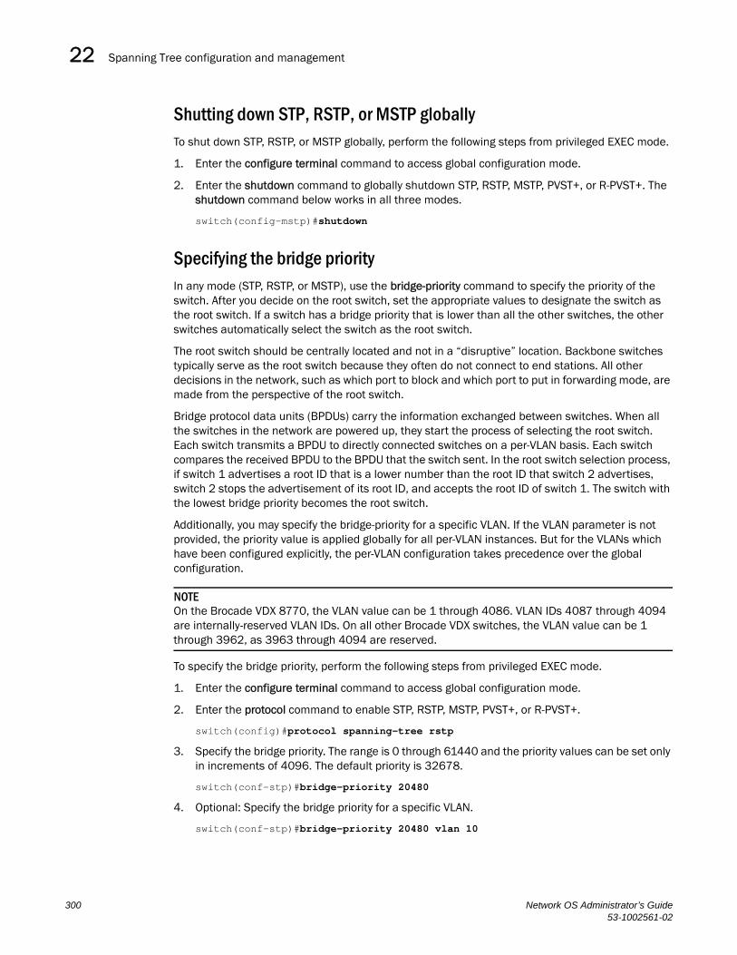
Spanning Tree configuration and management22
Shutting down STP, RSTP, or MSTP globallyTo shut down STP, RSTP, or MSTP globally, perform the following steps from privileged EXEC mode.
1. Enter the configure terminal command to access global configuration mode.
2. Enter the shutdown command to globally shutdown STP, RSTP, MSTP, PVST+, or R-PVST+. The shutdown command below works in all three modes.
switch(config-mstp)#shutdown
Specifying the bridge priorityIn any mode (STP, RSTP, or MSTP), use the bridge-priority command to specify the priority of the switch. After you decide on the root switch, set the appropriate values to designate the switch as the root switch. If a switch has a bridge priority that is lower than all the other switches, the other switches automatically select the switch as the root switch.
The root switch should be centrally located and not in a “disruptive” location. Backbone switches typically serve as the root switch because they often do not connect to end stations. All other decisions in the network, such as which port to block and which port to put in forwarding mode, are made from the perspective of the root switch.
Bridge protocol data units (BPDUs) carry the information exchanged between switches. When all the switches in the network are powered up, they start the process of selecting the root switch. Each switch transmits a BPDU to directly connected switches on a per-VLAN basis. Each switch compares the received BPDU to the BPDU that the switch sent. In the root switch selection process, if switch 1 advertises a root ID that is a lower number than the root ID that switch 2 advertises, switch 2 stops the advertisement of its root ID, and accepts the root ID of switch 1. The switch with the lowest bridge priority becomes the root switch.
Additionally, you may specify the bridge-priority for a specific VLAN. If the VLAN parameter is not provided, the priority value is applied globally for all per-VLAN instances. But for the VLANs which have been configured explicitly, the per-VLAN configuration takes precedence over the global configuration.
NOTEOn the Brocade VDX 8770, the VLAN value can be 1 through 4086. VLAN IDs 4087 through 4094 are internally-reserved VLAN IDs. On all other Brocade VDX switches, the VLAN value can be 1 through 3962, as 3963 through 4094 are reserved.
To specify the bridge priority, perform the following steps from privileged EXEC mode.
1. Enter the configure terminal command to access global configuration mode.
2. Enter the protocol command to enable STP, RSTP, MSTP, PVST+, or R-PVST+.
switch(config)#protocol spanning-tree rstp
3. Specify the bridge priority. The range is 0 through 61440 and the priority values can be set only in increments of 4096. The default priority is 32678.
switch(conf-stp)#bridge-priority 20480
4. Optional: Specify the bridge priority for a specific VLAN.
switch(conf-stp)#bridge-priority 20480 vlan 10
300 Network OS Administrator’s Guide53-1002561-02

Spanning Tree configuration and management 22
Specifying the bridge forward delayIn any mode (STP, RSTP, or MSTP), use this command to specify how long an interface remains in the listening and learning states before the interface begins forwarding all spanning tree instances.
The range is 4 through 30 seconds. The default is 15 seconds. The following relationship should be kept:
2*(forward_delay - 1)>=max_age>=2*(hello_time + 1)
Additionally, you may specify the forward delay for a specific VLAN. If the VLAN parameter is not provided, the priority value is applied globally for all per-VLAN instances. But for the VLANs which have been configured explicitly, the per-VLAN configuration takes precedence over the global configuration.
On the Brocade VDX 8770, the VLAN value can be 1 through 4086. VLAN IDs 4087 through 4094 are internally-reserved VLAN IDs. On all other Brocade VDX switches, the VLAN value can be 1 through 3962, as 3963 through 4094 are reserved.
To specify the bridge forward delay, perform the following steps from privileged EXEC mode.
1. Enter the configure terminal command to access global configuration mode.
2. Enter the protocol command to enable STP, RSTP, MSTP, PVST+, or R-PVST+.
switch(config)#protocol spanning-tree stp
3. Specify the bridge forward delay.
switch(conf-stp)#forward-delay 20
4. Optional: Specify the bridge forward delay for a specific VLAN.
switch(conf-stp)#forward-delay 20 vlan 10
Specifying the bridge maximum aging timeIn any mode (STP, RSTP, or MSTP), use this command to control the maximum length of time that passes before an interface saves its Bridge Protocol Data Unit (BPDU) configuration information.
When configuring the maximum aging time, the max-age setting must be greater than the hello-time setting. The range is 6 through 40 seconds. The default is 20 seconds. The following relationship should be kept:
2*(forward_delay - 1)>=max_age>=2*(hello_time + 1)
Additionally, you may specify the maximum aging for a specific VLAN. If the VLAN parameter is not provided, the priority value is applied globally for all per-VLAN instances. But for the VLANs which have been configured explicitly, the per-VLAN configuration takes precedence over the global configuration.
On the Brocade VDX 8770, the VLAN value can be 1 through 4086. VLAN IDs 4087 through 4094 are internally-reserved VLAN IDs. On all other Brocade VDX switches, the VLAN value can be 1 through 3962, as 3963 through 4094 are reserved.
To specify the bridge maximum aging time, perform the following steps from privileged EXEC mode.
1. Enter the configure terminal command to access global configuration mode.
2. Enter the protocol command to enable STP, RSTP, MSTP, PVST+, or R-PVST+.
switch(config)#protocol spanning-tree stp
Network OS Administrator’s Guide 30153-1002561-02
Spanning Tree configuration and management22
3. Specify the bridge maximum aging time.
switch(conf-stp)#max-age 25
4. Optional: Specify the bridge maximum aging time for a specific VLAN.
switch(conf-stp)#max-age 25 vlan 10
Enabling the error disable timeout timerIn any mode (STP, RSTP, or MSTP), use this command to enable the timer to bring a port out of the disabled state. When the STP BPDU guard disables a port, the port remains in the disabled state unless the port is enabled manually. This command allows you to enable the port from the disabled state. For details on configuring the error disable timeout interval, see “Specifying the error disable timeout interval” on page 302.
To enable the error disable timeout timer, perform the following steps from privileged EXEC mode. By default, the timeout feature is disabled.
1. Enter the configure terminal command to access global configuration mode.
2. Enter the protocol command to enable STP, RSTP, MSTP, PVST+, or R-PVST+.
switch(config)#protocol spanning-tree stp
3. Enable the error disable timeout timer.
switch(conf-stp)#error-disable-timeout enable
Specifying the error disable timeout intervalIn any mode (STP, RSTP, or MSTP), use this command to specify the time in seconds it takes for an interface to time out. The range is 10 through 1000000 seconds. The default is 300 seconds. By default, the timeout feature is disabled.
To specify the time in seconds it takes for an interface to time out, perform the following steps from privileged EXEC mode.
1. Enter the configure terminal command to access global configuration mode.
2. Enter the protocol command to enable STP, RSTP, MSTP, PVST+, or R-PVST+.
switch(config)#protocol spanning-tree stp
3. Specify the time in seconds it takes for an interface to time out.
switch(conf-stp)#error-disable-timeout interval 60
Specifying the port-channel path costIn any mode (STP, RSTP, or MSTP), use this command to specify the port-channel path cost. The default port cost is standard. The path cost options are:
• custom—Specifies that the path cost changes according to the port-channel’s bandwidth.
• standard—Specifies that the path cost does not change according to the port-channel’s bandwidth.
302 Network OS Administrator’s Guide53-1002561-02

Spanning Tree configuration and management 22
To specify the port-channel path cost, perform the following steps from privileged EXEC mode.
1. Enter the configure terminal command to access global configuration mode.
2. Enter the protocol command to enable STP, RSTP, MSTP, PVST+, or R-PVST+.
switch(config)#protocol spanning-tree stp
3. Specify the port-channel path cost.
switch(conf-stp)#port-channel path-cost custom
4. Return to privileged EXEC mode.
switch(config)#end
5. Enter the copy command to save the running-config file to the startup-config file.
switch#copy running-config startup-config
Specifying the bridge hello time In STP or RSTP mode, use this command to configure the bridge hello time. The hello time determines how often the switch interface broadcasts hello Bridge Protocol Data Units (BPDUs) to other devices.The range is 1 through 10 seconds. The default is 2 seconds.
When configuring the hello-time, the max-age setting must be greater than the hello-time setting. The following relationship should be kept:
2*(forward_delay - 1)>=max_age>=2*(hello_time + 1)
Additionally, you may specify the hello time for a specific VLAN. If the VLAN parameter is not provided, the priority value is applied globally for all per-VLAN instances. But for the VLANs which have been configured explicitly, the per-VLAN configuration takes precedence over the global configuration.
On the Brocade VDX 8770, the VLAN value can be 1 through 4086. VLAN IDs 4087 through 4094 are internally-reserved VLAN IDs. On all other Brocade VDX switches, the VLAN value can be 1 through 3962, as 3963 through 4094 are reserved.
To specify the bridge hello time, perform the following steps from privileged EXEC mode.
1. Enter the configure terminal command to access global configuration mode.
2. Enter the protocol command to enable STP, RSTP, MSTP, PVST+, or R-PVST+.
switch(config)#protocol spanning-tree stp
3. Specify the time range in seconds for the interval between the hello BPDUs sent on an interface.
switch(conf-stp)#hello-time 5
4. Optional: Specify the time range in seconds for the interval between the hello BPDUs sent on an interface for a specific VLAN.
switch(conf-stp)#hello-time 5 vlan 10
5. Return to privileged EXEC mode.
switch(config)#end
6. Enter the copy command to save the running-config file to the startup-config file.
switch#copy running-config startup-config
Network OS Administrator’s Guide 30353-1002561-02

Spanning Tree configuration and management22
Specifying the transmit hold count (RSTP, MSTP, and R-PVST+)In RSTP and MSTP mode, use this command to configure the BPDU burst size by specifying the transmit hold count value. The command configures the maximum number of BPDUs transmitted per second for RSTP and MSTP before pausing for 1 second. The range is 1 through 10. The default is 6.
To specify the transmit hold count, perform the following steps from privileged EXEC mode.
1. Enter the configure terminal command to access global configuration mode.
2. Specify the transmit hold count.
switch(config-mstp)#transmit-holdcount 5
3. Return to privileged EXEC mode.
switch(config)#end
4. Enter the copy command to save the running-config file to the startup-config file.
switch#copy running-config startup-config
Enabling Cisco interoperability (MSTP)In MSTP mode, use the cisco-interoperability command to enable or disable the ability to interoperate with certain legacy Cisco switches. If Cisco interoperability is required on any switch in the network, then all switches in the network must be compatible, and therefore enabled using this command. The default is Cisco interoperability is disabled.
NOTEThis command is necessary because the “version 3 length” field in the MSTP BPDU on some legacy Cisco switches does not conform to current standards.
To enable interoperability with certain legacy Cisco switches, perform the following steps from privileged EXEC mode.
1. Enter the configure terminal command to access global configuration mode.
2. Enter the protocol command to enable MSTP.
switch(config)#protocol spanning-tree mstp
3. Enable interoperability with certain legacy Cisco switches.
switch(config-mstp)#cisco-interoperability enable
Disabling Cisco interoperability (MSTP)1. Enter the configure terminal command to access global configuration mode.
2. Enter the protocol command to enable MSTP.
switch(config)#protocol spanning-tree mstp
3. Disable interoperability with certain legacy Cisco switches.
switch(config-mstp)#cisco-interoperability disable
304 Network OS Administrator’s Guide53-1002561-02

Spanning Tree configuration and management 22
Mapping a VLAN to an MSTP instanceIn MSTP mode, use the instance command to map a VLAN to an MTSP. You can group a set of VLANs to an instance. This command can be used only after the VLAN is created. VLAN instance mapping is removed from the configuration if the underlying VLANs are deleted.
To map a VLAN to an MSTP instance, perform the following steps from privileged EXEC mode.
1. Enter the configure terminal command to access global configuration mode.
2. Enter the protocol command to enable MSTP.
switch(config)#protocol spanning-tree mstp
3. Map a VLAN to an MSTP instance.
switch(config-mstp)#instance 5 vlan 300
4. Return to privileged EXEC mode.
switch(config-mstp)#end
5. Enter the copy command to save the running-config file to the startup-config file.
switch#copy running-config startup-config
Specifying the maximum number of hops for a BPDU (MSTP)In MSTP mode, use this command to configure the maximum number of hops for a BPDU in an MSTP region. Specifying the maximum hops for a BPDU prevents the messages from looping indefinitely on the interface. When you change the number of hops, it affects all spanning tree instances. The range is 1 through 40. The default is 20 hops.
To configure the maximum number of hops for a BPDU in an MSTP region, perform the following steps from privileged EXEC mode.
1. Enter the configure terminal command to access global configuration mode.
2. Enter the protocol command to enable MSTP.
switch(config)#protocol spanning-tree mstp
3. Enter the max-hops command to configure the maximum number of hops for a BPDU in an MSTP region.
switch(config-mstp)#max-hops hop_count
4. Return to privileged EXEC mode.
switch(config-mstp)#end
5. Enter the copy command to save the running-config file to the startup-config file.
switch#copy running-config startup-config
Specifying a name for an MSTP regionIn MSTP mode, use this command to assign a name to an MSTP region. The region name has a maximum length of 32 characters and is case-sensitive.
Network OS Administrator’s Guide 30553-1002561-02

Spanning Tree configuration and management22
To assign a name to an MSTP region, perform the following steps from privileged EXEC mode.
1. Enter the configure terminal command to access global configuration mode.
2. Enter the protocol command to enable MSTP.
switch(config)#protocol spanning-tree mstp
3. Enter the region command to assign a name to an MSTP region.
switch(config-mstp)#region sydney
4. Return to privileged EXEC mode.
switch(config-mstp)#end
5. Enter the copy command to save the running-config file to the startup-config file.
switch#copy running-config startup-config
Specifying a revision number for MSTP configurationIn MSTP mode, use this command to specify a revision number for an MSTP configuration. The range is 0 through 255. The default is 0.
To specify a revision number for an MSTP configuration, perform the following steps from privileged EXEC mode.
1. Enter the configure terminal command to access global configuration mode.
2. Enter the protocol command to enable MSTP.
switch(config)#protocol spanning-tree mstp
3. Enter the revision command to specify a revision number for an MSTP configuration.
switch(config-mstp)#revision 17
4. Return to privileged EXEC mode.
switch(config-mstp)#end
5. Enter the copy command to save the running-config file to the startup-config file.
switch#copy running-config startup-config
Clearing spanning tree countersIn privileged EXEC mode, use this command to clear spanning tree counters on all interfaces or on the specified interface.
To clear spanning tree counters, perform the following steps from privileged EXEC mode.
1. Use the clear command to restart the protocol migration process on all the interfaces.
switch#clear spanning-tree counter
2. Use the clear command to restart the protocol migration process associated with a specific port-channel or DCB port interface.
switch#clear spanning-tree counter interface tengigabitethernet 0/1
306 Network OS Administrator’s Guide53-1002561-02

Configuring STP, RSTP, or MSTP on DCB interface ports 22
Clearing spanning tree-detected protocolsIn privileged EXEC mode, restart the protocol migration process (force the renegotiation with neighboring switches) on all interfaces or on the specified interface.
To restart the protocol migration process, perform the following tasks from privileged EXEC mode.
1. Use the clear command to clear all spanning tree counters on all interfaces:
switch#clear spanning-tree detected-protocols
2. Use the clear command to clear the spanning tree counters associated with a specific port-channel or DCB port interface:
switch#clear spanning-tree detected-protocols interface tengigabitethernet 0/1
Displaying STP-related informationEnter the show spanning-tree brief command in privileged EXEC mode to display all STP, RSTP, MSTP, PVST+, or R-PVST+-related information.
NOTEThe show spanning-tree brief command output shows the port state as ERR, not root_inc, when root guard in in effect.
Configuring STP, RSTP, or MSTP on DCB interface portsThis section details the commands for enabling and configuring STP, RSTP, or MSTP on individual 10-Gigabit Ethernet DCB interface ports.
NOTEIn Brocade VCS Fabric mode, all STP options are disabled. Only when the switch is in standalone mode does it support STP, RSTP, MSTP, PVST+ and R-PVST+ on interface ports.
Enabling automatic edge detectionFrom the DCB interface, use this command to automatically identify the edge port. The port can become an edge port if no BPDU is received. By default, automatic edge detection is disabled.
To enable automatic edge detection on the DCB interface, perform the following steps from privileged EXEC mode.
1. Enter the configure terminal command to access global configuration mode.
2. Enter the interface command to specify the DCB interface type and slot/port number.
The gigabitethernet rbridge-id/slot/port operand is used only for the Brocade VDX 6710, Brocade VDX 8770-4, and Brocade VDX 8770-8. The prompt for these ports is in the format: switch(config-if-gi-22/0/1)#
switch(config)#interface tengigabitethernet 0/1
3. Enter the no shutdown command to enable the DCB interface.
Network OS Administrator’s Guide 30753-1002561-02

Configuring STP, RSTP, or MSTP on DCB interface ports22
switch(conf-if-te-0/1)#no shutdown
4. Enter the spanning-tree command to enable automatic edge detection on the DCB interface.
switch(conf-if-te-0/1)#spanning-tree autoedge
Configuring the path costFrom the DCB interface, use this command to configure the path cost for spanning tree calculations. The lower the path cost means there is a greater chance of the interface becoming the root port. The range is 1 through 200000000. The default path cost is 2000 for a 10g interface.
Additionally, you may specify the spanning tree cost for a specific VLAN. If the VLAN parameter is not provided, the priority value is applied globally for all per-VLAN instances. But for the VLANs which have been configured explicitly, the per-VLAN configuration takes precedence over the global configuration.
On the Brocade VDX 8770, the VLAN value can be 1 through 4086. VLAN IDs 4087 through 4094 are internally-reserved VLAN IDs. On all other Brocade VDX switches, the VLAN value can be 1 through 3962, as 3963 through 4094 are reserved.
To configure the path cost for spanning tree calculations on the DCB interface, perform the following steps from privileged EXEC mode.
1. Enter the configure terminal command to access global configuration mode.
2. Enter the interface command to specify the DCB interface type and slot/port number.
The gigabitethernet rbridge-id/slot/port operand is used only for the Brocade VDX 6710, Brocade VDX 8770-4, and Brocade VDX 8770-8. The prompt for these ports is in the format: switch(config-if-gi-22/0/1)#
switch(config)#interface tengigabitethernet 0/1
3. Enter the no shutdown command to enable the DCB interface.
switch(conf-if-te-0/1)#no shutdown
4. Enter the spanning-tree command to configure the path cost for spanning tree calculations on the DCB interface.
switch(conf-if-te-0/1)#spanning-tree cost 10000
5. Optional: Enter the spanning-tree command to configure the path cost for spanning tree calculations on the DCB interface.
switch(conf-if-te-0/1)#spanning-tree cost 10000 vlan 10
6. Return to privileged EXEC mode.
switch(conf-if-te-0/1)#end
7. Enter the copy command to save the running-config file to the startup-config file.
switch#copy running-config startup-config
308 Network OS Administrator’s Guide53-1002561-02

Configuring STP, RSTP, or MSTP on DCB interface ports 22
Enabling a port (interface) as an edge portFrom the DCB interface, use this command to enable the port as an edge port to allow the port to quickly transition to the forwarding state. To configure a port as an edge port, follow these guidelines:
• A port can become an edge port if no BPDU is received.
• When an edge port receives a BPDU, it becomes a normal spanning tree port and is no longer an edge port.
• Because ports that are directly connected to end stations cannot create bridging loops in the network, edge ports transition directly to the forwarding state and skip the listening and learning states.
• This command is only for RSTP and MSTP. Use the spanning-tree portfast command for STP (see “Enabling port fast (STP)” on page 312).
To enable the DCB interface as an edge port, perform the following steps from privileged EXEC mode.
1. Enter the configure terminal command to access global configuration mode.
2. Enter the interface command to specify the DCB interface type and slot/port number.
The gigabitethernet rbridge-id/slot/port operand is used only for the Brocade VDX 6710, Brocade VDX 8770-4, and Brocade VDX 8770-8. The prompt for these ports is in the format: switch(config-if-gi-22/0/1)#
switch(config)#interface tengigabitethernet 0/1
3. Enter the no shutdown command to enable the DCB interface.
switch(conf-if-te-0/1)#no shutdown
4. Enter the spanning-tree command to enable the DCB interface as an edge port.
switch(conf-if-te-0/1)#spanning-tree edgeport
Enabling the guard rootFrom the DCB interface, use this command to enable the guard root on the switch. The guard root feature provides a way to enforce the root bridge placement in the network. With the guard root enabled on an interface, the switch is able to restrict which interface is allowed to be the spanning tree root port or the path to the root for the switch. The root port provides the best path from the switch to the root switch. By default, guard root is disabled.
Guard root protects the root bridge from malicious attacks and unintentional misconfigurations where a bridge device that is not intended to be the root bridge becomes the root bridge. This causes severe bottlenecks in the data path. Guard root ensures that the port on which it is enabled is a designated port. If the guard root-enabled port receives a superior BPDU, it goes to a discarding state.
Additionally, you may enable the guard root for a specific VLAN. If the VLAN parameter is not provided, the priority value is applied globally for all per-VLAN instances. But for the VLANs which have been configured explicitly, the per-VLAN configuration takes precedence over the global configuration.
Network OS Administrator’s Guide 30953-1002561-02

Configuring STP, RSTP, or MSTP on DCB interface ports22
On the Brocade VDX 8770, the VLAN value can be 1 through 4086. VLAN IDs 4087 through 4094 are internally-reserved VLAN IDs. On all other Brocade VDX switches, the VLAN value can be 1 through 3962, as 3963 through 4094 are reserved.
To enable the guard root on a DCB interface, perform the following steps from privileged EXEC mode.
1. Enter the configure terminal command to access global configuration mode.
2. Enter the interface command to specify the DCB interface type and slot/port number.
The gigabitethernet rbridge-id/slot/port operand is used only for the Brocade VDX 6710, Brocade VDX 8770-4, and Brocade VDX 8770-8. The prompt for these ports is in the format: switch(config-if-gi-22/0/1)#
switch(config)#interface tengigabitethernet 0/1
3. Enter the no shutdown command to enable the DCB interface.
switch(conf-if-te-0/1)#no shutdown
4. Enter the spanning-tree command to enable the guard root on a DCB interface.
switch(conf-if-te-0/1)#spanning-tree guard root
5. Enter the spanning-tree command to enable the guard root for a specific VLAN.
switch(conf-if-te-0/1)#spanning-tree guard root vlan 10
Specifying the MSTP hello timeFrom the DCB interface, use this command to set the time interval between BPDUs sent by the root switch. Changing the hello-time affects all spanning tree instances.
The max-age setting must be greater than the hello-time setting (see “Specifying the bridge maximum aging time” on page 301). The range is 1 through 10 seconds. The default is 2 seconds.
To specify the MSTP hello time on a DCB interface, perform the following steps from privileged EXEC mode.
1. Enter the configure terminal command to access global configuration mode.
2. Enter the interface command to specify the DCB interface type and slot/port number.
The gigabitethernet rbridge-id/slot/port operand is used only for the Brocade VDX 6710, Brocade VDX 8770-4, and Brocade VDX 8770-8. The prompt for these ports is in the format: switch(config-if-gi-22/0/1)#
switch(config)#interface tengigabitethernet 0/1
3. Enter the no shutdown command to enable the DCB interface.
switch(conf-if-te-0/1)#no shutdown
4. Enter the spanning-tree command to specify the hello time on a DCB interface.
switch(conf-if-te-0/1)#spanning-tree hello-time 5
5. Return to privileged EXEC mode.
switch(conf-if-te-0/1)#end
6. Enter the copy command to save the running-config file to the startup-config file.
switch#copy running-config startup-config
310 Network OS Administrator’s Guide53-1002561-02

Configuring STP, RSTP, or MSTP on DCB interface ports 22
Specifying restrictions for an MSTP instance From the DCB interface, use this command to specify restrictions on the interface for an MSTP instance.
To specify restrictions for an MSTP instance on a DCB interface, perform the following steps.
1. Enter the configure terminal command to access global configuration mode from privileged EXEC mode.
2. Enter the interface command to specify the DCB interface type and slot/port number.
The gigabitethernet rbridge-id/slot/port operand is used only for the Brocade VDX 6710, Brocade VDX 8770-4, and Brocade VDX 8770-8. The prompt for these ports is in the format: switch(config-if-gi-22/0/1)#
switch(config)#interface tengigabitethernet 0/1
3. Enter the no shutdown command to enable the DCB interface.
switch(conf-if-te-0/1)#no shutdown
4. Enter the spanning-tree command to specify the restrictions for an MSTP instance on a DCB interface.
switch(conf-if-te-0/1)#spanning-tree instance 5 restricted-tcn
5. Return to privileged EXEC mode.
switch(conf-if-te-0/1)#end
6. Enter the copy command to save the running-config file to the startup-config file.
switch#copy running-config startup-config
Specifying a link typeFrom the DCB interface, use this command to specify a link type. Specifying the point-to-point keyword enables rapid spanning tree transitions to the forwarding state. Specifying the shared keyword disables spanning tree rapid transitions. The default setting is point-to-point.
To specify a link type on a DCB interface, perform the following steps from privileged EXEC mode.
1. Enter the configure terminal command to access global configuration mode.
2. Enter the interface command to specify the DCB interface type and slot/port number.
The gigabitethernet rbridge-id/slot/port operand is used only for the Brocade VDX 6710, Brocade VDX 8770-4, and Brocade VDX 8770-8. The prompt for these ports is in the format: switch(config-if-gi-22/0/1)#
switch(config)#interface tengigabitethernet 0/1
3. Enter the no shutdown command to enable the DCB interface.
switch(conf-if-te-0/1)#no shutdown
4. Enter the spanning-tree command to specify the link type on the DCB interface.
switch(conf-if-te-0/1)#spanning-tree link-type shared
Network OS Administrator’s Guide 31153-1002561-02

Configuring STP, RSTP, or MSTP on DCB interface ports22
Enabling port fast (STP)From the DCB interface, use this command to enable port fast on an interface to allow the interface to quickly transition to the forwarding state. Port fast immediately puts the interface into the forwarding state without having to wait for the standard forward time.
NOTEIf you enable the portfast bpdu-guard option on an interface and the interface receives a BPDU, the software disables the interface and puts the interface in the ERR_DISABLE state.
NOTEEnabling port fast on ports can cause temporary bridging loops, in both trunking and non-trunking mode.
Use the spanning-tree edgeport command for MSTP, RSTP, and R-PVST+ (see “Enabling a port (interface) as an edge port” on page 309).
To enable port fast on the DCB interface for STP, perform the following steps from privileged EXEC mode.
1. Enter the configure terminal command to access global configuration mode.
2. Enter the interface command to specify the DCB interface type and slot/port number.
The gigabitethernet rbridge-id/slot/port operand is used only for the Brocade VDX 6710, Brocade VDX 8770-4, and Brocade VDX 8770-8. The prompt for these ports is in the format: switch(config-if-gi-22/0/1)#
switch(config)#interface tengigabitethernet 0/1
3. Enter the no shutdown command to enable the DCB interface.
switch(conf-if-te-0/1)#no shutdown
4. Enter the spanning-tree command to enable port fast on the DCB interface.
switch(conf-if-te-0/1)#spanning-tree portfast
Specifying the port priorityFrom the DCB interface, use this command to specify the port priority. The range is 0 through 240 in increments of 16. The default is 128.
Additionally, you may specify the spanning tree priority for a specific VLAN. If the VLAN parameter is not provided, the priority value is applied globally for all per-VLAN instances. But for the VLANs which have been configured explicitly, the per-VLAN configuration takes precedence over the global configuration.
On the Brocade VDX 8770, the VLAN value can be 1 through 4086. VLAN IDs 4087 through 4094 are internally-reserved VLAN IDs. On all other Brocade VDX switches, the VLAN value can be 1 through 3962, as 3963 through 4094 are reserved.
To specify the port priority on the DCB interface, perform the following steps from privileged EXEC mode.
1. Enter the configure terminal command to access global configuration mode.
2. Enter the interface command to specify the DCB interface type and slot/port number.
312 Network OS Administrator’s Guide53-1002561-02

Configuring STP, RSTP, or MSTP on DCB interface ports 22
The gigabitethernet rbridge-id/slot/port operand is used only for the Brocade VDX 6710, Brocade VDX 8770-4, and Brocade VDX 8770-8. The prompt for these ports is in the format: switch(config-if-gi-22/0/1)#
switch(config)#interface tengigabitethernet 0/1
3. Enter the no shutdown command to enable the DCB interface.
switch(conf-if-te-0/1)#no shutdown
4. Enter the spanning-tree command to specify the port priority on the DCB interface.
switch(conf-if-te-0/1)#spanning-tree priority 32
5. Optional: Enter the spanning-tree command to specify the port priority for a specific VLAN.
switch(conf-if-te-0/1)#spanning-tree priority 32 vlan 10
Restricting the port from becoming a root portFrom the DCB interface, use this procedure to restrict a port from becoming a root port. The default is to allow the DCB interface to become a root port. This procedure affects MSTP only.
To restrict the DCB interface from becoming a root port, perform the following steps from privileged EXEC mode.
1. Enter the configure terminal command to access global configuration mode.
2. Enter the interface command to specify the DCB interface type and slot/port number.
The gigabitethernet rbridge-id/slot/port operand is used only for the Brocade VDX 6710, Brocade VDX 8770-4, and Brocade VDX 8770-8. The prompt for these ports is in the format: switch(config-if-gi-22/0/1)#
switch(config)#interface tengigabitethernet 0/1
3. Enter the no shutdown command to enable the DCB interface.
switch(conf-if-te-0/1)#no shutdown
4. Enter the spanning-tree command to restrict the DCB interface from becoming a root port.
switch(conf-if-te-0/1)#spanning-tree restricted-role
Restricting the topology change notificationFrom the DCB interface, use this command to restrict the topology change notification BPDUs sent on the interface. By default, the restriction is disabled. This procedure affects MSTP only.
To restrict the topology change notification BPDUs sent on the DCB interface, perform the following steps from privileged EXEC mode.
1. Enter the configure terminal command to access global configuration mode.
2. Enter the interface command to specify the DCB interface type and slot/port number.
The gigabitethernet rbridge-id/slot/port operand is used only for the Brocade VDX 6710, Brocade VDX 8770-4, and Brocade VDX 8770-8. The prompt for these ports is in the format: switch(config-if-gi-22/0/1)#
switch(config)#interface tengigabitethernet 0/1
3. Enter the no shutdown command to enable the DCB interface.
Network OS Administrator’s Guide 31353-1002561-02

Configuring STP, RSTP, or MSTP on DCB interface ports22
switch(conf-if-te-0/1)#no shutdown
4. Enter the spanning-tree command to restrict the topology change notification BPDUs sent on the DCB interface.
switch(conf-if-te-0/1)#spanning-tree restricted-tcn
Enabling spanning treeFrom the DCB interface, use this command to enable spanning tree on the DCB interface. By default, spanning tree is disabled.
To enable spanning tree on the DCB interface, perform the following steps from privileged EXEC mode.
1. Enter the configure terminal command to access global configuration mode.
2. Enter the interface command to specify the DCB interface type and slot/port number.
The gigabitethernet rbridge-id/slot/port operand is used only for the Brocade VDX 6710, Brocade VDX 8770-4, and Brocade VDX 8770-8. The prompt for these ports is in the format: switch(config-if-gi-22/0/1)#
switch(config)#interface tengigabitethernet 0/1
3. Enter the no shutdown command to enable the DCB interface.
switch(conf-if-te-0/1)#no shutdown
4. Enter the spanning-tree command to enable spanning tree on the DCB interface.
switch(conf-if-te-0/1)#no spanning-tree shutdown
Disabling spanning treeFrom the DCB interface, use this command to disable spanning tree on the DCB interface. By default, spanning tree is disabled.
To disable spanning tree on the DCB interface, perform the following steps from privileged EXEC mode.
1. Enter the configure terminal command to access global configuration mode.
2. Enter the interface command to specify the DCB interface type and slot/port number.
The gigabitethernet rbridge-id/slot/port operand is used only for the Brocade VDX 6710, Brocade VDX 8770-4, and Brocade VDX 8770-8. The prompt for these ports is in the format: switch(config-if-gi-22/0/1)#
switch(config)#interface tengigabitethernet 0/1
3. Enter the no shutdown command to enable the DCB interface.
switch(conf-if-te-0/1)#no shutdown
4. Enter the spanning-tree command to enable spanning tree on the DCB interface.
switch(conf-if-te-0/1)#spanning-tree shutdown
314 Network OS Administrator’s Guide53-1002561-02

53-1002561-02
Chapter
23
Configuring Link AggregationNetwork OS Administrator’s Guide 315
In this chapter
•Link aggregation overview . . . . . . . . . . . . . . . . . . . . . . . . . . . . . . . . . . . . . . 315
•Virtual LAG overview . . . . . . . . . . . . . . . . . . . . . . . . . . . . . . . . . . . . . . . . . . . 317
•LACP configuration guidelines and restrictions. . . . . . . . . . . . . . . . . . . . . . 322
•Default LACP configuration . . . . . . . . . . . . . . . . . . . . . . . . . . . . . . . . . . . . . . 322
•LACP configuration and management . . . . . . . . . . . . . . . . . . . . . . . . . . . . . 322
•LACP troubleshooting tips . . . . . . . . . . . . . . . . . . . . . . . . . . . . . . . . . . . . . . . 324
Link aggregation overviewLink aggregation allows you to bundle multiple physical Ethernet links to form a single logical trunk providing enhanced performance and redundancy. The aggregated trunk is referred to as a Link Aggregation Group (LAG). The LAG is viewed as a single link by connected devices, the Spanning Tree Protocol, IEEE 802.1Q VLANs, and so on. When one physical link in the LAG fails, the other links stay up and there is no disruption to traffic.
To configure links to form a LAG, the physical links must be the same speed and all links must go to the same neighboring device. Link aggregation can be done by manually configuring the LAG or by dynamically configuring the LAG using the IEEE 802.3ad Link Aggregation Control Protocol (LACP).
When queuing traffic from multiple input sources to the same output port, all input sources are given the same weight, regardless of whether the input source is a single physical link or a trunk with multiple member links.
NOTEThe LAG or LAG interface is also referred to as a port-channel.
The benefits of link aggregation are summarized as follows:
• Increased bandwidth (The logical bandwidth can be dynamically changed as the demand changes.)
• Increased availability
• Load sharing
• Rapid configuration and reconfiguration
The Brocade VDX family of switches supports the following trunk types:
• Static, standards-based LAG
• Dynamic, standards-based LAG using LACP
• Static, Brocade-proprietary LAG
• Dynamic, Brocade-proprietary LAG using proprietary enhancements to LACP

Link aggregation overview23
Link Aggregation Group configurationYou can configure a maximum of 24 Link Aggregation Groups (LAGs) with up to 16 links per standard LAG, or four links per Brocade-proprietary LAG. Each LAG is associated with an aggregator. The aggregator manages the Ethernet frame collection and distribution functions.
On each port, link aggregation control:
• Maintains configuration information to control port aggregation.
• Exchanges configuration information with other devices to form LAGs.
• Attaches ports to and detaches ports from the aggregator when they join or leave a LAG.
• Enables or disables an aggregator’s frame collection and distribution functions.
Each link in the Brocade VDX hardware can be associated with a LAG; a link cannot be associated with more than one LAG. The process of adding and removing links to and from a LAG is controlled statically, dynamically, or through LACP.
Each LAG consists of the following components:
• A MAC address that is different from the MAC addresses of the LAG’s individual member links.
• An interface index for each link to identify the link to neighboring devices.
• An administrative key for each link. Only links having the same administrative key value can be aggregated into a LAG. On each link configured to use LACP, LACP automatically configures an administrative key value equal to the port-channel identification number.
Link Aggregation Control ProtocolLink Aggregation Control Protocol (LACP) is an IEEE 802.3ad standards-based protocol that allows two partner systems to dynamically negotiate attributes of physical links between them to form logical trunks. LACP determines whether a link can be aggregated into a LAG. If a link can be aggregated into a LAG, LACP puts the link into the LAG. All links in a LAG inherit the same administrative characteristics. LACP operates in two modes:
• Passive mode—LACP responds to Link Aggregation Control Protocol Data Units (LACPDUs) initiated by its partner system but does not initiate the LACPDU exchange.
• Active mode—LACP initiates the LACPDU exchange regardless of whether the partner system sends LACPDUs.
Dynamic link aggregationDynamic link aggregation uses LACP to negotiate which links can be added and removed from a LAG. Typically, two partner systems sharing multiple physical Ethernet links can aggregate a number of those physical links using LACP. LACP creates a LAG on both partner systems and identifies the LAG by the LAG ID. All links with the same administrative key and all links that are connected to the same partner switch become members of the LAG. LACP continuously exchanges LACPDUs to monitor the health of each member link.
316 Network OS Administrator’s Guide53-1002561-02

Virtual LAG overview 23
Static link aggregationIn static link aggregation, links are added into a LAG without exchanging LACPDUs between the partner systems. The distribution and collection of frames on static links is determined by the operational status and administrative state of the link.
Brocade-proprietary aggregationBrocade-proprietary aggregation is similar to standards-based link aggregation but differs in how the traffic is distributed. It also has additional rules that member links must meet before they are aggregated:
• The most important rule requires that there is not a significant difference in the length of the fiber between the member links, and that all member links are part of the same port-group. The Brocade VDX 6720-24 has two port groups; te0/1 to te0/12 and te0/13 to te0/24. The Brocade VDX 6720-60 has six port groups; te0/1 to te0/10, te0/11 to te0/20, and so on.
• A maximum of four Brocade LAGs can be created per port-group.
LAG distribution processThe LAG aggregator is associated with the collection and distribution of Ethernet frames. The collection and distribution process is required to guarantee the following:
• Inserting and capturing control PDUs.
• Restricting the traffic of a given conversation to a specific link.
• Load balancing between individual links.
• Handling dynamic changes in LAG membership.
Virtual LAG overview Configuring a virtual LAG (vLAG) is similar to configuring a LAG. Once the Brocade VCS Fabric detects that the LAG configuration spans multiple switches, the LAG automatically becomes a vLAG.
LACP on the Brocade VCS Fabric emulates a single logical switch by sending the same LACP system ID and sending the same admin and operational key.
Features of vLAG:
• Only ports with the same speed are aggregated.
• Brocade proprietary LAGs are not available for vLAGs.
• LACP automatically negotiates and forms the vLAG.
• A port-channel interface is created on all the vLAG members.
• The Brocade VCS Fabric relies on you to consistently configure all nodes in the vLAG.
• Similar to static LAGs, vLAGs are not able to detect configuration errors.
• A zero port vLAG is allowed.
• IGMP snooping fits into the primary link of a vLAG to carry multicast traffic.
Network OS Administrator’s Guide 31753-1002561-02

Virtual LAG overview23
• Interface statistics are collected and shown per vLAG member switch. The statistics are not aggregated across switches participating in a vLAG.
• In order to provide link and node level redundancy, the Brocade VCS Fabric supports static vLAGs.
A Brocade VCS Fabric vLAG functions with servers that do not implement LACP because it supports static vLAGs as well.
Configuring the vLAGNetwork OS v3.0.0 supports the speed option to set the "Allowed Speed" of the port-channel to either 1 Gbps or 10 Gbps. The defaults is 10 Gbps. If the port-channel is 1 Gbps, then the speed needs to be configured prior to enabling the port-channel. Otherwise, the physical links are throttled down due to a speed mismatch. Refer to the Network OS Command Reference for information on the speed command.
NOTEFCoE and DCB capabilities are not supported by vLAG. FCoE traffic is treated similarly to normal LAN data traffic.
Perform this procedure on all member nodes of a vLAG.
To configure the vLAG, perform the following steps in global configuration mode.
1. Configure a LAG between two switches within theBrocade VCS Fabric.
See “Link Aggregation Group configuration” on page 316 for more information. Once the Brocade VCS Fabric detects that the LAG configuration spans multiple switches, the LAG automatically becomes a vLAG.
2. Configure each VLAG to treat FCoE MAC addresses as being multi-homed hosts, similar to LAN traffic.
The default configuration is to treat FCoE traffic as non-VLAG traffic. This command must be performed on every switch in the vLAG.
switch(config)#interface port-channel 10
3. Use the end command to return to privileged EXEC mode.
switch(config-Port-channel-10)#end switch#
4. Use the show command to verify the port channel details.
switch#show port-channel detail LACP Aggregator: Po 27 Aggregator type: Standard Ignore-split is disabledActor System ID - 0x8000,00-05-33-6f-18-18Admin Key: 0027 - Oper Key 0027Receive link count: 4 - Transmit link count: 4Individual: 0 - Ready: 1Partner System ID - 0x8000,00-05-1e-cd-6e-9fPartner Oper Key 0027
Member ports on rbridge-id 231:Link: Te 231/0/22 (0xE718160201) sync: 1 *Link: Te 231/0/23 (0xE718170202) sync: 1Link: Te 231/0/36 (0xE718240305) sync: 1
318 Network OS Administrator’s Guide53-1002561-02
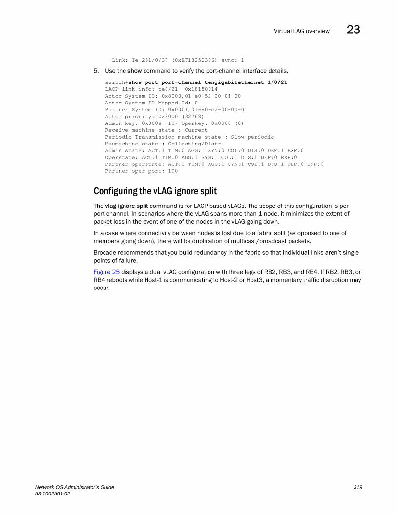
Virtual LAG overview 23
Link: Te 231/0/37 (0xE718250306) sync: 1
5. Use the show command to verify the port-channel interface details.
switch#show port port-channel tengigabitethernet 1/0/21 LACP link info: te0/21 -0x18150014 Actor System ID: 0x8000,01-e0-52-00-01-00 Actor System ID Mapped Id: 0 Partner System ID: 0x0001,01-80-c2-00-00-01 Actor priority: 0x8000 (32768) Admin key: 0x000a (10) Operkey: 0x0000 (0) Receive machine state : Current Periodic Transmission machine state : Slow periodic Muxmachine state : Collecting/Distr Admin state: ACT:1 TIM:0 AGG:1 SYN:0 COL:0 DIS:0 DEF:1 EXP:0 Operstate: ACT:1 TIM:0 AGG:1 SYN:1 COL:1 DIS:1 DEF:0 EXP:0 Partner operstate: ACT:1 TIM:0 AGG:1 SYN:1 COL:1 DIS:1 DEF:0 EXP:0 Partner oper port: 100
Configuring the vLAG ignore splitThe vlag ignore-split command is for LACP-based vLAGs. The scope of this configuration is per port-channel. In scenarios where the vLAG spans more than 1 node, it minimizes the extent of packet loss in the event of one of the nodes in the vLAG going down.
In a case where connectivity between nodes is lost due to a fabric split (as opposed to one of members going down), there will be duplication of multicast/broadcast packets.
Brocade recommends that you build redundancy in the fabric so that individual links aren’t single points of failure.
Figure 25 displays a dual vLAG configuration with three legs of RB2, RB3, and RB4. If RB2, RB3, or RB4 reboots while Host-1 is communicating to Host-2 or Host3, a momentary traffic disruption may occur.
Network OS Administrator’s Guide 31953-1002561-02

Virtual LAG overview23
NOTEWith ignore-split active, a vLAG node reboot can result in a more than one second loss while interoperating with a linux server/nic-team/CNA, due to premature egress of traffic from the server.
FIGURE 25 vLAG configuration of the ignore split
To reduce vLAG failover down time, you must set the ignore split on all of the legs in the vLAG (RB2, RB3 and RB4 in this case).
To configure the vLAG ignore split, perform the following steps from global configuration mode.
1. Log in to RB2, the first leg of the vLAG 1.
2. Access the port channel for the first leg.
switch(config)#interface port-channel 1
3. Activate vLAG ignore split.
switch(config-Port-channel-1)#vlag ignore-split
4. Log in to RB3, the second leg of vLAG 1.
5. Access the port channel for the second leg.
switch(config)#interface port-channel 2
6. Activate vLAG ignore split.
switch(config-Port-channel-2)#vlag ignore-split
7. Access the port channel for the third leg.
switch(config)#interface port-channel 3
8. Activate vLAG ignore split.
switch(config-Port-channel-3)#vlag ignore-split
320 Network OS Administrator’s Guide53-1002561-02

Virtual LAG overview 23
Configuring load balancing on a remote RbridgeThis feature allows you to configure the load balancing feature on a remote Rbridge which is not a member of the vLAG (also known as a non-local RBridge), to forward traffic to a vLAG. To distribute the traffic among the possible paths towards the VLAG, you can configure the vlag-load-balancing flavor on RB2. Available flavors are listed in Table 50.
Additionally, an Rbridge can be set to a different flavor for different vLAGs present in the cluster. This feature is available for each Rbridge and each VLAG, so different load-balance flavors can be set for traffic directed towards different VLAGs. The show running-config rbridge-id command displays the configuration information. The show fabric vlag-load-balance command displays the load blance for a VLAG.
The following example sets the flavor to “destination MAC address and VID based load balancing.”
Example
Switch(config)#rbridge-id 2 switch(config-rbridge-id-2)# fabric vlag 20 load-balance dst-mac-vid switch(config-rbridge-id-2)# end switch# show running-config rbridge-id 2 rbridge-id 2 interface-nodespecific ns-vlan 10 interface-nodespecific ns-ethernet 100 fabric vlag 10 load-balance src-dst-mac-vid fabric vlag 20 load-balance dst-mac-vid no protocol vrrp switch#show fabric vlag-load-balance 10Fabric Vlag Load-Balance Information ------------------------------- Rbridge-Id : 2 Vlag : 10 Load-Balance Flavor : Source and Destination MAC address and VID based load balancing
switch#show fabric vlag-load-balance all Fabric Vlag Load-Balance Information ------------------------------- Rbridge-Id : 2 Vlag : 10
TABLE 50 Load balance flavors
Flavor Definition
dst-mac-vid Destination MAC address and VID based load balancing.
src-mac-vid Source MAC address and VID based load balancing.
src-dst-mac-vid Source and Destination MAC address and VID based load balancing.
src-dst-ip Source and Destination IP address based load balancing.
src-dst-ip-mac-vid Source and Destination IP and MAC address and VID based load balancing.
src-dst-ip-port Source and Destination IP and TCP/UDP port based load balancing.
src-dst-ip-mac-vid-port Source and Destination IP, MAC address, VID and TCP/UDP port based load balancing.
Network OS Administrator’s Guide 32153-1002561-02

LACP configuration guidelines and restrictions23
LACP configuration guidelines and restrictionsThis section applies to standards-based and Brocade-proprietary LAG configurations, except where specifically noted otherwise.
Follow these LACP configuration guidelines and restrictions when configuring LACP:
• All ports on the Brocade VDX hardware can operate only in full-duplex mode.
• Brocade-proprietary LAGs only—All LAG member links must be part of the same port-group.
• Switchport interfaces—Interfaces configured as “switchport” interfaces cannot be aggregated into a LAG. However, a LAG can be configured as a switchport.
Default LACP configurationTable 51 lists the default LACP configuration.
LACP configuration and management
NOTEEnter the copy running-config startup-config command to save your configuration.
Enabling LACP on a DCB interfaceTo add additional interfaces to an existing LAG, repeat this procedure using the same LAG group number for the new interfaces.
To enable LACP on a DCB interface, perform the following steps from privileged EXEC mode.
1. Enter the configure terminal command to access global configuration mode.
2. Enter the interface command to specify the DCB interface type and slot/port number.
The gigabitethernet rbridge-id/slot/port operand is used only for the Brocade VDX 6710, Brocade VDX 8770-4, and Brocade VDX 8770-8. The prompt for these ports is in the format: switch(config-if-gi-22/0/1)#
switch(config)#interface tengigabitethernet 0/1
3. Enter the no shutdown command to enable the DCB interface.
4. Enter the channel-group command to configure the LACP for the DCB interface.
switch(conf-if)#channel-group 4 mode active type standard
TABLE 51 Default LACP configuration
Parameter Default setting
System priority 32768
Port priority 32768
Timeout Long (standard LAG) or short (Brocade LAG)
322 Network OS Administrator’s Guide53-1002561-02

LACP configuration and management 23
Configuring the LACP system priority You configure an LACP system priority on each switch running LACP. LACP uses the system priority with the switch MAC address to form the system ID and also during negotiation with other switches.
The system priority value must be a number in the range of 1 through 65535. The higher the number, the lower the priority. The default priority is 32768.
To configure the global LACP system priority, perform the following steps from privileged EXEC mode.
1. Enter the configure terminal command to access global configuration mode.
2. Specify the LACP system priority.
switch(config)#lacp system-priority 25000
Configuring the LACP timeout period on a DCB interfaceThe LACP timeout period indicates how long LACP waits before timing out the neighboring device. The short timeout period is 3 seconds and the long timeout period is 90 seconds. The default is long.
To configure the LACP timeout period on a DCB interface, perform the following steps from privileged EXEC mode.
1. Enter the configure terminal command to access global configuration mode.
2. Enter the interface command to specify the DCB interface type and slot/port number.
The gigabitethernet rbridge-id/slot/port operand is used only for the Brocade VDX 6710, Brocade VDX 8770-4, and Brocade VDX 8770-8. The prompt for these ports is in the format: switch(config-if-gi-22/0/1)#
switch(config)#interface tengigabitethernet 0/1
3. Enter the no shutdown command to enable the DCB interface.
4. Specify the LACP timeout period for the DCB interface.
switch(conf-if-te-0/1)#lacp timeout short
Clearing LACP counter statistics on a LAGTo clear LACP counter statistics, enter the clear command to clear the LACP counter statistics for the specified LAG group number.
Example of clearing LACP counters for a specific LAG.
switch#clear lacp 42 counters
Clearing LACP counter statistics on all LAG groupsTo clear LACP counter statistics, enter the clear command to clear the LACP counter statistics for all LAG groups.
Example of clearing LACP counters.
switch#clear lacp counters
Network OS Administrator’s Guide 32353-1002561-02

LACP troubleshooting tips23
Displaying LACP informationUse the show command to display LACP statistics and configuration information. See the Network OS Command Reference for information.
LACP troubleshooting tipsTo troubleshoot problems with your LACP configuration, use the following troubleshooting tips.
If a standard IEEE 802.3ad-based dynamic trunk is configured on a link and the link is not able to join the LAG:
• Make sure that both ends of the link are configured as standard for the trunk type.
• Make sure that both ends of the link are not configured for passive mode. They must be configured as active/active, active/passive, or passive/active.
• Make sure that the port-channel interface is in the administrative “up” state by ensuring that the no shutdown command was entered on the interface on both ends of the link.
• Make sure the speed parameter is configured to 1000 if the port-channel is using the gigabit interface.
• Make sure that the links that are part of the LAG are connected to the same neighboring switch.
• Make sure that the system ID of the switches connected by the link is unique. This can be verified by entering the show lacp sys-id command on both switches.
• You can verify the system ID of the switches in the Brocade VCS Fabric cluster with the show lacp sys-id command.
• Make sure that LACPDUs are being received and transmitted on both ends of the link and that there are no error PDUs. This can be verified by entering the show lacp counters number command and looking at the receive mode (rx) and transmit mode (tx) statistics. The statistics should be incrementing and should not be at zero or a fixed value. If the PDU rx count is not incrementing, check the interface for possible CRC errors by entering the show interface link-name command on the neighboring switch. If the PDU tx count is not incrementing, check the operational status of the link by entering the show interface link-name command and verifying that the interface status is “up.”
If a Brocade-based dynamic trunk is configured on a link and the link is not able to join the LAG:
• Make sure that both ends of the link are configured as Brocade for trunk type.
• Make sure that both ends of the link are not configured for passive mode. They must be configured as active/active, active/passive, or passive/active.
• Make sure that the port-channel interface is in the administrative “up” state by ensuring that the no shutdown command was entered on the interface on both ends of the link.
• Make sure that the links that are part of the LAG are connected to the same neighboring switch.
• Make sure that the system ID of the switches connected by the link is unique. This can be verified by entering the show lacp sys-id command on both switches.
324 Network OS Administrator’s Guide53-1002561-02
LACP troubleshooting tips 23
• Make sure that LACPDUs are being received and transmitted on both ends of the link and there are no error PDUs. This can be verified by entering the show lacp counters number command and looking at the rx and tx statistics. The statistics should be incrementing and should not be at zero or a fixed value. If the PDU rx count is not incrementing, check the interface for possible CRC errors by entering the show interface link-name command on the neighboring switch.
• Make sure that the fiber length of the link has a deskew value of 7 microseconds. If it does not, the link will not be able to join the LAG and the following RASLOG message is generated: Deskew calculation failed for link <link-name>.
When a link has this problem, the show port-channel command displays the following message:
Mux machine state : Deskew not OK.
If a Brocade-based static trunk is configured on a link and the link is not able to join the LAG:
• Make sure that both ends of the link are configured as Brocade for trunk type and verify that the mode is “on.”
• Make sure that the port-channel interface is in the administrative “up” state by ensuring that the no shutdown command was entered on the interface on both ends of the link.
If a standards-based static trunk is configured on a link and the link is not able to join the LAG:
• Make sure that both ends of the link are configured as standard for trunk type and verify that the mode is “on.”
• Make sure that the port-channel interface is in the administrative “up” state by ensuring that the no shutdown command was entered on the interface on both ends of the link.
Network OS Administrator’s Guide 32553-1002561-02

LACP troubleshooting tips23
326 Network OS Administrator’s Guide53-1002561-02

Network OS Administrator’s Guide53-1002561-02
Chapter
24
Configuring LLDPIn this chapter
•LLDP overview . . . . . . . . . . . . . . . . . . . . . . . . . . . . . . . . . . . . . . . . . . . . . . . . 327
•Layer 2 topology mapping . . . . . . . . . . . . . . . . . . . . . . . . . . . . . . . . . . . . . . . 328
•DCBX overview . . . . . . . . . . . . . . . . . . . . . . . . . . . . . . . . . . . . . . . . . . . . . . . . 329
•LLDP configuration guidelines and restrictions. . . . . . . . . . . . . . . . . . . . . . 331
•Default LLDP configuration. . . . . . . . . . . . . . . . . . . . . . . . . . . . . . . . . . . . . . 331
•LLDP configuration and management . . . . . . . . . . . . . . . . . . . . . . . . . . . . . 331
LLDP overviewThe IEEE 802.1AB Link Layer Discovery Protocol (LLDP) enhances the ability of network management tools to discover and maintain accurate network topologies and simplify LAN troubleshooting in multi-vendor environments. To efficiently and effectively operate the various devices in a LAN you must ensure the correct and valid configuration of the protocols and applications that are enabled on these devices. With Layer 2 networks expanding dramatically, it is difficult for a network administrator to statically monitor and configure each device in the network.
Using LLDP, network devices such as routers and switches advertise information about themselves to other network devices and store the information they discover. Details such as device configuration, device capabilities, and device identification are advertised. LLDP defines the following:
• A common set of advertisement messages.
• A protocol for transmitting the advertisements.
• A method for storing the information contained in received advertisements.
NOTELLDP runs over the data-link layer which allows two devices running different network layer protocols to learn about each other.
LLDP information is transmitted periodically and stored for a finite period. Every time a device receives an LLDP advertisement frame, it stores the information and initializes a timer. If the timer reaches the time to live (TTL) value, the LLDP device deletes the stored information ensuring that only valid and current LLDP information is stored in network devices and is available to network management systems.
327

Layer 2 topology mapping24
Layer 2 topology mappingThe LLDP protocol lets network management systems accurately discover and model Layer 2 network topologies. As LLDP devices transmit and receive advertisements, the devices store information they discover about their neighbors. Advertisement data such as a neighbor's management address, device type, and port identification is useful in determining what neighboring devices are in the network.
NOTEThe Brocade LLDP implementation supports a one-to-one connection. Each interface has one and only one neighbor.
The higher level management tools, such as the Brocade Network Advisor, can query the LLDP information to draw Layer 2 physical topologies. The management tools can continue to query a neighboring device through the device’s management address provided in the LLDP information exchange. As this process is repeated, the complete Layer 2 topology is mapped.
In LLDP the link discovery is achieved through the exchange of link-level information between two link partners. The link-level information is refreshed periodically to reflect any dynamic changes in link-level parameters. The basic format for exchanging information in LLDP is in the form of a type, length, value (TLV) field.
LLDP keeps a database for both local and remote configurations. The LLDP standard currently supports three categories of TLVs. Brocade’s LLDP implementation adds a proprietary Brocade extension TLV set. The four TLV sets are described as follows:
• Basic management TLV set. This set provides information to map the Layer 2 topology and includes the following TLVs:
- Chassis ID TLV—Provides the ID for the switch or router where the port resides. This is a mandatory TLV.
- Port description TLV—Provides a description of the port in an alphanumeric format. If the LAN device supports RFC-2863, the port description TLV value equals the “ifDescr” object. This is a mandatory TLV.
- System name TLV—Provides the system-assigned name in an alphanumeric format. If the LAN device supports RFC-3418, the system name TLV value equals the “sysName” object. This is an optional TLV.
- System description TLV—Provides a description of the network entity in an alphanumeric format. This includes system name, hardware version, operating system, and supported networking software. If the LAN device supports RFC-3418, the value equals the “sysDescr” object. This is an optional TLV.
- System capabilities TLV—Indicates the primary functions of the device and whether these functions are enabled in the device. The capabilities are indicated by two octets. The first octet indicates Other, Repeater, Bridge, WLAN AP, Router, Telephone, DOCSIS cable device, and Station, respectively. The second octet is reserved. This is an optional TLV.
- Management address TLV—Indicates the addresses of the local switch. Remote switches can use this address to obtain information related to the local switch. This is an optional TLV.
328 Network OS Administrator’s Guide53-1002561-02

DCBX overview 24
• IEEE 802.1 organizational TLV set. This set provides information to detect mismatched settings between local and remote devices. A trap or event can be reported once a mismatch is detected. This is an optional TLV. This set includes the following TLVs:
- Port VLANID TLV—Indicates the port VLAN ID (PVID) that is associated with an untagged or priority tagged data frame received on the VLAN port.
- PPVLAN ID TLV—Indicates the port- and protocol--based VLAN ID (PPVID) that is associated with an untagged or priority tagged data frame received on the VLAN port. The TLV supports a “flags” field that indicates whether the port is capable of supporting port- and protocol-based VLANs (PPVLANs) and whether one or more PPVLANs are enabled. The number of PPVLAN ID TLVs in a Link Layer Discovery Protocol Data Unit (LLDPDU) corresponds to the number of the PPVLANs enabled on the port.
- VLAN name TLV—Indicates the assigned name of any VLAN on the device. If the LAN device supports RFC-2674, the value equals the “dot1QVLANStaticName” object. The number of VLAN name TLVs in an LLDPDU corresponds to the number of VLANs enabled on the port.
- Protocol identity TLV—Indicates the set of protocols that are accessible at the device's port. The protocol identity field in the TLV contains a number of octets after the Layer 2 address that can enable the receiving device to recognize the protocol. For example, a device that wishes to advertise the spanning tree protocol includes at least eight octets: 802.3 length (two octets), LLC addresses (two octets), 802.3 control (one octet), protocol ID (two octets), and the protocol version (one octet).
• IEEE 802.3 organizational TLV set. This is an optional TLV set. This set includes the following TLVs:
- MAC/PHY configuration/status TLV—Indicates duplex and bit rate capabilities and the current duplex and bit rate settings of the local interface. It also indicates whether the current settings were configured through auto-negotiation or through manual configuration.
- Power through media dependent interface (MDI) TLV—Indicates the power capabilities of the LAN device.
- Link aggregation TLV—Indicates whether the link (associated with the port on which the LLDPDU is transmitted) can be aggregated. It also indicates whether the link is currently aggregated and provides the aggregated port identifier if the link is aggregated.
- Maximum Ethernet frame size TLV—Indicates the maximum frame size capability of the device’s MAC and PHY implementation.
DCBX overviewStorage traffic requires a lossless communication which is provided by DCB. The Data Center Bridging (DCB) Capability Exchange Protocol (DCBX) is used to exchange DCB-related parameters with neighbors to achieve more efficient scheduling and a priority-based flow control for link traffic.
DCBX uses LLDP to exchange parameters between two link peers; DCBX is built on the LLDP infrastructure for the exchange of information. DCBX-exchanged parameters are packaged into organizationally specific TLVs. The DCBX protocol requires an acknowledgement from the other side of the link, therefore LLDP is turned on in both transmit and receive directions. DCBX requires version number checking for both control TLVs and feature TLVs.
Network OS Administrator’s Guide 32953-1002561-02

DCBX overview24
DCBX interacts with other protocols and features as follows:
• LLDP—LLDP is run in parallel with other Layer 2 protocols such as RSTP and LACP. DCBX is built on the LLDP infrastructure to communicate capabilities supported between link partners. The DCBX protocol and feature TLVs are treated as a superset of the LLDP standard.
• QoS management—DCBX capabilities exchanged with a link partner are passed down to the QoS management entity to set up the Brocade VDX hardware to control the scheduling and priority-based flow control in the hardware.
The DCBX QoS standard is subdivided into two features sets:
• “Enhanced Transmission Selection”
• “Priority Flow Control”
Enhanced Transmission Selection In a converged network, different traffic types affect the network bandwidth differently. The purpose of Enhanced Transmission Selection (ETS) is to allocate bandwidth based on the different priority settings of the converged traffic. For example, Inter-process communications (IPC) traffic can use as much bandwidth as needed and there is no bandwidth check; LAN and SAN traffic share the remaining bandwidth. Table 52 displays three traffic groups: IPC, LAN, and SAN. ETS allocates the bandwidth based on traffic type and also assigns a priority to the three traffic types as follows: Priority 7 traffic is mapped to priority group 0 which does not get a bandwidth check, priority 2 and priority 3 are mapped to priority group 1, priorities 6, 5, 4, 1 and 0 are mapped to priority group 2.
The priority settings shown in Table 52 are translated to priority groups in the Brocade VDX hardware.
Priority Flow Control With Priority Flow Control (PFC), it is important to provide lossless frame delivery for certain traffic classes while maintaining existing LAN behavior for other traffic classes on the converged link. This differs from the traditional 802.3 PAUSE type of flow control where the pause affects all traffic on an interface.
PFC is defined by a one-byte bitmap. Each bit position stands for a user priority. If a bit is set, the flow control is enabled in both directions (Rx and Tx).
TABLE 52 ETS priority grouping of IPC, LAN, and SAN traffic
Priority Priority group Bandwidth check
7 0 No
6 2 Yes
5 2 Yes
4 2 Yes
3 1 Yes
2 1 Yes
1 2 Yes
0 2 Yes
330 Network OS Administrator’s Guide53-1002561-02

LLDP configuration guidelines and restrictions 24
LLDP configuration guidelines and restrictionsFollow these LLDP configuration guidelines and restrictions when configuring LLDP:
• Brocade’s implementation of LLDP supports Brocade-specific TLV exchange in addition to the standard LLDP information.
• Mandatory TLVs are always advertised.
• The exchange of LLDP link-level parameters is transparent to the other Layer 2 protocols. The LLDP link-level parameters are reported by LLDP to other interested protocols.
NOTEDCBX configuration simply involves configuring DCBX-related TLVs to be advertised. Detailed information is provided in “LLDP configuration and management” on page 331.
Default LLDP configurationTable 53 lists the default LLDP configuration.
LLDP configuration and management
NOTEEnter the copy running-config startup-config command to save your configuration changes.
Enabling LLDP globallyThe protocol lldp command enables LLDP globally on all interfaces unless it has been specifically disabled on an interface. LLDP is globally enabled by default.
To enable LLDP globally, perform the following steps from privileged EXEC mode.
1. Enter the configure terminal command to access global configuration mode.
2. Enter LLDP configuration mode.
switch(config)#protocol lldp
TABLE 53 Default LLDP configuration
Parameter Default setting
LLDP global state Enabled
LLDP receive Enabled
LLDP transmit Enabled
Transmission frequency of LLDP updates 30 seconds
Hold time for receiving devices before discarding 120 seconds
DCBX-related TLVs to be advertised dcbx-tlv
Network OS Administrator’s Guide 33153-1002561-02

LLDP configuration and management24
Disabling and resetting LLDP globallyThe no protocol lldp command returns all configuration settings made using the protocol lldp commands to their default settings. LLDP is globally enabled by default.
The disable command disables LLDP globally.
To reset LLDP globally, perform the following steps from privileged EXEC mode.
1. Enter the configure terminal command to access global configuration mode.
2. Reset LLDP globally.
switch(config)#no protocol lldp
To disable LLDP globally perform the following step from global configuration mode.
1. Enter the protocol lldp command to enter protocol configuration mode.
switch(config)#protocol lldp
2. Enter the disable command to disable LLDP globally.
switch(conf-lldp)# disable
Configuring LLDP global command optionsAfter entering the protocol lldp command from global configuration mode, you are in LLDP configuration mode which is designated with the switch(conf-lldp)# prompt. Using the keywords in this mode, you can set non-default parameter values that apply globally to all interfaces.
Specifying a system name for the Brocade VDX hardware
The global system name for LLDP is useful for differentiating between switches. By default, the “host-name” from the chassis/entity MIB is used. By specifying a descriptive system name, you will find it easier to configure the switch for LLDP.
To specify a global system name for the Brocade VDX hardware, perform the following steps from privileged EXEC mode.
1. Enter the configure terminal command to access global configuration mode.
2. Enter LLDP configuration mode.
switch(config)#protocol lldp
3. Specify an LLDP system name for the DCB switch.
switch(conf-lldp)#system-name Brocade_AlphaBrocade_Alpha(conf-lldp)#
Specifying an LLDP system description for the Brocade VDX hardware
NOTEBrocade recommends you use the operating system version for the description or use the description from the chassis/entity MIB. Do not use special characters, such as #$!@, as part of the system name and description.
332 Network OS Administrator’s Guide53-1002561-02

LLDP configuration and management 24
To specify an LLDP system description for the Brocade VDX hardware, perform the following steps from privileged EXEC mode. The system description is seen by neighboring switches.
1. Enter the configure terminal command to access global configuration mode.
2. Enter LLDP configuration mode.
switch(config)#protocol lldp
3. Specify a system description for the Brocade VDX hardware.
switch(conf-lldp)#system-description IT_1.6.2_LLDP_01
Specifying a user description for LLDP
To specify a user description for LLDP, perform the following steps from privileged EXEC mode. This description is for network administrative purposes and is not seen by neighboring switches.
1. Enter the configure terminal command to access global configuration mode.
2. Enter LLDP configuration mode.
switch(config)#protocol lldp
3. Specify a user description for LLDP.
switch(conf-lldp)#description Brocade-LLDP-installed-july-25
Enabling and disabling the receiving and transmitting of LLDP frames
By default both transmit and receive for LLDP frames is enabled. To enable or disable the receiving (rx) and transmitting (tx) of LLDP frames, perform the following steps from privileged EXEC mode.
1. Enter the configure terminal command to access global configuration mode.
2. Enter the mode command to:
• Enable only receiving of LLDP frames:
switch(conf-lldp)#mode rx
• Enable only transmitting of LLDP frames:
switch(conf-lldp)#mode tx
• Enable both transmit and receive modes.
switch(conf-lldp)#no mode
Configuring the transmit frequency of LLDP frames
To configure the transmit frequency of LLDP frames, perform the following steps from privileged EXEC mode.The default is 30 seconds.
1. Enter the configure terminal command to access global configuration mode.
2. Enter LLDP configuration mode.
switch(config)#protocol lldp
3. Configure the transmit frequency of LLDP frames.
switch(conf-lldp)#hello 45
Network OS Administrator’s Guide 33353-1002561-02

LLDP configuration and management24
Configuring the hold time for receiving devices
To configure the hold time for receiving devices, perform the following steps from privileged EXEC mode. This configures the number of consecutive LLDP hello packets that can be missed before declaring the neighbor information as invalid. The default is 4.
1. Enter the configure terminal command to access global configuration mode.
2. Enter LLDP configuration mode.
switch(config)#protocol lldp
3. Configure the hold time for receiving devices.
switch(conf-lldp)#multiplier 6
Advertising the optional LLDP TLVs
To advertise the optional LLDP TLVs, perform the following steps from privileged EXEC mode.
1. Enter the configure terminal command to access global configuration mode.
2. Enter LLDP configuration mode.
switch(config)#protocol lldp
3. Advertise the optional LLDP TLVs.
switch(conf-lldp)#advertise optional-tlv management-address port-descriptionsystem-capabilities system-name system-description
Configuring the advertisement of LLDP DCBX-related TLVs
By default , For a switch in standalone mode only "The dcbx-tlv" is advertised
For a switch in Brocade VCS Fabric mode the following TLVs are advertised by default:
• dcbx-tlv is advertised
• dcbx-fcoe-app-tlv
• dcbx-fcoe-logical-link-tlv
To configure the LLDP DCBX-related TLVs to be advertised, perform the following steps from privileged EXEC mode.
1. Enter the configure terminal command to access global configuration mode.
2. Enter LLDP configuration mode.
switch(config)#protocol lldp
3. Advertise the LLDP DCBX-related TLVs using these commands:
• switch(conf-lldp)#advertise dcbx-fcoe-app-tlv
• switch(conf-lldp)#advertise dcbx-fcoe-logical-link-tlv
• switch(conf-lldp)#advertise dcbx-tlv
• switch(conf-lldp)#advertise dot1-tlv
• switch(conf-lldp)#advertise dot3-tlv
334 Network OS Administrator’s Guide53-1002561-02
LLDP configuration and management 24
Configuring iSCSI priority
The iSCSI priority setting is used to configure the priority that will be advertised in the DCBx iSCSI TLV.
The iSCSI TLV is used only to advertise the iSCSI traffic configuration parameters to the attached CEE enabled servers and targets. No verification or enforcement of the usage of the advertised parameters by the iSCSI server or target is done by the switch.
To configure the iSCSI priority, perform the following steps from privileged EXEC mode.
1. Enter the configure terminal command to access global configuration mode.
2. Enter LLDP configuration mode.
switch(config)#protocol lldp
3. Configure the iSCSI priority.
switch(conf-lldp)#iscsi-priority 4
NOTEThe default iscsi-priority is 4 and does not display unless you change the iscsi-priority to a different value.
4. Advertise the TLV.
switch (conf-lldp)#advertise dcbx-iscsi-app-tlv
Configuring LLDP profiles
You can configure up to 64 profiles on a switch. Using the no profile NAME command deletes the entire profile.
To configure LLDP profiles, perform the following steps from privileged EXEC mode.
1. Enter the configure terminal command to access global configuration mode.
2. Enter LLDP configuration mode.
switch(config)#protocol lldp
3. Configure the profile name.
switch(conf-lldp)#profile UK_LLDP_IT
4. Specify a description for the profile.
switch(conf-lldp-profile-UK_LLDP_IT)#description standard_profile_by_Jane
5. Enable the transmitting and receiving of LLDP frames.
switch(conf-lldp-profile-UK_LLDP_IT)#no mode
6. Configure the transmission frequency of LLDP updates.
switch(conf-lldp-profile-UK_LLDP_IT)#hello 10
7. Configure the hold time for receiving devices.
switch(conf-lldp-profile-UK_LLDP_IT)#multiplier 2
Network OS Administrator’s Guide 33553-1002561-02

LLDP configuration and management24
8. Advertise the optional LLDP TLVs.
switch(conf-lldp)#advertise optional-tlv management-address port-descriptionsystem-capabilities system-name system-description
9. Advertise the LLDP DCBX-related TLVs.
switch(conf-lldp-profile-UK_LLDP_IT)#advertise dot1-tlvswitch(conf-lldp-profile-UK_LLDP_IT)#advertise dot3-tlv switch(conf-lldp-profile-UK_LLDP_IT)#advertise advertise dcbx-tlvswitch(conf-lldp-profile-UK_LLDP_IT)#advertise dcbx-fcoe-logical-link-tlvswitch(conf-lldp-profile-UK_LLDP_IT)#advertise dcbx-fcoe-app-tlvswitch(conf-lldp-profile-UK_LLDP_IT)#advertise dcbx-iscsi-app-tlv
NOTEBrocade recommends against advertising dot1.tlv and dot3.tlv LLDPs if your network contains CNAs from non-Brocade vendors,. This configuration may cause functionality problems.
10. Return to privileged EXEC mode.
switch(conf-lldp-profile-UK_LLDP_IT)#end
11. Enter the copy command to save the running-config file to the startup-config file.
switch(conf-lldp-profile-UK_LLDP_IT)#endswitch#copy running-config startup-config
Configuring the iSCSI profile
You can configure an iSCSI profile to be applied to individual interfaces. However, the priority bit must be set manually for each interface. Using the no profile name command deletes the entire profile.
To configure iSCSI profiles, perform the following steps from privileged EXEC mode.
1. Configure the cee-map, if it has not already been created.For information on the cee-map command structure, refer to the Network OS Command Reference.
switch(config)#cee-map defaultswitch(conf-ceemap)#priority-group-table 1 weight 50 pfcswitch(conf-ceemap)#priority-group-table 2 weight 30 pfc onswitch(conf-ceemap)#priority-group-table 3 weight 20 pfc onswitch(conf-ceemap)#priority-table 1 1 1 1 2 3 1 1
priority-table command syntax:
priority-table PGID0 PGID1 PGID2 PGID3 PGID4 PGID5 PGID6 PGID7
• PGID0 = Set the Priority Group ID for all packets with CoS = 0. PGID value range is 0..7 for DWRR Priority Group and 15.0..15.7 for Strict Priority Group.
• PGID1 = Set the Priority Group ID for all packets with CoS = 1. PGID value range is 0..7 for DWRR Priority Group and 15.0..15.7 for Strict Priority Group.
• PGID2 = Set the Priority Group ID for all packets with CoS = 2. PGID value range is 0..7 for DWRR Priority Group and 15.0..15.7 for Strict Priority Group.
• PGID3 = Set the Priority Group ID for all packets with CoS = 3. PGID value range is 0..7 for DWRR Priority Group and 15.0..15.7 for Strict Priority Group.
• PGID4 = Set the Priority Group ID for all packets with CoS = 4. PGID value range is 0..7 for DWRR Priority Group and 15.0..15.7 for Strict Priority Group.
336 Network OS Administrator’s Guide53-1002561-02

LLDP configuration and management 24
• PGID5 = Set the Priority Group ID for all packets with CoS = 5. PGID value range is 0..7 for DWRR Priority Group and 15.0..15.7 for Strict Priority Group.
• PGID6 = Set the Priority Group ID for all packets with CoS = 6. PGID value range is 0..7 for DWRR Priority Group and 15.0..15.7 for Strict Priority Group.
• PGID7 = Set the Priority Group ID for all packets with CoS = 7. PGID value range is 0..7 for DWRR Priority Group and 15.0..15.7 for Strict Priority Group.(Reserved for Fabric Priority)
Priority-Table in CEE map configuration requires that PGID 15.0 is dedicated for CoS7. Due to this restriction, make sure that PGID15.0 is configured only as the last parameter for Priority-Table configuration.
An explanation of syntax “priority-table 1 2 2 2 2 2 2 15.0” is:
This shows the definition of a a CEE Map with Priority to Priority Group mapping of CoS=1, CoS=2, CoS=3, CoS=4, CoS=5, and CoS=6 to a DWRR Priority Group ID of 2, and CoS=0 to a Priority Group ID of 1, and CoS=7 to a Strict Priority Group.
This is one way to provision the CEE Priority to Priority Group Table, which maps each of the eight ingress CoS into a Priority Group.
In VCS mode, traffic classes are either all strict priorities (802.1Q default) or a combination of strict and DWRR traffic classes.
2. Enter LLDP configuration mode.
switch(conf-ceemap)#protocol lldp
3. Create an LLDP profile for iSCSI.
switch(conf-lldp)#profile iscsi_config
4. Advertise the iSCSI TLV.
switch(conf-lldp-profile-iscsi_config)#advertise dcbx-iscsi-app-tlv
5. Enter configuration mode for the specific interface.
The gigabitethernet ports on the 6710 do not allow the cee default command. This port type does not support PFC or iSCSI App TLV.
switch (conf-lldp-profile-iscsi_config)#interface te 0/1
6. Apply the CEE Provisioning map to the interface.
switch(conf-if-te-0/1)#cee default
7. Apply the LLDP profile you created for iSCSI.
switch(conf-if-te-0/1)#lldp profile iscsi_config
8. Set the iSCSI priority bits for the interface.
switch(conf-if-te-0/1)#lldp iscsi-priority 4
9. Repeat steps 5 through 8 for additional interfaces.
Configuring LLDP interface-level command optionsOnly one LLDP profile can be assigned to an interface. If you do not use the lldp profile option at the interface level, the global configuration is used on the interface. If there are no global configuration values defined, the global default values are used.
Network OS Administrator’s Guide 33753-1002561-02

LLDP configuration and management24
To configure LLDP interface-level command options, perform the following steps from privileged EXEC mode.
1. Enter the interface command to specify the DCB interface type and slot/port number.
The gigabitethernet rbridge-id/slot/port operand is used only for the Brocade VDX 6710, Brocade VDX 8770-4, and Brocade VDX 8770-8. The prompt for these ports is in the format: switch(config-if-gi-22/0/1)#
switch(config)#interface tengigabitethernet 0/10
2. Apply an LLDP profile to the interface.
switch(conf-if-te-0/10)#lldp profile network_standard
3. Return to privileged EXEC mode.
switch(conf-if-te-0/10)#end
4. Enter the copy command to save the running-config file to the startup-config file.
switch#copy running-config startup-config
Clearing LLDP-related informationTo clear LLDP-related information, perform the following steps from privileged EXEC mode.
1. Use the clear command to clear LLDP neighbor information.
switch#clear lldp neighbors interface tengigabitethernet 0/1
2. Use the clear command to clear LLDP statistics.
switch#clear lldp statistics interface tengigabitethernet 0/1
Displaying LLDP-related informationTo display LLDP-related information, perform the following steps from privileged EXEC mode.
1. Use the show lldp command to display LLDP general information.
switch#show lldp
2. Use the show lldp command to display LLDP interface-related information.
The gigabitethernet rbridge-id/slot/port operand is used only for the Brocade VDX 6710, Brocade VDX 8770-4, and Brocade VDX 8770-8. The prompt for these ports is in the format: switch(config-if-gi-22/0/1)#
switch#show lldp interface tengigabitethernet 0/1
3. Use the show lldp command to display LLDP neighbor-related information.
switch#show lldp neighbors interface tengigabitethernet 0/1 detail
338 Network OS Administrator’s Guide53-1002561-02

Network OS Administrator’s Guide53-1002561-02
Chapter
25
Configuring ACLsIn this chapter
•ACL overview . . . . . . . . . . . . . . . . . . . . . . . . . . . . . . . . . . . . . . . . . . . . . . . . . 339
•Default ACL configuration . . . . . . . . . . . . . . . . . . . . . . . . . . . . . . . . . . . . . . . 340
•ACL configuration guidelines and restrictions . . . . . . . . . . . . . . . . . . . . . . . 340
•ACL configuration and management . . . . . . . . . . . . . . . . . . . . . . . . . . . . . . 340
•IP ACL . . . . . . . . . . . . . . . . . . . . . . . . . . . . . . . . . . . . . . . . . . . . . . . . . . . . . . . 345
ACL overview
NOTEIn the Brocade Network OS v3.0.0 release, both Ingress Layer 2 MAC access control lists (ACLs) and Layer 3 IP access control lists are supported.
ACLs filter traffic for the Brocade VDX hardware and permit or deny frames on ingress interfaces that have the ACLs applied to them. You can apply ACLs on the three kinds of Layer 2 interfaces that Brocade Network OS v 3.0.0 supports; physical (both tengigabitethernet and gigabitethernet), VLAN, and port-channel (both static and dynamic LAG), and Layer 3 IP virtual interfaces.
Each ACL is a unique collection of permit and deny statements (rules) that apply to frames. When a frame is received on an interface, the switch compares the fields in the frame against any ACLs applied to the interface to verify that the frame has the required permissions to be forwarded. The switch compares the frame, sequentially, against each rule in the ACL and either forwards the frame or drops the frame.
The switch examines ACLs associated with options configured on a given interface. As frames enter the switch on an interface, ACLs associated with all inbound options configured on that interface are examined.
The primary benefits of ACLs are as follows:
• Provide a measure of security.
• Save network resources by reducing traffic.
• Block unwanted traffic or users.
• Reduce the chance of denial of service (DOS) attacks.
There are two types of ACLs:
• Standard ACLs—Permit and deny traffic according to the source MAC address in the incoming frame. Use standard MAC ACLs if you only need to filter traffic based on source addresses.
• Extended ACLs—Permit and deny traffic according to the source and destination MAC addresses in the incoming frame, as well as EtherType.
339

Default ACL configuration25
MAC ACLs are supported on the following interface types:
• Physical interfaces
• Logical interfaces (LAGs)
• VLANs
IP ACLs are supported on the following interface types:
• Logical interfaces (LAGs)
• VLANs
Default ACL configurationWhen none of the policies are enforced on the switch these default ACL rules are effective in Network OS:
• seq 0 permit tcp any any eq 22
• seq 1 permit tcp any any eq 23
• seq 2 permit tcp any any eq 897
• seq 3 permit tcp any any eq 898
• seq 4 permit tcp any any eq 111
• seq 5 permit tcp any any eq 80
• seq 6 permit tcp any any eq 443
• seq 7 permit udp any any eq 161
• seq 8 permit udp any any eq 111
• seq 9 permit tcp any any eq 123
• seq 10 permit tcp any any range 600 65535
• seq 11 permit udp any any range 600 65535
ACL configuration guidelines and restrictionsFollow these ACL configuration guidelines and restrictions when configuring ACLs:
• The order of the rules in an ACL is critical. The first rule that matches the traffic stops further processing of the frames.
• Standard ACLs and extended ACLs cannot have the same name.
• There is a default permit rule added at the end of the rules list of an ACL. This implicit rule permits all Layer 2 streams that do not match any of the configured rules in the sequence list associated with the ACL.
ACL configuration and management
NOTEEnter the copy running-config startup-config command to save your configuration changes.
340 Network OS Administrator’s Guide53-1002561-02

ACL configuration and management 25
Creating a standard MAC ACL and adding rules
NOTEYou can use the resequence command to change all the sequence numbers assigned to the rules in a MAC ACL. For detailed information, see “Reordering the sequence numbers in a MAC ACL” on page 345.
A MAC ACL does not take effect until it is applied to a Layer 2 interface. Refer to “Applying a MAC ACL to a DCB interface” on page 342 and “Applying a MAC ACL to a VLAN interface” on page 343.
To create a standard MAC ACL and add rules, perform the following steps from privileged EXEC mode.
1. Enter the configure terminal command to access global configuration mode.
2. Create a standard MAC ACL and enter ACL configuration mode.
In this example, the name of the standard MAC ACL is “test_01.”
switch(config)#mac access-list standard test_01switch(conf-macl-std)#
3. Enter the deny command to create a rule in the MAC ACL to drop traffic with the source MAC address.
switch(conf-macl-std)#deny 0022.3333.4444 count
4. Enter the permit command to create a rule in the MAC ACL to permit traffic with the source MAC address.
switch(conf-macl-std)#permit 0022.5555.3333 count
5. Use the seq command to create MAC ACL rules in a specific sequence.
switch(conf-macl-std)#seq 100 deny 0011.2222.3333 countswitch(conf-macl-std)#seq 1000 permit 0022.1111.2222 count
6. Return to privileged EXEC mode.
switch(conf-macl-std)#end
7. Enter the copy command to save the running-config file to the startup-config file.
switch#copy running-config startup-config
Creating an extended MAC ACL and adding rules
NOTEYou can use the resequence command to change all the sequence numbers assigned to the rules in a MAC ACL. For detailed information, see “Reordering the sequence numbers in a MAC ACL” on page 345.
The MAC ACL name length is limited to 64 characters. A MAC ACL does not take effect until it is applied to a Layer 2 interface. Refer to “Applying a MAC ACL to a DCB interface” on page 342 and “Applying a MAC ACL to a VLAN interface” on page 343.
Network OS Administrator’s Guide 34153-1002561-02

ACL configuration and management25
To create an extended MAC ACL and add rules, perform the following steps from privileged EXEC mode.
1. Enter the configure terminal command to access global configuration mode.
2. Create an extended MAC ACL and enter ACL configuration mode.
switch(config)#mac access-list extended test_02
3. Create a rule in the MAC ACL to permit traffic with the source MAC address and the destination MAC address.
switch(conf-macl-ext)#permit 0022.3333.4444 0022.3333.5555
4. Use the seq command to insert the rule anywhere in the MAC ACL.
switch(conf-macl-ext)#seq 5 permit 0022.3333.4444 0022.3333.5555
5. Return to privileged EXEC mode.
switch(conf-macl-ext)#end
6. Enter the copy command to save the running-config file to the startup-config file.
switch#copy running-config startup-config
Applying a MAC ACL to a DCB interfaceEnsure that the ACL that you want to apply exists and is configured to filter traffic in the manner that you need for this DCB interface. An ACL does not take effect until it is expressly applied to an interface using the access-group command. Frames can be filtered as they enter an interface (ingress direction).
NOTEThe DCB interface must be configured as a Layer 2 switchport before an ACL can be applied as an access-group to the interface.
To apply a MAC ACL to a DCB interface, perform the following steps from privileged EXEC mode.
1. Enter the configure terminal command to access global configuration mode.
2. Enter the interface command to specify the DCB interface type and slot/port number.
The gigabitethernet rbridge-id/slot/port operand is used only for the Brocade VDX 6710, Brocade VDX 8770-4, and Brocade VDX 8770-8. The prompt for these ports is in the format: switch(config-if-gi-22/0/1)#
switch(config)#interface tengigabitethernet 0/1
3. Enter the switchport command to configure the interface as a Layer 2 switch port.
4. Enter the mac-access-group command to specify the MAC ACL that is to be applied to the Layer 2 DCB interface in the ingress direction.
switch(conf-if-te-0/1)#mac access-group test_02 in
342 Network OS Administrator’s Guide53-1002561-02
ACL configuration and management 25
Applying a MAC ACL to a VLAN interfaceEnsure that the ACL that you want to apply exists and is configured to filter traffic in the manner that you need for this VLAN interface. An ACL does not take effect until it is expressly applied to an interface using the access-group command. Frames can be filtered as they enter an interface (ingress direction).
Network OS Administrator’s Guide 34353-1002561-02

ACL configuration and management25
To apply a MAC ACL to a VLAN interface, perform the following steps from privileged EXEC mode.
1. Enter the configure terminal command to access global configuration mode.
2. Enter the interface command to apply the MAC ACL to the VLAN interface.
switch(config)#interface vlan 50
3. Enter the mac-access-group command to specify the MAC ACL that is to be applied to the VLAN interface in the ingress direction.
switch(config-Vlan-50)# mac access-group test_02 in
Modifying MAC ACL rulesYou cannot modify the existing rules of a MAC ACL. However, you can remove the rule and then recreate it with the desired changes.
If you need to add more rules between existing rules than the current sequence numbering allows, you can use the resequence command to reassign sequence numbers. For detailed information, see “Reordering the sequence numbers in a MAC ACL” on page 345.
Use a sequence number to specify the rule you wish to modify. Without a sequence number, a new rule is added to the end of the list, and existing rules are unchanged.
NOTEUsing the permit and deny keywords, you can create many different rules. The examples in this section provide the basic knowledge needed to modify MAC ACLs.
NOTEThis example assumes that test_02 contains an existing rule number 100 with the “deny any any” options.
To modify a MAC ACL, perform the following steps from privileged EXEC mode.
1. Enter the configure terminal command to access global configuration mode.
2. Enter the mac command to specify the ACL called test_02 for modification.
switch(config)#mac access-list extended test_02
3. Enter the no seq command to delete the existing rule 100.
switch (conf-macl-ext)#no seq 100
-or-
Enter the seq command to recreate rule number 100 by recreating it with new parameters.
switch(conf-macl-ext)#seq 100 permit any any
344 Network OS Administrator’s Guide53-1002561-02

IP ACL 25
Removing a MAC ACLA MAC ACL cannot be removed from the system unless the access-group applying the MAC ACL to a DCB or a VLAN interface is first removed.
To remove a MAC ACL, perform the following steps from privileged EXEC mode.
1. Enter the configure terminal command to access global configuration mode.
2. Enter the mac command to specify and delete the ACL that you want to remove. In this example, the extended MAC ACL name is “test_02.”
switch(config)#no mac access-list extended test_02
Reordering the sequence numbers in a MAC ACLYou can reorder the sequence numbers assigned to rules in a MAC ACL. Reordering the sequence numbers is useful when you need to insert rules into an ACL and there are not enough available sequence numbers. The default initial sequence number is 10 and the default increment is 10 for both Standard and Extended MAC ACLs
The first rule receives the number specified by the starting-sequence number that you specify. Each subsequent rule receives a number larger than the preceding rule. The difference in numbers is determined by the increment number that you specify. The starting-sequence number and the increment number must be in the range of 1 through 65535.
For example, in the task listed below the resequence command assigns a sequence number of 50 to the rule named test_02, then the second rule has a sequence number of 55 and the third rule a has a sequence number of 60.
switch#resequence access-list mac test_02 50 5
IP ACLThe IP ACLs control the access to the switch. The policies do not control the egress and outbound management traffic initiated from the switch. The IP ACLs support IPv4 and IPv6 at the simultaneously.
An IP ACL is a set of rules that are applied to the interface as a packet filtering firewall. Each rule defines whether traffic, of a combination of source and destination IP Address, protocol or port, is to be denied or permitted.
Each ACL must have a unique name, but there is no limit for the number of ACLs to be defined. An ACL can contain rules for only one version of IP (either v4/v6). Only one ACL by the version of IP can be active on the interface at a time. In other words, one ACL for IPv4 addresses and one ACL for IPv6 address on the interface for packet filtering can be active.
For filtering the traffic, each rule of the ACL applied to the interface is checked in the ascending order of their sequence numbers. 4,294,967,290 rules can be added to an access-list. When the ACL is applied to an interface, only the 256 lowest numbered rules are applied, if the ACL has more than 256 rules in it. If an ACL doesn’t contain any rules and is applied to the interface, it becomes no-op and all ingress traffic is permitted through the interface.
Once an IP ACL rule is created it is not possible to modify any of its options.
Network OS Administrator’s Guide 34553-1002561-02
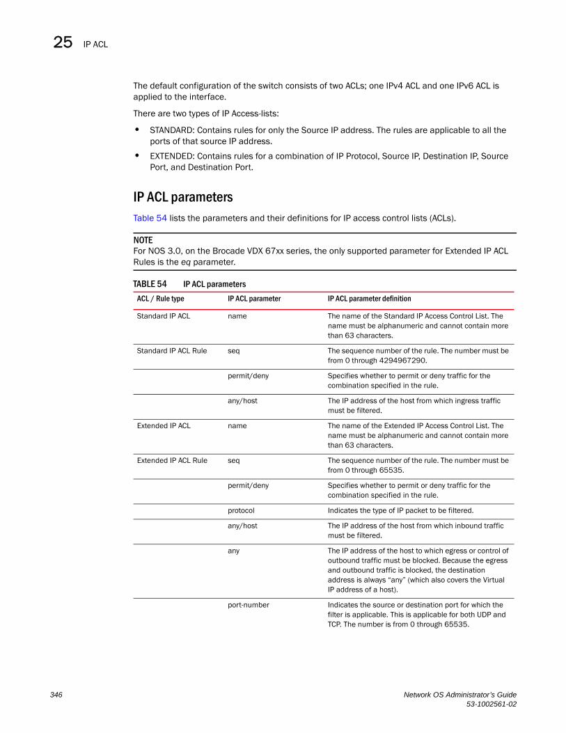
IP ACL25
The default configuration of the switch consists of two ACLs; one IPv4 ACL and one IPv6 ACL is applied to the interface.
There are two types of IP Access-lists:
• STANDARD: Contains rules for only the Source IP address. The rules are applicable to all the ports of that source IP address.
• EXTENDED: Contains rules for a combination of IP Protocol, Source IP, Destination IP, Source Port, and Destination Port.
IP ACL parametersTable 54 lists the parameters and their definitions for IP access control lists (ACLs).
NOTEFor NOS 3.0, on the Brocade VDX 67xx series, the only supported parameter for Extended IP ACL Rules is the eq parameter.
TABLE 54 IP ACL parameters
ACL / Rule type IP ACL parameter IP ACL parameter definition
Standard IP ACL name The name of the Standard IP Access Control List. The name must be alphanumeric and cannot contain more than 63 characters.
Standard IP ACL Rule seq The sequence number of the rule. The number must be from 0 through 4294967290.
permit/deny Specifies whether to permit or deny traffic for the combination specified in the rule.
any/host The IP address of the host from which ingress traffic must be filtered.
Extended IP ACL name The name of the Extended IP Access Control List. The name must be alphanumeric and cannot contain more than 63 characters.
Extended IP ACL Rule seq The sequence number of the rule. The number must be from 0 through 65535.
permit/deny Specifies whether to permit or deny traffic for the combination specified in the rule.
protocol Indicates the type of IP packet to be filtered.
any/host The IP address of the host from which inbound traffic must be filtered.
any The IP address of the host to which egress or control of outbound traffic must be blocked. Because the egress and outbound traffic is blocked, the destination address is always “any” (which also covers the Virtual IP address of a host).
port-number Indicates the source or destination port for which the filter is applicable. This is applicable for both UDP and TCP. The number is from 0 through 65535.
346 Network OS Administrator’s Guide53-1002561-02

IP ACL 25
Creating a standard IP ACLTo create a standard IP ACL, perform the following steps in global configuration mode.
1. Use the ip access-list standard command to enter the configuration mode.
switch(config)# ip access-list standard stdACL3
2. Use the seq command to enter the rules for the ACL. You can enter multiple rules.
switch(config-ip-std)# seq 5 permit host 10.20.33.4switch(config-ip-std)# seq 15 deny any
3. Use the exit command to return to global configuration mode. Your changes are automatically saved.
switch(config-ip-std)# exitswitch(config)#
Creating an extended IP ACLTo create an extended IP ACL, perform the following steps in global configuration mode.
1. Use the ip access-list extended command to enter the configuration mode.
switch(config)# ip access-list extended extdACL5
2. Use the seq command to enter the rules for the ACL. You can enter multiple rules.
switch(config-ip-ext)# seq 5 deny tcp host 10.24.26.145 any eq 23switch(config-ip-ext)# seq 7 deny tcp any any eq 80 switch(config-ip-ext)# seq 10 deny udp any any range 10 25switch(config-ip-ext)# seq 15 permit tcp any any
3. Use the exit command to return to global configuration mode. Your changes are automatically saved.
switch(config-ip-ext)# exitswitch(config)#
range If there is more than one destination port that must be filtered through the ACL rule, use the range parameter to specify the starting port and end port.
eq If there is only one destination port that must be filtered through the ACL rule, use the eq parameter.
dscp value Compares the specified value against the DSCP value of the received packet. The range of valid values is from 0 through 63.
ack, fin, rst, sync, urg, psh Any combination of the TCP flags may be specified.
log Packets matching the filter is sent to the CPU and a corresponding log entry is generated. The optional log parameter enables the logging mechanism. This option is only available with permit and deny.
TABLE 54 IP ACL parameters (Continued)
ACL / Rule type IP ACL parameter IP ACL parameter definition
Network OS Administrator’s Guide 34753-1002561-02

IP ACL25
Applying an IP ACL to a management interfaceTo apply the IP ACLs, perform the following steps in global configuration mode.
1. Use the interface command to enter the configuration mode for the management interface.
switch(config)# interface Management 3/1
2. Use the ip access-group command to apply the ipv4 standard ACL.
switch(config-Management-3/1)# ip access-group stdACL3 in
3. Use the ip access-group command to apply the ipv6 standard ACL.
switch(config-Management-3/1)# ipv6 access-group stdV6ACL1 in
4. Use the ip access-group command to apply the ipv4 extended ACL.
switch(config-Management-3/1)# ip access-group extdACL5 in
5. Use the exit command to return to global configuration mode. Your changes are automatically saved.
switch(config-Management-3/1)# exitswitch(config)#
Displaying the IP ACL configurationTo display the IP ACL configuration, use the show running-config ip access-list command in privileged EXEC mode.
switch# show running-config ip access-listip access-list standard stdACL3seq 5 permit host 10.20.33.4seq 7 permit any
!ip access-list extended extdACL5seq 5 deny tcp host 10.24.26.145 any eq 23seq 7 deny tcp any any eq 80seq 10 deny udp any any range 10 25seq 15 permit tcpp any any
348 Network OS Administrator’s Guide53-1002561-02
Network OS Administrator’s Guide53-1002561-02
Chapter
26
Configuring QoSIn this chapter•Standalone QoS. . . . . . . . . . . . . . . . . . . . . . . . . . . . . . . . . . . . . . . . . . . . . . . 349
•Rewriting . . . . . . . . . . . . . . . . . . . . . . . . . . . . . . . . . . . . . . . . . . . . . . . . . . . . 350
•Queueing . . . . . . . . . . . . . . . . . . . . . . . . . . . . . . . . . . . . . . . . . . . . . . . . . . . . 350
•Congestion control. . . . . . . . . . . . . . . . . . . . . . . . . . . . . . . . . . . . . . . . . . . . . 364
•Multicast rate limiting . . . . . . . . . . . . . . . . . . . . . . . . . . . . . . . . . . . . . . . . . . 370
•BUM storm control. . . . . . . . . . . . . . . . . . . . . . . . . . . . . . . . . . . . . . . . . . . . . 371
•Scheduling . . . . . . . . . . . . . . . . . . . . . . . . . . . . . . . . . . . . . . . . . . . . . . . . . . . 372
•Data Center Bridging map configuration . . . . . . . . . . . . . . . . . . . . . . . . . . . 375
•Brocade VCS Fabric QoS . . . . . . . . . . . . . . . . . . . . . . . . . . . . . . . . . . . . . . . . 379
•Restrictions for Layer 3 features in VCS mode . . . . . . . . . . . . . . . . . . . . . . 380
•Port-Based Policer . . . . . . . . . . . . . . . . . . . . . . . . . . . . . . . . . . . . . . . . . . . . . 380
Standalone QoS Standalone Quality of Service (QoS) provides you with the capability to control how the traffic is moved from switch to switch. In a network that has different types of traffic with different needs (also known as CoS), the goal of QoS is to provide each traffic type with a virtual pipe. FCoE uses traffic class mapping, scheduling, and flow control to provide quality of service.
Traffic running through the switches can be classified as either multicast traffic or unicast traffic. Multicast traffic has a single source but multiple destinations. Unicast traffic has a single source with a single destination. With all this traffic going through inbound and outbound ports, QoS can be set based on egress port and priority level of the CoS.
QoS can also be set on interfaces where the end-station knows how to mark traffic with QoS and it lies with the same trusted interfaces. An untrusted interface is when the end-station is untrusted and is at the administrative boundaries.
The QoS features are:
• Rewriting—Rewriting or marking a frame allows for overriding header fields such as the priority and VLAN ID.
• Queueing—Queueing provides temporary storage for frames while waiting for transmission. Queues are selected based on ingress ports, egress ports, and configured user priority level.
• Congestion control—When queues begin filling up and all buffering is exhausted, frames are dropped. This has a detrimental effect on application throughput. Congestion control techniques are used to reduce the risk of queue overruns without adversely affecting network throughput. Congestion control features include IEEE 802.3x Ethernet Pause, Tail Drop, Ethernet Priority Flow Control (PFC), and Random Early Discard (RED).
349

Rewriting26
• Multicast rate limiting—Many multicast applications cannot be adapted for congestion control techniques and the replication of frames by switching devices can exacerbate this problem. Multicast rate limiting controls frame replication to minimize the impact of multicast traffic. This feature is called BUM Storm Control on VDX 8770-4, VDX 8770-8, and later platforms.
• A traffic storm occurs when packets flood the LAN, creating excessive traffic and degrading network performance. BUM Storm Control allows you to limit the amount of broadcast, unknown unicast, and multicast (BUM) traffic admitted to the system to prevent disruptions on Layer 2 physical ports. All traffic received at a physical port in excess of a configured maximum rate for BUM traffic will be discarded. You can also specify whether to shut down an interface if the maximum rate has been exceeded within a 5 second sampling period and receive a LOG indication for the disabled interface. This feature is only supported on VDX 8770-4, VDX 8770-8, and later platforms.
• Data Center Bridging—DCB describes an enhanced Ethernet that will enable convergence of various applications in data centers (LAN, SAN, and IPC) onto a single interconnect technology.
RewritingRewriting a frame header field is typically performed by an edge device. Rewriting occurs on frames as they enter or exit a network because the neighboring device is untrusted, unable to mark the frame, or is using a different QoS mapping.
The frame rewriting rules set the Ethernet CoS and VLAN ID fields. Egress Ethernet CoS rewriting is based on the user-priority mapping derived for each frame as described later in the queueing section.
QueueingQueue selection begins by mapping an incoming frame to a configured user priority, then each user-priority mapping is assigned to one of the switch’s eight unicast traffic class queues or one of the eight multicast traffic class queues.
User-priority mappingThere are several ways an incoming frame can be mapped into a user-priority. If the neighboring devices are untrusted or unable to properly set QoS, then the interface is considered untrusted. All traffic must be user-priority mapped using explicit policies for the interface to be trusted; if it is not mapped in this way, the iEEE 802.1Q default-priority mapping is used. If an interface is trusted to have QoS set then the CoS header field can be interpreted.
In standalone mode:
• All incoming priority 7 tagged packets are counted in queue 7 (TC7).
• Untagged control frames are counted in queue 7 (TC7).
NOTEThe user priority mapping described in this section applies to both unicast and multicast traffic.
350 Network OS Administrator’s Guide53-1002561-02

Queueing 26
Default user-priority mappings for untrusted interfaces
When Layer 2 QoS trust is set to untrusted then the default is to map all Layer 2 switched traffic to the port default user priority value of 0 (best effort), unless configured to a different value.
Table 55 presents the Layer 2 QoS untrusted user priority generation table.
NOTENon-tagged Ethernet frames are interpreted as incoming CoS value of 0 (zero).
You can override the default user-priority mapping by applying explicit user-priority mappings.
When neighboring devices are trusted and able to properly set QoS then Layer 2 QoS trust can be set to CoS and the IEEE 802.1Q default-priority mapping is applied.
Table 56 presents the Layer 2 CoS user priority generation table conforming to 802.1Q default mapping. You can override this default user priority table per port if you want to change (mutate) the CoS value.
TABLE 55 Default priority value of untrusted interfaces
Incoming CoS User Priority
0 port <user priority> (default 0)
1 port <user priority> (default 0)
2 port <user priority> (default 0)
3 port <user priority> (default 0)
4 port <user priority> (default 0)
5 port <user priority> (default 0)
6 port <user priority> (default 0)
7 port <user priority> (default 0)
TABLE 56 IEEE 802.1Q default priority mapping
Incoming CoS User Priority
0 0
1 1
2 2
3 3
4 4
5 5
6 6
7 7
Network OS Administrator’s Guide 35153-1002561-02

Queueing26
Configuring the QoS trust mode
The QoS trust mode controls user priority mapping of incoming traffic. The Class of Service (CoS) mode sets the user priority based on the incoming CoS value. If the incoming packet is not priority tagged, then fallback is to the Interface Default CoS value.
NOTEWhen a CEE map is applied on an interface, the qos trust command is not allowed. The CEE map always puts the interface in the CoS trust mode.
To configure the QoS trust mode, perform the following steps from privileged EXEC mode.
1. Enter global configuration mode.
switch#configure terminal
2. Specify the Ethernet interface.
The gigabitethernet rbridge-id/slot/port operand is used only for the Brocade VDX 6710, Brocade VDX 8770-4, and Brocade VDX 8770-8. The prompt for these ports is in the format:
switch(config-if-gi-22/0/1)# switch(config)# interface tengigabitethernet 2/1/2
3. Set the interface mode to cos ‘trust’.
switch(conf-if-te-2/1/2)# qos trust cos
NOTETo deactivate qos trust from an interface, enter no qos trust cos.
4. Return to privileged EXEC mode.
switch(conf-if-te-0/2)# end
5. Enter the copy command to save the running-config file to the startup-config file.
switch# copy running-config startup-config
Verifying CoS trust
To verify applied CoS trust, you can enter the following command from global configuration mode where tengigabitethernet 0/2 is the interface name.
switch(config)# do show qos interface tengigabitethernet 0/2
Configuring user-priority mappings
To configure user-priority mappings, perform the following steps from privileged EXEC mode.
1. Enter global configuration mode.
switch#configure terminal
2. Specify the Ethernet interface.
The gigabitethernet rbridge-id/slot/port operand is used only for the Brocade VDX 6710, Brocade VDX 8770-4, and Brocade VDX 8770-8. The prompt for these ports is in the format: switch(config-if-gi-22/0/1)#
switch(config)#interface tengigabitethernet 1/2/2
352 Network OS Administrator’s Guide53-1002561-02

Queueing 26
3. Configure the interface to priority 3.
switch(conf-if-te-1/2/2)#qos cos 3
4. Return to privileged EXEC mode.
switch(conf-if-te-1/2/2)#end
5. Enter the copy command to save the running-config file to the startup-config file.
switch#copy running-config startup-config
Creating a CoS-to-CoS mutation QoS map
To create a CoS-to-CoS mutation, perform the following steps from privileged EXEC mode.
1. Enter global configuration mode.
switch#configure terminal
2. Create the CoS-to-CoS mutation QoS map. In this example ‘test’ is the map name.
switch(config)#qos map cos-mutation test 0 1 2 3 4 5 6 7
3. Enter the do copy command to save the running-config file to the startup-config file.
switch(config)#do copy running-config startup-config
Applying a CoS-to-CoS mutation QoS map to an interface
To apply a CoS-to-CoS mutation QoS map, perform the following steps from privileged EXEC mode.
1. Enter global configuration mode.
switch#configure terminal
2. Specify the Ethernet interface.
The gigabitethernet rbridge-id/slot/port operand is used only for the Brocade VDX 6710, Brocade VDX 8770-4, and Brocade VDX 8770-8. The prompt for these ports is in the format:
switch(config-if-gi-22/0/1)#switch(config)#interface tengigabitethernet 2/1/2
3. Activate or apply changes made to the CoS-to-CoS mutation QoS map. In this example ‘test’ is the map name.
switch(conf-if-te-2/1/2)#qos cos-mutation test
NOTETo deactivate the mutation map from an interface, enter no qos cos-mutation name.
4. Specify the trust mode for incoming traffic.
Use this command to specify the interface ingress QoS trust mode, which controls user priority mapping of incoming traffic. The untrusted mode overrides all incoming priority markings with the Interface Default CoS. The CoS mode sets the user priority based on the incoming CoS value, if the incoming packet is not priority tagged, then fallback is to the Interface Default CoS value.
switch(conf-if-te-2/1/2)#qos trust cos
5. Return to privileged EXEC mode.
switch(conf-if-te-2/1/2)#end
Network OS Administrator’s Guide 35353-1002561-02

Queueing26
6. Enter the copy command to save the running-config file to the startup-config file.
switch#copy running-config startup-config
Verifying CoS-to-CoS mutation QoS mapping
To verify applied QoS maps, you can use one or both of the following options from global configuration mode.
• Verify QoS mapping for a specific map using the do show qos maps qos-mutation command and the map name.
switch(config)#do show qos maps qos-mutation test
• Verify all QoS mapping by using the do show qos maps command with just qos-mutation parameter only.
switch(config)#do show qos maps qos-mutation
Configuring the DSCP trust mode
Like QoS trust mode, the Differentiated Services Code Point (DSCP) trust mode controls user priority mapping of incoming traffic. The user priority is based on the incoming DSCP value. When this feature is not enabled, DSCP values in the packet are ignored.
When DSCP trust is enabled, Table 57 on page 354 shows default mapping of DSCP values to user priority.
NOTENote the restrictions for using this feature in VCS mode under “Restrictions for Layer 3 features in VCS mode” on page 380.
To configure DSCP trust mode, perform the following steps from privileged EXEC mode.
1. Enter global configuration mode.
2. Specify the Ethernet interface.
The gigabitethernet rbridge-id/slot/port operand is used only for the Brocade VDX 6710, Brocade VDX 8770-4, and Brocade VDX 8770-8. The prompt for these ports is in the format: switch(config-if-gi-22/0/1)#
switch(config)#interface tengigabitethernet 10/0/2
TABLE 57 Default DSCP priority mapping
DSCP Values User Priority
0-7 0
8-15 1
16-23 2
24-31 3
32-39 4
40-47 5
48-55 6
56-63 7
354 Network OS Administrator’s Guide53-1002561-02

Queueing 26
3. Set the interface mode to ‘DSCP trust’.qos
switch(conf-if-te-10/0/2)#qos trust dscp
NOTETo deactivate the DSCP trust mode from an interface, enter no qos trust dscp.
4. Return to privileged EXEC mode.
switch(conf-if-te-10/0/2)#end
5. Enter the do copy command to save the running-config file to the startup-config file.
switch#copy running-config startup-config
Verifying DSCP trust
To verify applied DSCP trust, you can enter the following command from global configuration mode where tengigabitethernet 10/0/2 is the interface name.
switch(config)#do show qos running-config interface tengigabitethernet 10/0/2
Creating a DSCP mutation map
NOTEThis feature is only supported on VDX 8770-4, VDX 8770-8, and later models.
To create a DSCP mutation and remap the incoming DSCP value of the ingress packet to egress DSCP values, perform the following steps from privileged EXEC mode.
1. Enter global configuration mode.
switch#configure terminal
2. Create the DSCP mutation map by specifying a map name. The following command uses “test” as the map name and places the system in dscp-mutation mode so that you can map to traffic classes.
switch(config)# qos map dscp-mutation test
3. Once the system is in dscp-mutation mode for the configured map (in this case dscp-mutation-test), you can map ingress DSCP values to egress DSCP values using the mark parameter as in the following examples:
switch(dscp-mutation-test)# mark 1,3,5,7 to 9switch(dscp-mutation-test)# mark 11,13,15,17 to 19switch(dscp-mutation-test)# mark 12,14,16,18 to 20switch(dscp-mutation-test)# mark 2,4,6,8 to 10
This sets the following:
• DSCP values 1, 3, 5, and 7 are set to output as DSCP number 9.
• DSCP values 11, 13, 15, and 17 are set to output as DSCP number 19.
• DSCP values 12, 14, 16, and 18 are set to output as DSCP number 20
• DSCP values 2, 4, 6, and 8 are set to output as DSCP number 10.
4. Enter the do copy command to save the running-config file to the startup-config file.
switch(config)#do copy running-config startup-config
Network OS Administrator’s Guide 35553-1002561-02
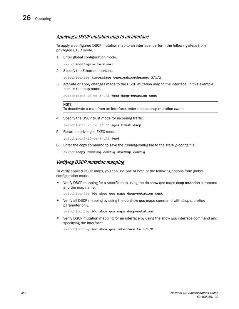
Queueing26
Applying a DSCP mutation map to an interface
To apply a configured DSCP mutation map to an interface, perform the following steps from privileged EXEC mode.
1. Enter global configuration mode.
switch#configure terminal
2. Specify the Ethernet interface.
switch(config)#interface tengigabitethernet 3/1/2
3. Activate or apply changes made to the DSCP mutation map to the interface. In this example ‘test’ is the map name.
switch(conf-if-te-3/1/2)#qos dscp-mutation test
NOTETo deactivate a map from an interface, enter no qos dscp-mutation name.
4. Specify the DSCP trust mode for incoming traffic.
switch(conf-if-te-3/1/2)#qos trust dscp
5. Return to privileged EXEC mode.
switch(conf-if-te-3/1/2)#end
6. Enter the copy command to save the running-config file to the startup-config file.
switch#copy running-config startup-config
Verifying DSCP mutation mapping
To verify applied DSCP maps, you can use one or both of the following options from global configuration mode.
• Verify DSCP mapping for a specific map using the do show qos maps dscp-mutation command and the map name.
switch(config)#do show qos maps dscp-mutation test
• Verify all DSCP mapping by using the do show qos maps command with dscp-mutation parameter only.
switch(config)#do show qos maps dscp-mutation
• Verify DSCP mutation mapping for an interface by using the show qos interface command and specifying the interface:
switch(config)#do show qos interface te 1/1/2
356 Network OS Administrator’s Guide53-1002561-02
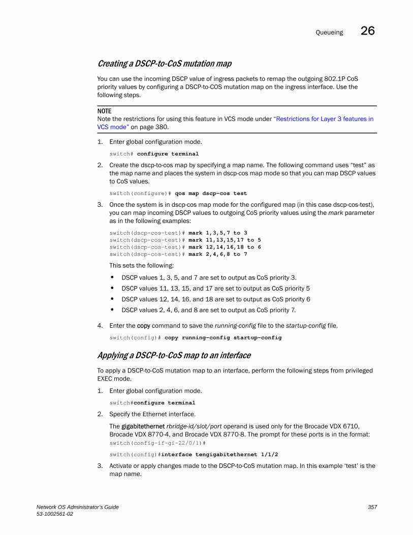
Queueing 26
Creating a DSCP-to-CoS mutation map
You can use the incoming DSCP value of ingress packets to remap the outgoing 802.1P CoS priority values by configuring a DSCP-to-COS mutation map on the ingress interface. Use the following steps.
NOTENote the restrictions for using this feature in VCS mode under “Restrictions for Layer 3 features in VCS mode” on page 380.
1. Enter global configuration mode.
switch# configure terminal
2. Create the dscp-to-cos map by specifying a map name. The following command uses “test” as the map name and places the system in dscp-cos map mode so that you can map DSCP values to CoS values.
switch(configure)# qos map dscp-cos test
3. Once the system is in dscp-cos map mode for the configured map (in this case dscp-cos-test), you can map incoming DSCP values to outgoing CoS priority values using the mark parameter as in the following examples:
switch(dscp-cos-test)# mark 1,3,5,7 to 3 switch(dscp-cos-test)# mark 11,13,15,17 to 5 switch(dscp-cos-test)# mark 12,14,16,18 to 6 switch(dscp-cos-test)# mark 2,4,6,8 to 7
This sets the following:
• DSCP values 1, 3, 5, and 7 are set to output as CoS priority 3.
• DSCP values 11, 13, 15, and 17 are set to output as CoS priority 5
• DSCP values 12, 14, 16, and 18 are set to output as CoS priority 6
• DSCP values 2, 4, 6, and 8 are set to output as CoS priority 7.
4. Enter the copy command to save the running-config file to the startup-config file.
switch(config)# copy running-config startup-config
Applying a DSCP-to-CoS map to an interface
To apply a DSCP-to-CoS mutation map to an interface, perform the following steps from privileged EXEC mode.
1. Enter global configuration mode.
switch#configure terminal
2. Specify the Ethernet interface.
The gigabitethernet rbridge-id/slot/port operand is used only for the Brocade VDX 6710, Brocade VDX 8770-4, and Brocade VDX 8770-8. The prompt for these ports is in the format: switch(config-if-gi-22/0/1)#
switch(config)#interface tengigabitethernet 1/1/2
3. Activate or apply changes made to the DSCP-to-CoS mutation map. In this example ‘test’ is the map name.
Network OS Administrator’s Guide 35753-1002561-02

Queueing26
switch(conf-if-te-1/1/2)#qos dscp-cos test
NOTETo deactivate a map from an interface, enter no qos dscp-cos name.
4. Specify the DSCP trust mode for incoming traffic.
Use this command to specify the interface ingress DSCP trust mode, which controls user priority mapping of incoming traffic. The untrusted mode will not classify packets based on DSCP. The DSCP trust mode classifies packets based on the incoming DSCP value. If the incoming packet is priority tagged, fallback is to classify packets based on the CoS value.
switch(conf-if-te-1/1/2)#qos trust dscp
5. Return to privileged EXEC mode.
switch(conf-if-te-1/1/2)#end
6. Enter the copy command to save the running-config file to the startup-config file.
switch#copy running-config startup-config
Verifying a DSCP-to-CoS mutation map
To verify applied DSCP-to-CoS maps, you can use one or both of the following options from global configuration mode.
• Verify DSCP mapping for a specific map using the do show qos maps dscp-cos command and the map name.
switch(config)#do show qos maps dscp-cos test
• Verify all DSCP mapping by using the do show qos maps command with dscp-cos parameter only.
switch(config)#do show qos maps dscp-cos
• Verify DSCP-to-CoS mutation mapping for an interface by using the show qos interface command and specifying the interface:
switch(config)#show qos interface te 1/1/2
Traffic class mappingThe Brocade switch supports eight unicast traffic classes for isolation and to control servicing for different priorities of application data. Traffic classes are numbered from 0 through 7, with higher values designating higher priority.
The traffic class mapping stage provides some flexibility in queue selection:
• The mapping may be many-to-one, such as mapping one byte user priority (256 values) to eight traffic classes.
• There may be a non-linear ordering between the user priorities and traffic classes.
358 Network OS Administrator’s Guide53-1002561-02
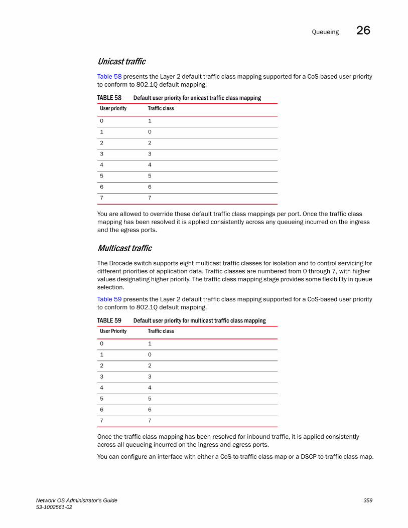
Queueing 26
Unicast traffic
Table 58 presents the Layer 2 default traffic class mapping supported for a CoS-based user priority to conform to 802.1Q default mapping.
You are allowed to override these default traffic class mappings per port. Once the traffic class mapping has been resolved it is applied consistently across any queueing incurred on the ingress and the egress ports.
Multicast traffic
The Brocade switch supports eight multicast traffic classes for isolation and to control servicing for different priorities of application data. Traffic classes are numbered from 0 through 7, with higher values designating higher priority. The traffic class mapping stage provides some flexibility in queue selection.
Table 59 presents the Layer 2 default traffic class mapping supported for a CoS-based user priority to conform to 802.1Q default mapping.
Once the traffic class mapping has been resolved for inbound traffic, it is applied consistently across all queueing incurred on the ingress and egress ports.
You can configure an interface with either a CoS-to-traffic class-map or a DSCP-to-traffic class-map.
TABLE 58 Default user priority for unicast traffic class mapping
User priority Traffic class
0 1
1 0
2 2
3 3
4 4
5 5
6 6
7 7
TABLE 59 Default user priority for multicast traffic class mapping
User Priority Traffic class
0 1
1 0
2 2
3 3
4 4
5 5
6 6
7 7
Network OS Administrator’s Guide 35953-1002561-02

Queueing26
Mapping CoS-to-Traffic-Class
To map a CoS-to-Traffic-Class, perform the following steps from privileged EXEC mode.
NOTECreating a CoS-to-Traffic-class-map is available only in standalone mode.”
1. Enter global configuration mode.
switch#configure terminal
2. Create the CoS-Traffic-Class mapping by specifying a name and the mapping.
switch(config)#qos map cos-traffic-class test 1 0 2 3 4 5 6 7
3. Return to privileged EXEC mode.
switch(config)#end
4. Enter the copy command to save the running-config file to the startup-config file.
switch#copy running-config startup-config
Applying CoS-to-Traffic-Class mapping to an interface
To activate a CoS-to-traffic class mapping, perform the following steps from privileged EXEC mode.
1. Enter global configuration mode.
switch#configure terminal
2. Specify the Ethernet interface.
The gigabitethernet rbridge-id/slot/port operand is used only for the Brocade VDX 6710, Brocade VDX 8770-4, and Brocade VDX 8770-8. The prompt for these ports is in the format: switch(config-if-gi-22/0/1)#
switch(config)#interface tengigabitethernet 12/2/2
3. Activate the CoS-to-Traffic-Class mapping. In this case ‘test’ is the map name.
switch(conf-if-te-12/2/2)#qos cos-traffic-class test
NOTETo deactivate the mutation map from an interface, enter no qos cos-traffic-class.
4. Return to privileged EXEC mode.
switch(conf-if-te-12/2/2)#end
5. Enter the copy command to save the running-config file to the startup-config file.
switch#copy running-config startup-config
360 Network OS Administrator’s Guide53-1002561-02

Queueing 26
Verifying CoS-to-Traffic-Class mapping
To verify a CoS-to-Traffic-Class mapping, you can use one or both of the following options from global configuration mode.
• Verify CoS-Traffic-Class mapping for a specific map by using the do show qos maps cos-traffic-class command and specifying a map name.
switch(config)#do show qos map cos-traffic-class test
• Verify all COS-to-Traffic-Class mapping with the do show qos maps command with cos-traffic-class only.
switch(config)#do show qos maps cos-traffic-class
• Verify CoS-to-Traffic-Class mapping for an interface by using the show qos interface command and specifying the interface:
switch(config)#do show qos interface te 12/2/2
Mapping DSCP-to-Traffic-Class
Ingress DSCP values can be used to classify traffic for the ingress interface into a specific traffic class using a DSCP-to-Traffic class-map. To map a DSCP-to-Traffic-Class, perform the following steps from privileged EXEC mode.
NOTENote the restrictions for using this feature in VCS mode under “Restrictions for Layer 3 features in VCS mode” on page 380.
1. Enter global configuration mode.
switch#configure terminal
2. Create the DSCP-Traffic-Class mapping by specifying a map name. The following command uses “test” as the map name and places the system in dscp-traffic-class mode so that you can configure mapping for the map that you created.
switch(config)#qos map dscp-traffic-class test
3. Once the system is in dscp-traffic-class mode for the configured map (in this case dscp-traffic-class-test), you can map DSCP values to traffic classes using the mark parameter as in the following examples:
switch(dscp-traffic-class-test) mark 1,3,5,7 to 3switch(dscp-traffic-class-test) mark 11,13,15,17 to 5switch(dscp-traffic-class-test) mark 12,14,16,18 to 6switch(dscp-traffic-class-test) mark 2,4,6,8 to 7
This sets the following:
• DSCP values 1, 3, 5, and 7 are mapped to traffic class 3.
• DSCP values 11, 13, 15, and 17 are mapped to traffic class 5.
• DSCP values 12, 14, 16, and 18 are mapped to traffic class 6.
• DSCP values 2, 4, 6, and 8 are mapped to traffic class 7.
4. Return to privileged EXEC mode:
switch(dscp-traffic-class-test)end
Network OS Administrator’s Guide 36153-1002561-02

Queueing26
5. Enter the copy command to save the running-config file to the startup-config file.
switch#copy running-config startup-config
362 Network OS Administrator’s Guide53-1002561-02

Queueing 26
Applying DSCP-to-Traffic-Class mapping to an interface
To activate a DSCP-to-Traffic Class mapping, perform the following steps from privileged EXEC mode.
1. Enter global configuration mode.
switch#configure terminal
2. Specify the Ethernet interface.
The gigabitethernet rbridge-id/slot/port operand is used only for the Brocade VDX 6710, Brocade VDX 8770-4, and Brocade VDX 8770-8. The prompt for these ports is in the format: switch(config-if-gi-22/0/1)#
switch(config)#interface tengigabitethernet 1/1/2
3. Activate the DSCP-to-Traffic-Class mapping. In this case ‘test’ is the map name.
switch(conf-if-te-1/1/2)#qos dscp-traffic-class test
NOTETo deactivate a DSCP-to-Traffic-Class map from an interface, enter no qos dscp-traffic-class name.
4. Return to privileged EXEC mode.
switch(conf-if-te-1/1/2)#end
5. Enter the copy command to save the running-config file to the startup-config file.
switch#copy running-config startup-config
Verifying DSCP-to-Traffic-Class mapping
To verify a DSCP-to-Traffic-Class mapping, you can use one or both of the following options from global configuration mode.
• Verify the DSCP-Traffic-Class mapping for specific map by using the do show qos maps dscp-traffic-class command and specifying a map name.
switch(config)#do show qos maps dscp-traffic-class test
• Verify all DSCP-Traffic-Class mapping with the just the do show qos maps command with the dscp-traffic-class parameter only.
switch(config)#do show qos maps dscp-traffic-class
• Verify DSCP-to-Traffic-Class mapping for an interface by using the show qos interface command and specifying the interface:
switch(config)#show qos interface te 1/1/2
Network OS Administrator’s Guide 36353-1002561-02

Congestion control26
Congestion controlQueues can begin filling up due to a number of reasons, such as over subscription of a link or backpressure from a downstream device. Sustained, large queue buildups generally indicate congestion in the network and can affect application performance through increased queueing delays and frame loss.
Congestion control covers features that define how the system responds when congestion occurs or active measures taken to prevent the network from entering a congested state.
NOTEYou cannot configure CoS thresholds and multicast tail drop on VDX 8770-4 and VDX 8770-8 platforms. Random Early Discard (RED) is only supported on VDX 8770-4 and VDX 8770-8 platforms.
Tail dropTail drop queueing is the most basic form of congestion control. Frames are queued in FIFO order and queue buildup can continue until all buffer memory is exhausted. This is the default behavior when no additional QoS has been configured.
The basic tail drop algorithm does not have any knowledge of multiple priorities and per traffic class drop thresholds can be associated with a queue to address this. When the queue depth breaches a threshold, then any frame arriving with the associated priority value will be dropped. Figure 26 describes how you can utilize this feature to ensure that lower priority traffic cannot totally consume the full buffer memory. Thresholds can also be used to bound the maximum queueing delay for each traffic class. Additionally if the sum of the thresholds for a port is set below 100 percent of the buffer memory, then you can also ensure that a single port does not monopolize the entire shared memory pool.
FIGURE 26 Queue depth
364 Network OS Administrator’s Guide53-1002561-02

Congestion control 26
The tail drop algorithm can be extended to support per priority drop thresholds. When the ingress port CoS queue depth breaches a threshold, then any frame arriving with the associated priority value will be dropped. Figure 26 describes how you can utilize this feature to ensure lower priority traffic cannot totally consume the full buffer memory. Thresholds can also be used to bound the maximum queueing delay for each traffic class. Additionally if the sum of the thresholds for a port is set below 100 percent of the buffer memory then you can also ensure that a single CoS does not monopolize the entire shared memory pool allocated to the port.
Changing the multicast Tail Drop threshold
To change the Tail Drop threshold, perform the following steps from privileged EXEC mode.
1. Enter global configuration mode.
switch#configure terminal
2. Change the Tail Drop threshold for each multicast traffic class. In this example, 1000pkt is used.
switch(config)#qos rcv-queue multicast threshold 1000 1000 1000 1000 1000 1000 1000 1000
3. Return to privileged EXEC mode.
switch(config)#end
4. Enter the copy command to save the running-config file to the startup-config file.
switch#copy running-config startup-config
Configuring CoS thresholdsEvery port has associated with it a total of 9 CoS thresholds, one for the port tail drop threshold and the other eight are thresholds for per priority. To give a fair allocation of buffers for the traffic from all priorities, the port buffers are allocated among different priorities. That is achieved through per priority tail drop thresholds. The port tail drop threshold represents the amount of buffers given to the port and per priority tail drop thresholds (called CoS tail drop thresholds from here on) represents the buffers allocated to each CoS.
Whenever the buffers allocated to a priority are fully exhausted, all the traffic coming in on that priority is dropped. In the absence of per priority tail drop thresholds (and only port tail drop threshold), the buffers would be consumed on a first come first serve basis and results in an unfair share of buffers between all the priorities. If you know which priority traffic is most seen, then giving good number of buffers for those priorities results in less number of packet drops for those priorities.
Therefore, instead of using the standard priority values, you can assign anywhere from 0% through 100% priority to any threshold, with the sum value of all eight priorities to not exceed 100%. For example, using the priorities 5 5 5 5 50 20 2 8 sums up to 100%, as shown in the following code:
switch(conf-if-te-0/1)# qos rcv-queue cos-threshold 5 5 5 5 50 20 2 8switch(conf-if-te-0/1)# do show qos in te 0/1Interface TenGigabitEthernet 0/1CoS-to-Traffic Class map 'default‘
In-CoS: 0 1 2 3 4 5 6 7-----------------------------------------------------Out-CoS/TrafficClass: 0/1 1/0 2/2 3/3 4/4 5/5 6/6 7/7
Per-Traffic Class Tail Drop Threshold (bytes)TC: 0 1 2 3 4 5 6 7
Network OS Administrator’s Guide 36553-1002561-02

Congestion control26
------------------------------------------------------------------Threshold: 10180 10180 10180 10180 101808 40723 4072 16289
The tail drop thresholds are not allowed to exceed 100%, but can be below 100%. For example, if the tail drop thresholds entered are less than 100%, then the buffer allocation happens as per what has been configured.
Random Early Discard
NOTEThis feature is only supported on VDX 8770-4, VDX 8770-8, and later models.
Traditionally, Random Early Discard (RED) is used for TCP traffic streams, which are generally more aggressive, as well as reactive, to network drops. If RED is not configured, queues build up at the switch and become full, resulting in tail drop. Tail drop situations can cause head-of-line blocking issues at the switch, which is not desirable. By configuring RED, you set a probability for dropping packets before traffic in the queue reaches a specific threshold. This allows congestion to ease more gradually, avoids retransmit synchronization, resolves “bursty” TCP connections during congestion conditions, and controls packet latency.
Configure RED using the following parameters:
• RED profile identification (0-384)
• Minimum threshold of a queue (0-100%)
• Maximum threshold of a queue (0-100%)
• Drop probability (0-100%)
The ASIC driver will map the configured minimum and maximum percentages to the actual queue size in bytes, depending on the bandwidth of the port (buffers are allocated to a port according to port speed). When buffers in the queue build up to the set minimum threshold, packets being enqueued are randomly dropped. The drop probability parameter defines the randomness of the drops. When the queues exceed the minimum threshold, packets are dropped according to the configured drop probability value. When the queue buffers exceed the set maximum threshold, packets are dropped with 100% probability. The higher the probability set, the more likely packets will be dropped when reaching the minimum percentage.
You can also map a specific CoS priority value (0 through 7) to a specific RED profile.
Configuring RED profiles
To configure an egress RED profile, perform the following steps from privileged EXEC mode.
1. Enter global configuration mode.
switch#configure terminal
2. Configure a RED profile. For the profile ID, 10 is used in this case. The min-threshold, max-threshold, and drop-probability values are percentages.
switch(config)#qos red-profile 10 min-threshold 10 max-threshold 80 drop-probablity 80
3. Return to privileged EXEC mode.
switch(config)#end
366 Network OS Administrator’s Guide53-1002561-02

Congestion control 26
4. Enter the copy command to save the running-config file to the startup-config file.
switch#copy running-config startup-config
Map CoS priority to RED profile on interface
To map a CoS priority value for a port to the RED profile created under “Configuring RED profiles” on page 366, perform the following steps from privileged EXEC mode.
1. Enter global configuration mode.
switch#configure terminal
2. Specify the Ethernet interface.
switch(config)#interface tengigabitethernet 1/2/2
3. Map the profile to use a CoS priority for a port. In the following example, CoS priority 3 is mapped to RED profile ID 10.
switch(conf-if-te-1/2/2)#qos random-detect cos 3 red-profile-id 10
NOTETo deactivate the map from an interface, enter no qos random-detect cos value.
4. Return to privileged EXEC mode.
switch(conf-if-te-1/2/2)#end
5. Enter the copy command to save the running-config file to the startup-config file.
switch#copy running-config startup-config
Verifying RED profiles
Verify a configured RED profiles using the show qos red profiles command.
switch# show qos red profiles
Examine the applied RED profiles for an interface using the show qos interface interface-name command. Note that besides the RED profile, this will display all QoS configurations applied to the interface, such as DSCP trust, DSCP-to-DSCP map, CoS-Traffic Class map, and others.
switch# show qos interface te 1/2/2
Considerations for RED
Consider the following when configuring RED.
• Up to four RED profiles can be applied to each port group. On the 48 x 10G line card, the port groups consist of ports 1-8, 9-16, 17-24, 25-32, 33-40, and 41-48. On the 12 x 40G line card, the port groups consist of ports 1-2, 3-4, 5-6, 7-8, 9-10, and 11-12.
• Trunk ports cannot share RED profiles with any other ports because the bandwidth for a trunk port changes according to the number of active links in the trunk.
• When queue thresholds in a RED profile are configured by percentage, the switch maps this to a total number of bytes as buffers allocated to a port depend on the port speed.
• A total of 384 RED profiles are supported per chassis.
Network OS Administrator’s Guide 36753-1002561-02
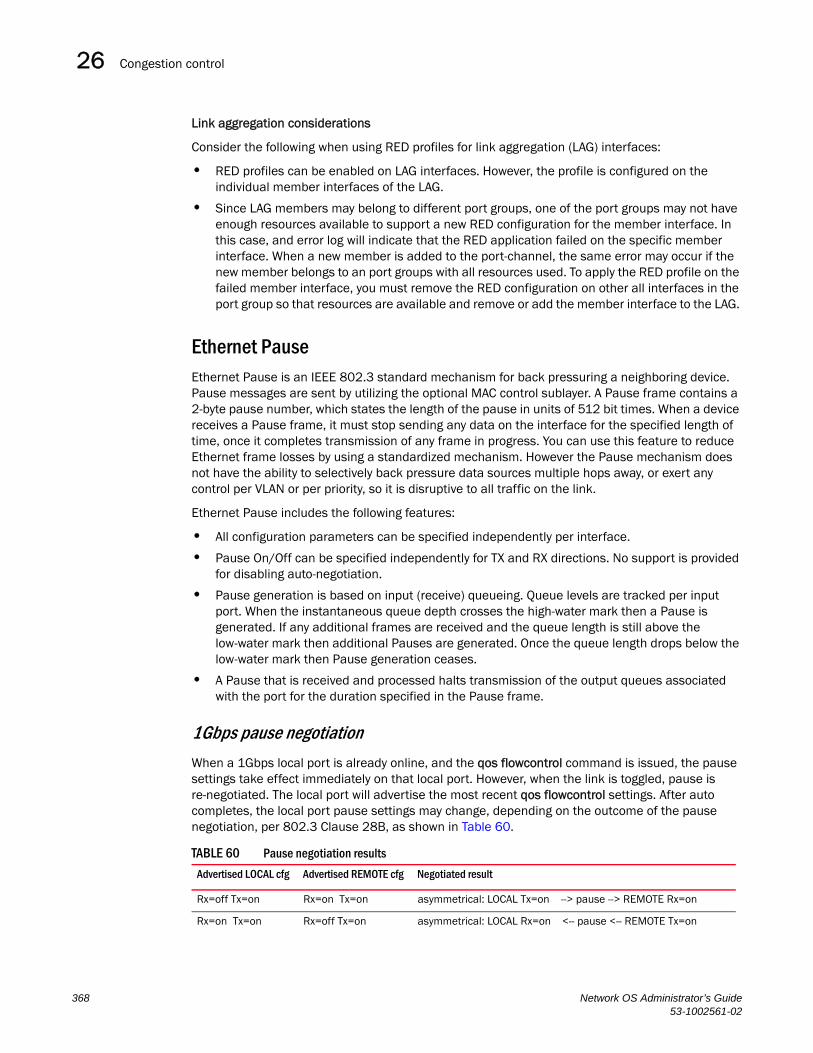
Congestion control26
Link aggregation considerations
Consider the following when using RED profiles for link aggregation (LAG) interfaces:
• RED profiles can be enabled on LAG interfaces. However, the profile is configured on the individual member interfaces of the LAG.
• Since LAG members may belong to different port groups, one of the port groups may not have enough resources available to support a new RED configuration for the member interface. In this case, and error log will indicate that the RED application failed on the specific member interface. When a new member is added to the port-channel, the same error may occur if the new member belongs to an port groups with all resources used. To apply the RED profile on the failed member interface, you must remove the RED configuration on other all interfaces in the port group so that resources are available and remove or add the member interface to the LAG.
Ethernet PauseEthernet Pause is an IEEE 802.3 standard mechanism for back pressuring a neighboring device. Pause messages are sent by utilizing the optional MAC control sublayer. A Pause frame contains a 2-byte pause number, which states the length of the pause in units of 512 bit times. When a device receives a Pause frame, it must stop sending any data on the interface for the specified length of time, once it completes transmission of any frame in progress. You can use this feature to reduce Ethernet frame losses by using a standardized mechanism. However the Pause mechanism does not have the ability to selectively back pressure data sources multiple hops away, or exert any control per VLAN or per priority, so it is disruptive to all traffic on the link.
Ethernet Pause includes the following features:
• All configuration parameters can be specified independently per interface.
• Pause On/Off can be specified independently for TX and RX directions. No support is provided for disabling auto-negotiation.
• Pause generation is based on input (receive) queueing. Queue levels are tracked per input port. When the instantaneous queue depth crosses the high-water mark then a Pause is generated. If any additional frames are received and the queue length is still above the low-water mark then additional Pauses are generated. Once the queue length drops below the low-water mark then Pause generation ceases.
• A Pause that is received and processed halts transmission of the output queues associated with the port for the duration specified in the Pause frame.
1Gbps pause negotiation
When a 1Gbps local port is already online, and the qos flowcontrol command is issued, the pause settings take effect immediately on that local port. However, when the link is toggled, pause is re-negotiated. The local port will advertise the most recent qos flowcontrol settings. After auto completes, the local port pause settings may change, depending on the outcome of the pause negotiation, per 802.3 Clause 28B, as shown in Table 60.
TABLE 60 Pause negotiation results
Advertised LOCAL cfg Advertised REMOTE cfg Negotiated result
Rx=off Tx=on Rx=on Tx=on asymmetrical: LOCAL Tx=on --> pause --> REMOTE Rx=on
Rx=on Tx=on Rx=off Tx=on asymmetrical: LOCAL Rx=on <-- pause <-- REMOTE Tx=on
368 Network OS Administrator’s Guide53-1002561-02

Congestion control 26
Enabling Ethernet Pause
This task configures FlowControl, in addition to enabling the Ethernet pause frames. Brocade recommends that you also configure the flow control parameters on the connecting device, not leave the options set to “auto”.
NOTEThe Ethernet Pause option is available only in standalone mode.
To enable Ethernet Pause, perform the following steps from privileged EXEC mode.
1. Enter global configuration mode.
switch#configure terminal
2. Specify the Ethernet interface.
The gigabitethernet rbridge-id/slot/port operand is used only for the Brocade VDX 6710, Brocade VDX 8770-4, and Brocade VDX 8770-8. The prompt for these ports is in the format: switch(config-if-gi-22/0/1)#
switch(config)#interface tengigabitethernet 3/0/2
3. Enable Ethernet Pause on the interface for both TX and RX traffic.
switch(conf-if-te-3/0/2)#qos flowcontrol tx on rx on
NOTETo deactivate Ethernet pause on an interface, enter no qos flowcontrol.
4. Return to privileged EXEC mode.
switch(conf-if-te-3/0/2)#end
5. Enter the copy command to save the running-config file to the startup-config file.
switch#copy running-config startup-config
Ethernet Priority Flow ControlEthernet Priority Flow Control (PFC) is a basic extension of the Ethernet Pause. The Pause MAC control message is extended with eight 2-byte pause numbers and a bitmask to indicate which values are valid. Each pause number is interpreted identically to the base Pause protocol; however each is applied to the corresponding Ethernet priority / class level. For example, the Pause number zero applies to priority zero, Pause number one applies to priority one, and so on. This addresses one shortcoming of the Ethernet Pause mechanism, which is disruptive to all traffic on the link. However, it still suffers from the other Ethernet Pause limitations.
Rx=on Tx=n/a Rx=on Tx=n/a symmetrical : LOCAL Tx/Rx=on <-- pause --> REMOTE Tx/Rx=on
Rx=n/a Tx=n/a Rx=off Tx=off disable pause both sides
TABLE 60 Pause negotiation results (Continued)
Advertised LOCAL cfg Advertised REMOTE cfg Negotiated result
Network OS Administrator’s Guide 36953-1002561-02

Multicast rate limiting26
Ethernet Priority Flow Control includes the following features:
• Everything operates exactly as in Ethernet Pause described above except there are eight high-water and low-water thresholds for each input port. This means queue levels are tracked per input port plus priority.
• Pause On/Off can be specified independently for TX and RX directions per priority.
• Pause time programmed into Ethernet MAC is a single value covering all priorities.
• Both ends of a link must be configured identically for Ethernet Pause or Ethernet Priority Flow Control because they are incompatible.
Enabling an Ethernet PFC
To enable Ethernet PFC, perform the following steps from privileged EXEC mode.
1. Enter global configuration mode.
switch#configure terminal
2. Specify the Ethernet interface.
The gigabitethernet rbridge-id/slot/port operand is used only for the Brocade VDX 6710, Brocade VDX 8770-4, and Brocade VDX 8770-8. The prompt for these ports is in the format: switch(config-if-gi-22/0/1)#
switch(config)#interface tengigabitethernet 1/1/2
3. Enable an Ethernet PFC on the interface.
switch(conf-if-te-1/1/2)#qos flowcontrol pfc 3 tx on rx on
NOTETo disable Ethernet PFC from an interface, enter no qos flowcontrol pfc cos value.
4. Return to privileged EXEC mode.
switch(conf-if-te-1/1/2)#end
5. Enter the copy command to save the running-config file to the startup-config file.
switch#copy running-config startup-config
Multicast rate limitingMulticast rate limiting provides a mechanism to control multicast frame replication and cap the effect of multicast traffic.
Multicast rate limit is applied to the output of each multicast receive queue. Rate limits apply equally to ingress receive queueing (first level expansion) and egress receive queueing (second level expansion) since the same physical receive queues are utilized. You can set policies to limit the maximum multicast frame rate differently for each traffic class level and cap the total multicast egress rate out of the system.
Multicast rate limiting includes the following features:
370 Network OS Administrator’s Guide53-1002561-02

BUM storm control 26
• All configuration parameters are applied globally. Multicast rate limits are applied to multicast receive queues as frame replications are placed into the multicast expansion queues. The same physical queues are used for both ingress receive queues and egress receive queues so rate limits are applied to both ingress and egress queueing.
• The rate limit value represents the maximum multicast expansion rate in packets per second (PPS).
NOTEMulticast rate limiting is not supported on VDX 8770-4 and 8770-8 platforms. For these products, refer to “BUM storm control” on page 371.
Creating a receive queue multicast rate-limitTo create the receive queue multicast rate-limit, perform the following steps from privileged EXEC mode.
1. Enter global configuration mode.
switch#configure terminal
2. Create a lower maximum multicast frame expansion rate. In this example, the rate is set to 10000 PPS.
switch(config)#qos rcv-queue multicast rate-limit 10000
3. Return to privileged EXEC mode.
switch(config)#end
4. Enter the copy command to save the running-config file to the startup-config file.
switch#copy running-config startup-config
BUM storm controlA traffic storm occurs when packets flood the LAN, creating excessive traffic and degrading network performance. Broadcast, unicast and unknown multicast (BUM) storm control can prevent disruptions on Layer 2 physical ports.
BUM storm control allows you to limit the amount of broadcast, unknown unicast, and multicast ingress traffic on a specified interface or on the entire system. All traffic received in excess of the configured rate gets discarded. You also have the option to specify whether to shutdown an interface if the maximum defined rate is exceeded within a five-second sampling period. When a port is shutdown, you receive a log message. You must then manually re-enable the interface using the no shut command.
Considerations• BUM storm control must be configured on one of the following physical interface:
• tengigabitethernet
• gigabitethernet
• fortygigabitethernet
Network OS Administrator’s Guide 37153-1002561-02

Scheduling26
• BUM storm control and input service-policy are mutually exclusive features. Only one can be enabled at a time on a given interface.
• BUM storm control replaces the multicast rate-limit feature for VDX 8770-4 and 8770-8, and later platforms. This command is not supported on VDX 6XXX modules, such as the VDX 6710, 6720, and 6730.
Configuring BUM storm controlTo configure storm control on a tengigabitethernet interface called 101/0/2, with the broadcast traffic type and limit-rate of 1000000 bps, perform the following steps:
1. Enter global configuration mode.
Switch# configure terminal
2. Specify the Ethernet interface.for the traffic you want to control. In the following example, interface 101/0/2 is in rbridge-id/slot/port format:
Switch(config)# interface tengigabitethernet 101/0/2
3. Issue the storm-control ingress command to set a bps traffic limit for broadcast traffic on the interface:
Switch (conf-if-te-101/0/2)# storm-control ingress broadcast 1000000
NOTETo deactivate storm control from an interface, enter no storm-control ingress {broadcast | unknown-unicast | multicast} {limit-bps | limit-percent } rate [ {monitor | shutdown] }.
SchedulingScheduling arbitrates among multiple queues waiting to transmit a frame. The Brocade switch supports both Strict Priority (SP) and Deficit Weighted Round Robin (DWRR) scheduling algorithms. Also supported is the flexible selection of the number of traffic classes using SP-to-DWRR. When there are multiple queues for the same traffic class, then scheduling takes these equal priority queues into consideration.
Strict priority schedulingStrict priority scheduling is used to facilitate support for latency-sensitive traffic. A strict priority scheduler drains all frames queued in the highest priority queue before continuing on to service lower priority traffic classes. A danger with this type of service is that a queue can potentially starve out lower priority traffic classes.
372 Network OS Administrator’s Guide53-1002561-02

Scheduling 26
Figure 27 describes the frame scheduling order for an SP scheduler servicing two SP queues. The higher numbered queue, SP2, has a higher priority.
FIGURE 27 Strict priority schedule — two queues
Deficit weighted round robin schedulingWeighted Round Robin (WRR) scheduling is used to facilitate controlled sharing of the network bandwidth. WRR assigns a weight to each queue; that value is then used to determine the amount of bandwidth allocated to the queue. The round robin aspect of the scheduling allows each queue to be serviced in a set ordering, sending a limited amount of data before moving onto the next queue and cycling back to the highest priority queue after the lowest priority is serviced.
Figure 28 describes the frame scheduling order for a WRR scheduler servicing two WRR queues. The higher numbered queue is considered higher priority (WRR2) and the weights indicate the network bandwidth should be allocated in a 2:1 ratio between the two queues. In Figure 28 WRR2 should receive 66 percent of bandwidth and WRR1 receives 33 percent. The WRR scheduler tracks the extra bandwidth used and subtracts it from the bandwidth allocation for the next cycle through the queues. In this way, the bandwidth utilization statistically matches the queue weights over longer time periods.
FIGURE 28 WRR schedule — two queues
Deficit Weighted Round Robin (DWRR) is an improved version of WRR. DWRR remembers the excess used when a queue goes over its bandwidth allocation and reduces the queue's bandwidth allocation in the subsequent rounds. This way the actual bandwidth usage is closer to the defined level when compared to WRR.
Traffic class scheduling policyThe traffic classes are numbered from 0 to 7; higher numbered traffic classes are considered higher priority. The Brocade switch provides full flexibility in controlling the number of SP-to-WRR queues. The number of SP queues is specified in N (SP1 through 8), then the highest priority traffic classes are configured for SP service and the remaining eight are WRR serviced. Table 61 describes the set of scheduling configurations supported.
When you configure the QoS queue to use strict priority 4 (SP4), then traffic class 7 will use SP4, traffic class 6 will use SP3, and so on down the list. You use the strict priority mappings to control how the different traffic classes will be routed in the queue.
Network OS Administrator’s Guide 37353-1002561-02

Scheduling26
Figure 29 shows that extending the frame scheduler to a hybrid SP+WRR system is fairly straightforward. All SP queues are considered strictly higher priority than WRR so they are serviced first. Once all SP queues are drained, then the normal WRR scheduling behavior is applied to the non-empty WRR queues.
FIGURE 29 Strict priority and Weighted Round Robin scheduler
Scheduling the QoS queue
To specify the schedule used, perform the following steps from privileged EXEC mode.
1. Enter global configuration mode.
switch#configure terminal
2. Specify the schedule to use and the traffic class to bandwidth mapping.
switch(config)#qos queue multicast scheduler dwrr 10 20 20 10 10 10 10 10
3. Return to privileged EXEC mode.
switch(config)#end
4. Enter the copy command to save the running-config file to the startup-config file.
switch#copy running-config startup-config
TABLE 61 Supported scheduling configurations
Traffic Class SP0 SP1 SP2 SP3 SP4 SP5 SP6 SP8
7 WRR8 SP1 SP2 SP3 SP4 SP5 SP6 SP8
6 WRR7 WRR7 SP1 SP2 SP3 SP4 SP5 SP7
5 WRR6 WRR6 WRR6 SP1 SP2 SP3 SP4 SP6
4 WRR5 WRR5 WRR5 WRR5 SP1 SP2 SP3 SP5
3 WRR4 WRR4 WRR4 WRR4 WRR4 SP1 SP2 SP4
2 WRR3 WRR3 WRR3 WRR3 WRR3 WRR3 SP1 SP3
1 WRR2 WRR2 WRR2 WRR2 WRR2 WRR2 WRR2 SP2
0 WRR1 WRR1 WRR1 WRR1 WRR1 WRR1 WRR1 SP1
374 Network OS Administrator’s Guide53-1002561-02

Data Center Bridging map configuration 26
Multicast queue schedulingThe multicast traffic classes are numbered from 0 to 7; higher numbered traffic classes are considered higher priority. A fixed mapping from multicast traffic class to equivalent unicast traffic class is applied to select the queue scheduling behavior. Table 62 presents the multicast traffic class with the equivalence mapping applied.
Once the multicast traffic class equivalence mapping has been applied, then scheduling and any scheduler configuration are inherited from the equivalent unicast traffic class. See Table 61 for details on exact mapping equivalencies.
Unicast ingress and egress queueing utilizes a hybrid scheduler that simultaneously supports SP+WRR service and multiple physical queues with the same service level. Multicast adds additional multicast expansion queues. Since multicast traffic classes are equivalent to unicast service levels, they're treated exactly as their equivalent unicast service policies.
Scheduling the QoS multicast queue
To schedule the QoS multicast queue, perform the following steps from privileged EXEC mode.
1. Enter global configuration mode.
switch#configure terminal
2. Specify the schedule to use and the traffic class to bandwidth mapping.
switch(config)#qos queue multicast scheduler dwrr 10 20 20 10 10 10 10 10
3. Return to privileged EXEC mode.
switch(config)#end
4. Enter the copy command to save the running-config file to the startup-config file.
switch#copy running-config startup-config
Data Center Bridging map configurationThe DCB QoS covers frame classification, priority and traffic class (queue) mapping, congestion control, and scheduling. Under the DCB Provisioning model all of these features are configured utilizing two configuration tables, Priority Group Table and Priority Table.
TABLE 62 Multicast traffic class equivalence mapping
Multicast traffic class Equivalent unicast traffic class
0 0
1 1
2 2
3 3
4 4
5 5
6 6
7 7
Network OS Administrator’s Guide 37553-1002561-02

Data Center Bridging map configuration26
DCB Priority Group Table defines each Priority Group ID (PGID) and its scheduling policy (Strict Priority versus DWRR, DWRR weight, relative priority), and partially defines the congestion control (PFC) configuration. There are 16 rows in the DCB Priority Group Table. Table 63 presents the default DCB Priority Group Table configuration.
NOTEOnly a single CoS can be mapped to a PFC-enabled priority queue.The switch automatically maps the CoS number to the same TC number when PFC is enabled. The PGID can be anything from 0-7. If your configuration violates this restriction an error message displays and the Priority Group Table is set back to the default values.
When the DCB map is applied, and the interface is connected to the CNA, only one strict priority PGID (PGID 15.0 to PGID 15.7) is allowed.
Strict Priority versus DWRR is derived directly from the PGID value. All PGIDs with prefix 15 receive Strict Priority scheduling policy and all PGIDs in the range 0 through 7 receive DWRR scheduling policy. Relative priority between Priority Group is exactly the ordering of entries listed in the table, with PGID 15.0 being highest priority and PGID 7 being lowest priority. Congestion control configuration is partially specified by toggling the PFC column On or Off. This provides only partial configuration of congestion control because the set of priorities mapped to the Priority Group is not known, which leads into the DCB Priority Table.
TABLE 63 Default DCB Priority Group Table configuration
PGID Bandwidth% PFC
15.0 — N
15.1 — N
15.2 — N
15.3 — N
15.4 — N
15.5 — N
15.6 — N
15.7 — N
0 0 N
1 0 N
2 0 N
3 0 N
4 0 N
5 0 N
6 0 N
7 0 N
376 Network OS Administrator’s Guide53-1002561-02

Data Center Bridging map configuration 26
The DCB Priority Table defines each CoS mapping to Priority Group, and completes PFC configuration. There are eight rows in the DCB Priority Table as shown in Table 64.
Creating a DCB mapTo create a DCB map, perform the following steps from privileged EXEC mode.
1. Enter global configuration mode.
switch#configure terminal
2. Create a DCB map using the cee-map command.
The only map name allowed is “default.”
switch(config)#cee-map default
3. Return to privileged EXEC mode.
switch(config)#exit
4. Enter the copy command to save the running-config file to the startup-config file.
switch#copy running-config startup-config
Defining a priority group tableTo define a priority group table map, perform the following steps from privileged EXEC mode.
1. Enter global configuration mode.
switch#configure terminal
2. Specify the name of the DCB map to define using the cee-map command.
The only map name allowed is “default.”
switch(config)#cee-map default
3. Define the DCB map for PGID 0.
switch(config-cee-map-default)#priority-group-table 0 weight 50 pfc on
4. Define the DCB map for PGID 1.
switch(config-cee-map-default)#priority-group-table 1 weight 50 pfc off
TABLE 64 Default DCB priority table
CoS PGID
0 15.6
1 15.7
2 15.5
3 15.4
4 15.3
5 15.2
6 15.1
7 15.0
Network OS Administrator’s Guide 37753-1002561-02

Data Center Bridging map configuration26
5. Return to privileged EXEC mode.
switch(config-cee-map-default)#end
6. Enter the copy command to save the running-config file to the startup-config file.
switch#copy running-config startup-config
Defining a priority-table mapTo define a priority-table map, perform the following steps from privileged EXEC mode.
1. Enter global configuration mode.
switch#configure terminal
2. Specify the name of the DCB map to define using the cee-map command. In this example ‘default’ is used.
switch(config)#cee-map default
3. Define the map.
switch(config-cee-map)#priority-table 1 1 1 0 1 1 1 15.0
NOTEFor information about priority-table definitions, see the “cee-map (configuration)” command in the NOS Command Reference, 3.0.
4. Return to privileged EXEC mode.
switch(config-cee-map)#end
5. Enter the copy command to save the running-config file to the startup-config file.
switch#copy running-config startup-config
Applying a DCB provisioning map to an interfaceTo apply a DCB provisioning map, perform the following steps from privileged EXEC mode.
1. Enter global configuration mode.
switch#configure terminal
2. Specify the Ethernet interface. In this example, 101/0/2 is used.
switch(config)#interface tengigabitethernet 101/0/2
3. Apply the DCB map on the interface.
switch(conf-if-te-101/0/2)#cee default
NOTETo deactivate the map on the interface, enter no cee.
4. Return to privileged EXEC mode.
switch(conf-if-te-101/0/2)#end
5. Enter the copy command to save the running-config file to the startup-config file.
switch#copy running-config startup-config
378 Network OS Administrator’s Guide53-1002561-02

Brocade VCS Fabric QoS 26
Verifying the DCB maps To verify the CoS DCB map, use the do show cee maps default command from global configuration mode.
switch#do show cee maps default
Brocade VCS Fabric QoSBrocade VCS Fabric QoS requires very little user configuration. The only options to modify are the fabric priority and the lossless priority.
Brocade VCS Fabric reserves a mapping priority and fabric priority of seven (7). Any traffic that enters the Brocade VCS Fabric cluster from upstream that is using the reserved priority value is automatically remapped to a lower priority.
Changing the mapping or fabric priority is not required. By default the values are set to zero (0) for both of the re-mapped priorities.
In Brocade VCS Fabric mode:
• All incoming priority 7 tagged packets are dropped on the edge ports.
• Untagged control frames are counted in queue 7 (TC7).
All switches in the Brocade VCS Fabric cluster must have matching re-mapping priority values and the same priority-group-table values.
Configuring Brocade VCS Fabric QoSTo configure the remapping priorities for the Brocade VCS Fabric, perform the following steps from global configuration mode.
1. Use the cee-map command to enter CEE map configuration mode.
switch(config)#cee-map default
2. Use the remap lossless priority command to set the lossless priority for Brocade VCS Fabric QoS.
The default lossless remap priority is set to 0.
switch(config-cee-map-default)#remap lossless-priority priority 2
3. Use the remap fabric priority command to set the fabric priority for Brocade VCS Fabric QoS.
The default FCoE remap fabric priority is set to 0.
switch(fabric-cee-map-default)#remap fabric-priority priority 2
4. Use the exit command to return to global configuration mode.
switch(config-cee-map)#exit
5. Specify the incoming Ethernet data interface.
switch(config)#interface tengigabitethernet 22/0/1
6. Apply the CEE Provisioning map to the interface.
switch(conf-if-te-22/0/1)#cee default
Network OS Administrator’s Guide 37953-1002561-02

Restrictions for Layer 3 features in VCS mode26
Restrictions for Layer 3 features in VCS modeWhen the switch is in VCS mode, the lossless priority for carrying FCoE traffic and the fabric priority for carrying fabric traffic must be isolated from any Layer 3 QoS markings and classification. Therefore, specific restrictions apply to some Layer 3 DSCP QoS features when the switch is working in VCS mode:
The following are restrictions for using applicable Layer 3 DSCP-Traffic-Class map, DSCP-CoS map, and DSCP Trust features in VCS mode. Note that DSCP mutation maps and the egress RED feature are not affected in VCS mode.
• DSCP trust will be disabled in VCS mode like it is for CoS trust.
• There will be no default DSCP maps while in VCS mode. Default maps occur when DSCP trust is enabled in standalone mode.
• A non-default DSCP-Traffic-Class map has the following restrictions:
- A DSCP value cannot be classified to Traffic Class 7.
- A DSCP value cannot be classified to a queue that carries lossless traffic (by default Traffic Class 3).
• A non-default DSCP-CoS map has the following restrictions:
- A DSCP value cannot be marked to CoS 7.
- A DSCP value cannot be marked to lossless priority (by default CoS 3).
• Lossless priorities will be identified through the CEE map.
• To enable DSCP based marking or classification, a non-default DSCP-Traffic-Class map and a DSCP-CoS map have to be applied on the interface.
• To apply a DSCP-Traffic-Class or DSCP-CoS map to an interface, the CoS and Traffic Class values have to be re-marked for lossless priorities. For example, when DSCP-Traffic-Class map “abcd” is created, it will have the default contents. When applied to an interface, an error will display that the fabric and lossless priorities are used in the map and it cannot be applied on the interface.
• When a valid DSCP-Traffic-Class map and DSCP-CoS map are applied on the interface, then DSCP trust is enabled with the configured maps.
Port-Based PolicerThe port-based Policer feature controls the amount of bandwidth consumed by an individual flow or aggregate of flows by limiting the inbound and outbound traffic rate on an individual port according to criteria defined by the user. The Policer provides rate control by prioritizing or dropping ingress and egress packets classified according to a two-rate, three-color marking scheme defined by RFC 4115. This feature is only supported on VDX 8770-4, VDX 8770-8, and later models.
The Policer supports the following features.
• Color-based priority mapping scheme for limiting traffic rate:
- One rate - two color policing with conform color options. Violate color traffic will be dropped.
- Two rate - three color policing with conform and exceed color options. Violate color traffic will be dropped.
• Policing option that allows packet headers to be modified for IP precedence.
380 Network OS Administrator’s Guide53-1002561-02

Port-Based Policer 26
• Policing options that allows packet headers to be modified for Class of Service (COS).
• Policing options that allows packet headers to be modified for Differentiated Services Code Point (DSCP).
• Policing options that allow packets to be assigned to a traffic class (0-7).
Color-based priority
Following is the color-based priority mapping scheme for limiting traffic rate:
• Traffic flagged to the green or “conform” color priority conforms to the committed information rate (CIR) as defined by the cir-rate variable for the policy-map (refer to “Policing parameters” on page 387). This rate can be anything from 40000 to 400000000000 bps.
• Traffic flagged as yellow or “exceed” exceeds the CIR, but conforms to the Excess Information Rate (EIR) defined by the eir-rate variable for the policy-map (refer to “Policing parameters” on page 387). This rate can be set from 0 through 400000000000 bps.
• Traffic flagged as red or “violate” are not compared to CIR or EIR and will be dropped.
Using policing parameters, you can define metering rates, such as CIR and EIR, and actions for traffic flagged as conforming or exceeding the rates. As a simple example, traffic within the conform rate may be sent at a certain CoS priority, traffic flagged at the exceed rate may be sent at a lower priority, and traffic that violates the set rates can be dropped (default and only option).
Configuring Policer functions
To configure port-based Policer functions, perform the following steps while in switch global configuration mode using Policer CLI commands and parameters:
1. Configure a class map to classify traffic according to traffic properties that you will configure with the policing parameters while adding the class map to a policy-map. Refer to “Configuring a class map” on page 381.
2. Configure a police priority-map to add color-based priority mapping. Refer to.“Configuring a police priority-map” on page 382. This is an optional step. If you do not define priority mapping for a color, the map defaults to priorities 0, 1, 2, 3, 4, 5, 6, and 7 (in other words, nothing is modified).
3. Configure a policy-map to associate QoS and policing parameters to traffic belonging to specific classification maps. Each policy-map can contain only one classification map. Refer to “Configuring the policy-map” on page 383.
4. Bind the policy-map to a specific interface using the service-policy command. Refer to “Binding the policy-map to an interface” on page 386.
Configuring a class mapThe classification map or “class map” classifies traffic based on match criteria that you configure using the with the class-map command. If traffic matches this criteria, it belongs to the class. Currently, the only match criteria is “match any.” With a “match any” criteria, traffic with any MAC address, IP address, VLAN ID, IP precedence, Access Control List (ACL) security, or other identification belongs to the class.
Network OS Administrator’s Guide 38153-1002561-02

Port-Based Policer26
When you add the class map to a policy-map, the traffic belonging to the class is subject to actions of the QoS and Policer parameters configured for the class-map in the policy-map. For more information on these parameters, refer to “Policing parameters” on page 387.
To configure a class map, use the following steps:
1. Enter the global configuration mode.
switch# configure terminal
2. Create a class map by providing a class map name. This enables class map configuration mode.
switch(config)# class-map default
The name for the class map (in this case default) can be a character string up to 64 characters.
NOTEThe class map created using switch(config)# class map becomes the default class-map and cannot be removed. You can remove the class-map from a policy map however.
3. Provide match criteria for the class.
switch(config-classmap)# match any
Note that the match any parameter is the only parameter available at this time. This specifics that traffic with any MAC address, IP address, VLAN ID, IP precedence, Access Control List (ACL) security, or other identification belongs to the class and must conform to actions set for the traffic by the policing parameters.
4. Exit the class map configuration mode.
switch(config-classmap)# exit
5. Return to privileged EXEC mode.
switch(config)# end
6. Save the running-config file to the startup-config file.
switch# copy running-config startup-config
NOTEEnter the no map class-map name command while in global configuration mode to remove the classification map
Configuring a police priority-mapAdd color-based priority CoS mapping by configuring a police priority-map. A police priority-map remaps frame class of service CoS values (802.1p priority bits in VLAN tag) to conform or exceed color values when rates conform or exceed limits set in a classification map.
The police priority-map will remark CoS values according to color-based green (conform), yellow (exceed), and red (violate) priorities. Creating a police priority-map is optional. If you do not define priority mapping for a color, the map defaults to priorities of 0, 1, 2, 3, 4, 5, 6, and 7 (in other words, nothing is modified). You can configure a maximum of 32 priority-maps (one reserved as a default), but only one map can be associated with a Policer.
382 Network OS Administrator’s Guide53-1002561-02

Port-Based Policer 26
NOTEYou can set a priority-map when creating a policy-map using appropriate Policer attributes.
To configure a priority-map, use the following steps:
1. Enter the global configuration mode.
switch# configure terminal
2. Create a priority-map by providing a priority-map name. This enables police priority-map configuration mode.
switch(config)# police-priority-map pmap1
The name for the priority-map (in this case pmap1) can be a character string up to 64 characters.
3. Create color-based priority mapping. The following example sets the CoS for traffic that conforms to the CIR set in the policy-map.
switch(config-policepmap)# conform 0 1 1 2 1 2 2 1 1
The following example sets the CoS for traffic that exceeds the CIR setting, but conforms to the EIR set in the policy-map.
switch(config-policepmap)# exceed 3 3 3 3 4 5 6 7
4. Exit the police priority-map configuration mode.
switch (config-policepmap)# exit
5. Return to privileged EXEC mode.
switch(config)# end
6. Save the running-config file to the startup-config file.
switch# copy running-config startup-config
To delete color-based CoS mapping, use the no operand as in the following examples;
• To delete the conform color, use the following example:
switch(config-policepmap#) no conform
• To delete the exceed color, use the following example:
switch(config-policpmap#) no exceed
• To delete an entire police priority-map, use the following example:
switch(config)# no police-priority-map name
Configuring the policy-mapConfigure a rate-limit policy-map to associate QoS and policing parameters with traffic belonging to a specific classification map. A policy-map can only contain one classification map. You can apply one policy-map per interface per traffic direction (inbound and outbound) using the service-policy command.
Network OS Administrator’s Guide 38353-1002561-02
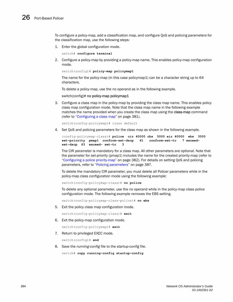
Port-Based Policer26
To configure a policy-map, add a classification map, and configure QoS and policing parameters for the classification map, use the following steps:
1. Enter the global configuration mode.
switch# configure terminal
2. Configure a policy-map by providing a policy-map name. This enables policy-map configuration mode.
switch(config)# policy-map policymap1
The name for the policy-map (in this case policymap1) can be a character string up to 64 characters.
To delete a policy-map, use the no operand as in the following example.
switch(config)# no policy-map policymap1
3. Configure a class map in the policy-map by providing the class map name. This enables policy class map configuration mode. Note that the class map name in the following example matches the name provided when you create the class map using the class-map command (refer to “Configuring a class map” on page 381).
switch(config-policymap)# class default
4. Set QoS and policing parameters for the class map as shown in the following example.
(config-policymap-class)# police cir 40000 cbs 5000 eir 40000 ebs 3000 set-priority pmap1 conform-set-dscp 61 conform-set-tc 7 exceed- set-dscp 63 exceed- set-tc 3
The CIR parameter is mandatory for a class map. All other parameters are optional. Note that the parameter for set-priority (pmap1) includes the name for the created priority-map (refer to “Configuring a police priority-map” on page 382). For details on setting QoS and policing parameters, refer to “Policing parameters” on page 387.
To delete the mandatory CIR parameter, you must delete all Policer parameters while in the policy-map class configuration mode using the following example:
switch(config-policymap-class)# no police
To delete any optional parameter, use the no operand while in the policy-map class police configuration mode. The following example removes the EBS setting.
switch(config-policymap-class-police)# no ebs
5. Exit the policy class map configuration mode.
switch(config-policymap-class)# exit
6. Exit the policy-map configuration mode.
switch(config-policymap)# exit
7. Return to privileged EXEC mode.
switch(config)# end
8. Save the running-config file to the startup-config file.
switch# copy running-config startup-config
384 Network OS Administrator’s Guide53-1002561-02

Port-Based Policer 26
Configuring parameters for a class map (policy class map policer mode)
You can configure QoS and policing parameters when configuring a class map in the policy-class- map configuration mode as shown in the preceding procedure or you can create or modify parameters for a class map in the policy-class-map Policer attributes mode as shown in the following example. Using the policy-class-map-policer mode is a convenience for adding or modifying single or multiple attributes for a policy
1. Enter the global configuration mode.
switch# configure terminal
2. Configure a policy-map by providing a policy-map name. This enables policy-map configuration mode.
switch(config)# policy-map policymap2
The name for the priority-map (in this case policymap2) can be a character string up to 64 characters.
To delete a policy-map, use the no operand as in the following example.
switch(config)# no policy-map policymap2
3. Configure a class map in the policy-map by providing the class map name. This enables policy class map configuration mode.
switch(config-policymap)# class default
NOTETo configure a class map in the policy-map you must create the class map first using the class-map command while in global configuration mode. Refer to “Configuring a class map” on page 381.
4. Provide a policing parameter for the class map. This enables class map Policer attributes mode.
switch(config-policymap-class)# police cir 4000000
5. Enter another parameter as applicable.
(config-policymap-class-police)# cbs 50000
6. Enter additional parameters as applicable.
switch(config-policymap-class-police)# eir 800000 ebs 400000 conform-set-tc 3 exceed-set-prec 4
7. Exit the policy class map Policer attributes mode.
switch(config-policymap-class-police)# exit
8. Exit the policy class map configuration mode.
switch (config-policymap-class)# exit
9. Exit the policy-map configuration mode.
switch(config-policymap)# exit
10. Return to privileged EXEC mode.
switch(config)# end
Network OS Administrator’s Guide 38553-1002561-02

Port-Based Policer26
11. Save the running-config file to the startup-config file.
switch# copy running-config startup-config
Binding the policy-map to an interfaceUse the service-policy command to associate a policy-map to an interface to apply policing parameters.
1. Enable the global configuration mode.
switch# configure terminal
2. Specify the Ethernet interface. The following enables tengigabitethernet interface mode for rbridge 1, slot 1, and port 2.
(config)# interface te 1/1/2
3. Bind a policy-map to egress traffic on the interface. The following associates binds policymjap1 (name of policy-map) to outbound traffic on the interface.
switch(config-if-te-1/1/2)# service-policy out policymap1
You can unbind the policy-map using the no operand.
switch(config-if-te-1/1/2)# no service-policy out
4. Bind a policy-map to inbound traffic on the interface. The following associates binds policymjap1 (name of policy-map) to inbound traffic on the interface.
switch(config-if-te-1/1/2)# service-policy in policymap1
You can unbind the policy-map using the no operand.
switch(config-if-te-1/1/2)# no service-policy in
5. Return to privileged EXEC mode.
switch(conf-if-te-1/1/2)# end
6. Enter the copy command to save the running-config file to the startup-config file.
switch# copy running-config startup-config
Policer binding rules
Consider the following rules when binding a policy-map to an interface:
• You can bind the same policy-map to multiple interfaces in both inbound and outbound directions.
• You can bind a policy-map to a physical port only. Policy-maps are not supported on LAG and VLAN interfaces.
• You cannot bind policy-maps to an interface if a class map is not associated with the policy-map.
• If policy-map is bound to an interface and the policy-map does not have mandatory Policer attributes, then traffic coming on that interface will be treated as conformed traffic. Packets on that interface will be marked as green and color based actions such as dscp, cos mapping etc will not be applied.
386 Network OS Administrator’s Guide53-1002561-02

Port-Based Policer 26
Policing parametersPolicing parameters provide values for CIR, CBS, EIR, and EBS, for classifying traffic by a specific class for color-based priority mapping. They also specify specific actions to perform on traffic with a color-class priority, such as having packet DSCP priority, traffic class (internal queue assignment), or traffic class (internal queue assignment) set to specific values.
CIR and CBS
The CIR is the maximum number of bits that a port can receive or send during one-second over an interface. For CIR, there are two parameters that define the available traffic: CIR and the Committed Burst Rate (CBR). The CIR represents a portion of the interface's total bandwidth expressed in bits per second (bps). It cannot be larger than the interface’s total bandwidth. CBS controls the bursty nature of the traffic. Traffic that does not use the configured CIR accumulates credits until the credits reach the configured CBS. These credits can be used when the rate temporarily exceeds the configured CIR. When credits are not available, the traffic is either dropped or subject to the policy set for the EIR. The traffic limited by the CIR can have its priority, traffic class, and DSCP values changed.
CIR is mandatory policing parameter for configuring a class map.
• cir cir-rate
The cir parameter defines the value of the CIR as the rate provided in the cir-rate variable. Acceptable values are in multiples of 40000 in the range 40000 - 40000000000 bps.
• cbs cbs-size
The cbs parameter defines the value of the CBS as the rate provided in the cbs-size variable. Acceptable values are 1250 - 5000000000 bytes in increments of 1 byte.
EIR and EBS
The Excess Information Rate (EIR) provides an option for traffic that has exceeded the CIR. For EIR, there are two parameters that define the available traffic: the EIR and the Excess Burst Size (EBS). The EIR and EBS operate exactly like the CIR and CBS except that they only act upon traffic that has been passed to the EIR because it could not be accommodated by the CIR. Like the CIR, the EIR provides an initial bandwidth allocation to accommodate inbound and outbound traffic. Like the CBS, the bandwidth available for burst traffic from the EBS is subject to the amount of bandwidth that is accumulated during periods when traffic allocated by the EIR policy is not used. When inbound or outbound traffic exceeds the bandwidth available (accumulated credits or tokens) it will be dropped. The traffic rate limited by the EIR can have its priority, traffic class, and DSCP values changed.
EIR and EBS parameters are optional policing parameters. If not set, they are considered disabled.
• eir eir-rate
The eir parameter defines the value of the EIR as the rate provided in the eir-rate variable. Acceptable values are in multiples of 40000 in the range 0 - 40000000000 bps.
• ebs ebs-size
The ebs parameter defines the value of the EBS as the rate provided in the ebs-size variable. Acceptable values are 1250 - 5000000000 bytes in increments of 1 byte.
Network OS Administrator’s Guide 38753-1002561-02

Port-Based Policer26
Parameters that apply actions to conform and exceed traffic
Following are policing parameters that apply actions to conform or exceed color traffic:
• conform-set-dscp dscp-num
The conform-set-dscp parameter specifies that traffic with bandwidth requirements within the rate configured for CIR will have packet DSCP priority set to the value specified in the dscp-num variable. Acceptable values for dscp-num are 0-63.
• conform-set-prec prec-num
The conform-set-prec parameter specifies that traffic with bandwidth requirements within the rate configured for CIR will have packet IP precedence value (first 3 bits of DSCP) set to the value in the prec-num variable. Acceptable values for prec-num are 0-7.
• conform-set-tc trafficlass
The conform-set-tc parameter specifies that traffic with bandwidth requirements within the rate configured for CIR will have traffic class (internal queue assignment) set to the value in the trafficlass variable. Acceptable values for trafficclass are 0-7.
• exceed-set-dscp dscp-num
The exceed-set-dscp parameter specifies that traffic with bandwidth requirements that exceeds the rate configured for CIR and sent to the EIR bucket will have packet DSCP priority set to the value in the dscp-num variable. Acceptable values for dscp-num are 0-63.
• exceed-set-prec prec-num
The exceed-set-prec parameter specifies that traffic with bandwidth requirements that exceed the rate configured for CIR and sent to the EIR bucket will have packet IP precedence set to the value in the prec-num variable. Acceptable values for prec-num are 0-7.
• exceed-set-tc trafficclass
The exceed-set-tc parameter specifies that traffic with bandwidth requirements that exceed the rate configured for CIR and is in the limit of what is configured for EIR will have its traffic class (internal queue assignment) set to the value in the trafficlass variable. Acceptable values for trafficlass are 0-7.
• set-priority priority-mapname
The set-priority parameter specifies the mapping used for setting QoS priority (802.1p priority) in the packet. The priority-mapname name variable should be same as configured for the priority-map (police-priority-map), which will have a set priority and color type (conform or exceed).
Displaying policing settings and policy-mapsUse the following commands to display policies configured in policy, class, and priority-maps.
policy-maps
In the following example, the show policymap command is used to display Policer policies and parameters set for the 10Gb Ethernet interface 4/1 inbound traffic.
switch# show policymap interface tengigabitethernet 4/1 inInterface : TenGigabitEthernet 4/1
388 Network OS Administrator’s Guide53-1002561-02

Port-Based Policer 26
Policymap: pl-mapDirection: InputInput Excluded lossless priorities: None
Class-map: defaultPolice:cir 5 bps cbs 5678 bytes eir 512000 bps ebs 4096 bytesPolice-priority-map: po-pr-map1Conformed: 30720 bytes set-dscp 0 set-tc 0Exceeded: 23424 bytes set-dscp 0 set-tc 0Violated: 0 bytesTotal: 54144 bytes
Entering show policymap without identifying an interface and specify inbound or outbound traffic displays policy-maps bound on all switch interfaces.
The following example displays the running configured policy-map using the show running-config policy-map command.
switch# show running-config policy-mappolicy-map policy_map1 class defaultpolice cir 50000 cbs 500000 eir 60000 ebs 40000 set-priority prio_map1
conform-set-dscp 23 conform-set-tc 4 exceed-set-prec 2 exceed-set-tc 5 !!policy-map policy_map2 class defaultpolice cir 1000000 cbs 200000
Class maps
The following example displays the running configured class map name and configured match attribute using the show running-config class-map command.
switch# show running-config class-mapclass-map class_map1 match any
Priority-maps
The following example displays the running configured police priority-map name and mapping of CoS values for conform and exceed color priorities using the show running-config police-priority-map command.
switch# show running-config police-priority-mappolice-priority-map prio_map1 conform 3 3 3 5 6 1 1 1 exceed 2 2 2 1 1 1 1 2
Network OS Administrator’s Guide 38953-1002561-02

Port-Based Policer26
Considerations and limitationsConsider the following when configuring the port-based Policer feature.
Best practices
Follow these best practices when configuring the port-based Policer feature:
• Avoid mapping lossy priority to lossless priority in conform and exceed CoS maps.
• Configure rate (cir or eir) and burst size (cbs or ebs) based on interface speed.
• Set conform and exceed tc to the same values to avoid any reordering issues
Configuration rules and considerations
Following are rules for configuring maps and using policing parameters for the Policer feature:
• A policy-map, class map, priority-map name must be unique among all maps of that type.
• A Policer name must begin with a-z, A-Z. You can us underscore, hyphen and numeric values 0-9 except as the first character.
• You cannot delete a policy-map, class map or priority-map if is active on the interface.
• You cannot delete a class map from a policy-map when the policy-map is active on the interface.
• Configure cir and eir in multiples of 40000 bps.
• Percentage as a rate limit is not supported,
• Policer actions are applicable only to data traffic. Control traffic, FCoE, and internal VLAN traffic is not subjected to policing.
• The egress Policer can overwrite ingress Policer results such as CoS mapping and DSCP mapping.
• If a policy-map is applied to an interface and no Policer attributes are present in that policy-map, then ingress and egress packets on that interface will be marked as green (conforming).
• If the configured cbs value is less than 2*MTU value then 2*MTU will be programmed as cbs on the hardware. For example, if you configure cbs at 4000 Bytes and the MTU on an interface is 3000 Bytes, when a policy-map is applied on this interface, the cbs programmed on the hardware is 2*MTU (6000bytes).
• If cbs and ebs values are not configured, then these values are derived from cir and eir values respectively. Burst size calculation is Burst size (cbs or ebs) = 1.2*information rate(CIR/EIR)/8.
• If you do not configure eir and ebs, then the single-rate two color scheme will be applied (packets will either be marked as green or red).
• You must configure rate limit threshold values on an interface based on interface speed. No validation is performed for user-configured values against interface speed.
Limitations
• Incremental step size for cir or eir value is set to 40000 bps.
390 Network OS Administrator’s Guide53-1002561-02

Port-Based Policer 26
• The Policer operates in color blind mode. In other words, color is evaluated at ingress and egress Policers independently. This may result in packets which are marked as yellow in inbound Policer to be evaluated as green at outbound Policer depending on Policer settings.
• Since inbound queue scheduling is performed before outbound policing, Setting traffic class (set-conform-tc or set-exceed-tc) based on policing results does not effect packet forwarding at the outbound side.
• Packets drops caused by any action other than ACL are included in Policer counters.
• L3 control packets are policed at the outbound side.
• Policing is enabled on lossless priorities at the outbound side.
Considerations for vLAGs
Since a virtual link aggregation group (vLAG) spans multiple switches, it is not possible to associate flows on each lag member port to a common Policer. Instead, apply the same policy-map on individual member ports so that traffic flow on member ports is controlled by a Policer configured on that member port. The total rate limit threshold values of on a vLAG is the cumulative values of rate limit thresholds on all member ports.
Policing behavior for control packets
Port-based Policer behavior for L2 and L3 control packets is shown in table Table 65.
When L2 control protocol is not enabled on an interface, packets are dropped during ingress and will be subjected to ingress policing. L3 control packets, irrespective of whether they are protocol-enabled or not, will not be subject to ingress and egress policing.
Lossless traffic
Following are considerations for lossless traffic:
• Policing is applicable only for lossy traffic. Lossless traffic should not get policed. For port- based policing, apply a policy-map to an interface even if PFC is configured on that interface. The CoS value (priority) on which PFC is applied will be excluded from being policed.
• Remapped priority values should not include lossless priorities. Do not remap lossy traffic priorities to lossless traffic priorities and vice-versa.
• Policer attributes conform-set-tc and exceed-set-tc should not be set to a lossless traffic class.
TABLE 65 Policing behavior for L2 and L3 control packets
Protocol Ingress Policer Egress Policer
LLDP Enabled if protocol is not enabled and disabled if protocol is enabled. Disabled
LACP Enabled if protocol is not enabled and disabled if protocol is enabled. Disabled
STP Enabled if protocol is not enabled and disabled if protocol is enabled. Disabled
DOT1X Enabled if protocol is not enabled and disabled if protocol is enabled. Disabled
PIM Disabled Enabled
OSPF Disabled Enabled
IGMP Disabled Enabled
VRRP/VRRP-E Disabled Enabled
Network OS Administrator’s Guide 39153-1002561-02

Port-Based Policer26
392 Network OS Administrator’s Guide53-1002561-02

Network OS Administrator’s Guide53-1002561-02
Chapter
27
Configuring 802.1x Port AuthenticationIn this chapter
•802.1x protocol overview . . . . . . . . . . . . . . . . . . . . . . . . . . . . . . . . . . . . . . . 393
•802.1x configuration guidelines and restrictions . . . . . . . . . . . . . . . . . . . . 393
•802.1x authentication configuration tasks . . . . . . . . . . . . . . . . . . . . . . . . . 394
•Interface-specific administrative tasks for 802.1x . . . . . . . . . . . . . . . . . . . 394
802.1x protocol overviewThe 802.1x protocol defines a port-based authentication algorithm involving network data communication between client-based supplicant software, an authentication database on a server, and the authenticator device. In this situation the authenticator device is the Brocade VDX hardware.
As the authenticator, the Brocade VDX hardware prevents unauthorized network access. Upon detection of the new supplicant, the Brocade VDX hardware enables the port and marks it “unauthorized”. In this state, only 802.1x traffic is allowed. All other traffic, such as DHCP and HTTP, is blocked. The Brocade VDX hardware transmits an EAP-request to the supplicant, which responds with the EAP-response packet. The Brocade VDX hardware, which then forwards the EAP-response packet to the RADIUS authentication server. If the credentials are validated by the RADIUS server database, the supplicant may access the protected network resources.
NOTE802.1x port authentication is not supported by LAG (Link Aggregation Group) or interfaces that participate in a LAG.
NOTEThe EAP-MD5, EAP-TLS, EAP-TTLS and PEAP-v0 protocols are supported by the RADIUS server and are transparent to the authenticator switch.
When the supplicant logs off, it sends an EAP-logoff message to the Brocade VDX hardware which then sets the port back to the “unauthorized” state.
802.1x configuration guidelines and restrictionsFollow these 802.1x configuration guidelines and restrictions when configuring 802.1x:
• If you globally disable 802.1x, then all interface ports with 802.1x authentication enabled automatically switch to force-authorized port-control mode.
393

802.1x authentication configuration tasks27
802.1x authentication configuration tasksThe tasks in this section describe the common 802.1x operations that you will need to perform. For a complete description of all the available 802.1x CLI commands for the Brocade VDX hardware, see the Network OS Command Reference.
Configuring authentication between the switch and CNA or NICThe radius-server command attempts to connect to the first RADIUS server. If the RADIUS server is not reachable, the next RADIUS server is contacted. However, if the RADIUS server is contacted and the authentication fails, the authentication process does not check for the next server in the sequence.
Perform the following steps to configure authentication.
1. Enter global configuration mode.
switch#configure terminal
2. Use the radius-server command to add the RADIUS to the switch as the authentication server.
This command can be repeated for additional servers. However, this command moves the new RADIUS server to the top of the access list.
switch(config)#radius-server host 10.0.0.5
3. Enable 802.1x authentication globally
switch(config)#dot1x enable
4. Use the interface command to select the interface port to modify.
The gigabitethernet rbridge-id/slot/port operand is used only for the Brocade VDX 6710, Brocade VDX 8770-4, and Brocade VDX 8770-8. The prompt for these ports is in the format: switch(config-if-gi-22/0/1)#
switch(config)#interface tengigabitethernet 1/12
5. Use the dot1x authentication command to enable 802.1x authentication.
switch(conf-if-te-1/12)#dot1x authentication
6. Return to privileged EXEC mode.
switch(conf-if-te-1/12)#end
7. Enter the copy command to save the running-config file to the startup-config file.
switch#copy running-config startup-config
Interface-specific administrative tasks for 802.1xIt is essential to configure the 802.1x port authentication protocol globally on the Brocade VDX hardware, and then enable 802.1x and make customized changes for each interface port. Since 802.1x was enabled and configured in “802.1x authentication configuration tasks”, use the administrative tasks in this section to make any necessary customizations to specific interface port settings.
394 Network OS Administrator’s Guide53-1002561-02

Interface-specific administrative tasks for 802.1x 27
802.1x readiness checkThe 802.1x readiness check monitors 802.1x activity on all the switch ports and displays information about the devices connected to the ports that support 802.1x. You can use this feature to determine if the devices connected to the switch ports are 802.1x-capable.
The 802.1x readiness check is allowed on all ports that can be configured for 802.1x. The readiness check is not available on a port that is configured by the dot1x force-unauthorized command.
When you configure the dot1x test eapol-capable command on an 802.1x-enabled port, and the link comes up, the port queries the connected client about its 802.1x capability. When the client responds with a notification packet, it is 802.1x-capable. A RASlog message is generated if the client responds within the timeout period. If the client does not respond to the query, the client is not 802.1x-capable. Syslog message is generated saying client is not EAPOL-capable.
Follow these guidelines to enable the readiness check on the switch:
• The readiness check is typically used before 802.1x is enabled on the switch.
• 802.1x authentication cannot be initiated while the 802.1x readiness test is in progress.
• The 802.1x readiness test cannot be initiated while 802.1x authentication is active.
• 802.1x readiness can be checked on a per-interface basis. Readiness check for all interfaces at once is not supported.
• The 802.1x test timeout is shown in show dot1x command.
• The gigabitethernet rbridge-id/slot/port operand is used only for the Brocade VDX 6710, Brocade VDX 8770-4, and Brocade VDX 8770-8. The prompt for these ports is in the format: switch(config-if-gi-22/0/1)#
This example shows how to enable a readiness check on a switch to query a port. It also shows the response received from the queried port verifying that the device connected to it is 802.1x-capable:
switch# dot1x test eapol-capable interface gigabitethernet 0/13
DOT1X_PORT_EAPOL_CAPABLE:DOT1X: MAC 00-01-02-4b-f1-a3 on gigabitethernet0/13 is EAPOL capable.
Configuring 802.1x on specific interface portsTo configure 802.1x port authentication on a specific interface port, perform the following steps from privileged EXEC mode. Repeat this task for each interface port you wish to modify.
1. Enter the configure terminal command to access global configuration mode.
2. Use the interface command to select the interface port to modify.
The gigabitethernet rbridge-id/slot/port operand is used only for the Brocade VDX 6710, Brocade VDX 8770-4, and Brocade VDX 8770-8. The prompt for these ports is in the format: switch(config-if-gi-22/0/1)#
switch(config)#interface tengigabitethernet 1/12
3. Use the dot1x authentication command to enable 802.1x authentication.
switch(conf-if-te-1/12)#dot1x authentication
4. Return to privileged EXEC mode.
switch(conf-if-te-1/12)#end
Network OS Administrator’s Guide 39553-1002561-02

Interface-specific administrative tasks for 802.1x27
5. Enter the copy command to save the running-config file to the startup-config file.
switch#copy running-config startup-config
Configuring 802.1x timeouts on specific interface ports
NOTEWhile you are free to modify the timeouts, Brocade recommends that you leave timeouts set to their default values.
To configure 802.1x timeout attributes on a specific interface port, perform the following steps from privileged EXEC mode. Repeat this task for each interface port you wish to modify.
1. Enter the configure terminal command to access global configuration mode.
2. Use the interface command to select the interface port to modify.
The gigabitethernet rbridge-id/slot/port operand is used only for the Brocade VDX 6710, Brocade VDX 8770-4, and Brocade VDX 8770-8. The prompt for these ports is in the format: switch(config-if-gi-22/0/1)#
switch(config)#interface tengigabitethernet 1/12
3. Configure the timeout interval.
switch(conf-if-te-1/12)#dot1x timeout supp-timeout 40
4. Return to privileged EXEC mode.
switch(conf-if-te-1/12)#end
5. Enter the copy command to save the running-config file to the startup-config file.
switch#copy running-config startup-config
Configuring 802.1x re-authentication on specific interface portsTo configure 802.1x port re-authentication on a specific interface port, perform the following steps from privileged EXEC mode. Repeat this task for each interface port you wish to modify.
1. Enter the configure terminal command to access global configuration mode.
2. Use the interface command to select the interface port to modify.
The gigabitethernet rbridge-id/slot/port operand is used only for the Brocade VDX 6710, Brocade VDX 8770-4, and Brocade VDX 8770-8. The prompt for these ports is in the format: switch(config-if-gi-22/0/1)#
switch(config)#interface tengigabitethernet 1/12
3. Enable 802.1x authentication for the interface port.
switch(conf-if-te-1/12)#dot1x authentication
4. Configure reauthentication for the interface port.
switch(conf-if-te-1/12)#dot1x reauthenticationswitch(conf-if-te-1/12)#dot1x timeout re-authperiod 4000
5. Return to privileged EXEC mode.
switch(conf-if-te-1/12)#end
396 Network OS Administrator’s Guide53-1002561-02

Interface-specific administrative tasks for 802.1x 27
6. Enter the copy command to save the running-config file to the startup-config file.
switch#copy running-config startup-config
Configuring 802.1x port-control on specific interface portsTo configure 802.1x port-control on a specific interface port, perform the following steps from privileged EXEC mode. Repeat this task for each interface port you wish to modify.
1. Use the configure terminal command to enter global configuration mode.
2. Use the interface command to select the interface port to modify.
The gigabitethernet rbridge-id/slot/port operand is used only for the Brocade VDX 6710, Brocade VDX 8770-4, and Brocade VDX 8770-8. The prompt for these ports is in the format: switch(config-if-gi-22/0/1)#
switch(config)#interface tengigabitethernet 1/12
3. Enable 802.1x authentication for the interface port.
switch(conf-if-te-1/12)#dot1x authentication
4. Change the port authentication mode to auto, force-authorized or force-unauthorized.
switch(conf-if-te-1/12)#dot1x port-control auto/force-authorized/force-unauthorized
5. Return to privileged EXEC mode.
switch(conf-if-te-1/12)#end
6. Enter the copy command to save the running-config file to the startup-config file.
switch#copy running-config startup-config
Re-authenticating specific interface portsTo re-authenticate supplicant connected to a specific interface port, perform the following steps from privileged EXEC mode. Repeat this task for each interface port you wish to reauthenticate.
1. Use the configure terminal command to enter global configuration mode.
2. Use the interface command to select the interface port to modify.
The gigabitethernet rbridge-id/slot/port operand is used only for the Brocade VDX 6710, Brocade VDX 8770-4, and Brocade VDX 8770-8. The prompt for these ports is in the format: switch(config-if-gi-22/0/1)#
switch(config)#interface tengigabitethernet 1/12
3. Start re-authentication on a port where dot1x is already enabled.
The gigabitethernet rbridge-id/slot/port operand is used only for the Brocade VDX 6710, Brocade VDX 8770-4, and Brocade VDX 8770-8.
switch(conf-if-te-1/12)#dot1x reauthenticate
4. Return to privileged EXEC mode.
switch(conf-if-te-1/12)#end
5. Enter the copy command to save the running-config file to the startup-config file.
Network OS Administrator’s Guide 39753-1002561-02

Interface-specific administrative tasks for 802.1x27
switch#copy running-config startup-config
Disabling 802.1x on specific interface portsTo disable 802.1x authentication on a specific interface port, perform the following steps from privileged EXEC mode.
1. Enter the configure terminal command to access global configuration mode.
2. Use the interface command to select the interface port to modify.
The gigabitethernet rbridge-id/slot/port operand is used only for the Brocade VDX 6710, Brocade VDX 8770-4, and Brocade VDX 8770-8. The prompt for these ports is in the format: switch(config-if-gi-22/0/1)#
switch(config)#interface tengigabitethernet 1/12
3. Use the no dot1x port-control command to disable 802.1x Authentication.
switch(conf-if-te-1/12)#no dot1x authentication
4. Return to privileged EXEC mode.
switch(conf-if-te-1/12)#end
5. Enter the copy command to save the running-config file to the startup-config file.
switch#copy running-config startup-config
Disabling 802.1x globallyTo disable 802.1x authentication globally, perform the following steps from privileged EXEC mode.
1. Enter the configure terminal command to access global configuration mode.
2. Use the no dot1x enable command to disable 802.1x Authentication.
switch(config)#no dot1x enable
3. Return to privileged EXEC mode.
switch(config)#end
4. Enter the copy command to save the running-config file to the startup-config file.
switch#copy running-config startup-config
Checking 802.1x configurationsTo check 802.1x configurations, perform the following steps from privileged EXEC mode.
1. To view all dot1x configuration information, use the show dot1x command with the all operand.
switch#show dot1x all
2. To check 802.1x configurations for specific interface ports, use the interface command to select the interface port to modify.
The gigabitethernet rbridge-id/slot/port operand is used only for the Brocade VDX 6710, Brocade VDX 8770-4, and Brocade VDX 8770-8. The prompt for these ports is in the format: switch(config-if-gi-22/0/1)#
3. switch(config)#interface tengigabitethernet 1/12
398 Network OS Administrator’s Guide53-1002561-02

Interface-specific administrative tasks for 802.1x 27
4. To check 802.1x authentication statistics on specific interface ports, use the show dot1x command with the statistics interface operand.
switch#show dot1x statistics interface tengigabitethernet 1/12
5. To check all diagnostics information of the authenticator associated with a specific interface port, use the show dot1x command with the diagnostics interface operand.
switch#show dot1x diagnostics interface tengigabitethernet 1/12
6. To check all statistical information of the established session, use the show dot1x command with the session-info interface operand.
switch#show dot1x session-info interface tengigabitethernet 1/12
Network OS Administrator’s Guide 39953-1002561-02

Interface-specific administrative tasks for 802.1x27
400 Network OS Administrator’s Guide53-1002561-02

Network OS Administrator’s Guide53-1002561-02
Chapter
28
Configuring sFlowIn this chapter
•sFlow protocol overview . . . . . . . . . . . . . . . . . . . . . . . . . . . . . . . . . . . . . . . . 401
•Configuring the sFlow protocol globally . . . . . . . . . . . . . . . . . . . . . . . . . . . . 402
•Interface-specific administrative tasks for sFlow . . . . . . . . . . . . . . . . . . . . 403
•Hardware support matrix for sFlow . . . . . . . . . . . . . . . . . . . . . . . . . . . . . . . 404
sFlow protocol overviewThe sFlow protocol is an industry standard technology for monitoring high-speed switched networks. The sFlow standard consists of an sFlow agent that resides anywhere within the path of the packet and an sFlow collector that resides on a central server.
The sFlow agent combines the flow samples and interface counters into sFlow datagrams and forwarding them to the sFlow Collector at regular intervals. The datagrams consist of information on, but not limited to, packet header, ingress and egress interfaces, sampling parameters, and interface counters. Packet sampling is typically performed by the ASIC. The sFlow collector analyzes the sFlow datagrams received from different devices and produces a network-wide view of traffic flows.
The sFlow datagram provides information about the sFlow version, its originating agent’s IP address, a sequence number, one sample, and protocol information.
The sFlow agent uses two forms of operation:
• Time-based sampling of interface counters
• Statistical sampling of switched packets
Interface flow samplesA flow sample is based on random packets being forwarded to the sFlow collector at defined numeric intervals, either for the entire Brocade switch or for a single port interface. For example, every 4,096th packet is forwarded to the sFlow collector for analysis and storage.
The sampling rate is adaptive, and the sFlow agent is free to schedule the sampling to maximize internal efficiency.
NOTEThis type of random sampling provides estimated flow rates, but not perfect accuracy.
401

Configuring the sFlow protocol globally28
Packet counter samplesA polling interval defines how often the sFlow octet and packet counter for a specific interface are sent to the sFlow collector, but the sFlow agent is free to schedule the polling in order to maximize internal efficiency.
Configuring the sFlow protocol globallyBrocade recommends that you globally configure sFlow on the Brocade switch first, and then enable sFlow on specific interface ports and make custom alterations, because sFlow parameters at the interface level can differ from those at the global level. For details, refer to “Interface-specific administrative tasks for sFlow” on page 403.
Enabling sFlow globally does not enable it on all interface ports. sFlow must be explicitly enabled on all the required interface ports. Refer to “Enabling and customizing sFlow on specific interfaces” on page 403.
NOTEOn the Brocade VDX 8770, Switched Port Analyzer (SPAN), and sFlow can be enabled at the same time. However, on the Brocade VDX 6720, SPAN and sFlow cannot be enabled at the same time.
For complete information on the sFlow CLI commands for the Brocade switch, refer to the Converged Enhanced Ethernet Command Reference.
To configure sFlow globally, perform the following steps in global configuration mode.
1. Globally enable the sFlow protocol.
switch(config)# sflow enable
2. Designate the IP address for the sFlow collector server. Optionally, you can designate the port number.
switch(config)# sflow collector 192.10.138.176 6343
3. Set the sFlow polling interval (in seconds).
switch(config)# sflow polling-interval 35
4. Set the sFlow sample-rate.
switch(config)# sflow sample-rate 4096
5. Return to privileged EXEC mode.
switch(config)# end
6. Confirm the sFlow configuration status with the show sflow command.
switch# show sflowsFlow services are: enabledGlobal default sampling rate: 4096 pktsGlobal default counter polling interval: 1 secsCollector server address: 192.10.138.176:6343Number of samples sent: 30
7. Clear any existing sFlow statistics to ensure accurate readings.
switch# clear sflow statistics
402 Network OS Administrator’s Guide53-1002561-02

Interface-specific administrative tasks for sFlow 28
Interface-specific administrative tasks for sFlowAfter the global sFlow configuration, sFlow must be explicitly enabled on all the required interface ports.
NOTEWhen sFlow is enabled on an interface port, it inherits the sampling rate and polling interval from the global sFlow configuration.
Enabling and customizing sFlow on specific interfaces
NOTEOn the Brocade VDX 8770, SPAN and sFlow can be enabled at the same time. However, on the Brocade VDX 6710, VDX 6720, or VDX 6730, SPAN and sFlow cannot be enabled at the same time.
Perform the following steps in privileged EXEC mode to enable and customize sFlow on an interface. This task assumes that sFlow has already been enabled at the global level, refer to “Configuring the sFlow protocol globally” on page 402.
1. Enter the interface command to specify the DCB interface type and slot/port number.
The gigabitethernet rbridge-id/slot/port operand is used only for the Brocade VDX 6710, Brocade VDX 8770-4, and Brocade VDX 8770-8. The prompt for these ports is in the format: switch(config-if-gi-22/0/1)#
switch(config)# interface tengigabitethernet 0/16
2. Configure the sFlow polling interval.
switch(conf-if-te-0/16)# sflow polling interval 35
3. Use the sflow enable command to enable sFlow on the interface.
switch(conf-if-te-0/16)# sflow enable
4. Set the sFlow sample-rate.
switch(conf-if-te-0/16)# sflow sample-rate 8192
5. Confirm the sFlow configuration status on the specific interface.
switch# show sflow interface tengigabitethernet 12/0/53sFlow info for interface TenGigabitEthernet 12/0/53------------------------------------------------Configured sampling rate: 32768 pktsActual sampling rate: 65536 pktsCounter polling interval: 20 secsSamples received from hardware: 291Port backoff-threshold : 6Counter samples collected : 10
Disabling sFlow on specific interfaces
NOTEDisabling sFlow on the interface port does not completely shut down the network communication on the interface port.
Network OS Administrator’s Guide 40353-1002561-02

Hardware support matrix for sFlow28
To disable sFlow on a specific interface, perform the following steps in interface configuration mode.
1. Disable the sFlow interface.
switch(conf-if)# no sflow enable
2. Return to privileged EXEC mode.
switch(conf-if)# end
3. Confirm the sFlow configuration status on the specific interface.
The gigabitethernet rbridge-id/slot/port operand is used only for the Brocade VDX 6710, Brocade VDX 8770-4, and Brocade VDX 8770-8. The prompt for these ports is in the format: switch(config-if-gi-22/0/1)#
switch# show sflow interface tengigabitethernet 0/12
Hardware support matrix for sFlowTable 66 describes which sFlow features are supported on Brocade hardware.
TABLE 66 sFlow feature support
Feature Brocade VDX 8770 Brocade VDX 67xx
sFlow global configurations for enabling sFlow, polling interval, collector, and sample rate
All are supported All are supported
sFlow data source interface Supports 1Gbps, 10Gbps, and 40Gbps interfaces
Supports on 10Gbps interfaces only
sFlow data source: Front port trunks and VLANs Not supported Not supported
sFlow scanning for inbound, outbound, or both directions on a port
Supports inbound only
Supports inbound only
sFlow counter polling support on per-port, per-VLAN, or per-trunk
Supports only per-port counter polling
Supports only per-port counter polling
All standard if_counters and Ethernet counters Supported Supported
Multiple collector configuration Not supported Not supported
Extended Gateway, Extended router, and NAT/MPLS/URL header formats
Not supported Not supported
Subagent-ID Filled with slot number of the interface
Filled with a zero (0)
Agent IP address Preference 1: Chassis IP Preference 2: Management CP IP
Management IP
Maximum packets per second 272 pkts/sec/ASIC VDX 8770-4: 6528 pkts/sec VDX 8770-8: 13056 pkts/sec
96 pkts/sec/ASIC Each ASIC supports eight front-user ports on the 48x10G and 48x1G line cards, and supports two front-user ports on the 12x48G Line card.
404 Network OS Administrator’s Guide53-1002561-02

Hardware support matrix for sFlow 28
Sample rate calculation Dropped packets (such as errors and ACL dropped packets) are not counted for the calculations used for sample generation
Dropped packets (such as errors and ACL dropped packets) are counted for the calculations used for sample generation
Maximum sFlow raw packet header size 228 bytesThe hardware truncates the packet.
128 bytesThe software truncates the packet.
SPAN and sFlow configurations SPAN and sFlow can be enabled at the same time
SPAN and sFlow cannot be enabled at the same time
TABLE 66 sFlow feature support (Continued)
Feature Brocade VDX 8770 Brocade VDX 67xx
Network OS Administrator’s Guide 40553-1002561-02

Hardware support matrix for sFlow28
406 Network OS Administrator’s Guide53-1002561-02

Network OS Administrator’s Guide53-1002561-02
Chapter
29
Configuring Switched Port AnalyzerIn this chapter
•Switched Port Analyzer protocol overview . . . . . . . . . . . . . . . . . . . . . . . . . . 407
•Configuring ingress SPAN . . . . . . . . . . . . . . . . . . . . . . . . . . . . . . . . . . . . . . . 408
•Configuring egress SPAN. . . . . . . . . . . . . . . . . . . . . . . . . . . . . . . . . . . . . . . . 409
•Configuring bidirectional SPAN. . . . . . . . . . . . . . . . . . . . . . . . . . . . . . . . . . . 409
•Deleting a SPAN connection from a session . . . . . . . . . . . . . . . . . . . . . . . . 410
•Deleting a SPAN session . . . . . . . . . . . . . . . . . . . . . . . . . . . . . . . . . . . . . . . . 410
Switched Port Analyzer protocol overviewSwitched Port Analyzer is used on a network switch to send a copy of network packets seen on one switch port to a network monitoring connection on another switch port. If you are interested in listening or snooping on traffic that passes through a particular port, Switched Port Analyzer (SPAN) artificially copies the packets to a port connected to your analyzer. Usually, this traffic is limited to incoming or outgoing packets, but Network OS v3.0.0 allows bidirectional traffic monitoring on the source port.
SPAN guidelines and limitationsThe guidelines and limitations of SPAN connections are:
• For the Brocade VDX 6720-24:
- The mirror port can be any port in the switch.
- Only one port per switch can be configured as a destination port for ingress mirroring.
- Only one port per switch can be configured as a destination port for egress mirroring.
• For the Brocade VDX 6720-60:
- The mirror port should be in the same port-group as the source port.
- Only one port per port-group can be configured as a destination port for ingress mirroring.
- Only one port per port-group can be configured as a destination port for egress mirroring.
• The mirror port should not be configured to carry normal traffic.
• A port cannot be mirrored to multiple locations in the same direction.
• A port cannot be made a destination port for bi-directional mirroring if a different port on that chip is already configured as destination port for any type of mirroring.
• If a port is configured as a destination port of bi-directional mirroring, no other port on that chip can be made destination port for any type of mirroring.
407

Configuring ingress SPAN29
• The destination mirror port can only handle 10G (line rate) worth of mirror traffic. If multiple ports, or both flows on same port, are mirrored to the same destination mirror port, then only 10G worth of mirror traffic is mirrored and the remaining traffic is ignored.
• If the source port receives burst traffic and the destination mirror port cannot handle all the bursts, some of the burst traffic is not mirrored.
• Mirroring of ISL ports is not supported.
• Mirroring of LAG or Port-Channel interfaces is not supported, but LAG members can be mirrored.
• TRILL ports cannot be designated as a source or destination port.
• Inter-chip port mirroring is not allowed.
• Pause frames are not mirrored.
• Mirroring of trunk port is not supported, though the ASIC supports the mirroring of a trunk. To mirror a trunk, you must individually enable mirroring on all member ports.
• The Multicast and Broadcast statistics are incorrectly updated on TX ports for mirrored traffic.
• All commands except for shutdown and no shutdown are blocked on a destination mirror port.
• The interface counters are cleared when a port is successfully designated as a destination mirror port.
• The show interface command hides the ‘Receive Statistics’ and ‘Rate Info (Input)’ information for a destination mirror port.
• The MTU of a port should be set to default value of 2500 bytes before making it a destination mirror port. When the port is successfully designated as the destination mirror, the MTU of that port is automatically set to the maximum value of 9208 bytes. When the port becomes a non-destination mirror, the MTU is restored to the default value.
• Port mirroring is supported on any physical front-end user-configurable port. The source port can be part of a LAG, VLAG, VLAN, or any other user configuration
• A maximum of 24 mirror sessions are supported in StandAlone and Fabric Cluster mode.
• A maximum of 512 sessions are supported in Management Cluster mode.
Configuring ingress SPAN
To configure SPAN for incoming packets only, perform the following steps in global configuration mode.
1. Open a monitor session and assign a session number
switch(config)# monitor session 1
2. Configure the source port and the destination port, with the rx parameter for received packets.
The destination port is always an external port. The source and destination ports must be in the same port group for the Brocade VDX 6720-60.
switch(config-session-1)#source tengigabitethernet 1/0/15 destination tengigabitethernet 1/0/18 direction rx
3. Optional: Use the description command to add a label to the monitor session.
switch(config-session-1)#description Hello World!
4. Repeat step 1 and step 2 as needed for additional ports.
408 Network OS Administrator’s Guide53-1002561-02
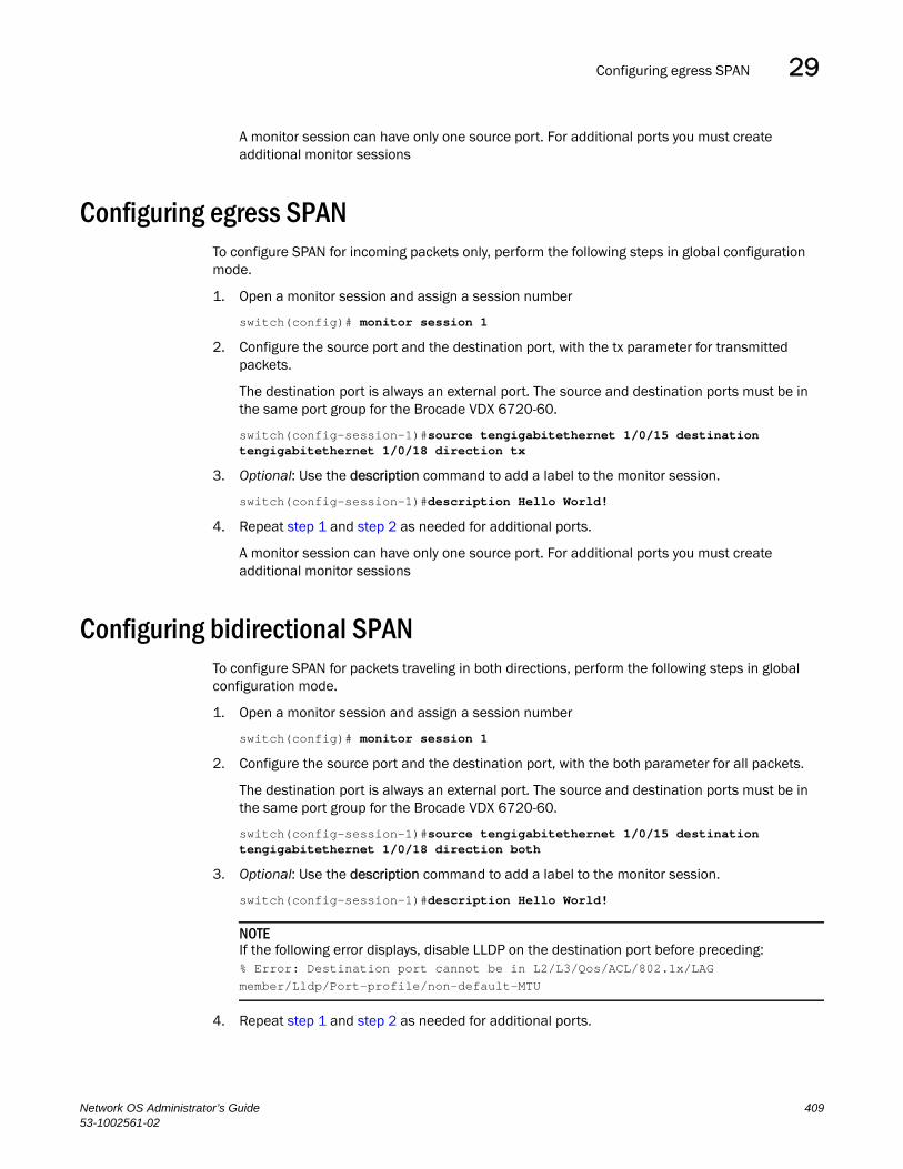
Configuring egress SPAN 29
A monitor session can have only one source port. For additional ports you must create additional monitor sessions
Configuring egress SPANTo configure SPAN for incoming packets only, perform the following steps in global configuration mode.
1. Open a monitor session and assign a session number
switch(config)# monitor session 1
2. Configure the source port and the destination port, with the tx parameter for transmitted packets.
The destination port is always an external port. The source and destination ports must be in the same port group for the Brocade VDX 6720-60.
switch(config-session-1)#source tengigabitethernet 1/0/15 destination tengigabitethernet 1/0/18 direction tx
3. Optional: Use the description command to add a label to the monitor session.
switch(config-session-1)#description Hello World!
4. Repeat step 1 and step 2 as needed for additional ports.
A monitor session can have only one source port. For additional ports you must create additional monitor sessions
Configuring bidirectional SPANTo configure SPAN for packets traveling in both directions, perform the following steps in global configuration mode.
1. Open a monitor session and assign a session number
switch(config)# monitor session 1
2. Configure the source port and the destination port, with the both parameter for all packets.
The destination port is always an external port. The source and destination ports must be in the same port group for the Brocade VDX 6720-60.
switch(config-session-1)#source tengigabitethernet 1/0/15 destination tengigabitethernet 1/0/18 direction both
3. Optional: Use the description command to add a label to the monitor session.
switch(config-session-1)#description Hello World!
NOTEIf the following error displays, disable LLDP on the destination port before preceding:% Error: Destination port cannot be in L2/L3/Qos/ACL/802.1x/LAG
member/Lldp/Port-profile/non-default-MTU
4. Repeat step 1 and step 2 as needed for additional ports.
Network OS Administrator’s Guide 40953-1002561-02

Deleting a SPAN connection from a session29
A monitor session can have only one source port. For additional ports you must create additional monitor sessions
Deleting a SPAN connection from a sessionTo remove a single connection from a SPAN session, perform the following steps in global configuration mode.
1. Display the existing configuration of the monitor session.
switch#show monitor session 1
2. Open an existing monitor session.
switch(config)#monitor session 1
3. Use the no option to delete a particular port connection.
switch(config-session-1)#no source tengigabitethernet 1/0/15 destination tengigabitethernet 1/0/18 direction both
4. Display the monitor session again to confirm the connection deletion.
switch#show monitor session 1
Deleting a SPAN sessionTo remove a SPAN session, perform the following steps in global configuration mode.
1. Display the existing configuration of the monitor session.
switch#show monitor session 1
2. Enter configuration mode with the config command.
3. Delete the existing monitor session using the no option.
switch(config)#no monitor session 1
4. Return to Privileged EXEC mode with the exit command.
5. Display the monitor session again to confirm the connection deletion.
switch#show monitor session 1
410 Network OS Administrator’s Guide53-1002561-02
Network OS Administrator’s Guide53-1002561-02
Section
IV
Network OS Layer 3 Routing FeaturesThis section describes Layer 3 routing features of Network OS, and includes the following chapters:
•In-band Management . . . . . . . . . . . . . . . . . . . . . . . . . . . . . . . . . . . . . . . . . . 413
•IP Route Policy . . . . . . . . . . . . . . . . . . . . . . . . . . . . . . . . . . . . . . . . . . . . . . . . 423
•IP Route Management. . . . . . . . . . . . . . . . . . . . . . . . . . . . . . . . . . . . . . . . . . 427
•Configuring OSPF. . . . . . . . . . . . . . . . . . . . . . . . . . . . . . . . . . . . . . . . . . . . . . 431
•Configuring VRRP. . . . . . . . . . . . . . . . . . . . . . . . . . . . . . . . . . . . . . . . . . . . . . 445
•Configuring Remote Monitoring . . . . . . . . . . . . . . . . . . . . . . . . . . . . . . . . . . 459
•Configuring IGMP. . . . . . . . . . . . . . . . . . . . . . . . . . . . . . . . . . . . . . . . . . . . . . 463
411

412 Network OS Administrator’s Guide53-1002561-02
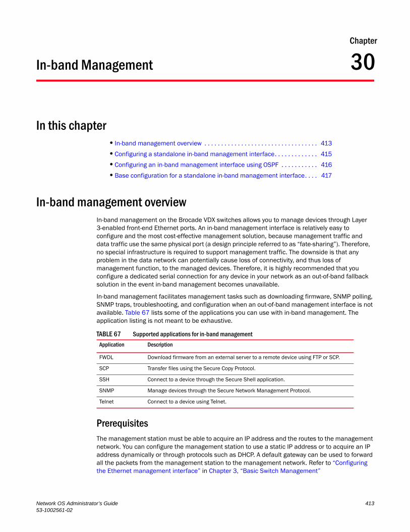
Network OS Administrator’s Guide53-1002561-02
Chapter
30
In-band ManagementIn this chapter•In-band management overview . . . . . . . . . . . . . . . . . . . . . . . . . . . . . . . . . . 413
•Configuring a standalone in-band management interface. . . . . . . . . . . . . 415
•Configuring an in-band management interface using OSPF . . . . . . . . . . . 416
•Base configuration for a standalone in-band management interface. . . . 417
In-band management overviewIn-band management on the Brocade VDX switches allows you to manage devices through Layer 3-enabled front-end Ethernet ports. An in-band management interface is relatively easy to configure and the most cost-effective management solution, because management traffic and data traffic use the same physical port (a design principle referred to as “fate-sharing”). Therefore, no special infrastructure is required to support management traffic. The downside is that any problem in the data network can potentially cause loss of connectivity, and thus loss of management function, to the managed devices. Therefore, it is highly recommended that you configure a dedicated serial connection for any device in your network as an out-of-band fallback solution in the event in-band management becomes unavailable.
In-band management facilitates management tasks such as downloading firmware, SNMP polling, SNMP traps, troubleshooting, and configuration when an out-of-band management interface is not available. Table 67 lists some of the applications you can use with in-band management. The application listing is not meant to be exhaustive.
PrerequisitesThe management station must be able to acquire an IP address and the routes to the management network. You can configure the management station to use a static IP address or to acquire an IP address dynamically or through protocols such as DHCP. A default gateway can be used to forward all the packets from the management station to the management network. Refer to “Configuring the Ethernet management interface” in Chapter 3, “Basic Switch Management”
TABLE 67 Supported applications for in-band management
Application Description
FWDL Download firmware from an external server to a remote device using FTP or SCP.
SCP Transfer files using the Secure Copy Protocol.
SSH Connect to a device through the Secure Shell application.
SNMP Manage devices through the Secure Network Management Protocol.
Telnet Connect to a device using Telnet.
413

In-band management overview30
In addition, you must configure IP routes and subnets. The front-end Ethernet port that you configure for management access acts as a router with IP forwarding implemented to allow communication with the target device. If the management station and the managed devices are in separate subnets, it is necessary to configure IP routes throughout the network to allow the communication to take place. You can either configure the management interface to use dynamic routing protocols, such as Open Shortest Path First (OSPF) or static routing.
• To configure the in-band management interface to use static routing, refer to “Configuring static routes” in Chapter 32, “IP Route Management”.
• To configure the in-band management interface to use dynamic routing, refer to Chapter 33, “Configuring OSPF”.
On switches running Network OS v 3.0.0 and later, in-band management is supported in VCS-enabled mode to manage devices through a Layer 2 or Layer 3 network. In standalone mode, a management station may be directly connected to another node in standalone mode. On switches running firmware prior to Network OS v3.0.0, in-band management is supported only in standalone mode.
NOTEStandalone mode is not supported on the Brocade VDX 8770 switches.
In-band management does not require any special configuration commands. Because management traffic rides over the existing IP routing infrastructure, the commands needed to configure an in-band management interface are the same you would use to configure IP interfaces supported by static or dynamic routing protocols to provide connectivity to target devices.
Supported interfacesIn-band management is supported on the interfaces shown in Table 68. Refer to the interface command documentation in the Network OS Command Reference for more information on the configuration options available for each of these interfaces.
NOTEA virtual Ethernet (Ve) interface is a logical port associated with a Layer 3 Virtual LAN (VLAN) configured on a Layer 3 switch. You can configure routing parameters on the virtual interface to enable the Layer 3 switch to route protocol traffic from one Layer 3 VLAN to the other, without using an external router. A corresponding VLAN must be configured before you can configure the VE interface.
TABLE 68 Ports configurable for in-band management
Interface Addressing Description
Management (Ma) rbridge-id/slot Management interface
GigabitEthernet (Gi) rbridge-id/slot/port 1GbE physical interface
TenGigabitEthernet (Te) rbridge-id/slot/port 10GbE physical interface
FortyGigabitEthernet (Fo) rbridge-id/slot/port 40GbE physical interface
Port-channel (Po) interface-id (IP or Po in standalone mode only) Port Channel interface
Virtual Ethernet (Ve) interface-id (corresponding VLAN ID) Virtual Ethernet Interface
414 Network OS Administrator’s Guide53-1002561-02

Configuring a standalone in-band management interface 30
Configuring a standalone in-band management interfaceFigure 30 shows the configuration of an in-band management interface in standalone mode. In this example, the management station IP address and Ethernet port interface IP addresses for Switch-A and Switch-B are all in the same subnet, and therefore, no routing protocols are needed for the management station to connect to Switch-B through Switch-A. The management station (a server or workstation) connects to the physically attached switch-A, and switch-A can connect to the physically connected Switch-B.
FIGURE 30 A management station communicating with a networked device in standalone mode.
The configuration shown in Figure 30 supports the following operations:
• Connecting from the management station to Switch-A through an SSH or Telnet session.
• Transferring files between the management station and Switch-A using secure copy (SCP) or FTP.
• Transferring files between Switch-A and Switch-B using secure copy (SCP).
• Using any of the applications in Table 67 between Switch-A and Switch-B.
Provisioning an in-band management interface in standalone modeThe following procedure configures the in-band management interface shown in Figure 30.
1. Connect to the switch through the serial console or through the management interface if available.
2. Issue the configure terminal command to enter global configuration mode.
3. Enter the interface command followed by the interface type you want to configure.
For a standalone in-band management interface, only a physical user port ( 1GbE, 10GbE, or 40GbE) needs to be configured with IP addresses. There is no need to configure either a VLAN or a VE interface.
Network OS Administrator’s Guide 41553-1002561-02

Configuring an in-band management interface using OSPF30
4. Enter the ip address IPv4_address/prefix_length command to set the IPv4 address for the interface.
NOTEYou must configure a primary IP address only. Secondary IP addresses are not supported.
5. Enter the ip mtu command to set the interface IP Maximum Transmission Unit (MTU) in bytes.
6. Enter the arp-ageing-timeout command to configure the interface timeout parameter (in minutes) for the Address Resolution Protocol (ARP).
The default timeout value is 4 hours.
7. Clear the ARP cache using the do clear-arp-cache command with the no-refresh option to delete unused ARP entries.
8. Configure a proxy ARP per interface with the ip proxy-arp command.
9. Display the configuration using the show ip interface command.
switch# configure terminalEntering configuration mode terminalswitch(config)# interface TenGigabitEthernet 1/0/1 switch(conf-if-te-10/1)# no shutdownswitch(conf-if-te-1/0/1)# ip address 1.1.1.1/24switch(conf-if-te-1/0/1)# ip mtu 1200switch(conf-if-te-1/0/1)# arp-ageing-timeout 300switch(conf-if-te-1/0/1)#( do clear-arp-cache no-refreshswitch(conf-if-te-1/0/1)# ip proxy-arpswitch(conf-if-te-1/0/1)# exit
switch# show ip interface TenGigabitEthernet 1/0/1 TenGigabitEthernet 10/1 is up protocol is upPrimary Internet Address is 1.1.1.1/24 broadcast is 1.1.1.255IP MTU is 1200Proxy Arp is EnabledICMP unreachables are always sentICMP mask replies are never sentIP fast switching is enabled
Configuring an in-band management interface using OSPFFigure 31 shows the configuration of an in-band management interface connected to a VCS fabric.
• In this scenario, a Brocade VDX 6720 (RB1 local), is connected to a modular Brocade VDX 8770 switch (RB2) in a VCS fabric through fabric ports.
• Another Brocade VDX 6720 switch (C1) is connected to a VCS fabric member (RB1) using the front panel port in RB1.
• OSPF is configured between RB1 and RB2 for Layer 3 forwarding, and to export and exchange routes.
• A management station (MS) is connected to C1 through a Telnet or SSH session.
• In a standalone configuration (“Base configuration for a standalone in-band management interface”) C1 and RB1 are in standalone mode. The management station connects to RB1 through C1 using physical front panel port connections.
416 Network OS Administrator’s Guide53-1002561-02

Base configuration for a standalone in-band management interface 30
• In VCS fabric mode (“Base configuration in VCS Fabric mode” on page 418), the management station connects to RB2 through C1 using OSPF and dynamic route distribution in a VCS fabric.
FIGURE 31 In-band management in a VCS fabric configured with dynamic routes (OSPF)
Base configuration for a standalone in-band management interfaceThe following configuration establishes an in-band management connection from the management station to RB1 through C1. For the purpose of this example, C1 and RB1 operate in standalone mode (VCS mode is disabled).
1. Configure the front-end Ethernet port on RB1 through a serial connection.
a. Connect to RB1 using the serial console.
b. Issue the configure terminal command to enter global configuration mode.
c. Configure a front-end Ethernet port using the interface vlan vlan_id command.
d. Issue the rbridge-id rbridge-id command to enter the RBridge sub-configuration mode.
e. Enter the interface ve ve_id command to configure the virtual Ethernet interface (VE).
The VE ID must correspond to the existing VLAN ID.
f. Enter the IP address of the interface.
g. Enter the no shutdown command to enable the interface.
h. Enter the do show vcs command to verify that RB1 is in standalone mode and not a part of a VCS fabric.
RB1# configure terminalEntering configuration mode terminal.RB1(config)# interface vlan 2
ManagementStation (MS)
C1 VDX 67202.2.2.1/24 RB1 (local)
VDX 6720100.100.100.17
RB2 (remote)VDX 8770
100.100.100.18
2.2.2.17
100.100.100.xx/24
2.2.2.xx
VCS Ospf Area 0Network
100/100/100/xx
Network OS Administrator’s Guide 41753-1002561-02

Base configuration for a standalone in-band management interface30
RB1(config)# rbridge-id 1RB1(config-rbridge-id-1)# interface ve 2RB1(config-Ve-2)# ip address 2.2.2.17/24RB1(config-Ve-2)# no shutdownRB1(config--Ve2)# exitRB1(config)# do show vcs
state : Disabled
2. C1 is a management station and automatically telnets into node RB1.
3. Verify the in-band management connection between the management station to C1, and between C1and RB1 (standalone test).
a. Connect to C1 through the management interface using an SSH session.
b. On C1, establish a Telnet connection from C1 to RB1.
C1# telnet 2.2.2.17/24Trying 2.2.2.17...Connected to 2.2.17.24.Escape character is '^]'.
You are now logged in to RB1 (note the prompt change).
c. Verify the Telnet notification on RB1.
RB1# 1970/01/01-02:16:27, [SEC-1203], 13406, M1, INFO, RB1, Login information: Login successful via TELNET/SSH/RSH. IP Addr: 2.2.17.24
d. Through the Telnet in-band management connection from C1, verify that RB1 is in standalone mode.
RB1# show vcs
state : Disabled
You can now perform in-band management functions on RB1 through the management interface SSH connection to C1, such as downloading firmware or managing SNMP.
Base configuration in VCS Fabric modeThe following configuration establishes an in-band management connection from a management station (MS) to C1, and from C1 to RB1 and RB2. RB1 is the local switch, RB2 is the remote switch. Both switches operate in VCS-enabled mode.
1. Set up an OSPF network (area 0) on RB1 to enable dynamic routing using the following procedure.
a. Connect to RB1 using a serial connection.
b. Issue the configure terminal command to enter global configuration mode.
c. Enter the interface vlan command to configure a VLAN on RB1.
RB1# configure terminalEntering configuration mode terminal.RB1(config)# interface vlan 100
d. Issue the rbridge-id rbridge-id command to enter the RBridge sub-configuration mode.
e. Configure OSPF using the router ospf command followed by the area command. Enter 0 to configure the OSPF area 0.
418 Network OS Administrator’s Guide53-1002561-02

Base configuration for a standalone in-band management interface 30
f. Enter the exit command to return to the RBridge configuration mode.
RB1(config-Vlan-100)# rbridge-id 17RB1(config-rbridge-id-17)# router ospfRB1(conf-ospf-router)# area 0RB1(conf-ospf-router)# exitRB1(config-rbridge-id-17)#
g. Configure a virtual Ethernet interface for the VLAN and assign the IP address for RB1.
h. Set the OSPF area 0 with the ip ospf area command.
i. Enter the no shutdown command to enable the interface.
RB1(config-rbridge-id-17)# interface ve 100RB1(config-Ve-100)# ip address 100.100.100.17/24RB1(config-Ve-100)# ip ospf area 0RB1(config-Ve-100)# no shutdown
2. Set up an OSPF network (area 0) on RB2 to enable dynamic routing. The configuration steps mirror the configuration on RB1.
a. Connect to RB2 using a serial connection.
b. Issue the configure terminal command to enter global configuration mode.
c. Enter the interface vlan command to configure a VLAN on RB2.
RB2# configure terminalEntering configuration mode terminal.RB2(config)# interface vlan 100
d. Issue the rbridge-id rbridge-id command to enter the RBridge sub-configuration mode.
e. Configure OSPF using the router ospf command followed by the area command. Enter 0 to configure the OSPF area 0.
f. Enter the exit command to return to the RBridge configuration mode.
RB2(config-Vlan-100)# rbridge-id 18RB2(config-rbridge-id-18)# router ospfRB2(conf-ospf-router)# area 0RB2(conf-ospf-router)# exitRB2(config-rbridge-id-18)#
g. Configure the virtual Ethernet interface for the VLAN and assign the IP address for RB2.
h. Set the OSPF area 0 with the ip ospf area command.
i. Enter the no shutdown command to enable the interface.
RB2(config-rbridge-id-18)# interface ve 100RB2(config-Ve-100)# ip address 100.100.100.18/24RB2(config-Ve-100)# ip ospf area 0RB1(config-Ve-100)# no shutdown
Network OS Administrator’s Guide 41953-1002561-02

Base configuration for a standalone in-band management interface30
3. Verify the OSPF configuration in the VCS fabric.
a. On RB2, verify adjacency between RB1 and RB2. RB2 is displayed as a neighbor.
RB2(config-Ve-100)# do show ip ospf neighbor
Port Address Pri State Neigh Address Neigh ID Ev Opt CntVe 100 100.100.100.18 1 FULL/BDR 100.100.100.17 100.100.100.17 6 2 0
b. On RB2, verify the IP routes between RB1 and RB2.
RB2(config-Ve-100)# do show ip routeTotal number of IP routes: 2Type Codes-B:BGP D:Connected I:ISIS O:OSPF R:RIP S:Static; Cost-Dist/MetricBGP Codes - i:iBGP e:eBGPISIS Codes - L1:Level-1 L2:Level-2OSPF Codes - i:Inter Area 1:External Type 1 2:External Type 2 s:Sham Link
Destination Gateway Port Cost Type Uptime1 2.2.2.0/24 100.100.100.17 Ve 100 110/10 O2 0m14s2 100.100.100.0/24 DIRECT Ve 100 0/0 D 5m2s
c. On RB1, distribute the routes between RB1 and RB2 as shown in the example.
RB1# configure terminalEntering configuration mode terminal.RB1(config)# rbridge-id 17RB1(config-rbridge-id-17)# router ospfRB1(conf-ospf-router)# redistribute connectedRB1(conf-ospf-router)# exitRB1(config)#
d. Verify the VCS fabric configuration on RB1.
RB1(config)# do show vcsConfig Mode : Local-OnlyVCS ID : 2Total Number of Nodes : 2Rbridge-Id WWN Management IP Status HostName-----------------------------------------------------------------------17 10:00:00:05:33:77:31:9C* 10.24.73.80 Online RB118 >10:00:00:05:33:77:23:6C 10.24.73.85 Online RB2
e. Verify the VCS fabric configuration on RB2.
RB2# show vcsConfig Mode : Local-OnlyVCS ID : 2Total Number of Nodes : 2Rbridge-Id WWN Management IP Status HostName-----------------------------------------------------------------------17 10:00:00:05:33:77:31:9C* 10.24.73.80 Online RB118 >10:00:00:05:33:77:23:6C 10.24.73.85 Online RB2
4. Verify the in-band management connection to RB1 and RB2.
a. Connect to C1 from the management station using an SSH connection.
b. On C1, verify connectivity to RB1 (local test) by issuing the ping command to the front-end Ethernet interface (VE port) IP address for RB1.
C1# ping 2.2.2.17PING 2.2.2.17 (2.2.2.17): 56 data bytes64 bytes from 2.2.2.17: icmp_seq=0 ttl=64 time=8.206 ms
420 Network OS Administrator’s Guide53-1002561-02

Base configuration for a standalone in-band management interface 30
64 bytes from 2.2.2.17: icmp_seq=1 ttl=64 time=7.126 ms--- 2.2.2.17 ping statistics ---
c. From C1, verify connectivity to RB2 (remote test) by issuing the ping command to the front-end Ethernet interface (VE port) IP address for RB2.
C1# ping 100.100.100.18PING 100.100.100.18 (100.100.100.18): 56 data bytes64 bytes from 100.100.100.18: icmp_seq=0 ttl=63 time=21.239 ms64 bytes from 100.100.100.18: icmp_seq=1 ttl=63 time=19.889 ms--- 100.100.100.18 ping statistics ---
d. From C1, establish a Telnet connection to RB1 by issuing the telnet command to the front-end Ethernet interface (VE port) IP address for RB1.
This test verifies the in-band management interface between C1 and the local RBridge, RB1. If the test succeeds, you can perform management functions on RB1 through C1.
C1# telnet 2.2.2.17Trying 2.2.2.17...Connected to 2.2.2.17Escape character is '^]'.
e. Verify the Telnet RASlog notification on RB1 through C1.
The RASlog message displays on the console.
RB1# 2012/05/10-17:31:09, [SEC-1203], 312942, M1, INFO, C1, Login information: Login successful via TELNET/SSH/RSH. IP Addr: 2.2.2.1
f. Verify the VCS fabric configuration on RB1 through C1.
The output is identical to the output generated in step 3d. The difference is that you are now connected to RB1 through the in-band management interface.
RB1# show vcsConfig Mode : Local-OnlyVCS ID : 2Total Number of Nodes : 2Rbridge-Id WWN Management IP Status HostName-----------------------------------------------------------------------17 10:00:00:05:33:77:31:9C* 10.24.73.80 Online RB118 >10:00:00:05:33:77:23:6C 10.24.73.85 Online RB2
g. From C1, establish a Telnet connection to RB2 by issuing the telnet command to the front-end Ethernet interface (VE port) IP address for RB2.
This test verifies the in-band management interface between C1 and the remote RBridge, RB2. If the test succeeds, you can perform management functions on RB2 through C1.
C1# telnet 100.100.100.18Trying 100.100.100.18...Connected to 100.100.100.18.Escape character is '^]'.
h. Verify the Telnet RASlog notification on RB2 through C1.
The RASlog message displays on the console.
RB2# 2012/05/10-17:31:09, [SEC-1203], 312942, M1, INFO, C1, Login information: Login successful via TELNET/SSH/RSH. IP Addr: 2.2.2.1
i. Verify the VCS fabric configuration on RB2 through C1.
Network OS Administrator’s Guide 42153-1002561-02

Base configuration for a standalone in-band management interface30
The output is identical to the output generated in step 3d. The difference is that you are now connected to RB2 through the in-band management interface.
RB2# show vcsConfig Mode : Local-OnlyVCS ID : 2Total Number of Nodes : 2Rbridge-Id WWN Management IP Status HostName-----------------------------------------------------------------------17 10:00:00:05:33:77:31:9C* 10.24.73.80 Online RB118 >10:00:00:05:33:77:23:6C 10.24.73.85 Online RB2
If all verification steps produce the desired results, the configuration is successful, and you can use the management interface on C1 to perform management functions on both, the local (RB1) and the remote switch (RB2).
For more information on IP address configuration in the VCS fabric, refer to “VCS Virtual IP address configuration” on page 98.
422 Network OS Administrator’s Guide53-1002561-02

Network OS Administrator’s Guide53-1002561-02
Chapter
31
IP Route PolicyIn this chapter
•About IP route policy . . . . . . . . . . . . . . . . . . . . . . . . . . . . . . . . . . . . . . . . . . . 423
•Configuring IP route policy . . . . . . . . . . . . . . . . . . . . . . . . . . . . . . . . . . . . . . 424
About IP route policyIP route policy controls how routes or IP subnets are transported from one subsystem to another subsystem. The IP route policy may perform “permit” or “deny” actions so that matched routes may be allowed or denied to the target subsystem accordingly. Additionally, IP route policy may also be used for modify the characteristics of a matched route and IP subnet pair.
There are two types of IP route policies supported; prefix-list and route-map.
IP prefix-listAn IP prefix-list is identified by its name. Each IP prefix-list may consist of one or more instances. The following is an example of IP prefix-list,
switch# ip prefix-list test 1 deny 1.2.0.0/16 ge 17 le 30switch# ip prefix-list test 2 permit 1.1.0.0/16
A matching condition of prefix-list instance contains two portions 1) IP subnet prefix and 2) optionally prefix (mask) length, where ge (greater or equal) is the lower limit of the mask length, and le (less or equal) is the upper limit of the mask length. If no ge and/or le is given in an instance, the exact match of subnet prefix length is needed.
In the example above, a route is considered match for instance 1 if this route is inside subnet 1.2.0.0/16 AND whose mask length is between 17 and 30. That is, route 1.2.1.0/24 matches, but route 1.2.1.1/32 does not due to mask length.
Similar to route-map, when finding match, each prefix-list instance is looked at in order specified by its instance ID. The look-up terminates at the first match. A route that does not find match in prefix list is denied.
At present, prefix-list is not used by itself. The IP prefix-list can be used as part of route-map match clauses. In this context, “permit” stands of matching this pattern, and “deny” stands for not matching this route pattern.
Route-mapA route-map is identified by its name. Each route-map may consist of one or more instances. Each route-map instances may contain zero or more matching clauses, and zero or more set clauses.
423
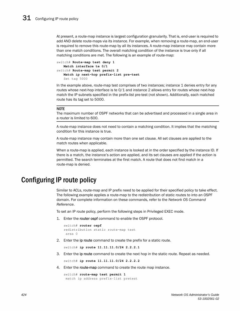
Configuring IP route policy31
At present, a route-map instance is largest configuration granularity. That is, end-user is required to add AND delete route-maps via its instance. For example, when removing a route-map, an end-user is required to remove this route-map by all its instances. A route-map instance may contain more than one match conditions. The overall matching condition of the instance is true only if all matching conditions are met. The following is an example of route-map:
switch# Route-map test deny 1Match interface te 0/1
switch# Route-map test permit 2Match ip next-hop prefix-list pre-testSet tag 5000
In the example above, route-map test comprises of two instances; instance 1 denies entry for any routes whose next-hop interface is te 0/1 and instance 2 allows entry for routes whose next-hop match the IP subnets specified in the prefix-list pre-test (not shown). Additionally, each matched route has its tag set to 5000.
NOTEThe maximum number of OSPF networks that can be advertised and processed in a single area in a router is limited to 600.
A route-map instance does not need to contain a matching condition. It implies that the matching condition for this instance is true.
A route-map instance may contain more than one set clause. All set clauses are applied to the match routes when applicable.
When a route-map is applied, each instance is looked at in the order specified by the instance ID. If there is a match, the instance’s action are applied, and its set clauses are applied if the action is permitted. The search terminates at the first match. A route that does not find match in a route-map is denied.
Configuring IP route policySimilar to ACLs, route-map and IP prefix need to be applied for their specified policy to take effect. The following example applies a route-map to the redistribution of static routes to into an OSPF domain. For complete information on these commands, refer to the Network OS Command Reference.
To set an IP route policy, perform the following steps in Privileged EXEC mode.
1. Enter the router ospf command to enable the OSPF protocol.
switch# router ospfredistribution static route-map test area 0
2. Enter the ip route command to create the prefix for a static route.
switch# ip route 11.11.11.0/24 2.2.2.1
3. Enter the ip route command to create the next hop in the static route. Repeat as needed.
switch# ip route 11.11.11.0/24 2.2.2.2
4. Enter the route-map command to create the route map instance.
switch# route-map test permit 1 match ip address prefix-list pretest
424 Network OS Administrator’s Guide53-1002561-02

Configuring IP route policy 31
5. Enter the ip prefix-list command to configure the IP prefix instance.
switch# ip prefix-list pretest 2 permit 1.1.1.0/24
In the example above, when the route-map test permit 1 command executes, only the static route 1.1.1.0/24 is exported into the OSPF domain because there are no matching rules in the ip prefix-list pretest for route 11.11.11.0/24. The default action of prefix list is deny (no match), therefore the route 11.11.11.0/24 is not exported into OSPF domain.
You can configure the router to explicitly permit or deny specific IP addresses. The router permits all IP addresses by default. If you want permit to remain the default behavior, define individual filters to deny specific IP addresses. If you want to change the default behavior to deny, define individual filters to permit specific IP addresses. Once you define a filter, the default action for addresses that do not match a filter is “deny”. To change the default action to “permit”, configure the last filter as “permit any any”.
Network OS Administrator’s Guide 42553-1002561-02

Configuring IP route policy31
426 Network OS Administrator’s Guide53-1002561-02

Network OS Administrator’s Guide53-1002561-02
Chapter
32
IP Route ManagementIn this chapter
•Overview of IP Route Management . . . . . . . . . . . . . . . . . . . . . . . . . . . . . . . 427
•How IP route management determines best route . . . . . . . . . . . . . . . . . . . 427
•Configuring static routes . . . . . . . . . . . . . . . . . . . . . . . . . . . . . . . . . . . . . . . . 428
Overview of IP Route ManagementIP route management is the term used to refer to software that manages routes and next hops from different sources in a routing table, from which the Brocade device selects the best routes for forwarding IP packets. This route management software gets activates automatically at system bootup and does not require pre-configuration.
IP route management runs on all platforms configured for Layer 3. and provides the following:
• Maintains routes submitted by other protocols.
• Supports route redistribution.
• Supports router identification.
• Selects and synchronizes routes to the forwarding information base (FIB).
• Synchronizes the Layer 3 interface to the FIB.
• Supports the following Layer 3 interfaces: virtual ethernet (VE), router port, loopback, and management.
NOTEIP route management supports IPv4 routes only.
How IP route management determines best routeThe sources of routes that are added into IP route management are:
• Dynamic routes from routing protocols. Open Shortest Path First (OSPF) is the only supported dynamic routing protocol in IP route management. If OSPF is enabled, the Brocade device can learn about routes from the advertisements other OSPF routers send. If the route has a lower administrative distance than any other routes from different sources to the same destination, the Brocade device places the route in the IP route table. The default administrative distance for OSPF is 110.
• Static configured routes: You can add routes directly to the route table. When you add a route to the IP route table, you are creating a static IP route. The default administrative distance of a static route is 1.
427

Configuring static routes32
• Directly connected routes from interface configuration: When you add an IP interface, the Brocade device automatically creates a route for the network. The default administrative distance is for directly connected routes is zero.
Administrative distance can be configured for route types other than connected routes. IP route management prefers routes with lower administrative distances.
Configuring static routesYou can add a static route to IP route management by using the ip route and ipv6 route commands in rbridge configuration mode. With these commands, you can specify either the next-hop gateway or egress interface to add the route.
Specifying the next-hop gatewayTo configure a static route to 207.95.7.0, using 207.95.6.157 as the next-hop gateway, use the ip route command in Rbridge sub-configuration mode, as shown in this example:
switch (config)# rbridge-id 30switch (config-rbridge-id-30)# ip route 207.95.7.0/24 207.95.6.157
This example is the same command using IPv6.
switch (config)# rbridge-id 30
switch (config-rbridge-id-30)# ipv6 route fe80::21b:edff:fe0b:3c00/64 fe80::21b:edff:fe0b:3c00
Specifying the egress interfaceTo configure a static IP route with a tengigabitethernet port, enter an ip route command such as the following.
switch (config)# rbridge-id 30switch (config-rbridge-id-30)# ip route 192.128.2.0/24 te 101/4/1
The command configures a static IP route for destination network 192.128.2.0/24. Because an Ethernet port is specified instead of a gateway IP address as the next hop, the Brocade device forwards traffic for the 192.128.2.0/24 network to the tengigabitethernet port 101/4/1.
This example is the same command using IPv6.
switch (config)# rbridge-id 30switch (config-rbridge-id-30)# ipv6 route fe80::21b:edff:fe0b:3c00/64 te 101/4/1
Configuring the default routeA default route is configured with an all-zero prefix/netmask (for example, 0.0.0.0/0). The default route is an example of a special static route with a destination prefix of zero All traffic that does not have other matching routes is forwarded using the default route.
To configure a default route with a next hop of 207.95.6.157, enter the following ip route command.
switch(config)# rbridge-id 30switch(config-rbridge-id-30)# ip route 0.0.0.0/0 207.95.6.157
428 Network OS Administrator’s Guide53-1002561-02

Other Routing Commands 32
Other Routing CommandsRefer to Network OS Command Reference for more information about all IP routing-related commands. For example:
• The ip route command offers an option that allow you to specifiy a tag value of a route for route filtering with a route map. The command also offers an option for specifying a cost metric.
• The ip load-sharing command can be used to balance IP traffic across up to eight equal paths.
• The ip route next-hop ospf command allows a Brocade device to use routes learned from OSPF to resolve a configured static route.
• The ip route next-hop-recursion command allows a Broade device to resolve a route by using as many as 10 recursive-level lookups of other routes.
Network OS Administrator’s Guide 42953-1002561-02

Other Routing Commands32
430 Network OS Administrator’s Guide53-1002561-02

Network OS Administrator’s Guide53-1002561-02
Chapter
33
Configuring OSPFIn this chapter•Overview of OSPF. . . . . . . . . . . . . . . . . . . . . . . . . . . . . . . . . . . . . . . . . . . . . . 431
•OSPF in a VCS environment . . . . . . . . . . . . . . . . . . . . . . . . . . . . . . . . . . . . . 433
•Using Designated Routers. . . . . . . . . . . . . . . . . . . . . . . . . . . . . . . . . . . . . . . 435
•Performing Basic OSPF Configuration . . . . . . . . . . . . . . . . . . . . . . . . . . . . . 436
•Changing Other Settings . . . . . . . . . . . . . . . . . . . . . . . . . . . . . . . . . . . . . . . . 443
Overview of OSPFOpen Shortest Path First (OSPF) is a link-state routing protocol that uses link-state advertisements (LSA) to update neighboring routers about its interfaces. Each router maintains an identical area-topology database to determine the shortest path to any neighboring router.
• OSPF must be configured in a Virtual Cluster Switching (VCS) environment.
• The following platforms support OSPF:
- Brocade VDX 6710-54
- Brocade VDX 6720
- Brocade VDX 6730
- VDX 8770-4
- VDX 8770-8
• OSPF can be configured on either a point-to-point or broadcast network.
• OSPF can be enabled on the following interfaces: gigabitethernet, tengigabitethernet, fortygigabitethernet, and Ve.
OSPF is built upon a hierarchy of network components. The highest level of the hierarchy is the Autonomous System (AS). An autonomous system is defined as a number of networks, all of which share the same routing and administration characteristics.
An AS can be divided into multiple areas as shown in Figure 32 on page 432. Each area represents a collection of contiguous networks and hosts. Areas limit the amount of advertisements sent (called flooding) within the network. An area is represented in OSPF by either an IP address or a number.
The backbone area (also known as area 0 or area 0.0.0.0) forms the core of an OSPF network. All other areas are connected to it, and inter-area routing happens via routers connected to the backbone area and to their own associated areas. The backbone area is the logical and physical structure for the OSPF domain and is attached to all nonzero areas in the OSPF domain.
431

Overview of OSPF33
The backbone area is responsible for distributing routing information between non-backbone areas. The backbone must be contiguous, but it does not need to be physically contiguous; backbone connectivity can be established and maintained through the configuration of virtual links.
You can further consolidate routes at an area boundary by defining an area range. The area range allows you to assign an aggregate value to a range of IP addresses. This aggregate value becomes the address that is advertised instead all of the individual addresses it represents being advertised. You can assign up to 32 ranges in an OSPF area.
An OSPF router can be a member of multiple areas. Routers with membership in multiple areas are known as Area Border Routers (ABRs). Each ABR maintains a separate topological database for each area the router is in. Each topological database contains all LSA databases for each router within a given area. The routers within the same area have identical topological databases. An ABR is responsible for forwarding routing information or changes between its border areas.
An Autonomous System Boundary Router (ASBR) is a router that is running multiple protocols and serves as a gateway to routers outside the OSPF domain and those operating with different protocols. The ASBR is able to import and translate different protocol routes into OSPF through a process known as redistribution. For more information about redistribution, see the redistribute command in Network OS Command Reference, 3.0.
FIGURE 32 OSPF operating in a network
Area 0.0.0.0 Backbone
Area 192.5.1.0
Area 200.5.0.0
Area 195.5.0.0
Router A
Router B
Router C
Router D
Router E
Router F
Router G
208.5.1.1
Area BorderRouter (ABR)
Virtual Link
Area BorderRouter (ABR)
Autonomous SystemBorder Router (ASBR)
RIP Router
206.5.1.1
e8
432 Network OS Administrator’s Guide53-1002561-02

OSPF in a VCS environment 33
OSPF in a VCS environmentFigure 33 shows one way in which OSPF can be used in a VCS environment. Routers RB1 and RB2, as well as the MLX switches, are configured with OSPF. Switches RB3, RB4, and RB5 are Layer-2 switches.
FIGURE 33 OSPF example in VCS environment
1. On Router RB1, do the following:
a. Enter the conf t command to enter terminal configuration mode.
b. Enter the interface vlan command followed by the VLAN number to create a VLAN for the router.
c. Enter the exit command to exit interface configuration mode.
d. Enter the rbridge-id command followed by the Rbridge ID to enter Rbridge subconfiguration mode.
e. Enter the router ospf command to enable the OSPF routing protocol and to enter OSPF router configuration mode.
f. Enter the area operand followed by the area ID to create this OSPF area on this router.
g. Enter the exit command to exit OSPF router configuration mode.
h. Enter the interface ve command followed by the VLAN number to enter interface configuration mode.
i. Enter the ip address operand followed by the IP address/subnet of the interface.
j. Enter the ip ospf area operand followed by the area ID to assign the interface to this area.
k. Enter the no shutdown command:
RB1# conf t
VRRP
OSPF Area0.0.0.0
RB2(Router)
Ve 1001101.1.1.2/24
Ve 1001101.1.1.1/24
RB4(Switch)
RB5(Switch)
RB3(Switch)
H1 H3
RB1(Router)
MLXMLX
MCTCORE
VCS
Network OS Administrator’s Guide 43353-1002561-02

OSPF in a VCS environment33
RB1(config)# interface vlan 1001RB1(config-Vlan-1001)# exitRB1(config)# rbridge-id 1 RB1(config-rbridge-id-1)# router ospfRB1(conf-ospf-router)# area 0.0.0.0RB1(conf-ospf-router)# exitRB1(config-rbridge-id-1)# interface ve 1001RB1(config-Ve-1001)# ip address 101.1.1.1/24RB1(config-Ve-1001)# ip ospf area 0.0.0.0RB1(config-Ve-1001)# no shutdown
2. On Router RB2, do the following:
a. Enter the conf t command to enter terminal configuration mode.
b. Enter the interface vlan command followed by the VLAN number to create a VLAN for the router.
c. Enter the exit command to exit interface configuration mode.
d. Enter the rbridge-id command followed by the Rbridge ID to enter Rbridge subconfiguration mode.
e. Enter the router ospf command to enable the OSPF routing protocol and to enter OSPF router configuration mode.
f. Enter the area operand followed by the area ID to create this OSPF area on this router.
g. Enter the exit command to exit OSPF router configuration mode.
h. Enter the interface ve command followed by the VLAN number to enter interface configuration mode.
i. Enter the ip address operand followed by the IP address/subnet of the interface.
j. Enter the ip ospf area operand followed by the area ID to assign the interface to this area.
k. Enter the no shutdown command:
RB2# conf tRB2(config)# interface vlan 1001RB2(config-Vlan-1001)# exitRB2(config)# rbridge-id 2 RB2(config-rbridge-id-2)# router ospfRB2(conf-ospf-router)# area 0.0.0.0RB2(conf-ospf-router)# exitRB2(config-rbridge-id-2)# interface ve 1001RB2(config-Ve-1001)# ip address 101.1.1.2/24RB2(config-Ve-1001)# ip ospf area 0.0.0.0RB2(config-Ve-1001)# no shutdown
3. Assign VLAN 1001 to a VLAG.
434 Network OS Administrator’s Guide53-1002561-02

Using Designated Routers 33
Using Designated RoutersIn an OSPF broadcast network, OSPF elects one router to serve as the designated router (DR) and another router on the segment to act as the backup designated router (BDR). This minimizes the amount of repetitive information that is forwarded on the network. OSPF forwards all messages to the designated router. Backup designated routers forward updates throughout the network.
On broadcast networks such as LAN links, all routers on the LAN other than the DR and BDR form full adjacencies with the DR and BDR and pass LSAs only to them. The DR forwards updates received from one neighbor on the LAN to all other neighbors on that same LAN. One of the main functions of a DR is to ensure that all the routers on the same LAN have identical LSDBs. Therefore, on broadcast networks, an LSDB is synchronized between a DROther (a router that is not a DR or a BDR) and its DR and BDR.
NOTEIn an OSPF point-to-point network, where a direct Layer 3 connection exists between a single pair of OSPF routers, there is no need for Designated and Backup Designated Routers.
In a network with no designated router and no backup designated router, the neighboring router with the highest priority is elected as the DR, and the router with the next highest priority is elected as the BDR, as shown in Figure 34. Priority is a configurable option at the interface level; refer to the ip ospf priority command in Network OS Command Reference, 3.0.
FIGURE 34 Designated and backup router election
If the DR goes off-line, the BDR automatically becomes the DR. The router with the next highest priority becomes the new BDR.
If two neighbors share the same priority, the router with the highest router ID is designated as the DR. The router with the next highest router ID is designated as the BDR. The DR and BDRs are recalculated after the OSPF protocol is disabled and re-enabled using [no] router ospf command.
NOTEBy default, the Brocade device’s router ID is the IP address configured on the lowest numbered loopback interface. If the device does not have a loopback interface, the default router ID is the lowest numbered IP address configured on the device.
When multiple routers on the same network are declaring themselves DRs, then both the priority and router ID are used to select the designated router and backup designated routers.
Router A
Router BRouter C
priority 10
priority 20priority 5
Designated Backup Router
Designated Router
Network OS Administrator’s Guide 43553-1002561-02

Performing Basic OSPF Configuration33
The DR and BDR election process is performed when one of the following events occurs:
• An interface is in a waiting state and the wait time expires.
• An interface is in a waiting state and receives a hello packet that addresses the BDR.
• A change in the neighbor state occurs, such as:
• a neighbor state transitions from ATTEMPT state to a higher state.
• communication to a neighbor is lost.
• a neighbor declares itself to be the DR or BDR for the first time.
Performing Basic OSPF ConfigurationTo begin using OSPF on the router, perform these steps:
1. Follow the rules in the “Configuration rules” on page 436.
2. Enable OSPF on the router. Refer to “Enabling or Disabling OSPF on the router” on page 436.
3. Assign the areas to which the router will be attached. Refer to “Assigning OSPF areas” on page 437.
4. Assign individual interfaces to the OSPF areas. Refer to “Assigning interfaces to an area” on page 441.
5. Assign a virtual link to any ABR that does not have a direct link to the OSPF backbone area. Refer to “Assigning virtual links” on page 441.
6. Refer to “Changing Other Settings” on page 443.
Configuration rules• If a router is to operate as an ASBR, you must enable the ASBR capability at the system level.
• Redistribution must be enabled on routers configured to operate as ASBRs.
• All router ports must be assigned to one of the defined areas on an OSPF router. When a port is assigned to an area, all corresponding subnets on that port are automatically included in the assignment.
Enabling or Disabling OSPF on the routerWhen you enable OSPF on the router, the protocol is automatically activated and you can assign areas and modify OSPF global parameters. To enable OSPF on the router, use the router ospf command:
1. In privileged EXEC mode, issue the configure command to enter global configuration mode.
2. Enter the rbridge-id command followed by the Rbridge ID to enter Rbridge sub-configuration mode.
3. Issue the router ospf command to enable OSPF on the router.
switch# configureswitch(config)# rbridge-id 101switch(config-rbridge-id-101)# router ospfswitch(conf-ospf-router)#
436 Network OS Administrator’s Guide53-1002561-02

Performing Basic OSPF Configuration 33
If you disable OSPF, the device removes all the configuration information for the disabled protocol from the running configuration. Moreover, when you save the configuration to the startup configuration file after disabling one of these protocols, all the configuration information for the disabled protocol is removed from the startup configuration file.
If you are testing an OSPF configuration and are likely to disable and re-enable the protocol, you might want to make a backup copy of the startup configuration file containing the protocol’s configuration information. This way, if you remove the configuration information by saving the configuration after disabling the protocol, you can restore the configuration by copying the backup copy of the startup configuration file onto the flash memory.
If the management default route information is available in the Chassis ID (CID) card, the OSPF default route is overwritten by the management default route when the switch reboots. In order to prevent this, remove the management default route after the switch reboots. The OSPF default route is automatically re-instated. Refer to Chapter 37, “Using the Chassis ID (CID) Recovery Tool”.
Assigning OSPF areasOnce OSPF is enabled on the system, you can assign areas. Assign an IP address or number as the area ID for each area. The area ID is representative of all IP addresses (subnets) on a router port. Each port on a router can support one area.
An area can be normal, a stub, or a Not-So-Stubby Area (NSSA):
• Normal – OSPF routers within a normal area can send and receive External Link State Advertisements (LSAs).
• Stub – OSPF routers within a stub area cannot send or receive External LSAs. In addition, OSPF routers in a stub area must use a default route to the area’s Area Border Router (ABR) or Autonomous System Boundary Router (ASBR) to send traffic out of the area.
• NSSA – The ASBR of an NSSA can import external route information into the area.
• ASBRs redistribute (import) external routes into the NSSA as type 7 LSAs. Type-7 External LSAs are a special type of LSA generated only by ASBRs within an NSSA, and are flooded to all the routers within only that NSSA.
• ABRs translate type 7 LSAs into type 5 External LSAs, which can then be flooded throughout the AS. You can configure summary-addresses on the ABR of an NSSA so that the ABR converts multiple type-7 External LSAs received from the NSSA into a single type-5 External LSA.
When an NSSA contains more than one ABR, OSPF elects one of the ABRs to perform the LSA translation for NSSA. OSPF elects the ABR with the highest router ID. If the elected ABR becomes unavailable, OSPF automatically elects the ABR with the next highest router ID to take over translation of LSAs for the NSSA. The election process for NSSA ABRs is automatic.
Example
To set up the backbone area shown in Figure 32 on page 432:
1. In privileged EXEC mode on Router A, issue the configure command to enter global configuration mode.
2. Enter the interface vlan command followed by the VLAN number to create a VLAN.
3. Enter the rbridge-id command followed by the RBridge ID to enter Rbridge sub-configuration mode.
Network OS Administrator’s Guide 43753-1002561-02

Performing Basic OSPF Configuration33
4. Enter the interface ve command followed by the VLAN number to enter interface configuration mode.
5. Enter the ip address operand followed by the IP address/subnet for the interface.
6. Issue the ip ospf area operand followed by the area ID to assign the interface to this area.
Router A# configureRouter A(config) # interface vlan 1001Router A(config-Vlan-1001) # rbridge 10Router A(config-rbridge-id-10) # interface Ve 1001Router A(config-Ve-1001 )# ip address 101.1.1.1/24Router A(config-Ve-1001) # ip ospf area 0.0.0.0
Supported Link State Advertisements
Link state advertisements (LSAs) supported for each area type are:
• Backbone (area 0) supports LSAs 1&2, 3, 4, 5, and 7.
• Non-backbone, not stub area supports LSAs 1&2, 3, 4, and 5.
• Stub area supports LSAs 1&2 and 3.
• Totally stubby area supports LSAs 1&2. Also supports a single LSA 3 per ABR, advertising a default route.
• No so stubby area supports LSAs 1&2, 3, and 7.
Assigning a Totally stubby area
By default, the device sends summary LSAs (LSA type 3) into stub areas. You can further reduce the number of link state advertisements (LSA) sent into a stub area by configuring the device to stop sending summary LSAs (type 3 LSAs) into the area. This is called assigning a Totally stubby area. You can disable the summary LSAs when you are configuring the stub area or later after you have configured the area.
This feature disables origination of summary LSAs, but the device still accepts summary LSAs from OSPF neighbors and floods them to other neighbors.
When you enter a command to disable the summary LSAs, the change takes effect immediately. If you apply the option to a previously configured area, the device flushes all of the summary LSAs it has generated (as an ABR) from the area.
NOTEThis feature applies only when the device is configured as an Area Border Router (ABR) for the area. To completely prevent summary LSAs from being sent to the area, disable the summary LSAs on each OSPF router that is an ABR for the area.
To disable summary LSAs for a stub area, enter a command such as the following.
Brocade(conf-ospf-router)# area 40 stub 99 no-summary
Assigning a Not-So-Stubby Area (NSSA)
The OSPF Not So Stubby Area (NSSA) feature enables you to configure OSPF areas that provide the benefits of stub areas, but that also are capable of importing external route information. OSPF does not flood external routes from other areas into an NSSA, but does translate and flood route information from the NSSA into other areas such as the backbone.
438 Network OS Administrator’s Guide53-1002561-02

Performing Basic OSPF Configuration 33
NSSAs are especially useful when you want to summarize Type-5 External LSAs (external routes) before forwarding them into an OSPF area. The OSPF specification prohibits summarization of Type-5 LSAs and requires OSPF to flood Type-5 LSAs throughout a routing domain. When you configure an NSSA, you can specify a summary-address for aggregating the external routes that the NSSA's ABR exports into other areas.
Figure 35 shows an example of an OSPF network containing an NSSA.
FIGURE 35 OSPF network containing an NSSA
This example shows two routing domains, a RIP domain and an OSPF domain. The ASBR inside the NSSA imports external routes from RIP into the NSSA as Type-7 LSAs, which the ASBR floods throughout the NSSA.
The ABR translates the Type-7 LSAs into Type-5 LSAs. If a summary-address is configured for the NSSA, the ABR also summarizes the LSAs into an aggregate LSA before flooding the Type-5 LSAs into the backbone.
Because the NSSA is partially stubby the ABR does not flood external LSAs from the backbone into the NSSA. To provide access to the rest of the Autonomous System (AS), the ABR generates a default Type-7 LSA into the NSSA.
Configuring an NSSA
To configure OSPF area 1.1.1.1 as an NSSA:
1. In privileged EXEC mode, issue the configure command to enter global configuration mode.
2. Enter the rbridge-id command followed by the RBridge ID to enter Rbridge sub-configuration mode.
RIP Domain
NSSA Area 1.1.1.1
Internal ASBR OSPF ABR
OSPF Area 0Backbone
Network OS Administrator’s Guide 43953-1002561-02

Performing Basic OSPF Configuration33
3. Enter the router ospf command to enable OSPF on the router.
4. Enter the area operand followed by the area ID, then enter the nssa operand followed by the nssa ID.
switch# configureswitch(config)# rbridge-id 101switch(config-rbridge-id-101)# router ospfSwitch(conf-ospf-router)# area 1.1.1.1 nssa 1
Configuring a summary-address for the NSSA
If you want the ABR that connects the NSSA to other areas to summarize the routes in the NSSA before translating them into Type-5 LSAs and flooding them into the other areas, configure a summary-address. The ABR creates an aggregate value based on the summary-address. The aggregate value becomes the address that the ABR advertises instead of advertising the individual addresses represented by the aggregate. You can configure up to 32 ranges in an OSPF area.
To configure a summary-address in NSSA 1.1.1.1 (This example assumes that you have already configured NSSA 1.1.1.1.):
1. In privileged EXEC mode, issue the configure command to enter global configuration mode.
2. Enter the rbridge-id command followed by the RBridge ID to enter Rbridge sub-configuration mode.
3. Enter the router ospf command to enable OSPF on the router and to enter router configuration mode.
4. Enter the area operand followed by the area ID, then enter the nssa operand followed by the nssa ID.
5. Enter the summary-address command followed by the IP address and mask for the summary route.
switch# configureswitch(config)# rbridge-id 101switch(config-rbridge-id-101)# router ospfswitch(conf-ospf-router)# area 1.1.1.1 nssa 10switch(conf-ospf-router)# summary-address 209.157.1.0 255.255.255.0
Assigning an area range (optional)
You can assign a range for an area, but it is not required. Ranges allow a specific IP address and mask to represent a range of IP addresses within an area, so that only that reference range address is advertised to the network, instead of all the addresses within that range. Each area can have up to 32 range addresses.
Example
To define an area range for subnets on 0.0.0.10 and 0.0.0.20:
1. In privileged EXEC mode, issue the configure command to enter global configuration mode.
2. Issue the rbridge-id command followed by the Rbridge ID to enter Rbridge sub-configuration mode.
3. Issue the router ospf command to enable OSPF on the router.
4. Issue the area operand followed by the area ID, then enter the range, and repeat as necessary.
switch# configure
440 Network OS Administrator’s Guide53-1002561-02

Performing Basic OSPF Configuration 33
switch(config)# rbridge-id 101switch(config-rbridge-id-101)# router ospfswitch(conf-ospf-router)# area 0.0.0.10 range 193.45.0.0 255.255.0.0switch(conf-ospf-router)# area 0.0.0.20 range 193.45.0.0 255.255.0.0
Assigning interfaces to an areaOnce you define OSPF areas, you can assign interfaces to the areas. All router ports must be assigned to one of the defined areas on an OSPF router. When a port is assigned to an area, all corresponding subnets on that port are automatically included in the assignment.
For example, to assign a tengigabitethernet interface 101/0/1 to a router area whose IP address is 192.5.0.0:
1. In privileged EXEC mode, issue the configure command to enter global configuration mode.
2. Issue the rbridge-id command followed by the Rbridge ID to enter Rbridge sub-configuration mode.
3. Issue the interface command followed by the interface ID to enter interface configuration mode.
4. Issue the ip ospf area command followed by the IP address of the area.
switch# configureswitch(config)# rbridge-id 101switch(config-rbridge-id-101)# int te 101/0/1switch(conf-if-te-101/0/1)# ip ospf area 192.5.0.0
If you want to set an interface to passive mode, use the ip ospf passive command. If you want to block flooding of outbound LSAa on specific OSPF interfaces, use the ip ospf database-filter all out command. Refer to the Network OS Command Reference, 3.0 for details.
Assigning virtual linksAll ABRs (area border routers) must have either a direct or indirect link to the OSPF backbone area (0.0.0.0 or 0). If an ABR does not have a physical link to the area backbone, the ABR can configure a virtual link to another router within the same area, which has a physical connection to the area backbone.
The path for a virtual link is through an area shared by the neighbor ABR (router with a physical backbone connection), and the ABR requires a logical connection to the backbone.
Two parameters fields must be defined for all virtual links—transit area ID and neighbor router:
• The transit area ID represents the shared area of the two ABRs and serves as the connection point between the two routers. This number should match the area ID value.
• The neighbor router field is the router ID (IP address) of the router that is physically connected to the backbone, when assigned from the router interface requiring a logical connection. When assigning the parameters from the router with the physical connection, be aware that the router ID is the IP address of the router requiring a logical connection to the backbone.
Network OS Administrator’s Guide 44153-1002561-02

Performing Basic OSPF Configuration33
NOTEBy default, the Brocade device’s router ID is the IP address configured on the lowest numbered loopback interface. If the device does not have a loopback interface, the default router ID is the lowest numbered IP address configured on the device. When you establish an area virtual link, you must configure it on both of the routers (both ends of the virtual link).
FIGURE 36 Defining OSPF virtual links within a network
Figure 36 shows an OSPF area border router, Device A, that is cut off from the backbone area (area 0). To provide backbone access to Device A, you can add a virtual link between Device A and Device C using area 1 as a transit area. To configure the virtual link, you define the link on the router that is at each end of the link. No configuration for the virtual link is required on the routers in the transit area.
To define the virtual link on Device A:
1. In privileged EXEC mode, issue the configure command to enter global configuration mode.
2. Enter the rbridge-id command followed by the Rbridge ID to enter Rbridge sub-configuration mode.
3. Enter the router ospf command to enable OSPF on the router.
4. Enter the area operand followed by the area ID, and repeat as necessary.
5. Enter the area operand followed by the area address in decimal or dotter-decimal format, then enter the virtual-link operand followed by ID of the OSPF router at the remote end of the virtual link.
Device A# configure
OSPF Area 0
OSPF Area 1“transit area”
OSPF Area 2
Device CRouter ID 209.157.22.1
Device BDevice ARouter ID 10.0.0.1
442 Network OS Administrator’s Guide53-1002561-02
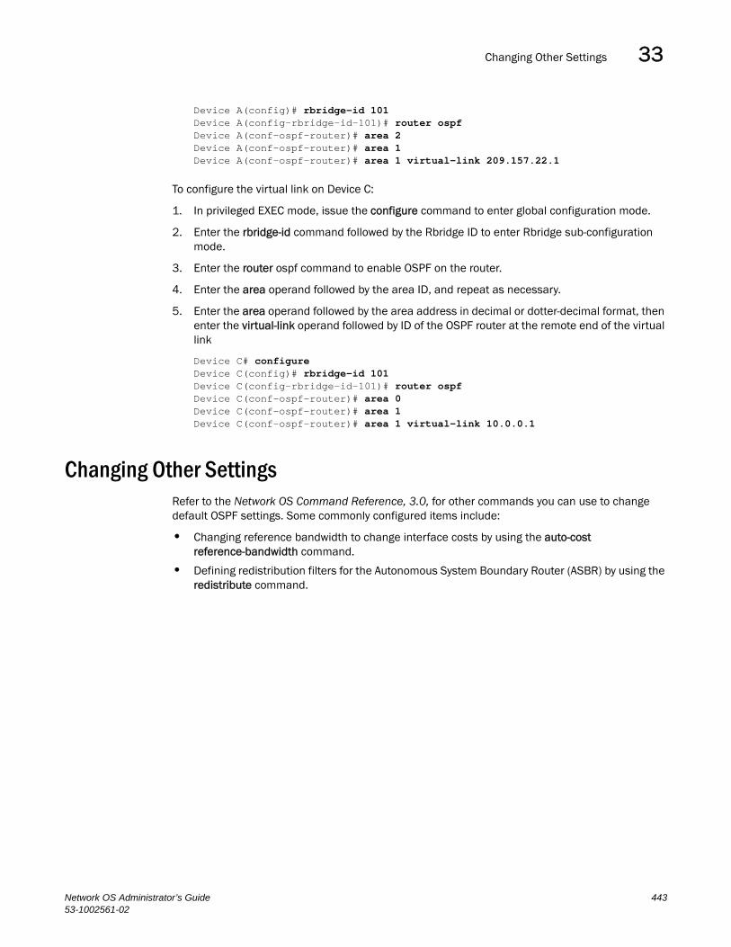
Changing Other Settings 33
Device A(config)# rbridge-id 101Device A(config-rbridge-id-101)# router ospfDevice A(conf-ospf-router)# area 2Device A(conf-ospf-router)# area 1Device A(conf-ospf-router)# area 1 virtual-link 209.157.22.1
To configure the virtual link on Device C:
1. In privileged EXEC mode, issue the configure command to enter global configuration mode.
2. Enter the rbridge-id command followed by the Rbridge ID to enter Rbridge sub-configuration mode.
3. Enter the router ospf command to enable OSPF on the router.
4. Enter the area operand followed by the area ID, and repeat as necessary.
5. Enter the area operand followed by the area address in decimal or dotter-decimal format, then enter the virtual-link operand followed by ID of the OSPF router at the remote end of the virtual link
Device C# configureDevice C(config)# rbridge-id 101Device C(config-rbridge-id-101)# router ospfDevice C(conf-ospf-router)# area 0Device C(conf-ospf-router)# area 1Device C(conf-ospf-router)# area 1 virtual-link 10.0.0.1
Changing Other SettingsRefer to the Network OS Command Reference, 3.0, for other commands you can use to change default OSPF settings. Some commonly configured items include:
• Changing reference bandwidth to change interface costs by using the auto-cost reference-bandwidth command.
• Defining redistribution filters for the Autonomous System Boundary Router (ASBR) by using the redistribute command.
Network OS Administrator’s Guide 44353-1002561-02

Changing Other Settings33
444 Network OS Administrator’s Guide53-1002561-02

Network OS Administrator’s Guide53-1002561-02
Chapter
34
Configuring VRRPIn this chapter•Overview of virtual routers . . . . . . . . . . . . . . . . . . . . . . . . . . . . . . . . . . . . . . 445
•Guidelines . . . . . . . . . . . . . . . . . . . . . . . . . . . . . . . . . . . . . . . . . . . . . . . . . . . 447
•VRRP/VRRP-E Packet Behavior . . . . . . . . . . . . . . . . . . . . . . . . . . . . . . . . . . 448
•VRRP basic configuration example . . . . . . . . . . . . . . . . . . . . . . . . . . . . . . . 448
•Enabling preemption . . . . . . . . . . . . . . . . . . . . . . . . . . . . . . . . . . . . . . . . . . . 450
•Using track ports and track priority with VRRP and VRRP-E. . . . . . . . . . . . 450
•Using Short-path forwarding (VRRP-E only) . . . . . . . . . . . . . . . . . . . . . . . . . 451
•Multigroup Configuration for VRRP/VRRP-E . . . . . . . . . . . . . . . . . . . . . . . . 454
Overview of virtual routersA virtual router is a collection of physical routers that can use the Virtual Router Redundancy Protocol (VRRP) to provide redundancy to routers within a LAN. Two or more VRRP-configured routers can create a virtual router. Each VRRP router can participate in as many as 255 virtual routers per LAN interface.
VRRP eliminates a single point of failure in a static, default-route environment by dynamically assigning virtual IP routers to participating hosts. The interfaces of all routers in a virtual router must belong to the same IP subnet. There is no restriction against reusing a virtual router ID (VRID) with a different address mapping on different LANs.
445

Overview of virtual routers34
Figure 37 shows a basic VRRP setup to illustrate some basic VRRP concepts. Router1 and Router2 are two physical routers that can be configured to compose one virtual router. This virtual router would provide redundant network access for Host1. If Router 1 were to fail, Router 2 could provide the default gateway out of the subnet.
FIGURE 37 Basic VRRP setup
The virtual router shown in Figure 37 is identified as Group1. A physical router forwards packets for the virtual router. This physical router is called the master router.
Some common VRRP-related terms and concepts you will need to know are.
• Virtual Router—A collection of physical routers that can use either the VRRP or VRRP-E protocol to provide redundancy to routers within a LAN.
NOTEMost of the information in this chapter applies to both VRRP and VRRP-E, and, therefore, the term “VRRP” is often used to mean either VRRP or VRRP-E. Where there are differences between the two protocols, these differences are explicitly described.
• Virtual Router Group—A group of physical routers that are assigned to the same virtual router.
• Virtual Router Address—The address you are backing up:
• For VRRP: The virtual router IP address must belong to the same subnet as a real IP address configured on the VRRP interface, and can be the same as a real IP addresses configured on the VRRP interface. The virtual router whose virtual IP address is the same as a real IP address is the IP address owner and the default master.
• For VRRP-E: The virtual router IP address must belong to the same subnet as a real IP address configured on the VRRP-E interface, but cannot be the same as a real IP address configured on the VRRP-E interface.
Router 1
Owner
Group 1Router 2 = BackupVRRP IP address = 192.53.5.1Virtual MAC address = 00-00-5E-00-01-01Priority = 100
Host 1Default Gateway
192.53.5.1
Group 1Router 1 = MasterVRRP IP address = 192.53.5.1Virtual MAC address = 00-00-5E-00-01-01Priority = 255
Router 2
Internetor
enterprise Internet
te 101/2/4 te 102/3/2
te 102/1/5 192.53.5.3 te 101/1/6 192.53.5.1
Internetor
enterprise Internet
446 Network OS Administrator’s Guide53-1002561-02

Guidelines 34
• Owner—This term applies only to the VRRP protocol, not to VRRP-E. The owner is the physical router whose real interface IP address is the IP address that you assign to the virtual router. The owner responds to packets addressed to any of the IP addresses in the corresponding virtual router. The owner, by default, is the master (see “Master” below) and has the highest priority (255).
• Master—The physical router that responds to packets addressed to any of the IP addresses in the corresponding virtual router. For VRRP, if the physical router whose real interface IP address is the IP address of the virtual router, then this physical router is always the master. For VRRP-E, the router with the highest priority becomes the master. The priority command is used to set priority for a physical router.
• Backup—Routers that belong to a virtual router but are not the master. Then, if the master becomes unavailable, the backup router with the highest priority (a configurable value) becomes the new master. By default, routers are given a priority of 100.
NOTEVRRP operation is independent of the Open Shortest Path First (OSPF) protocol and is unaffected when enabled on an OSPF interface.
Guidelines• Virtual routers must be configured in a Virtual Cluster Switching (VCS) environment.
• The following platforms support VRRP and VRRP-E:
• Brocade VDX 6710-54
• Brocade VDX 6720
• Brocade VDX 6730
• VDX 8770-4
• VDX 8770-8
• Brocade supports two VRRP protocols:
• Standard VRRP—The standard router redundancy protocol, VRRP v2 supports the IPv4 environment. Also, the Brocade version of standard VRRP is compliant with RFC 3768.
• VRRP-E (Extended)—A Brocade proprietary protocol similar to standard VRRP that is not standard compliant and cannot inter-operate with VRRP.
• Supported ports:
• For VRRP—FortyGigabitEthernet, TenGigabitEthernet, Gigabitethernet, and ve.
• For VRRP-E—ve ports only.
• Only IPv4 support is provided. IPv6 and VRRPv3 are not supported.
• The maximum number of supported configured VRRP and VRRP-E instances is 128 for VDX 8770 and 64 for the VDX 67xx series. The maximum number of VRRP/VRRP-E instances supported per interface is 16 for VDX 8770 and eight for the VDX 67xx series. An instance is a session configured on a router.
• Maximum number of Virtual IP addresses per virtual router session is 16 for VRRP and one for VRRP-E.
Network OS Administrator’s Guide 44753-1002561-02

VRRP/VRRP-E Packet Behavior34
VRRP/VRRP-E Packet BehaviorThere are some differences in how VRRP and VRRP-E handle ARP and VRRP control packets.
Gratuitous ARPVRRP: Sent only once when the VRRP router becomes the master.
VRRP-E: Sent every two seconds by the virtual router master because VRRP-E control packets do not use the virtual MAC address.
The source MAC address of the gratuitous ARP sent by the master is the virtual MAC address.
When a router (either master or backup) sends an ARP request or a reply packet, the MAC address of the sender is the MAC address of the router interface. One exception is if the owner sends an ARP request or a reply packet, in which case the MAC address of the sender is the virtual MAC address.
Only the master answers an ARP request for the virtual router IP address. Any backup router that receives this request forwards the request to the master.
VRRP control packetsVRRP: VRRP control packets are IP protocol type 112 (reserved for VRRP), and are sent to VRRP multicast address 224.0.0.18.
VRRP-E: control packets are UDP packets destined to port 8888, and are sent to all-router multicast address 224.0.0.2.
Source MAC in VRRP Control PacketsVRRP: The virtual MAC address is the source.
VRRP-E: The physical MAC address is the source.
VRRP basic configuration example You can implement the IPv4 VRRP configuration shown in Figure 37 on page 446 by entering just a few commands. This section contains information for configuring each router shown in Figure 37 on page 446.
Configuring Router 1 as Master for VRRP1. From the Router 1 switch (host name sw1 for this example) console, in privileged EXEC mode,
enter configuration mode by issuing the configure command:
sw1# configure
2. Enter the rbridge-id command, using the R-bridge ID (which has an asterisk next to it when you run a do show vcs command):
sw1(config)# rbridge-id 101
448 Network OS Administrator’s Guide53-1002561-02

VRRP basic configuration example 34
3. Globally enable both the VRRP and VRRP-E protocols:
sw1(config-rbridge-id-101)# protocol vrrp
4. Configure the tengigabitethernet interface link for Router 1:
sw1(config-rbridge-id-101)# int te 101/1/6
5. To configure the IP address of the ethernet link interface for Router 1, enter the command:
sw1(conf-if-te-101/1/6)# ip address 192.53.5.1/24
6. To assign Router 1 to a group called Group 1, enter the command:
sw1(conf-if-te-101/1/6)# vrrp-group 1
NOTEYou can assign a group number in the range of 1 to 255.
7. To assign a virtual router IP address, enter the command:
sw1(config-vrrp-group-1)# virtual-ip 192.53.5.1
NOTEFor VRRP, the physical router whose IP address is the same as the virtual router group IP address becomes the owner and master. However, for VRRP-E, you use the priority command to assign the highest priority to the router you want as master.
Configuring Router 2 as Backup for VRRP1. From the Router 2 switch (host name sw2 for this example) console, in Privileged EXEC mode,
enter configuration mode by issuing the configure command:
sw2# configure
2. Enter the rbridge-id command, using the R-bridge ID (which has an asterisk next to it when you run a do show vcs command):
sw2(config)# rbridge-id 102
3. Globally enable both the VRRP and VRRP-E protocols:
sw2(config-rbridge-id-102)# protocol vrrp
4. Configure the tengigabitethernet interface link for Router 2:
sw1(config-rbridge-id-102)# int te 102/1/5
5. To configure the IP address of the ethernet link for Router 2, enter the command:
sw2(conf-if-te-102/1/5)# ip address 192.53.5.3/24
NOTEThis router will become the backup router to Router 1.
6. To assign Router 2 to the same VRRP group as Router 1, enter the command:
sw2(conf-if-te-102/1/5)# vrrp-group 1
7. To assign Group 1 a virtual IP address, use the same virtual IP addresses you used for Router 1:
sw2(config-vrrp-group-1)# virtual-ip 192.53.5.1
Network OS Administrator’s Guide 44953-1002561-02

Enabling preemption34
VRRP-E differences for basic configurationIf you were to configure the two routers shown in Figure 37 on page 446, you would need to consider the following items specific to VRRP-E:
• The command protocol vrrp enables VRRP-E as well as VRRP. There is no command called protocol-vrrp-extended.
• The group command for VRRP-E is vrrp-extended-group <group-id>.
• VRRP-E virtual routers can be configured on ve interfaces only.
Enabling preemptionYou can allow a backup router that is acting as the master to be preempted by another backup router with a higher priority value.
Default: Preemption is enabled for VRRP; disabled for VRRP-E.
NOTEIf preemption is disabled for VRRP, the owner router is not affected because the owner router always preempts the active master.
To enable preemption for a virtual router, run the preempt-mode command in virtual-router-group configuration mode, as shown in the following example:
switch(config-vrrp-group-5)# preempt-mode
Using track ports and track priority with VRRP and VRRP-EA track port allows you to monitor the state of the interfaces on the other end of a the route path. A track-port also allows the virtual router to lower its priority if the exit path interface goes down, allowing another virtual router in the same VRRP (or VRRP-E) group to take over.
Rules• Track priorities must be lower than VRRP/VRRP-E priorities.
• The dynamic change of router priority can trigger mastership switchover if preemption is enabled. However, if the router is an owner (applicable only for VRRP), the mastership switchover will not occur.
• Maximum number of interfaces that can be tracked for a virtual router is 16.
• Port tracking is allowed for physical interfaces and port-channels.
450 Network OS Administrator’s Guide53-1002561-02

Using Short-path forwarding (VRRP-E only) 34
Track Priority ExampleUsing Figure 39 on page 454 as an example, you can configure interface ve 10 on Router1 to track interface 101/2/4, Then, if 101/2/4 goes down, interface ve 10 can respond by lowering the Router1 VRRP priority by the track-port priority value. The backup routers detect this change and negotiate to become the new master, thus providing a master with an uninterrupted path out of the network.
Perform the following:
1. Enter interface configuration mode and run the following command:
switch(config)# int ve 10
2. Run the following command to enter group configuration mode.
switch(conf-Ve-10)# vrrp-group 1
3. Run the following command to set the track port and priority:
switch(config-vrrp-group-1)# track te 101/2/4 priority 60
Using Short-path forwarding (VRRP-E only)VRRP-E is enhanced with the VRRP-E extension for Server Virtualization feature so that Brocade devices attempt to bypass the VRRP-E master router and directly forward packets to their destination through interfaces on the backup router. This is called short-path forwarding. A backup router participates in a VRRP-E session only when short-path-forwarding is enabled.
VRRP-E active-active load-balancing is achieved with ingress RBridge, by hashing either the L2-7 header information (VDX 8770) or the destination MAC address (VDX 67xx) to determine the path. All nodes in the VCS are aware of all VRRP-E sessions and the participating RBridges in each session.
If short-path forwarding is enabled, traffic travels through the short-path forwarding path (dashed line in Figure 38) to reach the client. Any packets coming from the local subnet of the virtual IP address are routed to the VRRP-E master router.
Network OS Administrator’s Guide 45153-1002561-02

Using Short-path forwarding (VRRP-E only)34
In Figure 38, the virtual servers are dynamically moved between Host Server 1 and Host Server 2.
FIGURE 38 Short Path Forwarding
VRRP-E Master10.71.2.1
VRRP-EBackupISL
ISL
Short-path-forwarding enabled
Normal forwarding
Virtual server 3GW: 10.71.2.1
Virtual server 1GW: 10.71.2.1
Virtual server 4GW: 10.71.2.1
Virtual server 2GW: 10.71.2.1
Virtual Servers can movebetween Host Server 1
and Host Server 2
Host Server 2(with virtualization
software)
Host Server 1(with virtualization
software)
Internet
452 Network OS Administrator’s Guide53-1002561-02

Using Short-path forwarding (VRRP-E only) 34
Enabling Short-Path ForwardingUnder the VRRP-E group-configuration level, there is an option to enable short-path-forwarding.
For example, follow these steps:
1. In switch configuration mode, run the int ve command:
switch(config)# int ve 10
2. In interface configuration mode, run the vrrp-extended-group command:
switch(config-Ve-10)# vrrp-extended-group 100
3. In group configuration mode, run the short-path-forwarding command:
switch(config-vrrp-extended-group-100)# short-path-forwarding
Packet routing with short-path forwarding (VRRP-E only)If you enable short-path forwarding for VRRP-E, all packets sent by the local subnet of the virtual IP address are routed to the WAN instead of switching them to the master router.
Network OS Administrator’s Guide 45353-1002561-02

Multigroup Configuration for VRRP/VRRP-E34
Multigroup Configuration for VRRP/VRRP-EFigure 39 on page 454 depicts a commonly employed virtual router setup. This setup introduces redundancy by configuring two virtual router groups — the first group has Router 1 as the master and Router 2 as the backup, and the second group has Router 2 as the master and Router 1 as the backup. This type of configuration is sometimes called Multigroup VRRP.
FIGURE 39 Router 1 and Router 2 are configured to provide dual redundant network access for the host
In this example, Router 1 and Router 2 use VRRP-E to load share as well as provide redundancy to the hosts. The load sharing is accomplished by creating two VRRP-E groups. Each group has its own virtual IP addresses. Half of the clients point to Group 1's virtual IP address as their default gateway and the other half point to Group 2's virtual IP address as their default gateway. This will enable some of the outbound Internet traffic to go through Router 1 and the rest to go through Router 2.
Router 1 is the master for Group 1 (master priority = 110) and Router 2 is the backup for Group 1 (backup priority = 100). Router 1 and Router 2 both track the uplinks to the Internet. If an uplink failure occurs on Router 1, its backup priority is decremented by 20 (track-port priority = 20) to 90, so that all traffic destined to the Internet is sent through Router 2 instead.
Similarly, Router 2 is the master for Group 2 (master priority = 110) and Router 1 is the backup for Group 2 (backup priority = 100). Router 1 and Router 2 are both tracking the uplinks to the Internet. If an uplink failure occurs on Router 2, its backup priority is decremented by 20 (track-port priority = 20) to 90, so that all traffic destined to the internet is sent through Router 1 instead.
Router 1
Group 1Router 2 = BackupVirtual IP address = 192.53.5.254Priority = 100 (Default)Track Port = te 102/3/2Track Priority = 20
Group 2Router 2 = MasterVirtual IP address = 192.53.5.253Priority = 110Track Port = te 102/3/2Track Priority = 20
Host 2Default Gateway
192.53.5.254
Group 1Router 1 = MasterVirtual IP address = 192.53.5.254Priority = 110Track Port = te 101/2/4Track Priority = 20
Group 2Router 1 = BackupVirtual IP address = 192.53.5.253Priority = 110 (Default)Track Port = te 101/2/4Track Priority = 20
Router 2te 101/2/4 te 102/3/2
ve 10 192.53.5.3 ve 10 192.53.5.2 ISL
Internet
Host 1Default Gateway
192.53.5.254
Host 4Default Gateway
192.53.5.253
Host 3Default Gateway
192.53.5.253
454 Network OS Administrator’s Guide53-1002561-02
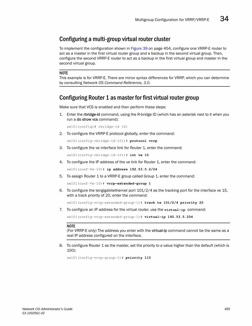
Multigroup Configuration for VRRP/VRRP-E 34
Configuring a multi-group virtual router clusterTo implement the configuration shown in Figure 39 on page 454, configure one VRRP-E router to act as a master in the first virtual router group and a backup in the second virtual group. Then, configure the second VRRP-E router to act as a backup in the first virtual group and master in the second virtual group.
NOTEThis example is for VRRP-E. There are minor syntax differences for VRRP, which you can determine by consulting Network OS Command Reference, 3.0.
Configuring Router 1 as master for first virtual router group Make sure that VCS is enabled and then perform these steps:
1. Enter the rbridge-id command, using the R-bridge ID (which has an asterisk next to it when you run a do show vcs command):
sw101(config)# rbridge-id 101
2. To configure the VRRP-E protocol globally, enter the command:
sw101(config-rbridge-id-101)# protocol vrrp
3. To configure the ve interface link for Router 1, enter the command:
sw101(config-rbridge-id-101)# int ve 10
4. To configure the IP address of the ve link for Router 1, enter the command:
sw101(conf-Ve-10)# ip address 192.53.5.2/24
5. To assign Router 1 to a VRRP-E group called Group 1, enter the command:
sw101(conf-Ve-10)# vrrp-extended-group 1
6. To configure the tengigabitethernet port 101/2/4 as the tracking port for the interface ve 15, with a track priority of 20, enter the command:
sw101(config-vrrp-extended-group-1)# track te 101/2/4 priority 20
7. To configure an IP address for the virtual router, use the virtual-ip command:
sw101(config-vrrp-extended-group-1)# virtual-ip 192.53.5.254
NOTE(For VRRP-E only) The address you enter with the virtual-ip command cannot be the same as a real IP address configured on the interface.
8. To configure Router 1 as the master, set the priority to a value higher than the default (which is 100):
sw101(config-vrrp-group-1)# priority 110
Network OS Administrator’s Guide 45553-1002561-02

Multigroup Configuration for VRRP/VRRP-E34
Configuring Router 1 as backup for second virtual router group1. Enter the rbridge-id command, using the R-bridge ID (which has an asterisk next to it when you
run a do show vcs command):
sw101(config)# rbridge-id 101
2. To configure the ve interface link for Router 1, enter the command:
sw101(config-rbridge-id-101)# int ve 10
3. To assign Router 1 to a group called Group 2, enter the command:
sw101(config-Ve-10)# vrrp-extended-group 2
4. To configure the tengigabitethernet port 101/2/4 as the tracking port for the interface ve 10, with a track priority of 20, enter the command:
sw101(config-vrrp-extended-group-2)# track te 101/2/4 priority 20
5. To configure an IP address for the virtual router, use the virtual-ip command:
sw101(config-vrrp-extended-group-2)# virtual-ip 192.53.5.253
NOTE(For VRRP-E only) The address you enter with the virtual-ip command cannot be the same as a real IP address configured on the interface.
Configuring Router 2 as backup for first virtual router groupMake sure that VCS is enabled and then perform these steps:
1. Enter the rbridge-id command, using the R-bridge ID (which has an asterisk next to it when you run a do show vcs command):
sw102(config)# rbridge-id 102
2. To configure the VRRP protocol globally, enter the command:
sw102(config-rbridge-id-102)protocol vrrp
3. To configure the ve interface link for Router 2, enter the command:
sw102(config-rbridge-id-102)# int ve 10
4. To configure the IP address of the ve link for Router 2, enter the command:
sw102(conf-Ve-15)# ip address 192.53.5.3/24
5. To assign Router 2 to the group called Group 1, enter the command:
sw102(conf-Ve-15)# vrrp-extended-group 1
6. To configure the tengigabitethernet port 102/3/2 as the tracking port for interface ve 15, with a track priority of 20, enter the command:
sw102(config-vrrp-extended-group-1)# track te 102/3/2 priority 20
7. To configure an IP address for the virtual router, use the virtual-ip command:
sw102(config-vrrp-extended-group-1)# virtual-ip 192.53.5.252
456 Network OS Administrator’s Guide53-1002561-02

Multigroup Configuration for VRRP/VRRP-E 34
NOTE(For VRRP-E only) The address you enter with the virtual-ip command cannot be the same as a real IP address configured on the interface.
Configuring Router 2 as master for second virtual router group1. Enter the rbridge-id command, using the R-bridge ID (which has an asterisk next to it when you
run a do show vcs command):
sw102(config)# rbridge-id 102
2. To configure the ve interface link for Router 2, enter the command:
sw102(config-rbridge-id-102)# int ve 15
3. To assign Router 2 to the group called Group 2, enter the command:
sw102(conf-Ve-15)# vrrp-extended-group 2
4. To configure the tengigabitethernet port 102/3/2 as the tracking port for interface ve 15, with a track priority of 20, enter the command:
sw102(config-vrrp-extended-group-2)# track te 102/3/2 priority 20
5. To configure an IP address for the virtual router, use the virtual-ip command:
sw101(config-vrrp-extended-group-2)# virtual-ip 192.53.5.251
NOTE(For VRRP-E only) The address you enter with the virtual-ip command cannot be the same as a real IP address configured on the interface.
6. To configure Router 2 as the master, set the priority to a value higher than the default (which is 100):
sw102(config-vrrp-extended-group-2)# priority 110
Network OS Administrator’s Guide 45753-1002561-02

Multigroup Configuration for VRRP/VRRP-E34
458 Network OS Administrator’s Guide53-1002561-02

Network OS Administrator’s Guide53-1002561-02
Chapter
35
Configuring Remote MonitoringIn this chapter
•RMON overview . . . . . . . . . . . . . . . . . . . . . . . . . . . . . . . . . . . . . . . . . . . . . . . 459
•RMON configuration and management . . . . . . . . . . . . . . . . . . . . . . . . . . . . 459
RMON overviewRemote monitoring (RMON) is an Internet Engineering Task Force (IETF) standard monitoring specification that allows various network agents and console systems to exchange network monitoring data. The RMON specification defines a set of statistics and functions that can be exchanged between RMON-compliant console managers and network probes. As such, RMON provides you with comprehensive network-fault diagnosis, planning, and performance-tuning information.
RMON configuration and managementAlarms and events are configurable RMON parameters:
• Events—Determines the action to take when an event is triggered by an alarm. The action can be to generate a log entry, an SNMP trap, or both. You must define the events before an alarm can be configured. If you do not configure the RMON event first, you will recieve an error when you configure the alarm settings.
• Alarms—Monitors a specific management information base (MIB) object for a specified interval, triggers an alarm at a specified value (rising threshold), and resets the alarm at another value (falling threshold). Alarms are paired with events; the alarm triggers an event, which can generate a log entry or an SNMP trap.
Default RMON configurationBy default, no RMON alarms and events are configured and RMON collection statistics are not enabled.
Configuring RMON eventsYou can add or remove an event in the RMON event table that is associated with an RMON alarm number.
459

RMON configuration and management35
To configure RMON events, perform the following steps from privileged EXEC mode.
1. Enter the configure terminal command to access global configuration mode.
switch#configure terminal
2. Configure the RMON event.
switch(config)#rmon event 27 description Rising_Threshold log owner john_smith trap syslog
3. Return to privileged EXEC mode.
switch(config)#end
4. Enter the copy command to save the running-config file to the startup-config file.
switch#copy running-config startup-config
Configuring RMON Ethernet group statistics collectionYou can collect RMON Ethernet group statistics on an interface. RMON alarms and events must be configured for you to display collection statistics. By default, RMON Ethernet group statistics are not enabled.
To collect RMON Ethernet group statistics on an interface, perform the following steps from privileged EXEC mode.
1. Enter the configure terminal command to access global configuration mode.
switch#configure terminal
2. Enter the interface command to specify the DCB interface type and slot/port number.
The gigabitethernet rbridge-id/slot/port operand is used only for the Brocade VDX 6710, Brocade VDX 8770-4, and Brocade VDX 8770-8. The prompt for these ports is in the format: switch(config-if-gi-22/0/1)#
switch(config)#interface tengigabitethernet 0/1
3. Enable the DCB interface.
switch(conf-if-te-0/1)#no shutdown
4. Configure RMON Ethernet group statistics on the interface.
switch(conf-if-te-0/1)#rmon collection stats 200 owner john_smith
5. Return to privileged EXEC mode.
switch(conf-if-te-0/1)#end
6. Enter the copy command to save the running-config file to the startup-config file.
switch#copy running-config startup-config
Configuring RMON alarm settingsTo configure RMON alarms and events, perform the following steps from privileged EXEC mode.
1. Enter the configure terminal command to access global configuration mode.
switch#configure terminal
2. Configure the RMON alarms.
460 Network OS Administrator’s Guide53-1002561-02

RMON configuration and management 35
Example of an alarm that tests every sample for a rising threshold
switch(config)#rmon alarm 5 1.3.6.1.2.1.16.1.1.1.5.65535 interval 30 absolute rising-threshold 95 event 27 owner john_smith
Example of an alarm that tests the delta between samples for a falling threshold
switch(config)#rmon alarm 5 1.3.6.1.2.1.16.1.1.1.5.65535 interval 10 delta falling-threshold 65 event 42 owner john_smith
3. Return to privileged EXEC mode.
switch(config)#end
4. Enter the copy command to save the running-config file to the startup-config file.
switch#copy running-config startup-config
Network OS Administrator’s Guide 46153-1002561-02

RMON configuration and management35
462 Network OS Administrator’s Guide53-1002561-02

Network OS Administrator’s Guide53-1002561-02
Chapter
36
Configuring IGMPIn this chapter•IGMP overview . . . . . . . . . . . . . . . . . . . . . . . . . . . . . . . . . . . . . . . . . . . . . . . . 463
•Configuring IGMP snooping . . . . . . . . . . . . . . . . . . . . . . . . . . . . . . . . . . . . . 465
•Configuring IGMP snooping querier . . . . . . . . . . . . . . . . . . . . . . . . . . . . . . . 466
•Monitoring IGMP snooping . . . . . . . . . . . . . . . . . . . . . . . . . . . . . . . . . . . . . . 466
•IGMP scalabilty . . . . . . . . . . . . . . . . . . . . . . . . . . . . . . . . . . . . . . . . . . . . . . . 467
IGMP overviewMulticast Control packet and Data Forwarding through a Layer 2 switch configured with VLANs is most easily achieved by Layer 2 forwarding of received Multicast Packets on all the member ports of the VLAN interfaces. However, this simple approach is not bandwidth efficient, since only a subset of member ports may be connected to devices interested in receiving those Multicast packets. In the worst case scenario the data would get forwarded to all port members of a VLAN with a large number of member ports (for example, all 24 ports), even if only a single VLAN member is interested in receiving the data. Such scenarios can lead to loss of throughput for a switch that gets hit by a high rate of Multicast Data Traffic.
Internet Group Management Protocol (IGMP) snooping is a mechanism by which a Layer 2 switch can effectively address this issue of inefficient Multicast Forwarding to VLAN port members. Snooping involves “learning” forwarding states for Multicast Data traffic on VLAN port members from the IGMP control (Join/Leave) packets received on them. The Layer 2 switch also provides for a way to configure forwarding states statically through the CLI.
NOTEBrocade Network OS 3.0.0 supports IGMP v1/v2 snooping. Brocade Network OS 3.0.0 does not support Layer 3 IGMP functionality.
Active IGMP snoopingIGMP snooping is normally passive by nature, as it simply monitors IGMP traffic without filtering. However, active IGMP snooping actively filters IGMP packets to reduce load on the multicast router. Upstream traffic is filtered so that only the minimal quantity of information is sent. The switch ensures the router only has a single entry for the VLAN, regardless of the number of active listeners downstream.
In active IGMP snooping, the router only knows about the most recent member of the VLAN. If there are two active listeners in a VLAN and the original member drops from the VLAN, the switch determines that the router does not need this information as the status of the VLAN remains unchanged. However the next time there is a routine query from the router, the switch will forward the reply from the remaining host to prevent the router from assuming there are no active listeners.
463

IGMP overview36
Multicast routingMulticast routers use IGMP to learn which groups have members on each of their attached physical networks. A multicast router keeps a list of multicast group memberships for each attached network, and a timer for each membership.
NOTE“Multicast group memberships” means that at least one member of a multicast group on a given attached network is available.
There are two ways that hosts join multicast routing groups:
• Send an unsolicited IGMP join request
• Send an IGMP join request as a response to a general query from a multicast router
In response to the request, the switch creates an entry in its Layer 2 forwarding table for that VLAN. When other hosts send join requests for the same multicast, the switch adds them to the existing table entry. Only one entry is created per VLAN in the Layer 2 forwarding table for each multicast group.
IGMP snooping suppresses all but one of the host join messages per multicast group and forwards this one join message to the multicast router. The switch forwards multicast traffic for the specified multicast group to the interfaces where the join messages were received.
vLAG and LAG primary portThe current DCE implementation of vLAGs and LAGs has a concept of a so-called primary port. One of the member ports of the vLAG and LAG is anointed the primary port and all multicast traffic egressing from the LAG or vLAG is sent on the primary port. Thus, normal hash based forwarding is not performed for multicast traffic, be it control traffic or data. Now, consider the case where rbridge R1 receives an IGMP Join request for group G1 on Po10, shown in Figure 40. This causes
464 Network OS Administrator’s Guide53-1002561-02

Configuring IGMP snooping 36
Po10 to be added to the list of IGMP receivers for group G1. Now, let’s say the primary port of the vLAG is the link connecting R4 and S1. Therefore any multicast traffic received by the cluster for group G1 egresses on the vLAG Po10 from R4 and not from R1 even though the original Join was received on R1.
FIGURE 40 IGMP snooping in Brocade VCS Fabric mode
If the primary port for the vLAG changes, such as if the link between R4 and S1 went down in Figure 40, then multicast traffic would egress out of the new primary port on the vLAG. In the above case, the new primary port would be the link connecting R1 and S1.
Configuring IGMP snoopingBy default, IGMP snooping is globally disabled on all VLAN interfaces. Refer to the CEE Command Reference for complete information about the commands in this section.
Use the following procedure to configure IGMP on a DCB/FCoE switch.
1. Enter the configure terminal command to access global configuration mode.
2. Enter the ip igmp snooping enable command to enable IGMP for all interfaces.
This command ensures that IGMP snooping is active on all interfaces.
switch(config)#ip igmp snooping enable
3. Enter the interface command to select the VLAN interface number.
switch(config)#interface vlan 10
4. Activate the default IGMP querier functionality for the VLAN.
switch(config-vlan-10)#ip igmp snooping querier enable
5. Optional: Activate the IGMP querier functionality with additional features.
R1
S1
Po10
R3
R4R2
JoinMrouter port
Join
Network OS Administrator’s Guide 46553-1002561-02

Configuring IGMP snooping querier36
Configuring IGMP snooping querierIf your multicast traffic is not routed because Protocol-Independent Multicast (PIM) and IGMP are not configured, use the IGMP snooping querier in a VLAN.
IGMP snooping querier sends out IGMP queries to trigger IGMP responses from switches that wish to receive IP multicast traffic. IGMP snooping listens for these responses to map the appropriate forwarding addresses.
Refer to the CEE Command Reference for complete information about the commands in this section.
Use the following procedure to configure the IGMP snooping querier.
1. Enter the configure terminal command to access global configuration mode.
2. Enter the interface command to select the VLAN interface number.
switch(config)#interface vlan 25
3. Activate IGMP querier functionality for the VLAN.
The valid range is 1 to 18000 seconds. The default is 125 seconds.
switch(config-vlan-25)#ip igmp query-interval 125
4. Set the last member query interval.
The valid range is 1000 to 25500 milliseconds. The default is 1000 milliseconds.
switch(config-vlan-25)#ip igmp last-member-query-interval 1000
5. Set the Max Response Time (MRT).
The valid range is 1 to 25 seconds. The default is 10 seconds.
switch(config-vlan-25)#ip igmp query-max-response-time 10
6. Activate the IGMP querier functionality for the VLAN.
switch(config-vlan-25)#ip igmp snooping querier enable
Monitoring IGMP snoopingMonitoring the performance of your IGMP traffic allows you to diagnose any potential issues on your switch. This helps you utilize bandwidth more efficiently by setting the switch to forward IP multicast traffic only to connected hosts that request multicast traffic.
Refer to the CEE Command Reference for complete information about the commands in this section.
Use the following procedure to monitor IGMP snooping on a DCB/FCoE switch.
1. Enter the configure terminal command to access global configuration mode.
2. Enter the show ip igmp groups command to display all information on IGMP multicast groups for the switch.
466 Network OS Administrator’s Guide53-1002561-02

IGMP scalabilty 36
Use this command to display the IGMP database, including configured entries for either all groups on all interfaces, or all groups on specific interfaces, or specific groups on specific interfaces.
switch#show ip igmp groups
3. Use the show ip igmp statistics command to display the IGMP statistics for a VLAN or interface.
switch#show ip igmp snooping statistics interface vlan 1
4. Use the show ip igmp mrouter to display multicast router (mrouter) port related information for all VLANs, or a specific VLAN.
switch#show ip igmp snooping mrouter
- or -
switch#show ip igmp snooping mrouter interface vlan 10
5. When you have reviewed the IGMP statistics for the switch, refer to “Configuring IGMP snooping” on page 465 or “Configuring IGMP snooping querier” on page 466 to make any needed corrections.
NOTERefer to the CEE Command Reference for additional information on IGMP CLI commands.
IGMP scalabiltyThis section describes the scalability limits of IGMP Snooping feature for Network OS v3.0.0 in various modes of switch operation and explains the various metrics involved in describing the scalability limits.
The IGMP metric values are:
• Maximum number of IGMP groups supported—This metric value is calculated based on the available hardware resources, such as MGID, configuration replay, and eNS distribution bandwidth.
• Maximum number of VLANs supported with IGMP Snooping configuration—This metric is limited by the number of general query packet generation capacity of IGMP software process running on the switch, eNS distribution bandwidth.
• Maximum IGMP packet processing rate per Switch—The scalability number described by this metric suggest the upper limit on the number of packets which can be processed by IGMP software process running on switch. If the packets are incoming from multiple ports/vlans, the same processing bandwidth will get shared.
• Maximum IGMP packet processing rate per Brocade VCS Fabric cluster—This metric specifies upper limit on the maximum IGMP packet rate incoming to logical Brocade VCS Fabric switch. It is limited by the eNS distribution bandwidth, number of nodes in the Brocade VCS Fabric cluster.
Network OS Administrator’s Guide 46753-1002561-02

IGMP scalabilty36
Standalone modeIn standalone mode, the VDX switch functions as an isolated box, possibly connected as a TOR switch. Table 69 describes the metric levels.
Brocade VCS Fabric cluster modeWhen supporting a flat Layer 2 network in a data center, VDX switches can be connected in any order to form a cluster. The number of nodes involved in a cluster ranges from four nodes to 24 nodes. Table 70 and Table 71 describe the metric levels.
TABLE 69 Standalone mode metrics
Metric Limit Comments
Maximum number of IGMP groups supported 2000 Join requests are sent on four ports of the same switch.
Maximum number of VLANs supported with IGMP configuration
128
Maximum IGMP packet processing rate per switch 512 packet/second
TABLE 70 Four node cluster metrics
Metric Limit Comments
Maximum number of IGMP groups supported 2000 Join requests are sent on four ports of the same switch.
Maximum number of VLANs supported with IGMP configuration
128
Maximum IGMP packet processing rate per switch 512 packet/second
Maximum IGMP packet processing rate per Brocade VCS Fabric cluster
512 packet/second
TABLE 71 Twenty node cluster metrics
Metric Limit Comments
Maximum number of IGMP groups supported 2000 Join requests are sent on four ports of the same switch.
Maximum number of VLANs supported with IGMP configuration
128
Maximum IGMP packet processing rate per Switch 512 packet/second
Maximum IGMP packet processing rate per Brocade VCS Fabric cluster
512 packet/second
468 Network OS Administrator’s Guide53-1002561-02

Network OS Administrator’s Guide53-1002561-02
Section
V
TroubleshootingThis section describes troubleshooting information, and includes the following chapters:
•Using the Chassis ID (CID) Recovery Tool . . . . . . . . . . . . . . . . . . . . . . . . . . 471
•Troubleshooting . . . . . . . . . . . . . . . . . . . . . . . . . . . . . . . . . . . . . . . . . . . . . . . 475
469

470 Network OS Administrator’s Guide53-1002561-02

Network OS Administrator’s Guide53-1002561-02
Chapter
37
Using the Chassis ID (CID) Recovery ToolIn this chapter
•Chassis ID card usage. . . . . . . . . . . . . . . . . . . . . . . . . . . . . . . . . . . . . . . . . . 471
•Automatic auditing and verification of CID card data . . . . . . . . . . . . . . . . . 472
•Running the CID recovery tool . . . . . . . . . . . . . . . . . . . . . . . . . . . . . . . . . . . 472
Chassis ID card usageEach VDX 8770-4 and VDX 8770-8 contains two chassis ID cards (CIDs) called CD1 and CD2. Most data on each card is identical, and CID2 is used only as a backup if CID1 encounters an issue.
The data contained on the CID card is essential for correct operation of the switch and is accessed most frequently during system startup.
Each CID contains two Serial Electronically Erasable Programmable Read Only Memory (SEEPROM) devices:
• Critical SEEPROM. This SEEPROM is read-only.
• Non-critical SEEPROM. This SEEPROM can be written to by the software.
Critical SEEPROM dataThe critical SEEPROM contains:
• A header with the CID part number, serial number, and other data about the CID card. If this data is corrupted or cannot be accessed, the card is identified as faulty in raslogs:
• [EM-1003], M1 | FFDC, CRITICAL, ..., CID 2 has unknown hardware identifier: FRU faulted.
• [FW-1432], M1, WARNING, sw0, Switch status change contributing factor Cid-Card: 1 bad.
• A chassis part number and serial number. Cluster configuration management uses the serial number to uniquely identify the chassis in the fabric.
• An eight-byte number that represents both the license ID and World Wide Name (WWN) base value for the chassis. The license ID is used to validate installed licenses. Licenses are invalid if the license ID is not available. The WWN is used to identify the switch in a fabric.
471

Automatic auditing and verification of CID card data37
Non-Critical SEEPROM dataThe non-critical SEEPROM contains the following data sets.
• The FRU history table, which contains logs of insertions and removals of FRUs into and from the chassis. The content of this table is not audited or verified.
• The IP data table, which contains management module and chassis management IP addresses/masks, the IP default gateway, and the chassis name.
• A power-off list, which controls the order in which blades are automatically powered off if an impending power loss is detected.
• A set of Data Center Ethernet (DCE) data containing chassis MAC addresses, without which the switch will not function.
Automatic auditing and verification of CID card dataThe contents of both CID cards are verified on a periodic basis and whenever an event indicates that an issue may exist.
Under normal circumstances, the CID card audit is run about one hour after a system startup or restart, then repeated every 24 hours. If no errors occur, no action is taken.
If CID card errors occur, if mismatches between data sets on the two CID cards are detected, or if a card is inserted, raslogs are shown on the console:
• [EM-1020]...M1, ERROR ... A problem was found on one or both CID cards (x), please run the cidrecov tool to get more information and recovery options.
• [EM-1021], ... M1, INFO, ... A CID card has been inserted, a CID verification audit will be run to detect any mismatches or other problems.
• [EM-1022], ... M1, WARNING, ... A CID card access problem has been encountered, please run the cidrecov tool to get more information and recovery options.
Running the CID recovery toolYou should run the CID recovery tool when instructed by raslogs, and you can also run the tool if you suspect an issue with one or both of the CID cards. To run the CID recovery tool, enter the cidrecov command in Privileged EXEC mode on the NOS command line:
sw0# cidrecov
Data corruption or mismatchesIf cidrecov detects any CID 1 or CID 2 non-critical SEEPROM corruption or mismatches, the tool displays related data and the following data-recovery options as applicable for each data-set error:
• Exit. Select this option if you do not want to change any data values.
• Recover with default values. Select this option if you want to reset all data in the data set to the factory defaults. For IP data, dummy IP addresses and masks are written. DCE and chassis-configuration data are based on the chassis type.
472 Network OS Administrator’s Guide53-1002561-02

Running the CID recovery tool 37
A system restart repopulates IP addresses and chassis names that appear in the startup configuration file. If you want to manually change the IP data, you can use the ip-address, ip gateway-address, chassis virtual-ip and chassis-name commands. For more information, refer to the Network OS Command Reference, v 3.0.
• Recover BAD from GOOD. This option is offered only if one CID card contains good data and the other card contains corrupt data. If you select this option, cidrecov copies the good data onto the affected card.
• “Recover CID 2 from CID 1” and “Recover CID 1 from CID 2.” These options are offered only if the data on both CID cards is good but there is a mismatch. You can select which card to use to overwrite data on the other card.
Example
The following is an example of running the cidrecov tool, receiving errors that can be fixed, and selecting the “Recover BAD from GOOD” option (note that the example below contains only some of the actual output):
sw0# cidrecov
CID 1 Non-Critical Seeprom is Inaccessible or Corrupted.
CID Non-Critical Seeprom Problem Details
CID 1 Non-Critical Seeprom IP address Control Data Checksum Bad !!!!
CID Recovery Options
0. Exit
1. Recover with default values
2. Recover BAD from GOOD
Enter Selection > 2Copy IP Data table...
Copy 384 bytes from CID 2 to CID 1, num blks 1 resid 128Read block 1 from CID 2 succeededWrite block 1 to CID 1 succeededRead last block from CID 2 succeededWrite last block to CID 1 succeededcopy successful
Copy succeeded for all data types attemptedIP Address CID Recovery completed.
CID card failureIf the critical SEEPROM of a CID card contains any errors, or if the non-critical SEEPROM cannot be read, then recovery is not possible, and the following message displays:
Recovery is not possible. Please contact Brocade Technical Support for replacement of the inaccessible CID(s).
Network OS Administrator’s Guide 47353-1002561-02

Running the CID recovery tool37
474 Network OS Administrator’s Guide53-1002561-02

Network OS Administrator’s Guide53-1002561-02
Chapter
38
TroubleshootingIn this chapter•Troubleshooting overview . . . . . . . . . . . . . . . . . . . . . . . . . . . . . . . . . . . . . . . 475
•Gathering troubleshooting information . . . . . . . . . . . . . . . . . . . . . . . . . . . . 475
•Understanding troubleshooting hotspots . . . . . . . . . . . . . . . . . . . . . . . . . . 477
•Troubleshooting procedures . . . . . . . . . . . . . . . . . . . . . . . . . . . . . . . . . . . . . 485
•Troubleshooting and diagnostic tools. . . . . . . . . . . . . . . . . . . . . . . . . . . . . . 515
Troubleshooting overviewThis appendix provides tips and procedures for troubleshooting issues that may occur while operating a Brocade switch running Network OS v2.1.1. It also introduces some of the common troubleshooting tools.
Gathering troubleshooting informationThe following information is helpful for incident investigation and resolution when you contact your switch-support provider:
• A network diagram and topology information
• A record of the steps and events leading to the incident
• Lists of applications, management agents, and scripts running at the time of the incident
• Supportsave files
• Output from the show media command if the issue is related to SFP transceivers
• Outputs from any commands run while attempting to troubleshoot the problem yourself
• Any network traces captured using Wireshark software or other network analyzer.
• Terminal Access Controller Access-Control System (TACACS) server version if the issue is related to TACACS.
Capturing supportsave dataThe copy support command not only runs diagnostic commands, but also gathers core dumps, trace files, and other relevant data. In the same action, the command also copies all this information to a remote host. Once on the remote host, your switch provider can proceed to analyze the problem. Meanwhile, your switch can be returned to production with minimal downtime.
475

Gathering troubleshooting information38
To capture supportsave data, complete the following steps:
1. Log in to the switch.
2. In privileged EXEC mode, enter the copy support command to capture the supportSave data.
The copy support command has options to copy the supportSave files to a remote server using FTP or SCP, or you can save to a local USB device. You can use the command in a single command line, or in interactive mode.
The following example uses the single command line mode to copy the supportSave files to a remote host using FTP.
switch# copy support ftp host 10.38.33.131 user admin directory 108Password: *****
The following example uses the interactive form of the command and FTP:
switch# copy support-interactiveServer Name or IP Address: 10.38.33.131Protocol (ftp, scp): ftpUser: adminPassword: *****Directory:/home/admin/supportVCS support [y/n]? (y): y
An approach to troubleshooting This section outlines a methodology for troubleshooting issues. It introduces steps that you might consider using, depending on the issue in question.
1. Check whether the switch has all the required licenses:
• License requirements include the POD license, VCS Fabric license, and FCoE license.
• License types include POD1, POD2, VCS Fabric (multi-node license for more than two nodes), and FCoE.
• No VCS Fabric license is needed for a one-node or two node VCS Fabric cluster.
• The FCoE license needs VCS Fabric mode enabled to be installed.
• After adding or modifying an FCoE or POD license, always reboot the switch to activate the license.
2. Verify the topology and switch configuration as conveyed by the switch
3. Enter the copy support command.
4. Run other relevant show commands (for example, show logging raslog) to look for clues or triggers of the reported failure.
5. Check the utilization of various resources.
a. Enter the show process cpu command to determine CPU use.
b. Enter the show process me command to determine memory use.
c. Enter the show mac-address-table count command to determine the number of MAC addresses used.
d. Enter the show fabric route topology command to determine the number of routes.
e. Enter the show fabric all command to determine the number of VCS Fabric nodes.
476 Network OS Administrator’s Guide53-1002561-02

Understanding troubleshooting hotspots 38
f. Enter the show media command to investigate any optics issues.
6. Conduct data-path fabric continuity tests:
a. Issue pings from and to the end-stations or devices.
b. Check the counters in the output of the show interface command to see if packets are coming in or are dropped as errors.
c. Verify that optics used are Brocade-certified. Enter the show media interface command and verify that the Vendor name field shows “Brocade.” Check also that the Tx and Rx Power fields are not zero.
d. Verify that the MAC address table learns the MAC addresses.
e. If the switch is part of a VCS Fabric cluster, verify that the MAC address tables are synchronized properly across all Brocade VDX switches in the cluster.
f. Check whether LLDP reports neighbors.
g. Check the Ethernet Name Server (ENS) functionality by ensuring that the MAC address table reports MAC addresses learned from other VCS Fabric switches.
h. Use the l2traceroute command for validating the data-path fabric continuity. This command helps identify where the packets are being dropped within the fabric.
The command prompts for some basic and allows you to choose to enter some extended parameters. Currently supported basic parameters include:
• Source Address (SA) and Destination Address (DA) of dynamically learned MAC addresses
• VLAN
• Edge routing bridge ID
Currently supported extended parameters include:
• Protocol type (IP)
• Source and destination IP addresses
• IP protocol type (recommend TCP)
• Source and destination port numbers
The purpose of IP parameters is to provide a way to make the traceroute packet traverse a specific ECMP link.
CAUTION
The following step affects configuration and should be used with care.
7. To track certain flows within the fabric, use permit ACLs and monitor the hit increments.
Understanding troubleshooting hotspotsThis section provides relevant background information and best practices guidance related to features of Network OS where problems have been reported. With this guidance, you should be able to avoid many potential problems.
Network OS Administrator’s Guide 47753-1002561-02

Understanding troubleshooting hotspots38
LicensingWhen a licenced feature does not work, one likely cause is that the license has not been installed correctly. Follow the guidelines and procedures in Chapter 7, “Administering Licenses” to ensure your features are licensed properly and those licenses installed correctly.
For license recovery procedures, refer to “License not properly installed” on page 498.
STP interoperability with Brocade MLX or other vendor switches• To use the Spanning Tree Protocol (STP) in a network with Brocade MLX switches, or switches
from other vendors such as Juniper or Cisco, you may have to configure the interface to send BPDUs to the shared spanning tree MAC address 0100.0ccc.cccd. Without this setting, the RPVST/PVST Root bridge is not recognized on VLANs other than VLAN 1.
To interoperate with MLX switches or other vendor switches, enter the following command in interface configuration mode:
switch(conf-if-te-0/1)# spanning-tree bpdu-mac 0100.0ccc.cccd
• If a Brocade IP switch has a VLAN is configured with tagged ports and Rapid Spanning Protocol (RSTP) is enabled under the VLAN (PVST), then BPDUs from the tagged ports received by the Brocade VDX switch will be dropped if pvst-mode is not configured under the ports that are in the VLAN and connected to the Brocade VDX switches.
The following example shows a configuration on a Brocade IP switch with tagged ports and RSTP enabled under the VLAN:
vlan 2tagged ethe 1/24 ethe 2/1 to 2/2router-interface ve 2rstp priority 100
If the conditions are met, then all the ports should have pvst-mode configured so that tagged BPDUs pass through the Brocade VDX switch. If pvst-mode is not enabled, enable it as follows:
Brocade(config)# interface ethernet 2/1Brocade(config-if-2/1)# pvst-mode
478 Network OS Administrator’s Guide53-1002561-02

Understanding troubleshooting hotspots 38
Load balancing distributionUnderstanding issues related to load balancing requires some basic knowledge of the criteria used by load balancing algorithms. Table 72 provides details for each feature that provides load balancing.
Static assignment of the routing bridge IDDuplicate routing bridge IDs are a common source of error when adding a switch to an Ethernet fabric. Before adding a switch to an Ethernet fabric, you must assign it a unique routing bridge ID. If the new switch is to be added to an existing VCS Fabric cluster, it must be assigned the same VCS ID as other switches in the cluster. Once the switch is added, the principal routing bridge performs the negotiation in the control plane to include the new switch and rebuild the fabric. The data plane remains unaffected.
Procedures for recovering from duplicate routing IDs are provided in “Routing bridge ID is duplicated” on page 506.
FSPF route changeWhen the Fabric Shortest Path First (FSPF) algorithms select a new route, a temporary disruption of traffic can occur. This behavior is normal as the old path is first deleted and then the new path is programmed. Such path changes can occur when FSPF calculates a new shortest route, or when the current path is down.
TABLE 72 Load balancing algorithms
Feature Algorithm
ECMP IP Paths are selected on the basis of a hash derived from the following parameters: • Source MAC address• Destination MAC address• VID• IP protocol• Source IP address• Destination IP address• Layer 4 source port• Layer 4 destination portYou can configure the hashing fields using the fabric-ecm load-balance and fabric-ecmp load-balance-hash-swap commands.For related recovery procedures, refer to “ECMP not load balancing as expected” on page 491.
ECMP FCoE Paths are selected on the basis of a hash derived form the following parameters: • Input Port ID• Source MAC address• Destination MAC address• VID• FID• SID• DID• OXID
LACP Provides adaptive load balancing based on up to seven criteria (7-tuple), depending upon what fields are available in the frame.
Brocade trunk Provides equal packet load balancing (round-robin) among member links.
Network OS Administrator’s Guide 47953-1002561-02

Understanding troubleshooting hotspots38
VCS Fabric mode and standalone modeSome key differences exist between standalone mode and VCS Fabric mode that you should be aware of when troubleshooting your system.
Interfaces are disabled by default in standalone mode but enabled by default in VCS Fabric mode. Thus, when you apply the default configuration, you should take this into account.
The interface can be configured as a Layer 2 switch port in standalone and VCS Fabric modes.
Switching between VCS Fabric mode and standalone mode and then reverting back to the original mode would result in the loosing the configuration and booting up using the default configuration.
A port-profile port is allowed only for Layer 2 ports.
The out-of-band management through the Management port allows default gateways to be configured.
vLAGyou should be aware of the following aspects of the vLAG feature before troubleshooting vLAG problems:
• Multicast (BUM) traffic in vLAG
• Edge port feature requirements
• Failover
Multicast traffic in vLAG
Flooding traffic always goes through a primary link of the vLAG. You should consider this restriction when provisioning bandwidth for most traffic. This link is marked with an asterisk(*) in the output of the show port-channel command.
switch# show port-channel 38LACP Aggregator: Po 38Aggregator type: StandardAdmin Key: 0038 - Oper Key 0038Partner System ID - 0x8000,01-e0-52-00-20-00Partner Oper Key 0038Member ports:Link: Te 0/13 (0x180D0102) sync: 1Link: Te 0/14 (0x180E0103) sync: 1 *
Edge port feature requirements for vLAG
LACP can be configured on edge ports only with either Brocade or Standard types. If Brocade is chosen, so that Link Reset (LR) primitives are exchanged properly, make sure the edge peering device is a Brocade Converged Network Adapter (CNA), a standalone Brocade VDX switch, or a Brocade 8000 switch.
480 Network OS Administrator’s Guide53-1002561-02

Understanding troubleshooting hotspots 38
Failover and vLAG
For the fast failover convergence requirements, Brocade recommends using the vlag ignore-split command, which enables subsecond failover times. This command is added automatically to all port-channel configurations when a Brocade VDX switch is upgraded to Network OS v2.1.x or when a new port-channel is added while running under Network OS v2.1.x.
When planning to deploy this feature in production, use care to prevent a “split-brain” scenario, in which vLAG members detach from each other. Brocade recommends having more than one interswitch link (ISL) between the vLAG member switches and to physically route them through separate conduits and cable trays. Secondly, Brocade strongly recommends using topologies that are certified by Brocade.
The following topics discuss the split-brain scenario and how to mitigate it.
Understanding “split-brain”
A split-brain can occur when the end-hosts or edge switches are connected to two separate cluster switches by way of a vLAG (using LACP). The end-devices see those two cluster switches as one switch because they have the same system ID advertised in LACP.
Under rare conditions, when all the ISLs between the two cluster switches are broken and both the cluster switches continue to advertise the same system ID to their LACP partner, a “segmented fabric” or “split-brain” condition exists, where the end-host or edge switch might not detect this segmentation and could continue to treat both the vLAG switches as one switch.
This condition can cause packet duplication or unexpected packet loss.
Network OS protects traffic during split-brain conditions
By default, Network OS has a capability to recover gracefully from the split-brain scenario. When all the ISLs between the VDX cluster switches go down, the switch with the lower routing bridge ID uses LACP to inform the edge-switch partner that it has segmented out of the port-channel. It does this by changing its advertised system ID. When the edge switch learns a different system ID on one of its members, it removes this member from that port-channel, and continues to function with only one vLAG member—the switch with the higher routing bridge ID. The other vLAG member switch still has the link up, but remains segmented out of the original port-channel (sync: 0). This capability prevents duplication of packets or potential packet drops due to a split-brain scenario.
When a member switch is reloaded
Reloading the switch with the lower routing bridge ID has no impact.
When the switch with the higher routing bridge ID is reloaded, the other vLAG member sees all of its ISLs down. Though this is not a real split-brain scenario, the switch with the lower routing bridge ID may not be able to differentiate, and thus would inform the partner about a changed system ID. The partner edge switch would see two events:
• The system ID on one link changes.
• The other interface goes down.
In such a case, LACP will renegotiate and reform the port-channel, which could flap the port-channel, impacting traffic momentarily. The same effect could occur when the switch boots up and joins the fabric again.
Network OS Administrator’s Guide 48153-1002561-02

Understanding troubleshooting hotspots38
Thus, if the switch with the higher routing bridge ID is reloaded, the potential impact could be a port-channel flap that can momentarily disrupt traffic. Note that this effect does not occur when the switch with the lower routing bridge ID is reloaded.
Avoiding traffic disruption during switch reload
Network OS switches offer flexibility to the user by providing a special vLAG ignore-split option that you can configure for the logical port-channel. This option should be configured on both vLAG member ports.
Configuring this option prevents the switch with the lower routing bridge ID from changing its system ID, so both switches will continue to advertise the same system ID. This action prevents the partner edge switch from detecting a change when one of the member switches is reloaded and the traffic is handled gracefully.
Using the vLAG ignore-split option
To use the vLAG ignore-split option, redundancy should be built around ISLs to prevent a situation in which all ISLs are broken at the same time. Brocade recommends using multiple ISLs, and routing those ISLs through different physical paths or conduits to eliminate the possibility of accidental damage to all links at the same time.
Principal routing bridge availabilityIf a new principal routing bridge is introduced into a working VCS Fabric cluster, or if the principal routing bridge is lost and a new switch must be elected, the fabric is rebuilt from the control-plane viewpoint, whereas the data plane continues to forward traffic without disruption. The primary responsibilities of the principal routing bridge in a VCS Fabric are:
• Routing bridge ID allocation
• Ownership of virtual management IP address
• Keeping the configuration database synchronized
Brocade trunksBrocade trunks is the only aggregation method that works using ISLs.
Brocade ISL trunks are formed automatically with other switches using Line Reset (LR) primitives signaling with the peer switch.
All ISL ports connected to the same neighbor Brocade switch attempt to form a trunk. For a successful trunk formation, all ports on the local switch must be part of the same port group and must be configured at the same speed. The number of ports allowed per trunk group is release-dependent. The trunk is turned on by default.
Table 73 shows allocation of port numbers to port groups for Brocade VDX switches.
TABLE 73 Port groups
Network OS switch Port groups
Brocade VDX 6720-24 and Brocade VDX 6730-32 (switches with 24 Ethernet ports)
te0/1 through te0/12
te0/13 through te0/24
482 Network OS Administrator’s Guide53-1002561-02

Understanding troubleshooting hotspots 38
NOTEBrocade trunks are not supported over 1G links.
To utilize the advantages of Brocade trunking between VDX switches, Brocade recommends having at least a two-member trunk and multiple ECMP paths. It is also recommend routing the cables in a trunk through separate conduits to ensure connectivity in case a conduit is accidentally cut.
NIC teaming with vLAGNIC teaming permits link aggregation between server and switch. It can be one of two types: active/passive model or active/active model. For the active/passive model, you may not need to configure a LAG on the switch side, as unique MAC addresses will be seen on only one link.
For the active/active model, the same MAC address may appear on both the links terminating on a switch (or pair of switches). In such a case, you must configure a LAG on the switch side.
Selecting the MTUAlways set the switch MTU to the maximum host MTU plus 100 bytes. This method is recommended because the definition of MTU sometimes varies among different vendors. If the switch MTU is set to the same as the connected host MTU, packets could be dropped.
Brocade VDX 6720-60 and Brocade VDX 6730-76 te0/1 through te0/10
te0/11 through te0/20
te0/21 through te0/30
te0/31 through te0/40
te0/41 through te0/50
te0/51 through te0/60
Brocade VDX 6710 te0/1 through te0/6
TABLE 73 Port groups (Continued)
Network OS switch Port groups
Network OS Administrator’s Guide 48353-1002561-02
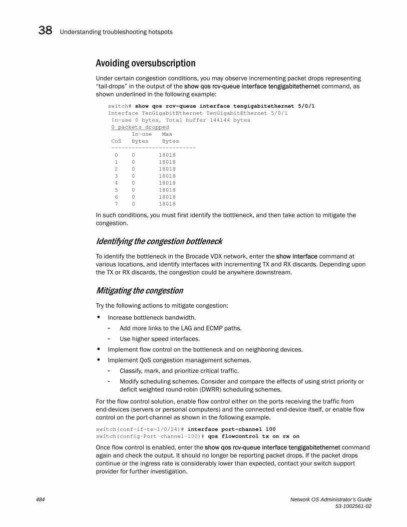
Understanding troubleshooting hotspots38
Avoiding oversubscriptionUnder certain congestion conditions, you may observe incrementing packet drops representing “tail-drops” in the output of the show qos rcv-queue interface tengigabitethernet command, as shown underlined in the following example:
switch# show qos rcv-queue interface tengigabitethernet 5/0/1Interface TenGigabitEthernet TenGigabitEthernet 5/0/1In-use 0 bytes, Total buffer 144144 bytes0 packets dropped
In-use MaxCoS Bytes Bytes-------------------------0 0 180181 0 180182 0 180183 0 180184 0 180185 0 180186 0 180187 0 18018
In such conditions, you must first identify the bottleneck, and then take action to mitigate the congestion.
Identifying the congestion bottleneck
To identify the bottleneck in the Brocade VDX network, enter the show interface command at various locations, and identify interfaces with incrementing TX and RX discards. Depending upon the TX or RX discards, the congestion could be anywhere downstream.
Mitigating the congestion
Try the following actions to mitigate congestion:
• Increase bottleneck bandwidth.
- Add more links to the LAG and ECMP paths.
- Use higher speed interfaces.
• Implement flow control on the bottleneck and on neighboring devices.
• Implement QoS congestion management schemes.
- Classify, mark, and prioritize critical traffic.
- Modify scheduling schemes. Consider and compare the effects of using strict priority or deficit weighted round-robin (DWRR) scheduling schemes.
For the flow control solution, enable flow control either on the ports receiving the traffic from end-devices (servers or personal computers) and the connected end-device itself, or enable flow control on the port-channel as shown in the following example.
switch(conf-if-te-1/0/24)# interface port-channel 100switch(config-Port-channel-100)# qos flowcontrol tx on rx on
Once flow control is enabled, enter the show qos rcv-queue interface tengigabitethernet command again and check the output. It should no longer be reporting packet drops. If the packet drops continue or the ingress rate is considerably lower than expected, contact your switch support provider for further investigation.
484 Network OS Administrator’s Guide53-1002561-02

Troubleshooting procedures 38
We recommend enabling asymmetric flow control with Brocade VDX switches. For any two adjacent devices, one device should have Rx ON and Tx OFF, while the other device should have Rx OFF and Tx ON.
Refer to “Congestion control and queuing” on page 265 for further details about congestion control.
ACL limits issuesIf you keep within the supported limits of ACL usage as shown in Table 74, you are unlikely to run into system limits issues. ACLs should instantiate quickly and correctly.
In addition, up 30,720 MAC addresses are supported.
As you approach or exceed combinations of these limits it is possible you might encounter slow instantiation of ACL rules, process exceptions, or ACL failure due to MAC learning issues.
Delays of several minutes can occur in the instantiation of ACL rules and counters if the number of ACLs or VLANs is excessive. The L2SYS process message queue can become full, or CPU context switching and process scheduling can increase to the point that ACL instantiation proceeds slowly. Periodic monitoring with the show statistics access-list mac command will show not more than 252 ACL rules with a nonzero and incrementing frame count for rules that are correctly instantiated and have hardware counters allocated.
Process exceptions can sometimes occur with the L2SYSD process when combinations of ACL limits are approached or exceeded.
Constant MAC learning and flushing can occur when chip table limitations are exceeded. Layer 2 frame switching can fail if the number of MAC address table entries is exceeded.
Troubleshooting proceduresThis section describes some potential problems you may encounter and suggestions on how to investigate or resolve each issue. If these steps do not lead to resolution of the problem, prepare a case for your switch provider, as described in “Getting technical help” on page xxxvii.
• “AMPP is not working” on page 486
• “Continuous panic reboots” on page 489
TABLE 74 ACL limits
Feature Limit
Number of standard or extended ACLs created but not applied for each switch 50
Number of rules per standard or extended ACL 256
Number of physical interfaces on which an ACL is applied concurrently 60 (standalone mode)48 (VCS mode)
Number of VLAN interfaces on which ACL is applied concurrently 100
Number of ACL counters 252
Number of TCAM table entries 1000
Number of ACL rules per switch 6000
Number of applied, co-existing standard and extended ACLs 50
Network OS Administrator’s Guide 48553-1002561-02

Troubleshooting procedures38
• “Corrupted CID card” on page 490
• “CPU use is unexpectedly high” on page 491
• “ECMP not load balancing as expected” on page 491
• “ENS functionality check” on page 492
• “FCoE devices unable to log in” on page 493
• “General debugging for traffic forwarding” on page 494
• “ISL does not come up on some ports” on page 495
• “License not properly installed” on page 498
• “Packets dropped in hardware” on page 500
• “Ping failure” on page 505
• “QoS configuration causes tail drops” on page 505
• “QoS is not marking or treating packets correctly” on page 506
• “Routing bridge ID is duplicated” on page 506
• “SNMP MIBs report incorrect values” on page 506
• “SNMP traps are missing” on page 507
• “Telnet operation into the switch fails” on page 507
• “Trunk member not used” on page 508
• “Upgrade failure” on page 509
• “VCS Fabric cannot be formed” on page 510
• “vLAG cannot be formed” on page 511
• “Zone does not form correctly” on page 513
AMPP is not workingConfiguring Brocade Automatic Migration of Port Profiles (AMPP) is complex. It works in standalone mode and VCS Fabric mode. For details on configuring AMPP, refer to Chapter 19, “Configuring AMPP”.
Problems encountered while using AMPP are usually the result of configuration errors in the port-profile itself, errors in the associated virtual machine (VM) configuration, or compatibility problems between the host adapters and AMPP. Specifically, AMPP problems can be caused by the following conditions:
• A port-profile configuration does not exist on the target switch or does not contain a basic switchport and VLAN configuration. Refer to “Verifying the port-profile configuration” on page 487.
• The VM MAC address does not appear in the MAC address table. Refer to “Verifying the VM MAC address” on page 487.
• The port-profile is not activated or is not associated with the correct MAC address. Refer to “Verifying the port-profile state” on page 488.
• The VM kernel MAC addresses are not associated correctly with the port-profile on the respective switches. Refer to “Verifying the VM kernel MAC addresses” on page 488.
• The VM and its associated hosts do not share a common storage device. Refer to “Verifying a shared storage device” on page 488.
486 Network OS Administrator’s Guide53-1002561-02

Troubleshooting procedures 38
• The port-profile was learned on a nonprofiled VLAN. Refer to “Verifying the status of a learned profiled MAC address” on page 488.
• A conflicting port-profile is applied to the same interface. Refer to “Verifying port profiles do not conflict” on page 489.
• The Ethernet Name Server is not functioning correctly. Refer to “Verifying the Ethernet Name Server” on page 489.
• An ESX host has an incompatible network adapter or driver installed. Refer to “Verifying an ESX host” on page 489.
Verifying the port-profile configuration
A valid port-profile must exist on the target switch. It must contain a basic switchport and VLAN configuration.
1. In the privileged EXEC mode, enter the show running-config port-profile command to verify that the port-profile configuration exists on the target switch, and that it contains a basic switchport and VLAN configuration.
switch# show running-config port-profileport-profile defaultvlan-profileswitchportswitchport mode trunkswitchport trunk allowed vlan allswitchport trunk native-vlan 1
!!port-profile pp1vlan-profile!
!port-profile pp2vlan-profile!
!
2. If the port-profile configuration does not exist or is missing the required switchport or VLAN configuration, create the port-profile as described in “Configuring AMPP port-profiles” on page 162.
Verifying the VM MAC address
For the correct functioning of AMPP, the MAC address for the VM and its associated hosts must appear in the MAC address table.
1. Enter the show mac-address-table command to verify that the VM MAC addresses appear in the switch MAC address table.
switch# show mac-address-tableVlanId Mac-address Type State Ports1 0000.0010.0001 Static Inactive Te 4/0/31 0000.0010.0002 Static Inactive Te 4/0/3Total MAC addresses : 2
2. If a VM MAC address is not present, contact your switch support provider for further investigation and provide this data.
Network OS Administrator’s Guide 48753-1002561-02

Troubleshooting procedures38
Verifying the port-profile state
For the correct functioning of AMPP, the port-profile must be active and must be associated with the correct MAC address.
1. Enter the show port-profile status command to verify that the port-profile is activated and is associated with the correct MAC address.
switch# show port-profile statusPort-Profile PPID Activated Associated MAC Interfacepp1 1 No None Nonepp2 2 No None None
2. Correct any misconfigurations as follows:
• If the port-profile is not activated, enter the port-profile profile-name activate command to activate it.
• If the port-profile is not associated with a MAC address, enter the port-profile port-profile-name static command to perform the association.
switch(config)# port-profile PP3 static 0050.5600.10030
• If the port-profile is associated with the wrong MAC address, enter the no port-profile port-profile-name static command to break the association with the incorrect MAC address, and then reassociate the port with the correct MAC address.
switch(config)# no port-profile PP3 static 0050.5600.10020switch(config)# port-profile PP3 static 0050.5600.10030
Refer to “Configuring a new port-profile” on page 252, for details about activating a port-profile and associating a port-profile with a MAC address.
Verifying the VM kernel MAC addresses
Confirm that the VM kernel MAC addresses are also associated with the port-profile on the respective switches. If not, perform the association as described in “Verifying the port-profile configuration” on page 487.
Verifying a shared storage device
Confirm that the VM and its associated hosts are sharing a storage device. If not, then reconfigure the VM and hosts to share a storage device.
Verifying the status of a learned profiled MAC address
For correct functioning of AMPP, the MAC address must be learned from a valid source—a profiled VLAN. This procedure determines whether a MAC address was learned from a valid source.
Enter the show mac-address-table port-profile command to check the status on learned profiled MAC addresses.
switch# show mac-address-table port-profileLegend: Untagged(U), Tagged (T), Not Forwardable(NF) and Conflict(C)VlanId Mac-address Type State Port-Profile Ports1 0050.5679.5351 Dynamic Active Profiled(U) Te 111/0/101 0050.567b.7030 Dynamic Active Profiled(U) Te 111/0/121 005a.8402.0000 Dynamic Active Profiled(T) Te 111/0/241 005a.8402.0001 Dynamic Active Profiled(NF) Te 111/0/24
488 Network OS Administrator’s Guide53-1002561-02

Troubleshooting procedures 38
1 005a.8402.0002 Dynamic Active Not Profiled Te 111/0/241 005a.8402.0003 Dynamic Active Not Profiled Te 111/0/241 005a.8402.0004 Dynamic Active Not Profiled Te 111/0/24(output truncated)Total MAC addresses : 17
Check for and investigate MAC addresses identified in the output as “Not Profiled.”
Verifying port profiles do not conflict
1. Enter the show port-profile name pp1_name name pp2_name validate command to validate whether multiple port-profiles applied on an interface can co-exist without conflict.
switch# show port-profile name pp1 name pp2 validatePort-Profile Port-Profile Conflicts-----------------------------------------------------------------------------pp1 pp2vlan-profile vlan-profile Noqos-profile qos-profile Nosecurity-profile security-profile No
2. If a conflict exists, reconfigure one of the port-profiles to avoid the conflict.
Refer to Chapter 19, “Configuring AMPP,” for information about the rules for co-existence.
Verifying the Ethernet Name Server
AMPP requires each VCS Fabric switch in the cluster have the same view of the MAC address table. Any differences in the view indicate a failure of the Ethernet Name Server (ENS). Refer to “ENS functionality check” on page 492 for details.
Verifying an ESX host
Verify that each ESX host has the correct Converged Network Adapter (CNA) installed with appropriate drivers, and does not use the Cisco Nexus 1000V software switch, as it might send out specially crafted packets.
Continuous panic rebootsIf your switch is having continuous panic reboots, perform the following procedure.
1. Bring the switch to a stable state with original binary or to swap the other partition with a good image.
a. In bootenv, execute setenv OSLoadOptions 2, saveenv and reset.
b. Immediately after reboot before panic, try to login and execute do chkconfig fabos off.
This boots the switch in single user mode, with just Linux OS and not loading the Network OS modules. Make the needed changes to the filesystem, such as changing the partition using bootenv or replacing with original good binaries.
In single user mode the networkis not accessible, so use the command ifconfig eth0 for any network support. Furthermore, the command init 3 boots the switch after reboot for case a) above. Otherwise reset with chkconfig fabos on; reboot .
2. If the switch comes to a halt after five repeated reboots, try cleaning up the DCMD database with the following command:
Network OS Administrator’s Guide 48953-1002561-02

Troubleshooting procedures38
rm -rf /etc/fabos/Dcmd/*.cfg; rm -rf /etc/fabos/Dcmd/WaveDatabase; rm -rf /etc/fabos/Ccmd/*.cfg; rm -rf /etc/fabos/Ccmd/WaveDatabase; reboot “/sbin/reboot -f
3. Download a good nightly build to return the switch to a stable state.
Corrupted CID cardIn the case of a corrupted CID card, perform the following steps.
1. Link the wwncardshow command to see the extent of the damage. This does not have to be done for single boards.)
switch# ln -s /fabos/cliexec/em /fabos/bin/wwncardshow
2. Display the wwncardshow data.
switch# wwncardshow ipdatapacket count is 2++ Wwn Card IP Data ++Type Num Field Address Mask Cfg/Zone---------------------------------------------------------CP 0 Eth IP: 255.255.255.255 255.255.255.255CP 1 Eth IP: 255.255.255.255 255.255.255.255Chassis GW IP: 255.255.255.255
LicID: 10:00:00:ff:ff:ff:ff:ff enet cfgName: VDX 6710-54 Gen#: -1/0
Sw 0 Eth IP: 10.17.10.84 255.255.240.0FC IP: 0.0.0.0 0.0.0.0GW IP: 10.17.0.1WWN: 10:00:00: 05:33:14:b2:70Name: swd77 Gen#: 0/0
Sw 1 Eth IP:FC IP:GW IP:WWN: 10:00:00:05:33:14:b2:71Name: Gen#: 0/0
Items that are FFs, 255s, or zeros are unacceptable. Only the first two groups count, and the things that must be correct are:
• The CP Eth IP entries. They only need valid data if that CP/MM is present.
• The chassis LicID entry.
• The Sw 0 Eth IP entry.
• The Sw 0 GW IP entry.
• The Sw 0 WWN entry.
3. To correct the CP Eth IP entries, run ipaddrset -cp <x>, where x is 0 for MM1 and 1 for MM2, and put in correct data at the prompts. To correct, run ipaddrset -chassis and enter the correct data as needed.
Sometimes if the entries have enough 255/0xff's in them ipaddrset won't update the values properly, in which case you have to use test_sysmod to clear a couple of them.
4. To correct Sw 0 WWN, run wwn -d626 xx:xx:xx:xx:xx:xx:xx:xx with the correct wwn value. The system must be rebooted for the change to take effect (at the prompt or manually).
5. To correct chassis LicID, you need the test_sysmod tool. Mount a filesystem (if necessary get eth0 up manually with ifconfig, or set the gateway first).
490 Network OS Administrator’s Guide53-1002561-02

Troubleshooting procedures 38
switch# Run test_sysmodtest_sysmod
6. At the first menu, enter 11 for WWN testing, then 2 for copy WWN to LID, and then enter 1 to confirm. Perform a Ctrl-C to exit.
7. The system must be rebooted for the change to take effect. Exit test_sysmod with Ctrl-C .
If you have lost both the wwn and license ID, then you must perform step 4 first. If you do not know the value, it is available in the MAC address in the boot environment variables (for pizza boxes only).
This value can be entered in the wwn command by inserting 10:00: before the MAC value).
8. Finally, if you can't correct the IP addresses, there is one more option in test_sysmod that can help. At the main menu, enter 11 for WWN testing and then 1 for clear WWN IP data entry, then 0, 1, 2, or 3 for which ever entries had a lot of FFs. If you clear all of the entries that are corrupted w/ FFs, you should be able to run ipaddrset to restore the real addresses.
9. Reboot the switch in order for the change to take effect.and the ipaddrset command available.
Verifying SEEPROM data
1. To verify the seeprom, copy the test_symod file to /fabos/bin as test_sysmod, and select option 10 for i2c and option 27 to Verify FRU Seeprom. The test begins automatically.
2. Use the offset of 0x6a4c, as that is where the IP table starts (size 256), but any offset (and size less than or equal to 256) will access that device.
CPU use is unexpectedly highUnexpectedly high CPU use is usually the result of a process consuming a large percentage of available CPU cycles. It can prevent access to the switch by Telnet or make an ISL nonfunctional.
If you suspect high CPU use, complete the following steps.
1. In privileged EXEC mode, enter the show process cpu command to determine which process is causing the high CPU reading.
2. Shut down the corresponding interface or delete the configuration suspected of causing the high CPU use.
ECMP not load balancing as expectedEqual cost multipath (ECMP) routing increases throughput by balancing traffic across multiple routes that tie for best cost. If you suspect that traffic is not being balanced as expected, complete the following steps.
1. In privileged EXEC mode, enter the show fabric route topology command to see whether ECMP routes are expected.
switch# show fabric route topology
Total Path Count: 1
Src Dst Out Out Nbr NbrRB-ID RB-ID Index Interface Hops Cost Index Interface BW Trunk-----------------------------------------------------------------------------
Network OS Administrator’s Guide 49153-1002561-02

Troubleshooting procedures38
66 1 124 Fi 66/0/4 1 500 129 Fi 1/-1/-1 32G Yes
If the output shows multiple equal cost paths between the source and destination switches, then ECMP load balancing is expected.
2. Check the interface utilization to verify whether it matches with the expected number of flows.
3. Enter the l2traceroute command to investigate whether Layer 2, Layer 3, and Layer 4 flows hash to separate ECMP links.
To avoid disruption of operation inherent in ECMP, the correctly functioning Brocade routing strategy routes a specific flow along one deterministic route. Additional flows take available equal cost routes. This step verifies whether this flow hashing strategy is functioning correctly.
For details about using the l2traceroute command, refer to “Layer 2 traceroute” on page 516.
ENS functionality checkThe Ethernet Name Server (ENS) is working correctly when the content of MAC address tables is the same among switches in the same VCS Fabric cluster. Perform the following checks to ensure ENS is working correctly:
• Check the that fabric membership information is what you expect. Refer to “Verifying the fabric” on page 492.
• Ensure that MAC addresses are not moving among ports. Refer to “Checking for MAC address movement among ports” on page 492.
• Ensure that no edge port has an external loopback. Refer to “Verifying edge ports have no external loopback” on page 493.
Verifying the fabric
Enter the show fabric all command and ensure that information about all switches in the VCS Fabric cluster is displayed.
switch# show fabric all
VCS Id: 1Config Mode: Local-Only
Rbridge-id WWN IP Address Name----------------------------------------------------------------------------
1 50:00:51:E4:44:40:0E:04 0.0.0.0 "fcr_fd_1"2 50:00:51:E4:44:50:0F:09 0.0.0.0 "fcr_xd_2_128"
60 10:00:00:05:33:5F:EA:A4 10.24.81.65 "switch"66 10:00:00:05:33:67:26:78 10.24.81.66 >"switch"
The Fabric has 4 Rbridge(s)
Checking for MAC address movement among ports
MAC address movement from port to port occurs when the same source address is detected on multiple ports. This condition is sometimes known as “MAC address flapping.”
To check for MAC address flapping, enter the show mac-address-table command multiple times and check the output.
492 Network OS Administrator’s Guide53-1002561-02
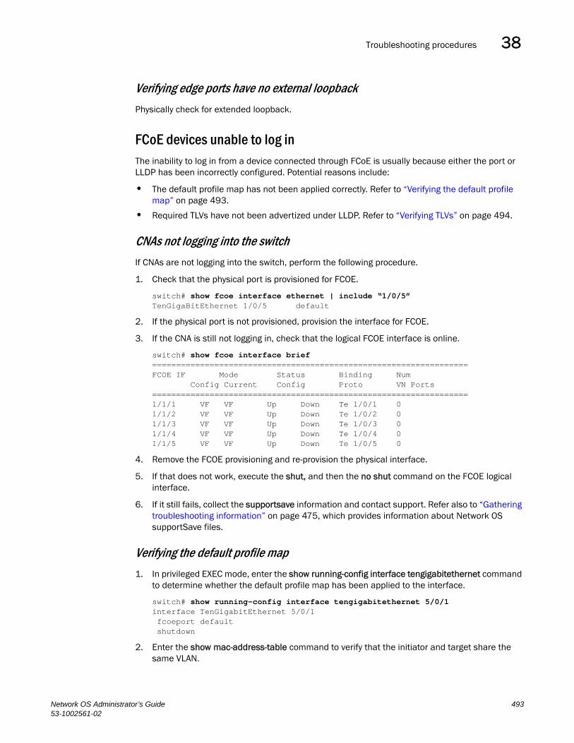
Troubleshooting procedures 38
Verifying edge ports have no external loopback
Physically check for extended loopback.
FCoE devices unable to log inThe inability to log in from a device connected through FCoE is usually because either the port or LLDP has been incorrectly configured. Potential reasons include:
• The default profile map has not been applied correctly. Refer to “Verifying the default profile map” on page 493.
• Required TLVs have not been advertized under LLDP. Refer to “Verifying TLVs” on page 494.
CNAs not logging into the switch
If CNAs are not logging into the switch, perform the following procedure.
1. Check that the physical port is provisioned for FCOE.
switch# show fcoe interface ethernet | include “1/0/5”TenGigaBitEthernet 1/0/5 default
2. If the physical port is not provisioned, provision the interface for FCOE.
3. If the CNA is still not logging in, check that the logical FCOE interface is online.
switch# show fcoe interface brief==================================================================FCOE IF Mode Status Binding Num
Config Current Config Proto VN Ports==================================================================1/1/1 VF VF Up Down Te 1/0/1 01/1/2 VF VF Up Down Te 1/0/2 01/1/3 VF VF Up Down Te 1/0/3 01/1/4 VF VF Up Down Te 1/0/4 01/1/5 VF VF Up Down Te 1/0/5 0
4. Remove the FCOE provisioning and re-provision the physical interface.
5. If that does not work, execute the shut, and then the no shut command on the FCOE logical interface.
6. If it still fails, collect the supportsave information and contact support. Refer also to “Gathering troubleshooting information” on page 475, which provides information about Network OS supportSave files.
Verifying the default profile map
1. In privileged EXEC mode, enter the show running-config interface tengigabitethernet command to determine whether the default profile map has been applied to the interface.
switch# show running-config interface tengigabitethernet 5/0/1interface TenGigabitEthernet 5/0/1 fcoeport default shutdown
2. Enter the show mac-address-table command to verify that the initiator and target share the same VLAN.
Network OS Administrator’s Guide 49353-1002561-02
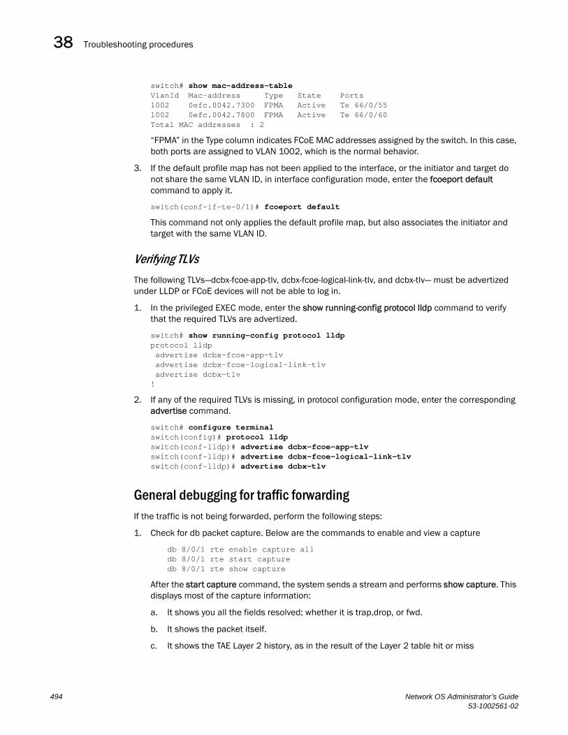
Troubleshooting procedures38
switch# show mac-address-tableVlanId Mac-address Type State Ports1002 0efc.0042.7300 FPMA Active Te 66/0/551002 0efc.0042.7800 FPMA Active Te 66/0/60Total MAC addresses : 2
“FPMA” in the Type column indicates FCoE MAC addresses assigned by the switch. In this case, both ports are assigned to VLAN 1002, which is the normal behavior.
3. If the default profile map has not been applied to the interface, or the initiator and target do not share the same VLAN ID, in interface configuration mode, enter the fcoeport default command to apply it.
switch(conf-if-te-0/1)# fcoeport default
This command not only applies the default profile map, but also associates the initiator and target with the same VLAN ID.
Verifying TLVs
The following TLVs—dcbx-fcoe-app-tlv, dcbx-fcoe-logical-link-tlv, and dcbx-tlv— must be advertized under LLDP or FCoE devices will not be able to log in.
1. In the privileged EXEC mode, enter the show running-config protocol lldp command to verify that the required TLVs are advertized.
switch# show running-config protocol lldpprotocol lldp advertise dcbx-fcoe-app-tlv advertise dcbx-fcoe-logical-link-tlv advertise dcbx-tlv!
2. If any of the required TLVs is missing, in protocol configuration mode, enter the corresponding advertise command.
switch# configure terminalswitch(config)# protocol lldpswitch(conf-lldp)# advertise dcbx-fcoe-app-tlvswitch(conf-lldp)# advertise dcbx-fcoe-logical-link-tlvswitch(conf-lldp)# advertise dcbx-tlv
General debugging for traffic forwarding If the traffic is not being forwarded, perform the following steps:
1. Check for db packet capture. Below are the commands to enable and view a capture
db 8/0/1 rte enable capture alldb 8/0/1 rte start capturedb 8/0/1 rte show capture
After the start capture command, the system sends a stream and performs show capture. This displays most of the capture information:
a. It shows you all the fields resolved; whether it is trap,drop, or fwd.
b. It shows the packet itself.
c. It shows the TAE Layer 2 history, as in the result of the Layer 2 table hit or miss
494 Network OS Administrator’s Guide53-1002561-02
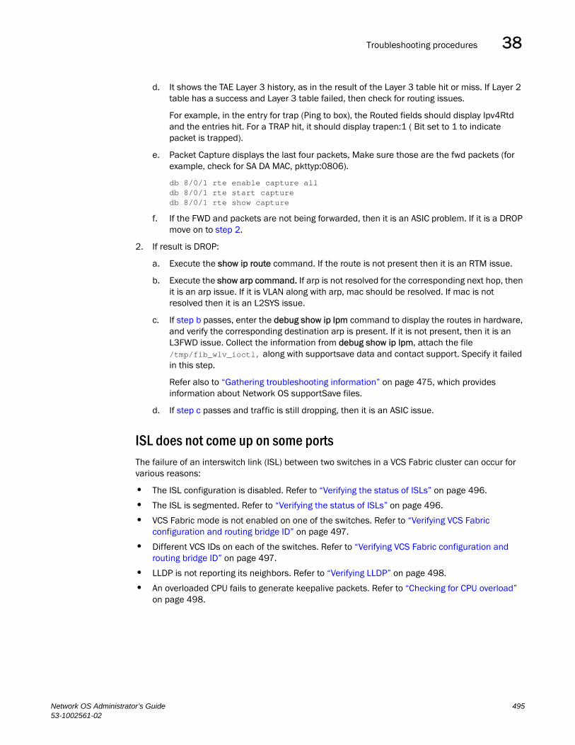
Troubleshooting procedures 38
d. It shows the TAE Layer 3 history, as in the result of the Layer 3 table hit or miss. If Layer 2 table has a success and Layer 3 table failed, then check for routing issues.
For example, in the entry for trap (Ping to box), the Routed fields should display Ipv4Rtd and the entries hit. For a TRAP hit, it should display trapen:1 ( Bit set to 1 to indicate packet is trapped).
e. Packet Capture displays the last four packets, Make sure those are the fwd packets (for example, check for SA DA MAC, pkttyp:0806).
db 8/0/1 rte enable capture alldb 8/0/1 rte start capturedb 8/0/1 rte show capture
f. If the FWD and packets are not being forwarded, then it is an ASIC problem. If it is a DROP move on to step 2.
2. If result is DROP:
a. Execute the show ip route command. If the route is not present then it is an RTM issue.
b. Execute the show arp command. If arp is not resolved for the corresponding next hop, then it is an arp issue. If it is VLAN along with arp, mac should be resolved. If mac is not resolved then it is an L2SYS issue.
c. If step b passes, enter the debug show ip lpm command to display the routes in hardware, and verify the corresponding destination arp is present. If it is not present, then it is an L3FWD issue. Collect the information from debug show ip lpm, attach the file /tmp/fib_wlv_ioctl, along with supportsave data and contact support. Specify it failed in this step.
Refer also to “Gathering troubleshooting information” on page 475, which provides information about Network OS supportSave files.
d. If step c passes and traffic is still dropping, then it is an ASIC issue.
ISL does not come up on some portsThe failure of an interswitch link (ISL) between two switches in a VCS Fabric cluster can occur for various reasons:
• The ISL configuration is disabled. Refer to “Verifying the status of ISLs” on page 496.
• The ISL is segmented. Refer to “Verifying the status of ISLs” on page 496.
• VCS Fabric mode is not enabled on one of the switches. Refer to “Verifying VCS Fabric configuration and routing bridge ID” on page 497.
• Different VCS IDs on each of the switches. Refer to “Verifying VCS Fabric configuration and routing bridge ID” on page 497.
• LLDP is not reporting its neighbors. Refer to “Verifying LLDP” on page 498.
• An overloaded CPU fails to generate keepalive packets. Refer to “Checking for CPU overload” on page 498.
Network OS Administrator’s Guide 49553-1002561-02

Troubleshooting procedures38
Verifying the status of ISLs
If any port looks suspicious, begin by checking the status of ISLs.
1. On the switches at each end of the broken link, in privileged EXEC mode, enter the show fabric isl command to view the status of ISL connections.
switch1# show fabric islRbridge-id: 2 #ISLs: 2Src Src Nbr NbrIndex Interface Index Interface Nbr-WWN BW Trunk Nbr-Name-----------------------------------------------------------------------------------------1 Te 2/0/1 1 Te 3/0/1 10:00:00:05:1E:CD:7A:7A 10G Yes "switch1"2 Te 2/0/2 ? Te ?/?/? ??:??:??:??:??:??:??:?? (segmented - incompatible)26 Te 2/0/26 56 Te 25/0/56 10:00:00:05:33:40:2F:C9 60G Yes "Edget12r31_25"34 Te 2/0/34 58 Te 26/0/58 10:00:00:05:33:41:1E:B7 40G Yes "Edget12r32_26"
Ports on which the ISL link is broken appear with the text “(segmented - incompatible).” Ports for which the ISL configuration is disabled do not appear in the output.
2. Enter the show fabric islports command to gather more information about the status of suspect ports.
sw0# show fabric islportsName: sw0Type: 107.4State: Online Role: Fabric SubordinateVCS Id: 10Config Mode: Local-OnlyRbridge-id: 11WWN: 10:00:00:05:33:6d:7f:77FCF MAC: 00:05:33:6d:7f:77
Index Interface State Operational State===================================================================
1 Te 11/0/1 Up ISL 10:00:00:05:33:00:77:80 "sw0" (upstream)(Trunk Primary) 2 Te 11/0/2 Down3 Te 11/0/3 Down4 Te 11/0/4 Up ISL (Trunk port, Primary is Te 11/0/1 )5 Te 11/0/5 Down6 Te 11/0/6 Down7 Te 11/0/7 Down8 Te 11/0/8 Down9 Te 11/0/9 Down
10 Te 11/0/10 Down11 Te 11/0/11 Up ISL 10:00:00:05:1e:00:50:00 "sw0" (Trunk Primary)
121 Fi 11/0/1 Up LS ISL 50:00:53:37:b6:93:5e:02 "fcr_fd_160" (downstream) (Trunk Primary) 122 Fi 11/0/2 Up LS ISL (Trunk port, Primary is Fi 11/0/1 )123 Fi 11/0/3 Down124 Fi 11/0/4 Down125 Fi 11/0/5 Down126 Fi 11/0/6 Down127 Fi 11/0/7 Down
3. If the port state is “Down,” enable the port with the no shutdown command.
switch# configure terminalEntering configuration mode terminal
496 Network OS Administrator’s Guide53-1002561-02

Troubleshooting procedures 38
switch(config)# interface tengigabitethernet 178/0/9switch(conf-if-te-178/0/9)# no shutdown
4. If the port state is “Up,” but the ISL is segmented, examine the Operational State string for further clues to the reason for the segmentation.
Refer to the Network OS Command Reference for details about the show fabric islports command and help in interpreting the Operational State string for a segmented ISL.
Verifying VCS Fabric configuration and routing bridge ID
For the ISL to function correctly, the following criteria must be true:
• Both switches must have VCS Fabric mode enabled.
• Both switches must have the same VCS ID.
• Each switch must have a unique routing bridge ID.
To check the criteria, complete the following steps.
1. Enter the show vcs command on each switch.
2. Depending on the output, proceed as follows:
• If the VCS Fabric mode is not enabled on either switch, enter the vcs enable command to enable it.
switch1# show vcsConfig Mode : Local-OnlyVCS ID : 1Total Number of Nodes : 1Rbridge-Id WWN Management IP Status HostName--------------------------------------------------------------------------66 >10:00:00:05:33:67:26:78* 10.24.81.66 Online switch1
switch2# show vcsstate : Disabled
switch2# vcs vcsid 1 enable
• If the show vcs command indicates that the VCS ID is not the same on each switch, enter the vcs vcsid command to correct the VCS ID on the switch that is in error.
switch1# show vcsConfig Mode : Local-OnlyVCS ID : 1Total Number of Nodes : 1Rbridge-Id WWN Management IP Status HostName--------------------------------------------------------------------------66 >10:00:00:05:33:67:26:78* 10.24.81.66 Online switch1
switch2# show vcsConfig Mode : Local-OnlyVCS ID : 2Total Number of Nodes : 1Rbridge-Id WWN Management IP Status HostName--------------------------------------------------------------------------66 >10:00:00:05:33:67:26:78* 10.24.81.77 Online switch1
Network OS Administrator’s Guide 49753-1002561-02

Troubleshooting procedures38
switch2# vcs vcsid 1
• If both switches have the same routing bridge ID, enter the vcs rbridge-id command to change the routing bridge ID to a unique value.
switch1# show vcsConfig Mode : Local-OnlyVCS ID : 1Total Number of Nodes : 1Rbridge-Id WWN Management IP Status HostName--------------------------------------------------------------------------66 >10:00:00:05:33:67:26:78* 10.24.81.66 Online switch1
switch2# show vcsConfig Mode : Local-OnlyVCS ID : 1Total Number of Nodes : 1Rbridge-Id WWN Management IP Status HostName--------------------------------------------------------------------------66 >10:00:00:05:33:67:26:78* 10.24.81.77 Online switch1
switch2# vcs rbridge-id 77
Verifying LLDP
When ISLs are functioning correctly, the show lldp neighbors command reports on each neighbor switch in the VCS Fabric cluster.
1. Enter the show lldp neighbors command to verify that LLDP reports on all of its neighbors.
switch1# show lldp neighborsLocal Intf Dead Interval Remaining Life Remote Intf Chassis ID Tx RxTe 66/0/55 120 106 port1 0005.1e78.f004 20300 19914Te 66/0/60 120 108 port0 0005.1e55.16c8 20300 19911
2. If neighbors are missing, perform further debugging or contact your switch support provider.
Checking for CPU overload
An abnormally high CPU load can cause an ISL to malfunction. Use the show process cpu command as described in “CPU use is unexpectedly high” on page 491 to troubleshoot an overloaded CPU.
License not properly installedIf a licensed feature is not functioning, a probable reason is that the license for that feature has not been installed correctly. Either the license was not installed, or it was installed and a required system reboot was not performed.
If, on a Brocade VDX 6720-24 or VDX 6730-32 switch, only eight Ethernet ports are working, it is probable that no DPOD license is installed. Similarly, if on a Brocade VDX 6720-60 or Brocade VDX 6730-76, only 40 Ethernet ports are working, it is probable that no DPOD license is installed.
498 Network OS Administrator’s Guide53-1002561-02

Troubleshooting procedures 38
If, on a Brocade VDX 6720-60 or Brocade VDX 6730-76, 50 Ethernet ports are working but the remaining 10 are not, it is likely that you have the DPOD1 license installed, but not the DPOD2 license.
If you are unable to add a third switch to a VCS Fabric cluster, it is likely that the VCS Fabric license is not installed.
If you are unable to connect an FCoE device or unable to use Fibre Channel ports on a Brocade VDX 6730 switch, it is likely that the FCoE license is not installed.
For detailed licensing information, refer to Chapter 7, “Administering Licenses”.
If you suspect a license is not properly installed, complete the following steps.
1. In privileged EXEC mode, enter the show license command to see which licenses are currently installed.
switch# show license
rbridge-id: 66xxxxxxxxxxxxxxxxxxxxxxxxxxxxxxxxxxxxxxxx
FCoE Base licenseFeature name:FCOE_BASE
xxxxxxxxxxxxxxxxxxxxxxxxxxxxxxxxxxxxxxxxVCS Fabric licenseFeature name:VCS_FABRIC
2. If the FCoE or DPOD license appears in the show license command output, but the feature does not work for the expected ports, the probable cause is that the affected ports were not re-enabled after installing the license.
NOTEAfter adding an FCoE or DPOD license, you must disable and re-enable all affected ports. The VCS Fabric license does not require re-enabling.
You can disable and then enable each affected port, or you can enter the chassis disable command followed by the chassis enable command to re-enable the entire chassis.
switch# chassis disableswitch# chassis enable
3. If the license does not appear in the show license command output, then it was not installed. In privileged EXEC mode, enter the license add lictstr command to install the license. For FCoE and DPOD licenses, you must also disable and enable the switch or port.
switch# license add licstr "*B slSETgzTgeVGUDeQR4WIfRx7mmXODdSwENoRGEnAmX3Ca3uHeZgXK0b,jzxyzfzKLrMsPN8ClSxvDQRRT8VyuULyyKTO0ryU6qm4s1jjiSAeV,COoedzCx1v6ycQgnYMeSVp#"
License Added [*B slSETgzTgeVGUDeQR4WIfRx7mmXODdSwENoRGEnAmX3Ca3uHeZgXK0b,jzxyzfzKLrMsPN8ClSxvDQRRT8VyuULyyKTO0ryU6qm4s1jjiSAeV,COoedzCx1v6ycQgnYMeSVp#]
For license change to take effect, please disable/enable port or switch...switch# chassis disableswitch# chassis enable
Network OS Administrator’s Guide 49953-1002561-02

Troubleshooting procedures38
Packets dropped in hardwareThis section discusses how to troubleshoot problems in which loss of packets occurs in all traffic, on specific traffic flows, in specific types of traffic, consistently, or intermittently. Dropped packets could occur for many reasons, including the following:
• High latency in an end device. Refer to “Packets dropped because of high latency end device” on page 500.
• Broken data path. Refer to “Verifying the data path” on page 502.
• Noise on an optical line caused by too many CRC errors, packet errors, or NIC interoperability errors. Refer to “Checking for noise on an optical line” on page 504.
Packets dropped because of high latency end device
Packets can sometimes be dropped because of buffer overrun within the fabric caused by end devices taking longer to respond than expected. For example, an overloaded disk array can cause such latency, as can a host that does not process data as quickly as expected. Devices that stop receiving data for an extended period of time can cause excessive latency.
The ultimate solution to these problems is to fix the end device itself. However, some adjustments to the switch and fabric configuration can help to reduce the problem.
To detect and relieve congestion and dropped packets resulting from latency in end devices, complete the following steps:
1. Enter the show lldp neighbors detail command to check under “DCBX TLVs” that the end device is DCB-ready and confirm that the end device is also advertising its DCB capabilities.
switch# show lldp neighbors detailNeighbors for Interface Te 66/0/55
MANDATORY TLVs===============Local Interface: Te 66/0/55 (Local Interface MAC: 0005.3367.26d3)Remote Interface: port1 (Remote Interface MAC: 0005.1e78.f004)Dead Interval: 120 secsRemaining Life : 104 secsChassis ID: 0005.1e78.f004LLDP PDU Transmitted: 2412 Received: 2372
OPTIONAL TLVs==============
DCBX TLVs===========Version : CEEDCBX Ctrl OperVersion: 0 MaxVersion: 0 SeqNo: 1 AckNo: 4DCBX ETS OperVersion: 0 MaxVersion: 0 Enabled: 1 Willing: 1 Error: 0Enhanced Transmission Selection (ETS)Priority-Group ID Map:Priority : 0 1 2 3 4 5 6 7Group ID : 2 2 2 1 2 2 2 15
Group ID Bandwidth Map:Group ID : 0 1 2 3 4 5 6 7Percentage: 0 40 60 0 0 0 0 0Number of Traffic Classes supported: 8
DCBX PFC OperVersion: 0 MaxVersion: 0 Enabled: 1 Willing: 1 Error: 0Priority-based Flow Control (PFC)
500 Network OS Administrator’s Guide53-1002561-02

Troubleshooting procedures 38
Enabled Priorities: 3Number of Traffic Class PFC supported: 8
FCoE App OperVersion: 0 MaxVersion: 0 Enabled: 1 Willing: 1 Error: 0FCoE Application Protocol
User Priorities: 3
2. Enter the show qos flowcontrol interface command to check for pause frames.
switch# show qos flowcontrol interface tengigabitethernet 66/0/55Interface TenGigabitEthernet 66/0/55Mode PFCDCBX enabled for PFC negotiationTX 4926331124 frames
TX TX RX RX Output PausedCoS Admin Oper Admin Oper 512 BitTimes-----------------------------------------0 Off Off Off Off 01 Off Off Off Off 02 Off Off Off Off 03 On On On On 04 Off Off Off Off 05 Off Off Off Off 06 Off Off Off Off 07 Off Off Off Off 0
3. Enter the show qos queue interface command to check the CoS statistics.
switch# show qos queue interface tengigabitethernet 66/0/60Interface TenGigabitEthernet 66/0/60
RX RX TX TXCoS Packets Bytes TC Packets Bytes------------------------------------ ------------------------------------0 1600 354184 0 0 01 0 0 1 7962 6369602 0 0 2 0 03 8508 544832 3 18 60484 0 0 4 0 05 0 0 5 0 06 0 0 6 0 07 0 0 7 2123 282360
untag 2082 216528
4. Enter the show qos rcv-queue interface command to check for indicators of congestion, including dropped packets, buffer consumption, and real-time queue statistics.
switch# show qos rcv-queue interface tengigabitethernet 66/0/55Interface TenGigabitEthernet TenGigabitEthernet 66/0/55In-use 27216 bytes, Total buffer 144144 bytes0 packets dropped
In-use MaxTC Bytes Bytes-------------------------0 0 2521 0 2522 0 2523 27216 752844 0 2525 0 2526 0 574567 0 9576
5. Enter the show qos interface command to check the QoS configuration.
Network OS Administrator’s Guide 50153-1002561-02

Troubleshooting procedures38
switch# show qos interface tengigabitethernet 66/0/55Interface TenGigabitEthernet 66/0/55Provisioning mode ceePriority Tag disableCEE Map defaultFCoE CoS: 3FCoE ProvisionedDefault CoS 0Interface trust cos
In-CoS: 0 1 2 3 4 5 6 7-----------------------------------------------------Out-CoS/TrafficClass: 0/6 1/6 2/6 3/3 4/6 5/6 6/6 0/7
Per-Traffic Class Tail Drop Threshold (bytes)TC: 0 1 2 3 4 5 6 7
------------------------------------------------------------------Threshold: 252 252 252 75284 252 252 57456 9576
Flow control mode PFCCoS3 TX on, RX on
Multicast Packet Expansion Rate Limit 3000000 pkt/s, max burst 4096 pktsMulticast Packet Expansion Tail Drop Threshold (packets)
TrafficClass: 0 1 2 3 4 5 6 7-----------------------------------------------------Threshold: 64 64 64 64 64 64 64 64
Traffic Class Scheduler configured for 1 Strict Priority queuesTrafficClass: 0 1 2 3 4 5 6 7---------------------------------------------DWRRWeight: 0 0 0 40 0 0 60 ---
Multicast Packet Expansion Traffic Class SchedulerTrafficClass: 0 1 2 3 4 5 6 7-----------------------------------------------------DWRRWeight: 12 13 12 13 12 13 12 13
6. Reconfigure QoS. Refer to Chapter 26, “Configuring QoS”.
Verifying the data path
This procedure checks whether fabric continuity might be the reason for dropped packets.
1. Enter the ping command to test for a complete path to the end device
switch# ping dest-address 10.24.81.2PING 10.24.81.2 (10.24.81.2): 56 octets data64 octets from 10.24.81.2: icmp_seq=0 ttl=128 time=9.4 ms64 octets from 10.24.81.2: icmp_seq=1 ttl=128 time=0.3 ms64 octets from 10.24.81.2: icmp_seq=2 ttl=128 time=0.3 ms64 octets from 10.24.81.2: icmp_seq=3 ttl=128 time=0.3 ms64 octets from 10.24.81.2: icmp_seq=4 ttl=128 time=0.3 ms
--- 10.24.81.2 ping statistics ---5 packets transmitted, 5 packets received, 0% packet lossround-trip min/avg/max = 0.3/2.1/9.4 ms
2. Enter the show interface command to see whether packets are coming in or are dropped as errors. Specifically, examine the output fields shown underlined in the following example.
switch# show interface tengigabitethernet 66/0/60TenGigabitEthernet 66/0/60 is up, line protocol is up (connected)Hardware is Ethernet, address is 0005.3367.26d8
Current address is 0005.3367.26d8Pluggable media presentInterface index (ifindex) is 283874428169
502 Network OS Administrator’s Guide53-1002561-02

Troubleshooting procedures 38
MTU 2500 bytesLineSpeed Actual : 10000 MbitLineSpeed Configured : Auto, Duplex: FullFlowcontrol rx: off, tx: offLast clearing of show interface counters: 22:07:59Queueing strategy: fifoReceive Statistics:
15254 packets, 1395269 bytesUnicasts: 10641, Multicasts: 2637, Broadcasts: 197664-byte pkts: 10874, Over 64-byte pkts: 3294, Over 127-byte pkts: 117Over 255-byte pkts: 969, Over 511-byte pkts: 0, Over 1023-byte pkts: 0Over 1518-byte pkts(Jumbo): 0Runts: 0, Jabbers: 0, CRC: 0, Overruns: 0Errors: 0, Discards: 0
Transmit Statistics:12633 packets, 1155963 bytesUnicasts: 18, Multicasts: 12615, Broadcasts: 0Underruns: 0Errors: 0, Discards: 0
Rate info (interval 299 seconds):Input 0.000128 Mbits/sec, 0 packets/sec, 0.00% of line-rateOutput 0.000000 Mbits/sec, 0 packets/sec, 0.00% of line-rate
Time since last interface status change: 1d00h40m
3. Enter the show media interface command to check that the optics used are Brocade-certified. Check the Vendor Name field shown underlined in the following example.
Check also the TX Power and RX Power fields to ensure they are not zero.
switch# show media interface tengigabitethernet 66/0/60Interface TenGigabitEthernet 66/0/60Identifier 3 SFPConnector 7 LCTransceiver 0000000000000010 10_GB/sName idEncoding 6Baud Rate 103 (units 100 megabaud)Length 9u 0 (units km)Length 9u 0 (units 100 meters)Length 50u 8 (units 10 meters)Length 62.5u 3 (units 10 meters)Length Cu 0 (units 1 meter)Vendor Name BROCADEVendor OUI 00:05:1eVendor PN 57-0000075-01Vendor Rev AWavelength 850 (units nm)Options 001aBR Max 0BR Min 0Serial No AAA209282044472Date Code 090709Temperature 35 CentigradeVoltage 3356.4 (mVolts)Current 5.564 (mAmps)TX Power 568.9 (uWatts)RX Power 549.9 (uWatts)
If the Vendor Name field shows anything other than BROCADE, replace the optics with Brocade-certified optics.
Network OS Administrator’s Guide 50353-1002561-02

Troubleshooting procedures38
4. Enter the show mac-address-table command to verify that the MAC address table learns new values.
The new MAC address should appear here.
switch# show mac-address-tableVlanId Mac-address Type State Ports1002 0efc.0042.7300 FPMA Active Te 66/0/551002 0efc.0042.7302 FPMA Active Te 66/0/551002 0efc.0042.7800 FPMA Active Te 66/0/60Total MAC addresses : 3
5. Enter the show lldp neighbors command to verify that LLDP reports all neighbors.
switch# show lldp neighborsLocal Intf Dead Interval Remaining Life Remote Intf Chassis ID Tx RxTe 66/0/55 120 101 port1 0005.1e78.f004 3000 2948Te 66/0/60 120 117 port0 0005.1e55.16c8 2999 2945
If the output does not show all neighbors, contact your switch support provider.
6. Enter the show mac-address-table command to verify the Ethernet Name Service functionality and to see whether MAC addresses learned from other VCS Fabric switches are present.
Enter this command on other switches in the fabric to ensure that those switches can see this MAC address.
switch# show mac-address-tableVlanId Mac-address Type State Ports1002 0efc.0042.7300 FPMA Active Te 66/0/551002 0efc.0042.7302 FPMA Active Te 66/0/551002 0efc.0042.7800 FPMA Active Te 66/0/60Total MAC addresses : 3
7. Enter the l2traceroute command to validate the data-path fabric continuity.
- Enter dynamically learned source MAC address and destination MAC address for the data path.
- Among the extended commands, use IP, SIP, DIP, TCP, Scr Port, and Dest Port commands.
- Enter the IP command parameters to ensure that the traceroute packet traverses a specific ECMP link.
For details on using the l2traceroute command, refer to “Layer 2 traceroute” on page 516.
Checking for noise on an optical line
Excessive noise on an optical line can result in dropped packets because of excessive CRC errors, NIC interoperability errors, or other conditions.
1. Enter the show interface command and check the output for CRC errors or TX discards; examine the fields shown underlined in the following example.
switch# show interface tengigabitethernet 66/0/55TenGigabitEthernet 66/0/55 is up, line protocol is up (connected)Hardware is Ethernet, address is 0005.3367.26d3
Current address is 0005.3367.26d3Pluggable media presentInterface index (ifindex) is 283874100484MTU 2500 bytesLineSpeed Actual : 10000 MbitLineSpeed Configured : Auto, Duplex: Full
504 Network OS Administrator’s Guide53-1002561-02
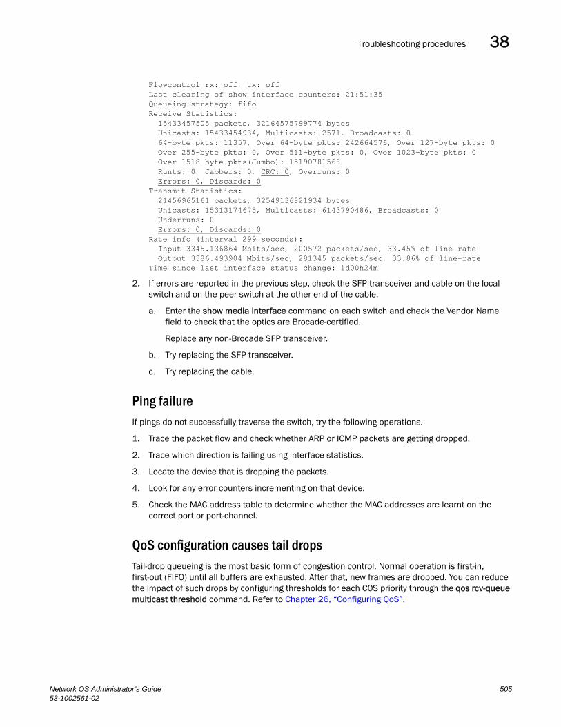
Troubleshooting procedures 38
Flowcontrol rx: off, tx: offLast clearing of show interface counters: 21:51:35Queueing strategy: fifoReceive Statistics:
15433457505 packets, 32164575799774 bytesUnicasts: 15433454934, Multicasts: 2571, Broadcasts: 064-byte pkts: 11357, Over 64-byte pkts: 242664576, Over 127-byte pkts: 0Over 255-byte pkts: 0, Over 511-byte pkts: 0, Over 1023-byte pkts: 0Over 1518-byte pkts(Jumbo): 15190781568Runts: 0, Jabbers: 0, CRC: 0, Overruns: 0Errors: 0, Discards: 0
Transmit Statistics:21456965161 packets, 32549136821934 bytesUnicasts: 15313174675, Multicasts: 6143790486, Broadcasts: 0Underruns: 0Errors: 0, Discards: 0
Rate info (interval 299 seconds):Input 3345.136864 Mbits/sec, 200572 packets/sec, 33.45% of line-rateOutput 3386.493904 Mbits/sec, 281345 packets/sec, 33.86% of line-rate
Time since last interface status change: 1d00h24m
2. If errors are reported in the previous step, check the SFP transceiver and cable on the local switch and on the peer switch at the other end of the cable.
a. Enter the show media interface command on each switch and check the Vendor Name field to check that the optics are Brocade-certified.
Replace any non-Brocade SFP transceiver.
b. Try replacing the SFP transceiver.
c. Try replacing the cable.
Ping failureIf pings do not successfully traverse the switch, try the following operations.
1. Trace the packet flow and check whether ARP or ICMP packets are getting dropped.
2. Trace which direction is failing using interface statistics.
3. Locate the device that is dropping the packets.
4. Look for any error counters incrementing on that device.
5. Check the MAC address table to determine whether the MAC addresses are learnt on the correct port or port-channel.
QoS configuration causes tail dropsTail-drop queueing is the most basic form of congestion control. Normal operation is first-in, first-out (FIFO) until all buffers are exhausted. After that, new frames are dropped. You can reduce the impact of such drops by configuring thresholds for each C0S priority through the qos rcv-queue multicast threshold command. Refer to Chapter 26, “Configuring QoS”.
Network OS Administrator’s Guide 50553-1002561-02
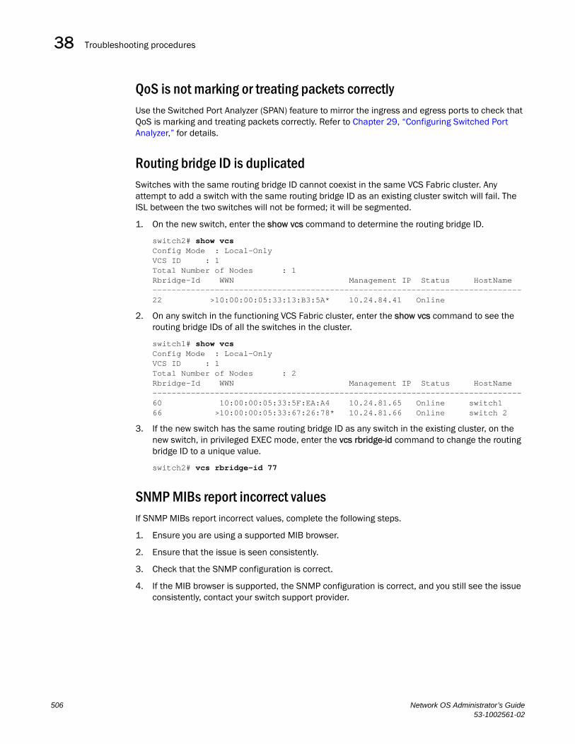
Troubleshooting procedures38
QoS is not marking or treating packets correctlyUse the Switched Port Analyzer (SPAN) feature to mirror the ingress and egress ports to check that QoS is marking and treating packets correctly. Refer to Chapter 29, “Configuring Switched Port Analyzer,” for details.
Routing bridge ID is duplicatedSwitches with the same routing bridge ID cannot coexist in the same VCS Fabric cluster. Any attempt to add a switch with the same routing bridge ID as an existing cluster switch will fail. The ISL between the two switches will not be formed; it will be segmented.
1. On the new switch, enter the show vcs command to determine the routing bridge ID.
switch2# show vcsConfig Mode : Local-OnlyVCS ID : 1Total Number of Nodes : 1Rbridge-Id WWN Management IP Status HostName-----------------------------------------------------------------------------22 >10:00:00:05:33:13:B3:5A* 10.24.84.41 Online
2. On any switch in the functioning VCS Fabric cluster, enter the show vcs command to see the routing bridge IDs of all the switches in the cluster.
switch1# show vcsConfig Mode : Local-OnlyVCS ID : 1Total Number of Nodes : 2Rbridge-Id WWN Management IP Status HostName-----------------------------------------------------------------------------60 10:00:00:05:33:5F:EA:A4 10.24.81.65 Online switch166 >10:00:00:05:33:67:26:78* 10.24.81.66 Online switch 2
3. If the new switch has the same routing bridge ID as any switch in the existing cluster, on the new switch, in privileged EXEC mode, enter the vcs rbridge-id command to change the routing bridge ID to a unique value.
switch2# vcs rbridge-id 77
SNMP MIBs report incorrect valuesIf SNMP MIBs report incorrect values, complete the following steps.
1. Ensure you are using a supported MIB browser.
2. Ensure that the issue is seen consistently.
3. Check that the SNMP configuration is correct.
4. If the MIB browser is supported, the SNMP configuration is correct, and you still see the issue consistently, contact your switch support provider.
506 Network OS Administrator’s Guide53-1002561-02

Troubleshooting procedures 38
SNMP traps are missingIf SNMP traps are missing, complete the following steps.
1. Ensure that the correct SNMP configuration is enabled. Refer to Chapter 8, “SNMP,” for details.
2. Ensure that the SNMP host is reachable.
3. If the problem still persists, contact your switch support provider.
As a workaround, set a trap configuration for syslog messages.
Telnet operation into the switch failsAssuming a correct IP address and correct login credentials, failure to access the switch using Telnet could be for one of the following reasons:
• The management port is down. Refer to “Verifying the status of the management port” on page 507 for details.
• Access to the management interface is denied by an ACL. Refer to “Checking for a deny ACL” on page 508 for details.
• The switch CPU is overloaded. Refer to “Checking for overloaded CPU” on page 508 for details.
Verifying the status of the management port
1. On the system console, enter the show system command to check the status of the management port, shown underlined in the following example.
switch# show systemStack MAC : 00:05:33:67:26:78
-- UNIT 0 --Unit Name : switchSwitch Status : OnlineHardware Rev : 107.4TengigabitEthernet Port(s) : 60Up Time : up 1 day, 2:52Current Time : 23:40:50 GMTNOS Version :Jumbo Capable : yesBurned In MAC : 00:05:33:67:26:78Management IP : 10.24.81.66Management Port Status : UP
-- Power Supplies --PS1 is faultyPS2 is OK
-- Fan Status --Fan 1 is OkFan 2 is OkFan 3 is Ok
2. If the status of the management port is DOWN, enter the interface management command to configure the management port correctly. Refer to “Configuring the Ethernet management interface” on page 31.
3. If the problem persists, contact your switch support provider.
Network OS Administrator’s Guide 50753-1002561-02
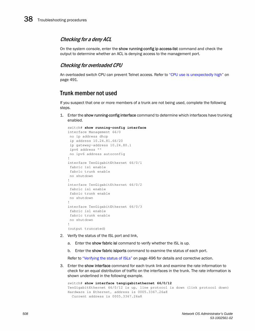
Troubleshooting procedures38
Checking for a deny ACL
On the system console, enter the show running-config ip access-list command and check the output to determine whether an ACL is denying access to the management port.
Checking for overloaded CPU
An overloaded switch CPU can prevent Telnet access. Refer to “CPU use is unexpectedly high” on page 491.
Trunk member not usedIf you suspect that one or more members of a trunk are not being used, complete the following steps.
1. Enter the show running-config interface command to determine which interfaces have trunking enabled.
switch# show running-config interfaceinterface Management 66/0 no ip address dhcp ip address 10.24.81.66/20 ip gateway-address 10.24.80.1 ipv6 address "" no ipv6 address autoconfig!interface TenGigabitEthernet 66/0/1 fabric isl enable fabric trunk enable no shutdown!interface TenGigabitEthernet 66/0/2 fabric isl enable fabric trunk enable no shutdown!interface TenGigabitEthernet 66/0/3 fabric isl enable fabric trunk enable no shutdown!(output truncated)
2. Verify the status of the ISL port and link,
a. Enter the show fabric isl command to verify whether the ISL is up.
b. Enter the show fabric islports command to examine the status of each port.
Refer to “Verifying the status of ISLs” on page 496 for details and corrective action.
3. Enter the show interface command for each trunk link and examine the rate information to check for an equal distribution of traffic on the interfaces in the trunk. The rate information is shown underlined in the following example.
switch# show interface tengigabitethernet 66/0/12TenGigabitEthernet 66/0/12 is up, line protocol is down (link protocol down)Hardware is Ethernet, address is 0005.3367.26a8
Current address is 0005.3367.26a8
508 Network OS Administrator’s Guide53-1002561-02
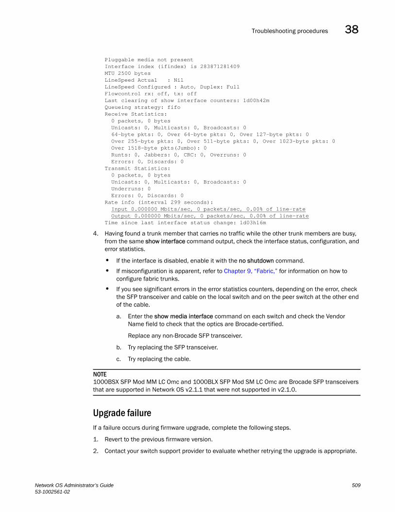
Troubleshooting procedures 38
Pluggable media not presentInterface index (ifindex) is 283871281409MTU 2500 bytesLineSpeed Actual : NilLineSpeed Configured : Auto, Duplex: FullFlowcontrol rx: off, tx: offLast clearing of show interface counters: 1d00h42mQueueing strategy: fifoReceive Statistics:
0 packets, 0 bytesUnicasts: 0, Multicasts: 0, Broadcasts: 064-byte pkts: 0, Over 64-byte pkts: 0, Over 127-byte pkts: 0Over 255-byte pkts: 0, Over 511-byte pkts: 0, Over 1023-byte pkts: 0Over 1518-byte pkts(Jumbo): 0Runts: 0, Jabbers: 0, CRC: 0, Overruns: 0Errors: 0, Discards: 0
Transmit Statistics:0 packets, 0 bytesUnicasts: 0, Multicasts: 0, Broadcasts: 0Underruns: 0Errors: 0, Discards: 0
Rate info (interval 299 seconds):Input 0.000000 Mbits/sec, 0 packets/sec, 0.00% of line-rateOutput 0.000000 Mbits/sec, 0 packets/sec, 0.00% of line-rate
Time since last interface status change: 1d03h16m
4. Having found a trunk member that carries no traffic while the other trunk members are busy, from the same show interface command output, check the interface status, configuration, and error statistics.
• If the interface is disabled, enable it with the no shutdown command.
• If misconfiguration is apparent, refer to Chapter 9, “Fabric,” for information on how to configure fabric trunks.
• If you see significant errors in the error statistics counters, depending on the error, check the SFP transceiver and cable on the local switch and on the peer switch at the other end of the cable.
a. Enter the show media interface command on each switch and check the Vendor Name field to check that the optics are Brocade-certified.
Replace any non-Brocade SFP transceiver.
b. Try replacing the SFP transceiver.
c. Try replacing the cable.
NOTE1000BSX SFP Mod MM LC Omc and 1000BLX SFP Mod SM LC Omc are Brocade SFP transceivers that are supported in Network OS v2.1.1 that were not supported in v2.1.0.
Upgrade failureIf a failure occurs during firmware upgrade, complete the following steps.
1. Revert to the previous firmware version.
2. Contact your switch support provider to evaluate whether retrying the upgrade is appropriate.
Network OS Administrator’s Guide 50953-1002561-02
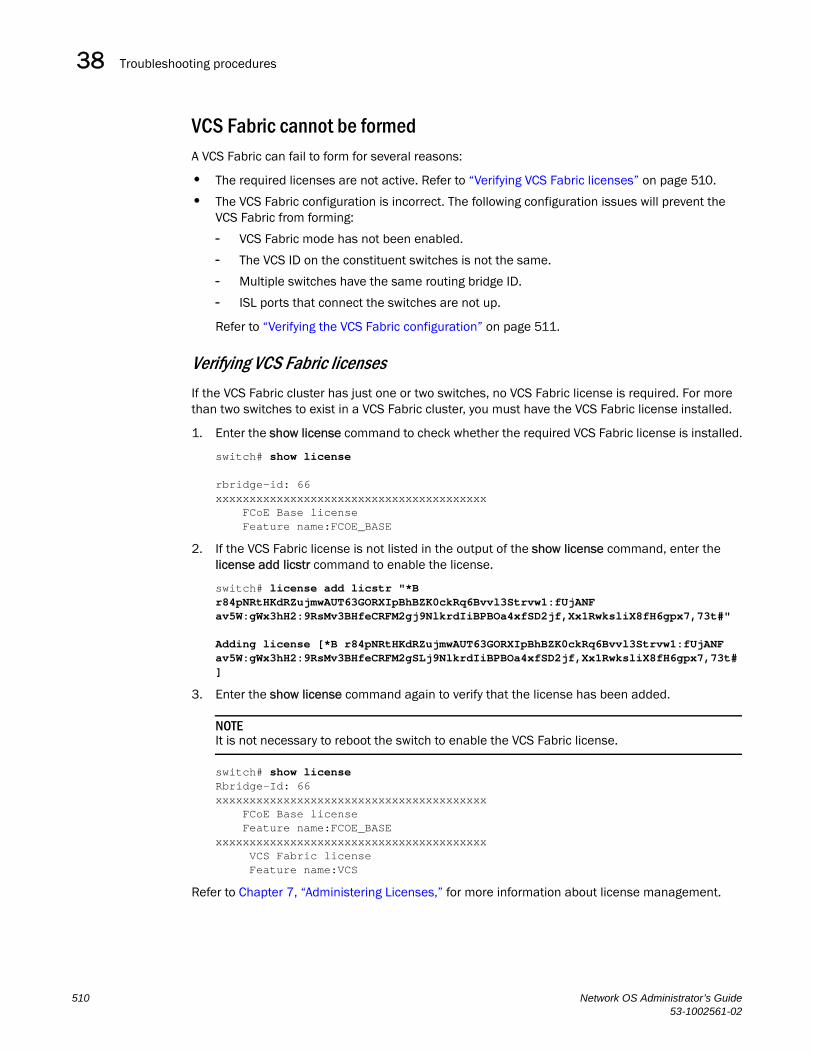
Troubleshooting procedures38
VCS Fabric cannot be formedA VCS Fabric can fail to form for several reasons:
• The required licenses are not active. Refer to “Verifying VCS Fabric licenses” on page 510.
• The VCS Fabric configuration is incorrect. The following configuration issues will prevent the VCS Fabric from forming:
- VCS Fabric mode has not been enabled.
- The VCS ID on the constituent switches is not the same.
- Multiple switches have the same routing bridge ID.
- ISL ports that connect the switches are not up.
Refer to “Verifying the VCS Fabric configuration” on page 511.
Verifying VCS Fabric licenses
If the VCS Fabric cluster has just one or two switches, no VCS Fabric license is required. For more than two switches to exist in a VCS Fabric cluster, you must have the VCS Fabric license installed.
1. Enter the show license command to check whether the required VCS Fabric license is installed.
switch# show license
rbridge-id: 66xxxxxxxxxxxxxxxxxxxxxxxxxxxxxxxxxxxxxxxx
FCoE Base licenseFeature name:FCOE_BASE
2. If the VCS Fabric license is not listed in the output of the show license command, enter the license add licstr command to enable the license.
switch# license add licstr "*B r84pNRtHKdRZujmwAUT63GORXIpBhBZK0ckRq6Bvvl3Strvw1:fUjANF av5W:gWx3hH2:9RsMv3BHfeCRFM2gj9NlkrdIiBPBOa4xfSD2jf,Xx1RwksliX8fH6gpx7,73t#"
Adding license [*B r84pNRtHKdRZujmwAUT63GORXIpBhBZK0ckRq6Bvvl3Strvw1:fUjANF av5W:gWx3hH2:9RsMv3BHfeCRFM2gSLj9NlkrdIiBPBOa4xfSD2jf,Xx1RwksliX8fH6gpx7,73t#]
3. Enter the show license command again to verify that the license has been added.
NOTEIt is not necessary to reboot the switch to enable the VCS Fabric license.
switch# show licenseRbridge-Id: 66xxxxxxxxxxxxxxxxxxxxxxxxxxxxxxxxxxxxxxxx
FCoE Base licenseFeature name:FCOE_BASE
xxxxxxxxxxxxxxxxxxxxxxxxxxxxxxxxxxxxxxxxVCS Fabric licenseFeature name:VCS
Refer to Chapter 7, “Administering Licenses,” for more information about license management.
510 Network OS Administrator’s Guide53-1002561-02
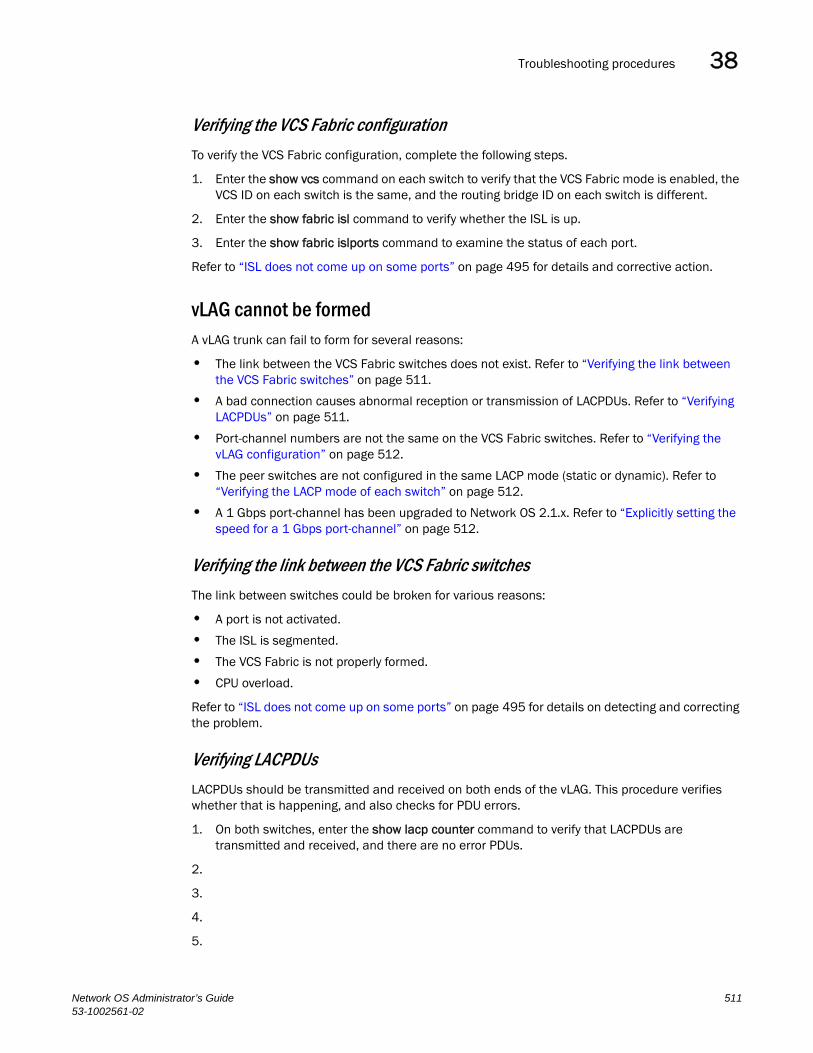
Troubleshooting procedures 38
Verifying the VCS Fabric configuration
To verify the VCS Fabric configuration, complete the following steps.
1. Enter the show vcs command on each switch to verify that the VCS Fabric mode is enabled, the VCS ID on each switch is the same, and the routing bridge ID on each switch is different.
2. Enter the show fabric isl command to verify whether the ISL is up.
3. Enter the show fabric islports command to examine the status of each port.
Refer to “ISL does not come up on some ports” on page 495 for details and corrective action.
vLAG cannot be formedA vLAG trunk can fail to form for several reasons:
• The link between the VCS Fabric switches does not exist. Refer to “Verifying the link between the VCS Fabric switches” on page 511.
• A bad connection causes abnormal reception or transmission of LACPDUs. Refer to “Verifying LACPDUs” on page 511.
• Port-channel numbers are not the same on the VCS Fabric switches. Refer to “Verifying the vLAG configuration” on page 512.
• The peer switches are not configured in the same LACP mode (static or dynamic). Refer to “Verifying the LACP mode of each switch” on page 512.
• A 1 Gbps port-channel has been upgraded to Network OS 2.1.x. Refer to “Explicitly setting the speed for a 1 Gbps port-channel” on page 512.
Verifying the link between the VCS Fabric switches
The link between switches could be broken for various reasons:
• A port is not activated.
• The ISL is segmented.
• The VCS Fabric is not properly formed.
• CPU overload.
Refer to “ISL does not come up on some ports” on page 495 for details on detecting and correcting the problem.
Verifying LACPDUs
LACPDUs should be transmitted and received on both ends of the vLAG. This procedure verifies whether that is happening, and also checks for PDU errors.
1. On both switches, enter the show lacp counter command to verify that LACPDUs are transmitted and received, and there are no error PDUs.
2.
3.
4.
5.
Network OS Administrator’s Guide 51153-1002561-02

Troubleshooting procedures38
switch# show lacp counter 10% Traffic statisticsPort LACPDUs Marker Pckt err
Sent Recv Sent Recv Sent Recv% Aggregator Po 10 1000000
Te 0/1 65 0 0 0 0 0Te 0/2 64 0 0 0 0 0Te 0/3 64 0 0 0 0 0Te 0/4 0 0 0 0 0 0
In this case, LACPDUs are being transmitted by the switch, but none are being received.
6. If the output shows that LACPDUs are not being transmitted and received correctly, or packet errors are showing, contact your switch support provider.
Verifying the vLAG configuration
The port-channel number must be the same across all vLAG member switches, or the vLAG will not form.
1. On each vLAG member switch, in privileged EXEC mode, enter the show port-channel summary command.
switch# show port-channel summary Static Aggregator: Po 15 Aggregator type: Standard Member ports:
Te 0/6Te 0/7Te 0/14Te 0/15
...switch2# show port-channel summaryswitch2#
2. If the port-channel does not appear on both switches, on the switch where it does not appear, in global configuration mode, enter the interface port-channel command to create the port-channel.
switch2(config)# interface port-channel 15
Refer to Chapter 23, “Configuring Link Aggregation,” for details.
Verifying the LACP mode of each switch
A vLAG must be configured either statically on both ends of the vLAG, or dynamically on both ends of the vLAG. Refer to Chapter 23, “Configuring Link Aggregation,” for details.
Explicitly setting the speed for a 1 Gbps port-channel
When upgrading firmware from Network OS v2.0.x to v2.1.x, any LAG or vLAG with a port speed of 1 Gbps will fail to come up unless the port speed is set explicitly in the configuration. The default port speed is 10 Gbps. LAGs and vLAGs with port speeds of 10 Gbps will come up following migration to Network OS v2.1.x without further intervention.
512 Network OS Administrator’s Guide53-1002561-02

Troubleshooting procedures 38
To set the port speed to 1 Gbps, complete the following steps.
1. In interface configuration mode, shut down the port-channel.
switch(config-Port-channel-2)# shutdown
2. Set the port-channel speed to 1 Gbps.
switch(config-Port-channel-2)# speed 1000
3. Re-enable all port members in the port-channel.
switch(config-Port-channel-2)# no shutdown
Zone does not form correctlySome problems you might encounter when configuring zones include potential Fibre Channel router issues. For a more detailed discussion of possible Fibre channel issues, refer to the Fabric OS Troubleshooting and Diagnostics Guide.
Some of the following problems may contribute to the zone not forming correctly:
• A Brocade VDX switch gets isolated when a routing bridge ID matches the front domain ID or translate domain ID in a mixed network. Refer to “Recovering an isolated switch in a mixed FCoE fabric” on page 513.
• A “FID over-subscribed” message occurs while trying to connect a backbone fabric to an edge fabric. Refer to “Recovering from FID oversubscription” on page 514.
• A “FID conflict” message occurs when trying to connect a backbone fabric to an edge fabric. Refer to “Recovering from Fabric ID conflict” on page 514.
• Interfabric link (IFL) traffic does not flow over the intended link. Refer to “Rebalancing traffic over multiple IFLs” on page 514.
• Zone merge was expected to be blocked following reboot, but was not blocked. Refer to “Blocking zone merge after reboot” on page 515.
• Stale translate domains exist in an edge fabric. Refer to “Removing stale translate domains” on page 515.
Recovering an isolated switch in a mixed FCoE fabric
In an FCoE fabric that spans Network OS switches and Fabric OS switches, a Network OS switch with a routing bridge ID that matches a front phantom domain ID or translate phantom domain ID of a connecting Fibre Channel router can become isolated.
FCoE connectivity across the Fibre Channel link between VCS Fabric clusters and Fibre Channel routers uses domain IDs to identify switches. Within a VCS Fabric cluster, a domain ID is the same as a routing bridge ID. When you connect to a Fibre Channel router, the Fibre Channel router service in the Fibre Channel fabric emulates virtual phantom Fibre Channel domains in the FCoE fabric. Each Fibre Channel router enabled switch emulates a single front phantom domain and each FC fabric is represented by a translate phantom domain.
To recover an isolated Network OS switch, complete the following steps.
1. Disable all FC routers that connect to the VCS Fabric cluster.
2. Reboot the isolated Network OS switch.
3. Re-enable all disabled FC routers.
Network OS Administrator’s Guide 51353-1002561-02

Troubleshooting procedures38
To prevent switch isolation, follow these steps on each FC router that attaches to a VCS Fabric cluster.
1. Enter the portCfgExPort -d Fabric OS command to set a unique front phantom domain ID.
2. Enter the fcrXlateConfig importedFID exportedFID preferredDomainID command to set a unique translate phantom domain ID.
Refer to the Fabric OS Command Reference for details about the portCfgExPort and fcrXlateConfig commands.
Recovering from FID oversubscription
A “FID over-subscribed” message occurs when different Fibre Channel backbones attempt to connect to the same edge fabric using different Fabric IDs (FIDs). When you assign a FID to the edge fabric (portCfgExPort -f command), you must use the same FID as any other Fibre Channel backbone that connects to the edge fabric.
To resolve this problem, complete the following steps.
1. On the Fibre Channel router on the backbone with the errant FID configured, disable the EX port.
2. Enter the portCfgExPort -f command to configure the EX_Port with the same FID as the EX_Port on the other Fibre Channel router that connects to the same edge fabric.
3. Re-enable the EX_Port.
Refer to the “Configuring an IFL for both edge and backbone connections” section in the Fabric OS Administrator’s Guide for details.
Recovering from Fabric ID conflict
The “FID conflict” message occurs when a backbone fabric connects to two or more edge fabrics that have the same Fabric ID (FID). Every edge fabric that a Fibre Channel router connects to must have a Fabric ID configured for the EX_Port that is unique on that Fibre Channel backbone. This error is most likely to occur when an edge fabric temporarily splits, causing it to appear as two edge fabrics with the same Fabric ID. This symptom might occur during VCS Fabric or Fibre Channel fabric upgrade, or as a result of a Brocade VDX or Fibre Channel switch reboot or crash.
Problem resolution depends on the cause of the problem. If the error occurred due to a temporary split, the problem will go away when the fabrics merge again.
If the problem is not due to a temporary fabric split, the most likely cause is misconfiguration. In this case, enter the portCfgExPort -f command to reconfigure one of the EX_Ports with a unique fabric ID.
Rebalancing traffic over multiple IFLs
If traffic across multiple interfabric links (IFLs) between a Fibre Channel router and an edge fabric is not balanced as you intended, it may be because the Fibre Channel router cannot determine an FSFP path from the Fibre Channel backbone to the target in the edge fabric. It uses all paths.
To direct the traffic the way you intend, on the FC router, use the fcrRouterPortCost command to configure a cost for each IFL. Traffic will flow across the lowest-cost IFL.
514 Network OS Administrator’s Guide53-1002561-02

Troubleshooting and diagnostic tools 38
1. Connect to the FC router and log in using an account with admin permissions.
2. Disable the EX_Port.
3. Enter the fcrRouterPortCost command to configure the link cost. Set the cost to 1000 if you want to the link to carry traffic during normal operation.
If you want the link to not carry traffic under normal operation, set the cost to 10000 and set the cost of at least one other link to 1000. The default value is 1000, which you get when you enter a value of 0.
4. Re-enable the port.
For details about the fcrRouterPortCost command, refer to the Fabric OS Command Reference.
Blocking zone merge after reboot
To be sure of blocking zone merge following a switch reboot, enter the no fabric isl enable command to disable the ISL between neighboring Brocade VDX switches. Brocade recommends you do not use the shutdown command. If you use the shutdown command, then following switch reboot, the zone merge could happen before the shutdown command is replayed by the running configuration.
To block zone merge following reboot, follow these steps on each ISL port.
1. In global configuration mode, enter the interface tengigabitethernet (or interface gigabitethernet) command to enter interface configuration mode.
2. Enter the no fabric isl enable command.
Removing stale translate domains
A translate domain becomes stale when the edge fabric it represents becomes unreachable. By default, the stale translate domain is not deleted until the local edge fabric is rebuilt.
To delete a stale translate domain and avoid the disruption caused by rebuilding the local edge fabric, complete the following steps.
1. Connect to the FC router and log in using an account with admin permissions.
2. On the FC router, enter the fcrXlateConfig --show stalexd command to list any stale translate domains.
3. Enter the fcrXlateConfig --delete stalexd command to delete the stale translate domain.
Refer to the Fabric OS Command Reference for details about the fcrXlateConfig command.
Troubleshooting and diagnostic toolsThis section describes the various troubleshooting and diagnostic tools available with Network OS v2.1.1 and provides some guidelines for their use:
• “Layer 2 traceroute” on page 516
• “Show commands” on page 520
• “Debug commands” on page 521
• “SPAN port and traffic mirroring” on page 522
Network OS Administrator’s Guide 51553-1002561-02

Troubleshooting and diagnostic tools38
• “Hardware diagnostics” on page 523
• “Viewing routing information with the ‘show fabric route pathinfo’ command” on page 524
Refer also to “Gathering troubleshooting information” on page 475, which provides information about Network OS supportSave files.
Layer 2 tracerouteTRILL OAM provides the l2traceroute command to verify the fabric path continuity. When the l2traceroute command is used with extended options, it provides granular control over the Layer 2 path that a Layer 2 traceroute packet takes.
Layer 2 traceroute packets
To use the Layer 2 traceroute tool, you need to understand the structure of the Layer 2 traceroute packet when observed on the wire, when it is a request frame, and when it is a response frame.
Figure 41 shows what a normal Layer 2 packet looks like when traversing through an Ethernet fabric, without Layer 2 traceroute applied.
FIGURE 41 Normal Layer 2 packet traversing a VCS fabric
Layer 2 switchMAC 3
Brocade VDXSwitch B
FCF MAC = B1
Brocade VDXSwitch A
FCF MAC = A1
Brocade VDXSwitch C
FCF MAC = C1
MAC 1
VCS Edge VCS EdgeVCS Fabric
MAC 2
Trill packet
ISL ISL
Port-channel Port-channel
L3 L2 L2TRILL
Ethernetpacket
L3 L2
Trill packet
L3 L2 L2TRILL
516 Network OS Administrator’s Guide53-1002561-02

Troubleshooting and diagnostic tools 38
In Figure 41, an Ethernet packet arrives from MAC 1 at the VCS fabric edge. TRILL header information is added while the packet passes through the VCS fabric. The TRILL information is removed on leaving the VCS fabric, and a regular Ethernet packet arrives at MAC 2. Table 75 shows the Layer 2 packet header details.
When viewing packets while using the l2traceroute command, you will see TRILL OAM header information added to the packets as they traverse the VCS fabric. Starting the trace on Switch A, TRILL OAM first verifies path continuity with its immediate neighbor, in this case Switch B. It does this as shown in Figure 42, by sending a Layer 2 traceroute request packet with the time-to-live (TTL) TRILL attribute set to 1. Switch B replies with reachability information regarding the next hop.
FIGURE 42 Verifying path continuity with immediate neighbor
TABLE 75 Packet header details—Layer 2 packer traverses VCS fabric
Ethernet packet TRILL packet—first hop TRILL packet—second hop
L2 DA = MAC 2L2 SA = MAC 1
Outer L2 DA = B1Outer L2 SA = A1Outer 802.1q tagOuter etype = TRILLTRILL destination RBridge ID = CTRILL source RBridge ID = ATRILL flagsInner L2 DA = MAC 2Inner L2 SA = MAC 1Inner 802.1q tagInner etype = 0x800
Outer L2 DA = C1Outer L2 SA = B1Outer 802.1q tagOuter etype = TRILLTRILL destination RBridge ID = CTRILL source RBridge ID = ATRILL flagsInner L2 DA = MAC 2Inner L2 SA = MAC 1Inner 802.1q tagInner etype = 0x800
Brocade VDXSwitch A
FCF MAC = A1
Layer 2 switchMAC 3
Brocade VDXSwitch B
FCF MAC = B1
Brocade VDXSwitch C
FCF MAC = C1
MAC 1
VCS Edge VCS Fabric
MAC 2L3L4 L2 L2TRILL
TRILL
TOAM Hdr
L2 L2 TOAM Hdr
Traceroute Request (TTL = 1)
Traceroute Response
VCS Edge
ISL ISL
Port-channel Port-channel
Network OS Administrator’s Guide 51753-1002561-02

Troubleshooting and diagnostic tools38
Table 76 shows the packet header information for the request and response. The added TRILL OAM information is shown in bold typeface.
Having successfully exchanged packets with the immediate neighbor (Switch B) and established the reachability of Switch C, the Layer 2 traceroute feature issues another request with TTL set to 2. Switch B decrements the TTL count and forwards the packet to Switch C, which returns a response to Switch A. Refer to Figure 43.
FIGURE 43 Verifying path continuity—second hop
TABLE 76 Packet header details with Layer 2 traceroute—first hop
Traceroute request packet header Traceroute reply packet header
Outer L2 DA = B1Outer L2 SA = A1Outer 802.1q tagOuter etype = TRILLTRILL destination RBridge ID = CTRILL source RBridge ID = ATRILL flags: TTL = 1Inner L2 DA = MAC 2Inner L2 SA = MAC 1Inner 802.1q tagInner etype = 0x800TOAM Opcode = 5 (request)
Outer L2 DA = B1Outer L2 SA = A1Outer 802.1q tagOuter etype = TRILLTRILL destination RBridge ID = ATRILL source RBridge ID = BTRILL flags: TTL = MAX (63)Inner L2 DA = A1Inner L2 SA = B1Inner 802.1q tagInner etype = TRILL OAMTOAM Opcode = 4 (reply)C reachable
Layer 2 switchMAC 3
Brocade VDXSwitch B
FCF MAC = B1
Brocade VDXSwitch A
FCF MAC = A1
Brocade VDXSwitch C
FCF MAC = C1
MAC 1
VCS Edge VCS EdgeVCS Fabric
MAC 2
L3L4 L2 L2TRILL
TRILL
TOAM Hdr
L2 L2 TOAM Hdr
Traceroute Request (TTL = 2)
Traceroute Response
ISL ISL
Port-channelPort-channel
L3L4 L2 L2TRILLTOAM Hdr
Traceroute Request (TTL = 1)
518 Network OS Administrator’s Guide53-1002561-02
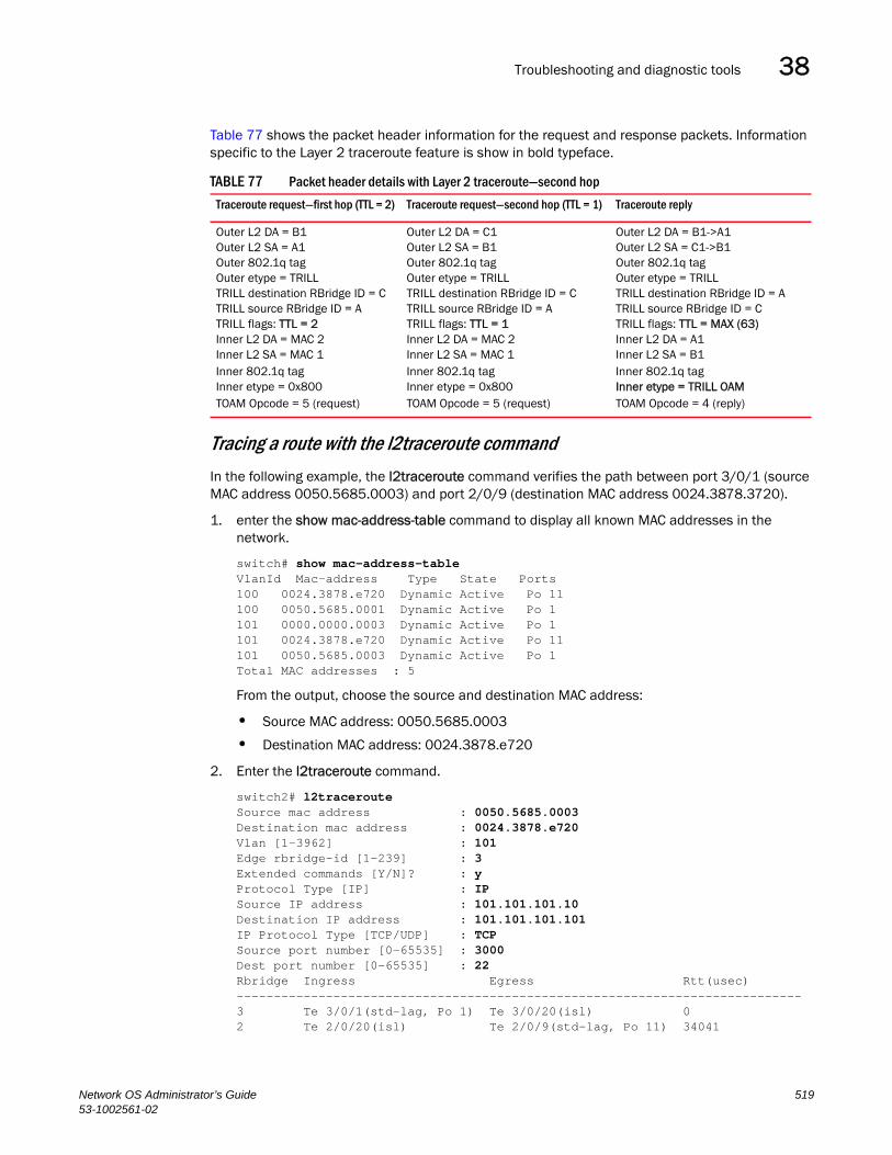
Troubleshooting and diagnostic tools 38
Table 77 shows the packet header information for the request and response packets. Information specific to the Layer 2 traceroute feature is show in bold typeface.
Tracing a route with the l2traceroute command
In the following example, the l2traceroute command verifies the path between port 3/0/1 (source MAC address 0050.5685.0003) and port 2/0/9 (destination MAC address 0024.3878.3720).
1. enter the show mac-address-table command to display all known MAC addresses in the network.
switch# show mac-address-table VlanId Mac-address Type State Ports100 0024.3878.e720 Dynamic Active Po 11100 0050.5685.0001 Dynamic Active Po 1101 0000.0000.0003 Dynamic Active Po 1101 0024.3878.e720 Dynamic Active Po 11101 0050.5685.0003 Dynamic Active Po 1Total MAC addresses : 5
From the output, choose the source and destination MAC address:
• Source MAC address: 0050.5685.0003
• Destination MAC address: 0024.3878.e720
2. Enter the l2traceroute command.
switch2# l2tracerouteSource mac address : 0050.5685.0003Destination mac address : 0024.3878.e720Vlan [1-3962] : 101Edge rbridge-id [1-239] : 3Extended commands [Y/N]? : yProtocol Type [IP] : IPSource IP address : 101.101.101.10Destination IP address : 101.101.101.101IP Protocol Type [TCP/UDP] : TCPSource port number [0-65535] : 3000Dest port number [0-65535] : 22Rbridge Ingress Egress Rtt(usec) ----------------------------------------------------------------------------3 Te 3/0/1(std-lag, Po 1) Te 3/0/20(isl) 02 Te 2/0/20(isl) Te 2/0/9(std-lag, Po 11) 34041
TABLE 77 Packet header details with Layer 2 traceroute—second hop
Traceroute request—first hop (TTL = 2) Traceroute request—second hop (TTL = 1) Traceroute reply
Outer L2 DA = B1Outer L2 SA = A1Outer 802.1q tagOuter etype = TRILLTRILL destination RBridge ID = CTRILL source RBridge ID = ATRILL flags: TTL = 2Inner L2 DA = MAC 2Inner L2 SA = MAC 1Inner 802.1q tagInner etype = 0x800TOAM Opcode = 5 (request)
Outer L2 DA = C1Outer L2 SA = B1Outer 802.1q tagOuter etype = TRILLTRILL destination RBridge ID = CTRILL source RBridge ID = ATRILL flags: TTL = 1Inner L2 DA = MAC 2Inner L2 SA = MAC 1Inner 802.1q tagInner etype = 0x800TOAM Opcode = 5 (request)
Outer L2 DA = B1->A1Outer L2 SA = C1->B1Outer 802.1q tagOuter etype = TRILLTRILL destination RBridge ID = ATRILL source RBridge ID = CTRILL flags: TTL = MAX (63)Inner L2 DA = A1Inner L2 SA = B1Inner 802.1q tagInner etype = TRILL OAMTOAM Opcode = 4 (reply)
Network OS Administrator’s Guide 51953-1002561-02

Troubleshooting and diagnostic tools38
Be advised of the following points:
• The MAC addresses used should be present in the MAC address-table (dynamic or static).
• The l2traceroute command can be used in VCS Fabric mode only.
• Make use of IP parameters to influence path selection.
Show commandsTable 78 lists some show commands that are often used for troubleshooting. Refer to the Network OS Command Reference for details of all show commands.
TABLE 78 Show commands used for troubleshooting
Command group
Commands Specific fields or purpose
System commands
show systemshow licenseshow running-configshow startup-configshow logging raslogshow versionshow chassisshow environmentshow vlan briefshow mac-address-tableshow process cpushow process memoryshow firmwaredownloadstatus
Interface commands
show interfaceshow mediashow ip int briefshow qos flowcontrol interface show qos queue interface show qos rcv-queue interface
show qos int
Check pause-framesCheck the CoS statisticsCheck packet drops, buffer consumption, real-time queue statisticsCheck the QoS configuration on an interface
Diagnostic commands
show diags statusshow diags post results detailedshow diag burninerrshowshow diag burninstatus
520 Network OS Administrator’s Guide53-1002561-02

Troubleshooting and diagnostic tools 38
Debug commandsYou can perform the following operations related to debugging features:
• To enable debugging on a feature, use the debug command.
debug feature required-keywords
• To check whether debugging is enabled on a feature, use the show debug command.
show debug feature
• To disable debugging, use the no debug command.
no debug feature required-keywords
Use caution when debugging in real time on a production switch because real-time debugging is CPU-intensive. Brocade recommends checking the debug output on a lab switch first, and then if the output looks acceptable, enable it on the production switch to get more data. In addition, to reduce CPU load, Brocade recommends using keywords such as events and summary that limit the extent of debugging rather than more comprehensive options such as detail and all.
Debugging operations are used mainly for debugging control plane protocols such as LACP and LLDP. For example, to view received LLDP packets on the console, use the following command.
switch# debug lldp packets all rx
If the switch is accessed via Telnet, enable logging using a terminal monitor.
The following are the most often used debug commands:
• debug lldp packets interface [rx | tx | both]
• debug lacp pdu [rx | tx]
Feature commands
show port-channel detailshow lacp countershow port-profile statusshow fcoe loginshow fcoe interface briefshow fcoe internal fcf-mac-addressshow lldp neighbors detailshow lldp statisticsshow qos interface all
VCS Fabric commands
show vcsshow fabric trunk allshow fabric allshow fabric islshow fabric islportsshow fabric route linkinfoshow fabric route multicastshow fabric route neighbor-stateshow fabric route pathinfoshow fabric route topologyshow name-server detail all
TABLE 78 Show commands used for troubleshooting (Continued)
Command group
Commands Specific fields or purpose
Network OS Administrator’s Guide 52153-1002561-02

Troubleshooting and diagnostic tools38
• debug spanning-tree bpdu [rx | tx] —Standalone mode only
• debug dot1x packet —Standalone mode only
SPAN port and traffic mirroringIn certain instances, you may need to examine packets in transit across links to understand the traffic pattern on a specific port. In such situations, Switched Port Analyzer (SPAN) can be configured to copy the traffic (with the desired direction) on the specific Ethernet port to a mirror port where a sniffing device is connected. You can then analyze the packets captured by the sniffing device.
switch(config)# monitor session 1switch(conf-mon-sess-1)# source tengigabitethernet 1/0/10 destination tengigabitethernet 1/0/15 direction both
switch# show monitor 1Session :1Description :Test SPAN SessionState :EnabledSource interface : 1/0/10 (Up)Destination interface : 1/0/15 (Up)Direction :Both
The source and destination ports must belong to the same eAnvil ASIC. The Brocade VDX 6720-24 and Brocade VDX 6730-32 switches have just one eAnvil ASIC, so source and destination can be any 10 GbE port. Other Brocade VDX switches have multiple eAnvil ASICs; Table 79 shows the mapping of ports to these ASICs.
The destination port cannot be an ISL, Layer 2, Layer 3, QoS, ACL, 802.1x, LAG member, LLDP, or port-profile port. The source port cannot be an ISL port. In VCS Fabric mode, only edge ports are eligible for mirroring.
TABLE 79 ASICs and ports
Network OS switch ASIC Port numbers
Brocade VDX 6720-60 and Brocade VDX 6730-76
0 te0/1 through te0/10
1 te0/11 through te0/20
2 te0/21 through te0/30
3 te0/31 through te0/40
4 te0/41 through te0/50
5 te0/51 through te0/60
Brocade VDX 6710 0 te0/1 through te0/6 and gi0/1 through gi0/14
1 gi0/15 through gi0/27
2 gi0/28 through gi0/48
522 Network OS Administrator’s Guide53-1002561-02

Troubleshooting and diagnostic tools 38
Hardware diagnosticsThe following diagnostic types currently exist:
Power-on self-test (POST)
• Offline diagnostics
Online diagnostics are not currently supported on Brocade VDX switches.
POST diagnostics
POST is run on bootup and the results are stored. Use the show diag post results command to view the stored results.
To enable POST, enter the diag post rbridge-id rbridge-id enable command.
Offline diagnostics
Offline diagnostics—otherwise known as system verification tests—are disruptive tests that check the individual hardware components thoroughly and report the findings. You must disable the chassis before running these tests. Do not run production traffic during this time.
Enter the diag systemverification command to run the entire set of offline diagnostics. This command can take up to two hours to finish, so Brocade recommends the less disruptive diag systemverification short command, which typically takes 10 to 15 minutes. Alternatively, you can run subsets of the offline commands that check various parts of the hardware. Table 80 shows the complete list of supported offline commands.
Table 81 lists the show commands that provide output from offline diagnostics.
TABLE 80 Offline diagnostic commands
Offline diagnostic command Purpose
diag burninerrclear Clears the errors that are stored in the nonvolatile storage during the burn-in process.
diag clearerror Clears the diagnostics failure status.
diag portledtest Runs various action modes on the port LEDs and validates the functionality.
diag portloopbacktest Sends frames between various ASICs on the switch and validates the ASIC functionality.
diag setcycle Configures all the parameters required for the system verification test.
diag systemverification Runs a combination of various hardware diagnostic tests.
diag turboramtest Performs a turbo static RAM (SRAM) test of the ASIC chips.
TABLE 81 Offline diagnostic show commands
Show offline diagnostic command Purpose
show diag burninerrshow Displays the errors that are stored in the nonvolatile storage during burn-in.
show diag burninstatus Displays the diagnostics burn-in status.
show diag setcycle Displays the current values used in system verification.
show diag status Displays the currently running diagnostics tests.
Network OS Administrator’s Guide 52353-1002561-02
Troubleshooting and diagnostic tools38
For details of the commands listed in Table 80 and Table 81, refer to the Network OS Command Reference.
Viewing routing information with the ‘show fabric route pathinfo’ command The show fabric route pathinfo command displays routing and statistical information from a source port index on the local switch to a destination port index on another switch in the same VCS Fabric cluster, a different VCS Fabric cluster, a connected Fabric OS backbone fabric, or Fabric OS edge fabric. This routing information describes the full path that a data stream travels between these ports, including all intermediate switches.
The routing and statistics information are provided by every switch along the path, based on the current routing table information and statistics calculated continuously in real time. Each switch represents one hop.
Use the show fabric route pathinfo command to display routing information from a source port on the local switch to a destination port on another switch. The command output describes the exact data path between these ports, including all intermediate switches.
To use the show fabric route pathinfo command across remote fabrics, you must specify both the VCS ID (or Fabric ID) and the routing bridge ID (or domain ID) of the remote switch. When obtaining path information across remote fabrics, the destination switch must be identified by its routing bridge ID or domain ID. Identifying the switch by name or WWN is not accepted.
For details about the show fabric route pathinfo command, refer to the Network OS Command Reference.
524 Network OS Administrator’s Guide53-1002561-02

Network OS Administrator’s Guide53-1002561-02
Appendix
A
TACACS+ Accounting ExceptionsIn this chapter•Command accounting limitations. . . . . . . . . . . . . . . . . . . . . . . . . . . . . . . . . 525
Command accounting limitationsTACACS+ command accounting is subject to the following limitations:
• The TACACS+ command accounting logs only the base command name. For example, if the command executed is secpolicy defined-policy SCC_POLICY, only the secpolicy command is logged in the TACACS++ server.
• the no radius-sever command is logged as radius-server command.
• A few commands are not accounted for. Refer to Table 82 for a listing of unsupported operational commands. Refer toTable 83 for a listing of unsupported configuration commands.
TABLE 82 Unsupported commands in privileged EXEC mode
Command name Command Description
cipherset Configures FIPS-compliant secure ciphers for LDAP and SSH
clear Clears the specified parameter
clear arp Clears Address Resolution Protocol (ARP) configuration data
clear counters Clears statistics from the switch
clear dot1x Clears IEEE 802.1X Port-Based Access Control configuration data
clear fcoe Clears FCoE configuration data
clear ip Clears Internet Protocol (IP) configuration data
clear lacp Clears Link Aggregation Control Protocol (LACP) configuration data
clear lldp Clears Link Layer Discovery Protocol(LLDP).configuration data
clear mac-address-table Clears the MAC address table.
clear mcagt Clears MCAGT agent
clear policy-map-counters
Clears the policy map counters
clear sflow Clears SFlow configuration data.
clear spanning-tree Clears spanning tree protocol (STP) configuration data
clear vrrp Clears Virtual Router Redundancy Protocol (VRRP) configuration data.
configure Configures access mode
copy Copies data
debug Sets debugging options
525
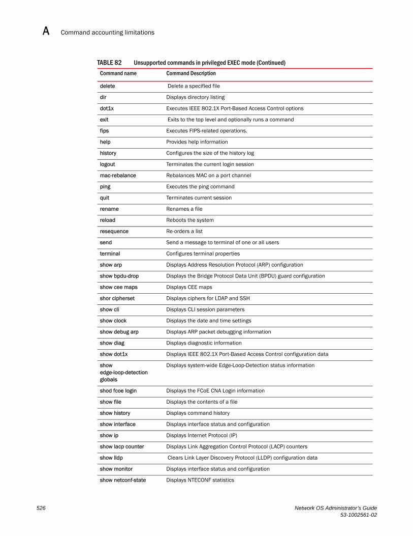
Command accounting limitationsA
delete Delete a specified file
dir Displays directory listing
dot1x Executes IEEE 802.1X Port-Based Access Control options
exit Exits to the top level and optionally runs a command
fips Executes FIPS-related operations.
help Provides help information
history Configures the size of the history log
logout Terminates the current login session
mac-rebalance Rebalances MAC on a port channel
ping Executes the ping command
quit Terminates current session
rename Renames a file
reload Reboots the system
resequence Re-orders a list
send Send a message to terminal of one or all users
terminal Configures terminal properties
show arp Displays Address Resolution Protocol (ARP) configuration
show bpdu-drop Displays the Bridge Protocol Data Unit (BPDU) guard configuration
show cee maps Displays CEE maps
shor cipherset Displays ciphers for LDAP and SSH
show cli Displays CLI session parameters
show clock Displays the date and time settings
show debug arp Displays ARP packet debugging information
show diag Displays diagnostic information
show dot1x Displays IEEE 802.1X Port-Based Access Control configuration data
show edge-loop-detection globals
Displays system-wide Edge-Loop-Detection status information
shod fcoe login Displays the FCoE CNA Login information
show file Displays the contents of a file
show history Displays command history
show interface Displays interface status and configuration
show ip Displays Internet Protocol (IP)
show lacp counter Displays Link Aggregation Control Protocol (LACP) counters
show lldp Clears Link Layer Discovery Protocol (LLDP) configuration data
show monitor Displays interface status and configuration
show netconf-state Displays NTECONF statistics
TABLE 82 Unsupported commands in privileged EXEC mode (Continued)
Command name Command Description
526 Network OS Administrator’s Guide53-1002561-02

Command accounting limitations A
show ntp Displays the active NTP server
show parser dump Displays parser dump
show policy-map Displays the configured rate-limiting policy maps
show port Displays port parameters
show port-channel Displays the port channel configuration
show port-profile Displays the port profile configuration
show qos Display Quality of Service (QoS) configuration
show running-config Displays the running configuration
show sflow Displays SFlow configuration
show spanning-tree Displays the Spanning-Tree configuration
show ssm Displays the switch services subsystem
show startup-db Displays the startup configuration
show storm-control Displays storm control configuration
show statistics Displays accounting information
show system Displays runtime system information
show rmon Displays the Remote Monitoring Protocol (RMON) configuration
show vcs Displays VCS information
show vlan Displays the VLAN configuration
show mac-address-table Displays the MAC address table
show startup-config Displays the contents of startup-configuration file
show zoning Displays zoning information
Traceroute Executes the traceroute command
TABLE 83 Unsupported commands in global configuration mode
Command name Command Description
abort Aborts the current configuration session
diag Manages diagnostic commands
do Executes an operational command while in global configuration mode
end Terminates the current configuration session
exit Exits from the current mode
help Provides help information
pwv Displays the current mode path
service Performs password encryption services
top Exits to the top level and optionally runs a command
no vlan Disables VLAN commands
TABLE 82 Unsupported commands in privileged EXEC mode (Continued)
Command name Command Description
Network OS Administrator’s Guide 52753-1002561-02

Command accounting limitationsA
528 Network OS Administrator’s Guide53-1002561-02

Network OS Administrator’s Guide53-1002561-02
Appendix
B
Supported time zones and regionsTime zones and regions supported by the Network Time Protocol are listed in the following tables.
• Africa—Table 84 on page 529
• America—Table 85 on page 530
• Antarctica—Table 86 on page 531
• Arctic—Table 87 on page 531
• Asia—Table 88 on page 531
• Atlantic—Table 89 on page 532
• Australia—Table 90 on page 532
• Europe—Table 91 on page 532
• Indian—Table 92 on page 533
• Pacific—Table 93 on page 533
AfricaTABLE 84 Region/city time zones in Africa
Africa/LuandaAfrica/OuagadougouAfrica/BujumburaAfrica/Porto-NovoAfrica/GaboroneAfrica/KinshasaAfrica/LubumbashiAfrica/BanguiAfrica/BrazzavilleAfrica/AbidjanAfrica/DoualaAfrica/DjiboutiAfrica/AlgiersAfrica/CairoAfrica/El_AaiunAfrica/AsmaraAfrica/CeutaAfrica/Addis_AbabaAfrica/LibrevilleAfrica/Accra
Africa/BanjulAfrica/ConakryAfrica/MalaboAfrica/BissauAfrica/NairobiAfrica/MonroviaAfrica/MaseruAfrica/TripoliAfrica/CasablancaAfrica/BamakoAfrica/NouakchottAfrica/BlantyreAfrica/MaputoAfrica/WindhoekAfrica/NiameyAfrica/LagosAfrica/KigaliAfrica/KhartoumAfrica/FreetownAfrica/Dakar
Africa/MogadishuAfrica/Sao_TomeAfrica/MbabaneAfrica/NdjamenaAfrica/LomeAfrica/TunisAfrica/Dar_es_SalaamAfrica/KampalaAfrica/JohannesburgAfrica/LusakaAfrica/Harare
529

AmericaB
AmericaTABLE 85 Region/city time zones in America
America/AntiguaAmerica/AnguillaAmerica/CuracaoAmerica/Argentina/Buenos_AiresAmerica/Argentina/CordobaAmerica/Argentina/San_LuisAmerica/Argentina/JujuyAmerica/Argentina/TucumanAmerica/Argentina/CatamarcaAmerica/Argentina/La_RiojaAmerica/Argentina/San_JuanAmerica/Argentina/MendozaAmerica/Argentina/Rio_GallegosAmerica/Argentina/UshuaiaAmerica/Aruba
America/GuatemalaAmerica/GuyanaAmerica/TegucigalpaAmerica/Port-au-PrinceAmerica/GuadeloupeAmerica/JamaicaAmerica/St_KittsAmerica/CaymanAmerica/St_LuciaAmerica/MarigotAmerica/AdakAmerica/MartiniqueAmerica/MontserratAmerica/Mexico_CityAmerica/Cancun
America/EdmontonAmerica/Cambridge_BayAmerica/YellowknifeAmerica/InuvikAmerica/Dawson_CreekAmerica/VancouverAmerica/WhitehorseAmerica/Thunder_BayAmerica/IqaluitAmerica/PangnirtungAmerica/ResoluteAmerica/Rankin_InletAmerica/WinnipegAmerica/Rainy_RiverAmerica/Regina
America/BarbadosAmerica/St_BarthelemyAmerica/La_PazAmerica/NoronhaAmerica/BelemAmerica/FortalezaAmerica/RecifeAmerica/AraguainaAmerica/MaceioAmerica/BahiaAmerica/Sao_PauloAmerica/Campo_GrandeAmerica/CuiabaAmerica/SantaremAmerica/Porto_Velho
America/MeridaAmerica/MonterreyAmerica/MazatlanAmerica/ChihuahuaAmerica/HermosilloAmerica/TijuanaAmerica/ManaguaAmerica/PanamaAmerica/LimaAmerica/MiquelonAmerica/Puerto_RicoAmerica/AsuncionAmerica/ParamariboAmerica/El_SalvadorAmerica/Grand_Turk
America/MontevideoAmerica/St_VincentAmerica/CaracasAmerica/TortolaAmerica/St_ThomasAmerica/New_YorkAmerica/DetroitAmerica/Kentucky/MonticelloAmerica/Indiana/IndianapolisAmerica/Indiana/VincennesAmerica/Indiana/KnoxAmerica/Indiana/WinamacAmerica/Indiana/MarengoAmerica/Indiana/VevayAmerica/Chicago
America/Boa_VistaAmerica/ManausAmerica/EirunepeAmerica/Rio_BrancoAmerica/NassauAmerica/BelizeAmerica/St_JohnsAmerica/HalifaxAmerica/Glace_BayAmerica/MonctonAmerica/Goose_BayAmerica/Blanc-SablonAmerica/MontrealAmerica/TorontoAmerica/Nipigon
America/Swift_CurrentAmerica/DawsonAmerica/SantiagoAmerica/BogotaAmerica/Costa_RicaAmerica/HavanaAmerica/DominicaAmerica/Santo_DomingoAmerica/GuayaquilAmerica/GrenadaAmerica/CayenneAmerica/GodthabAmerica/DanmarkshavnAmerica/ScoresbysundAmerica/Thule
America/Indiana/Tell_CityAmerica/Indiana/PetersburgAmerica/MenomineeAmerica/North_Dakota/CenterAmerica/North_Dakota/New_SalemAmerica/DenverAmerica/BoiseAmerica/ShiprockAmerica/PhoenixAmerica/Los_AngelesAmerica/AnchorageAmerica/JuneauAmerica/YakutatAmerica/NomeAmerica/Port_of_Spain
530 Network OS Administrator’s Guide53-1002561-02

Antarctica B
Antarctica
Arctic
Asia
TABLE 86 Region/city time zones in Antarctica
Antarctica/McMurdoAntarctica/South_PoleAntarctica/Rothera
Antarctica/MawsonAntarctica/DavisAntarctica/Casey
Antarctica/VostokAntarctica/DumontDUrvilleAntarctica/Syowa
TABLE 87 Region/city time zone in Arctic
Arctic/Longyearbyen
TABLE 88 Region/city time zones in Asia
Asia/DubaiAsia/KabulAsia/YerevanAsia/BakuAsia/DhakaAsia/BahrainAsia/BruneiAsia/ThimphuAsia/ShanghaiAsia/HarbinAsia/ChongqingAsia/UrumqiAsia/KashgarAsia/NicosiaAsia/TbilisiAsia/Hong_KongAsia/JakartaAsia/PontianakAsia/MakassarAsia/JayapuraAsia/JerusalemAsia/KolkataAsia/BaghdadAsia/TehranAsia/Amman
Asia/TokyoAsia/BishkekAsia/Phnom_PenhAsia/PyongyangAsia/SeoulAsia/KuwaitAsia/AlmatyAsia/QyzylordaAsia/AqtobeAsia/AqtauAsia/OralAsia/VientianeAsia/BeirutAsia/ColomboAsia/RangoonAsia/UlaanbaatarAsia/HovdAsia/ChoibalsanAsia/MacauAsia/Kuala_LumpurAsia/KuchingAsia/KatmanduAsia/MuscatAsia/ManilaAsia/Karachi
Asia/GazaAsia/QatarAsia/YekaterinburgAsia/OmskAsia/NovosibirskAsia/KrasnoyarskAsia/IrkutskAsia/YakutskAsia/VladivostokAsia/SakhalinAsia/MagadanAsia/KamchatkaAsia/AnadyrAsia/RiyadhAsia/SingaporeAsia/DamascusAsia/BangkokAsia/DushanbeAsia/DiliAsia/AshgabatAsia/TaipeiAsia/SamarkandAsia/TashkentAsia/Ho_Chi_MinhAsia/Aden
Network OS Administrator’s Guide 53153-1002561-02

AtlanticB
Atlantic
Australia
Europe
TABLE 89 Region/city time zones in Atlantic
Atlantic/BermudaAtlantic/Cape_VerdeAtlantic/CanaryAtlantic/Stanley
Atlantic/FaroeAtlantic/South_GeorgiaAtlantic/ReykjavikAtlantic/Madeira
Atlantic/AzoresAtlantic/St_Helena
TABLE 90 Region/city time zones in Australia
Australia/Lord_HoweAustralia/HobartAustralia/CurrieAustralia/Melbourne
Australia/SydneyAustralia/BrisbaneAustralia/LindemanAustralia/Adelaide
Australia/DarwinAustralia/PerthAustralia/Eucla
TABLE 91 Region/city time zones in Europe
Europe/AndorraEurope/TiraneEurope/ViennaEurope/MariehamnEurope/SarajevoEurope/BrusselsEurope/SofiaEurope/MinskEurope/ZurichEurope/PragueEurope/BerlinEurope/CopenhagenEurope/TallinnEurope/MadridEurope/HelsinkiEurope/ParisEurope/LondonEurope/GuernseyEurope/Oslo
Europe/GibraltarEurope/AthensEurope/ZagrebEurope/BudapestEurope/DublinEurope/Isle_of_ManEurope/RomeEurope/JerseyEurope/VaduzEurope/VilniusEurope/LuxembourgEurope/RigaEurope/MonacoEurope/ChisinauEurope/PodgoricaEurope/SkopjeEurope/MaltaEurope/Amsterdam
Europe/WarsawEurope/LisbonEurope/BucharestEurope/BelgradeEurope/KaliningradEurope/MoscowEurope/VolgogradEurope/SamaraEurope/StockholmEurope/LjubljanaEurope/BratislavaEurope/San_MarinoEurope/IstanbulEurope/KievEurope/UzhgorodEurope/ZaporozhyeEurope/SimferopolEurope/Vatican
532 Network OS Administrator’s Guide53-1002561-02
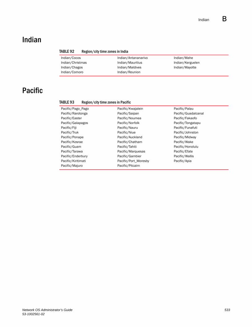
Indian B
Indian
Pacific
TABLE 92 Region/city time zones in India
Indian/CocosIndian/ChristmasIndian/ChagosIndian/Comoro
Indian/AntananarivoIndian/MauritiusIndian/MaldivesIndian/Reunion
Indian/MaheIndian/KerguelenIndian/Mayotte
TABLE 93 Region/city time zones in Pacific
Pacific/Pago_PagoPacific/RarotongaPacific/EasterPacific/GalapagosPacific/FijiPacific/TrukPacific/PonapePacific/KosraePacific/GuamPacific/TarawaPacific/EnderburyPacific/KiritimatiPacific/Majuro
Pacific/KwajaleinPacific/SaipanPacific/NoumeaPacific/NorfolkPacific/NauruPacific/NiuePacific/AucklandPacific/ChathamPacific/TahitiPacific/MarquesasPacific/GambierPacific/Port_MoresbyPacific/Pitcairn
Pacific/PalauPacific/GuadalcanalPacific/FakaofoPacific/TongatapuPacific/FunafutiPacific/JohnstonPacific/MidwayPacific/WakePacific/HonoluluPacific/EfatePacific/WallisPacific/Apia
Network OS Administrator’s Guide 53353-1002561-02

PacificB
534 Network OS Administrator’s Guide53-1002561-02

Index
Symbols
? (CLI help), 22
Numerics802.1x
LAG, 393overview, 393timeouts, 396
AAAA service requests, 191access
remote access policies, 198Access Control Lists
See ACLaccess interface, configuring, 283access mode, 277, 283ACL
configuration guidelines and restrictions, 340configuration procedures
applying a MAC ACL to a CEE interface, 342applying a MAC ACL to a VLAN interface, 343creating extended MAC ACL and adding rules,
341creating standard MAC ACL and adding rules, 341important notes, 340modifying a MAC ACL, 344removing a MAC ACL, 345reordering the sequence numbers, 345
default configuration, 340extended ACL, defined, 339overview, 267, 339standard ACL, defined, 339
ACLsFIPS, 222
activatingPOD, 81
Active DirectoryLDAP, 211
active IGMP, 463adding
alias members, 113admin login, 18alias
adding members, 113creating, 112deleting, 114removing members, 114
AMPPaccess-group, 255ACL, 255flow control, 254port-profile, 250port-profile states, 250priority, 254QoS profile, 254security profile, 255VLAN profile, 252
authenticationconfiguring, 191
authentication server, 393authenticator, 393
BBase Port Set, 80basic management TLV sets, 328bridge
forwarding delay, 301hello time, 303maximum aging time, 301priority, 300
Brocadeproprietary aggregation, 317
BUMconfiguration, 372considerations, 371
BUM storm control, 371
Network OS Administrator’s Guide 53553-1002561-02

CCA certificate, 212CEE interface
applying a MAC ACL, 342configuring for STP, RSTP, MSTP, 307configuring the hello time for MSTP, 310disable or enable STP on the interface, 314enabling and disabling, 280enabling as an edge port for RSTP, MSTP, 309enabling guard root for STP, RSTP, MSTP, 309enabling LACP, 322enabling port fast, 312path cost, 308restricting the port from becoming a root port for STP, RSTP, MSTP, 313
restricting the topology change notification for STP, RSTP, MSTP, 313
spanning-tree defaults, 298specifying a link type, 311specifying restrictions for an MSTP instance, 311specifying the port priority for STP, RSTP, MSTP, 312
cerutil, 212chassis ID (CID)
card usage, 471critical SEEPROM data, 471non-critical SEEPROM data, 471
chassis ID(CID) recovery tool, 472chassis name, 26
setting the, 27Cisco interoperability, disabling for MSTP, 304Cisco interoperability, enabling for MSTP, 304classifier groups, VLAN, 286classifier rules, VLAN, 285CLI, 18CLI, CEE
command completion, 23command modes, 18command syntax, 22configuration guidelines and restrictions, 17displaying commands, 22help, 22keyboard shortcuts, 21output modifiers, 23RBAC permissions, 18
color-based priority mapping, 381command completion, CEE CLI, 23command line interface, 18, 25command modes, CEE, 18command output modifiers, 23
command syntax, 22configuration, 51
backup, 56default, 53display, 54in Brocade VCS Fabric mode, 59restore, 56restore default, 57running, 53save, 54startup, 53, 54
configuration file, 51display settings, 51save to a host, 51
configuration managementsaving changes, 17
configureFCoE VLAN, 280
configuringauthentication, 191LINUX RADIUS server, 197
congestion controlQoS, 364queuing, 265
connectionserial, 25
console, 25contacting your switch support provider, 44converged mode, 277creating
alias, 112
DData Center Bridging (DCB) Capability Exchange Protocol
See DCBXDCB map, configuring, 377DCB maps, verifying, 379DCB provisioning map, applying, 378DCBX
Enhanced Transmission Selection, 330overviewPriority Flow Control, 330
default account, 26deleting
alias, 114dictionary.brocade, 197displaying
configuration settings, 51
536 Network OS Administrator’s Guide53-1002561-02

Double POD License, 80dynamic link aggregation, 316Dynamic POD license, 72, 76, 78Dynamic Ports on Demand, 80
EEAP, 393edge detection, 307edge port, enabling a CEE interface as an edge port for
RSTP, MSTP, 309Enhanced Transmission Selection
See ETSERR, 307error disable timeout, 302error disable timeout interval, 302Ethernet port, 25Ethernet, forwarding, 263ETS
overviewpriority grouping of IPC, LAN, and SAN traffic, 330
FFCoE
Layer 2 Ethernet overview, 263overview, 259queuing, 270terminology, 260VLAN forwarding, 264
FCoE initialization protocolSee FIP
Fibre Channel Association, xxxvifile
delete, 51rename, 51
file management, 51filtering VLAN ingress, 277FIP
FIP discovery, 268login, 269logout, 269name server, 270registered state change notification (RSCN), 270
FIPScertificates, deleting, 227certificates, installing, 227certificates, verifying, 227conditional tests, 217conditional tests, enabling, 221KATs, enabling, 221selftests, 221zeroization, 216, 221, 225
FIPS-compliant stateACLs for, 222enabling, 219LDAP, configuring for, 225
firmware, 61decompressing, 65download, 61download from USB, 67remote download, 66show version, 64upgrades, 65
firmware download, 70USB device, 67
flashdeleting a file, 52listing contents, 52renaming a file, 52
flash memory, 51flow control, 268frame classification, incoming, 265
Gguard root, enabling on a CEE interface, 309
HHA failover, 185hello time, 310hops, configuring for MSTP, 305host name, 26
setting the, 26
IIAS
remote access policies, 198IEEE 802.1 organizational TLV set, 329
Network OS Administrator’s Guide 53753-1002561-02

IEEE 802.3 organizational TLV set, 329IGMP
interface, 465interval, 466mrouter, 465MRT, 466querier, 466query-interval, 465tcn, 465timer, 465vlan, 465
incoming frame classification, 265ingress VLAN filtering, 277instance
MSTP, mapping a VLAN to, 305specifying restrictions for an MSTP instance, 311
interface, 271, 272, 280IP route management
configuring default route, 428configuring static routes, 428how best routes are determined, 427overview, 427
iSCSI priority, 335
Kkeyboard shortcuts, CEE CLI, 21
LLACP
configuration guidelines and restrictions, 322configuration procedures
clearing counters, 323configuring system priority, 323configuring timeout period, 323displaying LACP information, 324enabling on a CEE interface, 322important notes, 322
default LACP configuration, 322overviewtroubleshooting tips, 324
LAGs802.1x, 393distribution process, 317overview
Layer 2ACLEthernet overview, 263
Layer 2 Ethernet, 263Layer 2 forwarding, 263Layer 3 feature restrictions, 380LDAP, 212
Active Directory, 211attributes, 210cerutil, 212maprole, 212role, 211
ldapca, 212license, 71
Dynamic Ports on Demand, 72expiration, 74individual, 74permanent, 73removing, 78reservation, 84temporary, 73time-based, 73universal, 74upgrade, 75VCS Fabric license, 72
license ID, 73licenses
remove feature, 78Licensing, 71link aggregation
Brocade-proprietary, 317dynamic, 316LACP, 316LAG distribution process, 317LAGs, 316overview, 208, 315static, 317
Link Aggregation Control ProtocolSee LACP
link aggregation groupSee LAGs
Link Layer Discovery ProtocolSee LLDP
link type, specifying, 311Linux, configuring RADIUS on, 197
538 Network OS Administrator’s Guide53-1002561-02

LLDPconfiguration guidelines and restrictions, 331configuration procedures
clearing LLDP-related information, 338disabling LLDP globally, 332displaying LLDP-related information, 338enabling LLDP globally, 331global command options, 332important notes, 331interface-level command options, 337
DCBX overviewdefault configuration, 331Layer 2 topology mapping, 328overview, 327TLV sets, 328
loginFIP, 269
logoutFIP, 269
LSAN zone, 105example of, 134naming, 133
LSAN zoningconfiguration of, 133
MMAC addresses
configuration guidelines and restrictions, 279management port, 25map, 271, 272maprole, 212MSTP
configuration proceduresPVST configuration, 299
default configuration, 298overview, 295
MTU, configuring, 280multicast rate limiting, QoS, 370Multiple Spanning Tree Protocol
See MSTP
Nname server, 270network
flow control, 268trunking, 267
OOpen Shortest Path First (OSPF), 431OSPF
area border routers (ABRs), 432area ranges, 440autonomous system boundary routers (ASBRs), 432backbone area, 431configuration, 436designated routers, 435Link State Advertisements, 438not-so-stubby areas, 439supported platforms, 431totally stubby areas, 438VCS environment, 433virtual links, 441
output modifiers, CEE CLI, 23overview
ACL, 339link aggregation, 208, 315MSTP, 295PVST, 297RSTP, 292STP, 289
Ppaperpack, 71password, 26path cost
CEE interface, configuring for STP, RSTP, MSTP, 308port channel, 302
PEAP, 393POD
activating, 81port
activating POD, 81port assignment
release, 84port assignments
display, 82override, 83reserve, 83
port configuration for STP, RSTP, MSTP, 307port fast, enabling on a CEE interface, 312port priority, specifying on a CEE interface, 312
Network OS Administrator’s Guide 53953-1002561-02

Ports on DemandBase port set, 80Double POD set, 80port assignments, 81Single POD set, 80
Priority Flow Control (PFC), 330priority group table, mapping, 377priority mapping, QoS, 350priority-table, mapping, 378PVST
default configuration, 298overview, 297
QQoS
configuration proceduresactivating CoS-to-Traffic-Class mapping, 360activating DSCP-to-Traffic-Class mapping, 363applying a CEE provisioning map, 378applying a CoS-to-CoS mutation QoS map, 353applying a DCB provisioning map, 378applying a DSCP mutation map, 356applying a DSCP-to-COS mutation map, 357changing the multicast Tail Drop threshold, 365configuring Brocade VCS fabric QoS, 379configuring CoS thresholds, 365configuring QoS trust mode, 352configuring RED profiles, 366configuring the DSCP trust mode, 354configuring user priority mappings, 352creating a CEE map, 377creating a CoS-to-CoS mutation QoS map, 353creating a DCB map, 377creating a DSCP mutation map, 355creating a DSCP-to-COS mutation map, 357creating a receive queue multicast rate-limit, 371defining a priority group table, 377defining a priority-table map, 378enabling an Ethernet PFC, 370enabling Ethernet pause, 369enabling RED prfile to use CoS priority, 367mapping a priority group table, 377mapping a priority-table, 378mapping CoS-to-Traffic-Class, 360mapping DSCP-to-Traffic-Class, 361scheduling the QoS multicast queue, 375scheduling the QoS queue, 374verifying a DSCP-to-COS mutation map, 358verifying CEE maps, 379verifying CoS trust, 352verifying CoS-to-CoS mutation QoS mapping, 354verifying CoS-to-Traffic-Class mapping, 361verifying DCB maps, 379verifying DSCP mutation mapping, 356verifying DSCP trust, 355verifying DSCP-to-Traffic-Class mapping, 363,
540 Network OS Administrator’s Guide53-1002561-02

367congestion control, 364data center bridging map configuration overview, 375multicast rate limiting, 370overview, 247, 349, 401, 407port-based policer
binding the policy map to an interface, 386configuring a class map, 381configuring a police priority map, 382configuring parameters for a class map, 385configuring the policy map, 383considerations and limitations, 390displaying policing settings and policy maps, 388overview, 380policer binding rules, 386policing parameters, 387
queuingtraffic class mapping, 358user-priority mapping, 350
queuing overview, 350rewriting frame header field, 350scheduling, 372
Quality of ServiceSee QoS
querierinterval, 466MRT, 466VLAN, 466
queuingcongestion control, 265FCoE, 270QoS, 350
RRADIUS, 393RADIUS server
LINUX configuration, 197Rapid Spanning Tree Protocol
See RSTPRBAC permissionsregion name, specifying for MSTP, 305registered state notification protocol (RSCN), 270remote access policies, 198remove feature, 78removing
alias members, 114licensed feature, 78
revision number, specifying for MSTP, 306RJ-45, 25
Role-Based Action ControlSee RBAC
root port, CEE interface, restricting for Spanning Tree, 313root_inc, 307RSTP
configuration guidelines and restrictionsMSTP configuration guidelines and restrictions,
292configuration procedures, 299default configuration, 298overview, 292
Ssaving configuration, 17scheduling, QoS, 372secure shell, 25security
IAS remote access policies, 198serial connection, 25Single POD License, 80SNMP v3, 90Spanning Tree Protocol
See STPspanning-tree defaults, 298SSH, 25static link aggregation, 317STP
configuration guidelines and restrictions, 292configuration procedures, 299default configuration, 298overview, 289VDX switches, 289
supplicant, 393switch, 26
attributes, 26certificates, deleting for FIPS, 227certificates, installing for FIPS, 227certificates, verifying for FIPS, 227port configuration, 283
switchType, 28system priority, configuring for LACP, 323
TTelnet, 25telnet, 18time-based licenses, 73
Network OS Administrator’s Guide 54153-1002561-02

timeout period, configuring for LACP, 323TLV sets
basic management TLV, 328IEEE 802.1 organizational TLV set, 329IEEE 802.3 organizational TLV set, 329
topology change notification, CEE interface, restricting for Spanning Tree, 313
topology mapping, LLDP, 328traffic class mapping, QoS, 358transmit hold count, 304troubleshooting tips, LACP, 324trunk interface, configuring, 283trunk mode, 277, 283trunking, 267
UUSB, 56USB device, 67user-priority mapping, QoS, 350
VVCS restrictions for DSCP features, 380Virtual LANs
See VLANVirtual Router Redundancy Protocol (VRRP), 445VLAN
applying a MAC ACL, 343configuration guidelines and restrictions, 279configuration procedures
configuring a CEE interface as a Layer 2 switch port, 283
configuring a CEE interface as an access or trunk
interface, 283configuring the MTU on an interface, 280displaying VLAN information, 287enabling and disabling a CEE interface, 280important notes, 280VLAN classifier groups, 286VLAN classifier rules, 285
default configuration, 279FDB
overview, 279forwarding, 264important management notes, 280ingress VLAN filtering, 277overview, 277tagging, 264
VRRP, 446backup, 447control packets, 448gratuitous ARP, 448master, 447multigroup configuration, 454owner, 446track ports, 450track priority, 450virtual router address, 446virtual router group, 446
VRRP-E, 446packet routing with short-path forwarding, 453short-path forwarding, 451
Zzeroization, 216, 221, 225zone
alias, adding members, 113alias, deleting, 114alias, removing members, 114aliases, creating and managing, 112configuration, definition, 107creating, 115deleting, 117member, adding, 112, 113, 114, 116member, deleting, 114, 117merging, 127resources, optimizing, 103splitting a fabric, 129WWN, adding, 112, 113, 114, 116WWN, deleting, 114, 117zone configuration, adding to, 121
542 Network OS Administrator’s Guide53-1002561-02

zone configurationcreating, 120deleting, 123deleting all, 124disabling, 123enabling, 122zone, adding, 121zone, removing from, 121
zoningdatabase size for, 111default mode, setting, 111default modes, All Access, 110default modes, No Access, 111default modes, overview, 110defined configuration, 107defined configuration, viewing, 118downgrade, 109enabled configuration, 107enabled configuration, viewing, 119example of, 126LSAN configuration, 133LSAN, example of, 134LSAN, overview, 105management of, 109objects for, 106, 107overview, 103supported firmware, 108transaction abort, 124transaction commit, 110
Network OS Administrator’s Guide 54353-1002561-02

544 Network OS Administrator’s Guide53-1002561-02