network security - uclouvain · c. kaufman, r. perlman and m. speciner, network security : private...
TRANSCRIPT
© O. Bonaventure, 2008Network Security/2008.2
Network Security
Olivier Bonaventure
IP Networking LabDepartment of Computing Science and Engineering
Université catholique de Louvain (UCL)Place Sainte-Barbe, 2, B-1348, Louvain-la-Neuve (Belgium)
http://inl.info.ucl.ac.be
Part 2 : Networking
1
© O. Bonaventure, 2008Network Security/2008.2
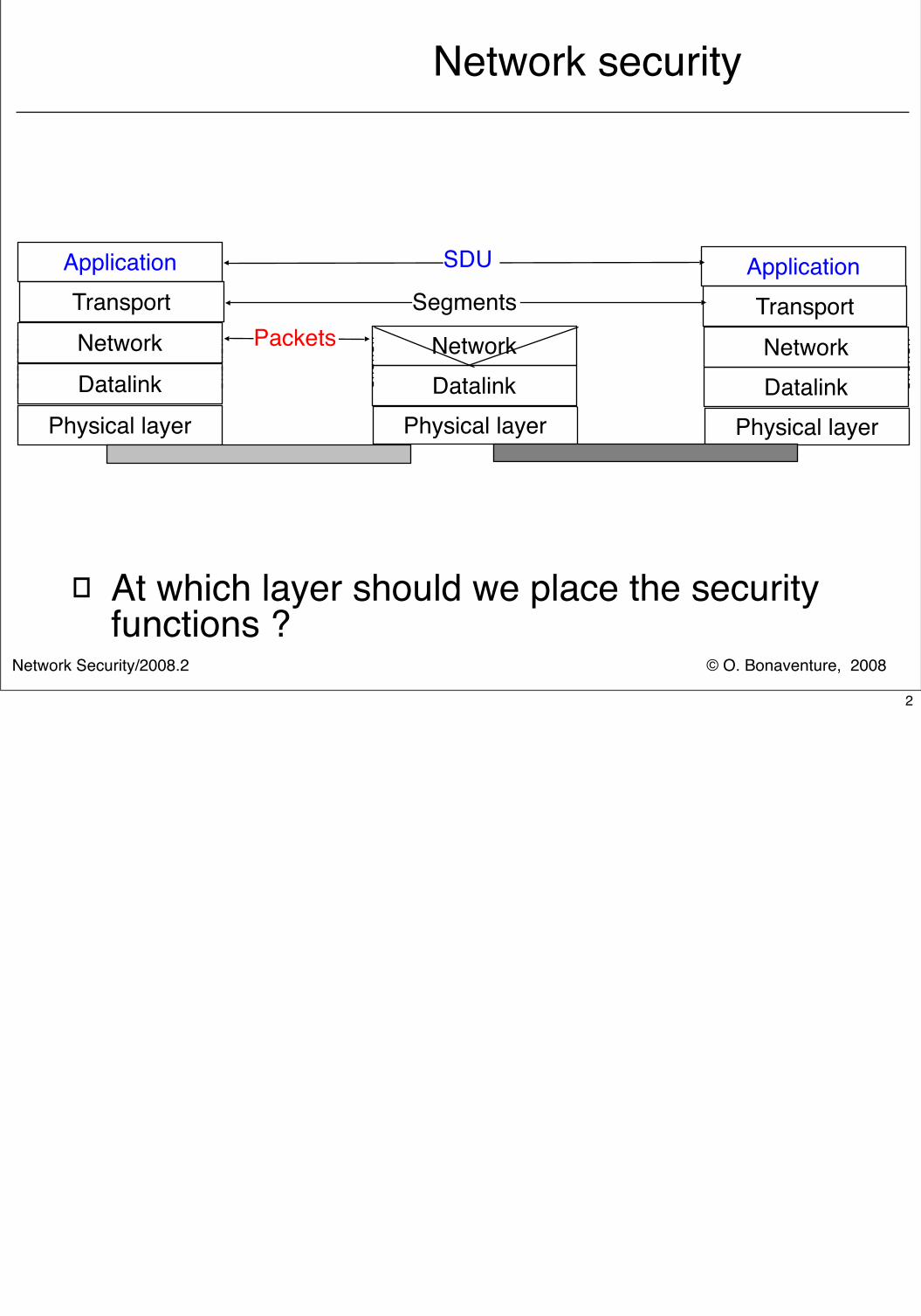
Network security
� At which layer should we place the security functions ?
Physical layer Physical layer
Datalink DatalinkNetworkNetwork
Physical layerDatalinkNetwork
SDUApplication ApplicationTransport TransportSegments
Packets
2
© O. Bonaventure, 2008Network Security/2008.2
Internet and Network security
� Crypto building blocks� Application-layer security
� Secure Socket Layer� Transport-layer security� Network-layer security
3
© O. Bonaventure, 2008Network Security/2008.2
Cryptographical building blocksHash functions
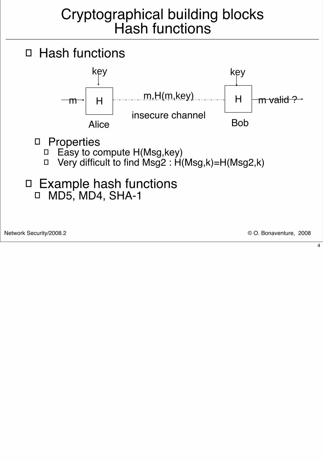
� Hash functions
� Properties� Easy to compute H(Msg,key) � Very difficult to find Msg2 : H(Msg,k)=H(Msg2,k)
� Example hash functions� MD5, MD4, SHA-1
Alice Bob
H Hm
key key
m,H(m,key)
insecure channelm valid ?
4
© O. Bonaventure, 2008Network Security/2008.2
Cryptographical building blocksSecret-key cryptography
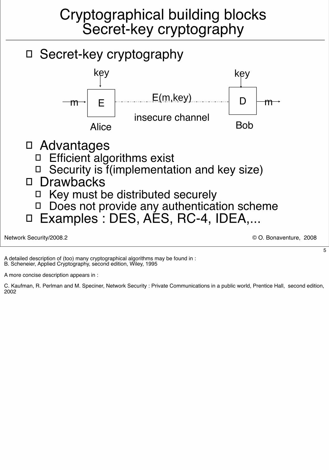
� Secret-key cryptography
� Advantages� Efficient algorithms exist� Security is f(implementation and key size)
� Drawbacks� Key must be distributed securely� Does not provide any authentication scheme
� Examples : DES, AES, RC-4, IDEA,...
Alice Bob
E Dm
key key
E(m,key)
insecure channelm
5A detailed description of (too) many cryptographical algorithms may be found in :B. Scheneier, Applied Cryptography, second edition, Wiley, 1995
A more concise description appears in :
C. Kaufman, R. Perlman and M. Speciner, Network Security : Private Communications in a public world, Prentice Hall, second edition, 2002
© O. Bonaventure, 2008Network Security/2008.2
Cryptographical building blocksPublic-key cryptography
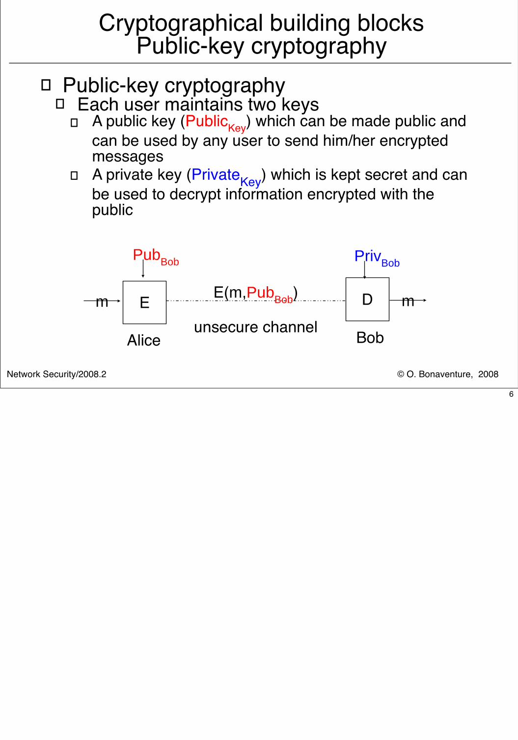
� Public-key cryptography� Each user maintains two keys
� A public key (PublicKey) which can be made public and can be used by any user to send him/her encrypted messages
� A private key (PrivateKey) which is kept secret and can be used to decrypt information encrypted with the public
Alice Bob
E Dm
PubBob PrivBob
E(m,PubBob)
unsecure channelm
6
© O. Bonaventure, 2008Network Security/2008.2
Cryptographical building blocks Public-key cryptography (2)
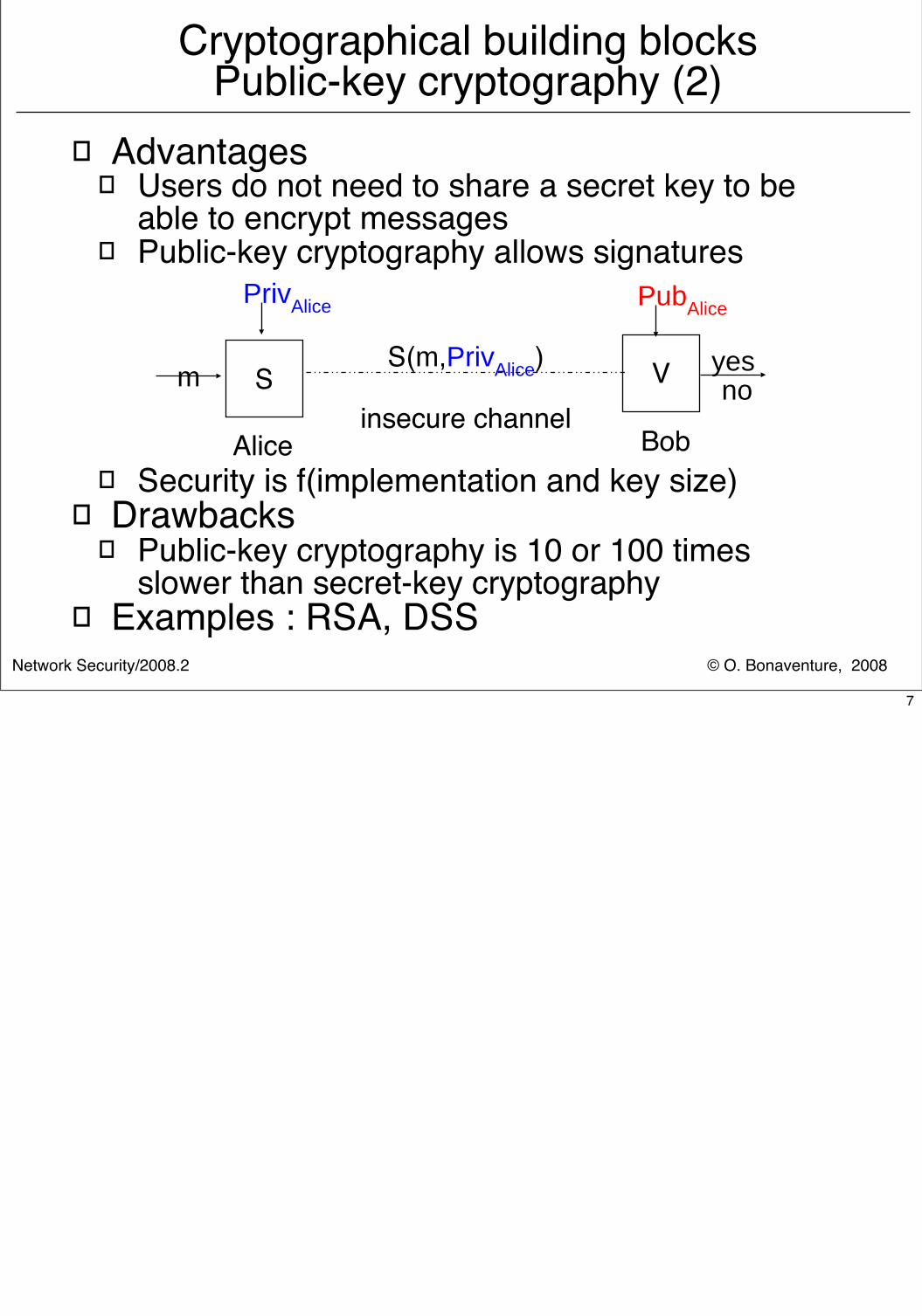
� Advantages� Users do not need to share a secret key to be
able to encrypt messages� Public-key cryptography allows signatures
� Security is f(implementation and key size)� Drawbacks
� Public-key cryptography is 10 or 100 times slower than secret-key cryptography
� Examples : RSA, DSS
Alice Bob
S Vm
PrivAlice PubAlice
S(m,PrivAlice)
insecure channel
yes no
7
© O. Bonaventure, 2008Network Security/2008.2
Internet and Network security
� Crypto building blocks� Application-layer security
� Secure Socket Layer� Transport-layer security� Network-layer security
8
© O. Bonaventure, 2008Network Security/2008.2
Building a simple secure protocol suitable for e-Commerce applications
� Problems to solve� How to authenticate the server ?
� How to authenticate the client ?
� How to agree on an encryption key ?
� How to encrypt data ?
9This section is partially based on :
C. Kaufman, R. Perlman, M. Speciner, Network Security : Private communication in a Public world, Prentice Hall
© O. Bonaventure, 2008Network Security/2008.2
How to authenticate the server ?
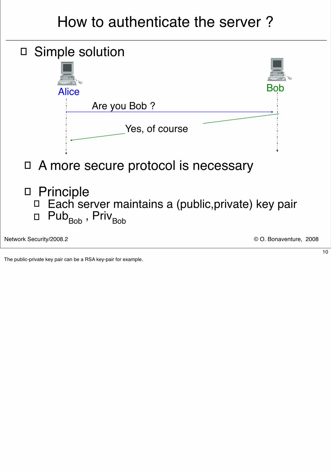
� Simple solution
Alice BobAre you Bob ?
Yes, of course
� A more secure protocol is necessary
� Principle� Each server maintains a (public,private) key pair� PubBob , PrivBob
10The public-private key pair can be a RSA key-pair for example.
© O. Bonaventure, 2008Network Security/2008.2
How to authenticate the server (2) ?
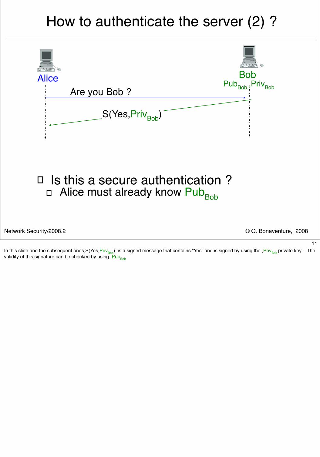
� Is this a secure authentication ?� Alice must already know PubBob
Alice BobAre you Bob ?
S(Yes,PrivBob)
PubBob,,PrivBob
11In this slide and the subsequent ones,S(Yes,PrivBob) is a signed message that contains “Yes” and is signed by using the ,PrivBob private key . The validity of this signature can be checked by using ,PubBob
© O. Bonaventure, 2008Network Security/2008.2
How to authenticate the server (3) ?
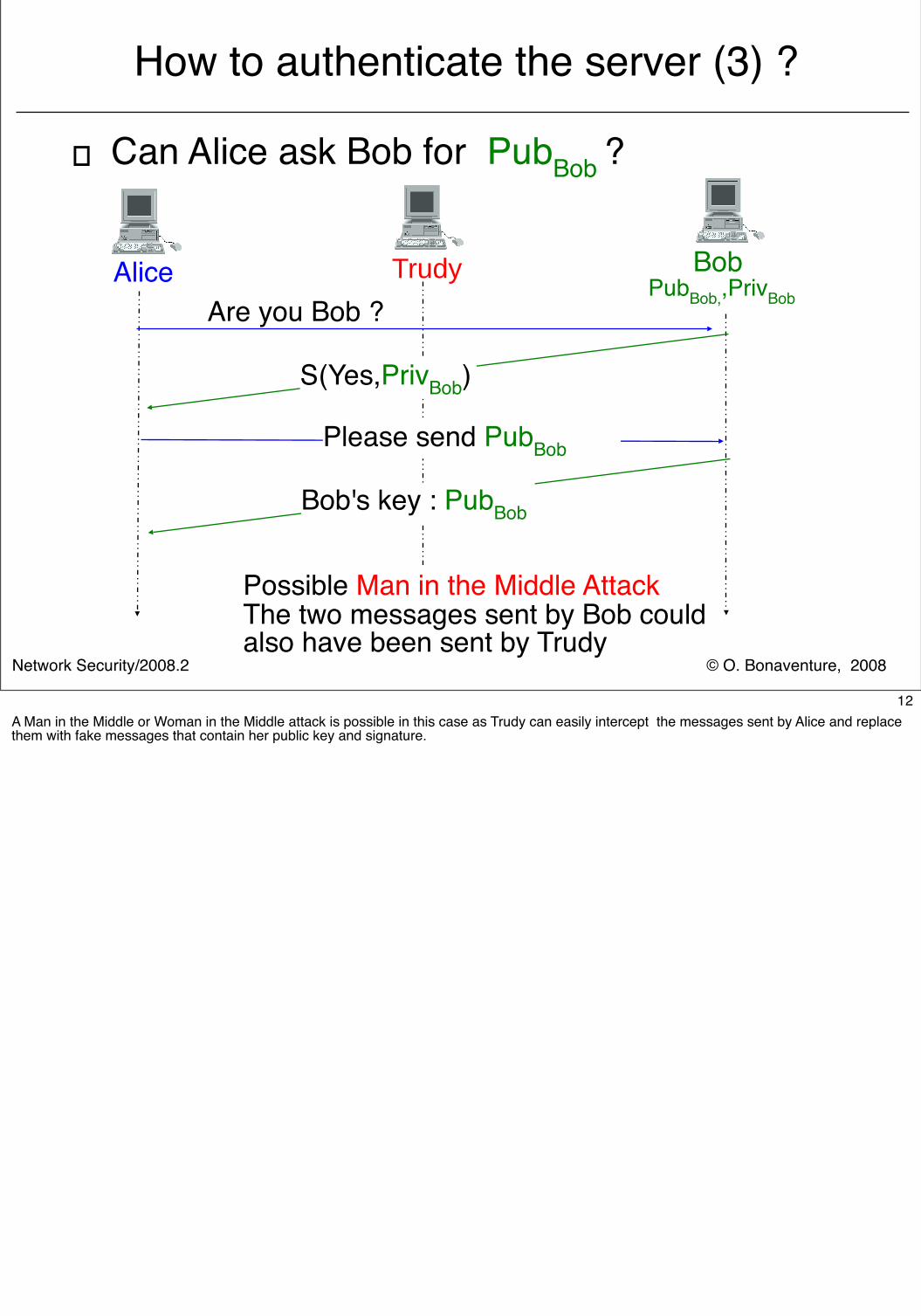
� Can Alice ask Bob for PubBob ?
Alice BobAre you Bob ?
S(Yes,PrivBob)
PubBob,,PrivBobTrudy
Please send PubBob
Possible Man in the Middle AttackThe two messages sent by Bob couldalso have been sent by Trudy
Bob's key : PubBob
12A Man in the Middle or Woman in the Middle attack is possible in this case as Trudy can easily intercept the messages sent by Alice and replace them with fake messages that contain her public key and signature.
© O. Bonaventure, 2008Network Security/2008.2
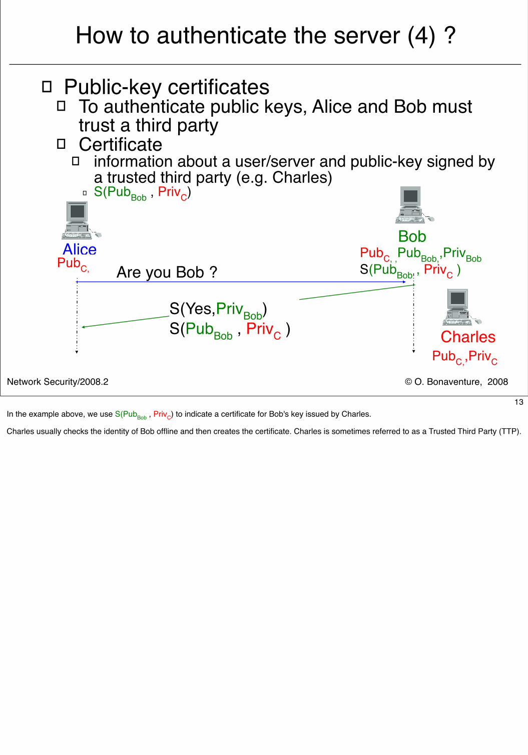
How to authenticate the server (4) ?
� Public-key certificates� To authenticate public keys, Alice and Bob must
trust a third party� Certificate
� information about a user/server and public-key signed by a trusted third party (e.g. Charles)
� S(PubBob , PrivC)
AliceBob
Are you Bob ?
S(Yes,PrivBob)S(PubBob , PrivC )
PubC, ,PubBob,,PrivBobS(PubBob , PrivC )
CharlesPubC,,PrivC
PubC,
13In the example above, we use S(PubBob , PrivC) to indicate a certificate for Bob's key issued by Charles.
Charles usually checks the identity of Bob offline and then creates the certificate. Charles is sometimes referred to as a Trusted Third Party (TTP).
© O. Bonaventure, 2008Network Security/2008.2
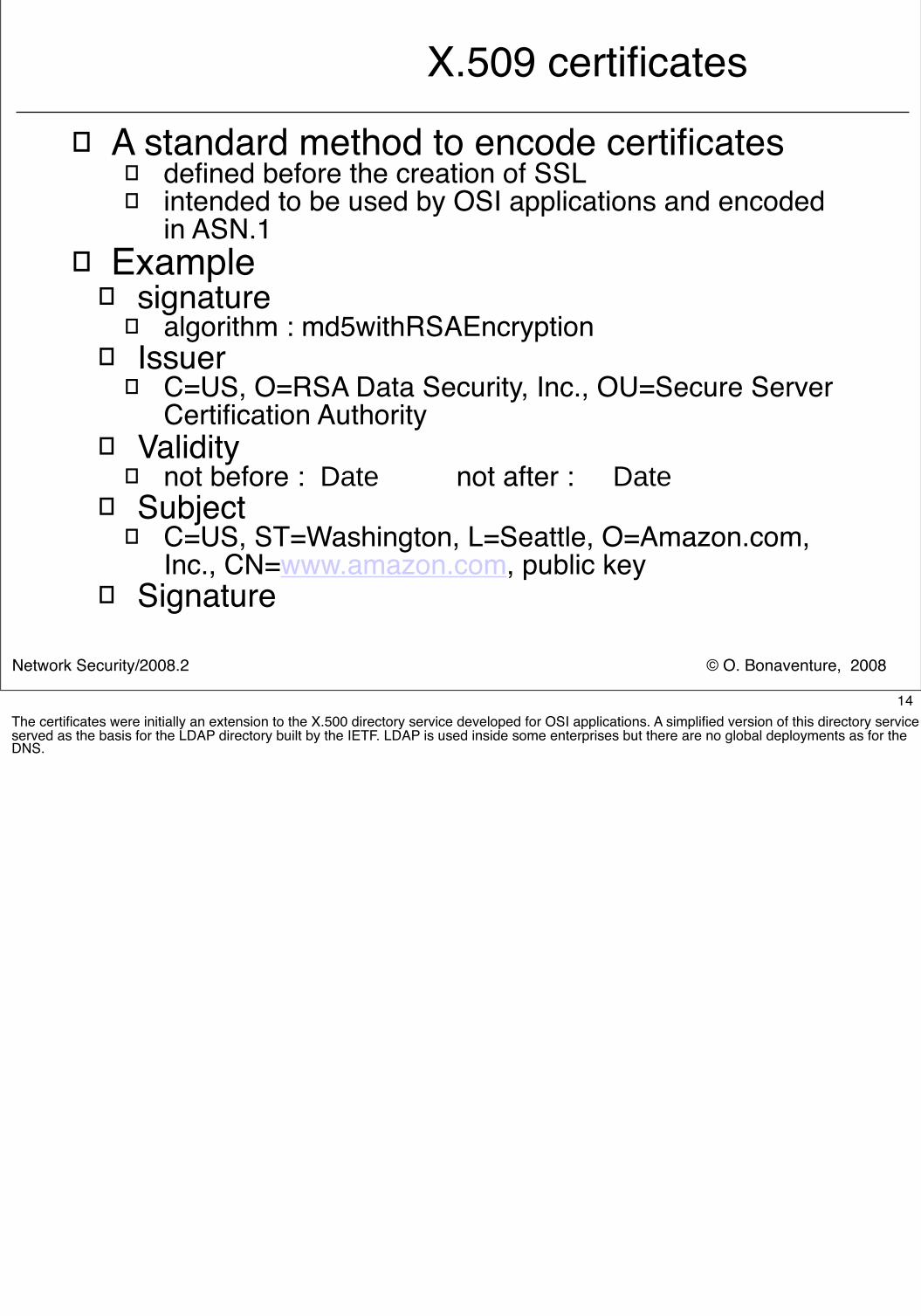
X.509 certificates� A standard method to encode certificates
� defined before the creation of SSL� intended to be used by OSI applications and encoded
in ASN.1� Example
� signature� algorithm : md5withRSAEncryption
� Issuer� C=US, O=RSA Data Security, Inc., OU=Secure Server
Certification Authority� Validity
� not before : Date not after : Date� Subject
� C=US, ST=Washington, L=Seattle, O=Amazon.com, Inc., CN=www.amazon.com, public key
� Signature
14The certificates were initially an extension to the X.500 directory service developed for OSI applications. A simplified version of this directory service served as the basis for the LDAP directory built by the IETF. LDAP is used inside some enterprises but there are no global deployments as for the DNS.
© O. Bonaventure, 2008Network Security/2008.2
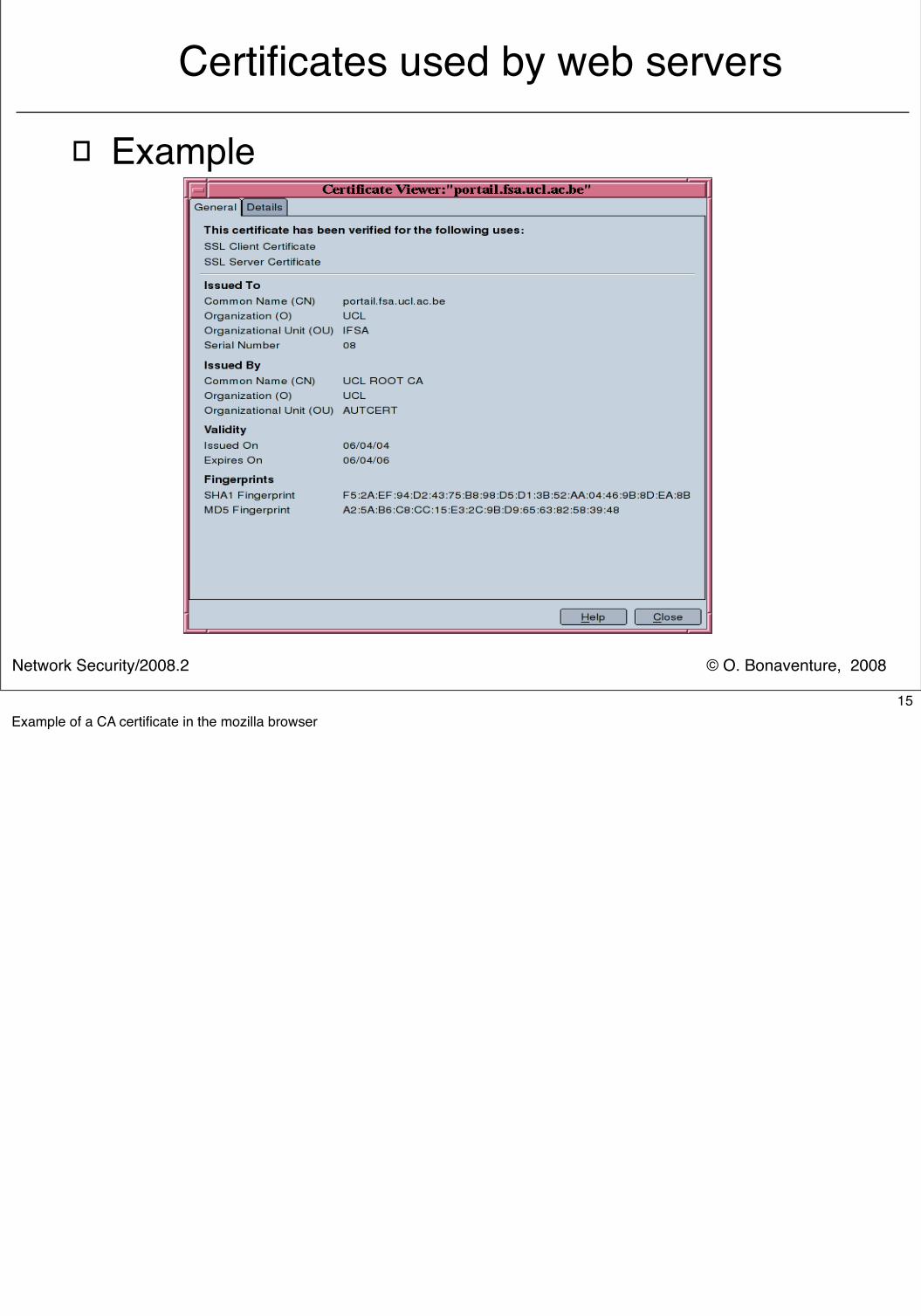
Certificates used by web servers
� Example
15Example of a CA certificate in the mozilla browser
© O. Bonaventure, 2008Network Security/2008.2
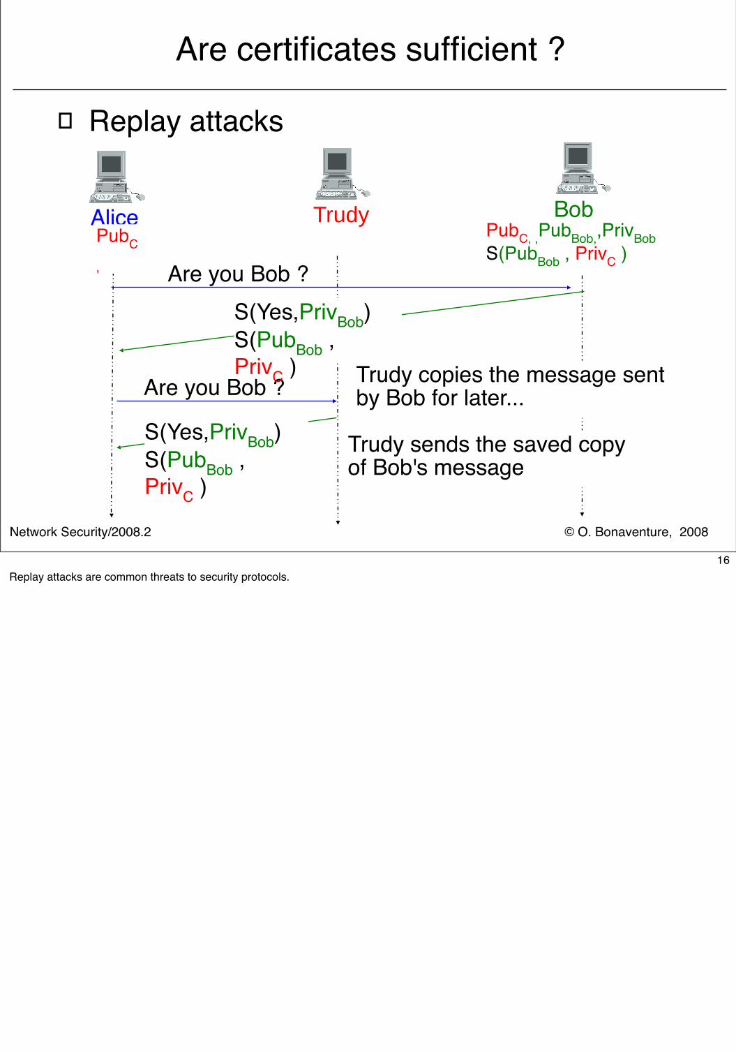
Are certificates sufficient ?
� Replay attacks
Alice Bob
Are you Bob ?
Trudy
Are you Bob ? Trudy copies the message sentby Bob for later...
Trudy sends the saved copyof Bob's message
S(Yes,PrivBob)S(PubBob , PrivC )
S(Yes,PrivBob)S(PubBob , PrivC )
PubC, ,PubBob,,PrivBobS(PubBob , PrivC )
PubC
,
16Replay attacks are common threats to security protocols.
© O. Bonaventure, 2008Network Security/2008.2
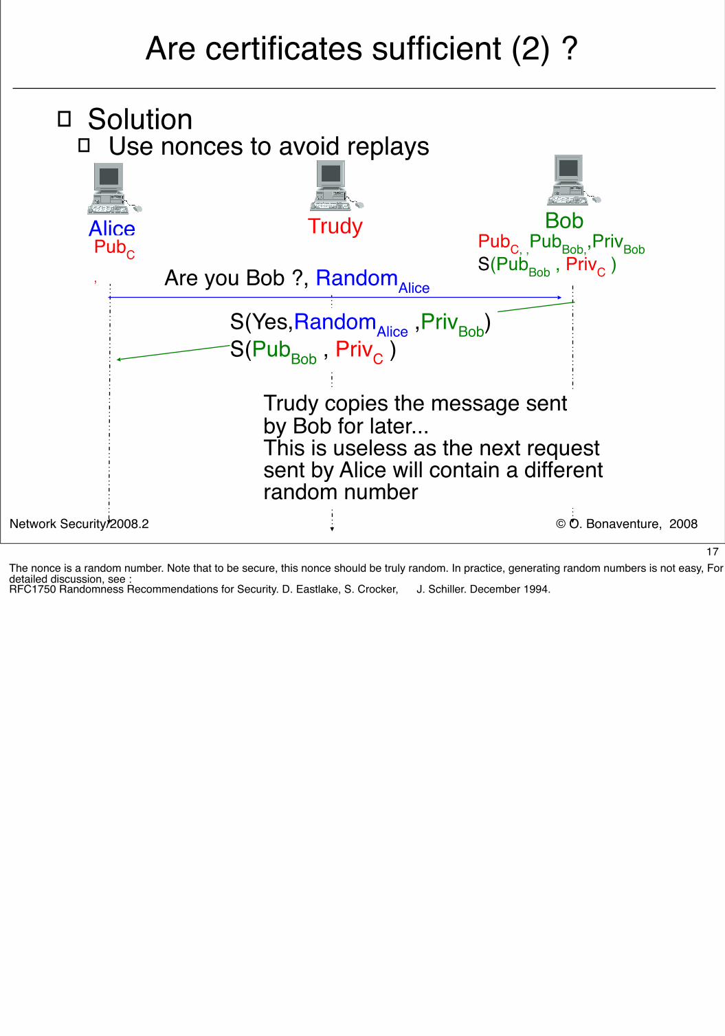
Are certificates sufficient (2) ?
� Solution� Use nonces to avoid replays
Alice Bob
Are you Bob ?, RandomAlice
Trudy
Trudy copies the message sentby Bob for later...This is useless as the next requestsent by Alice will contain a differentrandom number
S(Yes,RandomAlice ,PrivBob)S(PubBob , PrivC )
PubC, ,PubBob,,PrivBobS(PubBob , PrivC )
PubC
,
17The nonce is a random number. Note that to be secure, this nonce should be truly random. In practice, generating random numbers is not easy, For a detailed discussion, see :RFC1750 Randomness Recommendations for Security. D. Eastlake, S. Crocker, J. Schiller. December 1994.
© O. Bonaventure, 2008Network Security/2008.2
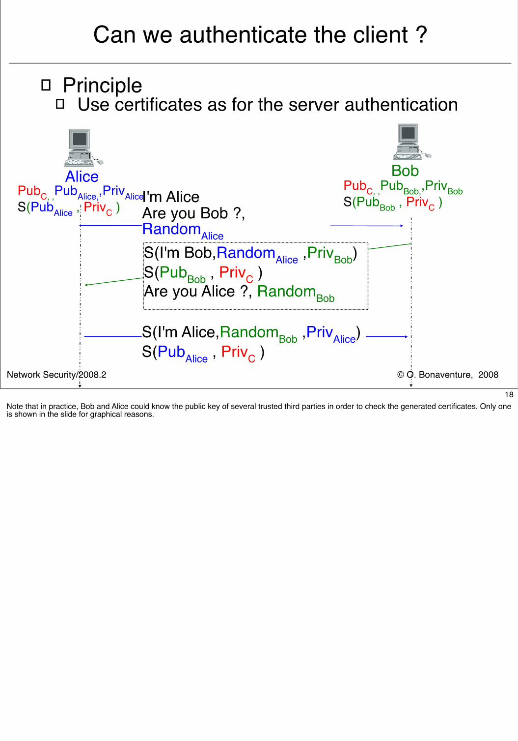
Can we authenticate the client ?
� Principle� Use certificates as for the server authentication
Alice BobI'm AliceAre you Bob ?, RandomAliceS(I'm Bob,RandomAlice ,PrivBob)S(PubBob , PrivC )Are you Alice ?, RandomBob
PubC, ,PubBob,,PrivBobS(PubBob , PrivC )
PubC, ,PubAlice,,PrivAliceS(PubAlice , PrivC )
S(I'm Alice,RandomBob ,PrivAlice)S(PubAlice , PrivC )
18Note that in practice, Bob and Alice could know the public key of several trusted third parties in order to check the generated certificates. Only one is shown in the slide for graphical reasons.
© O. Bonaventure, 2008Network Security/2008.2
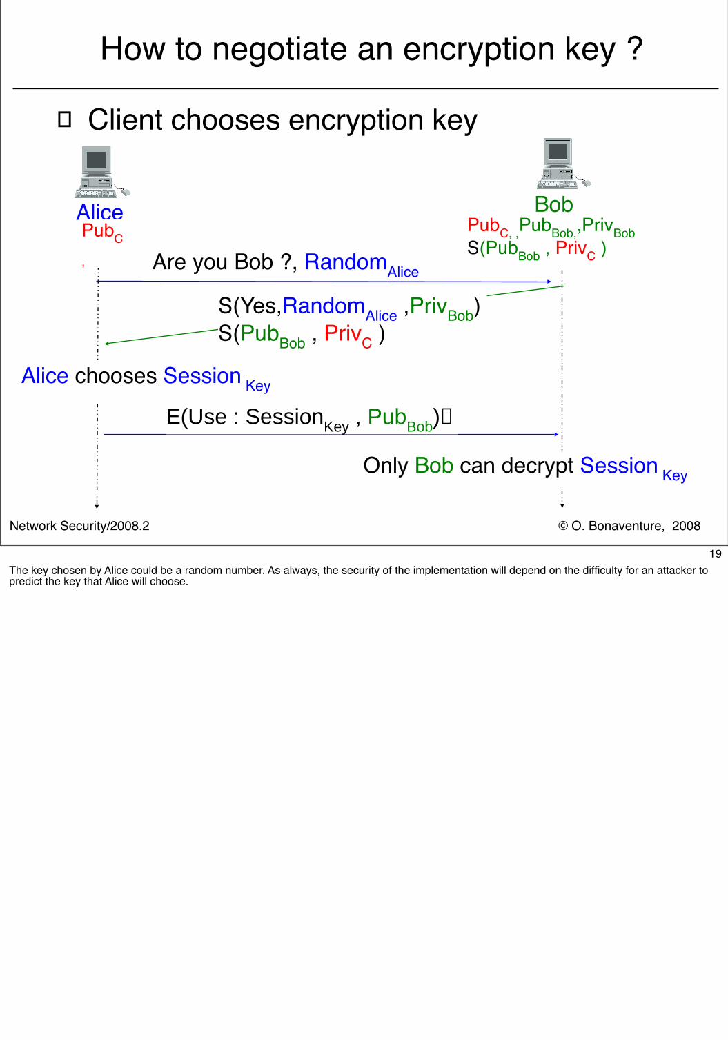
How to negotiate an encryption key ?
� Client chooses encryption key
Alice Bob
Are you Bob ?, RandomAlice
S(Yes,RandomAlice ,PrivBob)S(PubBob , PrivC )
PubC, ,PubBob,,PrivBobS(PubBob , PrivC )
PubC
,
E(Use : SessionKey , PubBob)
Alice chooses Session Key
Only Bob can decrypt Session Key
19The key chosen by Alice could be a random number. As always, the security of the implementation will depend on the difficulty for an attacker to predict the key that Alice will choose.
© O. Bonaventure, 2008Network Security/2008.2
How to negotiate an encryption key (2)?
� In practice, data will be sent� by client to server� by server to client
� Using a single key to encrypt two directions is a bad idea since when one key is broken, both directions can be decrypted
� Principle of the solution� Alice chooses a PreMasterSecret and uses
RandomAlice to compute several keys � Alice computes the Alice->Bob and Bob->Alice keys� Bob computes the Bob->Alice and Alice->Bob keys
20Of course, with this scheme Alice and Bob must use the same algorithm to generate the Session keys with the PreMasterSecret. This number should be sent encrypted, e.g. with Bob's public key, to ensure that an attacker cannot capture it.
© O. Bonaventure, 2008Network Security/2008.2
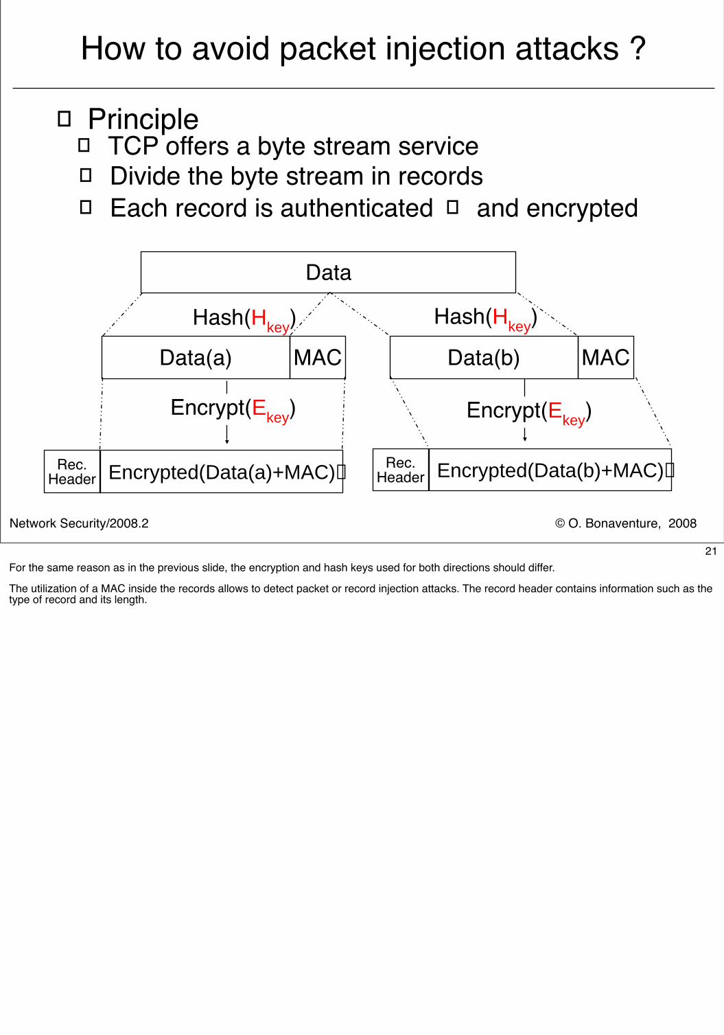
How to avoid packet injection attacks ?
� Principle� TCP offers a byte stream service
Data
Data(a) Data(b)MAC MAC
Hash(Hkey) Hash(Hkey)
Rec.Header Encrypted(Data(a)+MAC) Rec.
Header Encrypted(Data(b)+MAC)
Encrypt(Ekey)Encrypt(Ekey)
� Divide the byte stream in records� Each record is authenticated � and encrypted
21For the same reason as in the previous slide, the encryption and hash keys used for both directions should differ.
The utilization of a MAC inside the records allows to detect packet or record injection attacks. The record header contains information such as the type of record and its length.
© O. Bonaventure, 2008Network Security/2008.2
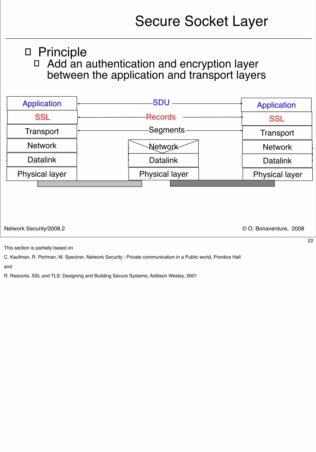
Secure Socket Layer
� Principle� Add an authentication and encryption layer
between the application and transport layers
Physical layer Physical layer
Datalink DatalinkNetworkNetwork
Physical layerDatalinkNetwork
SDU
Transport Transport
Application Application
SegmentsSSL SSLRecords
22This section is partially based on
C. Kaufman, R. Perlman, M. Speciner, Network Security : Private communication in a Public world, Prentice Hall
and
R. Rescorla, SSL and TLS: Designing and Building Secure Systems, Addison Wesley, 2001
© O. Bonaventure, 2008Network Security/2008.2
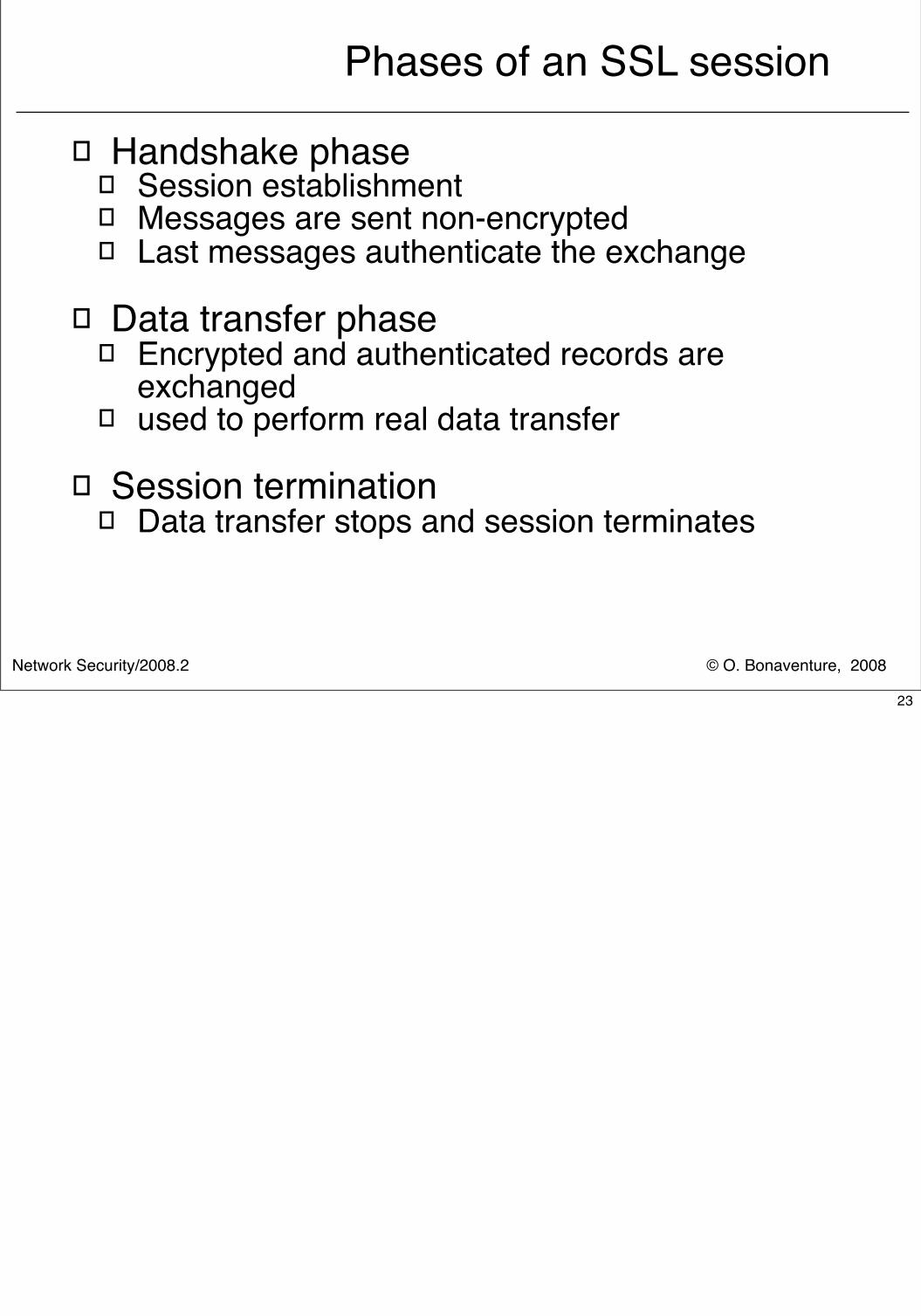
Phases of an SSL session
� Handshake phase� Session establishment� Messages are sent non-encrypted� Last messages authenticate the exchange
� Data transfer phase� Encrypted and authenticated records are
exchanged� used to perform real data transfer
� Session termination� Data transfer stops and session terminates
23
© O. Bonaventure, 2008Network Security/2008.2
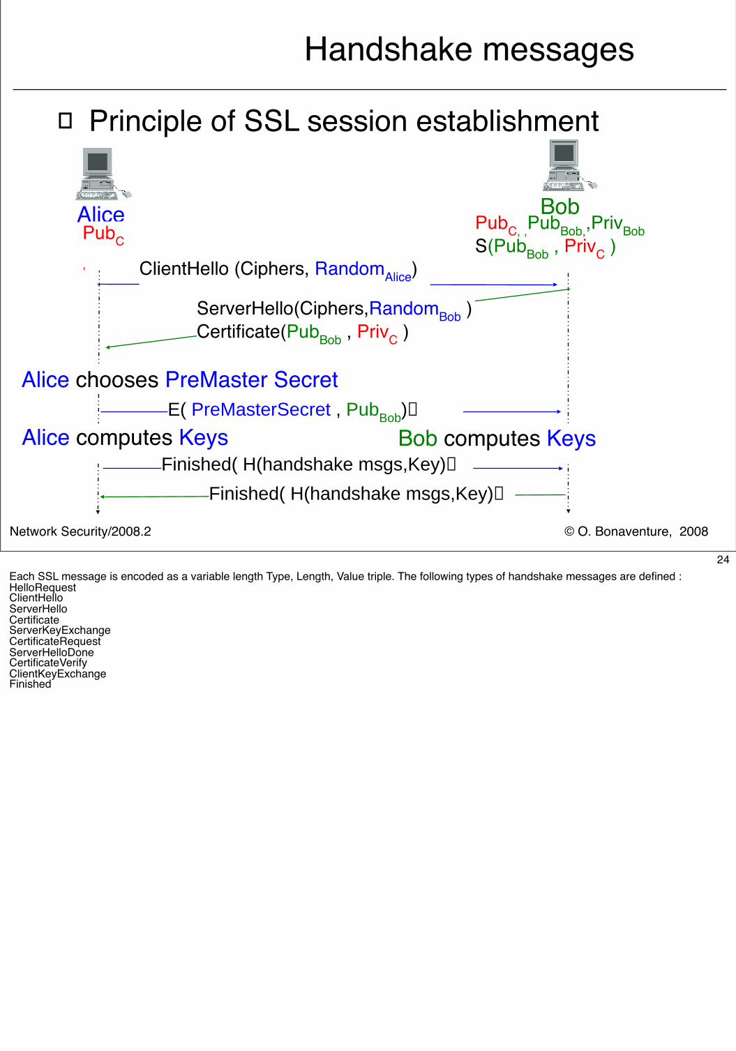
Handshake messages
� Principle of SSL session establishment
Alice Bob
ClientHello (Ciphers, RandomAlice)
ServerHello(Ciphers,RandomBob )Certificate(PubBob , PrivC )
PubC, ,PubBob,,PrivBobS(PubBob , PrivC )PubC
,
E( PreMasterSecret , PubBob)
Alice chooses PreMaster Secret
Bob computes Keys Alice computes KeysFinished( H(handshake msgs,Key)
Finished( H(handshake msgs,Key)
24Each SSL message is encoded as a variable length Type, Length, Value triple. The following types of handshake messages are defined :HelloRequestClientHelloServerHelloCertificateServerKeyExchangeCertificateRequestServerHelloDoneCertificateVerifyClientKeyExchangeFinished
© O. Bonaventure, 2008Network Security/2008.2
Handshake messagesClientHello
� Used by the Client to initiate SSL session� sent in clear without signature
� Contents� Protocol Version
� There are several variants of the SSL specification� 32 bytes long random number
� Composed of two parts� 4 bytes Unix time (number of seconds since 01/01/1970)� 28 bytes random number
� Session Id � Optional
� Used by client to resume a previous SSL session� Each SSL session has an identifier which can be used later to
restart a session� List of supported Ciphers� List of supported Compression Methods
25The main variants of the SSL specification are :SSLv2 defined in K. Hickman, The SSL Protocol, Feb. 1995http://wp.netscape.com/eng/security/SSL_2.html
SSLv3 defined in
A. Freier, P. Karlton, P. Kocher, The SSL Protocol, version 3.0, Internet draft, draft-freier-ssl-version3-02.txt, work in progress, Nov. 1996
TLS defined inT. Dierks, C. Allen, The TLS protocol, version 1.0, RFC2246, Jan 1999
Due to patent issues, the standardization bodies took a long time before defining compression methods to be used with SSL/TLS.
S. Hollenbeck,, Transport Layer Security Protocol Compression Methods, RFC3749, May 2004
Recently, LZS was added :
R. Friend, Transport Layer Security (TLS) Protocol Compression Using Lempel-Ziv-Stac (LZS), RFC3943, Nov. 2004
© O. Bonaventure, 2008Network Security/2008.2
Handshake messagesClientHello (2)
� List of supported ciphers� In fact a list (authentication + key exchange +
cipher + hash) � Authentication
� RSA or DSS� Key Exchange
� RSA, Diffie Hellman� Encryption
� None, RC4(40 bits), RC4 (128 bits), DES, 3DES, IDEA� Hash
� SHA or MD5� Some combinations are stronger than others
� Example � TLS RSA WITH NULL MD5� TLS RSA EXPORT WITH RC4 40 MD5� TLS RSA WITH RC4 128 MD5� TLS RSA WITH DES CBC SHA� TLS RSA WITH 3DES EDE CBC SHA
26For example, here are the ciphers supported by openssl, a freely available SSL library :DHE-RSA-AES256-SHA SSLv3 Kx=DH Au=RSA Enc=AES(256) Mac=SHA1DHE-DSS-AES256-SHA SSLv3 Kx=DH Au=DSS Enc=AES(256) Mac=SHA1AES256-SHA SSLv3 Kx=RSA Au=RSA Enc=AES(256) Mac=SHA1EDH-RSA-DES-CBC3-SHA SSLv3 Kx=DH Au=RSA Enc=3DES(168) Mac=SHA1EDH-DSS-DES-CBC3-SHA SSLv3 Kx=DH Au=DSS Enc=3DES(168) Mac=SHA1DES-CBC3-SHA SSLv3 Kx=RSA Au=RSA Enc=3DES(168) Mac=SHA1DES-CBC3-MD5 SSLv2 Kx=RSA Au=RSA Enc=3DES(168) Mac=MD5 DHE-RSA-AES128-SHA SSLv3 Kx=DH Au=RSA Enc=AES(128) Mac=SHA1DHE-DSS-AES128-SHA SSLv3 Kx=DH Au=DSS Enc=AES(128) Mac=SHA1AES128-SHA SSLv3 Kx=RSA Au=RSA Enc=AES(128) Mac=SHA1RC2-CBC-MD5 SSLv2 Kx=RSA Au=RSA Enc=RC2(128) Mac=MD5 DHE-DSS-RC4-SHA SSLv3 Kx=DH Au=DSS Enc=RC4(128) Mac=SHA1RC4-SHA SSLv3 Kx=RSA Au=RSA Enc=RC4(128) Mac=SHA1RC4-MD5 SSLv3 Kx=RSA Au=RSA Enc=RC4(128) Mac=MD5 RC4-MD5 SSLv2 Kx=RSA Au=RSA Enc=RC4(128) Mac=MD5 RC4-64-MD5 SSLv2 Kx=RSA Au=RSA Enc=RC4(64) Mac=MD5 EXP1024-DHE-DSS-DES-CBC-SHA SSLv3 Kx=DH(1024) Au=DSS Enc=DES(56) Mac=SHA1 exportEXP1024-DES-CBC-SHA SSLv3 Kx=RSA(1024) Au=RSA Enc=DES(56) Mac=SHA1 exportEXP1024-RC2-CBC-MD5 SSLv3 Kx=RSA(1024) Au=RSA Enc=RC2(56) Mac=MD5 exportEDH-RSA-DES-CBC-SHA SSLv3 Kx=DH Au=RSA Enc=DES(56) Mac=SHA1EDH-DSS-DES-CBC-SHA SSLv3 Kx=DH Au=DSS Enc=DES(56) Mac=SHA1DES-CBC-SHA SSLv3 Kx=RSA Au=RSA Enc=DES(56) Mac=SHA1DES-CBC-MD5 SSLv2 Kx=RSA Au=RSA Enc=DES(56) Mac=MD5 EXP1024-DHE-DSS-RC4-SHA SSLv3 Kx=DH(1024) Au=DSS Enc=RC4(56) Mac=SHA1 exportEXP1024-RC4-SHA SSLv3 Kx=RSA(1024) Au=RSA Enc=RC4(56) Mac=SHA1 exportEXP1024-RC4-MD5 SSLv3 Kx=RSA(1024) Au=RSA Enc=RC4(56) Mac=MD5 exportEXP-EDH-RSA-DES-CBC-SHA SSLv3 Kx=DH(512) Au=RSA Enc=DES(40) Mac=SHA1 exportEXP-EDH-DSS-DES-CBC-SHA SSLv3 Kx=DH(512) Au=DSS Enc=DES(40) Mac=SHA1 exportEXP-DES-CBC-SHA SSLv3 Kx=RSA(512) Au=RSA Enc=DES(40) Mac=SHA1 exportEXP-RC2-CBC-MD5 SSLv3 Kx=RSA(512) Au=RSA Enc=RC2(40) Mac=MD5 exportEXP-RC2-CBC-MD5 SSLv2 Kx=RSA(512) Au=RSA Enc=RC2(40) Mac=MD5 exportEXP-RC4-MD5 SSLv3 Kx=RSA(512) Au=RSA Enc=RC4(40) Mac=MD5 exportEXP-RC4-MD5 SSLv2 Kx=RSA(512) Au=RSA Enc=RC4(40) Mac=MD5 export
© O. Bonaventure, 2008Network Security/2008.2
Handshake messagesServerHello
� Used by the Server to reply to ClientHello� Sent in clear without signature
� Contents� Protocol version
� Highest version of the protocol supported by both client and server
� Random� A random structure generated by the server
� Session Id� Optional, sent by server if it allows sessions to be
resumed later� Cipher Suite
� One of the cipher suites proposed by the client� Compression Method
27The session id indicates the identifier of the SSL session. Servers and Clients may cache session information to be able to resume those sessions later. This is particularly useful for application protocols such as HTTP 1.0 where several TCP connections are established between the client and the server.
© O. Bonaventure, 2008Network Security/2008.2
Handshake messagesCertificate
� Utilisation of the Certificate message� Contains a list of X.509 certificates and is sent in
plain� server certificate� certificates of certification authorities if any� certificates are encoded in ASN.1
� Sent by the server to authenticate itself� a server may have several certificates from different
certification authorities
� Certificate can also be sent by the client when client authentication is requested by the server with CertificateRequest
28
© O. Bonaventure, 2008Network Security/2008.2
Handshake messagesServerHelloDone
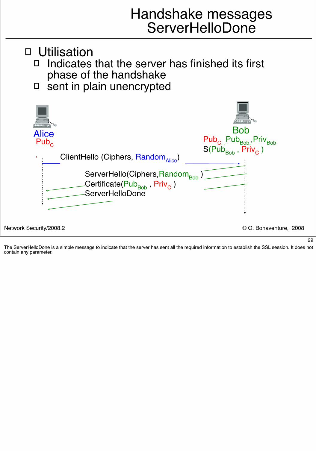
� Utilisation� Indicates that the server has finished its first
phase of the handshake� sent in plain unencrypted
Alice Bob
ClientHello (Ciphers, RandomAlice)
ServerHello(Ciphers,RandomBob )Certificate(PubBob , PrivC )ServerHelloDone
PubC, ,PubBob,,PrivBobS(PubBob , PrivC )
PubC
,
29The ServerHelloDone is a simple message to indicate that the server has sent all the required information to establish the SSL session. It does not contain any parameter.
© O. Bonaventure, 2008Network Security/2008.2
Handshake messagesClientKeyExchange
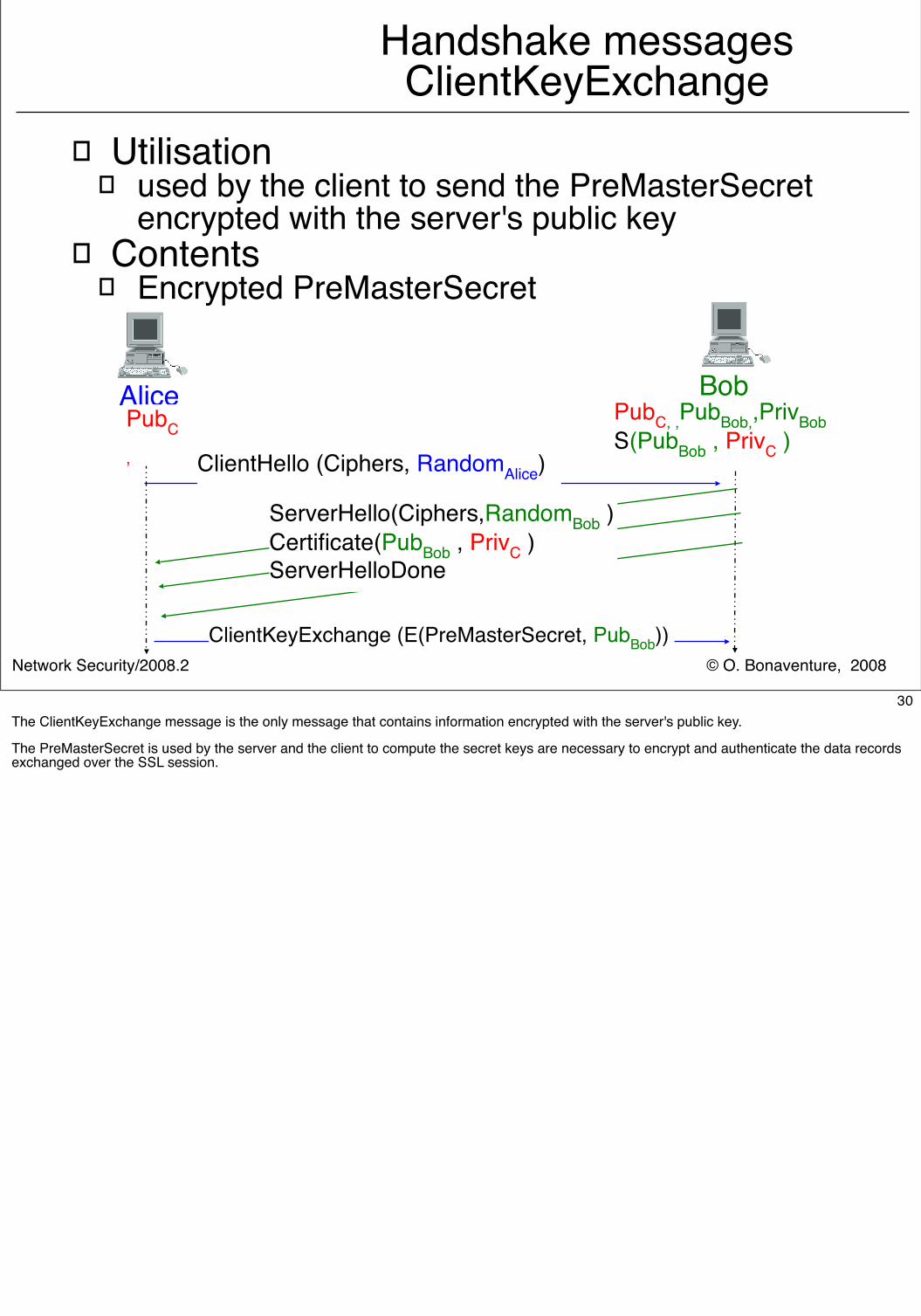
� Utilisation� used by the client to send the PreMasterSecret
encrypted with the server's public key� Contents
� Encrypted PreMasterSecret
Alice Bob
ClientHello (Ciphers, RandomAlice)
ServerHello(Ciphers,RandomBob )Certificate(PubBob , PrivC )ServerHelloDone
PubC, ,PubBob,,PrivBobS(PubBob , PrivC )
PubC
,
ClientKeyExchange (E(PreMasterSecret, PubBob))
30The ClientKeyExchange message is the only message that contains information encrypted with the server's public key.
The PreMasterSecret is used by the server and the client to compute the secret keys are necessary to encrypt and authenticate the data records exchanged over the SSL session.
© O. Bonaventure, 2008Network Security/2008.2
Key derivation
� PrinciplePreMaster
SecretClient
RandomServer
Random
Master Secret
Key Block
Client MAC
ServerMAC
ClientEncrypt
ServerEncrypt
ClientIV
ServerIV
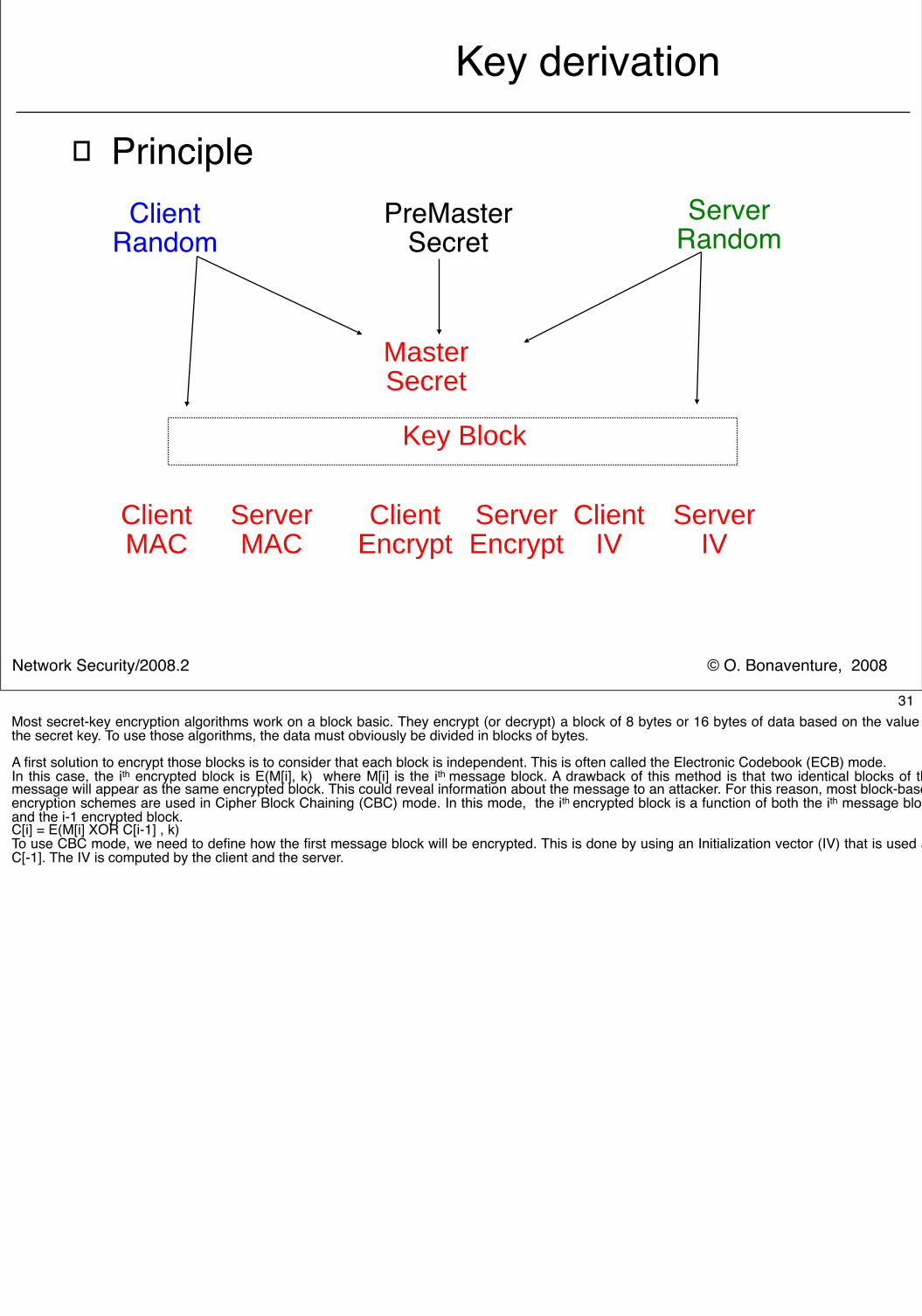
31Most secret-key encryption algorithms work on a block basic. They encrypt (or decrypt) a block of 8 bytes or 16 bytes of data based on the value of the secret key. To use those algorithms, the data must obviously be divided in blocks of bytes.
A first solution to encrypt those blocks is to consider that each block is independent. This is often called the Electronic Codebook (ECB) mode.In this case, the ith encrypted block is E(M[i], k) where M[i] is the ith message block. A drawback of this method is that two identical blocks of the message will appear as the same encrypted block. This could reveal information about the message to an attacker. For this reason, most block-based encryption schemes are used in Cipher Block Chaining (CBC) mode. In this mode, the ith encrypted block is a function of both the ith message block and the i-1 encrypted block.C[i] = E(M[i] XOR C[i-1] , k) To use CBC mode, we need to define how the first message block will be encrypted. This is done by using an Initialization vector (IV) that is used as C[-1]. The IV is computed by the client and the server.
© O. Bonaventure, 2008Network Security/2008.2
Key derivation in SSLv3
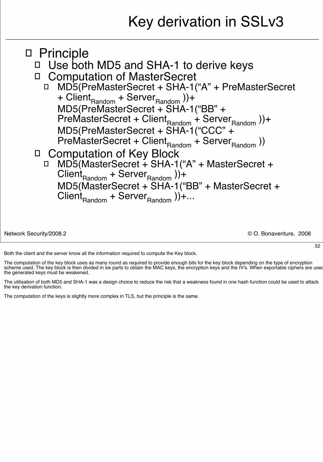
� Principle� Use both MD5 and SHA-1 to derive keys� Computation of MasterSecret
� MD5(PreMasterSecret + SHA-1(“A” + PreMasterSecret + ClientRandom + ServerRandom ))+MD5(PreMasterSecret + SHA-1(“BB” + PreMasterSecret + ClientRandom + ServerRandom ))+MD5(PreMasterSecret + SHA-1(“CCC” + PreMasterSecret + ClientRandom + ServerRandom ))
� Computation of Key Block� MD5(MasterSecret + SHA-1(“A” + MasterSecret +
ClientRandom + ServerRandom ))+MD5(MasterSecret + SHA-1(“BB” + MasterSecret + ClientRandom + ServerRandom ))+...
32Both the client and the server know all the information required to compute the Key block.
The computation of the key block uses as many round as required to provide enough bits for the key block depending on the type of encryption scheme used. The key block is then divided in six parts to obtain the MAC keys, the encryption keys and the IV's. When exportable ciphers are used, the generated keys must be weakened.
The utilisation of both MD5 and SHA-1 was a design choice to reduce the risk that a weakness found in one hash function could be used to attack the key derivation function.
The computation of the keys is slightly more complex in TLS, but the principle is the same.
© O. Bonaventure, 2008Network Security/2008.2
Handshake messagesChangeCipherSpec
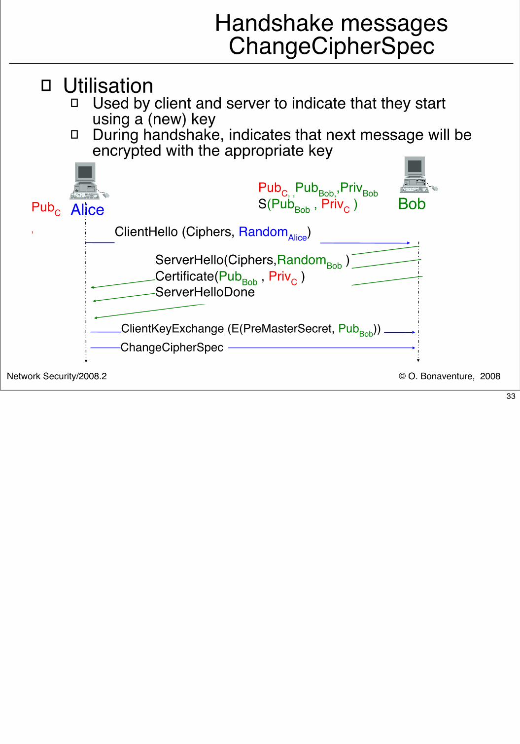
� Utilisation� Used by client and server to indicate that they start
using a (new) key� During handshake, indicates that next message will be
encrypted with the appropriate key
Alice BobClientHello (Ciphers, RandomAlice)
ServerHello(Ciphers,RandomBob )Certificate(PubBob , PrivC )ServerHelloDone
PubC, ,PubBob,,PrivBobS(PubBob , PrivC )PubC
,
ClientKeyExchange (E(PreMasterSecret, PubBob))ChangeCipherSpec
33
© O. Bonaventure, 2008Network Security/2008.2
Handshake messages Finished
� Utilisation� Sent by both client and server to confirm the
establishment of the secure SSL session� Session is established only is client received expected
Finished message from server and vice-versa� Allows to detect man in the middle attacks on
ClientHello and ServerHello messages� example
� Attacker changes cipher list to propose weaker ciphers � First encrypted message on each direction
� Contents� Keyed hash (MD5 or SHA-1) of all the handshake
messages and the MasterSecret
34The keyed hash found in the Finished message is computed in SSLv3 as follows :
hash=MD5( MasterSecret + pad2 + MD5 ( Handshake messages + Sender + MasterSecret + pad1))
In this function, Sender is a constant set to 0x434C4E54 on the client and 0X53525652 on the server. This ensures that the hash computed by the server will differ from the hash computed by the client to avoid replay attacks.pad1 is a string of byte 0x36 repeated 48 times and pad2 0x5c repeated 48 times.
MD5 can be replaced by SHA-1 when this hash has been selected.
The computation of the key hash in TLS is slightly different.
© O. Bonaventure, 2008Network Security/2008.2
SSL records
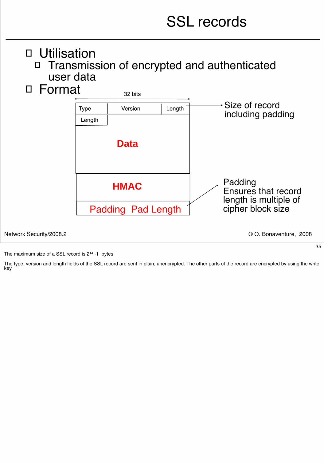
� Utilisation� Transmission of encrypted and authenticated
user data� Format 32 bits
Type Version Length
Data
Length
HMAC
Padding Pad Length
Size of recordincluding padding
PaddingEnsures that recordlength is multiple ofcipher block size
35The maximum size of a SSL record is 214 -1 bytes
The type, version and length fields of the SSL record are sent in plain, unencrypted. The other parts of the record are encrypted by using the write key.
© O. Bonaventure, 2008Network Security/2008.2
Authentication of SSL records
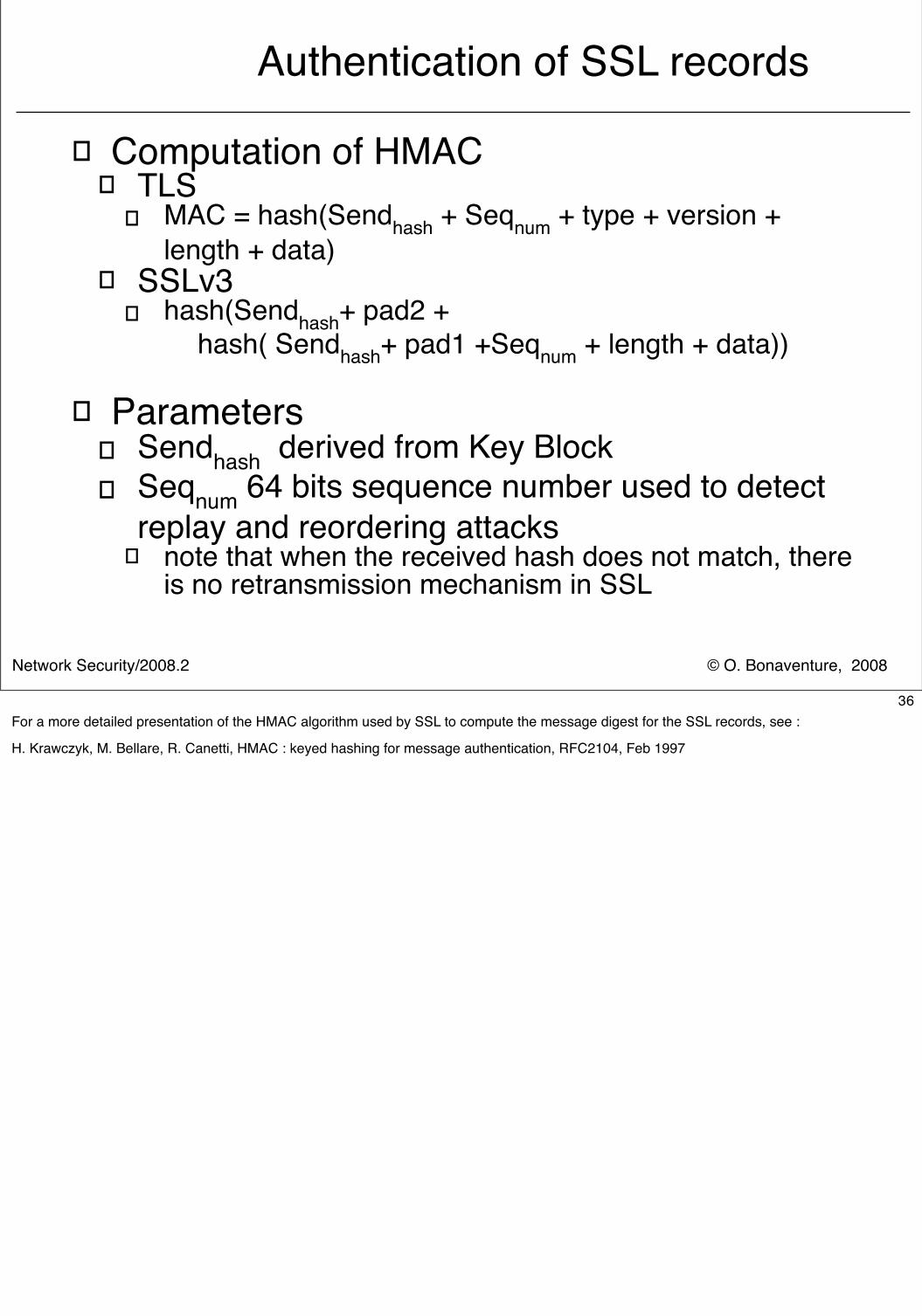
� Computation of HMAC � TLS
� MAC = hash(Sendhash + Seqnum + type + version + length + data)
� SSLv3� hash(Sendhash+ pad2 + hash( Sendhash+ pad1 +Seqnum + length + data))
� Parameters� Sendhash derived from Key Block� Seqnum 64 bits sequence number used to detect
replay and reordering attacks� note that when the received hash does not match, there
is no retransmission mechanism in SSL
36For a more detailed presentation of the HMAC algorithm used by SSL to compute the message digest for the SSL records, see :
H. Krawczyk, M. Bellare, R. Canetti, HMAC : keyed hashing for message authentication, RFC2104, Feb 1997
© O. Bonaventure, 2008Network Security/2008.2
SSL alerts
� Messages used to inform of problems on a SSL session
� Examples � bad_record_mac
� a record with bad MAC was received, session closed� handshake failure
� failure during the establishment of the SSL session� bad_certificate
� certificate was corrupted or invalid� revoked certificate / certificate expired
� certificate is not valid anymore� unknown ca
� certificate was singed by an unknown cert. authority� insufficient security
� ciphers proposed are not secure enough
37
© O. Bonaventure, 2008Network Security/2008.2
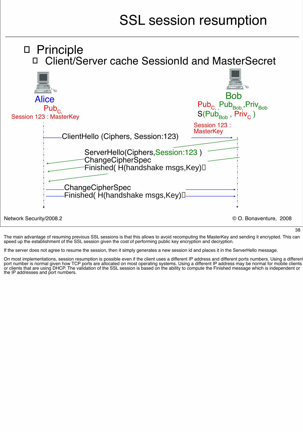
SSL session resumption
� Principle� Client/Server cache SessionId and MasterSecret
Alice Bob
ClientHello (Ciphers, Session:123)
ServerHello(Ciphers,Session:123 )ChangeCipherSpecFinished( H(handshake msgs,Key)
PubC, ,PubBob,,PrivBobS(PubBob , PrivC )
PubC,Session 123 : MasterKey
ChangeCipherSpecFinished( H(handshake msgs,Key)
Session 123 : MasterKey
38The main advantage of resuming previous SSL sessions is that this allows to avoid recomputing the MasterKey and sending it encrypted. This can speed up the establishment of the SSL session given the cost of performing public key encryption and decryption.
If the server does not agree to resume the session, then it simply generates a new session id and places it in the ServerHello message.
On most implementations, session resumption is possible even if the client uses a different IP address and different ports numbers. Using a different port number is normal given how TCP ports are allocated on most operating systems. Using a different IP address may be normal for mobile clients or clients that are using DHCP. The validation of the SSL session is based on the ability to compute the Finished message which is independent or the IP addresses and port numbers.

© O. Bonaventure, 2008Network Security/2008.2
SSL client authentication
� Principle � Server requires client to provide a valid certificate
to agree to establish session
� New messages� CertificateRequest
� Sent by server to request client certificate� Contains certificate type and list of acceptable
certification authorities
� CertificateVerify� Sent by client to prove to the server that it knows the
private key of the certificate that it sent� Content
� Signature of all the handshake messages sent and received with the client private key
39The CertificateRequest message contains the list of certification authorities that are considered as valid by the server. The client must provide a certificate issues by one of those certification authorities otherwise the server will not agree to establish the SSL session
The CertificateVerify is necessary to allow the server to verify that the client is able to encrypt something with the private key associated to the certified public key. As the client signs the handshake messages, it also signs the random number chosen by the server. This avoids replay attacks.
With the CertifcateVerify message, there is some asymmetry between the server and the client. The client uses the CertificateVerify message to prove that it knows the key announced in the certificate. The server does not send such a message. This is not necessary as the server must know the private key corresponding to its certificate to decrypt the ClientKeyExchange message and correctly compute the session keys and thus the Finished message.
© O. Bonaventure, 2008Network Security/2008.2
Ephemeral keys
� Problem� When SSL was designed, long RSA keys could
not be used with export clients
� Solutions� Each server maintains a long and a short key
� server must maintain several certificates� operational issues on server
� Ephemeral key� Server generates random short key for each session
� short key can be broken by government agencies if required� short key is signed by using the long server key
� ensures that � client validates the short key's signature and use it to
encrypt the PreMasterSecret
40
© O. Bonaventure, 2008Network Security/2008.2
Security issues with SSL
� Master secret must remain secret
� Server's private must remain secret
� Random number generators
� Certificates should be checked
� Cipher negotiation
41
© O. Bonaventure, 2008Network Security/2008.2
Security of MasterSecret
� Computed by client and server based on PreMasterSecret, Random Client , RandomServer
� Security risk� If attacker knows MasterSecret, he can read all
data and inject new data in SSL session
� Storage� SSL is usually implemented in software
� MasterSecret is usually stored in memory� on a multi-user machine, a process with administrator rights can
read at any memory location� MasterSecret should not be stored on disk
� implementation should make sure that memory containing MasterSecret is locked
� Core dumps may reveal MasterSecret as well
42On Unix, mlock can be used to mark memory zones that should not be placed on disk.
© O. Bonaventure, 2008Network Security/2008.2
Security of private keys
� Problem� Server maintains private,public key pair� Certified client also uses key pair
� Security risks� If server's private key is compromised, then all
captured sessions with the server can be recovered
� If client's private key is compromised, then any other client can impersonate it
� How to protect private keys ?
43
© O. Bonaventure, 2008Network Security/2008.2
Protection of client's private key
� Principle� User selects a pass phrase
� pass phrase is much longer than a password� pass phrase should be longer than protected key� dictionary attacks against pass phrases are more
difficult if pass phrase is well chosen� Private key is encrypted with pass phrase
� Computation of encrypted key� k = H(H(H(H(H(Passphrase , Salt)))))� Encrypted Key = E(Private Key, k)
� Salt is stored in plain with the encrypted private key� makes dictionary attacks more difficult for attacker
� H is computed several times to slow brute force and dictionary attacks
44
© O. Bonaventure, 2008Network Security/2008.2
Other approaches
� Pass-phrase based private key� Principle
� To generate a key pair, a random number generator is used
� usually RNG is seeded with with a random seed� instead, use the pass phrase to seed the RNG
� Private key stored on hardware� dumb device that simply stores the private key
� PIN number, password or pass phrase used to unlock the private key
� intelligent device such as a smart card� contains key pair, certificate and is able to encrypt� software interacts with smart card when message must
be encrypted with private key
45
© O. Bonaventure, 2008Network Security/2008.2
Protection of the server's private key� Software-based solutions
� Private key is protected by OS permissions� Private key is encrypted with pass phrase
� in this case, the administrator must provide pass phrase at each reboot
� Private key is not encrypted� server can automatically reboot, but an attack on the
server can reveal the private key� Hardware-based solutions
� simple storage device� no added security, pass phrase required
� hardware providing encryption� tamper resistant device stores key and encrypts
� improves performance as well� can be protected with a password or pass phrase� if device is physically stolen, private key also
46
© O. Bonaventure, 2008Network Security/2008.2
Random number generators
� How to obtain good random numbers ?
� Use random physical processes� lower bits of counter that counts number of
radioactive particles per unit of time� thermal fluctuations of electrons wandering
through a resistor or a semiconductor junction� included in some CPUs like Pentium
� Use pseudo random number generators� algorithms that generate a stream of pseudo
random numbers� stream depends on seed provided
� most OSes provide today random values to seed the PRNG, by measuring random delays such as time between key presses, delays between interrupts, ...
47For physical based random number generators, see e.g.http://www.americanscientist.org/template/AssetDetail/assetid/20829/page/4?&print=yes
Unix variants provide, in addition to the PRNG found in the standard library of all languages, kernel-based random number generators. Those random numbers are usually available via the /dev/random or /dev/urandom devices
© O. Bonaventure, 2008Network Security/2008.2
Certificate validation
� Content of the X.509 certificates� Not initially developed to certify e-commerce
servers� Multiple optional fields
� C=country� O=organisation� OU=Organisation Unit� CN=Common Name
� sometimes used to encode the DNS name for a server� certificates do not contain IP addresses
� ST=State� L=City� Key usage extensions
� digitalSignature, keyEncipherment, dataEncipherment, keyCertSign, ...
� Optional Fields� emailAddress, subjectAltName, ...
48
© O. Bonaventure, 2008Network Security/2008.2
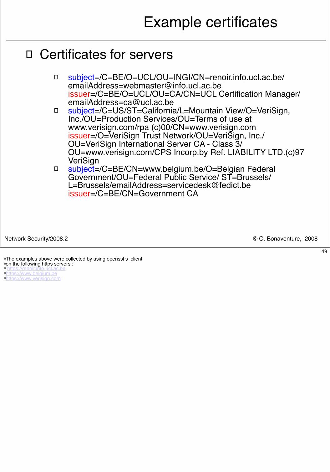
Example certificates
� Certificates for servers� subject=/C=BE/O=UCL/OU=INGI/CN=renoir.info.ucl.ac.be/
[email protected]=/C=BE/O=UCL/OU=CA/CN=UCL Certification Manager/[email protected]
� subject=/C=US/ST=California/L=Mountain View/O=VeriSign, Inc./OU=Production Services/OU=Terms of use at www.verisign.com/rpa (c)00/CN=www.verisign.comissuer=/O=VeriSign Trust Network/OU=VeriSign, Inc./OU=VeriSign International Server CA - Class 3/OU=www.verisign.com/CPS Incorp.by Ref. LIABILITY LTD.(c)97 VeriSign
� subject=/C=BE/CN=www.belgium.be/O=Belgian Federal Government/OU=Federal Public Service/ ST=Brussels/ L=Brussels/[email protected]=/C=BE/CN=Government CA
49� The examples above were collected by using openssl s_client� on the following https servers :� https://renoir.info.ucl.ac.be� https://www.belgium.be� https://www.verisign.com
© O. Bonaventure, 2008Network Security/2008.2
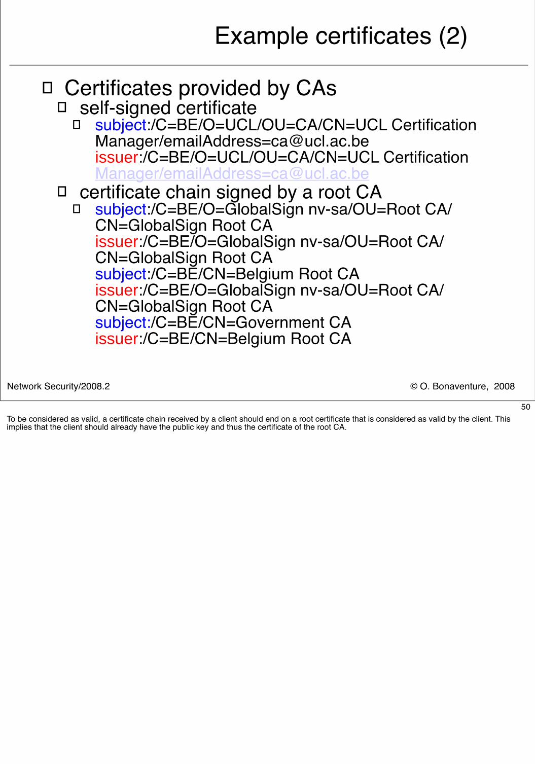
Example certificates (2)
� Certificates provided by CAs� self-signed certificate
� subject:/C=BE/O=UCL/OU=CA/CN=UCL Certification Manager/[email protected]:/C=BE/O=UCL/OU=CA/CN=UCL Certification Manager/[email protected]
� certificate chain signed by a root CA� subject:/C=BE/O=GlobalSign nv-sa/OU=Root CA/
CN=GlobalSign Root CAissuer:/C=BE/O=GlobalSign nv-sa/OU=Root CA/CN=GlobalSign Root CAsubject:/C=BE/CN=Belgium Root CAissuer:/C=BE/O=GlobalSign nv-sa/OU=Root CA/CN=GlobalSign Root CAsubject:/C=BE/CN=Government CAissuer:/C=BE/CN=Belgium Root CA
50To be considered as valid, a certificate chain received by a client should end on a root certificate that is considered as valid by the client. This implies that the client should already have the public key and thus the certificate of the root CA.
© O. Bonaventure, 2008Network Security/2008.2
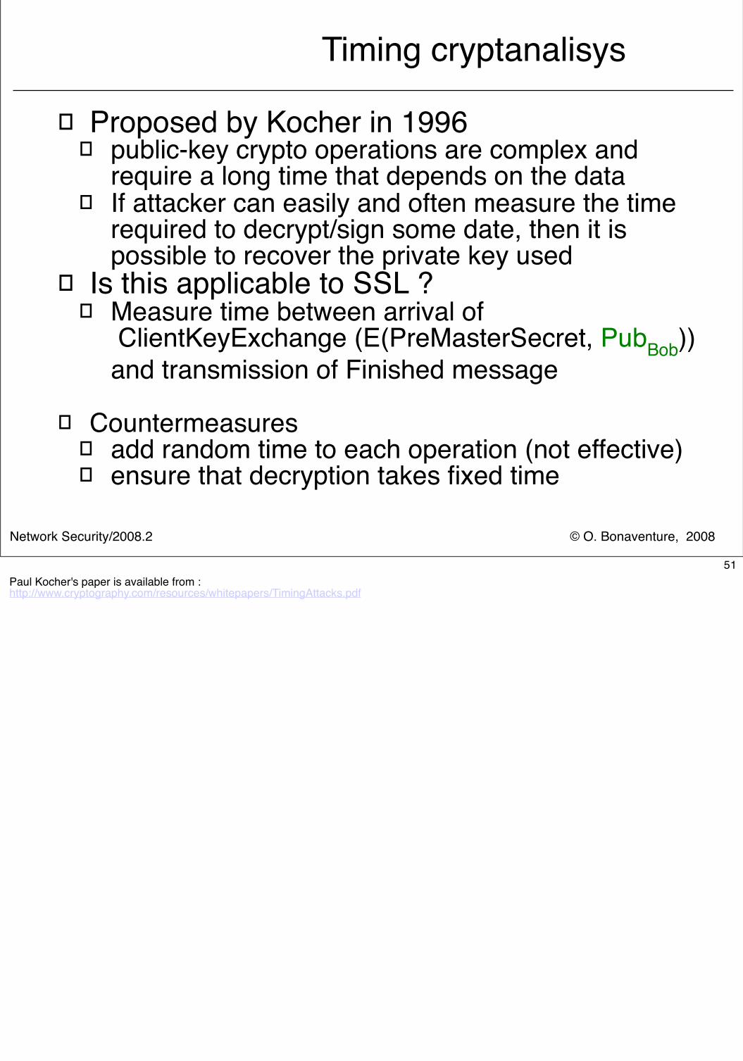
Timing cryptanalisys
� Proposed by Kocher in 1996� public-key crypto operations are complex and
require a long time that depends on the data� If attacker can easily and often measure the time
required to decrypt/sign some date, then it is possible to recover the private key used
� Is this applicable to SSL ?� Measure time between arrival of
ClientKeyExchange (E(PreMasterSecret, PubBob)) and transmission of Finished message
� Countermeasures� add random time to each operation (not effective)� ensure that decryption takes fixed time
51Paul Kocher's paper is available from :http://www.cryptography.com/resources/whitepapers/TimingAttacks.pdf
© O. Bonaventure, 2008Network Security/2008.2
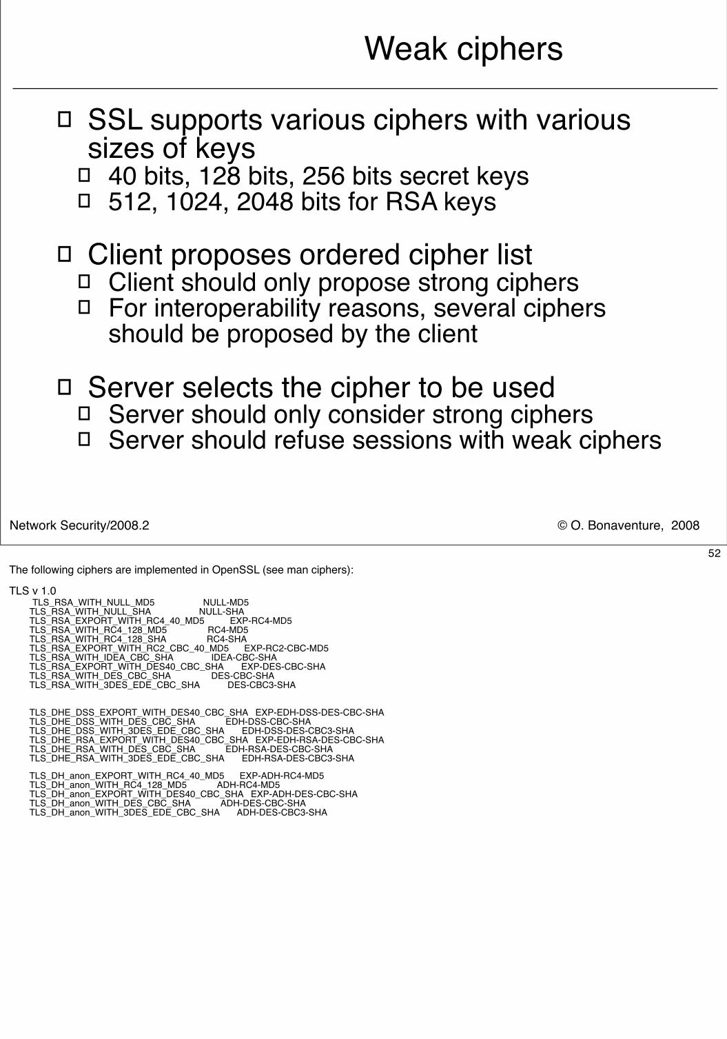
Weak ciphers
� SSL supports various ciphers with various sizes of keys
� 40 bits, 128 bits, 256 bits secret keys� 512, 1024, 2048 bits for RSA keys
� Client proposes ordered cipher list� Client should only propose strong ciphers� For interoperability reasons, several ciphers
should be proposed by the client
� Server selects the cipher to be used� Server should only consider strong ciphers� Server should refuse sessions with weak ciphers
52The following ciphers are implemented in OpenSSL (see man ciphers):
TLS v 1.0 TLS_RSA_WITH_NULL_MD5 NULL-MD5 TLS_RSA_WITH_NULL_SHA NULL-SHA TLS_RSA_EXPORT_WITH_RC4_40_MD5 EXP-RC4-MD5 TLS_RSA_WITH_RC4_128_MD5 RC4-MD5 TLS_RSA_WITH_RC4_128_SHA RC4-SHA TLS_RSA_EXPORT_WITH_RC2_CBC_40_MD5 EXP-RC2-CBC-MD5 TLS_RSA_WITH_IDEA_CBC_SHA IDEA-CBC-SHA TLS_RSA_EXPORT_WITH_DES40_CBC_SHA EXP-DES-CBC-SHA TLS_RSA_WITH_DES_CBC_SHA DES-CBC-SHA TLS_RSA_WITH_3DES_EDE_CBC_SHA DES-CBC3-SHA
TLS_DHE_DSS_EXPORT_WITH_DES40_CBC_SHA EXP-EDH-DSS-DES-CBC-SHA TLS_DHE_DSS_WITH_DES_CBC_SHA EDH-DSS-CBC-SHA TLS_DHE_DSS_WITH_3DES_EDE_CBC_SHA EDH-DSS-DES-CBC3-SHA TLS_DHE_RSA_EXPORT_WITH_DES40_CBC_SHA EXP-EDH-RSA-DES-CBC-SHA TLS_DHE_RSA_WITH_DES_CBC_SHA EDH-RSA-DES-CBC-SHA TLS_DHE_RSA_WITH_3DES_EDE_CBC_SHA EDH-RSA-DES-CBC3-SHA
TLS_DH_anon_EXPORT_WITH_RC4_40_MD5 EXP-ADH-RC4-MD5 TLS_DH_anon_WITH_RC4_128_MD5 ADH-RC4-MD5 TLS_DH_anon_EXPORT_WITH_DES40_CBC_SHA EXP-ADH-DES-CBC-SHA TLS_DH_anon_WITH_DES_CBC_SHA ADH-DES-CBC-SHA TLS_DH_anon_WITH_3DES_EDE_CBC_SHA ADH-DES-CBC3-SHA
© O. Bonaventure, 2008Network Security/2008.2
Internet and Network security
� Crypto building blocks� Application-layer security
� Secure Socket Layer� Transport-layer security
� Securing TCP� Network-layer security
53
Network Security/2008.2 © O. Bonaventure, 2008
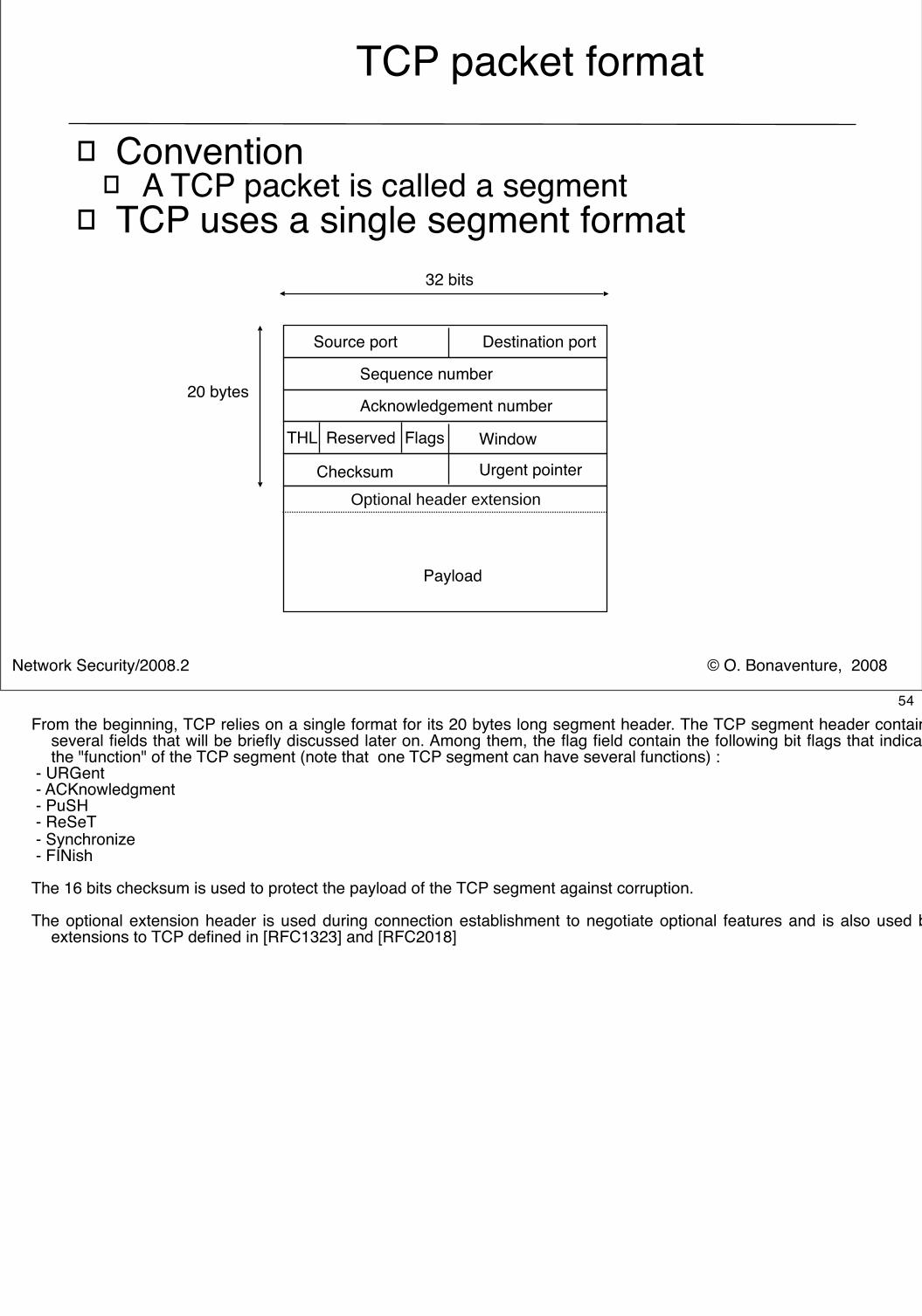
TCP packet format
� Convention� A TCP packet is called a segment
� TCP uses a single segment format
Source port Destination port
Payload
32 bits
Checksum Urgent pointer
THL Reserved Flags
20 bytesAcknowledgement number
Sequence number
Optional header extension
Window
54From the beginning, TCP relies on a single format for its 20 bytes long segment header. The TCP segment header contains
several fields that will be briefly discussed later on. Among them, the flag field contain the following bit flags that indicate the "function" of the TCP segment (note that one TCP segment can have several functions) :
- URGent - ACKnowledgment - PuSH - ReSeT - Synchronize - FINish
The 16 bits checksum is used to protect the payload of the TCP segment against corruption.
The optional extension header is used during connection establishment to negotiate optional features and is also used by extensions to TCP defined in [RFC1323] and [RFC2018]
Network Security/2008.2 © O. Bonaventure, 2008
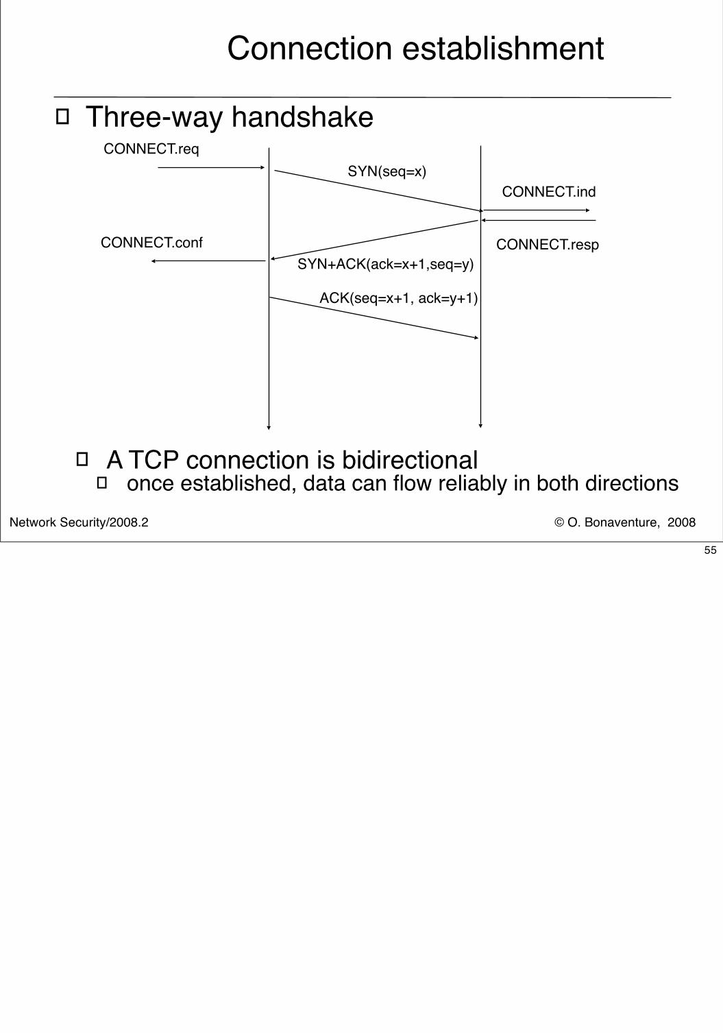
Connection establishment
� Three-way handshake
� A TCP connection is bidirectional� once established, data can flow reliably in both directions
ACK(seq=x+1, ack=y+1)
SYN(seq=x)CONNECT.req
CONNECT.ind
SYN+ACK(ack=x+1,seq=y)CONNECT.respCONNECT.conf
55
Network Security/2008.2 © O. Bonaventure, 2008
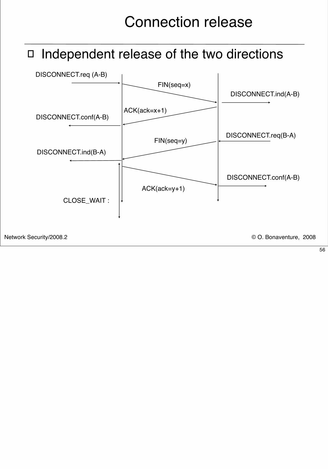
Connection release
� Independent release of the two directionsDISCONNECT.req (A-B)
FIN(seq=x)DISCONNECT.ind(A-B)
ACK(ack=x+1)DISCONNECT.conf(A-B)
ACK(ack=y+1)DISCONNECT.conf(A-B)
DISCONNECT.req(B-A)
DISCONNECT.ind(B-A)FIN(seq=y)
CLOSE_WAIT :
56
Network Security/2008.2 © O. Bonaventure, 2008
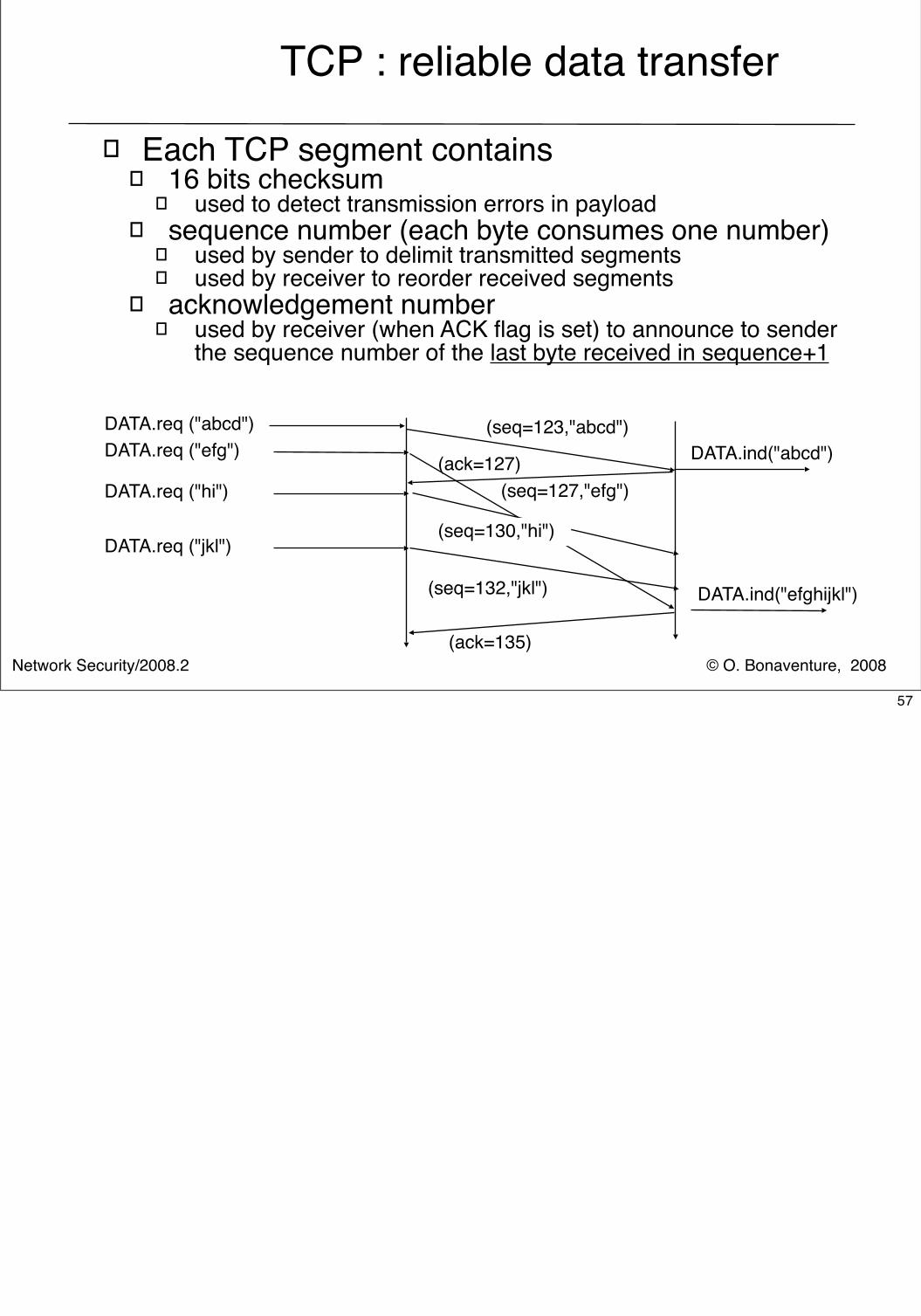
TCP : reliable data transfer
� Each TCP segment contains� 16 bits checksum
� used to detect transmission errors in payload� sequence number (each byte consumes one number)
� used by sender to delimit transmitted segments� used by receiver to reorder received segments
� acknowledgement number� used by receiver (when ACK flag is set) to announce to sender
the sequence number of the last byte received in sequence+1
DATA.req ("abcd")DATA.ind("abcd")
(seq=123,"abcd")DATA.req ("efg")
(seq=127,"efg")DATA.req ("hi")
(seq=130,"hi")DATA.req ("jkl")
(seq=132,"jkl") DATA.ind("efghijkl")
(ack=127)
(ack=135)
57
Network Security/2008.2 © O. Bonaventure, 2008
TCP : reliable data transfer (2)
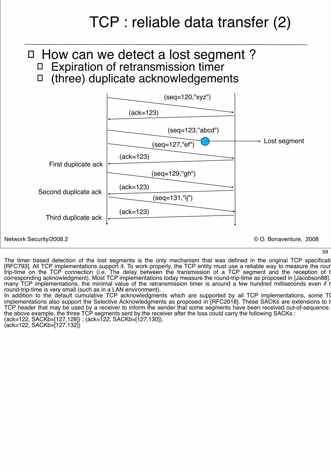
� How can we detect a lost segment ?� Expiration of retransmission timer� (three) duplicate acknowledgements
(seq=127,"ef")
(seq=120,"xyz")
(ack=123)
(seq=129,"gh")
(seq=131,"ij")
(seq=123,"abcd")Lost segment
(ack=123)First duplicate ack
(ack=123)Second duplicate ack
(ack=123)Third duplicate ack
58The timer based detection of the lost segments is the only mechanism that was defined in the original TCP specification [RFC793]. All TCP implementations support it. To work properly, the TCP entity must use a reliable way to measure the round-trip-time on the TCP connection (i.e. The delay between the transmission of a TCP segment and the reception of the corresponding acknowledgment). Most TCP implementations today measure the round-trip-time as proposed in [Jacobson88]. In many TCP implementations, the minimal value of the retransmission timer is around a few hundred milliseconds even if the round-trip-time is very small (such as in a LAN environment).In addition to the default cumulative TCP acknowledgments which are supported by all TCP implementations, some TCP implementations also support the Selective Acknowledgments as proposed in [RFC2018]. These SACKs are extensions to the TCP header that may be used by a receiver to inform the sender that some segments have been received out-of-sequence. In the above example, the three TCP segments sent by the receiver after the loss could carry the following SACKs :(ack=122, SACKb=[127,128]) ; (ack=122, SACKb=[127,130]), (ack=122, SACKb=[127,132])
Network Security/2008.2 © O. Bonaventure, 2008
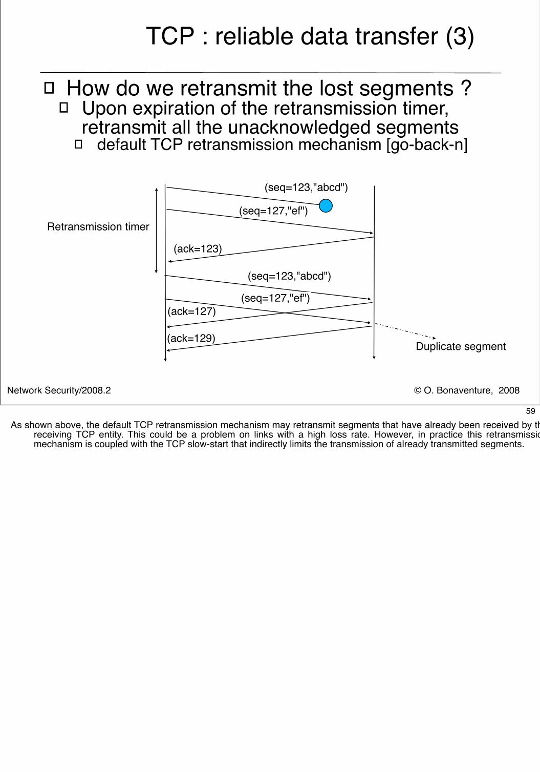
TCP : reliable data transfer (3)
� How do we retransmit the lost segments ?� Upon expiration of the retransmission timer,
retransmit all the unacknowledged segments� default TCP retransmission mechanism [go-back-n]
(seq=123,"abcd")
(seq=127,"ef")
(seq=123,"abcd")
(ack=123)
Retransmission timer
(ack=127)
(ack=129)
(seq=127,"ef")
Duplicate segment
59As shown above, the default TCP retransmission mechanism may retransmit segments that have already been received by the
receiving TCP entity. This could be a problem on links with a high loss rate. However, in practice this retransmission mechanism is coupled with the TCP slow-start that indirectly limits the transmission of already transmitted segments.
Network Security/2008.2 © O. Bonaventure, 2008
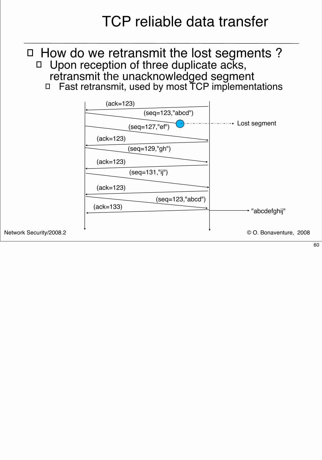
TCP reliable data transfer
� How do we retransmit the lost segments ?� Upon reception of three duplicate acks,
retransmit the unacknowledged segment� Fast retransmit, used by most TCP implementations
(seq=123,"abcd")
(seq=127,"ef")
(ack=123)
(seq=129,"gh")
(seq=131,"ij")
(ack=123)
(ack=123)
(ack=123)
Lost segment
(seq=123,"abcd")(ack=133) "abcdefghij"
60
Network Security/2008.2 © O. Bonaventure, 2008
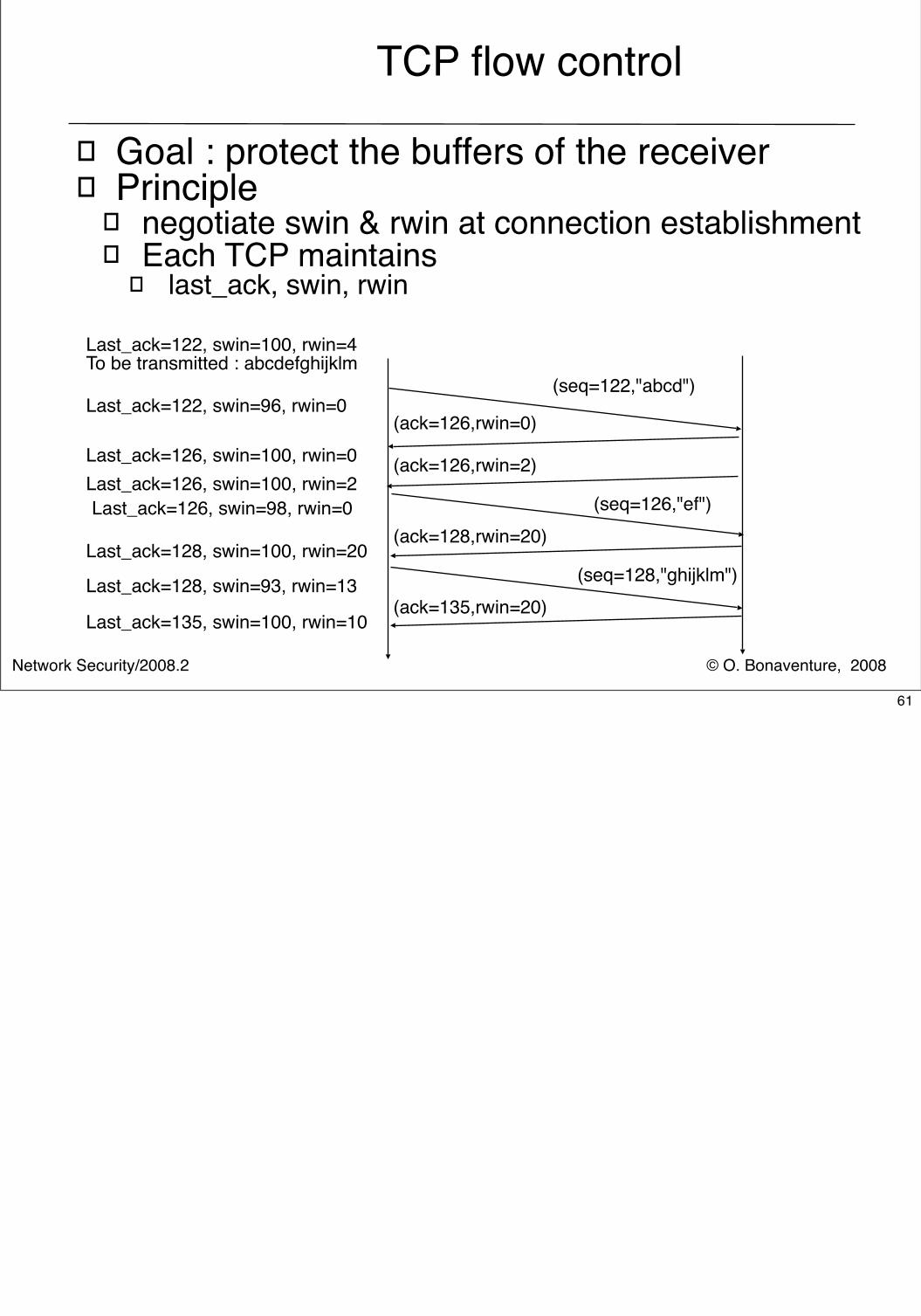
TCP flow control
� Goal : protect the buffers of the receiver� Principle
� negotiate swin & rwin at connection establishment� Each TCP maintains
� last_ack, swin, rwin
Last_ack=122, swin=100, rwin=4To be transmitted : abcdefghijklm
(seq=122,"abcd")Last_ack=122, swin=96, rwin=0
(ack=126,rwin=0)Last_ack=126, swin=100, rwin=0 (ack=126,rwin=2)Last_ack=126, swin=100, rwin=2
(ack=128,rwin=20)Last_ack=128, swin=100, rwin=20
Last_ack=128, swin=93, rwin=13 (seq=128,"ghijklm")(ack=135,rwin=20)
Last_ack=135, swin=100, rwin=10
(seq=126,"ef")Last_ack=126, swin=98, rwin=0
61
Network Security/2008.2 © O. Bonaventure, 2008
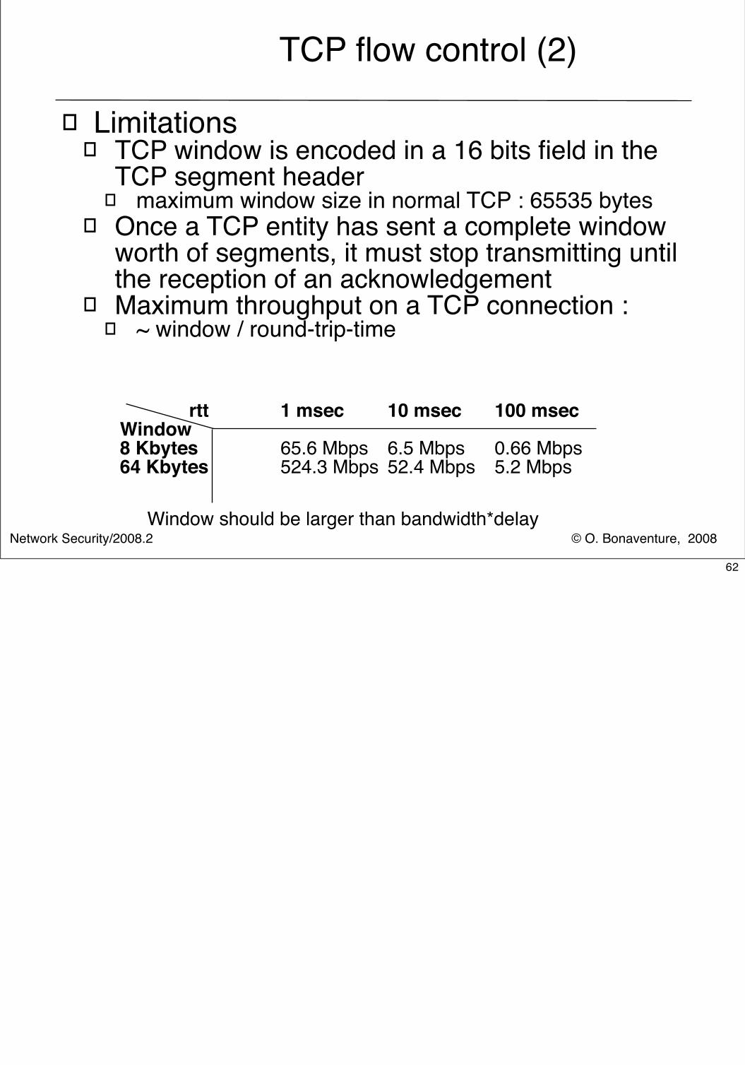
TCP flow control (2)
� Limitations� TCP window is encoded in a 16 bits field in the
TCP segment header� maximum window size in normal TCP : 65535 bytes
� Once a TCP entity has sent a complete window worth of segments, it must stop transmitting until the reception of an acknowledgement
� Maximum throughput on a TCP connection :� ~ window / round-trip-time
rtt 1 msec 10 msec 100 msecWindow8 Kbytes 65.6 Mbps 6.5 Mbps 0.66 Mbps 64 Kbytes 524.3 Mbps 52.4 Mbps 5.2 Mbps
Window should be larger than bandwidth*delay
62
Network Security/2008.2 © O. Bonaventure, 2008
TCP segment transmission
� When do we send a TCP segment ?� As soon as the application gave some data to TCP
� advantage : low delay� disadvantage : high overhead
� As soon as a MSS-sized segment can be sent� advantage : low overhead� disadvantage : delay can be high
� Nagle algorithm � a new segment with all the data waiting to be transmitted
is sent provided that either� a MSS-sized segment can be sent, or� there is currently no segment which has already been sent
but not yet acknowledged
63
Network Security/2008.2 © O. Bonaventure, 2008
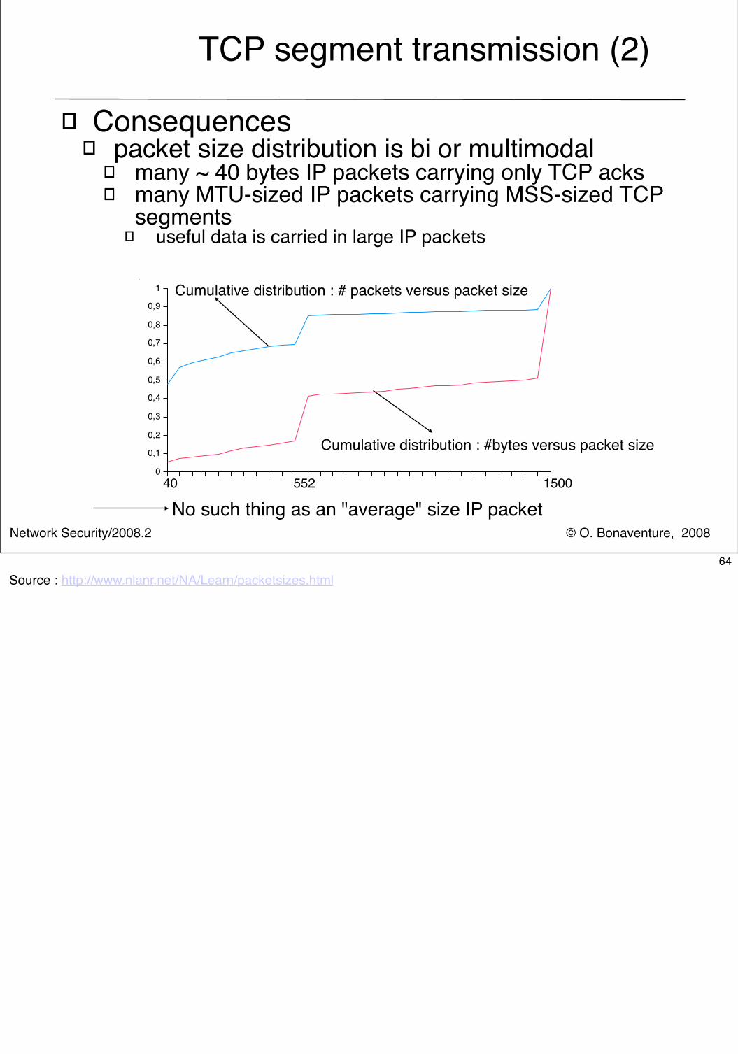
TCP segment transmission (2)
� Consequences� packet size distribution is bi or multimodal
� many ~ 40 bytes IP packets carrying only TCP acks � many MTU-sized IP packets carrying MSS-sized TCP
segments� useful data is carried in large IP packets
No such thing as an "average" size IP packet
Cumulative distribution : # packets versus packet size
Cumulative distribution : #bytes versus packet size
40 552 1500
64Source : http://www.nlanr.net/NA/Learn/packetsizes.html
© O. Bonaventure, 2008Network Security/2008.2
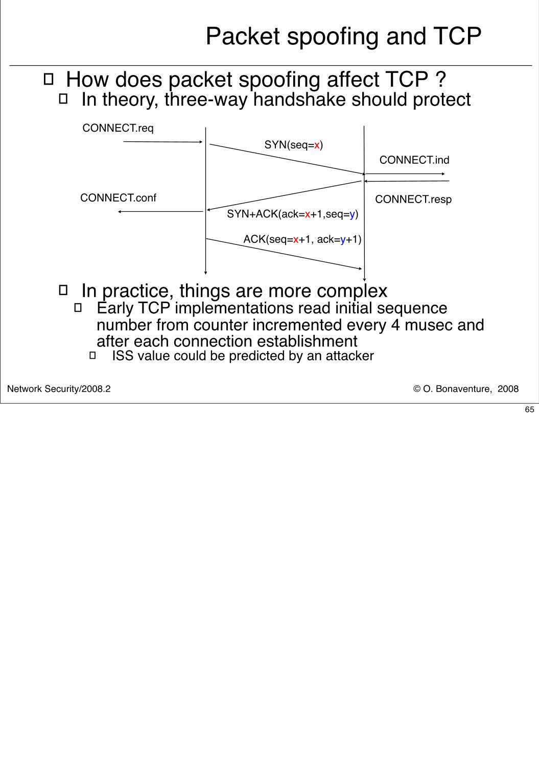
Packet spoofing and TCP� How does packet spoofing affect TCP ?
� In theory, three-way handshake should protect
� In practice, things are more complex� Early TCP implementations read initial sequence
number from counter incremented every 4 musec and after each connection establishment
� ISS value could be predicted by an attacker
SYN+ACK(ack=x+1,seq=y)
SYN(seq=x)
ACK(seq=x+1, ack=y+1)
CONNECT.req
CONNECT.ind
CONNECT.respCONNECT.conf
65
© O. Bonaventure, 2008Network Security/2008.2
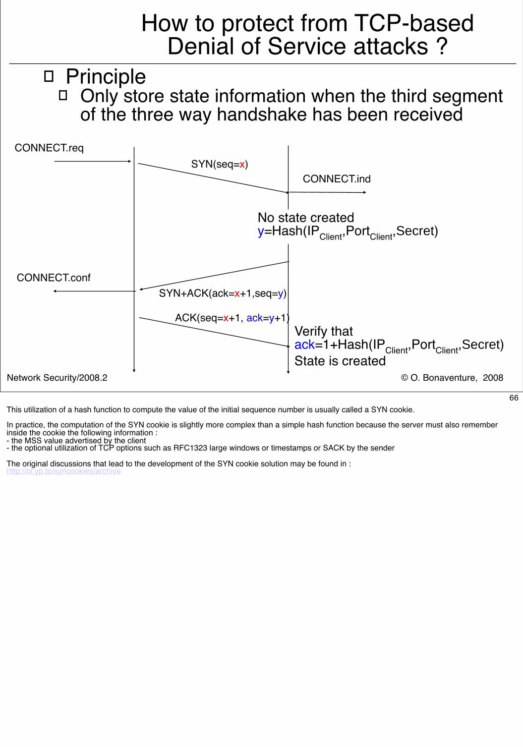
How to protect from TCP-based Denial of Service attacks ?
� Principle� Only store state information when the third segment
of the three way handshake has been received
SYN+ACK(ack=x+1,seq=y)
SYN(seq=x)
ACK(seq=x+1, ack=y+1)
CONNECT.req
CONNECT.ind
CONNECT.conf
No state createdy=Hash(IPClient,PortClient,Secret)
Verify thatack=1+Hash(IPClient,PortClient,Secret)State is created
66This utilization of a hash function to compute the value of the initial sequence number is usually called a SYN cookie.
In practice, the computation of the SYN cookie is slightly more complex than a simple hash function because the server must also remember inside the cookie the following information :- the MSS value advertised by the client- the optional utilization of TCP options such as RFC1323 large windows or timestamps or SACK by the sender
The original discussions that lead to the development of the SYN cookie solution may be found in :http://cr.yp.to/syncookies/archive
© O. Bonaventure, 2008Network Security/2008.2
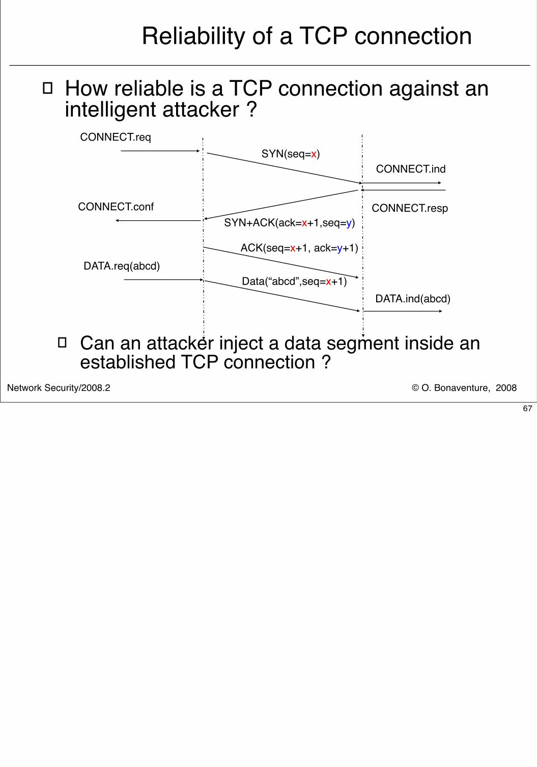
Reliability of a TCP connection
� How reliable is a TCP connection against an intelligent attacker ?
� Can an attacker inject a data segment inside an established TCP connection ?
SYN(seq=x)
SYN+ACK(ack=x+1,seq=y)
ACK(seq=x+1, ack=y+1)
CONNECT.req
CONNECT.ind
CONNECT.respCONNECT.conf
Data(“abcd”,seq=x+1)DATA.req(abcd)
DATA.ind(abcd)
67
© O. Bonaventure, 2008Network Security/2008.2
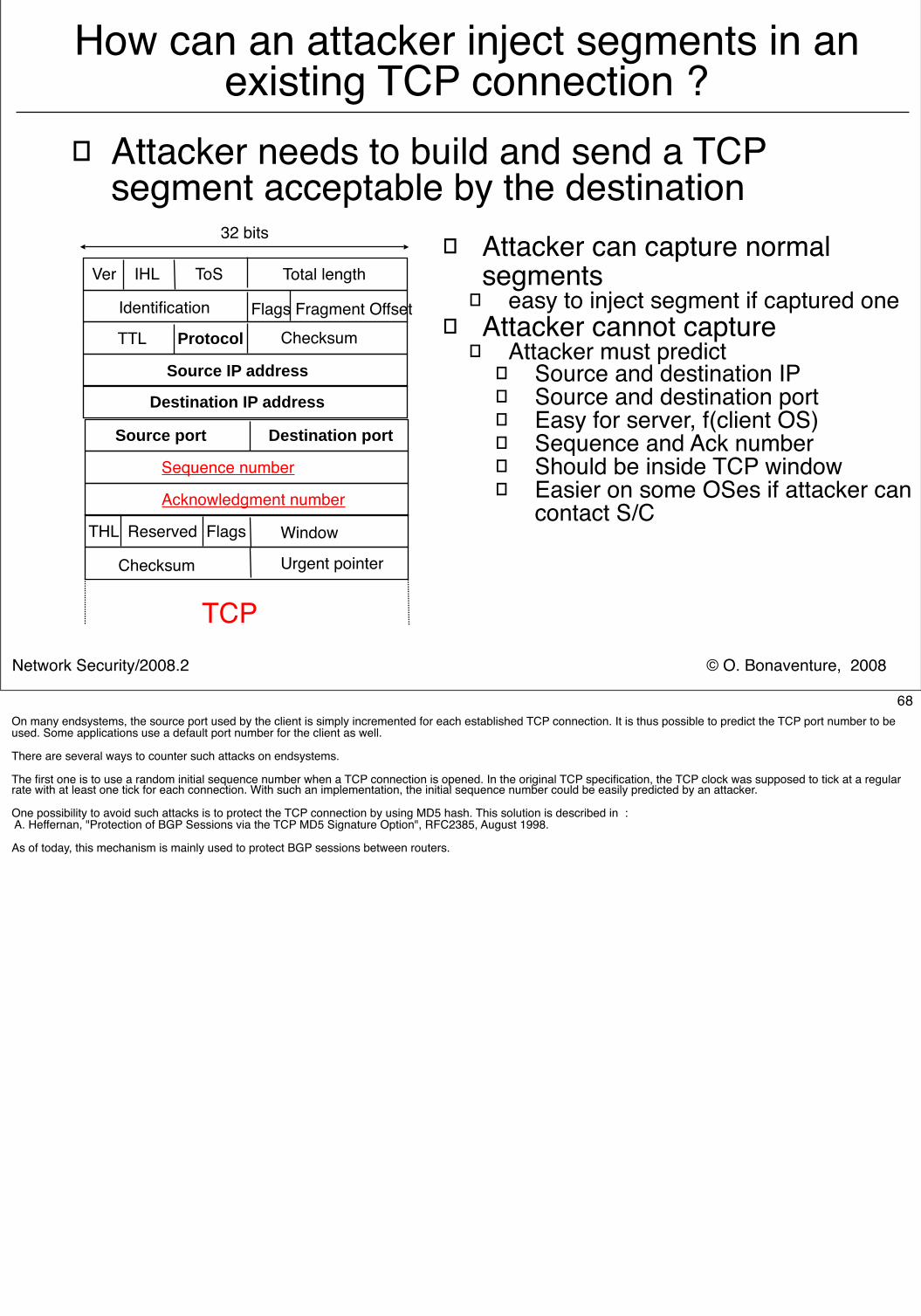
How can an attacker inject segments in an existing TCP connection ?
� Attacker needs to build and send a TCP segment acceptable by the destination
Source port Destination port
32 bits
Checksum Urgent pointer
THL Reserved Flags
Acknowledgment number
Sequence number
Window
Ver IHL ToS Total length
Checksum TTL Protocol
Flags Fragment Offset
Source IP address
Identification
Destination IP address
TCP
� Attacker can capture normal segments
� easy to inject segment if captured one� Attacker cannot capture
� Attacker must predict� Source and destination IP� Source and destination port� Easy for server, f(client OS)� Sequence and Ack number� Should be inside TCP window� Easier on some OSes if attacker can
contact S/C
68On many endsystems, the source port used by the client is simply incremented for each established TCP connection. It is thus possible to predict the TCP port number to be used. Some applications use a default port number for the client as well.
There are several ways to counter such attacks on endsystems.
The first one is to use a random initial sequence number when a TCP connection is opened. In the original TCP specification, the TCP clock was supposed to tick at a regular rate with at least one tick for each connection. With such an implementation, the initial sequence number could be easily predicted by an attacker.
One possibility to avoid such attacks is to protect the TCP connection by using MD5 hash. This solution is described in : A. Heffernan, "Protection of BGP Sessions via the TCP MD5 Signature Option", RFC2385, August 1998.
As of today, this mechanism is mainly used to protect BGP sessions between routers.
© O. Bonaventure, 2008Network Security/2008.2
RST attacks� The TCP RST segment
� sent upon reception of invalid TCP segment� syntax error in received segment� data or ack segment on invalid TCP connection
� Reception of RST segment -> abrupt release
� Validation of received TCP RST segment� RST segment must contain
� IP source and source port of active TCP connection� IP destination and destination port of active TCP connection� Sequence number of RST segment must be within received
window� TCP sequence number space is 232, with a 64KB window, 65535
RST segments are sufficient to reset a connection
69More details on this attack are available from :M. Dalal (Ed), Transmission Control Protocol security considerations, Internet draft, draft-ietf-tcpm-tcpsecure-02.txt, November 2004A similar attack is possible with the SYN bit instead of the RST bit.The test for the validity of a received segment in RFC793 is : 1) If the RST bit is set and the sequence number is outside the expected window, silently drop the segment. 2) If the RST bit is set and the sequence number is acceptable i.e.: (RCV.NXT <= SEG.SEQ <= RCV.NXT+RCV.WND) then reset the connection.
Several solutions to avoid this problem are being considered, but deploying them in all TCP implementations is challenging.A first solution is to restrict the validity check for the RST segments. A RST segment would be considered as valid only if : RCV.NXT <= SEG.SEQ <= RCV.NXT+1With this modification, an attacker has to guess the exact sequence number. However, this also forces the sender of a valid RST to know this information as well, which may not be possible if there are packet losses. To avoid this problem, a possibility is to force a TCP implementation to send a ACK segment (including RCV.NXT as its ACK number) in response to the received invalid RST segment to allow the remote endsystem to respond with a RST containing the correct sequence number.
© O. Bonaventure, 2008Network Security/2008.2
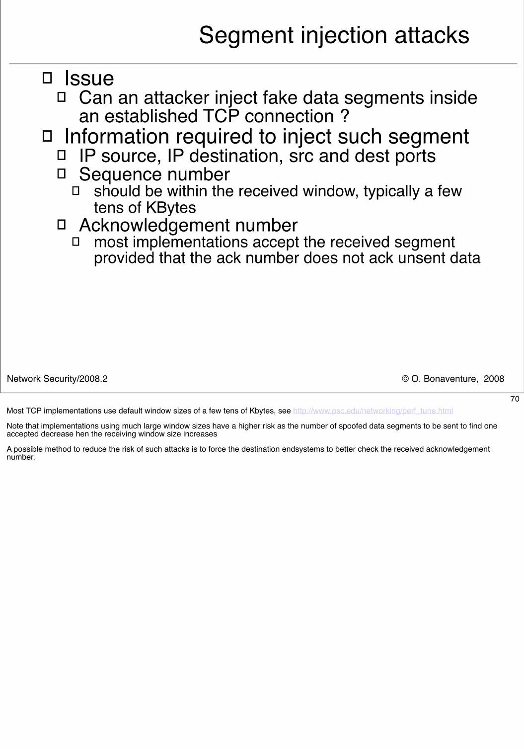
Segment injection attacks� Issue
� Can an attacker inject fake data segments inside an established TCP connection ?
� Information required to inject such segment � IP source, IP destination, src and dest ports� Sequence number
� should be within the received window, typically a few tens of KBytes
� Acknowledgement number� most implementations accept the received segment
provided that the ack number does not ack unsent data
70Most TCP implementations use default window sizes of a few tens of Kbytes, see http://www.psc.edu/networking/perf_tune.html
Note that implementations using much large window sizes have a higher risk as the number of spoofed data segments to be sent to find one accepted decrease hen the receiving window size increases
A possible method to reduce the risk of such attacks is to force the destination endsystems to better check the received acknowledgement number.
© O. Bonaventure, 2008Network Security/2008.2
Segment injection attacks (2)
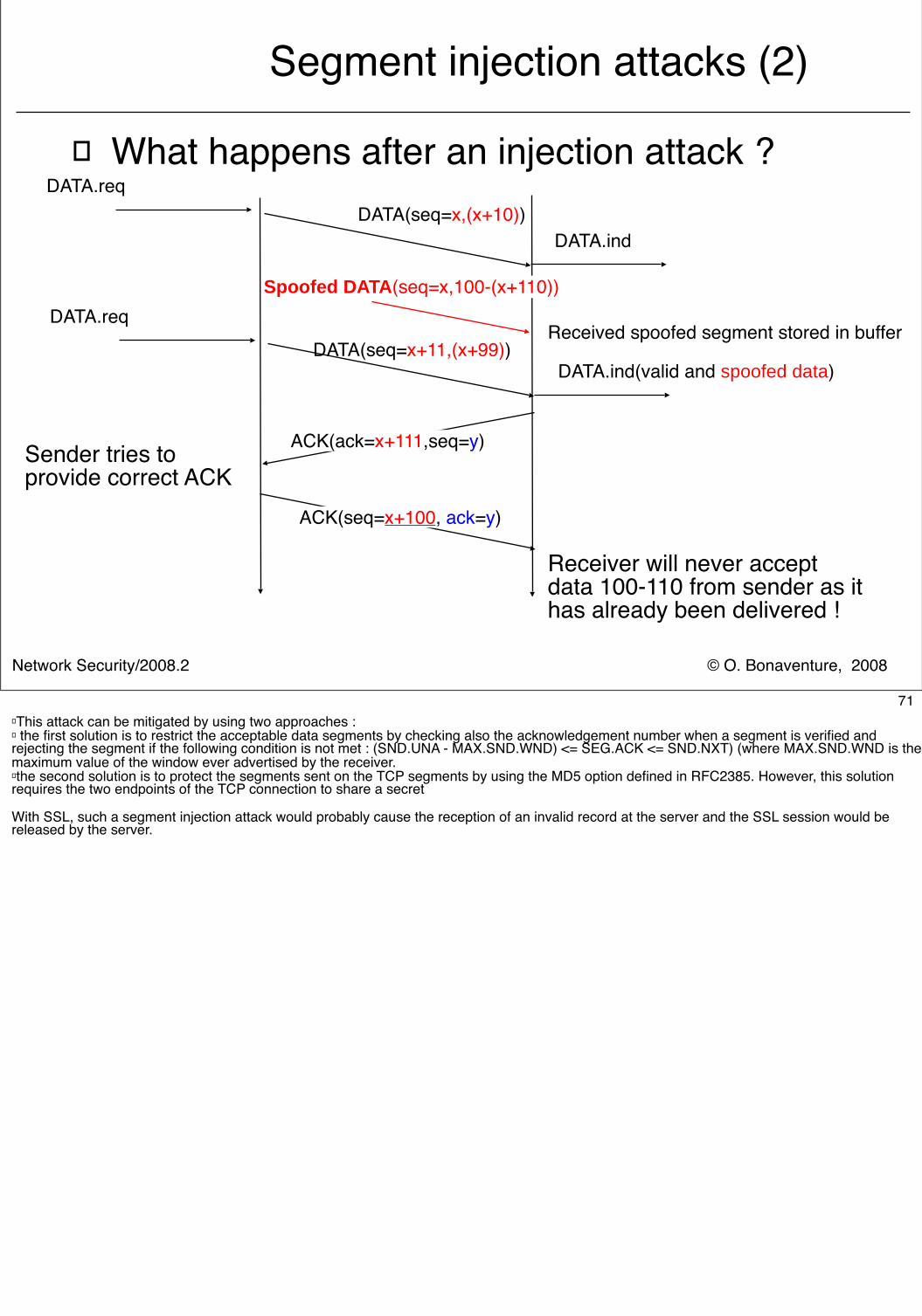
� What happens after an injection attack ?
ACK(ack=x+111,seq=y)
DATA(seq=x+11,(x+99))DATA.req
DATA.ind(valid and spoofed data)
ACK(seq=x+100, ack=y)
Sender tries to provide correct ACK
Spoofed DATA(seq=x,100-(x+110))
Received spoofed segment stored in buffer
DATA(seq=x,(x+10))DATA.req
DATA.ind
Receiver will never acceptdata 100-110 from sender as ithas already been delivered !
71� This attack can be mitigated by using two approaches :� the first solution is to restrict the acceptable data segments by checking also the acknowledgement number when a segment is verified and rejecting the segment if the following condition is not met : (SND.UNA - MAX.SND.WND) <= SEG.ACK <= SND.NXT) (where MAX.SND.WND is the maximum value of the window ever advertised by the receiver.� the second solution is to protect the segments sent on the TCP segments by using the MD5 option defined in RFC2385. However, this solution requires the two endpoints of the TCP connection to share a secret
With SSL, such a segment injection attack would probably cause the reception of an invalid record at the server and the SSL session would be released by the server.
© O. Bonaventure, 2008Network Security/2008.2
Impact of TCP security issues� SYN flooding
� all implementations use SYN cookies to mitigate them
� Segment injection attacks� To succeed, attacker must send many spoofed
packets and predict IP and TCP information� Long-lived TCP connections face higher risk than
short-lived TCP connections� easier to spoof continuous BGP or ssh session than http
� To reduce the impact of such attacks� Client should use random port numbers as often as
possible among the entire port range� windows should not be too large
72
© O. Bonaventure, 2008Network Security/2008.2
TCP MD5 option� Principle
� TCP MD5 option negotiated during TCP connection establishment
� MD5 option used to carry MD5 hash in each segment
� Two endpoints of TCP connection share secret
� On transmission, compute and place in segment� Hash = MD5 (IP source || IP destination || protocol
number || segment length ||TCP header without options and checksum || TCP data || secret)
� On segment arrival, recompute Hash and check� If MD5 option is correct, segment is processed� If MD5 option is incorrect, segment is discarded
73
© O. Bonaventure, 2008Network Security/2008.2
Internet and Network security
� Crypto building blocks� Application-layer security
� SSL� Transport-layer security
� Securing TCP� Network-layer security
� IPv4� IPv6� IPSec� Routing security
74
© O. Bonaventure, 2008Network Security/2008.2
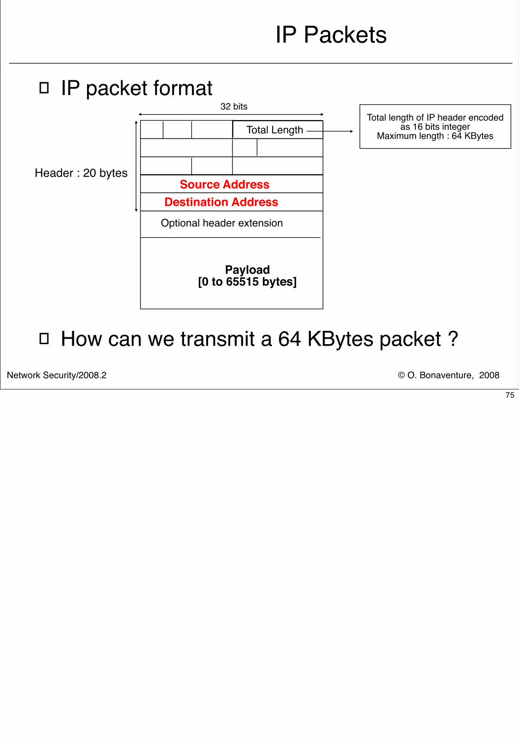
IP Packets
� IP packet format
� How can we transmit a 64 KBytes packet ?
Payload[0 to 65515 bytes]
32 bits
Source Address
Destination Address
Header : 20 bytes
Optional header extension
Total LengthTotal length of IP header encoded
as 16 bits integerMaximum length : 64 KBytes
75
© O. Bonaventure, 2008Network Security/2008.2
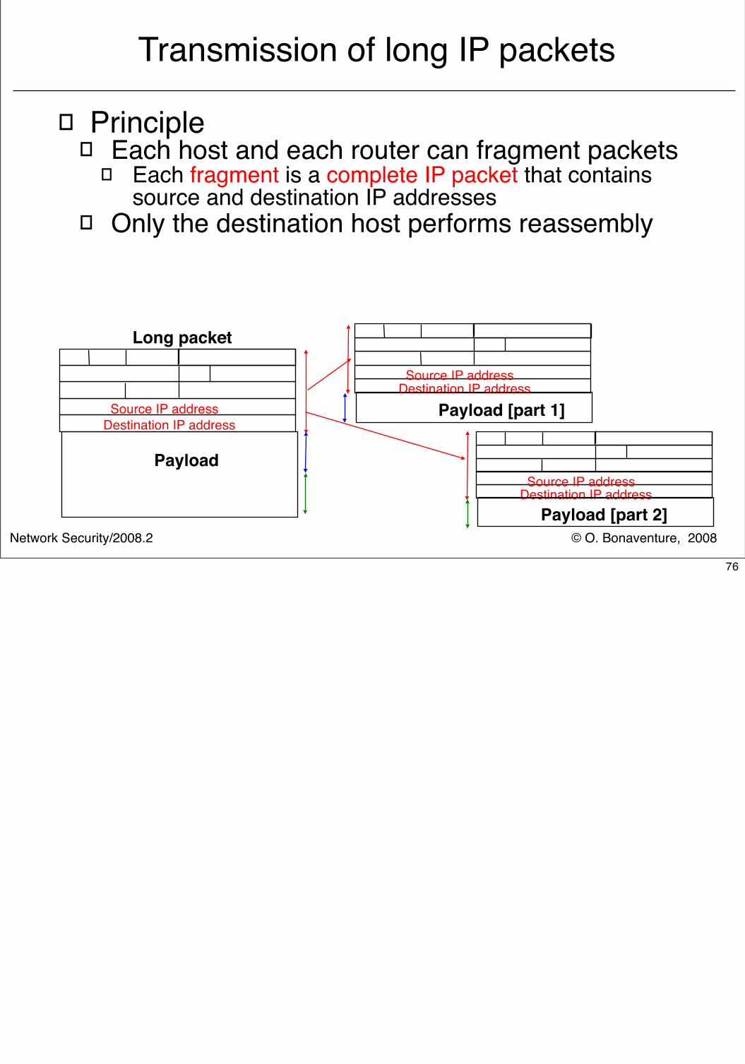
Transmission of long IP packets
� Principle� Each host and each router can fragment packets
� Each fragment is a complete IP packet that contains source and destination IP addresses
� Only the destination host performs reassembly
Payload
Source IP address
Destination IP address
Source IP address
Destination IP address
Long packet
Source IP address
Destination IP address
Payload [part 1]
Payload [part 2]
76
© O. Bonaventure, 2008Network Security/2008.2
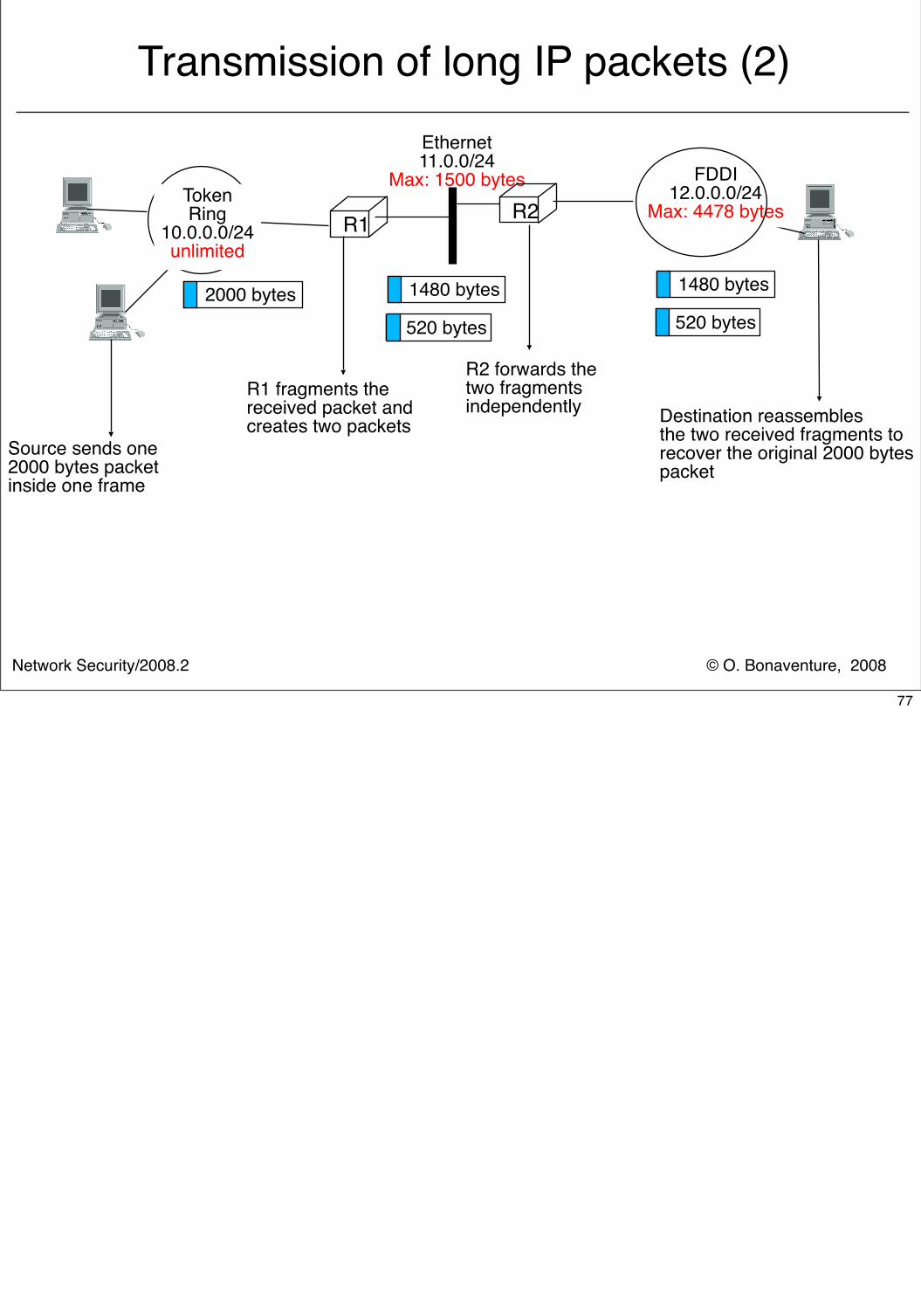
Transmission of long IP packets (2)
R1
Ethernet11.0.0/24
Max: 1500 bytes R2
FDDI12.0.0.0/24
Max: 4478 bytes TokenRing
10.0.0.0/24unlimited
2000 bytes
Source sends one2000 bytes packetinside one frame
Destination reassemblesthe two received fragments torecover the original 2000 bytespacket
1480 bytes
520 bytes
R1 fragments thereceived packet and creates two packets
R2 forwards the two fragments independently
1480 bytes
520 bytes
77
© O. Bonaventure, 2008Network Security/2008.2
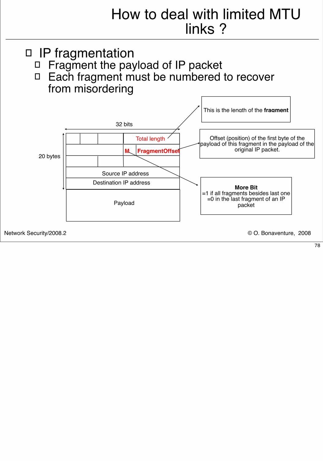
How to deal with limited MTU links ?
� IP fragmentation� Fragment the payload of IP packet� Each fragment must be numbered to recover
from misordering
Total length
Payload
32 bits
M FragmentOffset20 bytes
Source IP address Destination IP address
This is the length of the fragment
Offset (position) of the first byte of the payload of this fragment in the payload of the
original IP packet.
More Bit=1 if all fragments besides last one
=0 in the last fragment of an IP packet
78
© O. Bonaventure, 2008Network Security/2008.2
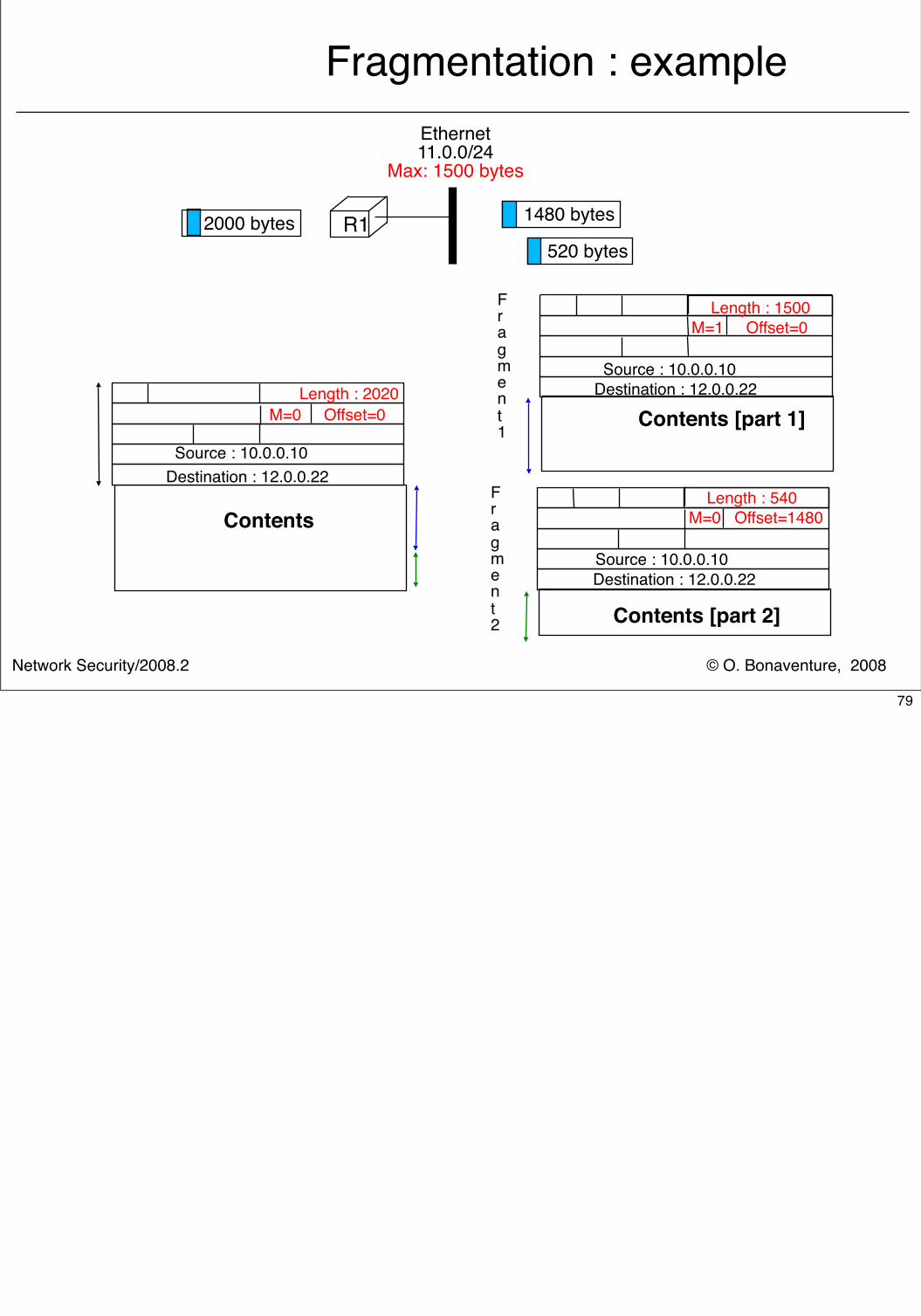
Fragmentation : example
R1
Ethernet11.0.0/24
Max: 1500 bytes
Contents
Source : 10.0.0.10
Destination : 12.0.0.22
2000 bytes
Length : 2020 M=0 Offset=0
Source : 10.0.0.10
Destination : 12.0.0.22
Contents [part 1]
Fragment1
Fragment2 Contents [part 2]
Length : 1500 M=1 Offset=0
M=0 Offset=1480 Length : 540
1480 bytes
520 bytes
Destination : 12.0.0.22Source : 10.0.0.10
79
© O. Bonaventure, 2008Network Security/2008.2
Reassembly
� Issues� When does the destination has received all
fragments ?� Last fragment contains bit More=0� How to handle lost fragments ?
� the IP packet will not be reassembled by destination and received fragments of this packet will be discarded
� How to deal with misordering� Offset field allows to reorder fragments from same
packet� But misordering can cause fragments from multiple
packets to be mixed� Each fragment must contain an identification of the original
packet from which is was created
80
© O. Bonaventure, 2008Network Security/2008.2
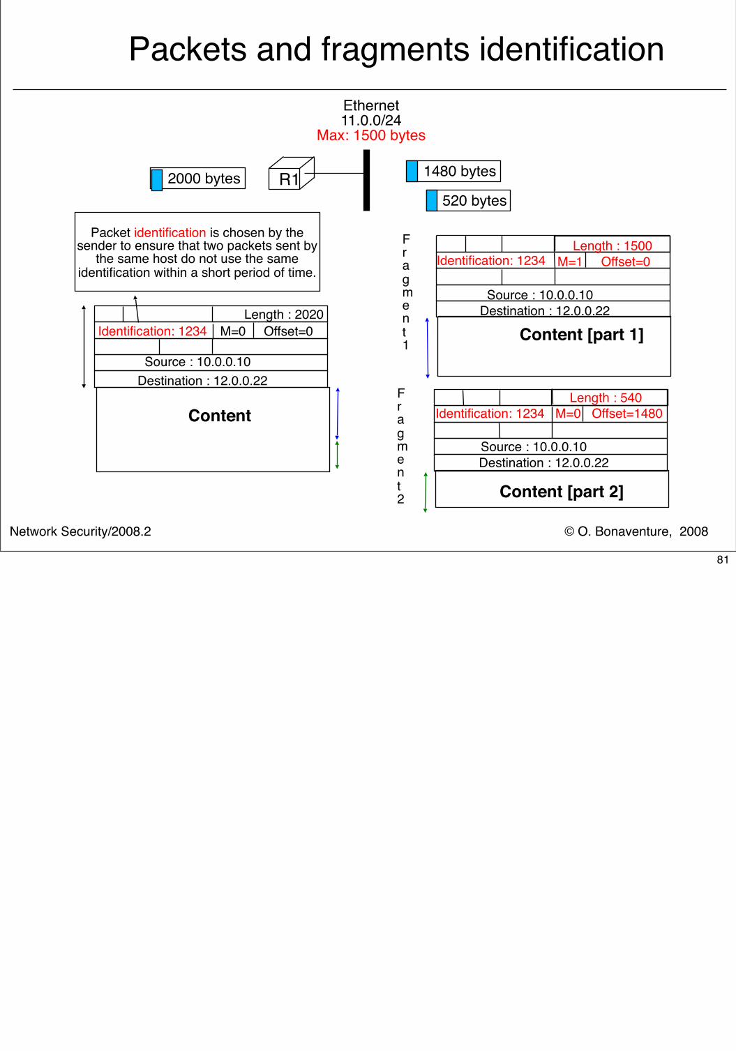
Packets and fragments identification
Content
Source : 10.0.0.10
Destination : 12.0.0.22
Source : 10.0.0.10
Destination : 12.0.0.22
Content [part 1]
Fragment1
Fragment2 Content [part 2]
Length : 1500 M=1 Offset=0
M=0 Offset=1480 Length : 540
R1
Ethernet11.0.0/24
Max: 1500 bytes
2000 bytes 1480 bytes
520 bytes
Length : 2020 M=0 Offset=0
Destination : 12.0.0.22Source : 10.0.0.10
Identification: 1234
Identification: 1234
Identification: 1234
Packet identification is chosen by the sender to ensure that two packets sent by
the same host do not use the same identification within a short period of time.
81
© O. Bonaventure, 2008Network Security/2008.2
IP reassembly
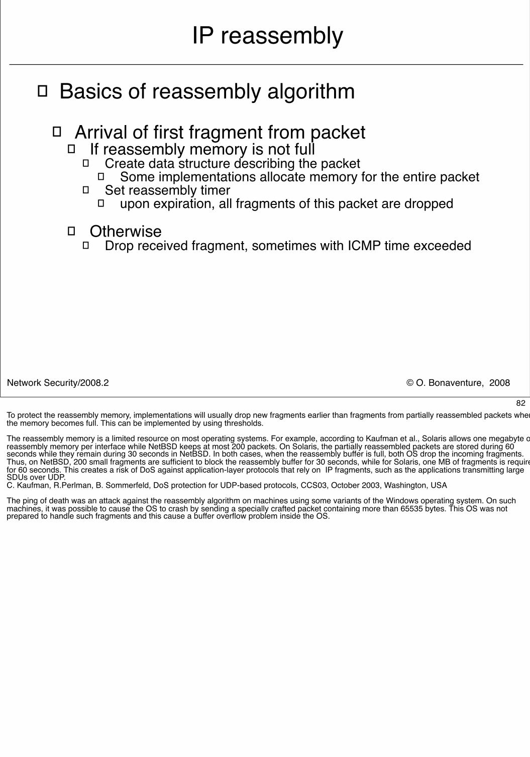
� Basics of reassembly algorithm� Arrival of first fragment from packet
� If reassembly memory is not full� Create data structure describing the packet
� Some implementations allocate memory for the entire packet� Set reassembly timer
� upon expiration, all fragments of this packet are dropped
� Otherwise� Drop received fragment, sometimes with ICMP time exceeded
82To protect the reassembly memory, implementations will usually drop new fragments earlier than fragments from partially reassembled packets when the memory becomes full. This can be implemented by using thresholds.
The reassembly memory is a limited resource on most operating systems. For example, according to Kaufman et al., Solaris allows one megabyte of reassembly memory per interface while NetBSD keeps at most 200 packets. On Solaris, the partially reassembled packets are stored during 60 seconds while they remain during 30 seconds in NetBSD. In both cases, when the reassembly buffer is full, both OS drop the incoming fragments. Thus, on NetBSD, 200 small fragments are sufficient to block the reassembly buffer for 30 seconds, while for Solaris, one MB of fragments is required for 60 seconds. This creates a risk of DoS against application-layer protocols that rely on IP fragments, such as the applications transmitting large SDUs over UDP.C. Kaufman, R.Perlman, B. Sommerfeld, DoS protection for UDP-based protocols, CCS03, October 2003, Washington, USA
The ping of death was an attack against the reassembly algorithm on machines using some variants of the Windows operating system. On such machines, it was possible to cause the OS to crash by sending a specially crafted packet containing more than 65535 bytes. This OS was not prepared to handle such fragments and this cause a buffer overflow problem inside the OS.
© O. Bonaventure, 2008Network Security/2008.2
IP reassembly (2)
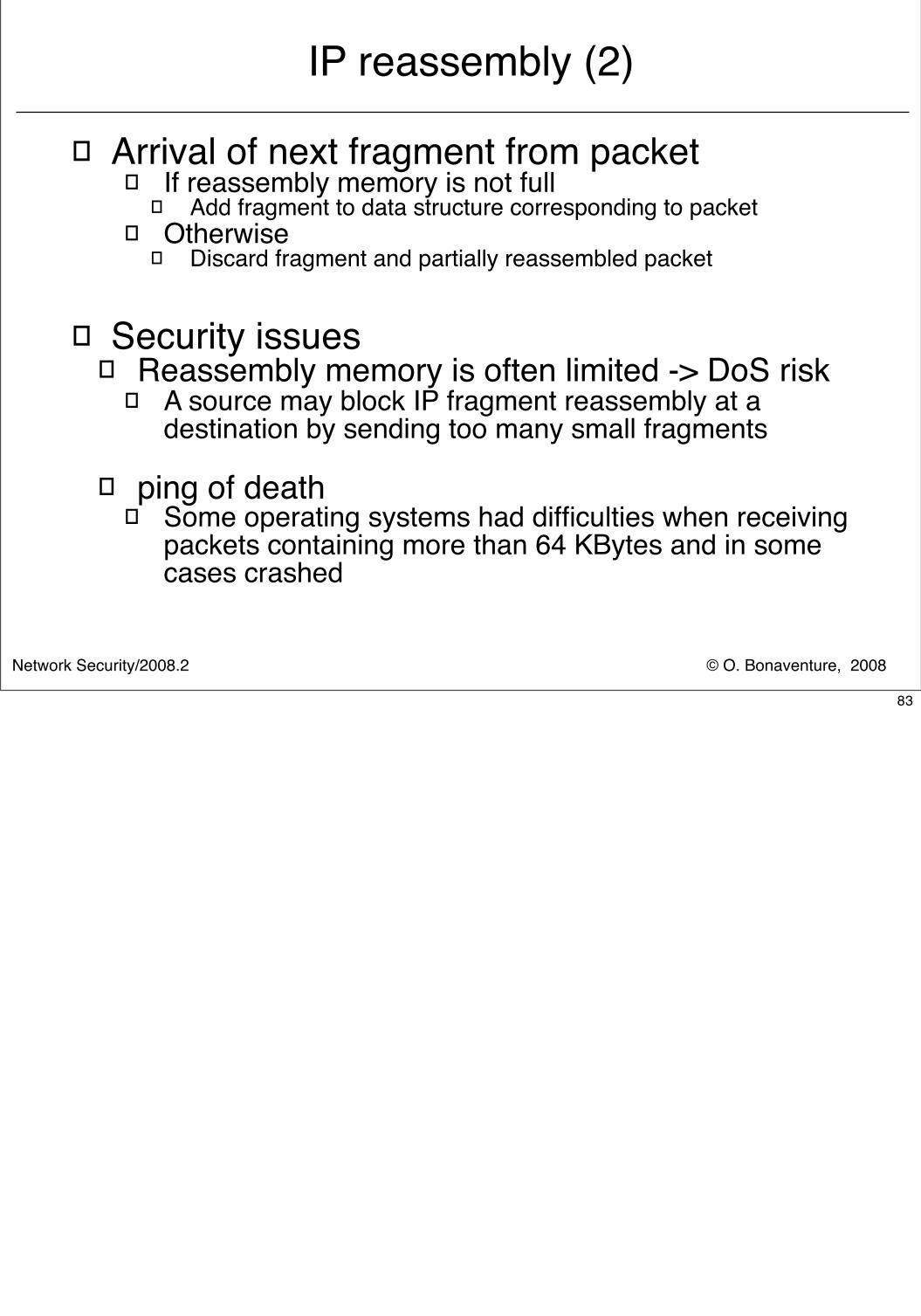
� Arrival of next fragment from packet� If reassembly memory is not full
� Add fragment to data structure corresponding to packet� Otherwise
� Discard fragment and partially reassembled packet
� Security issues� Reassembly memory is often limited -> DoS risk
� A source may block IP fragment reassembly at a destination by sending too many small fragments
� ping of death� Some operating systems had difficulties when receiving
packets containing more than 64 KBytes and in some cases crashed
83
© O. Bonaventure, 2008Network Security/2008.2
Transmission errors
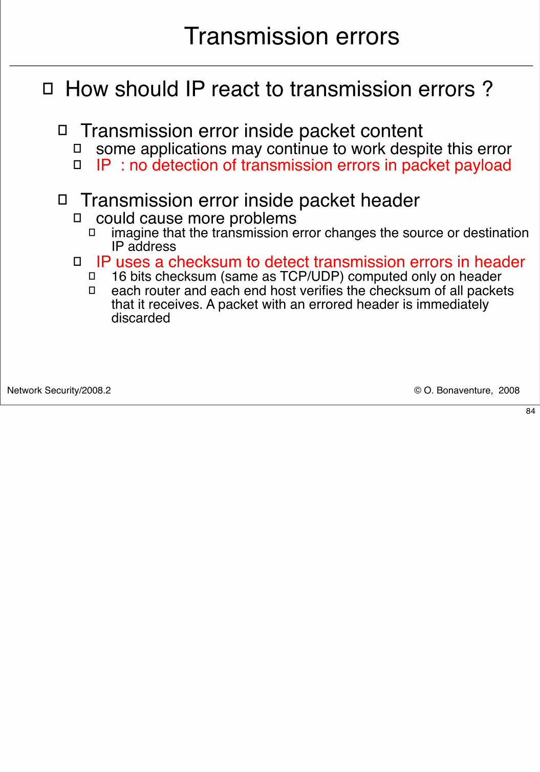
� How should IP react to transmission errors ?� Transmission error inside packet content
� some applications may continue to work despite this error� IP : no detection of transmission errors in packet payload
� Transmission error inside packet header� could cause more problems
� imagine that the transmission error changes the source or destination IP address
� IP uses a checksum to detect transmission errors in header� 16 bits checksum (same as TCP/UDP) computed only on header� each router and each end host verifies the checksum of all packets
that it receives. A packet with an errored header is immediately discarded
84
© O. Bonaventure, 2008Network Security/2008.2
Transient and permanent loops
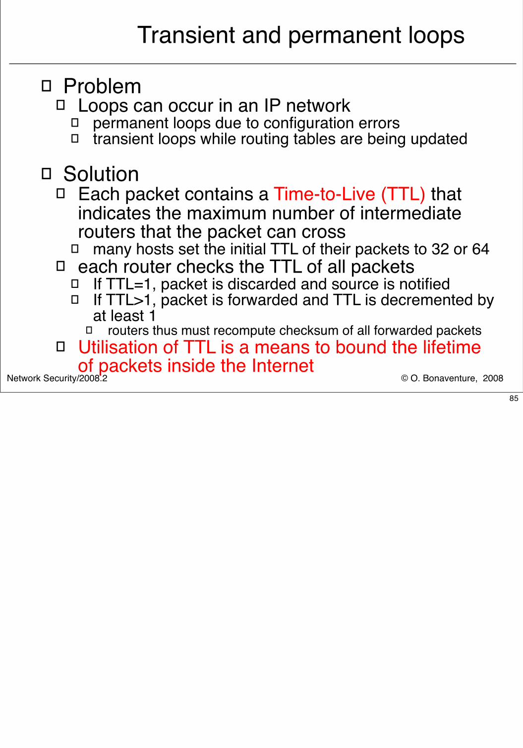
� Problem� Loops can occur in an IP network
� permanent loops due to configuration errors� transient loops while routing tables are being updated
� Solution� Each packet contains a Time-to-Live (TTL) that
indicates the maximum number of intermediate routers that the packet can cross
� many hosts set the initial TTL of their packets to 32 or 64� each router checks the TTL of all packets
� If TTL=1, packet is discarded and source is notified� If TTL>1, packet is forwarded and TTL is decremented by
at least 1� routers thus must recompute checksum of all forwarded packets
� Utilisation of TTL is a means to bound the lifetime of packets inside the Internet
85
© O. Bonaventure, 2008Network Security/2008.2
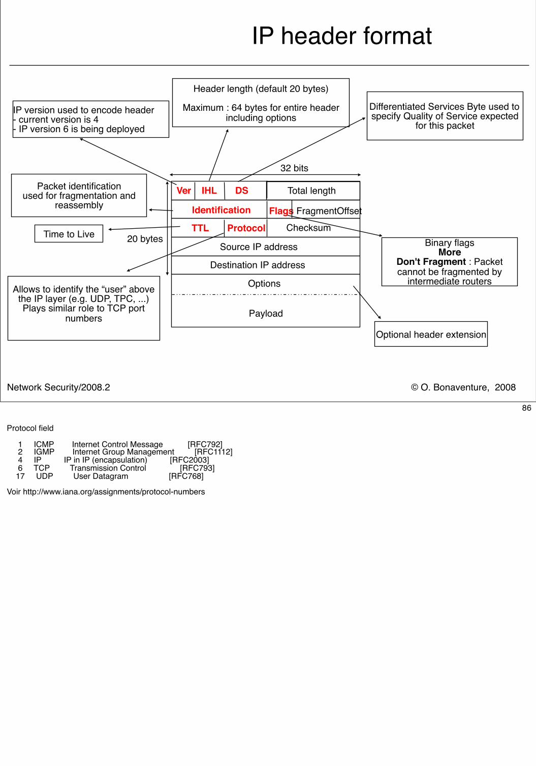
IP header format
Ver IHL DS Total length
Payload
32 bits
Checksum TTL ProtocolFlags FragmentOffset
20 bytesSource IP address
Identification
Destination IP address
Differentiated Services Byte used tospecify Quality of Service expected
for this packetIP version used to encode header- current version is 4- IP version 6 is being deployed
Header length (default 20 bytes)
Maximum : 64 bytes for entire header including options
Binary flagsMore
Don't Fragment : Packet cannot be fragmented by
intermediate routersAllows to identify the “user” above
the IP layer (e.g. UDP, TPC, ...)Plays similar role to TCP port
numbers
Packet identificationused for fragmentation and
reassembly
Options
Optional header extension
Time to Live
86
Protocol field
1 ICMP Internet Control Message [RFC792] 2 IGMP Internet Group Management [RFC1112] 4 IP IP in IP (encapsulation) [RFC2003] 6 TCP Transmission Control [RFC793] 17 UDP User Datagram [RFC768]
Voir http://www.iana.org/assignments/protocol-numbers
© O. Bonaventure, 2008Network Security/2008.2
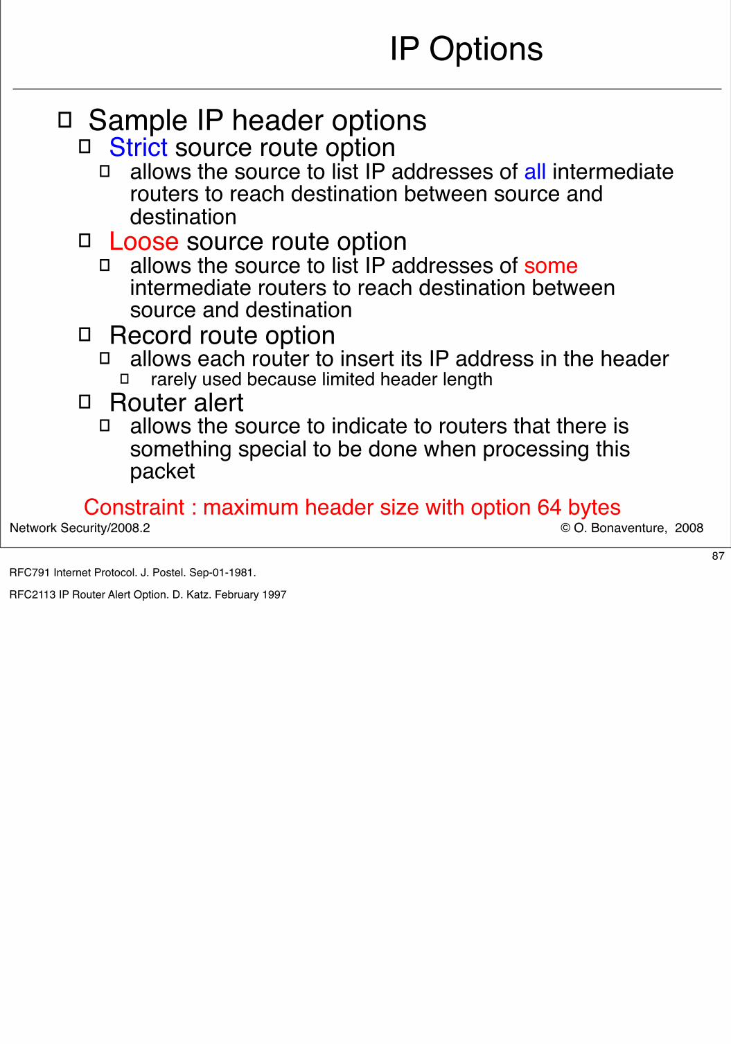
IP Options
� Sample IP header options� Strict source route option
� allows the source to list IP addresses of all intermediate routers to reach destination between source and destination
� Loose source route option� allows the source to list IP addresses of some
intermediate routers to reach destination between source and destination
� Record route option� allows each router to insert its IP address in the header
� rarely used because limited header length� Router alert
� allows the source to indicate to routers that there is something special to be done when processing this packet
Constraint : maximum header size with option 64 bytes
87RFC791 Internet Protocol. J. Postel. Sep-01-1981.
RFC2113 IP Router Alert Option. D. Katz. February 1997
© O. Bonaventure, 2008Network Security/2008.2
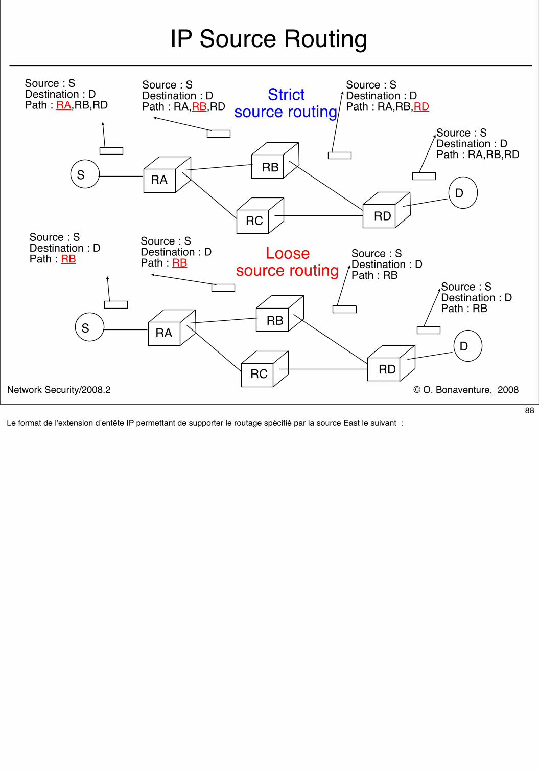
IP Source Routing
SD
RBRA
RC RD
Source : SDestination : DPath : RA,RB,RD
Source : SDestination : DPath : RA,RB,RD
Source : SDestination : DPath : RA,RB,RD
Source : SDestination : DPath : RA,RB,RD
Source : SDestination : DPath : RB
Source : SDestination : DPath : RB
Source : SDestination : DPath : RB
Source : SDestination : DPath : RB
Strict source routing
SD
RBRA
RC RD
Loose source routing
88Le format de l'extension d'entête IP permettant de supporter le routage spécifié par la source East le suivant :
© O. Bonaventure, 2008Network Security/2008.2
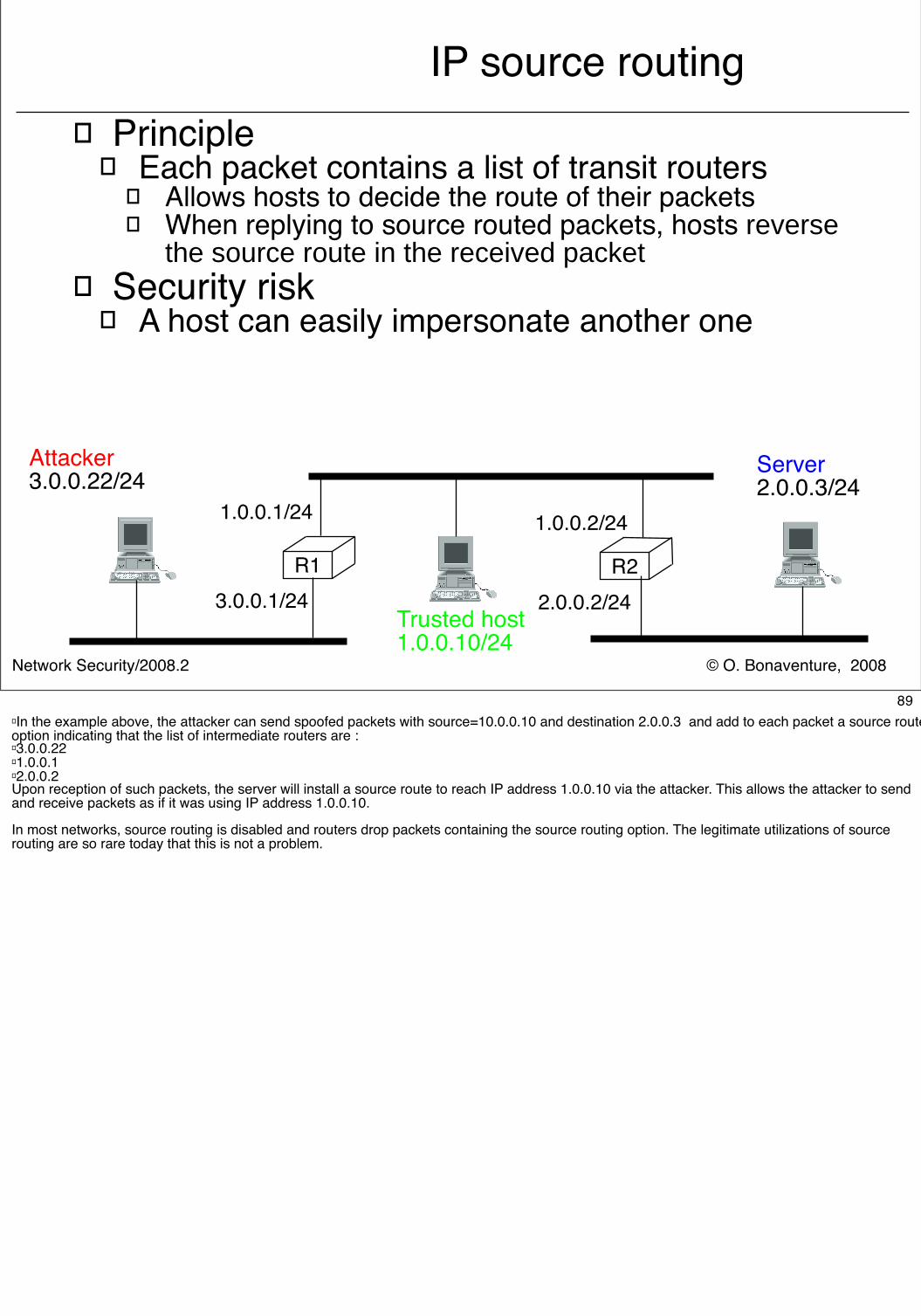
IP source routing� Principle
� Each packet contains a list of transit routers� Allows hosts to decide the route of their packets� When replying to source routed packets, hosts reverse
the source route in the received packet� Security risk
� A host can easily impersonate another one
Trusted host1.0.0.10/24
R2
1.0.0.2/24
2.0.0.2/24
Attacker3.0.0.22/24 Server
2.0.0.3/24
R1
1.0.0.1/24
3.0.0.1/24
89� In the example above, the attacker can send spoofed packets with source=10.0.0.10 and destination 2.0.0.3 and add to each packet a source route option indicating that the list of intermediate routers are :� 3.0.0.22� 1.0.0.1� 2.0.0.2Upon reception of such packets, the server will install a source route to reach IP address 1.0.0.10 via the attacker. This allows the attacker to send and receive packets as if it was using IP address 1.0.0.10.
In most networks, source routing is disabled and routers drop packets containing the source routing option. The legitimate utilizations of source routing are so rare today that this is not a problem.
© O. Bonaventure, 2008Network Security/2008.2
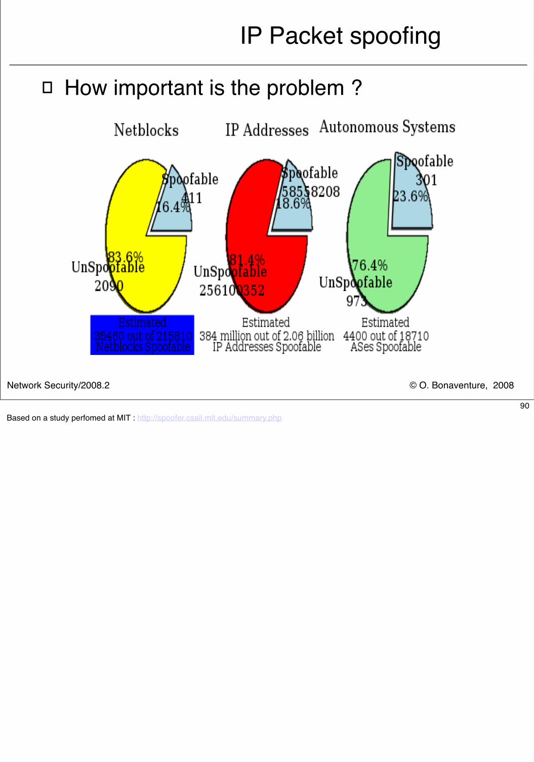
IP Packet spoofing
� How important is the problem ?
90Based on a study perfomed at MIT : http://spoofer.csail.mit.edu/summary.php
© O. Bonaventure, 2008Network Security/2008.2
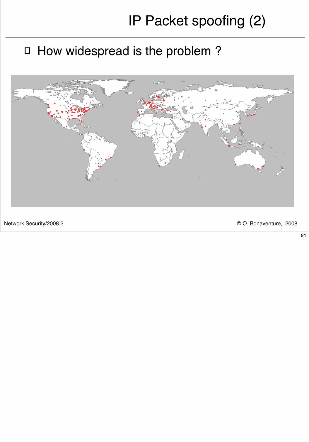
IP Packet spoofing (2)
� How widespread is the problem ?
91
© O. Bonaventure, 2008Network Security/2008.2
IP Packet spoofing (3)� What can be done to avoid spoofing ?
� Ingress filters � configure border routers of enterprise network to reject
all packets whose source address belongs to the IP prefixes of the enterprise
� RPF check� Principle
� When a packet arrives from source S on interface i, consult routing table to check that route to S is via i
� If yes, packet can be forwarded� Otherwise, packet is dropped
� Limitation� Does not protect against spoofing from the LAN containing the
subnet of the spoofed address
92Ingress filtering is defined in :
P. Ferguson, D. Senie. Network Ingress Filtering: Defeating Denial of Service Attacks which employ IP Source Address Spoofing. May 2000, RFC2827
© O. Bonaventure, 2008Network Security/2008.2
Operation of an IP endhost
� Required information on an IP endhost� IP addresses of its interfaces
� For each address, the subnet mask allows the endhost to determine the addresses that are directly reachable through the interface
� (small) routing table � Directly connected subnets
� From the subnet mask of its own IP addresses
� Default router� Router used to reach any unknown address� By convention, default route is 0.0.0.0/0
� Other subnets known by endhost� Could be manually configured or learned through routing protocols
are special packets (see later)
93Example
/sbin/ifconfig -alo0: flags=849<UP,LOOPBACK,RUNNING,MULTICAST> mtu 8232 inet 127.0.0.1 netmask ff000000 hme0: flags=863<UP,BROADCAST,NOTRAILERS,RUNNING,MULTICAST> mtu 1500 inet 130.104.229.58 netmask ffffff80 broadcast 130.104.229.127
Cette station dispose de deux interfaces, l'interface loopback East lo0 et l'interface Ethernet hme0.
table de routage
netstat -rnv
IRE Table: Destination Mask Gateway Device Mxfrg Rtt Ref Flg Out In/Fwd-------------------- --------------- -------------------- ------ ----- ----- --- --- ----- ------130.104.229.0 255.255.255.128 130.104.229.58 hme0 1500* 0 3 U 5750 0224.0.0.0 240.0.0.0 130.104.229.58 hme0 1500* 0 3 U 0 0default 0.0.0.0 130.104.229.126 1500* 0 0 UG 42564 0127.0.0.1 255.255.255.255 127.0.0.1 lo0 8232* 315 0 UH 65966 0
default correspond à la route par défaut, 0.0.0.0/0 et 224.0.0.0 correspond au multicast
© O. Bonaventure, 2008Network Security/2008.2
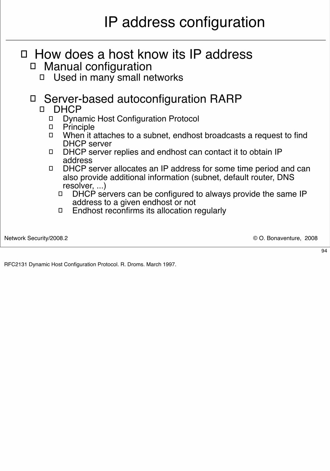
IP address configuration
� How does a host know its IP address � Manual configuration
� Used in many small networks
� Server-based autoconfiguration RARP� DHCP
� Dynamic Host Configuration Protocol� Principle� When it attaches to a subnet, endhost broadcasts a request to find
DHCP server� DHCP server replies and endhost can contact it to obtain IP
address � DHCP server allocates an IP address for some time period and can
also provide additional information (subnet, default router, DNS resolver, ...)
� DHCP servers can be configured to always provide the same IP address to a given endhost or not
� Endhost reconfirms its allocation regularly
94
RFC2131 Dynamic Host Configuration Protocol. R. Droms. March 1997.
© O. Bonaventure, 2008Network Security/2008.2
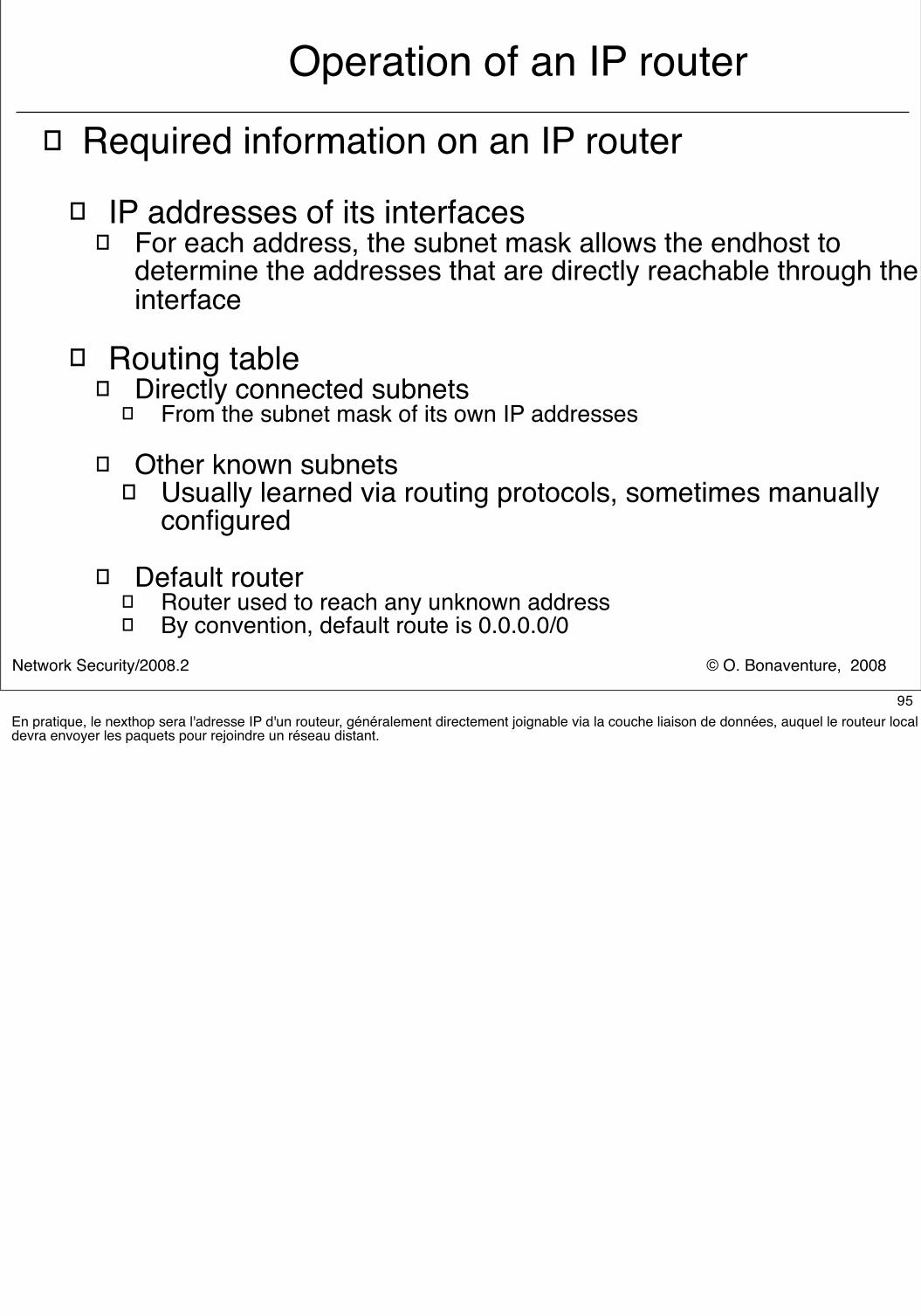
Operation of an IP router� Required information on an IP router
� IP addresses of its interfaces� For each address, the subnet mask allows the endhost to
determine the addresses that are directly reachable through the interface
� Routing table � Directly connected subnets
� From the subnet mask of its own IP addresses
� Other known subnets � Usually learned via routing protocols, sometimes manually
configured
� Default router� Router used to reach any unknown address� By convention, default route is 0.0.0.0/0
95En pratique, le nexthop sera l'adresse IP d'un routeur, généralement directement joignable via la couche liaison de données, auquel le routeur local devra envoyer les paquets pour rejoindre un réseau distant.
© O. Bonaventure, 2008Network Security/2008.2
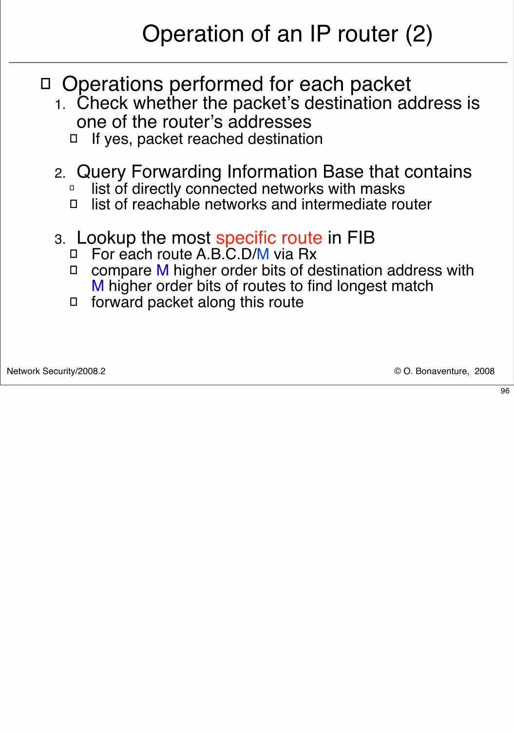
Operation of an IP router (2)
� Operations performed for each packet1. Check whether the packet’s destination address is
one of the router’s addresses� If yes, packet reached destination
2. Query Forwarding Information Base that contains� list of directly connected networks with masks� list of reachable networks and intermediate router
3. Lookup the most specific route in FIB� For each route A.B.C.D/M via Rx� compare M higher order bits of destination address with
M higher order bits of routes to find longest match� forward packet along this route
96
© O. Bonaventure, 2008Network Security/2008.2
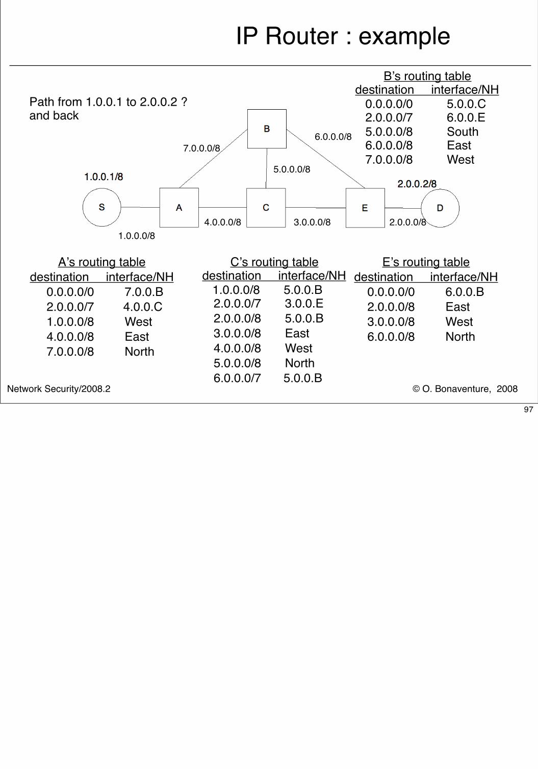
IP Router : example
A’s routing tabledestination interface/NH 0.0.0.0/0 7.0.0.B 2.0.0.0/7 4.0.0.C 1.0.0.0/8 West 4.0.0.0/8 East 7.0.0.0/8 North
B’s routing tabledestination interface/NH 0.0.0.0/0 5.0.0.C 2.0.0.0/7 6.0.0.E 5.0.0.0/8 South 6.0.0.0/8 East 7.0.0.0/8 West
C’s routing tabledestination interface/NH 1.0.0.0/8 5.0.0.B 2.0.0.0/7 3.0.0.E 2.0.0.0/8 5.0.0.B 3.0.0.0/8 East 4.0.0.0/8 West 5.0.0.0/8 North 6.0.0.0/7 5.0.0.B
E’s routing tabledestination interface/NH 0.0.0.0/0 6.0.0.B 2.0.0.0/8 East 3.0.0.0/8 West 6.0.0.0/8 North
1.0.0.0/84.0.0.0/8
7.0.0.0/8
2.0.0.0/8
5.0.0.0/8
3.0.0.0/8
6.0.0.0/8
Path from 1.0.0.1 to 2.0.0.2 ?and back
97
© O. Bonaventure, 2008Network Security/2008.2
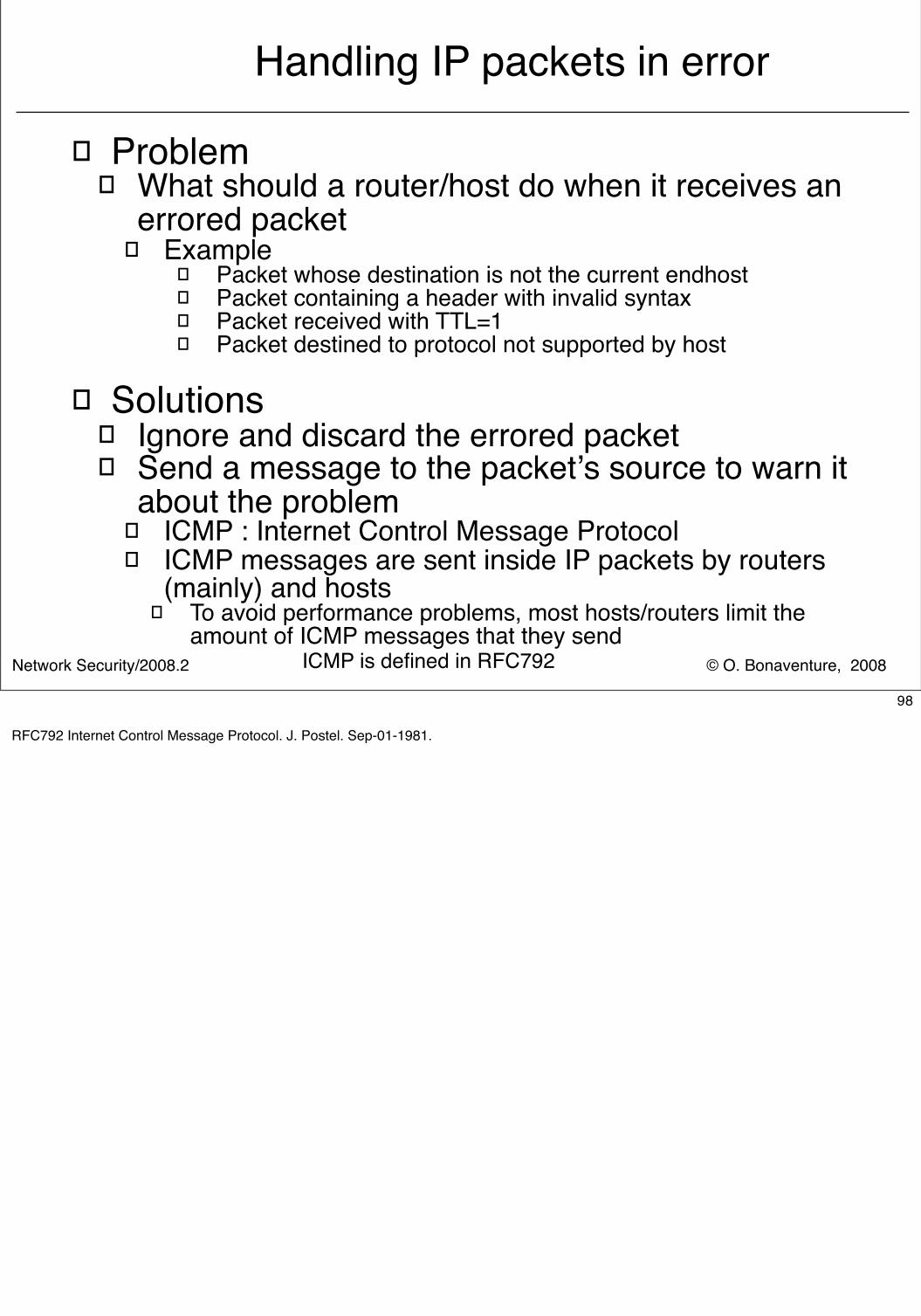
Handling IP packets in error
� Problem� What should a router/host do when it receives an
errored packet � Example
� Packet whose destination is not the current endhost� Packet containing a header with invalid syntax� Packet received with TTL=1� Packet destined to protocol not supported by host
� Solutions� Ignore and discard the errored packet� Send a message to the packet’s source to warn it
about the problem � ICMP : Internet Control Message Protocol� ICMP messages are sent inside IP packets by routers
(mainly) and hosts� To avoid performance problems, most hosts/routers limit the
amount of ICMP messages that they sendICMP is defined in RFC792
98
RFC792 Internet Control Message Protocol. J. Postel. Sep-01-1981.
© O. Bonaventure, 2008Network Security/2008.2
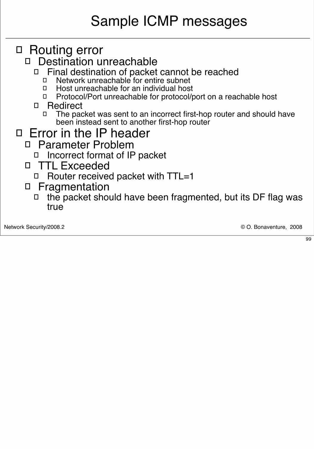
Sample ICMP messages
� Routing error� Destination unreachable
� Final destination of packet cannot be reached� Network unreachable for entire subnet� Host unreachable for an individual host� Protocol/Port unreachable for protocol/port on a reachable host
� Redirect� The packet was sent to an incorrect first-hop router and should have
been instead sent to another first-hop router� Error in the IP header
� Parameter Problem� Incorrect format of IP packet
� TTL Exceeded� Router received packet with TTL=1
� Fragmentation� the packet should have been fragmented, but its DF flag was
true
99
© O. Bonaventure, 2008Network Security/2008.2
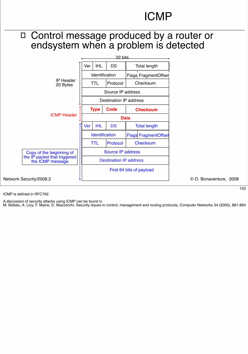
ICMP� Control message produced by a router or
endsystem when a problem is detected
Ver IHL DS
IP Header20 Bytes Checksum TTL Protocol
Source IP address
Identification
Destination IP address
Data
Type Code
Ver IHL DS Total length
Checksum TTL ProtocolFlags FragmentOffset
Source IP address
Identification
Destination IP address
First 64 bits of payload
Flags FragmentOffset
Copy of the beginning of the IP packet that triggered
the ICMP message
Total length
Checksum
32 bits
ICMP Header
100ICMP is defined in RFC792
A discussion of security attacks using ICMP can be found in M. Baltatu, A. Lioy, F. Maino, D. Mazzocchi, Security issues in control, management and routing protocols, Computer Networks 34 (2000), 881-894
© O. Bonaventure, 2008Network Security/2008.2
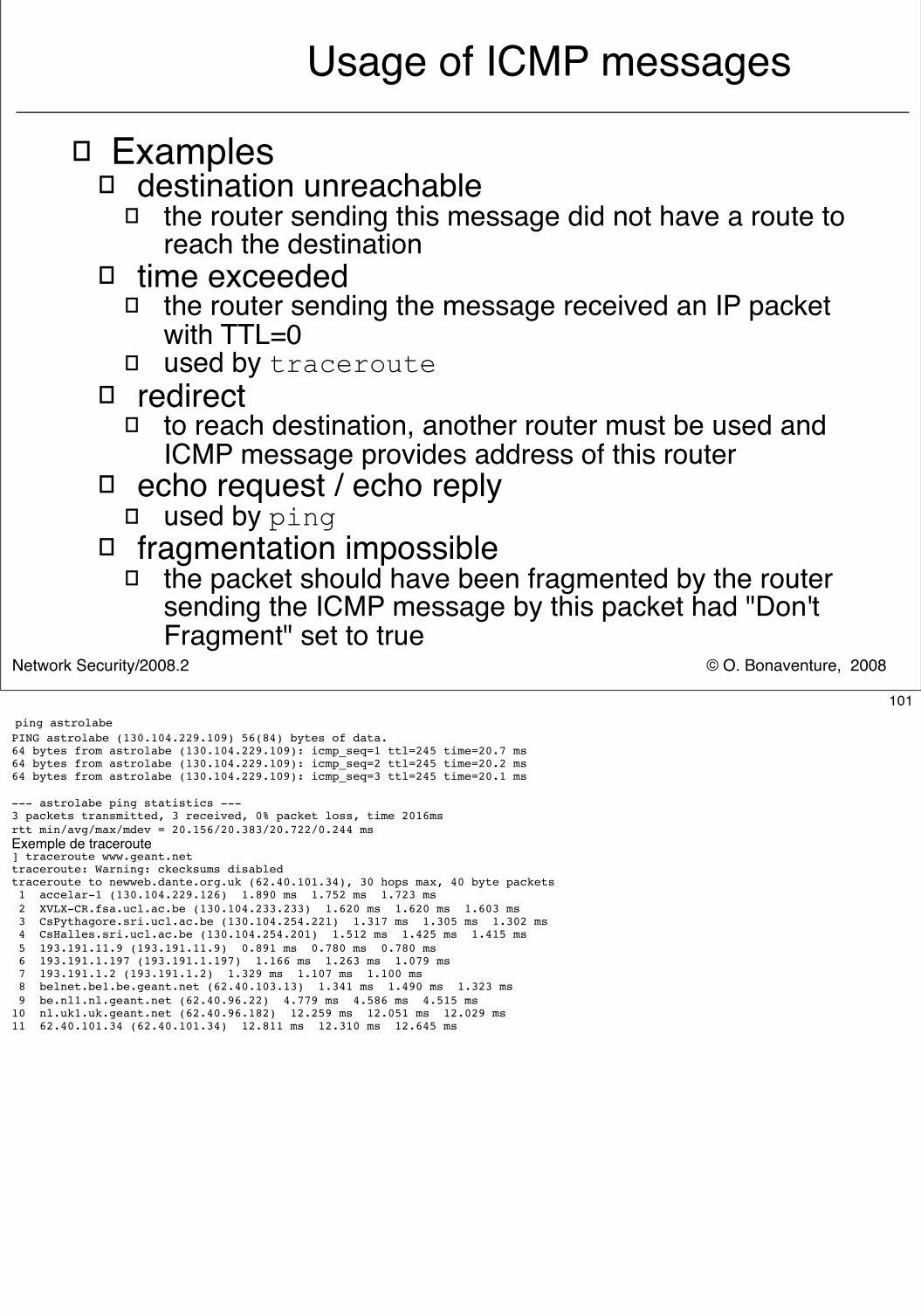
Usage of ICMP messages
� Examples� destination unreachable
� the router sending this message did not have a route to reach the destination
� time exceeded � the router sending the message received an IP packet
with TTL=0� used by traceroute
� redirect� to reach destination, another router must be used and
ICMP message provides address of this router� echo request / echo reply
� used by ping� fragmentation impossible
� the packet should have been fragmented by the router sending the ICMP message by this packet had "Don't Fragment" set to true
101 ping astrolabePING astrolabe (130.104.229.109) 56(84) bytes of data.64 bytes from astrolabe (130.104.229.109): icmp_seq=1 ttl=245 time=20.7 ms64 bytes from astrolabe (130.104.229.109): icmp_seq=2 ttl=245 time=20.2 ms64 bytes from astrolabe (130.104.229.109): icmp_seq=3 ttl=245 time=20.1 ms
--- astrolabe ping statistics ---3 packets transmitted, 3 received, 0% packet loss, time 2016msrtt min/avg/max/mdev = 20.156/20.383/20.722/0.244 msExemple de traceroute ] traceroute www.geant.nettraceroute: Warning: ckecksums disabledtraceroute to newweb.dante.org.uk (62.40.101.34), 30 hops max, 40 byte packets 1 accelar-1 (130.104.229.126) 1.890 ms 1.752 ms 1.723 ms 2 XVLX-CR.fsa.ucl.ac.be (130.104.233.233) 1.620 ms 1.620 ms 1.603 ms 3 CsPythagore.sri.ucl.ac.be (130.104.254.221) 1.317 ms 1.305 ms 1.302 ms 4 CsHalles.sri.ucl.ac.be (130.104.254.201) 1.512 ms 1.425 ms 1.415 ms 5 193.191.11.9 (193.191.11.9) 0.891 ms 0.780 ms 0.780 ms 6 193.191.1.197 (193.191.1.197) 1.166 ms 1.263 ms 1.079 ms 7 193.191.1.2 (193.191.1.2) 1.329 ms 1.107 ms 1.100 ms 8 belnet.be1.be.geant.net (62.40.103.13) 1.341 ms 1.490 ms 1.323 ms 9 be.nl1.nl.geant.net (62.40.96.22) 4.779 ms 4.586 ms 4.515 ms10 nl.uk1.uk.geant.net (62.40.96.182) 12.259 ms 12.051 ms 12.029 ms11 62.40.101.34 (62.40.101.34) 12.811 ms 12.310 ms 12.645 ms
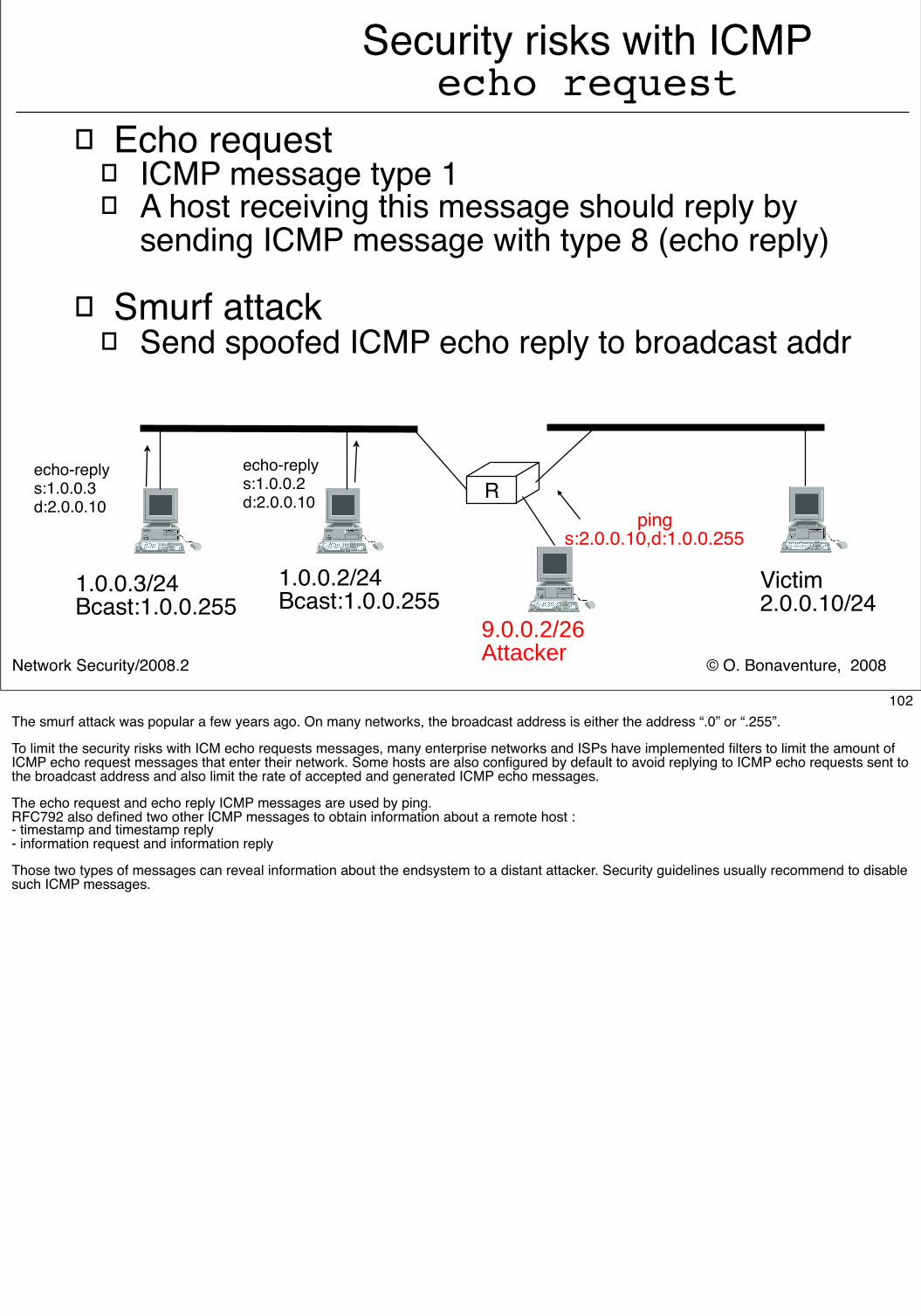
© O. Bonaventure, 2008Network Security/2008.2
Security risks with ICMPecho request
� Echo request� ICMP message type 1� A host receiving this message should reply by
sending ICMP message with type 8 (echo reply)
� Smurf attack� Send spoofed ICMP echo reply to broadcast addr
1.0.0.3/24Bcast:1.0.0.255
1.0.0.2/24Bcast:1.0.0.255
R
Victim2.0.0.10/24
9.0.0.2/26Attacker
pings:2.0.0.10,d:1.0.0.255
echo-replys:1.0.0.2d:2.0.0.10
echo-replys:1.0.0.3d:2.0.0.10
102The smurf attack was popular a few years ago. On many networks, the broadcast address is either the address “.0” or “.255”.
To limit the security risks with ICM echo requests messages, many enterprise networks and ISPs have implemented filters to limit the amount of ICMP echo request messages that enter their network. Some hosts are also configured by default to avoid replying to ICMP echo requests sent to the broadcast address and also limit the rate of accepted and generated ICMP echo messages.
The echo request and echo reply ICMP messages are used by ping. RFC792 also defined two other ICMP messages to obtain information about a remote host :- timestamp and timestamp reply- information request and information reply
Those two types of messages can reveal information about the endsystem to a distant attacker. Security guidelines usually recommend to disable such ICMP messages.
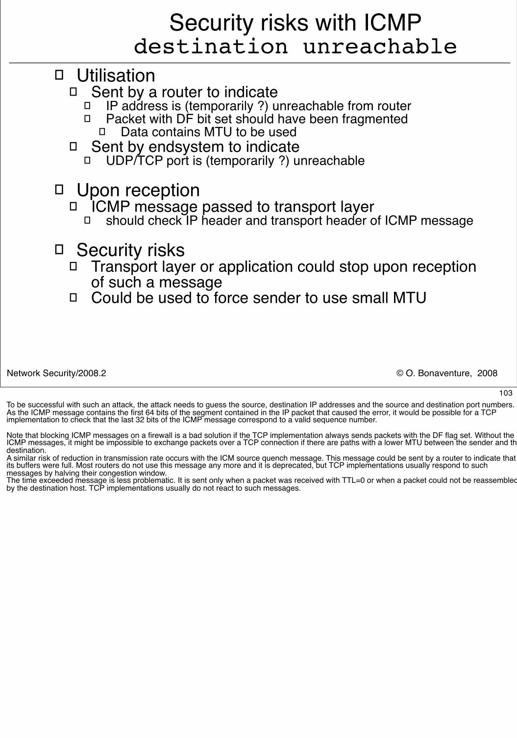
© O. Bonaventure, 2008Network Security/2008.2
� Utilisation� Sent by a router to indicate
� IP address is (temporarily ?) unreachable from router� Packet with DF bit set should have been fragmented
� Data contains MTU to be used� Sent by endsystem to indicate
� UDP/TCP port is (temporarily ?) unreachable
� Upon reception� ICMP message passed to transport layer
� should check IP header and transport header of ICMP message
� Security risks� Transport layer or application could stop upon reception
of such a message � Could be used to force sender to use small MTU
Security risks with ICMPdestination unreachable
103To be successful with such an attack, the attack needs to guess the source, destination IP addresses and the source and destination port numbers. As the ICMP message contains the first 64 bits of the segment contained in the IP packet that caused the error, it would be possible for a TCP implementation to check that the last 32 bits of the ICMP message correspond to a valid sequence number.
Note that blocking ICMP messages on a firewall is a bad solution if the TCP implementation always sends packets with the DF flag set. Without the ICMP messages, it might be impossible to exchange packets over a TCP connection if there are paths with a lower MTU between the sender and the destination.A similar risk of reduction in transmission rate occurs with the ICM source quench message. This message could be sent by a router to indicate that its buffers were full. Most routers do not use this message any more and it is deprecated, but TCP implementations usually respond to such messages by halving their congestion window.The time exceeded message is less problematic. It is sent only when a packet was received with TTL=0 or when a packet could not be reassembled by the destination host. TCP implementations usually do not react to such messages.
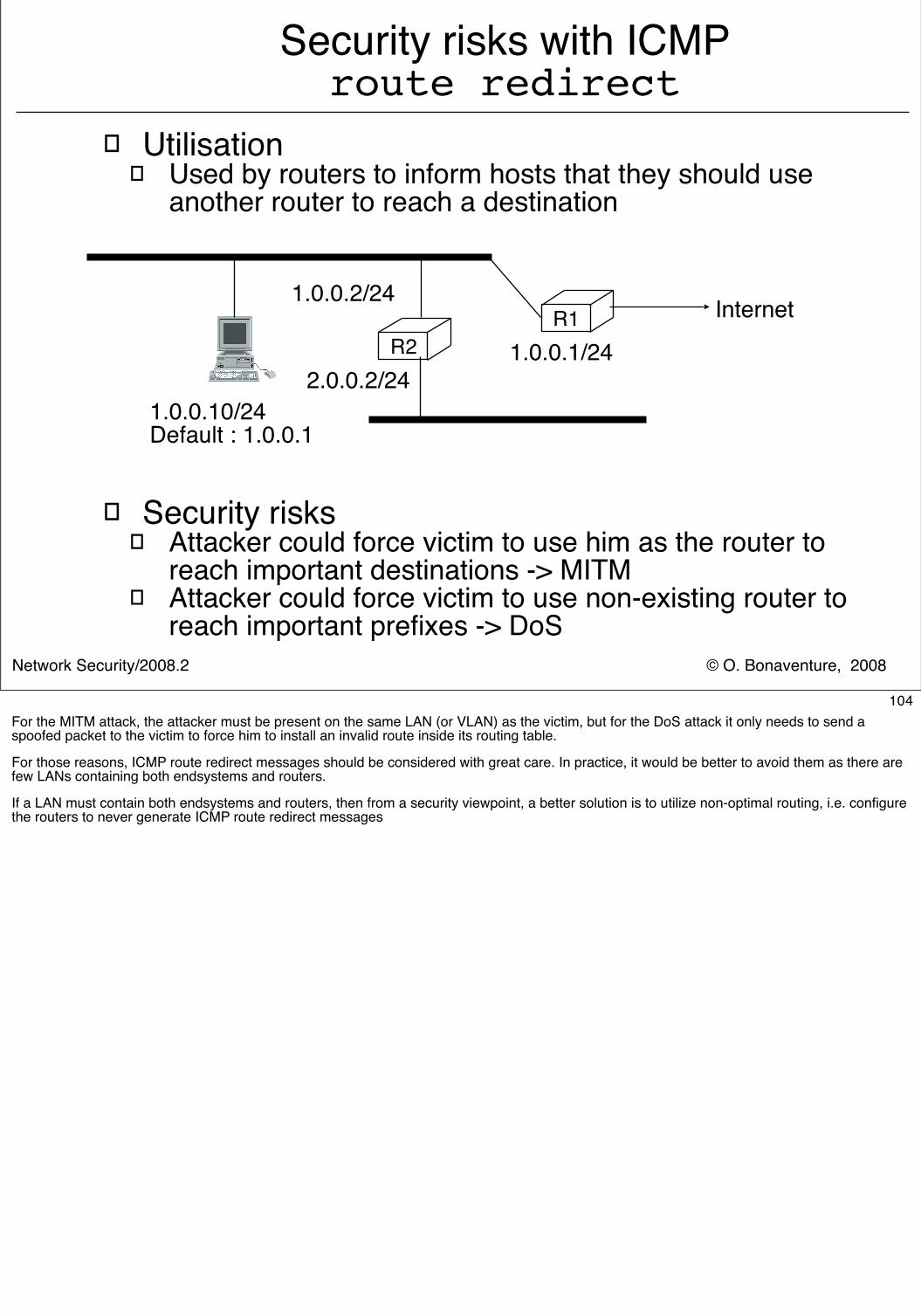
© O. Bonaventure, 2008Network Security/2008.2
Security risks with ICMProute redirect
� Utilisation� Used by routers to inform hosts that they should use
another router to reach a destination
� Security risks� Attacker could force victim to use him as the router to
reach important destinations -> MITM� Attacker could force victim to use non-existing router to
reach important prefixes -> DoS
1.0.0.10/24Default : 1.0.0.1
R11.0.0.1/24R2
1.0.0.2/24
2.0.0.2/24
Internet
104For the MITM attack, the attacker must be present on the same LAN (or VLAN) as the victim, but for the DoS attack it only needs to send a spoofed packet to the victim to force him to install an invalid route inside its routing table.
For those reasons, ICMP route redirect messages should be considered with great care. In practice, it would be better to avoid them as there are few LANs containing both endsystems and routers.
If a LAN must contain both endsystems and routers, then from a security viewpoint, a better solution is to utilize non-optimal routing, i.e. configure the routers to never generate ICMP route redirect messages
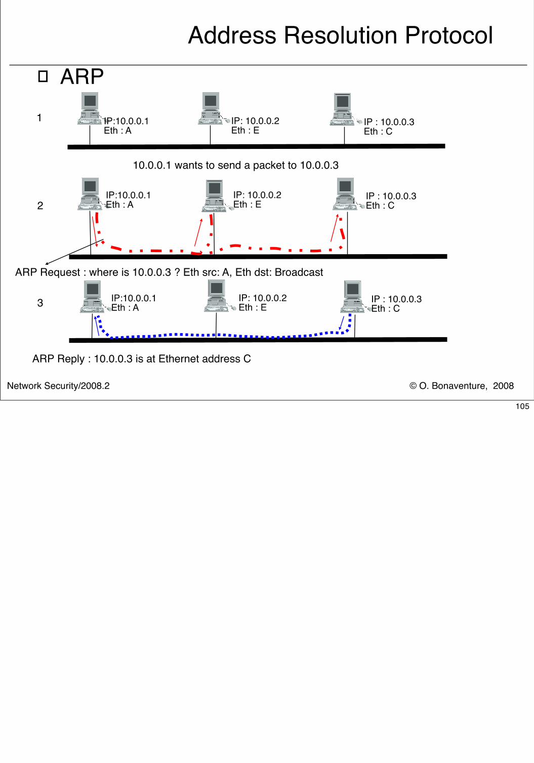
© O. Bonaventure, 2008Network Security/2008.2
Address Resolution Protocol� ARP
10.0.0.1 wants to send a packet to 10.0.0.3
IP:10.0.0.1Eth : A
1 IP: 10.0.0.2Eth : E
IP : 10.0.0.3Eth : C
ARP Request : where is 10.0.0.3 ? Eth src: A, Eth dst: Broadcast
2IP:10.0.0.1Eth : A
IP: 10.0.0.2Eth : E
IP : 10.0.0.3Eth : C
3
ARP Reply : 10.0.0.3 is at Ethernet address C
IP:10.0.0.1Eth : A
IP: 10.0.0.2Eth : E
IP : 10.0.0.3Eth : C
105
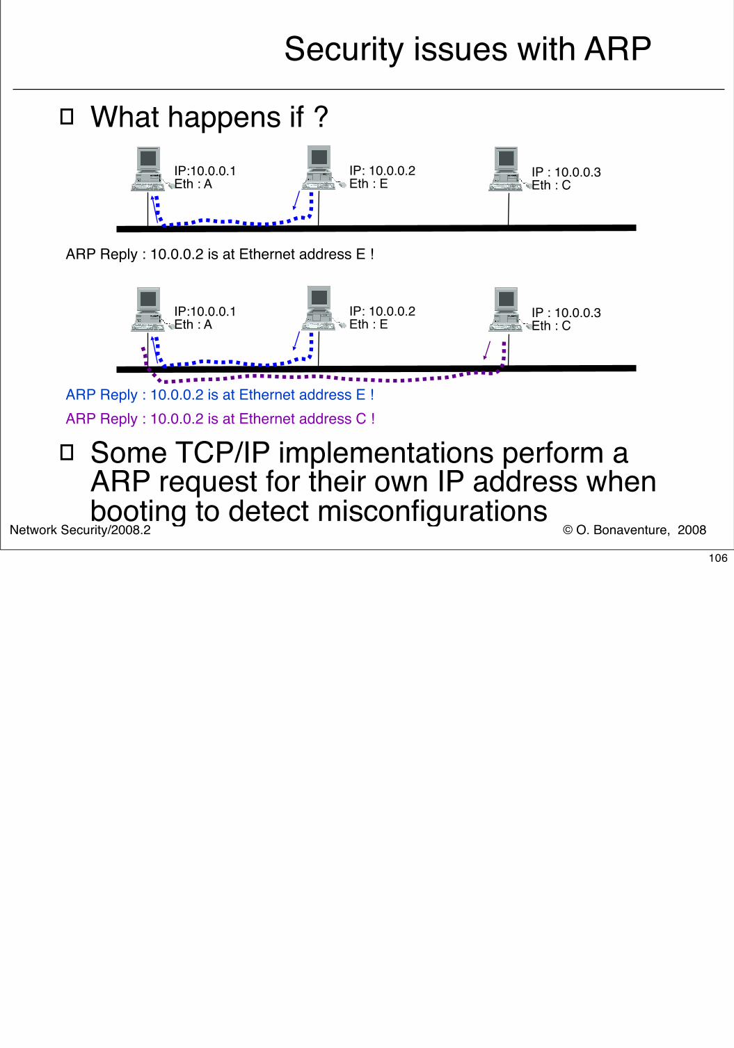
© O. Bonaventure, 2008Network Security/2008.2
Security issues with ARP
� What happens if ?
ARP Reply : 10.0.0.2 is at Ethernet address E !
IP:10.0.0.1Eth : A
IP: 10.0.0.2Eth : E
IP : 10.0.0.3Eth : C
ARP Reply : 10.0.0.2 is at Ethernet address E !
IP:10.0.0.1Eth : A
IP: 10.0.0.2Eth : E
IP : 10.0.0.3Eth : C
ARP Reply : 10.0.0.2 is at Ethernet address C !
� Some TCP/IP implementations perform a ARP request for their own IP address when booting to detect misconfigurations
106
© O. Bonaventure, 2008Network Security/2008.2
Internet and Network security
� Crypto building blocks� Application-layer security� Transport-layer security� Network-layer security
� IPv4� IPv6� IPSec� Routing security
107
© O. Bonaventure, 2008Network Security/2008.2
IP version 6
� Outline� Motivations for IP version 6
� IPv6 addressing architecture
� IPv6 packets
� ICMP v6
108There are many books and information about IPv6
An interesting book, but written in French, is G. Cizault, IPv6 Théorie et Pratique, O ReillyThe new versions of this book are available online : http://livre.point6.net/index.php/Accueil
A more practically oriented book isI. van Beijnum, Running IPv6, APress, 2006
IPv6 standardisation is carried out within the IETF, http://www.ietf.org
Other resources include
P. Smith, Introduction to IPv6, NANOG 42, ftp://ftp-eng.cisco.com/pfs/seminars/NANOG42-IPv6-Introduction.pdf
http://www.6journal.org/
http://www.ist-ipv6.org/
Information about IPv6 aware software and hardware is available from
http://www.ipv6-to-standard.org/
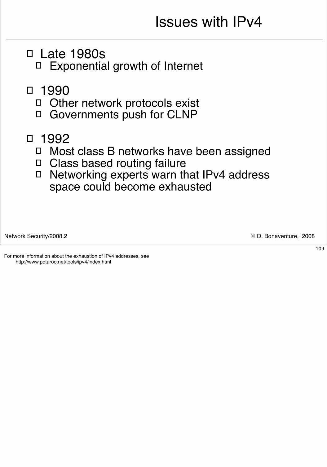
© O. Bonaventure, 2008Network Security/2008.2
Issues with IPv4
� Late 1980s� Exponential growth of Internet
� 1990� Other network protocols exist� Governments push for CLNP
� 1992� Most class B networks have been assigned� Class based routing failure� Networking experts warn that IPv4 address
space could become exhausted
109For more information about the exhaustion of IPv4 addresses, see http://www.potaroo.net/tools/ipv4/index.html
© O. Bonaventure, 2008Network Security/2008.2
Issues with IPv4 (2)
� How to solve the exhaustion of class B addresses ?
� Short term solution� Define Classless Interdomain Routing (CIDR)
and introduce the necessary changes in routers� Deployment started in 1994
� Long term solution� Develop Internet Protocol - next generation
(IPng)� call for proposals RFC1550, Dec 1993� Criteria for choix, RFC1719 and RFC1726, Dec. 1994� Proposed solutions
� TUBA - RFC1347, June 1992� PIP – RFC1621, RFC1622, May 1994 � CATNIP – RFC1707, October 1994 � SIP – RFC1710, October 1994 � NIMROD – RFC1753, December 1994 � ENCAPS – RFC1955, June 1996
110
© O. Bonaventure, 2008Network Security/2008.2
Issues with IPv4 (3)
� Implementation issues - 1990s� IPv4 packet format is complex� IP forwarding is difficult in hardware
� Missing functions - 1990s � IPv4 requires lots of manual configuration
� Competing protocols (CLNP, Appletalk, IPX, ...) already supported autoconfiguration in 1990s
� How to support Quality of Service in IP ?� Integrated services and Differentiated services did not
exist then� How to better support security in IP ?
� Security problems started to appear but were less important than today
� How to better support mobility in IP ?� GSM started to appear and some were dreaming of
mobile devices attached to the Internet111
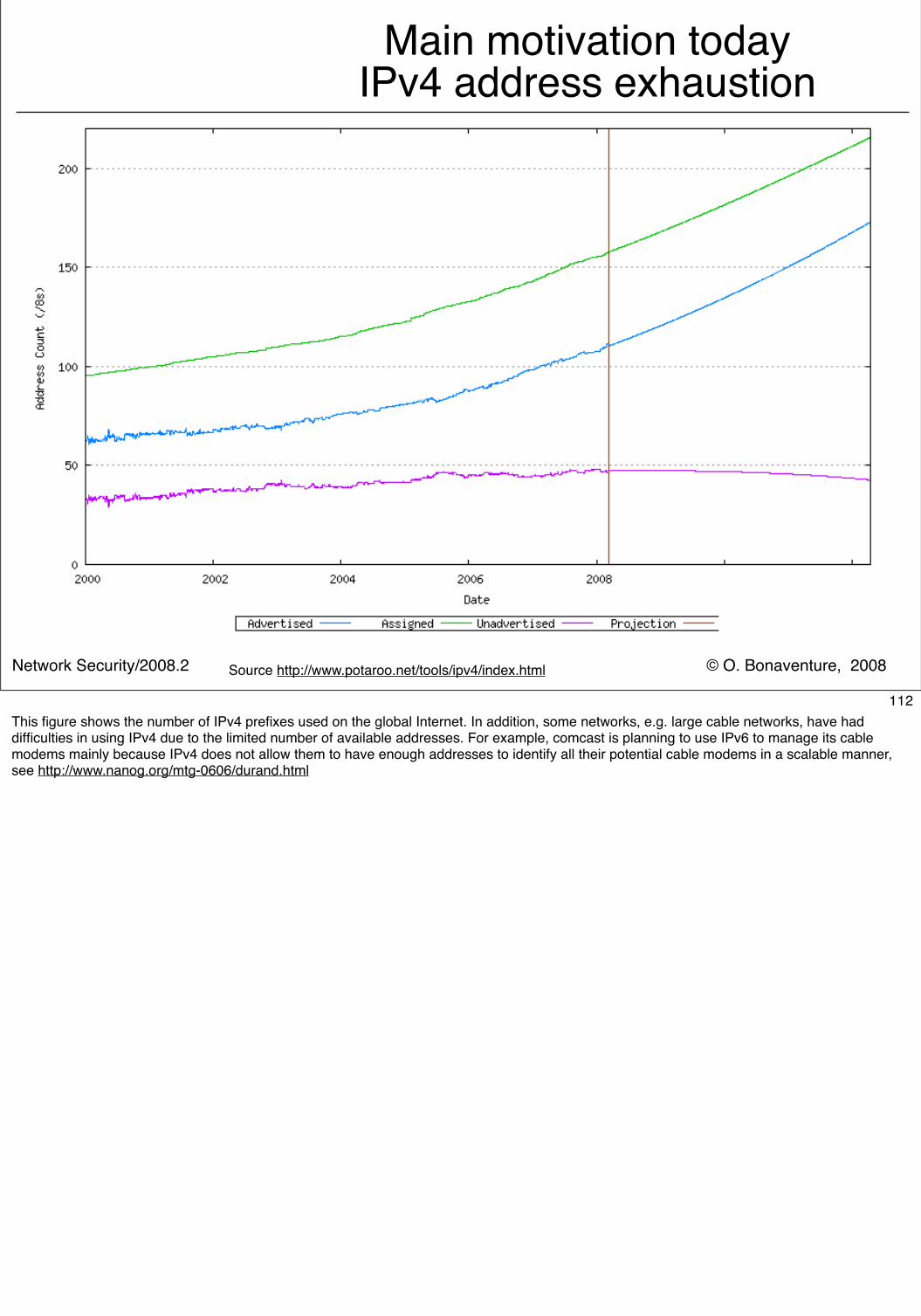
© O. Bonaventure, 2008Network Security/2008.2
Main motivation todayIPv4 address exhaustion
Source http://www.potaroo.net/tools/ipv4/index.html
112This figure shows the number of IPv4 prefixes used on the global Internet. In addition, some networks, e.g. large cable networks, have had difficulties in using IPv4 due to the limited number of available addresses. For example, comcast is planning to use IPv6 to manage its cable modems mainly because IPv4 does not allow them to have enough addresses to identify all their potential cable modems in a scalable manner, see http://www.nanog.org/mtg-0606/durand.html
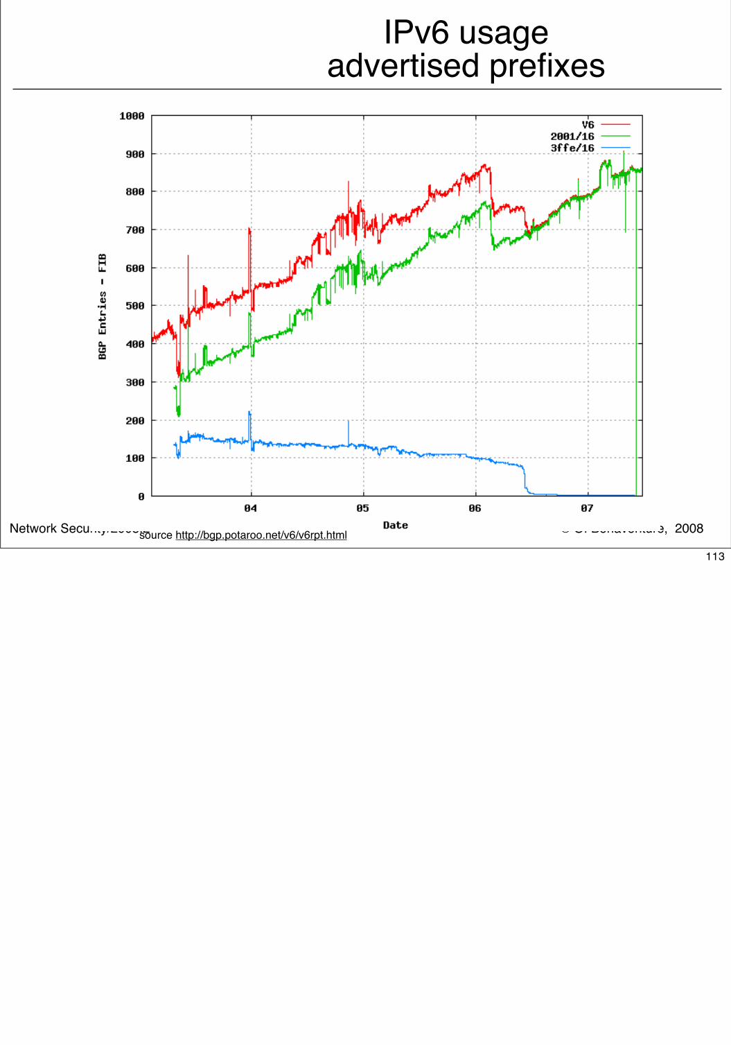
© O. Bonaventure, 2008Network Security/2008.2
IPv6 usageadvertised prefixes
source http://bgp.potaroo.net/v6/v6rpt.html
113
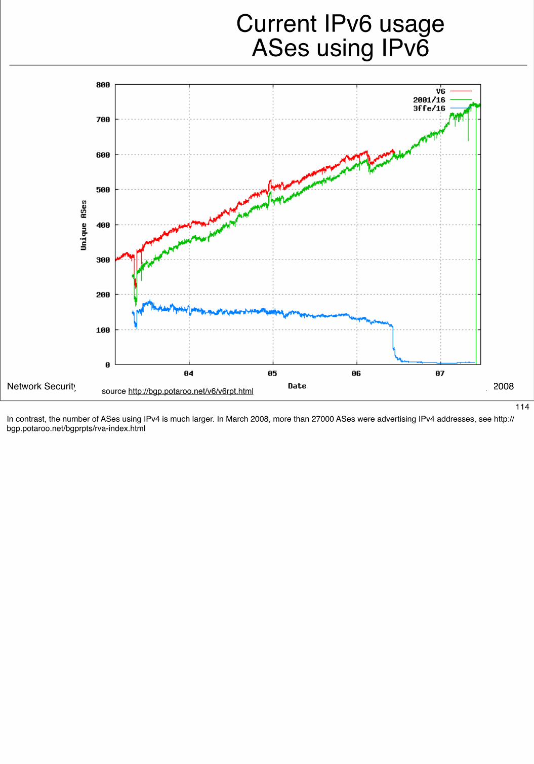
© O. Bonaventure, 2008Network Security/2008.2
Current IPv6 usageASes using IPv6
source http://bgp.potaroo.net/v6/v6rpt.html
114In contrast, the number of ASes using IPv4 is much larger. In March 2008, more than 27000 ASes were advertising IPv4 addresses, see http://bgp.potaroo.net/bgprpts/rva-index.html
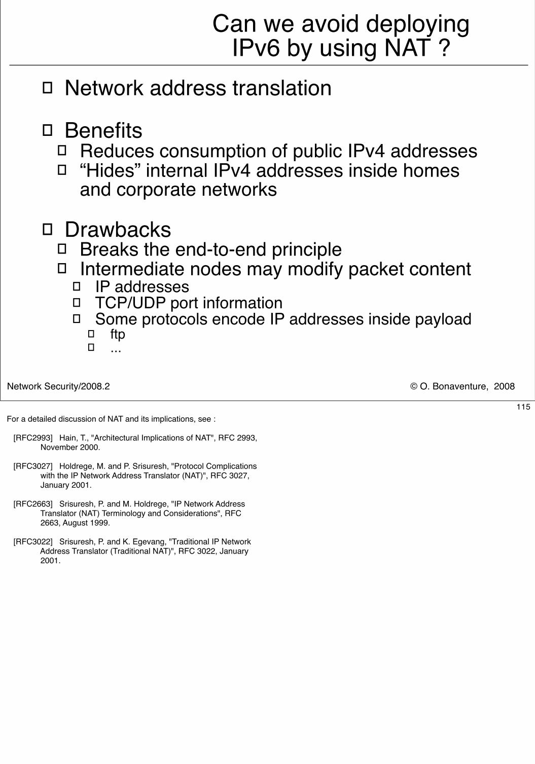
© O. Bonaventure, 2008Network Security/2008.2
Can we avoid deployingIPv6 by using NAT ?
� Network address translation
� Benefits� Reduces consumption of public IPv4 addresses� “Hides” internal IPv4 addresses inside homes
and corporate networks
� Drawbacks� Breaks the end-to-end principle� Intermediate nodes may modify packet content
� IP addresses � TCP/UDP port information� Some protocols encode IP addresses inside payload
� ftp� ...
115For a detailed discussion of NAT and its implications, see :
[RFC2993] Hain, T., "Architectural Implications of NAT", RFC 2993, November 2000.
[RFC3027] Holdrege, M. and P. Srisuresh, "Protocol Complications with the IP Network Address Translator (NAT)", RFC 3027, January 2001.
[RFC2663] Srisuresh, P. and M. Holdrege, "IP Network Address Translator (NAT) Terminology and Considerations", RFC 2663, August 1999.
[RFC3022] Srisuresh, P. and K. Egevang, "Traditional IP Network Address Translator (Traditional NAT)", RFC 3022, January 2001.
© O. Bonaventure, 2008Network Security/2008.2
IP version 6
� Outline� Motivations for IP version 6
� IPv6 addressing architecture
� IPv6 packets
� ICMP v6
116
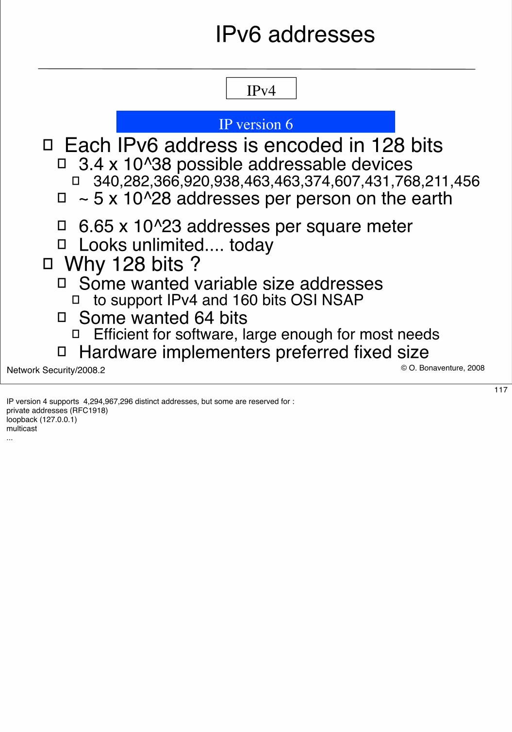
© O. Bonaventure, 2008Network Security/2008.2
IPv6 addresses
� Each IPv6 address is encoded in 128 bits� 3.4 x 10^38 possible addressable devices
� 340,282,366,920,938,463,463,374,607,431,768,211,456 � ~ 5 x 10^28 addresses per person on the earth � 6.65 x 10^23 addresses per square meter� Looks unlimited.... today
� Why 128 bits ?� Some wanted variable size addresses
� to support IPv4 and 160 bits OSI NSAP� Some wanted 64 bits
� Efficient for software, large enough for most needs� Hardware implementers preferred fixed size
IPv4
IP version 6
117IP version 4 supports 4,294,967,296 distinct addresses, but some are reserved for :private addresses (RFC1918)loopback (127.0.0.1)multicast...
© O. Bonaventure, 2008Network Security/2008.2
The IPv6 addressing architecture
� Three types of IPv6 addresses� Unicast addresses
� An identifier for a single interface. A packet sent to a unicast address is delivered to the interface identified by that address
� Anycast addresses� An identifier for a set of interfaces. A packet sent to an� anycast address is delivered to the “nearest” one of the
interfaces identified by that address
� Multicast addresses� An identifier for a set of interfaces. A packet sent to a
multicast address is delivered to all interfaces identified by that address.
118The IPv6 addressing architecture is defined in :
R. Hinden, S. Deering, IP Version 6 Addressing Architecture, RFC4291, February 2006
© O. Bonaventure, 2008Network Security/2008.2
Representation of IPv6 addresses
� How can we write a 128 bits IPv6 address ?� Hexadecimal format
� FEDC:BA98:7654:3210:FEDC:BA98:7654:3210� 1080:0:0:0:8:800:200C:417A
� Compact hexadecimal format� Some IPv6 addresses contain lots of zero
� utilize "::" to indicate one or more groups of 16 bits of zeros. The "::" can only appear once in an address
� Examples� 1080:0:0:0:8:800:200C:417A = 1080::8:800:200C:417A � FF01:0:0:0:0:0:0:101 = FF01::101� 0:0:0:0:0:0:0:1 = ::1
119
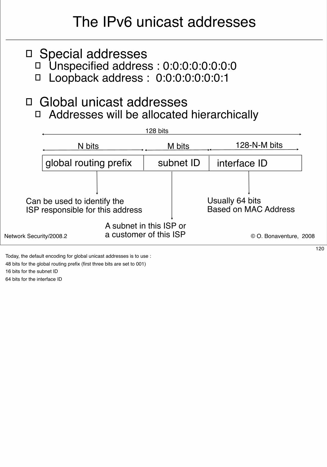
© O. Bonaventure, 2008Network Security/2008.2
The IPv6 unicast addresses
� Special addresses� Unspecified address : 0:0:0:0:0:0:0:0� Loopback address : 0:0:0:0:0:0:0:1
� Global unicast addresses� Addresses will be allocated hierarchically
interface ID
128 bits
N bits M bits 128-N-M bits
Usually 64 bitsBased on MAC Address
Can be used to identify the ISP responsible for this address
A subnet in this ISP ora customer of this ISP
global routing prefix subnet ID
120Today, the default encoding for global unicast addresses is to use :48 bits for the global routing prefix (first three bits are set to 001)16 bits for the subnet ID64 bits for the interface ID
© O. Bonaventure, 2008Network Security/2008.2
Allocation of IPv6 addresses
� IANA controls all IP addresses and delegates assignments of blocks to Regional IP Address Registries (RIR)
� RIPE, ARIN, APNIC, AFRINIC, ...
� An organisation can be allocated two different types of IPv6 addresses
� Provider Independent (PI) addresses� Usually allocated to ISPs or very large enterprises
directly by RIRs� Default size is /32
� Provider Aggregatable (PA) addresses� Smaller prefixes, assigned by ISPs from their PI block� Size
� /48 in the general case, except for very large subscribers� /64 when t one and only one subnet is needed by design� /128 when it is absolutely known that one and only one device is
connecting.121
See http://www.ripe.net/ripe/docs/ripe-388.html for the policy used by RIPE to allocate IP prefixes in Europe
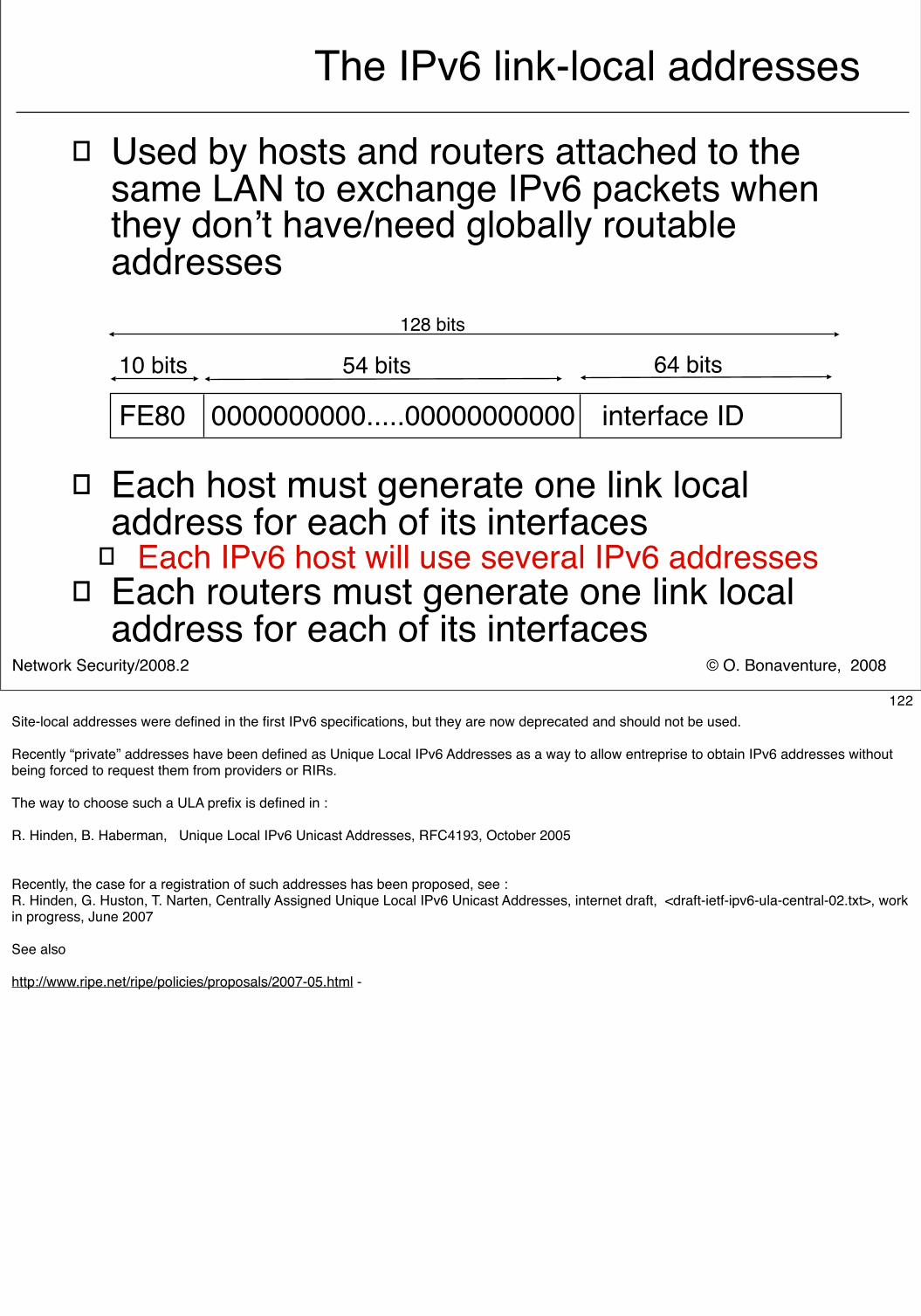
© O. Bonaventure, 2008Network Security/2008.2
The IPv6 link-local addresses
� Used by hosts and routers attached to the same LAN to exchange IPv6 packets when they don’t have/need globally routable addresses
� Each host must generate one link local address for each of its interfaces
� Each IPv6 host will use several IPv6 addresses� Each routers must generate one link local
address for each of its interfaces
interface ID
128 bits
10 bits 54 bits 64 bits
FE80 0000000000.....00000000000
122Site-local addresses were defined in the first IPv6 specifications, but they are now deprecated and should not be used.
Recently “private” addresses have been defined as Unique Local IPv6 Addresses as a way to allow entreprise to obtain IPv6 addresses without being forced to request them from providers or RIRs.
The way to choose such a ULA prefix is defined in :
R. Hinden, B. Haberman, Unique Local IPv6 Unicast Addresses, RFC4193, October 2005
Recently, the case for a registration of such addresses has been proposed, see :R. Hinden, G. Huston, T. Narten, Centrally Assigned Unique Local IPv6 Unicast Addresses, internet draft, <draft-ietf-ipv6-ula-central-02.txt>, work in progress, June 2007
See also http://www.ripe.net/ripe/policies/proposals/2007-05.html -
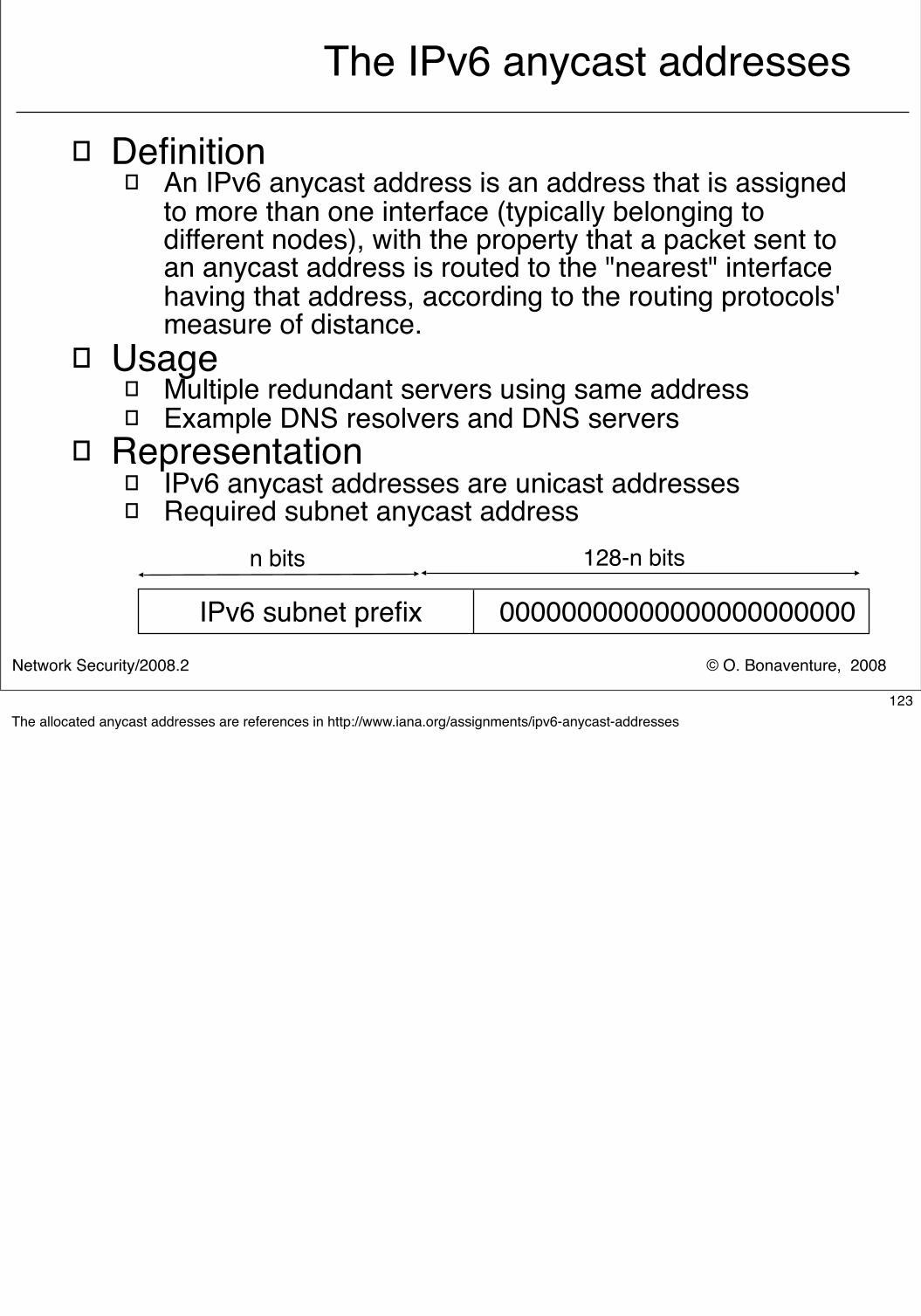
© O. Bonaventure, 2008Network Security/2008.2
The IPv6 anycast addresses
� Definition� An IPv6 anycast address is an address that is assigned
to more than one interface (typically belonging to different nodes), with the property that a packet sent to an anycast address is routed to the "nearest" interface having that address, according to the routing protocols' measure of distance.
� Usage� Multiple redundant servers using same address� Example DNS resolvers and DNS servers
� Representation� IPv6 anycast addresses are unicast addresses� Required subnet anycast address
00000000000000000000000
n bits 128-n bits
IPv6 subnet prefix
123The allocated anycast addresses are references in http://www.iana.org/assignments/ipv6-anycast-addresses
© O. Bonaventure, 2008Network Security/2008.2
IP version 6
� Outline� Motivations for IP version 6
� IPv6 addressing architecture
� IPv6 packets
� ICMP v6
124
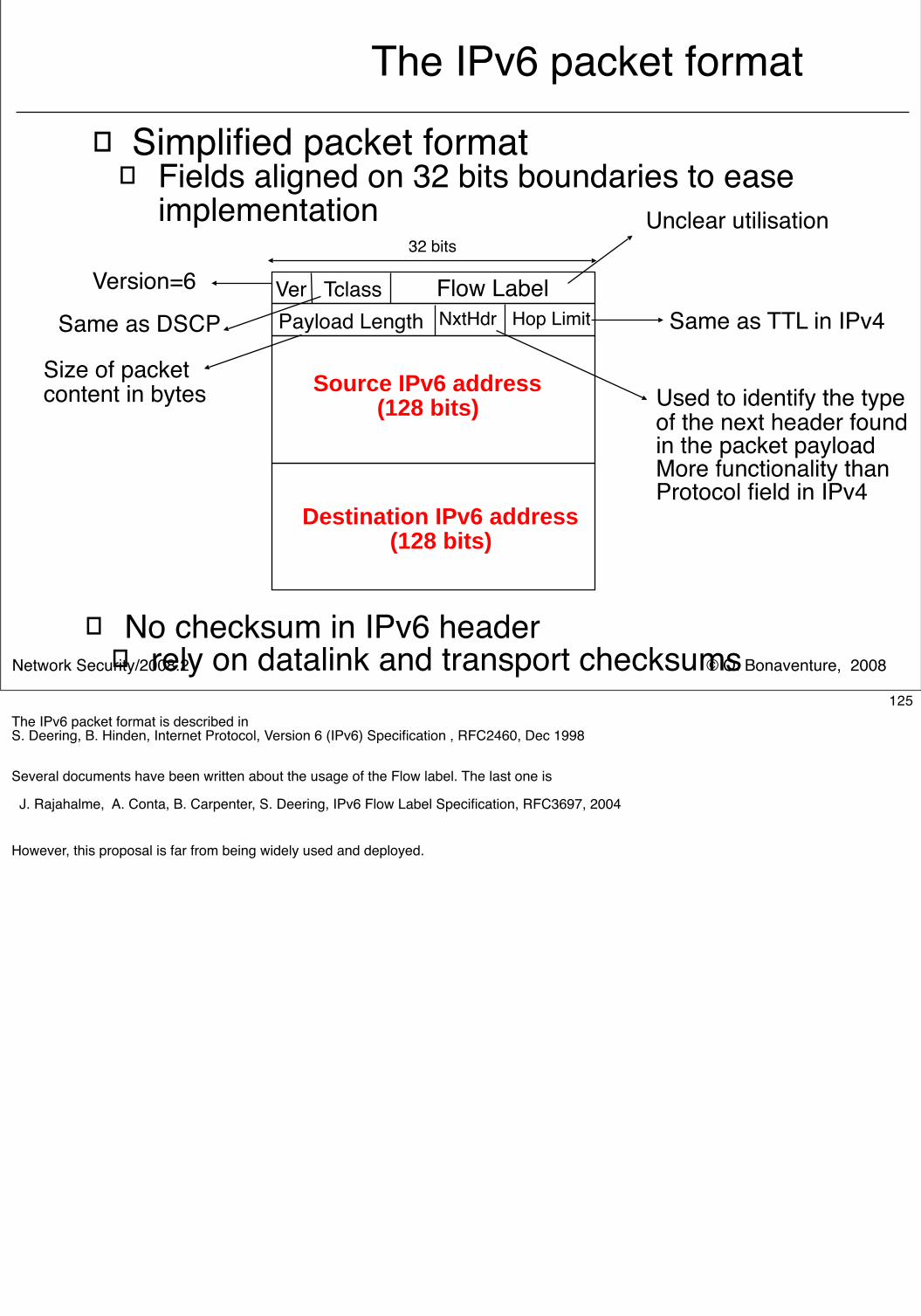
© O. Bonaventure, 2008Network Security/2008.2
The IPv6 packet format
� Simplified packet format� Fields aligned on 32 bits boundaries to ease
implementation32 bits
Ver Tclass Flow LabelNxtHdr Hop Limit
Source IPv6 address(128 bits)
Payload Length
Destination IPv6 address(128 bits)
Version=6
Same as DSCP
Size of packetcontent in bytes
Unclear utilisation
Same as TTL in IPv4
Used to identify the typeof the next header found in the packet payloadMore functionality thanProtocol field in IPv4
� No checksum in IPv6 header� rely on datalink and transport checksums
125The IPv6 packet format is described in S. Deering, B. Hinden, Internet Protocol, Version 6 (IPv6) Specification , RFC2460, Dec 1998
Several documents have been written about the usage of the Flow label. The last one is
J. Rajahalme, A. Conta, B. Carpenter, S. Deering, IPv6 Flow Label Specification, RFC3697, 2004
However, this proposal is far from being widely used and deployed.
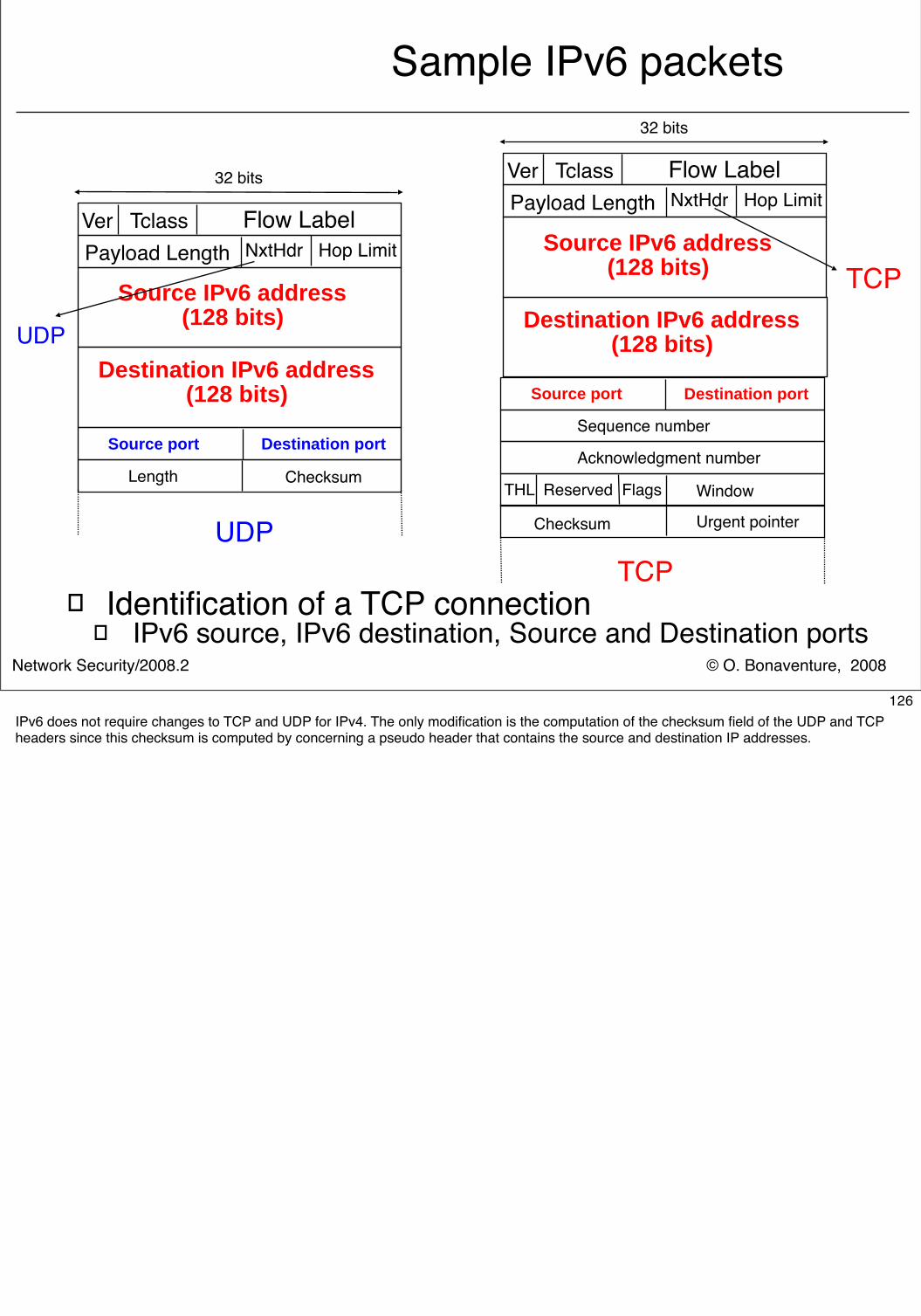
© O. Bonaventure, 2008Network Security/2008.2
Sample IPv6 packets
� Identification of a TCP connection� IPv6 source, IPv6 destination, Source and Destination ports
32 bits
Ver Tclass Flow LabelNxtHdr Hop Limit
Source IPv6 address(128 bits)
Payload Length
Destination IPv6 address(128 bits)
Source port Destination port
Length Checksum
UDP
32 bits
Ver Tclass Flow LabelNxtHdr Hop Limit
Source IPv6 address(128 bits)
Payload Length
Destination IPv6 address(128 bits)
Source port Destination port
Checksum Urgent pointer
THL Reserved Flags
Acknowledgment number
Sequence number
Window
TCP
UDP
TCP
126IPv6 does not require changes to TCP and UDP for IPv4. The only modification is the computation of the checksum field of the UDP and TCP headers since this checksum is computed by concerning a pseudo header that contains the source and destination IP addresses.
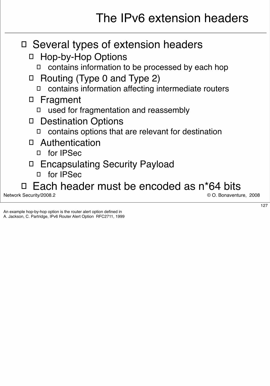
© O. Bonaventure, 2008Network Security/2008.2
The IPv6 extension headers
� Several types of extension headers� Hop-by-Hop Options
� contains information to be processed by each hop� Routing (Type 0 and Type 2)
� contains information affecting intermediate routers� Fragment
� used for fragmentation and reassembly� Destination Options
� contains options that are relevant for destination� Authentication
� for IPSec� Encapsulating Security Payload
� for IPSec� Each header must be encoded as n*64 bits
127An example hop-by-hop option is the router alert option defined inA. Jackson, C. Partridge, IPv6 Router Alert Option RFC2711, 1999
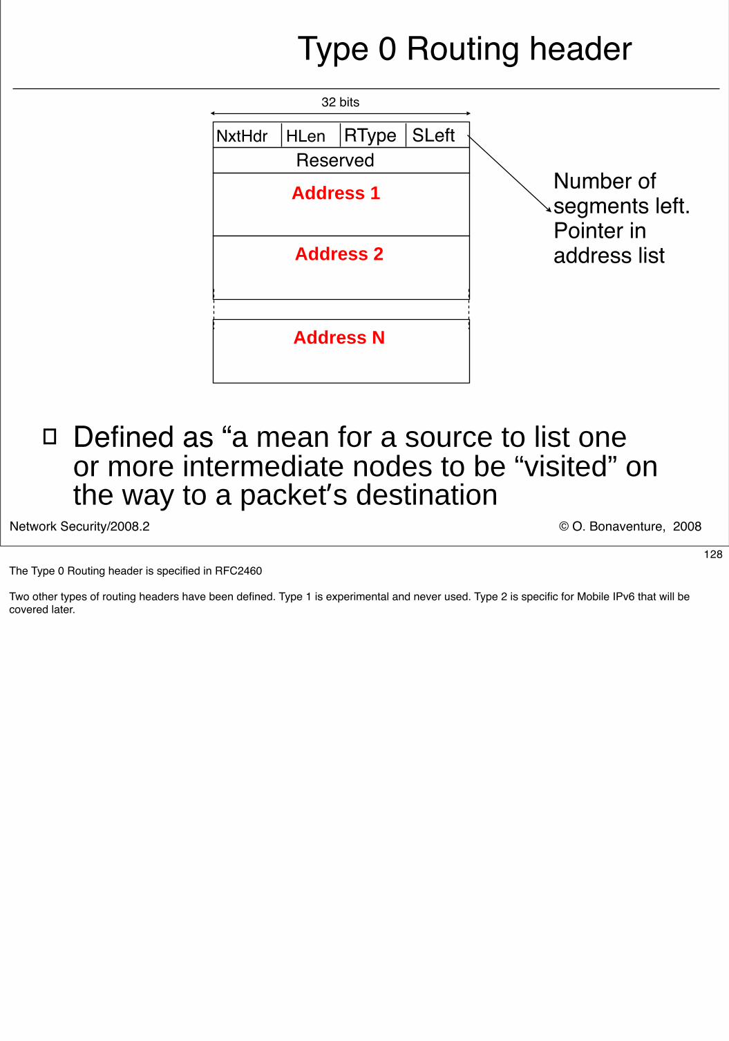
© O. Bonaventure, 2008Network Security/2008.2
Type 0 Routing header
� Defined as “a mean for a source to list one or more intermediate nodes to be “visited” on the way to a packet’s destination
32 bits
NxtHdr HLen RType SLeft
Address 1
Address 2
Reserved
Address N
Number of segments left. Pointer in address list
128The Type 0 Routing header is specified in RFC2460
Two other types of routing headers have been defined. Type 1 is experimental and never used. Type 2 is specific for Mobile IPv6 that will be covered later.
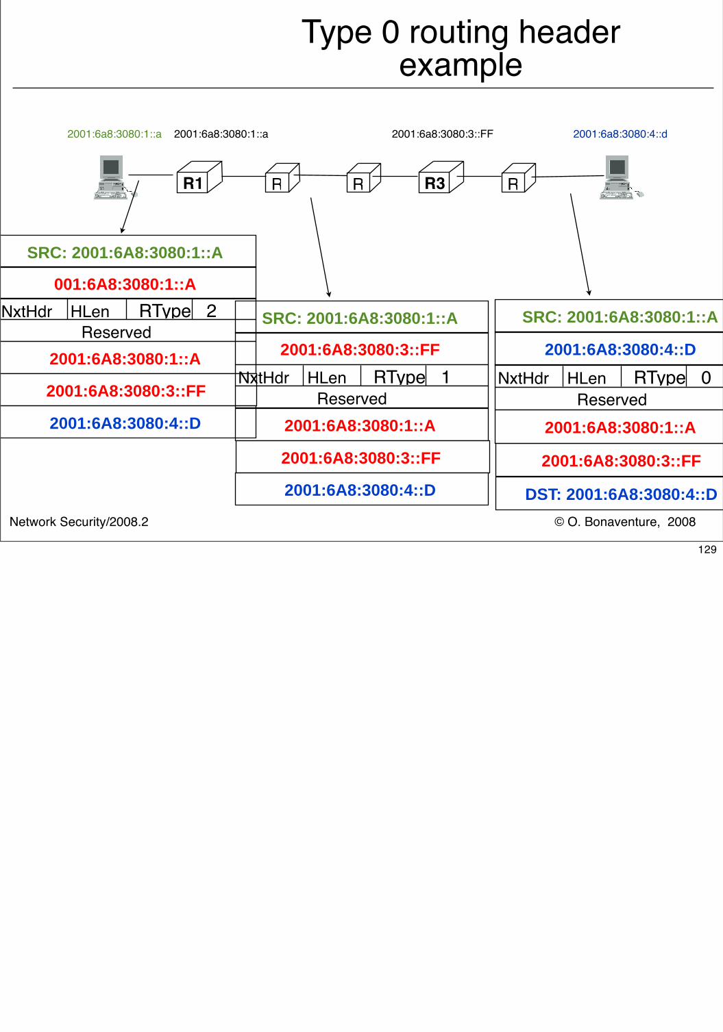
2001:6a8:3080:4::d
© O. Bonaventure, 2008Network Security/2008.2
Type 0 routing headerexample
R1 R R R3 R
2001:6a8:3080:1::a 2001:6a8:3080:1::a 2001:6a8:3080:3::FF
NxtHdr HLen RType 2
2001:6A8:3080:1::A
Reserved
SRC: 2001:6A8:3080:1::A
2001:6A8:3080:3::FF
2001:6A8:3080:4::D
001:6A8:3080:1::A
NxtHdr HLen RType 1
2001:6A8:3080:1::A
Reserved
SRC: 2001:6A8:3080:1::A
2001:6A8:3080:4::D
2001:6A8:3080:3::FF
2001:6A8:3080:3::FF
NxtHdr HLen RType 0
2001:6A8:3080:1::A
Reserved
SRC: 2001:6A8:3080:1::A
2001:6A8:3080:4::D
2001:6A8:3080:3::FF
DST: 2001:6A8:3080:4::D
129
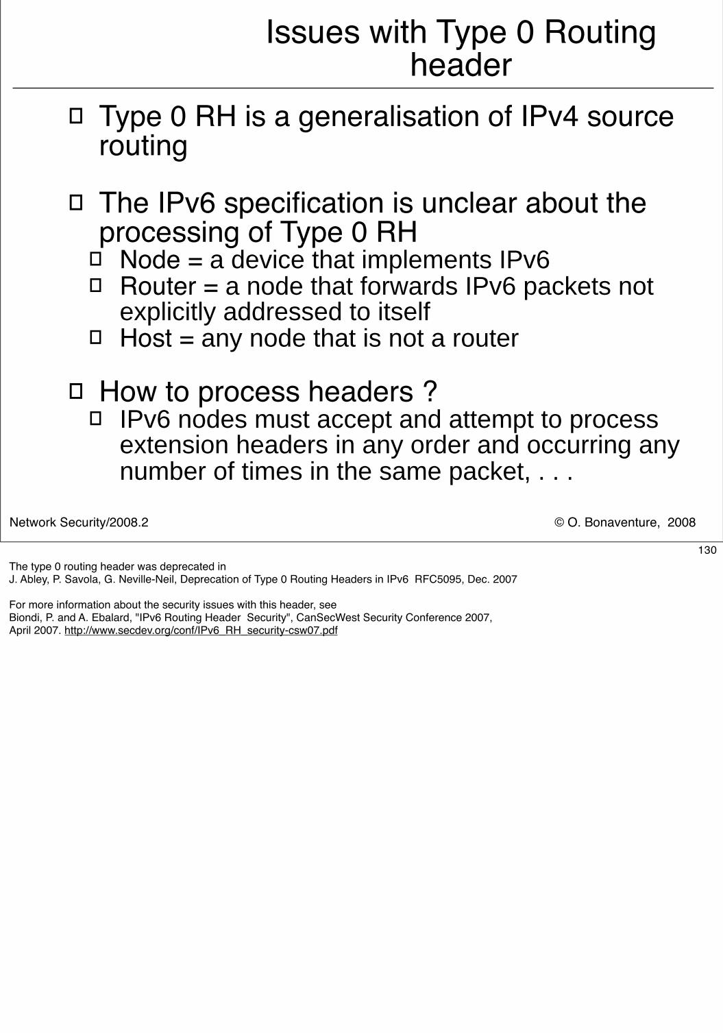
© O. Bonaventure, 2008Network Security/2008.2
Issues with Type 0 Routing header
� Type 0 RH is a generalisation of IPv4 source routing
� The IPv6 specification is unclear about the processing of Type 0 RH
� Node = a device that implements IPv6� Router = a node that forwards IPv6 packets not
explicitly addressed to itself � Host = any node that is not a router
� How to process headers ?
� IPv6 nodes must accept and attempt to process extension headers in any order and occurring any number of times in the same packet, . . .
130The type 0 routing header was deprecated in J. Abley, P. Savola, G. Neville-Neil, Deprecation of Type 0 Routing Headers in IPv6 RFC5095, Dec. 2007
For more information about the security issues with this header, seeBiondi, P. and A. Ebalard, "IPv6 Routing Header Security", CanSecWest Security Conference 2007,April 2007. http://www.secdev.org/conf/IPv6_RH_security-csw07.pdf
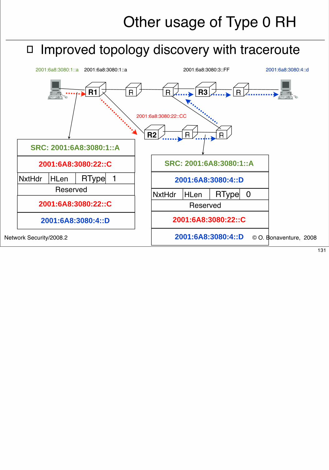
© O. Bonaventure, 2008Network Security/2008.2
Other usage of Type 0 RH� Improved topology discovery with traceroute
2001:6a8:3080:4::d
R1 R R R3 R
2001:6a8:3080:1::a 2001:6a8:3080:1::a 2001:6a8:3080:3::FF
R2
2001:6a8:3080:22::CC
R R
NxtHdr HLen RType 1
2001:6A8:3080:22::C
Reserved
SRC: 2001:6A8:3080:1::A
2001:6A8:3080:4::D
2001:6A8:3080:22::C
NxtHdr HLen RType 0
2001:6A8:3080:22::C
Reserved
SRC: 2001:6A8:3080:1::A
2001:6A8:3080:4::D
2001:6A8:3080:4::D
131
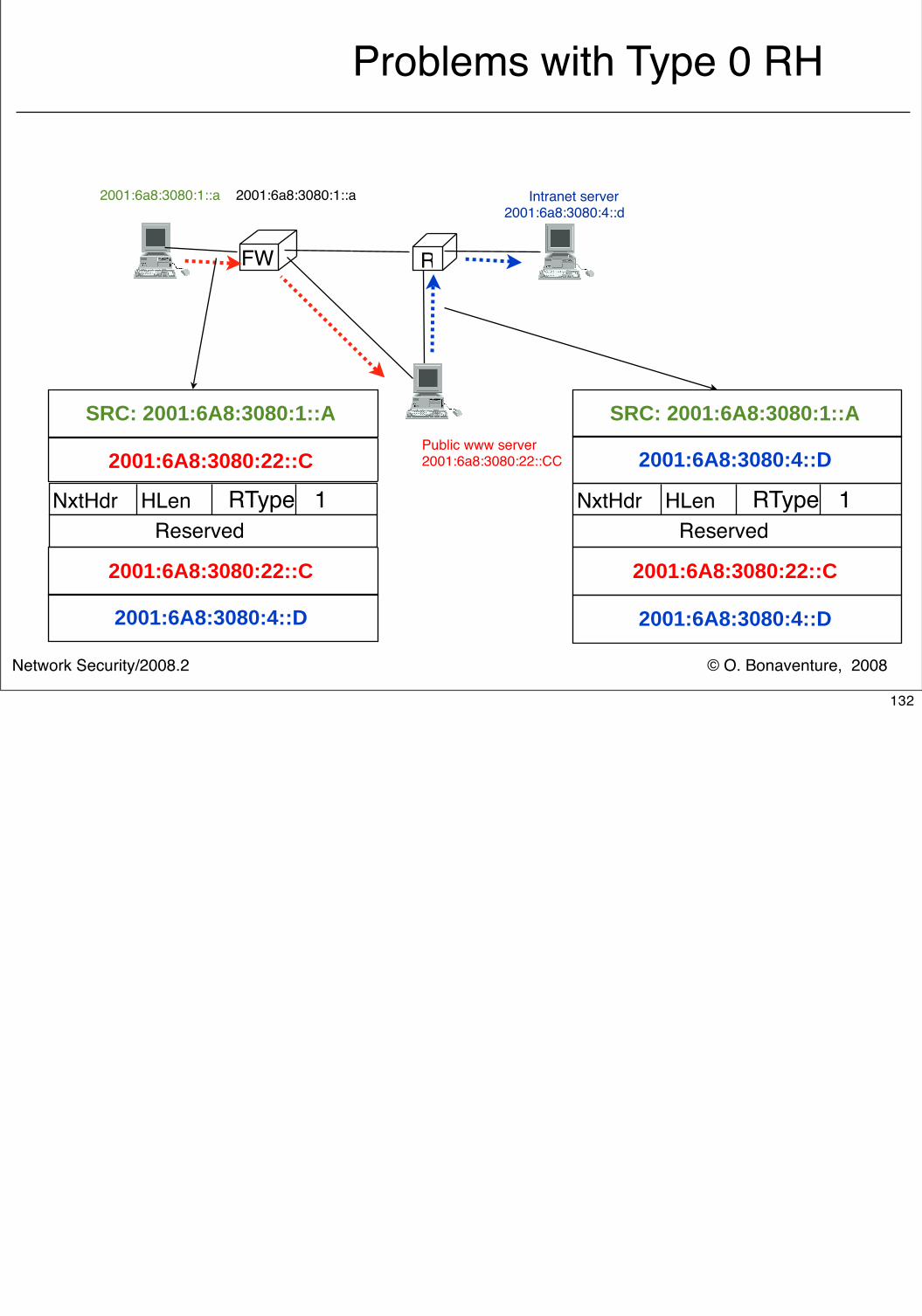
© O. Bonaventure, 2008Network Security/2008.2
Problems with Type 0 RH
Intranet server2001:6a8:3080:4::d
FW R
2001:6a8:3080:1::a 2001:6a8:3080:1::a
Public www server2001:6a8:3080:22::CC
NxtHdr HLen RType 1
2001:6A8:3080:22::C
Reserved
SRC: 2001:6A8:3080:1::A
2001:6A8:3080:4::D
2001:6A8:3080:22::C
NxtHdr HLen RType 1
2001:6A8:3080:22::C
Reserved
SRC: 2001:6A8:3080:1::A
2001:6A8:3080:4::D
2001:6A8:3080:4::D
132
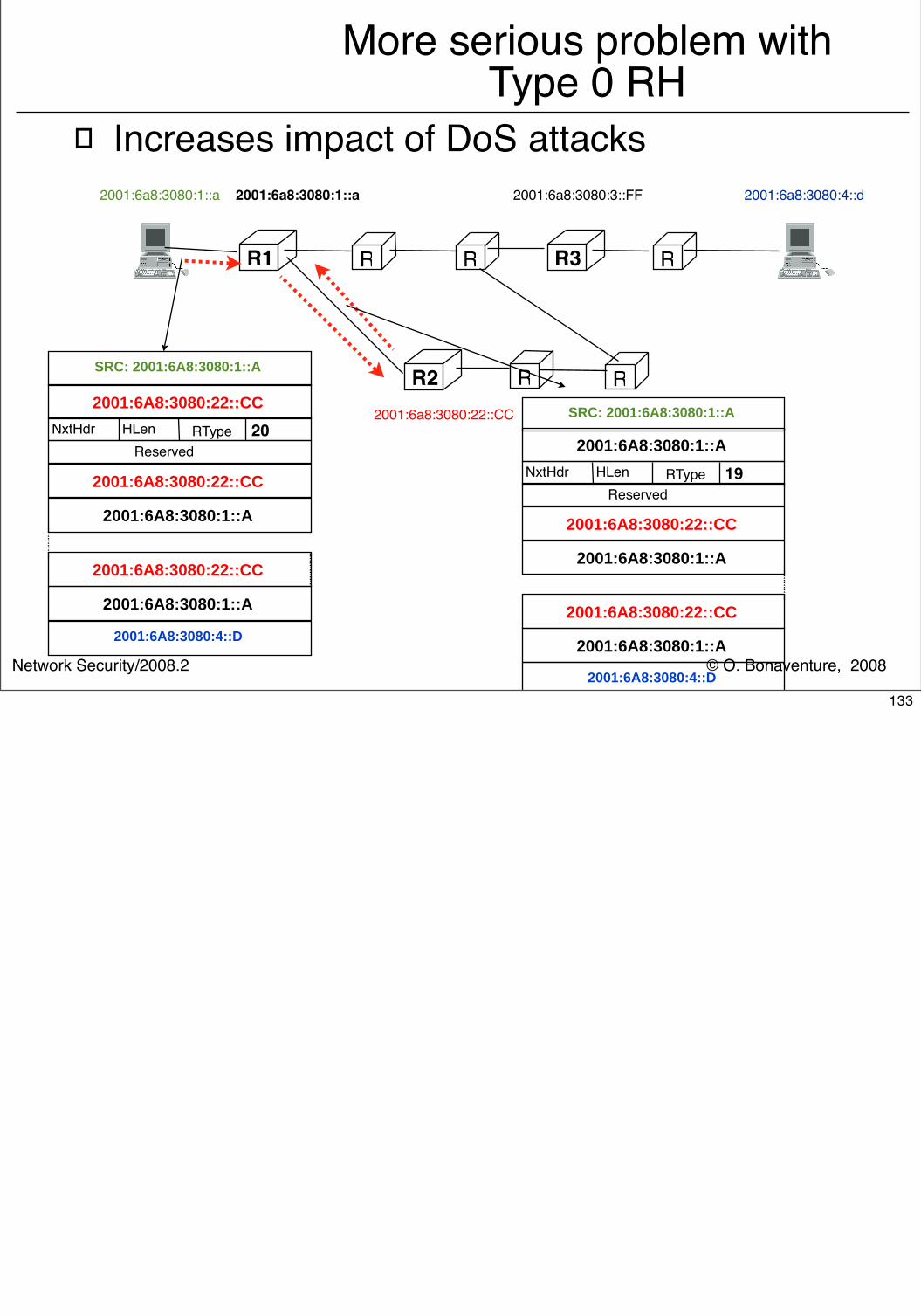
© O. Bonaventure, 2008Network Security/2008.2
More serious problem with Type 0 RH
� Increases impact of DoS attacks2001:6a8:3080:4::d
R1 R R R3 R
2001:6a8:3080:1::a 2001:6a8:3080:1::a 2001:6a8:3080:3::FF
R22001:6a8:3080:22::CC
R R
NxtHdr HLen RType 20
2001:6A8:3080:22::CC
Reserved
SRC: 2001:6A8:3080:1::A
2001:6A8:3080:4::D
2001:6A8:3080:1::A
2001:6A8:3080:22::CC
2001:6A8:3080:1::A
2001:6A8:3080:22::CC
NxtHdr HLen RType 19
2001:6A8:3080:22::CC
Reserved
SRC: 2001:6A8:3080:1::A
2001:6A8:3080:4::D
2001:6A8:3080:1::A
2001:6A8:3080:22::CC
2001:6A8:3080:1::A
2001:6A8:3080:1::A
133
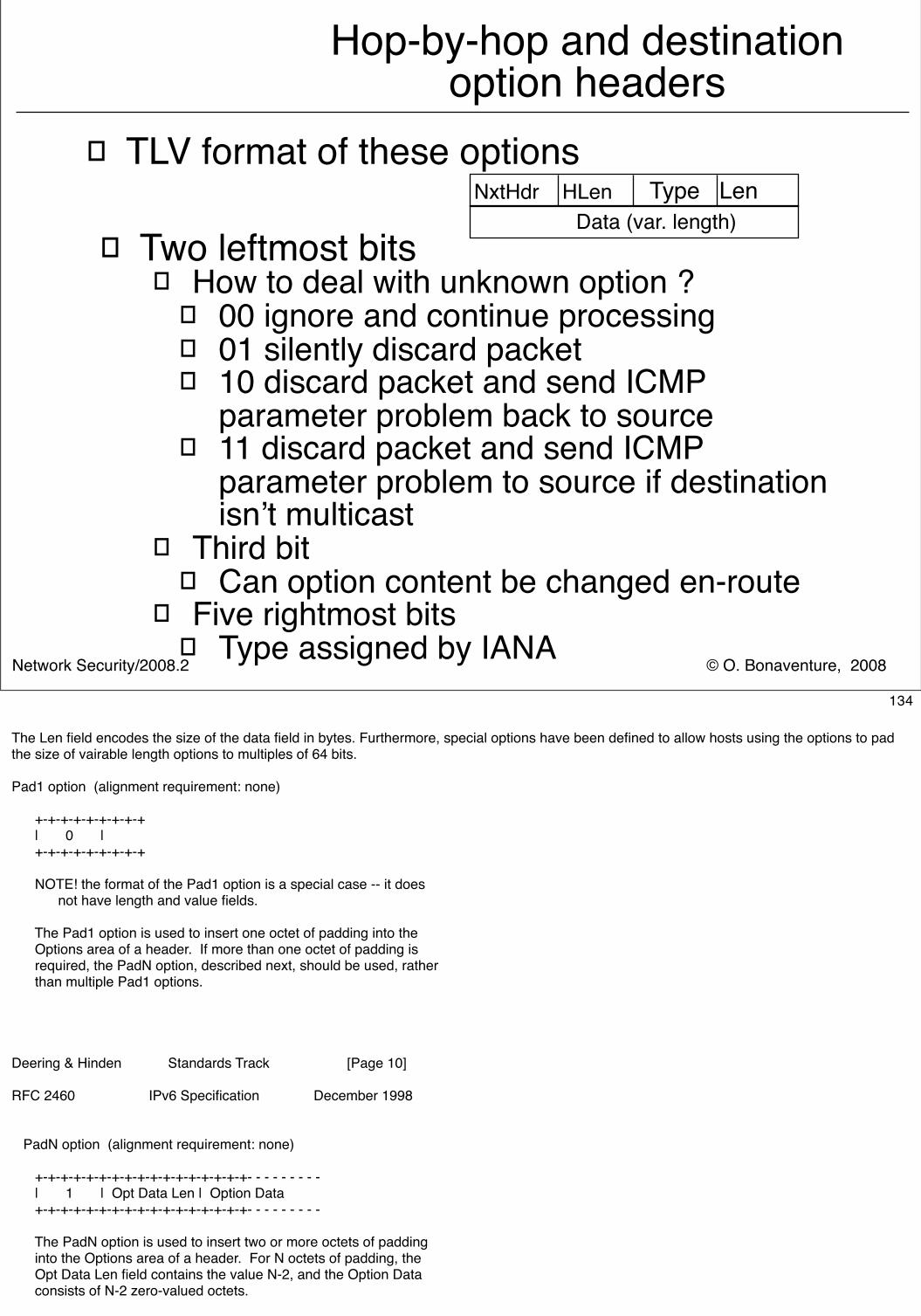
© O. Bonaventure, 2008Network Security/2008.2
Hop-by-hop and destination option headers
� TLV format of these options
� Two leftmost bits� How to deal with unknown option ?
� 00 ignore and continue processing� 01 silently discard packet� 10 discard packet and send ICMP
parameter problem back to source� 11 discard packet and send ICMP
parameter problem to source if destination isn’t multicast
� Third bit� Can option content be changed en-route
� Five rightmost bits� Type assigned by IANA
NxtHdr HLen Type Len Data (var. length)
134
The Len field encodes the size of the data field in bytes. Furthermore, special options have been defined to allow hosts using the options to pad the size of vairable length options to multiples of 64 bits.
Pad1 option (alignment requirement: none)
+-+-+-+-+-+-+-+-+ | 0 | +-+-+-+-+-+-+-+-+
NOTE! the format of the Pad1 option is a special case -- it does not have length and value fields.
The Pad1 option is used to insert one octet of padding into the Options area of a header. If more than one octet of padding is required, the PadN option, described next, should be used, rather than multiple Pad1 options.
Deering & Hinden Standards Track [Page 10] RFC 2460 IPv6 Specification December 1998
PadN option (alignment requirement: none)
+-+-+-+-+-+-+-+-+-+-+-+-+-+-+-+-+- - - - - - - - - | 1 | Opt Data Len | Option Data +-+-+-+-+-+-+-+-+-+-+-+-+-+-+-+-+- - - - - - - - -
The PadN option is used to insert two or more octets of padding into the Options area of a header. For N octets of padding, the Opt Data Len field contains the value N-2, and the Option Data consists of N-2 zero-valued octets.
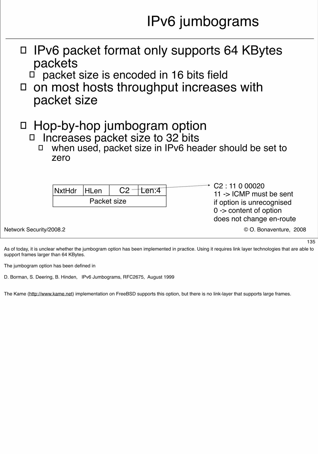
© O. Bonaventure, 2008Network Security/2008.2
IPv6 jumbograms
� IPv6 packet format only supports 64 KBytes packets
� packet size is encoded in 16 bits field� on most hosts throughput increases with
packet size
� Hop-by-hop jumbogram option� Increases packet size to 32 bits
� when used, packet size in IPv6 header should be set to zero
NxtHdr HLen C2 Len:4 Packet size
C2 : 11 0 0002011 -> ICMP must be sent if option is unrecognised0 -> content of option does not change en-route
135As of today, it is unclear whether the jumbogram option has been implemented in practice. Using it requires link layer technologies that are able to support frames larger than 64 KBytes.
The jumbogram option has been defined in
D. Borman, S. Deering, B. Hinden, IPv6 Jumbograms, RFC2675, August 1999
The Kame (http://www.kame.net) implementation on FreeBSD supports this option, but there is no link-layer that supports large frames.
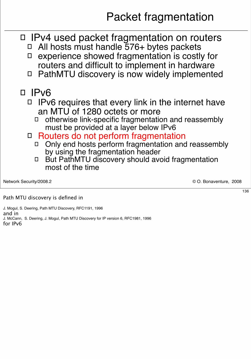
© O. Bonaventure, 2008Network Security/2008.2
Packet fragmentation� IPv4 used packet fragmentation on routers
� All hosts must handle 576+ bytes packets� experience showed fragmentation is costly for
routers and difficult to implement in hardware� PathMTU discovery is now widely implemented
� IPv6� IPv6 requires that every link in the internet have
an MTU of 1280 octets or more � otherwise link-specific fragmentation and reassembly
must be provided at a layer below IPv6� Routers do not perform fragmentation
� Only end hosts perform fragmentation and reassembly by using the fragmentation header
� But PathMTU discovery should avoid fragmentation most of the time
136
Path MTU discovery is defined in
J. Mogul, S. Deering, Path MTU Discovery, RFC1191, 1996and in J. McCann, S. Deering, J. Mogul, Path MTU Discovery for IP version 6, RFC1981, 1996for IPv6
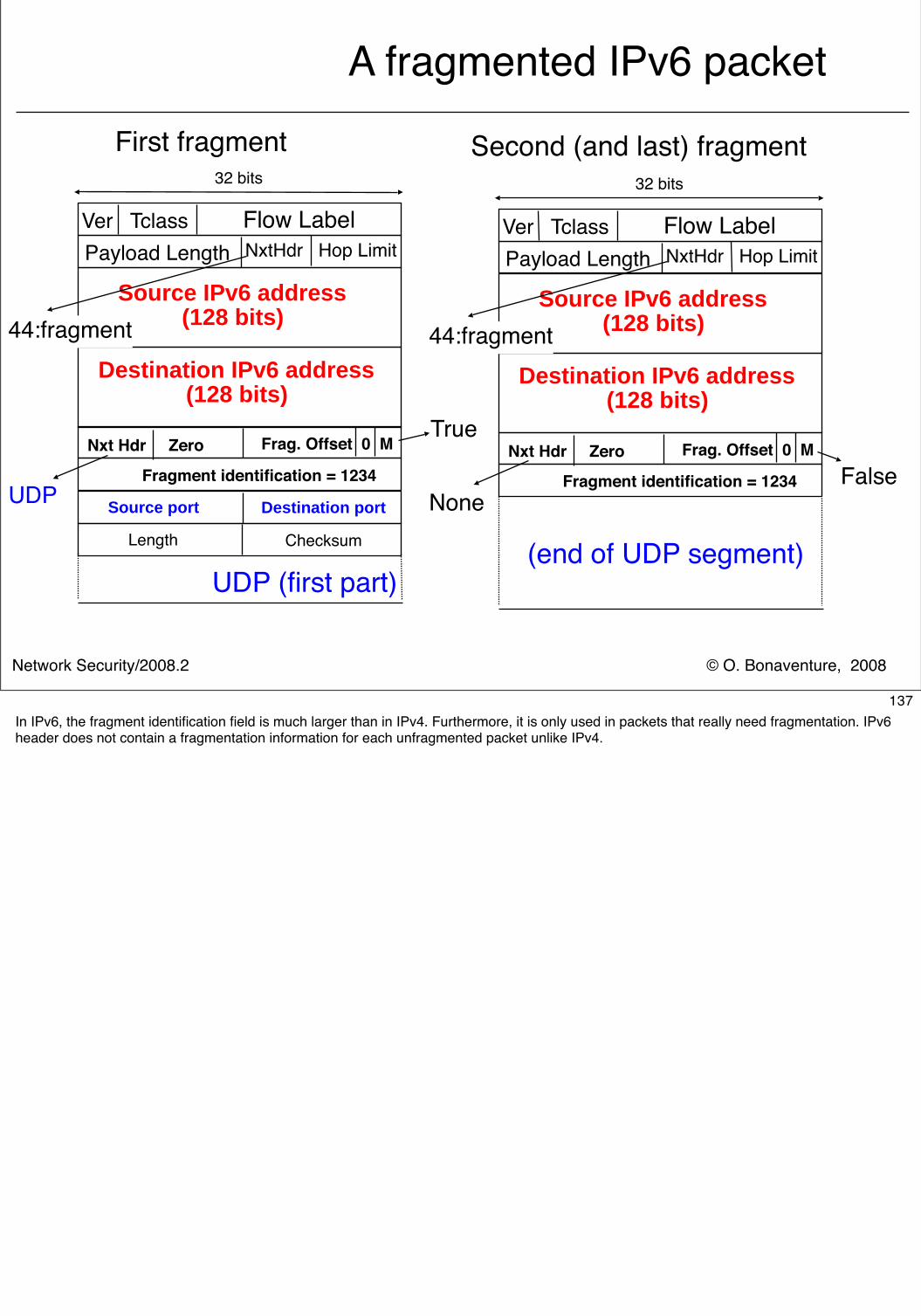
© O. Bonaventure, 2008Network Security/2008.2
A fragmented IPv6 packet
32 bits
Ver Tclass Flow LabelNxtHdr Hop Limit
Source IPv6 address(128 bits)
Payload Length
Destination IPv6 address(128 bits)
Source port Destination port
Length Checksum
UDP (first part)
44:fragment
Nxt Hdr Zero Frag. Offset 0 M
Fragment identification = 1234UDP
32 bits
Ver Tclass Flow LabelNxtHdr Hop Limit
Source IPv6 address(128 bits)
Payload Length
Destination IPv6 address(128 bits)
44:fragment
Nxt Hdr Zero Frag. Offset 0 M
Fragment identification = 1234None
True
False
First fragment Second (and last) fragment
(end of UDP segment)
137In IPv6, the fragment identification field is much larger than in IPv4. Furthermore, it is only used in packets that really need fragmentation. IPv6 header does not contain a fragmentation information for each unfragmented packet unlike IPv4.
© O. Bonaventure, 2008Network Security/2008.2
IP version 6
� Outline� Motivations for IP version 6
� IPv6 addressing architecture
� IPv6 packets
� ICMP v6
138
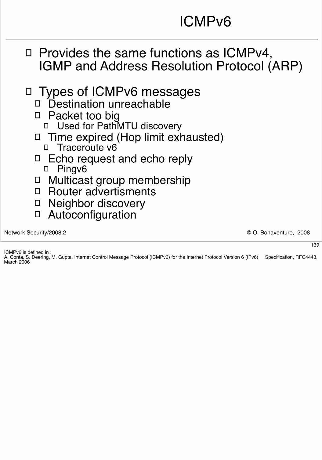
© O. Bonaventure, 2008Network Security/2008.2
ICMPv6
� Provides the same functions as ICMPv4, IGMP and Address Resolution Protocol (ARP)
� Types of ICMPv6 messages� Destination unreachable� Packet too big
� Used for PathMTU discovery� Time expired (Hop limit exhausted)
� Traceroute v6� Echo request and echo reply
� Pingv6� Multicast group membership� Router advertisments� Neighbor discovery� Autoconfiguration
139ICMPv6 is defined in :A. Conta, S. Deering, M. Gupta, Internet Control Message Protocol (ICMPv6) for the Internet Protocol Version 6 (IPv6) Specification, RFC4443, March 2006
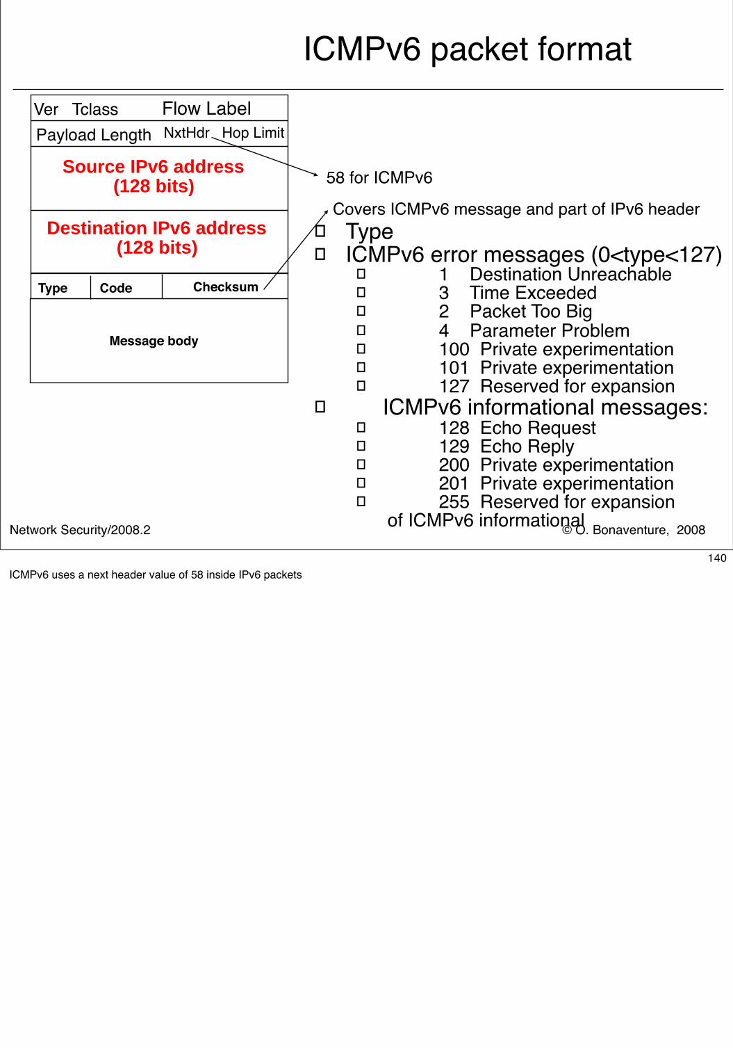
© O. Bonaventure, 2008Network Security/2008.2
ICMPv6 packet format
� Type� ICMPv6 error messages (0<type<127)
� 1 Destination Unreachable � 3 Time Exceeded � 2 Packet Too Big � 4 Parameter Problem � 100 Private experimentation� 101 Private experimentation� 127 Reserved for expansion
� ICMPv6 informational messages:� 128 Echo Request � 129 Echo Reply � 200 Private experimentation� 201 Private experimentation� 255 Reserved for expansion
of ICMPv6 informational
Type Code Checksum
Message body
Ver Tclass Flow LabelNxtHdr Hop Limit
Source IPv6 address(128 bits)
Payload Length
Destination IPv6 address(128 bits)
58 for ICMPv6
Covers ICMPv6 message and part of IPv6 header
140ICMPv6 uses a next header value of 58 inside IPv6 packets
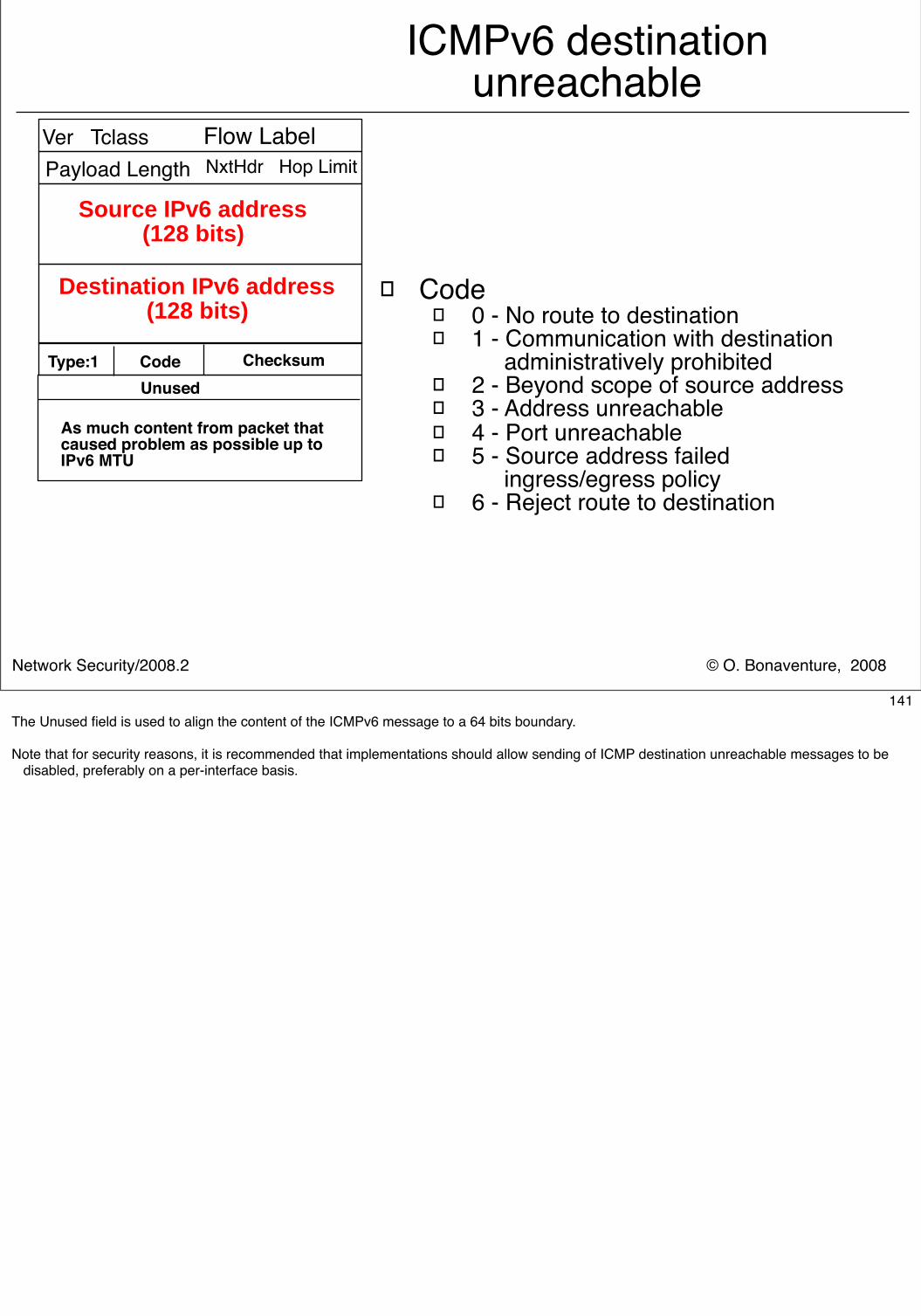
© O. Bonaventure, 2008Network Security/2008.2
ICMPv6 destination unreachable
� Code� 0 - No route to destination� 1 - Communication with destination
administratively prohibited� 2 - Beyond scope of source address� 3 - Address unreachable� 4 - Port unreachable� 5 - Source address failed
ingress/egress policy� 6 - Reject route to destination
Type:1 Code Checksum
As much content from packet thatcaused problem as possible up toIPv6 MTU
Ver Tclass Flow LabelNxtHdr Hop Limit
Source IPv6 address(128 bits)
Payload Length
Destination IPv6 address(128 bits)
Unused
141The Unused field is used to align the content of the ICMPv6 message to a 64 bits boundary.
Note that for security reasons, it is recommended that implementations should allow sending of ICMP destination unreachable messages to be disabled, preferably on a per-interface basis.
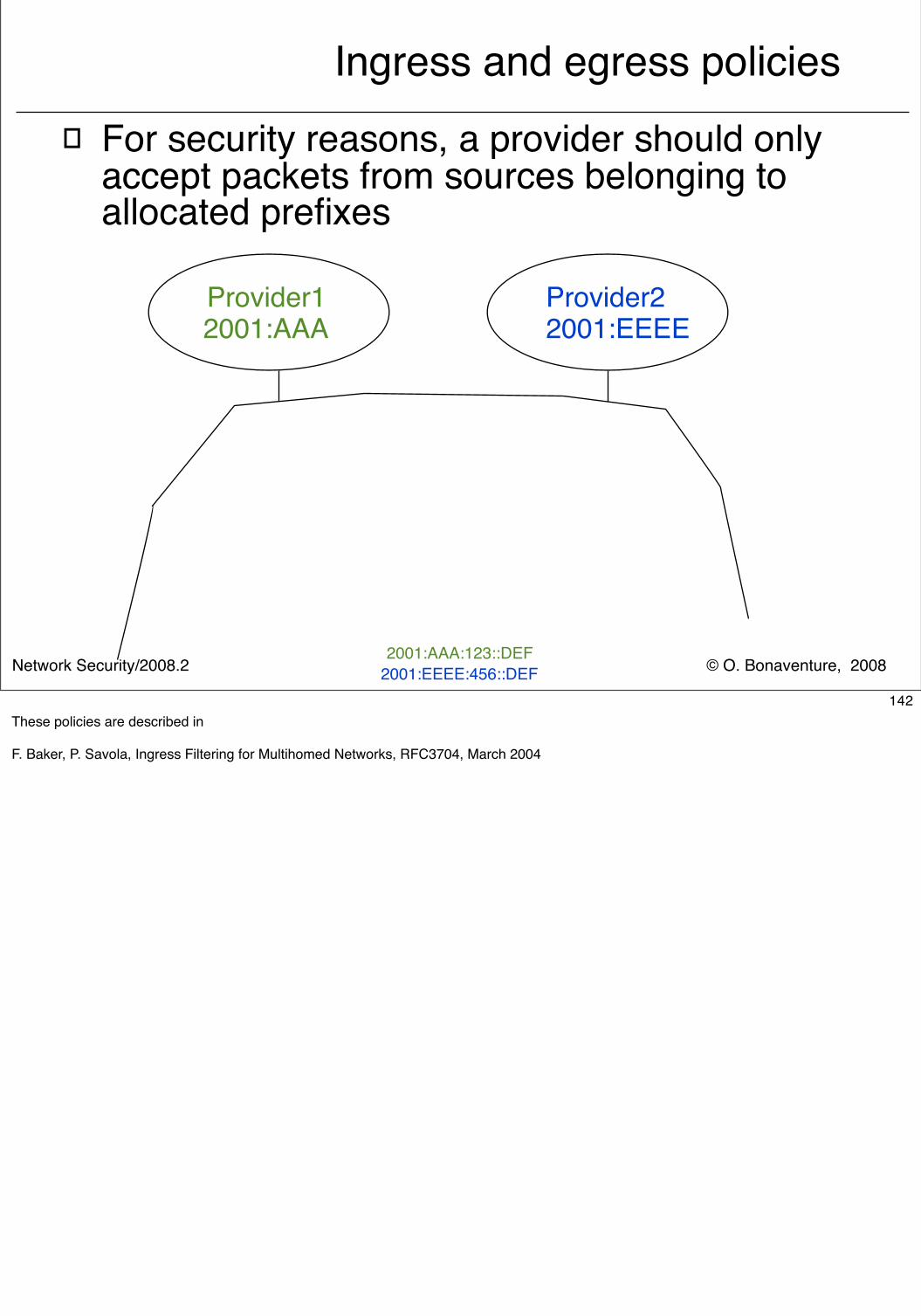
© O. Bonaventure, 2008Network Security/2008.2
Ingress and egress policies� For security reasons, a provider should only
accept packets from sources belonging to allocated prefixes
Provider12001:AAA
Provider22001:EEEE
R1 R2
R R
R R
2001:AAA:123::ABC2001:EEEE:456::EDC
2001:AAA:123::DEF2001:EEEE:456::DEF
142These policies are described in
F. Baker, P. Savola, Ingress Filtering for Multihomed Networks, RFC3704, March 2004
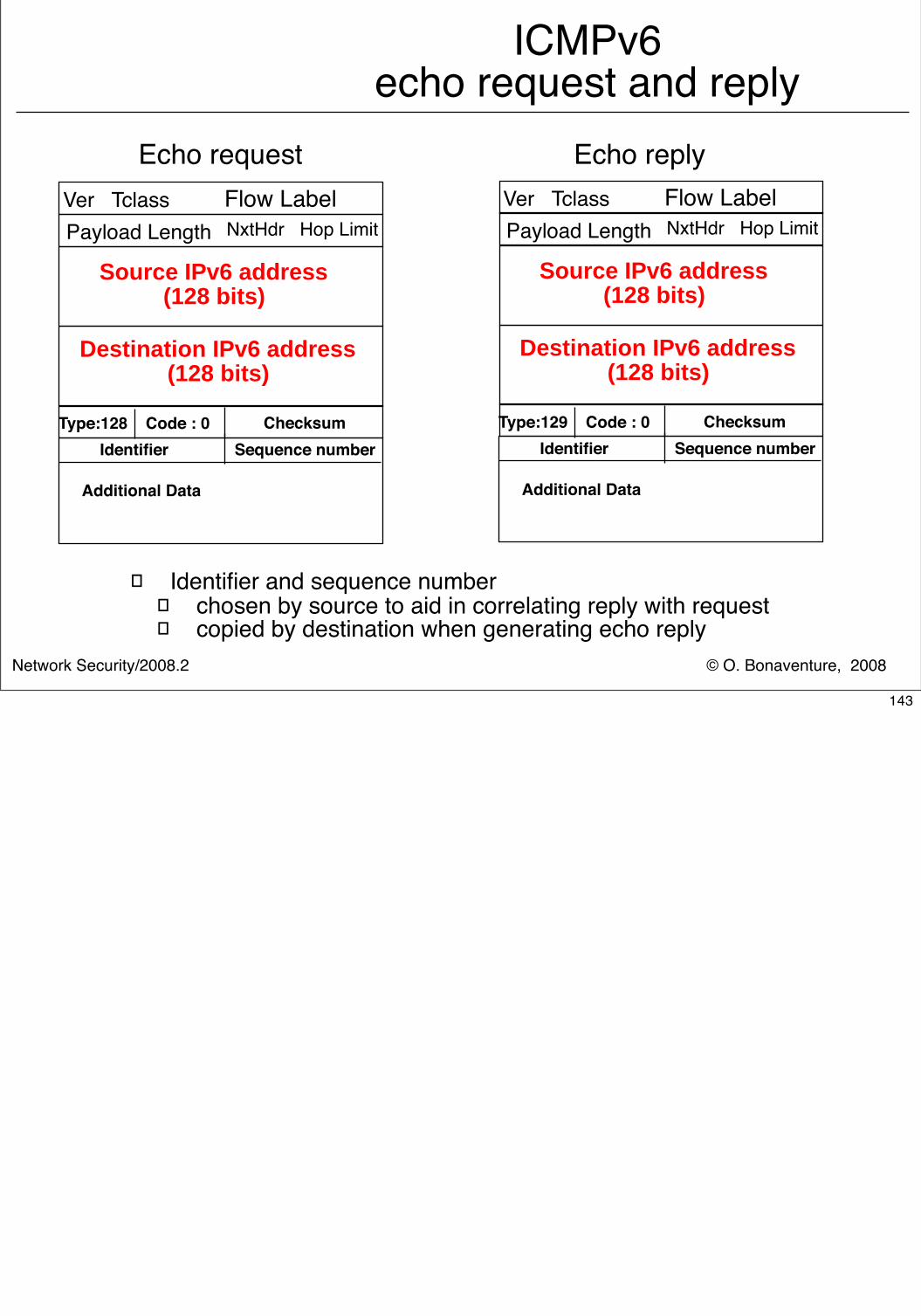
© O. Bonaventure, 2008Network Security/2008.2
ICMPv6echo request and reply
Type:128 Code : 0 Checksum
Additional Data
Ver Tclass Flow LabelNxtHdr Hop Limit
Source IPv6 address(128 bits)
Payload Length
Destination IPv6 address(128 bits)
Identifier Sequence numberType:129 Code : 0 Checksum
Additional Data
Ver Tclass Flow LabelNxtHdr Hop Limit
Source IPv6 address(128 bits)
Payload Length
Destination IPv6 address(128 bits)
Identifier Sequence number
Echo request Echo reply
� Identifier and sequence number� chosen by source to aid in correlating reply with request� copied by destination when generating echo reply
143
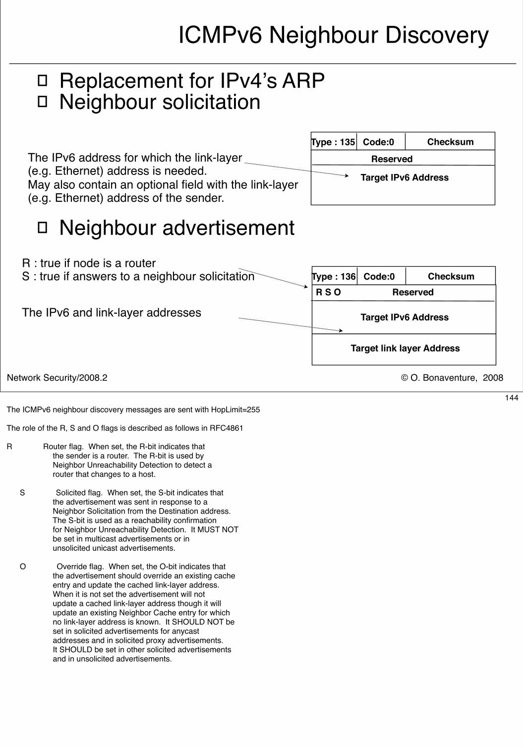
© O. Bonaventure, 2008Network Security/2008.2
ICMPv6 Neighbour Discovery
� Replacement for IPv4’s ARP� Neighbour solicitation
� Neighbour advertisement
Type : 135 Code:0 Checksum
Target IPv6 Address
ReservedThe IPv6 address for which the link-layer(e.g. Ethernet) address is needed.May also contain an optional field with the link-layer (e.g. Ethernet) address of the sender.
Type : 136 Code:0 Checksum
Target IPv6 Address
R S O Reserved
Target link layer Address
The IPv6 and link-layer addresses
R : true if node is a routerS : true if answers to a neighbour solicitation
144The ICMPv6 neighbour discovery messages are sent with HopLimit=255
The role of the R, S and O flags is described as follows in RFC4861
R Router flag. When set, the R-bit indicates that the sender is a router. The R-bit is used by Neighbor Unreachability Detection to detect a router that changes to a host.
S Solicited flag. When set, the S-bit indicates that the advertisement was sent in response to a Neighbor Solicitation from the Destination address. The S-bit is used as a reachability confirmation for Neighbor Unreachability Detection. It MUST NOT be set in multicast advertisements or in unsolicited unicast advertisements.
O Override flag. When set, the O-bit indicates that the advertisement should override an existing cache entry and update the cached link-layer address. When it is not set the advertisement will not update a cached link-layer address though it will update an existing Neighbor Cache entry for which no link-layer address is known. It SHOULD NOT be set in solicited advertisements for anycast addresses and in solicited proxy advertisements. It SHOULD be set in other solicited advertisements and in unsolicited advertisements.
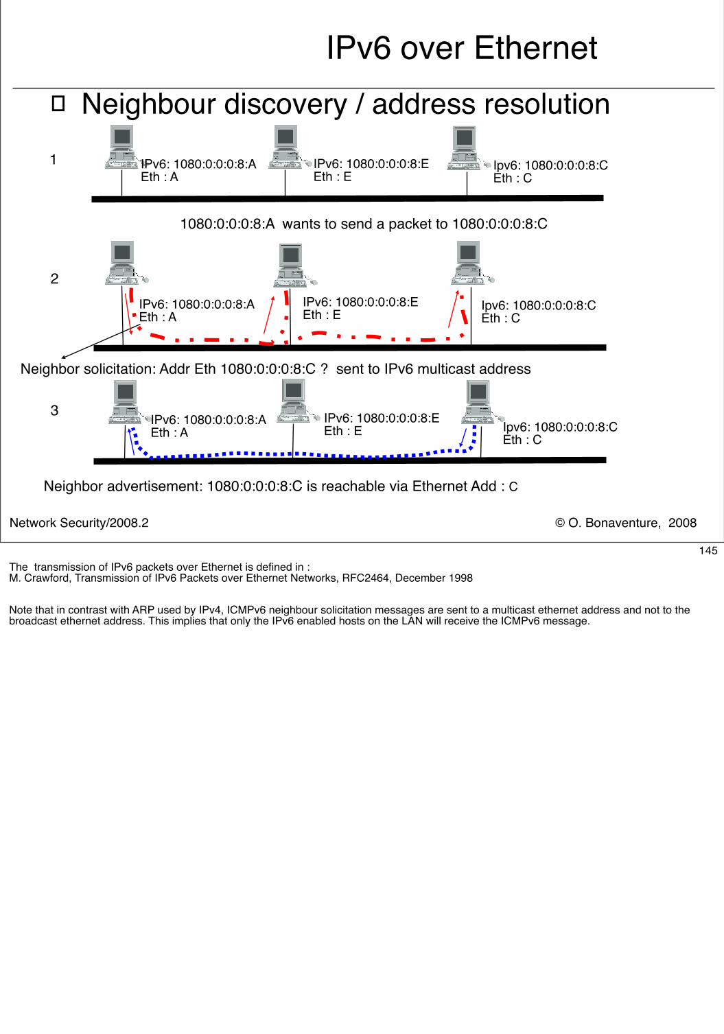
© O. Bonaventure, 2008Network Security/2008.2
IPv6 over Ethernet� Neighbour discovery / address resolution
IPv6: 1080:0:0:0:8:AEth : A
1080:0:0:0:8:A wants to send a packet to 1080:0:0:0:8:C
Neighbor solicitation: Addr Eth 1080:0:0:0:8:C ? sent to IPv6 multicast address
1
2
3
IPv6: 1080:0:0:0:8:EEth : E
Ipv6: 1080:0:0:0:8:CEth : C
Ipv6: 1080:0:0:0:8:CEth : C
IPv6: 1080:0:0:0:8:EEth : E
IPv6: 1080:0:0:0:8:AEth : A
Neighbor advertisement: 1080:0:0:0:8:C is reachable via Ethernet Add : C
Ipv6: 1080:0:0:0:8:CEth : C
IPv6: 1080:0:0:0:8:EEth : E
IPv6: 1080:0:0:0:8:AEth : A
145The transmission of IPv6 packets over Ethernet is defined in :M. Crawford, Transmission of IPv6 Packets over Ethernet Networks, RFC2464, December 1998
Note that in contrast with ARP used by IPv4, ICMPv6 neighbour solicitation messages are sent to a multicast ethernet address and not to the broadcast ethernet address. This implies that only the IPv6 enabled hosts on the LAN will receive the ICMPv6 message.
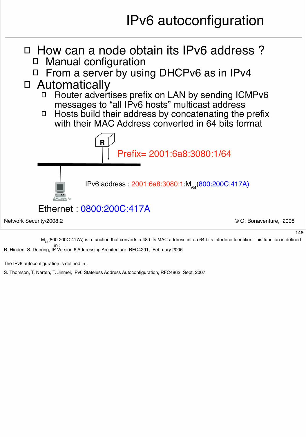
© O. Bonaventure, 2008Network Security/2008.2
IPv6 autoconfiguration
� How can a node obtain its IPv6 address ?� Manual configuration� From a server by using DHCPv6 as in IPv4
� Automatically� Router advertises prefix on LAN by sending ICMPv6
messages to “all IPv6 hosts” multicast address� Hosts build their address by concatenating the prefix
with their MAC Address converted in 64 bits format
RPrefix= 2001:6a8:3080:1/64
Ethernet : 0800:200C:417A
IPv6 address : 2001:6a8:3080:1:M64(800:200C:417A)
146M64(800:200C:417A) is a function that converts a 48 bits MAC address into a 64 bits Interface Identifier. This function is defined
in :R. Hinden, S. Deering, IP Version 6 Addressing Architecture, RFC4291, February 2006
The IPv6 autoconfiguration is defined in :
S. Thomson, T. Narten, T. Jinmei, IPv6 Stateless Address Autoconfiguration, RFC4862, Sept. 2007
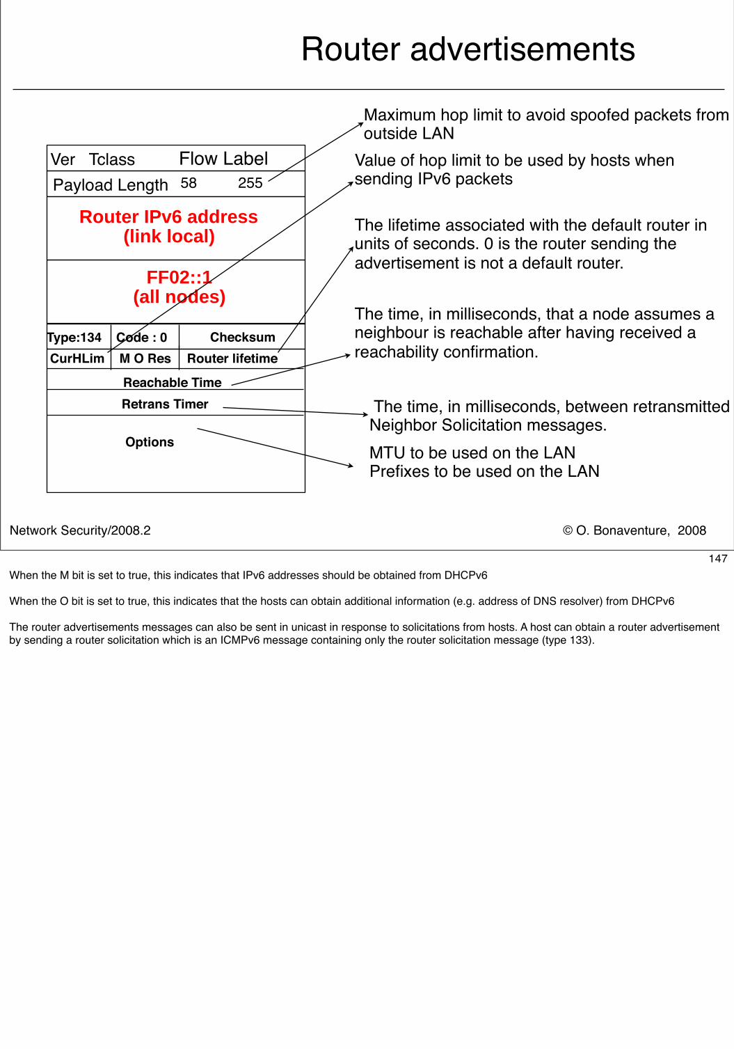
© O. Bonaventure, 2008Network Security/2008.2
Router advertisements
Type:134 Code : 0 Checksum
Retrans Timer
Ver Tclass Flow Label58 255
Router IPv6 address(link local)
Payload Length
FF02::1 (all nodes)
CurHLim Router lifetime
Maximum hop limit to avoid spoofed packets from outside LAN
M O Res
Reachable Time
Options
Value of hop limit to be used by hosts when sending IPv6 packets
The lifetime associated with the default router in units of seconds. 0 is the router sending the advertisement is not a default router.
The time, in milliseconds, that a node assumes a neighbour is reachable after having received a reachability confirmation.
The time, in milliseconds, between retransmitted Neighbor Solicitation messages. MTU to be used on the LANPrefixes to be used on the LAN
147When the M bit is set to true, this indicates that IPv6 addresses should be obtained from DHCPv6
When the O bit is set to true, this indicates that the hosts can obtain additional information (e.g. address of DNS resolver) from DHCPv6
The router advertisements messages can also be sent in unicast in response to solicitations from hosts. A host can obtain a router advertisement by sending a router solicitation which is an ICMPv6 message containing only the router solicitation message (type 133).
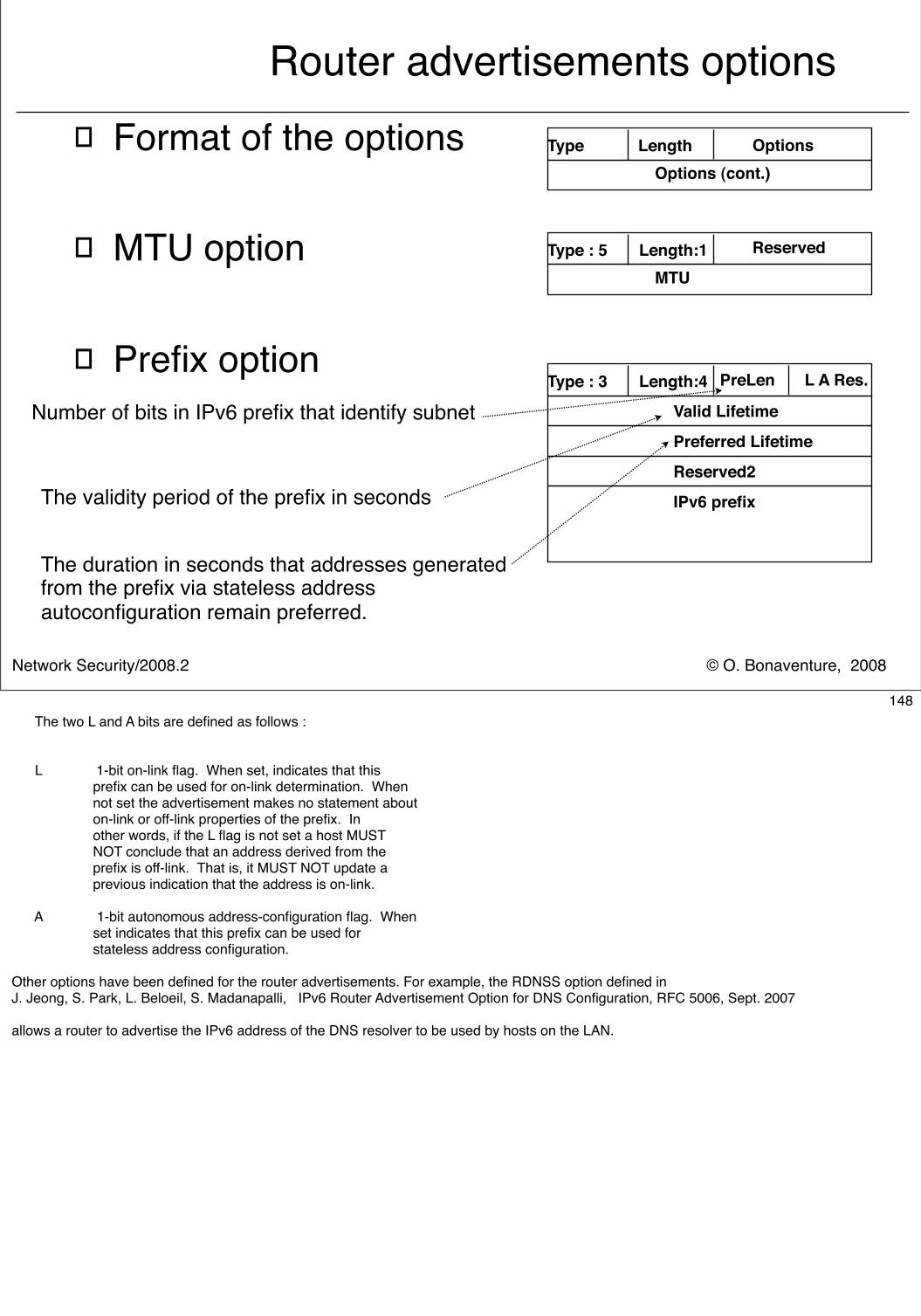
© O. Bonaventure, 2008Network Security/2008.2
Router advertisements options� Format of the options
� MTU option
� Prefix option
Type Length OptionsOptions (cont.)
Type : 5 Length:1 Reserved
MTU
Type : 3 Length:4 PreLen L A Res.
Valid Lifetime
Preferred Lifetime
Reserved2
IPv6 prefix
Number of bits in IPv6 prefix that identify subnet
The validity period of the prefix in seconds
The duration in seconds that addresses generated from the prefix via stateless address autoconfiguration remain preferred.
148 The two L and A bits are defined as follows :
L 1-bit on-link flag. When set, indicates that this prefix can be used for on-link determination. When not set the advertisement makes no statement about on-link or off-link properties of the prefix. In other words, if the L flag is not set a host MUST NOT conclude that an address derived from the prefix is off-link. That is, it MUST NOT update a previous indication that the address is on-link.
A 1-bit autonomous address-configuration flag. When set indicates that this prefix can be used for stateless address configuration.
Other options have been defined for the router advertisements. For example, the RDNSS option defined in J. Jeong, S. Park, L. Beloeil, S. Madanapalli, IPv6 Router Advertisement Option for DNS Configuration, RFC 5006, Sept. 2007
allows a router to advertise the IPv6 address of the DNS resolver to be used by hosts on the LAN.
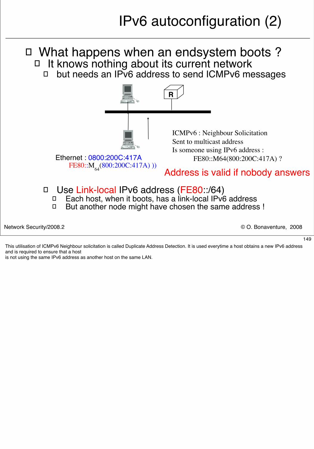
© O. Bonaventure, 2008Network Security/2008.2
IPv6 autoconfiguration (2)
� What happens when an endsystem boots ?� It knows nothing about its current network
� but needs an IPv6 address to send ICMPv6 messages
� Use Link-local IPv6 address (FE80::/64)� Each host, when it boots, has a link-local IPv6 address� But another node might have chosen the same address !
R
Ethernet : 0800:200C:417AFE80::M64(800:200C:417A) ))
Address is valid if nobody answers
ICMPv6 : Neighbour SolicitationSent to multicast addressIs someone using IPv6 address : FE80::M64(800:200C:417A) ?
149This utilisation of ICMPv6 Neighbour solicitation is called Duplicate Address Detection. It is used everytime a host obtains a new IPv6 address and is required to ensure that a hostis not using the same IPv6 address as another host on the same LAN.
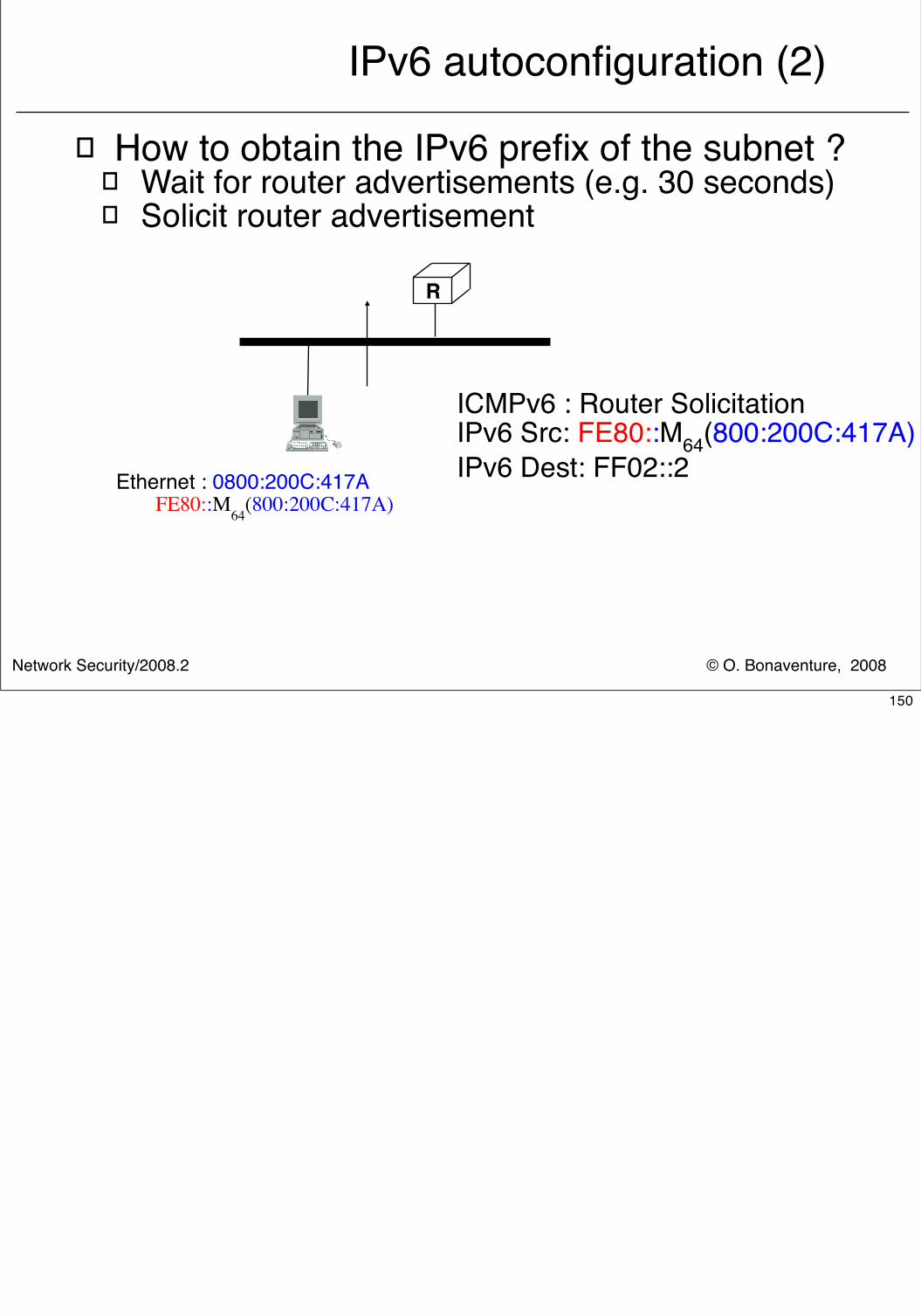
© O. Bonaventure, 2008Network Security/2008.2
IPv6 autoconfiguration (2)
� How to obtain the IPv6 prefix of the subnet ?� Wait for router advertisements (e.g. 30 seconds)� Solicit router advertisement
R
ICMPv6 : Router SolicitationIPv6 Src: FE80::M64(800:200C:417A)IPv6 Dest: FF02::2Ethernet : 0800:200C:417A
FE80::M64(800:200C:417A)
150
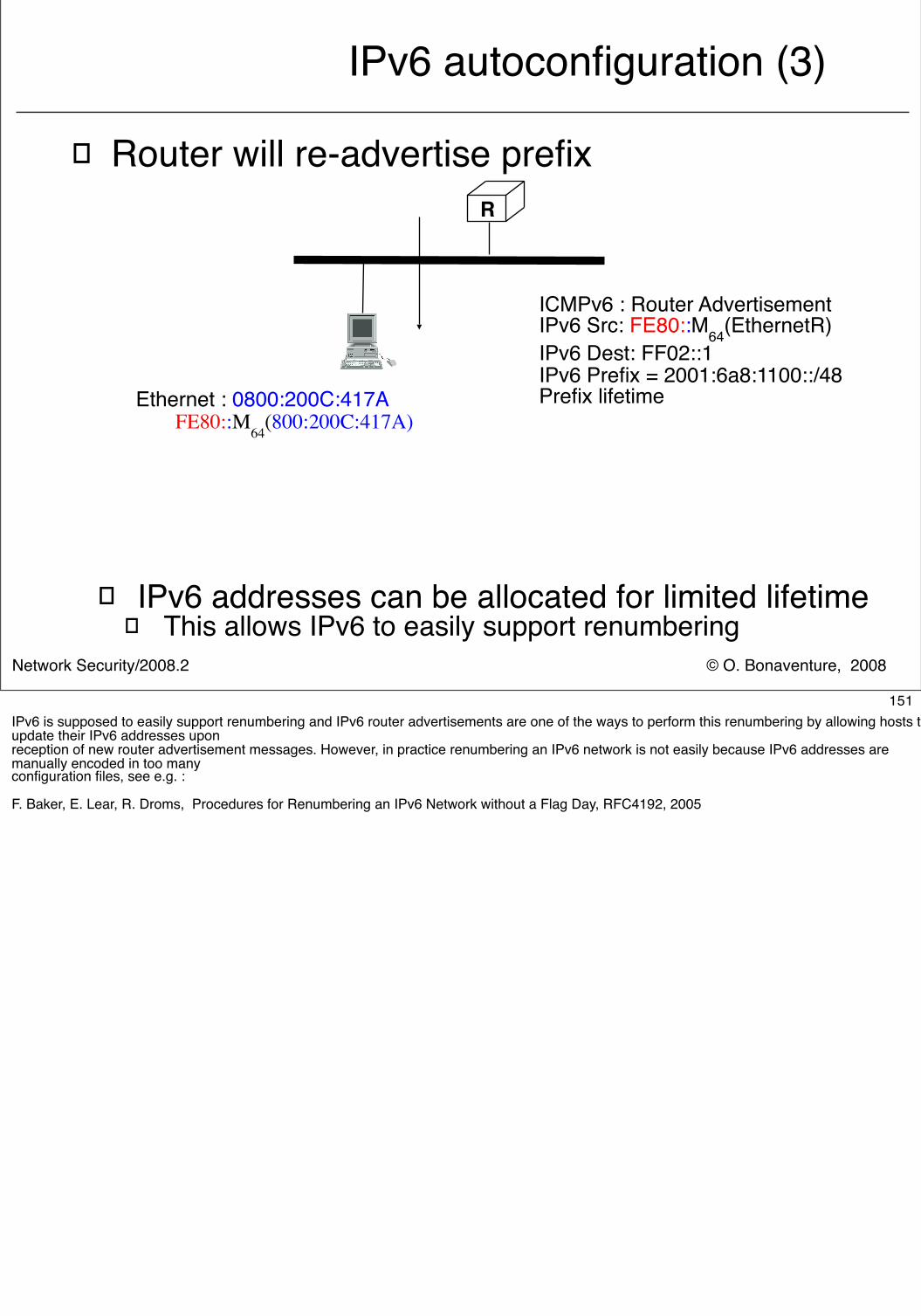
© O. Bonaventure, 2008Network Security/2008.2
IPv6 autoconfiguration (3)
� Router will re-advertise prefix
� IPv6 addresses can be allocated for limited lifetime� This allows IPv6 to easily support renumbering
R
ICMPv6 : Router AdvertisementIPv6 Src: FE80::M64(EthernetR)IPv6 Dest: FF02::1IPv6 Prefix = 2001:6a8:1100::/48Prefix lifetimeEthernet : 0800:200C:417A
FE80::M64(800:200C:417A)
151IPv6 is supposed to easily support renumbering and IPv6 router advertisements are one of the ways to perform this renumbering by allowing hosts to update their IPv6 addresses uponreception of new router advertisement messages. However, in practice renumbering an IPv6 network is not easily because IPv6 addresses are manually encoded in too manyconfiguration files, see e.g. :
F. Baker, E. Lear, R. Droms, Procedures for Renumbering an IPv6 Network without a Flag Day, RFC4192, 2005
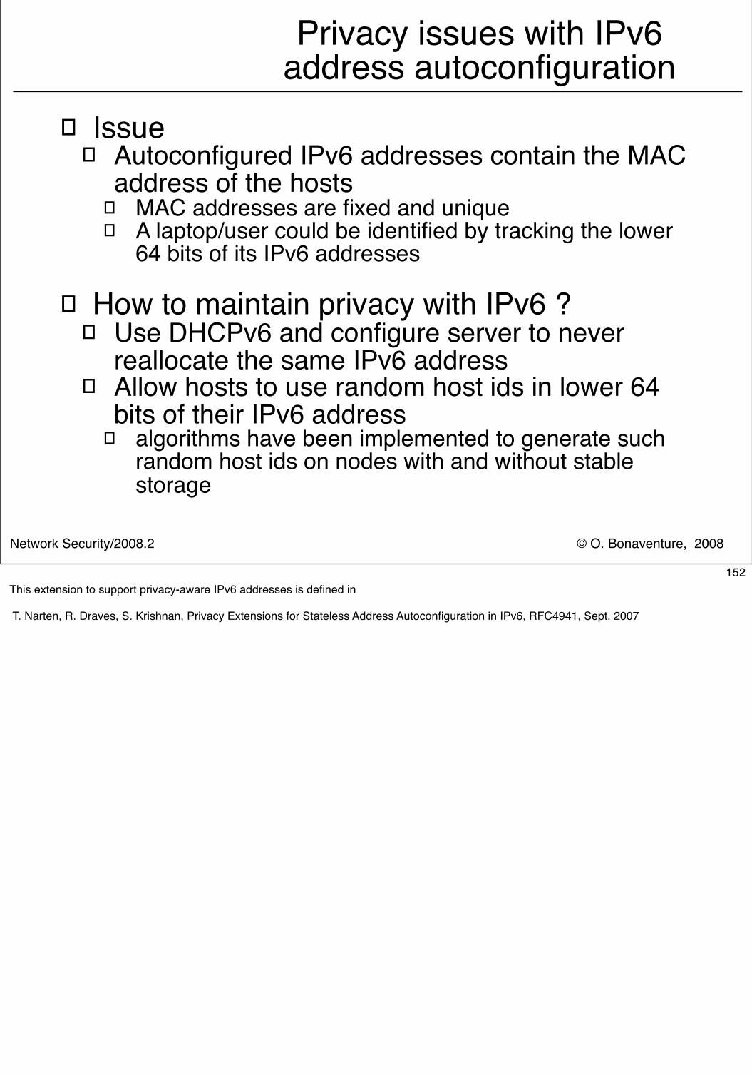
© O. Bonaventure, 2008Network Security/2008.2
Privacy issues with IPv6 address autoconfiguration
� Issue� Autoconfigured IPv6 addresses contain the MAC
address of the hosts� MAC addresses are fixed and unique� A laptop/user could be identified by tracking the lower
64 bits of its IPv6 addresses
� How to maintain privacy with IPv6 ?� Use DHCPv6 and configure server to never
reallocate the same IPv6 address� Allow hosts to use random host ids in lower 64
bits of their IPv6 address� algorithms have been implemented to generate such
random host ids on nodes with and without stable storage
152This extension to support privacy-aware IPv6 addresses is defined in
T. Narten, R. Draves, S. Krishnan, Privacy Extensions for Stateless Address Autoconfiguration in IPv6, RFC4941, Sept. 2007
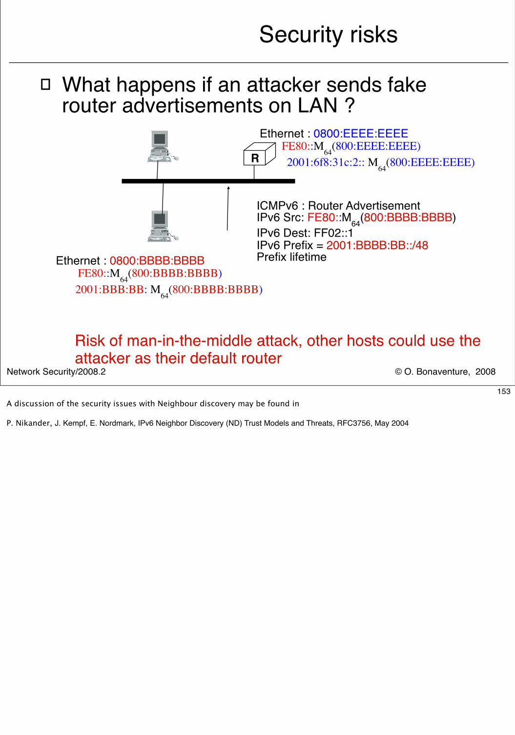
© O. Bonaventure, 2008Network Security/2008.2
Security risks
R
Ethernet : 0800:EEEE:EEEEFE80::M64(800:EEEE:EEEE)2001:6f8:31c:2:: M64(800:EEEE:EEEE)
� What happens if an attacker sends fake router advertisements on LAN ?
ICMPv6 : Router AdvertisementIPv6 Src: FE80::M64(800:BBBB:BBBB)IPv6 Dest: FF02::1IPv6 Prefix = 2001:BBBB:BB::/48Prefix lifetime
Risk of man-in-the-middle attack, other hosts could use the attacker as their default router
Ethernet : 0800:BBBB:BBBBFE80::M64(800:BBBB:BBBB)
2001:BBB:BB: M64(800:BBBB:BBBB)
153A discussion of the security issues with Neighbour discovery may be found in
P. Nikander, J. Kempf, E. Nordmark, IPv6 Neighbor Discovery (ND) Trust Models and Threats, RFC3756, May 2004
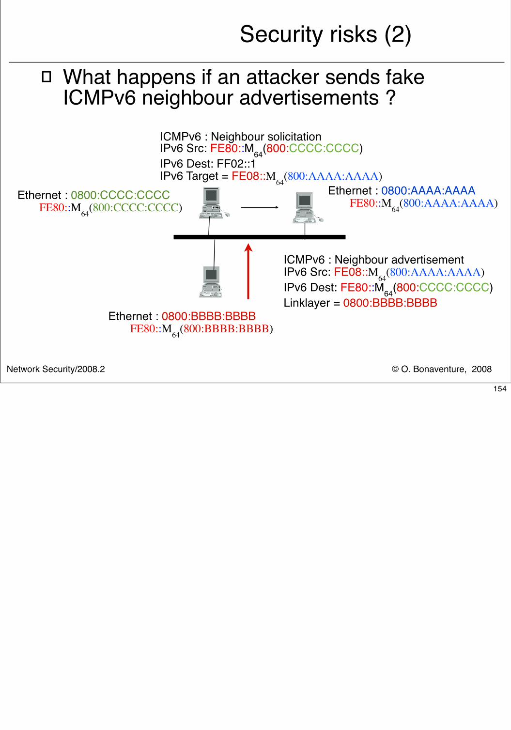
© O. Bonaventure, 2008Network Security/2008.2
Security risks (2)� What happens if an attacker sends fake
ICMPv6 neighbour advertisements ?ICMPv6 : Neighbour solicitationIPv6 Src: FE80::M64(800:CCCC:CCCC)IPv6 Dest: FF02::1IPv6 Target = FE08::M64(800:AAAA:AAAA)
Ethernet : 0800:BBBB:BBBBFE80::M64(800:BBBB:BBBB)
Ethernet : 0800:AAAA:AAAAFE80::M64(800:AAAA:AAAA)Ethernet : 0800:CCCC:CCCC
FE80::M64(800:CCCC:CCCC)
ICMPv6 : Neighbour advertisementIPv6 Src: FE08::M64(800:AAAA:AAAA) IPv6 Dest: FE80::M64(800:CCCC:CCCC) Linklayer = 0800:BBBB:BBBB
154
© O. Bonaventure, 2008Network Security/2008.2
Securing ICMPv6
� Principle of the solution� A host that replies to an ICMPv6 neighbour
solicitation should be able to prove that it owns the corresponding IPv6 address
� A router that sends router advertisements should be able to prove that it is authorised to serve as a router using the advertised prefixes
� Issues� How to exchange theses proofs and
authorisations ?� Is IPSec a solution ?
155
© O. Bonaventure, 2008Network Security/2008.2
First solution : certificates
� Principle� Each router has a public/private keypair� A certificate is generated for each router to
confirm :� that the keypair belongs to the router� that the owner of the keypair is a valid router
� Certificate must be anchored on an authority that is trusted by both routers and hosts
� ICMPv6 router advertisement messages are signed by the router
� Protocol issues� Need to extend ICMPv6 to support signatures
and certificates
156Additional information about the utilisation of X.509 certificates to represent IP prefixes and AS resources, see :
Lynn, C., Kent, S. and K. Seo, "X.509 Extensions for IP Addresses and AS Identifiers", RFC 3779, June 2004.
The development of these certificates is being performed within the SIDR working group of the IETF.
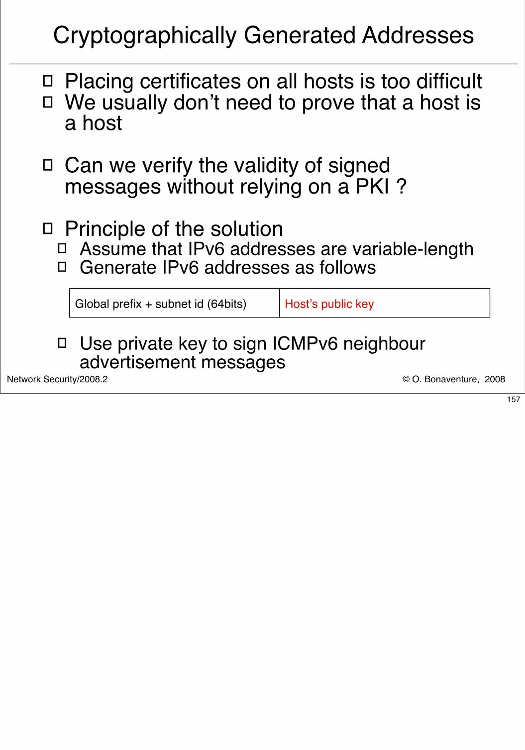
© O. Bonaventure, 2008Network Security/2008.2
Cryptographically Generated Addresses
� Placing certificates on all hosts is too difficult� We usually don’t need to prove that a host is
a host
� Can we verify the validity of signed messages without relying on a PKI ?
� Principle of the solution� Assume that IPv6 addresses are variable-length� Generate IPv6 addresses as follows
� Use private key to sign ICMPv6 neighbour advertisement messages
Global prefix + subnet id (64bits) Host’s public key
157
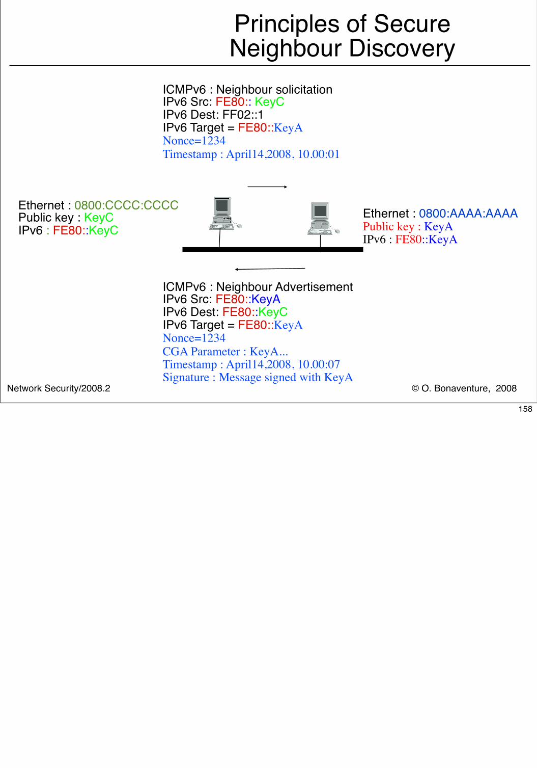
© O. Bonaventure, 2008Network Security/2008.2
Principles of Secure Neighbour Discovery
ICMPv6 : Neighbour solicitationIPv6 Src: FE80:: KeyCIPv6 Dest: FF02::1IPv6 Target = FE80::KeyANonce=1234Timestamp : April14,2008, 10.00:01
Ethernet : 0800:AAAA:AAAAPublic key : KeyAIPv6 : FE80::KeyA
Ethernet : 0800:CCCC:CCCCPublic key : KeyCIPv6 : FE80::KeyC
ICMPv6 : Neighbour AdvertisementIPv6 Src: FE80::KeyAIPv6 Dest: FE80::KeyCIPv6 Target = FE80::KeyANonce=1234CGA Parameter : KeyA...Timestamp : April14,2008, 10.00:07Signature : Message signed with KeyA
158
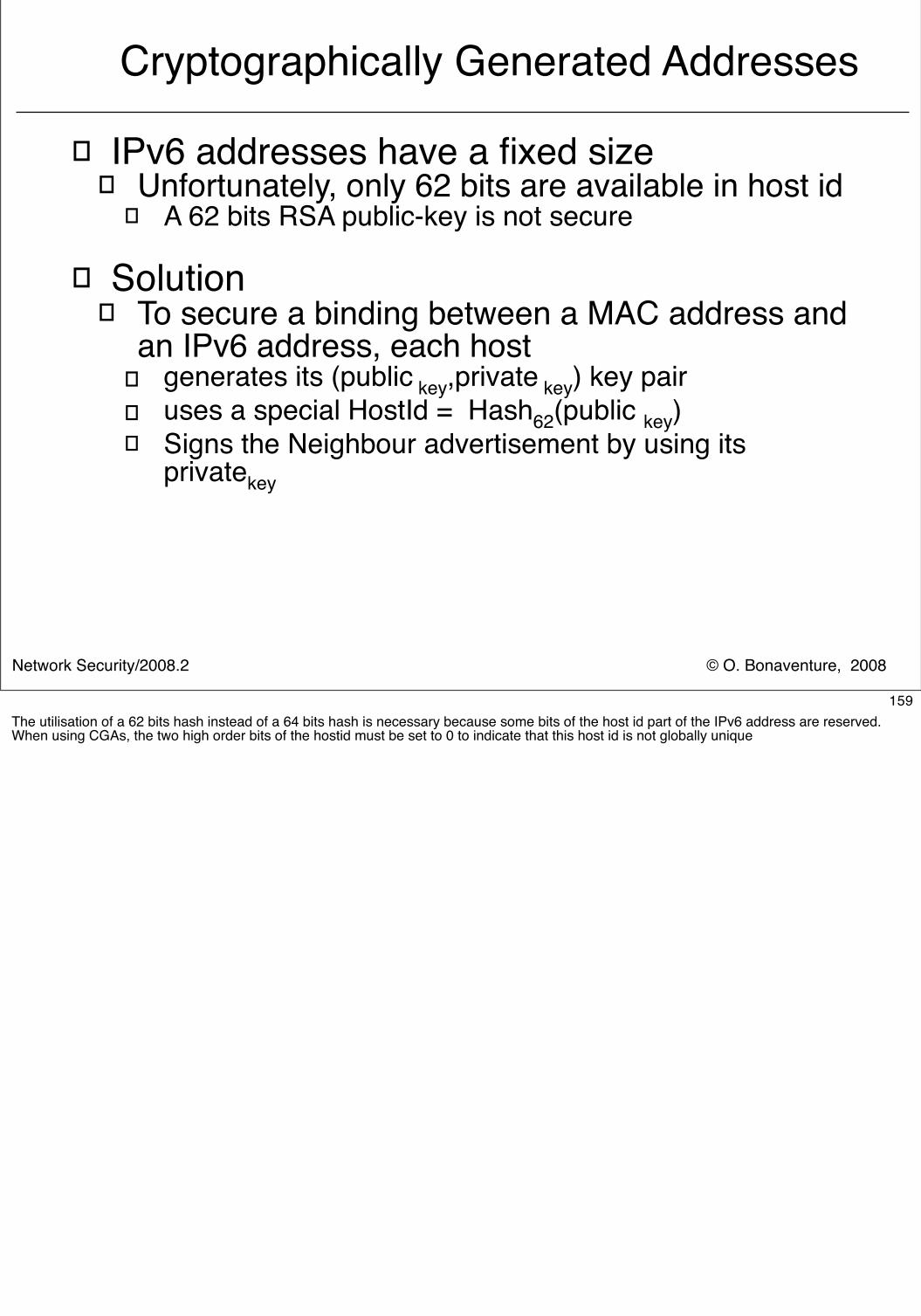
© O. Bonaventure, 2008Network Security/2008.2
Cryptographically Generated Addresses
� IPv6 addresses have a fixed size� Unfortunately, only 62 bits are available in host id
� A 62 bits RSA public-key is not secure
� Solution� To secure a binding between a MAC address and
an IPv6 address, each host � generates its (public key,private key) key pair � uses a special HostId = Hash62(public key)� Signs the Neighbour advertisement by using its
privatekey
159The utilisation of a 62 bits hash instead of a 64 bits hash is necessary because some bits of the host id part of the IPv6 address are reserved. When using CGAs, the two high order bits of the hostid must be set to 0 to indicate that this host id is not globally unique
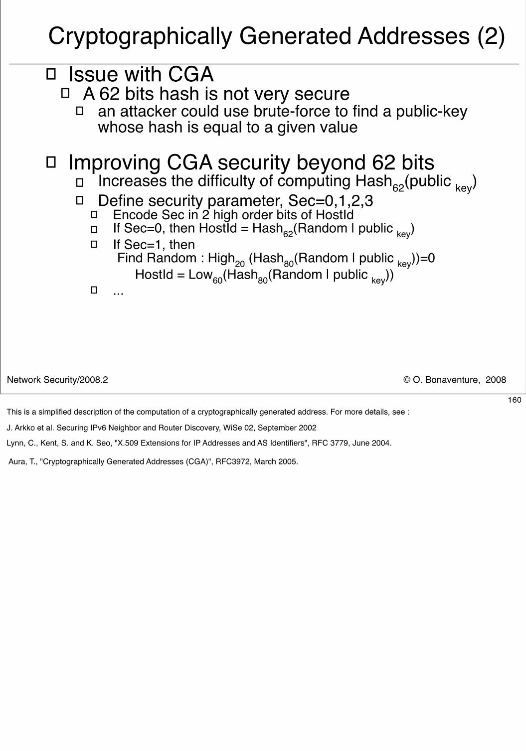
© O. Bonaventure, 2008Network Security/2008.2
� Issue with CGA� A 62 bits hash is not very secure
� an attacker could use brute-force to find a public-key whose hash is equal to a given value
� Improving CGA security beyond 62 bits� Increases the difficulty of computing Hash62(public key)� Define security parameter, Sec=0,1,2,3
� Encode Sec in 2 high order bits of HostId� If Sec=0, then HostId = Hash62(Random | public key)� If Sec=1, then
Find Random : High20 (Hash80(Random | public key))=0 HostId = Low60(Hash80(Random | public key))
� ...
Cryptographically Generated Addresses (2)
160This is a simplified description of the computation of a cryptographically generated address. For more details, see :
J. Arkko et al. Securing IPv6 Neighbor and Router Discovery, WiSe 02, September 2002
Lynn, C., Kent, S. and K. Seo, "X.509 Extensions for IP Addresses and AS Identifiers", RFC 3779, June 2004.
Aura, T., "Cryptographically Generated Addresses (CGA)", RFC3972, March 2005.
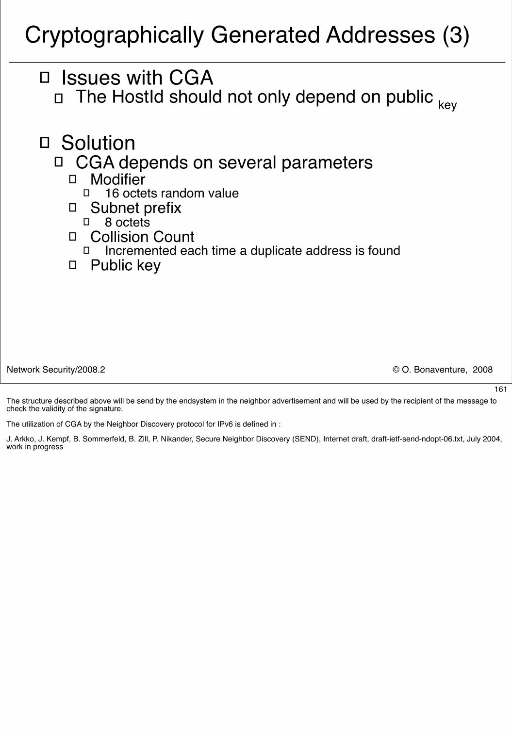
© O. Bonaventure, 2008Network Security/2008.2
� Issues with CGA� The HostId should not only depend on public key
� Solution� CGA depends on several parameters
� Modifier� 16 octets random value
� Subnet prefix� 8 octets
� Collision Count� Incremented each time a duplicate address is found
� Public key
Cryptographically Generated Addresses (3)
161The structure described above will be send by the endsystem in the neighbor advertisement and will be used by the recipient of the message to check the validity of the signature.
The utilization of CGA by the Neighbor Discovery protocol for IPv6 is defined in :
J. Arkko, J. Kempf, B. Sommerfeld, B. Zill, P. Nikander, Secure Neighbor Discovery (SEND), Internet draft, draft-ietf-send-ndopt-06.txt, July 2004, work in progress
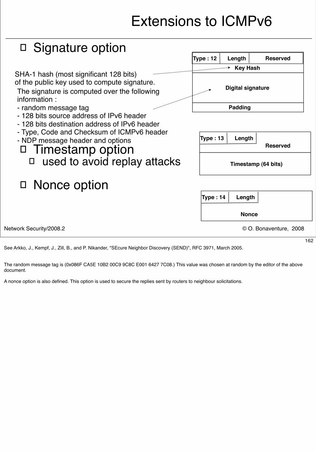
© O. Bonaventure, 2008Network Security/2008.2
Extensions to ICMPv6� Signature option
� Timestamp option� used to avoid replay attacks
� Nonce option
Type : 12 Length ReservedKey Hash
Digital signature
SHA-1 hash (most significant 128 bits) of the public key used to compute signature.The signature is computed over the following information :- random message tag - 128 bits source address of IPv6 header- 128 bits destination address of IPv6 header- Type, Code and Checksum of ICMPv6 header- NDP message header and options
Padding
Type : 13 LengthReserved
Timestamp (64 bits)
Type : 14 Length
Nonce
162See Arkko, J., Kempf, J., Zill, B., and P. Nikander, "SEcure Neighbor Discovery (SEND)", RFC 3971, March 2005.
The random message tag is (0x086F CA5E 10B2 00C9 9C8C E001 6427 7C08.) This value was chosen at random by the editor of the above document.
A nonce option is also defined. This option is used to secure the replies sent by routers to neighbour solicitations.
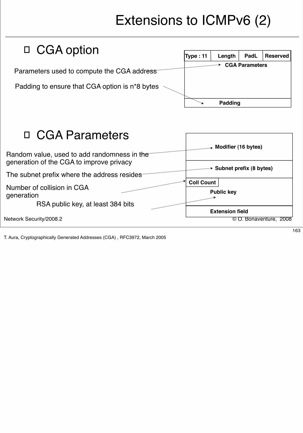
© O. Bonaventure, 2008Network Security/2008.2
Extensions to ICMPv6 (2)
� CGA option
� CGA Parameters
Type : 11 Length PadL ReservedCGA Parameters
Parameters used to compute the CGA address
Padding to ensure that CGA option is n*8 bytes
Padding
Modifier (16 bytes)
Subnet prefix (8 bytes)
Coll CountPublic key
Extension field
Random value, used to add randomness in thegeneration of the CGA to improve privacy
The subnet prefix where the address resides
Number of collision in CGAgeneration
RSA public key, at least 384 bits
163T. Aura, Cryptographically Generated Addresses (CGA) , RFC3972, March 2005
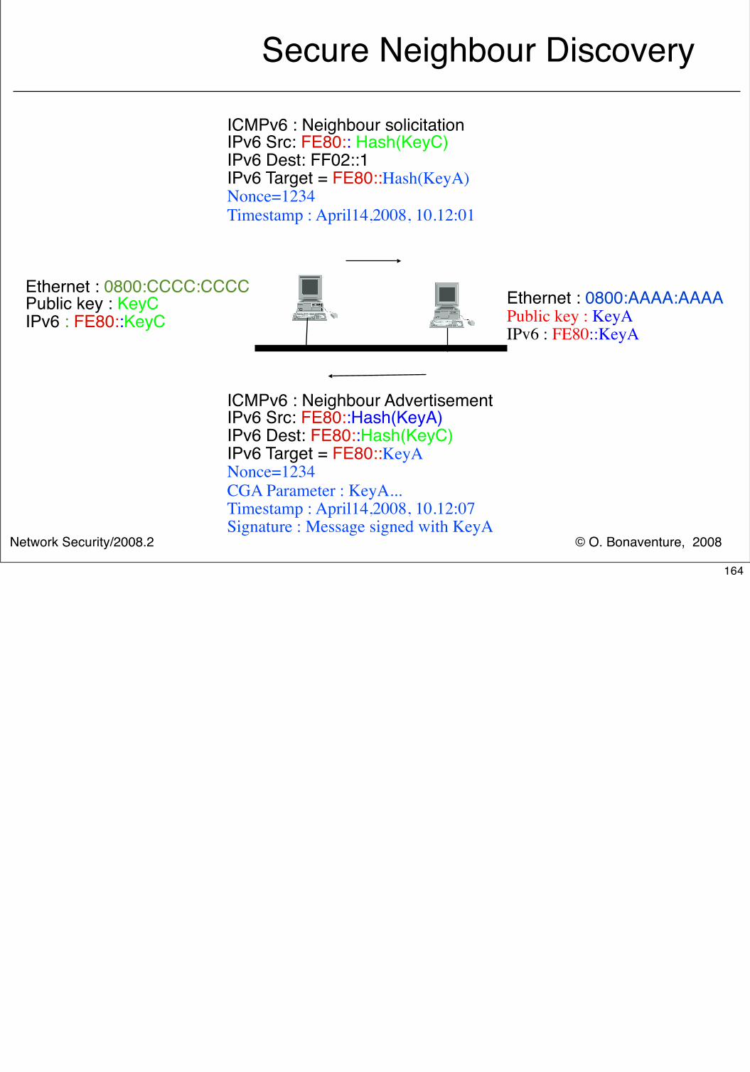
© O. Bonaventure, 2008Network Security/2008.2
Secure Neighbour Discovery
ICMPv6 : Neighbour solicitationIPv6 Src: FE80:: Hash(KeyC)IPv6 Dest: FF02::1IPv6 Target = FE80::Hash(KeyA)Nonce=1234Timestamp : April14,2008, 10.12:01
Ethernet : 0800:AAAA:AAAAPublic key : KeyAIPv6 : FE80::KeyA
Ethernet : 0800:CCCC:CCCCPublic key : KeyCIPv6 : FE80::KeyC
ICMPv6 : Neighbour AdvertisementIPv6 Src: FE80::Hash(KeyA)IPv6 Dest: FE80::Hash(KeyC)IPv6 Target = FE80::KeyANonce=1234CGA Parameter : KeyA...Timestamp : April14,2008, 10.12:07Signature : Message signed with KeyA
164
© O. Bonaventure, 2008Network Security/2008.2
Internet and Network security
� Crypto building blocks� Application-layer security� Transport-layer security� Network-layer security
� IPv4� IPv6� IPSec� Routing security
165
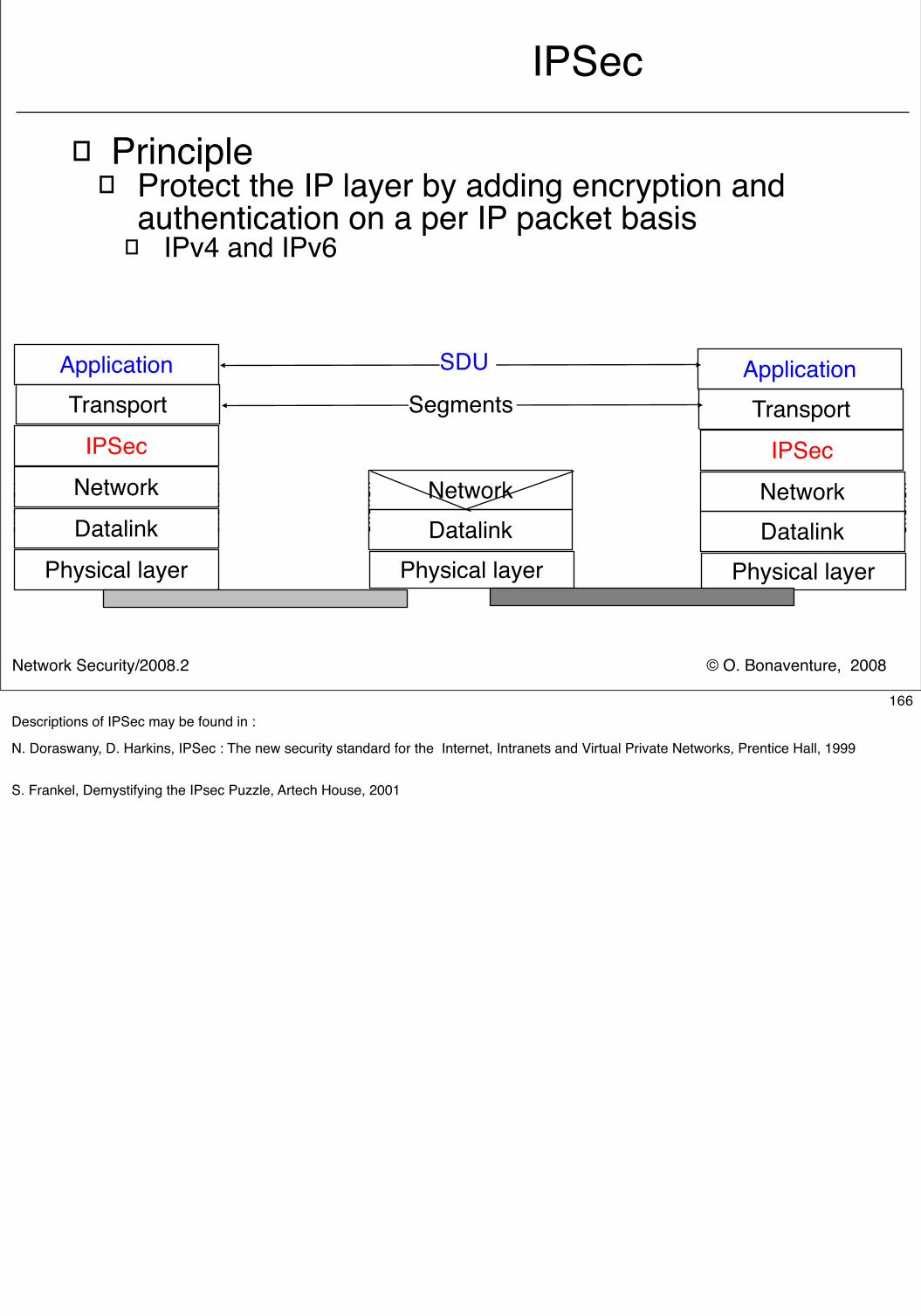
© O. Bonaventure, 2008Network Security/2008.2
IPSec
� Principle� Protect the IP layer by adding encryption and
authentication on a per IP packet basis� IPv4 and IPv6
Physical layer Physical layer
Datalink DatalinkNetworkNetwork
Physical layerDatalinkNetwork
SDU
IPSec IPSec
Application ApplicationTransport TransportSegments
166Descriptions of IPSec may be found in :
N. Doraswany, D. Harkins, IPSec : The new security standard for the Internet, Intranets and Virtual Private Networks, Prentice Hall, 1999
S. Frankel, Demystifying the IPsec Puzzle, Artech House, 2001
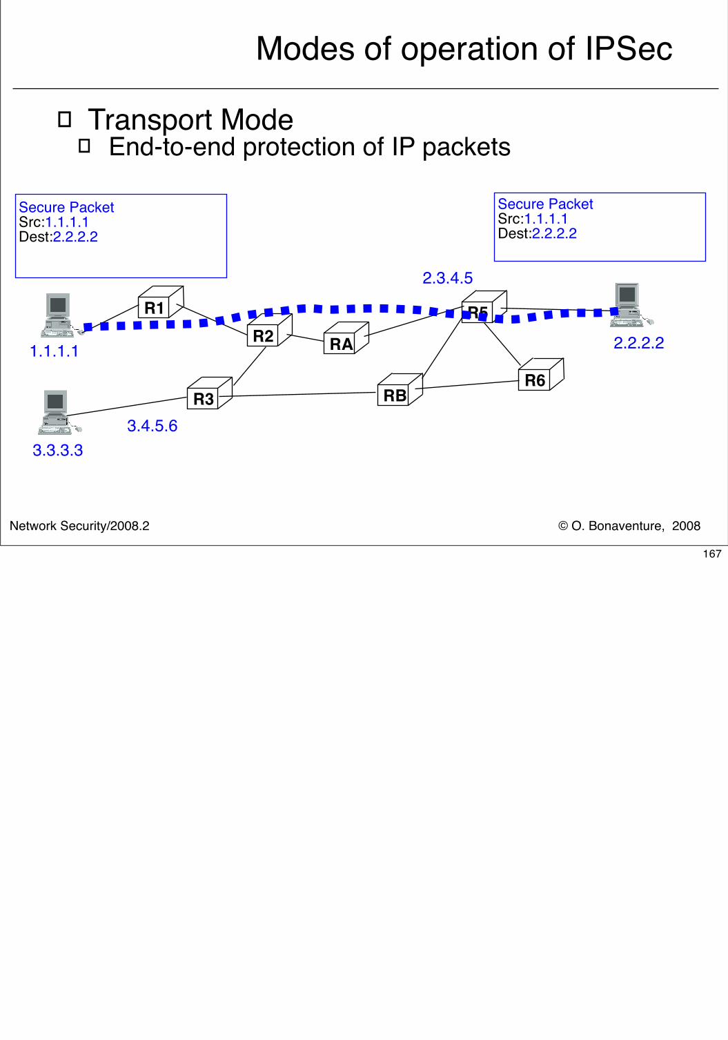
© O. Bonaventure, 2008Network Security/2008.2
Modes of operation of IPSec
� Transport Mode� End-to-end protection of IP packets
R1R2
R3
R5
R6
3.3.3.3
1.1.1.1
3.4.5.6
2.3.4.5
2.2.2.2RA
RB
Secure PacketSrc:1.1.1.1Dest:2.2.2.2
Secure PacketSrc:1.1.1.1Dest:2.2.2.2
167
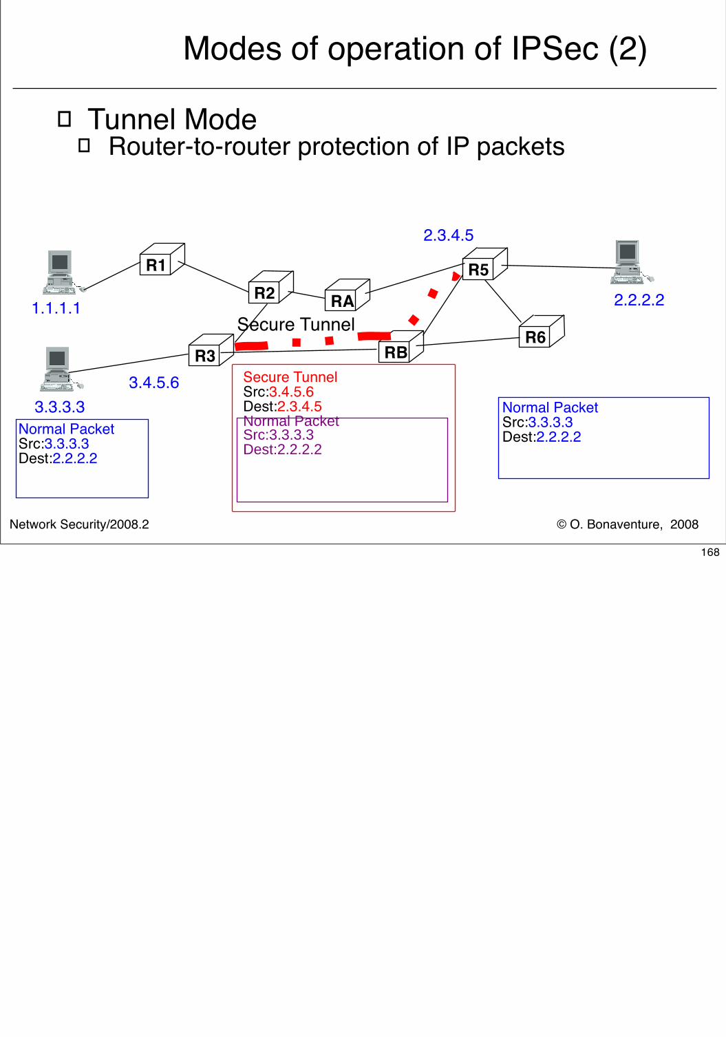
© O. Bonaventure, 2008Network Security/2008.2
Modes of operation of IPSec (2)
� Tunnel Mode� Router-to-router protection of IP packets
R1R2
R3
R5
R6
IPv4 PacketSrc:IPv4:R3EDest:IPv4:R6WIPv6 PacketSrc:IPv6:ADest:IPv6C
Secure TunnelSrc:3.4.5.6Dest:2.3.4.5Normal PacketSrc:3.3.3.3Dest:2.2.2.2
Normal PacketSrc:3.3.3.3Dest:2.2.2.2
Normal PacketSrc:3.3.3.3Dest:2.2.2.2
3.3.3.3
1.1.1.1
3.4.5.6
2.3.4.5
2.2.2.2RA
RBSecure Tunnel
168
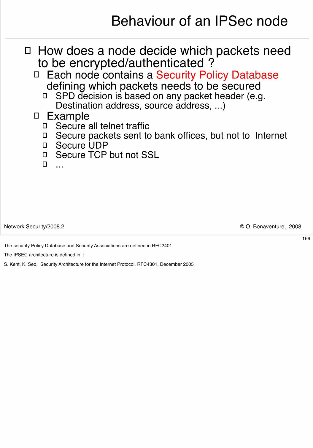
© O. Bonaventure, 2008Network Security/2008.2
Behaviour of an IPSec node
� How does a node decide which packets need to be encrypted/authenticated ?
� Each node contains a Security Policy Database defining which packets needs to be secured
� SPD decision is based on any packet header (e.g. Destination address, source address, ...)
� Example� Secure all telnet traffic� Secure packets sent to bank offices, but not to Internet� Secure UDP � Secure TCP but not SSL� ...
169The security Policy Database and Security Associations are defined in RFC2401
The IPSEC architecture is defined in :
S. Kent, K. Seo, Security Architecture for the Internet Protocol, RFC4301, December 2005
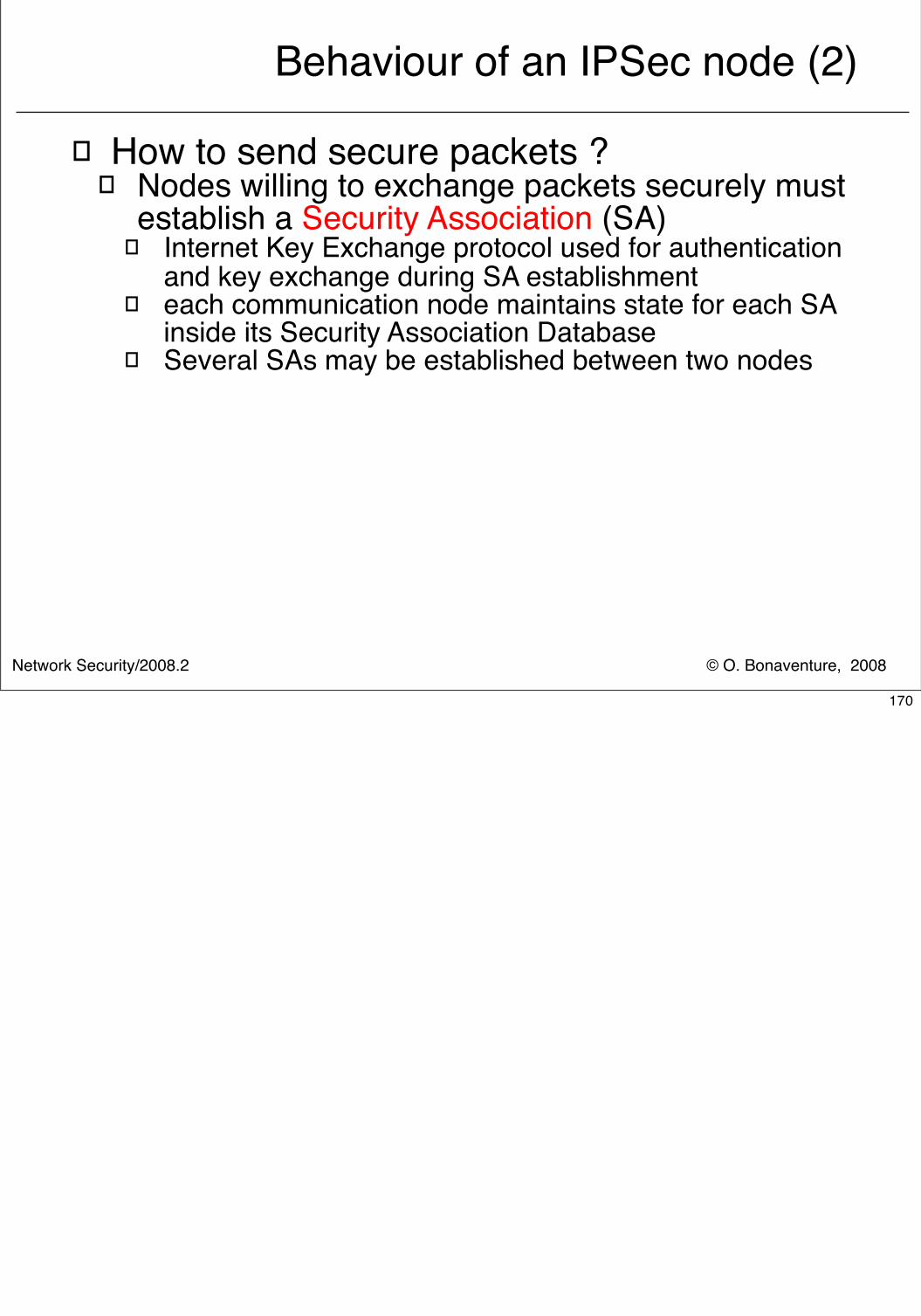
© O. Bonaventure, 2008Network Security/2008.2
Behaviour of an IPSec node (2)
� How to send secure packets ?� Nodes willing to exchange packets securely must
establish a Security Association (SA)� Internet Key Exchange protocol used for authentication
and key exchange during SA establishment� each communication node maintains state for each SA
inside its Security Association Database� Several SAs may be established between two nodes
170
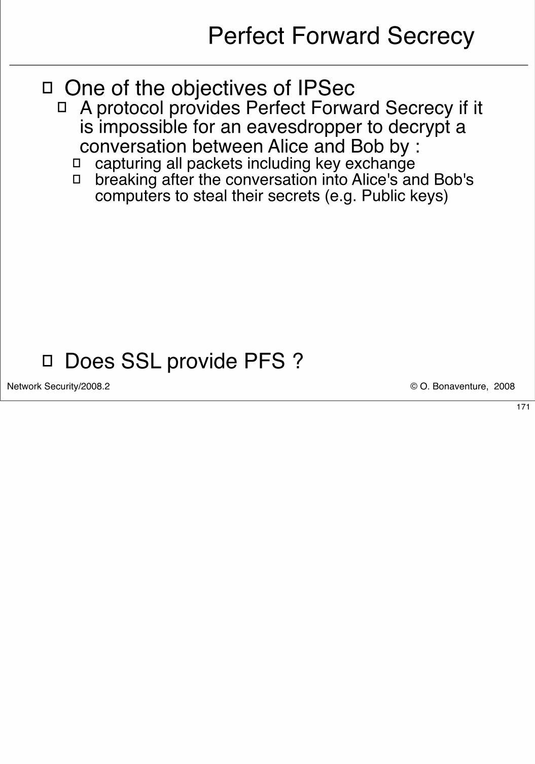
© O. Bonaventure, 2008Network Security/2008.2
Perfect Forward Secrecy
� One of the objectives of IPSec� A protocol provides Perfect Forward Secrecy if it
is impossible for an eavesdropper to decrypt a conversation between Alice and Bob by :
� capturing all packets including key exchange� breaking after the conversation into Alice's and Bob's
computers to steal their secrets (e.g. Public keys)
� Does SSL provide PFS ?
171
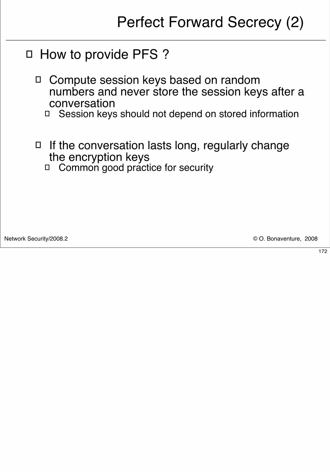
© O. Bonaventure, 2008Network Security/2008.2
Perfect Forward Secrecy (2)
� How to provide PFS ?� Compute session keys based on random
numbers and never store the session keys after a conversation
� Session keys should not depend on stored information
� If the conversation lasts long, regularly change the encryption keys
� Common good practice for security
172
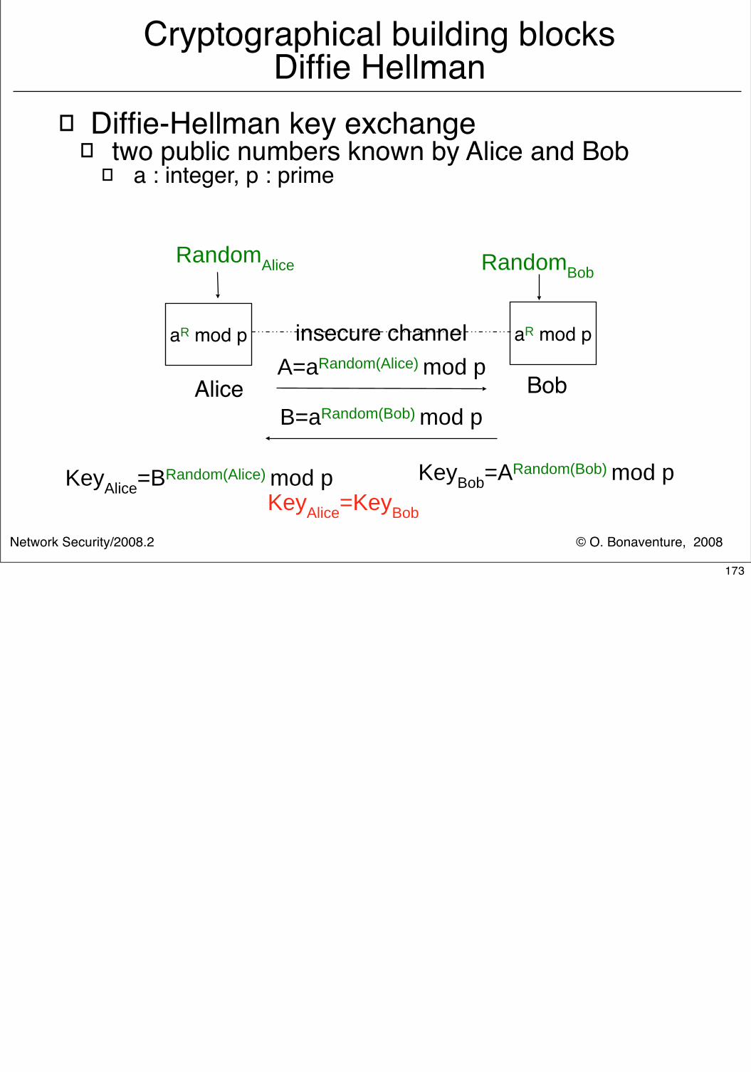
© O. Bonaventure, 2008Network Security/2008.2
Cryptographical building blocksDiffie Hellman
� Diffie-Hellman key exchange� two public numbers known by Alice and Bob
� a : integer, p : prime
Alice Bob
aR mod pA=aRandom(Alice) mod p
RandomAlice
insecure channel
RandomBob
B=aRandom(Bob) mod p
KeyAlice=BRandom(Alice) mod p KeyBob=ARandom(Bob) mod pKeyAlice=KeyBob
aR mod p
173
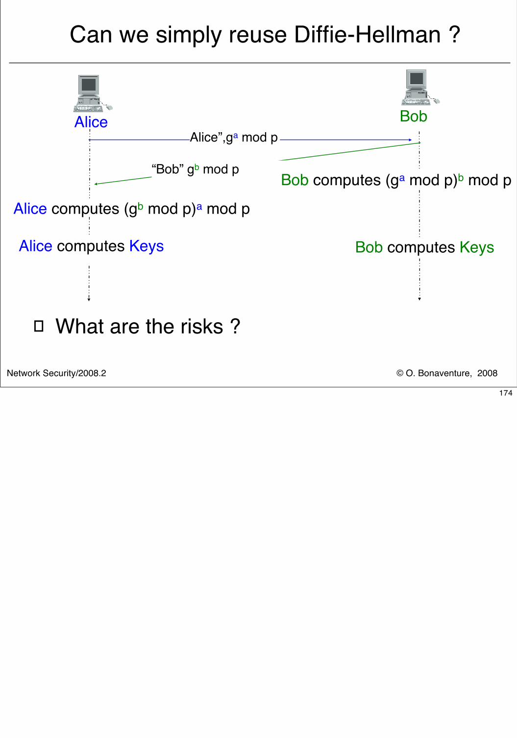
© O. Bonaventure, 2008Network Security/2008.2
Can we simply reuse Diffie-Hellman ?
� What are the risks ?
Alice BobAlice”,ga mod p
Alice computes (gb mod p)a mod p
Alice computes Keys
“Bob” gb mod pBob computes (ga mod p)b mod p
Bob computes Keys
174
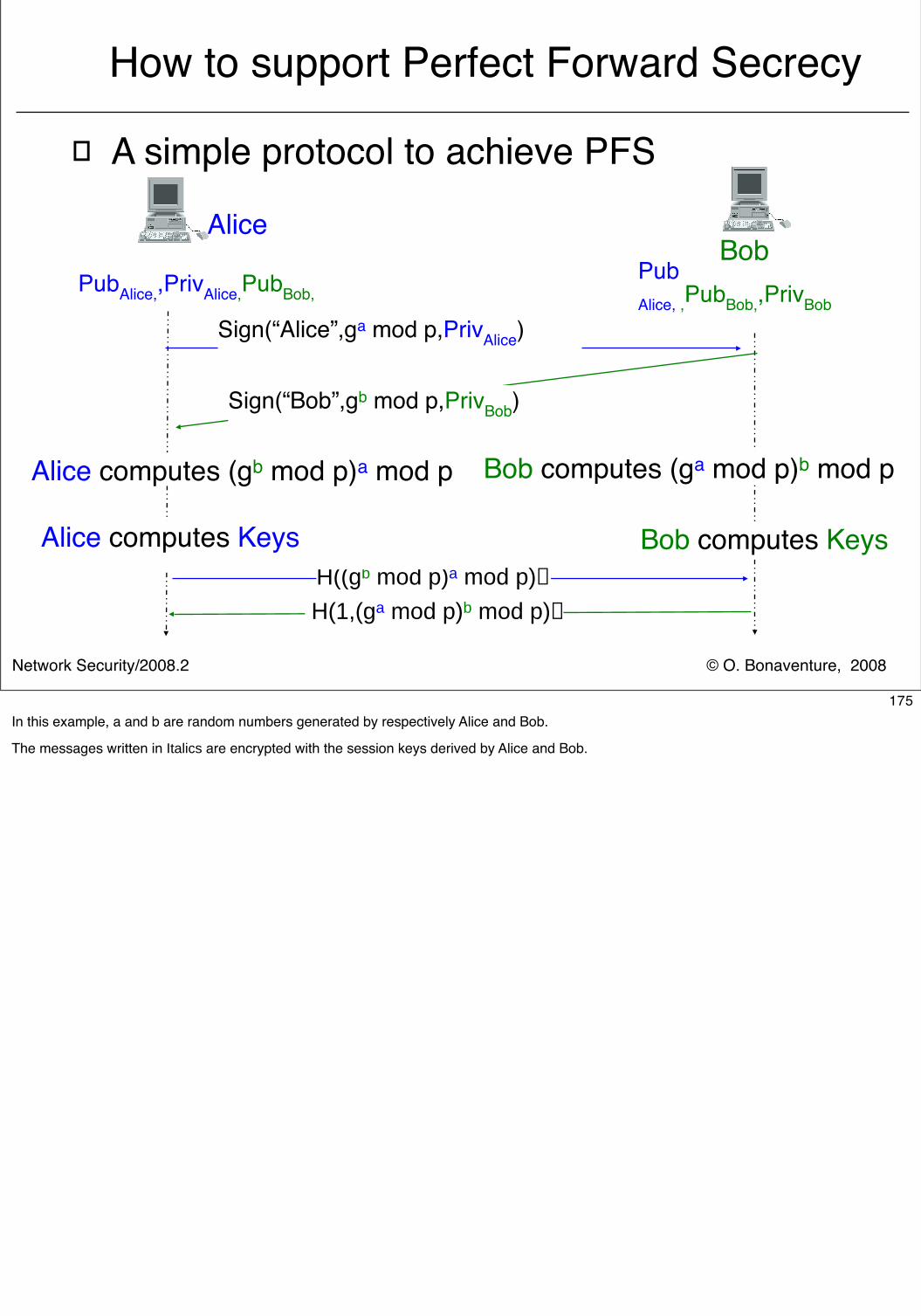
© O. Bonaventure, 2008Network Security/2008.2
How to support Perfect Forward Secrecy
� A simple protocol to achieve PFS
AliceBob
Sign(“Alice”,ga mod p,PrivAlice)
Pub Alice, ,PubBob,,PrivBob
PubAlice,,PrivAlice,PubBob,
H((gb mod p)a mod p)
H(1,(ga mod p)b mod p)
Sign(“Bob”,gb mod p,PrivBob)
Alice computes (gb mod p)a mod p Bob computes (ga mod p)b mod p
Alice computes Keys Bob computes Keys
175In this example, a and b are random numbers generated by respectively Alice and Bob.
The messages written in Italics are encrypted with the session keys derived by Alice and Bob.
© O. Bonaventure, 2008Network Security/2008.2
Evaluation of simple protocol
� Time to establish a security association� Can be used over UDP� Fast; one round-trip-time is sufficient
� DoS risk� Spoofed packets requesting establishment of a
security association could cause a DoS attack on the responder
� Responder must check signature� Responder must perform Diffie-Hellman computation
176
© O. Bonaventure, 2008Network Security/2008.2
Evaluation of simple protocol
� Fragmentation risk� First message sent by initiator can be large
� Diffie Hellmann parameters� Signature information
� Message is probably too large for a single IP packet and fragmentation will be required
� DoS on IP packet reassembly on the responder is possible
� Hosts have difficulties in correctly supporting reassembling
177The fragmentation problem is discussed in :Charlie Kaufman , Radia Perlman ,Bill Sommerfeld , DoS protection for UDP-based protocols, Proceedings of the 10th ACM conference on Computer and communications security, Washington D.C., USA, 2003
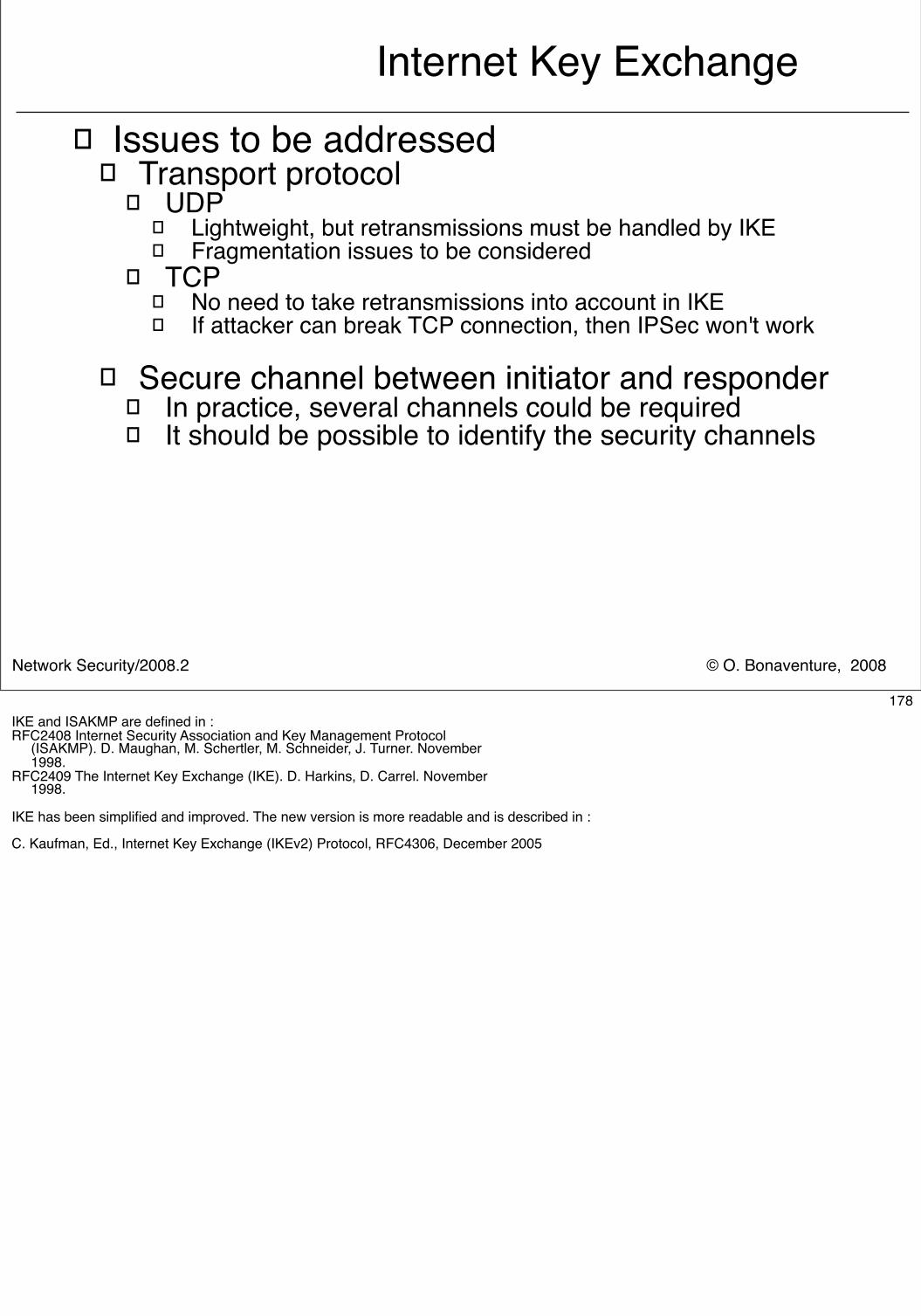
© O. Bonaventure, 2008Network Security/2008.2
Internet Key Exchange� Issues to be addressed
� Transport protocol� UDP
� Lightweight, but retransmissions must be handled by IKE� Fragmentation issues to be considered
� TCP� No need to take retransmissions into account in IKE� If attacker can break TCP connection, then IPSec won't work
� Secure channel between initiator and responder
� In practice, several channels could be required� It should be possible to identify the security channels
178IKE and ISAKMP are defined in :RFC2408 Internet Security Association and Key Management Protocol (ISAKMP). D. Maughan, M. Schertler, M. Schneider, J. Turner. November 1998. RFC2409 The Internet Key Exchange (IKE). D. Harkins, D. Carrel. November 1998.
IKE has been simplified and improved. The new version is more readable and is described in :
C. Kaufman, Ed., Internet Key Exchange (IKEv2) Protocol, RFC4306, December 2005
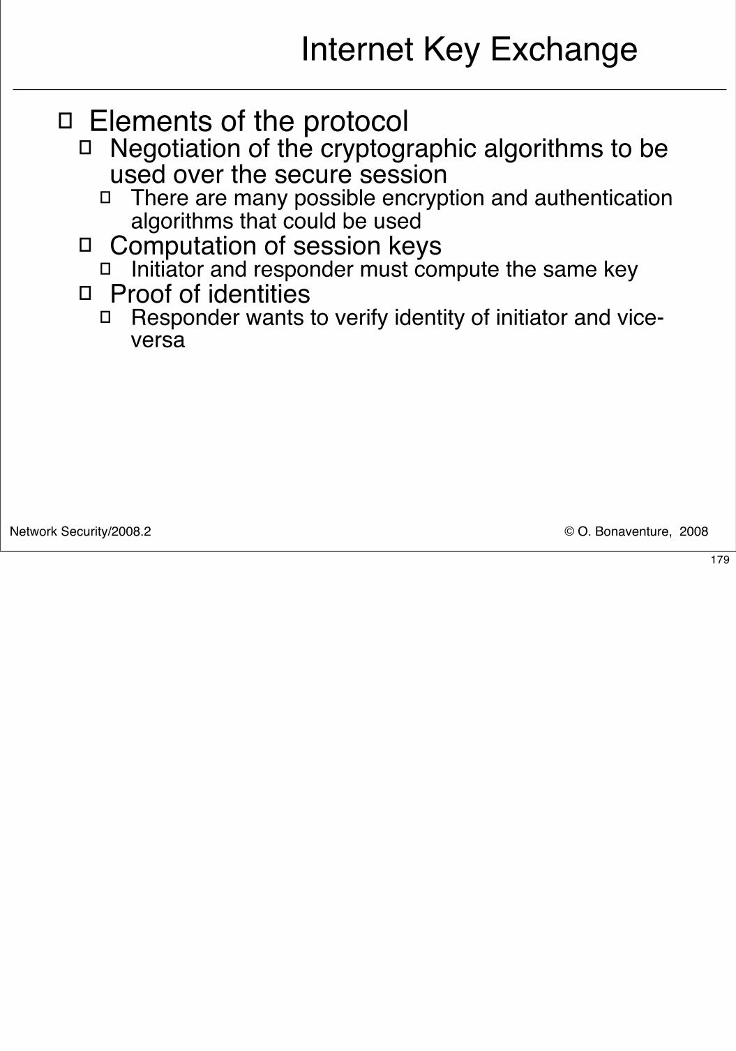
© O. Bonaventure, 2008Network Security/2008.2
Internet Key Exchange
� Elements of the protocol� Negotiation of the cryptographic algorithms to be
used over the secure session� There are many possible encryption and authentication
algorithms that could be used� Computation of session keys
� Initiator and responder must compute the same key� Proof of identities
� Responder wants to verify identity of initiator and vice-versa
179
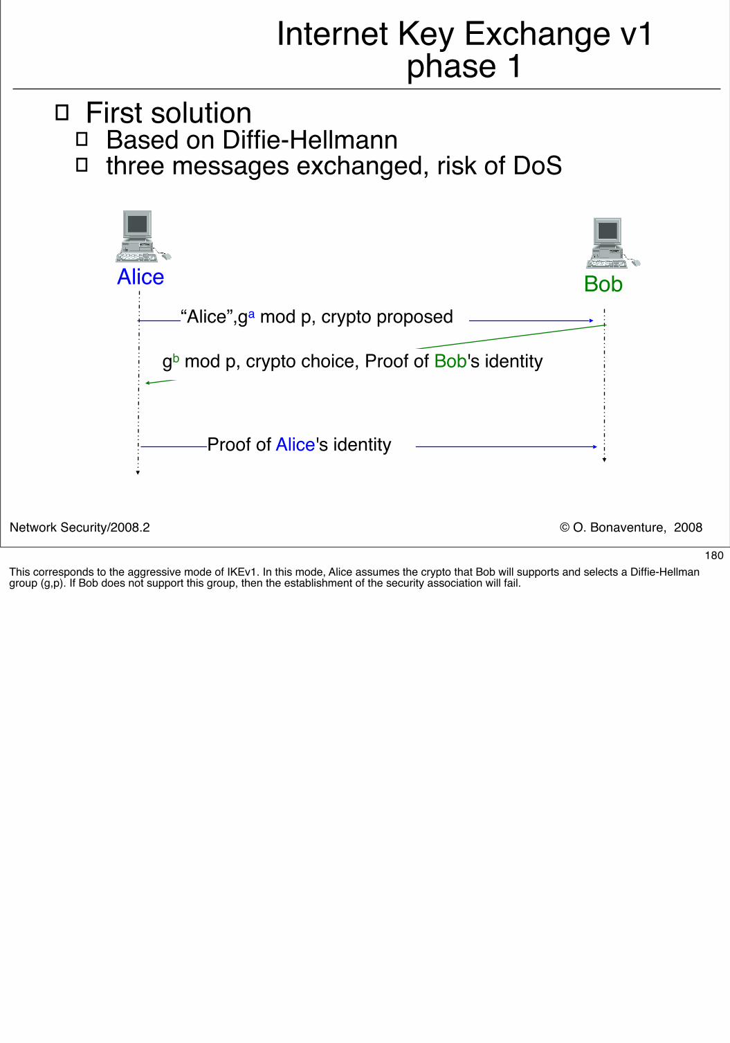
© O. Bonaventure, 2008Network Security/2008.2
Internet Key Exchange v1phase 1
� First solution� Based on Diffie-Hellmann� three messages exchanged, risk of DoS
Alice Bob“Alice”,ga mod p, crypto proposed
Proof of Alice's identity
gb mod p, crypto choice, Proof of Bob's identity
180This corresponds to the aggressive mode of IKEv1. In this mode, Alice assumes the crypto that Bob will supports and selects a Diffie-Hellman group (g,p). If Bob does not support this group, then the establishment of the security association will fail.
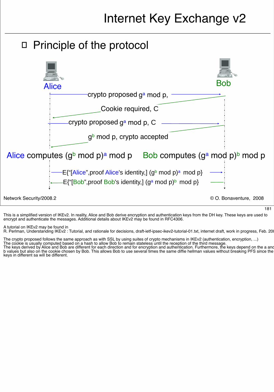
© O. Bonaventure, 2008Network Security/2008.2
Internet Key Exchange v2
� Principle of the protocol
Alice Bob
E{“[Alice”,proof Alice's identity,] (gb mod p)a mod p}
gb mod p, crypto accepted
Alice computes (gb mod p)a mod p Bob computes (ga mod p)b mod p
Cookie required, C
E{“[Bob”,proof Bob's identity,] (ga mod p)b mod p}
crypto proposed ga mod p,
crypto proposed ga mod p, C
181This is a simplified version of IKEv2. In reality, Alice and Bob derive encryption and authentication keys from the DH key. These keys are used to encrypt and authenticate the messages. Additional details about IKEv2 may be found in RFC4306.
A tutorial on IKEv2 may be found in R. Perlman, Understanding IKEv2 : Tutorial, and rationale for decisions, draft-ietf-ipsec-ikev2-tutorial-01.txt, internet draft, work in progress, Feb. 2003
The crypto proposed follows the same approach as with SSL by using suites of crypto mechanisms in IKEv2 (authentication, encryption, ...)The cookie is usually computed based on a hash to allow Bob to remain stateless until the reception of the third message.The keys derived by Alice and Bob are different for each direction and for encryption and authentication. Furthermore, the keys depend on the a and b values but also on the cookie chosen by Bob. This allows Bob to use several times the same diffie hellman values without breaking PFS since the keys in different sa will be different.
© O. Bonaventure, 2008Network Security/2008.2
Services provided by IPSec
� Authentication and data integrity only� AH : Authentication Header � Principle
� Sender authenticates source and protects packet content� Packet content can be read by anyone� Destination authenticates packet source and content
182The AH header is defined in RFC2402 IP Authentication Header. S. Kent, R. Atkinson. November 1998.
The new version is described in :
RFC4302, IP Authentication Header. S. Kent, December 2005
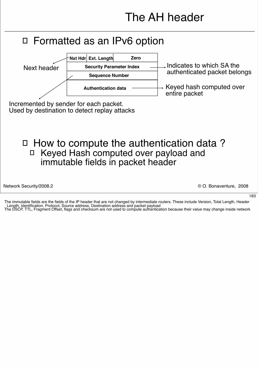
© O. Bonaventure, 2008Network Security/2008.2
The AH header
� Formatted as an IPv6 option
� How to compute the authentication data ?� Keyed Hash computed over payload and
immutable fields in packet header
Nxt Hdr Ext. Length Zero
Security Parameter Index
Sequence Number
Authentication data
Next header Indicates to which SA theauthenticated packet belongs
Incremented by sender for each packet.Used by destination to detect replay attacks
Keyed hash computed overentire packet
183The immutable fields are the fields of the IP header that are not changed by intermediate routers. These include Version, Total Length, Header
Length, Identification, Protocol, Source address, Destination address and packet payload The DSCP, TTL, Fragment Offset, flags and checksum are not used to compute authentication because their value may change inside network
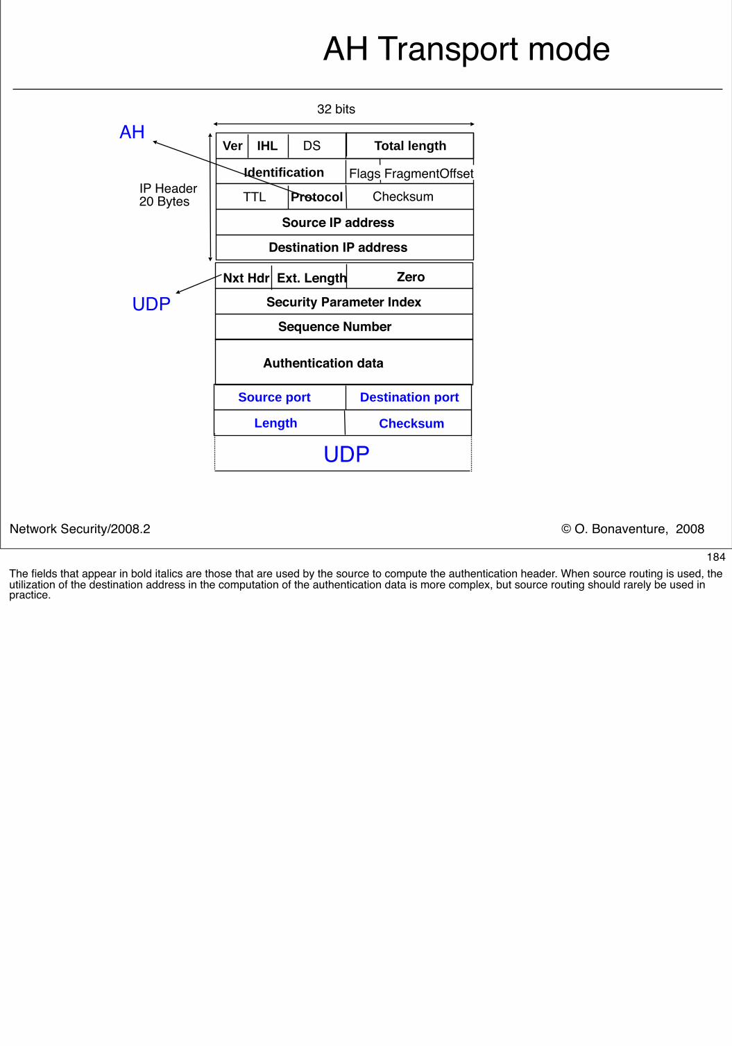
© O. Bonaventure, 2008Network Security/2008.2
AH Transport mode
Source port Destination port
Length Checksum
UDP
Nxt Hdr Ext. Length Zero
Security Parameter Index
Sequence Number
Authentication data
UDP
Ver IHL DS
IP Header20 Bytes Checksum TTL Protocol
Source IP address
Identification
Destination IP address
Flags FragmentOffset
Total length
32 bits
AH
184The fields that appear in bold italics are those that are used by the source to compute the authentication header. When source routing is used, the utilization of the destination address in the computation of the authentication data is more complex, but source routing should rarely be used in practice.
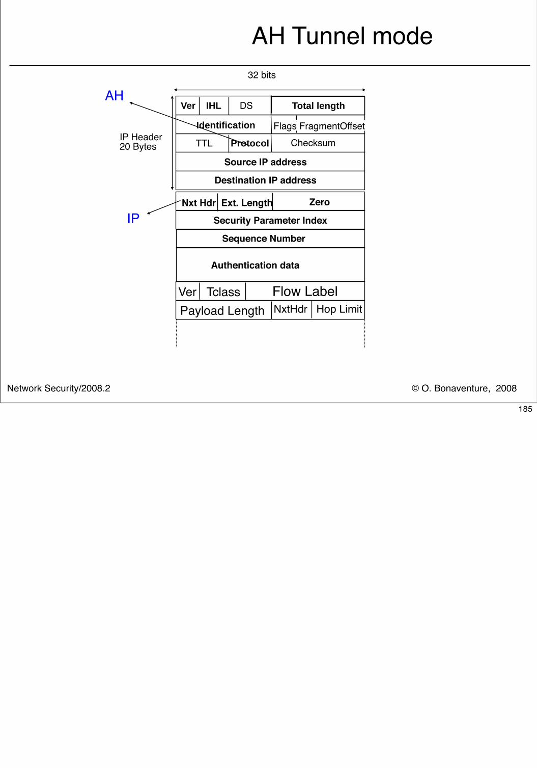
© O. Bonaventure, 2008Network Security/2008.2
AH Tunnel mode
Nxt Hdr Ext. Length Zero
Security Parameter Index
Sequence Number
Authentication data
IP
Ver Tclass Flow LabelNxtHdr Hop LimitPayload Length
Ver IHL DS
IP Header20 Bytes Checksum TTL Protocol
Source IP address
Identification
Destination IP address
Flags FragmentOffset
Total length
32 bits
AH
185
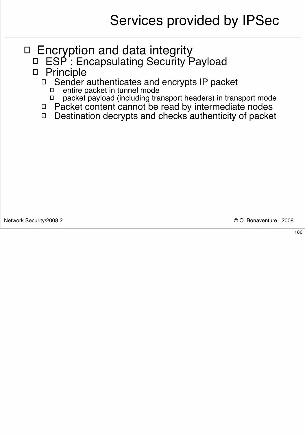
© O. Bonaventure, 2008Network Security/2008.2
Services provided by IPSec
� Encryption and data integrity� ESP : Encapsulating Security Payload � Principle
� Sender authenticates and encrypts IP packet� entire packet in tunnel mode� packet payload (including transport headers) in transport mode
� Packet content cannot be read by intermediate nodes� Destination decrypts and checks authenticity of packet
186
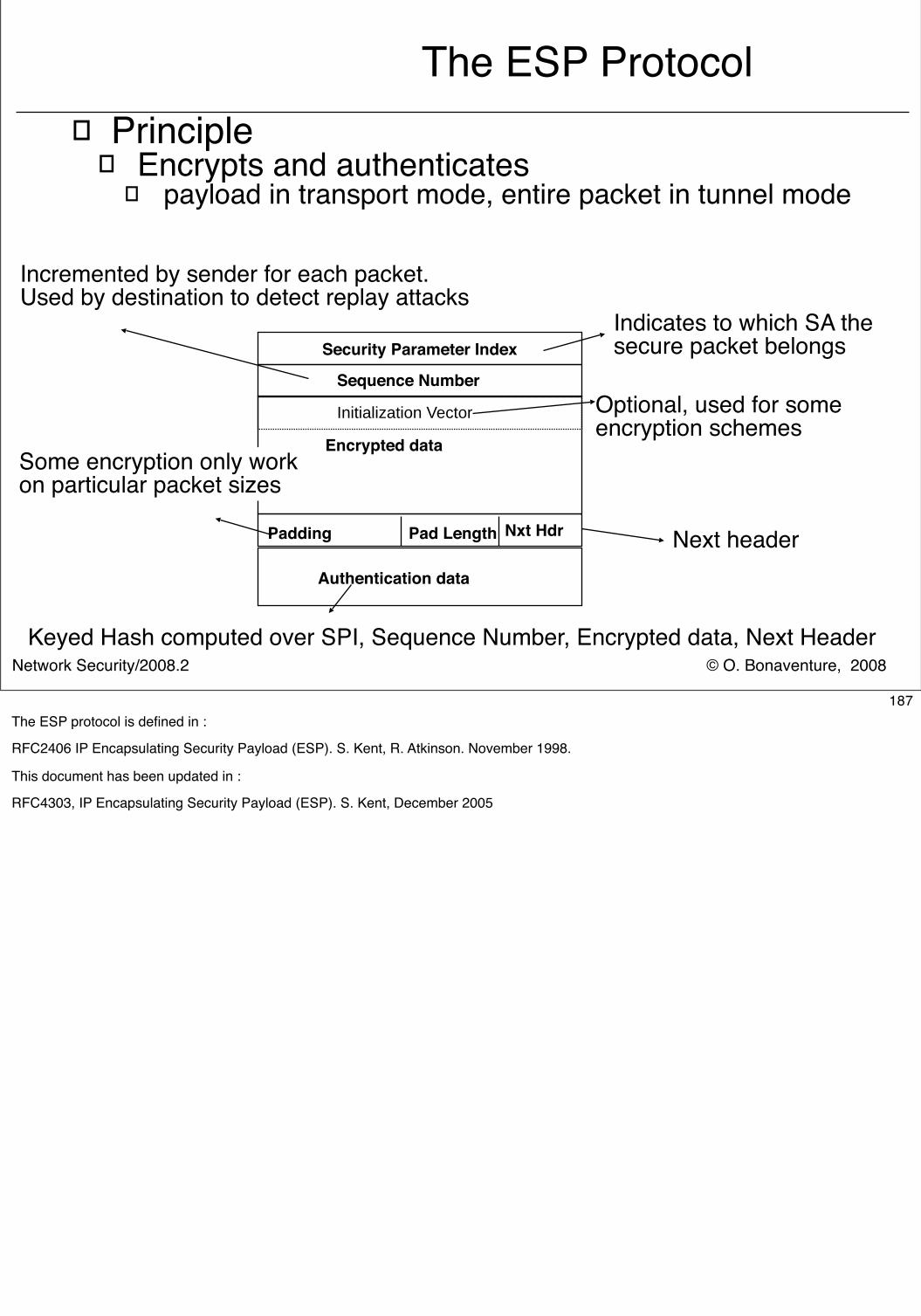
© O. Bonaventure, 2008Network Security/2008.2
The ESP Protocol� Principle
� Encrypts and authenticates � payload in transport mode, entire packet in tunnel mode
Padding Pad Length Nxt Hdr
Security Parameter Index
Sequence Number
Encrypted data
Authentication data
Next header
Indicates to which SA thesecure packet belongs
Incremented by sender for each packet.Used by destination to detect replay attacks
Some encryption only workon particular packet sizes
Keyed Hash computed over SPI, Sequence Number, Encrypted data, Next Header
Initialization Vector Optional, used for someencryption schemes
187The ESP protocol is defined in :
RFC2406 IP Encapsulating Security Payload (ESP). S. Kent, R. Atkinson. November 1998.
This document has been updated in :
RFC4303, IP Encapsulating Security Payload (ESP). S. Kent, December 2005
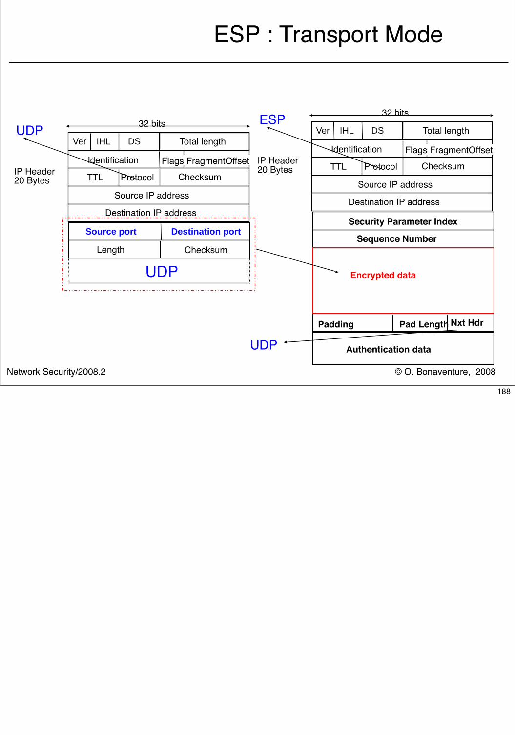
© O. Bonaventure, 2008Network Security/2008.2
ESP : Transport Mode
Source port Destination port
Length Checksum
UDP
Padding Pad Length Nxt Hdr
Security Parameter Index
Sequence Number
Encrypted data
Authentication dataUDP
Ver IHL DS
IP Header20 Bytes Checksum TTL Protocol
Source IP address
Identification
Destination IP address
Flags FragmentOffset
Total length
32 bitsUDP Ver IHL DS
IP Header20 Bytes Checksum TTL Protocol
Source IP address
Identification
Destination IP address
Flags FragmentOffset
Total length
32 bitsESP
188
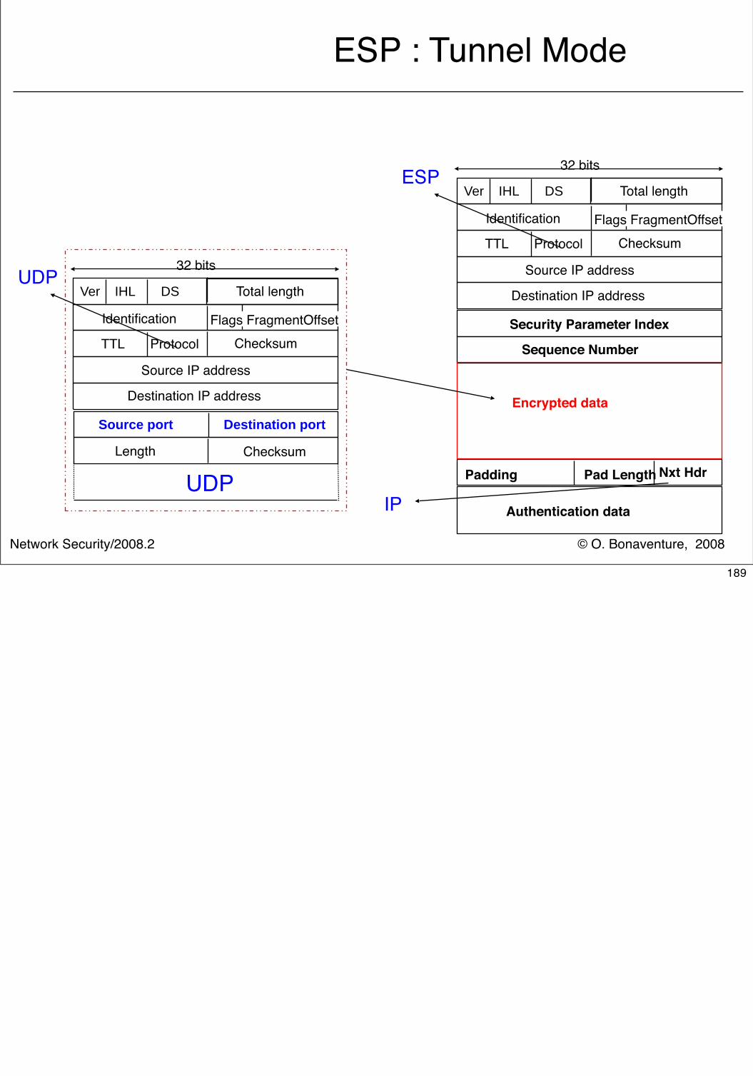
© O. Bonaventure, 2008Network Security/2008.2
ESP : Tunnel Mode
Source port Destination port
Length Checksum
UDP Padding Pad Length Nxt Hdr
Security Parameter Index
Sequence Number
Encrypted data
Authentication dataIP
Ver IHL DS
Checksum TTL Protocol
Source IP address
Identification
Destination IP address
Flags FragmentOffset
Total length
32 bitsUDP
Ver IHL DS
Checksum TTL Protocol
Source IP address
Identification
Destination IP address
Flags FragmentOffset
Total length
32 bitsESP
189
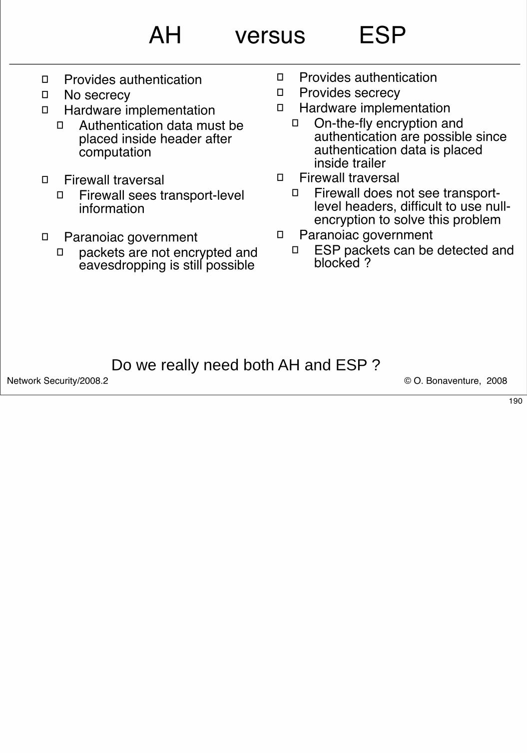
© O. Bonaventure, 2008Network Security/2008.2
AH versus ESP� Provides authentication� No secrecy� Hardware implementation
� Authentication data must be placed inside header after computation
� Firewall traversal� Firewall sees transport-level
information
� Paranoiac government� packets are not encrypted and
eavesdropping is still possible
� Provides authentication� Provides secrecy� Hardware implementation
� On-the-fly encryption and authentication are possible since authentication data is placed inside trailer
� Firewall traversal� Firewall does not see transport-
level headers, difficult to use null-encryption to solve this problem
� Paranoiac government� ESP packets can be detected and
blocked ?
Do we really need both AH and ESP ?
190
© O. Bonaventure, 2008Network Security/2008.2
Internet and Network security
� Crypto building blocks� Application-layer security� Transport-layer security� Network-layer security
� IPv4� IPv6� IPSec� Routing security
191
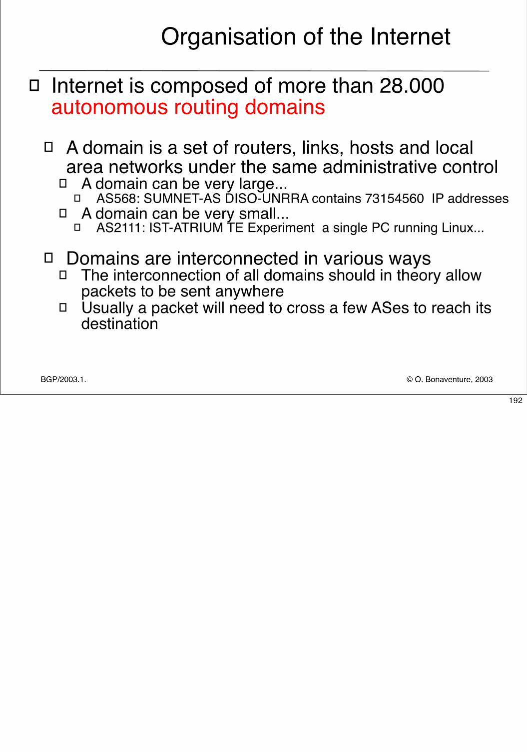
© O. Bonaventure, 2003BGP/2003.1.
Organisation of the Internet
� Internet is composed of more than 28.000 autonomous routing domains
� A domain is a set of routers, links, hosts and local area networks under the same administrative control
� A domain can be very large... � AS568: SUMNET-AS DISO-UNRRA contains 73154560 IP addresses
� A domain can be very small...� AS2111: IST-ATRIUM TE Experiment a single PC running Linux...
� Domains are interconnected in various ways
� The interconnection of all domains should in theory allow packets to be sent anywhere
� Usually a packet will need to cross a few ASes to reach its destination
192
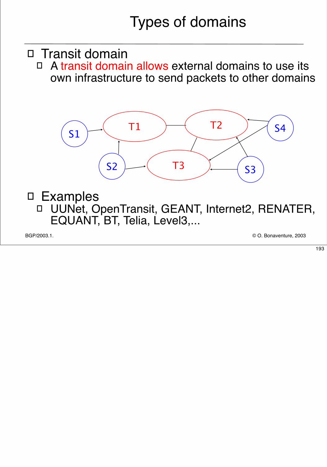
© O. Bonaventure, 2003BGP/2003.1.
Types of domains
� Transit domain� A transit domain allows external domains to use its
own infrastructure to send packets to other domains
� Examples� UUNet, OpenTransit, GEANT, Internet2, RENATER,
EQUANT, BT, Telia, Level3,...
T1 T2
T3
S1
S2 S3
S4
193
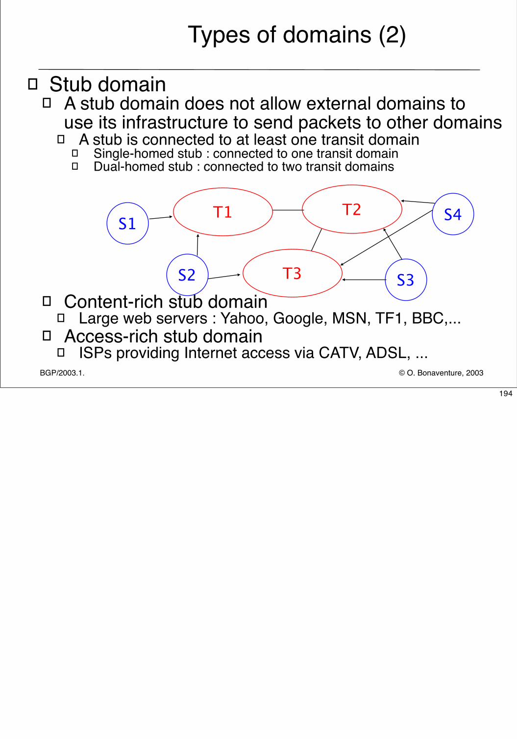
© O. Bonaventure, 2003BGP/2003.1.
Types of domains (2)
� Stub domain� A stub domain does not allow external domains to
use its infrastructure to send packets to other domains� A stub is connected to at least one transit domain
� Single-homed stub : connected to one transit domain� Dual-homed stub : connected to two transit domains
� Content-rich stub domain� Large web servers : Yahoo, Google, MSN, TF1, BBC,...
� Access-rich stub domain� ISPs providing Internet access via CATV, ADSL, ...
T1 T2
T3
S1
S2 S3
S4
194
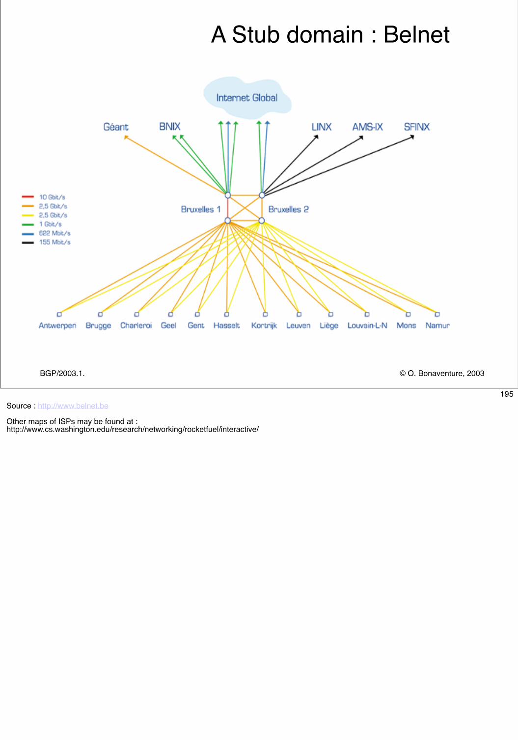
© O. Bonaventure, 2003BGP/2003.1.
A Stub domain : Belnet
195Source : http://www.belnet.be
Other maps of ISPs may be found at :http://www.cs.washington.edu/research/networking/rocketfuel/interactive/
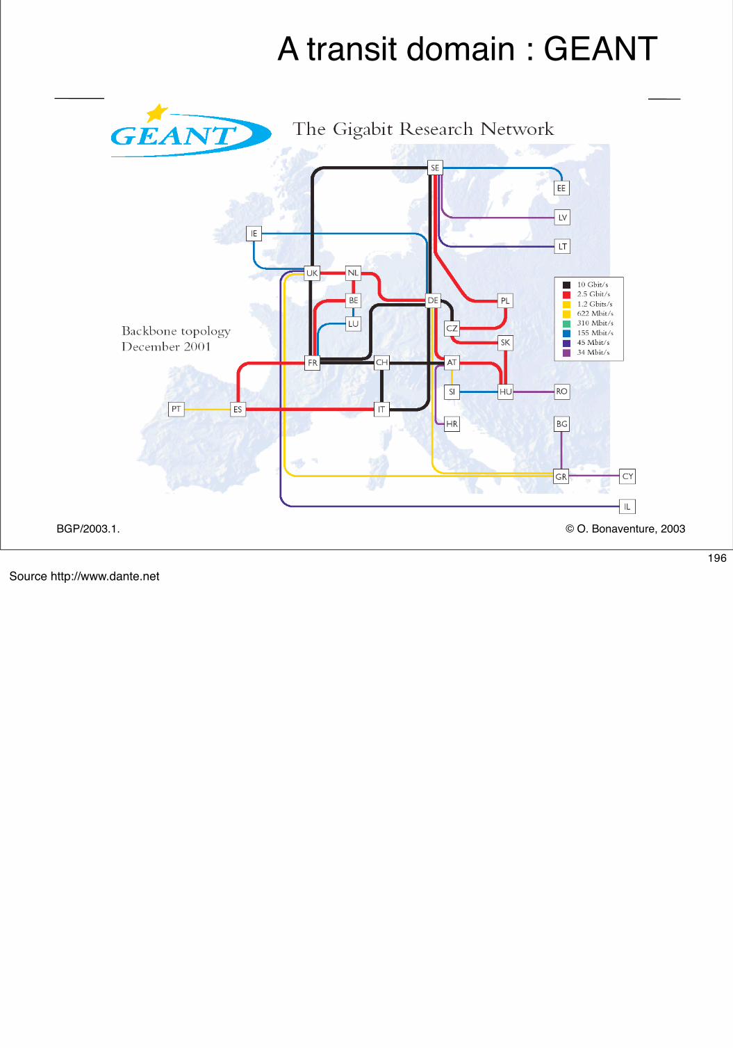
© O. Bonaventure, 2003BGP/2003.1.
A transit domain : GEANT
196Source http://www.dante.net
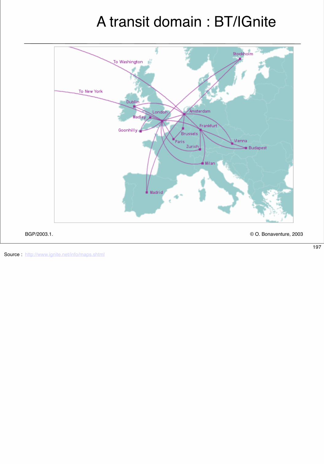
© O. Bonaventure, 2003BGP/2003.1.
A transit domain : BT/IGnite
197Source : http://www.ignite.net/info/maps.shtml
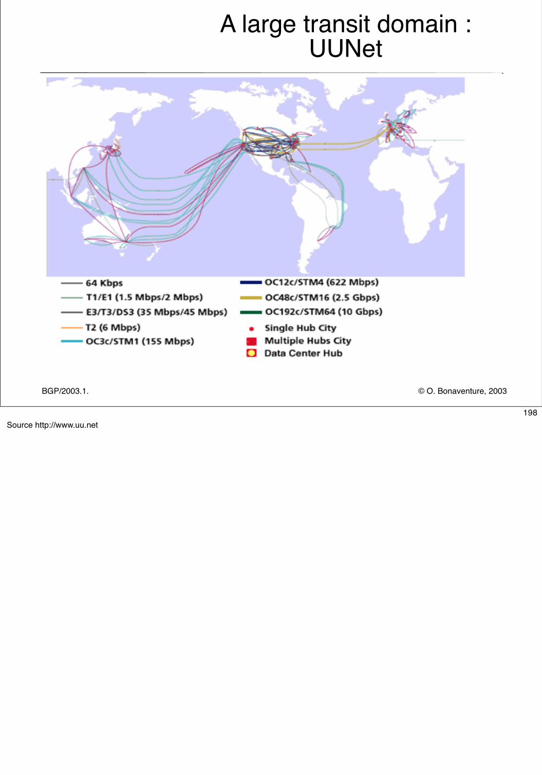
© O. Bonaventure, 2003BGP/2003.1.
A large transit domain : UUNet
198Source http://www.uu.net
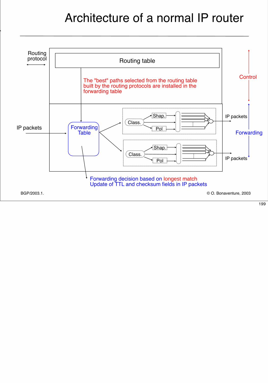
© O. Bonaventure, 2003BGP/2003.1.
Architecture of a normal IP router
Routing table
IP packets
Routing protocol
Control
Forwarding
Class.Shap.
Pol
Class.Shap.
Pol
ForwardingTable
IP packets
IP packets
Forwarding decision based on longest matchUpdate of TTL and checksum fields in IP packets
The "best" paths selected from the routing tablebuilt by the routing protocols are installed in theforwarding table
199
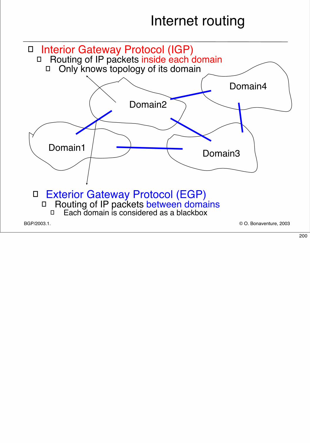
© O. Bonaventure, 2003BGP/2003.1.
Internet routing
� Exterior Gateway Protocol (EGP)� Routing of IP packets between domains
� Each domain is considered as a blackbox
� Interior Gateway Protocol (IGP)� Routing of IP packets inside each domain
� Only knows topology of its domain
Domain1
Domain2
Domain3
Domain4
200
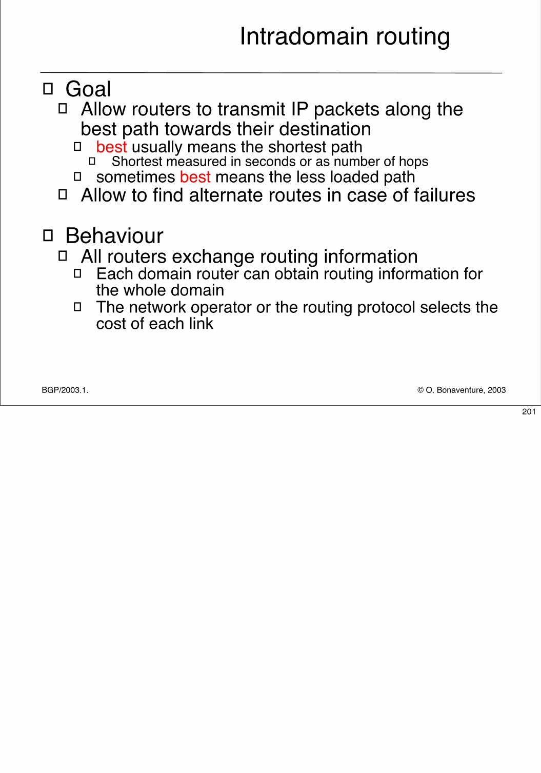
© O. Bonaventure, 2003BGP/2003.1.
Intradomain routing
� Goal � Allow routers to transmit IP packets along the
best path towards their destination � best usually means the shortest path
� Shortest measured in seconds or as number of hops� sometimes best means the less loaded path
� Allow to find alternate routes in case of failures
� Behaviour� All routers exchange routing information
� Each domain router can obtain routing information for the whole domain
� The network operator or the routing protocol selects the cost of each link
201
© O. Bonaventure, 2003BGP/2003.1.
Three types of Interior Gateway Protocols
� Static routing� Only useful in very small domains
� Distance vector routing� Routing Information Protocol (RIP)
� Still widely used in small domains despite its limitations
� Link-state routing� Open Shortest Path First (OSPF)
� Widely used in enterprise networks
� Intermediate System- Intermediate-System (IS-IS)� Widely used by ISPs
202
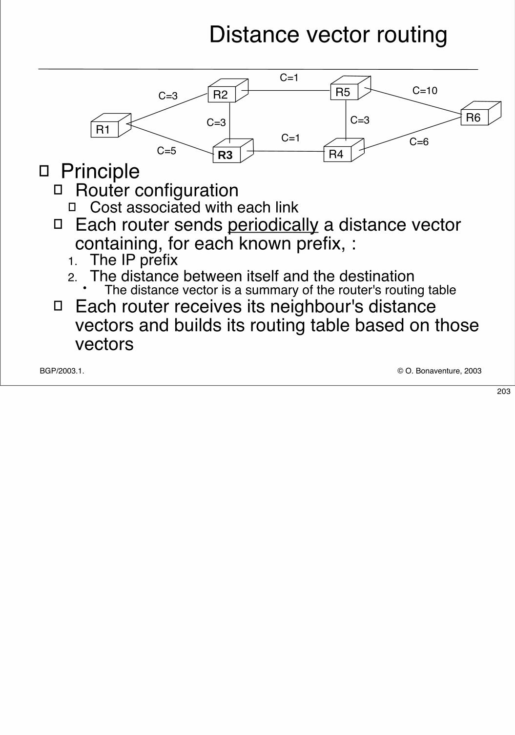
© O. Bonaventure, 2003BGP/2003.1.
Distance vector routing
� Principle� Router configuration
� Cost associated with each link� Each router sends periodically a distance vector
containing, for each known prefix, : 1. The IP prefix2. The distance between itself and the destination
• The distance vector is a summary of the router's routing table� Each router receives its neighbour's distance
vectors and builds its routing table based on those vectors
R2 R5
R3 R4
R1R6
C=5
C=3
C=3
C=1
C=1C=3
C=6
C=10
203
© O. Bonaventure, 2003BGP/2003.1.
Issues with distance vector routing
� How to deal with link failures ?� Routers should send their distance vector when
they detect the failure of one of their links
� How to avoid the count-to-infinity problem ?� Utilise a non-redundant star shaped network
� Limit the maximum distance between routers� For RIP, ∞=16 !
� Split horizon� Router A does not advertise to router B the routes for
which it sends packets via router B� Split horizon with Poison reverse
204
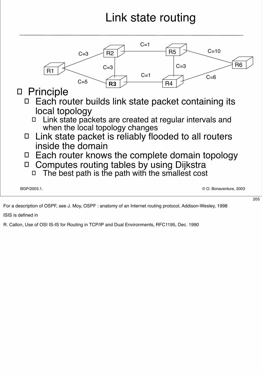
© O. Bonaventure, 2003BGP/2003.1.
Link state routing
� Principle� Each router builds link state packet containing its
local topology� Link state packets are created at regular intervals and
when the local topology changes� Link state packet is reliably flooded to all routers
inside the domain� Each router knows the complete domain topology � Computes routing tables by using Dijkstra
� The best path is the path with the smallest cost
R2 R5
R3 R4
R1R6
C=5
C=3
C=3
C=1
C=1C=3
C=6
C=10
205For a description of OSPF, see J. Moy, OSPF : anatomy of an Internet routing protocol, Addison-Wesley, 1998
ISIS is defined in
R. Callon, Use of OSI IS-IS for Routing in TCP/IP and Dual Environments, RFC1195, Dec. 1990
© O. Bonaventure, 2003Network Security/2008.2
Interdomain routing
� Goals� Allow to transmit IP packets along the best path
towards their destination through several transit domains while taking into account the routing policies of each domain without knowing the detailed topology of those domains
� From an interdomain viewpoint, best path often means cheapest path
� Each domain is free to specify inside its routing policy the domains for which it agrees to provide a transit service and the method it uses to select the best path to reach each destination
206
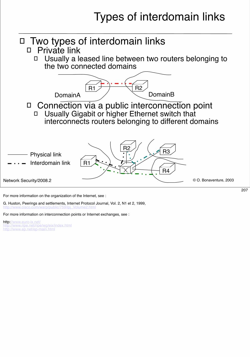
© O. Bonaventure, 2003Network Security/2008.2
Types of interdomain links
� Two types of interdomain links � Private link
� Usually a leased line between two routers belonging to the two connected domains
� Connection via a public interconnection point � Usually Gigabit or higher Ethernet switch that
interconnects routers belonging to different domains
R1
R2
R1 R2DomainA DomainB
R3
R4
Physical linkInterdomain link
207For more information on the organization of the Internet, see :
G. Huston, Peerings and settlements, Internet Protocol Journal, Vol. 2, N1 et 2, 1999,http://www.cisco.com/warp/public/759/ipj_Volume2.html
For more information on interconnection points or Internet exchanges, see :
http://www.euro-ix.net/http://www.ripe.net/ripe/wg/eix/index.htmlhttp://www.ep.net/ep-main.html
© O. Bonaventure, 2003Network Security/2008.2
Routing policies
� In theory BGP allows each domain to define its own routing policy...
� In practice there are two common policies� customer-provider peering
� Customer c buys Internet connectivity from provider P
� shared-cost peering� Domains x and y agree to exchange packets by using
a direct link or through an interconnection point
208
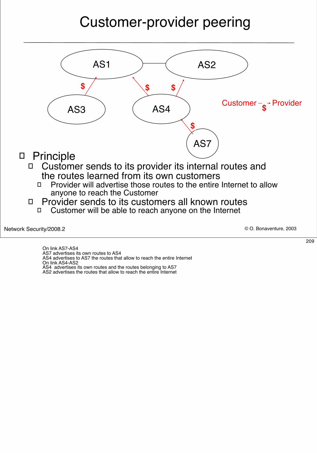
© O. Bonaventure, 2003Network Security/2008.2
Customer Provider
Customer-provider peering
� Principle� Customer sends to its provider its internal routes and
the routes learned from its own customers� Provider will advertise those routes to the entire Internet to allow
anyone to reach the Customer� Provider sends to its customers all known routes
� Customer will be able to reach anyone on the Internet
AS2AS1
AS3 AS4
AS7
$ $ $
$
$
209On link AS7-AS4AS7 advertises its own routes to AS4AS4 advertises to AS7 the routes that allow to reach the entire Internet On link AS4-AS2AS4 advertises its own routes and the routes belonging to AS7AS2 advertises the routes that allow to reach the entire Internet
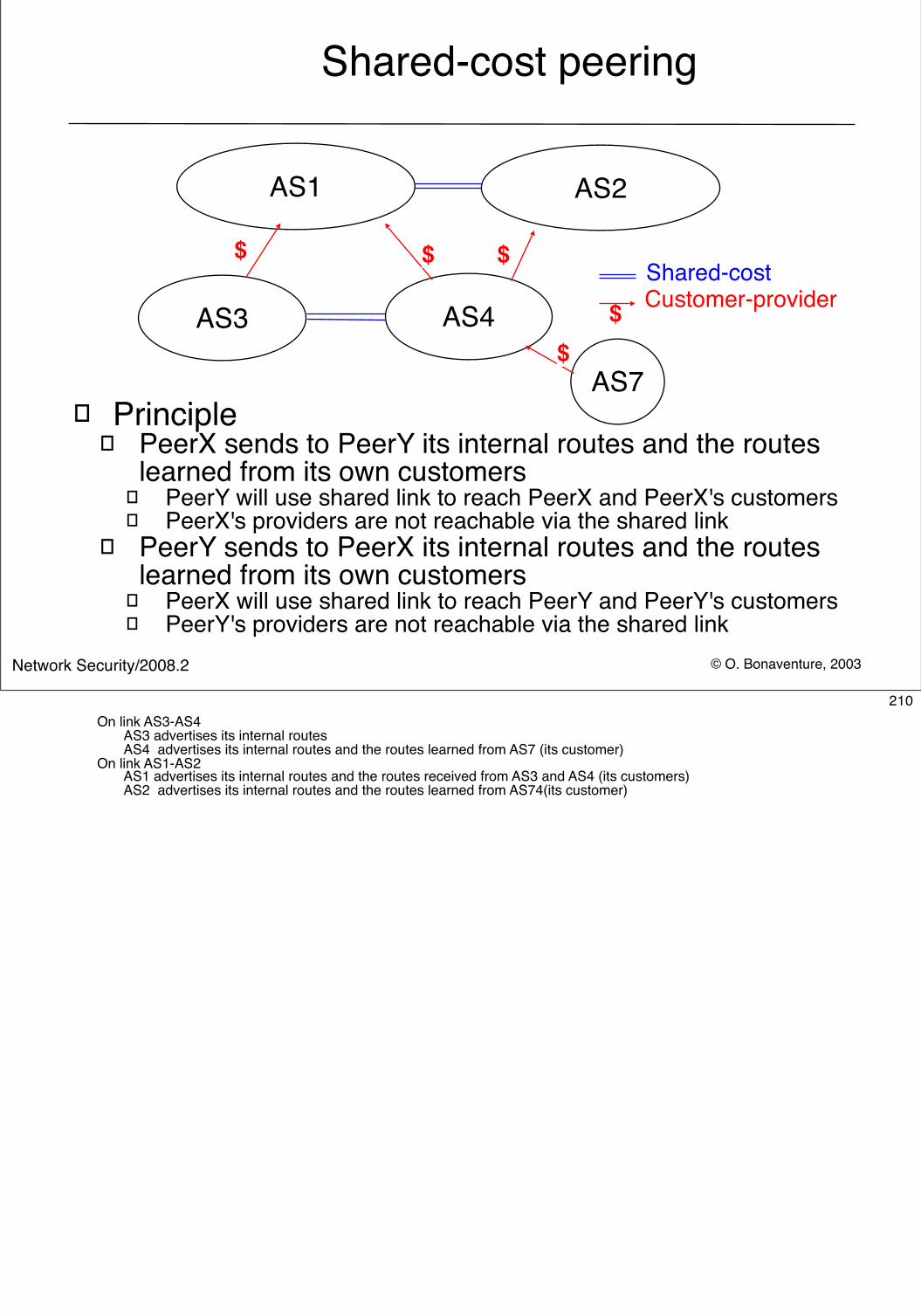
© O. Bonaventure, 2003Network Security/2008.2
Shared-cost peering
AS2AS1
AS3 AS4
AS7
$ Customer-provider
$ $ $
$
Shared-cost
� Principle� PeerX sends to PeerY its internal routes and the routes
learned from its own customers� PeerY will use shared link to reach PeerX and PeerX's customers� PeerX's providers are not reachable via the shared link
� PeerY sends to PeerX its internal routes and the routes learned from its own customers
� PeerX will use shared link to reach PeerY and PeerY's customers� PeerY's providers are not reachable via the shared link
210On link AS3-AS4
AS3 advertises its internal routesAS4 advertises its internal routes and the routes learned from AS7 (its customer)
On link AS1-AS2AS1 advertises its internal routes and the routes received from AS3 and AS4 (its customers) AS2 advertises its internal routes and the routes learned from AS74(its customer)
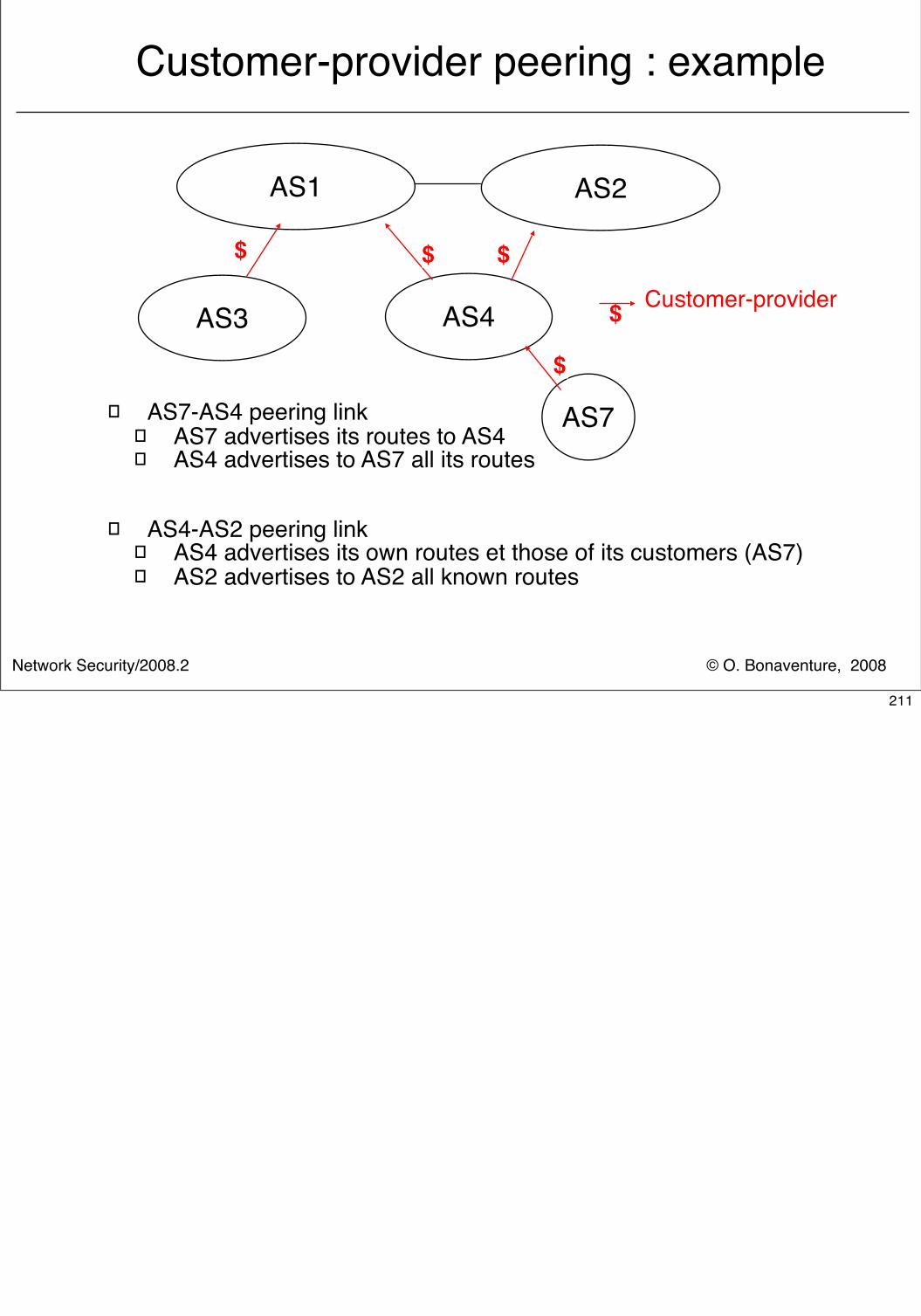
© O. Bonaventure, 2008Network Security/2008.2
Customer-provider peering : example
� AS7-AS4 peering link� AS7 advertises its routes to AS4� AS4 advertises to AS7 all its routes
� AS4-AS2 peering link� AS4 advertises its own routes et those of its customers (AS7)� AS2 advertises to AS2 all known routes
AS2AS1
AS3 AS4
AS7
$ Customer-provider
$ $ $
$
211
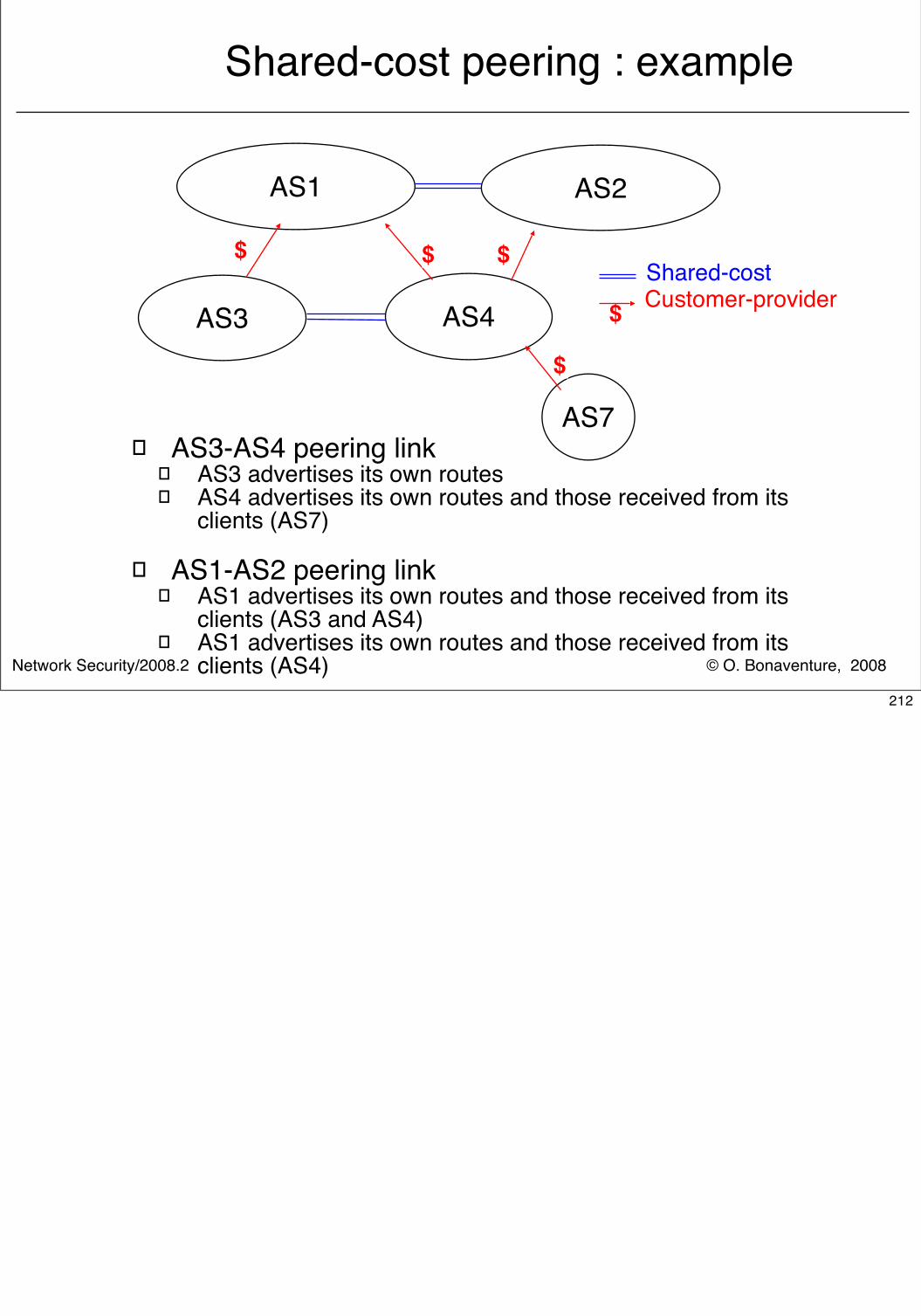
© O. Bonaventure, 2008Network Security/2008.2
Shared-cost peering : example
� AS3-AS4 peering link� AS3 advertises its own routes � AS4 advertises its own routes and those received from its
clients (AS7)
� AS1-AS2 peering link� AS1 advertises its own routes and those received from its
clients (AS3 and AS4) � AS1 advertises its own routes and those received from its
clients (AS4)
AS2AS1
AS3 AS4
AS7
$ Customer-provider
$ $ $
$
Shared-cost
212
© O. Bonaventure, 2003Network Security/2008.2
Routing policies
� A domain specifies its routing policy by defining on each BGP router two sets of filters for each peer
� Import filter � Specifies which routes can be accepted by the router
among all the received routes from a given peer
� Export filter� Specifies which routes can be advertised by the router to a
given peer
� Filters can be defined in RPSL� Routing Policy Specification Language
� defined in RFC2622 and examples in RFC2650� See also http://www.ripe.net/ripencc/pub-services/whois.html
213RFC 2622 Routing Policy Specification Language (RPSL). C. Alaettinoglu, C. Villamizar, E. Gerich, D. Kessens, D. Meyer, T. Bates, D. Karrenberg, M. Terpstra. June 1999.
RFC 2650 Using RPSL in Practice. D. Meyer, J. Schmitz, C. Orange, M. Prior, C. Alaettinoglu. August 1999.
Internet Routing Registries contain the routing policies of various ISPs, see :
http://www.ripe.net/ripencc/pub-services/whois.htmlhttp://www.arin.net/whois/index.htmlhttp://www.apnic.net/apnic-bin/whois.pl
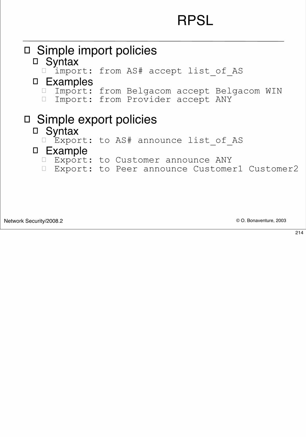
© O. Bonaventure, 2003Network Security/2008.2
RPSL
� Simple import policies� Syntax
� import: from AS# accept list_of_AS � Examples
� Import: from Belgacom accept Belgacom WIN� Import: from Provider accept ANY
� Simple export policies � Syntax
� Export: to AS# announce list_of_AS� Example
� Export: to Customer announce ANY� Export: to Peer announce Customer1 Customer2
214
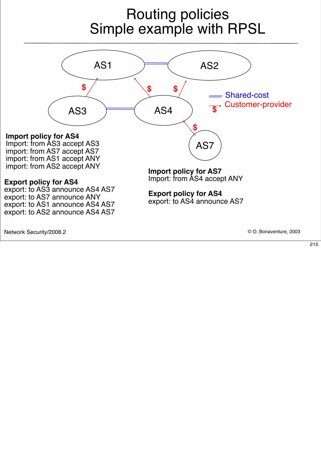
© O. Bonaventure, 2003Network Security/2008.2
Routing policies Simple example with RPSL
AS2AS1
AS3 AS4
AS7
$ Customer-provider
$ $ $
$
Shared-cost
Import policy for AS4Import: from AS3 accept AS3import: from AS7 accept AS7import: from AS1 accept ANYimport: from AS2 accept ANY
Export policy for AS4export: to AS3 announce AS4 AS7export: to AS7 announce ANYexport: to AS1 announce AS4 AS7export: to AS2 announce AS4 AS7
Import policy for AS7Import: from AS4 accept ANY
Export policy for AS4export: to AS4 announce AS7
215
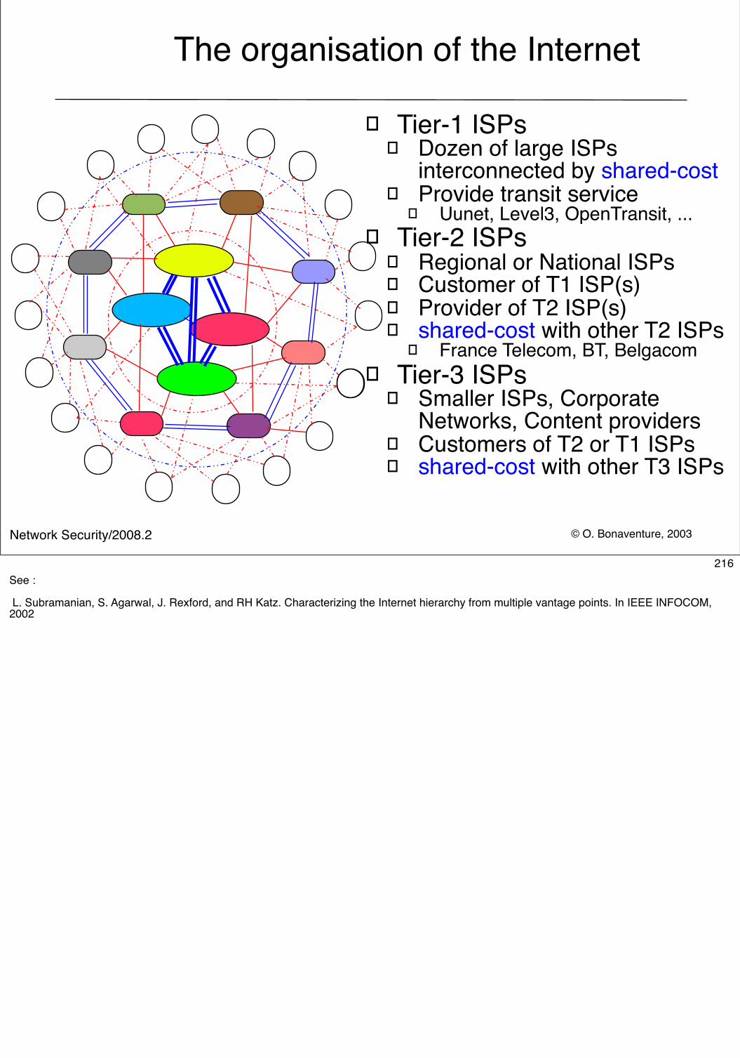
© O. Bonaventure, 2003Network Security/2008.2
The organisation of the Internet
� Tier-1 ISPs� Dozen of large ISPs
interconnected by shared-cost� Provide transit service
� Uunet, Level3, OpenTransit, ...� Tier-2 ISPs
� Regional or National ISPs � Customer of T1 ISP(s)� Provider of T2 ISP(s) � shared-cost with other T2 ISPs
� France Telecom, BT, Belgacom� Tier-3 ISPs
� Smaller ISPs, Corporate Networks, Content providers
� Customers of T2 or T1 ISPs� shared-cost with other T3 ISPs
216See :
L. Subramanian, S. Agarwal, J. Rexford, and RH Katz. Characterizing the Internet hierarchy from multiple vantage points. In IEEE INFOCOM, 2002
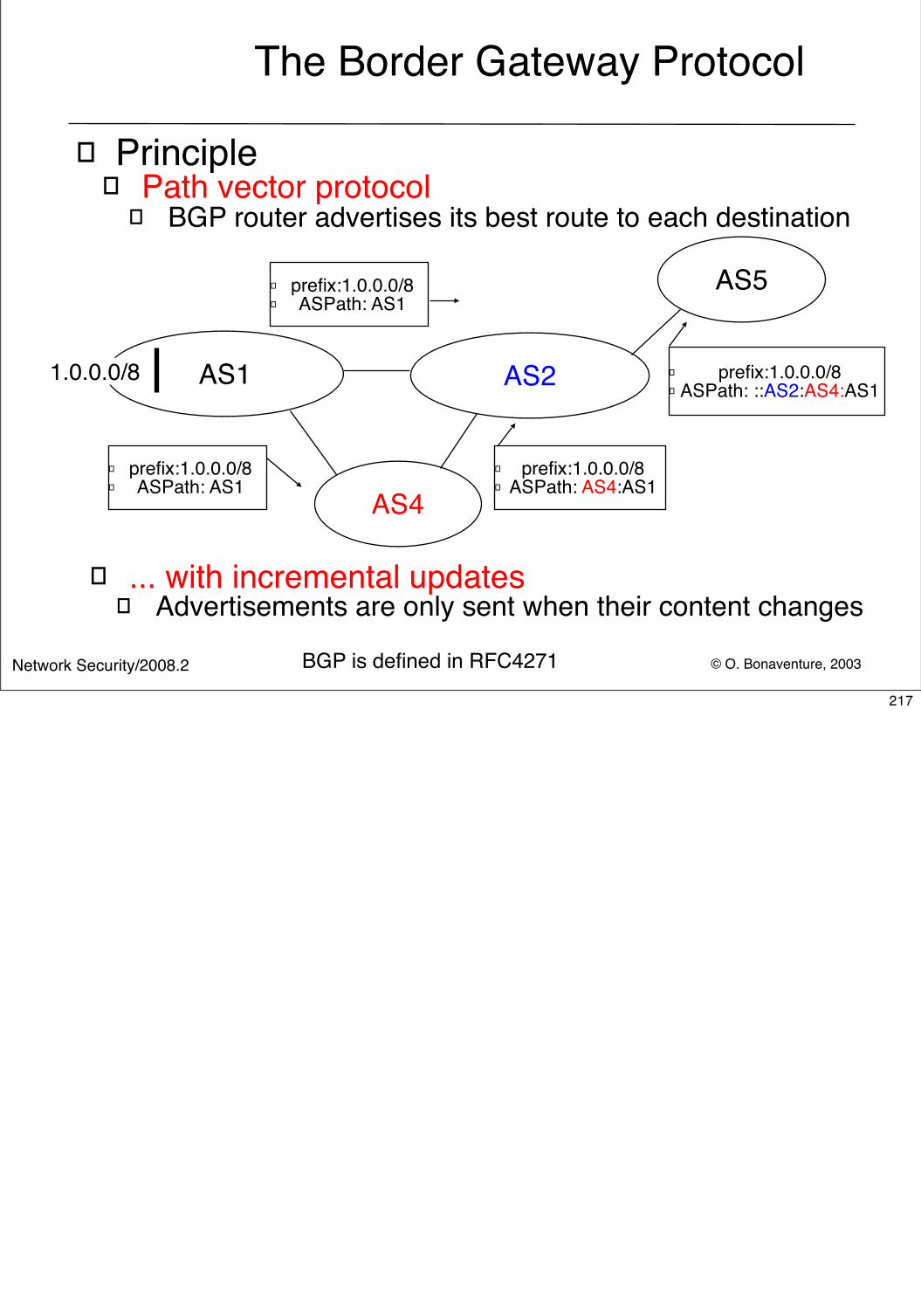
© O. Bonaventure, 2003Network Security/2008.2
The Border Gateway Protocol
� Principle� Path vector protocol
� BGP router advertises its best route to each destination
AS2AS1
AS4
1.0.0.0/8
AS5
� prefix:1.0.0.0/8� ASPath: AS1
� prefix:1.0.0.0/8� ASPath: AS4:AS1
� prefix:1.0.0.0/8� ASPath: ::AS2:AS4:AS1
� prefix:1.0.0.0/8� ASPath: AS1
� ... with incremental updates� Advertisements are only sent when their content changes
BGP is defined in RFC4271217
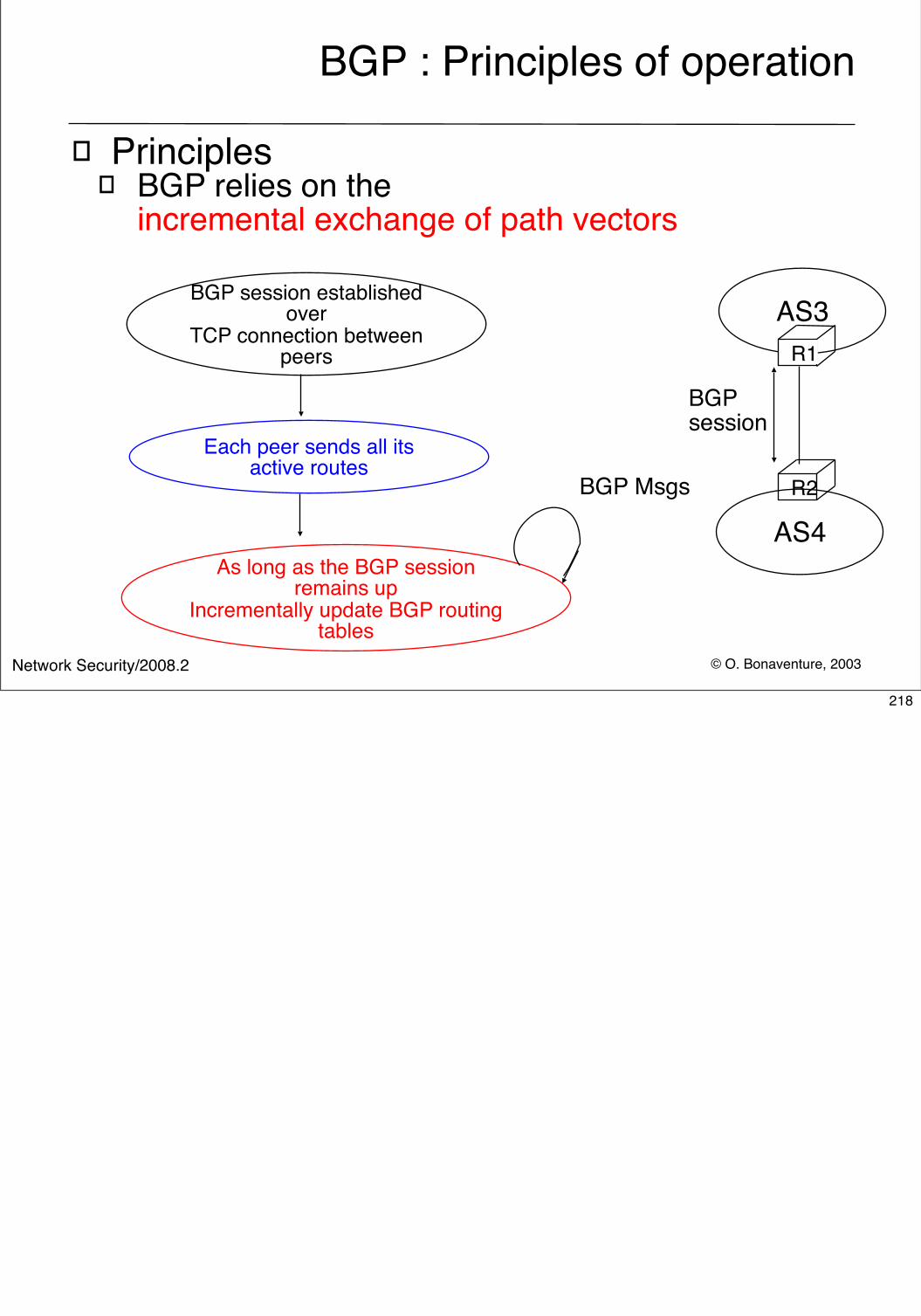
© O. Bonaventure, 2003Network Security/2008.2
BGP : Principles of operation
� Principles� BGP relies on the
incremental exchange of path vectors
BGP session established over
TCP connection between peers
Each peer sends all its active routes
As long as the BGP session remains up
Incrementally update BGP routing tables
AS3
AS4
R1
R2
BGP session
BGP Msgs
218
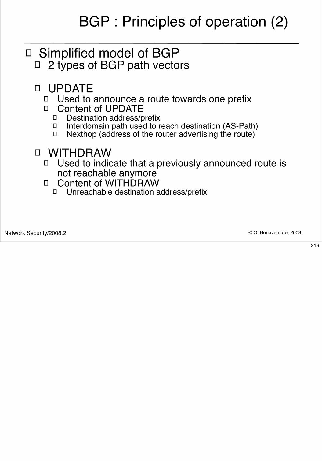
© O. Bonaventure, 2003Network Security/2008.2
BGP : Principles of operation (2)
� Simplified model of BGP� 2 types of BGP path vectors
� UPDATE � Used to announce a route towards one prefix� Content of UPDATE
� Destination address/prefix � Interdomain path used to reach destination (AS-Path)� Nexthop (address of the router advertising the route)
� WITHDRAW� Used to indicate that a previously announced route is
not reachable anymore� Content of WITHDRAW
� Unreachable destination address/prefix
219
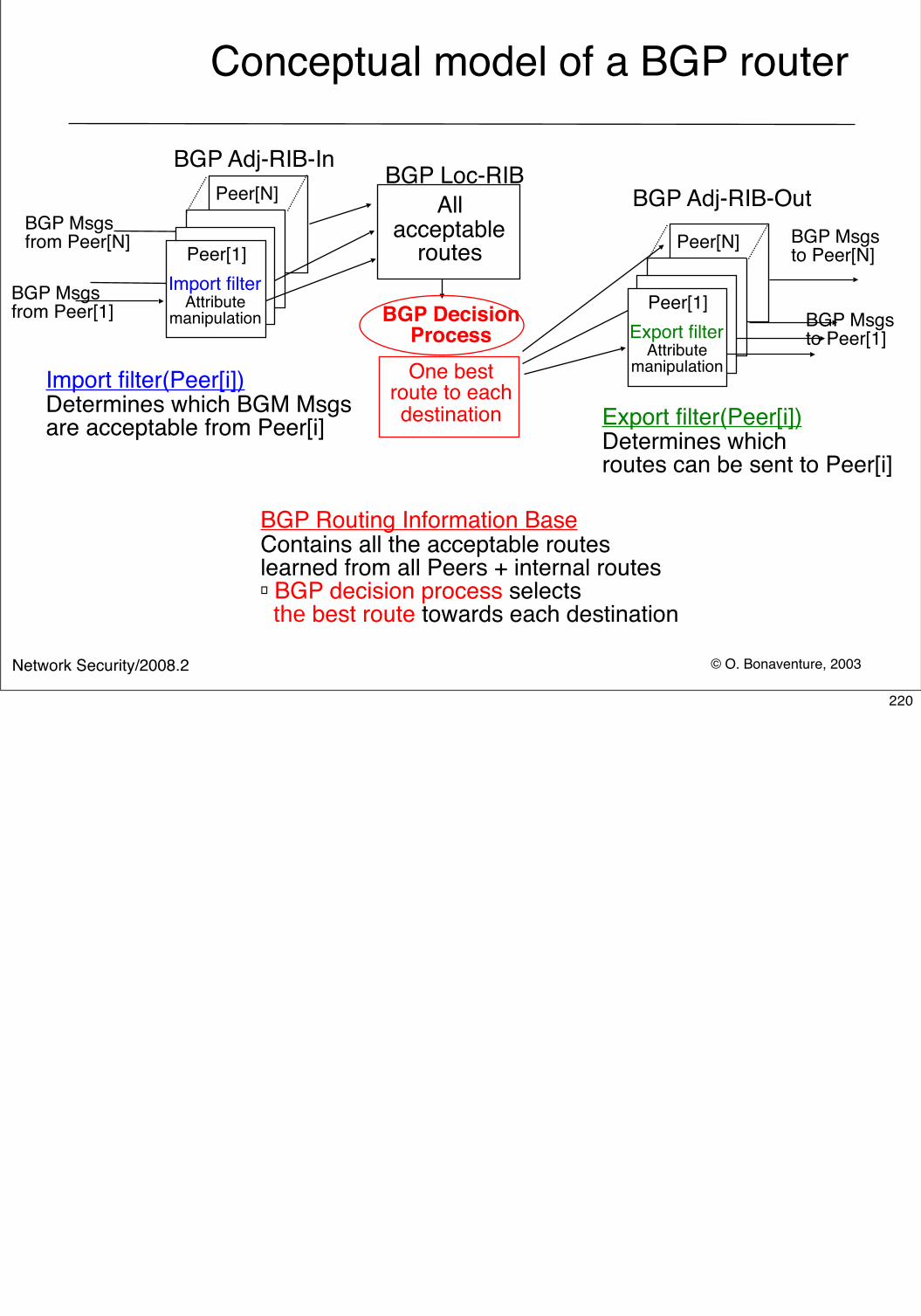
© O. Bonaventure, 2003Network Security/2008.2
Conceptual model of a BGP router
BGP Loc-RIB
Peer[1]
Peer[N]
Import filterAttribute
manipulation Peer[1]
Peer[N]
Export filterAttribute
manipulation
BGP Routing Information BaseContains all the acceptable routes learned from all Peers + internal routes� BGP decision process selects the best route towards each destination
BGP Msgs from Peer[1]
BGP Msgs from Peer[N] BGP Msgs
to Peer[N]
BGP Msgs to Peer[1]
Import filter(Peer[i])Determines which BGM Msgsare acceptable from Peer[i] Export filter(Peer[i])
Determines which routes can be sent to Peer[i]
One bestroute to eachdestination
All acceptable
routes
BGP Decision Process
BGP Adj-RIB-InBGP Adj-RIB-Out
220
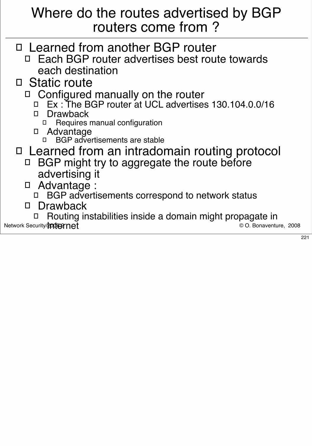
© O. Bonaventure, 2008Network Security/2008.2
Where do the routes advertised by BGP routers come from ?
� Learned from another BGP router� Each BGP router advertises best route towards
each destination� Static route
� Configured manually on the router� Ex : The BGP router at UCL advertises 130.104.0.0/16� Drawback
� Requires manual configuration� Advantage
� BGP advertisements are stable� Learned from an intradomain routing protocol
� BGP might try to aggregate the route before advertising it
� Advantage : � BGP advertisements correspond to network status
� Drawback� Routing instabilities inside a domain might propagate in
Internet221
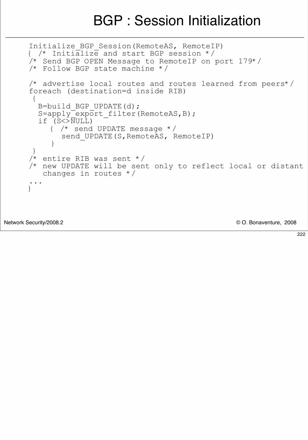
© O. Bonaventure, 2008Network Security/2008.2
BGP : Session InitializationInitialize_BGP_Session(RemoteAS, RemoteIP){ /* Initialize and start BGP session *//* Send BGP OPEN Message to RemoteIP on port 179*//* Follow BGP state machine */
/* advertise local routes and routes learned from peers*/foreach (destination=d inside RIB) { B=build_BGP_UPDATE(d); S=apply_export_filter(RemoteAS,B); if (S<>NULL) { /* send UPDATE message */ send_UPDATE(S,RemoteAS, RemoteIP) } }/* entire RIB was sent *//* new UPDATE will be sent only to reflect local or distant changes in routes */...}
222
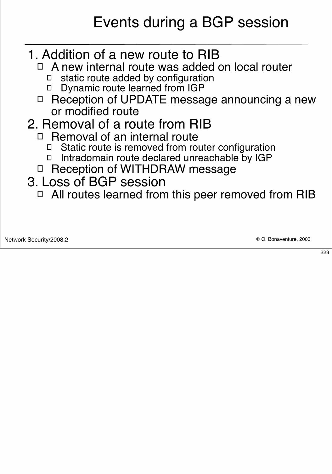
© O. Bonaventure, 2003Network Security/2008.2
Events during a BGP session
1. Addition of a new route to RIB� A new internal route was added on local router
� static route added by configuration� Dynamic route learned from IGP
� Reception of UPDATE message announcing a new or modified route
2. Removal of a route from RIB� Removal of an internal route
� Static route is removed from router configuration � Intradomain route declared unreachable by IGP
� Reception of WITHDRAW message3. Loss of BGP session
� All routes learned from this peer removed from RIB
223
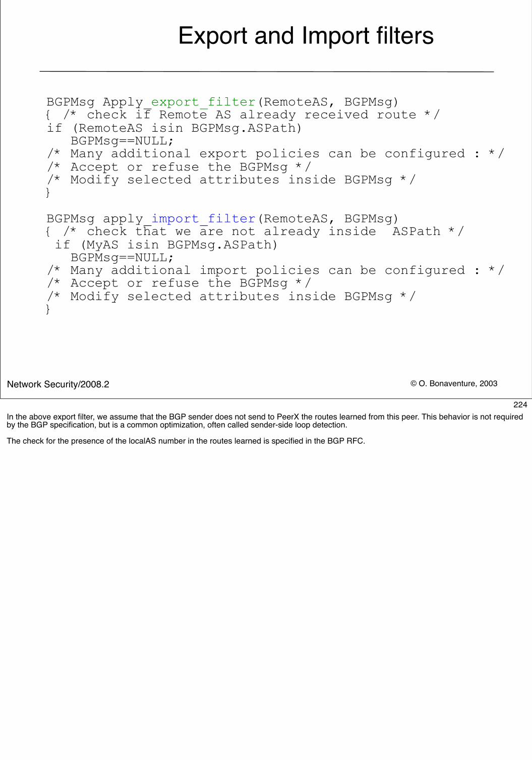
© O. Bonaventure, 2003Network Security/2008.2
Export and Import filters
BGPMsg Apply_export_filter(RemoteAS, BGPMsg){ /* check if Remote AS already received route */if (RemoteAS isin BGPMsg.ASPath) BGPMsg==NULL;/* Many additional export policies can be configured : *//* Accept or refuse the BGPMsg *//* Modify selected attributes inside BGPMsg */}
BGPMsg apply_import_filter(RemoteAS, BGPMsg){ /* check that we are not already inside ASPath */ if (MyAS isin BGPMsg.ASPath) BGPMsg==NULL;/* Many additional import policies can be configured : *//* Accept or refuse the BGPMsg *//* Modify selected attributes inside BGPMsg */}
224In the above export filter, we assume that the BGP sender does not send to PeerX the routes learned from this peer. This behavior is not required by the BGP specification, but is a common optimization, often called sender-side loop detection.
The check for the presence of the localAS number in the routes learned is specified in the BGP RFC.
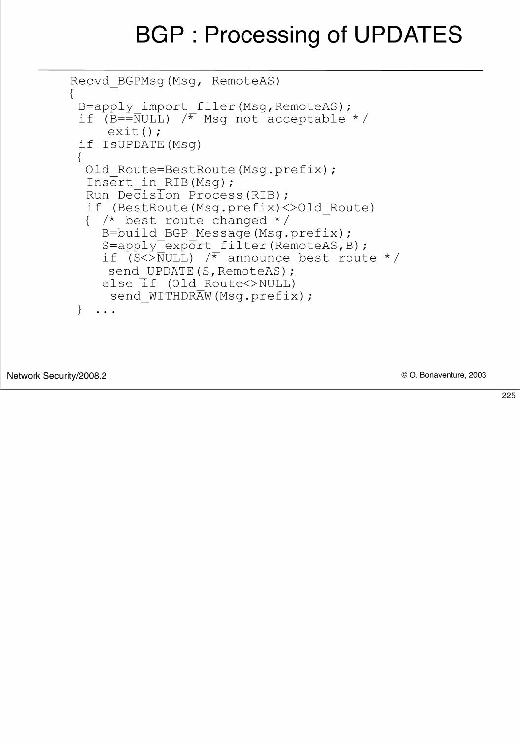
© O. Bonaventure, 2003Network Security/2008.2
BGP : Processing of UPDATESRecvd_BGPMsg(Msg, RemoteAS){ B=apply_import_filer(Msg,RemoteAS); if (B==NULL) /* Msg not acceptable */ exit(); if IsUPDATE(Msg) { Old_Route=BestRoute(Msg.prefix); Insert_in_RIB(Msg); Run_Decision_Process(RIB); if (BestRoute(Msg.prefix)<>Old_Route) { /* best route changed */ B=build_BGP_Message(Msg.prefix); S=apply_export_filter(RemoteAS,B); if (S<>NULL) /* announce best route */ send_UPDATE(S,RemoteAS); else if (Old_Route<>NULL) send_WITHDRAW(Msg.prefix); } ...
225
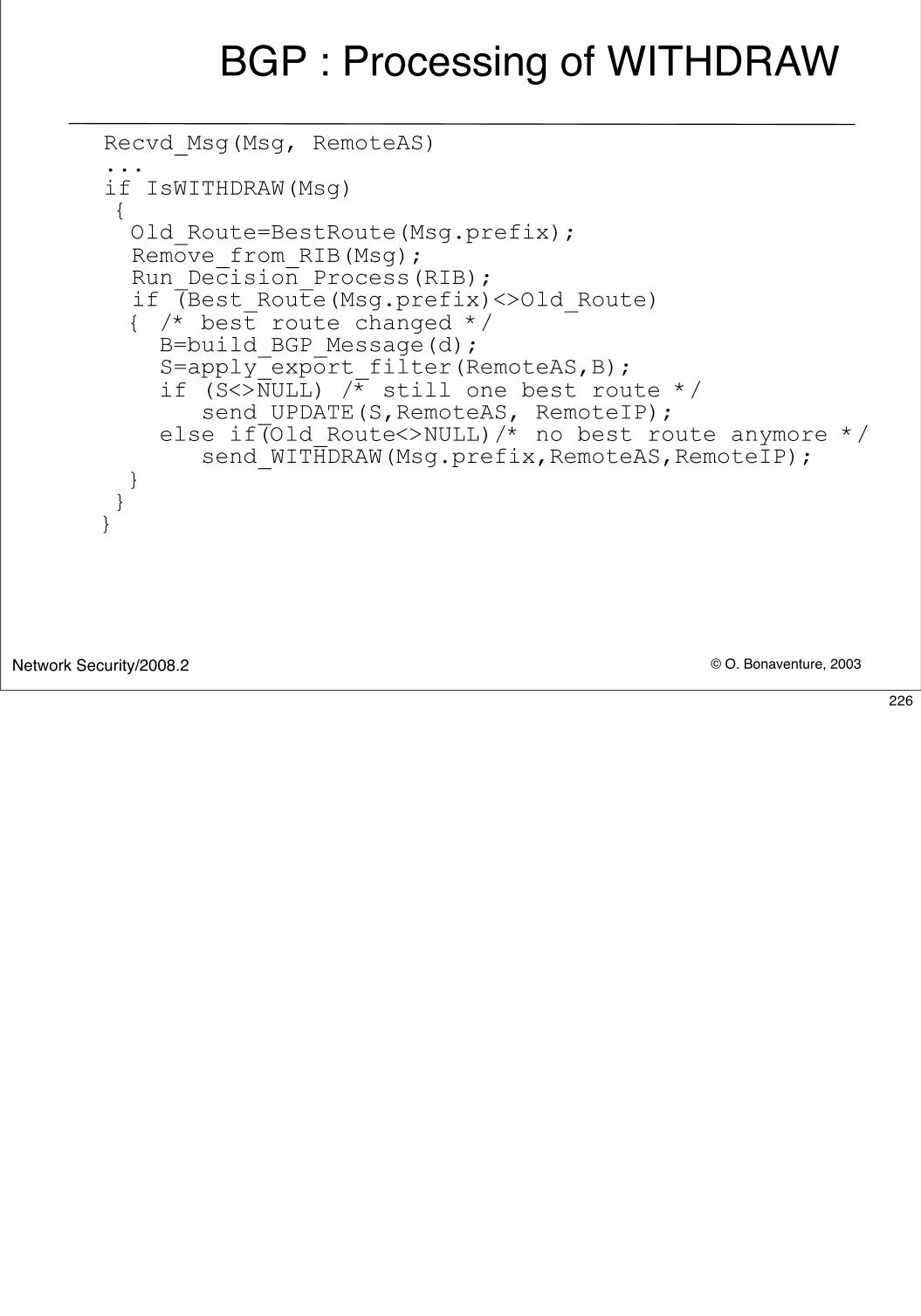
© O. Bonaventure, 2003Network Security/2008.2
BGP : Processing of WITHDRAWRecvd_Msg(Msg, RemoteAS)...if IsWITHDRAW(Msg) { Old_Route=BestRoute(Msg.prefix); Remove_from_RIB(Msg); Run_Decision_Process(RIB); if (Best_Route(Msg.prefix)<>Old_Route) { /* best route changed */ B=build_BGP_Message(d); S=apply_export_filter(RemoteAS,B); if (S<>NULL) /* still one best route */ send_UPDATE(S,RemoteAS, RemoteIP); else if(Old_Route<>NULL)/* no best route anymore */ send_WITHDRAW(Msg.prefix,RemoteAS,RemoteIP); } }}
226
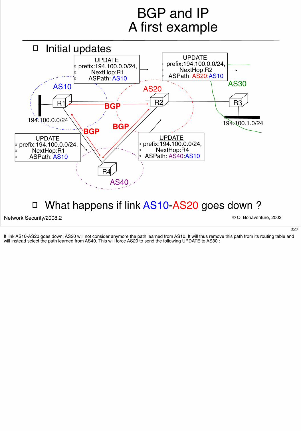
© O. Bonaventure, 2003Network Security/2008.2
BGP and IPA first example
� Initial updates
R2
AS20 AS30
R1 R3
AS10
194.100.1.0/24194.100.0.0/24
BGP
R4AS40
BGP BGP
UPDATE� prefix:194.100.0.0/24, � NextHop:R1� ASPath: AS10
UPDATE� prefix:194.100.0.0/24, � NextHop:R1� ASPath: AS10
UPDATE� prefix:194.100.0.0/24, � NextHop:R4� ASPath: AS40:AS10
UPDATE� prefix:194.100.0.0/24, � NextHop:R2� ASPath: AS20:AS10
� What happens if link AS10-AS20 goes down ?
227If link AS10-AS20 goes down, AS20 will not consider anymore the path learned from AS10. It will thus remove this path from its routing table and will instead select the path learned from AS40. This will force AS20 to send the following UPDATE to AS30 :
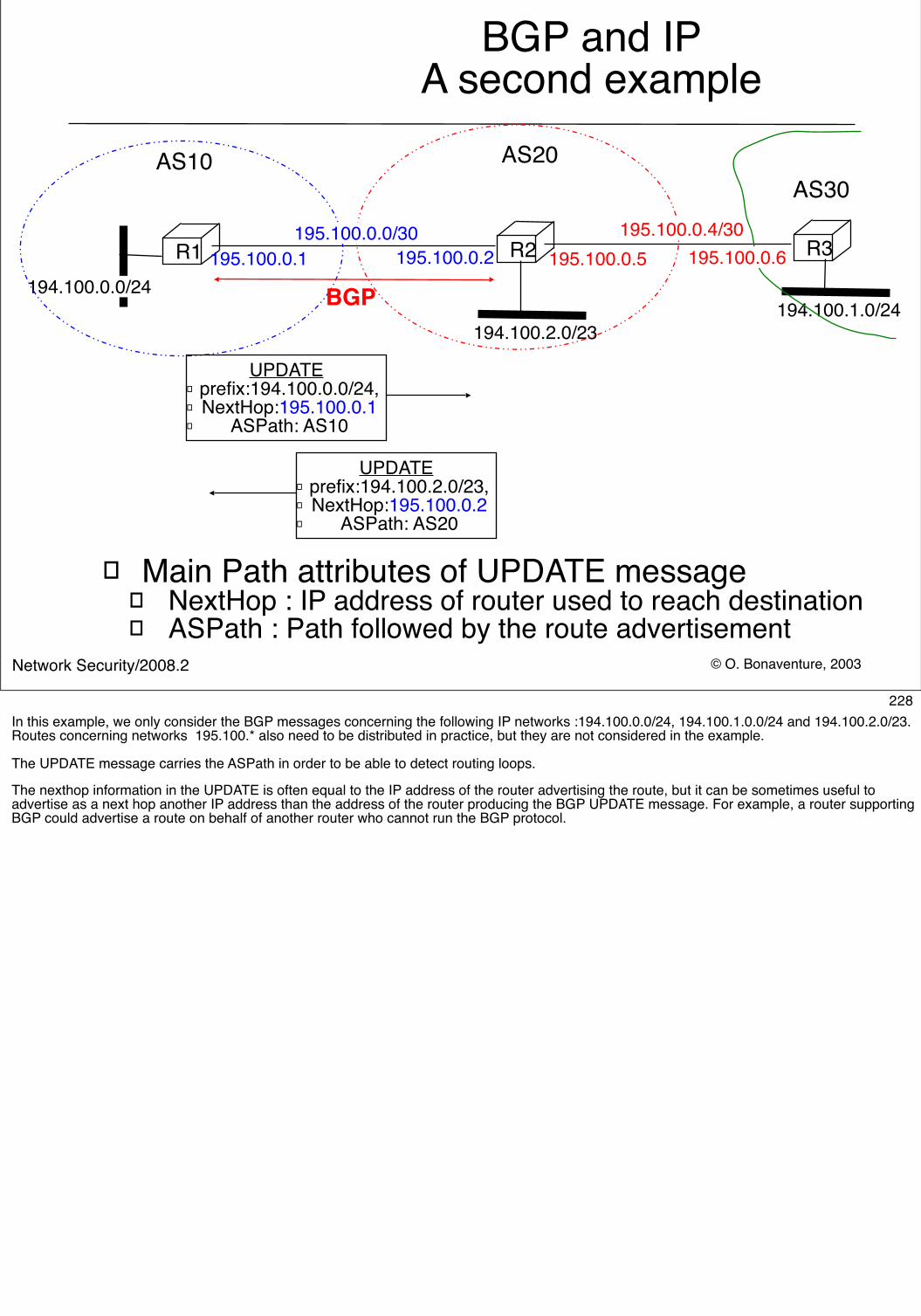
© O. Bonaventure, 2003Network Security/2008.2
BGP and IPA second example
R2
AS20AS30
R1 R3
AS10
194.100.1.0/24194.100.2.0/23
195.100.0.1 195.100.0.2 195.100.0.5194.100.0.0/24
195.100.0.0/30 195.100.0.4/30195.100.0.6
BGP
UPDATE� prefix:194.100.2.0/23, � NextHop:195.100.0.2� ASPath: AS20
UPDATE� prefix:194.100.0.0/24, � NextHop:195.100.0.1� ASPath: AS10
� Main Path attributes of UPDATE message� NextHop : IP address of router used to reach destination� ASPath : Path followed by the route advertisement
228In this example, we only consider the BGP messages concerning the following IP networks :194.100.0.0/24, 194.100.1.0.0/24 and 194.100.2.0/23. Routes concerning networks 195.100.* also need to be distributed in practice, but they are not considered in the example.
The UPDATE message carries the ASPath in order to be able to detect routing loops.
The nexthop information in the UPDATE is often equal to the IP address of the router advertising the route, but it can be sometimes useful to advertise as a next hop another IP address than the address of the router producing the BGP UPDATE message. For example, a router supporting BGP could advertise a route on behalf of another router who cannot run the BGP protocol.
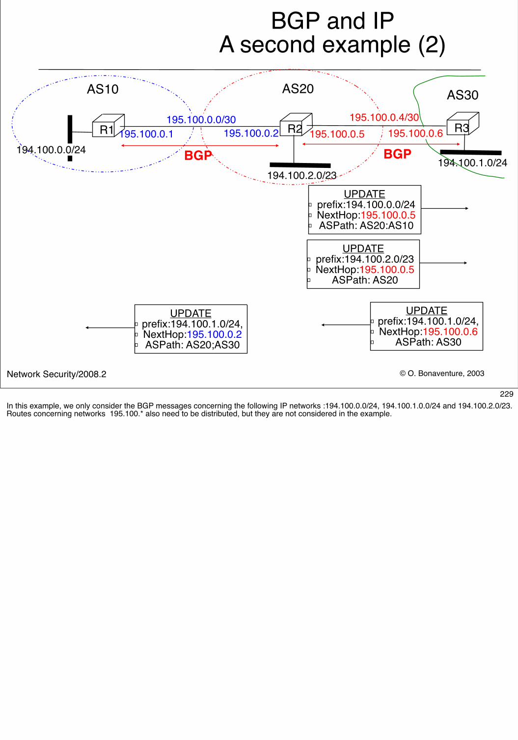
© O. Bonaventure, 2003Network Security/2008.2
BGP and IPA second example (2)
R2
AS20 AS30
R1 R3
AS10
194.100.1.0/24194.100.2.0/23
195.100.0.1 195.100.0.2 195.100.0.5194.100.0.0/24
195.100.0.0/30 195.100.0.4/30195.100.0.6
BGP BGP
UPDATE� prefix:194.100.1.0/24, � NextHop:195.100.0.6� ASPath: AS30
UPDATE� prefix:194.100.0.0/24 � NextHop:195.100.0.5� ASPath: AS20:AS10
UPDATE� prefix:194.100.2.0/23 � NextHop:195.100.0.5� ASPath: AS20
UPDATE� prefix:194.100.1.0/24, � NextHop:195.100.0.2� ASPath: AS20;AS30
229In this example, we only consider the BGP messages concerning the following IP networks :194.100.0.0/24, 194.100.1.0.0/24 and 194.100.2.0/23. Routes concerning networks 195.100.* also need to be distributed, but they are not considered in the example.
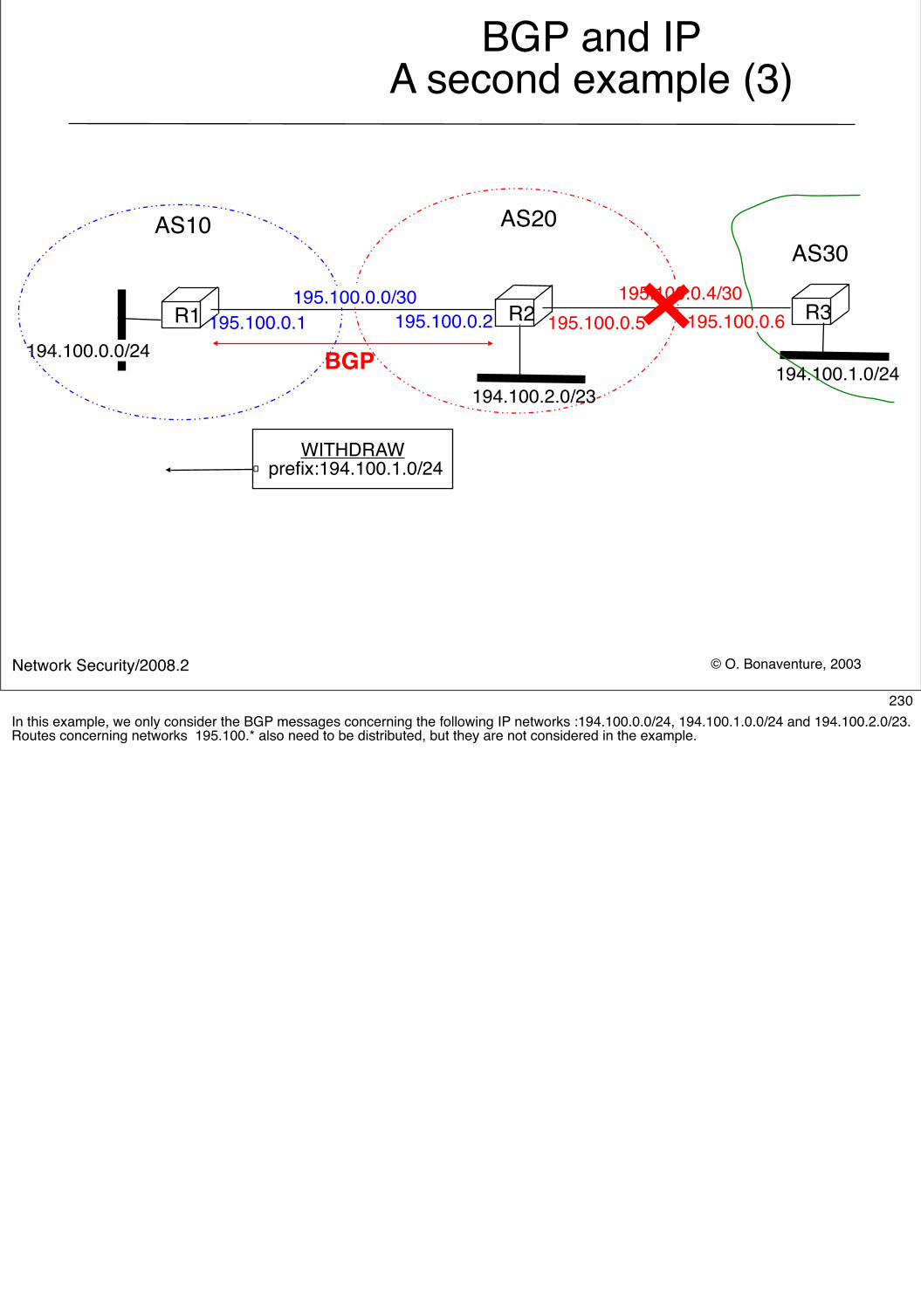
© O. Bonaventure, 2003Network Security/2008.2
BGP and IPA second example (3)
R2
AS20AS30
R1 R3
AS10
194.100.1.0/24194.100.2.0/23
195.100.0.1 195.100.0.2 195.100.0.5194.100.0.0/24
195.100.0.0/30 195.100.0.4/30195.100.0.6
BGP
WITHDRAW� prefix:194.100.1.0/24
230In this example, we only consider the BGP messages concerning the following IP networks :194.100.0.0/24, 194.100.1.0.0/24 and 194.100.2.0/23. Routes concerning networks 195.100.* also need to be distributed, but they are not considered in the example.
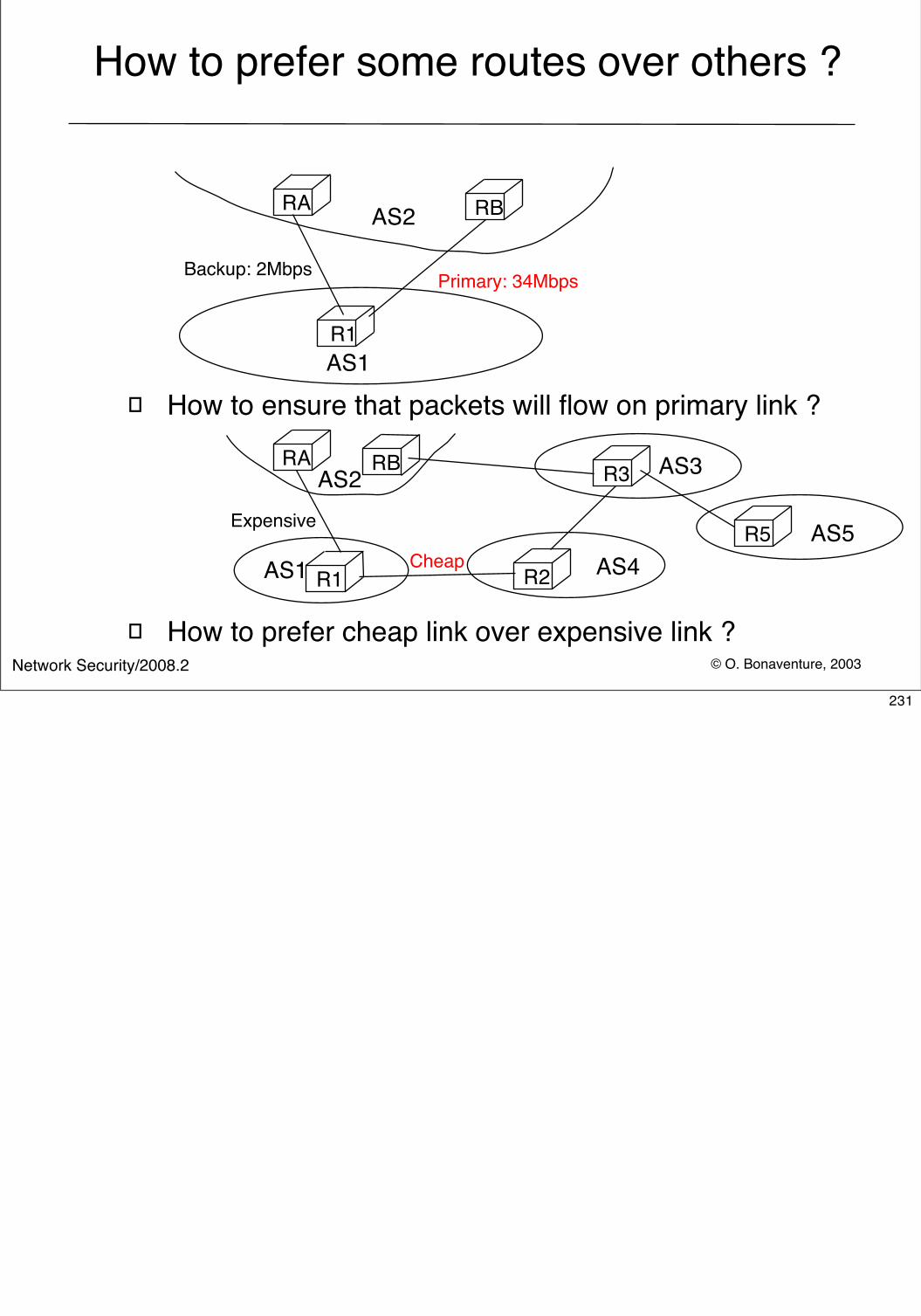
© O. Bonaventure, 2003Network Security/2008.2
How to prefer some routes over others ?
� How to ensure that packets will flow on primary link ?
� How to prefer cheap link over expensive link ?
R1
RA RB
Backup: 2Mbps Primary: 34Mbps
RA
R1 R2
R3RB
Cheap
Expensive
AS1
AS2
AS1
AS2 AS3
AS4R5 AS5
231
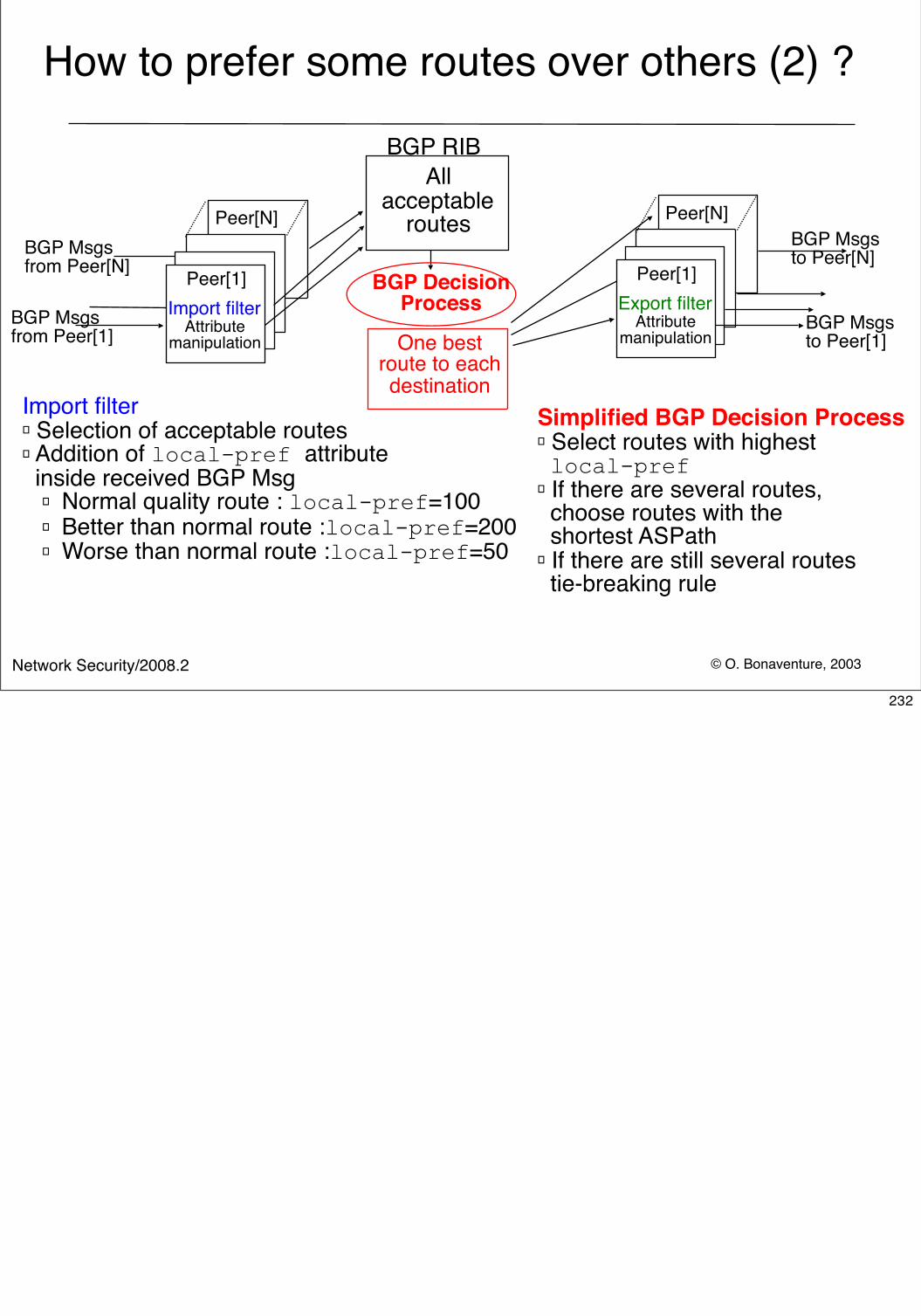
© O. Bonaventure, 2003Network Security/2008.2
How to prefer some routes over others (2) ?
BGP RIB
Peer[1]
Peer[N]
Import filterAttribute
manipulation
Peer[1]
Peer[N]
Export filterAttribute
manipulationBGP Msgs from Peer[1]
BGP Msgs from Peer[N]
BGP Msgs to Peer[N]
BGP Msgs to Peer[1]One best
route to eachdestination
All acceptable
routes
BGP Decision Process
Import filter� Selection of acceptable routes� Addition of local-pref attribute inside received BGP Msg
� Normal quality route : local-pref=100� Better than normal route :local-pref=200� Worse than normal route :local-pref=50
Simplified BGP Decision Process� Select routes with highest local-pref � If there are several routes, choose routes with the shortest ASPath � If there are still several routes tie-breaking rule
232
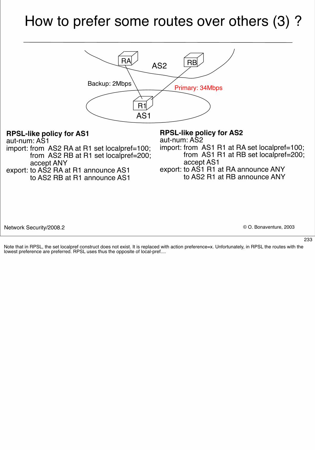
© O. Bonaventure, 2003Network Security/2008.2
How to prefer some routes over others (3) ?
R1
RA RB
Backup: 2Mbps Primary: 34Mbps
AS1
AS2
RPSL-like policy for AS1aut-num: AS1import: from AS2 RA at R1 set localpref=100; from AS2 RB at R1 set localpref=200; accept ANYexport: to AS2 RA at R1 announce AS1 to AS2 RB at R1 announce AS1
RPSL-like policy for AS2aut-num: AS2import: from AS1 R1 at RA set localpref=100; from AS1 R1 at RB set localpref=200; accept AS1export: to AS1 R1 at RA announce ANY to AS2 R1 at RB announce ANY
233Note that in RPSL, the set localpref construct does not exist. It is replaced with action preference=x. Unfortunately, in RPSL the routes with the lowest preference are preferred. RPSL uses thus the opposite of local-pref....
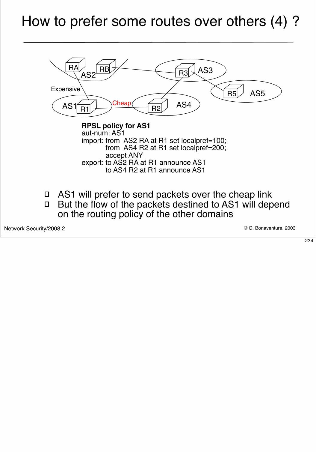
© O. Bonaventure, 2003Network Security/2008.2
How to prefer some routes over others (4) ?
� AS1 will prefer to send packets over the cheap link� But the flow of the packets destined to AS1 will depend
on the routing policy of the other domains
RA
R1 R2
R3RB
Cheap
Expensive
AS1
AS2 AS3
AS4R5 AS5
RPSL policy for AS1aut-num: AS1import: from AS2 RA at R1 set localpref=100; from AS4 R2 at R1 set localpref=200; accept ANYexport: to AS2 RA at R1 announce AS1 to AS4 R2 at R1 announce AS1
234
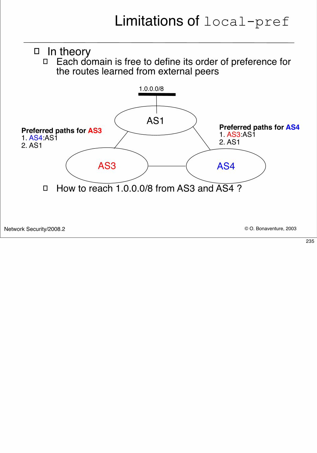
© O. Bonaventure, 2003Network Security/2008.2
Limitations of local-pref
� In theory� Each domain is free to define its order of preference for
the routes learned from external peers
� How to reach 1.0.0.0/8 from AS3 and AS4 ?
AS1
AS3 AS4
Preferred paths for AS41. AS3:AS12. AS1
Preferred paths for AS31. AS4:AS1 2. AS1
1.0.0.0/8
235
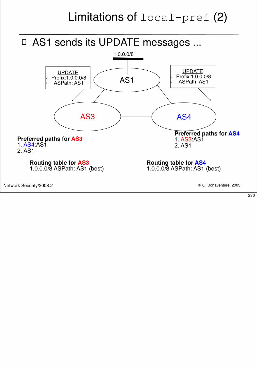
© O. Bonaventure, 2003Network Security/2008.2
Limitations of local-pref (2)
� AS1 sends its UPDATE messages ...
AS1
AS3 AS4
1.0.0.0/8
Preferred paths for AS31. AS4:AS1 2. AS1
UPDATE� Prefix:1.0.0.0/8 � ASPath: AS1
Routing table for AS31.0.0.0/8 ASPath: AS1 (best)
Preferred paths for AS41. AS3:AS12. AS1
UPDATE� Prefix:1.0.0.0/8 � ASPath: AS1
Routing table for AS41.0.0.0/8 ASPath: AS1 (best)
236
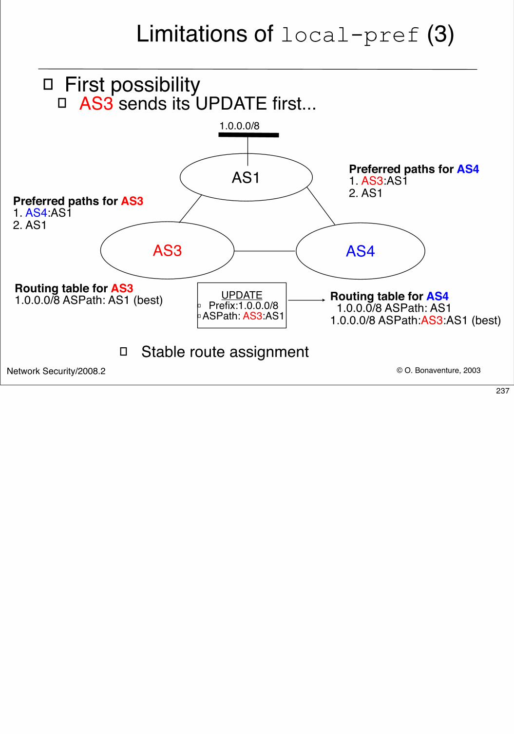
© O. Bonaventure, 2003Network Security/2008.2
Limitations of local-pref (3)
� First possibility� AS3 sends its UPDATE first...
AS1
AS3 AS4
Preferred paths for AS31. AS4:AS1 2. AS1
1.0.0.0/8
Routing table for AS31.0.0.0/8 ASPath: AS1 (best) UPDATE
� Prefix:1.0.0.0/8 � ASPath: AS3:AS1
Preferred paths for AS41. AS3:AS12. AS1
Routing table for AS4 1.0.0.0/8 ASPath: AS1 1.0.0.0/8 ASPath:AS3:AS1 (best)
� Stable route assignment
237
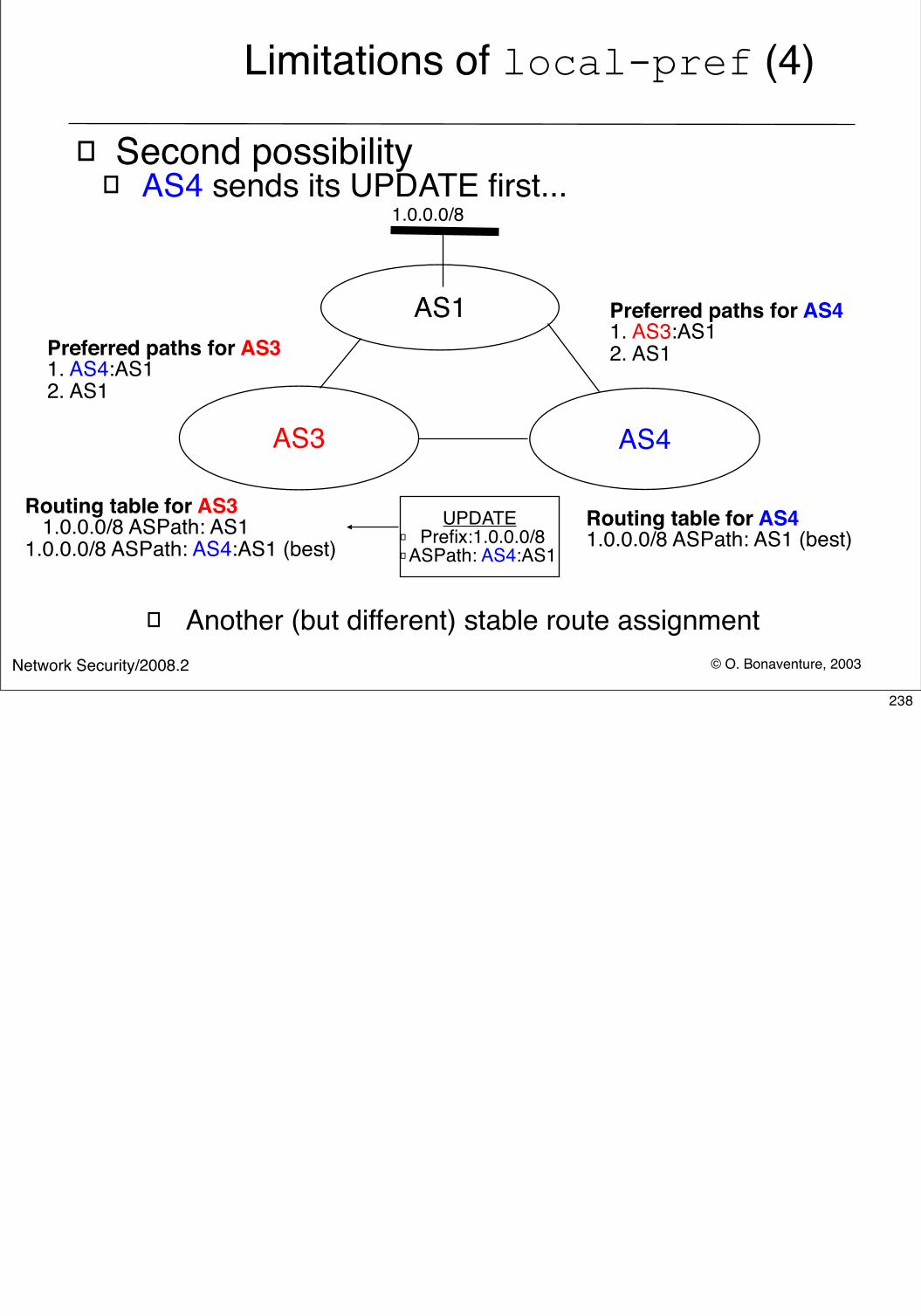
© O. Bonaventure, 2003Network Security/2008.2
Limitations of local-pref (4)
� Second possibility� AS4 sends its UPDATE first...
AS1
AS3 AS4
1.0.0.0/8
Preferred paths for AS41. AS3:AS12. AS1
Routing table for AS41.0.0.0/8 ASPath: AS1 (best)
Preferred paths for AS31. AS4:AS1 2. AS1
UPDATE� Prefix:1.0.0.0/8 � ASPath: AS4:AS1
Routing table for AS3 1.0.0.0/8 ASPath: AS11.0.0.0/8 ASPath: AS4:AS1 (best)
� Another (but different) stable route assignment
238
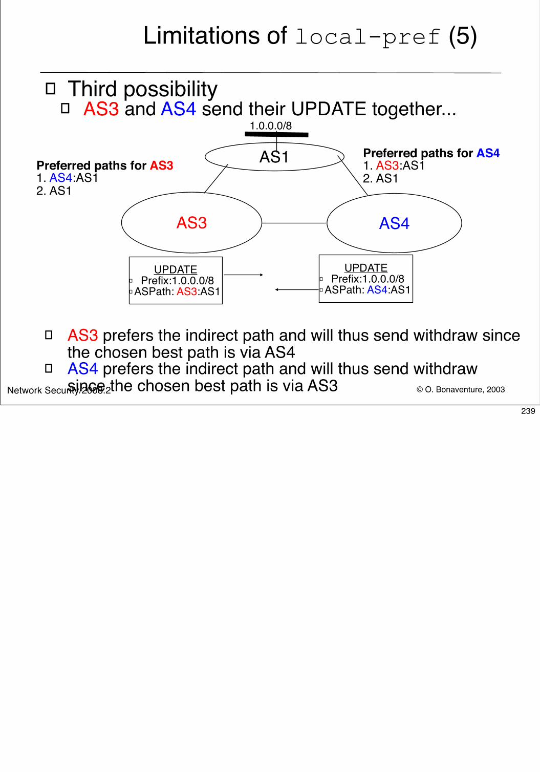
© O. Bonaventure, 2003Network Security/2008.2
Limitations of local-pref (5)
� Third possibility� AS3 and AS4 send their UPDATE together...
AS1
AS3 AS4
Preferred paths for AS31. AS4:AS1 2. AS1
1.0.0.0/8
UPDATE� Prefix:1.0.0.0/8 � ASPath: AS3:AS1
Preferred paths for AS41. AS3:AS12. AS1
UPDATE� Prefix:1.0.0.0/8 � ASPath: AS4:AS1
� AS3 prefers the indirect path and will thus send withdraw since the chosen best path is via AS4
� AS4 prefers the indirect path and will thus send withdrawsince the chosen best path is via AS3
239
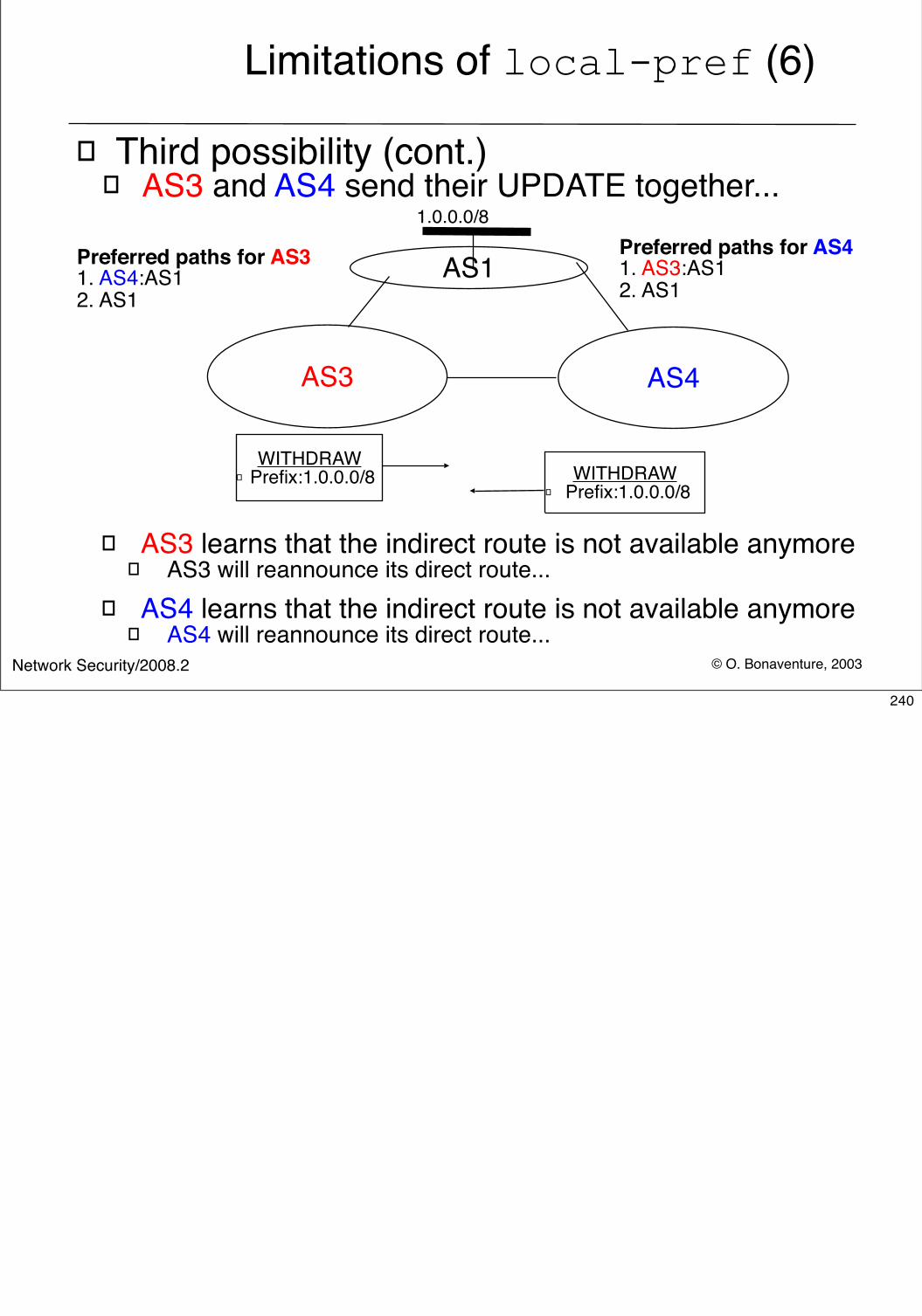
© O. Bonaventure, 2003Network Security/2008.2
Limitations of local-pref (6)
� Third possibility (cont.)� AS3 and AS4 send their UPDATE together...
AS1
AS3 AS4
Preferred paths for AS31. AS4:AS1 2. AS1
1.0.0.0/8Preferred paths for AS41. AS3:AS12. AS1
WITHDRAW� Prefix:1.0.0.0/8
� AS3 learns that the indirect route is not available anymore � AS3 will reannounce its direct route...
WITHDRAW� Prefix:1.0.0.0/8
� AS4 learns that the indirect route is not available anymore � AS4 will reannounce its direct route...
240
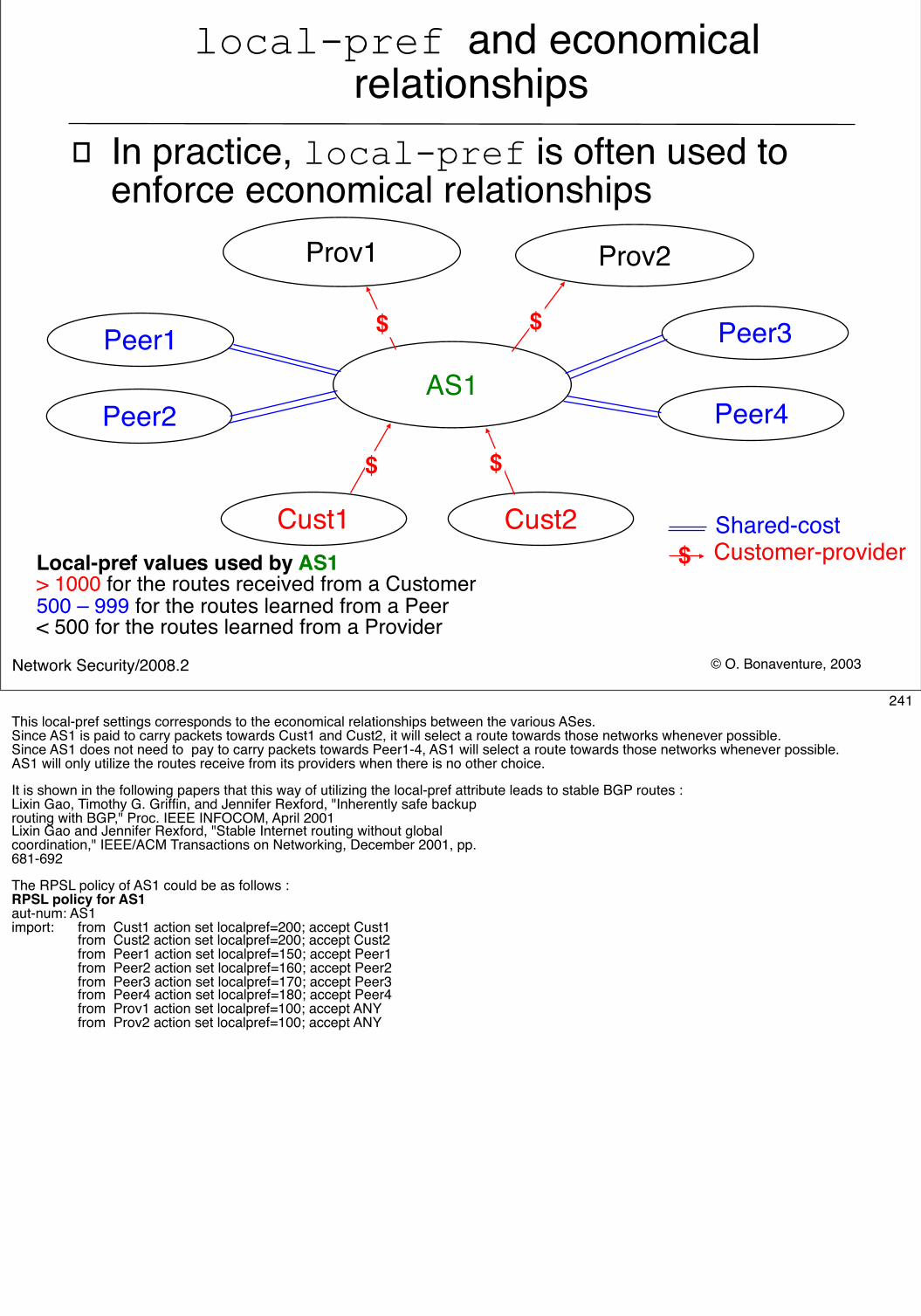
© O. Bonaventure, 2003Network Security/2008.2
local-pref and economical relationships
� In practice, local-pref is often used to enforce economical relationships
AS1
Prov1 Prov2
Peer1
Peer2
Peer3
Peer4
Cust1 Cust2$ Customer-provider
$
Shared-cost
$
$ $
Local-pref values used by AS1> 1000 for the routes received from a Customer500 – 999 for the routes learned from a Peer < 500 for the routes learned from a Provider
241This local-pref settings corresponds to the economical relationships between the various ASes. Since AS1 is paid to carry packets towards Cust1 and Cust2, it will select a route towards those networks whenever possible.Since AS1 does not need to pay to carry packets towards Peer1-4, AS1 will select a route towards those networks whenever possible.AS1 will only utilize the routes receive from its providers when there is no other choice.
It is shown in the following papers that this way of utilizing the local-pref attribute leads to stable BGP routes :Lixin Gao, Timothy G. Griffin, and Jennifer Rexford, "Inherently safe backuprouting with BGP," Proc. IEEE INFOCOM, April 2001 Lixin Gao and Jennifer Rexford, "Stable Internet routing without globalcoordination," IEEE/ACM Transactions on Networking, December 2001, pp.681-692
The RPSL policy of AS1 could be as follows :RPSL policy for AS1aut-num: AS1import: from Cust1 action set localpref=200; accept Cust1 from Cust2 action set localpref=200; accept Cust2 from Peer1 action set localpref=150; accept Peer1 from Peer2 action set localpref=160; accept Peer2 from Peer3 action set localpref=170; accept Peer3 from Peer4 action set localpref=180; accept Peer4 from Prov1 action set localpref=100; accept ANY from Prov2 action set localpref=100; accept ANY
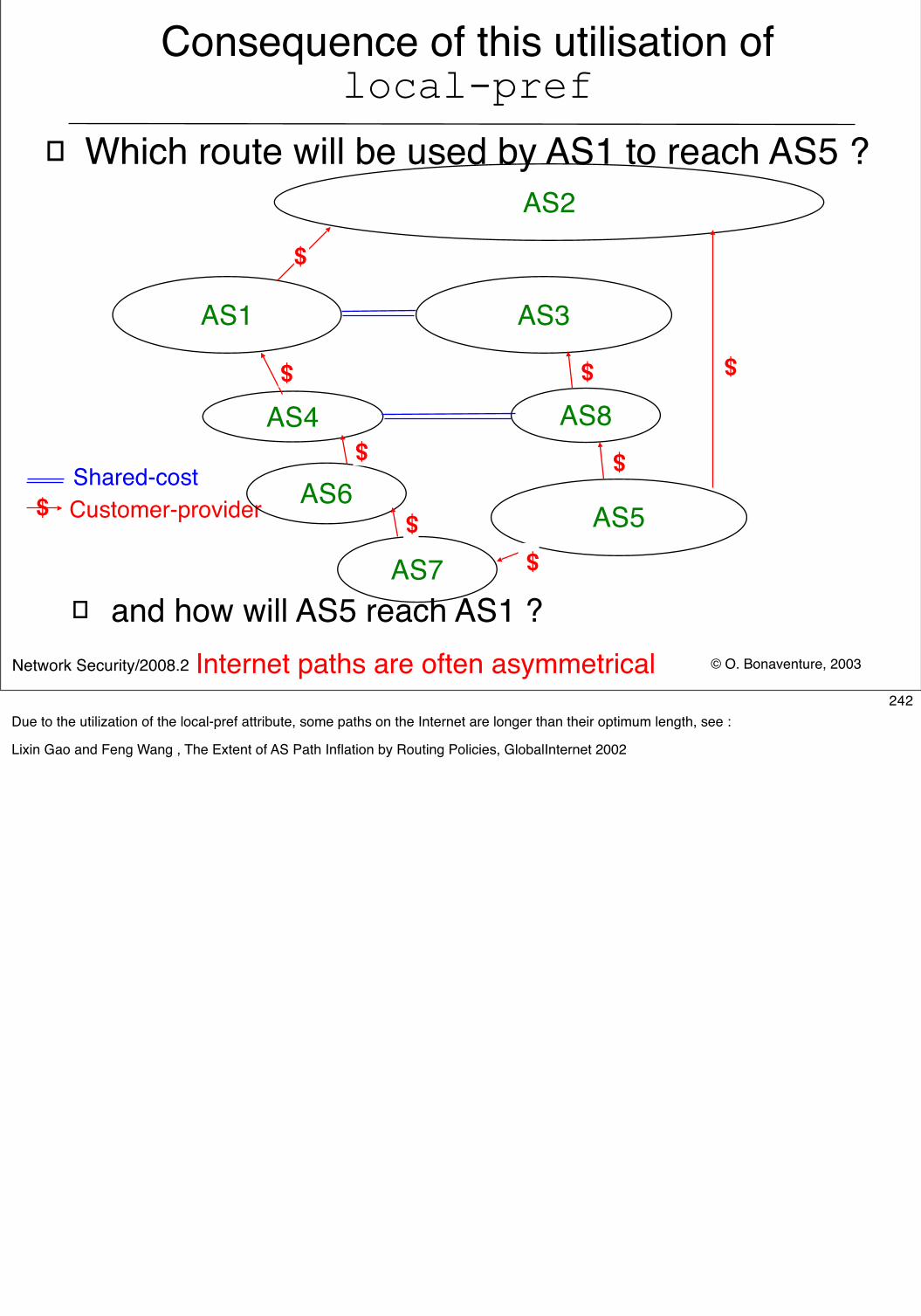
© O. Bonaventure, 2003Network Security/2008.2
Consequence of this utilisation of local-pref
� Which route will be used by AS1 to reach AS5 ?
� and how will AS5 reach AS1 ?
AS1
AS4
AS2
AS3
AS5$ Customer-providerShared-cost
$
$
$
$
$
AS8
$
AS6
AS7
$
$
Internet paths are often asymmetrical242
Due to the utilization of the local-pref attribute, some paths on the Internet are longer than their optimum length, see :
Lixin Gao and Feng Wang , The Extent of AS Path Inflation by Routing Policies, GlobalInternet 2002
© O. Bonaventure, 2008Network Security/2008.2
Security issues with interdomain routing� Major issue
� A BGP router from an AS should only advertise legitimate prefixes
� Unfortunately, BGP does not contain a mechanism to prove that a route is legitimate
� Configuration errors, intentional or not, are common� Possible consequence
� Risk of traffic redirection / MITM� an attacker AS could advertise the prefix of a large bank or e-
commerce site and redirect packets to his own site� Risk of Denial of service through blackholing
� an attacker AS could advertise the prefix and drop all received packets
243For a discussion of BGP security problems, see e.g.
S. Murphy, BGP Security Vulnerabilities Analysis, Internet draft, draft-murphy-bgp-vuln-02.txt, March 2003
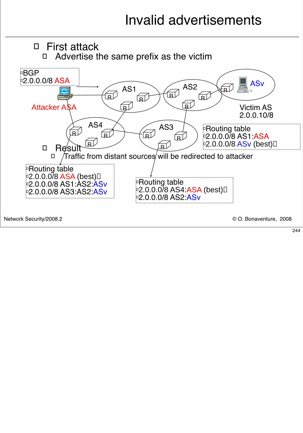
© O. Bonaventure, 2008Network Security/2008.2
Invalid advertisements� First attack
� Advertise the same prefix as the victim
� Result � Traffic from distant sources will be redirected to attacker
R
Victim AS2.0.0.10/8
RR
R
RR
R
RR
R
RR
R
AS1 AS2 ASv
AS3AS4
� Routing table� 2.0.0.0/8 ASA (best)� 2.0.0.0/8 AS1:AS2:ASv� 2.0.0.0/8 AS3:AS2:ASv
Attacker ASA
� BGP� 2.0.0.0/8 ASA
� Routing table� 2.0.0.0/8 AS4:ASA (best)� 2.0.0.0/8 AS2:ASv
� Routing table� 2.0.0.0/8 AS1:ASA � 2.0.0.0/8 ASv (best)
244
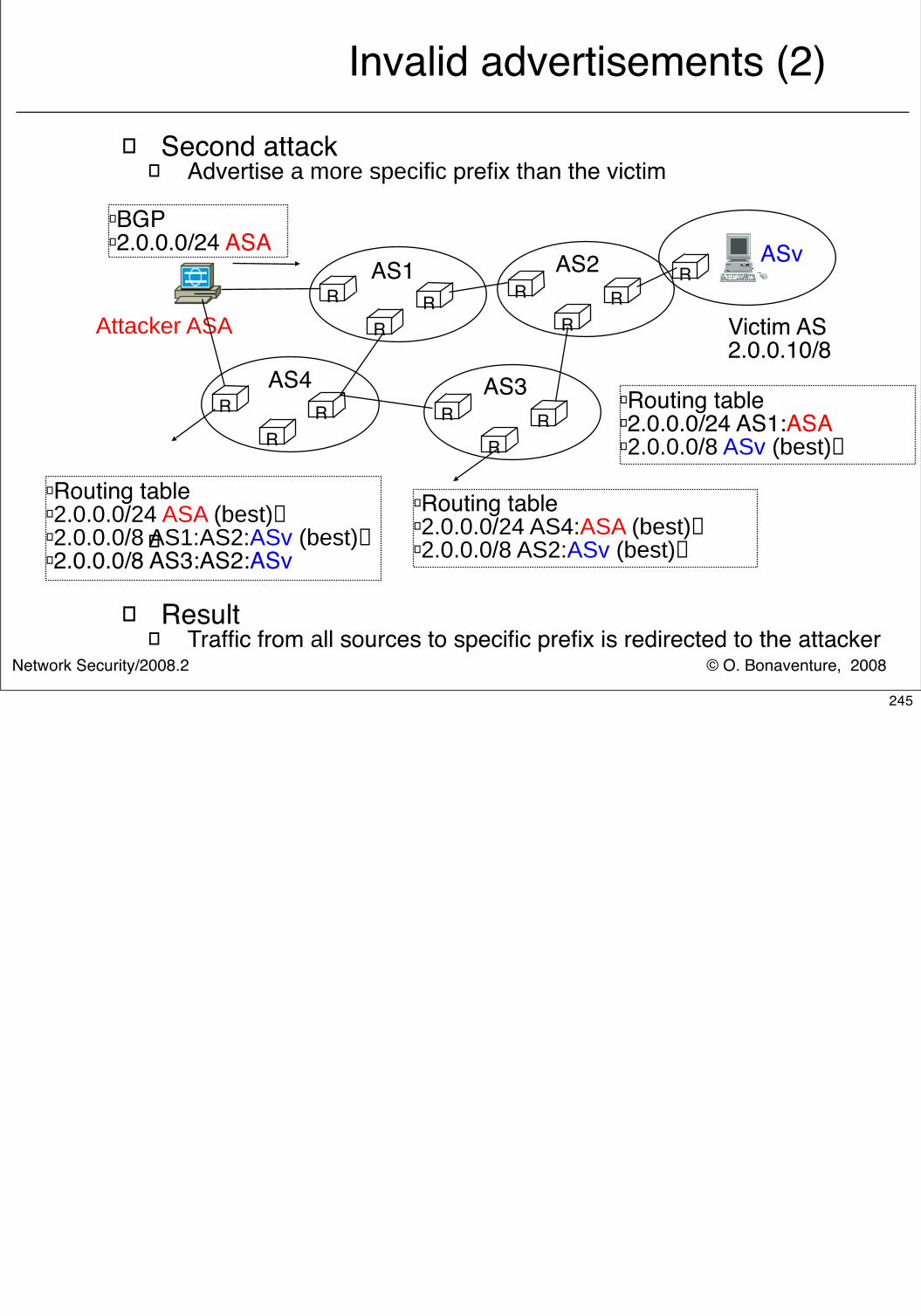
© O. Bonaventure, 2008Network Security/2008.2
Invalid advertisements (2)
� Second attack� Advertise a more specific prefix than the victim
�
� Result � Traffic from all sources to specific prefix is redirected to the attacker
R
Victim AS2.0.0.10/8
RR
R
RR
R
RR
R
RR
R
AS1 AS2 ASv
AS3AS4
� Routing table� 2.0.0.0/24 ASA (best)� 2.0.0.0/8 AS1:AS2:ASv (best)� 2.0.0.0/8 AS3:AS2:ASv
Attacker ASA
� BGP� 2.0.0.0/24 ASA
� Routing table� 2.0.0.0/24 AS4:ASA (best)� 2.0.0.0/8 AS2:ASv (best)
� Routing table� 2.0.0.0/24 AS1:ASA � 2.0.0.0/8 ASv (best)
245
© O. Bonaventure, 2008Network Security/2008.2
Security issues with interdomain routing (2)
� Problem� Any BGP router can change the content of a received
BGP UPDATE� Add its own AS number in the AS-Path� Add/change BGP communities, local-pref, ...
� Possible attack� Remove some ASes from received AS-Path
� AS-Path is used to select the best route, thus received route has better chance of being selected
� AS-Path is also used to detect routing loops, removing an AS number may cause interdomain loops
� Possible consequence� By manipulating received UPDATE messages, a BGP router
could attract packets for more destinations
246
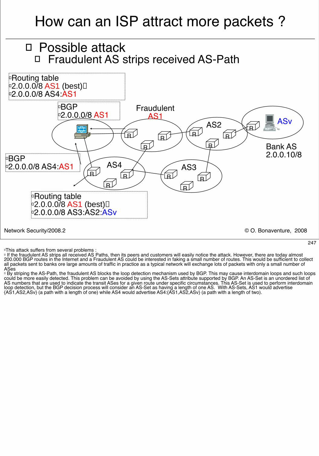
© O. Bonaventure, 2008Network Security/2008.2
How can an ISP attract more packets ?� Possible attack
� Fraudulent AS strips received AS-Path
R
Bank AS2.0.0.10/8
RR
R
RR
R
RR
R
RR
R
FraudulentAS1
AS2 ASv
AS3AS4
� Routing table� 2.0.0.0/8 AS1 (best)� 2.0.0.0/8 AS3:AS2:ASv
� BGP� 2.0.0.0/8 AS1
� BGP� 2.0.0.0/8 AS4:AS1
� Routing table� 2.0.0.0/8 AS1 (best)� 2.0.0.0/8 AS4:AS1
247� This attack suffers from several problems :� If the fraudulent AS strips all received AS Paths, then its peers and customers will easily notice the attack. However, there are today almost 200.000 BGP routes in the Internet and a Fraudulent AS could be interested in faking a small number of routes. This would be sufficient to collect all packets sent to banks ore large amounts of traffic in practice as a typical network will exchange lots of packets with only a small number of ASes� By striping the AS-Path, the fraudulent AS blocks the loop detection mechanism used by BGP. This may cause interdomain loops and such loops could be more easily detected. This problem can be avoided by using the AS-Sets attribute supported by BGP. An AS-Set is an unordered list of AS numbers that are used to indicate the transit ASes for a given route under specific circumstances. This AS-Set is used to perform interdomain loop detection, but the BGP decision process will consider an AS-Set as having a length of one AS. With AS-Sets, AS1 would advertise {AS1,AS2,ASv} (a path with a length of one) while AS4 would advertise AS4:{AS1,AS2,ASv} (a path with a length of two).
© O. Bonaventure, 2008Network Security/2008.2
Security issues with interdomain routing (3)
� Problem� A BGP session runs over a TCP connection
� TCP connection between the two routers on port 179� A BGP session is considered as closed and all
routes are withdrawn when TCP connection fails
� Security risks� If an attacker can inject valid BGP messages on
an existing session, he could inject routes on the entire Internet
� If an attacker could force a TCP connection to fail, he could cause large disruptions
248
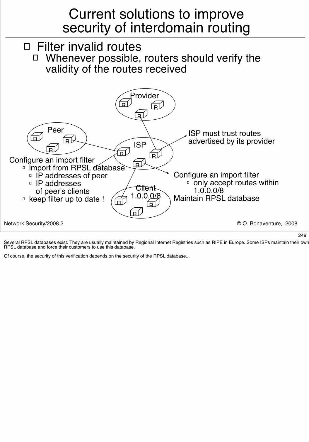
© O. Bonaventure, 2008Network Security/2008.2
Current solutions to improve security of interdomain routing
� Filter invalid routes� Whenever possible, routers should verify the
validity of the routes received
RR
RISP
RR
RProvider
RR
RPeer
RR
R
Client1.0.0.0/8
Configure an import filter� only accept routes within
1.0.0.0/8Maintain RPSL database
Configure an import filter� import from RPSL database
� IP addresses of peer� IP addresses
of peer's clients� keep filter up to date !
ISP must trust routes advertised by its provider
249Several RPSL databases exist. They are usually maintained by Regional Internet Registries such as RIPE in Europe. Some ISPs maintain their own RPSL database and force their customers to use this database.
Of course, the security of this verification depends on the security of the RPSL database...
© O. Bonaventure, 2008Network Security/2008.2
� Monitoring� Collect the advertisements for important prefixes
received by distant ASes� Verify that the origin AS is always correct
� Existing BGP monitors� Routeviews� RIPE RIS, myAS
� Limitations� Monitoring allows to detect problems, but solving
them usually require cooperation between ISPs
Current solutions to improve security of interdomain routing (2)
250Routeviews is a service maintained by the University of Oregon. It is composed of several BGP routers that receive the BGP routes advertised by a few tens of ISPs mainly located in the USA. Routeviews provides realtime access to the collected data as well as large archives :
http://www.routeviews.org
The Routing Information Service from RIPE is another service that collects BGP routes advertised by multiple ISPs, mainly inside Europe. RIPE has installed one route collector on many large Internet Exchange Points and collects all the BGP messages advertised by the ISPs attached to this IXP. RIPE also provides a service to ISPs where they can be informed immediately by SMS or email when one of their prefixes appears to be originated by another AS based on the BGP messages collected at the various collector.
http://www.ripe.net
© O. Bonaventure, 2008Network Security/2008.2
� Protection of the TCP connections� MD5 option
� each BGP peer is configured with a password� each TCP segment contains a keyed MD5 hash
� iBGP sessions� configure iBGP sessions between loopback addresses
inside same IP prefix� install packet filters on border routers to drop packets
sent to/from this prefix
� eBGP sessions� send TCP segments inside IP packets with TTL=255� only accept TCP segments received from valid IP address and
with TTL=255
Current solutions to improve security of interdomain routing (3)
251The TCP-MD5 option used to protect BGP sessions is described in :
A. Heffernan, Protection of BGP Sessions via the TCP MD5 Signature Option. . August 1998. RFC2385
The TTL Security Hack is described in :
V. Gill, J. Heasley, D. Meyer. , The Generalized TTL Security Mechanism (GTSM). February 2004. RFC3682
© O. Bonaventure, 2008Network Security/2008.2
BGP security extensions� Several extensions are being developed to
secure BGP, but they are not deployed� S-BGP
� assumes that two PKIs will be deployed to� First PKI is used to certify allocation of IP addresses � Second PKI is used to certify that AS numbers belong to
organisations and also for routers� allows ASes to sign the AS-Path that they announce
� main concern is the CPU cost
� SoBGP� A simpler and more pragmatic approach
� A PKI and certificates are used to prove prefix ownership� A database of inter-AS relations is built and used to validate the
received AS-Paths
� SIDR working group is developing certificates to prove owernship of addresses
252S-BGP is described in several papers, including :
S. Kent, C. Lynn, K. Seo, Secure Border Gateway Protocol (S-BGP), IEEE Journal on Selected Areas in Communications, Vol 18, N4, 2000
SoBGP is being developed within IETF. A tutorial description of SoBGP may be found in :
R. White, Securing BGP through secure origin BGP,Internet Protocol Journal Sept. 2003