network traffic amera • user manual - hikvision
TRANSCRIPT
Network Traffic Camera • User Manual
Network Traffic Camera
User Manual
Network Traffic Camera • User Manual
1
© 2019 Hangzhou Hikvision Digital Technology Co., Ltd. All rights reserved.
This Manual is the property of Hangzhou Hikvision Digital Technology Co., Ltd. or its affiliates (hereinafter referred to as
“Hikvision”), and it cannot be reproduced, changed, translated, or distributed, partially or wholly, by any means, without
the prior written permission of Hikvision. Unless otherwise expressly stated herein, Hikvision does not make any
warranties, guarantees or representations, express or implied, regarding to the Manual, any information contained
herein.
About this Manual
The Manual includes instructions for using and managing the Product. Pictures, charts, images and all other information
hereinafter are for description and explanation only. The information contained in the Manual is subject to change,
without notice, due to firmware updates or other reasons. Please find the latest version of this Manual at the Hikvision
website (https://www.hikvision.com/en/).
Please use this Manual with the guidance and assistance of professionals trained in supporting the Product.
Trademarks Acknowledgement
and other Hikvision’s trademarks and logos are the properties of Hikvision in various jurisdictions.
Other trademarks and logos mentioned are the properties of their respective owners.
LEGAL DISCLAIMER
TO THE MAXIMUM EXTENT PERMITTED BY APPLICABLE LAW, THIS MANUAL AND THE PRODUCT DESCRIBED, WITH
ITS HARDWARE, SOFTWARE AND FIRMWARE, ARE PROVIDED “AS IS” AND “WITH ALL FAULTS AND ERRORS”.
HIKVISION MAKES NO WARRANTIES, EXPRESS OR IMPLIED, INCLUDING WITHOUT LIMITATION, MERCHANTABILITY,
SATISFACTORY QUALITY, OR FITNESS FOR A PARTICULAR PURPOSE. THE USE OF THE PRODUCT BY YOU IS AT YOUR
OWN RISK. IN NO EVENT WILL HIKVISION BE LIABLE TO YOU FOR ANY SPECIAL, CONSEQUENTIAL, INCIDENTAL, OR
INDIRECT DAMAGES, INCLUDING, AMONG OTHERS, DAMAGES FOR LOSS OF BUSINESS PROFITS, BUSINESS
INTERRUPTION, OR LOSS OF DATA, CORRUPTION OF SYSTEMS, OR LOSS OF DOCUMENTATION, WHETHER BASED
ON BREACH OF CONTRACT, TORT (INCLUDING NEGLIGENCE), PRODUCT LIABILITY, OR OTHERWISE, IN
CONNECTION WITH THE USE OF THE PRODUCT, EVEN IF HIKVISION HAS BEEN ADVISED OF THE POSSIBILITY OF
SUCH DAMAGES OR LOSS.
YOU ACKNOWLEDGE THAT THE NATURE OF INTERNET PROVIDES FOR INHERENT SECURITY RISKS, AND HIKVISION
SHALL NOT TAKE ANY RESPONSIBILITIES FOR ABNORMAL OPERATION, PRIVACY LEAKAGE OR OTHER DAMAGES
RESULTING FROM CYBER-ATTACK, HACKER ATTACK, VIRUS INSPECTION, OR OTHER INTERNET SECURITY RISKS;
HOWEVER, HIKVISION WILL PROVIDE TIMELY TECHNICAL SUPPORT IF REQUIRED.
YOU AGREE TO USE THIS PRODUCT IN COMPLIANCE WITH ALL APPLICABLE LAWS, AND YOU ARE SOLELY
RESPONSIBLE FOR ENSURING THAT YOUR USE CONFORMS TO THE APPLICABLE LAW. ESPECIALLY, YOU ARE
RESPONSIBLE, FOR USING THIS PRODUCT IN A MANNER THAT DOES NOT INFRINGE ON THE RIGHTS OF THIRD
PARTIES, INCLUDING WITHOUT LIMITATION, RIGHTS OF PUBLICITY, INTELLECTUAL PROPERTY RIGHTS, OR DATA
PROTECTION AND OTHER PRIVACY RIGHTS. YOU SHALL NOT USE THIS PRODUCT FOR ANY PROHIBITED END-USES,
INCLUDING THE DEVELOPMENT OR PRODUCTION OF WEAPONS OF MASS DESTRUCTION, THE DEVELOPMENT OR
PRODUCTION OF CHEMICAL OR BIOLOGICAL WEAPONS, ANY ACTIVITIES IN THE CONTEXT RELATED TO ANY
NUCLEAR EXPLOSIVE OR UNSAFE NUCLEAR FUEL-CYCLE, OR IN SUPPORT OF HUMAN RIGHTS ABUSES.
IN THE EVENT OF ANY CONFLICTS BETWEEN THIS MANUAL AND THE APPLICABLE LAW, THE LATER PREVAILS.
Network Traffic Camera • User Manual
2
Regulatory Information
FCC Information
Please take attention that changes or modification not expressly approved by the party responsible
for compliance could void the user’s authority to operate the equipment.
FCC compliance: This equipment has been tested and found to comply with the limits for a Class A
digital device, pursuant to part 15 of the FCC Rules. These limits are designed to provide reasonable
protection against harmful interference when the equipment is operated in a commercial
environment. This equipment generates, uses, and can radiate radio frequency energy and, if not
installed and used in accordance with the instruction manual, may cause harmful interference to
radio communications. Operation of this equipment in a residential area is likely to cause harmful
interference in which case the user will be required to correct the interference at his own expense.
FCC Conditions
This device complies with part 15 of the FCC Rules. Operation is subject to the following two
conditions:
1. This device may not cause harmful interference.
2. This device must accept any interference received, including interference that may cause
undesired operation.
EU Conformity Statement
This product and - if applicable - the supplied accessories too are marked with "CE" and
comply therefore with the applicable harmonized European standards listed under the
EMC Directive 2014/30/EU, the LVD Directive 2014/35/EU, the RoHS Directive 2011/65/EU.
2012/19/EU (WEEE directive): Products marked with this symbol cannot be disposed of as
unsorted municipal waste in the European Union. For proper recycling, return this product
to your local supplier upon the purchase of equivalent new equipment, or dispose of it at
designated collection points. For more information see: www.recyclethis.info
2006/66/EC (battery directive): This product contains a battery that cannot be disposed
of as unsorted municipal waste in the European Union. See the product documentation
for specific battery information. The battery is marked with this symbol, which may include
lettering to indicate cadmium (Cd), lead (Pb), or mercury (Hg). For proper recycling, return the
battery to your supplier or to a designated collection point. For more information see:
www.recyclethis.info
Industry Canada ICES-003 Compliance
This device meets the CAN ICES-3 (A)/NMB-3(A) standards requirements.
Network Traffic Camera • User Manual
3
Applicable Models
This manual is applicable to the models listed in the following table.
Model
iDS-2CD9136-AIS
iDS-2CD9396-AIS
iDS-2CD9136-AS
iDS-2CD9396-AS
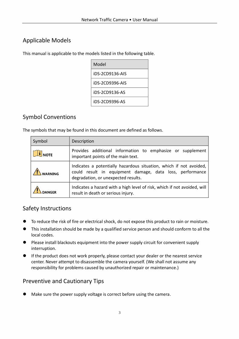
Symbol Conventions
The symbols that may be found in this document are defined as follows.
Safety Instructions
To reduce the risk of fire or electrical shock, do not expose this product to rain or moisture.
This installation should be made by a qualified service person and should conform to all the local codes.
Please install blackouts equipment into the power supply circuit for convenient supply interruption.
If the product does not work properly, please contact your dealer or the nearest service center. Never attempt to disassemble the camera yourself. (We shall not assume any responsibility for problems caused by unauthorized repair or maintenance.)
Preventive and Cautionary Tips
Make sure the power supply voltage is correct before using the camera.
Symbol Description
Provides additional information to emphasize or supplement important points of the main text.
Indicates a potentially hazardous situation, which if not avoided, could result in equipment damage, data loss, performance degradation, or unexpected results.
Indicates a hazard with a high level of risk, which if not avoided, will result in death or serious injury.

Network Traffic Camera • User Manual
4
Do not drop the camera or subject it to physical shock.
Do not touch sensor modules with fingers. If cleaning is necessary, use a clean cloth with a bit of ethanol and wipe it gently. If the camera will not be used for an extended period of time, put on the lens cap to protect the sensor from dirt.
Do not aim the camera lens at the strong light such as sun or incandescent lamp. The strong light can cause fatal damage to the camera.
The sensor may be burned out by a laser beam, so when any laser equipment is being used, make sure that the surface of the sensor not be exposed to the laser beam.
Do not place the camera in extremely hot, cold temperatures, dusty or damp environment, and do not expose it to high electromagnetic radiation.
To avoid heat accumulation, good ventilation is required for a proper operating environment.
Keep the camera away from water and any liquid.
While shipping, the camera should be packed in its original packing.
Network Traffic Camera • User Manual
5
TABLE OF CONTENTS Chapter 1 Network Connection ...................................................................................................... 7
Wiring over the LAN ............................................................................................................ 7
Activate the Camera ............................................................................................................ 8
Activation via Web Browser ........................................................................................ 8
Activation via SADP Software ...................................................................................... 9
Chapter 2 Login............................................................................................................................. 11
Chapter 3 Live View ...................................................................................................................... 12
Live View Page ................................................................................................................... 12
Start Live View ................................................................................................................... 13
Record and Capture Pictures Manually .............................................................................. 13
View Live Status and Traffic Statistics ................................................................................. 13
Scene Shot Area ........................................................................................................ 14
Traffic Light Status ..................................................................................................... 16
Traffic Statistics ......................................................................................................... 16
Chapter 4 Picture Search .............................................................................................................. 17
Chapter 5 Local Configuration ...................................................................................................... 18
Chapter 6 System Configuration ................................................................................................. 20
View Device Information ................................................................................................... 20
Configure Installation Parameters ...................................................................................... 21
Configure Serial Ports ........................................................................................................ 22
Configure Network Parameters .......................................................................................... 23
Configure Port ................................................................................................................... 25
Configure HTTPS ................................................................................................................ 25
Configure Time .................................................................................................................. 27
Enable User Lock ............................................................................................................... 29
Chapter 7 Encoding and Storage Configuration ............................................................................ 30
Configure Video Encoding .................................................................................................. 30
Configure Image Encoding ................................................................................................. 32
Configure ROI .................................................................................................................... 32
Configure Record Schedule ................................................................................................ 34
Configure Storage Management ........................................................................................ 35
Configure FTP .................................................................................................................... 36
Chapter 8 Text Overlay Configuration ........................................................................................... 40
Configure Capture Picture Overlay ..................................................................................... 40
Configure OSD Settings ...................................................................................................... 43
Configure Composite Picture Overlay ................................................................................ 44
Chapter 9 Capture Parameters Configuration ............................................................................... 45
Configure License Plate Parameters ................................................................................... 45
Configure Flash Light Parameters ....................................................................................... 45
Configure Traffic Light Synchronization .............................................................................. 48
Configure Image Composition ............................................................................................ 49
Network Traffic Camera • User Manual
6
Configure Vehicle Feature .................................................................................................. 51
Chapter 10 Image Parameters Configuration ................................................................................ 54
Configure Dual-Shutter Parameters ................................................................................. 54
Configure General Parameters ......................................................................................... 55
Configure Video Image .................................................................................................... 56
Configure Record ............................................................................................................. 57
Configure ICR ................................................................................................................... 58
Configure Light Calibration .............................................................................................. 59
Chapter 11 Application Mode Configuration ................................................................................ 61
Mixed-traffic Lane ............................................................................................................ 61
Configure Video Analysis Capture ........................................................................... 61
Configure Mixed-Traffic Lane................................................................................... 62
Video Analysis E-Police .................................................................................................... 64
Configure Video Analysis Capture ........................................................................... 65
Configure Lane Parameters and Trigger Rules ........................................................ 66
Configure Traffic Light ............................................................................................. 68
External Input .................................................................................................................. 71
Checkpoint Vehicle Detector ............................................................................................ 73
RS-485 Radar ................................................................................................................... 76
Chapter 12 Exception.................................................................................................................... 81
Chapter 13 Maintenance .............................................................................................................. 83
Device Status ................................................................................................................... 83
User Management ........................................................................................................... 83
Add a User .............................................................................................................. 84
Modify a User ......................................................................................................... 85
Delete a User .......................................................................................................... 86
Log Search ....................................................................................................................... 86
Reboot the Camera .......................................................................................................... 87
Restore Default Settings................................................................................................... 87
Export Debug File ............................................................................................................ 88
Export Configuration File ................................................................................................. 88
Import the Configuration File ........................................................................................... 88
Upgrade the System......................................................................................................... 89
Network Traffic Camera • User Manual
7
Chapter 1 Network Connection
You shall acknowledge that the use of the product with Internet access might be under
network security risks. For avoidance of any network attacks and information leakage,
please strengthen your own protection. If the product does not work properly, please
contact with your dealer or the nearest service center.
To ensure the network security of the camera, we recommend you to have the camera
assessed and maintained termly. You can contact us if you need such service.
Purpose:
To view and configure the camera via a LAN, you need to connect the camera in the same subnet with your computer, and install the SADP to search and change the IP address of the camera.
Wiring over the LAN
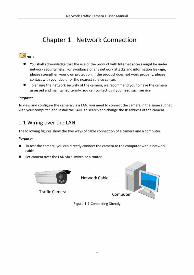
The following figures show the two ways of cable connection of a camera and a computer.
Purpose:
To test the camera, you can directly connect the camera to the computer with a network cable.
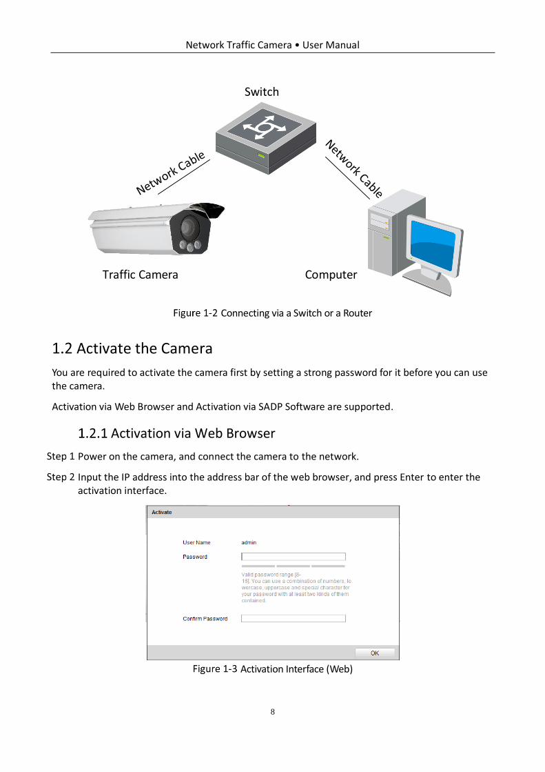
Set camera over the LAN via a switch or a router.
Network Cable
ComputerTraffic Camera
Connecting Directly
Network Traffic Camera • User Manual
8
Switch
ComputerTraffic Camera
Connecting via a Switch or a Router
Activate the Camera
You are required to activate the camera first by setting a strong password for it before you can use the camera.
Activation via Web Browser and Activation via SADP Software are supported.
Activation via Web Browser
Power on the camera, and connect the camera to the network.
Input the IP address into the address bar of the web browser, and press Enter to enter the activation interface.
Activation Interface (Web)
Network Traffic Camera • User Manual
9
Create a password and input the password into the password field.
STRONG PASSWORD RECOMMENDED– We highly recommend you create a strong password of your own choosing (using a minimum of 8 characters, including upper case letters, lower case letters, numbers, and special characters) in order to increase the security of your product. And we recommend you reset your password regularly, especially in the high security system, resetting the password monthly or weekly can better protect your product.
Confirm the password.
Click OK to save the password and enter the live view interface.
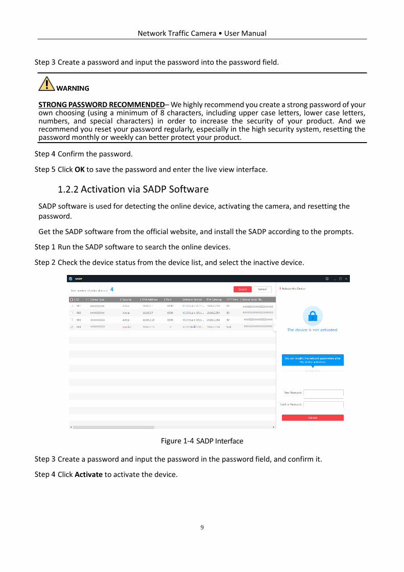
Activation via SADP Software
SADP software is used for detecting the online device, activating the camera, and resetting the password.
Get the SADP software from the official website, and install the SADP according to the prompts.
Run the SADP software to search the online devices.
Check the device status from the device list, and select the inactive device.
SADP Interface
Create a password and input the password in the password field, and confirm it.
Click Activate to activate the device.

Network Traffic Camera • User Manual
10
STRONG PASSWORD RECOMMENDED– We highly recommend you create a strong password of your own choosing (using a minimum of 8 characters, including upper case letters, lower case letters, numbers, and special characters) in order to increase the security of your product. And we recommend you reset your password regularly, especially in the high security system, resetting the password monthly or weekly can better protect your product.
Change the device IP address to the same subnet with your computer by either modifying the IP address manually.
Create Password
Input the password and click Modify to activate your IP address modification.

Network Traffic Camera • User Manual
11
Chapter 2 Login
Open the web browser.
In the browser address bar, input the IP address of the camera, and press the Enter key to enter the login interface.
Input User Name and Password.
Click Login.
Login
Install the plug-in before viewing the live video and operating the camera. Follow the installation prompts to install the plug-in.
You may have to close the web browser to install the plug-in. Please reopen the web browser and
log in again after installing the plug-in.
Network Traffic Camera • User Manual
12
Chapter 3 Live View
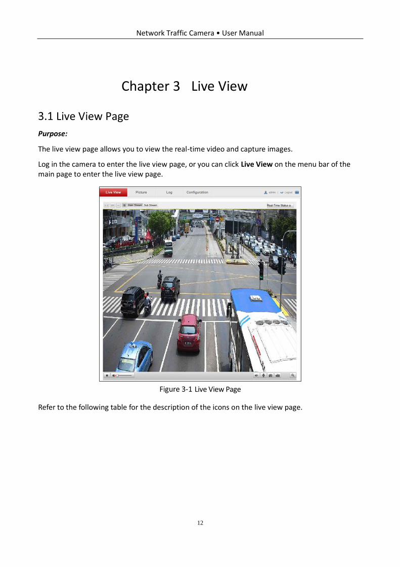
Live View Page
Purpose:
The live view page allows you to view the real-time video and capture images.
Log in the camera to enter the live view page, or you can click Live View on the menu bar of the main page to enter the live view page.
Live View Page
Refer to the following table for the description of the icons on the live view page.
Network Traffic Camera • User Manual
13
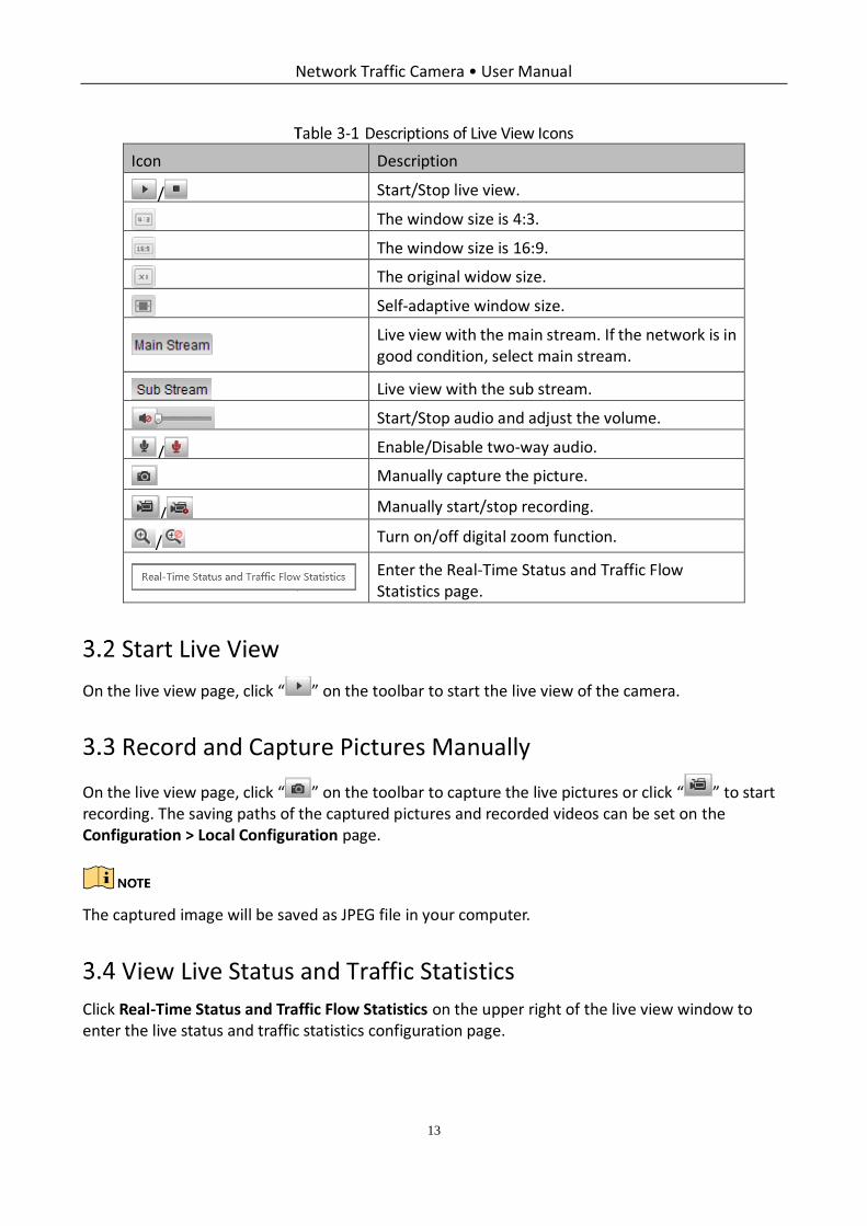
Descriptions of Live View Icons
Icon Description
/ Start/Stop live view.
The window size is 4:3.
The window size is 16:9.
The original widow size.
Self-adaptive window size.
Live view with the main stream. If the network is in good condition, select main stream.
Live view with the sub stream.
Start/Stop audio and adjust the volume.
/ Enable/Disable two-way audio.
Manually capture the picture.
/ Manually start/stop recording.
/ Turn on/off digital zoom function.
Enter the Real-Time Status and Traffic Flow Statistics page.
Start Live View
On the live view page, click “ ” on the toolbar to start the live view of the camera.
Record and Capture Pictures Manually
On the live view page, click “ ” on the toolbar to capture the live pictures or click “ ” to start recording. The saving paths of the captured pictures and recorded videos can be set on the Configuration > Local Configuration page.
The captured image will be saved as JPEG file in your computer.
View Live Status and Traffic Statistics
Click Real-Time Status and Traffic Flow Statistics on the upper right of the live view window to enter the live status and traffic statistics configuration page.
Network Traffic Camera • User Manual
14
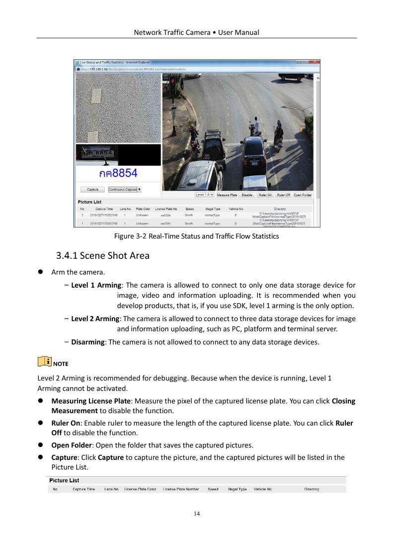
Real-Time Status and Traffic Flow Statistics
Scene Shot Area
Arm the camera.
− Level 1 Arming: The camera is allowed to connect to only one data storage device for
image, video and information uploading. It is recommended when you
develop products, that is, if you use SDK, level 1 arming is the only option.
− Level 2 Arming: The camera is allowed to connect to three data storage devices for image
and information uploading, such as PC, platform and terminal server.
− Disarming: The camera is not allowed to connect to any data storage devices.
Level 2 Arming is recommended for debugging. Because when the device is running, Level 1
Arming cannot be activated.
Measuring License Plate: Measure the pixel of the captured license plate. You can click Closing Measurement to disable the function.
Ruler On: Enable ruler to measure the length of the captured license plate. You can click Ruler Off to disable the function.
Open Folder: Open the folder that saves the captured pictures.
Capture: Click Capture to capture the picture, and the captured pictures will be listed in the Picture List.
Network Traffic Camera • User Manual
15
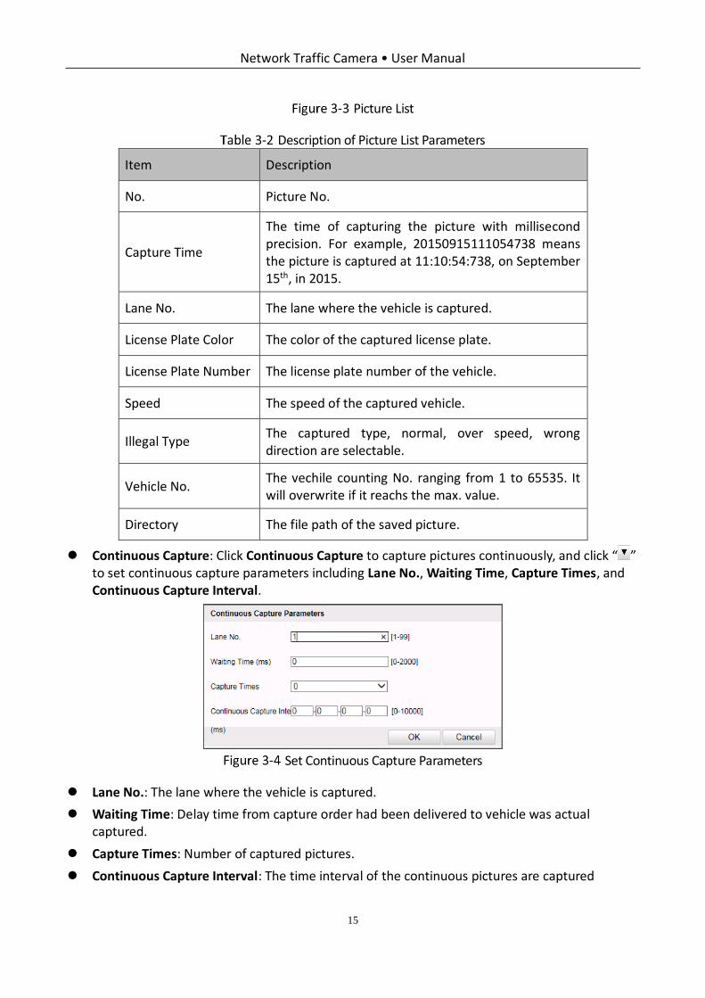
Picture List
Description of Picture List Parameters
Item Description
No. Picture No.
Capture Time
The time of capturing the picture with millisecond precision. For example, 20150915111054738 means the picture is captured at 11:10:54:738, on September 15th, in 2015.
Lane No. The lane where the vehicle is captured.
License Plate Color The color of the captured license plate.
License Plate Number The license plate number of the vehicle.
Speed The speed of the captured vehicle.
Illegal Type The captured type, normal, over speed, wrong direction are selectable.
Vehicle No. The vechile counting No. ranging from 1 to 65535. It will overwrite if it reachs the max. value.
Directory The file path of the saved picture.
Continuous Capture: Click Continuous Capture to capture pictures continuously, and click “ ” to set continuous capture parameters including Lane No., Waiting Time, Capture Times, and Continuous Capture Interval.
Set Continuous Capture Parameters
Lane No.: The lane where the vehicle is captured.
Waiting Time: Delay time from capture order had been delivered to vehicle was actual captured.
Capture Times: Number of captured pictures.
Continuous Capture Interval: The time interval of the continuous pictures are captured
Network Traffic Camera • User Manual
16
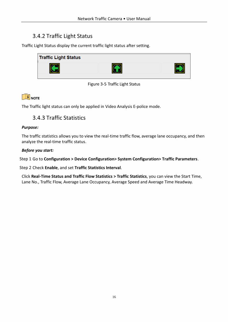
Traffic Light Status
Traffic Light Status display the current traffic light status after setting.
Traffic Light Status
The Traffic light status can only be applied in Video Analysis E-police mode.
Traffic Statistics
Purpose:
The traffic statistics allows you to view the real-time traffic flow, average lane occupancy, and then analyze the real-time traffic status.
Before you start:
Go to Configuration > Device Configuration> System Configuration> Traffic Parameters.
Check Enable, and set Traffic Statistics Interval.
Click Real-Time Status and Traffic Flow Statistics > Traffic Statistics, you can view the Start Time, Lane No., Traffic Flow, Average Lane Occupancy, Average Speed and Average Time Headway.
Network Traffic Camera • User Manual
17
Chapter 4 Picture Search
Purpose:
The captured picture of all types, including normal, overspeed, wrong-way driving, etc., can be searched from this page. You can also export the pictures to the PC local directory.
Before you start:
Please insert a TF card with up to 128 GB storage in the camera for picture storage. Picture cannot be searched if there is no TF card.
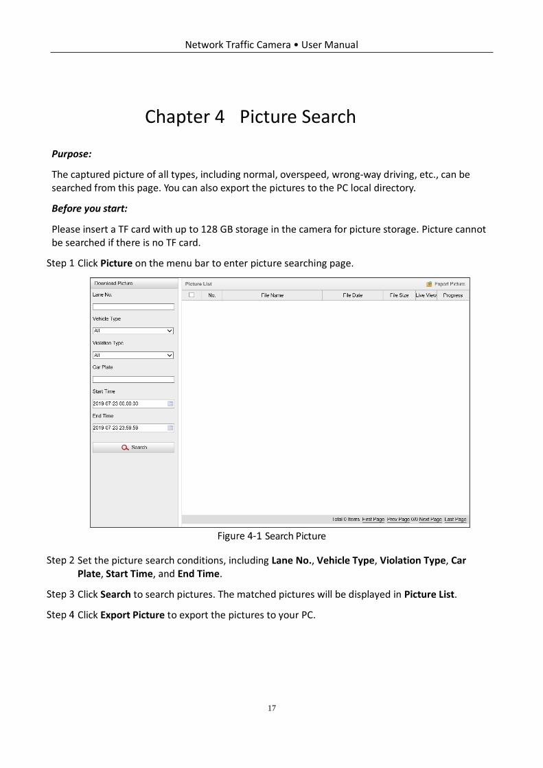
Click Picture on the menu bar to enter picture searching page.
Search Picture
Set the picture search conditions, including Lane No., Vehicle Type, Violation Type, Car Plate, Start Time, and End Time.
Click Search to search pictures. The matched pictures will be displayed in Picture List.
Click Export Picture to export the pictures to your PC.
Network Traffic Camera • User Manual
18
Chapter 5 Local Configuration
Purpose:
The local configuration refers to the parameters of the live view, record files and captured pictures. The record files and captured pictures are the ones you record and capture using the web browser and thus the saving paths of them are on the PC running the browser.
Go to Configuration > Local.
Configure the following settings:
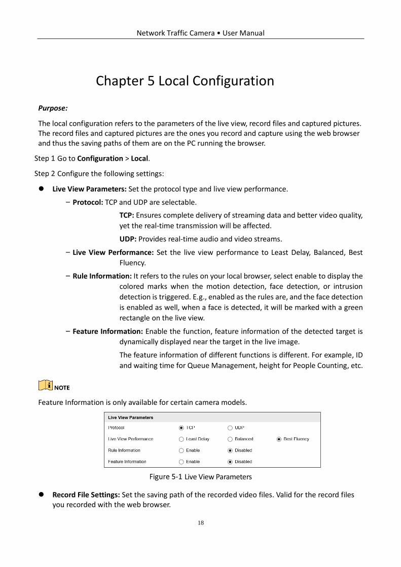
Live View Parameters: Set the protocol type and live view performance.
− Protocol: TCP and UDP are selectable.
TCP: Ensures complete delivery of streaming data and better video quality,
yet the real-time transmission will be affected.
UDP: Provides real-time audio and video streams.
− Live View Performance: Set the live view performance to Least Delay, Balanced, Best
Fluency.
− Rule Information: It refers to the rules on your local browser, select enable to display the
colored marks when the motion detection, face detection, or intrusion
detection is triggered. E.g., enabled as the rules are, and the face detection
is enabled as well, when a face is detected, it will be marked with a green
rectangle on the live view.
− Feature Information: Enable the function, feature information of the detected target is
dynamically displayed near the target in the live image.
The feature information of different functions is different. For example, ID
and waiting time for Queue Management, height for People Counting, etc.
Feature Information is only available for certain camera models.
Live View Parameters
Record File Settings: Set the saving path of the recorded video files. Valid for the record files you recorded with the web browser.
Network Traffic Camera • User Manual
19
− Record File Size: Select the packed size of the manually recorded and downloaded video
files. After the selection, the maximum record file size is the value you
selected.
− Save record files to: Set the saving path for the manually recorded video files.
Picture and Clip Settings: Set the saving paths of the captured pictures and clipped video files. Valid for the pictures you capture with the web browser.
− Save snapshots in live view to: Set the saving path of the manually captured pictures in
live view mode.
− Save download pictures to: Set the saving path of the download pictures.
− Save scene picture to: Set the saving path of the scene pictures.
You can click Browse to change the directory for saving the clips and pictures.
Click Save to save the settings.
Network Traffic Camera • User Manual
20
Chapter 6 System Configuration
Purpose:
You can configure the parameters on this page, including device information, serial ports, network parameters, time configuration, service, etc.
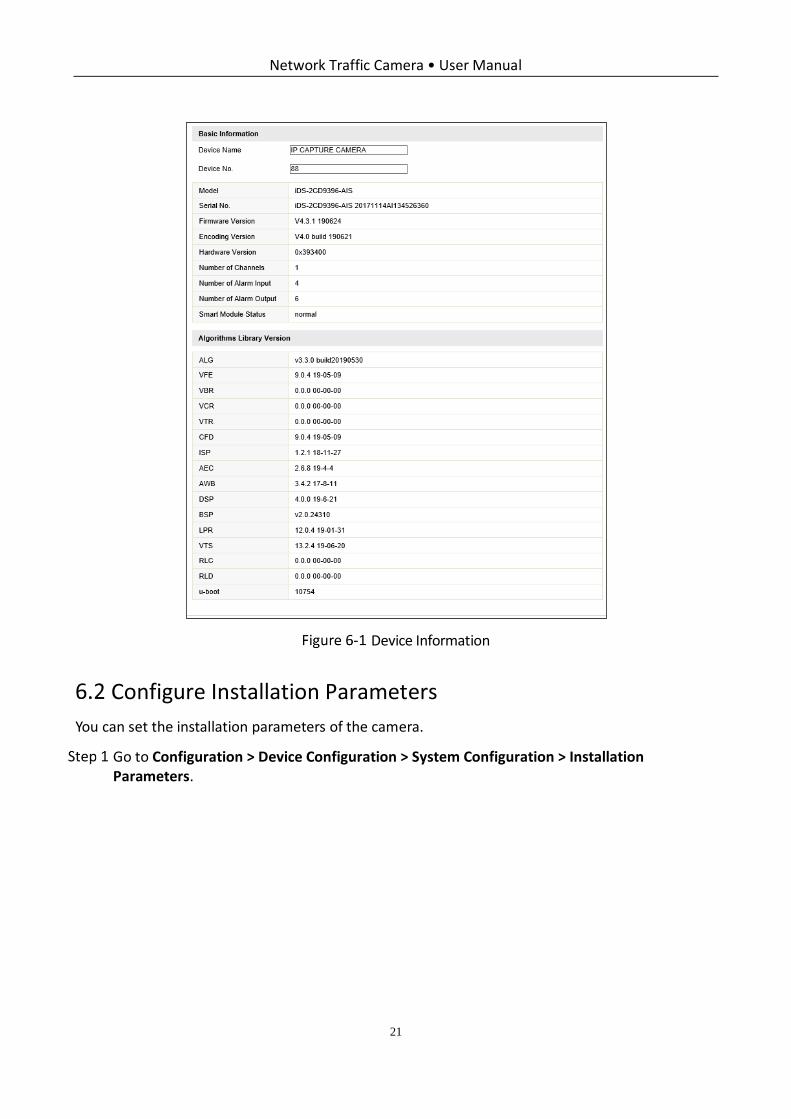
View Device Information
Go to Configuration > Device Configuration > System Configuration > Device Information.
Device Name and Device No. can be changed as desired.
Other information of the camera, such as Model, Serial No., Firmware Version, Encoding Version, Hardware Version, Number of Channels, Number of Alarm Input, Number of Alarm Output, and Smart Module Status are displayed for your reference. And the information cannot be edited in this menu.
Algorithms Library Version information can be viewed but cannot be edited in this menu.
Network Traffic Camera • User Manual
21
Device Information
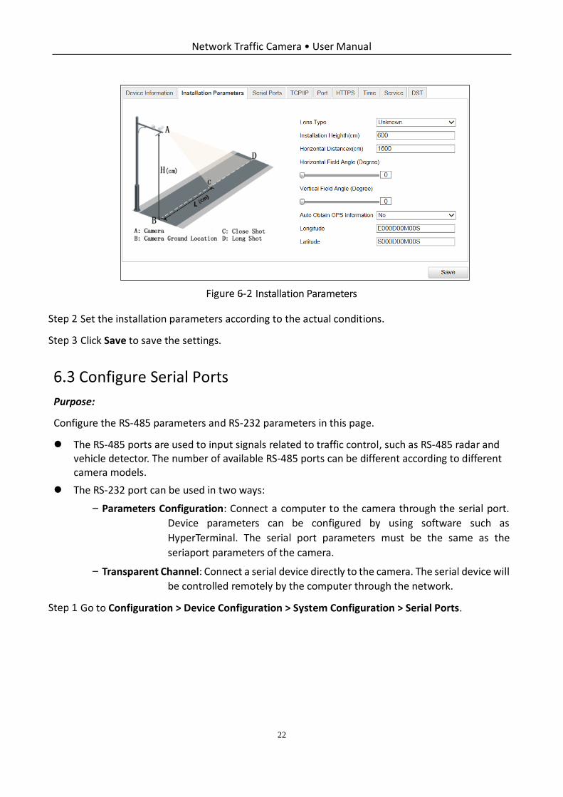
Configure Installation Parameters
You can set the installation parameters of the camera.
Go to Configuration > Device Configuration > System Configuration > Installation Parameters.
Network Traffic Camera • User Manual
22
Installation Parameters
Set the installation parameters according to the actual conditions.
Click Save to save the settings.
Configure Serial Ports
Purpose:
Configure the RS-485 parameters and RS-232 parameters in this page.
The RS-485 ports are used to input signals related to traffic control, such as RS-485 radar and vehicle detector. The number of available RS-485 ports can be different according to different camera models.
The RS-232 port can be used in two ways:
− Parameters Configuration: Connect a computer to the camera through the serial port.
Device parameters can be configured by using software such as
HyperTerminal. The serial port parameters must be the same as the
seriaport parameters of the camera.
− Transparent Channel: Connect a serial device directly to the camera. The serial device will
be controlled remotely by the computer through the network.
Go to Configuration > Device Configuration > System Configuration > Serial Ports.
Network Traffic Camera • User Manual
23
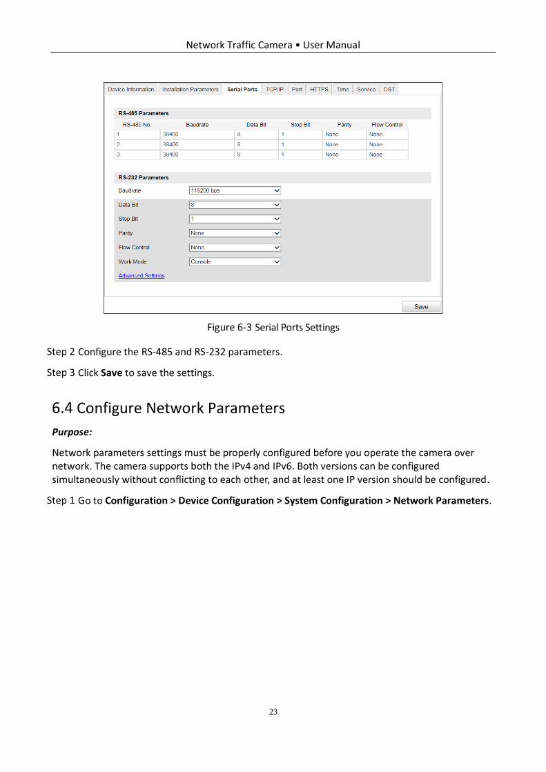
Serial Ports Settings
Configure the RS-485 and RS-232 parameters.
Click Save to save the settings.
Configure Network Parameters
Purpose:
Network parameters settings must be properly configured before you operate the camera over network. The camera supports both the IPv4 and IPv6. Both versions can be configured simultaneously without conflicting to each other, and at least one IP version should be configured.
Go to Configuration > Device Configuration > System Configuration > Network Parameters.
Network Traffic Camera • User Manual
24
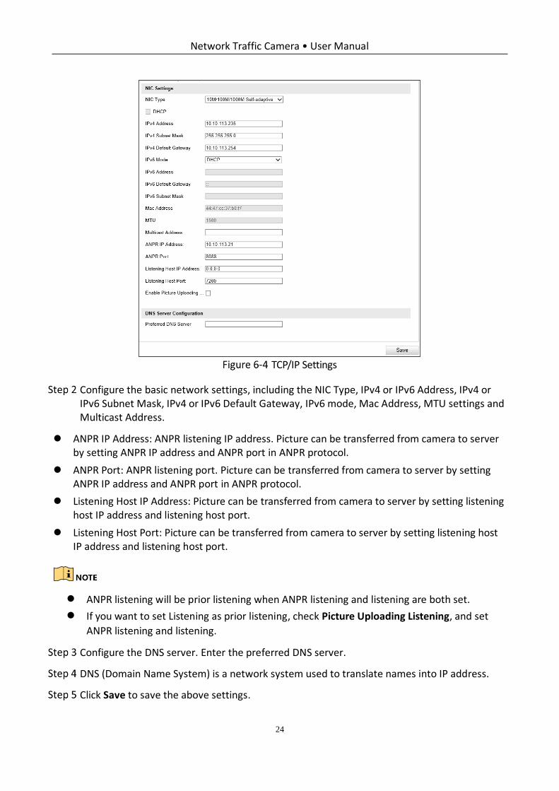
TCP/IP Settings
Configure the basic network settings, including the NIC Type, IPv4 or IPv6 Address, IPv4 or IPv6 Subnet Mask, IPv4 or IPv6 Default Gateway, IPv6 mode, Mac Address, MTU settings and Multicast Address.
ANPR IP Address: ANPR listening IP address. Picture can be transferred from camera to server by setting ANPR IP address and ANPR port in ANPR protocol.
ANPR Port: ANPR listening port. Picture can be transferred from camera to server by setting ANPR IP address and ANPR port in ANPR protocol.
Listening Host IP Address: Picture can be transferred from camera to server by setting listening host IP address and listening host port.
Listening Host Port: Picture can be transferred from camera to server by setting listening host IP address and listening host port.
ANPR listening will be prior listening when ANPR listening and listening are both set.
If you want to set Listening as prior listening, check Picture Uploading Listening, and set
ANPR listening and listening.
Configure the DNS server. Enter the preferred DNS server.
DNS (Domain Name System) is a network system used to translate names into IP address.
Click Save to save the above settings.
Network Traffic Camera • User Manual
25
The valid value range of MTU is 1280 to 1500.
The Multicast sends a stream to the multicast group address and allows multiple clients to
acquire the stream at the same time by requesting a copy from the multicast group
address. Before utilizing this function, you have to enable the Multicast function of your
router.
A reboot is required for the settings to take effect.
Configure Port
Purpose:
Configure the HTTP port, RTSP port, SDK port information to connect corresponding client.
Go to Configuration > Device Configuration > System Configuration > Port.
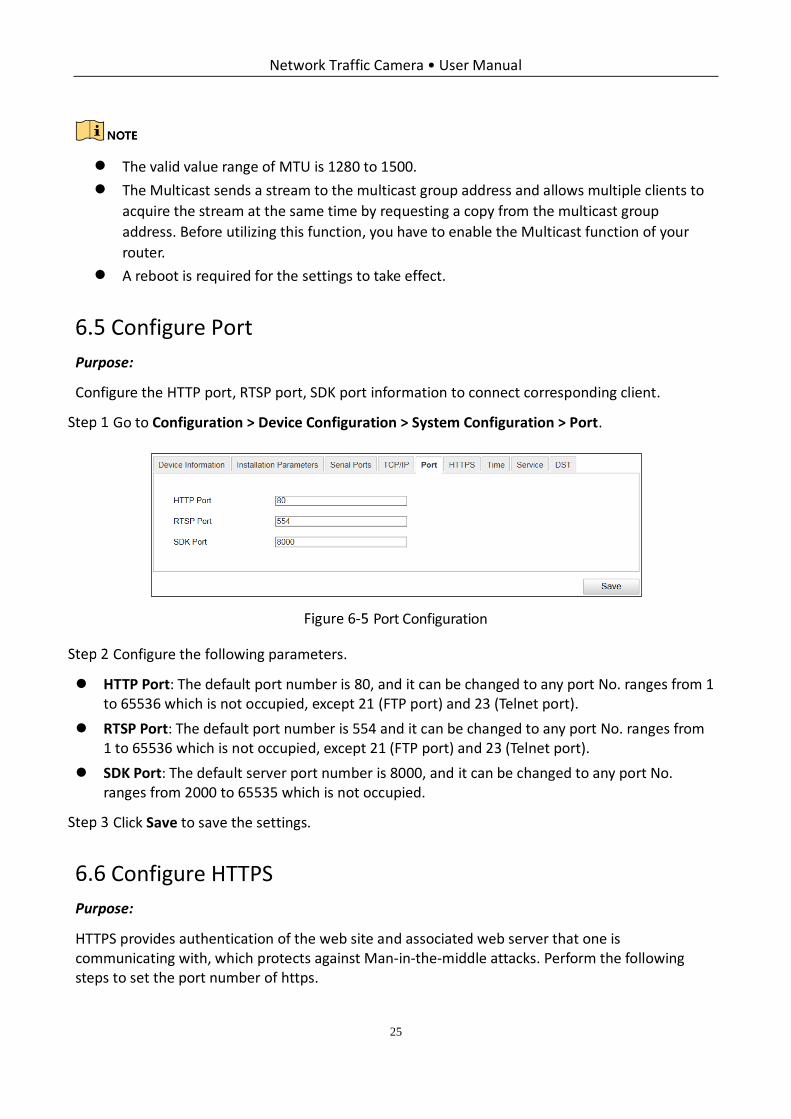
Port Configuration
Configure the following parameters.
HTTP Port: The default port number is 80, and it can be changed to any port No. ranges from 1 to 65536 which is not occupied, except 21 (FTP port) and 23 (Telnet port).
RTSP Port: The default port number is 554 and it can be changed to any port No. ranges from 1 to 65536 which is not occupied, except 21 (FTP port) and 23 (Telnet port).
SDK Port: The default server port number is 8000, and it can be changed to any port No. ranges from 2000 to 65535 which is not occupied.
Click Save to save the settings.
Configure HTTPS
Purpose:
HTTPS provides authentication of the web site and associated web server that one is communicating with, which protects against Man-in-the-middle attacks. Perform the following steps to set the port number of https.
Network Traffic Camera • User Manual
26
Example
If you set the port number as 443 and the IP address is 192.168.1.64, you may access the device by inputting https://192.168.1.64:443 via the web browser.
The HTTPS port can be only configured through the web browser.
Go to Configuration > Device Configuration > System Configuration > HTTPS.
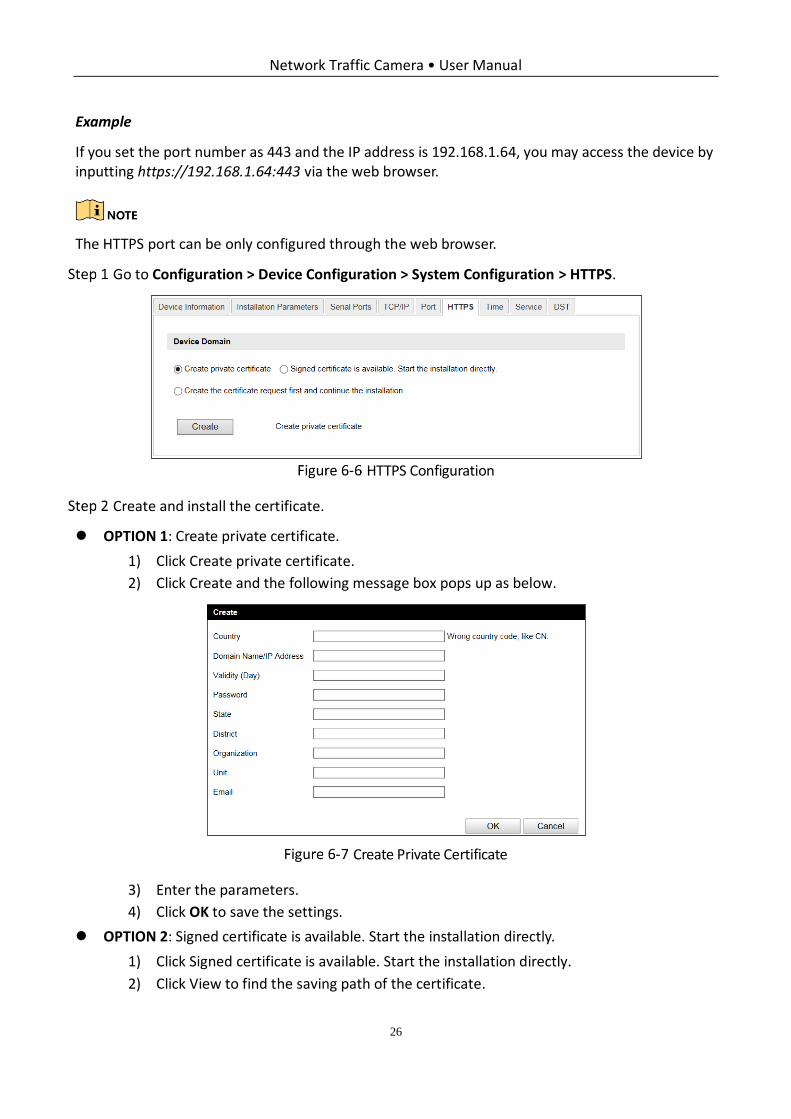
HTTPS Configuration
Create and install the certificate.
OPTION 1: Create private certificate.
1) Click Create private certificate.
2) Click Create and the following message box pops up as below.
Create Private Certificate
3) Enter the parameters.
4) Click OK to save the settings.
OPTION 2: Signed certificate is available. Start the installation directly.
1) Click Signed certificate is available. Start the installation directly.
2) Click View to find the saving path of the certificate.
Network Traffic Camera • User Manual
27
3) Click Install to install the certificate.
OPTION 3: Create the certificate request first and continue the installation.
1) Click Create the certificate request first and continue the installation.
2) Click Create to create the certificate request.
3) Click Download to download the certificate request and submit it to the trusted certificate authority for signature.
4) After receiving the signed valid certificate, click View to find the saving path of the certificate and click Install to install it.
5) (Optional) Click Delete to delete the certificate.
6) There will be the certificate information after you successfully create and install the certificate.
Configure Time
You can follow the instructions in this section to configure the time synchronization and DST settings.
Time Settings
Go to Configuration > Device Configuration > System Configuration> Time.
Select the time zone of your region.
You can adjust time manually. Or you can enable NTP (National Time Protocol) to synchronize time of your camera to the configured NTP server.
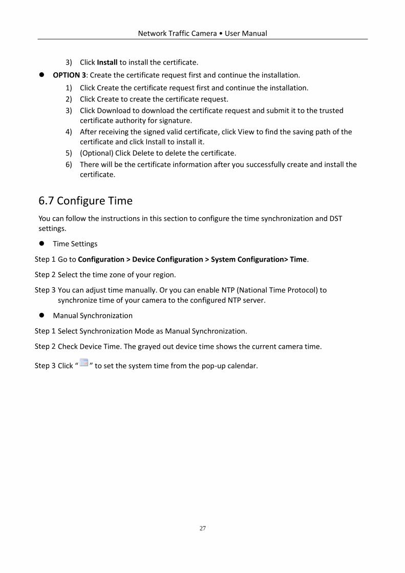
Manual Synchronization
Select Synchronization Mode as Manual Synchronization.
Check Device Time. The grayed out device time shows the current camera time.
Click “ ” to set the system time from the pop-up calendar.
Network Traffic Camera • User Manual
28
Manual Synchronization
(Optional) you can also check Synchronize with PC. The camera time is synchronized with the time of your computer.
Click Save to save the settings.
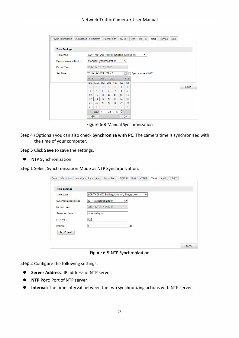
NTP Synchronization
Select Synchronization Mode as NTP Synchronization.
NTP Synchronization
Configure the following settings:
Server Address: IP address of NTP server.
NTP Port: Port of NTP server.
Interval: The time interval between the two synchronizing actions with NTP server.
Network Traffic Camera • User Manual
29
If the camera is connected to a public network, you should use a NTP server that has a time
synchronization function, such as the server at the National Time Center (IP Address:
210.72.145.44). If the camera is set in a customized network, NTP software can be used to
establish a NTP server for time synchronization.
Click Save to save the settings.
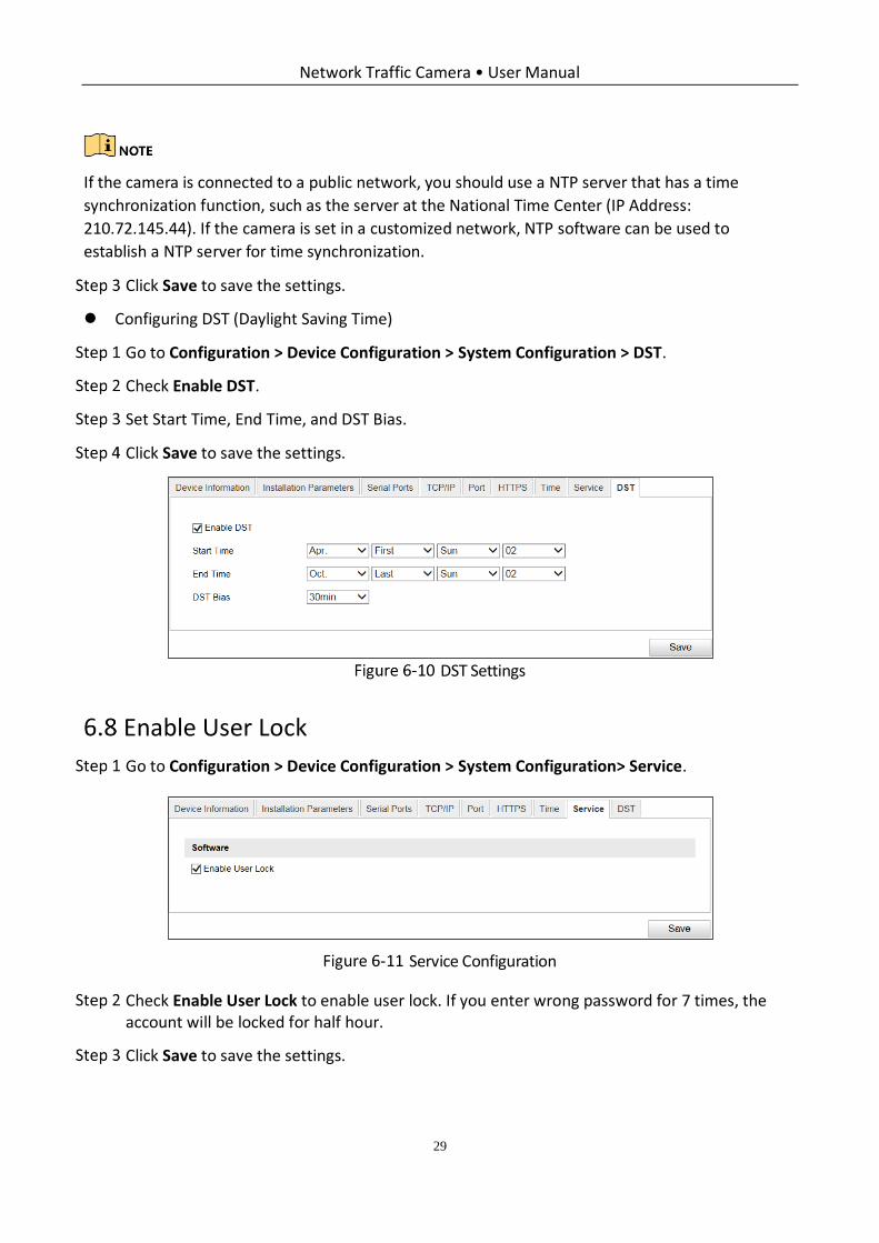
Configuring DST (Daylight Saving Time)
Go to Configuration > Device Configuration > System Configuration > DST.
Check Enable DST.
Set Start Time, End Time, and DST Bias.
Click Save to save the settings.
DST Settings
Enable User Lock
Go to Configuration > Device Configuration > System Configuration> Service.
Service Configuration
Check Enable User Lock to enable user lock. If you enter wrong password for 7 times, the account will be locked for half hour.
Click Save to save the settings.
Network Traffic Camera • User Manual
30
Chapter 7 Encoding and Storage Configuration
Purpose:
You can configure the encoding and storage related parameters from this page, including video encoding, image encoding, ROI, record schedule, redundant storage, FTP, and cloud storage.
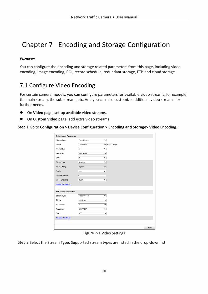
Configure Video Encoding
For certain camera models, you can configure parameters for available video streams, for example, the main stream, the sub-stream, etc. And you can also customize additional video streams for further needs.
On Video page, set-up available video streams.
On Custom Video page, add extra video streams
Go to Configuration > Device Configuration > Encoding and Storage> Video Encoding.
Video Settings
Select the Stream Type. Supported stream types are listed in the drop-down list.
Network Traffic Camera • User Manual
31
The main stream is usually for recording and live view with good bandwidth, and the sub-stream
can be used for live view when the bandwidth is limited.
You can customize the following parameters for the selected stream type.
Stream Type: Select the stream type to video stream, or video & audio composite stream. The audio signal will be recorded only when the Video Type is Video Audio.
Bitrate: Select the bitrate of the video.
Frame Rate: Set the frame rate. The frame rate is to describe the frequency at which the video stream is updated and it is measured by frames per second (fps). A higher frame rate is advantageous when there is movement in the video stream, as it maintains image quality throughout.
Resolution: Select the resolution of the video output.
SVC: Scalable Video Coding is an extension of the H.264/ MJPEG and H.265 standard. Select OFF/ON to disable/enable the SVC function. Select Auto and the device will automatically extract frames from the original video when the network bandwidth is insufficient.
Bitrate Type: Select the bitrate type to constant or variable.
Video Quality: When bitrate type is selected as Variable, 6 levels of video quality are selectable.
Max. Bitrate: Set the max. bitrate from 32 to 16384 Kbps. The higher value corresponds to the higher video quality, but the better bandwidth is required.
The maximum limit of the max. bitrate value varies according to different camera platforms. For
certain cameras, the maximum limit is 8192 Kbps or 12288 Kbps.
Profile: When you select H.264 or H.265 as video encoding, you can set the profile. Selectable profiles vary according to camera models.
I Frame Interval: Set I Frame Interval as default.
Video Encoding: The camera supports multiple video encodings types, such as H.264, H.265, and MJPEG. Supported encoding type for different stream types may differ. H.265 is a new encoding technology. Compared with H.264, it reduces the transmission bitrate under the same resolution, frame rate and image quality.
Selectable video encoding types may vary according to different camera modes.
Upgrade your video player to the latest version if live view or playback does not work
properly due to compatibility.
Click Save to save the settings.
Network Traffic Camera • User Manual
32
The video parameters vary according to different camera models. Refer to the actual display page
for camera functions.
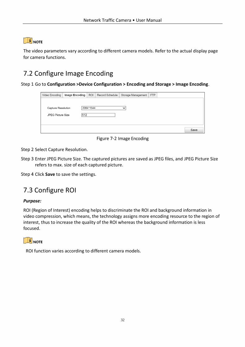
Configure Image Encoding
Go to Configuration >Device Configuration > Encoding and Storage > Image Encoding.
Image Encoding
Select Capture Resolution.
Enter JPEG Picture Size. The captured pictures are saved as JPEG files, and JPEG Picture Size refers to max. size of each captured picture.
Click Save to save the settings.
Configure ROI
Purpose:
ROI (Region of Interest) encoding helps to discriminate the ROI and background information in video compression, which means, the technology assigns more encoding resource to the region of interest, thus to increase the quality of the ROI whereas the background information is less focused.
ROI function varies according to different camera models.
Network Traffic Camera • User Manual
33
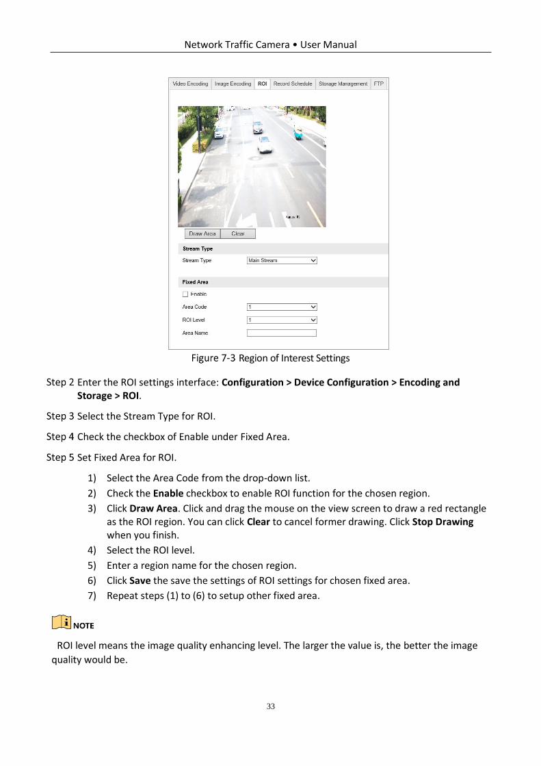
Region of Interest Settings
Enter the ROI settings interface: Configuration > Device Configuration > Encoding and Storage > ROI.
Select the Stream Type for ROI.
Check the checkbox of Enable under Fixed Area.
Set Fixed Area for ROI.
1) Select the Area Code from the drop-down list.
2) Check the Enable checkbox to enable ROI function for the chosen region.
3) Click Draw Area. Click and drag the mouse on the view screen to draw a red rectangle as the ROI region. You can click Clear to cancel former drawing. Click Stop Drawing when you finish.
4) Select the ROI level.
5) Enter a region name for the chosen region.
6) Click Save the save the settings of ROI settings for chosen fixed area.
7) Repeat steps (1) to (6) to setup other fixed area.
ROI level means the image quality enhancing level. The larger the value is, the better the image
quality would be.
Network Traffic Camera • User Manual
34
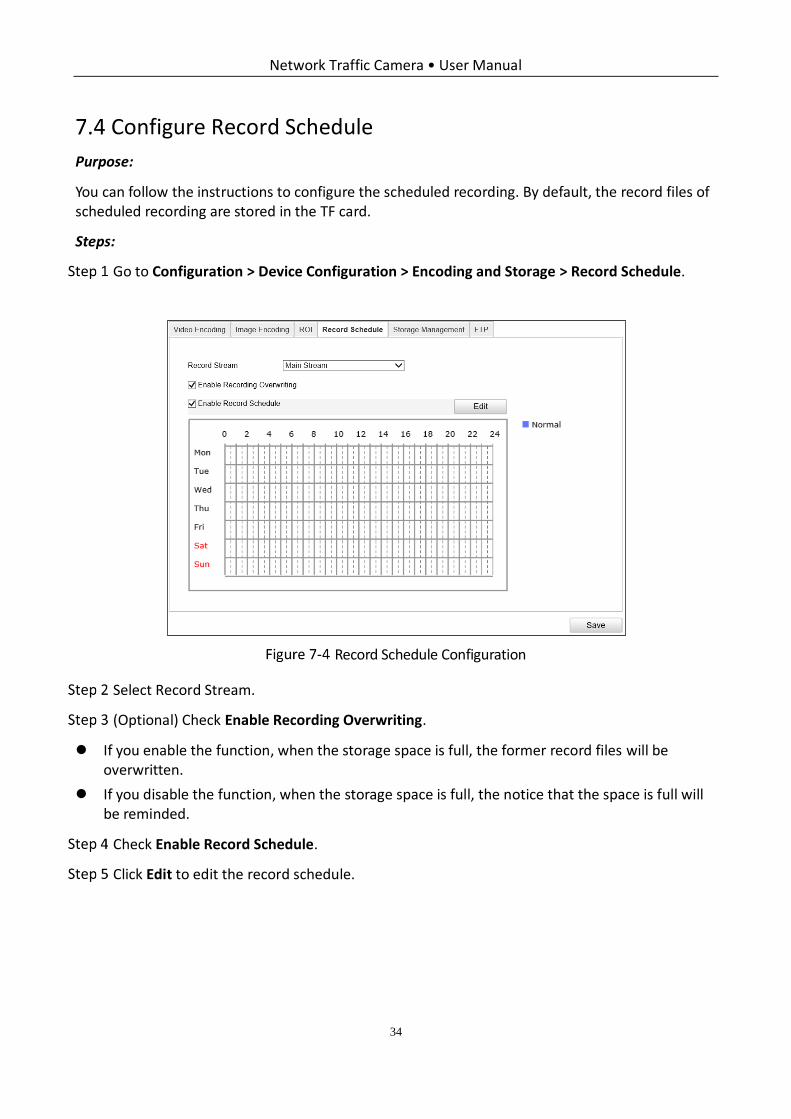
Configure Record Schedule
Purpose:
You can follow the instructions to configure the scheduled recording. By default, the record files of scheduled recording are stored in the TF card.
Steps:
Go to Configuration > Device Configuration > Encoding and Storage > Record Schedule.
Record Schedule Configuration
Select Record Stream.
(Optional) Check Enable Recording Overwriting.
If you enable the function, when the storage space is full, the former record files will be overwritten.
If you disable the function, when the storage space is full, the notice that the space is full will be reminded.
Check Enable Record Schedule.
Click Edit to edit the record schedule.
Network Traffic Camera • User Manual
35
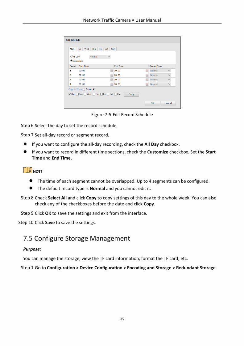
Edit Record Schedule
Select the day to set the record schedule.
Set all-day record or segment record.
If you want to configure the all-day recording, check the All Day checkbox.
If you want to record in different time sections, check the Customize checkbox. Set the Start Time and End Time.
The time of each segment cannot be overlapped. Up to 4 segments can be configured.
The default record type is Normal and you cannot edit it.
Check Select All and click Copy to copy settings of this day to the whole week. You can also check any of the checkboxes before the date and click Copy.
Click OK to save the settings and exit from the interface.
Click Save to save the settings.
Configure Storage Management
Purpose:
You can manage the storage, view the TF card information, format the TF card, etc.
Go to Configuration > Device Configuration > Encoding and Storage > Redundant Storage.
Network Traffic Camera • User Manual
36
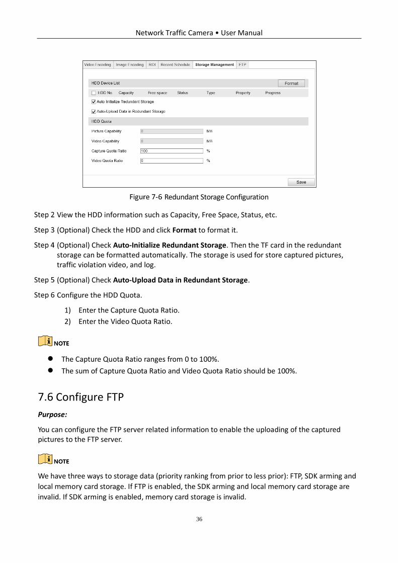
Redundant Storage Configuration
View the HDD information such as Capacity, Free Space, Status, etc.
(Optional) Check the HDD and click Format to format it.
(Optional) Check Auto-Initialize Redundant Storage. Then the TF card in the redundant storage can be formatted automatically. The storage is used for store captured pictures, traffic violation video, and log.
(Optional) Check Auto-Upload Data in Redundant Storage.
Configure the HDD Quota.
1) Enter the Capture Quota Ratio.
2) Enter the Video Quota Ratio.
The Capture Quota Ratio ranges from 0 to 100%.
The sum of Capture Quota Ratio and Video Quota Ratio should be 100%.
Configure FTP
Purpose:
You can configure the FTP server related information to enable the uploading of the captured pictures to the FTP server.
We have three ways to storage data (priority ranking from prior to less prior): FTP, SDK arming and
local memory card storage. If FTP is enabled, the SDK arming and local memory card storage are
invalid. If SDK arming is enabled, memory card storage is invalid.
Network Traffic Camera • User Manual
37
Go to Configuration > Device Configuration > Encoding and Storage > FTP.
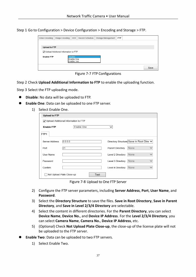
FTP Configurations
Check Upload Additional Information to FTP to enable the uploading function.
Select the FTP uploading mode.
Disable: No data will be uploaded to FTP.
Enable One: Data can be uploaded to one FTP server.
1) Select Enable One.
Upload to One FTP Server
2) Configure the FTP server parameters, including Server Address, Port, User Name, and Password.
3) Select the Directory Structure to save the files. Save in Root Directory, Save in Parent Directory, and Save in Level 2/3/4 Directory are selectable.
4) Select the content in different directories. For the Parent Directory, you can select Device Name, Device No., and Device IP Address. For the Level 2/3/4 Directory, you can select Camera Name, Camera No., Device IP Address, etc.
5) (Optional) Check Not Upload Plate Close-up, the close-up of the license plate will not be uploaded to the FTP server.
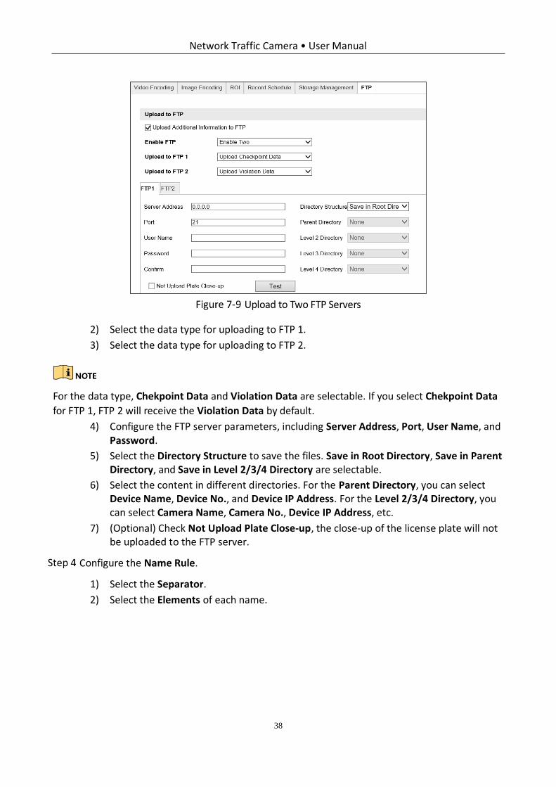
Enable Two: Data can be uploaded to two FTP servers.
1) Select Enable Two.
Network Traffic Camera • User Manual
38
Upload to Two FTP Servers
2) Select the data type for uploading to FTP 1.
3) Select the data type for uploading to FTP 2.
For the data type, Chekpoint Data and Violation Data are selectable. If you select Chekpoint Data
for FTP 1, FTP 2 will receive the Violation Data by default.
4) Configure the FTP server parameters, including Server Address, Port, User Name, and Password.
5) Select the Directory Structure to save the files. Save in Root Directory, Save in Parent Directory, and Save in Level 2/3/4 Directory are selectable.
6) Select the content in different directories. For the Parent Directory, you can select Device Name, Device No., and Device IP Address. For the Level 2/3/4 Directory, you can select Camera Name, Camera No., Device IP Address, etc.
7) (Optional) Check Not Upload Plate Close-up, the close-up of the license plate will not be uploaded to the FTP server.
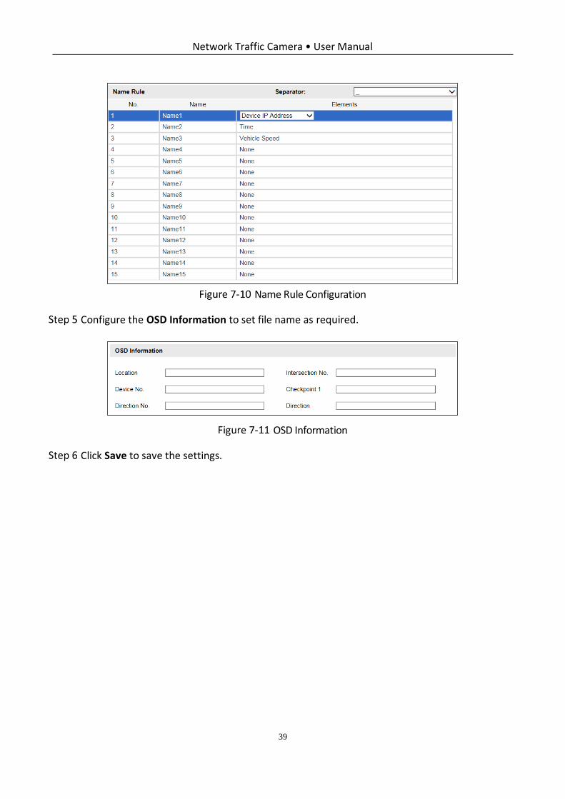
Configure the Name Rule.
1) Select the Separator.
2) Select the Elements of each name.
Network Traffic Camera • User Manual
39
Name Rule Configuration
Configure the OSD Information to set file name as required.
OSD Information
Click Save to save the settings.
Network Traffic Camera • User Manual
40
Chapter 8 Text Overlay Configuration
Purpose:
Configure the OSD on the captured pictures and videos.
Configure Capture Picture Overlay
Purpose:
You can configure the overlay information of the captured picture.
Steps:
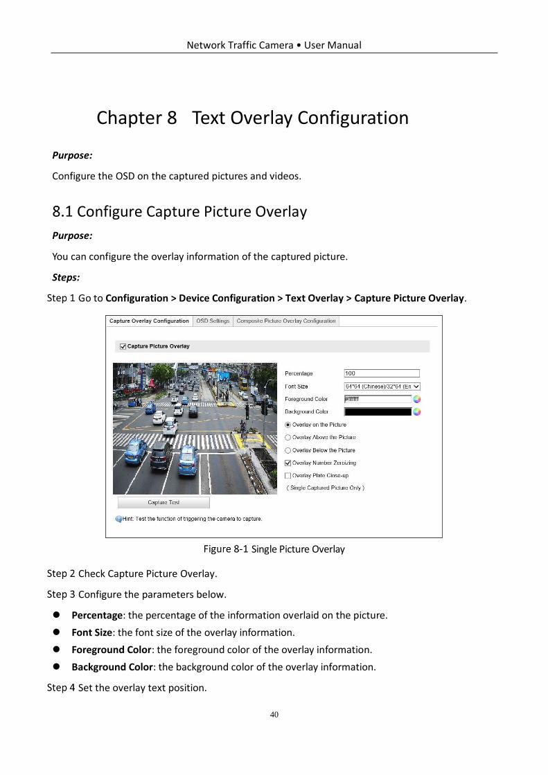
Go to Configuration > Device Configuration > Text Overlay > Capture Picture Overlay.
Single Picture Overlay
Check Capture Picture Overlay.
Configure the parameters below.
Percentage: the percentage of the information overlaid on the picture.
Font Size: the font size of the overlay information.
Foreground Color: the foreground color of the overlay information.
Background Color: the background color of the overlay information.
Set the overlay text position.
Network Traffic Camera • User Manual
41
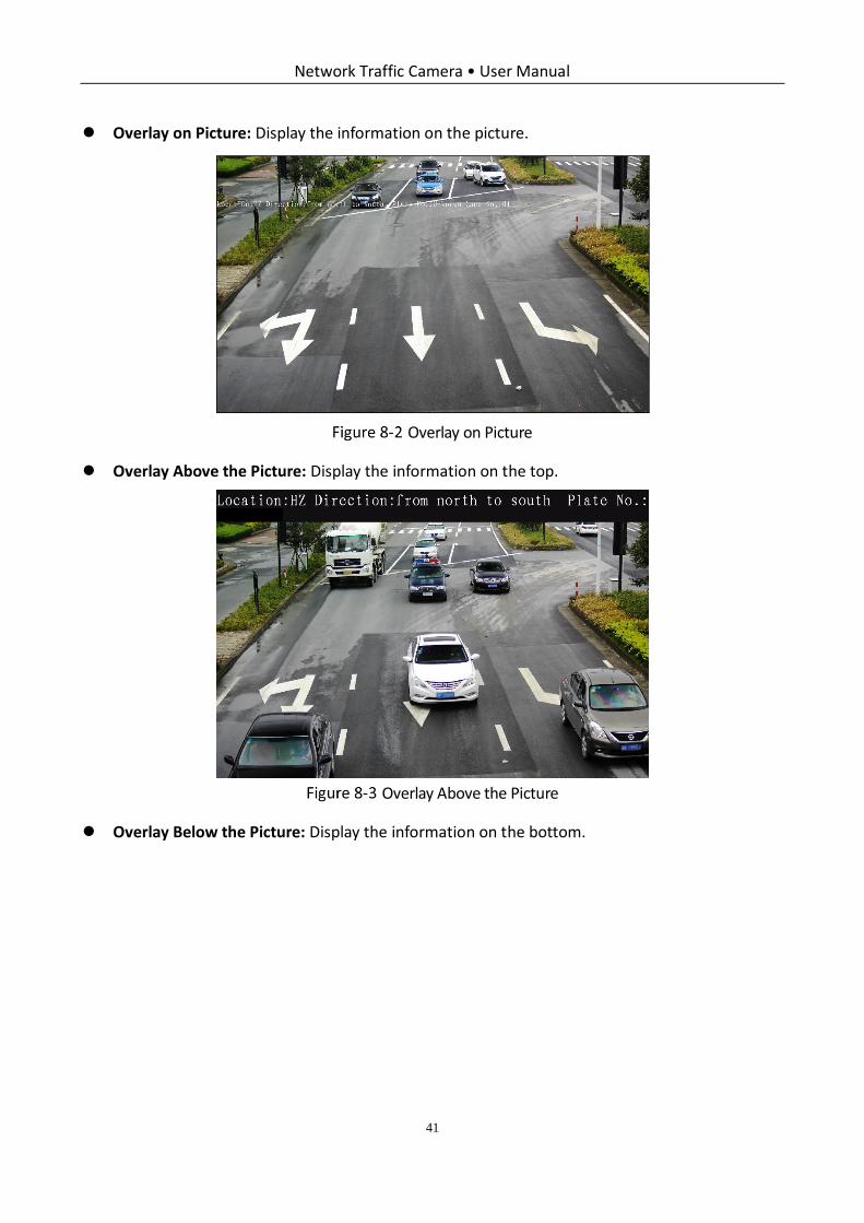
Overlay on Picture: Display the information on the picture.
Overlay on Picture
Overlay Above the Picture: Display the information on the top.
Overlay Above the Picture
Overlay Below the Picture: Display the information on the bottom.
Network Traffic Camera • User Manual
42
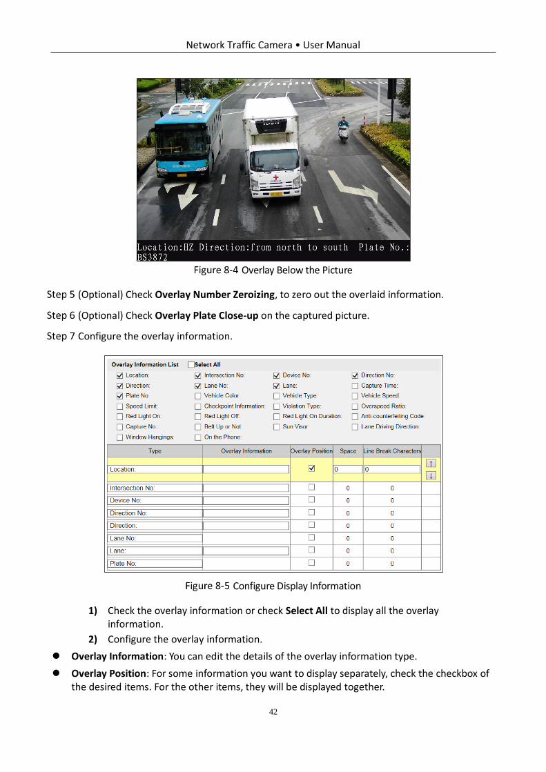
Overlay Below the Picture
(Optional) Check Overlay Number Zeroizing, to zero out the overlaid information.
(Optional) Check Overlay Plate Close-up on the captured picture.
Configure the overlay information.
Configure Display Information
1) Check the overlay information or check Select All to display all the overlay information.
2) Configure the overlay information.
Overlay Information: You can edit the details of the overlay information type.
Overlay Position: For some information you want to display separately, check the checkbox of the desired items. For the other items, they will be displayed together.
Network Traffic Camera • User Manual
43
Space: It stands for the length of blank space between the last character of the first item and the first character of the next item.
Line Break Characters: When you add Line Break Characters to an item, the item is displayed as a new paragraph, and the number stands for the scale of space above the paragraph.
/ : Click to move the overlay position up. Click to move the overlay position down.
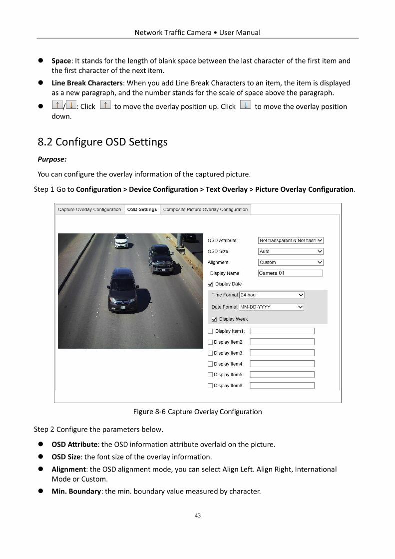
Configure OSD Settings
Purpose:
You can configure the overlay information of the captured picture.
Go to Configuration > Device Configuration > Text Overlay > Picture Overlay Configuration.
Capture Overlay Configuration
Configure the parameters below.
OSD Attribute: the OSD information attribute overlaid on the picture.
OSD Size: the font size of the overlay information.
Alignment: the OSD alignment mode, you can select Align Left. Align Right, International Mode or Custom.
Min. Boundary: the min. boundary value measured by character.
Network Traffic Camera • User Manual
44
Display Name: Camera name.
Time Format: 24-hour and 12-hour are selectable.
Date Format: The date format overlaid on the picture.
Display Week: Check it to display week information on the picture.
Display Item: You can check display item(s) and enter information as need, to overlay them on the picture.
Click Save to save the settings.
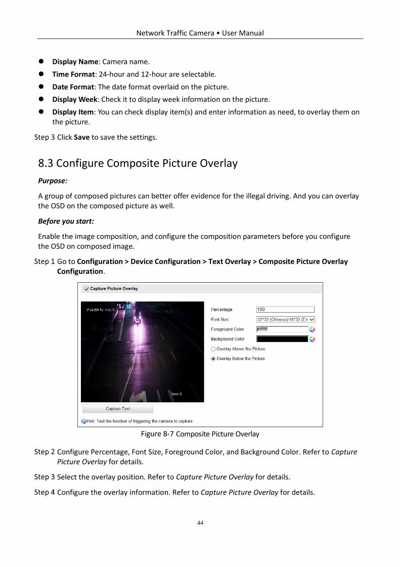
Configure Composite Picture Overlay
Purpose:
A group of composed pictures can better offer evidence for the illegal driving. And you can overlay the OSD on the composed picture as well.
Before you start:
Enable the image composition, and configure the composition parameters before you configure the OSD on composed image.
Go to Configuration > Device Configuration > Text Overlay > Composite Picture Overlay Configuration.
Composite Picture Overlay
Configure Percentage, Font Size, Foreground Color, and Background Color. Refer to Capture Picture Overlay for details.
Select the overlay position. Refer to Capture Picture Overlay for details.
Configure the overlay information. Refer to Capture Picture Overlay for details.
Network Traffic Camera • User Manual
45
Chapter 9 Capture Parameters Configuration
Purpose:
You can configure capture parameters before capturing, and edit capture parameters when the default capture parameters cannot meet actual needs.
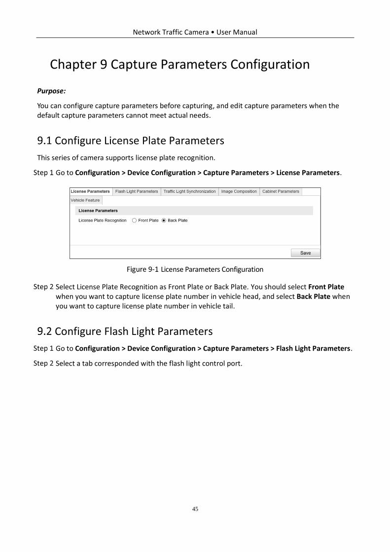
Configure License Plate Parameters
This series of camera supports license plate recognition.
Go to Configuration > Device Configuration > Capture Parameters > License Parameters.
License Parameters Configuration
Select License Plate Recognition as Front Plate or Back Plate. You should select Front Plate when you want to capture license plate number in vehicle head, and select Back Plate when you want to capture license plate number in vehicle tail.
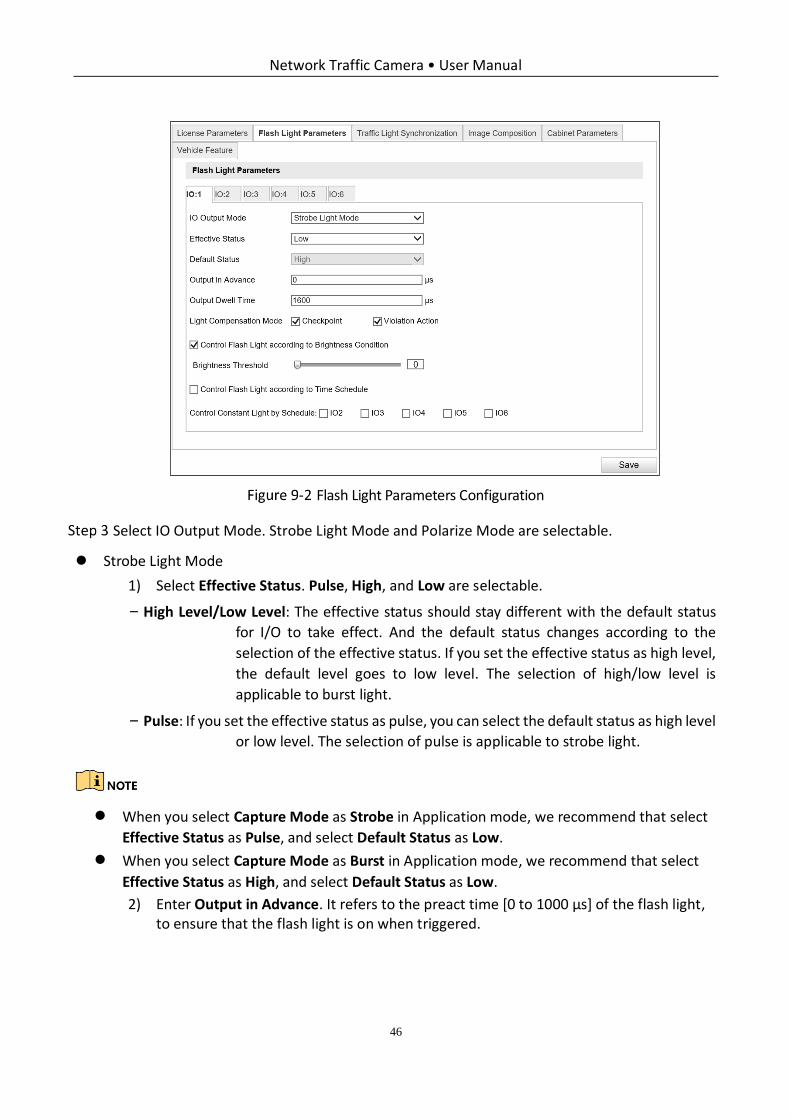
Configure Flash Light Parameters
Go to Configuration > Device Configuration > Capture Parameters > Flash Light Parameters.
Select a tab corresponded with the flash light control port.
Network Traffic Camera • User Manual
46
Flash Light Parameters Configuration
Select IO Output Mode. Strobe Light Mode and Polarize Mode are selectable.
Strobe Light Mode
1) Select Effective Status. Pulse, High, and Low are selectable.
− High Level/Low Level: The effective status should stay different with the default status
for I/O to take effect. And the default status changes according to the
selection of the effective status. If you set the effective status as high level,
the default level goes to low level. The selection of high/low level is
applicable to burst light.
− Pulse: If you set the effective status as pulse, you can select the default status as high level
or low level. The selection of pulse is applicable to strobe light.
When you select Capture Mode as Strobe in Application mode, we recommend that select
Effective Status as Pulse, and select Default Status as Low.
When you select Capture Mode as Burst in Application mode, we recommend that select
Effective Status as High, and select Default Status as Low.
2) Enter Output in Advance. It refers to the preact time [0 to 1000 μs] of the flash light, to ensure that the flash light is on when triggered.
Network Traffic Camera • User Manual
47
When IO Output Mode is selected as Strobe Light Mode, Effective status is selected as Low/High,
and Capture Mode is selected as Burst, the function will take effect.
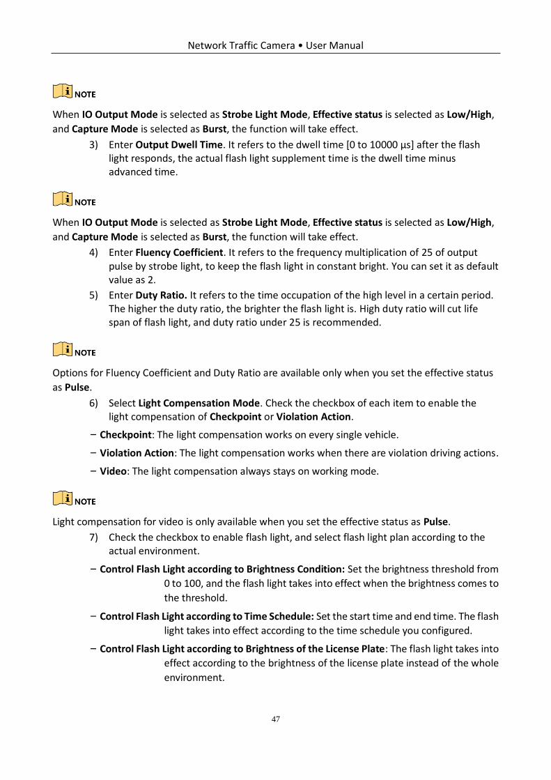
3) Enter Output Dwell Time. It refers to the dwell time [0 to 10000 μs] after the flash light responds, the actual flash light supplement time is the dwell time minus advanced time.
When IO Output Mode is selected as Strobe Light Mode, Effective status is selected as Low/High,
and Capture Mode is selected as Burst, the function will take effect.
4) Enter Fluency Coefficient. It refers to the frequency multiplication of 25 of output pulse by strobe light, to keep the flash light in constant bright. You can set it as default value as 2.
5) Enter Duty Ratio. It refers to the time occupation of the high level in a certain period. The higher the duty ratio, the brighter the flash light is. High duty ratio will cut life span of flash light, and duty ratio under 25 is recommended.
Options for Fluency Coefficient and Duty Ratio are available only when you set the effective status
as Pulse.
6) Select Light Compensation Mode. Check the checkbox of each item to enable the light compensation of Checkpoint or Violation Action.
− Checkpoint: The light compensation works on every single vehicle.
− Violation Action: The light compensation works when there are violation driving actions.
− Video: The light compensation always stays on working mode.
Light compensation for video is only available when you set the effective status as Pulse.
7) Check the checkbox to enable flash light, and select flash light plan according to the actual environment.
− Control Flash Light according to Brightness Condition: Set the brightness threshold from
0 to 100, and the flash light takes into effect when the brightness comes to
the threshold.
− Control Flash Light according to Time Schedule: Set the start time and end time. The flash
light takes into effect according to the time schedule you configured.
− Control Flash Light according to Brightness of the License Plate: The flash light takes into
effect according to the brightness of the license plate instead of the whole
environment.
Network Traffic Camera • User Manual
48
Control Flash Light according to Brightness of the License Plate is only available when you
set the effective status as Pulse.
Control Flash Light according to Time Schedule is recommended.
Polarize Mode
1) Enable polarizer according to the actual environment.
− Enable Polarizer by Brightness: Set the brightness threshold from 0 to 100, and the
polarizer takes into effect when the brightness comes to the threshold.
− Enable Polarizer by Schedule: Set the start time and end time. The polarizer takes into
effect according to the time schedule you configured.
(Optional) Check the channel No. to copy the same settings to other channels.
Click Save to save the settings.
IO:3 is built-in flash light.
Configure Traffic Light Synchronization
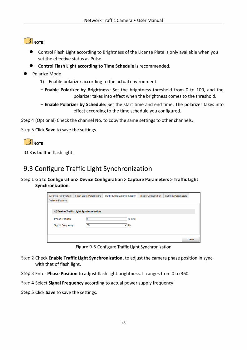
Go to Configuration> Device Configuration > Capture Parameters > Traffic Light Synchronization.
Configure Traffic Light Synchronization
Check Enable Traffic Light Synchronization, to adjust the camera phase position in sync. with that of flash light.
Enter Phase Position to adjust flash light brightness. It ranges from 0 to 360.
Select Signal Frequency according to actual power supply frequency.
Click Save to save the settings.
Network Traffic Camera • User Manual
49
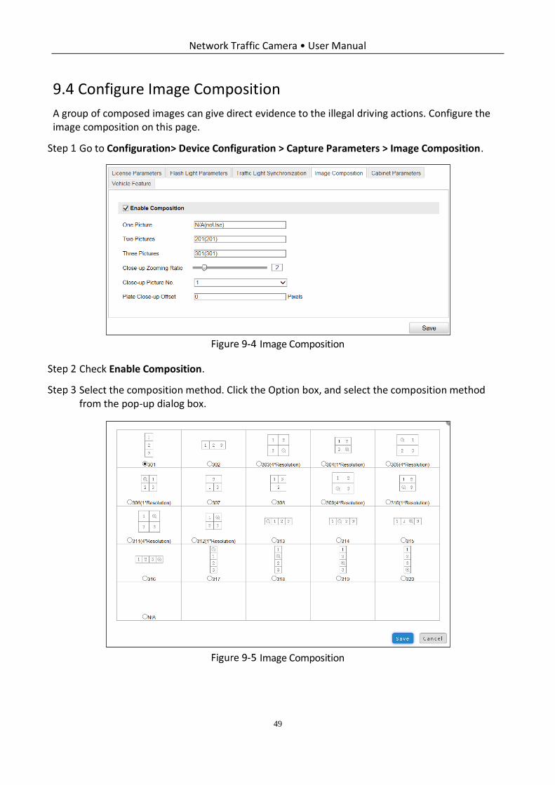
Configure Image Composition
A group of composed images can give direct evidence to the illegal driving actions. Configure the image composition on this page.
Go to Configuration> Device Configuration > Capture Parameters > Image Composition.
Image Composition
Check Enable Composition.
Select the composition method. Click the Option box, and select the composition method from the pop-up dialog box.
Image Composition
Network Traffic Camera • User Manual
50
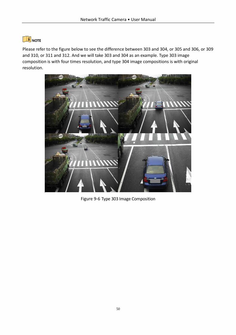
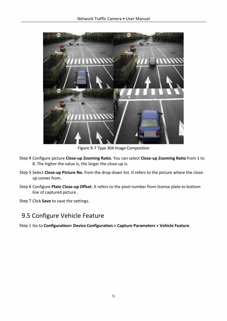
Please refer to the figure below to see the difference between 303 and 304, or 305 and 306, or 309
and 310, or 311 and 312. And we will take 303 and 304 as an example. Type 303 image
composition is with four times resolution, and type 304 image compositions is with original
resolution.
Type 303 Image Composition
Network Traffic Camera • User Manual
51
Type 304 Image Composition
Configure picture Close-up Zooming Ratio. You can select Close-up Zooming Ratio from 1 to 8. The higher the value is, the larger the close-up is.
Select Close-up Picture No. from the drop-down list. It refers to the picture where the close-up comes from.
Configure Plate Close-up Offset. It refers to the pixel number from license plate to bottom line of captured picture..
Click Save to save the settings.
Configure Vehicle Feature
Go to Configuration> Device Configuration > Capture Parameters > Vehicle Feature.
Network Traffic Camera • User Manual
52
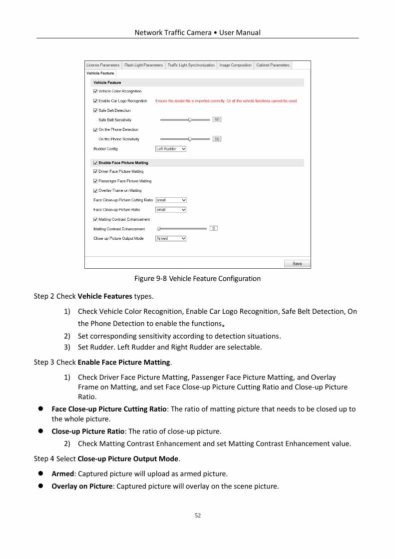
Vehicle Feature Configuration
Check Vehicle Features types.
1) Check Vehicle Color Recognition, Enable Car Logo Recognition, Safe Belt Detection, On
the Phone Detection to enable the functions。
2) Set corresponding sensitivity according to detection situations.
3) Set Rudder. Left Rudder and Right Rudder are selectable.
Check Enable Face Picture Matting.
1) Check Driver Face Picture Matting, Passenger Face Picture Matting, and Overlay Frame on Matting, and set Face Close-up Picture Cutting Ratio and Close-up Picture Ratio.
Face Close-up Picture Cutting Ratio: The ratio of matting picture that needs to be closed up to the whole picture.
Close-up Picture Ratio: The ratio of close-up picture.
2) Check Matting Contrast Enhancement and set Matting Contrast Enhancement value.
Select Close-up Picture Output Mode.
Armed: Captured picture will upload as armed picture.
Overlay on Picture: Captured picture will overlay on the scene picture.

Network Traffic Camera • User Manual
53
Click Save to save the settings.
Network Traffic Camera • User Manual
54
Chapter 10 Image Parameters Configuration
Purpose:
Configure double shutter parameters, general parameters, video parameters, and ICR on this page.
Configure Dual-Shutter Parameters
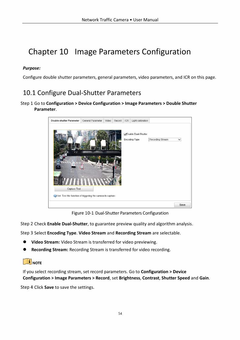
Go to Configuration > Device Configuration > Image Parameters > Double Shutter Parameter.
Dual-Shutter Parameters Configuration
Check Enable Dual-Shutter, to guarantee preview quality and algorithm analysis.
Select Encoding Type. Video Stream and Recording Stream are selectable.
Video Stream: Video Stream is transferred for video previewing.
Recording Stream: Recording Stream is transferred for video recording.
If you select recording stream, set record parameters. Go to Configuration > Device
Configuration > Image Parameters > Record, set Brightness, Contrast, Shutter Speed and Gain.
Click Save to save the settings.
Network Traffic Camera • User Manual
55
Configure General Parameters
Purpose:
General parameters refer to the image parameters applying to both video image and capture image, such as saturation, sensitivity, lens type, sharpness, white balance, gamma correction, and brightness enhancement.
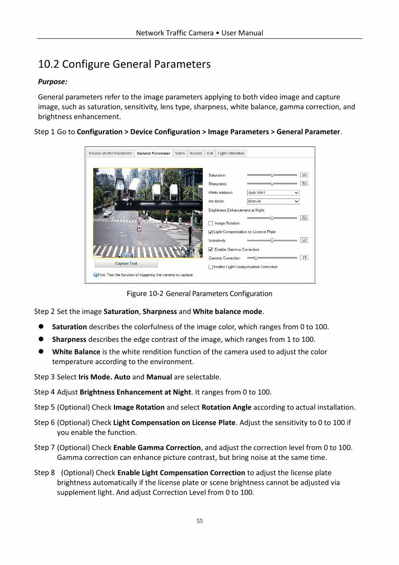
Go to Configuration > Device Configuration > Image Parameters > General Parameter.
General Parameters Configuration
Set the image Saturation, Sharpness and White balance mode.
Saturation describes the colorfulness of the image color, which ranges from 0 to 100.
Sharpness describes the edge contrast of the image, which ranges from 1 to 100.
White Balance is the white rendition function of the camera used to adjust the color temperature according to the environment.
Select Iris Mode. Auto and Manual are selectable.
Adjust Brightness Enhancement at Night. It ranges from 0 to 100.
(Optional) Check Image Rotation and select Rotation Angle according to actual installation.
(Optional) Check Light Compensation on License Plate. Adjust the sensitivity to 0 to 100 if you enable the function.
(Optional) Check Enable Gamma Correction, and adjust the correction level from 0 to 100. Gamma correction can enhance picture contrast, but bring noise at the same time.
(Optional) Check Enable Light Compensation Correction to adjust the license plate brightness automatically if the license plate or scene brightness cannot be adjusted via supplement light. And adjust Correction Level from 0 to 100.
Network Traffic Camera • User Manual
56
(Optional) Check Enable Black and White Mode at Night. When ICR is in night mode, you can check Enable Black and White Mode at Night to keep the video in black and white mode.
(Optional) Click Capture Test to test the effects after you complete the adjustment.
(Optional) Reboot the device if you enable image rotation. For other parameters, they will take effect in real time.
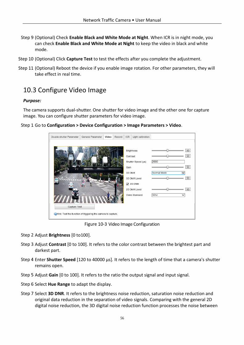
Configure Video Image
Purpose:
The camera supports dual-shutter. One shutter for video image and the other one for capture image. You can configure shutter parameters for video image.
Go to Configuration > Device Configuration > Image Parameters > Video.
Video Image Configuration
Adjust Brightness [0 to100].
Adjust Contrast [0 to 100]. It refers to the color contrast between the brightest part and darkest part.
Enter Shutter Speed [120 to 40000 μs]. It refers to the length of time that a camera's shutter remains open.
Adjust Gain [0 to 100]. It refers to the ratio the output signal and input signal.
Select Hue Range to adapt the display.
Select 3D DNR. It refers to the brightness noise reduction, saturation noise reduction and original data reduction in the separation of video signals. Comparing with the general 2D digital noise reduction, the 3D digital noise reduction function processes the noise between
Network Traffic Camera • User Manual
57
two frames besides processing the noise in one frame. The noise will be much less and the video will be clearer.
1) If you select Normal Mode, adjust 3D DNR Level from 0 to 100.
2) If you select Expert Mode, adjust Spatial Intensity and Time Intensity from 0 to 100.
(Optional) Check 2D DNR, and adjust 2D DNR Level from 0 to 100.
(Optional) Click Capture Test to test the effects.
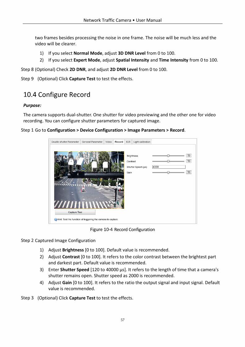
Configure Record
Purpose:
The camera supports dual-shutter. One shutter for video previewing and the other one for video recording. You can configure shutter parameters for captured image.
Go to Configuration > Device Configuration > Image Parameters > Record.
Record Configuration
Captured Image Configuration
1) Adjust Brightness [0 to 100]. Default value is recommended.
2) Adjust Contrast [0 to 100]. It refers to the color contrast between the brightest part and darkest part. Default value is recommended.
3) Enter Shutter Speed [120 to 40000 μs]. It refers to the length of time that a camera's shutter remains open. Shutter speed as 2000 is recommended.
4) Adjust Gain [0 to 100]. It refers to the ratio the output signal and input signal. Default value is recommended.
(Optional) Click Capture Test to test the effects.
Network Traffic Camera • User Manual
58
Configure ICR
Purpose:
IR Cut Filter is used to block or reflect infrared wavelengths but pass visible light. This series of cameras support auto switch of ICR to realize the 24-hour surveillance.
ICR configuration is not supported by all camera models of this series.
Go to Configuration > Device Configuration > Image Parameters > ICR.
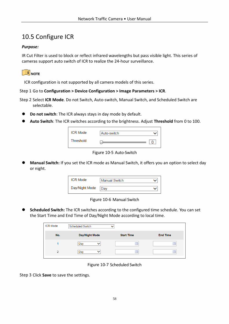
Select ICR Mode. Do not Switch, Auto-switch, Manual Switch, and Scheduled Switch are selectable.
Do not switch: The ICR always stays in day mode by default.
Auto Switch: The ICR switches according to the brightness. Adjust Threshold from 0 to 100.
Auto-Switch
Manual Switch: If you set the ICR mode as Manual Switch, it offers you an option to select day or night.
Manual Switch
Scheduled Switch: The ICR switches according to the configured time schedule. You can set the Start Time and End Time of Day/Night Mode according to local time.
Scheduled Switch
Click Save to save the settings.
Network Traffic Camera • User Manual
59
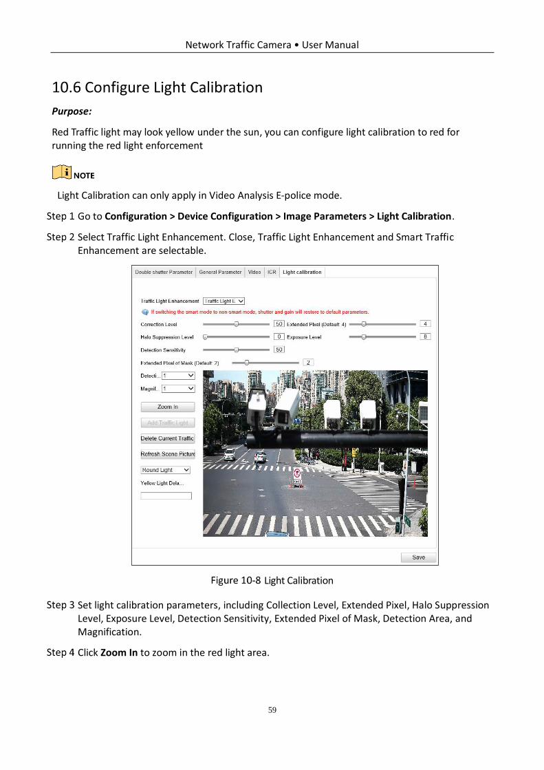
Configure Light Calibration
Purpose:
Red Traffic light may look yellow under the sun, you can configure light calibration to red for running the red light enforcement
Light Calibration can only apply in Video Analysis E-police mode.
Go to Configuration > Device Configuration > Image Parameters > Light Calibration.
Select Traffic Light Enhancement. Close, Traffic Light Enhancement and Smart Traffic Enhancement are selectable.
Light Calibration
Set light calibration parameters, including Collection Level, Extended Pixel, Halo Suppression Level, Exposure Level, Detection Sensitivity, Extended Pixel of Mask, Detection Area, and Magnification.
Click Zoom In to zoom in the red light area.
Network Traffic Camera • User Manual
60
Select Detection Area, click Add Traffic Light to overlay region frame on the traffic light, select Signal Light Type and set Yellow Light Delay Time.
Repeat the settings to other detection areas.
If the light is not on when setting, you can click Refresh Scene Picture until the light is on.
Detection Area should be set from left to right, and from top to bottom.
Click Save to save the setting.
Network Traffic Camera • User Manual
61
Chapter 11 Application Mode Configuration
Purpose:
This chapter introduces the parameters configuration under different trigger mode. The supported trigger modes vary according to the camera models.
The following configurations are not supported by all camera models of this series.
Mixed-traffic Lane
Mixed-traffic lane captures the vehicles via video detection. And it supports speed detection via radar if external radar is connected.
Enter the Mixed-traffic Lane configuration interface by Configuration > Device Configuration > Application Mode, and select Application Mode as Mixed-traffic Lane.
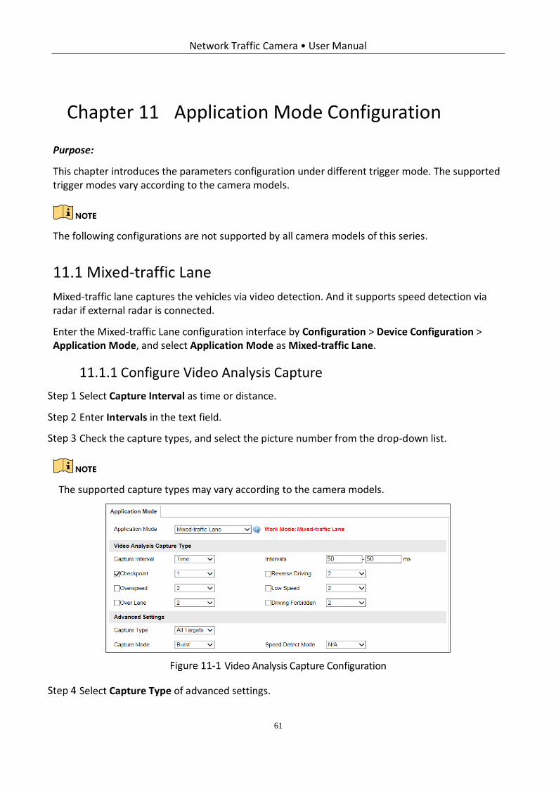
Configure Video Analysis Capture
Select Capture Interval as time or distance.
Enter Intervals in the text field.
Check the capture types, and select the picture number from the drop-down list.
The supported capture types may vary according to the camera models.
Video Analysis Capture Configuration
Select Capture Type of advanced settings.
Network Traffic Camera • User Manual
62
Motor vehicle, Non-motor vehicle, and Pedestrian: It captures motor vehicle, and non-motor vehicle, and pedestrian.
Motor Vehicle: Only motor vehicle will be captured.
Select Capture Mode. The capture mode is associated with the connected type of flashlight. Strobe and Burst are selectable.
Strobe: It adopts the frame extracting, and the captured pictures share the same exposure parameters with the video image.
Burst: It adopts the separate exposure.
A reboot is required when two modes switch.
If you set the capture mode as Burst, the capture image shares the same parameters with
the video image.
The Section 12.5 Configuring Picture is not supported when you select Strobe as the
capture mode.
Select Speed Detect Mode. N/A, Radar, and Video are selectable. N/A refers to disable the speed detection.
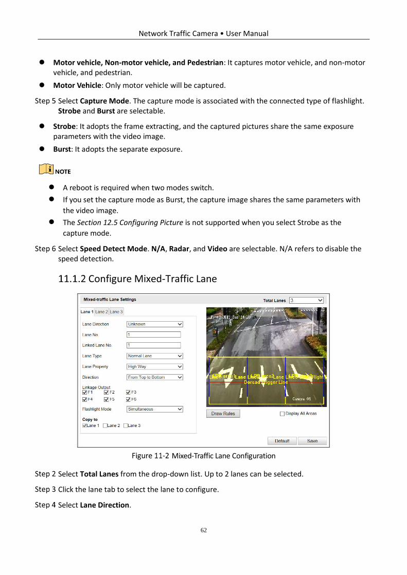
Configure Mixed-Traffic Lane
Mixed-Traffic Lane Configuration
Select Total Lanes from the drop-down list. Up to 2 lanes can be selected.
Click the lane tab to select the lane to configure.
Select Lane Direction.
Network Traffic Camera • User Manual
63
Enter Lane No. in the text field. The Lane No. is used as the OSD content.
Set the linkage lane by entering Linked Lane No., e.g.: if you select lane 1, the system will give the speed of lane 1 detected by radar.
Select Lane Type. Normal Lane, Bus Lane,Truck Forbidden Lane, and Highway Emergency
Lane are selectable.
Select Lane Property. High Way, City Express Way, and Other are selectable.
Select Direction. From Top to Bottom and From Bottom to Top are selectable. If you set the direction as From Top to Bottom, then the vehicle will be judged as wrong-way driving if it drives from Bottom to Top.
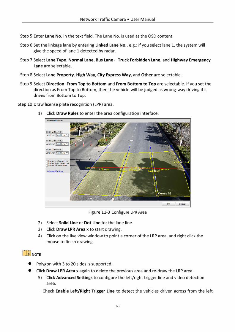
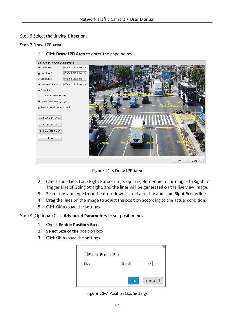
Draw license plate recognition (LPR) area.
1) Click Draw Rules to enter the area configuration interface.
Configure LPR Area
2) Select Solid Line or Dot Line for the lane line.
3) Click Draw LPR Area x to start drawing.
4) Click on the live view window to point a corner of the LRP area, and right click the mouse to finish drawing.
Polygon with 3 to 20 sides is supported.
Click Draw LPR Area x again to delete the previous area and re-draw the LRP area.
5) Click Advanced Settings to configure the left/right trigger line and video detection area.
− Check Enable Left/Right Trigger Line to detect the vehicles driven across from the left
Network Traffic Camera • User Manual
64
border or right border.
You can adjust the line position by dragging the line on the screen and adjust the line length by
dragging an end of the line.
− Check Enable Detection Area to enable the vehicle capture triggered by video analysis. It
is recommended to draw the video detection area according to the actual
environment to avoid the false trigger.
6) Click OK to save the drawing and exit the drawing interface.
7) (Optional) Check Display All Areas to display all the LPR areas.
Select the linkage flashlight output.
Usually one lane is linked to one flashlight. If you link more than 1 flashlight, you need to select
Flashlight Mode. Simultaneous flash and sequential flash are selectable.
(Optional) If you select Speed Detect Mode as Radar, configure the radar settings.
(Optional) Copy the configuration of current lane to other lanes.
Click Save to save the settings.
You can click the Default button to restore the parameters to default values.
Video Analysis E-Police
Go to Configuration > Device Configuration > Application Mode, and select Application Mode as Video Analysis E-police.
Network Traffic Camera • User Manual
65
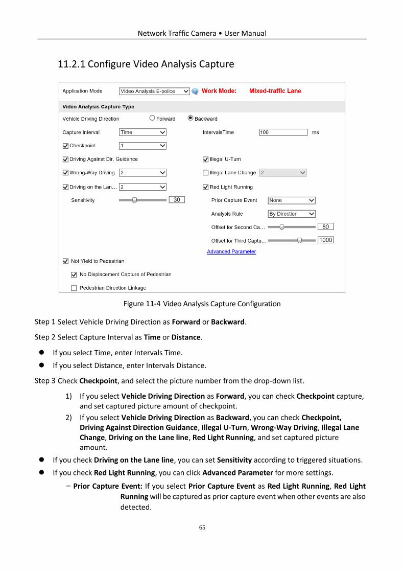
Configure Video Analysis Capture
Video Analysis Capture Configuration
Select Vehicle Driving Direction as Forward or Backward.
Select Capture Interval as Time or Distance.
If you select Time, enter Intervals Time.
If you select Distance, enter Intervals Distance.
Check Checkpoint, and select the picture number from the drop-down list.
1) If you select Vehicle Driving Direction as Forward, you can check Checkpoint capture, and set captured picture amount of checkpoint.
2) If you select Vehicle Driving Direction as Backward, you can check Checkpoint, Driving Against Direction Guidance, Illegal U-Turn, Wrong-Way Driving, Illegal Lane Change, Driving on the Lane line, Red Light Running, and set captured picture amount.
If you check Driving on the Lane line, you can set Sensitivity according to triggered situations.
If you check Red Light Running, you can click Advanced Parameter for more settings.
− Prior Capture Event: If you select Prior Capture Event as Red Light Running, Red Light
Running will be captured as prior capture event when other events are also
detected.
Network Traffic Camera • User Manual
66
− Analysis Rule: You can select Analysis rule as By Direction or By Lane, and draw
corresponding trigger line.
− Offset for Second Capture: It refers to the offset pixel of the second captured picture of
the vehicle running the red light to the stop line. The value ranges from 0
to 300.
− Offset for Third Capture: It refers to the min. offset pixel of the third captured picture of
the vehicle running the red light to the second captured picture. It is
recommended to remain the default value.
(Optional) If you check Vehicle on Non-Motor Vehicle Lane, set the time threshold for capture.
(Optional)Check Not Yield to Pedestrian, to detect the vehicle that not yields to pedestrian.
Not Yield to Pedestrian function may vary from different models, please refer to actual product.
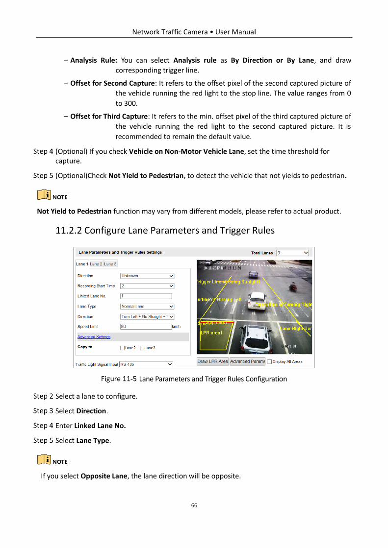
Configure Lane Parameters and Trigger Rules
Lane Parameters and Trigger Rules Configuration
Select a lane to configure.
Select Direction.
Enter Linked Lane No.
Select Lane Type.
If you select Opposite Lane, the lane direction will be opposite.
Network Traffic Camera • User Manual
67
Select the driving Direction.
Draw LPR area.
1) Click Draw LPR Area to enter the page below.
Draw LPR Area
2) Check Lane Line, Lane Right Borderline, Stop Line, Borderline of Turning Left/Right, or Trigger Line of Going Straight, and the lines will be generated on the live view image.
3) Select the lane type from the drop-down list of Lane Line and Lane Right Borderline.
4) Drag the lines on the image to adjust the position according to the actual condition.
5) Click OK to save the settings.
(Optional) Click Advanced Parameters to set position box.
1) Check Enable Position Box.
2) Select Size of the position box.
3) Click OK to save the settings.
Position Box Settings
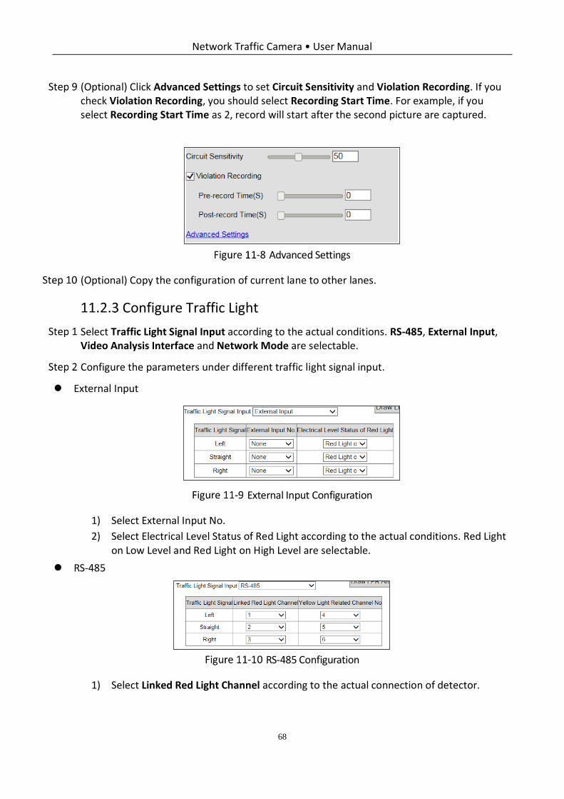
Network Traffic Camera • User Manual
68
(Optional) Click Advanced Settings to set Circuit Sensitivity and Violation Recording. If you check Violation Recording, you should select Recording Start Time. For example, if you select Recording Start Time as 2, record will start after the second picture are captured.
Advanced Settings
(Optional) Copy the configuration of current lane to other lanes.
Configure Traffic Light
Select Traffic Light Signal Input according to the actual conditions. RS-485, External Input, Video Analysis Interface and Network Mode are selectable.
Configure the parameters under different traffic light signal input.
External Input
External Input Configuration
1) Select External Input No.
2) Select Electrical Level Status of Red Light according to the actual conditions. Red Light on Low Level and Red Light on High Level are selectable.
RS-485
RS-485 Configuration
1) Select Linked Red Light Channel according to the actual connection of detector.
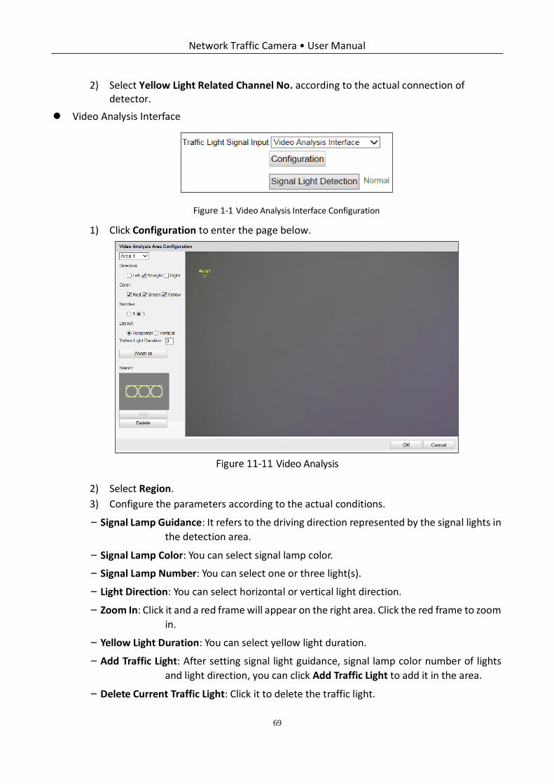
Network Traffic Camera • User Manual
69
2) Select Yellow Light Related Channel No. according to the actual connection of detector.
Video Analysis Interface
Figure 1-1 Video Analysis Interface Configuration
1) Click Configuration to enter the page below.
Video Analysis
2) Select Region.
3) Configure the parameters according to the actual conditions.
− Signal Lamp Guidance: It refers to the driving direction represented by the signal lights in
the detection area.
− Signal Lamp Color: You can select signal lamp color.
− Signal Lamp Number: You can select one or three light(s).
− Light Direction: You can select horizontal or vertical light direction.
− Zoom In: Click it and a red frame will appear on the right area. Click the red frame to zoom
in.
− Yellow Light Duration: You can select yellow light duration.
− Add Traffic Light: After setting signal light guidance, signal lamp color number of lights
and light direction, you can click Add Traffic Light to add it in the area.
− Delete Current Traffic Light: Click it to delete the traffic light.
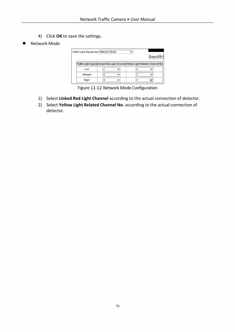
Network Traffic Camera • User Manual
70
4) Click OK to save the settings.
Network Mode
Network Mode Configuration
1) Select Linked Red Light Channel according to the actual connection of detector.
2) Select Yellow Light Related Channel No. according to the actual connection of detector.
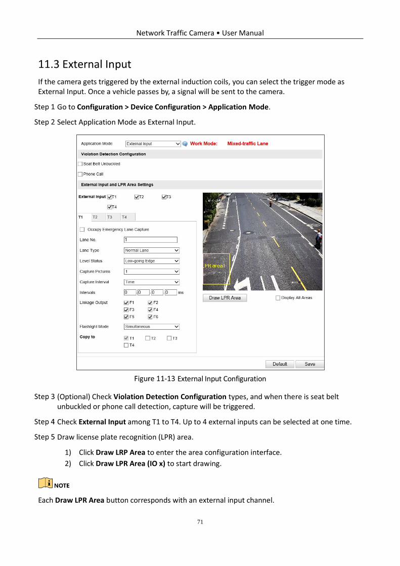
Network Traffic Camera • User Manual
71
External Input
If the camera gets triggered by the external induction coils, you can select the trigger mode as External Input. Once a vehicle passes by, a signal will be sent to the camera.
Go to Configuration > Device Configuration > Application Mode.
Select Application Mode as External Input.
External Input Configuration
(Optional) Check Violation Detection Configuration types, and when there is seat belt unbuckled or phone call detection, capture will be triggered.
Check External Input among T1 to T4. Up to 4 external inputs can be selected at one time.
Draw license plate recognition (LPR) area.
1) Click Draw LRP Area to enter the area configuration interface.
2) Click Draw LPR Area (IO x) to start drawing.
Each Draw LPR Area button corresponds with an external input channel.
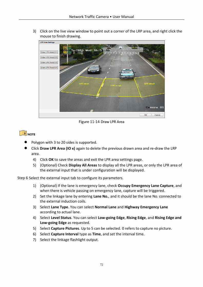
Network Traffic Camera • User Manual
72
3) Click on the live view window to point out a corner of the LRP area, and right click the mouse to finish drawing.
Draw LPR Area
Polygon with 3 to 20 sides is supported.
Click Draw LPR Area (IO x) again to delete the previous drawn area and re-draw the LRP
area.
4) Click OK to save the areas and exit the LPR area settings page.
5) (Optional) Check Display All Areas to display all the LPR areas, or only the LPR area of the external input that is under configuration will be displayed.
Select the external input tab to configure its parameters.
1) (Optional) If the lane is emergency lane, check Occupy Emergency Lane Capture, and when there is vehicle passing on emergency lane, capture will be triggered.
2) Set the linkage lane by entering Lane No., and it should be the lane No. connected to the external induction coils.
3) Select Lane Type. You can select Normal Lane and Highway Emergency Lane according to actual lane.
4) Select Level Status. You can select Low-going Edge, Rising Edge, and Rising Edge and Low-going Edge as requested.
5) Select Capture Pictures. Up to 5 can be selected. 0 refers to capture no picture.
6) Select Capture Interval type as Time, and set the interval time.
7) Select the linkage flashlight output.
Network Traffic Camera • User Manual
73
Usually one lane links to one flashlight. If you link more than 1 flashlight, you need to select
Flashlight Mode. You can select simultaneous flash and sequential flash as requested.
(Optional) Copy the configuration of current external input to other external inputs by checking the corresponding checkboxes among T1 to T4.
Click Save to save the settings.
You can click Default to restore the parameters to default values.
Checkpoint Vehicle Detector
If the camera gets triggered by the vehicle detector, you can select the trigger mode as Checkpoint Vehicle Detector. Once a vehicle passes by, a signal will be sent to the camera.
Go to Configuration > Device Configuration > Application Mode.
Select Application Mode as Checkpoint Vehicle Detector.
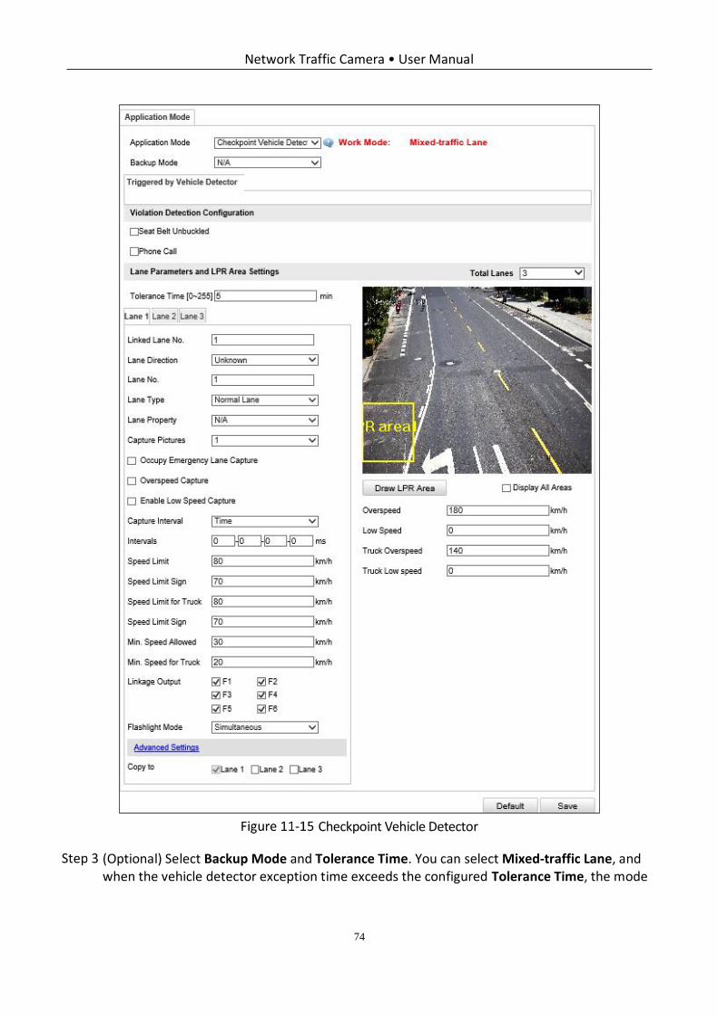
Network Traffic Camera • User Manual
74
Checkpoint Vehicle Detector
(Optional) Select Backup Mode and Tolerance Time. You can select Mixed-traffic Lane, and when the vehicle detector exception time exceeds the configured Tolerance Time, the mode
Network Traffic Camera • User Manual
75
will change to mixed-traffic lane automatically. When the camera can receive the signal from the vehicle detector normally, the mode will change to vehicle detector mode again.
(Optional) Check Violation Detection Configuration types, and when there is seat belt unbuckled or phone call detection, capture will be triggered.
Select Total Lanes from the drop-down list.
Up to 4 lanes can be supported. Supported total lanes may vary from different modes.
Click the lane tab to select the lane to configure.
Draw license plate recognition (LPR) area.
1) Click Draw LRP Area to enter the area configuration page.
2) Click Draw LPR Area (Lane x) to start drawing.
3) Click on the live view window to point out a corner of the LRP area, and right click the mouse to finish drawing.
Polygon with 3 to 20 sides is supported.
Click Draw LPR Area (Lane x) again to delete the previous area and re-draw the LRP area.
1) Click OK to save the areas and exit the LPR area settings page.
2) (Optional) Check Display All Areas to display all the LPR areas.
Set the linkage lane by entering Linked Lane No., and it should be the lane No. connected to the vehicle detector.
Select Lane Direction.
Enter Lane No. in the given field. The Lane No. is used as the OSD content.
Select Lane Type. You can select Normal Lane and Highway Emergency Lane according to actual lane.
Configure the capture parameters.
1) Select Capture Pictures. Up to 5 can be selected. 0 refers to capture no vehicle.
2) (Optional) If the lane is emergency lane, check Occupy Emergency Lane Capture, and when there is vehicle passing on the lane, capture will be triggered.
3) (Optional) Set Speed Limit value according to the actual limit speed. And check Overspeed Capture (capture one more picture) to capture an extra overspeed picture.
4) (Optional) Set Min. Speed Allowed value. And check Enable Low Speed Capture. When the vehicle speed exceeds the set min. speed, capture will be triggered.
Network Traffic Camera • User Manual
76
5) Select Capture Interval type between time and distance, and set the interval time or interval distance.
6) Set Speed Limit Sign according to actual speed value on speed restriction board, and it will be overlaid on captured picture.
7) Set Speed Limit for Truck. When the truck speed exceeds the set speed limit, capture will be triggered.
8) Set Min. Speed for Truck. When the truck speed exceeds the set min. speed, capture will be triggered.
9) Select the linkage flashlight output.
Usually one lane is linked to one flashlight. If you link more than one flashlight, you need to select
Flashlight Mode. Simultaneous flash and sequential flash are selectable.
(Optional) Copy the configuration of current lane to other lanes.
Click Save to save the settings.
You can click the Default to restore the parameters to default values.
RS-485 Radar
If high accuracy speed detection is required, you can select the trigger mode as RS-485 Radar.
Go to Configuration > Device Configuration > Application Mode.
Select Application Mode as RS-485 Radar.
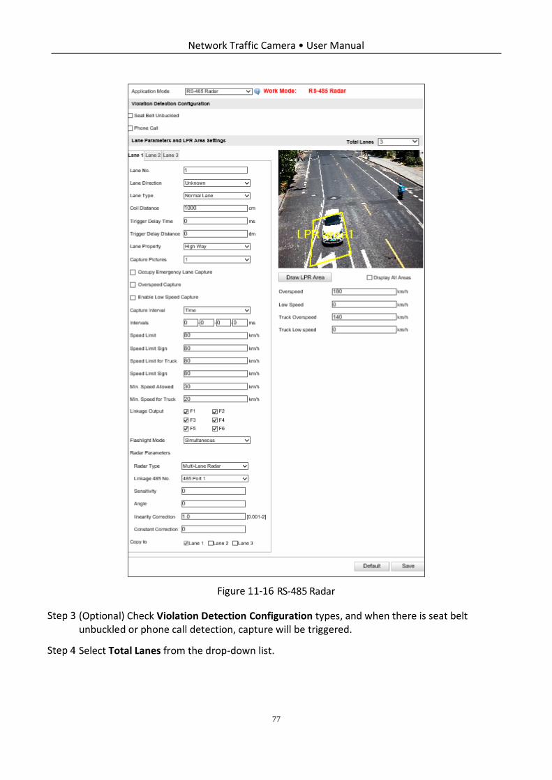
Network Traffic Camera • User Manual
77
RS-485 Radar
(Optional) Check Violation Detection Configuration types, and when there is seat belt unbuckled or phone call detection, capture will be triggered.
Select Total Lanes from the drop-down list.
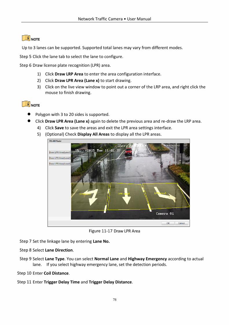
Network Traffic Camera • User Manual
78
Up to 3 lanes can be supported. Supported total lanes may vary from different modes.
Click the lane tab to select the lane to configure.
Draw license plate recognition (LPR) area.
1) Click Draw LRP Area to enter the area configuration interface.
2) Click Draw LPR Area (Lane x) to start drawing.
3) Click on the live view window to point out a corner of the LRP area, and right click the mouse to finish drawing.
Polygon with 3 to 20 sides is supported.
Click Draw LPR Area (Lane x) again to delete the previous area and re-draw the LRP area.
4) Click Save to save the areas and exit the LPR area settings interface.
5) (Optional) Check Display All Areas to display all the LPR areas.
Draw LPR Area
Set the linkage lane by entering Lane No.
Select Lane Direction.
Select Lane Type. You can select Normal Lane and Highway Emergency according to actual lane. If you select highway emergency lane, set the detection periods.
Enter Coil Distance.
Enter Trigger Delay Time and Trigger Delay Distance.
Network Traffic Camera • User Manual
79
Trigger Delay Time: The time between two vehicles being captured.
Trigger Delay Distance: The distance between two vehicles being captured.
Configure the capture parameters.
1) Select Capture Pictures. Up to 5 can be selected. 0 refers to capture no vehicle.
2) (Optional) If the lane is emergency lane, check Occupy Emergency Lane Capture, and when there is vehicle passing on the lane, capture will be triggered.
3) (Optional) Set Speed Limit value according to the actual limit speed. And check Overspeed Capture (capture one more picture) to capture an extra overspeed picture.
4) (Optional) Set Min. Speed Allowed value. And check Enable Low Speed Capture. When the vehicle speed exceeds the set min. speed, capture will be triggered.
5) Select Capture Interval type between time and distance, and set the interval time or interval distance.
Example: If you want to capture 3 pictures at one time and the capture interval is 20 ms, you should select 3 in Capture Pictures drop-down list and enter 20 in the first two blanks of Intervals.
If you set the interval as 0, then the pictures will be captured without interval.
6) Set Speed Limit Sign according to actual speed value on speed restriction board, and it will be overlaid on captured picture.
7) Set Speed Limit for Truck. When the truck speed exceeds the set speed limit, capture will be triggered.
8) Set Min. Speed for Truck. When the truck speed exceeds the set min. speed, capture will be triggered.
9) Select the linkage flashlight output.
Usually one lane is linked to one flashlight. If you link more than one flashlight, you need to select
Flashlight Mode. Simultaneous flash and sequential flash are selectable.
Configure Radar Parameters.
Radar Type: Multi-Lane Radar, Andoray (No Radar Controller), Olvia, Transmicrowave, Sensortech are selectable.
− CSR-IN(P) radar is recommended to select TransMicrowave.
− CSR-IM radar is recommended to select Multi-lane radar
− STJ-XXX is recommended to select Sensor.
− Other radars are recommended to select Custom.
Linkage 485 No.: Select the communication interface of radar.
Network Traffic Camera • User Manual
80
Sensitivity: Enter the sensitivity.
Angle: Enter the angle of the radar and the horizontal direction according to the actual application.
Linearity Correction: You may need to adjust the radar output result according to the actual speed.
Constant Correction: In order to improve the accuracy of the detection speed, there is a constant correction, which is the extra added/ minus speed value.
The final speed is the calculated according to the radar output speed, the linearity correction, and
constant correction together.
Example: The speed detected is 80km/h, and you set the linearity correction coefficient as 1.2, and
the constant correction as 5, then the final speed is 80km/h*1.2+5=101km/h. And if you do not
want to make any change to the detected speed, you can set the linearity correction coefficient as
1, and the constant correction as 0.
(Optional) Copy the configuration of current lane to other lanes.
Click Save to save the settings.
You can click the Default button to restore the parameters to default values.
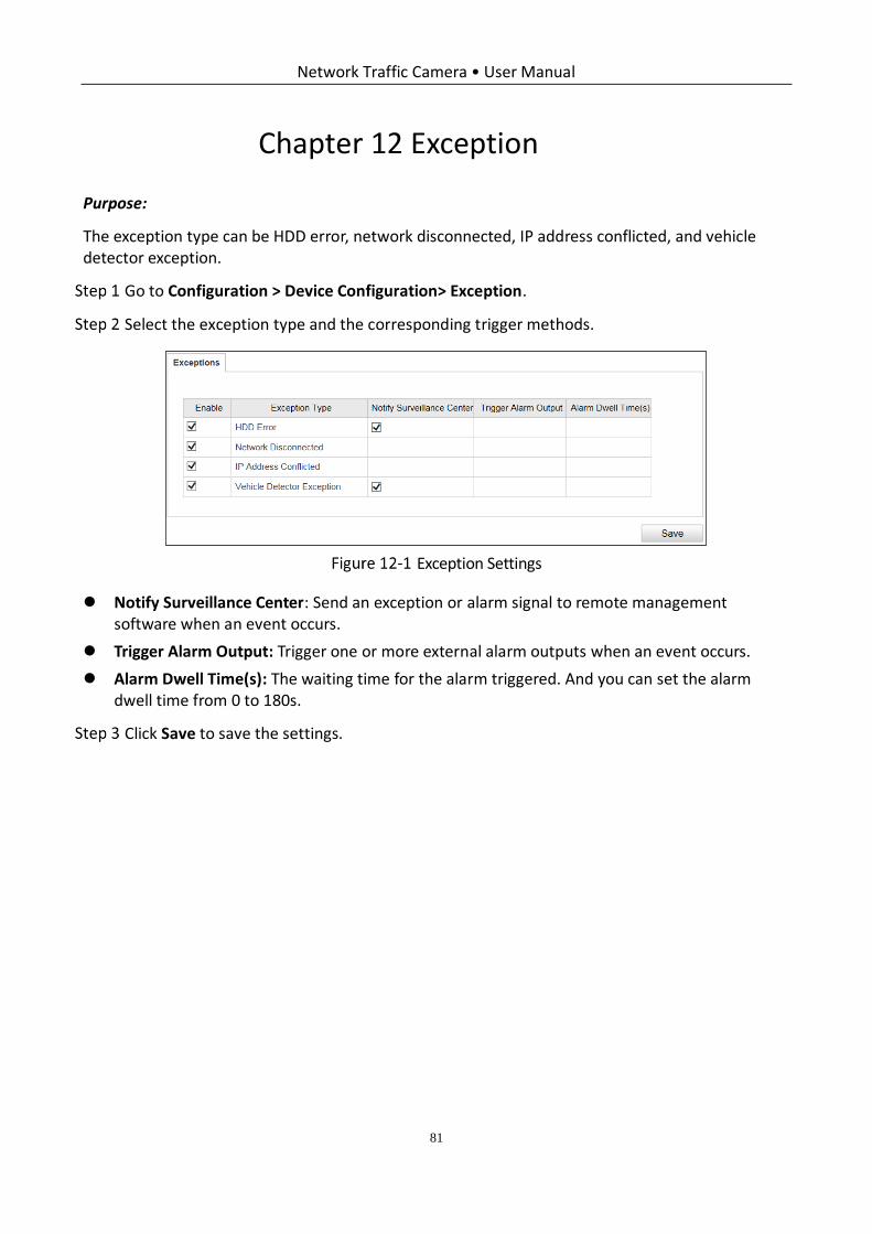
Network Traffic Camera • User Manual
81
Chapter 12 Exception
Purpose:
The exception type can be HDD error, network disconnected, IP address conflicted, and vehicle detector exception.
Go to Configuration > Device Configuration> Exception.
Select the exception type and the corresponding trigger methods.
Exception Settings
Notify Surveillance Center: Send an exception or alarm signal to remote management software when an event occurs.
Trigger Alarm Output: Trigger one or more external alarm outputs when an event occurs.
Alarm Dwell Time(s): The waiting time for the alarm triggered. And you can set the alarm dwell time from 0 to 180s.
Click Save to save the settings.
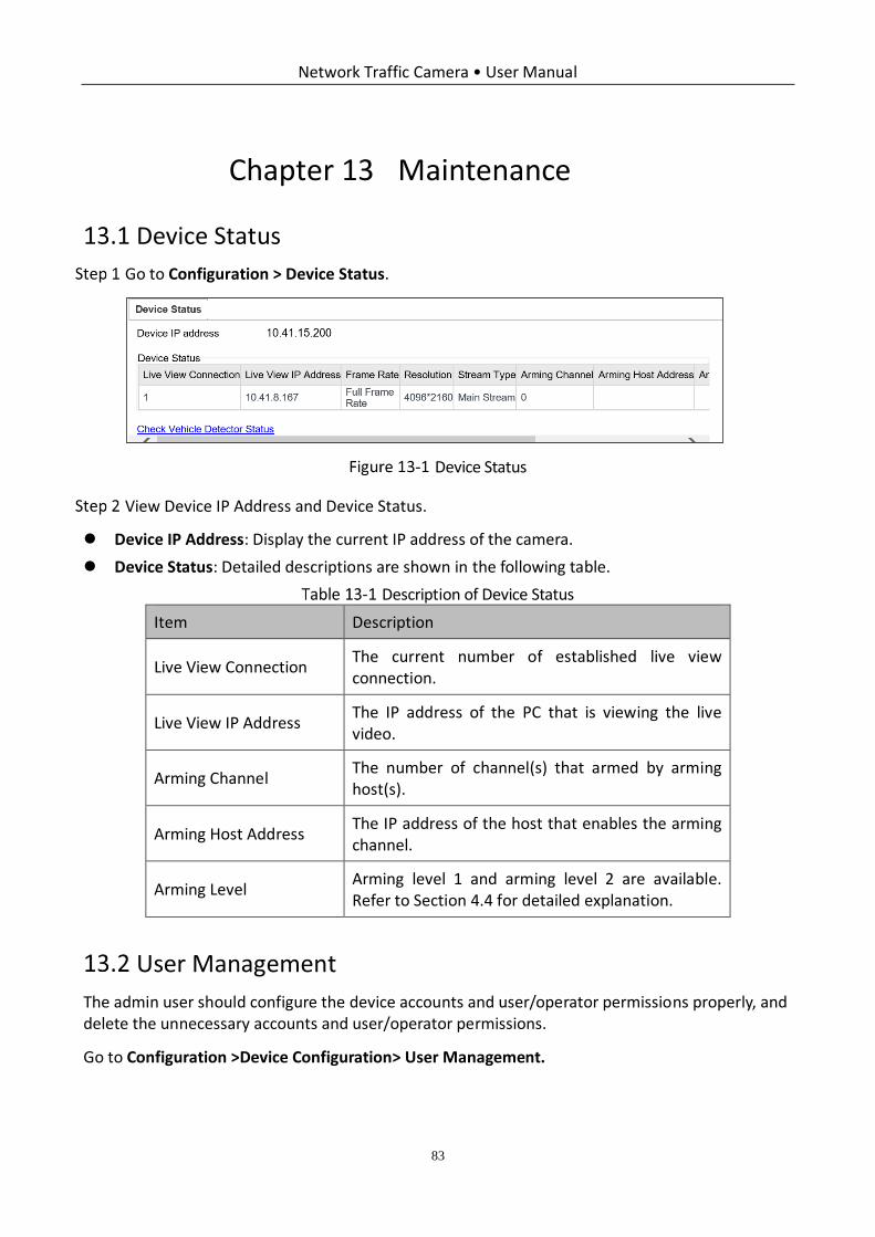
Network Traffic Camera • User Manual
83
Chapter 13 Maintenance
Device Status
Go to Configuration > Device Status.
Device Status
View Device IP Address and Device Status.
Device IP Address: Display the current IP address of the camera.
Device Status: Detailed descriptions are shown in the following table.
Description of Device Status
Item Description
Live View Connection The current number of established live view connection.
Live View IP Address The IP address of the PC that is viewing the live video.
Arming Channel The number of channel(s) that armed by arming host(s).
Arming Host Address The IP address of the host that enables the arming channel.
Arming Level Arming level 1 and arming level 2 are available. Refer to Section 4.4 for detailed explanation.
User Management
The admin user should configure the device accounts and user/operator permissions properly, and delete the unnecessary accounts and user/operator permissions.
Go to Configuration >Device Configuration> User Management.
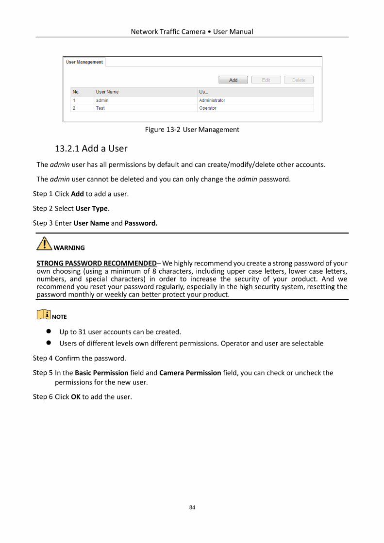
Network Traffic Camera • User Manual
84
User Management
Add a User
The admin user has all permissions by default and can create/modify/delete other accounts.
The admin user cannot be deleted and you can only change the admin password.
Click Add to add a user.
Select User Type.
Enter User Name and Password.
STRONG PASSWORD RECOMMENDED– We highly recommend you create a strong password of your own choosing (using a minimum of 8 characters, including upper case letters, lower case letters, numbers, and special characters) in order to increase the security of your product. And we recommend you reset your password regularly, especially in the high security system, resetting the password monthly or weekly can better protect your product.
Up to 31 user accounts can be created.
Users of different levels own different permissions. Operator and user are selectable
Confirm the password.
In the Basic Permission field and Camera Permission field, you can check or uncheck the permissions for the new user.
Click OK to add the user.
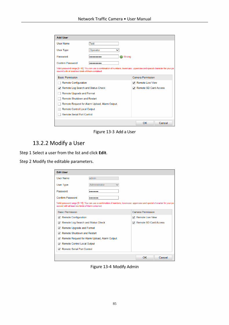
Network Traffic Camera • User Manual
85
Add a User
Modify a User
Select a user from the list and click Edit.
Modify the editable parameters.
Modify Admin
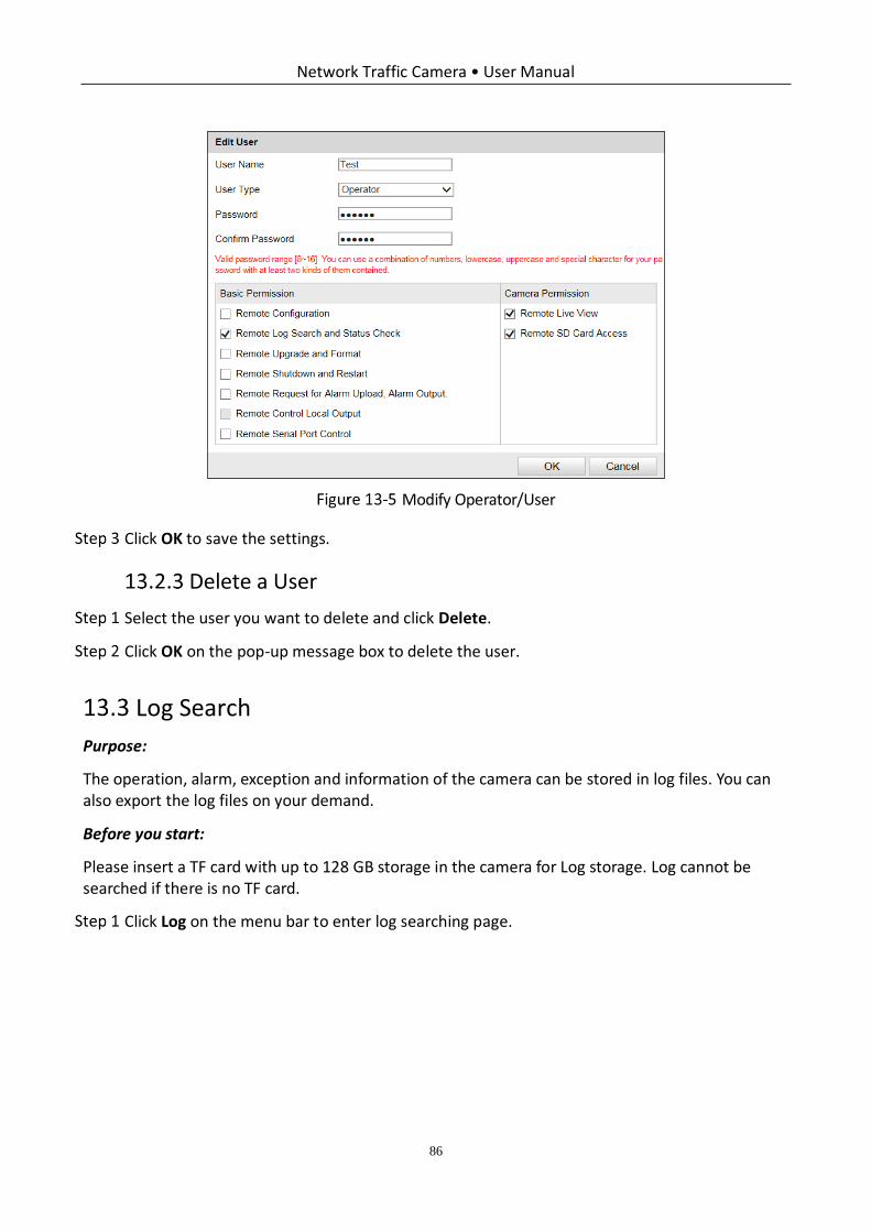
Network Traffic Camera • User Manual
86
Modify Operator/User
Click OK to save the settings.
Delete a User
Select the user you want to delete and click Delete.
Click OK on the pop-up message box to delete the user.
Log Search
Purpose:
The operation, alarm, exception and information of the camera can be stored in log files. You can also export the log files on your demand.
Before you start:
Please insert a TF card with up to 128 GB storage in the camera for Log storage. Log cannot be searched if there is no TF card.
Click Log on the menu bar to enter log searching page.
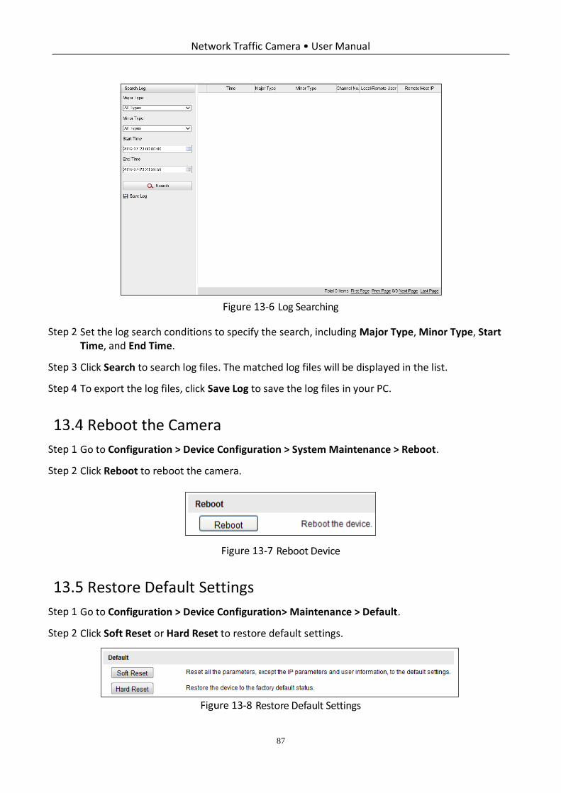
Network Traffic Camera • User Manual
87
Log Searching
Set the log search conditions to specify the search, including Major Type, Minor Type, Start Time, and End Time.
Click Search to search log files. The matched log files will be displayed in the list.
To export the log files, click Save Log to save the log files in your PC.
Reboot the Camera
Go to Configuration > Device Configuration > System Maintenance > Reboot.
Click Reboot to reboot the camera.
Reboot Device
Restore Default Settings
Go to Configuration > Device Configuration> Maintenance > Default.
Click Soft Reset or Hard Reset to restore default settings.
Restore Default Settings
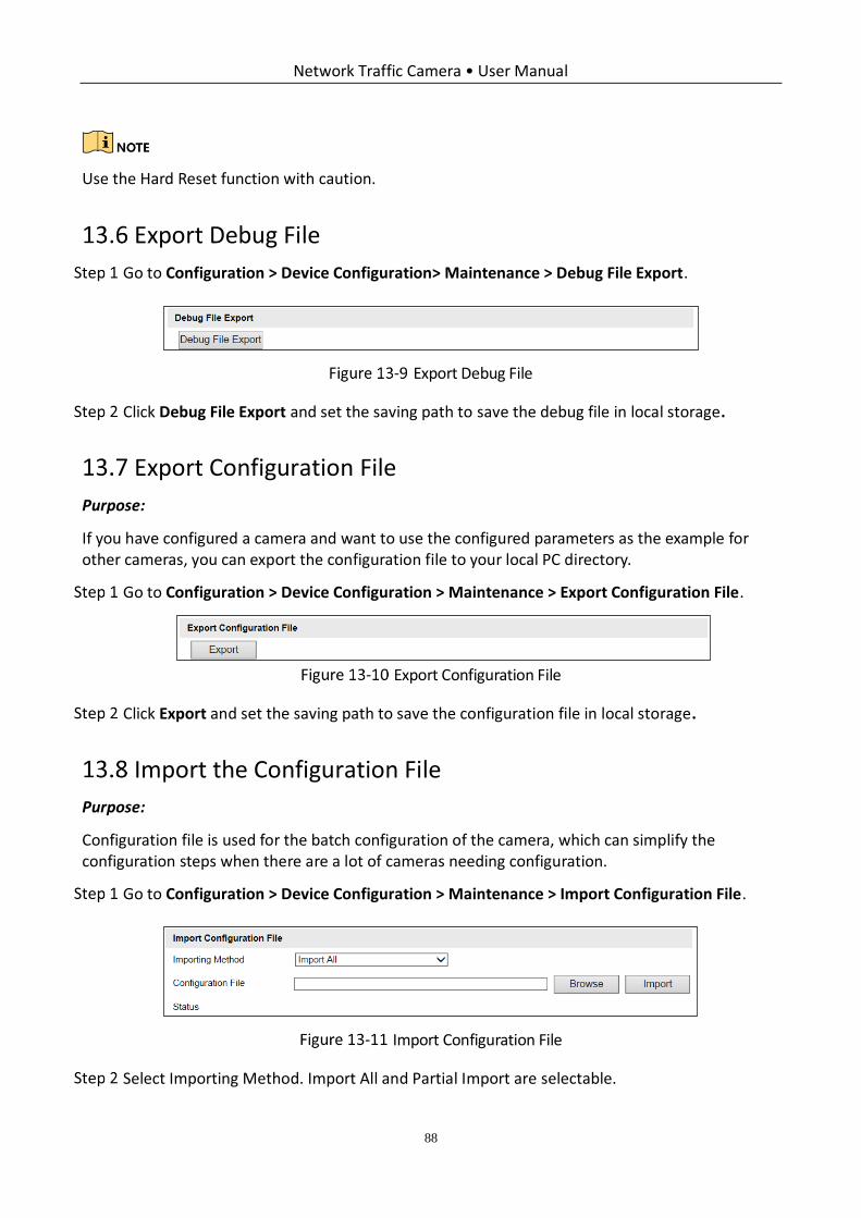
Network Traffic Camera • User Manual
88
Use the Hard Reset function with caution.
Export Debug File
Go to Configuration > Device Configuration> Maintenance > Debug File Export.
Export Debug File
Click Debug File Export and set the saving path to save the debug file in local storage.
Export Configuration File
Purpose:
If you have configured a camera and want to use the configured parameters as the example for other cameras, you can export the configuration file to your local PC directory.
Go to Configuration > Device Configuration > Maintenance > Export Configuration File.
Export Configuration File
Click Export and set the saving path to save the configuration file in local storage.
Import the Configuration File
Purpose:
Configuration file is used for the batch configuration of the camera, which can simplify the configuration steps when there are a lot of cameras needing configuration.
Go to Configuration > Device Configuration > Maintenance > Import Configuration File.
Import Configuration File
Select Importing Method. Import All and Partial Import are selectable.
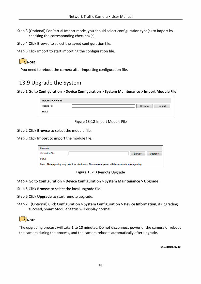
Network Traffic Camera • User Manual
89
(Optional) For Partial Import mode, you should select configuration type(s) to import by checking the corresponding checkbox(s).
Click Browse to select the saved configuration file.
Click Import to start importing the configuration file.
You need to reboot the camera after importing configuration file.
Upgrade the System
Go to Configuration > Device Configuration > System Maintenance > Import Module File.
Import Module File
Click Browse to select the module file.
Click Import to import the module file.
Remote Upgrade
Go to Configuration > Device Configuration > System Maintenance > Upgrade.
Click Browse to select the local upgrade file.
Click Upgrade to start remote upgrade.
(Optional) Click Configuration > System Configuration > Device Information, if upgrading succeed, Smart Module Status will display normal.
The upgrading process will take 1 to 10 minutes. Do not disconnect power of the camera or reboot
the camera during the process, and the camera reboots automatically after upgrade.
0403101090730

UD15859B