network utilisation and security monitoring using …
TRANSCRIPT

NETWORK UTILISATION AND SECURITY MONITORING USING SNMP
By
Ling Wei Joon
A REPORT
SUBMITTED TO
Universiti Tunku Abdul Rahman
in partial fulfillment of the requirements
for the degree of
BACHELOR OF INFORMATION TECHNOLOGY (HONS)
COMMUNICATION AND NETWORKING
Faculty of Information and Communication Technology
(Kampar Campus)
MAY 2020

UNIVERSITI TUNKU ABDUL RAHMAN
REPORT STATUS DECLARATION FORM
Title: NETWORK UTILISATION AND SECURITY MONITORING USING SNMP
Academic Session: MAY 2020
I LING WEI JOON
(CAPITAL LETTER)
declare that I allow this Final Year Project Report to be kept in
Universiti Tunku Abdul Rahman Library subject to the regulations as follows:
1. The dissertation is a property of the Library.
2. The Library is allowed to make copies of this dissertation for academic purposes.
Verified by,
_________________________ _________________________
(Author’s signature) (Supervisor’s signature)
Address:
__________________________
__________________________ _________________________
__________________________ Supervisor’s name
Date: 6/9/2020 Date: ____________________

NETWORK UTILISATION AND SECURITY MONITORING USING SNMP
By
Ling Wei Joon
A REPORT
SUBMITTED TO
Universiti Tunku Abdul Rahman
in partial fulfillment of the requirements
for the degree of
BACHELOR OF INFORMATION TECHNOLOGY (HONS)
COMMUNICATION AND NETWORKING
Faculty of Information and Communication Technology
(Kampar Campus)
MAY 2020

ii
BIS (Hons) Communications and Networking Faculty of Information and Communication Technology (Kampar Campus), UTAR
DECLARATION OF ORIGINALITY
I declare that this report entitled “NETWORK UTILISATION AND SECURITY
MONITORING USING SNMP” is my own work except as cited in the references.
The report has not been accepted for any degree and is not being submitted concurrently
in candidature for any degree or other award.
Signature : _________________________
Name : LING WEI JOON
Date : 6/9/2020

iii
BIS (Hons) Communications and Networking Faculty of Information and Communication Technology (Kampar Campus), UTAR
ACKNOWLEDGEMENT
I would like to express my sincere thanks and appreciation to my supervisors, Dr. Gan
Ming Lee who has given me this bright opportunity to engage in a network monitoring
project. It is my first step to establish a career in networking and security area. A million
thanks to you.

iv
BIS (Hons) Communications and Networking Faculty of Information and Communication Technology (Kampar Campus), UTAR
ABSTRACT
A monitor system is important in the filed which consists of network devices and
connectivity between them. In this study, we will learn about different type and
comparison between monitoring techniques. The challenges in keeping our system free
of failure are difficult. A system which cannot be guaranteed to be up during the whole-
time operations will make the user frustrated. Besides, system performance and usage
also another point where user always concerned with. When the usage on the network
or devices if fully occupied, the performance is degraded and eventually cause the
services to become unavailable. In this paper, the SNMP protocol is taken into
consideration and implementation for network monitoring. The protocol is worked by
sending out a message from a central point called management base station to the
network devices and those devices return the data information requested back.
Throughout the process, the targeted network is closely monitored with SNMP
monitoring system and penetration testing will be prosecuted. The outcome produced
from the SNMP system is being observed and determine the capability of detecting an
attack.

v
BIS (Hons) Communications and Networking Faculty of Information and Communication Technology (Kampar Campus), UTAR
TABLE OF CONTENTS
TITLE PAGE i
DECLARATION OF ORIGINALITY ii
ACKNOWLEDGEMENT iii
ABSTRACT vi
TABLE OF CONTENTS v
LIST OF FIGURES viii
LIST OF TABLES xi
LIST OF ABBREVIATIONS xii
CHAPTER 1 INTRODUCTION 1
1.1 Problem Statement and Motivation 1
1.2 Project Scope 1
1.3 Project Objectives 2
1.4 Impact, Significance and Contribution 2
1.5 Background Information
3
CHAPTER 2 LITERATURE REVIEW 6
2.1 Honeypot 6
2.1.1 Type of Honeypot 6
2.1.2 Level of Interaction 7
2.1.3 Advantages and Disadvantages of Honeypot 8
2.2 Intrusion Detection System 9
2.2.1 Types of Intrusion Detection System 9
2.2.2 Approaches of Intrusion Detection System 10
2.2.3 Advantages and Disadvantages of Intrusion Detection System 11

vi
BIS (Hons) Communications and Networking Faculty of Information and Communication Technology (Kampar Campus), UTAR
2.3 Cisco IOS NetFlow 13
2.3.1 NetFlow Components 13
2.3.2 Advantages and Disadvantages of NetFlow 14
2.4 Syslog 15
2.4.1 Syslog Layer 15
2.4.2 Syslog Server Components 16
2.4.3 Advantages and Disadvantages of Syslog 16
2.5 SNMP 18
2.5.1 Type of SNMP Message 18
2.5.2 Evolution of SNMP 19
2.5.3 Advantages and Disadvantages of SNMP 20
2.6 Comparison of Existing Systems 21
2.7 Summary
22
CHAPTER 3 SYSTEM DESIGN
23
CHAPTER 4 PROPOSED METHOD / APPROACH 26
4.1 Methodologies and General Work Procedures 26
4.2 Tools 27
4.3 Requirements 28
4.4 Implementation Issues and Challenges 29
4.5 Timeline
30
CHAPTER 5 IMPLEMENTATION
31
CHAPTER 6 EXPERIMENTAL RESULT 49
6.1 Network Traffic and CPU Usage Analysis 49

vii
BIS (Hons) Communications and Networking Faculty of Information and Communication Technology (Kampar Campus), UTAR
6.1.1 Behavior Analysis Before DDoS 49
6.1.2. SYN Flood Behavior Analysis 52
6.1.3 UDP Flood Behavior Analysis 54
6.1.4 ICMP Flood Behavior Analysis 56
6.2 DDoS Pattern Detection 58
6.3 DDoS Alert 60
6.4 Types of DDoS Analysis
61
CHAPTER 7 CONCLUSION 65
BIBLIOGRAHPY 66
APPENDIX A: WEEKLY REPORT A-1

viii
BIS (Hons) Communications and Networking Faculty of Information and Communication Technology (Kampar Campus), UTAR
LIST OF FIGURES
Figure Title Page
1.1 Attack Scenario 4
2.1 NetFlow Diagram 13
2.2 Syslog Layers 15
3.1 Flow of the System 23
3.2 SNMP System Architect 24
4.1 Network Architecture Diagram 26
4.2 Timeline for FYP1 and FYP2 30
5.1 Equipment Installation 31
5.2 Router Configure (1) 32
5.3 Router Configure (2) 32
5.4 Router Configure (3) 33
5.5 Router Configure (4) 33
5.6 Details 33
5.7 Ping 34
5.8 SNMP Services (1) 35
5.9 SNMP Services (2) 35
5.10 SNMP Services (3) 36
5.11 PRTG Home 37
5.12 PRTG Devices 37
5.13 Add Device 38
5.14 Add Sensor (1) 39
5.15 Add Sensor (2) 39
5.16 Add Sensor (3) 40
ix
BIS (Hons) Communications and Networking Faculty of Information and Communication Technology (Kampar Campus), UTAR
5.17 Add Sensor (4) 40
5.18 Add Sensor (5) 40
5.19 Add Sensor (6) 40
5.20 Modify Sensor (1) 41
5.21 Modify Sensor (2) 41
5.22 Modify Sensor (3) 42
5.23 Modify Sensor (4) 42
5.24 Modify Sensor (5) 43
5.25 Modify Sensor (6) 43
5.26 Modify Sensor (7) 44
5.27 Modify Sensor (8) 44
5.28 SYN Flood (1) 45
5.29 SYN Flood (2) 46
5.30 SYN Flood (3) 46
5.31 SYN Flood (4) 46
5.32 ICMP Flood (1) 47
5.33 ICMP Flood (2) 47
5.34 UDP Flood (1) 48
5.35 UDP Flood (2) 48
6.1 Normal Traffic (1) 49
6.2 Normal Traffic (2) 50
6.3 Normal CPU Usage 50
6.4 SYN Traffic (1) 52
6.5 SYN Traffic (2) 52
6.6 SYN CPU Usage 53
6.7 UDP Traffic (1) 54
6.8 UDP Traffic (2) 54

x
BIS (Hons) Communications and Networking Faculty of Information and Communication Technology (Kampar Campus), UTAR
6.9 UDP CPU Usage 55
6.10 ICMP Traffic (1) 56
6.11 ICMP Traffic (2) 56
6.12 ICMP CPU Usage 57
6.13 Traffic Volume 58
6.14 CPU Usage Percentage 59
6.15 Alert Message (1) 60
6.16 Alert Message (2) 60
6.17 SYN Pattern 61
6.18 UDP Pattern 62
6.19 ICMP Pattern 63
6.20 ICMP CPU Pattern 64

xi
BIS (Hons) Communications and Networking Faculty of Information and Communication Technology (Kampar Campus), UTAR
LIST OF TABLES
Table Title Page
2.1 Level of Interaction 7
2.2 Type of IDS 10
2.3 Approaches of IDS 11
2.4 Summary of Existing System 21
4.1 Desktop PC 28
4.2 Cisco Router 1841 28
4.3 Kali Linux 29
4.4 PRTG 29

xii
BIS (Hons) Communications and Networking Faculty of Information and Communication Technology (Kampar Campus), UTAR
LIST OF ABBREVIATIONS
CPU Central Processing Unit
DDOS Distributed Denial of Services
DHCP Dynamic Host Configuration Protocol
DNS Domain Name Service
FA Fast Ethernet
FYP Final Year Project
GUI Graphic User Interface
HIDS Host-based Intrusion Detection System
ICMP Internet Control Message Protocol
IDS Intrusion Detection System
IP Internet Protocol
ISP Internet Service Provider
KB Kilo Bytes
LAN Local Area Network
MAC Media Access Control
MIB Management Information Base
NAT Network Address Translation
NIDS Network-based Intrusion Detection System
NMS Network Monitoring System
OID Object Identifier
PC Personal Computer
SDLC Software Development Life Cycle
SNMP Simple Network Management Protocol
SSH Secure Shell

xiii
BIS (Hons) Communications and Networking Faculty of Information and Communication Technology (Kampar Campus), UTAR
SYN Synchronization
TCP Transmission Control Protocol
UDP User Datagram Protocol
VLAN Virtual Local Area Network

CHAPTER 1 INTORUDCTION
1 BIS (Hons) Communications and Networking Faculty of Information and Communication Technology (Kampar Campus), UTAR
CHAPTER 1 INTRODUCTION
1.1 Problem Statement and Motivation
It becomes very common for individuals or companies to use technology in assisting
their daily tasks or working process. A good system is key to keep the business continue
to operate. Tolerance toward the system faulty or failure is considered a critical
situation in which it might cause a decrease in the availability of services provided and
losing data. The reason why failure occurs often is due to a misconfiguration on the
network infrastructure. However, the most concern for the companies is about security.
It is essential to employ security practices on the network to prevent attacks from an
outsider.
Good practice in enabling protection on the network is to have a good monitoring tool.
A monitoring tool helps to analyse the flow which packets are passing on the network.
It may not be limited to the only network but also devices, applications and services
provided will be analysed. In result, any errors are detected and alert, things may get
control so that it will not affect the whole system or business processes.
1.2 Project Scope
At the end of the project, we are going to employ an SNMP enabled network which the
information flows within or across the network is captured into SNMP packet and send
it to the server for monitoring purpose. In the proposed network, the SNMP agents
communicate with the SNMP manager to exchange data that was captured by the
agents. With the utilization of the SNMP, information about managed devices is
collected by SNMP agents and being sent to the SNMP manager so that the information
will be organized, analysed and finally generates the output to the network
administrator. The information collected such as network bandwidth, CPU usage,
memory usage and so on. The administrator may configure a threshold on an acceptable
range of usage so that when it is about to exceed, it will automatically produce an alert
CHAPTER 1 INTORUDCTION
2 BIS (Hons) Communications and Networking Faculty of Information and Communication Technology (Kampar Campus), UTAR
to the administrator for troubleshooting. Furthermore, we will proceed to a penetration
testing on our designed network to overload the traffic and prevent legitimate request
to be processed by flooding the target network with superfluous requests, consequently
the resources become unavailable. Lastly, observe the data collected by SNMP to detect
such an attack performed on the network.
1.3 Project Objectives
i. To set up an SNMP enabled network. In the proposed project, network
devices such as a router, switch, host and server are connected to form a
simple network architecture. A server is configured as SNMP manager
which in charge of data collection, other network devices are enabled with
SNMP services so that it can pass the data to the server.
ii. Demonstrate the network monitoring capabilities of SNMP. Activities are
carried out where resources are used using network devices with SNMP
services turned on. The SNMP server will then collect any information for
further analysis.
iii. To execute penetration testing on the SNMP enabled network. Attacks on
network or transport layer will be executed to the targeted device. A simple
script is therefore written and run using the terminal in Kali Linux.
iv. To identify the SNMP can detect such attacks. At the end of the project, the
SNMP manager will pull the information for analysis. Observe the result
generated by the SNMP server to detect if any threshold for a certain
parameter is exceeded and generate an alarm to inform the network
administrator.
1.4 Impact, Significance and Contribution
By implementing a monitoring tool, protection on the network, as well as systems, are
increased. A monitoring tool will enable the administrator to have better control over
CHAPTER 1 INTORUDCTION
3 BIS (Hons) Communications and Networking Faculty of Information and Communication Technology (Kampar Campus), UTAR
their system and network. The administrator can keep track of the performance on the
system so that any failure of hardware is detected and fixed. System or network failure
often occurs without notifying the user, this may lead to delaying the business process
and even loss of data. To guarantee the availability of a system is stick to the peak, a
monitoring tool must be carried out. A monitoring tool can ensure the network and
system stay out of outages, which help to avoid critical impact to the organization.
Besides, it may also assist the administrator in identifying potential security threats.
1.5 Background Information
In the era globalization of technology, people are moving from traditional ways to
modern ways of handling their jobs. They start to make the use of smart devices to
handle their tasks either in the workplace or at home. What is a smart device? It is an
electronic device such as laptops, smartphones, and even smart televisions that
connected to other devices or network. Previously, we might need plenty of workers to
finish a project, but for now, we can simply utilize some devices to finish the task given
cooperatively. To accomplish the mission, devices must be all connected to the Internet
for them to communicate. A computer network is a digital telecommunications network
that provides devices to exchange data with each other when they are connected to the
Internet. The network contains millions of devices linked together. Networking allows
people to easily share data, remotely accesses to other connected devices to perform
tasks, provision of storage capacity to store and access their data in cloud services or
other machines on the network.
Networking becomes one of the most important aspects of the revolution in information
technology and is still evolving. Usage has become the most concern topic lately,
network utilization is the bandwidth usage for the network traffic on the network. There
is a maximum amount that can be supported within a network, once overloaded can
lead to a performance bottleneck. Unfortunately, people do not use the resources
properly and end up wasted the resources in the network (Jiang, 2016). One of the

CHAPTER 1 INTORUDCTION
4 BIS (Hons) Communications and Networking Faculty of Information and Communication Technology (Kampar Campus), UTAR
reasons caused by non-work employee’s activities, they use the network resources for
their interest during the working hours. A report state that over 90% of employees are
engaged in personal internet usage in the workplace (Sharma & Gupta, 2004). When
there are no more resources to support the workloads in the network, users will
experience slower speeds. The response time is far greater than expected, preventing
the business to operate efficiently. Performances are degraded due to many requests
that cannot be fulfilled in time.
Besides, people nowadays rely on the Internet for professional, social and personal
activities. Although benefits bringing by the Internet, it is also introduced o security
issues. There are people with the intention to break into other people’s devices and
networks to execute the malicious attack. Through security holes, a hacker can steal
confidential information and sell to third parties. They also intruded into the system
attempt to make it become malfunction. One of the most popular attacks that target on
the network is DDOS. According to (Elleithy, Blagovic, Cheng, and Sideleau, 2005),
an attacker is trying to prevent the legitimate user to use the resources by flooding the
server, system and even network with traffic generated by the attacker. This action
involves sacrificing the victim’s resources and end up terminating the user’s traffic.
Figure 1.1 shows an attack manipulating several machines to send superfluous requests
to the target machine and the intended user requests are unable to fulfil.
Figure 1.1 Attack Scenario
To prevent attacks, most of the devices are installed with a network security system
such as firewall and antivirus. Firewall defines a set of rules about which traffics
allowed to enter or leave a network. Antivirus software has a list of known malware
CHAPTER 1 INTORUDCTION
5 BIS (Hons) Communications and Networking Faculty of Information and Communication Technology (Kampar Campus), UTAR
signatures and checks all the files to determine if any matching signature to prove that
the malware program is existing. However, the number of malware programs is
growing rapidly, antivirus software can’t detect all malware attacks due to the limited
number of signatures to match with the patterns.
There are plenty of issues going on in our network nowadays. There are no perfect
solutions to cure the maters instead we can reduce the impact of these problems on the
network with a network monitor system. (Svoboda, J., Ghhfir, I. and Prenosil, V., 2005)
stated that network monitor always monitoring the computer network for any faults or
defect to ensure continuous network performance. It scans the health of network
components including the router, server and hosts. Any decelerating components are
detected, the network administrator is automatically get notified of the problem by the
network monitor system. There are few functions provided in the NMS such as
discovering, mapping, monitoring, alerting and reporting features. NMS starts with the
discovering process, it scans through all devices connected to the network and
dynamically allocates very discovered device with a specific device role. Coming to the
mapping process, NMS generates the network maps and displays the devices in up-to-
date status to visualize the network. Then NMS starts to monitor the devices based on
the previously assigned role to define what scope to monitor as well as CPU usage,
memory, disk space and interface utilization. The next alerting process is an alarm
where when something goes wrong in the network, the administrator gets notified via
email or logged the event when the threshold is exceeded to avoid affecting user,
application and business. Lastly, reporting process delivers the real-time and historical
data to the dashboard for visualization.

CHAPTER 2 LITERATURE REVIEW
6 BIS (Hons) Communications and Networking Faculty of Information and Communication Technology (Kampar Campus), UTAR
CHAPTER 2 LITERATURE REVIEW
2.1 Honeypot
Honeypot uses a concept of the fake system appears to be a real system for attackers.
The fake system looks like no different from a computer system we are using daily
which containing the applications, services stored in the system. The goal of the
honeypot is to lure attackers into a system that is isolated from the real environment to
observe and analyse malicious activities. Honeypot provides resources planned to get
attack and compromise to gain information on the attack, techniques and tools used.
Honeypot also can distract an attacker from their real targets by representing itself as a
potential target such as a server. Any malicious activities happen in the honeypot is
recorded down, after that the information is being analysed to learn new threats and
create a solution to mitigate the problem. The idea of the honeypot focuses on helping
the administrator to understand the existing threats rather than solving a specific
problem like what firewall or antivirus does. According to (Mokube and Adams, 2007)
honeypots is divided into a different category based on their aims and level of
interaction. Difference aims use a different type of honeypots such as research honeypot
and production honeypot.
2.1.1 Type of Honeypot
The two primary types of honeypot which are research honeypot and production
honeypot. Although both honeypots are intended to capture the information, there are
slight differences between them. Research honeypots often deployed by the security
researchers, military, and government organization in order to figure out new threats
and the motivation of the black hat community. Research honeypot aims to understand
the black hat community and improve its protection to the system, but it does not
increase the security of the organization. Production honeypots are widely used by most

CHAPTER 2 LITERATURE REVIEW
7 BIS (Hons) Communications and Networking Faculty of Information and Communication Technology (Kampar Campus), UTAR
of the organization. They gather limited information and often used low interaction
technique. This kind of honeypot usually functions as a real system, contains
information to attract and used up attack’s time and resources, providing administrator
time to come out with a solution to mitigate the threats in their real production system.
2.1.2 Level of Interaction
According to (Baumann and Platnner, 2002), there is three-level of involvements the
attacker can interact with the honeypot operating system. Low-level interaction
honeypot only provides one or more simple services. These services are implemented
in such a way that a listener is placed to log all incoming traffic into a log file to be
analysed. Since there is no real operating system involved in this interaction level, it is
not vulnerable to the attack, the risk of a system getting compromised is very low.
Follow by medium-level interaction honeypot, simulated software is presented to the
attacker, but the real operating system is still not exploited to the attacker. More
complex attacks can be performed and be logged into a log file for analysed. The risk
increases and the chances for an attacker to find leakage of security is getting bigger
due to the complexity of the honeypot. A high-level interaction honeypot introduces a
real operating system to attackers. The objective of this interaction level is to give the
attacker the right to gain root access on the machine and starts the real hacking skills.
This can lead to the highest risk a machine getting compromised, but at the same time,
the highest value of information can be collected.
Level of
Interaction
Information Gathering Work to Deploy
and Maintain
Knowledge to
Develop
Level of Risk
Low Connection Attempts Easy Low Low
Medium Requests Involved Low Medium
High All Difficult High High
Table 2.1 Level of Interaction

CHAPTER 2 LITERATURE REVIEW
8 BIS (Hons) Communications and Networking Faculty of Information and Communication Technology (Kampar Campus), UTAR
2.1.3 Advantages and Disadvantages of Honeypot
The benefit of the honeypot is that the administrator can collect data from malicious or
any unauthorized activities done by the attack and analyse the data to improve their
security. This process is done using a decoy computer system instead of a real system.
Thereby, significantly reduce the risk for a real operating system to get compromised
by the attacker. Besides, honeypot does not generate false alarms because there are no
legitimate users would access to the honeypot. However, honeypot also has some
limitation. The administrator can only collect the information if an attacker attacked the
system, there is no way to capture any information when there is no attack occurs.
Besides, experienced hackers can easily distinguish between a real system and
honeypot system through fingerprinting.

CHAPTER 2 LITERATURE REVIEW
9 BIS (Hons) Communications and Networking Faculty of Information and Communication Technology (Kampar Campus), UTAR
2.2 Intrusion Detection System
An intrusion detection system is a system that deployed to monitor the network traffic
for malicious activities and generates alarms when a significant event has occurred. An
IDS can collect information ranging from a single computer to a network. An IDS is
operating based on four stages of functions which the first function is data collection
(Tiwari et al., 2017). In this stage, data flows are captured into IDS as input and then
analysed. The second function is feature selection which the IDS will choose particular
features from large data to be evaluated since not all features are needed for the analysis.
Next, in the analysis stage, the IDS started to analyse the data to determine the
legitimacy of traffics. The analysis is done either using signature-based IDS or
anomaly-based IDS. In the last stage, IDS can either act actively or passively if an attack
is found. The active way means IDS can automatically drop the packets or close the
ports to prevent packets coming into the network, while the passive way is to generate
alerts to inform the administrator. A firewall has the similar features as the IDS but with
the static set of rules to define the packet and do not generate alarms while an IDS
describes the packet static or dynamically and generate alarms when it has detected
suspected intrusion.
2.2.1 Types of Intrusion Detection System
Classification of IDS can be divided into Network-based IDS, Host-based IDS and
Hybrid based IDS (Uppal et al., 2014). NIDS are usually network appliances that
monitor a network by utilizing network intrusion detection capabilities. NIDS can either
be placed before or after the firewall. NIDS is focusing on monitoring incoming and
outgoing packets of a network. All packets passing through the communication
mediums are being captured and scanned (Ashoor and Gore, 2011). HIDS is a software-
based intrusion detection system which running on hosts in the network. HIDS is
mainly focusing on monitoring events occurred in a host instead of the network.
According to (Beal, 2005), NIDS not only can identify the malicious traffic on the
CHAPTER 2 LITERATURE REVIEW
10 BIS (Hons) Communications and Networking Faculty of Information and Communication Technology (Kampar Campus), UTAR
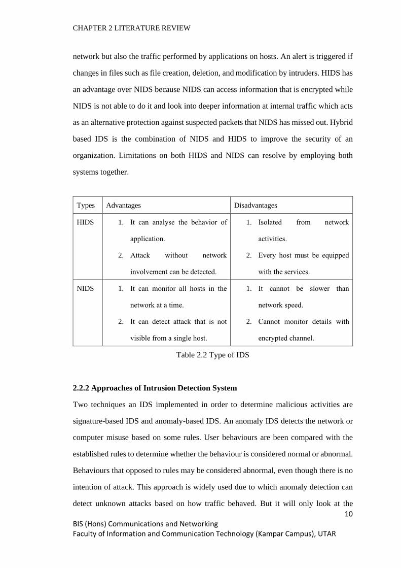
network but also the traffic performed by applications on hosts. An alert is triggered if
changes in files such as file creation, deletion, and modification by intruders. HIDS has
an advantage over NIDS because NIDS can access information that is encrypted while
NIDS is not able to do it and look into deeper information at internal traffic which acts
as an alternative protection against suspected packets that NIDS has missed out. Hybrid
based IDS is the combination of NIDS and HIDS to improve the security of an
organization. Limitations on both HIDS and NIDS can resolve by employing both
systems together.
Types Advantages Disadvantages
HIDS 1. It can analyse the behavior of
application.
2. Attack without network
involvement can be detected.
1. Isolated from network
activities.
2. Every host must be equipped
with the services.
NIDS 1. It can monitor all hosts in the
network at a time.
2. It can detect attack that is not
visible from a single host.
1. It cannot be slower than
network speed.
2. Cannot monitor details with
encrypted channel.
Table 2.2 Type of IDS
2.2.2 Approaches of Intrusion Detection System
Two techniques an IDS implemented in order to determine malicious activities are
signature-based IDS and anomaly-based IDS. An anomaly IDS detects the network or
computer misuse based on some rules. User behaviours are been compared with the
established rules to determine whether the behaviour is considered normal or abnormal.
Behaviours that opposed to rules may be considered abnormal, even though there is no
intention of attack. This approach is widely used due to which anomaly detection can
detect unknown attacks based on how traffic behaved. But it will only look at the

CHAPTER 2 LITERATURE REVIEW
11 BIS (Hons) Communications and Networking Faculty of Information and Communication Technology (Kampar Campus), UTAR
behaviour of the traffic instead of the payload of the packet, hence the non-standard
configuration on the network will cause the problem in figuring the traffic. However, a
signature-based IDS scan through all packets traversing the network and compare with
the existing database of malicious signatures to determine attacks. The limitation on
signature-based IDS is limited databases of threat signatures if a threat that is not known
will be considered legitimate. The signature-based IDS required frequent updates of the
signatures to ensure the database can detect the latest intruders. Intruders can bypass
this kind of IDS with a small thing changed about how the attack occurs to make the
database cannot keep up with the latest sign of the attacks. Furthermore, the processing
power keeps increasing as the database is growing and slower the analysing processes.
Types Pros Cons
Signature-
based IDS
1. Known attack is detected
easily.
1. Impossible to detect unknown attack.
2. Keeping the up-to-date signatures is
difficult.
Anomaly-
based IDS
1. Effective to detect unknown
attack.
1. Weak profiles accuracy due to observed
events.
2. Delay alerts are triggered.
Table 2.3 Approaches of IDS
2.2.3 Advantages and Disadvantages of Intrusion Detection System
IDS bring several benefits to the organization. An IDS analyse the quantity and types
of attacks. With the information given, an organization can take action to improve their
security system either by changing their security system or adding new controls to their
security system. Furthermore, NIDS has the capabilities to monitor specific content
within the network packets to discover any intrusions while the firewall is limited to
monitor on the port and IP address used between sender and receiver on the network.
There are also some limits on the IDS. An IDS capture data flows in the network to

CHAPTER 2 LITERATURE REVIEW
12 BIS (Hons) Communications and Networking Faculty of Information and Communication Technology (Kampar Campus), UTAR
examine the packet to uncover any attacks, but they may not be able to prevent those
attacks happen. Besides, an IDS is limited because they cannot process packet which is
encrypted, if attackers encrypt their packet before sending into the network then it can
easily bypass the IDS. Lastly, IDS can generate many false alarms due to the legitimate
activity is mistakenly considered as malicious.
CHAPTER 2 LITERATURE REVIEW
13 BIS (Hons) Communications and Networking Faculty of Information and Communication Technology (Kampar Campus), UTAR
2.3 Cisco IOS NetFlow
Netflow is a Cisco proprietary protocol which allows the network administrator to
collect and record down IP network traffic as it enters or exits an interface on Cisco
Netflow enabled routers. Netflow data contains its sources, destination, bandwidth and
paths of a network. Netflow provides monitoring capability where an administrator can
visualize the network traffic with the flow-based analysis technology. Netflow contains
information on the network and transport layer. With the summarization view of the
network traffic, the administrator can monitor how frequent an application is being
accessed and the use’s utilization of network resources to find out any potential threats.
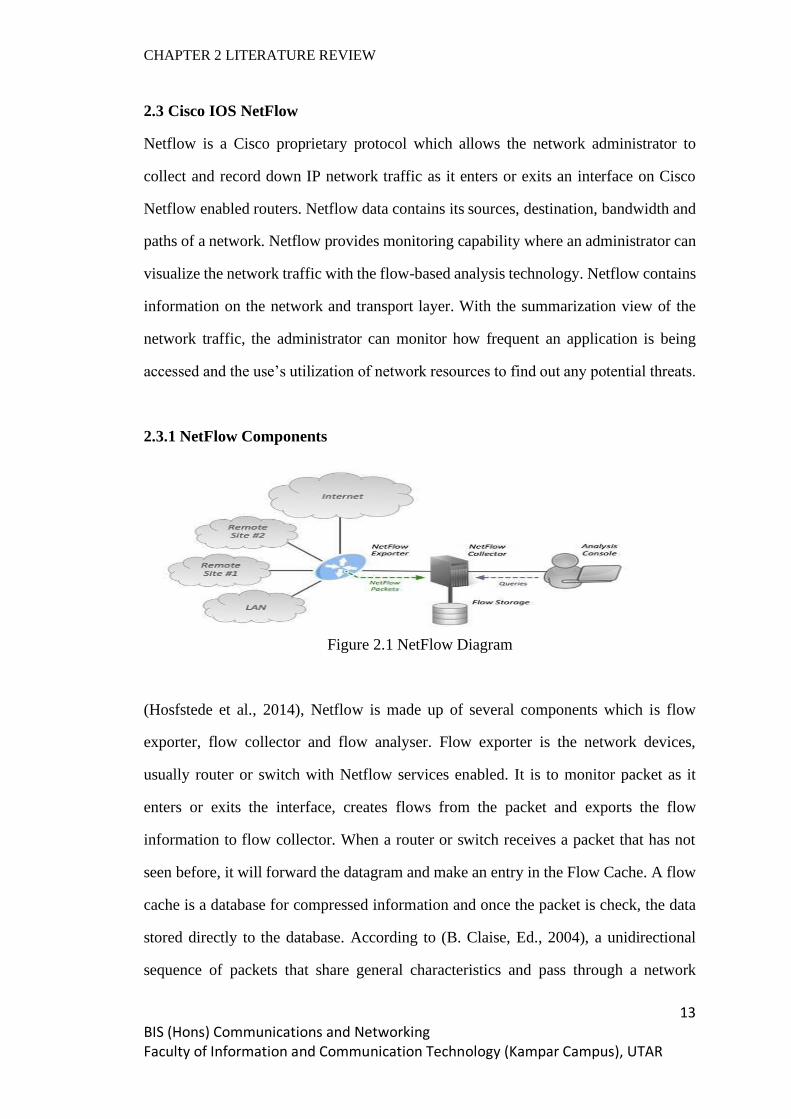
2.3.1 NetFlow Components
Figure 2.1 NetFlow Diagram
(Hosfstede et al., 2014), Netflow is made up of several components which is flow
exporter, flow collector and flow analyser. Flow exporter is the network devices,
usually router or switch with Netflow services enabled. It is to monitor packet as it
enters or exits the interface, creates flows from the packet and exports the flow
information to flow collector. When a router or switch receives a packet that has not
seen before, it will forward the datagram and make an entry in the Flow Cache. A flow
cache is a database for compressed information and once the packet is check, the data
stored directly to the database. According to (B. Claise, Ed., 2004), a unidirectional
sequence of packets that share general characteristics and pass through a network

CHAPTER 2 LITERATURE REVIEW
14 BIS (Hons) Communications and Networking Faculty of Information and Communication Technology (Kampar Campus), UTAR
device is described as a flow that includes IP address, port number, layer 3 protocol
type, class of service, and ingress interface. The flow information generated by the flow
exporter is exported to flow collector periodically. The information is exported to the
flow collector only when the flow becomes inactive for a certain time, which mean
there are no more packets to be observed or when the flow stays alive which longer
than the active timer, which required a router to expire the flow to be able to export the
flows. A server functions as a flow collector which is responsible for collecting and
storing the flow information from flow exporters. After that, a flow analyser starts to
process and analyse the flow of information collected by the flow collector.
2.3.2 Advantages and Disadvantages of NetFlow
The benefit of Netflow is that it provides the near real-time monitoring capabilities. The
flow-based analysis is used to visualize the network traffic patterns to have better
problem detection and troubleshooting. Furthermore, attacks can be identified in real-
time. Netflow data shows anomalies if any changes occurred in the network behaviour.
However, sending Netflow data can add too much overhead to the router and switch,
overloading the infrastructure which resulting in stopping engineers to enable Netflow
on their network. In addition, Netflow is limited to show routed traffic or packets. This
is because flow data is captured as the packet pass through the network devices, any
packets inside the internal LAN and VLAN is not visible to Netflow.

CHAPTER 2 LITERATURE REVIEW
15 BIS (Hons) Communications and Networking Faculty of Information and Communication Technology (Kampar Campus), UTAR
2.4 Syslog
Syslog is a protocol used by network administrators to monitor events in the network.
Network devices do generate logs about the events and their status, but it will be
difficult to track all the information. Syslog server provides a way for the logs generated
to be closely managed and monitored. In the operation of Syslog, Syslog message is
sent from network devices to the Syslog server. Syslog is unable to poll devices to
collect the information as the SNMP, messages are sent only when a specific event is
triggered. Syslog server then analyses the log to perform monitoring, troubleshooting
and other operational tasks. Syslog protocol allows network devices to log different
types of events. Syslog message must have a standardized definition and format to
ensure the sharing of data between different applications. In this way, the information
on both parties can be explained and understood. A Syslog message is classified into a
format which consists of a header, structured-data, and message. The header defines the
information such as the version, timestamp, hostname, application name and process
identification. The structured data included the data blocks in a specific format and
followed by the log messages that contain the actual information to be used for
evaluating.
2.4.1 Syslog Layer
Figure 2.2 Syslog Layers
(Gerhards, 2009) syslog protocol is working on three different layers which highest
layer is the content layer, the second layer is the application layer and the lowest layer

CHAPTER 2 LITERATURE REVIEW
16 BIS (Hons) Communications and Networking Faculty of Information and Communication Technology (Kampar Campus), UTAR
is the transport layer. The content layer is regarding the information contained within
the Syslog event message, such as facility codes and severity levels. The numeric
facility codes are codes that identifying the source of the message and have a range
from 0 to 23 to differentiate each message. Also, severity levels filed in the Syslog
message indicates the importance of the message. The severity levels are ranged from
0 which indicated the highest priority message to 7 which is the lowest priority message.
The following application layer is to generate, interpret, route, and store the message
and transport layer is responsible for sending and receiving the message via the
network.
2.4.2 Syslog Server Components
Syslog server usually is a central location which receives the Syslog event messages
sent by network devices, stores the Syslog data, and performs analysis on the data.
There are few components used to build up a Syslog server so that the workload is
distributed to each of the components. The first component is a Syslog listener, which
helps the server to gather Syslog data sent over on port 514 using UDP transport
protocol and via TCP protocol on port 1468 for the reliability transmissions. The second
component is the database. Syslog server collects Syslog data from multiple sources
and required a large memory to store the huge amount of data. The database allows the
server to store the data and retrieve the data. Finally, the third component, management
filtering system helps the server to filter the data to find the log entries needed.
According to the data, the server can generate alerts to inform the administrator to
resolve the problems as soon as possible.
2.4.3 Advantages and Disadvantages of Syslog
Syslog provides the ability for the administrator to roll back the system to the previous
status which before a failure happened. This is due to the reason that the events are
logged with Syslog messages as a backup. Besides, the operation of Syslog will not

CHAPTER 2 LITERATURE REVIEW
17 BIS (Hons) Communications and Networking Faculty of Information and Communication Technology (Kampar Campus), UTAR
affect the performance on the monitoring system due to the logs can be written
externally to the hard disks by the applications, so the network administrators can
continue monitoring the applications and network without worrying about affecting
performances. However, transportation of Syslog messages with UDP transport
protocol had limited the efficiency of the system. UDP does not guarantee the messages
can be arrived at the receiver due to network congestion or packet loss. Finally, Syslog
faced security issues since there is no authentication on the messages, an attacker can
masquerade a legitimate machine to send forged log events and also run replay attacks.

CHAPTER 2 LITERATURE REVIEW
18 BIS (Hons) Communications and Networking Faculty of Information and Communication Technology (Kampar Campus), UTAR
2.5 SNMP
SNMP protocol is a monitoring protocol that works on the application layer. SNMP is
used to monitor a device condition, changing the parameters of a device, detection of
an event failure, generate alarms and report for the administrator for troubleshooting
(Hare, 2011). For devices manufactured from different vendors to communicate, SNMP
provides a standard language to support communication. There are three main
components (Harrington et al., 2002) such as SNMP agent, SNMP server and
Management Information Base operating together to monitor the network. An SNMP
agent referred to the program or software running on the SNMP enabled network
devices including printers, routers, switches, computers, and so on. They are in charge
of collecting data such as bandwidth, CPU usage or disk space and send this information
to the SNMP server when it received the request from the SNMP server. An SNMP
server is software deployed on a server and functions as a central collector to the SNMP
agents. The SNMP manager collects information on the network devices through
querying a request to the SNMP agent so that the agent will reply with the data
requested. The Management information base is a database that resides in the SNMP
agents and has a collection of objects about a particular device. MIB stores the data in
a tree-like structure hierarchy to eliminate the burden of network devices to exchange
data in a rigid format. The objects can be queried and controlled by the SNMP. A MIB
can have many objects inside, so each of the objects is assigned with a unique identifier
which is OID.
2.5.1 Type of SNMP Message
There are several types of messages used by the SNMP protocol to communicate
between network devices and the management system which referred to SNMP agent
and SNMP manager. When the SNMP manager wants to collect data from the agent, it
generates a GET message to the agent to request the data. The message can be identified
through its OID. After receiving the GET message, the SNMP agent generates a

CHAPTER 2 LITERATURE REVIEW
19 BIS (Hons) Communications and Networking Faculty of Information and Communication Technology (Kampar Campus), UTAR
RESPONSE message with the requested data to reply to the GET message. A
GETNEXT message is issued by the SNMP manager to SNMP agent for the next
available OID data in the MIB’s hierarchy. This message is very useful to discover all
of the available data in the MIB. Besides, a GETBULK is used to retrieve large numbers
of data, usually functions as issuing several GETNEXT messages at once. Furthermore,
a SET message sent by the SNMP manager to dynamically performs configuration on
the SNMP agents and a TRAP message is an alert message which sent to the SNMP
manager from the SNMP agent to remind the administrator to declare an event has
occurred.
2.5.2 Evolution of SNMP
SNMP has developed into three versions which defined as SNMP v1, SNMP v2, and
SNMP v3 (Bibbs et al., 2006). SNMP v1 is the earliest version in the SNMP protocol.
The operation of the SNMP is depending on four basic protocol functions which are
Get, GetNext, Set, and Trap. The Get feature is used to collect multiple object instances
values from an agent while GetNext is to retrieve the value of the next object instance
within an agent. A Set function can configure the value of the object in an agent and
the Trap function used to inform the manager to indicate an important event. After that,
an SNMP v2 is designed with an enhancement to compare to the SNMP v1. In the
SNMP v2, there are two new protocol functions are introduced such as GetBulk and
Inform. GetBulk is used to obtain large blocks of data instead of retrieving data with
multiple Get function. The Inform function let the manager send trap information to
other managers and then receive a response. However, both version 1 and version 2 is
facing a security issue in which the messages transmitted is not encrypted, so anyone
within the network can sniff the packet and see the content of the packet. Thereby,
SNMP v3 is proposed to overcome the limitation on the previous version. SNMP v3
follows the same concept in the previous version but with additional capabilities which

CHAPTER 2 LITERATURE REVIEW
20 BIS (Hons) Communications and Networking Faculty of Information and Communication Technology (Kampar Campus), UTAR
the transmission of the messages is encrypted to improve the security and use a Set
function to remotely configure an agent.
2.5.3 Advantages and Disadvantages of SNMP
The main benefit of SNMP is that it can support and manage devices from different
vendors. SNMP uses a non-proprietary protocol so that it is not limited to support only
specific vendor devices. Next, SNMP allows the network administrator to configure
certain parameters on the network to be managed automatically. This can save time for
constantly checking on the system since the SNMP can automatically generate an alarm
when the threshold of the parameters are exceeded. However, an SNMP can only
demonstrate a very limit network details for the administrator to study and solve the
network issues. This is because SNMP uses a non-proprietary interface that supports
many devices from multiple vendors, SNMP only can manage limited parameters.
CHAPTER 2 LITERATURE REVIEW
21 BIS (Hons) Communications and Networking Faculty of Information and Communication Technology (Kampar Campus), UTAR
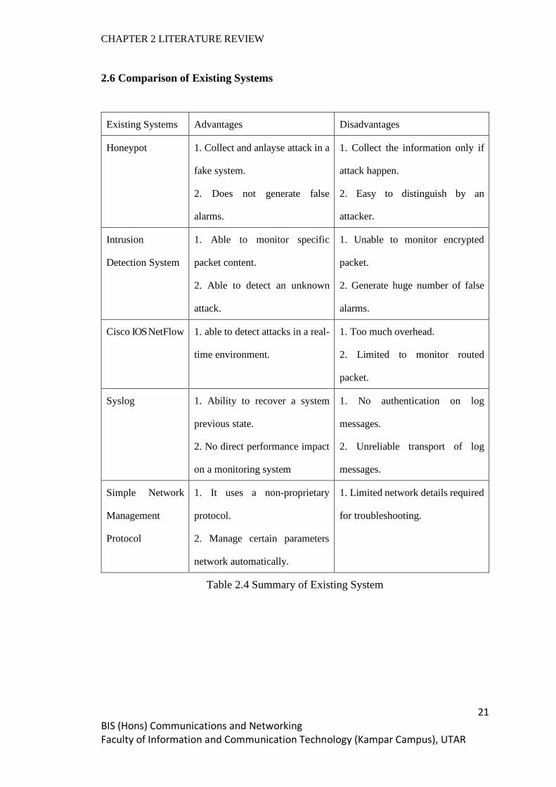
2.6 Comparison of Existing Systems
Existing Systems Advantages Disadvantages
Honeypot 1. Collect and anlayse attack in a
fake system.
2. Does not generate false
alarms.
1. Collect the information only if
attack happen.
2. Easy to distinguish by an
attacker.
Intrusion
Detection System
1. Able to monitor specific
packet content.
2. Able to detect an unknown
attack.
1. Unable to monitor encrypted
packet.
2. Generate huge number of false
alarms.
Cisco IOS NetFlow 1. able to detect attacks in a real-
time environment.
1. Too much overhead.
2. Limited to monitor routed
packet.
Syslog 1. Ability to recover a system
previous state.
2. No direct performance impact
on a monitoring system
1. No authentication on log
messages.
2. Unreliable transport of log
messages.
Simple Network
Management
Protocol
1. It uses a non-proprietary
protocol.
2. Manage certain parameters
network automatically.
1. Limited network details required
for troubleshooting.
Table 2.4 Summary of Existing System

CHAPTER 2 LITERATURE REVIEW
22 BIS (Hons) Communications and Networking Faculty of Information and Communication Technology (Kampar Campus), UTAR
2.7 Summary
In the project, we proposed an SNMP system monitor the network utilization and
security in our network. SNMP can better monitor a network compared to the Honeypot
because SNMP does generate alerts immediately if the defined threshold is exceeded.
In the IDS monitoring system, packets captured cannot be analysed if it is encrypted.
However, the packet is decrypted once it arrived at the destination and the SNMP agent
pass the information to the SNMP manager to analyse. SNMP can monitor packet
coming in and out from a network and within a local area network but Netflow does
not monitor packets that do not pass through the router. SNMP can poll devices for
information, but Syslog only sends messages to the server when events are triggered.
CHAPTER 3 SYSTEM DESIGN
23 BIS (Hons) Communications and Networking Faculty of Information and Communication Technology (Kampar Campus), UTAR
CHAPTER 3 SYSTEM DESIGN
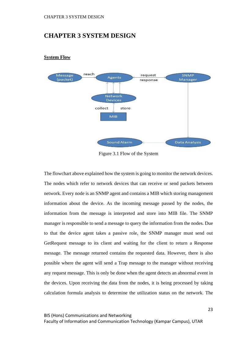
System Flow
Figure 3.1 Flow of the System
The flowchart above explained how the system is going to monitor the network devices.
The nodes which refer to network devices that can receive or send packets between
network. Every node is an SNMP agent and contains a MIB which storing management
information about the device. As the incoming message passed by the nodes, the
information from the message is interpreted and store into MIB file. The SNMP
manager is responsible to send a message to query the information from the nodes. Due
to that the device agent takes a passive role, the SNMP manager must send out
GetRequest message to its client and waiting for the client to return a Response
message. The message returned contains the requested data. However, there is also
possible where the agent will send a Trap message to the manager without receiving
any request message. This is only be done when the agent detects an abnormal event in
the devices. Upon receiving the data from the nodes, it is being processed by taking
calculation formula analysis to determine the utilization status on the network. The

CHAPTER 3 SYSTEM DESIGN
24 BIS (Hons) Communications and Networking Faculty of Information and Communication Technology (Kampar Campus), UTAR
warning is issued if there is any abnormal performance is calculated from the analysis
and hereafter sound an alert by sending an email to the administrator.
System Architecture
Figure 3.2 SNMP System Architect
The architecture on the SNMP manager system is categorized into (3) layers. The
bottom level is the data layer. It is used to communicate between the manager and the
agent. The data collection module handling the collection of data from agents and send
it to the upper layer. There are two ways to collect data. One is timing polling which
for a fixed interval, the manager will send a request message to an agent for querying
data information while another is emergency receive trap message from an agent and
pass it to the upper layer. The middle level is a service layer for which the data
processing stage is executed. The data being collected is sent to the upper layer for
displaying to the administrator and storing to the database as history information. The
top-level is a function layer where the user interface is implemented at the stage. The
stage consists of a monitoring module where the server status, performance and fault

CHAPTER 3 SYSTEM DESIGN
25 BIS (Hons) Communications and Networking Faculty of Information and Communication Technology (Kampar Campus), UTAR
information are displayed. The fault module is when there is any threshold exceed and
it will trigger an alarm to inform administrator to act for countermeasure. The statistic
module collects from the lower layer, organizes, and interprets the data information in
graphical format.
CHAPTER 4 PROPOSED METHOD / APPROACH
26 BIS (Hons) Communications and Networking Faculty of Information and Communication Technology (Kampar Campus), UTAR
CHAPTER 4 PROPOSED METHOD / APPROACH
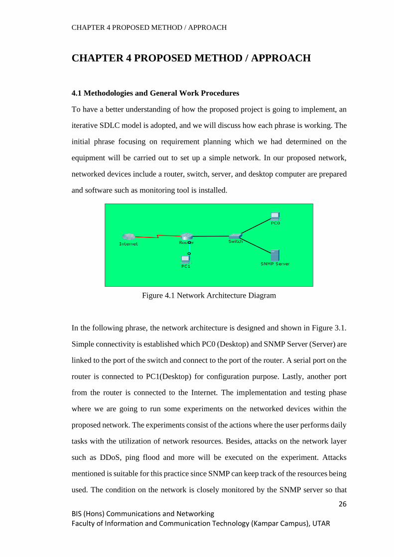
4.1 Methodologies and General Work Procedures
To have a better understanding of how the proposed project is going to implement, an
iterative SDLC model is adopted, and we will discuss how each phrase is working. The
initial phrase focusing on requirement planning which we had determined on the
equipment will be carried out to set up a simple network. In our proposed network,
networked devices include a router, switch, server, and desktop computer are prepared
and software such as monitoring tool is installed.
Figure 4.1 Network Architecture Diagram
In the following phrase, the network architecture is designed and shown in Figure 3.1.
Simple connectivity is established which PC0 (Desktop) and SNMP Server (Server) are
linked to the port of the switch and connect to the port of the router. A serial port on the
router is connected to PC1(Desktop) for configuration purpose. Lastly, another port
from the router is connected to the Internet. The implementation and testing phase
where we are going to run some experiments on the networked devices within the
proposed network. The experiments consist of the actions where the user performs daily
tasks with the utilization of network resources. Besides, attacks on the network layer
such as DDoS, ping flood and more will be executed on the experiment. Attacks
mentioned is suitable for this practice since SNMP can keep track of the resources being
used. The condition on the network is closely monitored by the SNMP server so that

CHAPTER 4 PROPOSED METHOD / APPROACH
27 BIS (Hons) Communications and Networking Faculty of Information and Communication Technology (Kampar Campus), UTAR
we can evaluate how the resources are being used and take action to fix any issues on
the network.
4.2 Tools
Hardware Components
i. Router – A network device operates on the network layer and performs routing
features. Routing enables data packet travels from one network to another network. The
router gives the user access to the Internet. Throughout the project, router act as a
gateway for the host to access to the Internet, meanwhile it is also an agent for SNMP
which responsible for replying message requested by the SNMP manager.
ii. Switch – It is a data link layer device offers connectivity between devices within a
network. It is based on the MAC address of devices for forwarding packets to the
destination host. To form a LAN, the switch is needed so that devices like desktop
computer and serer can be connected. Afterwards, the switch is linked to the router. It
also acts as an SNMP agent and having the same responsibility.
iii. Computer – A computer is a device used to process an input and return the output
to its user through the GUI. User may run services or applications on the computer. In
this project, we use the desktop to run penetration testing to obtain the result that will
be discussed on the following chapter.
iv. Server – It is like a computer that provides services for other devices; however, the
server does not perform tasks like a computer instead it is dedicated, which only
performs a specific task. In the project, the server is installed with monitoring software
to bear the responsibility to monitor the network devices on the network.
Software components

CHAPTER 4 PROPOSED METHOD / APPROACH
28 BIS (Hons) Communications and Networking Faculty of Information and Communication Technology (Kampar Campus), UTAR
i. PuTTY – Its GUI is similar like command prompt terminal and it can support several
network protocols for file transfer. The software helps to remotely configure the router
by connecting to the serial port on the devices.
ii. PRTG Network Monitor – A software used to monitor the network and developed
from Passler AG. The software can monitor many categories of device utilization such
as bandwidth, memory usage, uptime and more. It collects the data, performs analysis
and displays the output on the software GUI.
iii. Kali Linux – A system designed for the user to execute penetration testing purpose.
In the system, there are plenty of tools that allow the user to carried out attacks. Kali
Linux is used to perform penetration testing to the network devices.
4.3 Requirements
Desktop PC
Name Description
System Type Window 7 Professional 64-bit
Processor Intel® Core ™ i5-3340 CPU @ 3.10GHz
RAM 8GB
GPU Intel® HD Graphics
Table 4.1 Desktop PC
Cisco Router 1841
Name Description
DRAM Synchronous DDIM DRAM
DRAM Capacity Default: 256MB Maximum: 384MB
Flash Memory Capacity Default : 64MB Maximum: 128MB
Modular Slots WAN Access : 2 ; HWICs : 2
Fixed LAN ports Fast Ethernet (10/100) : 2
Table 4.2 Cisco Router 1841

CHAPTER 4 PROPOSED METHOD / APPROACH
29 BIS (Hons) Communications and Networking Faculty of Information and Communication Technology (Kampar Campus), UTAR
Kali Linux
Name Description
Disk Space Minimum 20GB
RAM I386 and AMD64 architecture, minimum 1GB, recommended 2GB
or more
Driver CD-DVD Drive / USB boot support
Table 4.3 Kali Linux
PRTG Network Monitor
Name Description
Hardware PC or Server
CPU Dual Core and above
RAM 2048MB and above
Operating System Windows Server 2019, Windows 10, Windows Server 2012 R2
Web Browser Google Chrome 72, Mozilla Firefox 65,
Internet Explorer 11
Table 4.4 PRTG
4.4 Implementation Issues and Challenges
During the process of the project, detecting attack such as DDoS become a challenging
implementation. Is it SNMP can detect the attack? DDoS is an attack which can
consume all bandwidth of the targeted device. Although SNMP is capable to monitor
the bandwidth usage, we might not be able to confirm such attack is happened based
on the utilization level on the bandwidth.
Besides, the SNMP software may not be able to provide real-time monitoring on the
network. Devices on the network are being set to reply to the SNMP message send by
the management station at a fixed interval. It might be difficult to detect a problem at
the right time even if the interval is small.

CHAPTER 4 PROPOSED METHOD / APPROACH
30 BIS (Hons) Communications and Networking Faculty of Information and Communication Technology (Kampar Campus), UTAR
4.5 Timeline
Figure 4.2 Timeline for FYP1 and FYP2
Gantt chart above displays the timeline for the whole final year project. For 12 weeks
in FYP1, a literature review is studied, and problems are stated. Then proceed to the
next task which is to find out the requirement to prosecute the proposed solution. The
necessary configuration on the network being setup is done before the software is
installed. Once the network connectivity is fulfilled, SNMP monitoring software is
installed, and the configuration will be done. After that, we are going to have tested on
what information will be collected by SNMP software. From FYP2 onwards, Kali
Linux platform will be installed and therefore penetration tests are executed. The output
generated from the SNMP monitoring software is observed and determine its capability
on detecting attacks. Documentation will be written according to the implementation of
the project.
CHAPTER 5 IMPLEMENTATION
31 BIS (Hons) Communications and Networking Faculty of Information and Communication Technology (Kampar Campus), UTAR
CHAPTER 5 IMPLEMENTATION
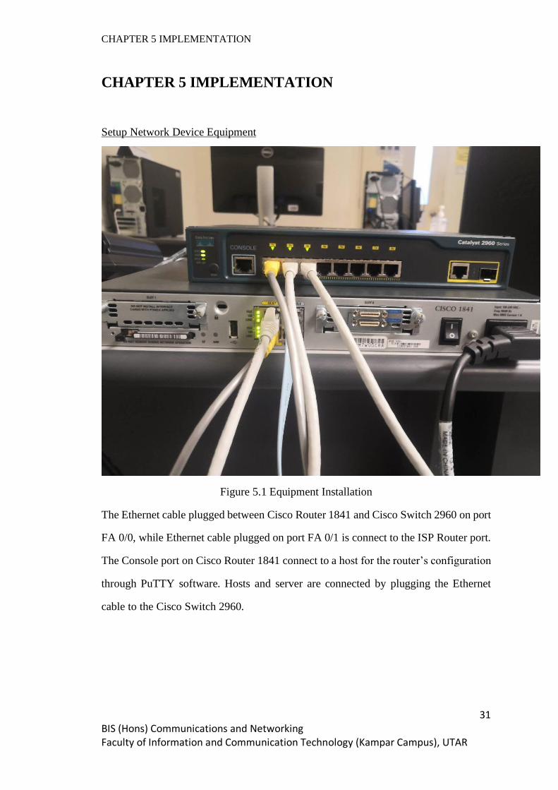
Setup Network Device Equipment
Figure 5.1 Equipment Installation
The Ethernet cable plugged between Cisco Router 1841 and Cisco Switch 2960 on port
FA 0/0, while Ethernet cable plugged on port FA 0/1 is connect to the ISP Router port.
The Console port on Cisco Router 1841 connect to a host for the router’s configuration
through PuTTY software. Hosts and server are connected by plugging the Ethernet
cable to the Cisco Switch 2960.

CHAPTER 5 IMPLEMENTATION
32 BIS (Hons) Communications and Networking Faculty of Information and Communication Technology (Kampar Campus), UTAR
Configuration on Cisco Router 1841
The following step involved configuring connectivity of hosts, DHCP services, IP NAT
and default gateway as well.
1. Set a DHCP services on proposed network 192.168.172.0 with subnet /24. The
gateway is 192.168.172.254 and DNS service IP address is 192.168.201.6
which is primary and 8.8.8.8 as an alternative DNS service.
Figure 5.2 Router Configure (1)
2. Configure FA0/0 with the IP address gateway corresponding to the internal
network 192.168.172.0/24 and FA0/1 with IP address gateway corresponding to
the ISP router. Assuming the IP address is unknown, use DHCP service to
dynamically retrieve the IP address.
3. NAT is also applied in the interface FA0/0 with “inside” to indicate a private
network and FA0/1 with “outside” to represent a public network.
Figure 5.3 Router Configure (2)

CHAPTER 5 IMPLEMENTATION
33 BIS (Hons) Communications and Networking Faculty of Information and Communication Technology (Kampar Campus), UTAR
4. Set a default route for the packet to route to the outside network with the next
hop allocated by DHCP service when the IP address is unknown.
Figure 5.4 Router Configure (3)
5. Configure an access list to allow the network 192.168.172.0/24 and place the
NAT in the outside interface which is FA0/1.
Figure 5.5 Router Configure (4)
6. Start > Network and Sharing Center > Local Area Connection 2 > Details.
Figure 5.6 Details
7. IP address and DNS server is configured dynamically by the DHCP service.
8. Start > Command Prompt.

CHAPTER 5 IMPLEMENTATION
34 BIS (Hons) Communications and Networking Faculty of Information and Communication Technology (Kampar Campus), UTAR
Figure 5.7 Ping
9. Ping testing on neighbor IP address and the Gateway on the network is success.

CHAPTER 5 IMPLEMENTATION
35 BIS (Hons) Communications and Networking Faculty of Information and Communication Technology (Kampar Campus), UTAR
Install / Turn on / Configure SNMP Services
An SNMP services is turn off by default. SNMP services is to allow the device to
receive SNMP packets from hosts. The following step is to show how to install,
configure and turn on the SNMP services.
1. Start > Control Panel > Programs > Turn Windows Features on or off.
2. Select SNMP and press OK.
Figure 5.8 SNMP Services (1)
3. The installation for SNMP services is started.
4. Start > Services > SNMP Services.
Figure 5.9 SNMP Services (2)

CHAPTER 5 IMPLEMENTATION
36 BIS (Hons) Communications and Networking Faculty of Information and Communication Technology (Kampar Campus), UTAR
5. Press Add button, key in the Community string with “public” and set the Rights
to “Read only”.
6. Select “Accept SNMP packets from any host” or “Accept SNMP packets from
these hosts” if you have specific host to accept packets from.
7. Press OK.
Figure 5.10 SNMP Services (3)

CHAPTER 5 IMPLEMENTATION
37 BIS (Hons) Communications and Networking Faculty of Information and Communication Technology (Kampar Campus), UTAR
Setting on PRTG Network Monitor
PRTG is a network monitoring software that gives the user the ability to observe the
traffic and performance going on in the network including the devices as well. To
monitor the state of the targeted devices on the network, we must define the devices as
well as the protocol used to monitor the device. The following step included Add
Devices, Add SNMP Sensors, and Configure SNMP Sensors in the PRTG.
Figure 5.11 PRTG Home
From the Home page, select Devices to setup the monitoring services on the network.
Figure 5.12 PRTG Devices
In Devices page, the overview of Devices (Hosts) and Sensors is displayed. Devices is
added into the monitor software through IP address. Sensors is a type of information
being monitored.

CHAPTER 5 IMPLEMENTATION
38 BIS (Hons) Communications and Networking Faculty of Information and Communication Technology (Kampar Campus), UTAR
Add Device
The following setup is to add the host’s device with it IP address into PRTG Network
Monitor.
Figure 5.13 Add Device
1. Press on Add Devices.
2. Fill in the name for Device. // ADMIN
3. Select “Connect with IPv4”.
4. Fill in the IP Address for the Device. // 172.168.172.2.
5. Press OK.

CHAPTER 5 IMPLEMENTATION
39 BIS (Hons) Communications and Networking Faculty of Information and Communication Technology (Kampar Campus), UTAR
Add SNMP Sensor
The following setup is to add the information to be monitored using SNMP.
1. Right click on ADMIN.
2. Press on Add Sensors.
Figure 5.14 Add Sensor (1)
3. Filter Target System Type with “Windows” and Technology Used with “SNMP”.
Figure 5.15 Add Sensor (2)
4. Create SNMP CPU Load Sensor.

CHAPTER 5 IMPLEMENTATION
40 BIS (Hons) Communications and Networking Faculty of Information and Communication Technology (Kampar Campus), UTAR
Figure 5.16 Add Sensor (3)
5. Click Create.
6. Create SNMP Traffic Sensor.
7. Select the targeted network traffic. // Local Area Connection 2
Figure 5.17 Add Sensor (4)
8. Select targeted type of Additional Channels. // Error, Discards, Unknown
Protocol
Figure 5.18 Add Sensor (5)
9. Press Create.
10. Sensors for CPU Load and Network Traffic are created.
Figure 5.19 Add Sensor (6)
CHAPTER 5 IMPLEMENTATION
41 BIS (Hons) Communications and Networking Faculty of Information and Communication Technology (Kampar Campus), UTAR
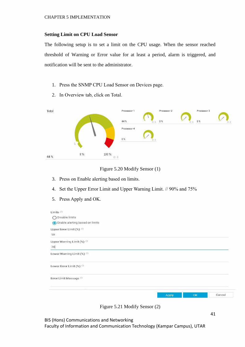
Setting Limit on CPU Load Sensor
The following setup is to set a limit on the CPU usage. When the sensor reached
threshold of Warning or Error value for at least a period, alarm is triggered, and
notification will be sent to the administrator.
1. Press the SNMP CPU Load Sensor on Devices page.
2. In Overview tab, click on Total.
Figure 5.20 Modify Sensor (1)
3. Press on Enable alerting based on limits.
4. Set the Upper Error Limit and Upper Warning Limit. // 90% and 75%
5. Press Apply and OK.
Figure 5.21 Modify Sensor (2)

CHAPTER 5 IMPLEMENTATION
42 BIS (Hons) Communications and Networking Faculty of Information and Communication Technology (Kampar Campus), UTAR
6. Go to Notification Triggers tab and press Add Threshold Trigger.
Figure 5.22 Modify Sensor (3)
7. Set the CPU Load is above 30% for continuous 20 seconds to trigger alarm.
Figure 5.23 Modify Sensor (4)
8. Press OK.

CHAPTER 5 IMPLEMENTATION
43 BIS (Hons) Communications and Networking Faculty of Information and Communication Technology (Kampar Campus), UTAR
Setting Limit on SNMP Traffic Sensor
The following setup is to define a value as the threshold for the incoming traffic on the
network. The incoming traffic indicates the number of packets come into the network
and criteria to detect the DDOS attack.
1. Press the SNMP Traffic Sensor on Devices page.
2. In Overview tab, click on Traffic In.
Figure 5.24 Modify Sensor (5)
3. Press on Enable alerting based on limits.
4. Set the Upper Error Limit and Upper Warning Limit. // 50MBit/s and 40MBit/s
5. Press Apply and OK.
Figure 5.25 Modify Sensor (6)

CHAPTER 5 IMPLEMENTATION
44 BIS (Hons) Communications and Networking Faculty of Information and Communication Technology (Kampar Campus), UTAR
6. Move to Notification Triggers tab and select Add Speed Trigger.
Figure 5.26 Modify Sensor (7)
7. Set the Traffic In with 50 Mbit/s above for 30 seconds to trigger alarm.
Figure 5.27 Modify Sensor (8)
8. Press OK.
CHAPTER 5 IMPLEMENTATION
45 BIS (Hons) Communications and Networking Faculty of Information and Communication Technology (Kampar Campus), UTAR
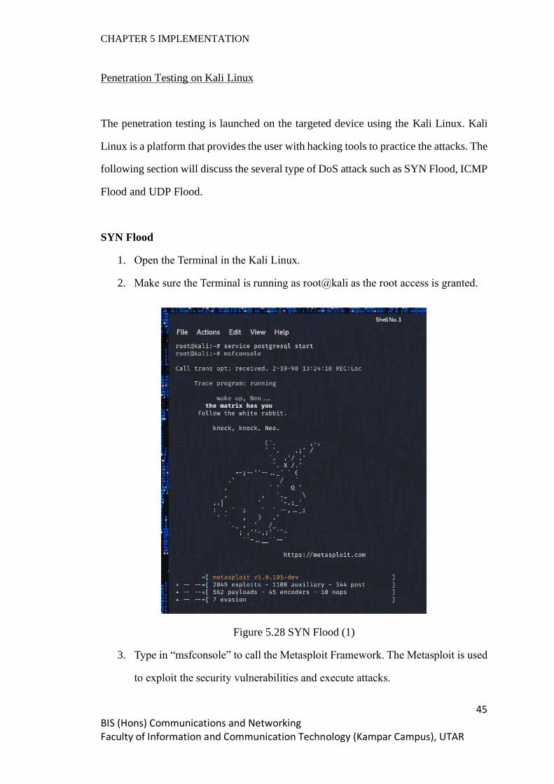
Penetration Testing on Kali Linux
The penetration testing is launched on the targeted device using the Kali Linux. Kali
Linux is a platform that provides the user with hacking tools to practice the attacks. The
following section will discuss the several type of DoS attack such as SYN Flood, ICMP
Flood and UDP Flood.
SYN Flood
1. Open the Terminal in the Kali Linux.
2. Make sure the Terminal is running as root@kali as the root access is granted.
Figure 5.28 SYN Flood (1)
3. Type in “msfconsole” to call the Metasploit Framework. The Metasploit is used
to exploit the security vulnerabilities and execute attacks.
CHAPTER 5 IMPLEMENTATION
46 BIS (Hons) Communications and Networking Faculty of Information and Communication Technology (Kampar Campus), UTAR
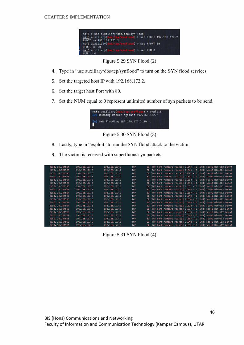
Figure 5.29 SYN Flood (2)
4. Type in “use auxiliary/dos/tcp/synflood” to turn on the SYN flood services.
5. Set the targeted host IP with 192.168.172.2.
6. Set the target host Port with 80.
7. Set the NUM equal to 0 represent unlimited number of syn packets to be send.
Figure 5.30 SYN Flood (3)
8. Lastly, type in “exploit” to run the SYN flood attack to the victim.
9. The victim is received with superfluous syn packets.
Figure 5.31 SYN Flood (4)

CHAPTER 5 IMPLEMENTATION
47 BIS (Hons) Communications and Networking Faculty of Information and Communication Technology (Kampar Campus), UTAR
ICMP Flood
1. Open the Terminal and run as root in Kali Linux.
2. Type in “hping3 192.168.172.2 --icmp --flood”.
Figure 5.32 ICMP Flood (1)
3. Hping3 is a network tool to send custom TCP/IP packets.
4. 192.168.172.2 is the targeted host IP address.
5. “--icmp” sends only ICMP type of packet.
6. “--flood” sends the packet as fast as possible.
7. The victim is surrounded by ICMP echo requests.
Figure 5.33 ICMP Flood (1)

CHAPTER 5 IMPLEMENTATION
48 BIS (Hons) Communications and Networking Faculty of Information and Communication Technology (Kampar Campus), UTAR
UDP Flood
1. Open the Terminal and run as root in Kali Linux.
2. Type in “hping3 192.168.172.2 --udp --flood”.
Figure 5.34 UDP Flood (1)
3. Hping3 is the tool for sending custom type of packet.
4. Set the targeted IP address as 192.168.172.2.
5. “--udp” set the UDP type of packet.
6. “--flood” set the packets to send as fast as possible.
7. The victim is flood with UDP packets.
Figure 5.35 UDP Flood (2)

CHAPTER 6 EXPERIMENTAL RESULT
49 BIS (Hons) Communications and Networking Faculty of Information and Communication Technology (Kampar Campus), UTAR
CHAPTER 6 EXPERIMENTAL RESULT
Here comes to the last step to observe the statistic generated by the SNMP server. We
are going to put our focus on the network traffic as well as the CPU usage because the
DDoS attack we launched will be based on volume-based, where a large amount of
packets is sent to the targeted device and observe the utilization on both traffic and CPU
usage. In the following discussion, we will see what the DDoS symptom are during the
penetrate tests on the targeted host and how to differentiate among the various type of
volume-based DDoS attacks based on its specific characteristics. In the PRTG Network
Monitor, the SNMP sensors will poll the information on the host device at
192.168.172.2 every 30 seconds and update the statistic.
6.1 Network Traffic and CPU Usage Analysis
We will study the statistic collected by the SNMP Traffic Sensor and CPU Load Sensor
to find out between the normal and abnormal behavior on the targeted device. We can
understand in what situation is considered the device has been attacked.
6.1.1 Behavior Analysis Before DDoS
Figure 6.1 Normal Traffic (1)

CHAPTER 6 EXPERIMENTAL RESULT
50 BIS (Hons) Communications and Networking Faculty of Information and Communication Technology (Kampar Campus), UTAR
Figure 6.2 Normal Traffic (2)
Figure 6.3 Normal CPU Usage

CHAPTER 6 EXPERIMENTAL RESULT
51 BIS (Hons) Communications and Networking Faculty of Information and Communication Technology (Kampar Campus), UTAR
Based on Figure 6.1, Figure 6.2, and Figure 6.3, we have collected about 20 rows of
data in 10 minutes. The average volume for Total Traffic is 10.714 kB which the Traffic
In occupied 70% while the Traffic Out occupied 30% of the Total Traffic. The speed
for Traffic In and Traffic Out run at 2.07 kB/s and 0.89 kB/s on average. The incoming
and outgoing Unicast packets are at the averaging value of 24 and 30 packets. The
average utilization of CPU is approximate at 5% for all the four CPU cores.

CHAPTER 6 EXPERIMENTAL RESULT
52 BIS (Hons) Communications and Networking Faculty of Information and Communication Technology (Kampar Campus), UTAR
6.1.2 SYN-Flood Behavior Analysis
Figure 6.4 SYN Traffic (1)
Figure 6.5 SYN Traffic (2)

CHAPTER 6 EXPERIMENTAL RESULT
53 BIS (Hons) Communications and Networking Faculty of Information and Communication Technology (Kampar Campus), UTAR
Figure 6.6 SYN CPU Usage
Based on Figure 6.4, Figure 6.5, and Figure 6.6, 20 rows of statistic during SYN flood
is collected in 10 minutes. The average volume for Traffic In and Traffic Out has
reached 149,000 kB and 30,000 kB. The speed for Traffic In and Traffic Out run at
43,000 kB/s and 8,600 kB/s on average. The incoming and outgoing Unicast packets
are at the averaging value of 2,500,000 and 600,000 packets. The CPU Usage during
SYN flood has reached 29% on average.

CHAPTER 6 EXPERIMENTAL RESULT
54 BIS (Hons) Communications and Networking Faculty of Information and Communication Technology (Kampar Campus), UTAR
6.1.3 UDP Flood Behavior Analysis
Figure 6.7 UDP Traffic (1)
Figure 6.8 UDP Traffic (2)

CHAPTER 6 EXPERIMENTAL RESULT
55 BIS (Hons) Communications and Networking Faculty of Information and Communication Technology (Kampar Campus), UTAR
Figure 6.9 UDP CPU Usage
Based on Figure 6.7, Figure 6.8, and Figure 6.9, 20 rows of statistic during UDP flood
is collected in 10 minutes. The average volume for Traffic In and Traffic Out has
reached 225,000 kB and 410 kB. The speed for Traffic In and Traffic Out run at 61,000
kB/s and 110 kB/s on average. The incoming and outgoing Unicast packets are at the
averaging value of 3,800,000 and 6,000 packets. The CPU Usage during SYN flood
has reached 34% on average.
CHAPTER 6 EXPERIMENTAL RESULT
56 BIS (Hons) Communications and Networking Faculty of Information and Communication Technology (Kampar Campus), UTAR
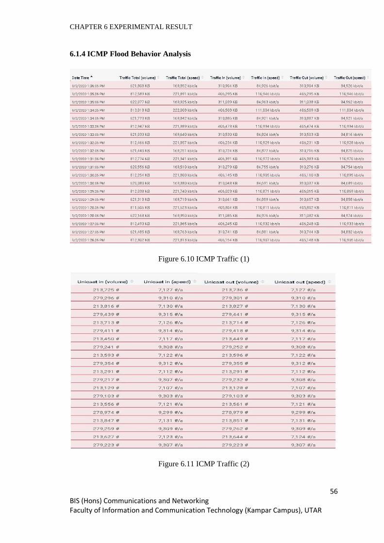
6.1.4 ICMP Flood Behavior Analysis
Figure 6.10 ICMP Traffic (1)
Figure 6.11 ICMP Traffic (2)
CHAPTER 6 EXPERIMENTAL RESULT
57 BIS (Hons) Communications and Networking Faculty of Information and Communication Technology (Kampar Campus), UTAR
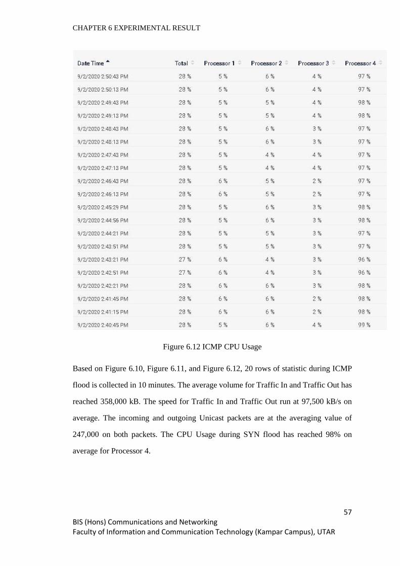
Figure 6.12 ICMP CPU Usage
Based on Figure 6.10, Figure 6.11, and Figure 6.12, 20 rows of statistic during ICMP
flood is collected in 10 minutes. The average volume for Traffic In and Traffic Out has
reached 358,000 kB. The speed for Traffic In and Traffic Out run at 97,500 kB/s on
average. The incoming and outgoing Unicast packets are at the averaging value of
247,000 on both packets. The CPU Usage during SYN flood has reached 98% on
average for Processor 4.

CHAPTER 6 EXPERIMENTAL RESULT
58 BIS (Hons) Communications and Networking Faculty of Information and Communication Technology (Kampar Campus), UTAR
6.2 DDoS Pattern Detection
In the following section, we will see a graphical presentation of network traffic and
CPU usage statistic when the DDoS attacks are happening on the targeted device. The
DDoS attacks included SYN flood, UDP flood and ICMP flood. These attacks are
mainly impacted by the volume of the traffic.
Figure 6.13 Traffic Volume
The graph above presented the total volume of traffic in (kB) including the incoming
and outgoing traffic on the Local Area Connection 2. The normal traffic pattern shows
a flat line throughout the period. An SYN flood pattern shows the traffic has increased
sharply by 190,000 kB from 10 kB to approximate 190,000 kB volume on the time
interval from 4 to 12. A UDP flood pattern shows the traffic also increase dramatically
by 225,000 kB from 10 kB to approximate 225,000 kB volume on the time interval
from 4 to 12. An ICMP flood pattern shows the highest increase in the traffic volume
which is from 10 kB to approximate 620,000 kB for the time interval from 4 to 12.
0
200000
400000
600000
800000
1 2 3 4 5 6 7 8 9 10 11 12 13 14 15
Local Area Connection 2 Traffic Volume
Normal Traffic Syn Flood Traffic Udp Flood Traffic Ping Flood Traffic

CHAPTER 6 EXPERIMENTAL RESULT
59 BIS (Hons) Communications and Networking Faculty of Information and Communication Technology (Kampar Campus), UTAR
Figure 6.14 CPU Usage Percentage
Besides, CPU usages are one of the criteria that the DDoS attack will impact. The
reason behind the attack is because whenever the device has received any incoming
packets, it will process the packet based on the purpose with the packet itself. The chart
above has visualized the CPU usage percentage in the line graph. The normal flow
shows the CPU usage is running at 5% mediocrely before the DDoS attack is happening.
However, an SYN flood has increased the CPU usage from 5% up to 28% and followed
by an increasing CPU usage from 5% to 33% by a UDP flood. Lastly, an ICMP flood
has the highest impact on the CPU usage which has increased the usage up to the peak
at 98%.
0
20
40
60
80
100
1 2 3 4 5 6 7 8 9 10 11 12 13 14 15 16 17 18 19 20
CPU Usage %
Normal Syn Flood Udp Flood Ping Flood

CHAPTER 6 EXPERIMENTAL RESULT
60 BIS (Hons) Communications and Networking Faculty of Information and Communication Technology (Kampar Campus), UTAR
6.3 DDoS Alert
Based on the statistic from the graph earlier, the network traffic and CPU usage that has
been growth sharply indicating the symptoms of a DDoS attack. Once the threshold for
which the sensors are reached, the alarms are generated immediately to inform the
administrator.
Figure 6.15 Alert Message (1)
As shown in the Figure 6.15, alarm is triggered immediately once the defined rule for
the Traffic sensor is violated. The alarm is triggered either the maximum speed or traffic
volume are exceeded.
Figure 6.16 Alert Message (2)
It is also same to the CPU Usage where alarm is triggered when the CPU utilization
reached predefined percentage for a certain period as shown in Figure 6.16.

CHAPTER 6 EXPERIMENTAL RESULT
61 BIS (Hons) Communications and Networking Faculty of Information and Communication Technology (Kampar Campus), UTAR
6.4 Types of DDoS Analysis
The result shows the SNMP can detect the DDoS attack on our network and notices the
administrator act in fighting the attack. It is essential to differentiate the type of DDoS
attack so a better solution can be designed to defense our network against the DDoS
attack. We are going to see what the characteristic and symptom of each of the DDoS
attack are.
SYN Flood
Figure 6.17 SYN Pattern
In the SYN flood scenario, SYN packets are sent to every port on the targeted device.
After that, the device will respond to an SYN-ACK packet to each of the SYN packets
from each port. However, the device will not receive the ACK packet from the source
and the port remains open. This leaves in the state that receiving the SYN packets
continuously and does not send back any SYN-ACK packet since there is no open ports
are available. Based on the statistic above, the incoming traffic volume has an averaging
134,000 kB and outgoing traffic has an averaging volume at 26,000 kB. The ratio for
Traffic In and Traffic Out is similar to Unicast In and Unicast Out at approximate 5:1.

CHAPTER 6 EXPERIMENTAL RESULT
62 BIS (Hons) Communications and Networking Faculty of Information and Communication Technology (Kampar Campus), UTAR
An SYN flood consumes both incoming and outgoing traffic in the way that the
incoming traffic is multiple times higher than the outgoing traffic.
UDP Flood
Figure 6.18 UDP Pattern
A UDP flood is a technique used to overwhelm random port on the targeted device with
repeated UDP packets. The targeted device will look for the applications associated
with the UDP datagrams. Sending the UDP packet does not go through the three-ways
handshake, therefore the receiver does not have to send back the acknowledgement
packet upon receiving the UDP packet. From the statistic collected above, the Traffic
In has the same volume with the Total Traffic at 225,000 kB. The incoming traffic
including incoming unicast packets has allocated more than 99.9% of the total traffic.
This statistic shows a clear UDP flood attack because it is only consumed the incoming
traffic. The targeted device does have to respond to each of the UDP packets.

CHAPTER 6 EXPERIMENTAL RESULT
63 BIS (Hons) Communications and Networking Faculty of Information and Communication Technology (Kampar Campus), UTAR
ICMP Flood
Figure 6.19 ICMP Pattern
An ICMP flood is done by sending many ICMP echo requests packets to the targeted
device and the device reply with ICMP echo reply packets as a response. In this type of
attack, the incoming and outgoing traffic will be consumed. With the statistic obtained,
both Traffic In and Traffic Out has the same volume of traffic as well as the Unicast In
and Out volume. Compare to SYN flood, the device waits for an available port to send
back ACK-SYN packet, while the ICMP flood does not wait for any ports to close a
connection between both parties, so the device will process the ping packet immediate
when there are resources available. The outgoing traffic for ICMP flood is higher than
the SYN flood.

CHAPTER 6 EXPERIMENTAL RESULT
64 BIS (Hons) Communications and Networking Faculty of Information and Communication Technology (Kampar Campus), UTAR
Figure 6.20 ICMP CPU Pattern
Other than the network traffic, ICMP flood has the symptom that consumes a relatively
high CPU usage compare to SYN and UDP flood. Since UDP flood does not require
sending any replies to the source and SYN flood is limited to sending back ACK-SYN
replies when there are available ports, both the attacks do not consume too much of
CPU usage. However, an ICMP flood must have the targeted device to reply upon
receiving the ICMP request packet, so it requires more processing power.

CHAPTER 7 CONCLUSION
65 BIS (Hons) Communications and Networking Faculty of Information and Communication Technology (Kampar Campus), UTAR
CHAPTER 7 CONCLUSION
In conclusion, the project discussed the utilization of a network and security issues that
we faced often. A network that is out of control could be critical to the business
processes. Tolerance towards system failure, degradation of performance and low
availability is not acceptable. Any delay on the system will impact on loss of data or
even causing the process out of order. The introducing to the monitoring system comes
with a solution that can be used to counter problems above. It can obtain the data
information about traffic usage, memory or even disk space on devices. A monitoring
system is not just a tool for tracking how the resources on a network are being used but
also can monitor abnormal activities likes DDoS attack which trying to consume the
resources on the network. We have found out and come to understand that the capability
of an SNMP protocol in monitoring the security and utilization on the network.
Throughout the process of the project, a network environment is designed with several
network devices. An SNMP server is arranged in the network served as a monitoring
tool to understand the situation on the network. Afterwards, several penetrate testing is
done to a targeted host from the same network. The attacks include SYN flood, UDP
flood, and Ping flood are done using the Kali Linux platform. The SNMP server poll
the device for information such as network traffic and CPU usage. At the end of the
project, based on the statistic produced by the SNMP server, a DDoS attack is
happening on the network if the traffic volume is increased incredibly and lasted for a
long time and the raising in the CPU usage in unexpected speed. Once a DDoS attack
is confirmed, the SNMP server sounded an alarm to notify the administrator to deal
with the DDoS attack. Finally, SNMP protocol is not limited to detecting DDoS attack
but also can analyse and differentiate distinct DDoS attack patterns and behavior such
as Ping flood, SYN flood and UDP flood. The capability makes SNMP protocol become
efficiency in mitigating the attack.

66 BIS (Hons) Communications and Networking Faculty of Information and Communication Technology (Kampar Campus), UTAR
BIBLIOGRAPHY
Ashoor, A.S. and Gore, S., 2011. Importance of intrusion detection system (IDS).
International Journal of Scientific and Engineering Research, 2(1), pp.1-4.
Baumann, R. and Plattner, C., 2002. White Paper: Honeypots.
Beal, V., 2005. Intrusion detection (IDS) and prevention (IPS) systems.
Claise, B., 2004. Cisco systems netflow services export version 9.
Elleithy, K.M., Blagovic, D., Cheng, W.K. and Sideleau,
P., 2005. Denial of Servie Attack
Techniques: Analysis, Implementation
and Comparison.
Gerhards, R., 2009. The syslog protocol.
Hare, C., 2011. Simple Network Management Protocol (SNMP).
Harrington, D., Wijnen, B. and Presuhn, R., 2002. An
architecture for describing simple network
management protocol (SNMP) management
frameworks.
Hofstede, R., Čeleda, P., Trammell, B., Drago, I., Sadre,
R., Sperotto, A. and Pras, A., 2014. Flow
monitoring explained: From packet capture to
data analysis with netflow and ipfix. IEEE
Communications Surveys & Tutorials, 16(4),
pp.2037-2064.
Jiang, H., 2016. Employee personal Internet usage in the workplace.
Jyväskylä studies in computing, (257).
Mokube, I. and Adams, M., 2007, March. Honeypots:
concepts, approaches, and challenges. In
Proceedings of the 45th annual southeast regional
conference (pp. 321- 326). ACM.

67 BIS (Hons) Communications and Networking Faculty of Information and Communication Technology (Kampar Campus), UTAR
Sharma, S.K. and Gupta, J.N., 2004. Improving workers'
productivity and reducing Internet abuse. Journal
of Computer Information Systems, 44(2), pp.74-
78.
Svoboda, J., Ghafir, I. and Prenosil, V., 2015. Network
monitoring approaches: An overview. Int
J Adv Comput Netw Secur, 5(2), pp.88-
93.
Uppal, H.A.M., Javed, M. and Arshad, M., 2014. An overview of
intrusion detection system (IDS) along with its commonly used
techniques and classifications. International Journal of
Computer Science and Telecommunications, 5(2), pp.20-24.

A-1 BIS (Hons) Communications and Networking Faculty of Information and Communication Technology (Kampar Campus), UTAR
FINAL YEAR PROJECT WEEKLY REPORT
(Project I / Project II)
Trimester, Year: Y4S1 Study week no.: 1
Student Name & ID: LING WEI JOON & 16ACB01604
Supervisor: DR. GAN MING LEE
Project Title: NETWORK UTILISATION AND SECURITY MONITORING
USING SNMP
1. WORK DONE
[Please write the details of the work done in the last fortnight.]
- Study on the implementation of project
2. WORK TO BE DONE
- Study on penetration test tutorial
- Study on the setting of PRTG software
3. PROBLEMS ENCOUNTERED
None
4. SELF EVALUATION OF THE PROGRESS
None
_________________________ _________________________
Supervisor’s signature Student’s signature

A-2 BIS (Hons) Communications and Networking Faculty of Information and Communication Technology (Kampar Campus), UTAR
FINAL YEAR PROJECT WEEKLY REPORT
(Project I / Project II)
Trimester, Year: Y4S1 Study week no.: 2
Student Name & ID: LING WEI JOON & 16ACB01604
Supervisor: DR. GAN MING LEE
Project Title: NETWORK UTILISATION AND SECURITY MONITORING
USING SNMP
1. WORK DONE
[Please write the details of the work done in the last fortnight.]
- Study on the implementation of project
2. WORK TO BE DONE
- Study on penetration test tutorial
- Study on the setting of PRTG software
3. PROBLEMS ENCOUNTERED
None
4. SELF EVALUATION OF THE PROGRESS
None
_________________________ _________________________
Supervisor’s signature Student’s signature

A-3 BIS (Hons) Communications and Networking Faculty of Information and Communication Technology (Kampar Campus), UTAR
FINAL YEAR PROJECT WEEKLY REPORT
(Project I / Project II)
Trimester, Year: Y4S1 Study week no.: 3
Student Name & ID: LING WEI JOON & 16ACB01604
Supervisor: DR. GAN MING LEE
Project Title: NETWORK UTILISATION AND SECURITY MONITORING
USING SNMP
1. WORK DONE
[Please write the details of the work done in the last fortnight.]
- Study on the implementation of project
2. WORK TO BE DONE
- Study on penetration test tutorial
- Study on the setting of PRTG software
3. PROBLEMS ENCOUNTERED
None
4. SELF EVALUATION OF THE PROGRESS
None
_________________________ _________________________
Supervisor’s signature Student’s signature

A-4 BIS (Hons) Communications and Networking Faculty of Information and Communication Technology (Kampar Campus), UTAR
FINAL YEAR PROJECT WEEKLY REPORT
(Project I / Project II)
Trimester, Year: Y4S1 Study week no.: 4
Student Name & ID: LING WEI JOON & 16ACB01604
Supervisor: DR. GAN MING LEE
Project Title: NETWORK UTILISATION AND SECURITY MONITORING
USING SNMP
1. WORK DONE
[Please write the details of the work done in the last fortnight.]
- Study on the implementation of project
2. WORK TO BE DONE
- Study on penetration test tutorial
- Study on the setting of PRTG software
3. PROBLEMS ENCOUNTERED
None
4. SELF EVALUATION OF THE PROGRESS
None
_________________________ _________________________
Supervisor’s signature Student’s signature

A-5 BIS (Hons) Communications and Networking Faculty of Information and Communication Technology (Kampar Campus), UTAR
FINAL YEAR PROJECT WEEKLY REPORT
(Project I / Project II)
Trimester, Year: Y4S1 Study week no.: 5
Student Name & ID: LING WEI JOON & 16ACB01604
Supervisor: DR. GAN MING LEE
Project Title: NETWORK UTILISATION AND SECURITY MONITORING
USING SNMP
1. WORK DONE
[Please write the details of the work done in the last fortnight.]
- Study on the implementation of project
2. WORK TO BE DONE
- Study on penetration test tutorial
- Study on the setting of PRTG software
3. PROBLEMS ENCOUNTERED
None
4. SELF EVALUATION OF THE PROGRESS
None
_________________________ _________________________
Supervisor’s signature Student’s signature

A-6 BIS (Hons) Communications and Networking Faculty of Information and Communication Technology (Kampar Campus), UTAR
FINAL YEAR PROJECT WEEKLY REPORT
(Project I / Project II)
Trimester, Year: Y4S1 Study week no.: 6
Student Name & ID: LING WEI JOON & 16ACB01604
Supervisor: DR. GAN MING LEE
Project Title: NETWORK UTILISATION AND SECURITY MONITORING
USING SNMP
1. WORK DONE
[Please write the details of the work done in the last fortnight.]
- Study on the implementation of project
2. WORK TO BE DONE
- Study on penetration test tutorial
- Study on the setting of PRTG software
3. PROBLEMS ENCOUNTERED
None
4. SELF EVALUATION OF THE PROGRESS
None
_________________________ _________________________
Supervisor’s signature Student’s signature

A-7 BIS (Hons) Communications and Networking Faculty of Information and Communication Technology (Kampar Campus), UTAR
FINAL YEAR PROJECT WEEKLY REPORT
(Project I / Project II)
Trimester, Year: Y4S1 Study week no.: 7
Student Name & ID: LING WEI JOON & 16ACB01604
Supervisor: DR. GAN MING LEE
Project Title: NETWORK UTILISATION AND SECURITY MONITORING
USING SNMP
1. WORK DONE
[Please write the details of the work done in the last fortnight.]
- Study on the implementation of project
2. WORK TO BE DONE
- Study on penetration test tutorial
- Study on the setting of PRTG software
3. PROBLEMS ENCOUNTERED
None
4. SELF EVALUATION OF THE PROGRESS
None
_________________________ _________________________
Supervisor’s signature Student’s signature

A-8 BIS (Hons) Communications and Networking Faculty of Information and Communication Technology (Kampar Campus), UTAR
FINAL YEAR PROJECT WEEKLY REPORT
(Project I / Project II)
Trimester, Year: Y4S1 Study week no.: 8
Student Name & ID: LING WEI JOON & 16ACB01604
Supervisor: DR. GAN MING LEE
Project Title: NETWORK UTILISATION AND SECURITY MONITORING
USING SNMP
1. WORK DONE
[Please write the details of the work done in the last fortnight.]
- Study on the implementation of project
2. WORK TO BE DONE
- Study on penetration test tutorial
- Study on the setting of PRTG software
3. PROBLEMS ENCOUNTERED
None
4. SELF EVALUATION OF THE PROGRESS
None
_________________________ _________________________
Supervisor’s signature Student’s signature

A-9 BIS (Hons) Communications and Networking Faculty of Information and Communication Technology (Kampar Campus), UTAR
FINAL YEAR PROJECT WEEKLY REPORT
(Project I / Project II)
Trimester, Year: Y4S1 Study week no.: 9
Student Name & ID: LING WEI JOON & 16ACB01604
Supervisor: DR. GAN MING LEE
Project Title: NETWORK UTILISATION AND SECURITY MONITORING
USING SNMP
1. WORK DONE
[Please write the details of the work done in the last fortnight.]
- Study on the implementation of project
2. WORK TO BE DONE
- Study on penetration test tutorial
- Study on the setting of PRTG software
3. PROBLEMS ENCOUNTERED
None
4. SELF EVALUATION OF THE PROGRESS
None
_________________________ _________________________
Supervisor’s signature Student’s signature

A-10 BIS (Hons) Communications and Networking Faculty of Information and Communication Technology (Kampar Campus), UTAR
FINAL YEAR PROJECT WEEKLY REPORT
(Project I / Project II)
Trimester, Year: Y4S1 Study week no.: 10
Student Name & ID: LING WEI JOON & 16ACB01604
Supervisor: DR. GAN MING LEE
Project Title: NETWORK UTILISATION AND SECURITY MONITORING
USING SNMP
1. WORK DONE
[Please write the details of the work done in the last fortnight.]
- Launched penetration testing
2. WORK TO BE DONE
- Launch penetration test on targeted machine
3. PROBLEMS ENCOUNTERED
None
4. SELF EVALUATION OF THE PROGRESS
None
_________________________ _________________________
Supervisor’s signature Student’s signature

A-11 BIS (Hons) Communications and Networking Faculty of Information and Communication Technology (Kampar Campus), UTAR
FINAL YEAR PROJECT WEEKLY REPORT
(Project I / Project II)
Trimester, Year: Y4S1 Study week no.: 11
Student Name & ID: LING WEI JOON & 16ACB01604
Supervisor: DR. GAN MING LEE
Project Title: NETWORK UTILISATION AND SECURITY MONITORING
USING SNMP
1. WORK DONE
[Please write the details of the work done in the last fortnight.]
- Launched penetration testing
2. WORK TO BE DONE
- Generate results from the implementation
3. PROBLEMS ENCOUNTERED
None
4. SELF EVALUATION OF THE PROGRESS
None
_________________________ _________________________
Supervisor’s signature Student’s signature

A-12 BIS (Hons) Communications and Networking Faculty of Information and Communication Technology (Kampar Campus), UTAR
FINAL YEAR PROJECT WEEKLY REPORT
(Project I / Project II)
Trimester, Year: Y4S1 Study week no.: 12
Student Name & ID: LING WEI JOON & 16ACB01604
Supervisor: DR. GAN MING LEE
Project Title: NETWORK UTILISATION AND SECURITY MONITORING
USING SNMP
1. WORK DONE
[Please write the details of the work done in the last fortnight.]
- Generate result based on the implementation
2. WORK TO BE DONE
- Write implementation, results and conclusion in proposal report
3. PROBLEMS ENCOUNTERED
None
4. SELF EVALUATION OF THE PROGRESS
None
_________________________ _________________________
Supervisor’s signature Student’s signature

A-13 BIS (Hons) Communications and Networking Faculty of Information and Communication Technology (Kampar Campus), UTAR
FINAL YEAR PROJECT WEEKLY REPORT
(Project I / Project II)
Trimester, Year: Y4S1 Study week no.: 13
Student Name & ID: LING WEI JOON & 16ACB01604
Supervisor: DR. GAN MING LEE
Project Title: NETWORK UTILISATION AND SECURITY MONITORING
USING SNMP
1. WORK DONE
[Please write the details of the work done in the last fortnight.]
- Documentation on the proposal report
2. WORK TO BE DONE
None
3. PROBLEMS ENCOUNTERED
None
4. SELF EVALUATION OF THE PROGRESS
None
_________________________ _________________________
Supervisor’s signature Student’s signature

BIS (Hons) Communications and Networking Faculty of Information and Communication Technology (Kampar Campus), UTAR
POSTER

BIS (Hons) Communications and Networking Faculty of Information and Communication Technology (Kampar Campus), UTAR
TURNITIN PLAGIARISM RESULT

BIS (Hons) Communications and Networking Faculty of Information and Communication Technology (Kampar Campus), UTAR

BIS (Hons) Communications and Networking Faculty of Information and Communication Technology (Kampar Campus), UTAR
FACULTY OF INFORMATION AND COMMUNICATION TECHNOLOGY
Full Name(s) of Candidate(s)
LING WEI JOON
ID Number(s)
16ACB01604
Programme / Course CN
Title of Final Year Project NETWORK UTILISATION AND SECURITY MONITORING USING
SNMP
Similarity Supervisor’s Comments
(Compulsory if parameters of originality exceeds the limits approved by UTAR)
Overall similarity index: 2 %
Similarity by source
Internet Sources: _______1_______% Publications: _______1_______ % Student Papers: _______2_______ %
Number of individual sources listed of more than 3% similarity: 0
Parameters of originality required and limits approved by UTAR are as Follows:
(i) Overall similarity index is 20% and below, and (ii) Matching of individual sources listed must be less than 3% each, and (iii) Matching texts in continuous block must not exceed 8 words
Note: Parameters (i) – (ii) shall exclude quotes, bibliography and text matches which are less than 8 words.
Note Supervisor/Candidate(s) is/are required to provide softcopy of full set of the
originality report to Faculty/Institute
Based on the above results, I hereby declare that I am satisfied with the originality of the
Final Year Project Report submitted by my student(s) as named above.
______________________________ ______________________________
Signature of Supervisor
Signature of Co-Supervisor
Name: ____LING WEI JOON______
Name: __________________________
Date: _______6/9/2020___________ Date: ___________________________
Universiti Tunku Abdul Rahman
Form Title : Supervisor’s Comments on Originality Report Generated by Turnitin
for Submission of Final Year Project Report (for Undergraduate Programmes) Form Number: FM-IAD-005 Rev No.: 0 Effective Date: 01/10/2013 Page No.: 1of 1

BIS (Hons) Communications and Networking Faculty of Information and Communication Technology (Kampar Campus), UTAR
UNIVERSITI TUNKU ABDUL RAHMAN
FACULTY OF INFORMATION & COMMUNICATION
TECHNOLOGY (KAMPAR CAMPUS)
CHECKLIST FOR FYP2 THESIS SUBMISSION
Student Id 16ACB01604
Student Name LING WEI JOON
Supervisor Name DR GAN MING LEE
TICK (√) DOCUMENT ITEMS
Your report must include all the items below. Put a tick on the left column after you have
checked your report with respect to the corresponding item.
Front Cover
Signed Report Status Declaration Form
Title Page
Signed form of the Declaration of Originality
Acknowledgement
Abstract
Table of Contents
List of Figures (if applicable)
List of Tables (if applicable)
List of Symbols (if applicable)
List of Abbreviations (if applicable)
Chapters / Content
Bibliography (or References)
All references in bibliography are cited in the thesis, especially in the chapter
of literature review
Appendices (if applicable)
Poster
Signed Turnitin Report (Plagiarism Check Result - Form Number: FM-IAD-005)
*Include this form (checklist) in the thesis (Bind together as the last page)

BIS (Hons) Communications and Networking Faculty of Information and Communication Technology (Kampar Campus), UTAR
I, the author, have checked and
confirmed all the items listed in the
table are included in my report.
______________________
(Signature of Student)
Date: 6/9/2020
Supervisor verification. Report with
incorrect format can get 5 mark (1
grade) reduction.
______________________
(Signature of Supervisor)
Date: