network virtualization for large-scale data centers · 2019-03-27 · network virtualization for...
TRANSCRIPT

292 FUJITSU Sci. Tech. J., Vol. 49, No. 3, pp. 292–299 (July 2013)
Network Virtualization for Large-Scale Data Centers
Tatsuhiro Ando Osamu Shimokuni Katsuhito Asano
The growing use of cloud technology by large enterprises to support their business continuity planning (BCP) and disaster recovery planning (DRP) is leading to an increase in the scale of the systems used by data center operators. As this increase in scale progresses, it is becoming more and more difficult to build virtual and physical networks using existing technologies. For example, the number of virtual local area networks (VLANs) that can be built in a data center using VLAN technology is limited to 4094 because of the bit length limit of a VLAN ID. With physical networks, inefficiencies in network line use due to the use of Spanning Tree Protocol (STP) switching and the complexity of network design are becoming issues. In this paper, we summarize the conditions and technical requirements faced by large-scale data centers. We also discuss various approaches to meeting these requirements such as extending the number of virtual networks and building physical networks using an alternative to STP switching, com-pare them, and discuss their characteristics.
1. IntroductionThe demand for high availability information
processing and services such as data storage and Web hosting provided by an enterprise is increasing due to increasing emphasis on business continuity planning (BCP) and disaster recovery planning (DRP). High availability information systems require sophisticated design and operation, so enterprises are migrating to cloud services, and the scale of cloud data center sys-tems is increasing.
There are various types of services offered by cloud service providers, including software as a service (SaaS), platform as a service (PaaS), and infrastructure as a service (IaaS). With IaaS in particular, multiple tenants (users) share use of the same physical system, so individual systems tend to increase in scale. With re-cent improvements in server performance, 20 or more virtual machines (VMs) can run on a single physical server. Regarding networks, 10 Gigabit Ethernet is be-coming mainstream for server network-interface cards (NICs), so there is a need for even larger capacity and integration.
In this paper, we discuss networking requirements
related to the increasing size of data centers, methods for increasing the scale of network virtualization, and methods for building physical networks.
2. Requirements faced by large-scale data centersCloud-based IaaS providers currently operate on
a scale of several hundred host servers and several thousand VMs.1) For discussion of the requirements large-scale data centers will face in the future, we have estimated the average scale of large-scale data centers between 2015 and 2020, as shown in Table 1. This data center scale will lead to several technical requirements. 1) Integrated management of server, storage, and
network resources linked to a cloud operating sys-tem (OS).
2) Automatic configuration changes linked to live migration.
3) Isolation exceeding 4094 tenants (virtual networks).4) Avoidance of traffic congestion.5) Layer 2 (L2) network extension between remote
data centers.

293FUJITSU Sci. Tech. J., Vol. 49, No. 3 (July 2013)
T. Ando et al.: Network Virtualization for Large-Scale Data Centers
It will also lead to two business requirements.1) Avoid vender lock-in (avoid devices dependent
on a single operator to capture business; adopt schemes supporting multiple vendors).
2) Support small start and scalability.It should be possible to increase usability for
end users and reduce customers‘ capital expenditure (CAPEX) and operational expenditure (OPEX) by cre-ating large-scale data center IaaS that meets these requirements. In this paper, we discuss approaches and methods for meeting the technical requirements listed above.
In the next section, we discuss the use of IaaS infrastructures that manage servers, storage, and net-works centrally, addressing technical requirements 1) and 2).
3. System structures for IaaS infrastructureData centers are actively moving to cloud tech-
nologies. The expected change in cloud system architecture is illustrated in Figure 1. Server, storage, and network resources are conventionally managed by separate departments. However, since virtual switches are implemented within the OS of hosts to support communication between VMs, it is more effi-cient to manage VMs and virtual switches together on a server. Moreover, VMs are often dynamically moved to a different server (i.e., “live migration”), so network settings must be changed automatically when a VM is moved. This means that there will be growing use of cloud operations management software (“cloud OS”)
to integrate the management of server, storage, and network resources.
In particular, there is growing use of the OpenStack open source OS and the CloudStack open source infrastructure, which support a wide range of vir-tual infrastructure software and hardware products. As a result, systems that were conventionally built using hardware from only one vendor (“vendor lock-in”) can now be built using hardware from various vendors.
In the next section, we address the VLAN limita-tion problem and present three possible approaches to solving it, addressing technical requirements 3) and 5).
4. Network virtualization for large-scale data centersIaaS infrastructure technology, as with server
virtualization technology, enables an independent net-work to be built for each tenant (the group or company using the service), as shown in Figure 2, so it requires network virtualization.
However, as mentioned above, the number of virtual networks (number of IDs) is limited to 4094, so large-scale data centers are becoming too large to be supported. Each tenant typically uses four or five VLANs depending on the structure of their systems, so only up to about 800 tenants can be supported in a single VLAN environment.
4.1 Approaches to network virtualizationPossible approaches to solving this problem
include interconnecting VLAN environments, using label switching between VMs, and using L2 over L3
Table 1Average scale of large-scale data centers between 2015 and 2020.
Item Sub-item Reference value
ServersNumber of VMs 20 000 or more
Number of physical servers 1024 or more
Storage
Storage per VM 75 GB or more
Total storage 500 TB or more
Number of storage devices 2×2 or more
Network
Number of tenants 2000 or more
Number of virtual networks(VLAN, VXLAN, etc.) 8000 or more
Connection points with Internet 2 or more
Facilities Number of data center locations 2 or more

294 FUJITSU Sci. Tech. J., Vol. 49, No. 3 (July 2013)
T. Ando et al.: Network Virtualization for Large-Scale Data Centers
tunneling.1) Interconnecting VLAN environments
The system scale could be increased by linking
multiple VLAN IaaS systems. The VLAN IDs for a given tenant are restricted to a single VLAN environment, and the IDs in other environments can be used by other
Storage control
Network device
Infrastructure layer
(hardware)
Control layer(device control
server)
Application layer
(cloud OS)
Network controlServer control
REST APIs,
etc.
Cloud operation and management
Server machine
Storage device
CLI,SNMP, etc.
CLI,SNMP, etc.
REST APIs,
etc.
REST APIs,
etc.
CLI,SNMP, etc.
REST API: Representational state transfer application programming interfaceCLI: Command line interfaceSNMP: Simple Network Management Protocol
Network device
Server machine
Storage device
Figure 1Cloud system architecture.
Figure 1Cloud system architecture.
Physical network (underlay network) L2 switch
Virtual network 1 (overlay network)
Virtual network 2 (overlay network)
Virtual network (overlay network)…
Figure 2Network virtualization.
N
Figure 2Network virtualization.
295FUJITSU Sci. Tech. J., Vol. 49, No. 3 (July 2013)
T. Ando et al.: Network Virtualization for Large-Scale Data Centers
tenants. A VLAN ID conversion switch could be placed between environments to enable virtual systems span-ning multiple VLAN environments to be built. With this approach, the number of virtual networks could be increased 4094 at a time by providing two-way connec-tions between VLAN environments. Virtual networks could also be extended between data centers by using technologies such as virtual private LAN service (VPLS). 2) Label switching between VMs
Communication among each tenantʼs VLANs could be controlled by using multiprotocol label switch-ing (MPLS) rather than conventional VLAN switching. The physical network in the data center could be built using MPLS, and labels could be created for each ten-ant and/or each link between servers, thereby enabling packets to be transmitted between VMs. MPLS shim header labels have 20 bits, so over one million virtual networks could be built. Virtual networks spanning data centers could also be implemented using MPLS. 3) L2 over L3 tunneling
L3 tunneling could be used instead of con-ventional VLAN switching to control communication between the VMs within each tenant. The number of virtual networks that could be configured is theoreti-cally limited by the bit length of the tunnel identifier. For example, it is 24 bits for VXLAN,2) so over 16 million virtual networks could be built. Since only L3 con-nectivity needs to be guaranteed for interconnecting virtual networks between remote data centers, virtual networks between remote data centers could be im-plemented by L2 over L3 tunneling using existing L3 technology.
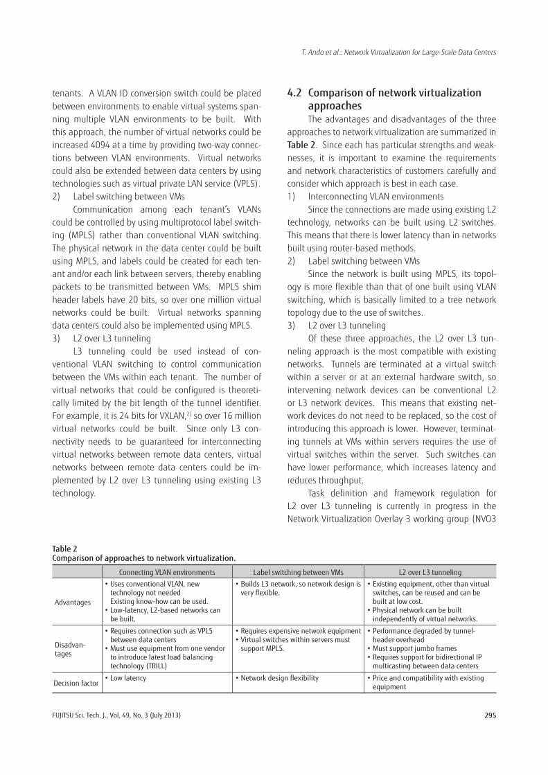
4.2 Comparison of network virtualization approachesThe advantages and disadvantages of the three
approaches to network virtualization are summarized in Table 2. Since each has particular strengths and weak-nesses, it is important to examine the requirements and network characteristics of customers carefully and consider which approach is best in each case.1) Interconnecting VLAN environments
Since the connections are made using existing L2 technology, networks can be built using L2 switches. This means that there is lower latency than in networks built using router-based methods.2) Label switching between VMs
Since the network is built using MPLS, its topol-ogy is more flexible than that of one built using VLAN switching, which is basically limited to a tree network topology due to the use of switches.3) L2 over L3 tunneling
Of these three approaches, the L2 over L3 tun-neling approach is the most compatible with existing networks. Tunnels are terminated at a virtual switch within a server or at an external hardware switch, so intervening network devices can be conventional L2 or L3 network devices. This means that existing net-work devices do not need to be replaced, so the cost of introducing this approach is lower. However, terminat-ing tunnels at VMs within servers requires the use of virtual switches within the server. Such switches can have lower performance, which increases latency and reduces throughput.
Task definition and framework regulation for L2 over L3 tunneling is currently in progress in the Network Virtualization Overlay 3 working group (NVO3
Table 2Comparison of approaches to network virtualization.
Connecting VLAN environments Label switching between VMs L2 over L3 tunneling
Advantages
•UsesconventionalVLAN,newtechnology not needed Existing know-how can be used.
•Low-latency,L2-basednetworkscanbe built.
•BuildsL3network,sonetworkdesignisveryflexible.
•Existingequipment,otherthanvirtualswitches, can be reused and can be built at low cost.
•Physicalnetworkcanbebuiltindependently of virtual networks.
Disadvan- tages
•RequiresconnectionsuchasVPLSbetween data centers
•Mustuseequipmentfromonevendorto introduce latest load balancing technology (TRILL)
•Requiresexpensivenetworkequipment•VirtualswitcheswithinserversmustsupportMPLS.
•Performancedegradedbytunnel-header overhead
•Mustsupportjumboframes•RequiressupportforbidirectionalIP
multicasting between data centers
Decision factor•Lowlatency •Networkdesignflexibility •Priceandcompatibilitywithexisting
equipment

296 FUJITSU Sci. Tech. J., Vol. 49, No. 3 (July 2013)
T. Ando et al.: Network Virtualization for Large-Scale Data Centers
WG) of the IETF. Standardization discussions include several possible tunneling methods, such as XVLAN,2)
NVGRE,3) and STT,4) so it is important to keep abreast of future changes.
In the next section, we discuss infrastructure for the physical networks (underlay networks) that support virtual networks (overlay networks) and ways to avoid traffi c congestion, addressing technical requirement 4).
5. Physical network infrastructure supporting virtual networksThere are also various approaches to building the
physical networks that support virtual networks, and it is important to select a suitable one. Increased traffi c between servers due to an increasing number of VMs on servers is a concern, so the ability to increase the capacity of physical networks is needed.
Normally, data center networks are organized in rack housing and consist of two layers, with a top-of-rack (ToR) switch in each rack and an aggregator switch accommodating the ToR switches, or into three layers, with an additional core switch that connects the
aggregator switches. In structures using conventional Spanning Tree Protocol (STP) switching, line waste oc-curs due to blocked ports, so it is important to build an effi cient network, i.e., a loop-free one.
The approaches typically used to build virtual networks upon L2 and L3 networks include using fab-ric switching, using a static L3 network, and using an MPLS network. The resulting network confi gurations are illustrated in Figure 3. 1) Fabric switching
With this approach, multiple fabric switches are controlled using a single virtual switch. Instead of using STP switching, the switches use a switching tech-nology based on Intermediate System to Intermediate System (IS-IS) routing (Shortest Path Bridging [SPB] and the Transparent Interconnection of Lots of Links [TRILL]) over Ethernet topology. This results in trans-mission based on a routing table without loops that can reach the destination, so the network is used more effi ciently. The cost per route can be controlled, and loads can be distributed over multiple routes to avoid traffi c congestion.
2) Static L3 network
Tenant B virtual network
Tenant A virtual network
1) Fabric switching
Tenant B virtual network
Tenant A virtual network
L2 switch
Fabric switching network
3) MPLS network
Tenant B virtual network
Tenant A virtual network
Router, MPLS router
L3 Technology Solution
L2 Technology Solution
L3 switchL3 switch
L2 switch
L2 switch
Figure 3Configurations of physical networks built using typical approaches.
Figure 3Confi gurations of physical networks built using typical approaches.

297FUJITSU Sci. Tech. J., Vol. 49, No. 3 (July 2013)
T. Ando et al.: Network Virtualization for Large-Scale Data Centers
2) Static L3 networkNetworks that can explicitly specify the amount of
traffi c that goes to each aggregator switch are built by aligning multiple aggregator switches gathering traffi c from ToR switches in parallel and specifying the IP ad-dress of an aggregator switch as the next-hop address. This load balancing reduces traffi c congestion.3) MPLS network
Networks are built using IP routing and MPLS, so loops are avoided, resulting in effective network usage. MPLS traffi c engineering (MPLS-TE) can be used to bal-ance the load over multiple routes and thereby avoid the concentration of traffi c.
To build the virtual networks described in the previous section, VLAN environment connection, a L2-based technology, can be combined with fabric switches, label switching between VMs can be com-bined with MPLS networks, and L2 over L3 tunneling can be combined with any of the approaches because the virtual network is independent of the physical network.
The relationships between these approaches to building virtual and physical networks are shown in Figure 4. Fabric switches are built using L2 switches, so networks can be built with lower latency than with the other approaches. Static L3 networks can be built
by combining existing L2 and L3 switches, resulting in lower cost and more stable operation. MPLS networks are built using MPLS, so network design is more fl exible than with the other approaches. There are many actual examples, so operational risk for the network is low.
The advantages and disadvantages of each approach are summarized in Table 3. As with the ap-proaches to building virtual networks, it is important to examine the requirements and network characteristics of customers carefully and consider which approach is best in each case.
In the next section, we discuss unifi ed manage-ment of the virtual and physical networks we have discussed with respect to building an IaaS infrastructure.
6. Unifi ed management of physical and virtual networksNetwork devices were conventionally confi gured
by sending commands to one device at a time. The differences in command syntax between vendors make the work of confi guring and/or modifying a network costly in terms of both time and money, so there is a desire to be able to control network devices centrally from a control server. Existing protocols for such con-trol include command line interface (CLI) protocols and the Simple Network Management Protocol (SNMP).
Virtual networks(overlay networks)
Physical network(underlay network)
Hypervisor (virtual switch)
VM VM VM
Hypervisor (virtual switch)
VM VM VM
Control using physical networking equipment 1) Fabric switching 2) Static L3 network 3) MPLS network
Control using virtual switches in server 1) Interconnecting VLAN environments 2) Label switching between VMs 3) L2 over L3 tunneling
Server Server
L2 switchL2 switch
Figure 4Relationships between virtual network and physical network structures.
Figure 4Relationships between virtual network and physical network structures.

298 FUJITSU Sci. Tech. J., Vol. 49, No. 3 (July 2013)
T. Ando et al.: Network Virtualization for Large-Scale Data Centers
VM (App)
Virtual network (overlay network)
Physical network (underlay network)
Virtual switchVirtual switch
Server
Server
Server
VM (DB)
Inter-data-center
network
Cloud OS(OpenStack, etc.)
Storage
Storage
Server-management
server
Storage management
serverVirtual network control server
Physical network control server
VM (Web)
Virtual switch
Figure 5Unified management of IaaS system using cloud OS.
Figure 5Unifi ed management of IaaS system using cloud OS.
Table 3Comparison of approaches typically used to build L2 and L3 networks.
Fabric switching Static L3 network MPLSnetwork
Advantages•Lowlatency •Lowcostthroughuseofexisting
equipment•Flexiblenetworkdesign•Lowriskduetousingexisting
technology
Disadvan- tages
•Requiresproductsfromsinglevendor•WithTRILL,already20bytesof
overhead
•Configurationprocessdifficultduetostaticconfiguration
•Latencyisrelativelylongduetouseofrouters and L3 switches.
Decision factor
•Costandlowlatency •Compatibilitywithexistingnetworks •Networkdesignflexibilityandlowoperating risk
Both the physical network and the virtual networks of each tenant need to be controlled by a control server. Control of physical and virtual networks can be concen-trated on a single control server, or separate servers can be provided to distribute control.
Cloud OS software for controlling not only the network but also the servers and storage devices in IaaS infrastructures is expected to become main-stream in the future. Current cloud OS products include OpenStack and CloudStack, which are open source, and several vendor-specifi c products. One advantage of the open source cloud OS options is that they avoid vendor lock-in, so devices from various vendors can be combined freely on the basis of cost and functionality. An advantage of the vendor-specifi c cloud OS option is that many vendors offer vendor-specifi c extensions for
functionality and administration that improve usability. It is important to select an appropriate cloud OS on the basis of the customer’s functional and performance requirements.
An image of unifi ed management in an IaaS sys-tem using a cloud OS is shown in Figure 5.
7. ConclusionIn this paper, we have discussed various ap-
proaches to implementing virtual networks that can support large-scale systems. We also discussed approaches to building physical networks that can sup-port such virtual networks.
The servers and storage devices used in data centers will continue to increase in density, and ultra high-speed interfaces (10 Gb/s or more) will become

299FUJITSU Sci. Tech. J., Vol. 49, No. 3 (July 2013)
T. Ando et al.: Network Virtualization for Large-Scale Data Centers
Tatsuhiro AndoFujitsu Ltd.Mr. Ando is currently engaged in the development of new solutions for commu-nications operators.
Osamu ShimokuniFujitsu Laboratories Ltd.Mr. Shimokuni is currently engaged in research and development of data center network technologies for communications operators and data center operators.
Katsuhito AsanoFujitsu Ltd.Mr. Asano is currently engaged in the development of new solutions for commu-nications operators.
mainstream. This means that traffic design will become even more important than it is now. For example, the placement of VMs should be carefully designed so as to localize traffic between VMs and to control traffic flow-ing into aggregation and core switches.
We will continue to research and develop network technologies that stabilize data center operation as data centers continue to increase in scale.
References1) S. Okubo: L2 Network Issues with the Sakura Cloud.
October 2011, MPLS Japan, 2011 (in Japanese).
http://mpls.jp/2011/presentations/ 20111024-sakura-mplsjp.pdf
2) IETF: VXLAN: A Framework for Overlaying Virtualized Layer 2 Networks over Layer 3 Networks draft-mahalingam-dutt-dcops-vxlan-03.
http://datatracker.ietf.org/doc/draft-mahalingam-dutt-dcops-vxlan/
3) IETF: NVGRE: Network Virtualization using Generic Routing Encapsulation draft-sridharan-virtualization-nvgre-02.
https://datatracker.ietf.org/doc/draft-sridharan-virtualization-nvgre/
4) IETF: A Stateless Transport Tunneling Protocol for Network Virtualization (STT) draft-davie-stt-03.
http://tools.ietf.org/html/draft-davie-stt-03