networking essentials: a comptia network+ n10-007...
TRANSCRIPT


NETWORKING ESSENTIALS,FIFTH EDITION
A COMPTIA NETWORK+ N10-007 TEXTBOOK
JEFFREY S. BEASLEY AND PIYASAT NILKAEW
Pearson800 East 96th Street
Indianapolis, Indiana 46240 USA

ii
Networking Essentials, Fifth Edition
Copyright © 2018 by Pearson Education, Inc.All rights reserved. No part of this book shall be reproduced, stored in a retrieval system,
or transmitted by any means, electronic, mechanical, photocopying, recording, or other-
wise, without written permission from the publisher. No patent liability is assumed with
respect to the use of the information contained herein. Although every precaution has been
taken in the preparation of this book, the publisher and author assume no responsibility for
errors or omissions. Nor is any liability assumed for damages resulting from the use of the
information contained herein.
ISBN-13: 978-0-7897-5874-3
ISBN-10: 0-7897-5874-1
Library of Congress Control Number: 2017957345
Printed in the United States of America
01 18
TrademarksAll terms mentioned in this book that are known to be trademarks or service marks have
been appropriately capitalized. Pearson IT Certification cannot attest to the accuracy of
this information. Use of a term in this book should not be regarded as affecting the validity
of any trademark or service mark.
Warning and DisclaimerEvery effort has been made to make this book as complete and as accurate as possible, but
no warranty or fitness is implied. The information provided is on an “as is” basis. The au-
thors and the publisher shall have neither liability nor responsibility to any person or entity
with respect to any loss or damages arising from the information contained in this book.
Special SalesFor information about buying this title in bulk quantities, or for special sales opportunities
(which may include electronic versions; custom cover designs; and content particular to
your business, training goals, marketing focus, or branding interests), please contact our
corporate sales department at [email protected] or (800) 382-3419.
For government sales inquiries, please contact [email protected].
For questions about sales outside the U.S., please contact [email protected].
EDITOR-IN-CHIEFMark Taub
PRODUCT LINE MANAGERBrett Bartow
DEVELOPMENT EDITORMarianne Bartow
MANAGING EDITORSandra Schroeder
PROJECT EDITORMandie Frank
COPY EDITORKitty Wilson
INDEXERKen Johnson
PROOFREADERDebbie Williams
TECHNICAL EDITORSean Wilkins
PEER REVIEWERSDeAnnia ClementsOsman GuzideGene CarwileDr. Theodor Richardson
PUBLISHING COORDINATORVanessa Evans
DESIGNERChuti Prasertsith
COMPOSITORTricia Bronkella

iii
CONTENTS AT A GLANCE
Introduction xxii
1 Introduction to Computer Networks 2
2 Physical Layer Cabling: Twisted-Pair 60
3 Physical Layer Cabling: Fiber Optics 118
4 Wireless Networking 158
5 Interconnecting LANs 204
6 TCP/IP 254
7 Introduction to Switch Configuration 310
8 Introduction to Router Configuration 352
9 Routing Protocols 390
10 Internet Technologies: Out to the Internet 458
11 Troubleshooting 510
12 Network Security 558
13 Cloud Computing and Virtualization 614
14 Codes and Standards 642
Glossary 674
Index 692

iv CONTENTS
TABLE OF CONTENTSIntroduction xxii
CHAPTER 1 Introduction to Computer Networks 2
Chapter Outline 3
Objectives 3
Key Terms 3
1-1 Introduction 5
1-2 Network Topologies 7
Section 1-2 Review 11
Test Your Knowledge 11
1-3 The OSI Model 12
Section 1-3 Review 14
Test Your Knowledge 15
1-4 The Ethernet LAN 16
IP Addressing 20
Section 1-4 Review 22
Test Your Knowledge 23
1-5 Home Networking 24
Securing a Home Network 33
IP Addressing in a Home Network 34
Section 1-5 Review 36
Test Your Knowledge 37
1-6 Assembling an Office LAN 38
Section 1-6 Review 43
Test Your Knowledge 43
1-7 Testing and Troubleshooting a LAN 44
Section 1-7 Review 47
Test Your Knowledge 47
Summary 48
Questions and Problems 48
Certification Questions 56
CHAPTER 2 Physical Layer Cabling: Twisted-Pair 60
Chapter Outline 61
Objectives 61
Key Terms 61

vCONTENTS
2-1 Introduction 63
2-2 Structured Cabling 64
Horizontal Cabling 67
Section 2-2 Review 70
Test Your Knowledge 70
2-3 Unshielded Twisted-Pair Cable 71
Shielded Twisted-Pair Cable 74
Section 2-3 Review 75
Test Your Knowledge 75
2-4 Terminating CAT6/5e/5 UTP Cables 76
Computer Communication 78
Straight-through and Crossover Patch Cables 80
Section 2-4 Review 87
Test Your Knowledge 88
2-5 Cable Testing and Certification 89
Section 2-5 Review 93
Test Your Knowledge 93
2-6 10 Gigabit Ethernet over Copper 94
Overview 94
Alien Crosstalk 95
Signal Transmission 96
Section 2-6 Review 97
Test Your Knowledge 97
2-7 Troubleshooting Cabling Systems 98
Installation 98
Cable Stretching 99
Cable Failing to Meet Manufacturer Specifications 99
CAT5e Cable Test Examples 100
Section 2-7 Review 106
Test Your Knowledge 106
Summary 107
Questions and Problems 107
Certification Questions 115
CHAPTER 3 Physical Layer Cabling: Fiber Optics 118
Chapter Outline 119
Objectives 119
Key Terms 119
3-1 Introduction 120

vi CONTENTS
3-2 The Nature of Light 123
Graded-Index Fiber 127
Single-Mode Fibers 127
Section 3-2 Review 128
Test Your Knowledge 129
3-3 Fiber Attenuation and Dispersion 129
Attenuation 129
Dispersion 131
Dispersion Compensation 132
Section 3-3 Review 133
Test Your Knowledge 133
3-4 Optical Components 134
Intermediate Components 135
Detectors 136
Fiber Connectorization 138
Section 3-4 Review 139
Test Your Knowledge 140
3-5 Optical Networking 140
Defining Optical Networking 141
Building Distribution 143
Campus Distribution 147
Section 3-5 Review 150
Test Your Knowledge 150
3-6 Safety 151
Section 3-6 Review 152
Test Your Knowledge 152
Summary 153
Questions and Problems 153
Certification Questions 156
CHAPTER 4 Wireless Networking 158
Chapter Outline 159
Objectives 159
Key Terms 159
4-1 Introduction 160
4-2 The IEEE 802.11 Wireless LAN Standard 161
Section 4-2 Review 169
Test Your Knowledge 170

viiCONTENTS
4-3 802.11 Wireless Networking 170
Section 4-3 Review 180
Test Your Knowledge 181
4-4 Bluetooth, WiMAX, RFID, and Mobile Communications 181
Bluetooth 181
WiMAX 184
Radio Frequency Identification 185
Mobile (Cellular) Communications 188
Section 4-4 Review 189
Test Your Knowledge 189
4-5 Configuring a Point-to-Multipoint Wireless LAN: A Case Study 190
Step 1. Conducting an Antenna Site Survey 191
Step 2. Establishing a Point-to-Point Wireless Link to the Home Network 191
Steps 3 and 4. Configuring the Multipoint Distribution and Conducting an RF Site Survey 192
Step 5. Configuring the Remote Installations 194
Section 4-5 Review 195
Test Your Knowledge 195
Summary 196
Questions and Problems 196
Critical Thinking 200
Certification Questions 201
CHAPTER 5 Interconnecting the LANs 204
Chapter Outline 205
Objectives 205
Key Terms 205
5-1 Introduction 206
5-2 The Network Bridge 207
Section 5-2 Review 212
Test Your Knowledge 213
5-3 The Network Switch 213
Hub and Switch Comparison 216
Managed Switches 218
Multilayer Switches 223
Section 5-3 Review 224
Test Your Knowledge 224
5-4 The Router 225
The Router Interface: Cisco 2800 Series 226
Section 5-4 Review 229
Test Your Knowledge 230

viii CONTENTS
5-5 Interconnecting LANs with the Router 230
Gateway Address 233
Network Segments 233
Section 5-5 Review 233
Test Your Knowledge 234
5-6 Configuring the Network Interface: Auto-negotiation 234
Auto-negotiation Steps 235
Full-Duplex/Half-Duplex 235
Section 5-6 Review 237
Test Your Knowledge 237
5-7 The Console Port Connection 238
Configuring the HyperTerminal Software (Windows) 240
Configuring the ZTerm Serial Communications Software (Mac) 242
Section 5-7 Review 244
Test Your Knowledge 244
Summary 245
Questions and Problems 245
Critical Thinking 250
Certification Questions 251
CHAPTER 6 TCP/IP 254
Chapter Outline 255
Objectives 255
Key Terms 255
6-1 Introduction 256
6-2 The TCP/IP Layers 257
The Application Layer 258
The Transport Layer 260
The Internet Layer 264
The Network Interface Layer 266
Section 6-2 Review 267
Test Your Knowledge 267
6-3 Number Conversion 268
Binary-to-Decimal Conversion 268
Decimal-to-Binary Conversion 270
Hexadecimal Numbers 271
Section 6-3 Review 274
Test Your Knowledge 274
6-4 IPv4 Addressing 274
Section 6-4 Review 278
Test Your Knowledge 278

ixCONTENTS
6-5 Subnet Masks 278
Section 6-5 Review 285
Test Your Knowledge 286
6-6 CIDR Blocks 286
Section 6-6 Review 289
Test Your Knowledge 289
6-7 IPv6 Addressing 290
IPv6 CIDR 294
Section 6-7 Review 295
Test Your Knowledge 295
Summary 296
Questions and Problems 296
Critical Thinking 305
Certification Questions 306
CHAPTER 7 Introduction to Switch Configuration 310
Chapter Outline 311
Objectives 311
Key Terms 311
7-1 Introduction 312
7-2 Introduction to VLANs 313
Virtual LANs 313
Section 7-2 Review 315
Test Your Knowledge 315
7-3 Introduction to Switch Configuration 316
Hostname 316
Enable Secret 317
Setting the Line Console Passwords 317
Static VLAN Configuration 319
Networking Challenge: Switch Configuration 323
Section 7-3 Review 323
Test Your Knowledge 324
7-4 Spanning-Tree Protocol 324
Section 7-4 Review 326
Test Your Knowledge 327
7-5 Network Management 327
Configuring SNMP 328
Section 7-5 Review 331
Test Your Knowledge 331

x CONTENTS
7-6 Power over Ethernet 332
Section 7-6 Review 334
Test Your Knowledge 335
7-7 Switch Security 335
Switch Port Security 337
STP Special Features 338
Section 7-7 Review 340
Test Your Knowledge 340
Summary 341
Questions and Problems 341
Critical Thinking 348
Certification Questions 348
CHAPTER 8 Introduction to Router Configuration 352
Chapter Outline 353
Objectives 353
Key Terms 353
8-1 Introduction 354
8-2 Router Fundamentals 355
Layer 3 Networks 356
Section 8-2 Review 362
Test Your Knowledge 362
8-3 The Router’s User EXEC Mode (Router>) 363
The User EXEC Mode 363
Router Configuration Challenge: User EXEC Mode 366
Section 8-3 Review 368
Test Your Knowledge 369
8-4 The Router’s Privileged EXEC Mode (Router#) 369
Hostname 371
Enable Secret 371
Setting the Line Console Passwords 372
FastEthernet Interface Configuration 373
Serial Interface Configuration 374
Router Configuration Challenge: Privileged EXEC Mode 376
Section 8-4 Review 378
Test Your Knowledge 379
Summary 380
Questions and Problems 380
Critical Thinking 385
Certification Questions 387

xiCONTENTS
CHAPTER 9 Routing Protocols 390
Chapter Outline 391
Objectives 391
Key Terms 391
9-1 Introduction 392
9-2 Static Routing 393
Gateway of Last Resort 400
Configuring Static Routes 400
Networking Challenge: Static Routes 403
Section 9-2 Review 404
Test Your Knowledge 404
9-3 Dynamic Routing Protocols 405
Section 9-3 Review 406
Test Your Knowledge 407
9-4 Distance Vector Protocols 407
Section 9-4 Review 410
Test Your Knowledge 410
9-5 Configuring RIP and RIPv2 410
Configuring Routes with RIP 412
Configuring Routes with RIPv2 417
Networking Challenge: RIPv2 418
Section 9-5 Review 419
Test Your Knowledge 420
9-6 Link State Protocols 420
Section 9-6 Review 423
Test Your Knowledge 423
9-7 Configuring the Open Shortest Path First (OSPF) Routing Protocol 424
Networking Challenge: OSPF 429
Section 9-7 Review 430
Test Your Knowledge 430
9-8 Advanced Distance Vector Protocol: Configuring Enhanced Interior Gateway Routing Protocol (EIGRP) 430
Configuring Routes with EIGRP 431
Networking Challenge: EIGRP 436
Section 9-8 Review 437
Test Your Knowledge 437
9-9 IPv6 Routing 438
IPv6 Static Routing 438
RIP for IPv6 438
OSPF for IPv6 439

xii CONTENTS
EIGRP for IPv6 440
Section 9-9 Review 440
Test Your Knowledge 440
Summary 442
Questions and Problems 442
Critical Thinking 455
Certification Questions 456
CHAPTER 10 Internet Technologies: Out to the Internet 458
Chapter Outline 459
Objectives 459
Key Terms 459
10-1 Introduction 461
10-2 The Line Connection 463
Data Channels 464
Point of Presence 465
Section 10-2 Review 468
Test Your Knowledge 468
10-3 Remote Access 468
Analog Modem Technologies 469
Cable Modems 470
xDSL Modems 470
Remote Access Server 472
Section 10-3 Review 475
Test Your Knowledge 475
10-4 Metro Ethernet/Carrier Ethernet 476
Ethernet Service Types 477
Service Attributes 479
Section 10-4 Review 479
Test Your Knowledge 480
10-5 Network Services: DHCP and DNS 480
The DHCP Data Packets 482
DHCP Deployment 483
Network Services: DNS 485
Internet Domain Names 486
Section 10-5 Review 491
Test Your Knowledge 492
10-6 Internet Routing: BGP 492
Section 10-6 Review 495
Test Your Knowledge 495

xiiiCONTENTS
10-7 Analyzing Internet Data Traffic 495
Utilization/Errors Strip Chart 497
Network Layer Matrix 497
Network Layer Host Table 498
Frame Size Distribution 498
Section 10-7 Review 499
Test Your Knowledge 500
Summary 501
Questions and Problems 501
Certification Questions 507
CHAPTER 11 Troubleshooting 510
Chapter Outline 511
Objectives 511
Key Terms 511
11-1 Introduction 512
11-2 Analyzing Computer Networks 514
Using Wireshark to Inspect Data Packets 514
Using Wireshark to Capture Packets 517
Section 11-2 Review 519
Test Your Knowledge 519
11-3 Analyzing Computer Networks: FTP Data Packets 519
Section 11-3 Review 520
Test Your Knowledge 521
11-4 Analyzing Campus Network Data Traffic 521
Section 11-4 Review 524
Test Your Knowledge 524
11-5 Troubleshooting the Router Interface 525
Section 11-5 Review 529
Test Your Knowledge 529
11-6 Troubleshooting the Switch Interface 530
Section 11-6 Review 534
Test Your Knowledge 534
11-7 Troubleshooting Fiber Optics: The OTDR 535
Section 11-7 Review 537
Test Your Knowledge 537
11-8 Troubleshooting Wireless Networks 537
Hardware Issues 537
Signal Strength Problems 538

xiv CONTENTS
Frequency Interference Problems 538
Load Issues 538
DHCP Issues 538
SSID Issues 538
Securing Wi-Fi Issues 538
Wireless Printer Issues 538
Wireless Router Issues 539
Extending the Wireless Range 539
Selecting Wireless Channels 539
Wireless Compatibility 539
Cable Issues 540
Switch Uptime 540
Section 11-8 Review 540
Test Your Knowledge 540
11-9 Troubleshooting IP Networks 541
Verifying Network Settings 543
Investigating IP Address Issues 543
Finding Subnet Mask Issues 544
Looking for Gateway Issues 544
Identifying Name Resolution Issues 544
Investigating DHCP Issues 545
Checking for Blocked TCP/UDP Ports 546
Section 11-9 Review 546
Test Your Knowledge 547
Summary 548
Questions and Problems 548
Certification Questions 555
CHAPTER 12 Network Security 558
Chapter Outline 559
Objectives 559
Key Terms 559
12-1 Introduction 560
12-2 Intrusion: How Attackers Gain Control of a Network 562
Social Engineering 562
Password Cracking 563
Packet Sniffing 564
Vulnerable Software 566
Preventing Vulnerable Software Attacks 567

xvCONTENTS
Viruses and Worms 569
Section 12-2 Review 570
Test Your Knowledge 571
12-3 Denial of Service 571
Distributed Denial of Service Attacks 574
Section 12-3 Review 574
Test Your Knowledge 574
12-4 Security Software and Hardware 575
Antivirus Software 575
Personal Firewalls 575
Configuring Firewall Settings for Windows 10 576
Configuring Firewall Settings for Mac OS X 580
Configuring Firewall Settings for Linux 581
Firewalls 582
Other Security Appliances 584
Computer Forensics 585
Section 12-4 Review 586
Test Your Knowledge 587
12-5 Managing Network Access 587
Section 12-5 Review 589
Test Your Knowledge 589
12-6 Introduction to Virtual Private Networks 590
VPN Tunneling Protocols 591
Configuring a Remote Access VPN Server 593
Configuring a Remote Client’s VPN Connection 593
Windows 10/8/7 VPN Client 593
Mac OS X VPN Client 594
Cisco VPN Client 595
Section 12-6 Review 599
Test Your Knowledge 599
12-7 Wireless Security 600
Section 12-7 Review 604
Test Your Knowledge 604
Summary 605
Questions and Problems 605
Critical Thinking 610
Certification Questions 611

xvi
CHAPTER 13 Cloud Computing and Virtualization 614
Chapter Outline 615
Objectives 615
Key Terms 615
13-1 Introduction 616
13-2 Virtualization 617
Setting Up Virtualization on Windows 8 or 10 620
Section 13-2 Review 628
Test Your Knowledge 628
13-3 Cloud Computing 629
Infrastructure as a Service (IaaS) 631
Platform as a Service (PaaS) 632
Software as a Service (SaaS) 632
Cloud Infrastructures 632
Section 13-3 Review 633
Test Your Knowledge 634
13-4 Enterprise Storage 634
Section 13-4 Review 635
Test Your Knowledge 635
Summary 637
Questions and Problems 637
Certification Questions 640
CHAPTER 14 Codes and Standards 642
Chapter Outline 643
Objectives 643
Key Terms 643
14-1 Introduction 644
14-2 Safety Standards and Codes 645
Design and Construction Requirements for Exit Routes (29 CFR 1910.36) 645
Maintenance, Safeguards, and Operational Features for Exit Routes (29 CFR 1910.37) 646
Emergency Action Plans (29 CFR 1910.38) 647
Fire Prevention Plans (29 CFR 1910.39) 647
Portable Fire Extinguishers (29 CFR 1910.157) 648
Fixed Extinguishing Systems (29 CFR 1910.160) 648
Fire Detection Systems (29 CFR 1910.164) 650
Employee Alarm Systems (29 CFR 1910.165) 650
Hazard Communication (29 CFR 1910.1200) 651

xvii
HVAC Systems 652
Door Access 652
Section 14-2 Review 652
Test Your Knowledge 653
14-3 Industry Regulatory Compliance 653
FERPA 653
FISMA 653
GLBA 654
HIPAA 654
PCI DSS 654
International Export Controls 654
Section 14-3 Review 656
Test Your Knowledge 656
14-4 Business Policies, Procedures, and Other Best Practices 657
Memorandum of Understanding 657
Service Level Agreement 658
Master Service Agreement 658
Master License Agreement 658
Non-Disclosure Agreement 659
Statement of Work 659
Acceptable Use Policy 659
Incident Response Policy 659
Password Policy 660
Privileged User Agreement 660
Standard Operating Procedure 660
Other Best Practices 661
Asset Management 661
Section 14-4 Review 662
Test Your Knowledge 662
14-5 Business Continuity and Disaster Recovery 663
Section 14-5 Review 664
Test Your Knowledge 665
Summary 666
Questions and Problems 666
Certification Questions 672
Glossary 674
Index 692

xviii
ABOUT THE AUTHORS
Jeff Beasley is a professor in the Information and Communications Technology program at New Mexico State
University, where he teaches computer networking and many related topics. He is coauthor of Modern Electronic Communication, 9th edition, author of Networking, 2nd edition, and coauthor of Networking Essentials, 4th edi-
tion, and Practical Guide to Advanced Networking.
Piyasat Nilkaew is the director of Telecommunications and Networking at New Mexico State University. He
has more than 20 years of experience in network management and consulting. He has extensive expertise in de-
ploying and integrating multi-protocol and multi-vendor data, voice, and video network solutions. He is coauthor
of Networking Essentials, 4th edition, and Practical Guide to Advanced Networking.

xix
DEDICATIONS
This book is dedicated to my family, Kim, Damon, and Dana. —Jeff Beasley
This book is dedicated to my family, Boonsong, Pariya, June, Ariya, and Atisat —Piyasat Nilkaew
ACKNOWLEDGMENTSI am grateful to the many people who have helped with this text. My sincere thanks go to the following technical
consultants: Danny Bosch and Matthew Peralta, for sharing their expertise with optical networks and unshielded
twisted-pair cabling, and Don Yates, for his help with the initial Net-Challenge software.
I would also like to thank my many past and present students for their help with this book:
• Abel Sanchez, Kathryn Sager, and Joshua Cook for their work on the Net-Challenge software; Adam Segura
for his help with taking pictures of the steps for CAT6 termination; Marc Montez, Carine George-Morris,
Brian Morales, Michael Thomas, Jacob Ulibarri, Scott Leppelman, and Aarin Buskirk for their help with
laboratory development; and Josiah Jones and Raul Marquez Jr. for their help with the Wireshark material.
• Aaron Shapiro and Aaron Jackson for their help testing the many network connections presented in the text.
• Paul Bueno and Anthony Bueno for reading through the early draft of the text.
Your efforts are greatly appreciated.
We appreciate the excellent feedback of the following reviewers: Phillip Davis, DelMar College, Texas; Thomas
D. Edwards, Carteret Community College, North Carolina; William Hessmiller, Editors & Training Associates;
Bill Liu, DeVry University, California; and Timothy Staley, DeVry University, Texas.
Our thanks to the people at Pearson for making this project possible: Brett Bartow, for providing us with the op-
portunity to work on the fifth edition of this text, and Vanessa Evans, for helping make this process enjoyable.
Thanks to Marianne Bartow and the all the people at Pearson IT Certification, and also to the many technical edi-
tors for their help with editing the manuscript.
Special thanks to our families for their continued support and patience.
—Jeffrey S. Beasley and Piyasat Nilkaew

xx
ABOUT THE TECHNICAL REVIEWER
Sean Wilkins (@Sean_R_Wilkins) is an accomplished networking consultant and writer for infoDispersion
(www.infodispersion.com). He has been in the IT field for more than 20 years, working with several large en-
terprises. Sean holds certifications with Cisco (CCNP/CCDP), Microsoft (MCSE), and CompTIA (A+ and Net-
work+). He spends most of his time writing articles and books for various clients, including Cisco Press, Pearson,
Tom’s IT Pro, and PluralSight, and he is an active video training author for PluralSight.
Sean maintains various online social media accounts, including Facebook (https://www.facebook.com/infoDis-
persion), Twitter (@Sean_R_Wilkins), and LinkedIn (http://www.linkedin.com/in/swilkins/en), and maintains a
website for centrally organizing his content across multiple clients (http://www.idisperse.info).

xxi
WE WANT TO HEAR FROM YOU!As the reader of this book, you are our most important critic and commentator. We value your opinion and want
to know what we’re doing right, what we could do better, what areas you’d like to see us publish in, and any other
words of wisdom you’re willing to pass our way.
We welcome your comments. You can email or write to let us know what you did or didn’t like about this book—
as well as what we can do to make our books better.
Please note that we cannot help you with technical problems related to the topic of this book.
When you write, please be sure to include this book’s title and author as well as your name and email address. We
will carefully review your comments and share them with the author and editors who worked on the book.
Email: [email protected]
Mail: Pearson IT Certification
ATTN: Reader Feedback
800 East 96th Street
Indianapolis, IN 46240 USA
READER SERVICESRegister your copy of Networking Essentials at www.pearsonitcertification.com for convenient access to the
book’s companion website as well as downloads, updates, and corrections as they become available. To start the
registration process, go to www.pearsonitcertification.com/register and log in or create an account. Enter the
product ISBN, 9780789758743, and click Submit. Once the process is complete, you will find any available bo-
nus content under Registered Products.
*Be sure to check the box indicating that you would like to hear from us in order to receive exclusive discounts
on future editions of this product.

xxii
INTRODUCTIONThis book provides a look at computer networking from the point of view of the network administrator. It guides
readers from an entry-level knowledge of computer networks to advanced concepts related to Ethernet networks;
router configuration; TCP/IP networks; routing protocols; local, campus, and wide area network configuration;
network security; wireless networking; optical networks; Voice over IP; network servers; and Linux networking.
After reading the entire text, you will have gained a solid knowledge base in computer networks.
In our years of teaching, we have observed that technology students prefer to learn “how to swim” after they have
gotten wet and taken in a little water. Then they are ready for more challenges. In this book, we therefore show
you the technology, how it is used, and why, and you can take the applications of the technology to the next level.
Allowing you to experiment with the technology helps you develop a greater understanding.
ORGANIZATION OF THE TEXTThis book has been thoroughly updated to reflect the latest version of the CompTIA Network+ exam. Networking Essentials, 5th edition, is a practical, up-to-date, and hands-on guide to the basics of networking. Written from
the viewpoint of the network administrator, it requires absolutely no previous experience with either network
concepts or day-to-day network management. Throughout the text, you will gain an appreciation of how basic
computer networks and related hardware are interconnected to form a network. You will come to understand the
concepts of twisted-pair cable, fiber optics, LANs interconnection, TCP/IP configuration, subnet masking, basic
router configuration, switch configuration and management, wireless networking, and network security.
The textbook’s companion website contains laboratory exercises, the Net-Challenge software, Wireshark cap-
tures, and the Network+ terminology quizzes.

xxiii
Key Pedagogical Features
• The Chapter Outline, Network+ Objectives, Key Terms, and Introduction at the beginning of each chapter
clearly outline specific goals for you, the reader. Figure I-1 shows an example of these features.
FIGURE I-1
319
Chapter Outline
Key Terms
7-1 Introduction
7-2 Router Fundamentals
7-3 The Console Port Connection
7-4 The Router’s User EXEC Mode
(Router>)
7-5 The Router’s Privileged EXEC Mode
(Router#)
Summary
Questions and Problems
Cisco IOS
command line interface
(CLI)
CCNA
CCNP
CCIE
broadcast domain
flat network
routed network
layer 3 network
default gateway address
next hop address
subnet, NET
RS-232
DB-9
DB-25
console cable
COM1, COM2, ...
rollover cable
hostname
user EXEC mode
user mode
?
show flashshow versionrouter uptime
privileged mode
enable
Router#
configure terminal (conf t)
Router(config)#
Router(config-line)#
Router(config-if)#
no shutdown (no shut)show ip interface brief (sh ip int brief)DCE
DTE
Objectives
• Describe the purpose of a router
• Describe the purpose of a gateway
• Describe the steps (software and hardware)
for connecting to a router’s console port
• Describe the Cisco IOS command structure
• Define the function of the command-line
interface
• Define the functional difference with the
router’s user and privileged EXEC modes
• Be able to enter basic router configuration
modes
• Demonstrate that you can enable and disable
certain router interfaces
• Describe what information is contained in
the running-configuration file
320 CHAPTER 7: INTRODUCTION TO ROUTER CONFIGURATION
7-1 INTRODUCTIONAn overview of router fundamentals is presented in section 7-2. Some of the router
concepts and terminology presented in Chapter 4, “Wireless Networking,” are reex-
amined, in particular the following:
• The concepts of interconnecting LANs with routers
• The concept of a network segment
• Data flow through a routed network
The procedure for configuring a router through the router’s console port is pre-
sented in section 7-3. The discussion includes an overview of configuring a com-
puter’s serial communication software and selecting the proper cable and hardware
for connecting the console port to a computer. Sections 7-4 and 7-5 introduce the
steps for accessing and programming the router interface. The user EXEC mode
is examined in section 7-4, and the privileged EXEC mode in section 7-5. These
sections teach the student how to work with the Cisco IOS command structure and
how to access many of the configuration layers in the Cisco IOS. Sections 7-4 and
7-5 also include networking challenges using the Net-Challenge software included
with the accompanying companion CD-ROM. These challenges enable students to
test their ability to access and program a router’s interface. The simulator software
was developed specifically for this text and emulates programming the interface
of a Cisco router. The console port connection is emulated with the software, and
although the simulator doesn’t emulate all the router programming modes or opera-
tional features, it does emulate the functions presented in the text.
The main objective of this chapter is to introduce the use of the Cisco IOS(Internetwork Operating System) software for configuring routers. Cisco IOS is the operating software used to configure all Cisco routers. It includes a command line interface (CLI) for inputting instructions to configure the Cisco router interface. There are many choices for routers in the market; however, Cisco routers have set the standard. Also, Cisco certifications such as the Cisco Certified Network Associate (CCNA); the Cisco Certified Network Professional (CCNP); and the professional benchmark for internetworking expertise, the Cisco Certified Internetwork Expert (CCIE), base their testing on the applicant’s ability to configure, troubleshoot, and analyze local area networks (LANs) that incorporate Cisco routers and switches.
Cisco IOSCisco Internet Operating System, the operating software used in all Cisco routers
Command LineInterface (CLI)The interface type used for inputting commands and configuring devices such as routers
CCNACisco Certified Network Associate
CCNPCisco Certified Network Professional
CCIECisco Certified Internetwork Expert
Chapter Outline Chapter Objectives
Key Terms for this Chapter
Introduction: Chapter openers clearly outline specific goals

xxiv
• The Net-Challenge software provides simulated hands-on experience configuring routers and switches.
Exercises provided in the text (see Figure I-2) and the textbook companion website challenge you to under-
take certain router/network configuration tasks. These challenges help you check your ability to enter basic
networking commands and to set up router functions, such as configuring the interface (Ethernet and serial)
and routing protocols (for example, RIP, static). The software has the look and feel of actually being connected
to a router’s console port.
FIGURE I-2
Net-Challenge exercises are found throughout the text where applicable
Exercises challenge readers to undertake certain tasks
3497-5: THE ROUTER’S PRIVILEGED EXEC MODE (ROUTER#)
The status of the serial interfaces can be checked using the sh ip int brief command
as demonstrated here:
Router# sh ip int brief
Interface IP-Address OK? Method Status Protocol
FastEthernet0 10.10.20.250 YES manual up up
FastEthernet1 10.10.200.1 YES manual up up
FastEthernet2 10.10.100.1 YES manual up up
Serial0 10.10.128.1 YES manual up up
Serial1 10.10.64.1 YES manual up up
Router Configuration Challenge: The Privileged EXEC ModeUse the Net-Challenge software included with the companion CD-ROM to com-
plete this exercise. Place the CD-ROM in your computer’s drive. The software is
located in the NetChallenge folder on the CD-ROM. Open the folder and click the
Net-ChallengeV4.exe file. The program will open on your desktop with the screen
shown previously in Figure 7-15. The Net-Challenge software is based on a three-
router campus network setting. The topology for the network can be viewed by
clicking the View Topology button. The network topology used in the software is
shown in Figure 7-20. The software allows the user to configure each of the three
routers and to configure the network interface for computers in the LANs attached
to each router. Clicking one of the router symbols in the topology will enable you to
view the IP address for the router required for the configuration.
FIGURE 7-20 The network topology for Net-Challenge. The arrows indicate where to click to display the router IP address configurations.
350 CHAPTER 7: INTRODUCTION TO ROUTER CONFIGURATION
Connection to each router is provided by clicking one of the three router buttons
shown previously in Figure 7-17. An arrow is pointing to the buttons used to es-
tablish a console connection. Clicking a button connects the selected router to a
terminal console session, enabling the simulated console terminal access to all three
routers. The routers are marked with their default hostnames of Router A, Router
B, and Router C. This challenge tests your ability to use router commands in the
privileged EXEC mode, also called the enable mode. Click the Net-ChallengeV4.exe file to start the software. Next, click the Select Challenge button to open a list
of challenges available with the software. Select the Chapter 7 - Privileged EXEC Mode challenge to open a check box screen. Each challenge will be checked when
the task has been successfully completed:
1. Make sure you are connected to Router A by clicking the appropriate selection
button.
2. Demonstrate that you can enter the router’s privileged EXEC mode. The router
screen should display Router#. The password is Chile.
3. Place the router in the terminal configuration mode [Router(config)#].
4. Use the hostname command to change the router hostname to RouterA.
5. Set the enable secret for the router to Chile.
6. Set the vty password to ConCarne.
7. Configure the three FastEthernet interfaces on RouterA as follows:
FastEthernet0/0 (fa0/0) 10.10.20.250 255.255.255.0
FastEthernet0/1 (fa0/1) 10.10.200.1 255.255.255.0
FastEthernet0/2 (fa0/2) 10.10.100.1 255.255.255.0
8. Enable each of the router FastEthernet interfaces using the no shut command.
9. Use the sh ip interface brief (sh ip int brief) command to verify that the
interfaces have been configured and are functioning. For this challenge, the
interfaces on Router B and Router C have already been configured.
10. Configure the serial interfaces on the router. Serial interface 0/0 is the DCE.
The clock rate should be set to 56000. (use clock rate 56000) The IP addresses
and subnet masks are as follows:
Serial 0/0 10.10.128.1 255.255.255.0
Serial 0/1 10.10.64.1 255.255.255.0
11. Use the sh ip int brief command to verify that the serial interfaces are properly
configured. For this challenge, the interfaces on Router B and Router C have
already been configured.
12. Use the ping command to verify that you have a network connection for the
following interfaces :
RouterA FA0/1 (10.10.200.1) to RouterB FA0/2 (10.10.200.2)
RouterA FA0/2 (10.10.100.1) to RouterC FA0/2 (10.10.100.2)

xxv
• The textbook features and introduces how to use the Wireshark network protocol analyzer. Examples of us-
ing the software to analyze data traffic are included throughout the text. Numerous worked-out examples are
included in every chapter to reinforce key concepts and aid in subject mastery, as shown in Figure I-3.
FIGURE I-3
52111-2: ANALYZING COMPUTER NETWORKS
FIGURE 11-4 The echo reply from computer 2.
Using Wireshark to Capture PacketsThe first exercise with the Wireshark software demonstrated how to use the proto-
col analyzer to inspect captured packets. In most cases, the user will want to cap-
ture data packets from her own network. The following steps describe how to use
the software to capture packets.
1. In Windows, click Start > Programs > Wireshark > and select Wireshark to
start the program.
2. To capture packets on an operating network, you first need to select the in-
terfaces in which you would like to obtain the capture (see Figure 11-5). You
can do this by going to Capture > Interfaces. After selecting your interfaces,
click Start to start capturing as shown in Figure 11-6. You can also get to the
interface list by clicking on Interface List from the Wireshark home screen.
3. To examine the packets, stop the simulation by clicking Capture > Stop. Re-
member, there must be some activity on your network for packets to be trans-
ferred. You might see little traffic activity if your network is in the lab and there
is limited network activity. You can always use the ping command to generate
some network data activity if needed.
To open a saved capture file, click File > Open or click Open from the Wireshark
home screen.
To change capture options, click Capture > Options to change the options to your
preferred settings.
Examples using the Wireshark protocol analyzer are included throughout the text where applicable

xxvi
• Key Terms and their definitions are highlighted in the margins to foster inquisitiveness and ensure retention.
Illustrations and photos are used throughout to aid in understanding the concepts discussed (see Figure I-4).
FIGURE I-4
174 CHAPTER 4: WIRELESS NETWORKING
If data is being sent from PC-A to PC-D, the data is first sent to the access point
and then relayed to PC-D. Data sent from a wireless client to a client in the wired
LAN also passes through the access point. The users (clients) in the wireless LAN
can communicate with other members of the network as long as a link is estab-
lished with the access point. For example, data traffic from PC-A to PC-E will first
pass through the access point and then to PC-E in the wired LAN.
The problem with the Basic Service Set is that mobile users can travel outside the
radio range of a station’s wireless link with one access point. One solution is to add
multiple access points to the network. Multiple access points extend the range of
mobility of a wireless client in the LAN. This arrangement is called an Extended Service Set (ESS). An example is provided in Figure 4-3. The mobile computer will
establish an authorized connection with the access point that has the strongest sig-
nal level (for example, AP-1). As the user moves, the signal strength of the signal
from AP-1 will decrease. At some point, the signal strength from AP-2 will exceed
AP-1, and the wireless bridge will establish a new connection with AP-2. This is
called a hand-off. This is an automatic process for the wireless client adapter in
802.11, and the term used to describe this is roaming.
Network access in 802.11 uses a technique called carrier sense multiple access/
collision avoidance (CSMA/CA). In CSMA/CA, the client station listens for other us-
ers of the wireless network. If the channel is quiet (no data transmission), the client
station can transmit. If the channel is busy, the station(s) must wait until transmis-
sion stops. Each client station uses a unique random back-off time. This technique
prevents client stations from trying to gain access to the wireless channel as soon
as it becomes quiet. Currently four physical layer technologies are being used in
802.11 wireless networking. These are direct sequence spread spectrum (DSSS),
frequency hopping spread spectrum (FHSS), infrared, and orthogonal frequency
division multiplexing (OFDM). DSSS is used in 802.11b/g/n wireless networks,
and OFDM is used in 802.11a, 802.11g, and 802.11n. Note that 802.11g/n use both
DSSS and OFDM technology .
AP-1
AP-2
AP-3
LaptopComputer
FIGURE 4-3 An example of an Extended Service Set used for increased user mobility.
Extended Service Set(ESS)The use of multiple access points to extend user mobility
Hand-offWhen the user’s computer establishes an association with another access point
RoamingThe term used to describe a user’s’ ability to maintain network connectivity as he moves through the workplace
CSMA/CACarrier sense multiple access/collision avoidance
Key terms are highlighted in the text and defined in the margin

xxvii
• A Summary, Questions and Problems, Critical Thinking, and Certification Questions are provided at the end
of each chapter, as shown in Figure I-5
FIGURE I-5
210 CHAPTER 4: WIRELESS NETWORKING
SUMMARYThis chapter presented an overview of wireless networking. The fundamental con-
cept and sample networks were also presented. The vendors of wireless networking
equipment have made them easy to integrate into existing networks, but the reader
must understand that the key objective of the network administrator is to provide a
fast, reliable, and secure computer network. Carelessly integrating wireless com-
ponents into the network can easily compromise this objective. Students should
understand the following from reading this chapter:
• The operating characteristics of the 802.11 wireless networks
• The purpose of access points, wireless LAN adapters, and wireless bridges
• How to perform a basic site survey on a building
• How to configure the network for user mobility
• How to plan multipoint wireless distribution
A final note: The new wireless networking technologies have greatly simplified
planning and installation. Anytime you are working with RF there is a chance of
unexpected interference and noise. A well-planned RF installation requires a study
of all known interference and a search for any possible interference. An RF study
will also include signal path studies that enable the user to prepare a well-thought-
out plan and allow an excellent prediction of received signal level. The bottom line
is to obtain support for conducting an RF study.
QUESTIONS AND PROBLEMS
Section 4-2
1. List two advantages of wireless networking.
2. What are the three areas defined for the IEEE 802.11 standard?
3. What is an ad hoc network?
4. What is the purpose of an Extended Service Set?
215 CRITICAL THINKING
Section 4-6
39. What type of wireless connection is used to connect the home network to a
multipoint distribution site?
40. Use the Internet to find a source of omnidirectional and directional antennas for
each of the following standards.
a. 802.11b
b. 802.11a
c. 802.11g
d. 802.11n
Prepare a list of three manufacturers for each antenna type. Include cost figures.
CRITICAL THINKING41. A wireless network receiving site is experiencing occasional loss of signal due
to interference. Discuss the steps you would take to correct this problem.
42. Prepare a memo to your supervisor explaining why it is important to run encryp-
tion on your wireless network.
43. Your company has a suite in a business complex. Another company in the suite
next to you has a wireless 802.11b network with an SSID of “Company A.” You
can pick up their signal from your suite. Your company would like to put up its
own wireless network with two access points. Discuss how you would set up
these two access points so that your company can obtain optimal performance.
Questions and problems are organized by section
Summary ofkey concepts
Critical Thinking questions and problems further develop analytical skills

xxviii
• An extensive online Glossary offers quick, accessible definitions to key terms and acronyms, and this book
also includes an exhaustive Index (see Figure I-6).
FIGURE I-6
647
? The help command that can be used at any prompt
in the command line interface for the Cisco IOS
software
“Hello” Packets Used in the OSPF protocol to verify
that the links are still communicating
10GBASE-T 10GB over twisted-pair copper
3G/4G 3G (third generation) was developed to
provide broadband network wireless services. The
standard defining 3G wireless is called international
mobile communications, or IMT 2000. 4G (fourth gen-
eration) is the successor to 3G technology and provides
download speeds of 100Mbps.
6to4 Prefix A technique that enables IPv6 hosts to
communicate over the IPv4 Internet
AAAA (Quad-A) Record The DNS record for IPv6
Absorption Light interaction with the atomic struc-
ture of the fiber material; also involves the conversion
of optical power to heat
Acceptable Use Policy (AUP) Defines the con-
straints and practices the user must agree to in order to
have access to the network.
Access Lists (ACLs) A basic form of firewall
protection
Access Point A transceiver used to interconnect a
wireless and a wired LAN
ACK Acknowledgement packet
Ad Hoc Another term used to describe an indepen-
dent network
Address Resolution Protocol (ARP) Used to map an
IP address to its MAC address
Administratively Down Indicates that the router in-
terface has been shut off by the administrator
ADSL (Asymmetric DSL) A service providing up to
1.544Mbps from the user to the service provider and
up to 8Mbps back to the user from the service provider
Advertise The sharing of route information
AES Advance Encryption Standard
AES Advanced Encryption Standard
Aging Time The length of time a MAC address re-
mains assigned to a port
AH Authentication Header
Alien Crosstalk (AXT) Unwanted signal coupling
from one permanent link to another
Anycast Address Is obtained from a list of addresses
APIPA Automatic Private IP Addressing
Application Layer Interacts with application pro-
grams that incorporate a communication component
such as your Internet browser and email
Area 0 In OSPF, this is the root area and is the back-
bone for the network.
Areas The partition of a large OSPF network into
smaller OSPF networks
ARIN American Registry for Internet Numbers
ARP Cache Temporary storage of MAC addresses
recently contacted
ARP Reply A network protocol where the MAC ad-
dress is returned
ARP Table Another name for the ARP cache
ARP Address Resolution Protocol
ARP Address Resolution Protocol, used to map an IP
address to its MAC address
ARPAnet Advanced Research Projects Agency
network
AS Autonomous systems
ASN Autonomous systems number
Association Indicates that the destination address is
for a networking device connected to one of the ports
on the bridge
Asymmetric Operation Describes the modem opera-
tion when the data transfer rates to and from the ser-
vice provider differ
Attenuation (Insertion Loss) The amount of loss in
the signal strength as it propagates down a wire or fiber
strand
Auto-negotiation Protocol used by interconnected
electronic devices to negotiate a link speed
Backbone Main fiber distribution. The primary path
for data traffic to and from destinations and sources in
the campus network
663
Numbers3DES (Triple Data Encryption Standard), 5823G/4G, WLAN, 1986to4 Prefix (IPv6 addresses), 3028P8C connectors. See RJ-45 modular plugs10GBASE-T cables, 7810GBASE-T Ethernet over copper, 9929 CFR 1910 (Code of Federal Regulations)
29 CFR 1910.36, exit route design/construction
requirements, 627
29 CFR 1910.37, exit route maintenance, safeguards,
operational features, 628
29 CFR 1910.38, Emergency Action Plans (EAP), 628-629
29 CFR 1910.39, Fire Prevention Plans (FPP), 629
29 CFR 1910.157, portable fire extinguishers, 629-630
29 CFR 1910.160, fixed fire extinguishing systems,
630-631
29 CFR 1910.164, fire detection systems, 631-632
29 CFR 1910.165, employee alarm systems, 632
29 CFR 1910.1200, hazard communication, 633
802.11 wireless networks. See WLAN802.11a (Wireless-A) standard, 25802.11ac (Wireless-AC) standard, 25802.11b (Wireless-B) standard, 25802.11g (Wireless-G) standard, 25802.11n (Wireless-N) standard, 25
AA records
dynamic updates, 492
manual updates, 491
AAAA (quad-A) records, 495absorption (attenuation), 138access (networks)
controlling, workplace safety, 633
home access, 33
public access, 33
access points. See APACK (Acknowledgement) packets, 268, 271ACL (Access Lists), 574ACR (Attenuation-to-Crosstalk Ratio), 97active status (RFID tags), 195adapter addresses. See MAC addressesadaptive cut-through switching, 237ad hoc networks. See BSS
administrative distance and routing protocols, 414administratively down (routers), 531administrators (network), isolating errors, 14ADSL (Asymmetric DSL), 475-476advertising networks, 418AES (Advanced Encryption Standard), 582, 592aging time (MAC addresses), 234, 237AH (Authentication Headers), 582alarms
alarm systems, 632
CSU/DSU, 470
analog modemsconnections, 473
ports, Cisco 2600 series routers, 242
analysis stage (forensics examinations), 577antennas
spatial diversity, 181
WLAN, 181-182, 204-208
antivirus software, 567anycast IPv6 addresses, 301AP (Access Points)
ESS, 174
home networks, 30
loss of association, 188
SSID, 181
WLAN, 173, 181-182, 188
APIPA (Automatic Private IP Addressing), 485appearance of home networks, 33Application layer
OSI model, 14
TCP/IP, 266-268
Area 0 (OSPF protocol), 434areas (OSPF protocol), 429ARIN (American Registry for Internet Numbers), 287ARP (Address Resolution Protocol), 272, 519
caches, 223-225
replies, 519
tables, 223
ARPAnet (Advanced Research Projects Agency), TCP/IP development, 264
AS (Autonomous Systems), 498ASN (Autonomous System Numbers), 498-499associations, 223asymetric operation, V.92/V.90 analog modem standard,
473attenuation (insertion loss), cabling, 94-95ACR (Attenuation-to-Crosstalk Ratio), 97
Complete Glossary of terms and acronyms provide quick reference
Exhaustive Index provides quick reference

xxix
Companion Website
The companion website includes the captured data packets used in the text. It also includes the Net-Challenge
software, which was developed specifically for this text. A new addition to the fifth edition is the Network+ quiz
software. This quiz bank includes more than 450+ quiz questions to help the student better learn the CompTIA
terms featured in Network+ N10-007. The companion website also includes sample videos on network virtualiza-
tion from the CompTIA Network+ N10-007 Complete Video Course. See the special offer for a discount on the
full version of this product in the sleeve in the back of the book.
To access the companion website, go to: www.pearsonitcertification.com/register to register your book ISBN
(9780789758743). Once you answer the challenge questions, your book will appear in the Registered Products
tab on your account page. Simply click the Access Bonus Content link to access the companion website and
download the digital assets that come with this book.

1CHAPTER
INTRODUCTION TO COMPUTER NETWORKS

3
Chapter Outline
Key Terms
1-1 Introduction
1-2 Network Topologies
1-3 The OSI Model
1-4 The Ethernet LAN
1-5 Home Networking
1-6 Assembling an Office LAN
1-7 Testing and Troubleshooting a LAN
Summary
Questions and Problems
local area network (LAN)
protocol
topology
Token Ring topology
token passing
IEEE
deterministic
Token Ring hub
bus topology
star topology
hub
multiport repeater
broadcast
switch
ports
mesh topology
OSI
OSI model
physical layer
data link layer
network layer
transport layer
session layer
presentation layer
application layer
CSMA/CD
frame
network interface card
(NIC)
MAC address
organizationally unique
identifier (OUI)
Ethernet, physical, hard-
ware, or adapter address
ipconfig /allIANA
IP address
network number
host number
host address
ISP
private addresses
intranet
IP internetwork
TCP/IP
wired network
wireless network
Wi-Fi
wireless router
range extender
hotspot
service set identifier (SSID)
firewall protection
stateful packet inspection
(SPI)
virtual private network
(VPN)
network address
translation (NAT)
overloading
port address translation
(PAT)
Objectives
• Explain the various LAN topologies
• Define the function of a networking protocol
• Describe CSMA/CD for the Ethernet protocol
• Describe the structure of the Ethernet frame
• Define the function of the network interface
card
• Describe the purpose of the MAC address on
a networking device
• Discuss how to determine the MAC address
for a computer
• Discuss the fundamentals of IP addressing
• Discuss the issues of configuring a home
network
• Discuss the issue of assembling an office
LAN

4 CHAPTER 1: INTRODUCTION TO COMPUTER NETWORKS
port forwarding (port
mapping)
CAT6 (category 6)
RJ-45
Mbps
numerics
ports
crossover
straight-through
uplink port
link light
link integrity test
link pulses
pingICMP
ipconfig
Key Terms continued

5 1-1: INTRODUCTION
1-1 INTRODUCTIONEach day, computer users use their computers for browsing the Internet, send-ing and retrieving email, scheduling meetings, sharing files, preparing reports, exchanging images, downloading music, and maybe checking the current price of an auction item on the Internet. All this requires computers to access mul-tiple networks and share their resources. The multiple networks required to accomplish this are the local area network (LAN), the enterprise network, the campus area network (CAN), the metropolitan area network (MAN), Metro Ether-net, the personal area network (PAN), and the wide area network (WAN).
This text introduces the essentials for implementing modern computer networks. Each chapter steps you through the various modern networking technologies. The accompanying textbook web-link comes with the Net-Challenge simulator software developed specifically for this text. This software provides the reader with invaluable insight into the inner workings of computer networking and with the experience of configuring the router and switch for use in computer networks.
The ease of connecting to the Internet and the dramatic decrease in computer
systems’ cost has led to an explosion in their usage. Organizations such as cor-
porations, colleges, and government agencies have acquired large numbers of
single-user computer systems. These systems might be dedicated to word process-
ing, scientific computation, or process control, or they might be general-purpose
computers that perform many tasks. Interconnection of these locally distributed
computer networks allows users to exchange information (data) with other network
members. It also allows resource sharing of expensive equipment such as file serv-
ers and high-quality graphics printers or access to more powerful computers for
tasks too complicated for the local computer to process. The network commonly
used to accomplish this interconnection is called a local area network (LAN), which
is a network of users that share computer resources in a limited area.
Table 1-1 outlines the CompTIA Network+ objectives and identifies the chapter
section that covers each objective. At the end of each chapter section you will find a
review with comments on the Network+ objectives presented in that section. These
comments are provided to help reinforce your understanding of each Network+
objective. The chapter review also includes “Test Your Knowledge” questions to
aid in your understanding of key concepts before you advance to the next section of
the chapter. The end of the chapter includes a complete set of questions as well as
sample certification exam-type questions.
Local Area Network (LAN)Network of users that share computer resources in a limited area

6 CHAPTER 1: INTRODUCTION TO COMPUTER NETWORKS
TABLE 1-1 Chapter 1 CompTIA Network+ Objectives
Domain/Objective Number
Domain/Objective Description Section Where Objective Is Covered
1.0 Networking Concepts
1.2 Explain devices, applications, protocols and services at their appropriate OSI layers
1-3
1.3 Explain the concepts and characteristics of routing and switching
1-3, 1-4, 1-5
1.4 Given a scenario, configure the appropriate IP addressing components
1-4, 1-6
1.5 Compare and contrast the characteristics of network topologies, types, and technologies
1-1, 1-2
1.6 Given a scenario, implement the appropriate wireless technologies and configurations
1-5
1.8 Explain the function of network services 1-7
2.0 Infrastructure
2.1 Given a scenario, deploy the appropriate cabling solution
1-6
2.2 Given a scenario, determine the appropriate placement of networking devices on a network and install/configure them
1-2, 1-4, 1-5
2.5 Compare and contrast WAN technologies 1-4, 1-5
3.0 Network Operations
3.2 Compare and contrast business continuity and disaster recovery concepts
1-4
3.4 Given a scenario, use remote access methods 1-5
4.0 Network Security
4.3 Given a scenario, secure a basic wireless network 1-5
4.4 Summarize common networking attacks 1-5
5.0 Network Troubleshooting Tools
5.1 Explain the network troubleshooting methodology 1-3
5.2 Given a scenario, use the appropriate tool 1-3, 1-4, 1-7
5.4 Given a scenario, troubleshoot common wireless connectivity and performance issues
1-5

7 1-2: NETWORK TOPOLOGIES
1-2 NETWORK TOPOLOGIESLocal area networks are defined in terms of the protocol and the topology used for
accessing the network. The networking protocol is the set of rules established for
users to exchange information. The topology is the network architecture used to
interconnect the networking equipment. The most common architectures for LANs
are the ring, bus, and star, as illustrated in Figure 1-1.
Figure 1-2 shows an example of a LAN configured using the Token Ring topology.
In this topology, a “token” (shown as a T) is placed in the data channel and circu-
lates around the ring, hence the name Token Ring. If a user wants to transmit, the
computer waits until it has control of the token. This technique is called token pass-ing and is based on the IEEE 802.5 Token-Ring Network standard. A Token Ring
network is a deterministic network, meaning each station connected to the network
is ensured access for transmission of its messages at regular or fixed time intervals.
(b) Ring network(a) Star network
(c) Bus network
FIGURE 1-1 Network topologies. (From Modern Electronic Communication 9/e, by G. M. Miller & J. S. Beasley, 2008 Copyright © 2008 Pearson Education, Inc. Reprinted by permission of Pearson Education, Inc., Upper Saddle River, NJ.)
One disadvantage of the Token Ring system is that if an error changes the token
pattern, it can cause the token to stop circulating. In addition, ring networks rely on
each system to relay the data to the next user. A failed station can cause data traffic
to cease. Another disadvantage of the Token Ring network is from a troubleshoot-
ing and maintenance point of view. The Token Ring path must be temporarily bro-
ken (path interrupted) if a computer or any device connected to the network is to be
removed or added to the network. This results in downtime for the network. A fix to
ProtocolSet of rules established for users to exchange information
TopologyArchitecture of a network
Token Ring TopologyA network topology configured in a logical ring that complements the token passing protocol
Token PassingA technique in which an electrical token circulates around a network, and control of the token enables the user to gain access to the network
IEEEInstitute of Electrical and Electronics Engineers, one of the major standards-setting bodies for technological development
DeterministicA type of network in which access to the network is provided at fixed time intervals

8 CHAPTER 1: INTRODUCTION TO COMPUTER NETWORKS
this is to attach all the computers to a central Token Ring hub. Such a device man-
ages the passing of the token rather than relying on individual computers to pass it,
which improves the reliability of the network. It is important to note that the Token
Ring network has become a “legacy” now in computer networking. Ethernet tech-
nology has replaced it in almost all modern computer networks.
Token ring
Workstation
Laptop computer
Power Mac
Plotter
Laser printer
T
The passing of the token
PC
PC
PC
FIGURE 1-2 The Token Ring network topology.
Figure 1-3 illustrates a bus topology. In a bus system, the computers share the me-
dia (coaxial cable) for data transmission. In this topology, a coaxial cable (called
ThinNet) is looped through each networking device to facilitate data transfer.
In a bus topology, all LAN data traffic is carried over a common coaxial cable
link. Referring to Figure 1-3, if computer 1 is printing a large file, the line of com-
munications is between computer 1 and the printer. However, in a bus system, all
networking devices can see computer 1’s data traffic to the printer, and the other
devices have to wait for pauses in transmission or until transmission is complete
before they can initiate their own transmissions. If more than one computer’s data is
placed on the network at the same time, the data is corrupted and has to be retrans-
mitted. This means that the use of a shared coaxial cable in a bus topology prevents
Token Ring HubA hub that manages the passing of the token in a Token Ring network
Bus TopologyA system in which the computers share the media (coaxial cable) for data transmission

9 1-2: NETWORK TOPOLOGIES
data transmission from being very bandwidth efficient. This is one reason, but not
the only reason, bus topologies are seldom used in modern computer networks.
Laser printer
Laptop computer
Ethernet
Traffic
50 Ω 50 Ω
PC Power Mac
PC
1
4
2 3
FIGURE 1-3 The bus topology.
The star topology, shown in Figure 1-4, is the most common networking topology
in today’s LANs. Twisted-pair cables (see Chapter 2, “Physical Layer Cabling:
Twisted-Pair”) with modular plugs are used to connect the computers and other
networking devices. At the center of a star network is either a switch or a hub. This
connects the network devices and facilitates the transfer of data. For example, if
computer 1 wants to send data to the network laser printer, the hub or switch pro-
vides the network connection. If a hub is used, computer 1’s data is sent to the hub,
which then forwards it to the printer. However, a hub is a multiport repeater, mean-
ing the data it receives is broadcast and seen by all devices connected to its ports.
Therefore, the hub broadcasts computer 1’s data traffic to all networking devices in-
terconnected in the star network. The data traffic path for this is shown in the solid
black arrowed lines going to all networking devices in Figure 1-4. This is similar to
the bus topology in that all data traffic on the LAN is being seen by all computers.
The fact that the hub broadcasts all data traffic to the devices connected to its net-
work ports makes these devices of limited use in large networks.
To minimize unnecessary data traffic and isolate sections of the network, a switch
can be used at the center of a star network, as shown in Figure 1-4. Each network-
ing device, such as a computer, has a hardware or physical address. (This concept is
fully detailed in Section 1-4, “The Ethernet LAN.”) A switch stores the hardware or
physical address for each device connected to its ports. The storage of the address
enables the switch to directly connect two communicating devices without broad-
casting the data to all devices connected to its ports.
Star TopologyThe most common networking topology in today’s LANs, where all networking devices connect to a central switch or hub
HubDevice that broadcasts the data it receives to all devices connected to its ports
Multiport RepeaterAnother name for a hub
BroadcastTransmission of data by a hub to all devices connected to its ports
SwitchA device that forwards a frame it receives directly out the port associated with its destination address
PortsThe physical input/output interfaces to networking hardware

10 CHAPTER 1: INTRODUCTION TO COMPUTER NETWORKS
PC
3
PC
PC
iMac ProLaser printer
Hub traffic from computer 1 to the printer
Switch traffic from computer 1 to the printer
Switch traffic from computer 5 to computer 6
Hub or switch
6
Laptop computer
5
PC
7
PC
4 1
2
FIGURE 1-4 The star topology.
For example, if a switch is used instead of a hub, the data from computer 1 is trans-
mitted directly to the printer, and the other computers do not see the data traffic.
The traffic path for the switched network is shown in the dotted lines in Figure 1-4.
The use of a switched connection greatly improves the efficiency of the available
bandwidth. It also permits additional devices in the LAN to simultaneously com-
municate with each other without tying up network resources. For example, while
computer 1 is printing a large file, computers 5 and 6 can communicate with each
other, as shown in the dashed line in Figure 1-4. For troubleshooting and mainte-
nance, individual computers can be removed without negatively affecting the net-
work in a star or extended star topology. Also, the upgrade from a hub to a switched
topology can be accomplished without requiring a change in the cable infrastruc-
ture and therefore requires minimal downtime and expense.
Another topology is the mesh topology, shown in Figure 1-5. In this topology, all
networking devices are directly connected to each other. This provides for full re-
dundancy in the network data paths but at a cost. The additional data paths increase
the cabling costs and the networking hardware cost (for example, the expense of
multiple network ports for each device connected to the network). In addition, the
Mesh TopologyA topology in which all networking devices are directly connected to each other

11 1-2: NETWORK TOPOLOGIES
mesh design adds complexity. This topology can be suitable for high-reliability ap-
plications but can be too costly for general networking applications.
FIGURE 1-5 The mesh topology.
Section 1-2 Review
This section covers the following Network+ exam objectives.
1.5 Compare and contrast the characteristics of network topologies, types,
and technologies
This section presents the star, ring, bus, and mesh network topologies. You should be able to identify each topology and understand how data travels in each network topology. You should also have a basic understanding of the differ-ence between a topology and a protocol.
2.2 Given a scenario, determine the appropriate placement of networking
devices and install/configure them
This section introduces some basic networking hardware, such as the hub and switch. Make sure you have a basic understanding of each device. You should also have developed an understanding that data from a hub is replicated out all ports. This means that the information is seen by all networking devices con-nected to its ports.
Test Your Knowledge 1. What is the most common network topology today?
a. Star
b. Hub
c. Ring
d. Mesh

12 CHAPTER 1: INTRODUCTION TO COMPUTER NETWORKS
1-3 THE OSI MODELThe Open Systems Interconnection (OSI) reference model was developed by the
International Organization for Standardization in 1984 to enable different types
of networks to be linked together. The model contains seven layers, as shown in
Figure 1-6. These layers describe networking functions from the physical network
interface to the software applications interfaces. The intent of the OSI model is to
provide a framework for networking that ensures compatibility in the network hard-
ware and software and to accelerate the development of new networking technolo-
gies. A discussion of the OSI model follows, along with a summary of the seven
layers outlined in Table 1-2.
7. Application
6. Presentation
5. Session
4. Transport
3. Network
2. Data link
1. Physical
FIGURE 1-6 The seven layers of the OSI reference model.
OSIOpen Systems Interconnection
OSI ModelA seven-layer model that describes network functions
2. True or false: A hub is also called a multiport repeater.
a. True
b. False
3. The term deterministic means
a. access to the network is provided at random time intervals.
b. access to the network is provided using CSMA/CD.
c. access to the network is provided at fixed time intervals.
d. None of these answers is correct.
4. True or false: A protocol defines the network architecture used to intercon-
nect the networking equipment.
a. True
b. False

13 1-3: THE OSI MODEL
TABLE 1-2 Summary of the OSI Layers
Layer Function Examples
7. Application Support for applications HTTP, FTP, SMTP (email)
6. Presentation Protocol conversion, data translation ASCII, JPEG
5. Session Establishes, manages, and terminates sessions
NFS, SQL
4. Transport Ensures error-free packets TCP, UDP
3. Network Provides routing decisions IP, IPX
2. Data link Provides for the flow of data MAC addresses
1. Physical Signals and media NICs, twisted-pair cable, fiber
Briefly, the OSI model consists of the following layers:
1. Physical layer: Provides the electrical and mechanical connection to the net-
work. Examples of technologies working in this layer are Electronic Industries
Alliance/Telecommunications Industry Association (EIA/TIA)–related technol-
ogies, UTP, fiber, and network interface cards (NICs).
2. Data link layer: Handles error recovery, flow control (synchronization), and
sequencing (which terminals are sending and which are receiving). It is consid-
ered the “media access control layer” and is where media access control (MAC)
addressing is defined. The Ethernet 802.3 standard is defined in this area, which
is why the MAC address is sometimes called the Ethernet address.
3. Network layer: Accepts outgoing messages and combines messages or seg-
ments into packets, adding a header that includes routing information. It acts as
the network controller. Examples of protocols working in this layer are Internet
Protocol (IP) and Internetwork Packet Exchange (IPX).
4. Transport layer: Is concerned with message integrity between source and des-
tination. It also segments/reassembles (the packets) and handles flow control.
Examples of protocols working in this layer are Transmission Control Protocol
(TCP) and User Datagram Protocol (UDP).
5. Session layer: Provides the control functions necessary to establish, manage,
and terminate the connections as required to satisfy the user request. Examples
of technologies working in this layer are Network File System (NFS) and
Structured Query Language (SQL).
6. Presentation layer: Accepts and structures the messages for the application.
It translates the message from one code to another, if necessary. This layer is
responsible for data compression and encryption. Examples of technologies
working in this layer are American Standard Code for Information Interchange
(ASCII) and Joint Photographic Experts Group (JPEG).
7. Application layer: Interacts with application programs that incorporate a commu-
nication component such as your Internet browser and email. This layer is respon-
sible for logging the message in, interpreting the request, and determining what
information is needed to support the request. Examples are Hypertext Transfer
Physical LayerLayer 1 of the OSI model, which provides the electrical and mechanical connection to the network
Data Link LayerLayer 2 of the OSI model, which handles error recovery, flow control (synchronization), and sequencing
Network LayerLayer 3 of the OSI model, which accepts outgoing messages and combines messages or segments into packets, adding a header that includes routing information
Transport LayerLayer 4 of the OSI model, which is concerned with message integrity between source and destination
Session LayerLayer 5 of the OSI model, which provides the control functions necessary to establish, manage, and terminate the connections
Presentation LayerLayer 6 of the OSI model, which accepts and structures the messages for the application
Application LayerLayer 7 of the OSI model, which interacts with application programs that incorporate a communication component such as your Internet browser and email

14 CHAPTER 1: INTRODUCTION TO COMPUTER NETWORKS
Protocol (HTTP) for web browsing, File Transfer Protocol (FTP) for transferring
files, and Simple Mail Transfer Protocol (SMTP) for email transmission.
NoteNetwork administrators often describe networking problems by layer number. For example, a physical link problem is described as a layer 1 problem; a router problem is a layer 3 issue; and so on.
A network administrator needs to have a good understanding of all seven layers
of the OSI model. Knowledge of the layers can help to isolate network problems.
There are three basic steps in the process of isolating a network problem:
Step 1 Is the connection to the machine down? (layer 1)
Step 2 Is the network down? (layer 3)
Step 3 Is a service on a specific machine down? (layer 7)
A network administrator uses the OSI model to troubleshoot network problems by
verifying the functionality of each layer. In many cases, troubleshooting network
problems requires the network administrator to isolate at which layer the network
problem occurs.
For example, assume that a network is having problems accessing an email server
that uses SMTP—a layer 7 application. The first troubleshooting step for the net-
work administrator is to ping the IP address of the email server (layer 3 test). A
“ping” to an IP address can be used to quickly check whether there is a network
connection. (Note: The ping command is discussed in detail in Section 1-7, “Test-
ing and Troubleshooting a LAN.”) A “reply from” response for the ping indicates
that the connection to the server is up. A “request timed out” response indicates that
the network connection is down. This could be due to a cabling problem (layer 1)
or a problem with a switch (layer 2) or a router (layer 3), or the email server could
be completely down (layer 7). In the case of “request timed out,” the network ad-
ministrator has to go directly to the telecommunications closet or the machine to
troubleshoot the problem. In this case, the administrator should first check for layer
1 (physical layer) problems. Many times this just requires verifying that a network
cable is connected. Cables do get knocked loose or break.
Section 1-3 Review
This section covers the following Network+ exam objectives.
1.2 Explain devices, applications, protocols and services at their appropri-
ate OSI layers
A network administrator needs to have a good understanding of all seven layers of the OSI model. Knowledge of the layers can help in isolating a network problem. Remember that there are three basic steps in the process of isolating a network problem:
1. Is the connection to the machine down? (layer 1)
2. Is the network down? (layer 3)
3. Is a service on a specific machine down? (layer 7)

15 1-3: THE OSI MODEL
5.1 Explain the network troubleshooting methodology
A network administrator uses the OSI model to troubleshoot network problems by verifying the functionality of each layer. In many cases, troubleshooting net-work problems requires a network administrator to isolate at which layer the network problem occurs.
5.2 Given a scenario, use the appropriate tool
This section presents the ping command, which is a very useful tool for trouble-shooting computer networks.
Test Your Knowledge 1. TCP functions at which layer of the OSI model?
a. Layer 4
b. Layer 2
c. Layer 3
d. Layer 5
e. Layer 7
2. HTTP functions at which layer of the OSI model?
a. Layer 6
b. Layer 5
c. Layer 4
d. Layer 7
e. All of these answers are correct.
3. IP is an example of a protocol that operates in which layer of the OSI model?
a. Layer 7
b. Layer 6
c. Layer 5
d. Layer 2
e. None of these answers is correct.
4. The NIC operates at which layer of the OSI model?
a. Layer 1
b. Layer 3
c. Layer 5
d. Layer 7
e. All of these answers are correct.

16 CHAPTER 1: INTRODUCTION TO COMPUTER NETWORKS
1-4 THE ETHERNET LANThe networking protocol used in most modern computer networks is Ethernet, a
carrier sense multiple access with collision detection (CSMA/CD) protocol for local
area networks. It originated in 1972, and the full specification for the protocol was
provided in 1980 via a joint effort among Xerox, Digital Equipment Corporation,
and Intel. Basically, for a computer to “talk” on the Ethernet network, it first “lis-
tens” to see whether there is any data traffic (carrier sense). This means that any
computer connected to the LAN can be “listening” for data traffic, and any of the
computers on the LAN can access the network (multiple access). There is a chance
that two or more computers may attempt to broadcast a message at the same time;
therefore, Ethernet systems must have the capability to detect data collisions (colli-
sion detection).
The information in an Ethernet network is exchanged in a frame format. The frame
provides grouping of the information for transmission that includes the header,
data, and trailer. The header consists of the preamble, start frame delimiter, destina-
tion and source addresses, and length/type field. Next is the actual data being trans-
mitted, followed by the padding used to bring the total number of bytes up to the
minimum of 46 if the data field is less than 46 bytes. The last part of the frame is a
4-byte cyclic redundancy check (CRC) value used for error checking. The structure
of the Ethernet packet frame is shown in Figure 1-7 and described in Table 1-3.
PreambleStartframedelimiter
DestinationMACaddress
SourceMACaddress
Framechecksequence
Lengthtype
Data Pad
FIGURE 1-7 The data structure for the Ethernet frame. (From Modern Electronic Communication 9/e, by G. M. Miller & J. S. Beasley, 2008. Copyright © 2008 Pearson Education, Inc. Reprinted by permission of Pearson Education, Inc., Upper Saddle River, NJ.)
CSMA/CDCarrier sense multiple access with collision detection , the Ethernet LAN media access method
FrameA format that provides grouping of information for transmission
5. True or false: The network address is another name for a layer 4 address.
a. True
b. False

17 1-4: THE ETHERNET LAN
TABLE 1-3 Components of the Ethernet Packet Frame (IEEE 802.3 Standard)
Preamble An alternating pattern of 1s and 0s used for synchronization.
Start frame delimiter
A binary 8-bit sequence of 1 0 1 0 1 0 1 1 that indicates the start of the frame.
Destination MAC address and source
The unique media access control address associated with each computer’s Ethernet network interface card (NIC) or network adapter.
MAC address The associated MAC address , which is 6 bytes (12 hex characters) in length.
Length/type An indication of the number of bytes in the data field if this value is less than 1500. (If this number is greater than 1500, it indicates the type of data format—for example, IP and IPX.)
Data The variable length of data being transferred from the source to the destination.
Pad A field used to bring the total number of bytes up to the minimum of 64 if the data field is less than 64 bytes.
Frame check sequence
A 4-byte CRC value used for error detection. The CRC is performed on the bits from the destination MAC address through the Pad fields. If an error is detected, the frame is discarded.
The minimum length of the Ethernet frame is 64 bytes from the destination MAC address through the frame check sequence. The maximum Ethernet frame length set by the IEEE 802.3 standard is 1518 bytes: 6 bytes for the destination MAC address, 6 bytes for the source MAC address, 2 bytes for length/type, and 1500 bytes for the data. Ethernet jumbo frames now allow for 9000-byte payload frames with a payload size of 8960 bytes of data.
Source: Adapted from Modern Electronic Communication 9/e, by G. M. Miller & J. S. Beasley, 2008. Copyright © 2008 Pearson Education, Inc. Adapted by permission of Pearson Educa-tion, Inc., Upper Saddle River, NJ.
How are the destination and source addresses for the data determined within a
LAN? Each networked device, such as a computer or a network printer, has an elec-
tronic hardware interface to the LAN called a network interface card (NIC) or an
integrated network port. Sometimes more than one NIC is installed on a computer.
The NICs are sometimes combined in what is called NIC teaming. The objective of
teaming is to provide load balancing and fault tolerance (traffic failover). The idea
of traffic failover is to keep the computer connected even if there is a failure of the
NIC.
The NIC contains a unique network address called the MAC address. MAC stands
for media access control. The MAC address is 6 bytes, or 48 bits, in length. The
address is displayed in 12 hexadecimal digits. The first 6 digits are used to indicate
the vendor of the network interface, also called the organizationally unique identi-fier (OUI), and the last 6 numbers form a unique value for each NIC assigned by
the vendor. IEEE is the worldwide source of registered OUIs.
Network Interface Card (NIC)The electronic hardware used to interface a computer to a network
MAC AddressA unique 6-byte address assigned by the vendor of a network interface card
Organizationally Unique Identifier (OUI)The first 3 bytes of the MAC address that identifies the manufacturer of the network hardware

18 CHAPTER 1: INTRODUCTION TO COMPUTER NETWORKS
The MAC address, also called the Ethernet, physical, hardware, or adapter address,
can be obtained from computers operating under Microsoft Windows by typing the
ipconfig /all command while in the command mode or at the MS-DOS prompt.
The following is an example of obtaining the MAC address for a computer operat-
ing under Windows 7 and Windows 10.
In Windows 7, you can enter cmd at the search field of the Start menu or find it by
selecting Start > Programs > Accessories > cmd. In Windows 10, you can search
for command prompt or cmd in the search field of the Start menu, as shown in
Figure 1-8, or find it under Start > Windows System.
FIGURE 1-8 The command prompt in Windows 10.
At the command prompt, enter the ipconfig /all command, as shown in Figure 1-9.
The /all switch on the command enables the MAC address information to be dis-
played—for this example, the information for computer 1. Note in this example that
the Host Name for the computer is COMPUTER-1. This information is typically
established when the computer’s operating system is installed, but it can be changed
as needed. The MAC address is listed under Ethernet adapter Local Area Con-nection, as shown in Figure 1-9. The Media State—Media disconnected text
indicates that no active Ethernet device, such as a hub or switch, is connected to the
computer. Description lists the manufacturer and model of the network interface,
and the Physical Address of 00-10-A4-13-99-2E is the actual MAC address for the
computer.
Ethernet, Physical, Hardware, or Adapter AddressOther names for the MAC address
ipconfig /allA command that enables the MAC address information to be displayed from the command prompt

19 1-4: THE ETHERNET LAN
FIGURE 1-9 A typical text screen result when entering the ipconfig /all command in the command window.
Table 1-4 lists how the MAC address can be obtained for various computer operat-
ing systems.
TABLE 1-4 Commands for Obtaining the MAC Address for Various Operating Systems
Operating System Command Sequence Comments
Windows 98 Click Start > Run, type winipcfg, and press Enter.
The adapter address is the MAC address.
Windows NT Click Start > Run and type winipcfg. At the command prompt, type ipconfig /all and press Enter.
The physical address is the MAC address.
Windows 2000 Click Start > Run and type cmd. At the command prompt, type ipconfig /all and then press Enter.
The physical address is the MAC address.
Windows Vista/XP In Windows XP and Vista, enter the command window by selecting Start and then Run. At the command prompt, type ipconfig /all and then press Enter.
The physical address is the MAC address.
Windows 7, 8, 10 In Windows 7, 8, 10 the text cmd can be entered at the search field of the Start menu. In the command prompt, type ipconfig/all, and then press Enter.
The physical address is the MAC address.
Linux At the command prompt, type ifconfig. The HWaddr line contains the MAC address.

20 CHAPTER 1: INTRODUCTION TO COMPUTER NETWORKS
Operating System Command Sequence Comments
Mac OS (9.x and older)
Click the Apple icon and then select Control Panels > AppleTalk and click the Info button.
The hardware address is the MAC address.
Mac OS X Click Apple icon > About This MAC > More Info > Network > Built-in Ethernet.
The hardware address is the MAC address.
In summary, the MAC address provides the information that ultimately enables the
data to reach a destination in a LAN. This is also how computer 1 and the printer
communicated directly in the star topology example using the switch (refer to
Figure 1-4). The switch stored the MAC addresses of all devices connected to its
ports and used this information to forward the data from computer 1 directly to
the printer. The switch also used the MAC address information to forward the data
from computer 5 to computer 6 (refer to Figure 1-4).
MAC addresses are listed in hexadecimal (base-16). The complete MAC address
consists of 12 hexadecimal digits. The first 6 digits identify the vendor. The last 6
form a serial number assigned by the manufacturer of the network interface card.
A searchable database of IEEE OUI and company ID assignments is available at
http://standards-oui.ieee.org/oui.txt. Large companies may have many OUI num-
bers assigned to them. For example, the OUI 00-AA-00 is only one of Intel’s many
OUIs. Table 1-5 lists a few examples of MAC addresses.
TABLE 1-5 A Sample of MAC Addresses
Company ID-Vendor Serial Number Manufacturer (Company ID)
00-AA-00-B6-7A-57 Intel Corporation (00-AA-00)
00-00-86-15-9E-7A Megahertz Corporation (00-00-86)
00-50-73-6C-32-11 Cisco Systems, Inc. (00-50-73)
00-04-76-B6-9D-06 3COM (00-04-76)
00-0A-27-B7-3E-F8 Apple Computer, Inc. (00-0A-27)
IP AddressingThe MAC address provides the physical address for a network interface card but
provides no information about its network location or even on what LAN or in
which building, city, or country the network resides. Internet Protocol (IP) address-
ing provides a solution to worldwide addressing through incorporating a unique
address that identifies the computer’s local network. IP network numbers are as-
signed by Internet Assigned Numbers Authority (IANA), the agency that assigns IP
addresses to computer networks and makes sure no two different networks are as-
signed the same IP network address. The web address for IANA is www.iana.org.
IANAInternet Assigned Numbers Authority, the agency that assigns IP addresses to computer networks

21 1-4: THE ETHERNET LAN
IP addresses are classified as either IPv4 or IPv6. IP version 4 (IPv4) is the current
TCP/IP addressing technique being used on the Internet. Address space for IPv4 is
quickly running out due to the rapid growth of the Internet and the development of
new Internet-compatible technologies. However, both IPv4 and IPv6 are being sup-
ported by manufacturers of networking equipment and the latest computer operat-
ing systems. The details about IPv6 are addressed in Chapter 6, “TCP/IP.” IPv4 is
currently the most common method for assigning IP addresses. This text refers to
IPv4 addressing as “IP addressing.” The IP address is a 32-bit address that identi-
fies on which network a computer is located and differentiates the computer from
all other devices on that network. The address is divided into four 8-bit parts. The
format for the IP address is:
A.B.C.D
where the A.B.C.D values are written as the decimal equivalent of the 8-bit binary
value. The range for each of the decimal values is 0–255. IP addresses can be cat-
egorized by class. Table 1-6 provides examples of the classes of IP networks, and
Table 1-7 provides the address range for each class.
TABLE 1-6 The Classes of IPv4 Networks
Class Description Examples of IP Numbers
Maximum Number of Hosts
Class A Governments, very large networks 44.x.x.x. 224=16,777,214
Class B Midsize companies, universities, and so on
128.123.x.x 216=65,534
Class C Small networks 192.168.1.x 28=254
Class D Reserved for multicast groups 224.x.x.x not applicable
TABLE 1-7 The Address Range for Each Class of Network
Class A 0.0.0.0 to 127.255.255.255
Class B 128.0.0.0 to 191.255.255.255
Class C 192.0.0.0 to 223.255.255.255
Class D 224.0.0.0 to 239.255.255.255
Examples of network addresses also are shown in Table 1-6. The decimal numbers
indicate the network number, which is the portion of the IP address that defines
which network the IP packet is originating from or being delivered to. The x entries
for each class represent the host number, which is the portion of the IP address that
defines the address of the networking device connected to the network. The host
number is also called the host address. The network number provides sufficient
information for routing the data to the appropriate destination network. A device
IP AddressA unique 32-bit address that identifies on which network a computer is located and differentiates the computer from all other devices on the same network
Network NumberThe portion of an IP address that defines which network an IP packet is originating from or being delivered to
Host NumberThe portion of an IP address that defines the location of a networking device connected to the network; also called the host address
Host AddressAnother term for host number

22 CHAPTER 1: INTRODUCTION TO COMPUTER NETWORKS
on the destination network then uses the remaining information (the x portion) to
direct the packet to the destination computer or host. The x portion of the address
is typically assigned by the local network system administrator or is dynamically
assigned when users need access outside their local networks. For example, your
Internet service provider (ISP) dynamically assigns an IP address to your computer
when you log on to the Internet. Remember that you can check the IP address as-
signed to your computer by your ISP by using the ipconfig command at the com-
mand prompt.
This book uses a group of IP addresses called private addresses for assigning IP
addresses to networks. Private addresses are IP addresses set aside for use in private
intranets. An intranet is an internal internetwork that provides file and resource
sharing. Private addresses are not valid addresses for Internet use because they have
been reserved for internal use and are not routable on the Internet. However, these
addresses can be used within a private LAN (intranet) to create an IP internetwork.
An IP internetwork uses IP addressing to identify devices connected to the network
and is also the addressing scheme used in TCP/IP networks. TCP/IP stands for
Transmission Control Protocol/Internet Protocol and is the protocol suite used for
internetworks such as the Internet. The three address blocks for the private IP ad-
dresses are as follows:
10.0.0.0–10.255.255.255
172.16.0.0–172.31.255.255
192.168.0.0–192.168.255.255
Notice that the private IP addresses are a reduced subset of the public IP addresses
listed in Table 1-7.
The topic of IP addressing is examined in greater detail throughout the text. For this
chapter, the objective is to use the IP addresses for configuring the addresses of the
computers for operation in a TCP/IP network.
ISPInternet service provider
Private AddressesIP addresses set aside for use in private intranets
IntranetAn internal network that provides file and resource sharing but is not accessed from the Internet
IP InternetworkA network that uses IP addressing for identifying devices connected to the network
TCP/IPTransmission Control Protocol/Internet Protocol, the protocol suite used for internetworks such as the Internet
Section 1-4 Review
This section covers the following Network+ exam objectives.
1.3 Explain the concepts and characteristics of routing and switching
This section introduces CSMA/CD. Make sure you understand how this protocol manages network access from multiple devices.
1.4 Given a scenario, configure the appropriate IP addressing components
It is important that you understand the structure of the IPv4 address and what bits define the network address and which bits are the host bits. Make sure you understand the structure of both the MAC address and the IPv4 address and know how to get this information from many types of computers. You should also make sure you have an understanding of the concept of private versus public IP addresses.

23 1-4: THE ETHERNET LAN
2.2 Given a scenario, determine the appropriate placement of networking
devices on a network and install/configure them.
This section presents the concept of the networking hub and switch and how to use the ipconfig /all command to verify connectivity.
2.5 Compare and contrast WAN technologies
This section presents the concept of public versus private IP addresses. Make sure you know the address range for each.
3.2 Compare and contrast business continuity and disaster recovery concepts
This section introduces the concept of NIC teaming. Sometimes more than one NIC is installed on a computer. The purpose of NIC teaming is to provide load balancing and fault tolerance (traffic failover). The idea of traffic failover is to keep the computer connected even if there is a failure of the NIC.
5.2 Given a scenario, use the appropriate tool
Remember that you can check the IP address assigned to your computer by your ISP by using the ipconfig command at the command prompt. Issuing the ipconfig /all command enables a network administrator to determine whether the network interface card is connected to a network and to determine the MAC and IP addresses of a networking device.
Test Your Knowledge 1. How do the IP address and MAC address differ?
a. They are the same.
b. The MAC address defines the network location.
c. The IP address is only used as part of the ARP request.
d. The MAC address provides the physical address of the network inter-
face card while the IP address provides the network location.
2. True or false: The MAC address on a Windows computer can be accessed
by typing ipconfig /all at the command prompt.
a. True
b. False
3. True or false: The OUI for the MAC address 00-10-A4-13-99-2E is 13992E.
a. True
b. False
4. What does NIC stand for?
a. Network interface card
b. National integrated communicator
c. Network integration card
d. National integration communicator
e. None of these answers is correct.

24 CHAPTER 1: INTRODUCTION TO COMPUTER NETWORKS
1-5 HOME NETWORKINGMost students have at some point set up a home network. This is an exciting oppor-
tunity for the student to demonstrate his/her knowledge of computer networks, but
setting up a home network can be quite a challenge. One of the first issues to deter-
mine is whether to set up a wired or wireless home network. A wired network uses
cabling and connectors to establish the network connections. A wireless network
uses radio signals to establish the network connection.
Section 1-6, “Assembling an Office LAN,” discusses setting up wired networks for
both office and home networks; however, the home networking technologies are
presented in this section.
A wireless home network is probably the most common home network configura-
tion in use today.
Table 1-8 lists the advantages and disadvantages of both wired and wireless
networks.
TABLE 1-8 Wired and Wireless Network Advantages and Disadvantages
Advantages Disadvantages
Wired network
Faster network data transfer speeds (within the LAN).
Relatively inexpensive to set up.
The network is not susceptible to outside interference.
The cable connections typically require the use of specialized tools.
The cable installation can be labor-intensive and expensive.
Wireless network
User mobility.
Simple installations.
No cables.
Security issues.
The data transfer speed within the LAN can be slower than in wired networks.
Wireless networks also go by the name Wi-Fi, which is the abbreviated name for the
Wi-Fi Alliance (Wi-Fi stands for wireless fidelity). The Wi-Fi Alliance is an organi-
zation whose function is to test and certify wireless equipment for compliance with
the 802.11x standards, which is the group of wireless standards developed under
IEEE 802.11. IEEE is the Institute of Electrical and Electronics Engineers. These
are the most common IEEE wireless standards:
• 802.11a (Wireless-A): This standard can provide data transfer rates up to
54Mbps and an operating range up to 75 feet. It operates at 5GHz.
• 802.11b (Wireless-B): This standard can provide data transfer rates up to
11Mbps, with ranges of 100–150 feet. It operates at 2.4GHz.
• 802.11g (Wireless-G): This standard can provide data transfer rates up to
54Mbps up to 150 feet. It operates at 2.4GHz.
Wired NetworkA network that uses cables and connectors to establish the network connection
Wireless NetworkA network that uses radio signals to establish the network connection
Wi-FiWi-Fi Alliance—an organization that tests and certifies wireless equipment for compliance with the 802.11x standards

25 1-5: HOME NETWORKING
• 802.11n (Wireless-N): This standard provides data transfer rates up to 4 ×
802.11g speeds (200+Mbps). It operates either at 2.4GHz or 5GHz.
• 802.11ac (Wireless-AC): This is the latest wireless standard. It provides sin-
gle-station data transfer rates of 1.3Gbps and operates in the 5GHz frequency
band.
Figure 1-10 illustrates the placement and type of equipment found in a typical
wired or wireless home network. Figure 1-10(a) shows a wired LAN in which ca-
bling interconnects the networking devices and a router is being used to make the
connection to the ISP. The router can also contain a switch and a broadband mo-
dem. The switch is used to interconnect other networking devices, and the broad-
band modem is used to make the data connection to the ISP. The most common
broadband connections to the ISP are via a cable modem and DSL. The cable mo-
dem connection is sometimes called a cable broadband connection. In some cases
the router, switch, and broadband modem are separate devices, but most often they
are integrated into one device. One of the computers may also have the configura-
tion settings for managing the router, which can include the settings for connecting
to the ISP.
Figure 1-10(b) shows a wireless LAN that is being used to interconnect the net-
working devices. A wireless router makes the data connection to the ISP, which is
typically via a cable modem or DSL modem. The wireless router also has a wire-
less access point and typically has a switch to facilitate wired network connections.
Sometimes the broadband modem is integrated into the wireless router. The access
point is used to establish the wireless network connection to each of the wireless
computers.
to ISP
Router + Switch +Broadband Modem
(a)
Wireless Router(Access Point/Switch/Broadband Modem)
(b)
to ISP
FIGURE 1-10 Examples of (a) wired and (b) wireless Wi-Fi home networks.
A home network can include the following components:
• Hub: This is used to interconnect networking devices. A drawback to a hub
is that it broadcasts the data it receives to all devices connected to its ports. In
most modern networks, hubs have been replaced by network switches.
Wireless RouterA device used to interconnect wireless networking devices and to give access to wired devices and establish the broadband Internet connection to the ISP

26 CHAPTER 1: INTRODUCTION TO COMPUTER NETWORKS
• Switch: This is the best choice for interconnecting networking devices. A
switch can establish a direct connection from the sender to the destination
without passing the data traffic to other networking devices. Figure 1-11 pro-
vides an image of a switch.
• Network adapter: Wired and wireless network adapters are available. The
type of network adapter used in desktop computers is the network interface
card (NIC). Figure 1-12 provides an image of a wired network adapter. This
type of NIC is inserted into an expansion slot on a computer’s motherboard
and is a wired-only adapter.
FIGURE 1-11 A Cisco 12-port PoE (Power over Ethernet) switch.
FIGURE 1-12 A 4-port PCI Express Gigabit Ethernet card.
Another option for connecting to networks is to use a network adapter that
attaches to a USB port on the computer. Such a device has the USB type A
connector on one end and an RJ-45 jack on the other and can support connec-
tions to 1000Mbps (gigabit) data networks. Figure 1-13 provides an image of
USB and Thunderbolt Ethernet network adapters.
• Router: A networking device used to connect two or more networks (for ex-
ample, your LAN and the Internet) using a single connection to your ISP. A
modern home networking router can also contain a switch and a broadband
modem. Figure 1-14 provides an image of a router.

27 1-5: HOME NETWORKING
FIGURE 1-13 A USB Ethernet adapter and Thunderbolt Ethernet adapter.
FIGURE 1-14 A Netgear wireless router.
• Access point: An access point is used to interconnect wireless devices and
provide a connection to the wired LAN. The data transfer speeds for access
points are dictated by the choice of wireless technology for the clients, but
these devices can support up to Wireless-ac. Figure 1-15 provides an image of
an access point.

28 CHAPTER 1: INTRODUCTION TO COMPUTER NETWORKS
FIGURE 1-15 A Linksys Wireless-N access point.
• Wireless router: This device uses RF to connect to the networking devices.
A wireless router typically contains a router, switch, and wireless access point
and is probably the most common way to interconnect wireless LANs to the
ISP’s access device. Note that these devices also have wired network connec-
tions available on the system. Figure 1-16 provides an image of a wireless
router.
FIGURE 1-16 A TP-Link wireless router.

29 1-5: HOME NETWORKING
• Cable modem: This device is used to make a broadband network connection
from your home network to the ISP, using your cable connection. This setup
requires a splitter to separate the cable TV from the home network. Access
to the Internet is typically provided by the cable TV service provider. Figure
1-17 provides an image of a cable modem.
FIGURE 1-17 A Surfboard cable modem.
• Broadband modem/gateway: This type of device is used to provide high-
speed data access via your cable connection or via a telephone company’s
DSL connection. A gateway combines a modem and a router into one net-
work box. Figure 1-18 provides an image of a broadband modem/gateway.
• DSL modem: This device is used to make a broadband network connection
from your home network to the ISP using the telephone line. Broadband ac-
cess to the Internet is provided via the phone company or a separate ISP. The
DSL connection requires the placement of filters on all telephone lines except
the one going into the modem to prevent interference. Figure 1-19 provides
an image of a DSL modem.

30 CHAPTER 1: INTRODUCTION TO COMPUTER NETWORKS
FIGURE 1-18 An ActionTec cable modem.
FIGURE 1-19 A Zoom DSL wireless router.

31 1-5: HOME NETWORKING
Several issues should be considered when planning for a home network, including
the following:
• Data speed: The data speed is determined by whether you chose to imple-
ment a wired or wireless home network. Wired networks offer the best
data transfer rate inside the home network, up to 10Gbps. The best data
transfer rates for a wireless home network can be obtained using 802.11ac
(Wireless-ac) technology. This is the next generation of high-speed wireless
connectivity, providing single-station data transfer rates of 1.3Gbps.
• Cost: Implementing a high-speed wired network can be quite expensive. With
the networking hardware, cabling, and related hardware, you can incur unex-
pected additional costs in implementing a high-speed wired home network.
The cost of switching to or implementing a Wireless-ac network is minimal,
and such a network is a suitable alternative to a wired network. But remember
that the maximum data rate for a Wireless-ac network is still much lower than
the possible maximum data rate with a wired LAN.
• Ease of implementation: A wireless home network is probably the easiest to
implement if the cabling and connectors for a wired network are not already
installed. The time required to install a wireless home network is usually
minimal as long as unexpected problems do not surface.
• Appearance: A wireless home network offers the best choice in regard to
appearance because there won’t be cables and networking hardware scattered
around the house. The wireless home network requires a wireless router and
an external wired connection to the ISP (refer to Figure 1-10(b)).
• Home access: The choice of wired or wireless technology does not affect
home access. However, while a wired network offers the best data transfer
speed internal to the network, a wireless network offers the best choice for
mobility.
• Public access: The choice of wired or wireless technology does not impact
public access. The data rate for the connection to/from the ISP is the limiting
factor for the data transfer rate for public access.
It is not uncommon for a wired or wireless home network to stop functioning, al-
though the downtime is usually minimal. The steps for troubleshooting wired and
wireless home networks include the following:
Step 1 Check to ensure that the proper lights for your networking device that con-
nects you to your ISP are properly displayed. Incorrect lights can indicate
a connection problem with your cable modem, DSL modem, or telephone
connection. Your ISP might also be having a problem, and you might need
to call the ISP to verify your connection.
Step 2 Next, to fix basic connection problems to the ISP, you should reboot the
host computer (the computer connected to the router) and reboot the router.
This usually fixes the problem, and the correct lights should be displayed. In
some cases, you might also have to power down/up your broadband modem.
(Note that the broadband modem might be integrated with the router.) Once
again, check to see whether the correct lights are being displayed.

32 CHAPTER 1: INTRODUCTION TO COMPUTER NETWORKS
Step 3 Verify that your hardware cable or phone connection is in place and has
not been pulled loose. Make corrections as needed. You should also verify
that all wireless units have network connections. The following are steps to
verify wireless connectivity for Windows 10/8/7, and Mac OS X:
• Windows 10/8/7: Go to Control Panel > Network and Sharing Center. The wireless connection appears as enabled if there is a wire-
less connection.
• Mac OS X: Click the Apple icon > System Preferences > Network. Look for the following indicators:
• If you are connected, the Wi-Fi status displays “Connected” with a
green indicator.
• If the wireless Wi-Fi is on but is not connected to a network, the
Wi-Fi status displays “On” with an amber indicator.
• If the Wi-Fi is off, the Wi-Fi status displays “Off” with a red
indicator.
Also note that if you are connected to a wireless network, a radio wave icon
appears at the top of the screen in the menu bar to indicate that you are con-
nected to a wireless network.
Step 4 Sometimes you might need to verify your network settings. This can happen
if your computer has lost the data for the settings. In this case, follow the
steps provided by the manufacturer of your broadband modem or your ISP.
The following are the basic steps for establishing a wireless connection for a wire-
less notebook computer running Windows 10/8/7 or Mac OS X:
• Windows 10/8: Go to Control Panel > Network and Sharing Center—Set Up a New Connection or Network. You need to choose the Connect to the Internet option and then select Wireless to establish a wireless connection.
• Windows 7: Click Start > Control Panel > Network and Sharing Center—Set Up a New Connection or Network. You need to choose the
Connect to the Internet option and then select Wireless to establish a wire-
less connection.
• Mac OS X: Click the Apple icon > System Preferences > Network, select
the Wi-Fi connection, and then click the Turn Wi-Fi On button. The avail-
able wireless networks appear under the Network Name drop-down menu.
Select a desired wireless network and enter the WEP/WPA/WPA2 password
for when prompted. If you are connected, a radio wave should appear at the
top of the screen in the menu bar, indicating that the network is connected.
There are many choices of wireless technologies for configuring a wireless net-
work. The 802.11b, g, n, and ac (Wireless-B, -G, –N, and -ac) technologies are
compatible even though they offer different data speeds. If compatible but different
wireless technologies are being used, the data transfer speeds are negotiated at the
rate specified by the slowest technology. For example, the 802.11n (Wireless-N)
standard offers a faster data rate than Wireless-G, but when devices of both tech-
nologies are present, the data transfer rate is negotiated at the Wireless-G data rate.
In some cases, the wireless signal might not be reaching all the areas that need cov-
erage. In such a case, a device called a wireless range extender can be used. This
device relays the wireless signals from an access point or wireless router into areas
with a weak signal or no signal at all. This improves the wireless remote access
Range ExtenderA device that relays the wireless signals from an access point or wireless router into areas with a weak signal or no signal at all

33 1-5: HOME NETWORKING
from all points in the home. This same technology can also be used to improve con-
nectivity in stores and warehouses and can also be used to provide excellent con-
nectivity in public places such as hotspots. A hotspot is a limited geographic area
that provides wireless access for the public. A captive portal is a web page that the
user of a public access network is obliged to view and interact with before access is
granted. Captive portals are typically used in business centers, airports, hotel lob-
bies, coffee shops, libraries, schools, and other venues that offer free Wi-Fi hotspots
for Internet users.
Securing a Home NetworkMany potential security issues are associated with wireless networks. Securing a
wireless home network is extremely important because if a wireless signal is inter-
cepted by the wrong person, he or she can possibly connect to your network. The
following are some basic measures that can be used to help protect a home network:
• Change the default factory passwords. Wireless equipment is shipped
with default passwords that are set at the factory. These default settings are
known by the public, including people who would like to gain access to your
network and possibly change your settings. It is best to select your own pass-
word that is a combination of alphanumeric characters.
• Change the default SSID. The service set identifier (SSID)is the name used
to identify your network that is used by your access point or wireless router
to establish an association. Establishing an association means that a wireless
client can join the network. The SSID can be up to 32 characters and should
be changed often so hackers who have figured out your SSID no longer have
access to your home network.
• Turn on encryption. Probably the most important thing to do is turn on
the security features such as data encryption. These options include Wired
Equivalent Privacy (WEP), Wi-Fi Protected Access (WPA), and WPA2.
WPA2 is a product certification issued by the Wi-Fi Alliance. It uses a stron-
ger encryption than WPA and is also backward compatible with adapters us-
ing WPA. Wi-Fi Protected Setup (WPS) simplifies the configuration process,
enabling the user to set up WPA PSK without having to enter a long string of
symbols, random numbers, or letters. Although WPS helps protect wireless
networks, it is susceptible to brute-force attacks.
• Turn off the SSID broadcast. Wireless systems broadcast the SSID so that
the network can be easily identified as an available network. Hackers can
use this information to possibly gain access to your network, so you should
turn off the SSID broadcast. The exception to this is in hotspots where public
access is available. Note that hotspots make it easy for the user to gain wire-
less access, but hackers can also be on the same network, so it is important to
have encryption turned on.
• Enable MAC address filtering (MAC filtering). Every computer device has
a unique MAC address that identifies the device. This address can be used to
select which devices can be allowed access to the network. When MAC ad-
dress filtering (MAC filtering) is turned on, only wireless devices that have
specific MAC addresses are allowed access to the network.
HotspotA limited geographic area that provides wireless access for the public
Service Set Identifier (SSID)A name that is used to identify your wireless network and is used by your access point or wireless router to establish an association

34 CHAPTER 1: INTRODUCTION TO COMPUTER NETWORKS
Another important security concern is limiting outside access to your home network
via your connection to the ISP. The following are some things that can be done to
protect a home network from outside threats:
• Network address translation (NAT): With NAT, an outsider sees only the
router’s IP address because the IP addresses of the internal networking de-
vices are not provided on the Internet. Only the ISP-assigned IP address of
the router is provided. The home network typically uses a private address that
is not routable on the Internet. (Private IP addresses are blocked by the ISP.)
• Firewall protection: A common practice is to turn on firewall protection.
The purpose of a firewall is to prevent unauthorized access to your network.
Firewall protection is available in both the Windows and MAC operating en-
vironments. A type of firewall protection is stateful packet inspection (SPI).
This type of protection inspects incoming data packets to make sure they cor-
respond to an outgoing request. For example, if you are exchanging informa-
tion with a website, data packets that are not requested may be rejected. The
topic of firewalls is covered in more detail in Chapter 12, “Network Security.”
• VPN connections for transferring sensitive information: A virtual private network (VPN) establishes a secure network connection and helps protect
your LAN’s data from being observed by outsiders. The VPN connection
capability is available with Windows 10, Windows 8, Windows 7, and Mac
OS X. A VPN connection enables a remote or mobile user to access the
network as if he or she were actually physically at the network. In addition,
the VPN connection is encrypted, providing privacy for the data packets
being transmitted.
IP Addressing in a Home NetworkHow is IP addressing handled for all the computers connected to the Internet? A
home network typically has only one connection to the ISP, but multiple computers
can be connected to the Internet at the same time. IP addressing for a home network
is managed by the router or wireless router that connects to the ISP. The ISP issues
an IP address to the router from an available pool of IP addresses managed by the
ISP. The computers in the home network should be issued private IP addresses
(applicable ranges are 10.0.0.0–10.255.255.255, 172.16.0.0–172.31.255.255,
and 192.168.0.0–192.168.255.255) using a technique called network address translation (NAT).
Figure 1-20 provides an example. A routable public IP address is issued by the ISP
for the wireless router. This public IP address enables all computers in the home
network access to the Internet. The wireless router issues private addresses to all
computers connected to the network.
Firewall ProtectionA type of protection used to prevent unauthorized access to your network
Stateful Packet Inspection (SPI)A type of firewall that inspects incoming data packets to make sure they correspond to an outgoing request
Virtual Private Network (VPN)A secure network connection that helps protect your LAN’s data from being observed by outsiders
Network Address Translation (NAT)A technique that involves translating a private IP address to a public address for routing over the Internet

35 1-5: HOME NETWORKING
FIGURE 1-20 A home network using a wireless router connected to the ISP.
NAT translates the private IP address to a public address for routing over the In-
ternet. For example, computer 1 in the home network shown in Figure 1-20 might
establish a connection to an Internet website. The wireless router uses NAT to
translate computer 1’s private IP address to the public IP address assigned to the
router. The router uses a technique called overloading, in which NAT translates
the home network’s private IP addresses to the single public IP address assigned
by the ISP. In addition, the NAT process tracks a port number for the connection.
This technique is called port address translation (PAT). The router stores the home
network’s IP address and port number in a NAT lookup table. The port number dif-
ferentiates the computer that is establishing a connection to the Internet because
the router uses the same address for all computers. This port number is used when
a data packet is returned to the home network. The port number identifies the com-
puter that established the Internet connection, and the router can deliver the data
packet to the correct computer. Another application of NAT is port forwarding
(also called port mapping), in which packets from one IP address/port number are
redirected to another. This is often used to make services on one part of a network
available to hosts on the opposite side.
For example, if computer 1 establishes a connection to a website on the Internet,
the data packets from the website are sent back to computer 1 using the home net-
work’s routable public IP address. First, the network enables the data packet to be
routed back to the home network. Next, the router uses the NAT lookup table and
port number to translate the destination for the data packet back to the computer
1 private IP address and original port number, which might be different. Figure
1-21 shows an example of the NAT translation process for a home network. The
home network has been assigned Class C private IP addresses (192.168.0.x) by the
router. The x is a unique number (from 1 to 254) assigned to each computer. The
router translates the private IP addresses to the public routable IP address assigned
by the ISP. In addition, the router tracks a port number with the public IP address
to identify the computer. For example, the computer with the private IP address
192.168.0.64 is assigned the public IP address 128.123.246.55:1962, where 1962 is
the port number tracked by the router .
OverloadingA process in which NAT translates a home network’s private IP addresses to a single public IP address
Port Address Translation (PAT)A technique that involves tracking a port number with the client computer’s private address when translating to a public address
Port Forwarding (Port Mapping)An application of NAT in which packets from one IP address/port number are redirected to another
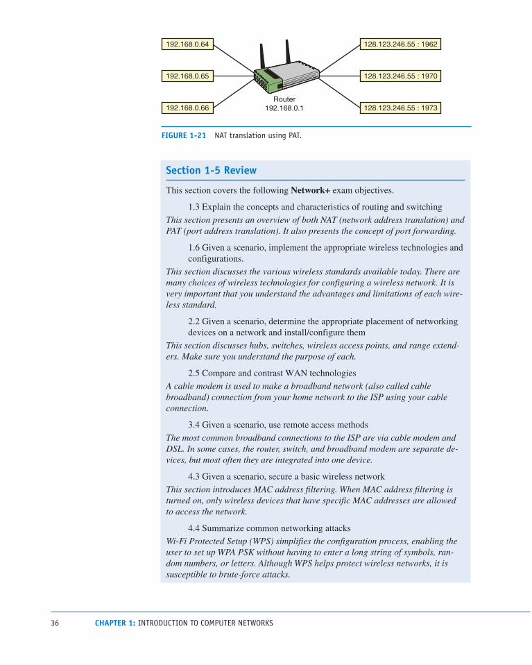
36 CHAPTER 1: INTRODUCTION TO COMPUTER NETWORKS
192.168.0.65
192.168.0.64 128.123.246.55 : 1962
128.123.246.55 : 1970
Router192.168.0.1192.168.0.66 128.123.246.55 : 1973
FIGURE 1-21 NAT translation using PAT.
Section 1-5 Review
This section covers the following Network+ exam objectives.
1.3 Explain the concepts and characteristics of routing and switching
This section presents an overview of both NAT (network address translation) and PAT (port address translation). It also presents the concept of port forwarding.
1.6 Given a scenario, implement the appropriate wireless technologies and
configurations.
This section discusses the various wireless standards available today. There are many choices of wireless technologies for configuring a wireless network. It is very important that you understand the advantages and limitations of each wire-less standard.
2.2 Given a scenario, determine the appropriate placement of networking
devices on a network and install/configure them
This section discusses hubs, switches, wireless access points, and range extend-ers. Make sure you understand the purpose of each.
2.5 Compare and contrast WAN technologies
A cable modem is used to make a broadband network (also called cable broadband) connection from your home network to the ISP using your cable connection.
3.4 Given a scenario, use remote access methods
The most common broadband connections to the ISP are via cable modem and DSL. In some cases, the router, switch, and broadband modem are separate de-vices, but most often they are integrated into one device.
4.3 Given a scenario, secure a basic wireless network
This section introduces MAC address filtering. When MAC address filtering is turned on, only wireless devices that have specific MAC addresses are allowed to access the network.
4.4 Summarize common networking attacks
Wi-Fi Protected Setup (WPS) simplifies the configuration process, enabling the user to set up WPA PSK without having to enter a long string of symbols, ran-dom numbers, or letters. Although WPS helps protect wireless networks, it is susceptible to brute-force attacks.

37 1-5: HOME NETWORKING
5.4 Given a scenario, troubleshoot common wireless connectivity and per-
formance issues
This section introduces the concept of interference with wireless versus wired connections. You always need to make sure that your area is not subject to out-side radio interference. You also need to be aware of possible interference issues with poorly installed DSL connections.
Test Your Knowledge 1. Which of the following issues should be considered when planning for a
home network?
a. Data speed
b. Public access
c. Cost
d. All of these answers are correct.
2. How does MAC address filtering help to secure a wireless network?
a. It is used to help prevent the theft of network interface cards.
b. It requires an additional login step in which the user enters his or her
MAC address.
c. MAC address filtering is seldom used anymore because of NIC
restrictions.
d. It can be used to select which networking devices can be allowed ac-
cess to the network.
3. Which of the following is an example of a wireless technology?
a. 802.11a
b. 802.11g
c. 802.11n
d. All of these answers are correct.
4. What is NAT?
a. Network asynchronous transfer
b. Network address translation
c. Network address transfer
d. None of these answers is correct.

38 CHAPTER 1: INTRODUCTION TO COMPUTER NETWORKS
1-6 ASSEMBLING AN OFFICE LANThis section presents an example of assembling an office-type LAN. In this exam-
ple, the Ethernet protocol is used for managing the exchange of data in the network,
and the networking devices are interconnected in a star topology. There are many
options for assembling and configuring a LAN, but this example presents a net-
working approach that is simple and consistent with modern computer networking.
It also provides a good introduction to the networking topics presented in the text.
For this example, three computers and one printer are to be configured in the star
topology. Each device in the network should be assigned an IP address from the
private address space. The following step-by-step discussion guides you through the
process of assembling, configuring, and testing an office LAN:
Step 1 Document the devices to be connected in the network and prepare a simple
sketch of the proposed network. Each device’s MAC and IP addresses
should be included in the network drawing documentation.
Figure 1-22 provides an example of a small office LAN. The desired IP
addresses and the actual MAC addresses for each computer and printer are
listed. Remember that each NIC contains a unique MAC address, and the
IP addresses are locally assigned by the network administrator. The MAC
addresses were obtained by entering the ipconfig /all command from the
command prompt in Windows 7. Repeat this step for all computing devices
connected to the LAN. Table 1-9 provides the results of the MAC address
inquiries. Each networking device should be assigned an IP address, and
Table 1-9 also lists the planned IP addresses of the devices used in this office
LAN.
TABLE 1-9 The MAC and Assigned IP Addresses for the Devices in the Office LAN
Device (Hostname) MAC Address IP Address
Computer 1 00-10-A4-13-99-2E 10.10.10.1
Computer 2 00-10-A4-13-6C-6E 10.10.10.2
Computer 3 00-B0-D0-25-BF-48 10.10.10.3
Laser printer 00-10-83-0B-A6-2F 10.10.10.20

39 1-6: ASSEMBLING AN OFFICE LAN
Laser printerSwitch
MAC Address 00-10-A4-13-99-2EIP Address 10.10.10.1
MAC Address 00-B0-D0-25-BF-48IP Address 10.10.10.3
MAC Address 00-10-A4-13-6C-6EIP Address 10.10.10.2
MAC Address 00-10-83-0B-A6-2FIP Address 10.10.10.20
CAT6 cable CAT6 cable
CAT6 cable
CAT6 cable
1
2
3
FIGURE 1-22 An example of a small office LAN star topology.
NoteIn this text, you will function as the network administrator. The network administrator must know how to obtain all IP and MAC address information for devices connected to the network. The network administrator must therefore keep good documentation of the network.
Step 2 Connect all the networking devices using the star topology shown in Figure
1-22. At the center of this star topology network is a switch or hub. Recall
that either a switch or a hub can be used to connect the networking devices.
The switch is the best choice in this case because the hub broadcasts data
it receives to all devices connected to its ports, and the switch enables the
devices to communicate directly. Although hubs are not as sophisticated as
switches and are not reflective of modern computer networking, hubs are
still suitable for use in small networks.
The connections from the switch to the computers and the printer are
made using premade twisted-pair patch cables. The cable type used here is
CAT6 (category 6) twisted-pair cable. CAT6 twisted-pair cables have RJ-45modular connectors on each end, as shown in Figure 1-23, and are capable
of carrying 1000Mbps (1 gigabit) or more of data up to a length of 100 me-
ters; this is the typical speed and distance requirements for CAT6. Chapter
2 covers the twisted-pair media and its various category specifications, as
well as issues associated with the proper cabling. If the network hardware
and software are properly set up, all computers can access the printer and
other computers.
CAT6 (category 6)Twisted-pair cable capable of carrying up to 1000Mbps (1 gigabit) of data up to a length of 100 meters
RJ-45The 8-pin modular connector used with CAT6/5e/5 cable
MbpsMegabits per second

40 CHAPTER 1: INTRODUCTION TO COMPUTER NETWORKS
FIGURE 1-23 The RJ-45 twisted-pair patch cables (courtesy of StarTech.com).
The media used for transporting data in a modern computer network are either
wireless, twisted-pair, or fiber-optic cables. The principles behind selecting,
installing, and testing twisted-pair cabling are presented in Chapter 2. Table
1-10 lists the common numerics used to describe the data rates for the
twisted-pair media and the older-style copper coaxial cable used in a LAN.
Common numerics for fiber-optic LANs are also listed. Numerics provide
an alphanumeric description of a technology. For example, 100BaseT means
that this is a 100Mbps baseband, twisted-pair technology.
TABLE 1-10 Common Numerics for Ethernet LAN Cabling and Ethernet Deployment Standards
Numeric Description
10Base2 10Mbps over coaxial cable up to 185 m, also called Thinnet (seldom used anymore)
10Base5 10Mbps over coaxial cable up to 500 m, also called Thicknet (seldom used anymore)
10BaseT 10Mbps over twisted-pair
10BaseF 10Mbps over multimode fiber-optic cable
10BaseFL 10Mbps over 850 nm multimode fiber-optic cable
100BaseT 100Mbps over twisted-pair (also called Fast Ethernet)
100BaseFX 100Mbps over fiber
1000BaseT 1000Mbps over twisted-pair
1000BaseFX 1000Mbps over fiber
1000BaseLS 1000Mbps over fiber
1000BaseSX 1000Mbps over fiber
1000BaseLX 1000Mbps over fiber
10GE 10GB (10GBaseT) Ethernet
NumericsNumerical representations

41 1-6: ASSEMBLING AN OFFICE LAN
The RJ-45 plugs connect to the switch inputs via the RJ-45 jacks. Figure
1-24 shows a simple 8-port switch. The inputs to the switch are also called
the input ports, and they are the interfaces for the networking devices. The
switch inputs marked with an “x” (or “uplink”), as shown in Figure 1-24(b),
indicate that these devices are cross-connected, meaning the transmit and
receive pairs on the twisted-pair cable are crossed to properly align each for
data communication. The term for a cable that has cross-connected TX/RX
data lines is crossover. Some of the switches might have the port labeled
“uplink,” which indicates the cross-connect capability. Furthermore, some
newer switches are equipped with automatic crossover detection, so you
don’t have to worry about whether to use a straight-through cable or a cross-
over cable. Examples of straight-through and crossover cables are presented
in Chapter 2.
RJ-45 Jack
X
(b)(cross-connected input)
(a)The switch used to connect the networking devices
FIGURE 1-24 (a) The switch used to connect the networking devices; (b) close-up view of “x” input, indicating an uplink port (courtesy of Anixter, Inc.).
Figure 1-25(a) provides an example of this cross-connected concept.
Switches usually have at least one port that can be switched or selected for
use as either a cross-connected or straight-through input. A straight-through
port is also called an uplink port. The uplink port allows for the connection
of a switch to a switch or hub without the use of a special cable. Devices
requiring cross-connected input ports are computers, printers, and routers.
Devices requiring a straight-through connection are uplink connections to
other switches or hubs. Figure 1-25(b) provides a block diagram explaining
the concept of a straight-through input.
(a) (b)
TX
RX
TX
RX
TX
RX
TX
RX
FIGURE 1-25 (a) An example of the wiring on an “x” type input on a switch; (b) an example of straight-through wiring.
PortsInterfaces for networking devices
CrossoverCable in which the transmit and receive signal pairs are crossed to properly align the transmit signal on one device with the receive signal on the other device
Straight-throughAn input in which the transmit and receive signal pairs are aligned end-to-end
Uplink PortA port that allows the connection of a switch to another switch without requiring a crossover cable

42 CHAPTER 1: INTRODUCTION TO COMPUTER NETWORKS
A networking connection can be verified by examining the link light on the
switch or hub. The presence of a link light indicates that the transmit and re-
ceive pairs are properly aligned and the connected devices are communicat-
ing. Absence of the light indicates a possible cabling or hardware problem.
The Ethernet protocol uses the link integrity test to verify that a commu-
nication link between two Ethernet devices has been established. The link
light remains lit when communication is established and remains lit as long
as there is a periodic exchange of link pulses from the attached devices. Link pulses are sent by each of the connected devices via the twisted-pair cables
to indicate that the link is up, but the link pulses are not part of the Ethernet
packet and are sent at regular intervals when data is not being transmitted.
Step 3 Configure the IP address settings on each computer according to the as-
signed addresses provided in Table 1-9. Configuring the computers to
operate on the LAN requires that each computing device be assigned an
IP address. To configure the computers in the office LAN using Windows
10/8/7 or Mac OS X, use the IP addresses from Table 1-9 and the following
procedures:
• Windows 10/8: Go to Control Panel > Network and Internet—Network and Sharing Center. Click Local Area Connection and se-
lect Properties and then click Continue. In the Local Area Connection
Properties menu, double-click Internet Protocol Version 4 (TCP/IPv4). From the Properties menu, select Use the Following IP Address,
enter the IP address and subnet mask, and click OK.
• Windows 7: Click Start > Control Panel > Network and Internet—Network and Sharing Center. Click Local Area Connection and se-
lect Properties and then click Continue. In the Local Area Connection
Properties menu, double-click Internet Protocol Version 4 (TCP/IPv4). From the Properties menu, select Use the Following IP Address,
enter the IP address and subnet mask, and click OK.
• Mac OS X: Click the Apple icon > System Preferences > Network and select the Ethernet or USB Ethernet connection. From the
Configure IPv4 drop-down menu, select Manually. This option lets
you manually set the IP address and subnet mask. Fields should now be
displayed for inputting both the IP address and subnet mask. Enter the
desired IP address and subnet mask and click Apply.
As shown in Table 1-9, the IP address for computer 1 is 10.10.10.1, and in this
example, a subnet mask of 255.255.0.0 is being used. Chapter 6 examines subnet
masking in detail. For now, leave the remaining fields empty; their purposes are
discussed later in the text. Your network configuration for computer 1 should now
be complete, and you can repeat these steps for computers 2 and 3 in this LAN
example.
Link LightAn indicator on a switch or hub that shows whether the transmit and receive pairs are properly aligned
Link Integrity TestA test used to verify that a communication link between two Ethernet devices has been established
Link PulsesPulses sent by two connected devices via the twisted-pair cables when data is not being transmitted to indicate that the link is still up

43 1-6: ASSEMBLING AN OFFICE LAN
Section 1-6 Review
This section covers the following Network+ exam objectives.
1.4 Given a scenario, configure the appropriate IP addressing components
This section presents examples that demonstrate how to manually configure sub-net masks on the computer.
2.1 Given a scenario, deploy the appropriate cabling solution
RJ-45 plugs and jacks are introduced in this section. This type of connector is used on all computer networks. Table 1-10 provides a good description of the common networking cable types.
Test Your Knowledge 1. True or false: The “x” on the input to a switch represents a router-only port.
a. True
b. False
2. A cross-connected input port
a. indicates that the transmit and receive pairs are crossed.
b. is used only on connections to routers.
c. indicates that the cable is wired incorrectly.
d. must be avoided on hub and switch port inputs.
3. What does a lit link light indicate? (Select all that apply.)
a. The Link Integrity Test is operational.
b. Link pulses are being shared by all devices in the LAN.
c. A 10Mbps data link has been established.
d. A 100Mbps data link has been established.

44 CHAPTER 1: INTRODUCTION TO COMPUTER NETWORKS
1-7 TESTING AND TROUBLESHOOTING A LANWhen the network configurations on the computers are completed and the cable
connections are in place, you need to test and possibly troubleshoot the network.
First, you need to verify that the computers are properly connected on the network.
Do this by verifying that you have link lights on each switch port connected to a
computer or other networking device. Figure 1-26 shows an example of a switch
with the link light activated.
FIGURE 1-26 An example of the link light on a hub.
After you have verified that the networking devices are physically connected, use
the ping command to verify that the networking devices are communicating. ping
uses Internet Control Message Protocol (ICMP) echo requests and replies to test that
a device on the network is reachable. The ICMP protocol verifies that messages are
being delivered. You can use the ping command, which is available in the Windows
command window, to verify that the networking devices are communicating. The
command structure for the ping command is as follows:
Usage ping[-t][-a][-n count)[-1 size][-f -i TTL][-v TOS] [-r count][-s count]
[[-j host-list]:[-k host-list][-w timeout] destination-list
Options
-t Ping the specified host until stopped
To see statistics and continue, type Control-Break
To stop, type Control-C
pingCommand used to test that a device on the network is reachable
ICMPInternet Control Message Protocol, which verifies that messages are being delivered

45 1-7: TESTING AND TROUBLESHOOTING A LAN
-a Resolve addresses to host-names
-n count Number of echo requests to send
-1 size Send buffer size
-f Set Don’t Fragment flag in packet
-I
TTL Time To Live v
TOS Type Of Service
r count Record route for count hops
s count Timestamp for count hops
j host-list Loose source route along host-list
k host-list Strict source route along host-list
w timeout in milliseconds to wait for each reply
For example, you can use the command ping 10.10.10.1 to ping the IP address for
computer 1 because the IP address 10.10.10.1 is the destination address. Another
example would be the destination IP address for computer 3; in this case, you
would use ping 10.10.10.3. (Refer to Table 1-9 and Figure 1-22 for the IP addresses
of the computers in the sample network.)
The following is an example of pinging another computer on the network to verify
that the computers are communicating. In this example, computer 1 is used to ping
computer 2. Remember that the ping command is executed from the command
window:
ping 10.10.10.2
Pinging 10.10.10.2 with 32 bytes of data:
Reply from 10.10.10.2: bytes 32 time<1ms TTL 128
Reply from 10.10.10.2: bytes 32 time<1ms TTL 128
Reply from 10.10.10.2: bytes 32 time<1ms TTL 128
Reply from 10.10.10.2: bytes 32 time<1ms TTL 128
Ping statistics for 10.10.10.2:
Packets: Sent = 4, Received = 4, Lost = 0 (0% loss),
Approximate round trip times in milli-seconds:
Minimum = 0ms, Maximum = 0ms, Average = 0ms
The text shows that 32 bytes of data is being sent to the computer with the IP ad-
dress 10.10.10.2. “Reply from 10.10.10.2” indicates that computer 2 received the
message. If the computer at IP address 10.10.10.2 did not respond, the message
“Request timed out.” is displayed:
ping 10.10.10.2
Pinging 10.10.10.2 with 32 bytes of data:
Request timed out.
Request timed out.
Request timed out.
Request timed out.
Ping statistics for 10.10.10.2:
Packets: Sent = 4, Received = 0, Lost= 4
(100% loss),

46 CHAPTER 1: INTRODUCTION TO COMPUTER NETWORKS
At times you might want to verify the IP address of the computer you are work-
ing on. Remember that you can obtain the IP address by entering the command
ipconfig at the command prompt. You don’t need to include the /all switch after the
ipconfig command unless you also want the MAC address information displayed.
Figure 1-27 shows an example of displaying the IP address for computer 1.
(b)
(a)
FIGURE 1-27 (a) An example of displaying the IP address for computer 1 using the ipconfig command in Windows and (b) an example of the displayed IP address in Mac OS X for the built-in Ethernet connection.
ipconfigA command used to display a computer’s address

47 1-7: TESTING AND TROUBLESHOOTING A LAN
Section 1-7 Review
This section covers the following Network+ exam objectives.
1.8 Explain the function of network services
An important step in verifying connectivity between two networking devices is to issue the ping command, using the destination IP address for the other device. The ping command is available from the command window in Windows. Make sure you know how to issue the command and the options available with the command, such as implementing continuous pinging and setting the buffer size.
5.2 Given a scenario, use the appropriate tool
This section introduces the important step of verifying network connectivity using the ping command. It presents several examples of using ping to troubleshoot a network.
Test Your Knowledge 1. A network administrator needs to verify a network connection. Which of the
following steps should be taken? (Select two.)
a. Verify the link lights.
b. Use the ping command to verify network connectivity.
c. Perform an ARP request.
d. Ping the MAC address.
2. What does the ping -t ip address command do? (Select all that apply.)
a. It pings the host at the specified IP address until it is stopped.
b. It pings the MAC address of the host at the specified IP address.
c. It allows the ping to pass through routers.
d. It allows the ping command to be executed from the command
prompt.

48 CHAPTER 1: INTRODUCTION TO COMPUTER NETWORKS
SUMMARYThis chapter introduces the basic concepts of computer networking. It presents the
technologies and techniques for assembling a computer network using the Ethernet
protocol. You should now understand the following major topics:
• The various LAN topologies
• The concept of CSMA/CD in the Ethernet protocol
• The structure of the Ethernet frame
• The purpose of a network interface card
• The purpose of a MAC address
• How to determine the MAC address for a computer
• The purpose and structure of an IP address
• The concept of private IP addresses
• The OSI model
• The network topologies and technologies used to implement twisted-pair
computer networks
• How to configure and verify a computer’s IP address
• How to configure a home network and an office LAN
• The purpose of the link light
• The purpose of using ping to test a network connection
QUESTIONS AND PROBLEMS
Section 1-1
1. State whether each of the following network descriptions describes a MAN, a
WAN, or a LAN:
a. A network of users who share computer resources in a limited area
b. A network of users who share computer resources across a metropolitan
area
c. A network that connects local area networks across a large geographic
area
49 QUESTIONS AND PROBLEMS
2. Expand the acronym NIC.
3. Expand the acronym MAC.
4. Expand the acronym LAN.
5. Expand the acronym WAN.
Section 1-2
6. Define the term protocol.
7. Define the term topology.
8. Define the term deterministic.
9. A disadvantage of the token-ring system is that if an error changes the token
pattern, it can cause the token to stop circulating. This can be eliminated by
adding which of the following?
a. Router
b. Multiport repeater
c. Token passer
d. Token-ring hub
10. Name each network topology shown in Figure 1-28 (bus, star, ring, or mesh).
a. Mesh
b. Bus
c. Ring
d. Star

50 CHAPTER 1: INTRODUCTION TO COMPUTER NETWORKS
(a)
(c) (d)
(b)
FIGURE 1-28 The networks for question 10.
11. What is the difference between a hub and a switch?
Section 1-3
12. What are the seven layers of the OSI model?

51 QUESTIONS AND PROBLEMS
13. Which OSI layer is responsible for adding a header that includes routing
information?
14. Which OSI layer is considered the media access control layer?
15. Which OSI layer combines messages or segments into packets?
16. At what layer does a router work?
17. Which OSI layer is responsible for the mechanical connection to the network?
18. Which OSI layer is responsible for data compression and encryption?
19. TCP functions at what layer of the OSI model?
20. HTTP functions at what layer of the OSI model?
21. IP and IPX are examples of protocols that operate in what layer of the OSI
model?
22. A network interface card operates at what layer of the OSI model?
23. Why are the layers of the OSI model important to a network administrator?
Section 1-4
24. Expand the acronym CSMA/CD. What protocol uses CSMA/CD?
25. What information is not included in an Ethernet frame?
a. Frame size
b. Source MAC address
c. Pad
d. Frame check sequence

52 CHAPTER 1: INTRODUCTION TO COMPUTER NETWORKS
26. What is the minimum size of the data payload in an Ethernet frame?
27. An Ethernet packet size greater than 1500 bytes is called
a. a bad frame.
b. a jumbo frame.
c. an MTU.
d. All of the above
e. None of the above
28. Expand the acronym OUI. Where is the OUI used?
29. What does the OUI represent?
30. In Windows 10, how can you find the Ethernet (MAC) address?
31. INTERNET SEARCH: Find the device manufacturer for each of the following
Ethernet devices:
a. 00-C0-4F-49-68-AB
b. 00-0A-27-B7-3E-F8
c. 00-04-76-B6-9D-06
d. 00-00-36-69-42-27
32. State the class of address (A, B, or C) for each of the following IP addresses:
a. 46.39.42.05____
b. 220.244.38.168____
c. 198.1.0.4____
d. 126.87.12.34____
e. 99.150.200.251____
f. 128.64.32.16____
33. Expand the acronym TCP/IP.

53 QUESTIONS AND PROBLEMS
Section 1-5
34. What are three advantages of a wireless network?
35. What does it mean for a wireless networking device to be Wi-Fi compliant?
36. What are the most common types of equipment that are used to establish broad-
band connections to ISPs?
37. Name six issues that should be considered when planning a home network.
38. Why is checking the lights of the networking device that connects to the ISP
important?
39. What is the purpose of a range expander?
40. What is a hotspot?
41. List five steps that can be used to protect a home network.
42. You have the choice of selecting a networking device with WEP or a device
with WPA. Which offers better security and why?
43. What are the potential problems related to using the default factory passwords?

54 CHAPTER 1: INTRODUCTION TO COMPUTER NETWORKS
44. What is the purpose of the SSID, and what can a network administrator do to
protect a network from hackers who might have learned the SSID?
45. What is the purpose of MAC filtering on a wireless network?
46. How does NAT (network address translation) help protect outsider access to
computers in a home network?
47. What is stateful packet inspection?
48. What is a VPN, and how does it protect the data transferred over a wireless
network?
49. How is IP addressing typically handled in a home network?
50. What is port address translation (PAT)?
51. A router on a home network is assigned the IP address 128.123.45.67. A com-
puter in the home network is assigned the private IP address 192.168.10.62. This
computer is assigned the public IP address 128.123.45.67:1922. Which IP ad-
dress is used for routing data packets on the Internet? Is overloading being used?
55 QUESTIONS AND PROBLEMS
Section 1-6
52. Which of the following is not a step in building an office LAN?
a. Obtaining proper government permits
b. Configuring the network settings
c. Connecting the devices together
d. Network documentation
53. What is RJ-45?
a. A 45-pin connector for CAT6
b. An IEEE standard for data speed
c. An 8-pin modular connector for twisted-pair Ethernet
d. A protocol used to verify a communications link
54. What is an uplink port?
55. What is the maximum speed and length for Category 6 cabling?
56. What do the link lights on a hub indicate?
57. What does cross-connected mean?
58. DOCUMENTATION: Draw a network diagram similar to Figure 1-29, consist-
ing of three computers, a switch, and a printer. Use the MAC addresses given in
Table 1-9. Assign each network device an IP address from the private address
space 192.168.5.x network. You are the network administrator and may choose
the host address for each device.

56 CHAPTER 1: INTRODUCTION TO COMPUTER NETWORKS
MAC Address: 00-10-A4-13-99-2EIP Address: 192.168.5.1
MAC Address: 00-10-A4-13-6C-6EIP Address: 192.168.5.2
MAC Address: 00-B0-D0-25-BF-48IP Address: 192.168.5.3
Switch
- CAT6 cable
- CAT6 cable
CAT6 cableCAT6 cable
1
2
3
FIGURE 1-29 The sample network diagram for question 58.
Section 1-7
59. What command would you use to ping 10.3.9.42 indefinitely?
60. What command would you use to ping 192.168.5.36 20 times with 1024 bytes of
data?
61. Expand the acronym TTL.
Certification Questions62. In terms of computer security, a switch offers better security than a hub. Why is this?
a. A hub requires a special pin to activate the connection.
b. A hub forwards the data it receives to every device connected to the hub.
It is possible for network devices to pick up data intended for a different
device. A switch eliminates this by only forwarding data packets to the
correct device whenever possible.
c. A switch forwards the data it receives to every device connected to the
switch. It is possible for network devices to pick up data intended for a
different device. A hub eliminates this by only forwarding data packets to
the correct device whenever possible.
d. The use of the switch guarantees that all devices connected to it share link
integrity pulses. This sharing of the pulses strengthens the security of the
connection.

57 QUESTIONS AND PROBLEMS
63. What networking protocol does Ethernet use?
a. Ethernet uses a Token Ring passing scheme. The computer devices must
possess the ring to be able to pass a token.
b. Ethernet uses carrier access multiple sensing with collision detection.
c. Ethernet uses carrier sense – multiple access with collision detection.
d. Ethernet uses collision sense – carrier access with multiple pairing.
64. A network interface card has the MAC address 00-00-86-15-7A. From this
information, specify the OUI.
a. There is not sufficient information to specify the OUI.
b. The OUI is 86-15-7A.
c. The OUI is 86-00-00.
d. The OUI is 00-00-86.
65. An IP address for a computer is assigned by the
a. Internet Assigned Numbers Authority.
b. local network administrator.
c. user of the computer.
d. Internet Address Numbers Authority.
66. Which network topology is shown here?
a. Star
b. Token Ring
c. Bus
d. Mesh
e. None of these answers is correct.

58 CHAPTER 1: INTRODUCTION TO COMPUTER NETWORKS
67. Which network topology is shown here?
a. Star
b. Token Ring
c. Bus
d. Mesh
e. None of these answers is correct.
68. Which network topology is shown here?
a. Star
b. Token Ring
c. Bus
d. Mesh
e. None of these answers is correct.
69. The pad field in an Ethernet packet
a. is used to bring the total number of bytes up to 46 if the data file is less
than 46 bytes.
b. is used to bring the total number of bytes up to 64 if the data file is less
than 64 bytes.
c. is not required with CSMA/CD.
d. provides grouping of the information for transmission.
70. The IP address 10.10.20.250 is an example of which of the following? (Select
all that apply.)
a. A Class A address
b. A Class B address
c. A private IP address
d. A routable IP address
e. A nonroutable Internet IP address

59 QUESTIONS AND PROBLEMS
71. Which of the following is true of an intranet? (Select all that apply.)
a. It uses class E addressing.
b. It is used in high-speed (Gigabit) Ethernet.
c. It is an internal network that provides file and resource sharing.
d. It enables Fast Ethernet connections.
e. It is not accessed from the Internet.

INDEX

693
Numbers3DES (Triple Data Encryption Standard), 5923G wireless, WLAN, 1884G wireless, WLAN, 1886to4 prefixes (IPv6 addresses), 2928P8C. See RJ-45 (8P8C) modular plugs10GBASE-T cables, 7410GBASE-T Ethernet over copper, 94-9729 CFR 1910.36 (Design and Construction Re-
quirements for Exit Routes), 645-64629 CFR 1910.37 (Maintenance, Safeguards and Op-
erational Features for Exit Routes), 64629 CFR 1910.38 (Emergency Action Plans), 64729 CFR 1910.39 (Fire Prevention Plans), 647-64829 CFR 1910.157 (Portable Fire Extinguishers), 64829 CFR 1910.160 (Fixed Fire Extinguishing/Sup-
pression Systems), 648-64929 CFR 1910.164 (Fire Detection Systems), 65029 CFR 1910.165 (Employee Alarm Systems),
650-65129 CFR 1910.1200 (Hazard Communication), 65132-bit CPU (Central Processing Units), 61764-bit CPU (Central Processing Units), 617802.1x wireless standard, 337802.11a (Wireless-A) standard, 24, 169802.11ac (Wireless-AC) standard, 25, 169802.11b (Wireless-B) standard, 24, 169802.11g (Wireless-G) standard, 24, 169802.11i wireless standard, 169802.11n (Wireless-N) standard, 25, 169802.11r wireless standard, 169
AAAA (Authentication, Authorization and
Accounting), 587-588AAAA (Quad-A) records, 491absorption (attenuation), 130access
controlling, 802.1x, 337
door access (security), 652
home access, home networks, 31
managing
AAA, 587-588
Kerberos authentication, 588
NAC, 588
private networks, 590
RADIUS, 588, 591, 603
TACACS+, 588
UTM, 589
public access, home networks, 31
access-list permit ip any any command, 582accounting (AAA), 587-588ACK (Acknowledgement) packets, 260-262ACL (Access Control Lists), 582ACR (Attenuation to Crosstalk Ratio), 92active RFID tags, 186AD (Administrative Distance), 406ad hoc networks, 162, 182adapter addresses. See MAC addressesadaptive cut-through switching, 223administration (network), troubleshooting network
problems, 14administratively down (routers), 528ADSL (Asymmetric DSL) modems, 471advertising networks, 411AES (Advanced Encryption Standard), 592, 602Aging Time, 220-222AH (Authentication Headers), 592alarms
CSU/DSU, 466
Employee Alarm Systems (29 CFR 1910.165),
650-651
analog modems, WAN remote access, 469analyzing data traffic
frame size distribution graph, 499
inbound data traffic, 496
network layer host table, 498
network layer matrix graph, 497
outbound data traffic, 496
utilization/errors strip chart, 497
Ant+ wireless standard, 169antennas (WLAN), 172, 191-194antivirus software, 575anycast IPv6 addresses, 292

694 AP (ACCESS POINTS)
AP (Access Points)CAPWAP, 174
defining, 27
loss of association, 179
troubleshooting, 537-538
WLAN, 163, 171-174, 179
APC connectors, 62APIPA (Automatic Private IP Addressing), 481, 545appearance, home networks, 31Application layer (OSI model), defining, 13Application layer (TCP/IP), 258-260Area 0 (OSPF protocol), defining, 425areas (OSPF protocol), 421ARIN (American Registry for Internet Numbers),
277-278ARP (Address Resolution Protocol), 264-265, 515
ARP caches, 209-211, 565
ARP replies, 516
ARP tables, 209
broadcasts, 209
defining, 209
ARPAnet (Advanced Research Projects Agency), TCP/IP development, 256
AS (Autonomous Systems), 494-495ASN (Autonomous Systems Numbers), 494-495asset management, 661associations
defining, 209
WLAN, 171-172, 179
asymmetric operation, 469attacks
ARP cache poisoning attacks, 565
Bluejacking, 603
Bluesnarfing, 603
brute force attacks, 563
buffer overflow attacks, 566
coordinated DDoS attacks, 574
DDoS attacks, 574
dictionary attacks, 563
directed broadcast attacks, 573
DoS attacks, 571-573
evil twin attacks, 565
hacker strategies, 562
logic bombs, 570
man-in-the-middle attacks, 565
packet sniffing attacks, 564-565
password cracking attacks, 563-564
PDoS attacks, 573
reflective/amplified DoS attacks, 573
session hijacking attacks, 566
Smurf attacks, 572
social engineering attacks, 562
spoofing attacks, 573
SYN attacks, 572
viruses, 569, 575
wireless deauthentication attacks, 573
worms, 569
zero-day attacks, 570
attenuation (signal)insertion loss, cabling, 89-90
optical networks, 121, 130, 136
WLAN, 172
AUP (Acceptable Use Policies), 659authentication
802.1x, 337
AAA, 587-588
AH, 592
CCMP, 602
CHAP, 591
EAP, 591, 603
Kerberos authentication, 588
MD5 hashing algorithm, 591
open authentication, wireless networks, 601
PAP, 591
RADIUS, 588, 591, 603
routers and RIP, 416
SHA, 591
shared key authentication, wireless networks, 601
wireless deauthentication attacks, 573
authorization (AAA), 587-588auto-negotiation
advantages/disadvantages of, 236
FLP, 234
LAN interconnectivity, 234-235
autoconfiguration, SLAAC and IPv6 addressing, 293

695BUSINESS POLICIES/PROCEDURES
automation, cloud computing, 633auxiliary input (routers), 226AXT (Alien Crosstalk), 94-95
Bbackbone cabling, cabling standards, 65backbones, 421backscatter, 185backups, business continuity/disaster recovery
plans, 663balanced data cabling, 96balanced mode (cabling), 72bandwidth, 406
Carrier Ethernet rate limits, 479
CBS, 479
CIR, 479
EBS, 479
EIR, 479
optical networks, 120
rate limits, 479
utilization/errors strip chart, 497
BD (Building Distribution) fiber, optical networks, 143
beacons, wireless networks, 601beamforming, WLAN, 168best practices, 661BGP (Border Gateway Protocol), 492-495BiDi transceivers, 147binary-to-decimal conversion, 268-269biometric systems (security), 652blocked TCP/UDP ports, troubleshooting, 546blocking state (STP), 325Bluetooth, 181, 184
Bluejacking, 603
Bluesnarfing, 603
inquiry procedures, 182
paging procedures, 182
pairing devices, 182
passkeys, 182
piconets, 182
security, 603
slaves, 182
BNC connectors, 62
BOOTP (Bootstrap Protocol)clients, 482
IP address discovery, 480
servers, 482
botnets, 574bottlenecking. See networks, congestionbottom-to-top (bottom-up) troubleshooting, 542BPDU (Bridge Protocol Data Unit), 324
BPDU filter, 339
BPDU guard, 339
configuration BPDU, 325
branching devices (optical networks), 136bridges
advantages/disadvantages of, 212
associations, 209
bridge tables, 208-209
broadcasts, 209
collision domains, 213
defining, 207
isolating data traffic, 209-211
multiport bridges. See layer 2 switches
translation bridges, 211
transparent bridges, 211
wireless bridges, WLAN, 172
broadband modems/gateways, defining, 29broadcasts
broadcast domains, 222, 356, 362, 380
broadcast storms, 209, 212
defining, 9, 209
brute force attacks, 563BSS (Basic Service Sets), 162-163buffer overflow attacks, 566buffering, 228building distributions (fiber-optic networks),
143-146bus topology, defining, 8business policies/procedures
asset management, 661
AUP, 659
best practices, 661
business continuity/disaster recovery plans, 663-664
incident response policies, 659
MLA, 658
MOU, 657

696 BUSINESS POLICIES/PROCEDURES
MSA, 658
NDA, 659
password policies, 660
privileged user agreements, 660
SLA, 658
SOP, 660
SOW, 659
BWA (Broadband Wireless Access), WiMAX, 184BYOD (Bring Your Own Device), 541
Ccable modems
defining, 29
DOCSIS, 470
ranging, 470
WAN remote access, 470
cables/cabling. See also connectors10GBASE-T cables, 74
10GBASE-T Ethernet over copper, 94-97
ACR, 92
attenuation, 89-90
AXT, 94-95
backbone cabling, 65
balanced data, 96
balanced mode, 72
cable terminations, troubleshooting, 67
CAT1 cables, 73
CAT2 cables, 73
CAT3 cables, 73
CAT5 cables, 73-76, 85-86
CAT5e cables, 63, 71-73, 85-86, 89-90
terminating, 76
text examples, 100-102, 105
CAT6 cables, 39, 42, 63, 71-73, 76, 81-84, 89, 90-91
CAT6A cables, 73-74, 89-90
CAT7 cables, 73-74, 89-90
CAT7A cables, 73-74, 89-90
coaxial cables, 62
color guidelines, 76
console cables, 226, 238
cross-connects
defining, 65
HC, 66
crossover cables, 41, 80
crosstalk, 89-96
delay skew, 92
EIA/TIA 568B standard, 64, 76, 89-90
EIA/TIA 569B standard, 65
ELFEXT, 91
ELTCTL, 96
EMI, 74
ER, 64-65
Ethernet, 10GBASE-T Ethernet over copper, 94-97
F/UTP cables, 95
FastEthernet, defining, 73
full channel, 89
full-duplex, defining, 74
Gigabit data rates, 93
Gigabit Ethernet, 80
defining, 74
Ethernet over copper, 94
horizontal cabling, 65, 81-84
cable terminations, 67
labeling cables, 69
LAN, 67
patch cables, 68
planning installations, 67
port labeling, 70
rack diagrams, 70
system labeling, 70
telecommunications closets, 67-69
IC, 65
installing, troubleshooting installations, 98
labeling cables, 69, 149
LCL, 96
links, 89
manufacturer specifications, 99
MC, 65
multimeters, 105
network congestion, 73
NEXT, 89-90
numerics, Ethernet LAN cabling, 40-41
NVP, 92
open/short connections, troubleshooting, 105
patch cables, 68, 80, 85-86, 100-102, 105
physical layer cabling, defining, 62

697CCNP (CISCO CERTIFIED NETWORK PROFESSIONAL)
pin outs, troubleshooting, 105
plenum-rated cables, 74
propagation delay, 92
PSAACRF, 95-96
PSACR, 92
PSANEXT, 95-96
PSELFEXT, 92
PSNEXT, 91
PVC cable, 74
return loss, 92
RJ-45 (8P8C) connectors
office LAN, 39
wire color codes, 77
rollover cable, 239-240
short/open connections, troubleshooting, 105
signal transmission, 96-97
slack loops, 81
STP cables, 74
straight-through cables, 80, 85-86
stretching, 99
TCL, 96
TCO, 65
TCTL, 96
telecommunications closets, 64, 67-69
terminating, 81-84
troubleshooting
bent pins, 105
damaged cables, 105
failing to meet manufacturer specifications, 99
incorrect cable types, 105
installations, 98
open/short connections, 105
pin outs, 105
ports, 105
stretching cables, 99
twisted-pair cables
categories of, 72-73
Gigabit data rates, 93
UTP cables, 63, 71, 95
balanced mode, 72
terminating, 76
wireless networks, troubleshooting, 540
wiremaps, 80
WO, 66
work areas, 65
caches (virtualization), 617CAM (Content Addressable Memory), 222cameras, CCTV, 652campus distributions (fiber-optic networks),
147-149campus networks, 64
defining, 206
static routing
three-router campus networks, 396
two-router campus networks, 397
CAPWAP (Configuration and Provisioning of Wireless Access Points), 174
Carrier Ethernet, WAN, 476bandwidth rate limits, 479
service attributes, 479
service types, 477
CAT1 cables, 73CAT2 cables, 73CAT3 cables, 73CAT5 cables, 73-74
straight-through CAT5 patch cables, 85-86
terminating, 76
CAT5e cables, 63, 71-73certification, 89-90
straight-through CAT5e patch cables, 85-86
terminating, 76
test examples, 100-102, 105
CAT6 cables, 63, 71-73, 91CAT6 horizontal link cables, terminating, 81-84
certification, 89-90
link pulses, 42
office LAN, 39
terminating, 76
CAT6A cables, 73-74, 89-90CAT7 cables, 73-74, 89-90CAT7A cables, 73-74, 89-90CBS (Committed Burst Size), 479CCIE (Cisco Certified Internetwork Expert), 354CCMP (Counter Mode with Cipher Block Chaining
Message Authentication Code Protocol), 602CCNA (Cisco Certified Network Associate), 354CCNP (Cisco Certified Network Professional), 354

698 CCTV (CLOSED CIRCUIT TELEVISION)
CCTV (Closed Circuit Television), 652CDMA (Code Division Multiple Access), WLAN,
188cellular (mobile) communications, 188CFR (Code of Federal Regulations), defining, 645change-control policies, 542channel bonding, WLAN, 165channels (wireless), selecting, 539CHAP (Challenge Handshake Authentication
Protocol), 591chromatic dispersion (optical networks), 131-132CIDR (Classless Interdomain Routing), 287
CIDR blocks, 288-289
IPv6 CIDR, 294-295
CIR (Committed Information Rates), 479Cisco IOS, router configuration, 363-368cladding, 124class network addresses, 411classful addressing, 411classful networks, 286classful routing protocols, RIP as, 416CLI (Command-Line Interfaces), routers, 354client/server networks, 473
advantages/disadvantages of, 475
example of, 474
client-to-site VPN (Virtual Private Networks), 590clients
BOOTP clients, 482
defining, 473
DNS servers, 487-491
cloud computing. See also virtualizationautomation, 633
cloud infrastructures, 632
cloud services, 630
clouds, defining, 629
community clouds, 632
email services, 630
hybrid clouds, 632
IaaS, 631
integration, 633
outsourcing, 629
PaaS, 632
private clouds, 632
public clouds, 632
SaaS, 632
security, 633
SLA, 630
telco clouds
CSU/DSU, 466
WAN line connections, 464
clustering, 485CNA (Cisco Network Assistant), 218CNAME (Canonical Name) records, 489, 631coaxial cables, 62codes/standards, 644
business policies/procedures, 657
asset management, 661
AUP, 659
best practices, 661
business continuity/disaster recovery plans, 663-664
incident response policies, 659
MLA, 658
MOU, 657
MSA, 658
NDA, 659
password policies, 660
privileged user agreements, 660
SLA, 658
SOP, 660
SOW, 659
industry regulatory compliance
FERPA, 653
FISMA, 653
GLBA, 654
HIPAA, 654
international export controls, 654-656
PCI DSS, 654
safety standards/codes
29 CFR 1910.36 (Design and Construction Requirements for Exit Routes), 645-646
29 CFR 1910.37 (Maintenance, Safeguards and Operational Features for Exit Routes), 646
CFR, defining, 645
door access, 652
EAP (29 CFR 1910.38), 647
Employee Alarm Systems (29 CFR 1910.165), 650-651

699CONFIGURING
Fire Detection Systems (29 CFR 1910.164), 650
Fixed Fire Extinguishing/Suppression Systems (29 CFR 1910.160), 648-649
FPP (29 CFR 1910.39), 647-648
Hazard Communication (29 CFR 1910.1200), 651
HVAC systems, 652
MSDS, 651
NFPA, 645
OSHA, 645
OSH Act, 645
Portable Fire Extinguishers (29 CFR 1910.157), 648
SDS, 651
cold sites, business continuity/disaster recovery plans, 664
collision domains, 212bridges and, 213
isolating, 222
switches and, 213-215, 222
color, cabling guidelines, 76COM1 (serial communication port), 239COM2 (serial communication port), 239community clouds, 632computer forensics, 585-586configuration BPDU (Bridge Protocol Data Unit),
325configure terminal command
EIGRP configuration, 432
OSPF configuration, 426
static routing, 400
configure terminal commandrouter configuration, 371
switch configuration, 316-317
configuringEIGRP, 431-436
firewalls
Linux firewalls, 581
Mac OS X firewalls, 580-581
Windows 10 firewalls, 576-579
HyperTerminal software, 240-241
office LAN, 42
OSPF protocol, 424-428
remote access VPN, 593
RIP, 410-416
RIPng, 439
RIPv2, 410, 417-418
routers
Cisco IOS and, 363-368
configure terminal command, 371
consoles (primary terminal lines), 372
enable secret command, 371
FastEthernet, 360-361, 373
hostnames, 371
line console passwords, 372
MAC addresses, 360
no shut (no shutdown) command, 373, 376
password protection, 371
passwords, 372
Router(config)# prompt, 372
Router(config-if)# prompt, 373
Router(config-line)# prompt, 372
Router# (Privileged EXEC mode), 369-378
security, 371
serial interface configurations, 374-376
show ip interface brief command, 374-376
User EXEC mode, 363-368
viewing flash memory, 365
viewing uptime, 366
viewing version information, 366
SLAAC and IPv6 addressing, 293
SNMP, 328-331
static routes, 400-402
static VLAN, 319-323
switches, 323
configure terminal command, 316-317
consoles (primary terminal lines), 318
enable command, 316
enable secret command, 317
hostname command, 317
line console passwords, 317-319
passwords, 317-319
PoE, 332-334
privileged mode, 316-317
security, 335-339
SNMP, 327-331
static VLAN configuration, 319-323

700 CONFIGURING
STP, 324-326, 339
Switch(config)# prompt, 317
Switch(config-line)# prompt, 318
Switch# prompt, 317
viewing current configuration, 336
vty (Virtual Terminals), 318
virtualization, Windows 8/10 configuration, 620-623,
626
VPN
Cisco VPN clients, 595-596, 599
Mac OS X VPN clients, 594
remote access VPN, 593
remote client VPN connections, 593
Windows 10/8/7 VPN clients, 593-594
WLAN, 170-180
ZTerm serial communications software, 242-243
congestion (networks), 73connection loss, optical networks, 136-137connection-oriented protocols, 260connectors. See also cabling
APC connectors, 62
BNC connectors, 62
FC fiber connectors, 138
fiber couplers, 62
fiber-to-coaxial connectors, 62
inline couplers. See UTP couplers
LC fiber connectors, 138
MT-RJ fiber connectors, 138
RJ-45 connectors, 39
SC fiber connectors, 138
ST fiber connectors, 138
UPC connectors, 62
UTP couplers, 62
console cables, 226, 238console input (routers), 226console ports (routers)
console cable and, 238
DB-9 connectors, 238
DB-25 connectors, 238
HyperTerminal software, configuring, 240-241
LAN interconnectivity, 238
rollover cable and, 239-240
RS-232 console port, 238
ZTerm serial communications software, configuring,
242-243
consoles (primary terminal lines)router configuration, 372
switch configuration, 318
contiguous networks, 411controllers (wireless), WLAN, 174convergence, dynamic routing protocols, 405conversion (numeric)
binary-to-decimal conversion, 268-269
decimal-to-binary conversion, 270-271
hexadecimal number conversion, 271-273, 291
coordinated DDoS attacks, 574copy run start command
RIP configuration, 416
static routing, 402-403
copy running-config startup-config command, troubleshooting router interface, 529
cores (virtualization), multicore CPU, 617corrosion, optical networks, 121cost, 406
home networks, 31
optical networks, 121
country domains, 485couplers, 62CPU (Central Processing Units)
32-bit CPU, 617
64-bit CPU, 617
multicore CPU, 617
cross-connectsdefining, 65
HC, 66
crossover cables, 41, 80crosstalk (cabling)
ACR, 92
AXT, 94-95
ELFEXT, 91
NEXT, 89-90
optical networks, 121
PSAACRF, 95-96
PSACR, 92
PSANEXT, 95-96

701DHCP (DYNAMIC HOST CONFIGURATION PROTOCOL)
PSELFEXT, 92
PSNEXT, 91
CSMA/CA (Carrier Sense Multiple Access with Collision Avoidance), 164
CSMA/CD (Carrier Sense Multiple Access with Collision Detection), 16
CSU/DSU (Channel Service Unit/Data Service Unit)alarms, 466
telco clouds, 466
WAN line connections, 465
cut-through switching, 223
Ddata broadcasts, 9data encapsulation, 467data flow control, STP, 324-326, 339Data Link layer (OSI model), defining, 13data packets
ACK packets, 260-262
buffering, 228
DHCP data packets
MT ACK, 483
MT Discover, 482
MT Offer, 483
MT Request, 483
error thresholds, 223
fragment collisions, 223
“Hello” packets, 421
jitter, 228
keepalive packets, 525
multiplexing, 465
next hop addresses, 360
packet filtering, 583
Linux firewalls, 576, 581
Mac OS X firewalls, 576, 580-581
Windows 10 firewalls, 576-579
packet shapers, 228, 585
packet sniffing attacks, 564-565
source-quench packets, 265
spoofing attacks, 573
switch latency, 222-223
SYN packets, 260-262
SYN ACK packets, 260-262
UDP packet transfers, 263-264
unicast packets, 482
wire speed routing, 223
Wireshark Network Analyzer
capturing packets, 517-519
FTP packets, 519-520
inspecting packets, 514-517
data rates, xDSL modems, 470-471data speed, home networks, 31data traffic analysis, 521-524
frame size distribution graph, 499
inbound data traffic, 496
network layer host table, 498
network layer matrix graph, 497
outbound data traffic, 496
utilization/errors strip chart, 497
DB-9 connectors, router console port connections, 238
DB-25 connectors, router console port connections, 238
DC (Distribution Closets), IDC and optical networks, 145
DCE (Data Communications Equipment), 374-375DDoS (Distributed Denial of Service) attacks, 574decimal-to-binary conversion, 270-271default gateway addresses, 357default gateways, 394delay skew, 92delays, 406demarcation (WAN line connections), line of, 465DES (Data Encryption Standard), 592destination IP addresses, 397-398destination MAC address and source, Ethernet
packet frames, 17deterministic networks, defining, 7DFB (Distributed Feedback) lasers, optical
networks, 134DHCP (Dynamic Host Configuration Protocol),
480-481data packets
MT ACK, 483
MT Discover, 482
MT Offer, 483
MT Request, 483

702 DHCP (DYNAMIC HOST CONFIGURATION PROTOCOL)
deployments, 483-484
DHCP snooping, 545
pools, 484
troubleshooting, 538, 545-546
dictionary attacks, 563differential backups, 663Diffie-Hellman key exchange algorithm, 593dig command, CNAME records, 489Dijkstra, E.W., 420diplexers. See BiDi transceiversdirected broadcast attacks, 573disabling STP, 326disaster recovery plans, 663-664dispersion (signal), optical networks
chromatic dispersion, 131-132
dispersion compensating fiber, 133
dispersion shifts, 132
fiber Bragg grating, 133
modal dispersion, 131
polarization mode dispersion, 131-132
zero-dispersion wavelength, 132
distance vector protocols, 407hop counts, 409
RIP, 409
configuring, 410-416
IPv6 routing, 438-439
limitations of, 416-417
RIPng, IPv6 routing, 439
RIPv2
configuring, 410, 417-418
networking challenge, 418-419
divide-and-conquer troubleshooting, 542DKIM (Domain Keys Identified Mail), 490DL (Diode Lasers), optical networks, 134DMT (Discrete Multitone) modems, 471DMZ (Demilitarized Zones), 583DNS (Domain Name Service)
CNAME records, 631
country domains, 485
DNS servers, 486
campus network example, 487
dynamically adding clients to campus networks, 487-491
manually adding clients to campus networks, 487
forward DNS, 485
MX records, 631
name resolution, 544
PTR, 488
reverse DNS, 485
TLD, 485
troubleshooting, 544
DOCSIS (Data Over Cable Service Interface Speci-fication), cable modems, 470
documentationbest practices, 661
rack diagrams, 70
troubleshooting IP networks, 542-543
domain registrars, 486door access (security), 652DoS (Denial of Service) attacks, 571-573dotted-decimal format (IP addressing), 276down status, 525DS (Digital Signal) subscriber lines, WAN line
connections, 464DS-0 to DS-3 data rates, WAN line connections, 464DSL (Digital Subscriber Lines)
ADSL modems, 471
filters, 471
modems, defining, 29
xDSL modems, WAN remote access, 470
DSSS (Direct Sequence Spread Spectrum), 164-165DTE (Data Terminal Equipment), 374-375DUAL (Diffusing Update Algorithm) and EIGRP,
431duplex operation (fiber-optic networks), 143dvSwitches, 619DWDM (Dense Wavelength Division Multiplex),
optical networks, 135dynamic (private) ports, 258dynamic assignments (MAC addresses), 219dynamic routing protocols, 405dynamic VLAN, 314
EE-LAN (Ethernet LAN) service type, 477E-Line (Ethernet Line) service type, 477E-Tree (Ethernet Tree) service type, 477-478

703ETHERNET
E1 data rates, WAN line connections, 465E3 data rates, WAN line connections, 465EAP (Emergency Action Plans), 647EAP (Extensible Authentication Protocol), 591, 603eBGP (External BGP), 495EBS (Excess Burst Size), 479echo requests, 516-517EDGE (Enhanced Data GSM Evolution), WLAN,
188education records (FERPA), 653EIA (Electronic Industries Alliance)
defining, 64
EIA/TIA 568B standard, 64, 76, 89-90
EIA/TIA 569B standard, 65
EIGRP (Enhanced Interior Gateway Routing Protocol)
configuring, 431-436
defining, 430
DUAL finite state machine, 431
IPv6 routing, 440
neighbor discovery/recovery, 431
networking challenge, 436-437
protocol dependent modules, 431
reliability, 431
EIR (Excess Information Rates), 479electrostatic interference, optical networks, 120ELFEXT (Equal Level FEXT), 91-92ELTCTL (Equal Level Transverse Conversion
Loss), balanced data cabling, 96email services, cloud computing and, 630EMI (Electromagnetic Interference), 74Employee Alarm Systems (29 CFR 1910.165),
650-651enable command
Router# (Privileged EXEC mode), router configu-
ration, 370
switch configuration, 316
enable secret commandrouter configuration, 371
switch configuration, 317
encap (encapsulation) command, 467encryption
3DES, 592
AES, 592, 602
DES, 592
home networks, 33
endpoint PSE (Power Sourcing Equipment), 332enterprise networks, 231Enterprise Storage, 616
NAS, 635
SAN, 634-635
ER (Equipment Room), cabling standards, 64-65error thresholds, 223ESP (Encapsulating Security Protocol), 592ESS (Extended Service Sets), 164EtherChannel, 326Ethernet
10GBASE-T Ethernet over copper, 94-97
addresses. See MAC addresses
Carrier Ethernet, WAN, 476-479
E-LAN service type, 477
E-Line service type, 477
E-Tree service type, 477-478
Ethernet bonding, WLAN, 165
Ethernet over Copper, 94
Ethernet Service Definition, 476
EVC, 476
FastEthernet
defining, 73
down status, 525
router configuration, 360-361, 373
switch configuration, 320-321
troubleshooting router interface, 526-529
troubleshooting switch interface, 530
up status, 525-526
FastEthernet ports (routers), 226, 231
Gigabit Ethernet, 80
defining, 74
Ethernet over copper, 94
transceivers, 146
troubleshooting switch interface, 531
LAN
CSMA/CD, 16
Ethernet packet frames, 16-17
interconnecting LAN, 231
NIC, 17
numerics, 40-41

704 ETHERNET
link integrity tests, 42
MEF, 476
Metro Ethernet, WAN, 476-479
optical Ethernet, 142-143
packet frames, 16-17
PoE
PoE+, 334
PoE switches, 332
WAN
Carrier Ethernet, 476-479
Metro Ethernet, 476-479
EVC (Ethernet Virtual Connections), 476events (fiber optics), troubleshooting, 535evil twin attacks, 565exit routes
29 CFR 1910.36 (Design and Construction Re-
quirements for Exit Routes), 645-646
29 CFR 1910.37 (Maintenance, Safeguards and
Operational Features for Exit Routes), 646
export controls (international), 654-656
FF/UTP (Foil over Twisted-Pair) cables, 95fast-forward switching, 223FastEthernet
defining, 73
down status, 525
router configuration, 360-361, 373
switch configuration, 320-321
troubleshooting
router interface, 526-529
switch interface, 530
up status, 525-526
FastEthernet ports (routers), 226, 231FC (Fibre Channel)
fiber connectors, 138
SAN, 634
FCoE (Fibre Channel over Ethernet), SAN, 635FD (Flood Distributors). See HCFERPA (Family Education Rights and Privacy Act),
653FHSS (Frequency Hopping Spread Spectrum),
hopping sequences, 166
fiber Bragg grating (optical networks), 133fiber connectorization (optical networks), 138-139fiber couplers, 62fiber cross-connect, optical networks, 143fiber-optic networks, 140
advantages of, 120-121
attenuation, 121, 130, 136
bandwidth, 120
BD fiber, 143
branching devices, 136
building distributions, 143-146
campus distributions, 147-149
cladding, 124
connection loss, 136-137
corrosion, 121
costs of, 121
crosstalk, 121
defining, 141
DFB lasers, 134
dispersion, 131-133
DL, 134
duplex operation, 143
DWDM, 135
electrostatic interference, 120
elements of, 120
fiber, 135
fiber Bragg grating, 133
fiber connectorization, 138-139
fiber cross-connect, 143
fiber-optic transmission strands, 120
FTTB, 124, 142
FTTC, 142
FTTD, 142
FTTH, 124, 142
fusion splicing, 137
GBIC, 145
Gigabit Ethernet transceivers, 146
glasses, 135
graded-index fiber, 127
IC fiber branch exchange, 145
IDC, 145
index-matching gel, 138
isolators, 135

705FTTH (FIBER-TO-THE-HOME), OPTICAL NETWORKS
labeling cables, 149
LED, 120, 134
light
infrared light, 124
light beams/lasers, 120
light detectors, 136-137
light pipes, 135
refraction of, 123
refractive index, 123
logical fiber maps, 147
mechanical splicing, 137
multimode fiber, 124-126
numerical aperture, 125
optical connectors, 120
optical Ethernet, 142-143
optical spectrum, 124
optical-line amplifiers, 136
photosensitive detectors, 120
physical fiber maps, 147
pulse dispersion, 126
RSL, 136
safety, 151-152
safety of, 121
SDH, 141-142
security, 121
SFP, 145
single mode fiber, 124, 128
SONET, 141-142
splitters, 136
STS, 141
troubleshooting, 136-137, 535
tunable lasers, 135
VCSEL, 135
wavelength division multiplexers, 136
fiber-to-coaxial connectors, 62filtering data packets, 583
Linux firewalls, 576, 581
Mac OS X firewalls, 576, 580-581
Windows 10 firewalls, 576-579
filters (DSL), 471fire prevention/safety
Fire Detection Systems (29 CFR 1910.164), 650
Fixed Fire Extinguishing/Suppression Systems (29
CFR 1910.160), 648-649
FPP (29 CFR 1910.39), 647-648
NFPA, 645
Portable Fire Extinguishers (29 CFR 1910.157), 648
firewallsACL, 582
defining, 34, 582
DMZ, 583
home networks, 34
Linux firewalls, 576, 581
Mac OS X firewalls, 576, 580-581
NGFW, 585
perimeter deployments, 584
stateful firewalls, 583
Windows 10 firewall, 576-579
FISMA (Federal Information Security Management Act), 653
Fixed Fire Extinguishing/Suppression Systems (29 CFR 1910.160), 648-649
flash memory, viewing, 365flat networks, 356flooding, 222flow control (data), STP, 324-326, 339FLP (Fast Link Pulses), 234forensics, 585-586forward DNS (Domain Name Service), 485forwarding state (STP), 326FPP (Fire Prevention Plans), 647-648fragment collisions, 223fragment-free switching, 223frames
Ethernet packet frames, 16-17
size distribution graph, 499
frequency interference (wireless networks), trouble-shooting, 538
FTP (File Transfer Protocol)data packets, 519-520
SFTP, 519
FTTB (Fiber-To-The-Business), optical networks, 124, 142
FTTC (Fiber-To-The-Curb), optical networks, 142FTTD (Fiber-To-The-Desktop), optical networks,
142FTTH (Fiber-To-The-Home), optical networks, 124,
142
706 FULL BACKUPS
full backups, 663full channel, 89full IPv6 addresses, 290full-duplex, defining, 74full-duplex mode, LAN interconnectivity, 235full-duplex transmissions, 97fusion splicing (optical networks), 137
Ggateways, 358
default gateway addresses, 357
default gateways, 394
defining, 233
gateways of last resort, 400
troubleshooting, 544
VoIP gateways, 229
GBIC (Gigabit Interface Converters), optical networks, 145
geofencing, WLAN, 188Gigabit data rates, 93Gigabit Ethernet, 80
defining, 74
Ethernet over copper, 94
transceivers, 146
troubleshooting switch interface, 531
glasses (optical networks), 135GLBA (Gramm-Leach-Bliley Act), 654goodput, WLAN, 177graded-index fiber (fiber-optic systems), 127GRE (Generic Routing Encapsulation), 591guest machines, 617-619
HHA (High Availability), business continuity/disaster
recovery plans, 664hackers/attacks
ARP cache poisoning attacks, 565
Bluejacking, 603
Bluesnarfing, 603
brute force attacks, 563
buffer overflow attacks, 566
coordinated DDoS attacks, 574
DDoS attacks, 574
dictionary attacks, 563
directed broadcast attacks, 573
DoS attacks, 571-573
evil twin attacks, 565
hacker strategies, 562
logic bombs, 570
man-in-the-middle attacks, 565
packet sniffing attacks, 564-565
password cracking attacks, 563-564
PDoS attacks, 573
reflective/amplified DoS attacks, 573
session hijacking attacks, 566
Smurf attacks, 572
social engineering attacks, 562
spoofing attacks, 573
SYN attacks, 572
viruses, 569, 575
wireless deauthentication attacks, 573
worms, 569
zero-day attacks, 570
half-duplex mode, LAN interconnectivity, 235hand-offs, WLAN, 164hardware addresses. See MAC addressesharmonics, analog modems, 469Hazard Communication (29 CFR 1910.1200), 651HC (Horizontal Cross-connects), 66HDLC (High-Level Data Link Control), WAN line
connections, 466-467“Hello” packets, 421hexadecimal number conversion, 271-273, 291HF (High-Frequency) RFID tags, 187HIDS (Host-based Intrusion Detection Systems),
584HIPAA (Health Insurance Portability and Account-
ability Act), 654home networks
AP, 27
appearance, 31
broadband modems/gateways, 29
cable modems, 29
cost, 31
data speed, 31
DSL modems, 29

707IBGP (INTERNAL BGP)
home access, 31
hubs, 25
implementing, 31
IP addressing, 34-35
network adapters, 26
NIC, 26
performance, 31
public access, 31
routers, 26
security
changing passwords, 33
changing SSID, 33
encryption, 33
firewall protection, 34
MAC filtering, 33
NAT, 34
SPI, 34
turning off SSID broadcasts, 33
VPN, 34
switches, 26
troubleshooting, 31
wired networks, 24
wireless connectivity
hotspots, 33
range extenders, 32
verifying, 32
wireless networks, 24, 35
wireless routers, 28
honeypots, 573hop counts, 405
distance vector protocols, 409
RIP, 416
hopping sequences, FHSS, 166horizontal cabling
cable terminations, 67
cabling standards, 65
CAT6 horizontal link cables, terminating, 81-84
labeling
cables, 69
ports, 70
systems, 70
LAN, 67
patch cables, 68
planning installations, 67
rack diagrams, 70
telecommunications closets, 67-69
host addresses. See host numbershost machines, 617-618host numbers (IP addresses), defining, 21hostname command
router configuration, 371
switch configuration, 317
hostnames, routers, 363hot sites, business continuity/disaster recovery
plans, 664hotspots, 33HSPA+ (Evolved High-Speed Packet Access), 188HSSI (High-Speed Serial Interface), WAN line
connections, 463HTTP (Hypertext Transfer Protocol) ports, 259HTTPS (Hypertext Transfer Protocol Secure) ports,
259hubs, 214
defining, 9
home networks, 25
link lights, defining, 42
ping command and, 216
switches versus, 216-218
Token Ring hub, 8
HVAC (Heating, Ventilation and Air Conditioning) systems, 652
hybrid clouds, 632hybrid echo cancellation circuits (signal trans-
mission), 97Hyper-V, 620-623, 626HyperTerminal software
configuring, 240-241
switch configuration, 319
hypervisors, 618
IIaaS (Infrastructure as a Service), 631IANA (Internet Assigned Numbers Authority), 20,
486IB (Infiniband), SAN, 635iBGP (Internal BGP), 495

708 IC (INTERCONNECT) FIBER BRANCH EXCHANGE, OPTICAL NETWORKS
IC (Interconnect) fiber branch exchange, optical networks, 145
IC (Intermediate Cross-connect), cabling standards, 65
ICANN (Internet Corporation for Assigned Names and Numbers), 258, 486
ICMP (Internet Control Message Protocol)defining, 44
echo requests, 516-517
LAN tests, 44
ping command and, 265, 516
source-quench packets, 265
ID badges, 652IDC (Intermediate Distribution Closets), optical
networks, 145IDS (Intrusion Detection Systems), 584IEEE (Institute of Electrical and Electronics
Engineers), 7IEEE 802.1x, 337IEEE 802.3an-2006 10GBASE-T standard, 94IEEE 802.11 WLAN standard, 161-169IETF (Internet Engineering Task Force), defining,
420ifconfig command, verifying network settings, 543IGMP (Internet Group Message Protocol), 266IKE (Internet Key Exchange), 592inbound data traffic, 496incident response policies, 659incremental backups, 663index-matching gel (optical networks), 138infrared light, 124inline couplers. See UTP couplersinquiry procedures (Bluetooth), 182insertion loss. See attenuationinstalling cabling, troubleshooting, 98integration, cloud computing, 633interconnecting LAN (Local Area Networks), 355
associations, 209
auto-negotiation, 234
advantages/disadvantages of, 236
full-duplex mode, 235
half-duplex mode, 235
bridges, 207
advantages/disadvantages of, 212
bridge tables, 208-209
broadcasts, 209
collision domains, 213
isolating data traffic, 209-211
translation bridges, 211
transparent bridges, 211
campus networks, 206
CNA, 218
Ethernet LAN, 231
hubs, 214
ping command and, 216
switches versus, 216-218
multicasts, 215
routers, 232
console port connections, 238-243
enterprise networks, 231
gateways, 233
segments, 233
switches
adaptive cut-through switching, 223
adaptive-cut-through switching, 223
CAM, 222
CNA, 218
collision domains, 213-215, 222
cut-through switching, 223
error thresholds, 223
fast-forward switching, 223
flooding, 222
fragment-free switching, 223
hubs versus, 216-218
IP address configurations, 221
latency, 222-223
layer 2 switches, 214
MAC address assignments, 219
managed switches, 218
MLS, 223
ping command and, 217-218
store-and-forward switching, 222
interference (frequency), wireless networks, 538intermediate systems. See routinginternational export controls, 654-656

709IP (INTERNET PROTOCOL)
Internetdata traffic analysis
frame size distribution graph, 499
inbound data traffic, 496
network layer host table, 498
network layer matrix graph, 497
outbound data traffic, 496
utilization/errors strip chart, 497
domain registrars, 486
IANA, 486
ICANN, 486
multihomed customers, 494
Internet layer (TCP/IP), 258ARP, 264-265
ICMP, 265
IGMP, 266
IP, 264
intranetsdefining, 22
private IP addresses, 277
inverse mask bits. See wildcard bitsIoT (Internet of Things), 541IP (Internet Protocol), 264
addresses
APIPA, 481, 545
ARP, 515-516
BOOTP, 480
defining, 21
destination IP addresses, 397-398
DHCP, 480-483
discovering, 480
home networks, 34-35
host numbers, 21
ipconfig command, 46
IPv4 addressing, 274, 277-278, 291
IPv4 networks, 21
IPv6 addressing, 290-293
lease time, 481
NAT, 35
network numbers, 21
next hop IP addresses, 397-398
office LAN assembly, 38
PAT, 35
private addresses, 22
root servers, 486
spoofing attacks, 573
subnet addresses, 484
subnet masks, 397-398
switch configurations, 221
troubleshooting, 543
VIP versus, 619
CIDR, 287
CIDR blocks, 288-289
IPv6 CIDR, 294-295
default gateway addresses, 357
dotted-decimal format, 276
internetworks, defining, 22
IPv4 addressing
ARIN, 277-278
classes, 274
converting to IPv6, 291
private IP addresses, 277
RIR, 277
IPv4 networks, 21
IPv6 addressing
6to4 prefixes, 292
anycast IPv6 addresses, 292
full addresses, 290
IPv4 address conversion to IPv6, 291
link local IPv6 addresses, 292-293
multicast IPv6n addresses, 292
network prefixes, 292
Toredo and, 293
unicast IPv6 addresses, 292
IPv6 routing
EIGRP, 440
OSPFv3, 439
RIP, 438-439
static routing, 438
networks, troubleshooting
blocked TCP/UDP ports, 546
bottom-to-top (bottom-up) approach, 542
change-control policies, 542
DHCP, 545-546
divide-and-conquer approach, 542
documentation, 542-543

710 IP (INTERNET PROTOCOL)
gateways, 544
IP addresses, 543
name resolution, 544
spot-the-difference approach, 542
subnet masks, 544
tier 1 support, 541
top-to-bottom (top-down) approach, 542
verifying network settings, 543
next hop addresses, 360
non-Internet routable IP addresses, 277
ports, displaying open ports, 567
private IP addresses, 277
subnet masks, 278-288
supernetting, 286-288
tunnels, 590
ip address show command, verifying network settings, 543
ip dhcp snooping command, 545ip dhcp snooping trust command, 545ip route command, static routing, 397-403ipconfig /all command
MAC addresses, 18, 38
troubleshooting DHCP, 545
verifying network settings, 543
ipconfig commanddefining, 46
LAN tests, 46
troubleshooting
DHCP, 538
LAN, 46
wireless printers, 539
ipconfig getpacket command, verifying network settings, 543
IPng (Internet Protocol Next Generation). See IP (Internet Protocol), IPv6 addressing
IPS (Intrusion Prevention Systems), 584IPsec (IP Security)
AH, 592
ESP, 592
packet sniffing attacks, 565
iptables, 576, 581
IPv4 (Internet Protocol version 4)addressing
ARIN, 277-278
classes, 274
converting to IPv6, 291
private IP addresses, 277
RIR, 277
networks, 21
IPv6 (Internet Protocol version 6)addressing
6to4 prefixes, 292
anycast IPv6 addresses, 292
full addresses, 290
IPv4 address conversion to IPv6, 291
link local IPv6 addresses, 292-293
multicast IPv6n addresses, 292
network prefixes, 292
Toredo and, 293
unicast IPv6 addresses, 292
routing
EIGRP, 440
OSPFv3, 439
RIP, 438-439
static routing, 438
ISAKMP (Internet Security Association and Key Management Protocol), 593
IS-IS (Intermediate System to Intermediate System) protocol, 422-423
iSCSI (Internet Small Computer Systems In-terface), SAN, 635
ISM (Industrial, Scientific, Medical) band and DSSS, 164
isolators (optical networks), 135ISP (Internet Service Providers), defining, 22
J-Ljamming wireless networks, 600jitter, 228
keepalive packets, 525Kerberos authentication, 588

711LAN (LOCAL AREA NETWORKS)
L2F (Layer 2 Forwarding), 592L2TP (Layer 2 Tunneling Protocol), 592labeling
cables, 69, 149
ports, 70
system labeling, 70
LACP (Link Aggregation Control Protocol)network redundancy, 326
port bonding, 326
LAN (Local Area Networks), 5associations, 209
bridges, 207
advantages/disadvantages of, 212
bridge tables, 208-209
collision domains, 213
isolating data traffic, 209-211
translation bridges, 211
transparent bridges, 211
broadcasts, 209
campus networks, 64, 206
CNA, 218
computer communication, 78
E-LAN service type, 477
Ethernet LAN
CSMA/CD, 16
Ethernet packet frames, 16-17
interconnecting LAN, 231
NIC, 17
numerics, 40-41
flat networks, 356
horizontal cabling, 67
hubs, 214
ping command and, 216
switches versus, 216-218
interconnecting LAN, 355
associations, 209
auto-negotiation, 234-236
bridges, 207-213
bridge tables, 208-209
broadcasts, 209
campus networks, 206
CNA, 218
Ethernet LAN, 231
hubs, 214-218
multicasts, 215
routers, 231-233, 238-243
switches, 213-223
layer 3 networks, 357-361
MAC addresses, 20
multicasts, 215
office LAN, 41
CAT6 twisted-pair cables, 39, 42
configuring, 42
RJ-45 modular connectors, 39
star topology example, 38-39
routers
console port connections, 238-243
enterprise networks, 231
gateways, 233
interface, 226-228
jitter, 228
LAN interconnections, 231-233
network addresses, 225
network latency, 228
segments, 233
RX, 78
size of, 355
static routing, 396-398
switches
adaptive cut-through switching, 223
adaptive-cut-through switching, 223
CAM, 222
CNA, 218
collision domains, 213-215, 222
cut-through switching, 223
error thresholds, 223
fast-forward switching, 223
flooding, 222
fragment-free switching, 223
hubs versus, 216-218
IP address configurations, 221
latency, 222-223
layer 2 switches, 214
MAC address assignments, 219
managed switches, 218

712 LAN (LOCAL AREA NETWORKS)
MLS, 223
ping command and, 217-218
store-and-forward switching, 222
testing
ICMP, 44
ipconfig command, 46
ping command, 44-46
troubleshooting
ICMP, 44
ipconfig command, 46
ping command, 44-46
TX, 78
VLAN
defining, 313
dynamic VLAN, 314
port-based VLAN, 313
protocol-based VLAN, 313-314
static VLAN, 314, 319-323
switch configuration, 318-319
tag-based VLAN, 313-314
VLAN tagging, 314
VTP, 315
WLAN, 160
AES, 602
antennas, 172, 191-194
AP, 163, 171-174, 179
associations, 171-172, 179
authentication, 601
beacons, 601
beamforming, 168
benefits of, 162
Bluetooth, 181-184, 603
case study, 190-194
CCMP, 602
channel bonding, 165
configuring, 170-180
CSMA/CA, 164
DSSS, 164-165
EAP, 603
ESS, 164
Ethernet bonding, 165
FHSS, 166
goodput, 177
hand-offs, 164
IEEE 802.11 WLAN standard, 161-169
ISM, 164
jamming, 600
LEAP, 602
MIMO, 168
mobile (cellular) communications, 188
MUMIMO, 168
OFDM, 166
open authentication, 601
RADIUS, 603
range extenders, 179-180
RF signals, 177
RFID, 185-188, 196
roaming, 164
security, 600-603
shared key authentication, 601
signal attenuation, 172
site surveys, 174-176, 179, 191-193
space-division multiplexing, 168
spatial diversity, 172
spatial streams, 168
SSID, 171, 177, 601
TKIP, 602
transceivers, 163
U-NII, 166
war chalking, 603
war driving, 603
WEP, 601
Wi-Fi Alliance, 168
WiMAX, 184-185
wireless bridges, 172
wireless capacity, 174
wireless controllers, 174
WPA, 602
lasersDFB lasers, optical networks, 134
DL, optical networks, 134
optical networks, 120
tunable lasers, optical networks, 135
VCSEL, optical networks, 135
last mile, WiMAX, 185

713LOGIC BOMBS
latency, 406network latency, 228
switch latency, 222-223
layer 2 switches, 214layer 3 addressing. See network addresseslayer 3 networks, 357-361LC fiber connectors, 138LCL (Longitudinal Conversion Loss), balanced
data cabling, 96LEAP security protocol, 602learning state (STP), 326lease time, 481LED (Light-Emitting Diodes), optical networks,
120, 134LF (Low-Frequency) RFID tags, 187light
infrared light, 124
light detectors, 136-137
light pipes, 135
optical networks, 120
optical spectrum, 124
pulse dispersion, 126
refraction of, 123
refractive index, 123
line connectionsCSU/DSU, 466
telco clouds, 466
WAN
CSU/DSU, 465
DS-0 to DS-3 data rates, 464
DS subscriber lines, 464
E1 data rates, 465
E3 data rates, 465
HDLC, 466-467
HSSI, 463
line of demarcation, 465
multiplexing, 465
OC data rates, 464
POP, 465
PPP, 466
T1 to T3 data rates, 464
telco clouds, 464
line console passwordsrouter configuration, 372
switch configuration, 317-319
line of demarcation, WAN line connections, 465link aggregation, 326link integrity tests, defining, 42link lights, 42link local IPv6 addresses, 292-293link pulses, defining, 42links (cabling), 89link state protocols
defining, 420
EIGRP
configuring, 431-436
defining, 430
DUAL finite state machine, 431
IPv6 routing, 440
neighbor discovery/recovery, 431
networking challenge, 436-437
protocol dependent modules, 431
reliability, 431
IS-IS protocol, 422-423
OSPF
advantages/disadvantages of, 422
Area 0, 425
areas, 421
configuring, 424-428
defining, 420
“Hello” packets, 421
networking challenge, 429
VLSM, 421
OSPFv3 protocol, IPv6 routing, 439
Linuxfirewalls, 576, 581
iptables, 576, 581
MAC address commands, 19
nmap command, 568
listening state (STP), 326Live Migration, 619load balancing, dynamic routing protocols, 405load issues (wireless networks), troubleshooting, 538loads (metrics), 406logic bombs, 570
714 LOGICAL ADDRESSES
logical addresses. See network addresseslogical fiber maps, optical networks, 147long haul applications (optical networks), single
mode fiber and, 128loopbacks, 394loops
routing loops, 409
STP, 324-326, 339
loss of association, AP, 179LSA (Link State Advertisements)
defining, 421
route flapping, 422
LTE/4G, WLAN, 188LUN (Logical Unit Numbers), 634
MMAC addresses
Aging Time, 220-222
ARP, 515
ARP caches, 209-211
ARP replies, 516
associations, 209
bridge tables, 208-211
CAM, 222
commands for obtaining MAC addresses for various
operating systems, 19
duplicate MAC addresses, troubleshooting, 543
dynamic assignments, 219
echo requests, 516-517
Ethernet packet frames, 17
ipconfig /all command, 18, 38
LAN and, 20
Linux commands, 19
Mac OS (9.x and older) commands, 20
Mac OS X commands, 20
NIC, 17
office LAN assembly, 38
OUI, 17, 20
physical addresses, 225
router configuration, 360
sample of, 20
secure addresses, 219
static assignments, 219
switches, troubleshooting switch interface, 533
Windows 7 commands, 19
Windows 8 commands, 19
Windows 10 commands, 19
Windows 98 commands, 19
Windows NT commands, 19
Windows Vista commands, 19
Windows XP commands, 19
MAC filtering, 33Mac OS (9.x and older), MAC address commands,
20Mac OS X
firewalls, 576, 580-581
MAC address commands, 20
office LAN configurations, 42
PF, 576, 580-581
VPN client configurations, 594
macrobending (attenuation), 130malware
logic bombs, 570
viruses, 569, 575
worms, 569
man-in-the-middle attacks, 565managing
assets, 661
network access
AAA, 587-588
Kerberos authentication, 588
NAC, 588
private networks, 590
RADIUS, 588, 591, 603
TACACS+, 588
UTM, 589
networks
port mirroring, 331
SNMP, 327-331
power
PD, 332-333
PoE, 332-334
PSE, 332
resistive power discovery, 333
switches, 218

715NAQC (NETWORK ACCESS QUARANTINE CONTROL)
manufacturer specifications (cabling), trouble-shooting, 99
Mbps (Megabits per second), 39MC (Main Cross-connect), cabling standards, 65MD5 hashing algorithm, 591mechanical splicing (optical networks), 137media converters, 227MEF (Metro Ethernet Forum), 476memory
caches (virtualization), 617
CAM, 222
flash memory, viewing, 365
mesh topology, defining, 10metrics
bandwidth, 406
costs, 406
delays, 406
dynamic routing protocols, 405
hop counts, 405
latency, 406
loads, 406
reliability, 405
RIP, hop counts, 416
ticks, 406
Metro Ethernet, WAN, 476service attributes, 479
service types, 477
MIB (Management Information Base) and SNMP, 328
microbending (attenuation), 130midspan (midpoint) PSE (Power Sourcing
Equipment), 332MIMO (Multiple-Input Multiple-Output), WLAN,
168mirroring (port), 331MLA (Master License Agreements), 658MLS (Multilayer Switches), 223mobile (cellular) communications, 188modal dispersion (optical networks), 131mode field diameter (single mode fiber), 128modems
ADSL modems, 471
analog modems, WAN remote access, 469
broadband modems/gateways, 29
cable modems, 29, 470
DMT modems, 471
DSL modems, 29
xDSL modems, 470-471
modular connectors (RJ-45), office LAN, 39monomode fiber. See single-mode fiberMOU (Memorandums of Understanding), 657MPLS (Multiprotocol Label Switching), routers,
227MSA (Master Service Agreements), 658MSDS (Material Safety Data Sheets), 651MSTP (Multiple Spanning-Tree Protocol), 326MT ACK (Message Type of ACK), DHCP data
packets, 483MT Discover, 482MT Offer, DHCP data packets, 483MT Request, DHCP data packets, 483MT-RJ fiber connectors, 138MTBF (Mean Time Between Failure) metric,
business continuity/disaster recovery plans, 663MTTF (Mean Time to Failure) metric, business
continuity/disaster recovery plans, 663MTTR (Mean Time to Recover or Repair) metric,
business continuity/disaster recovery plans, 663multicasting
defining, 266
multicast IPv6 addresses, 292
multicore CPU (Central Processing Units), 617multihomed customers, 494multilevel encoding (signal transmission), 96multimeters, 105multimode fiber (optical networks), 124-126multiplexing, WAN line connections, 465multiport bridges. See layer 2 switchesmultiport repeaters, defining, 9MUMIMO (Multiuser Multiple-Input Multiple-
Output), WLAN, 168MX (Mail Exchange) records, 489, 631
NNAC (Network Access Control), 588name resolution, troubleshooting, 544NAQC (Network Access Quarantine Control), 575
716 NAS (NETWORK ATTACHED STORAGE)
NAS (Network Attached Storage), 635NAT (Network Address Translation)
defining, 34
home networks, 34
overloading, 35
port forwarding/port mapping, 35
translating with PAT, 35
NCP (Network Control Protocol), 256NDA (Non-Disclosure Agreements), 659near-end testing, 90negotiating LAN connectivity, 234
advantages/disadvantages of, 236
full-duplex mode, 235
half-duplex mode, 235
NET (Network Entity Tables). See segmentsnetstat-a command, displaying open IP ports, 567netstat-b command, 567netstat-r command, static routing, 394-395, 404network adapters, 26network addresses, 225network administrators, troubleshooting network
problems, 14network command
OSPF configuration, 425
RIP configuration, 411, 414
Network Interface layer (TCP/IP), 258, 266network latency, 228network layer host table, 498network layer matrix graph, 497Network layer (OSI model), defining, 13network numbers, 21, 425network prefixes (IPv6 addressing), 292networking protocols, defining, 7networks
access management
AAA, 587-588
Kerberos authentication, 588
NAC, 588
private networks, 590
RADIUS, 588, 591, 603
TACACS+, 588
UTM, 589
ad hoc networks, 162, 182
analyzing
capturing data packets, 517-519
data traffic, 521-524
FTP data packets, 519-520
inspecting data packets, 514-517
backbones, 421
BSS, 162-163
campus networks, 64
three-router campus networks, 396
two-router campus networks, 397
classful networks, 286
clients, 473
client/server networks, 473
advantages/disadvantages of, 475
example of, 474
congestion, 73
deterministic networks, 7
enterprise networks, 231
ESS, 164
home networks, 35
IP internetworks, 22
IP networks, troubleshooting, 541-546
LAN, 5, 64, 396
E-LAN service type, 477
static routing, 398
layer 3 networks, 361
managing
port mirroring, 331
SNMP, 327-331
NAS, 635
optical networks, 120-152
peers, 473
peer-to-peer networks
advantages/disadvantages of, 474
example of, 473
private networks, VPN, 590-596, 599
remote access, 468
ADSL modems, 471
analog modems, 469
cable modems, 470
DMT modems, 471
RAS, 472-475
xDSL modems, 470-471

717NETWORKS
routers, 361, 374-375
SAN
FC, 634
FCoE, 635
IB, 635
iSCSI, 635
LUN, 634
security, 560-561
access management, 587-591, 603
ACL, 582
antivirus software, 575
ARP cache poisoning attacks, 565
botnets, 574
brute force attacks, 563
buffer overflow attacks, 566
coordinated DDoS attacks, 574
DDoS attacks, 574
dictionary attacks, 563
directed broadcast attacks, 573
DMZ, 583
DoS attacks, 571-573
evil twin attacks, 565
firewalls, 576-585
forensics, 585-586
hacker strategies, 562
HIDS, 584
honeypots, 573
IDS, 584
IPS, 584
logic bombs, 570
man-in-the-middle attacks, 565
NAQC, 575
packet filtering, 583
packet shapers, 585
packet sniffing attacks, 564-565
password cracking attacks, 563-564
PDoS attacks, 573
penetration testing, 569
proxy servers, 583
reflective/amplified DoS attacks, 573
session hijacking attacks, 566
Smurf attacks, 572
social engineering attacks, 562
software security, 567-570, 575
spoofing attacks, 573
stateful firewalls, 583
SYN attacks, 572
viruses, 569, 575
VPN, 590-596, 599
wireless deauthentication attacks, 573
wireless networks, 600-603
WLAN, 600-603
worms, 569
zero-day attacks, 570
segments, 222, 233, 361
slowdowns, 209
topologies
bus topology, 8
defining, 7
mesh topology, 10
star topology, 9, 38-39
Token Ring topology, 7
VLAN, tag preservations, 479
VPN
Cisco VPN client configuration, 595-596, 599
client-to-site VPN, 590
IP tunnels, 590
Mac OS X VPN client configuration, 594
remote access VPN, 590, 593
remote client VPN connections, 593
site-to-site VPN, 590
tunneling protocols, 591-593
VPN Concentrators, 590
Windows 10/8/7 VPN client configuration, 593-594
WAN
BGP routing protocol, 492-495
defining, 461
deployments, 483-484
DHCP, 480-483
DNS, 485-491
Ethernet, 476-479
example of, 461
line connections, 463-467
remote access, 468-475

718 NETWORKS
static routing, 493-495
telco connections, 463-467
wireless networks, 35
AES, 602
beacons, 601
Bluejacking, 603
Bluesnarfing, 603
CCMP, 602
compatibility, 539
EAP, 603
jamming, 600
LEAP, 602
open authentication, 601
RADIUS, 603
security, 600-603
shared key authentication, 601
SSID, 601
TKIP, 602
troubleshooting, 537-540
war chalking, 603
war driving, 603
WEP, 601
wireless deauthentication attacks, 573
WPA, 602
WLAN, 160, 191-194
antennas, 172
AP, 179
associations, 171-172, 179
beacons, 601
beamforming, 168
benefits of, 162
Bluetooth and, 181-184
case study, 190-194
configuring, 170-180
goodput, 177
IEEE 802.11 WLAN standard, 161-169
MIMO, 168
mobile (cellular) communications, 188
MUMIMO, 168
open authentication, 601
RF signals, 177
RFID, 185-188, 196
security, 600-603
shared key authentication, 601
signal attenuation, 172
space-division multiplexing, 168
spatial diversity, 172
spatial streams, 168
SSID, 171, 177, 601
WEP, 601
Wi-Fi Alliance, 168
WiMAX, 184-185
wireless bridges, 172
wireless capacity, 174
wireless controllers, 174
WMN, 162
NEXT (Near-End Crosstalk), 89-90ELFEXT, 91
PSANEXT, 95-96
PSELFEXT, 92
PSNEXT, 91
next hop addresses, 360, 397-398NFC (Near Field Communication), WLAN, 188NFPA (National Fire Protection Association), 645NGFW (Next-Generation Firewalls), 585NIC (Network Interface Cards), 26
defining, 17
MAC addresses, 17
physical addresses, 225
NLOS (Non-Line-Of-Sight), WiMAX, 184nmap command, 568no shut (no shutdown) command
router configuration, 373, 376
static routing, 400-401
NOC (Network Operations Center)DHCP deployments, 484
utilization/errors strip chart, 497
non-Internet routable IP addresses, 277NS (Name Server) records, 489nslookup command
CNAME records, 489
MX records, 490
NS records, 489
PTR records, finding in IP addresses, 488
troubleshooting DNS, 544

719OPTICAL NETWORKS
numeric conversionbinary-to-decimal conversion, 268-269
decimal-to-binary conversion, 270-271
hexadecimal number conversion, 271-273, 291
numerics (cables), Ethernet LAN cabling, 40-41numerical aperture (optical networks), 125NVP (Nominal Velocity of Propagation), 92
OOC (Optical Carrier) data rates, WAN line
connections, 464OFDM (Orthogonal Frequency Division Multi-
plexing), WLAN, 166office LAN (Local Area Networks), 41
CAT6 twisted pair cables, 39, 42
configuring, 42
RJ-45 modular connectors, 39
star topology example, 38-39
open authentication, wireless networks, 601open/short connections (cabling), troubleshooting,
105optical Ethernet, 142-143optical-line amplifiers (optical networks), 136optical networks, 140
advantages of, 120-121
attenuation, 121, 130, 136
bandwidth, 120
BD fiber, 143
branching devices, 136
building distributions, 143-146
campus distributions, 147-149
cladding, 124
connection loss, 136-137
corrosion, 121
costs of, 121
crosstalk, 121
defining, 141
DFB lasers, 134
dispersion
chromatic dispersion, 131-132
dispersion compensating fiber, 133
dispersion shifts, 132
modal dispersion, 131
polarization mode dispersion, 131-132
zero-dispersion wavelength, 132
DL, 134
duplex operation, 143
DWDM, 135
electrostatic interference, 120
elements of, 120
fiber, 135
fiber Bragg grating, 133
fiber connectorization, 138-139
fiber cross-connect, 143
fiber-optic transmission strands, 120
FTTB, 124, 142
FTTC, 142
FTTD, 142
FTTH, 124, 142
fusion splicing, 137
GBIC, 145
Gigabit Ethernet transceivers, 146
glasses, 135
graded-index fiber, 127
IC fiber branch exchange, 145
IDC, 145
index-matching gel, 138
isolators, 135
labeling cables, 149
LED, 120, 134
light
infrared light, 124
refraction of, 123
refractive index, 123
light beams/lasers, 120
light detectors, 136-137
light pipes, 135
logical fiber maps, 147
mechanical splicing, 137
multimode fiber, 124-126
numerical aperture, 125
optical connectors, 120
optical Ethernet, 142-143
optical-line amplifiers, 136
optical spectrum, 124

720 OPTICAL NETWORKS
photosensitive detectors, 120
physical fiber maps, 147
pulse dispersion, 126
RSL, 136
safety, 151-152
safety of, 121
SDH, 141-142
security, 121
SFP, 145
single-mode fiber, 124-128
SONET, 141-142
splitters, 136
STS, 141
troubleshooting connection loss, 136-137
tunable lasers, 135
VCSEL, 135
wavelength division multiplexers, 136
optical spectrum, 124OSH Act, 645OSHA (Occupational Safety and Health Adminis-
tration), 645OSI (Open System Interconnect) model
Application layer, 13
Data Link layer, 13
defining, 12
Network layer, 13
Physical layer, 13
Presentation layer, 13
Session layer, 13
Transport layer, 13
troubleshooting network problems, 14
OSPF (Open Shortest Path First) protocoladvantages/disadvantages of, 422
Area 0, 425
areas, 421
configuring, 424-428
defining, 420
“Hello” packets, 421
networking challenge, 429
stubby areas, 494
totally stubby areas, 494
VLSM, 421
wildcard bits, 425
OSPFv3 (Open Shortest Path First version 3) protocol, IPv6 routing, 439
OTDR (Optical Time-Domain Reflectometer), 512, 535
OUI (Organizationally Unique Identifiers), MAC addresses, 17, 20
outbound data traffic, 496outsourcing (cloud computing), 629overloading (NAT), 35
PPaaS (Platform as a Service), 632packet frames (Ethernet), 16-17packet shapers, 228packets (data)
ACK packets, 260-262
DHCP data packets, 482-483
“Hello” packets, 421
inspecting, 514-515
keepalive packets, 525
multiplexing, 465
next hop addresses, 360
packet filtering, 583
Linux firewalls, 576, 581
Mac OS X firewalls, 576, 580-581
Windows 10 firewalls, 576-579
packet shapers, 585
packet sniffing attacks, 564-565
source-quench packets, 265
SPI, 34
spoofing attacks, 573
SYN packets, 260-262
SYN ACK packets, 260-262
UDP packet transfers, 263-264
unicast packets, 482
Wireshark Network Analyzer
capturing packets, 517-519
FTP packets, 519-520
inspecting packets, 514-517
pads, Ethernet packet frames, 17paging procedures (Bluetooth), 182PAgP (Port Aggregation Protocol), 326pairing Bluetooth devices, 182

721PORTS
PAP (Password Authentication Protocol), 591passive RFID tags, 186passkeys (Bluetooth), 182passwords
changing, 33
LEAP security protocol, 602
line console passwords
router configuration, 372
switch configuration, 317-319
PAP, 591
password cracking attacks, 563-564
password policies, 660
privileged mode, 317
router configuration, 371-372
SFTP, 519
switch configuration, 317-319
PAT (Port Address Translation), 35patch cables, 68, 80
straight-through CAT5 patch cables, 85-86
straight-through CAT5e patch cables, 85-86
testing, 100-102, 105
path determination, dynamic routing protocols, 405pathping command, 524PBX (Private Branch Exchange), 229PCI DSS (Payment Card Industry Data Security
Standard), 654PD (Powered Devices), 332-333PDoS (Permanent Denial of Service) attacks, 573peer-to-peer networks
advantages/disadvantages of, 474
example of, 473
peering, 495penetration testing, 569performance
home networks, 31
network slowdowns, 209
PF (Packet Filters), 576, 580-581photosensitive detectors, optical networks, 120PHY layer (IEEE 802.11 WLAN standard), 162physical addresses. See MAC addressesphysical fiber maps, optical networks, 147Physical layer (OSI model), defining, 13physical layer cabling, 62
physical security, 652piconets (Bluetooth), 182pin outs (cabling), troubleshooting, 105ping command, 524
data packets, inspecting, 515
defining, 44
hubs and, 216
ICMP and, 265
LAN tests, 44-46
switches and, 217-218
troubleshooting
ICMP, 44
LAN, 44-46
verifying network connectivity, 516
plenum-rated cables, 74PoE (Power over Ethernet)
PoE+, 334
PoE switches, 332
polarization mode dispersion (optical networks), 131-132
POP (Point of Presence), WAN line connections, 465port forwarding/port mapping, 35port-based VLAN, 313Portable Fire Extinguishers (29 CFR 1910.157), 648ports
bonding, 326
bridge ports, 208-211
COM1, 239
COM2, 239
console ports (routers)
console cable and, 238
DB-9 connectors, 238
DB-25 connectors, 238
HyperTerminal software, configuring, 240-241
LAN interconnectivity, 238
rollover cable and, 239-240
RS-232 console port, 238
ZTerm serial communications software, con-figuring, 242-243
defining, 9, 41, 258
dynamic (private) ports, 258
FastEthernet ports, 226, 231, 361
HTTP ports, 259

722 PORTS
HTTPS ports, 259
IP ports, 567
labeling, 70
mapping, CAM, 222
mirroring, 331
nmap command, 568
PAgP and port bonding, 326
port number assignments, 259-260
port scanners, nmap command, 568
registered ports, 258
reserved ports. See well known (reserved) ports
serial ports (routers), 231-232, 374-376
SSH ports, 259
switch ports
security, 337-338
viewing status of, 319
TCP ports, 259-260
TCP/UDP ports, 546
troubleshooting, 105, 546
trunk ports, 315
UDP ports, 259-260
uplink ports, 41
VLAN port assignments, 531
well known (reserved) ports, 258
POTS splitters, 471power management
PD, 332-333
PoE
PoE+, 334
PoE switches, 332
PSE, 332
resistive power discovery, 333
PPP (Point-to-Point Protocol), 466, 591PPTP (Point-to-Point Tunneling Protocol), 591preambles, Ethernet packet frames, 17prefix length notation (subnet masks), 287Presentation layer (OSI model), defining, 13printers (wireless), troubleshooting, 538privacy, WEP, 601private addresses, defining, 22private clouds, 632private IP addresses, 277
private networks, VPNCisco VPN client configuration, 595-596, 599
client-to-site VPN, 590
IP tunnels, 590
Mac OS X VPN client configuration, 594
remote access VPN, 590, 593
remote client VPN connections, 593
site-to-site VPN, 590
tunneling protocols, 591-593
VPN Concentrators, 590
Windows 10/8/7 VPN client configuration, 593-594
private ports. See dynamic (private) portsPrivileged EXEC mode (Router#), router configu-
ration, 369-370FastEthernet interface configuration, 373
hostnames, 371
line console passwords, 372
password protection, 371
serial interface configuration, 374-378
privileged modepasswords, 317
switch configuration, 316-317
privileged user agreements, 660propagation delay, 92protocol-based VLAN, 313-314protocols
defining, 7
down status, 525
keepalive packets, 525
up status, 525
Wireshark Network Analyzer
capturing data packets, 517-519
FTP data packets, 519-520
inspecting data packets, 514-517
proxy servers, 583PSAACRF (Power Sum Alien Attenuation to
Crosstalk Radio), 95-96PSACR (Power Sum ACR), 92PSANEXT (Power Sum Alien NEXT), 95-96PSE (Power Sourcing Equipment)
endpoint PSE, 332
midspan (midpoint) PSE, 332
resistive power discovery, 333

723ROUTER OSPF COMMAND, OSPF CONFIGURATION
PSELFEXT (Power Sum ELFEXT), 92pseudorandom, defining, 166PSNEXT (Power Sum NEXT), 91PSTN (Public Switched Telephone Networks), VoIP
gateways, 229PTR (Pointer) records, 488public access, home networks, 31public clouds, 632pulse dispersion (optical networks), 126PVC cables, 74
Q-Rrack diagrams, 70RADIUS (Remote Authentication Dial-In User
Service), 588, 591, 603range (wireless)
cable modems and, 470
extending, 539
range extendersdefining, 32
WLAN, 179-180
RAS (Remote Access Servers), WAN remote access, 472-475
rate limits (bandwidth), 479Rayleigh scattering, 130readers (RFID), 185redundancy, STP and network redundancy, 326reflective/amplified DoS attacks, 573refraction of light, 123refractive index (light), 123registered ports, 258reliability, 405, 431remote access, 468
ADSL modems, 471
analog modems, 469
cable modems, 470
DMT modems, 471
RAS, 472-475
VPN, 590, 593
xDSL modems, 470-471
reserved ports. See well known (reserved) portsresistive power discovery, 333
response speed (light detectors), 136responsivity (light detectors), 136return loss, 92reverse DNS (Domain Name Service), 485RF signals, WLAN, 177RFID (Radio Frequency Identification), 196
backscatter, 185
readers, 185
RFID tags, 185
active tags, 186
HF RFID tags, 187
LF RFID tags, 187
passive tags, 186
semi-active tags, 186
Slotted Aloha protocol, 188
UHF RFID tags, 187
RG-6 cables. See coaxial cablesRG-59 cables. See coaxial cablesRIP (Routing Information Protocol), 409
configuring, 410-416
IPv6 routing, 438-439
limitations of, 416-417
RIPng (Routing Information Protocol next generation), configuring, 439
RIPv2 (Routing Information Protocol version 2)configuring, 410, 417-418
networking challenge, 418-419
RIR (Regional Internet Registries), 277RJ-45 (8P8C) connectors
office LAN, 39
wire color codes, 77
RJ-45 (8P8C) modular plugs, 68, 72, 85-86roaming and WLAN, 164rollover cable, 239-240root guard, 339root servers, 486route print command, static routing, 394-395, 404routed networks. See layer 3 networksrouter eigrp command, EIGRP configuration,
434-435router OSPF command, OSPF configuration,
425-427

724 ROUTER RIP COMMAND
router rip commandRIP configuration, 413-414
RIPv2 configuration, 417-418
Router(config)# prompt, router configuration, 372Router(config-if)# prompt, router configuration,
373Router(config-line)# prompt, router configuration,
372Router# (Privileged EXEC mode), router configu-
ration, 369-370FastEthernet interface configuration, 373
hostnames, 371
line console passwords, 372
password protection, 371
serial interface configuration, 374-378
routers/routingAD, 406
administratively down, 528
BGP routing protocol, 492-495
campus networks
three-router campus networks, 396
two-router campus networks, 397
CIDR, 287
CIDR blocks, 288-289
IPv6 CIDR, 294-295
Cisco IOS, 354, 363-368
CLI, 354
configuring
Cisco IOS and, 363-368
configure terminal command, 371
consoles (primary terminal lines), 372
enable secret command, 371
FastEthernet, 360-361, 373
hostnames, 371
line console passwords, 372
MAC addresses, 360
no shut (no shutdown) command, 373, 376
passwords, 371-372
Router(config-if)# prompt, 373
Router(config-line)# prompt, 372
Router(config)# prompt, 372
Router# (Privileged EXEC mode), 369-378
security, 371
serial interface configurations, 374-376
sh ip int brief (show ip interface brief) command, 374-376
User EXEC mode, 363-368
viewing flash memory, 365
viewing uptime, 366
viewing version information, 366
console port connections
console cable and, 238
DB-9 connectors, 238
DB-25 connectors, 238
HyperTerminal software, configuring, 240-241
rollover cable and, 239-240
RS-232 console port, 238
ZTerm serial communications software, configuring, 242-243
data encapsulation, 467
data traffic, analyzing, 521-524
DCE, 374-375
defining, 26
distance vector protocols, 407
hop counts, 409
RIP, 409-417, 438-439
RIP2, 410
RIPng, 439
RIPv2, 417-419
DTE, 374-375
dynamic routing protocols, 405
enterprise networks, 231
flash memory, viewing, 365
home networks, 26
hostname routers, 363
interface
auxiliary input, 226
console input, 226
FastEthernet ports, 226, 231
media converters, 227
MPLS, 227
packet shapers, 228
serial interface, 226
serial ports, 231-232
USB interface, 226
VIC, 227

725SAFETY
VIC-4FXS/DID, 227
WIC2AM, 227
IPv6 routing
EIGRP, 440
OSPFv3, 439
RIP, 438-439
static routing, 438
jitter, 228
LAN interconnections, 231-233
layer 3 networks, 357-361
link state protocols
defining, 420
OSPF, 420
OSPF protocol, 425
link static protocols
EIGRP, 430-437, 440
IS-IS protocol, 422-423
OSPF protocol, 421-429
OSPFv3 protocol, 439
metrics
bandwidth, 406
costs, 406
delays, 406
dynamic routing protocols, 405
hop counts, 405, 416
latency, 406
loads, 406
reliability, 405
ticks, 406
NAT, 35
network addresses, 225
network latency, 228
overloading, 35
PAT, 35
peering, 495
route flapping, 422
Router(config-if)# prompt, 374
routing loops, 409
routing tables, 232, 360
static routing protocols, 393
configure terminal command, 400
configuring static routes, 400-402
copy run start command, 402-403
default gateways, 394
gateways of last resort, 400
ip route command, 397-403
IPv6 routing, 438
LAN, 396-398
loopbacks, 394
netstat -r command, 394-395, 404
networking challenge, 403
no shut command, 400-401
route print command, 394-395, 404
show ip interface brief (sh ip int brief) command, 401
show ip route (sh ip route) command, 397-400, 403
show ip route static (sh ip route static) command, 401-403
show running-config (sh run) command, 402-403
show startup-config (sh start) command, 402-403
three-router campus networks, 396
two-router campus networks, 397
VLSM, 397
write memory (wr m) command, 402-403
stubby areas, 494
totally stubby areas, 494
troubleshooting router interface, 525-529
uptime, viewing, 366
version information, viewing, 366
wireless routers, 25, 28, 539
RS-232 console port (routers), 238RSL (Received Signal Level), optical networks, 136RSTP (Rapid Spanning-Tree Protocol), 326RX (receive), computer communication, 78
SSaaS (Software as a Service), 632safety
CFR, defining, 645
door access, 652
EAP (29 CFR 1910.38), 647
Employee Alarm Systems (29 CFR 1910.165),
650-651

726 SAFETY
exit routes
29 CFR 1910.36 (Design and Construction Re-quirements for Exit Routes), 645-646
29 CFR 1910.37 (Maintenance, Safeguards and Operational Features for Exit Routes), 646
Fire Detection Systems (29 CFR 1910.164), 650
Fixed Fire Extinguishing/Suppression Systems (29
CFR 1910.160), 648-649
FPP (29 CFR 1910.39), 647-648
Hazard Communication (29 CFR 1910.1200), 651
HVAC systems, 652
MSDS, 651
NFPA, 645
optical networks, 121, 151-152
OSHA, 645
OSH Act, 645
Portable Fire Extinguishers (29 CFR 1910.157), 648
SDS, 651
SAN (Storage Area Networks)FC, 634
FCoE, 635
IB, 635
iSCSI, 635
LUN, 634
SC fiber connectors, 138scattering (attenuation), 130SDH, optical networks, 141-142SDS (Safety Data Sheets), 651secure MAC addresses, 219security, 560-561
3DES, 592
access management
AAA, 587-588
Kerberos authentication, 588
NAC, 588
private networks, 590
RADIUS, 588, 591, 603
TACACS+, 588
UTM, 589
ACL, 582
AES, 592, 602
ARP cache poisoning attacks, 565
biometric systems, 652
Bluetooth, 603
botnets, 574
brute force attacks, 563
buffer overflow attacks, 566
CCMP, 602
CCTV, 652
cloud computing, 633
coordinated DDoS attacks, 574
DDoS attacks, 574
DES, 592
dictionary attacks, 563
directed broadcast attacks, 573
DMZ, 583
door access, 652
DoS attacks, 571-573
EAP, 603
encryption, home networks, 33
evil twin attacks, 565
firewalls
ACL, 582
defining, 582
DMZ, 583
home networks, 34
Linux firewalls, 576, 581
Mac OS X firewalls, 576, 580-581
NGFW, 585
perimeter deployments, 584
stateful firewalls, 583
Windows 10 firewall, 576-579
forensics, 585-586
hacker strategies, 562
HIDS, 584
home networks
changing passwords, 33
changing SSID, 33
encryption, 33
firewall protection, 34
MAC filtering, 33
NAT, 34
SPI, 34
turning off SSID broadcasts, 33
VPN, 34

727SECURITY
honeypots, 573
ID badges, 652
IDS, 584
IP tunnels, 590
IPS, 584
IPSec, 592
LEAP security protocol, 602
Linux, firewalls, 576, 581
MAC filtering, 33
Mac OS X, firewalls, 576, 580-581
man-in-the-middle attacks, 565
NAQC, 575
NAT, 34-35
optical networks, 121
packet filtering, 583
packet shapers, 585
packet sniffing attacks, 564-565
passwords
changing, 33
password cracking attacks, 563-564
password policies, 660
router configuration, 371
PDoS attacks, 573
physical security, 652
proxy servers, 583
reflective/amplified DoS attacks, 573
security guards, 652
session hijacking attacks, 566
SFTP, 519
SHA-1, 592
Smurf attacks, 572
social engineering attacks, 562
software
antivirus software, 575
coordinated DDoS attacks, 574
DDoS attacks, 574
directed broadcast attacks, 573
DoS attacks, 571-573
logic bombs, 570
netstat-a command, 567
netstat-b command, 567
nmap command, 568
PDoS attacks, 573
penetration testing, 569
reflective/amplified DoS attacks, 573
Smurf attacks, 572
spoofing attacks, 573
SYN attacks, 572
viruses, 569, 575
worms, 569
zero-day attacks, 570
SPI, 34
spoofing attacks, 573
SSID, 33
switches, 335
ports, 337-338
STP, 339
SYN attacks, 572
TKIP, 602
video surveillance, 652
VPN
Cisco VPN client configuration, 595-596, 599
client-to-site VPN, 590
IP tunnels, 590
Mac OS X VPN client configuration, 594
remote access VPN, 590, 593
remote client VPN connections, 593
site-to-site VPN, 590
tunneling protocols, 591-593
VPN Concentrators, 590
Windows 10/8/7 VPN client configuration, 593-594
WEP, 601
wireless deauthentication attacks, 573
wireless networks, 35
AES, 602
Bluejacking, 603
Bluesnarfing, 603
CCMP, 602
EAP, 603
jamming, 600
LEAP, 602
RADIUS, 603
TKIP, 602
war chalking, 603

728 SECURITY
war driving, 603
WEP, 601
WPA, 602
WLAN
AES, 602
Bluejacking, 603
Bluesnarfing, 603
CCMP, 602
EAP, 603
jamming, 600
LEAP, 602
RADIUS, 603
TKIP, 602
war chalking, 603
war driving, 603
WEP, 601
WPA, 602
WPA, 602
segments, 361defining, 222, 233
IS-IS protocol, 423
semi-active RFID tags, 186serial communications, configuring ZTerm
software, 242-243serial interface (routers), 226serial ports (routers), 231-232, 374-376servers
BOOTP servers, 482
DNS servers, 486
campus network example, 487
dynamically adding clients to campus networks, 487-491
manually adding clients to campus networks, 487
proxy servers, 583
RADIUS server, 591, 603
RAS, WAN remote access, 472-475
remote access VPN servers, 593
root servers, 486
session hijacking attacks, 566Session layer (OSI model), defining, 13SFP (Small Form Pluggable), optical networks, 145SFP+ transceivers, 146SFTP (Secure File Transfer Protocol), 519
SHA (Secure Hash Algorithms), 591SHA-1 (Secure Hash Algorithm-1), 592shared key authentication, wireless networks, 601short/open connections (cabling), troubleshooting,
105show flash command, 365show interface command, troubleshooting router
interface, 528-529show interface s0 command, verifying data encap-
sulation, 467show interface status command, 512, 530show ip command, OSPF configuration, 428show ip interface brief command, 512
EIGRP configuration, 433
OSPF configuration, 424-427
RIP configuration, 413
router configuration, 374-376
static routing, 401
troubleshooting
router interface, 525-529
switch interface, 530-531
show ip protocol commandEIGRP configuration, 432-434
RIP configuration, 413
RIPv2 configuration, 417
show ip route commandEIGRP configuration, 433-436
OSPF configuration, 427-428
RIP configuration, 414, 416
RIPv2 configuration, 418
static routing, 397-403
show ip route ospf command, OSPF configuration, 428
show ip route static command, static routing, 401-403
show mac address-table command, 512, 530-533show run command, EIGRP configuration, 433show running-config command
RIP configuration, 415-416
static routing, 402-403
troubleshooting
router interface, 529
switch interface, 530

729SPF (SENDER POLICY FRAMEWORK), TXT RECORDS
show startup-config (sh start) command, static routing, 402-403
show version commandrouter uptime, viewing, 366
router version information, viewing, 366
troubleshooting switch interface, 533
SIEM (Security Information and Event Man-agement), analyzing data traffic, 523-524
signal attenuationinsertion loss, cabling, 89-90
optical networks, 121, 130, 136
WLAN, 172
signal dispersion, optical networkschromatic dispersion, 131-132
dispersion compensating fiber, 133
dispersion shifts, 132
fiber Bragg grating, 133
modal dispersion, 131
polarization mode dispersion, 131-132
zero-dispersion wavelength, 132
signal strength (wireless networks), troubleshooting, 538
signal transmission (cabling)full-duplex transmissions, 97
hybrid echo cancellation circuits, 97
multilevel encoding, 96
signaling, 229single mode fiber (fiber-optic systems), 124, 128site surveys, WLAN, 174-176, 179, 191-193site-to-site VPN (Virtual Private Networks), 590SLA (Service Level Agreements), 630, 658SLAAC (Stateless Address Autoconfiguration),
IPv6 addressing, 293slack loops, 81slaves (Bluetooth), 182Slotted Aloha protocol, RFID tags, 188slowdowns (network), 209smart devices, 541Smurf attacks, 572snapshots (virtualization), 619SNMP (Simple Network Management Protocol)
configuring, 328-331
MIB and, 328
routers, analyzing data traffic, 521-524
SNMPv1, 327
SNMPv2, 330
SNMPv3, 330
social engineering attacks, 562software
antivirus software, 575
buffer overflow attacks, 566
hypervisors, 618
logic bombs, 570
security
coordinated DDoS attacks, 574
DDoS attacks, 574
directed broadcast attacks, 573
DoS attacks, 571-573
logic bombs, 570
netstat-a command, 567
netstat-b command, 567
nmap command, 568
PDoS attacks, 573
penetration testing, 569
reflective/amplified DoS attacks, 573
Smurf attacks, 572
spoofing attacks, 573
SYN attacks, 572
viruses, 569, 575
worms, 569
zero-day attacks, 570
viruses, 569, 575
worms, 569
zero-day attacks, 570
SOHO (Small Office/Home Office), DHCP deployments, 483
SONET (Synchronous Optical Networks), 141-142SOP (Standard Operating Procedures), 660source-quench packets, 265SOW (Statements of Work), 659space-division multiplexing, WLAN, 168spatial diversity, WLAN, 172spatial streams, WLAN, 168spectral response (light detectors), 136speed of data, home networks, 31SPF (Sender Policy Framework), TXT records, 490

730 SPI (STATEFUL PACKET INSPECTION)
SPI (Stateful Packet Inspection), 34splicing (optical networks), 137splitters (optical networks), 136spoofing attacks, 573spot-the-difference troubleshooting, 542SRV (Service) records, 491SSH (Secure Shell), ports, 259SSID (Service Set Identifiers)
changing, 33
defining, 33
troubleshooting, 538
turning off SSID broadcasts, 33
wireless networks, 601
WLAN, 171, 177
SSL (Secure Sockets Layer), packet sniffing attacks, 564
ST fiber connectors, 138standards/codes, 644
business policies/procedures
asset management, 661
AUP, 659
best practices, 661
business continuity/disaster recovery plans, 663-664
incident response policies, 659
MLA, 658
MOU, 657
MSA, 658
NDA, 659
password policies, 660
privileged user agreements, 660
SLA, 658
SOP, 660
SOW, 659
industry regulatory compliance
FERPA, 653
FISMA, 653
GLBA, 654
HIPAA, 654
international export controls, 654-656
PCI DSS, 654
safety standards/codes
29 CFR 1910.36 (Design and Construction Re-quirements for Exit Routes), 645-646
29 CFR 1910.37 (Maintenance, Safeguards and Operational Features for Exit Routes), 646
CFR, defining, 645
door access, 652
EAP (29 CFR 1910.38), 647
Employee Alarm Systems (29 CFR 1910.165), 650-651
Fire Detection Systems (29 CFR 1910.164), 650
Fixed Fire Extinguishing/Suppression Systems (29 CFR 1910.160), 648-649
FPP (29 CFR 1910.39), 647-648
Hazard Communication (29 CFR 1910.1200), 651
HVAC systems, 652
MSDS, 651
NFPA, 645
OSHA, 645
OSH Act, 645
Portable Fire Extinguishers (29 CFR 1910.157), 648
SDS, 651
star topologydefining, 9
office LAN, 38-39
start frame delimiters, Ethernet packet frames, 17stateful firewalls, 583static assignments (MAC addresses), 219static routing protocols
configure terminal command, 400
configuring static routes, 400-402
copy run start command, 402-403
default gateways, 394
defining, 393
gateways of last resort, 400
ip route command, 397-403
IPv6 routing, 438
LAN, 396-398
loopbacks, 394
netstat -r command, 394-395, 404
networking challenge, 403

731SWITCHES
no shut command, 400-401
route print command, 394-395, 404
show ip interface brief command, 401
show ip route command, 397-400, 403
show ip route static command, 401-403
show running-config command, 402-403
show startup-config command, 402-403
three-router campus networks, 396
two-router campus networks, 397
VLSM, 397
WAN, 493-495
write memory command, 402-403
static VLAN, 314, 319-323storage
Enterprise Storage, 616
NAS, 635
SAN, 634-635
NAS, 635
SAN
FC, 634
FCoE, 635
IB, 635
iSCSI, 635
LUN, 634
store-and-forward switching, 222STP (Shielded Twisted-Pair) cables, 74STP (Spanning Tree Protocol), 324
blocking state, 325
BPDU filter, 339
BPDU guard, 339
disabled STP, 326
forwarding state, 326
learning state, 326
listening state, 326
MSTP, 326
network redundancy, 326
port bonding, 326
root guard, 339
RSTP, 326
STP PortFast, 339
straight-through cables, 80, 85-86straight-through inputs, defining, 41
stretching cable, troubleshooting, 99STS (Synchronous Transport Signals), 141stubby areas, 494subnet addresses, 484subnet masks, 278-285, 397-398
CIDR, 287
CIDR blocks, 288-289
IPv6 CIDR, 294-295
converting, 287
layer 3 networks, 358-361
prefix length notation, 287
supernetting, 286-288
troubleshooting, 544
VLSM, 397, 421
subnets. See segmentssupernetting, 286-288Switch(config)# prompt, switch configuration, 317Switch(config-line)# prompt, switch configuration,
318Switch# prompt, switch configuration, 317Switch# show version command, 540switches
adaptive cut-through switching, 223
adaptive-cut-through switching, 223
BPDU, 324-325
broadcast domains, 356, 362, 380
CAM, 222
CNA, 218
collision domains, 213-215, 222
configuring
configure terminal command, 316-317
consoles (primary terminal lines), 318
enable command, 316
enable secret command, 317
hostname command, 317
line console passwords, 317-319
passwords, 317-319
PoE, 332-334
privileged mode, 316-317
security, 335-339
SNMP, 327-331
static VLAN configuration, 319-323
STP, 324-326, 339

732 SWITCHES
Switch(config)# prompt, 317
Switch(config-line)# prompt, 318
Switch# prompt, 317
viewing current configuration, 336
vty (Virtual Terminals), 318
cut-through switching, 223
defining, 9
error thresholds, 223
fast-forward switching, 223
flooding, 222
fragment-free switching, 223
hardware information, finding, 335
home networks, 26
hubs versus, 216-218
IP addresses, switch configurations, 221
latency, 222-223
layer 2 switches, 214
link lights, defining, 42
MAC addresses
CAM, 222
dynamic assignments, 219
flooding, 222
secure addresses, 219
static assignments, 219
managed switches, 218
MLS, 223
ping command and, 217-218
port mirroring, 331
ports, 41
security, 337-338
viewing status of, 319
security, 335
ports, 337-338
STP, 339
store-and-forward switching, 222
STP, 324-326, 339
TCA, 325
TCN, 325
troubleshooting
switch interface, 530-533
uptime, 540
trunk ports, 315
uptime, 540
SYN ACK (Synchronizing Acknowledgement) packets, 260-262
SYN attacks, 572SYN packets, 260-262system labeling, 70
TT1 to T3 data rates, WAN line connections, 464T568A wiring color guideline (EIA/TIA 568B
standard), 76T568B wiring color guideline (EIA/TIA 568B
standard), 76TACACS+ (Terminal Access Controller Access-
Control System Plus), 588tag-based VLAN, 313-314, 479TCA (Topology Change Notification Acknowl-
edgements), 325TCL (Transverse Conversion Loss), balanced data
cabling, 96TCN (Topology Change Notifications), 325TCO (Telecommunications Outlets), cabling
standards, 65TCP (Transport Control Protocol), 259-262TCP/IP (Transmission Control Protocol/Internet
Protocol), 257Application layer, 258-260
CIDR, 287
CIDR blocks, 288-289
IPV6 CIDR, 294-295
defining, 22, 256
development of, 256
Internet layer, 258
ARP, 264-265
ICMP, 265
IGMP, 266
IP, 264
IPv4 addressing, 276
ARIN, 277-278
classes, 274
converting to IPv6, 291
private IP addresses, 277
RIR, 277

733TRANSCEIVERS
IPv6 addressing
6to4 prefixes, 292
anycast IPv6 addresses, 292
full addresses, 290
IPv4 address conversion to IPv6, 291
link local IPv6 addresses, 292-293
multicast IPv6 addresses, 292
network prefixes, 292
SLAAC, 293
Toredo and, 293
unicast IPv6 addresses, 292
Network Interface layer, 258, 266
subnet masks, 278-288
Transport layer, 258
TCP, 260-262
UDP, 263-264
TCP/UDP ports, troubleshooting, 546TCTL (Transverse Conversion Transfer Loss),
balanced data cabling, 96TE (Telecommunications Enclosures). See
telecommunications closetstelco clouds
CSU/DSU, 466
WAN line connections, 464
telco (line) connections, WANCSU/DSU, 465
DS-0 to DS-3 data rates, 464
DS subscriber lines, 464
E1 data rates, 465
E3 data rates, 465
HDLC, 466-467
HSSI, 463
line of demarcation, 465
multiplexing, 465
OC data rates, 464
POP, 465
PPP, 466
T1 to T3 data rates, 464
telco clouds, 464
telecommunications closets, 69cabling standards, 64
components of, 67
terminating CAT6 horizontal link cables, 81-84tests
CAT5e cables, 100-102, 105
LAN
ICMP, 44
ipconfig command, 46
ping command, 44-46
near-end testing, 90
patch cables, 100-102, 105
penetration testing, 569
TIA (Telecommunications Industry Association)defining, 64
EIA/TIA 568B standard, 64, 76, 89-90
EIA/TIA 569B standard, 65
ticks (metrics), 406tier 1 support, 541TKIP (Temporal Key Integrity Protocol), 602TLD (Top-Level Domains), 485TLS (Transport Layer Security), packet sniffing
attacks, 564TO (Telecommunications Outlets). See WOtoken passing, 7Token Ring hubs, 8Token Ring topology, 7toner probes, troubleshooting cable terminations,
67top-to-bottom (top-down) troubleshooting, 542topologies
bus topology, 8
defining, 7
mesh topology, 10
star topology, 9, 38-39
Token Ring topology, 7
Toredo, IPv6 addressing, 293totally stubby areas, 494TR (Telecommunications Rooms). See
telecommunications closetstraceroute command, 524tracert command, 524transceivers
BiDi transceivers, 147
Gigabit Ethernet transceivers, 146
optical networks, 146
WLAN, 163

734 TRANSLATION BRIDGES
translation bridges, 211transmission strands (fiber-optic), 120transmitting signals (cabling)
hybrid echo cancellation circuits, 97
multilevel encoding, 96
transparent bridges, 211Transport layer (OSI model), 13Transport layer (TCP/IP), 258
TCP, 260-262
UDP, 263-264
tree services, E-Tree service type, 477-478troubleshooting
AP, 537-538
blocked TCP/UDP ports, 546
bottom-to-top (bottom-up) approach, 542
cable terminations, 67
cabling
bent pins, 105
damaged cables, 105
failing to meet manufacturer specifications, 99
incorrect cable types, 105
installations, 98
open/short connections, 105
pin outs, 105
ports, 105
short/open connections, 105
stretching cables, 99
wireless networks, 540
change-control policies, 542
data packets
capturing packets, 517-519
FTP packets, 519-520
inspecting packets, 514-517
data traffic, 521-524
DHCP, 538, 545-546
divide-and-conquer approach, 542
DNS, 544
fiber-optic networks, connection loss, 136-137
fiber optics, 535
gateways, 544
home networks, 31
IP addresses, 543
IP networks
blocked TCP/UDP ports, 546
bottom-to-top (bottom-up) approach, 542
change-control policies, 542
DHCP, 545-546
divide-and conquer approach, 542
documentation, 542-543
gateways, 544
IP addresses, 543
name resolution, 544
spot-the-difference approach, 542
subnet masks, 544
tier 1 support, 541
top-to-bottom (top-down) approach, 542
verifying network settings, 543
LAN
ICMP, 44
ipconfig command, 46
ping command, 44-46
MAC addresses, 543
name resolution, 544
optical networks, connection loss, 136-137
ports, 105
printers (wireless), 538
routers
router interface, 525-529
wireless routers, 539
spot-the-difference approach, 542
SSID, 538
subnet masks, 544
switches
switch interface, 530-533
uptime, 540
top-to-bottom (top-down) approach, 542
Wi-Fi, 538
wireless networks
cabling, 540
channel selection, 539
compatibility, 539
DHCP, 538
extending range, 539
hardware, 537-538

735VCSEL (VERTICAL CAVITY SURFACE EMITTING LASERS), OPTICAL NETWORKS
load issues, 538
printers, 538
routers, 539
signal strength, 538
SSID, 538
switch uptime, 540
Wi-Fi, 538
Wireshark Network Analyzer
capturing data packets, 517-519
FTP data packets, 519-520
inspecting data packets, 514-517
trunk ports, 315TTLS (Tunneled Transport Layer Security), packet
sniffing attacks, 565tunable lasers, optical networks, 135tunneling protocols
3DES, 592
AES, 592
AH, 592
CHAP, 591
DES, 592
EAP, 591
ESP, 592
GRE, 591
IKE, 592
ISAKMP, 593
L2F, 592
L2TP, 592
MD5, 591
PAP, 591
PPP, 591
PPTP, 591
RADIUS, 588, 591, 603
SHA, 591
SHA-1, 592
twisted-pair cablesCAT6 cables
link pulses, 42
office LAN, 39
categories of, 72-73
Gigabit data rates, 93
TX (transmit), computer communication, 78TXT (Text) records, 490type-1 hypervisors, 618type-2 hypervisors, 618
UU-NII (Unlicensed National Information Infra-
structure), WLAN, 166UDP (User Datagram Protocol)
data packet transfers, 263-264
port assignments, 259-260
UHF RFID tags, 187UNI (User Network Interface)
Carrier Ethernet, 476
EVC, 476
unicast data packets, 482unicast IPv6 addresses, 292up status
FastEthernet, 525-526
protocols, 525
UPC connectors, 62uplink ports, 41uptime (routers), viewing, 366uptime (switches), troubleshooting, 540USB interface (routers), 226User EXEC mode (router configuration), 363-368utilization/errors strip chart, 497UTM (Unified Threat Management), 589UTP (Unshielded Twisted-Pair) cables, 63, 71
balanced mode, 72
F/UTP cables, 95
terminating, 76
UTP (Unshielded Twisted-Pair) couplers, 62
VV.44/V.34 analog modem connection standard, 469V.92/V.90 analog modem connection standard, 469VCSEL (Vertical Cavity Surface Emitting Lasers),
optical networks, 135

736 VERIFYING
verifyingIP network settings, 543
wireless connectivity, home networks, 32
VFL (Visual Fault Locators), troubleshooting fiber optics, 535
VIC (Voice Interface Cards), routers, 227VIC-4FXS/DID (routers), 227video
CCTV, 652
surveillance (security), 652
VIP (Virtual IP), IP addresses versus, 619virtual terminals. See vtyvirtualization. See also cloud computing
benefits of, 618
caches, 617
CPU
32-bit CPU, 617
64-bit CPU, 617
multicore CPU, 617
dvSwitches, 619
guest machines, 617-619
host machines, 617-618
Hyper-V, 620-623, 626
hypervisors, 618
Live Migration, 619
snapshots, 619
VIP versus IP addresses, 619
virtual switches, 619-623
VM, 617-618
snapshots, 619
Windows 8/10 configuration, 623, 626
VMM, 618
vMotion, 619
vSwitches, 619
Windows 8/10 configuration, 620-623, 626
XenMotion, 619
viruses, 569, 575VLAN (Virtual Local Area Networks)
defining, 313
dynamic VLAN, 314
port assignments, 531
port-based VLAN, 313
protocol-based VLAN, 313-314
static VLAN, 314, 319-323
switch configuration, 318-319
tag-based VLAN, 313-314
tag preservations, 479
VTP, 315
VLSM (Variable Length Subnet Masks), 397, 421VM (Virtual Machines), 617-618
snapshots, 619
Windows 8/10 configuration, 623, 626
VMM (Virtual Machine Monitors), 618vMotion, 619VoIP (Voice over Internet Protocol)
gateways, 229
network latency, 228
VoIP PBX, 229
VPN (Virtual Private Networks)client configurations
Cisco VPN clients, 595-596, 599
Mac OS X VPN clients, 594
remote client VPN connections, 593
Windows 10/8/7 VPN clients, 593-594
client-to-site VPN, 590
defining, 34
home networks, 34
IP tunnels, 590
remote access VPN, 590, 593
site-to-site VPN, 590
tunneling protocols, 591-593
VPN Concentrators, 590
vSwitches, 619VTP (VLAN Trunking Protocol), 315vty (Virtual Terminals), switch configuration, 318
WWAN (Wide Area Networks)
BGP routing protocol, 492-495
defining, 461
DHCP, 480-481
data packets, 482-483
deployments, 483-484

737WINDOWS 98, MAC ADDRESS COMMANDS
DNS
country domains, 485
DNS servers, 486-491
forward DNS, 485
reverse DNS, 485
TLD, 485
Ethernet, 476-479
example of, 461
line connections
CSU/DSU, 465
DS-0 to DS-3 data rates, 464
DS subscriber lines, 464
E1 data rates, 465
E3 data rates, 465
HDLC, 466-467
HSSI, 463
line of demarcation, 465
multiplexing, 465
OC data rates, 464
POP, 465
PPP, 466
T1 to T3 data rates, 464
telco clouds, 464
remote access, 468
analog modems, 469
cable modems, 470
RAS, 472-475
xDSL modems, 470-471
static routing, 493-495
telco connections
CSU/DSU, 465
DS-0 to DS-3 data rates, 464
DS subscriber lines, 464
E1 data rates, 465
E3 data rates, 465
HDLC, 466-467
HSSI, 463
line of demarcation, 465
multiplexing, 465
OC data rates, 464
POP, 465
PPP, 466
T1 to T3 data rates, 464
telco clouds, 464
war chalking, 603war driving, 603warm sites, business continuity/disaster recovery
plans, 664wavelength division multiplexers (optical networks),
136WDM couplers. See BiDi transceiverswell known (reserved) ports, 258WEP (Wired Equivalent Privacy), 601WIC2AM (WAN Interface Cards), 227Wi-Fi
troubleshooting, 538
war chalking, 603
war driving, 603
WPA, 602
Wi-Fi Alliance802.11 wireless standard, 168
defining, 24
wildcard bits, OSPF protocol, 425WiMAX (Worldwide Interoperability for
Microwave Access)BWA, 184
last mile, 185
NLOS, 184
Windows 1, virtualization, 620-623, 626Windows 7
MAC address commands, 19
office LAN configurations, 42
VPN client configurations, 593-594
Windows 8MAC address commands, 19
office LAN configurations, 42
virtualization, 620-623, 626
VPN client configurations, 593-594
Windows 10firewalls, 576-579
MAC address commands, 19
office LAN configurations, 42
VPN client configurations, 593-594
Windows 98, MAC address commands, 19

738 WINDOWS 2000, MAC ADDRESSES
Windows 2000, MAC addresses, 19Windows NT, MAC address commands, 19Windows Vista, MAC address commands, 19Windows XP, MAC address commands, 19wire speed routing, 223wired networks, advantages/disadvantages of, 24Wireless-A (802.11a) standard, 24Wireless-AC (802.11ac) standard, 25Wireless-B (802.11b) standard, 24wireless bridges, WLAN, 172wireless capacity, WLAN, 174wireless controllers, WLAN, 174wireless deauthentication attacks, 573Wireless-G (802.11g) standard, 24Wireless-N (802.11n) standard, 25wireless networks. See also WLAN
advantages/disadvantages of, 24
AES, 602
authentication, 601
beacons, 601
Bluetooth, 603
CCMP, 602
compatibility, 539
defining, 24
EAP, 603
home networks, verifying wireless connectivity, 32
hotspots, 33
jamming, 600
LEAP, 602
RADIUS, 603
range extenders, 32
security, 35, 600-603
SSID, 601
TKIP, 602
troubleshooting
cabling, 540
channel selection, 539
compatibility, 539
DHCP, 538
extending range, 539
hardware, 537-538
load issues, 538
printers, 538
routers, 539
signal strength, 538
SSID, 538
switch uptime, 540
Wi-Fi, 538
war chalking, 603
war driving, 603
WEP, 601
wireless deauthentication attacks, 573
WPA, 602
wireless range, extending, 539wireless routers, 25, 28wiremaps, 80Wireshark Network Analyzer, data packets
capturing, 517-519
FTP data packets, 519-520
inspecting, 514-517
WLAN (Wireless Local Area Networks), 160AES, 602
antennas, 172, 191-194
AP, 163, 171-174, 179
associations, 171-172, 179
authentication, 601
beacons, 601
beamforming, 168
benefits of, 162
Bluetooth, 181-184, 603
case study, 190-194
CCMP, 602
channel bonding, 165
configuring, 170-180
CSMA/CA, 164
DSSS, 164-165
EAP, 603
ESS, 164
Ethernet bonding, 165
FHSS, 166
goodput, 177
hand-offs, 164
IEEE 802.11 WLAN standard, 161-169
ISM, 164
jamming, 600
LEAP, 602
739WRITE MEMORY (WR M) COMMAND, STATIC ROUTING
MIMO, 168
mobile (cellular) communications, 188
MUMIMO, 168
OFDM, 166
RADIUS, 603
range extenders, 179-180
RF signals, 177
RFID, 196
backscatter, 185
readers, 185
RFID tags, 185-187
Slotted Aloha protocol, 188
roaming, 164
security, 600-603
signal attenuation, 172
site surveys, 174-176, 179, 191-193
space-division multiplexing, 168
spatial diversity, 172
spatial streams, 168
SSID, 171, 177, 601
TKIP, 602
transceivers, 163
U-NII, 166
war chalking, 603
war driving, 603
WEP, 601
Wi-Fi Alliance, 168
WiMAX, 184-185
wireless bridges, 172
wireless capacity, 174
wireless controllers, 174
WPA, 602
WMN (Wireless Mesh Networks), 162WO (Work Area Outlets), 66work areas, cabling standards, 65workplace policies/procedures
asset management, 661
AUP, 659
best practices, 661
business continuity/disaster recovery plans, 663-664
incident response policies, 659
MLA, 658
MOU, 657
MSA, 658
NDA, 659
password policies, 660
privileged user agreements, 660
SLA, 658
SOP, 660
SOW, 659
workplace safetydoor access, 652
EAP (29 CFR 1910.38), 647
Employee Alarm Systems (29 CFR 1910.165),
650-651
exit routes
29 CFR 1910.36 (Design and Construction Requirements for Exit Routes), 645-646
29 CFR 1910.37 (Maintenance, Safeguards and Operational Features for Exit Routes), 646
Fire Detection Systems (29 CFR 1910.164), 650
fire protection/safety, NFPA, 645
Fixed Fire Extinguishing/Suppression Systems (29
CFR 1910.160), 648-649
FPP (29 CFR 1910.39), 647-648
Hazard Communication (29 CFR 1910.1200), 651
HVAC systems, 652
industry regulatory compliance
FERPA, 653
FISMA, 653
GLBA, 654
HIPAA, 654
international export controls, 654-656
PCI DSS, 654
MSDS, 651
OSHA, 645
OSH Act, 645
Portable Fire Extinguishers (29 CFR 1910.157), 648
SDS, 651
workstations. See WOworms, 569WPA (Wi-Fi Protected Access), 602write memory (wr m) command, static routing,
402-403

740 X2 TRANSCEIVERS
XX2 transceivers, 146xDSL modems, 470-471XenMotion, 619XENPAX transceivers, 146XFP transceivers, 146XPAK transceivers, 146
Y-ZZ-Wave wireless standard, 169zero-day attacks, 570zero-dispersion wavelength, 132ZTerm serial communications software, 242-243