networking fundamentals
TRANSCRIPT
FUNDAMENTALS OFNETWOKING
WHAT IS A NETWORK?
A network is defined as the interconnection of two or more computers either homogeneous or heterogeneous in nature to carry out a successful transmission of data or information and resource sharing.
A network is the most powerful mechanism to establish communication between computers.
A computer over a network can be either client (resource requester) or server ( resource allocator).
TYPES OF NETWORKS
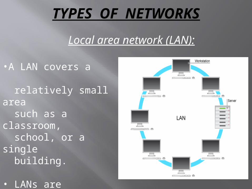
Local area network (LAN):
•A LAN covers a relatively small area such as a classroom, school, or a single building.
• LANs are inexpensive to install and also provide higher speeds.
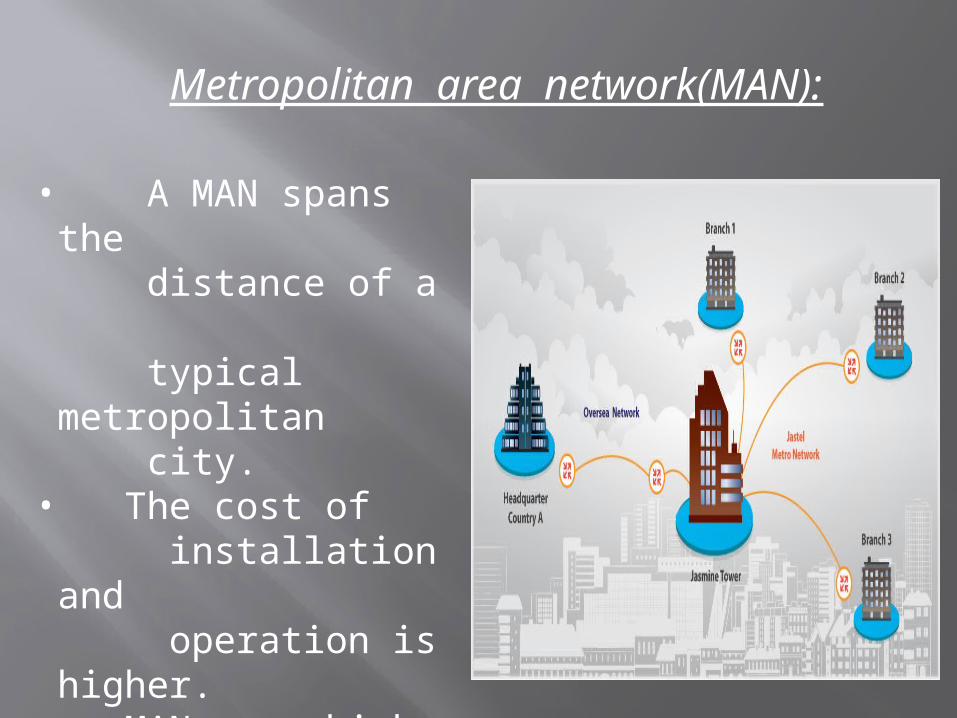
Metropolitan area network(MAN):
• A MAN spans the distance of a typical metropolitan city.
• The cost of installation and operation is higher.
• MANs use high- speed connections such as fiber optics to achieve higher speeds.
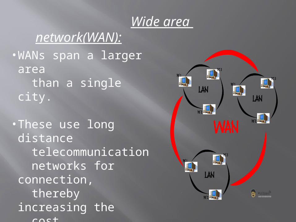
Wide area network(WAN):
• WANs span a larger area than a single city.
• These use long distance telecommunication networks for connection, thereby increasing the cost.
• The Internet is a good example of a WAN.
LAYERED APPROACH IN NETWORKING
In layered approach , the overall task is broken down into sub-tasks and each task is handled at different layers of a virtual model to bring about efficiency and reliability in data transmission.
Layered approach in networking , broadly, involves:
Open System Interconnection(OSI) model. Transmission Control Protocol/Internet
Protocol (TCP/IP) model. Cisco 3- layered model.
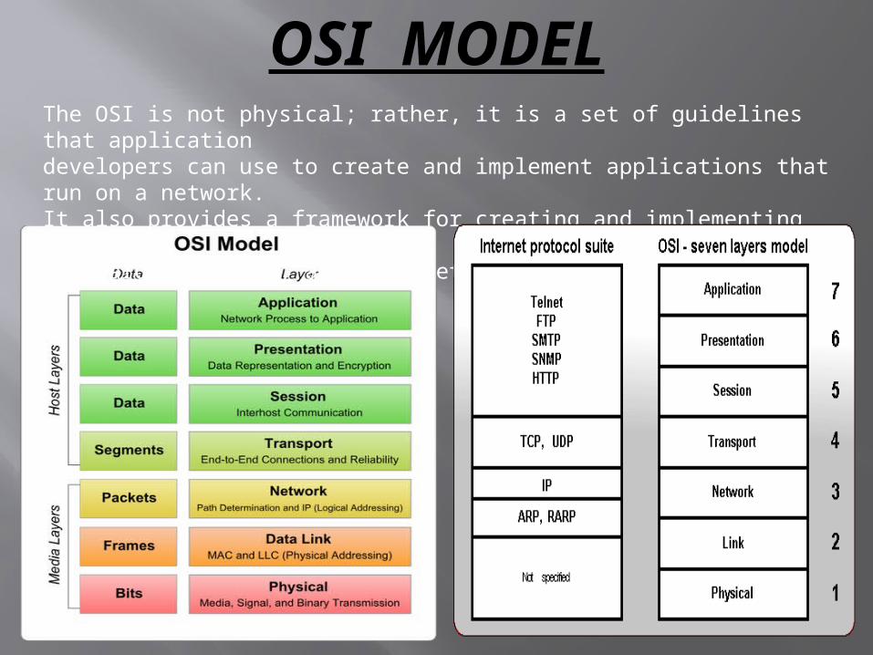
OSI MODELThe OSI is not physical; rather, it is a set of guidelines that applicationdevelopers can use to create and implement applications that run on a network.It also provides a framework for creating and implementing networkingstandards, devices, and internetworking schemes.
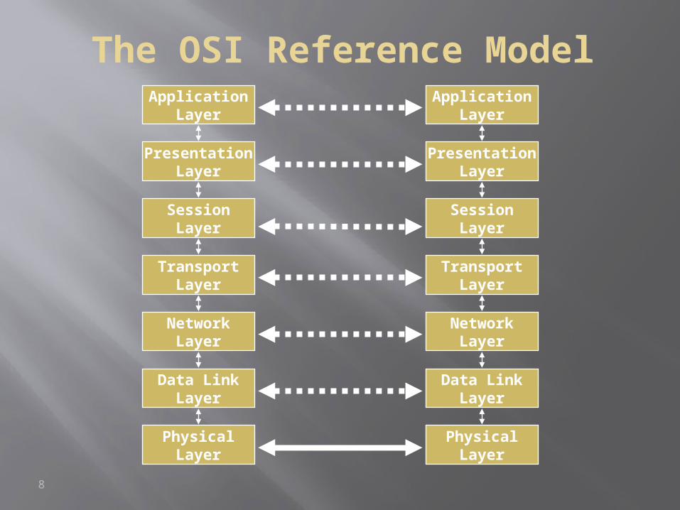
The OSI Reference Model
8
NetworkLayer
Data LinkLayer
PhysicalLayer
ApplicationLayer
PresentationLayer
SessionLayer
TransportLayer
NetworkLayer
Data LinkLayer
PhysicalLayer
ApplicationLayer
PresentationLayer
SessionLayer
TransportLayer
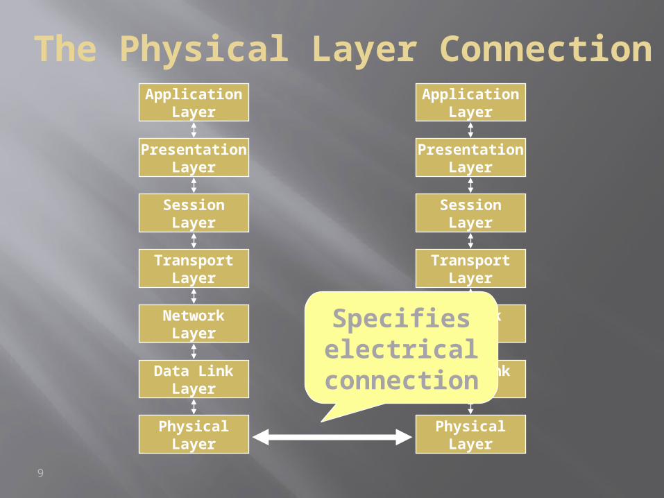
The Physical Layer Connection
9
NetworkLayer
Data LinkLayer
PhysicalLayer
ApplicationLayer
PresentationLayer
SessionLayer
TransportLayer
NetworkLayer
Data LinkLayer
PhysicalLayer
ApplicationLayer
PresentationLayer
SessionLayer
TransportLayer
Specifies electrical
connection
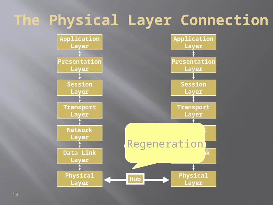
The Physical Layer Connection
10
NetworkLayer
Data LinkLayer
PhysicalLayer
ApplicationLayer
PresentationLayer
SessionLayer
TransportLayer
NetworkLayer
Data LinkLayer
PhysicalLayer
ApplicationLayer
PresentationLayer
SessionLayer
TransportLayer
Hub
AmplificationRegeneration
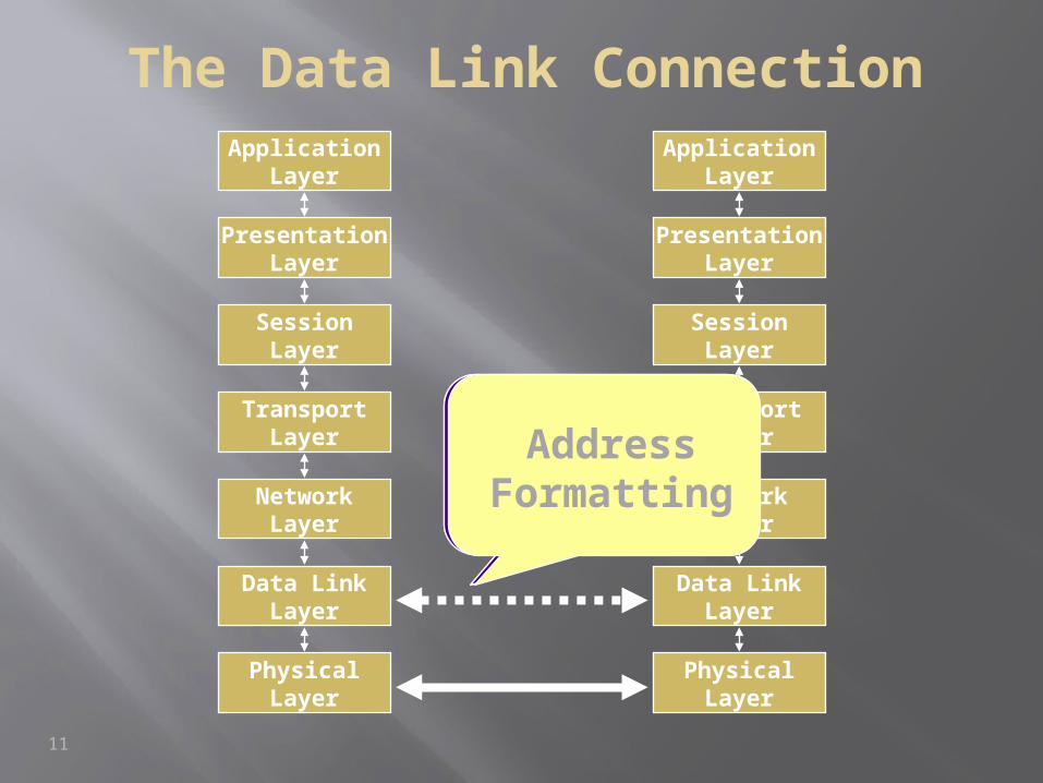
The Data Link Connection
11
NetworkLayer
Data LinkLayer
PhysicalLayer
ApplicationLayer
PresentationLayer
SessionLayer
TransportLayer
NetworkLayer
Data LinkLayer
PhysicalLayer
ApplicationLayer
PresentationLayer
SessionLayer
TransportLayerDelineation
ofData
ErrorDetection
AddressFormatting
12
NetworkLayer
Data LinkLayer
PhysicalLayer
ApplicationLayer
PresentationLayer
SessionLayer
TransportLayer
NetworkLayer
Data LinkLayer
PhysicalLayer
ApplicationLayer
PresentationLayer
SessionLayer
TransportLayer
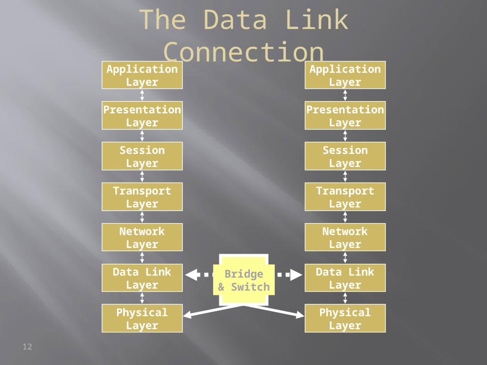
Bridge& Switch
The Data Link Connection
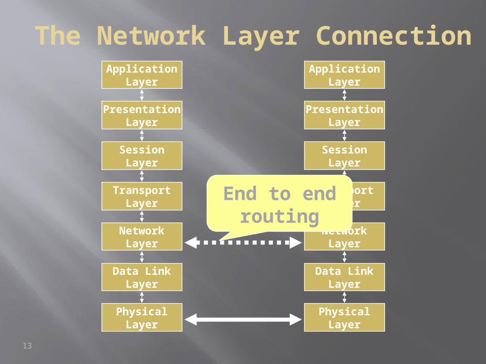
The Network Layer Connection
13
NetworkLayer
Data LinkLayer
PhysicalLayer
ApplicationLayer
PresentationLayer
SessionLayer
TransportLayer
NetworkLayer
Data LinkLayer
PhysicalLayer
ApplicationLayer
PresentationLayer
SessionLayer
TransportLayer
End to end routing
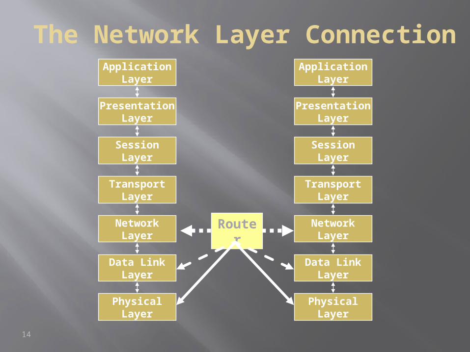
The Network Layer Connection
14
NetworkLayer
Data LinkLayer
PhysicalLayer
ApplicationLayer
PresentationLayer
SessionLayer
TransportLayer
NetworkLayer
Data LinkLayer
PhysicalLayer
ApplicationLayer
PresentationLayer
SessionLayer
TransportLayer
Router
NetworkLayer
Data LinkLayer
PhysicalLayer
ApplicationLayer
PresentationLayer
SessionLayer
TransportLayer
NetworkLayer
Data LinkLayer
PhysicalLayer
ApplicationLayer
PresentationLayer
SessionLayer
TransportLayer
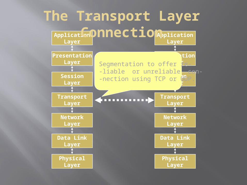
The Transport Layer Connection
Segmentation to offer re--liable or unreliable con--nection using TCP or UDP.
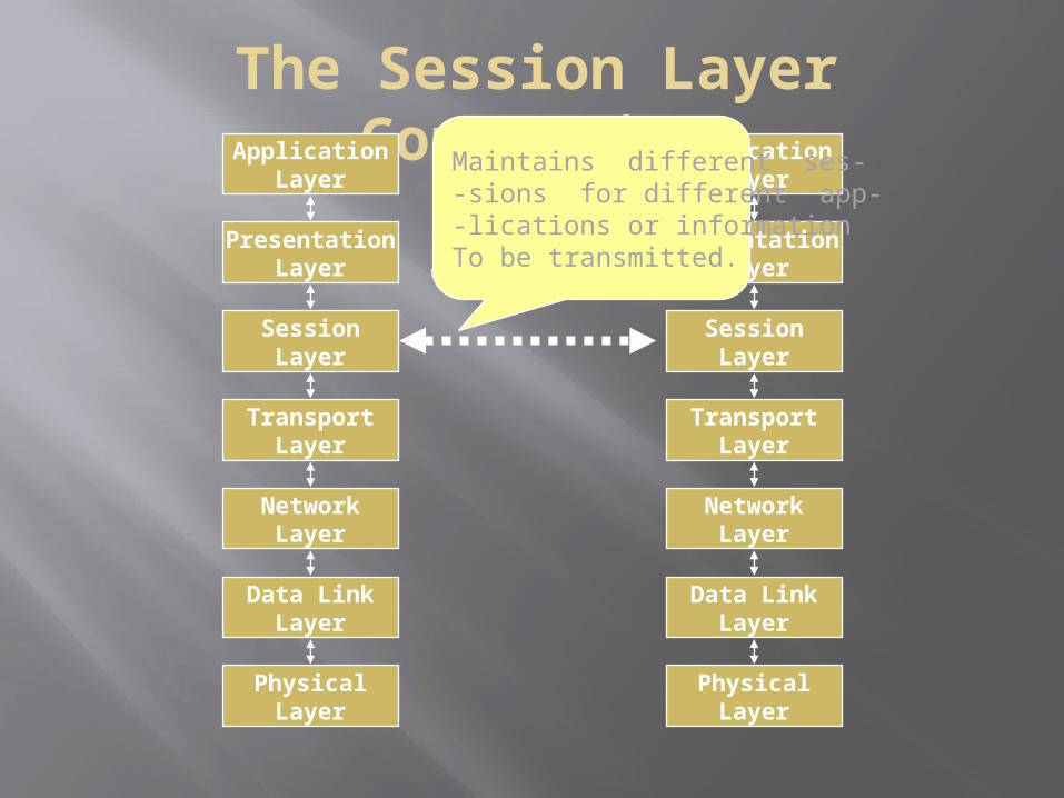
The Session Layer Connection
NetworkLayer
Data LinkLayer
PhysicalLayer
ApplicationLayer
PresentationLayer
SessionLayer
TransportLayer
NetworkLayer
Data LinkLayer
PhysicalLayer
ApplicationLayer
PresentationLayer
SessionLayer
TransportLayer
Maintains different ses--sions for different app--lications or informationTo be transmitted.
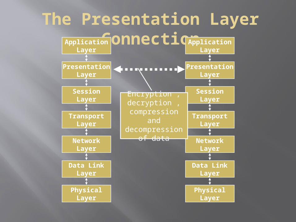
The Presentation Layer Connection
NetworkLayer
Data LinkLayer
PhysicalLayer
ApplicationLayer
PresentationLayer
SessionLayer
TransportLayer
NetworkLayer
Data LinkLayer
PhysicalLayer
ApplicationLayer
PresentationLayer
SessionLayer
TransportLayer
Encryption , decryption , compression
and decompression
of data
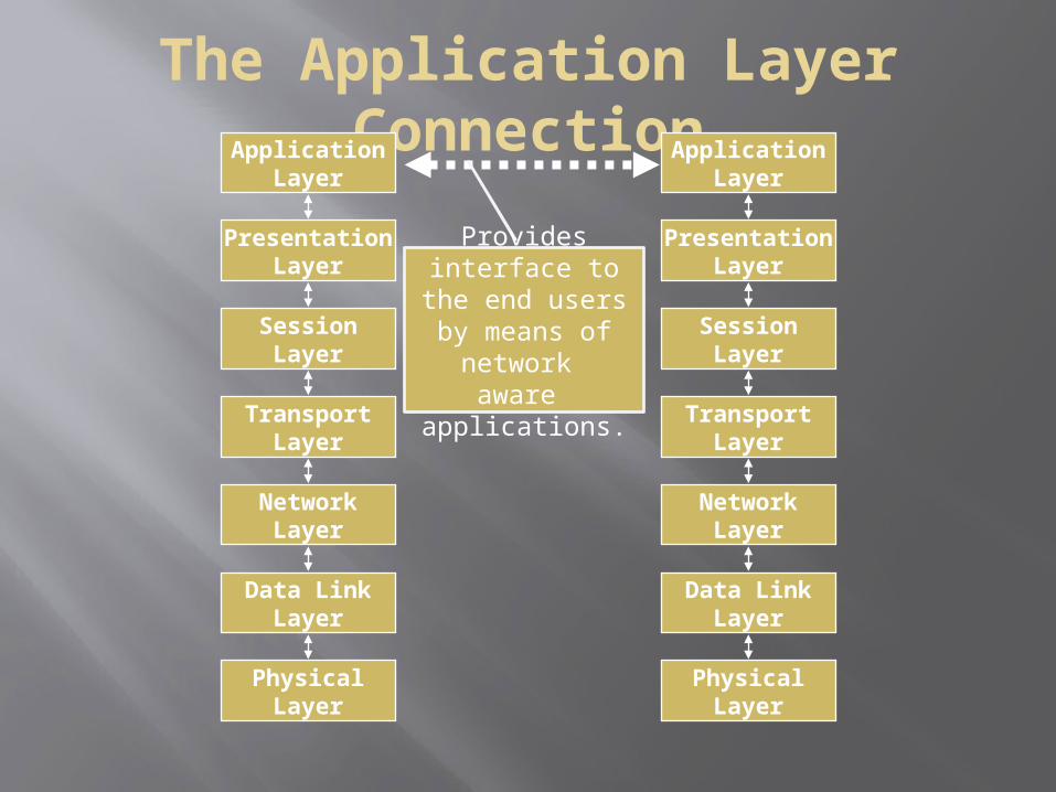
The Application Layer Connection
NetworkLayer
Data LinkLayer
PhysicalLayer
ApplicationLayer
PresentationLayer
SessionLayer
TransportLayer
NetworkLayer
Data LinkLayer
PhysicalLayer
ApplicationLayer
PresentationLayer
SessionLayer
TransportLayer
Provides interface to the
end users by means of
network aware applications.
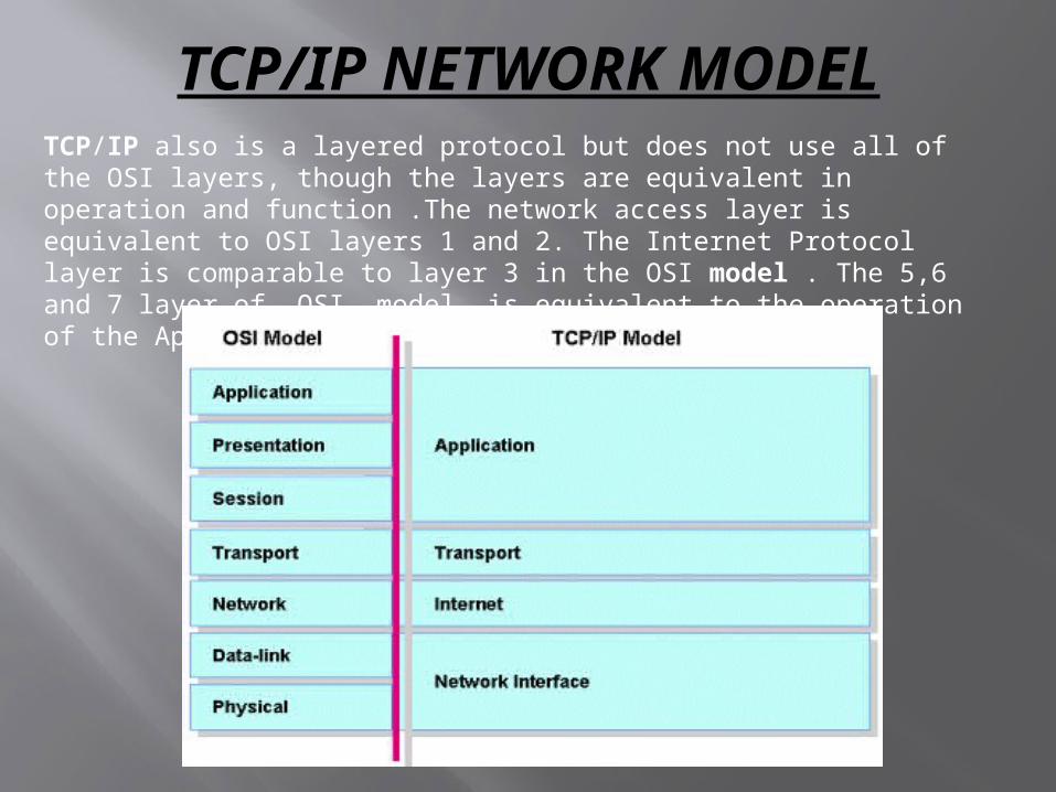
TCP/IP NETWORK MODELTCP/IP also is a layered protocol but does not use all of the OSI layers, though the layers are equivalent in operation and function .The network access layer is equivalent to OSI layers 1 and 2. The Internet Protocol layer is comparable to layer 3 in the OSI model . The 5,6 and 7 layer of OSI model is equivalent to the operation of the Application layer of TCP/IP model.
CISCO 3-LAYER HIERARCHICAL MODEL
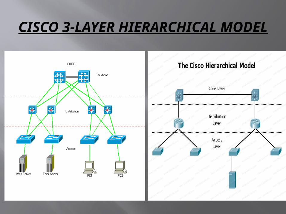
Cisco has defined a hierarchical model known as the hierarchical internetworking model. This model simplifies the task of building a reliable, scalable, and less expensive hierarchical internetwork because rather than focusing on packet construction, it focuses on the three functional areas, or layers, of network:
Core layer: This layer is considered the backbone of the network and includes the high-end switches and high-speed cables such as fibre cables. This layer of the network does not route traffic at the LAN. In addition, no packet manipulation is done by devices in this layer. Rather, this layer is concerned with speed and ensures reliable delivery of packets.
Distribution layer: This layer includes LAN-based routers and layer 3 switches. This layer ensures that packets are properly routed between subnets and VLANs in your enterprise. This layer is also called the Workgroup layer.
Access layer: This layer includes hubs and switches. This layer is also called the desktop layer because it focuses on connecting client nodes, such as workstations to the network. This layer ensures that packets are delivered to end user computers.
CISCO 3-LAYER HIERARCHICAL MODEL
NETWORKING DEVICES
The devices that allows user to transmit data over a network ,thereby allowing successful transference and retrieval of the sent data over a network are called networking devices.
The devices which operate within a network are called intra-networking devices and the devices that allow transmission over distinct networks are called inter-networking devices. The major networking devices are:
• Hub• Repeater• Modem• Gateway• Bridge• Switch• Router
HUB
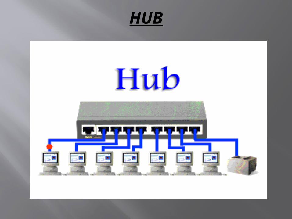
A hub is the most basic networking device that connects multiple computers or other network devices together . A network hub has no routing tables or intelligence on where to send information and broadcasts all network data across each connection. Most hubs can detect basic network errors such as collisions, but having all information broadcast to multiple ports can be a security risk and cause bottlenecks.
Hubs are commonly used to connect segments of a LAN. A hub contains multiple ports. When a packet arrives at one port, it is copied to the other ports so that all segments of the LAN can see all packets.
A hub interconnects two or more workstations into a local area network. When a workstation transmits to a hub, the hub immediately resends the data frame to all connecting links . Hubs expand one Ethernet connection into many. For example, a four-port hub connects up to four machines.
HUB
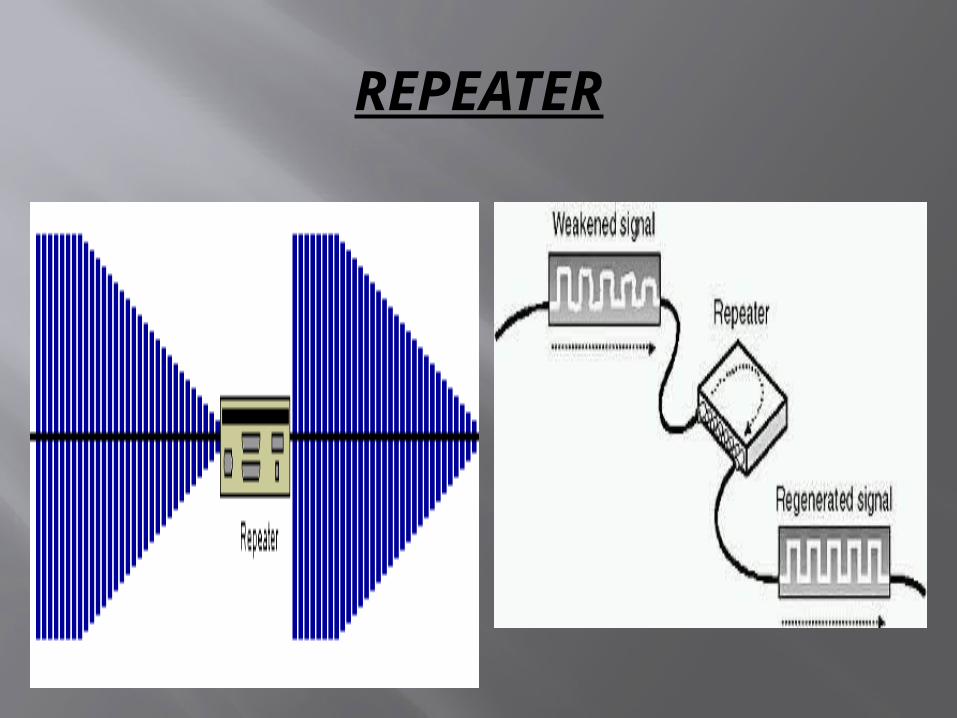
REPEATER A repeater is a network device that retransmits a received
signal with more power and to an extended geographical or topological network boundary than what would be capable with the original signal.
A repeater is implemented in computer networks to expand the coverage area of the network, repropagate a weak or broken signal and or service remote nodes. Repeaters amplify the received/input signal to a higher frequency domain so that it is reusable, scalable and available.
Repeaters were introduced in wired data communication networks due to the limitation of a signal in propagating over a longer distance and now are a common installation in wireless networks for expanding cell size.
REPEATER
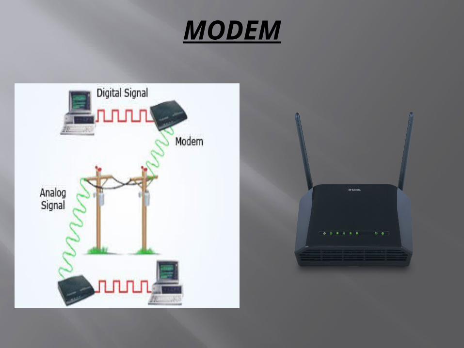
MODEM Modem is abbreviation for Modulator –
Demodulator. Modems are used for data transfer from one computer network to another computer network through telephone lines. The computer network works in digital mode, while analog technology is used for carrying massages across phone lines.
Modulator converts information from digital mode to analog mode at the transmitting end and demodulator converts the same from analog to digital at receiving end.
The process of converting analog signals of one computer network into digital signals of another computer network so they can be processed by a receiving computer is referred to as digitizing.
MODEM
GATEWAY
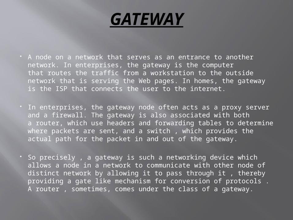
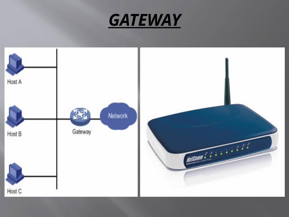
A node on a network that serves as an entrance to another network. In enterprises, the gateway is the computer that routes the traffic from a workstation to the outside network that is serving the Web pages. In homes, the gateway is the ISP that connects the user to the internet.
In enterprises, the gateway node often acts as a proxy server and a firewall. The gateway is also associated with both a router, which use headers and forwarding tables to determine where packets are sent, and a switch , which provides the actual path for the packet in and out of the gateway.
So precisely , a gateway is such a networking device which allows a node in a network to communicate with other node of distinct network by allowing it to pass through it , thereby providing a gate like mechanism for conversion of protocols . A router , sometimes, comes under the class of a gateway.
GATEWAY
BRIDGE A bridge reads the outermost section of data on the data packet, to
tell where the message is going. It reduces the traffic on other network segments, since it does not send all packets.
Bridges can be programmed to reject packets from particular networks. Bridging occurs at the data link layer of the OSI model, which means the bridge cannot read IP addresses, but only the outermost hardware address of the packet.
In general case the bridge can read the ethernet data which gives the hardware address of the destination address, not the IP address. Bridges forward all broadcast messages.
Only a special bridge called a translation bridge will allow two networks of different architectures to be connected. Bridges do not normally allow connection of networks with different architectures.
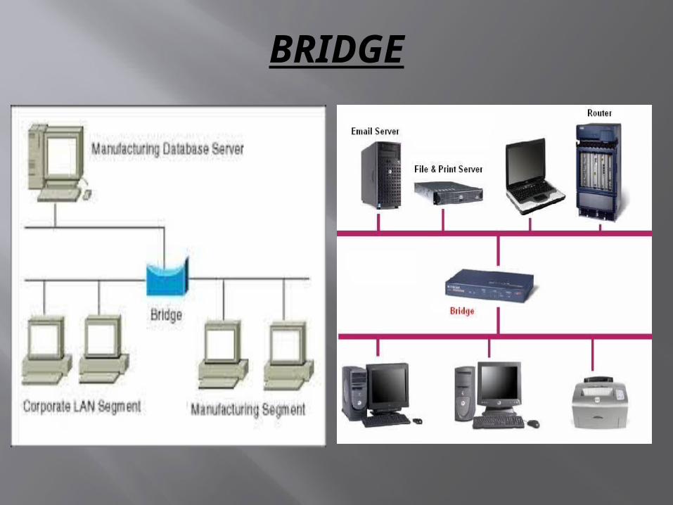
Bridging has nothing to do with logical addressing . It is primarily used to connect two or more segments of a same network. A bridge device filters data traffic at a network boundary
BRIDGE
SWITCH
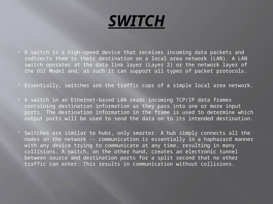
A switch is a high-speed device that receives incoming data packets and redirects them to their destination on a local area network (LAN). A LAN switch operates at the data link layer (Layer 2) or the network layer of the OSI Model and, as such it can support all types of packet protocols.
Essentially, switches are the traffic cops of a simple local area network.
A switch in an Ethernet-based LAN reads incoming TCP/IP data frames containing destination information as they pass into one or more input ports. The destination information in the frame is used to determine which output ports will be used to send the data on to its intended destination.
Switches are similar to hubs, only smarter. A hub simply connects all the nodes on the network -- communication is essentially in a haphazard manner with any device trying to communicate at any time, resulting in many collisions. A switch, on the other hand, creates an electronic tunnel between source and destination ports for a split second that no other traffic can enter. This results in communication without collisions.

SWITCH
Switch
StationA
StationB
StationC
StationD
Connection 1A-C
Connection 1A-C
Connection 2B-D
Connection 2B-D
With a switch, multiple stations may transmit simultaneously: no congestion as traffic grows.
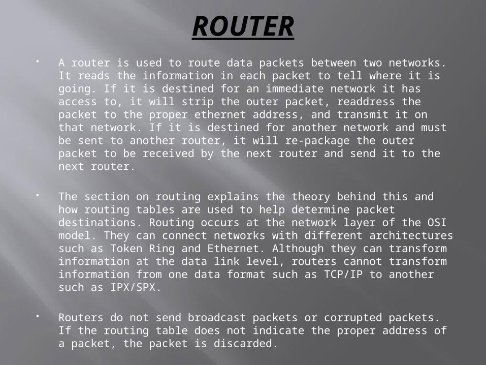
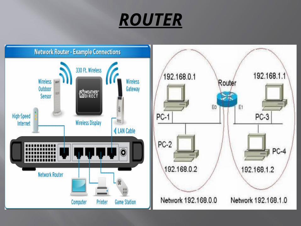
ROUTER A router is used to route data packets between two networks. It reads the
information in each packet to tell where it is going. If it is destined for an immediate network it has access to, it will strip the outer packet, readdress the packet to the proper ethernet address, and transmit it on that network. If it is destined for another network and must be sent to another router, it will re-package the outer packet to be received by the next router and send it to the next router.
The section on routing explains the theory behind this and how routing tables are used to help determine packet destinations. Routing occurs at the network layer of the OSI model. They can connect networks with different architectures such as Token Ring and Ethernet. Although they can transform information at the data link level, routers cannot transform information from one data format such as TCP/IP to another such as IPX/SPX.
Routers do not send broadcast packets or corrupted packets. If the routing table does not indicate the proper address of a packet, the packet is discarded.
Routers are located at gateways, the places where two or more networks connect. Routers use headers and forwarding tables to determine the best path for forwarding the packets, and they use protocols such as ICMP to communicate with each other and configure the best route between any two hosts.
ROUTER