networkingforadmins wahl ch8pdf
TRANSCRIPT
7/23/2019 NetworkingforAdmins Wahl Ch8pdf
http://slidepdf.com/reader/full/networkingforadmins-wahl-ch8pdf 1/26
Networking for VMware Administrators
◦ Christopher Wahl & Steven Pantol
◦ VMware Press
◦ Coming March 2014
Increasingly, virtualization administrators and architects must
have a deep understanding of networks. However, many have
come to virtualization from other IT backgrounds, and do not
have the knowledge they need to interact effectively with
network specialists or solve problems with virtual
networks. N e t w o r k i n g f o r VMw a r e Adm i n is t r a t o r s fills
this crucial gap, illuminating the core concepts required to
"speak the language" of networking, and showing exactly how
they apply to VMware vSphere.
Drawing on their extensive experience architecting, delivering, and troubleshooting virtual networks with
VMware, Cisco, and other technologies, Christopher Wahl and Steve Pantol address all this and more:
Physical networking: concepts, models, Ethernet, hardware, protocols, VLANs, routing/Subnetting,
and more
Virtual switching and how it differs from physical switching
vSphere standard and distributed switch concepts, terminology, configuration, and design
Third party switches, including Nexus 1000v: architecture and overview
Storage networking: use cases, design, and configuration
Other design scenarios: 1 Gb Ethernet, 10 Gb Ethernet, blade servers, converged traffic, and virtual
NICs
7/23/2019 NetworkingforAdmins Wahl Ch8pdf
http://slidepdf.com/reader/full/networkingforadmins-wahl-ch8pdf 2/26
Chapter 8
vSphere Standard Switch
Key Concepts: Control and Data Planes
Virtual Ports
vSwitch Security
Traffic Shaping
NIC Teaming and Failover
VMkernel Ports
Port Groups
Introduction
A VMware ESXi server cannot do much of anything worthwhile without some means of
getting network traffic to and from the VMs it hosts. Fortunately, VMware realized this
and has thoughtfully provided two solutions to this problem, the vSphere Standard Switch
and the vSphere Distributed Switch. This chapter focuses on the former, the original
recipe vSwitch that is included with every license level. Don’t let the “standard” part of
the Standard Switch fool you—it includes a bunch of great features to help you shuffle
traffic around your network. With that said, let’s look at what makes a VMware Standard
Switch tick.
7/23/2019 NetworkingforAdmins Wahl Ch8pdf
http://slidepdf.com/reader/full/networkingforadmins-wahl-ch8pdf 3/26
The vSphere Standard Switch
The goal of VMware’s Standard Switch is to allow network traffic to flow in any
scenario. This could mean that the ESXi host is not connected to a vCenter server at all,
which is typically referred to as a “standalone” or “vSphere Hypervisor” install of
vSphere. In this case, there’s no higher level of management than the host itself, so thestandard level switch needs to be able to function with nothing more than the host telling
it what to do.
TIP
If you think about it deeper, when you first install VMware ESXi onto a server, it is a blank
slate—it has no name, IP, or DNS information. While there are ways to script the install to
auto-assign these identities, no assumptions can be made. This is another reason why the
standard vSwitch must be able to operate with nothing more fancy than a standalone
installation of ESXi.
Plane English
Before getting too far into how the Standard Switch works, we need to introduce a bit of
terminology. When describing switch functions, we often use the terms “control plane”
and “data plane.” Control plane traffic and functions can best be thought of as traffic to
the switch, and data plane traffic is traffic through the switch. Management, monitoring,
and configuration traffic concerning the switch is control plane traffic. Frames passing
from a virtual machine (VM) out to the rest of the world would be data plane traffic.
In your typical physical, top-of-rack style switch, control and data planes live within the
same piece of equipment. With virtual switches, these functions can be separated.
Control PlaneThe control plane of a standard vSwitch resides on the VMware host. That is, any
manipulation of the vSwitch configuration, number of ports, and the way that traffic is
moved around are all part of the host’s responsibilities. More specifically, it’s the job of
the hypervisor kernel (called the VMkernel) to make sure that the vSwitch is configured
and operational.
As such, even when you cluster a bunch of VMware hosts together, each host is
responsible for its own standard vSwitches. In the case of a vCenter failure, every host’s
standard vSwitch would still be configurable by connecting the vSphere client directly to
the host.
Data Plane

7/23/2019 NetworkingforAdmins Wahl Ch8pdf
http://slidepdf.com/reader/full/networkingforadmins-wahl-ch8pdf 4/26
Every Standard vSwitch on a host is responsible for switching frames, which means that
the data plane is a host’s responsibility. As data enters the host NICs, which form the
uplinks for a standard vSwitch, the VMkernel makes sure that the frames get to the
appropriate destination. Sometimes this means that the traffic gets ignored, especially in
the case of external traffic that enters the vSwitch with an unknown destination MAC
address.
vSwitch Properties
Every vSwitch has two basic properties that can be configured in order to meet the
requirements of your design and network maximum transmission size.
Ports
Ports indicate the number of virtual ports that will be kept in memory, tracked, and made
available to VMs, VMkernel ports, and uplinks that reside on the host. One weakness of a
standard vSwitch is the requirement that the ESXi host be restarted if you change the
number of ports. Prior to vSphere 4.1, the default number of vSwitch ports was only 56,leading many a green VMware administrator to hit that limit before realizing it was
something that could be changed. Over time, VMware listened to the woes of
virtualization administrators and, in vSphere 4.1, the default number of ports assigned to a
standard vSwitch has been changed to 128, allowing some breathing room. An
administrator can adjust the number of ports by powers of 2, from 128 to 256 and so on,
all the way up to 4,096 possible ports.
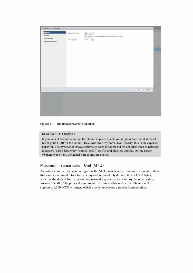
Figure 8.1 shows the default vSwitch properties dialog in the vSphere Web Client.
7/23/2019 NetworkingforAdmins Wahl Ch8pdf
http://slidepdf.com/reader/full/networkingforadmins-wahl-ch8pdf 5/26
Figure 8.1 The default vSwitch properties
REAL WORLD EXAMPLE
If you look at the port count on the classic vSphere client, you might notice that it shows 8
fewer ports (120) for the default. Hey, who stole my ports? Don’t worry, this is the expected behavior. The hypervisor always reserves 8 ports for overhead for activities such as network
discovery, Cisco Discovery Protocol (CDP) traffic, and physical uplinks. On the newer
vSphere web client, the actual port counts are shown.
Maximum Transmission Unit (MTU)
The other item that you can configure is the MTU, which is the maximum amount of data
that can be crammed into a frame’s payload segment. By default, this is 1,500 bytes,
which is the default for just about any networking device you can buy. You can safely
assume that all of the physical equipment that runs northbound of the vSwitch will
support a 1,500 MTU or larger, which avoids unnecessary packet fragmentation.
7/23/2019 NetworkingforAdmins Wahl Ch8pdf
http://slidepdf.com/reader/full/networkingforadmins-wahl-ch8pdf 6/26
There’s also an option to increase this size and set it to a “jumbo” size. We do love our
silly names in this industry. Jumbo frames are just frames larger than the default size of
1,500. Even setting an MTU of 1,501 is technically enabling jumbo frames. Tremble
before the mighty, slightly larger frame.
Most of the time, though, the term jumbo frame refers to a frame with an MTU of 9,000or higher, though 9,000 is the maximum MTU ESXi will support. If you are talking to a
network engineer and want to get an idea of what MTU size to set on your vSwitch, ask
specifically what the MTU value is—don’t just ask if he or she is running jumbo frames.
This avoids any confusion.
REAL WORLD EXAMPLE
I’ve done a lot of work with people who want to enable jumbo frames thinking that a larger
number is by default going to increase performance. This is not always true, and in some
cases, enabling jumbo frames can actually hurt performance. It’s also incredibly difficult to
make sure that all of the physical networking equipment is properly configured for a jumbo
frame size. Make sure that you have a solid technical reason, with performance testing, before you worry about increasing your MTU size on your infrastructure.
Security
The security settings on a vSwitch are probably one of the most misunderstood portions
of a vSwitch configuration. There are three settings available for tuning: promiscuous
mode, MAC address changes, and forged transmits, as shown in Figure 8.2.

7/23/2019 NetworkingforAdmins Wahl Ch8pdf
http://slidepdf.com/reader/full/networkingforadmins-wahl-ch8pdf 7/26
Figure 8.2 Security settings on a vSwitch
Promiscuous Mode
If you think back to when we covered physical switching, you’ll probably recall that one
major advantage to it is that we have the ability to switch traffic directly to a single
destination MAC address. Unless the traffic is being flooded, broadcast, or specifically
intended for a destination, devices on the network do not “see” the other traffic floating
across the switch. This is great for most use cases as it provides for greater scalability and
improved performance of the network, and is the default behavior on a standard vSwitch.
There are some situations where we really do want a VM to see traffic that is intended for
another device. Imagine having some sort of network monitoring VM that needs to sniff
traffic. This is where Promiscuous Mode comes in handy. By setting it to Accept, we are
ordering the vSwitch to share traffic on each VLAN among other VMs on the same
VLAN.
PITFALL
7/23/2019 NetworkingforAdmins Wahl Ch8pdf
http://slidepdf.com/reader/full/networkingforadmins-wahl-ch8pdf 8/26
Promiscuous mode does not allow a VM to see traffic on VLANs that aren’t specified by
the port group. It can still only see traffic for the VLAN(s) that it belongs to. This is a very
common misconception.
MAC Address Changes
The idea of MAC Address Changes tends to confuse a lot of people, so we’ll go deep into
this one. First, what exactly is a MAC Address Change from a vSwitch perspective? To
understand this, you must first know more about how the switch keeps track of MAC
addresses for VMs.
To begin with, every VM has three different types of MAC addresses: the Initial,
Effective, and Runtime MAC addresses:
The Initial MAC address is configured on the virtual network adapter inside the
VM. This is something you either let vSphere decide for you when the virtual NIC
is created, or manually set yourself by changing that vSphere-provided value. It is
very similar to a physical NIC’s burned-in address (BIA).
The Effective MAC address is configured within the VM by the guest operating
system (OS). Typically, the guest OS just uses the Initial MAC address, much like
your PC will by default use the BIA or your NIC.
The Runtime MAC address is the actual live address that is being seen by the
vSwitch port.
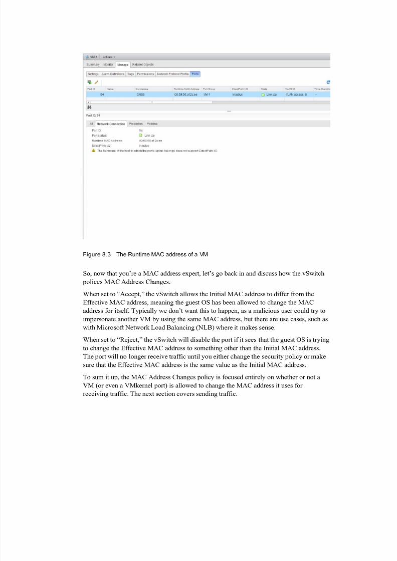
Figure 8.3 shows the Runtime MAC address of a VM in the vSphere Web Client.
7/23/2019 NetworkingforAdmins Wahl Ch8pdf
http://slidepdf.com/reader/full/networkingforadmins-wahl-ch8pdf 9/26
Figure 8.3 The Runtime MAC address of a VM
So, now that you’re a MAC address expert, let’s go back in and discuss how the vSwitch
polices MAC Address Changes.
When set to “Accept,” the vSwitch allows the Initial MAC address to differ from theEffective MAC address, meaning the guest OS has been allowed to change the MAC
address for itself. Typically we don’t want this to happen, as a malicious user could try to
impersonate another VM by using the same MAC address, but there are use cases, such as
with Microsoft Network Load Balancing (NLB) where it makes sense.
When set to “Reject,” the vSwitch will disable the port if it sees that the guest OS is trying
to change the Effective MAC address to something other than the Initial MAC address.
The port will no longer receive traffic until you either change the security policy or make
sure that the Effective MAC address is the same value as the Initial MAC address.
To sum it up, the MAC Address Changes policy is focused entirely on whether or not a
VM (or even a VMkernel port) is allowed to change the MAC address it uses for
receiving traffic. The next section covers sending traffic.
7/23/2019 NetworkingforAdmins Wahl Ch8pdf
http://slidepdf.com/reader/full/networkingforadmins-wahl-ch8pdf 10/26
Forged Transmits
Very similar to the MAC Address Changes policy, the Forged Transmits policy is
concerned with MAC Address Changes, but only as it concerns transmitting traffic.
If set to “Accept,” the VM can put in any MAC address it wishes into the “source
address” field of a Layer 2 frame. The vSwitch port will just happily let those framesmove along to their destination.
If the policy is set to “Reject,” the port will interrogate all the traffic that is generated by
the VM. The policy will check to see if the source MAC address field has been tampered
with. As long as the source MAC field is the same as the Effective MAC address, the
frame is allowed by the port. However, if it finds a non-matching MAC address, the frame
is dropped.
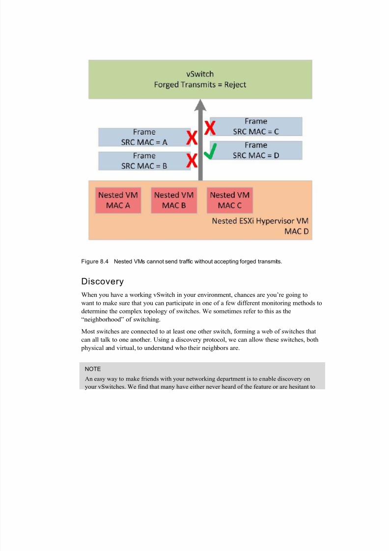
It’s very common to see issues with the Forged Transmit policy when doing nested
virtualization. Nesting is the term used to describe running the ESXi hypervisor inside a
VM, which then runs other nested VMs with their own unique MAC addresses. The many
different MAC addresses will be seen by the port used by the nested hypervisor VM
because the nested guest VMs are sending traffic. In this case, you would have to
configure the policy for Forged Transmits to Accept.
Figure 8.4 illustrates this process.
7/23/2019 NetworkingforAdmins Wahl Ch8pdf
http://slidepdf.com/reader/full/networkingforadmins-wahl-ch8pdf 11/26
Figure 8.4 Nested VMs cannot send traffic without accepting forged transmits.
Discovery
When you have a working vSwitch in your environment, chances are you’re going to
want to make sure that you can participate in one of a few different monitoring methods to
determine the complex topology of switches. We sometimes refer to this as the
“neighborhood” of switching.
Most switches are connected to at least one other switch, forming a web of switches that
can all talk to one another. Using a discovery protocol, we can allow these switches, both
physical and virtual, to understand who their neighbors are.
NOTE
An easy way to make friends with your networking department is to enable discovery on
your vSwitches. We find that many have either never heard of the feature or are hesitant to
7/23/2019 NetworkingforAdmins Wahl Ch8pdf
http://slidepdf.com/reader/full/networkingforadmins-wahl-ch8pdf 12/26
enable it. Make sure your security team is okay with you using a discovery protocol before
turning it on, but once on, it makes understanding the neighborhood of physical and virtual
switches dramatically easier for everyone!
Cisco Discovery Protocol (CDP)The VMware standard vSwitch supports only one single protocol for discovery, the Cisco
Discovery Protocol. Can you guess which switch manufacturer uses this protocol? We’ll
give you a hint—it’s not Brocade.
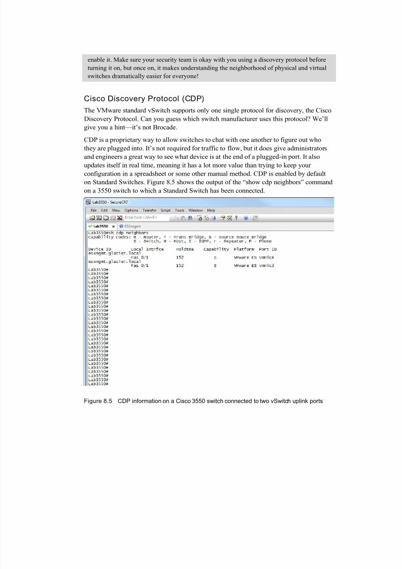
CDP is a proprietary way to allow switches to chat with one another to figure out who
they are plugged into. It’s not required for traffic to flow, but it does give administrators
and engineers a great way to see what device is at the end of a plugged-in port. It also
updates itself in real time, meaning it has a lot more value than trying to keep your
configuration in a spreadsheet or some other manual method. CDP is enabled by default
on Standard Switches. Figure 8.5 shows the output of the “show cdp neighbors” command
on a 3550 switch to which a Standard Switch has been connected.
Figure 8.5 CDP information on a Cisco 3550 switch connected to two vSwitch uplink ports
7/23/2019 NetworkingforAdmins Wahl Ch8pdf
http://slidepdf.com/reader/full/networkingforadmins-wahl-ch8pdf 13/26
Traffic Shaping
Traffic shaping is the ability to control the quantity of traffic that is allowed to flow across
a link. That is, rather than letting the traffic go as fast as it possibly can, you can set limits
to how much traffic can be sent.
Within a standard vSwitch, you can only enforce traffic shaping on outbound traffic that
is being sent out of an object—such as a VM or VMkernel port—toward another object.
This is referred to by VMware as “ingress traffic” and refers to the fact that data is
coming into the vSwitch by way of the virtual ports. Later, we cover how to set “egress
traffic” shaping, which is the control of traffic being received by a port group headed
toward a VM or VMkernel port, when we start talking about the distributed switch in the
next chapter.
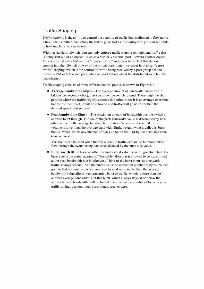
Traffic shaping consists of three different control points, as shown in Figure 8.6.
Average bandwidth (Kbps) —The average amount of bandwidth, measured in
kilobits per second (Kbps), that you allow the switch to send. There might be short
periods where the traffic slightly exceeds this value, since it is an average over time, but for the most part, it will be enforced and traffic will go no faster than the
defined speed limit set here.
Peak bandwidth (Kbps) —The maximum amount of bandwidth that the switch is
allowed to let through. The use of the peak bandwidth value is determined by how
often we’ve hit the average bandwidth limitation. Whenever the actual traffic
volume is lower than the average bandwidth limit, we gain what is called a “burst
bonus” which can be any number of bytes up to the limit set by the burst size value
(covered next).
This bonus can be used when there is a pent-up traffic demand to let more traffic
flow through the switch using data sizes dictated by the burst size value.
Burst size (KB) —This is an often misunderstood value, so we’ll go into detail. The burst size is the actual amount of “burstable” data that is allowed to be transmitted
at the peak bandwidth rate in kilobytes. Think of the burst bonus as a network
traffic savings account. And the burst size is the maximum number of bytes that can
go into that account. So, when you need to send more traffic than the average
bandwidth value allows, you transmit a burst of traffic, which is more than the
allowed average bandwidth. But this burst, which always stays at or below the
allowable peak bandwidth, will be forced to end when the number of bytes in your
traffic savings account, your burst bonus, reaches zero.
7/23/2019 NetworkingforAdmins Wahl Ch8pdf
http://slidepdf.com/reader/full/networkingforadmins-wahl-ch8pdf 14/26
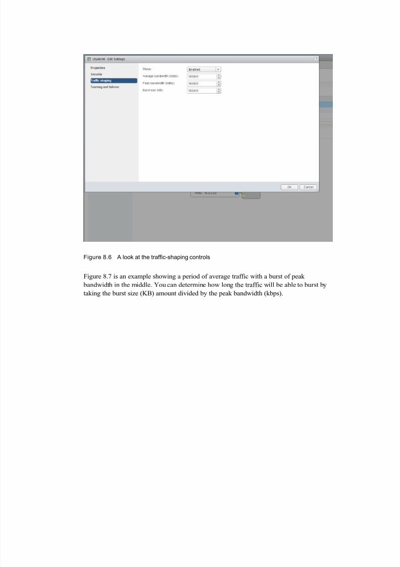
Figure 8.6 A look at the traffic-shaping controls
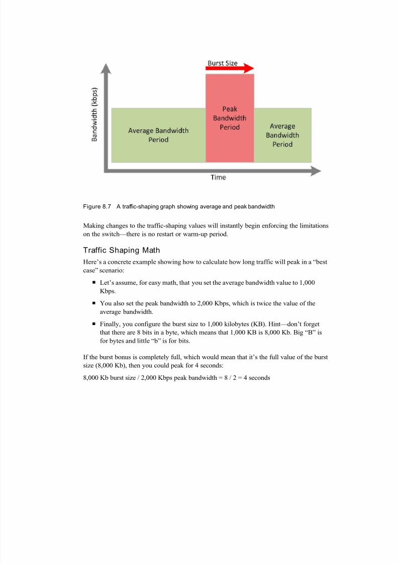
Figure 8.7 is an example showing a period of average traffic with a burst of peak
bandwidth in the middle. You can determine how long the traffic will be able to burst by
taking the burst size (KB) amount divided by the peak bandwidth (kbps).
7/23/2019 NetworkingforAdmins Wahl Ch8pdf
http://slidepdf.com/reader/full/networkingforadmins-wahl-ch8pdf 15/26
Figure 8.7 A traffic-shaping graph showing average and peak bandwidth
Making changes to the traffic-shaping values will instantly begin enforcing the limitations
on the switch—there is no restart or warm-up period.
Traffic Shaping Math
Here’s a concrete example showing how to calculate how long traffic will peak in a “best
case” scenario:
Let’s assume, for easy math, that you set the average bandwidth value to 1,000
Kbps.
You also set the peak bandwidth to 2,000 Kbps, which is twice the value of the
average bandwidth.
Finally, you configure the burst size to 1,000 kilobytes (KB). Hint—don’t forget
that there are 8 bits in a byte, which means that 1,000 KB is 8,000 Kb. Big “B” is
for bytes and little “b” is for bits.
If the burst bonus is completely full, which would mean that it’s the full value of the burst
size (8,000 Kb), then you could peak for 4 seconds:
8,000 Kb burst size / 2,000 Kbps peak bandwidth = 8 / 2 = 4 seconds
7/23/2019 NetworkingforAdmins Wahl Ch8pdf
http://slidepdf.com/reader/full/networkingforadmins-wahl-ch8pdf 16/26
NIC Teaming
Let’s take a well-deserved break from networking math for a moment and shift into the
fun world of NIC teaming. The concept of teaming goes by many different names:
bonding, grouping, and trunking to name a few. Really, it just means that we’re taking
multiple physical NICs on a given ESXi host and combining them into a single logicallink that provides bandwidth aggregation and redundancy to a vSwitch. You might think
that this sounds a little bit like port channels from earlier in the book. And you’re partially
right—the goal is very similar, but the methods are vastly different.
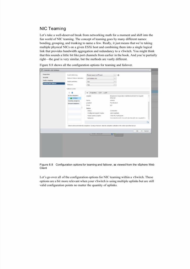
Figure 8.8 shows all the configuration options for teaming and failover.
Figure 8.8 Configuration options for teaming and failover, as viewed from the vSphere Web
Client
Let’s go over all of the configuration options for NIC teaming within a vSwitch. These
options are a bit more relevant when your vSwitch is using multiple uplinks but are still
valid configuration points no matter the quantity of uplinks.
7/23/2019 NetworkingforAdmins Wahl Ch8pdf
http://slidepdf.com/reader/full/networkingforadmins-wahl-ch8pdf 17/26
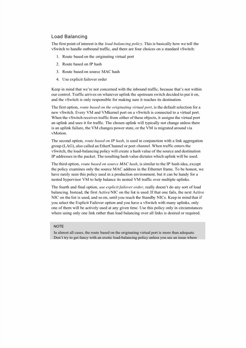
Load Balancing
The first point of interest is the load-balancing policy. This is basically how we tell the
vSwitch to handle outbound traffic, and there are four choices on a standard vSwitch:
1. Route based on the originating virtual port
2. Route based on IP hash
3. Route based on source MAC hash
4. Use explicit failover order
Keep in mind that we’re not concerned with the inbound traffic, because that’s not within
our control. Traffic arrives on whatever uplink the upstream switch decided to put it on,
and the vSwitch is only responsible for making sure it reaches its destination.
The first option, route based on the originating virtual port , is the default selection for a
new vSwitch. Every VM and VMkernel port on a vSwitch is connected to a virtual port.
When the vSwitch receives traffic from either of these objects, it assigns the virtual port
an uplink and uses it for traffic. The chosen uplink will typically not change unless thereis an uplink failure, the VM changes power state, or the VM is migrated around via
vMotion.
The second option, route based on IP hash, is used in conjunction with a link aggregation
group (LAG), also called an EtherChannel or port channel. When traffic enters the
vSwitch, the load-balancing policy will create a hash value of the source and destination
IP addresses in the packet. The resulting hash value dictates which uplink will be used.
The third option, route based on source MAC hash, is similar to the IP hash idea, except
the policy examines only the source MAC address in the Ethernet frame. To be honest, we
have rarely seen this policy used in a production environment, but it can be handy for a
nested hypervisor VM to help balance its nested VM traffic over multiple uplinks.
The fourth and final option, use explicit failover order , really doesn’t do any sort of load
balancing. Instead, the first Active NIC on the list is used. If that one fails, the next Active
NIC on the list is used, and so on, until you reach the Standby NICs. Keep in mind that if
you select the Explicit Failover option and you have a vSwitch with many uplinks, only
one of them will be actively used at any given time. Use this policy only in circumstances
where using only one link rather than load balancing over all links is desired or required.
NOTE
In almost all cases, the route based on the originating virtual port is more than adequate.
Don’t try to get fancy with an exotic load-balancing policy unless you see an issue where

7/23/2019 NetworkingforAdmins Wahl Ch8pdf
http://slidepdf.com/reader/full/networkingforadmins-wahl-ch8pdf 18/26
the majority of traffic is being sent down the same uplink and other uplinks are relatively
quiet. Remember our motto—the simplest designs are almost always the best design.
A single VM will not be able to take advantage of more than a single uplink in most
circumstances. If you provide a pair of 1 Gb Ethernet uplinks to your vSwitch, a VM will
still only use one of those uplinks at a time. There are exceptions to this concept, such as
when a VM has multiple virtual NICs attached on a vSwitch with IP hash, but are relatively
rare to see in production environments.
Network Failure Detection
When a network link fails (and they definitely do), the vSwitch is aware of the failure
because the link status reports the link as being down. This can usually be verified by
seeing if anyone tripped over the cable or mistakenly unplugged the wrong one. In most
cases, this is good enough to satisfy your needs and the default configuration of “link
status only” for the network failure detection is good enough.
But what if you want to determine a failure further up the network, such as a failure
beyond your upstream connected switch? This is where beacon probing might be able tohelp you out. Beacon probing is actually a great term because it does roughly what it
sounds like it should do. A beacon is regularly sent out from the vSwitch through its
uplinks to see if the other uplinks can “hear” it.
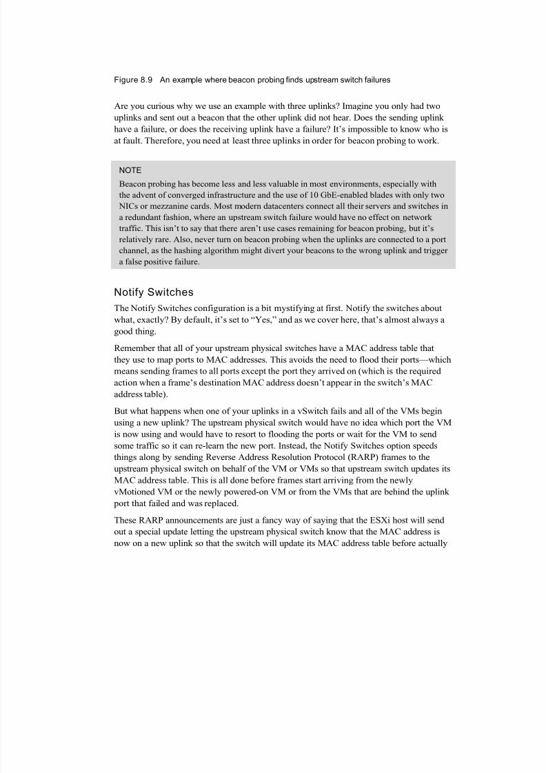
Figure 8.9 shows an example of a vSwitch with three uplinks. When Uplink1 sends out a
beacon that Uplink2 receives but Uplink3 does not, this is because the upstream
aggregation switch 2 is down, and therefore, the traffic is unable to reach Uplink3.
7/23/2019 NetworkingforAdmins Wahl Ch8pdf
http://slidepdf.com/reader/full/networkingforadmins-wahl-ch8pdf 19/26
Figure 8.9 An example where beacon probing finds upstream switch failures
Are you curious why we use an example with three uplinks? Imagine you only had two
uplinks and sent out a beacon that the other uplink did not hear. Does the sending uplink
have a failure, or does the receiving uplink have a failure? It’s impossible to know who is
at fault. Therefore, you need at least three uplinks in order for beacon probing to work.
NOTE
Beacon probing has become less and less valuable in most environments, especially with
the advent of converged infrastructure and the use of 10 GbE-enabled blades with only two
NICs or mezzanine cards. Most modern datacenters connect all their servers and switches in
a redundant fashion, where an upstream switch failure would have no effect on network
traffic. This isn’t to say that there aren’t use cases remaining for beacon probing, but it’s
relatively rare. Also, never turn on beacon probing when the uplinks are connected to a port
channel, as the hashing algorithm might divert your beacons to the wrong uplink and trigger
a false positive failure.
Notify Switches
The Notify Switches configuration is a bit mystifying at first. Notify the switches about
what, exactly? By default, it’s set to “Yes,” and as we cover here, that’s almost always a
good thing.
Remember that all of your upstream physical switches have a MAC address table that
they use to map ports to MAC addresses. This avoids the need to flood their ports—which
means sending frames to all ports except the port they arrived on (which is the required
action when a frame’s destination MAC address doesn’t appear in the switch’s MAC
address table).
But what happens when one of your uplinks in a vSwitch fails and all of the VMs begin
using a new uplink? The upstream physical switch would have no idea which port the VM
is now using and would have to resort to flooding the ports or wait for the VM to send
some traffic so it can re-learn the new port. Instead, the Notify Switches option speeds
things along by sending Reverse Address Resolution Protocol (RARP) frames to the
upstream physical switch on behalf of the VM or VMs so that upstream switch updates its
MAC address table. This is all done before frames start arriving from the newly
vMotioned VM or the newly powered-on VM or from the VMs that are behind the uplink
port that failed and was replaced.
These RARP announcements are just a fancy way of saying that the ESXi host will send
out a special update letting the upstream physical switch know that the MAC address is
now on a new uplink so that the switch will update its MAC address table before actually
7/23/2019 NetworkingforAdmins Wahl Ch8pdf
http://slidepdf.com/reader/full/networkingforadmins-wahl-ch8pdf 20/26
needing to send frames to that MAC address. It’s sort of like ESXi is shouting to the
upstream physical switch and saying, “Hey! This VM is over here now!”
Failback
Since we’re already on the topic of an uplink failure, let’s talk about Failback. If you havea Standby NIC in your NIC Team, it will become Active if there are no more Active NICs
in the team. Basically, it will provide some hardware redundancy while you go figure out
what went wrong with the failed NIC. When you fix the problem with the failed Active
NIC, the Failback setting determines if the previously failed Active NIC should now be
returned to Active duty.
If you set this value to Yes, the now-operational NIC will immediately go back to being
Active again, and the Standby NIC returns to being Standby. Things are returned back to
the way they were before the failure.
If you choose the No value, the replaced NIC will simply remain inactive until either
another NIC fails or you return it to Active status.
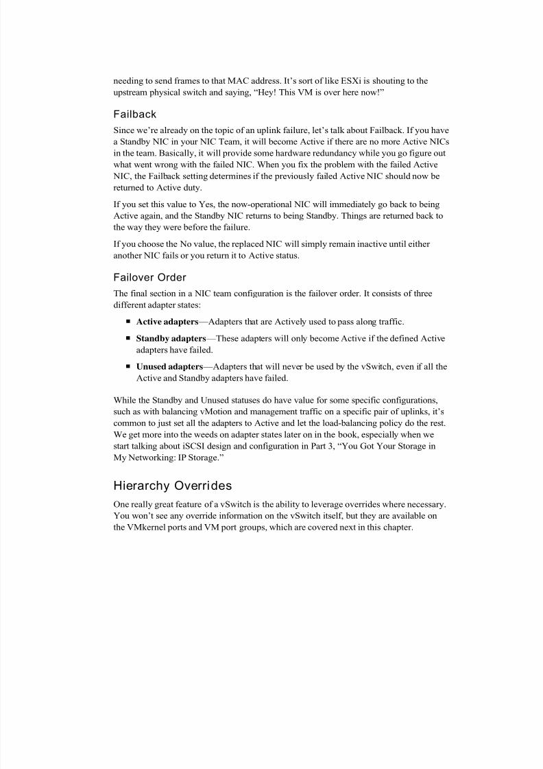
Failover Order
The final section in a NIC team configuration is the failover order. It consists of three
different adapter states:
Active adapters —Adapters that are Actively used to pass along traffic.
Standby adapters —These adapters will only become Active if the defined Active
adapters have failed.
Unused adapters —Adapters that will never be used by the vSwitch, even if all the
Active and Standby adapters have failed.
While the Standby and Unused statuses do have value for some specific configurations,such as with balancing vMotion and management traffic on a specific pair of uplinks, it’s
common to just set all the adapters to Active and let the load-balancing policy do the rest.
We get more into the weeds on adapter states later on in the book, especially when we
start talking about iSCSI design and configuration in Part 3, “You Got Your Storage in
My Networking: IP Storage.”
Hierarchy Overrides
One really great feature of a vSwitch is the ability to leverage overrides where necessary.
You won’t see any override information on the vSwitch itself, but they are available on
the VMkernel ports and VM port groups, which are covered next in this chapter.
7/23/2019 NetworkingforAdmins Wahl Ch8pdf
http://slidepdf.com/reader/full/networkingforadmins-wahl-ch8pdf 21/26
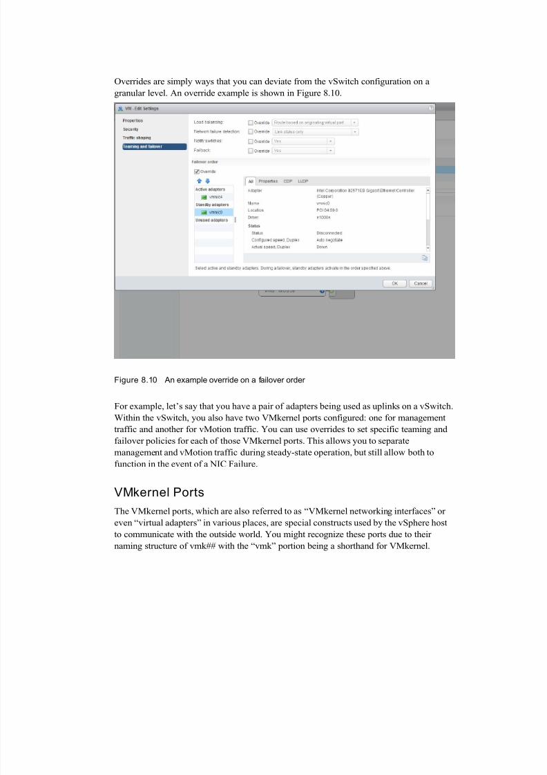
Overrides are simply ways that you can deviate from the vSwitch configuration on a
granular level. An override example is shown in Figure 8.10.
Figure 8.10 An example override on a failover order
For example, let’s say that you have a pair of adapters being used as uplinks on a vSwitch.Within the vSwitch, you also have two VMkernel ports configured: one for management
traffic and another for vMotion traffic. You can use overrides to set specific teaming and
failover policies for each of those VMkernel ports. This allows you to separate
management and vMotion traffic during steady-state operation, but still allow both to
function in the event of a NIC Failure.
VMkernel Ports
The VMkernel ports, which are also referred to as “VMkernel networking interfaces” or
even “virtual adapters” in various places, are special constructs used by the vSphere host
to communicate with the outside world. You might recognize these ports due to their
naming structure of vmk## with the “vmk” portion being a shorthand for VMkernel.
7/23/2019 NetworkingforAdmins Wahl Ch8pdf
http://slidepdf.com/reader/full/networkingforadmins-wahl-ch8pdf 22/26
The goal of a VMkernel port is to provide some sort of Layer 2 or Layer 3 services to the
vSphere host. Although a VM can talk to a VMkernel port, they do not consume them
directly.
Port Properties and Services
VMkernel ports have important jobs to do and are vital for making sure that the vSphere
host can be useful to the VMs. In fact, every VMkernel port can provide any combination
of the following six services:
vMotion traffic
Fault tolerance (FT) logging
Management traffic
vSphere replication traffic
iSCSI traffic
NFS traffic
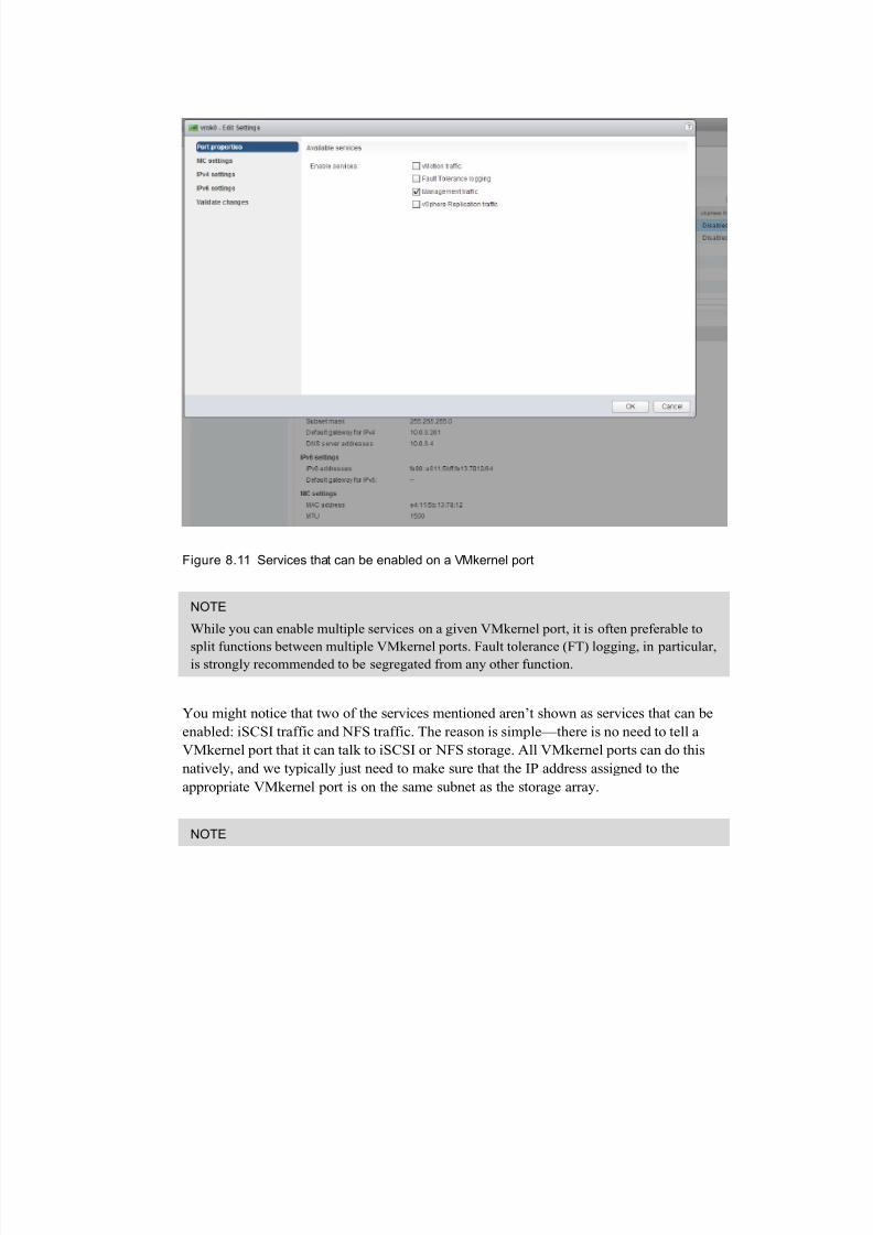
Figure 8.11 shows the administratively-selectable services that can be enabled on a
VMkernel port.
7/23/2019 NetworkingforAdmins Wahl Ch8pdf
http://slidepdf.com/reader/full/networkingforadmins-wahl-ch8pdf 23/26
Figure 8.11 Services that can be enabled on a VMkernel port
NOTE
While you can enable multiple services on a given VMkernel port, it is often preferable to
split functions between multiple VMkernel ports. Fault tolerance (FT) logging, in particular,is strongly recommended to be segregated from any other function.
You might notice that two of the services mentioned aren’t shown as services that can be
enabled: iSCSI traffic and NFS traffic. The reason is simple—there is no need to tell a
VMkernel port that it can talk to iSCSI or NFS storage. All VMkernel ports can do this
natively, and we typically just need to make sure that the IP address assigned to the
appropriate VMkernel port is on the same subnet as the storage array.
NOTE
7/23/2019 NetworkingforAdmins Wahl Ch8pdf
http://slidepdf.com/reader/full/networkingforadmins-wahl-ch8pdf 24/26
There are a lot of interesting design concepts around the use of VMkernel ports for iSCSI
and NFS storage—feel free to skip ahead to Part 3 of this book if you want to learn more.
For now, we’ll just accept the fact that a VMkernel port doesn’t need a service enabled to
be useful for IP storage traffic.
IP Addresses
Every VMkernel port will have either an IPv4 or IPv6 address assigned, along with an
MTU value. You have the choice of using a DHCP server for your IP address—which is
not recommended for any serious production deployment —or assigning a static IP
address.
Note that the default gateway and DNS server addresses are not definable by a VMkernel
port. These values are input into the vSphere host directly. If the subnet you use for the
VMkernel port’s IP address does not match the subnet of the destination IP address, the
traffic will be routed over the VMkernel port that can reach the default gateway. Often,
but not always, this is vmk0 (the default first VMkernel port created when you install
ESXi).
TIP
Look carefully at the MAC address assigned to the vmk0 VMkernel port. Notice anything
different about it when compared to other VMkernel ports? You should notice that vmk0
uses the real, burned-in address of the physical NIC instead of a randomly generated
VMware MAC address. This MAC address is “seeded” at the time of the ESXi installation.
VM Port Groups
The final topic to touch on is VM port groups, which can be a bit of a struggle to
understand at first. Let’s imagine that you have a huge, unconfigured virtual switch with
hundreds of ports on it. Chances are, you don’t want all of the ports to be configured the
same way—some of them will be used by your production VMs, others by your
developers’ VMs, and even more might be for the engineering VMs.
VM port groups are a way that we can create logical rules around the virtual ports that are
made available to VMs. It’s common to create a port group for each VLAN and network
subnet that you want to present to your VMs. VM port groups do not provide vSphere
services or require IP addresses—they are just ways to configure policy for a group of
virtual ports on your vSwitch.
Figure 8.12 shows an example from our lab showing a vSwitch with a VM port group
named “VM” —not very creative, sure, but it gets the point across. This is where we place

7/23/2019 NetworkingforAdmins Wahl Ch8pdf
http://slidepdf.com/reader/full/networkingforadmins-wahl-ch8pdf 25/26
our VMs, which are SQL, vCenter, and DC in this example. We’ve also disconnected one
of the network adapters to show what that looks like.
Figure 8.12 An example vSwitch with a VM port group named “VM”
You can also see our VMkernel port named “Management” just below the VM portgroup. It looks a lot like a VM port group, and that might be confusing at first. Don’t
worry, though—vCenter won’t let you put a VM onto the “Management” VMkernel port.
Summary
We covered a lot of ground here, digging into every nook and cranny of the vSphere
Standard Switch. You should now feel more knowledgeable about virtual switch
configuration options, security settings, discovery settings, traffic-shaping policies, load-
balancing methods, VMkernel ports, and port group configuration. In the next chapter, we
take a close look at the options available with the vSphere Distributed Switch,

7/23/2019 NetworkingforAdmins Wahl Ch8pdf
http://slidepdf.com/reader/full/networkingforadmins-wahl-ch8pdf 26/26
highlighting the features that go above and beyond what is available with the Standard
Switch.