neuburg siliceous earth for epoxy pipeline powder coatings for... · page 2 1 introduction...
TRANSCRIPT

Neuburg Siliceous Earth
for Epoxy Pipeline Powder Coatings
Authorship: Susanne Reiter
Hubert Oggermüller
VM / Dr. Alexander Risch
HOFFMANN MINERAL GmbH · Postfach 14 60 · D-86619 Neuburg (Donau) · Telefon (0 84 31) 53-0 · Telefax (0 84 31) 53-3 30
Internet: www.hoffmann-mineral.com · eMail: [email protected]
VM
-2/0
4.2
00
9/0
61
429
80
VM
-2/0
50
8/0
4.2
00
9
HOFFMANN MINERAL GmbH • P.O. Box 14 60 • D-86633 Neuburg (Donau) • Phone (+49-84 31) 53-0 • Fax (+49-84 31) 53-3 30 Internet: www.hoffmann-mineral.com • e-mail: [email protected]

page 1
Index
1. Introduction
2. Experimental
2.1. Base formulation and variations
2.2. Fillers used and their characteristics
2.3. Preparation and application of the coatings
3. Results
3.1. Tests without significant filler effects
3.2. Fluidizability
3.3. Deposition efficiency
3.4. Flow tendency (run-off)
3.5. Gloss at 60°
3.6. Visual assessment of surface appearance
3.7. Impact / reverse impact resistance
3.8. Cupping test
3.9. Mandrel bending test
3.10. Abrasion resistance (Taber) with CS 17 abrader wheels
and S 42 emery paper tapes
3.11. Salt spray test
3.12. Humidity test
3.13. Chemical resistance in hot water at 90°C
4. Summary and outlook

page 2
1 Introduction
The following study will compare Neuburg Siliceous Earth (Neuburger Kieselerde) with various other fillers in a pipeline powder coating based on epoxy resin. The objective of the work was to obtain an improvement of the property profile of the coatings by changing the nature of the filler.
The project was carried out at the iLF Institute in Magdeburg, Germany, under the supervision of Dipl. Ing. Markus Witter between November 2005 and May 2006. Corrosion and chemical resistance tests (except cathodic disbondment) were run at the Coatings Laboratory of Hoffmann Mineral.
2 Experimental
2.1 Base formulation and variations
The guide formulation in Fig.1 from the Hexion Company (ex Resolution) served as the starting point of the study. Epikote 1055 is a solid epoxy resin based on Bisphenol A / epichlorohydrine with an epoxide equivalent mass of about 850; Epi-Cure 104, an accelerated dicyanamide, was used as hardener.
Fig. 1
VM-01/1207/06.2008
Formulation
Base formulation (from Hexion)
Parts per
weight
Epikote 1055 Solid epoxy resin 827
Epi-cure Curing Agent P-104 Hardener 33
BYK 368-P Levelling agent 10
Iron oxide red 3296 Color pigment 15
Barite Filler 120
Total 1005
Density 1.32
PVC (%) 4.2
EXPERIMENTAL
RESULTS
• Application
Properties
• Optical
Properties
• Mechanical
Properties
• Resistance
Properties
SUMMARY

page 3
The fillers were varied as follows. Starting with 120 parts by weight (pbw) of barite, corresponding to PVC of 4.2 %, a formulation was included entirely without filler as a zero control. Sillitin Z 86 was incorporated, maintaining the same PVC as with the barite. In view of existing industrial formulations, the PVC was then increased to 7.6 % with the fillers listed in Fig. 2.
Fig. 2
2.2 Fillers used and their characteristics
Neuburg Siliceous Earth, extracted in the surrounding of Neuburg (Danube), is a natural combination of corpuscular Neuburg Silica and lamellar kaolinite: a loose mixture impossible to separate by physical methods. As a result of natural formation, the silica portion exhibits a round grain shape and consists of aggregated, cryptocrystalline primary particles of about 200 nm diameter. This structure explains the relatively high surface area and oil number, aside from the rheological activity the reasons for good mechanical properties.
For the Neuburg Siliceous Earth, as base materials were selected Sillitin Z 86 as well as the surface modified grades Aktisil AM (an activated Sillitin Z 86 whose surface was treated with an aminosilane) and an analogous grade Aktisil MM (surface treated with a mercaptosilane). The reference fillers included barite, calcium carbonate, wollastonite, clay, mica and talc. Fig. 3 lists the medium and higher particle sizes, oil numbers and specific surface areas of the fillers used. Apart from the somewhat coarser wollastonite and mica, the fillers are largely comparable with respect to their particle size. Barite and calcium carbonate are characterized by a very low oil number, all the others range between 47 and 66 g of oil per 100 g of filler. Barite has the smallest surface area with 0.7 m²/g, followed by wollastonite (1.1 m²/g) and calcium carbonate (3.4 m²/g). Mica and talc are located at the same level of about 5 m²/g. Aktisil MM, AM and Sillitin Z 86 exhibit higher BET surface areas between 7.4 and 11.1 m²/g, and clay takes the top with 17.8 m²/g.
VM-01/1207/06.2008
Formulation
Filler variations
Without filler
Barite 120
Sillitin Z 86 74
Barite 240
Sillitin Z 86 149
Aktisil AM 149
Aktisil MM 149
(NCC) Natural
Calcium Carbonat
154
Wollastonite 163
Clay (Kaolin) 149
Mica 162
Talc 159
PVC (%) 0.4 4.2 4.2 7.6 7.6 7.6 7.6 7.6 7.6 7.6
EXPERIMENTAL
RESULTS
• Application
Properties
• Optical
Properties
• Mechanical
Properties
• Resistance
Properties
SUMMARY

page 4
Fig. 3
2.3 Preparation of the coatings and application
The individual components of the powder coating formulations were weighed out and mixed for 10 min at 500 min-1 in an ‘Universalmischer’ from MIT Mischtechnik GmbH. This premix was then extruded in a twin-screw extruder MP 19 (from APV Baker; D = 19 mm, L = 25 D). In the entry zone, the temperature was controlled at 100 °C, in the process zone at 120 °C. Extrusion was done at 300 rpm with a load of 55 to 65 %. The extrudates were coarsely broken up and ground in an ultracentrifuge mill (Pulverisette 14 from Fritsch) at 16.000 min-1 and finally sieved through a mesh of 100 µm size. According to the formulations, application followed two routes: - with a Corona powder gun (70 kV) onto Q-Panel R 36 steel sheets for the optical
and Martens hardness tests, film thickness 100 - 150 µm - via tribodeposition on sandblasted steel sheets (surface roughness 50 - 70 µm)
pre-heated to 200 °C in order to ensure the high film thicknesses of 300 - 500 µm, for the mechanical tests except Martens hardness
Hardening was carried out at an object temperature of 200 °C for 10 min.
VM-01/1207/06.2008
Filler characteristics
Particle Size
d50 / d97
[µm]
Oil
Absorption
[g/100 g]
Surface
Area - BET
[m2/g]
Surface
Tratement
Barite 4.3 17 12 0.7 none
Sillitin Z 86 1.9 8 47 11.1 none
Aktisil AM 2.2 10 53 9.0 Aminosilane
Aktisil MM 2.3 10 48 7.4 Mercaptosilane
NCC 1.9 7 27 3.4 none
Wollastonite 12.3 77 55 1.1 none
Clay 2.0 11 65 17.8 none
Mica 14.5 53 66 5.7 none
Talc 7.1 20 55 4.5 none
EXPERIMENTAL
RESULTS
• Application
Properties
• Optical
Properties
• Mechanical
Properties
• Resistance
Properties
SUMMARY

page 5
3 Results
3.1 Tests without significant filler effects
The tests listed in Fig. 4 were carried out, but they will not be discussed here in detail, as no significant effects of the individual fillers could be observed. The cathodic disbondment was tested in 3 % NaCl (potential: -1050 mV) for 38 days at 23 °C, but no delamination was seen. The test severity was then increased to a higher temperature, and after 38 days at 60 °C all fillers showed a delamination of 0 - 1 mm, only the control without filler was higher at about 10 mm.
Fig. 4
VM-01/1207/06.2008
Results
The following tests did not effect any significant filler effects:
• Gel time (ISO 8130-6) results between 40 and 48 s
• Melt viscosity (EN ISO 3219)
• Martens hardness (EN ISO 14577) on Q-Panel R 36 sheets; film
thickness 100-150 µm; results between 140 - 160 N/mm²
• Cross cut test (DIN EN ISO 2409): Gt 0 on blastet metal sheets (film
thickness 300-600 µm) also after humidity test and water immersion at
90° C
• Cathodic disbondment (DIN EN ISO 15711); 0-1 mm, poorer results
were only obtained with the filler-free formulation (about 10 mm)
• Chemical resistance:
• 1000 h H2SO4 (10 %) at 23 °C (DIN EN ISO 2812-1)
• 1500 h NaOH (10 %) at 23 °C (DIN EN ISO 2812-1)
EXPERIMENTAL
RESULTS
• Application
Properties
• Optical
Properties
• Mechanical
Properties
• Resistance
Properties
SUMMARY

page 6
3.2 Fluidizability
Fluidizability was tested according to DIN ISO 8130-8 in a Fluidimeter AS 100 (from Sames). The Fluidimeter is filled with 250 g of the coating powder, and clean dry air is introduced through the porous bottom with a throughput sufficient for optimum fluidizing of the sample. The sample will be stirred by hand with a spatula for such a time until the height of the fluid bed remains constant. The height of the fluidized coating powder is measured and noted as “h1“. After stopping the air supply and settling of the powder, the height of the settled powder is measured as „h0“. Again, the powder is fluidized with the same air throughput as before. After obtaining a constant height of the fluid bed, the amount „m“ of coating powder is determined which discharges through an opening in the container. The flow rate „R“ is calculated as m x (h1/h0). Of course, the tests were carried out without the addition of free-flow agents. Good fluidizability was found for the control without filler, with Sillitin Z 86, Aktisil AM, Aktisil MM and the clay. By contrast, the powders with calcium carbonate and talc are very difficult to fluidize (Fig. 5).
Fig. 5
VM-01/1207/06.2008
Fluidizability ISO 8130-8
Assessment of
Fluidizability
PVK 0.4 Without filler +
PVK 4.2Barite 0
Sillitin Z 86 +
PVK 7.6
Barite 0
Sillitin Z 86 +
Aktisil AM +
Aktisil MM +
NCC -
Wollastonite 0
Clay +
Mica 0
Talc -
0 moderate (80 – 120)
poor (< 80)
+ good (120 – 140)
EXPERIMENTAL
RESULTS
• Application
Properties
• Optical
Properties
• Mechanical
Properties
• Resistance
Properties
SUMMARY

page 7
3.3 Deposition efficiency
The deposition efficiency characterizes the mass amount of sprayed powder coating that is deposited on a standard object. In this case, the standard object was built up from five steel tubes wrapped in aluminium foil (outer diameter 25 mm, length 500 mm). The foil used for the central tube will be weighed before the test. The powder coating is sprayed onto the objects from a constant distance for 60 seconds. The tubes are placed into the furnace, and after melting the residual (cooled-down) amount of coating is weighed out. The deposition efficiency «E» (as a mass percentage) is calculated as E = (m x 60 x 100) / (Pf x t), with m = the mass of powder coating deposited onto the foil in grams, t = spray time in seconds, and Pf = the throughput rate of the powder in grams per minute. The results given in Fig. 6 do not represent absolute figures, but are differentiated according to the application profile. All the same, the fillers can be characterized as follows: a good deposition efficiency is offered by talc. The filler-free control, Sillitin Z 86 (at lower PVC), calcium carbonate, wollastonite and mica do not quite reach the same optimum level. Barite, clay and the Neuburg Siliceous Earth grades at higher PVC do not influence the deposition efficiency compared to the control with barite.
Fig. 6
VM-01/1207/06.2008
Deposition efficiency
ISO 8130-10
Assessment of
Deposition Efficiency
Results
in %
PVK 0.4 Without filler 0- 7.5
PVK 4.2Barite 0 9.3
Sillitin Z 86 - 5.6
PVK 7.6
Barite 0 9.0
Sillitin Z 86 0 8.9
Aktisil AM 0 8.8
Aktisil MM 0 9.7
NCC - 6.9
Wollastonite 0- 7.8
Clay 0 8.3
Mica 0- 7.3
Talc + 13.6
EXPERIMENTAL
RESULTS
• Application
Properties
• Optical
Properties
• Mechanical
Properties
• Resistance
Properties
SUMMARY

page 8
3.4 Flow tendency (run-off)
In order to obtain the high film thicknesses, the metal sheets were pre-heated. During the application, therefore, the powder coating started to melt. The assessment of the run-off tendency did show only minor differences between the fillers; the high run-off stability of the talc remains noteworthy, but also the wollastonite and the Neuburg Siliceous Earth grades came up with a reduced tendency to sag (Fig. 7).
Fig. 7
VM-01/1207/06.2008
Run-off
Run-off tendency
during Stoving
PVK 0.4 Without filler -
PVK 4.2Barite 0
Sillitin Z 86 -
PVK 7.6
Barite 0
Sillitin Z 86 +
Aktisil AM +
Aktisil MM +
NCC 0
Wollastonite +
Clay -
Mica 0
Talc ++
0 moderate
high
+ marginal
++ no
EXPERIMENTAL
RESULTS
• Application
Properties
• Optical
Properties
• Mechanical
Properties
• Resistance
Properties
SUMMARY
page 9
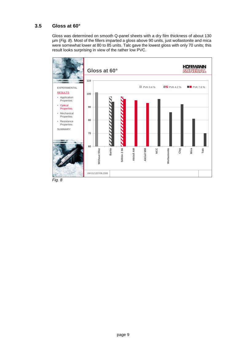
3.5 Gloss at 60°
Gloss was determined on smooth Q-panel sheets with a dry film thickness of about 130 µm (Fig. 8). Most of the fillers imparted a gloss above 90 units, just wollastonite and mica were somewhat lower at 80 to 85 units. Talc gave the lowest gloss with only 70 units; this result looks surprising in view of the rather low PVC.
Fig. 8
VM-01/1207/06.2008
Gloss at 60°
60
70
80
90
100
110
Wit
ho
ut
fill
er
Bari
te
Sil
liti
n Z
86
Akti
sil
AM
Akti
sil
MM
NC
C
Wo
llas
ton
ite
Cla
y
Mic
a
Talc
EXPERIMENTAL
RESULTS
• Application
Properties
• Optical
Properties
• Mechanical
Properties
• Resistance
Properties
SUMMARY
PVK 0.4 % PVK 4.2 % PVK 7.6 %

page 10
3.6 Visual assessment of surface appearance
The visual assessment took into account the waviness of the surface and the surface structure (precision of depicting the ceiling lamp in reflexion, following DOI = Distinctness of image), at a film thickness of about 450 µm. The control formulation without any filler came up with the best leveling, with the talc on the lower end (Fig. 9). All others can be rated as moderate.
Fig. 9
VM-01/1207/06.2008
Visual assessment of the surface
appearance
good moderate poor
PVC 0.4%:
Without filler
PVC 4.2%:
Barite and Sillitin Z 86
PVC 7.6%:
Barite, Sillitin Z 86,
Mica, NCC, Clay,
Wollastonite,
Aktisil AM and MM
PVC 7.6%:
Talc
EXPERIMENTAL
RESULTS
• Application
Properties
• Optical
Properties
• Mechanical
Properties
• Resistance
Properties
SUMMARY

page 11
3.7 Impact Test In order to test the response to rapid deformation by a falling weight, the Impact Test resp. the Reverse Impact Test was carried out according to DIN EN ISO 6272. The film thickness was between 300 and 500 µm on sandblasted steel sheets. In the Impact Test, a 2 kg weight is dropped onto the coated side, in the Reverse Impact Test onto the uncoated side. The hatched areas of the bars represent the range of measured data. On the coated side, the individual fillers showed no differentiation, because all results were higher than 200 kg x cm. When the test was run on the backside, the control formulation, Sillitin Z 86 at low PVC and Aktisil MM even in higher concentration gave rise to the best Reverse Impact results above 100 kg x cm. The fillers used at PVC 7.6 showed the following ranking: Aktisil AM (about 70 kg x cm) > Sillitin Z 86 (about 50 kg x cm) > barite and wollastonite (about 35 kg x cm), clay and mica (about 15 kg x cm) > talc (<10 kg x cm). Neuburg Siliceous Earth offers benefits because of its special structure, and the effects are further increased by the reactive surface treatment of the Aktisils. (Fig. 10)
Fig. 10
VM-01/1207/06.2008
0
10
20
30
40
50
60
70
80
90
100
Wit
ho
ut
fill
er
Bari
te
Sil
liti
n Z
86
Bari
te
Sil
liti
n Z
86
Akti
sil
AM
Akti
sil
MM
NC
C
Wo
llas
ton
ite
Cla
y
Mic
a
Talc
kg
x c
m
Reverse impact test
DIN EN ISO 6272
EXPERIMENTAL
RESULTS
• Application
Properties
• Optical
Properties
• Mechanical
Properties
• Resistance
Properties
SUMMARY
>100 >100 >100
<10
PVK 0.4 % PVK 4.2 % PVK 7.6 %
page 12
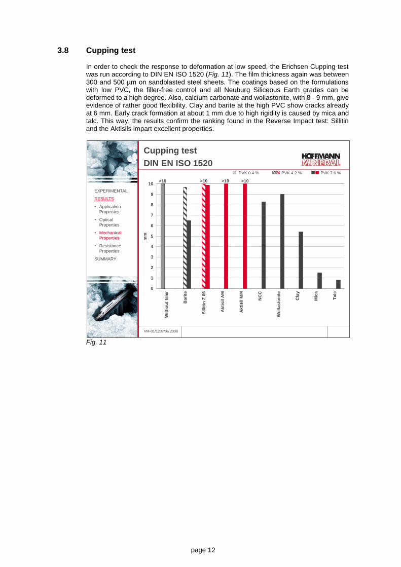
3.8 Cupping test
In order to check the response to deformation at low speed, the Erichsen Cupping test was run according to DIN EN ISO 1520 (Fig. 11). The film thickness again was between 300 and 500 µm on sandblasted steel sheets. The coatings based on the formulations with low PVC, the filler-free control and all Neuburg Siliceous Earth grades can be deformed to a high degree. Also, calcium carbonate and wollastonite, with 8 - 9 mm, give evidence of rather good flexibility. Clay and barite at the high PVC show cracks already at 6 mm. Early crack formation at about 1 mm due to high rigidity is caused by mica and talc. This way, the results confirm the ranking found in the Reverse Impact test: Sillitin and the Aktisils impart excellent properties.
Fig. 11
VM-01/1207/06.2008
0
1
2
3
4
5
6
7
8
9
10
Wit
ho
ut
fill
er
Bari
te
Sil
liti
n Z
86
Akti
sil
AM
Akti
sil
MM
NC
C
Wo
llas
ton
ite
Cla
y
Mic
a
Talc
mm
Cupping test
DIN EN ISO 1520
>10 >10 >10 >10
EXPERIMENTAL
RESULTS
• Application
Properties
• Optical
Properties
• Mechanical
Properties
• Resistance
Properties
SUMMARY
PVK 0.4 % PVK 4.2 % PVK 7.6 %

page 13
3.9 Mandrel bending test
A further mechanical test relative to deformation resistance was the Mandrel bending test according to DIN EN ISO 1519. A coated metal sheet with a dry film thickness of 300 to 500 µm is bent around a mandrel with a diameter of 32 mm. Mica and talc flaked off immediately. Barite at the high PVC and calcium carbonate showed medium to large cracks. All other formulations exhibited better flexibility, as only small cracks became visible (Fig. 12).
Fig. 12
Summing up the flexibility tests, mica and talc throughout show the least satisfactory results. The Neuburg Siliceous Earth formulations with Sillitin Z 86, Aktisil AM and Aktisil MM are distinguished by outstanding flexibility.
VM-01/1207/06.2008
Mandrel bending test
DIN EN ISO 1519
Mandrel Bending Test
[mandrel = 32 mm]
PVK 0.4 Without filler fine cracks
PVK 4.2Barite fine cracks
Sillitin Z 86 fine cracks
PVK 7.6
Barite large cracks
Sillitin Z 86 fine cracks
Aktisil AM fine cracks
Aktisil MM fine cracks
NCC moderate cracks
Wollastonite fine cracks
Clay fine cracks
Mica flake-off
Talc flake-off
EXPERIMENTAL
RESULTS
• Application
Properties
• Optical
Properties
• Mechanical
Properties
• Resistance
Properties
SUMMARY

page 14
3.10 Abrasion resistance (Taber) with abrader wheels CS 17 and S 42 abrasive paper strips
Abrasion tests were carried out following two different standards: ASTM D 4060: with abrader wheels CS 17 (moderately abrasive), load 1 kg. Fig. 13 shows the weight loss in milligrams after 1000 revolutions. DIN 53754: with S 42 abrasive paper strips (markedly more abrasive than CS 17), load 5.4 N. Fig.14 summarizes the average weight losses in milligrams after 100 revolutions.
Fig. 13
In the test with the slightly abrasive CS 17 abrader wheels, in particular Sillitin Z 86 at low PVC and Aktisil AM at high PVC stand out with a good abrasion resistance comparable to the control formulation without filler. All other products result in increased abrasion loss, above all the barite.
VM-01/1207/06.2008
Abrasion resistance
ASTM D 4060
20
30
40
50W
ith
ou
t fi
lle
r
Bari
te
Sil
liti
n Z
86
Akti
sil
AM
Akti
sil
MM
NC
C
Wo
llas
ton
ite
Cla
y
Mic
a
Talc
mg
CS 17 / 1000 g / 1000 rev
EXPERIMENTAL
RESULTS
• Application
Properties
• Optical
Properties
• Mechanical
Properties
• Resistance
Properties
SUMMARY
PVK 0.4 % PVK 4.2 % PVK 7.6 %

page 15
Fig. 14
When tested with the markedly more highly abrasive S 42 strips which do not only abrade the layers near the surface, Sillitin Z 86 at the same PVC gives rise to better results than barite or the other fillers. In particular, talc stands out with a very high abrasion loss which will be due to its low mineralogical hardness.
VM-01/1207/06.2008
Abrasion resistance
DIN 53754
S 42 / 5,4 N / 100 rev
20
30
40
50
60
70
80
90
Wit
ho
ut
fill
er
Bari
te
Sil
liti
n Z
86
Ak
tis
il A
M
Akti
sil
MM
NC
C
Wo
llas
ton
ite
Cla
y
Mic
a
Talc
mg
EXPERIMENTAL
RESULTS
• Application
Properties
• Optical
Properties
• Mechanical
Properties
• Resistance
Properties
SUMMARY
PVK 0.4 % PVK 4.2 % PVK 7.6 %
page 16
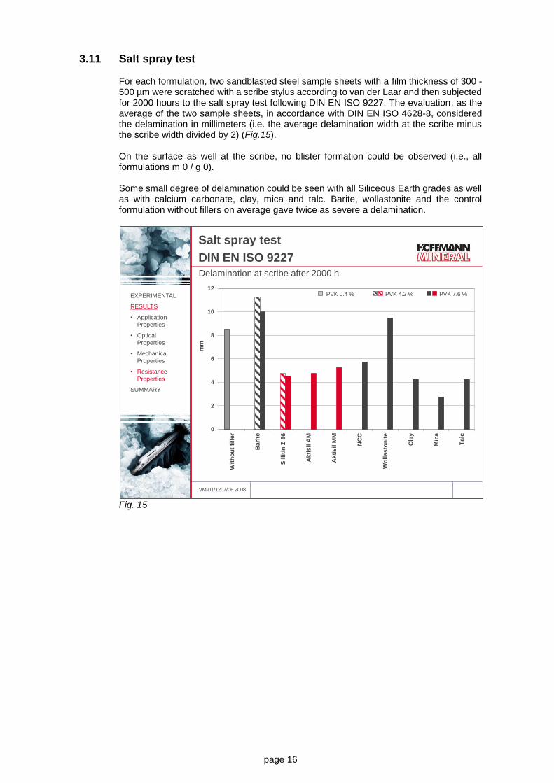
3.11 Salt spray test
For each formulation, two sandblasted steel sample sheets with a film thickness of 300 - 500 µm were scratched with a scribe stylus according to van der Laar and then subjected for 2000 hours to the salt spray test following DIN EN ISO 9227. The evaluation, as the average of the two sample sheets, in accordance with DIN EN ISO 4628-8, considered the delamination in millimeters (i.e. the average delamination width at the scribe minus the scribe width divided by 2) (Fig.15). On the surface as well at the scribe, no blister formation could be observed (i.e., all formulations m 0 / g 0). Some small degree of delamination could be seen with all Siliceous Earth grades as well as with calcium carbonate, clay, mica and talc. Barite, wollastonite and the control formulation without fillers on average gave twice as severe a delamination.
Fig. 15
VM-01/1207/06.2008
Salt spray test
DIN EN ISO 9227
Delamination at scribe after 2000 h
0
2
4
6
8
10
12
Wit
ho
ut
fill
er
Bari
te
Sil
liti
n Z
86
Akti
sil
AM
Ak
tis
il M
M
NC
C
Wo
llas
ton
ite
Cla
y
Mic
a
Talc
mm
EXPERIMENTAL
RESULTS
• Application
Properties
• Optical
Properties
• Mechanical
Properties
• Resistance
Properties
SUMMARY
PVK 0.4 % PVK 4.2 % PVK 7.6 %

page 17
Fig. 16 illustrates the evaluation as the average of the two sample sheets according to DIN EN ISO 4628-8 via the degree of corrosion (i.e. the average width of rusting at the scribe minus the scribe width divided by 2). A low degree of corrosion is obtained with the control formulation, barite, calcium carbonate, wollastonite and all Neuburg Siliceous Earth grades. Clay, mica and talc give rise to markedly more corrosion at the scribe.
Fig. 16
VM-01/1207/06.2008
Salt spray test
DIN EN ISO 9227
Corrosion at scribe after 2000 h
0,0
0,2
0,4
0,6
0,8
1,0
1,2
Wit
ho
ut
fill
er
Bari
te
Sil
liti
n Z
86
Akti
sil
AM
Akti
sil
MM
NC
C
Wo
llas
ton
ite
Cla
y
Mic
a
Talc
mm
EXPERIMENTAL
RESULTS
• Application
Properties
• Optical
Properties
• Mechanical
Properties
• Resistance
Properties
SUMMARY
PVK 0.4 % PVK 4.2 % PVK 7.6 %

page 18
3.12 Humidity test
Sandblasted metal sheets with a coating film thickness of 300 to 500 µm were scratched with a scribe stylus according to van der Laar, and exposed for 4000 hours to a constant condensation water environment CH (DIN EN ISO 6270-2: 40 °C and 100 % relative humidity). The evaluation again followed DIN EN ISO 4628-8 in defining the degree of delamination in millimeters (i.e., the average width of delamination at the scribe minus the scribe width divided by 2). On the coating surface, none of the formulations showed blisters. Fig. 17 visualizes the scribes and the delamination, Fig. 18 shows the corresponding average delamination in millimeters. Barite and talc give rise to very high, Sillitin Z 86, Aktisil AM, calcium carbonate and mica to very little delamination. The control formulation without filler, wollastonite, clay and Aktisil MM came off without any delamination.
Fig. 17
VM-01/1207/06.2008
Humidity test
DIN EN ISO 6270-2
Delamination at scribe after 4000 h
Wit
ho
ut
fille
r
Ba
rite
Silliti
n Z
86
Ba
rite
Silliti
n Z
86
Ak
tis
il A
M
Ak
tis
il M
M
NC
C
Wo
lla
sto
nit
e
Cla
y
Mic
a
Ta
lc
PVC
0.4%
PVC
4.2%
PVC
7.6%
EXPERIMENTAL
RESULTS
• Application
Properties
• Optical
Properties
• Mechanical
Properties
• Resistance
Properties
SUMMARY

page 19
Fig. 18 On unscratched metal sample sheets, after 4000 hours of exposure to the humidity test, the cupping test was run according to DIN EN ISO 1520. The results came out similar to the tests without exposure, apart from barite which turned out better, and wollastonite and clay which turned out poorer (Fig. 19).
Fig. 19
VM-01/1207/06.2008
Humidity test
DIN EN ISO 6270-2
Average Delamination [mm] at scribe after 4000 h
0
1
2
3
4
5
Wit
ho
ut
fill
er
Bari
te
Sil
liti
n Z
86
Akti
sil
AM
Akti
sil
MM
NC
C
Wo
llas
ton
ite
Cla
y
Mic
a
Talc
mm
EXPERIMENTAL
RESULTS
• Application
Properties
• Optical
Properties
• Mechanical
Properties
• Resistance
Properties
SUMMARY
PVK 0.4 % PVK 4.2 % PVK 7.6 %
VM-01/1207/06.2008
Humidity test
DIN EN ISO 6270-2
Cupping test [mm] after 4000 h
0
1
2
3
4
5
6
7
8
9
10
Wit
ho
ut
fill
er
Bari
te
Sil
liti
n Z
86
Ak
tis
il A
M
Akti
sil
MM
NC
C
Wo
llas
ton
ite
Cla
y
Mic
a
Talc
mm
>10 >10 >10 >10>10 >9.4 >9.5EXPERIMENTAL
RESULTS
• Application
Properties
• Optical
Properties
• Mechanical
Properties
• Resistance
Properties
SUMMARY
PVK 0.4 % PVK 4.2 % PVK 7.6 %

page 20
3.13 Chemical resistance in hot water at 90 °C
Sandblasted steel sample sheets after coating with a film thickness of 300 to 500 µm were immerged for 1700 hours in distilled water at 90 °C. Fig. 20 shows the degree of fading for the individual formulations, Fig. 21 illustrates the corresponding color change in ΔE. The strongest fading is caused by calcium carbonate and wollastonite. Hardly a change is seen with Sillitin Z 86 and Aktisil AM, which consequently offer the best hot water resistance.
Fig. 20
Fig. 21
VM-01/1207/06.2008
Chemical resistance
DIN EN ISO 2812-2
Immersion in distilled water at 90 °C 1700 hW
ith
ou
t
fille
r
Ba
rite
Silliti
n Z
86
Ba
rite
Silliti
n Z
86
Ak
tis
il A
M
Ak
tis
il M
M
NC
C
Wo
lla
sto
nit
e
Cla
y
Mic
a
Ta
lc
PVC
0.4%
PVC
4.2%
PVC
7.6%
EXPERIMENTAL
RESULTS
• Application
Properties
• Optical
Properties
• Mechanical
Properties
• Resistance
Properties
SUMMARY
VM-01/1207/06.2008
Chemical resistance
DIN EN ISO 2812-2
Color change delta E after 1700 h immersion in water at 90 °C
0
2
4
6
8
10
12
Wit
ho
ut
fille
r
Ba
rite
Silliti
n Z
86
Ak
tis
il A
M
Ak
tis
il M
M
NC
C
Wo
lla
sto
nit
e
Cla
y
Mic
a
Ta
lc
EXPERIMENTAL
RESULTS
• Application
Properties
• Optical
Properties
• Mechanical
Properties
• Resistance
Properties
SUMMARY
PVK 0.4 % PVK 4.2 % PVK 7.6 %

page 21
The remaining relative pendulum hardness after the hot water immersion is summarized in Fig. 22. Here again, calcium carbonate and wollastonite show the poorest results, which means that these formulations have undergone the strongest softening during the exposure.
Fig. 22
VM-01/1207/06.2008
Chemical resistance
DIN EN ISO 2812-2
Remaining pendulum hardness (%) after 1700 h immersion in
water at 90 °C
0
20
40
60
80
100
Wit
ho
ut
fille
r
Ba
rite
Silliti
n Z
86
Ak
tis
il A
M
Ak
tis
il M
M
NC
C
Wo
lla
sto
nit
e
Cla
y
Mic
a
Ta
lc
EXPERIMENTAL
RESULTS
• Application
Properties
• Optical
Properties
• Mechanical
Properties
• Resistance
Properties
SUMMARY
PVK 0.4 % PVK 4.2 % PVK 7.6 %
page 22
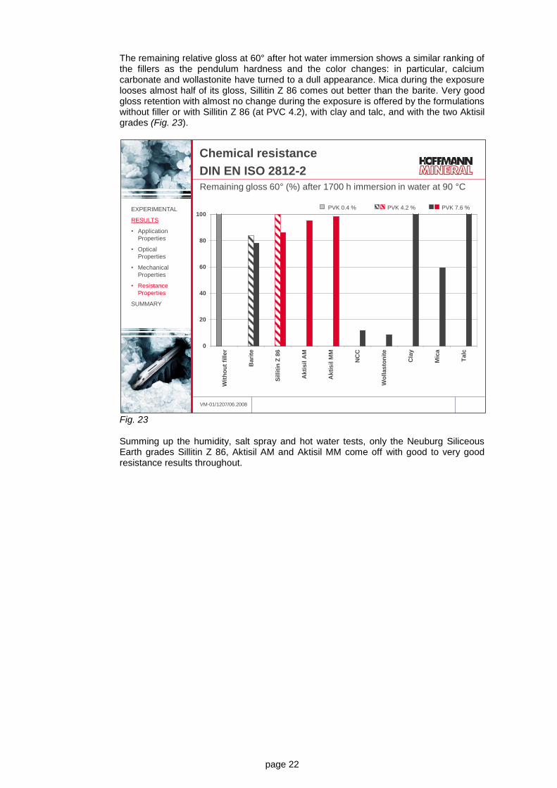
The remaining relative gloss at 60° after hot water immersion shows a similar ranking of the fillers as the pendulum hardness and the color changes: in particular, calcium carbonate and wollastonite have turned to a dull appearance. Mica during the exposure looses almost half of its gloss, Sillitin Z 86 comes out better than the barite. Very good gloss retention with almost no change during the exposure is offered by the formulations without filler or with Sillitin Z 86 (at PVC 4.2), with clay and talc, and with the two Aktisil grades (Fig. 23).
Fig. 23 Summing up the humidity, salt spray and hot water tests, only the Neuburg Siliceous Earth grades Sillitin Z 86, Aktisil AM and Aktisil MM come off with good to very good resistance results throughout.
VM-01/1207/06.2008
Chemical resistance
DIN EN ISO 2812-2
Remaining gloss 60° (%) after 1700 h immersion in water at 90 °C
0
20
40
60
80
100
Wit
ho
ut
fill
er
Bari
te
Sil
liti
n Z
86
Akti
sil
AM
Akti
sil
MM
NC
C
Wo
llas
ton
ite
Cla
y
Mic
a
Talc
EXPERIMENTAL
RESULTS
• Application
Properties
• Optical
Properties
• Mechanical
Properties
• Resistance
Properties
SUMMARY
PVK 0.4 % PVK 4.2 % PVK 7.6 %

page 23
4. Summary and outlook
Fig. 24 gives a summary of the fillers tested and their advantages and disadvantages in the tests as discussed, reported versus the barite formulation at 4.2 % PVC as reference.
Fig. 24
The use of Neuburg Siliceous Earth offers the following benefits: - improved fluidizability
- optical properties maintained at high level
- mechanical properties (flexibility, impact resistance) markedly improved
- improved abrasion resistance
- delamination markedly improved, low corrosion at scribe
- hot water resistance increased
These positive effects are also evident with the high PVC formulations. Sillitin Z 86 recommends itself because of a favorable price/performance ratio. Aktisil AM gives the best results in the resistance tests. Aktisil MM imparts low delamination and better mechanical properties.
VM-01/1207/06.2008
Summary
Without filler (PVC 0.4) + 0- - 0 + 0 + + 0 + + + 0 ++ 0 0 + +
Sillitin Z 86 (PVC 4.2) + - - 0 0 0 + + 0 + 0 ++ 0 + 0 0 + 0
Barite (PVC 7.6) 0 0 0 0 0 0 - - - -- - 0 0 0 0 0 0 0
Sillitin Z 86 (PVC 7.6) + 0 + 0 0 0 0- 0 0 0 0+ ++ 0 + 0 + 0 0
Aktisil AM (PVC 7.6) + 0 + 0 0 0 0 + 0 + 0 ++ 0 + 0 + + 0
Aktisil MM (PVC 7.6) + 0 + 0 0 0 + + 0 0 0 ++ 0 ++ 0 0 + 0
NCC (PVC 7.6) - - 0 0 0 0 - 0 0- 0 0 ++ 0 + 0 -- -- -Wollastonite (PVC 7.6) 0 0- + - 0 0 - 0 0 0 - 0 0 ++ - -- -- -Clay (PVC 7.6) + 0 - 0 0 0 -- 0- 0 0 0 ++ - ++ -- 0 + 0
Mica (PVC 7.6) 0 0- 0 - 0 0 -- -- -- 0 0 ++ - + -- -- - 0-
Talc (PVC 7.6) - + ++ -- - 0 -- -- -- 0 -- ++ - 0 -- 0 + 0
Ma
nd
rel b
en
din
g t
es
t
Glo
ss
at
60
°
Vis
ua
l as
se
ss
me
nt
of
su
rfa
ce
ap
pe
ara
nc
e
Ab
ras
ion
los
s (
CS
17
)
Ab
ras
ion
los
s (
S 4
2)
Sa
lt s
pra
y t
es
t (d
ela
min
ati
on
)
Cu
pp
ing
te
st
Reference:
standard
(with barite
PVC 4.2)F
luid
iza
bili
ty
De
po
sit
ion
eff
icie
nc
y
Ru
n-o
ff d
uri
ng
ap
plic
ati
on
(fl
ow
te
nd
en
cy
)
Imp
ac
t te
st
Re
ve
rse
imp
ac
t te
st
Sa
lt s
pra
y t
es
t (c
orr
os
ion
)
Wa
ter
imm
ers
ion
at
90
°C
(re
ma
inin
g p
en
du
lum
ha
rdn
es
s)
Hu
mid
ity
te
st
(de
lam
ina
tio
n)
Hu
mid
ity
te
st
(cu
pp
ing
te
st
aft
er
imm
ers
ion
)
Wa
ter
imm
ers
ion
at
90
°C
(c
olo
r c
ha
ng
e)
Wa
ter
imm
ers
ion
at
90
°C
(re
ma
inin
g g
los
s a
t 6
0°)
EXPERIMENTAL
RESULTS
• Application
Properties
• Optical
Properties
• Mechanical
Properties
• Resistance
Properties
SUMMARY
Compared to the
standard barite
PVC 4.2:
+ Advantage
++ Significant
advantage
- Disadvantage
-- Significant
disadvantage
0 No significant
effect
Our technical service suggestions and the information contained in this report are based on experience and are made to the best of our knowledge and belief, but must nevertheless be regarded as non-binding advice subject to no guarantee. Working and employment conditions over which we have no control exclude any damage claims arising from the use of our data and recommendations. Furthermore, we cannot assume any responsibility for any patent infringements which might result from the use of our information.