neural networks application for …nnw.cz/doi/2017/nnw.2017.27.013.pdf · neural networks...
TRANSCRIPT

NEURAL NETWORKS APPLICATION FORMECHANICAL PARAMETERS
IDENTIFICATION OF ASYNCHRONOUSMOTOR
D. Balara∗, J. Timko∗, J. Zilkova∗, M. Leso∗
Abstract: A method for identification of mechanical parameters of an asyn-chronous motor is presented in this paper. The identification method is based onthe use of our knowledge of the system. This paper clarifies the method by usingthe example identifying of mechanical parameters of the three-phase squirrel-cageasynchronous motor.A model of mechanical subsystem of the motor is presented aswell as results of simulation. The special neural network is used as an identificationmodel and its adaptation is based on the gradient descent method.The parametersof mechanical subsystem are derived from the values of synaptic weights of theneural identification model after its adaptation. Deviation of identified mechanicalparameters in the case of moment inertia was up to 0.03 % and in the case of loadtorque was 1.45 % of real values.
Key words: neural network, identification, electric drive
Received: June 14, 2016 DOI: 10.14311/NNW.2017.27.013Revised and accepted: June 11, 2017
1. Introduction
To ensure a high quality control of nonlinear dynamic systems, precise knowledge ofparameters is required. In the system identification many different approaches canbe used depending on the prior information available. The solution to the questionof identification of parameters of non-linear dynamic systems and of electrical drivesas well, the use of conventional identification methods necessitates complicated andtime consuming calculations and they can be expensive to perform special prepa-ration of the system for the measurement [12, 14]. What more, the conventionalmethods used for the identification of systems parameters are based on a number ofassumptions that are not valid under all operating conditions. In recent years, theresearch in the field of electrical drives is has been also focused on the application ofdifferent methods of artificial intelligence [1,3–7,13,15,17] as the theory of artificial
∗Dusan Balara; Jaroslav Timko; Jaroslava Zilkova; Martin Leso – Corresponding author;Technical University of Kosice, Department of Electrical Engineering and Mechatronics, Letna9, 042 00 Kosice, Slovak Republic, E-mail: [email protected], [email protected],[email protected], [email protected]
c©CTU FTS 2017 259

Neural Network World 3/2017, 259–270
neural networks (ANN) and the fuzzy sets theory or the genetic algorithms theory.The theory of fuzzy sets is most often used for systems control [4, 7, 15] and thegenetic algorithms are often used for optimization tasks [5,7] in the field of electricdrives. The artificial neural networks (ANNs) are most commonly used for solvingtasks as: approximation, association, classification, control or prediction. ANNscan work in parallel and thus shorter computation time can be achieved. Moreover,they can be used to identify and control the non-linear dynamic systems becausethey can approximate a wide range of nonlinear functions to any desired degree ofaccuracy [9,10]. In the field of electric drives ANNs can be used for electric drivescontrol [4, 7, 13, 15], estimation quantities of electric drives [4, 13, 15], especiallyangular speed, and also for identification of electric drives parameters [1, 13,17].
Used at designing the neural identification structure can be of two differingapproaches:
• When using neural network with a larger number of neurons approximatedis the estimated quantity or parameter, based on simply measurable systemquantities [13].
• The neural structure is determined by using the analogy of structure of aknown system mathematical model, and thus the neural network parametricstructure is created, while the network parameters containing information onthe system parameters are being looked for [1].
In this paper, a special neural network is presented as an identification modeland parameters of mechanical subsystem of a squirrel-cage asynchronous motorare identified by using the single neuron with adaptation rule based on gradientdescent algorithm widely used in neural networks training [2]. The proposed iden-tification model identifies the following parameters of mechanical subsystem of anasynchronous motor: moment of inertia J , constant passive load torque mL andsteepness of linear friction characteristic b. Magnetic fluxes [1] of the asynchronousmotor were supposed to be derived from an observer and stator voltages, statorcurrents and mechanical speed are supposed to be measured. The proposed iden-tification neural model was tested by simulation, including the identified motor.
2. Model of an asynchronous motor
We considered was a two-pole representation of a squirrel-cage asynchronous mo-tor model transformed into x, y reference frame rotating with synchronous speedgiven by Eqs. (1)–(9). The transformation of the three-phases stator voltages intostationary α, β reference frame (1) by [8] is shown in Fig. 1.
uα1 =1
3(2ua − ub − uc) and uβ1 =
1√3
(ub − uc) . (1)
Fig. 2 shows transformation of two-phases stator voltages stationary referenceframe α, β into x, y reference frame rotating with synchronous speed by Eq. (2) [8]:
ux1 = cosϑS · uα + sinϑS · uβ , (2)
260

Balara D. et al.: Neural networks application for mechanical. . .
2 1/3
1/u
u
ub
ua
uc3
Fig. 1 Transformation of phase voltages into α, β frame of reference.
sin cos S
uy1u
u ux1
S
Fig. 2 Transformation of stator voltages into x,y frame of reference.
uy1 = − sinϑS · uα + cosϑS · uβ anddϑSdt
= ωS .
The two phase electrical equations of a squirrel-cage asynchronous motor in α, βreference frame transformed into x, y reference frame rotating with synchronousspeed shown in Eqs. (3)–(9) are given by [13]:
ux1 = RSix1 +dψx1
dt− ωsψy1, (3)
uy1 = RSiy1 +dψy1
dt+ ωsψx1,
ux2 = RRix2 +dψx2
dt− (ωs − ωmech) · ψy2,
uy2 = RRiy2 +dψy2
dt+ (ωs − ωmech) · ψx2,
ix1 =1
Lsσ
(ψx1 −
1
νRψx2
), iy1 =
1
Lsσ
(ψy1 −
1
νRψy2
), (4)
ix2 =1
Lsσ
(ψx2 −
1
νSψx1
), iy2 =
1
Lsσ
(ψy2 −
1
νSψy1
),
dψx1dt
= ux1 −RSix1 + ωSψy1, (5)
261

Neural Network World 3/2017, 259–270
dψy1dt
= uy1 −RSiy1 − ωSψx1,
dψx2dt
= ux2 −RRix2 + (ωS − ωmech)ψy2,
dψy2dt
= uy2 −RRiy2 − (ωS − ωmech)ψx2,
where for a squirrel-cage asynchronous motor is ux2 = uy2 = 0 and
ωS =2πf
pp, σ = 1− Lh
2
LSLR, νS =
LSLh
, νR =LRLh
. (6)
i1, i2 stator and rotor currentsu1, u2 stator and rotor voltagesψ1, ψ2 stator and rotor magnetic fluxespp number of the pole pairsωs synchronous angular speedωmech mechanical angular speedm,mL,mf motor, load and friction torqueLS , LR, Lh leakage inductances of stator and rotor, mutual inductanceRS , RR stator and rotor resistanceJ moment of inertia
Tab. I Used symbols.
Discrete models of stator and rotor according to Eqs. (3)–(6) with use of rect-angular method of numerical integration are presented by models in Fig. 3 andFig. 4.
RS
RS
1/R
1/R
1/LS
1/LS
y1
x1
ix1
y2
x2pp.S
uy1
ux1
iy1
Fig. 3 Model of stator.
262
Balara D. et al.: Neural networks application for mechanical. . .
RR
RR
1/S
1/S
1/LR
1/LR
y2
x2
ix2
y1
x1
Siy2
mech
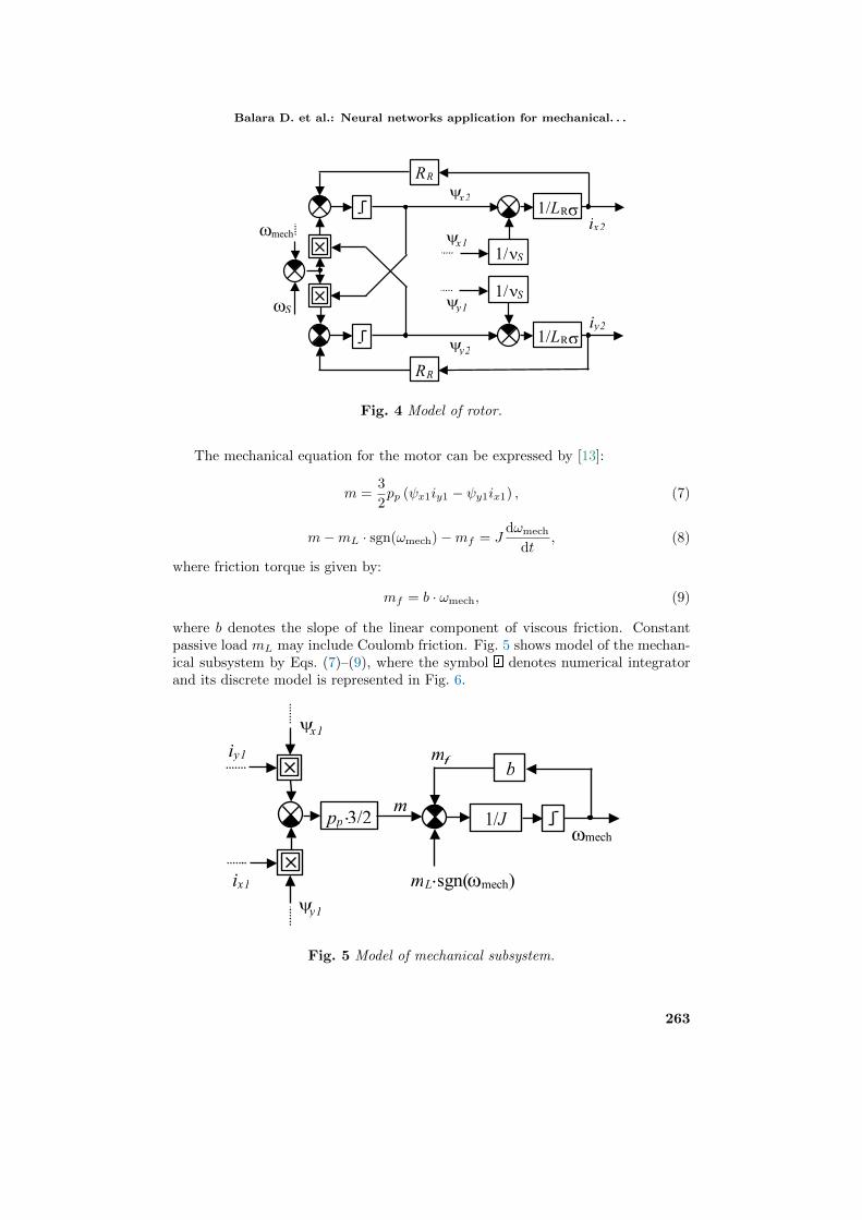
Fig. 4 Model of rotor.
The mechanical equation for the motor can be expressed by [13]:
m =3
2pp (ψx1iy1 − ψy1ix1) , (7)
m−mL · sgn(ωmech)−mf = Jdωmech
dt, (8)
where friction torque is given by:
mf = b · ωmech, (9)
where b denotes the slope of the linear component of viscous friction. Constantpassive load mL may include Coulomb friction. Fig. 5 shows model of the mechan-ical subsystem by Eqs. (7)–(9), where the symbol denotes numerical integratorand its discrete model is represented in Fig. 6.
1/ J
mLsgn(mech)
m
mech
pp3/2
y1
ix1
iy1
x1
m
bf
Fig. 5 Model of mechanical subsystem.
263
Neural Network World 3/2017, 259–270
p p/J ΔT z-1 p p/1
b
m(k)
ω(k)
ωmech(k)
mf(k)
mL sgn(ωmech(k))
ix1iy1
x1 y1
pp3/2
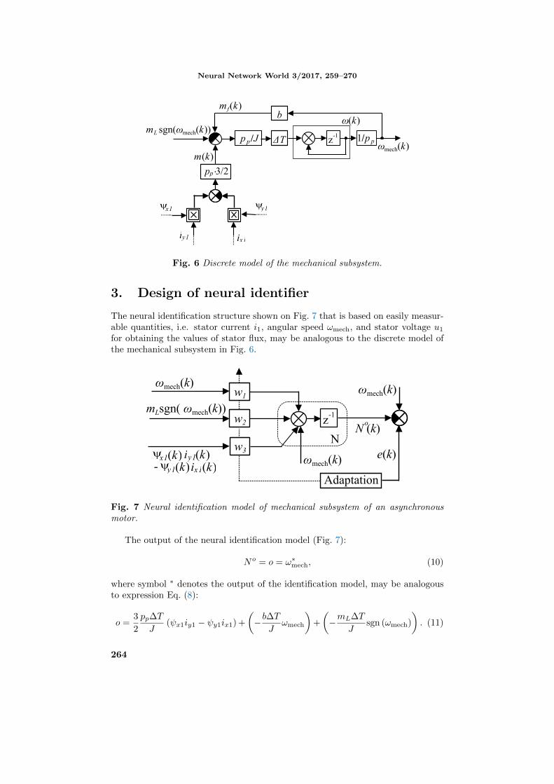
Fig. 6 Discrete model of the mechanical subsystem.
3. Design of neural identifier
The neural identification structure shown on Fig. 7 that is based on easily measur-able quantities, i.e. stator current i1, angular speed ωmech, and stator voltage u1for obtaining the values of stator flux, may be analogous to the discrete model ofthe mechanical subsystem in Fig. 6.
w1
w2
w3ωmech(k)
z-1
NN (k)o
Adaptation
ωmech(k)
e(k)
ωmech(k)
mLsgn( ωmech(k))
x1(k) i (k)y1y1(k)ix1(k)-
Fig. 7 Neural identification model of mechanical subsystem of an asynchronousmotor.
The output of the neural identification model (Fig. 7):
No = o = ω∗mech, (10)
where symbol ∗ denotes the output of the identification model, may be analogousto expression Eq. (8):
o =3
2
pp∆T
J(ψx1iy1 − ψy1ix1) +
(−b∆T
Jωmech
)+
(−mL∆T
Jsgn (ωmech)
). (11)
264
Balara D. et al.: Neural networks application for mechanical. . .
The network weights w1, w2 and w3 (Fig. 7) are elected so that they corre-sponded with the asynchronous motor mechanical parameters Eq. (11) as below:
w1 ≈32pp∆T
J,w2 ≈ −
b∆T
J,w3 ≈ −
mL∆T
J. (12)
In the case of ideal adaptation of identification model weights we find the valuesof mechanical parameters from Eq. (12).
4. Rules of adaption
When using stator currents and stator magnetic fluxes as inputs and mechanicalangular speed as a desired output, the identification model adapts its weights usingthe well known gradient descent method [2]. The identification model with struc-ture identical to mechanical subsystem is represented by linear neuron N on Fig. 7.The neural model output o = No is compared with the desired measured angularspeed value and deviation e serves for adaptation of the neuron weights so that theneural model output agreed with the measured value of angular speed.
Let E be the cost function:
E =1
2e2, (13)
where e is deviation between the desired and actual neuron output. According tothe gradient descent algorithm the change of every weight should be performed inthe direction opposite to the particular component of gradient of E:
∆wn = −ηcn∂E
∂wn,∂E
∂wn= −e · ∂o
∂wn,∂o
∂wn= in, (14)
where in is n-th input of the neuron and ηcn is learning rate. From Eq. (14) follows:
∆wn(k) = ηn · e(k) · in(k), (15)
where ηn = ηcn ·∆T. The adaptation rule must be modified to take into accountthe time delay member:
∆wn(k) = ηn · e(k) · in(k − 1). (16)
After the adaptation, when the behaviour of the model is almost identical to thebehaviour of the motor, the identified parameters can be derived from particularweights of neuron N with use of Eq. (11). We obtain parameter J from weight w1,b from w2 and mL from weight w3.
5. Identification of parameters
The parameters of a squirrel-cage asynchronous motor used in the simulation were:mL = 5 Nm, b = 0.01 Nms, U = 190 V, f = 50 Hz, RS = 0.181 Ω, RR = 0.161 Ω,J = 0.11 kgm2, pp = 2, LS = 0.06583 H, LR = 0.06583 H, Lh = 0.064 H.
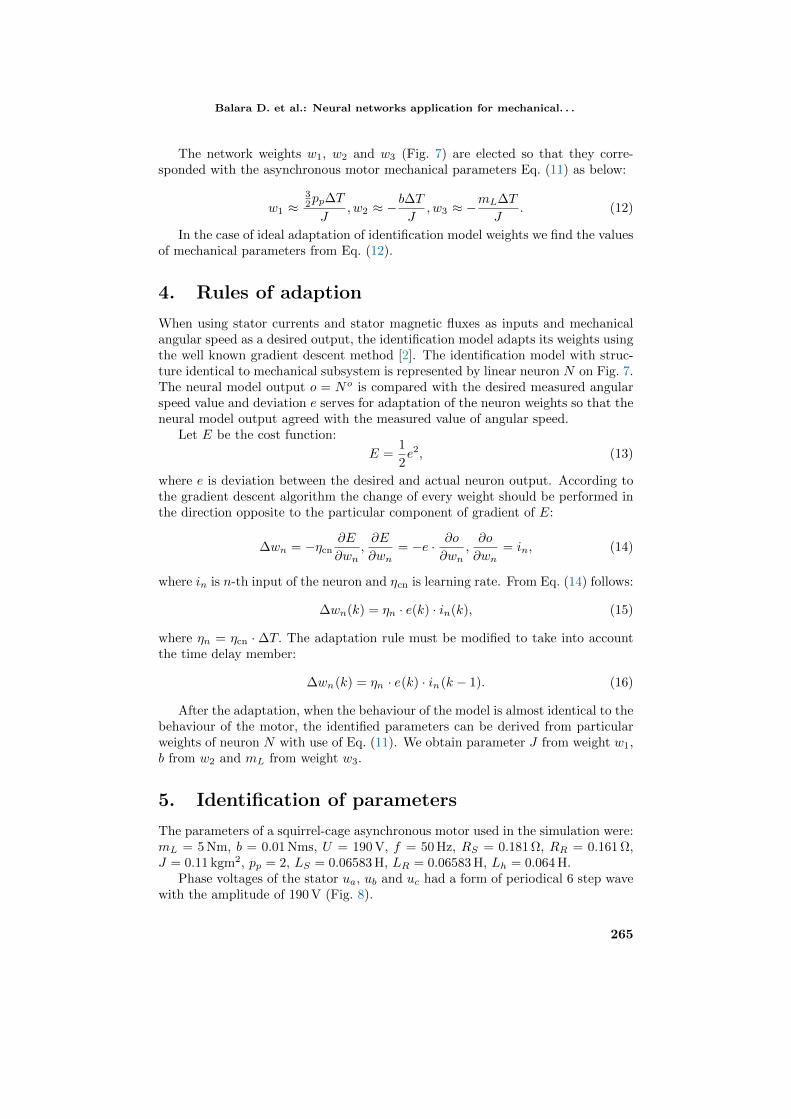
Phase voltages of the stator ua, ub and uc had a form of periodical 6 step wavewith the amplitude of 190 V (Fig. 8).
265
Neural Network World 3/2017, 259–270
Fig. 8 Phase voltage ua and two-pole representation voltages transformed into xyframe.
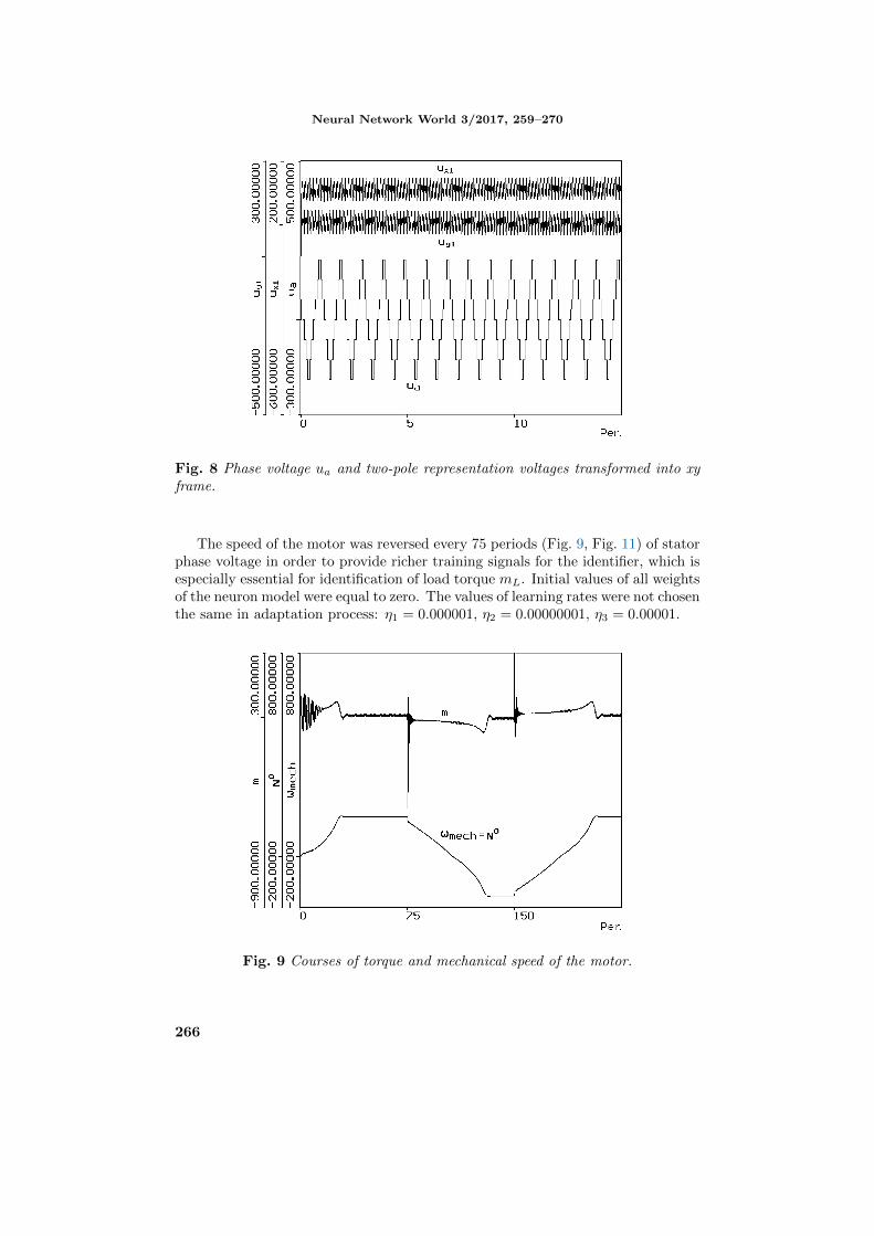
The speed of the motor was reversed every 75 periods (Fig. 9, Fig. 11) of statorphase voltage in order to provide richer training signals for the identifier, which isespecially essential for identification of load torque mL. Initial values of all weightsof the neuron model were equal to zero. The values of learning rates were not chosenthe same in adaptation process: η1 = 0.000001, η2 = 0.00000001, η3 = 0.00001.
Fig. 9 Courses of torque and mechanical speed of the motor.
266
Balara D. et al.: Neural networks application for mechanical. . .
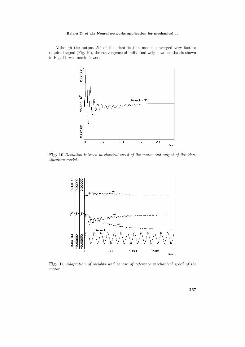
Although the output No of the identification model converged very fast torequired signal (Fig. 10), the convergence of individual weight values that is shownin Fig. 11, was much slower.
Fig. 10 Deviation between mechanical speed of the motor and output of the iden-tification model.
Fig. 11 Adaptation of weights and course of reference mechanical speed of themotor.
267
Neural Network World 3/2017, 259–270
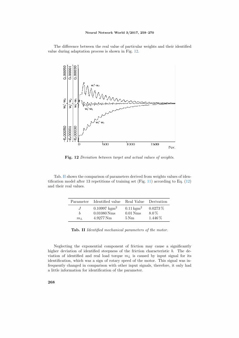
The difference between the real value of particular weights and their identifiedvalue during adaptation process is shown in Fig. 12.
Fig. 12 Deviation between target and actual values of weights.
Tab. II shows the comparison of parameters derived from weights values of iden-tification model after 13 repetitions of training set (Fig. 11) according to Eq. (12)and their real values.
Parameter Identified value Real Value Derivation
J 0.10997 kgm2 0.11 kgm2 0.0273 %b 0.01080 Nms 0.01 Nms 8.0 %mL 4.9277 Nm 5 Nm 1.446 %
Tab. II Identified mechanical parameters of the motor.
Neglecting the exponential component of friction may cause a significantlyhigher deviation of identified steepness of the friction characteristic b. The de-viation of identified and real load torque mL is caused by input signal for itsidentification, which was a sign of rotary speed of the motor. This signal was in-frequently changed in comparison with other input signals, therefore, it only hada little information for identification of the parameter.
268
Balara D. et al.: Neural networks application for mechanical. . .
6. Conclusion
In this paper the neural identification method of nonlinear dynamic systems issuggested. The proposed identification method is based on the use of our knowledgeof the identified system. Very simple neural adaptive structure, analogous to themodel of system was used as the neural identifier. In the identification modelsimple measured signals of the system are used as inputs to the model. Parametersof the system were derived from the values of synaptic weights of the neural modelafter its adaptation. The gradient descent algorithm was used for adaptation ofparameters of the neural network.
The identification method was used as an example of the neural networks appli-cations for a squirrel-cage asynchronous motor. Our aim was to identify mechanicalparameters of an asynchronous motor like moment of inertia J , constant passiveload moment mL and steepness of linear friction characteristic b. The identificationmethod was completely computer simulated, including the identified motor. Theachieved identified values of parameters of the system are very close to their realvalues.
The identification method should be successfully applied to identify the pa-rameters of many other nonlinear dynamic systems, especially if we know theirstructures.
Acknowledgement
The authors wish to thank the project VEGA 1/0464/15 for its support.
References
[1] BALARA D., TIMKO J., ZILKOVA J. Application of neural network model for parametersidentification of non-linear dynamic system. Neural Network World. 2013, 23(2) pp. 103–116,doi: 10.14311/NNW.2013.23.008.
[2] BALDI P.: Gradient Descent Learning Algorithm Overview: A General dynamical systemsperspective. IEEE Transaction on Neural Networks.. 1995, 6(1) pp. 182–195, doi: 10.1109/72.363438.
[3] BORBEL M., TIMKO J., ZILKOVA J. Neural speed estimator for the induction motordrive. Electrotechnica et Informatica. 2002, 2(4) pp. 27–30.
[4] BOSE B.K. Expert system, fuzzy logic, and neural network applications in power electronicsand motion control. Proceedings of the IEEE. 1994, 82(8) pp. 1303–1323, doi: 10.1109/5.301690.
[5] BRANDSTETTER P., DOBROVSKY M., KUCHAR M. Implementation of Genetic Al-gorithm in Control Structure of Induction Motor AC Drive. Advances in Electrical andComputer Engineering. 2014, 14(4) pp. 15–20, doi: 10.4316/AECE.2014.04003.
[6] BRANDSTETTER P., KUCHAR M., NEBORAK I. Selected applications of artificial neuralnetworks in the control of AC induction motor drives. International Review on Modellingand Simulations. 2011, 4(3) pp. 1084–1093.
[7] KAZMIERKOWSKI M.P., MALESANI L. Current control techniques for three-phasevoltage-source PWM converters: a survey. IEEE Transaction on Industrial Electronics. 1998,45(5) pp. 691–703, doi: 10.1109/41.720325.
[8] LEONHARD W. Control of Electrical Drives. Berlin: Springer-Verlag, 2001, doi: 10.1007/978-3-642-56649-3.
269

Neural Network World 3/2017, 259–270
[9] LEVIN A.U., NARENDRA K.S.: Control of non-linear dynamical systems using neuralnetworks – Part II: Observability, identification, and control. IEEE Transaction on NeuralNetworks.. 1996, 7(1) pp. 30–42, doi: 10.1109/72.478390.
[10] NARENDRA K.S., PARTHASARATHY K. Identification and control of dynamical systemsusing neural networks. IEEE Transaction on Neural Networks.. 1990, 1(1) pp. 4–27, doi: 10.1109/72.80202.
[11] PERDUKOVA D., FEDOR P. The Identification of Induction Motor Inner Values. Interna-tional Conference on Applied Electrical Engineering and Informatics , Germany. 2012, pp.76–80.
[12] SHAW S.R., LEEB S.B. Identification of induction motor parameters from transient statorcurrent measurements. IEEE Transaction on Industrial Electronics. 1999, 46(1), pp. 139–149, doi: 10.1109/41.744405.
[13] TIMKO J., ZILKOVA J., BALARA D. Applications of artificial neural networks in electricaldrives. Kosice: Calypso s.r.o, 2002.
[14] VAS P. Parameter estimation, condition monitoring and diagnosis of electrical machines.Oxford: Oxford University Press, 1993.
[15] VAS P. Artificial-inteligence-based electrical machines and drives. Oxford: Oxford UniversityPress, 1999.
[16] ZASKALICKY P. Complex fourier series analysis of a three-phase induction motor suppliedby a three-phase inverter with PWM output voltage control. Power Electronics and MotionControl Conference and Exposition (PEMC), 2014 16th International, Antalya, Turkey.2014, pp. 1183–1188, doi: 10.1109/EPEPEMC.2014.6980672.
[17] ZILKOVA J., TIMKO J. On-line identification of a rotor resistor of an induction motor usingthe neural network. Electrotechnica et Informatica. 2003, 3(1) pp. 53–56.
270