new amplifier technology redefines performance · pdf filenew amplifier technology redefines...
TRANSCRIPT

New Amplifier Technology Redefines Performance BenchmarksNAD Masters Series M2 Direct Digital Amplifier
by: Greg Stidsen, Director, Product Development, NAD Electronics International Craig Bell, Product Marketing Manager - Audio, Diodes Zetex Semiconductors Ltd.

2
New Amplifier Technology Redefines Performance BenchmarksNAD Masters Series M2 Direct Digital Amplifier - by: Greg Stidsen and Craig Bell
NAD Masters Series Concept The NAD brand has come to represent high value products that
consistently offer musically honest performance. In 2005, NAD introduced
the Masters Series concept as the evolution of NAD’s core values of
performance, simplicity and value. Each component in the series offers
performance, both measured and subjective, that is at the upper limits of
today’s technology. Elegant industrial design and impressive build quality
are also essential to this concept. As a way to showcase its engineering
prowess and to create a new class of NAD products, Masters Series has
been a qualified success.
Another key element of the Masters philosophy is the introduction of new
technology that can later trickle down to NAD’s less expensive products.
This is where our M2 Direct Digital Amplifier story begins.
The M2 Design StoryThe first ‘Class D’ amplifiers for audio were developed in the 1960s by
Gordon Edge, a brilliant engineer working for famed British entrepreneur
Clive Sinclair (Sinclair Radionics). But the performance of this early design
was marginal. In the 1970s, Infinity Systems experimented with a more
advanced design called SWAMP, but could not advance this development
into a commercially viable product. Thirty years later, Class D amplifiers
are now widely used in both professional and consumer products, but not
without compromise. Noted for higher efficiency when compared with
linear Class A and Class AB amplifiers, Class D still has not been able to
achieve the same levels of performance, both measured and subjective, as
the best Class AB designs.
By the late 1990s the gap had narrowed considerably and NAD started
experimenting with various Class D design solutions. But our investigations
revealed that even when the amplifiers we measured performed well
on paper, they did not sound very musical. Some were etched and dry
sounding while others were soft and lacked high frequency extension and
detail. All of them sounded less dynamic and less fluid than our reference
Class AB amplifiers.
Because NAD considers performance to be its most important brand value, it
was decided that an NAD branded Class D amplifier would not be introduced
until it could offer equal or better sonic performance to NAD’s traditional
Class AB designs.
NAD and Diodes Zetex CollaborationOne of the most promising designs we tried came from a British
semiconductor company named Zetex. The circuit architecture was fully
digital, which differed greatly from most of the Class D amplifiers in the
market. Conceptually, Zetex had addressed the major weaknesses of
previous designs and early listening tests were extremely encouraging.
The sound was open and dynamic without the harshness or softness
of the other solutions. Transients were superbly rendered and the amp
sounded fast and tight, but not overly etched or dry.
Zetex (now Diodes Zetex Ltd.) was looking for a development partner
to bring their digital development out of the laboratory and into the
marketplace. NAD’s strong engineering resources and worldwide
reputation for performance proved to be a good match and so NAD and
Zetex started to collaborate in 2005. Our mission was to push this new
digital platform to the limit and make a very powerful amplifier as the first
introduction of this new invention. The design brief for the M2 started to
take shape.
The Advantages of a True Digital AmplifierOur initial thought was to make a basic power amp without any controls
that could stand as a reference to other amplifiers. But one of the
strongest attributes of a true digital amplifier is the ability to take a digital
PCM signal directly, thus avoiding multiple conversions and amplifying
stages that are present in all analogue designs, which tend to strip the
music of detail by adding hazy layers of noise and distortion. Ever since
the introduction of digital source material in the 1980s, a pure digital
signal path was always an attractive proposition; now it could be a reality.
New Amplifier Technology Redefines Performance BenchmarksNAD Masters Series M2 Direct Digital Amplifier
By: Greg Stidsen, Director, Product Development, NAD Electronics International Craig Bell, Product Marketing Manager - Audio, Diodes Zetex Semiconductors Ltd.
3
New Amplifier Technology Redefines Performance BenchmarksNAD Masters Series M2 Direct Digital Amplifier - by: Greg Stidsen and Craig Bell
Although the early Zetex prototypes already had very good sound quality,
the measured performance was still not quite up to the best available
amplifiers. The first prototypes showed performance that was typical of
the best available digital amps with a measured SNR of 105dB referenced
to full power. But the NAD standard is >90dB referenced to 1 watt –
we needed to find an additional 10 – 15dB of dynamic range. With
35-bit architecture it was theoretically possible to achieve this level of
performance from the Zetex DDFA™ (Direct Digital Feedback Amplifier)
circuit, and we were determined to achieve this goal. Step-by-step, as we
made measurable improvements, the subjective sound also became more
detailed and expansive. This was very encouraging and motivated the
team to push further and further.
The benchmark SNR performance of >90dB Referenced to 1W is a difficult
technical challenge, but it very closely relates to the noise performance
at typical listening levels and discloses the absolute magnitude of the
noise, which is the most honest way of declaring the performance. This
performance level is delivered by NAD analogue power amplifiers, but
we must consider how this power amplifier performance fits within the
overall signal chain. We can now gain insight into the difference between
a conventional analogue approach and a direct digital amplifier – and the
opportunity it presents.
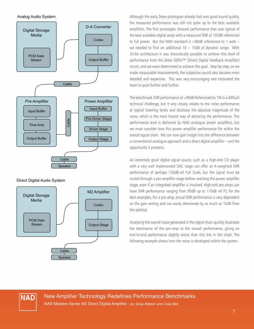
An extremely good digital signal source, such as a high-end CD player
with a very well implemented DAC stage can offer an A-weighted SNR
performance of perhaps 120dB-ref Full Scale, but the signal must be
routed through a pre-amplifier stage before reaching the power amplifier
stage, even if an integrated amplifier is involved. High-end pre-amps can
have SNR performance ranging from 95dB up to 110dB ref FS, for the
best examples. For a pre-amp, actual SNR performance is very dependent
on the gain setting and can easily deteriorate by as much as 10dB from
the optimal.
Analysing the overall noise generated in the signal chain quickly illustrates
the dominance of the pre-amp to the overall performance, giving an
end-to-end performance slightly worse than this link in the chain. The
following example shows how the noise is developed within the system.
Digital StorageMedia
Direct Digital Audio System
PCM DataStream
M2 Amplifier
Codec
Output Stage
Digital StorageMedia
Analog Audio System
PCM DataStream
Pre-Amplifier
D-A Converter
Codec
Cable
Cable
Speaker
Cable
Speaker
Output Buffer
Input Buffer
Output Buffer
Power Amplifier
Input Buffer
Driver Stage
Output Stage
Pre Driver Stage
Cab
le
Tone Amp

4
New Amplifier Technology Redefines Performance BenchmarksNAD Masters Series M2 Direct Digital Amplifier - by: Greg Stidsen and Craig Bell
modulation and gain stage, where PCM data is converted to PWM (Pulse
Width Modulation) to create the switching output. The system SNR
performance is completely unaffected by the volume control setting,
so audible noise is never evident at the speaker. More importantly,
such a low level of noise and distortion translates directly to subjective
performance. SNR performance of the M2 is 91dB ref 1W (un-weighted),
in all circumstances.
How it WorksThe modulation stage is the part of the M2 where the most critical
innovations were required in order to hit the performance targets. The
modulation process where PCM is converted to PWM is an inherently
digital one, with the widths of the modulation pulses being quantized
by the internal clock frequency, which in the case of the M2 is 108MHz.
This means that pulses can be defined to a resolution of 9.2ns within
a modulation period which is 1.18us long, for a maximum of 128
possible pulse widths. At first glance, this would seem to be much too
small a number to represent an audio signal. However, there are many
modulation cycles available within the period of even the highest audio
frequency cycle, so noise shaping techniques can be applied to accurately
resolve the signal. Put simply, varying pulse widths can be applied, so that
the cumulative effect is to reproduce precisely the correct amplitude at
the output.
The actual amplification step is performed by the FET output stage, which
amplifies the logic level pulses from the modulator output levels (3.3V)
to high voltage pulses with amplitude of approximately +/-50V, and fed
to the speaker terminals through an LC or reconstruction filter, which
removes the high frequency energy and delivers the audio signal to the
speaker. The output stage is where the very real challenges of switching
power electronics arise.
In reality, the pulses at the bridge output differ hugely from the perfect
This 107.1dB figure is referenced to a 200W output power. Stating it
referenced to 1W, gives a figure of 84.1dB. This is the true end-to-end
performance of even this exceptional conventional signal chain. Even the
outstanding power amplifier used in this example cannot help, if noise is
presented at its input.
For the M2 digital amplifier, the situation is quite different. Starting at the
source, a well executed digital output has no noise or distortion, beyond
the fundamental limits of the number format. A Zero output is simply
represented by zero in the PCM data. As it enters the digital amplifier,
all pre-processing such as filters and volume controls are implemented
in DSP, and as a consequence, are not subject to the effects of noise in
analogue components, nor tolerances in their values. The DSP architecture
selected for the M2 is very high resolution, with a minimum of 35 bits at
any point in the processing datapath to ensure maximum retention of
resolution.
Take the volume control as an example. The 35-bit system datapath means
that even a 24-bit input signal has 11 bits of headroom, so the volume
control can be set as low as -66dB without losing any of the original
signal resolution. If the source was a CD player with 16-bit data, then the
figure is astonishing at -114dB. While either of these levels is normally
inaudible, the processing resolution involved is paramount to retaining
and reproducing the subtleties of the original recording.
The only source of noise or distortion in the M2 architecture is the final
Source DACSNR 115dB
GeneratedNoise
1.78uV
Power - AmpSNR 115dB
175.8uVSNR = 107.1dB
These numbers are expressed in un-weighted terms.
Amplifiedx40
174.4uV
GeneratedNoise
22.5uV
Pre - AmpSNR 108dB
GeneratedNoise
3.98uV

5
New Amplifier Technology Redefines Performance BenchmarksNAD Masters Series M2 Direct Digital Amplifier - by: Greg Stidsen and Craig Bell
amazingly low output impedance. This very tight or direct feedback path
gave rise to the name Direct Digital Feedback Amplifier.
The Engineering ChallengeThe engineering challenge of making this process happen cannot be
understated. For example, the reference PWM signal serves as the
system’s definition of perfection, so it must be highly pure. One familiar
metric to illustrate the difficulty: clock jitter to achieve the necessary
120dB dynamic range of the reference signal must be at a level of 5
picoseconds! (A picosecond is one trillionth of a second or 0.000 000
000 001).
Another way to consider the M2 technology is to judge it as if it were
simply a DAC. Think of the M2 as providing digital-to-analogue conversion
with amplifier gain attached. During the development, a lot of attention
has been paid to assessing the performance in these terms to ensure the
most accurate possible reproduction. For example, the linearity of the M2
compares well to the claims of the highest performance DAC chips.
In fact the performance is so good the results at very low signal levels can
shape we might hope for, and the deviation from perfection results in
errors in the output signal.
Most digital amplifiers are open loop and have no correction mechanism,
so their performance falls far short of linear amplifiers. They cannot
correct for the imperfections that are inevitable in power supplies, or
real-life switching waveforms. Attempting to perfect the power supply or
switching structures is not a practical approach, so the DDFA technology
was developed to implement correction for the problems.
Feedback Re-inventedAn analogue amplifier, whether linear or Class D, can use conventional
negative feedback methods to compensate, but the problem is much more
difficult for a true digital amplifier. The obvious method of digitizing the
analogue output and feeding back to subtract from the input is hampered
by the large delays involved and results in an unstable system.
To solve the problem, the Zetex team has developed an entirely new
approach, which is best described as noise shaping error correction. Any
deviation from the perfectly programmed pulse shape is regarded as an
error. This could be caused by the amplitude of the pulse (power supply
ripple or sag), the width of the pulse, or even the slope of the edges. Any
of these factors will impact the area under the pulse (which is really how
the signal amplitude is encoded).
The system operates by comparing the output PWM signal with a high purity
‘Reference PWM’ signal to create an error signal, which is representative
of the voltage error at the output. Integration in time provides an
indication of the pulse area error, which is digitized at a conversion rate of
108MHz to pass back to the digital domain. The error information is then
processed to compensate subsequent modulation cycles. The system can
be considered to be constantly adapting to minimize the errors and hence
deliver as true a signal as possible to the speaker. The output signal is
also monitored at the output of the LC filter, which means the system has

6
New Amplifier Technology Redefines Performance BenchmarksNAD Masters Series M2 Direct Digital Amplifier - by: Greg Stidsen and Craig Bell
Extremely low jitter is another impressive digital performance metric.
Using the j-test to assess data-related jitter, the telltale side bands at
229Hz intervals from the fundamental are totally missing. Quite simply
there is no jitter.
Measured Performance of the NAD M2 Direct Digital Amplifier
The familiar measurement of THD+N vs. output level shows the expected
level of performance for a high-end amplifier. However, much more is
revealed by looking at the M2 performance in terms of low level detail.
be misleading. At the lower end of the linearity plot, the measurement of
linearity error is influenced by the noise present. By performing an FFT on
the amplifier output using multiple averages, the outstanding amplitude
accuracy becomes clear. The error level is less than 0.1dB at -120dB
Zooming in further reveals useful resolution down to -135dB!
Audio Precision 03/26/09 10:06:41EV4 FFT 1kHz
EV4 Power OP Dynamic Range FFT.at2c
ColorSweep Trace Line Style Thick Data Axis Comment
1 1 Red Solid 1 Fft.Ch.2 Ampl Right
44.1 kHz -60dB
-180
+0
-170
-160
-150
-140
-130
-120
-110
-100
-90
-80
-70
-60
-50
-40
-30
-20
-10
dBr B
8k 14k9k 10k 11k 12k 13k
Hz
Audio Precision 03/25/09 14:17:32NAD M2 BTL THD+N vs Power Out 4ohm Loads
M2 BTL THD+N Plot.at2c
ColorSweep Trace Line Style Thick Data Axis Comment
1 1 Blue Solid 1 Anlr.THD+N Ratio Left1 3 Yellow Solid 1 Anlr.THD+N Ratio Left
Digital Input 44.1kHz, 24bits 1kHz -4.8dB FSDVolume 0dB
0.0025
0.05
0.005
0.0075
0.01
0.0125
0.015
0.0175
0.02
0.0225
0.025
0.0275
0.03
0.0325
0.035
0.0375
0.04
0.0425
0.045
0.0475
%
400m 3001 2 5 10 20 50 100 200
W
Audio Precision 03/25/09 15:21:57 D-A LINEARITY Data and Computed deviation
EV3 Power OP DAC linearity.at2c
ColorSweep Trace Line Style Thick Data Axis Comment
1 1 Blue Solid 1 Anlr.Bandpass Left1 2 Red Solid 1 Anlr.Bandpass!Linearity Right
1kHz, -1dBFS 44.1kHz
-2
+2
-1.8
-1.6
-1.4
-1.2
-1
-0.8
-0.6
-0.4
-0.2
+0
+0.2
+0.4
+0.6
+0.8
+1
+1.2
+1.4
+1.6
+1.8
dBr A
-140
+0
-130
-120
-110
-100
-90
-80
-70
-60
-50
-40
-30
-20
-10
dBr A
-140 -20-120 -100 -80 -60 -40
dBFS
Audio Precision 03/25/09 15:26:35 D-A LINEARITY Data and Computed deviation
EV3 Power OP DAC linearity.at2c
ColorSweep Trace Line Style Thick Data Axis Comment
1 1 Blue Solid 1 Anlr.Bandpass Left1 2 Red Solid 1 Anlr.Bandpass Right
1kHz, -1dBFS 44.1kHz
-2
+2
-1.8
-1.6
-1.4
-1.2
-1
-0.8
-0.6
-0.4
-0.2
+0
+0.2
+0.4
+0.6
+0.8
+1
+1.2
+1.4
+1.6
+1.8
dBr A
-140
-100
-138
-136
-134
-132
-130
-128
-126
-124
-122
-120
-118
-116
-114
-112
-110
-108
-106
-104
-102
dBr A
-140 -100-135 -130 -125 -120 -115 -110 -105
dBFS
7
New Amplifier Technology Redefines Performance BenchmarksNAD Masters Series M2 Direct Digital Amplifier - by: Greg Stidsen and Craig Bell
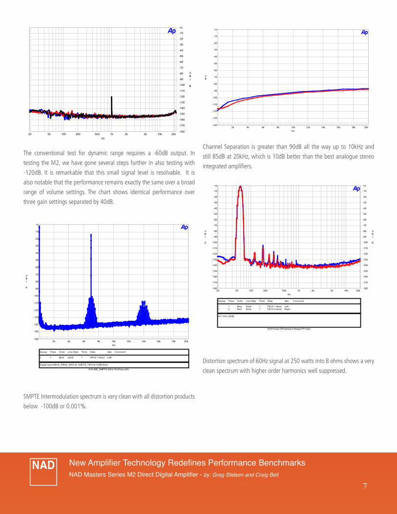
Channel Separation is greater than 90dB all the way up to 10kHz and
still 85dB at 20kHz, which is 10dB better than the best analogue stereo
integrated amplifiers.
Distortion spectrum of 60Hz signal at 250 watts into 8 ohms shows a very
clean spectrum with higher order harmonics well suppressed.
The conventional test for dynamic range requires a -60dB output. In
testing the M2, we have gone several steps further in also testing with
-120dB. It is remarkable that this small signal level is resolvable. It is
also notable that the performance remains exactly the same over a broad
range of volume settings. The chart shows identical performance over
three gain settings separated by 40dB.
SMPTE Intermodulation spectrum is very clean with all distortion products
below -100dB or 0.001%.
Audio Precision 03/25/09 14:54:28M2 IMD SMPTE 60Hz/7kHz 12dB ratio
EV4 IMD_SMPTE 60Hz 7kHzTest.at2c
ColorSweep Trace Line Style Thick Data Axis Comment
1 1 Blue Solid 1 Fft.Ch.1 Ampl Left
Digital Input 48kHz, 24bits, 60Hz at -3dB FS, 7kHz at 12dB down
-160
+0
-150
-140
-130
-120
-110
-100
-90
-80
-70
-60
-50
-40
-30
-20
-10
dBr A
2k 20k4k 6k 8k 10k 12k 14k 16k 18k
Hz
Audio Precision 03/25/09 15:14:45M2 BTL crosstalk -26dB
NAD BTLcrosstalk sweep.at2c
ColorSweep Trace Line Style Thick Data Axis Comment
1 1 Blue Solid 1 Anlr.Crosstalk Left1 2 Red Solid 1 Anlr.Crosstalk Left
Digital Input 44.1kHz, 24bits 1kHz -26dB FSDVolume 0dB
-140
+0
-130
-120
-110
-100
-90
-80
-70
-60
-50
-40
-30
-20
-10
dB
2k 20k4k 6k 8k 10k 12k 14k 16k 18k
Hz
T
Zetex plc 03/25/09 13:48:31M2 -120dB FFT Optical IP, Multiple volume settings
M2 SEtst -60dB FFT.at2c
ColorSweep Trace Line Style Thick Data Axis Comment
2 1 Blue Solid 1 Fft.Ch.2 Ampl Right Vol -20dB3 1 Red Solid 1 Fft.Ch.2 Ampl Right Vol -40dB4 1 Black Solid 1 Fft.Ch.2 Ampl Right Vol -60dB
Digital Input 44.1kHz
-180
+0
-170
-160
-150
-140
-130
-120
-110
-100
-90
-80
-70
-60
-50
-40
-30
-20
-10
dBr B
20 20k50 100 200 500 1k 2k 5k 10k
Hz
Audio Precision 03/25/09 15:03:03M2 FFT 60Hz
EV4 Power OP Dynamic Range FFT.at2c
ColorSweep Trace Line Style Thick Data Axis Comment
1 1 Blue Solid 1 Fft.Ch.1 Ampl Left1 2 Red Solid 1 Fft.Ch.2 Ampl Right
44.1 kHz -60dB
-180
+0
-170
-160
-150
-140
-130
-120
-110
-100
-90
-80
-70
-60
-50
-40
-30
-20
-10
dBr B
-180
+0
-170
-160
-150
-140
-130
-120
-110
-100
-90
-80
-70
-60
-50
-40
-30
-20
-10
dBr A
20 20k50 100 200 500 1k 2k 5k 10k
Hz

8
New Amplifier Technology Redefines Performance BenchmarksNAD Masters Series M2 Direct Digital Amplifier - by: Greg Stidsen and Craig Bell
Selectable Digital and Analogue Inputs This allows the M2 to be used without a preamp for the shortest possible signal path. Both balanced and single-ended signal sources are supported.
Ultra-high Resolution Analogue-to-Digital Conversion Analogue inputs must be converted to the digital domain of the M2. NAD is using the very latest state-of-the-art devices which, along with an optimized circuit design, results in superb performance. Sample Rate of 48kHz, 96kHz and 192kHz can be selected. The performance of the Analogue inputs is within 1dB of the Digital inputs for all measurements!
Speaker Compensation Even though the DDFA corrects for the influence of the output filter, we offer further fine-tuning using digital filters to flatten response at 20kHz to within 0.5dB. Speaker impedances from 1 ohm to greater than 8 ohms are accommodated in 1 ohm steps.
Dual Mono Design Three separate ultra low noise Switch Mode Power Supplies are employed – one for each audio channel and one for control. Digital Processor Loop This allows the insertion of a PC into the signal path to add signal processing such as crossover filters or room correction filters. Connection is via Optical SPDIF.
Two Sets of Speaker Outputs This is to allow for convenient Bi-Wiring of loudspeakers.
Large VFD Display The front panel display shows selected input, incoming Sample Rate, ADC Sample Rate, Volume Setting and Mute. Each input can be renamed if desired.
System Remote Control IR remote controls NAD CD Players as well as the M2. Front IR Sensor and Rear IR Input.
12V Trigger InputAllows for automated On/Standby function.
RS-232 Port Interfaces to third-party automated control and allows for software updates.
NAD’s Unique Implementation of DDFA The M2 has taken Diodes Zetex’s core technology and integrated NAD’s
many years of amplifier expertise to create a really unique product. The
implementation of DDFA within the M2 uses customized logic within a
Xilinx FPGA. This gives a custom platform on which to blend the DDFA
technology with NAD’s own innovations within this unique architecture.
Digital PowerDrive™The benefit of NAD’s PowerDrive™ technology is the ability to have high
dynamic power necessary for accurate reproduction of musical transients
coupled with the ability to drive difficult speaker loads without increased
distortion. The DDFA architecture allowed us to translate this important
attribute into the digital domain giving a highly accurate power/time
envelope that closely matches our ‘ideal’ based on NAD’s research of
recorded music requirements.
Digital Soft Clipping NAD first developed Soft Clipping in the 1970s as a way to avoid the
harsh and highly non-musical sound when an amplifier is driven beyond
its limits. Soft Clipping allows a graceful overload without the usual
generation of high order harmonic distortion that normally occurs as the
sine wave gets squared off. Now digitally controlled, it can be carefully
modeled for ideal results.
Perfect Digital Volume Control Signal-to-noise, distortion and channel separation are the same for all
control settings. Channel tracking is perfect. There is a fixed setting
available for analogue inputs allowing the M2 to be used as a basic
power amp with analogue preamps if desired.