new analytical method to evaluate casing integrity during
TRANSCRIPT
Research ArticleNew Analytical Method to Evaluate Casing Integrity duringHydraulic Fracturing of Shale Gas Wells
Jun Li1 Xueli Guo 12 Gonghui Liu13 Shuoqiong Liu2 and Yan Xi1
113e College of Petroleum Engineering China University of Petroleum Beijing China2CNPC Engineering Technology RampD Company Limited Beijing China3Beijing University of Technology Beijing China
Correspondence should be addressed to Xueli Guo clouder0713163com
Received 1 July 2018 Accepted 25 March 2019 Published 24 April 2019
Academic Editor Francesco Pellicano
Copyright copy 2019 Jun Li et al -is is an open access article distributed under the Creative Commons Attribution License whichpermits unrestricted use distribution and reproduction in any medium provided the original work is properly cited
An accurate analysis of casing stress distribution and its variation regularities present several challenges during hydraulicfracturing of shale gas wells In this paper a new analytical mechanical-thermal coupling method was provided to evaluate casingstress For this new method the casing cement sheath and formation (CCF) system was divided into three parts such as initialstress field wellbore disturbance field and thermal stress field to simulate the processes of drilling casing cementing andfracturing -e analytical results reached a good agreement with a numerical approach and were in-line with the actual boundarycondition of shale gas wells Based on this new model the parametric sensitivity analyses of casing stress such as mechanical andgeometry properties operation parameters and geostress were conducted during multifracturing Conclusions were drawn fromthe comparison between new and existing models -e results indicated that the existing model underestimated casing stressunder the conditions of the geostress heterogeneity index at the range of 05ndash225 the fracturing pressure larger than 25MPa anda formation with large elastic modulus or small Poissonrsquos ratio-e casing stress increased dramatically with the increase of in situstress nonuniformity degree-e stress decreased first and then increased with the increase of fracturing pressure -icker casinghigher fluid temperature and cement sheath with small modulus large Poissonrsquos ratio and thinner wall were effective to decreasethe casing stress-is newmethod was able to accurately predict casing stress which can become an alternative approach of casingintegrity evaluation for shale gas wells
1 Introduction
During the multistage fracturing process fracturing fluidsare pressed into a borehole with a high pump rate andpressure -e complex downhole environmentsmdashhighpressure and large temperature variationmdashincrease the riskof casing deformation -e volume fracturing techniqueeffectively reconstructs shale reservoirs however frequentand serious casing deformation failures occur [1] -erewere over 36 wells with casing deformation (including 112horizontal wells by 2017) during fracturing process in someshale gas plays Drilling tools were blocked and seriousdeformation sections were abandoned before fracturingoperation completion [2ndash4] -erefore casing integrity hasalways been themain issue in designing shale gas wells under
harsh conditions and accurately calculating casing stressbecomes primary to guarantee the casing safety A casingstress analysis presents several challenges regarding thedrilling completion and fracturing phases of shale gas wellsMany scholars have predicted the casing stress by simpli-fying the actual situations
Analytical solutions have been developed under dif-ferent conditions for casing-cement sheath-formationsystem In-plane and out-of-plane analyses for the stressfield around an internally pressurized cased cementedand remotely loaded circular hole were developed [5]Taking the in situ stresses and well trajectory into accountthe mechanical model of casing in the directional wellunder in situ stresses is established [6] Other scholars gavea comprehensively analytical solution of the stress
HindawiShock and VibrationVolume 2019 Article ID 4253241 19 pageshttpsdoiorg10115520194253241
distribution in a casing-cement-formation system under an-isotropic in situ stresses Fang et al [7] developed a multilayercemented casing system in the directional well under aniso-tropic formation to investigate the collapse resistance of casingunder nonuniform in situ stress and anisotropic formationBased on the stress function method a three-dimensionalmodel of the casing-cement sheath-formation (CCF) systemwas proposed subjected to linear crustal stress and then ananalytical solution of the model was obtained [8]
A finite element method (FEM) had been proposed toachieve a better understanding of the ultimate collapsestrength of casing [9] Using this method casing stress wasbetter analyzed subjected to external and nonuniformloading caused by void and pressure [10] -e results of aseries of finite element studies of the cemented casing undera variety of stress conditions for both burst and collapse werepresented demonstrating the inadequacy of accepted designequations under many cemented conditions [11] Apurpose-built finite element model was applied to simulatethe radial displacement of a casing string constrained withinan outer wellbore [12] Casing stress on the inner wall underthe condition of elliptic casing was calculated and analyzedto improve the designing and correction of casing strength[13] -e main controlling factor to the plastic limit load ofdefective casing was analyzed by the combination of hightemperature and high steam injection pressure [14]
However the above analytical or FEM solutions areobtained by setting the casing and cement together instantlyat the beginning of the analysis -e strains induced by theinitial stress are included in the model which is not in-linewith the actual situation In fact initial stress has alreadyexisted in the formation before wellbore excavation -ewellbore stress redistributed after removing the rocks thatoriginally occupied the borehole volume and just affected thestress and displacement near wellbore zones In view of thismore sophisticated solutions have been developed withadditional parameters and appropriate assumptions re-garding the drilling completion and fracturing phases
Pattillo and Kristiansen [15] developed a finite modelstarting with the virgin reservoir which considered pre-wellbore depletion drilling the wellbore installation of casingand cement and subsequent draw down Behavior of variousconfigurations during subsequent draw down permitted themto be ranked according to the life expectancy of the resultingcompletion Gray et al [16] presented a staged-finite elementprocedure during the well construction which consideredsequentially the stress states and displacements at and near thewellbore But temperature flow and poroelasticity effectswere not included Mackay and Fontoura [17] carried anumerical analysis to determine the effect of salt creep andcontacts amongst the materials before during and afterdrilling the well focusing on the drilling of the wellbore andon the hardening of the cement Zhang et al [18] used thestaged-finite element modeling approach to simulate the wellconstruction processes and injection cycle using a ldquorealisticrdquobottom-hole state of stress to simulate the microannuligeneration by the tensile debonding of the cement-formationinterface Simone et al [19] developed an analytical solutionof single and double casing configurations to assess the
stresses during the drilling construction and productionphases But the nonuniform boundary stress was not con-sidered in this model Liu et al [20] presented an analyticalmethod for evaluating the stress field within a casing-cement-formation system of oilgas wells under anisotropic in situstresses in the rock formation and uniform pressure withinthe casing However the temperature was not considered inthis model
In this work to evaluate the thermal and mechanicalstresses of casing an analytical model of casing-cementsheath-formation system was established considering well-bore construction -e boundary stresses in the wellborecoordinate system were obtained through three-dimensionalrotations from principal in situ stresses-e casing stress wasobtained by dividing the model into three parts such asinitial stress field disturbance stress field and thermal stressfield -e continuous homogeneous isotropy and linearelasticity were taken into consideration Solutions werevalidated by a finite element method Sensitivity analyseswere conducted to estimate the influence of different factorson casing stress such as property of cement sheath andcasing fracturing pressure fluid temperature and initialgeostress Useful countermeasures were put forward todecrease casing stress during the fracturing operation
2 Method and Basic Conditions Analysis
21 Method Comparison
211 Existing Method For existing method the casingcement sheath and formation were set together at the be-ginning of analysis -en temperature boundary and loadswere added to the system to calculate wellbore stress dis-tribution as shown in Figure 1-is method did not considerthe process of wellbore construction and hydraulic frac-turing So the wellbore stress distribution could not accu-rately be calculated under the condition of formation straininduced by the initial in situ stress
212 New Method To exactly predict the wellbore stressdistribution a casing-cement sheath-formation model usinga new analysis method was provided -e analysis processwas divided into four steps (Figure 2) Before drilling theinitial stresses such as normal stress and shear stress wereloaded in the model and initial strains were produced -econstrained boundary conditions were assigned to the entiremodel which reached initial mechanical equilibrium Duringdrilling the rock was excavated causing stress concentrationaround the borehole -e drilling mud pressure Pm wasapplied to the internal face of the wellbore During casingand cementing casing and cement sheath elements wereadded simultaneously to the model and the cement hard-ening procedure was not considered Initial stress and strainin casing and cement sheath were ignored-e cement slurrypressure Pc was applied to the internal casing wall Duringfracturing a low temperature Tn and the fracturing pressurePf were assigned in the internal casing wall -e wellborestress field was obtained under the condition of thermal-mechanical coupling
2 Shock and Vibration
22 Stress Transformation -e stress state and coordinatetransformation system are shown in Figure 3 -e co-ordinate rotation processes from the principal in situ stresscoordinate system to the wellbore coordinate systemare shown as XHYhZy⟶ XprimeYprimeZprime ⟶ XPrimeYPrimeZPrime ⟶XPrimeprimeYPrimeprimeZPrimeprime ⟶ XYZ first rotating anticlockwise φ aroundthe Zv-axis and rotating clockwise β around the Zv-axissecond rotating anticlockwise α around the YPrime axis (afterthe second time rotation) and finally rotating anticlockwise90deg around the ZPrimeprime axis (after the third time rotation)
In the principal stress coordinate system the principalhorizontal stress matrix is σ0 whose components are maxi-mum principal stress σH the minimum principal stress σhand the overburden pressure σv shown in equation (2) -estress matrix in the wellbore coordinate system is σAccording to the right-hand rule the direction cosine ma-trices rotating around X-axis Y-axis and Z-axis are shown inequation (1) [21] -e wellbore boundary stress is obtained bythe three-dimensional rotations from the principal in situstress coordinate system shown in equation (3)
Cxαx
1 0 0
0 cos αx sin αx
0 minussin αx cos αx
⎡⎢⎢⎢⎢⎢⎢⎢⎢⎢⎢⎢⎢⎢⎣
⎤⎥⎥⎥⎥⎥⎥⎥⎥⎥⎥⎥⎥⎥⎦
Cyαy
cos αy 0 minussin αy
0 1 0
sin αy 0 cos αy
⎡⎢⎢⎢⎢⎢⎢⎢⎢⎢⎢⎢⎢⎢⎢⎢⎣
⎤⎥⎥⎥⎥⎥⎥⎥⎥⎥⎥⎥⎥⎥⎥⎥⎦
Czαz
cos αz sin αz 0
minussin αz cos αz 0
0 0 1
⎡⎢⎢⎢⎢⎢⎢⎢⎢⎢⎢⎢⎢⎢⎣
⎤⎥⎥⎥⎥⎥⎥⎥⎥⎥⎥⎥⎥⎥⎦
(1)
σ0
minusσH 0 00 minusσh 00 0 minusσv
⎡⎢⎢⎢⎢⎢⎢⎢⎢⎢⎢⎣⎤⎥⎥⎥⎥⎥⎥⎥⎥⎥⎥⎦ (2)
σ Cz90CyαCzβCzjσ0CT
zjCTzβC
TyαC
Tz90 (3)
Foramtion ForamtionDrilling fluid
Cement sheathFracturing fluid
ForamtionCasing
Cement sheathFracturing fluid
ForamtionCasing
Initial state Drilling Casing and completing Fracturing
Y
σy
σxX
τyx
τxy
Tf
TnPf
Y
σy
σxX
τyx
τxy
Tf
Tn
Pm
Y
σy
σxX
τyx
τxy
Tf
Tn
Pc
Y
σy
σxX
τyx
τxy
Tf
TnPf
Figure 2 Loading process of the new method Outer boundary temperature Tf inner boundary temperature Tn normal stress σx and σyshear stress τxy drilling mud pressure Pm cement slurry pressure Pc fracturing pressure Pf
Before loading
Y Y
σy
σxX
τyx
τyx
Tf
TnPfX
After loading
ForamtionCasing
Cement sheathFluid
Figure 1 Loading process of the existing method Outer boundary temperature Tf inner boundary temperature Tn normal stress σx andσy shear stress τxy
Shock and Vibration 3
where Cxαx Cyαy and Czαz are the coordinate rotationmatrices of the x y and z directions σ0 and σ are the stressmatrices in the principal stress coordinate and local wellborecoordinate systems and αx αy and αz are the rotation anglesin a counterclockwise direction when looking towards theorigin coordinate
23 BasicHypotheses A thermo-pressure coupling model ofcasing-cement sheath-formation (CCF) system was estab-lished (Figure 4) -e boundary stresses of σx σy and τxywere obtained by using equation (3) Compared to thelongitude of the well the radial dimension was very smalland a long cylindrical model was loaded by forces that wereperpendicular to the axial line and did not vary in lengthBoth the geometric form of the object and the external loadsexerted on the object did not change along the longitudinal(z-axis) direction and that the length of the object might betreated as an infinite one -ere were no additional re-strictions on the external loads -e wellbore stress wasobtained under this kind of stress state called the plane strainproblem [22 23]
For simplicity some assumptions have been made [24]
(1) Geometry the casing cement and borehole wereconcentric circles which were assumed to be per-fectly bonded to each other at each interface -eperfect bonding mathematically indicated that thecontinuity of radial stress and displacement wassatisfied at each interface
(2) -ermal effect the stress induced by wellboretemperature variation was assumed to be steady stateand the time effect was ignored
(3) Material to simplify the complex property of stronganisotropy and well-developed bedding planes ofshale formation [25] the formation was assumed tobe a linear elastic material with an infinite radius (R4⟶ infin) -e cement sheath was also a complexmaterial -e 3D images revealed the evolution of a
large connected pore network with characteristicwidths on the micrometer scale as hydration pro-ceeded [26] It was assumed to be an elastic materialneglecting the complex microstructure It is gener-ally accepted that the casing was an elastic-plasticmaterial and the casing yielding had nothing to dowith hydrostatic pressure In the model it was as-sumed that the deformation of the casing was withinthe elastic range
24 Stress Superposition -e boundary compression normalstresses (minusσx minusσy) were decomposed into uniform stress (p0)and deviator stress (s) expressed as equation (4) in theCartesian coordinate system -e other boundary stress wasshear stress (τxy)
minusσx 0
0 minusσy
⎡⎣ ⎤⎦ minusp0 0
0 minusp01113890 1113891 +
minuss 0
0 s1113890 1113891 (4)
where the uniform stress p0 (σx + σy)2 and the deviatorstress s (σx minus σy)2
According to the basic hypotheses in Section 22 thedeformation history of all phases in the CCF system wasindependent with each other -e principal of the linearsuperposition for the stress was applied as shown in thefollowing equation
σistress σprimeiUniformminusstress + σPrimeiDeviatorminusstress + σPrimeprimeiShearminusstress
+ σTiThermalminusstress
(5)
-e stress distribution of the thermal-pressure cou-pling model around a wellbore was decomposed into fourparts as shown in Figure 5 -e stress field of the first partwas induced by the uniform stress and inner casingpressure -e second one was induced by the deviatorstress and the third one was induced by the shear stress-ermal stress of the fourth part was induced by thetemperature variation
Wellbore trajectory
σv
σh
σH
YPrime
Yprimeh (East)
Xprimeh (North)
YPrime Y XXPrime
XPrime
ZPrime Z ZvZ Z
X
ZPrime
Y
Oβ
α
φ
Xh
XH
Principle in-situ stress
Figure 3 -e coordinate rotation processes (a) stress state of a horizontal well and (b) coordinate transformation system Principal in situstress coordinate system XHYhZy geodetic coordinate system XprimeYprimeZprime coordinate system XPrimeYPrimeZPrime after the second time rotationcoordinate system XPrimeprimeYPrimeprimeZPrimeprime after the third time rotation local wellbore coordinate system XYZ wellbore deviation angle α wellboreazimuth angle β the maximum horizontal stress azimuth angle φ
4 Shock and Vibration
It was convenient to convert the Cartesian coordinatesystem into the polar coordinate system to calculate wellborestress -e normal boundary stresses in the polar coordinatesystem were expressed as follows under the conditions of theinfinite outer boundary radius of R4
σprime30r
1113868111386811138681113868rinfin minusp0 minus s cos(2θ)
τprime30rθ
11138681113868111386811138681113868rinfin s sin(2θ)
⎧⎪⎨
⎪⎩(6)
where σprime30r and τprime30rθ are the initial normal and shear stresses inthe formation respectively
Since temperature and stress were coupled the stressdistribution around a cased wellbore induced by tempera-ture variation was hard to solve in the closed form Howeverthe steady-state condition made the temperature and stressdecouple and the problem analytically solvable [27]
3 Stress Distribution around Wellbore
31 Stress Induced byUniformStress Under the condition ofthe uniform internal pressure and external stress the stress
and displacement in a thin wall cylinder were obtained byusing the following equations shown in Figure 6
uprimei
r 12Gi
1minus 2μi( 1113857Aiprimer + Ciprime1r
1113876 1113877qi
+12Gi
1minus 2μi( 1113857Biprimer + Ciprime1r
1113876 1113877qi+1 minus rεprimei0r
(7)
σprimeir Aiprime minusCiprime 1r2
1113874 1113875qi + Biprime minusCiprime 1r2
1113874 1113875qi+1
σprimeiθ Aiprime + Ciprime 1r2
1113874 1113875qi + Biprime + Ciprime 1r2
1113874 1113875qi+1
⎧⎪⎪⎪⎪⎨
⎪⎪⎪⎪⎩
(8)
where σprimeir σprimeiθ and uprimei
r are the radial stress tangential stressand radial displacement respectively σprimei0r σprimei0θ and uprime
i0r are
the initial radial stress tangential stress and displacement Eiis the material elastic modulus μi is the material Poissonrsquosratio Gi Ei((1 + μi)2) is the material shear modulus qiqi+1 were the interfacial pressure positive in the radial in-crease direction i 1 2 3 represented the casing cement
Y
Y
R4
R3 R2 R1
σy
σx
TnPf σx
σy
X
τyx
τyx
τxy
Tf
θ
Z
X
ForamtionCasing
Cement sheathFluid
Figure 4 CCF composite assembly Formation boundary temperature Tf internal casing temperature Tn internal casing pressure Piradius Ri i 1 2 3 4 present the radii of the internal casing wall outer casing wall internal wellbore and formation boundary respectivelythe counterclockwise angle from the x-direction to the calculated point θ
Shear stress Thermal stressUniform stress Deviator stress
Y
R4
R3 R2 R1
Pf
p0
p0
X R3 R2 R1R3 R3
R2 R2R1 R1
R4 R4 R4
Tn
Tfndashs
s
Y Y Y
X X
τyx
τxy
X
Cement sheathFracturing fluid
ForamtionCasing
Cement sheathFracturing fluid
ForamtionCasing
Cement sheathFracturing fluid
ForamtionCasing
Cement sheathFracturing fluid
ForamtionCasing
Figure 5 Stress decompositions Inner casing pressure Pi thermal stress σT
Shock and Vibration 5
sheath and formation respectively Aiprime R2
i (R2i+1 minusR2
i )Biprime R2
i+1(R2i+1 minusR2
i ) Ciprime AiprimeR2
i+1 are the constants Ri (i 12 3 4) is the radii of internal casing wall external casingwall external cement sheath wall and formation boundaryrespectively
311 Formation Stress Before drilling the borehole theinitial geostress field already existed in the formation Whenthe rock was removed from the borehole the wellbore stressfield redistributed to produce a disturbance field which onlyaffected the near-wellbore zones [28] So the model wasdecomposed into two parts such as the original field and thedisturbance field -e original field had initial stress anddisplacement-e disturbance field was induced by drilling awellbore and mud pressure In view of this the actual stressfield of F1 in the formation induced by the uniform stressand internal pressure was decomposed into three parts asshown in Figure 7 -ey were the original stress field of A1the excavation disturbance field of B1 induced by drilling ofa wellbore and the interface disturbance field of C1 inducedby the fluid column pressure
In the polar coordinate system the initial conditions ofA1 were σ30r σ30θ minusp0 εprime30r p02G3(1minus 2μ3) andboundary stress conditions of B1 andC1 were σprime3r |rR3 B1 p0and σprime3r |rR3 C1 minusp3prime Substituting the initial and boundaryconditions into equations (7) and (8) the displacement andstress in formation were obtained as shown below BecauseR4 approached to infinity A3prime 0 and C3prime R2
3 wereobtained
uprime3
r (r) 1
2G3
R23
rp3prime minusp0( 1113857
σprime3r (r) minusp0 minusR23
r2p3prime minusp0( 1113857
σprime3θ (r) minusp0 +R23
r2p3prime minusp0( 1113857
⎧⎪⎪⎪⎪⎪⎨
⎪⎪⎪⎪⎪⎩
(9)
where uprime3r was the radial displacement in formation and uprime3rand σprime3θ were the radial and tangential stresses in formationrespectively
312 Casing and Cement Sheath Stress -e pressures atcasing-cement sheath interface and cement sheath-formation interface were p2prime and p3prime respectively (Fig-ure 8) -e initial stresses of the casing and the cementsheath were σprimei0r σprimei0θ 0 and εprimei0r 0 -e boundary stressconditions were σprime2r |rR3
minusp3prime and σprime2r |rR2 minusp2prime
σprime1r |rR1 minuspi
Substituting these initial and boundary conditionsin equations (7) and (8) the displacement and stress incasing and cement sheath were obtained as follows Sub-scripts 1 and 2 represent the casing and cement sheathrespectively
uprime1r 1
2G11minus 2μ1( 1113857A1primer + C1prime
1r
1113876 1113877pi
+1
2G11minus 2μ1( 1113857B1primer + C1prime
1r
1113876 1113877 minusp2prime( 1113857
uprime2r 1
2G21minus 2μ2( 1113857A2primer + C2prime
1r
1113876 1113877p2prime
+1
2G21minus 2μ2( 1113857B2primer + C2prime
1r
1113876 1113877 minusp3prime( 1113857
⎧⎪⎪⎪⎪⎪⎪⎪⎪⎪⎪⎪⎪⎪⎪⎪⎪⎪⎪⎪⎨
⎪⎪⎪⎪⎪⎪⎪⎪⎪⎪⎪⎪⎪⎪⎪⎪⎪⎪⎪⎩
(10)
σprime1r A1prime minusC1prime1r2
1113874 1113875pi + B1prime minusC1prime1r2
1113874 1113875 minusp2prime( 1113857
σprime1θ A1prime + C1prime1r2
1113874 1113875p2prime + B1prime + C1prime1r2
1113874 1113875 minusp2prime( 1113857
σprime2r A2prime minusC2prime1r2
1113874 1113875p2prime + B2prime minusC2prime1r2
1113874 1113875 minusp3prime( 1113857
σprime2θ A2prime + C2prime1r2
1113874 1113875p2prime + B2prime + C2prime1r2
1113874 1113875 minusp3prime( 1113857
⎧⎪⎪⎪⎪⎪⎪⎪⎪⎪⎪⎪⎪⎪⎪⎨
⎪⎪⎪⎪⎪⎪⎪⎪⎪⎪⎪⎪⎪⎪⎩
(11)
According to the hypotheses that cement sheath-formation interface and casing-cement sheath interfacewere perfectly bonded to each other the interfacial dis-placement continuity conditions were expressed in thefollowing equation
uprime1r1113868111386811138681113868rR2
uprime2r1113868111386811138681113868rR2
uprime2r1113868111386811138681113868rR3
uprime3r1113868111386811138681113868rR3
⎧⎪⎨
⎪⎩(12)
Substituting equation (10) into equation (12) the binaryequations were obtained as
AAp2prime minusBBp3prime CCpi
DDp2prime minusEEp3prime FFp0
⎧⎨
⎩ (13)
Ri
qi
Ri + 1
qi + 1
Figure 6 Stress induced by the uniform stress
6 Shock and Vibration
where
AA 1
2G11minus 2μ1( 1113857B1primeR2 + C1
1R2
1113890 1113891
+1
2G21minus 2μ2( 1113857A2primeR2 + C2prime
1R2
1113890 1113891
BB 1
2G11minus 2μ1( 1113857B1primeR2 + C1
1R2
1113890 1113891
CC 1
2G11minus 2μ1( 1113857A1primer + C1prime
1R2
1113890 1113891
DD 1
2G21minus 2μ2( 1113857A2primeR3 + C2prime
1R3
1113890 1113891
EE 1
2G11minus 2μ1( 1113857B1primeR3+C1
1R3
1113890 1113891 +1
2G3R31113896 1113897
FF minusR3
2G3
⎧⎪⎪⎪⎪⎪⎪⎪⎪⎪⎪⎪⎪⎪⎪⎪⎪⎪⎪⎪⎪⎪⎪⎪⎪⎪⎪⎪⎪⎪⎪⎪⎪⎪⎪⎪⎪⎪⎪⎪⎪⎪⎪⎪⎪⎨
⎪⎪⎪⎪⎪⎪⎪⎪⎪⎪⎪⎪⎪⎪⎪⎪⎪⎪⎪⎪⎪⎪⎪⎪⎪⎪⎪⎪⎪⎪⎪⎪⎪⎪⎪⎪⎪⎪⎪⎪⎪⎪⎪⎪⎩
(14)
-e interfacial pressures p2prime and p3prime could be calculated byusing equation (14) Substituting them into equation (11)the stresses induced by uniform stress were obtainedsubsequently
32 Stress Induced by Deviator Stress -e deviator stressboundary conditions are shown in Figure 9 To calculate thestress distribution induced by deviator stress the stressfunction was defined as
ϕ APrimei r4
+ BPrimei r2
+ CPrimei +DPrimeir2
1113888 1113889cos(2θ) (15)
-e stress and strain under the condition of nonuniformstress are
σPrimeir minus 2BPrimei +4CPrimeir2
+6DPrimeir4
1113888 1113889cos 2θ
σPrimeiθ 12APrimei r2 + 2BPrimei +6DPrimeir4
1113888 1113889cos 2θ
τPrimeirθ 6APrimei r2 + 2BPrimei minus2CPrimeir2minus6DPrimeir4
1113888 1113889sin 2θ
⎧⎪⎪⎪⎪⎪⎪⎪⎪⎪⎪⎪⎪⎨
⎪⎪⎪⎪⎪⎪⎪⎪⎪⎪⎪⎪⎩
εPrimeir minus1 + μi
Ei
12υiAPrimei r
2+ 2BPrimei + 1minus μi( 1113857
4CPrimeir2
+6DPrimeir4
1113890 1113891
middot cos 2θminus εPrimei0r
εPrimeiθ 1 + μi
Ei
12 1minus μi( 1113857APrimei r2
+ 2BPrimei + μi
4CPrimeir2
+6DPrimeir4
1113890 1113891
middot cos 2θminus εPrimei0θ
⎧⎪⎪⎪⎪⎪⎪⎪⎪⎪⎪⎪⎪⎪⎨
⎪⎪⎪⎪⎪⎪⎪⎪⎪⎪⎪⎪⎪⎩
(16)
A1 B1 C1 F1
p0
p0
p0
R4 R4 R4 R4
R3 R3 R3
pprime3 pprime3 p0
p0
R3
p0
Figure 7 Wellbore stress components under the condition of uniform stress
Casing
pi p0pprime2 pprime3
Cement sheath Formation
Figure 8 Interface pressures induced by uniform stress pcos2θ scos2θ
RiRi+1
Figure 9 Stress induced by deviator stress Outer stress s cos 2θinterface pressure p cos 2θ
Shock and Vibration 7
where σPrimeir and σPrimeiθ are the radial and tangential stressesεPrimei0r and εPrimei0θ are the initial radial and tangential strains andAPrimei BPrimei CPrimei andDPrimei were the constants i 1 2 3 representedthe casing cement sheath and formation
From the geometric equations
εPrimeir zuPrime
ir
zr
εPrimeiθ 1r
zuPrimei
θzθ
+uPrime
ir
r
⎧⎪⎪⎪⎪⎪⎪⎨
⎪⎪⎪⎪⎪⎪⎩
(17)
-e radial displacement uPrimei
r and tangential displacementuPrime
i
θ were obtained as
uPrimei
r minus1 + μi
Ei
4μiAPrimei r
3+ 2BPrimei rminus 1minus μi( 1113857
4CPrimeirminus2DPrimeir3
1113890 1113891
middot cos 2θminus rεPrimei0r
uPrimei
θ 1 + μi
2Ei
4 3minus 2μi( 1113857APrimei r3
+ 4BPrimei rminus 1minus 2μi( 11138574CPrimei
r+4DPrimeir3
1113890 1113891
middot sin 2θ + r 1113946 εPrimei0r minus εPrimei0θ1113874 1113875dθ
⎧⎪⎪⎪⎪⎪⎪⎪⎪⎪⎪⎪⎪⎪⎪⎪⎨
⎪⎪⎪⎪⎪⎪⎪⎪⎪⎪⎪⎪⎪⎪⎪⎩
εPrimei0r 1 + μi
Ei
1minus μi( 1113857σPrimei0r minus μiσPrimei0θ1113876 1113877
εPrimei0θ 1 + μi
Ei
1minus μi( 1113857σPrimei0θ minus μiσPrimei0
r1113876 1113877
⎧⎪⎪⎪⎪⎪⎨
⎪⎪⎪⎪⎪⎩
(18)
where σPrimei0r and σPrimei0θ were the initial radial and tangentialstresses
321 Formation Stress Similar to that of uniform stress theactual stress field F2 in the strata induced by the non-uniform stress was decomposed into three parts theoriginal stress field A2 the disturbance field B2 induced bythe wellbore excavation and the interface pressure C2 in-duced by the interface pressure (Figure 10)
In the polar coordinate system initial stresses wereσPrime30r minuss cos(2θ) σPrime30θ s cos(2θ) and τPrime30rθ s sin(2θ)initial strains were εPrime30r minus(1 + μ3)E3 middot s cos(2θ) andεPrime30θ (1 + μ3)E3 middot s cos(2θ) and the boundary stresses wereσPrime3r |rinfin minuss cos(2θ) σPrime3θ s cos(2θ) and τPrime3rθ |rinfin
s sin(2θ) Substituting the initial and boundary conditionsinto (14) and (15) it was obtained that APrime3 0 andBPrime3 S2-e displacements and stresses in formation were expressed asshown in the following equations
uPrime3r minus1
G3minus 1minus μ3( 1113857
2CPrime3rminus
DPrime3r3
1113890 1113891cos 2θ
uPrime3θ 1
G3minus 1minus 2μ3( 1113857
CPrime3r
+DPrime3r3
1113890 1113891sin 2θ
⎧⎪⎪⎪⎪⎪⎪⎪⎨
⎪⎪⎪⎪⎪⎪⎪⎩
(19)
σPrime3r minus s +4CPrime3r2
+6DPrime3r4
1113888 1113889cos 2θ
σPrime3θ s +6DPrime3r4
1113888 1113889cos 2θ
τPrime3rθ sminus2CPrime3r2minus6DPrime3r4
1113888 1113889sin 2θ
⎧⎪⎪⎪⎪⎪⎪⎪⎪⎪⎪⎪⎨
⎪⎪⎪⎪⎪⎪⎪⎪⎪⎪⎪⎩
(20)
322 Casing and Cement Sheath Stress For casing andcement sheath in the polar coordinate system initial stresseswere σPrimei0r σPrimei0θ 0 and initial strains were εPrimei0r εPrimei0θ 0Substituting the initial and boundary conditions intoequations (14) and (15) the displacements and stresses wereobtained as follows
uPrimei
r minus1Gi
2μiAPrimei r
3+ BPrimei rminus 1minus μi( 1113857
2CPrimeirminus
DPrimeir3
1113890 1113891cos 2θ
uPrimei
θ 1Gi
3minus 2μi( 1113857APrimei r3
+ BPrimei rminus 1minus 2μi( 1113857CPrimeir
+DPrimeir3
1113890 1113891sin 2θ
⎧⎪⎪⎪⎪⎪⎪⎪⎨
⎪⎪⎪⎪⎪⎪⎪⎩
(21)
σPrimeir minus 2BPrimei +4CPrimeir2
+6DPrimeir4
1113888 1113889cos 2θ
σPrimeiθ 12APrimei r2 + 2BPrimei +6DPrimeir4
1113888 1113889cos 2θ
τPrimeirθ 6APrimei r2 + 2BPrimei minus2CPrimeir2minus6DPrimeir4
1113888 1113889sin 2θ
⎧⎪⎪⎪⎪⎪⎪⎪⎪⎪⎪⎪⎨
⎪⎪⎪⎪⎪⎪⎪⎪⎪⎪⎪⎩
(22)
-e interfacial displacement and stress continuity andboundary conditions were expressed in the followingequation
σPrime1r
1113868111386811138681113868rR1 0
τPrime1rθ
11138681113868111386811138681113868rR1 0
⎧⎪⎪⎨
⎪⎪⎩
σPrime1r
1113868111386811138681113868rR2σPrime2r
1113868111386811138681113868rR2
τPrime1rθ
11138681113868111386811138681113868rR2 τPrime2rθ
11138681113868111386811138681113868rR2
⎧⎪⎪⎨
⎪⎪⎩
σPrime2r
1113868111386811138681113868rR3σPrime3r
1113868111386811138681113868rR3
τPrime2rθ
11138681113868111386811138681113868rR3 τPrime3rθ
11138681113868111386811138681113868rR3
⎧⎪⎪⎨
⎪⎪⎩
uPrime1r
1113868111386811138681113868rR2 uPrime2r
1113868111386811138681113868rR2
uPrime1θ
11138681113868111386811138681113868rR2 uPrime
2θ
11138681113868111386811138681113868rR2
⎧⎪⎪⎨
⎪⎪⎩
uPrime2r
1113868111386811138681113868rR3 uPrime3r
1113868111386811138681113868rR3
uPrime2θ
11138681113868111386811138681113868rR3 uPrime
3θ
11138681113868111386811138681113868rR3
⎧⎪⎪⎨
⎪⎪⎩
(23)
8 Shock and Vibration
Substituting equations (20)ndash(23) into the followingequation equations were obtained as
minus2BPrime1 minus4CPrime1
R21minus6DPrime1
R41
1113888 1113889cos 2θ 0
6R21APrime1 + 2BPrime1 minus
2R21CPrime1 minus
6R41DPrime11113888 1113889sin 2θ 0
⎧⎪⎪⎪⎪⎪⎪⎪⎨
⎪⎪⎪⎪⎪⎪⎪⎩
(24)
minus 2BPrime1 +4CPrime1
R22
+6DPrime1
R42
1113888 1113889 + 2BPrime2 +4CPrime2
R22
+6DPrime2
R42
1113888 1113889 0
6APrime1R22 + 2BPrime1 minus
2CPrime1
R22minus6DPrime1
R42
1113888 1113889
minus 6APrime2R22 + 2BPrime2 minus
2CPrime2
R22minus6DPrime2
R42
1113888 1113889 0
⎧⎪⎪⎪⎪⎪⎪⎪⎪⎪⎪⎪⎪⎪⎨
⎪⎪⎪⎪⎪⎪⎪⎪⎪⎪⎪⎪⎪⎩
(25)
minus BPrime2 +2CPrime2
R23
+3DPrime2
R43
1113888 1113889 +2CPrime3
R23
+3DPrime3
R43
minuss
3APrime2R23 + BPrime2 minus
CPrime2
R23minus3DPrime2
R43
1113888 1113889 +CPrime3
R23
+3DPrime3
R43
s
⎧⎪⎪⎪⎪⎪⎪⎨
⎪⎪⎪⎪⎪⎪⎩
(26)
minus1
G12μ1R
32APrime1 + R2B
Prime1 minus 1minus μ1( 1113857
2R2
CPrime1 minus1
R32DPrime11113890 1113891
+1
G22μ2R
32APrime2 + R2B
Prime2 minus 1minus μ2( 1113857
2R2
CPrime2 minus1
R32DPrime21113890 1113891 0
1G1
3minus 2μ1( 1113857R32APrime1 + R2B
Prime1 minus 1minus 2μ1( 1113857
1R2
CPrime1 +1
R32DPrime11113890 1113891minus
1G2
middot 3minus 2μ2( 1113857R32APrime2 + R2B
Prime2 minus 1minus 2μ2( 1113857
1R2
CPrime2 +1
R32DPrime21113890 1113891 0
⎧⎪⎪⎪⎪⎪⎪⎪⎪⎪⎪⎪⎪⎪⎪⎪⎪⎪⎪⎪⎪⎨
⎪⎪⎪⎪⎪⎪⎪⎪⎪⎪⎪⎪⎪⎪⎪⎪⎪⎪⎪⎪⎩
(27)
minus1
G22μ2R
33APrime2 + R3B
Prime2 minus 1minus μ2( 1113857
2R3
CPrime2 minus1
R33DPrime21113890 1113891
+1
G3minus 1minus μ3( 1113857
2R3
CPrime3 minus1
R33DPrime31113890 1113891 0
1G2
3minus 2μ2( 1113857R33APrime2 + R3B
Prime2 minus 1minus 2μ2( 1113857
1R3
CPrime2 +1
R33DPrime21113890 1113891
minus1
G3minus 1minus 2μ3( 1113857
1R3
CPrime3 +1
R33DPrime31113890 1113891 0
⎧⎪⎪⎪⎪⎪⎪⎪⎪⎪⎪⎪⎪⎪⎪⎪⎪⎪⎨
⎪⎪⎪⎪⎪⎪⎪⎪⎪⎪⎪⎪⎪⎪⎪⎪⎪⎩
(28)
where the constants of APrime1 BPrime1 CPrime1 DPrime1 APrime2 BPrime2 CPrime2 DPrime2 CPrime3
andDPrime3 were calculated by the total 10 equations in equa-tions (24)ndash(28) -en wellbore stress distribution inducedby deviator stress was obtained by substituting these 10constants and APrime3 andBPrime3 into equations (19)ndash(22)
33 Stress Induced by Shear Stress -e stress induced byshear stress was uPrimeprime
ir uPrimeprime
i
θ σPrimeprimeir σPrimeprimeiθ and τPrimeprimeirθ i 1 2 3 repre-sented the casing cement sheath and formation re-spectively (Figure 11) -e angle of Ω between σx and x-direction was calculated by using equation (29) -en theprincipal stresses were obtained as follows [29]
Ω 12arctan minus
2τxy
σx minus σy
1113888 1113889 π4
(29)
σπ4 τxy
σminusπ4 minusτxy1113896 (30)
It could be found that the stress distribution induced byshear stress was similar with that by deviator stress whencounterclockwise rotating the angle of π4 -e stresses anddisplacements were obtained by substituting the referencevariable θ θprime(minusπ4) into the stress induced by deviatorstress discussed in Section 32
34 Stress Induced by Temperature Variation -e thermalfield was obtained by using the steady temperature distri-bution model to calculate the thermal stress When frac-turing fluids were pumped into a wellbore with a high pump
A2 B2 F2C2
ndashscos2θ
ndashscos2θ
RiRi+1
scos2θ
RiRi + 1
pcos2θRi
Ri + 1
ndashscos2θ
pcos2θ
RiRi + 1
Figure 10 Formation stress components under the nonuniform stress condition
Shock and Vibration 9
rate they were always in the turbulent state -e heattransfer coefficient between casing and fluid was calculatedusing the Marshall model [30] shown in the followingequation
h Stkm
D 00107
km
D
ρaDeff 4QπD2( 1113857
K((3n + 1)4n)n 32QπD3( )nminus11113896 1113897
067
middotK((3n + 1)4n)n 32QπD3( 1113857
nminus1Cm
km1113890 1113891
033
(31)
where h is the heat transfer coefficient (Wmiddotmminus2middotdegCminus1) St is theStanton number Pr is the Prandtl number Reg is theReynolds number μwapp is the fluid apparent viscosity D isthe inner diameter (m) Deff is the equivalent diameter (m)ρa is the fluid density (kgmiddotmminus3) n is the liquidity index K isthe consistency coefficient (Pamiddotsn) v is the fluid velocity Q isthe fracturing pump rate (m3middotminminus1) km is the coefficient ofheat conductivity (Wmiddotmminus1middotdegCminus1) and Cm is the fluid specificheat capacity (Jmiddotkgminus1middotdegCminus1)
-e temperature distribution among casing cementsheath and formation is shown in Figure 12 In the cylin-drical coordinate system of CCF the differential equationof steady heat conduction of the cylinder is expressed as [31]
d2T
dr2+1r
dT
dr 0 (32)
Temperature field distribution solutions were obtainedaccording to integral and boundary conditions kidTdr
hn(Ti minusTn) T|rRi Ti T|rRi+1
Ti+1 shown in the follow-ing equation
Ti(r) A
Ti ln r + B
Ti (33)
ATi
Ti+1 minusTn
ln Ri+1Ri( 1113857 + i22( )minus(5i2) + 3( )kiRih
BTi
Tn lnRi+1 minusTi+1 lnRi + i22( 1113857minus(5i2) + 3( 1113857 kiRih( 1113857Ti+1
ln Ri+1Ri( 1113857 + i22( )minus(5i2) + 3( ) kiRih( 1113857
⎧⎪⎪⎪⎪⎨
⎪⎪⎪⎪⎩
(34)
where Ti is the temperature (degC) Ti is the temperature at theinterface (degC) Tn is the fluid temperature (degC) ki is thematerial thermal conductivity (Wmiddotmminus1middotdegCminus1) Ri is the radius
(m) and ATi andBT
i were the constants i 1 2 3 representedcasing cement sheath and formation respectively
-e heat flow density continuity conditions wereexpressed as
ki
dTi(r)
dr
11138681113868111386811138681113868111386811138681113868rRi+1
ki+1dTi+1(r)
dr
11138681113868111386811138681113868111386811138681113868rRi+1
(35)
-e temperatures at interfaces of casing-cement sheathand cement sheath-formation system were defined as T2 andT3 and were calculated by using the following equation
1 + β1( 1113857T2 minus β1T3 T1
minusT2 + 1 + β2( 1113857T3 β2T41113896 (36)
where
β1 k2
k1
ln R2R1( 1113857 + k1R1h( 1113857
ln R3R2( 1113857
β2 k3
k2
ln R3R2( 1113857
ln R4R3( 11138571113890 1113891
⎧⎪⎪⎪⎪⎪⎪⎨
⎪⎪⎪⎪⎪⎪⎩
(37)
Interfacial temperature of Ti was obtained by solvingequation (36) -e steady-state temperature field around thewellbore could be calculated by substituting Ti into equa-tions (33) and (34) According to thermal elastic mechanicsconstitutive equations for a plane strain problem wereexpressed as
εTr
1 + μi
Ei
1minus μi( 1113857σTr minus μiσ
Tθ1113960 1113961 + 1 + μi( 1113857αiT
εTθ
1 + μi
Ei
1minus μi( 1113857σTθ minus μiσ
Tr1113960 1113961 + 1 + μi( 1113857αiT
εTz 0
cTrθ
2 1 + μi( 1113857
Ei
τTrθ
⎧⎪⎪⎪⎪⎪⎪⎪⎪⎪⎪⎪⎪⎪⎪⎪⎪⎪⎪⎨
⎪⎪⎪⎪⎪⎪⎪⎪⎪⎪⎪⎪⎪⎪⎪⎪⎪⎪⎩
(38)
-e actual thermal stress field F3 in the strata inducedby the temperature changes was decomposed into two
Shear stress field
R3 R3
R4
R2 R2R1 R1
R4
Y Yσπ4 = ndashτxy
σπ4 = τxy
XX
τyx
τxy
Stress transformation
Figure 11 Stress distribution induced by shear stress
CasingCement sheathFormation
R4 R3 R2 R1
T4 T3 T2 T1
Figure 12 -e distribution of interface temperatures
10 Shock and Vibration
parts the original stress field A3 and the disturbance fieldB3 induced by the temperature variation shown inFigure 13
-e initial stresses were σTi0r σTi0
θ 0 and the initialstrains were εTi0
r εTi0θ 0 -e stresses and displacements
induced by thermal variations were expressed as
uTir
1 + μi( 1113857
1minus μi( 1113857
αi
r1113946
r
Ri
rΔTidr + C
Ti1 r +
CTi2rminus rεTi0
r (39)
σTir minus
αiEi
1minus μi
1r2
1113946r
Ri
rΔTidr +
Ei
1 + μi
CTi1
1minus 2μi
minusCTi2
r21113890 1113891
σTiθ
αiEi
1minus μi
1r2
1113946r
Ri
rΔTidr +
Ei
1 + μi
CTi1
1minus 2μi
+CTi2
r21113890 1113891
minusαiEi
1minus μi
ΔTi
⎧⎪⎪⎪⎪⎪⎪⎪⎪⎪⎪⎪⎨
⎪⎪⎪⎪⎪⎪⎪⎪⎪⎪⎪⎩
(40)
where CTi1 andCTi
2 are the constants σTir and σTi
θ are the radialand tangential stresses (Pa) uTi
r is the radial displacement(m) ΔTi is the temperature changes (degC) pi is the interfacepressure (Pa) and αi is the material thermal expansioncoefficient i 1 2 3 represented casing cement sheath andformation respectively
-e temperatures were known and the boundary wasfree at internal casing and external formation So radialstress at inner and outer boundaries equals to zero andradial displacement at the outer boundary equals to zero aswell -e boundary and interfacial displacement continuityconditions were expressed as
uT1r
1113868111386811138681113868rR2 uT2
r
1113868111386811138681113868rR2
uT2r
1113868111386811138681113868rR3 uT3
r
1113868111386811138681113868rR3
⎧⎪⎨
⎪⎩
σT1r
1113868111386811138681113868rR2σT2
r
1113868111386811138681113868rR2
σT2r
1113868111386811138681113868rR3σT3
r
1113868111386811138681113868rR3
⎧⎪⎨
⎪⎩
σT1r
1113868111386811138681113868rR1 0
σT3r
1113868111386811138681113868rR4 0
⎧⎪⎨
⎪⎩
(41)
Substituting equations (39) and (40) into the followingequation the equations were obtained as
CT11 R2 +
CT12
R2minusC
T21 R2 minus
CT22
R2 minus
1 + μ1( 1113857
1minus μ1( 1113857
α1R2
1113946R2
R1
rT1dr
CT21 R3 +
CT22
R3minusC
T31 R3 minus
CT32
R3
1 + μ2( 1113857
1minus μ2( 1113857
α2R3
1113946R3
R2
rT2dr
⎧⎪⎪⎪⎪⎪⎪⎪⎨
⎪⎪⎪⎪⎪⎪⎪⎩
(42)
E1
1 + μ1
CT11
1minus 2μ1minus
CT12
R22
1113890 1113891minusE2
1 + μ2
CT21
1minus 2μ2minus
CT22
R22
1113890 1113891
α1E1
1minus μ11
R22
1113946R2
R1
rΔT1dr
E2
1 + μ2
CT21
1minus 2μ2minus
CT22
R23
1113890 1113891minusE3
1 + μ3
CT31
1minus 2μ3minus
CT32
R23
1113890 1113891
α2E2
1minus μ21
R23
1113946R3
R2
rΔT2dr
⎧⎪⎪⎪⎪⎪⎪⎪⎪⎪⎪⎪⎪⎪⎪⎪⎪⎪⎪⎨
⎪⎪⎪⎪⎪⎪⎪⎪⎪⎪⎪⎪⎪⎪⎪⎪⎪⎪⎩
(43)
C11R1 +
C12
R1 0
C31R4 +
C32
R4 minus
1 + μ2( 1113857
1minus μ2( 1113857
α2R4
1113946R4
R3
rT dr
⎧⎪⎪⎪⎪⎪⎨
⎪⎪⎪⎪⎪⎩
(44)
-e constants of CT11 CT1
2 CT21 CT2
2 CT31 andCT3
2 wereobtained by equations (42)ndash(44) -e wellbore stress wasobtained by substituting these constants into equation (40)
-e total stresses were obtained using the followingequation
σir σprimeir + σPrimeir + σPrimeprimeir + σTi
r
σiθ σprimeiθ + σPrimeiθ + σPrimeprimeiθ + σTi
θ
σiz μi σi
r + σiθ( 1113857
τirθ τPrimeirθ + τPrimeprimeirθ
⎧⎪⎪⎪⎪⎪⎪⎪⎨
⎪⎪⎪⎪⎪⎪⎪⎩
(45)
where σir is the radial stress σ
iθ is the tangential stress σ
iz is
the axial stress and τirθ is the shear stress
35 Estimation ofWellbore Integrity It is generally acceptedthat the yield of isotropic material such as casing has nothingto do with hydrostatic pressure while hydrostatic pressure isnot considered in vonMises yield criterion So this criterionwas adopted to determine the casing failure
f J2 k( 1113857 J2
1113968minus k 0
J2 16
σ11 minus σ22( 11138572
+ σ22 minus σ33( 11138572
+ σ33 minus σ11( 11138572
1113960 1113961
+ σ212 + σ223 + σ231(46)
where J2 is the second stress partial tensor k is the criticalvalue of failure and σij is the stress components i j 1 2 3represented the three directions of the system respectively
For uniaxial tensionJ2
1113968 σ
3
radic the von Mises stress
could be expressed as follows in the polar coordinate
Shock and Vibration 11
σMises
12
σr minus σθ( 11138572
+ σθ minus σz( 11138572
+ σz minus σr( 11138572
1113960 1113961 + 3τ2rθ + 3τ2θz + 3τ2zr
1113970
(47)
4 Model Validation
From 2009 to 2017 PetroChina has drilled 141 fracturingwells (including 112 horizontal wells) in the Changning-Weiyuan National Shale Gas Demonstration Area -egeometrical dimensions of the CCF model were a wellborediameter of 85 in casing diameter of 55 in and casingthickness of 917mm According to the Saint-Venantprinciple a formation boundary dimension should befive to six times larger than that of the wellbore geometryto avoid the influence of boundary effect on wellborestress In view of this the model geometry was2000 times 2000mm while the corresponding wellbore di-ameter was 2159mm -e direction of horizontal in situstress was N120degE -e well deviation angle was 90deg andthe wellbore azimuth was N30degE indicating that thehorizontal trajectory was along the minimum in situ stressdirection -e internal casing pressure was calculated fromthe pump pressure plus the downhole hydrostatic fluidpressure -e external boundary stress was obtained fromthe geostress data of the shale reservoir -e thermal andmechanical properties of different materials are presentedin Table 1 -e casing stress and displacement were cal-culated and analyzed considering thermal-pressurecoupling
-e applied maximum horizontal stress σH was 82MPathe minimum horizontal stress σh was 55MPa the verticalstress σv was 57MPa the inner casing pressure Pi was75MPa the boundary temperature T4 was 100degC the fluidtemperature Ta was 20degC and the convective heat transfercoefficient was obtained by using equation (20) (1890Wmiddotmminus2middotdegCminus1) at the pump rate of 20m3min
-e finite element analysis method was adopted tovalidate the results of the analytical models A steady-statethermal analysis followed by a static structural analysiswas conducted to calculate the stress considering thermal-pressure coupling -e solutions of radial stress cir-cumferential stress and Mises stress are compared inFigure 14
-e analytical solutions of radial stress circumferentialstress and Mises stress were in good agreement with theresults obtained by a finite element method which indicates
the validity of the analytical method -e maximum de-viation between analytical and finite element results was14ndash139 indicating that the analytical model could pro-vide an accurate calculation of stress distribution for theCCF system
From Figures 14(a) and 14(b) the radial stress in-creased with the increase of radius in casing and cementsheath but decreased in the formation -e absolute valueof radial stress calculated by the new model was smallerthan that of the existing model-is was mainly because thenew model excluded the strain induced by the initial stressFrom Figures 14(c) and 14(d) the circumferential stressdecreased with the increase of radius in the casing andcement sheath and increased slowly to a constant value inthe formation -e interfacial stress at the internal casingwall was larger than that at the external casing wall -esolutions calculated by the new model were larger thanthose by the existing model From Figure 14(e) casingMises stress obtained by the newmodel was larger than thatof the existing model It could be explained that circum-ferential stress was larger than radial stress and had a maininfluence on Mises stress
-e radial displacements along the 0deg direction calcu-lated by the new model and existing model under the sameconditions were shown in Figure 15 -ere was an obviousdifference for two models especially at the outer boundary-e displacements of new model approached zero when theouter boundary was infinite which reached an agreementwith the actual boundary condition However the dis-placements obtained by the existing model increased linearlyin the formation So only the new model could reflect theactual situation
5 Sensitivity Analysis
-e sensitivity analyses were carried out to study the in-fluences of cement sheath properties geostress fracturingpressure fluid temperature casing thickness and cementsheath thickness on casing stress During analyzing only oneparameter was variable and others were constants Unlessotherwise mentioned the parameters were set as mentionedin Section 4
A3
R3
R4
B3 C3
R4
R3
T3T4T4 T4 T3 T4p3 p3
R3
R4
(a)
Casing Cement sheath Formation
p2 p3
(b)
Figure 13 -ermal stress field (a) Formation stress components (b) Interface pressures pi is the interface pressure i 2 3 represented thecasing-cement sheath interface and cement sheath-formation interface
12 Shock and Vibration
ndash90
ndash80
ndash70
ndash60
ndash50
ndash40
ndash30
ndash20
ndash10
0
0 200 400 600 800 1000
Radi
al st
ress
(MPa
)
Radial displacement (mm)
New analyticalmodelndash0degExisting analyticalmodelndash0degNew FEM modelndash0degExisting FEM modelndash0deg
ndash80
ndash60
ndash40
ndash20
0 20 40 60 80 100
New analyticalmodelndash90degExisting analyticalmodelndash90degNew FEM modelndash90degExisting FEM model-90deg
(a)
ndash70
ndash65
ndash60
ndash55
ndash50
ndash45
ndash40
ndash35
ndash30
ndash25
ndash20
0 30 60 90 120 150 180 210 240 270 300 330 360
Mise
s stre
ss (M
Pa)
Circumferential Angle (deg)
New analylical modelndashouter casingNew FEM modelndashouter casing
Existing analylical modelndashouter casingExisting FEM modelndashouter casing
(b)
ndash200
ndash100
0
100
200
300
400
0 200 400 600 800 1000
Tang
entia
l stre
ss (M
Pa)
Raial displacement (mm)
ndash200
0
200
400
0 2 4 6 8 10ndash40
ndash30
ndash20
ndash10
0
10 20 30 40 50
Existing FEM modelndash0deg
New analyticalmodelndash0degExisting analyticalmodelndash0degNew FEM modelndash0deg
Existing FEM modelndash90deg
New analyticalmodelndash90degExisting analyticalmodelndash90degNew FEM modelndash90deg
(c)
ndash300
ndash200
ndash100
0
100
200
300
400
0 30 60 90 120 150 180 210 240 270 300 330 360
Mise
s stre
ss (M
Pa)
Circumference angles (deg)
New analylical modelndashinner casingNew FEM modelndashinner casingExisting analylical modelndashinner casingExisting FEM modelndashinner casing
New analylical modelndashouter casingNew FEM modelndashouter casingExisting analylical modelndashouter casingExisting FEM modelndashouter casing
(d)
Figure 14 Continued
Table 1 -ermal and mechanical Parameters of fluid-casing-cement sheath-formation system
Property Casing Cement sheath Formation FluidElastic modulus Ei (GPa) 210 5 35 mdashPoissonrsquos ratio μi 03 015 025 mdashCoefficient of thermal expansion αi (10minus5middotdegCminus1) 15 10 10 mdash-ermal conductivity ki (Wmiddotmminus1middotdegCminus1) 582 10 10 173Specific heat Cpi (Jmiddotkgminus1middotdegCminus1) 460 1830 1043 3935Density ρi (kgmiddotmminus3) 7850 1800 2500 1080Note properties in parenthesis were used in the parametric study
Shock and Vibration 13
51 Influence of Elastic Modulus Cement sheath propertiesis crucial for casing safety To evaluate the effect of elasticmodulus on casing stress the cement sheath elastic modulusof E2 was set at the range from 2GPa to 50GPa and theformation elastic modulus of E3 was set as 5 and 35GPa tosimulate a soft and hard formation -e Mises stresses atinternal casing are shown in Figure 16
From Figures 16(a) and 16(c) the maximum Mises stressappeared at the angles of 0deg and 180deg for the new model and90deg and 270deg for the existing model when the formation
modulus was small However the maximum stress allappeared at the angles of 0deg and 180deg for the new and existingmodels when the formation modulus was large FromFigure 16(b) in a soft formation (a modulus of 5GPa) withthe increase of the cement sheath modulus the maximumcasing stress increased first and then decreased for existingmodel while decreasing all the time for the new model FromFigure 16(b) in a hard formation (modulus of 35GPa) themaximum casing stress always decreased with the increase ofthe cement sheath modulus for two models In the soft
0
50
100
150
200
250
300
350
400
450
0 30 60 90 120 150 180 210 240 270 300 330 360
Mise
s stre
ss (M
Pa)
Circumference angles (deg)
New analylicalmodelndashinner casingNew FEMmodelndashinner casingExisting analylicalmodelndashinner casingExisting FEMmodelndashinner casing
New analylicalmodelndashouter casingNew FEMmodelndashouter casingExisting analylicalmodelndashouter casingExisting FEMmodelndashouter casing
(e)
Figure 14 Comparison of numerical and analytical solutions (a) Radial stress along the radial directions of 0deg and 90deg (b) Radial stress atthe internal casing wall (c) Circumferential stress along the radial directions of 0deg and 90deg (d) Circumferential stress at the internal casingwall (e) Mises stress at inner and outer casing walls
0
05
00
ndash05
ndash10
ndash15
Radi
al d
ispla
cem
ent (
mm
)
ndash20
ndash25300
New modelExisting model
Casing
0200
ndash02ndash04
0 50 100
Cement sheathFormation
600Radial distance from the wellbore (mm)
900 1200 1500
Figure 15 Radial displacements of the wellbore assembly along the 0deg direction
14 Shock and Vibration
formation the stress calculated by the new model was smallerthan that by the existing model However the stress obtainedby the newmodel was larger than that by the existingmodel ina hard formation According to the fact that shale formationhad a large elastic modulus the existing model under-estimated casing stress during the fracturing operation
52 Inuence of Poissonrsquos Ratio To evaluate the eect ofPoissonrsquos ratio on casing stress cement sheath Poissonrsquosratio μ2 with a range from 005 to 045 was adopted and theformation Poissonrsquos ratio μ3 was set as 005 and 045 to
simulate a hard and soft formatione casingMises stressesare shown in Figure 17
From Figures 17(a) and 17(b) the maximum Misesstress decreased with the increase of cement sheath Pois-sonrsquos ratio for two models In a hard formation (Poissonrsquosratio of 005) the maximum stress obtained by the newmodel was larger than that by the existing model Howeverin a soft formation (Poissonrsquos ratio of 045) it was a littlesmaller than that by the existing model According to thefact that shale formation had a small Poissonrsquos ratio theexisting model underestimated casing stress during thefracturing process
0
100
200
300
400
500
600
700
800
0 100 200 300 400
Mise
s str
ess (
MPa
)
Circumference angle (deg)
E2 = 5GPa existing modelE2 = 20GPa existing modelE2 = 35GPa existing modelE2 = 50GPa existing model
E2 = 5GPa new model E2 = 20GPa new model E2 = 35GPa new model E2 = 50GPa new model
(a)
0
200
400
600
800
0 10 20 30 40 50
Mise
s str
ess (
MPa
)
Cement sheath modulus (GPa)
New modelExisting model
(b)
0
100
200
300
400
500
600
700
800
0 100 200 300 400
Mise
s str
ess (
MPa
)
Circumference angle (deg)
E2 = 5GPa existing modelE2 = 20GPa existing modelE2 = 35GPa existing modelE2 = 50GPa existing model
E2 = 5GPa new model E2 = 20GPa new model E2 = 35GPa new model E2 = 50GPa new model
(c)
200
300
100
400
500
600M
ises s
tres
s (M
Pa)
00 10 20 30 40 50
Cement sheath modulus (GPa)
New modelExisting model
(d)
Figure 16 Casing Mises stress (a b) E3 5GPa and (c d) E3 35GPa
Shock and Vibration 15
53 Inuence of In Situ Stress Nonuniformity During themultifracturing operation for shale gas wells the fracturinguid was pressed into the formation and the in situ stresseld changed abruptly to increase the nonuniformity of thestress around the wellbore To evaluate the eect of in situstress nonuniformity on casing stress the nonuniformityindex was dened as δ σHσv Dierent δ with a range of01ndash30 was adopted e casing Mises stresses calculated bytwo models are shown in Figure 18
As seen from Figure 18(a) for δ smaller than 10 themaximumMises stresses appeared at 90deg and 270deg directionsHowever for δ larger than 10 the maximum Mises stressesappeared at 0deg and 180deg directions For δ of 10 the casingMises stress around the wellbore was at a uniform stateFrom Figure 18(b) the maximum casing stress increaseddramatically with the increase of δ from 10 or decrease of δfrom 10 e solution obtained by the new model was largerthan that by the existing model for δ between 05 and 225When δ was larger than 225 or smaller than 05 the casingstress obtained by the existing model was larger than that bythe new model
54 Inuence of Fracturing Pressure A fracturing uid withhigh pressure was used to fracture a shale formation ehigh pressure depended on the formation regional tectonicstress the larger the tectonic stress the higher the pressureMoreover a high fracturing pressure posed a great potentialchallenge to casing failure Dierent fracturing pressureswith a range of 5ndash105MPa were adopted to evaluate theeect of fracturing pressure on casing stress e maximumcasing Mises stresses are shown in Figure 19
It can be seen from Figure 19 that the casing stressescalculated by the two models decreased rst and then in-creased with the increase of fracturing pressure e min-imum stress appeared at 15MPa for the new modelhowever it appeared at about 25MPa for the existing model
In addition the casing Mises stress obtained by the existingmodel was larger than that by the new model for pressurelower than 25MPa and smaller than that by the new modelfor pressure higher than 25MPa During fracturing oper-ation pressure must be large enough to fracture the for-mation so the existing model underestimated the casingstress
55 Inuence of Fluid Temperature During the cycle in-jection of fracturing uid the heat transfer coecient h wascalculated using equation (20) with a pump rate of 20m3min e corresponding casing internal Mises stress wascalculated under dierent uid temperatures at a range of10ndash100degC to evaluate the eect on casing stress Figure 20presented the maximum casing stress over temperature andthe comparison of the results obtained by the existing modeland new model
From Figure 20 the maximum Mises stress decreasedwith the increase of the injection uid temperature in-dicating that a fracturing uid with high temperature waseective to decrease casing stress Furthermore the stressobtained by the existing model was smaller than that by thenew model It revealed that the existing model under-estimated the casing Mises stress
56 Inuence of ickness e thickness of cement sheathand casing was curial for casing safety To evaluate the eectof thickness on the casing stress the cement thickness wasset at a range of 2ndash50mm and the casing thickness was set ata range of 5ndash15mm e comparisons of maximum casingMises stress obtained by the two models are shown inFigure 21
As shown in Figure 21 the maximum casing Mises stressincreased with the increase of cement sheath thickness andhowever decreased with the increase of casing thickness Soa thicker casing wall and thinner cement sheath were
0
100
200
300
400
500
600
0 01 02 03 04 05
Mise
s str
ess (
MPa
)
Cement sheath Poissonrsquos ratio
New modelExisting model
(a)
100
200
300
400
500
600
0 01 02 03 04 05
Mise
s str
ess (
MPa
)
Cement sheath Poissonrsquos ratio
New modelExisting model
(b)
Figure 17 Casing Mises stresses for dierent Poissonrsquos ratios (a) μ3 005 (b) μ3 045
16 Shock and Vibration
eective to ensure the casing integrity Meanwhile casingstress obtained by the existing model was smaller than thatby the new model indicating that the existing modelunderestimated casing stress
6 Conclusions
A new analytical model considering drilling constructionwas established to assess the casing stress under dierentconditions considering thermal-pressure coupling e so-lutions were obtained by dividing the model into three partssuch as initial stress eld wellbore disturbance eld andthermal stress eld Sensitivity analyses of dierent factorswere conducted to evaluate the inuences on casing stress
Some conclusions were drawn from the comparisons be-tween new model and existing model
(1) e results of radius stress tangential stress andcasing Mises stress calculated by the analyticalmethod were in good agreement with the solutionsby a nite element solution e minor deviationsdid not exceed 139 Moreover the analytical so-lutions were in-line with the actual boundary con-ditions of shale gas wells
(2) e casing stress calculated by the existing modelwas smaller than that by the new model for hard
0
200
400
600
800
1000
1200
0 60 120 180 240 300 360
Mise
s str
ess (
MPa
)
Circumference angle (deg)
δ = 01 existing modelδ = 05 existing modelδ = 10 existing modelδ = 20 existing modelδ = 30 existing model
δ = 01 new model δ = 05 new model δ = 10 new model δ = 20 new model δ = 30 new model P110 yield stress
(a)
400
600
800
1000
0 05 1 15 2 25 3
Mise
s str
ess (
MPa
)
Stress nonuniformity index
New modelExisting modelP110 yield stress
(b)
Figure 18 Casing Mises stress for dierent stress nonuniformity indexes (a) casing internal stress and (b) maximum casing stress
0
200
400
600
800
0 15 30 45 60 75 90 105
Mise
s str
ess (
MPa
)
Fracturing pressure (MPa)
New modelExisting model
Figure 19 Maximum casing Mises stress for dierent pressures
400
500
600
700
0 20 40 60 80 100
Mise
s str
ess (
MPa
)
Fluid temperature (degC)
New modelExisting model
Figure 20 Casing Mises stress for dierent temperatures
Shock and Vibration 17
formation with larger modulus or low Poissonrsquosratio geostress heterogeneity index at a range of05ndash225 and fracturing pressure larger than25MPa
(3) e casing stress increased with the increase of the insitu stress nonuniformity index With the increase offracturing pressure casing stress decreased rst andthen increased
(4) Cement sheath with appropriate modulus and largerPoissonrsquos ratio thinner cement sheath thicker cas-ing and higher uid temperature were eective todecrease the casing stress
In conclusion the new analytical model can accuratelypredict casing stress and become an alternative method ofcasing integrity evaluation for shale gas wells It is a usefuland ecient method for a preliminary design being capableof simulating the actual situations in order to assess thecasing stresses and integrity
Data Availability
e data of each gure used to support the ndings of thisstudy are available from the corresponding author uponrequest
Conflicts of Interest
e authors declare that they have no conicts of interest
Acknowledgments
is research was nancially supported by the NationalNatural Science Funds of China (51674272) the Key Programof National Natural Science Foundation of China (U1762211)and China Petrochemical Corporation (HX20180001) e
assistance of Dr Wei Lian in contribution to modify thelanguage of the manuscript and the pictures and editablegure les is gratefully acknowledged
References
[1] Z Lv L Wang S Deng et al ldquoChinarsquos marine qiongzhusishale play rst deep Asia pacic region horizontal multiplestage frac case history operation amp executionrdquo in Proceedingsof the International Petroleum Technology Conference 2013
[2] W Yan L Zou H Li J Deng H Ge and H Wang ldquoIn-vestigation of casing deformation during hydraulic fracturingin high geo-stress shale gas playrdquo Journal of Petroleum Scienceand Engineering vol 150 pp 22ndash29 2017
[3] G E King and R L Valencia ldquoWell integrity for fracturingand re-fracturing what is needed and whyrdquo in Proceedings ofthe SPE Hydraulic Fracturing Technology Conference Feb-ruary 2016
[4] R J Davies S Almond R S Ward et al ldquoOil and gas wellsand their integrity implications for shale and unconventionalresource exploitationrdquo Marine and Petroleum Geologyvol 56 pp 239ndash254 2014
[5] C Atkinson and D A Eftaxiopoulos ldquoA plane model for thestress eld around an inclined cased and cemented wellborerdquoInternational Journal for Numerical and Analytical Methods inGeomechanics vol 20 no 8 pp 549ndash569 1996
[6] F Yin and D Gao ldquoMechanical analysis and design of casingin directional well under in-situ stressesrdquo Journal of NaturalGas Science and Engineering vol 20 pp 285ndash291 2014
[7] J Fang Y Wang and D Gao ldquoOn the collapse resistance ofmultilayer cemented casing in directional well under aniso-tropic formationrdquo Journal of Natural Gas Science and Engi-neering vol 26 pp 409ndash418 2015
[8] Z Chen W Zhu and Q Di ldquoElasticity solution for the casingunder linear crustal stressrdquo Engineering Failure Analysisvol 84 pp 185ndash195 2018
[9] X Huang M Mihsein K Kibble and R Hall ldquoCollapsestrength analysis of casing design using nite element
300
500
400
600
700
0 10 20 30 40 50
Max
imum
mise
s str
ess (
MPa
)
Cement sheath thickness (mm)
New modelExisting model
(a)
400
800
600
1000
4 6 8 10 12 1614
Max
imum
mise
s str
ess (
MPa
)
Casing thickness (mm)
New modelExisting model
(b)
Figure 21 Casing Mises stress for dierent thicknesses of casing and cement sheath (a) Dierent cement thickness (b) Dierent casingthickness
18 Shock and Vibration
methodrdquo International Journal of Pressure Vessels and Pipingvol 77 no 7 pp 359ndash367 2000
[10] A Berger W W Fleckenstein A W Eustes andG -onhauser ldquoEffect of eccentricity voids cement chan-nels and pore pressure decline on collapse resistance ofcasingrdquo in Proceedings of the SPE Annual Technical Confer-ence and Exhibition March 2004
[11] W W Fleckenstein A W Eustes W J Rodriguez et alldquoCemented casing the true stress picturerdquo in Proceedings ofthe AADE 2005 National Technical Conference and Exhibitionthe American Association of Drilling Engineers the WyndamGreenspoint in Houston Society of Petroleum EngineersHouston TX USA April 2005
[12] A R McSpadden O D Coker and G C Ruan ldquoAdvancedcasing design with finite-element model of effective doglegseverity radial displacements and bending loadsrdquo in Pro-ceedings of the SPE Production and Operations SymposiumMarch 2011
[13] G Wang Z Chen J Xiong and K Yang ldquoStudy on the effectof non-uniformity load and casing eccentricity on the casingstrengthrdquo Energy Procedia vol 14 pp 285ndash291 2012
[14] X Zhu S Liu and H Tong ldquoPlastic limit analysis of defectivecasing for thermal recovery wellsrdquo Engineering FailureAnalysis vol 27 pp 340ndash349 2013
[15] P D Pattillo and T G Kristiansen ldquoAnalysis of horizontalcasing integrity in the valhall fieldrdquo in Proceedings of the SPEISRM Rock Mechanics Conference October 2002
[16] K E Gray E Podnos and E Becker ldquoFinite-element studiesof near-wellbore region during cementing operations part IrdquoSPE Drilling amp Completion vol 24 no 1 pp 127ndash136 2009
[17] F Mackay and S A B Fontoura ldquo-e description of a processfor numerical simulations in the casing cementing of pe-troleum salt wellsmdashpart I from drilling to cementingrdquo inProceedings of the 48th US Rock MechanicsGeomechanicsSymposium American Rock Mechanics Association Min-neapolis MN USA June 2014
[18] W Zhang A Eckert and X Liu ldquoNumerical simulation ofmicro-annuli generation by thermal cyclingrdquo in Proceedingsof the 51st US Rock MechanicsGeomechanics SymposiumAmerican Rock Mechanics Association San Francisco CAUSA June 2017
[19] M D Simone F L G Pereira and D M Roehl ldquoAnalyticalmethodology for wellbore integrity assessment consideringcasing-cement-formation interactionrdquo International Journalof Rock Mechanics and Mining Sciences vol 94 pp 112ndash1222017
[20] W Liu B Yu and J Deng ldquoAnalytical method for evaluatingstress field in casing-cement-formation system of oilgaswellsrdquo Applied Mathematics and Mechanics vol 38 no 9pp 1273ndash1294 2017
[21] T L Chow Mathematical Methods for Physicists-A ConciseIntroduction Cambridge University Press New York NYUSA 2010
[22] X Wang Z Qu Y Dou and W Ma ldquoLoads of casing andcement sheath in the compressive viscoelastic salt rockrdquoJournal of Petroleum Science and Engineering vol 135pp 146ndash151 2015
[23] Z Wu and S Li ldquo-e generalized plane strain problem and itsapplication in three-dimensional stress measurementrdquo In-ternational Journal of Rock Mechanics and Mining Sciences ampGeomechanics Abstracts vol 27 no 1 pp 43ndash49 1990
[24] H Jo and K E Gray ldquoMechanical behavior of concentriccasing cement and formation using analytical and numericalmethodsrdquo in Proceedings of the 44th US Rock Mechanics
Symposium and 5th US-Canada Rock Mechanics SymposiumAmerican Rock Mechanics Association Salt Lake City UTUSA June 2010
[25] C Yan J Deng Y Cheng M Li Y Feng and X Li ldquoMe-chanical properties of gas shale during drilling operationsrdquoRock Mechanics and Rock Engineering vol 50 no 7pp 1753ndash1765 2017
[26] L Helfen F Dehn P Mikulık and T Baumbach ldquo-ree-dimensional imaging of cement microstructure evolutionduring hydrationrdquo Advances in Cement Research vol 17no 3 pp 103ndash111 2005
[27] L Zhang X Yan X Yang and X Zhao ldquoEvaluation ofwellbore integrity for HTHP gas wells under solid-temperature coupling using a new analytical modelrdquo Jour-nal of Natural Gas Science and Engineering vol 25pp 347ndash358 2015
[28] A Lavrov and M Torsaeligter Physics and Mechanics of PrimaryWell Cementing Springer Berlin Germany 1st edition 2016
[29] S P Timoshenko and J N Goodier 13eory of ElasticityMcGraw-Hill Book Company Inc New York NY USA 3rdedition 1970
[30] D W Marshall and R G Bentsen ldquoA computer model todetermine the temperature distributions in a wellborerdquoJournal of Canadian Petroleum Technology vol 21 no 1pp 63ndash75 1982
[31] J B J Fourier 13eorie Analytique de la Chaleur CambridgeUniversity Press New York NY USA 1822
Shock and Vibration 19
International Journal of
AerospaceEngineeringHindawiwwwhindawicom Volume 2018
RoboticsJournal of
Hindawiwwwhindawicom Volume 2018
Hindawiwwwhindawicom Volume 2018
Active and Passive Electronic Components
VLSI Design
Hindawiwwwhindawicom Volume 2018
Hindawiwwwhindawicom Volume 2018
Shock and Vibration
Hindawiwwwhindawicom Volume 2018
Civil EngineeringAdvances in
Acoustics and VibrationAdvances in
Hindawiwwwhindawicom Volume 2018
Hindawiwwwhindawicom Volume 2018
Electrical and Computer Engineering
Journal of
Advances inOptoElectronics
Hindawiwwwhindawicom
Volume 2018
Hindawi Publishing Corporation httpwwwhindawicom Volume 2013Hindawiwwwhindawicom
The Scientific World Journal
Volume 2018
Control Scienceand Engineering
Journal of
Hindawiwwwhindawicom Volume 2018
Hindawiwwwhindawicom
Journal ofEngineeringVolume 2018
SensorsJournal of
Hindawiwwwhindawicom Volume 2018
International Journal of
RotatingMachinery
Hindawiwwwhindawicom Volume 2018
Modelling ampSimulationin EngineeringHindawiwwwhindawicom Volume 2018
Hindawiwwwhindawicom Volume 2018
Chemical EngineeringInternational Journal of Antennas and
Propagation
International Journal of
Hindawiwwwhindawicom Volume 2018
Hindawiwwwhindawicom Volume 2018
Navigation and Observation
International Journal of
Hindawi
wwwhindawicom Volume 2018
Advances in
Multimedia
Submit your manuscripts atwwwhindawicom

where
AA 1
2G11minus 2μ1( 1113857B1primeR2 + C1
1R2
1113890 1113891
+1
2G21minus 2μ2( 1113857A2primeR2 + C2prime
1R2
1113890 1113891
BB 1
2G11minus 2μ1( 1113857B1primeR2 + C1
1R2
1113890 1113891
CC 1
2G11minus 2μ1( 1113857A1primer + C1prime
1R2
1113890 1113891
DD 1
2G21minus 2μ2( 1113857A2primeR3 + C2prime
1R3
1113890 1113891
EE 1
2G11minus 2μ1( 1113857B1primeR3+C1
1R3
1113890 1113891 +1
2G3R31113896 1113897
FF minusR3
2G3
⎧⎪⎪⎪⎪⎪⎪⎪⎪⎪⎪⎪⎪⎪⎪⎪⎪⎪⎪⎪⎪⎪⎪⎪⎪⎪⎪⎪⎪⎪⎪⎪⎪⎪⎪⎪⎪⎪⎪⎪⎪⎪⎪⎪⎪⎨
⎪⎪⎪⎪⎪⎪⎪⎪⎪⎪⎪⎪⎪⎪⎪⎪⎪⎪⎪⎪⎪⎪⎪⎪⎪⎪⎪⎪⎪⎪⎪⎪⎪⎪⎪⎪⎪⎪⎪⎪⎪⎪⎪⎪⎩
(14)
-e interfacial pressures p2prime and p3prime could be calculated byusing equation (14) Substituting them into equation (11)the stresses induced by uniform stress were obtainedsubsequently
32 Stress Induced by Deviator Stress -e deviator stressboundary conditions are shown in Figure 9 To calculate thestress distribution induced by deviator stress the stressfunction was defined as
ϕ APrimei r4
+ BPrimei r2
+ CPrimei +DPrimeir2
1113888 1113889cos(2θ) (15)
-e stress and strain under the condition of nonuniformstress are
σPrimeir minus 2BPrimei +4CPrimeir2
+6DPrimeir4
1113888 1113889cos 2θ
σPrimeiθ 12APrimei r2 + 2BPrimei +6DPrimeir4
1113888 1113889cos 2θ
τPrimeirθ 6APrimei r2 + 2BPrimei minus2CPrimeir2minus6DPrimeir4
1113888 1113889sin 2θ
⎧⎪⎪⎪⎪⎪⎪⎪⎪⎪⎪⎪⎪⎨
⎪⎪⎪⎪⎪⎪⎪⎪⎪⎪⎪⎪⎩
εPrimeir minus1 + μi
Ei
12υiAPrimei r
2+ 2BPrimei + 1minus μi( 1113857
4CPrimeir2
+6DPrimeir4
1113890 1113891
middot cos 2θminus εPrimei0r
εPrimeiθ 1 + μi
Ei
12 1minus μi( 1113857APrimei r2
+ 2BPrimei + μi
4CPrimeir2
+6DPrimeir4
1113890 1113891
middot cos 2θminus εPrimei0θ
⎧⎪⎪⎪⎪⎪⎪⎪⎪⎪⎪⎪⎪⎪⎨
⎪⎪⎪⎪⎪⎪⎪⎪⎪⎪⎪⎪⎪⎩
(16)
A1 B1 C1 F1
p0
p0
p0
R4 R4 R4 R4
R3 R3 R3
pprime3 pprime3 p0
p0
R3
p0
Figure 7 Wellbore stress components under the condition of uniform stress
Casing
pi p0pprime2 pprime3
Cement sheath Formation
Figure 8 Interface pressures induced by uniform stress pcos2θ scos2θ
RiRi+1
Figure 9 Stress induced by deviator stress Outer stress s cos 2θinterface pressure p cos 2θ
Shock and Vibration 7
where σPrimeir and σPrimeiθ are the radial and tangential stressesεPrimei0r and εPrimei0θ are the initial radial and tangential strains andAPrimei BPrimei CPrimei andDPrimei were the constants i 1 2 3 representedthe casing cement sheath and formation
From the geometric equations
εPrimeir zuPrime
ir
zr
εPrimeiθ 1r
zuPrimei
θzθ
+uPrime
ir
r
⎧⎪⎪⎪⎪⎪⎪⎨
⎪⎪⎪⎪⎪⎪⎩
(17)
-e radial displacement uPrimei
r and tangential displacementuPrime
i
θ were obtained as
uPrimei
r minus1 + μi
Ei
4μiAPrimei r
3+ 2BPrimei rminus 1minus μi( 1113857
4CPrimeirminus2DPrimeir3
1113890 1113891
middot cos 2θminus rεPrimei0r
uPrimei
θ 1 + μi
2Ei
4 3minus 2μi( 1113857APrimei r3
+ 4BPrimei rminus 1minus 2μi( 11138574CPrimei
r+4DPrimeir3
1113890 1113891
middot sin 2θ + r 1113946 εPrimei0r minus εPrimei0θ1113874 1113875dθ
⎧⎪⎪⎪⎪⎪⎪⎪⎪⎪⎪⎪⎪⎪⎪⎪⎨
⎪⎪⎪⎪⎪⎪⎪⎪⎪⎪⎪⎪⎪⎪⎪⎩
εPrimei0r 1 + μi
Ei
1minus μi( 1113857σPrimei0r minus μiσPrimei0θ1113876 1113877
εPrimei0θ 1 + μi
Ei
1minus μi( 1113857σPrimei0θ minus μiσPrimei0
r1113876 1113877
⎧⎪⎪⎪⎪⎪⎨
⎪⎪⎪⎪⎪⎩
(18)
where σPrimei0r and σPrimei0θ were the initial radial and tangentialstresses
321 Formation Stress Similar to that of uniform stress theactual stress field F2 in the strata induced by the non-uniform stress was decomposed into three parts theoriginal stress field A2 the disturbance field B2 induced bythe wellbore excavation and the interface pressure C2 in-duced by the interface pressure (Figure 10)
In the polar coordinate system initial stresses wereσPrime30r minuss cos(2θ) σPrime30θ s cos(2θ) and τPrime30rθ s sin(2θ)initial strains were εPrime30r minus(1 + μ3)E3 middot s cos(2θ) andεPrime30θ (1 + μ3)E3 middot s cos(2θ) and the boundary stresses wereσPrime3r |rinfin minuss cos(2θ) σPrime3θ s cos(2θ) and τPrime3rθ |rinfin
s sin(2θ) Substituting the initial and boundary conditionsinto (14) and (15) it was obtained that APrime3 0 andBPrime3 S2-e displacements and stresses in formation were expressed asshown in the following equations
uPrime3r minus1
G3minus 1minus μ3( 1113857
2CPrime3rminus
DPrime3r3
1113890 1113891cos 2θ
uPrime3θ 1
G3minus 1minus 2μ3( 1113857
CPrime3r
+DPrime3r3
1113890 1113891sin 2θ
⎧⎪⎪⎪⎪⎪⎪⎪⎨
⎪⎪⎪⎪⎪⎪⎪⎩
(19)
σPrime3r minus s +4CPrime3r2
+6DPrime3r4
1113888 1113889cos 2θ
σPrime3θ s +6DPrime3r4
1113888 1113889cos 2θ
τPrime3rθ sminus2CPrime3r2minus6DPrime3r4
1113888 1113889sin 2θ
⎧⎪⎪⎪⎪⎪⎪⎪⎪⎪⎪⎪⎨
⎪⎪⎪⎪⎪⎪⎪⎪⎪⎪⎪⎩
(20)
322 Casing and Cement Sheath Stress For casing andcement sheath in the polar coordinate system initial stresseswere σPrimei0r σPrimei0θ 0 and initial strains were εPrimei0r εPrimei0θ 0Substituting the initial and boundary conditions intoequations (14) and (15) the displacements and stresses wereobtained as follows
uPrimei
r minus1Gi
2μiAPrimei r
3+ BPrimei rminus 1minus μi( 1113857
2CPrimeirminus
DPrimeir3
1113890 1113891cos 2θ
uPrimei
θ 1Gi
3minus 2μi( 1113857APrimei r3
+ BPrimei rminus 1minus 2μi( 1113857CPrimeir
+DPrimeir3
1113890 1113891sin 2θ
⎧⎪⎪⎪⎪⎪⎪⎪⎨
⎪⎪⎪⎪⎪⎪⎪⎩
(21)
σPrimeir minus 2BPrimei +4CPrimeir2
+6DPrimeir4
1113888 1113889cos 2θ
σPrimeiθ 12APrimei r2 + 2BPrimei +6DPrimeir4
1113888 1113889cos 2θ
τPrimeirθ 6APrimei r2 + 2BPrimei minus2CPrimeir2minus6DPrimeir4
1113888 1113889sin 2θ
⎧⎪⎪⎪⎪⎪⎪⎪⎪⎪⎪⎪⎨
⎪⎪⎪⎪⎪⎪⎪⎪⎪⎪⎪⎩
(22)
-e interfacial displacement and stress continuity andboundary conditions were expressed in the followingequation
σPrime1r
1113868111386811138681113868rR1 0
τPrime1rθ
11138681113868111386811138681113868rR1 0
⎧⎪⎪⎨
⎪⎪⎩
σPrime1r
1113868111386811138681113868rR2σPrime2r
1113868111386811138681113868rR2
τPrime1rθ
11138681113868111386811138681113868rR2 τPrime2rθ
11138681113868111386811138681113868rR2
⎧⎪⎪⎨
⎪⎪⎩
σPrime2r
1113868111386811138681113868rR3σPrime3r
1113868111386811138681113868rR3
τPrime2rθ
11138681113868111386811138681113868rR3 τPrime3rθ
11138681113868111386811138681113868rR3
⎧⎪⎪⎨
⎪⎪⎩
uPrime1r
1113868111386811138681113868rR2 uPrime2r
1113868111386811138681113868rR2
uPrime1θ
11138681113868111386811138681113868rR2 uPrime
2θ
11138681113868111386811138681113868rR2
⎧⎪⎪⎨
⎪⎪⎩
uPrime2r
1113868111386811138681113868rR3 uPrime3r
1113868111386811138681113868rR3
uPrime2θ
11138681113868111386811138681113868rR3 uPrime
3θ
11138681113868111386811138681113868rR3
⎧⎪⎪⎨
⎪⎪⎩
(23)
8 Shock and Vibration
Substituting equations (20)ndash(23) into the followingequation equations were obtained as
minus2BPrime1 minus4CPrime1
R21minus6DPrime1
R41
1113888 1113889cos 2θ 0
6R21APrime1 + 2BPrime1 minus
2R21CPrime1 minus
6R41DPrime11113888 1113889sin 2θ 0
⎧⎪⎪⎪⎪⎪⎪⎪⎨
⎪⎪⎪⎪⎪⎪⎪⎩
(24)
minus 2BPrime1 +4CPrime1
R22
+6DPrime1
R42
1113888 1113889 + 2BPrime2 +4CPrime2
R22
+6DPrime2
R42
1113888 1113889 0
6APrime1R22 + 2BPrime1 minus
2CPrime1
R22minus6DPrime1
R42
1113888 1113889
minus 6APrime2R22 + 2BPrime2 minus
2CPrime2
R22minus6DPrime2
R42
1113888 1113889 0
⎧⎪⎪⎪⎪⎪⎪⎪⎪⎪⎪⎪⎪⎪⎨
⎪⎪⎪⎪⎪⎪⎪⎪⎪⎪⎪⎪⎪⎩
(25)
minus BPrime2 +2CPrime2
R23
+3DPrime2
R43
1113888 1113889 +2CPrime3
R23
+3DPrime3
R43
minuss
3APrime2R23 + BPrime2 minus
CPrime2
R23minus3DPrime2
R43
1113888 1113889 +CPrime3
R23
+3DPrime3
R43
s
⎧⎪⎪⎪⎪⎪⎪⎨
⎪⎪⎪⎪⎪⎪⎩
(26)
minus1
G12μ1R
32APrime1 + R2B
Prime1 minus 1minus μ1( 1113857
2R2
CPrime1 minus1
R32DPrime11113890 1113891
+1
G22μ2R
32APrime2 + R2B
Prime2 minus 1minus μ2( 1113857
2R2
CPrime2 minus1
R32DPrime21113890 1113891 0
1G1
3minus 2μ1( 1113857R32APrime1 + R2B
Prime1 minus 1minus 2μ1( 1113857
1R2
CPrime1 +1
R32DPrime11113890 1113891minus
1G2
middot 3minus 2μ2( 1113857R32APrime2 + R2B
Prime2 minus 1minus 2μ2( 1113857
1R2
CPrime2 +1
R32DPrime21113890 1113891 0
⎧⎪⎪⎪⎪⎪⎪⎪⎪⎪⎪⎪⎪⎪⎪⎪⎪⎪⎪⎪⎪⎨
⎪⎪⎪⎪⎪⎪⎪⎪⎪⎪⎪⎪⎪⎪⎪⎪⎪⎪⎪⎪⎩
(27)
minus1
G22μ2R
33APrime2 + R3B
Prime2 minus 1minus μ2( 1113857
2R3
CPrime2 minus1
R33DPrime21113890 1113891
+1
G3minus 1minus μ3( 1113857
2R3
CPrime3 minus1
R33DPrime31113890 1113891 0
1G2
3minus 2μ2( 1113857R33APrime2 + R3B
Prime2 minus 1minus 2μ2( 1113857
1R3
CPrime2 +1
R33DPrime21113890 1113891
minus1
G3minus 1minus 2μ3( 1113857
1R3
CPrime3 +1
R33DPrime31113890 1113891 0
⎧⎪⎪⎪⎪⎪⎪⎪⎪⎪⎪⎪⎪⎪⎪⎪⎪⎪⎨
⎪⎪⎪⎪⎪⎪⎪⎪⎪⎪⎪⎪⎪⎪⎪⎪⎪⎩
(28)
where the constants of APrime1 BPrime1 CPrime1 DPrime1 APrime2 BPrime2 CPrime2 DPrime2 CPrime3
andDPrime3 were calculated by the total 10 equations in equa-tions (24)ndash(28) -en wellbore stress distribution inducedby deviator stress was obtained by substituting these 10constants and APrime3 andBPrime3 into equations (19)ndash(22)
33 Stress Induced by Shear Stress -e stress induced byshear stress was uPrimeprime
ir uPrimeprime
i
θ σPrimeprimeir σPrimeprimeiθ and τPrimeprimeirθ i 1 2 3 repre-sented the casing cement sheath and formation re-spectively (Figure 11) -e angle of Ω between σx and x-direction was calculated by using equation (29) -en theprincipal stresses were obtained as follows [29]
Ω 12arctan minus
2τxy
σx minus σy
1113888 1113889 π4
(29)
σπ4 τxy
σminusπ4 minusτxy1113896 (30)
It could be found that the stress distribution induced byshear stress was similar with that by deviator stress whencounterclockwise rotating the angle of π4 -e stresses anddisplacements were obtained by substituting the referencevariable θ θprime(minusπ4) into the stress induced by deviatorstress discussed in Section 32
34 Stress Induced by Temperature Variation -e thermalfield was obtained by using the steady temperature distri-bution model to calculate the thermal stress When frac-turing fluids were pumped into a wellbore with a high pump
A2 B2 F2C2
ndashscos2θ
ndashscos2θ
RiRi+1
scos2θ
RiRi + 1
pcos2θRi
Ri + 1
ndashscos2θ
pcos2θ
RiRi + 1
Figure 10 Formation stress components under the nonuniform stress condition
Shock and Vibration 9
rate they were always in the turbulent state -e heattransfer coefficient between casing and fluid was calculatedusing the Marshall model [30] shown in the followingequation
h Stkm
D 00107
km
D
ρaDeff 4QπD2( 1113857
K((3n + 1)4n)n 32QπD3( )nminus11113896 1113897
067
middotK((3n + 1)4n)n 32QπD3( 1113857
nminus1Cm
km1113890 1113891
033
(31)
where h is the heat transfer coefficient (Wmiddotmminus2middotdegCminus1) St is theStanton number Pr is the Prandtl number Reg is theReynolds number μwapp is the fluid apparent viscosity D isthe inner diameter (m) Deff is the equivalent diameter (m)ρa is the fluid density (kgmiddotmminus3) n is the liquidity index K isthe consistency coefficient (Pamiddotsn) v is the fluid velocity Q isthe fracturing pump rate (m3middotminminus1) km is the coefficient ofheat conductivity (Wmiddotmminus1middotdegCminus1) and Cm is the fluid specificheat capacity (Jmiddotkgminus1middotdegCminus1)
-e temperature distribution among casing cementsheath and formation is shown in Figure 12 In the cylin-drical coordinate system of CCF the differential equationof steady heat conduction of the cylinder is expressed as [31]
d2T
dr2+1r
dT
dr 0 (32)
Temperature field distribution solutions were obtainedaccording to integral and boundary conditions kidTdr
hn(Ti minusTn) T|rRi Ti T|rRi+1
Ti+1 shown in the follow-ing equation
Ti(r) A
Ti ln r + B
Ti (33)
ATi
Ti+1 minusTn
ln Ri+1Ri( 1113857 + i22( )minus(5i2) + 3( )kiRih
BTi
Tn lnRi+1 minusTi+1 lnRi + i22( 1113857minus(5i2) + 3( 1113857 kiRih( 1113857Ti+1
ln Ri+1Ri( 1113857 + i22( )minus(5i2) + 3( ) kiRih( 1113857
⎧⎪⎪⎪⎪⎨
⎪⎪⎪⎪⎩
(34)
where Ti is the temperature (degC) Ti is the temperature at theinterface (degC) Tn is the fluid temperature (degC) ki is thematerial thermal conductivity (Wmiddotmminus1middotdegCminus1) Ri is the radius
(m) and ATi andBT
i were the constants i 1 2 3 representedcasing cement sheath and formation respectively
-e heat flow density continuity conditions wereexpressed as
ki
dTi(r)
dr
11138681113868111386811138681113868111386811138681113868rRi+1
ki+1dTi+1(r)
dr
11138681113868111386811138681113868111386811138681113868rRi+1
(35)
-e temperatures at interfaces of casing-cement sheathand cement sheath-formation system were defined as T2 andT3 and were calculated by using the following equation
1 + β1( 1113857T2 minus β1T3 T1
minusT2 + 1 + β2( 1113857T3 β2T41113896 (36)
where
β1 k2
k1
ln R2R1( 1113857 + k1R1h( 1113857
ln R3R2( 1113857
β2 k3
k2
ln R3R2( 1113857
ln R4R3( 11138571113890 1113891
⎧⎪⎪⎪⎪⎪⎪⎨
⎪⎪⎪⎪⎪⎪⎩
(37)
Interfacial temperature of Ti was obtained by solvingequation (36) -e steady-state temperature field around thewellbore could be calculated by substituting Ti into equa-tions (33) and (34) According to thermal elastic mechanicsconstitutive equations for a plane strain problem wereexpressed as
εTr
1 + μi
Ei
1minus μi( 1113857σTr minus μiσ
Tθ1113960 1113961 + 1 + μi( 1113857αiT
εTθ
1 + μi
Ei
1minus μi( 1113857σTθ minus μiσ
Tr1113960 1113961 + 1 + μi( 1113857αiT
εTz 0
cTrθ
2 1 + μi( 1113857
Ei
τTrθ
⎧⎪⎪⎪⎪⎪⎪⎪⎪⎪⎪⎪⎪⎪⎪⎪⎪⎪⎪⎨
⎪⎪⎪⎪⎪⎪⎪⎪⎪⎪⎪⎪⎪⎪⎪⎪⎪⎪⎩
(38)
-e actual thermal stress field F3 in the strata inducedby the temperature changes was decomposed into two
Shear stress field
R3 R3
R4
R2 R2R1 R1
R4
Y Yσπ4 = ndashτxy
σπ4 = τxy
XX
τyx
τxy
Stress transformation
Figure 11 Stress distribution induced by shear stress
CasingCement sheathFormation
R4 R3 R2 R1
T4 T3 T2 T1
Figure 12 -e distribution of interface temperatures
10 Shock and Vibration
parts the original stress field A3 and the disturbance fieldB3 induced by the temperature variation shown inFigure 13
-e initial stresses were σTi0r σTi0
θ 0 and the initialstrains were εTi0
r εTi0θ 0 -e stresses and displacements
induced by thermal variations were expressed as
uTir
1 + μi( 1113857
1minus μi( 1113857
αi
r1113946
r
Ri
rΔTidr + C
Ti1 r +
CTi2rminus rεTi0
r (39)
σTir minus
αiEi
1minus μi
1r2
1113946r
Ri
rΔTidr +
Ei
1 + μi
CTi1
1minus 2μi
minusCTi2
r21113890 1113891
σTiθ
αiEi
1minus μi
1r2
1113946r
Ri
rΔTidr +
Ei
1 + μi
CTi1
1minus 2μi
+CTi2
r21113890 1113891
minusαiEi
1minus μi
ΔTi
⎧⎪⎪⎪⎪⎪⎪⎪⎪⎪⎪⎪⎨
⎪⎪⎪⎪⎪⎪⎪⎪⎪⎪⎪⎩
(40)
where CTi1 andCTi
2 are the constants σTir and σTi
θ are the radialand tangential stresses (Pa) uTi
r is the radial displacement(m) ΔTi is the temperature changes (degC) pi is the interfacepressure (Pa) and αi is the material thermal expansioncoefficient i 1 2 3 represented casing cement sheath andformation respectively
-e temperatures were known and the boundary wasfree at internal casing and external formation So radialstress at inner and outer boundaries equals to zero andradial displacement at the outer boundary equals to zero aswell -e boundary and interfacial displacement continuityconditions were expressed as
uT1r
1113868111386811138681113868rR2 uT2
r
1113868111386811138681113868rR2
uT2r
1113868111386811138681113868rR3 uT3
r
1113868111386811138681113868rR3
⎧⎪⎨
⎪⎩
σT1r
1113868111386811138681113868rR2σT2
r
1113868111386811138681113868rR2
σT2r
1113868111386811138681113868rR3σT3
r
1113868111386811138681113868rR3
⎧⎪⎨
⎪⎩
σT1r
1113868111386811138681113868rR1 0
σT3r
1113868111386811138681113868rR4 0
⎧⎪⎨
⎪⎩
(41)
Substituting equations (39) and (40) into the followingequation the equations were obtained as
CT11 R2 +
CT12
R2minusC
T21 R2 minus
CT22
R2 minus
1 + μ1( 1113857
1minus μ1( 1113857
α1R2
1113946R2
R1
rT1dr
CT21 R3 +
CT22
R3minusC
T31 R3 minus
CT32
R3
1 + μ2( 1113857
1minus μ2( 1113857
α2R3
1113946R3
R2
rT2dr
⎧⎪⎪⎪⎪⎪⎪⎪⎨
⎪⎪⎪⎪⎪⎪⎪⎩
(42)
E1
1 + μ1
CT11
1minus 2μ1minus
CT12
R22
1113890 1113891minusE2
1 + μ2
CT21
1minus 2μ2minus
CT22
R22
1113890 1113891
α1E1
1minus μ11
R22
1113946R2
R1
rΔT1dr
E2
1 + μ2
CT21
1minus 2μ2minus
CT22
R23
1113890 1113891minusE3
1 + μ3
CT31
1minus 2μ3minus
CT32
R23
1113890 1113891
α2E2
1minus μ21
R23
1113946R3
R2
rΔT2dr
⎧⎪⎪⎪⎪⎪⎪⎪⎪⎪⎪⎪⎪⎪⎪⎪⎪⎪⎪⎨
⎪⎪⎪⎪⎪⎪⎪⎪⎪⎪⎪⎪⎪⎪⎪⎪⎪⎪⎩
(43)
C11R1 +
C12
R1 0
C31R4 +
C32
R4 minus
1 + μ2( 1113857
1minus μ2( 1113857
α2R4
1113946R4
R3
rT dr
⎧⎪⎪⎪⎪⎪⎨
⎪⎪⎪⎪⎪⎩
(44)
-e constants of CT11 CT1
2 CT21 CT2
2 CT31 andCT3
2 wereobtained by equations (42)ndash(44) -e wellbore stress wasobtained by substituting these constants into equation (40)
-e total stresses were obtained using the followingequation
σir σprimeir + σPrimeir + σPrimeprimeir + σTi
r
σiθ σprimeiθ + σPrimeiθ + σPrimeprimeiθ + σTi
θ
σiz μi σi
r + σiθ( 1113857
τirθ τPrimeirθ + τPrimeprimeirθ
⎧⎪⎪⎪⎪⎪⎪⎪⎨
⎪⎪⎪⎪⎪⎪⎪⎩
(45)
where σir is the radial stress σ
iθ is the tangential stress σ
iz is
the axial stress and τirθ is the shear stress
35 Estimation ofWellbore Integrity It is generally acceptedthat the yield of isotropic material such as casing has nothingto do with hydrostatic pressure while hydrostatic pressure isnot considered in vonMises yield criterion So this criterionwas adopted to determine the casing failure
f J2 k( 1113857 J2
1113968minus k 0
J2 16
σ11 minus σ22( 11138572
+ σ22 minus σ33( 11138572
+ σ33 minus σ11( 11138572
1113960 1113961
+ σ212 + σ223 + σ231(46)
where J2 is the second stress partial tensor k is the criticalvalue of failure and σij is the stress components i j 1 2 3represented the three directions of the system respectively
For uniaxial tensionJ2
1113968 σ
3
radic the von Mises stress
could be expressed as follows in the polar coordinate
Shock and Vibration 11
σMises
12
σr minus σθ( 11138572
+ σθ minus σz( 11138572
+ σz minus σr( 11138572
1113960 1113961 + 3τ2rθ + 3τ2θz + 3τ2zr
1113970
(47)
4 Model Validation
From 2009 to 2017 PetroChina has drilled 141 fracturingwells (including 112 horizontal wells) in the Changning-Weiyuan National Shale Gas Demonstration Area -egeometrical dimensions of the CCF model were a wellborediameter of 85 in casing diameter of 55 in and casingthickness of 917mm According to the Saint-Venantprinciple a formation boundary dimension should befive to six times larger than that of the wellbore geometryto avoid the influence of boundary effect on wellborestress In view of this the model geometry was2000 times 2000mm while the corresponding wellbore di-ameter was 2159mm -e direction of horizontal in situstress was N120degE -e well deviation angle was 90deg andthe wellbore azimuth was N30degE indicating that thehorizontal trajectory was along the minimum in situ stressdirection -e internal casing pressure was calculated fromthe pump pressure plus the downhole hydrostatic fluidpressure -e external boundary stress was obtained fromthe geostress data of the shale reservoir -e thermal andmechanical properties of different materials are presentedin Table 1 -e casing stress and displacement were cal-culated and analyzed considering thermal-pressurecoupling
-e applied maximum horizontal stress σH was 82MPathe minimum horizontal stress σh was 55MPa the verticalstress σv was 57MPa the inner casing pressure Pi was75MPa the boundary temperature T4 was 100degC the fluidtemperature Ta was 20degC and the convective heat transfercoefficient was obtained by using equation (20) (1890Wmiddotmminus2middotdegCminus1) at the pump rate of 20m3min
-e finite element analysis method was adopted tovalidate the results of the analytical models A steady-statethermal analysis followed by a static structural analysiswas conducted to calculate the stress considering thermal-pressure coupling -e solutions of radial stress cir-cumferential stress and Mises stress are compared inFigure 14
-e analytical solutions of radial stress circumferentialstress and Mises stress were in good agreement with theresults obtained by a finite element method which indicates
the validity of the analytical method -e maximum de-viation between analytical and finite element results was14ndash139 indicating that the analytical model could pro-vide an accurate calculation of stress distribution for theCCF system
From Figures 14(a) and 14(b) the radial stress in-creased with the increase of radius in casing and cementsheath but decreased in the formation -e absolute valueof radial stress calculated by the new model was smallerthan that of the existing model-is was mainly because thenew model excluded the strain induced by the initial stressFrom Figures 14(c) and 14(d) the circumferential stressdecreased with the increase of radius in the casing andcement sheath and increased slowly to a constant value inthe formation -e interfacial stress at the internal casingwall was larger than that at the external casing wall -esolutions calculated by the new model were larger thanthose by the existing model From Figure 14(e) casingMises stress obtained by the newmodel was larger than thatof the existing model It could be explained that circum-ferential stress was larger than radial stress and had a maininfluence on Mises stress
-e radial displacements along the 0deg direction calcu-lated by the new model and existing model under the sameconditions were shown in Figure 15 -ere was an obviousdifference for two models especially at the outer boundary-e displacements of new model approached zero when theouter boundary was infinite which reached an agreementwith the actual boundary condition However the dis-placements obtained by the existing model increased linearlyin the formation So only the new model could reflect theactual situation
5 Sensitivity Analysis
-e sensitivity analyses were carried out to study the in-fluences of cement sheath properties geostress fracturingpressure fluid temperature casing thickness and cementsheath thickness on casing stress During analyzing only oneparameter was variable and others were constants Unlessotherwise mentioned the parameters were set as mentionedin Section 4
A3
R3
R4
B3 C3
R4
R3
T3T4T4 T4 T3 T4p3 p3
R3
R4
(a)
Casing Cement sheath Formation
p2 p3
(b)
Figure 13 -ermal stress field (a) Formation stress components (b) Interface pressures pi is the interface pressure i 2 3 represented thecasing-cement sheath interface and cement sheath-formation interface
12 Shock and Vibration
ndash90
ndash80
ndash70
ndash60
ndash50
ndash40
ndash30
ndash20
ndash10
0
0 200 400 600 800 1000
Radi
al st
ress
(MPa
)
Radial displacement (mm)
New analyticalmodelndash0degExisting analyticalmodelndash0degNew FEM modelndash0degExisting FEM modelndash0deg
ndash80
ndash60
ndash40
ndash20
0 20 40 60 80 100
New analyticalmodelndash90degExisting analyticalmodelndash90degNew FEM modelndash90degExisting FEM model-90deg
(a)
ndash70
ndash65
ndash60
ndash55
ndash50
ndash45
ndash40
ndash35
ndash30
ndash25
ndash20
0 30 60 90 120 150 180 210 240 270 300 330 360
Mise
s stre
ss (M
Pa)
Circumferential Angle (deg)
New analylical modelndashouter casingNew FEM modelndashouter casing
Existing analylical modelndashouter casingExisting FEM modelndashouter casing
(b)
ndash200
ndash100
0
100
200
300
400
0 200 400 600 800 1000
Tang
entia
l stre
ss (M
Pa)
Raial displacement (mm)
ndash200
0
200
400
0 2 4 6 8 10ndash40
ndash30
ndash20
ndash10
0
10 20 30 40 50
Existing FEM modelndash0deg
New analyticalmodelndash0degExisting analyticalmodelndash0degNew FEM modelndash0deg
Existing FEM modelndash90deg
New analyticalmodelndash90degExisting analyticalmodelndash90degNew FEM modelndash90deg
(c)
ndash300
ndash200
ndash100
0
100
200
300
400
0 30 60 90 120 150 180 210 240 270 300 330 360
Mise
s stre
ss (M
Pa)
Circumference angles (deg)
New analylical modelndashinner casingNew FEM modelndashinner casingExisting analylical modelndashinner casingExisting FEM modelndashinner casing
New analylical modelndashouter casingNew FEM modelndashouter casingExisting analylical modelndashouter casingExisting FEM modelndashouter casing
(d)
Figure 14 Continued
Table 1 -ermal and mechanical Parameters of fluid-casing-cement sheath-formation system
Property Casing Cement sheath Formation FluidElastic modulus Ei (GPa) 210 5 35 mdashPoissonrsquos ratio μi 03 015 025 mdashCoefficient of thermal expansion αi (10minus5middotdegCminus1) 15 10 10 mdash-ermal conductivity ki (Wmiddotmminus1middotdegCminus1) 582 10 10 173Specific heat Cpi (Jmiddotkgminus1middotdegCminus1) 460 1830 1043 3935Density ρi (kgmiddotmminus3) 7850 1800 2500 1080Note properties in parenthesis were used in the parametric study
Shock and Vibration 13
51 Influence of Elastic Modulus Cement sheath propertiesis crucial for casing safety To evaluate the effect of elasticmodulus on casing stress the cement sheath elastic modulusof E2 was set at the range from 2GPa to 50GPa and theformation elastic modulus of E3 was set as 5 and 35GPa tosimulate a soft and hard formation -e Mises stresses atinternal casing are shown in Figure 16
From Figures 16(a) and 16(c) the maximum Mises stressappeared at the angles of 0deg and 180deg for the new model and90deg and 270deg for the existing model when the formation
modulus was small However the maximum stress allappeared at the angles of 0deg and 180deg for the new and existingmodels when the formation modulus was large FromFigure 16(b) in a soft formation (a modulus of 5GPa) withthe increase of the cement sheath modulus the maximumcasing stress increased first and then decreased for existingmodel while decreasing all the time for the new model FromFigure 16(b) in a hard formation (modulus of 35GPa) themaximum casing stress always decreased with the increase ofthe cement sheath modulus for two models In the soft
0
50
100
150
200
250
300
350
400
450
0 30 60 90 120 150 180 210 240 270 300 330 360
Mise
s stre
ss (M
Pa)
Circumference angles (deg)
New analylicalmodelndashinner casingNew FEMmodelndashinner casingExisting analylicalmodelndashinner casingExisting FEMmodelndashinner casing
New analylicalmodelndashouter casingNew FEMmodelndashouter casingExisting analylicalmodelndashouter casingExisting FEMmodelndashouter casing
(e)
Figure 14 Comparison of numerical and analytical solutions (a) Radial stress along the radial directions of 0deg and 90deg (b) Radial stress atthe internal casing wall (c) Circumferential stress along the radial directions of 0deg and 90deg (d) Circumferential stress at the internal casingwall (e) Mises stress at inner and outer casing walls
0
05
00
ndash05
ndash10
ndash15
Radi
al d
ispla
cem
ent (
mm
)
ndash20
ndash25300
New modelExisting model
Casing
0200
ndash02ndash04
0 50 100
Cement sheathFormation
600Radial distance from the wellbore (mm)
900 1200 1500
Figure 15 Radial displacements of the wellbore assembly along the 0deg direction
14 Shock and Vibration
formation the stress calculated by the new model was smallerthan that by the existing model However the stress obtainedby the newmodel was larger than that by the existingmodel ina hard formation According to the fact that shale formationhad a large elastic modulus the existing model under-estimated casing stress during the fracturing operation
52 Inuence of Poissonrsquos Ratio To evaluate the eect ofPoissonrsquos ratio on casing stress cement sheath Poissonrsquosratio μ2 with a range from 005 to 045 was adopted and theformation Poissonrsquos ratio μ3 was set as 005 and 045 to
simulate a hard and soft formatione casingMises stressesare shown in Figure 17
From Figures 17(a) and 17(b) the maximum Misesstress decreased with the increase of cement sheath Pois-sonrsquos ratio for two models In a hard formation (Poissonrsquosratio of 005) the maximum stress obtained by the newmodel was larger than that by the existing model Howeverin a soft formation (Poissonrsquos ratio of 045) it was a littlesmaller than that by the existing model According to thefact that shale formation had a small Poissonrsquos ratio theexisting model underestimated casing stress during thefracturing process
0
100
200
300
400
500
600
700
800
0 100 200 300 400
Mise
s str
ess (
MPa
)
Circumference angle (deg)
E2 = 5GPa existing modelE2 = 20GPa existing modelE2 = 35GPa existing modelE2 = 50GPa existing model
E2 = 5GPa new model E2 = 20GPa new model E2 = 35GPa new model E2 = 50GPa new model
(a)
0
200
400
600
800
0 10 20 30 40 50
Mise
s str
ess (
MPa
)
Cement sheath modulus (GPa)
New modelExisting model
(b)
0
100
200
300
400
500
600
700
800
0 100 200 300 400
Mise
s str
ess (
MPa
)
Circumference angle (deg)
E2 = 5GPa existing modelE2 = 20GPa existing modelE2 = 35GPa existing modelE2 = 50GPa existing model
E2 = 5GPa new model E2 = 20GPa new model E2 = 35GPa new model E2 = 50GPa new model
(c)
200
300
100
400
500
600M
ises s
tres
s (M
Pa)
00 10 20 30 40 50
Cement sheath modulus (GPa)
New modelExisting model
(d)
Figure 16 Casing Mises stress (a b) E3 5GPa and (c d) E3 35GPa
Shock and Vibration 15
53 Inuence of In Situ Stress Nonuniformity During themultifracturing operation for shale gas wells the fracturinguid was pressed into the formation and the in situ stresseld changed abruptly to increase the nonuniformity of thestress around the wellbore To evaluate the eect of in situstress nonuniformity on casing stress the nonuniformityindex was dened as δ σHσv Dierent δ with a range of01ndash30 was adopted e casing Mises stresses calculated bytwo models are shown in Figure 18
As seen from Figure 18(a) for δ smaller than 10 themaximumMises stresses appeared at 90deg and 270deg directionsHowever for δ larger than 10 the maximum Mises stressesappeared at 0deg and 180deg directions For δ of 10 the casingMises stress around the wellbore was at a uniform stateFrom Figure 18(b) the maximum casing stress increaseddramatically with the increase of δ from 10 or decrease of δfrom 10 e solution obtained by the new model was largerthan that by the existing model for δ between 05 and 225When δ was larger than 225 or smaller than 05 the casingstress obtained by the existing model was larger than that bythe new model
54 Inuence of Fracturing Pressure A fracturing uid withhigh pressure was used to fracture a shale formation ehigh pressure depended on the formation regional tectonicstress the larger the tectonic stress the higher the pressureMoreover a high fracturing pressure posed a great potentialchallenge to casing failure Dierent fracturing pressureswith a range of 5ndash105MPa were adopted to evaluate theeect of fracturing pressure on casing stress e maximumcasing Mises stresses are shown in Figure 19
It can be seen from Figure 19 that the casing stressescalculated by the two models decreased rst and then in-creased with the increase of fracturing pressure e min-imum stress appeared at 15MPa for the new modelhowever it appeared at about 25MPa for the existing model
In addition the casing Mises stress obtained by the existingmodel was larger than that by the new model for pressurelower than 25MPa and smaller than that by the new modelfor pressure higher than 25MPa During fracturing oper-ation pressure must be large enough to fracture the for-mation so the existing model underestimated the casingstress
55 Inuence of Fluid Temperature During the cycle in-jection of fracturing uid the heat transfer coecient h wascalculated using equation (20) with a pump rate of 20m3min e corresponding casing internal Mises stress wascalculated under dierent uid temperatures at a range of10ndash100degC to evaluate the eect on casing stress Figure 20presented the maximum casing stress over temperature andthe comparison of the results obtained by the existing modeland new model
From Figure 20 the maximum Mises stress decreasedwith the increase of the injection uid temperature in-dicating that a fracturing uid with high temperature waseective to decrease casing stress Furthermore the stressobtained by the existing model was smaller than that by thenew model It revealed that the existing model under-estimated the casing Mises stress
56 Inuence of ickness e thickness of cement sheathand casing was curial for casing safety To evaluate the eectof thickness on the casing stress the cement thickness wasset at a range of 2ndash50mm and the casing thickness was set ata range of 5ndash15mm e comparisons of maximum casingMises stress obtained by the two models are shown inFigure 21
As shown in Figure 21 the maximum casing Mises stressincreased with the increase of cement sheath thickness andhowever decreased with the increase of casing thickness Soa thicker casing wall and thinner cement sheath were
0
100
200
300
400
500
600
0 01 02 03 04 05
Mise
s str
ess (
MPa
)
Cement sheath Poissonrsquos ratio
New modelExisting model
(a)
100
200
300
400
500
600
0 01 02 03 04 05
Mise
s str
ess (
MPa
)
Cement sheath Poissonrsquos ratio
New modelExisting model
(b)
Figure 17 Casing Mises stresses for dierent Poissonrsquos ratios (a) μ3 005 (b) μ3 045
16 Shock and Vibration
eective to ensure the casing integrity Meanwhile casingstress obtained by the existing model was smaller than thatby the new model indicating that the existing modelunderestimated casing stress
6 Conclusions
A new analytical model considering drilling constructionwas established to assess the casing stress under dierentconditions considering thermal-pressure coupling e so-lutions were obtained by dividing the model into three partssuch as initial stress eld wellbore disturbance eld andthermal stress eld Sensitivity analyses of dierent factorswere conducted to evaluate the inuences on casing stress
Some conclusions were drawn from the comparisons be-tween new model and existing model
(1) e results of radius stress tangential stress andcasing Mises stress calculated by the analyticalmethod were in good agreement with the solutionsby a nite element solution e minor deviationsdid not exceed 139 Moreover the analytical so-lutions were in-line with the actual boundary con-ditions of shale gas wells
(2) e casing stress calculated by the existing modelwas smaller than that by the new model for hard
0
200
400
600
800
1000
1200
0 60 120 180 240 300 360
Mise
s str
ess (
MPa
)
Circumference angle (deg)
δ = 01 existing modelδ = 05 existing modelδ = 10 existing modelδ = 20 existing modelδ = 30 existing model
δ = 01 new model δ = 05 new model δ = 10 new model δ = 20 new model δ = 30 new model P110 yield stress
(a)
400
600
800
1000
0 05 1 15 2 25 3
Mise
s str
ess (
MPa
)
Stress nonuniformity index
New modelExisting modelP110 yield stress
(b)
Figure 18 Casing Mises stress for dierent stress nonuniformity indexes (a) casing internal stress and (b) maximum casing stress
0
200
400
600
800
0 15 30 45 60 75 90 105
Mise
s str
ess (
MPa
)
Fracturing pressure (MPa)
New modelExisting model
Figure 19 Maximum casing Mises stress for dierent pressures
400
500
600
700
0 20 40 60 80 100
Mise
s str
ess (
MPa
)
Fluid temperature (degC)
New modelExisting model
Figure 20 Casing Mises stress for dierent temperatures
Shock and Vibration 17
formation with larger modulus or low Poissonrsquosratio geostress heterogeneity index at a range of05ndash225 and fracturing pressure larger than25MPa
(3) e casing stress increased with the increase of the insitu stress nonuniformity index With the increase offracturing pressure casing stress decreased rst andthen increased
(4) Cement sheath with appropriate modulus and largerPoissonrsquos ratio thinner cement sheath thicker cas-ing and higher uid temperature were eective todecrease the casing stress
In conclusion the new analytical model can accuratelypredict casing stress and become an alternative method ofcasing integrity evaluation for shale gas wells It is a usefuland ecient method for a preliminary design being capableof simulating the actual situations in order to assess thecasing stresses and integrity
Data Availability
e data of each gure used to support the ndings of thisstudy are available from the corresponding author uponrequest
Conflicts of Interest
e authors declare that they have no conicts of interest
Acknowledgments
is research was nancially supported by the NationalNatural Science Funds of China (51674272) the Key Programof National Natural Science Foundation of China (U1762211)and China Petrochemical Corporation (HX20180001) e
assistance of Dr Wei Lian in contribution to modify thelanguage of the manuscript and the pictures and editablegure les is gratefully acknowledged
References
[1] Z Lv L Wang S Deng et al ldquoChinarsquos marine qiongzhusishale play rst deep Asia pacic region horizontal multiplestage frac case history operation amp executionrdquo in Proceedingsof the International Petroleum Technology Conference 2013
[2] W Yan L Zou H Li J Deng H Ge and H Wang ldquoIn-vestigation of casing deformation during hydraulic fracturingin high geo-stress shale gas playrdquo Journal of Petroleum Scienceand Engineering vol 150 pp 22ndash29 2017
[3] G E King and R L Valencia ldquoWell integrity for fracturingand re-fracturing what is needed and whyrdquo in Proceedings ofthe SPE Hydraulic Fracturing Technology Conference Feb-ruary 2016
[4] R J Davies S Almond R S Ward et al ldquoOil and gas wellsand their integrity implications for shale and unconventionalresource exploitationrdquo Marine and Petroleum Geologyvol 56 pp 239ndash254 2014
[5] C Atkinson and D A Eftaxiopoulos ldquoA plane model for thestress eld around an inclined cased and cemented wellborerdquoInternational Journal for Numerical and Analytical Methods inGeomechanics vol 20 no 8 pp 549ndash569 1996
[6] F Yin and D Gao ldquoMechanical analysis and design of casingin directional well under in-situ stressesrdquo Journal of NaturalGas Science and Engineering vol 20 pp 285ndash291 2014
[7] J Fang Y Wang and D Gao ldquoOn the collapse resistance ofmultilayer cemented casing in directional well under aniso-tropic formationrdquo Journal of Natural Gas Science and Engi-neering vol 26 pp 409ndash418 2015
[8] Z Chen W Zhu and Q Di ldquoElasticity solution for the casingunder linear crustal stressrdquo Engineering Failure Analysisvol 84 pp 185ndash195 2018
[9] X Huang M Mihsein K Kibble and R Hall ldquoCollapsestrength analysis of casing design using nite element
300
500
400
600
700
0 10 20 30 40 50
Max
imum
mise
s str
ess (
MPa
)
Cement sheath thickness (mm)
New modelExisting model
(a)
400
800
600
1000
4 6 8 10 12 1614
Max
imum
mise
s str
ess (
MPa
)
Casing thickness (mm)
New modelExisting model
(b)
Figure 21 Casing Mises stress for dierent thicknesses of casing and cement sheath (a) Dierent cement thickness (b) Dierent casingthickness
18 Shock and Vibration
methodrdquo International Journal of Pressure Vessels and Pipingvol 77 no 7 pp 359ndash367 2000
[10] A Berger W W Fleckenstein A W Eustes andG -onhauser ldquoEffect of eccentricity voids cement chan-nels and pore pressure decline on collapse resistance ofcasingrdquo in Proceedings of the SPE Annual Technical Confer-ence and Exhibition March 2004
[11] W W Fleckenstein A W Eustes W J Rodriguez et alldquoCemented casing the true stress picturerdquo in Proceedings ofthe AADE 2005 National Technical Conference and Exhibitionthe American Association of Drilling Engineers the WyndamGreenspoint in Houston Society of Petroleum EngineersHouston TX USA April 2005
[12] A R McSpadden O D Coker and G C Ruan ldquoAdvancedcasing design with finite-element model of effective doglegseverity radial displacements and bending loadsrdquo in Pro-ceedings of the SPE Production and Operations SymposiumMarch 2011
[13] G Wang Z Chen J Xiong and K Yang ldquoStudy on the effectof non-uniformity load and casing eccentricity on the casingstrengthrdquo Energy Procedia vol 14 pp 285ndash291 2012
[14] X Zhu S Liu and H Tong ldquoPlastic limit analysis of defectivecasing for thermal recovery wellsrdquo Engineering FailureAnalysis vol 27 pp 340ndash349 2013
[15] P D Pattillo and T G Kristiansen ldquoAnalysis of horizontalcasing integrity in the valhall fieldrdquo in Proceedings of the SPEISRM Rock Mechanics Conference October 2002
[16] K E Gray E Podnos and E Becker ldquoFinite-element studiesof near-wellbore region during cementing operations part IrdquoSPE Drilling amp Completion vol 24 no 1 pp 127ndash136 2009
[17] F Mackay and S A B Fontoura ldquo-e description of a processfor numerical simulations in the casing cementing of pe-troleum salt wellsmdashpart I from drilling to cementingrdquo inProceedings of the 48th US Rock MechanicsGeomechanicsSymposium American Rock Mechanics Association Min-neapolis MN USA June 2014
[18] W Zhang A Eckert and X Liu ldquoNumerical simulation ofmicro-annuli generation by thermal cyclingrdquo in Proceedingsof the 51st US Rock MechanicsGeomechanics SymposiumAmerican Rock Mechanics Association San Francisco CAUSA June 2017
[19] M D Simone F L G Pereira and D M Roehl ldquoAnalyticalmethodology for wellbore integrity assessment consideringcasing-cement-formation interactionrdquo International Journalof Rock Mechanics and Mining Sciences vol 94 pp 112ndash1222017
[20] W Liu B Yu and J Deng ldquoAnalytical method for evaluatingstress field in casing-cement-formation system of oilgaswellsrdquo Applied Mathematics and Mechanics vol 38 no 9pp 1273ndash1294 2017
[21] T L Chow Mathematical Methods for Physicists-A ConciseIntroduction Cambridge University Press New York NYUSA 2010
[22] X Wang Z Qu Y Dou and W Ma ldquoLoads of casing andcement sheath in the compressive viscoelastic salt rockrdquoJournal of Petroleum Science and Engineering vol 135pp 146ndash151 2015
[23] Z Wu and S Li ldquo-e generalized plane strain problem and itsapplication in three-dimensional stress measurementrdquo In-ternational Journal of Rock Mechanics and Mining Sciences ampGeomechanics Abstracts vol 27 no 1 pp 43ndash49 1990
[24] H Jo and K E Gray ldquoMechanical behavior of concentriccasing cement and formation using analytical and numericalmethodsrdquo in Proceedings of the 44th US Rock Mechanics
Symposium and 5th US-Canada Rock Mechanics SymposiumAmerican Rock Mechanics Association Salt Lake City UTUSA June 2010
[25] C Yan J Deng Y Cheng M Li Y Feng and X Li ldquoMe-chanical properties of gas shale during drilling operationsrdquoRock Mechanics and Rock Engineering vol 50 no 7pp 1753ndash1765 2017
[26] L Helfen F Dehn P Mikulık and T Baumbach ldquo-ree-dimensional imaging of cement microstructure evolutionduring hydrationrdquo Advances in Cement Research vol 17no 3 pp 103ndash111 2005
[27] L Zhang X Yan X Yang and X Zhao ldquoEvaluation ofwellbore integrity for HTHP gas wells under solid-temperature coupling using a new analytical modelrdquo Jour-nal of Natural Gas Science and Engineering vol 25pp 347ndash358 2015
[28] A Lavrov and M Torsaeligter Physics and Mechanics of PrimaryWell Cementing Springer Berlin Germany 1st edition 2016
[29] S P Timoshenko and J N Goodier 13eory of ElasticityMcGraw-Hill Book Company Inc New York NY USA 3rdedition 1970
[30] D W Marshall and R G Bentsen ldquoA computer model todetermine the temperature distributions in a wellborerdquoJournal of Canadian Petroleum Technology vol 21 no 1pp 63ndash75 1982
[31] J B J Fourier 13eorie Analytique de la Chaleur CambridgeUniversity Press New York NY USA 1822
Shock and Vibration 19
International Journal of
AerospaceEngineeringHindawiwwwhindawicom Volume 2018
RoboticsJournal of
Hindawiwwwhindawicom Volume 2018
Hindawiwwwhindawicom Volume 2018
Active and Passive Electronic Components
VLSI Design
Hindawiwwwhindawicom Volume 2018
Hindawiwwwhindawicom Volume 2018
Shock and Vibration
Hindawiwwwhindawicom Volume 2018
Civil EngineeringAdvances in
Acoustics and VibrationAdvances in
Hindawiwwwhindawicom Volume 2018
Hindawiwwwhindawicom Volume 2018
Electrical and Computer Engineering
Journal of
Advances inOptoElectronics
Hindawiwwwhindawicom
Volume 2018
Hindawi Publishing Corporation httpwwwhindawicom Volume 2013Hindawiwwwhindawicom
The Scientific World Journal
Volume 2018
Control Scienceand Engineering
Journal of
Hindawiwwwhindawicom Volume 2018
Hindawiwwwhindawicom
Journal ofEngineeringVolume 2018
SensorsJournal of
Hindawiwwwhindawicom Volume 2018
International Journal of
RotatingMachinery
Hindawiwwwhindawicom Volume 2018
Modelling ampSimulationin EngineeringHindawiwwwhindawicom Volume 2018
Hindawiwwwhindawicom Volume 2018
Chemical EngineeringInternational Journal of Antennas and
Propagation
International Journal of
Hindawiwwwhindawicom Volume 2018
Hindawiwwwhindawicom Volume 2018
Navigation and Observation
International Journal of
Hindawi
wwwhindawicom Volume 2018
Advances in
Multimedia
Submit your manuscripts atwwwhindawicom
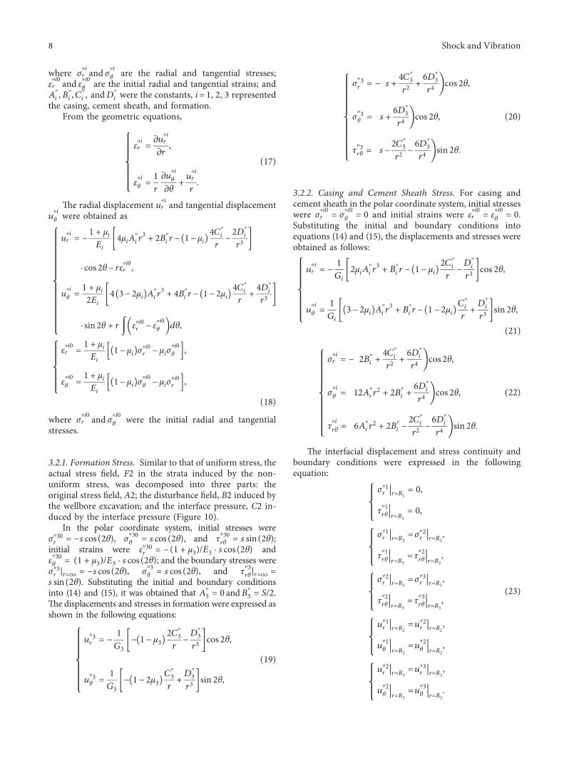
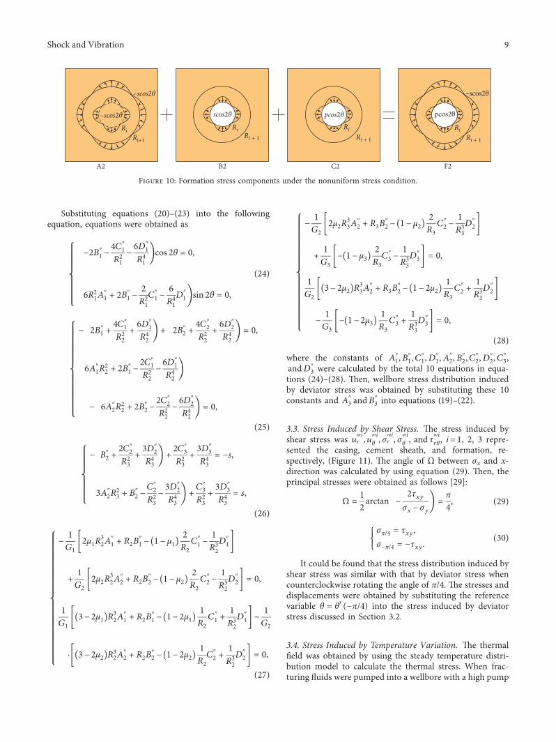
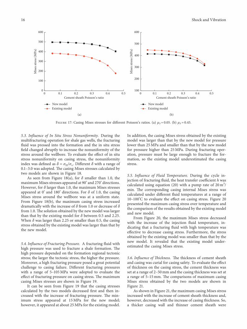

International Journal of
AerospaceEngineeringHindawiwwwhindawicom Volume 2018
RoboticsJournal of
Hindawiwwwhindawicom Volume 2018
Hindawiwwwhindawicom Volume 2018
Active and Passive Electronic Components
VLSI Design
Hindawiwwwhindawicom Volume 2018
Hindawiwwwhindawicom Volume 2018
Shock and Vibration
Hindawiwwwhindawicom Volume 2018
Civil EngineeringAdvances in
Acoustics and VibrationAdvances in
Hindawiwwwhindawicom Volume 2018
Hindawiwwwhindawicom Volume 2018
Electrical and Computer Engineering
Journal of
Advances inOptoElectronics
Hindawiwwwhindawicom
Volume 2018
Hindawi Publishing Corporation httpwwwhindawicom Volume 2013Hindawiwwwhindawicom
The Scientific World Journal
Volume 2018
Control Scienceand Engineering
Journal of
Hindawiwwwhindawicom Volume 2018
Hindawiwwwhindawicom
Journal ofEngineeringVolume 2018
SensorsJournal of
Hindawiwwwhindawicom Volume 2018
International Journal of
RotatingMachinery
Hindawiwwwhindawicom Volume 2018
Modelling ampSimulationin EngineeringHindawiwwwhindawicom Volume 2018
Hindawiwwwhindawicom Volume 2018
Chemical EngineeringInternational Journal of Antennas and
Propagation
International Journal of
Hindawiwwwhindawicom Volume 2018
Hindawiwwwhindawicom Volume 2018
Navigation and Observation
International Journal of
Hindawi
wwwhindawicom Volume 2018
Advances in
Multimedia
Submit your manuscripts atwwwhindawicom