new control strategies for neuroprosthetic systems · new control strategies for neuroprosthetic...
TRANSCRIPT

Department ofVeterans Affairs
Journal of Rehabilitation Research andDevelopment Vol 33 No . 2, April 1996Pages 158-172
New control strategies for neuroprosthetic systems
Patrick E. Crago, PhD ; Ning Lan, PhD ; Peter H. Veltink, PhD; James J. Abbas, PhD ; Carole Kantor, MSDepartment of Biomedical Engineering, Case Western Reserve University and FES Center, Cleveland VA MedicalCenter, Cleveland, OH 44106; Biomedical Engineering and Instrumentation, Department of ElectricalEngineering, Tsinghua University, Beijing 100084, P . R. China; Department of Electrical Engineering, Universityof Twente, 7500 AE Enschede, The Netherlands ; Center for Biomedical Engineering, University of Kentucky,Lexington, KY 40506; Tantalus, Inc ., Highland Park, NJ 08904
Abstract—The availability of techniques to artificially exciteparalyzed muscles opens enormous potential for restoringboth upper and lower extremity movements withneuroprostheses . Neuroprostheses must stimulate muscle, andcontrol and regulate the artificial movements produced.Control methods to accomplish these tasks includefeedforward (open-loop), feedback, and adaptive control.Feedforward control requires a great deal of informationabout the biomechanical behavior of the limb . For the upperextremity, an artificial motor program was developed toprovide such movement program input to a neuroprosthesis.In lower extremity control, one group achieved their bestresults by attempting to meet naturally perceived gaitobjectives rather than to follow an exact joint angle trajectory.Adaptive feedforward control, as implemented in the cycle-to-cycle controller, gave good compensation for the gradualdecrease in performance observed with open-loop control . Aneural network controller was able to control its system tocustomize stimulation parameters in order to generate adesired output trajectory in a given individual and to maintaintracking performance in the presence of muscle fatigue . Theauthors believe that practical FNS control systems mustexhibit many of these features of neurophysiological systems.
This material is based upon work supported by the Department ofVeterans Affairs, Rehabilitation Research and Development Service,Washington, DC ; Paralyzed Veterans of America Spinal Cord ResearchFund ; National Science Foundation ; University of Miami ; BakkenResearch Center; National Institute of Child Health and HumanDevelopment of the National Center for Medical Rehabilitation andResearch; and, the National Institute of Neurological Disorders andStroke.Address all correspondence and requests for reprints to : Patrick E. Crago,PhD, Cleveland FES Center, 11000 Cedar Avenue, Suite 207, Case WesternReserve University, Cleveland, OH 44106-7211 .
Key words : adaptive control, closed-loop, feedback, feedfor-ward, FES, FNS, open-loop.
INTRODUCTION
The availability of techniques to artificially exciteparalyzed muscles opens up enotttlous potential forrestoring both upper extremity and lower extremitymovements with neuroprostheses . In addition to stimu-lating the muscle, the neuroprosthesis must take onother tasks normally performed by the nervous systemto both control and regulate the artificial movements.The control task refers to specification of the temporalpatterns of muscle stimulation to produce the desiredmovements; and the regulation task is the modificationof these patterns during use to correct for unanticipatedchanges (disturbances) in the stimulated muscles or inthe environment.
The purpose of this paper is to review recentdevelopments in the control and regulation of move-ments produced by neuroprostheses . The topics werechosen not because they are current clinical practice, butbecause they represent significant recent advances andare representative of the diverse control approaches thatare likely to be required in future neuroprostheses . Thisintroduction will define some basic control concepts(feedforward, feedback, and adaptive control, see Fig-ure 1) that are used in the subsequent sections . Theseconcepts are not unique to engineering ; examples can befound throughout physiology . A good fundamentaldescription of the concepts with specific reference to
158

159CRAGO et al . New Control Strategies for Neuroprosthetic Systems
Figure 1.Generic block diagram illustrating concepts of feedforward (open-loop) control, feedback control, and adaptive control . In feedforwardcontrol, the desired movements and forces are used to generate themuscle activation patterns that should produce the movement . Infeedback control, sensors are used to monitor the actual movementsand forces, and a feedback controller modifies the activation patternsto correct for differences between the desired and actual outputs . Inadaptive control, the inputs and outputs are monitored and thefeedforward and/or feedback controllers are modified to optimizeperformance.
physiological systems can be found in Houk's writing(1) .
The temporal specification of stimulation patterns(control) for both upper and lower extremity neuro-prostheses is difficult because of the complexity of themusculoskeletal systems . Specification of the patternsmust account for the nonlinear and dynamic relation-ships between stimulus parameters and muscle output,and between muscle output and limb output, as well asthe varying load encountered as the user interacts withthe environment . In some systems, only the steady-state(static) input-output properties are considered ; however,in most systems, both static and dynamic properties areimportant . For example, in the hand grasp neuro-prosthesis developed at Case Western Reserve Univer-sity and the Cleveland VA Medical Center (CWRU/VAMC), the stimulus parameters for seven muscles arealtered on the basis of a single continuously gradedcommand signal to open and close the grasp and tomodulate the force applied to objects being grasped (2).Grasp control is synthesized by specifying constantrelationships (pulse width maps) between the singlecommand signal that is graded by the user and the pulsewidth applied to each muscle . Synthesis is carried outeither by following simple qualitative rules (3) or with aquantitative automated process (4) . Grasp synthesisaccounts for nonlinear relationships between the stimu-lus parameters and the grasp output, but does not takeinto account the dynamic properties of the system beingcontrolled, since the dynamic properties are not verysignificant for grasp-release tasks .
Grasp control in the CWRU/VAMC system doesnot require a command signal to be generated by theneuroprosthesis, since it is under voluntary control bythe user. In contrast, a neuroprosthesis controller forlocomotion, while allowing stimulation to be started andstopped voluntarily by the user, must generate com-mands to create the basic walking pattern. Furthermore,the synthesis process must take into account thedynamic properties of the muscles and the limb.
In current neuroprosthetic implementations, loco-motion is synthesized by iteratively modifying a basictime-varying stimulation pattern to improve the gait ofeach subject (5) . Stimulus magnitudes and timing arealtered on the basis of walking performance, as assessedvisually or by quantitative motion analysis . The iterativemodification rules are based on the experience ofexperts, and compensate for both system nonlinearitiesand dynamic properties . The dynamic properties that aremost important are the inertia of limb segments and thetime between when a muscle is stimulated and when itactually generates force to accelerate or decelerate thelimb. Because of the dynamic system properties, asingle pattern is not suitable for all walking speeds.
The control systems described above can beclassified as feedforward control systems, since theyspecify the stimulus parameters (musculoskeletal systeminputs) that are expected to be needed to produce thedesired movement (system outputs) . Feedforward con-trol systems do not make corrections if the actualmovement deviates from the desired movement. Devia-tions are common in neuroprostheses because propertiesof stimulated muscle vary with time (e .g ., fatigue) andbecause the user operates in a constantly changingenvironment (e .g ., changes in the slope of the walkingsurface).
A broad category of control systems that correctfor a changing system or environment is feedbackcontrol . In a feedback control system, sensors monitorthe output and corrections are made if the output doesnot behave as desired . The corrections are made on thebasis of a control law, which is a mathematicalprescription for how to change the input to reduce thedifference (error) between the desired output and theactual output . Much of the work done in automaticcontrol of stimulated muscle in the last 20 years hasfocused on feedback controllers . The objectives havebeen assessing how well feedback control can regulatemotor activities, and identifying the best control law forthe system being controlled and for the type of behaviordesired (6) . Feedback control has been successful in
desiredmovements,
forcesInputs
>
open-loop
adjustedactivation
activationpatterns
patterns
external andinternal
disturbances
actualmovements,
ores
Outputs
FeedforwardController
AdaptiveControlle
Controlled Systemmuscles, limbs, loads,
environment
FeedbackController
C
feedbackloop
Sensors

160
Journal of Rehabilitation Research and Development Vol . 33 No. 2 1996
regulating hand grasp (7) and standing posture (8), but itappears that another strategy, adaptive feedforwardcontrol, is likely to be required for dynamic activitiessuch as locomotion.
Adaptation refers to the ability of a control systemto change how it responds to inputs or disturbances,based on changes in the properties of the controlledsystem or the environment . In movement control, themusculoskeletal system properties are monitored bymeasuring the inputs (commands, stimulus parameters)and the actual outputs (movements, forces) duringneuroprosthesis operation. From the inputs and outputs,the feedforward controller and/or the feedback controllaw are altered to improve performance according to apredetermined optimization criterion . For example, inlocomotion control, the quadriceps stimulation intensitymight be progressively increased in amplitude tocompensate for fatigue that would cause the knee tobuckle during standing.
There are tradeoffs in the choice of control systemfor a neuroprosthesis . Even extremely simple feedbackcontrol laws can improve performance greatly and cancompensate for any source of disturbance, but they alsohave drawbacks. Feedback control requires outputsensors, and compensation is generally slower than infeedforward control since an output error must bepresent to generate a controller response . Thus, feed-back control might be best used for slow movements,and for maintaining a steady posture (e .g ., hand grasp).On the other hand, feedforward control requires muchmore detailed internal infonnation about how thesystem behaves in order to generate a stimulus patternthat will produce an accurate movement, and it mayproduce poor movements if the system propertieschange . The most significant advantages of feedforwardcontrol are that it can be used for rapid movements suchas the swing phase of gait, and it does not requiresensors . Adaptation requires sensors to monitor output,and can be used to improve the performance of eitherfeedback or feedforward control . The neuroprostheticsystems described below use a mix of the three types ofcontrol system, and all employ some type of machineintelligence . The technologies that have been investi-gated include optimization, rule bases, neural networks,adaptive logic networks, and fuzzy logic.
Control of Upper Extremity Motor Tasks withFunctional Neuromuscular Stimulation (FNS)
Control of the upper extremity involves transport-ing the hand to a desired position in space and
providing postural stability for the aim while manipulat-ing objects . In people with C4–C6 spinal cord injury(SCI), the muscles that control these functions may bepartially or completely paralyzed . The goal of FNS is torestore some degree of the lost function even withlimited channels of stimulation and simple controlstrategies (9) . An important and distinctive characteris-tic of most upper extremity movements is that they aregoal directed rather than cyclic . The amplitude, speedand direction of arm motions vary from one movementto the next. Thus, a generator of movement patternsmust be capable of providing a rich variety of patterns.This contrasts significantly with the needs of a patterngenerator for locomotion, which is repetitive andrequires relatively few patterns.
Structure of a Perturbation ControllerEarlier studies focused on developing feedback
control strategies for FNS motor task control . Onestrategy was to regulate the stiffness of the limb bycombining position feedback and force feedback . Stiff-ness is an inherent property of muscles that is animportant determinant of limb stiffness (10–12) . Stiff-ness regulation, as opposed to pure position or pureforce regulation, is advantageous because it can operateunder both isometric and/or unloaded conditions toprovide regulation of interaction force and/or move-ments . Stiffness regulation has been demonstrated inhand grasp tasks (7), and can be implemented with avariety of feedback controllers (13) . Feedback stiffnesscontrol has also been demonstrated in an animal modelfor two-joint movement control or end-point forcecontrol (14).
In arm movements, the inertias and interactionsbetween joints play significant roles in determiningmovement trajectories (15) . Feedback control cannotcompensate accurately for these effects . Withfeedforward (open-loop) control, compensation is oftenmade in advance. It is based on the mechanics of thesystem to ensure consistent perfounance under changingconditions.
Control of arm movement by FNS entails specifi-cation of a stimulation pattern for a set of redundantmuscles, which are highly nonlinear and time-varyingactuators . To account for the biomechanics of the limband the muscles, and to adapt to system changes such asmuscle fatigue, Lan has proposed a combined strategythat includes both open-loop and closed-loop controls toachieve the needed diversity of task control (16) . Thecontroller, shown in Figure 2, is called a perturbation

161
CRAGO et at . New Control Strategies for Neuroprosthetic Systems
Visual Feedback
Figure 2.A perturbation control structure for controlling arm movements andregulating the stiffness at the end point of the arm . In this case, thefeedforward controller specifies the nominal muscle activationpatterns (Un), and in addition specifies the desired movementtrajectory and the desired endpoint stiffness . Sensors monitor theendpoint position and force so that a feedback controller can makeadjustments (Ud) to the activation patterns . The controlled systemconsists of the muscles, external load, and limb dynamics.
controller . In this system, the user initiates a task byinstructing the controller with specific commands . Thefeedforward controller interprets the instructions andgenerates a pattern of stimulation commands to themuscles . Theoretically, if all dynamic and nonlinearproperties are taken into consideration, the feedforwardrules should be able to drive the limb to perfoun themovement satisfactorily . In practice, necessary simplifi-cations in the specification of stimulation pattern by thefeedforward controller result in errors in performance.In addition, muscle fatigue will also cause deviationfrom the desired movements . Therefore, a feedbackcontroller is incorporated to eliminate the performanceerrors due to these disturbances, which are viewed asperturbations to the system.
An Artificial Motor Program for MultijointMovements
Currently, Lan is focusing on the feedforwardcontroller, and developing an artificial motor program(AMP) that can generate muscle stimulation patterns fora class of movements of various directions, speeds, anddistances (17,18) . The goals for the AMP are 1) toproduce normal looking movements ; 2) to generate awhole class of movements rather than just a singlemovement ; 3) to be tunable to suit different users anddifferent muscles ; and 4) to be able to minimize musclestimulation (i .e ., limit fatigue) . This is illustrated for thesimplest case of multijoint movement control, a two-joint system controlled by at least three pairs of
muscles . One pair of muscles controls the elbow joint, asecond pair controls the shoulder joint, and a third pair(biarticular muscles) controls both the elbow and theshoulder . The number of muscles is greater than thenumber of mechanical degrees of freedom, making thesystem redundant . In such systems, there is no uniquesolution to the kinematic control problem, and morethan one set of muscle inputs can produce nearlyidentical trajectories.
The human brain has solved the problem ofcontrolling arm movement through a hierarchical neuralcontrol structure . Although we do not fully understandhow the nervous system achieves the solution, we stillcan use the normal motor system as a template forpotentially useful strategies of FNS movement control.In this way, Lan established a method of generating anAMP guided by the hierarchical structure of the humanmotor control system. He created a three-level modelstructure: a bottom level consisting of a two-jointmusculoskeletal system with three pairs of muscles,a middle level analogous to reflex control, and atop level that minimizes effort of movement (19) . Theinput to this model consists of three parameters thatspecify a movement : PO is the initial position of thearm, Pf is the final position of the arm, and Phconstrains the maximal level of an excitation signal(ranging from 0 to 1) for each pair of muscles . TheAMP puts out a vector of control signals ; each elementcontains two components : one for flexor control andone for extensor control.
The bottom level of the model includes nonlineartwo-joint dynamics of the arm, a proportionality be-tween muscle force and stiffness, linear muscle activa-tion dynamics and a nonlinear joint viscosity . Themiddle level contains a neural circuit of reciprocalinhibition, and linear neural excitation dynamics . Theneural circuit integrates the efferent and afferent sig-nals to produce muscle activation signals . This func-tion is believed to be accomplished in the normalspinal cord through interneurons (20) . The top levelcalculates two descending commands, equilibriumpoints for each joint and excitation signals for each pairof antagonist muscles . These are continuous functionsof time.
The model has constraints due to its global inputs:movement has to start at the initial position and finish atthe final position, and there is an upper bound on theexcitation signal which delineates the maximal level ofmuscle force that can be recruited . Also, there is aconstrained range of joint movement and a constrained
PatientCommands
FeedforwardController
d ForceSensor
Desired Stiffness
Desired Movement Trajectory
RegulatedStiffness
u
Muscles
FeedbackController
Fd
LimbDynamics
ExternalLoad
P
PositionSensor

162
Journal of Rehabilitation Research and Development Vol . 33 No. 2 1996
range of muscle inputs . The upper bound of excitation isthe parameter that is tuned to adjust the kinematiccharacteristics of the movement.
Analysis of the AMPThe input parameters specifying the movement do
not completely specify the input signals to the muscles.The complete set of muscle input signals is found by adynamic optimization technique that analyzes the be-havior of the AMP for two-joint planar arm movements(17,18) . The optimization criterion was to minimize theeffort, as defined by Hasan (19), which tends also tominimize joint stiffness. With this criterion, the co-contraction of antagonistic muscles is at a minimumlevel, and thus muscle fatigue can be reduced duringFNS movement control.
An example of a reaching movement is shown inFigure 3 . Hand movement is illustrated in Figure 3a . Anearly straight movement with a bell-shaped velocityprofile is obtained . The movement in the Y direction,particularly, is very similar to what would be observedin a single joint movement . The joint movements areillustrated in Figure 3b . These movements are also verysimilar to a single joint movement. The joint stiffnessesare dynamically modulated . Muscle activation patternsare illustrated in Figure 3c . A triphasic and biphasicpattern of muscle activation is produced.
In summary, the optimized AMP displayed fourdistinct features:
1. The movement produced was smooth with abell-shaped path-velocity profile, giving it thegrace of a natural movement.
2. The AMP could generate movements in differentdirections, across different distances, and at differ-ent speeds. Therefore, it had sufficient diversityfor controlling a class of movements.
3. The AMP could be tuned to accommodate differ-ent inertial loads of the limb . Thus, it could beused in people with different limb sizes.
4. The AMP produced triphasic burst activities inmuscle stimulation patterns in both moderate andfast speed movements . The normal EMG patternsobserved during voluntary movements have simi-lar triphasic burst features (21) . This characteristicmay be seen as the result of minimizing muscleactivation.
Muscle stimulation patterns and movement kine-matics obtained by the AMP are consistent withexperimental data on both single joint and multijoint
arm movements . Thus, it appears that this AMP can beused as a starting point for implementing a feedforwardcontroller for arm movements, or even for the swingphase of gait . Further computer simulation and experi-mental studies will be required to realize and test thisAMP with the combined feedforward/feedback control-ler design (22).
Control Strategies for FNS-Assisted AmbulationTwo important functional goals for lower extremity
FNS are standing and locomotion . Standing and main-taining a balanced posture are required to perform manyactivities, and feedback control of standing posture hasbeen an important area of investigation . Feedbackcontrol is especially appropriate for postural regulationduring standing because adequate time is available forfeedback corrections. Restoring gait is considered to bemore challenging because of 1) the high inertia of thelimbs during swing and the body during stance, 2) thelow muscle torques generated by electrical stimulation,3) the slow response of muscles to control inputscompared to the duration of the movement, and 4) theinteraction of the endpoint of the limb with a changingterrain . Two approaches to gait control were tested.First were attempts to control and regulate the swingphase of gait, which is particularly difficult because ofthe high inertia and the short duration . The second studyinvestigates the use of artificial neural networks forpattern generation of the cyclic behavior required forgait.
Four Strategies for Controlling and Regulatingthe Swing Phase of Gait
The goal was to optimize stimulation patterns inorder to obtain well coordinated cyclical movement, in away that would compensate for muscle fatigue andexternal disturbances . In controlling cyclical movement,such as ambulation, one can try to follow pre-set (i .e .,reference) joint angle trajectories . However, in theswing phase of gait, following exact trajectories isunimportant and inefficient, leading to fatigue due to thelarge forces that must be exerted to precisely control thehigh inertia body segments . For these reasons, controlof movements was based on natural gait objectives suchas step length, foot clearance, or balance.
A group at the University of Twente in TheNetherlands examined the swing of the lower leggenerated by stimulation of quadriceps in a controlledsetup . The objective was to reach a reference maximalknee angle at each cycle . Successful performance was

163
CRAGO et al . New Control Strategies for Neuroprosthetic Systems
A. HAND MOVEMENT IN CARTESIAN SPACE
B . JOINT MOVEMENTS
0 .7 - - Hand path Equil . path
0 .6 -
F 0.5 -
- 0.4 -
0.3 -
0.2 -
0.1 -
-0 .2
0 .0
0.2X axis (m)
0.3 -
E 0.2- Equil . path- Hand path
0.1 -
d0.0
-0.1 -
i -0.2 -
3 .0 - - Path vet. 'fi 1 .4 --v 2.5 - - - - Vel . in Y
01 .2 -
- Vel . in X1 .0 -2.0 - 0
A . 0 .8 -1 .5 -Q O 0 .6 --
d 1 .0 -s 0.5 -
v0
0 .4 -
0 .2 -a0 .0 sa, 0 .0
0 .0 0 .1 0.2
0 .3
0 .4 0.0Time (sec)
Joint position Equil . position
t
1
0 .1
0.2
0 .3
0 .4Time (sec)
20-8 Elbow
- Shoulder
0 .00
0 .1
0 .2
0.3
0.4
0 .0
0 .1
0.2
0 .3
0 .4Time (sec)
Time (sec)
C. MUSCLE ACTIVATION
- Flexor
Extensor
1
1
10 .0
0 .1
0.2
0.3
0 .4Time (sec)
0.3 --
0.2 -a - Flexorc 0.1 -0
0.0F3 -0.1 -
uw -0.2 - Extensor
-0.3 1T t 1
0 .0
0 .1
0.2
0 .3
0 .4Time (sec)
0.3 -
- Shoulder- Elbow
0.2-
-- . Two joint
0.1 -
- Biceps S.H
0.0 -
-0.1 -
-0.2 -
-0.30.0
0 .1
0 .2
0.3
0.4Time (sec)
0 .0
judged by accuracy of the angle reached, degree ofcompensation for fatigue, degree of compensation fordisturbances, and ability to minimize stimulation . Fourcontrol strategies were compared : 1) open-loop (i .e .,feedforward control with an optimized pre-set stimula-tion pattern); 2) feedback control to follow pre-setreference trajectories ; 3) cycle-to-cycle control (open-
Figure 3.Simulated arm movement produced by an artificial motor program.Part A shows the movement of the endpoint of the arm, where x andy represent movement in the medial/lateral and forward directionsrespectively . The arm is moving nearly straight out from the shoulder.The equilibrium point is the location of the endpoint that wouldproduce no acceleration of the limb. At the beginning of the movement,the equilibrium point moves ahead of the actual position of the arm toproduce forward acceleration . Later in the movement, the equilibriumpoint stays behind the actual location to decelerate the limb . Part Bshows the joint movements that produced the endpoint movementsshown in part A. The movements show sigmoidal position trajectoriesand asymmetrical velocity trajectories, similar to those produced byable-bodied individuals. Part C shows the muscle activation patternsproduced by the artificial motor program for the movement shown inpart A . Activation is in brief bursts, with overlap in the excitation of theflexors and extensors.
loop during each cycle, comparison with objective andadjustment of the stimulation pattern for the next cycle);and 4) model-based predictive control (23) . In model-based predictive control, adjustment for disturbances isattempted during the same cycle . This is only possible ifone can estimate (predict) at each point during the cyclewhether or not the objective (in this case, the knee joint

164
Journal of Rehabilitation Research and Development Vol . 33 No . 2 1996
angle) will be reached. Such a prediction requires amodel of the system, and therefore the first objective ofthis study was to develop such a model.
Identification of a Model for ControlAn important need in adaptive control is a model
that can be used to adjust the stimulation pattern on thebasis of recent system behavior . In the case of theswinging shank, the controlled system includes apassive component (the shank and knee) which can bemodelled as a pendulum with an angle dependence,gravity, stiffness, damping, and an inertia . The secondactive component consists of the stimulated muscle . Themuscle models that were considered included activationdynamics with a delay, angular velocity dependence,and angle dependence . Thus, the combined passive andactive model components would allow prediction of theangle trajectory that would be achieved by a series ofstimulation pulses.
The Dutch researchers identified a model of thestimulation controlled shank in a series of experimentsin which the quadriceps was stimulated in a randomway such that the whole range of combinations of angleand angular velocity was covered. Knee joint angle,angular velocity and acceleration were measured duringthe stimulation, as shown in Figure 4a, b, and c. Thesubject was seated with the lower leg free to move(24,25).
The slow-varying part of the angular accelerations(Figure 4c) are due to the passive dynamics of theswinging leg and the effects of gravity . The sharp peaksare the result of the stimulation . Peak heights vary withangle and angular velocity due to muscle length-tensionand force-velocity properties . In order to estimate theaccelerations due to muscle stimulation alone, Frankenand colleagues at Twente used the slowly varyingcomponents to model the behavior of the leg betweenthe pulses (24) . The passive model was then used tosubtract the passive contributions from the total accel-eration . The remaining active muscle contribution isplotted as the acceleration due to the muscle stimulationin Figure 4d.
The muscle model selected was the simplestamong four that were evaluated (25) . It involved only again and a delay and did as well as the model withactivation dynamics in predicting joint angle trajectory.Prediction results for 100 ms and 1000 ms aheadare shown in Figure 5 . Since muscle fatigue wouldbe apparent in the muscle gain, it was estimatedadaptively .
a.60 --'
Time (s(
Time [sl
Figure 4.Measured and estimated signals of the freely swinging shank system.The quadriceps were stimulated with a pseudorandom interpulseinterval (IPI) stimulation sequence at maximal recruitment . a . themeasured knee angle . b . knee angular velocity estimated from theangle signal. c. the measured angular acceleration and appliedstimulation pulses . d . the estimated equivalent acceleration M/I dueto quadriceps stimulation . MIT was obtained by subtracting thecontribution of the passive system from the measured angularacceleration . Each sample of MIT resulted from substitution ofmeasured knee angle, angular velocity, and accleration in theidentified model for the passive system . The stimulation pulses arealso shown . Reprinted with permission from Franken HM, VeltinkPH, Tijsmans R, Nijmeijer H, Boom HBK . Identification ofquadriceps-shank dynamics using randomized interpulse intervalstimulation : IEEE Trans Rehab Eng 1995 :3 :182-92, © 1995 IEEE.
Experimental Comparison of the Four ControlStrategies
Three types of tests were used to evaluate the fourcontrol strategies : open-loop, trajectory-following, cycle-to-cycle, and predictive control . All four were tested forcontrol and regulation of knee extension in sittingsubjects . In addition, cycle-to-cycle control was com-pared to open-loop control in tests with subjectsstanding and walking.
In tests of all four strategies, subjects sat with theirshanks free to swing forward under control of thestimulated quadriceps (see Figure 6) . Every 3 sec a newmovement was initiated from a resting position . Forsome trials a freely hanging basketball obstructed themotion . In these comparisons, the cycle-to-cycle andmodel-based predictive controllers performed betterthan the open-loop and trajectory-following controllerswith respect to accuracy after disturbance of the swing
1C
Time (s(
b .
II I! I I Ill5
100
40
P- 200
-20
-40
2000
11 I .I 115
10-4000 0
C.4000

165
CRAGO et al . New Control Strategies for Neuroprosthetic Systems
(basket)ball
cushion
left stander right stander
standingtable (side view)
standingtable (front view)
Figure 6.Experimental setup for testing control strategies of lower leg swingwith paraplegic subject seated.
Figure 5.Actual (solid) and estimated (dashed) knee angle in subject JM-left,using the simplest muscle model . Each point in the graph for theestimated knee angle followed from a prediction ahead for a periodof 100 ms (top) or 1000 ms (bottom) . Adapted from Franken HM,Veltink PH, Tijsmans R, Nijmeijer H, Boom HBK . Identification ofquadriceps-shank dynamics using randomized interpulse intervalstimulation : IEEE Trans Rehab Eng 1995 :3 :182-92, © 1995 IEEE.
and adaptation to fatigue . Model-based control was theonly strategy that corrected for disturbances during acycle; this occurred when the disturbance was early inthe cycle, but not in all instances.
In the next set of comparisons, attempts were madeto generate stepping-like movements from stance . Thesubject wore a reciprocating gait orthosis (RGO), andstood in a standing table, as shown in Figure 7 (26).Surface stimulation at 50 Hz was applied to hamstrings,quadriceps, and hip flexors . The cycle-to-cycle controlstrategy was compared to the open-loop strategy . In thecycle-to-cycle strategy, movement parameters at the endof each cycle were compared to the gait objectives, andthe stimulation for the next cycle was adjusted on thebasis of the error in the preceding cycle . This test wasrestricted to adjustment of hip flexor stimulation.Objectives were constant hip angle range (equivalent toconstant step length), foot clearance, and knee extension
at the end of the swing phase. For open-loop control, anoptimized stimulation pattern was developed to yieldthese objectives, as shown in Figure S . Each cyclebegan with stimulation of the hamstrings (for foot clear-ance), followed by the hip flexors (to swing the legforward), and finally the quadriceps (to extend the knee).
Open-loop control produced a large overshoot inthe hip angle range at the start . Over the next fewhundred cycles, the range decreased below the targetlevel as the muscles fatigued. In comparison, withcycle-to-cycle control the overshoot was shorter, withthe angle well regulated at the target level.
Finally, some of these control elements wereincorporated into the stimulation system . In completeT5–6 level SCI subjects, Franken and colleagues used ahybrid system to provide surface stimulation to thequadriceps, hamstrings, and hip flexors, together withan RGO (27) . While not an optimal neuroprostheticsystem, it was adequate to allow testing of these controlmethods . A high level control allowed the user toinitiate each step. This was a finite state system similarto ones reported by others (28) . Sensors (a hipgoniometer and a crutch force sensor) allowed the userto start each step without having to operate a handswitch. Addition of the cycle-to-cycle controller suc-

166
Journal of Rehabilitation Research and Development Vol . 33 No. 2 1996
80
m 60t° 40m
0O1 20m
0
50
100
150
200
250cycle
H'64*4o hamstrings
— hip flexors o quadriceps
0
80
m
60rn
40
m
20
800
600
400
200
0
0
0 50 100 150 200 250
cycle
Figure 7.Experimental setup for testing control strategies of leg swing whileparaplegic subject was standing . Subject wore a self-fitting modularorthosis that restricted motion of the freely swing-leg to the sagittalplan with a locked ankle joint . Hip, knee, and ankle of thesupporting leg were locked; the standing leg was elevated by ablock ; a bicycle saddle provided additional support . Trunk andpelvis movements in the sagittal and frontal plane were prevented bythe setup . Hip and knee angles of the freely swinging leg weremeasured by externally mounted goniometers . Reprinted withpermission (26).
cessfully adjusted stimulation bursts on the two sides tomake the gait symmetrical . Effectiveness of the control-ler was limited by the limited range of electricallyactivated hip torques that could be generated and by themovement limitations imposed by the RGO.
In summary, the best control was achieved byattempting to meet naturally perceived gait objectivesrather than following an exact joint angle trajectory.Adaptive feedforward control, as implemented in thecycle-to-cycle controller, gave good compensation forthe gradual decrease in performance observed withopen-loop control . Disturbances during a cycle may beadjusted for with a model-based predictive controlstrategy. The model does not need to include theactivation dynamics of muscle, since in this caseperformance is limited by the inertia of the limbsegment being controlled.
Neural Network Algorithms in Locomotion ControlNeural networks have been applied in a wide
variety of engineering problems that involve pattern
Figure 8.Results of stimulation trials . Left: hip and knee angle andstimulation onset and duration during the open-loop stimulation trialin subject A with optimised stimulation for the three muscle groups:hip flexors, quadriceps, and hamstrings . Stimulation sequences wereapplied without adaptation . Upper right: hip angle range per swingcycle obtained in the open-loop controlled stimulation trial withoptimized stimulation timing for the three muscle groups in subjectA . The desired value for each swing phase objective is indicated bythe dotted line . Lower right: hip angle range (solid) and hip flexorburst duraton (dash-dot) per swing cycle obtained in a cycle-to-cyclecontrolled stimulation trial in subject A . Hip flexor stimulaton burstduration was adapted from cycle-to-cycle with the onset remainingunchanged . Stimulation onset and burst duration for hamstrings andquadriceps were identical to the open-loop experiment settings.Reprinted with permission (26).
recognition, pattern classification, adaptive filtering, andcontrol . In an engineering block diagram, a neuralnetwork is a block that receives inputs, performs somecalculations, and generates outputs . It is called a neuralnetwork because the algorithm used in its internalprocessing is based on models of nervous systemfunction . The underlying idea is that each neurongenerates output based on the inputs that it receivesfrom other neurons . The pattern of interconnectionsamong neurons determines the network architecture.Neurons may receive inputs from or send outputs toother system components . The interconnection strengthsamong neurons are often adapted using a learningalgorithm to modify the input-output properties of thenetwork. The capability of learning complex nonlinearinput-output mappings is often the characteristic thatmakes neural networks an attractive option in engineer-ing design.
The development of new algorithms and architec-tures and the application of existing algorithms are both
167
CRAGO et al . New Control Strategies for Neuroprosthetic Systems
active areas of research . In one approach, new neuralnetworks incorporate more complex biological featuressuch as the capacity to generate complex oscillatorypatterns . The authors believe that a practical FNScontrol system must exhibit many features of neuro-physiological systems. Neural network techniques, whenused in conjunction with other engineering controlsystem and signal processing techniques, may be aviable approach to achieving this goal.
The nonlinear processing capabilities of neuralnetworks make them attractive for use in many bio-medical problems . Also, their adaptive capabilitiesmake neural networks particularly attractive for use inrehabilitation applications where the engineering systemmust often be customized for a particular individual.Several researchers have previously used neural net-works in FNS systems. Veltink et al . used neuralnetworks to generate stimulation patterns by learningthe mappings between biomechanical output variablesand EMG signals from normal subjects (29) . Lan et al.used neural networks to generate muscle stimulationpatterns for the control of arm movements (30) . Kostovet al . used adaptive logic networks (which are similar toneural networks) to provide switching signals to amultistate FNS controller (31). The successes of thesestudies, along with the results reported here, indicatethat neural networks may be useful in many componentsof a variety of FNS control systems.
This section describes a neural network (both thearchitecture and learning algorithm) that was developedby Abbas and colleagues for the purpose of controllingcyclic movements in an FNS system (32-34) . Thelong-term objective of this work is the development ofcontrol systems for FNS locomotion . In such an FNScontrol system, the major problems to be addressed are:1) each patient is different in terms of strength,recruitment properties, weight, height, and so forth ; 2)muscle response properties change due to fatigue ; and3) the external environment is uncertain . Here, ourfocus is on the first problem, intersubject variability,which arises on a practical level when an FNS system istuned for a particular user . Automatically customizingthe control system addresses the first problem and mayalso be able to address the problem of muscle fatigue,provided the customization can be performed on-lineand rapidly. The problem of the uncertain environment,which is not addressed here, may require the use ofcontrollers that exploit the inherent stiffness propertiesof muscle and/or those that use feedback or predictivecontrol as described above .
Abbas and colleagues developed a control systemthat utilizes one neural network as a pattern generatorand a second neural network as an adaptive filter . Theyconducted experiments on simple, one-segment systems,constituting the first stages of the evaluation of thecontrol system. The first set of experiments wasperformed on computer-simulated models of a single-segment skeletal system; the second set of experimentswas performed on seated human subjects . Resultsindicate that the control system performs well on thesesimpler systems; thus, further evaluation on morecomplex systems is warranted.
Design of Neural Network ControllerThe control system builds on a general model of
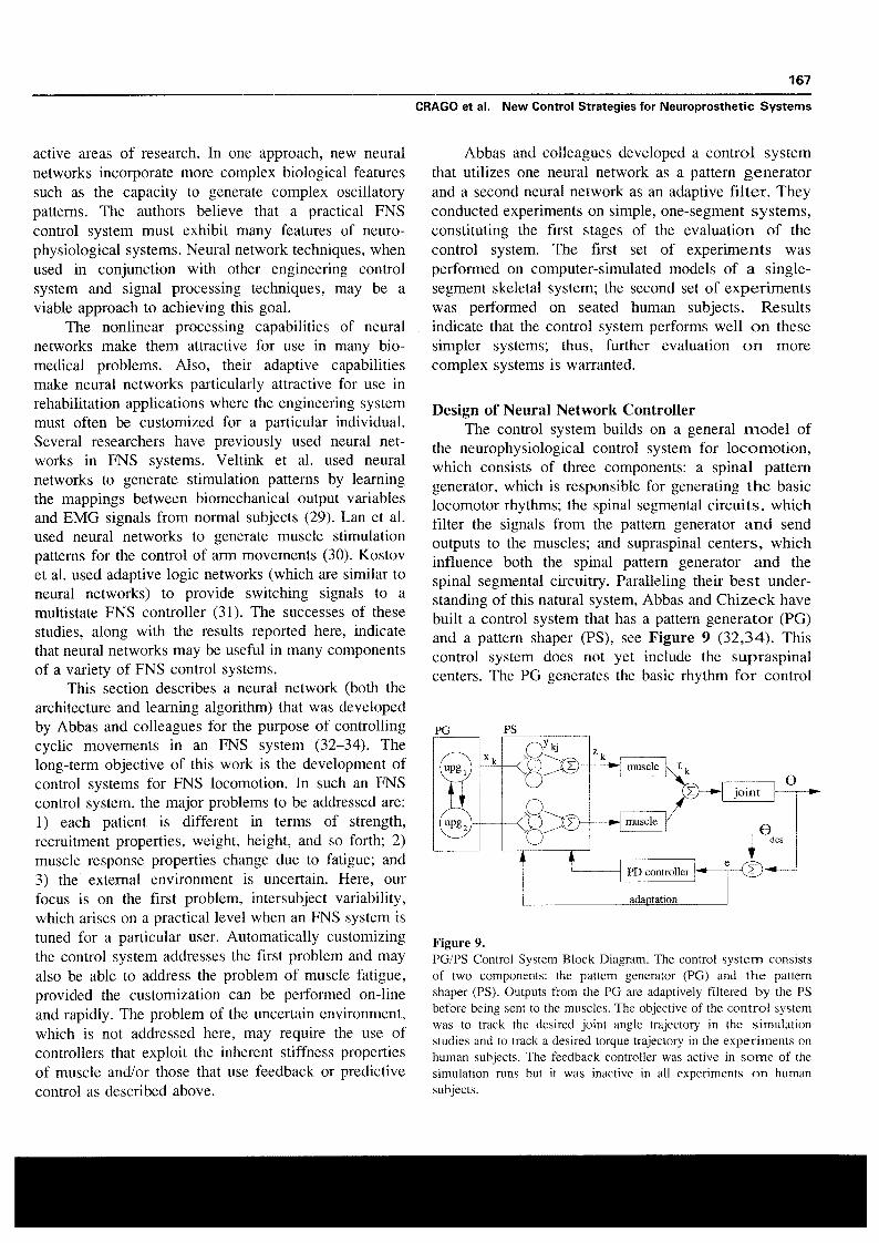
the neurophysiological control system for locomotion,which consists of three components : a spinal patterngenerator, which is responsible for generating the basiclocomotor rhythms ; the spinal segmental circuits, whichfilter the signals from the pattern generator and sendoutputs to the muscles ; and supraspinal centers, whichinfluence both the spinal pattern generator and thespinal segmental circuitry . Paralleling their best under-standing of this natural system, Abbas and Chizeck havebuilt a control system that has a pattern generator (PG)and a pattern shaper (PS), see Figure 9 (32,34) . Thiscontrol system does not yet include the supraspinalcenters . The PG generates the basic rhythm for control
PG
Ps
Figure 9.PG/PS Control System Block Diagram . The control system consistsof two components : the pattern generator (PG) and the patternshaper (PS) . Outputs from the PG are adaptively filtered by the PSbefore being sent to the muscles . The objective of the control systemwas to track the desired joint angle trajectory in the simulationstudies and to track a desired torque trajectory in the experiments onhuman subjects . The feedback controller was active in some of thesimulation runs but it was inactive in all experiments on humansubjects .

168
Journal of Rehabilitation Research and Development Vol . 33 No. 2 1996
ling a given movement . The PS adaptively filters thosesignals and sends its output to the muscles . The adaptiveproperties of the PS provide the control system with theability to customize stimulation parameters for a par-ticular individual and to adjust them on-line to accountfor fatigue . In some of the computer simulationexperiments reported below, a proportional-derivativefeedback controller was also active.
The PG is a set of coupled neural oscillators, basedon a model of neural circuitry (35) . In this work, the PGwas chosen to generate two outputs : one to drive theflexor muscle and one to drive the extensor muscles.Each output from the PG first passes through a PS unit,which adaptively filters the signal before it is sent to themuscle. Each PS unit consists of a set of 16 neurons.The output of the PS unit is the weighted summation ofthe outputs of the neurons in the unit . The learningalgorithm uses a tracking error signal to adjust theweights on this summation (34) . A novel feature of thelearning developed for use in this controller is themanner in which past stimulation values are related totracking errors at the current time . This allows thelearning algorithm to account for the delay and thedynamics of the musculoskeletal system response . It isimportant to note that the adaptation of the controllerparameters does not require an explicit model of thesystem being controlled . It only assumes the direction inwhich a muscle will act (i .e ., more stimulation to theflexor will produce more flexion) and that trackingerrors at the current time can be attributed to stimulationvalues over the past several time steps . In summary, theoperation of the PG/PS controller can be described asfollows : the PG provides the basic pattern of activationfor each of the muscles for a particular movement andthe PS provides fine tuning of that pattern for aparticular individual.
Evaluation of Neural Network Controller inSimulation
Computer simulation studies were used in thedevelopment and evaluation of the control system.These studies (34) used a model of a single skeletalsegment in a swinging pendulum and in an invertedpendulum configuration that included linear stiffnessand damping. The skeletal segment was acted upon byan agonist/antagonist pair of muscles. For each muscle,the torque generated was modeled as the product ofthree terms : an activation term (that included nonlinearrecruitment and linear dynamics), a torque-angularvelocity term (to account for the length-tension proper-
ties of muscle), and a torque-angle term (to account forthe force-velocity properties of muscle).
One component of the evaluation sought to charac-terize the controller's ability to automatically determinean appropriate set of stimulation parameters to generatea specified movement in a given individual . Here, thepattern generator was configured to provide an oscilla-tory signal at a frequency of 1 Hz, and the patternshaper output weights were initialized to 0 (thereforewithout adaptation, no stimulation would be sent) . Thedesired joint angle trajectory was specified to be a 1 Hzsinusoid with an amplitude of 20° . The network wastrained for 20 cycles with the feedback controller active.Figure 10 demonstrates that good tracking wasachieved after only a few cycles and that the trackingperformance was maintained (RMS tracking error is lessthan 0.5°) after the feedback controller had beeninactivated, thus indicating that the PS had adapted sothan an appropriate feedforward stimulation pattern wasdelivered to the muscles.
In order to determine if the PS could adapt togenerate the same movement on different individuals,several trials were conducted with the same computersimulation experiment described above on the samesystem model, but the parameters of the model werevaried from trial to trial . Seven system parameters(muscle gain, torque-angle width, torque-velocity slope,maximum shortening velocity, segment mass, jointstiffness, and joint damping) were varied over a rangeof -!-50 percent in increments of 10 percent to generate71 different systems on which to test the adaptationalgorithm . In each of these trials, the RMS error of thefeedforward controller was approximately 0 .5°, which isabout 1 percent of peak-to-peak amplitude of the signalbeing tracked. These results indicate that the networkwas able to customize the stimulation parameters foreach of the 71 model variations.
Similar tests on an inverted pendulum have indi-cated that the network was able to customize thestimulation parameters to generate the desired move-ment of this inherently unstable system and thus achievevery good tracking without the use of feedback con-trol . Other tests using computer simulations wereperformed in order to determine the effects of measure-ment noise and disturbances on both the adaptation andthe feedforward tracking performance . These testsindicated that the performance of the network wasdegraded, but still within acceptable limits, for largevalues of measurement noise and mechanical distur-bances (34) .

169
CRAGO et al . New Control Strategies for Neuroprosthetic Systems
6
rms error(deg)
020
Tracking performance as muscle fatigues
training the control systemactualdesired
1PSz(t)
0
4
6time (sec)
8
10musclegain0
feedforward control50
100time (sec)
00
Figure 10.Simulation results demonstrating that rapid training achieved by thecontrol system (top) and that excellent tracking is achieved by thefeedforward controller after adaptation was complete (bottom) . Theactual and desired traces virtually overlap.
In another stage of the evaluation, Abbas sought tocharacterize the performance of the controller underconditions of muscle fatigue . In these sets of experi-ments, he first trained the controller on a system thatwas not fatiguing for 20 cycles of movement ; then heintroduced muscle fatigue by producing an asymptoticdecay of muscle gain to 50 percent of its original value,as shown in Figure 11 . He examined the performanceof four controllers : the feedforward controller thatalready had been trained, feedforward with feedback,feedforward with adaptation, and feedforward with bothadaptation and feedback. The results shown in Figure11 indicate that performance degrades with fatigue forthe feedforward or the feedforward with feedback
Figure 11.Simulation results demonstrating that tracking performance ismaintained as muscle fatigues if adaptation is enabled. The bottomtrace shows the drop in muscle gain through the course of the trial,the top set of traces shows the tracking performance (RMS value ofthe tracking error) of each of the controller configurations tested.The performance of the non-adaptive controllers (FF, FF/FB)degrades as fatigue sets in, but the adaptive controllers (FF/AD andFF/AD/FB) maintain very good tracking performance throughout thetrial (note that these two traces virtually overlap).
control configurations and that perfonntance is main-tained when the adaptation is enabled . Thus, theadaptive properties of the PS provide the controller withthe ability to compensate for muscle fatigue.
To summarize this section, computer simulationstudies have been used to characterize the performanceof the PG/PS neural network control system . It iscapable of customizing the stimulation parameters togenerate a given movement in a variety of simulatedsystems and it is able to adjust those parameters on-linein order to account for simulated muscle fatigue.
Evaluation of Neural Network Controller inExperiments on Human Subjects
Although computer simulations are a useful toolfor iterative development of FNS control systems, expe-rimentation on human subjects is still required to assessthe performance of the control system . In the first eval-uation of this control system in humans, the task of thecontroller was to control isometric muscle torque in
1
2time (sec)
25angle(deg)
-25
PS 1z(t)
0
actualdesired
flexors— extensors
170
Journal of Rehabilitation Research and Development Vol . 33 No . 2 1996
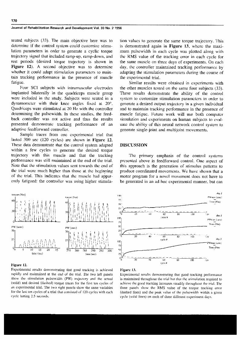
seated subjects (33). The main objective here was todetermine if the control system could customize stimu-lation parameters in order to generate a cyclic torquetrajectory signal that included ramp-up, ramp-down, andrest periods (desired torque trajectory is shown inFigure 12) . A second objective was to determinewhether it could adapt stimulation parameters to main-tain tracking performance in the presence of musclefatigue.
Four SCI subjects with intramuscular electrodesimplanted bilaterally in the quadriceps muscle groupwere included in the study . Subjects were seated in adynamometer with their knee angles fixed at 20°.Quadriceps were stimulated at 20 Hz with the controllerdetermining the pulsewidth . In these studies, the feed-back controller was not active and thus the resultspresented demonstrate tracking performance of anadaptive feedforward controller.
Sample traces from one experimental trial thatlasted 300 sec (120 cycles) are shown in Figure 12.These data demonstrate that the control system adaptedwithin a few cycles to generate the desired torquetrajectory with this muscle and that the trackingperformance was still maintained at the end of the trial.Note that the stimulation values sent towards the end ofthe trial were much higher than those at the beginningof the trial . This indicates that the muscle had appar-ently fatigued: the controller was using higher stimula-
tion values to generate the same torque trajectory . Thisis demonstrated again in Figure 13, where the maxi-mum pulsewidth in each cycle was plotted along withthe RMS value of the tracking error in each cycle forthe same muscle on three days of experiments . On eachday, the controller maintained tracking performance byadapting the stimulation parameters during the course ofthe experimental trial.
Similar results were obtained in experiments withthe other muscles tested on the same four subjects (33).These results demonstrate the ability of the controlsystem to customize stimulation parameters in order togenerate a desired output trajectory in a given individualand to maintain tracking performance in the presence ofmuscle fatigue . Future work will use both computersimulation and experiments on human subjects to eval-uate the ability of this neural network control system togenerate single-joint and multijoint movements.
DISCUSSION
The primary emphasis of the control systemspresented above is feedforward control . One aspect ofthis approach is the generation of stimulus patterns toproduce coordinated movements . We have shown that amotor program for a novel movement does not have tobe generated in an ad hoc experimental manner, but can
Trrns (Nm)
torque (Nm)
0
torque (Nm)
60
30
0
day I
PWmax (usec)
Trms (Nm)
80
100
120
day 2
PWmax (usec)cycle #
100
75
50
25
00
20
40
60
ro60
30
PW (usec)50
0
15
20time (sec)
25
day 3
PWmax (usec)
Tams (Nm)
120
20
40
60
80
00
120cycle #
Figure 12.Experimental results demonstrating that good tracking is achievedrapidly and maintained at the end of the trial . The two left panelsshow the stimulation pulsewidth (PW) trajectory and the actual(solid) and desired (dashed) torque traces for the first ten cycles ofan experimental trial . The two right panels show the same variablesfor the last ten cycles of a trial that consisted of 120 cycles with eachcycle lasting 2.5 seconds .
Figure 13.Experimental results demonstrating that good tracking performanceis maintained throughout the trial but that the stimulation required toachieve the good tracking increases steadily throughout the trial . Thethree panels show the RMS value of the torque tracking error(dashed lines) and the peak value of the pulsewidth within a givencycle (solid lines) on each of three different experiment days.
25
.uwt
I~
III
Ip ~I /\// I275 280 285 290 295 300
time (sec)
PW (usec)50
25

171
CRAGO et al . New Control Strategies for Neuroprosthetic Systems
be generated computationally by application of simpleprinciples. Another aspect of fundamental importance infeedforward control is adaptation when the details of thecontrolled system are unknown to begin with, and aresubject to temporal variations. The two systems forlower extremity control described above showed rapidadaptation to meet the needs for individual subjects andto compensate for fatigue.
All the results presented were obtained underlimited, well controlled conditions or in computersimulation. This is appropriate since the objective wasto show the feasibility of novel control approaches tomeet the needs of the more complex clinical problem. Itis likely that many different approaches will have to becombined to implement automatic control in clinicalsystems. Different phases of motor tasks will requiredifferent solutions . For example, rapid arm movementsor the swing phase of gait may require adaptivefeedforward control such as demonstrated above . Amethod of implementing such control clinically forcontrol of gait is under development at the ClevelandVA Medical Center. The adaptive function is effectedby a gait evaluator that incorporates rules developedfrom expert knowledge of the system' . In contrast to thegait cycle, the stance phase of gait, quiet standing, ormaintenance of a stable arm posture may benefit fromfeedback control in addition to feedforward control andadaptation.
Several lower extremity motor neuroprosthesesincorporate orthoses which reduce the number ofdegrees of freedom to be controlled, provide supportand assist balance, and offer mounting sites for me-chanical sensors (36-39) . While these orthoses maydecrease the number of muscles that need to bestimulated to produce stepping or walking, in theirpresent form, they interfere with the full range ofelectrically-activated motions 2 . Another element thatdemands consideration in designing control methods isthe neuroprosthesis user's residual voluntary function.
Many difficulties still lie ahead for integratingautomatic control techniques into motor systemneuroprostheses . One of these difficulties is sensors . Bynecessity, anything other than pure feedforward controlrelies on sensors to measure the movement outcomes.Sensors must 1) identify the phase or state of amovement task to determine what controls are to beenforced at a given time, and 2) provide information
H . Chizeck, personal communication, July 1994.
2 D . Popovic, personal communication, July 1994 .
about the performance of the stimulated limb to be usedfor feedback corrections, feedforward commands, oradaptation to changing conditions (40).
While most of the variables to be measured areroutine for conventional engineering systems, theypresent formidable challenges in neuroprosthetic appli-cations . The challenges include 1) development ofsensors of small size, 2) mounting the sensors on (or in)the person in an unobtrusive and cosmetically accept-able manner, 3) providing communication of power andinformation to and from the sensor and the point ofcontrol processing, and 4) developing sensor signalprocessing methods. The use of natural sensors (asdescribed by Hoffer et al . in this issue) may solve thefirst two problems, but greatly increases the difficultiesof signal acquisition and processing.
The difficulties outlined above are likely to limitthe rate at which advanced control techniques areintegrated into motor system neuroprostheses. However,the significant increase in performance achieved makessuch an approach highly attractive, and in many casesmandatory.
ACKNOWLEDGMENTS
This paper arose from presentations at the Engi-neering Foundation Conference "Neural Prostheses:Motor Systems IV" on July 23-28, 1994 in Mt.Sterling, Ohio.
REFERENCES
1. Houk JC. Control strategies in physiological systems . FASEB
J 1988 :2 :97-107.2. Keith MW, et al . Implantable functional neuromuscular
stimulation in the tetraplegic hand . J Hand Surg1989 :14A(3) :524-30.
3. Kilgore KL, Peckham PH, Thrope GB, Keith MW, Gallaher-stone KA. Synthesis of hand grasp using functionalneuromuscular stimulation. IEEE Trans Biomed Eng1989:36 :761-70.
4. Kilgore KL, Peckham PH . Grasp synthesis for upper-extremity FNS . Part 1 . Automated method for synthesizingthe stimulus map . Med Biol Eng Comput 1993 :31 :607-14.
5. Kobetic R, Marsolais EB . Synthesis of paraplegic gait withmulti-channel functional neuromuscular stimulation . IEEETrans Rehab Eng 1994:2 :66-79.
6. Chizeck HJ . Adaptive and nonlinear control methods forneural prostheses . In : Stein RB, Peckham PH, Popovic DB,eds . Neural prostheses : replacing motor function after disease

172
Journal of Rehabilitation Research and Development Vol . 33 No. 2 1996
or disability . New York : Oxford University Press, 1992:298-328 .
25 . Franken HM, Veltink PH, Tijsmans R, Nijmeijer H, BoomHBK .
Identification
of quadriceps-shank dynamics
using7 . Crago PE, Nakai RJ, Chizeck HJ. Feedback regulation of randomized interpulse interval stimulation : IEEE Trans Rehab
hand grasp opening and contact force during stimulation of Eng 1995 :3 :182-92.paralyzed muscle . IEEE Trans Biomed Eng 1991 :38(1) :17-28 .
26. Franken HM, Veltink PH, Baardman G, Redmeijer RA, BoomHBK . Cycle-to-cycle control of swing phase of paraplegic gait
8 . Chizeck HJ, Kobetic R, Marsolais EB, Abbas JJ, Donner IH, induced by surface electrical stimulation . Med Biol EngSimon E. Control of functional neuromuscular stimulation Comput 1995 :33 :440-51.
9 .
system
for
standing
and
locomotion
in
paraplegics .
In:Proceedings IEEE 1988 :76 :1155-65.Miller LJ, Peckham PH, Keith MW . Elbow extension in the
27 . Franken HM, Veltink PH, Boom HBK . Restoring Gait inparaplegics by functional electrical stimulation . IEEE EngMed Biol 1994 :13 :564-70.
C5 quadriplegic using Functional Neuromuscular Stimulation.IEEE Trans Biomed Eng Special Issue on Functional Electri-cal Stimulation 1989 :36(7) :771-80.
28 . Popovic D . Finite state model of locomotion for functionalelectrical stimulation systems . Prog Brain Res 1993 :97 :397-407.
10. Rack PMH, Westbury DR . The effects of length and stimulus 29 . Veltink PH, Rijkhoff NJM, Rutten WLC . Neural networks forrate on tension in the isometric cat soleus muscle . J Physiol1969 :204:443-60 .
reconstructing muscle activation from external sensor signalsduring human walking . In: Proceedings IEEE conference
11 . Houk JC, Rymer WZ . Neural control of muscle length and intelligent motion control, Istanbul, Turkey 1990:469-73.
12.
tension . In: Brooks VB, ed . Handbook of physiology: sectionI : the nervous system, part 1, chapter 8, 1981 :257-324.Hogan N . The mechanics of multi-joint posture and move-
30 . Lan N, Fang H, Crago PE . Neural network generation ofmuscle stimulation patterns for control of arm movements.IEEE Trans Rehab Eng 1994:2(4) :213-24.
ment control . Biol Cybern 1985 :52 :315-31 . 31 . Kostov A, Andrews BJ, Popovic DB, Stein RB, Armstrong13 . Lan N, Crago PE, Chizeck HJ . Feedback control methods for WW. Machine learning in control of functional electrical
task regulation by electrical stimulation of muscles . IEEETrans Biomed Eng 1991 :38(12):1213-23 .
stimulation systems for locomotion. IEEE Trans Biomed Eng1995 :42(6):541-51.
14 . Lan N, Crago PE, Chizeck HJ. Control of end-point forces of 32 . Abbas JJ, Chizeck HJ . A neural network controller for
15 .
a multi-joint limb by Functional Neuromuscular Stimulation.IEEE Trans Biomed Eng 1991 :38(10) :953-65.Hollerbach JM, Flash T. Dynamic interactions between limb 33 .
functional neuromuscular stimulation systems. In : ProceedingsIEEE/EMBS Conference, Orlando, FL 1991 :13 :1456-7.Abbas JJ, Triolo RJ . Experimental evaluation of an adaptive
segments
during
planar
arm
movement .
Biol
Cybern1982 :44:67-77.
feedforward controller for use in functional neuromuscularstimulation systems . In : Proceedings IEEE/EMBS Conference
16 . Lan N, Crago PE, Chizeck HJ . A perturbation control strategy 1993 :15 :1326-7.
17 .
for FNS motor prostheses . In: Proceedings of the 12th AnnualIEEEJEMBS Conference 1990 :2327-8.Lan N, Gopakumaran B . Optimal control of multi-joint limb
34 . Abbas JJ, Chizeck HJ . Neural network control of functionalneuromuscular stimulation systems : computer simulation stud-ies . IEEE Trans Biomed Eng . In press.
18 .
movement in Functional Electrical Stimulation . In : Proceed-ings IFAC Symposium on Modeling and Control in Biomedi-cal Systems, Galveston, TX, 1994:420-I.Lan N, Crago PE. Optimal control of antagonistic muscle
35 . Brodin L, Traven H, Lansner A, Wallen P, Grillner S.Computer
simulations
of
N-Methl-D-Aspartate
receptor-induced
membrane
properties
in
a
neuron
model.
JNeurophysiol 1991 :66(2) :473-84.
stiffness
during
voluntary
movements .
Biol
Cybern1994 :71 :123-35 .
36 . Petrofsky JS, Phillips CA, Larson P, Douglas R . Computersynthesized walking, J Neurol Orthop Med Surg 1985 :6:219-
19 . Hasan Z . Optimized movement trajectories and joint stiffness 30.in
unperturbed,
inertially
load
movements .
Biol
Cybern1986 :53 :373-82 .
37 . Popovic DB, Tomovic R, Stein RB . Finite state models forgait with hybrid assistive systems .
In :
Proceedings IEEE20 . Brooks VB . The neural basis of motor control . New York : EMBS Conference 1991 :13(2) :930-2.
Oxford University Press, 1986 . 38 . Tomovic R, Anastasijevic, Vuco J, Tepavac D. The study of21 . Karst GM, Hasan Z. Timing and magnitude of electro- locomotion
by
finite
state
models .
Biol
Cybernmyographic activity for two-joint arm movements in different 1990 :63 :271-6.directions . J Neurophysiol 1991 :66(5) :1594-604. 39 . Tomovic R, Popovic DB, Tepavac D. Rule based control of
22 . Lan N, Feng HQ, Crago PE. Neural network generation of sequential
hybrid
assistive
systems .
In :
Popovic
D,
ed.
23 .
muscle activation patterns for control of arm movements.IEEE Trans Rehab Eng 1994:3(4) :213-24.Veltink PH. Control of FES-induced cyclical movements of 40.
Advances in External Control of Human Extremities X,Nauka, Belgrade, 1990:11-20.Crago PE, Chizeck HJ, Neuman MR, Hambrecht FT . Sensors
24.the lower leg. Med Biol Eng Comput 1991 :29 :NS8-12.Franken HM, Veltink PH, Tijsmans R, Nijmeijer H, Boom
for use
with functional
neuromuscular stimulation .
IEEETrans Biomed Eng 1986:33 :256-68.
HBK . Identification of passive knee joint and shank dynamicsin
paraplegics
using
quadriceps
stimulation.
IEEE TransRehab Eng : 1993 :1 : 154-64.