new developments in combustionnew developments … lecture... · new developments in combustionnew...
TRANSCRIPT

New Developments in CombustionNew Developments in Combustion TechnologyPart II: Step change in efficiencyGeo. A. Richards, Ph.D.National Energy Technology Laboratory - U. S. Department of Energy
2012 Princeton-CEFRC Summer School On CombustionCourse Length: 3 hrs
Presentation Identifier (Title or Location), Month 00, 2008
gJune 26, 2012

Today’s presentation• New approaches in three ways
– Inherent carbon capture: chemical looping combustion.– Step-change in generator efficiency: pressure gain combustion– Frontier approach (?): making oxy-fuel an efficiency advantageFrontier approach (?): making oxy fuel an efficiency advantage.
2

The role of capture AND generator efficiency• A simple• A simple
heat/energy balance defines the overall
Define: = (kg CO2 produced) / (kg fuel burned )CO2 = (separation work, Joules ) / (kg CO2) CO2 the overall
efficiency ov with a carbon separation unit.g
• Reducing the penalty from carbon capture
GeneratorCarbon
Q = mfHFuel Heat
Input
gGeneratorEfficiency
WoGross
Generator
W1Net
Output carbon capture comes from BOTH:
Decreasing
Carbon SeparationUnit
Work
– Decreasing CO2
– Increasing g
3
Approx Ranges: (30 – 60%) (6-10%)

Turbines for Power and Propulsion• Turbines are the workhouse for large power (~>5MW) or propulsion.• Advanced cooling flow and material schemes enable high efficiency
(power) and less fuel per flight (propulsion).
Efficiency gains areEfficiency gains are linked to advances in firing temperature enabled by cooling and materials
Hot WorkingFlow
Hot WorkingFlow
Hot WorkingFlow
Cooling FlowCooling FlowCooling Flow
4

History and Turbine Efficiency• Combined Cycle Gas Turbine Gas turbine efficiency trend*
Efficiency is today + 61% (LHV).
• Efficiency gains have occurred 40506070
Cyc
lecy
(%)
Linear …y gwith steady progress in materials, heat transfer, and system design.– About +0.5 % per year (right).
y = 0.5x - 942
10203040
ombi
ned
CH
V Ef
ficie
nc
p y ( g )
• Impressive performance is still well-below potential:
010
1960 1980 2000 2020
C LH
Yearwell below potential:
Carnot @ 1600C = 1-293/(1873) = 84%
~ State of the art turbine inlet temperature
• What can be done to “jump above” the line?
5
* Sources: (1) Herzog, H., Unger, D. (1998) Comparative Study on Energy R&D Perfrmance: Gas Turbine Case Study, Final Report for Central Research Institute of Electric Power Industry (CRIEPI), Figure B, pp. iii. , http://web.mit.edu/energylab/www/pubs/el98-003a.pdf (2) Gas Turbine World 2012 Performance Specs, 28th ed Vol 42, No1, pp 31.

A step-change in efficiency• Turbine pressure ratio and firing temperature• Turbine pressure-ratio and firing temperature
influence the combined cycle efficiency. • A combined cycle exploits the heat rejected by
the “hotter” turbine cycle to the “colder”the hotter turbine cycle to the colder steam cycle.
• Further increases in pressure-ratio and firing temperature of the gas turbine can increasetemperature of the gas turbine can increase the combined cycle efficiency.
• If YOU wanted to increase the efficiency above the “historical” line what would YOU do?the historical line, what would YOU do?A. Improve the steam cycle – supercritical CO2?B. Make the turbine a bottoming cycle to a fuel cell.C Find a different thermodynamic CYCLEC. Find a different thermodynamic CYCLE.D. Invent turbine blades made out of diamond
(melting point 3550˚C).E Other
6
E. Other_________________________________

Pressure Gain CombustionA different cycleA different cycle
Constant-volume combustion products are at a significantly greater thermodynamic availability than constant-pressure.
30 bar, 600 K
30 bar, 1600 K
30 bar, 600 K
100 bar, 2000 K
C ti l t d b tiConventional steady combustion(~constant pressure)
Pressure -gain combustion(~constant volume)
H = QC T Q
U = QC T Q
7
Cp Tcons P = Q Cv Tcons V = Q

Pressure Gain CombustionA different cycleA different cycle
Constant-volume combustion products are at a significantly greater thermodynamic availability than constant-pressure but whatthermodynamic availability than constant pressure…..but what happens if the pressure is bled off to the ambient -unrestrained? Unrestrained
expansion Returns to constant
pressure
30 bar, 600 K
30 bar, 1600 K
30 bar, 600 K
100 bar, 2000 K
availability –must capture the
pressure gain to have a benefit.
C ti l t d b ti
30 bar, 1600 K
Conventional steady combustion(~constant pressure)
Pressure -gain combustion(~constant volume)
H = QC T Q
U = QC T Q
Noisy,but no benefit
8
Cp Tcons P = Q Cv Tcons V = Q
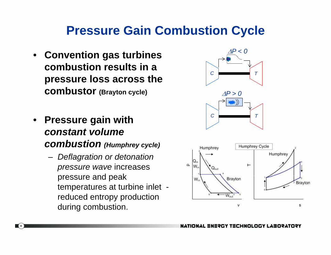
Pressure Gain Combustion Cycle
• Convention gas turbines combustion results in a pressure loss across the
P < 0
C Tpressure loss across the combustor (Brayton cycle) P > 0
• Pressure gain with constant volume combustion (H h l )
C T
combustion (Humphrey cycle)
– Deflagration or detonation pressure wave increases pressure and peakpressure and peak temperatures at turbine inlet -reduced entropy production during combustion
9
during combustion.

History• The idea of capturing the available energy from confined
combustion (versus constant pressure) is well recognizedcombustion (versus constant pressure) is well recognized.– Piston engines do this already.– Early gas turbines used the concept (Holzwarth “explosion” turbine).
Compound piston turbines have been built and flown– Compound piston-turbines have been built and flown.– Constant-volume combustion eclipsed by easier improvements
THYSSEN-HOLZWARTH OIL AND GAS TURBINES, Journal of the American Society for Naval Engineers Volume 34, Issue 3, pages 453–457, August 1922. .
From the article: “……Holzwarth-turbine workingturbine working with a compression of 2.2 atmospheres and an explosion pressure of 17.3 atmospheres absolute….”
Napier Nomad Engine (~1950)
FIG. 8. – THE 500B.H.P. THYSSEN-HOLZWARTH OILTURBINE, WHICH MAY BE THE POWER OF THE FUTUREFOR MERCHANT SHIPS.
Photo used with permission from Naval Engineers Journal
10
Nomad photo credit: Kimble D. McCutcheon via the Aircraft Engine Historical Society. http://www.enginehistory.org/napier.htm

Why is pressure-gain appealing now?Pressure-Gain Combustion for Power GenerationPressure Gain Combustion for Power Generation
Michael Idelchik, Vice President of Advanced Technologies at GE Research…Research…Sept 2009 interview on Pulse Detonation for Technology Review published by MIT.
“An existing turbine burns at constant pressure. With detonation, pressure is rising, and the total energy available for the turbine increases. We see the potential of 30 percent fuel-efficiency improvement. Of course realization, including all the hardware around this process, would reduce thisreduce this.
I think it (efficiency gains) will be anywhere from 5 percent to 10 percent. That's percentage points--say from 59 to 60 percent efficient to 65 percent efficient. We have other technology that will get us close [to that] but no other technology that can get so much atthat will get us close [to that] but no other technology that can get so much at once. It's very revolutionary technology.
The first application will definitely be land-based--it will be power generation at a natural-gas power plant “power plant.
“If we can turn 5% pressure loss in a turbine into 5% pressure gain, it has the same impact as doubling the compression ratio” – Dr. Sam Mason, Rolls-Royce (2008)*
11
p g p , y ( )
* Quotation courtesy Fred Schauer AFRL

Current Technology ApproachesResonant Pulsed Combustion
Detonationor
‘Fast’ Deflagration
Resonant Pulsed Combustion( deflagration)†
†Envisioned as a canular arrangement
G.E. Global Research Center 2005
NASA Glenn, 2005
IUPUI/Purdue/LibertyWorks, 2009
University of Cambridge, 2008
Rotating DetonationEngine (NRL)DOE National Energy Technology Laboratory, 1993
12
g ( )gy gy y,
Slide provide by Dan Paxson, NASA Glenn

Pulse deflagration combustion
Current R&D at NASA, Cambridge-WhittlePast Work at NETL
13

Aerovalved Pressure Gain Combustor
14

NETL Atmospheric Pressure Rig (1991)
• Combustor constructed with standard pipe fittings.• Allows simple changes in inlet and tailpipe
15
Allows simple changes in inlet and tailpipe geometry.

One-Dimensional Modeling
Characteristic Timescales
• Divide combustor into three distinct zones.• Solve conservation equations of mass, momentum and energy.
16
Solve conservation equations of mass, momentum and energy.• Provides estimation of frequency and amplitude.

One-Dimensional Modeling
Wh t CFD?Characteristic Timescales
Why not CFD?1) Hint: this was 1990.
2) No theory for initial design & scaling.
NiceComputer!
• Divide combustor into three distinct zones.• Solve conservation equations of mass, momentum and energy.
17
Solve conservation equations of mass, momentum and energy.• Provides estimation of frequency and amplitude.
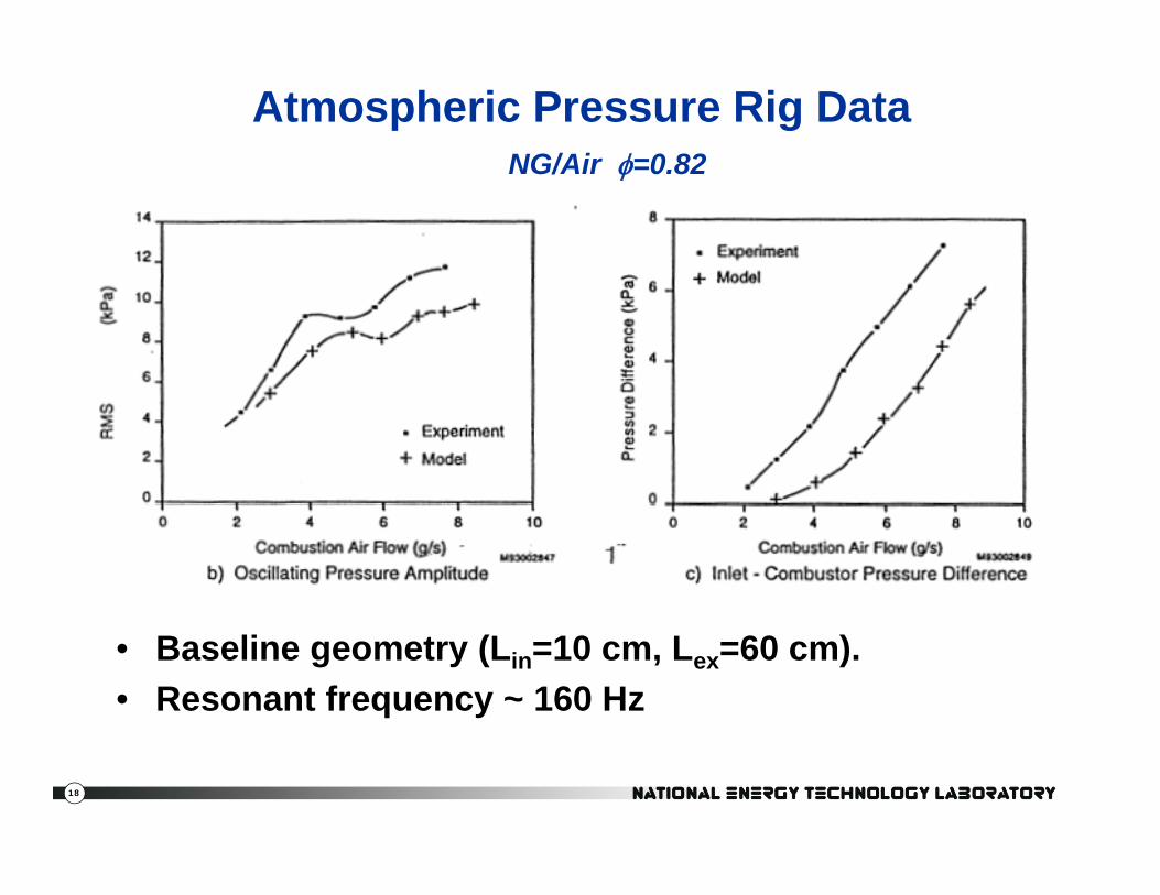
Atmospheric Pressure Rig DataNG/Air =0 82NG/Air =0.82
• Baseline geometry (Lin=10 cm, Lex=60 cm).• Resonant frequency ~ 160 Hz
18

Optimized Geometry
• Maximum of 0 45% pressure0.45% pressure gain achieved.
19

NETL High Pressure Rig (1994)
• NG/Air up to 11 atm.• Simple non-rectified design.
20

High Pressure Results
• Pressure controlled with a control valve on chamber exhaust.
Fl t i d• Flow rates increased linearly with pressure.
• Little effect of pressure when flow-rates are scaled linearly with pressure.
21
• Slight gain likely due to reduced frictional and heat losses.

Some challenging problems
• Predicting a design that will produce oscillations.P i li i ti ill ti i i d– Progress in eliminating oscillations in premixed gas turbines makes this (relatively) easy.
– But, at what operating condition?But, at what operating condition?• Developing an oscillating design that will also have a
pressure gain.– Qualitative understanding, but no fundamental
criterion, theory.Modern CFD may be the enabler!– Modern CFD may be the enabler!
• Capturing the energy of the unsteady flow
22

Capturing the pressure-gainCourtesy R.J.Miller, Whittle Lab, Cambridge University
• Time resolved experimental data.• Vortex-induced separation leads to loss in Phase II.• Work in progress: some configurations avoid the loss!• Work in progress: some configurations avoid the loss!
ColorColor corresponds to pressure gain fraction (0.1 = 10%
pressure gain)Imposedunsteady jet with 2-3%
Phase I Phase II
jet with 2-3% pressure gain
Pressure gain in free stream
Large rise in loss as vortex exits
Transonic test facility
23
Cause of loss : Vortex interacting with vane suction surface.

Work at NASA• Demonstrated pressure-gain and small turbine operation.• Simulations of pulse jet using commercial CFD.
Liquid fueled.
Automotive turbocharger “turbine”
Reed-valve pulse combustor.
Experimental results*:Combustor pressure ratio p1.035 at temperature ratio 2.2
Simulation of pulse-jet p jbehavior –with NOxemissions and experimental validation.
24
Graphics courtesy Dan Paxson, NASA Glenn* Paxson, D. , Dougherty, K. (2008). Operability of an Ejector Enhanced Pulse Combustorin a Gas Turbine Environment NASA/TM—2008-215169

Pulse Detonation (Tubes)
The detonation essentially “traps” the combustion behind the shockThe detonation essentially traps the combustion behind the shock.
Compared to pulse deflagration, much higher pressure gains are possible.
This may be the only constructive applications of detonations?This may be the only constructive applications of detonations?
Pow!
25

4. Detonation wave propagates at CJ velocity with
Typical Pulse Detonation Cycle1. Fill
coupled combustion wave
5. Detonation wave exits tube. Remaining gas at elevated T and P.2. Upstream end closes
6. Rarefaction wave propagate upstream to assist with purging burned gases
3. Detonation initiated (DDT)
7. Exhaust complete
26
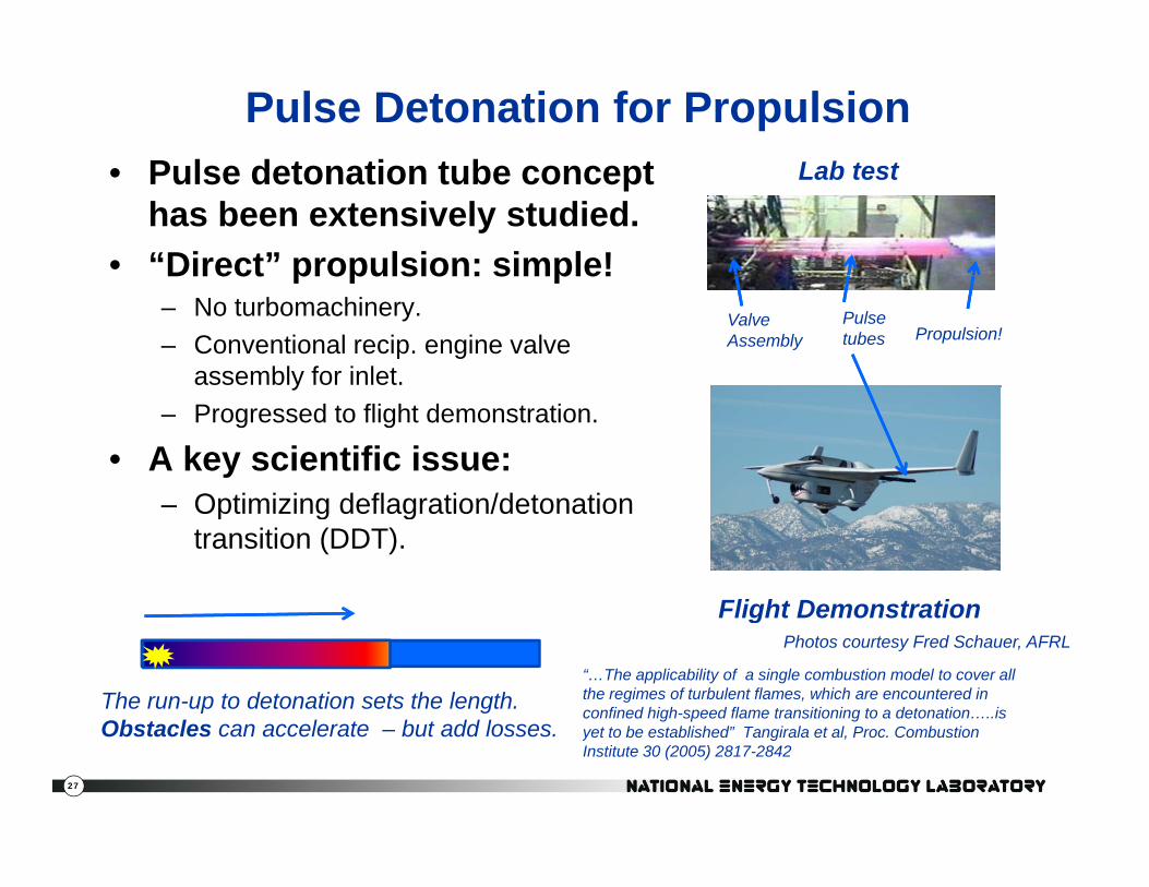
Pulse Detonation for PropulsionP l d t ti t b t L b t t• Pulse detonation tube concept has been extensively studied.
• “Direct” propulsion: simple!
Lab test
Direct propulsion: simple!– No turbomachinery.– Conventional recip. engine valve
assembly for inlet.
Valve Assembly
Pulse tubes Propulsion!
y– Progressed to flight demonstration.
• A key scientific issue:Optimizing deflagration/detonation– Optimizing deflagration/detonation transition (DDT).
Flight DemonstrationFlight DemonstrationPhotos courtesy Fred Schauer, AFRL
The run-up to detonation sets the length.Ob t l l t b t dd l
“…The applicability of a single combustion model to cover all the regimes of turbulent flames, which are encountered in confined high-speed flame transitioning to a detonation…..is
27
Obstacles can accelerate – but add losses. yet to be established” Tangirala et al, Proc. Combustion Institute 30 (2005) 2817-2842

DARPA Vulcan ProjectI t ti i• Integration in a turbine –humphreyhumphreycycle.
• Combines the PDE with turbomachinery
28

Multitube PDC-Turbine Hybrid System
• Eight tubes arranged in a can-annular configurationcan annular configuration coupled to a single stage axial turbine
• Accumulated 144 minutesAccumulated 144 minutes of PDC fired operation
• Turbine performance was indistinguishable betweenindistinguishable between steady flow operation and pulsed flow at 20 Hz per tube
Some work supported from: NASA Constant Volume Combustion Cycle Engine Program
Tangirala, V., Rasheed, A. and Dean, A.J., “Performance of a Pulse Detonation Combustor-Based Hybrid Engine”, GT2007-28056, ASME Turbo Expo, Montreal, Canada, May 14-17, 2007.
29
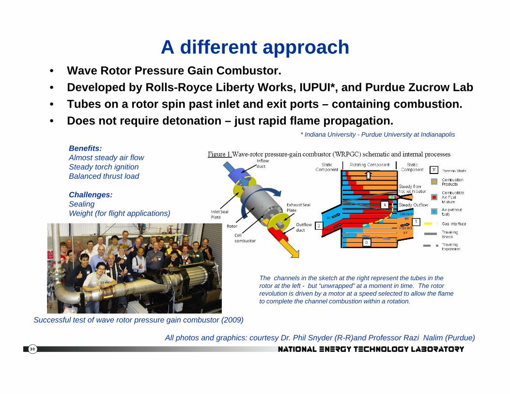
A different approach• Wave Rotor Pressure Gain Combustor.Wave Rotor Pressure Gain Combustor.• Developed by Rolls-Royce Liberty Works, IUPUI*, and Purdue Zucrow Lab• Tubes on a rotor spin past inlet and exit ports – containing combustion.• Does not require detonation – just rapid flame propagationDoes not require detonation just rapid flame propagation.
* Indiana University - Purdue University at Indianapolis
Benefits:Almost steady air flowSteady torch ignitionBalanced thrust load
Challenges:SealingWeight (for flight applications)
The channels in the sketch at the right represent the tubes in the rotor at the left - but “unwrapped” at a moment in time. The rotor revolution is driven by a motor at a speed selected to allow the flame to complete the channel combustion within a rotation.
Successful test of wave rotor pressure gain combustor (2009)
30
All photos and graphics: courtesy Dr. Phil Snyder (R-R)and Professor Razi Nalim (Purdue)
Successful test of wave rotor pressure gain combustor (2009)
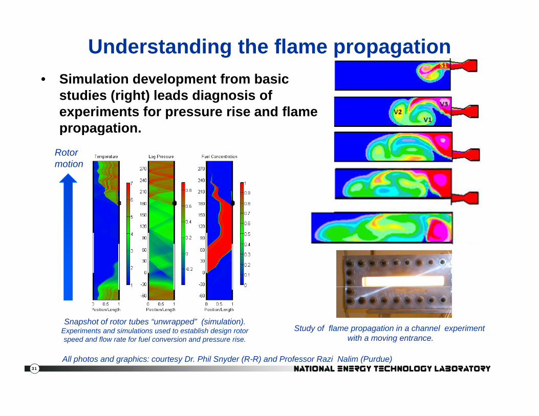
Understanding the flame propagationSimulation development from basic• Simulation development from basic studies (right) leads diagnosis of experiments for pressure rise and flame propagationpropagation.
Rotormotion
Snapshot of rotor tubes “unwrapped” (simulation). Experiments and simulations used to establish design rotor speed and flow rate for fuel conversion and pressure rise
Study of flame propagation in a channel experiment with a moving entrance
31
speed and flow rate for fuel conversion and pressure rise.
All photos and graphics: courtesy Dr. Phil Snyder (R-R) and Professor Razi Nalim (Purdue)
with a moving entrance.

Rotating Detonation Wave Engine• Objective: detonation pressure rise with ~ steady output.• Rotating detonation idea has been in the literature since 1950s.*
• Recent studies have demonstrated new potential for the concept.
Higher pressure, ~ steady flow~ steady flow
to turbine
Rotating
Experiment at AFRLCourtesy Fred Schauer
Inletfrom
Detonation
compressor
Simulation results courtesy K. Kailasanath,
32
yU. S.. Naval Research Laboratory
*see Kailasanath, K. (2011). The Rotating-Detonation –Wave Engine Concept: A Brief Status Report ,AIAA 2011-580.

From tests at AFRLEnd view
SideView M iMovie
SideExperiment at AFRL
Courtesy Fred Schauer
Rotation rateRotation rate ~ 5000 Hz
S
Movie
33
EndSimulation results courtesy K. Kailasanath,
U. S.. Naval Research Laboratory
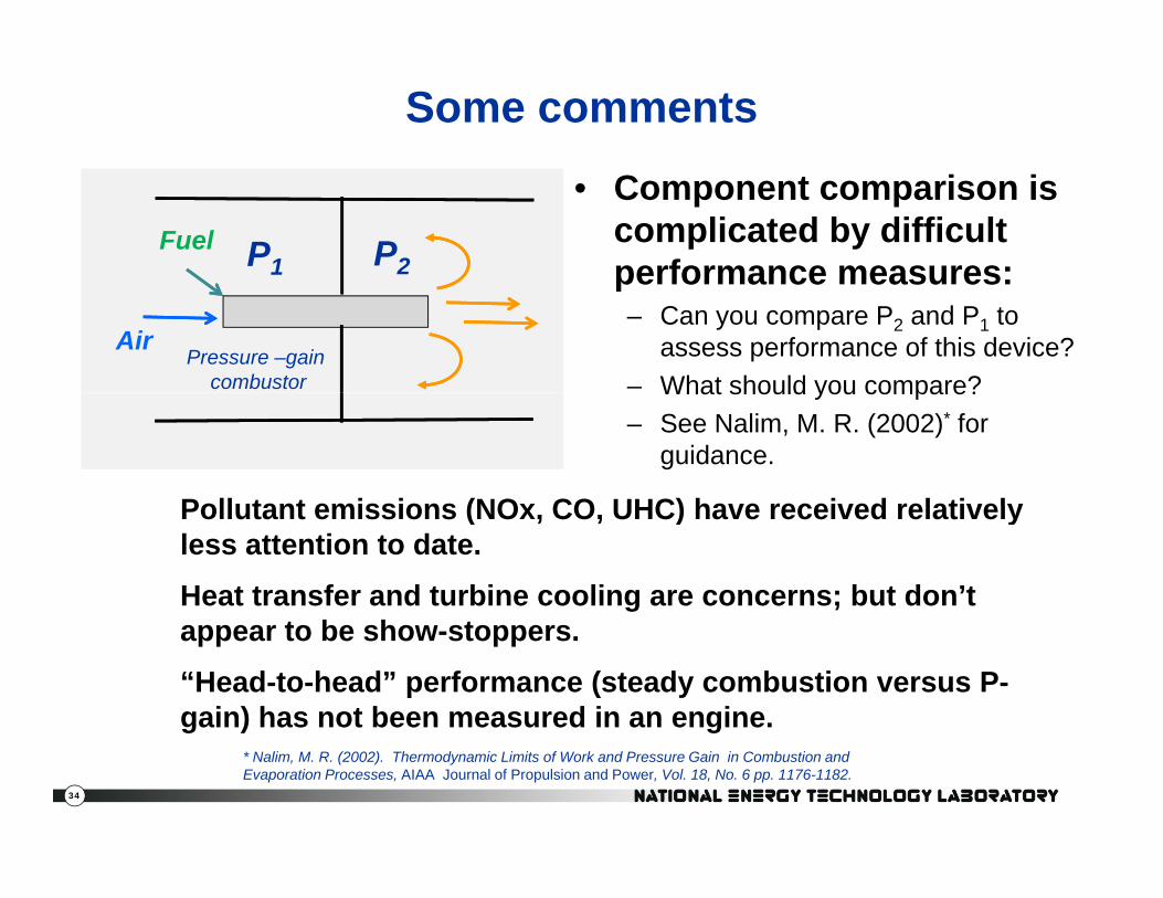
Some comments
• Component comparison is complicated by difficult performance measures:P1 P2
Fuelperformance measures:– Can you compare P2 and P1 to
assess performance of this device?– What should you compare?
Pressure –gain combustor
AirWhat should you compare?
– See Nalim, M. R. (2002)* for guidance.
Pollutant emissions (NOx CO UHC) have received relativelyPollutant emissions (NOx, CO, UHC) have received relatively less attention to date.
Heat transfer and turbine cooling are concerns; but don’t appear to be show-stoppers.
“Head-to-head” performance (steady combustion versus P-gain) has not been measured in an engine.
34
g ) g* Nalim, M. R. (2002). Thermodynamic Limits of Work and Pressure Gain in Combustion and Evaporation Processes, AIAA Journal of Propulsion and Power, Vol. 18, No. 6 pp. 1176-1182.
Discussion/Thinking Questions:Discussion/Thinking Questions: Pressure-gain Combustion
• What are the combustion research issues associatedWhat are the combustion research issues associated with different types of pressure-gain?
• In your opinion, what is the greatest challenge to development of the pressure gain technology?
35

Power generation classes: Turbines and Reciprocating Engines
Left blank to write notes from question slide
75Reciprocating engines
50 Combined cycle turbines
cien
cy
25Simple cycle turbines
Relative sizes & scales
Effi
c
1 10 100 MW Power
Small turbines are approximate
• Where would a +5% efficiency boost get the most interest?• What would the cost of development be for each class?
36
p

Summary of Pressure-gain combustion
• Potential for an efficiency breakthrough.• Similar past concepts recognized; eclipsed by p p g ; p y
“conventional” improvements.• Successful demonstrations for direct propulsion
tubestubes.• Promising work on turbine applications:
– Pulse deflagrationg– Detonation tubes integrated with engine– Constant volume combustion wave-rotor
Rotating detonation wave combustor– Rotating detonation wave combustor
• Combustion and thermal science research needs discussed.
37