new developments in numerical modelling of pile installation · new developments in numerical...
TRANSCRIPT

New developments in numerical modellingof pile installationNguyen Phuong, Frits van Tol, Alexander Rohe
18 September 2014 | KIVI Geotechnical Lectures Evening | TU Delft
Displacement pilesà installation effects
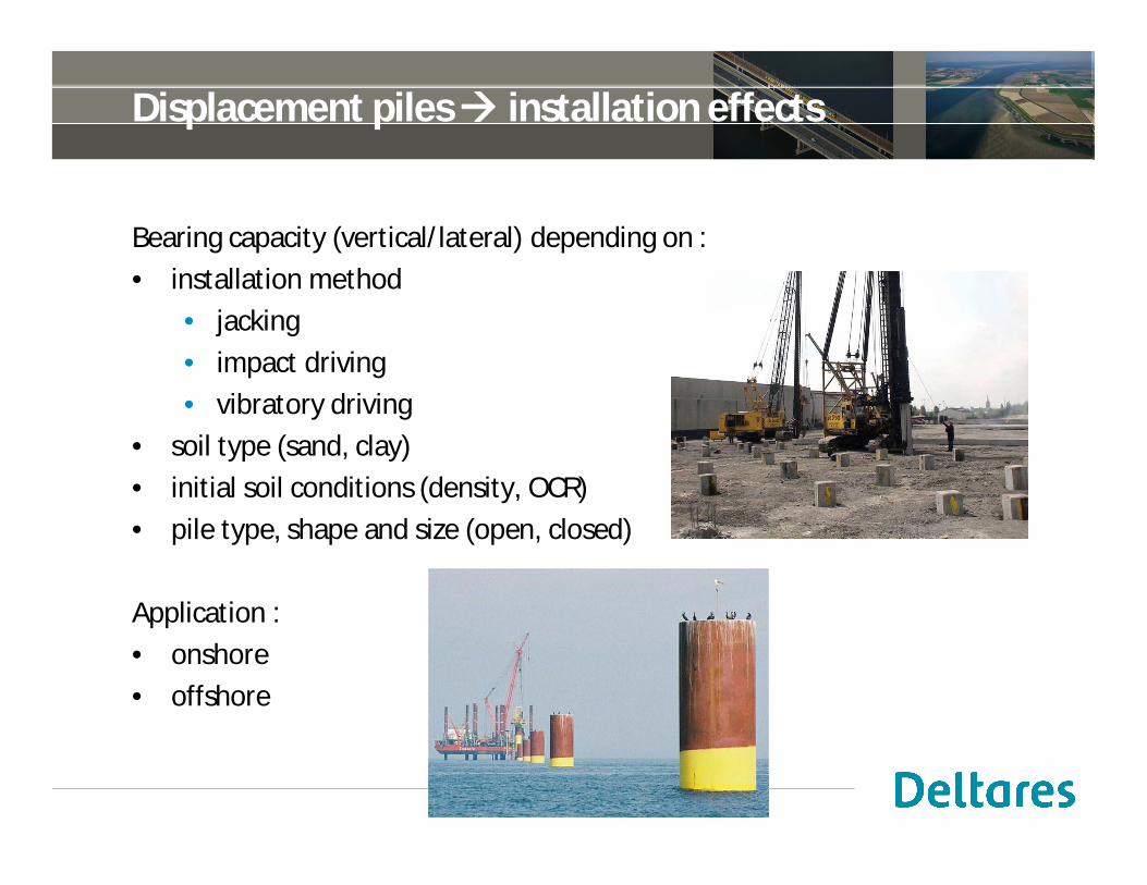
Bearing capacity (vertical/lateral) depending on :• installation method
• jacking• impact driving• vibratory driving
• soil type (sand, clay)• initial soil conditions (density, OCR)• pile type, shape and size (open, closed)
Application :• onshore• offshore
2

Installation methods (displacement piles)
jacking impact driving vibratory driving
3

Testing pile capacity
static load test (SLT) rapid load test (RLT)
lateral load test
4

Current approaches
• empirical methodslimited to very specific cases and conditions
• embedded piles / volume pilesbeam/volume elements with special interfaces, no installation effects
• press and replace techniques (Engin, 2013)displacement applied + geometry update
• wished-in-place pileimposing installation field around pile
• cavity expansionexpansion of cylindrical cavity, shaft?
• advanced FE methods (large strain models, e.g. CEL, ALE)
5

How to determine capacity of displacement piles?
Numerical model would require :
• numerical method allowing for large deformations (installation)
• model incorporating coupled two-phase material behaviour(soil and water, consolidation)
• a constitutive model coupling changes in density and stress to soilstrength and stiffness properties (e.g. hypoplasticity)
• model including dynamics and cyclic behaviour (also high frequencies)
• a 3D model (e.g. lateral load test in non-symmetric conditions)
• model handling liquefaction and material softening with stable solutionalgorithm in such zero effective stress states
Modelling aspects
6

Numerical modelMaterial Point Method (MPM) with coupled two-phase behaviour

Mesh distortion in classical FEM
Material Point Method (MPM)• can model large deformation• no problems with mesh distortion• state variables are traced by
material points• no need for remeshing• enhancement of FEMà re-using established knowledge
• continuum approach
8
FEM

Basic FEM approaches
- material does not crosselements
- nodes remain onboundary
- mesh distortion ?
- material flows througha fixed mesh
- no mesh distortion- state parameters ?
Lagrangian : mesh deforms as the body deforms à SOIL MECHANICS
Eulerian : material flows through a fixed mesh à FLUID MECHANICS
9

Basic concept of MPM
Lagrangian Eulerian
initial configuration deformation after resetting the mesh
in each calculation step :
10
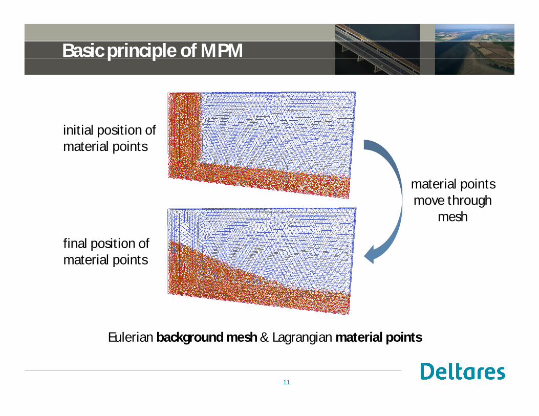
Basic principle of MPM
initial position ofmaterial points
final position ofmaterial points
Eulerian background mesh & Lagrangian material points
material pointsmove through
mesh
11

Example of MPM calculation
collapsing sand column: total displacements in [m]
12
total displacements [m]

Modelling saturated soil
13

Two-phase formulation (v-w-formulation)
14

strain [-]
triaxialconditions
0
100
200
300
400
500
600
700
0 0,1 0,2 0,3 0,4 0,5 0,6
Relative density = 80%
Relative density = 63%
Relative density = 30%
1s
1s
2s2s
s1–s2
[kPa
]
0.1 0.2 0.3 0.4 0.5 0.6
stress and strain (rate) dependent, density dependentà therefore correct handling of state parameters extremely important
Constitutive model: hypoplasticity
15
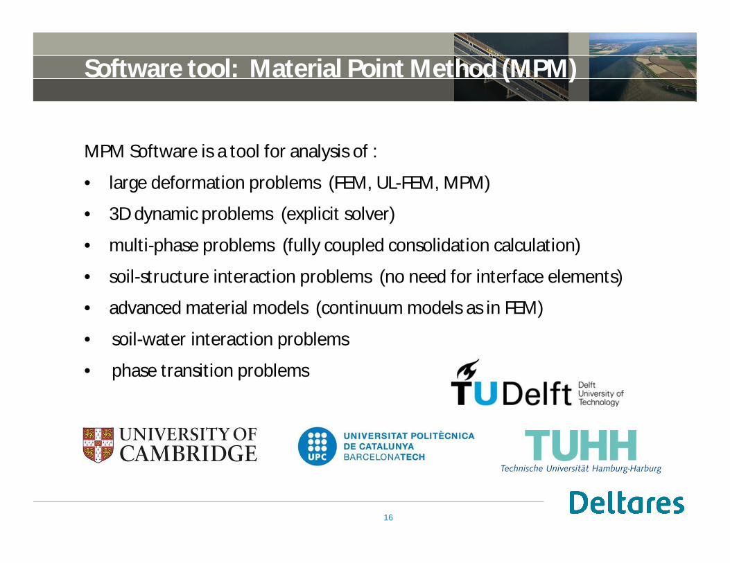
Software tool: Material Point Method (MPM)
MPM Software is a tool for analysis of :
• large deformation problems (FEM, UL-FEM, MPM)
• 3D dynamic problems (explicit solver)
• multi-phase problems (fully coupled consolidation calculation)
• soil-structure interaction problems (no need for interface elements)
• advanced material models (continuum models as in FEM)
• soil-water interaction problems
• phase transition problems
16

Pile jacking and static load test (SLT)Validation with centrifuge tests
Centrifuge tests
18
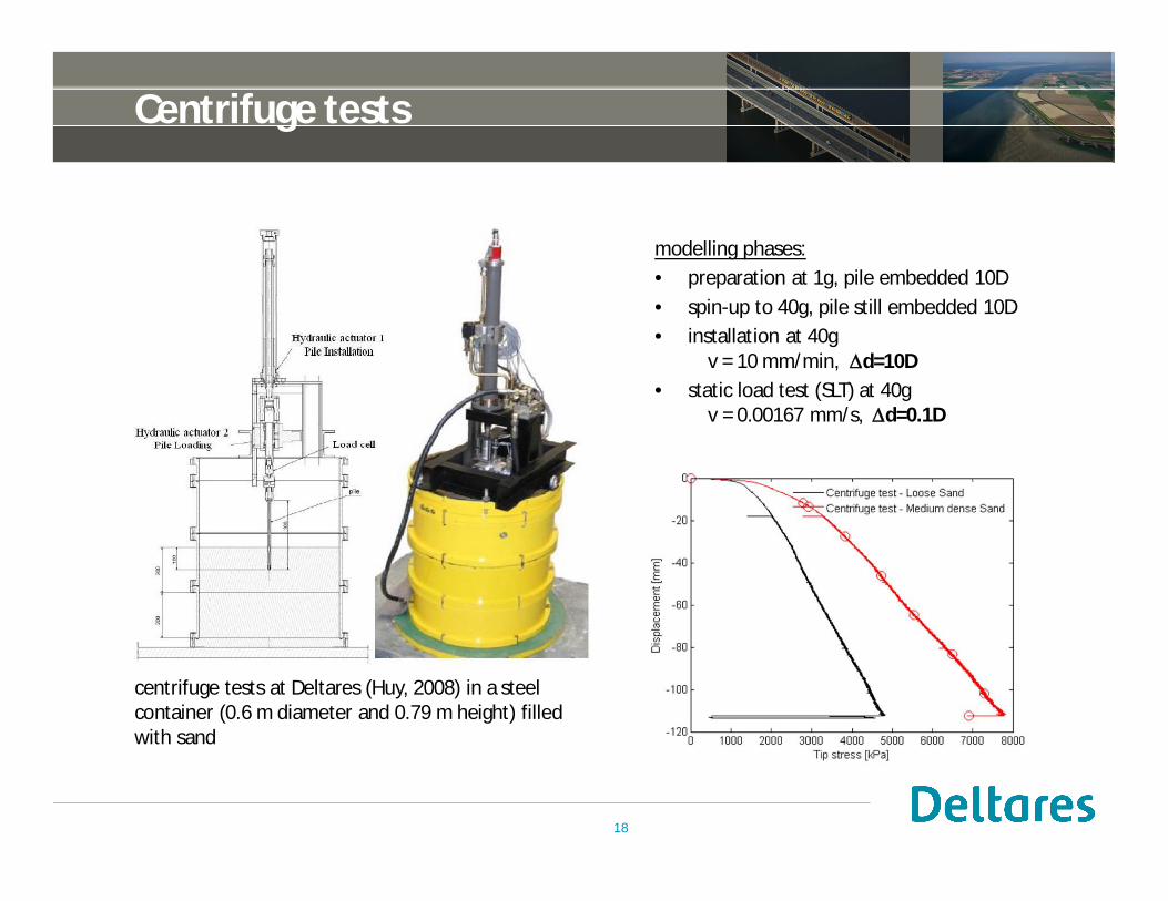
modelling phases:• preparation at 1g, pile embedded 10D• spin-up to 40g, pile still embedded 10D• installation at 40g
v = 10 mm/min, Dd=10D• static load test (SLT) at 40g
v = 0.00167 mm/s, Dd=0.1D
centrifuge tests at Deltares (Huy, 2008) in a steelcontainer (0.6 m diameter and 0.79 m height) filledwith sand
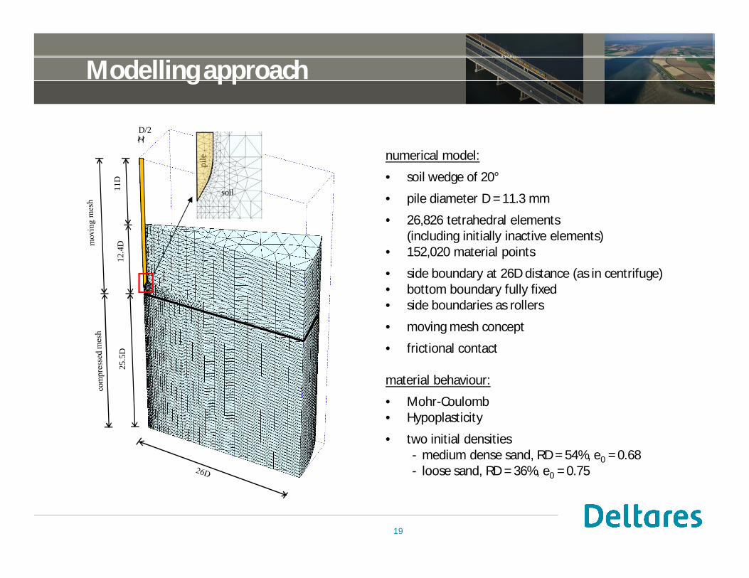
Modelling approach
19
12.4
D11
D25
.5D
pile
soil
D/2
numerical model:
• soil wedge of 20°
• pile diameter D = 11.3 mm
• 26,826 tetrahedral elements(including initially inactive elements)
• 152,020 material points
• side boundary at 26D distance (as in centrifuge)• bottom boundary fully fixed• side boundaries as rollers
• moving mesh concept
• frictional contact
material behaviour:
• Mohr-Coulomb• Hypoplasticity
• two initial densities- medium dense sand, RD = 54%, e0 = 0.68- loose sand, RD = 36%, e0 = 0.75

Results using Mohr-Coulomb model (1)
vertical effective stress [kPa]after spin-up at 40g
20
sand RD [%] E [kPa] jmax [°] ymax [°] c [kPa] n [-]
medium dense 54 40 000 30 0 1.0 0.3
loose 36 22 000 30 0 1.0 0.3
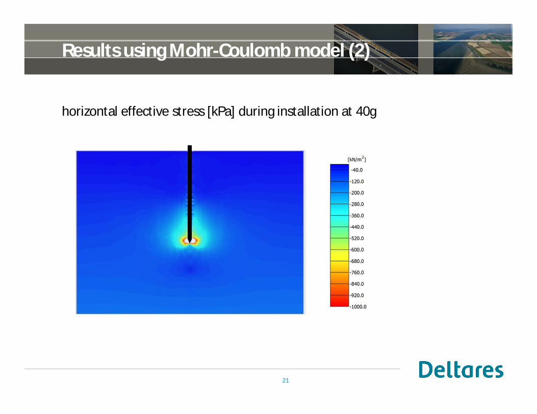
Results using Mohr-Coulomb model (2)
horizontal effective stress [kPa] during installation at 40g
21
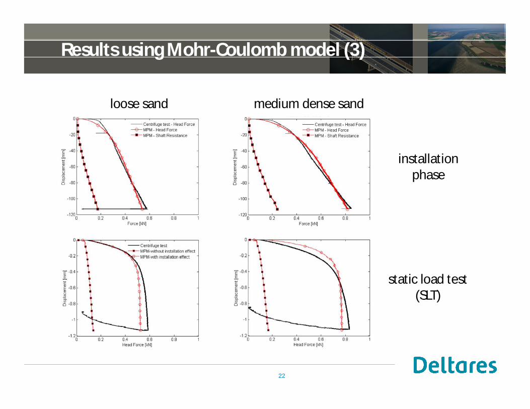
Results using Mohr-Coulomb model (3)
installationphase
static load test(SLT)
22
loose sand medium dense sand
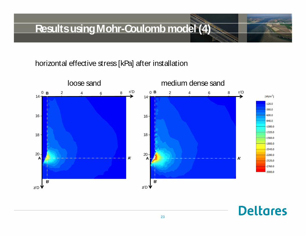
Results using Mohr-Coulomb model (4)
horizontal effective stress [kPa] after installation
23
loose sand medium dense sand
20
18
16
14
z/D
0 2 4 6 8 r/D
A A’
B
B’
20
18
16
14
z/D
0 2 4 6 8 r/D
A A’
B
B’
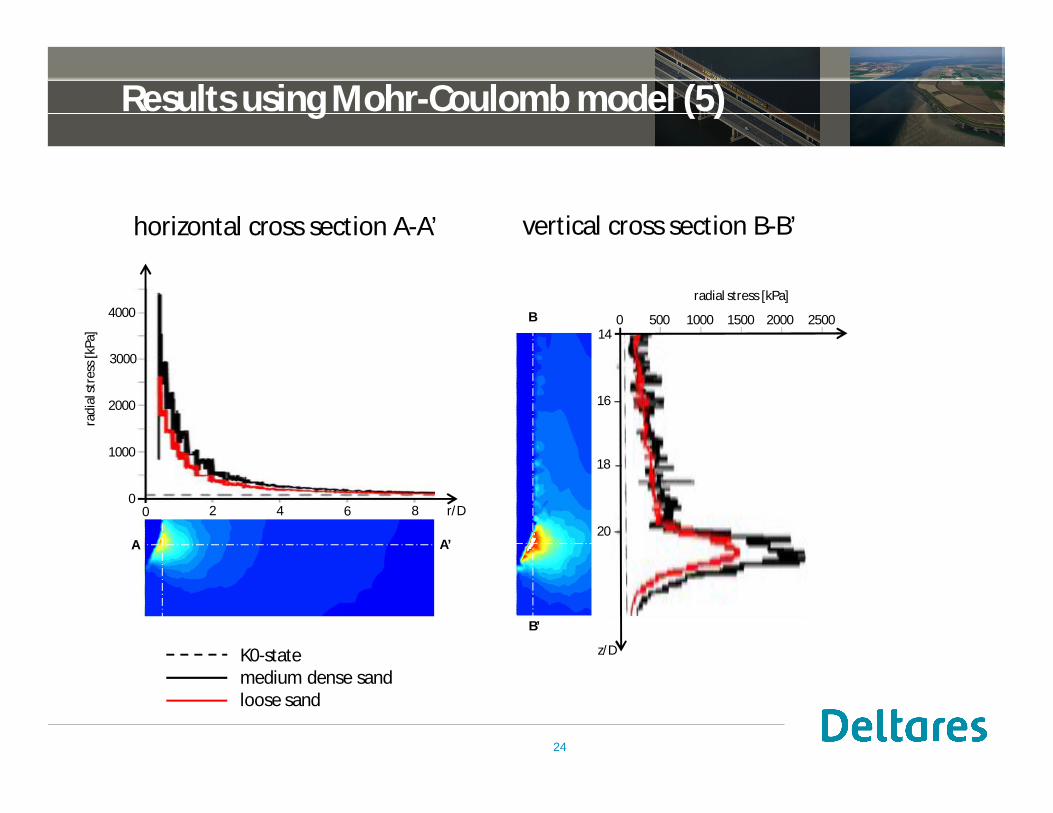
Results using Mohr-Coulomb model (5)
24
0 2 4 6 8
A A’
B
z/D
B
B’
vertical cross section B-B’
K0-statemedium dense sandloose sand
loose sand
horizontal cross section A-A’
4000
1000
3000
2000
0
radi
alst
ress
[kPa
]
0 2 4 6 8 r/D
0 500 1000 1500 2000 2500
radial stress [kPa]
14
20
18
16
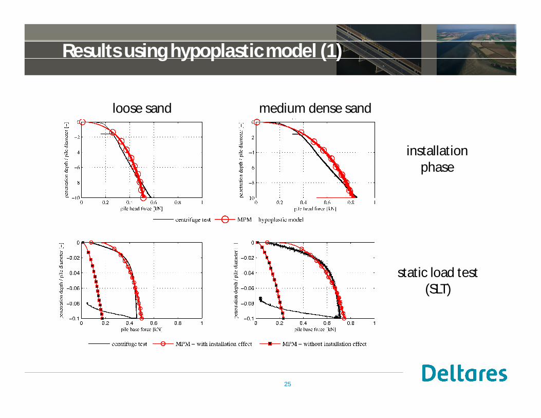
Results using hypoplastic model (1)
25
installationphase
static load test(SLT)
loose sand medium dense sand

Results using hypoplastic model (2)
void ratio during installation
26

determination of pile capacity
Comparison to NEN 9997-2011
27
Normalised plots showing the relative stiffnessof load-displacement curve response from thenumerical simulations in comparison with thedesign curves in NEN 9997-2011. For areliable design using this code, the ultimatebase capacity is determined at 0.1Ddisplacement for a driven pile (with installationeffect) and at 0.2D displacement for a boredpile (without installation effect).
The normalised base resistance curve of theMPM simulation of the SLT is in goodagreement with curve 1 for driven piles. Thisdemonstrates the importance of using anadvanced soil model e.g. hypoplastic model inmodelling pile load tests. The curve thatsimulates the pre-embedded pile shows agood correspondence with the curvesuggested by curve 3 for a bored pile.

Pile driving

Modelling approach
29
40/3D
10D
4/3D
D/2
pile
soil
4D
mov
ing
mes
hco
mpr
esse
dm
esh
numerical model:
• soil wedge of 20°
• pile diameter D = 0.3 m
• bottom and right side boundaryare full viscous boundaries
• other side boundaries are rollers
• moving mesh concept
• frictional contact
material behaviour:
• Hypoplasticity
modelling phases:• initialisation by K0-procedure• gravity loading for self-weight pile• impulse loading
Fimp = 1000 kPatimp = 0.012 stblow = 0.25 s
Fimp
timp

Results for loose sand
volumetric strain shear straindisplacement
uxuy gsev
-2.0 m
0.4 m
-0.2 m
0.2 m
-0.3
0.3
0.0
5.0RD = 30.4%, m = 0.5
each step represents one blow
displacement
30

First results
31
Rapid load test (RLT)

Effect of stiffness and permeability
33

E = 48 300 kPaj = 40°y = 5°k = 2·10-5 m/sdamping 0.05
Comparison with centrifuge test
34
Conclusions
• numerical method (MPM) presented, which is able to model• large deformations and strains• coupled two-phase behaviour (consolidation)• (quasi-)static and dynamic loading conditions• liquefying soil and material softening• advanced material behaviour (constitutive models)
• validation of MPM for jacked piles and static load testswith centrifuge experiments
• verification of MPM for impact driven piles and rapid load tests
• extension of MPM for vibratory driven piles is ongoing
• bearing capacity of displacement piles can be numerically determineddepending on installation method, soil conditions, pile specifications
35

Outlook
Practical use for foundation engineering :
• simulate installation of each pile?Ø computational timeØ numerical experience
• impose stress and density state on mesh?Ø equilibrium stateØ flexibility and variation
36
Thank you for your attention!