new emergency operations center for - tn.gov · new emergency operations center for: architect’s...
TRANSCRIPT
New Emergency Operations Center for: Architect’s Project No. C00218Carter County, TN
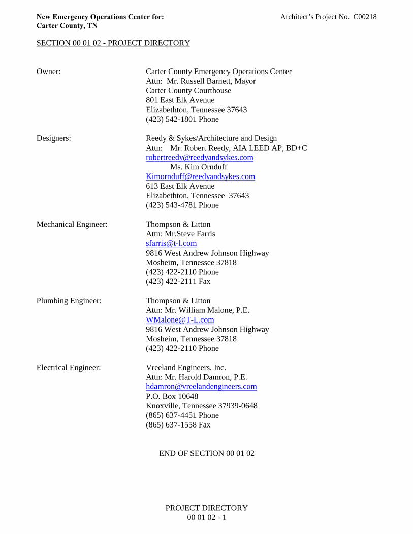
SECTION 00 01 02 - PROJECT DIRECTORY
Owner: Carter County Emergency Operations CenterAttn: Mr. Russell Barnett, MayorCarter County Courthouse801 East Elk AvenueElizabethton, Tennessee 37643(423) 542-1801 Phone
Designers: Reedy & Sykes/Architecture and DesignAttn: Mr. Robert Reedy, AIA LEED AP, BD+C [email protected]
Ms. Kim [email protected] 613 East Elk AvenueElizabethton, Tennessee 37643(423) 543-4781 Phone
Mechanical Engineer: Thompson & LittonAttn: Mr.Steve [email protected] 9816 West Andrew Johnson HighwayMosheim, Tennessee 37818(423) 422-2110 Phone(423) 422-2111 Fax
Plumbing Engineer: Thompson & LittonAttn: Mr. William Malone, [email protected] 9816 West Andrew Johnson HighwayMosheim, Tennessee 37818(423) 422-2110 Phone
Electrical Engineer: Vreeland Engineers, Inc.Attn: Mr. Harold Damron, [email protected] P.O. Box 10648Knoxville, Tennessee 37939-0648(865) 637-4451 Phone(865) 637-1558 Fax
END OF SECTION 00 01 02
PROJECT DIRECTORY00 01 02 - 1
New Emergency Operations Center for: Architect’s Project No. C00218Carter County, TN
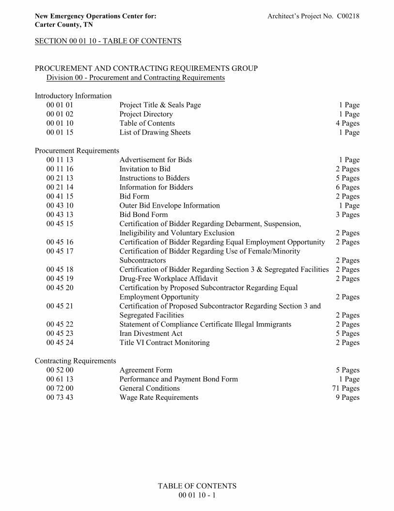
SECTION 00 01 10 - TABLE OF CONTENTS
PROCUREMENT AND CONTRACTING REQUIREMENTS GROUPDivision 00 - Procurement and Contracting Requirements
Introductory Information00 01 01 Project Title & Seals Page 1 Page00 01 02 Project Directory 1 Page00 01 10 Table of Contents 4 Pages00 01 15 List of Drawing Sheets 1 Page
Procurement Requirements00 11 13 Advertisement for Bids 1 Page00 11 16 Invitation to Bid 2 Pages00 21 13 Instructions to Bidders 5 Pages00 21 14 Information for Bidders 6 Pages00 41 15 Bid Form 2 Pages00 43 10 Outer Bid Envelope Information 1 Page00 43 13 Bid Bond Form 3 Pages00 45 15 Certification of Bidder Regarding Debarment, Suspension,
Ineligibility and Voluntary Exclusion 2 Pages00 45 16 Certification of Bidder Regarding Equal Employment Opportunity 2 Pages00 45 17 Certification of Bidder Regarding Use of Female/Minority
Subcontractors 2 Pages00 45 18 Certification of Bidder Regarding Section 3 & Segregated Facilities 2 Pages00 45 19 Drug-Free Workplace Affidavit 2 Pages00 45 20 Certification by Proposed Subcontractor Regarding Equal
Employment Opportunity 2 Pages00 45 21 Certification of Proposed Subcontractor Regarding Section 3 and
Segregated Facilities 2 Pages00 45 22 Statement of Compliance Certificate Illegal Immigrants 2 Pages00 45 23 Iran Divestment Act 5 Pages00 45 24 Title VI Contract Monitoring 2 Pages
Contracting Requirements00 52 00 Agreement Form 5 Pages00 61 13 Performance and Payment Bond Form 1 Page00 72 00 General Conditions 71 Pages00 73 43 Wage Rate Requirements 9 Pages
TABLE OF CONTENTS00 01 10 - 1
New Emergency Operations Center for: Architect’s Project No. C00218Carter County, TN
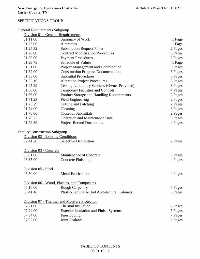
SPECIFICATIONS GROUP
General Requirements SubgroupDivision 01 - General Requirements01 11 00 Summary of Work 1 Page01 23 00 Alternates 1 Page01 25 32 Substitution Request Form 2 Pages01 26 00 Contract Modification Procedures 3 Pages01 29 00 Payment Procedures 2 Pages01 29 73 Schedule of Values 1 Page01 31 00 Project Management and Coordination 3 Pages01 32 00 Construction Progress Documentation 3 Pages01 33 00 Submittal Procedures 5 Pages01 35 16 Alteration Project Procedures 3 Pages01 45 29 Testing Laboratory Services (Owner Provided) 3 Pages01 50 00 Temporary Facilities and Controls 4 Pages01 66 00 Product Storage and Handling Requirements 2 Pages01 71 23 Field Engineering 2 Pages01 73 29 Cutting and Patching 2 Pages01 74 00 Cleaning 3 Pages01 78 00 Closeout Submittals 2 Pages01 78 23 Operation and Maintenance Data 3 Pages01 78 39 Project Record Documents 4 Pages
Facility Construction SubgroupDivision 02 - Existing Conditions02 41 20 Selective Demolition 2 Pages
Division 03 - Concrete03 01 00 Maintenance of Concrete 3 Pages03 35 00 Concrete Finishing 4 Pages
Division 05 - Steel05 50 00 Metal Fabrications 4 Pages
Division 06 - Wood, Plastics, and Composites 06 10 00 Rough Carpentry 5 Pages06 41 16 Plastic-Laminate-Clad Architectural Cabinets 5 Pages
Division 07 - Thermal and Moisture Protection07 21 00 Thermal Insulation 2 Pages07 24 00 Exterior Insulation and Finish Systems 5 Pages07 84 00 Firestopping 7 Pages07 92 00 Joint Sealants 5 Pages
TABLE OF CONTENTS00 01 10 - 2

New Emergency Operations Center for: Architect’s Project No. C00218Carter County, TN
Division 08 - Openings08 11 00 Metal Doors and Frames 9 Pages08 14 23.16 Plastic-Laminate-Faced Wood Doors 8 Pages08 43 10 Aluminum-Framed Entrances and Storefronts 8 Pages08 71 00 Door Hardware 27 Pages08 81 00 Glass Glazing 6 Pages
Division 09 - Finishes09 22 16 Non-Structural Metal Framing 7 Pages09 29 00 Gypsum Board 5 Pages09 51 00 Acoustical Ceilings 4 Pages09 65 00 Resilient Flooring 4 Pages09 65 10 Transition Strips 2 Pages09 68 00 Carpeting 4 Pages09 84 13 Fixed Sound-Absorption Panels 4 Pages09 91 00 Painting 7 Pages
Division 10 - Specialties10 14 23 Panel Signage 3 Pages10 28 13 Toilet Accessories 2 Pages10 43 13 Defribrillator Cabinet 2 Pages10 44 13 Fire Extinguisher Cabinets 2 Pages10 44 16 Fire Extinguishers 2 Pages
Division 13 - Special Construction13 34 19 Metal Building Systems 4 Pages
Facility Services SubgroupDivision 22 - Plumbing22 07 19 Plumbing Piping Insulation 5 Pages22 10 05 Plumbing Piping 8 Pages22 10 06 Plumbing Piping Specialties 3 Pages22 40 00 Plumbing Fixtures 6 Pages
Division 23 - Heating, Ventilating, and Air-Conditioning (HVAC) 23 05 93 Testing, Adjusting, and Balancing for HVAC 6 Pages23 07 13 Duct Insulation 3 Pages23 07 13 HVAC Piping Insulation 2 Pages23 23 00 Refrigerant Piping 6 Pages23 31 00 HVAC Ducts and Casings 3 Pages23 33 00 Air Duct Accessories 4 Pages23 34 16 Centrifugal HVAC Fans 3 Pages23 37 00 Air Outlets and Inlets 2 Pages
TABLE OF CONTENTS00 01 10 - 3
New Emergency Operations Center for: Architect’s Project No. C00218Carter County, TN
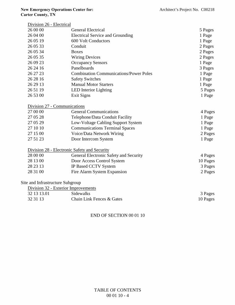
Division 26 - Electrical 26 00 00 General Electrical 5 Pages26 04 00 Electrical Service and Grounding 1 Page26 05 19 600 Volt Conductors 1 Page26 05 33 Conduit 2 Pages26 05 34 Boxes 2 Pages26 05 35 Wiring Devices 2 Pages26 09 23 Occupancy Sensors 1 Page26 24 16 Panelboards 3 Pages26 27 23 Combination Communications/Power Poles 1 Page 26 28 16 Safety Switches 1 Page26 29 13 Manual Motor Starters 1 Page26 51 19 LED Interior Lighting 5 Pages26 53 00 Exit Signs 1 Page
Division 27 - Communications27 00 00 General Communications 4 Pages27 05 28 Telephone/Data Conduit Facility 1 Page27 05 29 Low-Voltage Cabling Support System 1 Page27 10 10 Communications Terminal Spaces 1 Page27 15 00 Voice/Data Network Wiring 2 Pages27 51 23 Door Intercom System 1 Page
Division 28 - Electronic Safety and Security28 00 00 General Electronic Safety and Security 4 Pages28 13 00 Door Access Control System 10 Pages28 23 13 IP Based CCTV System 3 Pages28 31 00 Fire Alarm System Expansion 2 Pages
Site and Infrastructure SubgroupDivision 32 - Exterior Improvements32 13 13.01 Sidewalks 3 Pages32 31 13 Chain Link Fences & Gates 10 Pages
END OF SECTION 00 01 10
TABLE OF CONTENTS00 01 10 - 4
New Emergency Operations Center for: Architect’s Project No. C00218Carter County, TN
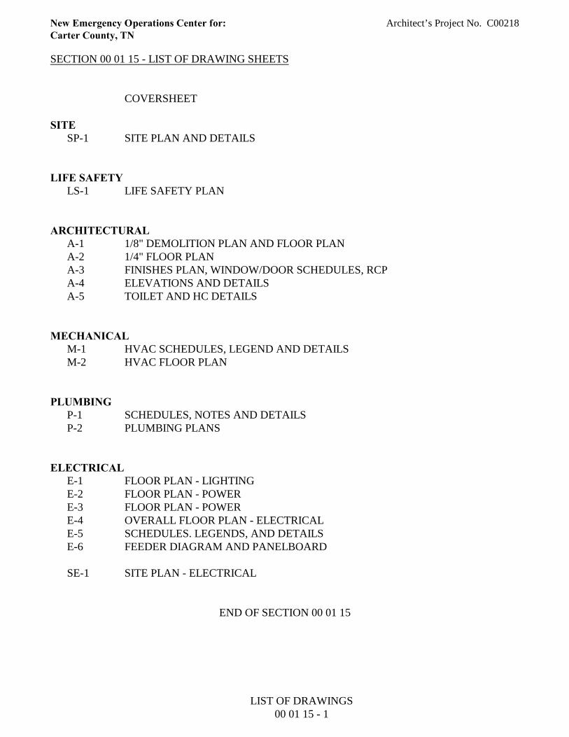
SECTION 00 01 15 - LIST OF DRAWING SHEETS
COVERSHEET
SITESP-1 SITE PLAN AND DETAILS
LIFE SAFETYLS-1 LIFE SAFETY PLAN
ARCHITECTURALA-1 1/8" DEMOLITION PLAN AND FLOOR PLANA-2 1/4" FLOOR PLANA-3 FINISHES PLAN, WINDOW/DOOR SCHEDULES, RCPA-4 ELEVATIONS AND DETAILSA-5 TOILET AND HC DETAILS
MECHANICALM-1 HVAC SCHEDULES, LEGEND AND DETAILSM-2 HVAC FLOOR PLAN
PLUMBINGP-1 SCHEDULES, NOTES AND DETAILSP-2 PLUMBING PLANS
ELECTRICALE-1 FLOOR PLAN - LIGHTINGE-2 FLOOR PLAN - POWERE-3 FLOOR PLAN - POWERE-4 OVERALL FLOOR PLAN - ELECTRICALE-5 SCHEDULES. LEGENDS, AND DETAILSE-6 FEEDER DIAGRAM AND PANELBOARD
SE-1 SITE PLAN - ELECTRICAL
END OF SECTION 00 01 15
LIST OF DRAWINGS00 01 15 - 1
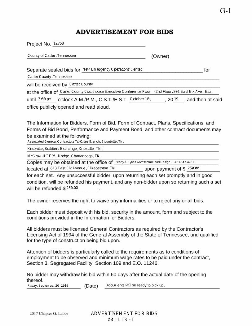
ADVERTISEMENT FOR BIDS
Project No.
(Owner)
Separate sealed bids for ____________________________________________ for ______________________________________________________________________ will be received by _______________________________________________________ at the office of __________________________________________________________ until _______ o'clock A.M./P.M., C.S.T./E.S.T. _____________, 20____, and then at said office publicly opened and read aloud.
The Information for Bidders, Form of Bid, Form of Contract, Plans, Specifications, and Forms of Bid Bond, Performance and Payment Bond, and other contract documents may be examined at the following: Copies may be obtained at the office of ______________________________________ located at __________________________________ upon payment of $ ____________ for each set. Any unsuccessful bidder, upon returning each set promptly and in good condition, will be refunded his payment, and any non-bidder upon so returning such a set will be refunded $____________. The owner reserves the right to waive any informalities or to reject any or all bids. Each bidder must deposit with his bid, security in the amount, form and subject to the conditions provided in the Information for Bidders. All bidders must be licensed General Contractors as required by the Contractor's Licensing Act of 1994 of the General Assembly of the State of Tennessee, and qualified for the type of construction being bid upon. Attention of bidders is particularly called to the requirements as to conditions of employment to be observed and minimum wage rates to be paid under the contract, Section 3, Segregated Facility, Section 109 and E.O. 11246. No bidder may withdraw his bid within 60 days after the actual date of the opening thereof. (Date)
G-1
2017 Chapter G: Labor
New Emergency Operations Center for: Architect’s Project No. C00218Carter County, TN
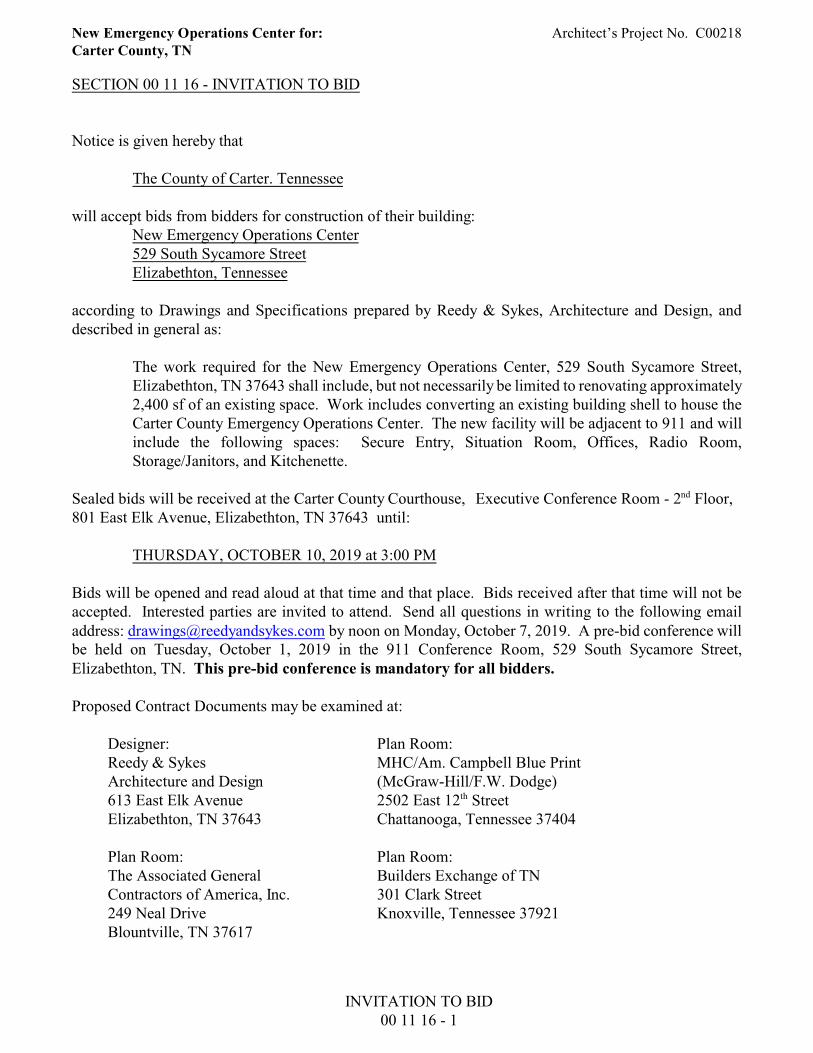
SECTION 00 11 16 - INVITATION TO BID
Notice is given hereby that
The County of Carter. Tennessee
will accept bids from bidders for construction of their building:New Emergency Operations Center529 South Sycamore StreetElizabethton, Tennessee
according to Drawings and Specifications prepared by Reedy & Sykes, Architecture and Design, anddescribed in general as:
The work required for the New Emergency Operations Center, 529 South Sycamore Street,Elizabethton, TN 37643 shall include, but not necessarily be limited to renovating approximately2,400 sf of an existing space. Work includes converting an existing building shell to house theCarter County Emergency Operations Center. The new facility will be adjacent to 911 and willinclude the following spaces: Secure Entry, Situation Room, Offices, Radio Room,Storage/Janitors, and Kitchenette.
Sealed bids will be received at the Carter County Courthouse, Executive Conference Room - 2nd Floor, 801 East Elk Avenue, Elizabethton, TN 37643 until:
THURSDAY, OCTOBER 10, 2019 at 3:00 PM
Bids will be opened and read aloud at that time and that place. Bids received after that time will not beaccepted. Interested parties are invited to attend. Send all questions in writing to the following emailaddress: [email protected] by noon on Monday, October 7, 2019. A pre-bid conference willbe held on Tuesday, October 1, 2019 in the 911 Conference Room, 529 South Sycamore Street,Elizabethton, TN. This pre-bid conference is mandatory for all bidders.
Proposed Contract Documents may be examined at:
Designer:Reedy & SykesArchitecture and Design613 East Elk AvenueElizabethton, TN 37643
Plan Room:The Associated GeneralContractors of America, Inc.249 Neal DriveBlountville, TN 37617
Plan Room:MHC/Am. Campbell Blue Print(McGraw-Hill/F.W. Dodge)2502 East 12th StreetChattanooga, Tennessee 37404
Plan Room:Builders Exchange of TN301 Clark StreetKnoxville, Tennessee 37921
INVITATION TO BID00 11 16 - 1

New Emergency Operations Center for: Architect’s Project No. C00218Carter County, TN
All bidders must be licensed General Contractors as required by the Contractor’s Licensing Act of 1994of the General Assembly of the State of Tennessee, and qualified for the type of construction being bidupon.
Bona fide general contract bidders may secure copies of the proposed Contract Documents from theoffice of the Designer on the following basis:
1. One copy of the Project Manual, including specifications, plus one set of prints of theDrawings, upon payment of $250.00 deposit, (make Plan Deposit checks payable to REEDY& SYKES.) completely refundable if returned to the Designer, in satisfactory condition,within ten calendar days after bid opening.
2. If the contractor requests that a set of plans be shipped to their office, the Designer will shipthese documents by UPS upon payment of $25 per shipment, non-refundable. Contractor isresponsible for providing shipping instructions.
Additional copies of the proposed Contract Documents may be purchased from the office of the Designeron the following basis:
1. Additional copies of the Project Manual, including Specifications, plus additional sets ofprints of the Drawings, upon payment of $250.00 per set, non-refundable.
2. No partial sets of the Project Manual, including Specifications, or partial sets of prints of theDrawings, will be issued.
If a prime bidder or a subcontract bidder wants to receive email notifications of Addenda, theymust register with the Designer with their contact person, phone number, and email address.
A copy of electronic media of the proposed Contract Documents may be purchased from the office ofthe Designer on the following basis:
1. A CD which includes the Project Manual, including Specifications, and the Drawings, uponpayment of $25.00 per CD, non-refundable made out to Reedy & Sykes.
2. No partial sets of the Project Manual, including Specifications, or partial sets of prints of theDrawings, will be issued.
Bid Security in the amount of 5% of the base bid will be required to accompany bids.
Attention of bidders is particularly called to the requirements as to conditions of employment to beobserved and minimum wage rates to be paid under the contract, Section 3, Segregated Facility, Section109 and E.O. 11246.
The Owner reserves the right to reject any or all bids and to waive irregularity in the bids and in thebidding.
END OF SECTION 00 11 16
INVITATION TO BID00 11 16 - 2
New Emergency Operations Center for: Architect’s Project No. C00218Carter County, TN
SECTION 00 21 13 - INSTRUCTIONS TO BIDDERS
PART 1 - GENERAL
1.01 THE WORK
NEW EMERGENCY OPERATIONS CENTER FOR:CARTER COUNTY, TENNESSEEELIZABETHTON, TENNESSEE
1.02 SECURING DOCUMENTS
Copies of the proposed Contract Documents may be obtained from:
Reedy & SykesArchitecture and Design613 East Elk AvenueElizabethton, Tennessee 37643
upon the conditions set forth in the Invitation to Bid, Section 00 11 16.
1.03 BID FORM
In order to receive consideration, make bids in strict accordance with the following:
A. Make bids upon the forms provided therefore, properly signed and with all items filled out. Donot change the wording of the bid form, and do not add words to the bid form. Unauthorizedconditions, limitations, or provisions attached to the bid will be cause for rejection of the bid. If alterations by erasure or interlineation are made for any reason, explain over such erasure orinterlineation with a signed statement from the bidder.
B. No telegraphic bid or telegraphic modification of a bid will be considered. No bids receivedafter the time fixed for receiving them will be considered. Late bids will be returned to thebidder unopened.
C. Address bids to the Owner, and deliver to the address given in the Invitation to Bid on or beforethe day and hour set for opening the bids. Enclose each bid in a sealed envelope bearing the titleof the Work, the name of the bidder, and the date and hour of the bid opening. Submit only theoriginal signed copy of the bid. It is the sole responsibility of the bidder to see that his bid isreceived on time.
D. All blanks on FORM 00 43 10 OUTER BID ENVELOPE INFORMATION must be filled inor bids will not be opened. The Subcontractors portion of this form must be filled in as follows:1. If subcontractor bid is $25,000 or larger, the Contractor is responsible to list the name of
the subcontractor, their license number, license expiration, and license classification on theouter bid form for the following disciplines:
INSTRUCTIONS TO BIDDERS00 21 13 - 1
New Emergency Operations Center for: Architect’s Project No. C00218Carter County, TN
a. Plumbing;b. HVAC;c. Electrical.
2. If subcontractor bid is under $25,000, the Contractor is responsible to write on the outerbid form “under $25,000" for the following disciplines:a. Plumbing;b. HVAC;c. Electrical.
3. The Contractor is responsible to list the name of the geothermal well driller subcontractor,their license number, license expiration, and license classification on the outer bid formif geothermal is part of the project.
4. If bid is $100,000 or larger, the Contractor is responsible to list the name of thesubcontractor, their license number, license expiration, and license classification on theouter bid form for the following disciplines:a. Masonry.
5. If bid is under $100,000, the Contractor is responsible to write on the outer bid form“under $100,000" for the following disciplines:a. Masonry.
6. If no work is required, the Contractor is responsible to write “none required” on the outerbid form for the following disciplines:a. Plumbing;b. HVAC;c. Electrical;d. Geothermal;e. Masonry.
1.04 BONDS
A. Bid security in the amount stated in the Invitation to Bid must accompany each bid. Thesuccessful bidder's security will be retained until he has signed the Contract and has furnishedthe required Certificates of Insurance, and Performance and Payment Bonds.
B. The Owner reserves the right to retain the security of all bidders until the successful bidderenters into the Contract or until 60 days after bid opening, whichever is sooner. Other bidsecurity will be returned as soon as practicable. If any bidder refuses to enter into a Contract,the Owner may retain his bid security as liquidated damages but not as a penalty.
C. Prior to signing the Contract, the Owner will require the successful bidder to secure and post aLabor and Materials Payment Bond and a Performance Bond, each in the amount of 100% ofthe Contract Sum. Such bonds shall be issued by Surety acceptable to the Owner. Costs of suchbonds will be included in the bid.
1.05 EXAMINATION OF DOCUMENTS AND SITE OF WORK
A. Before submitting a bid, each bidder shall examine the Drawings carefully, and shall read theSpecifications and all other proposed Contract Documents, and shall visit the site of the Work. Each bidder shall fully inform himself prior to bidding as to existing conditions and limitations
INSTRUCTIONS TO BIDDERS00 21 13 - 2
New Emergency Operations Center for: Architect’s Project No. C00218Carter County, TN
under which the Work is to be performed, and shall include in his bid a sum to cover the costof items necessary to perform the work as set forth in the proposed Contract Documents. Noallowance will be made to a bidder because of lack of such examination or knowledge. Thesubmission of a bid will be considered as conclusive evidence that the bidder has made suchexamination.
1.06 WITHDRAWAL OF BIDS
A. A bidder may withdraw his bid, either personally or by written request, at any time prior to thescheduled time for opening bids.
B. No bidder may withdraw his bid for a period of sixty calendar days after the date set for openingthereof, and bids shall be subject to acceptance by the Owner during this period.
1.07 AWARD OR REJECTION OF BIDS
A. The Contract, if awarded, will be awarded to the responsible bidder who has proposed thelowest Contract Sum, subject to the Owner's right to reject any or all bids and to waiveinformality and irregularity in the bids and in the bidding.
1.08 EXECUTION OF AGREEMENT
A. The form of Agreement which the successful bidder will be required to execute is included inthe Project Manual.
B. The bidder to whom the Contract is awarded shall, within fifteen calendar days after notice ofaward and receipt of Agreement forms from the Owner, sign and deliver required copies to theOwner.
C. At or prior to delivery of the signed Agreement the bidder to whom the Contract is awardedshall deliver to the Owner those Certificates of Insurance required by the Contract Documentsand such Labor and Materials Payment Bonds and Performance Bond as are required by theOwner.
D. Bonds and Certificates of Insurance shall be approved by the Owner before the successful biddermay proceed with the Work. Failure or refusal to provide Bonds or Certificates of Insurance ina form satisfactory to the Owner shall subject the successful bidder to loss of time from theallowable construction period equal to the time of delay in furnishing the required material.
E. In accordance with Executive Order 11246 (30 F.R. 12319-25), the implementing rules andregulations thereof, and orders of the Secretary of Labor, a Certification regarding EqualOpportunity is required of bidders or prospective contractors and their proposed subcontractorsprior to the award of contracts or subcontracts.
INSTRUCTIONS TO BIDDERS00 21 13 - 3
New Emergency Operations Center for: Architect’s Project No. C00218Carter County, TN
1.09 INTERPRETATION OF CONTRACT DOCUMENTS PRIOR TO BIDDING
A. If any person contemplating submitting a bid for construction of the Work is in doubt as to thetrue meaning of any part of the proposed Contract Documents, or finds discrepancies in oromissions from any part of the proposed Contract Documents, he may submit to the Architecta written request for interpretation thereof not later than seven days before bids will be opened. The person submitting the request shall be responsible for its prompt delivery.
B. Interpretation or correction of proposed Contract Documents will be made only by Addendumand will be e-mailed to each general contract bidder of record. The Owner will not beresponsible for any other explanations or interpretations of the proposed Contract Documents.
1.10 PRE-BID CONFERENCE
A. A Pre-Bid Conference will be held at the site for the purpose of considering questions posed bybidders. The conference will be open to general contract and subcontract bidders. The locationand time of the conference will be at the Carter County Courthouse, Executive ConferenceRoom on the 2nd floor, Elizabethton, Tennessee on TBD am local time.
PRE-BID IS MANDATORY FOR ALL PRIME BIDDERS.
1.11 BID PACKAGE
At the Pre-Bid Conference, one bid package will be given to each bidder.
A. The bid package will include:1. Bid Form,2. Outer Bid Envelope Form,3. Bid Bond Form,4. Certification of Bidder Regarding Debarment, Suspension, Ineligibility and Voluntary
Exclusion,5. Certification of Bidder Regarding Equal Employment Opportunity,6. Certification of Bidder Regarding Use of Female/Minority Subcontractors ,7. Certification of Bidder Regarding Section 3 and Segregated Facilities,8. Drug-Free Workplace Affidavit,9. Certification by Proposed Subcontractor Regarding Equal Employment Opportunity,10. Certification of Proposed Subcontractor Regarding Section 3 and Segregated Facilities,11. Statement of Compliance Certificate Illegal Immigrants,12. Iran Divestment Act.13. Title VI Contract Monitoring.
1.12 CONSTRUCTION TIME AND LIQUIDATED DAMAGES
A. The Base Bid Agreement will include a stipulation that the Work be completed in a period of
One Hundred Fifty (150) Calendar Days
following receipt of the Notice to Proceed.
INSTRUCTIONS TO BIDDERS00 21 13 - 4
New Emergency Operations Center for: Architect’s Project No. C00218Carter County, TN
B. Alternate No. 1 will include a stipulation that the Work be completed in a period of
Thirty (30) Additional Calendar Days
following receipt of the Notice to Proceed.
C. The Agreement will include a stipulation that liquidated damages will be established in theamount of
Five Hundred Dollars ($500.00)
per calendar day for each calendar day after the agreed completion date that the Work is notfully certified by the Designer as being Substantially Complete as that stage of completion isdefined in the Conditions of the Contract.
END OF SECTION 00 21 13
INSTRUCTIONS TO BIDDERS00 21 13 - 5
INFORMATION FOR BIDDERS
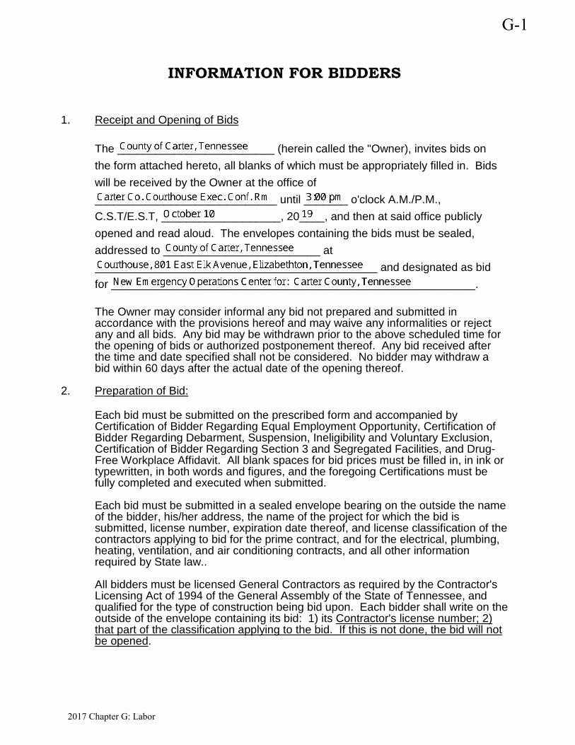
1. Receipt and Opening of Bids
The _________________________ (herein called the "Owner), invites bids on the form attached hereto, all blanks of which must be appropriately filled in. Bids will be received by the Owner at the office of _____________________________ until _______ o'clock A.M./P.M., C.S.T/E.S.T, ___________________, 20____, and then at said office publicly opened and read aloud. The envelopes containing the bids must be sealed, addressed to _________________________ at _____________________________________________ and designated as bid for __________________________________________________________.
The Owner may consider informal any bid not prepared and submitted in accordance with the provisions hereof and may waive any informalities or reject any and all bids. Any bid may be withdrawn prior to the above scheduled time for the opening of bids or authorized postponement thereof. Any bid received after the time and date specified shall not be considered. No bidder may withdraw a bid within 60 days after the actual date of the opening thereof.
2. Preparation of Bid:
Each bid must be submitted on the prescribed form and accompanied by Certification of Bidder Regarding Equal Employment Opportunity, Certification of Bidder Regarding Debarment, Suspension, Ineligibility and Voluntary Exclusion, Certification of Bidder Regarding Section 3 and Segregated Facilities, and Drug-Free Workplace Affidavit. All blank spaces for bid prices must be filled in, in ink or typewritten, in both words and figures, and the foregoing Certifications must be fully completed and executed when submitted. Each bid must be submitted in a sealed envelope bearing on the outside the name of the bidder, his/her address, the name of the project for which the bid is submitted, license number, expiration date thereof, and license classification of the contractors applying to bid for the prime contract, and for the electrical, plumbing, heating, ventilation, and air conditioning contracts, and all other information required by State law.. All bidders must be licensed General Contractors as required by the Contractor's Licensing Act of 1994 of the General Assembly of the State of Tennessee, and qualified for the type of construction being bid upon. Each bidder shall write on the outside of the envelope containing its bid: 1) its Contractor's license number; 2) that part of the classification applying to the bid. If this is not done, the bid will not be opened.
G-1
2017 Chapter G: Labor
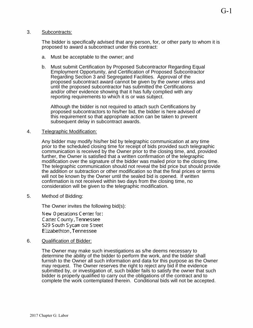
3. Subcontracts: The bidder is specifically advised that any person, for, or other party to whom it is proposed to award a subcontract under this contract: a. Must be acceptable to the owner; and
b. Must submit Certification by Proposed Subcontractor Regarding Equal
Employment Opportunity, and Certification of Proposed Subcontractor Regarding Section 3 and Segregated Facilities. Approval of the proposed subcontract award cannot be given by the owner unless and until the proposed subcontractor has submitted the Certifications and/or other evidence showing that it has fully complied with any reporting requirements to which it is or was subject. Although the bidder is not required to attach such Certifications by proposed subcontractors to his/her bid, the bidder is here advised of this requirement so that appropriate action can be taken to prevent subsequent delay in subcontract awards.
4. Telegraphic Modification: Any bidder may modify his/her bid by telegraphic communication at any time prior to the scheduled closing time for receipt of bids provided such telegraphic communication is received by the Owner prior to the closing time, and, provided further, the Owner is satisfied that a written confirmation of the telegraphic modification over the signature of the bidder was mailed prior to the closing time. The telegraphic communication should not reveal the bid price but should provide the addition or subtraction or other modification so that the final prices or terms will not be known by the Owner until the sealed bid is opened. If written confirmation is not received within two days from the closing time, no consideration will be given to the telegraphic modification.
5. Method of Bidding: The Owner invites the following bid(s):
6. Qualification of Bidder: The Owner may make such investigations as s/he deems necessary to determine the ability of the bidder to perform the work, and the bidder shall furnish to the Owner all such information and data for this purpose as the Owner may request. The Owner reserves the right to reject any bid if the evidence submitted by, or investigation of, such bidder fails to satisfy the owner that such bidder is properly qualified to carry out the obligations of the contract and to complete the work contemplated therein. Conditional bids will not be accepted.
G-1
2017 Chapter G: Labor
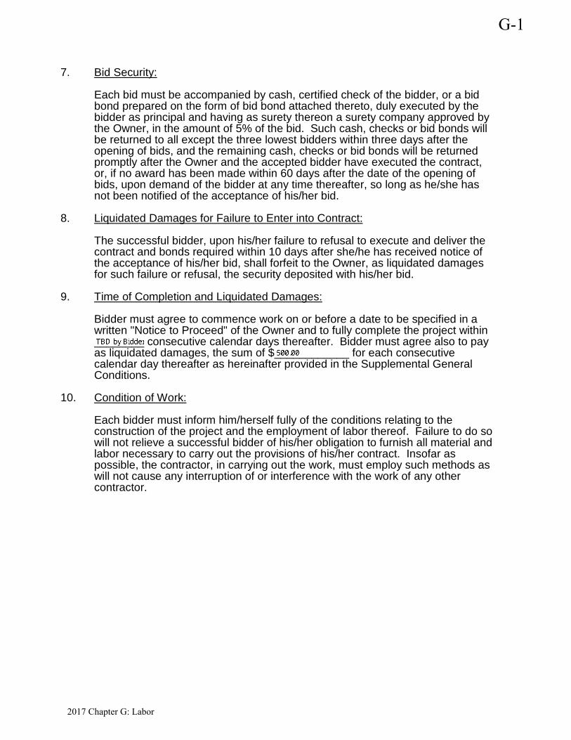
7. Bid Security: Each bid must be accompanied by cash, certified check of the bidder, or a bid bond prepared on the form of bid bond attached thereto, duly executed by the bidder as principal and having as surety thereon a surety company approved by the Owner, in the amount of 5% of the bid. Such cash, checks or bid bonds will be returned to all except the three lowest bidders within three days after the opening of bids, and the remaining cash, checks or bid bonds will be returned promptly after the Owner and the accepted bidder have executed the contract, or, if no award has been made within 60 days after the date of the opening of bids, upon demand of the bidder at any time thereafter, so long as he/she has not been notified of the acceptance of his/her bid.
8. Liquidated Damages for Failure to Enter into Contract: The successful bidder, upon his/her failure to refusal to execute and deliver the contract and bonds required within 10 days after she/he has received notice of the acceptance of his/her bid, shall forfeit to the Owner, as liquidated damages for such failure or refusal, the security deposited with his/her bid.
9. Time of Completion and Liquidated Damages: Bidder must agree to commence work on or before a date to be specified in a written "Notice to Proceed" of the Owner and to fully complete the project within ________ consecutive calendar days thereafter. Bidder must agree also to pay as liquidated damages, the sum of $____________ for each consecutive calendar day thereafter as hereinafter provided in the Supplemental General Conditions.
10. Condition of Work: Each bidder must inform him/herself fully of the conditions relating to the construction of the project and the employment of labor thereof. Failure to do so will not relieve a successful bidder of his/her obligation to furnish all material and labor necessary to carry out the provisions of his/her contract. Insofar as possible, the contractor, in carrying out the work, must employ such methods as will not cause any interruption of or interference with the work of any other contractor.
G-1
2017 Chapter G: Labor
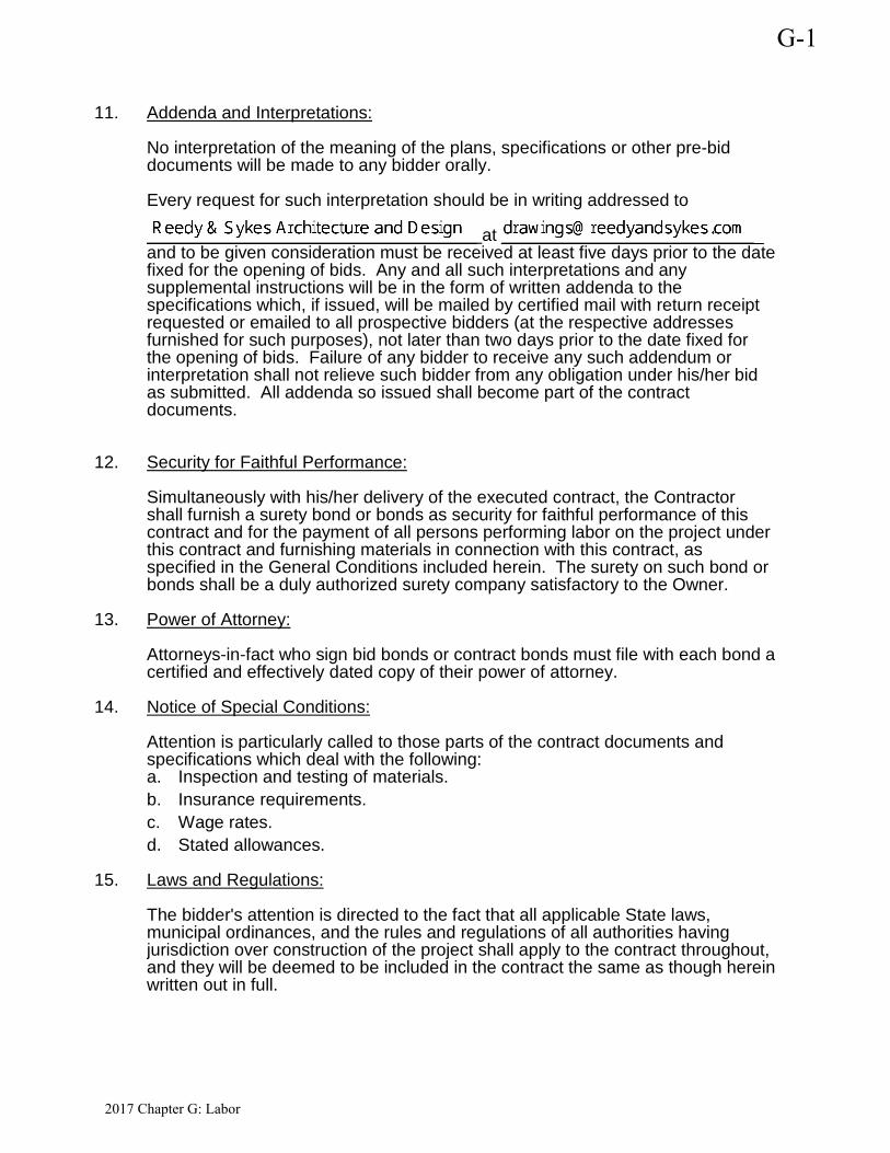
11. Addenda and Interpretations: No interpretation of the meaning of the plans, specifications or other pre-bid documents will be made to any bidder orally. Every request for such interpretation should be in writing addressed to __________________________________ at ___________________________ and to be given consideration must be received at least five days prior to the date fixed for the opening of bids. Any and all such interpretations and any supplemental instructions will be in the form of written addenda to the specifications which, if issued, will be mailed by certified mail with return receipt requested or emailed to all prospective bidders (at the respective addresses furnished for such purposes), not later than two days prior to the date fixed for the opening of bids. Failure of any bidder to receive any such addendum or interpretation shall not relieve such bidder from any obligation under his/her bid as submitted. All addenda so issued shall become part of the contract documents.
12. Security for Faithful Performance: Simultaneously with his/her delivery of the executed contract, the Contractor shall furnish a surety bond or bonds as security for faithful performance of this contract and for the payment of all persons performing labor on the project under this contract and furnishing materials in connection with this contract, as specified in the General Conditions included herein. The surety on such bond or bonds shall be a duly authorized surety company satisfactory to the Owner.
13. Power of Attorney: Attorneys-in-fact who sign bid bonds or contract bonds must file with each bond a certified and effectively dated copy of their power of attorney.
14. Notice of Special Conditions: Attention is particularly called to those parts of the contract documents and specifications which deal with the following: a. Inspection and testing of materials. b. Insurance requirements. c. Wage rates. d. Stated allowances.
15. Laws and Regulations:
The bidder's attention is directed to the fact that all applicable State laws, municipal ordinances, and the rules and regulations of all authorities having jurisdiction over construction of the project shall apply to the contract throughout, and they will be deemed to be included in the contract the same as though herein written out in full.
G-1
2017 Chapter G: Labor
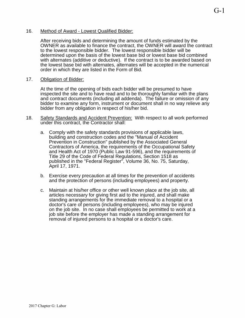
16. Method of Award - Lowest Qualified Bidder: After receiving bids and determining the amount of funds estimated by the OWNER as available to finance the contract, the OWNER will award the contract to the lowest responsible bidder. The lowest responsible bidder will be determined upon the basis of the lowest base bid or lowest base bid combined with alternates (additive or deductive). If the contract is to be awarded based on the lowest base bid with alternates, alternates will be accepted in the numerical order in which they are listed in the Form of Bid.
17. Obligation of Bidder: At the time of the opening of bids each bidder will be presumed to have inspected the site and to have read and to be thoroughly familiar with the plans and contract documents (including all addenda). The failure or omission of any bidder to examine any form, instrument or document shall in no way relieve any bidder from any obligation in respect of his/her bid.
18. Safety Standards and Accident Prevention: With respect to all work performed under this contract, the Contractor shall: a. Comply with the safety standards provisions of applicable laws,
building and construction codes and the "Manual of Accident Prevention in Construction" published by the Associated General Contractors of America, the requirements of the Occupational Safety and Health Act of 1970 (Public Law 91-596), and the requirements of Title 29 of the Code of Federal Regulations, Section 1518 as published in the "Federal Register", Volume 36, No. 75, Saturday, April 17, 1971.
b. Exercise every precaution at all times for the prevention of accidents and the protection of persons (including employees) and property.
c. Maintain at his/her office or other well known place at the job site, all articles necessary for giving first aid to the injured, and shall make standing arrangements for the immediate removal to a hospital or a doctor's care of persons (including employees), who may be injured on the job site. In no case shall employees be permitted to work at a job site before the employer has made a standing arrangement for removal of injured persons to a hospital or a doctor's care.
G-1
2017 Chapter G: Labor
New Emergency Operations Center for: Architect’s Project No. C00218Carter County, TN
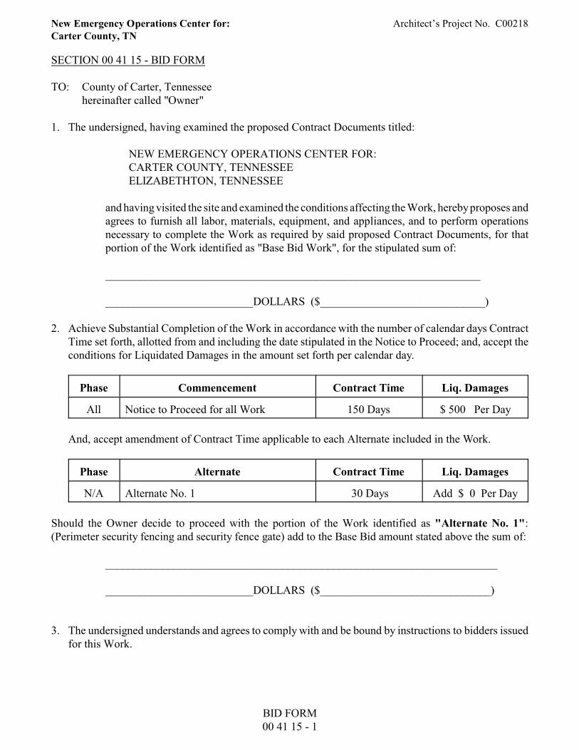
SECTION 00 41 15 - BID FORM
TO: County of Carter, Tennesseehereinafter called "Owner"
1. The undersigned, having examined the proposed Contract Documents titled:
NEW EMERGENCY OPERATIONS CENTER FOR:CARTER COUNTY, TENNESSEEELIZABETHTON, TENNESSEE
and having visited the site and examined the conditions affecting the Work, hereby proposes andagrees to furnish all labor, materials, equipment, and appliances, and to perform operationsnecessary to complete the Work as required by said proposed Contract Documents, for thatportion of the Work identified as "Base Bid Work", for the stipulated sum of:
__________________________________________________________________
__________________________DOLLARS ($_____________________________)
2. Achieve Substantial Completion of the Work in accordance with the number of calendar days ContractTime set forth, allotted from and including the date stipulated in the Notice to Proceed; and, accept theconditions for Liquidated Damages in the amount set forth per calendar day.
Phase Commencement Contract Time Liq. Damages
All Notice to Proceed for all Work 150 Days $ 500 Per Day
And, accept amendment of Contract Time applicable to each Alternate included in the Work.
Phase Alternate Contract Time Liq. Damages
N/A Alternate No. 1 30 Days Add $ 0 Per Day
Should the Owner decide to proceed with the portion of the Work identified as "Alternate No. 1":(Perimeter security fencing and security fence gate) add to the Base Bid amount stated above the sum of:
_____________________________________________________________________
__________________________DOLLARS ($______________________________)
3. The undersigned understands and agrees to comply with and be bound by instructions to bidders issuedfor this Work.
BID FORM00 41 15 - 1
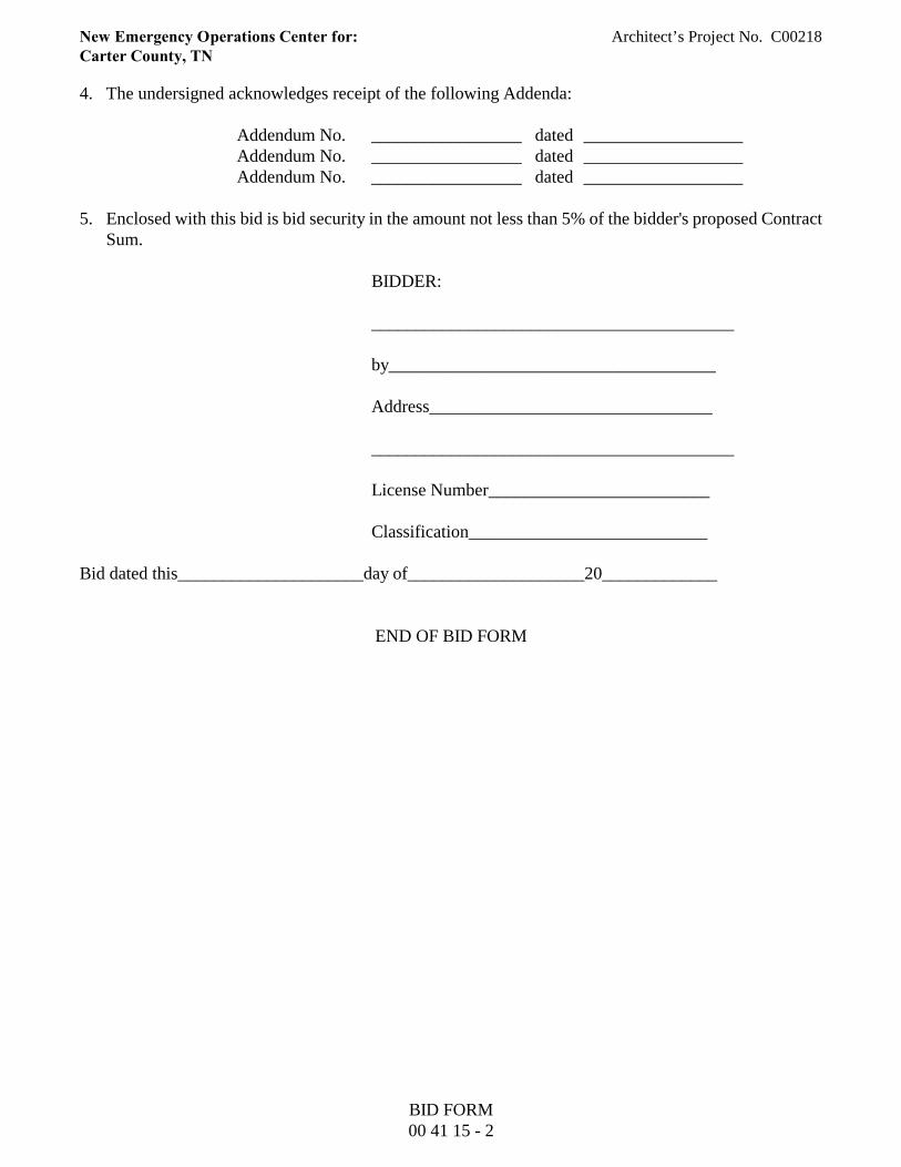
New Emergency Operations Center for: Architect’s Project No. C00218Carter County, TN
4. The undersigned acknowledges receipt of the following Addenda:
Addendum No. _________________ dated __________________Addendum No. _________________ dated __________________Addendum No. _________________ dated __________________
5. Enclosed with this bid is bid security in the amount not less than 5% of the bidder's proposed ContractSum.
BIDDER:
_________________________________________
by_____________________________________
Address________________________________
_________________________________________
License Number_________________________
Classification___________________________
Bid dated this_____________________day of____________________20_____________
END OF BID FORM
BID FORM00 41 15 - 2
New Emergency Operations Center for: Architect’s Project No. C00218Carter County, TN
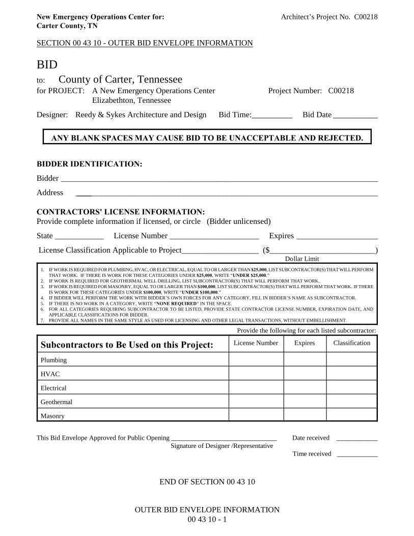
SECTION 00 43 10 - OUTER BID ENVELOPE INFORMATION
BIDto: County of Carter, Tennesseefor PROJECT: A New Emergency Operations Center Project Number: C00218
Elizabethton, Tennessee
Designer: Reedy & Sykes Architecture and Design Bid Time:__________ Bid Date ___________
ANY BLANK SPACES MAY CAUSE BID TO BE UNACCEPTABLE AND REJECTED.
BIDDER IDENTIFICATION:
Bidder ______________________________________________________________________________
Address ______________________________________________________________________________
CONTRACTORS' LICENSE INFORMATION:Provide complete information if licensed, or circle (Bidder unlicensed)
State ____________ License Number ______________________ Expires ____________________
License Classification Applicable to Project___________________ ( $__________________________) Dollar Limit
1. IF WORK IS REQUIRED FOR PLUMBING, HVAC, OR ELECTRICAL, EQUAL TO OR LARGER THAN $25,000, LIST SUBCONTRACTOR(S) THAT WILL PERFORMTHAT WORK. IF THERE IS WORK FOR THESE CATEGORIES UNDER $25,000, WRITE “UNDER $25,000.”
2. IF WORK IS REQUIRED FOR GEOTHERMAL WELL DRILLING, LIST SUBCONTRACTOR(S) THAT WILL PERFORM THAT WORK.3. IF WORK IS REQUIRED FOR MASONRY, EQUAL TO OR LARGER THAN $100,000, LIST SUBCONTRACTOR(S) THAT WILL PERFORM THAT WORK. IF THERE
IS WORK FOR THESE CATEGORIES UNDER $100,000, WRITE “UNDER $100,000.”4. IF BIDDER WILL PERFORM THE WORK WITH BIDDER’S OWN FORCES FOR ANY CATEGORY, FILL IN BIDDER’S NAME AS SUBCONTRACTOR.5. IF THERE IS NO WORK IN A CATEGORY, WRITE “NONE REQUIRED” IN THE SPACE.6. FOR ALL CATEGORIES REQUIRING SUBCONTRACTOR TO BE LISTED, PROVIDE STATE CONTRACTOR LICENSE NUMBER, EXPIRATION DATE, AND
APPLICABLE CLASSIFICATIONS FOR BIDDER.7. PROVIDE ALL NAMES IN THE SAME STYLE AS USED FOR LICENSING AND OTHER LEGAL TRANSACTIONS, WITHOUT EMBELLISHMENT.
Provide the following for each listed subcontractor:
Subcontractors to Be Used on this Project: License Number Expires Classification
Plumbing
HVAC
Electrical
Geothermal
Masonry
This Bid Envelope Approved for Public Opening _______________________________ Date received ____________Signature of Designer /Representative
Time received ____________
END OF SECTION 00 43 10
OUTER BID ENVELOPE INFORMATION00 43 10 - 1
New Emergency Operations Center for: Architect’s Project No. C00218Carter County, TN
SECTION 00 43 13 - BID BOND FORM
The Owner requires a5% Bid Bond
for this project.The Contractor can use the
Bid Bond Formprovided bythe Owner
found on the following pages,or the Contractor can use the
Bid Bond Formprovided by
their Surety Company.
BID BOND FORM00 43 13 - 1

BID BOND
KNOW ALL MEN BY THESE PRESENTS, that we, the undersigned, ______________ _____________________________________________________________________ as Principal, and ________________________________________________________ as Surety, are hereby held and firmly bound unto ______________________________ as owner in the penal sum of _________________________________________ for the payment of which, well and truly to be made, we hereby jointly and severally bind ourselves, our heirs, executors, administrators, successors and assigns.
Signed, this _________ day of ___________________________, 20____.
The condition of the above obligation is such that whereas the Principal has submitted to _______________________________________________ a certain Bid, attached hereto and hereby made a part hereof to enter into a contract in writing for the
NOW, THEREFORE,
(a) If said Bid shall be rejected, or in the alternate.
(b) If said Bid shall be accepted and the Principal shall execute and deliver a contract in the Form of Contract attached hereto (properly completed in accordance with said Bid) and shall furnish a bond for his faithful performance of said contract, and for the payment of all persons performing labor or furnishing materials in connection therewith, and shall in all other respects perform the agreement created by the acceptance of said Bid, then this obligation shall be void, otherwise the same shall remain in force and effect, it being expressly understood and agreed that the liability of the Surety for any and all claims hereunder shall, in no event, exceed the penal amount of this obligation as herein stated.
The surety for value received, hereby stipulates and agrees that the obligations of said Surety and its bond shall be in no way impaired or affected by an extension of the time within which the Owner may accept such Bid; and said Surety does hereby waive notice of any such extension.
G-1
2017 Chapter G: Labor
IN WITNESS WHEREOF, the Principal and the Surety have hereunto set their hand and seals, and such of them as are corporations have caused their corporate seals to be hereto affixed and these presents to be signed by their proper officers, the day and year first set forth above. (L.S.) Principal Surety SEAL By:
G-1
2017 Chapter G: Labor
New Emergency Operations Center for: Architect’s Project No. C00218Carter County, TN
SECTION 00 45 15 - CERTIFICATION OF BIDDER REGARDING DEBARMENT, SUSPENSION,INELIGIBILITY AND VOLUNTARY EXCLUSION
The Owner has indicated anintention to use
"Certification of Bidder Regarding Debarment, Suspension, Ineligibility and Voluntary Exclusion” Form,
as part of theContract Documents for this Work.
A copy of the referencedDocument is found on the following page.
This document shall be included as part of the Bid Package.
CERTIFICATION OF BIDDER REGARDING DEBARMENT, SUSPENSION, INELIGIBILITY ANDVOLUNTARY EXCLUSION
00 45 15 - 1
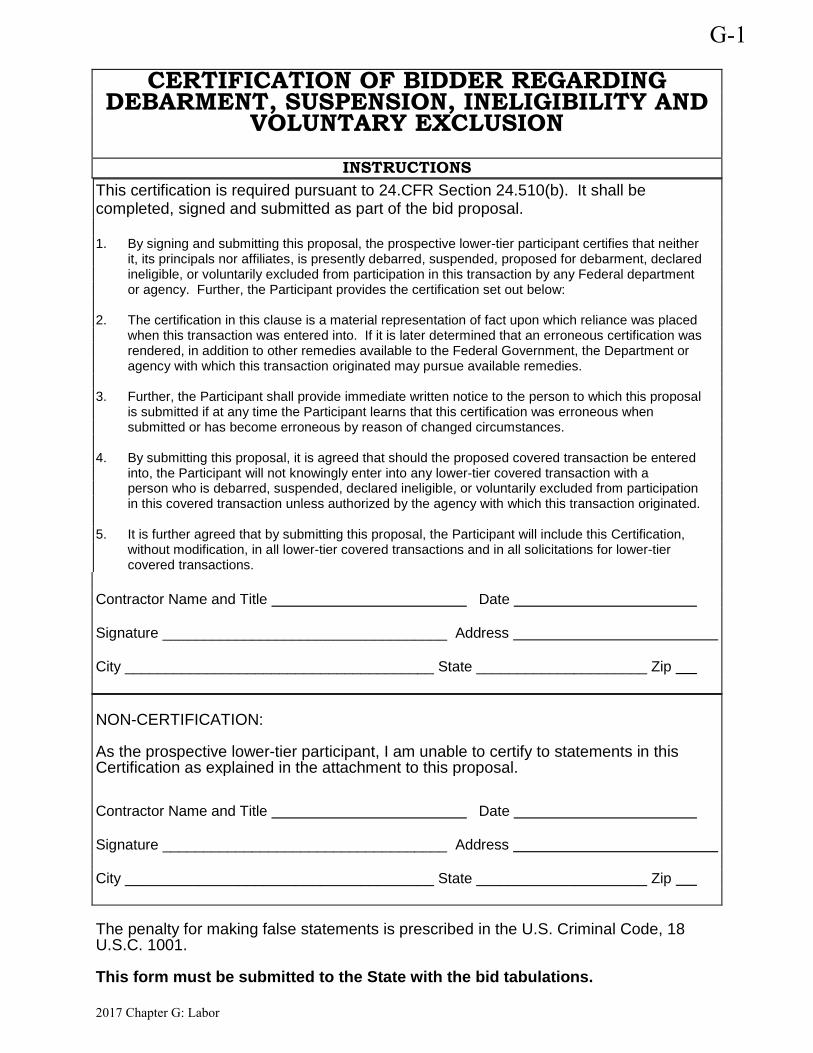
CERTIFICATION OF BIDDER REGARDING DEBARMENT, SUSPENSION, INELIGIBILITY AND
VOLUNTARY EXCLUSION
INSTRUCTIONS This certification is required pursuant to 24.CFR Section 24.510(b). It shall be completed, signed and submitted as part of the bid proposal. 1. By signing and submitting this proposal, the prospective lower-tier participant certifies that neither it, its principals nor affiliates, is presently debarred, suspended, proposed for debarment, declared ineligible, or voluntarily excluded from participation in this transaction by any Federal department or agency. Further, the Participant provides the certification set out below: 2. The certification in this clause is a material representation of fact upon which reliance was placed when this transaction was entered into. If it is later determined that an erroneous certification was rendered, in addition to other remedies available to the Federal Government, the Department or agency with which this transaction originated may pursue available remedies. 3. Further, the Participant shall provide immediate written notice to the person to which this proposal is submitted if at any time the Participant learns that this certification was erroneous when submitted or has become erroneous by reason of changed circumstances. 4. By submitting this proposal, it is agreed that should the proposed covered transaction be entered into, the Participant will not knowingly enter into any lower-tier covered transaction with a person who is debarred, suspended, declared ineligible, or voluntarily excluded from participation in this covered transaction unless authorized by the agency with which this transaction originated. 5. It is further agreed that by submitting this proposal, the Participant will include this Certification, without modification, in all lower-tier covered transactions and in all solicitations for lower-tier covered transactions. Contractor Name and Title Date Signature ___________________________________ Address City ______________________________________ State _____________________ Zip NON-CERTIFICATION: As the prospective lower-tier participant, I am unable to certify to statements in this Certification as explained in the attachment to this proposal. Contractor Name and Title Date Signature ___________________________________ Address City ______________________________________ State _____________________ Zip The penalty for making false statements is prescribed in the U.S. Criminal Code, 18 U.S.C. 1001. This form must be submitted to the State with the bid tabulations.
G-1
2017 Chapter G: Labor
New Emergency Operations Center for: Architect’s Project No. C00218Carter County, TN
SECTION 00 45 16 - CERTIFICATION OF BIDDER REGARDING EQUAL EMPLOYMENTOPPORTUNITY
The Owner has indicated anintention to use
"Certification of Bidder Regarding Equal Employment Opportunity” Form,
as part of theContract Documents for this Work.
A copy of the referencedDocument is found on the following page.
This document shall be included as part of the Bid Package.
CERTIFICATION OF BIDDER REGARDING EQUAL EMPLOYMENT OPPORTUNITY00 45 16 - 1
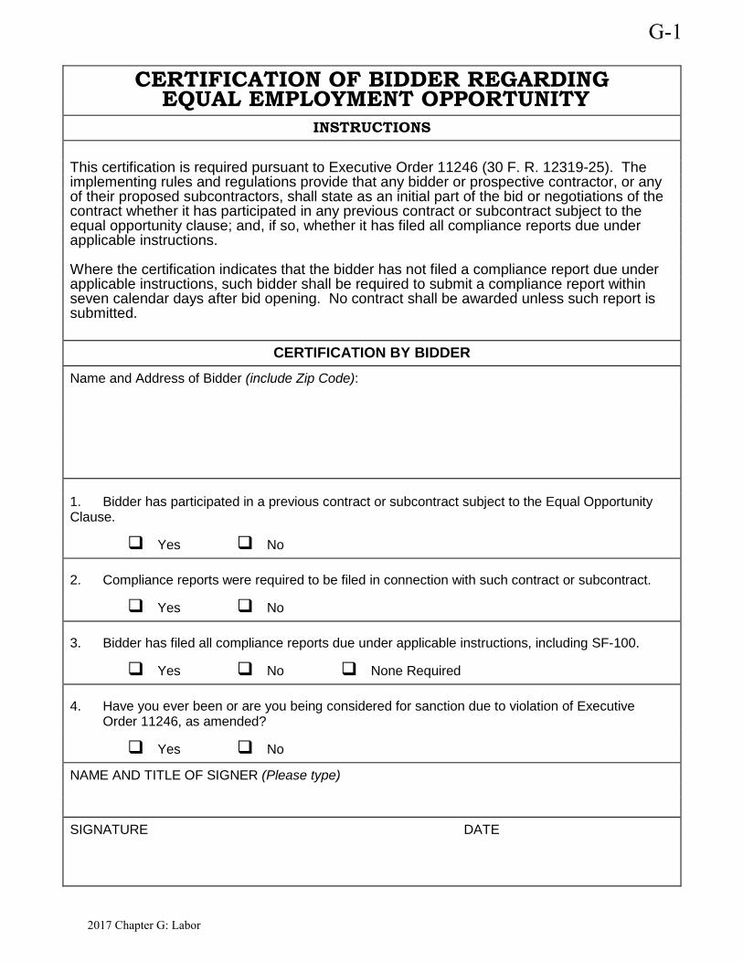
CERTIFICATION OF BIDDER REGARDING EQUAL EMPLOYMENT OPPORTUNITY
INSTRUCTIONS
This certification is required pursuant to Executive Order 11246 (30 F. R. 12319-25). The implementing rules and regulations provide that any bidder or prospective contractor, or any of their proposed subcontractors, shall state as an initial part of the bid or negotiations of the contract whether it has participated in any previous contract or subcontract subject to the equal opportunity clause; and, if so, whether it has filed all compliance reports due under applicable instructions. Where the certification indicates that the bidder has not filed a compliance report due under applicable instructions, such bidder shall be required to submit a compliance report within seven calendar days after bid opening. No contract shall be awarded unless such report is submitted.
CERTIFICATION BY BIDDER Name and Address of Bidder (include Zip Code):
1. Bidder has participated in a previous contract or subcontract subject to the Equal Opportunity Clause.
Yes No
2. Compliance reports were required to be filed in connection with such contract or subcontract.
Yes No
3. Bidder has filed all compliance reports due under applicable instructions, including SF-100.
Yes No None Required
4. Have you ever been or are you being considered for sanction due to violation of Executive Order 11246, as amended?
Yes No
NAME AND TITLE OF SIGNER (Please type)
SIGNATURE DATE
G-1
2017 Chapter G: Labor
New Emergency Operations Center for: Architect’s Project No. C00218Carter County, TN
SECTION 00 45 17 - CERTIFICATION OF BIDDER REGARDING USE OF FEMALE/MINORITYSUBCONTRACTORS
The Owner has indicated anintention to use
"Certification of Bidder Regarding Use of Female/Minority Subcontractors” Form,
as part of theContract Documents for this Work.
A copy of the referencedDocument is found on the following page.
This document shall be included as part of the Bid Package.
CERTIFICATION OF BIDDER REGARDING USE OF FEMALE/MINORITY SUBCONTRACTORS00 45 17 - 1
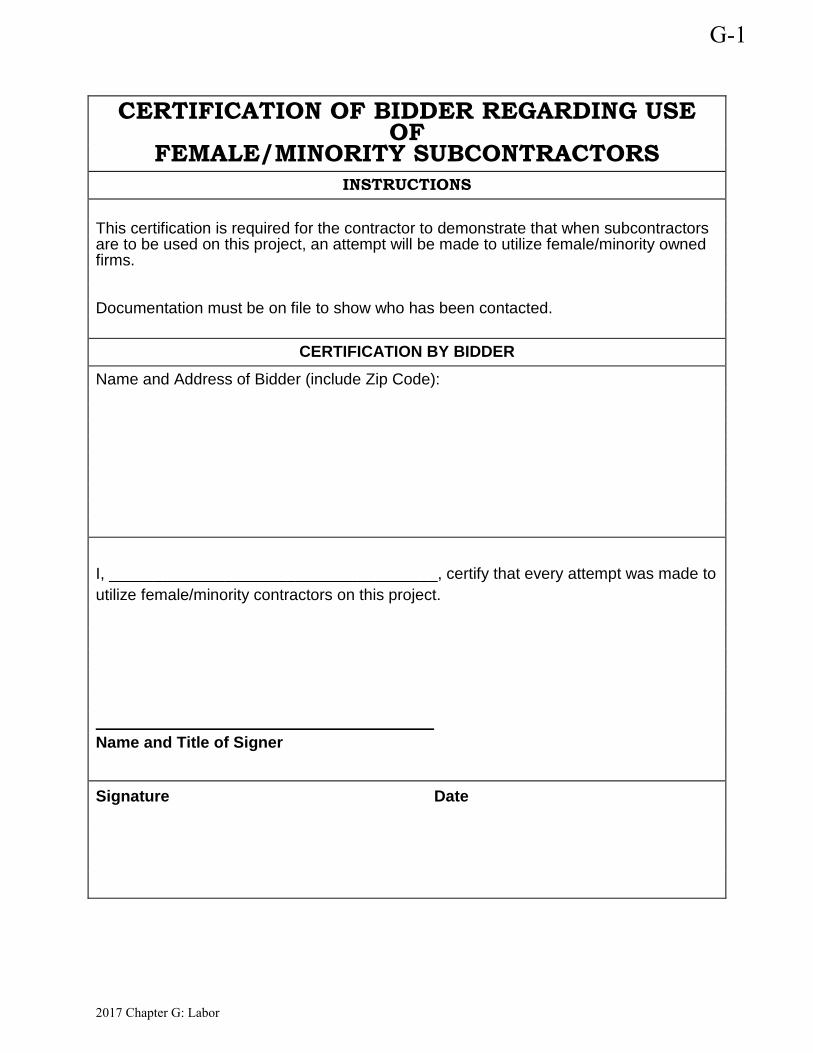
CERTIFICATION OF BIDDER REGARDING USE OF
FEMALE/MINORITY SUBCONTRACTORS INSTRUCTIONS
This certification is required for the contractor to demonstrate that when subcontractors are to be used on this project, an attempt will be made to utilize female/minority owned firms. Documentation must be on file to show who has been contacted.
CERTIFICATION BY BIDDER Name and Address of Bidder (include Zip Code):
I, _____________________________________, certify that every attempt was made to utilize female/minority contractors on this project. Name and Title of Signer
Signature Date
G-1
2017 Chapter G: Labor
New Emergency Operations Center for: Architect’s Project No. C00218Carter County, TN
SECTION 00 45 18 - CERTIFICATION OF BIDDER REGARDING SECTION 3 AND SEGREGATEDFACILITIES
The Owner has indicated anintention to use
"Certification of Bidder Regarding Section 3 and Segregated Facilities” Form,
as part of theContract Documents for this Work.
A copy of the referencedDocument is found on the following page.
This document shall be included as part of the Bid Package.
CERTIFICATION OF BIDDER REGARDING SECTION 3 AND SEGREGATED FACILITIES00 45 18 - 1
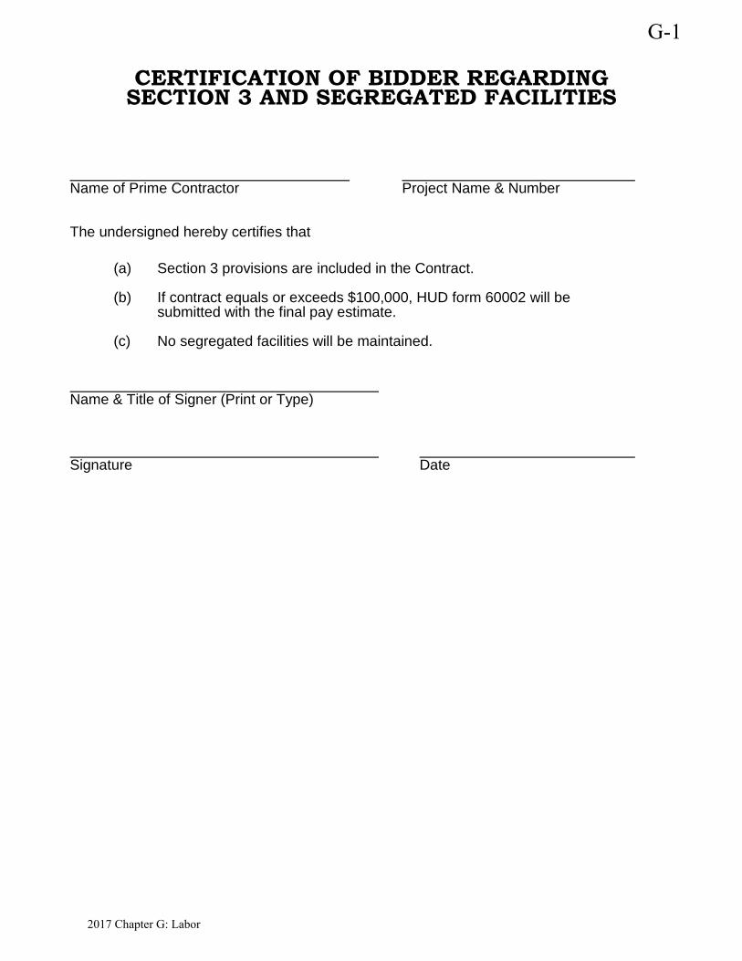
CERTIFICATION OF BIDDER REGARDING SECTION 3 AND SEGREGATED FACILITIES
Name of Prime Contractor Project Name & Number
The undersigned hereby certifies that
(a) Section 3 provisions are included in the Contract.
(b) If contract equals or exceeds $100,000, HUD form 60002 will be submitted with the final pay estimate.
(c) No segregated facilities will be maintained.
Name & Title of Signer (Print or Type)
Signature Date
G-1
2017 Chapter G: Labor

New Emergency Operations Center for: Architect’s Project No. C00218Carter County, TN
SECTION 00 45 19 - DRUG-FREE WORKPLACE AFFIDAVIT
The Owner has indicated anintention to use
"Drug-Free Workplace Affidavit” Form, as part of the
Contract Documents for this Work.A copy of the referenced
Document is found on the following page.This document shall be included
as part of the Bid Package.
DRUG-FREE WORKPLACE AFFIDAVIT00 45 19 - 1
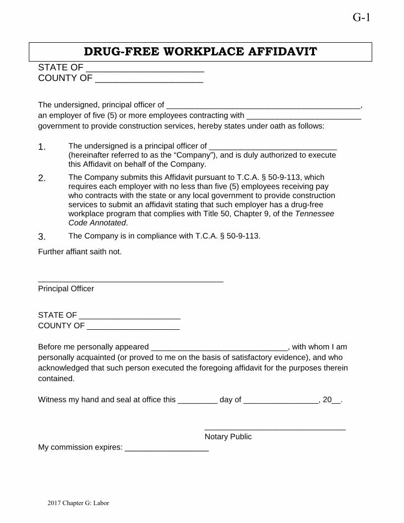
STATE OF _______________________ COUNTY OF _____________________
The undersigned, principal officer of ____________________________________________, an employer of five (5) or more employees contracting with __________________________ government to provide construction services, hereby states under oath as follows: 1. The undersigned is a principal officer of _____________________________
(hereinafter referred to as the “Company”), and is duly authorized to execute this Affidavit on behalf of the Company.
2. The Company submits this Affidavit pursuant to T.C.A. § 50-9-113, which requires each employer with no less than five (5) employees receiving pay who contracts with the state or any local government to provide construction services to submit an affidavit stating that such employer has a drug-free workplace program that complies with Title 50, Chapter 9, of the Tennessee Code Annotated.
3. The Company is in compliance with T.C.A. § 50-9-113.
Further affiant saith not.
__________________________________________ Principal Officer
STATE OF _______________________ COUNTY OF _____________________ Before me personally appeared _______________________________, with whom I am personally acquainted (or proved to me on the basis of satisfactory evidence), and who acknowledged that such person executed the foregoing affidavit for the purposes therein contained. Witness my hand and seal at office this _________ day of _________________, 20__.
________________________________ Notary Public My commission expires: ___________________
DRUG-FREE WORKPLACE AFFIDAVIT
G-1
2017 Chapter G: Labor
New Emergency Operations Center for: Architect’s Project No. C00218Carter County, TN
SECTION 00 45 20 - CERTIFICATION BY PROPOSED SUBCONTRACTOR REGARDING EQUALEMPLOYMENT OPPORTUNITY
The Owner has indicated anintention to use
"Certification by Proposed Subcontractor Regarding Equal Employment Opportunity” Form,
as part of theContract Documents for this Work.
A copy of the referencedDocument is found on the following page.
This document shall be included as part of the Bid Package.
CERTIFICATION BY PROPOSED SUBCONTRACTOR REGARDING EQUAL EMPLOYMENTOPPORTUNITY
00 45 20 - 1

CERTIFICATION BY PROPOSED SUBCONTRACTOR REGARDING EQUAL EMPLOYMENT OPPORTUNITY
NAME OF PRIME CONTRACTOR PROJECT NUMBER
INSTRUCTIONS This certification is required pursuant to Executive Order 11246 (30 F. R. 12319-25). The implementing rules and regulations provide that any bidder or prospective contractor, or any of their proposed subcontractors, shall state as an initial part of the bid or negotiations of the contract whether it has participated in any previous contract or subcontract subject to the equal opportunity clause; and, if so, whether it has filed all compliance reports due under applicable instructions. Where the certification indicates that the subcontractor has not filed a compliance report due under applicable instructions, such subcontractor shall be required to submit a compliance report before the owner approves the subcontract or permits work to begin under the subcontract.
SUBCONTRACTOR'S CERTIFICATION NAME AND ADDRESS OF SUBCONTRACTOR (include ZIP Code):
1. Bidder has participated in a previous contract or subcontract subject to the Equal Opportunity Clause.
Yes No
2. Compliance reports were required to be filed in connection with such contract or subcontract.
Yes No
3. Bidder has filed all compliance reports due under applicable instructions, including SF-100.
Yes No None Required
4. Have you ever been or are you being considered for sanction due to violation of Executive Order 11246, as amended?
Yes No
NAME AND TITLE OF SIGNER (Please type)
SIGNATURE DATE
G-1
2017 Chapter G: Labor
New Emergency Operations Center for: Architect’s Project No. C00218Carter County, TN
SECTION 00 45 21 - CERTIFICATION OF PROPOSED SUBCONTRACTOR REGARDING SECTION3 AND SEGREGATED FACILITIES
The Owner has indicated anintention to use
"Certification of Proposed Subcontractor Regarding Section 3 and Segregated Facilities” Form,
as part of theContract Documents for this Work.
A copy of the referencedDocument is found on the following page.
This document shall be included as part of the Bid Package.
CERTIFICATION OF PROPOSED SUBCONTRACTOR REGARDING SECTION 3 ANDSEGREGATED FACILITIES
00 45 21 - 1
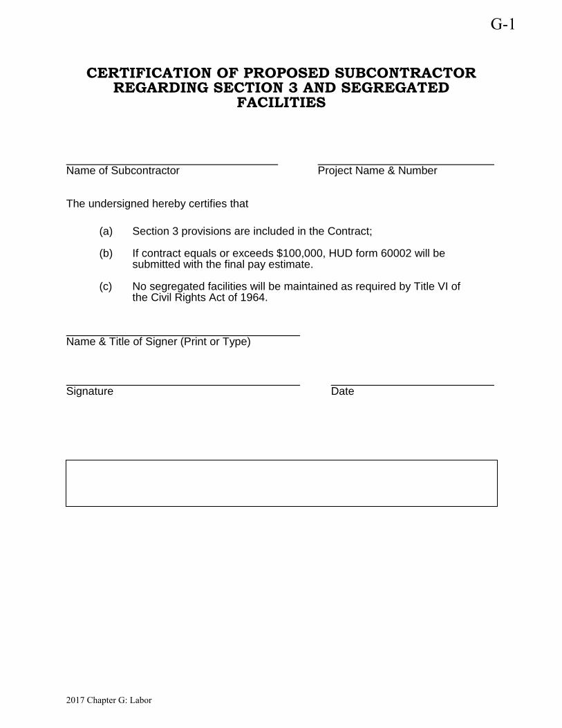
CERTIFICATION OF PROPOSED SUBCONTRACTOR REGARDING SECTION 3 AND SEGREGATED
FACILITIES
Name of Subcontractor Project Name & Number
The undersigned hereby certifies that
(a) Section 3 provisions are included in the Contract;
(b) If contract equals or exceeds $100,000, HUD form 60002 will be submitted with the final pay estimate.
(c) No segregated facilities will be maintained as required by Title VI of the Civil Rights Act of 1964.
Name & Title of Signer (Print or Type)
Signature Date
G-1
2017 Chapter G: Labor
New Emergency Operations Center for: Architect’s Project No. C00218Carter County, TN
SECTION 00 45 22 - STATEMENT OF COMPLIANCE CERTIFICATE ILLEGAL IMMIGRANTS
The Owner has indicated anintention to use
"Statement of Compliance CertificateIllegal Immigrants” Form,
as part of theContract Documents for this Work.
A copy of the referencedDocument is found on the following page.
This document shall be included as part of the Bid Package.
STATEMENT OF COMPLIANCE CERTIFICATE ILLEGAL IMMIGRANTS00 45 22 - 1
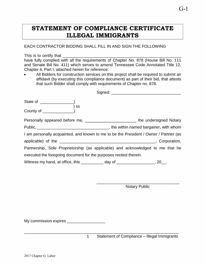
STATEMENT OF COMPLIANCE CERTIFICATE ILLEGAL IMMIGRANTS
EACH CONTRACTOR BIDDING SHALL FILL IN AND SIGN THE FOLLOWING This is to certify that _____________________________________________________ have fully complied with all the requirements of Chapter No. 878 (House Bill No. 111 and Senate Bill No. 411) which serves to amend Tennessee Code Annotated Title 12, Chapter 4, Part I, attached herein for reference. • All Bidders for construction services on this project shall be required to submit an
affidavit (by executing this compliance document) as part of their bid, that attests that such Bidder shall comply with requirements of Chapter no. 878.
Signed: _______________________________ State of _______________) ) ss County of ______________) Personally appeared before me, _______________________ the undersigned Notary
Public, ________________________________, the within named bargainer, with whom
I am personally acquainted, and known to me to be the President / Owner / Partner (as
applicable) of the ___________________________________________, Corporation,
Partnership, Sole Proprietorship (as applicable) and acknowledged to me that he
executed the foregoing document for the purposes recited therein.
Witness my hand, at office, this __________ day of _________________, 20__.
_____________________________________ Notary Public
My commission expires _________________
_____________________________________________________________________ 1 Statement of Compliance – Illegal Immigrants
G-1
2017 Chapter G: Labor
New Emergency Operations Center for: Architect’s Project No. C00218Carter County, TN
SECTION 00 45 23 - IRAN DIVESTMENT ACT
The Owner has indicated anintention to use
"Iran Divestment Act” Form, as part of the
Contract Documents for this Work.A copy of the referenced
Document is found on the following pages.This document shall be included
as part of the Bid Package.
IRAN DIVESTMENT ACT00 45 23 - 1
G-1
CDBG Manual - Labor Chapter - Contracts Document Guide 23
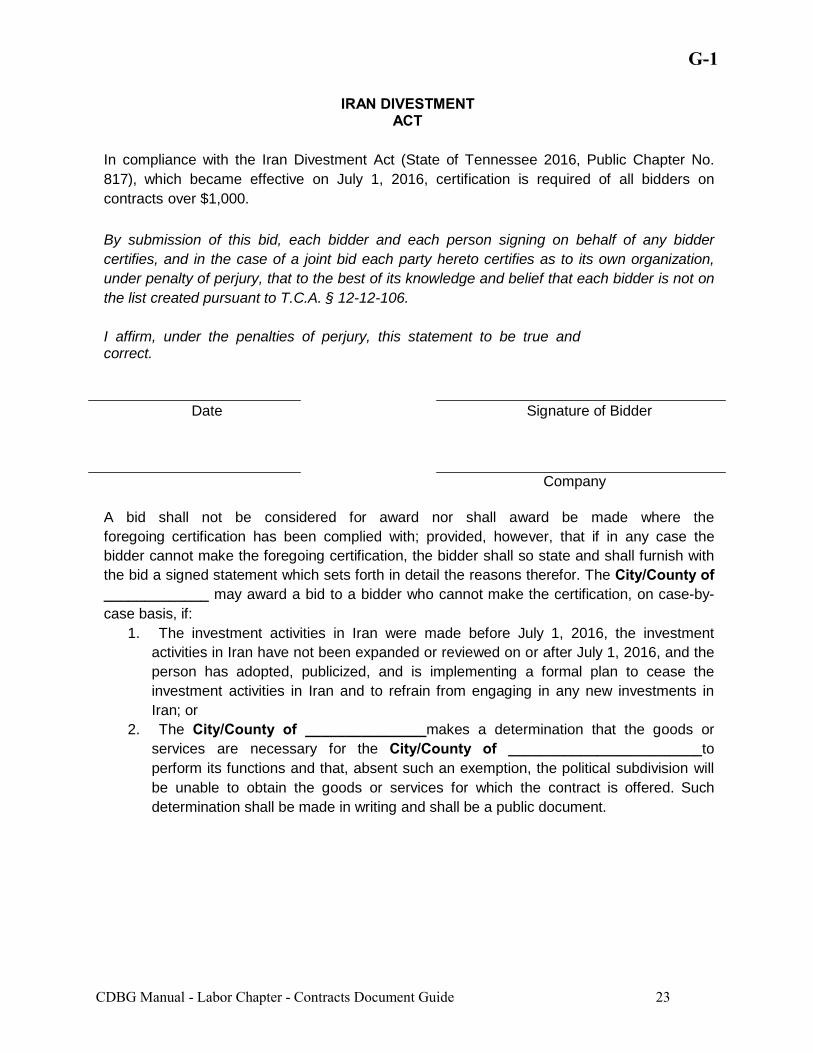
IRAN DIVESTMENT ACT
In compliance with the Iran Divestment Act (State of Tennessee 2016, Public Chapter No.
817), which became effective on July 1, 2016, certification is required of all bidders on
contracts over $1,000.
By submission of this bid, each bidder and each person signing on behalf of any bidder
certifies, and in the case of a joint bid each party hereto certifies as to its own organization,
under penalty of perjury, that to the best of its knowledge and belief that each bidder is not on
the list created pursuant to T.C.A. § 12-12-106.
I affirm, under the penalties of perjury, this statement to be true and correct.
Date Signature of Bidder
Company
A bid shall not be considered for award nor shall award be made where the
foregoing certification has been complied with; provided, however, that if in any case the
bidder cannot make the foregoing certification, the bidder shall so state and shall furnish with
the bid a signed statement which sets forth in detail the reasons therefor. The City/County of _____________ may award a bid to a bidder who cannot make the certification, on case-by-
case basis, if:
1. The investment activities in Iran were made before July 1, 2016, the investment
activities in Iran have not been expanded or reviewed on or after July 1, 2016, and the
person has adopted, publicized, and is implementing a formal plan to cease the
investment activities in Iran and to refrain from engaging in any new investments in
Iran; or
2. The City/County of _______________makes a determination that the goods or
services are necessary for the City/County of ________________________to
perform its functions and that, absent such an exemption, the political subdivision will
be unable to obtain the goods or services for which the contract is offered. Such
determination shall be made in writing and shall be a public document.

July 15, 2016
NOTICE
Tenn. Code Ann. § 12-12-106 requires the chief procurement officer to publish, using credible information freely available to the public, a list of persons it determines engage in investment activities in Iran, as described in § 12-12-105. For these purposes, the State intends to use the attached list of “Entities Ineligible to Contract with the State of South Carolina or any Political Subdivision of the State per the Iran Divestment Act of 2014, S.C. Code Ann. §§ 11-57-10, et. seq.” While inclusion on this list would make a person ineligible to contract with the state of Tennessee, if a person ceases its engagement in investment activities in Iran, it may be removed from the list. If you feel as though you have been erroneously included on this list please contact the Central Procurement Office at [email protected].
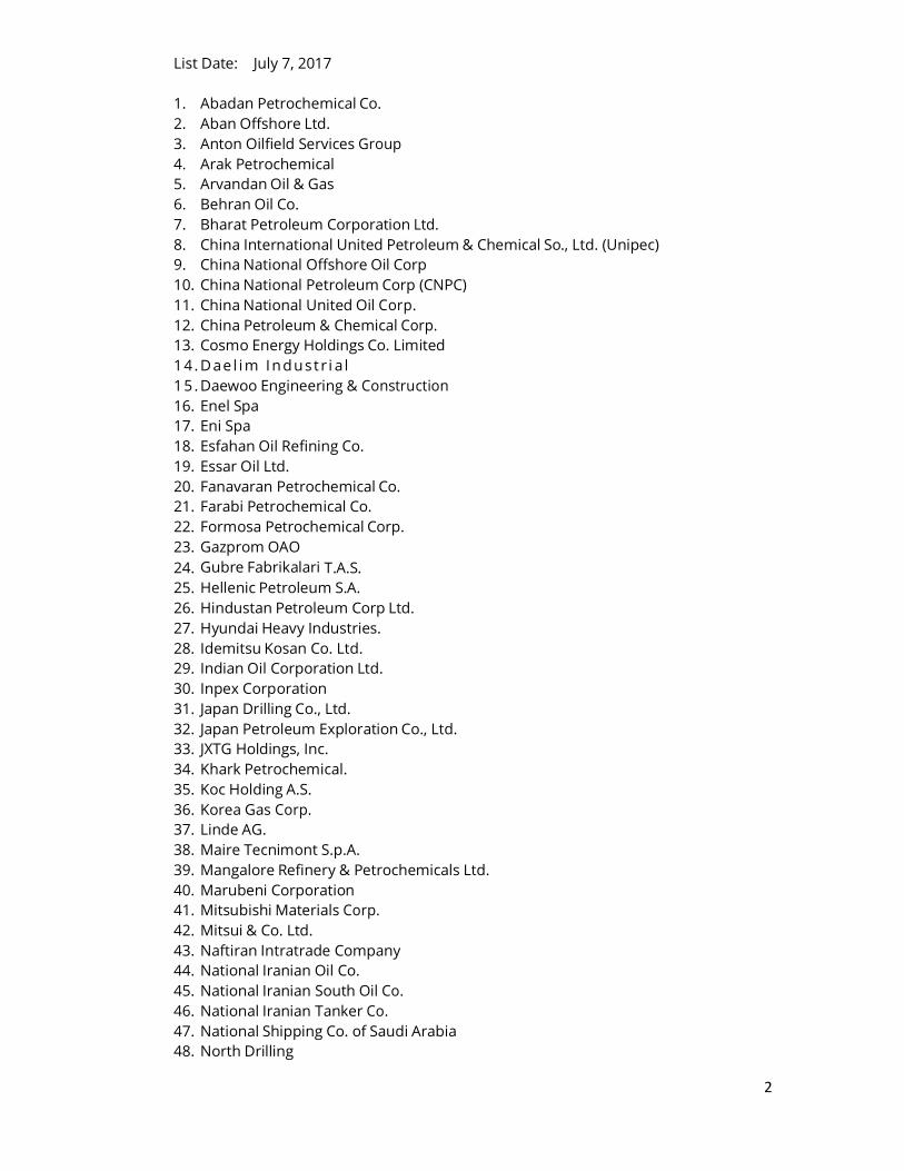
2
List Date: July 7, 2017
1. Abadan Petrochemical Co.
2. Aban Offshore Ltd.
3. Anton Oilfield Services Group
4. Arak Petrochemical
5. Arvandan Oil & Gas
6. Behran Oil Co.
7. Bharat Petroleum Corporation Ltd.
8. China International United Petroleum & Chemical So., Ltd. (Unipec)
9. China National Offshore Oil Corp
10. China National Petroleum Corp (CNPC)
11. China National United Oil Corp.
12. China Petroleum & Chemical Corp.
13. Cosmo Energy Holdings Co. Limited
14. Dae l im Industr i a l
15 . Daewoo Engineering & Construction
16. Enel Spa
17. Eni Spa
18. Esfahan Oil Refining Co.
19. Essar Oil Ltd.
20. Fanavaran Petrochemical Co.
21. Farabi Petrochemical Co.
22. Formosa Petrochemical Corp.
23. Gazprom OAO
24. Gubre Fabrikalari T.A.S.
25. Hellenic Petroleum S.A.
26. Hindustan Petroleum Corp Ltd.
27. Hyundai Heavy Industries.
28. Idemitsu Kosan Co. Ltd.
29. Indian Oil Corporation Ltd.
30. Inpex Corporation
31. Japan Drilling Co., Ltd.
32. Japan Petroleum Exploration Co., Ltd.
33. JXTG Holdings, Inc.
34. Khark Petrochemical.
35. Koc Holding A.S.
36. Korea Gas Corp.
37. Linde AG.
38. Maire Tecnimont S.p.A.
39. Mangalore Refinery & Petrochemicals Ltd.
40. Marubeni Corporation
41. Mitsubishi Materials Corp.
42. Mitsui & Co. Ltd.
43. Naftiran Intratrade Company
44. National Iranian Oil Co.
45. National Iranian South Oil Co.
46. National Iranian Tanker Co.
47. National Shipping Co. of Saudi Arabia
48. North Drilling
3
49. Oil & Natural Gas Corporation Ltd.
50. Oil India Ltd.
51. Oil Industry Investment Co.
52. ONGC Videsh Ltd. (OVL)
53. Pardis Petrochemical Co.
54. Pars Oil Co.
55. Parsian Oil and Gas Development Co.
56. Petrochemical Industries Investment Co.
57. Petrochemical Transport Co.
58. PetroChina Co. Ltd.
59. PJSC Lukoil
60. Polskie Gornictwo Naftowe i Gazownictwo SA
61. Royal Dutch Shell Plc.
62. Sadid Pipe & Equipments Co.
63. Saras Raffinerie Sarde SPA
64. Sepehr Energy
65. Shiraz Petrochemical Co.
66. Showa Shell Sekiyu K K
67. Sinopec Group.
68. Sk Holdings Co. Ltd.
69. SK Innovation
70. Tabriz Oil Refining Company
71. Total S.A.
72. Toyo Engineering Corporation
73. Turkiye Petrol Rafinerileri AS
74. Zhuh
75. Ai Zhenrong Company
New Emergency Operations Center for: Architect’s Project No. C00218Carter County, TN
SECTION 00 45 24 - TITLE VI CONTRACT MONITORING
The Owner has indicated anintention to use
"Title VI Contract Monitoring” Form, as part of the
Contract Documents for this Work.A copy of the referenced
Document is found on the following page.This document shall be included
as part of the Bid Package.
TITLE VI CONTRACT MONITORING00 45 24 - 1
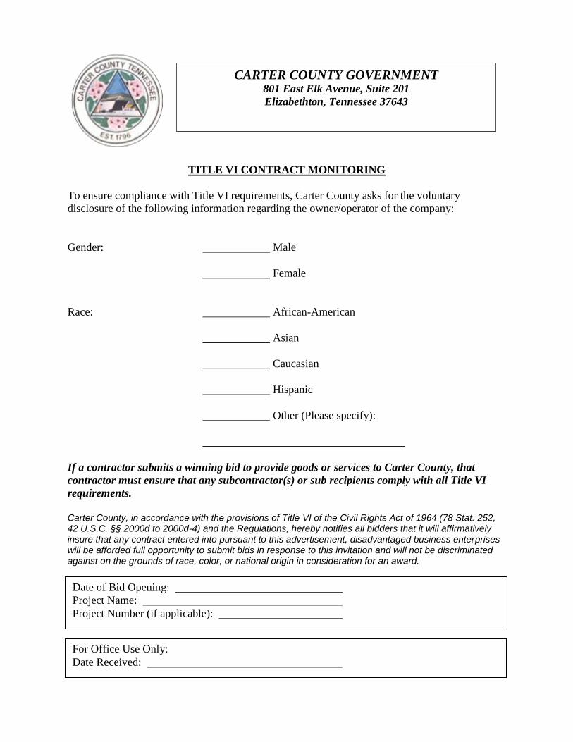
TITLE VI CONTRACT MONITORING
To ensure compliance with Title VI requirements, Carter County asks for the voluntary
disclosure of the following information regarding the owner/operator of the company:
Gender: Male
Female
Race: African-American
Asian
Caucasian
Hispanic
Other (Please specify):
If a contractor submits a winning bid to provide goods or services to Carter County, that
contractor must ensure that any subcontractor(s) or sub recipients comply with all Title VI
requirements.
Carter County, in accordance with the provisions of Title VI of the Civil Rights Act of 1964 (78 Stat. 252, 42 U.S.C. §§ 2000d to 2000d-4) and the Regulations, hereby notifies all bidders that it will affirmatively insure that any contract entered into pursuant to this advertisement, disadvantaged business enterprises will be afforded full opportunity to submit bids in response to this invitation and will not be discriminated against on the grounds of race, color, or national origin in consideration for an award.
CARTER COUNTY GOVERNMENT 801 East Elk Avenue, Suite 201
Elizabethton, Tennessee 37643
Date of Bid Opening:
Project Name:
Project Number (if applicable):
For Office Use Only:
Date Received:
New Emergency Operations Center for: Architect’s Project No. C00218Carter County, TN
SECTION 00 52 00 - AGREEMENT FORM
The Ownerwill be using the Agreement Form
on the following pages, as part of theContract documents for this Work.All persons intending to provide
goods or services in connection withthe Work are advised to read and
understand the referencedDocuments prior to proceeding.
AGREEMENT FORM00 52 00 - 1

AGREEMENT
THIS AGREEMENT, made this __________ day of __________________, 20____, by and between __________________________________________________________, herein called "Owner", acting herein through its _______________________________ _________________________________________________________________, and ____________________________________________________________________ STRIKE OUT (a corporation) (a partnership) INAPPLICABLE (an individual doing business as ) TERMS of _______________________, County of __________________________, and State of __________________________, hereinafter called "Contractor".
WITNESSETH: That for and in consideration of the payments and agreements hereinafter mentioned, to be made and performed by the OWNER, the CONTRACTOR hereby agrees with the OWNER to commence and complete the construction described as follows:
hereinafter called "the project", for the sum of _________________________________ ________________________________________________ Dollars ($____________) and all extra work in connection therewith, under the terms as stated in the General and Special Conditions of the Contract; and at this (its or their) own property cost and expense to furnish all the materials , supplies, machinery, equipment, tools, superintendence, labor, insurance, and other accessories and services necessary to complete the said project in accordance with the conditions and prices stated in the Proposal, the General Conditions, Supplemental General Conditions and Special Conditions of the Contract, the plans, which include all maps, plats, blue prints, and other drawings and printed or written explanatory matter thereof, the specifications and contract documents therefore as prepared by ________________________________, herein entitled "the Architect/Engineer", and as enumerated in Paragraph 1 of the Supplemental General Conditions, all of which are made a part hereof and collectively evidence and constitute the contract. The Contractor hereby agrees to commence work under this contract on or before a date to be specified in a written "Notice to Proceed" of the Owner and to fully complete the project within _________ consecutive calendar days thereafter. The Contractor further agrees to pay, as liquidated damages, the sum of $_________ for each consecutive calendar day thereafter as hereinafter provided in Paragraph 3 of the Supplemental General Conditions. The OWNER agrees to pay the CONTRACTOR in current funds for the performance of the contract, subject to additions and deductions, as provided in the General Conditions of the Contract, and to make payments on account thereof as provided in Paragraph 3, "Payments to Contractor", of the Supplemental General Conditions.
G-1
2017 Chapter G: Labor
IN WITNESS WHEREOF, the parties to these presents have executed this contract in six (6) counterparts, each of which shall be deemed an original, in the year and day first above mentioned.
(Seal) ATTEST: (Owner)
By: (Secretary)
(Witness) (Title)
(Seal)
(Contractor)
By: (Secretary)
(Witness) (Title)
(Address and Zip Code)
NOTE: Secretary of the Owner should attest. If Contractor is a corporation, Secretary should attest.
G-1
2017 Chapter G: Labor
G-1
CDBG Manual - Labor Chapter - Contracts Document Guide 28
BONDING AND INSURANCE
1. This Attachment sets forth bonding and insurance requirements for grants.
No other bonding and insurance requirements shall be imposed other than those normally required by the grantee . 2. Except as otherwise required by law, a grant that requires the contracting (or subcontracting) for construction or facility improvements shall provide for the grantee to follow its own requirements relating to bid guarantees, performance bonds, and payment bonds unless the construction contract or subcontract exceeds $150,000 (See 2 CFR 200.88). For those contracts or subcontracts exceeding $150,000, the Federal agency may accept the bonding policy and requirements of the grantee provided the Federal agency has made a determination that the Government's interest is adequately protected. If such a determination has not been made, the minimum requirements shall be as follows: (a) A bid guarantee from each bidder equivalent to five percent of the
bid price. The "bid guarantee" shall consist of a firm commitment such as a bid bond, certified check, or other negotiable instrument accompanying a bid as assurance that the bidder will, upon acceptance of his bid, execute such contractual documents as may be required within the time specified.
(b) A performance bond on the part of the contractor for 100 percent of the contract price. A "performance bond" is one executed in connection with a contract to secure fulfillment of all the contractor's obligations under such contract.
(c) A payment bond on the part of the contractor for 100 percent of the contract price. A "payment bond" is one executed in connection with a contract to assure payment as required by law of all persons supplying labor and material in the execution of the work provided for in the contract.
3. Where the Federal Government guarantees or insures the repayment of money borrowed by the grantee, the Federal agency, at its discretion, may require adequate bonding and insurance if the bonding and insurance requirements of the grantee are not deemed adequate to protect the interest of the Federal Government.
4. Where bonds are required in the situations described above, the bonds shall be obtained from companies holding certificates of authority as acceptable sureties (31 CFR 223).
NOTE: AIA Document A311 is acceptable for use as Performance and Payment Bonds.
CERTIFICATE OF OWNER'S ATTORNEY
I, the undersigned, ______________________________________, the duly authorized and acting legal representative of __________________________________________ do hereby certify as follows:
I have examined the attached contract(s) and surety bonds and the manner of execution thereof, and I am of the opinion that each of the aforesaid agreements has been duly executed by the proper parties thereto acting through their duly authorized representatives; that said representatives have full power and authority to execute said agreements on behalf of the respective parties named thereon; and that the foregoing agreements constitute valid and legally binding obligations upon the parties executing the same in accordance with terms, conditions and provisions thereof.
Date: ____________________________ ______________________________
G-1
2017 Chapter G: Labor
New Emergency Operations Center for: Architect’s Project No. C00218Carter County, TN
SECTION 00 61 13 - PERFORMANCE AND PAYMENT BOND FORM
The Owner requires a 100%"Performance Bond and Labor and Material
Payment Bond".The Contractor can use the
Performance Bond and Labor and MaterialPayment Bond Form
provided by theirSurety Company.
PERFORMANCE AND PAYMENT BOND FORM00 61 13 - 1
New Emergency Operations Center for: Architect’s Project No. C00218Carter County, TN
SECTION 00 72 00 - GENERAL CONDITIONS
The Owner has indicated anintention to use Form G-10
"Community Development Block Grant Program (CDBGP) General Conditions”,
as part of the Contract Documents for this Work.A copy of the referenced CDBGP
Document can be found on the following pages.All persons intending to provide
goods or services in connection withthe Work are advised to read and
understand the referenced CDBGPDocument prior to proceeding.
GENERAL CONDITIONS00 72 00 - 1
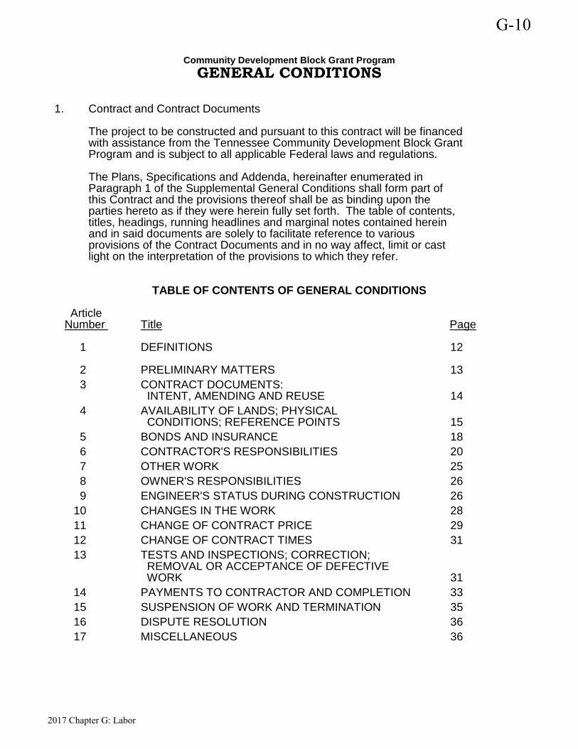
Community Development Block Grant Program GENERAL CONDITIONS
1. Contract and Contract Documents The project to be constructed and pursuant to this contract will be financed with assistance from the Tennessee Community Development Block Grant Program and is subject to all applicable Federal laws and regulations. The Plans, Specifications and Addenda, hereinafter enumerated in Paragraph 1 of the Supplemental General Conditions shall form part of this Contract and the provisions thereof shall be as binding upon the parties hereto as if they were herein fully set forth. The table of contents, titles, headings, running headlines and marginal notes contained herein and in said documents are solely to facilitate reference to various provisions of the Contract Documents and in no way affect, limit or cast light on the interpretation of the provisions to which they refer.
TABLE OF CONTENTS OF GENERAL CONDITIONS
Article Number Title Page
1 DEFINITIONS 12
2 PRELIMINARY MATTERS 13 3 CONTRACT DOCUMENTS: INTENT, AMENDING AND REUSE 14 4 AVAILABILITY OF LANDS; PHYSICAL CONDITIONS; REFERENCE POINTS 15 5 BONDS AND INSURANCE 18 6 CONTRACTOR'S RESPONSIBILITIES 20 7 OTHER WORK 25 8 OWNER'S RESPONSIBILITIES 26 9 ENGINEER'S STATUS DURING CONSTRUCTION 26 10 CHANGES IN THE WORK 28 11 CHANGE OF CONTRACT PRICE 29 12 CHANGE OF CONTRACT TIMES 31 13 TESTS AND INSPECTIONS; CORRECTION; REMOVAL OR ACCEPTANCE OF DEFECTIVE WORK 31 14 PAYMENTS TO CONTRACTOR AND COMPLETION 33 15 SUSPENSION OF WORK AND TERMINATION 35 16 DISPUTE RESOLUTION 36 17 MISCELLANEOUS 36
G-10
2017 Chapter G: Labor
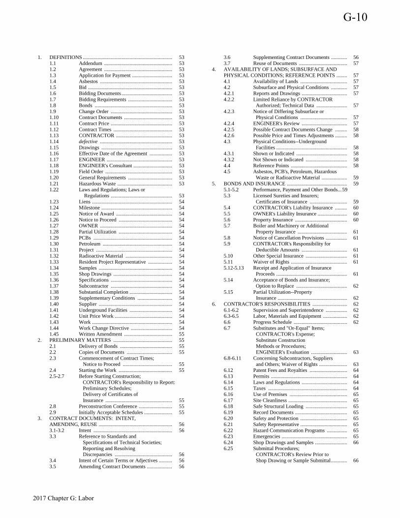
1. DEFINITIONS ................................................................... 53 1.1 Addendum ................................................... 53 1.2 Agreement ................................................... 53 1.3 Application for Payment .............................. 53 1.4 Asbestos ...................................................... 53 1.5 Bid ............................................................... 53 1.6 Bidding Documents ...................................... 53 1.7 Bidding Requirements ................................. 53 1.8 Bonds .......................................................... 53 1.9 Change Order .............................................. 53 1.10 Contract Documents .................................... 53 1.11 Contract Price .............................................. 53 1.12 Contract Times ............................................ 53 1.13 CONTRACTOR .......................................... 53 1.14 defective ...................................................... 53 1.15 Drawings ..................................................... 53 1.16 Effective Date of the Agreement ................. 53 1.17 ENGINEER ................................................. 53 1.18 ENGINEER's Consultant ............................. 53 1.19 Field Order .................................................. 53 1.20 General Requirements ................................. 53 1.21 Hazardous Waste ......................................... 53 1.22 Laws and Regulations; Laws or Regulations .............................................. 53 1.23 Liens ............................................................ 54 1.24 Milestone ..................................................... 54 1.25 Notice of Award .......................................... 54 1.26 Notice to Proceed ........................................ 54 1.27 OWNER ...................................................... 54 1.28 Partial Utilization ........................................ 54 1.29 PCBs ........................................................... 54 1.30 Petroleum .................................................... 54 1.31 Project ......................................................... 54 1.32 Radioactive Material ................................... 54 1.33 Resident Project Representative .................. 54 1.34 Samples ....................................................... 54 1.35 Shop Drawings ............................................ 54 1.36 Specifications .............................................. 54 1.37 Subcontractor .............................................. 54 1.38 Substantial Completion ................................ 54 1.39 Supplementary Conditions .......................... 54 1.40 Supplier ....................................................... 54 1.41 Underground Facilities ................................ 54 1.42 Unit Price Work ........................................... 54 1.43 Work ............................................................ 54 1.44 Work Change Directive ............................... 54 1.45 Written Amendment .................................... 55 2. PRELIMINARY MATTERS ............................................ 55 2.1 Delivery of Bonds ....................................... 55 2.2 Copies of Documents .................................. 55 2.3 Commencement of Contract Times; Notice to Proceed ..................................... 55 2.4 Starting the Work ........................................ 55 2.5-2.7 Before Starting Construction; CONTRACTOR's Responsibility to Report: Preliminary Schedules; Delivery of Certificates of Insurance .................................................. 55 2.8 Preconstruction Conference ......................... 55 2.9 Initially Acceptable Schedules ..................... 55 3. CONTRACT DOCUMENTS: INTENT, AMENDING, REUSE ....................................................... 56 3.1-3.2 Intent ........................................................... 56 3.3 Reference to Standards and Specifications of Technical Societies; Reporting and Resolving Discrepancies ........................................... 56 3.4 Intent of Certain Terms or Adjectives .......... 56 3.5 Amending Contract Documents ................... 56
3.6 Supplementing Contract Documents ............ 56 3.7 Reuse of Documents .................................... 57 4. AVAILABILITY OF LANDS; SUBSURFACE AND PHYSICAL CONDITIONS; REFERENCE POINTS ........ 57 4.1 Availability of Lands ................................... 57 4.2 Subsurface and Physical Conditions ............ 57 4.2.1 Reports and Drawings .................................. 57 4.2.2 Limited Reliance by CONTRACTOR Authorized; Technical Data ....................... 57 4.2.3 Notice of Differing Subsurface or Physical Conditions ................................... 57 4.2.4 ENGINEER's Review .................................. 57 4.2.5 Possible Contract Documents Change ......... 58 4.2.6 Possible Price and Times Adjustments ......... 58 4.3 Physical Conditions--Underground Facilities ..................................................... 58 4.3.1 Shown or Indicated ...................................... 58 4.3.2 Not Shown or Indicated ............................... 58 4.4 Reference Points .......................................... 58 4.5 Asbestos, PCB's, Petroleum, Hazardous Waste or Radioactive Material ................... 59 5. BONDS AND INSURANCE ............................................. 59 5.1-5.2 Performance, Payment and Other Bonds ... 59 5.3 Licensed Sureties and Insurers; Certificates of Insurance ............................ 59 5.4 CONTRACTOR's Liability Insurance ......... 60 5.5 OWNER's Liability Insurance ...................... 60 5.6 Property Insurance ....................................... 60 5.7 Boiler and Machinery or Additional Property Insurance ..................................... 61 5.8 Notice of Cancellation Provisions ................ 61 5.9 CONTRACTOR's Responsibility for Deductible Amounts .................................. 61 5.10 Other Special Insurance ............................... 61 5.11 Waiver of Rights .......................................... 61 5.12-5.13 Receipt and Application of Insurance Proceeds ..................................................... 61 5.14 Acceptance of Bonds and Insurance; Option to Replace ...................................... 62 5.15 Partial Utilization--Property Insurance .................................................... 62 6. CONTRACTOR'S RESPONSIBILITIES .......................... 62 6.1-6.2 Supervision and Superintendence ................ 62 6.3-6.5 Labor, Materials and Equipment .................. 62 6.6 Progress Schedule ........................................ 62 6.7 Substitutes and "Or-Equal" Items; CONTRACTOR's Expense; Substitute Construction Methods or Procedures; ENGINEER's Evaluation ........................... 63 6.8-6.11 Concerning Subcontractors, Suppliers and Others; Waiver of Rights ..................... 63 6.12 Patent Fees and Royalties ............................ 64 6.13 Permits ......................................................... 64 6.14 Laws and Regulations .................................. 64 6.15 Taxes ........................................................... 64 6.16 Use of Premises ........................................... 65 6.17 Site Cleanliness ............................................ 65 6.18 Safe Structural Loading ............................... 65 6.19 Record Documents ....................................... 65 6.20 Safety and Protection ................................... 65 6.21 Safety Representative ................................... 65 6.22 Hazard Communication Programs ............... 65 6.23 Emergencies ................................................. 65 6.24 Shop Drawings and Samples ........................ 66 6.25 Submittal Procedures; CONTRACTOR's Review Prior to Shop Drawing or Sample Submittal ............ 66
G-10
2017 Chapter G: Labor
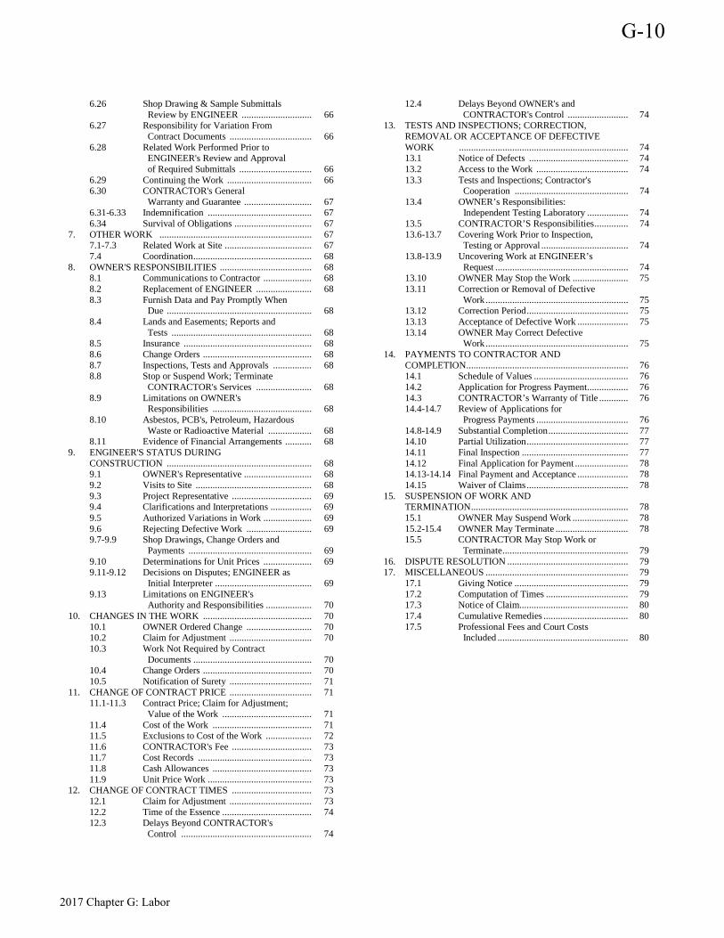
6.26 Shop Drawing & Sample Submittals Review by ENGINEER ............................. 66 6.27 Responsibility for Variation From Contract Documents .................................. 66 6.28 Related Work Performed Prior to ENGINEER's Review and Approval of Required Submittals .............................. 66 6.29 Continuing the Work ................................... 66 6.30 CONTRACTOR's General Warranty and Guarantee ............................ 67 6.31-6.33 Indemnification ........................................... 67 6.34 Survival of Obligations ................................ 67 7. OTHER WORK ............................................................... 67 7.1-7.3 Related Work at Site .................................... 67 7.4 Coordination ................................................. 68 8. OWNER'S RESPONSIBILITIES ...................................... 68 8.1 Communications to Contractor .................... 68 8.2 Replacement of ENGINEER ....................... 68 8.3 Furnish Data and Pay Promptly When Due ............................................................ 68 8.4 Lands and Easements; Reports and Tests .......................................................... 68 8.5 Insurance ..................................................... 68 8.6 Change Orders ............................................. 68 8.7 Inspections, Tests and Approvals ................ 68 8.8 Stop or Suspend Work; Terminate CONTRACTOR's Services ....................... 68 8.9 Limitations on OWNER's Responsibilities ......................................... 68 8.10 Asbestos, PCB's, Petroleum, Hazardous Waste or Radioactive Material .................. 68 8.11 Evidence of Financial Arrangements ........... 68 9. ENGINEER'S STATUS DURING CONSTRUCTION ............................................................ 68 9.1 OWNER's Representative ............................ 68 9.2 Visits to Site ................................................ 68 9.3 Project Representative ................................. 69 9.4 Clarifications and Interpretations ................. 69 9.5 Authorized Variations in Work .................... 69 9.6 Rejecting Defective Work ........................... 69 9.7-9.9 Shop Drawings, Change Orders and Payments ................................................... 69 9.10 Determinations for Unit Prices .................... 69 9.11-9.12 Decisions on Disputes; ENGINEER as Initial Interpreter ........................................ 69 9.13 Limitations on ENGINEER's Authority and Responsibilities ................... 70 10. CHANGES IN THE WORK ............................................. 70 10.1 OWNER Ordered Change ........................... 70 10.2 Claim for Adjustment .................................. 70 10.3 Work Not Required by Contract Documents ................................................. 70 10.4 Change Orders ............................................. 70 10.5 Notification of Surety .................................. 71 11. CHANGE OF CONTRACT PRICE .................................. 71 11.1-11.3 Contract Price; Claim for Adjustment; Value of the Work ..................................... 71 11.4 Cost of the Work ......................................... 71 11.5 Exclusions to Cost of the Work ................... 72 11.6 CONTRACTOR's Fee ................................. 73 11.7 Cost Records ............................................... 73 11.8 Cash Allowances ......................................... 73 11.9 Unit Price Work ........................................... 73 12. CHANGE OF CONTRACT TIMES ................................. 73 12.1 Claim for Adjustment .................................. 73 12.2 Time of the Essence ..................................... 74 12.3 Delays Beyond CONTRACTOR's Control ...................................................... 74
12.4 Delays Beyond OWNER's and CONTRACTOR's Control ......................... 74 13. TESTS AND INSPECTIONS; CORRECTION, REMOVAL OR ACCEPTANCE OF DEFECTIVE WORK ...................................................................... 74 13.1 Notice of Defects ......................................... 74 13.2 Access to the Work ...................................... 74 13.3 Tests and Inspections; Contractor's Cooperation ............................................... 74 13.4 OWNER’s Responsibilities: Independent Testing Laboratory ................. 74 13.5 CONTRACTOR’S Responsibilities .............. 74 13.6-13.7 Covering Work Prior to Inspection, Testing or Approval .................................... 74 13.8-13.9 Uncovering Work at ENGINEER’s Request ....................................................... 74 13.10 OWNER May Stop the Work ....................... 75 13.11 Correction or Removal of Defective Work ........................................................... 75 13.12 Correction Period .......................................... 75 13.13 Acceptance of Defective Work ..................... 75 13.14 OWNER May Correct Defective Work ........................................................... 75 14. PAYMENTS TO CONTRACTOR AND COMPLETION ................................................................... 76 14.1 Schedule of Values ....................................... 76 14.2 Application for Progress Payment ................. 76 14.3 CONTRACTOR’s Warranty of Title ............ 76 14.4-14.7 Review of Applications for Progress Payments ...................................... 76 14.8-14.9 Substantial Completion ................................. 77 14.10 Partial Utilization .......................................... 77 14.11 Final Inspection ............................................ 77 14.12 Final Application for Payment ...................... 78 14.13-14.14 Final Payment and Acceptance ..................... 78 14.15 Waiver of Claims .......................................... 78 15. SUSPENSION OF WORK AND
TERMINATION ................................................................. 78 15.1 OWNER May Suspend Work ....................... 78 15.2-15.4 OWNER May Terminate .............................. 78 15.5 CONTRACTOR May Stop Work or Terminate .................................................... 79 16. DISPUTE RESOLUTION .................................................. 79 17. MISCELLANEOUS ........................................................... 79 17.1 Giving Notice ............................................... 79 17.2 Computation of Times .................................. 79 17.3 Notice of Claim............................................. 80 17.4 Cumulative Remedies ................................... 80 17.5 Professional Fees and Court Costs Included ...................................................... 80
G-10
2017 Chapter G: Labor
Article or Paragraph Number
Article or Paragraph Number
Acceptance of-- Bonds and Insurance ................................................................. 5.14 defective Work ................................................. 10.4.1, 13.13, 13.15 final payment ................................................................. 9.12,14.15 insurance .................................................................................. 5.14 other Work, by CONTRACTOR ................................................ 7.3 Substitutes and "Or-Equal" Items............................................. 6.7.1 Work by OWNER ......................................................2.5, 6.30, 6.34 Access to the-- Lands, OWNER and CONTRACTOR responsibilities .......................................................................... 4.1 site, related work ........................................................................ 7.2 Work, .................................................................... 13.2, 13.14, 14.9 Acts or Omissions--, Acts and Omissions-- CONTRACTOR .......................................................... 6.9.1, 9.13.3 ENGINEER .................................................................. 6.20, 9.13.3 OWNER............................................................................. 6.20, 8.9 Addenda--definition of (also see definition of Specifications) ................................ (1.6, 1.10, 6.19) 1.1 Additional Property Insurances ....................................................... 5.7 Adjustments Contract Price or Contract Times .............................. 1.5, 3.5, 4.1, 4.3.2, 4.5.2, 4.5.3, 9.4, 9.5, 10.2-10.4, 11, 12, 14.8, 15.1 progress schedule ........................................................................ 6.6 Agreement-- definition of ............................................................................... 1.2 All risk Insurance, policy form .................................................... 5.6.2 Allowances, Cash ......................................................................... 11.8 Amending Contract Documents ..................................................... 3.5 Amendment, Written-- in general .................. 1.10, 1.45, 3.5, 5.10, 5.12, 6.6.2, 6.8.2, 6.19, 10.1, 10.4, 11.2, 12.1, 13.12.2, 14.7.2 Appeal,, OWNER or CONTRACTOR intent to ................................................. 9.10, 9.11, 10.4, 16.2, 16.5 Application for Payment-- definition of ............................................................................... 1.3 ENGINEER's Responsibility ...................................................... 9.9 final payment ........................................ 9.13.4, 9.13.5, 14.12-14.15 in general ................................................. 2.8, 2.9, 5.6.4, 9.10, 15.5 progress payment ............................................................. 14.1, 14.7 review of .......................................................................... 14.4-14.7 Arbitration (Optional)............................................................ 16.1-16.6 Asbestos-- claims pursuant thereto .................................................. 4.5.2, 4.5.3 CONTRACTOR authorized to stop Work ............................... 4.5.2 definition of ................................................................................ 1.4 OWNER responsibility for .............................................. 4.5.1, 8.10 possible price and times change ............................................... 4.5.2 Authorized Variations in Work ............................... 3.6, 6.25, 6.27, 9.5 Availability of Lands ................................................................ 4.1, 8.4 Award, Notice of--defined ............................................................. 1.25 Before Starting Construction ..................................................... 2.5-2.8 Bid--definition of ............................................................................ 1.5 (1.1, 1.10, 2.3, 3.3, 4.2.6.4, 6.13, 11.4.3, 11.9.1) Bidding Documents--definition of ....................................... 1.6 (6.8.2) Bidding Requirements--definitions of ........................ 1.7 (1.1, 4.2.6.2) Bonds-- acceptance of ............................................................................ 5.14 additional bonds ......................................................... 10.5, 11.4.5.9 Cost of the Work .................................................................... 11.5.4 definition of ............................................................................... 1.8 delivery of ........................................................................... 2.1, 5.1 final application for payment ........................................ 14.12-14.14 general ................................... 1.10, 5.1-5.3, 5.13, 9.13, 10.5, 14.7.6 performance, Payment and Other .......................................... 5.1-5.2 Bonds and Insurance--in general ........................................................ 5 Builder's risk "all risk" policy form ............................................. 5.6.2 Cancellation Provisions, Insurance .............................. 5.4.11, 5.8, 5.15 Cash Allowances ........................................................................... 11.8 Certificate of Substantial Completion .............................1.38, 6.30.2.3,
14.8, 14.10 Certificates of Inspection ........................................ 9.13.4, 13.5, 14.12 Certificates of Insurance ................... 2.7, 5.3, 5.4.11, 5.4.13, 5.6.5, 5.8 ........................................................................... 5.14, 9.13.4, 14.12 Change in Contract Price-- Cash Allowances ....................................................................... 11.8 claim for price adjustment ...................... 4.1, 4.2.6, 4.5, 5.15, 6.8.2, 9.4, 9.5, 9.11, 10.2, 10.5, 11.2, 13.9, 13.13, 13.14, 15.1, 15.5 CONTRACTOR's fee ................................................................ 11.6 Cost of the Work general ............................................................................ 11.4-11.7 Exclusions to ............................................................................ 11.5 Cost Records ............................................................................. 11.7 in general .................................... 1.19, 1.44, 9.11, 10.4.2, 10.4.3, 11 Lump Sum Pricing ................................................................. 11.3.2 Notification of Surety ................................................................ 10.5 Scope of ............................................................................ 10.3-10.4 Testing and Inspection, Uncovering the Work .......................... 13.9 Unit Price Work ........................................................................ 11.9 Value of Work ........................................................................... 11.3 Change in Contract Times-- Claim for times adjustment .................... 4.1, 4.2.6, 4.5, 5.15, 6.8.2, 9.4, 9.5, 9.11, 10.2, 10.5, 12.1, 13.9, 13.13, 13.14, 14.7, 15.1, 15.5 Contractual time limits .............................................................. 12.2 Delays beyond CONTRACTOR's control ................................. 12.3 Delays beyond OWNER's and CONTRACTOR's control .................................................................................... 12.4 Notification of surety................................................................. 10.5 Scope of change ................................................................ 10.3-10.4 Change Orders-- Acceptance of Defective Work ................................................ 13.13 Amending Contract Documents .................................................. 3.5 Cash Allowances ....................................................................... 11.8 Change of Contract Price.............................................................. 11 Change of Contract Times ............................................................ 12 Changes in the Work .................................................................... 10 CONTRACTOR's fee ................................................................ 11.6 Cost of the Work ............................................................... 11.4-11.7 Cost Records ............................................................................. 11.7 definition of ................................................................................. 1.9 emergencies ............................................................................... 6.23 ENGINEER's responsibility ............................. 9.8, 10.4, 11.2, 12.1 execution of .............................................................................. 10.4 Indemnification .............................................. 6.12, 6.16, 6.31, 6.33 Insurance, Bonds and .............................................. 5.10, 5.13, 10.5 OWNER may terminate .................................................... 15.2-15.4 OWNER's Responsibility ................................................... 8.6, 10.4 Physical Conditions-- Subsurface and, .......................................................................... 4.2 Underground Facilities ........................................................... 4.3.2 Record Documents .................................................................... 6.19 Scope of Change ............................................................... 10.3-10.4 Substitutes ..................................................................... 6.7.3, 6.8.2 Unit Price Work ....................................................................... 11.9 value of Work, covered by ....................................................... 11.3 Changes in the Work ........................................................................ 10 Notification of surety ................................................................ 10.5 OWNER's and CONTRACTOR's responsibilities .................... 10.4 Right to an adjustment .............................................................. 10.2 Scope of change ............................................................... 10.3-10.4 Claims-- against CONTRACTOR ........................................................... 6.16 against ENGINEER .................................................................. 6.32 against OWNER ....................................................................... 6.32 Change of Contract Price ................................................... 9.4, 11.2
Article or Paragraph Number
G-10
2017 Chapter G: Labor
Change of Contract Times ................................................. 9.4.12.1 CONTRACTOR's 4, 7.1, 9.4, 9.5, 9.11, 10.2, 11.2, 11.9, 12.1, 14.8, 15.1, 15.5, 17.3 CONTRACTOR's Fee .............................................................. 11.6 CONTRACTOR's liability ............................... 5.4, 6.12, 6.16, 6.31 Cost of the Work ............................................................. 11.4, 11.5 Decisions on Disputes ...................................................... 9.11, 9.12 Dispute Resolution .................................................................... 16.1 Dispute Resolution Agreement ......................................... 16.1-16.6 ENGINEER as initial interpreter ............................................... 9.11 Lump Sum Pricing ................................................................ 11.3.2 Notice of .................................................................................. 17.3 OWNER's .............................. 9.4, 9.5, 9.11, 10.2, 11.2, 11.9, 12.1, 13.9, 13.13, 13.14, 17.3 OWNER's liability ..................................................................... 5.5 OWNER may refuse to make payment .................................... 14.7 Professional Fees and Court Costs Included ............................ 17.5 request for formal decision on .................................................. 9.11 Substitute items .................................................................... 6.7.1.2 Time Extension ........................................................................ 12.1 Time requirements .......................................................... 9.11, 12.1 Unit Price Work .................................................................... 11.9.3 Value of ................................................................................... 11.3 Waiver of--on Final Payment ...................................... 14.14, 14.15 Work Change Directive ........................................................... 10.2 written notice required ............................................9.11, 11.2, 12.1 Clarifications and Interpretations .................................3.6.3, 9.4, 9.11 Clean Site ..................................................................................... 6.17 Codes of Technical Society, Organization or Association .......................................................................... 3.3.3 Commencement of Contract Times ................................................ 2.3 Communications-- general ...................................................................... 6.2, 6.9.2, 8.1 Hazard Communication Programs ........................................... 6.22 Completion-- Final Application for Payment ............................................... 14.12 Final Inspection ...................................................................... 14.11 Final Payment and Acceptance .................................... 14.13-14.14 Partial Utilization ................................................................... 14.10 Substantial Completion ........................................... 1.38, 14.8-14.9 Waiver of Claims ................................................................... 14.15 Computation of Times .................................................... 17.2.1-17.2.2 Concerning Subcontractors, Suppliers and Other ............................................................ 6.8-6.11 Conferences-- initially acceptable schedules ..................................................... 2.9 preconstruction ........................................................................... 2.8 Conflict, Error, Ambiguity, Discrepancy-- CONTRACTOR to Report ................................................ 2.5, 3.3.2 Construction, before starting by CONTRACTOR ..................... 2.5-2.7 Construction Machinery, Equipment, Etc. ....................................... 6.4 Continuing the Work ........................................................... 6.29, 10.4 Contract Documents-- Amending ................................................................................... 3.5 Bonds ......................................................................................... 5.1 Cash Allowances ...................................................................... 11.8 Change of Contract Price ............................................................. 11 Change of Contract Times .......................................................... 12 Changes in the Work ........................................................ 10.4-10.5 check and verify ......................................................................... 2.5 Clarifications and Interpretations ......................... 3.2, 3.6, 9.4, 9.11 definition of ............................................................................. 1.10 ENGINEER as initial interpreter of ......................................... 9.11 ENGINEER as OWNER's representative .................................. 9.1 general .......................................................................................... 3 Insurance .................................................................................... 5.3 Intent .................................................................................... 3.1-3.4 minor variations in the Work ..................................................... 3.6 OWNER's responsibility to furnish data .................................... 8.3 OWNER's responsibility to make prompt payment ....................................................8.3, 14.4, 14.13 precedence ....................................................................... 3.1, 3.3.3 Record Documents ................................................................... 6.19
Reference to Standards and Specifications of Technical Societies ............................................................... 3.3 Related Work ............................................................................. 7.2 Reporting and Resolving Discrepancies .............................. 2.5, 3.3 Reuse of ..................................................................................... 3.7 Supplementing ............................................................................ 3.6 Termination of ENGINEER's Employment ................................ 8.2 Unit Price Work ....................................................................... 11.9 variations .................................................................. 3.6, 6.23, 6.27 Visits to Site, ENGINEER's ....................................................... 9.2 Contract Price-- adjustment of ...................................... 3.5, 4.1, 9.4, 10.3, 11.2-11.3 Change of .................................................................................... 11 Decision on Disputes ................................................................ 9.11 definition of .............................................................................. 1.11 Contract Times-- adjustment of ................................................. 3.5, 4.1, 9.4, 10.3, 12 Change of ......................................................................... 12.1-12.4 Commencement of ..................................................................... 2.3 definition of .............................................................................. 1.12 CONTRACTOR-- Acceptance of Insurance ........................................................... 5.14 Limited Reliance on Technical Data Authorized ..................... 4.2.2 Communications ............................................................... 6.2, 6.9.2 Continue Work ................................................................ 6.29, 10.4 coordination and scheduling .................................................... 6.9.2 definition of .............................................................................. 1.13 May Stop Work or Terminate ................................................... 15.5 provide site access to others .............................................. 7.2, 13.2 Safety and Protection ....................... 4.3, 1.2, 6.16, 6.18, 6.21-6.23, 7.2, 13.2 Shop Drawing and Sample Review Prior to Submittal ............. 6.25 Stop Work requirements .......................................................... 4.5.2 CONTRACTOR's-- Compensation ................................................................... 11.1-11.2 Continuing Obligation ............................................................ 14.15 Defective Work ..................................................... 9.6, 13.10-13.14 Duty to correct defective Work .............................................. 13.11 Duty to Report-- Changes in the Work caused by Emergency ............................................................................. 6.23 Defects in Work of Others ........................................................ 7.3 Differing conditions .............................................................. 4.2.3 Discrepancy in Documents ................................. 2.5, 3.3.2, 6.14.2 Underground Facilities not indicated ..................................... 4.3.2 Emergencies ............................................................................. 6.23 Equipment and Machinery Rental, Cost of the Work ...................................................................... 11.4.5.3 Fee--Cost-Plus ............................................... 11.4.5.6, 11.5.1, 11.6 General Warranty and Guarantee ............................................. 6.30 Hazard Communication Programs ............................................ 6.22 Indemnification .............................................. 6.12, 6.16, 6.31-6.33 Inspection of the Work ...................................................... 7.3, 13.4 Labor, Materials and Equipment ..........................................6.3-6.5 Laws and Regulations, Compliance by .................................. 6.14.1 Liability Insurance ...................................................................... 5.4 Notice of Intent to Appeal ............................................... 9.10, 10.4 obligation to perform and complete the Work .......................... 6.30 Patent Fees and Royalties, paid for by ...................................... 6.12 Performance and Other Bonds .................................................... 5.1 Permits, obtained and paid for by ............................................. 6.13 Progress Schedule .................... 2.6, 2.8, 2.9, 6.6, 6.29, 10.4, 15.2.1 Request for formal decision on disputes ................................... 9.11 Responsibilities-- Changes in the Work .............................................................. 10.1 Concerning Subcontractors, Suppliers and Others. ............ 6.8-6.11 Continuing the Work ..................................................... 6.29, 10.4 CONTRACTOR's expense .................................................... 6.7.1 CONTRACTOR's General Warranty and Guarantee .............. 6.30 CONTRACTOR's review prior to Shop Drawing or Sample Submittal ................................................................. 6.25 Coordination of Work ............................................................. 6.9.2 Emergencies ........................................................................... 6.23
G-10
2017 Chapter G: Labor
ENGINEER's evaluation, Substitutes or "Or-Equal" Items ............................................................ 6.7.3 For Acts and Omissions of Others ...................... 6.9.1-6.9.2, 9.13 for deductible amounts, insurance ............................................ 5.9 general ....................................................................6, 7.2, 7.3, 8.9 Hazardous Communication Programs .................................... 6.22 Indemnification .............................................................. 6.31-6.33 Labor, Materials and Equipment ........................................ 6.3-6.5 Laws and Regulations ............................................................ 6.14 Liability Insurance ................................................................... 5.4 Notice of variation from Contract Documents ....................... 6.27 Patent Fees and Royalties ....................................................... 6.12 Permits ................................................................................... 6.13 Progress Schedule .................................................................... 6.6 Record Documents ................................................................. 6.19 related Work performed prior to ENGINEER's approval of required submittals ............................................ 6.28 safe structural loading ............................................................ 6.18 Safety and Protection ..............................................6.20, 7.2, 13.2 Safety Representative ............................................................. 6.21 Scheduling the Work ............................................................. 6.9.2 Shop Drawings and Samples .................................................. 6.24 Shop Drawings and Samples Review by ENGINEER .................................................................... 6.26 Site Cleanliness ...................................................................... 6.17 Submittal Procedures ............................................................. 6.25 Substitute Construction Methods and Procedures ........................................................................... 6.7.2 Substitutes and "Or-Equal" Items .......................................... 6.7.1 Superintendence ....................................................................... 6.2 Supervision .............................................................................. 6.1 Survival of Obligations .......................................................... 6.34 Taxes ...................................................................................... 6.15 Tests and Inspections ............................................................. 13.5 To Report ................................................................................. 2.5 Use of Premises ............................................. 6.16-6.18, 6.30, 2.4 Review Prior to Shop Drawing or Sample Submittal ................ 6.25 Right to adjustment for changes in the Work ........................... 10.2 right to claim ............... 4, 7.1, 9.4, 9.5, 9.11, 10.2, 11.2, 11.9, 12.1, 13.9, 14.8, 15.1, 15.5, 17.3 Safety and Protection ....................................... 6.20-6.22, 7.2, 13.2 Safety Representative ............................................................... 6.21 Shop Drawings and Samples Submittals .......................... 6.24-6.28 Special Consultants ............................................................... 11.4.4 Substitute Construction Methods and Procedures ...................... 6.7 Substitutes and "Or-Equal" Items, Expense ................... 6.7.1, 6.7.2 Subcontractors, Suppliers and Others ................................. 6.8-6.11 Supervision and Superintendence .............................. 6.1, 6.2, 6.21 Taxes, Payment by ................................................................... 6.15 Use of Premises ............................................................... 6.16-6.18 Warranties and guarantees ................................................ 6.30, 6.5 Warranty of Title ..................................................................... 14.3 Written Notice Required-- CONTRACTOR stop Work or terminate ............................... 15.5 Reports of Differing Subsurface and Physical Conditions ............................................................................ 4.2.3 Substantial Completion .......................................................... 14.8 CONTRACTORs--other .................................................................... 7 Contractual Liability Insurance ................................................. 5.4.10 Contractual Times Limits ............................................................. 12.2 Coordination CONTRACTOR's responsibility ............................................. 6.9.2 Copies of Documents ..................................................................... 2.2 Correction Period ....................................................................... 13.12 Correction, Removal or Acceptance of Defective Work in general ......................................................... 10.4.1, 13.10-13.14 Acceptance of Defective Work .............................................. 13.13 Correction or Removal of Defective Work ................... 6.30, 13.11 Correction Period ................................................................... 13.12 OWNER May Correct Defective Work ................................. 13.14 OWNER May Stop Work ...................................................... 13.10 Cost-- of Tests and Inspections ........................................................... 13.4
Records .................................................................................... 11.7 Cost of the Work-- Bonds and insurance, additional ......................................... 11.4.5.9 Cash Discounts ...................................................................... 11.4.2 CONTRACTOR's Fee .............................................................. 11.6 Employee Expenses ............................................................ 11.4.5.1 Exclusions to ............................................................................ 11.5 General ............................................................................. 11.4-11.5 Home office and overhead expenses ........................................ 11.5 Losses and damages ........................................................... 11.4.5.6 Materials and equipment ....................................................... 11.4.2 Minor expenses .................................................................. 11.4.5.8 Payroll costs on changes ........................................................ 11.4.1 performed by Subcontractors ................................................. 11.4.3 Records .................................................................................... 11.7 Rentals of construction equipment and machinery ............. 11.4.5.3 Royalty payments, permits and license fees ....................... 11.4.5.5 Site office and temporary facilities ..................................... 11.4.5.2 Special Consultants, CONTRACTOR's ................................ 11.4.4 Supplemental ......................................................................... 11.4.5 Taxes related to the Work ................................................... 11.4.5.4 Tests and Inspection ................................................................. 13.4 Trade Discounts ..................................................................... 11.4.2 Utilities, fuel and sanitary facilities .................................... 11.4.5.7 Work after regular hours ....................................................... 11.4.1 Covering Work ..................................................................... 13.6-13.7 Cumulative Remedies ........................................................... 17.4-17.5 Cutting, fitting and patching ........................................................... 7.2 Data, to be furnished by OWNER ................................................... 8.3 Day--definition of ...................................................................... 17.2.2 Decisions on Disputes .......................................................... 9.11, 9.12 defective--definition of ................................................................. 1.14 defective Work-- Acceptance of ............................................................. 10.4.1, 13.13 Correction or Removal of ........................................... 10.4.1, 13.11 Correction Period ................................................................... 13.12 in general ................................................................. 13, 14.7, 14.11 Observation by ENGINEER ....................................................... 9.2 OWNER May Stop Work ....................................................... 13.10 Prompt Notice of Defects ......................................................... 13.1 Rejecting .................................................................................... 9.6 Uncovering the Work ............................................................... 13.8 Definitions ......................................................................................... 1 Delays ................................................................... 4.1, 6.29, 12-3-12.4 Delivery of Bonds ........................................................................... 2.1 Delivery of certificates of insurance ............................................... 2.7 Determinations for Unit Prices ..................................................... 9.10 Differing Subsurface or Physical Conditions Notice of .................................................................................. 4.2.3 ENGINEER's Review .............................................................. 4.2.4 Possible Contract Documents Change ..................................... 4.2.6 Possible Price and Times Adjustments .................................... 4.2.6 Discrepancies-Reporting and Resolving .................... 2.5, 3.3.2, 6.14.2 Dispute Resolution-- Agreement ......................................................................... 16.1-16.6 Arbitration ........................................................................ 16.1-16.5 general ......................................................................................... 16 Mediation ................................................................................. 16.6 Dispute Resolution Agreement ............................................. 16.1-16.6 Disputes, Decisions by ENGINEER ...................................... 9.11-9.12 Documents-- Copies of .................................................................................... 2.2 Record ...................................................................................... 6.19 Reuse of ..................................................................................... 3.7 Drawings--definition of ................................................................ 1.15 Easements ....................................................................................... 4.1 Effective date of Agreement--definition of ................................... 1.16 Emergencies ................................................................................. 6.23 ENGINEER-- as initial interpreter on disputes ........................................ 9.11-9.12 definition of .............................................................................. 1.17 Limitations on authority and responsibilities ........................................................................ 9.13
G-10
2017 Chapter G: Labor

Replacement of .......................................................................... 8.2 Resident Project Representative ................................................. 9.3 ENGINEER's Consultant--definition of ....................................... 1.18 ENGINEER's-- authority and responsibility, limitations on .............................. 9.13 Authorized Variations in the Work ............................................ 9.5 Change Orders, responsibility for ............................. 9.7,10, 11, 12 Clarifications and Interpretations ..................................... 3.6.3, 9.4 Decisions on Disputes ...................................................... 9.11-9.12 defective Work, notice of ......................................................... 13.1 Evaluation of Substitute Items ................................................ 6.7.3 Liability .......................................................................... 6.32, 9.12 Notice Work is Acceptable .................................................... 14.13 Observations .................................................................. 6.30.2, 9.2 OWNER's Representative .......................................................... 9.1 Payments to the CONTRACTOR, Responsibility for ............................................................... 9.9, 14 Recommendation of Payment ....................................... 14.4, 14.13 Responsibilities-- Limitations on ................................................................ 9.11-9.13 Review of Reports on Differing Subsurface and Physical Conditions ........................................................ 4.2.4 Shop Drawings and Samples, review responsibility .......................................................................... 6.26 Status During Construction-- authorized variations in the Work ............................................ 9.5 Clarifications and Interpretations ............................................. 9.4 Decisions on Disputes .................................................... 9.11-9.12 Determination on Unit Price .................................................. 9.10 ENGINEER as Initial Interpreter ................................... 9.11-9.12 ENGINEER's Responsibilities ......................................... 9.1-9.12 Limitations on ENGINEER's Authority and Responsibilities .................................................................... 9.13 OWNER's Representative ........................................................ 9.1 Project Representative .............................................................. 9.3 Rejecting Defective Work ........................................................ 9.6 Shop Drawings, Change Orders and Payments .......................................................................... 9.7-9.9 Visits to Site ............................................................................. 9.2 Unit Price Determinations ........................................................ 9.10 Visits to Site ............................................................................... 9.2 Written consent required ..................................................... 7.2, 9.1 Equipment, Labor, Materials and ............................................. 6.3-6.5 Equipment rental, Cost of the Work ....................................... 11.4.5.3 Equivalent Materials and Equipment .............................................. 6.7 Errors or omissions ....................................................................... 6.33 Evidence of Financial Arrangements ............................................ 8.11 Explorations of physical conditions ............................................. 4.2.1 Fee, CONTRACTOR's--Costs-Plus ............................................. 11.6 Field Order-- definition of ............................................................................. 1.19 issued by ENGINEER ...................................................... 3.6.1, 9.5 Final Application for Payment ................................................... 14.12 Final Inspection .......................................................................... 14.11 Final Payment-- and Acceptance ............................................................ 14.13-14.14 Prior to, for cash allowances .................................................... 11.8 General Provisions ............................................................... 17.3-17.4 General Requirements-- definition of ............................................................................. 1.20 principal references to ................................... 2.6, 6.4, 6.6-6.7, 6.24 Giving Notice ............................................................................... 17.1 Guarantee of Work--by CONTRACTOR ........................................................... 6.30, 14.12 Hazard Communication Programs ................................................ 6.22 Hazardous Waste-- definition of ............................................................................. 1.21 general ....................................................................................... 4.5 OWNER's responsibility for .................................................... 8.10 Indemnification .................................................. 6.12, 6.16, 6.31-6.33 Initially Acceptable Schedules ....................................................... 2.9 Inspection-- Certificates of ..................................................... 9.13.4, 13.5, 14.12 Final ....................................................................................... 14.11
Special, required by ENGINEER ............................................... 9.6 Tests and Approval .................................................... 8.7, 13.3-13.4 Insurance-- Acceptance of, by OWNER ...................................................... 5.14 Additional, required by changes in the Work ....................................................................... 11.4.5.9 Before starting the Work ............................................................ 2.7 Bonds and--in general ................................................................... 5 Cancellation Provisions .............................................................. 5.8 Certificates of ................ 2.7, 5, 5.3, 5.4.11, 5.4.13, 5.6.5, 5.8, 5.14, 9.13.4, 14.12 completed operations ............................................................. 5.4.13 CONTRACTOR's Liability ........................................................ 5.4 CONTRACTOR's objection to coverage .................................. 5.14 Contractual Liability .............................................................. 5.4.10 deductible amounts, CONTRACTOR's responsibility ............................................................................ 5.9 Final Application for Payment ............................................... 14.12 Licensed Insurers ........................................................................ 5.3 Notice requirements, material changes .......................................................................... 5.8, 10.50 Option to Replace ..................................................................... 5.14 other special insurances ............................................................ 5.10 OWNER as fiduciary for insured ..................................... 5.12-5.13 OWNER's Liability .................................................................... 5.5 OWNER's Responsibility ........................................................... 8.5 Partial Utilization, Property Insurance ...................................... 5.15 Property .............................................................................. 5.6-5.10 Receipt and Application of Insurance Proceeds ................ 5.12-5.13 Special Insurance ...................................................................... 5.10 Waiver of Rights ...................................................................... 5.11 Intent of Contract Documents ...................................................3.1-3.4 Interpretations and Clarifications .......................................... 3.6.3, 9.4 Investigations of physical conditions .............................................. 4.2 Labor, Materials and Equipment ...............................................6.3-6.5 Lands-- and Easements ............................................................................ 8.4 Availability of ..................................................................... 4.1, 8.4 Reports & Tests .......................................................................... 8.4 Laws and Regulations--Laws or Regulations-- Bonds ...................................................................................5.1-5.2 Changes in the Work ................................................................ 10.4 Contract Documents ................................................................... 3.1 CONTRACTOR's Responsibilities .......................................... 6.14 Correction Period, defective Work ......................................... 13.12 Cost of the Work, taxes ...................................................... 11.4.5.4 definition of .............................................................................. 1.22 general ...................................................................................... 6.14 Indemnification ................................................................ 6.31-6.33 Insurance .................................................................................... 5.3 Precedence ....................................................................... 3.1, 3.3.3 Reference to ............................................................................ 3.3.1 Safety and Protection ....................................................... 6.20, 13.2 Subcontractors, Suppliers and Others ................................. 6.8-6.11 Tests and Inspections ................................................................ 13.5 Use of Premises ........................................................................ 6.16 Visits to Site ............................................................................... 9.2 Liability Insurance-- CONTRACTOR's ...................................................................... 5.4 OWNER's ................................................................................... 5.5 Licensed Sureties and Insurers ........................................................ 5.3 Liens-- Application for Progress Payment ............................................ 14.2 Contractor's Warranty of Title .................................................. 14.3 Final Application for Payment ............................................... 14.12 definition of .............................................................................. 1.23 Waiver of Claims ................................................................... 14.15 Limitations on ENGINEER's authority and responsibilities .......................................................................... 9.13 Limited Reliance by CONTRACTOR Authorized ....................... 4.2.2 Maintenance and Operating Manuals-- Final Application for Payment ............................................... 14.12 Manuals (of others)-- Precedence ........................................................................... 3.3.3.1
G-10
2017 Chapter G: Labor
Reference to in Contract Documents ....................................... 3.3.1 Materials and equipment-- furnished by CONTRACTOR .................................................... 6.3 not incorporated in Work ......................................................... 14.2 Materials or equipment--equivalent ................................................ 6.7 Mediation (Optional) .................................................................... 16.7 Milestones--definition of .............................................................. 1.24 Miscellaneous-- Computation of Times ............................................................. 17.2 Cumulative Remedies .............................................................. 17.4 Giving Notice ........................................................................... 17.1 Notice of Claim ........................................................................ 17.3 Professional Fees and Court Costs Included ............................ 17.5 Multi-prime contracts ........................................................................ 7 Not Shown or Indicated ............................................................... 4.3.2 Notice of-- Acceptability of Project ......................................................... 14.13 Award, definition of ................................................................. 1.25 Claim ....................................................................................... 17.3 Defects ..................................................................................... 13.1 Differing Subsurface or Physical Conditions .......................... 4.2.3 Giving ...................................................................................... 17.1 Tests and Inspections ............................................................... 13.3 Variation, Shop Drawing and Sample ...................................... 6.27 Notice to Proceed-- definition of ............................................................................. 1.26 giving of ..................................................................................... 2.3 Notification to Surety ................................................................... 10.5 Observations, by ENGINEER ............................................... 6.30, 9.2 Occupancy of the Work ....................................... 5.15, 6.30.2.4, 14.10 Omissions or acts by CONTRACTOR .................................. 6.9, 9.13 "Open peril" policy form, Insurance ............................................ 5.6.2 Option to Replace ......................................................................... 5.14 "Or Equal" Items ............................................................................ 6.7 Other work ........................................................................................ 7 Overtime Work--prohibition of ...................................................... 6.3 OWNER-- Acceptance of defective Work ............................................... 13.13 appoint an ENGINEER .............................................................. 8.2 as fiduciary ...................................................................... 5.12-5.13 Availability of Lands, responsibility .......................................... 4.1 definition of ............................................................................. 1.27 data, furnish ............................................................................... 8.3 May Correct Defective Work ................................................. 13.14 May refuse to make payment ................................................... 14.7 May Stop the Work ................................................................ 13.10 may suspend work, terminate ...................................................... 8.3, 13.10, 15.1-15.4 Payment, make prompt ...........................................8.3, 14.4, 14.13 performance of other Work ........................................................ 7.1 permits and licenses, requirements ........................................... 6.13 purchased insurance requirements ...................................... 5.6-5.10 OWNER's-- Acceptance of the Work ..................................................... 6.30.2.5 Change Orders, obligation to execute ............................................................................ 8.6, 10.4 Communications ........................................................................ 8.1 Coordination of the Work .......................................................... 7.4 Disputes, request for decision .................................................. 9.11 Inspections, tests and approvals ........................................ 8.7, 13.4 Liability Insurance ..................................................................... 5.5 Notice of Defects ..................................................................... 13.1 Representative-- During Construction, ENGINEER's Status ................................................................. 9.1 Responsibilities-- Asbestos, PCB's, Petroleum, Hazardous Waste on Radioactive Material ............................................ 8.10 Change Orders ......................................................................... 8.6 Changes in the Work .............................................................. 10.1 communications ....................................................................... 8.1 CONTRACTOR's responsibilities ........................................... 8.9 evidence of financial arrangements ........................................ 8.11 inspections, tests and approvals ............................................... 8.7 Insurance .................................................................................. 8.5
lands and easements ................................................................. 8.4 prompt payment by ................................................................... 8.3 replacement of ENGINEER ..................................................... 8.2 reports and tests ........................................................................ 8.4 stop or suspend Work ........................................... 8.8, 13.10, 15.1 terminate CONTRACTOR's services .............................. 8.8, 15.2 separate representative at site ..................................................... 9.3 independent testing ................................................................... 13.4 use or occupancy of the Work ....................................... 5.15, 14.10 written consent or approval required .......................... 9.1, 6.3, 11.4 written notice required ............. 7.1, 9.4, 9.11, 11.2, 11.9, 14.7, 15.4 PCBs-- definition of .............................................................................. 1.29 general ........................................................................................ 4.5 OWNER's responsibility for ..................................................... 8.10 Partial Utilization-- definition of .............................................................................. 1.29 general ..................................................................... 6.30.2.4, 14.10 Property Insurance .................................................................... 5.15 Patent Fees and Royalties ............................................................. 6.12 Payment Bonds .........................................................................5.1-5.2 Payments, Recommendation of .................................. 14.4-14.7, 14.13 Payments to CONTRACTOR and Completion-- Application for Progress Payments ........................................... 14.2 CONTRACTOR's Warranty of Title ........................................ 14.3 Final Application for Payment ............................................... 14.12 Final Inspection ...................................................................... 14.11 Final Payment and Acceptance ..................................... 14.13-14.14 general .................................................................................. 8.3, 14 Partial Utilization ................................................................... 14.10 Retainage .................................................................................. 14.2 Review of Applications for Progress Payments ........................................................................ 14.4-14.7 prompt payment ......................................................................... 8.3 Schedule of Values ................................................................... 14.1 Substantial Completion .................................................... 14.8-14.9 Waiver of Claims ................................................................... 14.15 when payments due ....................................................... 14.4, 14.13 withholding payment ................................................................ 14.7 Performance Bonds ...................................................................5.1-5.2 Permits .......................................................................................... 6.13 Petroleum-- definition of .............................................................................. 1.30 general ........................................................................................ 4.5 OWNER's responsibility for ..................................................... 8.10 Physical Conditions-- Drawings of, in or relating to ................................................ 4.2.1.2 ENGINEER's review ............................................................... 4.2.4 existing structures .................................................................... 4.2.2 general .................................................................................. 4.2.1.2 Subsurface and, .......................................................................... 4.2 Underground Facilities ............................................................... 4.3 Possible Contract Documents Change ..................................... 4.2.5 Possible Price and Times Adjustments .................................... 4.2.6 Reports and Drawings ............................................................. 4.2.1 Notice of Differing Subsurface or, .......................................... 4.2.3 Subsurface and ........................................................................... 4.2 Subsurface Conditions .......................................................... 4.2.1.1 Technical Data, Limited Reliance by CONTRACTOR Authorized ................................................. 4.2.2 Underground Facilities-- general ...................................................................................... 4.3 Not Shown or Indicated ......................................................... 4.3.2 Protection of .................................................................... 4.3, 6.20 Shown or Indicated ................................................................ 4.3.1 Technical Data ........................................................................ 4.2.2 Preconstruction Conference ............................................................ 2.8 Preliminary Matters ........................................................................... 2 Preliminary Schedules .................................................................... 2.6 Premises, Use of ................................................................... 6.16-6.18 Price, Change of Contract ................................................................ 11 Price, Contract--definition of ........................................................ 1.11 Progress Payment, Applications for .............................................. 14.2 Progress payment--retainage ......................................................... 14.2
G-10
2017 Chapter G: Labor
Progress schedule, CONTRACTOR's ` ...................... 2.6, 2.8, 2.9, 6.6, 6.29, 10.4, 15.2.1 Project--definition of .................................................................... 1.31 Project Representative-- ENGINEER's Status During Construction ................................. 9.3 Project Representative, Resident --definition of ........................................................................... 1.33 prompt payment by OWNER ......................................................... 8.3 Property Insurance Additional .................................................................................. 5.7 general ............................................................................... 5.6-5.10 Partial Utilization ....................................................... 5.15, 14.10.2 receipt and application of proceeds ......................................................................... 5.12-5.13 Protection, Safety and .................................................. 6.20-6.21, 13.2 Punch list .................................................................................... 14.11 Radioactive Material-- definition .................................................................................. 1.32 general ....................................................................................... 4.5 OWNER's responsibility for .................................................... 8.10 Recommendation of Payment .................................... 14.4, 14.5, 14.13 Record Documents ............................................................ 6.19, 14.12 Records, procedures for maintaining .............................................. 2.8 Reference Points ............................................................................. 4.4 Reference to Standards and Specifications of Technical Societies ................................................................ 3.3 Regulations, Laws and (or) ........................................................... 6.14 Rejecting Defective Work .............................................................. 9.6 Related Work-- at Site ................................................................................... 7.1-7.3 Performed prior to Shop Drawings and Samples submittals review .............................................. 6.28 Remedies, cumulative ......................................................... 17.4, 17.5 Removal or Correction of Defective Work ...................................................................... 13.11 rental agreements, OWNER approval required .............................................................................. 11.4.5.3 replacement of ENGINEER, by OWNER ...................................... 8.2 Reporting and Resolving Discrepancies .................... 2.5, 3.3.2, 6.14.2 Reports-- and Drawings .......................................................................... 4.2.1 and Tests, OWNER's responsibility ........................................... 8.4 Resident Project Representative-- definition of ............................................................................. 1.33 provision for ............................................................................... 9.3 Resident superintendent, CONTRACTOR's ................................... 6.2 Responsibilities-- CONTRACTOR's-in general ........................................................ 6 ENGINEER's-in general ............................................................... 9 Limitations on ........................................................................ 9.13 OWNER's-in general .................................................................... 8 Retainage ...................................................................................... 14.2 Reuse of Documents ....................................................................... 3.7 Review by CONTRACTOR: Shop Drawings and Samples Prior to Submittal ................................................ 6.25 Review of Applications for Progress Payments .......................................................................... 14.4-14.7 Right to an adjustment .................................................................. 10.2 Rights of Way ................................................................................ 4.1 Royalties, Patent Fees and ............................................................ 6.12 Safe Structural Loading ................................................................ 6.18 Safety-- and Protection ....................... 4.3.2, 6.16, 6.18, 6.20-6.21, 7.2, 13.2 general ............................................................................. 6.20-6.23 Representative, CONTRACTOR's ........................................... 6.21 Samples-- definition of ............................................................................. 1.34 general .............................................................................. 6.24-6.28 Review by CONTRACTOR .................................................... 6.25 Review by ENGINEER .................................................. 6.26, 6.27 related Work ............................................................................ 6.28 submittal of ........................................................................... 6.24.2 submittal procedures ................................................................ 6.25 Schedule of progress ..................... 2.6, 2.8-2.9, 6.6, 6.29, 10.4, 15.2.1
Schedule of Shop Drawing and Sample Submittals ..................................................... 2.6, 2.8-2.9, 6.24-6.28 Schedule of Values ................................................... 2.6, 2.8-2.9, 14.1 Schedules-- Adherence to ......................................................................... 15.2.1 Adjusting .................................................................................... 6.6 Change of Contract Times ........................................................ 10.4 Initially Acceptable ..............................................................2.8-2.9 Preliminary ................................................................................. 2.6 Scope of Changes ............................................................. 10.3-10.4 Subsurface Conditions .............................................................. 4.2.1.1 Shop Drawings-- and Samples, general ........................................................ 6.24-6.28 Change Orders & Applications for Payments, and ....................................................................9.7-9.9 definition of .............................................................................. 1.35 ENGINEER's approval of ........................................................ 3.6.2 ENGINEER's responsibility for review ................................................................ 9.7, 6.24-6.28 related Work ............................................................................. 6.28 review procedures ..................................................... 2.8, 6.24-6.28 submittal required .................................................................. 6.24.1 Submittal Procedures ................................................................ 6.25 use to approve substitutions ..................................................... 6.7.3 Shown or Indicated ...................................................................... 4.3.1 Site Access ............................................................................. 7.2, 13.2 Site Cleanliness ............................................................................. 6.17 Site, Visits to-- by ENGINEER .................................................................. 9.2, 13.2 by others ................................................................................... 13.2 "Special causes of loss" policy form, insurance ........................... 5.6.2 Specifications-- definition of .............................................................................. 1.36 of Technical Societies, reference to ......................................... 3.3.1 precedence ............................................................................... 3.3.3 Standards and Specifications of Technical Societies ..................................................................................... 3.3 Starting Construction, Before ...................................................2.5-2.8 Starting the Work ............................................................................ 2.4 Stop or Suspend Work-- by CONTRACTOR .................................................................. 15.5 by OWNER ............................................................ 8.8, 13.10, 15.1 Storage of materials and equipment ........................................ 4.1, 7.2 Structural Loading, Safety ............................................................ 6.18 Subcontractor-- Concerning ......................................................................... 6.8-6.11 definition of .............................................................................. 1.37 delays ....................................................................................... 12.3 waiver of rights ........................................................................ 6.11 Subcontractors--in general ....................................................... 6.8-6.11 Subcontracts--required provisions ........................... 5.11, 6.11, 11.4.3 Submittals-- Applications for Payment ......................................................... 14.2 Maintenance and Operation Manuals ..................................... 14.12 Procedures ................................................................................ 6.25 Progress Schedules .............................................................. 2.6, 2.9 Samples ............................................................................ 6.24-6.28 Schedule of Values ............................................................ 2.6, 14.1 Schedule of Shop Drawings and Samples Submissions .................................................. 2.6, 2.8-2.9 Shop Drawings ................................................................. 6.24-6.28 Substantial Completion-- certification of ................................................... 6.30.2.3, 14.8-14.9 definition of .............................................................................. 1.38 Substitute Construction Methods or Procedures .......................... 6.7.2 Substitutes and "Or-Equal" Items ................................................... 6.7 CONTRACTOR's Expense .................................................. 6.7.1.3 ENGINEER's Evaluation ......................................................... 6.7.3 "Or-Equal" ............................................................................... 6.7.1 Substitute Construction Methods of Procedures ...................... 6.7.2 Substitute Items .................................................................... 6.7.1.2 Subsurface and Physical Conditions-- Drawings of, in or relating to ................................................ 4.2.1.2 ENGINEER's Review .............................................................. 4.2.4
G-10
2017 Chapter G: Labor
general ....................................................................................... 4.2 Limited Reliance by CONTRACTOR Authorized ............................................................................ 4.2.2 Notice of Differing Subsurface or Physical Conditions .............................................................. 4.2.3 Physical Conditions ............................................................. 4.2.1.2 Possible Contract Documents Change ..................................... 4.2.5 Possible Price and Times Adjustments .................................... 4.2.6 Reports and Drawings ............................................................. 4.2.1 Subsurface and ......................................................................... 4.2 Subsurface Conditions at the Site ....................................... 4.2.1.1 Technical Data ...................................................................... 4.2.2 Supervision-- CONTRACTOR's responsibility ................................................ 6.1 OWNER shall not supervise ...................................................... 8.9 ENGINEER shall not supervise ..................................... 9.2, 9.13.2 Superintendence ............................................................................. 6.2 Superintendent, CONTRACTOR's resident ............................... 6.2 Supplementary costs .................................................................. 11.4.5 Supplementary Conditions-- definition of ............................................................................. 1.39 principal reference to .................... 1.10, 1.18, 2.2, 2.7, 4.2, 4.3, 5.1 5.3, 5.4, 5.6-5.9, 5.11 6.8, 6.13, 7.4, 8.11, 9.3, 9.10 Supplementing Contract Documents .............................................. 3.6 Supplier-- definition of ............................................................................. 1.40 principal references to ......................................... 3.7, 6.5, 6.8-6.11, 6.20, 6.24, 9.13, 14.12 Waiver of Rights ...................................................................... 6.11 Surety-- consent to final payment ............................................. 14.12, 14.14 ENGINEER has no duty to ...................................................... 9.13 Notification of .........................................................10.1, 10.5, 15.2 qualification of ..................................................................... 5.1-5.3 Survival of Obligations ................................................................ 6.34 Suspend Work, OWNER May ........................................... 13.10, 15.1 Suspension of Work and Termination-- ............................................ 15 CONTRACTOR May Stop Work or Terminate ............................................................................... 15.5 OWNER May Suspend Work .................................................. 15.1 OWNER May Terminate ................................................. 15.2-15.4 Taxes-Payment by CONTRACTOR ............................................ 6.15 Technical Data-- Limited Reliance by CONTRACTOR .................................... 4.2.2 Possible Price and Times Adjustments .................................... 4.2.6 Reports of Differing Subsurface and Physical Conditions .............................................................. 4.2.3 Temporary construction facilities ................................................... 4.1 Termination-- by CONTRACTOR ................................................................. 15.5 by OWNER ............................................................... 8.8, 15.1-15.4 of ENGINEER's employment .................................................... 8.2 Suspension of Work-in general ................................................... 15 Terms and Adjectives ..................................................................... 3.4 Tests and Inspections-- Access to the Work, by others .................................................. 13.2 CONTRACTOR's responsibilities ........................................... 13.5 cost of ...................................................................................... 13.4 covering Work prior to ..................................................... 13.6-13.7 Laws and Regulations (or) ....................................................... 13.5 Notice of Defects ..................................................................... 13.1 OWNER May Stop Work ...................................................... 13.10 OWNER's independent testing ................................................. 13.4 special, required by ENGINEER ............................................... 9.6 timely notice required .............................................................. 13.4 Uncovering the Work, at ENGINEER's request ............................................................................ 13.8-13.9 Times-- Adjusting ................................................................................... 6.6 Change of Contract ..................................................................... 12 Adjusting ................................................................................... 6.6 Computation of ........................................................................ 17.2 Contract Times--definition of ................................................... 1.12 day ......................................................................................... 17.72
Milestones ................................................................................... 12 Requirements-- appeals ....................................................................................... 16 clarifications, claims and disputes .................................................................. 9.11, 11.2, 12 commencement of contract times ............................................. 2.3 preconstruction conference ....................................................... 2.8 schedules .................................................................... 2.6, 2.9, 6.6 starting the Work ..................................................................... 2..4 Title, Warranty of ......................................................................... 14.3 Uncovering Work ................................................................. 13.8-13.9 Underground Facilities, Physical Conditions-- definition of .............................................................................. 1.41 Not Shown or Indicated ........................................................... 4.3.2 protection of ...................................................................... 4.3, 6.20 Shown or Indicated .................................................................. 4.3.1 Unit Price Work-- claims .................................................................................... 11.9.3 definitions of ............................................................................ 1.42 general .................................................................... 11.9, 14.1, 14.5 Unit Prices-- general ................................................................................... 11.3.1 Determination for ..................................................................... 9.10 Use of Premises .................................................... 6.16, 6.18, 6.30.2.4 Utility owners ................................................ 6.13, 6.20, 7.1-7.3, 13.2 Utilization, Partial ..................................... 1.28, 5.15, 6.30, 2.4, 14.10 Value of the Work ........................................................................ 11.3 Values, Schedule of ................................................. 2.6, 2.8-2.9, 14.1 Variations in Work--Minor Authorized ................................................................ 6.25, 6.27, 9.5 Visits of Site--by ENGINEER ........................................................ 9.2 Waiver of Claims--on Final Payment .................................................................................. 14.15 Waiver of Rights by insured parties ..................................... 5.11, 6.11 Warranty and Guarantee, General--by CONTRACTOR ....................................................................... 6.30 Warranty of Title, CONTRACTOR's ............................................ 14.3 Work-- Access to .................................................................................. 13.2 by others ........................................................................................ 7 Changes in the ............................................................................. 10 Continuing the, ......................................................................... 6.29 CONTRACTOR May Stop Work or Terminate ........................................................................... 15.5 Coordination of .......................................................................... 7.4 Costs of the ....................................................................... 11.4-11.5 definition of .............................................................................. 1.43 neglected by CONTRACTOR ................................................ 13.14 other Work .................................................................................... 7 OWNER May Stop Work ....................................................... 13.10 OWNER May Suspend Work ........................................ 13.10, 15.1 Related, Work at Site ............................................................7.1-7.3 Starting the ................................................................................. 2.4 Stopping by CONTRACTOR ................................................... 15.5 Stopping by OWNER ....................................................... 15.1-15.4 Variation and deviation authorized, minor ........................................................................................ 3.6 Work Change Directive-- claims pursuant to ..................................................................... 10.2 definition of .............................................................................. 1.44 principal references to ........................................... 3.5.3, 10-1-10.2 Written Amendment-- definition of .............................................................................. 1.45 principal references to ................. 1.10, 3.5, 5.10, 5.12, 6.6.2, 6.8.2, 6.19, 10.1, 10.4, 11.2, 12.1, 13.12.2, 14.7.2 Written Clarifications and Interpretations ........................................................ 3.6.3, 9.4, 9 .11 Written Notice Required-- by CONTRACTOR ....................... 7.1, 9.10--9.11, 10.4, 11.2, 12.1 by OWNER ......................................... 9.10-9.11, 10.4, 11.2, 13.14
G-10
2017 Chapter G: Labor
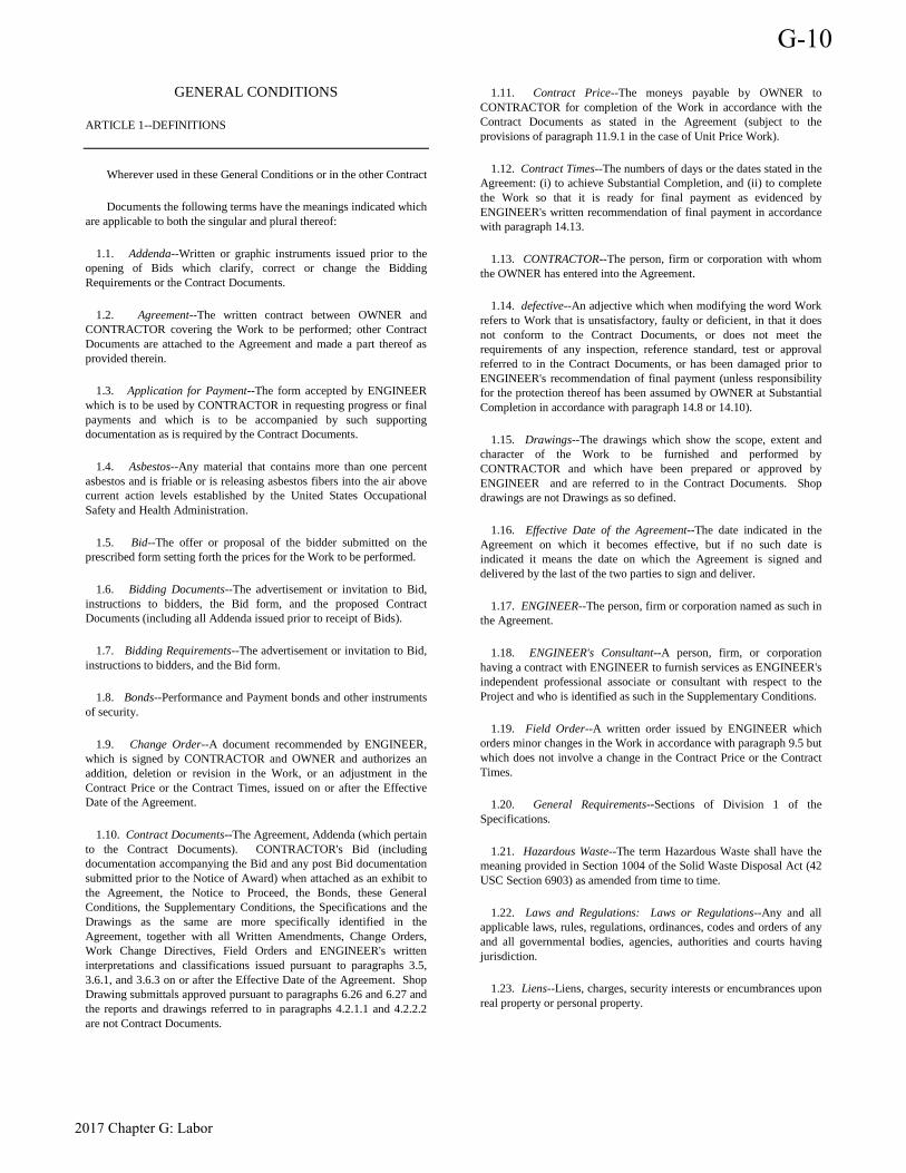
GENERAL CONDITIONS
ARTICLE 1--DEFINITIONS
Wherever used in these General Conditions or in the other Contract
Documents the following terms have the meanings indicated which are applicable to both the singular and plural thereof:
1.1. Addenda--Written or graphic instruments issued prior to the opening of Bids which clarify, correct or change the Bidding Requirements or the Contract Documents.
1.2. Agreement--The written contract between OWNER and CONTRACTOR covering the Work to be performed; other Contract Documents are attached to the Agreement and made a part thereof as provided therein.
1.3. Application for Payment--The form accepted by ENGINEER which is to be used by CONTRACTOR in requesting progress or final payments and which is to be accompanied by such supporting documentation as is required by the Contract Documents.
1.4. Asbestos--Any material that contains more than one percent asbestos and is friable or is releasing asbestos fibers into the air above current action levels established by the United States Occupational Safety and Health Administration.
1.5. Bid--The offer or proposal of the bidder submitted on the prescribed form setting forth the prices for the Work to be performed.
1.6. Bidding Documents--The advertisement or invitation to Bid, instructions to bidders, the Bid form, and the proposed Contract Documents (including all Addenda issued prior to receipt of Bids).
1.7. Bidding Requirements--The advertisement or invitation to Bid, instructions to bidders, and the Bid form.
1.8. Bonds--Performance and Payment bonds and other instruments of security.
1.9. Change Order--A document recommended by ENGINEER, which is signed by CONTRACTOR and OWNER and authorizes an addition, deletion or revision in the Work, or an adjustment in the Contract Price or the Contract Times, issued on or after the Effective Date of the Agreement.
1.10. Contract Documents--The Agreement, Addenda (which pertain to the Contract Documents). CONTRACTOR's Bid (including documentation accompanying the Bid and any post Bid documentation submitted prior to the Notice of Award) when attached as an exhibit to the Agreement, the Notice to Proceed, the Bonds, these General Conditions, the Supplementary Conditions, the Specifications and the Drawings as the same are more specifically identified in the Agreement, together with all Written Amendments, Change Orders, Work Change Directives, Field Orders and ENGINEER's written interpretations and classifications issued pursuant to paragraphs 3.5, 3.6.1, and 3.6.3 on or after the Effective Date of the Agreement. Shop Drawing submittals approved pursuant to paragraphs 6.26 and 6.27 and the reports and drawings referred to in paragraphs 4.2.1.1 and 4.2.2.2 are not Contract Documents.
1.11. Contract Price--The moneys payable by OWNER to CONTRACTOR for completion of the Work in accordance with the Contract Documents as stated in the Agreement (subject to the provisions of paragraph 11.9.1 in the case of Unit Price Work).
1.12. Contract Times--The numbers of days or the dates stated in the Agreement: (i) to achieve Substantial Completion, and (ii) to complete the Work so that it is ready for final payment as evidenced by ENGINEER's written recommendation of final payment in accordance with paragraph 14.13.
1.13. CONTRACTOR--The person, firm or corporation with whom the OWNER has entered into the Agreement.
1.14. defective--An adjective which when modifying the word Work refers to Work that is unsatisfactory, faulty or deficient, in that it does not conform to the Contract Documents, or does not meet the requirements of any inspection, reference standard, test or approval referred to in the Contract Documents, or has been damaged prior to ENGINEER's recommendation of final payment (unless responsibility for the protection thereof has been assumed by OWNER at Substantial Completion in accordance with paragraph 14.8 or 14.10).
1.15. Drawings--The drawings which show the scope, extent and character of the Work to be furnished and performed by CONTRACTOR and which have been prepared or approved by ENGINEER and are referred to in the Contract Documents. Shop drawings are not Drawings as so defined.
1.16. Effective Date of the Agreement--The date indicated in the Agreement on which it becomes effective, but if no such date is indicated it means the date on which the Agreement is signed and delivered by the last of the two parties to sign and deliver.
1.17. ENGINEER--The person, firm or corporation named as such in the Agreement.
1.18. ENGINEER's Consultant--A person, firm, or corporation having a contract with ENGINEER to furnish services as ENGINEER's independent professional associate or consultant with respect to the Project and who is identified as such in the Supplementary Conditions.
1.19. Field Order--A written order issued by ENGINEER which orders minor changes in the Work in accordance with paragraph 9.5 but which does not involve a change in the Contract Price or the Contract Times.
1.20. General Requirements--Sections of Division 1 of the Specifications.
1.21. Hazardous Waste--The term Hazardous Waste shall have the meaning provided in Section 1004 of the Solid Waste Disposal Act (42 USC Section 6903) as amended from time to time.
1.22. Laws and Regulations: Laws or Regulations--Any and all applicable laws, rules, regulations, ordinances, codes and orders of any and all governmental bodies, agencies, authorities and courts having jurisdiction.
1.23. Liens--Liens, charges, security interests or encumbrances upon real property or personal property.
G-10
2017 Chapter G: Labor

1.24. Milestone--A principal event specified in the Contract Documents relating to an intermediate completion date or time prior to Substantial Completion of all the Work.
1.25. Notice of Award--The written notice by OWNER to the apparent successful bidder stating that upon compliance by the apparent successful bidder with the conditions precedent enumerated therein, within the time specified, OWNER will sign and deliver the Agreement.
1.26. Notice to Proceed--A written notice given by OWNER to CONTRACTOR (with a copy to ENGINEER) fixing the date on which the Contract Times will commence to run and on which CONTRACTOR shall start to perform CONTRACTOR's obligations under the Contract Documents.
1.27. OWNER--The public body or authority, corporation, association, firm or person with whom CONTRACTOR has entered into the Agreement and for whom the Work is to be provided.
1.28. Partial Utilization--Use by OWNER of a substantially completed part of the Work for the purpose for which it is intended (or a related purpose) prior to Substantial Completion of all the Work.
1.29. PCBs--Polychlorinated biphenyls.
1.30. Petroleum--Petroleum, including crude oil or any fraction thereof which is liquid at standard conditions of temperature and pressure (60 degrees Fahrenheit and 14.7 pounds per square inch absolute), such as oil, petroleum, fuel oil, oil sludge, oil refuse, gasoline, kerosene, and oil mixed with other non-Hazardous Wastes and crude oils.
1.31. Project--The total construction of which the Work to be provided under the Contract Documents may be the whole, or a part as indicated elsewhere in the Contract Documents.
1.32. Radioactive Material--Source, special nuclear, or byproduct material as defined by the Atomic Energy Act of 1954 (42 USC Section 2011 et seq.) as amended from time to time.
1.33. Resident Project Representative--The authorized representative of ENGINEER who may be assigned to the site or any part thereof.
1.34. Samples--Physical examples of materials, equipment, or workmanship that are representative of some portion of the Work and which establish the standards by which such portion of the Work will be judged.
1.35. Shop Drawings--All drawings, diagrams, illustrations, schedules and other data or information which are specifically prepared or assembled by or for CONTRACTOR and submitted by CONTRACTOR to illustrate some portion of the Work.
1.36. Specifications--Those portions of the Contract Documents consisting of written technical descriptions of materials, equipment, construction systems, standards and workmanship as applied to the Work and certain administrative details applicable thereto.
1.37. Subcontractor--An individual, firm or corporation having a direct contract with CONTRACTOR or with any other Subcontractor for the performance of a part of the Work at the site.
1.38. Substantial Completion--The Work (or a specified part thereof) has progressed to the point where, in the opinion of ENGINEER as evidenced by ENGINEER's definitive certificate of Substantial Completion, it is sufficiently complete, in accordance with the Contract Documents, so that the Work (or specified part) can be utilized for the purposes for which it is intended; or if no such certificate is issued, when the Work is complete and ready for final payment as evidenced by ENGINEER's written recommendation of final payment in accordance with paragraph 14.13. The terms "substantially complete" and "substantially completed" as applied to all or part of the Work refer to Substantial Completion thereof.
1.39. Supplementary Conditions--The part of the Contract Documents which amends or supplements these General Conditions.
1.40. Supplier--A manufacturer, fabricator, supplier, distributor, materialman or vendor having a direct contract with CONTRACTOR or with any Subcontractor to furnish materials or equipment to be incorporated in the Work by CONTRACTOR or any Subcontractor.
1.41. Underground Facilities--All pipelines, conduits, ducts, cables, wires, manholes, vaults, tanks, tunnels or other such facilities or attachments, and any encasements containing such facilities which have been installed underground to furnish any of the following services or materials: electricity, gases, steam, liquid petroleum products, telephone or other communications, cable television, sewage and drainage removal, traffic or other control systems or water.
1.42. Unit Price Work--Work to be paid for on the basis of unit prices.
1.43. Work--The entire completed construction or the various separately identifiable parts thereof required to be furnished under the Contract Documents. Work includes and is the result of performing or furnishing labor and furnishing and incorporating materials and equipment into the construction, and performing or furnishing services and furnishing documents, all as required by the Contract Documents.
1.44. Work Change Directive--A written directive to CONTRACTOR, issued on or after the Effective Date of the Agreement and signed by OWNER and recommended by ENGINEER, ordering an addition, deletion or revision in the Work, or responding to differing or unforeseen physical conditions under which the Work is to be performed as provided in paragraph 4.2 or 4.3 or to emergencies under paragraph 6.23. A Work Change Directive will not change the Contract Price or the Contract Times, but is evidence that the parties expect that the change directed or documented by a Work Change Directive will be incorporated in a subsequently issued Change Order following negotiations by the parties as to its effect, if any, on the Contract Price or Contract Times as provided in paragraph 10.2.
1.45. Written Amendment--A written amendment of the Contract Documents, signed by OWNER and CONTRACTOR on or after the Effective Date of the Agreement and normally dealing with the nonengineering or nontechnical rather than strictly construction-related aspects of the Contract Documents.
ARTICLE 2--PRELIMINARY MATTERS
Delivery of Bonds:
2.1. When CONTRACTOR delivers the executed Agreements to OWNER, CONTRACTOR shall also deliver to OWNER such Bonds
G-10
2017 Chapter G: Labor
as CONTRACTOR may be required to furnish in accordance with paragraph 5.1.
Copies of Documents:
2.2. OWNER shall furnish to CONTRACTOR up to ten copies (unless otherwise specified in the Supplementary Conditions) of the Contract Documents as are reasonably necessary for the execution of the Work. Additional copies will be furnished, upon request, at the cost of reproduction.
Commencement of Contract Times; Notice to Proceed:
2.3. The Contract Times will commence to run on the thirtieth day after the Effective Date of the Agreement, or, if a Notice to Proceed is given, on the day indicated in the Notice to Proceed. A Notice to Proceed may be given at any time within thirty days after the Effective Date of the Agreement. In no event will the Contract Times commence to run later than the sixtieth day after the day of Bid opening or the thirtieth day after the Effective Date of the Agreement, whichever date is earlier.
Starting the Work:
2.4. CONTRACTOR shall start to perform the Work on the date when the Contract Times commence to run, but no Work shall be done at the site prior to the date on which the Contract Times commence to run.
Before Starting Construction:
2.5. Before undertaking each part of the Work, CONTRACT-OR shall carefully study and compare the Contract Documents and check and verify pertinent figures shown thereon and all applicable field measurements. CONTRACTOR shall promptly report in writing to ENGINEER any conflict, error, ambiguity or discrepancy which CONTRACTOR may discover and shall obtain a written interpretation or clarification from ENGINEER before proceeding with any Work affected thereby; however, CONTRACTOR shall not be liable to OWNER or ENGINEER for failure to report any conflict, error, ambiguity or discrepancy in the Contract Documents, unless CONTRACTOR knew or reasonably should have known thereof.
2.6. Within ten days after the Effective Date of the Agreement (unless otherwise specified in the General Requirements), CONTRACTOR shall submit to ENGINEER for review:
2.6.1. a preliminary progress schedule indicating the times (numbers of days or dates) for starting and completing the various stages of the Work, including any Milestones specified in the Contract Documents;
2.6.2. a preliminary schedule for Shop Drawing and Sample submittals which will list each required submittal and the times for submitting, reviewing and processing such submittal;
2.6.3. a preliminary schedule of values for all of the Work which will include quantities and prices of items aggregating the Contract Price and will subdivide the Work into component parts in sufficient detail to serve as the basis for progress payments during construction. Such prices will include an appropriate amount of overhead and profit applicable to each item of Work.
2.7. Before any Work at the site is started, CONTRACTOR and OWNER shall each deliver to the other, with copies to each additional insured identified in the Supplementary Conditions, certificates of insurance (and other evidence of insurance which either of them or any additional insured may reasonably request) which CONTRACTOR and OWNER respectively are required to purchase and maintain in accordance with paragraphs 5.4, 5.6 and 5.7.
Preconstruction Conference:
2.8. Within twenty days after the Contract Times start to run, but before any Work at the site is started, a conference attended by CONTRACTOR, ENGINEER and others as appropriate will be held to establish a working understanding among the parties as to the Work and to discuss the schedules referred to in paragraph 2.6, procedures for handling Shop Drawings and other submittals, processing Applications for Payment and maintaining required records.
Initially Acceptable Schedules:
2.9. Unless otherwise provided in the Contract Documents, at least ten days before submission of the first Application for Payment a conference attended by CONTRACTOR, ENGINEER and others as appropriate will be held to review for acceptability to ENGINEER as provided below the schedules submitted in accordance with paragraph 2.6. CONTRACTOR shall have an additional ten days to make corrections and adjustments and to complete and resubmit the schedules. No progress payment shall be made to CONTRACTOR until the schedules are submitted to and acceptable to ENGINEER as provided below. The progress schedule will be acceptable to ENGINEER as providing an orderly progression of the Work to completion within any specified Milestones and the Contract Times, but such acceptance will neither impose on ENGINEER responsibility for the sequencing, scheduling or progress of the Work nor interfere with or relieve CONTRACTOR from CONTRACTOR's full responsibility therefore. CONTRACTOR's schedule of Shop Drawing and Sample submissions will be acceptable to ENGINEER as providing a workable arrangement for reviewing and processing the required submittals. CONTRACTOR's schedule of values will be acceptable to ENGINEER as to form and substance.
ARTICLE 3--CONTRACT DOCUMENT: INTENT, AMENDING, REUSE
Intent:
3.1. The Contract Documents comprise the entire agreement between OWNER and CONTRACTOR concerning the Work. The Contract Documents are complementary; what is called for by one is as binding as if called for by all. The Contract Documents will be construed in accordance with the law of the place of the Project.
3.2. It is the intent of the Contract Documents to describe a functionally complete Project (or part thereof) to be constructed in accordance with the Contract Documents. Any Work, materials or equipment that may reasonably be inferred from the Contract Documents or from prevailing custom or trade usage as being required to produce the intended result will be furnished and performed whether or not specifically called for. When words or phrases which have a well-known technical or construction industry or trade meaning are used to describe Work, materials or equipment, such words or phrases shall be interpreted in accordance with that meaning. Clarifications and interpretations of the Contract Documents shall be issued by ENGINEER as provided in paragraph 9.4.
G-10
2017 Chapter G: Labor
3.3. Reference to Standards and Specifications of Technical Societies; Reporting and Resolving Discrepancies:
3.3.1. Reference to standards, specifications, manuals or codes of any technical society, organization or association, or to the Laws or Regulations of any governmental authority, whether such reference be specific or by implication, shall mean the latest standard, specification, manual, code or Laws or Regulations in effect at the time of opening of Bids (or, on the Effective Date of the Agreement if there were no Bids), except as may be otherwise specifically stated in the Contract Documents.
3.3.2. If, during the performance of the Work, CONTRACTOR discovers any conflict, error, ambiguity or discrepancy within the Contract Documents or between the Contract Documents and any provision of any such Law or Regulation applicable to the performance of the Work or of any such standard, specification, manual or code or of any instruction of any Supplier referred to in paragraph 6.5, CONTRACTOR shall report it to ENGINEER in writing at once, and, CONTRACTOR shall not proceed with the Work affected thereby (except in an emergency as authorized by paragraph 6.23) until an amendment or supplement to the Contract Documents has been issued by one of the methods indicated in paragraph 3.5 or 3.6; provided, however, that CONTRACTOR shall not be liable to OWNER or ENGINEER for failure to report any such conflict, error, ambiguity or discrepancy unless CONTRACTOR knew or reasonably should have known thereof.
3.3.3. Except as otherwise specifically stated in the Contract Documents or as may be provided by amendment or supplement thereto issued by one of the methods indicated in paragraph 3.5 or 3.6, the provisions of the Contract Documents shall take precedence in resolving any conflict, error, ambiguity or discrepancy between the provisions of the Contract Documents and:
3.3.3.1. the provisions of any such standard, specification, manual, code or instruction (whether or not specifically incorporated by reference in the Contract Documents); or
3.3.3.2. the provisions of any such Laws or Regulations applicable to the performance of the Work (unless such an interpretation of the provisions of the Contract Documents would result in violation of such Law or Regulation).
No provision of any such standard, specification, manual, code or instruction shall be effective to change the duties and responsibilities of OWNER, CONTRACTOR or ENGINEER, or any of their subcontractors, consultants, agents, or employees from those set forth in the Contract Documents, nor shall it be effective to assign to OWNER, ENGINEER or any of ENGINEER's Consultants, agents or employees any duty or authority to supervise or direct the furnishing or performance of the Work or any duty or authority to undertake responsibility inconsistent with the provisions of paragraph 9.13 or any other provision of the Contract Documents.
3.4. Whenever in the Contract Documents the terms" as ordered," "as directed," "as required," "as allowed," "as approved" or terms of like effect or import are used, or the adjectives "reasonable," "suitable," "acceptable," "proper" or "satisfactory" or adjectives of like effect or import are used to describe a requirement, direction, review or judgment of ENGINEER as to the Work, it is intended that such requirement, direction, review or judgment will be solely to evaluate, in general, the completed Work for compliance with the requirements of and information in the Contract Documents and conformance with the
design concept of the completed Project as a functioning whole as shown or indicated in the Contract Documents (unless there is a specific statement indicating otherwise). The use of any such term or adjective shall not be effective to assign to ENGINEER any duty or authority to supervise or direct the furnishing or performance of the Work or any duty or authority to undertake responsibility contrary to the provisions of paragraph 9.13 or any other provision of the Contract Documents.
Amending and Supplementing Contract Documents:
3.5. The Contract Documents may be amended to provide for additions, deletions and revisions in the Work or to modify the terms and conditions thereof in one or more of the following ways:
3.5.1. a formal Written Amendment.
3.5.2. a Change Order (pursuant to paragraph 10.4), or
3.5.3. a Work Change Directive (pursuant to paragraph 10.1).
3.6. In addition, the requirements of the Contract Documents may be supplemented, and minor variations and deviations in the Work may be authorized, in one or more of the following ways:
3.6.1. a Field Order (pursuant to paragraph 9.5),
3.6.2. ENGINEER's approval of a Shop Drawing or Sample (pursuant to paragraphs 6.26 and 6.27), or
3.6.3. ENGINEER's written interpretation or clarification (pursuant to paragraph 9.4).
Reuse of Documents:
3.7. CONTRACTOR, and any Subcontractor or Supplier or other person or organization performing or furnishing any of the Work under a direct or indirect contract with OWNER (i) shall not have or acquire any title to or ownership rights in any of the Drawings, Specifications or other documents (or copies of any thereof) prepared by or bearing the seal of ENGINEER or ENGINEER's Consultant, and (ii) shall not reuse any of such Drawings, Specifications, other documents or copies on extensions of the Project or any other project without written consent of OWNER and ENGINEER and specific written verification or adaption by ENGINEER.
ARTICLE 4--AVAILABILITY OF LANDS; SUBSURFACE AND PHYSICAL CONDITIONS; REFERENCE POINTS
Availability of Lands:
4.1. OWNER shall furnish, as indicated in the Contract Documents, the lands upon which the Work is to be performed, rights-of-way and easements for access thereto, and such other lands which are designated for the use of CONTRACTOR. Upon reasonable written request, OWNER shall furnish CONTRACTOR with a correct statement of record legal title and legal description of the lands upon which the Work is to be performed and OWNER's interest therein as necessary for giving notice of or filing a mechanic's lien against such lands in accordance with applicable Laws and Regulations. OWNER shall identify any encumbrances or restrictions not of general application but
G-10
2017 Chapter G: Labor

specifically related to use of lands so furnished with which CONTRACTOR will have to comply in performing the Work. Easements for permanent structures or permanent changes in existing facilities will be obtained and paid for by OWNER, unless otherwise provided in the Contract Documents. If CONTRACTOR and OWNER are unable to agree on entitlement to or the amount or extent of any adjustments in the Contract Price or the Contract Times as a result of any delay in OWNER's furnishing these lands, rights-of-way or easements, CONTRACTOR may make a claim therefore as provided in Articles 11 and 12. CONTRACTOR shall provide for all additional lands and access thereto that may be required for temporary construction facilities or storage of materials and equipment.
4.2. Subsurface and Physical Conditions:
4.2.1. Reports and Drawings: Reference is made to the Supplementary Conditions for identification of:
4.2.1.1. Subsurface Conditions: Those reports of explorations and tests of subsurface conditions at or contiguous to the site that have been utilized by ENGINEER in preparing the Contract Documents; and
4.2.1.2. Physical Conditions: Those drawings of physical conditions in or relating to existing surface or subsurface structures at or contiguous to the site (except Underground Facilities) that have been utilized by ENGINEER in preparing the Contract Documents.
4.2.2. Limited Reliance by CONTRACTOR Authorized: Technical Data: CONTRACTOR may rely upon the general accuracy of the "technical data" contained in such reports and drawings, but such reports and drawings are not Contract Documents. Such "technical data" is identified in the Supplementary Conditions. Except for such reliance on such "technical data." CONTRACTOR may not rely upon or make any claim against OWNER, ENGINEER or any of ENGINEER's Consultants with respect to:
4.2.2.1. the completeness of such reports and drawings for CONTRACTOR's purposes, including, but not limited to, any aspects of the means, methods, techniques, sequences and procedures of construction to be employed by CONTRACTOR and safety precautions and programs incident thereto, or
4.2.2.2. other data, interpretations, opinions and information contained in such reports or shown or indicated in such drawings, or
4.2.2.3. any CONTRACTOR interpretation of or conclusion drawn from any "technical data" or any such data, interpretations, opinions or information.
4.2.3. Notice of Differing Subsurface or Physical Conditions: If CONTRACTOR believes that any subsurface or physical condition at or contiguous to the site that is uncovered or revealed either:
4.2.3.1. is of such a nature as to establish that any "technical data" on which CONTRACTOR is entitled to rely as provided in paragraphs 4.2.1 and 4.2.2 is materially inaccurate, or
4.2.3.2. is of such a nature as to require a change in the Contract Documents, or
4.2.3.3. differs materially from that shown or indicated in the Contract Documents, or
4.2.3.4. is of an unusual nature, and differs materially from conditions ordinarily encountered and generally recognized as inherent in work of the character provided for in the Contract Documents; then
CONTRACTOR shall, promptly after becoming aware thereof and before further disturbing conditions affected thereby or performing any Work in connection therewith (except in an emergency as permitted by paragraph 6.23), notify OWNER and ENGINEER in writing about such condition. CONTRACTOR shall not further disturb such conditions or perform any Work in connection therewith (except as aforesaid) until receipt of written order to do so.
4.2.4. ENGINEER's Review: ENGINEER will promptly review the pertinent conditions, determine the necessity of OWNER's obtaining additional exploration or tests with respect thereto and advise OWNER in writing (with a copy to CONTRACTOR) of ENGINEER's findings and conclusions.
4.2.5. Possible Contract Documents Change: If ENGINEER concludes that a change in the Contract Documents is required as a result of a condition that meets one or more of the categories in paragraph 4.2.3., a Work Change Directive or a Change Order will be issued as provided in Article 10 to reflect and document the consequences of such change.
4.2.6. Possible Price and Times Adjustments: An equitable adjustment in the Contract Price or in the Contract Times, or both, will be allowed to the extent that the existence of such uncovered or revealed condition causes an increase or decrease in CONTRACTOR's cost of, or time required for performance of, the Work; subject, however, to the following:
4.2.6.1. such condition must meet any one or more of the categories described in paragraphs 4.2.3.1 through 4.2.3.4, inclusive;
4.2.6.2. a change in the Contract Documents pursuant to paragraph 4.2.5 will not be an automatic authorization of nor a condition precedent to entitlement to any such adjustment;
4.2.6.3. with respect to Work that is paid for on a Unit Price Basis, any adjustment in Contract Price will be subject to the provisions of paragraphs 9.10 and 11.9; and
4.2.6.4. CONTRACTOR shall not be entitled to any adjustment in the Contract Price or Times if;
4.2.6.4.1. CONTRACTOR knew of the existence of such conditions at the time CONTRACTOR made a final commitment to OWNER in respect of Contract Price and Contract Times by the submission of a bid or becoming bound under a negotiated contract; or
4.2.6.4.2. the existence of such condition could reasonably have been discovered or revealed as a result of any examination, investigation, exploration, test or study of the site and contiguous areas required by the Bidding Requirements or Contract Documents to be conducted by or for CONTRACTOR prior to CONTRACTOR's making such final commitment; or
G-10
2017 Chapter G: Labor
4.2.6.4.3. CONTRACTOR failed to give the written notice within the time and as required by paragraph 4.2.3.
If OWNER and CONTRACTOR are unable to agree on entitlement to or as to the amount or length of any such equitable adjustment in the Contract Price or Contract Times, a claim may be made therefore as provided in Articles 11 and 12. However, OWNER, ENGINEER and ENGINEER's Consultants shall not be liable to CONTRACTOR for any claims, costs, losses or damages sustained by CONTRACTOR on or in connection with any other project or anticipated project.
4.3. Physical Conditions--Underground Facilitates:
4.3.1. Shown or Indicated: The information and data shown or indicated in the Contract Documents with respect to existing Underground Facilities at or contiguous to the site is based on information and data furnished to OWNER or ENGINEER by the owners of such Underground Facilities or by others. Unless it is otherwise expressly provided in the Supplementary Conditions:
4.3.1.1. OWNER and ENGINEER shall not be responsible for the accuracy or completeness of any such information or data; and
4.3.1.2. The cost of all of the following will be included in the Contract Price and CONTRACTOR shall have full responsibility for: (i) reviewing and checking all such information and data, (ii) locating all Underground Facilities shown or indicated in the Contract Documents, (iii) coordination of the Work with the owners of such Underground Facilities during construction, and (iv) the safety and protection of all such Underground Facilities as provided in paragraph 6.20 and repairing any damage thereto resulting from the Work.
4.3.2. Not Shown or Indicated: If an Underground Facility is uncovered or revealed at or contiguous to the site which was not shown or indicated in the Contract Documents, CONTRACTOR shall, promptly after becoming aware thereof and before further disturbing conditions affected thereby or performing any Work in connection therewith (except in an emergency as required by paragraph 6.23), identify the owner of such Underground Facility and give written notice to that owner and to OWNER and ENGINEER. ENGINEER will promptly review the Underground Facility and determine the extent, if any, to which a change is required in the Contract Documents to reflect and document the consequences of the existence of the Underground Facility. If ENGINEER concludes that a change in the Contract Documents is required, a Work Change Directive or a Change Order will be issued as provided in Article 10 to reflect and document such consequences. During such time, CONTRACTOR shall be responsible for the safety and protection of such Underground Facility as provided in paragraph 6.20. CONTRACTOR shall be allowed an increase in the Contract Price or an extension of the Contract Times, or both, to the extent that they are attributable to the existence of any Underground Facility that was not shown or indicated in the Contract Documents and that CONTRACTOR did not know of and could not reasonably have been expected to be aware of or to have anticipated. If OWNER and CONTRACTOR are unable to agree on entitlement to or the amount or length of any such adjustment in Contract Price or Contract Times, CONTRACTOR may make a claim therefore as provided in Articles 11 and 12. However, OWNER, ENGINEER and ENGINEER's Consultants shall not be liable to CONTRACTOR for any claims, costs, losses or damages incurred or sustained by CONTRACTOR on or in connection with any other project or anticipated project.
Reference Points:
4.4. OWNER shall provide engineering surveys to establish reference points for construction which in ENGINEER's judgment are necessary to enable CONTRACTOR to proceed with the Work. CONTRACTOR shall be responsible for laying out the Work, shall protect and preserve the established reference points and shall make no changes or relocations without the prior written approval of OWNER. CONTRACTOR shall report to ENGINEER whenever any reference point is lost or destroyed or requires relocation because of necessary changes in grades or locations, and shall be responsible for the accurate replacement or relocation of such reference points by professionally qualified personnel.
4.5. Asbestos, PCBs, Petroleum, Hazardous Waste or Radioactive Material:
4.5.1. OWNER shall be responsible for any Asbestos, PCBs, Petroleum, Hazardous Waste or Radioactive Material uncovered or revealed at the site which was not shown or indicated in Drawings or Specifications or identified in the Contract Documents to be within the scope of the Work and which may present a substantial danger to persons or property exposed thereto in connection with the Work at the site. OWNER shall not be responsible for any such materials brought to the site by CONTRACTOR, Subcontractor, Suppliers or anyone else for whom CONTRACTOR is responsible.
4.5.2. CONTRACTOR shall immediately: (i) stop all Work in connection with such hazardous condition and in any area affected thereby (except in an emergency as required by paragraph 6.23), and (ii) notify OWNER and ENGINEER (and thereafter confirm such notice in writing). OWNER shall promptly consult with ENGINEER concerning the necessity for OWNER to retain a qualified expert to evaluate such hazardous condition or take corrective action, if any. CONTRACTOR shall not be required to resume Work in connection with such hazardous condition or in any such affected area until after OWNER has obtained any required permits related thereto and delivered to CONTRACTOR special written notice: (i) specifying that such condition and any affected area is or has been rendered safe for the resumption of Work, or (ii) specifying any special conditions under which such Work may be resumed safely. If OWNER and CONTRACTOR cannot agree as to entitlement to or the amount or extent of an adjustment, if any, in Contract Price or Contract Times as a result of such Work stoppage or such special conditions under which Work is agreed by CONTRACTOR to be resumed, either party may make a claim therefore as provided in Articles 11 and 12.
4.5.3. If after receipt of such special written notice CONTRACTOR does not agree to resume such Work based on a reasonable belief it is unsafe, or does not agree to resume such Work under such special conditions, then OWNER may order such portion of the Work that is in connection with such hazardous condition or in such affected area to be deleted from the Work. If OWNER and CONTRACTOR cannot agree as to entitlement to or the amount or extent of an adjustment, if any, in Contract Price or Contract Times as a result of deleting such portion of the Work, then either party may make a claim therefore as provided in Articles 11 and 12. OWNER may have such deleted portion of the Work performed by OWNER's own forces or others in accordance with Article 7.
4.5.4. To the fullest extent permitted by Laws and Regulations, OWNER shall indemnify and hold harmless CONTRACTOR, Subcontractors, ENGINEER, ENGINEER's Consultants and the officers, directors, employees, agents, other consultants and subcontractors of each and any of them from and against all
G-10
2017 Chapter G: Labor
claims, costs, losses and damages arising out of or resulting from such hazardous condition, provided that: (i) any such claim, cost, loss or damage is attributable to bodily injury, sickness, disease or death, or to injury to or destruction of tangible property (other than the Work itself), including the loss of use resulting there from, and (ii) nothing in this subparagraph 4.5.4 shall obligate OWNER to indemnify any person or entity from and against the consequences of that person's or entity's own negligence.
4.5.5. The provisions of paragraphs 4.2 and 4.3 are not intended to apply to Asbestos, PCBs, Petroleum, Hazardous Waste or Radioactive Material uncovered or revealed at the site.
ARTICLE 5--BONDS AND INSURANCE
Performance, Payment and Other Bonds:
5.1. CONTRACTOR shall furnish Performance and Payment Bonds, each in an amount at least equal to the Contract Price as security for the faithful performance and payment of all CONTRACTOR's obligations under the Contract Documents. These Bonds shall remain in effect at least until one year after the date when final payment becomes due, except as provided otherwise by Laws or Regulations or by the Contract Documents. CONTRACTOR shall also furnish such other Bonds as are required by the Supplementary Conditions. All Bonds shall be in the form prescribed by the Contract Documents except as provided otherwise by Laws or Regulations, and shall be executed by such sureties as are named in the current list of "Companies Holding Certificates of Authority as Acceptable Sureties on Federal Bonds and as Acceptable Reinsuring Companies" as published in Circular 570 (amended) by the Audit Staff, Bureau of Government Financial Operations, U.S. Treasury Department. All Bonds signed by an agent must be accompanied by a certified copy of such agent's authority to act.
5.2. If the surety on any Bond furnished by CONTRACTOR is declared a bankrupt or becomes insolvent or its right to do business is terminated in any state where any part of the Project is located or it ceases to meet the requirements of paragraph 5.1, CONTRACTOR shall within ten days thereafter substitute another Bond and surety, both of which must be acceptable to OWNER.
5.3. Licensed Sureties and Insurers; Certificates of Insurance:
5.3.1. All Bonds and insurance required by the Contract Documents to be purchased and maintained by OWNER or CONTRACTOR shall be obtained from surety or insurance companies that are duly licensed or authorized in the jurisdiction in which the Project is located to issue Bonds or insurance policies for the limits and coverages so required. Such surety and insurance companies shall also meet such additional requirements and qualifications as may be provided in the Supplementary Conditions.
5.3.2. CONTRACTOR shall deliver to OWNER, with copies to each additional insured identified in the Supplementary Conditions, certificates of insurance (and other evidence of insurance requested by OWNER or any other additional insured) which CONTRACTOR is required to purchase and maintain in accordance with paragraph 5.4. OWNER shall deliver to CONTRACTOR, with copies to each additional insured identified in the Supplementary Conditions, certificates of insurance (and other evidence of insurance requested by CONTRACTOR or any other additional insured) which OWNER is
required to purchase and maintain in accordance with paragraphs 5.6 and 5.7 hereof.
CONTRACTOR's Liability Insurance:
5.4. CONTRACTOR shall purchase and maintain such liability and other insurance as is appropriate for the Work being performed and furnished and as will provided protection from claims set forth below which may arise out of or result from CONTRACTOR's performance and furnishing of the Work and CONTRACTOR's other obligations under the Contract Documents, whether it is to be performed or furnished by CONTRACTOR, any Subcontractor or Supplier, or by anyone directly or indirectly employed by any of them to perform or furnish any of the Work, or by anyone for whose acts any of them may be liable:
5.4.1. claims under workers' compensation, disability benefits and other similar employee benefit acts;
5.4.2. claims for damages because of bodily injury, occupational sickness or disease, or death of CONTRACTOR's employees;
5.4.3. claims for damages because of bodily injury, sickness or disease, or death of any person other than CONTRACTOR's employees;
5.4.4. claims for damages insured by customary personal injury liability coverage which are sustained: (i) by any person as a result of an offense directly or indirectly related to the employment of such person by CONTRACTOR , or (ii) by any other person for any other reason;
5.4.5. claims for damages, other than to the Work itself, because of injury to or destruction of tangible property wherever located, including loss of use resulting there from; and
5.4.6. claims for damages because of bodily injury or death of any person or property damage arising out of the ownership, maintenance or use of any motor vehicle.
The policies of insurance so required by this paragraph 5.4 to be purchased and maintained shall:
5.4.7. with respect to insurance required by paragraphs 5.4.3. through 5.4.6 inclusive, include as additional insured (subject to any customary exclusion in respect of professional liability) OWNER, ENGINEER, ENGINEER's Consultants and any other persons or entities identified in the Supplementary Conditions, all of whom shall be listed as additional insured, and include coverage for the respective officers and employees of all such additional insured;
5.4.8. include the specific coverages and be written for not less than the limits of liability provided in the Supplementary Conditions or required by Laws or Regulations, whichever is greater;
5.4.9. include completed operations insurance;
5.4.10. include contractual liability insurance covering CONTRACTOR's indemnity obligations under paragraphs 6.12, 6.16 and 6.31 through 6.33;
G-10
2017 Chapter G: Labor
5.4.11. contain a provision or endorsement that the coverage afforded will not be cancelled, materially changed or renewal refused until at least thirty days prior written notice has been given to OWNER and CONTRACTOR and to each other additional insured identified in the Supplementary Conditions to whom a certificate of insurance has been issued (and the certificates of insurance furnished by the CONTRACTOR pursuant to paragraph 5.3.2 will so provide);
5.4.12. remain in effect at least until final payment and at all times thereafter when CONTRACTOR may be correcting, removing or replacing defective Work in accordance with paragraph 13.12; and
5.4.13. with respect to completed operations insurance, and any insurance coverage written on a claims-made basis, remain in effect for at least two years after final payment (and CONTRACTOR shall furnish OWNER and each other additional insured identified in the Supplementary Conditions to whom a certificate of insurance has been issued evidence satisfactory to OWNER and any such additional insured of continuation of such insurance at final payment and one year thereafter).
OWNER's Liability Insurance:
5.5. In addition to the insurance required to be provided by CONTRACTOR under paragraph 5.4, OWNER, at OWNER's option, may purchase and maintain at OWNER's expense OWNER's own liability insurance as will protect OWNER against claims which may arise from operations under the Contract Documents.
Property Insurance:
5.6. Unless otherwise provided in the Supplementary Conditions, OWNER shall purchase and maintain property insurance upon the Work at the site in the amount of the full replacement cost thereof (subject to such deductible amounts as may be provided in the Supplementary Conditions or required by Laws and Regulations). This insurance shall:
5.6.1. include the interests of OWNER, CONTRACTOR, Subcontractors, ENGINEER, ENGINEER's Consultants and any other persons or entities identified in the Supplementary Conditions, each of whom is deemed to have an insurable interest and shall be listed as an insured or additional insured;
5.6.2. be written on a Builder's Risk "all-risk" or open peril or special causes of loss policy form that shall at least include insurance for physical loss or damage to the Work, temporary buildings, false work and Work in transit and shall insure against at least the following perils fire, lightning, extended coverage, theft, vandalism and malicious mischief, earthquake, collapse, debris removal, demolition occasioned by enforcement of Laws and Regulations, water damage, and such other perils as may be specifically required by the Supplementary Conditions;
5.6.3. include expenses incurred in the repair or replacement of any insured property (including but not limited to fees and charges of engineers and architects);
5.6.4. cover materials and equipment stored at the site or at another location that was agreed to in writing by OWNER prior to being incorporated in the Work, provided that such materials and equipment have been included in an Application for Payment recommended by ENGINEER; and
5.6.5. be maintained in effect until final payment is made unless otherwise agreed to in writing by OWNER, CONTRACTOR and ENGINEER with thirty days written notice to each other additional insured to whom a certificate of insurance has been issued.
5.7. OWNER shall purchase and maintain such boiler and machinery insurance or additional property insurance as may be required by the Supplementary Conditions or Laws and Regulations which will include the interests of OWNER, CONTRACTOR, Subcontractors, ENGINEER, ENGINEER's Consultants and any other persons or entities identified in the Supplementary Conditions, each of whom is deemed to have an insurable interest and shall be listed as an insured or additional insured.
5.8. All the policies of insurance (and the certificates or other evidence thereof) required to be purchased and maintained by OWNER in accordance with paragraphs 5.6 and 5.7 will contain a provision or endorsement that the coverage afforded will not be canceled or materially changed or renewal refused until at least thirty days' prior written notice has been given to OWNER and CONTRACTOR and to each other additional insured to whom a certificate of insurance has been issued and will contain waiver provisions in accordance with paragraph 5.11.
5.9. OWNER shall not be responsible for purchasing and maintaining any property insurance to protect the interests of CONTRACTOR, Subcontractors or others in the Work to the extent of any deductible amounts that are identified in the Supplementary Conditions. The risk of loss within such identified deductible amount, will be borne by CONTRACTOR, Subcontractor or others suffering any such loss and if any of them wishes property insurance coverage within the limits of such amounts, each may purchase and maintain it at the purchaser's own expense.
5.10. If CONTRACTOR requests in writing that other special insurance be included in the property insurance policies provided under paragraphs 5.6 or 5.7, OWNER shall, if possible, include such insurance, and the cost thereof will be charged to CONTRACTOR by appropriate Change Order or Written Amendment. Prior to commencement of the Work at the site, OWNER shall in writing advise CONTRACTOR whether or not such other insurance has been procured by OWNER.
5.11. Waiver of Rights:
5.11.1. OWNER and CONTRACTOR intend that all policies purchased in accordance with paragraphs 5.6 and 5.7 will protect OWNER, CONTRACTOR, Subcontractors, ENGINEER, ENGINEER's Consultants and all other persons or entities identified in the Supplementary Conditions to be listed as insureds or additional insureds in such policies and will provide primary coverage for all losses and damages caused by the perils covered thereby. All such policies shall contain provisions to the effect that in the event of payment of any loss or damage the insurers will have no rights of recovery against any of the insureds or additional insureds thereunder. OWNER and CONTRACTOR waive all rights against each other and their respective officers, directors, employees and agents for all losses and damages caused by, arising out of or resulting from any of the perils covered by such policies and any other property insurance applicable to the Work; and, in addition, waive all such rights against Subcontractors, ENGINEER, ENGINEER's Consultants and all other persons or entities identified in the Supplementary Conditions to be listed as insureds or additional insureds under such policies for losses and damages so caused. None of the above waivers shall extend to the
G-10
2017 Chapter G: Labor
rights that any party making such waiver may have to the proceeds of insurance held by OWNER as trustee or otherwise payable under any policy so issued.
5.11.2. In addition, OWNER waives all rights against CONTRACTOR, Subcontractors, ENGINEER, ENGINEER's Consultants and the officers, directors, employees and agents of any of them, for:
5.11.2.1. loss due to business interruption, loss of use or other consequential loss extending beyond direct physical loss or damage to OWNER's property or the Work caused by, arising out of or resulting from fire or other peril, whether or not insured by OWNER; and
5.11.2.2. loss or damage to the completed Project or part thereof caused by, arising out of or resulting from fire or other insured peril covered by any property insurance maintained on the completed Project or part thereof by OWNER during partial utilization pursuant to paragraph 14.10, after substantial completion pursuant to paragraph 14.8 or after final payment pursuant to paragraph 14.13.
Any insurance policy maintained by OWNER covering any loss, damage or consequential loss referred to in this paragraph 5.11.2 shall contain provisions to the effect that in the event of payment of any such loss, damage or consequential loss the insurers will have no rights of recovery against any of CONTRACTOR, Subcontractors, ENGINEER, ENGINEER's Consultants and the officers, directors, employees and agents of any of them.
Receipt and Application of Insurance Proceeds
5.12. Any insured loss under the policies of insurance required by paragraphs 5.6 and 5.7 will be adjusted with OWNER and made payable to OWNER as fiduciary for the insureds, as their interests may appear, subject to the requirements of any applicable mortgage clause and of paragraph 5.13. OWNER shall deposit in a separate account any money so received, and shall distribute it in accordance with such agreement as the parties in interest may reach. If no other special agreement is reached the damaged Work shall be repaired or replaced, the moneys so received applied on account thereof and the Work and the cost thereof covered by an appropriate Change Order or Written Amendment.
5.13. OWNER as fiduciary shall have power to adjust and settle any loss with the insurers unless one of the parties in interest shall object in writing within fifteen days after the occurrence of loss to OWNER's exercise of this power. If such objection be made, OWNER as fiduciary shall make settlement with the insurers in accordance with such agreement as the parties in interest may reach. If no such agreement among the parties in interest is reached, OWNER as fiduciary shall adjust and settle the loss with the insurers and, if required in writing by any party in interest, OWNER as fiduciary shall give bond for the proper performance of such duties.
Acceptance of Bonds and Insurance; Option to Replace;
5.14. If either party (OWNER or CONTRACTOR) has any objection to the coverage afforded by or other provisions of the Bonds or insurance required to be purchased and maintained by the other party in accordance with Article 5 on the basis of non-conformance with the Contract Documents, the objecting party shall so notify the other party in writing within ten days after receipt of the certificates (or other evidence requested) required by paragraph 2.7. OWNER and
CONTRACTOR shall each provide to the other such additional information in respect of insurance provided as the other may reasonably request. If either party does not purchase or maintain all of the Bonds and insurance required of such party by the Contract Documents, such party shall notify the other party in writing of such failure to purchase prior to the start of the Work , or of such failure to maintain prior to any change in the required coverage. Without prejudice to any other right or remedy, the other party may elect to obtain equivalent Bonds or insurance to protect such other party's interests at the expense of the party who was required to provide such coverage, and a Change Order shall be issued to adjust the Contract Price accordingly.
Partial Utilization--Property Insurance:
5.15. If OWNER finds it necessary to occupy or use a portion or portions of the Work prior to Substantial Completion of all the Work, such use or occupancy may be accomplished in accordance with paragraph 14.10; provided that no such use or occupancy shall commence before the insurers providing the property insurance have acknowledged notice thereof and in writing effected any changes in coverage necessitated thereby. The insurers providing the property insurance shall consent by endorsement on the policy or policies, but the property insurance shall not be cancelled or permitted to lapse on account of any such partial use or occupancy.
ARTICLE 6--CONTRACTOR'S RESPONSIBILITIES
Supervision and Superintendence:
6.1. CONTRACTOR shall supervise, inspect and direct the Work competently and efficiently, devoting such attention thereto and applying such skills and expertise as may be necessary to perform the Work in accordance with the Contract Documents. CONTRACTOR shall be solely responsible for the means, methods, techniques, sequences and procedures of construction, but CONTRACTOR shall not be responsible for the negligence of others in the design or specification of a specific means, method, technique, sequence or procedure of construction which is shown or indicated in and expressly required by the Contract Documents. CONTRACTOR shall be responsible to see that the completed Work complies accurately with the Contract Documents.
6.2. CONTRACTOR shall keep on the Work at all times during its progress a competent resident superintendent, who shall not be replaced without written notice to OWNER and ENGINEER except under extraordinary circumstances. The superintendent will be CONTRACTOR's representative at the site and shall have authority to act on behalf of CONTRACTOR. All communications to the superintendent shall be as binding as if given to CONTRACTOR.
Labor, Materials and Equipment:
6.3. CONTRACTOR shall provide competent, suitably qualified personnel to survey, lay out and construct the Work as required by the Contract Documents. CONTRACTOR shall at all times maintain good discipline and order at the site. Except as otherwise required for the safety or protection of persons or the Work or property at the site or adjacent thereto, and except as otherwise indicated in the Contract Documents, all Work at the site shall be performed during regular working hours and CONTRACTOR will not permit overtime work or the performance of Work on Saturday, Sunday or any legal holiday without OWNER's written consent given after prior written notice to ENGINEER.
G-10
2017 Chapter G: Labor
6.4. Unless otherwise specified in the General Requirements, CONTRACTOR shall furnish and assume full responsibility for all materials, equipment, labor, transportation, construction equipment and machinery, tools, appliances, fuel, power, light, heat, telephone, water sanitary facilities, temporary facilities and all other facilities and incidentals necessary for the furnishing, performance, testing, start-up and completion of the Work.
6.5. All materials and equipment shall be of good quality and new, except as otherwise provided in the Contract Documents. All warranties and guarantees specifically called for by the Specifications shall expressly run to the benefit of OWNER. If required by ENGINEER, CONTRACTOR shall furnish satisfactory evidence (including reports of required tests) as to the kind and quality of materials and equipment. All materials and equipment shall be applied, installed, connected, erected, used, cleaned and conditioned in accordance with instructions of the applicable Supplier, except as otherwise provided in the Contract Documents.
Progress Schedule:
6.6. CONTRACTOR shall adhere to the progress schedule established in accordance with paragraph 2.9 as it may be adjusted from time to time as provided below:
6.6.1. CONTRACTOR shall submit to ENGINEER for acceptance (to the extent indicated in paragraph 2.9) proposed adjustments in the progress schedule that will not change the Contract Times (or Milestones). Such adjustments will conform generally to the progress schedule then in effect and additionally will comply with any provisions of the General Requirements applicable thereto.
6.6.2. Proposed adjustments in the progress schedule that will change the Contract Times (or Milestones) shall be submitted in accordance with the requirements of paragraph 12.1. Such adjustments may only be made by a Change Order or Written Amendment in accordance with Article 12.
6.7. Substitutes and "Or-Equal" Items:
6.7.1. Whenever an item of material or equipment is specified or described in the Contract Documents by using the name of a proprietary item or the name of a particular Supplier, the specification or description is intended to establish the type, function and quality required. Unless the specification or description contains or is followed by words reading that no like, equivalent or "or-equal" item or no substitution is permitted, other items of material or equipment or material or equipment of other Suppliers may be accepted by ENGINEER under the following circumstances:
6.7.1.1. "Or-Equal": If in ENGINEER's sole discretion an item of material or equipment proposed by CONTRACTOR is functionally equal to that named and sufficiently similar so that no change in related Work will be required, it may be considered by ENGINEER as an "or-equal" item, in which case review and approval of the proposed item may, in ENGINEER's sole discretion, be accomplished without compliance with some or all of the requirements for acceptance of proposed substitute items.
6.7.1.2. Substitute Items: If in ENGINEER's sole discretion an item of material or equipment proposed by CONTRACTOR does not qualify as an "or-equal" item under
subparagraph 6.7.1.1., it will be considered a proposed substitute item. CONTRACTOR shall submit sufficient information as provided below to allow ENGINEER to determine that the item of material or equipment proposed is essentially equivalent to that named and an acceptable substitute therefore. The procedure for review by the ENGINEER will include the following as supplemented in the General Requirements and as ENGINEER may decide is appropriate under the circumstances. Requests for review of proposed substitute items of material or equipment will not be accepted by ENGINEER from anyone other than CONTRACTOR. If CONTRACTOR wishes to furnish or use a substitute item of material or equipment, CONTRACTOR shall first make written application to ENGINEER for acceptance thereof, certifying that the proposed substitute will perform adequately the functions and achieve the results called for by the general design, be similar in substance to that specified and be suited to the same use as that specified. The application will state the extent, if any, to which the evaluation and acceptance of the proposed substitute will prejudice CONTRACTOR's achievement of Substantial Completion on time, whether or not acceptance of the substitute for use in the Work will require a change in any of the Contract Documents (or in the provisions of any other direct contract with OWNER for work on the Project) to adapt the design to the proposed substitute and whether or not incorporation or use of the substitute in connection with the Work is subject to payment of any license fee or royalty. All variations of the proposed substitute from that specified will be identified in the application and available maintenance, repair and replacement service will be indicated. The application will also contain an itemized estimate of all costs or credits that will result directly or indirectly from acceptance of such substitute, including costs of redesign and claims of other contractors affected by the resulting change, all of which will be considered by ENGINEER in evaluating the proposed substitute. ENGINEER may require CONTRACTOR to furnish additional data about the proposed substitute.
6.7.1.3. CONTRACTOR's Expense: All data to be provided by CONTRACTOR in support of any proposed "or-equal" or substitute item will be at CONTRACTOR's expense.
6.7.2. Substitute Construction Methods or Procedures: If a specific means, method, technique, sequence or procedure of construction is shown or indicated in and expressly required by the Contract Documents, CONTRACTOR may furnish or utilize a substitute means, method, technique, sequence or procedure of construction acceptable to ENGINEER. CONTRACTOR shall submit sufficient information to allow ENGINEER, in ENGINEER's sole discretion, to determine that the substitute proposed is equivalent to that expressly called for by the Contract Documents. The procedure for review by ENGINEER will be similar to that provided in subparagraph 6.7.1.2.
6.7.3. Engineer's Evaluation: ENGINEER will be allowed a reasonable time within which to evaluate each proposal or submittal made pursuant to paragraphs 6.7.1.2 and 6.7.2. ENGINEER will be the sole judge of acceptability. No "or-equal" or substitute will be ordered, installed or utilized without ENGINEER's prior written acceptance which will be evidenced by either a Change Order or an approved Shop Drawing. OWNER may require CONTRACTOR to furnish at CONTRACTOR's expense a special performance guarantee or other surety with respect to any "or-equal" or substitute. ENGINEER will record time required by ENGINEER and ENGINEER's Consultants in
G-10
2017 Chapter G: Labor

evaluating substitutes proposed or submitted by CONTRACTOR pursuant to paragraphs 6.7.1.2 and 6.7.2 and in making changes in the Contract Documents (or in the provisions of any other direct contract with OWNER for work on the Project) occasioned thereby. Whether or not ENGINEER accepts a substitute item so proposed or submitted by CONTRACTOR, CONTRACTOR shall reimburse OWNER for the charges of ENGINEER and ENGINEER's Consultants for evaluating each such proposed substitute item.
Concerning Subcontractors, Suppliers and Others:
6.8.1. CONTRACTOR shall not employ any Subcontractor, Supplier or other person or organization (including those acceptable to OWNER and ENGINEER as indicated in paragraph 6.8.2), whether initially or as a substitute, against whom OWNER or ENGINEER may have reasonable objection. CONTRACTOR shall not be required to employ any Subcontractor, Supplier or other person or organization to furnish or perform any of the Work against whom CONTRACTOR has reasonable objection.
6.8.2. If the Supplementary Conditions require the identity of certain Subcontractors, Suppliers or other persons or organization (including those who are to furnish the principal items of materials or equipment) to be submitted to OWNER in advance of the specified date prior to the Effective Date of the Agreement for acceptance by OWNER and ENGINEER, and if CONTRACTOR has submitted a list thereof in accordance with the Supplementary Conditions, OWNER's or ENGINEER's acceptance (either in writing or by failing to make written objection thereto by the date indicated for acceptance or objection in the bidding documents or the Contract Documents) of any such Subcontractor, Supplier or other person or organization so identified may be removed on the basis of reasonable objection after due investigation, in which case CONTRACTOR shall submit an acceptable substitute, the Contract Price will be adjusted by the difference in the cost occasioned by such substitution and an appropriate Change Order will be issued or Written Amendment signed. No acceptance by OWNER or ENGINEER of any such Subcontractor, Supplier or other person or organization shall constitute a waiver of any right of OWNER or ENGINEER to reject defective Work.
6.9.1. CONTRACTOR shall be fully responsible to OWNER and ENGINEER for all acts and omissions of the Subcontractors, Suppliers and other persons and organizations performing or furnishing any of the Work under a direct or indirect contract with CONTRACTOR just as CONTRACTOR is responsible for CONTRACTOR's own acts and omissions. Nothing in the Contract Documents shall create for the benefit of any such Subcontractor, Supplier or other person or organization any contractual relationship between OWNER and ENGINEER and any such Subcontractor, Supplier or other person or organization, nor shall it create any obligation on the part of OWNER or ENGINEER to pay or to see to the payment of any moneys due any such Subcontractor, Supplier or other person or organization except as may otherwise be required by Laws and Regulations.
6.9.2. CONTRACTOR shall be solely responsible for scheduling and coordinating the Work of Subcontractors, Suppliers and other persons and organizations performing or furnishing any of the Work under a direct or indirect contract with CONTRACTOR. CONTRACTOR shall require all Subcontractors, Suppliers and such other persons and organizations performing or furnishing any of the Work to communicate with the ENGINEER through CONTRACTOR.
6.10. The divisions and sections of the Specifications and the identifications of any Drawings shall not control CONTRACTOR in dividing the Work among Subcontractors or Suppliers or delineating the Work to be performed by any specific trade.
6.11. All Work performed for CONTRACTOR by a Subcontractor or Supplier will be pursuant to an appropriate agreement between CONTRACTOR and the Subcontractor or Supplier which specifically binds the Subcontractor or Supplier to the applicable terms and conditions of the Contract Documents for the benefit of OWNER and ENGINEER. Whenever any such agreement is with a Subcontractor or Supplier who is listed as an additional insured on the property insurance provided in paragraph 5.6 or 5.7, the agreement between the CONTRACTOR and the Subcontractor or Supplier will contain provisions whereby the Subcontractor or Supplier waives all rights against OWNER, CONTRACTOR, ENGINEER, ENGINEER's Consultants and all other additional insureds for all losses and damages caused by, arising out of or resulting from any of the perils covered by such policies and any other property insurance applicable to the Work. If the insurers on any such policies require separate waiver forms to be signed by any Subcontractor or Supplier, CONTRACTOR will obtain the same.
Patent Fees and Royalties:
6.12. CONTRACTOR shall pay all license fees and royalties and assume all costs incident to the use in the performance of the Work or the incorporation in the Work of any invention, design, process, product or device which is the subject of patent rights or copyrights held by others. If a particular invention, design, process, product or device is specified in the Contract Documents for use in the performance of the Work and if to the actual knowledge of OWNER or ENGINEER its use is subject to patent rights or copyrights calling for the payment of any license fee or royalty to others, the existence of such rights shall be disclosed by OWNER in the Contract Documents. To the fullest extent permitted by Laws and Regulations, CONTRACTOR shall indemnify and hold harmless OWNER, ENGINEER, ENGINEER's Consultants and the officers, directors, employees, agents and other consultants of each and any of them from and against all claims, costs, losses and damages arising out of or resulting from any infringement of patent rights or copyrights incident to the use in the performance of the Work or resulting from the incorporation in the Work of any invention, design, process, product or device not specified in the Contract Documents.
Permits:
6.13. Unless otherwise provided in the Supplementary Conditions, CONTRACTOR shall obtain and pay for all construction permits and licenses. OWNER shall assist CONTRACTOR, when necessary, in obtaining such permits and licenses. CONTRACTOR shall pay all governmental charges and inspection fees necessary for the prosecution of the Work, which are applicable at the time of opening of Bids, or, if there are no Bids, on the Effective Date of the Agreement. CONTRACTOR shall pay all charges of utility owners for connections to the Work, and OWNER shall pay all charges of such utility owners for capital costs related thereto such as plant investment fees.
Laws and Regulations:
6.14.1. CONTRACTOR shall give all notices and comply with all Laws and Regulations applicable to furnishing and performance of the Work. Except where otherwise expressly required by applicable Laws and Regulations, neither OWNER nor ENGINEER shall be responsible for monitoring CONTRACTOR's compliance with any Laws or Regulations.
G-10
2017 Chapter G: Labor
6.14.2. If CONTRACTOR performs any Work knowing or having reason to know that it is contrary to Laws or Regulations, CONTRACTOR shall bear all claims, costs, losses and damages caused by, arising out of or resulting there from; however, it shall not be CONTRACTOR's primary responsibility to make certain that the Specifications and Drawings are in accordance with Laws and Regulations, but this shall not relieve CONTRACTOR or CONTRACTOR's obligations under paragraph 3.3.2.
Taxes:
6.15. CONTRACTOR shall pay all sales, consumer, use and other similar taxes required to be paid by CONTRACTOR in accordance with Laws and Regulations of the place of the Project which are applicable during the performance of the Work.
Use of Premises:
6.16. CONTRACTOR shall confine construction equipment, the storage of materials and equipment and the operations of workers to the site and land and areas identified in and permitted by the Contract Documents and other land and areas permitted by Laws and Regulations, rights-of-way, permits and easements, and shall not unreasonably encumber the premises with construction equipment or other materials or equipment. CONTRACTOR shall assume full responsibility for any damage to any such land or area, or to the owner or occupant thereof or of any adjacent land or areas, resulting from the performance of the Work. Should any claim be made by any such owner or occupant because of the performance of the Work, CONTRACTOR shall promptly settle with such other party by negotiation or otherwise resolve the claim by arbitration or other dispute resolution proceeding or at law. CONTRACTOR shall, to the fullest extent permitted by Laws and Regulations, indemnify and hold harmless OWNER, ENGINEER, ENGINEER's Consultant and anyone directly or indirectly employed by any of them from and against all claims, costs, losses and damages arising out of or resulting from any claim or action, legal or equitable, brought by any such owner or occupant against OWNER, ENGINEER or any other party indemnified hereunder to the extent caused by or based upon CONTRACTOR's performance of the Work.
6.17. During the progress of the Work, CONTRACTOR shall keep the premises free from accumulations of waste materials, rubbish and other debris resulting from the Work. At the completion of the Work CONTRACTOR shall remove all waste materials, rubbish and debris from and about the premises as well as all tools, appliances, construction equipment and machinery and surplus materials. CONTRACTOR shall leave the site clean and ready for occupancy by OWNER at Substantial Completion of the Work. CONTRACTOR shall restore to original condition all property not designated for alteration by the Contract Documents.
6.18. CONTRACTOR shall not load nor permit any part of any structure to be loaded in any manner that will endanger the structure, nor shall CONTRACTOR subject any part of the Work or adjacent property to stresses or pressures that will endanger it.
Record Documents:
6.19. CONTRACTOR shall maintain in a safe place at the site one record copy of all Drawings, Specifications, Addenda, Written Amendments, Change Orders, Work Change Directives, Field Orders and written interpretations and clarifications (issued pursuant to paragraph 9.4) in good order and annotated to show all changes made during construction. These record documents together with all
approved Samples and a counter part of all approved Shop Drawings will be available to ENGINEER for reference. Upon completion of the Work, these record documents, Samples and Shop Drawings will be delivered to ENGINEER for OWNER.
Safety and Protection:
6.20. CONTRACTOR shall be responsible for initiating, maintaining and supervising all safety precautions and programs in connection with the Work. CONTRACTOR shall take all necessary precautions for the safety of, and shall provide the necessary protection to prevent damage, injury or loss to:
6.20.1. all persons on the Work site or who may be affected by the Work;
6.20.2. all the Work and materials and equipment to be incorporated therein, whether in storage on or off the site; and
6.20.3. other property at the site or adjacent thereto, including trees, shrubs, lawns, walks, pavements, roadways, structures, utilities and Underground Facilities not designated for removal, relocation or replacement in the course of construction.
CONTRACTOR shall comply with all applicable Laws and Regulations of any public body having jurisdiction for safety of persons or property or to protect them from damage, injury or loss; and shall erect and maintain all necessary safeguards for such safety and protection. CONTRACTOR shall notify owners of adjacent property and of Underground Facilities and utility owners when prosecution of the Work may affect them, and shall cooperate with them in the protection, removal, relocation and replacement of their property. All damage, injury or loss to any property referred to in paragraph 6.20.2 or 6.20.3 caused, directly or indirectly, in whole or in part, by CONTRACTOR, any Subcontractor, Supplier or any other person or organization directly or indirectly employed by any of them to perform or furnish any of the Work or anyone for whose acts any of them may be liable, shall be remedied by CONTRACTOR (except damage or loss attributable to the fault of Drawings or Specifications or to the acts or omissions of OWNER or ENGINEER or ENGINEER's Consultant or anyone employed by any of them or anyone for whose acts any of them may be liable, and not attributable, directly or indirectly, in whole or in part, to the fault or negligence of CONTRACTOR or any Subcontractor, Supplier or other person or organization directly or indirectly employed by any of them). CONTRACTOR's duties and responsibilities for safety and for protection of the Work shall continue until such time as all the Work is completed and ENGINEER has issued a notice to OWNER and CONTRACTOR in accordance with paragraph 14.13 that the Work is acceptable (except as otherwise expressly provided in connection with Substantial Completion).
Safety Representative:
6.21. CONTRACTOR shall designate a qualified and experienced safety representative at the site whose duties and responsibilities shall be the prevention of accidents and the maintaining and supervising of safety precautions and programs.
Hazard Communication Program:
6.22. CONTRACTOR shall be responsible for coordinating any exchange of material safety data sheets or other hazard communication information required to be made available to or exchanged between or among employers at the site in accordance with Laws or Regulations.
G-10
2017 Chapter G: Labor
Emergencies:
6.23. In emergencies affecting the safety or protection of persons or the Work or property at the site or adjacent thereto, CONTRACTOR, without special instruction or authorization from OWNER or ENGINEER, is obligated to act to prevent threatened damage, injury or loss. CONTRACTOR shall give ENGINEER prompt written notice if CONTRACTOR believes that any significant changes in the Work or variations from the Contract Documents have been caused thereby. If ENGINEER determines that a change in the Contract Documents is required because of the action taken by CONTRACTOR in response to such an emergency, a Work Change Directive or Change Order will be issued to document the consequences of such action.
6.24. Shop Drawings and Samples:
6.24.1. CONTRACTOR shall submit Shop Drawings to ENGINEER for review and approval in accordance with the accepted schedule of Shop Drawings and Sample submittals (see paragraph 2.9). All submittals will be identified as ENGINEER may require and in the number of copies specified in the General Requirements. The data shown on the Shop Drawings will be complete with respect to quantities, dimensions, specified performance and design criteria, materials and similar data to show ENGINEER the materials and equipment CONTRACTOR proposes to provide and to enable ENGINEER to review the information for the limited purposes required by paragraph 6.26.
6.24.2. CONTRACTOR shall also submit Samples to ENGINEER for review and approval in accordance with said accepted schedule of Shop Drawings and Sample submittals. Each Sample will be identified clearly as to material, Supplier, pertinent data such as catalog numbers and the use for which intended and otherwise as ENGINEER may require to enable ENGINEER to review the submittal for the limited purposes required by paragraph 6.26. The numbers of each Sample to be submitted will be as specified in the Specifications.
6.25. Submittal Procedures:
6.25.1. Before submitting each Shop Drawing or Sample, CONTRACTOR shall have determined and verified:
6.25.1.1. all field measurements, quantities, dimensions, specified performance criteria, installation requirements, materials, catalog numbers and similar information with respect thereto.
6.25.1.2. all materials with respect to intended use, fabrication, shipping, handling, storage, assembly and installation pertaining to the performance of the Work, and
6.25.1.3. all information relative to CONTRACTOR's sole responsibilities in respect of means, methods, techniques, sequences and procedures of construction and safety precautions and programs incident thereto.
CONTRACTOR shall also have reviewed and coordinated each Shop Drawing or Sample with other Shop Drawings and Samples and with the requirements of the Work and the Contract Documents.
6.25.2. Each submittal will bear a stamp or specific written indication that CONTRACTOR has satisfied CONTRACTOR's obligations under the Contract Documents with respect to CONTRACTOR's review and approval of that submittal.
6.25.3. At the time of each submission, CONTRACTOR shall give ENGINEER specific written notice of such variations, if any, that the Shop Drawings or Sample submitted may have from the requirements of the Contract Documents, such notice to be in a written communication separate from the submittal; and, in addition, shall cause a specific notation to be made on each Shop Drawing and Sample submitted to ENGINEER for review and approval of each such variation.
6.26. ENGINEER will review and approve Shop Drawings and Samples in accordance with the schedule of Shop Drawings and Sample submittals accepted by ENGINEER as required by paragraph 2.9. ENGINEER's review and approval will be only to determine if the items covered by the submittals will, after installation or incorporation in the Work, conform to the information given in the Contract Documents and be compatible with the design concept of the completed project as a functioning whole as indicated by the Contract Documents. ENGINEER's review and approval will not extend to means, methods, techniques, sequences or procedures of construction (except where particular means, method, technique, sequence or procedure of construction is specifically and expressly called for by the Contract Documents) or to safety precautions or programs incident thereto. The review and approval of a separate item as such will not indicate approval of the assembly in which the item functions. CONTRACTOR shall make corrections required by ENGINEER, and shall return the required number of corrected copies of Shop Drawings and submit as required new Samples for review and approval. CONTRACTOR shall direct specific attention in writing to revisions other than the corrections called for by ENGINEER on previous submittals.
6.27. ENGINEER's review and approval of Shop Drawings or Samples shall not relieve CONTRACTOR from responsibility for any variation from the requirements of the Contract Documents unless CONTRACTOR has in writing called ENGINEER's attention to each such variation at the time of submission as required by paragraph 6.25.3 and ENGINEER has given written approval of each such variation by specific written notation thereof incorporated in or accompanying the Shop Drawing or Sample approval; nor will any approval by ENGINEER relieve CONTRACTOR from responsibility for complying with the requirements of paragraph 6.25.1.
6.28. Where a Shop Drawing or Sample is required by the Contract Documents or the schedule of Shop Drawings and Sample submissions accepted by ENGINEER as required by paragraph 2.9, any related Work performed prior to ENGINEER's review and approval of the pertinent submittal will be at the sole expense and responsibility of CONTRACTOR.
Continuing the Work:
6.29. CONTRACTOR shall carry on the Work and adhere to the progress schedule during all disputes or disagreements with OWNER. No Work shall be delayed or postponed pending resolution of any disputes or disagreements, except as permitted by paragraph 15.5 or as OWNER and CONTRACTOR may otherwise agree in writing.
6.30. CONTRACTOR's General Warranty and Guarantee
6.30.1. CONTRACTOR warrants and guarantees to OWNER, ENGINEER and ENGINEER's Consultants that all Work will be in accordance with the Contract Documents and will not be defective. CONTRACTOR's warranty and guarantee hereunder excludes defects or damage caused by:
G-10
2017 Chapter G: Labor
6.30.1.1. abuse, modification or improper maintenance or operation by persons other than CONTRACTOR, Subcontractors or Suppliers; or
6.30.1.2. normal wear and tear under normal usage.
6.30.2. CONTRACTOR's obligation to perform and complete the Work in accordance with the Contract Documents shall be absolute. None of the following will constitute an acceptance of Work that is not in accordance with the Contract Documents or a release of CONTRACTOR's obligation to perform the Work in accordance with the Contract Documents:
6.30.2.1. observations by ENGINEER;
6.30.2.2. recommendation of any progress or final payment by ENGINEER;
6.30.2.3. the issuance of a certificate of Substantial Completion or any payment by OWNER to CONTRACTOR under the Contract Documents;
6.30.2.4. use or occupancy of the Work or any part thereof by OWNER;
6.30.2.5. any acceptance by OWNER or any failure to do so;
6.30.2.6. any review and approval of a Shop Drawing or Sample submittal or the issuance of a notice of acceptability by ENGINEER pursuant to paragraph 14.13;
6.30.2.7. any inspection, test or approval by others; or
6.30.2.8. any correction of defective Work by OWNER.
Indemnification:
6.31. To the fullest extent permitted by Laws and Regulations, CONTRACTOR shall indemnify and hold harmless OWNER, ENGINEER, ENGINEER's Consultants and the officers, directors, employees, agents and other consultants of each and any of them from and against all claims, costs, losses and damages (including but not limited to all fees and charges of engineers, architects, attorneys and other professionals and all court or arbitration or other dispute resolution costs) caused by, arising out of or resulting from the performance of the Work, provided that any such claim, cost, loss or damage: (i) is attributable to bodily injury, sickness, disease or death, or to injury to or destruction of tangible property (other than the Work itself), including the loss of use resulting there from, and (ii) is caused in whole or in part by any negligent act or omission of CONTRACTOR, any Subcontractor, any Supplier, any person or organization directly or indirectly employed by any of them to perform or furnish any of the Work or anyone for whose acts any of them may be liable, regardless of whether or not caused in part by any negligence or omission of a person or entity indemnified hereunder or whether liability is imposed upon such indemnified party by Laws and Regulations regardless of the negligence of any such person or entity.
6.32. In any and all claims against OWNER or ENGINEER or any of their respective consultants, agents, officers, directors or employees by any employee (or the survivor or personal representative of such employee) of CONTRACTOR, any Subcontractor, any Supplier, any person or organization directly or indirectly employed by any of them
to perform or furnish any of the Work, or anyone for whose acts any of them may be liable, the indemnification obligation under paragraph 6.31 shall not be limited in any way by any limitation on the amount or type of damages, compensation or benefits payable by or for CONTRACTOR or any such Subcontractor, Supplier or other person or organization under workers' compensation acts, disability benefit acts or other employee benefit acts.
6.33. The indemnification obligations of CONTRACTOR under paragraph 6.31 shall not extend to the liability of ENGINEER and ENGINEER's Consultants, officers, directors, employees or agents caused by the professional negligence errors or omissions of any of them.
Survival of Obligations:
6.34. All representatives, indemnifications, warranties and guarantees made in, required by or given in accordance with the Contract Documents, as well as all continuing obligations indicated in the Contract Documents, will survive final payment, completion and acceptance of the Work and termination or completion of the Agreement.
ARTICLE 7--OTHER WORK
Related Work at Site:
7.1. OWNER may perform other work related to the Project at the site by OWNER's own forces, or let other direct contracts therefore which shall contain General Conditions similar to these, or have other work performed by utility owners. If the fact that such other work is to be performed was not noted in the Contract Documents, then: (i) written notice thereof will be given to CONTRACTOR prior to starting any such other work, and (ii) CONTRACTOR may make a claim therefore as provided in Articles 11 and 12 if CONTRACTOR believes that such performance will involve additional expense to CONTRACTOR or requires additional time and the parties are unable to agree as to the amount or extent thereof.
7.2. CONTRACTOR shall afford each other contractor who is a party to such a direct contract and each utility owner (and OWNER, if OWNER is performing the additional work with OWNER's employees) proper and safe access to the site and a reasonable opportunity for the introduction and storage of materials and equipment and the execution of such other work and shall properly connect and coordinate the Work with theirs. Unless otherwise provided in the Contract Documents, CONTRACTOR shall do all cutting, fitting and patching of the Work that may be required to make its several parts come together properly and integrate with such other work. CONTRACTOR shall not endanger any work of others by cutting, excavating or otherwise altering their work and will only cut or alter their work with the written consent of ENGINEER and the others whose work will be affected. The duties and responsibilities of CONTRACTOR under this paragraph are for the benefit of such utility owners and other contractors to the extent that there are comparable provisions for the benefit of CONTRACTOR in said direct contracts between OWNER and such utility owners and other contractors.
7.3. If the proper execution or results of any part of CONTRACTOR's Work depends upon work performed by others under this Article 7, CONTRACTOR shall inspect such other work and promptly report to ENGINEER in writing any delays, defects or deficiencies in such other work that render it unavailable or unsuitable
G-10
2017 Chapter G: Labor
for the proper execution and results of CONTRACTOR's Work. CONTRACTOR's failure so to report will constitute an acceptance of such other work as fit and proper for integration with CONTRACTOR's Work except for latent or nonapparent defects and deficiencies in such other work.
Coordination:
7.4. If OWNER contracts with others for the performance of other work on the Project at the site, the following will be set forth in Supplementary Conditions:
7.4.1. the person, firm or corporation who will have authority and responsibility for coordination of the activities among the various prime contractors will be identified;
7.4.2. the specific matters to be covered by such authority and responsibility will be itemized; and
7.4.3. the extent of such authority and responsibilities will be provided.
Unless otherwise provided in the Supplementary Conditions, OWNER shall have sole authority and responsibility in respect of such coordination.
ARTICLE 8--OWNER'S RESPONSIBILITIES
8.1. Except as otherwise provided in these General Conditions, OWNER shall issue all communications to CONTRACTOR through ENGINEER.
8.2. In case of termination of the employment of ENGINEER, OWNER shall appoint an engineer against whom CONTRACTOR makes no reasonable objection, whose status under the Contract Documents shall be that of the former ENGINEER.
8.3. OWNER shall furnish the data required of OWNER under the Contract Documents promptly and shall make payments to CONTRACTOR promptly when they are due as provided in paragraphs 14.4 and 14.13.
8.4. OWNER's duties in respect of providing lands and easements and providing engineering surveys to establish reference points are set forth in paragraphs 4.1 and 4.4. Paragraph 4.2 refers to OWNER's identifying and making available to CONTRACTOR copies of reports of explorations and tests of subsurface conditions at the site and drawings of physical conditions in existing structures at or contiguous to the site that have been utilized by ENGINEER in preparing the Contract Documents.
8.5. OWNER's responsibilities in respect of purchasing and maintaining liability and property insurance are set forth in paragraphs 5.5 through 5.10.
8.6. OWNER is obligated to execute Change Orders as indicated in paragraph 10.4.
8.7. OWNER's responsibility in respect of certain inspections, tests and approvals is set forth in paragraph 13.4.
8.8. In connection with OWNER's right to stop Work or suspend Work, see paragraphs 13.10 and 15.1. Paragraph 15.2 deals with OWNER's right to terminate services of CONTRACTOR under certain circumstances.
8.9. The OWNER shall not supervise, direct or have control or authority over, nor be responsible for, CONTRACTOR's means, methods, techniques, sequences or procedures of construction or the safety precautions and programs incident thereto, or for any failure of CONTRACTOR to comply with Laws and Regulations applicable to the furnishing or performance of the Work. OWNER will not be responsible for CONTRACTOR's failure to perform or furnish the Work in accordance with the Contract Documents.
8.10. OWNER's responsibility in respect of undisclosed Asbestos, PCBs, Petroleum, Hazardous Waste or Radioactive Materials uncovered or revealed at the site is set forth in paragraph 4.5.
8.11. If and to the extent OWNER has agreed to furnish CONTRACTOR reasonable evidence that financial arrangements have been made to satisfy OWNER's obligations under the Contract Documents, OWNER's responsibility in respect thereof will be as set forth in the Supplementary Conditions.
ARTICLE 9--ENGINEER'S STATUS DURING CONSTRUCTION
OWNER's Representative:
9.1. ENGINEER will be OWNER's representative during the construction period. The duties and responsibilities and the limitations of authority of ENGINEER as OWNER's representative during construction are set forth in the Contract Documents and shall not be extended without written consent of OWNER and ENGINEER.
Visits to Site:
9.2. ENGINEER will make visits to the site at intervals appropriate to the various stages of construction as ENGINEER deems necessary in order to observe as an experienced and qualified design professional the progress that has been made and the quality of the various aspects of CONTRACTOR's executed Work. Based on information obtained during such visits and observations, ENGINEER will endeavor for the benefit of OWNER to determine, in general, if the Work is proceeding in accordance with the Contract Documents. ENGINEER will not be required to make exhaustive or continuous on-site inspections to check the quality or quantity of the Work. ENGINEER's efforts will be directed toward providing for OWNER a greater degree of confidence that the completed Work will conform generally to the Contract Documents. On the basis of such visits and on-site observations, ENGINEER will keep OWNER informed of the progress of the Work and will endeavor to guard OWNER against defective Work. ENGINEER's visits and on-site observations are subject to all the limitations on ENGINEER's authority and responsibility set forth in paragraph 9.13, and particularly, but without limitation, during or as a result of ENGINEER's on-site visits or observations of CONTRACTOR's Work ENGINEER will not supervise, direct, control or have authority over or be responsible for CONTRACTOR's means, methods, techniques, sequences or procedures of construction, or the safety precautions and programs incident thereto, or for any failure of CONTRACTOR to comply with Laws and Regulations applicable to the furnishing or performance of the Work.
Project Representative:
G-10
2017 Chapter G: Labor
9.3. If OWNER and ENGINEER agree, ENGINEER will furnish a Resident Project Representative to assist ENGINEER in providing more continuous observation of the Work. The responsibilities and authority and limitations thereon of any such Resident Project Representative and assistants will be as provided in paragraph 9.13 and in the Supplementary Conditions. If OWNER designates another representative or agent to represent OWNER at the site who is not ENGINEER's Consultant, agent or employee, the responsibilities and authority and limitations thereon of such other person will be as provided in the Supplementary Conditions.
Clarifications and Interpretations:
9.4. ENGINEER will issue with reasonable promptness such written clarifications or interpretations of the requirements of the Contract Documents (in the form of Drawings or otherwise) as ENGINEER may determine necessary, which shall be consistent with the intent of and reasonably inferable from Contract Documents. Such written clarifications and interpretations will be binding on OWNER and CONTRACTOR. If OWNER or CONTRACTOR believes that a written clarification or interpretation justifies an adjustment in the Contract Price or the Contract Times and the parties are unable to agree to the amount or extent thereof, if any, OWNER or CONTRACTOR may make a written claim therefore as provided in Article 11 or Article 12.
Authorized Variations in Work:
9.5. ENGINEER may authorize minor variations in the Work from the requirements of the Contract Documents which do not involve an adjustment in the Contract Price or the Contract Times and are compatible with the design concept of the completed Project as a functioning whole as indicated by the Contract Documents. These may be accomplished by a Field Order and will be binding on OWNER and also on CONTRACTOR who shall perform the Work involved promptly. If OWNER or CONTRACTOR believes that a Field Order justifies an adjustment in the Contract Price or the Contract Times and the parties are unable to agree as to the amount or extent thereof, OWNER or CONTRACTOR may make a written claim therefore as provided in Article 11 or 12.
Rejecting Defective Work:
9.6. ENGINEER will have authority to disapprove or reject Work which ENGINEER believes to be defective, or that ENGINEER believes will not produce a completed Project that conforms to the Contract Documents or that will prejudice the integrity of the design concept of the completed Project as a functioning whole as indicated by the Contract Documents. ENGINEER will also have authority to require special inspection or testing of the Work as provided in paragraph 13.9, whether or not the Work is fabricated, installed or completed.
Shop Drawings, Change Orders and Payments:
9.7. In connection with ENGINEER's authority as to Shop Drawings and Samples, see paragraphs 6.24 through 6.28 inclusive.
9.8. In connection with ENGINEER's authority as to Change Orders, see Articles 10, 11, and 12.
9.9. In connection with ENGINEER's authority as to Applications for Payment, see Article 14.
Determinations for Unit Price:
9.10. ENGINEER will determine the actual quantities and classifications of Unit Price Work performed by CONTRACTOR. ENGINEER will review with CONTRACTOR the ENGINEER's preliminary determinations on such matters before rendering a written decision thereon (by recommendation of an Application for Payment or otherwise). ENGINEER's written decision thereon will be final and binding upon OWNER and CONTRACTOR, unless, within ten days after the date of any such decision, either OWNER or CONTRACTOR delivers to the other and to ENGINEER written notice of intention to appeal from ENGINEER's decision and: (i) an appeal from ENGINEER's decision is taken within the time limits and in accordance with the procedures set forth in Exhibit GC-A, "Dispute Resolution Agreement," entered into between OWNER and CONTRACTOR pursuant to Article 16, or (ii) if no such Dispute Resolution Agreement has been entered into, a formal proceeding is instituted by the appealing party in a forum of competent jurisdiction to exercise such rights or remedies as the appealing party may have with respect to ENGINEER's decision, unless otherwise agreed in writing by OWNER and CONTRACTOR. Such appeal will not be subject to the procedures of paragraph 9.11.
Decisions on Disputes:
9.11. ENGINEER will be the initial interpreter of the requirements of the Contract Documents and judge of the acceptability of the Work thereunder. Claims, disputes and other matters relating to the acceptability of the Work or the interpretation of the requirements of the Contract Documents pertaining to the performance and furnishing of the Work and Claims under Articles 11 and 12 in respect of changes in the Contract Price or Contract Times will be referred initially to ENGINEER in writing with a request for a formal decision in accordance with this paragraph. Written notice of each such claim, dispute or other matter will be delivered by the claimant to ENGINEER and the other party to the Agreement promptly (but in no event later than thirty days) after the start of the occurrence or event giving rise thereto, and written supporting data will be submitted to ENGINEER and the other party within sixty days after the start of such occurrence or event unless ENGINEER allows an additional period of time for the submission of additional or more accurate data in support of such claim, dispute or other matter. The opposing party shall submit any response to ENGINEER and the claimant within thirty days after receipt of the claimant's last submittal (unless ENGINEER allows additional time). ENGINEER will render a formal decision in writing within thirty days after receipt of the opposing party's submittal, if any, in accordance with this paragraph. ENGINEER's written decision on such claim, dispute or other matter will be final and binding upon OWNER and CONTRACTOR unless: (i) an appeal from ENGINEER's decision is taken within the time limits and in accordance with the procedures set forth in EXHIBIT GC-A, "Dispute Resolution Agreement," entered into between OWNER and CONTRACTOR pursuant to Article 16, or (ii) if no such Dispute Resolution Agreement has been entered into, a written notice of intention to appeal from ENGINEER's written decision is delivered by OWNER or CONTRACTOR to the other and to ENGINEER within thirty days after the date of such decision and a formal proceeding is instituted by the appealing party in a forum of competent jurisdiction to exercise such rights or remedies as the appealing party may have with respect to such claim, dispute or other matter in accordance with applicable Laws and Regulations within sixty days of the date of such decision, unless otherwise agreed in writing by OWNER and CONTRACTOR.
9.12. When functioning as interpreter and judge under paragraphs 9.10 and 9.11, ENGINEER will not show partiality to OWNER or CONTRACTOR and will not be liable in connection with any interpretation or decision rendered in good faith in such capacity. The rendering of a decision by ENGINEER pursuant to paragraphs 9.10 or
G-10
2017 Chapter G: Labor
9.11 with respect to any such claim, dispute or other matter (except any which have been waived by the making or acceptance of final payment as provided in paragraph 14.16) will be a condition precedent to any exercise by OWNER or CONTRACTOR of such rights or remedies as either may otherwise have under the Contract Documents or by Laws or Regulations in respect of any such claim, dispute or other matter pursuant to Article 16.
9.13. Limitations on ENGINEER's Authority and Responsibilities:
9.13.1. Neither ENGINEER's authority or responsibility under this Article 9 or under any other provision of the Contract Documents nor any decision made by ENGINEER in good faith either to exercise or not exercise such authority or responsibility or the undertaking, exercise or performance of any authority or responsibility by ENGINEER shall create, impose or give rise to any duty owed by ENGINEER to CONTRACTOR, any Subcontractor, any Supplier, any other person or organization, or to any surety for or employee or agent of any of them.
9.13.2. ENGINEER will not supervise, direct, control or have authority over or be responsible for CONTRACTOR's means, methods, techniques, sequences or procedures of construction, or the safety precautions and programs incident thereto, or for any failure of CONTRACTOR to comply with Laws and Regulations applicable to the furnishing or performance of the Work. ENGINEER will not be responsible for CONTRACTOR's failure to perform or furnish the Work in accordance with the Contract Documents.
9.13.3. ENGINEER will not be responsible for the acts or omissions of CONTRACTOR or of any Subcontractor, any Supplier, or of any other person or organization performing or furnishing any of the Work.
9.13.4. ENGINEER's review of the final Application for Payment and accompanying documentation and all maintenance and operating instructions, schedules, guarantees, bonds and certificates of inspection, tests and approvals and Other documentation required to be delivered by paragraph 14.12 will only be to determine generally that their content complies with the requirements of, and in the case of certificates of inspections, tests and approvals that the results certified indicate compliance with, the Contract Documents.
9.13.5. The limitations upon authority and responsibility set forth in this paragraph 9.13 shall also apply to ENGINEER's Consultants, Resident Project Representative and assistants.
ARTICLE 10--CHANGES IN THE WORK
10.1. Without invalidating the Agreement and without notice to any surety, OWNER may, at any time or from time to time, order additions, deletions or revisions in the Work. Such additions, deletions or revisions will be authorized by a Written Amendment, a Change Order, or a Work Change Directive. Upon receipt of any such document, CONTRACTOR shall promptly proceed with the Work involved which will be performed under the applicable conditions of the Contract Documents (except as otherwise specifically provided).
10.2. If OWNER and CONTRACTOR are unable to agree as to the extent, if any, of an adjustment in the Contract Price or an adjustment of the Contract Times that should be allowed as a result of a Work
Change Directive, a claim may be made therefore as provided in Article 11 or Article 12.
10.3. CONTRACTOR shall not be entitled to an increase in the Contract Price or an extension of the Contract Times with respect to any Work performed that is not required by the Contract Documents as amended, modified and supplemented as provided in paragraphs 3.5 and 3.6 except in the case of any emergency as provided in paragraph 6.23 or in the case of uncovering Work as provided in paragraph 13.9.
10.4. OWNER and CONTRACTOR shall execute appropriate Change Orders recommended by ENGINEER (or Written Amendments) covering:
10.4.1. changes in the Work which are (i) ordered by OWNER pursuant to paragraph 10.1, (ii) required because of acceptance of defective Work under paragraph 13.13 or correcting defective Work under paragraph 13.14, or (iii) agreed to by the parties;
10.4.2. changes in the Contract Price or Contract Times which are agreed to by the parties; and
10.4.3. changes in the Contract Price or Contract Times which embody the substance of any written decision rendered by ENGINEER pursuant to paragraph 9.11;
provided that, in lieu of executing any such Change Order, an appeal may be taken from any such decision in accordance with the provisions of the Contract Documents and applicable Laws and Regulations, but during any such appeal, CONTRACTOR shall carry on the Work and adhere to the progress schedule as provided in paragraph 6.29.
10.5. If notice of any change affecting the general scope of the Work or the provisions of the Contract Documents (including, but not limited to, Contract Price or Contract Times) is required by the provisions of any Bond to be given to a surety, the giving of any such notice will be CONTRACTOR's responsibility, and the amount of each applicable Bond will be adjusted accordingly.
ARTICLE 11--CHANGE OF CONTRACT PRICE
11.1. The Contract Price constitutes the total compensation (subject to authorized adjustments) payable to CONTRACTOR for performing the Work. All duties, responsibilities and obligations assigned to or undertaken by CONTRACTOR shall be at CONTRACTOR's expense without change in the Contract Price.
11.2. The Contract Price may only be changed by a Change Order or by a Written Amendment. Any claim for an adjustment in the Contract Price shall be based on written notice delivered by the party making the claim to the other party and to ENGINEER promptly (but in no event later than thirty days) after the start of the occurrence or event giving rise to the claim and stating the general nature of the claim. Notice of the amount of the claim with supporting data shall be delivered within sixty days after the start of such occurrence or event (unless ENGINEER allows additional time for claimant to submit additional or more accurate data in support of the claim) and shall be accompanied by claimant's written statement that the adjustment claimed covers all known amounts to which the claimant is entitled as a result of said occurrence or event. All claims for adjustment in the Contract Price shall be determined by ENGINEER in accordance with paragraph 9.11 if OWNER and CONTRACTOR cannot otherwise
G-10
2017 Chapter G: Labor
agree on the amount involved. No claim for an adjustment in the Contract Price will be valid if not submitted in accordance with this paragraph 11.2.
11.3. The value of any Work covered by a Change Order or of any claim for an adjustment in the Contract Price will be determined as follows:
11.3.1. where the Work involved is covered by unit prices contained in the Contract Documents, by application of such unit prices to the quantities of the items involved (subject to the provisions of paragraphs 11.9.1 through 11.9.3, inclusive);
11.3.2. where the Work involved is not covered by unit prices contained in the Contract Documents, by a mutually agreed lump sum (which may include an allowance for overhead and profit not necessarily in accordance with paragraph 11.6.2);
11.3.3. where the Work involved is not covered by unit prices contained in the Contract Documents and agreement to a lump sum is not reached under paragraph 11.3.2, on the basis of the Cost of the Work (determined as provided in paragraphs 11.4 and 11.5) plus a CONTRACTOR's fee for overhead and profit (determined as provided in paragraph 11.6).
Cost of the Work:
11.4. The term Cost of the Work means the sum of all costs necessarily incurred and paid by Contractor in the proper performance of the Work. Except as otherwise may be agreed to in writing by OWNER, such costs shall be in amount no higher than those prevailing in the locality of the Project, shall include only the following items and shall not include any of the costs itemized in paragraph 11.5:
11.4.1. Payroll costs for employees in the direct employ of CONTRACTOR in the performance of the Work under schedules of job classifications agreed upon by OWNER and CONTRACTOR. Such employees shall include without limitation superintendents, foremen and other personnel employed full-time at the site. Payroll costs for employees not employed full time on the Work shall be apportioned on the basis of their time spent on the Work. Payroll costs shall include, but not be limited to, salaries and wages plus the cost of fringe benefits which shall include social security contributions, unemployment, excise and payroll taxes, workers' compensation, health and retirement benefits, bonuses, sick leave, vacation and holiday pay applicable thereto. The expenses of performing Work after regular working hours, on Saturday, Sunday or legal holidays, shall be included in the above to the extent authorized by OWNER.
11.4.2. Cost of all materials and equipment furnished and incorporated in the Work, including costs of transportation and storage thereof, and Suppliers' field services required in connection therewith. All cash discounts shall accrue to CONTRACTOR unless OWNER deposits funds with CONTRACTOR with which to make payments, in which case the cash discounts shall accrue to OWNER. All trade discounts, rebates and refunds and returns from sale of surplus materials and equipment shall accrue to OWNER, and CONTRACTOR shall make provisions so that they may be obtained.
11.4.3. Payments made by CONTRACTOR to the Subcontractors for Work performed or furnished by Subcontractors. If required by OWNER, CONTRACTOR shall
obtain competitive bids from subcontractors acceptable to OWNER and CONTRACTOR and shall deliver such bids to OWNER who will then determine, with the advice of ENGINEER, which bids, if any, will be accepted. If any subcontract provides that the Subcontractor is to be paid on the basis of Cost of the Work Plus a fee, the Subcontractor's Cost of the Work and fee shall be determined in the same manner as CONTRACTOR's Cost of the Work and fee as provided in paragraphs 11.4, 11.5, 11.6 and 11.7. All subcontracts shall be subject to the other provisions of the Contract Documents insofar as applicable.
11.4.4. Costs of special consultants (including but not limited to engineers, architects, testing laboratories, surveyors, attorneys and accountants) employed for services specifically related to the Work.
11.4.5. Supplemental costs including the following:
11.4.5.1. The proportion of necessary transportation, travel and subsistence expenses of CONTRACTOR's employees incurred in discharge of duties connected with the Work.
11.4.5.2. Cost, including transportation and maintenance, of all materials, supplies, equipment, machinery, appliances, office and temporary facilities at the site and hand tools not owned by the workers, which are consumed in the performance of the Work, and cost less market value of such items used but not consumed which remain the property of CONTRACTOR.
11.4.5.3. Rentals of all construction equipment and machinery and the parts thereof whether rented from CONTRACTOR or others in accordance with rental agreements approved by OWNER with the advice of ENGINEER, and the costs of transportation, loading, unloading, installation, dismantling and removal thereof--all in accordance with the terms of said rental agreements. The rental of any such equipment, machinery or parts shall cease when the use thereof is no longer necessary for the Work.
11.4.5.4. Sales, consumer, use or similar taxes related to the Work, and for which CONTRACTOR is liable, imposed by Laws and Regulations.
11.4.5.5. Deposits lost for causes other than negligence of CONTRACTOR, any Subcontractor or anyone directly or indirectly employed by any of them or for whose acts any of them may be liable, and royalty payments and fees for permits and licenses.
11.4.5.6. Losses and damages (and related expenses) caused by damage to the Work, not compensated by insurance or otherwise, sustained by CONTRACTOR in connection with the performance and furnishing of the Work (except losses and damages within the deductible amounts of property insurance established by OWNER in accordance with paragraph 5.9), provided they have resulted from causes other than the negligence of CONTRACTOR, any Subcontractor, or anyone directly or indirectly employed by any of them or for whose acts any of them may be liable. Such losses shall include settlements made with the written consent and approval of OWNER. No such losses, damages and expenses shall be included in the Cost of the Work for the purpose of determining CONTRACTOR's fee. If, however, any such loss or damage requires reconstruction and CONTRACTOR is
G-10
2017 Chapter G: Labor
placed in charge thereof, CONTRACTOR shall be paid for services a fee proportionate to that stated in paragraph 11.6.2.
11.4.5.7. The cost of utilities, fuel and sanitary facilities at the site.
11.4.5.8. Minor expenses such as telegrams, long distance telephone calls, telephone service at the site, expressage and similar petty cash items in connection with the Work.
11.4.5.9. Cost of premiums for additional Bonds and insurance required because of changes in the Work.
11.5. The term Cost of the Work shall not include any of the following:
11.5.1. Payroll costs and other compensation of CONTRACTOR's officers, executives, principals (of partnership and sole proprietorships), general managers, engineers, architects, estimators, attorneys, auditors, accountants, purchasing and contracting agents, expediters, timekeepers, clerks and other personnel employed by CONTRACTOR whether at the site or in CONTRACTOR's principal or a branch office for general administration of the Work and not specifically included in the agreed upon schedule of job classifications referred to in paragraph 11.4.1. or specifically covered by paragraph 11.4.4--all of which are to be considered administrative costs covered by the CONTRACTOR's fee.
11.5.2. Expenses of CONTRACTOR's principal and branch offices other than CONTRACTOR's office at the site.
11.5.3. Any part of CONTRACTOR's capital expenses, including interest on CONTRACTOR's capital employed for the Work and charges against CONTRACTOR for delinquent payments.
11.5.4. Cost of premiums for all Bonds and for all insurance whether or not CONTRACTOR is required by the Contract Documents to purchase and maintain the same (except for the cost of premiums covered by subparagraph 11.4.5.9 above).
11.5.5. Costs due to the negligence of CONTRACTOR, any Subcontractor, or anyone directly or indirectly employed by any of them or for whose acts any of them may be liable, including but not limited to, the correction of defective Work, disposal of materials or equipment wrongly supplied and making good any damage to property.
Other overhead or general expense costs of any kind and the costs of any item not specifically and expressly included in paragraph 11.4.
11.6. The CONTRACTOR's fee allowed to CONTRACTOR for overhead and profit shall be determined as follows:
11.6.1. a mutually acceptable fixed fee
11.7. Whenever the cost of any Work is to be determined pursuant to paragraphs 11.4 and 11.5, CONTRACTOR will establish and maintain records thereof in accordance with generally accepted accounting practices and submit in form acceptable to ENGINEER an itemized cost breakdown together with supporting data.
Cash Allowance:
11.8. It is understood that CONTRACTOR has included in the Contract Price all allowances so named in the Contract Documents and shall cause the Work so covered to be furnished and performed for such sums as may be acceptable to OWNER and ENGINEER. CONTRACTOR agrees that:
11.8.1. the allowances include the cost to CONTRACTOR (less any applicable trade discounts) of materials and equipment required by the allowances to be delivered at the site, and all applicable taxes; and
11.8.2. CONTRACTOR's cost for unloading and handling on the site, labor, installation costs, overhead, profit and other expenses contemplated for the allowances have been included in the Contract Price and not in the allowances and no demand for additional payment on account of any of the foregoing will be valid.
Prior to final payment, an appropriate Change Order will be issued as recommended by ENGINEER to reflect actual amounts due CONTRACTOR on account of Work covered by allowances, and the Contract Price shall be correspondingly adjusted.
11.9. Unit Price Work:
11.9.1. Where the Contract Documents provide that all or part of the Work is to be Unit Price Work, initially the Contract Price will be deemed to include for all Unit Price Work an amount equal to the sum of the established unit price for each separately identified item of Unit Price Work times the estimated quantity of each item as indicated in the Agreement. The estimated quantities of items of Unit Price Work are not guaranteed and are solely for the purpose of comparison of Bids and determining an initial Contract Price. Determinations of the actual quantities and classifications of Unit Price Work performed by CONTRACTOR will be made by ENGINEER in accordance with paragraph 9.10.
11.9.2. Each unit price will be deemed to include an amount considered by CONTRACTOR to be adequate to cover CONTRACTOR's overhead and profit for each separately identified item.
11.9.3. OWNER or CONTRACTOR may make a claim for an adjustment in the Contract Price in accordance with Article 11 if:
G-10
2017 Chapter G: Labor
11.9.3.1. the quantity of any item of Unit Price Work performed by CONTRACTOR differs materially and significantly from the estimated quantity of such item indicated in the Agreement; and
11.9.3.2. there is no corresponding adjustment with respect to any other item of Work; and
11.9.3.3. if CONTRACTOR believes that CONTRACTOR is entitled to an increase in Contract Price as a result of having incurred additional expense or OWNER believes that OWNER is entitled to a decrease in Contract Price and the parties are unable to agree as to the amount of any such increase or decrease.
ARTICLE 12--CHANGE OF CONTRACT TIMES
12.1. The Contract Times (or Milestones) may only be changed by a Change Order or a Written Amendment. Any claim for an adjustment of the Contract Times (or Milestones) shall be based on written notice delivered by the party making the claim to the other party and to ENGINEER promptly (but in no event later than thirty days) after the occurrence of the event giving rise to the claim and stating the general nature of the claim. Notice of the extent of the claim with supporting data shall be delivered within sixty days after such occurrence (unless ENGINEER allows an additional period of time to ascertain more accurate data in support of the claim) and shall be accompanied by the claimant's written statement that the adjustment claimed is the entire adjustment to which the claimant has reason to believe it is entitled as a result of the occurrence of said event. All claims for adjustment in the Contract Times (or Milestones) shall be determined by ENGINEER in accordance with paragraph 9.11 if OWNER and CONTRACTOR cannot otherwise agree. No claim for an adjustment in the Contract Times (or Milestones) will be valid if not submitted in accordance with the requirements of this paragraph 12.1.
12.2. All time limits stated in the Contract Documents are of the essence of the Agreement.
12.3. Where CONTRACTOR is prevented from completing any part of the Work within the Contract Times (or Milestones) due to delay beyond the control of CONTRACTOR, the Contract Times (or Milestones) will be extended in an amount equal to the time lost due to such delay if a claim is made therefore as provided in paragraph 12.1. Delays beyond the control of CONTRACTOR shall include, but not be limited to, acts or neglect by OWNER, acts or neglect of utility owners or other contractors performing other work as contemplated by Article 7, fires, floods, epidemics, abnormal weather conditions or acts of God. Delays attributable to and within the control of a Subcontractor or Supplier shall be deemed to be delays within the control of CONTRACTOR.
12.4. Where CONTRACTOR is prevented from completing any part of the Work within the Contract Times (or Milestones) due to delay beyond the control of both OWNER and CONTRACTOR, an extension of the Contract Times (or Milestones) in an amount equal to the time lost due to such delay shall be CONTRACTOR's sole and exclusive remedy for such delay. In no event shall OWNER be liable to CONTRACTOR, any Subcontractor, any Supplier, any other person or organization, or to any surety for or employee or agent of any of them, for damages arising out of or resulting from (i) delays caused by or within the control of CONTRACTOR, or (ii) delays beyond the control of both parties including but not limited to fires, floods,
epidemics, abnormal weather conditions, acts of God or acts or neglect by utility owners or other contractors performing other work as contemplated by Article 7.
ARTICLE 13--TESTS AND INSPECTIONS; CORRECTION, REMOVAL OR ACCEPTANCE OF DEFECTIVE WORK
13.1. Notice of Defects: Prompt notice of all defective Work of which OWNER or ENGINEER have actual knowledge will be given to CONTRACTOR. All defective Work may be rejected, corrected or accepted as provided in this Article 13.
Access to Work:
13.2. OWNER, ENGINEER, ENGINEER's Consultants, other representatives and personnel of OWNER, independent testing laboratories and governmental agencies with jurisdiction interests will have access to the Work at reasonable times for their observation, inspecting and testing. CONTRACTOR shall provide them proper and safe conditions for such access and advise them of CONTRACTOR's site safety procedures and programs so that they may comply therewith as applicable.
Tests and Inspections:
13.3. CONTRACTOR shall give ENGINEER timely notice of readiness of the Work for all required inspections, tests or approvals, and shall cooperate with inspection and testing personnel to facilitate required inspections or tests.
13.4. OWNER shall employ and pay for the services of an independent testing laboratory to perform all inspections, tests, or approvals required by the Contract Documents except:
13.4.1. for inspections, tests or approvals covered by paragraph 13.5 below;
13.4.2. that costs incurred in connection with tests or inspections conducted pursuant to paragraph 13.9 below shall be paid as provided in said paragraph 13.9; and
13.4.3. as otherwise specifically provided in the Contract Documents.
13.5. If Laws or Regulations of any public body having jurisdiction require any Work (or part thereof) specifically to be inspected, tested or approved by an employee or other representative of such public body, CONTRACTOR shall assume full responsibility for arranging and obtaining such inspections, tests or approvals, pay all costs in connection therewith, and furnish ENGINEER the required certificates of inspection, or approval. CONTRACTOR shall also be responsible for arranging and obtaining and shall pay all costs in connection with any inspections, tests or approvals required for OWNER's and ENGINEER's acceptance of materials or equipment to be incorporated in the Work, or of materials, mix designs, or equipment submitted for approval prior to CONTRACTOR's purchase thereof for incorporation in the Work.
13.6. If any Work (or the work of others) that is to be inspected, tested or approved is covered by CONTRACTOR without written concurrence of ENGINEER, it must, if requested by ENGINEER, be uncovered for observation.
G-10
2017 Chapter G: Labor
13.7. Uncovering Work as provided in paragraph 13.6 shall be at CONTRACTOR's expense unless CONTRACTOR has given ENGINEER timely notice of CONTRACTOR's intention to cover the same and ENGINEER has not acted with reasonable promptness in response to such notice.
Uncovering Work:
13.8. If any Work is covered contrary to the written request of ENGINEER, it must, if requested by ENGINEER, be uncovered for ENGINEER's observation and replaced at CONTRACTOR's expense.
13.9. If ENGINEER considers it necessary or advisable that covered Work be observed by ENGINEER or inspected or tested by others, CONTRACTOR, at ENGINEER's request, shall uncover, expose or otherwise make available for observation, inspection or testing as ENGINEER may require, that portion of the Work in question, furnishing all necessary labor, material and equipment. If it is found that such Work is defective, CONTRACTOR shall pay all claims, costs, losses and damages caused by, arising out of or resulting from such uncovering, exposure, observation, inspection and testing and of satisfactory replacement or reconstruction (including but not limited to all costs of repair or replacement of work of others); and OWNER shall be entitled to an appropriate decrease in the Contract Price, and, if the parties are unable to agree as to the amount thereof, may make a claim therefore as provided in Article 11. If, however, such Work is not found to be defective, CONTRACTOR shall be allowed an increase in the Contract Price or an extension of the Contract Times (or Milestones), or both, directly attributable to such uncovering, exposure, observation, inspection, testing, replacement and reconstruction; and, if the parties are unable to agree as to the amount or extent thereof, CONTRACTOR may make a claim therefore as provided in Articles 11 and 12.
OWNER May Stop the Work:
13.10. If the Work is defective, or CONTRACTOR fails to supply sufficient skilled workers or suitable materials or equipment, or fails to furnish or perform the Work in such a way that the completed Work will conform to the Contract Documents, OWNER may order CONTRACTOR to stop the Work, or any portion thereof, until the cause for such order has been eliminated; however, this right of OWNER to stop the Work shall not give rise to any duty on the part of OWNER to exercise this right for the benefit of CONTRACTOR or any surety or other party.
Correction or Removal of Defective Work:
13.11. If required by ENGINEER, CONTRACTOR shall promptly, as directed, either correct all defective Work, whether or not fabricated, installed or completed, or, if the Work has been rejected by ENGINEER, remove it from the site and replace it with Work that is not defective. CONTRACTOR shall pay all claims, costs, losses and damages caused by or resulting from such correction or removal (including but not limited to all costs of repair or replacement of work of others).
13.12. Correction Period:
13.12.1. If within one year after the date of Substantial Completion or such longer period of time as may be prescribed by Laws or Regulations or by the terms of any applicable special guarantee required by the Contract Documents or by any specific provision of the Contract Documents, any Work is found to be defective, CONTRACTOR shall promptly, without cost to
OWNER and in accordance with OWNER's written instructions: (i) correct such defective Work, or, if it has been rejected by OWNER, remove it from the site and replace it with Work that is not defective, and (ii) satisfactorily correct or remove and replace any damage to other Work or the work of others resulting there from. If CONTRACTOR does not promptly comply with the terms of such instructions, or in an emergency where delay would cause serious risk of loss or damage, OWNER may have the defective Work corrected or the rejected Work removed and replaced, and all claims, costs, losses and damages caused by or resulting from such removal and replacement (including but not limited to all costs of repair or replacement of work of others) will be paid by CONTRACTOR.
13.12.2. In special circumstances where a particular item of equipment is placed in continuous service before Substantial Completion of all the Work, the correction period for that item may start to run from an earlier date if so provided in the Specifications or by Written Amendment.
13.12.3. Where defective Work (and damage to other Work resulting there from) has been corrected, removed or replaced under this paragraph 13.12, the correction period hereunder with respect to such Work will be extended for an additional period of one year after such correction or removal and replacement has been satisfactorily completed.
Acceptance of Defective Work:
13.13. If, instead of requiring correction or removal and replacement of defective Work OWNER (and, prior to ENGINEER's recommendation of final payment, also ENGINEER) prefers to accept it, OWNER may do so. CONTRACTOR shall pay all claims, costs, losses and damages attributable to OWNER's evaluation of and determination to accept such defective Work (such costs to be approved by ENGINEER as to reasonableness). If any such acceptance occurs prior to ENGINEER's recommendation of final payment, a Change Order will be issued incorporating the necessary revisions in the Contract Documents with respect to the Work; and OWNER shall be entitled to an appropriate decrease in the Contract Price, and, if the parties are unable to agree as to the amount thereof, OWNER may make a claim therefore as provided in Article 11. If the acceptance occurs after such recommendation, an appropriate amount will be paid by CONTRACTOR to OWNER.
OWNER May Correct Defective Work:
13.14. If CONTRACTOR fails within a reasonable time after written notice from ENGINEER to correct defective Work or to remove and replace rejected Work as required by ENGINEER in accordance with paragraph 13.11, of if CONTRACTOR fails to perform the Work in accordance with the Contract Documents, or if CONTRACTOR fails to comply with any other provision of the Contract Documents, OWNER may, after seven days' written notice to CONTRACTOR, correct and remedy any such deficiency. In exercising the rights and remedies under this paragraph OWNER shall proceed expeditiously. In connection with such corrective and remedial action, OWNER may exclude CONTRACTOR from all or part of the site, take possession of all or part of the Work, and suspend CONTRACTOR's services related thereto, take possession of CONTRACTOR's tools, appliances, construction equipment and machinery at the site and incorporate in the Work all materials and equipment stored at the site or for which OWNER has paid CONTRACTOR but which are stored elsewhere. CONTRACTOR shall allow OWNER, OWNER's representatives, agents and employees, OWNER's other contractors and ENGINEER and ENGINEER's Consultants access to the site to enable OWNER to
G-10
2017 Chapter G: Labor
exercise the rights and remedies under this paragraph. All claims, costs, losses and damages incurred or sustained by OWNER in exercising such rights and remedies will be charged against CONTRACTOR and a Change Order will be issued incorporating the necessary revisions in the Contract Documents with respect to the Work; and OWNER shall be entitled to an appropriate decrease in the Contract Price, and, if the parties are unable to agree as to the amount thereof, OWNER may make a claim therefore as provided in Article 11. Such claims, costs, losses and damages will include but not be limited to all costs of repair or replacement of work of others destroyed or damaged by correction, removal or replacement of CONTRACTOR's defective Work. CONTRACTOR shall not be allowed an extension of the Contract Times (or Milestones) because of any delay in the performance of the Work attributable to the exercise by OWNER of OWNER's rights and remedies hereunder.
ARTICLE 14--PAYMENTS TO CONTRACTOR AND COMPLETION
Schedule of Values:
14.1. The schedule of values established as provided in paragraph 2.9 will serve as the basis for progress payments and will be incorporated into a form of Application for Payment acceptable to ENGINEER. Progress payments on account of Unit Price Work will be based on the number of units completed.
Application for Progress Payment
14.2. At least twenty days before the date established for each progress payment (but not more often than once a month), CONTRACTOR shall submit to ENGINEER for review an Application for Payment filled out and signed by CONTRACTOR covering the Work completed as of the date of the Application and accompanied by such supporting documentation as is required by the Contract Documents. If payment is requested on the basis of materials and equipment not incorporated in the Work but delivered and suitably stored at the site or at another location agreed to in writing, the Application for Payment shall also be accompanied by a bill of sale, invoice or other documentation warranting that OWNER has received the materials and equipment free and clear of all Liens and evidence that the materials and equipment are covered by appropriate property insurance and other arrangements to protect OWNER's interest therein, all of which will be satisfactory to OWNER. The amount of retainage with respect to progress payments will be as stipulated in the Agreement.
CONTRACTOR's Warranty of Title:
14.3. CONTRACTOR warrants and guarantees that title to all Work, materials and equipment covered by any Application for Payment, whether incorporated in the Project or not, will pass to OWNER no later than the time of payment free and clear of all Liens.
Review of Applications for Progress Payment:
14.5. ENGINEER's recommendation of any payment requested in an Application for Payment will constitute a representation by ENGINEER to OWNER, based on ENGINEER's on-site observations of the executed Work as an experienced and qualified design professional and on ENGINEER's review of the Application for Payment and the accompanying data and schedules, that to the best of ENGINEER's knowledge, information and belief:
14.5.1. the Work has progressed to the point indicated.
14.5.2. the quality of the Work is generally in accordance with the Contract Documents (subject to an evaluation of the Work as a functioning whole prior to or upon Substantial Completion, to the results of any subsequent tests called for in the Contract Documents, to a final determination of quantities and classifications for Unit Price Work under paragraph 9.10, and to any other qualifications stated in the recommendation), and
14.5.3. the conditions precedent to CONTRACTOR's being entitled to such payment appear to have been fulfilled in so far as it is ENGINEER's responsibility to observe the Work.
However, by recommending any such payment ENGINEER will not thereby be deemed to have represented that: (i) exhaustive or continuous on-site inspections have been made to check the quality or the quantity of the Work beyond the responsibilities specifically assigned to ENGINEER in the Contract Documents or (ii) that there may not be other matters or issues between the parties that might entitle CONTRACTOR to be paid additionally by OWNER or entitle OWNER to withhold payment to CONTRACTOR.
14.6. ENGINEER's recommendation of any payment, including final payment, shall not mean that ENGINEER is responsible for CONTRACTOR's means, methods, techniques, sequences or procedures of construction, or the safety precautions and programs incident thereto, or for any failure of CONTRACTOR to comply with Laws and Regulations applicable to the furnishing or performance of Work, or for any failure of CONTRACTOR to perform or furnish Work in accordance with the Contract Documents.
14.7. ENGINEER may refuse to recommend the whole or any part of any payment if, in ENGINEER's opinion, it would be incorrect to make the representations to OWNER referred to in paragraph 14.5. ENGINEER may also refuse to recommend any such payment, or, because of subsequently discovered evidence or the results of subsequent inspections or tests, nullify any such payment previously recommended, to such extent as may be necessary in ENGINEER's opinion to protect OWNER from loss because:
14.7.1. the Work is defective, or completed Work has been damaged requiring correction or replacement,
14.7.2. the Contract Price has been reduced by Written Amendment or Change Order,
G-10
2017 Chapter G: Labor
14.7.3. OWNER has been required to correct defective Work or complete Work in accordance with paragraph 13.14, or
14.7.4. ENGINEER has actual knowledge of the occurrence of any of the events enumerated in paragraphs 15.2.1 through 15.2.4 inclusive.
OWNER may refuse to make payment of the full amount recommended by ENGINEER because:
14.7.5. claims have been made against OWNER on account of CONTRACTOR's performance or furnishing of the Work,
14.7.6. Liens have been filed in connection with the Work, except where CONTRACTOR has delivered a specific Bond satisfactory to OWNER to secure the satisfaction and discharge of such Liens.
14.7.7. there are other items entitling OWNER to a set-off against the amount recommended, or
14.7.8. OWNER has actual knowledge of the occurrence of any of the events enumerated in paragraphs 14.71. through 14.7.3 or paragraphs 15.2.1 through 15.2.4 inclusive;
but OWNER must have CONTRACTOR immediate written notice (with a copy to ENGINEER) stating the reasons for such action and promptly pay CONTRACTOR the amount so withheld, or any adjustment thereto agreed to by OWNER and CONTRACTOR, when CONTRACTOR corrects to OWNER's satisfaction the reasons for such action.
Substantial Completion:
14.8. When CONTRACTOR considers the entire Work ready for its intended use CONTRACTOR shall notify OWNER and ENGINEER in writing that the entire Work is substantially complete (except for items specifically listed by CONTRACTOR as incomplete) and request that ENGINEER issue a certificate of Substantial Completion. Within a reasonable time thereafter, OWNER, CONTRACTOR and ENGINEER shall make an inspection of the Work to determine the status of completion. If ENGINEER does not consider the Work substantially complete, ENGINEER will notify CONTRACTOR in writing giving the reasons therefore. If ENGINEER considers the Work substantially complete, ENGINEER will prepare and deliver to OWNER a tentative certificate of Substantial Completion which shall fix the date of Substantial Completion. There shall be attached to the certificate a tentative list of items to be completed or corrected before final payment. OWNER shall have seven days after receipt of the tentative certificate during which to make written objection to ENGINEER as to any provisions of the certificate or attached list. If, after considering such objections, ENGINEER concludes that the Work is not substantially complete, ENGINEER will within fourteen days after submission of the tentative certificate to OWNER notify CONTRACTOR in writing, stating the reasons therefore. If, after consideration of OWNER's objections, ENGINEER considers the Work substantially complete, ENGINEER will within said fourteen days execute and deliver to OWNER and CONTRACTOR a definitive certificate of Substantial Completion (with a revised tentative list of items to be completed or corrected) reflecting such changes from the tentative certificate as ENGINEER believes justified after consideration of any objections from OWNER. At the time of delivery of the tentative certificate of Substantial Completion ENGINEER will deliver to OWNER and CONTRACTOR a written recommendation as to division of responsibilities pending final payment between OWNER
and CONTRACTOR with respect to security, operation, safety, maintenance, heat, utilities, insurance and warranties and guarantees. Unless OWNER and CONTRACTOR agree otherwise in writing and so inform ENGINEER in writing prior to ENGINEER's issuing the definitive certificate of Substantial Completion, ENGINEER's aforesaid recommendation will be binding on OWNER and CONTRACTOR until final payment.
14.9. OWNER shall have the right to exclude CONTRACTOR from the Work after the date of Substantial Completion, but OWNER shall allow CONTRACTOR reasonable access to complete or correct items on the tentative list.
Partial Utilization:
14.10. Use by OWNER at OWNER's option of any substantially completed part of the Work which: (i) has specifically been identified in the Contract Documents, or (ii) OWNER, ENGINEER and CONTRACTOR agree constitutes a separately functioning and usable part of the Work that can be used by OWNER for its intended purpose without significant interference with CONTRACTOR's performance of the remainder of the Work, may be accomplished prior to Substantial Completion of all the Work subject to the following:
14.10.1. OWNER at any time may request CONTRACTOR in writing to permit OWNER to use any such part of the Work which OWNER believes to be ready for its intended use and substantially complete. If CONTRACTOR agrees that such part of the Work is substantially complete, CONTRACTOR will certify to OWNER and ENGINEER that such part of the Work is substantially complete and request ENGINEER to issue a certificate of Substantial Completion for that part of the Work. CONTRACTOR at any time may notify OWNER and ENGINEER in writing that CONTRACTOR considers any such part of the Work ready for its intended use and substantially complete and request ENGINEER to issue a certificate of Substantial Completion for that part of the Work. Within a reasonable time after either such request, OWNER, CONTRACTOR and ENGINEER shall make an inspection of that part of the Work to determine its status of completion. If ENGINEER does not consider that part of the Work to be substantially complete, ENGINEER will notify OWNER and CONTRACTOR in writing giving the reasons therefore. If ENGINEER considers that part of the Work to be substantially complete, the provisions of paragraphs 14.8 and 14.9 will apply with respect to certification of Substantial Completion of that part of the Work and the division of responsibility in respect thereof and access thereto.
14.10.2. No occupancy or separate operation of part of the Work will be accomplished prior to compliance with the requirements of paragraph 5.15 in respect of property insurance.
Final Inspection:
14.11. Upon written notice from CONTRACTOR that the entire Work or an agreed portion thereof is complete, ENGINEER will make a final inspection with OWNER and CONTRACTOR and will notify CONTRACTOR in writing of all particulars in which this inspection reveals that the Work is incomplete or defective. CONTRACTOR shall immediately take such measures as are necessary to complete such Work or remedy such deficiencies.
Final Application for Payment:
G-10
2017 Chapter G: Labor
14.12. After CONTRACTOR has completed all such corrections to the satisfaction of ENGINEER and delivered in accordance with the Contract Documents all maintenance and operating instructions, schedules, guarantees, Bonds, certificates or other evidence of insurance required by paragraph 5.4, certificates of inspection, marked-up record documents (as provided in paragraph 6.19) and other documents, CONTRACTOR may make application for final payment following the procedure for progress payments. The final Application for Payment shall be accompanied (except as previously delivered) by: (i) all documentation called for in the Contract Documents, including but not limited to the evidence of insurance required by subparagraph 5.4.13, (ii) consent of the surety, if any, to final payment, and (iii) complete and legally effective releases or waivers (satisfactory to OWNER) of all Liens arising out of or filed in connection with the Work. In lieu of such releases or waivers of Liens and as approved by OWNER, CONTRACTOR may furnish receipts or releases in full and an affidavit of CONTRACTOR that: (i) the releases and receipts include all labor, services, material and equipment for which a Lien could be filed, and (ii) all payrolls, material and equipment bills and other indebtedness connected with the Work for which OWNER or OWNER's property might in any way be responsible have been paid or otherwise satisfied. If any Subcontractor or Supplier fails to furnish such a release or receipt in full, CONTRACTOR may furnish a Bond or other collateral satisfactory to OWNER to indemnify OWNER against any Lien.
Final Payment and Acceptance:
14.13. If, on the basis of ENGINEER's observation of the Work during construction and final inspection, and ENGINEER's review of the final Application for Payment and accompanying documentation as required by the Contract Documents, ENGINEER is satisfied that the Work has been completed and CONTRACTOR's other obligations under the Contract Documents have been fulfilled, ENGINEER will, within ten days after receipt of the final Application for Payment, indicate in writing ENGINEER's recommendation of payment and present the Application to OWNER for payment. At the same time ENGINEER will also give written notice to OWNER and CONTRACTOR that the Work is acceptable subject to the provisions of paragraph 14.15. Otherwise, ENGINEER will return the Application to CONTRACTOR, indicating in writing the reasons for refusing to recommend final payment, in which case CONTRACTOR shall make the necessary corrections and resubmit the Application.
14.14. If, through no fault of CONTRACTOR, final completion of the Work is significantly delayed and if ENGINEER so confirms, OWNER shall, upon receipt of CONTRACTOR's final Application for Payment and recommendation of ENGINEER, and without terminating the Agreement, make payment of the balance due for that portion of the Work fully completed and accepted. If the remaining balance to be held by OWNER for Work not fully completed or corrected is less than the retainage stipulated in the Agreement, and if Bonds have been furnished as required in paragraph 5.1, the written consent of the surety to the payment of the balance due for that portion of the Work fully completed and accepted shall be submitted by CONTRACTOR to ENGINEER with the Application for such payment. Such payment shall be made under the terms and conditions governing final payment, except that it shall not constitute a waiver of claims.
Waiver of Claims:
14.15. The making and acceptance of final payment will constitute:
14.15.1. a waiver of all claims by OWNER against CONTRACTOR, except claims arising from unsettled Liens, from defective Work appearing after final inspection pursuant to
paragraph 14.11, from failure to comply with the Contract Documents or the terms of any special guarantees specified therein, or from CONTRACTOR's continuing obligations under the Contract Documents; and
14.15.2. a waiver of all claims by CONTRACTOR against OWNER other than those previously made in writing and still unsettled.
ARTICLE 15--SUSPENSION OF WORK AND TERMINATION
OWNER May Suspend Work:
15.1. At any time and without cause, OWNER may suspend the Work, or any portion thereof for a period of not more than ninety days by notice in writing to CONTRACTOR and ENGINEER which will fix the date on which Work will be resumed. CONTRACTOR shall resume the Work on the date so fixed. CONTRACTOR shall be allowed an adjustment in the Contract Price or an extension of the Contract Times, or both, directly attributable to any such suspension if CONTRACTOR makes an approved claim therefore as provided in Articles 11 and 12.
OWNER May Terminate:
15.2. Upon the occurrence of any one or more of the following events:
15.2.1. if CONTRACTOR persistently fails to perform the Work in accordance with the Contract Documents (including, but not limited to, failure to supply sufficient skilled workers or suitable materials or equipment or failure to adhere to the progress schedule established under paragraph 2.9 as adjusted from time to time pursuant to paragraph 6.6);
15.2.2. if CONTRACTOR disregards Laws or Regulations of any public body having jurisdiction;
15.2.3. if CONTRACTOR disregards the authority of ENGINEER; or
15.2.4. if CONTRACTOR otherwise violates in any substantial way any provisions of the Contract Documents;
OWNER may, after giving CONTRACTOR (and the surety, if any,) seven days' written notice and to the extent permitted by Laws and Regulations, terminate the services of CONTRACTOR, exclude CONTRACTOR from the site and take possession of the Work and of all CONTRACTOR's tools, appliances, construction equipment and machinery at the site and use the same to the full extent they could be used by CONTRACTOR (without liability to CONTRACTOR for trespass or conversion), incorporate in the Work all materials and equipment stored at the site or for which Owner has paid CONTRACTOR but which are stored elsewhere, and finish the Work as OWNER may deem expedient. In such case CONTRACTOR shall not be entitled to receive any further payment until the Work is finished. If the unpaid balance of the Contract Price exceeds all claims, costs, losses and damages sustained by OWNER arising out of or resulting from completing the Work such excess will be paid to CONTRACTOR. If such claims, costs, losses and damages exceed such unpaid balance, CONTRACTOR shall pay the difference to OWNER. Such claims, costs, losses and damages incurred by
G-10
2017 Chapter G: Labor
OWNER will be reviewed by ENGINEER as to their reasonableness and when so approved by ENGINEER incorporated in a Change Order, provided that when exercising any rights or remedies under this paragraph OWNER shall not be required to obtain the lowest price for the Work performed.
15.3. Where CONTRACTOR's services have been so terminated by OWNER, the termination will not affect any rights or remedies of OWNER against CONTRACTOR then existing or which may thereafter accrue. Any retention or payment of monies due CONTRACTOR by OWNER will not release CONTRACTOR from liability.
15.4. Upon seven day's written notice to CONTRACTOR and ENGINEER, OWNER may, without cause and without prejudice to any other right or remedy of OWNER, elect to terminate the Agreement. In such case, CONTRACTOR shall be paid (without duplication of any items);
15.4.1. for completed and acceptable Work executed in accordance with the Contract Documents prior to the effective date of termination, including fair and reasonable sums for overhead and profit on such Work;
15.4.2. for expenses sustained prior to the effective date of termination in performing services and furnishing labor, materials or equipment as required by the Contract Documents in connection with uncompleted Work, plus fair and reasonable sums for overhead and profit on such expenses;
15.4.3. for all claims, costs, losses and damages incurred in settlement of terminated contracts with Subcontractors, Suppliers and others; and
15.4.4. for reasonable expenses directly attributable to termination.
CONTRACTOR shall not be paid on account of loss of anticipated profits or revenue or other economic loss arising out of or resulting from such termination.
CONTRACTOR May Stop Work or Terminate:
15.5. If, through no act or fault of CONTRACTOR, the Work is suspended for a period of more than ninety days by OWNER or under an order of court or other public authority, or ENGINEER fails to act on any Application of Payment within thirty days after it is submitted or OWNER fails for thirty days to pay CONTRACTOR any sum finally determined to be due, then CONTRACTOR may, upon seven days' written notice to OWNER and ENGINEER, and provided OWNER and ENGINEER do not remedy such suspension or failure within that time, terminate the Agreement and recover from OWNER payment on the same terms as provided in paragraph 15.4. In lieu of terminating the Agreement and without prejudice to any other right or remedy, if ENGINEER has failed to act on an Application for Payment within thirty days after it is submitted, or OWNER has failed for thirty days to pay CONTRACTOR any sum finally determined to be due, CONTRACTOR may upon seven day's written notice to OWNER and ENGINEER stop the Work until payment of all such amount due CONTRACTOR, including interest thereon. The provisions of this paragraph 15.5 are not intended to preclude CONTRACTOR from making claim under Articles 11 and 12 for an increase in Contract Price or Contract Times or otherwise for expenses or damage directly attributable to CONTRACTOR's stopping Work as permitted by this paragraph.
ARTICLE 16--DISPUTE RESOLUTION
If and to the extent that OWNER and CONTRACTOR have agreed on the method and procedure for resolving disputes between them that may arise under this Agreement, such dispute resolution method and procedure, if any, shall be as set forth in Exhibit GC-A, "Dispute Resolution Agreement," to be attached hereto and made a part hereof. If no such agreement on the method and procedure for resolving such disputes has been reached, and subject to the provisions of paragraphs 9.10, 9.11, and 9.12, OWNER and CONTRACTOR may exercise such rights or remedies as either may otherwise have under the Contract Documents or by Laws or Regulations in respect of any dispute.
ARTICLE 17--MISCELLANEOUS
Giving Notice:
17.1. Whenever any provision of the Contract Documents requires the giving of written notice, it will be deemed to have been validly given if delivered in person to the individual or to a member of the firm or to an officer of the corporation for whom it is intended, or if delivered at or sent by registered or certified mail, postage prepaid, to the last business address known to the giver of the notice.
Computation of Times:
17.2.1. When any period of time is referred to in the Contract Documents by days, it will be computed to exclude the first and include the last day of such period. If the last day of any such period falls on a Saturday or Sunday or on a day made a legal holiday by the law of the applicable jurisdiction, such day will be omitted from the computation.
17.2.2. A calendar day of twenty-four hours measured from midnight to the next midnight will constitute a day.
Notice of Claim:
17.3. Should OWNER or CONTRACTOR suffer injury or damage to person or property because of any error, omission or act of the other party or of any of the other party's employees or agents or others for whose acts the other party is legally liable, claim will be made in writing to the other party within a reasonable time of the first observance of such injury or damage. The provisions of this paragraph 17.3 shall not be construed as a substitute for or a waiver of the provisions of any applicable statute of limitations or repose.
G-10
2017 Chapter G: Labor
Cumulative Remedies:
17.4. The duties and obligations imposed by these General Conditions and the rights and remedies available hereunder to the parties hereto, and, in particular but without limitation, the warranties, guarantees and obligations imposed upon CONTRACTOR by paragraphs 6.12, 6.16, 6.30, 6.31, 6.32, 13.1, 13.12, 13.14, 14.3 and 15.2 and all of the rights and remedies available to OWNER and ENGINEER thereunder, are in addition to, and are not to be construed in any way as a limitation of, any rights and remedies available to any or all of them which are otherwise imposed or available by Laws or Regulations, by special warranty or guarantee or by other provisions of the Contract Documents, and the provisions of this paragraph will be as effective as if repeated specifically in the Contract Documents in connection with each particular duty, obligation, right and remedy to which they apply.
Professional Fees and Court Costs Included:
17.5. Whenever reference is made to "claims, costs, losses and damages," it shall include in each case, but not be limited to, all fees and charges of engineers, architects, attorneys and other professionals and all court or arbitration or other dispute resolution costs.
[The remainder of this page was left blank intentionally.]
G-10
2017 Chapter G: Labor
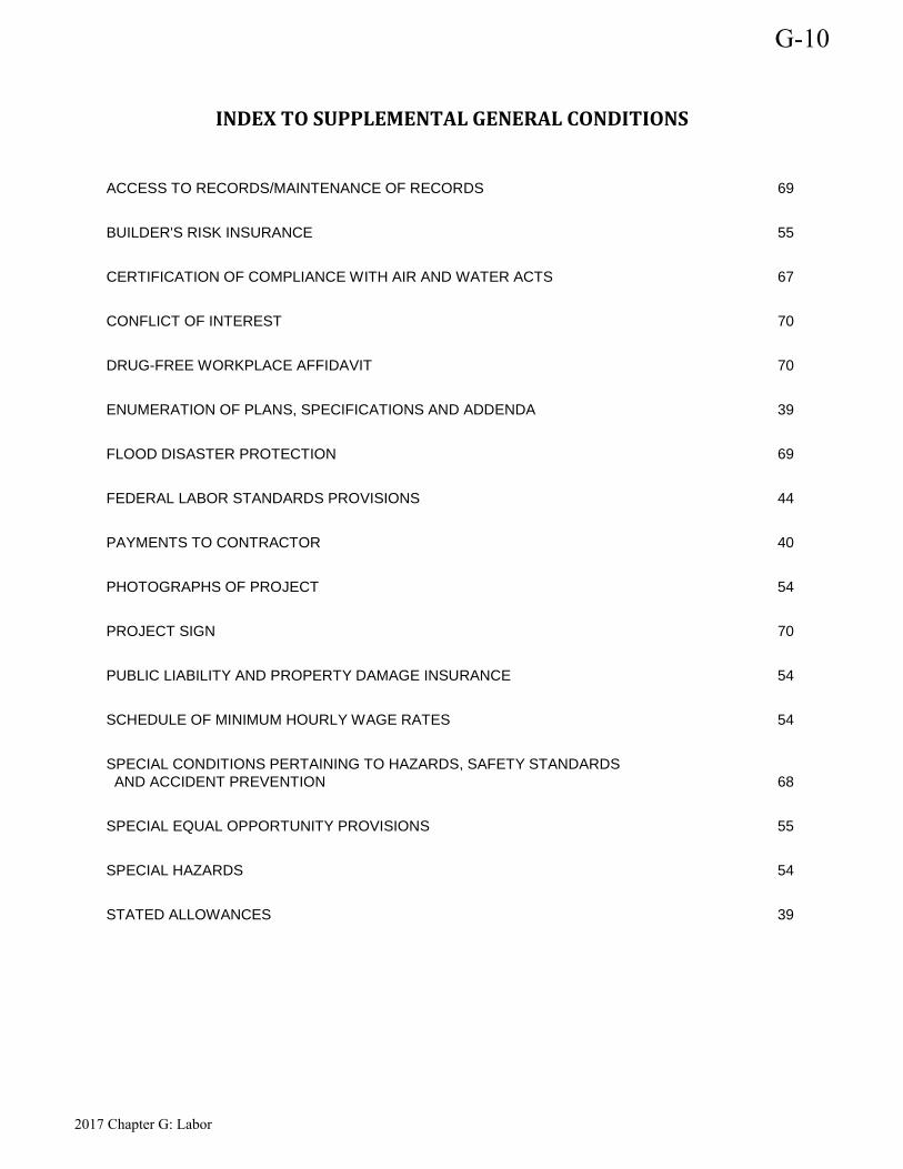
INDEX TO SUPPLEMENTAL GENERAL CONDITIONS
ACCESS TO RECORDS/MAINTENANCE OF RECORDS 69
BUILDER'S RISK INSURANCE 55
CERTIFICATION OF COMPLIANCE WITH AIR AND WATER ACTS 67
CONFLICT OF INTEREST 70
DRUG-FREE WORKPLACE AFFIDAVIT 70
ENUMERATION OF PLANS, SPECIFICATIONS AND ADDENDA 39
FLOOD DISASTER PROTECTION 69
FEDERAL LABOR STANDARDS PROVISIONS 44
PAYMENTS TO CONTRACTOR 40
PHOTOGRAPHS OF PROJECT 54
PROJECT SIGN 70
PUBLIC LIABILITY AND PROPERTY DAMAGE INSURANCE 54
SCHEDULE OF MINIMUM HOURLY WAGE RATES 54
SPECIAL CONDITIONS PERTAINING TO HAZARDS, SAFETY STANDARDS AND ACCIDENT PREVENTION 68
SPECIAL EQUAL OPPORTUNITY PROVISIONS 55
SPECIAL HAZARDS 54
STATED ALLOWANCES 39
G-10
2017 Chapter G: Labor
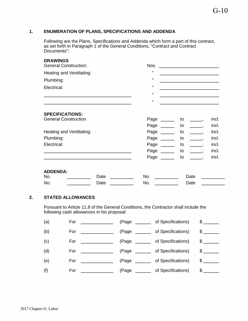
1. ENUMERATION OF PLANS, SPECIFICATIONS AND ADDENDA Following are the Plans, Specifications and Addenda which form a part of this contract, as set forth in Paragraph 1 of the General Conditions, "Contract and Contract Documents": DRAWINGS General Construction: Nos. Heating and Ventilating: " Plumbing: " Electrical: " " "
SPECIFICATIONS: General Construction Page to , incl. Page to , incl. Heating and Ventilating: Page to , incl. Plumbing: Page to , incl. Electrical: Page to , incl. Page to , incl. Page to , incl.
ADDENDA: No. Date No. Date No. Date No. Date
2. STATED ALLOWANCES
Pursuant to Article 11.8 of the General Conditions, the Contractor shall include the following cash allowances in his proposal: (a) For (Page of Specifications) $
(b) For (Page of Specifications) $
(c) For (Page of Specifications) $
(d) For (Page of Specifications) $
(e) For (Page of Specifications) $
(f) For (Page of Specifications) $
G-10
2017 Chapter G: Labor
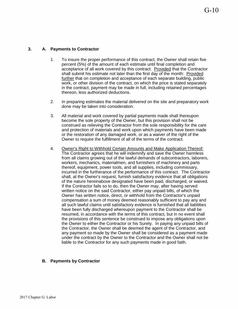
3.
A.
Payments to Contractor
1. To insure the proper performance of this contract, the Owner shall retain five
percent (5%) of the amount of each estimate until final completion and acceptance of all work covered by this contract: Provided that the Contractor shall submit his estimate not later than the first day of the month: Provided further that on completion and acceptance of each separate building, public work, or other division of the contract, on which the price is stated separately in the contract, payment may be made in full, including retained percentages thereon, less authorized deductions.
2. In preparing estimates the material delivered on the site and preparatory work done may be taken into consideration.
3. All material and work covered by partial payments made shall thereupon become the sole property of the Owner, but this provision shall not be construed as relieving the Contractor from the sole responsibility for the care and protection of materials and work upon which payments have been made or the restoration of any damaged work, or as a waiver of the right of the Owner to require the fulfillment of all of the terms of the contract.
4. Owner's Right to Withhold Certain Amounts and Make Application Thereof: The Contractor agrees that he will indemnify and save the Owner harmless from all claims growing out of the lawful demands of subcontractors, laborers, workers, mechanics, materialmen, and furnishers of machinery and parts thereof, equipment, power tools, and all supplies, including commissary, incurred in the furtherance of the performance of this contract. The Contractor shall, at the Owner's request, furnish satisfactory evidence that all obligations of the nature hereinabove designated have been paid, discharged, or waived. If the Contractor fails so to do, then the Owner may, after having served written notice on the said Contractor, either pay unpaid bills, of which the Owner has written notice, direct, or withhold from the Contractor's unpaid compensation a sum of money deemed reasonably sufficient to pay any and all such lawful claims until satisfactory evidence is furnished that all liabilities have been fully discharged whereupon payment to the Contractor shall be resumed, in accordance with the terms of this contract, but in no event shall the provisions of this sentence be construed to impose any obligations upon the Owner to either the Contractor or his Surety. In paying any unpaid bills of the Contractor, the Owner shall be deemed the agent of the Contractor, and any payment so made by the Owner shall be considered as a payment made under the contract by the Owner to the Contractor and the Owner shall not be liable to the Contractor for any such payments made in good faith.
B. Payments by Contractor
G-10
2017 Chapter G: Labor
The Contractor shall pay (a) for all transportation and utility services not later than the 20th day of the calendar month following that in which services are rendered, (b) for all materials, tools, and other expendable equipment to the extent of ninety percent (90%) of the cost thereof, not later than the 20th day of the calendar month following that in which such materials, tools, and equipment are delivered at the site of the project, and the balance of the cost thereof, not later than the 30th day following the completion of that part of the work in or on which such materials, tools, and equipment are incorporated or used, and (c) to each of his subcontractors, not later than the 5th day following each payment to the Contractor, the respective amounts allowed the Contractor on account of the work performed by his subcontractors to the extent of each subcontractor's interest therein.
C. Time for Completion and Liquidated Damages
It is hereby understood and mutually agreed, by and between the Contractor and the Owner, that the date of beginning and the time for completion as specified in the contract of the work to be done hereunder are ESSENTIAL CONDITIONS of this contract; and it is further mutually understood and agreed that the work embraced in this contract shall be commenced on a date to be specified in the "Notice to Proceed". The Contractor agrees that said work shall be prosecuted regularly, diligently, and uninterruptedly at such rate of progress as will insure full completion thereof within the time specified. It is expressly understood and agreed, by and between the Contractor and the Owner, that the time for the completion of the work described herein is a reasonable time for the completion of the same, taking into consideration the average climatic range and usual industrial conditions prevailing in this locality. If the said Contractor shall neglect, fail or refuse to complete the work within the time herein specified, or any proper extension thereof granted by the Owner, then the Contractor does hereby agree, as a part consideration for the awarding of this contract, to pay to the Owner the amount specified in the contract, not as a penalty but as liquidated damages for such breach of contract as hereinafter set forth, for each and every calendar day that the Contractor shall be in default after the time stipulated in the contract for completing the work. The said amount is fixed and agreed upon by and between the Contractor and the Owner because of the impracticability and extreme difficulty of fixing and ascertaining the actual damages the Owner would in such event sustain, and said amount is agreed to be the amount of damages which the Owner would sustain and said amount shall be retained from time to time by the Owner from current periodical estimates.
G-10
2017 Chapter G: Labor
It is further agreed that time is of the essence of each and every portion of this contract and of the specifications wherein a definite and certain length of time is fixed for the performance of any act whatsoever; and where under the contract an additional time is allowed for the completion of any work, the new time limit fixed by such extension shall be of the essence of this contract. Provided that the Contractor shall not be charged with liquidated damages or any excess cost when the Owner determines that the Contractor is without fault and the Contractor's reasons for the time extension are acceptable to the Owner; Provided further that the Contractor shall not to be charged with liquidated damages or any excess cost when the delay in completion of the work is due:
(a) To any preference, priority or allocation order duly issued by the Government.
(b) To unforeseeable cause beyond the control and without the fault or
negligence of the Contractor, including, but not restricted to, acts of God, or of the public enemy, acts of the Owner, acts of another Contractor in the performance of a contract with the Owner, fires, floods, epidemics, quarantine restrictions, strikes, freight embargoes, and severe weather; and
(c) To any delays of Subcontractors or suppliers occasioned by any of the causes specified in subsections (a) and (b) of this article:
Provided further that the Contractor shall, within ten (10) days from the beginning of such delay, unless the Owner shall grant a further period of time prior to the date of final settlement of the contract, notify the Owner, in writing, of the delay and notify the Contractor within a reasonable time of its decision in the matter.
D. Protection of Lives and Health
"The Contractor shall exercise proper precaution at all times for the protection of persons and property and shall be responsible for all damages to persons or property, either on or off the site, which occur as a result of his prosecution of the work. The safety provisions of applicable laws and building and construction codes, in addition to specific safety and health regulations described by Chapter XIII, Bureau of Labor Standards, Department of Labor, Part 1518, Safety and Health Regulations for Construction, as outlined in the Federal Register, Volume 36, No. 75, Saturday, April 17, 1971. Title 29 - LABOR, shall be observed and the Contractor shall take or cause to be taken, such additional safety and health measures as the Contracting Authority may determine to be reasonably necessary."
E. Subcontracts The contractor or subcontractor shall insert in any subcontracts the clauses contained in 29 CFR 5.5 (a)(1) through (10) and such other clauses as the (Department of Housing and Urban Development) may by appropriate instructions require, and also a clause requiring the subcontractors to include these clauses in any lower tier subcontracts. The prime contractor shall be responsible for the compliance by any subcontractor or lower tier subcontractor with all the contract clauses in 29 CFR 5.5.
F. Interest of Member of or Delegate to Congress
G-10
2017 Chapter G: Labor
No member of or Delegate to Congress, or Resident Commissioner, shall be admitted to any share or part of this contract or to any benefit that may arise there from, but this provision shall not be construed to extend to this contract if made with a corporation for its general benefit.
G. Other Prohibited Interests No official of the Owner who is authorized in such capacity and on behalf of the Owner to negotiate, make, accept or approve, or to take part in negotiating, making, accepting, or approving any architectural, engineering, inspection, construction or material supply contract or any subcontract in connection with the construction of the project, shall become directly or indirectly interested personally in this contract or in any part hereof. No officer, employee, architect, attorney, engineer or inspector of or for the Owner who is authorized in such capacity and on behalf of the Owner to exercise any legislative, executive, supervisory or other similar functions in connection with the construction of the project, shall become directly or indirectly interested personally in this contract or in any part thereof, any material supply contract, subcontract, insurance contract, or any other contract pertaining to the project.
H. Use and Occupancy Prior to Acceptance by Owner The Contractor agrees to the use and occupancy of a portion or unit of the project before formal acceptance by the Owner, provided the Owner: (a) Secures written consent of the Contractor except in the event, in the opinion of
the Architect/Engineer, the Contractor is chargeable with unwarranted delay in final clean-up of punch list items or other contract requirements.
(b) Secures endorsement from the insurance carrier and consent of the surety permitting occupancy of the building or use of the project during the remaining period of construction, or,
(c) When the project consists of more than one building, and one of the buildings is occupied, secures permanent fire and extended coverage insurance, including a permit to complete construction. Consent of the surety must also be obtained.
I. Photographs of the Project If required by the Owner, the Contractor shall furnish photographs of the project, in the quantities and as described in the Supplemental General Conditions.
J. Suspension of Work Should the Owner be prevented or enjoined from proceeding with work either before or after the start of construction by reason of any litigation or other reason beyond the control of the Owner, the Contractor shall not be entitled to make or assert claim for damage by reason of said delay; but time for completion of the work will be extended to such reasonable time as the Owner may determine will compensate for time lost by such delay with such determination to be set forth in writing.
4. FEDERAL LABOR STANDARDS PROVISIONS
G-10
2017 Chapter G: Labor
Applicability The Project or Program to which the construction work covered by this contract pertains is being assisted by the United States of America and the following Federal Labor Standards Provisions are included in this Contract pursuant to the provisions applicable to such Federal assistance. A. 1. (i) Minimum Wages
All laborers and mechanics employed or working upon the site of the work (or under the United States Housing Act of 1937 or under the Housing Act of 1949 in the construction or development of the project), will be paid unconditionally and not less often than once a week, and without subsequent deduction or rebate on any account (except such payroll deductions as are permitted by regulations issued by the Secretary of Labor under the Copeland Act (29 CFR Part 3), the full amount of wages and bona fide fringe benefits (or cash equivalents thereof) due at time of payment computed at rates not less than those contained in the wage determination of the Secretary of Labor which is attached hereto and made a part hereof, regardless of any contractual relationship which may be alleged to exist between the contractor and such laborers and mechanics. Contributions made or costs reasonably anticipated for bona fide fringe benefits under Section 1(b)(2) of the Davis-Bacon Act on behalf of laborers or mechanics are considered wages paid to such laborers or mechanics, subject to the provisions of 29 CFR 5.5(a)(1)(iv); also, regular contributions made or costs incurred for more than a weekly period (but not less than often than quarterly) under plans, funds, or programs, which cover the particular weekly period, are deemed to be constructively made or incurred during such weekly period. Such laborers and mechanics shall be paid the appropriate wage rate and fringe benefits on the wage determination for the classification of work actually performed, without regard to skill, except as provided in 29 CFR Part 5.5(a)(iv). Laborers or mechanics performing work in more than one classification may be compensated at the rate specified for each classification for the time actually worked therein: provided, that the employer's payroll records accurately set forth the time spent in each classification in which work is performed. The wage determination (including any additional classification and wage rates conformed under 29 FR Part 5.5(a)(1)(ii) and the Davis-Bacon poster (WH-1321) shall be posted at all times by the contractor and its subcontractors at the site of the work in a prominent and accessible place where it can be easily seen by the workers.
(ii)(a) Any class of laborers or mechanics which is not listed in the wage
determination and which is to be employed under the contract shall be classified in conformance with the wage determination. HUD shall approve an additional classification and wage rate and fringe benefits therefore only when the following criteria have been met:
G-10
2017 Chapter G: Labor

(1) The work to be performed by the classification requested is not performed by a classification in the wage determination; and
(2) The classification is utilized in the area by the construction industry; and
(3) The proposed wage rate, including any bona fide fringe benefits, bears a reasonable relationship to the wage rates contained in the wage determination.
(b) If the contractor and the laborers and mechanics to be employed in the classification (if known), or their representatives, and HUD or its designee agree on the classification and wage rate (including the amount designated for fringe benefits where appropriate), a report of the action taken shall be sent by HUD or its designee to the Administrator of the Wage and Hour Division, Employment Standards Administration, U.S. Department of Labor, Washington, D.C. 20210. The Administrator, or an authorized representative, will approve, modify, or disapprove every additional classification action within 30 days of receipt and so advise HUD or its designee or will notify HUD or its designee within the 30-day period that additional time is necessary. (Approved by the Office of Management and Budget under OMB Control Number 1215-0140.)
(c) In the event the contractor, the laborers or mechanics to be employed in the classification or their representative, and HUD or its designee do not agree on the proposed classification and wage rate (including the amount designated for fringe benefits, where appropriate), HUD or its designee shall refer the questions, including the views of all interested parties and the recommendation of HUD or its designee, to the Administrator for determination. The Administrator, or an authorized representative, will issue a determination within 30 days of receipt and so advise HUD or its designee or will notify HUD or its designee within the 30-day period that additional time is necessary. (Approved by the Office of Management and Budget under OMB Control Number 1215-0140.)
(d) The wage rate (including the fringe benefits where appropriate) determined pursuant to subparagraphs (1)(b) or (c) of this paragraph, shall be paid to all workers performing work in the classification under this contract from the first day on which work is performed in the classification.
(iii) Whenever the minimum wage rate prescribed in the contract for a class of laborers or mechanics includes a fringe benefit which is not expressed as an hourly rate, the contractor shall either pay the benefit as stated in the wage determination or shall pay another bona fide fringe benefit or an hourly cash equivalent thereof.
G-10
2017 Chapter G: Labor
(iv) If the contractor does not make payments to a trustee or other third persons, the contractor may consider as part of the wages of any laborer or mechanic the amount of any costs reasonably anticipated in providing bona fide fringe benefits under a plan or program, provided, that the Secretary of Labor has found, upon the written request of the contractor, that the applicable standards of the Davis-Bacon Act have been met. The Secretary of Labor may require the contractor to set aside in a separate account assets for the meeting of obligations under the plan or program. (Approved by the Office of Management and Budget under OMB Control Number 1215-0140.)
2. Withholding
HUD or its designee shall upon its own action or upon written request of an authorized representative of the Department of Labor withhold or cause to be withheld from the contractor under this contract or any other Federal contract with the same prime contractor, or any other Federally-assisted contract subject to Davis-Bacon prevailing wage requirements, which is held by the same prime contractor so much of the accrued payments or advances as may be considered necessary to pay laborers and mechanics, including apprentices and trainees, employed by the contractor or any subcontractor the full amount of wages required by the contract. In the event of failure to pay any laborer or mechanic, including any apprentice or trainee, employed or working on the site of the work (or under the United States Housing Act of 1937 or under the Housing Act of 1949 in the construction or development of the project), all or part of the wages required by the contract, HUD or its designee may, after written notice to the contractor, sponsor, applicant, or owner, take such action as may be necessary to cause the suspension of any further payment, advance, or guarantee of funds until such violations have ceased. HUD or its designee may, after written notice to the contractor, disburse such amounts withheld for and on account of the contractor or subcontractor to the respective employees to whom they are due. The Comptroller General shall make sure disbursements in the case of direct Davis-Bacon Act contracts.
3. (i) Payrolls and basic records.
G-10
2017 Chapter G: Labor
Payrolls and basic records relating thereto shall be maintained by the contractor during the course of the work preserved for a period of three years thereafter for all laborers and mechanics working at the site of the work (or under the United States Housing Act of 1937, or under the Housing Act of 1949, in the construction or development of the project). Such records shall contain the name, address, and social security number of each such worker, his or her correct classification, hourly rates of wages paid (including rates of contributions or costs anticipated for bona fide fringe benefits or cash equivalents thereof of the types described in Section 1(b)(2)(B) of the Davis-Bacon Act), daily and weekly number of hours worked, deductions made and actual wages paid. Whenever the Secretary of Labor has found under 29 CFR 5.5 (a)(1)(iv) that the wages of any laborer or mechanic include the amount of any costs reasonably anticipated in providing benefits under a plan or program described in Section 1 (b)(2)(B) of the Davis-Bacon Act, the contractor shall maintain records which show that the commitment to provide such benefits is enforceable, that the plan or program is financially responsible, and that the plan or program has been communicated in writing to the laborers or mechanics affected, and records which show the costs anticipated or the actual cost incurred in providing such benefits. Contractors employing apprentices or trainees under approved programs shall maintain written evidence of the registration of apprenticeship programs and certification of trainee programs, the registration of the apprentices and trainees, and the ratios and wage rates prescribed in the applicable programs. (Approved by the Office of Management and Budget under OMB Control Numbers 1215-0140 and 1215-0017.)
(ii)(a) The contractor shall submit weekly for each week in which any contract work is performed a copy of all payrolls to HUD or its designee if the agency is a party to the contract, but if the agency is not such a party, the contractor will submit the payrolls to the applicant, sponsor, or owner, as the case may be, for transmission to HUD or its designee. The payrolls submitted shall set out accurately and completely all of the information required to be maintained under 29 CFR Part 5.5(a)(3)(i). This information may be submitted in any form desired. Optional Form WH-347 is available for this purpose and may be purchased from the Superintendent of Documents (Federal Stock Number 029-005-00014-1), U.S. Government Printing Office, Washington, D.C. 20402. The prime contractor is responsible for the submission of copies of payrolls by all subcontractors. (Approved by the Office of Management and Budget under OMB Control Number 1215-0149).
(b) Each payroll submitted shall be accompanied by a "Statement of Compliance," signed by the contractor or subcontractor or his or her agent who pays or supervises the payment of the persons employed under the contract and shall certify the following: (1) That the payroll for the payroll period contains the
information required to be maintained under 29 CFR Part 5.5(a)(3)(i) and that such information is correct and complete;
G-10
2017 Chapter G: Labor
(2) That each laborer or mechanic (including each apprentice and trainee) employed on the contract during the payroll period has been paid the full weekly wages earned, without rebate, either directly or indirectly, and that no deductions have been made either directly or indirectly from the full wages earned, other than permissible deductions as set forth in 29 CFR Part 3;
(3) That each laborer or mechanic has been paid not less than the applicable wage rates and fringe benefits or cash equivalents for the classification of work performed, as specified in the applicable wage determination incorporated into the contract.
(c) The weekly submission of a properly executed certification set forth on the reverse side of Optional Form WH-347 shall satisfy the requirement for submission of the "Statement of Compliance" required by paragraph A.3.(ii)(b) of this section.
(d) The falsification of any of the above certifications may subject the contractor or subcontractor to civil or criminal prosecution under Section 1001 of Title 18 and Section 231 of Title 31 of the United States Code.
(iii) The contractor or subcontractor shall make the records required under paragraph A.3.(i) of this section available for inspection, copying, or transcription by authorized representative of HUD or its designee or the Department of Labor, and shall permit such representative to interview employees during working hours on the job. If the contractor or subcontractor fails to submit the required records or to make them available, HUD or its designee may, after written notice to the contractor, sponsor, applicant, or owner, take such action as may be necessary to cause the suspension of any further payment, advance, or guarantee of funds. Furthermore, failure to submit the required records upon request or to make such records available may be grounds for debarment action pursuant to 29 CFR Part 5.12.
4. (i) Apprentices.
G-10
2017 Chapter G: Labor
Apprentices will be permitted to work at less than the predetermined rate for the work they performed when they are employed pursuant to and individually registered in a bona fide apprenticeship program registered with the U.S. Department of Labor, Employment and Training Administration, Bureau of Apprenticeship and Training, or with a State Apprenticeship Agency recognized by the Bureau, or if a person is employed in his or her first 90 days of probationary employment as an apprentice in such an apprenticeship program, who is not individually registered in the program, but who has been certified by the Bureau of Apprenticeship and Training or a State Apprenticeship Agency (where appropriate) to be eligible for probationary employment as an apprentice. The allowable ratio of apprentices to journeymen on the job site in any craft classification shall not be greater than the ratio permitted to the contractor as to the entire work force under the registered program. Any worker listed on a payroll at an apprentice wage rate, who is not registered or otherwise employed as stated above, shall be paid not less than the applicable wage rate on the wage determination for the classification of work actually performed. In addition, any apprentice performing work on the job site in excess of the ratio permitted under the registered program shall be paid not less than the applicable wage rate on the wage determination for the work actually performed. Where a contractor is performing construction on a project in a locality other than that in which its program is registered, the ratios and wage rates (expressed in percentages of the journeyman's hourly rate) specified in the contractor's or subcontractor's registered program shall be observed. Every apprentice must be paid at not less than the rate specified in the registered program for the apprentice's level of progress, expressed as a percentage of the journeymen hourly rate specified in the applicable wage determination. Apprentices shall be paid fringe benefits in accordance with the provisions of the apprenticeship program. If the apprenticeship program does not specify fringe benefits, apprentices must be paid the full amount of fringe
G-10
2017 Chapter G: Labor
benefits listed on the wage determination for the applicable classification. If the Administrator determines that a different practice prevails for the applicable apprentice classification, fringes shall be paid in accordance with that determination. In the event the Bureau of Apprenticeship and Training, or a State Apprenticeship Agency recognized by the Bureau, withdraws approval of an apprenticeship program, the contractor will no longer be permitted to utilize apprentices at less than the applicable predetermined rate for the work performed until an acceptable program is approved.
(ii) Trainees.
Except as provided in 29 CFR 5.16, trainees will not be permitted to work at less than the predetermined rate for the work performed unless they are employed pursuant to and individually registered in a program which has received prior approval, evidenced by formal certification by the U.S. Department of Labor, Employment and Training Administration. The ratio of trainees to journeymen on the job site shall not be greater than permitted under the plan approved by the Employment and Training Administration. Every trainee must be paid at not less than the rate specified in the approved program for the trainee's level of progress, expressed as a percentage of the journeyman hourly rate specified in the applicable wage determination. Trainees shall be paid fringe benefits in accordance with the provisions of the trainee program. If the trainee program does not mention fringe benefits, trainees shall be paid the full amount of fringe benefits listed on the wage determination unless the Administrator of the Wage and Hour Division determines that there is an apprenticeship program associated with the corresponding journeyman wage rate on the wage determination which provides for less than full fringe benefits for apprentices. Any employee listed on the payroll at a trainee rate who is not registered and participating in a training plan approved by the Employment and Training Administration shall be paid not less than the applicable wage rate on the wage determination for the work actually performed. In addition, any trainee performing work on the job site in excess of the ratio permitted under the registered program shall be paid not less than the applicable wage rate on the wage determination for the work actually performed. In the event the Employment and Training Administration withdraws approval of a training program, the contractor will no longer be permitted to utilize trainees at less than the applicable predetermined rate for the work performed until an acceptable program is approved.
(iii) Equal employment opportunity.
The utilization of apprentices, trainees and journeyman under this part shall be in conformity with the equal employment opportunity requirements of Executive Order 11246, as amended, and 29 CFR Part 30.
5. Compliance with Copeland Act requirements.
The contractor shall comply with the requirements of 29 CFR Part 3 which are incorporated by reference in this contract.
G-10
2017 Chapter G: Labor
6. Subcontracts.
The contractor or subcontractor will insert in any subcontracts the clauses contained in 29 CFR 5.5(a)(1) through (10) and such other clauses as HUD or its designee may by appropriate instructions require, and also a clause requiring the subcontractors to include these clauses in any lower tier subcontracts. The prime contractor shall be responsible for the compliance by any subcontractor or lower tier subcontractor with all the contract clauses in 29 CFR Part 5.5
7. Contract termination; debarment.
A breach of the contract clauses in 29 CFR 5.5 may be grounds for termination of the contract, and for debarment as a contractor and a subcontractor as provided in 29 CFR 5.12.
8. Compliance with Davis-Bacon and Related Act Requirements.
All rulings and interpretations of the Davis-Bacon and Related Acts contained in 29 CFR Parts 1, 3, and 5 are herein incorporated by reference in this contract.
9. Disputes concerning labor standards.
Disputes arising out of the labor standards provisions of this contract shall not be subject to the general disputes clause of this contract. Such disputes shall be resolved in accordance with the procedures of the Department of Labor set forth in 29 CFR Parts 5, 6, and 7. Disputes within the meaning of this clause include disputes between the contractor (or any of its subcontractors) and HUD or its designee, the U.S. Department of Labor, or the employees or their representatives.
G-10
2017 Chapter G: Labor

10. Certification of Eligibility.
(i) By entering into this contract, the contractor certifies that neither it (nor he or she) nor any person or firm who has an interest in the contractor's firm is a person or firm ineligible to be awarded Government contracts by virtue of Section 3(a) of the Davis-Bacon Act or 29 CFR 5.12(a)(1) or to be awarded HUD contracts or participate in HUD programs pursuant to 24 CFR Part 24. (ii) No part of this contract shall be subcontracted to any person or firm ineligible for award of a Government contract by virtue of Section 3(a) of the Davis-Bacon Act or 29 CFR 5.12(a)(1) or to be awarded HUD contracts or participate in HUD programs pursuant to 24 CFR Part 24. (iii) The penalty for making false statements is prescribed in the U.S. Criminal Code, 18 U.S.C. 1001. Additionally, U.S. Criminal Code, Section 1010, Title 18, U.S.C., "Federal Housing Administration transactions", provides in part "Whoever, for the purpose of ...influencing in any way the action of such Administration ...makes, utters or publishes any statement, knowing the same to be false ...shall be fined not more than $5,000 or imprisoned not more than two years, or both."
11. Complaints, Proceedings, or Testimony by Employees.
No laborer or mechanic to whom the wage, salary, or other labor standards provisions of this Contract are applicable shall be discharged or in any other manner discriminated against by the Contractor or any subcontractor because such employee has filed any complaint or instituted or caused to be instituted any proceeding or has testified or is about to testify in any proceeding under or relating to the labor standards applicable under this Contract to his employer.
B. Contract Work Hours and Safety Standards Act
As used in this paragraph, the terms "laborers" and "mechanics" include watchmen and guards. 1. Overtime requirements.
No contractor or subcontractor contracting for any part of the contract work which may require or involve the employment of laborers or mechanics shall require or permit any such laborer or mechanic in any workweek in which he or she is employed on such work to work in excess of forty hours in such workweek unless such laborer or mechanic receives compensation at a rate not less than one and one-half times the basic rate of pay for all hours worked in excess of forty hours in such workweek.
2. Violation; liability for unpaid wages, liquidated damages.
G-10
2017 Chapter G: Labor
In the event of any violation of the clause set forth in subparagraph (1) of this paragraph, the contractor and any subcontractor responsible therefore shall be liable for the unpaid wages. In addition, such contractor and subcontractor shall be liable to the United States (in the case of work done under contract for the District of Columbia or a territory, to such District or to such territory), for liquidated damages. Such liquidated damages shall be computed with respect to each individual laborer or mechanic, including watchmen and guards, employed in violation of the clause set forth in subparagraph (1) of this paragraph, in the sum of $10 for each calendar day on which such individual was required or permitted to work in excess of the standard workweek of forty hours without payment of the overtime wages required by the clause set forth in subparagraph (1) of this paragraph.
3. Withholding for unpaid wages and liquidated damages.
HUD or its designee shall upon its own action or upon written request of an authorized representative of the Department of Labor withhold or cause to be withheld, from any moneys payable on account of work performed by the contractor or subcontractor under any such contract or any other Federal contract with the same prime contract, or any other Federally-assisted contract subject to the Contract Work Hours and Safety Standards Act, which is held by the same prime contractor such sums as may be determined to be necessary to satisfy any liabilities of such contractor or subcontractor for unpaid wages and liquidated damages as provided in the clause set forth in subparagraph (2) of this paragraph.
4. Subcontracts.
The contractor or subcontractor shall insert in any subcontracts the clauses set forth in subparagraph (1) through (4) of this paragraph and also a clause requiring the subcontractors to include these clauses in any lower tier subcontracts. The prime contractor shall be responsible for compliance by any subcontractor or lower tier subcontractor with the clauses set forth in subparagraphs (1) through (4) of this paragraph.
C. Health and Safety
G-10
2017 Chapter G: Labor
1. No laborer or mechanic shall be required to work in surroundings or under working conditions which are unsanitary, hazardous, or dangerous to his health and safety as determined under construction safety and health standards promulgated by the Secretary of Labor by regulation. 2. The contractor shall comply with all regulations issued by the Secretary of Labor pursuant to Title 29 Part 1926 (formerly part 1518) and failure to comply may result in imposition of sanctions pursuant to the Contract Work Hours and Safety Standards Act (Public Law 91-54, 83 Stat. 96). 3. The Contractor shall include the provisions of this Article in every subcontract so that such provisions will be binding on each subcontractor. The Contractor shall take such action with respect to any subcontract as the Secretary of Housing and Urban Development or the Secretary of Labor shall direct as a means of enforcing such provisions.
5. SPECIAL HAZARDS
The Contractor's and his Subcontractor's Public Liability and Property Damage Insurance shall provide adequate protection against the following special hazards:
6. CONTRACTOR'S AND SUBCONTRACTOR'S PUBLIC LIABILITY, VEHICLE LIABILITY, AND PROPERTY DAMAGE INSURANCE As required under Article 5 of the General Conditions, the Contractor's Public Liability Insurance and Vehicle Liability Insurance shall be in an amount not less than $___________ for injuries, including accidental death, to any one person, and subject to the same limit for each person, in an amount not less than $____________ on account of one accident, and Contractor's Property Damage Insurance in an amount not less than $___________. The Contractor shall either (1) require each of his subcontractors to procure and to maintain during the life of his subcontract, Subcontractor's Public Liability and Property Damage Insurance of this type and in the same amounts as specified in the preceding paragraph, or (2) insure the activities of his subcontractors in his own policy.
7. PHOTOGRAPHS OF PROJECT As provided in Paragraph 3.I of the Supplemental General Conditions, the Contractor will furnish photographs in the number, type, and stage as enumerated below:
8. SCHEDULE OF OCCUPATIONAL CLASSIFICATIONS AND MINIMUM HOURLY WAGE RATES AS REQUIRED UNDER PARAGRAPH 4.B OF THE SUPPLEMENTAL GENERAL CONDITIONS Given on Pages _______, _______ and _______.
G-10
2017 Chapter G: Labor
9. BUILDER'S RISK INSURANCE As provided in the General Conditions, Article 5.6, the Contractor will/will not** maintain Builder's Risk Insurance (fire and extended coverage) on a 100 percent completed value basis on the insurable portions of the project for the benefit of the Owner, the Contractor, and all Subcontractors, as their interests may appear. _______________________ ** Strike out one.
10. SPECIAL EQUAL OPPORTUNITY PROVISIONS
A. Activities and Contracts Not Subject to Executive Order 11246, as Amended
(Applicable to Federally assisted construction contracts and related subcontracts $10,000 and under.) During the performance of this contract, the Contractor agrees as follows: 1. The Contractor shall not discriminate against any employee or applicant for
employment because of race, color, religion, sex, or national origin. The Contractor shall take affirmative action to ensure that applicants for employment are employed, and that employees are treated during employment, without regard to their race, color, religion, sex, or national origin. Such action shall include, but not be limited to, the following: employment, upgrading, demotion, or transfer; recruitment or recruitment advertising; layoff or termination; rates of pay or other forms of compensation; and selection for training, including apprenticeship.
2. The Contractor shall post in conspicuous places, available to employees and applicants for employment, notices to be provided by Contracting Officer setting forth the provisions of this nondiscrimination clause. The Contractor shall state that all qualified applicants will receive consideration for employment without regard to race, color, religion, sex, or national origin.
3. Contractors shall incorporate foregoing requirements in all subcontracts.
B. Executive Order 11246 (contracts/subcontracts above $10,000) 1. Section 202 Equal Opportunity Clause
During the performance of this contract, the Contractor agrees as follows:
G-10
2017 Chapter G: Labor
a. The Contractor will not discriminate against any employee or applicant for employment because of race, color, religion, sex, or national origin. The Contractor will take affirmative action to ensure that applicants are employed, and that employees are treated during employment, without regard to their race, color, religion, sex, or national origin. Such action shall include, but not be limited to, the following: employment, upgrading, demotion, or transfer; recruitment, or recruitment advertising; layoff or termination; rates of pay or other forms of compensation; and selection for training, including apprenticeship. The Contractor agrees to post in conspicuous places, available to employees and applicants for employment, notices to be provided setting forth the provisions of this nondiscrimination clause.
b. The Contractor will, in all solicitations or advertisements for employees placed by or on behalf of the Contractor, state that all qualified applicants will receive consideration without regard to race, color, religion, sex, or national origin.
c. The Contractor will send to each labor union or representative of workers with which he has a collective bargaining agreement or other contract or understanding a notice to be provided by the Contract Compliance Officer advising the said labor union or workers' representatives of the Contractor's commitment under this section, and shall post copies of the notice in conspicuous places available to employees and applicants for employment.
d. The Contractor will comply with all provisions of Executive Order 11246 of September 24, 1965, and of the rules, regulations, and relevant orders of the Secretary of Labor.
e. The Contractor will furnish all information and reports required by Executive Order 11246 of September 24, 1965, and by rules, regulations, and orders of the Secretary of Labor, or pursuant thereto, and will permit access to his books, records, and accounts by the Department of the Secretary of Labor for purposes of investigation to ascertain compliance with such rules, regulations, and others.
f. In the event of the Contractor's noncompliance with the nondiscrimination clauses of this contract or with any of the said rules, regulations, or orders, this contract may be cancelled, terminated, or suspended in whole or in part and the Contractor may be declared ineligible for further Government contracts in accordance with procedures authorized in Executive Order 11246 of September 24, 1965, or by rule, regulation, or order of the Secretary of Labor, or as otherwise provided by law.
G-10
2017 Chapter G: Labor
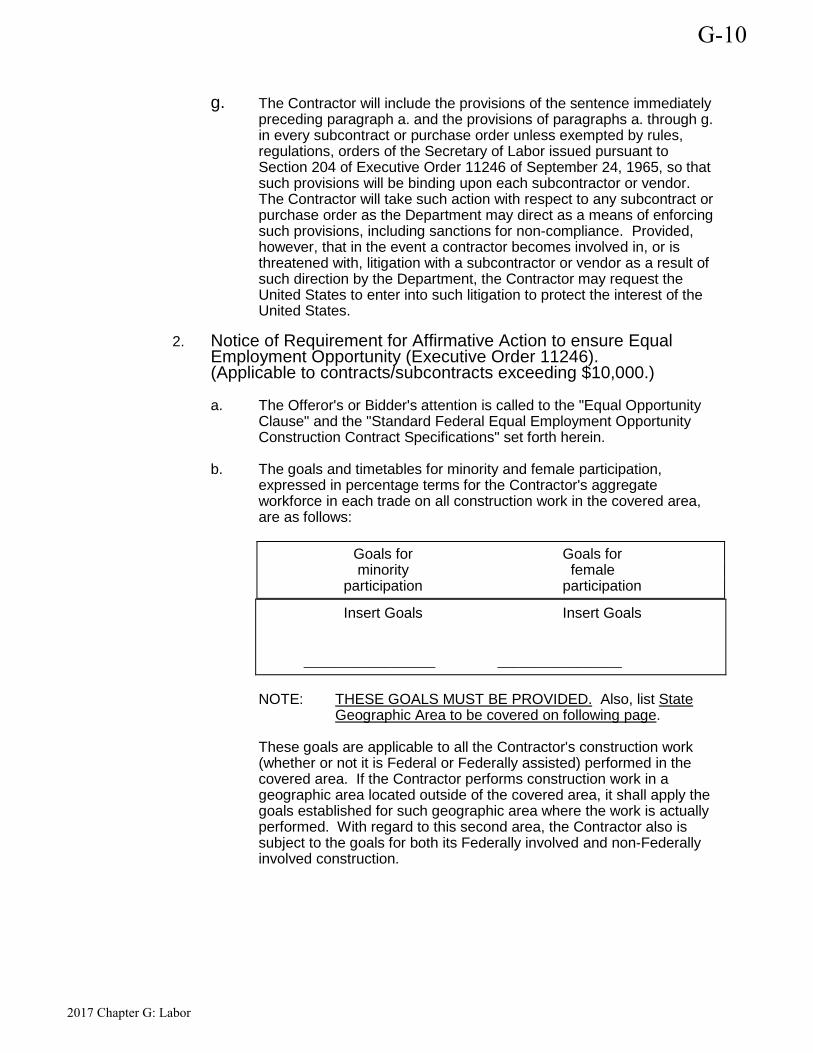
g. The Contractor will include the provisions of the sentence immediately preceding paragraph a. and the provisions of paragraphs a. through g. in every subcontract or purchase order unless exempted by rules, regulations, orders of the Secretary of Labor issued pursuant to Section 204 of Executive Order 11246 of September 24, 1965, so that such provisions will be binding upon each subcontractor or vendor. The Contractor will take such action with respect to any subcontract or purchase order as the Department may direct as a means of enforcing such provisions, including sanctions for non-compliance. Provided, however, that in the event a contractor becomes involved in, or is threatened with, litigation with a subcontractor or vendor as a result of such direction by the Department, the Contractor may request the United States to enter into such litigation to protect the interest of the United States.
2. Notice of Requirement for Affirmative Action to ensure Equal Employment Opportunity (Executive Order 11246). (Applicable to contracts/subcontracts exceeding $10,000.)
a. The Offeror's or Bidder's attention is called to the "Equal Opportunity Clause" and the "Standard Federal Equal Employment Opportunity Construction Contract Specifications" set forth herein.
b. The goals and timetables for minority and female participation, expressed in percentage terms for the Contractor's aggregate workforce in each trade on all construction work in the covered area, are as follows: Goals for Goals for minority female participation participation
Insert Goals Insert Goals
__________________ _________________ NOTE:
THESE GOALS MUST BE PROVIDED. Also, list State Geographic Area to be covered on following page.
These goals are applicable to all the Contractor's construction work (whether or not it is Federal or Federally assisted) performed in the covered area. If the Contractor performs construction work in a geographic area located outside of the covered area, it shall apply the goals established for such geographic area where the work is actually performed. With regard to this second area, the Contractor also is subject to the goals for both its Federally involved and non-Federally involved construction.
G-10
2017 Chapter G: Labor
The contractor's compliance with the Executive Order and the regulations in 41 CFR Part 60-4 shall be based on its implementation of the Equal Opportunity Clause, specific affirmative action obligations required by the specifications set forth in 41 CFR 60-4.3(a), and its efforts to meet the goals established for the geographical area where the contract resulting from this solicitation is to be performed. The hours of minority and female employment and training must be substantially uniform throughout the length of the contract, and in each trade, and the Contractor shall make a good faith effort to employ minorities and women evenly on each of its projects. The transfer of minority or female employees or trainees from Contractor to Contractor or from project to project for the sole purpose of meeting the Contractor's goals shall be a violation of the contract, the Executive Order, and the regulations in 41 CFR Part 60-4. Compliance with the goals will be measured against the total work hours performed.
c. The Contractor shall provide written notification to the Director of the Office of Federal Contract Compliance Programs within 10 working days of award of any construction subcontract in excess of $10,000 at any tier for construction work under the contract resulting from this solicitation. The notification shall list the name, address, and telephone number of the subcontractor; employer identification number; estimated dollar amount of the subcontract; estimated starting and completion dates of the subcontract; and the geographical area in which the contract is to be performed.
d. As used in this Notice, and in the contract resulting from this solicitation, the "covered area" is _______________________ __________________________________________________.
3. Standard Federal Equal Employment Opportunity Construction Contract Specifications (Executive Order 11246) a. As used in these specifications:
(1) "Covered area" means the geographical area described in the
solicitation from which this contract resulted;
(2) "Director" means Director, Office of Federal Contract Compliance Programs, United States Department of Labor, or any person to whom the Director delegates authority;
(3) "Employer identification number" means the federal social security number used on the Employer's Quarterly Federal Tax Return, U.S. Treasury Department Form 941;
(4) "Minority" includes: (a) Black (all persons having origins in any of the Black African
racial groups not of Hispanic origin);
G-10
2017 Chapter G: Labor
(b) Hispanic (all persons of Mexican, Puerto Rican, Cuban, Central or South America or other Spanish Culture or origin, regardless of race);
(c) Asian and Pacific Islander (all persons having origins in any of the original peoples of the Far East, Southeast Asia, the Indian Subcontinent, or the Pacific Islands);
(d) American Indian or Alaskan Native (all persons having origins in any of the original peoples of North America and maintaining identifiable tribal affiliations through membership and participation or community identification).
b. Whenever the Contractor, or any Subcontractor at any tier, subcontracts a portion of the work involving any construction trade, it shall physically include in each subcontract in excess of $10,000 the provisions of these specifications and the Notice which contains the applicable goals for minority and female participation and which is set forth in the solicitations from which this contract resulted.
c. If the Contractor is participating (pursuant to 41 CFR 60-4.5) in a Hometown Plan approved by the U.S. Department of Labor in the covered area either individually or through an association, its affirmative action obligations on all work in the Plan area (including goals and timetables) shall be in accordance with that Plan for those trades which have unions participating in the Plan. Contractors must be able to demonstrate their participation in and compliance with the provisions of any such Hometown Plan. Each Contractor or Subcontractor participating in an approved Plan is individually required to comply with its obligations under the EEO clause, and to make a good faith effort to achieve each goal under the Plan in each trade in which it has employees. The overall good faith performance by other Contractors or Subcontractors toward a goal in an approved Plan does not excuse any covered Contractor's or Subcontractor's failure to take good faith efforts to achieve the Plan goals and timetables.
G-10
2017 Chapter G: Labor
d. The Contractor shall implement the specific affirmative action standards provided in paragraphs g.(1) through (16) of these specifications. The goals set forth in the solicitation from which this contract resulted are expressed as percentages of the total hours of employment and training of minority and female utilization the Contractor should reasonably be able to achieve in each construction trade in which it has employees in the covered area. Covered construction contractors performing contracts in geographical areas where they do not have a Federal or Federally-assisted construction contract shall apply the minority and female goals established for the geographic area where the contract is being performed. Goals are published periodically in the Federal Register in notice form and such notices may be obtained from any Office of Federal Contract Compliance Programs office or from Federal procurement contracting officers. The Contractor is expected to make substantially uniform progress in meeting its goals in each craft during the period specified.
e. Neither the provisions of any collective bargaining agreement, nor the failure by a union with whom the Contractor has a collective bargaining agreement, to refer either minorities or women shall excuse the Contractor's obligations under these specifications, Executive Order 11246, or the regulations promulgated pursuant thereto.
f. In order for the nonworking training hours of apprentices and trainees to be counted in meeting the goals, such apprentices and trainees must be employed by the Contractor during the training period, and the Contractor must have made a commitment to employ the apprentices and trainees at the completion of their training, subject to the availability of employment opportunities. Trainees must be trained pursuant to training programs approved by the U.S. Department of Labor.
g. The Contractor shall take specific affirmative actions to ensure equal employment opportunity. The evaluation of the Contractor's compliance with these specifications shall be based upon its effort to achieve maximum results from its actions. The Contractor shall document these efforts fully, and shall implement affirmative action steps at least as extensive as the following:
G-10
2017 Chapter G: Labor
(1) Ensure and maintain a working environment free of harassment, intimidation, and coercion at all sites, and in all facilities at which the Contractor's employees are assigned to work. The Contractor, where possible, will assign two or more women to each construction project. The Contractor shall specifically ensure that all foremen, superintendents, and other on-site supervisory personnel are aware of and carry out the Contractor's obligation to maintain such a working environment, with specific attention to minority or female individuals working at such sites or in such facilities.
(2) Establish and maintain a current list of minority and female recruitment sources, provide written notification to minority and female recruitment sources and to community organizations when the Contractor or its union have employment opportunities available, and maintain a record of the organization’s responses.
(3) Maintain a current file of the names, addresses, and telephone numbers of each minority and female off-the-street applicant and minority or female referral from a union, a recruitment source, or community organization and of what action was taken with respect to each such individual. If such individual was sent to the union hiring hall for referral and was not referred back to the Contractor by the union or, if referred, not employed by the Contractor, this shall be documented in the file with the reason therefore, along with whatever additional actions the Contractor may have taken.
(4) Provide immediate written notification to the Director when the union or unions with which the Contractor has a collective bargaining agreement has not referred to the Contractor a minority person or woman sent by the Contractor, or when the Contractor has other information that the union referral process has impeded the Contractor's efforts to meet its obligations.
(5) Develop on-the-job training opportunities and/or participate in training programs for the area which expressly include minorities and women, including upgrading programs and apprenticeship and trainee programs relevant to the Contractor's employment needs, especially those programs funded or approved by the Department of Labor. The Contractor shall provide notice of these programs to the sources compiled under g.(2) above.
G-10
2017 Chapter G: Labor
(6) Disseminate the Contractor's EEO policy by providing notice of the policy to unions and training programs and requesting their cooperation in assisting the Contractor in meeting its EEO obligations; by including it in any policy manual and collective bargaining agreement; by publicizing it in the company newspaper, annual report, etc.; by specific review of the policy with all management personnel and with all minority and female employees at least once a year; and by posting the company's EEO policy on bulletin boards accessible to all employees at each location where construction work is performed.
(7) Review, at least annually, the company's EEO policy and affirmative action obligations under these specifications with all employees having any responsibility for hiring, assignment, layoff, termination, or other employment decisions including specific review of these items with on-site supervisory personnel such as Superintendents, General Foremen, etc., prior to the initiation of construction work at any job site. A written record shall be made and maintained identifying the time and place of these meetings, persons attending, subject matter discussed, and disposition of the subject matter.
(8) Disseminate the Contractor's EEO policy externally by including it in any advertising in the news media, specifically including minority and female news media, and providing written notification to and discussing the Contractor's EEO policy with other Contractors and Subcontractors with whom the Contractor does or anticipates doing business.
(9) Direct its recruitment efforts, both oral and written, to minority, female and community organizations, to schools with minority and female students and to minority and female recruitment and training organizations serving the Contractor's recruitment area and employment needs. Not later than one month prior to the date of the acceptance of applications for apprenticeship or other training by any recruitment source, the Contractor shall send written notification to organizations such as the above, describing the openings, screening procedures, and tests to be used in the selection process.
(10) Encourage present minority and female employees to recruit other minority persons and women and, where reasonable, provide after school, summer, and vacation employment to minority and female youth both on the site and in other areas of a Contractor's work force.
G-10
2017 Chapter G: Labor
(11) Validate all tests and other selection requirements where there is an obligation to do so under 41 CFR part 60-3.
(12) Conduct, at least annually, an inventory and evaluation at least of all minority and female personnel for promotional opportunities and encourage these employees to seek or to prepare for, through appropriate training, etc., such opportunities.
(13) Ensure that seniority practices, job classifications, work assignments and other personnel practices, do not have a discriminatory effect by continually monitoring all personnel and employment related activities to ensure that the EEO policy and the Contractor's obligations under these specifications are being carried out.
(14) Ensure that all facilities and company activities are nonsegregated except that separate or single-user toilet and necessary changing facilities shall be provided to assure privacy between the sexes.
(15) Document and maintain a record of all solicitations of offers for subcontracts from minority and female construction contractors and suppliers, including circulation of solicitations to minority and female contractor associations and other business associations.
(16) Conduct a review, at least annually, of all supervisors' adherence to and performance under the Contractor's EEO policies and affirmative action obligations.
h. Contractors are encouraged to participate in voluntary associations which assist in fulfilling one or more of their affirmative action obligations g.(1) through (16). The efforts of a contractor association, joint contractor-union, contractor-community, or other similar group of which the Contractor is a member and participant, may be asserted as fulfilling any one or more of its obligations under g.(1) through (16) of these Specifications provided that the Contractor actively participates in the group, makes every effort to assure that the group has a positive impact on the employment of minorities and women in the industry, ensures that the concrete benefits of the program are reflected in the Contractor's minority and female workforce participation, makes a good faith effort to meet its individual goals and timetables, and can provide access to documentation which demonstrates the effectiveness of actions taken on behalf of the Contractor. The obligation shall not be a defense for the Contractor's non-compliance.
G-10
2017 Chapter G: Labor
i. A single goal for minorities and a separate single goal for women have been established. The Contractor, however, is required to provide equal employment opportunity and to take affirmative action for all minority groups, both male and female, and all women, both minority and non-minority. Consequently, the Contractor may be in violation of the Executive Order if a particular group is employed in a substantially disparate manner (for example, even though the Contractor has achieved its goals for women generally the Contractor may be in violation of the Executive Order if a specific minority group of women is underutilized).
j. The Contractor shall not use the goals and timetables or affirmative action standards to discriminate against any person because of race, color, religion, sex, or national origin.
k. The Contractor shall not enter into any Subcontract with any person or firm debarred from Government contracts pursuant to Executive Order 11246.
l. The Contractor shall carry out such sanctions and penalties for violation of these specifications and of the Equal Opportunity Clause, including suspension, termination and cancellation of existing subcontracts as may be imposed or ordered pursuant to Executive Order 11246, as amended, and its implementing regulations, by the Office of Federal Contract Compliance Programs. Any contractor who fails to carry out such sanctions and penalties shall be in violation of these specifications and Executive Order 11246, as amended.
m. The Contractor, in fulfilling its obligations under these specifications, shall implement specific affirmative action steps, at least as extensive as those standards prescribed in paragraph g. of these specifications, so as to achieve maximum results from its efforts to ensure equal employment opportunity. If the Contractor fails to comply with the requirements of the Executive Order, the implementing regulations, or these specifications, the Director shall proceed in accordance with 41 CFR 60-4.8.
G-10
2017 Chapter G: Labor
n. The Contractor shall designate a responsible official to monitor all employment related activity to ensure that the company's EEO policy is being carried out, to submit reports relating to the provisions hereof as may be required by the Government and to keep records. Records shall at least include for each employee, the name, address, telephone numbers, construction trade, union affiliation if any, employee identification number where assigned, social security number, race, sex, status (e.g., mechanic, apprentice trainee, helper, or laborer), dates of changes in status, hours worked per week in the indicated trade, rate of pay, and location at which the work was performed. Records shall be maintained in an easily understandable and retrievable form; however, to the degree that existing records satisfy this requirement, contractor shall not be required to maintain separate records.
o. Nothing herein provided shall be construed as a limitation upon the application of other laws which establish different standards of compliance or upon the application of requirements for the hiring of local or other area residents (e.g., those under the Public Works Employment Act of 1977 and the Community Development Block Grant Program).
C. Certification of Nonsegregated Facilities (Over $10,000) By the submission of this bid, the bidder, offeror, applicant or subcontractor certifies that he/she does not maintain or provide for his/her employees any segregated facility at any of his/her establishments, and that he/she does not permit employees to perform their services at any location, under his/her control, where segregated facilities are maintained. He/She certifies further that he/she will not maintain or provide for employees any segregated facilities at any of his/her establishments, and he/she will not permit employees to perform their services at any location under his/her control where segregated facilities are maintained. The bidder, offeror, applicant or subcontractor agrees that a breach of this certification is a violation of the Equal Opportunity Clause of this contract. As used in this certification, the term "segregated facilities" means any waiting rooms, work areas, rest rooms and wash rooms, restaurants and other eating areas, time clocks, locker rooms, and other storage or dressing areas, ***transportation and housing facilities provided for employees which are segregated on the basis of race, color, religion, or are in fact segregated on the basis of race, color, religion, or otherwise. He/She further agrees that (except where he/she has obtained identical certifications from proposed subcontractors for specific time periods) he/she will obtain identical certification from proposed subcontractors prior to the award of subcontracts exceeding $10,000 which are not exempt from the provisions of the Equal Opportunity Clause; that he/she will retain such certifications in his/her files; and that he/she will forward the following notice to such proposed subcontractors (except where proposed subcontractors have submitted identical certifications for specific time periods).
D. Civil Rights Act of 1964
G-10
2017 Chapter G: Labor
Under Title VI of the Civil Rights Act of 1964, no person shall, on the grounds of race, color, or national origin, be excluded from participation in, be denied the benefits of, or be subjected to discrimination under any program or activity receiving Federal financial assistance.
E. Section 109 of the Housing and Community Development Act of 1974 No person in the United States shall on the grounds of race, color, national origin, or sex be excluded from participation in, be denied the benefits of, or be subjected to discrimination under any program or activity funded in whole or in part with funds made available under this title.
F. "The Section 3 Clause" 1. The work to be performed under this contract is on a project assisted
under a program providing direct Federal financial assistance from the Department of Housing and Urban Development and is subject to the requirements of section 3 of the Housing Urban Development Act of 1968, as amended, 12 U.S.C. 1701u. Section 3 requires that to the greatest extent feasible, opportunities for training and employment be given to lower income residents of the area of the Section 3 covered project, and contracts for work in connection with the project be awarded to business concerns which are located in, or owned in substantial part by persons residing in the area of the Section 3 covered project.
2. The parties to this contract will comply with the provisions of said Section 3 and the regulations issued pursuant thereto by the Secretary of Housing and Urban Development set forth in 24 Part CFR 135, and all applicable rules and orders of the Department issued thereunder prior to the execution of this contract. The parties to this contract certify and agree that they are under no contractual or other disability which would prevent them from complying with these requirements.
3. The contractor will send to each labor organization or representative of workers with which he has a collective bargaining agreement or other contract or understanding, if any, a notice advising the said labor organization or workers' representative of his commitments under this Section 3 clause and shall post copies of the notice in conspicuous places available to employees and applicants for employment or training.
4. The contractor will include this Section 3 clause in every subcontract for work in connection with the project and will, at the direction of the applicant for or recipient of Federal Financial assistance, take appropriate action pursuant to the subcontract upon a finding that the subcontractor is in violation of regulations issued by the Secretary of Housing and Urban Development, 24 CFR Part 135. The contractor will not subcontract with any subcontractor where it has notice or knowledge that the latter has been found in violation of regulations under 24 CFR part 135 and will not let any subcontract unless the subcontractor has first provided it with a preliminary statement of ability to comply with the requirements of these regulations.
G-10
2017 Chapter G: Labor

5. Compliance with the provisions of Section 3, the regulations set forth in 24 CFR Part 135, and all applicable rules and orders of the Department issued thereunder prior to the execution of the contract, shall be a condition of the Federal financial assistance provided to the project, binding upon the applicant or recipient, its contractors and subcontractors, its successors, and assigns to those sanctions specified by the grant or loan agreement or contract through which Federal assistance is provided, and to such sanctions as are specified by 24 CFR Part 135.
G. Age Discrimination Act of 1975 No person in the United States shall, on the basis of age, be excluded from participation in, be denied the benefits of, or be subjected to discrimination under, any program or activity receiving Federal financial assistance.
H. Section 504 Handicapped Non-Discrimination for Handicapped Workers No otherwise qualified handicapped individual in the U.S., as defined in Section 7, Paragraph 6 of the Rehabilitation Act of 1973 shall, solely by reason of this handicap, be excluded from the participation in, be denied the benefits of, or be subjected to discrimination under any program or activity receiving Federal financial assistance.
11. CERTIFICATION OF COMPLIANCE WITH AIR AND WATER ACTS (Applicable to Federally assisted construction contracts and related subcontracts exceeding $100,000) Compliance with Air and Water Acts During the performance of this contract the contractor and all subcontractors shall comply with the requirements of the Clean Air Act, as amended, 42 USC 1857 et seq., the Federal Water Pollution Control Act, as amended, 33 USC 1251 et seq., and the regulations of the Environmental Protection Agency with respect thereto, at 40 CFR Part 15, as amended. In addition to the foregoing requirements, all nonexempt contractors and subcontractors shall furnish to the Owner, the following:
1. A stipulation by the Contractor or subcontractors, that any facility to be utilized in the performance of any nonexempt contract or subcontract, is not listed on the List of Violating Facilities issued by the Environmental Protection Agency (EPA) pursuant to 40 CFR 15.20.
G-10
2017 Chapter G: Labor
2. Agreement by the Contractor to comply with all the requirements of Section 114 of the Clean Air Act, as amended, (42 USC 1857c-8) and Section 308 of the Federal Water Pollution Control Act, as amended, (33 USC 1318) relating to inspection, monitoring, entry, reports and information, as well as all other requirements specified in said Section 114 and Section 308, and all regulations and guidelines issued thereunder.
3. A stipulation that as a condition for the award of the contract, prompt notice will be given of any notification received from the Director, Office of Federal Activities, EPA, indicating that a facility utilized, or to be utilized for the contract, is under consideration to be listed on the EPA List of Violating Facilities.
4. Agreement by the Contractor that he will include, or cause to be included, the criteria and requirements in paragraph (1) through (4) of this section in every nonexempt subcontract and requiring that the Contractor will take such action as the Government may direct as a means of enforcing such provisions.
12. SPECIAL CONDITIONS PERTAINING TO HAZARDS, SAFETY STANDARDS AND ACCIDENT PREVENTION A. Lead-Based Paint Hazards
(Applicable to contracts for construction or rehabilitation of residential structures.) The construction or rehabilitation of residential structures is subject to the HUD Lead-Based Paint regulations, 24 CFR Part 35. The Contractor and Subcontractors shall comply with the provisions for the elimination of lead-base paint hazards under sub-part B of said regulations. The Owner will be responsible for the inspections and certifications required under Section 35.14(f) thereof.
B. Use of Explosives (Modify as Required) When the use of explosives is necessary for the prosecution of the work, the Contractor shall observe all local, state and Federal laws in purchasing and handling explosives. The Contractor shall take all necessary precaution to protect completed work, neighboring property, water lines, or other underground structures. Where there is danger to structures or property from blasting, the charges shall be reduced and the material shall be covered with suitable timber, steel or rope mats. The Contractor shall notify all owners of public utility property of intention to use explosives at least eight hours before blasting is done, close to such property. Any supervision or direction of use of explosives by the engineer, does not in any way reduce the responsibility of the Contractor or his Surety for damages that may be caused by such use.
C. Danger Signals and Safety Devices (Modify as Required)
G-10
2017 Chapter G: Labor
The Contractor shall make all necessary precautions to guard against damages to property and injury to persons. He shall put up and maintain in good condition, sufficient red or warning lights at night, suitable barricades and other devices necessary to protect the public. In case the Contractor fails or neglects to take such precautions, the Owner may have such lights and barricades installed and charge the cost of this work to the Contractor. Such action by the Owner does not relieve the Contractor of any liability incurred under these specifications or contract.
13. FLOOD DISASTER PROTECTION This Contract is subject to the requirements of the Flood Disaster Protection Act of 1973 (P.L. 93-234). Nothing included as a part of this Contract is approved for acquisition or construction purposes as defined under Section 3(a) of said Act, for use in an area identified by the Secretary of HUD as having special flood hazards which is located in a community not then in compliance with the requirements for participation in the national flood insurance program pursuant to Section 201(d) of said Act; and the use of any assistance provided under this Contract for such acquisition or construction in such identified areas in communities then participating in the national flood insurance program shall be subject to the mandatory purchase of flood insurance requirements of Section 102(a) of said Act. Any contract or agreement for the sale, lease, or other transfer of land acquired, cleared or improved with assistance provided under the Contract shall contain, if such land is located in an area identified by the Secretary as having special flood hazards and in which the sale of flood insurance has been made available under the National Flood Insurance Act of 1968, as amended, 42 U.S.C. 4001 et seq., provisions obligating the transferee and its successors or assigns to obtain and maintain, during the ownership of such land, such flood insurance as required with respect to financial assistance for acquisition or construction purposes under Section 102(a) of the Flood Disaster Protection Act of 1973.
14. ACCESS TO RECORDS/MAINTENANCE OF RECORDS The Contractor shall maintain accounts and records, including personnel, property, and financial records, adequate to identify and account for all costs pertaining to the contract and such other records as may be deemed necessary by the locality to assure proper accounting for all funds. These records will be available for audit purposes to the locality or the State or any other authorized representative, and will be retained for three years after contract completion unless permission to destroy them is granted by the locality. Moreover, the locality, State, or any authorized representative shall have access to any books, documents, papers, and records of the Contractor which are directly pertinent to this contract for the purpose of making audit, examination, excerpts, and transcriptions.
15. CONFLICT OF INTEREST OF OFFICERS OR EMPLOYEES OF THE LOCAL JURISDICTION, MEMBERS OF THE LOCAL GOVERNING BODY, OR OTHER PUBLIC OFFICIALS No officer or employee of the local jurisdiction or its designees or agents, no member of the governing body, and no other public official of the locality who exercises any function or responsibility with respect to this contract, during his/her tenure or for one year thereafter, shall have any interest, direct or indirect, in any contract or subcontract, or the proceeds thereof, for work to be performed. Further, the contractor shall cause to be incorporated in all subcontracts the language set forth in this paragraph prohibiting conflict of interest.
G-10
2017 Chapter G: Labor
16. DRUG-FREE WORKPLACE Under the provisions of Tennessee Code Annotate § 50-9-113 enacted by the General Assembly effective 2001, a) employers with five (5) or more employees who contract with either the state or a local government to provide construction services are required to submit an affidavit stating that they have a drug free workplace program that complies with Title 50, Chapter 9, in effect at the time of submission of a bid at least to the extent required of governmental entities. The statute, imposes other requirements on the contractor, but the grantee’s responsibility is specifically limited in section (b) of the state as follows: (b) A written affidavit by the principal officer of a covered employer provided to a local government at the time such bid or contract is submitted stating that the employer is in compliance with this section shall absolve the local government of all further responsibility under this section and any liability arising from the employer’s compliance or failure of compliance with the provisions of this section.
17. PROJECT SIGN If a project sign is erected, it must include the following: Governor (Name) Department of Economic and Community Development Commissioner (Name) CDBG Grant (Amount)
G-10
2017 Chapter G: Labor
SPECIFICATIONS
Description of Project
Location (Recipient)
List of Contracts
Contract No.
Name and Address of Consultant or, if Prepared by Recipient Staff, the Name of the Office to be Contacted
for Information Pertaining to Project
G-10
2017 Chapter G: Labor

New Emergency Operations Center for: Architect’s Project No. C00218Carter County, TN
SECTION 00 73 43 - WAGE RATE REQUIREMENTS
The County of Carter, Tennesseewill be using the Wage Rates
on the following pages, as part of theContract documents for this Work.All persons intending to provide
goods or services in connection withthe Work are advised to read and
understand the referencedDocuments prior to proceeding.
WAGE RATE REQUIREMENTS00 73 43 - 1
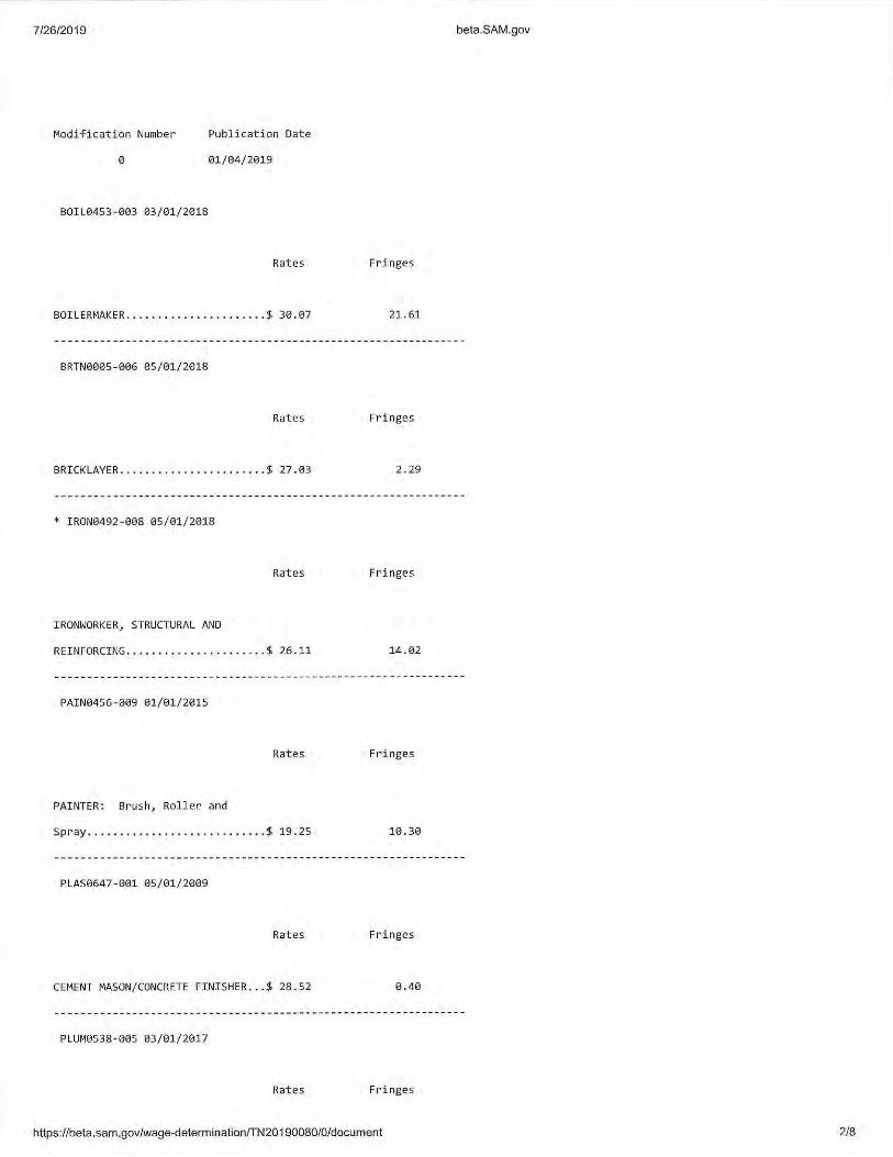
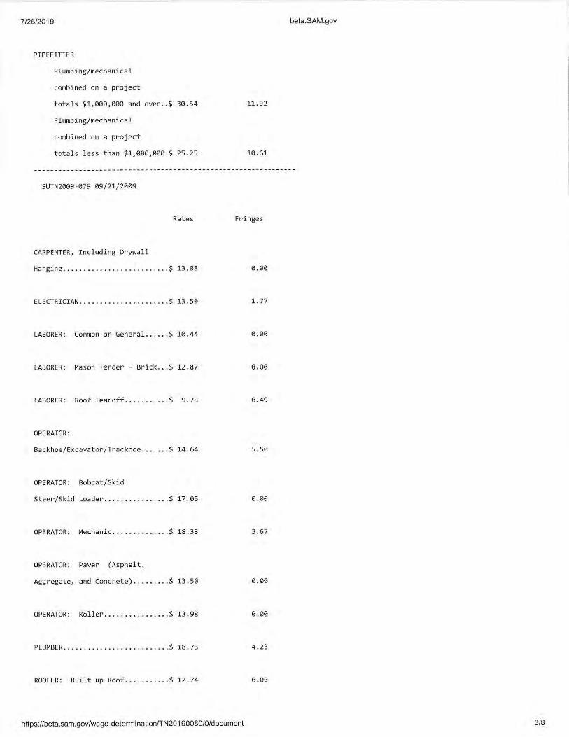
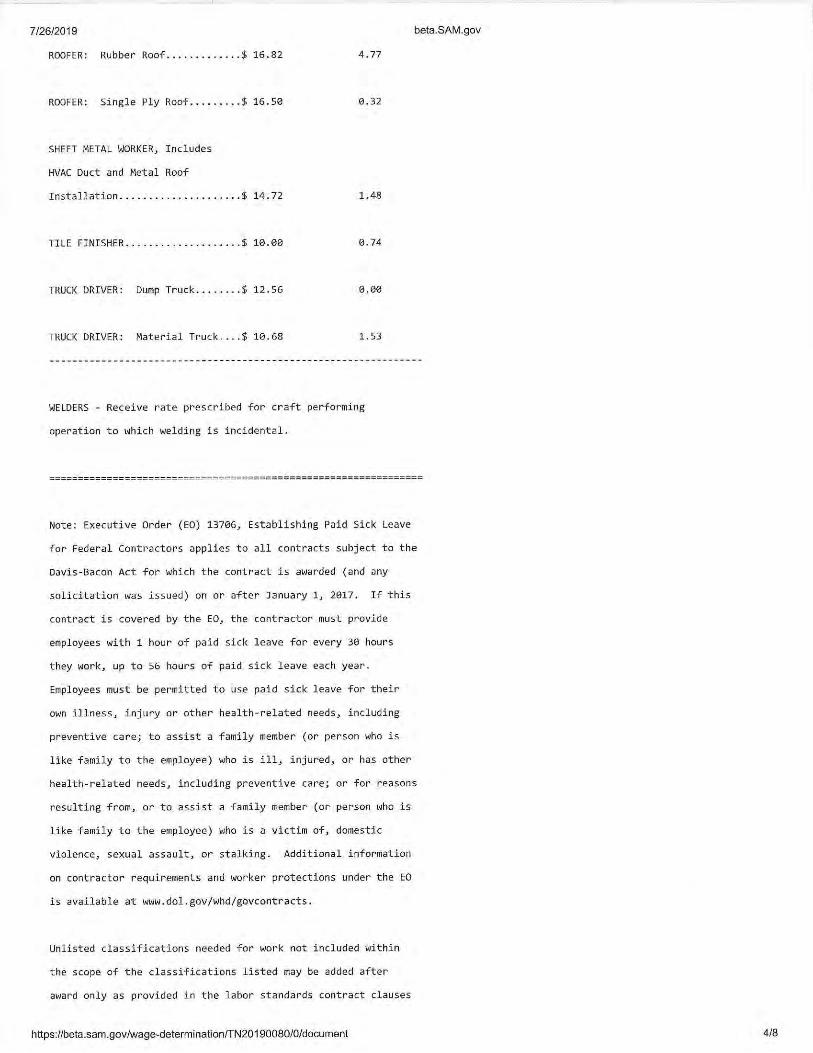

New Emergency Operations Center for: Architect’s Project No. C00218Carter County, TN
SECTION 01 11 00 - SUMMARY OF WORK
PART 1 - GENERAL
1.01 DESCRIPTION
A. Work included:1. The "Project," of which the "Work" of this Contract is a part, is titled "New Emergency
Operations Center”, 529 South Sycamore Street, Elizabethton, TN 37643and shall include,but not necessarily be limited to renovating approximately 2,400 sf of an existing space. Work includes converting an existing building shell to house the Carter County EmergencyOperations Center. The new facility will be adjacent to 911 and will include the followingspaces: Secure Entry, Situation Room, Offices, Radio Room, Storage/Janitors, andKitchenette.a. Installation of new walls, ceiling systems, electrical, mechanical, plumbing, interior
finishes and minor exterior finishes; b. Site security fencing as an alternate.
B. Work not included:1. All items marked N.I.C.
C. Related work:1. Documents affecting work of this Section include, but are not necessarily limited to,
General Conditions, Supplementary Conditions, and Sections in Division 01 of theseSpecifications.
2. The work of other contracts is described in various contract documents prepared therefore,some of which are in the possession of the Owner and are available for inspection byinterested parties.
END OF SECTION 01 11 00
SUMMARY OF WORK01 11 00 - 1
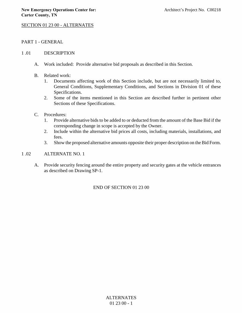
New Emergency Operations Center for: Architect’s Project No. C00218Carter County, TN
SECTION 01 23 00 - ALTERNATES
PART 1 - GENERAL
1 .01 DESCRIPTION
A. Work included: Provide alternative bid proposals as described in this Section.
B. Related work:1. Documents affecting work of this Section include, but are not necessarily limited to,
General Conditions, Supplementary Conditions, and Sections in Division 01 of theseSpecifications.
2. Some of the items mentioned in this Section are described further in pertinent otherSections of these Specifications.
C. Procedures:1. Provide alternative bids to be added to or deducted from the amount of the Base Bid if the
corresponding change in scope is accepted by the Owner.2. Include within the alternative bid prices all costs, including materials, installations, and
fees.3. Show the proposed alternative amounts opposite their proper description on the Bid Form.
1 .02 ALTERNATE NO. 1
A. Provide security fencing around the entire property and security gates at the vehicle entrancesas described on Drawing SP-1.
END OF SECTION 01 23 00
ALTERNATES01 23 00 - 1
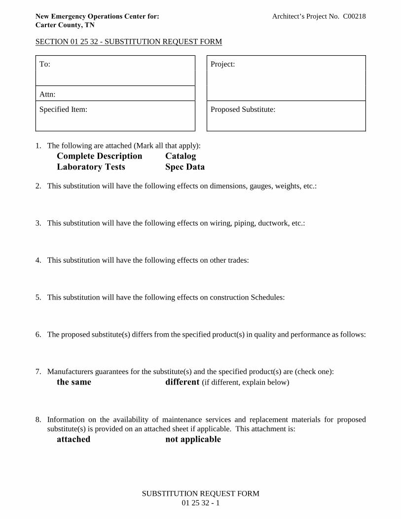
New Emergency Operations Center for: Architect’s Project No. C00218Carter County, TN
SECTION 01 25 32 - SUBSTITUTION REQUEST FORM
To: Project:
Attn:
Specified Item: Proposed Substitute:
1. The following are attached (Mark all that apply):
Complete Description CatalogLaboratory Tests Spec Data
2. This substitution will have the following effects on dimensions, gauges, weights, etc.:
3. This substitution will have the following effects on wiring, piping, ductwork, etc.:
4. This substitution will have the following effects on other trades:
5. This substitution will have the following effects on construction Schedules:
6. The proposed substitute(s) differs from the specified product(s) in quality and performance as follows:
7. Manufacturers guarantees for the substitute(s) and the specified product(s) are (check one):
the same different (if different, explain below)
8. Information on the availability of maintenance services and replacement materials for proposedsubstitute(s) is provided on an attached sheet if applicable. This attachment is:
attached not applicable
SUBSTITUTION REQUEST FORM01 25 32 - 1
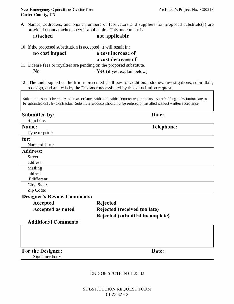
New Emergency Operations Center for: Architect’s Project No. C00218Carter County, TN
9. Names, addresses, and phone numbers of fabricators and suppliers for proposed substitute(s) areprovided on an attached sheet if applicable. This attachment is:
attached not applicable
10. If the proposed substitution is accepted, it will result in:
no cost impact a cost increase ofa cost decrease of
11. License fees or royalties are pending on the proposed substitute.
No Yes (if yes, explain below)
12. The undersigned or the firm represented shall pay for additional studies, investigations, submittals,redesign, and analysis by the Designer necessitated by this substitution request.
Substitutions must be requested in accordance with applicable Contract requirements. After bidding, substitutions are tobe submitted only by Contractor. Substitute products should not be ordered or installed without written acceptance.
Submitted by: Date: Sign here:
Name: Telephone:Type or print:
for:Name of firm:
Address:Streetaddress:Mailingaddressif different:
City, State,Zip Code:
Designer’s Review Comments:Accepted RejectedAccepted as noted Rejected (received too late)
Rejected (submittal incomplete)Additional Comments:
For the Designer: Date:Signature here:
END OF SECTION 01 25 32
SUBSTITUTION REQUEST FORM01 25 32 - 2
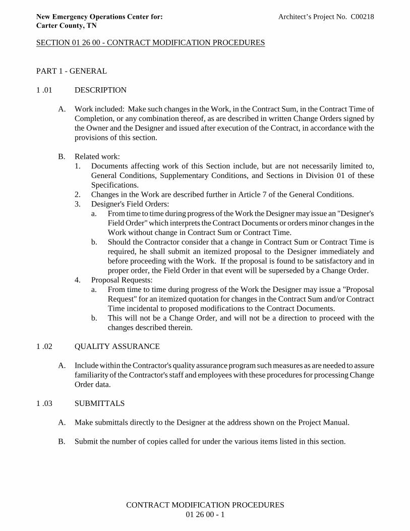
New Emergency Operations Center for: Architect’s Project No. C00218Carter County, TN
SECTION 01 26 00 - CONTRACT MODIFICATION PROCEDURES
PART 1 - GENERAL
1 .01 DESCRIPTION
A. Work included: Make such changes in the Work, in the Contract Sum, in the Contract Time ofCompletion, or any combination thereof, as are described in written Change Orders signed bythe Owner and the Designer and issued after execution of the Contract, in accordance with theprovisions of this section.
B. Related work:1. Documents affecting work of this Section include, but are not necessarily limited to,
General Conditions, Supplementary Conditions, and Sections in Division 01 of theseSpecifications.
2. Changes in the Work are described further in Article 7 of the General Conditions.3. Designer's Field Orders:
a. From time to time during progress of the Work the Designer may issue an "Designer'sField Order" which interprets the Contract Documents or orders minor changes in theWork without change in Contract Sum or Contract Time.
b. Should the Contractor consider that a change in Contract Sum or Contract Time isrequired, he shall submit an itemized proposal to the Designer immediately andbefore proceeding with the Work. If the proposal is found to be satisfactory and inproper order, the Field Order in that event will be superseded by a Change Order.
4. Proposal Requests:a. From time to time during progress of the Work the Designer may issue a "Proposal
Request" for an itemized quotation for changes in the Contract Sum and/or ContractTime incidental to proposed modifications to the Contract Documents.
b. This will not be a Change Order, and will not be a direction to proceed with thechanges described therein.
1 .02 QUALITY ASSURANCE
A. Include within the Contractor's quality assurance program such measures as are needed to assurefamiliarity of the Contractor's staff and employees with these procedures for processing ChangeOrder data.
1 .03 SUBMITTALS
A. Make submittals directly to the Designer at the address shown on the Project Manual.
B. Submit the number of copies called for under the various items listed in this section.
CONTRACT MODIFICATION PROCEDURES01 26 00 - 1
New Emergency Operations Center for: Architect’s Project No. C00218Carter County, TN
1 .04 PRODUCT HANDLING
A. Maintain a "Register of Proposal Requests, Field Orders, and Change Orders" at the job site,accurately reflecting current status of all pertinent data.
B. Make the Register available to the Designer for review at his request.
1 .05 PROCESSING CHANGES INITIATED BY THE OWNER
A. Should the Owner contemplate making a change in the Work or a change in the Contract Timeof Completion, the Designer will issue a "Proposal Request" or "Field Order" to the Contractor.
B. If the Contractor has been directed by the Designer to make the described change in the Workat no change in the Contract Sum and no change in the Contract Time of Completion, but theContractor wishes to make a claim for one or both of such changes, the Contractor shall proceedwith the change and shall notify the Designer as provided for under Subparagraphs 15.1.4 and15.1.5 of the General Conditions.
C. If the Contractor has been directed by the Designer to make the described change subject to laterdetermination of cost or credit in accordance with Paragraph 7.2 of the General Conditions, theContractor shall.1. Take such measures as needed to make the change;2. Consult with the Designer and reach agreement on the most appropriate method for
determining credit or cost for the change.
D. If the Contractor has been directed by the Designer to promptly advise him as to credit or costproposed for the described change, the Contractor shall:1. Analyze the described change and its impact on costs and time;2. Secure the required information and forward it to the Designer for review with the
following information:a. Itemization Summary: listing the itemizations of work by subcontractors and the
Contractor that together apply to an entire related change in work;b. Itemization of Work: detailing the quantities, units, costs, and extensions for
materials, equipment, and labor, subtotaled, plus overhead, and profit related to aspecific proposed change in the Work.
3. Meet with the Designer as required to explain costs and, when appropriate, determine otheracceptable ways to achieve the desired objective;
4. Alert pertinent personnel and subcontractors as to the impending change and, to themaximum extent possible, avoid such work as would increase the Owner's cost for makingthe change, advising the Designer in writing when such avoidance no longer is practicable.
1 .06 PROCESSING CHANGES INITIATED BY THE CONTRACTOR
A. Should the Contractor discover a discrepancy among the Contract Documents, a concealedcondition as described in Paragraph 3.7.4 of the General Conditions, or other cause forsuggesting a change in the Work, a change in the Contract Sum, or a change in the ContractTime of Completion, he shall notify the Designer as required by pertinent provisions of the
CONTRACT MODIFICATION PROCEDURES01 26 00 - 2
New Emergency Operations Center for: Architect’s Project No. C00218Carter County, TN
Contract Documents.
B. Upon agreement by the Designer that there is reasonable cause to consider the Contractor'sproposed change, the Designer will issue a Proposal Request in accordance with the provisionsdescribed in subparagraph 1.01-B-4 above.
1 .07 PROCESSING PROPOSAL REQUESTS
A. Make written reply to the Designer in response to each Proposal Request.1. State proposed change in the Contract Sum, if any.2. State proposed change in the Contract Time of Completion, if any.3. Clearly describe other changes in the Work, if any, required by the proposed change or
desirable therewith.4. Include full backup data such as subcontractor's letter of proposal or similar information.5. Submit this response in single copy.
B. When cost or credit for the change has been agreed upon by the Owner and the Contractor, orthe Owner has directed that cost or credit be determined in accordance with provisions ofParagraph 7.2 of the General Conditions, the Designer will issue a "Change Order" to theContractor.
1 .08 PROCESSING CHANGE ORDERS
A. Change Orders will be dated and will be numbered in sequence.
B. The Change Order will describe the change or changes, will refer to the Proposal Requests orField Orders involved, and will be signed by the Owner and the Designer.
C. The Designer will issue four copies of each Change Order to the Contractor.1. The Contractor promptly shall sign all four copies and return three copies to the Designer.2. The Designer will retain one signed copy in his file, will forward one signed copy to the
Owner.
D. Should the Contractor disagree with the stipulated change in Contract Sum or change inContract Time of Completion, or both:1. The Contractor promptly shall return three copies of the Change Order, unsigned by him,
to the Designer with a letter signed by the Contractor and stating the reason or reasons forthe Contractor's disagreement.
2. The Contractor's disagreement with the Change Order shall not in any way relieve theContractor of his responsibility to proceed with the change as ordered and to seeksettlement of the dispute under pertinent provisions of the Contract Documents.
END OF SECTION 01 26 00
CONTRACT MODIFICATION PROCEDURES01 26 00 - 3

New Emergency Operations Center for: Architect’s Project No. C00218Carter County, TN
SECTION 01 29 00 - PAYMENT PROCEDURES
PART 1 - GENERAL
1 .01 DESCRIPTION
A. Work included: Comply with procedures described in this Section when applying for progresspayment and final payment under the Contract.
B. Related work:1. Documents affecting work of this Section include, but are not necessarily limited to,
General Conditions, Supplementary Conditions, and Sections in Division 01 of theseSpecifications.
2. The Contract Sum and the schedule for payments are described in the Form of Agreement.3. Payments upon Substantial Completion and Completion of the Work are described in the
General Conditions and in Section 01 78 00 of these Specifications.4. The Designer's approval of applications for progress payment and final payment may be
contingent upon the Designer's approval of status of Project Record Documents asdescribed in Section 01 78 39 of these Specifications.
1 .02 QUALITY ASSURANCE
A. Prior to start of the construction, secure the Designer's approval of the schedule of valuesrequired to be submitted under Paragraph 9.2 of the General Conditions, and further describedin Section 01 29 73 of these Specifications.
B. During progress of the Work, modify the schedule of values as approved by the Designer toreflect changes in the Contract Sum due to Change Orders or other modifications of theContract.
C. Base requests for payment on the approved schedule of values.
1 .03 SUBMITTALS
A. Informal submittal: Unless otherwise directed by the Designer.1. Email or mail an informal submittal of request for payment by email or by filling in, with
erasable pencil, pertinent portions of AIA Document G702, "Application and Certificatefor Payment," plus continuation sheet or sheets.
2. Make the preliminary submittal to the Designer at least three (3) days prior to the monthlyProgress Meeting.
3. Revise the informal submittal of request for payment as agreed.
B. Formal submittal: Unless otherwise directed by the Designer:1. Make formal submittal of request for payment by filling in the agreed data, by typewriter
or neat lettering in ink, on AIA Document G702, "Application and Certificate forPayment," plus continuation sheet or sheets.
PAYMENT PROCEDURES01 29 00 - 1
New Emergency Operations Center for: Architect’s Project No. C00218Carter County, TN
2. Sign and notarize the Application and Certificate for Payment.3. Submit the original of the Application and Certificate for Payment, plus four identical
copies of the continuation sheet or sheets, to the Designer.4. The Designer will compare the formal submittal with the approved informal submittal and,
when approved, will sign the Application and Certificate for Payment, will make requiredcopies, and will distribute.a. One copy to Contractor;b. Two copies to Owner; andc. One copy to Designer's file.
5. Owner will, upon approval, disburse directly to the contractor.
END OF SECTION 01 29 00
PAYMENT PROCEDURES01 29 00 - 2

New Emergency Operations Center for: Architect’s Project No. C00218Carter County, TN
SECTION 01 29 73 - SCHEDULE OF VALUES
PART 1 - GENERAL
1 .01 DESCRIPTION
A. Work included: Provide a detailed breakdown of the agreed Contract Sum showing valuesallocated to each of the various parts of the Work, as specified herein and in other provisionsof the Contract Documents.
B. Related work:1. Documents affecting work of this Section include, but are not necessarily limited to,
General Conditions, Supplementary Conditions, and Sections in Division 01 of theseSpecifications.
2. Schedule of values is required under Paragraph 9.2 of the General Conditions.3. Schedule of values is required to be compatible with the "continuation sheet"
accompanying applications for payment, as described in Section 01 29 00.
1 .02 QUALITY ASSURANCE
A. Use required means to assure arithmetical accuracy of the sums described.
B. When so required by the Designer, provide copies of the subcontracts or other data acceptableto the Designer, substantiating the sums described.
1 .03 SUBMITTAL
A. Prior to first application for payment, submit a proposed schedule of values to the Designer.1. Meet with the Designer and determine additional data, if any, required to be submitted.2. Secure the Designer's approval of the schedule of values prior to submitting first
application for payment.
END OF SECTION 01 29 73
SCHEDULE OF VALUES01 29 73 - 1
New Emergency Operations Center for: Architect’s Project No. C00218Carter County, TN
SECTION 01 31 00 - PROJECT MANAGEMENT AND COORDINATION
PART 1 - GENERAL
1.01 DESCRIPTION
A. Work included: To enable orderly review during progress of the Work, and to provide forsystematic discussion of the problems, the Designer will conduct project meetings throughoutthe construction period.
B. Related work:1. Documents affecting work of this Section include, but are not necessarily limited to,
General Conditions, Supplementary Conditions, and Sections in Division 01 of theseSpecifications.
2. The Contractor's relations with his subcontractors and materials suppliers, and discussionsrelative thereto, are the Contractor's responsibility and normally are not part of projectmeetings content.
1.02 QUALITY ASSURANCE
A. For those persons designated by the Contractor to attend and participate in project meetings,provide required authority to commit the Contractor to solutions agreed upon in the projectmeetings.
1.03 SUBMITTALS
A. Agenda items: To the maximum extent practicable, advise the Designer at least 24 hours inadvance of project meetings regarding items to be added to the agenda.
B. Minutes:1. The Designer will compile minutes of each Progress Meeting, and will furnish a copy to
the Contractor and required copies to the Owner.2. Recipients of copies may make and distribute such other copies as they wish.
PART 2 - PRODUCTS
Not applicable to this section.
PART 3 - EXECUTION
3.01 MEETING SCHEDULE
A. Except as noted below for Pre-Construction Meeting, Progress Meetings will be held monthly.
PROJECT MANAGEMENT AND COORDINATION01 31 00 - 1
New Emergency Operations Center for: Architect’s Project No. C00218Carter County, TN
B. Coordinate as necessary to establish mutually acceptable schedule for meetings.
3.02 MEETING LOCATION
A. The Designer will establish meeting location. To the maximum extent practicable, meetingswill be held at the job site.
3.03 PRE-CONSTRUCTION MEETING
A. Pre-Construction Meeting will be scheduled to be held within 15 working days after the Noticeto Proceed.1. Provide attendance by authorized representatives of the Contractor and major
subcontractors.2. The Designer will advise other interested parties, including the Owner, and request their
attendance.
B. Minimum agenda: Data will be distributed and discussed on at least the following items:1. Organizational arrangement of Contractor's forces and personnel, and those of
subcontractors, materials suppliers, and Designer.2. Channels and procedures for communication.3. Construction schedule, including sequence of critical work.4. Contract Documents, including distribution of required copies of original Documents and
revisions.5. Processing of Shop Drawings and other data submitted to the Designer for review.6. Processing of Bulletins, field decisions, and Change Orders.7. Rules and regulations governing performance of the Work; and8. Procedures for safety and first aid, security, and related matters.
3.04 PROGRESS MEETINGS
A. Attendance:1. To the maximum extent practicable, assign the same person or persons to represent the
Contractor at project meetings throughout progress of the Work.2. Subcontractors, materials suppliers, and other may be invited to attend those project
meetings in which their aspect of the Work is involved.
B. Minimum agenda:1. Review, revise as necessary, and approve minutes of previous meetings.2. Review progress of the Work since last meeting, including status of submittals for
approval.3. Identify problems which impede planned progress.4. Develop corrective measures and procedures to regain planned schedule.5. Complete other current business.
PROJECT MANAGEMENT AND COORDINATION01 31 00 - 2
New Emergency Operations Center for: Architect’s Project No. C00218Carter County, TN
C. Revisions to the minutes:1. Unless published minutes are challenged in writing prior to the next regularly scheduled
progress meeting, they will be accepted as properly stating the activities and decisions ofthe meeting.
2. Persons challenging published minutes shall reproduce and distribute copies of thechallenge to all indicated recipients of the particular set of minutes.
3. Challenge to minutes shall be settled as priority portion of "old business" at the nextregularly scheduled meeting.
END OF SECTION 01 31 00
PROJECT MANAGEMENT AND COORDINATION01 31 00 - 3
New Emergency Operations Center for: Architect’s Project No. C00218Carter County, TN
SECTION 01 32 00 - CONSTRUCTION PROGRESS DOCUMENTATION
PART 1 - GENERAL
1 .01 DESCRIPTION
A. Work included: To assure adequate planning and execution of the Work so that the Work iscompleted within the number of calendar days allowed in the Contract, and to assist theDesigner in appraising the reasonableness of the proposed schedule and in evaluating progressof the Work, prepare and maintain the schedules and reports described in this Section.
B. Related work:1. Documents affecting work of this Section include, but are not necessarily limited to,
General Conditions, Supplementary Conditions, and Sections in Division 01 of theseSpecifications.
2. Requirements for progress schedule: General Conditions.3. Construction period: Agreement Form.
C. Definitions:1. "Day", as used throughout the Contract, unless otherwise stated, means "calendar day".
1 .02 QUALITY ASSURANCE
A. Employ a scheduler who is thoroughly trained and experienced in compiling constructionschedule data, and in preparing and issuing periodic reports as required below.
B. Perform data preparation, analysis, charting, and updating in accordance with standardsapproved by the Designer.
C. Reliance upon the approved schedule:1. The construction schedule as approved by the Designer will be an integral part of the
Contract and will establish interim completion dates for the various activities under theContract.
2. Should any activity not be completed within 15 days after the stated scheduled date, theOwner shall have the right to require the Contractor to expedite completion of the activityby whatever means the Owner deems appropriate and necessary, without additionalcompensation to the Contractor.
3. Should any activity be 30 days or more behind schedule, the Owner shall have the right toperform the activity or have the activity performed by whatever method the Owner deemsappropriate.
4. Costs incurred by the owner and by the Designer in connection with expeditingconstruction activity under this article shall be reimbursed by the Contractor.
5. It is expressly understood and agreed that failure by the Owner to exercise the option eitherto order the Contractor to expedite an activity or to expedite the activity by other meansshall not be considered to set a precedent for any other activities.
CONSTRUCTION PROGRESS DOCUMENTATION01 32 00 - 1
New Emergency Operations Center for: Architect’s Project No. C00218Carter County, TN
1 .03 SUBMITTALS
A. Comply with pertinent provisions of Section 01 33 00.
B. Preliminary analysis: Within ten calendar days after the contractor has received the Notice toProceed, submit one reproducible copy and four prints of a preliminary construction scheduleprepared in accordance with Part 3 of this Section.
C. Construction schedule: Within fifteen calendar days after the Contractor has received the Noticeto Proceed, submit two prints of a construction schedule prepared in accordance with Part 3 ofthis Section.
D. Periodic reports: On the first working day of each month following the submittal described inParagraph 1.03-C above, submit two prints of the construction schedule updated as describedin Part 3 of this Section.
PART 2 - PRODUCTS
2.01 CONSTRUCTION ANALYSIS
A. Graphically show by bar-chart the order and interdependence of all activities necessary tocomplete the Work, and the sequence in which each activity is to be accomplished, as plannedby the Contractor and his project field superintendent in coordination with all subcontractorswhose work is shown on the diagram.
B. Include, but do not necessarily limit indicated activities to:1. Project mobilization;2. Submittal and approval of Shop Drawings and Samples;3. Procurement of equipment and critical materials;4. Fabrication of special material and equipment, and its installation and testing.5. Final cleanup;6. Final inspecting and testing; and7. All activities by the Designer that effect progress, required dates for completion, or both,
for all and each part of the Work.
PART 3 - EXECUTION
3.01 PRELIMINARY ANALYSIS
A. Contents:1. Show all activities of the Contractor under this Work for the period between receipt of
Notice to Proceed and submittal of construction schedule required under Paragraph 1.03-Cabove;
2. Show the Contractor's general approach to remainder of the Work;
CONSTRUCTION PROGRESS DOCUMENTATION01 32 00 - 2
New Emergency Operations Center for: Architect’s Project No. C00218Carter County, TN
3. Show cost of all activities scheduled for performance before submittal and approval of theconstruction schedule.
B. Submit in accordance with Paragraph 1.03-C above.
3.02 CONSTRUCTION SCHEDULE
A. As soon as practicable after receipt of Notice to Proceed, complete the construction analysis inpreliminary form, meet with the Designer, review contents of the proposed constructionschedule, and make all revisions agreed upon.
B. Submit in accordance with Paragraph 1.03-C above.
3.03 PERIODIC REPORTS
A. As required under Paragraph 1.03-D above, update the approved construction schedule.1. Indicate "actual" progress in percent completion for each activity;2. Provide written narrative summary of revisions causing delay in the program, and an
explanation of corrective actions taken or proposed.
3.04 REVISIONS
A. Make only those revisions to approved construction schedule as are approved in advance by theDesigner.
END OF SECTION 01 32 00
CONSTRUCTION PROGRESS DOCUMENTATION01 32 00 - 3
New Emergency Operations Center for: Architect’s Project No. C00218Carter County, TN
SECTION 01 33 00 - SUBMITTAL PROCEDURES
PART 1 - GENERAL
1 .01 DESCRIPTION
A. Work included: Make submittals required by the Contract Documents, and revise and resubmitas necessary to establish compliance with the specified requirements.
B. Related work:1. Documents affecting work of this Section include, but are not necessarily limited to,
General Conditions, Supplementary Conditions, and Sections in Division 01 of theseSpecifications.
2. Individual requirements for submittals also may be described in pertinent sections of theseSpecifications.
3. Section 01 29 73: Schedule of Values.
C. Work not included:1. Unrequired submittals will not be reviewed by the Designer.2. The Contractor may require his subcontractors to provide drawings, settings diagrams, and
similar information to help coordinate the Work, but such data shall remain between theContractor and his subcontractors and will not be reviewed by the Designer.
1 .02 QUALITY ASSURANCE
A. Coordination of submittals:1. Prior to each submittal, carefully review and coordinate all aspects of each item being
submitted.2. Verify that each item and the submittal for it conform in all respects with the specified
requirements.3. By affixing the Contractor's signature to each submittal, certify that this coordination has
been performed.4. The Contractor shall require all shop drawings to be checked 100% before they are
submitted to the Designer for review. Failure to do so will result in the shop drawing beingreturned without any action.
B. Substitutions:1. The Contract is based on the standards of quality established in the Contract Documents.
Substitutions will be considered only when listed at time of bidding.2. The following products do not require further approval except for interface within the
Work:a. Products specified by reference to standard specifications such as ASTM and similar
standards.b. Products specified by manufacturer's name and catalog model number.
3. Do not substitute materials, equipment, or methods unless such substitution has beenspecifically approved in writing for this Work by the Designer.
SUBMITTAL PROCEDURES01 33 00 - 1
New Emergency Operations Center for: Architect’s Project No. C00218Carter County, TN
C. "Or equal":1. Where the phrase "or equal", or "or equal as approved by the Designer", occurs in the
Contract Documents, do not assume that the materials, equipment, or methods will beapproved as equal unless the item has been specifically so approved for this Work by theDesigner.
2. The decision of the Designer shall be final.
1 .03 SUBMITTALS
A. Make submittals of Shop Drawings, Samples, substitution requests, and other items inaccordance with the provisions of this Section.
B. General: Where it is necessary to provide intermediate submittals between the initial and finalsubmittals, provide and process intermediate submittals in the same manner as for initialsubmittals.
C. Submit the number of copies which are required to be returned, plus one copy which will beretained by the Designer. (NOTE: If the submittals are to be reviewed by the Designer’sConsultants, submit two copies, in addition to those to be returned, which will be retained bythe Designer and their Consultant.)
D. Additional Copies: Provide additional copies of submittals required by governing authoritiesthat are in addition to copies specified for submittal to the Designer.
E. Maintain one copy of all submittals at the project site for reference purposes.
F. If the Contractor elects to submit shop drawings by email, only the email copy is required to besubmitted to the Designer. Approval of shop drawings will be by the Designer and theirConsultants by email. The contractor will be responsible for providing copies required toproceed with approved documents. All documents should be submitted so they can be printedin the original sheet size of the documents.
PART 2 - PRODUCTS
2 .01 SHOP DRAWINGS
A. Scale and measurements: Make Shop drawings accurately to a scale sufficiently large to showall pertinent aspects of the item and its method of connection to the Work.
B. Coordination: Coordinate the preparation and processing of shop drawings with the performanceof the Work. Coordinate each separate submittal with other submittals and related activities thatrequire sequential activity. Prepare and transmit each submittal sufficiently in advance of thescheduled performance of related work and similar activities.
SUBMITTAL PROCEDURES01 33 00 - 2
New Emergency Operations Center for: Architect’s Project No. C00218Carter County, TN
2 .02 PRODUCT DATA
A. Mark each copy to indicate the actual product to be provided; show selections from amongoptions in the manufacturer’s printed product data.
2 .03 MANUFACTURERS' LITERATURE
A. Where contents of submitted literature from manufacturers includes data not pertinent to thesubmittal, clearly show which portions of the contents is being submitted for review.
B. Submit the number of copies which are required to be returned, plus one copy which will beretained by the Designer.
2 .04 SAMPLES
A. Provide Sample or Samples identical to the precise article proposed to be provided. Identify asdescribed under "Identification of submittals" below.
B. Number of samples required:1. Unless otherwise specified, submit Samples in the quantity which is required to be
returned, plus one which will be retained by the Designer.2. By prearrangement in specific cases, a single Sample may be submitted for review and,
when approved, be installed in the Work at a location agreed upon by the Designer.
2 .05 COLORS AND PATTERNS
A. Unless the precise color and pattern is specifically called out in the Contract Documents, andwhenever a choice of color or pattern is available in the specified products, submit accuratecolor and pattern charts to the Designer for selection.
2 .06 MISCELLANEOUS SUBMITTALS
A. Warranties: Submit two executed copies, plus additional copies as required.
B. Inspection and Test Reports: Where not processed as shop drawings or project data, provide twocopies plus additional copies as required.
C. Field Records: Four copies, including one copy which will be returned for inclusion in thesubmittal of record documents.
D. Record Drawings: Submit original maintained marked-up prints.
SUBMITTAL PROCEDURES01 33 00 - 3
New Emergency Operations Center for: Architect’s Project No. C00218Carter County, TN
PART 3 - EXECUTION
3.01 IDENTIFICATION OF SUBMITTALS
A. Consecutively number all submittals.1. When material is resubmitted for any reason, transmit under a new letter of transmittal and
with a new transmittal number.2. On resubmittals, cite the original submittal number for reference.
B. Accompany each submittal with a letter of transmittal showing all information required foridentification and checking.
C. On at least the first page of each submittal, and elsewhere as required for positive identification,mark each submittal with a permanent label for identification. Provide project name, date, nameof Designer, name of Contractor, number and title of appropriate specification section andsimilar definitive information. Provide a space on the label for Contractors and Designer reviewmarkings.
D. Maintain an accurate submittal log for the duration of the Work, showing current status of allsubmittals at all times. Make the submittal log available to the Designer for his review uponrequest.
3.02 GROUPING OF SUBMITTALS
A. Unless otherwise specified, make submittals in groups containing all associated items to assurethat information is available for checking each item when it is received.1. Partial submittals may be rejected as not complying with the provisions of the Contract.2. The Contractor may be held liable for delays so occasioned.
3.03 TIMING OF SUBMITTALS
A. Make submittals far enough in advance of scheduled dates for installation to provide timerequired for reviews, for securing necessary approvals, for possible revisions and resubmittals,and for placing orders and securing delivery.
B. In scheduling, allow at least seven working days for review by the Designer following hisreceipt of the submittal.
3.04 DESIGNER'S REVIEW
A. Review by the Designer does not relieve the Contractor from responsibility for errors which mayexist in the submitted data nor does it relieve the Contractor from full compliance with therequirements of the Contract Documents.
B. Review Time: Allow two weeks for the Designer’s initial processing of each submittal. Allowone week for reprocessing each submittal resubmitted.
SUBMITTAL PROCEDURES01 33 00 - 4
New Emergency Operations Center for: Architect’s Project No. C00218Carter County, TN
C. Revisions:1. Make revisions required by the Designer.2. If the Contractor considers any required revision to be a change, he shall so notify the
Designer as provided for in Subparagraph 7.1 of the General Conditions.3. Make only those revisions directed or approved by the Designer.
D. Reimbursement of Designer's costs:1. In the event substitutions are proposed to the Designer after the Contract has been awarded,
the Designer will record all time used by him and by his consultants in evaluation of eachsuch proposed substitution.
2. Whether or not the Designer approves a proposed substitution, the Contractor promptlyupon receipt of the Designer's Billing shall reimburse the Designer for all time spent by theDesigner and his Consultants in evaluating the proposed substitution. These reimbursablerates shall be made available to the Contractor upon written request to the Designer.
END OF SECTION 01 33 00
SUBMITTAL PROCEDURES01 33 00 - 5

New Emergency Operations Center for: Architect’s Project No. C00218Carter County, TN
SECTION 01 35 16 - ALTERATION PROJECT PROCEDURES
PART 1 - GENERAL
1 .01 DESCRIPTION
A. Work included: Perform alterations and related work as shown or specified and in accordancewith requirements of the Contract Documents.
B. Related work:1. Documents affecting work of this Section include, but are not necessarily limited to,
General Conditions, Supplementary Conditions, and Sections in Division 01 of theseSpecifications.
2. Reinforcing, cutting, and other modifications of existing structural components.3. Disconnecting, removal, and/or relocation of existing mechanical and electrical work,
including equipment, piping, wiring, and so on.
1 .02 QUALITY ASSURANCE
A. Use adequate numbers of skilled workmen who are thoroughly trained and experienced in thenecessary crafts and who are completely familiar with the specified requirements and themethods needed for proper performance of the work of this Section.
PART 2 - PRODUCTS
(No products are required in this Section)
PART 3 - EXECUTION
3 .01 SCHEDULING
A. Before commencing any alteration or demolition work, submit for review by the Designer andapproval of the Owner, a schedule showing the commencement, the order, and the completiondates for the various parts of this work.
B. Before starting any work relating to existing utilities (electrical, sewer, water, heat, gas, fire linesetc.) that will temporarily discontinue or disrupt service to the existing building, notify theDesigner and the Owner 72 hours in advance and obtain the Owner’s approval in writing beforeproceeding with the work.
ALTERATION PROJECT PROCEDURES01 35 16 - 1

New Emergency Operations Center for: Architect’s Project No. C00218Carter County, TN
3 .02 PROTECTION
A. Make sure explorations and probes as are necessary to ascertain any required protectivemeasures before proceeding with demolition and removal. Give particular attention to shoringand bracing requirements so as to prevent any damage to existing construction.
B. Provide, erect, and maintain catch platforms, lights, barriers, weather protection, warning signs,and other items as required for proper protection of the workmen engaged in demolitionoperations, occupants of the building, public, and adjacent construction.
C. Provide and maintain weather protection at exterior openings so as to fully protect the interiorpremises against damage from the elements until such openings are closed by new construction.
D. Provide and maintain temporary protection of the existing structure designated to remain wheredemolition, removal, and new work are being done, connections made, materials handled, orequipment moved.
E. Take necessary precautions to prevent dust and dirt from rising by wetting demolished masonry,concrete, plaster, and similar debris. Protect unaltered portions of the existing building affectedby the operations under this section by dustproof partitions and other adequate means.
F. Provide adequate fire protection in accordance with local Fire Department requirements.
G. Do not close or obstruct walkways, passageways, or stairways without the authorization of theDesigner. Do not store or place materials in passageways, stairs, or other means of egress. Conduct operations with minimum traffic interference.
H. Be responsible for any damage to the existing structure or contents by reason of the insufficiencyof protection provided.
3 .03 WORKMANSHIP
A. Demolition, removal, and alteration work shall be as shown on the drawings. Perform suchwork required with due care, including shoring, bracing, and so on. Be responsible for anydamage that may be caused by such work to any part or parts of existing structures or itemsdesignated for reuse. Perform patching, restoration, and new work in accordance withapplicable technical sections of the Specifications.
B. Materials or items designated to become the property of the Owner shall be as shown on thedrawings. Remove such items with care and store them in a location at the site to be designatedby the Owner.
C. Materials or items designated to be reinstalled shall be as shown on the Drawings. Remove suchitems with care under the supervision of the trade responsible for reinstallation; protect and storeuntil required. Replace material or items damaged in its removal with similar new material.
ALTERATION PROJECT PROCEDURES01 35 16 - 2
New Emergency Operations Center for: Architect’s Project No. C00218Carter County, TN
D. Materials or items demolished and not designated to become the property of the Owner or to bereinstalled shall become the property of the Contractor and shall be removed from the Owner’sproperty.
E. Execute the work in a careful and orderly manner, with the least possible disturbance to thepublic and to the occupants of the building.
F. In general, demolish masonry in small sections. Where necessary to prevent collapse of anyexisting construction, install temporary shores, struts, or bracing.
G. Where alterations occur, or new and old work join, cut, remove, patch, repair, or refinish theadjacent surfaces or so much thereof as is required by the involved conditions, and leave in asgood a condition as existed prior to the commencing of the work. The materials andworkmanship employed in the alterations, unless otherwise shown or specified, shall conformto that of the original work. Alteration work shall be performed by the various respective tradesthat normally perform the particular items of work.
H. Finish new and adjacent existing surfaces as specified for new work. Clean existing surfacesof dirt, grease, loose paint, and so on before refinishing.
I. Where existing equipment and/or fixtures are indicated to be reused, repair such equipmentand/or fixtures and refinish to put in perfect working order. Refinish as directed.
J. Cut out embedded anchorage and attachment items as required to properly provide for patchingand repair of respective finishes.
K. Confine cutting of existing roof areas designated to remain to the limits required for the properinstallation of the new work. Cut and fold back existing EPDM roofing. Cut and removeinsulation and so on. Provide temporary weathertight protection as required until new roofingand flashings are installed. Consult the Owner to ascertain if existing guarantee bonds are inforce and execute the work so as not to invalidate such bonds.
3 .04 CLEANING UP
A. Remove debris as the work progresses. Maintain the premises in a neat and clean condition.
END OF SECTION 01 35 16
ALTERATION PROJECT PROCEDURES01 35 16 - 3

New Emergency Operations Center for: Architect’s Project No. C00218Carter County, TN
SECTION 01 45 29 - TESTING LABORATORY SERVICES (OWNER PROVIDED)
PART 1 - GENERAL
1 .01 DESCRIPTION
A. Work included:1. Cooperate with the Owner's selected testing agency and all others responsible for testing
and inspecting the Work.2. Provide such other testing and inspecting as are specified to be furnished by the Contractor
in this Section and/or elsewhere in the Contract Documents.
B. Related work:1. Documents affecting work of this Section include, but are not necessarily limited to,
General Conditions, Supplementary Conditions, and Sections in Division 01 of theseSpecifications.
2. Requirements for testing may be described in various Sections of these specifications.3. Where no testing requirements are described, but the Owner decides that testing is
required, the Owner may require such testing to be performed under current pertinentstandards for testing. Payment for such testing will be made as described in this Section.
C. Work not included:1. Selection of testing laboratory: The Owner will select a prequalified independent testing
laboratory.2. Payment for initial services of the testing laboratory as further described in Article 2.01 of
this Section.
1 .02 QUALITY ASSURANCE
A. The testing laboratory will be qualified to the Owner's approval in accordance with ASTME329.
B. Testing, when required, will be in accordance with all pertinent codes and regulations, and withselected standards of the American Society for Testing and Materials.
1 .03 PRODUCT HANDLING
A. Comply with pertinent provisions of Section 01 66 00.
B. Promptly process and distribute required copies of test reports and related instructions to assurenecessary retesting and replacement of materials with the least possible delay in progress of theWork.
TESTING LABORATORY SERVICES (OWNER PROVIDED)01 45 29 - 1
New Emergency Operations Center for: Architect’s Project No. C00218Carter County, TN
PART 2 - PRODUCTS
2 .01 PAYMENT FOR TESTING
A. Initial services:1. The Owner will pay for initial testing services requested by the Owner.2. When initial tests indicate non-compliance with the Contract Documents, the costs of
initial test associated with that non-compliance will be deducted by the Owner from theContract Sum.
B. Retesting: When initial test indicate non-compliance with the Contract Documents, subsequentretesting occasioned by the non-compliance shall be performed by the same testing agency, andcosts thereof will be deducted by the Owner from the Contract Sum.
2 .02 CODE COMPLIANCE TESTING
A. Inspections and tests required by codes or ordinances, or by a plan approval authority, and whichare made by a legally constituted authority, shall be the responsibility of and shall be paid forby the Contractor, unless otherwise provided in the Contract Documents.
2 .03 CONTRACTOR'S CONVENIENCE TESTING
A. Inspecting and testing performed exclusively for the Contractor's convenience shall be the soleresponsibility of the Contractor.
PART 3 - EXECUTION
3 .01 COOPERATION WITH TESTING LABORATORY
A. Representatives of the testing laboratory shall have access to the Work at all times and at alllocations where the Work is in progress. Provide facilities for such access to enable thelaboratory to perform its functions properly.
3 .02 TAKING SPECIMENS
A. All specimens and samples for testing, unless otherwise provided in the Contract Documents,shall be taken by the testing personnel. All sampling equipment and personnel will be providedby the testing laboratory. All deliveries of specimens and samples to the testing laboratory willbe performed by the testing laboratory.
TESTING LABORATORY SERVICES (OWNER PROVIDED)01 45 29 - 2
New Emergency Operations Center for: Architect’s Project No. C00218Carter County, TN
3 .03 SCHEDULES FOR TESTING
A. Establishing a schedule:1. By advance discussion with the testing laboratory selected by the Owner, determine the
time required for the laboratory to perform its tests and to issue each of its findings.2. Provide all required time within the Construction schedule.
B. Revising schedule: When changes of construction schedule are necessary during construction,coordinate all such changes with the testing laboratory as required.
C. Adherence to schedule: When the testing laboratory is ready to test according to the establishedschedule, but is prevented from testing or taking specimens due to incompleteness of the Work,all extra charges for testing attributable to the delay may be back-charges to the Contractor andshall not be borne by the Owner.
END OF SECTION 01 45 29
TESTING LABORATORY SERVICES (OWNER PROVIDED)01 45 29 - 3
New Emergency Operations Center for: Architect’s Project No. C00218Carter County, TN
SECTION 01 50 00 - TEMPORARY FACILITIES AND CONTROLS
PART 1 - GENERAL
1 .01 DESCRIPTION
A. Work included: Provide temporary facilities and controls needed for the Work including, butnot necessarily limited to:1. Temporary utilities such as heat, water, electricity, email, and telephone;2. Field office for the Contractor's personnel;3. Sanitary facilities;4. Enclosures such as tarpaulins, barricades, and canopies;5. Temporary fencing of construction site;6. Project sign.7. Construction Waste Management Areas;8. Staging Areas, laydown areas, washdown areas, refueling areas.
B. Related work:1. Documents affecting work of this Section include, but are not necessarily limited to,
General Conditions, Supplementary Conditions, and Sections in Division 01 of theseSpecifications.
2. Except that equipment furnished by subcontractors shall comply with requirements ofpertinent safety regulations, such equipment normally furnished by the individual tradesin execution of their own portions of the Work are not part of this Section.
3. Permanent installation and hookup of the various utility lines are described in otherSections.
1 .02 PRODUCT HANDLING
A. Maintain temporary facilities and controls in proper and safe condition throughout progress ofthe Work.
B. Limit areas of heavy traffic to areas delineated by Designer for site development; minimizingsite disturbance and compaction.
PART 2 - PRODUCTS
2 .01 UTILITIES
A. Water:1. The Owner shall provide and pay for water used in this Project.2. The Contractor shall provide necessary temporary piping and, upon completion of the
Work, remove such temporary facilities.
TEMPORARY FACILITIES AND CONTROLS01 50 00 - 1
New Emergency Operations Center for: Architect’s Project No. C00218Carter County, TN
B. Electricity:1. The Owner shall provide and pay for electricity used in this Project.2. The Contractor shall provide necessary temporary wiring and, upon completion of the
Work, remove such temporary facilities.3. Provide area distribution boxes so located that the individual trades may furnish and use
100 ft maximum length extension cords to obtain power and lighting at points whereneeded for work, inspection, and safety.
C. Heating: Provide and maintain heat necessary for proper conduct of operations needed in thework. Practice energy conservation.
D. Telephone:1. Make necessary arrangements and pay costs for telephone service throughout the project..2. Post listing of operational and emergency telephone numbers at each telephone.3. Mobile phones may be utilized to satisfy this requirement.4. Make the telephone available to the Designer for use in connection with the Work.
E. Email: 1. Make necessary arrangements and pay costs for installation and operation of email service
to the Contractor’s office at the site.
2 .02 FIELD OFFICES AND SHEDS
A. Contractor's facilities:1. Provide a field office building and sheds adequate in size and accommodation for
Contractor's offices, supply, and storage.2. Within the Contractor's facilities, provide enclosed space adequate for holding project
meetings. Furnish with table, chairs, and utilities.
B. Sanitary facilities:1. Provide temporary sanitary facilities in the quantity required for use by all personnel.2. Maintain in a sanitary condition at all times.
2 .03 ENCLOSURES
A. Provide and maintain for the duration of construction all scaffolds, tarpaulins, canopies, warningsigns, steps, platforms, bridges, and other temporary construction necessary for propercompletion of the Work in compliance with pertinent safety and other regulations. Stay withinareas designated for site development as delineated on site plan.
2 .04 TEMPORARY FENCING
A. Provide and maintain for the duration of construction a temporary fence of design and typeneeded to prevent entry onto the Work by the public.
TEMPORARY FACILITIES AND CONTROLS01 50 00 - 2
New Emergency Operations Center for: Architect’s Project No. C00218Carter County, TN
2 .05 SECURITY AND PROTECTION
A. General: Provide facilities and services as necessary to effectively protect project from lossesand persons from injury during the course of construction.
B. Fire Protection: Provide fire extinguishers of types and sizes recommended by NFPA. ProvideType A extinguishers in Field Offices and for similar exposures: Type ABC in constructionareas. Prohibit cigarette type smoking except in marked, non-hazardous areas.
C. Barricades: Provide barricades at hazardous locations and around perimeter of work area asnecessary to prohibit the public from crossing the construction site. Provide signs, generallighting, warning lights and similar devices where appropriate or required by regulations.
D. Lockup and Security: As construction progresses and it becomes feasible to secure projectagainst intrusion, provide temporary security enclosure, doors, locks, etc. as necessary to preventunauthorized entrance.
E. Environmental Protection: Review exposure to possible environmental problems, with Ownerand Designer. Establish procedures and discipline among tradesmen and provide neededfacilities which will protect against environmental problems (pollution of air, water and soil,excessive noise, and similar problems.)
F. Protect trees and shrubs designated for preservation with effective barriers or fencing.
2 .06 PROJECT SIGNS
A. Prior to start of construction, secure from the Designer's office one of the Designer's standardjob signs. Mount at the job site where directed by the Designer.
B. Upon completion of the Work, demount the Designer's job sign and return it to the Designer'soffice.
C. Except as otherwise specifically approved by the Designer, do not permit other signs oradvertising on the job site.
2 .07 STAGING AND OTHER WORK AREAS
A. Prior to start of construction, coordinate with Designer to designate areas for material staging,equipment washdown and refueling, and parking in order to limit site compaction.
TEMPORARY FACILITIES AND CONTROLS01 50 00 - 3
New Emergency Operations Center for: Architect’s Project No. C00218Carter County, TN
PART 3 - EXECUTION
3 .01 MAINTENANCE AND REMOVAL
A. Maintain temporary facilities and controls as long as needed for safe and proper completion ofthe Work.
B. Remove such temporary facilities and controls as long as progress of the Work will permit, oras directed by the Designer.
END OF SECTION 01 50 00
TEMPORARY FACILITIES AND CONTROLS01 50 00 - 4
New Emergency Operations Center for: Architect’s Project No. C00218Carter County, TN
SECTION 01 66 00 - PRODUCT STORAGE AND HANDLING REQUIREMENTS
PART 1 - GENERAL
1.01 DESCRIPTION
A. Work included: Protect products scheduled for use in the Work by means including, but notnecessarily limited to, those described in this Section.
B. Related work:1. Documents affecting work of this Section include, but are not necessarily limited to,
General Conditions, Supplementary Conditions, and Sections in Division 01 of theseSpecifications.
2. Additional procedures also may be prescribed in other Sections of these Specifications.
1.02 QUALITY ASSURANCE
A. Include within the Contractor's quality assurance program such procedures as are required toassure full protection of work and materials.
1.03 MANUFACTURERS' RECOMMENDATIONS
A. Except as otherwise approved by the Designer, determine and comply with manufacturers'recommendations on product handling, storage, and protection.
1.04 PACKAGING
A. Deliver products to the job site in their manufacturer's original container, with labels intact andlegible.1. Maintain packaged materials with seals unbroken and labels intact until time of use.2. Promptly remove damaged material and unsuitable items from the job site, and promptly
replace with material meeting the specified requirements, at no additional cost to theOwner.
B. The Designer may reject as non-complying such material and products that do not bearidentification satisfactory to the Designer as to manufacturer, grade, quality, and other pertinentinformation.
1.05 PROTECTION
A. Protect finish surfaces, including jambs and soffits of openings used as passageways, throughwhich equipment and materials are handled.
B. Provide protection for finished floor surfaces in traffic areas prior to allowing equipment ormaterials to be moved over such surfaces.
PRODUCT STORAGE AND HANDLING REQUIREMENTS01 66 00 - 1

New Emergency Operations Center for: Architect’s Project No. C00218Carter County, TN
C. Maintain finished surfaces clean, unmarred, and suitably protected until accepted by the Owner.
D. No ferrous metals shall be allowed to lay on concrete which will be exposed to view to preventrust staining. Store all ferrous metals off concrete surfaces. Also, no cutting operationsrequiring lubricants will be allowed to take place directly over concrete work without the useof an impermeable protective barrier to prevent staining fo the surface. Maintain the barrier ingood condition.
1.06 REPAIRS AND REPLACEMENTS
A. In event of damage, promptly make replacements and repairs to the approval of the Designer andat no additional cost to the Owner.
B. Additional time required to secure replacements and to make repairs will not be considered bythe Designer to justify an extension in the Contract Time of Completion.
END OF SECTION 01 66 00
PRODUCT STORAGE AND HANDLING REQUIREMENTS01 66 00 - 2
New Emergency Operations Center for: Architect’s Project No. C00218Carter County, TN
SECTION 01 71 23 - FIELD ENGINEERING
PART 1 - GENERAL
1 .01 DESCRIPTION
A. Work included: Provide such field engineering services as are required for proper completionof the Work including, but not necessarily limited to:1. Establishing and maintaining lines and levels;2. Structural design of shores, forms, and similar items provided by the Contractor as part of
his means and methods of construction.
B. Related work:1. Documents affecting work of this Section include, but are not necessarily limited to,
General Conditions, Supplementary Conditions, and Sections in Division 01 of theseSpecifications.
2. Additional requirements for field engineering also may be described in other Sections ofthese Specifications.
3. As described in subparagraph 2.2.3 of the General Conditions, the Owner will furnishsurvey limitations, utility locations, and legal description of the site.
1 .02 QUALITY ASSURANCE
A. Use adequate numbers of skilled workmen who are thoroughly trained and experienced in thenecessary crafts and who are completely familiar with the specified requirements and themethods needed for proper performance of the work of this Section.
1 .03 SUBMITTALS
A. Comply with pertinent provisions of Section 01 33 00 Submittal Procedures.
B. Upon request of the Designer, submit:1. Data demonstrating qualification of persons proposed to be engaged for field engineering
services;2. Documentation verifying accuracy of field engineering work;3. Certification, signed by the Contractor's retained field engineer, certifying that elevations
and locations of improvements are in conformance or nonconformance with requirementsof the Contract Documents.
1 .04 PROCEDURES
A. In addition to procedures directed by the Contractor for proper performances of the Contractor'sresponsibilities:1. Locate and protect control points before starting work on the site.2. Preserve permanent reference points during progress of the Work.
FIELD ENGINEERING01 71 23 - 1
New Emergency Operations Center for: Architect’s Project No. C00218Carter County, TN
3. Do not change or relocate reference points or items of the Work without specific approvalfrom the Designer.
4. Promptly advise the Designer when a reference point is lost or destroyed, or requiresrelocation because of other changes in the Work.a. Upon direction of the Designer, require the field engineer to replace reference stakes
or markers.b. Locate such replacements according to the original survey control.
END OF SECTION 01 71 23
FIELD ENGINEERING01 71 23 - 2
New Emergency Operations Center for: Architect’s Project No. C00218Carter County, TN
SECTION 01 73 29 - CUTTING AND PATCHING
PART 1 - GENERAL
1.01 DESCRIPTION
A. Work included: This Section establishes general requirements pertaining to cutting (includingexcavating), fitting, and patching of the Work required to:1. Make the several parts fits properly;2. Uncover work to provide for installing, inspecting, or both, of ill-timed work;3. Remove and replace work not conforming to requirements of the Contract Documents; and4. Remove and replace defective work.
B. Related work:1. Documents affecting work of this Section include, but are not necessarily limited to,
General Conditions, Supplementary Conditions, and Sections in Division 01 of theseSpecifications.
2. In addition to other requirements specified, upon the Designer's request uncover work toprovide for inspection by the Designer of covered work, and remove samples of installedmaterials for testing.
3. Do not cut or alter work performed under separate contracts without the Designer’s writtenpermission.
1.02 QUALITY ASSURANCE
A. Use adequate numbers of skilled workmen who are thoroughly trained and experienced in thenecessary crafts and who are completely familiar with the specified requirements and themethods needed for proper performance of the work of this Section.
1.03 SUBMITTALS
A. Request for Designer’s consent:1. Prior to cutting which effects structural safety, submit written request to the Designer for
permission to proceed with cutting.2. Should conditions of the Work, or schedule, indicate a required change of materials or
methods for cutting and patching, so notify the Designer and secure his written permissionand the required Change Order prior to proceeding.
B. Notices to the Designer:1. Prior to cutting and patching performed pursuant to the Designer's instructions, submit cost
estimate to the Designer. Secure the Designer's approval of cost estimates and type ofreimbursement before proceeding with cutting and patching.
2. Submit written notice to the Designer designating the time the Work will be uncovered,to provide for the Designer's observation.
CUTTING AND PATCHING01 73 29 - 1

New Emergency Operations Center for: Architect’s Project No. C00218Carter County, TN
PART 2 - PRODUCTS
2.01 MATERIALS
A. For replacement of items removed, use materials complying with pertinent Sections of theseSpecifications.
2.02 PAYMENT FOR COSTS
A. The Owner will reimburse the contractor for cutting and patching performed pursuant to thewritten Change Order, after claim for such reimbursement is submitted by the Contractor. Perform other cutting and patching needed to comply with the Contract Documents at noadditional cost to the Owner.
PART 3 - EXECUTION
3.01 SURFACE CONDITIONS
A. Inspection:1. Inspect existing conditions, including elements subject to movement or damage during
cutting, excavating, patching, and backfilling.2. After uncovering the work, inspect conditions affecting installation of new work.
B. Discrepancies:1. If uncovered conditions are not as anticipated, immediately notify the Designer and secure
needed directions.2. Do not proceed until unsatisfactory conditions are corrected.
3.02 PREPARATION PRIOR TO CUTTING
A. Provide required protection including, but not necessarily limited to, shoring, bracing, andsupport to maintain structural integrity of the Work.
3.03 PERFORMANCE
A. Perform required excavating and backfilling as required under pertinent other Sections of theseSpecifications.1. Perform cutting and demolition by methods which will prevent damage to other portions
of the Work and provide proper surfaces to receive installation of repair and new work.2. Perform fitting and adjusting of products to provide finished installation complying with
the specified tolerances and finishes.
END OF SECTION 01 73 29
CUTTING AND PATCHING01 73 29 - 2
New Emergency Operations Center for: Architect’s Project No. C00218Carter County, TN
SECTION 01 74 00 - CLEANING
PART 1 - GENERAL
1.01 DESCRIPTION
A. Work included: Throughout the construction period, maintain the buildings and site in astandard of cleanliness as described in this Section.
B. Related work:1. Documents affecting work of this Section include, but are not necessarily limited to,
General Conditions, Supplementary Conditions, and Sections in Division 01 of theseSpecifications.
2. In addition to standards described in this Section, comply with requirements for cleaningas described in pertinent other Sections of these Specifications.
1.02 QUALITY ASSURANCE
A. Conduct daily inspection, and more often if necessary, to verify that requirements for cleanlinessare being met.
B. In addition to the standards described in this Section, comply with pertinent requirements ofgovernmental agencies having jurisdiction.
PART 2 - PRODUCTS
2.01 CLEANING MATERIALS AND EQUIPMENT
A. Provide required personnel, equipment, and materials needed to maintain the specified standardof cleanliness.
2.02 COMPATIBILITY
A. Use only the cleaning materials and equipment which are compatible with the surface beingcleaned, as recommended by the manufacturer of the material.
PART 3 - EXECUTION
3.01 PROGRESS CLEANING
A. General:1. Retain stored items in an orderly arrangement allowing maximum access, not impeding
traffic or drainage, and providing required protection of materials.
CLEANING01 74 00 - 1
New Emergency Operations Center for: Architect’s Project No. C00218Carter County, TN
2. Do not allow accumulation of scrap, debris, waste material, and other items not requiredfor construction or this Work.
3. At least twice each month, and more often if necessary, completely remove all scrap,debris, and waste material from the job site.
4. Provide adequate storage for all items awaiting removal from the job site, observingrequirements for fire protection and protection of the ecology.
B. Site:1. Daily, and more often if necessary, inspect the site and pick up all scrap, debris, and waste
material. Remove such items to the place designated for their storage.2. Weekly, and more often if necessary, inspect all arrangements of materials stored on the
site. Restack, tidy, or otherwise service arrangements to meet the requirements ofsubparagraph 3.01-A-1 above.
3. Maintain the site in a neat and orderly condition at all times.
C. Structures:1. Weekly, and more often if necessary, inspect the structures and pick up all scrap, debris,
and waste material. Remove such items to the place designated for their storage.2. Weekly, and more often if necessary, sweep interior spaces clean.
a. "Clean", for the purposes of this subparagraph, shall be interpreted as meaning freefrom dust and other material capable of being removed by use of reasonable effortand a hand-held broom.
3. As required preparatory to installation of succeeding materials, clean the structures orpertinent portions thereof to the degree of cleanliness recommended by the manufacturerof the succeeding material, using equipment and materials required to achieve thenecessary cleanliness.
4. Following the installation of finish floor materials, clean the finish floor daily (and moreoften if necessary) at all times while work is being performed in the space in which finishmaterials are installed.a. "Clean", for the purpose of this subparagraph, shall be interpreted as meaning free
from foreign material which, in the opinion of the Designer, may be injurious to thefinish floor material.
3.02 FINAL CLEANING
A. "Clean", for the purpose of this Article, and except as may be specifically provided otherwise,shall be interpreted as meaning the level of cleanliness generally provided by skilled cleanersusing commercial quality building maintenance equipment and materials.
B. Prior to completion of the Work, remove from the job site all tools, surplus materials,equipment, scrap, debris, and waste. Conduct final progress cleaning as described in Paragraph3.01 above.
C. Site:1. Unless otherwise specifically directed by the Designer, broom clean paved areas on the site
and public paved areas adjacent to the site.2. Completely remove resultant debris.
CLEANING01 74 00 - 2
New Emergency Operations Center for: Architect’s Project No. C00218Carter County, TN
D. Structures:1. Exterior:
a. Visually inspect exterior surfaces and remove all traces of soil, waste materials,smudges, and other foreign matter.
b. Remove all traces of splashed materials from adjacent surfaces.c. If necessary to achieve a uniform degree of cleanliness, hose down the exterior of the
structure.d. In the event of stubborn stains not removable with water, the Designer may require
light sandblasting or other cleaning at no additional cost to the Owner.2. Interior:
a. Visually inspect interior surfaces and remove all traces of soil, waste materials,smudges, and other foreign matter.
b. Remove all traces of splashed material from adjacent surfaces.c. Remove paint droppings, spots, stains, and dirt from finished surfaces.
3. Glass: Clean inside and outside.4. Polished surfaces: To surfaces requiring routine application of buffed polish, apply the
polish recommended by the manufacturer of the material being polished.
E. Schedule final cleaning as approved by the Designer to enable the Owner to accept a completelyclean Work.
3.03 CLEANING DURING OWNER'S OCCUPANCY
A. Should the Owner occupy the Work or any portion thereof prior to its completion by theContractor and acceptance by the Owner, responsibilities for interim and final cleaning shall beas determined by the Designer in accordance with General Conditions of the Contract.
3.04 WASTE MANAGEMENT
A. Minimize, segregate, recycle/reuse and otherwise manage waste.
END OF SECTION 01 74 00
CLEANING01 74 00 - 3
New Emergency Operations Center for: Architect’s Project No. C00218Carter County, TN
SECTION 01 78 00 - CLOSEOUT SUBMITTALS
PART 1 - GENERAL
1.01 DESCRIPTION
A. Work included: Provide an orderly and efficient transfer of the completed Work to the Owner.
B. Related work:1. Documents affecting work of this Section include, but are not necessarily limited to,
General Conditions, Supplementary Conditions, and Sections in Division 01 of theseSpecifications.
2. Activities relative to Contract closeout are described in, but not necessarily limited to,Paragraphs 4.2.9, 9.8, and 9.10 of the General Conditions.
3. "Substantial Completion" is defined in Paragraph 9.8.1 of the General Conditions.4. Section 01 78 23: Operation and Maintenance Data.5. Section 01 78 39: Project Record Documents.
1.02 QUALITY ASSURANCE
A. Prior to requesting inspection by the Designer, use adequate means to assure that the Work iscompleted in accordance with the specified requirements and is ready for the requestedinspection.
1.03 PROCEDURES
A. Substantial Completion:1. Prepare and submit the list required by the first sentence of Paragraph 9.8.2 of the General
Conditions.2. Within a reasonable time after receipt of the list, the Designer will inspect to determine
status of completion.3. Should the Designer determine that the Work is not substantially complete:
a. The Designer promptly will so notify the Contractor, in writing, giving the reasonstherefore.
b. Remedy the deficiencies and notify the Designer when ready for reinspection.c. The Designer will reinspect the Work.
4. When the Designer concurs that the Work is substantially complete:a. The Designer will prepare a "Certificate of Substantial Completion" on AIA Form
G704, accompanied by the Contractor's list of items to be completed or corrected, asverified by the Designer.
b. The Designer will submit the Certificate to the Owner and to the Contractor for theirwritten acceptance of the responsibilities assigned to them in the Certificate.
B. Final Completion:1. Prepare and submit the notice required by the first sentence of Paragraph 9.10.1 of the
General Conditions.
CLOSEOUT SUBMITTALS01 78 00 - 1
New Emergency Operations Center for: Architect’s Project No. C00218Carter County, TN
2. Verify that the Work is complete including, but not necessarily limited to, the itemsmentioned in Paragraph 9.10.2 of the General Conditions.
3. Certify that:a. Contract Documents have been reviewed;b. Work has been inspected for compliance with the Contract Documents;c. Work has been completed in accordance with the Contract Documents;d. Equipment and systems have been tested as required, and are operational;e. Work is completed and ready for final inspection.
4. The Designer will make an inspection to verify status of completion.5. Should the Designer determine that the Work is incomplete or defective:
a. The Designer promptly will so notify the Contractor, in writing, listing the incompleteor defective work.
b. Remedy the deficiencies promptly, and notify the Designer when ready forreinspection.
6. When the Designer determines that the Work is acceptable under the Contract Documents,he will request the Contractor to make closeout submittals.
C. Closeout submittals include, but are not necessarily limited to:1. Project Record Documents described in Section 01 78 39;2. Operation and maintenance data for items so listed in pertinent other Sections of these
Specifications, and for other items when so directed by the Designer;3. Warranties and bonds;4. Keys and keying schedule;5. Spare parts and materials extra stock;6. Evidence of compliance with requirements of governmental agencies having jurisdiction
including, but not necessarily limited to:a. Certificates of Inspection;b. Certificates of Occupancy;
7. Certificates of Insurance for products and completed operations;8. Evidence of payment and release of liens;9. List of subcontractors, service organizations, and principal vendors, including names,
addresses, and telephone numbers where they can be reached for emergency service at alltimes including nights, weekends, and holidays.
D. Final adjustment of accounts:1. Submit a final statement of accounting to the Designer, showing all adjustments to the
Contract Sum.2. If so required, the Designer will prepare a final Change Order showing adjustments to the
Contract Sum which were not made previously by Change Orders.
1.04 INSTRUCTION
A. Instruct the Owner's personnel in proper operation maintenance of systems, equipment, andsimilar items which were provided as part of the Work.
END OF SECTION 01 78 00
CLOSEOUT SUBMITTALS01 78 00 - 2
New Emergency Operations Center for: Architect’s Project No. C00218Carter County, TN
SECTION 01 78 23 - OPERATION AND MAINTENANCE DATA
PART 1 - GENERAL
1.01 DESCRIPTION
A. Work included: To aid the continued instruction of operating and maintenance personnel, andto provide a positive source of information regarding the products incorporated into the Work,furnish and deliver the data described in this Section and in pertinent other Sections of theseSpecifications.
B. Related work:1. Documents affecting work of this Section include, but are not necessarily limited to,
General Conditions, Supplementary Conditions, and Sections in Division 01 of theseSpecifications.
2. Required contents of submittals also may be amplified in pertinent other Sections of theseSpecifications.
3. Section 01 78 00: Closeout Submittals.
1.02 QUALITY ASSURANCE
A. In preparing data required by this Section, use only personnel who are thoroughly trained andexperienced in operation and maintenance of the described items, completely familiar with therequirements of this Section, and skilled in technical writing to the extent needed forcommunicating the essential data.
1.03 SUBMITTALS
A. Comply with pertinent provisions of Section 01 33 00.
B. Submit two copies of a preliminary draft of the proposed Manual or Manuals to the Designerfor review and comments.
C. Unless otherwise directed in other Sections, or in writing by the Designer, submit three copiesof the final Manual to the Designer prior to indoctrination of operation and maintenancepersonnel.
PART 2 - PRODUCTS
2.01 INSTRUCTION MANUALS
A. Where instruction Manuals are required to be submitted under other Sections of theseSpecifications, prepare in accordance with the provisions of this Section.
OPERATION AND MAINTENANCE DATA01 78 23 - 1
New Emergency Operations Center for: Architect’s Project No. C00218Carter County, TN
B. Format:1. Size: 8-1/2" x 11"2. Paper: White bond, at least 20 lb. weight.3. Text: Neatly written or printed.4. Drawings: 11" in height preferable; bind in with text; foldout acceptable but fold to
fit within the manual and provide a drawing pocket inside rear cover orbind in with text.
5. Flysheets: Separate each portion of the Manual with neatly prepared flysheets brieflydescribing contents of the ensuing portion; flysheets may be in color.
6. Binding: Use heavy-duty plastic or fiberboard covers with binding mechanismconcealed inside the Manual; 3-ring binders will be acceptable; allbinding is subject to the Designer's approval.
7. Measurements: Provide all measurements in U.S. standard units such as feet-and-inches,lbs, and cfm; where items may be expected to be measured within tenyears in accordance with metric formulae; provide additionalmeasurements in the "International System of Units" (SI).
C. Provide front and back covers for each Manual, using durable material approved by theDesigner, and clearly identified on or through the cover with at least the following information:
OPERATING AND MAINTENANCE INSTRUCTIONS
( NAME AND ADDRESS OF WORK )( )( NAME OF CONTRACTOR )( )( GENERAL SUBJECT OF THIS MANUAL )( )( SPACE FOR APPROVAL SIGNATURE OF )( THE DESIGNER AND APPROVAL DATE )
D. Contents: Include at least the following:1. Neatly typewritten index near the front of the Manual, giving immediate
information as to location within the Manual of all emergency informationregarding the installation.
2. Complete instructions regarding operation and maintenance of allequipment involved including lubrication, disassembly, and reassembly.
3. Complete nomenclature of all parts of all equipment.4. Complete nomenclature and part numbers of all replaceable parts, name
and address of nearest vendor, and all other data pertinent to procurementprocedures.
5. Copy of all guarantees and warranties issued.
OPERATION AND MAINTENANCE DATA01 78 23 - 2
New Emergency Operations Center for: Architect’s Project No. C00218Carter County, TN
6. Manufacturers' bulletins, cuts, and descriptive data, where pertinent, clearlyindicating the precise items included in this installation and deleting, orotherwise clearly indicating, all manufacturers' data with which thisinstallation is not concerned.
7. Such other data as required in pertinent Sections of these Specifications.
PART 3 - EXECUTION
3.01 INSTRUCTION MANUALS
A. Preliminary:1. Prepare a preliminary draft of each proposed Manual.2. Show general arrangement, nature of contents in each portion, probable
number of drawings and their size, and proposed method of binding andcovering.
3. Secure the Designer's approval prior to proceeding.
B. Final: Complete the Manuals in strict accordance with the approved preliminarydrafts and the Designers's review comments.
C. Revisions:1. Following the indoctrination and instruction of operation and maintenance
personnel, review all proposed revisions of the Manual with the Designer.2. If the Contractor is required by the Designer to revise previously approved
Manuals, compensation will be made as provided for under "Changes" inthe General Conditions.
END OF SECTION 01 78 23
OPERATION AND MAINTENANCE DATA01 78 23 - 3
New Emergency Operations Center for: Architect’s Project No. C00218Carter County, TN
SECTION 01 78 39 - PROJECT RECORD DOCUMENTS
PART 1 - GENERAL
1.01 DESCRIPTION
A. Work included:1. Throughout progress of the Work, maintain an accurate record of changes in the Contract
Documents, as described in Paragraph 3.01 below.2. Upon completion of the Work, transfer the recorded changes to a set of Record
Documents, as described in Paragraph 3.02 below.
B. Related work:1. Documents affecting work of this Section include, but are not necessarily limited to,
General Conditions, Supplementary Conditions, and Sections in Division 01 of theseSpecifications.
2. Other requirements affecting Project Record Documents may appear in pertinent otherSections of these Specifications.
1.02 QUALITY ASSURANCE
A. Delegate the responsibility for maintenance of Record Documents to one person on theContractor's staff as approved by the Designer.
B. Accuracy of records:1. Thoroughly coordinate changes within the Record Documents, making adequate and
proper entries on each page of Specifications and each sheet of Drawings and otherDocuments where such entry is required to show the change properly.
2. Accuracy of records shall be such that future search for items shown in the ContractDocuments may rely reasonably on information obtained from the approved Project RecordDocuments.
C. Make entries within 24 hours after receipt of information that the change has occurred.
1.03 SUBMITTALS
A. Comply with pertinent provisions of Section 01 33 00.
B. The Designer's approval of the current status of Project Record Documents may be aprerequisite to the Designer's approval of requests for progress payment and request for finalpayment under the Contract.
C. Prior to submitting each request for progress payment, secure the Designer's approval of thecurrent status of the Project Record Documents.
PROJECT RECORD DOCUMENTS01 78 39 - 1
New Emergency Operations Center for: Architect’s Project No. C00218Carter County, TN
D. Prior to submitting request for final payment, submit the final Project Record Documents to theDesigner and secure his approval.
1.04 PRODUCT HANDLING
A. Maintain the job set of Record Documents completely protected from deterioration and fromloss and damage until completion of the Work and transfer of all recorded data to the finalProject Record Documents.
B. In the event of loss of recorded data, use means necessary to again secure the data to theDesigner's approval.1. Such means shall include, if necessary in the opinion of the Designer, removal and
replacement of concealing materials.2. In such a case, provide replacements to the standards originally required by the Contract
Documents.
PART 2 - PRODUCTS
2.01 RECORD DOCUMENTS
A. Job set: Promptly following receipt of the Notice to Proceed, secured from the Designer at nocharge to the Contractor one complete set of all Documents comprising the Contract.
B. Final Record Documents: At a time nearing the completion of the Work, secure from theDesigner at no charge to the Contractor one complete set of copies of all Drawings in theContract.
PART 3 - EXECUTION
3.01 MAINTENANCE OF JOB SET
A. Immediately upon receipt of the job set described in Paragraph 2.01-A above, identify each ofthe Documents with the title, "RECORD DOCUMENTS - JOB SET".
B. Preservation:1. Considering the Contract completion time, the probable number of occasions upon which
the job set must be taken out for new entries and for examination, and the conditions underwhich these activities will be performed, devise a suitable method for protecting the jobset to the approval of the Designer.
2. Do not use the job set for any purposes except entry of new data and for review by theDesigner, until start of transfer of data to final Project Record Documents.
3. Maintain the job set at the site of Work as that site is designated by the Designer.
PROJECT RECORD DOCUMENTS01 78 39 - 2
New Emergency Operations Center for: Architect’s Project No. C00218Carter County, TN
C. Making entries on Drawings:1. Using an erasable colored pencil (not ink or indelible pencil), clearly describe the change
by graphic line and note as required.2. Date all entries.3. Call attention to the entry by a "cloud" drawn around the area or areas affected.4. In the event of overlapping changes, use different colors for the overlapping changes.
D. Make entries in the pertinent other Documents as approved by the Designer.
E. Conversion of schematic layouts:1. In some cases on the Drawings, arrangements of conduits, circuits, piping, ducts, and
similar items, is shown schematically and is not intended to portray precise physical layout.a. Final physical arrangement is determined by the Contractor, subject to the Designer's
approval.b. However, design of future modifications of the facility may require accurate
information as to the final physical layout of items which are shown onlyschematically on the Drawings.
2. Show on the job set of Record Drawings, by dimension accurate to within one inch, thecenterline of each run of items such as are described in subparagraph 3.01-E-1 above.a. Clearly identify the item by accurate note such as "cast iron drain", "galv. water", and
the like.b. Show, by symbol or note, the vertical location of the item ("under slab", "in ceiling
plenum", "exposed", and the like).c. Make all identification sufficiently descriptive that it may be related reliably to the
Specifications.3. The Designer may waive the requirements for conversion of schematic layouts where, in
the Designer's judgement, conversion serves no useful purpose. However, do not rely uponwaivers being issued except as specifically issued in writing by the Designer.
3.02 FINAL PROJECT RECORD DOCUMENTS
A. The purpose of the final Project Record Documents is to provide factual information regardingall aspects of the Work, both concealed and visible, to enable future modification of the Workto proceed without lengthy and expensive site measurement, investigation, and examination.
B. Approval of recorded data prior to transfer:1. Following receipt of the transparencies described in Paragraph 2.01-F above, and prior to
start of transfer of recorded data thereto, secure the Designer's approval of all recordeddata.
2. Make required revisions.
C. Transfer of data to Drawings:1. Carefully transfer change data shown on the job set of Record Drawings to the
corresponding transparencies, coordinating the changes as required.2. Clearly indicate at each affected detail and other Drawing a full description of changes
made during construction, and the actual location of items described in subparagraph 3.01-E-1 above.
PROJECT RECORD DOCUMENTS01 78 39 - 3
New Emergency Operations Center for: Architect’s Project No. C00218Carter County, TN
3. Call attention to each entry by drawing a "cloud" around the area or areas affected.4. Make changes neatly, consistently, and with the proper media to assure longevity and clear
reproduction.
D. Transfer of data to other Documents:1. If the Documents other than Drawings have been kept clean during progress of the Work,
and if entries thereon have been orderly to the approval of the Designer, the job set of thoseDocuments other than Drawings will be accepted as final Record Documents.
2. If any such Document is not so approved by the Designer, secure a new copy of thatDocument from the Designer at the Designer's usual charge for reproduction and handling,and carefully transfer the change data to the new copy to the approval of the Designer.
E. Review and Submittal:1. Submit the completed set of Project Record Documents to the Designer as described in
Paragraph 1.03-D above.2. Participate in review meetings as required.3. Make required changes and promptly deliver the final Project Record Documents to the
Designer.
3.03 CHANGES SUBSEQUENT TO ACCEPTANCE
A. The Contractor has no responsibility for recording changes in the Work subsequent to FinalCompletion, except for changes resulting from work performed under Warranty.
END OF SECTION 01 78 39
PROJECT RECORD DOCUMENTS01 78 39 - 4
New Emergency Operations Center for: Architect’s Project No. C00218Carter County, TN
SECTION 02 41 20 - SELECTIVE DEMOLITION
PART 1 - GENERAL
1.01 DESCRIPTION
A. Work included: Carefully demolish and remove from the site those items scheduled to be sodemolished and removed.
B. Related work:1. Documents affecting work of this Section include, but are not necessarily limited to,
General Conditions, Supplementary Conditions, and Sections in Division 01 of theseSpecifications.
2. Section 01 73 29: Cutting and patching.
PART 2 - PRODUCTS
(No products are required in this Section)
PART 3 - EXECUTION
3.01 SURFACE CONDITIONS
A. Examine the areas and conditions under which work of this Section will be performed. Correctconditions detrimental to timely and proper completion of the Work. Do not proceed untilunsatisfactory conditions are corrected.
3.02 DEMOLITION
A. By careful study of the Contract Documents, determine the location and extent of selectivedemolition to perform.
B. In company with the Designer, visit the site and verify the extent and location of selectivedemolition required.1. Carefully identify limits of selective demolition.2. Mark interface surfaces as required to enable workmen also to identify items to be
removed and items to be left in place intact.
C. Prepare and follow an organized plan for demolition and removal of items.1. Shut off, cap, and otherwise protect existing public utility lines in accordance with the
requirements of the public agency or utility having jurisdiction.2. Completely remove items scheduled to be so demolished and removed, leaving surfaces
clean, solid, and ready to receive new materials specified elsewhere.
SELECTIVE DEMOLITION02 41 20 - 1
New Emergency Operations Center for: Architect’s Project No. C00218Carter County, TN
3. In all activities, comply with pertinent regulations of governmental agencies havingjurisdiction.
D. Demolished material shall be considered to be property of the Contractor and shall becompletely removed from the job site.
E. Use means necessary to prevent dust becoming a nuisance to the public, to neighbors, and toother work begin performed on or near the site.
3.03 REPLACEMENTS
A. In the event of demolition of items not so scheduled to be demolished, promptly replace suchitems to the approval of the Designer and at no additional cost to the Owner.
END OF SECTION 02 41 20
SELECTIVE DEMOLITION02 41 20 - 2
New Emergency Operations Center for: Architect’s Project No. C00218Carter County, TN
SECTION 03 01 00 - MAINTENANCE OF CONCRETE
PART 1 - GENERAL
1 .01 DESCRIPTION
A. Work included: Provide concrete patching where shown on the Drawings, as specified herein,and as needed for a complete and proper installation.
B. Related work:1. Documents affecting work of this Section include, but are not necessarily limited to,
General Conditions, Supplementary Conditions, and Sections in Division 01 of theseSpecifications.
1 .02 QUALITY ASSURANCE
A. Use adequate numbers of skilled workmen who are thoroughly trained and experienced in thenecessary crafts and who are completely familiar with the specified requirements and themethods needed for proper performance of the work of this Section.
B. Verify existing conditions affecting work at building site.
C. Weather Conditions: Unless adequate protection is provided and approved, do not placeconcrete during rain, sleet, or snow. Mix and place concrete only when the temperature is atleast 40 degrees F and rising.
D. Protection: Barricade areas to be repaired while this work is in progress.
1 .03 SUBMITTALS
A. Comply with pertinent provisions of Section 01 33 00.
B. Product data: Within 30 calendar days after the Contractor has received the Notice to Proceed,submit:1. Materials list of items proposed to be provided under this Section;2. Manufacturers' specifications and other data needed to prove compliance with the specified
requirements;3. Manufacturer's recommended application procedures, when approved by the Designer, will
become the basis for accepting or rejecting actual application procedures used on theWork.
1 .04 PRODUCT HANDLING
A. Comply with pertinent provision of Section 01 66 00.
MAINTENANCE OF CONCRETE03 01 00 - 1
New Emergency Operations Center for: Architect’s Project No. C00218Carter County, TN
PART 2 - PRODUCTS
2.01 MATERIALS
A. Materials shall meet the requirement of Referenced American Society for Testing and Materials(ASTM) Standards.
B. Cement Base Patching Material: Fast setting, non-shrink, non-metallic ASTM C-109, will notslump from edges of patch. "Thorite" by Thoro System Products, 7800 NW 38th St., Miami,FL 33166 or approved equal. Utilize to patch all voids and cracks.
C. Concrete slabs shall be patched and leveled with "Thoropatch", a two-component cement-baseacrylic polymer patching compound as manufactured by Thoro System Products, 7800 NW 38thSt., Miami, FL 33166 or approved equal.
D. Waterproof Coating: Cement base, aggregate type, heavy duty coating. Complied with ASTMC-109, C-190, C-348, C-666, and E-96. "Thoroseal" by Thoro System Products, 7800 NW 38thSt., Miami, Fl 33166 or approved equal. Waterproof entire sections of repaired concrete.
2.02 OTHER MATERIALS
A. Provide other materials not specifically described but required for a complete and properinstallation, as selected by the Contractor subject to the approval of the Designer.
PART 3 - EXECUTION
3.01 SURFACE CONDITIONS
A. Examine the areas and conditions under which work of this Section will be performed. Correctconditions detrimental to timely and proper completion of the Work. Do not proceed untilunsatisfactory conditions are corrected.
3.02 PREPARATION
A. Chip out all loose materials and disintegrated concrete. Clean off all oils, grease, dirt, saltdeposits, etc. Prepare a good clean surface, flush clean and then patch area followingmanufacturer's instructions. Do not apply at temperatures below 40 degrees F within 48 hours.
B. Remove all loose particles and unsound concrete by vigorously scrubbing with a wire-bristlebrush. Remove dust and similar fine particles by sweeping and blowing with compressed air. Clean by sandblasting areas showing traces of oils or grease. Water blast all surfaces with ahigh pressure water jet (1500 psi) followed by an air jet to remove free water.
MAINTENANCE OF CONCRETE03 01 00 - 2
New Emergency Operations Center for: Architect’s Project No. C00218Carter County, TN
3.03 APPLICATION
A. Cement Base Patching Material: Follow manufacturer's published instructions for applicationto the prepared surfaces. Apply over sound cement with sufficient pressure to obtain full bondand contact. The placing of cement base patching shall be rapid and continuous for each area.
B. Waterproof Coating: Follow manufacturer's published instructions for application to repairedconcrete and surrounding areas.
3.04 CLEAN-UP
A. Remove all equipment, unused materials, dirt, rubbish and debris resulting from performing thiswork. Clean existing surfaces of adjoining work where stained by concrete leakage and removeconcrete droppings incident to this work.
END OF SECTION 03 01 00
MAINTENANCE OF CONCRETE03 01 00 - 3
New Emergency Operations Center for: Architect’s Project No. C00218Carter County, TN
SECTION 03 35 00 - CONCRETE FINISHING
PART 1 - GENERAL
1 .01 DESCRIPTION
A. Work included: Provide finishes on cast-in-place concrete as called for on the Drawings,specified herein, and needed for a complete and proper installation.
B. Related work:1. Documents affecting work of this Section include, but are not necessarily limited to,
General Conditions, Supplementary Conditions, and Sections in Division 01 of theseSpecifications.
2. Section 03 01 00: Maintenance of Concrete and Section 32 13 13.01: Sidewalks.
1 .02 QUALITY ASSURANCE
A. Use adequate numbers of skilled workmen who are thoroughly trained and experienced in thenecessary crafts and who are completely familiar with the specified requirements and themethods needed for proper performance of the work of this Section.
B. Except as may be modified herein or otherwise directed by the Designer, comply with ACI 301,"Specifications for Structural Concrete for Buildings."
1 .03 SUBMITTALS
A. Comply with pertinent provisions of Section 01 33 00.
1 .04 PRODUCT HANDLING
A. Comply with pertinent provision of Section 01 66 00.
PART 2 - PRODUCTS
2.01 MATERIALS
A. General:1. Carefully study the Drawings and these Specifications, and determine the location, extent,
and type of required concrete finishes.2. As required for the Work, provide the following materials or equals.
B. Concrete materials: Comply with pertinent provisions of Section 03 01 00 and 32 13 13.01,except as may be modified herein.
CONCRETE FINISHING03 35 00 - 1
New Emergency Operations Center for: Architect’s Project No. C00218Carter County, TN
2.02 OTHER MATERIALS
A. Provide other materials not specifically described but required for a complete and properinstallation, as selected by the Contractor subject to the approval of the Designer.
PART 3 - EXECUTION
3.01 SURFACE CONDITIONS
A. Examine the areas and conditions under which work of this Section will be performed. Correctconditions detrimental to timely and proper completion of the Work. Do not proceed untilunsatisfactory conditions are corrected.
3.02 FINISHING SLABS
A. Definition of finishing tolerances:1. "Class A": True plane within 1/8" in ten feet as determined by a ten foot straightedge
placed anywhere on the slab in any direction.2. "Class B": True plane within 1/4" in ten feet as determined by a ten foot straightedge
placed anywhere on the slab in any direction.3. "Class C": True plane within 1/4" in two feet as determined by a two foot straightedge
placed anywhere on the slab in any direction.
B. Floated finish:1. After the concrete has been placed, consolidated, struck off, and leveled, do not work the
concrete further until ready for floating.2. Begin floating when the water sheen has disappeared and when the surface has stiffened
sufficiently to permit the operation.3. During or after the first floating, check the planeness of the surface with a ten foot
straightedge applied at not less than two different angles.4. Cut down high spots and fill low spots, and produce a surface with a Class B tolerance
throughout.5. Refloat the slab immediately to a uniform sandy texture.
C. Troweled finish:1. Provide a floated finish as described above, followed by a power troweling and then a hand
troweling.a. Produce an initial surface which is relatively free from defects, but which still may
show some trowel marks.b. Provide hand troweling when a ringing sound is produced as the trowel is moved over
the surface.c. Thoroughly consolidate the surface by hand troweling.
CONCRETE FINISHING03 35 00 - 2
New Emergency Operations Center for: Architect’s Project No. C00218Carter County, TN
2. Provide a finished surface essentially free from trowel marks, uniform in texture andappearance, and in a plane of Class A tolerance.a. On surfaces intended to support floor coverings, use grinding or other means as
necessary and remove all defects of such magnitude as would show through the floorcovering.
D. Broom finish:1. Provide a floated finish as described above.2. While the surface is still plastic, provide a textured finish by drawing a fiber bristle broom
uniformly over the surface.3. Unless otherwise directed by the Designer, provide the texturing in one direction only,
transverse to the flow of traffic.4. Provide "light", "medium", or "coarse" texturing as directed by the Designer or otherwise
called for on the Drawings.
E. Unspecified finish: If the finish of slab surfaces is not specifically called for elsewhere in theContract Documents, provide the following finishes as applicable:1. Troweled finish:
a. For floors intended as walking surfaces:b. Floors scheduled to receive floor coverings of waterproof membrane.c. Dumpster pad.
2. Broom finish:a. Exterior walks, curbs, and gutters.
3.03 CURING AND PROTECTION
A. Beginning immediately after placement, protect concrete from premature drying, excessivelyhot and cold temperatures, and mechanical injury.
B. Preservation of moisture:1. Unless otherwise directed by the Designer, apply one of the following procedures to
concrete not in contact with forms, immediately after completion of placement andfinishing.a. Ponding or continuous sprinkling;b. Application of absorptive mats or fabric kept continuously wet;c. Application of sand kept continuously wet;d. Continuous application of steam (not exceeding 150 degrees F) or mist spray;e. Application of waterproof sheet materials specified in Part 2 of this Section;f. Application of other moisture-retaining covering as approved by the Designer;g. Application of the curing agent specified in Part 2 of this Section or elsewhere in the
Contract Documents.
2. Where forms are exposed to the sun, minimize moisture loss by keeping the forms wetuntil they can be removed safely.
3. Cure concrete by preserving moisture as specified above for at least seven days.
CONCRETE FINISHING03 35 00 - 3
New Emergency Operations Center for: Architect’s Project No. C00218Carter County, TN
C. Temperature, wind, and humidity:1. Cold weather:
a. When the mean daily temperature outdoors in less than 40 degrees F, maintain thetemperature of the concrete between 50 degrees F and 70 degrees F for the requiredcuring period.
b. When necessary, provide proper and adequate heating system capable of maintainingthe required heat without injury due to concentration of heat.
c. Do not use combustion heaters during the first 24 hours unless precautions are takento prevent exposure of the concrete to exhaust gases which contain carbon dioxide.
2. Hot weather: When necessary, provide wind breaks, fog spraying, shading, sprinkling,ponding, or wet covering with a light colored material, applying as quickly as concretehardening and finishing operations will allow.
3. Rate of temperature change: Keep the temperature of the air immediately adjacent to theconcrete during and immediately following the curing period as uniform as possible andnot exceeding a change of 5 degrees F in any one hour period, or 50 degrees F in any 24hour period.
D. Protection from mechanical injury:1. During the curing period, protect the concrete from damaging mechanical disturbances
such as heavy shock, load stresses, and excessive vibration.2. Protect finished concrete surfaces from damage from construction equipment, materials,
and methods, by running water.3. Do not load self-supporting structures in such a way as to over stress the concrete.
END OF SECTION 03 35 00
CONCRETE FINISHING03 35 00 - 4
New Emergency Operations Center for: Architect’s Project No. C00218Carter County, TN
SECTION 05 50 00 - METAL FABRICATIONS
PART 1 - GENERAL
1.01 DESCRIPTION
A. Work included: Provide miscellaneous metal work shown on the Drawings, as specified herein,and as needed for a complete and proper installation.
B. Related work:1. Documents affecting work of this Section include, but are not necessarily limited to,
General Conditions, Supplementary Conditions, and Sections in Division 01 of theseSpecifications.
1.02 QUALITY ASSURANCE
A. Use adequate numbers of skilled workmen who are thoroughly trained and experienced in thenecessary crafts and who are completely familiar with the specified requirements and themethods needed for proper performance of the work of this Section.
B. Perform shop and/or field welding required in connection with the work of this Section in strictaccordance with pertinent recommendations of the American Welding Society.
1.03 SUBMITTALS
A. Comply with pertinent provisions of Section 01 33 00 Submittal.
B. Product data: Within 30 calendar days after the Contractor has received the Notice to Proceed,submit:1. Materials list of items proposed to be provided under this Section;2. Manufacturers' specifications and other data needed to prove compliance with the specified
requirements;3. Shop Drawings in sufficient detail to show fabrication, installation, anchorage, and
interface of the work of this Section with the work of adjacent trades;4. Manufacturer's recommended application procedures, when approved by the Designer, will
become the basis for accepting or rejecting actual application procedures used on theWork.
1.04 PRODUCT HANDLING
A. Comply with pertinent provisions of Section 01 66 00.
METAL FABRICATIONS05 50 00 - 1
New Emergency Operations Center for: Architect’s Project No. C00218Carter County, TN
PART 2 - PRODUCTS
2.01 MATERIALS
A. In fabricating items which will be exposed to view, limit materials to those which are free fromsurface blemishes, pitting, rolled trade names, and roughness.
B. Comply with the following standards, as pertinent:1. Steel plates, shapes, and bars: ASTM A36;2. Steel plates to be bent or cold-formed: ASTM A283, grade C;3. Steel tubing (hot-formed, welded, or seamless): ASTM A501;4. Steel bars and bar-size shapes: ASTM A306, grade 65, or ASTM A36;5. Cold-finished steel bars: ASTM A108;6. Cold-rolled carbon steel sheets: ASTM A336;7. Galvanized carbon steel sheets: ASTM A526, with G90 zinc coating in accordance with
ASTM A525;8. Stainless steel sheets: AISI type 302 or 304, 24 gage, with number 4 finish;9. Gray iron castings: ASTM A48, class 10;10. Malleable iron castings: ASTM A47;11. Steel pipe: ASTM A53, grade A, schedule 40, black finish unless otherwise noted;12. Concrete inserts:
a. Threaded or wedge type galvanized ferrous castings of malleable iron complying withASTM A27;
b. Provide required bolts, shims, and washers, hot-dip galvanized in accordance withASTM A153.
2.02 FASTENERS
A. General:1. For exterior use and where built into exterior walls, provide zinc-coated fasteners, unless
indicated otherwise.2. Provide fasteners of type, grade, and class required for the particular use.
B. Comply with the following standards as pertinent:1. Bolts and nuts: Provide hexagon-head regular type complying with ASTM A307, grade
A;2. Lag bolts: Provide square-head type complying with Fed Spec FF-B-561;3. Machine screws: Provide cadmium plated steel type complying with Fed Spec FF-S-111;4. Washers:
a. Plain washers: Comply with Fed Spec FF-W-92, round, carbon steel;b. Lock washers: Comply with Fed Spec FF-W-84, helical spring type carbon steel;
5. Toggle bolts: Provide type, class, and style needed but complying with Fed Spec FF-B-588;
6. Anchorage devices: Provide expansion shield complying with Fed Spec FF-S-325.
METAL FABRICATIONS05 50 00 - 2
New Emergency Operations Center for: Architect’s Project No. C00218Carter County, TN
2.03 OTHER MATERIALS
A. Provide other materials not specifically described but required for a complete and properinstallation, as selected by the Contractor subject to the approval of the Designer.
2.04 SHOP PAINT
A. Shop Paint: FS TT-P636, Type I; SSPCS 15068T; red oxide base metal primer.
B. For repair of galvanizing, use a high zinc-dust content paint complying with MIL-P-21035.
2.05 FABRICATION
A. Except as otherwise shown on the Drawings or the approved Shop Drawings, use materials ofsize, thickness, and type required to produce reasonable strength and durability in the work ofthis Section.
B. Fabricate with accurate angles and surfaces which are true to the required lines and levels,grinding exposed welds smooth and flush, forming exposed connections with hairline joints, andusing concealed fasteners wherever possible.
C. Prior to shop painting or priming, properly clean metal surfaces as required for the applied finishand for the proposed use of the item.
D. On surfaces inaccessible after assembly or erection, apply two coats of the specified primer. Change color of second coat to distinguish it from the first.
PART 3 - EXECUTION
3.01 SURFACE CONDITIONS
A. Examine the areas and conditions under which work of this Section will be performed. Correctconditions detrimental to timely and proper completion of the Work. Do not proceed untilunsatisfactory conditions are corrected.
3.02 COORDINATION
A. Coordinate as required with other trades to assure proper and adequate provision in the work ofthose trades for interface with the work of this Section.
3.03 INSTALLATION
A. General:1. Set work accurately into position, plumb, level, true, and free from rack.2. Anchor firmly into position.
METAL FABRICATIONS05 50 00 - 3
New Emergency Operations Center for: Architect’s Project No. C00218Carter County, TN
3. Where field welding is required, comply with AWS recommended procedures of manual-shielded metal-arc welding for appearance and quality of weld and for methods to be usedin correcting welding work.
4. Grind exposed welds smooth, and touchup shop prime coats.5. Do not cut, weld, or abrade surfaces which have been hot-dip galvanized after fabrication
and which are intended for bolted or screwed field connections.
B. Immediately after erection, clean the field welds, bolted connections, and abraded areas of shoppriming. Paint the exposed areas with same material used for shop priming.
3.04 WASTE MANAGEMENT
A. Minimize, segregate, recycle/reuse and otherwise manage waste.
END OF SECTION 05 50 00
METAL FABRICATIONS05 50 00 - 4
New Emergency Operations Center for: Architect’s Project No. C00218Carter County, TN
SECTION 06 10 00 - ROUGH CARPENTRY
PART 1 - GENERAL
1.01 DESCRIPTION
A. Work included: Provide wood, nails, bolts, screws, framing anchors, and other rough hardware,and other items needed, and perform rough carpentry for the construction shown on theDrawings, as specified herein, and as needed for a complete and proper installation, including,but not limited to:1. Blocking in metal stud/gypsum drywall walls and partitions for attachment of wall
mounted:a. Cabinets and casework;b. Toilet fixtures and accessories.
2. Infill window and door openings.
B. Related work:1. Documents affecting work of this Section include, but are not necessarily limited to,
General Conditions, Supplementary Conditions, and Sections in Division 01 of theseSpecifications.
1.02 QUALITY ASSURANCE
A. Use adequate numbers of skilled workmen who are thoroughly trained and experienced in thenecessary crafts and who are completely familiar with the specified requirements and themethods needed for proper performance of the work of this Section.
1.03 SUBMITTALS
A. Comply with pertinent provisions of Section 01 33 00.
B. Product data: Within 30 calendar days after the Contractor has received the Notice to Proceed,submit:1. Producers' or manufacturers' specifications and installation recommendations for the
following products, including laboratory test reports and other data required to provecompliance with the specified requirements.
1.04 PRODUCT HANDLING
A. Comply with pertinent provisions of Section 01 66 00 Product Storage and HandlingRequirements.
B. Protection:1. Deliver the materials to the job site and store, in a safe area, out of the way of traffic, and
shored up off the ground surface.2. Identify framing lumber as to grades, and store each grade separately from other grades.
ROUGH CARPENTRY06 10 00 - 1
New Emergency Operations Center for: Architect’s Project No. C00218Carter County, TN
3. Protect metals with adequate waterproof outer wrapping.4. Use extreme care in off loading of lumber to prevent damage, splitting, and breaking of
materials.
PART 2 - PRODUCTS
2.01 GRADE STAMPS
A. Identify framing lumber by the grade stamp of the Southern Forest Products Association, or suchother grade stamp as is approved in advance by the Designer.
B. Identify plywood as to species, grade, and glue type by the stamp of the American PlywoodAssociation.
C. Identify other materials of this Section by the appropriate stamp of the agency approved inadvance by the Designer.
2.02 MATERIALS
A. Blocking shall be Southern Pine or Douglas Fir no. 2 Structural-S4S.
B. Preservative Pressure Treatment:1. Toxicity/IEQ: Products containing chromium will not be permitted. Products containing
arsenic will not be permitted2. Waterborne Wood Preservatives:
a. Wood products shall be treated with waterborne wood preservatives conforming toAWPA Standards P5, excluding those which contain arsenic and/or chromium.
b. Pressure treatment of wood products shall conform to the requirements of AWPAStandards U1 and T1.
c. Retention of preservatives:1) Moderate service conditions (weather exposure): 0.25 pounds per cubic foot
(oxide basis).2) Severe conditions (constant contact with ground or water): 0.40 pounds per
cubic foot (oxide basis).3. Treat indicated items and the following:
a. Wood sills, sleepers, blocking, furring, stripping, and similar concealed members incontact with masonry or concrete.
b. Wood framing members less than 18" above grade.
C. Exterior wall sheathing at stud wall to be ½" exterior grade CD plywood or Structurwood ratedsheathing. Nail as per manufacturer's recommendations.
ROUGH CARPENTRY06 10 00 - 2

New Emergency Operations Center for: Architect’s Project No. C00218Carter County, TN
2.03 ANCHORS AND FASTENERS
A. Wood and plywood backing and blocking shall be secured to metal framing for gypsum boardwalls and partitions with self-drilling, self-tapping tempered steel drywall screws of type andsize required for the installation.
B. Toggle bolts or screws may be employed to secure wood members to metal framing andsubstrates through drilled holes, providing the winged anchor is not visible in the finished work.
C. All anchors and fasteners shall be stainless steel, galvanized, or specially treated to preventcorrosion or galvanic action.
2.04 OTHER MATERIALS
A. Accessories:1. Adhesive2. Fasteners and Anchorages: Provide size, type, material and finish as indicated and as
recommended by applicable standards, complying with applicable Federal Specificationsfor screws, bolts, nuts, washers, and anchoring devices.
3. Where rough carpentry work is pressure-treated material exposed to weather, in groundcontact or in area of high relative humidity, provide fasteners and anchorages with a hot-dip zinc coating (ASTM A 153).
4. Building Paper: ASTM D 226, Type I; asphalt saturated felt, non-perforated, 15-lb. type.
B. Provide other materials, not specifically described but required for a complete and properinstallation, as selected by the Contractor subject to the approval of the Designer.
PART 3 - EXECUTION
3.01 SURFACE CONDITIONS
A. Examine the areas and conditions under which work of this Section will be performed. Correctconditions detrimental to timely and proper completion of the Work. Do not proceed untilunsatisfactory conditions are corrected.
3.02 DELIVERIES
A. Stockpile materials sufficiently in advance of need to assure their availability in a timely mannerfor this Work.
B. Make as many trips to the job site as are needed to deliver materials of this Section in a timelymanner to ensure orderly progress of the Work.
ROUGH CARPENTRY06 10 00 - 3
New Emergency Operations Center for: Architect’s Project No. C00218Carter County, TN
3.03 COMPLIANCE
A. Do not permit materials not complying with the provisions of this Section to be brought ontoor to be stored at the job site.
B. Promptly remove non-complying materials from the job site and replace with materials meetingthe requirements of this Section.
3.04 WORKMANSHIP
A. Produce joints which are tight, true, and well nailed, with members assembled in accordancewith the Drawings and with pertinent codes and regulations.
B. Selection of lumber pieces:1. Carefully select lumber.2. Select individual pieces so that knots and obvious defects will not interfere with placing
bolts or proper nailing, and will allow making of proper connections.3. Cut out and discard defects which render a piece unable to serve its intended function.4. Lumber may be rejected by the Designer, whether or not it has been installed, for excessive
warp, twist, bow, crook, mildew, fungus, or mold, as well as for improper cutting andfitting.
C. Do not shim any framing component.
3.05 GENERAL FRAMING
A. General:1. In addition to framing operations normal to the fabrication and erection indicated on the
Drawings, install wood blocking and backing required for the work of other trades.2. Set horizontal and sloped members with crown up.3. Do not notch, cut, or bore members for pipes, ducts, or conduits, or for other reasons
except as shown on the Drawings or as specifically approved in advance by the Designer.
B. Bearings:1. Make bearings full unless otherwise indicated on the Drawings.2. Finish bearing surfaces on which structural members are to rest so as to give sure and even
support.3. Where framing members slope, cut or notch the ends as required to give uniform bearing
surface.
3.06 BLOCKING
A. Install blocking as required to support items of finish.
B. Install blocking as required to support items of finish and to cut off concealed draft openings,both vertical and horizontal, between ceiling and floor areas.
ROUGH CARPENTRY06 10 00 - 4
New Emergency Operations Center for: Architect’s Project No. C00218Carter County, TN
C. Blocking will be provided beside all windows and doors that are determined by Owner to havecurtains. This blocking needs to extend to the wall and to the ceiling in areas of nearly all glass. Smaller windows will require 16" of blocking on either side and to the ceiling.
3.07 ALIGNMENT
A. On framing members to receive a finished surface, align the finish subsurface to vary not morethan 1/8" from the plane of surfaces of adjacent furring and framing members.
3.08 FASTENING:
A. Nailing:1. Use only common wire nails or spikes, except where otherwise specifically noted on the
Drawings.2. Provide penetration into the piece receiving the point of not less than ½ the length of the
nail or spike, provided, however, that 16d nails may be used to connect two pieces of 2"(nominal) thickness.
3. Nail without splitting wood.4. Prebore as required.5. Remove split members and replace with members complying with the specified
requirements.
3.09 SITE ENVIRONMENTAL PROCEDURES
A. Indoor Air Quality:1. Temporary ventilation: Provide temporary ventilation during work of this Section.
a. During and immediately after installation of treated wood, engineered wood products,and laminated wood products at interior spaces, provide temporary ventilation.
B. Waste Management: Minimize, segregate, recycle/reuse and otherwise manage waste.
END OF SECTION 06 10 00
ROUGH CARPENTRY06 10 00 - 5
New Emergency Operations Center for: Architect’s Project No. C00218Carter County, TN
SECTION 06 41 16 -PLASTIC-LAMINATE-CLAD ARCHITECTURAL CABINETS
PART 1 - GENERAL
1.01 DESCRIPTION
A. Work included: Provide all plastic laminate casework and accessory items as specified herein. Refer to plans for specific details and requirements.
B. Related work:1. Documents affecting work of this Section include, but are not necessarily limited to,
General Conditions, Supplementary Conditions, and Sections in Division 01 of theseSpecifications.
2. Division 06 of these Specifications shall apply to work in this section.
C. Related work specified elsewhere1. General millwork unless specified herein or so noted on plans as included within this
section.2. Rubber base at toe space.
1.02 QUALITY ASSURANCE
A. Use adequate numbers of skilled workmen who are thoroughly trained and experienced in thenecessary crafts and who are completely familiar with the specified requirements and themethods needed for proper performance of the work of this Section.
1.03 SUBMITTAL
A. Comply with pertinent provisions of Section 01 33 00 Submittal Procedures.
B. Submit Shop Drawings for approval. Show materials, dimensions, sink locations, fittings andother accessories. Show relation of material furnished under this section with connecting orrelated work of other suppliers and trades.
C. Samples of colors shall be submitted upon award of contract for selection and coordination withother suppliers. Designer may request and retain samples and catalog cuts as required foraccessory and special items.
1.04 PRODUCT HANDLING
A. Comply with pertinent provision of Section 01 66 00.
PLASTIC-LAMINATE-CLAD ARCHITECTURAL CABINETS06 41 16 - 1
New Emergency Operations Center for: Architect’s Project No. C00218Carter County, TN
1.05 QUALIFICATIONS
A. Drawings and specifications are based upon casework as manufactured by LSI Corporation ofAmerica, Inc. 2100 Xenium Lane, Minneapolis, Minnesota 55441 or approved equal. Construction and design shall be L44 series with 3 millimeter edges.
B. Casework by English Cabinet Shop, Kingsport, TN, and Preston Woodworking Johnson City,TN, are approved to bid this project provided they meet the requirements specified herein aswell as the following specific requirements:1. All backs must be 3/8" thick and must be fully let in on all four sides of cabinet. The back
must be sealed with hot melt glue. Stapled backs will not be accepted.2. Cabinet sides may not extend to floor. Cabinet base shall be exterior grade plywood.3. All edges of doors and drawer fronts shall be 3 millimeter PVC with both edges and all 4
corners radiused to 1/8". Designer shall have a minimum of twelve colors from which tochoose.
4. All cabinets to be fastened to the wall through a 1" thick installation rail on back ofcabinet.
5. All cabinets must have a minimum 3/4" thick core before laminate. Finished thicknessshall be not less than 13/16".
6. Provide stretchers between all drawers in drawer cabinets.7. Tops and bottoms of all wall cabinets shall be 1" thick.8. Interior of all cabinets shall have a clear span for all units up to 48" wide unless otherwise
noted.9. All drawer bodies shall be constructed of 1/2" thick medium density fiberboard overlaid
with Melamine Laminate. Particleboard is not acceptable.
C. Additional equal products form other manufacturer's will be considered by the Designer uponreceipt of request for approval accompanied with sufficient documentation to prove compliancewith these specifications and an actual sample of proposed cabinet. Request must be receivedno later than 14 days prior to bid to be considered.
PART 2 - PRODUCTS
2 .01 MATERIALS
A. Engineered wood products
B. Laminated Plastic/Finishes:1. High pressure plastic laminate, V32 grade, for exposed surfaces.2. Color Selection Available: Manufacturers Standard (Minimum of 50)
C. High Performance Particle Board Core:1. Particle board shall be of 47 lb. density, and balanced construction with moisture content
not to exceed 8%.
PLASTIC-LAMINATE-CLAD ARCHITECTURAL CABINETS06 41 16 - 2
New Emergency Operations Center for: Architect’s Project No. C00218Carter County, TN
2. Particle board shall meet the following performance requirements. Submit compliancedata from the manufacturer prior to fabrication:
Screw Holding, Face................................................385 lbs.Screw Holding, Edge................................................290 lbs.
D. Hardboard: Hardboard shall meet or exceed Commercial Standards, CS-125 and FederalSpecification LLL-B-00810. Tempered Hardboard 1/4" thick smooth both sides.
E. Edging:1. Solid, high impact, purified, color through, acid resistant, 3mm thick PVC edging
machine-applied.2. Flat edge design for cabinet body.
F. Hardware:1. Hinges:
a. Full concealed Blum 1200 Self Closing type.b. One pair per door to 48 inch height. One and one-half pair over 48 inches in height.
Hinge to accommodate 13/16 inch thick laminated door, and allow 170 degree swing.c. Finish to be LH-301 Dull Chrome.
2. Pulls: Dull Chrome 4 inch projecting type LH-319.3. Drawer Slides:
a. Standard Drawers: LSI 100 lb. rated Epoxy Powder coated to match drawer bodycolor, self closing from 3" out.
b. Shallow Drawers: Grant No. 328, full extensionc. File Drawers: Grant No. 329, full extension
4. Adjustable shelf clips: to have locking device to prevent shelf slide-off and to be of suchdesign as to support a tested load of minimum 150 lbs. each without failure. Cabinetinterior sides shall be flush, without shelf system permanent projection.
G. Detailed Requirements for Cabinet Construction:1. Sub-Base: Cabinet Sub-base: To be separate and continuous (no cabinet body sides-to-
floor), waterproof plywood with concealed fastening to cabinet bottom. Ladder-typeconstruction, of front, back and intermediates, to form a secure and level platform to whichcabinets attach.
2. Cabinet Top and Bottom - Wall and Base:a. Base cabinet bottoms to be white colored polyester laminated particle board interior
side, 3/4 inch thick with phenolic neutral colored backer sheet on concealed side. Wall cabinet bottoms and tops are 1 inch thick.
b. Solid sub-top shall be furnished for all lower base cabinets to be phenolic overlayneutral color.
3. Cabinet Edgesa. Exposed edges shall be Flat Edge.b. Exposed exterior cabinet ends or backs to be laminated with plastic laminate.
4. Fixed and Adjustable Shelves:a. White colored polyester laminated particle board two sides. Leading exposed edge
of shelves to be edges with Flat Edge PVC, putty in color.
PLASTIC-LAMINATE-CLAD ARCHITECTURAL CABINETS06 41 16 - 3
New Emergency Operations Center for: Architect’s Project No. C00218Carter County, TN
b. Thickness: 3/4 inch standard shelving to 36 inches wide. One inch shelving 36inches wide and over.
5. Cabinet Backs: Standard cabinet back to be 3/8 inch thick, prefinished putty, for use onall cabinets with or without doors. Rear, unexposed, side of back to receive continuoushot melt glue at joint between back and sides/top/bottom for sealing against moisture andvermin, and further contribute to case rigidity.
6. Doors and Drawer Fronts:a. Plastic laminated doors and drawer fronts to be 13/16 inch thick for all hinged and
sliding doors. Core material to be 3/4 inch thick, 47 lb. density particle board bondedon exterior with high pressure laminate and with white colored heavy gaugebalancing sheet on interior face.
b. Exposed edges shall be 3 mm thick solid PVC radiused to 1/8" on edges and allcorners.
7. Drawers:a. Drawer fronts shall be applied to separate drawer body component sub-front.b. Sides and back of drawers to be 1/2 inch thick white colored polyester laminated
fiberboard; sub-front same, except 5/8 inch thick.c. Fiberboard to be of uniform densityd. Drawer bottom shall be putty color polyester laminate, 1/4 inch thick, housed and
glued into front, sides and back. Underside of drawer to receive continuous hot meltglue at joint between bottom and back/sides/front for sealing and rigidity.
e. All drawers shall have roller guides as specified under Paragraph 2.01.E.3.
H. Countertops:1. High pressure plastic laminate bonded to particle board core. Thickness as shown on plans
and specifications. Provide square edge post formed type unless indicated otherwise. Plywood core to be used at all sink locations.
I. Workmanship:1. All exposed exterior cabinet surfaces shall be 1/32" high pressure plastic laminate.2. Provide removable back panels and closure panels for plumbing access where valves or
other devices would be otherwise concealed by cabinet.
PART 3 - EXECUTION
3 .01 COORDINATION
A. Coordinate work of this Section with related work of other sections as necessary to obtainproper installation of all items.
B. Verify site dimensions of cabinet locations in building prior to fabrication.
PLASTIC-LAMINATE-CLAD ARCHITECTURAL CABINETS06 41 16 - 4
New Emergency Operations Center for: Architect’s Project No. C00218Carter County, TN
3 .02 INSTALLATION
A. Storage and Protection: Casework shall be protected in transit. Store under cover in a ventilatedbuilding not exposed to extreme temperature and humidity changes. Do not store or install inbuilding until concrete, masonry, and plaster work is dry.
B. Workmanship:1. Erect casework straight, level and plumb and securely anchor in place. Scribe and closely
fit to adjacent work. Cut and fit work around pipes, ducts, etc.2. Install all items complete and adjust all moving parts to operate properly.3. Leave surface clean and free from defects at time of final acceptance.
C. Guarantee: All materials to be guaranteed for period of one year from manufacturer's defectsand workmanship.
D. Clean Up: Remove all cartons, debris, sawdust, scraps, etc., and leave spaces clean and allcasework ready for Owner's use.
3 .03 WASTE MANAGEMENT
A. Minimize, segregate, recycle/reuse and otherwise manage.
END OF SECTION 06 41 16
PLASTIC-LAMINATE-CLAD ARCHITECTURAL CABINETS06 41 16 - 5
New Emergency Operations Center for: Architect’s Project No. C00218Carter County, TN
SECTION 07 21 00 - THERMAL INSULATION
PART 1 - GENERAL
1.01 DESCRIPTION
A. Work included: Provide building insulation where shown on the Drawings, as specified herein,and as needed for a complete and proper installation.
B. Related work:1. Documents affecting work of this Section include, but are not necessarily limited to,
General Conditions, Supplementary Conditions, and Sections in Division 01 of theseSpecifications.
1.02 QUALITY ASSURANCE
A. Use adequate numbers of skilled workmen who are thoroughly trained and experienced in thenecessary crafts and who are completely familiar with the specified requirements and themethods needed for proper performance of the work of this Section.
B. Upon completion of this portion of the Work, complete and post a certificate of insulationcompliance in accordance with pertinent requirements of governmental agencies havingjurisdiction.
1.03 SUBMITTALS
A. Comply with pertinent provisions of Section 01 33 00 Submittal Procedures.
B. Product data: Within 30 calendar days after the Contractor has received the Notice to Proceed,submit:1. Materials list of items proposed to be provided under this Section;2. Manufacturers' specifications and other data needed to prove compliance with the specified
requirements;3. Manufacturer's recommended application procedures, when approved by the Designer, will
become the basis for accepting or rejecting actual application procedures used on theWork.
1.04 PRODUCT HANDLING
A. Comply with pertinent provision of Section 01 66 00.
B. Materials shall be delivered to the site in the original sealed containers or packages, and shallbear the manufacturer's name and brand design. Materials shall be stored and handled in amanner to protect them from damage during the entire construction period.
THERMAL INSULATION07 21 00 - 1
New Emergency Operations Center for: Architect’s Project No. C00218Carter County, TN
PART 2 - PRODUCTS
2 .01 MATERIALS
A. Provide the following building insulation where shown on the Drawings or otherwise neededto achieve the degree of insulation required under pertinent regulations of governmentalagencies having jurisdiction.
B. Provide sound attenuation mineral wool batts in 4 inch thickness as shown on drawings andmanufactured by Owens Corning, Johns Manville, or Dow Chemical or equal product withapproval.
C. Provide the following building insulation where shown on the Drawings or otherwise neededto achieve the degree of insulation required under pertinent regulations of governmentalagencies having jurisdiction. The basis of design for these specifications are Owens-CorningFiberglass. Equal products by Johns Manville Corp. or Certainteed are acceptable or equalproduct with approval.1. Exterior 2x6 stud walls: R-21 kraft faced batts, Performance Plus.
2 .02 OTHER MATERIALS
A. Provide other materials, not specifically described but required for a complete and properinstallation, as selected by the Contractor subject to the approval of the Designer.
PART 3 - EXECUTION
3.01 SURFACE CONDITIONS
A. Examine the areas and conditions under which work of this Section will be performed. Correctconditions detrimental to timely and proper completion of the Work. Do not proceed untilunsatisfactory conditions are corrected.
B. Remove, or protect against, projections in construction substrates which may damage or preventproper insulation.
3.02 INSTALLATION
A. Install the work of this Section in strict accordance with the original design, requirements ofgovernmental agencies having jurisdiction, and manufacturer's recommended installationprocedures as approved by the Designer, anchoring all components firmly into position.
3.03 WASTE MANAGEMENT
A. Minimize, segregate, recycle/reuse and otherwise manage waste.
END OF SECTION 07 21 00
THERMAL INSULATION07 21 00 - 2
New Emergency Operations Center for: Architect’s Project No. C00218Carter County, TN
SECTION 07 24 00 - EXTERIOR INSULATION AND FINISH SYSTEMS
PART 1 - GENERAL
1 .01 DESCRIPTION
A. Work included: Provide exterior insulation and finish system where shown on the Drawings,as specified herein, and as needed for a complete and proper installation.
B. Related work:1. Documents affecting work of this Section include, but are not necessarily limited to,
General Conditions, Supplementary Conditions, and Sections in Division 01 of theseSpecifications.
2. Section 06 10 00 - Rough Carpentry3. Section 07 92 00 - Joint Sealants
1 .02 QUALITY ASSURANCE
A. Use adequate numbers of skilled workmen who are thoroughly trained and experienced in thenecessary crafts and who are completely familiar with the specified requirements and themethods needed for proper performance of the work of this Section.
B. Use an installer currently approved in writing by the manufacturer of the approved exteriorinsulation and finish system materials.
1 .03 SUBMITTALS
A. Comply with pertinent provisions of Section 01 33 00.
B. Product data: Within 30 calendar days after the Contractor has received the Notice to Proceed,submit:1. Materials list of items proposed to be provided under this Section;2. Manufacturers' specifications and other data needed to prove compliance with the specified
requirements;3. Samples: The contractor shall submit to the Owner/Designer two (2) samples of the
Outsulation Plus MD System for each finish, texture and color to be used on the project. The same tools and techniques proposed for the actual installation shall be used. Samplesshall be of sufficient size to accurately represent each color and texture being utilized onthe project.
4. Test Reports: When requested, the contractor shall submit to the Owner/Designer copiesof selected test reports verifying the performance of the Outsulation Plus MD System.
5. Manufacturer's recommended installation procedures, when approved by the Designer, willbecome the basis for accepting or rejecting actual installation procedures used on theWork.
EXTERIOR INSULATION AND FINISH SYSTEMS07 24 00 - 1
New Emergency Operations Center for: Architect’s Project No. C00218Carter County, TN
1 .04 QUALITY ASSURANCE
A. Use adequate numbers of skilled workmen who are thoroughly trained and experienced in thenecessary crafts and who are completely familiar with the specified requirements and themethods needed for proper performance of the work of this Section.
B. Use an installer currently approved in writing by the manufacturer of the approved exteriorinsulation and finish system materials.
1 .05 PRODUCT HANDLING
A. Comply with pertinent provision of Section 01 66 00.
1 .06 EXTRA STOCK
A. Upon completion of the Work, deliver to the Owner at the job site a maintenance kit, including,but not necessarily limited to:1. Printed maintenance instructions;2. One gallon of the approved adhesive;3. One gallon of the approved finish for each color installed, and from the same batch as the
installed finish;4. Twenty sq ft of the approved reinforcing fabric;5. Twenty sq ft of the approved insulation board.
B. Package the containers securely to prevent deterioration and damage, and label each item clearlyas to contents and where used.
1 .07 WARRANTY
A. Manufacturer shall provide a written moisture drainage and limited materials warranty againstdefective material upon written request.
B. The applicator shall warrant workmanship.
PART 2 - PRODUCTS
2.01 ACCEPTABLE MANUFACTURERS
A. Except as otherwise approved by the Architect, provide a complete system from one of thefollowing or approved equal:1. Dryvit Systems, Inc., 420 Lincoln Avenue, Warwick, Rhode Island 02288;2. STO Energy Conservation, Inc., 25 Curtis Avenue, Rutland, Vermont 05101.
EXTERIOR INSULATION AND FINISH SYSTEMS07 24 00 - 2

New Emergency Operations Center for: Architect’s Project No. C00218Carter County, TN
2.02 MATERIALS
A. Except as otherwise approved by the Architect, provide materials complying with the following:1. Portland cement: ASTM C150, type I.2. Insulation board: Expanded polystyrene meeting the requirement of Fed Spec HH-T-524b,
type I, class A, with flame spread rating less than 25 when tested in accordance withASTM E84; Thickness shown on Drawings.
3. Adhesive: As supplied by the manufacturer of the approved system.4. Reinforcing fabric: Glass fiber fabric as supplied by the manufacturer of the approved
system.5. Flashing Materials: Used to protect substrate edges at terminations.
a. Liquid Applied: An extremely flexible water-based polymer material, ready for use.1) Shall be AquaFlash and AquaFlash Mesh
b. Sheet Type:1) Shall be Flashing Tape and Surface Conditioner
a) Dryvit Flashing Tape™: A high density polyethylene film backed with arubberized asphalt adhesive available in rolls 102 mm (4 in), 152 mm (6in) and 229 mm (9 in) wide by 23 m (75 ft) long or approved equal.
b) Dryvit Flashing Tape Surface Conditioner™: A water-based surfaceconditioner and adhesion promoter for the Dryvit Flashing Tape orapproved equal.
6. Finish: Synthetic plaster as supplied by the manufacturer of the approved system, in colorand texture selected by the Architect from standard colors and textures of the approvedsystem.
7. Water: Clean and potable.
2.03 OTHER MATERIALS
A. Provide other materials, not specifically described but required for a complete and properinstallation, as selected by the Contractor subject to the approval of the Designer.
PART 3 - EXECUTION
3.01 SURFACE CONDITIONS
A. Examine the areas and conditions under which work of this Section will be performed. Correctconditions detrimental to timely and proper completion of the Work. Do not proceed untilunsatisfactory conditions are corrected.
B. As necessary, provide proper remedy for:1. Substrata contrary to recommendations of the manufacturer of the approved system;2. Defects or coatings on substrata that will adversely affect execution and quality of the
work;3. Hot spots, other residue, and releasing agents such as silicones and oils;4. Planar irregularities greater than 1/4".
EXTERIOR INSULATION AND FINISH SYSTEMS07 24 00 - 3
New Emergency Operations Center for: Architect’s Project No. C00218Carter County, TN
3.02 MIXING
A. If the Dryvit system has been approved for use on this Work, use the following procedures. Modify the procedures as approved by the Architect in the event other system has beenapproved.
B. Adhesive:1. For mixing and preparing adhesive:
a. Use a clean container, free from all foreign substance;b. Do not use a container which has been used for a petroleum product, or which has
been cleaned with a petroleum product;c. Immediately after mixing, clean the containers and mixing equipment.
2. Use a mixer similar to "Goldblatt Jiffler Mixer Number 15311H7", powered by ½" drillat 400 to 500 rpm.
3. Stir the adhesive prior to adding Portland cement.4. Mix the specified Portland cement with the specified adhesive in a ratio of one part
Portland cement to one part adhesive.a. Measure quantities of Portland cement and adhesive separately prior to mixing;b. Add the cement to the adhesive in small increments while thoroughly mixing each
increment;c. Add the specified water only as required to adjust workability.
5. Do not add rapid binders, anti-freeze, accelerators, or any other material except asspecifically approved by the Architect and by the manufacturer of the approved system.
6. Keep container closed when not in use.
C. Finish:1. Using the high speed mixer, thoroughly mix the factory-prepared finish material until a
uniformly workable consistency is attained.2. Add the specified water only as required to adjust workability.
3.03 APPLICATION
A. Insulation board:1. For application to vertical surfaces, begin at the base from firm permanent or temporary
support.2. Apply the board horizontally in running bond.3. Precut the board as required to fit openings and projections, staggering vertical joints at
corners.4. With a trowel, apply a bead of mixed adhesive 2" wide by 3/8" thick on the entire
perimeter of the board.a. Also apply dabs of mixed adhesive 3/8" thick by 4" in diameter, approximately 8" on
centers in the interior area;b. Provide a minimum adhesive area of 25% of the area of the panel;c. As an alternative, the Contractor may use a 3/8" notched trowel and apply mixed
adhesive to the entire surface.
EXTERIOR INSULATION AND FINISH SYSTEMS07 24 00 - 4
New Emergency Operations Center for: Architect’s Project No. C00218Carter County, TN
5. Apply pressure over the entire surface of the board to achieve uniform contact and highinitial grab.a. Butt all joints tightly, and achieve an overall flush level surface.b. Where irregularities exist, use a rasp and make the surface flush within a tolerance
of 1/16".6. Install expansion joints and other required items completely embedded in mixed adhesive.
B. Coating and reinforcing fabric:1. Using a stainless steel trowel, apply the mixed adhesive to the entire surface of the
insulation board to a uniform thickness of approximately 1/16".2. Immediately thereafter, place the specified reinforcing fabric against the coating and, by
troweling from the center to the edges, embed the fabric into the coating.a. Make reinforcing fabric continuous at corners, and lap not less than 2-1/2" at fabric
edges;b. Permit no fabric wrinkles;c. Completely embed the fabric into the coating.
3. Where additional impact layers of adhesive and reinforcing fabric are shown on theDrawings, repeat the above procedures after the preceding layer has set up.
C. Finish:1. Do not commence application of finish until coating and reinforcing fabric layers are
completely dry and hard.2. Using a clean stainless steel trowel, apply a tight coat of the specified finish material
directly to the reinforcing coating.a. Apply and level during the same operation to the minimum thickness obtainable
consistent with uniform coverage.b. Apply and texture in a continuous operation over a wall surface.c. Work to corners and joints, and do not allow finish material to set up within a distinct
wall or panel area.d. Use sufficient staging and personnel to accomplish a uniform appearance.
3. Make the final texture after the finish has gelled to where it does not stick to the trowel.a. Achieve the approved texture by allowing trowel to roll on the round aggregate, using
a variety of motions and trowels or floats to match the approved sample.b. Provide a final thickness not greater than the diameter of the largest aggregate of the
finish material.
END OF SECTION 07 24 00
EXTERIOR INSULATION AND FINISH SYSTEMS07 24 00 - 5
New Emergency Operations Center for: Architect’s Project No. C00218Carter County, TN
SECTION 07 84 00 - FIRESTOPPING
PART 1 - GENERAL
1 .01 RELATED DOCUMENTS
A. Related work:1. Documents affecting work of this Section include, but are not necessarily limited to,
General Conditions, Supplementary Conditions, and Sections in Division 01 of theseSpecifications.
1 .02 DEFINITIONS
A. Firestopping: Material or combination of materials used to retain integrity of fire-ratedconstruction by maintaining an effective barrier against the spread of flame, smoke, and hotgases through penetrations in, or construction joints between, fire rated wall and floorassemblies.
1 .03 GENERAL DESCRIPTION OF THE WORK OF THIS SECTION
Only tested firestop systems shall be used in specific locations as follows:
A. Penetrations for the passage of duct, cable, cable tray, conduit, piping, electrical busways andraceways through fire-rated vertical barriers (walls and partitions), horizontal barriers(floor/ceiling assemblies), and vertical service shaft walls and partitions.
B. Openings between structurally separate sections of wall or floors.
C. Gaps between the top of walls and ceilings or roof assemblies.
D. Expansion joints in walls and floors.
E. Openings and penetrations in fire-rated partitions or walls containing fire doors.
F. Openings around structural members which penetrate floors or walls.
1 .04 RELATED WORK OF OTHER SECTIONS
A. Coordinate work of this section with work of other sections as required to properly execute thework and as necessary to maintain satisfactory progress of the work of other sections, including:1. Section 07 92 00 - Joint Sealants2. Section 09 29 00 - Gypsum Board3. Division 22 - Plumbing4. Division 23 - Mechanical5. Division 26 - Electrical
FIRESTOPPING07 84 00 - 1

New Emergency Operations Center for: Architect’s Project No. C00218Carter County, TN
1 .05 REFERENCES
A. Test Requirements: ASTM E 814, "Standard Method of Fire Tests of Through Penetration FireStops"
B. Test Requirements: UL 1479, “Fire Tests of Through-Penetration Firestops”
C. Test Requirements: UL 2079, “Tests for Fire Resistance of Building Joint Systems”
D. Underwriters Laboratories (UL) of Northbrook, IL publishes tested systems in their "FIRERESISTANCE DIRECTORY" that is updated annually.1. UL Fire Resistance Directory:
a. Firestop Devices (XHJI)b. Fire Resistance Ratings (BXRH)c. Through-Penetration Firestop Systems (XHEZ)d. Fill, Voids, or Cavity Material (XHHW)e. Forming Materials (XHKU)f. Joint Systems (XHBN)g. Perimeter Fire Containment Systems (XHDG)
2. Alternate Systems: “Omega Point Laboratories Directory” (updated annually).
E. Test Requirements: ASTM E 1966, “Standard Test Method for Fire Resistive Joint Systems”
F. Test Requirements: ASTM E 2307, “Standard Test Method for Determining Fire Resistance ofPerimeter Fire Barrier Systems Using Intermediate-Scale, Multi-story Test Apparatus”
G. Inspection Requirements: ASTM E 2174, “Standard Practice for On-site Inspection of InstalledFire Stops”
H. ASTM E 84, “Standard Test Method for Surface Burning Characteristics of Building Materials”
I. International Firestop Council Guidelines for Evaluating Firestop Systems EngineeringJudgments
J. All major building codes: including SBCCI and IBC.
K. NFPA 101 - Life Safety Code
L. NFPA 70 - National Electric Code
1 .06 QUALITY ASSURANCE
A. A manufacturer's direct representative (not distributor or agent) to be on-site during initialinstallation of firestop systems to train appropriate contractor personnel in proper selection andinstallation procedures. This will be done per manufacturer's written recommendationspublished in their literature and drawing details.
FIRESTOPPING07 84 00 - 2
New Emergency Operations Center for: Architect’s Project No. C00218Carter County, TN
B. Firestop System installation must meet requirements of ASTM E 814, UL 1479 or UL 2079tested assemblies that provide a fire rating equal to that of construction being penetrated.
C. Proposed firestop materials and methods shall conform to applicable governing codes havinglocal jurisdiction.
D. Firestop Systems do not reestablish the structural integrity of load bearing partitions/assemblies,or support live loads and traffic. Installer shall consult the structural engineer prior topenetrating any load bearing assembly.
E. For those firestop applications that exist for which no UL tested system is available through amanufacturer, an engineering judgment derived from similar UL system designs or other testswill be submitted to local authorities having jurisdiction for their review and approval prior toinstallation. Engineering judgment drawings must follow requirements set forth by theInternational Firestop Council.
1 .07 SUBMITTALS
A. Submit Product Data: Manufacturer's specifications and technical data for each type of materialrequired including the composition and limitations, documentation of UL firestop systems tobe used and manufacturer's installation instructions to comply with Section 01 33 00.
B. Manufacturer's engineering judgment identification number and drawing details when no ULsystem is available for an application. Engineering judgment must include both project nameand contractor’s name who will install firestop system as described in drawing.
C. Submit material safety data sheets provided with product delivered to job-site.
1 .08 INSTALLER QUALIFICATIONS
A. Engage an experienced Installer who is certified, licensed, or otherwise qualified by thefirestopping manufacturer as having been provided the necessary training to installmanufacturer’s products per specified requirements. A supplier’s willingness to sell itsfirestopping products to the Contractor or to an Installer engaged by the Contractor does not initself confer qualification on the buyer.
1 .09 DELIVERY, STORAGE, AND HANDLING
A. Deliver materials undamaged in manufacturer's clearly labeled, unopened containers, identifiedwith brand, type, and UL label where applicable.
B. Coordinate delivery of materials with scheduled installation date to allow minimum storage timeat job-site.
C. Store materials under cover and protect from weather and damage in compliance withmanufacturer's requirements, including temperature restrictions.
FIRESTOPPING07 84 00 - 3
New Emergency Operations Center for: Architect’s Project No. C00218Carter County, TN
D. Comply with recommended procedures, precautions or remedies described in material safetydata sheets as applicable.
E. Do not use damaged or expired materials.
1 .10 PROJECT CONDITIONS
A. Do not use materials that contain flammable solvents.
B. Schedule installation of firestopping after completion of penetrating item installation but priorto covering or concealing of openings.
C. Verify existing conditions and substrates before starting work. Correct unsatisfactory conditionsbefore proceeding.
D. Weather conditions: Do not proceed with installation of firestop materials when temperaturesexceed the manufacturer's recommended limitations for installation printed on product label andproduct data sheet.
E. During installation, provide masking and drop cloths to prevent firestopping materials fromcontaminating any adjacent surfaces.
PART 2 - PRODUCTS
2.01 FIRESTOPPING, GENERAL
A. Provide firestopping composed of components that are compatible with each other, thesubstrates forming openings, and the items, if any, penetrating the firestopping under conditionsof service and application, as demonstrated by the firestopping manufacturer based on testingand field experience.
B. Provide components for each firestopping system that are needed to install fill material. Useonly components specified by the firestopping manufacturer and approved by the qualifiedtesting agency for the designated fire-resistance-rated systems.
2.02 ACCEPTABLE MANUFACTURERS
A. Subject to compliance with through penetration firestop systems (XHEZ), joint systems(XHBN), and perimeter firestop systems (XHDG) listed in Volume 2 of the UL Fire ResistanceDirectory; provide products of the following manufacturers as identified below or approvedequal for the appropriate application:1. 3M Brand Contractor Product, St. Paul Minnesota2. Hilti, Inc., Tulsa, Oklahoma, 800-879-8000/www.us.hilti.com3. Rector Seal, Houston, TX, 800-441-0051.
FIRESTOPPING07 84 00 - 4
New Emergency Operations Center for: Architect’s Project No. C00218Carter County, TN
2.03 APPLICATION OF MATERIALS
Use only firestop products that have been UL 1479, ASTM E 814 or UL 2079 tested for specificfire-rated construction conditions conforming to construction assembly type, penetrating itemtype, annular space requirements, and fire-rating involved for each separate instance as outlinedbelow.
A. Sealants, caulking materials, or foams for use with non-combustible items including steel pipe,copper pipe, rigid steel conduit and electrical metallic tubing (EMT).
B. Sealants or caulking materials for use with sheet metal ducts.
C. Sealants, caulking or spray materials for use with fire-rated construction joints and other gaps.
D. Pre-formed mineral wool designed to fit flutes of metal profile deck and gap between top of walland metal profile deck; as a backer for spray material - or approved equal.1. Hilti CP 777 Speed Plugs, or equal products by 3M Brand or Rector Seal.2. Hilti CP 767 Speed Strips, or equal products by 3M Brand or Rector Seal.
E. Intumescent sealants, caulking materials for use with combustible items (penetrants consumedby high heat and flame) including insulated metal pipe, PVC jacketed, flexible cable or cablebundles and plastic pipe.
F. Foams, intumescent sealants, or caulking materials for use with flexible cable or cable bundles.
G. Non-curing, re-penetrable intumescent putty or foam materials for use with flexible cable orcable bundles.
H. Wall opening protective materials for use with U.L. listed metallic and specified nonmetallicoutlet boxes.
I. Firestop collar or wrap devices attached to assembly around combustible plastic pipe (closedand open piping systems).
J. Materials used for large openings and complex penetrations made to accommodate cable traysand bundles, multiple steel and copper pipes, electrical busways in raceways.
K. Non curing, re-penetrable materials used for large size/complex penetrations made toaccommodate cable trays and bundles, multiple steel and copper pipes, electrical busways inraceways.
L. Sealants or caulking materials used for openings between structurally separate sections of walland floors.
M. For blank openings made in fire-rated wall or floor assemblies, where future penetration ofpipes, conduits, or cables is expected.
FIRESTOPPING07 84 00 - 5
New Emergency Operations Center for: Architect’s Project No. C00218Carter County, TN
N. Provide a firestop system with a "F" Rating as determined by UL 1479 or ASTM E814 whichis equal to the time rating of construction being penetrated.
O. Provide a firestop system with an Assembly Rating as determined by UL 2079 which is equalto the time rating of construction joint assembly.
PART 3 - EXECUTION
3.01 PREPARATION
A. Verification of Conditions: Examine areas and conditions under which work is to be performedand identify conditions detrimental to proper or timely completion.1. Verify penetrations are properly sized and in suitable condition for application of materials.2. Surfaces to which firestop materials will be applied shall be free of dirt, grease, oil, rust,
laitance, release agents, water repellents, and any other substances that may affect properadhesion.
3. Provide masking and temporary covering to prevent soiling of adjacent surfaces byfirestopping materials.
4. Comply with manufacturer's recommendations for temperature and humidity conditionsbefore, during and after installation of firestopping.
5. Do not proceed until unsatisfactory conditions have been corrected.
3.02 COORDINATION
A. Coordinate location and proper selection of cast-in-place Firestop Devices with traderesponsible for the work. Ensure device is installed before placement of concrete.
B. Responsible trades to provide adequate spacing of field run pipes to allow for installation ofcast-in-place firestop devices without interferences.
3.03 INSTALLATION
A. Regulatory Requirements: Install firestop materials in accordance with details on drawings andwith UL Fire Resistance Directory.
B. Manufacturer's Instructions: Comply with manufacturer's instructions for installation ofthrough-penetration and construction joint materials.1. Seal all holes or voids made by penetrations to ensure an air and water resistant seal.2. Consult with mechanical engineer, project manager, and damper manufacturer prior to
installation of UL firestop systems that might hamper the performance of fire dampers asit pertains to duct work.
3. Protect materials from damage on surfaces subjected to traffic.
FIRESTOPPING07 84 00 - 6
New Emergency Operations Center for: Architect’s Project No. C00218Carter County, TN
3.04 FIELD QUALITY CONTROL
A. Examine sealed penetration areas to ensure proper installation before concealing or enclosingareas.
B. Keep areas of work accessible until inspection by applicable code authorities.
C. Inspection of through-penetration firestopping shall be performed in accordance with ASTME 2174, “Standard Practice for On-Site Inspection of Installed Fire Stops” or other recognizedstandard.
D. Perform under this section patching and repairing of firestopping caused by cutting orpenetrating of existing firestop systems already installed by other trades.
3.05 ADJUSTING AND CLEANING
A. Remove equipment, materials and debris, leaving area in undamaged, clean condition.
B. Clean all surfaces adjacent to sealed holes and joints to be free of excess firestop materials andsoiling as work progresses.
3.06 WASTE MANAGEMENT
A. Minimize, segregate, recycle/reuse and otherwise manage waste.
END OF SECTION 07 84 00
FIRESTOPPING07 84 00 - 7
New Emergency Operations Center for: Architect’s Project No. C00218Carter County, TN
SECTION 07 92 00 - JOINT SEALANTS
PART 1 - GENERAL
1.01 DESCRIPTION
A. Work included: Throughout the Work, seal and caulk joints where shown on Drawings andelsewhere as required to provide a barrier against passage of moisture and passage of air.
B. Related work:1. Documents affecting work of this Section include, but are not necessarily limited to,
General Conditions, Supplementary Conditions, and Sections in Division 01 of theseSpecifications.
1.02 QUALITY ASSURANCE
A. Use adequate numbers of skilled workmen who are thoroughly trained and experienced in thenecessary crafts and who are completely familiar with the specified requirements and themethods needed for proper performance of the work of this Section.
1.03 SUBMITTALS
A. Comply with pertinent provisions of Section 01 33 00 Submittal Procedures.
B. Product data: Within 30 calendar days after the Contractor has received the Notice to Proceed,submit:1. Materials list of items proposed to be provided under this Section;2. Manufacturers' specifications and other data needed to prove compliance with the specified
requirements;3. Manufacturer's recommended installation procedures, when approved by the Designer, will
become the basis for accepting or rejecting actual installation procedures used on theWork.
C. Samples: Upon request of the Designer, submit Samples of each sealant, each backing material,each primer, and each bond breaker proposed to be used.
1.04 PRODUCT HANDLING
A. Comply with pertinent provision of Section 01 66 00.
B. Do not retain at the job site material which has exceeded the shelf life recommended by itsmanufacturer.
JOINT SEALANTS07 92 00 - 1
New Emergency Operations Center for: Architect’s Project No. C00218Carter County, TN
PART 2 - PRODUCTS
2.01 MATERIALS
A. General Requirements: As close as possible, match darkest adjacent finish or in brick, matchmortar joints with manufacturer's standard colors.
B. Sealant for Thresholds: Dow Corning 790 by Dow Corning, or approved equal.
C. Sealant for Interior at Painted Areas: Acrylic-latex caulk, permanent flexible, nonstaining andnonbleeding by Pecora AC-20; Pro Select Acrylic-latex Caulk 850A by Sherwin Williams; DAPAlex Plus Acrylic-latex Caulk plus Silicone, or approved equal.
D. Sealant for Interior Cabinetry: One part silicone, SILPRUF by General Electric, Proglaze byTremco or approved equal.
E. Interior at Plumbing Fixtures: One part silicone sanitary sealant by Pecora 898 Sanitary MildewResistant Silicon treatment by Mather Dunster Pecora Corporation; OmniplusTM by BASF; DowCorning 786 Silicone Sealant or approved equal.
F. Sealant for exterior sealing of door and window framing; and other building components. Approved products are: Bostik "Chem-Calk 900,"; Sonneborn "Sonolastic NP-1" or Dymeric240 FC Polyurethane Sealant by Tremco or approved equal. Where sealant is non-painted,provide color to match adjacent surface.
G. Joint Treatment Fire Stop for Rated Assemblies: 3M Fire Barrier CP 25WB Caulk or approvedequal.
H. Foam sealant shall be "Polycel One" as manufactured by W.R. Grace & Co or approved equal.
I. Other Sealants and Caulking Compounds:1. Horizontal Joint Application: (Sealant) One-part, self-leveling, moisture-curing
polyurethane sealant for exterior and interior horizontal joints in floor slabs, sidewalk anddriveways. Provide “Urexpan” NR-201 by Pecora or approved equal. Colors as selectedby Designer.
2. Vertical Joint Application: (Sealant) One-part, non-sag, polyurethane rubber sealant forexterior and interior use in expansion and control joints in masonry and concrete, louvers,window and door buck perimeters. Provide “DynatrolI” by Pecora or approved equal. PerFS-S-230C (Type II) ASTM C 920. Colors as selected by Designer.
3. Miscellaneous Joint Application: (Caulk) Premium quality one-part, non-sag, acrylic latexpolymer caulk for general purpose interior caulking and sealing compound around windowand door buck perimeters, interior wall surfaces and wall penetrations. Provide AC-20 byPecora or approved equal. Per ASTM C834-76
4. Other approved manufacturers:a. Mameco International, Inc.b. Parr, Inc.c. Polymer plastics Corp.
JOINT SEALANTS07 92 00 - 2

New Emergency Operations Center for: Architect’s Project No. C00218Carter County, TN
d. Sonneborn/Contrach, Inc.e. W. R. Meadows, Inc.
J. Joint Fillers, Pavement Types:1. Bituminous and Fiber Joint Filler: Provide resilient and non-extruding type premolded
bituminous-impregnated fiber-board units complying with ASTM C 1751; FS HH-F-341,Type I; or AASHTO M 213.
2.02 MISCELLANEOUS MATERIALS
A. Joint Primer/Sealer: Provide type of joint primer/sealer recommended by sealant manufacturerfor joint surfaces to be primed.
B. Sealant Backer Rod: Provide compressible rod stock or polyethylene foam, polyurethane foam,polyethylene jacketed polyurethane foam, butyl rubber foam, neoprene foam or other flexiblepermanent, durable nonabsorptive material as recommended by sealant manufacturer for back-up of the compatibility with sealant. Where used with hot applied compatibility with sealant,provide heat-resistant type which will not be deteriorated by sealant application temperature asindicated.
C. Manufacturers:1. Backer Rod MFR & Supply Co.2. W. R. Meadows, Inc.3. Rubatex Corp.4. Sonneborn/Contech, Inc.
2.03 TAPES
A. Bond Breaker Tape: Polyethylene or other plastic tape recommended by sealant manufacturer,to be applied to sealant-contact surfaces where bond to substrate or joint filler is not desirable.
B. For masking around joints, provide an appropriate masking tape which will effectively preventapplication of sealant on surfaces not scheduled to receive it, and which is removable withoutdamage to substrate.
2.04 OTHER MATERIALS
A. Provide other materials, not specifically described but required for a complete and properinstallation, as selected by the Contractor subject to the approval of the Designer.
PART 3 - EXECUTION
3.01 SURFACE CONDITIONS
A. Examine the areas and conditions under which work of this Section will be performed. Correctconditions detrimental to timely and proper completion of the Work. Do not proceed untilunsatisfactory conditions are corrected.
JOINT SEALANTS07 92 00 - 3
New Emergency Operations Center for: Architect’s Project No. C00218Carter County, TN
3.02 INDOOR AIR QUALITY
A. Temporary ventilation: provide temporary ventilation during work of this section.
B. Coordinate interior application of joint sealant with interior finisher’s schedule.
3.03 PREPARATION
A. Concrete:1. Install only on surfaces which are dry, sound, and well brushed, wiping free from dust.2. At open joints, remove dust by mechanically blown compressed air if so required.3. To remove oil and grease, use sandblasting or wire brushing.4. Where surfaces have been treated, remove the surface treatment by sandblasting or wire
brushing.5. Remove laitance and mortar from joint cavities.
B. Steel surfaces:1. Steel surfaces in contact with sealant:
a. Scrape the metal or wire brush to remove mill scale and rust.b. Use solvent to remove oil and grease, wiping the surfaces with clean white rags only.
C. Aluminum surfaces:1. Aluminum surfaces:
a. Remove temporary protective coatings, dirt, oil, and grease.b. When masking tape is used for protective cover, remove the tape just prior to
applying the sealant.2. Use only such solvents to remove protective coatings as are recommended for that purpose
by the manufacturer of the aluminum work, and which are non-staining.
3.04 INSTALLATION OF BACKUP MATERIAL
A. When using backup of tube or rod stock, avoid lengthwise stretching of the material. Do nottwist or braid hose or rod backup stock.
B. Installation tool:1. For installation of backup material, provide a blunt-surfaced tool of wood or plastic,
having shoulders designed to ride on the adjacent finished surface and a protrusion of therequired dimensions to assure uniform depth of backup material below the sealant.
2. Do not, under any circumstances, use a screwdriver or similar tool for this purpose.3. Using the approved tool, smoothly and uniformly place the backup material to the depth
indicated on the Drawings or otherwise required, compressing the backup material 25%to 50% and securing a positive fit.
JOINT SEALANTS07 92 00 - 4
New Emergency Operations Center for: Architect’s Project No. C00218Carter County, TN
3.05 BOND-BREAKER INSTALLATION
A. Provide an approved bond-breaker where recommended by the manufacturer of the sealant, andwhere directed by the Designer, adhering strictly to the manufacturers' installationrecommendations.
3.06 INSTALLATION OF SEALANTS
A. Prior to start of installation in each joint, verify the joint type according to details on theDrawings, or as otherwise directed by the Designer, and verify that the required proportion ofwidth of joint to depth of joint has been secured.
B. Equipment:1. Apply sealant under pressure with power-actuated hand gun or manually-operated hand
gun, or by other appropriate means.2. Use guns with nozzle of proper size, and providing sufficient pressure to completely fill
the joints as designed.
C. Thoroughly and completely mask joints where the appearance of primer or sealant on adjacentsurfaces would be objectionable.
D. Install the sealant in strict accordance with the manufacturer's recommendations, thoroughlyfilling joints to the recommended depth.
E. Tool joints to the profile shown on the Drawings, or as otherwise required if such profiles arenot shown on the Drawings.
F. "Polycel One" shall be applied to the following areas:1. Around the rough-in frame of all exterior doors and windows.2. At or beneath all perimeter base plates and any penetration for pipes.3. Penetrations through top and bottom plates for wiring and plumbing.4. Corner joints and T-walls.5. Any cracks or penetrations in exterior sheathing.6. Around air ducts and exhaust vents.
G. Cleaning up:1. Remove masking tape immediately after joints have been tooled.2. Clean adjacent surfaces free from sealant as the installation progresses, using solvent or
cleaning agent recommended by the manufacturer of the sealant used.3. Upon completion of the work of this Section, promptly remove from the job site all debris,
empty containers, and surplus material derived from this portion of the Work.
3.07 WASTE MANAGEMENT
A. Minimize, segregate, recycle/reuse and otherwise manage.
END OF SECTION 07 92 00
JOINT SEALANTS07 92 00 - 5
New Emergency Operations Center for: Architect’s Project No. C00218 Carter County, TN
METAL DOORS AND FRAMES
08 11 00 - 1
SECTION 08 11 00 - METAL DOORS AND FRAMES PART 1 - GENERAL 1.01 DESCRIPTION
A. Work Included: 1. The work under this section shall include the furnishing of all items shown on the
drawings and as specified herein, as needed for a complete and proper installation, including, but not limited to the following: a. Metal Doors. b. Metal Door Frames. c. Metal Sidelights, Borrowed Lites, and Transom Frames.
B. Related Work:
1. Documents affecting work of this Section include, but are not necessarily limited to, General Conditions, Supplementary Conditions, and Sections in Division 01 of these Specifications, and the following: a. Section 04 22 00 - Concrete Unit Masonry b. Section 07 92 00 - Joint Sealants c. Section 08 14 23.16 - Plastic-Laminate-Faced Wood Doors d. Section 08 71 00 - Door Hardware e. Section 09 91 00 - Painting
1.02 REFERENCES
A. ASTM - American Society for Testing and Materials: 1. ASTM A 653 / A 653M - Standard Specification for Steel Sheet, Zinc-Coated
(Galvanized) or Zinc-Iron Alloy-Coated (Galvannealed) by the Hot-Dip Process. 2. ASTM A 924 - Specification for General Requirements for Steel Sheet, Metallic
Coated by the Hot Dip Process. 3. ASTM A 1008 / A 1008M - Standard Specification for Steel, Sheet, Cold-Rolled,
Carbon, High Strength Low-Alloy, High Strength Low Alloy with Improved Formability, Solution Hardened, and Bake Hardenable.
4. ASTM E 90 - Laboratory Measurement of Airborne Sound Transmission Loss of Building Partitions.
5. ASTM E 413 - Classification for Rating Sound Insulation.
B. ANSI - American National Standards Institute: 1. ANSI / DHI A115 - Specifications for Hardware Preparations in Standard Steel
Doors and Frames. 2. ANSI / DHI A115.IG - Installation Guide for Doors and Hardware. 3. ANSI A156.7 - Hinge Template Dimensions. 4. ANSI A 250.3 - Test Procedure and Acceptance Criteria for Factory Applied
Finish Painted Steel Surfaces for Steel Doors and Frames. 5. ANSI A250.4 - Test Procedure and Acceptance Criteria for Physical Endurance
for Steel Doors and Hardware Reinforcing.
New Emergency Operations Center for: Architect’s Project No. C00218 Carter County, TN
METAL DOORS AND FRAMES
08 11 00 - 2
6. ANSI A 250.8 - SDI-100 Recommended Specifications for Standard Steel Doors and Frames.
7. ANSI A 250.10 - Test Procedure and Acceptance Criteria for Prime Painted Steel Surfaces for Steel Doors and Frames.
8. ANSI / SDI 250.11 - Recommended Erection Instructions for Steel Frames.
C. SDI - Steel Door Institute: 1. SDI 105 - Recommended Erection Instructions for Steel Frames. 2. SDI 111 - Recommended Details and Guidelines for Standard Steel Doors and
Frames and Accessories. 3. SDI 112 - Zinc-Coated (Galvanized / Galvannealed) Standard Steel Doors and
Frames. 4. SDI 117 - Manufacturing Tolerances for Standard Steel Doors and Frames. 5. SDI 118 - Basic Fire Door Requirements. 6. SDI 122 - Installation and Troubleshooting Guide for Standard Steel Doors and
Frames. 7. SDI 124 - Maintenance of Standard Steel Doors and Frames.
D. NAAMM / HMMA - Hollow Metal Manufacturers Association:
1. HMMA 840 - Guide Specification for Installation and Storage of Hollow Metal Doors and Frames.
2. HMMA 820 TN01 - Grouting Hollow Metal Frames. 3. HMMA 820 TN03 - Guidelines for Glazing of Hollow Metal Transoms,
Sidelights, and Windows.
E. Building Code References: 1. ANSI / UL 10C - Standard for Safety for Positive Pressure Fire Tests of Door
Assemblies. 2. International Building Code (2012 Edition). 3. NFPA 70 - National Electrical Code (2011 Edition). 4. NFPA 80 - Standard for Fire Doors and Other Opening Protectives
(2010 Edition). 5. NFPA 101 - Life Safety Code (2012 Edition). 6. NFPA 105 - Standard for the Installation of Smoke Door Assemblies and Other
Opening Protectives. 7. NFPA 252 - Standard Method of Fire Tests of Door Assemblies. 8. UL - Building Materials Directory; Underwriters Laboratories, Inc.. 9. UL 1784 - Air Leakage Tests of Door Assemblies. 10. WH - Certification Listings; Warnock Hersey International, Inc..
1.03 REQUIREMENTS OF REGULATORY AGENCIES
A. Doors and Frames: Conform to applicable codes for fire ratings. It is the intent of this specification that door hardware and its application comply or exceed the standards for labeled openings. In case of conflicts in required fire protection ratings, provide fire ratings as required by NFPA and UL.
New Emergency Operations Center for: Architect’s Project No. C00218 Carter County, TN
METAL DOORS AND FRAMES
08 11 00 - 3
1. Fire Door Assemblies in Exit Enclosures and Exit Passageways: Maximum transmitted temperature end point of not more than 250°F (121°C) above ambient at the end of 30 minutes of the standard fire test exposure.
1.04 SUBMITTALS
A. Comply with pertinent provisions of Section 01 33 00 - Submittal Procedures.
B. Coordinate approved shop drawings with all other trades and manufacturers whose products are used in conjunction with the Metal Doors and Frames, as listed under Section 08 11 00.
C. Door hardware supplier is to furnish all required templates, template reference numbers
and / or physical hardware to the steel door and frame supplier in order to cut, reinforce, or otherwise prepare the doors and frames to receive the door hardware items.
D. Metal door and frame supplier shall furnish, to the Architect, complete copies of the
proposed metal door and frames schedule and / or shop drawings, as described in Section 01 33 00, using the same reference number for details and openings as those on the contract drawings. These shall be submitted to the Architect for approval.
E. Upon request of the Architect or for any substitution to this specification, six (6) copies
of the steel door and frame manufacturer’s catalog cut sheets are to be submitted to the Architect for approval, before any material is placed on the jobsite.
1.05 QUALITY ASSURANCE
A. Use adequate numbers of skilled workmen who are thoroughly trained and experienced in the necessary crafts and who are completely familiar with the specified requirements and the methods needed for the proper performance of the work to be performed in this Section.
B. Select a qualified hollow metal distributor who is a direct account of the manufacturer of
the products furnished. In addition, that distributor must have in their regular employment an Architectural Hardware Consultant (AHC), a Certified Door Consultant (CDC), or an Architectural Openings Consultant (AOC), who will be available to consult with the Architect and Contractor regarding matters affecting the door and frame openings.
C. Provide steel doors and frames as manufactured by a single firm specializing in the
production of this type of work.
D. Provide steel doors and frames complying with the Steel Door Institute recommended specifications for Standard Steel Doors and Frames ANSI/SDI 100 (Latest Edition) and as herein specified.
E. Fire Ratings Compliance: Fire-rated hollow metal doors and frames shall comply with
building code standards having local jurisdiction. All doors and frames shall be installed in accordance with NFPA-80.
New Emergency Operations Center for: Architect’s Project No. C00218 Carter County, TN
METAL DOORS AND FRAMES
08 11 00 - 4
Positive Pressure Testing - UBC-7-2-97 or UL10C.
Only smoke gasketing applied around the perimeter of the frames to meet the “S” rating is permissible.
1.06 SAMPLES
A. If requested by the Architect, submit an 18” x 24” cut-away sample door and frame with provisions for hinge, lockset, and corner section. 1. Construct door sample to show vertical edge construction, top and bottom
construction, insulation, face stiffeners, hinge, and other applied hardware reinforcements. Include louver sections and glazing stop where applicable.
2. Construct frame sample to show frame profile, welded corner joint, welded hinge
reinforcement, dust cover boxes, floor anchors, and wall anchors. Include panel and louver sections and glazing stops where applicable.
1.07 DELIVERY, STORAGE, AND HANDLING
A. Comply with the pertinent provisions of Division 01 - General Requirements.
B. All metal doors and frames must be properly marked with a door opening mark number to correspond with the door schedule.
C. Deliver all steel doors in cartons and palletized to provide protection during transit and
job storage.
D. Inspect doors and frames upon delivery for damage. Minor damage is to be repaired, provided the finish items are equal in all respects to the new work and acceptable to the Architect.
E. Store doors and frames, at the building site, under cover. Place units on wood sills or on
the floor in a manner that will prevent rust and damage. Avoid the use of non-vented plastic or canvas shelters, which could create a humidity chamber. If the wrapper on the door becomes wet, remove the carton immediately. Provide a 4” space between stacked doors to promote air circulation. Proper storage is required to comply with the requirements of ANSI / SDI A250.11 and HMMA 840.
1.08 JOB CONDITIONS
A. The installer must examine the conditions under which steel doors and frames will be installed and notify the contractor in writing of any condition detrimental to the proper and timely completion of the work.
New Emergency Operations Center for: Architect’s Project No. C00218 Carter County, TN
METAL DOORS AND FRAMES
08 11 00 - 5
PART 2 - PRODUCTS 2.01 ACCEPTABLE MANUFACTURERS
A. Acceptable manufacturers - must comply with the following specifications: 1. CECO Door Products; An ASSA ABLOY Group company 2. Concept Frames, Inc.; An ASSA ABLOY Group company 3. CURRIES®; An ASSA ABLOY Group company 4. Republic Doors and Frames; Division of Allegion, PLC 5. Steelcraft Manufacturing Company; Division of Allegion, PLC
B. Substitutions: Comply with pertinent provisions of Section 00 21 13 - Instructions To
Bidders. 2.02 HARDWARE LOCATIONS AND GENERAL REINFORCEMENTS
A. Locate hardware on doors and frames in accordance with the manufacturer’s standard locations.
B. When metal frames are used with wood doors or FRP Doors, the hardware preparation on
the doors is governed by its location on the frames. If the doors are to be factory mortised, the door supplier is responsible for coordinating hardware locations.
C. Hardware reinforcements are to be in accordance with the minimum standard gauges as
listed in ANSI/SDI-100; or as specified under Section 08 71 00 - Door Hardware.
D. Doors shall be mortised, reinforced, and function holes provided, at the factory, in accordance with the hardware schedule and templates provided by the hardware supplier. All through-bolt holes, attachment holes, or drilling and tapping for surface hardware, shall be performed by others.
2.03 METAL FRAMES
A. Materials: 1. Shall be fabricated of a commercial quality 16 gauge [0.053” (1.3mm)], cold
rolled steel that complies with ASTM Designations A366 or A568. 2. All frames are to be assembled so that the face miter seam is “closed and tight”.
Weld the face miter seam, grind with a minimum 100-grit sandpaper for a higher gloss paint application, and dress the welded area smooth. Stitch weld in the throat of the frame corner or intersection. Apply a zinc rich primer over the grinding area, and finish with a matching prime paint.
3. Hinge reinforcements shall be not less than a 7 gauge [0.180” (4.7mm)] universal plate, 1-1/4” x 9” height, to receive heavy weight [0.180” (4.7mm)] hinges; or as specified under Section 08 71 00 - Door Hardware. Strike reinforcements shall be not less than a 16 gauge [0.053” (1.3mm)] plate, and closer reinforcements shall be not less than a 14 gauge [0.067” (1.7mm)] plate. Adequate reinforcements shall be provided for other door hardware items, as required. Steel plaster guards shall be furnished for all mortised cutouts. All required reinforcements, for door
New Emergency Operations Center for: Architect’s Project No. C00218 Carter County, TN
METAL DOORS AND FRAMES
08 11 00 - 6
hardware items, shall be welded to the door frames and fabricated of cold rolled steel or galvannealed steel.
B. Fabrication:
1. General Design and Construction: a. Provide metal frames for doors, transoms, sidelights, borrowed lites and
other openings to the size and design as shown on the architectural drawings.
b. All finished work shall be strong and rigid, neat in appearance, square, true, and free of defects, warp or buckle.
c. Jamb depths, trim, profile, and backbends shall be as scheduled by the Architect and shown on approved shop drawings.
d. When shipping limitations so dictate, frames for large openings shall be fabricated in sections designed for splicing or splining in the field by others.
e. Hardware reinforcements are to be in accordance with the minimum standard gauges as listed in ANSI/SDI-100.
f. Frames shall be mortised, reinforced, drilled, and tapped at the factory for template mortised hardware only, in accordance with an approved hardware schedule and templates; provided by the hardware contractor. Where surface mounted hardware is to be applied, frames shall have reinforcing plates only; all drilling and tapping shall be performed by others.
g. Hinge reinforcements shall be no less than 7 gauge [0.180” (4.7mm)] steel.
C. Anchors:
1. Floor anchors shall be provided, loose or welded to the frame and punched with 3/8” (9.6mm) holes, for anchoring to the floor; at each jamb.
2. Anchors for installation in masonry walls shall be of the wire type. Provide not less than three (3) anchors for each jamb. Anchors shall be not less than 0.156 inch diameter steel wire.
3. Anchors for installation in stud partitions shall be steel of a suitable design, not less than the gauge of the frame thickness. Provide not less than three (3) anchors for each jamb.
4. Dust boxes or mortar guards shall be no less than 26 gauge [0.0179” (0.455mm)] on frames to be set in masonry or on strike mortises in drywall or plaster partitions.
5. All frames, that are to be welded, shall be provided with a steel spreader temporarily attached to the bottom of both jambs to serve as a brace during shipping and handling. Spreader bars are for bracing only and shall not be used to size the frame opening. Installers are not to assume that just because frames are shipped with spreader bars, that the frames are already square. Spreader bars are to be removed immediately prior to setting frames accurately in position.
6. Loose glazing stops shall be of galvanized steel, not less than 16 gauge [0.053” (1.3mm)], butted at corner joints and secured to the frame with countersunk cadmium or zinc-plated screws.
New Emergency Operations Center for: Architect’s Project No. C00218 Carter County, TN
METAL DOORS AND FRAMES
08 11 00 - 7
7. Except on gasketed doors, drill the stop to receive three (3) silencers on single door frames, four (4) silencers on single “dutch” door frames, and two (2) silencers on double door frames.
D. Protective Coatings:
1. Protect the inside of all frames, where frames are being utilized in grout filled wall conditions or when an anti-freeze agent is being used. Where frames are being utilized in grout filled wall conditions, the total inside area of all frames shall be fully grouted and shall be coated with a asphaltic or flexible rubberized epoxy-fortified coating prior to grouting. This coating shall be field applied, by the General Contractor, to a minimum 1/16” (1.6mm) thickness.
2.04 LABELED DOORS AND FRAMES
A. Construct and install doors and frames to comply with the current issue of the National Fire Protection Association (NFPA) Standard Number 80, as herein specified.
B. Labeled doors and frames shall comply with the procedures of the labeling agencies and
the codes of the Authority Having Jurisdiction.
C. Labeled doors and frames shall be provided for those openings requiring fire protection rating as determined and scheduled.
D. All labeled fire doors and frames shall be of a type which has been investigated and
tested in accordance with NFPA 252, UL-10(c), or UBC 7-2-1997.
E. Underwriter’s Laboratories, Inc. (UL) labeled doors and frames shall be manufactured under the UL factory inspection program and in strict compliance to UL procedures, and shall provide a degree of fire protection, heat transmission, and panic loading capability indicated by the opening class.
F. Intertek Testing Services - Warnock Hersey (ITS-WH) labeled doors and frames shall be
manufactured to meet the specific requirements of that labeling agency’s current procedure for the tested hourly rating designated and shall be subject to inspection by representatives of the labeling agency.
G. A physical label or approved marking shall be affixed to the fire door and/or fire door
frame, at an authorized facility as evidence of compliance with procedures of the labeling agency.
2.05 PRIME FINISH
A. Doors and frames are to be thoroughly cleaned and chemically treated to insure a maximum finish paint adhesion. All surfaces of the door and frame exposed to view shall receive a factory applied coat of rust inhibiting primer. The finish shall meet the requirements for acceptance stated in ANSI A224.1 “Test Procedure and Acceptance Criteria for Prime Painted Steel Surfaces”. The prime finish is not intended to be the final layer of protection from the elements. Field painting using a good grade of oil based
New Emergency Operations Center for: Architect’s Project No. C00218 Carter County, TN
METAL DOORS AND FRAMES
08 11 00 - 8
paints shall be provided in accordance with the recommendations of the door and frame manufacturer. For specialty types of finished coatings, the paint supplier should also be consulted.
PART 3 - EXECUTION 3.01 INSPECTION
A. It is the responsibility of the General Contractor to make sure that all dimensions for existing openings or exiting frames (strike height, hinge spacing, hinge backset, etc.), given to the steel door and frame manufacturer, are accurate.
B. It is the responsibility of the General Contractor to assure that scratches or
disfigurements, caused in shipping or handling, are properly cleaned and touched up with a rust inhibiting primer.
3.02 INSTALLATION
A. Door Frames: 1. Prior to installation, all frames must be checked for rack, twist, and out of square
conditions. 2. Place frames prior to enclosing walls and ceilings. Set frames accurately in
position, plumbed, and braced securely until permanent anchors are set. Remove shipping spreader bars and insert, a minimum of three (3), wooden spreaders cut to the opening width and notched to clear the stops of the frame.
3. Fill frames in masonry walls solid with mortar. 4. When temperature conditions necessitate an additive to be used in plaster or
mortar to prevent freezing, the contractor installing the frames shall coat the total inside area of all frames, in the field, with a corrosion inhibiting asphaltic or flexible rubberized epoxy-fortified coating prior to grouting. This coating shall be field applied to a minimum 1/16” (1.6mm) thickness.
5. SDI-105, “Recommended Erection Instructions for Steel Frames” and SDI-110 “Standard Steel Doors and Frames for Modular Masonry Construction” shall indicate the proper installation procedures.
6. Install fire rated frames in accordance with NFPA 80. 7. Field splice only at approved locations indicated on the shop drawings. Weld,
grind, and finish as required to conceal evidence of splicing on exposed surfaces. 8. Provide full height 3/8” to 1-1/2” thick strips of polystyrene foam blocking at
frames requiring grouting where continuous hinges are specified. Apply the strips to the back of the frames, where the hinges are to be installed, to allow for field drilling and/or tapping.
9. Where grouting is required in masonry, provide and install temporary bottom and intermediate wood spreaders to maintain proper width and avoid bowing or deforming of frame members. Refer to ANSI A250.11-2001, Standard. a. Hollow Metal Frames to Receive Grouting: Comply with a current copy
of ANSI / SDI Standard A250.8, paragraph 4.2.2, whereby grout will be mixed to provide a 4" maximum slump consistency and hand troweled
New Emergency Operations Center for: Architect’s Project No. C00218 Carter County, TN
METAL DOORS AND FRAMES
08 11 00 - 9
into place. Do not use grout mixed to a thinner, pumpable consistency; this practice is not recommended and not permissible. Refer to HMMA 820 TN01 Grouting Hollow Metal Frames.
B. Doors:
1. Install doors plumb and in true alignment in a prepared opening and fasten them to achieve the maximum operational effectiveness and appearance.
2. Proper door clearance must be maintained in accordance with SDI-110. 3. Where necessary, metal hinge shims are acceptable to maintain clearances. 4. “Installation Guide for Doors and Hardware”, published by DHI, is recommended
for further details.
C. Hardware must be applied in accordance with the hardware manufacturer’s templates and instructions.
3.03 ADJUST AND CLEAN
A. Final Adjustments: 1. Check and readjust operating finish hardware items in hollow metal work just
prior to final inspection. 2. Leave work in complete and proper operating condition. 3. Remove defective work and replace with work complying with the specified
requirements.
B. Immediately after erection, sand smooth all rusted and damaged areas of prime coat, and apply a touch up of a compatible air-drying primer.
3.04 SCHEDULES
A. After installation, copies of the door schedules shall be placed in a file folder, along with a copy of all door submittals, and turned over to the Owner when the building is accepted.
END OF SECTION 08 11 00
New Emergency Operations Center for: Architect’s Project No. C00218 Carter County, TN
PLASTIC-LAMINATE-FACED WOOD DOORS
08 14 23.16 - 1
SECTION 08 14 23.16 - PLASTIC-LAMINATE-FACED WOOD DOORS PART 1 - GENERAL 1.01 DESCRIPTION
A. Work Included: Provide flush 1-3/4” high-pressure decorative laminate faced wood door leaves, fire rated and non-rated as noted on the schedule, complete in place with door hardware installed, as specified herein, and as needed for a complete and proper installation.
B. Related Work: Documents affecting work of this Section include, but are not necessarily
limited to, General Conditions, Supplementary Conditions, Sections in Division 01 of these Specifications, and of the following: 1. Section 06 20 00 - Finish Carpentry 2. Section 08 11 00 - Metal Doors and Frames 3. Section 08 71 00 - Door Hardware 4. Section 08 81 00 - Glass Glazing 5. Section 09 91 00 - Painting
1.02 REFERENCES AND REGULATORY REQUIREMENTS
A. Use adequate numbers of skilled workmen who are thoroughly trained and experienced in the necessary crafts and who are completely familiar with the specified requirements and the methods needed for proper performance of the work of this Section.
B. In addition to complying with pertinent codes and regulations of agencies having
jurisdiction, comply with the following references: 1. ASTM E90-99 - Standard Test Method for Laboratory Measurement of Airborne
Sound Transmission Loss of Building Partitions and Elements. 2. ASTM E1332-90 - Standard Classification for Determination of Outdoor - Indoor
Transmission Class. 3. ASTM E2074-00e1 - Standard Method for Fire Tests of Door Assemblies,
Including Positive Pressure Testing of Side-Hinged and Pivoted Swinging Door Assemblies.
4. NFPA 80 - National Fire Protection Association, Pamphlet 80, Standard for Fire Doors and Fire Windows.
5. NFPA 252 - National Fire Protection Association Standard Methods of Fire Tests of Door Assemblies.
6. UBC 7-2, 1997. 7. UBC 43-2 - Fire Tests of Door Assemblies. 8. UL 10C - Underwriter’s Laboratories, Inc. Fire Tests of Door Assemblies -
Positive Pressure. 9. Quality Standards:
a. ANSI A115. W Series - Wood Door Hardware Standards (American National Standards Institute, Inc.).
New Emergency Operations Center for: Architect’s Project No. C00218 Carter County, TN
PLASTIC-LAMINATE-FACED WOOD DOORS
08 14 23.16 - 2
b. AWI / AWMAC / WI - Architectural Woodwork Standards, Edition 1, Section 9 - Doors.
c. WDMA Industry Standard I.S. 1-A-11 - Architectural Wood Flush Doors. (Window & Door Manufacturers Association).
10. Labeling Agencies: a. Intertek Testing Services - Warnock Hersey (ITS-WH). b. Underwriter’s Laboratories, Inc. (UL).
1.03 SUBMITTALS
A. Comply with pertinent provisions of Section 01 33 00 - Submittal Procedures.
B. Shop Drawings are to illustrate door opening criteria, elevations, sizes, types, swings, undercuts required, special beveling, special blocking for hardware in mineral core doors, and identify all cutouts for glazing, louvers, etc.. Indicate door core materials, thickness, construction, veneer species, cut, matching requirements, factory machining criteria, and factory finishing criteria.
C. Samples:
1. Construction Samples: Submit corner sections illustrating door faces, edges, and cores representative of the specified door type(s). Corner samples shall not be less than 5-1/4” x 5-1/4” in size.
2. Veneer Color Samples: Submit a total of three (3) sets of plastic laminate samples of door veneer illustrating pattern color, finish (matte / texture), and sheen, with the sample date indicated.
D. Product Data: Submit door manufacturer’s product construction data, hardware
attachment performance data, specifications, and installation instructions for each type of wood door, including details of core, edge construction, trim for lite openings, and similar components.
E. Specific Product Warranty: The door shall be warranted by the manufacturer to be free
of manufacturing defects for the life of the original, interior-use, installation. This warranty shall provide for repair or replacement of the door as originally furnished. The manufacturer shall elect to repair or replace the defective door(s) and will assume reasonable costs associated with the same. The manufacturer may, per its discretion, elect to use either its own, or third party resources to resolve any warranty claims.
1.04 QUALITY ASSURANCE
A. Manufacturer: A Company specializing in manufacturing products specified in Section 08 14 23.16 with a minimum of five (5) years of documented experience. All doors shall be supplied through one (1) Company.
B. Quality Standard: Doors shall comply with ANSI / WDMA I.S. 1A - 2011 (Window and Door Manufacturers Association).
New Emergency Operations Center for: Architect’s Project No. C00218 Carter County, TN
PLASTIC-LAMINATE-FACED WOOD DOORS
08 14 23.16 - 3
C. Fire Ratings Compliance: Fire-rated wood doors shall comply with building code standards having local jurisdiction. All doors shall be installed in accordance with NFPA-80.
Positive Pressure Opening Assemblies: UBC 7-2-1997 / UL10C.
Doors shall include all requirements as part of the door construction per Category A guidelines as published by Intertek Testing Services - Warnock Hersey (ITS-WH). Intumescents Are Not Allowed On The Frames. Only smoke gasketing applied around the perimeter of the frames to meet the “S” rating is permissible.
D. Label Certification: All doors requiring fire-ratings will carry either an Underwriter’s
Laboratories, Inc. (UL) or Intertek Testing Services - Warnock Hersey (ITS-WH) label. The manufacturer’s certification labels may be used for door size variations if approved by the Authority Having Jurisdiction (AHJ).
1.05 DELIVERY, STORAGE, HANDLING, AND SITE CONDITIONS
A. Deliver the doors to the job site, after the plaster and cement are dry, and after the building has reached an average prevailing humidity of its locality.
B. Deliver, store, protect, and handle products, to the job site, under the provisions of
WDMA, AWI, the manufacturer’s instructions, and Division 01 - General Requirements.
C. All doors shall be individually polybag wrapped, for maximum protection, during transit and storage at the job site. Inspect for damage, upon receipt.
D. Do not store in damp or wet areas. Cover the stored doors with an opaque covering
material, where sunlight might bleach or cause oxidization of the veneer. Seal the top and bottom edges, of the doors, if stored for more than one (1) week; if furnished unfinished.
E. HVAC systems shall be operating and balanced, providing a temperature range of 50 to
90 degrees Fahrenheit, prior to the arrival of the doors. The acceptable relative humidity shall be no less than 30%, nor greater than 60%.
F. Break the seals, at the job site, to permit ventilation.
G. Do not drag the doors across one another; lift the doors and carry them into position.
Handle doors with clean hands or gloves.
H. All door leaves must be properly marked with the door opening mark numbers, to correspond with the door schedule.
1.06 ENVIRONMENTAL REQUIREMENTS
A. Do not subject doors to extreme conditions or changes in temperature or relative humidity in accordance with WDMA I.S. 1-A.
New Emergency Operations Center for: Architect’s Project No. C00218 Carter County, TN
PLASTIC-LAMINATE-FACED WOOD DOORS
08 14 23.16 - 4
1.07 COORDINATION
A. Coordinate the work under the provisions of Division 01 - General Requirements.
B. Coordinate the work with door opening construction, door frame, and door hardware installation. Where wood door leaves are to be used in conjunction with metal frames, the frame will determine the hardware locations.
1.08 WARRANTY
A. Provide the manufacturer’s signed warranty covering manufacturing or material defects for the life of the original installation, including repair, replacement, machining, detailing, and/or prefinishing, is a required part of the manufacturer’s warranty for interior doors. Exterior applications shall be per the manufacturer.
PART 2 - PRODUCTS 2.01 ACCEPTABLE MANUFACTURERS
A. V.T. Industries, Inc., quality as defined in this Section.
B. Other acceptable manufacturers - as long as they comply with the following specifications: 1. Eggers Industries 2. MARSHFIELD-ALGOMA™; by Masonite Architectural®
C. Substitutions: Comply with pertinent provisions of Section 00 21 13 - Instructions To
Bidders.
D. Supply all doors from the same manufacturer. 2.02 DOOR CORE MATERIALS
A. Non-Rated 1-3/4” Door Leaves: 1. Particleboard Core (PC-HPDL-5); which complies with ANSI Standard A208.1,
Type 1, Grade LD-2 minimum performance levels for interior applications with a face screw holding power of 124 lbs., a modulus of rupture of 725 psi, a modulus of elasticity of 148,700 psi, and a density of 30-32 lbs. per cubic foot.
B. Fire-Rated 1-3/4” Door Leaves:
1. 20 Minute - Particleboard Core (PC-20PP-HPDL-5); which complies with ANSI Standard A208.1, Type 1, Grade LD-2 minimum performance levels for interior applications with a face screw holding power of 124 lbs., a modulus of rupture of 725 psi, a modulus of elasticity of 148,700 psi, and a density of 30-32 lbs. per cubic foot.
New Emergency Operations Center for: Architect’s Project No. C00218 Carter County, TN
PLASTIC-LAMINATE-FACED WOOD DOORS
08 14 23.16 - 5
2. 45 Minute (FD-45PP-HPDL-5) - Structural Composite Lumber Core [Laminated Strand Lumber (LSL)]; which complies with WDMA minimum performance levels for interior applications with a screw holding power of 540 lbs., a modulus of rupture of 6,500 psi, a modulus of elasticity of 1,300,000 psi, and a density of 38 lbs. per cubic foot, Agrifiber Board material, which complies with ANSI A208.1, Type 1, Grade LD-2, with a density of 28-32 lbs. per cubic foot, or Asbestos-free incombustible mineral composite material.
C. Crossbands: Wood-based composites of a minimum thickness of 1/16”. Crossbands and
face veneers shall be laminated to the core with Type 2, water-resistant, interior use, adhesive, utilizing the Hot Press method. Crossbands shall extend the full width of the door. Minimum properties include an internal bond of 100 psi and a density of 50 lbs. per cubic foot.
2.03 WORKMANSHIP AND DOOR VENEER
A. Comply with WDMA / AWI workmanship for veneer faces, vertical edges, crossbands, horizontal edges, and dimensional tolerances.
B. Veneer: All doors shall be furnished with High Pressure Decorative Laminate, General
Purpose Grade, with a minimum thickness of .050”, with edging cut from the same material, and complying with National Electrical Manufacturers Association (NEMA) Standard LD-3.
Plastic Laminate pattern color number, finish (matte / texture), and sheen shall be as manufactured by Wilsonart International.
Other acceptable manufacturers of plastic laminate shall be Formica Corporation, Nevamar, or Pionite Decorative Surfaces.
2.04 MATERIALS
A. Vertical Edges (Stiles): 1. Non-Rated Door Leaves:
a. Stiles shall be hardwood, one piece, laminated. Laminated edges may use structural composite lumber as an inner stile component. Stile edges of doors shall be furnished with plastic laminate edges, matching the face veneer, and applied PRIOR to faces, so as to avoid any black line effect.
2. 20 Minute Fire-Rated Door Leaves: a. Stiles shall be the manufacturer’s standard laminated edge construction
with improved screw-holding capability and split resistance. Both the inner and outer stiles shall not contain salt treating. Stile edges of doors shall be furnished with plastic laminate edges, matching the face veneer, and applied PRIOR to faces, so as to avoid any black line effect.
3. 45 Minute Fire-Rated Door Leaves: a. Stiles shall be veneer banded, to match the face veneer, over the
manufacturer’s standard laminated edge construction with improved screw-holding capability and split resistance. Both the inner and outer stiles shall not contain salt treating. Stile edges of doors shall be furnished
New Emergency Operations Center for: Architect’s Project No. C00218 Carter County, TN
PLASTIC-LAMINATE-FACED WOOD DOORS
08 14 23.16 - 6
with plastic laminate edges, matching the face veneer, and applied PRIOR to faces, so as to avoid any black line effect.
B. Horizontal Edges (Rails):
1. Mill option structural composite lumber or hardwood lumber.
C. Adhesives: 1. Face Assembly Adhesive: Type I - waterproof. 2. Core Assembly Adhesive: Type II - water-resistant.
2.05 ACCESSORIES
A. Vision Frames: 1. Style #110, 18 Gauge, Cold Rolled Steel, Prime Coated, Metal Vision Frames.
2.06 FABRICATION
A. Fabricate non-rated and fire-rated, 5-ply doors, in accordance with the specified manufacturer’s warranty policies and fire labeling procedures.
B. Bond stiles and rails to the core then sand the assembled core for a uniform thickness.
C. Laminate the door veneer, cross banding and assembled core in a Hot Press Method.
D. Factory sand the assembled door leaf.
E. Factory prefit and bevel doors 1/8” in 2” (3 Degrees) to coincide with the frame sizes
indicated, with a 3/16” prefit in width, +0” / -1/32”, tolerances. Prefit the top of the door 1/8” +1/16” / -0” and undercut as designated by the floor conditions. For fire-rated doors, comply with NFPA-80 for required prefits and undercuts.
F. Factory pre-machine doors for specified door hardware items that are not surface applied.
The locations and hole patterns shall comply with the specified door hardware requirements as per NFPA-80 standards for doors specified; and shall maintain the door manufacturer’s warranty. 1. Specific locations for door hardware items shall be coordinated between the frame
and door manufacturers. 2. Specific preparations for door hardware items shall be per the door hardware
schedule(s) provided. Door hardware preparations shall be neatly and cleanly squared as required per the door hardware templates.
3. Metal astragals and channels shall be supplied where fire-ratings will not allow metal-free edges.
G. Factory Preparation for Light Openings and Louvers - Cut and trim openings through
doors shall comply with NFPA-80 requirements, where indicated; and shall maintain the door manufacturer’s warranty.
New Emergency Operations Center for: Architect’s Project No. C00218 Carter County, TN
PLASTIC-LAMINATE-FACED WOOD DOORS
08 14 23.16 - 7
2.07 FINISH
A. If required by the manufacturer to be within compliance with their warranty requirements, all doors, prior to departure from the factory, shall have the top and bottom rails sealed against moisture penetration.
B. Installation of all doors shall be performed just prior to the Substantial Completion.
PART 3 - EXECUTION 3.01 EXAMINATION
A. Verify the substrate adequacy of the frame opening conditions.
B. Verify the frame opening sizes and tolerances are acceptable and are ready to receive this work. Do not install doors in frame openings that are not plumb or are out of tolerance for size or alignment.
C. Inspect doors for any damage, manufacturing defects, or laminate inconsistency, e.g.
wrong color or poor finish.
D. If frames and doors pass inspections, proceed with installation. If there are any issues in either frames or doors, do not proceed with installation. Contact the appropriate supplier to correct the unsatisfactory conditions and proceed with installation only after the corrections have been accomplished.
E. It is the responsibility of the General Contractor to verify that all dimensions for existing
frames (strike height, hinge spacing, hinge backset, and etc.) be supplied to the wood door supplier and are accurate.
F. Allow doors to become acclimated to building temperature and relative humidity for a
minimum of 24 hours prior to installation. 3.02 INSTALLATION
A. Install wood door leaves in accordance with NFPA-80, manufacturer’s instructions, ITS-WH and / or UL requirements.
B. Trim non-rated door width by cutting equally on both stiles.
C. Trim the non-rated door height by cutting the bottom rail to a minimum of 1/2”
clearance; if required. Trim the fire-rated door height at the bottom rail only, in accordance with fire-rating requirements.
D. Pilot drill proper size hinge screw and bolt holes using templates provided by the
hardware manufacturer. Use a minimum 1-1/4” screws, injecting glue into the pilot holes prior to the insertion. Combination thread screws are not acceptable. Use threaded thru-

New Emergency Operations Center for: Architect’s Project No. C00218 Carter County, TN
PLASTIC-LAMINATE-FACED WOOD DOORS
08 14 23.16 - 8
bolts and back plates for half and full surface hinges.
E. Coordinate the installation of the doors with the installation of the frames specified in Section 08 11 00 and door hardware specified in Section 08 71 00.
F. Coordinate the installation of the glass and glazing specified in Section 08 81 00.
G. Reseal and refinish any doors that require any job site alterations.
3.03 WARRANTY TOLERANCES
A. Maximum Diagonal Distortion (Warp): 1/4" measured with straight edge or taught string, corner to corner, over a maximum 42 x 84 inch surface area.
B. Maximum Vertical Distortion (Bow): 1/4" measured with straight edge or taught string,
top to bottom, over a maximum 42 x 84 inch surface area.
C. Maximum Diagonal Distortion (Cup): 1/4" measured with straight edge or taught string, edge to edge, over a maximum 42 x 84 inch surface area.
3.04 ADJUSTING
A. Adjust doors for a smooth and balanced door movement, under provisions of Division 01 - General Requirements.
3.05 COMPLIANCE
A. Owner reserves the right to request and pay for an inspection by a representative of the referenced organization to determine that the work of this Section has been performed in accordance with the specified standards.
B. In the event such inspection determines that the work of this Section does not comply
with the specified requirements, immediately remove the non-complying items and replace them with items complying with the specified requirements, all at no additional cost to the Owner, and reimburse the Owner for the cost of the inspection.
3.06 SCHEDULES
A. After installation, copies of the door schedules shall be placed in a folder, along with a copy of all door submittals, and turned over to the owner on project close out.
END OF SECTION 08 14 23.16
New Emergency Operations Center for: Architect’s Project No. C00218Carter County, TN
SECTION 08 43 10 - ALUMINUM-FRAMED ENTRANCES AND STOREFRONTS
PART 1 - GENERAL
1 .01 DESCRIPTION
A. Work included: Provide architectural aluminum storefront systems, including perimeter trims,stools, accessories, shims and anchors, and perimeter sealing of storefront units where shownon the Drawings, as specified herein, and as needed for a complete and proper installation.1. Aluminum Storefront Systems include:
a. Window Framing System – Match existing frame sizes; Thermal; Front, ScrewSpline.
B. Related work:1. Documents affecting work of this Section include, but are not necessarily limited to,
General Conditions, Supplementary Conditions, and Sections in Division 01 of theseSpecifications.
2. Section 07 92 00 - Joint Sealants.3. Section 08 81 00 - Glass Glazing.
1 .02 DEFINITIONS
A. Definitions: For fenestration industry standard terminology and definitions refer to AmericanArchitectural Manufacturers Association (AAMA) – AAMA Glossary (AAMA AG).
1 .03 PERFORMANCE REQUIREMENTS
A. Storefront System Performance Requirements:1. Wind loads: Provide storefront system; include anchorage, capable of withstanding wind
load design pressures based on the 2012 Building Code; IBC Edition.2. Air Leakage: The test specimen shall be tested in accordance with ASTM E 283. Air
Leakage rate shall not exceed 0.06 cfm/ft2 (0.3 l/s · m2) at a static air pressure differentialof 6.2 psf (300 Pa) with interior seal, or, rate shall not exceed 0.06 cfm/ft2 (0.3 l/s · m2)at a static air pressure differential of 1.6 psf (75 Pa) without interior seal. CSA A440 FixedRating.
3. Water Resistance: The test specimen shall be tested in accordance with ASTM E 331.There shall be no leakage at a minimum static air pressure differential of 8 psf (383 Pa) asdefined in AAMA 501.
4. Uniform Load: A static air design load of 35 psf (1680 Pa) shall be applied in the positiveand negative direction in accordance with ASTM E 330. There shall be no deflection inexcess of L/175 of the span of any framing member. At a structural test load equal to 1.5times the specified design load, no glass breakage or permanent set in the framingmembers in excess of 0.2% of their clear spans shall occur.
5. Seismic: When tested to AAMA 501.4, system must meet design displacement of 0.010x the story height and ultimate displacement of 1.5 x the design displacement.
ALUMINUM-FRAMED ENTRANCES AND STOREFRONTS08 43 10 - 1

New Emergency Operations Center for: Architect’s Project No. C00218Carter County, TN
6. Thermal Movements: Allow for thermal movements resulting from the followingmaximum change (range) in ambient and surface temperatures:a. Temperature Change (Range): 0 deg F (-18 deg C); 180 deg F (82 deg C).b. Test Interior Ambient-Air Temperature: [75 deg F (24 deg C)] .c. Test Performance: No buckling; stress on glass; sealant failure; excess stress on
framing, anchors, and fasteners; or reduction of performance when tested accordingto AAMA 501.5 for a minimum 3 cycles.
7. Energy Efficiency: Thermal Transmittance (U-factor): When tested to AAMASpecification 1503, the thermal transmittance (U-factor) shall not be more than:a. Glass to Exterior – 0.47 (low-e) or 0.61 (clear).b. Glass to Center – 0.44 (low-e) or 0.61 (clear).c. Glass to Interior – 0.41 (low-e) or 0.56 (clear).
8. Condensation Resistance (CRF): When tested to AAMA Specification 1503, thecondensation resistance factor shall not be less than:a. Glass to Exterior – 70frame and 69glass (low-e).b. Glass to Center – 62frame and 68glass (low-e).c. Glass to Interior – 56frame and 67glass (low-e).
1 .04 QUALITY ASSURANCE
A. Use adequate numbers of skilled workmen who are thoroughly trained and experienced in thenecessary crafts and who are completely familiar with the specified requirements and themethods needed for proper performance of the work of this Section.
B. Installer Qualifications: An installer which has had successful experience with installation ofthe same or similar units required for the project and other projects of similar size and scope.
C. Manufacturer Qualifications: A manufacturer capable of providing aluminum-framed storefrontsystem that meet or exceed performance requirements indicated and of documenting thisperformance by inclusion of test reports, and calculations.
D. Source Limitations: Obtain aluminum-framed storefront system through one source from asingle manufacturer.
E. Product Options: Drawings indicate size, profiles (match existing), and dimensionalrequirements of aluminum-framed storefront system and are based on the specific systemindicated. Refer to Division 01 Section “Product Requirements”. Do not modify size anddimensional requirements.1. Do not modify intended aesthetic effects, as judged solely by Architect, except with
Architect's approval. If modifications are proposed, submit comprehensive explanatorydata to Architect for review.
F. Structural-Sealant Glazing: Comply with ASTM C 1401, “Guide for Structural SealantGlazing” for design and installation of structural-sealant-glazed systems.
G. Structural-Sealant Joints: Design reviewed and approved by structural-sealant manufacturer.
ALUMINUM-FRAMED ENTRANCES AND STOREFRONTS08 43 10 - 2
New Emergency Operations Center for: Architect’s Project No. C00218Carter County, TN
1 .05 SUBMITTALS
A. Comply with pertinent provisions of Section 01 33 00 Submittal Procedures.
B. Product data: Within 30 calendar days after the Contractor has received the Notice to Proceed,submit:1. Shop Drawings: Include plans, elevations, sections, details, hardware, and attachments to
other work, operational clearances and installation details.2. Samples for Initial Selection: For units with factory-applied color finishes including
samples of hardware and accessories involving color selection.3. Product Test Reports: Based on evaluation of comprehensive tests performed by a
qualified testing agency for each type of aluminum-framed storefront.4. Manufacturer's recommended application procedures, when approved by the Designer, will
become the basis for accepting or rejecting actual application procedures used on theWork.
1 .06 PRODUCT HANDLING
A. Comply with pertinent provision of Section 01 66 00.
1 .07 PROJECT CONDITIONS
A. Field Measurements: Verify actual dimensions of aluminum-framed storefront openings byfield measurements before fabrication and indicate field measurements on Shop Drawings.
1 .08 WARRANTY
A. Manufacturer’s Warranty: Submit, for Owner’s acceptance, manufacturer’s standard warranty. Warranty Period: Two (2) years from Date of Substantial Completion of the project providedhowever that the Limited Warranty shall begin in no event later than six months from date ofshipment by manufacturer.
PART 2 - PRODUCTS
2 .01 MANUFACTURERS
A. Basis-of-Design Product:1. Kawneer Company Inc.2. Trifab™ VG 451T (Thermal) Framing System 3. System Dimensions: Match Existing4. Glass: Match Existing
B. Other manufacturers approved in advance by the Designer and which can prove compliance withthese specifications.
ALUMINUM-FRAMED ENTRANCES AND STOREFRONTS08 43 10 - 3
New Emergency Operations Center for: Architect’s Project No. C00218Carter County, TN
2 .02 MATERIALS
A. Aluminum Extrusions: Alloy and temper recommended by aluminum storefront manufacturerfor strength, corrosion resistance, and application of required finish and not less than 0.070" (1.8mm) wall thickness at any location for the main frame and complying with ASTM B 221: 6063-T6 alloy and temper.
B. Fasteners: Aluminum, nonmagnetic stainless steel or other materials to be non-corrosive andcompatible with aluminum framing members, trim hardware, anchors, and other components.
C. Anchors, Clips, and Accessories: Aluminum, nonmagnetic stainless steel, or zinc-coated steelor iron complying with ASTM B 633 for SC 3 severe service conditions or other suitable zinccoating; provide sufficient strength to withstand design pressure indicated.
D. Reinforcing Members: Aluminum, nonmagnetic stainless steel, or nickel/chrome-plated steelcomplying with ASTM B 456 for Type SC 3 severe service conditions, or zinc-coated steel oriron complying with ASTM B 633 for SC 3 severe service conditions or other suitable zinccoating; provide sufficient strength to withstand design pressure indicated.
E. Sealant: For sealants required within fabricated storefront system, provide permanently elastic,non-shrinking, and non-migrating type recommended by sealant manufacturer for joint size andmovement.
F. Tolerances: Reference to tolerances for wall thickness and other cross-sectional dimensions ofstorefront members are nominal and in compliance with AA Aluminum Standards and Data.
G. Thermal Barrier (Trifab™ VG 451T):1. Kawneer IsoLock™ Thermal Break with a 1/4" (6.4 mm) separation consisting of a two-
part chemically curing, high-density polyurethane, which is mechanically and adhesivelyjoined to aluminum storefront sections.
2. Thermal Break shall be designed in accordance with AAMA TIR-A8 and tested inaccordance with AAMA 505.
H. Brackets and Reinforcements: Manufacturer's standard high-strength aluminum withnonstaining, nonferrous shims for aligning system components.
I. Fasteners and Accessories: Manufacturer's standard corrosion-resistant, nonstaining,nonbleeding fasteners and accessories compatible with adjacent materials. Where exposes shallbe stainless steel.
J. Perimeter Anchors: When steel anchors are used, provide insulation between steel material andaluminum material to prevent galvanic action
K. Packing, Shipping, Handling and Unloading: Deliver materials in manufacturer's original,unopened, undamaged containers with identification labels intact.
ALUMINUM-FRAMED ENTRANCES AND STOREFRONTS08 43 10 - 4
New Emergency Operations Center for: Architect’s Project No. C00218Carter County, TN
L. Storage and Protection: Store materials protected from exposure to harmful weather conditions.Handle storefront material and components to avoid damage. Protect storefront material againstdamage from elements, construction activities, and other hazards before, during and afterstorefront installation.
2 .03 GLAZING SYSTEMS
A. Glazing: As specified in Section 08 81 00 Glass Glazing. Note: Match existing tint.
B. Glazing Gaskets: Manufacturer's standard compression types; replaceable, extruded EPDMrubber.
C. Spacers and Setting Blocks: Manufacturer's standard elastomeric type.
D. Bond-Breaker Tape: Manufacturer's standard TFE-fluorocarbon or polyethylene material towhich sealants will not develop adhesion.
E. Glazing Sealants: For structural-sealant-glazed systems, as recommended by manufacturer forjoint type, and as follows:1. Structural Sealant: ASTM C 1184, single-component neutral-curing silicone formulation
that is compatible with system components with which it comes in contact, specificallyformulated and tested for use as structural sealant and approved by a structural-sealantmanufacturer for use in aluminum-framed systems indicated.a. Color: Black
2. Weatherseal Sealant: ASTM C 920 for Type S, Grade NS, Class 25, Uses NT, G, A, andO; single-component neutral-curing formulation that is compatible with structural sealantand other system components with which it comes in contact; recommended by structural-sealant, weatherseal-sealant, and aluminum-framed-system manufacturers for this use.a. Color: Matching structural sealant.
2 .04 ACCESSORY MATERIALS
A. Joint Sealants: For installation at perimeter of aluminum-framed systems, as specified inDivision 07 Section “Joint Sealants”.
B. Bituminous Paint: Cold-applied, asphalt-mastic paint complying with SSPC-Paint 12requirements except containing no asbestos; formulated for 30 mil (0.762 mm) thickness percoat.
2 .05 FABRICATION
A. Framing Members, General: Fabricate components that, when assembled, have the followingcharacteristics:1. Profiles that are sharp, straight, and free of defects or deformations.2. Accurately fit joints; make joints flush, hairline and weatherproof.3. Means to drain water passing joints, condensation within framing members, and moisture
migrating within the system to exterior.
ALUMINUM-FRAMED ENTRANCES AND STOREFRONTS08 43 10 - 5

New Emergency Operations Center for: Architect’s Project No. C00218Carter County, TN
4. Physical and thermal isolation of glazing from framing members.5. Accommodations for thermal and mechanical movements of glazing and framing to
maintain required glazing edge clearances.6. Provisions for field replacement of glazing. 7. Fasteners, anchors, and connection devices that are concealed from view to greatest extent
possible.
B. Mechanically Glazed Framing Members: Fabricate for flush glazing without projecting stops.
C. Structural-Sealant-Glazed Framing Members: Include accommodations for using temporarysupport device to retain glazing in place while structural sealant cures.
D. Storefront Framing: Fabricate components for assembly using manufacturer’s standardinstallation instructions.
E. After fabrication, clearly mark components to identify their locations in Project according toShop Drawings.
2 .06 ALUMINUM FINISHES
A. Finish designations prefixed by AA comply with the system established by the AluminumAssociation for designating aluminum finishes.
B. Factory Finishing: Kawneer Permanodic™ AA-M10C21A44 / AA-M45C22A44, AAMA 611,Architectural Class I Color Anodic Coating (Color Bronze).
2 .07 OTHER MATERIALS
A. Provide other materials not specifically described but required for a complete and properinstallation, as selected by the Contractor subject to the approval of the Designer.
PART 3 - EXECUTION
3 .01 EXAMINATION
A. Examine the areas and conditions under which work of this Section will be performed. Correctconditions detrimental to timely and proper completion of the Work. Do not proceed untilunsatisfactory conditions are corrected.
B. Examine openings, substrates, structural support, anchorage, and conditions, with Installerpresent, for compliance with requirements for installation tolerances and other conditionsaffecting performance of work. Verify rough opening dimensions, levelness of sill plate andoperational clearances. Examine wall flashings, vapor retarders, water and weather barriers, andother built-in components to ensure a coordinated, weather tight framed aluminum storefrontsystem installation.
ALUMINUM-FRAMED ENTRANCES AND STOREFRONTS08 43 10 - 6
New Emergency Operations Center for: Architect’s Project No. C00218Carter County, TN
1. Wood Frame Walls: Dry, clean, sound, well nailed, free of voids, and without offsets atjoints. Ensure that nail heads are driven flush with surfaces in opening and within 3 inches(76 mm) of opening.
2. Metal Surfaces: Dry; clean; free of grease, oil, dirt, rust, corrosion, and welding slag;without sharp edges or offsets at joints.
3. Proceed with installation only after unsatisfactory conditions have been corrected.
3 .02 INSTALLATION
A. Comply with Drawings, Shop Drawings, and manufacturer's written instructions for installingaluminum-framed storefront system, accessories, and other components.
B. Install aluminum-framed storefront system level, plumb, square, true to line, without distortionor impeding thermal movement, anchored securely in place to structural support, and in properrelation to wall flashing and other adjacent construction.
C. Set sill members in bed of sealant or with gaskets, as indicated, for weather tight construction.
D. Install aluminum-framed storefront system and components to drain condensation, waterpenetrating joints, and moisture migrating within aluminum-framed storefront to the exterior.
E. Separate aluminum and other corrodible surfaces from sources of corrosion or electrolytic actionat points of contact with other materials.
3 .03 FIELD QUALITY CONTROL
A. Field Tests: Designer shall select storefront units to be tested as soon as a representative portionof the project has been installed, glazed, perimeter caulked and cured. Conduct tests for airinfiltration and water penetration with manufacturer's representative present. Tests not meetingspecified performance requirements and units having deficiencies shall be corrected as part ofthe contract amount.1. Testing: Testing shall be performed by a qualified independent testing agency. Refer to
Testing Section for payment of testing and testing requirements. Testing Standard perAAMA 503, including reference to ASTM E 783 for Air Infiltration Test and ASTM E1105 Water Infiltration Test.a. Air Infiltration Tests: Conduct tests in accordance with ASTM E 783. Allowable air
infiltration shall not exceed 1.5 times the amount indicated in the performancerequirements or 0.09 cfm/ft2, whichever is greater.
b. Water Infiltration Tests: Conduct tests in accordance with ASTM E 1105. Nouncontrolled water leakage is permitted when tested at a static test pressure of two-thirds the specified water penetration pressure but not less than 6.2 psf (300 Pa).
B. Manufacturer's Field Services: Upon Owner’s written request, provide periodic site visit bymanufacturer’s field service representative.
ALUMINUM-FRAMED ENTRANCES AND STOREFRONTS08 43 10 - 7
New Emergency Operations Center for: Architect’s Project No. C00218Carter County, TN
3 .04 ADJUSTING, CLEANING, AND PROTECTION
A. Clean aluminum surfaces immediately after installing aluminum-framed storefronts. Avoiddamaging protective coatings and finishes. Remove excess sealants, glazing materials, dirt, andother substances.
B. Clean glass immediately after installation. Comply with glass manufacturer's writtenrecommendations for final cleaning and maintenance. Remove nonpermanent labels, and cleansurfaces.
C. Remove and replace glass that has been broken, chipped, cracked, abraded, or damaged duringconstruction period
3 .05 WASTE MANAGEMENT
A. Minimize, segregate, recycle/reuse and otherwise manage waste.
END OF SECTION 08 43 10
ALUMINUM-FRAMED ENTRANCES AND STOREFRONTS08 43 10 - 8
New Emergency Operations Center for: Architect’s Project No. C00218Carter County, TN
SECTION 08 71 00 - DOOR HARDWARE
PART 1 - GENERAL
1.01 RELATED DOCUMENTS
A. Drawings and general provisions of Contract, including General and SupplementaryConditions and Division 01 Specification Sections, apply to this Section.
B. Installation of all electrified and mechanical door hardware items is described andrequired to be provided in other related Sections of these Specifications.
Hardware supplier must be an authorized, direct factory distributor of all doorhardware and electronic access control products specified herein to insurecompliance and service of these products.
C. Unless otherwise approved by the Architect / Engineer, furnish all door hardware itemsas described in the door hardware schedule.
1.02 SUMMARY
A. This Section includes items known commercially as finish or door hardware that arerequired for swing, sliding, and folding doors, except special types of unique hardwarespecified in the same sections as the doors and door frames on which they are installed.
B. This Section includes the following:1. Butt Hinges2. Cylinders and Keys3. Cylindrical Latchsets and Locksets4. Door Closers5. Overhead Door Stops and Holders6. Constant Latching Flush Bolts7. Roller Latches8. Wall Stops9. Door Coordinators10. Mop and Kick Plates11. Thresholds12. Door Sweeps13. Self-Adhesive Gasketing14. Perimeter Gasketing15. Door Silencers16. Key Control System17. Security Equipment
C. Related Sections: The following Sections contain requirements that relate to thisSection:1. Section 05 50 00 - Metal Fabrications2. Section 06 20 00 - Finish Carpentry
DOOR HARDWARE08 71 00 - 1
New Emergency Operations Center for: Architect’s Project No. C00218Carter County, TN
3. Section 07 92 00 - Joint Sealants4. Section 08 11 00 - Metal Doors and Frames5. Section 08 14 23.16 - Plastic-Laminate-Faced Wood Doors6. Division 26 - Electrical7. Division 27 - Communications8. Division 28 - Electronic Safety And Security9. Hardware specified under other Sections is excluded from this Section.
1.03 REFERENCES
A. Standards of the following as referenced:1. 2010 ADA Standards for Accessible Design2. American National Standards Institute, Inc. (ANSI)3. Door and Hardware Institute (DHI)4. International Building Code (2012 Edition)5. Intertek Testing Services - Warnock Hersey (ITS-WH)6. Life Safety Code (NFPA 101, 2012 Edition)7. National Electrical Code (NFPA 70, 2011 Edition)8. North Carolina State Building Code (2002 Edition with 2004 Amendments)9. Standard for Fire Doors and Other Opening Protectives (NFPA 80, 2010 Edition)10. Underwriter’s Laboratories, Inc. (UL)
B. Regulatory standards of the following as referenced:1. Department of Justice, Office of the Attorney General, Americans with
Disabilities Act, Public Law 101-336 (ADA)2. ICC/ANSI A117.1: Accessible and Usable Buildings and Facilities, 2009
Edition.
1.04 SYSTEM DESCRIPTION
A. Refer to applicable headings for system description for electric hardware products.
1.05 SUBMITTALS
A. General: Submit the following in accordance with Conditions of Contract and Division01 Specification, Section 01 33 00 - Submittal Procedures; for submittal procedures.
B. Product data including manufacturers’ technical product data for each item of doorhardware, installation instructions, maintenance of operating parts and finish, and otherinformation necessary to show compliance with requirements. Clearly highlight eachsubmitted item and data applicable to this project on manufacturer’s cut sheets. Arrangecut sheets in an order in which each item appears in the hardware sets.
C. Final hardware / access control systems schedule coordinated with doors, frames, andrelated work to ensure proper size, thickness, hand, function, and finish of door hardware.1. Final Hardware Schedule Content: Based on hardware indicated, organize
schedule into vertical format “hardware sets” indicating complete designations ofevery item required for each door or opening. Use specification Set Numbers withany variations suffixed with A, B, etc.. Include the following information:
DOOR HARDWARE08 71 00 - 2
New Emergency Operations Center for: Architect’s Project No. C00218Carter County, TN
a. Type, style, function, size, and finish of each hardware item.b. Name and manufacturer of each item.c. Fastenings and other pertinent information.d. Location of each hardware set cross referenced to indications on drawings
both on floor plans and in door and frame schedule.e. Explanation of all abbreviations, symbols, and codes contained in
schedule.f. Mounting locations for hardware.g. Door and frame sizes and materials.h. Keying information.i. Provide a complete and detailed system of operating and elevation
diagrams specifically developed for each opening requiring electrifiedhardware, except openings where only electromagnetic door holdersand/or door position switches are specified.Provide these diagrams with the hardware schedule submittals, forapproval. The following shall be included:(1) Point-To-Point wiring diagram.(2) Elevation of each door.(3) Description of each electrified door hardware function, including
location, sequence of operation, and interface with other buildingcontrol systems.
j. Cross reference numbers used within schedule deviating from thosespecified.(1) Column 1: State specified item and manufacturer.(2) Column 2: State prior approved substituted item and its
manufacturer.2. Submittal Sequence: Submit schedule at earliest possible date particularly where
acceptance of hardware schedule must precede fabrication of other work (e.g.:hollow metal frames) which is critical in the Project construction schedule.Include with schedule the product data, samples, shop drawings of other workaffected by door hardware, and other information essential to the coordinatedreview of hardware schedule.
3. Keying Schedule: Submit separate detailed schedule indicating clearly how theOwner’s final instructions on keying of locks has been fulfilled.
D. Samples of each type of exposed hardware unit in finish indicated and tagged with fulldescription for coordination with schedule. Submit samples prior to submission of finalhardware schedule.1. Samples will be returned to the supplier. Units that are acceptable and remain
undamaged through submittal, review, and field comparison process may, afterfinal check of operation, be incorporated in the work, within limitations of keyingcoordination requirements.
E. Templates for doors, frames, and other work specified to be factory prepared for theinstallation of door hardware. Check shop drawings of other work to confirm thatadequate provisions are made for locating and installing door hardware to comply withindicated requirements.
DOOR HARDWARE08 71 00 - 3
New Emergency Operations Center for: Architect’s Project No. C00218Carter County, TN
This is a requirement of the door hardware supplier to furnish all templates of eachrequired door hardware item to the suppliers of the hollow metal doors and frames. Notemplates shall be sent until all door hardware items have been approved.
F. Electronic Hardware Systems:1. Wiring Diagrams: Coordinate the installation of all required electronic hardware
items with the Project Electrical Engineer and provide all necessary installationand technical data, including wiring diagram drawings, to the Project ElectricalEngineer and Electrical Sub-Contractor. Provide a copy of all wiring diagramdrawings with each door hardware schedule submitted after approval.
2. Provide complete operational descriptions of electronic components listed byeach door opening in the door hardware submittals. Operational descriptions areto detail how each electrical component functions within the door opening,incorporating all conditions of ingress and egress. Provide this information witheach door hardware schedule submitted for approval.
3. Provide elevation drawings of electronic hardware items and systems identifyinglocations of the system’s components with respect to their placement in the dooropening. Provide a copy of all elevation drawings with each door hardwareschedule submitted for approval.
4. The electrical products contained within this specification represents a completeengineered system. If alternate electrical products are submitted, it is theresponsibility of the distributor to bear any and all costs of providing a completeand operational system including re-engineering of electrical diagrams andsystem layout, as well as power supplies, power transfers, and all other requiredelectrical components. Coordinate with the Project Electrical Engineer andElectrical Sub-Contractor to ensure that line voltage and low voltage wiringrequirements are coordinated to provide a complete and operational system.
5. Upon completion of the electrical hardware installation, the door hardwaresupplier shall verify that all electrical components are functioning properly andstate in the required guarantee that this inspection has been performed.
G. Contract closeout submittals: At the completion of this Project, furnish to the Owner two(2) copies of an Owner’s Operation and Maintenance Manual. This manual shall consistof a labeled, hardcover, three-ring binder with the following technical information.1. Maintenance instructions for each door hardware item.2. Manufacturers’ catalog cut-sheets for each of their respective products.3. Parts list for each of the manufacturers’ respective products.4. Final “Approved” Door Hardware Schedule.5. Final “Approved” Keying Schedule.6. Warranty: Completed and executed warranty forms.
1.06 QUALITY ASSURANCE
A. General Contractor’s Investigation: Prior to Contract Execution, the General Contractorshall have thoroughly investigated the entities such as employees, consultants, sub-contractors, manufacturers, suppliers, etc., and other entities that will be performing workor supplying materials, products, equipment, or systems for this project, to ensure thatthey comply with all of the qualifications and requirements mentioned or implied in theContract Documents. If it is later determined that any of the previously mentioned
DOOR HARDWARE08 71 00 - 4
New Emergency Operations Center for: Architect’s Project No. C00218Carter County, TN
entities do not comply with the qualifications and requirements specified in the ContractDocuments, the General Contractor will be required to replace that entity with a qualifiedentity at no increase in Contract Sum or Contract Time.
B. Single Source Responsibility: Obtain each type of hardware (latch and lock sets, hinges,closers, security equipment, etc.) from a single manufacturer, although several may beindicated as offering products complying with requirements.
C. Qualifications of Supplier: A recognized architectural door hardware supplier, withwarehousing facilities, who has been furnishing hardware and installation in the Project’svicinity for a period of not less than 5 years. The supplier shall be, or shall employ, acertified Architectural Hardware Consultant (AHC) and Security Consultant who isavailable, at reasonable times during the course of the work, for consultation about theProject’s hardware requirements, to the Owner, Architect, and Contractor. A certifiedArchitectural Hardware Consultant (AHC) and Security Consultant shall prepare allhardware and access control schedules. Supplier shall be responsible for propercoordination of all door hardware items and access control items with related sections, toinsure compatibility of products.1. Hardware supplier must be an authorized, direct factory distributor of all door
hardware and access control products specified herein to insure compliance andservice of these products.
2. Require supplier to meet with Owner to finalize keying requirements and toobtain final instructions in writing.
D. Qualifications of Installer: The hardware installer shall have no less than five (5) yearsof documented experience in the installation of hardware of similar quantities and typesas required for this project. The installer’s qualifications shall be submitted to thearchitect, in writing, for approval by the architect before any work shall commence.
E. Fire-Rated Openings: Furnish door hardware for fire-rated openings that complies withNFPA Standard No. 80 and requirements of the Authorities Having Jurisdiction. Furnishonly items, of door hardware, that are listed and are identical to products tested by UL,ITS-WH, FM, or other testing and inspecting organization acceptable to the AuthoritiesHaving Jurisdiction, for use on types and sizes of doors indicated, in compliance with therequirements of fire-rated door and door frame labels.
Project requires door assemblies and components that are compliant with positivepressure and S Label requirements. Specifications must be cross-referenced andcoordinated with door and frame manufacturers to ensure that total door openingengineering is compatible with UL10C Standard for Positive Pressure Fire Tests of DoorAssemblies.
F. Product Qualifications: Manufacturers names and numbers are used to indicate thestandards of design and quality. Submittals should include a sheet listing grade of item,duty rating (if applicable) and finish.
DOOR HARDWARE08 71 00 - 5
New Emergency Operations Center for: Architect’s Project No. C00218Carter County, TN
G. Substitutions: All substitution requests are required to be submitted prior to the bid dateand complying with the procedures and time frame as outlined in Section00 21 13 - Instructions To Bidders. Approval of submitted products is at the discretion ofthe Architect and his Hardware Consultant.
H. General Contractor, hardware distributor, access control supplier, and installers shallcount, coordinate, and store all door hardware and access control items herein, verifyingcomplete counts of all items scheduled and furnished. The manufacturers’ and Owner’srepresentatives will inspect the installation of the door hardware and access control itemsduring that phase of construction. Any deficiencies in installation of all materialsincluded herein shall be corrected before installation continues.
I. At the Project’s Completion, the Owner’s Representative shall accompany the Architectand General Contractor during the door hardware and Access Control items punch listphase of the project close-out, insuring the Owner’s Representative is familiar with allapplications and systems, as installed. Refer to additional requirements under 3. -EXECUTION.
J. Pre-Installation Meeting: Prior to door hardware installation, the General Contractor /Construction Manager shall request a hardware installation meeting to be held at theproject’s location. This meeting shall convene no later than one month prior to thehardware’s installation. The types of hardware this meeting shall include are: locksets,exit devices, and door closers. The manufacturer’s representatives of the above listedproducts, in conjunction with the hardware supplier for this project, shall conduct theinstallation training. All hardware installers shall be required to attend this meeting toreceive certificate of authorized training. This meeting shall serve as door openingscoordination and review of all shop drawings from related trades prior to the hardwareinstallation.
The hardware supplier shall include any related meeting costs in their proposal.
K. Electrified Hardware And Security Hardware Systems: Prior to ordering the electrifiedhardware, the General Contractor shall request a coordination meeting. This meetingshall convene prior to or after the Door Hardware Schedule and the wiring diagrams havebeen submitted to the General Contractor. All related trades shall be represented at thismeeting, which shall also include the architect, the Owner’s representative, and thehardware supplier. This meeting shall serve as a review and coordination of allelectrified hardware, wiring, connections, location for power supplies, and remoteswitches, and door functions. All related trades shall make any required changes, andresubmit schedules, diagrams, and any other required data, no later than one (1) weekfollowing this meeting.
1.07 PRODUCT HANDLING
A. Tag each item or package separately with identification related to final hardwareschedule and include basic installation instructions with each item or package.
DOOR HARDWARE08 71 00 - 6
New Emergency Operations Center for: Architect’s Project No. C00218Carter County, TN
B. Packaging of door hardware is the responsibility of the supplier. As material is receivedby the hardware supplier from various manufacturers, sort and repackage in containersclearly marked with appropriate hardware set numbers to match the set numbers of theapproved hardware schedule. Two or more identical sets may be packed in the samecontainer.
C. Door hardware supplier shall deliver all individually packaged hardware items promptlyto the place of installation (Shop or Project Site); direct factory shipments are notacceptable unless agreed upon beforehand. Hardware supplier shall coordinate deliverytimes and schedules with the Contractor.
D. Inventory door hardware jointly with the General Contractor, representatives of thehardware supplier, and the hardware installer, until each is satisfied that the count iscorrect.
E. At the time of the hardware delivery, the door hardware supplier in conjunction with theContractor shall verify and check in all hardware items. The Contractor must report allshortages (discrepancies with shipping documents) within five (5) working days.
F. General Contractor shall provide a secure lock-up for the door hardware and securityequipment delivered to the Project, but not yet installed. Control handling andinstallation of the hardware items that are not immediately replaceable, so thatcompletion of the work will not be delayed by hardware losses, both before and afterinstallation.
1.08 WARRANTY
A. All materials must be warranted against defects in workmanship and materials for aperiod of one (1) year from date of acceptance of this project, unless otherwise noted.Any evidence of misuse or abuse voids all warranties. These warranties shall be eachmanufacturer’s standard written warranty.
B. Special Warranties:1. Interchangeable Core Cylinders: Three (3) Year Period.2. Cylindrical Latchsets and Locksets: Ten (10) Year Period.3. Door Closers: Thirty (30) Year Period.4. Thresholds, Door Sweeps, Self-Adhesive Gasketing, and Perimeter Gasketing:
Three (3) Year Period.5. Multi-Technology Readers: Limited Lifetime.
C. Any manufacturer whose standard written warranty does not equal or exceed therequirements listed above must provide a letter stating that they will extend theirwarranty to comply with the requirements of this specification.
D. Refer to Section 01 77 70 - Contract Closeout; for additional warranty requirements.
DOOR HARDWARE08 71 00 - 7
New Emergency Operations Center for: Architect’s Project No. C00218Carter County, TN
1.09 MAINTENANCE
A. Maintenance Tools and Instructions: The General Contractor shall furnish a complete setof specialized tools and maintenance instructions as needed for the Owner’s continuedadjustment, maintenance, and removal and replacement of door hardware.
B. Parts Kits: Furnish manufacturers’ standard parts kits for locksets, exit devices, and doorclosers.
PART 2 - PRODUCTS
2.01 MANUFACTURERS
Substitutions: Where specific manufacturers and their products are listed as “acceptablemanufacturers”, provide those products from specified manufacturers;subject to compliance with specified requirements stated herein.
Any request for substitutions shall be submitted prior to the bid date andcomplying with the procedures and time frame as outlined in Section00 21 13 - Instructions To Bidders. Approved substitutions will be providedby addendum only.
Substitutions will not be allowed where only one manufacturer and theirproducts are listed.
A. BUTT HINGES1. Acceptable Manufacturers:
a. Hager Companies - AB700 / AB800.b. IVES; Division of Allegion, PLC (IVE) - 3CB1.c. Stanley Hardware; A Division of Stanley Security Solutions, Inc. - CB179
/ CB191.2. Characteristics:
a. Tested to be in accordance with ANSI / BHMA A156.1.b. Type: Three (3) knuckle, full mortise, concealed anti-friction bearing.c. Templates: Furnish only template-produced units.d. Fasteners: Furnish Phillips flat-head screws complying with the following
requirements.(1) For metal doors and frames, install machine screws into drilled and
tapped holes.(2) For wood doors and frames, install threaded-to-the-head wood
screws.(3) For fire-rated wood doors, install #12 x 1-1/4 inch, threaded-to-
the-head steel wood screws.(4) Finish screw heads to match surface of hinges or pivots.
e. Hinge Pins: Except as otherwise indicated, furnish hinge pins as follows:(1) Out-Swing Exterior Doors: Non-removable pins.(2) Out-Swing Interior Doors: Non-rising pins and Non-removable
pins; as indicated in Door Hardware Sets.
DOOR HARDWARE08 71 00 - 8
New Emergency Operations Center for: Architect’s Project No. C00218Carter County, TN
(3) In-Swing Exterior / Interior Doors: Non-rising pins.(4) Tips: Flat button and matching plug. Finished to match leaves.
f. Size: Size hinges in accordance with the specified manufacturer’spublished recommendations.
g. Quantity: Furnish one pair of hinges for all doors up to 5’-0” high. Furnish one additional hinge for each additional 2-1/2 feet or fractionthereof.
B. CYLINDERS AND KEYS1. Acceptable Manufacturers:
a. Schlage Lock Company, LLC; Division of Allegion, PLC (SCH) - Everestand Everest Primus (Level 8).
2. Characteristics:a. Tested to be in accordance with ANSI / BHMA A156.5, Grade 1, and
ANSI / BHMA A156.28.b. Existing Patented Security Key System: Provide all permanent
interchangeable core cylinders keyed into the facility’s existing Schlage,patent protected, security, key system for this project.
c. Equip all cylinders and locksets with, a minimum of, 7-pininterchangeable core, tumbler cylinders.
d. Furnish cylinders and locksets with temporary, brass / keyed,“Construction” interchangeable cores for the duration of the time ofconstruction. Construction cores, operating keys, and control keys shallnot be part of Owner’s permanent key system or furnished on samekeyway (or key section) as Owner’s permanent key system. Constructioncores, operating keys, and control keys are the property of themanufacturer and shall be returned when permanent cores and keys areinstalled. Remove these “Construction” interchangeable cores ONLYwhen directed by Architect and / or Owner.
e. Furnish final permanent interchangeable cores and keys, for installation bythe Owner.
f. Metals: Construct lock cylinder parts from brass or bronze, stainless steel,or nickel silver.
g. Comply with the Owner’s instructions for keying requirements and,except as otherwise indicated, furnish individual change keys for eachlock that is not designated to be keyed alike with a group of related locks.
All keys are to be Patent Restricted and Geographically Restricted by timezones, to maintain exclusivity.(1) Permanently inscribe each key with number of lock that identifies
the cylinder manufacturer’s key symbol, and notation, “DO NOTDUPLICATE”.
h. A keying meeting between the Owner and a representative of thesuccessful door hardware distributor shall be arranged subsequent to thereturn of the approved Door Hardware Schedule. A keying schedule willbe established by the door hardware’s representative and submitted to theOwner, for approval. After the Owner’s review, the keying schedule shallbe returned to the distributor’s representative such that the permanentcores and keys can be prepared on a timely basis.
DOOR HARDWARE08 71 00 - 9
New Emergency Operations Center for: Architect’s Project No. C00218Carter County, TN
i. Permanent cores and keys will be transmitted directly to the Owner by thedoor hardware distributor. Owner shall be responsible for the installationof the permanent cores and the return of the construction cores and keys.
j. Key Material: Provide keys of nickel silver only.k. Key Quantities: Furnish the following quantities of keys for the entire
project.(1) Ten (10) Each - Construction Master Keys(2) Two (2) Each - Construction Control Keys(3) Five (5) Each - Permanent Master Keys(4) Two (2) Each - Permanent Control Keys(5) Four (4) Each - Permanent Change Keys
(For Each Keyed Door Opening)
Notes: Furnish ALL permanent keys as Patented Security Keys.“Exterior” and “Interior” permanent interchangeable corecylinders shall be operated by the same Patented Security Keys.
Deliver all construction interchangeable cores and keys to theGeneral Contractor. Deliver all permanent interchangeable coresand keys to the Owner, via Registered Mail.
C. CYLINDRICAL LATCHSETS AND LOCKSETS1. Acceptable Manufacturers:
a. Schlage Lock Company, LLC; Division of Allegion, PLC (SCH) - NDSeries x “Sparta (SPA)” Trim Design.
2. Characteristics:a. Tested to exceed ANSI / BHMA A156.2, Series 4000, Grade 1 Strength
and Operational requirements.b. Locksets shall be certified and documented to exceed a minimum of 15
million cycles with near zero visible lever sag and wobble, and be able towithstand over a minimum of 3,000 in./lbs. of abusive torque applied tothe locked lever without gaining access.
c. U.L. Listed for 3-hour doors.d. Locksets shall be non-handed.e. Chassis: Cylindrical housing design, heavy gauge, cold rolled steel
mechanisms, corrosion treated for normal atmosphere conditions.f. Locksets shall have separate anti-rotational through-bolts for positive
mounting / interlocking to the door, without any exposed mountingscrews.
g. Locksets shall have solid cast levers, plated to match the specified finishsymbols. Levers shall operate independently, and shall have separate,heavy duty, lever return springs or spring cages, allowing for a smoothoperation of the lockset, for effective lever support, which shall preventlever sag. Outside lever handles shall be a minimum of 4-5/8” in lengthand shall provide a minimum of 2” clearance from the surface of the doorto the inside of the lever, at the midpoint.
h. Outside lever handles, on keyed locksets, shall be removable only whenthe designated key is in the cylinder.
DOOR HARDWARE08 71 00 - 10

New Emergency Operations Center for: Architect’s Project No. C00218Carter County, TN
i. When outside lever handle is locked, lever shall rotate freely and shallreturn to its horizontal position when released. The locked outside leverhandle shall freely rotate up and down while remaining securely locked.
j. Roses: Wrought brass, bronze or stainless steel, plated to match thespecified finish symbols. Roses shall be a minimum 3-7/16” in diameter,for coverage of the ANSI / DHI A115.18 - 1994 door preparation.
k. All locksets shall be furnished with a 1/2” throw latchbolt and shall belisted by Underwriter’s Laboratories, Inc. for A label and lesser class4’-0” x 10’-0” single doors.
l. Backsets: 2-3/4” (70mm).m. Strike: Brass, bronze or stainless steel, plated to match the specified
finish symbols. Conform to ANSI A115.2 (4-7/8” x 1-1/4”), with lips of asufficient length to clear trim and protect clothing.
D. DOOR CLOSERS1. Acceptable Manufacturers:
a. LCN; Division of Allegion, PLC (LCN) - 4010 / 4110 Series.2. Characteristics:
a. Door closers shall have fully hydraulic, full rack and pinion action with ahigh strength cast iron cylinder; which have been tested and certifiedunder ANSI Standard A156.4, Grade 1.
b. Hydraulic fluid shall be of an all weather type, requiring no seasonalcloser adjustment.
c. Spring power shall be continuously adjustable over the full range of closersizes and allowing for reduced opening force for the physicallyhandicapped. Hydraulic regulations shall be by tamper-proof, non-criticalvalves. Closers shall have separate adjustment for latch speed, generalspeed and back check.
Pressure Relief Valves (PRV) shall not be acceptable.
d. All closers shall have solid forged steel main arms (and forearms forparallel arm closers) and where specified shall have a spring loaded stopin the soffit shoe; as indicated in Door Hardware Sets. Where door travelon out-swing doors must be limited, use spring loaded stop in the soffitshoe type closers. Auxiliary stops are not required when spring loadedstop in the soffit shoe type closers are used.
e. Closers shall have non-metallic full, plastic, covers, which providescomplete enclosure.
f. All closers shall be certified to exceed Ten Million (10,000,000) full loadcycles by a recognized independent testing laboratory. All closers shall beof one manufacturer and shall maintain the manufacturer’s thirty (30) yearwarranty.
g. Access-Free Manual Closers: Where manual closers are indicated fordoors required to be accessible to the physically handicapped, provideadjustable units complying with ADA and ANSI A117.1 provisions fordoor opening force.
h. Closers shall be attached utilizing through bolts with wood and machinescrews.
DOOR HARDWARE08 71 00 - 11
New Emergency Operations Center for: Architect’s Project No. C00218Carter County, TN
i. Closers to be installed to allow door swing as shown on plans. Doorsswinging into exit corridors shall provide for corridor clear width asrequired by code. Where possible, mount closers inside rooms.
j. Powder coating finish to be certified to exceed 100 hours salt spray testingby ETL, an independent testing laboratory used by BHMA for ANSIcertification.
Lacquer or painted finish on metal components shall not be acceptable.
k. Where indicated in Door Hardware Sets, door closers shall be furnishedwith a Special Rust Inhibitor Pre-Treatment.
l. Where indicated in Door Hardware Sets, furnish door closers with anAdvanced Variable Backcheck to start backcheck function atapproximately 45°.
E. OVERHEAD DOOR STOPS AND HOLDERS1. Acceptable Manufacturers:
a. Glynn-Johnson; Division of Allegion, PLC (GLY) - 90 / 450 Series.b. Rixson Specialty Door Controls; An ASSA ABLOY Group company - 9 /
10 Series.c. Sargent Manufacturing Company; An ASSA ABLOY Group company -
590 / 1540 Series.2. Characteristics:
a. Tested to be in accordance with ANSI / BHMA A156.8, Grade 1.b. Furnish medium / heavy duty door stops, non-handed / reversible, of a,
where detailed, carbon steel base substrate material or 300 Series stainlesssteel substrate material.
c. Furnish units with a shock absorbing mechanism for added durability.d. All units are to be installed with the jamb bracket mounted on the stop,
unless as indicated in Door Hardware Sets, “Angle Jamb Brackets” arespecified to be utilized. Overhead door stops and holders specified with“Angle Jamb Brackets” are used to convert the installation of the units tohinge side mounting.
F. CONSTANT LATCHING FLUSH BOLTS1. Acceptable Manufacturers:
a. Burns Manufacturing, Inc. - 7845 / 545.b. IVES; Division of Allegion, PLC (IVE) - FB51P / DP2.c. Triangle Brass Manufacturing Company, Inc. - 3820 x 3810 / 3910.
2. Characteristics:a. Tested to be in accordance with ANSI / BHMA A156.3, Type 25.b. Flush bolts shall be semi-automatic. Inactive door remains latched until
active door is opened, releasing automatic bottom bolt and then top bolt isable to be manually released. Inactive door will relatch automaticallywhen closed.
c. Flush bolts shall have a 3/4” bolt throw.d. Flush bolts shall be U.L. Listed for installation on fire-labeled door
openings.e. Furnish dust proof strikes, for indicated flush bolts, with a spring loaded
DOOR HARDWARE08 71 00 - 12
New Emergency Operations Center for: Architect’s Project No. C00218Carter County, TN
plunger which will return to floor or threshold anytime flush bolt isretracted. Dust proof strikes shall be installed in floors or thresholds, asindicated in Door Hardware Sets.
G. ROLLER LATCHES1. Acceptable Manufacturers:
a. Burns Manufacturing, Inc. - 550.b. IVES; Division of Allegion, PLC (IVE) - RL30.c. Triangle Brass Manufacturing Company, Inc. - 1559WA.
2. Characteristics:a. Tested to be in accordance with ANSI / BHMA A156.16, Grade 1.b. Roller latches shall be 1” Wide x 3-3/8” Long x 1-11/16” Deep, made
from cast / forged brass, with solid nylon rollers for durable silentoperation.
c. Actuation shall be accomplished by closing of the door which shall causethe roller to fall into the depression of the strike, thereby holding the doorin a closed position.
d. The projection of the roller shall be adjusted by utilizing the adjustmentscrews on the face of the unit.
e. Maximum projection of the roller shall be 3/8”, allowing for variances inthe door clearance.
H. WALL STOPS1. Acceptable Manufacturers:
a. Burns Manufacturing, Inc. - 560.b. IVES; Division of Allegion, PLC (IVE) - WS401CVX.c. Triangle Brass Manufacturing Company, Inc. - 1270CX.
2. Characteristics:a. Tested to be in accordance with ANSI / BHMA A156.16, Grade 1.b. Wall stops shall have a solid forged brass housing with a concealed, in the
convex bumper, attachment. Furnish with wood screw and plasticanchors.
I. DOOR COORDINATORS1. Acceptable Manufacturers:
a. Burns Manufacturing, Inc. - 7600 Series x 72AB / 72C MountingBrackets.
b. IVES; Division of Allegion, PLC (IVE) - COR Series x MB1F / MB2F /MB3F Mounting Brackets.
c. Triangle Brass Manufacturing Company, Inc. - 3094 Series x 3095 / 3096Mounting Brackets.
2. Characteristics:a. Tested to be in accordance with ANSI / BHMA A156.3, Type 21.b. Door coordinators shall be stop mounted, non-handed, fully automatic,
and designed for sequential closing of pairs of doors with or without anastragal.
c. Coordinators shall be designed to prevent the “active” door leaf fromclosing prior to the “inactive” door leaf closing, by means of a lever andtrigger mechanism.
DOOR HARDWARE08 71 00 - 13
New Emergency Operations Center for: Architect’s Project No. C00218Carter County, TN
d. Door coordinators shall have a safety release mechanism, which willallow the “active” door leaf to close first, if put under extreme pressure,preventing damage to the door, hinges, or coordinator.
e. Coordinator channel shall be 1-5/8” wide x 5/8” high aluminum, withvariable lengths suitable to the door opening size.
f. Filler bars shall be used in conjunction with door coordinators to cover theentire length of the door opening’s stop.
g. Mounting brackets shall be used in conjunction with door coordinators toallow stop mounted hardware to be properly installed without damagingthe door coordinators, such as parallel arm door closers or surfacemounted vertical rod exit device strikes.
h. Coordinators shall be U.L. Listed for installation on fire-labeled dooropenings.
J. MOP AND KICK PLATES1. Acceptable Manufacturers:
a. Burns Manufacturing, Inc. - MP50 / KP50 Series.b. IVES; Division of Allegion, PLC (IVE) - 8400 Series.c. Triangle Brass Manufacturing Company, Inc. - KM050 / KO050 Series.
2. Characteristics:a. Tested to be in accordance with ANSI / BHMA A156.6, Grade 1.b. All mop and kick plates shall be US18 gauge (.050”) thick of stainless
steel material.c. Fabricate mop plates not more than 1 inch less than door widths on “Pull”
side and kick plates not more than 1-1/2 inches less than door widths on“Push” side; or as indicated in Door Hardware Sets.
d. Heights:(1) Mop Plates shall be 4 inches in height.(2) Kick Plates shall be 10 inches in height.
e. Bevel all four (4) edges.f. Fabricate mop and kick plates with countersunk screw holes.g. Furnish mop and kick plates with #6 x 5/8” truss head stainless steel, sheet
metal screws.
K. THRESHOLDS
1. Acceptable Manufacturers:a. National Guard Products, Inc..b. Reese Enterprises, Inc..c. Zero International, Inc.; Division of Allegion, PLC (ZER).
2. Characteristics:a. Thresholds shall be certified by an independent testing laboratory to meet
the requirements of ANSI / BHMA A156.21 and in accordance with therequirements of A.D.A.A.G. and ICC / ANSI A117.1.
b. Thresholds shall be furnished in an aluminum extrusion that is of alloy6063 hardness T-5.
c. Furnish thresholds with a rugged abrasive “non-skid” finish of a nickel-aluminum composite, which is bonded by a heat-fusion process to themetal surface, by an exothermic reaction, at high temperatures.
DOOR HARDWARE08 71 00 - 14
New Emergency Operations Center for: Architect’s Project No. C00218Carter County, TN
d. Thresholds shall be furnished with 1/4”-20 x 3” stainless steel sleeveanchors.
L. DOOR SWEEPS1. Acceptable Manufacturers:
a. National Guard Products, Inc..b. Reese Enterprises, Inc..c. Zero International, Inc.; Division of Allegion, PLC (ZER).
2. Characteristics:a. Tested to be in accordance with ANSI / BHMA A156.22.b. Door sweeps shall be furnished encased in a high quality aluminum
extrusion that is of alloy 6063 hardness T-5.c. Furnish all door sweeps with neoprene / vinyl seals, rain drip strips, and
#6 x 1” stainless steel, truss head, sheet metal screw fasteners.
M. SELF-ADHESIVE GASKETING1. Acceptable Manufacturers:
a. National Guard Products, Inc..b. Reese Enterprises, Inc..c. Zero International, Inc.; Division of Allegion, PLC (ZER).
2. Characteristics:a. Self-adhesive gasketing shall conform to ANSI / BHMA A156.22 for
Door Gasketing Systems, as well as, ASTM E283-1984.b. Gasketing shall be furnished extruded from high grade silicone, with
pressure sensitive, double backed, self-adhesive.c. Gasketing shall be classified by UL.
N. PERIMETER GASKETING1. Acceptable Manufacturers:
a. National Guard Products, Inc..b. Reese Enterprises, Inc..c. Zero International, Inc.; Division of Allegion, PLC (ZER).
2. Characteristics:a. Tested to be in accordance with ANSI / BHMA A156.22.b. Gasketing shall be furnished encased in a high quality aluminum extrusion
that is of alloy 6063 hardness T-5.c. Furnish gasketing with silicone seals and #6 x 1” stainless steel, truss
head, sheet metal screw fasteners.
O. DOOR SILENCERS1. Acceptable Manufacturers:
a. Burns Manufacturing, Inc. - 500.b. IVES; Division of Allegion, PLC (IVE) - SR64.c. Triangle Brass Manufacturing Company, Inc. - 1229A.
2. Characteristics:a. Tested to be in accordance with ANSI / BHMA A156.16, Grade 1.b. Silencers shall be fabricated from a gray, opaque, rubber material, and
featuring a pneumatic design that, once installed, forms an air pocket toabsorb shock, reduce noise of door closing, eliminate door rattle, and
DOOR HARDWARE08 71 00 - 15
New Emergency Operations Center for: Architect’s Project No. C00218Carter County, TN
provide constant tension for door latches or locks.c. Silencers shall be installed into pre-drilled hollow metal door frames,
which if installed properly, shall become Tamper-Proof.d. Silencers shall be installed into pre-drilled wood door frames. To prevent
removal, a small brad shall be driven into the stop strips of the woodframes and through the stems of the silencers.
e. Furnish three (3) for each single door, four (4) for each single “Dutch”door, and two (2) for each pair of doors.
P. KEY CONTROL SYSTEM1. Acceptable Manufacturers:
a. Lund Equipment Company, Inc. (LUN).b. MMF Industries.c. Telkee Key Management System / Division of Tri-Palm International.
2. Characteristics:a. Tested to be in accordance with ANSI / BHMA A156.5, Grade 1.b. Furnish a surface, wall-mounted, two tag, key control system, complete
with numbered labels, key gathering envelopes, permanent or file keytags, duplicate or working key tags, cross indexing system, receipt tabs,and an Index Book to protect the identity of the key borrowers whileReceipt Tabs shall be utilized for temporary loan.
c. The key control system shall be contained in a, minimum, 18 gauge, steel,metal cabinet, with an index pocket on the door, and one (1) coat of abaked-enamel finish.
d. Key cabinet shall be equipped with a “TouchPoint” keyless pushbuttoncam lock, as manufactured by GE Security.
e. Door hardware supplier shall be responsible for setting up key cabinet toOwner’s specifications.
f. The key control system shall be furnished with a capacity as indicated bythe model number listed below.
3. Type: The Complete System shall be equal to Model Number 1200, asmanufactured by Lund Equipment Company, Inc..
Q. SECURITY EQUIPMENTa. Multi-Technology Readers:
1. Schlage Lock Company, LLC; Division of Allegion, PLC (SCE) -MT15.
b. Electric Strikes:1. Von Duprin, Inc.; Division of Allegion, PLC (VON) - 6300 / 6400
Series.2. Characteristics:
a. Furnish all items as indicated in Door Hardware Sets.3. Coordinate all required security equipment items with Division 26 - Electrical,
Division 27 - Communications, Division 28 - Electronic Safety And Security, theProject Electrical Engineer, the Electrical Sub-Contractor, and the SystemIntegrator.
DOOR HARDWARE08 71 00 - 16

New Emergency Operations Center for: Architect’s Project No. C00218Carter County, TN
2.02 MATERIALS AND FABRICATION
A. Manufacturer’s Name Plate: Do not use manufacturers’ products that havemanufacturer’s name or trade name displayed in a visible location (omit removablenameplates) except in conjunction with required fire-rated labels and as otherwiseacceptable to Architect.1. Manufacturer’s identification will be permitted on rim of lock cylinders only.
B. Base Metals: Produce hardware units of basic metal and forming method indicated,using manufacturer’s standard metal alloy, composition, temper, and hardness, but in nocase of lesser (commercially recognized) quality than specified for applicable hardwareunits by applicable ANSI / BHMA A156 series standards for each type of hardware itemand with ANSI / BHMA A156.18 for finish designations indicated. Do not furnish“optional” materials or forming methods for those indicated, except as otherwisespecified.
C. Fasteners: Furnish hardware manufactured to conform to published templates, generallyprepared for machine screw installation.1. Do not furnish hardware that has been prepared for self-tapping sheet metal
screws, except as specifically indicated.2. Furnish screws for installation with each hardware item. Furnish Phillips flat-
head screws except as otherwise indicated. Finish exposed (exposed under anycondition) screws to match hardware finish or, if exposed in surfaces of otherwork, to match finish of this other work as closely as possible, including“prepared for paint” surfaces to receive painted finish.
3. Furnish concealed fasteners for hardware units that are exposed when door isclosed except to the extent no standard units of type specified are available withconcealed fasteners. Do not use thru-bolts for installation where bolt head or nuton opposite face is exposed in other work unless their use is the only means ofadequately fastening the hardware. Coordinate with wood doors and metal doorsand frames where thru-bolts are used as a means of reinforcing the work, furnishsleeves for each thru-bolt or use sex screw fasteners.
2.03 HARDWARE FINISHES
A. Match items to the manufacturer’s standard color and texture finish for the latch and locksets (or push-pull units if no latch of lock sets).
B. Furnish finishes that match those established by ANSI or, if none established, match theArchitect’s sample.
C. Furnish quality of finish, including thickness of plating or coating (if any), composition,hardness, and other qualities complying with the manufacturer’s standards, but in no caseless than specified by the referenced standards, for the applicable units of hardware.
D. The designations used to indicate hardware finishes are those listed in ANSI / BHMAA156.18, “Materials and Finishes”, including coordination with the traditional U.S.finishes, shown by certain manufacturers for their products.
DOOR HARDWARE08 71 00 - 17
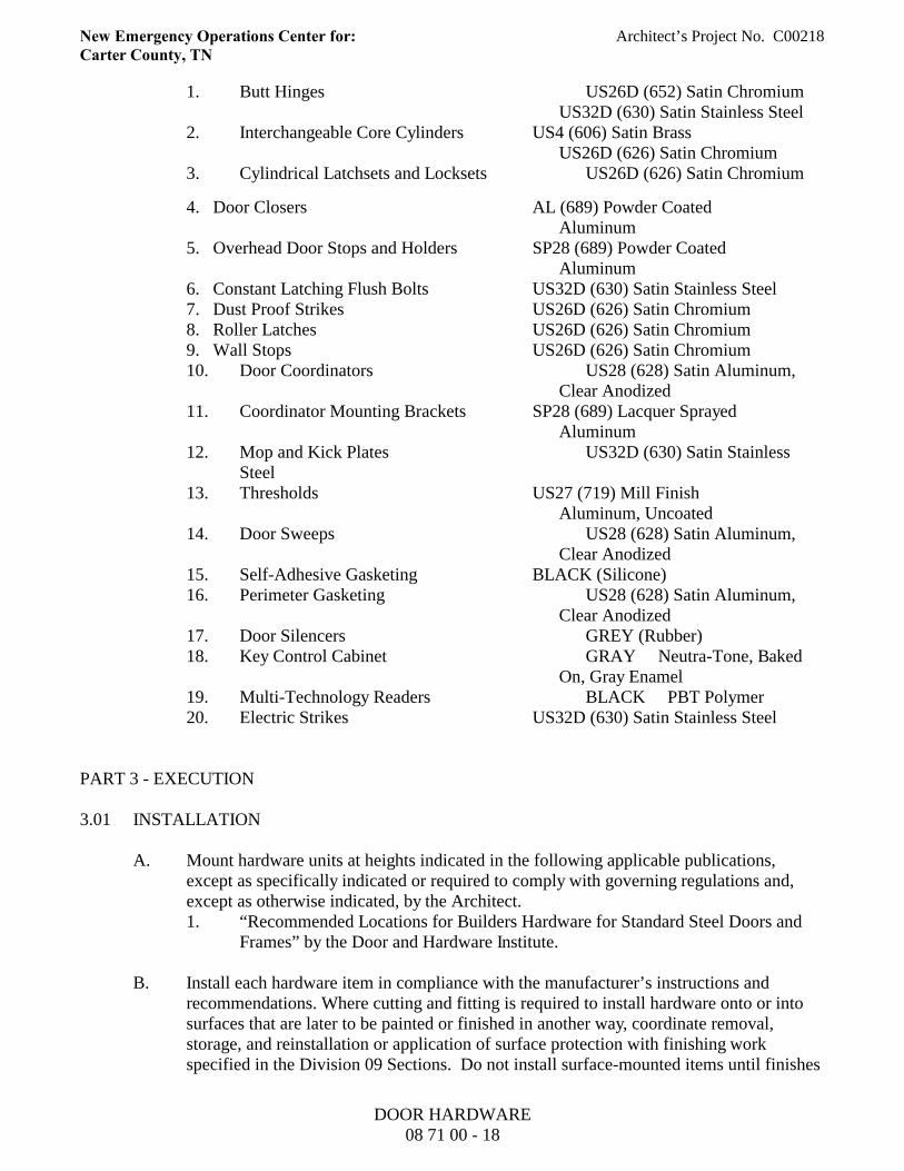
New Emergency Operations Center for: Architect’s Project No. C00218Carter County, TN
1. Butt Hinges US26D (652) Satin ChromiumUS32D (630) Satin Stainless Steel
2. Interchangeable Core Cylinders US4 (606) Satin BrassUS26D (626) Satin Chromium
3. Cylindrical Latchsets and Locksets US26D (626) Satin Chromium
4. Door Closers AL (689) Powder CoatedAluminum
5. Overhead Door Stops and Holders SP28 (689) Powder CoatedAluminum
6. Constant Latching Flush Bolts US32D (630) Satin Stainless Steel7. Dust Proof Strikes US26D (626) Satin Chromium8. Roller Latches US26D (626) Satin Chromium9. Wall Stops US26D (626) Satin Chromium10. Door Coordinators US28 (628) Satin Aluminum,
Clear Anodized11. Coordinator Mounting Brackets SP28 (689) Lacquer Sprayed
Aluminum12. Mop and Kick Plates US32D (630) Satin Stainless
Steel13. Thresholds US27 (719) Mill Finish
Aluminum, Uncoated14. Door Sweeps US28 (628) Satin Aluminum,
Clear Anodized15. Self-Adhesive Gasketing BLACK (Silicone)16. Perimeter Gasketing US28 (628) Satin Aluminum,
Clear Anodized17. Door Silencers GREY (Rubber)18. Key Control Cabinet GRAY Neutra-Tone, Baked
On, Gray Enamel19. Multi-Technology Readers BLACK PBT Polymer20. Electric Strikes US32D (630) Satin Stainless Steel
PART 3 - EXECUTION
3.01 INSTALLATION
A. Mount hardware units at heights indicated in the following applicable publications,except as specifically indicated or required to comply with governing regulations and,except as otherwise indicated, by the Architect.1. “Recommended Locations for Builders Hardware for Standard Steel Doors and
Frames” by the Door and Hardware Institute.
B. Install each hardware item in compliance with the manufacturer’s instructions andrecommendations. Where cutting and fitting is required to install hardware onto or intosurfaces that are later to be painted or finished in another way, coordinate removal,storage, and reinstallation or application of surface protection with finishing workspecified in the Division 09 Sections. Do not install surface-mounted items until finishes
DOOR HARDWARE08 71 00 - 18
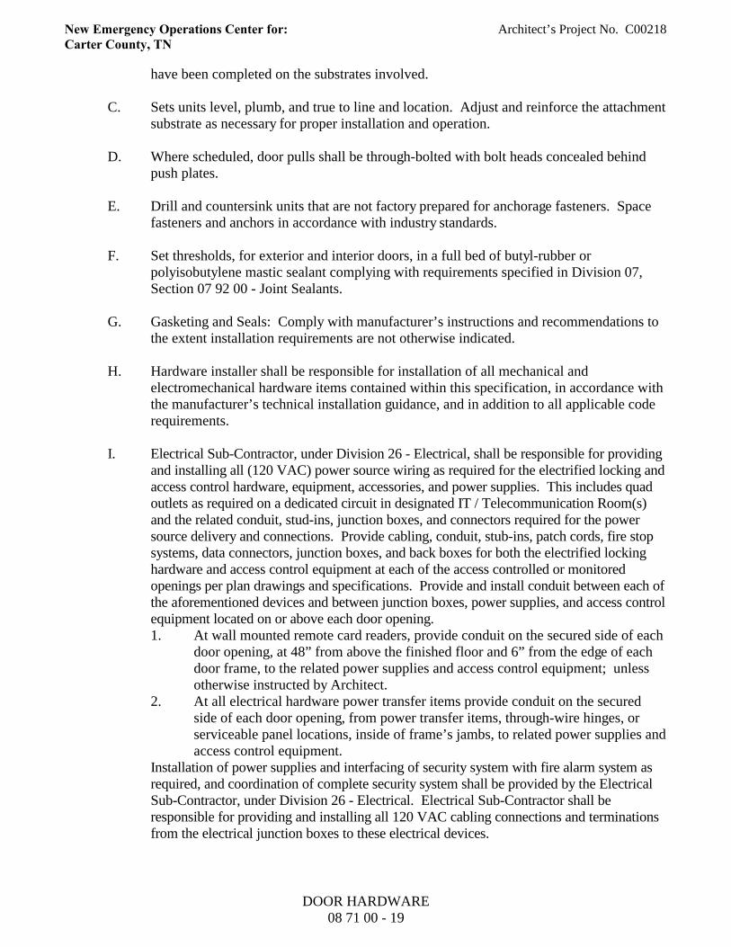
New Emergency Operations Center for: Architect’s Project No. C00218Carter County, TN
have been completed on the substrates involved.
C. Sets units level, plumb, and true to line and location. Adjust and reinforce the attachmentsubstrate as necessary for proper installation and operation.
D. Where scheduled, door pulls shall be through-bolted with bolt heads concealed behindpush plates.
E. Drill and countersink units that are not factory prepared for anchorage fasteners. Spacefasteners and anchors in accordance with industry standards.
F. Set thresholds, for exterior and interior doors, in a full bed of butyl-rubber orpolyisobutylene mastic sealant complying with requirements specified in Division 07,Section 07 92 00 - Joint Sealants.
G. Gasketing and Seals: Comply with manufacturer’s instructions and recommendations tothe extent installation requirements are not otherwise indicated.
H. Hardware installer shall be responsible for installation of all mechanical andelectromechanical hardware items contained within this specification, in accordance withthe manufacturer’s technical installation guidance, and in addition to all applicable coderequirements.
I. Electrical Sub-Contractor, under Division 26 - Electrical, shall be responsible for providingand installing all (120 VAC) power source wiring as required for the electrified locking andaccess control hardware, equipment, accessories, and power supplies. This includes quadoutlets as required on a dedicated circuit in designated IT / Telecommunication Room(s)and the related conduit, stud-ins, junction boxes, and connectors required for the powersource delivery and connections. Provide cabling, conduit, stub-ins, patch cords, fire stopsystems, data connectors, junction boxes, and back boxes for both the electrified lockinghardware and access control equipment at each of the access controlled or monitoredopenings per plan drawings and specifications. Provide and install conduit between each ofthe aforementioned devices and between junction boxes, power supplies, and access controlequipment located on or above each door opening.1. At wall mounted remote card readers, provide conduit on the secured side of each
door opening, at 48” from above the finished floor and 6” from the edge of eachdoor frame, to the related power supplies and access control equipment; unlessotherwise instructed by Architect.
2. At all electrical hardware power transfer items provide conduit on the securedside of each door opening, from power transfer items, through-wire hinges, orserviceable panel locations, inside of frame’s jambs, to related power supplies andaccess control equipment.
Installation of power supplies and interfacing of security system with fire alarm system asrequired, and coordination of complete security system shall be provided by the ElectricalSub-Contractor, under Division 26 - Electrical. Electrical Sub-Contractor shall beresponsible for providing and installing all 120 VAC cabling connections and terminationsfrom the electrical junction boxes to these electrical devices.
DOOR HARDWARE08 71 00 - 19
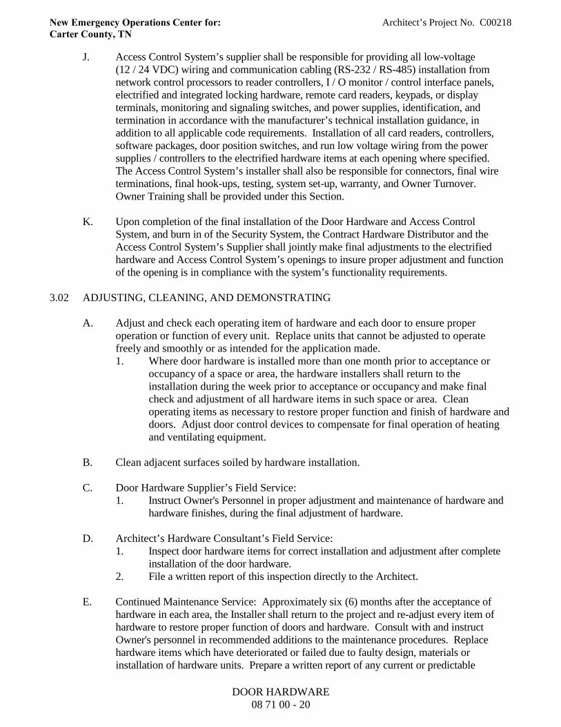
New Emergency Operations Center for: Architect’s Project No. C00218Carter County, TN
J. Access Control System’s supplier shall be responsible for providing all low-voltage(12 / 24 VDC) wiring and communication cabling (RS-232 / RS-485) installation fromnetwork control processors to reader controllers, I / O monitor / control interface panels,electrified and integrated locking hardware, remote card readers, keypads, or displayterminals, monitoring and signaling switches, and power supplies, identification, andtermination in accordance with the manufacturer’s technical installation guidance, inaddition to all applicable code requirements. Installation of all card readers, controllers,software packages, door position switches, and run low voltage wiring from the powersupplies / controllers to the electrified hardware items at each opening where specified. The Access Control System’s installer shall also be responsible for connectors, final wireterminations, final hook-ups, testing, system set-up, warranty, and Owner Turnover. Owner Training shall be provided under this Section.
K. Upon completion of the final installation of the Door Hardware and Access ControlSystem, and burn in of the Security System, the Contract Hardware Distributor and theAccess Control System’s Supplier shall jointly make final adjustments to the electrifiedhardware and Access Control System’s openings to insure proper adjustment and functionof the opening is in compliance with the system’s functionality requirements.
3.02 ADJUSTING, CLEANING, AND DEMONSTRATING
A. Adjust and check each operating item of hardware and each door to ensure properoperation or function of every unit. Replace units that cannot be adjusted to operatefreely and smoothly or as intended for the application made.1. Where door hardware is installed more than one month prior to acceptance or
occupancy of a space or area, the hardware installers shall return to theinstallation during the week prior to acceptance or occupancy and make finalcheck and adjustment of all hardware items in such space or area. Cleanoperating items as necessary to restore proper function and finish of hardware anddoors. Adjust door control devices to compensate for final operation of heatingand ventilating equipment.
B. Clean adjacent surfaces soiled by hardware installation.
C. Door Hardware Supplier’s Field Service:1. Instruct Owner's Personnel in proper adjustment and maintenance of hardware and
hardware finishes, during the final adjustment of hardware.
D. Architect’s Hardware Consultant’s Field Service:1. Inspect door hardware items for correct installation and adjustment after complete
installation of the door hardware.2. File a written report of this inspection directly to the Architect.
E. Continued Maintenance Service: Approximately six (6) months after the acceptance ofhardware in each area, the Installer shall return to the project and re-adjust every item ofhardware to restore proper function of doors and hardware. Consult with and instructOwner's personnel in recommended additions to the maintenance procedures. Replacehardware items which have deteriorated or failed due to faulty design, materials orinstallation of hardware units. Prepare a written report of any current or predictable
DOOR HARDWARE08 71 00 - 20
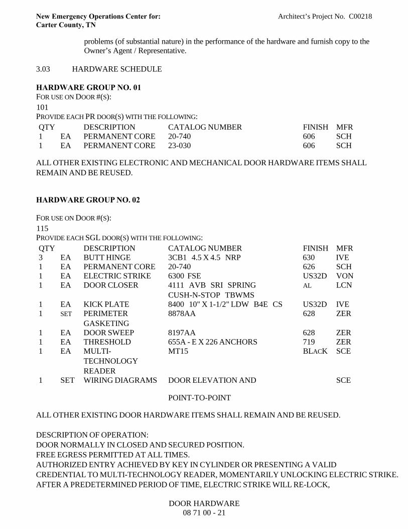
New Emergency Operations Center for: Architect’s Project No. C00218Carter County, TN
problems (of substantial nature) in the performance of the hardware and furnish copy to theOwner’s Agent / Representative.
3.03 HARDWARE SCHEDULE
HARDWARE GROUP NO. 01FOR USE ON DOOR #(S):
101PROVIDE EACH PR DOOR(S) WITH THE FOLLOWING:
QTY DESCRIPTION CATALOG NUMBER FINISH MFR1 EA PERMANENT CORE 20-740 606 SCH1 EA PERMANENT CORE 23-030 606 SCH
ALL OTHER EXISTING ELECTRONIC AND MECHANICAL DOOR HARDWARE ITEMS SHALLREMAIN AND BE REUSED.
HARDWARE GROUP NO. 02
FOR USE ON DOOR #(S):
115PROVIDE EACH SGL DOOR(S) WITH THE FOLLOWING:
QTY DESCRIPTION CATALOG NUMBER FINISH MFR3 EA BUTT HINGE 3CB1 4.5 X 4.5 NRP 630 IVE1 EA PERMANENT CORE 20-740 626 SCH1 EA ELECTRIC STRIKE 6300 FSE US32D VON1 EA DOOR CLOSER 4111 AVB SRI SPRING
CUSH-N-STOP TBWMSAL LCN
1 EA KICK PLATE 8400 10" X 1-1/2" LDW B4E CS US32D IVE1 SET PERIMETER
GASKETING8878AA 628 ZER
1 EA DOOR SWEEP 8197AA 628 ZER1 EA THRESHOLD 655A - E X 226 ANCHORS 719 ZER1 EA MULTI-
TECHNOLOGYREADER
MT15 BLACK SCE
1 SET WIRING DIAGRAMS DOOR ELEVATION AND
POINT-TO-POINT
SCE
ALL OTHER EXISTING DOOR HARDWARE ITEMS SHALL REMAIN AND BE REUSED.
DESCRIPTION OF OPERATION:DOOR NORMALLY IN CLOSED AND SECURED POSITION.FREE EGRESS PERMITTED AT ALL TIMES.AUTHORIZED ENTRY ACHIEVED BY KEY IN CYLINDER OR PRESENTING A VALIDCREDENTIAL TO MULTI-TECHNOLOGY READER, MOMENTARILY UNLOCKING ELECTRIC STRIKE.AFTER A PREDETERMINED PERIOD OF TIME, ELECTRIC STRIKE WILL RE-LOCK,
DOOR HARDWARE08 71 00 - 21

New Emergency Operations Center for: Architect’s Project No. C00218Carter County, TN
SECURING DOOR OPENING.UPON LOSS OF POWER, ELECTRIC STRIKE REMAINS SECURE, REQUIRING A KEY INCYLINDER TO MECHANICALLY OPEN DOOR FROM SECURE SIDE (FAIL-SECURE).
ALL HEAD END EQUIPMENT, INCLUDING BUT NOT LIMITED TO, READER CONTROLLER,READER INTERFACE, POWER SUPPLY, WIRE, AND ALL OTHER COMPONENTS NECESSARYFOR A COMPLETE AND FUNCTIONING ACCESS CONTROL SYSTEM SHALL BE PROVIDEDBY SECURITY SUB-CONTRACTOR.
SUPPLIER SHALL COORDINATE ELECTRICAL REQUIREMENTS WITH ELECTRICALENGINEERS, ALARM SYSTEM'S ENGINEERS, AND ACCESS CONTROL SYSTEM'S INTEGRATORS.
HARDWARE GROUP NO. 03
FOR USE ON DOOR #(S):
117PROVIDE EACH SGL DOOR(S) WITH THE FOLLOWING:
QTY DESCRIPTION CATALOG NUMBER FINISH MFR3 EA BUTT HINGE 3CB1 4.5 X 4.5 630 IVE1 EA PRIVACY LATCHSET ND40S SPA 626 SCH1 EA DOOR CLOSER 4011 REGULAR TBWMS AL LCN1 EA MOP PLATE 8400 4" X 1" LDW B4E CS US32D IVE1 EA KICK PLATE 8400 10" X 1-1/2" LDW B4E CS US32D IVE1 EA WALL STOP WS401CCV US26D IVE1 EA SELF-ADHESIVE
GASKETING8144S-BK BLACK ZER
HARDWARE GROUP NO. 04
FOR USE ON DOOR #(S):
105 108PROVIDE EACH SGL DOOR(S) WITH THE FOLLOWING:
QTY DESCRIPTION CATALOG NUMBER FINISH MFR3 EA BUTT HINGE 3CB1 4.5 X 4.5 626 IVE1 EA OFFICE LOCKSET ND91TD SPA 626 SCH1 EA PERMANENT CORE 23-030 626 SCH1 EA WALL STOP WS401CCV US26D IVE3 EA SILENCER SR64 GREY IVE
DOOR HARDWARE08 71 00 - 22
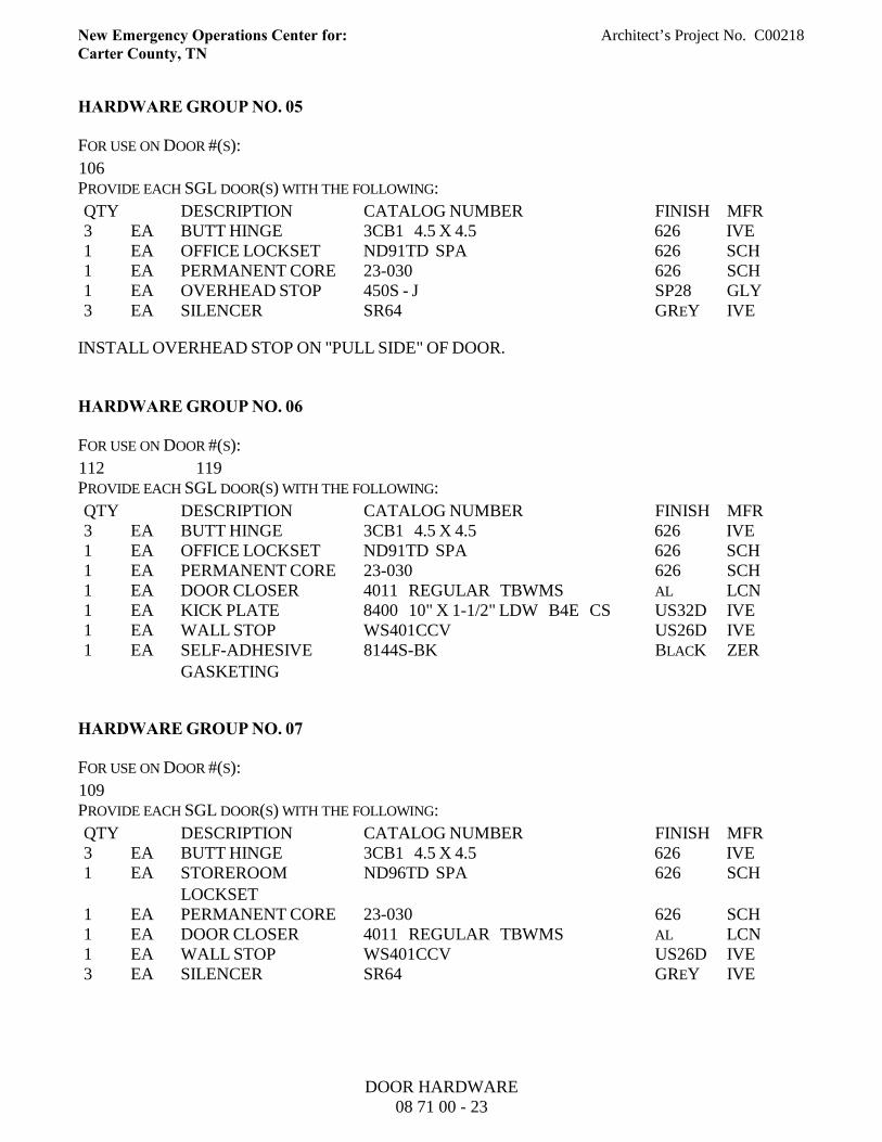
New Emergency Operations Center for: Architect’s Project No. C00218Carter County, TN
HARDWARE GROUP NO. 05
FOR USE ON DOOR #(S):
106PROVIDE EACH SGL DOOR(S) WITH THE FOLLOWING:
QTY DESCRIPTION CATALOG NUMBER FINISH MFR3 EA BUTT HINGE 3CB1 4.5 X 4.5 626 IVE1 EA OFFICE LOCKSET ND91TD SPA 626 SCH1 EA PERMANENT CORE 23-030 626 SCH1 EA OVERHEAD STOP 450S - J SP28 GLY3 EA SILENCER SR64 GREY IVE
INSTALL OVERHEAD STOP ON "PULL SIDE" OF DOOR.
HARDWARE GROUP NO. 06
FOR USE ON DOOR #(S):
112 119PROVIDE EACH SGL DOOR(S) WITH THE FOLLOWING:
QTY DESCRIPTION CATALOG NUMBER FINISH MFR3 EA BUTT HINGE 3CB1 4.5 X 4.5 626 IVE1 EA OFFICE LOCKSET ND91TD SPA 626 SCH1 EA PERMANENT CORE 23-030 626 SCH1 EA DOOR CLOSER 4011 REGULAR TBWMS AL LCN1 EA KICK PLATE 8400 10" X 1-1/2" LDW B4E CS US32D IVE1 EA WALL STOP WS401CCV US26D IVE1 EA SELF-ADHESIVE
GASKETING8144S-BK BLACK ZER
HARDWARE GROUP NO. 07
FOR USE ON DOOR #(S):
109PROVIDE EACH SGL DOOR(S) WITH THE FOLLOWING:
QTY DESCRIPTION CATALOG NUMBER FINISH MFR3 EA BUTT HINGE 3CB1 4.5 X 4.5 626 IVE1 EA STOREROOM
LOCKSETND96TD SPA 626 SCH
1 EA PERMANENT CORE 23-030 626 SCH1 EA DOOR CLOSER 4011 REGULAR TBWMS AL LCN1 EA WALL STOP WS401CCV US26D IVE3 EA SILENCER SR64 GREY IVE
DOOR HARDWARE08 71 00 - 23
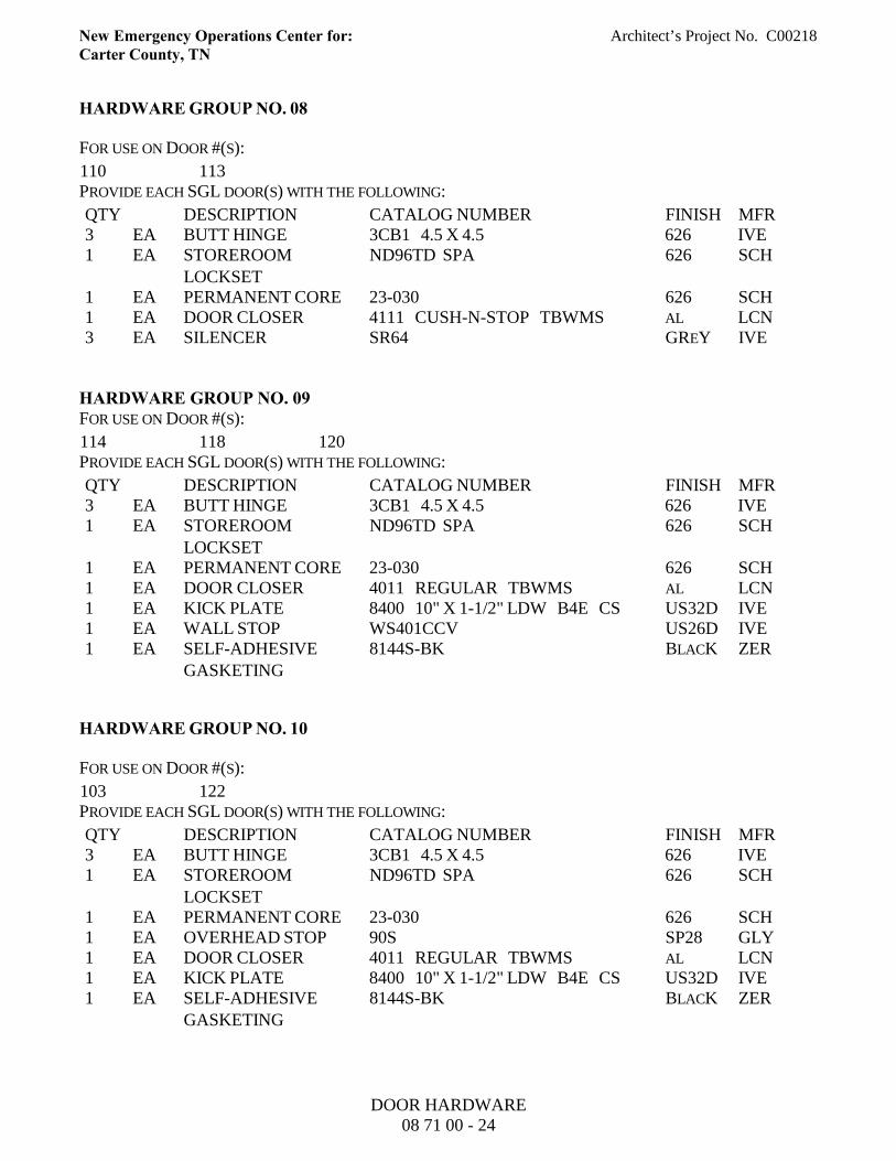
New Emergency Operations Center for: Architect’s Project No. C00218Carter County, TN
HARDWARE GROUP NO. 08
FOR USE ON DOOR #(S):
110 113PROVIDE EACH SGL DOOR(S) WITH THE FOLLOWING:
QTY DESCRIPTION CATALOG NUMBER FINISH MFR3 EA BUTT HINGE 3CB1 4.5 X 4.5 626 IVE1 EA STOREROOM
LOCKSETND96TD SPA 626 SCH
1 EA PERMANENT CORE 23-030 626 SCH1 EA DOOR CLOSER 4111 CUSH-N-STOP TBWMS AL LCN3 EA SILENCER SR64 GREY IVE
HARDWARE GROUP NO. 09FOR USE ON DOOR #(S):
114 118 120PROVIDE EACH SGL DOOR(S) WITH THE FOLLOWING:
QTY DESCRIPTION CATALOG NUMBER FINISH MFR3 EA BUTT HINGE 3CB1 4.5 X 4.5 626 IVE1 EA STOREROOM
LOCKSETND96TD SPA 626 SCH
1 EA PERMANENT CORE 23-030 626 SCH1 EA DOOR CLOSER 4011 REGULAR TBWMS AL LCN1 EA KICK PLATE 8400 10" X 1-1/2" LDW B4E CS US32D IVE1 EA WALL STOP WS401CCV US26D IVE1 EA SELF-ADHESIVE
GASKETING8144S-BK BLACK ZER
HARDWARE GROUP NO. 10
FOR USE ON DOOR #(S):
103 122PROVIDE EACH SGL DOOR(S) WITH THE FOLLOWING:
QTY DESCRIPTION CATALOG NUMBER FINISH MFR3 EA BUTT HINGE 3CB1 4.5 X 4.5 626 IVE1 EA STOREROOM
LOCKSETND96TD SPA 626 SCH
1 EA PERMANENT CORE 23-030 626 SCH1 EA OVERHEAD STOP 90S SP28 GLY1 EA DOOR CLOSER 4011 REGULAR TBWMS AL LCN1 EA KICK PLATE 8400 10" X 1-1/2" LDW B4E CS US32D IVE1 EA SELF-ADHESIVE
GASKETING8144S-BK BLACK ZER
DOOR HARDWARE08 71 00 - 24
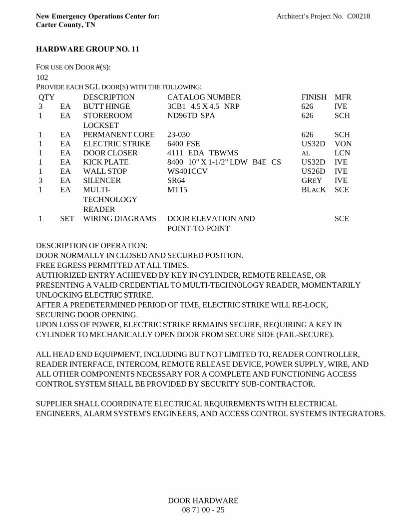
New Emergency Operations Center for: Architect’s Project No. C00218Carter County, TN
HARDWARE GROUP NO. 11
FOR USE ON DOOR #(S):
102PROVIDE EACH SGL DOOR(S) WITH THE FOLLOWING:
QTY DESCRIPTION CATALOG NUMBER FINISH MFR3 EA BUTT HINGE 3CB1 4.5 X 4.5 NRP 626 IVE1 EA STOREROOM
LOCKSETND96TD SPA 626 SCH
1 EA PERMANENT CORE 23-030 626 SCH1 EA ELECTRIC STRIKE 6400 FSE US32D VON1 EA DOOR CLOSER 4111 EDA TBWMS AL LCN1 EA KICK PLATE 8400 10" X 1-1/2" LDW B4E CS US32D IVE1 EA WALL STOP WS401CCV US26D IVE3 EA SILENCER SR64 GREY IVE1 EA MULTI-
TECHNOLOGYREADER
MT15 BLACK SCE
1 SET WIRING DIAGRAMS DOOR ELEVATION ANDPOINT-TO-POINT
SCE
DESCRIPTION OF OPERATION:DOOR NORMALLY IN CLOSED AND SECURED POSITION.FREE EGRESS PERMITTED AT ALL TIMES.AUTHORIZED ENTRY ACHIEVED BY KEY IN CYLINDER, REMOTE RELEASE, ORPRESENTING A VALID CREDENTIAL TO MULTI-TECHNOLOGY READER, MOMENTARILYUNLOCKING ELECTRIC STRIKE.AFTER A PREDETERMINED PERIOD OF TIME, ELECTRIC STRIKE WILL RE-LOCK,SECURING DOOR OPENING.UPON LOSS OF POWER, ELECTRIC STRIKE REMAINS SECURE, REQUIRING A KEY INCYLINDER TO MECHANICALLY OPEN DOOR FROM SECURE SIDE (FAIL-SECURE).
ALL HEAD END EQUIPMENT, INCLUDING BUT NOT LIMITED TO, READER CONTROLLER,READER INTERFACE, INTERCOM, REMOTE RELEASE DEVICE, POWER SUPPLY, WIRE, ANDALL OTHER COMPONENTS NECESSARY FOR A COMPLETE AND FUNCTIONING ACCESSCONTROL SYSTEM SHALL BE PROVIDED BY SECURITY SUB-CONTRACTOR.
SUPPLIER SHALL COORDINATE ELECTRICAL REQUIREMENTS WITH ELECTRICALENGINEERS, ALARM SYSTEM'S ENGINEERS, AND ACCESS CONTROL SYSTEM'S INTEGRATORS.
DOOR HARDWARE08 71 00 - 25
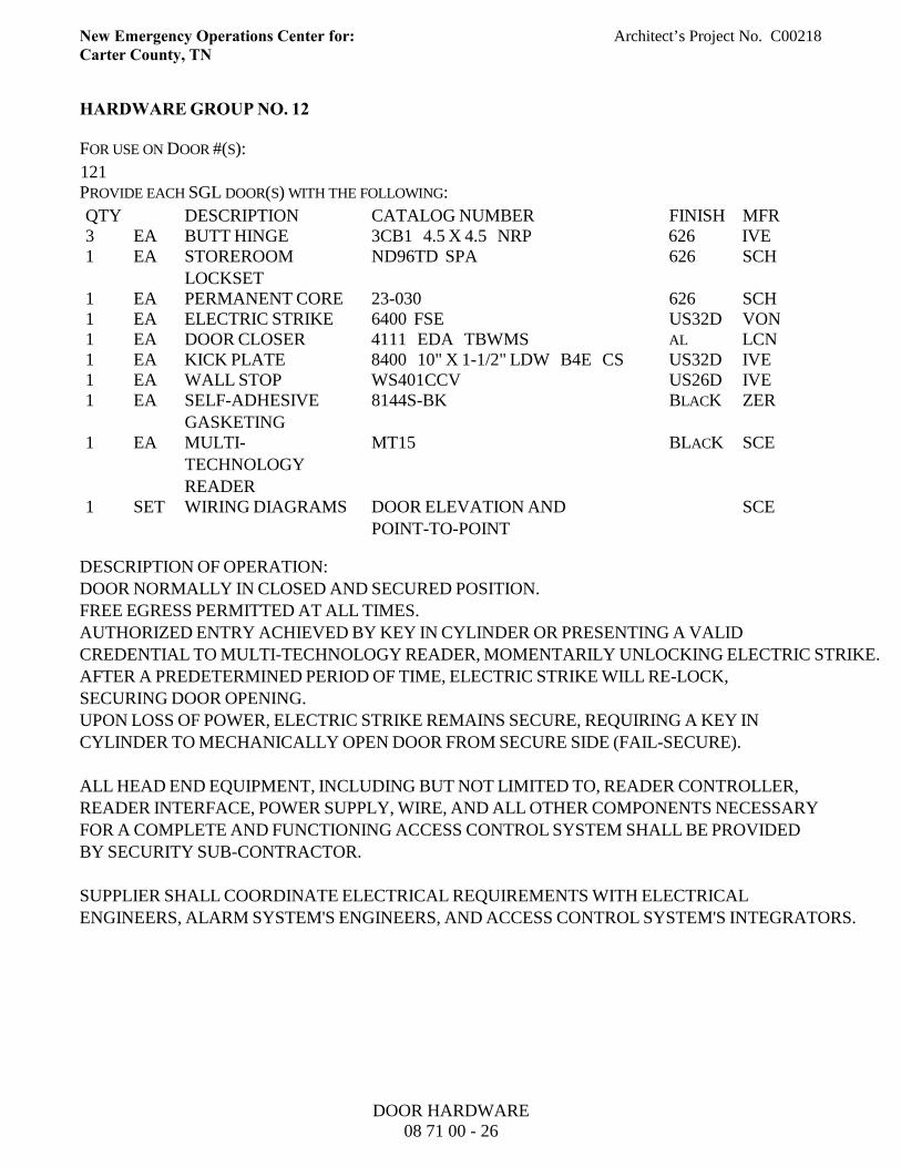
New Emergency Operations Center for: Architect’s Project No. C00218Carter County, TN
HARDWARE GROUP NO. 12
FOR USE ON DOOR #(S):
121PROVIDE EACH SGL DOOR(S) WITH THE FOLLOWING:
QTY DESCRIPTION CATALOG NUMBER FINISH MFR3 EA BUTT HINGE 3CB1 4.5 X 4.5 NRP 626 IVE1 EA STOREROOM
LOCKSETND96TD SPA 626 SCH
1 EA PERMANENT CORE 23-030 626 SCH1 EA ELECTRIC STRIKE 6400 FSE US32D VON1 EA DOOR CLOSER 4111 EDA TBWMS AL LCN1 EA KICK PLATE 8400 10" X 1-1/2" LDW B4E CS US32D IVE1 EA WALL STOP WS401CCV US26D IVE1 EA SELF-ADHESIVE
GASKETING8144S-BK BLACK ZER
1 EA MULTI-TECHNOLOGYREADER
MT15 BLACK SCE
1 SET WIRING DIAGRAMS DOOR ELEVATION ANDPOINT-TO-POINT
SCE
DESCRIPTION OF OPERATION:DOOR NORMALLY IN CLOSED AND SECURED POSITION.FREE EGRESS PERMITTED AT ALL TIMES.AUTHORIZED ENTRY ACHIEVED BY KEY IN CYLINDER OR PRESENTING A VALIDCREDENTIAL TO MULTI-TECHNOLOGY READER, MOMENTARILY UNLOCKING ELECTRIC STRIKE.AFTER A PREDETERMINED PERIOD OF TIME, ELECTRIC STRIKE WILL RE-LOCK,SECURING DOOR OPENING.UPON LOSS OF POWER, ELECTRIC STRIKE REMAINS SECURE, REQUIRING A KEY INCYLINDER TO MECHANICALLY OPEN DOOR FROM SECURE SIDE (FAIL-SECURE).
ALL HEAD END EQUIPMENT, INCLUDING BUT NOT LIMITED TO, READER CONTROLLER,READER INTERFACE, POWER SUPPLY, WIRE, AND ALL OTHER COMPONENTS NECESSARYFOR A COMPLETE AND FUNCTIONING ACCESS CONTROL SYSTEM SHALL BE PROVIDEDBY SECURITY SUB-CONTRACTOR.
SUPPLIER SHALL COORDINATE ELECTRICAL REQUIREMENTS WITH ELECTRICALENGINEERS, ALARM SYSTEM'S ENGINEERS, AND ACCESS CONTROL SYSTEM'S INTEGRATORS.
DOOR HARDWARE08 71 00 - 26
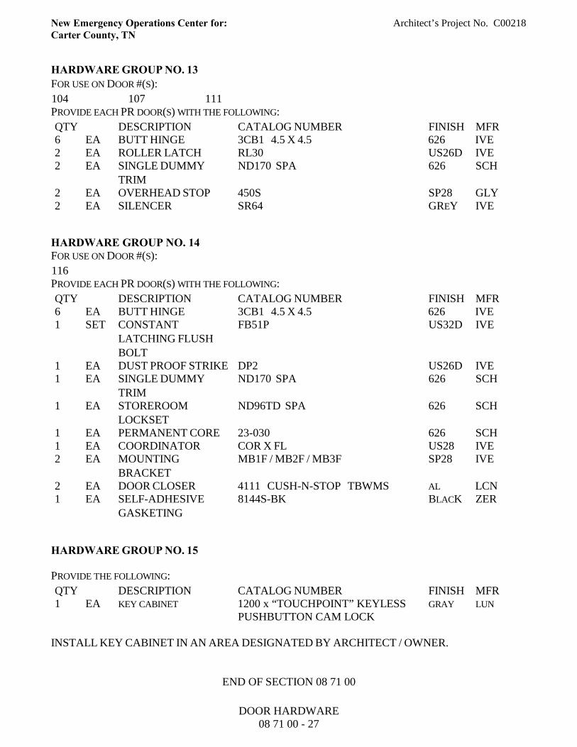
New Emergency Operations Center for: Architect’s Project No. C00218Carter County, TN
HARDWARE GROUP NO. 13FOR USE ON DOOR #(S):
104 107 111PROVIDE EACH PR DOOR(S) WITH THE FOLLOWING:
QTY DESCRIPTION CATALOG NUMBER FINISH MFR6 EA BUTT HINGE 3CB1 4.5 X 4.5 626 IVE2 EA ROLLER LATCH RL30 US26D IVE2 EA SINGLE DUMMY
TRIMND170 SPA 626 SCH
2 EA OVERHEAD STOP 450S SP28 GLY2 EA SILENCER SR64 GREY IVE
HARDWARE GROUP NO. 14FOR USE ON DOOR #(S):
116PROVIDE EACH PR DOOR(S) WITH THE FOLLOWING:
QTY DESCRIPTION CATALOG NUMBER FINISH MFR6 EA BUTT HINGE 3CB1 4.5 X 4.5 626 IVE1 SET CONSTANT
LATCHING FLUSHBOLT
FB51P US32D IVE
1 EA DUST PROOF STRIKE DP2 US26D IVE1 EA SINGLE DUMMY
TRIMND170 SPA 626 SCH
1 EA STOREROOMLOCKSET
ND96TD SPA 626 SCH
1 EA PERMANENT CORE 23-030 626 SCH1 EA COORDINATOR COR X FL US28 IVE2 EA MOUNTING
BRACKETMB1F / MB2F / MB3F SP28 IVE
2 EA DOOR CLOSER 4111 CUSH-N-STOP TBWMS AL LCN1 EA SELF-ADHESIVE
GASKETING8144S-BK BLACK ZER
HARDWARE GROUP NO. 15
PROVIDE THE FOLLOWING:
QTY DESCRIPTION CATALOG NUMBER FINISH MFR1 EA KEY CABINET 1200 x “TOUCHPOINT” KEYLESS
PUSHBUTTON CAM LOCKGRAY LUN
INSTALL KEY CABINET IN AN AREA DESIGNATED BY ARCHITECT / OWNER.
END OF SECTION 08 71 00
DOOR HARDWARE08 71 00 - 27

New Emergency Operations Center for: Architect’s Project No. C00218Carter County, TN
SECTION 08 81 00 - GLASS GLAZING
PART 1 - GENERAL
1.01 DESCRIPTION
A. Work included: Provide glazing and glazing accessories where shown on the Drawings, asspecified herein, and as needed for a complete and proper installation.
B. Related work:1. Documents affecting work of this Section include, but are not necessarily limited to,
General Conditions, Supplementary Conditions, and Sections in Division 01 of theseSpecifications.
2. Section 08 11 00: Metal Doors and Frames.3. Section 08 14 23.16: Plastic-Laminate-Faced Wood Doors4. Section 08 43 10: Aluminum Framed Entrances and Storefronts.
1.02 QUALITY ASSURANCE
A. Use adequate numbers of skilled workmen who are thoroughly trained and experienced in thenecessary crafts and who are completely familiar with the specified requirements and themethods needed for proper performance of the work of this Section.
B. Comply with Safety Standard for Architectural Glazing Materials (16 CFR 1201) of theConsumer Product Safety Division.
C. In addition to complying with pertinent codes and regulations of governmental agencies havingjurisdiction, comply with pertinent recommendations contained in:1. Flat Glass Marketing Association:
a. "Glazing Sealing Systems Manual";b. "Glazing Manual".
D. Glass labels:1. Deliver glass with labels intact, and indicating name of manufacturer, type, thickness, and
quality of each piece.2. Leave labels on glass until it has been inspected, except that labels shall be removed from
exterior glass prior to exposure to sunlight.3. Where required, provide U.L. labels on all wire glass.
1.03 SUBMITTAL
A. Comply with pertinent provisions of Section 01 33 00 Submittal Procedures,.
GLASS GLAZING08 81 00 - 1
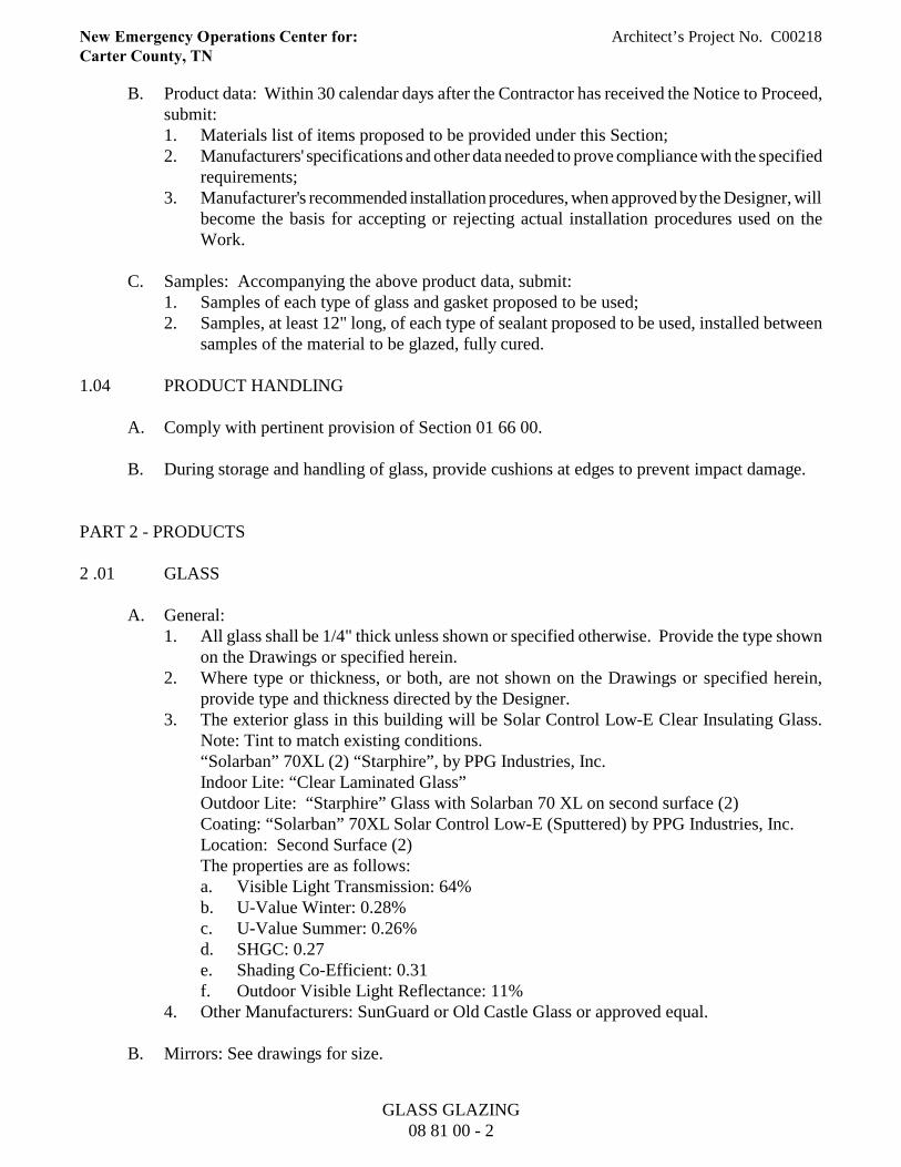
New Emergency Operations Center for: Architect’s Project No. C00218Carter County, TN
B. Product data: Within 30 calendar days after the Contractor has received the Notice to Proceed,submit:1. Materials list of items proposed to be provided under this Section;2. Manufacturers' specifications and other data needed to prove compliance with the specified
requirements;3. Manufacturer's recommended installation procedures, when approved by the Designer, will
become the basis for accepting or rejecting actual installation procedures used on theWork.
C. Samples: Accompanying the above product data, submit:1. Samples of each type of glass and gasket proposed to be used;2. Samples, at least 12" long, of each type of sealant proposed to be used, installed between
samples of the material to be glazed, fully cured.
1.04 PRODUCT HANDLING
A. Comply with pertinent provision of Section 01 66 00.
B. During storage and handling of glass, provide cushions at edges to prevent impact damage.
PART 2 - PRODUCTS
2 .01 GLASS
A. General:1. All glass shall be 1/4" thick unless shown or specified otherwise. Provide the type shown
on the Drawings or specified herein. 2. Where type or thickness, or both, are not shown on the Drawings or specified herein,
provide type and thickness directed by the Designer.3. The exterior glass in this building will be Solar Control Low-E Clear Insulating Glass.
Note: Tint to match existing conditions.“Solarban” 70XL (2) “Starphire”, by PPG Industries, Inc. Indoor Lite: “Clear Laminated Glass” Outdoor Lite: “Starphire” Glass with Solarban 70 XL on second surface (2)Coating: “Solarban” 70XL Solar Control Low-E (Sputtered) by PPG Industries, Inc.Location: Second Surface (2)The properties are as follows:a. Visible Light Transmission: 64%b. U-Value Winter: 0.28%c. U-Value Summer: 0.26%d. SHGC: 0.27e. Shading Co-Efficient: 0.31f. Outdoor Visible Light Reflectance: 11%
4. Other Manufacturers: SunGuard or Old Castle Glass or approved equal.
B. Mirrors: See drawings for size.
GLASS GLAZING08 81 00 - 2
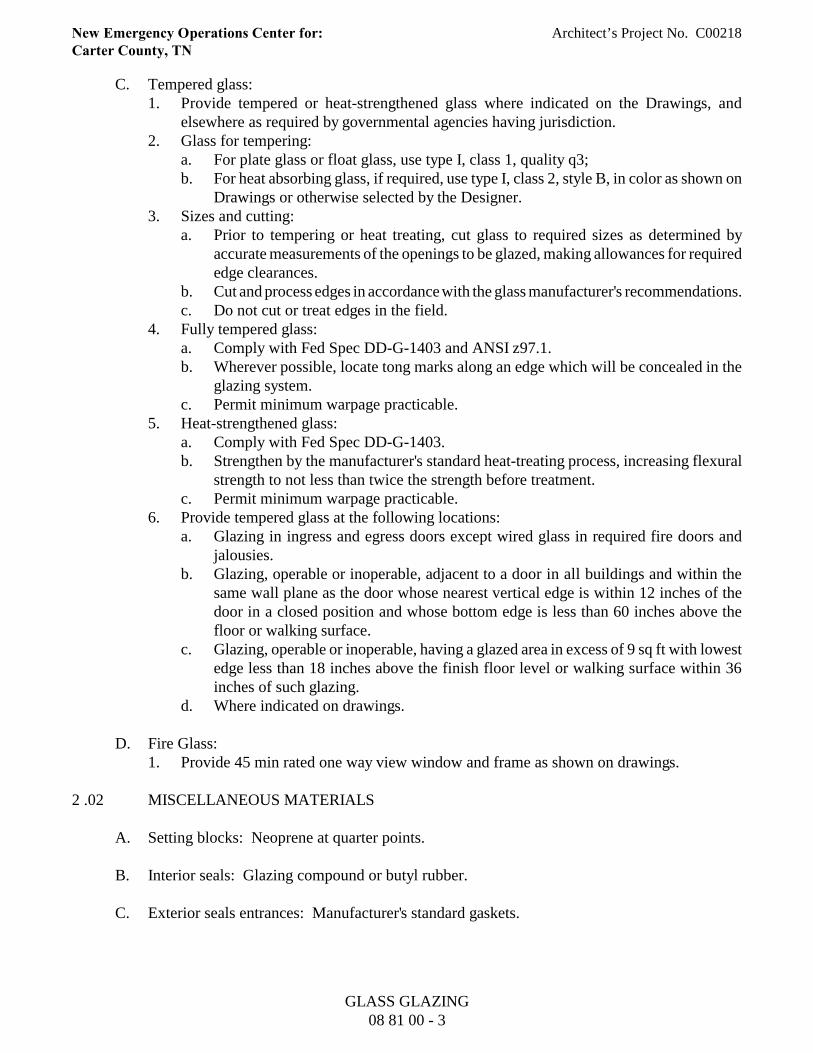
New Emergency Operations Center for: Architect’s Project No. C00218Carter County, TN
C. Tempered glass:1. Provide tempered or heat-strengthened glass where indicated on the Drawings, and
elsewhere as required by governmental agencies having jurisdiction.2. Glass for tempering:
a. For plate glass or float glass, use type I, class 1, quality q3;b. For heat absorbing glass, if required, use type I, class 2, style B, in color as shown on
Drawings or otherwise selected by the Designer.3. Sizes and cutting:
a. Prior to tempering or heat treating, cut glass to required sizes as determined byaccurate measurements of the openings to be glazed, making allowances for requirededge clearances.
b. Cut and process edges in accordance with the glass manufacturer's recommendations.c. Do not cut or treat edges in the field.
4. Fully tempered glass:a. Comply with Fed Spec DD-G-1403 and ANSI z97.1.b. Wherever possible, locate tong marks along an edge which will be concealed in the
glazing system.c. Permit minimum warpage practicable.
5. Heat-strengthened glass:a. Comply with Fed Spec DD-G-1403.b. Strengthen by the manufacturer's standard heat-treating process, increasing flexural
strength to not less than twice the strength before treatment.c. Permit minimum warpage practicable.
6. Provide tempered glass at the following locations:a. Glazing in ingress and egress doors except wired glass in required fire doors and
jalousies.b. Glazing, operable or inoperable, adjacent to a door in all buildings and within the
same wall plane as the door whose nearest vertical edge is within 12 inches of thedoor in a closed position and whose bottom edge is less than 60 inches above thefloor or walking surface.
c. Glazing, operable or inoperable, having a glazed area in excess of 9 sq ft with lowestedge less than 18 inches above the finish floor level or walking surface within 36inches of such glazing.
d. Where indicated on drawings.
D. Fire Glass:1. Provide 45 min rated one way view window and frame as shown on drawings.
2 .02 MISCELLANEOUS MATERIALS
A. Setting blocks: Neoprene at quarter points.
B. Interior seals: Glazing compound or butyl rubber.
C. Exterior seals entrances: Manufacturer's standard gaskets.
GLASS GLAZING08 81 00 - 3
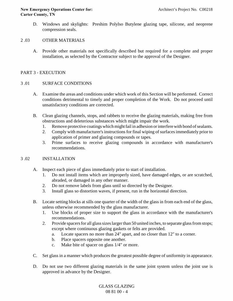
New Emergency Operations Center for: Architect’s Project No. C00218Carter County, TN
D. Windows and skylights: Preshim Polylso Butylene glazing tape, silicone, and neoprenecompression seals.
2 .03 OTHER MATERIALS
A. Provide other materials not specifically described but required for a complete and properinstallation, as selected by the Contractor subject to the approval of the Designer.
PART 3 - EXECUTION
3 .01 SURFACE CONDITIONS
A. Examine the areas and conditions under which work of this Section will be performed. Correctconditions detrimental to timely and proper completion of the Work. Do not proceed untilunsatisfactory conditions are corrected.
B. Clean glazing channels, stops, and rabbets to receive the glazing materials, making free fromobstructions and deleterious substances which might impair the work.1. Remove protective coatings which might fail in adhesion or interfere with bond of sealants.2. Comply with manufacturer's instructions for final wiping of surfaces immediately prior to
application of primer and glazing compounds or tapes.3. Prime surfaces to receive glazing compounds in accordance with manufacturer's
recommendations.
3 .02 INSTALLATION
A. Inspect each piece of glass immediately prior to start of installation.1. Do not install items which are improperly sized, have damaged edges, or are scratched,
abraded, or damaged in any other manner.2. Do not remove labels from glass until so directed by the Designer.3. Install glass so distortion waves, if present, run in the horizontal direction.
B. Locate setting blocks at sills one quarter of the width of the glass in from each end of the glass,unless otherwise recommended by the glass manufacturer.1. Use blocks of proper size to support the glass in accordance with the manufacturer's
recommendations.2. Provide spacers for all glass sizes larger than 50 united inches, to separate glass from stops;
except where continuous glazing gaskets or felts are provided.a. Locate spacers no more than 24" apart, and no closer than 12" to a corner.b. Place spacers opposite one another.c. Make bite of spacer on glass 1/4" or more.
C. Set glass in a manner which produces the greatest possible degree of uniformity in appearance.
D. Do not use two different glazing materials in the same joint system unless the joint use isapproved in advance by the Designer.
GLASS GLAZING08 81 00 - 4
New Emergency Operations Center for: Architect’s Project No. C00218Carter County, TN
E. Mask, or otherwise protect, surfaces adjacent to installation of sealants.
F. Miter-cut and seal the joints of glazing gaskets in accordance with the manufacturer'srecommendations, to provide watertight and airtight seal at corners and other locations wherejoints are required.
3 .03 PROTECTION
A. Protect glass from breakage after installation by promptly installing streamers or ribbons,suitably attached to framing and held free from glass. Do not apply warning markings,streamers, ribbons, or other items directly to the glass except as specifically directed by theDesigner.
3 .04 WASTE MANAGEMENT
A. Minimize, segregate, recycle/reuse and otherwise manage waste.
END OF SECTION 08 81 00
GLASS GLAZING08 81 00 - 5
New Emergency Operations Center for: Architect’s Project No. C00218Carter County, TN
SECTION 09 22 16 - NON-STRUCTURAL METAL FRAMING
PART 1 - GENERAL
1.01 DESCRIPTION
A. Work included: Provide steel studs wall systems, wall furring, fasteners, and accessories for thescrew attachment of gypsum board, or other building boards as indicated on the Drawings, asspecified herein, and as needed for a complete and proper installation.
B. Related work:1. Documents affecting work of this Section include, but are not necessarily limited to,
General Conditions, Supplementary Conditions, and Sections in Division 01 of theseSpecifications.
2. Ceiling suspension systems for acoustical tile or panels: Section 09 51 00 - ACOUSTICALCEILINGS.
1.02 TERMINOLOGY
A. Description of terms shall be in accordance with ASTM C754, ASTM C11, ASTM C841 andas specified.
B. Underside of Structure Overhead: In spaces where steel trusses or bar joists are shown, theunderside of structure overhead shall be the underside of the floor or roof construction supportedby beams, trusses, or bar joists.
C. Thickness of steel specified is the minimum bare (uncoated) steel thickness.
1.03 QUALITY ASSURANCE
A. Use adequate numbers of skilled workmen who are thoroughly trained and experienced in thenecessary crafts and who are completely familiar with the specified requirements and themethods needed for proper performance of the work of this Section.
B. In addition to complying with the pertinent codes and regulations of governmental agencieshaving jurisdiction, comply with pertinent recommendations contained in "Specifications forMetal Lathing and Furring" published by the Metal Lath/Steel Framing Association.
1.04 SUBMITTAL
A. Comply with pertinent provisions of Section 01 33 00 Submittal Procedures.
B. Product data: Within 30 calendar days after the Contractor has received the Notice to Proceed,submit:1. Materials list of items proposed to be provided under this Section;
NON-STRUCTURAL METAL FRAMING09 22 16 - 1
New Emergency Operations Center for: Architect’s Project No. C00218Carter County, TN
2. Manufacturers' specifications and other data needed to prove compliance with the specifiedrequirements including:a. Studs, runners and accessories. b. Hanger inserts. c. Channels (Rolled steel). d. Furring channels. e. Screws, clips and other fasteners.
C. Shop Drawings1. Typical metal stud and furring construction system including details around openings and
corner details. 2. Typical fire rated assembly and column fireproofing showing details of construction same
as that used in fire rating test as applicable.
1.05 PRODUCT HANDLING
A. Comply with pertinent provision of Section 01 66 00.
B. In accordance with the requirements of ASTM C754.
1.06 APPLICABLE PUBLICATIONS
A. The publications listed below form a part of this specification to the extent referenced. Thepublications are referenced in the text by the basic designation only.
B. American Society For Testing And Materials (ASTM)
A123-02 Zinc (Hot-dip Galvanized) Coatings on Iron and Steel ProductsA653/A653M-03 Steel Sheet, Zinc-Coated (Galvanized) or Zinc-Iron Alloy Coated
(Galvannealed) by the Hot-Dip Process A641-98 Zinc-Coated (Galvanized) Carbon Steel Wire C11-03 Terminology Relating to Gypsum and Related Building Materials and
Systems C645-03 Non-Structural Steel Framing Members C754-00 Installation of Steel Framing Members to Receive Screw-Attached
Gypsum Panel Products C954-00 Steel Drill Screws for the Application of Gypsum Panel Products or
Metal Plaster Bases to Steel Studs from 0.033 in. to 0.112 in. inThickness
C1002-00 Steel Self-Piercing Tapping Screws for the Application of Gypsum PanelProducts or Metal Plaster Bases to Wood Studs or Steel Studs
E580-02 Application of Ceiling Suspension Systems for Acoustical Tile and Lay-in Panels in Areas Requiring Moderate Seismic Restraint.
NON-STRUCTURAL METAL FRAMING09 22 16 - 2
New Emergency Operations Center for: Architect’s Project No. C00218Carter County, TN
C. Federal Specification (Fed. Spec.):
FF-P-395B Pin, Drive, Guided And Pin Drive, Power Actuated (Fasteners ForPowder Actuated And Hand Actuated Fastening Tools)
PART 2 - PRODUCTS
2 .01 PROTECTIVE COATING
A. Galvanize steel studs, runners (track), rigid (hat section) furring channels, "Z" shaped furringchannels, and resilient furring channels, with coating designation of G-60 minimum, per ASTM123.
2 .02 STEEL STUDS AND RUNNERS (TRACK)
A. ASTM C645, modified for thickness specified and sizes and shown. 1. Use ASTM A525 steel, 20 gauge thick bare metal.2. Runners same gauge as studs.
B. Provide not less than two cutouts in web of each stud, approximately 12 inches from each end,and intermediate cutouts on approximately 24-inch centers.
C. Doubled studs for openings and studs for supporting concrete backer-board.
D. Studs12 feet or less in length shall be in one piece.
E. Studs and runners to be 3 5/8” and 6” in depth with 1 ¼” flanges or legs as indicated ondrawings.
2 .03 FURRING CHANNELS
A. Rigid furring channels (hat shape): ASTM C645.
B. Resilient furring channels: 1. Not less than 0.0179-inch thick bare metal. 2. Semi-hat shape, only one flange for anchorage with channel web leg slotted on anchorage
side, channel web leg on other side stiffens fastener surface but shall not contact anchoragesurface other channel leg is attached to.
C. Rolled Steel Channels: ASTM C754, cold rolled; or, ASTM C841, cold rolled.
2 .04 FASTENERS, CLIPS, AND OTHER METAL ACCESSORIES
A. ASTM C754, except as otherwise specified.
NON-STRUCTURAL METAL FRAMING09 22 16 - 3
New Emergency Operations Center for: Architect’s Project No. C00218Carter County, TN
B. For fire rated construction: Type and size same as used in fire rating test.
C. Fasteners for steel studs thicker than 0.033-inch thick. Use ASTM C954 steel drill screws ofsize and type recommended by the manufacturer of the material being fastened.
D. Clips: ASTM C841 (paragraph 6.11), manufacturer’s standard items. Clips used in lieu of tiewire shall have holding power equivalent to that provided by the tie wire for the specificapplication.
E. Tie Wire and Hanger Wire: 1. ASTM A641, soft temper, Class 1 coating. 2. Gage (diameter) as specified in ASTM C754 or ASTM C841.
F. Attachments for Wall Furring: 1. Manufacturers standard items fabricated from zinc-coated (galvanized) steel sheet. 2. For concrete or masonry walls: Metal slots with adjustable inserts or adjustable wall
furring brackets. Spacers may be fabricated from 0.0396-inch thick galvanized steel withcorrugated edges.
G. Power Actuated Fasteners: 1. Fed. Spec. FF-P-395. 2. Fastener length and Class as required to resist twice the imposed loads; style suitable for
type of hanger or bracket used. 3. Eye Pin: Type I, Class 4, Style EP. 4. Threaded Stud: Style SC for concrete; Style SS for steel. 5. Drive Pins: Style PC for concrete, Style PS for steel. 6. For applications not specified, type and size as recommended by the manufacturer of the
material being fastened.
2 .05 LIGHT GAGE FRAMING AND ACCESSORIES
A. Metal studs:1. At interior light gage framing, unless otherwise shown on the Drawings, provide standard
punched steel studs of the gauges shown on the Drawings, hot-dip galvanized.2. Use only one type throughout the Work, unless otherwise shown on the Drawings or
specifically approved in advance by the Architect.
B. Accessories: Provide all accessories including, but not necessarily limited to, tracks, clips,anchors, web stiffeners, fastening devices, sound attenuation pencil rods and resilient clips, andother accessories required for a complete and proper installation, and as recommended by themanufacturer of the steel studs used.
2 .06 GROUT
A. Provide a good grade of commercial grout for leveling the floor runner member of steel studpartitions as required.
NON-STRUCTURAL METAL FRAMING09 22 16 - 4
New Emergency Operations Center for: Architect’s Project No. C00218Carter County, TN
2 .07 OTHER MATERIALS
A. Sill Plate Gasket: Provide 1/4" x 3 ½" or 1/4" x 5 ½" corrugated polyethylene foam gasketbetween the slab and sill plate at all exterior walls and all walls between conditioned andunconditioned spaces. Gasket to be equal to Green Guard as manufactured by Pactive BuildingProducts of Atlanta, Georgia.
PART 3 - EXECUTION
3 .01 SURFACE CONDITIONS
A. Examine the areas and conditions under which work of this Section will be performed. Correctconditions detrimental to timely and proper completion of the Work. Do not proceed untilunsatisfactory conditions are corrected.
3 .02 INSTALLATION CRITERIA
A. Where fire rated construction is required for walls, partitions, columns, beams and floor-ceilingassemblies, the construction shall be same as that used in fire rating test.
B. Construction requirements for fire rated assemblies and materials shall be as shown andspecified, the provisions of the Scope paragraph (1.2) of ASTM C754 and ASTM C841regarding details of construction shall not apply.
3 .03 INSTALLING STUDS
A. Install studs in accordance with ASTM C754, except as otherwise shown or specified.
B. Space studs not more than 16 inches on center.
C. Cut studs 1/4 to 3/8-inch less than floor to underside of structure overhead when extended tounderside of structure overhead.
D. Where studs are shown to terminate above suspended ceilings, provide bracing as shown orextend studs to underside of structure overhead.
E. Extend studs to underside of structure overhead for fire rated partitions, smoke partitions, shafts,and sound rated partitions.
F. Openings: 1. Frame jambs of openings in stud partitions and furring with two studs placed back to back
or as shown. 2. Fasten back to back studs together with 3/8-inch long Type S pan head screws at not less
than two feet on center, staggered along webs.
NON-STRUCTURAL METAL FRAMING09 22 16 - 5
New Emergency Operations Center for: Architect’s Project No. C00218Carter County, TN
3. Studs fastened flange to flange shall have splice plates on both sides approximately 50 X2 by 3 inches screwed to each stud with two screws in each stud. Locate splice plates at24 inches on center between runner tracks.
G. Fastening Studs: 1. Fasten studs located adjacent to partition intersections, corners and studs at jambs of
openings to flange of runner tracks with two screws through each end of each stud andflange of runner.
2. Do not fasten studs to top runner track when studs extend to underside of structureoverhead.
H. Chase Wall Partitions: 1. Locate cross braces for chase wall partitions to permit the installation of pipes, conduits,
carriers and similar items. 2. Use studs or runners as cross bracing not less than 2-1/2 inches wide.
I. Form building seismic or expansion joints with double studs back to back spaced three inchesapart plus the width of the seismic or expansion joint.
J. Form control joint, with double studs spaced 1/2-inch apart.
3 .04 INSTALLING WALL FURRING FOR FINISH APPLIED TO ONE SIDE ONLY
A. In accordance with ASTM C754, or ASTM C841 except as otherwise specified or shown.
B. Wall furring-Stud System: 1. Framed with 2-1/2 inch or narrower studs, 24 inches on center. 2. Brace as specified in ASTM C754 for Wall Furring-Stud System or brace with sections or
runners or studs placed horizontally at not less than three foot vertical intervals on sidewithout finish.
3. Securely fasten braces to each stud with two Type S pan head screws at each bearing.
3 .05 INSTALLING SUPPORTS REQUIRED BY OTHER TRADES
A. Provide for attachment and support of electrical outlets, plumbing, laboratory or heatingfixtures, toilet accessories, access panel frames, wall bumpers, wood seats, toilet stall partitions,dressing booth partitions, urinal screens, chalkboards, tackboards, wall-hung casework, handrailbrackets, recessed fire extinguisher cabinets and other items supported by stud construction.
B. Provide additional studs where required. Install metal backing plates, or special metal shapesas required, securely fastened to metal studs.
3 .06 TOLERANCES
A. Fastening surface for application of subsequent materials shall not vary more than 1/8-inch fromthe layout line.
NON-STRUCTURAL METAL FRAMING09 22 16 - 6
New Emergency Operations Center for: Architect’s Project No. C00218Carter County, TN
B. Plumb and align vertical members within 1/8-inch.
C. Level or align ceilings within 1/8-inch.
3 .07 LEVELING
A. By use of the specified grout, or by other means approved by the Architect, provide continuoussolid bearing under floor runner members of steel stud partitions and walls.
B. Level in a manner to provide uniform interface with ceilings and other overhead construction.
3 .08 SOUND ATTENUATING PARTITIONS
A. At sound attenuating partitions, set floor runners in two 1/4" diameter continuous beads ofsealant complying with provisions of Section 07 92 00 of these Specifications.
3 .09 WASTE MANAGEMENT
A. Minimize, segregate, recycle/reuse and otherwise manage waste.
END OF SECTION 09 22 16
NON-STRUCTURAL METAL FRAMING09 22 16 - 7
New Emergency Operations Center for: Architect’s Project No. C00218Carter County, TN
SECTION 09 29 00 - GYPSUM BOARD
PART 1 - GENERAL
1.01 DESCRIPTION
A. Work included: Provide gypsum drywall and accessories where shown on the Drawings, asspecified herein, and as needed for a complete and proper installation.
B. Related work:1. Documents affecting work of this Section include, but are not necessarily limited to,
General Conditions, Supplementary Conditions, and Sections in Division 01 of theseSpecifications.
2. Section 06 10 00: Rough Carpentry.3. Section 09 22 16: Non-Structural Metal Framing.
1.02 QUALITY ASSURANCE
A. Use adequate numbers of skilled workmen who are thoroughly trained and experienced in thenecessary crafts and who are completely familiar with the specified requirements and themethods needed for proper performance of the work of this Section.
1.03 SUBMITTAL
A. Comply with pertinent provisions of Section 01 33 00 Submittal Procedures.
B. Product data: Within 30 calendar days after the Contractor has received the Notice to Proceed,submit:1. Materials list of items proposed to be provided under this Section;2. Manufacturers' specifications and other data needed to prove compliance with the specified
requirements;3. Shop Drawings showing typical gypsum board installation, showing corner details, edge
trim details and the like. Also, show typical fire rated assembly and column fireproofing,indicating details of construction same as that used in the fire rating test.
4. Manufacturer's recommended installation procedures, when approved by the Designer, willbecome the basis for accepting or rejecting actual installation procedures used on theWork.
1.04 PRODUCT HANDLING
A. Comply with pertinent provision of Section 01 66 00.
GYPSUM BOARD09 29 00 - 1

New Emergency Operations Center for: Architect’s Project No. C00218Carter County, TN
PART 2 - PRODUCTS
2 .01 GYPSUM WALLBOARD
A. General:1. Provide gypsum wallboard complying with Fed Spec SS-L-30D, in 48" widths and in such
lengths as will result in a minimum of joints.2. Regular wallboard: Provide type III, grade R, class 1, 5/8" thick except as may be shown
otherwise on the Drawings.3. Fire-Retardant wallboard: Provide type III, grade X, class 1, 5/8" thick, except as may be
shown otherwise on the Drawings.4. Water-resistant wallboard: Provide type VII, grade W or X as required, class 2, 5/8" thick
except as may be shown otherwise on the Drawings.
B. All products shall be furnished by the same manufacturer; one of the following:1. United States Gypsum Company;2. National Gypsum Company;3. Celotex Corporation;4. Temple-Inland Gypsum by Temple Inland Forest Products, Cumberland City, TN;5. Sheetrock Brand Gypsum Panels by USG Corporation;6. Gold Bond Gypsum Wallboard by National Gypsum Company, Charlotte, NC.7. Or equal with approval.
C. Gypsum board panels:1. Regular Gypsum Board: ASTM C36, of types, edge configuration and thickness indicated
below; in maximum lengths available to minimize end-to-end butt joints.a. Type: Type “X” for fire-rated assemblies, unless otherwise required by specific U.L.
Assembly Number;b. Edges: Tapered;c. Thickness: 5/8" all locations, unless otherwise indicated.
2. At rooms indicated on Drawings, use moisture resistance “greenboard” gypsum board.
2 .02 METAL TRIM
A. Form from zinc-coated steel not lighter than 26 gauge, complying with Fed Spec QQ-S-775,type I, class d or e.
B. Casing beads:1. Provide channel-shapes with an exposed wing, and with a concealed wing not less than
7/8" wide.2. The exposed wing may be covered with paper cemented to the metal, but shall be suitable
for joint treatment.
C. Corner beads: Provide angle shapes with wings not less than 7/8" wide and perforated fornailing and joint treatment, or with combination metal and paper wings bonded together, not lessthan 1-1/4" wide and suitable for joint treatment.
GYPSUM BOARD09 29 00 - 2
New Emergency Operations Center for: Architect’s Project No. C00218Carter County, TN
2 .03 JOINTING SYSTEM
A. Joint compound: Murco M100 Joint Compound (dry mix), available from Murco Wall Products800-446-7124; USG Sheetrock all purpose joint compound; ProformR Brand Ultra Ready MixJoint Compound by National Gypsum Co., or other equal ready-mix compound.
B. Joint Tape.
C. Provide a jointing system, including reinforcing tape and compound, designed as a system tobe used together and as recommended for this use by the manufacturer of the gypsum wallboardapproved for use on this Work.
D. Jointing compound may be used for finishing if so recommended by its manufacturer.
2 .04 FASTENING DEVICES
A. For fastening gypsum wallboard in place on metal studs and metal channels, use flat-headscrews, shouldered, specially designed for use with power-driven tools, not less than 1" long,with self-tapping threads and self-drilling points.
B. For fastening gypsum wallboard in place on wood, use 1-1/4" type W bugle-head screws, or useannular ring type nails complying with ASTM C514 and of the length required by governmentalagencies having jurisdiction.
2 .05 SEALANTS
A. Acoustical Sealant: USG Acoustical Sealant or equal products by Georgia-Pacific Gypsum LLCor National Gypsum Company or equal.
B. Water Resistant Sealant: USG W/R Sealant or equal.
2 .06 OTHER MATERIALS
A. Provide other materials not specifically described but required for a complete and properinstallation, as selected by the Contractor subject to the approval of the Designer.
PART 3 - EXECUTION
3 .01 SURFACE CONDITIONS
A. Examine the areas and conditions under which work of this Section will be performed. Correctconditions detrimental to timely and proper completion of the Work. Do not proceed untilunsatisfactory conditions are corrected.
GYPSUM BOARD09 29 00 - 3
New Emergency Operations Center for: Architect’s Project No. C00218Carter County, TN
3 .02 INSTALLATION
A. General:1. Install the gypsum wallboard in accordance with the Drawings and with the separate
boards in moderate contact but not forced into place.2. At internal and external corners, conceal the cut edges of the boards by the overlapping
covered edges of the abutting boards.3. Stagger the boards so that corners of any four boards will not meet at a common point
except in vertical corners.
B. Walls:1. Install the gypsum wallboard to studs at right angles to the furring or framing members.2. Make end joints, where required, over framing or furring members.
C. Attaching:1. Drive the specified screws with clutch-controlled power screwdrivers, spacing the screws
12" on centers at ceilings and 16" on centers at walls.2. Where framing members are spaces 24" apart on walls, space screws 12" on centers.3. Attach double layers in accordance with the pertinent codes and the manufacturer's
recommendations as approved by the Designer.4. Attach to wood as required by governmental agencies having jurisdiction
3 .03 JOINT TREATMENT
A. General:1. Inspect areas to be joint treated, verifying that the gypsum wallboard fits snugly against
supporting framework.2. In areas where joint treatment and compound finishing will be performed, maintain a
temperature of not less than 55 degrees for 24 hours prior to commencing the treatment,and until joint and finishing compounds have dried.
3. Apply the joint treatment and finishing compound by machine or hand tools.4. Provide a minimum drying time of 24 hours between coats, with additional drying time in
poorly ventilated areas.
B. Embedding compounds:1. Apply to gypsum wallboard joints and fastener heads in a thin uniform layer.2. Spread the compound not less than 3" wide at joints, center the reinforcing tape in the
joint, and embed the tape in the compound. Then spread a thin layer of compound overthe tape.
3. After this treatment has dried, apply a second coat of embedding compound to joints andfastener heads, spreading in a thin uniform coat to not less than 6" wide at joints, andfeather edged.
4. Sandpaper between coats as required.5. When thoroughly dry, sandpaper to eliminate ridges and high points.
GYPSUM BOARD09 29 00 - 4
New Emergency Operations Center for: Architect’s Project No. C00218Carter County, TN
C. Finishing compounds:1. After embedding compound is thoroughly dry and has been completely sanded, apply a
coat of finishing compound to joints and fastener heads.2. Feather the finishing compound to not less than 12" wide.3. When thoroughly dry, sandpaper to obtain a uniformly smooth surface, taking care to not
scuff the paper surface of the wallboard.
3 .04 CORNER TREATMENT
A. Internal corners: Treat as specified for joints, except fold the reinforcing tape lengthwisethrough the middle and fit neatly into the corner.
B. External corners:1. Install the specified corner bead, fitting neatly over the corner and securing with the same
type fasteners used for installing the wallboard.2. Space the fasteners approximately 6" on centers, and drive through the wallboard into the
framing or furring member.3. After the corner bead has been secured into position, treat the corner with joint compound
and reinforcing tape as specified for joints, feathering the joint compound out from 8" to10" on each side of the corner.
3 .05 OTHER METAL TRIM
A. General:1. The Drawings do not purport to show all locations and requirements for metal trim.2. Carefully study the Drawings and the installation, and provide all metal trim normally
recommended by the manufacturer of the gypsum wallboard approved for use in this Work.
3 .06 CLEANING UP
A. In addition to other requirements for cleaning, use necessary care to prevent scattering gypsumwallboard scraps and dust, and to prevent tracking gypsum and joint finishing compound ontofloor surfaces.
B. At completion of each segment of installation in a room or space, promptly pick up and removefrom the working area all scrap, debris, and surplus material of this Section.
3 .07 WASTE MANAGEMENT
A. Minimize, segregate, recycle/reuse and otherwise manage waste.
END OF SECTION 09 29 00
GYPSUM BOARD09 29 00 - 5
New Emergency Operations Center for: Architect’s Project No. C00218Carter County, TN
SECTION 09 51 00 - ACOUSTICAL CEILINGS
PART 1 - GENERAL
1.01 DESCRIPTION
A. Work included: Provide acoustical ceilings where shown on the Drawings, as specified herein,and as needed for a complete and proper installation.
B. Related work:1. Documents affecting work of this Section include, but are not necessarily limited to,
General Conditions, Supplementary Conditions, and Sections in Division 01 of theseSpecifications.
1.02 QUALITY ASSURANCE
A. Use adequate numbers of skilled workmen who are thoroughly trained and experienced in thenecessary crafts and who are completely familiar with the specified requirements and themethods needed for proper performance of the work of this Section.
B. Comply with U.L. Assembly # P225.
1.03 SUBMITTAL
A. Comply with pertinent provisions of Section 01 33 00 Submittal Procedures.
B. Product data: Within 30 calendar days after the Contractor has received the Notice to Proceed,submit:1. Materials list of items proposed to be provided under this Section;2. Manufacturers' specifications and other data needed to prove compliance with the specified
requirements;3. Shop Drawings in sufficient detail to show suspension, layout, lateral restraint, installation,
anchorage, and interface of the work of this Section with the Work of adjacent trades;4. Manufacturer's recommended installation procedures, when approved by the Designer, will
become the basis for accepting or rejecting actual installation procedures used on theWork.
1.04 PRODUCT HANDLING
A. Comply with pertinent provision of Section 01 66 00.
1.05 EXTRA STOCK
A. Deliver to the Owner for his use in future modifications, an extra stock of approximately 1% ofeach type of acoustical material installed, packaging each type of material separately, distinctlymarked, and adequately protected against deterioration.
ACOUSTICAL CEILINGS09 51 00 - 1
New Emergency Operations Center for: Architect’s Project No. C00218Carter County, TN
PART 2 - PRODUCTS
2 .01 GENERAL
A. Acoustical Ceiling Tile: 1. Cellulose Base:
a. Toxicity/IEQ: Coating or Panel based anti-microbial treatment to inhibit growth ofmold and mildew: 1) Coating-Based Antimicrobial Treatment: Provide acoustical panels with face
and back surfaces coated with antimicrobial treatment; and showing no mold ormildew growth when tested in accordance with ASTM D3273.
2) Panel-Based Antimicrobial Treatment: Provide acoustical panels manufacturedwith antimicrobial treatment in the panels.
2. Mineral Base: a. Toxicity/IEQ: Coating or Panel based anti-microbial treatment to inhibit growth of
mold and mildew: 1) Coating-Based Antimicrobial Treatment: Provide acoustical panels with face
and back surfaces coated with antimicrobial treatment; and showing no mold ormildew growth when tested in accordance with ASTM D3273.
2) Panel-Based Antimicrobial Treatment: Provide acoustical panels manufacturedwith antimicrobial treatment in the panels.
2 .02 "T" GRID SYSTEM
A. Provide a complete system of supporting members, anchors, wall cornices, adapters for lightfixtures and grilles, and accessories of every type required for a complete suspended "T" gridsystem of the arrangements shown on the Drawings, in color or colors selected by the Designerfrom standard colors of the approved manufacturer, and complying with pertinent requirementsof Underwriters Laboratories, Inc., and governmental agencies having jurisdiction.
B. Armstrong World Industries, Inc., Chicago Metallic Corp., USG Donn or approved equal.1. Aluminum with baked polyester paint finish, Armstrong AL Prelude Plus XL 15/16"
Exposed Tee or equal. Color to be white.2. Ceiling grid shall bear the U.L. Classification Marking.
2 .03 ACOUSTICAL CEILING PANELS
A. Acceptable products:1. Armstrong World Industries, Inc., Chicago Metallic Corp., USG Donn or approved equal.
a. Acoustical Ceiling tile, tegular lay-in system: 24" x 48" x 15/16". Tile to beArmstrong Fine Fissured Medium Texture #1732 or equal. Color to be white.
2. Ceiling tiles shall bear the U.L. Classification Marking.
2 .04 OTHER MATERIALS
A. Provide other materials not specifically described but required for a complete and properinstallation, as selected by the Contractor subject to the approval of the Designer.
ACOUSTICAL CEILINGS09 51 00 - 2
New Emergency Operations Center for: Architect’s Project No. C00218Carter County, TN
PART 3 - EXECUTION
3 .01 SURFACE CONDITIONS
A. Examine the areas and conditions under which work of this Section will be performed. Correctconditions detrimental to timely and proper completion of the Work. Do not proceed untilunsatisfactory conditions are corrected.
3 .02 INSTALLATION, GENERAL
A. Except as modified by requirements of governmental agencies having jurisdiction,recommendations of the manufacturer as approved by the Designer, or specific directions of theDesigner, install in accordance with ASTM C636 and the pertinent UL design requirements.
B. Lateral bracing: Provide lateral bracing as required by pertinent codes and regulations. Securelateral bracing to structural members. Secure at right angles to the direction of the partition andfour ways in large ceiling areas.
C. Provide hold-down clips no. 24 MSG spring steel, placed over cross-tees 24" o.c.
D. Make all grid level within a tolerance of one in 1000 and straight within a tolerance of one in1000.
3 .03 INSTALLATION OF ACOUSTICAL MATERIALS
A. "T" grid system: Install acoustical ceiling boards so linearity of facing is as directed by theDesigner.
B. Sound walls: Set acoustical ceiling boards in four continuous bead of 1/4" diameter sealant, onea top of each edge of the gypsum drywall and two on top of the top metal runner track.
3 .04 FIXTURE PROTECTION, ACOUSTICAL MATERIAL
A. 5/8 inch thick, cut to form a five-side enclosure, trapezoidal in cross-section, approximately ½inch longer and wider and 5/8 inch higher than the light fixture housing. For 24" x 48" fixturethe protection consists of a 23-3/4 inch x 47-3/4 inch top piece, two 5-7/8 inch x 47-3/4 inchside pieces, and two 4-1/2 inch x 23-3/4 inch end pieces. The top edge of each fixtureprotection side piece may be provided with a 1 inch deep by 20 inch maximum long notch nearits midpoint. The side and top pieces are laid in place and the end pieces are held in place withthree 8d nails spaced 8 inches o.c. For other size fixtures make enclosure similar.
3 .05 CLEANING UP
A. In addition to other stipulated requirements for cleaning, completely remove finger prints andtraces of soil from the surfaces of grid and acoustical materials, using only those cleaningmaterials recommended for the purpose by the manufacturer of the material being cleaned.
ACOUSTICAL CEILINGS09 51 00 - 3
New Emergency Operations Center for: Architect’s Project No. C00218Carter County, TN
3 .06 WASTE MANAGEMENT
A. Minimize, segregate, recycle/reuse and otherwise manage waste.
END OF SECTION 09 51 00
ACOUSTICAL CEILINGS09 51 00 - 4
New Emergency Operations Center for: Architect’s Project No. C00218Carter County, TN
SECTION 09 65 00 - RESILIENT FLOORING
PART 1 - GENERAL
1.01 DESCRIPTION
A. Work included: Provide resilient flooring and base where shown on the Drawings, as specifiedherein, and as needed for a complete and proper installation.
B. Related work:1. Documents affecting work of this Section include, but are not necessarily limited to,
General Conditions, Supplementary Conditions, and Sections in Division 01 of theseSpecifications.
1.02 QUALITY ASSURANCE
A. Use adequate numbers of skilled workmen who are thoroughly trained and experienced in thenecessary crafts and who are completely familiar with the specified requirements and themethods needed for proper performance of the work of this Section. If linoleum is used, useworkman with linoleum experience since installation procedures are not the same as those forvinyl.
1.03 SUBMITTAL
A. Comply with pertinent provisions of Section 01 33 00 Submittal Procedures.
B. Product data: Within 30 calendar days after the Contractor has received the Notice to Proceed,submit:1. Materials list of items proposed to be provided under this Section;2. Manufacturers' specifications and other data needed to prove compliance with the specified
requirements;3. Samples of each item, color and pattern available in the specified grades from the proposed
manufacturers;4. Manufacturer's recommended application procedures, when approved by the Designer, will
become the basis for accepting or rejecting actual application procedures used on theWork.
1.04 PRODUCT HANDLING
A. Comply with pertinent provision of Section 01 66 00.
B. If vinyl is used, VOCs may be reduced by having product unrolled to air out prior to installationfor 1-2 weeks.
RESILIENT FLOORING09 65 00 - 1

New Emergency Operations Center for: Architect’s Project No. C00218Carter County, TN
1.05 EXTRA STOCK
A. Deliver to the Owner for his use in future modifications an extra stock of approximately 5% ofeach color and pattern of VCT and approximately 1% of each color and pattern of rubber base installed under this Section, packaging each type of material separately, distinctly marked, andadequately protected against deterioration.
PART 2 - PRODUCTS
2 .01 MATERIALS, GENERAL
A. Provide colors and patterns as selected by the Designer from standard colors and patterns of theapproved manufacturer in the specified type.
B. Adhesives:1. Provide waterproof and stabilized type adhesive as recommended by the manufacturer of
the material being installed.2. Asphalt emulsions and other non-waterproof adhesives will not be acceptable.3. Comply with standard referenced this Section Paragraph 1.02 B.
C. Concrete slab primer: Provide non-staining type as required and as recommended by themanufacturer of the material being installed.1. Comply with standard referenced this Section Paragraph 1.02 B.
2 .02 WALL BASE
A. Tarkett Tightlock Resilient Rubber Base1. 1/4 in. thickness, satin finish; ASTM F18612. Product: 1/4 in. Rubber Wall Base.3. Color: Select from manufacturer’s standard color array.4. Profile: Cove5. Size: 4 3/8" in.6. Equal products by the following manufacturers:
a. Tarkettb. Burkec. Roppe Corporationd. Or approved equal.
2 .03 RESILIENT FLOORING
A. LVT (Luxury Vinyl Tile):1. Dimension: Provide Floorfolio LVT tile in colors and patterns as indicated on Drawings.2. Acceptable Products:
a. EF Contractb. Interfacec. Floorfolio
RESILIENT FLOORING09 65 00 - 2
New Emergency Operations Center for: Architect’s Project No. C00218Carter County, TN
d. Tarkette. Or approved equal.
B. Pattern/ Texture: Stone/ abstract appearance with earth color tones. For example; browns, tans, greys, and blacks.
C. Wear layer thickness to be 20 mil or higher.
2 .04 FLOORING ACCESSORIES
A. See Section 09 65 10 for flooring accessories required.
2 .05 OTHER MATERIALS
A. Provide other materials not specifically described but required for a complete and properinstallation, as selected by the Contractor subject to the approval of the Designer.
PART 3 - EXECUTION
3 .01 SURFACE CONDITIONS
A. Examine the areas and conditions under which work of this Section will be performed. Correctconditions detrimental to timely and proper completion of the Work. Do not proceed untilunsatisfactory conditions are corrected.
3 .02 INDOOR AIR QUALITY
A. Temporary ventilation: Provide temporary ventilation as follows. 1. Ventilate products prior to installation. Remove from packaging and ventilate in a secure,
dry, well-ventilated space free from strong contaminant sources and residues. Provide atemperature range of 60 degrees F minimum to 90 degree F maximum continuously forminimum 72 hours. Do not ventilate within limits of Work unless otherwise approved byDesigner.
3 .03 PREPARATION
A. Subfloors:1. Verify that substrate is smooth, level, at required finish elevation, and without more that
1/8" in 10'-0" variation from level or slopes shown on the Drawings.2. Prior to laying materials, broom clean or vacuum the surfaces to be covered, and inspect
the subfloors.
B. Priming:1. Apply concrete slab primer if so recommended by the resilient flooring manufacturer.2. Apply in accordance with the manufacturer's recommendations as approved by the
Designer.
RESILIENT FLOORING09 65 00 - 3
New Emergency Operations Center for: Architect’s Project No. C00218Carter County, TN
3 .04 INSTALLATION
A. General:1. Install materials only after finishing operations, including painting, have been completed
and after permanent heating system is operating.2. Verify that moisture content of concrete slabs, building air temperature, and relative
humidity are within the limits recommended by the manufacturers of the materials used.3. Maintain reference markers, holes, and openings that are in place or plainly marked for
future cutting by repeating on the finish surface as marked in the subfloor. Use chalk orother non-permanent marking device.
B. Installing resilient tiles:1. Place units with adhesive cement in strict compliance with the manufacturer's
recommendations as approved by the Designer.a. Butt units tightly to the vertical surfaces, nosings, edgings, and thresholds.b. Scribe as necessary around obstructions to produce neat joints.c. Place tiles tightly laid, even, and in straight parallel lines.d. Extend units into toe spaces, door reveals, and in closets and similar spaces.
2. Lay units from center marks established with principal walls, discounting minor offsets,so that units at opposite edges of the room are of equal width.a. Adjust as necessary to avoid use of cut widths less than 3" wide at room perimeters.b. Lay units square to axis of the room or space.
3. Match units for color and pattern by using materials from cartons in the same sequence asmanufactured and packaged.
4. Lay in ashlar pattern with grain in all units running the same direction, unless otherwisedirected by the Designer.
5. Place resilient edge strips tightly butted to units and secured with adhesive, providing atall unprotected edges unless otherwise shown.
C. Installing base:1. Install base where shown on the Drawings.2. Use factory-performed exterior corners and job-mitered interior corners.
D. Additional requirements for installing resilient flooring:1. Install in strict accordance with the manufacturer's recommendations as approved by the
Designer.2. Take special care to fill behind nosings of stair treads as shown on the Drawings.
3 .05 CLEANING AND PROTECTING
A. Remove excess adhesive and other blemishes from exposed surfaces, using neutral cleanerrecommended by the manufacturer of the resilient materials.
3 .06 WASTE MANAGEMENT
A. Minimize, segregate, recycle/reuse and otherwise manage waste.
END OF SECTION 09 65 00
RESILIENT FLOORING09 65 00 - 4
New Emergency Operations Center for: Architect’s Project No. C00218Carter County, TN
SECTION 09 65 10 - TRANSITION STRIPS
PART 1 - GENERAL
1.01 DESCRIPTION
A. Work included: Provide flooring accessories where shown on the Drawings, as specified herein,and as needed for a complete and proper installation.
B. Related work:1. Documents affecting work of this Section include, but are not necessarily limited to,
General Conditions, Supplementary Conditions, and Sections in Division 01 of theseSpecifications.
2. Section 09 65 00 - Resilient Flooring3. Section 09 68 00 - Carpeting
1.02 QUALITY ASSURANCE
A. Use adequate numbers of skilled workmen who are thoroughly trained and experienced in thenecessary crafts and who are completely familiar with the specified requirements and themethods needed for proper performance of the work of this Section.
B. Coordinate as required with other trades to assure proper and adequate provision in the work ofthe trades for interface with the work of this Section. It is the Contractors responsibility toassure that all products required on this job are coordinated with the actual material to beinstalled so that all material installations will be properly aligned.
1.03 SUBMITTALS
A. Comply with pertinent provisions of Section 01 33 00 Submittal Procedures.
B. Product data: Within 30 calendar days after the Contractor has received the Notice to Proceed,submit:1. Materials list of items proposed to be provided under this Section;2. Manufacturers' specifications and other data needed to prove compliance with the specified
requirements;3. Samples of each type and color/finish of transition strip required, not less than 3" in length.
1.04 PRODUCT HANDLING
A. Comply with pertinent provision of Section 01 66 00.
TRANSITION STRIPS09 65 10 - 1
New Emergency Operations Center for: Architect’s Project No. C00218Carter County, TN
PART 2 - PRODUCTS
2.01 MATERIALS
A. Provide Burke Mercer rubber transition strips as listed below for the indicated floor transitions:1. Carpet to LVT: 1522. LVT to Concrete: 735
Note: All colors and finishes of the above products to be selected by the Designer from themanufacturer’s standard color chart.
B. Equal products by Roppe Corporation or Johnsonite, Inc. will be accepted or approved equal.
2.02 OTHER MATERIALS
A. Provide other materials not specifically described but required for a complete and properinstallation, as selected by the Contractor subject to the approval of the Designer.
PART 3 - EXECUTION
3.01 SURFACE CONDITIONS
A. Examine the areas and conditions under which work of this Section will be performed. Correctconditions detrimental to timely and proper completion of the Work. Do not proceed untilunsatisfactory conditions are corrected.
3.02 INSTALLATION
A. Install the work of this Section in strict accordance with the manufacturer’s recommendationsas approved by the Designer.
3.03 WASTE MANAGEMENT
A. Minimize, segregate, recycle/reuse and otherwise manage waste.
END OF SECTION 09 65 10
TRANSITION STRIPS09 65 10 - 2
New Emergency Operations Center for: Architect’s Project No. C00218Carter County, TN
SECTION 09 68 00 - CARPETING
PART 1 - GENERAL
1.01 DESCRIPTION
A. Work included: Provide carpet installation and carpet accessories where shown on theDrawings, as specified herein, and as needed for a complete and proper installation.
B. Related work:1. Documents affecting work of this Section include, but are not necessarily limited to,
General Conditions, Supplementary Conditions, and Sections in Division 01 of theseSpecifications.
2. Section 09 65 00 - Resilient Flooring.
1.02 QUALITY ASSURANCE
A. Use adequate numbers of skilled workmen who are thoroughly trained and experienced in thenecessary crafts and who are completely familiar with the specified requirements and themethods needed for proper performance of the work of this Section.
1.03 SUBMITTAL
A. Comply with pertinent provisions of Section 01 33 00 Submittal Procedures.
B. Product data: Within 30 calendar days after the Contractor has received the Notice to Proceed,submit:1. Materials list of items proposed to be provided under this Section;2. Manufacturers' specifications and other data needed to prove compliance with the specified
requirements;3. Shop Drawings showing location of seams and locations and types of carpet metal and
accessories;4. Manufacturer's recommended application procedures, when approved by the Designer, will
become the basis for accepting or rejecting actual application procedures used on theWork.
1.04 PRODUCT HANDLING
A. Comply with pertinent provision of Section 01 66 00.
1.05 EXTRA STOCK
A. Deliver to the Owner for his use in future modifications, an extra stock of approximately 1% ofeach color and pattern in each material installed under this Section, packaging each type ofmaterial separately, distinctly marked, and adequately protected against deterioration
CARPETING09 68 00 - 1
New Emergency Operations Center for: Architect’s Project No. C00218Carter County, TN
PART 2 - PRODUCTS
2 .01 CARPET TILES
A. Provide carpet tiles equal to or exceeding the following requirements, carpet shall be Class Iradiant panel (ASTM-648, NFPA 253 and pass pill test [CPSC FF1-70, ASTM-2859]). Thefollowing spec is based upon EDGELAND 10517 URBAN RELIEF as manufactured byPatcraft:
Product Type: TileColor: From manufacturer’s standard colorsSize: 24" x 24"Construction: Multi level patterned loopDye Method: Solution DyedProtective Treatment(s): Antistatic, soil protection, antimicrobialPrimary Backing: SyntheticSecondary Backing: StrataWorxGauge: 1/12Face Weight: 26 oz.Stitches per inch: 8.5Finished Pile Thickness: 0.095Average Density: 6442Flammability: ASTM E-648 flooring radiant panel class 1,
ASTM E-662 NBS smoke chamber less than 450Electrostatic Propensity: Less than 3.5 KV, permanent conductive filamentProtective Treatments: SSP Shaw Soil ProtectionWarranty: 10 year Commercial LimitedRecommended Installation: Monolithic, 1/4 Turn, Brick, Ashlar, RandomTufted Pile Height: 6/32"Total Thickness: .220 inchesUM 44 & Type/Class: Type I & II, Class 2
B. Equal products by other manufacturers, including products that meet specification above thatare manufactured by one of the following:1. Shaw Industries;2. Interface.3. Or approved equal.
2 .02 FLOORING ACCESSORIES
A. Adhesive: 1. Toxicity/IEQ: Comply with applicable regulations regarding toxic and hazardous materials,
GS-36 for Commercial Adhesive, and as specified.
B. Flame Retardant Additives:1. Toxicity/IEQ: Free of pentabromodiphenyl ether (pentaBDE).
CARPETING09 68 00 - 2
New Emergency Operations Center for: Architect’s Project No. C00218Carter County, TN
C. See Section 09 65 10 for flooring accessories required.
2 .03 OTHER MATERIALS
A. Adhesives: Adhesives shall have maximum VOC level of 50 gm/liter and manufacturerrecommended. Some acceptable if compatible with carpet tile and consistent with carpet tilemanufacturer’s installation instructions are Bentley Prince Street Healthbond Ultra Green, Shaw5000.
B. Provide other materials not specifically described but required for a complete and properinstallation, as selected by the Contractor subject to the approval of the Designer.
PART 3 - EXECUTION
3 .01 SURFACE CONDITIONS
A. Examine the areas and conditions under which work of this Section will be performed. Correctconditions detrimental to timely and proper completion of the Work. Do not proceed untilunsatisfactory conditions are corrected.
3 .02 SURFACE PREPARATION
A. Immediately prior to installation of the work of this Section, thoroughly clean substrata andremove oil, grease, paint, varnish, hardeners, and other items which would adversely affect thebond of adhesive.
B. Make substrata level and free from irregularities. Assure one constant floor height after carpetis installed, filling low spots and grinding high spots as required.
3 .03 CARPET INSTALLATION
A. Indoor Air Quality:1. Temporary ventilation: Provide temporary ventilation as follows:
a. Ventilate products prior to installation. Remove from packaging and ventilate in asecure, dry, well-ventilated space free from strong contaminant sources and residues.Provide a temperature range of 60 degrees F minimum to 90 degree F maximumcontinuously for minimum 72 hours. Do not ventilate within limits of Work unlessotherwise approved by Designer.
2. Immediately after installation, clean carpet thoroughly with a high-efficiency particulateair (HEPA) filtration vacuum or vacuum cleaner.
3. Final cleaning: As specified in Section 01 74 00 - Cleaning.
B. General:1. Glue directly to the floor, using no pads and no foam.2. Scribe the carpet accurately to vertical surfaces.
CARPETING09 68 00 - 3
New Emergency Operations Center for: Architect’s Project No. C00218Carter County, TN
3. Align the lines of carpet, as woven, using no fill strips less than 6" wide, laying all carpetin the same direction unless specifically directed otherwise by the Designer.
C. Seams:1. Locate seams only where shown on the approved Shop Drawings, or where specifically
otherwise approved by the Designer.2. Locate seams to the maximum extent practicable out of the way of traffic.3. Fabricate seams by the compression method, using a butt joint, and properly bead and seal.4. Do not stretch seams.
D. In addition to the cleaning requirements stated elsewhere, thoroughly clean carpet and adjacentsurfaces prior to final acceptance of the carpeted areas by the Owner.
3 .04 FLOORING ACCESSORIES INSTALLATION
A. Install the work of this Section in strict accordance with the manufacturer’s recommendationsas approved by the Designer.
3 .05 PROTECTION
A. Provide a heavy non-staining paper or plastic walkway as required over carpeting in directionof traffic, maintaining intact until carpeted space is accepted by the Owner.
3 .06 SURPLUS MATERIAL
A. Allow the Owner to inspect and select from scrap carpet remaining after the installation. Bundle, wrap in burlap, and deliver to the Owner the carpet scraps selected by him.
3 .07 WASTE MANAGEMENT
A. Minimize, segregate, recycle/reuse and otherwise manage waste.
B. Provide for return of extra scrap product to manufacturer if possible.
END OF SECTION 09 68 00
CARPETING09 68 00 - 4
New Emergency Operations Center for: Architect’s Project No. C00218Carter County, TN
SECTION 09 84 13 - FIXED SOUND-ABSORPTION PANELS
PART 1 - GENERAL
1.01 DESCRIPTION
A. Work included: Provide and install fixed sound absorption panels where shown on theDrawings, as specified herein, and as needed for a complete and proper installation.
B. Related work:1. Documents affecting work of this Section include, but are not necessarily limited to,
General Conditions, Supplementary Conditions, and Sections in Division 01 of theseSpecifications.
1.02 QUALITY ASSURANCE
A. Use adequate numbers of skilled workmen who are thoroughly trained and experienced in thenecessary crafts and who are completely familiar with the specified requirements and themethods needed for proper performance of the work of this Section. All work of this Sectionshall be manufactured by a single firm.
1.03 SUBMITTALS
A. Comply with pertinent provisions of Section 01 33 00.
B. Product data: Within 30 calendar days after the Contractor has received the Notice to Proceed,submit:1. Product Data: Installation instructions and general recommendations, including data
substantiating that materials comply with requirements, for each type of acoustical wallpanel specified.
2. Shop Drawings: Show fabrication and installation of acoustical wall panels includingplans, elevations, sections, details of components, and attachments to other construction.
3. Selection Samples: 12" square units of each type of acoustical wall panel required and ineach color, texture, and pattern indicated or selected for facing materials. Includerepresentative samples of installation devices and accessories.
4. Quality Control Submittals: Acoustical wall panel manufacturer’s certification that theirproducts comply with the specified requirements.
C. Manufacturer’s Product Warranty: Submit manufacturer’s standard limited product writtenwarranty, signed by the manufacturer’s authorized representative, guaranteeing to correctfailures in product which may occur during the warranty period, without reducing or otherwiselimiting any other rights to correction which the Owner may have under the contract documents.
1.04 PRODUCT HANDLING
A. Comply with pertinent provision of Section 01 66 00.
FIXED SOUND-ABSORPTION PANELS09 84 13 - 1
New Emergency Operations Center for: Architect’s Project No. C00218Carter County, TN
1.05 PERFORMANCE REQUIREMENTS
A. NRC (Noise Reduction Coefficient) : Specified average of the sound absorption coefficients atthe frequency bands 0f 250, 500, 1000, & 2000 Hz expressed to the nearest integral multiple of0.05 when panel is tested in accordance with ASTM C 423 in Mounting Type A (ASTM E795).
B. Fire Performance Requirements: Specified surface burning characteristics when core and facingmaterial are tested in accordance with ASTM E 84 as an assembled panel.
PART 2 - PRODUCTS
2 .01 MATERIALS
A. Acoustical Wall Panels - General1. Attach facing materials to cores to produce installed panels with visible surfaces fully
covered and free from waves in fabric weave, wrinkles, sags, blisters, seams, adhesive orother foreign matter.
2. Where radius corners are indicated, attach facing material so there are no seams orgathering of material.
3. Dimensional Tolerances of Finished Units: Overall height and width of panels: Plus orminus 1/16" inch.
4. Panel height and width - See drawings.
B. Sound Control Panels1. ½" cellulose fiber composition board “Sound-A-Sote Panels”.
C. Back-Mounted Acoustical Wall Panels1. NRC: Minimum of 0.952. Panel facing material: Abuse-resistant woven polyester fabric over glass fiber scrim.3. Maximum Flame Spread: 254. Maximum smoke developed: 4505. Color: To be selected by Owner from manufacture’s full range of standard colors.6. Texture: To be selected by Owner from manufacture’s full range of standard textures.7. Pattern: To be selected by Owner from manufacture’s full range of standard patterns.8. Edge Detail: Half Beveled.9. Corner Detail: Square.10. Nominal panel thickness: 1"11. Panel Size: See Drawings12. Core Density: 6 to 7 pcf.13. Core Edges: Edge framed in wood.14. Core facing: Impact resistant facing.
2 .02 ACCESSORIES
A. Back-Mounting accessories: Manufacturer’s standard or recommended accessories for securelymounting panels of type and size indicated to substrates provided.
FIXED SOUND-ABSORPTION PANELS09 84 13 - 2
New Emergency Operations Center for: Architect’s Project No. C00218Carter County, TN
B. Mechanical Clips: Mounted into the back of panels with companion wall clips mounted to thewall in a position to establish the final location of the acoustical wall panels.
2 .03 MANUFACTURERS
A. Provide products complying with requirements of contract documents and manufactured byConwed Designscape of Ladysmith, Wisconsin.
B. Provide products complying with requirements of contract documents and manufactured by Homasote Company, West Trenton, New Jersey 08628.
C. Other manufacturers of similar products will be accepted provided information and samples ofthose products have submitted to the Owner for approval.
2 .04 OTHER MATERIALS
A. Provide other materials not specifically described but required for a complete and properinstallation, as selected by the Contractor subject to the approval of the Designer.
PART 3 - EXECUTION
3 .01 SURFACE CONDITIONS
A. Examine the areas and conditions under which work of this Section will be performed. Correctconditions detrimental to timely and proper completion of the Work. Do not proceed untilunsatisfactory conditions are corrected.
3 .02 INSTALLATION
A. Install the work of this Section in strict accordance with the manufacturer's recommendationsas approved by the Designer. Install in locations noted on the Drawings with vertical surfacesand edges plumb, top edges level and in alignment with other panels.
B. Tolerances:1. Variation from plumb & level: +/- 1/16"2. Variation of Joints from hairline: not more than 1/16"
FIXED SOUND-ABSORPTION PANELS09 84 13 - 3

New Emergency Operations Center for: Architect’s Project No. C00218Carter County, TN
C. Sound Control Panels1. Apply "Sound-A-Sote" direct to metal stud framing. Space fasteners ½" from edges 6"
apart around panel edges and 12" apart on each stud in panel field. Countersink allfasteners at least 1/16" below surface. Provide a gap of 1/8" between abutting edges, and1/4" gap at floor and ceilings. Stagger butt joints on opposite sides of walls. Using a goodgrade drywall laminating compound and a notched trowel, apply a 6" wide strip down thevertical center of 5/8" thick Type X Gypsum Board and a 6" wide strip down each side, 2"away from edges. Apply the compound-coated Gypsum Board direct to "Sound-A-Sote". Avoid coinciding butt joints of Gypsum with "Sound-A-Sote" joints. Secure Gypsum withdouble headed nails, or bracing, until laminating compound sets. Tape and spackleGypsum in conventional manner. Refer to Application Procedure, and Sound ControlSection and seal peripheries and apertures.
3 .03 ADJUSTING
A. Replace panels which are discolored or damaged in any way, in a manner which results in theacoustical wall panel system showing no evidence of replacement work.
3 .04 CLEANING
A. Clean panels upon completion of installation to remove dust and other foreign materials fromthe facing. Clean area after installation of wall panels including removal of surplus materials,rubbish and debris from the installation.
3 .05 PROTECTION
A. Provide final protection and maintain conditions, in a manner acceptable to the manufacturerand installer, that ensure that acoustical wall panels are without damage or deterioration at theend of installation.
B. Replace panels that cannot be cleaned and repaired in a manner acceptable to the Owner.
3 .06 WASTE MANAGEMENT
A. Minimize, segregate, recycle/reuse and otherwise manage waste.
END OF SECTION 09 84 13
FIXED SOUND-ABSORPTION PANELS09 84 13 - 4
New Emergency Operations Center for: Architect’s Project No. C00218Carter County, TN
SECTION 09 91 00 - PAINTING
PART 1 - GENERAL
1.01 DESCRIPTION
A. Work included: Provide paint to finish the exterior and interior exposed surfaces listed on thePainting Schedule in Part 3 of this Section, as specified herein, and as needed for a complete andproper installation.
B. Related work:1. Documents affecting work of this Section include, but are not necessarily limited to,
General Conditions, Supplementary Conditions, and Sections in Division 01 of theseSpecifications.
2. Priming or priming and finishing of certain surfaces may be specified to be factory-performed or installer-performed under pertinent other Sections.
C. Work not included:1. Unless otherwise indicated, painting is not required on surfaces in concealed areas and
inaccessible areas such as furred spaces, foundation spaces, utility tunnels, pipe spaces, andduct shafts.
2. Metal surfaces of anodized aluminum, stainless steel, chromium plate, copper, bronze, andsimilar finished materials will not require painting under this Section except as may be sospecified.
3. Do not paint moving parts of operating units; mechanical or electrical parts such as valveoperators; linkages; sensing devices; and motor shafts, unless otherwise indicated.
4. Do not paint over required labels or equipment identification, performance rating, name,or nomenclature plates.
5. Do not paint concrete which has been sandblasted.
D. Definitions:1. "Paint", as used herein, means coating systems materials including primers, emulsions,
epoxy, enamels, sealers, fillers, and other applied materials whether used as prime,intermediate, or finish coats.
E. Stenciling of Rated Fire Partitions is required in compliance with Local Building Code.
1.02 QUALITY ASSURANCE
A. Use adequate numbers of skilled workmen who are thoroughly trained and experienced in thenecessary crafts and who are completely familiar with the specified requirements and themethods needed for proper performance of the work of this Section.
B. Paint coordination:1. Provide finish coats which are compatible with the prime coats actually used.
PAINTING09 91 00 - 1
New Emergency Operations Center for: Architect’s Project No. C00218Carter County, TN
2. Review other Sections of these Specifications as required, verifying the Prime coats to beused and assuring compatibility of the total coating system for the various substrata.
3. Upon request, furnish information on the characteristics of the specific finish materials toassure that compatible prime coats are used.
4. Provide barrier coats over non-compatible primers, or remove the primer and re-prime asrequired.
5. Notify the Designer in writing of anticipated problems in using the specified coatingsystems over prime-coatings supplied under other Sections.
1.03 SUBMITTAL
A. Comply with pertinent provisions of Section 01 33 00 Submittal Procedures.
B. Product data: Within 30 calendar days after the Contractor has received the Notice to Proceed,submit:1. Materials list of items proposed to be provided under this Section;2. Manufacturers' specifications and other data needed to prove compliance with the specified
requirements.
1.04 PRODUCT HANDLING
A. Comply with pertinent provision of Section 01 66 00.
1.05 JOB CONDITIONS
A. Do not apply solvent-thinned paints when the temperature of surfaces to be painted and thesurrounding air temperatures are below 45 degrees F, unless otherwise permitted by themanufacturers' printed instructions as approved by the Designer.
B. Weather conditions:1. Do not apply paint in snow, fog, rain or mist; or when the relative humidity exceeds 85%;
or to damp or wet surfaces, unless otherwise permitted by the manufacturers' printedinstructions as approved by the Designer.
2. Applications may be continued during inclement weather only within the temperaturelimits specified by the paint manufacturer as being suitable for use during application anddrying periods.
1.06 EXTRA STOCK
A. Upon completion of the work of this Section, at discretion of Owner, deliver to the Owner asextra stock equaling 1% of each color, type, and gloss of paint used in the Work, tightly sealingeach container, and clearly labeling with contents and location used.
PAINTING09 91 00 - 2
New Emergency Operations Center for: Architect’s Project No. C00218Carter County, TN
PART 2 - PRODUCTS
2 .01 MATERIALS
A. Acceptable materials:1. All paints, coatings and finishes to be No/Low VOC and No/Low Odor.2. Equal products of other manufacturers may be substituted in accordance with provisions
of the Contract.3. Where products are proposed other than those specified by name and number in the
Painting Schedule, provide a new painting schedule compiled in the same format used forthe Painting Schedule included in this Section.
B. Undercoats and thinners:1. Provide undercoat paint produced by the same manufacturer as the finish coat.2. Use only the thinners recommended by the paint manufacturer, and use only to the
recommended limits.3. Insofar as practicable, use undercoat, finish coat, and thinner material as parts of a unified
system of paint finish.
2 .02 OTHER MATERIALS
A. Provide other materials not specifically described but required for a complete and properinstallation, as selected by the Contractor subject to the approval of the Designer.
2 .03 COLOR SCHEDULES
A. The Designer will prepare a color schedule with samples for guidance in painting.
B. The Designer may select, allocate, and vary colors on different surfaces throughout the Work,subject to the following:1. Exterior work: A maximum of five different colors will be used, with variations for trim,
doors, miscellaneous work, and metal work.2. Interior work: A maximum of five different pigmented colors will be used, with variations
for trim and wall surfaces and wainscots.3. Dark tones: A maximum of five dark tones will be used as accent colors for interior.
2 .04 APPLICATION EQUIPMENT
A. For application of the approved paint, use only such equipment as is recommended for theapplication of the particular paint by the manufacturer of the particular paint, and as approvedby the Designer.
B. Prior to use of application equipment, verify that the proposed equipment is actually compatiblewith the material to be applied, and that integrity of the finish will not be jeopardized by use ofthe proposed equipment.
PAINTING09 91 00 - 3
New Emergency Operations Center for: Architect’s Project No. C00218Carter County, TN
PART 3 - EXECUTION
3 .01 SURFACE CONDITIONS
A. Examine the areas and conditions under which work of this Section will be performed. Correctconditions detrimental to timely and proper completion of the Work. Do not proceed untilunsatisfactory conditions are corrected.
3 .02 PROTECTION OF ADJACENT WORK
A. Protect adjacent work, materials by suitable covering or other method. Upon completion ofwork, remove paint, varnish spots, stain from floors, glass, other surfaces, remove rubbish, etc.
3 .03 MATERIALS PREPARATION
A. General:1. Use temporary ventilation systems.2. Mix and prepare paint materials in strict accordance with manufacturer's recommendations
as approved by the Designer.3. When materials are not in use, store in tightly covered containers.4. Maintain containers used in storage, mixing, and application of paint in a clean condition,
free from foreign materials and residue.
B. Stirring:1. Stir materials before application, producing a mixture of uniform density.2. Do not stir into the material any film which may form on the surface, but remove the film
and, if necessary, strain the material before using.
3 .04 SURFACE PREPARATION
A. General:1. Perform preparation and cleaning procedures in strict accordance with the paint
manufacturers' recommendations as approved by the Designer.2. Remove removable items which are in place and are not scheduled to receive paint finish;
or provide surface-applied protection prior to surface preparation and painting operations.3. Following completion of painting in each space or area, reinstall the removed items by
using workmen who are skilled in the necessary trades.4. Clean each surface to be painted prior to applying paint of surface treatment.5. Remove oil and grease with clean cloths and cleaning solvent of low toxicity and flash
point in excess of 200 degrees F, prior to start of mechanical cleaning.6. Schedule the cleaning and painting so that dust and other contaminants from the cleaning
process will not fall onto wet newly painted surfaces.
B. Preparation of wood surfaces:1. Clean wood surfaces until free from dirt, oil, and other foreign substances.
PAINTING09 91 00 - 4

New Emergency Operations Center for: Architect’s Project No. C00218Carter County, TN
2. Smooth finished wood surfaces exposed to view, using the proper sandpaper. Where sorequired, use varying degrees of coarseness in sandpaper to produce a uniformly smoothand unmarred wood surface.
3. Unless specifically approved by the Designer, do not proceed with painting of woodsurfaces until the moisture content of the wood is 12% or less as measured by a moisturemeter approved by the Designer.
C. Preparation of metal surfaces:1. Thoroughly clean surfaces until free from dirt, oil, and grease.2. On galvanized surfaces, use solvent for the initial cleaning, and then treat the surface
thoroughly with phosphoric acid etch. Remove etching solution completely beforeproceeding.
3. Allow to dry thoroughly before application of paint.
3 .05 PAINT APPLICATION
A. General:1. Touch up shop-applied prime coats which have been damaged, and touch up bare areas
prior to start of finish coat application.2. Sand and dust between coats to remove defects visible to the unaided eye from a distance
of five (5) feet.3. On removable panels and hinged panels, paint the back side to match the exposed sides.4. Slightly vary the color of succeeding coats.
a. Do not apply additional coats until the completed coat has been inspected andapproved.
b. Only the inspected and approved coats of paint will be considered in determining thenumber of coats applied.
B. Drying:1. Allow sufficient drying time between coats, modifying the period as recommended by the
material manufacturer to suit adverse weather conditions.2. Consider oil-base and oleo-resinous solvent-type paint as dry for recoating when the paint
feels firm, does not deform or feel sticky under moderate pressure of the thumb, and whenthe application of another coat of paint does not cause lifting or loss of adhesion of theundercoat.
C. Brush application:1. Brush out and work the brush coats onto the surface in an even film.2. Cloudiness, spotting, holidays, laps, brush marks, runs, sags, ropiness, and other surface
imperfections will not be acceptable.
D. For completed work, match the approved Samples as to texture, color, and coverage. Remove,refinish, or repaint work not in compliance with the specified requirements.
E. Spray application:1. Except as specifically otherwise approved by the Designer, confine spray application to
metal framework and similar surfaces where hand brush work would be inferior.
PAINTING09 91 00 - 5
New Emergency Operations Center for: Architect’s Project No. C00218Carter County, TN
2. Where spray application is used, apply each coat to provide the hiding equivalent of brushcoats.
3. Do not double back with spray equipment to build up film thickness of two coats in onepass.
F. Miscellaneous surfaces and procedures:1. Exposed mechanical items:
a. Finish electric panels, access doors, conduits, pipes, ducts, grilles, registers, vents anditems of similar nature to match the adjacent wall and ceiling surfaces, or as directed.
b. Paint visible duct surfaces behind vents, registers, and grilles flat black.c. Wash metal with solvent, prime, and apply two coats of alkyd enamel.
2. Exposed pipe and duct insulation:a. Apply one coat of latex paint on insulation which has been sized or primed under
other Section; apply two coats on such surfaces when unprepared.b. Match color of adjacent surfaces.c. Remove band before painting, and replace after painting.
3. Hardware: Paint prime coated hardware to match adjacent surfaces.4. Wet areas:
a. In toilet rooms and contiguous areas, add an approved fungicide to paints.b. For oil based paints, use 1% phenolmercuric or 4% tetra chlorophenol.c. For water emulsion and glue size surfaces, use 4% sodium tetrachlorophenate.
5. Interior: Use "stipple" finish where enamel is specified.6. Exposed vents: Apply two coats of heat-resistant paint approved by the Designer.
3 .06 PAINTING SCHEDULE
A. Provide the following paint finishes or other low VOC products that meet specifications andQuality Assurance Standards in Section 1.02 as offered by ICI Devoe, Sherwin Williams, AFMSafeCoat, or Benjamin Moore or approved equal.
B. Exterior Metal Doors and Frames (Garage Doors, Bumper Posts):1. First Coat: ICI Deflex Acrylic Metal Primer #4020(Touch up as needed)2. Second Coat: ICI Advanced Alkyd Interior/Exterior Enamel #15083. Third Coat: ICI Advanced Alkyd Interior /Exterior Enamel #1508
C. Interior View Windows, and Frames:1. First Coat: ICI Devflex Acrylic Metal Primer #4020( Touch up as needed)2. Second Coat: ICI Advanced Alkyd Interior/Exterior Eggshell Enamel #15023. Third Coat: ICI Advanced Alkyd Interior/Exterior Eggshell Enamel #1502
NOTE: All hollow metal door frames where the inside face of frames will be in contact withplaster, masonry or concrete, are to be coated with a high-build fibered asphalt emulsion coating- National Asphalt Aluminum #110
PAINTING09 91 00 - 6

New Emergency Operations Center for: Architect’s Project No. C00218Carter County, TN
D. Interior Gypsum Wallboard:1. First Coat: ICI Lifemaster Interior Wall Primer #91162. Second Coat: ICI Lifemaster Interior Eggshell #93003. Third Coat: ICI Lifemaster Interior Eggshell #9300
E. Wood Surfaces (painted finish):1. First Coat: Alkyd wall and wood primer B49W2.2. Second Coat: Promar eggshell alkyd. Enamel B33 series.3. Third Coat: Promar eggshell alkyd. Enamel B33 series.
F. Exterior Metal Bollards:1. First Coat: Shop primed. Touch up as required.2. Second Coat: Industrial Enamel. B54 series.3. Third Coat: Industrial Enamel. B54 series.
3 .07 WASTE MANAGEMENT
A. Extra paint should be containerized and sealed tightly for future use by Owner or donated todonated to local charities at Owner’s direction.
B. Minimize, segregate, recycle/reuse and otherwise manage waste.
END OF SECTION 09 91 00
PAINTING09 91 00 - 7
New Emergency Operations Center for: Architect’s Project No. C00218Carter County, TN
SECTION 10 14 23 - PANEL SIGNAGE
PART 1 - GENERAL
1.01 DESCRIPTION
A. Work included: Provide panel signage where shown on the Drawings, as specified herein, andas needed for a complete and proper installation, including, but not necessarily limited to:1. Door signs.
B. Related work:1. Documents affecting work of this Section include, but are not necessarily limited to,
General Conditions, Supplementary Conditions, and Sections in Division 01 of theseSpecifications.
1.02 QUALITY ASSURANCE
A. Use adequate numbers of skilled workmen who are thoroughly trained and experienced in thenecessary crafts and who are completely familiar with the specified requirements and themethods needed for proper performance of the work of this Section.
1.03 SUBMITTAL
A. Comply with pertinent provisions of Section 01 33 00.
B. Product data: Within 30 calendar days after the Contractor has received the Notice to Proceed,submit:1. Materials list of items proposed to be provided under this Section;2. Manufacturers' specifications and other data needed to prove compliance with the specified
requirements;3. Details of installation and anchorage sufficient to enable proper interface of the work of
this Section with the work of other trades;4. Manufacturer's recommended application procedures, when approved by the Designer, will
become the basis for accepting or rejecting actual application procedures used on theWork.
1.04 PRODUCT HANDLING
A. Comply with pertinent provision of Section 01 66 00.
PANEL SIGNAGE10 14 23 - 1
New Emergency Operations Center for: Architect’s Project No. C00218Carter County, TN
PART 2 - PRODUCTS
2 .01 APPROVED MANUFACTURERS
A. Space Identification Signage: Provide products from Mohawk Sign Systems, P.O. Box 966,Schenectady, NY 12301 - 0966 (518) 370 - 3433 or FAX (518) 370 - 3332, The Southwell Co.,or Advance Corporation.
B. Provide the products upon which design is based, or provide equal products of anothermanufacturer.
C. Except as otherwise approved by the Designer, provide all products of this Section from a singlemanufacturer
2 .02 DOOR SIGNS
A. All signs shall be manufactured using Graphic Process Series 200A - Sand Carved using TypeC Format.1. Tactile characters/symbols shall be raised the required 1/32" inches from sign face. Glue-
on letters or etched backgrounds are not acceptable.2. All text shall be accompanied by Grade 2 braille. Grade 2 braille translation to be
provided by signage manufacturer.3. Perimeter borders shall be 3/8".4. All letters, numbers and/or symbols shall contrast with their background, either light
characters on a dark background or dark characters on a light background. Characters andbackground shall have a non-glare finish.
B. Letterform shall be Helvetica Medium upper case or other sans serif or simple serif letterformsapproved by the Designer.
C. Size of letters and number shall be as follows:1. Lettering for room ID signs shall be 5/8" minimum.2. Symbol size shall be 3-1/2".3. Standard Grade 2 braille shall be below copy.
D. All copy shall be centered on sign.
E. Text indicated in schedule is tentative and subject to minor changes.
F. Sign Size:1. Restroom signs shall be 6" x 8" with picto-gram.2. Corners: 1/2" radius.
G. Mounting: Use double sided vinyl adhesive tape as recommended by manufacturer.
PANEL SIGNAGE10 14 23 - 2
New Emergency Operations Center for: Architect’s Project No. C00218Carter County, TN
PART 3 - EXECUTION
3 .01 SURFACE CONDITIONS
A. Examine the areas and conditions under which work of this Section will be performed. Correctconditions detrimental to timely and proper completion of the Work. Do not proceed untilunsatisfactory conditions are corrected.
3 .02 INSTALLATION
A. Install the work of this Section in strict accordance with the manufacturer's recommendationsas approved by the Designer, using only the approved mounting materials, and locating allcomponents firmly into position, level and plumb.
B. Comply with ADA requirements for location and mounting heights.
3 .03 WASTE MANAGEMENT
A. Minimize, segregate, recycle/reuse and otherwise manage waste.
END OF SECTION 10 14 23
PANEL SIGNAGE10 14 23 - 3
New Emergency Operations Center for: Architect’s Project No. C00218Carter County, TN
SECTION 10 28 13 - TOILET ACCESSORIES
PART 1 - GENERAL
1.01 DESCRIPTION
A. Work included: Provide toilet accessories where shown on the Drawings, as scheduled on SheetA-5, as specified herein, and as needed for a complete and proper installation.
B. Related work:1. Documents affecting work of this Section include, but are not necessarily limited to,
General Conditions, Supplementary Conditions, and Sections in Division 01 of theseSpecifications.
1.02 QUALITY ASSURANCE
A. Use adequate numbers of skilled workmen who are thoroughly trained and experienced in thenecessary crafts and who are completely familiar with the specified requirements and themethods needed for proper performance of the work of this Section.
1.03 SUBMITTAL
A. Comply with pertinent provisions of Section 01 33 00 Submittal Procedures.
B. Product data: Within 30 calendar days after the Contractor has received the Notice to Proceed,submit:1. Materials list of items proposed to be provided under this Section;2. Manufacturers' specifications and other data needed to prove compliance with the specified
requirements;3. Manufacturer's data clearly defining the required support and other details of installation
to enable proper interface with the work of other trades;4. Manufacturer's recommended installation procedures, when approved by the Designer, will
become the basis for accepting or rejecting actual installation procedures used on theWork.
1.04 PRODUCT HANDLING
A. Comply with pertinent provision of Section 01 66 00.
TOILET ACCESSORIES10 28 13 - 1
New Emergency Operations Center for: Architect’s Project No. C00218Carter County, TN
PART 2 - PRODUCTS
2 .01 TOILET ROOM ACCESSORIES
A. Anchors and fasteners:1. Provide anchors and fasteners capable of developing a retaining force commensurate with
the strength of the accessory to be mounted, and well suited for use with the supportingconstruction.
2. Where exposed fasteners are permitted, provide oval head fasteners with finish matchingthe accessory.
B. Provide stainless steel with satin finish on all items of this Section.
C. Acceptable manufacturers:1. Bobrick, McKinney/Parker, Bradley, and ASI or approved equal.2. Provide all items from a single manufacturer.3. Where indicated on the Drawings or otherwise required, provide the following items or
equal.4. The information on the drawings are based upon Bobrick products.
2 .02 OTHER MATERIALS
A. Provide other materials not specifically described but required for a complete and properinstallation, as selected by the Contractor subject to the approval of the Designer.
PART 3 - EXECUTION
3 .01 SURFACE CONDITIONS
A. Examine the areas and conditions under which work of this Section will be performed. Correctconditions detrimental to timely and proper completion of the Work. Do not proceed untilunsatisfactory conditions are corrected.
3 .02 INSTALLATION
A. Coordinate as required with other trades to assure proper and adequate provision in the work ofthose trades for interface with the work of this Section.
B. Install each item in its proper location, firmly anchored into position, level and plumb, and inaccordance with the manufacturer's recommendations.
3 .03 WASTE MANAGEMENT
A. Minimize, segregate, recycle/reuse and otherwise manage waste.
END OF SECTION 10 28 13
TOILET ACCESSORIES10 28 13 - 2

New Emergency Operations Center for: Architect’s Project No. C00218Carter County, TN
SECTION 10 43 13 -DEFIBRILLATOR CABINET
PART 1 - GENERAL
1.01 DESCRIPTION
A. Work included: Provide defibrillator cabinets in locations and quantities as shown on theDrawings, as specified herein, and as needed for a complete and proper installation.
B. Related work:1. Documents affecting work of this Section include, but are not necessarily limited to,
General Conditions, Supplementary Conditions, and Sections in Division 01 of theseSpecifications.
1.02 QUALITY ASSURANCE
A. Use adequate numbers of skilled workmen who are thoroughly trained and experienced in thenecessary crafts and who are completely familiar with the specified requirements and themethods needed for proper performance of the work of this Section.
1.03 SUBMITTAL
A. Comply with pertinent provisions of Section 01 33 00 Submittal Procedures.
B. Product data: Within 30 calendar days after the Contractor has received the Notice to Proceed,submit:1. Materials list of items proposed to be provided under this Section.2. Manufacturers' specifications and other data needed to prove compliance with the specified
requirements.3. Dimensioned drawings as needed to depict the space required for these items, and their
interface with the work of other trades.4. Manufacturer's recommended application procedures, when approved by the Designer, will
become the basis for accepting or rejecting actual application procedures used on theWork.
1.04 PRODUCT HANDLING
A. Comply with pertinent provision of Section 01 66 00.
DEFIBRILLATOR CABINET10 43 13 - 1
New Emergency Operations Center for: Architect’s Project No. C00218Carter County, TN
PART 2 - PRODUCTS
2 .01 DEFIBRILLATOR CABINETS
A. Where shown on the Drawings, provide Philips AED Defibrillator Cabinets, Premium, Semi-Recessed #PFE7023D. Equal products by Zoll or Premium will be acceptable or approvedequal.
B. The cabinets shall be solid steel and tempered glass construction with inside compartmentdimensions of 14" x 22.5" x 6", footprint on wall dimensions of 16.5" x 24.5" x 2.5" andweighing 30 lbs.
C. The device must comply with the requirements of the medical device directive, 93/42/EEC andshall be equipped with a 30 second audible alarm and flashing lights.
PART 3 - EXECUTION
3 .01 SURFACE CONDITIONS
A. Examine the areas and conditions under which work of this Section will be performed. Correctconditions detrimental to timely and proper completion of the Work. Do not proceed untilunsatisfactory conditions are corrected.
3 .02 INSTALLATION
A. Coordinate as required with other trades to assure proper and adequate provision in the work ofthose trades for interface with the work of this Section.
B. Install the work of this Section in strict accordance with the original design, the approved shopdrawings, pertinent requirements of governmental agencies having jurisdiction, and themanufacturer's recommended installation procedures as approved by the Owner, anchoring allcomponents firmly into position for long life under hard use.
3 .03 WASTE MANAGEMENT
A. Minimize, segregate, recycle/reuse and otherwise manage waste.
END OF SECTION 10 43 13
DEFIBRILLATOR CABINET10 43 13 - 2
New Emergency Operations Center for: Architect’s Project No. C00218Carter County, TN
SECTION 10 44 13 - FIRE EXTINGUISHER CABINETS
PART 1 - GENERAL
1.01 DESCRIPTION
A. Work included: Provide fire extinguisher cabinets where shown on the Drawings, as specifiedherein, and as needed for a complete and proper installation.
B. Related work:1. Documents affecting work of this Section include, but are not necessarily limited to,
General Conditions, Supplementary Conditions, and Sections in Division 01 of theseSpecifications.
1.02 QUALITY ASSURANCE
A. Use adequate numbers of skilled workmen who are thoroughly trained and experienced in thenecessary crafts and who are completely familiar with the specified requirements and themethods needed for proper performance of the work of this Section.
1.03 SUBMITTAL
A. Comply with pertinent provisions of Section 01 33 00 Submittal Procedures.
B. Product data: Within 30 calendar days after the Contractor has received the Notice to Proceed,submit:1. Materials list of items proposed to be provided under this Section.2. Manufacturers' specifications and other data needed to prove compliance with the specified
requirements.3. Dimensioned drawings as needed to depict the space required for these items, and their
interface with the work of other trades.4. Manufacturer's recommended application procedures, when approved by the Designer, will
become the basis for accepting or rejecting actual application procedures used on theWork.
1.04 PRODUCT HANDLING
A. Comply with pertinent provision of Section 01 66 00.
FIRE EXTINGUISHER CABINETS10 44 13 - 1
New Emergency Operations Center for: Architect’s Project No. C00218Carter County, TN
PART 2 - PRODUCTS
2 .01 CABINETS
A. Where shown on the Drawings, provide Larsen’s “Architectural” Series, model numberAL2409-5R with vertical duo clear acrylic door. Door and trim to be fabricated from aluminum.1. Finish: Clear anodized aluminum.2. Equal products by Strike First Corporation of America or J.L. Industries, Inc., or Potter-
Roemer will be acceptable or approved equal.
B. In fire-rated walls provide cabinets with Flame-Shield rated option.
PART 3 - EXECUTION
3 .01 SURFACE CONDITIONS
A. Examine the areas and conditions under which work of this Section will be performed. Correctconditions detrimental to timely and proper completion of the Work. Do not proceed untilunsatisfactory conditions are corrected.
3 .02 INSTALLATION
A. Coordinate as required with other trades to assure proper and adequate provision in the work ofthose trades for interface with the work of this Section.
B. Install the work of this Section in strict accordance with the original design, the approved shopdrawings, pertinent requirements of governmental agencies having jurisdiction, and themanufacturer's recommended installation procedures as approved by the Owner, anchoring allcomponents firmly into position for long life under hard use.
3 .03 WASTE MANAGEMENT
A. Minimize, segregate, recycle/reuse and otherwise manage.
END OF SECTION 10 44 13
FIRE EXTINGUISHER CABINETS10 44 13 - 2

New Emergency Operations Center for: Architect’s Project No. C00218Carter County, TN
SECTION 10 44 16 - FIRE EXTINGUISHERS
PART 1 - GENERAL
1.01 DESCRIPTION
A. Work included: Provide fire extinguishers where shown on the Drawings, as specified herein,and as needed for a complete and proper installation.
B. Related work:1. Documents affecting work of this Section include, but are not necessarily limited to,
General Conditions, Supplementary Conditions, and Sections in Division 01 of theseSpecifications.
2. Section 10 44 13 - Fire Extinguisher Cabinets.
1.02 QUALITY ASSURANCE
A. Use adequate numbers of skilled workmen who are thoroughly trained and experienced in thenecessary crafts and who are completely familiar with the specified requirements and themethods needed for proper performance of the work of this Section.
1.03 SUBMITTAL
A. Comply with pertinent provisions of Section 01 33 00.
B. Product data: Within 30 calendar days after the Contractor has received the Notice to Proceed,submit:1. Materials list of items proposed to be provided under this Section.2. Manufacturers' specifications and other data needed to prove compliance with the specified
requirements.3. Manufacturer's recommended application procedures, when approved by the Designer, will
become the basis for accepting or rejecting actual application procedures used on theWork.
1.04 PRODUCT HANDLING
A. Comply with pertinent provision of Section 01 66 00.
FIRE EXTINGUISHERS10 44 16 - 1
New Emergency Operations Center for: Architect’s Project No. C00218Carter County, TN
PART 2 - PRODUCTS
2 .01 FIRE EXTINGUISHERS
A. Where shown on the Drawings, provide one (1) Larsen’s MP Series, model number MP10 fireextinguisher for each Fire Extinguisher Cabinet. Equal products by Strike First Corporation ofAmerica or J.L. Industries, Inc., or Potter-Roemer will be acceptable or an approved equal. Fireextinguishers shall be from the same manufacturer as fire extinguisher cabinets.
B. Where shown on the drawings, provide one (1) Larsen’s MP Series, model number MP10 fireextinguisher with standard bracket #5525. Equal products by Strike First Corporation ofAmerica or J.L. Industries, Inc., or Potter-Roemer will be acceptable or approved equal.
PART 3 - EXECUTION
3 .01 SURFACE CONDITIONS
A. Examine the areas and conditions under which work of this Section will be performed. Correctconditions detrimental to timely and proper completion of the Work. Do not proceed untilunsatisfactory conditions are corrected.
3 .02 INSTALLATION
A. Coordinate as required with other trades to assure proper and adequate provision in the work ofthose trades for interface with the work of this Section.
B. Install the work of this Section in strict accordance with the manufacturer's recommendedinstallation procedures as approved by the Designer, anchoring all components firmly intoposition for long life under hard use.
END OF SECTION 10 44 16
FIRE EXTINGUISHERS10 44 16 - 2
New Emergency Operations Center for: Architect’s Project No. C00218Carter County, TN
SECTION 13 34 19 - METAL BUILDING SYSTEM
PART 1 - GENERAL
1 .01 DESCRIPTION
A. This specification is written using components which are products of Butler ManufacturingCompany Building System or equal. The Building System includes the structural steel system(primary and secondary structurals), metal roof system, wall system, and all roof and wallinsulation, canopies, trim and accessories as required by the drawings.
B. Technical specifications and information for Butler Manufacturing Company products andproprietary designs are included in the TECHNICAL SPECIFICATIONS portion of thisdocument. Where several alternatives are described in the TECHNICAL SPECIFICATIONS,such as for finishes and trim options, the option proposed shall be as set forth in this section.
C. Related work:1. Documents affecting work of this Section include, but are not necessarily limited to,
General Conditions, Supplementary Conditions, and Sections in Division 01 of theseSpecifications.
2. Section 07 21 00 - Thermal Insulation.
D. Pre-approved alternate manufacturers, subject to full compliance with the followingspecifications include:1. Kirby Manufacturing;2. American Buildings;3. A&S Building Systems;4. Varco Pruden.
1 .02 QUALITY ASSURANCE
A. Use adequate numbers of skilled workmen who are thoroughly trained and experienced in thenecessary crafts and who are completely familiar with the specified requirements and themethods needed for proper performance of the work of this Section. Installer of systemsspecified herein are required to be certified by the system manufacturer prior to beginninginstallation of the metal building system.
B. AISC Certification: Building System Manufacturer shall be American Institute of SteelConstruction - Category MB certified.
1 .03 SUBMITTALS
A. Comply with pertinent provisions of Section 01 33 00.
B. AISC Certification - Submit proof of AISC - MB (Category - Metal Building) Certification oneweek prior to bid date. This certifications shall be submitted to the office of the Designer withthe words "MB CERTIFICATION ENCLOSED" on the envelope containing the certification.
METAL BUILDING SYSTEM13 34 19 - 1
New Emergency Operations Center for: Architect’s Project No. C00218Carter County, TN
C. Product Data: Submit manufacturer’s product information, specifications, and installationinstructions for building components and accessories.
D. Samples: Submit samples one week prior to bid date, two (2) each of the following forDesigners's review. Samples will be used as basis for evaluating quality of wall systems.1. Twelve inch long by actual width of siding panels, with required finishes.2. Fasteners for application of siding.
1 .04 PRODUCT HANDLING
A. Comply with pertinent provision of Section 01 66 00.
PART 2 - PRODUCTS
2 .01 WALL SYSTEM
A. General:1. The wall panels used in the work are replacement panels to patch holes created when
relocating doors and light fixtures.
B. Panel Description:1. Exterior replacement wall panels shall match the existing building wall’s profile and color
to achieve seamless transition between old and new panels. The panels shall requireapproval by the Designer before installation.
2. Panels shall be one piece from base to building eave.3. Wall panels shall be factory punched or field drilled at panel ends and shall match factory
punched or field drilled holes in structurals for proper alignment.
C. Panel Design:1. Panel design shall be in accordance with the 2004 edition of the AISI “North American
Specification for the Design of Cold Formed Steel Structural Members”, and in accordancewith sound engineering methods and practices.
D. Panel Material and Finish:1. The panel material as specified shall be 26 gage painted Galvalume® aluminum-zinc alloy
as per ASTM Specification A-792 with exterior colors of a full strength, 70% Kynar 500®
or Hylar 5000® fluoropolymer coating. Manufacturer shall warrant that coating shall notpeel, crack or chip for 20 years. For a period of 20 years chalking shall not exceed ASTMD4214 #8 rating and will not fade more than 5 color difference units per ASTM D2244.
E. Panel Application:1. Panels shall be aligned and attached in accordance with erection drawings furnished by the
Building Manufacturer.2. All side laps shall be at least one full corrugation.3. Panels shall be sealed at the base with metal closures.
METAL BUILDING SYSTEM13 34 19 - 2
New Emergency Operations Center for: Architect’s Project No. C00218Carter County, TN
4. Trim material should be as follows:a. All exterior trim shall be of the same finish as the exterior color of the wall panel
except the following:1) All gutters, downspouts, eave trim, gable trim, door side flashings and header
flashings to be painted with exterior colors of Butler-Cote™ 500 FP finishsystem, a full strength, 70% Kynar 500® or Hylar 5000® fluoropolymer coatingin the Manufacturer’s standard color.
2) Windows shall be of aluminum extrusions (thermally broken) factory painted.5. All interior trim shall be painted.6. All flashings, trims, closures and similar items shall be as detailed on drawings as supplied
by approved manufacturer.
F. Fasteners:1. Wall panel-to-structural connections shall be manufacturer’s standard.2. Wall panel-to-panel connections shall be manufacturer’s standard.3. Fastener locations shall be as shown on erection drawings as furnished by the
manufacturer.4. All exposed fasteners shall be factory painted to match wall color.
2 .02 OTHER MATERIALS
A. Provide other materials not specifically described but required for a complete and properinstallation, as selected by the Contractor subject to the approval of the Designer.
PART 3 - EXECUTION
3 .01 EXAMINATION:
A. Prior to the start of the metal panel erection, examine the installed insulation and structural steelfor the accuracy of erection, the proper installation of the girts and/or purlins, and readiness forthe structure to receive the metal panels. Report any defects that would effect the installationand propose repair methods.
B. Examine concealed fasteners for the correct type, number, and proper engagement with thestructural support and the siding.
C. Examine the completed siding panel installation. Clean and repair soiled or abraded areas. Sealgaps or loose edges of trim and flashings by caulking and adding screws to bring the parts intoalignment. Remove protective removable film, if provided on the panels.
3 .02 PREPARATION:
A. Coordinate the insulation installation with the roof and wall panel installation to ensure theinsulation is covered and protected from precipitation immediately after installation. Do notstart insulation installation until all materials required for the roof and wall panel installationare at the job site.
METAL BUILDING SYSTEM13 34 19 - 3
New Emergency Operations Center for: Architect’s Project No. C00218Carter County, TN
B. Limit the amount of unbundled siding and roofing panels to the amount for immediateinstallation.
3 .03 ERECTION/INSTALLATION:
A. Provide shapes of proper design and size to reinforce openings and to carry loads and vibrationsimposed, including equipment furnished under mechanical or electrical work.
B. Do not install insulation during periods of inclement weather.
C. Field erect wall panels. Place and erect the panels plumb, true, and level.
D. Inspect fasteners that will be concealed for the correct type, numbers, and proper engagementwith structural support.
E. Install flashings, closures, and trim as shown on the shop and design drawings. Caulk and sealjoints weathertight. Closely follow siding installation with the flashings, trim, and closureinstallation to protect the insulation from precipitation.
F. Provide any repair or spare materials that may be needed such as extra fasteners, touch-up paint,insulation tape, etc.
3 .04 PROTECTION:
A. At the completion of each work period, secure loose unfastened panels and flashings to preventbeing wind borne from the stored location.
B. Protect the installed insulation from construction damage and exposure to precipitation.
END OF SECTION 13 34 19
METAL BUILDING SYSTEM13 34 19 - 4
New Emergency Operations Center for: Architect’s Project No. C00218 Carter County, TN
PLUMBING PIPING INSULATION 22 07 19 - 1
SECTION 22 07 19 - PLUMBING PIPING INSULATION
PART 1 GENERAL
1.01 SECTION INCLUDES
A. Piping insulation.
B. Jackets and accessories.
1.02 RELATED REQUIREMENTS
A. Section 22 10 05 - Plumbing Piping: Placement of hangers and hanger inserts.
1.03 REFERENCE STANDARDS
A. ASTM B209 - Standard Specification for Aluminum and Aluminum-Alloy Sheet and Plate; 2010.
B. ASTM B209M - Standard Specification for Aluminum and Aluminum-Alloy Sheet and Plate [Metric]; 2010.
C. ASTM C177 - Standard Test Method for Steady-State Heat Flux Measurements and Thermal Transmission Properties by Means of the Guarded Hot Plate Apparatus; 2013.
D. ASTM C195 - Standard Specification for Mineral Fiber Thermal Insulating Cement; 2007 (Reapproved 2013).
E. ASTM C449 - Standard Specification for Mineral Fiber Hydraulic-Setting Thermal Insulating and Finishing Cement; 2007 (Reapproved 2013).
F. ASTM C518 - Standard Test Method for Steady-State Thermal Transmission Properties by Means of the Heat Flow Meter Apparatus; 2010.
G. ASTM C533 - Standard Specification for Calcium Silicate Block and Pipe Thermal Insulation; 2013.
H. ASTM C534/C534M - Standard Specification for Preformed Flexible Elastomeric Cellular Thermal Insulation in Sheet and Tubular Form; 2013.
I. ASTM C547 - Standard Specification for Mineral Fiber Pipe Insulation; 2012.
J. ASTM C552 - Standard Specification for Cellular Glass Thermal Insulation; 2013.
K. ASTM C591 - Standard Specification for Unfaced Preformed Rigid Cellular Polyisocyanurate Thermal Insulation; 2013.
New Emergency Operations Center for: Architect’s Project No. C00218 Carter County, TN
PLUMBING PIPING INSULATION 22 07 19 - 2
L. ASTM C610 - Standard Specification for Molded Expanded Perlite Block and Pipe Thermal Insulation; 2011.
M. ASTM C795 - Standard Specification for Thermal Insulation for Use in Contact with Austenitic Stainless Steel; 2008 (Reapproved 2013).
N. ASTM E84 - Standard Test Method for Surface Burning Characteristics of Building Materials; 2014.
O. ASTM E96/E96M - Standard Test Methods for Water Vapor Transmission of Materials; 2013.
P. NFPA 255 - Standard Method of Test of Surface Burning Characteristics of Building Materials; National Fire Protection Association; 2006.
Q. UL 723 - Standard for Test for Surface Burning Characteristics of Building Materials; Underwriters Laboratories Inc.; Current Edition, Including All Revisions.
1.04 SUBMITTALS
A. See Section 01 30 00 - Administrative Requirements, for submittal procedures.
B. Product Data: Provide product description, thermal characteristics, list of materials and thickness for each service, and locations.
1.05 QUALITY ASSURANCE
A. Manufacturer Qualifications: Company specializing in manufacturing the Products specified in this section with not less than three years of documented experience.
PART 2 PRODUCTS
2.01 REQUIREMENTS FOR ALL PRODUCTS OF THIS SECTION
A. Surface Burning Characteristics: Flame spread/Smoke developed index of 25/50, maximum, when tested in accordance with ASTM E84, NFPA 255, or UL 723.
2.02 GLASS FIBER A. Insulation: ASTM C547 and ASTM C795; rigid molded, noncombustible.
1. 'K' value: ASTM C177, 0.24 at 75 degrees F. 2. Maximum service temperature: 850 degrees F. 3. Maximum moisture absorption: 0.2 percent by volume.
B. Insulation: ASTM C547 and ASTM C795; semi-rigid, noncombustible, end grain adhered to jacket. 1. 'K' value: ASTM C177, 0.24 at 75 degrees F. 2. Maximum service temperature: 650 degrees F.
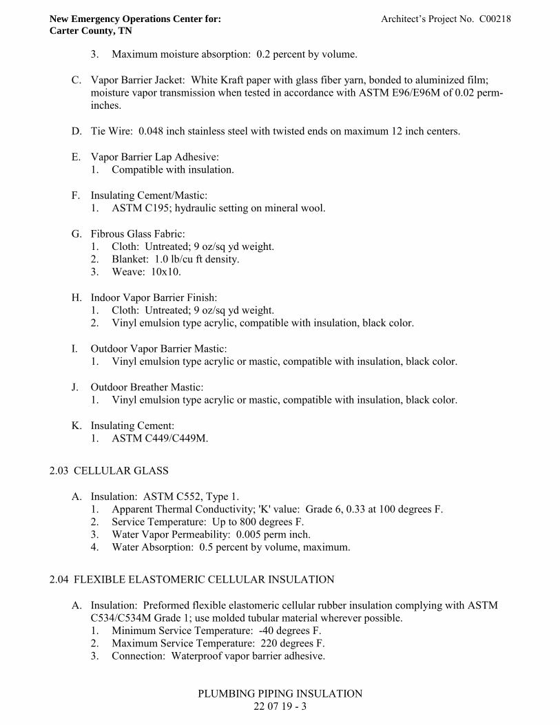
New Emergency Operations Center for: Architect’s Project No. C00218 Carter County, TN
PLUMBING PIPING INSULATION 22 07 19 - 3
3. Maximum moisture absorption: 0.2 percent by volume.
C. Vapor Barrier Jacket: White Kraft paper with glass fiber yarn, bonded to aluminized film; moisture vapor transmission when tested in accordance with ASTM E96/E96M of 0.02 perm-inches.
D. Tie Wire: 0.048 inch stainless steel with twisted ends on maximum 12 inch centers.
E. Vapor Barrier Lap Adhesive: 1. Compatible with insulation.
F. Insulating Cement/Mastic: 1. ASTM C195; hydraulic setting on mineral wool.
G. Fibrous Glass Fabric: 1. Cloth: Untreated; 9 oz/sq yd weight. 2. Blanket: 1.0 lb/cu ft density. 3. Weave: 10x10.
H. Indoor Vapor Barrier Finish: 1. Cloth: Untreated; 9 oz/sq yd weight. 2. Vinyl emulsion type acrylic, compatible with insulation, black color.
I. Outdoor Vapor Barrier Mastic: 1. Vinyl emulsion type acrylic or mastic, compatible with insulation, black color.
J. Outdoor Breather Mastic: 1. Vinyl emulsion type acrylic or mastic, compatible with insulation, black color.
K. Insulating Cement: 1. ASTM C449/C449M.
2.03 CELLULAR GLASS
A. Insulation: ASTM C552, Type 1. 1. Apparent Thermal Conductivity; 'K' value: Grade 6, 0.33 at 100 degrees F. 2. Service Temperature: Up to 800 degrees F. 3. Water Vapor Permeability: 0.005 perm inch. 4. Water Absorption: 0.5 percent by volume, maximum.
2.04 FLEXIBLE ELASTOMERIC CELLULAR INSULATION
A. Insulation: Preformed flexible elastomeric cellular rubber insulation complying with ASTM C534/C534M Grade 1; use molded tubular material wherever possible. 1. Minimum Service Temperature: -40 degrees F. 2. Maximum Service Temperature: 220 degrees F. 3. Connection: Waterproof vapor barrier adhesive.
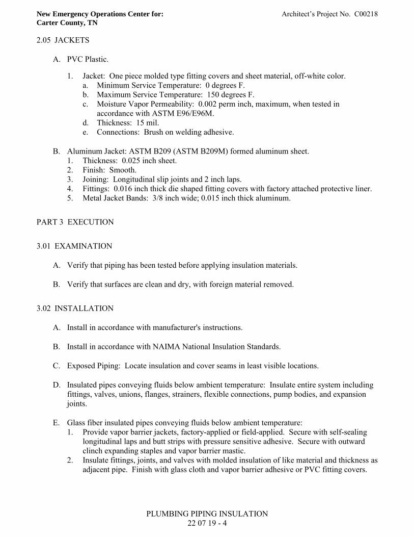
New Emergency Operations Center for: Architect’s Project No. C00218 Carter County, TN
PLUMBING PIPING INSULATION 22 07 19 - 4
2.05 JACKETS
A. PVC Plastic.
1. Jacket: One piece molded type fitting covers and sheet material, off-white color. a. Minimum Service Temperature: 0 degrees F. b. Maximum Service Temperature: 150 degrees F. c. Moisture Vapor Permeability: 0.002 perm inch, maximum, when tested in
accordance with ASTM E96/E96M. d. Thickness: 15 mil. e. Connections: Brush on welding adhesive.
B. Aluminum Jacket: ASTM B209 (ASTM B209M) formed aluminum sheet. 1. Thickness: 0.025 inch sheet. 2. Finish: Smooth. 3. Joining: Longitudinal slip joints and 2 inch laps. 4. Fittings: 0.016 inch thick die shaped fitting covers with factory attached protective liner. 5. Metal Jacket Bands: 3/8 inch wide; 0.015 inch thick aluminum.
PART 3 EXECUTION
3.01 EXAMINATION
A. Verify that piping has been tested before applying insulation materials.
B. Verify that surfaces are clean and dry, with foreign material removed.
3.02 INSTALLATION
A. Install in accordance with manufacturer's instructions.
B. Install in accordance with NAIMA National Insulation Standards.
C. Exposed Piping: Locate insulation and cover seams in least visible locations.
D. Insulated pipes conveying fluids below ambient temperature: Insulate entire system including fittings, valves, unions, flanges, strainers, flexible connections, pump bodies, and expansion joints.
E. Glass fiber insulated pipes conveying fluids below ambient temperature: 1. Provide vapor barrier jackets, factory-applied or field-applied. Secure with self-sealing
longitudinal laps and butt strips with pressure sensitive adhesive. Secure with outward clinch expanding staples and vapor barrier mastic.
2. Insulate fittings, joints, and valves with molded insulation of like material and thickness as adjacent pipe. Finish with glass cloth and vapor barrier adhesive or PVC fitting covers.
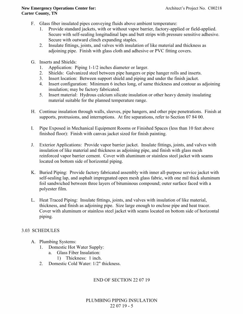
New Emergency Operations Center for: Architect’s Project No. C00218 Carter County, TN
PLUMBING PIPING INSULATION 22 07 19 - 5
F. Glass fiber insulated pipes conveying fluids above ambient temperature: 1. Provide standard jackets, with or without vapor barrier, factory-applied or field-applied.
Secure with self-sealing longitudinal laps and butt strips with pressure sensitive adhesive. Secure with outward clinch expanding staples.
2. Insulate fittings, joints, and valves with insulation of like material and thickness as adjoining pipe. Finish with glass cloth and adhesive or PVC fitting covers.
G. Inserts and Shields: 1. Application: Piping 1-1/2 inches diameter or larger. 2. Shields: Galvanized steel between pipe hangers or pipe hanger rolls and inserts. 3. Insert location: Between support shield and piping and under the finish jacket. 4. Insert configuration: Minimum 6 inches long, of same thickness and contour as adjoining
insulation; may be factory fabricated. 5. Insert material: Hydrous calcium silicate insulation or other heavy density insulating
material suitable for the planned temperature range.
H. Continue insulation through walls, sleeves, pipe hangers, and other pipe penetrations. Finish at supports, protrusions, and interruptions. At fire separations, refer to Section 07 84 00.
I. Pipe Exposed in Mechanical Equipment Rooms or Finished Spaces (less than 10 feet above finished floor): Finish with canvas jacket sized for finish painting.
J. Exterior Applications: Provide vapor barrier jacket. Insulate fittings, joints, and valves with insulation of like material and thickness as adjoining pipe, and finish with glass mesh reinforced vapor barrier cement. Cover with aluminum or stainless steel jacket with seams located on bottom side of horizontal piping.
K. Buried Piping: Provide factory fabricated assembly with inner all-purpose service jacket with self-sealing lap, and asphalt impregnated open mesh glass fabric, with one mil thick aluminum foil sandwiched between three layers of bituminous compound; outer surface faced with a polyester film.
L. Heat Traced Piping: Insulate fittings, joints, and valves with insulation of like material, thickness, and finish as adjoining pipe. Size large enough to enclose pipe and heat tracer. Cover with aluminum or stainless steel jacket with seams located on bottom side of horizontal piping.
3.03 SCHEDULES
A. Plumbing Systems: 1. Domestic Hot Water Supply:
a. Glass Fiber Insulation: 1) Thickness: 1 inch.
2. Domestic Cold Water: 1/2" thickness.
END OF SECTION 22 07 19
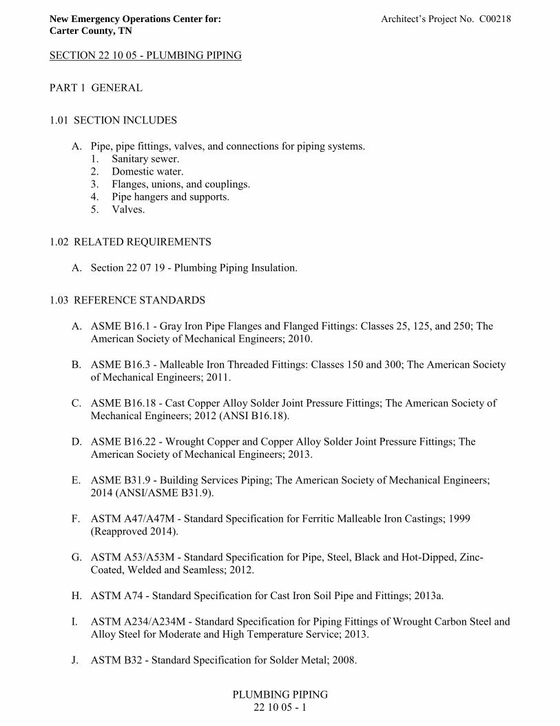
New Emergency Operations Center for: Architect’s Project No. C00218 Carter County, TN
PLUMBING PIPING 22 10 05 - 1
SECTION 22 10 05 - PLUMBING PIPING
PART 1 GENERAL
1.01 SECTION INCLUDES
A. Pipe, pipe fittings, valves, and connections for piping systems. 1. Sanitary sewer. 2. Domestic water. 3. Flanges, unions, and couplings. 4. Pipe hangers and supports. 5. Valves.
1.02 RELATED REQUIREMENTS
A. Section 22 07 19 - Plumbing Piping Insulation.
1.03 REFERENCE STANDARDS
A. ASME B16.1 - Gray Iron Pipe Flanges and Flanged Fittings: Classes 25, 125, and 250; The American Society of Mechanical Engineers; 2010.
B. ASME B16.3 - Malleable Iron Threaded Fittings: Classes 150 and 300; The American Society of Mechanical Engineers; 2011.
C. ASME B16.18 - Cast Copper Alloy Solder Joint Pressure Fittings; The American Society of Mechanical Engineers; 2012 (ANSI B16.18).
D. ASME B16.22 - Wrought Copper and Copper Alloy Solder Joint Pressure Fittings; The American Society of Mechanical Engineers; 2013.
E. ASME B31.9 - Building Services Piping; The American Society of Mechanical Engineers; 2014 (ANSI/ASME B31.9).
F. ASTM A47/A47M - Standard Specification for Ferritic Malleable Iron Castings; 1999 (Reapproved 2014).
G. ASTM A53/A53M - Standard Specification for Pipe, Steel, Black and Hot-Dipped, Zinc-Coated, Welded and Seamless; 2012.
H. ASTM A74 - Standard Specification for Cast Iron Soil Pipe and Fittings; 2013a.
I. ASTM A234/A234M - Standard Specification for Piping Fittings of Wrought Carbon Steel and Alloy Steel for Moderate and High Temperature Service; 2013.
J. ASTM B32 - Standard Specification for Solder Metal; 2008.

New Emergency Operations Center for: Architect’s Project No. C00218 Carter County, TN
PLUMBING PIPING 22 10 05 - 2
K. ASTM B88 - Standard Specification for Seamless Copper Water Tube; 2009.
L. ASTM B88M - Standard Specification for Seamless Copper Water Tube (Metric); 2013.
M. ASTM B302 - Standard Specification for Threadless Copper Pipe, Standard Sizes; 2012.
N. ASTM B813 - Standard Specification for Liquid and Paste Fluxes for Soldering of Copper and Copper Alloy Tube; 2010.
O. ASTM B828 - Standard Practice for Making Capillary Joints by Soldering of Copper and Copper Alloy Tube and Fittings; 2002 (Reapproved 2010).
P. ASTM C564 - Standard Specification for Rubber Gaskets for Cast Iron Soil Pipe and Fittings; 2014.
Q. ASTM F708 - Standard Practice for Design and Installation of Rigid Pipe Hangers; 1992 (Reapproved 2008).
R. ASTM F876 - Standard Specification for Crosslinked Polyethylene (PEX) Tubing; 2013a.
S. ASTM F877 - Standard Specification for Crosslinked Polyethylene (PEX) Plastic Hot- and Cold-Water Distribution Systems; 2011.
T. ASTM F1281 - Standard Specification for Crosslinked Polyethylene/Aluminum/Crosslinked Polyethylene (PEX-AL-PEX) Pressure Pipe; 2011.
U. AWS A5.8/A5.8M - Specification for Filler Metals for Brazing and Braze Welding; American Welding Society; 2011 and errata.
V. AWWA C105/A21.5 - Polyethylene Encasement for Ductile-Iron Pipe Systems; American Water Works Association; 2010 (ANSI/AWWA C105/A21.5).
W. AWWA C110/A21.10 - American National Standard for Ductile-Iron and Gray-Iron Fittings, 3 In. Through 48 In. (75 mm Through 1200 mm), for Water and Other Liquids; American Water Works Association; 2012.
X. AWWA C111/A21.11 - Rubber-Gasket Joints for Ductile-Iron Pressure Pipe and Fittings; American Water Works Association; 2012 (ANSI/AWWA C111/A21.11).
Y. AWWA C151/A21.51 - Ductile-Iron Pipe, Centrifugally Cast, for Water; American Water Works Association; 2009 (ANSI/AWWA C151/A21.51).
Z. CISPI 301 - Standard Specification for Hubless Cast Iron Soil Pipe and Fittings for Sanitary and Storm Drain, Waste and Vent Piping Applications; Cast Iron Soil Pipe Institute; 2009.
AA. CISPI 310 - Specification for Coupling for Use in Connection with Hubless Cast Iron Soil Pipe and Fittings for Sanitary and Storm Drain, Waste, and Vent Piping Applications; Cast Iron Soil Pipe Institute; 2011
New Emergency Operations Center for: Architect’s Project No. C00218 Carter County, TN
PLUMBING PIPING 22 10 05 - 3
AB. MSS SP-58 - Pipe Hangers and Supports - Materials, Design, Manufacture, Selection, Application, and Installation; Manufacturers Standardization Society of the Valve and Fittings Industry, Inc.; 2009.
AC. MSS SP-67 - Butterfly Valves; Manufacturers Standardization Society of the Valve and Fittings Industry, Inc.; 2011.
AD. MSS SP-110 - Ball Valves Threaded, Socket-Welding, Solder Joint, Grooved and Flared Ends; Manufacturers Standardization Society of the Valve and Fittings Industry, Inc.; 2010.
AE. NSF 61 - Drinking Water System Components - Health Effects; 2012.
AF. NSF 372 - Drinking Water System Components - Lead Content; 2011.
AG. PPI TR-4 - PPI Listing of Hydrostatic Design Basis (HDB), Hydrostatic Design Stress (HDS), Strength Design Basis (SDB), Pressure Design Basis (PDB), and Minimum Required Strength (MRS) Ratings For Thermoplastic Piping Materials or Pipe; Plastics Pipe Institute; 2013.
1.04 SUBMITTALS
A. See Section 01 30 00 - Administrative Requirements, for submittal procedures.
B. Product Data: Provide data on pipe materials, pipe fittings, valves, and accessories. Provide manufacturers catalog information. Indicate valve data and ratings.
1.05 QUALITY ASSURANCE
A. Perform work in accordance with applicable codes.
1.06 DELIVERY, STORAGE, AND HANDLING
A. Accept valves on site in shipping containers with labeling in place. Inspect for damage.
B. Provide temporary end caps and closures on piping and fittings. Maintain in place until installation.
C. Protect piping systems from entry of foreign materials by temporary covers, completing sections of the work, and isolating parts of completed system.
1.07 FIELD CONDITIONS
A. Do not install underground piping when bedding is wet or frozen.
New Emergency Operations Center for: Architect’s Project No. C00218 Carter County, TN
PLUMBING PIPING 22 10 05 - 4
PART 2 PRODUCTS
2.01 GENERAL REQUIREMENTS
A. Potable Water Supply Systems: Provide piping, pipe fittings, and solder and flux (if used), that comply with NSF 61 and NSF 372 for maximum lead content; label pipe and fittings.
2.02 SANITARY SEWER PIPING, BURIED WITHIN 5 FEET OF BUILDING
A. Cast Iron Pipe: ASTM A74 service weight. 1. Fittings: Cast iron. 2. Joints: Hub-and-spigot, CISPI HSN compression type with ASTM C564 neoprene
gaskets or lead and oakum.
B. PVC Pipe: ASTM D2665 or ASTM D3034. 1. Fittings: PVC. 2. Joints: Solvent welded, with ASTM D2564 solvent cement.
2.03 SANITARY SEWER PIPING, ABOVE GRADE
A. Cast Iron Pipe: CISPI 301, hubless, service weight. 1. Fittings: Cast iron. 2. Joints: CISPI 310, neoprene gaskets and stainless steel clamp-and-shield assemblies.
B. PVC Pipe: ASTM D2665. 1. Fittings: PVC. 2. Joints: Solvent welded, with ASTM D2564 solvent cement.
2.04 WATER PIPING, ABOVE GRADE
A. Copper Tube: ASTM B88 (ASTM B88M), Type L (B), Drawn (H). 1. Fittings: ASME B16.18, cast copper alloy or ASME B16.22, wrought copper and bronze. 2. Joints: ASTM B32, alloy Sn95 solder.
B. Cross-Linked Polyethylene Pipe: ASTM F876 or ASTM F877. 1. PPI TR-4 Pressure Design Basis:
a. 160 psig at maximum 73 degrees F. b. 100 psig at maximum 180 degrees F. c. 80 psig at maximum 200 degrees F.
2. Fittings: Brass and copper. 3. Joints: Mechanical compression fittings.
2.05 FLANGES, UNIONS, AND COUPLINGS
A. Unions for Pipe Sizes 3 Inches and Under: 1. Ferrous pipe: Class 150 malleable iron threaded unions.
New Emergency Operations Center for: Architect’s Project No. C00218 Carter County, TN
PLUMBING PIPING 22 10 05 - 5
2. Copper tube and pipe: Class 150 bronze unions with soldered joints.
B. Flanges for Pipe Size Over 1 Inch: 1. Ferrous pipe: Class 150 malleable iron threaded or forged steel slip-on flanges; preformed
neoprene gaskets. 2. Copper tube and pipe: Class 150 slip-on bronze flanges; preformed neoprene gaskets.
2.06 PIPE HANGERS AND SUPPORTS
A. Provide hangers and supports that comply with MSS SP-58. 1. If type of hanger or support for a particular situation is not indicated, select appropriate
type using MSS SP-58 recommendations. 2. Overhead Supports: Individual steel rod hangers attached to structure or to trapeze
hangers. 3. Trapeze Hangers: Welded steel channel frames attached to structure. 4. Vertical Pipe Support: Steel riser clamp.
B. Plumbing Piping - Drain, Waste, and Vent: 1. Hangers for Pipe Sizes 1/2 Inch to 1-1/2 Inches: Malleable iron, adjustable swivel, split
ring. 2. Hangers for Pipe Sizes 2 Inches and Over: Carbon steel, adjustable, clevis. 3. Wall Support for Pipe Sizes to 3 Inches: Cast iron hook. 4. Wall Support for Pipe Sizes 4 Inches and Over: Welded steel bracket and wrought steel
clamp. 5. Floor Support: Cast iron adjustable pipe saddle, lock nut, nipple, floor flange, and
concrete pier or steel support. 6. Copper Pipe Support: Carbon steel ring, adjustable, copper plated.
C. Plumbing Piping - Water: 1. Hangers for Pipe Sizes 1/2 Inch to 1-1/2 Inches: Malleable iron, adjustable swivel, split
ring. 2. Hangers for Cold Pipe Sizes 2 Inches and Over: Carbon steel, adjustable, clevis. 3. Hangers for Hot Pipe Sizes 2 Inches to 4 Inches: Carbon steel, adjustable, clevis. 4. Wall Support for Pipe Sizes to 3 Inches: Cast iron hook. 5. Floor Support for Cold Pipe: Cast iron adjustable pipe saddle, lock nut, nipple, floor
flange, and concrete pier or steel support. 6. Copper Pipe Support: Carbon steel ring, adjustable, copper plated.
D. Hanger Fasteners: Attach hangers to structure using appropriate fasteners, as follows: 1. Other Types: As required.
2.07 GATE VALVES
A. Up To and Including 3 Inches: 1. 1, Class 150, bronze body, bronze trim, rising stem, handwheel, inside screw, solid wedge
disc, threaded ends.
New Emergency Operations Center for: Architect’s Project No. C00218 Carter County, TN
PLUMBING PIPING 22 10 05 - 6
B. 2 Inches and Larger: 1. 1, Class 125, iron body, bronze trim, outside screw and yoke, handwheel, solid wedge
disc, flanged ends. Provide chain-wheel operators for valves 6 inches and larger mounted over 8 feet above floor.
2.08 GLOBE VALVES
A. Up To and Including 3 Inches: 1. 1, Class 125, bronze body, bronze trim, handwheel, bronze disc, solder ends.
B. 2 Inches and Larger: 1. 1, Class 125, iron body, bronze trim, handwheel, outside screw and yoke, renewable
bronze plug-type disc, renewable seat, flanged ends. Provide chain-wheel operators for valves 6 inches and larger mounted over 8 feet above floor.
2.09 BALL VALVES
A. Construction, 4 Inches and Smaller: MSS SP-110, Class 150, 400 psi CWP, bronze or ductile iron body, 304 stainless steel ball, regular port, teflon seats and stuffing box ring, blow-out proof stem, lever handle with balancing stops, solder, threaded, or grooved ends with union.
2.10 PLUG VALVES
A. Construction 2-1/2 Inches and Larger: 1, 175 psi CWP, cast iron body and plug, pressure lubricated, teflon or Buna N packing, flanged ends. Provide lever operator with set screw.
2.11 BUTTERFLY VALVES
A. Construction 1-1/2 Inches and Larger: MSS SP-67, 200 psi CWP, cast or ductile iron body, nickel-plated ductile iron disc, resilient replaceable Buna N seat, wafer ends, extended neck, 10 position lever handle.
B. Provide gear operators for valves 8 inches and larger, and chain-wheel operators for valves mounted over 8 feet above floor.
2.12 SWING CHECK VALVES
A. Up to 2 Inches: 1. 1, Class 150, bronze body and cap, bronze swing disc with rubber seat, solder ends.
New Emergency Operations Center for: Architect’s Project No. C00218 Carter County, TN
PLUMBING PIPING 22 10 05 - 7
PART 3 EXECUTION
3.01 EXAMINATION
A. Verify that excavations are to required grade, dry, and not over-excavated.
3.02 INSTALLATION
A. Install in accordance with manufacturer's instructions.
B. Route piping in orderly manner and maintain gradient. Route parallel and perpendicular to walls.
C. Install piping to maintain headroom, conserve space, and not interfere with use of space.
D. Provide clearance in hangers and from structure and other equipment for installation of insulation and access to valves and fittings. Refer to Section 22 07 19.
E. Provide access where valves and fittings are not exposed. Coordinate size and location of access doors with Section 08 31 00.
F. Establish elevations of buried piping outside the building to ensure not less than 3 ft of cover.
G. Install valves with stems upright or horizontal, not inverted.
H. Install water piping to ASME B31.9.
I. Copper Pipe and Tube: Make soldered joints in accordance with ASTM B828, using specified solder, and flux meeting ASTM B813; in potable water systems use flux also complying with NSF 61 and NSF 372.
J. PVC Pipe: Make solvent-welded joints in accordance with ASTM D2855.
K. Pipe Hangers and Supports: 1. Install in accordance with ASME B31.9. 2. Install hangers to provide minimum 1/2 inch space between finished covering and
adjacent work. 3. Place hangers within 12 inches of each horizontal elbow. 4. Where several pipes can be installed in parallel and at same elevation, provide multiple or
trapeze hangers.
30.3 APPLICATION
A. Install gate valves for shut-off and to isolate equipment, part of systems, or vertical risers.
B. Install globe valves for throttling, bypass, or manual flow control services.
New Emergency Operations Center for: Architect’s Project No. C00218 Carter County, TN
PLUMBING PIPING 22 10 05 - 8
C. Provide lug end butterfly valves adjacent to equipment when provided to isolate equipment.
3.04 TOLERANCES
A. Drainage Piping: Establish invert elevations within 1/2 inch vertically of location indicated and slope to drain at minimum of 1/8 inch per foot slope.
B. Water Piping: Slope at minimum of 1/32 inch per foot and arrange to drain at low points.
3.05 DISINFECTION OF DOMESTIC WATER PIPING SYSTEM
A. Prior to starting work, verify system is complete, flushed and clean.
B. Bleed water from outlets to ensure distribution and test for disinfectant residual at minimum 15 percent of outlets.
3.06 SERVICE CONNECTIONS
A. Provide new sanitary sewer services. Before commencing work check invert elevations required for sewer connections, confirm inverts and ensure that these can be properly connected with slope for drainage and cover to avoid freezing.
B. Provide new water service complete with approved reduced pressure backflow preventer and water meter with by-pass valves, pressure reducing valve . 1. Provide sleeve in wall for service main and support at wall with reinforced concrete
bridge. Calk enlarged sleeve and make watertight with pliable material. Anchor service main inside to concrete wall.
3.07 SCHEDULES
A. Pipe Hanger Spacing: 1. Metal Piping:
a. Pipe size: 1/2 inches to 1-1/4 inches: 1) Maximum hanger spacing: 6.5 ft. 2) Hanger rod diameter: 3/8 inches.
b. Pipe size: 1-1/2 inches to 2 inches: 1) Maximum hanger spacing: 10 ft. 2) Hanger rod diameter: 3/8 inch.
c. Pipe size: 2-1/2 inches to 3 inches: 1) Maximum hanger spacing: 10 ft. 2) Hanger rod diameter: 1/2 inch.
END OF SECTION 22 10 05

New Emergency Operations Center for: Architect’s Project No. C00218 Carter County, TN
PLUMBING PIPING SPECIALTIES 22 10 06 - 1
SECTION 22 10 06 - PLUMBING PIPING SPECIALTIES
PART 1 GENERAL
1.01 SECTION INCLUDES
A. Cleanouts.
B. Water hammer arrestors.
1.02 RELATED REQUIREMENTS
A. Section 22 10 05 - Plumbing Piping.
B. Section 22 40 00 - Plumbing Fixtures.
1.03 REFERENCE STANDARDS
A. ADA Standards - Americans with Disabilities Act (ADA) Standards for Accessible Design; 2010.
B. ASME A112.6.3 - Floor and Trench Drains; The American Society of Mechanical Engineers; 2001 (R2007).
C. ASME A112.6.4 - Roof, Deck, and Balcony Drains; The American Society of Mechanical Engineers; 2003.
D. ASSE 1011 - Hose Connection Vacuum Breakers; American Society of Sanitary Engineering; 2004 (ANSI/ASSE 1011).
E. ASSE 1012 - Backflow Preventer with Intermediate Atmospheric Vent; American Society of Sanitary Engineering; 2009 (ANSI/ASSE 1012).
F. ASSE 1013 - Reduced Pressure Principle Backflow Preventers and Reduced Pressure Fire Protection Principle Backflow Preventers; American Society of Sanitary Engineering; 2011.
G. ASSE 1019 - Vacuum Breaker Wall Hydrants, Freeze Resistant Automatic Draining Type; American Society of Sanitary Engineering; 2011 (ANSI/ASSE 1019).
H. NSF 61 - Drinking Water System Components - Health Effects; 2012.
I. NSF 372 - Drinking Water System Components - Lead Content; 2011.
J. PDI-WH 201 - Water Hammer Arresters; Plumbing and Drainage Institute; 2010.
New Emergency Operations Center for: Architect’s Project No. C00218 Carter County, TN
PLUMBING PIPING SPECIALTIES 22 10 06 - 2
1.04 SUBMITTALS
A. See Section 01 30 00 - Administrative Requirements, for submittal procedures.
B. Product Data: Provide component sizes, rough-in requirements, service sizes, and finishes.
C. Shop Drawings: Indicate dimensions, weights, and placement of openings and holes.
D. Manufacturer's Instructions: Indicate Manufacturer's Installation Instructions: Indicate assembly and support requirements.
1.05 QUALITY ASSURANCE
A. Manufacturer Qualifications: Company specializing in manufacturing the Products specified in this section with not less than three years documented experience.
1.06 DELIVERY, STORAGE, AND HANDLING
A. Accept specialties on site in original factory packaging. Inspect for damage.
PART 2 PRODUCTS
2.01 GENERAL REQUIREMENTS
A. Specialties in Potable Water Supply Systems: Provide products that comply with NSF 61 and NSF 372 for maximum lead content.
2.02 DRAINS
A. Dura-Coated cast iron, two piece body with double drainage flange, weep holes, reversible clamping collar, and round, adjustable nickel bronze strainer.
2.03 CLEANOUTS
A. Cleanouts at Exterior Surfaced Areas : 1. Round cast nickel bronze access frame and non-skid cover.
B. Cleanouts at Exterior Unsurfaced Areas (CO-2): 1. Line type with lacquered cast iron body and round epoxy coated gasketed cover.
C. Cleanouts at Interior Finished Floor Areas : 1. Lacquered cast iron body with anchor flange, reversible clamping collar, threaded top
assembly, and round gasketed scored cover in service areas and round gasketed depressed cover to accept floor finish in finished floor areas.
New Emergency Operations Center for: Architect’s Project No. C00218 Carter County, TN
PLUMBING PIPING SPECIALTIES 22 10 06 - 3
D. Cleanouts at Interior Finished Wall Areas : 1. Line type with lacquered cast iron body and round epoxy coated gasketed cover, and
round stainless steel access cover secured with machine screw.
2.04 WATER HAMMER ARRESTORS
A. Water Hammer Arrestors: 1. Stainless steel construction, bellows type sized in accordance with PDI-WH 201,
precharged suitable for operation in temperature range -100 to 300 degrees F and maximum 250 psi working pressure.
PART 3 EXECUTION
3.01 INSTALLATION
A. Install in accordance with manufacturer's instructions.
B. Extend cleanouts to finished floor or wall surface. Lubricate threaded cleanout plugs with mixture of graphite and linseed oil. Ensure clearance at cleanout for rodding of drainage system.
C. Encase exterior cleanouts in concrete flush with grade.
D. Install floor cleanouts at elevation to accommodate finished floor.
E. Install approved portable water protection devices on plumbing lines where contamination of domestic water may occur; on boiler feed water lines, janitor rooms, fire sprinkler systems, premise isolation, irrigation systems, flush valves, interior and exterior hose bibbs.
F. Pipe relief from backflow preventer to nearest drain.
G. Install water hammer arrestors complete with accessible isolation valve on hot and cold water supply piping to lavatories sinks.
END OF SECTION 22 10 06
New Emergency Operations Center for: Architect’s Project No. C00218 Carter County, TN
DUCT INSULATION 22 40 00 - 1
SECTION 22 40 00 - PLUMBING FIXTURES
PART 1 – GENERAL
1.1 SECTION INCLUDES
A. Water closets.
B. Lavatories.
C. Sinks.
D. Mop sinks.
E. Electric water coolers.
1.2 REFERENCE STANDARDS
A. ADA Standards - Americans with Disabilities Act (ADA) Standards for Accessible Design 2010.
B. ASME A112.18.9 - Protectors/Insulators for Exposed Waste and Supplies on Accessible Fixtures 2011 (Reaffirmed 2017).
C. ASHRAE Std 18 - Methods of Testing for Rating Drinking-Water Coolers with Self-Contained Mechanical Refrigeration. 2013.
D. ASME A112.6.1M - Supports for Off-the-Floor Plumbing Fixtures for Public Use 1997 (Reaffirmed 2017).
E. ASME A112.18.1 - Plumbing Supply Fittings 2018.
F. ASME A112.19.1 – Enameled Cast Iron and Enameled Steel Plumbing Fixtures 2018.
G. ASME A112.19.2 - Ceramic Plumbing Fixtures 2018.
H. ASME A112.19.3 - Stainless Steel Plumbing Fixtures 2017.
I. ASME A112.19.4M - Porcelain Enameled Formed Steel Plumbing Fixtures 1994 (R2009).
J. ASSE 1070 - Performance Requirements for Water Temperature Limiting Devices 2015.
K. NSF 61 - Drinking Water System Components - Health Effects 2017.
L. NSF 372 - Drinking Water System Components - Lead Content 2016.
New Emergency Operations Center for: Architect’s Project No. C00218 Carter County, TN
DUCT INSULATION 22 40 00 - 2
1.3 SUBMITTALS
A. See Section 01 30 00 - Administrative Requirements, for submittal procedures.
B. Product Data: Provide catalog illustrations of fixtures, sizes, rough-in dimensions, utility sizes, trim, and finishes.
C. Manufacturer's Instructions: Indicate installation methods and procedures.
D. Maintenance Data: Include fixture trim exploded view and replacement parts lists.
E. Warranty: Submit manufacturer warranty and ensure forms have been completed in Owner's name and registered with manufacturer.
1.4 QUALITY ASSURANCE
A. Manufacturer Qualifications: Company specializing in manufacturing the type of products specified in this section, with minimum three years of documented experience.
1.5 DELIVERY, STORAGE, AND HANDLING
A. Accept fixtures on site in factory packaging. Inspect for damage.
B. Protect installed fixtures from damage by securing areas and by leaving factory packaging in place to protect fixtures and prevent use.
2.1 WARRANTY
A. See Section 01 78 00 - Closeout Submittals, for additional warranty requirements.
B. Provide five-year manufacturer warranty for electric water cooler.
PART 2 PRODUCTS
2.1 GENERAL REQUIREMENTS
New Emergency Operations Center for: Architect’s Project No. C00218 Carter County, TN
DUCT INSULATION 22 40 00 - 3
A. Potable Water Systems: Provide plumbing fittings and faucets that comply with NSF 61 and NSF 372 for maximum lead content; label pipe and fittings.
2.2 REGULATORY REQUIREMENTS
A. Perform work in accordance with local health department regulations.
B. Provide certificate of compliance from Authority Having Jurisdiction indicating approval of installation.
2.3 TANK TYPE WATER CLOSETS
A. Bowl: ASME A112.19.2; floor mounted, siphon jet, vitreous china, 16.5 inches (420 mm) high, close-coupled closet combination with elongated rim, insulated vitreous china closet tank with fittings and lever flushing valve, bolt caps, vandal proof cover locking device.
1. Water Consumption: Maximum 1.28 gallons (4.8 liters) per flush.
B. Seat: Solid white plastic, open front, extended back, less cover, complete with self-sustaining hinge.
2.4 LAVATORIES
A. Vitreous China Wall Hung Basin: ASME A112.19.2; vitreous china wall hung lavatory, 20" x 18" minimum, with 4 inch (100 mm) high back, rectangular basin with splash lip, front overflow, and soap depression.
1. Drilling Centers: 4-inch (100 mm).
B. Supply Faucet: ASME A112.18.1; chrome plated supply fitting with open grid strainer, water economy aerator with maximum flow of 0.5 gallon per minute (low-flow) (1.9 liters per minute (low-flow)), indexed handles.
C. Thermostatic Mixing Valve: Thermostatic mixing valve, ASSE 1070 listed, with combination stop, strainer, and check valves, and flexible stainless-steel connectors.
New Emergency Operations Center for: Architect’s Project No. C00218 Carter County, TN
DUCT INSULATION 22 40 00 - 4
2.5 SINKS
A. Double Compartment Bowl: ASME A112.19.3; 33" x 21" x 5.5" outside dimensions 18 gage thick, Type 302 stainless steel, self rimming and undercoated, with ledge back drilled for trim.
1. Drain: 1-1/2 inch (38 mm) chromed brass drain.
2.6 BI-LEVEL, ELECTRIC WATER COOLERS
A. Water Cooler: Bi-level, electric, mechanically refrigerated; surface mounted, ADA compliant; stainless steel top, vinyl on steel body, elevated anti-squirt bubbler with stream guard, automatic stream regulator, push button, mounting bracket; integral air-cooled condenser and stainless-steel grille.
1. Capacity: 8 gallons per hour (30.3 liters per hour) of 50 degrees F (10 degrees C) water with inlet at 80 degrees F (27 degrees C) and room temperature of 90 degrees F (32 degrees C), when tested in accordance with ASHRAE Std 18.
2. Electrical: 115 V, 60 Hertz compressor, 6 foot (2 m) cord and plug for connection to electric wiring system including grounding connector.
2.7 MOP SINKS
A. Material: Precast terrazzo composed of marble chips cast in Portland cement.
B. Type: Rectilinear, standard height.
C. Grid strainer: Stainless steel; integral; removable.
D. Dimensions: As indicated on drawings.
E. Accessories:
1. 5 feet (1.5 m) of 1/2-inch (13 mm) diameter plain end reinforced plastic hose.
3. Hose clamp hanger.
4. Mop hanger.
New Emergency Operations Center for: Architect’s Project No. C00218 Carter County, TN
DUCT INSULATION 22 40 00 - 5
PART 3 EXECUTION
3.1 EXAMINATION
A. Verify that walls and floor finishes are prepared and ready for installation of fixtures.
B. Confirm that millwork is constructed with adequate provision for the installation of countertop lavatories and sinks.
3.2 PREPARATION
A. Rough-in fixture piping connections in accordance with minimum sizes indicated in fixture rough-in schedule for particular fixtures.
3.3 INSTALLATION
A. Install each fixture with trap, easily removable for servicing and cleaning.
B. Provide chrome plated rigid or flexible supplies to fixtures with loose key stops, reducers, and escutcheons.
C. Install components level and plumb.
D. Install and secure fixtures in place with wall supports and bolts.
E. Solidly attach water closets to floor with lag screws. Lead flashing is not intended to hold fixture in place.
3.4 INTERFACE WITH WORK OF OTHER SECTIONS
A. Review millwork shop drawings. Confirm location and size of fixtures and openings before rough-in and installation.
3.5 ADJUSTING
A. Adjust stops or valves for intended water flow rate to fixtures without splashing, noise, or overflow.
New Emergency Operations Center for: Architect’s Project No. C00218 Carter County, TN
DUCT INSULATION 22 40 00 - 6
3.6 CLEANING
A. Clean plumbing fixtures and equipment.
3.7 PROTECTION
A. Protect installed products from damage due to subsequent construction operations.
B. Repair or replace damaged products before Date of Substantial Completion.
END OF SECTION 22 40 00
New Emergency Operations Center for:
Carter County, TN Architect's Project No. C00218
HVAC PIPING INSULATION 23 07 19 - 1
SECTION 23 07 19 - HVAC PIPING INSULATION
PART 1 GENERAL
1.01 SECTION INCLUDES
A. Piping insulation.
1.02 REFERENCE STANDARDS
A. ASTM C534/C534M - Standard Specification for Preformed Flexible Elastomeric Cellular Thermal Insulation in Sheet and Tubular Form; 2014.
B. ASTM E84 - Standard Test Method for Surface Burning Characteristics of Building Materials; 2015a.
C. UL 723 - Standard for Test for Surface Burning Characteristics of Building Materials; Underwriters Laboratories Inc.; Current Edition, Including All Revisions.
1.03 SUBMITTALS
A. Product Data: Provide product description, thermal characteristics, list of materials and thickness for each service, and locations.
PART 2 PRODUCTS
2.01 REGULATORY REQUIREMENTS
A. Surface Burning Characteristics: Flame spread index/Smoke developed index of 25/50, maximum, when tested in accordance with ASTM E84 or UL 723.
2.02 FLEXIBLE ELASTOMERIC CELLULAR INSULATION
A. Insulation: Preformed flexible elastomeric cellular rubber insulation complying with ASTM C534/C534M Grade 3; use molded tubular material wherever possible. 1. Minimum Service Temperature: Minus 40 degrees F. 2. Maximum Service Temperature: 220 degrees F. 3. Connection: Waterproof vapor barrier adhesive.
New Emergency Operations Center for:
Carter County, TN Architect's Project No. C00218
HVAC PIPING INSULATION 23 07 19 - 2
PART 3 EXECUTION
3.01 INSTALLATION
A. Install in accordance with manufacturer's instructions.
B. Install in accordance with NAIMA National Insulation Standards.
C. Exposed Piping: Locate insulation and cover seams in least visible locations.
3.02 SCHEDULE
A. Cooling Systems: 1. Refrigerant Suction: Minimum thickness of 3/4" 2. Refrigerant Hot Gas: Minimum thickness of 3/4"
END OF SECTION 23 07 19
New Emergency Operations Center for:
Carter County, TN
Architect's Project No. C00218
TESTING, ADJUSTING, AND BALANCING FOR HVAC 23 05 93 - 1
SECTION 23 05 93 - TESTING, ADJUSTING, AND BALANCING FOR HVAC
PART 1 GENERAL
1.01 SECTION INCLUDES
A. Testing, adjustment, and balancing of air systems.
B. Measurement of final operating condition of HVAC systems.
1.02 REFERENCE STANDARDS
A. ASHRAE Std 111 - Measurement, Testing, Adjusting, and Balancing of Building HVAC Systems; American Society of Heating, Refrigerating and Air-Conditioning Engineers, Inc.; 2008.
B. NEBB (TAB) - Procedural Standard for Testing Adjusting and Balancing of Environmental Systems; National Environmental Balancing Bureau; 2005, Seventh Edition.
C. SMACNA (TAB) - HVAC Systems Testing, Adjusting, and Balancing; Sheet Metal and Air Conditioning Contractors' National Association; 2002.
1.03 SUBMITTALS
A. TAB Plan: Submit a written plan indicating the testing, adjusting, and balancing standard to be followed and the specific approach for each system and component. 1. Submit to Architect/Engineer. 2. Include at least the following in the plan:
a. List of all air flow, water flow, sound level, system capacity and efficiency measurements to be performed and a description of specific test procedures, parameters, formulas to be used.
b. Copy of field checkout sheets and logs to be used, listing each piece of equipment to be tested, adjusted and balanced with the data cells to be gathered for each.
c. Identification and types of measurement instruments to be used and their most recent calibration date.
d. Discussion of what notations and markings will be made on the duct and piping drawings during the process.
e. Final test report forms to be used. f. Detailed step-by-step procedures for TAB work for each system and issue, including:
1) Terminal flow calibration (for each terminal type). 2) Diffuser proportioning. 3) Branch/submain proportioning. 4) Total flow calculations. 5) Rechecking. 6) Diversity issues.
g. Details of how TOTAL flow will be determined; for example:

New Emergency Operations Center for:
Carter County, TN
Architect's Project No. C00218
TESTING, ADJUSTING, AND BALANCING FOR HVAC 23 05 93 - 2
1) Air: Sum of terminal flows via control system calibrated readings or via hood readings of all terminals, supply (SA) and return air (RA) pitot traverse, SA or RA flow stations.
h. Procedures for formal deficiency reports, including scope, frequency and distribution.
B. Final Report: Indicate deficiencies in systems that would prevent proper testing, adjusting, and balancing of systems and equipment to achieve specified performance. 1. Revise TAB plan to reflect actual procedures and submit as part of final report. 2. Submit draft copies of report for review prior to final acceptance of Project. Provide final
copies for Architect/Engineer and for inclusion in operating and maintenance manuals. 3. Include actual instrument list, with manufacturer name, serial number, and date of
calibration. 4. Form of Test Reports: Where the TAB standard being followed recommends a report
format use that; otherwise, follow ASHRAE Std 111. 5. Units of Measure: Report data in I-P (inch-pound) units only. 6. Include the following on the title page of each report:
a. Name of Testing, Adjusting, and Balancing Agency. b. Address of Testing, Adjusting, and Balancing Agency. c. Telephone number of Testing, Adjusting, and Balancing Agency. d. Project name. e. Project location. f. Project Architect/Engineer. g. Project Contractor. h. Report date.
C. Project Record Documents: Record actual locations of flow measuring stations and balancing valves and rough setting.
PART 2 PRODUCTS - NOT USED
PART 3 EXECUTION
3.01 GENERAL REQUIREMENTS
A. Perform total system balance in accordance with one of the following: 1. AABC MN-1, AABC National Standards for Total System Balance. 2. ASHRAE Std 111, Practices for Measurement, Testing, Adjusting and Balancing of
Building Heating, Ventilation, Air-Conditioning, and Refrigeration Systems. 3. NEBB Procedural Standards for Testing Adjusting Balancing of Environmental Systems. 4. SMACNA (TAB).
B. Begin work after completion of systems to be tested, adjusted, or balanced and complete work prior to Substantial Completion of the project.
C. TAB Agency Qualifications: 1. Company specializing in the testing, adjusting, and balancing of systems specified in this
section.
New Emergency Operations Center for:
Carter County, TN
Architect's Project No. C00218
TESTING, ADJUSTING, AND BALANCING FOR HVAC 23 05 93 - 3
2. Having minimum of three years documented experience. 3. Certified by one of the following:
a. AABC, Associated Air Balance Council: www.aabchq.com; upon completion submit AABC National Performance Guaranty.
b. NEBB, National Environmental Balancing Bureau: www.nebb.org. c. TABB, The Testing, Adjusting, and Balancing Bureau of National Energy
Management Institute: www.tabbcertified.org.
D. TAB Supervisor and Technician Qualifications: Certified by same organization as TAB agency.
3.02 EXAMINATION
A. Verify that systems are complete and operable before commencing work. Ensure the following conditions: 1. Systems are started and operating in a safe and normal condition. 2. Temperature control systems are installed complete and operable. 3. Proper thermal overload protection is in place for electrical equipment. 4. Final filters are clean and in place. If required, install temporary media in addition to final
filters. 5. Duct systems are clean of debris. 6. Fans are rotating correctly. 7. Fire and volume dampers are in place and open. 8. Air coil fins are cleaned and combed. 9. Access doors are closed and duct end caps are in place. 10. Air outlets are installed and connected. 11. Duct system leakage is minimized.
B. Submit field reports. Report defects and deficiencies that will or could prevent proper system balance.
C. Beginning of work means acceptance of existing conditions.
3.03 ADJUSTMENT TOLERANCES
A. Air Handling Systems: Adjust to within plus or minus 5 percent of design for supply systems and plus or minus 10 percent of design for return and exhaust systems.
B. Air Outlets and Inlets: Adjust total to within plus 10 percent and minus 5 percent of design to space. Adjust outlets and inlets in space to within plus or minus 10 percent of design.
3.04 RECORDING AND ADJUSTING
A. Ensure recorded data represents actual measured or observed conditions.
B. Permanently mark settings of valves, dampers, and other adjustment devices allowing settings to be restored. Set and lock memory stops.
New Emergency Operations Center for:
Carter County, TN
Architect's Project No. C00218
TESTING, ADJUSTING, AND BALANCING FOR HVAC 23 05 93 - 4
C. After adjustment, take measurements to verify balance has not been disrupted or that such disruption has been rectified.
D. Leave systems in proper working order, replacing belt guards, closing access doors, closing doors to electrical switch boxes, and restoring thermostats to specified settings.
3.05 AIR SYSTEM PROCEDURE
A. Adjust air handling and distribution systems to provide required or design supply, return, and exhaust air quantities at site altitude.
B. Make air quantity measurements in ducts by Pitot tube traverse of entire cross sectional area of duct.
C. Measure air quantities at air inlets and outlets.
D. Adjust distribution system to obtain uniform space temperatures free from objectionable drafts and noise.
E. Use volume control devices to regulate air quantities only to extend that adjustments do not create objectionable air motion or sound levels. Effect volume control by duct internal devices such as dampers and splitters.
F. Vary total system air quantities by adjustment of fan speeds. Provide drive changes required. Vary branch air quantities by damper regulation.
G. Measure static air pressure conditions on air supply units, including filter and coil pressure drops, and total pressure across the fan. Make allowances for 50 percent loading of filters.
H. Adjust outside air automatic dampers, outside air, return air, and exhaust dampers for design conditions.
I. Measure temperature conditions across outside air, return air, and exhaust dampers to check leakage.
3.06 SCOPE
A. Test, adjust, and balance the following: 1. Forced Air Furnaces 2. Air Cooled Refrigerant Condensers 3. Air Coils 4. Fans 5. Air Filters 6. Air Inlets and Outlets
New Emergency Operations Center for:
Carter County, TN
Architect's Project No. C00218
TESTING, ADJUSTING, AND BALANCING FOR HVAC 23 05 93 - 5
3.07 MINIMUM DATA TO BE REPORTED
A. Electric Motors: 1. Manufacturer 2. Model/Frame 3. HP/BHP 4. Phase, voltage, amperage; nameplate, actual, no load 5. RPM 6. Service factor 7. Starter size, rating, heater elements 8. Sheave Make/Size/Bore
B. V-Belt Drives: 1. Identification/location 2. Required driven RPM 3. Driven sheave, diameter and RPM 4. Belt, size and quantity 5. Motor sheave diameter and RPM 6. Center to center distance, maximum, minimum, and actual
C. Combustion Equipment: 1. Model number 2. Serial number 3. Firing rate 4. Gas pressure at meter outlet 5. Gas flow rate 6. Heat input 7. Heat output
D. Air Cooled Condensers: 1. Identification/number 2. Location 3. Manufacturer 4. Model number 5. Serial number 6. Entering DB air temperature, design and actual 7. Leaving DB air temperature, design and actual 8. Number of compressors
E. Cooling Coils: 1. Identification/number 2. Location 3. Service 4. Manufacturer 5. Air flow, design and actual 6. Entering air DB temperature, design and actual 7. Entering air WB temperature, design and actual 8. Leaving air DB temperature, design and actual 9. Leaving air WB temperature, design and actual
New Emergency Operations Center for:
Carter County, TN
Architect's Project No. C00218
TESTING, ADJUSTING, AND BALANCING FOR HVAC 23 05 93 - 6
10. Air pressure drop, design and actual
F. Return Air/Outside Air: 1. Identification/location 2. Design air flow 3. Actual air flow 4. Design return air flow 5. Actual return air flow 6. Design outside air flow 7. Actual outside air flow 8. Return air temperature 9. Outside air temperature 10. Actual mixed air temperature 11. Design outside/return air ratio 12. Actual outside/return air ratio
G. Exhaust Fans: 1. Location 2. Manufacturer 3. Model number 4. Serial number 5. Air flow, specified and actual 6. Total static pressure (total external), specified and actual 7. Inlet pressure 8. Discharge pressure 9. Sheave Make/Size/Bore 10. Number of Belts/Make/Size 11. Fan RPM
H. Air Distribution Tests: 1. Air terminal number 2. Room number/location 3. Terminal type 4. Terminal size 5. Area factor 6. Design velocity 7. Design air flow 8. Test (final) velocity 9. Test (final) air flow 10. Percent of design air flow
END OF SECTION 23 05 93
New Emergency Operations Center for:
Carter County, TN Architect's Project No. C00218
DUCT INSULATION 23 07 13 - 1
SECTION 23 07 13 - DUCT INSULATION
PART 1 GENERAL
1.01 SECTION INCLUDES
A. Duct insulation.
1.02 RELATED REQUIREMENTS
A. Section 23 31 00 - HVAC Ducts and Casings: Glass fiber ducts.
1.03 REFERENCE STANDARDS
A. ASTM C518 - Standard Test Method for Steady-State Thermal Transmission Properties by Means of the Heat Flow Meter Apparatus; 2010.
B. ASTM C553 - Specification for Mineral Fiber Blanket Thermal Insulation for Commercial and Industrial Applications; 2013.
C. ASTM C612 - Standard Specification for Mineral Fiber Block and Board Thermal Insulation; 2014.
D. ASTM E84 - Standard Test Method for Surface Burning Characteristics of Building Materials; 2014.
E. ASTM E96/E96M - Standard Test Methods for Water Vapor Transmission of Materials; 2014.
F. NFPA 255 - Standard Method of Test of Surface Burning Characteristics of Building Materials; National Fire Protection Association; 2006.
G. UL 723 - Standard for Test for Surface Burning Characteristics of Building Materials; Underwriters Laboratories Inc.; Current Edition, Including All Revisions.
1.04 SUBMITTALS
A. Product Data: Provide product description, thermal characteristics, list of materials and thickness for each service, and locations.
PART 2 PRODUCTS
2.01 REQUIREMENTS FOR ALL PRODUCTS OF THIS SECTION
A. Surface Burning Characteristics: Flame spread/Smoke developed index of 25/50, maximum, when tested in accordance with ASTM E84, NFPA 255, or UL 723.

New Emergency Operations Center for:
Carter County, TN Architect's Project No. C00218
DUCT INSULATION 23 07 13 - 2
2.02 GLASS FIBER, FLEXIBLE
A. Insulation: ASTM C553; flexible, noncombustible blanket. 1. 'K' value: 0.36 at 75 degrees F, when tested in accordance with ASTM C518. 2. Maximum Service Temperature: 1200 degrees F. 3. Maximum Water Vapor Sorption: 5.0 percent by weight.
B. Vapor Barrier Jacket: 1. Kraft paper with glass fiber yarn and bonded to aluminized film. 2. Moisture Vapor Permeability: 0.02 perm inch, when tested in accordance with ASTM
E96/E96M.
C. Vapor Barrier Tape: 1. Kraft paper reinforced with glass fiber yarn and bonded to aluminized film, with pressure
sensitive rubber based adhesive.
2.03 GLASS FIBER, RIGID
A. Insulation: ASTM C612; rigid, noncombustible blanket. 1. 'K' value: 0.24 at 75 degrees F, when tested in accordance with ASTM C518. 2. Maximum service temperature: 450 degrees F. 3. Maximum Water Vapor Sorption: 5.0 percent. 4. Maximum Density: 8.0 lb/cu ft.
B. Vapor Barrier Jacket: 1. Kraft paper with glass fiber yarn and bonded to aluminized film. 2. Moisture Vapor Permeability: 0.02 perm inch, when tested in accordance with ASTM
E96/E96M.
C. Vapor Barrier Tape: 1. Kraft paper reinforced with glass fiber yarn and bonded to aluminized film, with pressure
sensitive rubber based adhesive.
D. Indoor Vapor Barrier Finish: 1. Cloth: Untreated; 9 oz/sq yd weight, glass fabric. 2. Vinyl emulsion type acrylic, compatible with insulation, black color.
PART 3 EXECUTION
3.01 INSTALLATION
A. Install in accordance with manufacturer's instructions.
B. Insulated ducts conveying air below ambient temperature: 1. Provide insulation with vapor barrier jackets. 2. Finish with tape and vapor barrier jacket. 3. Continue insulation through walls, sleeves, hangers, and other duct penetrations.
New Emergency Operations Center for:
Carter County, TN Architect's Project No. C00218
DUCT INSULATION 23 07 13 - 3
4. Insulate entire system including fittings, joints, flanges, fire dampers, flexible connections, and expansion joints.
C. Insulated ducts conveying air above ambient temperature: 1. Provide with or without standard vapor barrier jacket. 2. Insulate fittings and joints. Where service access is required, bevel and seal ends of
insulation.
3.02 SCHEDULES
A. Exhaust Ducts Within 10 ft of Exterior Openings: 2", 1# Density fiberglass with vapor barrier.
B. Outside Air Intake Ducts: 2", 1# Density fiberglass with vapor barrier.
C. Supply Ducts: 2", 1# Density fiberglass with vapor barrier. Insulated flex duct shall have a minimum of R-6 insulation.
D. Return Ducts: 2", 1# Density fiberglass with vapor barrier.
END OF SECTION 23 07 13
New Emergency Operations Center for:
Carter County, TN Architect's Project No. C00218
REFRIGERANT PIPING 23 23 00 - 1
SECTION 23 23 00 - REFRIGERANT PIPING
PART 1 GENERAL
1.01 SECTION INCLUDES
A. Piping.
B. Refrigerant.
C. Moisture and liquid indicators.
D. Valves.
E. Strainers.
F. Check valves.
G. Filter-driers.
H. Expansion valves.
1.02 RELATED REQUIREMENTS
A. Section 23 07 19 - HVAC Piping Insulation.
1.03 REFERENCE STANDARDS
A. AHRI 750 - Standard for Thermostatic Refrigerant Expansion Valves; Air-Conditioning, Heating, and Refrigeration Institute; 2007.
B. AHRI 760 - Standard for Performance Rating of Solenoid Valves for Use With Volatile Refrigerants; Air-Conditioning, Heating, and Refrigeration Institute; 2007.
C. ASHRAE Std 15 - Safety Standard for Refrigeration Systems; American Society of Heating, Refrigerating and Air-Conditioning Engineers, Inc.; 2013 (ANSI/ASHRAE Std 15).
D. ASME B16.22 - Wrought Copper and Copper Alloy Solder Joint Pressure Fittings; The American Society of Mechanical Engineers; 2013.
E. ASME B16.26 - Cast Copper Alloy Fittings For Flared Copper Tubes; The American Society of Mechanical Engineers; 2013.
F. ASME B31.5 - Refrigeration Piping and Heat Transfer Components; The American Society of Mechanical Engineers; 2013.
New Emergency Operations Center for:
Carter County, TN Architect's Project No. C00218
REFRIGERANT PIPING 23 23 00 - 2
G. ASTM B88 - Standard Specification for Seamless Copper Water Tube; 2009.
H. ASTM B88M - Standard Specification for Seamless Copper Water Tube (Metric); 2013.
I. ASTM B280 - Standard Specification for Seamless Copper Tube for Air Conditioning and Refrigeration Field Service; 2013.
J. AWS A5.8M/A5.8 - Specification for Filler Metals for Brazing and Braze Welding; American Welding Society; 2011-AMD 1.
K. MSS SP-58 - Pipe Hangers and Supports - Materials, Design and Manufacture, Selection, Application, and Installation; Manufacturers Standardization Society of the Valve and Fittings Industry, Inc.; 2009.
L. UL 429 - Electrically Operated Valves; Underwriters Laboratories Inc.; Current Edition, Including All Revisions.
1.04 SYSTEM DESCRIPTION
A. Provide pipe hangers and supports in accordance with ASME B31.5 unless indicated otherwise.
B. Valves: 1. Use service valves on suction and discharge of compressors. 2. Use gage taps at compressor inlet and outlet. 3. Use check valves on compressor discharge.
1.05 SUBMITTALS
A. Product Data: Provide general assembly of specialties, including manufacturers catalogue information. Provide manufacturers catalog data including load capacity.
PART 2 PRODUCTS
2.01 PIPING
A. Copper Tube: ASTM B280, H58 hard drawn or O60 soft annealed. 1. Fittings: ASME B16.22 wrought copper. 2. Joints: Braze, AWS A5.8 BCuP silver/phosphorus/copper alloy.
B. Copper Tube to 7/8 inch OD: ASTM B88 (ASTM B88M), Type K (A), annealed. 1. Fittings: ASME B16.26 cast copper. 2. Joints: Flared.
New Emergency Operations Center for:
Carter County, TN Architect's Project No. C00218
REFRIGERANT PIPING 23 23 00 - 3
C. Pipe Supports and Anchors: 1. Provide hangers and supports that comply with MSS SP-58.
a. If type of hanger or support for a particular situation is not indicated, select appropriate type using MSS SP-58 recommendations.
2. Hangers for Pipe Sizes 1/2 to 1-1/2 Inch: Malleable iron adjustable swivel, split ring. 3. Hangers for Pipe Sizes 2 Inches and Over: Carbon steel, adjustable, clevis. 4. Multiple or Trapeze Hangers: Steel channels with welded spacers and hanger rods. 5. Wall Support for Pipe Sizes to 3 Inches: Cast iron hook. 6. Vertical Support: Steel riser clamp. 7. Copper Pipe Support: Carbon steel ring, adjustable, copper plated. 8. Hanger Rods: Mild steel threaded both ends, threaded one end, or continuous threaded. 9. Inserts: Malleable iron case of galvanized steel shell and expander plug for threaded
connection with lateral adjustment, top slot for reinforcing rods, lugs for attaching to forms; size inserts to suit threaded hanger rods.
2.02 REFRIGERANT
A. Refrigerant: Use only refrigerants that have ozone depletion potential (ODP) of zero and global warming potential (GWP) of less than 50.
2.03 MOISTURE AND LIQUID INDICATORS
A. Indicators: Single port type, UL listed, with copper or brass body, flared or solder ends, sight glass, color coded paper moisture indicator with removable element cartridge and plastic cap; for maximum temperature of 200 degrees F and maximum working pressure of 500 psi.
2.04 VALVES
A. Diaphragm Packless Valves: 1. UL listed, globe or angle pattern, forged brass body and bonnet, phosphor bronze and
stainless steel diaphragms, rising stem and handwheel, stainless steel spring, nylon seat disc, solder or flared ends, with positive backseating; for maximum working pressure of 500 psi and maximum temperature of 275 degrees F.
B. Packed Angle Valves: 1. Forged brass or nickel plated forged steel, forged brass seal caps with copper gasket,
rising stem and seat with backseating, molded stem packing, solder or flared ends; for maximum working pressure of 500 psi and maximum temperature of 275 degrees F.
C. Ball Valves: 1. Two piece bolted forged brass body with teflon ball seals and copper tube extensions,
brass bonnet and seal cap, chrome plated ball, stem with neoprene ring stem seals; for maximum working pressure of 500 psi and maximum temperature of 300 degrees F.
D. Service Valves: 1. Forged brass body with copper stubs, brass caps, removable valve core, integral ball
check valve, flared or solder ends, for maximum pressure of 500 psi.
New Emergency Operations Center for:
Carter County, TN Architect's Project No. C00218
REFRIGERANT PIPING 23 23 00 - 4
2.05 STRAINERS
A. Straight Line or Angle Line Type: 1. Brass or steel shell, steel cap and flange, and replaceable cartridge, with screen of
stainless steel wire or monel reinforced with brass; for maximum working pressure of 430 psi.
2.06 CHECK VALVES
A. Globe Type: 1. Cast bronze or forged brass body, forged brass cap with neoprene seal, brass guide and
disc holder, phosphor-bronze or stainless steel spring, teflon seat disc; for maximum temperature of 300 degrees F and maximum working pressure of 425 psi.
B. Straight Through Type: 1. Brass body and disc, phosphor-bronze or stainless steel spring, neoprene seat; for
maximum working pressure of 500 psi and maximum temperature of 200 degrees F.
2.07 PRESSURE REGULATORS
A. Brass body, stainless steel diaphragm, direct acting, adjustable over 0 to 80 psi range, for maximum working pressure of 450 psi.
2.08 PRESSURE RELIEF VALVES
A. Straight Through or Angle Type: Brass body and disc, neoprene seat, factory sealed and stamped with ASME UV and National Board Certification NB, selected to ASHRAE Std 15, with standard setting of 235 psi.
2.09 FILTER-DRIERS
A. Performance: 1. Pressure Drop: 2 psi, maximum, when operating at full connected evaporator capacity. 2. Design Working Pressure: 350 psi, minimum.
B. Cores: Molded or loose-fill molecular sieve desiccant compatible with refrigerant, activated alumina, activated charcoal, and filtration to 40 microns, with secondary filtration to 20 microns; of construction that will not pass into refrigerant lines.
C. Construction: UL listed. 1. Connections: As specified for applicable pipe type.
New Emergency Operations Center for:
Carter County, TN Architect's Project No. C00218
REFRIGERANT PIPING 23 23 00 - 5
2.10 SOLENOID VALVES
A. Valve: AHRI 760, pilot operated, copper or brass body and internal parts, synthetic seat, stainless steel stem and plunger assembly (permitting manual operation in case of coil failure), integral strainer, with flared, solder, or threaded ends; for maximum working pressure of 500 psi.
B. Coil Assembly: UL 429, UL listed, replaceable with molded electromagnetic coil, moisture and fungus proof, with surge protector and color coded lead wires, integral junction box with pilot light.
2.11 EXPANSION VALVES
A. Angle or Straight Through Type: AHRI 750; design suitable for refrigerant, brass body, internal or external equalizer, bleed hole, adjustable superheat setting, replaceable inlet strainer, with non-replaceable capillary tube and remote sensing bulb and remote bulb well.
B. Selection: Evaluate refrigerant pressure drop through system to determine available pressure drop across valve. Select valve for maximum load at design operating pressure and minimum 10 degrees F superheat. Select to avoid being undersized at full load and excessively oversized at part load.
PART 3 EXECUTION
3.01 PREPARATION
A. Ream pipe and tube ends. Remove burrs. Bevel plain end ferrous pipe.
B. Remove scale and dirt on inside and outside before assembly.
C. Prepare piping connections to equipment with flanges or unions.
3.02 INSTALLATION
A. Install refrigeration specialties in accordance with manufacturer's instructions.
B. Route piping in orderly manner, with plumbing parallel to building structure, and maintain gradient.
C. Install piping to conserve building space and avoid interference with use of space.
D. Group piping whenever practical at common elevations and locations. Slope piping one percent in direction of oil return.
E. Install piping to allow for expansion and contraction without stressing pipe, joints, or connected equipment.
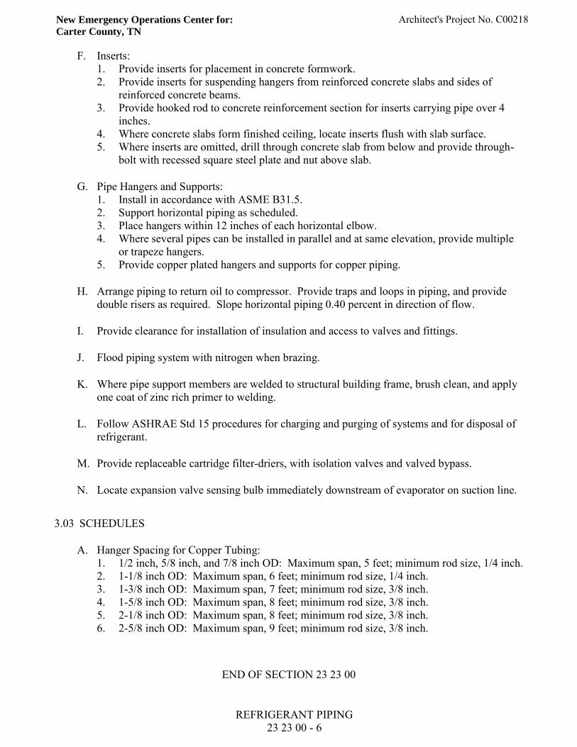
New Emergency Operations Center for:
Carter County, TN Architect's Project No. C00218
REFRIGERANT PIPING 23 23 00 - 6
F. Inserts: 1. Provide inserts for placement in concrete formwork. 2. Provide inserts for suspending hangers from reinforced concrete slabs and sides of
reinforced concrete beams. 3. Provide hooked rod to concrete reinforcement section for inserts carrying pipe over 4
inches. 4. Where concrete slabs form finished ceiling, locate inserts flush with slab surface. 5. Where inserts are omitted, drill through concrete slab from below and provide through-
bolt with recessed square steel plate and nut above slab.
G. Pipe Hangers and Supports: 1. Install in accordance with ASME B31.5. 2. Support horizontal piping as scheduled. 3. Place hangers within 12 inches of each horizontal elbow. 4. Where several pipes can be installed in parallel and at same elevation, provide multiple
or trapeze hangers. 5. Provide copper plated hangers and supports for copper piping.
H. Arrange piping to return oil to compressor. Provide traps and loops in piping, and provide double risers as required. Slope horizontal piping 0.40 percent in direction of flow.
I. Provide clearance for installation of insulation and access to valves and fittings.
J. Flood piping system with nitrogen when brazing.
K. Where pipe support members are welded to structural building frame, brush clean, and apply one coat of zinc rich primer to welding.
L. Follow ASHRAE Std 15 procedures for charging and purging of systems and for disposal of refrigerant.
M. Provide replaceable cartridge filter-driers, with isolation valves and valved bypass.
N. Locate expansion valve sensing bulb immediately downstream of evaporator on suction line.
3.03 SCHEDULES
A. Hanger Spacing for Copper Tubing: 1. 1/2 inch, 5/8 inch, and 7/8 inch OD: Maximum span, 5 feet; minimum rod size, 1/4 inch. 2. 1-1/8 inch OD: Maximum span, 6 feet; minimum rod size, 1/4 inch. 3. 1-3/8 inch OD: Maximum span, 7 feet; minimum rod size, 3/8 inch. 4. 1-5/8 inch OD: Maximum span, 8 feet; minimum rod size, 3/8 inch. 5. 2-1/8 inch OD: Maximum span, 8 feet; minimum rod size, 3/8 inch. 6. 2-5/8 inch OD: Maximum span, 9 feet; minimum rod size, 3/8 inch.
END OF SECTION 23 23 00
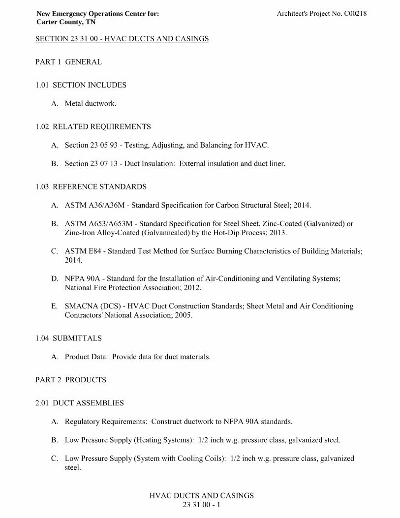
New Emergency Operations Center for:
Carter County, TN Architect's Project No. C00218
HVAC DUCTS AND CASINGS 23 31 00 - 1
SECTION 23 31 00 - HVAC DUCTS AND CASINGS
PART 1 GENERAL
1.01 SECTION INCLUDES
A. Metal ductwork.
1.02 RELATED REQUIREMENTS
A. Section 23 05 93 - Testing, Adjusting, and Balancing for HVAC.
B. Section 23 07 13 - Duct Insulation: External insulation and duct liner.
1.03 REFERENCE STANDARDS
A. ASTM A36/A36M - Standard Specification for Carbon Structural Steel; 2014.
B. ASTM A653/A653M - Standard Specification for Steel Sheet, Zinc-Coated (Galvanized) or Zinc-Iron Alloy-Coated (Galvannealed) by the Hot-Dip Process; 2013.
C. ASTM E84 - Standard Test Method for Surface Burning Characteristics of Building Materials; 2014.
D. NFPA 90A - Standard for the Installation of Air-Conditioning and Ventilating Systems; National Fire Protection Association; 2012.
E. SMACNA (DCS) - HVAC Duct Construction Standards; Sheet Metal and Air Conditioning Contractors' National Association; 2005.
1.04 SUBMITTALS
A. Product Data: Provide data for duct materials.
PART 2 PRODUCTS
2.01 DUCT ASSEMBLIES
A. Regulatory Requirements: Construct ductwork to NFPA 90A standards.
B. Low Pressure Supply (Heating Systems): 1/2 inch w.g. pressure class, galvanized steel.
C. Low Pressure Supply (System with Cooling Coils): 1/2 inch w.g. pressure class, galvanized steel.
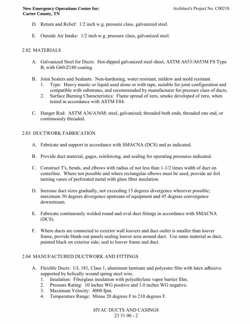
New Emergency Operations Center for:
Carter County, TN Architect's Project No. C00218
HVAC DUCTS AND CASINGS 23 31 00 - 2
D. Return and Relief: 1/2 inch w.g. pressure class, galvanized steel.
E. Outside Air Intake: 1/2 inch w.g. pressure class, galvanized steel.
2.02 MATERIALS
A. Galvanized Steel for Ducts: Hot-dipped galvanized steel sheet, ASTM A653/A653M FS Type B, with G60/Z180 coating.
B. Joint Sealers and Sealants: Non-hardening, water resistant, mildew and mold resistant. 1. Type: Heavy mastic or liquid used alone or with tape, suitable for joint configuration and
compatible with substrates, and recommended by manufacturer for pressure class of ducts. 2. Surface Burning Characteristics: Flame spread of zero, smoke developed of zero, when
tested in accordance with ASTM E84.
C. Hanger Rod: ASTM A36/A36M; steel, galvanized; threaded both ends, threaded one end, or continuously threaded.
2.03 DUCTWORK FABRICATION
A. Fabricate and support in accordance with SMACNA (DCS) and as indicated.
B. Provide duct material, gages, reinforcing, and sealing for operating pressures indicated.
C. Construct T's, bends, and elbows with radius of not less than 1-1/2 times width of duct on centerline. Where not possible and where rectangular elbows must be used, provide air foil turning vanes of perforated metal with glass fiber insulation.
D. Increase duct sizes gradually, not exceeding 15 degrees divergence wherever possible; maximum 30 degrees divergence upstream of equipment and 45 degrees convergence downstream.
E. Fabricate continuously welded round and oval duct fittings in accordance with SMACNA (DCS).
F. Where ducts are connected to exterior wall louvers and duct outlet is smaller than louver frame, provide blank-out panels sealing louver area around duct. Use same material as duct, painted black on exterior side; seal to louver frame and duct.
2.04 MANUFACTURED DUCTWORK AND FITTINGS
A. Flexible Ducts: UL 181, Class 1, aluminum laminate and polyester film with latex adhesive supported by helically wound spring steel wire. 1. Insulation: Fiberglass insulation with polyethylene vapor barrier film. 2. Pressure Rating: 10 inches WG positive and 1.0 inches WG negative. 3. Maximum Velocity: 4000 fpm. 4. Temperature Range: Minus 20 degrees F to 210 degrees F.
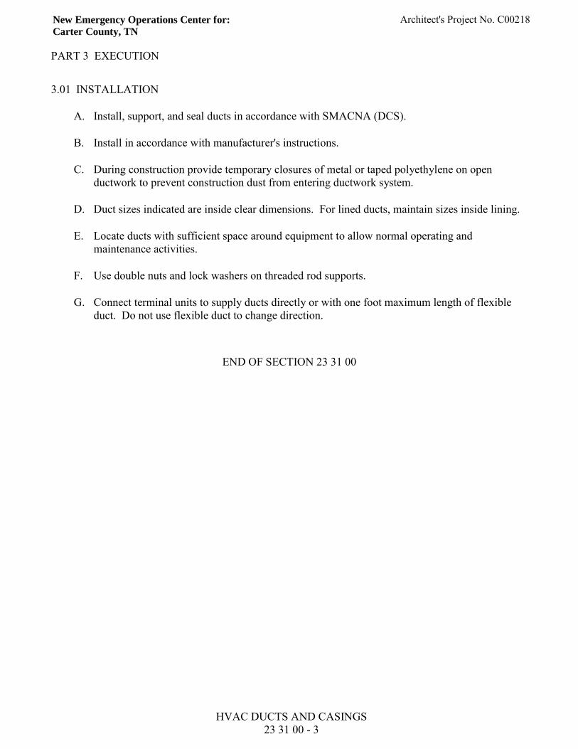
New Emergency Operations Center for:
Carter County, TN Architect's Project No. C00218
HVAC DUCTS AND CASINGS 23 31 00 - 3
PART 3 EXECUTION
3.01 INSTALLATION
A. Install, support, and seal ducts in accordance with SMACNA (DCS).
B. Install in accordance with manufacturer's instructions.
C. During construction provide temporary closures of metal or taped polyethylene on open ductwork to prevent construction dust from entering ductwork system.
D. Duct sizes indicated are inside clear dimensions. For lined ducts, maintain sizes inside lining.
E. Locate ducts with sufficient space around equipment to allow normal operating and maintenance activities.
F. Use double nuts and lock washers on threaded rod supports.
G. Connect terminal units to supply ducts directly or with one foot maximum length of flexible duct. Do not use flexible duct to change direction.
END OF SECTION 23 31 00
New Emergency Operations Center for:
Carter County, TN Architect's Project No. C00218
AIR DUCT ACCESSORIES 23 33 00 - 1
SECTION 23 33 00 - AIR DUCT ACCESSORIES
PART 1 GENERAL
1.01 SECTION INCLUDES
A. Air turning devices/extractors.
B. Backdraft dampers - metal.
C. Duct access doors.
D. Fire dampers.
E. Flexible duct connections.
F. Volume control dampers.
1.02 RELATED REQUIREMENTS
A. Section 23 31 00 - HVAC Ducts and Casings.
1.03 REFERENCE STANDARDS
A. NFPA 90A - Standard for the Installation of Air-Conditioning and Ventilating Systems; National Fire Protection Association; 2012.
B. SMACNA (DCS) - HVAC Duct Construction Standards; 2005.
C. UL 33 - Standard for Safety Heat Responsive Links for Fire-Protection Service; Underwriters Laboratories Inc.; Current Edition, Including All Revisions.
1.04 SUBMITTALS
A. Product Data: Provide for shop fabricated assemblies including volume control dampers. Include electrical characteristics and connection requirements.
1.05 DELIVERY, STORAGE, AND HANDLING
A. Protect dampers from damage to operating linkages and blades.
Renovations & Additions for:
Carter County Health Department Architect's Project No. C02714
AIR DUCT ACCESSORIES 23 33 00 - 2
PART 2 PRODUCTS
2.01 AIR TURNING DEVICES/EXTRACTORS
A. Multi-blade device with blades aligned in short dimension; steel construction; with individually adjustable blades, mounting straps.
2.02 BACKDRAFT DAMPERS - METAL
A. Gravity Backdraft Dampers, Size 18 x 18 inches or Smaller, Furnished with Air Moving Equipment: Air moving equipment manufacturer's standard construction.
B. Multi-Blade, Parallel Action Gravity Balanced Backdraft Dampers: Galvanized steel, with center pivoted blades of maximum 6 inch width, with felt or flexible vinyl sealed edges, linked together in rattle-free manner with 90 degree stop, steel ball bearings, and plated steel pivot pin; adjustment device to permit setting for varying differential static pressure.
2.03 DUCT ACCESS DOORS
A. Fabrication: Rigid and close-fitting of galvanized steel with sealing gaskets and quick fastening locking devices. For insulated ducts, install minimum 1 inch thick insulation with sheet metal cover. 1. Less Than 12 inches Square: Secure with sash locks. 2. Up to 18 inches Square: Provide two hinges and two sash locks. 3. Up to 24 x 48 inches: Three hinges and two compression latches with outside and inside
handles.
2.04 FIRE DAMPERS
A. Fabricate in accordance with NFPA 90A and UL 555, and as indicated.
B. Horizontal Dampers: Galvanized steel, 22 gage, 0.0299 inch frame, stainless steel closure spring, and lightweight, heat retardant non-asbestos fabric blanket.
C. Curtain Type Dampers: Galvanized steel with interlocking blades. Provide stainless steel closure springs and latches for horizontal installations. Configure with blades out of air stream except for 1.0 inch pressure class ducts up to 12 inches in height.
D. Multiple Blade Dampers: 16 gage, 0.0598 inch galvanized steel frame and blades, oil-impregnated bronze or stainless steel sleeve bearings and plated steel axles, 1/8 x 1/2 inch plated steel concealed linkage, stainless steel closure spring, blade stops, and lock.
E. Fusible Links: UL 33, separate at 160 degrees F with adjustable link straps for combination fire/balancing dampers.
Renovations & Additions for:
Carter County Health Department Architect's Project No. C02714
AIR DUCT ACCESSORIES 23 33 00 - 3
2.05 FLEXIBLE DUCT CONNECTIONS
A. Fabricate in accordance with SMACNA (DCS) and as indicated.
B. Flexible Duct Connections: Fabric crimped into metal edging strip. 1. Fabric: UL listed fire-retardant neoprene coated woven glass fiber fabric to NFPA 90A,
minimum density 30 oz per sq yd. 2. Metal: 3 inches wide, 24 gage, 0.0239 inch thick galvanized steel.
2.06 VOLUME CONTROL DAMPERS
A. Fabricate in accordance with SMACNA (DCS) and as indicated.
B. Splitter Dampers: 1. Material: Same gage as duct to 24 inches size in either direction, and two gages heavier
for sizes over 24 inches. 2. Blade: Fabricate of single thickness sheet metal to streamline shape, secured with
continuous hinge or rod. 3. Operator: Minimum 1/4 inch diameter rod in self aligning, universal joint action, flanged
bushing with set screw .
C. Single Blade Dampers: Fabricate for duct sizes up to 6 x 30 inch. 1. Fabricate for duct sizes up to 6 x 30 inch. 2. Blade: 24 gage, 0.0239 inch, minimum.
D. Multi-Blade Damper: Fabricate of opposed blade pattern with maximum blade sizes 8 x 72 inch. Assemble center and edge crimped blades in prime coated or galvanized channel frame with suitable hardware. 1. Blade: 18 gage, 0.0478 inch, minimum.
PART 3 EXECUTION
3.01 INSTALLATION
A. Install accessories in accordance with manufacturer's instructions, NFPA 90A, and follow SMACNA (DCS). Refer to Section 23 31 00 for duct construction and pressure class.
B. Provide backdraft dampers on exhaust fans or exhaust ducts nearest to outside and where indicated.
C. Provide duct access doors for inspection and cleaning before and after filters, coils, fans, automatic dampers, at fire dampers, combination fire and smoke dampers, and elsewhere as indicated. Provide minimum 8 x 8 inch size for hand access, size for shoulder access, and as indicated. Provide 4 x 4 inch for balancing dampers only. Review locations prior to fabrication.

Renovations & Additions for:
Carter County Health Department Architect's Project No. C02714
AIR DUCT ACCESSORIES 23 33 00 - 4
D. Provide fire dampers at locations indicated, where ducts and outlets pass through fire rated components, and where required by Authorities Having Jurisdiction. Install with required perimeter mounting angles, sleeves, breakaway duct connections, corrosion resistant springs, bearings, bushings and hinges.
E. Demonstrate re-setting of fire dampers to Owner's representative.
F. At fans and motorized equipment associated with ducts, provide flexible duct connections immediately adjacent to the equipment.
G. Provide balancing dampers at points on supply, return, and exhaust systems where branches are taken from larger ducts as required for air balancing. Install minimum 2 duct widths from duct take-off.
END OF SECTION 23 33 00
New Emergency Operations Center for:
Carter County, TN Architect's Project No. C00218
CENTRIFUGAL HVAC FANS 23 34 16 - 1
SECTION 23 34 16 - CENTRIFUGAL HVAC FANS
PART 1 GENERAL
1.01 SECTION INCLUDES
A. Inline centrifugal fans.
B. Motors and drives.
1.02 RELATED REQUIREMENTS
A. Section 23 07 13 - Duct Insulation.
B. Section 23 33 00 - Air Duct Accessories: Backdraft dampers.
1.03 REFERENCE STANDARDS
A. ABMA STD 9 - Load Ratings and Fatigue Life for Ball Bearings; American Bearing Manufacturers Association, Inc.; 2015.
B. AMCA 99 - Standards Handbook; Air Movement and Control Association International, Inc.; 2010.
C. AMCA 210 - Laboratory Methods of Testing Fans for Certified Aerodynamic Performance Rating; Air Movement and Control Association International, Inc.; 2007 (ANSI/AMCA 210, same as ANSI/ASHRAE 51).
D. SMACNA (DCS) - HVAC Duct Construction Standards; 2005.
1.04 SUBMITTALS
A. Product Data: Provide data on centrifugal fans and accessories including fan curves with specified operating point clearly plotted, power, RPM, sound power levels for both fan inlet and outlet at rated capacity, and electrical characteristics and connection requirements.
PART 2 PRODUCTS
2.01 HOUSING
A. Heavy gage steel, spot welded for AMCA 99 Class I and II fans, and continuously welded for Class III, adequately braced, designed to minimize turbulence with spun inlet bell and shaped cut
New Emergency Operations Center for:
Carter County, TN Architect's Project No. C00218
CENTRIFUGAL HVAC FANS 23 34 16 - 2
B. Factory finish before assembly to manufacturer's standard. For fans handling air downstream of humidifiers, provide two additional coats of paint. Prime coating on aluminum parts is not required.
2.02 BEARINGS AND DRIVES
A. Bearings: Heavy duty pillow block type, selfgreasing ball bearings, with ABMA STD 9 life at 50,000 hours.
B. Shafts: Hot rolled steel, ground and polished, with keyway, protectively coated with lubricating oil, and shaft guard.
C. Drive: Cast iron or steel sheaves, dynamically balanced, keyed. Variable and adjustable pitch sheaves for motors 15 hp and under, selected so required rpm is obtained with sheaves set at mid Fixed sheave for 20 hp and over, matched belts, and drive rated as recommended by manufacturer or minimum 1.5 times nameplate rating of the motor.
D. Belt Guard: Fabricate to SMACNA (DCS); 0.106 inch thick, 3/4 inch diamond mesh wire screen welded to steel angle frame or equivalent, prime coated. Secure to fan or fan supports without short circuiting vibration isolation, with provision for adjustment of belt tension, lubrication, and use of tachometer with guard in place.
2.03 PERFORMANCE REQUIREMENTS
A. Performance Ratings: Determined in accordance with AMCA 210 and bearing the AMCA Certified Rating Seal.
B. Performance Base: Sea level conditions.
PART 3 EXECUTION
3.01 INSTALLATION
A. Install in accordance with manufacturer's instructions.
B. Install flexible connections between fan inlet and discharge ductwork; refer to Section 23 33 00. Ensure metal bands of connectors are parallel with minimum one inch flex between ductwork and fan while running.
C. Provide fixed sheaves required for final air balance.
D. Provide safety screen where inlet or outlet is exposed.
New Emergency Operations Center for:
Carter County, TN Architect's Project No. C00218
CENTRIFUGAL HVAC FANS 23 34 16 - 3
E. Provide backdraft dampers on discharge of exhaust fans and as indicated; refer to Section 23 33 00.
END OF SECTION 23 34 16
New Emergency Operations Center for:
Carter County, TN Architect's Project No. C00218
AIR OUTLETS AND INLETS 23 37 00 - 1
SECTION 23 37 00 - AIR OUTLETS AND INLETS
PART 1 GENERAL
1.01 SECTION INCLUDES
A. Diffusers.
B. Registers/grilles.
1.02 SUBMITTALS
A. Product Data: Provide data for equipment required for this project. Review outlets and inlets as to size, finish, and type of mounting prior to submission. Submit schedule of outlets and inlets showing type, size, location, application, and noise level.
PART 2 PRODUCTS
2.01 RECTANGULAR CEILING DIFFUSERS
A. Type: Provide square, stamped, multi-core, square, adjustable pattern,stamped, multi-core, square and rectangular, multi-louvered, square and rectangular, adjustable pattern, and multi-louvered diffuser to discharge air in four way pattern with sectorizing baffles where indicated.
B. Connections: Round.
C. Frame: Provide surface mount and inverted T-bar type. In plaster ceilings, provide plaster frame and ceiling frame.
D. Color: As shown on drawings.
2.02 CEILING EGG CRATE EXHAUST AND RETURN GRILLES
A. Type: Egg crate style face consisting of 1/2 x 1/2 x 1/2 inch, 1/2 x 1/2 x 1 inch, and 1 x 1 x 1 inch grid core.
B. Fabrication: Grid core consists of aluminum with mill aluminum finish.
C. Color: As shown on the drawings

New Emergency Operations Center for:
Carter County, TN Architect's Project No. C00218
AIR OUTLETS AND INLETS 23 37 00 - 2
PART 3 EXECUTION
3.01 INSTALLATION
A. Install in accordance with manufacturer's instructions.
B. Check location of outlets and inlets and make necessary adjustments in position to conform with architectural features, symmetry, and lighting arrangement.
C. Install diffusers to ductwork with air tight connection.
END OF SECTION 23 37 00
New Emergency Operations Center for: Architect’s Project No. C00218 Carter County, TN
GENERAL ELECTRICAL 26 00 00 - 1
SECTION 26 00 00 - GENERAL ELECTRICAL PART 1 - GENERAL 1.01 OTHER CONDITIONS
A. Applicable provisions of the General conditions, Supplementary Conditions, and Division 1, General Requirements, apply to the Work under this Section.
10.2 SCOPE OF WORK
A. The work included under this specification consists of, but is not limited to, work as indicated on the drawings and hereinafter specified in Division 26. Without limiting the generality implied by the drawings an specifications, electrical consists of furnishing all materials, accessories, tools, and labor required and incidental thereto, to provide: 1. Lighting fixtures and lamps. 2. A complete system of conduit and new conductors to supply electricity throughout the
renovation area. 3. Panelboards, wiring devices, etc. 4. Wiring in connection with heating, ventilating, plumbing, and air conditioning. 5. Exit signs and emergency lighting. 6. Fire alarm facility expansion. 7. Access control system expansion. 8. Voice/data network wiring facility expansion 9. IP based CCTV system expansion.
1.03 RELATED WORK
A. Mechanical work is specified under Division 23. B. See drawings and other sections for equipment requiring electrical service. C. Painting (except factory-applied finishes on equipment) is specified elsewhere.
1.04 REFERENCE STANDARDS
A. Make entire electrical installation in strict accordance with the requirements of all city, county, state, or federal codes of law having jurisdiction, the requirements and recommendations of the Board of Fire Underwriters, including all amendments and/or additions to said codes, laws, requirements, and recommendations and the requirements and recommendations of the Power Company.
B. Should any work shown on the drawings or herein specified be construed a being contrary to
or not conforming to the previously mentioned Codes, etc., bring it to the attention of the Architect before executing the work in conformity with the various codes, etc., without additional cost to the Owner, but not until the matter in question has been reviewed by the Architect.
New Emergency Operations Center for: Architect’s Project No. C00218 Carter County, TN
GENERAL ELECTRICAL 26 00 00 - 2
C. Should any work shown on the drawings or herein specified be more rigid as to requirements than the requirements of the various codes, the drawings and specifications in executing the work.
D. File with proper authorities all necessary drawings as required by various codes, laws,
ordinances, or other requirements. E. Obtain and pay for all permits and for all required inspection certificates. Pay necessary
fees. 1.05 WARRANTY-GUARANTEE
A. Warrant and guarantee that all work executed under this section of the specifications will be free from defects of materials and workmanship for a period of one year from the date of final acceptance of the building. The above parties further agree that they will, at their own expense, repair and replace all such defective work and all other work damaged thereby which defective during the term of the warranty-guarantee.
1.06 ARCHITECTURAL DRAWINGS
A. Refer to architectural drawings for details such as finishes, dimensions, materials, etc. Refer to drawings for door locations, door swings, partitions location, cabinet and counters, making proper allowances therefore. Refer to equipment plans for exact location of electrical connections which are dimensioned.
PART 2 - PRODUCTS 2.01 SUBMITTALS
A. Manufacturer's Data: Submit copies of manufacturer's specifications, descriptions, illustrations, and installation instructions for each type of manufactured product to include: Lighting fixtures, lamps, fire alarm, panelboards, exit signs, wiring devices, intended for use on this project. The submittal shall consist of one or more brochures each containing only "one" copy of material describing the product. Several products may be included in each brochure. Submittal shall be provided in electronic PDF file format, neatly organized with appropriate filename(s).
B. Include manufacturer's certification as may be required to show compliance with these
specifications. Indicate by transmittal form that a copy of each instruction has been distributed to the installer.
C. Provide operating and maintenance instructions applying to equipment installed in
conjunction with this contract; include parts lists, wiring diagrams, catalog data, stamped approval submittal data, and operational checkout data as called for in these specifications, bound in hardback binders. Instructions shall be submitted to the Architect for approval at least one month in advance of initial system start-up.
New Emergency Operations Center for: Architect’s Project No. C00218 Carter County, TN
GENERAL ELECTRICAL 26 00 00 - 3
2.02 MATERIALS
A. Materials shall not be ordered until architect's review of submittal material has been made. They shall be new and unused and the manufacturers standard product and the latest designs.
PART 3 - EXECUTION 3.01 INSTALLATION
A. The electrical drawings which show the work included are diagrammatic only; the locations, routing, etc., of the various fixtures, items of equipment, wiring, etc., are approximate only. The entire installation is subject to such deviations, modifications, rerouting, etc., as may be necessary to meet the requirements of the architectural, structural, and other drawings; and also as necessary to obtain a proper coordination of the work with that of all other trades.
B. Carefully check and become familiar with the above-mentioned drawings, and frequently
consult with all other trades so that the work may proceed as a harmonious whole. C. Install concealed all wiring except where the Architect grants specified permission to run
same exposed. D. Installer shall defer the installation of all electrical fixtures liable to damage. After fixtures
are permanently installed, completely protect against breaking, damage, or the depositing of any waste material therein until the system is accepted.
3.02 COORDINATION
A. Carefully check locations, layouts, and dimensions of all items to be installed under this section with the above-mentioned drawings, and coordinate with all trades affected.
B. Any work installed without properly checking and coordinating same as above provided,
which as a result interferes with the proper installation of the work of other trades, is to be removed and properly reinstalled without additional cost to the owner.
C. It is the installer's responsibility to notify well in advance, all trades affected, or any chases,
recesses, etc., which may be required for the installation of the electrical work. Should this be neglected, any cutting and/or patching required for such chases, recesses, etc., to be done at this contractor's expense.
D. Carefully examine all architectural, structural, plumbing, heating, electrical, and other
drawings; and all other sections of the specifications for items, equipment, etc., not a part of the electrical contract which may require electrical connections. Unless explicitly indicated to the contrary, furnish and install all necessary electrical lines, boxes, etc., and make final connections to all such items, equipment, etc.
New Emergency Operations Center for: Architect’s Project No. C00218 Carter County, TN
GENERAL ELECTRICAL 26 00 00 - 4
3.03 PROTECTION AND CLEANING
A. Protect work, fixtures, and materials at all times. Tightly cover and protect equipment against dirt, water, chemical, or mechanical injury. At final completion of all work to be thoroughly cleaned and delivered in a perfect unblemished condition.
B. Touch-up all damaged paint surfaces on equipment to match original paint.
3.04 WORK IN CONNECTION WITH MOTORS
A. Check rotation and connect for proper rotation. Check overload heater element furnished with starters against nameplate rating or motor and code, call attention to improper sizes to mechanical contractor and architect. Connect all motors with short length of flexible conduit. Connect all pump motors with "UA" type flexible conduit as manufactured by American Brass Co. Use proper type connector with the type conduit. Connect all motors and controls completely, neatly, orderly, and properly tagged to proper operation of system involved.
3.05 WORK IN CONNECTION WITH THE MECHANICAL EQUIPMENT
A. Furnish and install all conduit and wiring necessary for the line voltage power supply of plumbing and heating, ventilating and air conditioning equipment. All magnetic motor starters will be furnished as part of Division 15 (Mechanical) work and shall be installed as a part of Division 16 (Electrical) work. Furnish and install disconnect switches with the motors where indicated on drawings or as otherwise required by Code. Refer to the plumbing, heating, and air conditioning drawings and specifications.
B. All control wiring (including conduit) for HVAC and plumbing equipment will be furnished and installed as part of Division 15 work.
3.06 SERVICE TO EQUIPMENT
A. Check service required by equipment prior to making final connections. Call differences to attention of Architect. Check equipment for proper protective devices and safety devices to allow proper operation of equipment and prevent burnout. Assist Owner in initial operation of equipment and make necessary adjustment for proper operation.
3.07 INITIAL OPERATION OF EQUIPMENT
A. Give all equipment furnished in the contract an operational test prior to final acceptance. Assist the Owner in the initial operation when the owner operates the building and equipment. Instruct the owner's personnel in the proper operation and maintenance of all the equipment furnished under this section of the specifications.
3.08 PROTECTION OF ROOF
A. Coordinate electrical work with roofing work in regard to any electrical items which may pierce or otherwise affect the roof. Hold consultation well in advance of the installation of the final roofing and allow sufficient time for the roofing work to be prepared for the electrical work.
New Emergency Operations Center for: Architect’s Project No. C00218 Carter County, TN
GENERAL ELECTRICAL 26 00 00 - 5
B. Arrange for any cutting or repairing to roofing which might already be installed when an
electrical installation is made. See roofing specification for roofing with relation to work of other trades piercing the roof. If necessary consultation is not held, any roof repairs necessitated by the electrical installation shall come under the scope of the work under this section.
3.09 FIRE-RATED PENETRATIONS
A. Where conduit penetrates fire-rated walls and floors, the space between the penetration item and the fire barrier wall shall be properly protected. The space adjoining the conduit penetration shall be filled with a material capable of maintaining the fire rating of the fire barrier, or it shall be protected by an approved device designed for this specific purpose. Where penetrating sleeves are used, the sleeves shall be solidly set in this fire barrier wall, and the space between the conduit and the sleeve shall be filled with a material capable of maintaining the fire resistance of the fire-rated wall.
3.10 VISIT THE SITE
A. Visit the site so as to have a full understanding of work required in existing building. Make due allowance for same in bid price.
END OF SECTION 26 00 00

New Emergency Operations Center for: Architect’s Project No. C00218 Carter County, TN
ELECTRICAL SERVICE AND GROUNDING 26 04 00 - 1
SECTION 26 04 00 - ELECTRICAL SERVICE AND GROUNDING PART 1 - GENERAL 1.01 DESCRIPTION
A. Electrical power service for the renovation area shall be taken from existing building 120/208-volts, 3-phase, 4-wire power distribution system as indicated on drawings.
PART 2 - PRODUCTS 2.01 MATERIALS
A. Materials shall be as specified elsewhere in these specifications. PART 3 - EXECUTION 3.01 INSTALLATION
A. Install separate insulated grounding conductors in all conduit runs. Separate grounding conductor is generally not indicated on plans but shall be required.
B. Ground equipment and lighting fixtures in accordance with the Code.
END OF SECTION 26 04 00
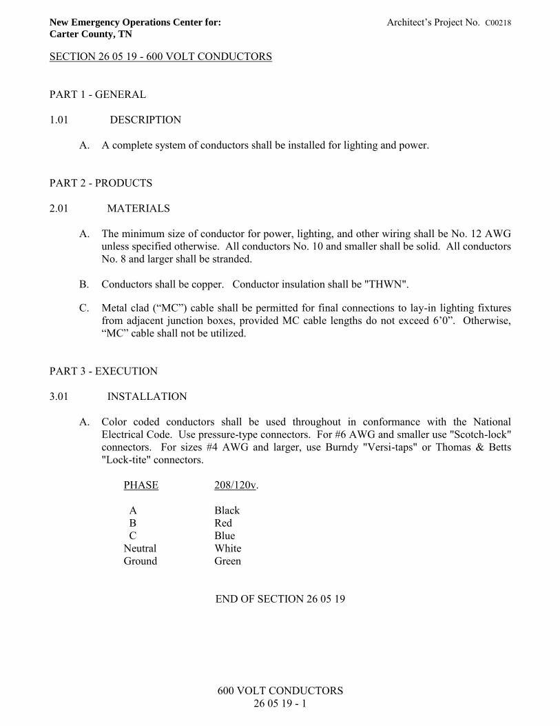
New Emergency Operations Center for: Architect’s Project No. C00218 Carter County, TN
600 VOLT CONDUCTORS 26 05 19 - 1
SECTION 26 05 19 - 600 VOLT CONDUCTORS PART 1 - GENERAL 1.01 DESCRIPTION
A. A complete system of conductors shall be installed for lighting and power. PART 2 - PRODUCTS 2.01 MATERIALS
A. The minimum size of conductor for power, lighting, and other wiring shall be No. 12 AWG unless specified otherwise. All conductors No. 10 and smaller shall be solid. All conductors No. 8 and larger shall be stranded.
B. Conductors shall be copper. Conductor insulation shall be "THWN".
C. Metal clad (“MC”) cable shall be permitted for final connections to lay-in lighting fixtures from adjacent junction boxes, provided MC cable lengths do not exceed 6’0”. Otherwise, “MC” cable shall not be utilized.
PART 3 - EXECUTION 3.01 INSTALLATION
A. Color coded conductors shall be used throughout in conformance with the National Electrical Code. Use pressure-type connectors. For #6 AWG and smaller use "Scotch-lock" connectors. For sizes #4 AWG and larger, use Burndy "Versi-taps" or Thomas & Betts "Lock-tite" connectors.
PHASE 208/120v. A Black B Red C Blue Neutral White Ground Green
END OF SECTION 26 05 19
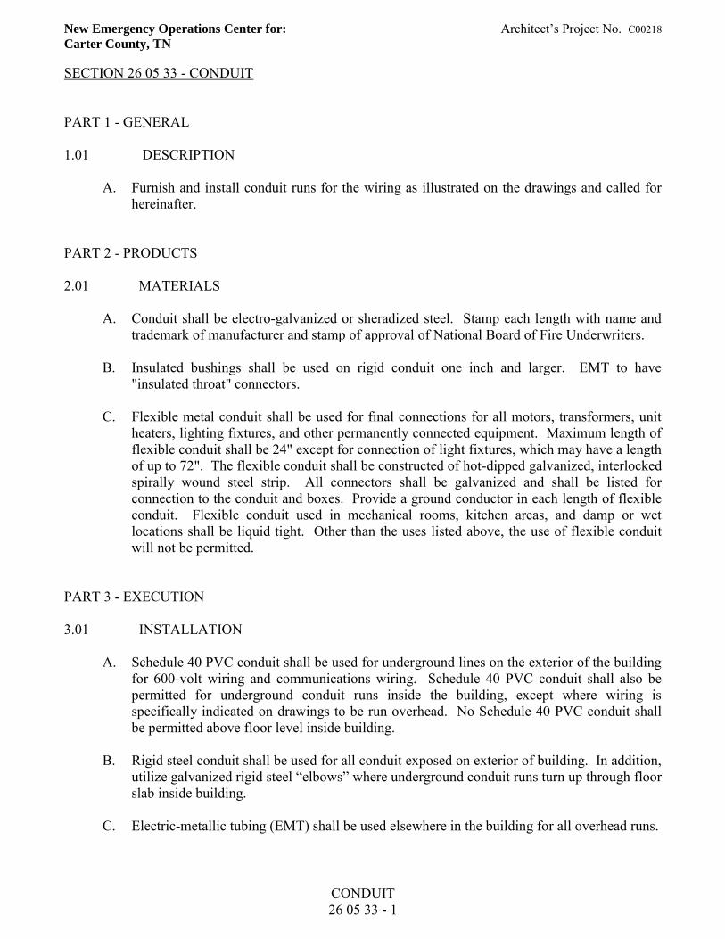
New Emergency Operations Center for: Architect’s Project No. C00218 Carter County, TN
CONDUIT 26 05 33 - 1
SECTION 26 05 33 - CONDUIT PART 1 - GENERAL 1.01 DESCRIPTION
A. Furnish and install conduit runs for the wiring as illustrated on the drawings and called for hereinafter.
PART 2 - PRODUCTS 2.01 MATERIALS
A. Conduit shall be electro-galvanized or sheradized steel. Stamp each length with name and trademark of manufacturer and stamp of approval of National Board of Fire Underwriters.
B. Insulated bushings shall be used on rigid conduit one inch and larger. EMT to have
"insulated throat" connectors. C. Flexible metal conduit shall be used for final connections for all motors, transformers, unit
heaters, lighting fixtures, and other permanently connected equipment. Maximum length of flexible conduit shall be 24" except for connection of light fixtures, which may have a length of up to 72". The flexible conduit shall be constructed of hot-dipped galvanized, interlocked spirally wound steel strip. All connectors shall be galvanized and shall be listed for connection to the conduit and boxes. Provide a ground conductor in each length of flexible conduit. Flexible conduit used in mechanical rooms, kitchen areas, and damp or wet locations shall be liquid tight. Other than the uses listed above, the use of flexible conduit will not be permitted.
PART 3 - EXECUTION 3.01 INSTALLATION
A. Schedule 40 PVC conduit shall be used for underground lines on the exterior of the building for 600-volt wiring and communications wiring. Schedule 40 PVC conduit shall also be permitted for underground conduit runs inside the building, except where wiring is specifically indicated on drawings to be run overhead. No Schedule 40 PVC conduit shall be permitted above floor level inside building.
B. Rigid steel conduit shall be used for all conduit exposed on exterior of building. In addition,
utilize galvanized rigid steel “elbows” where underground conduit runs turn up through floor slab inside building.
C. Electric-metallic tubing (EMT) shall be used elsewhere in the building for all overhead runs.
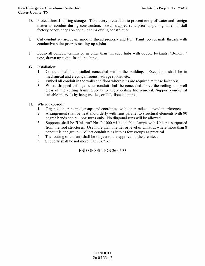
New Emergency Operations Center for: Architect’s Project No. C00218 Carter County, TN
CONDUIT 26 05 33 - 2
D. Protect threads during storage. Take every precaution to prevent entry of water and foreign matter in conduit during construction. Swab trapped runs prior to pulling wire. Install factory conduit caps on conduit stubs during construction.
E. Cut conduit square, ream smooth, thread properly and full. Paint job cut male threads with
conductive paint prior to making up a joint. F. Equip all conduit terminated in other than threaded hubs with double locknuts, "Bondnut"
type, drawn up tight. Install bushing. G. Installation:
1. Conduit shall be installed concealed within the building. Exceptions shall be in mechanical and electrical rooms, storage rooms, etc.
2. Embed all conduit in the walls and floor where runs are required at those locations. 3. Where dropped ceilings occur conduit shall be concealed above the ceiling and well
clear of the ceiling framing so as to allow ceiling tile removal. Support conduit at suitable intervals by hangers, ties, or U.L. listed clamps.
H. Where exposed:
1. Organize the runs into groups and coordinate with other trades to avoid interference. 2. Arrangement shall be neat and orderly with runs parallel to structural elements with 90
degree bends and pullbox turns only. No diagonal runs will be allowed. 3. Supports shall be "Unistrut" No. P-1000 with suitable clamps with Unistrut supported
from the roof structures. Use more than one tier or level of Unistrut where more than 8 conduit is one group. Collect conduit runs into as few groups as practical.
4. The routing of all runs shall be subject to the approval of the architect. 5. Supports shall be not more than; 6'6" o.c.
END OF SECTION 26 05 33
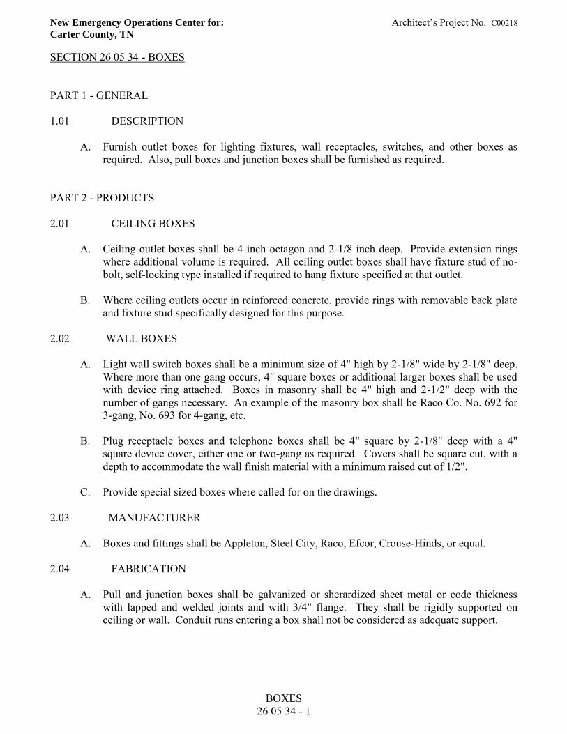
New Emergency Operations Center for: Architect’s Project No. C00218 Carter County, TN
BOXES 26 05 34 - 1
SECTION 26 05 34 - BOXES PART 1 - GENERAL 1.01 DESCRIPTION
A. Furnish outlet boxes for lighting fixtures, wall receptacles, switches, and other boxes as required. Also, pull boxes and junction boxes shall be furnished as required.
PART 2 - PRODUCTS 2.01 CEILING BOXES
A. Ceiling outlet boxes shall be 4-inch octagon and 2-1/8 inch deep. Provide extension rings where additional volume is required. All ceiling outlet boxes shall have fixture stud of no-bolt, self-locking type installed if required to hang fixture specified at that outlet.
B. Where ceiling outlets occur in reinforced concrete, provide rings with removable back plate
and fixture stud specifically designed for this purpose. 2.02 WALL BOXES
A. Light wall switch boxes shall be a minimum size of 4" high by 2-1/8" wide by 2-1/8" deep. Where more than one gang occurs, 4" square boxes or additional larger boxes shall be used with device ring attached. Boxes in masonry shall be 4" high and 2-1/2" deep with the number of gangs necessary. An example of the masonry box shall be Raco Co. No. 692 for 3-gang, No. 693 for 4-gang, etc.
B. Plug receptacle boxes and telephone boxes shall be 4" square by 2-1/8" deep with a 4"
square device cover, either one or two-gang as required. Covers shall be square cut, with a depth to accommodate the wall finish material with a minimum raised cut of 1/2".
C. Provide special sized boxes where called for on the drawings.
2.03 MANUFACTURER
A. Boxes and fittings shall be Appleton, Steel City, Raco, Efcor, Crouse-Hinds, or equal. 2.04 FABRICATION
A. Pull and junction boxes shall be galvanized or sherardized sheet metal or code thickness with lapped and welded joints and with 3/4" flange. They shall be rigidly supported on ceiling or wall. Conduit runs entering a box shall not be considered as adequate support.
New Emergency Operations Center for: Architect’s Project No. C00218 Carter County, TN
BOXES 26 05 34 - 2
PART 3 - EXECUTION 3.01 INSTALLATION
A. Install pull and/or junction boxes in conduit lines wherever necessary to avoid excessive length of runs or number of bends in run. No run shall exceed 100 feet without a pull box.
B. Pull and junction boxes shall be accessible and sized in accordance with provisions of
Article No. 370-18 of latest edition of National Electrical Code. C. Pull and junction boxes shall be installed so that cover shall be accessible at all times.
END OF SECTION 26 05 34
New Emergency Operations Center for: Architect’s Project No. C00218 Carter County, TN
WIRING DEVICES 26 05 35 - 1
SECTION 26 05 35 - WIRING DEVICES PART 1 - GENERAL 1.01 DESCRIPTION
A. Furnish and install wall switches, plug receptacles, clock hanger outlets, etc., as specified hereafter and shown on the drawings. Devices offered as a substitute to those specified will be carefully checked to see that quality such as grounding continuity, retention force for insertion devices, are equal to those specified.
B. Special colors may be required by the architect and request for color variation must be made
well in advance of product procurement. For the basis of the specification, it shall be assumed that the switch device handles and plug receptacle bodies are grey.
PART 2 - PRODUCTS 2.01 MATERIALS
A. The plug receptacles shall have a minimum rating of 20-amperes for the voltage service applied and shall be specification grade. Provide device leveler for each, Erico No. RLC.
B. Wall switches shall be 20-amperes, minimum capacity and single pole, 3-way or 4-way as
required. Other variations of the devices shall be as called for on the drawings. Where pilot lights are required, they shall be separately ganged.
C. Coverplates: Utilize stainless steel coverplates. D. Provide other type devices (isolated ground, GFCI, etc.) as called for on the drawings of
similar grade, with minimum rating of 20-amperes. E. Approved manufacturers: Eagle, Arrow Hart, Leviton, Hubbell, Pass and Seymour, Bryant,
and General Electric. F. Device and coverplate color shall be as directed by Architect.
PART 3 - EXECUTION 3.01 INSTALLATION
A. Installation of devices shall be in accord with the manufacturer's recommendations. Grounding devices such as jumper straps between the device grounding pole and the junction box, or the connection of a grounding conductor will be required at each plug
New Emergency Operations Center for: Architect’s Project No. C00218 Carter County, TN
WIRING DEVICES 26 05 35 - 2
receptacle. Where metal conduit serves the outlet box, a device using a "UL" listed grounding arrangement making use of the contact between the yoke and the device box is approved for use.
END OF SECTION 26 05 35
New Emergency Operations Center for: Architect’s Project No. C00218 Carter County, TN
OCCUPANCY SENSORS 26 09 23 - 1
SECTION 26 09 23 – OCCUPANCY SENSORS PART 1 – GENERAL
1.01 DESCRIPTION
A. Furnish and install occupancy sensors and related equipment for control of lighting as indicated on drawings and as called for hereinafter.
PART 2 - PRODUCTS 2.01 MATERIALS
A. See details on drawings for occupancy sensor requirements. All occupancy sensors shall be Lutron or equal product by other manufacturers. Proposed equal products by other manufacturers will be acceptable for use, provided that they meet all requirements of specified equipment.
PART 3 - EXECUTION 3.01 INSTALLATION
A. Refer to wiring diagrams on drawings for wiring requirements of occupancy sensors. Occupancy sensor installation shall be in accordance with manufacturer’s recommendations.
END OF SECTION 26 09 23
New Emergency Operations Center for: Architect’s Project No. C00218 Carter County, TN
PANELBOARDS 26 24 16 - 1
SECTION 26 24 16 - PANELBOARDS PART 1 - GENERAL 1.01 DESCRIPTION
A. Furnish and install panelboards with circuit breaker equipment as indicated on drawings and specified hereinafter.
B. Shop drawings shall be submitted for approval. Shop drawings shall be specific indicating
busing, breaker dimensions, gutter dimension, number size, trip, and interrupting capacity of all circuits.
PART 2 - PRODUCTS 2.01 MATERIALS
A. Branch circuit panelboards shall be of the circuit breaker, dead-front safety type equal to Square D types "NQ" with contents, as indicated on panel scheduled, shall bear approved device label of UL, and shall meet all applicable requirements of National Electrical Manufacturers Association. Panelboards shall be the product of either Square D Company, Siemens, General Electric, or Eaton.
B. Bus shall be copper. C. Number of branch circuits, their rating, number of poles arrangements, etc., are indicated on
drawings. D. Panelboards shall have lugs (both main lugs and branch circuit lugs) suitable and UL
approved for both aluminum and copper conductors. Such panelboards shall have their breakers labeled and approved by UL.
E. Provide neutral bars for all 4-wire system feeders. Isolate such neutral bars from the panel
box. F. Panels shall have a separate "ground bar" installed with lugs or connectors on bar. Such bar
shall be grounded to panel box. G. Bus bars shall be of sequence-phase type arranged for 120/208-volts, 3-phase, 4-wire mains.
All circuits shown as common neutral shall be installed in accordance with National Electrical Code.
H. Balance all circuits in a panel to achieve not more than 10 percent unbalanced neutral
current in panel feeder. Panel circuit numbering shall be revised as necessary and arranged to facilitate above.
New Emergency Operations Center for: Architect’s Project No. C00218 Carter County, TN
PANELBOARDS 26 24 16 - 2
I. Multiple breakers shall have common trip. Trip indication shall be as indicated by breaker
handle moving to a position other than ON or OFF. Equip doors on panels with chrome-plated lock and a catch with two keys supplied for each lock, concealed hinges and attachment means. Panelboards shall be flush or surface mounted as required.
J. Furnish six handle "lock-on" devices for each panel for installation on circuits as directed by
Owner to prevent unauthorized personnel from turning off circuits to controls, unit heaters, clocks, night lights, etc. Any spare lock-ons remaining shall be turned over to Owner.
K. Provide typed or printed directory cards under plastic on doors. Submit detailed drawings
for approval showing size of cabinets, trim, detail for busing, locks, method of numbering, voltage, phase, etc., and obtain approval from Architect before manufacture is commenced.
L. Distribution or power panels (all panels greater than 225-amperes) shall be similar and equal
to Square D I-line type or Siemens type CDP circuit breaker distribution panelboard. Main distribution panel shall have molded case main circuit breaker. Main distribution panel shall have service entrance label.
M. Circuit breakers shall be fully rated and temperature rated for a 40 degrees C. ambient. All
panelboards shall have lugs (both main lugs and branch circuit lugs) suitable and UL approved for aluminum and copper conductors. Such panelboards shall have their breakers labeled and approved by UL.
N. Breakers shall be of thermal magnetic type, sized and numbered as indicated on schedule
on drawings, and shall be quick-make, with trip indication shown by a handle position other than ON or OFF with trip on all multipole breakers.
O. Minimum short circuit interrupting capacity shall be as indicated on panel schedule. P. Panelboard fronts shall have concealed hinges and attachment bolts, be complete with door
cylinder lock and catch, all keyed alike. Fronts shall have adjusting indicating trim clamps and Bakelite nameplates engraved to indicate device, panel, or motor being served. Spare breakers and spaces only shall have nameplates with no engraving. Secure all nameplates to panelboard trim with two round head sheet metal screws.
Q. Panelboards shall be UL approved. Panelboard main sizes, branch circuit rating, and
mounting shall be as indicated on plans. Shop drawings shall be submitted for approval. Shop drawings shall be specific showing busing, breaker dimensions, gutter dimensions, spare space dimensions, number, size, trip, and interrupting capacity on all circuits. Standard factory work sheets will not be acceptable as shop drawings.
PART 3 - EXECUTION 3.01 INSTALLATION
A. Unless directed otherwise, panelboards shall be mounted to have the top 6 feet clear above finished floor.
New Emergency Operations Center for: Architect’s Project No. C00218 Carter County, TN
PANELBOARDS 26 24 16 - 3
B. The directories within each panelboard shall be properly filled out, so as to have a comprehensive understanding of the loads to which each circuit breaker is connected. They shall be filled out by use of a typewriter.
C. Panelboards shall be painted to match adjacent walls and labeled inside with a suitable
engraved, laminated plastic plate to identify the panelboard designation and its voltage.
END OF SECTION 26 24 16
New Emergency Operations Center for: Architect’s Project No. C00218 Carter County, TN
COMBINATION COMMUNICATIONS/POWER POLES 26 27 23 - 1
SECTION 26 27 23 – COMBINATION COMMUNICATIONS/POWER POLES PART 1 - GENERAL 1.01 DESCRIPTION
A. Furnish and install combination communications/power poles where indicated on drawings to provide service to island equipment/furniture where indicated on drawings and as called for hereinafter.
PART 2 - PRODUCTS 2.01 MATERIALS
A. Each combination communications/power pole shall have a built-in U.L. listed divider to separate power and communications wiring per requirements of National Electrical Code. Combination communications/power poles shall be similar and equal to Wiremold No. AMDTP-4 Series, with overall height of pole coordinated with ceiling height of room where pole is to be located. Each combination communications/power pole shall be equipped with two (2) 120-volt, 20-ampere duplex plug receptacles and RJ45 modular jacks as required to serve the communications drops illustrated on drawings at each specific location.
PART 3 - EXECUTION 3.01 INSTALLATION
A. Installation of combination communications/power poles shall be in strict accordance with manufacturer’s recommendations. Properly secure pole to ceiling and to finished floor. Adjust lengths as required.
END OF SECTION 26 27 23
New Emergency Operations Center for: Architect’s Project No. C00218 Carter County, TN
SAFETY SWITCHES 26 28 16 - 1
SECTION 26 28 16 - SAFETY SWITCHES PART 1 - GENERAL 1.01 DESCRIPTION:
A. Furnish and install fuse safety switches and/or disconnect switches as called for on the drawings, and as may be otherwise required by the Codes.
PART 2 - PRODUCTS 2.01 MATERIALS:
A. Safety switches shall be heavy-duty, horsepower rated, quick-make, quick-break with arc shields with enclosed construction.
PART 3 - EXECUTION: 3.01 INSTALLATION
A. Install where called for on the drawings and/or as required by the National Electrical Code. B. Where disconnect or safety switches are called for away from walls, a suitable support shall
be provided to allow the switch to be in a position of approximately 4-1/2 feet above floor. Where necessary, provide a steel frame attached to the floor or overhead structural system or both. Switches may be mounted on equipment where specific approval is realized from the supplier of the equipment, so as not to interfere with normal and ready maintenance of this equipment.
END OF SECTION 26 28 16
New Emergency Operations Center for: Architect’s Project No. C00218 Carter County, TN
MANUAL MOTOR STARTERS 26 29 13 - 1
SECTION 26 29 13 - MANUAL MOTOR STARTERS PART 1 - GENERAL 1.01 DESCRIPTION
A. Furnish and install manual motor starters for 120-volt equipment as shown on drawings and called for hereinafter.
PART 2 - PRODUCTS 2.01 MATERIALS
A. Manual motor starters shall be equipped with melting alloy type thermal overload relay. Manual motor starters shall be provided with pilot lights. Unit shall be similar and equal to Square D Company 2510 Series, catalog No. FF-1P.
PART 3 - EXECUTION 3.01 INSTALLATION
A. Manual motor starters shall be installed at HVAC equipment in accordance with NEC requirements for disconnecting means. Install in accordance with manufacturer’s recommendations.
END OF SECTION 26 29 13
New Emergency Operations Center for: Architect’s Project No. C00218 Carter County, TN
LED INTERIOR LIGHTING 26 51 19 - 1
SECTION 26 51 19 - LED INTERIOR LIGHTING PART 1 - GENERAL 1.01 RELATED DOCUMENTS
A. Drawings and general provisions of the Contract, including General and Supplementary Conditions and Division 01 Specification Sections, apply to this Section.
1.02 ACTION SUBMITTALS
A. Product Data: For each type of product. 1. Arrange in order of luminaire designation. 2. Include data on features, accessories and finishes. 3. Include physical description and dimensions of luminaires. 4. Include life, output (lumens, CCT, and CRI), and energy efficiency data. 5. Photometric data and adjustment factors based on laboratory tests IES LM-79
and IES LM-80. a. Manufacturer’s Certified Data: Photometric data certified by
manufacturer’s laboratory with a current accreditation under the National Voluntary Laboratory Accreditation Program for Energy Efficient Lighting Products.
B. Shop Drawings: For nonstandard or custom luminaires.
1. Include plans, elevations, sections, and mounting and attachment details. 2. Include details of luminaire assemblies. Indicate dimensions, weights, loads,
required clearances, method of field assembly, components and location and size of each field connection.
3. Include diagrams for power, signal, and control wiring.
C. Product Schedule: For luminaires and lamps, use same designations indicated on Drawings.
1.03 CLOSEOUT SUBMITTALS
A. Operation and Maintenance Data: For luminaires and lighting systems to include in
operation and maintenance manuals. Provide a list of all lamp types used on Project; use ANSI and manufacturer’s codes.
1.04 QUALITY ASSURANCE
A. Luminaire Photometric Data Testing Laboratory Qualifications: Luminaire manufacturer’s laboratory that is accredited under the NVLAP for Energy Efficient Lighting Products.
New Emergency Operations Center for: Architect’s Project No. C00218 Carter County, TN
LED INTERIOR LIGHTING 26 51 19 - 2
B. Luminaire Photometric Data Testing Laboratory Qualifications: Provided by an independent agency, with the experience and capability to conduct the testing indicated, that is an NRTL as defined by OSHA in 29 CFR 1910.7, accredited under the NVLAP for Energy Efficient Lighting Products, and complying with the applicable IES testing standards.
C. Provide luminaires from a single manufacturer for each luminaire type.
1.05 DELIVERY, STORAGE, AND HANDLING
A. Protect finishes of exposed surfaces by applying a strippable, temporary protective covering before shipping.
1.06 WARRANTY
A. Warranty: Manufacturer and Installer agree to repair or replace components of luminaires that fail in materials or workmanship within specified warranty period.
B. Warranty Period: One year(s) from date of Substantial Completion. PART 2 - PRODUCTS 2.01 PERFORMANCE REQUIREMENTS
A. Seismic Performance: Luminaires shall withstand the effects of earthquake motions determined according to ASCE/SEI 7. The term “withstand” means “the luminaire will remain in place without separation of any parts when subjected to the seismic forces specified.”
2.02 LUMINAIRE REQUIREMENTS
A. Electrical Components, Devices, and Accessories: Listed and labeled as defined in NFPA 70, by a qualified testing agency, and marked for intended location and application.
B. NRTL Compliance: Luminaires for hazardous locations shall be listed and labeled for indicated class and division of hazard by an NRTL.
C. Recessed fixtures: Comply with NEMA LE 4.
D. CRI of 80 CCT of 3500 K.
E. Rated lamp life of 50,000 hours or more.
F. Where dimming is indicated, lamps dimmable from 100 percent to 0 percent of maximum light output.
New Emergency Operations Center for: Architect’s Project No. C00218 Carter County, TN
LED INTERIOR LIGHTING 26 51 19 - 3
G. Internal driver.
H. Nominal Operating Voltage: As indicated.
I. Lens Thickness: At least 0.125 inch minimum unless otherwise indicated.
J. Housings: 1. Extruded-aluminum housing and heat sink. 2. Finish as indicated.
2.03 MATERIALS
A. Metal Parts: 1. Free of burrs and sharp corners and edges. 2. Sheet metal components shall be steel unless otherwise indicated. 3. Form and support to prevent warping and sagging.
B. Doors, Frames, and Other Internal Access: Smooth operating, free of light leakage
under operating conditions, and designed to permit relamping without use of tools. Designed to prevent doors, frames, lenses, diffusers, and other components from falling accidentally during relamping and when secured in operating positions.
C. Diffusers and Globes: 1. Prismatic acrylic clear, UV-stabilized acrylic. 2. Acrylic Diffusers: One hundred percent virgin acrylic plastic with high
resistance to yellowing and other changes due to aging, exposure to heat, and UV radiation.
3. Lens Thickness: At least 0.125 inch minimum unless otherwise indicated.
D. Housings: Extruded-aluminum housing and heat sink. Finish as indicated.
E. Factory-Applied Labels: Comply with UL 1598. Include recommended lamps. Locate labels where they will be readily visible to service personnel, but not seen from normal viewing angles when lamps are in place. Label shall include the following lamp characteristics: 1. “USE ONLY” and include specific lamp type. 2. Lamp diameter, shape, size, wattage, and coating. 3. CCT and CRI for all luminaires.
2.04 METAL FINISHES
A. Variations in finishes are unacceptable in the same piece. Variations in finishes of adjoining components are acceptable if they are within the range of approved Samples and if they can be and are assembled or installed to minimize contrast.
New Emergency Operations Center for: Architect’s Project No. C00218 Carter County, TN
LED INTERIOR LIGHTING 26 51 19 - 4
2.05 LUMINAIRE FIXTURE SUPPORT COMPOENTS
A. Wires: ASTM A 641/A 641 M, Class 3, soft temper, zinc coated steel, 12 gage.
B. Rod Hangers: 3/16-inch minimum diameter, cadmium-plated, threaded steel rod. PART 3 - EXECUTION 3.01 EXAMINATION
A. Examine substrates, areas, and conditions, with installer present, for compliance with requirements for installation tolerances and other conditions affecting performance of the Work.
B. Examine roughing-in for luminaire to verify actual locations of luminaire and
electrical connections before fixture installation. Proceed with installation only after unsatisfacto5ry conditions have been corrected.
3.02 INSTALLATION
A. Comply with NECA 1.
B. Install luminaires level, plumb, and square with ceilings and walls unless otherwise indicated.
C. Install lamps in each luminaire.
D. Supports: 1. Sized and rated for luminaire weight. 2. Able to maintain luminaire positions after cleaning and relamping. 3. Provide support for luminaire without causing deflection of ceiling or wall. 4. Luminaire mounting devices shall be capable of supporting a horizontal force of
100 percent of luminaire weight and vertical force of 400 percent of luminaire weight.
E. Flush-Mounted Luminaire Support:
1. Secured to outlet box. 2. Attached to ceiling structural members at four points equally spaced around
circumference of luminaire. 3. Trim ring flush with finished surface.
F. Wall-Mounted Luminaire Support:
1. Attached to structural members in walls. 2. Do not attach luminaires directly to gypsum board.
New Emergency Operations Center for: Architect’s Project No. C00218 Carter County, TN
LED INTERIOR LIGHTING 26 51 19 - 5
G. Ceiling-Mounted Luminaire Support: 1. Ceiling mount with two 5/32-inch diameter aircraft cable supports adjustable to
120 inches in length. 2. Ceiling mount with two-point pendant mount with 5/32-inch diameter aircraft
cable supports adjustable to 120 inches in length.
H. Suspended Luminaire Support 1. Pendants and Rods: Where longer than 48 inches, brace to limit swinging.
Stem-Mounted, Single-Unit Luminaires: Suspend with twin-stem hangers. Support with approved outlet box and accessories that hold stem and provide damping of luminaire oscillations. Support outlet box vertically to building structure using approved devices.
2. Continuous Rows of Luminaires: Use tubing or stem for wiring at one point (unless indicated otherwise) and wire support for suspension for each unit length of luminaire classis, including one at each end.
3. Do not use ceiling grid as support for pendent luminaires. Connect support wires or rods to building structure.
I. Ceiling-Grid-Mounted Luminaires:
1. Secure to any required outlet box. 2. Secure luminaire to the luminaire opening using approved fasteners in a
minimum of four locations, spaced near corners of luminaire. 3. Use approved devices and support components to connect luminaire to ceiling
grid and building structure in a minimum of four locations, spaced near corners of luminaire.
J. Comply with requirements in Section 260519 “Low-Voltage Electrical Power Conductors and Cables” for wiring connections.
3.03 FIELD QUALITY CONTROL
A. Perform the following tests and inspections: 1. Operational Test: After installing luminaires, switches, and accessories, and
after electrical circuitry has been energized, test units to confirm proper operation.
2. Test for Emergency Lighting: Interrupt power supply to demonstrate proper operation. Verify transfer from normal power to emergency power and retransfer to normal.
B. Luminaire will be considered defective if it does not pass operation tests and
inspections.
C. Prepare test and inspection reports.
END OF SECTION 26 51 19
New Emergency Operations Center for: Architect’s Project No. C00218 Carter County, TN
EXIT SIGNS 26 53 00 - 1
SECTION 26 53 00 - EXIT SIGNS PART 1 - GENERAL 1.01 DESCRIPTION
A. Furnish and install exit signs where illustrated on the drawings. They shall have built-in battery packs to maintain their self-illumination on the occasion of normal power interruption. Mounting configuration shall be as set forth on the drawings and described hereinafter.
PART 2 - PRODUCTS 2.01 MATERIALS
A. The unit shall be of polycarbonate construction. Lamps shall be LED. Letters shall be red. Finish of housing shall be matte white. The units shall have built-in battery which shall energize the exit sign on the occasion of normal power interruption. They shall be equipped with a device to prevent deep draw down of the battery unit after approximately 1-1/2 to 2 hours of operation. The equipment shall be similar and equal to Lithonia Co. No. LQM1/3R-120/277-ELN. Similar equipment by the Emergi-lite Company, the Dual-lite Company, Sure-Lite Company, and the Chloride Company are approved. The units mounted on a lay-in type ceiling shall be supported by use of a Caddy Co. acoustical "Tee Bar" box hanger, catalog No. 512 or similar product. Ceiling surface mounted units shall have a "recessed" battery unit so as to minimize the projection down from the ceiling.
PART 3 - EXECUTION 3.01 INSTALLATION
A. The unit shall be configured for the mounting called for on the drawings, either single face or double face or either ceiling mounting or wall mounting. Directional arrows shall be provided as indicated. Where ceilings above 9' are involved, the ceiling mounted units are to be pendant mounted to where the bottom of the sign is approximately 8'6" above floor. Conform to the manufacturers recommendations.
END OF SECTION 26 53 00
New Emergency Operations Center for: Architect’s Project No. C00218 Carter County, TN
GENERAL COMMUNICATIONS 27 00 00 - 1
SECTION 27 00 00 – GENERAL COMMUNICATIONS PART 1 - GENERAL 1.01 OTHER CONDITIONS
A. Applicable provisions of the General conditions, Supplementary Conditions, and Division 1,
General Requirements, apply to the Work under this Section. 1.02 SCOPE OF WORK:
A. The work included under this specification consists of, but is not limited to, work as
indicated on the drawings and hereinafter specified in Division 27. Without limiting the generality implied by the drawings an specifications, communications consists of furnishing all materials, accessories, tools, and labor required and incidental thereto, to provide: 1. Data/voice network wiring facility. 2. Door intercom system.
1.03 RELATED WORK:
A. Division 22: Plumbing; Division 23: Mechanical; Division 26: Electrical; Division 28:
Electronic Safety and Security.
B. See drawings and other sections for equipment requiring electrical service.
C. Painting (except factory-applied finishes on equipment) is specified elsewhere. 1.04 REFERENCE STANDARDS:
A. Make entire electrical installation in strict accordance with the requirements of all city, county, state, or federal codes of law having jurisdiction, the requirements and recommendations of the Board of Fire Underwriters, including all amendments and/or additions to said codes, laws, requirements, and recommendations and the requirements and recommendations of the Power Company. Applicable codes are as follows: 1. NFPA 101 Life Safety Code. 2. NFPA 72 3. NFPA 70 4. NFPA 90A 5. NFPA 92A 6. NFPA 13 7. NFPA 13R 8. NFPA 13D 9. NFPA 14 10. International Building Code 11. International Fire Code 12. International Mechanical Code 13. NFPA 20
New Emergency Operations Center for: Architect’s Project No. C00218 Carter County, TN
GENERAL COMMUNICATIONS 27 00 00 - 2
B. Should any work shown on the drawings or herein specified be construed a being contrary to or not conforming to the previously mentioned Codes, etc., bring it to the attention of the Architect before executing the work in conformity with the various codes, etc., without additional cost to the Owner, but not until the matter in question has been reviewed by the Architect.
C. Should any work shown on the drawings or herein specified be more rigid as to requirements
than the requirements of the various codes, the drawings and specifications shall be used in executing the work.
D. File with proper authorities all necessary drawings as required by various codes, laws,
ordinances, or other requirements. E. Obtain and pay for all permits and for all required inspection certificates. Pay necessary
fees.
1.05 WARRANTY-GUARANTEE
A. Warrant and guarantee that all work executed under this section of the specifications will be free from defects of materials and workmanship for a period of one year from the date of final acceptance of the building. The above parties further agree that they will, at their own expense, repair and replace all such defective work and all other work damaged thereby which defective during the term of the warranty-guarantee.
1.06 ARCHITECTURAL DRAWINGS:
A. Refer to architectural drawings for details such as finishes, dimensions, materials, etc. Refer
to drawings for door locations, door swings, partitions location, cabinet and counters, making proper allowances therefore. Refer to equipment plans for exact location of electrical connections which are dimensioned.
PART 2 - PRODUCTS 2.01 SUBMITTALS:
A. Manufacturer's Data: For information only, submit 6 copies of manufacturer's
specifications, descriptions, illustrations, and installation instructions for each type of manufactured product to include: Data/voice network facility and door intercom system intended for use on this project. The submittal shall consist of one or more brochures each containing only "one" copy of material describing the product. Several products may be included in each brochure.
B. Include manufacturer's certification as may be required to show compliance with these
specifications. Indicate by transmittal form that a copy of each instruction has been distributed to the installer.
New Emergency Operations Center for: Architect’s Project No. C00218 Carter County, TN
GENERAL COMMUNICATIONS 27 00 00 - 3
C. Furnish three complete sets of operating and maintenance instructions applying to equipment installed in conjunction with this contract; include parts lists, wiring diagrams, catalog data, stamped approval submittal data, and operational checkout data as called for in these specifications, bound in hardback binders. Instructions shall be submitted to the Architect for approval at least one month in advance of initial system start-up.
2.02 PRODUCTS
A. Materials shall not be ordered until architect's review of submittal material has been made.
They shall be new and unused and the manufacturers standard product and the latest designs. PART 3 - EXECUTION 3.01 INSTALLATION
A. The drawings which show the work included are diagrammatic only; the locations, routing,
etc., of the various fixtures, items of equipment, wiring, etc., are approximate only. The entire installation is subject to such deviations, modifications, rerouting, etc., as may be necessary to meet the requirements of the architectural, structural, and other drawings; and also as necessary to obtain a proper coordination of the work with that of all other trades.
B. Carefully check and become familiar with the above-mentioned drawings, and frequently
consult with all other trades so that the work may proceed as a harmonious whole. C. Install concealed all wiring except where the Architect grants specified permission to run
same exposed. D. Installer shall defer the installation of all electrical fixtures liable to damage. After fixtures
are permanently installed, completely protect against breaking, damage, or the depositing of any waste material therein until the system is accepted.
3.02 COORDINATION
A. Carefully check locations, layouts, and dimensions of all items to be installed under this
section with the above-mentioned drawings, and coordinate with all trades affected. B. Any work installed without properly checking and coordinating same as above provided,
which as a result interferes with the proper installation of the work of other trades, is to be removed and properly reinstalled at contractor’s expense.
C. It is the installer's responsibility to notify well in advance, all trades affected, or any chases,
recesses, etc., which may be required for the installation of the work. Should this be neglected, any cutting and/or patching required for such chases, recesses, etc., to be done at this contractor's expense.

New Emergency Operations Center for: Architect’s Project No. C00218 Carter County, TN
GENERAL COMMUNICATIONS 27 00 00 - 4
3.03 PROTECTION AND CLEANING
A. Protect work, equipment, and materials at all times. Tightly cover and protect equipment against dirt, water, chemical, or mechanical injury. At final completion of all work to be thoroughly cleaned and delivered in a perfect unblemished condition.
B. Touch-up all damaged paint surfaces on equipment to match original paint.
3.04 INITIAL OPERATION OF EQUIPMENT
A. Give all equipment furnished in the contract an operational test prior to final acceptance.
Assist the Owner in the initial operation when the owner operates the building and equipment. Instruct the owner's personnel in the proper operation and maintenance of all the equipment furnished under this section of the specifications.
3.05 FIRE-RATED WALL PENETRATIONS
A. Where conduit penetrates fire-rated walls, the space between the penetration item and the fire barrier wall shall be properly protected. The space adjoining the conduit penetration shall be filled with a material capable of maintaining the fire rating of the fire barrier, or it shall be protected by an approved device designed for this specific purpose. Where penetrating sleeves are used, the sleeves shall be solidly set in this fire barrier wall, and the space between the conduit and the sleeve shall be filled with a material capable of maintaining the fire resistance of the fire-rated wall.
END OF SECTION 27 00 00
New Emergency Operations Center for: Architect’s Project No. C00218 Carter County, TN
TELEPHONE/DATA CONDUIT FACILITY 27 05 28 - 1
SECTION 27 05 28 – TELEPHONE/DATA CONDUIT FACILITY PART 1 - GENERAL 1.01 DESCRIPTION
A. Furnish and install a system of empty conduit and boxes for data/voice wiring in the facility. All data/voice cabling, faceplates, etc., will be furnished and installed by others.
PART 2 - PRODUCTS 2.01 MATERIALS
A. Size of service entrance conduit shall be 4". Provide a suitable "pull-wire" in conduits. B. Conduit used for data/voice outlets shall be 3/4" minimum. Boxes for data/voice outlets
shall be 4” square with single-gang device ring unless noted otherwise on drawings. PART 3 - EXECUTION 3.01 INSTALLATION
A. Coordinate service requirements with telephone company. Conform with their requirements.
END OF SECTION 27 05 28
New Emergency Operations Center for: Architect’s Project No. C00218 Carter County, TN
LOW-VOLTAGE CABLING SUPPORT SYSTEM 27 05 29 - 1
SECTION 27 05 29 - LOW-VOLTAGE CABLING SUPPORT SYSTEM PART 1 – GENERAL
1.01 DESCRIPTION
A. Furnish and install a system of cabling supports above lay-in ceilings for low-voltage (data
wiring, integrated communications, sound reinforcement) wiring. PART 2 - PRODUCTS 2.01 MATERIALS
A. Low-voltage cable support system shall be J-hook system, similar and equal to Steel Cooper BCH Series. Non-metallic J-hook system by Panduit or equal will also be approved for use.
B. Provide separate J-hook systems for 1) voice/data network, (2) CCTV and (3) access control.
C. Provide all necessary supports and attachments to allow connection to structure for these supports. Where wall mounted above ceiling, J-hook supports shall be secured directly to metal studs or masonry walls. J-hooks shall not be permitted to be attached directly to gypboard walls.
PART 3 - EXECUTION 3.01 INSTALLATION
A. Low voltage cabling shall only be permitted to be run exposed in low voltage cabling
support system above accessible lay-in ceilings in communications rooms and in mechanical mezzanine spaces. Otherwise, all low voltage cabling shall be run in conduit in areas where there is no lay-in ceiling.
B. Cabling supports shall be located minimum 4’ to 5’ on center throughout entire length of low-voltage cabling runs above ceiling. Locate supports well clear of acoustical lay-in ceiling tiles. Supports shall be located such that tiles can be removed without interfering with support system.
C. Maximum number of data network cables to be installed per J-hook shall be forty (40). Provide additional sets of J-hook support systems as needed to support data network cables.
D. Coordinate installation of low-voltage supports with other trades as required.
E. Entire installation shall be in accordance with manufacturer’s recommendations.
END OF SECTION 27 05 29
New Emergency Operations Center for: Architect’s Project No. C00218 Carter County, TN
COMMUNICATIONS TERMINAL SPACES 27 10 10 -1
SECTION 27 10 10 - COMMUNICATIONS TERMINAL SPACES PART 1 - GENERAL 1.01 DESCRIPTION
A. Furnish and install communications terminal spaces as indicated on drawings and as called for hereinafter.
PART 2 - PRODUCTS 2.01 MATERIALS
A. The communications terminal spaces shall consist of 3/4" marine plywood bolted to the wall with the top 6' above floor and the bottom 24" above floor, the width as shown to scale on the drawings. Provide Unistrut channel above and below the plywood to secure inbound and outbound conduit. Conduit at that location shall be fitted with bushings. Conduit shall be terminated in a horizontal position within 6" of the terminal mounting board. Paint plywood with two coats of gray paint.
PART 3 - EXECUTION 3.01 INSTALLATION
A. Furnish and install at terminal space a #3/0 AWG copper grounding conductor extended to main electrical service ground. Provide grounding bar, 4” x 12”, 5 hole minimum, Chatsworth 40153-12 or equal by Panduit, Cooper, Homaco, or Hubbell.
END OF SECTION 27 10 10
New Emergency Operations Center for: Architect’s Project No. C00218 Carter County, TN
VOICE/DATA NETWORK WIRING 27 15 00 - 1
SECTION 27 15 00 – VOICE/DATA NETWORK WIRING PART 1 - GENERAL
1.01 SCOPE
A. Furnish and install as specified and shown on plans a Category 6E enhanced cabling system including, but not limited to, cabling, patch panels, modular jacks, work outlet faceplates, patch cords, etc.
B. System shall consist of Category 6E cabling, Patch Panels, and Jacks for a 250MHZ Base T
Network. C. All cable shall be tested and certified per ANSI/TIA/ISO/IEC standards. Test reports shall be
generated and furnished to the owner in hardback copies. A certified technician using Ideal Lan-Tek 11 Cable certifier and similar by Fluke shall do all testing.
1.02 SUBMITTAL:
A. Specification sheet shall be furnished on items including cabling as per contract documents. 1.03 SERVICE MAINTENANCE
A. The Installing Company shall be a licensed Contractor with a least five years experience in
similar type work. A list of five current installations shall be furnished with submittal documents. The installing contractor must be trained and certified installer by Leviton or Hubbell and offer a Life Time warranty.
PART 2 - PRODUCTS 2.01 MATERIAL:
A. Category 6E cable shall be Enhanced cable meeting ANSI/TIA/EIA 568A or B Requirements for
Ethernet 100 Base TX, 1000 Base T, Token Ring or Ethernet 1000 Base T. Cat6E cable shall be as manufactured by Superior Essex or General, or approved equal by another manufacturer. All cable shall be a color coded to match jack.
B. Patch Panels shall be Category 6E 110 Patch Panels with wire management. The Panel shall be
rack or wall mounted with rear access. Patch Panels shall be 24 or 48 Port position as required with 50 % spares. Patch Panels shall be 568B as manufactured by Hubbell, Leviton, Panduit, or equal by another manufacturer. Furnish Cable Management vertical and horizontal for all patch panels
C. Patch Cables shall be furnished one per drop in 14-ft length at far end and 3 ft drops at near end.
The patch cables shall be colored coded to match computer jacks. Cat 6 Patch cables shall be as manufactured by the above listed companies. All patch cables shall be turned over to the owner at the completion of the project.
New Emergency Operations Center for: Architect’s Project No. C00218 Carter County, TN
VOICE/DATA NETWORK WIRING 27 15 00 - 2
D. Category 6E Jacks shall be installed and furnished as indicated on plans. The wall or floor mounted jack plates shall be Ivory or as Indicated by Architect with Blue inserts for Data, White for Telephone, Orange for auxiliary and green for Printer.
E. Faceplates shall be ivory or white as directed by architect. Modular jacks and faceplates at work
outlets shall be Hubbell “Speedgain” or equal by Leviton, Panduit, or other manufacturer. F. Switches shall be furnished as required at all patch panels by the Owner’s technology department.
Contractor shall provide patch cords for all network drops to allow tie-in from contractor installed patch panels to owner installed equipment.
G. The Contractor shall use all connectors and patch cords that are approved by the premise wiring
warranty provider. 1. All patch cords are to be a minimum of three foot long. 2. The Contractor shall provide fourteen foot patch cable for every information/data outlet. 3. The Contractor shall provide as a minimum 3 meter multimode SC fiber optic patch cords. 4. The Contractor will coordinate all equipment connections, the type optical fiber and the type
connectors necessary with the owner.
H. Provide Free Standing racks in main telecommunications equipment room, similar and equal to Hubbell HPW84RR19 with HLS1012 Ladder Rack and HLX0612 wall bracket secured with HJJB J bolts.
I. Category Cat 6E Cable CMR/CMP 10 Base-T through 10,000 Base-T Ethernet Cable by Superior
Essex, General, or approved equal by another manufacturer.
PART 3 - EXECUTION 3.01 INSTALLATION
A. Installation shall be installed in a professional manor as required by Manufacturer’s standards.
Test reports shall be furnished to owner in hardcopy and CD disk. Each installed cable shall be tested and labeled in accordance with EIA/TIA Standards.
END OF SECTION 2715 00
New Emergency Operations Center for: Architect’s Project No. C00218 Carter County, TN
DOOR INTERCOM SYSTEM 27 51 23 - 1
SECTION 27 51 23 – DOOR INTERCOM SYSTEM PART 1 - GENERAL 1.01 DESCRIPTION
A. The Contractor shall furnish all required equipment as described in these specifications, for the installation of Intercom System.
B. The equipment specified herein constitutes the type and quality of equipment necessary for
proper system function. Any alternate system must be approved by the specifying authority. Submission of an alternate shall contain engineering drawings of system with specification sheets for all components of the system. The system and equipment drawing and specification sheet shall meet all items of the specification.
C. Work Included: Furnish and install all equipment, accessories, and materials in accordance with
these specifications and drawings to provide a complete and operating intercom system.
D. Submittal: Submit equipment electronic wiring diagrams and specification sheets for each item specified herein. Provide a tabulation of the specification clearly comparing the submitted item with the specified items being able to refer to all written expressed functions and capabilities.
1.02 SERVICE AND MAINTENANCE
A. The contractor shall provide a one year warranty of the installed system against defects in material and workmanship. All labor and materials shall be provided at no expense to the owner during normal working hours. The warranty period shall begin on the date of acceptance by the owner and engineer.
PART 2 - PRODUCTS 2.01 INTERCOM SYSTEM
A. Aiphone LEM-1 intercom master with station call by voice and monitoring of sub stations. Master station shall be desk or wall mounted. Unit shall be 500 m watts power output with Skk-620C power supply. This master station shall allow for the connection of 1 sub stations.
B. Sub stations shall be recessed stainless LE-DA with two-way speaker and call button.
PART 3 - EXECUTION 3.01 INSTALLATION, WIRING, AND RACEWAY PROVISIONS
A. Make installation in strict accordance with approved manufacturer's drawings and instructions. B. Wiring shall be West Penn 291 2 conductor 22 gauge with over all shield.
END OF SECTION 27 51 23
New Emergency Operations Center for: Architect’s Project No. C00218 Carter County, TN
GENERAL ELECTRONIC SAFETY AND SECURITY 28 00 00 - 1
SECTION 28 00 00 - GENERAL ELECTRONIC SAFETY AND SECURITY PART 1 - GENERAL 1.01 OTHER CONDITIONS
A. Applicable provisions of the General conditions, Supplementary Conditions, and Division 1,
General Requirements, apply to the Work under this Section. 1.02 SCOPE OF WORK:
A. The work included under this specification consists of, but is not limited to, work as
indicated on the drawings and hereinafter specified in Division 28. Without limiting the generality implied by the drawings an specifications, electronic safety and security consists of furnishing all materials, accessories, tools, and labor required and incidental thereto, to provide: 1. Fire alarm system. 2. Door access control system. 3. IP based CCTV system.
1.03 RELATED WORK:
A. Division 22: Plumbing; Division 23: Mechanical; Division 26: Electrical; Division 27: Communications.
B. See drawings and other sections for equipment requiring electrical service.
C. Painting (except factory-applied finishes on equipment) is specified elsewhere. 1.4 REFERENCE STANDARDS:
A. Make entire electrical installation in strict accordance with the requirements of all city, county, state, or federal codes of law having jurisdiction, the requirements and recommendations of the Board of Fire Underwriters, including all amendments and/or additions to said codes, laws, requirements, and recommendations and the requirements and recommendations of the Power Company. Applicable codes are as follows: 1. NFPA 101 Life Safety Code. 2. NFPA 72 3. NFPA 70 4. NFPA 90A 5. NFPA 92A 6. NFPA 13 7. NFPA 13R 8. NFPA 13D 9. NFPA 14 10. International Building Code 11. International Fire Code
New Emergency Operations Center for: Architect’s Project No. C00218 Carter County, TN
GENERAL ELECTRONIC SAFETY AND SECURITY 28 00 00 - 2
12. International Mechanical Code 13. NFPA 20
B. Should any work shown on the drawings or herein specified be construed a being contrary to or not conforming to the previously mentioned Codes, etc., bring it to the attention of the Architect before executing the work in conformity with the various codes, etc., without additional cost to the Owner, but not until the matter in question has been reviewed by the Architect.
C. Should any work shown on the drawings or herein specified be more rigid as to requirements
than the requirements of the various codes, the drawings and specifications shall be used in executing the work.
D. File with proper authorities all necessary drawings as required by various codes, laws, ordinances, or other requirements.
E. Obtain and pay for all permits and for all required inspection certificates. Pay necessary fees.
1.05 WARRANTY-GUARANTEE
A. Warrant and guarantee that all work executed under this section of the specifications will be
free from defects of materials and workmanship for a period of one year from the date of final acceptance of the building. The above parties further agree that they will, at their own expense, repair and replace all such defective work and all other work damaged thereby which defective during the term of the warranty-guarantee.
1.06 ARCHITECTURAL DRAWINGS:
A. Refer to architectural drawings for details such as finishes, dimensions, materials, etc. Refer
to drawings for door locations, door swings, partitions location, cabinet and counters, making proper allowances therefore. Refer to equipment plans for exact location of electrical connections which are dimensioned.
PART 2 - PRODUCTS 2.01 SUBMITTALS:
A. Manufacturer's Data: For information only, submit 6 copies of manufacturer's
specifications, descriptions, illustrations, and installation instructions for each type of manufactured product to include: Fire alarm, access control, and CCTV systems intended for use on this project. The submittal shall consist of one or more brochures each containing only "one" copy of material describing the product. Several products may be included in each brochure.
B. Include manufacturer's certification as may be required to show compliance with these specifications. Indicate by transmittal form that a copy of each instruction has been distributed to the installer.

New Emergency Operations Center for: Architect’s Project No. C00218 Carter County, TN
GENERAL ELECTRONIC SAFETY AND SECURITY 28 00 00 - 3
C. Furnish three complete sets of operating and maintenance instructions applying to equipment installed in conjunction with this contract; include parts lists, wiring diagrams, catalog data, stamped approval submittal data, and operational checkout data as called for in these specifications, bound in hardback binders. Instructions shall be submitted to the Architect for approval at least one month in advance of initial system start-up.
2.02 PRODUCTS
A. Materials shall not be ordered until architect's review of submittal material has been made.
They shall be new and unused and the manufacturers standard product and the latest designs.
PART 3 - EXECUTION 3.01 INSTALLATION
A. The drawings which show the work included are diagrammatic only; the locations, routing,
etc., of the various fixtures, items of equipment, wiring, etc., are approximate only. The entire installation is subject to such deviations, modifications, rerouting, etc., as may be necessary to meet the requirements of the architectural, structural, and other drawings; and also as necessary to obtain a proper coordination of the work with that of all other trades.
B. Carefully check and become familiar with the above-mentioned drawings, and frequently
consult with all other trades so that the work may proceed as a harmonious whole. C. Install concealed all wiring except where the Architect grants specified permission to run
same exposed. D. Installer shall defer the installation of all electrical fixtures liable to damage. After fixtures
are permanently installed, completely protect against breaking, damage, or the depositing of any waste material therein until the system is accepted.
3.02 COORDINATION
A. Carefully check locations, layouts, and dimensions of all items to be installed under this
section with the above-mentioned drawings, and coordinate with all trades affected. B. Any work installed without properly checking and coordinating same as above provided,
which as a result interferes with the proper installation of the work of other trades, is to be removed and properly reinstalled at contractor’s expense.
C. It is the installer's responsibility to notify well in advance, all trades affected, or any chases,
recesses, etc., which may be required for the installation of the electrical work. Should this be neglected, any cutting and/or patching required for such chases, recesses, etc., to be done at this contractor's expense.
New Emergency Operations Center for: Architect’s Project No. C00218 Carter County, TN
GENERAL ELECTRONIC SAFETY AND SECURITY 28 00 00 - 4
3.03 PROTECTION AND CLEANING
A. Protect work, equipment, and materials at all times. Tightly cover and protect equipment
against dirt, water, chemical, or mechanical injury. At final completion of all work to be thoroughly cleaned and delivered in a perfect unblemished condition.
B. Touch-up all damaged paint surfaces on equipment to match original paint.
3.04 INITIAL OPERATION OF EQUIPMENT
A. Give all equipment furnished in the contract an operational test prior to final acceptance.
Assist the Owner in the initial operation when the owner operates the building and equipment. Instruct the owner's personnel in the proper operation and maintenance of all the equipment furnished under this section of the specifications.
3.05 FIRE-RATED WALL PENETRATIONS
A. Where conduit penetrates fire-rated walls, the space between the penetration item and the fire barrier wall shall be properly protected. The space adjoining the conduit penetration shall be filled with a material capable of maintaining the fire rating of the fire barrier, or it shall be protected by an approved device designed for this specific purpose. Where penetrating sleeves are used, the sleeves shall be solidly set in this fire barrier wall, and the space between the conduit and the sleeve shall be filled with a material capable of maintaining the fire resistance of the fire-rated wall.
END OF SECTION 28 00 00
New Emergency Operations Center for: Architect’s Project No. C00218 Carter County, TN
DOOR ACCESS CONTROL SYSTEM 28 13 00 - 1
SECTION 28 13 00 – DOOR ACCESS CONTROL SYSTEM PART 1 - GENERAL 1.01 INTENT
A. The intent of this document is to describe the operational requirements of the system (and sub-systems) to be used for access control.
B. All systems and/or sub-systems shall conform to the following regulatory organization
requirements. 1. CSA Bonding and Grounding of electrical equipment 2. UL294 Access Control System Unit or equivalent 3. IEEE – communications (RS232C and RS485 communications) 4. EMI emissions – (FCC part 15 subsection j for a Class A device) 5. IEC – Electrostatic immunity IEC – 801.2 level 4 6. Contractor must be licensed Tennessee Alarm Contractor.
C. All features specified within this document shall be inherent to the Access Control Unit
(ACU). D. The ACU shall comprise a basic unit of a system, which may, in future, be expanded upon to
provide access control for more doors and/or greater functionality. The ACU shall, without modification, function with full capabilities within either a stand-alone or system environment.
PART 2 - PRODUCTS
2.1 EXPERIENCE
A. The ACCESS CONTROL UNIT (hereinafter referred to as the ACU), readers, locking mechanisms, alarm input devices and alarm output devices shall be manufactured by reliable firms having at least ten (10) years experience in the development and manufacture of access control, lock and alarm monitoring products. Contract shall furnish a list of four similar installs.
2.02 SUPPLEMENTARY ITEMS
A. The supplier shall furnish install and initially program the ACU and related equipment. B. The supplier shall include all wiring required for communication, monitoring, alarm output
control and power. C. The supplier shall provide One (1) operation manual. All software and licensing shall be
turned over to the owner at completion of project.
New Emergency Operations Center for: Architect’s Project No. C00218 Carter County, TN
DOOR ACCESS CONTROL SYSTEM 28 13 00 - 2
D. The supplier as a precondition shall provide on-site training to owner designated personnel. Training session shall be minimum of four hours.
E. The purchaser shall provide (110/220) VAC where required for all electronic and electrical
equipment. 2.03 MAINTENANCE
A. The supplier shall be capable of providing training, on-going maintenance and service for the ACU and its related equipment. Service shall be available 24 hours a day, seven days a week with service facility within 30 miles of the job site.
2.04 ACCESS CONTROL UNIT
A. The ACU’s shall be capable of controlling either two, four or eight doors, all of which may be equipped with an associated card sensing device (card reader) and request to exit input to provide entry and egress control. It shall also be capable of controlling doors with true IN/OUT antipassback (APB) facilities.
B. The access control system shall support the following components for this project.
1. Prox Readers 2. Door Monitoring Switches with Prop Alarm 3. DC Electric Strikes or Maglock by Hardware Contractor 4. 200 each Proximity Cards 5. Door DC Power Supply by Hardware Contractor 6. Proximity DC Power Supply 7. ACU Controller for Doors 8. Windows Software 9. Intel Core 5 Computer with Windows 7 professional Software and 20 Inch LCD
Monitor 10. All door hardware will be furnished and installed by hardware contractor.
C. Output:
1. Form “C” unlock relay rated 10 Amps. 24 VAC or 32 VDC for control of electric locking device
2. Form “C” relay rated 10 Amps. 24 VAC or 32 VDC for external alarm activation 3. Tone audio feedback for keypad data entry and door held or left open warning signals 4. Audio feedback output as each PIN code key is activated 5. A minimum of 6 alarm/timed outputs per ACU
D. The ACU cabinet shall be suitably sized to house at least the following:
1. For each reader controlled door, all necessary relays required to: Control locking mechanisms Actuate alarm outputs and Inhibit alarm detectors monitored by external agencies
2. All electronics required to monitor and control reader doors including: Inputs for card sensing devices Inputs for door position monitoring for each reader controlled door
New Emergency Operations Center for: Architect’s Project No. C00218 Carter County, TN
DOOR ACCESS CONTROL SYSTEM 28 13 00 - 3
Provision for PIN number pad connection for each door Request to exit input for each reader controlled door and Minimum of eight additional alarm input points per ACU
3. All connections necessary to add option packages to the access control unit 4. A tamper detection switch (optional) 5. A power supply with battery charging facilities 6. Space and terminations for addition of a suitably sized battery to provide a minimum
four (4) hour standby power
E. To minimize potential service problems and downtime in the event of equipment failure, all termination contact for connection of externally mounted devices shall be via removable terminal blocks.
F. Solid-state non-volatile memory media shall be used for storage of database information
entered by the user. G. Each ACU shall have an independent integral power supply capable of charging a battery
from flat while still maintaining card processing. In the event of an electrical power failure external to the ACU, a facility shall be provided which shall permit normal access control and card processing for a minimum of four hours. A degraded mode of card processing is unacceptable. There shall be a dedicated input to monitor AC failure with a programmable timed output for 1- 15 minutes.
H. The ACU shall, as standard equipment, provide for future connection to a separate
intelligent device or system for upward system expansion capabilities. I. The ACU shall be compatible with the various styles of card readers detailed in section 3.2 J. It shall be possible to mix reader technologies (as detailed in section
3.2) K. The ACU shall have storage capacity for a minimum of 8000 cards with a 12-character name
or 16,000 cards with numbers only. L. Each access card shall be internally encoded with a unique number. The ACU shall provide
user accessible programming facilities whereby these numbers may be programmed into the memory of the ACU for use at all readers or selectable readers including time zone applications.
M. Card storage shall accept any mix of card numbers in the numeric range of 1 to 65,535 for
Wiegand technology, 1 to 65,535 for Wiegand compatible technologies (proximity, etc) or magnetic stripe technology up to the capacity specified. Systems, which restrict cards to a specific range, shall not be considered as acceptable alternatives. Systems should accept up to 256 multiple facility codes simultaneously.
N. It shall be possible to delete any previously programmed card from an ACU which is loaded
with the maximum capacity of cards without having to delete either a group or range of cards and subsequently add any new card number in the above ranges without requiring issue levels. ACU’s, which require issue levels to replace a card, shall not be considered as acceptable alternatives.
New Emergency Operations Center for: Architect’s Project No. C00218 Carter County, TN
DOOR ACCESS CONTROL SYSTEM 28 13 00 - 4
O. The ACU shall provide for connection of audio feedback device for each reader-controlled
door. This device shall provide the following tones: 1. A low level audio tone to provide the cardholder with positive confirmation that a key
has been depressed 2. A high level audio tone whenever an alarm condition is detected. This alarm condition
shall be used to indicate that a door is held or left open.
P. The ACU shall be capable of receiving data transmitted from readers installed up to five hundred (500’) cable feet from the ACU.
Q. The ACU shall be capable of the connection of a three by four matrix keypad for entry of a
card associated PIN code. The addition of the PIN number pad shall not require modification to the control unit. The keypad and reader shall share a common communication link of 5 wires.
2.05 GENERAL CONSIDERATIONS
A. The ACU shall comprise a basic unit, which may, in future, be expanded upon to provide access control for more doors and/or greater functionality. Expansion shall be possible up to 256 controlled doors and 10 elevators of 40 floors each
B. The following facilities shall be standard features of each ACU:
Clock/calendar Text display facilities Holiday processing Automatic unlock/relock schedule capabilities Printer support including database listings and selective printing Visitor card deletion
2.06 CLOCK/CALENDAR
A. The clock/calendar for the ACU which shall provide the following facilities: 1. 24 hour clock 2. True calendar using day, date, month and year 3. Holiday processing for minimum of sixty-four (64) holidays 4. Minimum of three (3) holiday types 5. Automatic command capabilities for a minimum of two hundred and fifty-six (256)
time zones and five hundred and twelve (512) weekly schedules 6. Daylight savings/standard time automatically set on appropriate dates
B. The information shall be entered in military format. Each day shall start at 00:00 and end at
23:59. C. It shall be possible for the user to define a minimum of two hundred and fifty-six (256) time
zones and five hundred and twelve (512) time schedules, which shall permit, time control over cardholders.
New Emergency Operations Center for: Architect’s Project No. C00218 Carter County, TN
DOOR ACCESS CONTROL SYSTEM 28 13 00 - 5
D. It shall be possible for the user to create schedules as one day; that overlap midnight without having to create or link other days’ schedules.
E. Each time schedule shall support a minimum of seven (7) day week plus three (3) additional
days for special holiday processing. For scheduling purposes Monday shall be considered as the first day of the week. Each of the 10 days may have a unique schedule.
F. Provision shall be made to accommodate the different access requirements of an individual
or a group of people on different holiday dates. It shall be possible to permit entry to one individual or group on a particular date or dates while denying access on other dates without reprogramming after the first date has occurred.
G. It shall be possible for the user to define a minimum of sixty-four (64) holiday dates. H. It shall be possible for the user to define up to two hundred and fifty-six (256) time zones
and five hundred and twelve (512) weekly schedules for automatic activity to occur at a reader controlled door. This activity can include unlock and relock, changing the card processing modes and auto arm and disarm of security inputs.
I. Time scheduled data entry shall be done in a structured manner to minimize the number of
entries required. Time scheduling shall provide, under user control, the flexibility of assigning different time requirements to different cardholders for each day of the week including holiday processing.
J. Accommodate the year 2000 calendar shift.
2.07 READERS
A. The ACU shall be connected to card sensing devices (readers) installed at each controlled door. These readers shall be capable of reading the internal number encoded on each card, which is presented to it, and passing this information to the ACU.
B. The ACU shall be capable of accepting readers of at least the following technologies:
Proximity
C. The readers shall be attractive in appearance and shall be available in the following styles: Proximity
D. Readers shall be equipped with visual indicators for reader status, access granted. E. In order to accommodate a high volume of traffic through controlled doors, the ACU shall
allow successive cards to be read at the reader without requiring door closure between reads.
2.08 CARDS
A. Cards shall be supplied which may be issued to personnel for use in gaining access through each controlled door. Each access card shall be internally encoded with a unique number. Furnish 200 Graphic Cards with System.
New Emergency Operations Center for: Architect’s Project No. C00218 Carter County, TN
DOOR ACCESS CONTROL SYSTEM 28 13 00 - 6
B. Cards used for access control shall contain randomly encoded numbers using Wiegand Effect Technology. These cards shall be standard credit card size and shape, using at least 36 data bits for the encoded number.
C. Magnetic stripe cards used for access control shall contain encoded numbers on standard
credit card size and shape cards. D. Each card shall, unless specified otherwise, have a card identification number on its surface. E. Credit card size and shape cards shall be such that a user applied photo ID may be printed or
laminated onto the card surface for visual verification of cardholder identity. F. Cards shall be available which contain, in addition to the randomly encoded number
specified above, a “system’ or facility code which can be unique to this facility. Where used, this code shall be checked by the ACU and access shall be denied to cards, which do not belong to this facility. ACU shall be capable of identifying up to 256 facility codes.
G. For higher security, an additional capability shall be available at each reader for entry of a
Personal Identification number (PIN) code. This code shall be used to verify the identity of the cardholder.
This facility shall require the entry of a minimum five digit PIN code at the reader within a
ten (10) second interval of the presentation of a valid card before access shall be granted. The ACU shall unlock the door momentarily only if it determines that the card is authorized access through the reader-controlled door and the PIN code entered matches that PIN required for the card presented.
Activation and disabling of the PIN number pad shall be via user accessible commands or time zones to change the card processing mode from card only, card or PIN and card and PIN.
Provision shall be made to identify entry being made in this mode while the cardholder is
under a duress condition. It shall be possible to distinguish through PIN code entry or sequence that this duress condition exists.
H. The PIN number associated with each card shall not be obtainable by direct manipulation of
the internal encoded number or the external printed number. 2.09 OPERATIONAL REQUIREMENTS
A. The ACU shall provide facilities whereby card numbers may be programmed into the memory of the ACU without requiring an independent programming device.
B. The ACU shall process information read from the access card and determine the access
validity. If the card has authorization (i.e. the card access authorization is valid), the ACU shall unlock the appropriate controlled door.
C. The controlled door(s) shall be unlocked for authorized personnel in less than one (1) second
from a valid request for entry. HID Card Readers shall be furnished as part of this contract for installation.
New Emergency Operations Center for: Architect’s Project No. C00218 Carter County, TN
DOOR ACCESS CONTROL SYSTEM 28 13 00 - 7
D. The ACU shall have programmable outputs available for each controlled door in addition to
the unlock relay for that door. All ACU shall be interfaced with the building fire alarm for override during alarm.
E. The ACU’s shall provide a means of monitoring two (2), four (4) or eight (8) reader
controlled doors or up to 40 floors of elevator control. F. Each ACU shall provide an on-board input for each door, which will provide a means to
allow for exit without a card transaction at the controlled door. Activation of the associated input at the controlled door shall prevent the forced entry alarm output being generated whenever personnel wish to exit through the door from the secured area. This input shall be referred to as the Request to Exit (RTE) input.
G. When a request to exit input is activated, the ACU shall respond as for access granted for a
card. H. The ACU shall be capable of being configured via user accessible programming to any of
the following configurations: 1. Exclusive control of a door complete with IN/OUT processing (door monitoring with
in/out anti pass back active). 2. Exclusive control of a door without IN/OUT processing (door monitoring with in/out
anti pass back active).
2.10 DOOR MONITORING AND CONTROL
A. Door position monitoring shall be an integral aspect of the ACU. Door monitoring shall be capable of distinguishing between secure (door closed and locked), alarm (door forced open) and (alarm) door held open.
B. Door position monitoring shall provide the facility of detecting door forced open, valid door
open, door held open and door left open conditions, in addition to door secure. C. The amount of time for which the door may remain open shall be user definable up to 99
seconds. D. The time duration for which the door will be momentarily unlocked shall be user definable
from one (1) to ninety-nine (99) seconds in length. E. The ACU shall have an automatic relock facility which shall activate under any and all of
the following conditions: 1. When the door is sensed as being closed after having been opened 2. When the user defined unlock duration expired if the door has not been opened or 3. If left open beyond the programmed unlock duration
F. The ACU shall feature provisions for forced entry detection at each door such that an alarm
can be generated immediately and transmitted to a host system whenever the door is opened from the exterior without the use of a card.
New Emergency Operations Center for: Architect’s Project No. C00218 Carter County, TN
DOOR ACCESS CONTROL SYSTEM 28 13 00 - 8
G. IP Video Intercom System manufactured by Aiphone JKS-IPED with software and power supply. Includes JK-1MD Master Station, JK-DA Sub Station and JKW-IP Network Adaptor. Install at front entrance.
2.11 AUXILIARY POINT MONITORING
A. In addition to the door position monitor for each door, the 4 and 8 reader ACU’s shall provide for at least sixteen (16) digital and/or sixty-four (64) supervised two (2) wire inputs to be used in detecting other alarm points, detection zones or additional conditions as required.
B. Each supervised input shall provide four state line supervision between the detector
activating the input and the ACU. These four states shall be secure, alarm, trouble open and trouble short.
C. The ACU shall feature a means of selectively actuating alarm outputs for each door, where
required (such as a lamp, bell or central station alarm monitor). Implementation of this alarm output shall be user definable.
D. The conditions for which an alarm output is actuated shall be programmable to be none, one
or all of the following: Access denied at a door for any reason PIN entry made under duress conditions Illegal use of the door (such as door held open too long or forced open) Intrusion or some other violation detected by one or more of the other alarm points
E. An alarm output shall, when utilized, always be actuated if a tamper condition is detected at
the ACU cabinet F. To prevent alarms during normal access, the ACU shall provide an external alarm shunt
feature for each reader-controlled door. This feature may be used to inhibit an alarm detector monitored by an external agency (such as a central station) while the door is permitted to be open. The operation of this feature shall be user definable.
2.12 CARD PROCESSING
A. The ACU shall support the following inputs as a source for determining valid access requests. Each of the criteria shall be further detailed in the following sections: 1. Determination of a valid card transaction 2. Detection of the activation of a request to exit input or 3. Receipt of a command from the host system
B. The ACU shall determine valid card access transaction based upon the following criteria:
1. Card is authorized for that door 2. The card is authorized for entry at that door during that time 3. The PIN code entered on the reader numbered is correct for the card which was read, if
PIN code processing has been enabled 4. The card is not violating antipassback conditions
New Emergency Operations Center for: Architect’s Project No. C00218 Carter County, TN
DOOR ACCESS CONTROL SYSTEM 28 13 00 - 9
5. If facility code processing has been enabled, the card must also contain the correct facility code
C. If the ACU determines that the cardholder is not allowed access through the associated door,
the door shall remain locked and an alarm output relay may be activated. If an otherwise valid card is presented to a number pad equipped reader and an incorrect PIN is entered for that card, an alarm output may be activated.
D. An ‘antipassback” feature shall be available to prevent multiple use of a card at the same
door. E. In addition to the automatic door control specified above, it shall be possible (from the
ACU) to manually command reader-controlled doors to lock and unlock doors. PART 3 - EXECUTION 3.01 PROGRAMMING AND PROTECTION
A. The ACU shall permit the operator to enter and/or change card data, to define and/or modify device parameters and to issue/rescind commands by a simple easy to use command structure entered on a programming terminal.
B. The ACU shall allow card number and cardholder name 12 characters, to be programmed by
the system user. Facilities to add or delete either individual or groups of cards for doors shall be provided. Facilities to change the ACU operating parameters shall be provided to the user.
C. All card and system information entered into the ACU shall be stored in solid state
nonvolatile memory in order to eliminate the need to re-enter information after a power failure or servicing of the unit.
D. The ACU programming functions shall require entry of a passkey code in order to prevent
unauthorized programming. A minimum of nine (9) passkeys shall be provided. 3.02 COMPUTER CONTROLLER
A. Furnish and Install an Intel Core 5 Base Computer with 20-inch monitor. And Windows 7 software.
B. The communication port for the ACU shall provide at least the following facilities:
1. RS232C interface to terminal or PC using XON/XOFF protocol 2. Real time audit copy of programming commands including data entered 3. Database list facility for current database information 4. Real time audit copy of event logging 5. Selective event logging of specified events
C. Real time event logging shall contain at least the following information:
1. Time and date 2. Location (15 characters) 3. Card number
New Emergency Operations Center for: Architect’s Project No. C00218 Carter County, TN
DOOR ACCESS CONTROL SYSTEM 28 13 00 - 10
4. Cardholder name (12 characters)
D. Database listings shall contain at least the following information: 1. Cardholder assignment 2. Time information including active windows and weekly schedules 3. Controller parameter information 4. Reader setup information 5. Holiday information
3.03 CABLING
A Communication cable from ACU to doors shall be Profusion Composite cable. Genesis 3295 Plenum rated consisting of 4/18 sh,22/3pr,22/2sh and 4/22sh.
END OF SECTION 28 13 00

New Emergency Operations Center for: Architect’s Project No. C00218 Carter County, TN
IP BASED CCTV SYSTEM 28 23 13 - 1
SECTION 28 23 13 - IP BASED CCTV SYSTEM
PART 1 - GENERAL 1.01 RELATED DOCUMENTS
A. Drawings and general provisions of the Contract, including General and Supplementary Conditions and Division 1 Specification Sections, apply to this Section.
1.02 SCOPE OF WORK
A. Expand CCTV system into renovation area as described in this specification and as shown on the plans. Provide all necessary labor and materials for a complete system.
1.03 QUALITY ASSURANCE
A. The contractor shall be an established communications and electronics contractor that has had and currently maintains a locally run and operated business for at least five years. The contractor shall be a licensed CCTV Alarm contractor as required by the state of Tennessee. A copy of this license shall be submitted with the submittal package.
B. System wiring and equipment installation shall be in accordance with good engineering
practices as established by the EIA and the NEC. Wiring shall meet all state and local electrical codes. All wiring shall test free from all grounds and shorts
1.04 COORDINATION
A. Coordinate size and location of raceway system, and provisions for electrical power to equipment of this Section.
PART 2 - PRODUCTS 2.01 ACCEPTABLE MANUFACTURERS:
A. In order to be compatible with existing system, all new products shall match existing products in the building. No substitutions.
2.02 MEGA PIXEL IP CAMERAS
A. The dome IP camera shall include 2 MP 1080p resolution. The camera shall provide a 4 mm lens with MPEG/JPEG compression format. The housing shall be ceiling or wall mounted on an arm for wall mounting. The camera shall be POE powered. Camera shall include a SD Card backup Slot and 2 way-audio.

New Emergency Operations Center for: Architect’s Project No. C00218 Carter County, TN
IP BASED CCTV SYSTEM 28 23 13 - 2
2.03 MONITORS
A. The VGA Flat Panel Monitors shall be 32-inch LCD color monitor and 1280X1024 of resolution.
2.04 NETWORK VIDEO RECORDERS
A. Network Video Recorders shall be furnished for each group of 16 Cameras. The NVR shall have 4-TB -480FPS hard drive capacity, TCP/IP address for Ethernet viewing. Remote viewer software to allow live or recorded video to be viewed. The search feature shall allow camera, time date and alarm search. 16 channel video/audio, D1 real time DVR or Analog Ports, 16 channels audio inputs. Rack mounted with IR Remote Control. Furnish rack mounted UPS for each DVR 1000 Watt. Furnish CMS software to allow viewing of several NVR for central video management.
B. POE Network Switch for cameras 24 Port Web Ming 10/100/1000 ENET all POE Port Switch. Netgear GS724TP smart switch
with POE. Furnished with web based management tool for deployment. C. Patch panel’s furnish and install Leviton or equal Category 6 patch panels to terminate all
camera cable with patch cords for connection to POE Switch. Leviton 6910G-U24 with 6d460-03E three foot patch cables.
2.05 RACK
A. Free Standing Rack Hubbell HPW84RR19 with HLS1012 Ladder Rack and HLX0612 wall bracket secured with HJJB J bolts.
2.06 CABLING
A. Cabling to each camera shall be Cat 6 cable shall be color coded to distinguish it from other network cable used on this project.
PART 3 - EXECUTION 3.01 INSTALLATION
A. Installation of the CCTV System shall be in strict compliance with manufacturer's recommendations, Local, State and National Codes.
New Emergency Operations Center for: Architect’s Project No. C00218 Carter County, TN
IP BASED CCTV SYSTEM 28 23 13 - 3
3.02 FIELD QUALITY CONTROL
A. Pre-testing: Align and adjust system and pretest components, wiring, and functions to verify that they comply with specified requirements. Replace malfunctioning or damaged items. Retest until satisfactory performance and conditions are achieved.
3.03 SERVICE AND MAINTENANCE:
A. The contractor shall provide a one-year warranty of the installed system against defects in material and workmanship. All labor and materials shall be provided at no expense to the owner during normal working hours. The warranty period shall begin on the date of acceptance by the owner/engineer.
B. The contractor shall, at the owner's request, make available a service contract offering
continuing factory authorized service of this system after the initial warranty period. 3.04 IN-SERVICE TRAINING:
A. The contractor shall provide a minimum of four hours of in-service training with this system. Operator Manuals and Users Guides shall be provided at the time of this training.
END OF SECTION 28 23 13

New Emergency Operations Center for: Architect’s Project No. C00218 Carter County, TN
FIRE ALARM SYSTEM EXPANSION 28 31 00 - 1
SECTION 28 31 00 - FIRE ALARM SYSTEM EXPANSION PART 1 - GENERAL 1.01 DESCRIPTION
A. Expand the existing building fire alarm system into renovation area as indicated on drawings and as called for hereinafter.
PART 2 - PRODUCTS 2.01 MATERIALS
A. Modify the existing building main fire alarm control panel as required to incorporate new peripheral devices and wiring illustrated on drawings. Provide additional zone modules, control modules, relays, power supplies, battery capacity, etc., at existing fire alarm control panel as required to incorporate new devices into system. Provide necessary reprogramming of system main fire alarm control panel to incorporate new devices as required.
B. Existing system currently in use in building is a Simplex Company 4008 addressable system. In order to be compatible with existing system components, all new equipment shall be by Simplex. No substitutions will be permitted.
PART 3 - EXECUTION 3.01 INSTALLATION
A. All work under this specification shall be installed by a factory authorized installer of equipment. Entire installation shall comply with all applicable building codes, local ordinances and regulations, and the requirements of the Authority Having Jurisdiction.
B. All fire alarm wiring shall be installed in conduit. Cable shall be of type listed for its intended use by an approval agency acceptable to the Authority Having Jurisdiction and shall be installed in accordance with appropriate articles from NFPA 70. It is contractor’s responsibility to obtain from the fire alarm manufacturer written instructions regarding the appropriate wire/cable to use for this installation.

New Emergency Operations Center for: Architect’s Project No. C00218 Carter County, TN
FIRE ALARM SYSTEM EXPANSION 28 31 00 - 2
C. Test system in accordance with requirements outlined in NFPA 72. Test shall be witnessed by representative of the Authority Having Jurisdiction. Factory authorized service representatives shall be present at the test. Provide written documentation to the architect indicating that system has been tested and is functioning properly.
END OF SECTION 28 31 00

New Emergency Operations Center for: Architect’s Project No. C00218Carter County, TN
SECTION 32 13 13.01 - SIDEWALKS
PART 1 - GENERAL
1.01 DESCRIPTION
A. Work included: Provide concrete walks and pads where shown on the Drawings, as specifiedherein, and as needed for a complete and proper installation.
B. Related work:1. Documents affecting work of this Section include, but are not necessarily limited to,
General Conditions, Supplementary Conditions, and Sections in Division 01 of theseSpecifications.
1.02 QUALITY ASSURANCE
A. Use adequate numbers of skilled workmen who are thoroughly trained and experienced in thenecessary crafts and who are completely familiar with the specified requirements and themethods needed for proper performance of the work of this Section.
B. Wavy undulating or ponding walks will not be acceptable and must be replaced at theContractor's expense.
1.03 JOB CONDITIONS
A. Place no surfacing on frozen or saturated sub-grade.
1.04 PRODUCT HANDLING
A. Comply with pertinent provision of Section 01 66 00.
1.05 SUBMITTALS
A. Comply with pertinent provisions of Section 01 33 00 Submittal Procedures.
B. Product data: Within 30 calendar days after the Contractor has received the Notice to Proceed,submit:1. Materials list of items proposed to be provided under this Section.2. Certificates, signed by the materials producer and asphalt paving subcontractor, stating that
materials meet or exceed the specified requirements.
SIDEWALKS32 13 13.01 - 1
New Emergency Operations Center for: Architect’s Project No. C00218Carter County, TN
PART 2 - PRODUCTS
2 .01 MATERIALS
A. Concrete shall be "ready mixed" conforming to ASTM Specifications C 9496. Cement used inthe concrete shall conform to ASTM Specifications C 172 for air entraining Portland Cement.
B. All concrete to be used shall be delivered only in quantities for immediate use. Concrete whichhas set prior to placement shall be discarded.
C. Expansion joint filler shall be ½" premolded asphaltic impregnated material conforming toASTM C 1751, latest revision.
D. Concrete: Minimum 4000 psi with air entrainment.
E. Welded Wire Fabric (WWF): ASTM A 185, welded steel wire fabric.
F. Retarder: "Rusasol" as manufactured by Sika Chemical Corporation or equal products by EuclidChemical Company or Master Builders.
PART 3 - EXECUTION
3 .01 INSTALLATION
A. Concrete walks shall be constructed in accordance with the following provisions:1. Slopes: The Contractor shall construct all walks and pads in accordance with the spot
elevations, details and cross sections. This shall include the cross slopes, expansion joints,construction joints and finish. In addition, the following shall apply to the construction ofwalks and pads where not otherwise covered by details. Provide grade stakes not morethan 25' apart for all walk construction. Check tops of forms for grade before placingconcrete. Introduce short vertical curves in walks as shown on the drawings or at pointswhere change in walk grade exceeds 2%. For a distance of 2' from top and bottom ofsteps, walk slopes shall not exceed 1/4" per foot. Provide 1/4" per foot crown or crossslope in the direction indicated on the drawings. Pitch walks to make slight adjustmentsin slope at walk intersections as necessary or directed to provide proper drainage.
2. Dimensions: Concrete walks shall be of one-course construction 4" thick unless notedotherwise, of widths shown on the drawings. Concrete pads shall be 6" thick withreinforcing wire mesh and/or as shown on the drawings.
3. Expansion Joints: Provide ½" transverse expansion joints, with premolded filler, not morethan 40' apart, also at walk junctions and intersections, at tops and bottoms of steps, andwhere walks abut curb returns, buildings, platforms or other fixed structures, or terminatedat curbs. Locate expansion joints at such points where concrete panels are not larger than200 square feet. At walk junctions and intersections, the required expansion joints shallbe located at the end of each rounding or fillet. Expansion joints shall be at right anglesto the slab and extend the full depth thereof: the premolded filler shall extend to within1/4" of the surface.
SIDEWALKS32 13 13.01 - 2
New Emergency Operations Center for: Architect’s Project No. C00218Carter County, TN
4. Finish: Broom Textured Finish: Tamp and screed the concrete true to grade and section,bringing sufficient mortar to the surface for finishing, and give wood or carpet-float finish,provided that where the walk grade exceeds 6%, the surface shall be given a bolted orbroomed finish as directed by the Owner. Round all edges, including those alongexpansion joints and grooves, to a 1/4" radius. Where walks terminate at curbs, finish thewalk 1/4" above the curb, providing neat bevel.
5. Transverse Construction Joints: Between expansion joints, tool or cut joints as detailedon drawings spread approximately 5'-0" o.c. (equally spaced).
6. Protection: Remove no forms for 24 hours after pouring concrete. Protect concrete walksfrom pedestrian traffic for a period of three days after pouring.
7. Existing Roads, Walks and Curbs:a. Cut, patch & replace existing roads, walks, & curbs as required for new construction.b. Repair or replace existing surfacing damaged by construction activities.
3 .02 WASTE MANAGEMENT
A. Minimize, segregate, recycle/reuse and otherwise manage waste.
END OF SECTION 32 13 13.01
SIDEWALKS32 13 13.01 - 3
New Emergency Operations Center for: Architect’s Project No. C00218Carter County, TN
SECTION 32 31 13 - CHAIN LINK FENCES & GATES
PART 1 - GENERAL
1.01 DESCRIPTION
A. Work included: Provide chain link fence system where shown on the Drawings, as specifiedherein, and as needed for a complete and proper installation.
B. Related work:1. Documents affecting work of this Section include, but are not necessarily limited to,
General Conditions, Supplementary Conditions, and Sections in Division 01 of theseSpecifications.
1.02 QUALITY ASSURANCE
A. Use adequate numbers of skilled workmen who are thoroughly trained and experienced in thenecessary crafts and who are completely familiar with the specified requirements and themethods needed for proper performance of the work of this Section.
1.03 REFERENCES FOR GATES
A. Underwriters Laboratory Gate Operator Requirements (UL 325).
B. ASTM F 2200-05 - Standard Specification for Automated Vehicular Gate Construction.
C. ASTM F 1184-03 Standard Specification for Industrial and Commercial Horizontal Slide Gates,Type II, Class 2.
D. American Welding Society AWS D1.2 Structural Welding Code.
E. ASTM A 123 Standard Specification for Zinc (Hot-Dip Galvanized) Coatings on Iron and Steel.
1.04 SUBMITTALS
A. Comply with pertinent provisions of Section 01 33 00 Submittal Procedures.
B. Product data: Within 30 calendar days after the Contractor has received the Notice to Proceed,submit:1. Materials list of items proposed to be provided under this Section.2. Manufacturers' specifications and other data needed to prove compliance with the specified
requirements.3. Operated Gate System:
a. Furnish detailed sequence of operation (description of system).b. Furnish two (2) copies of operation and maintenance data coving the installed
products.
CHAIN LINK FENCES & GATES32 31 13 - 1
New Emergency Operations Center for: Architect’s Project No. C00218Carter County, TN
4. Shop Drawings:a. In sufficient detail to show fabrication, installation, anchorage, and interface of the
work of this Section with the work of adjacent trades.b. Show the relationship of gate system with other work. Include details of all major
components to be provided.c. Include complete details of gate construction, gate height, and post spacing
dimensions.5. Certifications:
a. Gate in compliance with ASTM F 2200-05, Standard Specification for AutomatedVehicular Gate Construction.
b. The aluminum welders and welding process must be certified per 1.3-D.6. Manufacturer's recommended application procedures, when approved by the Designer, will
become the basis for accepting or rejecting actual application procedures used on theWork.
1.05 PRODUCT HANDLING
A. Comply with pertinent provisions of Section 01 66 00.
PART 2 - PRODUCTS
2 .01 DIMENSIONAL DATA
A. General:1. Pipe sizes indicated are commercial pipe sizes.2. Tube sizes indicated are nominal outside dimensions.3. H-section sized indicated are normal flange dimensions.4. Roll-formed section sizes indicated are the nominal outside dimensions.
2 .02 GALVANIZING
A. On steel framework and appurtenances, provide galvanized finish with not less than thefollowing weight of zinc per sq ft.1. Pipe: 1.8 oz, complying with ASTM A120.2. Hardware and accessories: Comply with Table I of ASTM A153.3. Fabric: 2.0 oz, complying with class II of ASTM A121.
2 .03 FABRIC
A. Provide number 9 gage or 0.148" wires in 2" mesh, with top and bottom selvages twisted andbarbed.
B. Provide fabric in one piece widths.
CHAIN LINK FENCES & GATES32 31 13 - 2

New Emergency Operations Center for: Architect’s Project No. C00218Carter County, TN
2 .04 POSTS, RAILS, AND ASSOCIATED ITEMS
A. End, corner, slope, and pull posts: Provide at least the following minimum sizes and weights:Material and dimensions: Lbs. per lin ft:Schedule 40 Pipe, galvanized, 2.875" outside dimension: 5.79Tubing, 2-1/2" square: 5.70Roll-formed section, 3-1/2" x 3-1/2": 5.14
B. Line posts: Provide minimum sizes and weights as follows:Material and dimensions: Lbs. per lin ft:Schedule 40 Pipe, galvanized, 2.375" outside dimension: 3.65H-section, 2.25" x 1.95" x 0.143": 0.10
C. Gate posts: Provide gate posts for supporting single gate leaf, or one leaf of a double gateinstallation, for normal gate widths as follows:
Material and dimensions: Lbs. per lin ft:Pipe, 4" outside dimension: 9.10Tubing, 3" square: 9.10H-section, 4": 14.00
1. Over 13 feet wide, and up to 18 feet wide: Use 6.625" outside diameter pipe weighing14.0 lbs. per lin ft.
2. Over 18 feet wide: Use 8.625" outside diameter pipe weighing 24.70 lbs. per lin ft.
D. Top rails:1. Use 1.660" outside diameter pipe weighing 1.80 lbs. per lin ft; or 2. Use 1.625" x 1.25" roll-formed sections weighing 1.35 lbs. per lin ft.3. Provide in manufacturer's longest lengths, with expansion type couplings approximately
6" long for each joint.4. Provide means for attaching top rail securely to each gate, corner, pull, slope, and end post.
E. Post brace assemblies:1. Provide at end and gate posts, and at both sides of corner, slope, and pull posts, with the
horizontal brace located at mid-height of the fabric.2. Use 1.660" outside diameter pipe weighing 1.80 lbs. per lin ft for horizontal brace.3. Use 3/8" diameter rod with turnbuckle for diagonal truss.
F. Tension wire: Provide number 7 gage galvanized coiled spring wire at top and bottom of fabric.
G. Post tops:1. Provide steel, wrought iron, or malleable iron, designed as weather tight closure barb wire
arm.2. Provide one cap for each post.3. Provide caps with openings to permit through passage of tension wire.
H. Stretcher bars:1. Provide one-piece lengths equal to full height of fabric, with a minimum cross-section of
3/16" x 3/4".
CHAIN LINK FENCES & GATES32 31 13 - 3
New Emergency Operations Center for: Architect’s Project No. C00218Carter County, TN
2. Provide one stretcher bar for each gate and end post, and two for each corner, slope, andpull post, except where fabric is woven integrally into the post.
I. Stretcher bar bands:1. Provide steel spaced not over 15" on centers, to secure stretcher bars to end, corner, pull,
slope, and gate posts.2. Bands may be used also with special fittings for securing rails to end, corner, pull, slope,
and gate posts.
J. Barbed wire:1. Provide three (3) strands of barbed wire on 45E support arm along top of fence.2. Provide one (1) support arm per post.
K. Corner and end posts shall be 12 inches taller than height of fence and designed to receive barbwire.
2 .05 GATES
A. General:1. Fabricate gate perimeter frames of tubular members.2. Provide additional horizontal and vertical members to assure proper operation of the gate.3. Fabricate gate frames from:
Material and dimensions: Lbs. per lin ft:Pipe, 1.90" outside diameter: 2.72Tubing, 2" square 2.60
B. Fabrication:1. Assemble gate frames by welding with special malleable or pressed steel fittings and rivets
for rigid connections.2. Use same fabric as used in the fence.3. Install fabric with stretcher bars at vertical edges as a minimum.4. Attach stretchers to gate frame at not more than 15" on centers.5. Attach hardware with rivets or by other means which will provide security against removal
and breakage.6. Provide diagonal cross-bracing consisting of 3/8" diameter adjustable length truss rods on
gates where required to frame rigidity without sag or twist.
C. Gate hardware: Provide following for each gate:1. Hinges:
a. Pressed or forged steel, or malleable iron, to suit the gate size; non-lift-off type, offsetto permit 180 degree opening.
b. Provide 1-1/2 pr of hinges for each leaf over 6 feet in nominal height.2. Latches:
a. Provide forked type or plunger-bar type to permit operation from either side of thegate.
b. Provide padlock eye as integral part of latch.
CHAIN LINK FENCES & GATES32 31 13 - 4
New Emergency Operations Center for: Architect’s Project No. C00218Carter County, TN
3. Keeper: Provide keeper for vehicle gates, which automatically engages the gate leaf andholds it in the open position until manually released.
4. Double gates:a. Provide gate stops for double gates consisting of mushroom or flush plate, with
anchors.b. Set in concrete to engage the center drop rod or plunger bar.c. Provide locking device and padlock eyes as an integral part of the latch, requiring one
padlock for locking both gate leaves.
2 .06 SWINGING GATES
A. Swinging Gate posts: Provide gate posts for supporting single gate leaf, or one leaf of a doublegate installation, for normal gate widths as follows:
Material and dimensions: Lbs. per lin ft:Schedule 40 Pipe, galvanized, 4" outside dimension: 9.10
1. Over 13 feet wide, and up to 18 feet wide: Use 6.625" outside diameter pipe weighing14.0 lbs. per lin ft.
2. Over 18 feet wide: Use 8.625" outside diameter pipe weighing 24.70 lbs. per lin ft.
B. Frames: Schedule 40 Pipe, galvanized, 2" outside dimension.
C. Hinge: 180 degree swing.
D. Latch: Provide fork latch for 3'-0" gate only.
2 .07 AUTOMATED SECURITY GATES
A. CANTILEVER SLIDE GATE MANUFACTURERS:1. The cantilever sliding gate system shall be manufactured by Tymetal Corp., 2549 State
Route 40, Greenwich, NY 12834 - (800) 328 - 4283 or equal.2. Approved substitution – All other systems must be submitted to the design team in
accordance with substitution requirements as set forth in the general provisions of thespecification manual for approval prior to the bid date. Products submitted must meetperformance criteria as per section 1.03 C. Products submitted after the bid date willnot be approved.
3. Gate manufacturer shall certify gate is manufactured in compliance with ASTM F 2200, Standard Specification for Automated Vehicular Gate Construction. See 1.03 D.1.
4. Gate manufacturer shall provide independent certification as to the use of a documentedWelding Procedure Specification and Procedure Qualification Record to insureconformance to the AWS D1.2 welding code. Upon request, Individual Certificates ofWelder Qualification documenting successful completion of the requirements of theAWS D1.2 code shall also be provided. See 1.03 D.3.
B. GATE DIMENSIONS: 1. Fortress Heavy Duty Cantilever Slide Gate dimensions shall be as shown on the detail
drawings.
CHAIN LINK FENCES & GATES32 31 13 - 5
New Emergency Operations Center for: Architect’s Project No. C00218Carter County, TN
C. GATE CONSTRUCTION DETAILS:1. Gate Frame:
a. The gate frame shall be fabricated from 6063-T6 aluminum alloy extrusions. Thetop member shall be a 3" x 5" (76mm x 127mm) aluminum structural channel/tubeextrusion weighing not less than 3.0 lb/lf (4.4kg/m). To maintain structuralintegrity this frame member shall be "keyed" to interlock with the “keyed” trackmember. If fabricated as a single horizontal piece, the bottom member shall be a2" x 5" (51mm x 127mm) aluminum structural tube weighing not less than 2.0lb/lf (2.9kg/m). If fabricated in two horizontal pieces, the bottom member shall bea 5" (127mm) aluminum structural channel weighing not less than 2.6 lb/lf(3.8kg/m). When the gate frame is manufactured in two horizontal pieces orsections, they shall be spliced in the field (the gate frame shall be fabricated in oneor multiple sections depending on size requirements or project constraints).
2. Vertical Members (Chain Link):a. The vertical members at the ends of the gate frame shall be “P” shaped in cross
section with a nominal base dimension of no less than 2” x 2” (51mm x 51mm)and weighing not less than 1.6 lb/lf (2.3kg/m). Major 2” x 2” (51mm x 51mm)vertical members weighing not less than 1.1 lb/lf shall separate each bay and shallbe spaced at less than gate height intervals.
b. Intermediate 1” x 2” (25mm x 51mm) vertical members weighing not less than .82lb/lf shall alternate between 2” x 2” major members.
3. Gate Track: a. The gate frame shall have a separate semi-enclosed “keyed” track, extruded from
6005A-T61 or 6105-T5 aluminum alloy, weighing not less than 2.9 lb/lf(4.2kg/m). The track member is to be located on only one side of the top primary. Welds to be placed alternately along the top and side of the track at 9" (229mm)centers with welds being a minimum of 2" (51mm).
b. All welds on the gate frame shall conform to Welding Procedure Specification andProcedure Qualification Record to insure conformance to the AWS D1.2 StructuralWelding Code. All individual welders shall be certified to AWS D1.2 welding code. See 1.02 D.
4. Gate Mounting: a. The gate frame is to be supported from the track by two (2) swivel type, self-
aligning, 4-wheeled, sealed lubricant, ball-bearing truck assemblies.b. The bottom of each support post shall have a bracket equipped with a pair of 3”
(76mm) UHMW guide wheels Wheel cover protectors shall be included withbottom guides to comply with UL325.
c. Gap protectors shall be provided and installed, compliant with ASTM F 2200-05.5. Diagonal Bracing:
a. Diagonal "X" bracing of 3/16" (5mm) minimum diameter stainless steel aircraftcable shall be installed throughout the entire gate frame.
b. The gate shall be completed by installation of approved filler as specified.
CHAIN LINK FENCES & GATES32 31 13 - 6
New Emergency Operations Center for: Architect’s Project No. C00218Carter County, TN
6. Chain Linka. Chain Link: 2” x 2” x 9 gauge aluminized steel chain link fabric shall extend the
entire length of the gate (if operated gate, counterbalance must also have fabric toprevent reach through and comply with ASTM F2200, see 1.03 C.1) Fabric shallbe attached at each end of the gate frame by standard fence industry tension barsand tied at each 2” x 2” (51mm x 51mm) vertical member with standard fenceindustry ties. ASTM F2200 requires attachment method that leaves no leading orbottom edge protrusions (cannot exceed 0.5 inch).
D. FINISH: 1. Gate to be mill finish aluminum or color coated with polyester powder as specified. If
powder coated, the gate (including track member) and all accessories shall be pretreatedchemically by sand blasting or other acceptable method to ensure proper coating adherence.
E. WARRANTY: 1. The truck assembly shall be warranted against manufacturing defects by the manufacturer
for a period of (5) five years from date of sale. 3.01 MISCELLANEOUS MATERIALS AND ACCESSORIES
A. Wire ties:1. For tying fabric to line posts, use number 9 gage wire ties spaced 12" on centers.2. For tying fabric to rails and braces, use number 9 gage wire ties spaced 24" on centers.3. For tying fabric to tension wire, use number 9 gage hog rings spaced 24" on centers.4. Manufacturer's standard wire ties will be acceptable if of equal strength and durability.
B. Concrete: Comply with provisions of Section 03 30 00 for 2500 psi concrete.
PART 3 - EXECUTION
3.01 SURFACE CONDITIONS
A. Examine the areas and conditions under which work of this Section will be performed. Correctconditions detrimental to timely and proper completion of the Work. Do not proceed untilunsatisfactory conditions are corrected.
3.02 INSTALLATION
A. General:1. Install posts at a maximum spacing of 10 feet on centers.2. Install corner or slope posts where changes in line or grade exceed a 30 degree deflection.
B. Excavating:1. Drill holes for post footings in firm, undisturbed or compacted soil, strictly adhering to the
dimensions and spacing shown.2. Post hole dimensions:
a. Provide 36" deep by 8" diameter foundations for line posts for fabric heightsexceeding 5 feet.
b. Provide 36" deep by 12" diameter foundations for all other posts.
CHAIN LINK FENCES & GATES32 31 13 - 7
New Emergency Operations Center for: Architect’s Project No. C00218Carter County, TN
3. Spread soil from excavations uniformly adjacent to the fence line, or on adjacent areas ofthe site if so directed.
4. When solid rock is encountered near the surface, drill into rock at least 12" for line postsand at least 18" for end, pull, gate, and corner posts. Drill hole at least 1" greater diameterthan the largest dimension of the post to be placed.
5. If solid rock is below soil overburden, drill to full depth required, except penetration intorock need not exceed minimum depths specified above.
C. Setting posts:1. Remove loose and foreign materials from sides and bottoms of holes, and moisten soil prior
to placing concrete.2. Center and align posts in holes.3. Place concrete around posts in a continuous pour, and vibrate or tamp for consolidation.4. Check each post for vertical and top alignment, and hold in position during placement and
finishing operations.5. Trowel tops of footings, and slope or dome to direct water away from posts.6. Extend footings for gate posts to the underside of bottom hinge.7. Set keeps, stops, sleeves, and other accessories into concrete as required.8. Keep exposed concrete surfaces moist for at least seven days after placement, or cure with
membrane curing material or other curing method approved by the Designer.9. Grout-in those posts which are set into sleeved holes, concrete constructions, or rock
excavations, using non-shrink Portland cement grout or other grouting material approved bythe Designer.
D. Concrete strength:1. Allow concrete to attain at least 75% of its minimum 28-day strength before rails, tension
wires, and/or fabric is installed.2. Do not, in any case, install such items in less than seven days after placement of concrete.3. Do not stretch and tension fabric and wire, and do not hang gates, until concrete has
attained its full design strength.
E. Rails and bracing:1. Install fence with a top rail and bottom tension wire.2. Install top rails continuously through post caps or extension arms, bending to radius for
curved runs.3. Provide expansion couplings as recommended by the fencing manufacturer.4. Provide bracing to the midpoint of the nearest line post or posts at all end, corner, slope,
pull, and gate posts.5. Install tension wires parallel to the line of fabric by weaving through the fabric, and tying to
each post with not less than number 6 gage galvanized wire, or by securing the wire to thefabric.
F. Installing fabric:1. Leave approximately 2" between finish grade and bottom selvage.2. Excavate high points in the ground to clear the bottom of the fence.3. Place and compact fill to within 1" of the bottom of the fabric in depressions.4. Pull fabric taut and tie to posts, rails, and tension wires.
CHAIN LINK FENCES & GATES32 31 13 - 8
New Emergency Operations Center for: Architect’s Project No. C00218Carter County, TN
5. Install fabric on outward side facing side of fence, and anchor to framework so that thefabric remains in tension after pulling force is removed.
6. Install stretcher bars by threading through or clamping to fabric on 4" centers, and secure toposts with metal bands spaced 15" on centers.
G. Installing gates:1. Install gates plumb, level, and secure for full opening without interference.2. Install ground-set items in concrete for anchorage in accordance with the fence
manufacturer's recommendations as approved by the Designer.3. Lubricate and adjust the hardware for smooth operation.
H. Installing cantilever slide gates:1. Install gates plumb, level, and secure for full opening without interference.2. Install ground-set items in concrete for anchorage in accordance with the fence
manufacturer's recommendations as approved by the Designer.3. Lubricate and adjust the hardware for smooth operation.4. Equipment in this section shall be installed in strict accordance with the company’s printed
instructions unless otherwise shown on the contract drawings.5. The gate and installation shall conform to ASTM F 1184-03 standards for aluminum
cantilever slide gates, Type II, Class 2.6. The automated gate system: the gate and installation shall also comply with ASTM F
2200-05 and UL 325.
I. Cantilever Slide Gate System Validation:1. The complete system shall be adjusted to assure it is performing properly.2. The system shall be operated for a sufficient period of time to determine that the system is
in proper working order.3. For operated gate systems - test and explain safety features:
a. Each system feature and device is a separate component of the gate system.b. Read and follow all instructions for each component.c. Ensure that all instructions for mechanical components, safety devices and the gate
operator are available for everyone who will be using the gate system.d. The warning signs shipped with the gate operator must be installed in prominent
position on both sides of the gate.e. Ensure the owner is clear with regard to the safety points concerning the basic
operational guidelines of the safety features of the gate operator system. These safetypoints are listed in the gate operator manual and must be read prior to system use.
J. Miscellaneous:1. Use U-shaped tie-wires, conforming to diameter of pipe to which attached, clasping pipe
and fabric firmly with ends twisted at least two full turns.2. Bend ends of wire to minimize hazards to person and clothing.3. Fasteners:
a. Install nuts for tension band and guardware bolts on side of fence opposite fabric side.b. Peen the ends of bolts to prevent removal of nuts.
CHAIN LINK FENCES & GATES32 31 13 - 9
New Emergency Operations Center for: Architect’s Project No. C00218Carter County, TN
4. Repair coatings damaged in the shop or field erection, using a hot-applied repair compoundapplied in accordance with its manufacturer's recommendations as approved by theDesigner.
3.03 WASTE MANAGEMENT
A. Minimize, segregate, recycle/reuse and otherwise manage waste.
END OF SECTION 32 31 13
CHAIN LINK FENCES & GATES32 31 13 - 10