new features and extensions using factorytalk view me...
TRANSCRIPT

NEW Features and Extensions Using FactoryTalk
View ME v6.10 and PanelView Plus 6
For Classroom Use Only!

Important User Information
This documentation, whether, illustrative, printed, “online” or electronic (hereinafter “Documentation”) is intended for use only as a learning aid when using Rockwell Automation approved demonstration hardware, software and firmware. The Documentation should only be used as a learning tool by qualified professionals. The variety of uses for the hardware, software and firmware (hereinafter “Products”) described in this Documentation, mandates that those responsible for the application and use of those Products must satisfy themselves that all necessary steps have been taken to ensure that each application and actual use meets all performance and safety requirements, including any applicable laws, regulations, codes and standards in addition to any applicable technical documents. In no event will Rockwell Automation, Inc., or any of its affiliate or subsidiary companies (hereinafter “Rockwell Automation”) be responsible or liable for any indirect or consequential damages resulting from the use or application of the Products described in this Documentation. Rockwell Automation does not assume responsibility or liability for damages of any kind based on the alleged use of, or reliance on, this Documentation. No patent liability is assumed by Rockwell Automation with respect to use of information, circuits, equipment, or software described in the Documentation.
Except as specifically agreed in writing as part of a maintenance or support contract, equipment users are responsible for:
• properly using, calibrating, operating, monitoring and maintaining all Products consistent with all Rockwell Automation
or third-party provided instructions, warnings, recommendations and documentation;
• ensuring that only properly trained personnel use, operate and maintain the Products at all times;
• staying informed of all Product updates and alerts and implementing all updates and fixes; and • all other factors affecting the Products that are outside of the direct control of Rockwell Automation.
Reproduction of the contents of the Documentation, in whole or in part, without written permission of Rockwell Automation is prohibited. Throughout this manual we use the following notes to make you aware of safety considerations:
Identifies information about practices or circumstances that can cause an explosion in a hazardous environment, which may lead to personal injury or death, property damage, or economic loss.
Identifies information that is critical for successful application and understanding of the product.
Identifies information about practices or circumstances that can lead to personal injury or death, property damage, or economic loss. Attentions help you: • identify a hazard • avoid a hazard • recognize the consequence
Labels may be located on or inside the drive to alert people that dangerous voltage may be present.
Labels may be located on or inside the drive to alert people that surfaces may be dangerous temperatures.

3 of 154
NEW Features and Extensions Using FactoryTalk
View ME v6.10 and PanelView Plus 6 Contents
Contents
Before You Begin .......................................................................................................................................... 5
About this lab .................................................................................................................................................................................... 5
Tools & prerequisites ........................................................................................................................................................................ 5
Document conventions ..................................................................................................................................................................... 6
Chapter 1 – Demo ......................................................................................................................................... 9
Before You Begin ............................................................................................................................................................................ 10
Animating a Custom Graphic .......................................................................................................................................................... 11
Increase Line Productivity - Managing Machine / Process Parameters with Recipe Manager ....................................................... 12
Reduce Travel Cost - Alert Personnel of Alarm and Monitor Application Remotely with ViewPoint and Email .............................. 16
Reduce Travel Cost - Remote Display Access with New VNC ....................................................................................................... 24
Increase OEE - Archive Production Data with DataStore Plus ....................................................................................................... 28
Reduce Down Time - Troubleshoot System Status using Faceplates ............................................................................................ 32
Reduce Maintenance Cost - Switch Application Language to Operator’s Native Language .......................................................... 36
Reduce Development Time - Reuse Common HMI Components with Global Objects .................................................................. 38
Increase Line Productivity - Access Reference Material from Terminal with WebBrowser and PDF Viewer ................................. 40
Chapter 2 – How To .................................................................................................................................... 42
Before You Begin ............................................................................................................................................................................ 43
Animating a Custom Graphic .......................................................................................................................................................... 44
Managing Machine / Process Parameters with Recipe Manager ................................................................................................... 48
Alert Personnel of Alarm and Monitor Application Remotely with ViewPoint and Email ................................................................. 62
Remote Display Access with New VNC .......................................................................................................................................... 77
Archive Production Data with DataStore Plus ................................................................................................................................. 81
Troubleshoot System Status using Faceplates ............................................................................................................................... 87
Switch Application Language to Operator’s Native Language ........................................................................................................ 88
Reuse Common HMI Components with Global Objects ................................................................................................................. 95
Access Reference Material from the Terminal using a WebBrowser and a PDF Viewer ............................................................. 104

4 of 154
Appendix A ................................................................................................................................................ 108
Creating a ‘Hello World’ Application .............................................................................................................................................. 108
Applying Communications to an Application ................................................................................................................................. 123
Testing an Application on the Desktop ......................................................................................................................................... 139
Notes ......................................................................................................................................................... 141
Appendix B ................................................................................................................................................ 142
Create Block_Machine_Partial Runtime File ................................................................................................................................ 142
Download Block_Machine_Partial.mer File to a PanelView Plus Terminal .................................................................................. 143
Lab Setup and Configuration Information ................................................................................................. 147
Lab Information ............................................................................................................................................................................. 147
Hardware Configuration ................................................................................................................................................................ 147
Computer/Host Settings ................................................................................................................................................................ 148
Photograph of Hardware: .............................................................................................................................................................. 148
Basic Setup Diagram .................................................................................................................................................................... 149
Application/Programming .............................................................................................................................................................. 150
Additional Equipment Required .................................................................................................................................................... 150
RSLinx - DDE/OPC Topic Configuration ....................................................................................................................................... 150
RSLinx - Driver Configuration ....................................................................................................................................................... 150
RSLinx Enterprise - Shortcut Configuration .................................................................................................................................. 151
Application Versions ..................................................................................................................................................................... 151
Required Pre-Lab Configuration ................................................................................................................................................... 152

5 of 154
Before You Begin
About this lab
This lab uses real life plant floor scenarios that take place at a fictitious company called MX Toy Company. This company makes
toy cubes of various sizes. The scenarios demonstrate how an engineer can use some of the new features in FactoryTalk View
Studio for Machine Edition along with some of the extended capabilities of the PanelView Plus 6 terminals to resolve real plant
floor issues. The lab then takes you behind the scenes of the demo and shows you how the features were configured. Users
who are not familiar with FactoryTalk View Studio for Machine Edition or the PanelView Plus 6 terminals have the ability to work
through a basic application lab in Appendix A.
This lab takes approximately 1.5 hours to complete.
Who should complete this lab
This lab is intended for both new users and users with existing experience using FactoryTalk View Machine Edition. The lab’s
content is designed to demo the capabilities of both Machine Edition and the PanelView Plus terminals. New users can go
directly to Appendix A and work through a hands on lab to create a basic application
How the lab is organized
The lab is organized into two sections. The first section is a demo of some of the new features in FactoryTalk View ME along
with showing some of the extended capabilities of the PanelView Plus 6 terminal. The second section is comprised of how to
descriptions for each of the demo features, going behind the scenes and explaining how the system was configured to achieve
the desired results. Most of the scenarios require some minor configuration to complete the setup. There is also an Appendix A
section for those who are new to FactoryTalk View Machine Edition and PanelView Plus.
Tools & prerequisites
To complete this lab you must use the following hardware and software:
� A Microsoft Windows 7 32-bit computer
� Ethernet connection between computer and PanelView Plus terminal
� FactoryTalk View Machine Edition Studio v6.10 (CPR9 SR4)
� FactoryTalk Services Platform 2.40 (CPR9 SR4)
� RSLinx Enterprise v5.40 (CPR9 SR4)
� RSLinx Classic Lite v2.58 (CPR9 SR4)
� RSLogix 5000 v19 (CPR9 SR3)
� SoftLogix 5800 v19
� Microsoft Excel 2010
� PanelView™ Plus 6 terminal with FactoryTalk View Machine Edition Station v6.10 and OS v2.0
� FactoryTalk® ViewPoint V2.10
� Silverlight v4 or greater
� Tight VNC Client v2.0.3 or greater

6 of 154
Document conventions
Throughout this workbook, we have used the following conventions to help guide you through the lab materials.
This style or symbol: Indicates:
Words shown in bold italics (e.g., RSLogix 5000 or OK)
Any item or button that you must select, click on, or a menu name from which you must choose an option or command. This will be an actual name of an item that you see on your screen or in an example.
Words shown in bold (e.g., Communication Setup)
This is the name of an item that you see on your screen or in an example.
Words shown underlined and enclosed in single quotes
(e.g., ‘Controller1')
An entry that you must type in the specified field. This is information that you must supply based on your application (e.g., a variable).
Note: When you type the text in the field, remember that you do not need to type the quotes; simply type the words that are contained within them (e.g., Controller1).
This is sample text.
Text that appears inside of a gray box is supplemental information regarding the lab materials or learning goals; the information is not required for you to complete the lab exercises. The supplemental text may provide you with helpful hints that can make it easier for you to use this product.
Note: If the mouse button is not specified in the text, you should click on the left mouse button.
FactoryTalk® View Machine Edition
FactoryTalk® View Machine Edition (ME) is a machine-level HMI product that supports both open and dedicated operator
interface solutions for monitoring and controlling individual machines or small processes. It provides a consistent operator
interface across multiple platforms, including Microsoft® Windows® CE and 32-bit Microsoft® Windows® 7, XP, and Vista
solutions.
FactoryTalk View Machine Edition contains two components:
� FactoryTalk View® Studio - This is the development environment containing the tools you need for creating all aspects of a
human-machine interface (HMI), including graphic displays, trends, alarm reporting and real-time animation. It also provides
tools for testing individual displays and entire applications. When development is completed, a run-time (.MER) file is
created to run on a PanelView Plus or personal computer.
� FactoryTalk View® Machine Edition Station - This is the run-time environment. FactoryTalk View Machine Edition Station
executes the run-time (.MER file) application. FactoryTalk View Machine Edition Station is embedded in PanelView Plus
terminals. Run-time applications may also be executed on a personal computer. Executing run-time applications on a
personal computer requires additional software licenses.

7 of 154
PanelView™ Plus 6
The PanelView Plus are operator interface terminals designed to optimize system development, performance, and efficiency.
The PanelView Plus 6 line is the latest addition to Rockwell Automation’s versatile family of Allen-Bradley PanelView operator
interface displays for machine level operator terminal applications in industrial environments.
Enhancements to the hardware platform, embedded operating system and development environment enable users to:
� Take time and costs out of application development - PanelView Plus 6 dramatically reduces development, setup and
troubleshooting time through features like tag re-use, complete Symbol Factory graphic library and pre-built face plates.
� Run their processes more effectively - Improved hardware performance delivers up to 30% faster screen response,
enabling operators to navigate through screens more quickly, and can help avoid maintenance calls resulting from
mistakenly pressing inputs multiple times. In addition, new capabilities wring more value from your process.
� Reduce maintenance costs - New features like on-board pdf capability and remote user access enable context-sensitive
help and can avoid on-site visits to get processes back up and running faster when things go wrong.
FactoryTalk® ViewPoint
FactoryTalk ViewPoint is an add-on to FactoryTalk View ME running on PanelView Plus that provides for a fully scalable, fully
animated, read-only view of existing applications from a Web browser.
To make information about your plant or process available on demand from a Web browser in your office, home, or hotel, all you
have to do is select the FactoryTalk View graphic displays you want to make ready for the Web, and then publish the displays to
the FactoryTalk ViewPoint Server which runs on a PanelView Plus.
There is no installation of any Rockwell Software products on the browser computer. All you need to connect to a published
FactoryTalk ViewPoint Web application is the name (or IP address) of the PanelView Plus hosting the FactoryTalk ViewPoint
Server that stores the application.
Once you enter a simple address directly into your Web browser using the name or IP address, the browser will connect to the
published web application and open the initial display selected. Use navigation buttons in the application to view other published
displays, or use the web browser's navigation tools.
SD Card Serial Port
Dual
USB
2.0
Mini B
USB Device
Ethernet
AC or DC
Power Input
Indicates new feature
For PanelView Plus 6

8 of 154
What is Silverlight?
FactoryTalk ViewPoint uses Microsoft’s Silverlight technology to visualize FactoryTalk View content in a browser. Microsoft
Silverlight is a Web presentation technology that was created to run on a variety of platforms to deliver applications for the Web.
It enables the creation of rich, visually stunning and interactive experiences that can run everywhere: within browsers and on
multiple devices and desktop operating systems.
If Silverlight is not installed on a client computer that connects to the PanelView Plus and the client computer is connected to the
internet, the client computer is automatically redirected to the Microsoft Silverlight installation site for download. If the client
computer is not connected to the internet, instructions for installing Silverlight are automatically provided in the browser.
For the purpose of this lab, Silverlight has already been installed.

9 of 154
Chapter 1 – Demo

10 of 154
Before You Begin
1. Launch FTViewME Station by double clicking the icon on the PanelView Plus 6 terminal desktop.
2. Click .
3. Select Block_Machine_Done.mer or Block_Machine_Done_1000.mer if using a PanelView Plus 6 1000 and
click .
4. Click to replace the terminal’s current communication configuration.
5. Click .

11 of 154
Animating a Custom Graphic
Business Issue
The MX Toy Company would like to animate one of their toy cube graphics and have this be the initial screen when the
application is launched.
Solution
Samantha takes advantage of the full set of animation available with basic shapes such as a polygon. She creates a group that
inherits the animation she desires using polygons and then places her custom graphic into that group.
Demo
1. Click on the numeric entry object and enter a value from 1 to 20. Observe how the animation changes.
2. Click on the goto display button, , to advance to the Home screen.
Click the MX logo, , to go back to the startup screen, if desired.

12 of 154
Increase Line Productivity - Managing Machine / Process Parameters with Recipe Manager
Business Issue
Each time MX Toy Company approves a new toy model for production, the control engineer, Rita, spends excess time editing
recipe files within the HMI or Controller application. As a result, Rita is looking for a simplified way to manage recipes.
Solution
Rita takes advantage of the Recipe ActiveX Control which uses a CSV (Comma Separated Values) file format to easily create a
new production recipe using Microsoft® Excel. As a result, Rita is quickly able to edit an old recipe file to accommodate the new
toy model – enabling operators to immediately adjust machine parameters.
Demo
You have been asked to perform a small run of 100 Large cubes and then switch over to produce the new Keychain cube.
1. If not logged in as Operator, click the Login icon at the top of the display on the PanelView Plus 6
terminal.
User name: ‘Operator’
Password: ‘pvp6’.
The login status will update indicating Operator is logged in.

13 of 154
2. Click the Navigation icon at the top of the display.
3. Select from the drop down list.
4. Click the Recipe icon and then click the Recipe Selector icon to bring up the Recipe
Selector display.

14 of 154
5. Select the Large Cube recipe in order to complete the 100 piece run by using the Up and Down arrow keys and
the Enter key .
6. Click the Recipe Load icon .
The recipe setup consists of two steps. The first step loads the recipe values into the memory space of the ActiveX control. By doing this, it allows one the ability to change the values of the recipe at the terminal, if desired, before downloading them to the controller. The second step downloads the values from the ActiveX control’s memory into the controller tags.
7. Click the Download button .
The values for Heads 1 through 3 may not change depending on what was previously loaded.
8. Select the new Keychain Cube recipe by using the Up arrow and the Enter key.
9. Click the Recipe Load icon .
The new recipe values have now changed. Values that are different from the current values are hi-lighted in red

15 of 154
10. Click the Download button .
The recipe values for the new Keychain cube have been downloaded to the controller and you are ready to start production.
11. Click the button to close the Recipe Selector display.

16 of 154
Reduce Travel Cost - Alert Personnel of Alarm and Monitor Application Remotely with ViewPoint and Email
Business Issue
Without any visibility to the system, the maintenance engineer, Bill, at MX Toy Company wastes too much time driving to the
plant to assess a non-catastrophic problem. After becoming frustrated, Bill explores alternate options.
Solution
Bill takes advantage of the E-Mail ActiveX to receive an alarm notification and then uses ViewPoint, a thin client connection via a
web browser, to remotely connect to the PanelView Plus 6 terminal. These capabilities provide Bill with real-time data and limited
control to assess the problem and respond appropriately from home. As a result, Bill has eliminated extra trips to the plant.
Email Demo
1. Click the Email icon at the top of the display on the PanelView Plus 6 terminal.
2. Click the Email string input field.
3. Enter ‘[email protected]’ using the on-screen keyboard.
The Addressee field will be populated with the Email address.
4. Click on the Generate Alarm button to generate an alarm.
The Subject and Body fields are populated appropriately and the alarm is sent

17 of 154
You should see Mail Sent Successfully in the Mail Status field.
If any configuration or transmission error occurs, the alarm message is not sent. An error message and error code will appear in
the Mail Status field.
It may take up to 1 minute before the Mail Status is updated.
5. On the Lab PC, click Start > All Programs > Microsoft Office > Microsoft Outlook 2010.
6. Click the arrow next to [email protected] to expand its options.

18 of 154
7. Select the Inbox. Note: the e-mail may also appear in the Junk E-mail folder.
8. Click the refresh icon in the upper right corner of Outlook if the Inbox does not contain the e-mail.
9. Click the Email link to view the Email.
10. Close Microsoft Outlook.

19 of 154
ViewPoint Demo
1. Launch Internet Explorer on the PC and enter the following address: http://192.168.1.20/FTVP where
192.168.1.20 is the IP address of the external NIC card. This is the corporate network in our scenario.
2. Log into the application.
� Enter ‘Engineer’ for the user name.
� Enter ‘pvp6’ for the password.
� Click the Log On button.

20 of 154
2. Click the Navigation icon in the upper left corner to navigate to the 81 Motor Start display.
It may take several seconds for the display to initially load.
3. Click the Stop Pelleter button.
4. Click on the New value for the pelleter to bring up the numeric entry keypad.

21 of 154
5. Using the keypad, enter the same value that appears in the Current column. In the example below, it’s 300. It
may be different depending on which recipe was last loaded. You may need to drag the keypad to the left in
order to fully view it.
6. Click the Start Pelleter button.
7. Click the Navigation icon to return to the trend display.

22 of 154
Trending
A FactoryTalk ViewPoint trend consists of the trend chart, the pens, a current value legend, a value bar, an X and Y axis, play
and pause buttons, and a pan and zoom slider. Note all the components that make up the trend control.
1. Clear or select the pen’s checkbox to hide or show the associated pen.
Current value legend
Value bar with pen markers
Trend chart
Y and X axes Pan and Zoom slider
Play and pause

23 of 154
2. Click on the green pen Temperature to display its value range on the Y-axis. If it intersects the value bar, its
tooltip will be larger than others on the value bar.
3. Drag the value bar across the trend data in a FactoryTalk ViewPoint trend to display values associated with
specific trend data points. Note the pen values in the tooltip and current value legend also update to the value
where the pen intersects the value bar. Also note that the trend is paused anytime you interact with it.
4. Click Play to resume viewing data from the point where the trend was paused.
5. Click and drag the left handle on the horizontal slider back and forth to zoom into and out of the trend data.
6. Click and drag the slider back and forth to pan the trend data.
7. Click anywhere on the trend chart and drag back and forth as another method to pan the data.
8. Close Internet Explorer.

24 of 154
Reduce Travel Cost - Remote Display Access with New VNC
Business Issue
MX Toy Company fixed a broken Powder Feeder so Laura, Mark’s manager, has to monitor the data trend to provide a status
update to the plant manager the next morning. However, the repaired Powder Feeder is at a plant in another city. Laura would
like to monitor it remotely to save the travel cost and time.
Solution
Mark uses the IP Info ActiveX tool to provide Laura with the IP address of his terminal. Laura connects to the company’s VPN
and then to the terminal through VNC using a view only password. She is now able to view a live feed of the terminal’s display
and is able to monitor the trend data.
Demo
1. Login as Mark by clicking the Login icon at the top of the display on the PanelView Plus 6 terminal.
User name: ‘Engineer’
Password: ‘pvp6’
The login status will update indicating Engineer is logged.
2. Click the Diagnostics icon at the top of the display. Record the IP Address found in Network
Information for the VNC connection.

25 of 154
3. As Laura, launch the TightVNC client from the PC, Start > All Programs > TightVNC > TightVNC Viewer.
4. Enter the IP address provided by Mark in step 2 and click Connect.
5. Enter ‘Pass2’ for the password and click OK.
Laura is now connected to Mark’s terminal.

26 of 154
6. As Laura, using the VNC connection, try clicking on the icons across the top of the application. Nothing should
happen as Laura only has view control.
7. As Mark, click the Navigation icon at the top of the display on the PanelView Plus 6 terminal.
8. Select from the drop down list.
9. Click on the first Powder Feeder icon .
Laura is now viewing a live feed of the trend data for Powder Feeder 1 on her PC.

27 of 154
10. Click on the middle of the feeder to return to the previous display. Feel free to view data for Powder Feeders 2,
3, and 4.
11. Exit the VNC connection on the PC by clicking the X to close the window.

28 of 154
Increase OEE - Archive Production Data with DataStore Plus
Business Issue
MX Toy Company invested in a new production line which is expected to yield higher throughput. The production engineer,
Marcus, is responsible for maximizing throughput and generating daily performance reports.
Solution
Marcus uses the Data Store Plus ActiveX to daily archive new data log files in a CSV (Comma Separated Values) file format. To
access this data from the terminal, Marcus conveniently uses the FTP feature of the PanelView Plus 6 to copy the CSV log files
directly to his PC in order to easily trend and generate yield reports using Microsoft® Excel. As a result, Marcus has optimized
inefficiencies within the new production line.
Demo
1. If not logged in as Engineer, click the Login icon at the top of the display on the PanelView Plus 6
terminal.
User name: ‘Engineer’
Password: ‘pvp6’.
The login status will update indicating Engineer is logged in.
2. Click the Diagnostics icon at the top of the display.
3. Click the Datalog selector switch to turn off the datalogger.
4. Open Internet Explorer on the PC, enter the following information into the address field, and press Enter.

29 of 154
You will receive the following error:
5. Select Page and then Open FTP Site in Windows Explorer.
6. Click OK when the following error message appears.

30 of 154
7. Right click on the white space of the new window and select Login as …
8. Enter ‘User1’ and ‘Pass1’ for the login information and click Logon.
9. You are now connected to the PanelView Plus 6. Open the My Documents folder.

31 of 154
10. Copy one of the 3, CSV files from the terminal to the desktop of the PC by dragging the file over.
11. Exit the FTP connection by closing both Internet Explorer windows on the PC.
12. Open the CSV file located on the desktop of the PC and examine its contents.
13. Close Microsoft Excel.
14. Start the datalog again by clicking the Datalog selector switch on the PanelView Plus 6
terminal.

32 of 154
Reduce Down Time - Troubleshoot System Status using Faceplates
Scenario
Barry is an engineer at the MX Toy Company. Barry receives a message from production that the currently running toy cubes
are not being formed properly. Barry would like to quickly identify what is causing the anomaly.
Solution
Barry accesses the PanelView terminal screen remotely and navigates to the display that contains the ControlLogix faceplate.
Barry uses the faceplate to determine a minor fault has occurred in the Program and proceeds to investigate what caused the
minor fault using RSLogix 5000.
Demo
1. If not logged in as Engineer, click the Login icon at the top of the display on the PanelView Plus 6
terminal.
User name: ‘Engineer’
Password: ‘pvp6’.
The login status will update indicating Engineer is logged in.

33 of 154
2. Click the Diagnostics icon at the top of the display to bring up the Maintenance display.
3. Click the ControlLogix Faceplate button to bring up the faceplate.

34 of 154
4. Click the Fault icon on the faceplate to bring up the controller fault status.
5. Click the Trigger Fault button to simulate a minor fault – the Program Fault indicator lights
red.

35 of 154
6. On the PC, click in the system tray to bring up RSLogix 5000.
7. Observe that a Program fault has occurred and the details of the fault.
8. Click Clear Minors to reset the Program Fault indicator on the Controller faceplate.
9. Exit RSLogix 5000.
10. Close the Controller faceplate by clicking the X.

36 of 154
Reduce Maintenance Cost - Switch Application Language to Operator’s Native Language
Business Issue
Because the MX Toy Company is shipping new machines to its new production facilities in Europe and Asia, the control engineer
has to create and manage multiple HMI application files which are in the native language specific to the operators so they can
operate the equipment. Managing multiple files is challenging and time consuming.
Solution
The control engineer takes advantage of PanelView Plus language switching capabilities which allows him or her to manage only
one HMI application file. With the push of a button, the operator can simply change the application language to his or her native
language. As a result, the file managing time is reduced because only one application file is required for standardize machines
that ship to different countries.
Demo
1. Click the Home icon at the top of the display of the PanelView Plus 6 terminal to select the overview
display. If the icon is not visible, the application is at the overview display already.

37 of 154
2. Click the Globe icon at the top of the display to bring up the language selection buttons.
3. Click the Chinese flag and notice that most of the text has changed on all of the status objects.
4. Click the other flags and notice how quickly the languages change.
5. Click the US flag to switch the language back to English.

38 of 154
Reduce Development Time - Reuse Common HMI Components with Global Objects
Business Issue
There are four identical Powder Feeders in The MX Toy Company production plant and each one is represented on a different HMI screen. The control engineer, Ray, has to individually edit each Powder Feeder throughout his development project when the same updates are required to each Powder Feeder. This repetitiveness consumes too much time – preventing Ray from working on other projects.
Solution
Ray takes advantage of Global objects with parameter passing to consolidate four HMI screens of the Powder Feeders into one
HMI screen which serves as an overview of all four Powder Feeders. However, each Powder Feeder maintains its unique set of
controller tag values by parameter passing in the specified set of unique tags associated with each Powder Feeder. As a result,
now when updates need to be made to the Powder Feeders, Ray is able to preserve time because he only has to make the
update in his project once in one location.
Demo
1. Click the Navigation icon at the top of the display of the PanelView Plus 6 terminal.
2. Select from the drop down list.
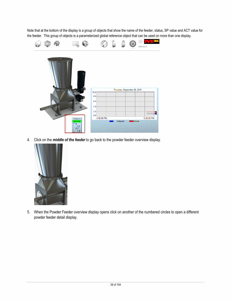
3. When the Powder Feeder overview display opens click on the numbered circle labeled 4 to open the
detail display for powder feeder number 4.
39 of 154
Note that at the bottom of the display is a group of objects that show the name of the feeder, status, SP value and ACT value for
the feeder. This group of objects is a parameterized global reference object that can be used on more than one display.
4. Click on the middle of the feeder to go back to the powder feeder overview display.
5. When the Powder Feeder overview display opens click on another of the numbered circles to open a different
powder feeder detail display.

40 of 154
Increase Line Productivity - Access Reference Material from Terminal with WebBrowser and PDF Viewer
Business Issue
At MX Toy Company, downtime is excessive because many of the printed manuals are disorganized or difficult to locate.
Therefore, the production manager mandated that all reference materials be stored electronically in a central location and
accessible from each PVP 6 terminal.
Solution
The control engineer, Chris, stored the latest PDF Manuals in a network folder accessible from each PVP 6 terminal. The
manuals became accessible from each terminal because Chris added the new WebBrowser ActiveX Control to the HMI
application. This ActiveX enabled a webpage to launch in which provided an index description of all the reference material. From
this index, any operator can open the appropriate PDF manual for help. As a result, the production manager noticed a decrease
in downtime.
Demo
1. Click the Web Browser icon at the top of the display.
2. Select the HTML link from the drop down.
Notice the list of PDF files located on the central server.
Web access is also available, but the plant manager wants to prevent web surfing.

41 of 154
3. Click the PanelView Plus 6 Installation Guide link.
You may notice a progress bar as the PDF loads.
4. Navigate through the document to explore the features of Foxit Reader.
This document could be any type of reference material such as alarm or machine instruction.
5. Close the pdf reader and the HTML Pop-up display.

42 of 154
Chapter 2 – How To

43 of 154
Before You Begin
You will configure and explore the FactoryTalk View Machine Edition application that was used to create the Demo. Start by
opening the application on the PC.
1. From the Start menu, select All Programs > Rockwell Software > FactoryTalk View > FactoryTalk View
Studio or All Programs > FactoryTalk View Studio as shown below.
2. Select the Block_Machine_Partial application and click Open.

44 of 154
Animating a Custom Graphic
This scenario uses a group that consists of basic shapes to gain access to all the available animation options. The custom
graphic is then placed into this group and thereby inherits the applied animation.
Let’s complete the desired animation for the Animation group.
1. Open the 1 Main display by double clicking it.
2. Using the Object Explorer, find the Animation group and click + to expand it.

45 of 154
3. Right click the Animation group, select Animation, and then select Horizontal Position.
4. Select the entire tag and copy it by using CTRL + C.
5. Select the Height tab and paste the tag using CTRL + V. Modify the Expression range & Vertical change
settings as indicated and then click Apply.

46 of 154
6. Select the Width tab and copy & paste the same tag used for the Height animation. Modify the Expression
range & Horizontal change settings as indicated and then click Apply.
7. Click Close when finished.
Now, let’s place our custom image into the Animation group.
1. Find the RubiksCube image using Object Explorer. Right click RubiksCube and select Cut.
2. Right click Polygon19 and select Paste.

47 of 154
3. Now RubiksCube is part of the Animation group. Ensure that the image is covering the 2 polygons as shown
below. If not, just move the Rubiks cube image over the 2 polygons.
4. Close the 1 Main display and select Yes to save the changes.
Since the Rubiks Cube image is now part of the Animation group, it has the same animation characteristics as the group.
Each scenario is modular. If desired, create a runtime file and load it on the terminal. See Appendix B for instructions on
creating a runtime file and downloading it to the terminal. Refer back to page 11 for the scenario steps.

48 of 154
Managing Machine / Process Parameters with Recipe Manager
This scenario uses the Recipe 2 Enhanced ActiveX to manage 4 different recipe files – Keychain, Small, Medium, and Large toy
cubes. The Recipe 2 Enhanced ActiveX uses CSV files and therefore recipes can be managed offline by using Microsoft Excel.
Let’s assign the Recipe folder path
1. Open the HMI tag database by double clicking Tags and then double click the Recipe folder.
2. Find the Recipe\FolderName tag. Enter the Initial Value as shown, check the Retentive checkbox, and click
Accept to apply the changes.
3. Close the HMI tag database.

49 of 154
We now have 3 recipe files. We want to create a 4th recipe for the Keychain cube. We will assign the 4th recipe file name to the
Recipe ActiveX control.
1. Open the 41 Rotary Moulder Recipe display by double clicking it.
2. Using the Object Explorer, find MERecipe2Enhanced3 and double click it to bring up its properties.

50 of 154
3. Click on the Connections tab to view the tags associated with the ActiveX control.
The demo uses RecipeNumber, FolderName, LoadEn, Float001 – Float010, RecipeName001 - RecipeName004, and Status.
RecipeNumber is an analog HMI tag that corresponds to the number associated with the recipe file.
FolderName is a string HMI tag that specifies where the recipe files are located – they are located on the terminal at \My Documents\Cube Recipes.
LoadEn is a digital HMI tag and a transition from 0 to 1 will load the recipe values from the selected recipe file into the tags specified by Float001 – Float010.
Float001 - Float010 are assigned to controller tags that correspond to the setpoints in the recipe file.
RecipeName001 – RecipeName004 are HMI string tags that contain the names of the recipe files – Keychain Cube, Small Cube, Medium Cube, and Large Cube.
Status is an analog HMI tag that indicates the current state of the ActiveX control.
A single recipe file can contain up to 512 numeric values and 100 string values.
The 41 Rotary Moulder Recipe display also contains tables to show Current value and New value for the 3 heads of the molder machine and the pelleter – these values are updated by the recipe files.

51 of 154
The New column objects are actually Numeric Entry Input displays and could be used to change the values of the recipe files online. However, the demo hi-lighted the offline management of recipe files since the ActiveX utilizes a CSV file. The New column objects are associated to ::[BlockComms]Program:Rotary_Moulder.PVP_recipe_temp[1] - ::[BlockComms]Program:Rotary_Moulder.PVP_recipe_temp[10] (assigned to Float001 – Float010 of the control)
A goto display button was used to bring up pop-up display, 42 Recipe Load, that contains the recipe selector.
4. Assign HMI tag, Recipename4, to RecipeName004 by using the Tag Browser.
5. Click OK to save the changes and close the ME Recipe 2 Enhanced Properties window.

52 of 154
We will now create a 4th state in the Piloted List Selector and assign the same HMI string variable we just assigned to the
ActiveX control for its caption.
1. Open the 42 Recipe Load display by double clicking it.
2. Using the Object Explorer, find PilotedListSelector1 and double click it to bring up its properties.

53 of 154
3. Click the States tab.
When the state changes based on using the arrow keys and the enter key, the state value is passed into Recipe\RecipeNumber (assigned to RecipeNumber of the control). This number corresponds to the 4 recipe files. Each state’s caption uses an embedded string variable associated to Recipe\Recipename1 – Recipe\Recipename4 (assigned to RecipeName001 – RecipeName004 of the control). These are the names of the recipe files.
4. Select State2 and then click Insert State to create State 3 that will be a pointer to the keychain cube recipe.

54 of 154
5. Select State3 and change the Caption color to black. Click Insert Variable, and then click String. This
variable is used to display the recipe name in the selector list.
6. Click the tag browser button and select Recipename4.
7. Click OK twice to accept the tag and click Apply to save the Caption changes.

55 of 154
Next, let’s assign a HMI tag to Value which provides the state value (1 – 4) for the Piloted List Selector.
1. Click the Connections tab and assign the tag, RecipeNumber , to Value using the Tag Browser.
2. Click OK twice to accept the tag update and close the Piloted List Selector Properties window.

56 of 154
The Recipe Selector display contains a multistate indicator to show the recipe action status. Let’s explore its configuration.
1. Using the Object Explorer, find MultistateIndicator1 and double click it to bring up its properties.

57 of 154
2. Click the Connections and States tabs to explore the properties.
The ActiveX control passes its state info to the control’s Status property. Status is assigned to Recipe\Status_Tag. This value corresponds to the value assigned to the 6 states. Each state displays the unique caption corresponding to the status of the control.
The final object pertaining to recipes is a Download to Controller button . Pressing this button updates the corresponding controller tags with the selected recipe values – the values in ::[BlockComms]Program:Rotary_Moulder.PVP_recipe_temp[1] - ::[BlockComms]Program:Rotary_Moulder.PVP_recipe_temp[10] are copied to .
3. Close the Multistate Indicator Properties window.
4. Close the 41 Rotary Moulder Recipe and 42 Recipe Load displays. Select Yes if prompted to save changes.

58 of 154
Finally, let’s create the Keychain cube recipe using Microsoft Excel and then FTP the csv file to the PanelView Plus 6 terminal.
1. Browse for the Keychain Cube.csv file and double click it to open it.
C:\Lab Files\NEW Features and Extensions Using FactoryTalk View ME v6.10 and PanelView Plus 6
2. Find PELLETER SPEED and enter ‘250’ in column A.
3. Save and close the csv file.
4. Open Internet Explorer on the PC, enter the following information into the address field, and press Enter.
You will receive the following error:

59 of 154
5. Select Page and then Open FTP Site in Windows Explorer.
6. Click OK when the following error message appears.
7. Right click on the white space of the new window and select Login as …

60 of 154
8. Enter ‘User1’ and ‘Pass1’ for the login information and click Logon.
You are now connected to the PanelView Plus 6.
9. Open the My Documents folder and then the Cube Recipes folder.

61 of 154
10. Open a new Windows Explorer window by right clicking the Windows Explorer icon and then selecting Windows
Explorer.
11. Browse to C:\Lab Files\NEW Features and Extensions Using FactoryTalk View ME v6.10 and PanelView
Plus 6 and select the Keychain Cube.csv file.
12. Copy the Keychain Cube.csv file from the Local Windows Explorer window and paste it into the PanleView Plus
Windows Explorer window.
13. If prompted to replace the existing file, select Yes.
14. Close both Windows Explorer windows.
Each scenario is modular. If desired, create a runtime file and load it on the terminal. See Appendix B for instructions on
creating a runtime file and downloading it to the terminal. Refer back to page 12 for the scenario steps.

62 of 154
Alert Personnel of Alarm and Monitor Application Remotely with ViewPoint and Email
This scenario uses the E-mail ActiveX to alert Bill of a process anomaly. Bill then uses ViewPoint to remotely connect to the
PanelView Plus 6 terminal and address the process anomaly.
The “100 SMTP EMAIL” display was created to allow configuration of e-mail & text message options. For the purposes of this
section, we will focus on the ActiveX control properties and the Alarm message configuration and not on the specific display
creation.
Clicking the Generate Alarm button runs a macro that sets SMTP_EMAIL\Alarm_Digital2 to a 1.

63 of 154
Let’s Explore the E-mail ActiveX connections.
1. Open the 99 Load ActiveX display by double clicking it.
2. Using the Object Explorer, find ME_EmailSenderControl1 and double click it to bring up its properties.

64 of 154
3. Click the Connections tab to view the tags associated with the ActiveX control.
The control uses an SMTP server to send an e-mail or text. Depending on the specific SMTP server, it may require a User id, Password, SSL, and SSL port number. Or, it may send the e-mail or text anonymously and use the standard port number. This demo used ArGoSoft Mail Server as the SMTP server. The server is installed locally in the VM Ware image and is used when internet access is not available.
SMTPSrvrAddress is 192.168.1.1 since it is loaded locally.
SMTPUserid is the user name of the account and is blank in this case.
SMTPUserPwd is the password for the account and is blank in this case.
SSLEnable is set to a 0 as the mail server is set to not use SMTP authentication.
SMTPPort is set to 25, which is the default SMTP port number.
From_Address is set to the e-mail address of the account that is sending the e-mail. The demo used a Gmail account address. A Gmail account was created so that e-mails or texts could also be sent through the Gmail SMTP server if internet access is available.
From_Name is the name of the person or entity sending the e-mail. The demo used “PanelView Plus SMTP Demo”.
These parameters were passed to the ActiveX control by using a macro.
4. Close the ME_EmailSender Control Properties window and the 99 Load ActiveX display. Select No if
prompted to save any changes.

65 of 154
Let’s assign some Initial values to a few HMI tags to better understand how these tags are used.
1. Open the HMI tag database and double click the SMTP_EMAIL folder.
2. Select the ArgoSoft_From_Email tag and enter your own e-mail address for Initial Value. Click Accept to
save the changes.
3. Select the ArgoSoft_From_Name tag and enter your own name for Initial Value. Click Accept to save the
changes.

66 of 154
4. Select the ArgoSoft_Server tag and enter ‘192.168.1.1’ for the Initial Value. Click Accept to save the
changes.
5. Close the HMI tag database.
Next, let’s assign an alarm message to send via an e-mail.
1. Open Alarm Setup by double clicking it.
The Alarm Setup was configured to send an alarm message to a tag instead of a printer or a display. The alarm message is the body of the e-mail or text. Alarm message #2 was used in the demo. It is configured to send the text “Pelleter High Speed Warning!” to SMTP_EMAIL\Body when SMTP_EMAIL\Alarm_Digital2 goes to a 1.
The Alarm Setup contains 5 digital triggers – SMTP_EMAIL\Alarm_Digital2 was the only trigger used in the demo. The Optional trigger connections – Message and Message Notification were tied to HMI tags.
Message is associated to the ActiveX control’s Body property. This is the body of the e-mail or text message and in this case is alarm message #2. The trigger setting connection, Message Notification, is assigned a digital tag and it goes to a 1 when trigger setting connection, Message, receives a new string value. Message Notification is used to trigger the E-mail ActiveX control.

67 of 154
2. Click the Messages tab. Enter ‘Pelleter High Speed Warning!’ in the Message field for Alarm message 2 and
check the Message to Tag check box.
3. Click the Triggers tab and select Alarm_Digital2.
4. Assign HIM tag, SMTP_EMAIL\Body, to Message using the Tag Browser.

68 of 154
5. Assign HIM tag, SMTP_EMAIL\Alarm_Message_Notification, to Message Notification using the Tag
Browser.
Shown below are the settings associated with the Advanced tab.
The Advanced tab contains a Time settings property – Hold time. If no handshake is used, the Hold time is used to reset Message Notification which stays at 1 for the hold time of 750mS and then is reset to 0.
The ActiveX control writes a 1 to its Handshake property once it recognizes the e-mail or text message – the string contained in Body.
6. Click OK twice to exit the Alarm Setup.

69 of 154
Macros were used to perform the E-mail logic functions rather than a PLC. Let’s explore the macro configurations.
1. Open Global Connections by double clicking it.
2. Click on the Macro tab to explore its configuration.
Remote Macro 2 is triggered once SMTP_EMAIL\Alarm_Message_Notification goes to a 1 (this is associated to Alarm Setup’s Message Notification).
Remote Macro3 is triggered once SMTP_EMAIL\Handshake goes to a 1.
3. Close the Global Connections window.

70 of 154
4. Open Macro 2 by double clicking it to explore its configuration.
Macro2 triggers the e-mail to be sent and adds the Subject to the e-mail.
5. Close the Macro2 window.
6. Open Macro3 by double clicking it to explore its configuration.

71 of 154
Macro3 resets the E-mail ActiveX Trigger and Handshake.
7. Close the Macro3 window.

72 of 154
FactoryTalk ViewPoint Administration
Configuration of FactoryTalk ViewPoint is done through the FactoryTalk ViewPoint Administration tool, launched from
FactoryTalk View Studio. Here, the desired displays are selected and published so that they will be available to any browser
client connecting to your operator interface terminal.
With FactoryTalk ViewPoint ME, the Administration tool runs on the same computer as FactoryTalk View Studio and is installed
using the FactoryTalk ViewPoint ME install available on the ViewPoint CD. The FactoryTalk ViewPoint ME Administration tool is
separate from the ViewPoint ME server that runs on PanelView Plus because the components used to convert and publish
ViewPoint displays are not supported on the PanelView Plus and are too large to store on the terminal.
1. Select ViewPoint Administration from the Application menu to launch the tool.

73 of 154
2. Uncheck 1 Main and 2 Home.
2. Scroll down to and select both 80 VP Production Data & 81 VP Motor Start. Assign 80 VP Production Data
as the initial dsipaly. Then publish these diplays.

74 of 154
Configuring FactoryTalk ViewPoint ME security
New in ViewPoint 2.0 is the ability to secure individual display access as well as secure the new write capability. You can also
continue to secure the entire application if you like, just as you have been able to do with previous versions of ViewPoint.
1. Select Security Settings on the red navigation bar in the FactoryTalk ViewPoint Administration tool window.
Note that in ViewPoint 2.0 security is role based rather than user based. As a result only User Groups are shown and not individual users. You can expand on the groups that have a + sign beside them to see the list of users assigned to each group but you cannot individually select the user.

75 of 154
2. Select the Secured Displays tab and check Enable Application Security.
Once Enable Application Security is checked, security is applied to each published display.
3. Select 80 VP Production Data and assign its security settings as shown below.
Engineers are given write and view privileges. Operators and PlantManagers are given only view privileges.

76 of 154
4. Select 81 VP Motor Start and assign its security settings as shown below.
Engineers are given write and view privileges. Operators and PlantManagers are given only view privileges.
5. Click Save to apply the security settings.
6. Close the FactoryTalk ViewPoint Administration Tool window.
Each scenario is modular. If desired, create a runtime file and load it on the terminal. See Appendix B for instructions on
creating a runtime file and downloading it to the terminal. Refer back to page 16 for the scenario steps.

77 of 154
Remote Display Access with New VNC
This scenario uses the IP Info ActiveX and VNC to allow Laura to remotely access a PanelView Plus 6 terminal. In this scenario,
the IP Info ActiveX provided the terminal’s IP address without having to shutdown the application.
Let’s explore the IP Info ActiveX configuration.
IP Info ActiveX
The IP Info ActiveX control was used to provide the terminal’s IP address without needing to shutdown the application.
1. Open the 99 Load ActiveX display by double clicking it.
2. Using the Object Explorer, find MEIPInfoControl1 and double click it to bring up its properties.

78 of 154
3. Click the Connections tab to view the tags associated with the ActiveX control.
4. Close the ME IPInfo Control Properties window and the 99 Load ActiveX display.

79 of 154
VNC – Virtual Network Computing
The PanelView Plus 6 terminal comes with a VNC server pre-loaded. The terminal ships with this server disabled by default.
Let’s explore the VNC configuration.
1. Click on the very bottom of the PanelView Plus 6 screen to bring up the task bar.
2. Click on Start > Settings > Control Panel.
3. Double click in the Control Panel of the terminal. The VNC Server was enabled by clicking the VNC
Server button to change it from red to green, indicating it is enabled.
4. Click Done to exit Services.

80 of 154
5. Double click located in the Control Panel of the terminal. The VNC Server tab is used to set security
for the VNC server. View Only (no remote control) was unchecked and Enable security was checked. A
password for Password and View-only password were created by typing the password in the text box for each
selection.
If write control is desired, you would connect to the PanelView Plus 6 using the password for Password. If Enable security & View Only (no remote control) is unchecked, no password is needed when connecting to the terminal and full control is granted. Checking View Only (no remote control) overrides any write control privileges.
6. Exit the Network Server Configuration and the Control Panel.
Each scenario is modular. If desired, create a runtime file and load it on the terminal. See Appendix B for instructions on
creating a runtime file and downloading it to the terminal. Refer back to page 24 for the scenario steps.

81 of 154
Archive Production Data with DataStore Plus
This scenario uses the DataStorePlus ActiveX Control and FTP to demonstrate how to remotely access a data log file.
DataStorePlus ActiveX Control
Let’s configure the ActiveX.
1. Open the 99 Load ActiveX display by double clicking it.
2. Using the Object Explorer, find MEDataStorePlus1 and double click it to bring up its properties.
This ActiveX control allows one to configure which analog tags and string tags to log to a CSV file.

82 of 154
3. Click the General tab assign the file management settings as shown below.
The control was setup to start a new log file every hour and to only maintain 3 log files total.
4. Click the Advanced tab and assign the logging settings as shown below.
The control was setup to log data every second and to keep each log file to a maximum size of 1MB.

83 of 154
5. Click the Connections tab and enter the literal string for FileLocation as shown below.
6. Assign HMI tag, Maintenance\Datalog_trigger, to Trigger by using the Tag Browser.
7. Assign the direct reference tag, {::[BlockComms]Program:Zone6_Temperature.Temperature_Zone6.CV},to
Float06 using the Tag Browser.
8. Select OK to save the changes and close ME DataStore Plus Properties window.
The FileLocation connection uses a literal string that places the 3 log files into My Documents on the PanelView Plus 6 terminal and to include Block_log in the name of each file. The Trigger connection uses a digital HMI tag to enable and disable the data logging.

84 of 154
This same digital HMI tag is also tied to the Datalog enable/disable selector switch
The Float01 – Float06 connections specify to log Zone1 – Zone6 current temperature values.
9. Close the 99 Load ActiveX display and select Yes to save changes.
FTP
There is a FTP server that is pre-loaded and enabled by default on the PanelView Plus 6 terminal.
Let’s explore the FTP configuration.
1. Click on the very bottom of the PanelView Plus 6 screen to bring up the task bar.
2. Click on Start > Settings > Control Panel.
3. Double click in the Control Panel of the terminal. The FTP Server is running as indicated by the
green button.

85 of 154
4. Click Done to exit Services.
5. Double click in the Control Panel of the terminal. Two user accounts, User1 & User2, were created.
Click X to exit User Account Manager.
6. Double click located in the Control Panel of the terminal.
7. Select the FTP Server tab. Under the General settings, the Default Directory was set to “\” so that all the
folders on the terminal are seen upon a connection.

86 of 154
8. Scroll down to the Security options.
Use Authentication is checked, the 3 Anonymous options are unchecked, and the User List is modified to include the user accounts, User1 & User2, that were previously created using the NTLM Account Manager.
9. Exit the Network Server Configuration and the Control Panel.
Each scenario is modular. If desired, create a runtime file and load it on the terminal. See Appendix B for instructions on
creating a runtime file and downloading it to the terminal. Refer back to page 28 for the scenario steps.

87 of 154
Troubleshoot System Status using Faceplates
This scenario uses a ControlLogix faceplate to determine that a minor program fault had occurred. There are a number of
faceplates available to help customers troubleshoot their systems or to quickly apply basic configuration parameters to various
Rockwell Automation products.
The faceplates are available from the sample code library - http://samplecode.rockwellautomation.com.
1. Browse to the following folder on your lab PC to learn more about the ControlLogix faceplate – its use and
configuration:
C:\Lab Files\NEW Features and Extensions Using FactoryTalk View ME v6.10 and PanelView Plus 6\
Logix_Diag_Toolkit_Instructions_V1_10.pdf
2. Close the pdf viewer and the explorer window when finshed.
Each scenario is modular. Use the Block_Machine_Done.mer file if you desire to test run this scenario. Refer back to page 32
for the scenario steps.

88 of 154
Switch Application Language to Operator’s Native Language
This scenario uses Language Switch buttons to quickly switch between different languages.
Let’s add French as an additional language to the application.
1. Click Tools from the menu in FTViewME and then click Languages.
2. Click Add, select French (France) from the pick list, and then click OK.
3. Click Apply.
Once the languages are added to the application, the strings are exported to an Excel file. This has been done for you already.

89 of 154
The strings are then manually translated into the other languages.
3. Browse to C:\Lab Files\NEW Features and Extensions Using FactoryTalk View ME v6.10 and PanelView
Plus 6. Open the Block_Machine_Partial_5.csv file by double clicking it.
4. Select Yes to the following message.
5. Go to the fr-FR column and enter the following for rows 3 & 4, replacing the text **UNDEFINED**.
Row 3: ‘VIDAGE SILOT’
Row 4: ‘RESERVOIRS’
6. Save the changes and close the Excel file.

90 of 154
7. Import the updated Excel file containing the translations back into the application.
8. Click OK to close the Language Configuration window.

91 of 154
Let’s add a French language switch button to the Banner display.
1. Open the Banner display under Global Objects by double clicking it.
2. Using the Object Explorer, expand Group5.

92 of 154
3. Find LanguageSwitchButton1 and right click on it to bring up its properties. Select Copy.
4. Right click on LanguageSwitchButton1again and select Paste.
We will now make changes to the new Language Switch button instance to switch to the French language that was previously
added.

93 of 154
5. Double click the newly added Language Switch button to bring up its properties and click the General tab.
Change the Language from English to French.
6. Click the Label tab and change the Image: to the French flag using the Image Browser.

94 of 154
7. Select the Common tab. Change the Top & Left positions as shown below
8. Click OK to close the Language Switch Button Properties window.
9. Close the Banner display and select Yes to save the changes.
Each scenario is modular. If desired, create a runtime file and load it on the terminal. See Appendix B for instructions on
creating a runtime file and downloading it to the terminal. Refer back to page 38 for the scenario steps.

95 of 154
Reuse Common HMI Components with Global Objects
This scenario uses global objects with parameters and the parameter list feature of the goto display button to pass in the name of
the powder feeder to the detail display.
Ray created a global object for the powder feeder details on a global object display called “Screen Objects” that Ray used to hold
a collection of global objects for use in the application. The global object display called “Screen Objects” is a special display
within the Machine Edition application that the operator does not see however the individual global objects it contains can be
used in one or more places within the application. The base object defined here can be modified and any change will replicate to
all the reference objects used in the application.
Let’s assign a parameter to the feeder bar graph Global Object.
1. Open the Screen Objects display under Gloabal Objects by double clicking it.

96 of 154
2. Using the Object Explorer, find Group21 and right click on it.
3. Select Global Object Parameter Definitions.

97 of 154
4. Enter the information shown below and click OK.
The global object contains a parameter reference that can be replaced by all or part of a tag name or literal value at runtime. The reference, #1, will be replaced by the number of the feeder such as “4” by using the parameter list feature of the goto display button.
5. Right click on Polygon9 in Group20 which is contained in Group21.

98 of 154
6. Select Animation > Fill. Enter the tag, ‘{#2_Flow_actual}’, in the Expression field. Select to use constant –
Min value = 0 & Max value = 10. Click Apply to save the changes.
7. Close the Animation window. Close the Screen Objects display and select Yes to save the changes.
Next, let’s configure the parameter list for the Powder Feeder 4 goto pushbutton.
1. Open the 50 Powder Feeders Four display by double clicking it.

99 of 154
This powder feeder overview display contains 4 goto display buttons, numbered 1-4 such as . They provide navigation to the “51 Powder Feeder” display which is the powder feeder detail display.

100 of 154
2. Using the Object Explorer, find GotoDisplayButton12 and double click it to bring up its properties.
3. Click the General tab. Enter the following for the Parameter list and click OK.
‘{4},{::[BlockComms]Program:Powder_Feeders.Powder_Feeder4}’
The configuration of the Goto Display button brings up the “51 Powder Feeder” display and passes it the number 4 as the first parameter from the Parameter list. In this manner we specify that we are showing the info for Powder Feeder 4. The next parameter that replaces #2 is the direct reference tag for Powder Feeder 4 actual flow. This tag provides the fill animation for the bar graph, Polygon9.

101 of 154
4. Click OK to save the changes and close the Goto Display Button Properties window.
5. Close the 50 Powder Feeders Four display and select Yes to save the changes.
NOTE: Each time a powder feeder detail display is opened the global object shown below is being opened with a different set of parameters allowing for different values to be shown using the same object. Ray designed a global object once and used global object parameters to shown different values for different powder feeders rather than creating duplicate objects with different tag values assigned. If Ray needs to edit this object in the future he can do it by editing the global objects base object in one place and the changes will replicate to every instance of the global object reference objects used in the application.
Other parts of the application use the global objects defined on the global object display called “Screen Objects”. One of the most powerful features of the global object parameters is that more than one copy of the global object can be used on the same display and each can have a unique parameter assigned to it that is not used anywhere else on the display. This can be seen in the “Main” display that contains multiple copies of the same global objects yet each displays a value for a unique part of the block machine.

102 of 154
Right clicking on any global reference object on the “Main” display and selecting Global Object Parameter Values will show you what parameters have been defined for that global object.
Below we can see that the global reference object we selected has been defined with a literal value of “6”. When the “Main” display is opened at runtime the #1 for this global object will be replaced by “6”. Other global objects on the display will use different literal or tag values at runtime.

103 of 154
Also note that the drop down menus at the top of the application are global reference objects that were designed once and used throughout the application. Below is what the navigation button bar looks at as a global object base object at design time.
Each scenario is modular. If desired, create a runtime file and load it on the terminal. See Appendix B for instructions on
creating a runtime file and downloading it to the terminal. Refer back to page 40 for the scenario steps.

104 of 154
Access Reference Material from the Terminal using a WebBrowser and a PDF Viewer
This scenario used the WebBrowser ActiveX Control to view an HTML file which contained links to various pdf files. In the next
steps, we’ll configure an HMI tag that specifies the path to the HTML file and assign the HMI tag to WebBrowser ActiveX Control.
1. Open the HMI tag database by double clicking Tags and then double click the URLfolder.

105 of 154
2. Find the tag, URL\URL_PB4. Enter the Initial Value as shown. Check the Retentive box. Click Accept to
save the changes. Close the HMI tag database.
3. Open the 220 HTML_Popup display by double clicking it.

106 of 154
The WebBrowser ActiveX resides within this display.
“
4. Right click in the middle of the display and select Properties.
5. Click the Connections tab.

107 of 154
Notice that you have now reached the parameter settings for the WebBrowser ActiveX control which needs to be configured by the application developer.
The URL parameter can be assigned to a tag which contains the website address or html file location.
6. Assign the HMI tag, URL\URL_PB4, to URL by using the HMI Tag Browser.
7. Click OK to save the changes and close the RSView WebBrowser Control Properties window.
8. Close the 220 HTML_Popup display and select Yes to save the changes.
This capability allows you to quickly access reference material directly from your terminal without shutting down your application. Also, the ActiveX can be used to specify a web address that restricts the user to only that web page.
Each scenario is modular. If desired, create a runtime file and load it on the terminal. See Appendix B for instructions on
creating a runtime file and downloading it to the terminal. Refer back to page 42 for the scenario steps.

108 of 154
Appendix A
Creating a ‘Hello World’ Application
Completing this section requires approximately 20 minutes.
In this section you will learn how to:
� Launch FactoryTalk View Studio for Machine Edition.
� Create a new project, configure project settings, and add content to the project.
� Run the project on a PanelView Plus terminal.
Creating a FactoryTalk Machine Edition Application
1. Using the Start menu select All Programs>Rockwell Software>FactoryTalk View> FactoryTalk View Studio
item.
After the FactoryTalk View Studio for Machine Edition application opens, you will see a screen similar to the screenshot shown
below:

109 of 154
2. Click the New tab to activate the tab.
3. In the Application name field, enter ‘VZ01’.
.
4. Next, click the Create button .
After creating the application, the FactoryTalk View Studio for Machine Edition opens the application:
The Import button is used to import:
• PanelBuilder application files for
PanelView Standard or PanelView
Plus Enhanced
• PanelView Plus Standard or
Enhanced runtime files
• Other FactoryTalk Studio for
Machine Edition applications
This is analogous to using Application Manager to
copy the project.

110 of 154
If you are unfamiliar with FactoryTalk View Studio for Machine Edition, please review the information in the next few pages.
Exploring FactoryTalk View Studio for Machine Edition Interface
The FactoryTalk View Studio for Machine Edition Application Windows is divided in to several key elements
Application Menu
Used to interact with
the application;
Open/ Close/ Create
new applications;
Import/ Export
information.
The menu changes
context based on
what project object is
open in the Work
Pane
Work Pane
Open project object contents
are display in this area.
In this example, an untitled
display has added to the
application.
Diagnostic List
Contains status and error
messages related to
system, application and
project.
Explorer Pane
Contains all objects
related to an
application project.
Application objects
are opened in the
Work Pane.
The Explorer’s
content is described
in more detail on the
next page.
Objects Toolbar
Provides easy
access to objects
that are used on
displays to create
the user
interaction. Ex.
Numeric Input,
String Display,
Ramp button, etc.
Graphics Toolbar
Provides easy
access to tools
that are used to
manipulate objects
on a display.
Ex. Rotate, Group,
Ungroup, etc.

111 of 154
contains computer-scoped components,
FactoryTalk View Data Server and FactoryTalk Services
Platform objects.
contains application-scoped components like the
FactoryTalk View HMI Server and RSLinx Enterprise
configurations. . The FactoryTalk View Data Server object
is used to add additional data servers (Ex. OPC) to an
application project. This is an advanced operation and not
covered in the manual.
contains all information scoped to the HMI server
such as, Project Settings, HMI Tags, Graphic files, Alarms,
Information Messages, Macros, Data Logs, and Recipes.
contains project-scope settings such as
Resolution, Security settings, Startup graphic files,
Diagnostic configuration.
contains all tags resident in the memory of
the HMI Server. Applications for Logix Controllers use direct
tag referencing eliminating the need to create HMI tags to
communicate with the PLC.
contains all graphic images used in the
application as displays, or contained within displays and
parameter files. Parameter files are one way to enable
graphic reuse between applications.
Symbol Factory provides access to thousands of stock
images organized in an easy to use library.
contains the application’s alarm configuration
including triggers and messages.
contains the application’s information
message configuration.
contains the application’s macros.
contains any Data Log Model configured for
the application.
contains the Recipe management system
configuration and any configured recipes.
contains communication shortcuts
used by the application.
contains FactoryTalk Services Platform related
configuration. This is primarily used to manage users and
groups in a FactoryTalk Machine Edition application.
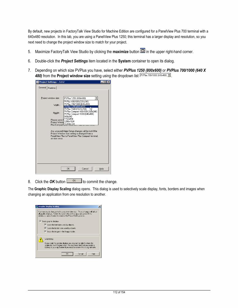
112 of 154
By default, new projects in FactoryTalk View Studio for Machine Edition are configured for a PanelView Plus 700 terminal with a
640x480 resolution. In this lab, you are using a PanelView Plus 1250; this terminal has a larger display and resolution, so you
next need to change the project window size to match for your project.
5. Maximize FactoryTalk View Studio by clicking the maximize button in the upper right-hand corner.
6. Double-click the Project Settings item located in the System container to open its dialog.
7. Depending on which size PVPlus you have, select either PVPlus 1250 (800x600) or PVPlus 700/1000 (640 X
480) from the Project window size setting using the dropdown list .
8. Click the OK button to commit the change.
The Graphic Display Scaling dialog opens. This dialog is used to selectively scale display, fonts, borders and images when
changing an application from one resolution to another.

113 of 154
9. Click the OK button to proceed. There is no need to change any setting on this dialog.
While changing the project’s display size a progress dialog is shown.
Upon creation of a new project, FactoryTalk View ME 6.X now automatically creates a default display called MAIN which is also
defined as the initial startup display. We will use this display for the following steps in our lab. If you require more displays, you
can always add a new display to the project you are working on. We will see an example of this in the section on Global Objects.
10. To open existing displays, open the Displays container by clicking the expander from the Explorer Pane
window.
11. Double-click on the MAIN display.
The display will open in the Work Pane of FactoryTalk View Studio for Machine Edition. You will notice that a Shutdown button
has automatically been created for you. You are now ready to add objects to the display.
Adding Content to a Display
All objects in FactoryTalk View Studio have properties. The properties are organized by function on to tabs on a property dialog.
At a minimum, all objects provide a General and Common tab.
Tab Name Purpose
General Configure the operation and appearance of the object.
Common Configure the object’s size (Height and Width) and display position. Display top-left
corner is {0,0} coordinate.
Each object provides a set of tabs that vary with the object type. For instance, most objects that display static text (e.g. Text,
Shutdown button) have a Label tab.
Tab Name Purpose
Label Configure an object’s caption font, font size, font color.
1. Select the Text tool , and add a text box to the display.
When you release the mouse button, the Text Properties dialog will immediately open.

114 of 154
2. Click the Text field and enter ‘Hello World! This is my VZ01 application’.
3. Click the OK button .
This display should now look similar to this:
4. Close the display using the File > Close menu item.
When prompted to save ‘MAIN’ click the YES button.

115 of 154
Now that you have created objects on the Main display, verify that it is configured as the application’s Startup graphic.
5. To open the Startup dialog, double-click on the Startup item in the System container.
6. Click OK to close the dialog.
Creating the Runtime Application File
Next, you must build the runtime application;
1. Select the Application> Create Runtime Application menu item.

116 of 154
2. Save the runtime project using the suggested name ‘VZ01.mer’ by clicking the Save button .
While FactoryTalk View Studio for Machine Edition
is creating the runtime MER file, a progress dialog
will appear:
The Conversion to development application
options allow later recovery of the design files from
the runtime project using the Application Manager, if
allowed.
Always allow conversion [Default]
The design information is always included with
the runtime, so that it may be restored from the
MER.
The resulting MER requires more terminal
memory to store the file.
Never allow conversion
Design information cannot be recovered from an
MER created with this option selected.
The MER created requires the least amount of
terminal memory.
Conversion protected by password
When using Application Manager to extract the
design information from the runtime file, the user
will be prompted for the configured password.
The resulting MER requires more terminal
memory to store the file.

117 of 154
After creating the runtime MER file, the FactoryTalk View Studio for Machine Edition displays the open application.
Downloading a runtime MER to a PanelView Plus terminal
1. To download the runtime MER to the PanelView Plus 1250 terminal at your workstation, first select the Tools>
Transfer Utility menu item:

118 of 154
The Transfer Utility will open.
2. Click the Source File Browse button to select the runtime MER file to download.
This opens the Select File to Download dialog.
This button allows you to
browse for runtime MER files.

119 of 154
3. Click on the VZ01.mer file to select the project. The File Name box should update to reflect the selection.
4. Click the Open button to complete the project selection.
5. Double-click the EtherNet, Ethernet driver to expand the item.
6. Select the 192.168.1.20, PanelView Plus_6 1250, PanelView Plus_6 1250 item by clicking on it once. The
screen that you will see may look slightly different from the example shown below:
7. To initiate the download process, click the Download button .
If you get a message stating VZ01 already exists, select YES to overwrite.

120 of 154
When the download process completes a confirmation dialog is shown.
8. Click the OK button to acknowledge the dialog.
9. Click the Exit button to close the Transfer Utility.
Running an Application on a PanelView Plus Terminal
In this lab section, you will work with a PanelView Plus terminal. Execute the following steps to run the FactoryTalk Machine
Edition application you just completed.
1. Tap on the PanelView Plus screen on your lab station if the screensaver is active.
You will now see the PanelView Plus 6 desktop.
2. Locate the FTView ME Station icon on the desktop and double-tap it to launch FTView ME Station.
3. Press the Load Application [F1] button.

121 of 154
4. Select the VZ01.MER file from those available from the terminal’s Internal Storage.
5. Press Load [F2] to load the runtime file in to memory.
6. When prompted, press Yes [F7] to overwrite the terminal’s current communication configuration with the
configuration contained within the VZ01.MER file.
7. Once successfully loaded, press the Run Application [F2] to start executing the runtime file.
While the terminal is starting the application, an update dialog is displayed.

122 of 154
After the start-up processing completes, you should see your application’s startup display:
8. Click the Shutdown button to terminate the application.
Congratulations!!
You have successfully created a FactoryTalk View Studio for Machine Edition application, added application content, created a
runtime file, downloaded the runtime file to a terminal, and ran the application on a PanelView Plus terminal.

123 of 154
Applying Communications to an Application
Completing this section requires approximately 20 minutes.
In this section you will learn how to:
� Configure RSLinx Enterprise Communications for an application.
� Add ‘Live’ object to a display.
� Test an application on the Desktop.
Configuring Communications
1. Double-click the RSLinx Enterprise item to expand.
2. Right-click on the Communication Setup item and select Open to launch the RSLinx Enterprise
Configuration Wizard.
3. Select the Create a new configuration option; this is the default.
Communication Configuration
Create a new configuration
Generates an empty communication
configuration scheme for the application.
Copy an existing configuration from a
previously created projects
Reuse a communication configuration from
a different application file.
Copy the configuration that is currently
running on this workstation Infrequently used; copies the communication configuration from an application currently being hosted using FactoryTalk Machine Edition Station on the same workstation.

124 of 154
4. Click the Finish button . The Communication Setup dialog opens.
You can resize the dialog by using the size handles, or click the maximize button.

125 of 154
Exploring the Communication Setup Dialog
The Communication Setup dialog has three main areas.
You will notice that the Network Path dialog area has two tabs, Design (Local), and Runtime (Target). The definitions below should help you
to understand how to use these tabs, and why there provide powerful flexibility when designing an application. These tabs allow you to
develop and debug an application while at your desk, working on the shop floor, or some other location that is not co-located with the control
system.
The tabs can be used as described below
Design (Local) Configure the network and device path(s) for the development environment in
which the application will be designed and debugged. This network topology
and device path(s) may be different than the production environment where the
application will ultimately run.
If the development and production environments are identical, you can copy
the Design (Local) configuration to the Runtime (Target) configuration using
the Copy from Design to Runtime button .
Runtime (Target) Configure the network and device path(s) for the production environment in
which the application will run (e.g. customer facility). The network topology
and path(s) may be completely different than those defined using the Design
(Local) tab.
Device Shortcuts
A list of shortcuts
defined on the
workstation in RSLinx
Enterprise.
Offline Tag File
Displays the harddrive path to the ACD file associated
with the selected shortcut. The offline ACD file is
used for tag browsing when disconnected from a
network.
Network Path
Displays the
network topology
path to the device
associated with the
selected shortcut.
Also used to create
a new shortcut to
the select network
device.

126 of 154
5. To create a new shortcut, click the Add button in the Device Shortcuts area.
6. Name the shortcut ‘VZ01’ and then press the [Enter] key on the keyboard.
If you have successfully completed these steps, the Communication Setup dialog will look like this:
7. Expand the EtherNet, Ethernet driver by clicking the expander once.
8. Click the expander once to open the 192.168.1.1, SoftLogix 5800 EtherNet/IP, SoftLogix 5800
EtherNet/IP item.
9. Click the expander to open the 1789-A17/A, 1789-A17/A Virtual Chassis item.
10. Select 2, 1789-L60/A, Block_Machine by clicking on it once. The dialog should now look like this:
When you click the Add button, a new shortcut is created. The shortcut’s name field is open and ready to be edited.

127 of 154
11. Click the Apply button to associate the selected device (e.g. SoftLogix 5800 Controller) with the selected
communication shortcut (e.g. VZ01).
12. Click the Yes button to confirm the association.
In this lab, the design and production environments are identical. To proceed you have two options:
A. Use the Copy from Design to Runtime button to copy the design environment
topology and device paths to the production environment (e.g. Runtime (Target) tab).
It is estimated this option will require less than 5 minutes to complete.
B. Manually configure the production environment so that you understand how this functionality works. It is estimated
manual configuration will require 5 to 10 minutes to complete.
Choose either Option A or Option B.

128 of 154
Option A
a) Click the Copy from Design to Runtime button to copy the communication
configuration from the Design (Local) tab to the Runtime (Target) tab.
b) When prompted click Yes button to confirm the operation.
c) Click on the Runtime (Target) tab to select it.
Using the expanders, open the topology items (e.g. drivers and devices) to confirm that the Design (Local) configuration have
been replicated.
d) Go to step 17.
Option B
a) Click on the Runtime (Target) tab to select it.
b) Right-click on EtherNet, Ethernet item to open the context menu, and select Add Device.
c) Click Add Device which opens the Add Device Selection dialog.
d) Expand the EtherNetIP Devices item by clicking the expander .
e) Select the expander next to SoftLogix 5800 EtherNet/IP.

129 of 154
f) Select SoftLogix 5800 EtherNet/IP, Major Revision 19.
g) Click the OK button to accept the selection. This action opens the Device Properties dialog.
h) Enter ‘192.168.1.1’ in the Address field to set the device’s TCP/IP address.
i) Change the selected Slot to ‘3’.

130 of 154
k) Click the OK button to add the device to the Runtime (Target) configuration.
l) Use the expander to open the 192.168.1.1, SoftLogix5800 EtherNet/IP, SoftLogix 5800 EtherNet/IP device.
m) Right-click the 1789-A17, 1789-A17 Virtual Chassis item and select Add Device.
n) Expand the 1789-L60/A, 1789-L60/A SoftLogix 5860 Controller item by clicking.
o) Select the 1789-L60/A SoftLogix 5860 Controller, Major Revision 19 item.
It is important that you select the correct
Major Revision for the SoftLogix 5860
Controller.
The correct revision is Major Revision 19.
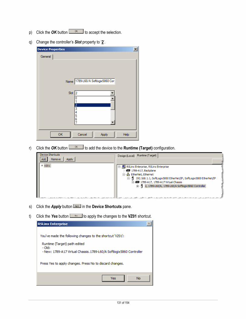
131 of 154
p) Click the OK button to accept the selection.
q) Change the controller’s Slot property to ‘2’.
r) Click the OK button to add the device to the Runtime (Target) configuration.
s) Click the Apply button in the Device Shortcuts pane.
t) Click the Yes button to apply the changes to the VZ01 shortcut.

132 of 154
15. Click the Verify button to confirm the Design and Runtime associations.
Confirm both the Design and Runtime devices are assigned for shortcut VZ01.
16. Close the Shortcut Verifier dialog by clicking the Close button .
17. Click the OK button to complete the communication setup and close the Communication Setup dialog.
Be sure to use the OK button! If you close the dialog with the Close button, the communication setup will not be saved to
the application.

133 of 154
Adding ‘Live’ Objects to a Display
Now that a communication path to a controller is configured, you are ready to add objects (buttons, numeric displays, etc.) to the
display that use information from the controller. The lab uses a variety of different buttons, data displays, and images to illustrate
FactoryTalk Machine Edition functionality and application capabilities.
1. Double-click the MAIN display in the Explorer to open the display.
2. Select the Numeric Display tool from the Objects toolbar or select Objects->Numeric and String-
>Numeric Display.
3. Move the mouse cursor onto a free area of the MAIN display frame; click and hold the left mouse button, and
then drag down and to the right to create a Numeric Display object.

134 of 154
4. Position the cursor over the Numeric Display and double-click the mouse to open the Numeric Display
Properties dialog.
5. Click the Common tab to activate.
6. Change the Height, Width, Top, and Left fields to size and position the Numeric Display exactly.
Height 85
Width 100
Top 175
Left 250
7. Click the Apply button to commit these changes. The button should move and resize on the display
to match these settings.
If you accidently clicked OK button, simply reopen the button’s property dialog by double-clicking the button.
8. Click the Connections tab to activate.
9. In the Value row, click on the Browse button in the Tag column.
This action opens the Tag Browser.
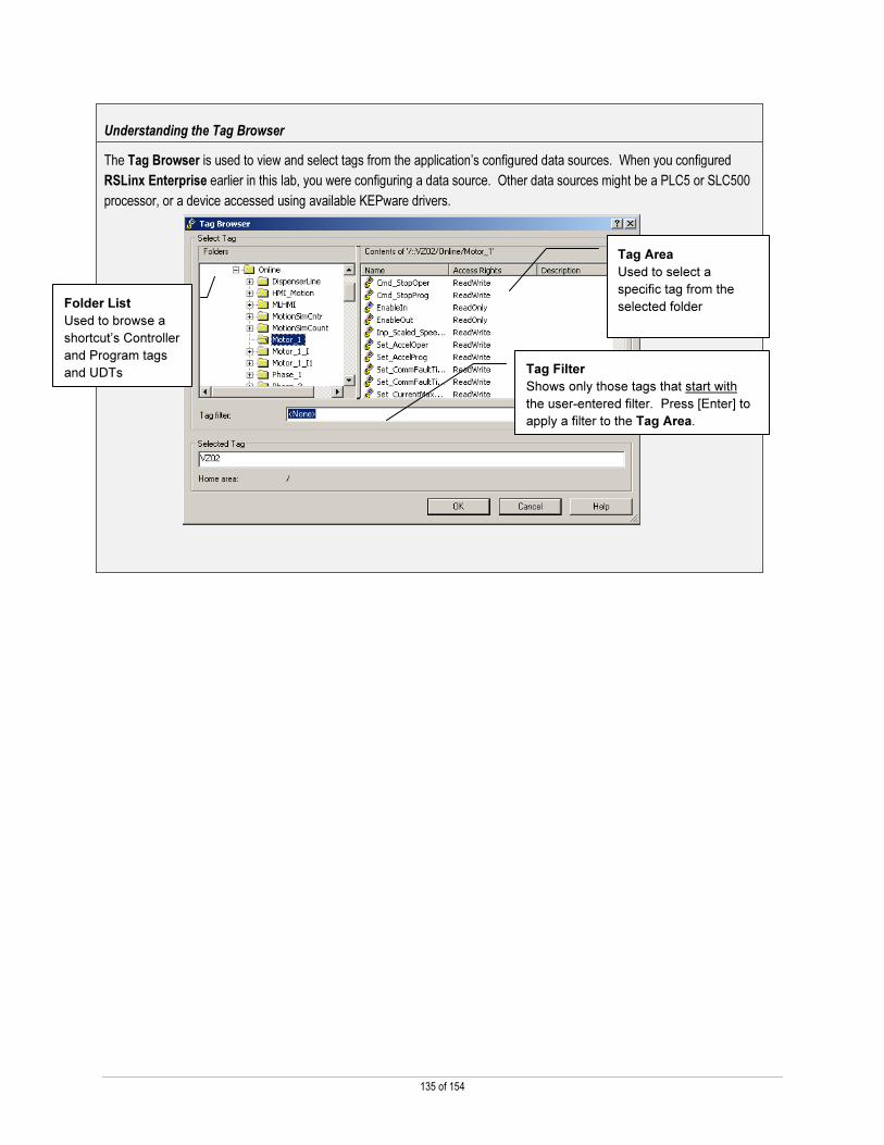
135 of 154
Understanding the Tag Browser
The Tag Browser is used to view and select tags from the application’s configured data sources. When you configured
RSLinx Enterprise earlier in this lab, you were configuring a data source. Other data sources might be a PLC5 or SLC500
processor, or a device accessed using available KEPware drivers.
Folder List
Used to browse a
shortcut’s Controller
and Program tags
and UDTs
Tag Area
Used to select a
specific tag from the
selected folder
Tag Filter
Shows only those tags that start with
the user-entered filter. Press [Enter] to
apply a filter to the Tag Area.

136 of 154
The following further defines and highlights the uses and functionality provided in the Tag Browser.
Folder List
HMI Server (e.g. )
Contains tags defined in the HMI Server,
referred to as memory tags. The
FactoryTalk Machine Edition runtime
manages and updates these tags.
System
Contains default HMI tags for system
information, such as, time of day, date,
etc.
<Communication Shortcut> (e.g. VZ01)
Contains tags that exist in the memory of
the device the shortcut represents.
Diagnostic Items
Predefined diagnostic and troubleshooting
tags useful for monitoring communication
and controller status.
Online
Tags contained in a Logix Controller’s
memory; the tags are directly referenced
by the FactoryTalk Machine Edition
runtime.
Tag Area
Name
Column containing the tag’s name. Use
the Tag filter function to quickly find tags
that start with the user-entered filter.
Access Rights
Beginning with V18 firmware, Logix
Controllers implement Access Rights for
tags. This column displays a tag’s
Access Rights property. Tags are either
ReadOnly or ReadWrite.
10. Right-click on the VZ01 item in the Folders list; select the Refresh All Folders item.

137 of 154
11. Double-click the VZ01 folder to expand.
12. Double-click the Online item to expand.
13. In the Tag Area, locate and select the tag Extruder_speed_actual.
Note that the Selected Tag text box reflects your selection.
14. Click OK to complete the assignment.

138 of 154
15. This display should look similar to the following:
16. Save the MAIN display using the File> Save menu item.
17. Close the MAIN display using the File> Close menu item.

139 of 154
Testing an Application on the Desktop
There are two methods available to test an entire application. One is to download the application to a PanelView Plus terminal.
The other is to use the terminal emulation capability that is included with FactoryTalk Studio for Machine Edition. You will be
testing the application on the desktop using the terminal emulation functionality.
1. From the Application menu, select the Test
Application item.
The system will build the runtime MER just as if the
application were going to be downloaded to a PanelView
Plus terminal.
When the runtime MER file is built, the system loads the runtime MER in to an emulation mode. The application will appear in
the upper left-hand corner of the computer display.

140 of 154
2. Click on the Shutdown button to end the emulation.
Congratulations!!
You have successfully added ‘live’ content; configured communications with a controller; created a runtime file; and exercised
the application on your desktop.

141 of 154
Notes

142 of 154
Appendix B
Create Block_Machine_Partial Runtime File
1. Select the Application> Create Runtime Application menu item.
2. Select File name – Block_Machine_Partial.mer. Save type as Runtime 6.10 Application. Always allow
conversion. Check to Include ViewPoint content. Select FactoryTalk ViewPoint 2.10. Finally, select Save.

143 of 154
3. Check all the languages listed. Pick English for the initial runtime language. Select Finish to generate the
runtime file.
Download Block_Machine_Partial.mer File to a PanelView Plus Terminal
1. To download the runtime MER to the PanelView Plus terminal at your workstation, first select the Tools>
Transfer Utility menu item:

144 of 154
The Transfer Utility will open.
2. Click the Source File Browse button to select the runtime MER file to download.
This opens the Select File to Download dialog.
This button allows you to
browse for runtime MER files.

145 of 154
3. Click on the Block_Machine_Partial.mer file to select the project. The File Name box should update to reflect
the selection.
4. Click the Open button to complete the project selection.
5. Double-click the EtherNet, Ethernet driver to expand the item. The screen that
you will see may look slightly different from the example shown below:
6. Select the 192.168.1.20, PanelView Plus_6 1250, PanelView Plus_6 1250 item by clicking on it once. The
screen that you will see may look slightly different from the example shown below:
7. To initiate the download process, click the Download button .
If you get a message stating Block_Machine_Partial already exists, select YES to overwrite.

146 of 154
When the download process completes a confirmation dialog is shown.
8. Click the OK button to acknowledge the dialog.
9. Click the Exit button to close the Transfer Utility.

147 of 154
Lab Setup and Configuration Information
Lab Information
Lab Name
NEW Features and Extensions Using FactoryTalk View ME v6.10 and PanelView
Plus 6
Lab Description
Demo highlighting some of the features in FTView ME 6.10 & PanelView Plus 6, 2.0
OS & a how to section describing how the demo was created.
Lab Creator Wil Mattheis
Date Created 12-14-2011
Updates:
Hardware Configuration
Qty Demo Cat.# / Description Communication Location Firmware
1
2711P-RP9A ser A or later /
PanelView Plus 6 logic module Ethernet – DHCP
6.10 w/ 2.0
OS
1
2711P-RDT12C ser C or later
/ PanelView Plus 1250 display
module
1 Crossover ethernet cable
1 2711P-RN0
1 6189V-PCIENET 192.168.1.20

148 of 154
Computer/Host Settings
Location Files
Computer Name CORE
IP Address 192.168.1.1
Operating System Windows 7
Photograph of Hardware:

149 of 154
Basic Setup Diagram
To Classroom network
DHCP assigned IP
Student Station
PanelView Plus 6 1250
CAT5E cross-over
cable
Tank
02
F1
F7
F2
F8
F3
F9
F4
F10
F5
F11
F6
F1212 102 31
High level Tank 02
M
P
P
P
P
P
P
Na
H2O
Ca
Li
Pb
Cu
Waste
ON
Tem p.:Speed:
123 gr56 m /s
ON
ON
ON
ON
ON
ON
OFF
ON
Temp.:
Press.:
Level:
123deg
12Pa
4,5m
PLANT J45
Output:
Tank 01
Tank 02
Tank 03
Tank 04
Converter
React. A
React. B
React. C
React. D
React. E
Level H234
Start/Stop
Auto
Manual
Force
Setpoint
Output
34 5
34
LL L H HH
NIC 2
Host computer TCP/IP setting: DHCP
VMWare image TCP/IP setting: IP Addr 192.168.1.1
Subnet 255.255.255.0
IP Addr: 192.168.1.20
Subnet: 255.255.255.0
CAT5E cable
NIC 1
Host computer TCP/IP setting: DHCP

150 of 154
Application/Programming
Location Files
C:\Lab Files\ NEW Features and Extensions
Using FactoryTalk View ME v6.10 and PanelView
Plus 6 Block_Machine_Done.apa
C:\Lab Files\ NEW Features and Extensions
Using FactoryTalk View ME v6.10 and PanelView
Plus 6 Block_Machine_Done.ACD
Batch file to update the PVP6 firmware and to place the
CSV, HTM, and pdf files into My Documents on the terminal
Additional Equipment Required
Qty Items
RSLinx - DDE/OPC Topic Configuration
Topic Name Path to Hardware
n/a
RSLinx - Driver Configuration
Topic Name Path to Hardware
AB_VBP-1 (no topic
required) Virtual Backplane driver to access the SoftLogix processor

151 of 154
RSLinx Enterprise - Shortcut Configuration
Topic Name Path to Hardware
BlockComms
Through SoftLogix Ethernet IP module in slot 3 to SoftLogix processor in slot
2
Ethernet, Ethernet > 3, 192.168.1.1 > Backplane > 2, 1789-L60 v19
Application Versions
Vendor Software Version
Service
Pack
FactoryTalk View Machine Edition Studio 6.10
FactoryTalk Services Platform 2.40
RSLinx Enterprise 5.40
RSLinx Classic 2.58
RSLogix 5000 19
SoftLogix 5800 19
FactoryTalk® ViewPoint 2.10
Microsoft Excel 2010
Silverlight 4.0.60531.0
Tight VNC Client 2.0.3

152 of 154
Required Pre-Lab Configuration
Configure the Virtual Network
Select Virtual Network Editor from the Edit menu to open the Virtual Network Editor dialog.
The dialog below will appear.

153 of 154
Select the Host Virtual Network Mapping tab.
For VMnet0 select the physical ethernet adapter that will be connected to the PanelView Plus terminal.
Click the OK button to commit the changes that have been made.

154 of 154
Publication CE-DM222A-EN-E— December 2011 Copyright© 2011 Rockwell Automation, Inc. All rights reserved.