new generation cim - xml new topology interface · maintenance intelligence of tomorrow new...
TRANSCRIPT
Maintenance Intelligence of Tomorrow
New Generation CIM - XML new Topology Interface
IPS
Munich
20. – 21. November 2012
Zoltan Solga

Common Information Model (CIM) – motivation and definition
CIM XML
CIM’s concepts of ConnectivityNodes (CNs) and TopologicalNodes (TNs)
Bus-Branch and Node-Breaker Modeling
IPS-ENERGY Topology Manager – The IPS model
The IPS and CIM model interoperability
PSS/E®ODMS – IPS – CAPE data exchange process
IPS-ENERGY Topology Manager – Graphical Editor
IPS-ENERGY Topology Manager – Connection to IPS-ENERGY
location/asset model
Overview

Power system operations need to model their systems and portions of
neighboring systems
Electric utility organizations need to exchange operational system models
Need for unified platform to support:
- system planning functions
- energy management
- control center applications
- maintainence of operational power system models
Solution is expected to be:
- Platform independent
- Vendor independent
- Supported by international standards
Common Information Model (CIM) - Motivation

The CIM defines the common power system entities and their relationships.
The CIM specifies common semantics for power system resources, their
attributes and relationships.
CIM provides a comprehensive, logical view of EMS information for
transmission network analysis, generation control, SCADA, and operator
training simulation.
The CIM represents the modeling information which is relevant for model
exchange.
Simple Definition
Open data format for power system model to be used for data
exchange between power system organizations including vendors.
Common Information Model (CIM) - Definition
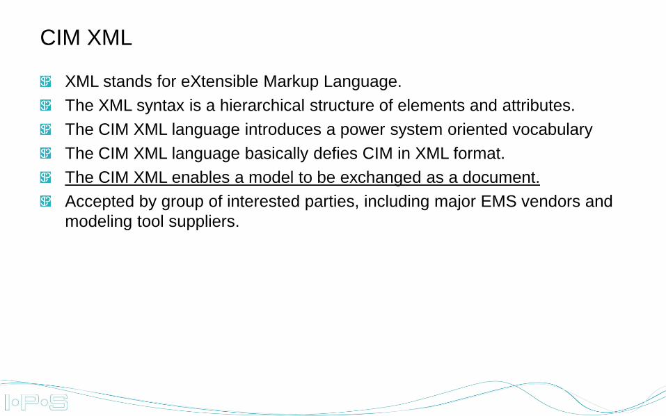
XML stands for eXtensible Markup Language.
The XML syntax is a hierarchical structure of elements and attributes.
The CIM XML language introduces a power system oriented vocabulary
The CIM XML language basically defies CIM in XML format.
The CIM XML enables a model to be exchanged as a document.
Accepted by group of interested parties, including major EMS vendors and
modeling tool suppliers.
CIM XML

CIM XML – Schema for Zone (Sample)
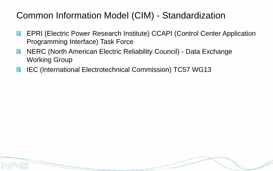
EPRI (Electric Power Research Institute) CCAPI (Control Center Application
Programming Interface) Task Force
NERC (North American Electric Reliability Council) - Data Exchange
Working Group
IEC (International Electrotechnical Commission) TC57 WG13
Common Information Model (CIM) - Standardization

BB
CN CN CN CN CN CN CN
CN
BB
CN CN CN
CN
BB
CN CN CN
CN
CN
CN BB
CNCN
BB
CIM CN-based representation
Note that ACLineSegments might get
merged if they are electrically
indifferent. This is not considered a
topic if this deck and in the example
they will just remain separate.
One breaker is open for
the sake of example

The previous CN model corresponds to these topological nodes, bridging all
closed switches.
CIM TN-based representation

The TN-based model of the same grid is a simplification, and will thus look
like this
CIM TN-based representation – Simple view

The system planning functions because of the model’s size are usually
reduced to into bus/branch oriented models.
The CIM representation of bus/branch model is the CIM TN-based
representation.
Real-time power system operation requires far greater detail about the field
equipment and its connectivity.
These models must include the substation bus segments, switches, and
measurement details and known as a node/breaker model.
The CIM representation of node/breaker model is the CIM CN-based
representation.
Bus-Branch and Node-Breaker Modeling

The model implemented in IPS-ENERGY Topology Manager is match the
CIM connectivity node (CN) based representation.
The IPS model extends the standard CIM model related to following
information:
- Implements specific protection functionality placement to exact place in
CN-based representation
- Implements CT, VT and CVT placement to exact place in CN-based
representation
- Implements CT modeling related to certain protection functions
- Provides full connectivity to IPS-ENERGY asset/location model
- Identifies concept of feeders in topology model
The IPS model – Topology Manager

The IPS implements „topology” based on connectivity node representation
IPS-ENERGY provides 1 to 1 mapping between IPS model and the CIM
CN-based representation.
The IPS specific implementation is „encoded” in CIM as a standard CIM
extension.
The IPS model could be created from CIM and vice versa. The IPS model
could be exported in CIM XML format (CN-based representation).
IPS „topology” also supports TN-based model and even a combination of
two models (CN and TN based representation) at the same time
The IPS and CIM model interoperability

IPS-ENERGY is capable to import PSS/E ODMS CIM XML export file based
on CN-based representation.
After proper mapping of ODMS CIM the model is enriched with relay, CT
and VT specific connectivity information
The new enriched model could be exported in CIM format (with CIM
extensions).
The IPS enriched CIM model could be imported by CAPE and various
analysis could be performed in CAPE
Functionality expected to be available July 2013.
PSS/E®ODMS – IPS – CAPE data exchange process

Graphical Editor for CN-based and TN-based model drawing
CN-based model representation
Connection to IPS-ENERGY assets and locations available in asset
management
Full network model is available related to to CB-based model elements
The IPS topology model is the integral part of the entire IPS-ENERGY
model (the zones for instance are defined in IPS topology model only).
IPS-ENERGY Topology Manager - Functionality

IPS-ENERGY Topology Model – Sample Graphical View

www.ips-energy.com
Maintenance Intelligence of Tomorrow