new magnetic stimulation routes with magnetic ...€¦ · v résumé les nanoparticules...
TRANSCRIPT

New magnetic stimulation routes with magnetic nanoparticles from process intensification in chemical
engineering
Thèse
Pouya Hajiani
Doctorat en génie chimique Philosophiae Doctor (Ph.D.)
Québec, Canada
© Pouya Hajiani, 2013


I will prepare, and some day my chance will come.
Abraham Lincoln
Nothing is more common than unfulfilled potential.
Howard Hendricks


v
Résumé
Les nanoparticules magnétiques (NPM) suscitent un vif intérêt dans plusieurs branches de
l’ingénierie et de la recherche. En effet, la taille de ces dernières ainsi que leur propriétés
magnétiques lorsqu’en suspension permettent leur manipulation à distance en utilisant des
champs magnétiques externes appropriés. Cela ouvre la voie à l’activation de
fonctionnalités supplémentaires lorsqu’ancrées à des catalyseurs métalliques, des enzymes
ou des agents thérapeutiques. Conséquemment, les NPM ont été impliquées au sein de
plusieurs applications dans lesquelles le mélange à l’échelle microscopique est une
problématique importante, par exemple dans les réactions catalytiques, la séparation et
l’administration de médicaments.
Le présent travail de thèse explore l’utilisation de NPM en tant que dispositifs
nanométriques pour manipuler le mélange à l’échelle microscopique lorsque le système
complet est soumis à des champs magnétiques. Toutes les expérimentations ont été menées
à l’intérieur d’un électro-aimant à bobines tubulaire statique possédant deux pôles et trois
phases. Ce dernier génère des champs magnétiques rotatifs uniformes (CMR), des champs
magnétiques oscillatoires (CMO) ainsi que des champs magnétiques stationnaires (CMS).
En premier lieu, une technique de mélange dans laquelle un CMR transforme des NPM en
agitateurs nanométriques créant de petits tourbillons dans la phase liquide est présentée.
L’utilisation de cette technique permet l’augmentation du coefficient de diffusion de l’eau
quiescente dans une cellule de diffusion statique jusqu’à 200 fois. Les études systématiques
des paramètres d’opération révèlent que l’ampleur de l’augmentation dépend de la fraction
volumique en NPM ainsi que de la force et de la fréquence du champ magnétique.
En second lieu, un écoulement convectif est utilisé afin de comprendre l’effet du couple
hydrodynamique sur le comportement des NPM en champs magnétiques. Des tests de
distribution de temps de séjour par impulsion sont effectués avec et sans champ magnétique
dans le but d’examiner la dispersion axiale d’un écoulement laminaire de Poiseuille à
l’intérieur d’un tube capillaire (Tests de dispersion de Taylor). Les résultats obtenus
démontrent que le mélange latéral au long du tube est favorisé en présence de NPM et d’un
champ magnétique. De plus, l’effet hydrodynamique observé de ce mélange latéral sur le

vi
profil de vitesse laminaire est interprété comme provenant d’une approche d’un profil de
vitesse plat similaire à celui d’un écoulement piston. À l’aide de la même technique, l’effet
des CMO et des CMS sur la dispersion de Taylor et sur le profil de vitesse laminaire est
aussi examiné en écoulement capillaire. Alors que les CMO n’induisent pas de mélange
nano-convectif dans le capillaire et ont un impact négligeable sur la dispersion axiale, les
CMS pour leur part, détériorent le mélange latéral du traceur et créent des profils de vitesse
déviant de la forme parabolique vers une forme plus saillie. Une discussion détaillée de la
vorticité du fluide en fonction de l’orientation du champ magnétique est aussi présentée.
Finalement, un écoulement multiphasique est étudié en ciblant le transfert de matière gaz-
liquide entre des bulles de Taylor d’oxygène et la phase liquide, composée d’une solution
diluée de NPM, à l’intérieur de tubes capillaires soumis à des CMR, des CMO et des CMS.
Les résultats indiquent que les NPM qui tournent sous l’action d’un CMR améliorent le
mélange dans le film lubrificateur qui entoure les bulles de Taylor comme cela est révélé
par une augmentation mesurable du kLa. À l’opposé, les CMS immobilisent les NPM,
menant à des taux de transfert de matière systématiquement plus faibles alors que les CMO
n’ont pas d’effet détectable sur le coefficient de transfert de matière. Par ailleurs,
l’interaction entre le couple magnétique et le couple hydrodynamique nécessaire pour
dominer la direction de rotation des NPM est tirée de ces résultats.

vii
Abstract
Magnetic nanoparticles (MNPs) have attracted significant interest in diverse areas of
engineering and research. Particle size and magnetic properties of suspended MNPs in a
suspension allow their manipulation at a distance using appropriate external magnetic
fields. In particular by enabling additional functionality in forms anchored to metal
catalysts, enzymes or therapeutic drug agents. Owing to this feature, MNPs have been
involved in many applications where mixing in micro-scale is also a critical issue, e.g.,
catalytic reaction, separation and drug delivery.
This thesis explores MNPs as nano-scale devices to manipulate mixing in micro-scale when
the whole system is subject to magnetic fields. All the experiments were performed in
tubular two-pole, three-phase stator winding magnet, generating uniform rotating magnetic
field (RMF), oscillating magnetic field (OMF) and stationary magnetic field (SMF).
Initially, we present a mixing technique in which a RMF converts MNPs into nano-stirrers
generating small vortices in liquid phase. Using this technique, self-diffusion coefficient of
motionless water in a static diffusion cell was intensified up to 200 folds. Systematic
studies of operating parameters revealed that the extent of enhancement depends on MNP
volume fraction, and strength and frequency in magnetic field.
In order to understand the effect of hydrodynamic torque on the MNPs behavior under
magnetic fields, convective flow was also included. As such, axial dispersion of pressure-
driven laminar Poiseuille flows in a capillary tube (Taylor dispersion test) was examined
through a series of impulse (residence time distribution) RTD tests with and without RMF.
This resulted in lateral mixing along the channel that was promoted relative to that in
absence of MNPs or magnetic field. Moreover, we interpreted the observed hydrodynamic
effects of such lateral mixing on laminar velocity profile as resulting from an approach to
plug flow-like flat velocity profile. Using the same technique, the effect of OMF and SMF
on Taylor dispersion and laminar velocity profile was examined in capillary flows. OMF
did not induce nano-convective mixing in the capillary and had negligible impact on axial
dispersion. On the contrary, SMF deteriorated lateral mixing of solute tracer and led to

viii
velocity profiles deviating from parabolic shape towards more protruded ones. A detailed
discussion of magnetic field orientation versus fluid vorticity vector was presented.
Finally a multiphase flow case concerned gas-liquid mass transfer from oxygen Taylor
bubbles to the liquid in capillaries which was studied using dilute concentration of MNPs as
the liquid phase under RMF, OMF and SMF. Experimental results implied that spinning
MNPs under RMF improved mixing in the lubricating film that surrounds Taylor bubbles
which reflected in a measurable enhancement of kLa. On the contrary, SMF pinned MNPs
leading to systematically degraded gas-liquid mass transfer rates whereas axial oscillating
magnetic field had no detectable effects on the mass transfer coefficient. Moreover,
interaction between magnetic torque and hydrodynamic torque to dominate MNP spin
direction was conceived from these results.

ix
Acknowledgements
I would like to thank my advisor, Prof. Faical Larachi, for being a superior mentor to me
who generously shared his knowledge, experience, and time with me. He has helped me
become a better researcher and technical writer. I am grateful for the amount of time he
spent reading and discussing the material of this thesis. His level of rigor and care in
research, writing and teaching are something I will never forget and will always aspire
towards in my life.
I would like to thank Dr. Hamidipour, former student of our group, for showing me the
door through which I walked in and was admitted in this group. He was always being
concerned about my progress.
I would like to thank Mugurel Munteanu for teaching me how to use the Vibrating Sample
Magnetometer and Rodica Plesu from CERMA group who helped me to figure out how to
perform particle size analysis with Zetasizer for my specific application. I also appreciate
Olivier Gravel’s contribution in the lab during last four semesters. We had a lot of fun and I
learned from his diverse area of interests in science and philosophy. I would like to thank
Ali Faridkhou for helpful editing assistance of last two chapters of the thesis.
The help of the chemical engineering department technical staff (in Pavillon Adrien
Pouliot), Jerome Noel, Marc Lavoie, and Claude Carrier during this research project is also
appreciated.
I acknowledge the financial support of Natural Sciences and Engineering Research Council
of Canada (NSERC) and the Canada Research Chair “Green processes for cleaner and
sustainable energy”.
I would also like to thank my office colleagues for their support. To all my friends who
have always been there for me as my family through all these years. The list is a long one
but I would like to thank Hamidreza Radfarnia and Sanaz Mossadegh Sedghi in particular.
We shared great times with each other that I will always remain in the lanes of my memory.

x
I would like to thank my parents, Fatemeh Shapouri and Hamidreza Hajiani, and my
brother Payam. If it were not by your support over these years, I would have not made it.
Thank you for giving me everything I ever wanted in life and supporting me in every
endeavor I have undertaken.
My deep and sincere gratitude goes to my loving wife, Elahe, for her constant support and
apprehension in this long way. During the darkest days and nights of graduate life here, I
was still happy because of her even though around me there was very little reason to be so.

xi
Foreword
This PhD thesis comprises five chapters. Each chapter represents an article published,
accepted or submitted in the scientific journals. These articles are listed below.
P. Hajiani, F. Larachi, Ferrofluid applications in chemical engineering, International
Review of Chemical Engineering, 1 (2009) 221-237.
P. Hajiani, F. Larachi, Reducing Taylor dispersion in capillary laminar flows using
magnetically excited nanoparticles: Nano-mixing mechanism for micro/nanoscale
applications, Chemical Engineering Journal, 203 (2012) 492-498.
P. Hajiani, F. Larachi, Giant liquid-self diffusion in stagnant liquids by magnetic nano-
mixing, Chemical Engineering and Processing, Accepted.
P. Hajiani, F. Larachi, Remotely excited magnetic nanoparticles and gas-liquid mass
transfer in Taylor flow regime, Chemical Engineering Science, Accepted.
P. Hajiani, F. Larachi, Controlling lateral mixing and velocity profile of dilute ferrofluid in
capillary in uniform DC, AC and rotating magnetic fields, Chemical Engineering Journal,
Submitted.
Some results of these studies were presented in the following conferences:
P. Hajiani, F. Larachi, Lateral nano-mixing and velocity profile of dilute ferrofluid
capillary flows in uniform DC, AC and rotating magnetic fields: Single- and multiphase
flow cases, IMFT, 2012, Toulouse, France.
P. Hajiani, F. Larachi, Lateral nano-mixing in micro-channel, GLS-F6, 2012, Marrakech,
Morocco.
P. Hajiani, O. Gravel, F. Larachi, Augmentation de la diffusion en milileu liquide par
rotation de nanoparticules magnétiques (npm) en champs magnétiques rotatifs, ACFAS 80,
2012, Montreal, Canada.

xii
P. Hajiani, F. Larachi, Nano-mixing: A technique to overcome intrinsic liquid phase self-
diffusion barrier via spinning magnetic nanoparticles, NanoQuebec, 2012, Quebec, Canada.
P. Hajiani, F. Larachi, Ferrofluid applications in chemical engineering, CCEC 61, 2011,
London, Canada.
P. Hajiani, F. Larachi, Spin-up flows: Application in transport phenomena intensification,
CERPIC, 2011, Quebec, Canada.

xiii
Table of contents
Résumé ............................................................................................................................................................... v
Abstract ............................................................................................................................................................. vii
Acknowledgements ............................................................................................................................................ ix
Foreword ............................................................................................................................................................ xi
Table of contents ............................................................................................................................................... xiii
List of Figures ................................................................................................................................................... xvii
List of Tables .................................................................................................................................................... xxii
1 Introduction ................................................................................................................................................. 1
1.1 Ferrofluids .......................................................................................................................................... 1
1.2 Background ........................................................................................................................................ 2
1.2.1 Response to magnetic field ........................................................................................................... 2
1.2.2 Equilibrium magnetization .............................................................................................................. 3
1.2.3 Relaxation time .............................................................................................................................. 3
1.2.4 Magnetization relaxation equation ................................................................................................. 5
1.2.5 Magnetoviscosity ........................................................................................................................... 7
1.2.6 Ferrohydrodynamic transport equations ...................................................................................... 13
1.3 Application ....................................................................................................................................... 16
1.3.1 Pipe flow momentum transfer ...................................................................................................... 16
1.3.2 Ferrohydrodynamic laminar model .............................................................................................. 18
1.3.3 Ferrohydrodynamic turbulent model ............................................................................................ 24
1.3.4 Porous media momentum transfer .............................................................................................. 31
1.3.5 Mass transfer enhancement ........................................................................................................ 33
1.4 Scope of thesis ................................................................................................................................ 43
1.5 Nomenclature ................................................................................................................................... 44
1.6 References ....................................................................................................................................... 50
2 Giant liquid-self diffusion in stagnant liquids by magnetic nano-mixing .................................................... 55
2.1 Abstract ............................................................................................................................................ 55
2.2 Introduction ...................................................................................................................................... 56
2.3 Experimental .................................................................................................................................... 57
2.3.1 Colloidal suspension .................................................................................................................... 57
2.3.2 Magnet ......................................................................................................................................... 58
2.3.3 Diffusion measurement ................................................................................................................ 59

xiv
2.4 Result and discussion ...................................................................................................................... 62
2.5 Conclusion ....................................................................................................................................... 65
2.6 References ....................................................................................................................................... 67
3 Reducing Taylor dispersion in capillary laminar flows using magnetically excited nanoparticles: Nano-
mixing mechanism for micro/nanoscale applications ............................................................................... 71
3.1 Abstract ............................................................................................................................................ 71
3.2 Introduction ...................................................................................................................................... 71
3.3 Experimental section ........................................................................................................................ 72
3.3.1 MNP suspension .......................................................................................................................... 72
3.3.2 Magnet ......................................................................................................................................... 73
3.3.3 RTD test ....................................................................................................................................... 73
3.4 Results and discussion .................................................................................................................... 74
3.4.1 Taylor dispersion test ................................................................................................................... 74
3.4.2 MNPs alter laminar velocity profile in capillary tube ..................................................................... 81
3.5 Conclusion ....................................................................................................................................... 84
3.6 References ....................................................................................................................................... 85
4 Controlling lateral nano-mixing and velocity profile of dilute ferrofluid capillary flows in uniform DC, AC
and rotating magnetic fields ............................................................................................................................... 91
4.1 Abstract ............................................................................................................................................ 91
4.2 Introduction ...................................................................................................................................... 91
4.3 Experimental section ........................................................................................................................ 94
4.3.1 Magnet ......................................................................................................................................... 94
4.3.2 Taylor dispersion in capillary ........................................................................................................ 98
4.3.3 Impulse RTD test ......................................................................................................................... 98
4.3.4 Capillary tube and magnetic field relative alignment .................................................................. 100
4.3.5 Colloidal suspension .................................................................................................................. 101
4.4 Results and discussion .................................................................................................................. 101
4.4.1 Taylor dispersion under TRMF and TOMF .................................................................................. 101
4.4.2 Taylor dispersion under SMF ..................................................................................................... 108
4.4.3 Excited MNPs alter laminar velocity profile in capillary flow ....................................................... 114
4.5 Conclusion ..................................................................................................................................... 119
4.6 Nomenclature ................................................................................................................................. 120
4.7 References ..................................................................................................................................... 123

xv
5 Remotely excited magnetic nanoparticles promote gas-liquid mass transfer in capillary Taylor flow regime
129
5.1 Abstract .......................................................................................................................................... 129
5.2 Introduction .................................................................................................................................... 129
5.3 Experimental .................................................................................................................................. 132
5.3.1 Magnet ....................................................................................................................................... 132
5.3.2 Colloidal suspension .................................................................................................................. 134
5.3.3 Capillary tube and magnetic field relative alignment .................................................................. 134
5.3.4 Experimental setup .................................................................................................................... 135
5.4 Results and discussion .................................................................................................................. 137
5.4.1 Mass transfer enhancement in rotating magnetic field .............................................................. 138
5.4.2 Mass transfer enhancement in oscillating magnetic field ........................................................... 141
5.4.3 Mass transfer enhancement in static magnetic field .................................................................. 143
5.5 Conclusion ..................................................................................................................................... 144
5.6 Nomenclature ................................................................................................................................. 145
5.7 References ..................................................................................................................................... 147
6 Conclusion and future work .................................................................................................................... 151
6.1 Key contributions ........................................................................................................................... 151
6.2 Suggested future work ................................................................................................................... 152
7 Appendix A ............................................................................................................................................. 155
7.1 Properties of magnetic nanoparticles (MNP) ................................................................................. 155
7.2 Section II: magnet .......................................................................................................................... 157
7.3 Section III: RTD test & data reduction ............................................................................................ 158
7.4 References ..................................................................................................................................... 162


xvii
List of Figures
FIGURE 1-1 : STEADY-STATE ILLUSTRATION OF TYPICAL RDMNPS SUBJECT TO DC MAGNETIC FIELD IN PLANAR
COUETTE OR POISEUILLE FLOW. DEVIATION OF MAGNETIZATION FROM X DIRECTION IS DUE TO FLUID
VORTICITY [2], [10] ..................................................................................................................................... 8
FIGURE 1-2 : ONE CYCLE OF AC-FIELD OSCILLATION .......................................................................................... 9
FIGURE 1-3 : SCHEMATIC OF MNPS EXPOSED TO AC MAGNETIC FIELD IN PLANE COUETTE OR POISEUILLE FLOW
IN RISING ART OF THE CYCLE. DEVIATION OF MAGNETIZATION FROM X DIRECTION IS CAUSED BY FLUID
VORTICITY [4] ........................................................................................................................................... 10
FIGURE 1-4 : SCHEMATIC OF MNPS EXPOSED TO AC MAGNETIC FIELD IN PLANE COUETTE OR POISEUILLE FLOW
IN DIVING PART OF THE CYCLE. DEVIATION OF MAGNETIZATION FROM X DIRECTION IS CAUSED BY FLUID
VORTICITY [4] ........................................................................................................................................... 11
FIGURE 1-5 : IMPACT ON AC-FIELD MAGNETOVISCOSITY PHENOMENA WITH RESPECT TO THE RELATIVE ORDER
OF BROWNIAN, HYDRODYNAMIC AND AC CHARACTERISTIC TIMES: A) ΤB > ΤH> ΤAC, ∆Η>0; B) ΤB > ΤAC> ΤH,
∆Η>0; C) ΤAC > ΤB> ΤH, ∆Η<0 .................................................................................................................... 12
FIGURE 1-6 : OSCILLATING MAGNETIC FIELD CAUSES SYNCHRONIZED ROTATION OF RDMNPS WHEN ΤAC > ΤB>
ΤH .............................................................................................................................................................. 12
FIGURE 1-7 : COUETTE FLOWS OF FERROFLUID CONFINED BETWEEN TWO PARALLEL PLATES SUBJECT TO
MAGNETIC FIELD. ADAPTED FROM [22] ..................................................................................................... 15
FIGURE 1-8 : FRACTIONAL PRESSURE DROP VERSUS FERROFLUID REYNOLDS NUMBER MEASURED AT DIFFERENT
STRENGTHS OF 400 HZ AC MAGNETIC FIELD. ADAPTED FROM [25] .......................................................... 17
FIGURE 1-9 : SIMULATED PROFILES OF NORMALIZED VELOCITY U, SPIN VELOCITY Ω AND AVERAGED MAGNETIC
BODY TORQUE T0 FOR FERROFLUID LAMINAR PIPE FLOW EXPOSED TO OSCILLATING MAGNETIC FIELD (948
OE, 60 HZ) IN COMPARISON WITH ZERO FIELD PROFILES. ADAPTED FROM [25]. ........................................ 21
FIGURE 1-10 : FITTED BROWNIAN TIME CONSTANT VERSUS FERROFLUID REYNOLDS NUMBER AT DIFFERENT AC-
FIELD FREQUENCIES. ADAPTED FROM [25]) ............................................................................................... 21
FIGURE 1-11 : SIMULATED PROFILES OF NORMALIZED VELOCITY U, SPIN VELOCITY Ω AND AVERAGED
MAGNETIC BODY TORQUE T0, TURBULENT KINETIC ENERGY K AND TURBULENT DISSIPATION RATE Ε FOR
FERROFLUID TURBULENT PIPE FLOWS EXPOSED TO OSCILLATING MAGNETIC FIELD (948 OE, 60 HZ).
ADAPTED FROM [25]. ................................................................................................................................ 22
FIGURE 1-12 : COMPARISON OF SIMULATED RE-DEPENDENT FRACTIONAL PRESSURE DROP WITH EXPERIMENTAL
DATA FOR DIFFERENT OSCILLATING MAGNETIC FIELD STRENGTH. MAGNETIC FIELD FREQUENCY (A) 60 HZ,
(B) 400 HZ, (C) 1000 HZ. ADAPTED FROM [25]. ........................................................................................ 24
FIGURE 1-13 : EFFECT OF MAGNETIC FIELD STRENGTH (EMBEDDED IN DIMENSIONLESS MAGNETIC FIELD, ON
(A) RMS SPIN VELOCITY, (B) RMS LINEAR VELOCITY, (C) ON AVERAGED ENERGY TERMS: ◊ FOR ΦB; ○ FOR
ΕV; □ FOR ΨS; + FOR ΕC; FOR ΕA, IN TURBULENT MODEL. ADAPTED FROM [15] ....................................... 29
FIGURE 1-14 : POROUS MEDIUM AND FLOW DETAILS: PACKED BED AND MAGNETIC FIELD PROGRAMMING [30] 32
FIGURE 1-15 : SPIN VELOCITY PROFILES AND POSITIVE/NEGATIVE GRADIENT MAGNETIC FIELD AT (A) BED EXIT Z
= L, RE = 2110. BOX LEGEND SYNTAX: A (+) H0Z = A Z/L OE; A (-) H0Z = A (1 - Z/L) OE, [30] .... 32
FIGURE 1-16 : AXIAL VELOCITY COMPONENT RADIAL PROFILES AND POSITIVE/NEGATIVE GRADIENT MAGNETIC
FIELD AT BED EXIT Z = L AND FERROFLUID REYNOLDS NUMBERS RE = 21.1. BOX LEGEND SYNTAX: A (+)
H0Z = A Z/L OE; A (-) H0Z = A (1 - Z/L) OE, [30] ............................................................................... 33
FIGURE 1-17 : ENHANCEMENT FACTOR VS. MNP MASS FRACTION AT 300 AND 500 STIRRER SPEED, PHYSICAL
ABSORPTION TESTS. ADAPTED FROM [34] ................................................................................................. 36
FIGURE 1-18 : ENHANCEMENT VS. DISSIPATED ENERGY AT THREE DIFFERENT MNP CONCENTRATIONS IN
CHEMICAL ABSORPTION TESTS AT VS = 14.5 CM/MIN. ADAPTED FROM [34] .............................................. 36
FIGURE 1-19 : ENHANCEMENT VS. SUPERFICIAL VELOCITY AT THREE MNP MASS CONCENTRATIONS IN
CHEMICAL ABSORPTION TESTS AT POWER P.U.V = 2.1 KW/M3. ADAPTED FROM [34] ................................ 37

xviii
FIGURE 1-20 : KLA, A, KL ENHANCEMENT VS. DISSIPATED ENERGY AT THREE DIFFERENT MNP
CONCENTRATIONS IN CHEMICAL ABSORPTION TESTS AT VS = 14.5 CM/MIN. ADAPTED FROM [34] ............ 37
FIGURE 1-21 : KLA, A, KL ENHANCEMENT VS. SPECIAL VELOCITY AT THREE DIFFERENT MNP CONCENTRATIONS
IN CHEMICAL ABSORPTION TESTS AT POWER P.U.V = 2.1 KW/M3. ADAPTED FROM [34] ............................ 38
FIGURE 1-22 : STABILITY OF MAGNETIC NANOPARTICLE SIZES AT DIFFERENT CONCENTRATIONS OF MDEA VS.
TIME. ADAPTED FROM [36] ........................................................................................................................ 39
FIGURE 1-23 : PARTICLE SIZE DISTRIBUTION OF SILICA AGGREGATES (VOLUME FRACTION SCALE), FLUID AT
REST (BLACK LINE), AFTER 1 H, RE = 26 000 IN ABSENCE (RED LINE), AND IN PRESENCE (BLUE LINE) OF
EXTERNAL MAGNETIC FIELD. ADAPTED FROM [37] ................................................................................... 41
FIGURE 1-24 : PARTICLE SIZE EVOLUTION OF SILICA AGGREGATES IN PRESENCE (BLUE LINE) AND ABSENCE
(RED LINE) OF EXTERNAL MAGNETIC FIELD, RE = 8 000. ADAPTED FROM [37] ......................................... 42
FIGURE 1-25 : MEAN DIAMETER OF Γ-ALUMINA CLUSTERS FORMED IN PRESENCE OF MAGNETIC FIELD (BLUE
LINE) AND IN ABSENCE OF MAGNETIC FIELD (RED LINE) VERSUS REYNOLDS NUMBER. ADAPTED FROM [37]
.................................................................................................................................................................. 42
FIGURE 2-1 : A) TOP AND SIDE VIEW OF THE MAGNET WITH DIFFUSION CELL EMBEDDED INSIDE WITH CELL
CONTAINING MNP SUSPENSION. B) DIFFUSION CELL SUBJECT TO URMF GENERATED BY TWO-POLE THREE-
PHASE MAGNET ENERGIZED BY A THREE-PHASE POWER SUPPLY. C) DIFFUSION CELL WITH TWO SETS OF
ELECTRICAL CONDUCTIVITY SENSORS. ........................................................................................................ 59
FIGURE 2-2 : ELECTRODE RESPONSES OF A CONDUCTIVITY CELL, WITH AND WITHOUT URMF NANO-MIXING
STIMULATION. MINUTE VOLUME OF TRACER IS INJECTED UPSTREAM INTO THE CAPILLARY TUBE (D = 1
MM) AND TRACKED AT TWO POSITIONS, FIVE AND THIRTY-FIVE MM DOWN THE INJECTION POINT BY TWO
SETS OF ELECTRODES MEASURING CROSS-SECTIONAL AVERAGE ELECTRICAL CONDUCTIVITY. TRENDS
REPRESENT THE TIME EVOLUTION OF TRACER CONDUCTIVITY AS DETECTED BY UPSTREAM AND
DOWNSTREAM ELECTRODES A) MAGNETIC FIELD DISABLED, = 0.004 AND B) MAGNETIC FIELD ENABLED
UNDER URMF, = 0.01, H0 = 31.4 KA/M, F = 100 HZ ............................................................................... 61
FIGURE 2-3 : SCHEMATIC DIAGRAM OF MNPS SPIN IN HYDROSTATIC CONDITIONS WITH AND WITHOUT URMF
(A) IN ABSENCE OF MAGNETIC FIELD, MNPS GYRATION AND TRANSLATION IS SOLELY DUE TO BROWNIAN
THERMAL AGITATION; MNP TIME-AVERAGE SPIN VECTOR () IS EQUAL TO ZERO SINCE MNP MAGNETIC
MOMENTS (M) ARE RANDOMIZED IN ALL DIRECTIONS; (B) IN PRESENCE OF URMF (H0), MNP SPIN VECTOR
() TURNS NORMAL TO H0 AND HENCE LATERAL MIXING OCCURS IN ALL DIRECTIONS ALONG CAPILLARY.
.................................................................................................................................................................. 63
FIGURE 2-4 : DIFFUSION ENHANCEMENT FACTOR UNDER URMF VERSUS A) MAGNETIC FIELD STRENGTH, B)
MAGNETIC FIELD FREQUENCY AND C) MNP CONCENTRATION. D0 IS LIQUID SELF-DIFFUSION COEFFICIENT
WITHOUT MAGNETIC FIELD ........................................................................................................................ 65
FIGURE 3-1 : TAYLOR DISPERSION IN CAPILLARY TUBE EXPOSED TO A ROTATING MAGNETIC FIELD (A)
DISPERSION OF A TRACER PLUG IN POISEUILLE FLOW; (B) EXPERIMENTAL SETUP CONSISTS OF A TWO-POLE
THREE-PHASE TUBULAR MAGNET (6 CM LONG, 4.5 CM I.D.) POWERED BY A THREE-PHASE POWERSUPPLY TO
GENERATE A TRANSVERSE ROTATING MAGNETIC FIELD (WITH VARIABLE FREQUENCY AND STRENGTH)
ACROSS A COAXIALLY ALIGNED GLASS CAPILLARY (10 CM LONG, 1 MM I.D.) (C) MAGNET UPPER VIEW
SHOWING A UNIFORM HORIZONTAL ROTATING MAGNETIC FIELD OVER A CAPILLARY FLOW OF A DILUTE
SUSPENSION OF MAGNETIC NANOPARTICLES ............................................................................................. 75
FIGURE 3-2 : SCHEMATIC DIAGRAM OF MNPS SPIN IN SHEAR FLOW WITH AND WITHOUT TRMF (A) IN THE
ABSENCE OF MAGNETIC FIELD, MNPS GYRATE SYNCHRONOUSLY WITH FLUID VORTICITY; MNP SPIN
VECTOR () IS EQUAL HALF FLUID VORTICITY (1/2×V) AND MNP MAGNETIC MOMENTS (M) ARE
RANDOMIZED IN ALL DIRECTIONS; (B) IN PRESENCE OF TRMF (H0), MNP SPIN VECTOR () TURNS NORMAL
TO AZIMUTHAL FLUID VORTICITY VECTOR AND HENCE MIXING IS LATERAL. MIXED SPHEROID ZONES FORM
AROUND MNPS WHEN MAGNETIC TORQUE (0M×H, M IS MNP MAGNETIC MOMENT, H IS MAGNETIC FIELD
AND 0 IS VACUUM PERMEABILITY) OVERCOMES BROWNIAN AGITATION AND FRICTIONAL TORQUE

xix
(2(×U-2), U IS LINEAR FLUID VELOCITY, IS LOCAL MNP SPIN, IS SPIN VISCOSITY). THE DISTANCE
BETWEEN STIRRED SPHEROIDS IS AFFECTED BY MNP CONCENTRATION AND TRMF FREQUENCY.
SIGNIFICANT MIXING OCCURS WHEN MOST OF THE STIRRED ZONES OVERLAP TO ASSIST MATERIAL
EXCHANGE AMONGST THEM. ..................................................................................................................... 76
FIGURE 3-3 : IMPULSE RESPONSE OF A TAYLOR DISPERSION CAPILLARY WITH AND WITHOUT NANO-MIXING (A)
SCHEMATIC OF TAYLOR DISPERSION CAPILLARY TUBE WITH TWO SETS OF DETECTORS INSIDE MAGNET BORE;
(B,C) LAMINAR POISEUILLE FLOW IN A CAPILLARY TUBE: D = 1 MM, PE ~ 103, RE ~ 1. A PLUG OF TRACER IS
INJECTED UPSTREAM INTO THE CAPILLARY TUBE AND TRACKED AT TWO POSITIONS, FIVE AND EIGHT CM
DOWN THE INJECTION POINT BY TWO SETS OF ELECTRODES MEASURING CROSS-SECTIONAL AVERAGE
ELECTRICAL CONDUCTIVITY. TRENDS REPRESENT THE TIME EVOLUTION OF TRACER CONDUCTIVITY AS
DETECTED BY UPSTREAM AND DOWNSTREAM ELECTRODES (■,□) FOR UNSTIRRED POISEUILLE FLOW, (▲,Δ)
NANO-MIXING FOR LATERALLY STIRRED MNPS = 0.0025, H0 = 10.4 KA/M, F = 50 HZ, (●,○) NANO-
MIXING FOR LATERALLY STIRRED MNPS = 0.0025, H0 = 36.5 KA/M, F = 50 HZ. PEAK NARROWING
INDICATES AXIAL DISPERSION IS REDUCED UNDER NANO-MIXING. ............................................................ 77
FIGURE 3-4 : THE EFFECT OF CONVECTIVE FLOW ON AXIAL DISPERSION ATTENUATION AXIAL DISPERSION
COEFFICIENT, PRESENTED AS DIMENSIONLESS NUMBER D/UL, AND ESTIMATED FROM MOMENT ANALYSIS OF
CONVOLUTED DATA FROM IMPULSE TESTS (SUCH AS IN FIGURE 3-3). EXPERIMENTS PERFORMED WITH =
0.001, H0 = 31.4 KA/M. MILDER SLOPES IMPLY STRONG NANO-MIXING COUNTERACTING CONVECTIVE
STRETCHING. ERROR BARS INDICATE STANDARD DEVIATION (NUMBER OF REPEAT RUNS = 3) .................. 78
FIGURE 3-5 : AXIAL DISPERSION ATTENUATION IS DEPENDENT ON TRMF STRENGTH AND FREQUENCY, AND MNP
CONCENTRATION AND CORE DIAMETER. EXPERIMENTS CARRIED OUT AT = 0.001 AND MNP MEDIAN
DIAMETER DC = 16.0 NM UNLESS OTHERWISE STATED. (A) D/D0 VERSUS F (▲) AT H0 = 31.4 KA/M PLATEAUS
AT ABOUT 50 HZ. D/D0 VERSUS H0 (●) AT F = 50 HZ. (B) D/D0 VERSUS () AT H0 = 31.4 KA/M PLATEAUS AT
ABOUT 0.0012. D/D0 VERSUS DC (■)AT H0 = 36.5 KA/M AND F = 50 HZ. ERROR BARS INDICATE STANDARD
DEVIATION (NUMBER OF REPEAT RUNS = 12). ........................................................................................... 80
FIGURE 3-6 : MIXING EFFECT ON LAMINAR VELOCITY PROFILE. POWER-LAW INDEX N AND /MIN RATIO AS A
FUNCTION OF (A) MAGNETIC FIELD STRENGTH, (B) MAGNETIC FIELD FREQUENCY, (C) MNP VOLUME FRACTION.
ERROR BARS INDICATE STANDARD DEVIATION (NUMBER OF REPEAT RUNS = 6), (D) SIMULATED LAMINAR
FLOW VELOCITY PROFILE FOR DIFFERENT LATERAL MIXING INTENSITIES IN A CAPILLARY AS A FUNCTION
OF POWER-LAW INDEX. ............................................................................................................................. 83
FIGURE 4-1 : TAYLOR DISPERSION IN CAPILLARY TUBE EXPOSED TO MAGNETIC FIELD. A) SCHEMATIC DRAWING
DEPICTS DISPERSION OF A TRACER BLOB IN POISEUILLE FLOW WITH PARABOLIC LAMINAR VELOCITY
PROFILE. B) SCHEMATIC OF THE EXPERIMENTAL SETUP INCLUDING TWO-POLE THREE-PHASE MAGNET AND
GLASS-MADE CAPILLARY TUBE AT THE CENTER. C) UPFRONT VIEW OF MAGNET WITH A CAPILLARY SET
VERTICALLY AND COAXIALLY WITH MAGNET BORE, A UNIFORM HORIZONTAL MAGNETIC FIELD IMPOSED
ACROSS CAPILLARY TUBE HOSTING A FLOW OF MNP-LADEN SUSPENSION. ............................................... 96
FIGURE 4-2 : TAYLOR DISPERSION CAPILLARY TUBE SUBMITTED TO THREE MAGNETIC FIELD SCENARIOS. TWO-
POLE THREE-PHASE MAGNET GENERATES A) UNIFORM ROTATING MAGNETIC FIELD (RMF) WHEN
ENERGIZED BY A THREE-PHASE POWER SUPPLY, B) OSCILLATING MAGNETIC FIELD (OMF) WHEN
ENERGIZED BY A SINGLE-PHASE POWER SUPPLY, C) UNIFORM STATIC MAGNETIC FIELD (SMF) WHEN
ENERGIZED BY A DC CURRENT. PERPENDICULAR TO (Y,X) PLANE IS Z-DIRECTION. ................................... 97
FIGURE 4-3 : IMPULSE TEST OF A TAYLOR DISPERSION CAPILLARY WITH AND WITHOUT RMF. A) SCHEMATIC
DRAWING OF TAYLOR DISPERSION CAPILLARY TUBE WITH TWO SETS OF DETECTORS FIVE AND EIGHT CM
DOWN THE INJECTION POINT. B) RTD RESPONSES FROM FIRST (FULL MARKS) AND SECOND (EMPTY MARKS)
ELECTRODE. TRENDS REPRESENT TIME EVOLUTION OF TRACER IMPULSE RESPONSES, RESPECTIVELY, OF
FIRST AND SECOND ELECTRODES (INTENSITY IN ARBITRARY UNITS): (■,□) FOR MAGNETIC-FIELD-FREE
POISEUILLE FLOW, (▲,Δ) FOR POISEUILLE FLOW LATERALLY STIRRED BY NANO-MIXING ( = 0.0025, H0 =
10.4 KA/M, F = 50 HZ), (●,○)FOR POISEUILLE FLOW LATERALLY STIRRED BY NANO-MIXING ( = 0.0025,

xx
H0 = 36.5 KA/M, F = 50 HZ). PEAK NARROWING INDICATES LATERAL MIXING UNDER ROTATING MAGNETIC
FIELD. C, D) SCHEMATIC DIAGRAM OF MNPS SPIN IN SHEAR FLOW WITH AND WITHOUT RMF. C) IN THE
ABSENCE OF MAGNETIC FIELD, MNP SPINS,, GYRATE COLLINEAR TO FLUID VORTICITY AND MNP
MAGNETIC MOMENTS (M) ARE RANDOMIZED IN ALL DIRECTIONS. D) UNDER TRANSVERSE RMF (H0),
BECOMES PERPENDICULAR TO AZIMUTHAL FLUID VORTICITY AND HENCE, MIXING IS LATERAL. IT IS
EXPECTED THAT A MIXED ZONE FORMS AROUND MNP WHEN MAGNETIC TORQUE, M×H OVERCOMES
BROWNIAN THERMAL AGITATION AND VISCOUS SHEAR FORCES. ............................................................ 100
FIGURE 4-4 : AXIAL DISPERSION COEFFICIENT IN CAPILLARY WITH LOW RE NUMBER SUBJECTED TO TRANSVERSE
OMF AND RMF. AXIAL DISPERSION COEFFICIENT, COMPACTED IN DIMENSIONLESS NUMBER UL/D, ESTIMATED
FROM IMPULSE RTD TESTS. EXPERIMENTS PERFORMED AT = 0.001, D/ = 1.0, H0 = 31.4 KA/M FOR TRMF
AND H0RMS = 31.4 KA/M FOR TOMF. AXIAL DISPERSION ATTENUATION UNDER
TRMF IMPLIES THAT IT
CHANGES ORIENTATION OF MNP SPIN VECTORS THUS INDUCING LATERAL MIXING IN CAPILLARY WHILST
UNDER TOMF, MNP BEHAVIOR DOES NOT SHOW SIGNIFICANT CHANGE RELATIVE TO NO MAGNETIC FIELD
TESTS. ERROR BARS INDICATE STANDARD DEVIATION (TRIPLICATE TESTS). ............................................ 104
FIGURE 4-5 : RELATIVE AXIAL DISPERSION COEFFICIENT IN CAPILLARY UNDER TOMF AND
TRMF. K0 = 3.47×10
-6
M2/S IS AXIAL DISPERSION COEFFICIENT OF DILUTE FERROFLUID (= 0.001) WITHOUT MAGNETIC FIELD
EXCITATION. MODERATE-STRENGTH TOMF AT LOW FREQUENCY CANNOT EXCITE MNPS TO REFLECT IN
NOTABLE EFFECTS ON AXIAL DISPERSION. AXIAL DISPERSION ATTENUATION UNDER TRMF OCCURS AND
REACHES A PLATEAU AFTER A CERTAIN FREQUENCY. ERROR BARS INDICATE STANDARD DEVIATION (N = 12).
................................................................................................................................................................ 104
FIGURE 4-6 : MNP RESPONSE TO TOMF IN A POSITION WHERE MAGNETIC FIELD DIRECTION IS PERPENDICULAR TO
FLUID VORTICITY, A) MAGNETIC FIELD IS STRONG ENOUGH TO ORIENT MNPS TO ITS DOMINANT DIRECTION, B) TOMF PASSES BRIEFLY THROUGH ZERO WHILE CHANGING DIRECTION LEAVING MNP MAGNETIC MOMENTS
SHORTLY UNASSISTED TO LOSE, DUE TO RANDOMIZATION EFFECT OF BROWNIAN COLLISIONS, THEIR COHERENT
DIRECTION, C) MAGNETIC FIELD ON THE RISE UNTIL PEAK AND MNP MAGNETIC MOMENTS TO RESUME
ORIENTATIONAL COHERENCE. SYNCHRONOUS PARTICLE ROTATION DRIVEN BY TOMF IS PROHIBITED BY
MIDWAY BROWNIAN RESHUFFLING OF MNPS. ........................................................................................... 106
FIGURE 4-7 : MNP RESPONSE TO OMF IN A POSITION WHERE MAGNETIC FIELD DIRECTION IS PARALLEL TO FLUID
VORTICITY. MNP GYRATION UNDER SHEAR FLOW IS NOT OPPOSED BY MAGNETIC TORQUE. AS A RESULT, THERE
IS NO MOMENTUM TRANSFER BETWEEN MNP AND FLUID DUE TO OMF-NANOPARTICLE INTERACTIONS. ...... 108
FIGURE 4-8 : IMPULSE TEST OF A TAYLOR DISPERSION CAPILLARY WITH AND WITHOUT SMF. A) SCHEMATIC
DRAWING OF TAYLOR DISPERSION CAPILLARY TUBE WITH TWO SETS OF DETECTORS ONE AND FOUR CM DOWN
THE INJECTION POINT, B) RTD RESPONSES FROM FIRST (FULL MARKS) AND SECOND ELECTRODE (EMPTY
MARKS). TRENDS REPRESENT THE TIME EVOLUTION OF TRACER INTENSITY FROM FIRST AND SECOND
ELECTRODES, RESPECTIVELY, (▲,Δ) WITH UNEXCITED MNPS FLOWING IN LAMINAR POISEUILLE FLOW, (●,○)
WITH EXCITED MNPS ( = 0.0025, H0 = 31.4 KA/M). AXIAL DISPERSION INCREASES IN CAPILLARY WHEN
MAGNETIC TORQUE PREVENTS MNPS GYRATION UNDER SHEAR FLOW. .................................................. 110
FIGURE 4-9 : SCHEMATIC OF MNPS MOTION UNDER SHEAR FLOW IN CAPILLARY TUBE. A) MAGNETIC FIELD FREE,
PARTICLES GYRATE BY FRICTION TORQUE AND THEIR MAGNETIC MOMENTS DIRECTIONS ARE RANDOMIZED. B)
UNDER ASMF, HARD DIPOLES ARE LOCKED BY THE COAXIALLY APPLIED EXTERNAL MAGNETIC FIELD.
NANOMETRICALLY, THE VELOCITY GRADIENT HAS BEEN REMOVED IN SOME REGIONS (WHERE HIGHLIGHTED)
AND AUGMENTED IN THE REST TO SATISFY CONTINUITY (BLACK DOTTED LINE). THAT MAY RESULT IN MIMETIC
SHEAR THICKENING BEHAVIOUR OF LIQUID UNDER ASMF. THE BROWN DASH-DOTTED LINE REPRESENTS THE
ORIGINAL PARABOLIC VELOCITY PROFILE AS IT OCCURS IN A). .................................................................... 111
FIGURE 4-10 : AXIAL DISPERSION PERTURBATIONS UNDER TRMF AND
ASMF VERSUS A) MAGNETIC FIELD STRENGTH
AND B) MNP CONCENTRATION. A, B) ASMF PROMOTES AXIAL DISPERSION (●,) WHILST
TRMF ATTENUATES
K/K0 (,▲). ERROR BARS INDICATE STANDARD DEVIATION (NUMBER OF REPEAT RUNS = 6).
MAGNETICALLY LOCKED MNPS UNDER ASMF REDUCE LATERAL MASS TRANSFER RATE IN CAPILLARY

xxi
WHEREAS MAGNETICALLY SPINNING MNPS UNDER TRMF PROMOTE LATERAL MASS TRANSFER THROUGH
NANOCONVECTIVE MIXING. IN A) K0(=0.001,TRMF) = 3.47×10
-6 M
2/S AND K0(=0.005,
ASMF) = 1.13×10
-6
M2/S. IN B) K0(=0,
TRMF) = 5.08×10
-6 M
2/S AND K0(=0,
ASMF) = 1.11×10
-6 M
2/S. .................................... 113
FIGURE 4-11 : EXCITED MNPS EFFECT ON LAMINAR VELOCITY PROFILE UNDER TRMF AND
ASMF. POWER-LAW
INDEX N AND /TMIN RATIO AS A FUNCTION OF A) MAGNETIC FIELD STRENGTH, B) MNP VOLUME FRACTION.
ERROR BARS INDICATE STANDARD DEVIATION (NUMBER OF REPEAT RUNS = 6). C) EXPECTED LAMINAR
FLOW VELOCITY PROFILE IN A CAPILLARY AS A FUNCTION OF POWER-LAW INDEX. ................................. 116
FIGURE 4-12 : EFFECTIVE DIFFUSIVITY IN LAMINAR FLOW UNDER TRMF AND
ASMF. DEFF/D RATIO AS A FUNCTION
OF A) MAGNETIC FIELD STRENGTH, B) MNP VOLUME FRACTION. ................................................................ 119
FIGURE 5-1 : TAYLOR BUBBLES IN CAPILLARY TUBE EXPOSED TO MAGNETIC FIELD: A) EXPERIMENTAL SET-UP
INCLUDING TWO-POLE THREE-PHASE MAGNET AND GLASS-MADE CAPILLARY TUBE AT THE CENTER; B)
UPFRONT VIEW OF MAGNET WITH CAPILLARY SET VERTICALLY AND COAXIALLY WITH MAGNET BORE, AND
UNIFORM HORIZONTAL MAGNETIC FIELD IMPOSED ACROSS CAPILLARY TUBE HOSTING A FLOW OF MNP-
LADEN SUSPENSION; C) RISING TAYLOR BUBBLES IN CAPILLARY; D) EXPANDED AREA OF LUBRICATING
FILM WHERE MNP SPIN PLANE IS PERPENDICULAR TO CAPILLARY WALL. ............................................... 133
FIGURE 5-2 : A) EXPERIMENTAL SET-UP FOR GAS-LIQUID MASS TRANSFER STUDY IN CAPILLARY; B) SINGLE
TAYLOR BUBBLE SURROUNDED BY SPINNING MNPS IN A TRMF ............................................................. 137
FIGURE 5-3 : A) CAPILLARY TUBE LOCATED COAXIALLY IN THE BORE OF A TWO-POLE THREE-PHASE MAGNET
(TOP VIEW). MAGNET GENERATES A UNIFORM ROTATING MAGNETIC FIELD (RMF) WHEN ENERGIZED BY A
THREE-PHASE POWER SUPPLY; B) KLA ENHANCEMENT FACTOR AS A FUNCTION OF TRMF FREQUENCY: FOR
EXPERIMENTS UNDER MAGNETIC FIELD (, ▲, ●), ENHANCEMENT WAS DUE TO TRMF AND KLA0 IS MASS
TRANSFER COEFFICIENT IN ABSENCE OF MAGNETIC FIELD FOR EACH PARTICLE CONCENTRATION, UL = 0.1 CM/S,
UG = 0.3 CM/S AND H0 = 31.4 KA/M. FOR KLA VERSUS GAS FLOW RATE WITHOUT MAGNETIC FIELD (■),
ENHANCEMENT ORIGINATED FROM GAS FLOW AUGMENTATION AND KLA0 CORRESPONDS TO UG = 0.3 CM/S.
OTHER PARAMETERS ARE THE SAME (I.E., = 0 AND UL = 0.1 CM/S); C) KLA ENHANCEMENT FACTOR UNDER
TRMF AS A FUNCTION OF UG FOR TWO MNP CONCENTRATIONS WHILE UL, H0 AND WERE KEPT CONSTANT.
................................................................................................................................................................ 140
FIGURE 5-4 : A) SIDE VIEW OF THE MAGNET WITH A CAPILLARY TUBE WHICH WAS SET VERTICALLY AND
TRANSVERSE WITH MAGNET BORE, A UNIFORM VERTICAL MAGNETIC FIELD IMPOSED ALONG CAPILLARY
TUBE; B) RISING TAYLOR BUBBLES SURROUNDED WITH AZIMUTHALLY SPINNING MNPS ARE SHOWN.
FLUID VORTICITY AND CONSEQUENTLY, PARTICLE SPIN VECTOR INVERTED OVER FILM THICKNESS; C) THE
MAGNET GENERATES A UNIFORM OSCILLATING MAGNETIC FIELD (OMF) WHEN ENERGIZED BY AN AC
POWER SUPPLY; D) KLA ENHANCEMENT FACTOR VERSUS FIELD FREQUENCY FOR THREE PARTICLE
CONCENTRATIONS EXPOSED TO H0 RMS = 31.4 KA/M. KLA0 IS MASS TRANSFER COEFFICIENT FOR EACH PARTICLE
CONCENTRATION WITHOUT MAGNETIC FIELD EFFECT. ................................................................................ 143
FIGURE 5-5 : A) CAPILLARY TUBE WAS LOCATED VERTICALLY IN HORIZONTAL MAGNET (SIDE VIEW). THE
MAGNET GENERATES A UNIFORM STATIONARY MAGNETIC FIELD (SMF) WHEN ENERGIZED BY A DC POWER
SUPPLY; B) KLA ENHANCEMENT FACTOR VERSUS FIELD INTENSITY FOR THREE PARTICLE CONCENTRATIONS.
KLA0 IS SUSPENSION MASS TRANSFER COEFFICIENT FOR EACH PARTICLE CONCENTRATION WITHOUT MAGNETIC
FIELD EFFECT. .......................................................................................................................................... 144
FIGURE 7-1: MAGNETIZATION CURVE OF EMG705 WATER-BASED FERROFLUID (MS = 18.7 KA/M) ................. 156
FIGURE 7-2 : MAGNETIZATION LINEAR REGION FOR EMG705 WATER-BASED FERROFLUID ( = 2.94) ........... 156
FIGURE 7-3 : PARTICLE SIZE DISTRIBUTION MEASUREMENT FOR EMG705 BY DLS TECHNIQUE (NUMBER
AVERAGE DIAMETER = 24.8 NM), ERROR BARS INDICATE STANDARD DEVIATION WITH 3 RUNS. .............. 157
FIGURE 7-4 : GOODNESS OF FIT BETWEEN MEASURED III AND SIMULATED I2 OUTLET SIGNALS USING AXIAL
DISPERSION MODEL. ................................................................................................................................ 160
t

xxii
List of Tables
TABLE 1-1 : PARAMETERS USED IN FERROFLUID LAMINAR AND TURBULENT SIMULATIONS [25] ....................... 17
TABLE 1-2 : MAGNETIC AND HYDRODYNAMIC PARAMETERS USED IN FERROFLUID TURBULENT SIMULATIONS
[15] ........................................................................................................................................................... 30
TABLE 1-3 : TIME-AVERAGED 3-D SPIN VELOCITY, FERROFLUID VELOCITY, INDUCED MAGNETIC FIELD AND
MAGNETIZATION RMS COMPONENTS OF TURBULENT FLOW AS SIMULATED IN [15] .................................. 30
TABLE 2-1 : MAGNETIC PROPERTIES OF EMG 705 FROM MAGNETOMETRY MEASUREMENT .............................. 57
TABLE 4-1 : MAGNETIC PROPERTIES OF EMG 705 FROM MAGNETOMETRY MEASUREMENT ............................ 101
TABLE 5-1 : MAGNETIC PROPERTIES OF EMG 705 FROM MAGNETOMETRY MEASUREMENT ............................ 134
TABLE 7-1 : RMF STRENGTH GENERATED BY 3-PHASE CURRENT INTENSITY AT CENTER OF MAGNET BORE .... 158

1
1 Introduction
Ferrofluids have been vastly persuaded in diverse areas of engineering and research. This
introduction briefly exposes some concepts specific to ferrofluids and how they relate to
recent applications emerging in chemical engineering, including mass transfer
enhancement, momentum transfer in laminar and turbulent pipe flows and in porous media
flows, and the motion of magnetic nanoparticles in gas-liquid mass transfer mechanisms
with/without external magnetic fields. The noticeable effects of magnetic fields on
ferrofluid flow behavior will be surveyed as well as a discussion about common
assumptions to simplify and solve some ferrohydrodynamic models. As the core concept
involved in this report, magnetoviscosity was explained phenomenologically and some
contradictions in literature addressed as well. With respect to the intriguing features caused
by dispersed magnetic nanoparticles on ferrofluid behavior, considerable theoretical and
experimental work is left for mining new opportunities in chemical engineering on the
subject of ferrofluid interactions between magnetic fields, mass, heat, and momentum
transfer phenomena.
1.1 Ferrofluids
Ferrofluids are man-made magnetic colloidal dispersions involving aqueous or organic non-
magnetic liquid carriers wherein a large number (ca. 1017
particles per cubic centimeter) of
magnetic nanoparticles (MNP), ca. 10 to 15 nm in magnetic core size, are seeded and
maintained afloat thanks to thermal agitation and ad hoc grafted surfacting moieties [1, 2].
While Brownian agitation prevents MNP sedimentation and, to some extent, magnetic
dipole-dipole induced agglomeration, it is insufficient to undo agglomeration by the short-
range van der Waals attraction, thus requiring surfactant agents and/or the nanoparticles to
be electrically charged to achieve stability of the colloidal system. The giant magnetic
moment borne in those MNP inclusions typically ranges between 103 and 10
5 Bohr
magneton units depending on the (ferri)/ferromagnetic material and particle size [1]. The
magnetization of ferrofluids in response to a moderate external magnetic field (about a few
tenths of Tesla) is reminiscent of materials endowed with simple paramagnetism; though
ferrofluids, in comparison, possess a colossal magnetic susceptibility which is to be linked
to the super-paramagnetism stemming from the single-domain feature of their MNPs.

2
Application of an external magnetic field bestows on ferrofluids unique and intriguing
characteristics owing to which they are increasingly scrutinized in the scientific and
technical literatures. Shifting from the traditional realm of physics to that of engineering at
large, ferrofluid applications, in chemical engineering in particular, are perhaps lagging
behind those in other engineering areas, as few applications have hitherto been dubbed to
chemical engineering. This brief review will be devoted to a discussion of some nascent
and potentially relevant applications of ferrofluids to chemical engineering. We will briefly
remind some fundamental concepts of ferrofluids before summarizing the experimental and
theoretical studies about mass transfer enhancement, and momentum transfer in
laminar/turbulent pipe flows as well as flow through porous media.
1.2 Background
1.2.1 Response to magnetic field
There are two types of MNPs as regards freedom of rotation of the magnetic moment vector
inside their solid crystal structures. In particles with ‘rigid dipoles magnetic nanoparticle’
(rdMNP) [3], or synonymously ‘freezing-in magnetic moment’ [4], the strong anisotropic
energy locks the magnetic moment inside the solid crystal. Conversely, ‘soft dipoles’
particles (sdMNP) enable the magnetic moment to twist freely inside the solid crystal due to
thermal agitation perturbations, and therefore exhibit super-paramagnetism [5]. The
magnetic dipole moment for each nanoparticle experiences a torque from the magnetic field
prevailing inside the ferrofluid which tends to align the magnetic moment to the field
direction. In the case of rdMNP, the torque is also felt through the solid body and may
result in an “asynchronous” angular motion vis-à-vis the surrounding fluid. Whereas in the
case of sdMNP, alignment of the magnetic moment does not require an exerting torque on
the particle’s body. The rdMNP spin can even be blocked, regardless of fluid flow vorticity,
if a sufficiently strong stationary magnetic field is applied; whilst, in the same conditions,
the sdMNP spin would match flow vorticity [3]. Magnetic dipole rigidity or softness is
characterized by a relaxation time constant, τ, to be explained later after introducing the
magnetization phenomenon.

3
1.2.2 Equilibrium magnetization
Magnetization is the macroscopic magnetic response of a (magnetic or non-magnetic)
material to an external magnetic field. In (motionless) magnetohydrostatic context, the
magnetization of ferrofluids is described by means of the same Langevin magnetization
equation originally proposed for non-magnetic materials featuring simple paramagnetism
[1],[2]:
1
0 s 0 p B, coth , μ ,M L L m H k T HH
H
M H
(1)
In equation 1, mp is the magnetic dipole moment of one single MNP with magnetic core
diameter dp; Ms stands for the saturation magnetization which occurs when all the MNP
magnetic moment vectors are aligned with the external vector field, H; μ0 and kB are the
vacuum permeability and the Boltzmann constant, respectively; and T is the absolute
temperature.
1.2.3 Relaxation time
Consider an external magnetic field is applied on a collection of MNPs, seeded in a
ferrofluid at rest, such that saturation magnetization, Ms, is achieved. After this magnetic
field is suddenly disabled, magnetization will decay according to [5]:
mτ
s τ0 te tMM (2)
where τm is the observational time scale of the experiment and τ is a relaxation time
constant. For τm << τ, the instantaneous magnetization remains stable near Ms over τm. For
small τ (τm >> τ), the instantaneous magnetization decays to zero as time evolves because of
the randomizing effect by thermal agitation on the magnetic moments [5]. Thermal
agitation in ferrofluids shuffles the magnetic moments following two different mechanisms
depending on whether MNPs are rigid or soft dipoles. rdMNPs are randomly, but “bodily”,
rotated as a result of Brownian collisions. Such a Brownian relaxation mechanism,
stemming from a hydrodynamically-driven Brownian rotational diffusion, is characterized
by a time constant τB [2]:
B h Bτ 3 μV k T (3)

4
Martsenyuk et al. [6] attempted to quantify the effect of magnetic field on τB using an
effective-field theory and the Fokker-Planck equation. They assumed small deviations of
magnetization from equilibrium-state magnetization (equation 1) and derived two time
constants for relaxation of the parallel and perpendicular (with respect to external magnetic
field) magnetization vector components. They finally concluded that the effect of magnetic
field on parallel Brownian relaxation time constant is insignificant, unlike the perpendicular
one which is field dependent:
B
B BB
2ττ τ τ
2 α αL
(4)
However, a field-invariant τB, as calculated from equation 3, has been indistinguishably
employed in the literature for any magnetic field changes and without verifying Martsenyuk
et al. [6] assumptions.
The second thermal agitation mechanism of magnetization relaxation manifests due to
rotation of the magnetic moment inside the crystal lattice of the particle and does not
necessitate “bodily” rotation of the MNP, per se. This mechanism applies to sdMNP and is
characterized by a Néelian relaxation time constant, τN [1],[2].
p
N0 B
1τ exp
KV
f k T
(5)
MNP size distributions in commercial ferrofluids present some polydispersity so that soft
and rigid dipoles may coexist within the same fluid sample with a threshold size
demarcating the finer sdMNP, which relax according to a Néelian mechanism, and coarser
rdMNP which swerve following a Brownian mechanism. In this case, Martsenyuk et al. [6]
proposed to use an effective relaxation time constant defined as a harmonic mean between
τB or τN [1] to reflect more weight by the smaller of the two relaxation times:
BN
BN
ττ
τττ
(6)

5
1.2.4 Magnetization relaxation equation
Different dynamic circumstances may arise in practice in which the magnetization vector
cannot catch up instantaneously with the equilibrium magnetization vector. These comprise,
for instance, ferrofluids subject to time-varying magnetic fields such as rotating or
alternating current (AC) magnetic field. In motionless ferrofluids under rotating magnetic
fields, the magnetization vector, M, lags behind the magnetic field vector, H, due to the
relaxation time. In AC magnetic fields, despite M is all the time collinear with H, relaxation
is also in action due to the distribution in magnetic dipoles misalignments. Another example
resulting in a lack of collinearity between M and H can also be due to local flow vorticity
when a ferrofluid is set to motion in a magnetic field featuring a normal component with
respect to the vorticity axis. These cases, or variants thereof, require establishment of a
constitutive equation for non-equilibrium magnetization to account for the relaxation
phenomenon. Since an accurate and comprehensive kinetic theory to describe MNP
relaxation at the microscopic level has yet to be developed, ersatz phenomenological
approaches have been considered [7]. Mathematical model proposed for all magnetization
equations has a similar frame work. An infinitesimal small volume (i.s.v.) respect to
hydrodynamic dimensions is considered containing large number of MNPs. A local frame
coordinate at the center of the i.s.v. rotates in average spin velocity of MNPs (ω) presenting
them immobilized in local reference view (zero mean spin velocity). Magnetization of
MNPs in this element is treated like equilibrium magnetization following Langevin
equation (equation 1) locally. Authors proposed different deviation terms representing
magnetization variation from local equilibrium. From dynamic of a vector in rotating
coordinate, term (ω×M) is added to magnetization equilibrium deviation term as a coupling
of local magnetization vector and locally averaged spin velocity. This term quantifies the
abovementioned assumption implying that local magnetization vector of a i.s.v. rotates in ω
providing the synchronized rotation of all MNPs inside the i.s.v. regardless of other
intervening factors like fluid vorticity or relaxation time constants. As it will be discussed
later, there are circumstances in which this assumption becomes reasonable, (i.e. rotating
magnetic field or high frequency AC-field) providing satisfying prediction of the
experimental results [11], [8]. In other cases, model predictions deviate from experimental

6
results due to the dramatic violation of this assumption [9]. Three major magnetization
equations have been proposed in the literature which shall be recalled briefly.
Shliomis [10] pioneered the contributions regarding the magnetization relaxation
constitutive equations. In his approach, the magnetization relaxation equation treats a
ferrofluid as a homogeneous fluid. A slight deviation from equilibrium magnetization of the
locally-averaged magnetization, i.e., 1/τ(M-M0), was assumed along with considering the
rotation of local magnetization vector coupled to the locally-averaged spin velocity of
MNP, ω, i.e., ω×M, to account for the exchange to external-observer referential:
0
1
τt
Mu M ω M M M
(7)
where u is the ferrofluid linear velocity and τ is as defined in equation 6.
However, the predictive capability of equation 7 was challenged by Bacri et al. [11] as it
was found unsuccessful in predictions of experimental results especially for hydrodynamic
time scales (1/|v|) smaller than the relaxation time.
In a second approach, Martsenyuk et al. [6] improved the former magnetization relaxation
equation by defining a local effective magnetic field, He, under which magnetization would
follow Langevin equilibrium equation [6]. In doing so, they solved the Fokker-Planck
equation on locally averaged (macroscopic) MNP dipole moment vector distribution,
obtaining a dynamic magnetization equation with a set of two time constants [6],[12]:
e e e
2 2
e e e
ξ ξ1 1 11
2 τ 6μξ ξ ξ
L
t L
ξ ξMu M u M M M M H
e
ees
B
ep0
B
p0
ξξ
μμ ξM
Hξ
Hξ LM
Tk
m
Tk
me
(8)
where M is a non-equilibrium magnetization which is in equilibrium with (dimensionless)
effective magnetic field ξe.

7
Felderhof and Kroh [13] proposed a phenomenological magnetization relaxation equation
in the framework of irreversible thermodynamics by deriving an expression for entropy
production during dynamic magnetization [13],[14]:
0
eq
χ
τt
Mu M ω M H H
(9)
where χ0 given as limH→0(M0/H)=(μ0mpMs)/(3kBT) is the initial susceptibility of the
ferrofluid obtained in the linear-limit of Langevin function (equation 1). Furthermore, Heq
represents the local equilibrium magnetic field calculated using Heq = MC(|M|). A form of
C as used by Schumacher et al. [25] is given as follows:
1 1
2 2 20 0
x y z
S S
3χ 3χtanh ,SM C C M M M
M M
Μ Μ Μ Μ
(10)
1.2.5 Magnetoviscosity
One of the most fascinating attributes of ferrofluids is their ability to exhibit anisotropic
apparent viscosity when subject to magnetic fields. In essence, this anisotropy stems from
the rdMNPs being pinned by the magnetic field forcing them to spin asynchronously
relative to the contiguous fluid. This leads the wall shear stress a ferrofluid exerts on a wall
to change in the presence of a magnetic field [2]. The physical manifestations of this
magnetoviscosity can be categorized into three classes depending on the nature of the
applied magnetic field, i.e. static (or DC) field magnetoviscosity, AC field
magnetoviscosity, and rotating field magnetoviscosity.
DC-field magnetoviscosity arises when the external field exhibits a perpendicular
projection with respect to the fluid vorticity vector, which we refer to as the normal-to-
vorticity magnetic field component (H(v)≠0). This magnetoviscous behavior was first
observed by Rosensweig et al. [26] and McTague [27], and a theoretical framework to
explain it was elaborated by Shliomis [10]. While rdMNPs tend to be rotated by fluid
vorticity under viscid-flow shear forcing, the normal-to-vorticity magnetic field component
hinders the dipoles free rotation. This results in an inflated apparent viscosity. A directional
mismatch between M and H occurs in response to an ensemble-average effect of the local

8
fluid’s frictional torques exerting on each MNP. This causes inflation in the measured
viscosity denoted, in the literature, as rotational viscosity, Δη [1], [4]. Figure 1-1 depicts a
representative rdMNP in planar (Couette or Poiseuille) flow subject to (+ x oriented) static
magnetic field as explained by Shliomis [10] and Rosensweig [2]. It can be seen that the
resulting (+ z oriented) magnetic torque acts in opposition to the (– z oriented) vorticity
torque (i.e., mechanical torque). Obviously, magnetoviscosity would not manifest in ( z
oriented) magnetic fields as M would be able to align with H without being bothered by
vorticity.
Figure 1-1 : Steady-state illustration of typical rdMNPs subject to DC magnetic field in planar Couette or
Poiseuille flow. Deviation of magnetization from x direction is due to fluid vorticity [2], [10]
AC-field magnetoviscosity was first theoretically conceived by Shliomis and Morozov [4]
and then experimentally investigated by Bacri et al. [11] and Zeuner et al. [28]. Ferrofluids
are polarized linearly (i.e., with invariant direction) with an alternating magnetic field
(figure 1-2) so that their rdMNPs would try to imitate the H pattern via gyration. In the
motionless case, gyration transitions are racemic in the sense that the rdMNPs have two
equiprobable choices to swing, either clockwise or anticlockwise, in a manner reminiscent
of a metronome rhythm imposed by the alternating magnetic field. This entrains the average
spin angular velocity per unit volume (p.u.v.) of ferrofluid to be in permanence zero, i.e., ω

9
= 0, with M being forced to transition across 0 in its quest in tracking H. In shear flows and
provided (H(v)≠0), the rdMNP spin is partly orchestrated by the fluid vorticity which
imposes its rotational direction, v, as the preferential direction. This biasing direction
destroys symmetry between the two aforementioned equiprobable swing directions by
privileging the one as illustrated in figure 1-3 and 1-4. Figure 1-3 depicts the rdMNP
behavior of a Couette-Poiseuille flow in an AC magnetic field while the field is rising to
maximum amplitude, and conversely figure 1-4, while the field is decreasing to zero [4].
Figure 1-2 : One cycle of AC-field oscillation
Shliomis and Morozov [4] view the “vorticity” slap on the rdMNP as the determining event
for the initialization of rotation of the magnetization vector [in its quest for catching up the
varying magnetic field]. We will denote the fluid vorticity (hydrodynamic) time scale as τh.
They also view the characteristic time scale of AC magnetic field as equal to the Brownian
relaxation time τB that is the characteristic time for which the magnetization vector is
locked to the changing magnetic field. Assuming Re 1, they arrived at τB << τh which
implies that the rotation of M, after its initiation by the vorticity slap, is relayed by the AC
magnetic field. This nuances the role of fluid vorticity in the rotation of the rdMNPs as it
only comes into play as a starter, each time H transitions through 0 (figure 1-2).
-1.5
-1
-0.5
0
0.5
1
1.5
0 1 2 3 4 5 6
H
t(s)
One cycle of H oscillation
H
-H

10
It has been shown theoretically [4] and later proven experimentally [11],[18] that low
frequency (ΩAC, ΩACτB < 1) AC field inflates ferrofluid apparent viscosity, that is Δη > 0
and ω < ½|v|. When ΩACτB = 1, the magnetoviscous effect is nullified (Δη = 0) which is
tantamount to ω = ½v or to cancelled friction torque between rdMNP and fluid mixture.
High frequency magnetic fields (ΩACτB > 1) occasion energy transfers from the AC field to
the fluid flow via rdMNP kinetic energy. It is this “oriented” energy transfer that decreases
the apparent viscosity (Δη < 0; ω > ½|v|). Unlike what is shown in Figure 1-3 and 1-4,
the mechanical torque exerted on the rdMNP is in opposite direction [4]. It is this
phenomenon which is referred to as negative rotational viscosity in the literature.
Figure 1-3 : Schematic of MNPs exposed to AC magnetic field in plane Couette or Poiseuille flow in rising
art of the cycle. Deviation of magnetization from x direction is caused by fluid vorticity [4]

11
Figure 1-4 : Schematic of MNPs exposed to AC magnetic field in plane Couette or Poiseuille flow in diving
part of the cycle. Deviation of magnetization from x direction is caused by fluid vorticity [4]
We have just seen that three characteristic times come into play in ferrofluid AC-field
magnetoviscosity. Figure 1-5a-c highlight the three possible scenarios that might occur
depending on the values of τB, τAC (= 1/ΩAC), and τh (= 1/|v|≈R/uRMS). Let us analyze the
“rotational” fate of the rdMNP within one AC-field cycle. For case I (τB < τh < τAC, figure
1-5a), when H transitions across zero, Brownian agitation is capable of quickly
randomizing the rdMNPs orientations because such reshuffling requires less time than the
AC-field period. In addition, since τh < τAC, the breakage (with respect to fluid vorticity) is
the most acutely felt by the rotating rdMNP when H is about to peak twice within each
cycle, i.e., at its maximum and minimum values (figure 1-2). This breakage gives rise to
positive rotational viscosity (Δη > 0). In case II (τB < τAC < τh, see figure 1-5b), Brownian
agitation entails the same effect as in case I. However, remagnetization of the ferrofluid
after it is Brownianly reshuffled (near H 0) follows a path similar to the one depicted
above in the motionless situation, that is ω 0 when H is decreasing towards –H. This
explains in part the occurrence in case II of ω < ½|v| and of the positive rotational
viscosity effect. In case III (τAC < τB < τh, see figure 1-5c), and unlike cases I and II,
ferrofluid magnetization survives when H comes across 0 because Brownian agitation is too

12
slow to disorganize the rdMNPs. In addition and unlike in the motionless situation, the
vorticity slap is crucial at enabling all the rdMNPs to rotate at diapason to allow a gyrating
magnetization vector to catch the oscillating magnetic field (figure 1-6). Since rdMNP
rotation is locked to the frequency of the magnetic field, and this frequency being faster
than fluid vorticity, therefore ω > ½|v| yielding negative rotational viscosity (Δη < 0).
Figure 1-5 : Impact on AC-field magnetoviscosity phenomena with respect to the relative order of Brownian,
hydrodynamic and AC characteristic times: a) τB > τh> τAC, ∆η>0; b) τB > τAC> τh, ∆η>0; c) τAC > τB> τh, ∆η<0
Figure 1-6 : Oscillating magnetic field causes synchronized rotation of rdMNPs when τAC > τB> τh
The rotating magnetic field (RMF) is generated using a two-pole three phase stator. The
major character makes rotating-field magnetoviscosity distinguishable from AC-field

13
magnetoviscosity is the fact that in former case, neither magnetic field nor magnetization
vector pass via zero point during a cycle. Thus, Ferrofluid magnetization vector (M) tracks
H regardless of the field frequency. Since there is no off-field moment, thermal agitation
mechanism not allowed destroying M by shuffling MNPs. As a result, synchronized
rotation of rdMNPs is attainable even in low field frequencies. Following all given
reasoning, one expects negative rotational viscosity in much lower frequencies rather than
AC-field magnetoviscosity. Torque measurement experiments of ferrofluid exposed to
RMF performed by MIT group (Rosenthal et al. [8], Rinaldi et al. [19], and He et al. [20])
declare that considerable negative rotational viscosity is achievable. These experiments
show even negative apparent viscosity (η+∆η) < 0 at 50 Hz (96 Gauss field), 100 Hz (60
Gauss), 500 Hz (41 Gauss) using the same size of MNPs as used by Bacri et al. [11]. In
literature, RMF magnetoviscosity modeled and treated exactly similar to AC-field
magnetoviscosity following Shliomis and Morozov [4] approach. An argument on the
puzzling huge frequency difference in negative rotational viscosity manifestation arises
using AC-field or RMF is still lacking.
1.2.6 Ferrohydrodynamic transport equations
Solving the ferrohydrodynamic transport equations require embedding the physical
concepts relating to Brownian relaxation, magnetization relaxation, and chiefly,
magnetoviscosity, into conventional Newtonian non-magnetic fluid transport equations.
This was accomplished by Shliomis [10] as explained in details by Rosensweig [2].
Magnetoviscosity entails the formulation of an internal angular momentum balance
equation for the magnetic nanoparticles.
The conservation equation of ferrofluid linear momentum writes as:
2
0ρ μ ζ 2ζ μ λ μ ζpt
uu u u ω M H u
(11) (11)
Similarly, the conservation equation of ferrofluid internal angular momentum is:
2
0ρ η 2ζ 2 μ λ ηIt
ωu ω ω u ω M H ω
(12) (12)
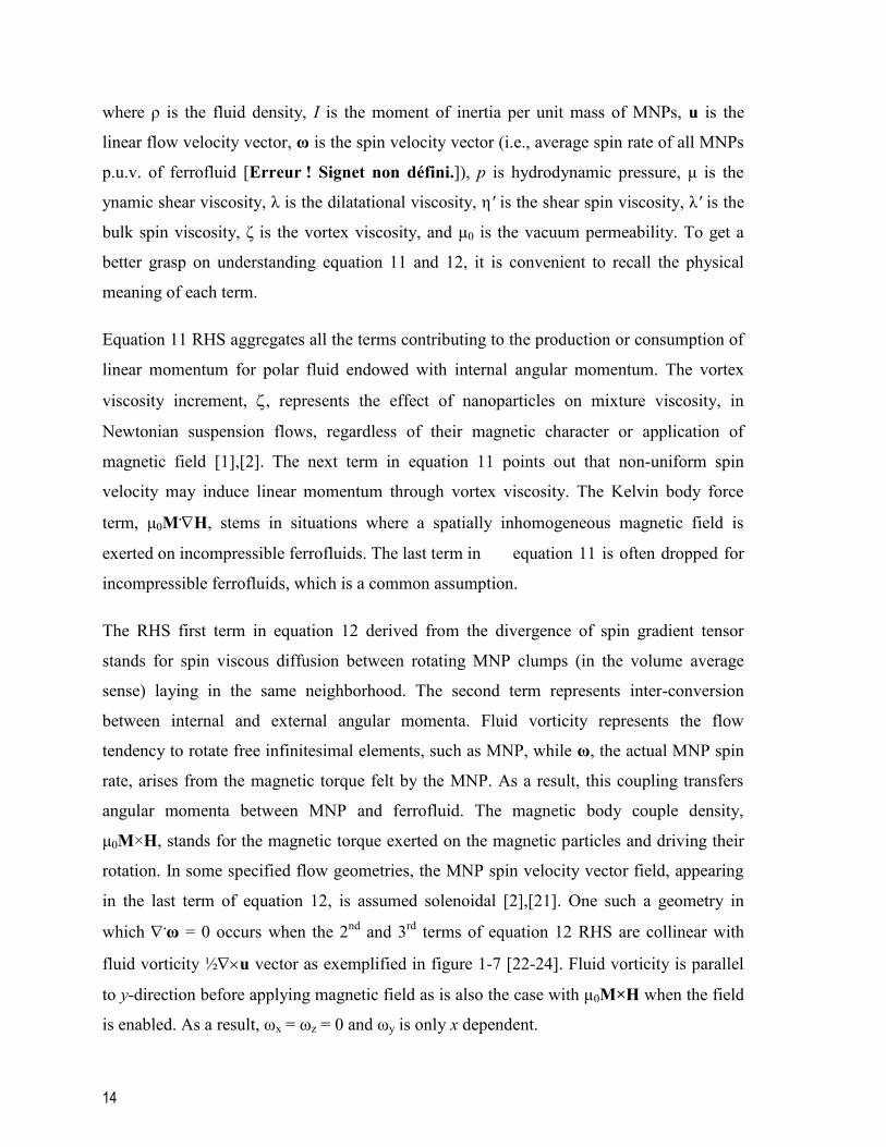
14
where ρ is the fluid density, I is the moment of inertia per unit mass of MNPs, u is the
linear flow velocity vector, ω is the spin velocity vector (i.e., average spin rate of all MNPs
p.u.v. of ferrofluid [Erreur ! Signet non défini.]), p is hydrodynamic pressure, μ is the
ynamic shear viscosity, λ is the dilatational viscosity, η' is the shear spin viscosity, λ' is the
bulk spin viscosity, ζ is the vortex viscosity, and μ0 is the vacuum permeability. To get a
better grasp on understanding equation 11 and 12, it is convenient to recall the physical
meaning of each term.
Equation 11 RHS aggregates all the terms contributing to the production or consumption of
linear momentum for polar fluid endowed with internal angular momentum. The vortex
viscosity increment, , represents the effect of nanoparticles on mixture viscosity, in
Newtonian suspension flows, regardless of their magnetic character or application of
magnetic field [1],[2]. The next term in equation 11 points out that non-uniform spin
velocity may induce linear momentum through vortex viscosity. The Kelvin body force
term, μ0M.H, stems in situations where a spatially inhomogeneous magnetic field is
exerted on incompressible ferrofluids. The last term in equation 11 is often dropped for
incompressible ferrofluids, which is a common assumption.
The RHS first term in equation 12 derived from the divergence of spin gradient tensor
stands for spin viscous diffusion between rotating MNP clumps (in the volume average
sense) laying in the same neighborhood. The second term represents inter-conversion
between internal and external angular momenta. Fluid vorticity represents the flow
tendency to rotate free infinitesimal elements, such as MNP, while ω, the actual MNP spin
rate, arises from the magnetic torque felt by the MNP. As a result, this coupling transfers
angular momenta between MNP and ferrofluid. The magnetic body couple density,
μ0M×H, stands for the magnetic torque exerted on the magnetic particles and driving their
rotation. In some specified flow geometries, the MNP spin velocity vector field, appearing
in the last term of equation 12, is assumed solenoidal [2],[21]. One such a geometry in
which .ω = 0 occurs when the 2
nd and 3
rd terms of equation 12 RHS are collinear with
fluid vorticity ½u vector as exemplified in figure 1-7 [22-24]. Fluid vorticity is parallel
to y-direction before applying magnetic field as is also the case with μ0M×H when the field
is enabled. As a result, ωx = ωz = 0 and ωy is only x dependent.

15
The ferrofluid continuity and conservation equations of the linear and internal angular
momenta combined with one of the magnetization relaxation equations discussed in section
II.5, are in principle closed by adjoining the Maxwell equations. Maxwell’s equations
consist of the Gauß’s law for magnetic flux density and the (zero free-current density)
Ampere’s law for magnetic field intensity, respectively:
0, B H 0 (13)
Vector fields B, H and M are related through the well-known BHM constitutive equation:
HMB 0μ (14)
In equation 14, B and H are, respectively, total magnetic flux density and total magnetic
field intensity in which both external field and induced field generated by (and felt within)
ferrofluid are summed-up. Outside the ferrofluid domain, for instance in the non-magnetic
surrounding material, the contribution of magnetization via BHM constitutive equation is
marginal ( 0) with B and H only generated by the sources external to the non-magnetic
material (i.e., including the ferrofluid magnetization contribution).
Figure 1-7 : Couette flows of ferrofluid confined between two parallel plates subject to magnetic field.
Adapted from [22]
z
x
y
Vz
ωzvz

16
1.3 Application
1.3.1 Pipe flow momentum transfer
Further than the experiments performed in AC fields by Bacri et al. [11] and Zeuner et al.
[18] to validate the magnetoviscosity theory, Schumacher et al. [25] aimed at investigating
the effect of AC fields on pressure drop of ferrofluid pipe flow in laminar and turbulent
regime. They also proposed a computational model based on ferrohydrodynamic theory and
accompanied it with experimental data. Schumacher et al. [25] tested AC (in the [0-1] kHz
range) magnetic field in the range [0 - 1264] Oe with a ferrofluid passing through 3 mm
inner diameter tube. They defined the fractional pressure drop (fPd = ΔP(H)/ΔP(H = 0) - 1)
merely as the relative variation of (downstream) pressure drop subject to H (inside
solenoid) with respect to (upstream) pressure drop (outside solenoid, i.e., H = 0) over equal
tube lengths and fully developed flows. As illustrated in figure 1-8, fPd was obtained for a
range of Reynolds numbers covering laminar and transitional flow regimes. This figure
highlights a strong dependence of fPd to flow rate. Based on the arguments discussed above
regarding AC-field magnetoviscosity, fPd can take negative values (i.e., negative pressure
drop) only if ΩACτB > 1. The maximum ΩACτB reached by Schumacher et al. [25] was 0.061
thus explaining why only fPd > 0 were reported coherent with expectation from theory. In
the two sub-sections below we will try to summarize the modeling efforts by these authors
regarding the ferrohydrodynamic models in laminar and turbulent pipe flows.

17
Figure 1-8 : Fractional pressure drop versus ferrofluid Reynolds number measured at different strengths of
400 Hz AC magnetic field. Adapted from [25]
Table 1 lists the parameters used by Schumacher et al. [25] in their ferrofluid flow
simulations.
Table 1-1 : Parameters used in ferrofluid laminar and turbulent simulations [25]
Laminar Flow
Model
Turbulent Flow
Model
μ (Pa s) 3.85×10⁻³
3.85×10⁻³
ρ (kg m-3
) 1187.4 1187.4
ζ (Pa.s) 1.93×10
-3 1.93×10
-3
η' (kg.m
.s
-1) 6.40×10
-20 6.40×10
-20
C1 = ζ/ μ 0.5 0.5
C3 = η'/R2ζ 1.5×10
-11 1.5×10
-11
Q (mL.min
-1) 500 1400
H (Oe) 948 948
Ω (Hz) 60 60
τB (μs) 1.5 1.5
χ0 0.04 0.04
φ 0.025 0.025
0
0.02
0.04
0.06
0.08
0.1
500 1000 1500 2000 2500 3000
fPd
Re
62.9
37.7
25.1
12.6
Magnetic field strength(kA/m)

18
1.3.2 Ferrohydrodynamic laminar model
Schumacher et al. [25] solved the one-dimensional axisymmetrical laminar version of pipe
flow ferrohydrodynamic model in which the continuity, the linear momentum (equation
11), the angular momentum (equation 12), and the magnetization relaxation (equation 7)
equations were simplified into a set of four algebraic 2nd
-order differential equations for
solving the axial ferrofluid velocity component (u), the MNP spin rate (ω = ω), the axial
pressure gradient (-dp/dz) and the magnetic torque density (MH) as a function of pipe
radial coordinate, r. The following assumptions were made:
* (Pseudo)-steady-state flow, ∂/∂t = 0;
* Axisymmetry, ∂/∂θ = 0;
* Fully developed flow for ferrofluid velocity and MNP spin rate, ∂u/∂z = 0, ∂ω/∂z = 0;
* Ferrofluid flow is incompressible, i.e., .u = 0, which is also supported by the fully
developed flow assumption;
* In the absence of magnetic field, the spin rate vector ω is in θ direction. According to AC
magnetoviscosity theory [4] summarized above, streamwise H oscillations constrain ω to
keep along θ direction yielding .ω = 0 (i.e., ∂ω/∂θ = 0). This supports the above
axisymmetry assumption;
* The spatially uniform magnetic field entrains that M.H = 0 in equation 11;
* Viscous forces are dominant so that inertial effects in equation 11 are negligible as well as
in equation 12 so that I(u.ω) = 0;
* By extension, inertial effects on transporting magnetization are also neglected in equation
(7), u.M = 0. This is justified by the fact that in uniform magnetic field, magnetization
spatial dependency is only due to velocity field gradient u which is perpendicular to u in
the studied geometry.
Therefore, the linear and internal angular momentum balance equations simplify to:

19
μ ζ d ωd d 2ζ d0
d d d d
ru pr
r r r r r z
(15)
AC
2
02 2 θ 1/
d ω 1 dω ω dη 2ζ 2ω μ 0
d dd
u
r r rr r
M H
(16)
Regarding description of the hydrodynamic effects on the magnetization relaxation
phenomenon, Schumacher et al. [25] bypassed the necessity to solve the magnetization
relaxation equation by averaging the magnetic body couple density over one cycle of the
AC field and by including it in the pseudo steady-state angular momentum balance equation
16. Following the same assumption, Zahn and Pioch [23] derived an expression for the
time-averaged magnetic body couple density for planar Couette flow subject to a rotating
magnetic field.
AC0 θ 1/
0 0 02 2 2
0 0
2 2
AC 0 AC 0
AC 0
μ 0.5χ χ
μ
ωτ Ω τ 1 χ , Ω τ 2 χ ,
ωτ 1 , Ω τ , 1 χ ωτ
T a e c ce dfH a b
a b
c d f e
M H
(17)
Schumacher et al. [25] assumed this expression also valid in his AC field Poiseuille flow
experiments and used it in equation 16. Schumacher et al. [25] assumed also a rotation of
the magnetization vector, in flow conditions, to track the AC magnetic field. Let us evaluate
the likelihood of this assumption in the light of the Shliomis and Morozov [4] AC-field
magnetoviscosity theory explained in section II.5. In laminar flow for Re = 1090, the
hydrodynamic time scale is estimated to be τh = 1.3 ms, whereas in the transitional flow
region for Re = 4160 (the highest Re value hit in the authors’ tests) τh = 0.3 ms. The
Brownian time scale estimated by Schumacher et al. [25] was τB = 1.5 μs. For an AC field,
τAC = 8.3 ms, 1.2 ms, 0.5 ms, respectively, for 60 Hz, 400 Hz and 1000 Hz frequencies.
According to figure 1-5 taxonomy, a positive rotational magnetoviscosity prevails in
Schumacher et al. [25] tests regardless of AC field frequency. In our opinion, this might
affect the hypothesis regarding rotation of the magnetization vector because the
magnetization vector may decay twice towards zero during one cycle due to Brownian
relaxation in the laminar case, and Brownian and fluid vorticity mechanisms in the
transitional case. Stricto sensu, this entrains that the magnetization vector keeps nearly

20
parallel to the magnetic field thus yielding on the contrary a nearly zero time-averaged
magnetic body couple density instead of what is suggested by equation 17. A post facto
justification of this interpretation indeed comes out from the authors’ own simulations. For
example in figure 1-9 (adapted from figure 1-9 in [25]), it is suggested that MNP spin
velocity take the same values as (no-magnetic-field) fluid vorticity. However, the radial
velocity profiles with and without magnetic field are virtually identical suggesting that fluid
vorticity remains nearly indifferent to magnetic field.
To improve model representation of pressure drop experiments, the authors also assumed
an ad hoc empirical correction of initial magnetic susceptibility vis-à-vis the applied
magnetic field intensity. They also found that τB needed to be readjusted in laminar flow
regime for each of the AC-field frequencies (ΩAC) and for each flow rate. This further
assumption was justified by the authors as due to the possibility of MNPs agglomeration to
form clusters in laminar flow which would imply larger Brownian relaxation time constants
instead of the theoretical single MNP equation 6. Figure 1-10 illustrates the fitted cluster
Brownian relaxation times normalized by the single MNP τB as a function of Re and
parameterized by AC field frequency. It can be seen that the higher the Re (similarly, the
higher the AC), the lower the τB. In the transitional flow regime, the higher shear stresses
involved would likely go against cluster formation whereby single MNP τB value is
sufficient to describe the Re and AC field frequency changes. Figure 1-12a-c gather the
simulated fPD as a function of Re and parameterized with different magnetic field
intensities for three different AC field frequencies. The simulated fPD measurements in
laminar flow concern the left portion of these figures. It is worthy of notice that the good
match between model and measurements is the resultant of the above mentioned two fitted
parameters, which indicates that there is still room for developing fully predictive Poiseuille
flow models Krekhov et al. [26].

21
Figure 1-9 : Simulated profiles of normalized velocity U, spin velocity ω and averaged magnetic body torque
T0 for ferrofluid laminar pipe flow exposed to oscillating magnetic field (948 Oe, 60 Hz) in comparison with
zero field profiles. Adapted from [25].
Figure 1-10 : Fitted Brownian time constant versus ferrofluid Reynolds number at different AC-field
frequencies. Adapted from [25])
-0.6
-0.4
-0.2
-1E-15
0.2
0.4
0.6
0.8
1
0 0.2 0.4 0.6 0.8 1
r
U(0)
(0)T0(0)
U(H)
(H)T0(H)
0
5
10
15
20
25
30
35
40
45
600 700 800 900 1000 1100 1200 1300 1400
τ B (C
lust
er)
/τB
(M
NP
)
Re
Titre du graphique60 Hz
400 Hz
1000 Hz

22
Figure 1-11 : Simulated profiles of normalized velocity U, spin velocity ω and averaged magnetic body
torque T0, turbulent kinetic energy k and turbulent dissipation rate ε for ferrofluid turbulent pipe flows
exposed to oscillating magnetic field (948 Oe, 60 Hz). Adapted from [25].
-1
-0.8
-0.6
-0.4
-0.2
0
0.2
0.4
0.6
0.8
1
0 0.2 0.4 0.6 0.8 1
r
U(H)
(H)T0(H)
U(0)
(0)T0(0)

23
0
0.02
0.04
0.06
0.08
0.1
0.12
0.14
500 1000 1500 2000 2500 3000
fPd
Re
Sim.(75.4)
Sim.(37.7)
Sim.(25.1)
Sim.(12.6)
Exp.(75.4)
Exp.(37.7)
Exp.(25.1)
Exp.(12.6)
Magnetic field strength(kA/m)
a
0
0.01
0.02
0.03
0.04
0.05
0.06
0.07
500 1000 1500 2000 2500 3000
fPd
Re
Sim.(37.7)
Sim.(25.1)
Sim.(12.6)
Exp.(37.8)
Exp.(25.1)
Exp.(12.6)
Magnetic field strength(kA/m)
b

24
Figure 1-12 : Comparison of simulated Re-dependent fractional pressure drop with experimental data for
different oscillating magnetic field strength. Magnetic field frequency (a) 60 Hz, (b) 400 Hz, (c) 1000 Hz.
Adapted from [25].
1.3.3 Ferrohydrodynamic turbulent model
The main assumption made by Schumacher et al. [25] is to analogize ferrofluid turbulent
behavior to that of a Newtonian fluid suspension with inflated dynamic viscosity, ( + ).
In their proposed framework, the range of the eddy sizes, from the Kolmogorov length
microscale (i.e., smallest eddy size) to the system’s integral length scale [27], is not
overlapping with the much smaller MNP length scale. Derivation of time-averaged
(turbulent flow) forms of ferrofluid linear and angular momentum balance equation 15 and
16 was attempted. A low Reynolds number k-ε model was applied to close the Reynolds
turbulence stress tensor in the time-averaged linear momentum balance. An important
assumption was that magnetoviscosity does not affect turbulent kinetic energy and turbulent
kinetic energy dissipation rate [25]. Since time averaging of the angular momentum was
taken over one cycle of the AC magnetic field, the averaged angular equation ignored
turbulence connection to spin velocity as if the remote action of magnetic fields on the
rotation of the MNPs would remains unfelt at the eddy scale. This is perhaps a gross
approximation as is evident from the RHS second term of equation 12 after introducing the
Reynolds decomposition on velocity field, u = <u> + u*. In 2ζ(×u - 2ω), MNP spin
0
0.005
0.01
0.015
0.02
0.025
0.03
0.035
500 1000 1500 2000 2500 3000
fPd
Re
Sim.(25.1)
Sim.(12.6)
Exp.(25.1)
Exp.(12.6)
Magnetic field strength(kA/m)
c

25
perturbation originates from two vorticity sources out of the time-average velocity
component (<u>) and the fluctuating velocity component (u*).
Simulations using the low-Reynolds k- turbulence model of the time-average radial
profiles of axial velocity component, MNP spin velocity and cycle-averaged magnetic
torque density are shown in figure 1-11 for a magnetic field intensity of 948 Oe and AC-
field frequency of 60 Hz. Simulations with disabling the magnetic field are also shown for
the similar hydrodynamic variables. Figure 1-12a-c gather the simulated fPd data in the
non-laminar region (Figure 1-12 right portion) for the same magnetic field features given in
the previous section III.1.1. These figures suggest that the simulated fPd are fairly well in
agreement in comparison to their measured counterparts. The proposed k-ε turbulent model
represented the fPd experimental data successfully in AC-magnetic fields.
Very recently, Schumacher et al. [15] provided a rigorous homogeneous turbulent model
for ferrofluid flow subject to steady spatially uniform magnetic field in which flow is
simulated in a cube with periodic boundary conditions. An important innovation in their
work is the additive inter-conversion of three energy terms representing different forms of
energies in ferrofluid including translational kinetic energy (ρ/2)ui2, rotational kinetic
energy (ρI/2)ωi2, and internal energy U. Time averaging after Reynolds decomposition of
the dependent variables, the Reynolds-averaged forms of linear and internal angular
momentum and continuity equations were arrived at. In addition to the classical Reynolds
turbulence stress tensor, the averaging procedure brings out three additional nonlinear
fluctuating tensors through decomposition of the magnetic field intensity, magnetic flux
density and magnetization fields into fluctuating and time average contributions. These
terms are namely the turbulent transport flux of fluctuating spin velocity, the fluctuating
Kelvin body force, and the fluctuating body couple density, all of which requiring closures.
By assuming zero mean velocity and zero spin gradients as well as homogeneous
turbulence, to turn to zero all the spatial gradients of averaged quantities, Schumacher et al.
[15] proposed expressions for the mean kinetic (translational and rotational) energies and
mean internal energy:

26
V A b
C b S
int
V A C
dε ε
d
dε
d
dε ε ε
d
t
r
E
t
E
t
U
t
(18)
where, 2 2intt i r i int V ij ij A i i C ij ij i i
1 1 1ρ , ρ ω , ρ , ε 2μ , ε , ε 2η , ,
2 2 4ζE u E I U U e e A A s s u S
b i i s i iω , ωA Q
where εV is the viscous dissipation rate of translational turbulent kinetic energy due to
viscous shear stresses, εC is the dissipation rate depicting the loss of rotational kinetic
energy due to the couple stresses, Φb is the rate of work done on the spin by the asymmetric
stresses, and results in the transfer of translational kinetic energy to (or from) rotational
kinetic energy, εA is the dissipation rate of translational kinetic energy due to antisymmetric
part of the stress, Ψ is the rate of work done on the turbulent flow by the magnetic body
forces, and Ψs is the rate of work done on the turbulent flow by the magnetic body couples
[15]. These five terms are novelties introduced in this turbulent ferrofluid model. Omitting
those degenerates the energy conservation equation to the one as derived for Newtonian
fluids.
In their numerical simulations, Schumacher et al. [15] expanded the fluctuating variables as
finite three-dimensional Fourier series before performing direct numerical simulation of a
ferrohydrodynamic turbulent flow. In the absence of magnetic field, Schumacher et al. [15]
showed that ferrofluids behave similarly to a Newtonian fluid. Table 2 lists the magnetic
and hydrodynamic properties used in turbulent simulations. Time-average root mean square
components of spin velocity and linear velocity are listed in Table 2. This table indicates
that uniform magnetic fields do not affect the RMS fluctuating velocities in turbulent flow
simulations. However, there are indications that magnetic fields bring considerable
anisotropic dampening in the fluctuations for the two spin velocity components normal to
the magnetic field. Induced magnetic field fluctuations and magnetization fluctuations due
to turbulence were also estimated by Schumacher et al. [15] for their particular cubic
ferrofluid element. Table 3 illustrates the marginal contributions of the simulated RMS

27
fluctuating magnetic field and resulting fluctuating magnetization to the applied magnetic
field H = 251 A.cm
-1 and mean magnetization M = 68.3 A
.cm
-1. It is worth mentioning that
although these fluctuations remain very small in comparison to the mean values, one should
be alert that these fluctuations may exhibit non-negligible spatial gradients that could cause
significant magnetic body force (via H') or magnetic convection (via M') terms.
The effect of magnetic field intensity on spin velocity fluctuation and velocity fluctuation is
illustrated in figure 1-13a, b as a function of the dimensionless magnetic field () and using
the various most popular magnetization relaxation equations. The damping effect of
magnetic field on spin velocity fluctuation is remarkable whereas the velocity fluctuations
are barely influenced as already discussed from table 3 data. The effect of magnetic field
strength on energetic terms in equation 18 is illustrated in figure 1-13 using the Shliomis
[10] and Martsenyuk et al. [6] magnetization relaxation equations. An instructive display is
shown on how energy dissipation terms are mutually involved in converting energy due to
an interacting external magnetic field. The slight decrease of εV is very well understood by
the fact that the decrease of uRMS versus magnetic field is marginal. The blocking effect of
magnetic field on spin velocity fluctuations (Table 3, Figure1-13a) is mirrored by a
reduction in energy dissipation via εC. The increasing trend of εA as magnetic field is
increased can be understood as a hindrance effect by the decreasing spin velocity
fluctuations (Figure 1-13b) on ferrofluid vorticity.

28
300
600
900
1200
0.1 1 10 100
ωR
MS
(cm
/s)
Felderhof & Kroh
Martsenyuk et al.
Shliomis
a
17.1
17.2
17.3
17.4
17.5
17.6
17.7
17.8
17.9
0.1 1 10 100
uR
MS
(cm
/s)
Felderhof & Kroh
Martsenyuk et al.
Shliomis
b

29
Figure 1-13
spin velocity, (b) RMS linear velocity, (c) on averaged energy terms: ◊ for Φb; ○ for εv; □ for Ψs; + for εC;
for εA, in turbulent model. Adapted from [15]
0.1
1
10
100
1000
10000
100000
0.1 1 10 100
X (c
m2/s
3)
ebsb
phib
EbsA
ebsc
v
b
A
C
c
X

30
Table 1-2 : Magnetic and hydrodynamic parameters used in ferrofluid turbulent simulations [15]
dp (nm) 10
dh (nm) 29.5
μ (Pa.s) 3.85×10⁻³
ρ (kg.m
-3) 1187.4
mp (A.m
2) 2.5×10
-19
Ms (Oe) 164
ζ/μ 0.5
η' (kg.m
.s
-1) 2×10
-15
τB (μs) 10
H (Oe) 158, 316, 1264
χ0 0.332
T (K) 298.15
dtube (mm) 3
Re 3100
uRMS (cm.s
-1) 20.9
Table 1-3 : Time-averaged 3-D spin velocity, ferrofluid velocity, induced magnetic field and magnetization
RMS components of turbulent flow as simulated in [15]
H (Oe) 0 158 316 1264
2
xω (s-1
) 379 375 368 355
2
yω (s-1
) 401 364 295 178
2
zω (s-1
) 381 345 280 169
2
xu (cm s-1
) 19.8 - 19.5 -
2
yu (cm s-1
) 22.2 - 22.1 -
2
zu (cm s-1
) 19.6 - 19.4 -
H = 251 A.cm
-1
2
xH (A.cm
-1) 0.049 2
xM (A.cm
-1) 0.009
2
yH (A.cm
-1) 0.062 2
yM (A.cm
-1) 0.120
2
zH (A.cm
-1) 0.069 2
zM (A.cm
-1) 0.125

31
1.3.4 Porous media momentum transfer
Taktarov [28, 29] was the first author who considered the motion of magnetizable fluids in
porous media. In his study, volume-average formulations of the equations of motion were
derived for magnetizable non-electroconductive liquids in nonmagnetic porous media
subject to external non-uniform magnetic fields. Spatial averaging was applied for the
linear momentum conservation equation (equation 11) assuming zero vortex viscosity (ζ =
0). This led to the neglect in his analysis of formulating an internal angular momentum
conservation equation.
More recently, Larachi and coworker, [30-33] developed a model of ferrofluid flow through
porous media in presence of steady non-uniform magnetic field. The effect of static field
magnetoviscosity and magnetic body force on flow behavior was numerically investigated.
The starting point of the approach was the microscale ferrohydrodynamic set of ferrofluid
phasic equations as depicted in section II.6. Employing spatial averaging theorems, the
microscale formulation was muted into macroscale ferrohydrodynamic model equations
which led to numerous additional closure terms. Spatially-averaged continuity, linear
momentum balance, internal angular momentum balance, and magnetization relaxation
equations plus Gauß’s law and Ampere’s law were obtained for 3-D axisymmetrical
cylindrical geometry. The system of partial differential equations was solved for a
ferrofluid flow inside packed bed porous media subject to a linearly increasing (or
decreasing) external magnetic field in direction of bulk flow (figure 1-14). One application
sought out of this work was a magnetic remote control of fluid velocity patterns aimed at
overcoming wall channeling and flow short-circuiting in packed beds with low column to
particle diameter ratios. As many of the 15 closure terms arouse through volume averaging,
some assumptions were made to decouple the ferrohydrodynamic model into a
hydrodynamic sub-model and a magnetostatic sub-model. This decoupling was mainly
motivated by convergence difficulties associated with induced magnetic field effects. An
important result stemming from their simulations was a dramatic reduction of spin velocity
due to the external magnetic field close to the packed bed wall (figure 1-15), together with
better approach to plug-flow radial velocity profile despite the large permeability contrasts
between bed core and wall (figure 1-16). Magnetoviscosity effect was found to prevail
mostly close to the wall (figure 1-15).

32
Figure 1-14 : Porous medium and flow details: Packed bed and magnetic field programming [30]
Figure 1-15 : Spin velocity profiles and positive/negative gradient magnetic field at (a) bed exit z = L, Re =
- - z/L) Oe, [30]
-3000
-2000
-1000
0
1000
2000
3000
4000
0 0,1 0,2 0,3 0,4 0,5 0,6 0,7 0,8 0,9 1
r/R
6000(+)
1000(+)
0
1000(-)
6000(-) Re = 2 110
θω /rd s

33
Figure 1-16 : Axial velocity component radial profiles and positive/negative gradient magnetic field at bed
0z = A z/L Oe; A (-
H0z = A (1 - z/L) Oe, [30]
1.3.5 Mass transfer enhancement
Quite recently an emerging trend in chemical engineering concerns attempts to enhance
transport operations beyond what can be accomplished in the classical paradigm. For
example, it has been stated that the presence of MNPs may enhance gas-liquid mass
transfer both in presence and in absence of an external magnetic field.
1.3.5.1 MNP Suspensions & No Magnetic Field
Olle et al. [34] dispersed MNPs in liquid phase with the objective to enhance gas-liquid
mass transfer. The MNPs consisted of oleic-acid grafted surfactant as an internal layer, and
(Hitenol-BC) grafted as second-layer polymerizable surfactant. Synthesis, purification and
pH stability issues were resolved during the preparation of these MNPs with large
hydrodynamic diameter due to the double-surfactant layer. Stability against agglomeration
over a wide pH range was also examined. The volumetric gas-liquid mass transfer
coefficient kLa was determined according to physical and chemical absorption protocols.
smvz /
0
0,002
0,004
0,006
0,008
0,01
0,012
0,014
0 0,2 0,4 0,6 0,8 1
0
200(+)
1000(+)
5000(+)
r /R
Re = 21.1
smuz /

34
During physical absorption, dissolved oxygen absorption dynamic tests were carried out in
a flat-surface mechanically-stirred cell. The kLa values were obtained in the absence of an
external magnetic field with and without introducing MNP in the aqueous medium. The
MNP mass fractions ranged from zero (control test) to 4%, and an enhancement factor due
to the presence of MNPs, was defined as EH=0 = kLMNP/kL. Up to 70% amelioration of EH=0
is shown in figure 1-17 as a function of stirrer speed and MNP mass fraction. It can be seen
that in presence of up to 1% w/w of MNP in liquid, an enhancement of gas-liquid mass
transfer takes place. Although the enhancement mechanism is still not elucidated,
improvements are more visible at lower agitation rates.
Chemical absorption experiments were also carried out using copper (or cobalt)
homogeneously catalyzed oxidation of sulfite into sulfate with dissolved oxygen in aqueous
phase.
Copper-catalyzed reaction gave access to the pure physical mass transfer coefficients in the
so-called slow-reaction in diffusion film and rapid reaction in liquid bulk (chemical
enhancement factor 1, O2 dissolved concentration in liquid bulk 0). An MNP
enhancement factor similar to the one defined in the case of physical absorption was
defined while considering that the gas-liquid contacting area is no longer a flat interface:
L L MNP
L
k aE
k a
(19)
The cobalt-catalyzed reaction gave access to the gas-liquid interfacial area in the so-called
fast-reaction diffusional film (Hatta number > 3, chemical enhancement factor Hatta
number, O2 dissolved concentration in liquid bulk 0). An interfacial area MNP
enhancement factor in this absorption regime can be defined as:
2 2
2 2
1
O OMNP L MNP L
a1
L O OL MNP
n
n
C CN aaE
a N a C C
(20)
Mass transfer coefficient enhancement E' (equation 19) increases with increasing MNP
concentration as shown as a function of specific power dissipation and sparging superficial

35
gas velocity and illustrated in figure 1-18 and 1-19, respectively. The absorption process
can be enhanced up to five times due to the presence of MNPs (Figure 1-18). However, as
power dissipation increases after a certain limit, the enhancement factor decreases,
regardless of MNP concentration. Figure 1-19 shows that gas superficial velocity is not a
determining operating variable in the enhancement of mass transfer, equation 20.
Ea enhancement factor along with E' enhancement factor and the enhancement brought
about only on the pure mass transfer coefficient kL are illustrated in figure 1-20 and 1-21.
From figure 1-20 it may be seen that most of volumetric mass transfer enhancement is due
to the interfacial area growth (more than 80% of 600% total enhancement) over the total
range of power draw. The kL slight enhancement seen at low power input and superficial
velocity collapses afterwards when these variables keep increasing. Such effects are
coherent with reduction in surface tension with up to 0.1% MNP concentration, as seen
commonly during gas sparging in mechanically agitated systems with coalescence
inhibiting liquids. However, increasing further MNPs concentration had no major effect on
surface tension reduction. These results purport evidence of the presence of MNPs near the
gas-liquid interface to explain these enhancement factors. However, no mechanism can be
ruled out for explaining the enhancement on kL and a [34]. The question as to whether this
phenomenon is related in any sort to the magnetic nature of nanoparticles has to be
elucidated.

36
Figure 1-17 : Enhancement factor vs. MNP mass fraction at 300 and 500 stirrer speed, physical absorption
tests. Adapted from [34]
Figure 1-18 : Enhancement vs. dissipated energy at three different MNP concentrations in chemical
absorption tests at Vs = 14.5 cm/min. Adapted from [34]
1
1.1
1.2
1.3
1.4
1.5
1.6
1.7
0 0.01 0.02 0.03 0.04 0.05
k LE
nh
an
cem
en
t :E
MNP mass fraction
300 rpm
500 rpm
3
3.5
4
4.5
5
5.5
0 2 4 6 8 10 12
kLa
En
ha
ncem
en
t :E
Stirrer Power per Unit Volume (kW/m3)
0.01
0.005
0.0025
MNP Mass Fraction

37
Figure 1-19 : Enhancement vs. superficial velocity at three MNP mass concentrations in chemical
absorption tests at power p.u.v = 2.1 kW/m3. Adapted from [34]
Figure 1-20 : KLa, a, KL enhancement vs. dissipated energy at three different MNP concentrations in
chemical absorption tests at Vs = 14.5 cm/min. Adapted from [34]
3
4
5
6
7
8
0 10 20 30 40 50 60
kLa
En
han
cem
en: E
Superficial Velocity (cm/min)
0.01
0.005
0.0025
MNP Mass Fraction
1
1.5
2
2.5
3
3.5
4
4.5
5
0 2 4 6 8 10 12
kLa
, a
an
dk
LE
nh
ance
ment
Stirrer Power per Unit Volume (kW/m3)
kL
a
kLa
kL
a
kLa

38
Figure 1-21 : KLa, a, KL enhancement vs. special velocity at three different MNP concentrations in chemical
absorption tests at power p.u.v = 2.1 kW/m3. Adapted from [34]
1.3.5.2 MNP Suspensions & Magnetic Field
In this approach, first proposed by Suresh and Bhalerao [35], a ferrofluid volume was added
to alkaline aqueous solution in a wetted-wall falling-film column and bubble column to
monitor effects from MNP in carbon dioxide absorption using an AC magnetic field to
enhance gas-liquid interfacial mass transfer. The Olle et al. [34] measured diminution of
surface tension through addition of minute MNP concentration levels indicates that MNP
are enough small to protrude through, and populate, the liquid diffusional boundary layer.
MNP stimulations by an external magnetic field makes them reminiscent of microscale
stirrers in the liquid diffusional boundary layer and thus are foreseen to decrease interfacial
mass transfer resistance.
A 50-Hz AC magnetic field was generated by two coils one mounted on top of the other.
Instantaneous diffusion-limited absorption reactions (CO2 absorption in carbonate-
bicarbonate buffers and in sodium hydroxide solutions) were selected for rate
measurements in presence and in absence of AC magnetic field. The saturation
magnetization of the ferrofluid used was Ms = 100 Gauß before dilution and Ms = 2 Gauß
after fifty-fold dilution in the alkaline aqueous solutions. Similarly to Olle al. [34], they
reported a slight mass transfer enhancement of ca 5% in the absence of magnetic field and
1
1.5
2
2.5
3
3.5
4
4.5
5
0 5 10 15 20 25 30
k La
, a a
nd
k LE
nh
an
cem
en
t
Superficial Velocity (cm/min)
Series1
Series2
Series5
kL
a
kLa

39
26% with the magnetic field ON. Since these two studies concerned three different reactor
types (falling film, bubble column, stirred tank), apart from the consensual qualitative
enhancement in mass transfer, it is difficult to drive the comparisons to a farther level.
Mass transfer improvements plateaued after 2.3% v/v MNP ferrofluid was added into the
alkaline solutions. Maximum enhancement achieved was 50% on kLa which is lower than
what Olle et al. [34] reported. Possible MNP agglomeration, driven by ionic strength and
pH effects, was advanced by the authors as a reason for the lesser improvements arrived at.
Figure 1-22 : Stability of magnetic nanoparticle sizes at different concentrations of MDEA vs. time. Adapted
from [36]
More recently, CO2 absorption was implemented by in methyl-diethanolamine (MDEA)
aqueous solutions using a falling-film device [35]. The amine, being tertiary and thus little
reactive one, shifts the absorption regime to intermediate between diffusion control and
chemical control. A 50% v/v blend of ferrofluid (0.4% solid volume fraction, Ms = 35
Gauß) and MDEA solution was used. AC magnetic fields from 100 to 300 Gauß and 500Hz
to 100 kHz were tested. Another coil generating up to 1000 Gauß AC field was used to
investigate mass transfer enhancement in much stronger fields. Komati and Suresh [36]
selected the matrix liquid solution based on MNP size stability. Using a dynamic light
scattering technique, ferrofluid colloids were indeed found to be more stable in solutions of
25
27
29
31
33
35
37
39
41
43
0.1 1 10 100
Hy
dro
dynam
ic D
iam
ete
r (n
m)
Time(h)
3
2
1
0.5
MDEA Concentration(mole/L)

40
tertiary amines, such as triethanolamine and MDEA than ferrofluid in solutions with
primary and secondary amines. MNP clusters coarsen in MDEA to a diameter of ca 28-38
nm after ca 5 h and then nearly stabilize in size. Figure 1-22 shows the growth of MNP
clusters as a function of MDEA concentration and time. The same enhancement definition
(equation 19) proposed by Olle et al. [34] was used by Komati and Suresh [36] and found
that the volumetric mass transfer coefficient can be almost doubled. According to the
authors, the flow regime of the falling film precluding ripples’ formation on the free surface
led them to ascribe the enhancement only to the kL factor.
Most recently, Stuyven et al. [37] devised a clever experiment in which a steady-state
homogeneous magnetic field was applied to promote dispersion and disaggregation of non-
magnetic nanoclusters in high ionic strength solutions. This approach was dubbed as a new
energy process intensification method compared to more conventional disaggregation
techniques relying on microwaves, ultrasounds, and jet and ball mills. A mild static
magnetic field (0.31 T) was generated by two permanent magnets which set a transverse
magnetic field with respect to the flow of silica nanoparticle suspension.
The size of the agglomerated nanoparticles was observed for different Reynolds numbers
with and without applied magnetic field. Figure 1-23 shows three different particle fraction
distributions -PSD- (based on volume). The black line represents PSD in a fluid at rest
without external magnetic field. The red line stands for the PSD after 1 h turbulent flow at
Re = 26 000 without external magnetic field. In this case, the shear forces arising in
turbulent flow were able to disaggregate nanoclusters from 1400 nm to 261 nm in size.
Applying an external magnetic field at the same Re value reduced further the mean particle
diameter to 169 nm (blue line). The narrower PSD shape in this last case indicates that most
of the clusters are broken when the Lorentz force come to into play along with the
hydrodynamic forces.
Figure 1-24 illustrates another experiment by Stuyven et al. [37] in which nanoparticles size
stabilized (red portion of the curve on the left) around 390 nm at Re =8 000 without
magnetic field. Enabling the magnetic field caused a reduction of the mean diameter to 310
nm (blue middle portion) then disabling the magnetic field (red portion of the curve on the
right) resumed nearly reversibly re-agglomeration of particles.

41
Another set of experiments was aimed to the study of the effect of Re on the magnetic field-
agglomeration interaction. It can be seen that magnetic fields enhance agglomeration in
laminar flow regime (figure 1-25) and cluster disaggregation in transitional and turbulent
flows. The stable aggregation was interpreted by Stuyven et al. [37] as resulting from a
balance between attractive and repulsive forces between initially charged nanoparticles. In
laminar flow, collision frequency is promoted by the magnetic field while hydrodynamic
strain on cluster due to velocity gradient is weak. In this regime the Lorentz force acting on
the differently charged nanoparticles, being part and parcel of a given nanoclusters, cannot
split them apart, thus agglomeration prevails. Conversely, in turbulent flow regime, the
random shear stress fluctuations and strong strain, especially near the wall, promote small
size clusters. In this case, the Lorentz force drags the charged clusters towards the wall
hence enhancing their disaggregation.
Figure 1-23 : Particle size distribution of silica aggregates (volume fraction scale), fluid at rest (Black line),
after 1 h, Re = 26 000 in absence (Red line), and in presence (Blue line) of external magnetic field. Adapted
from [37]
0
0.2
0.4
0.6
0.8
1
0 250 500 750 1000 1250 1500 1750 2000
Vo
lum
e F
racti
on
Dis
trib
uti
on o
f d
H
MNP Hydrodynamic Diameter, dH(nm)
Re = 0, B = 0
Re = 26000, B = 0
Re = 26000, B = 0.3 T

42
Figure 1-24 : Particle size evolution of silica aggregates in presence (Blue line) and absence (Red line) of
external magnetic field, Re = 8 000. Adapted from [37]
Figure 1-25 : Mean diameter of γ-alumina clusters formed in presence of magnetic field (Blue line) and in
absence of magnetic field (Red line) versus Reynolds number. Adapted from [37]
250
270
290
310
330
350
370
390
20 40 60 80 100 120 140 160 180 200
dH
(nm
)
Time (min)
300
350
400
450
500
550
600
650
700
750
1000 10000 100000
dH
(nm
)
Re
Laminar Flow Turbulent Flow

43
1.4 Scope of thesis
Although ferrofluids are applied widely across many disciplines and industrial sectors, they
have not received sufficient coverage in the realm of chemical engineering. In this
introduction, the most potentially relevant theoretical concepts and practical applications of
ferrofluid to chemical engineering have been summarized and discussed.
The purpose of this research is to provide experimental data on transport phenomenon in
the presence of magnetically excited MNPs suspended in liquid. In particular, this thesis is
focused on mass transfer enhancement in the presence of MNPs and magnetic field to
unveil new mechanisms and discoveries of fluid-fluid enhancement processes which are
relevant to chemical reaction engineering.
In the presence of rotating magnetic fields (RMF), MNPs will rotate with an attempt to
align their magnetic moment with the field. Also, stationary magnetic field (SMF) locks
MNP and prohibits the gyration under shear forces. Because of the viscous fluid, spinning
or pinned particle delivers a magnetic torque to the adjacent liquid around it. This torque
may induce nano-convective mixing under RMF or create a nano-stagnant zone. Therefore,
mixing properties of the liquid which is dominated by molecular diffusion in nano-scale, is
affected by the mechanism. This effect is measured and described in the thesis using several
experimental scenarios. The sensitivity of this effect is analyzed as a function of magnetic
field amplitude, frequency and MNP concentration. The first set of experiments in chapter
2, measure the nano-convective mixing effect on self-diffusion coefficient of a suspension
in a capillary. The diffusion cell is centered inside the two-pole three-phase magnet
horizontally. Significant mass transfer enhancement observed and discussed. The
experiments in chapter 3 and 4 consist of axial dispersion coefficient measurement in the
capillary to identify the effect of magnetically excited MNPs on Taylor dispersion and on
laminar velocity profile under RMF, OMF and SMF. Chapter 5 studies gas-liquid mass
transfer coefficient (kLa) when the Taylor flow regime in conducted in the tube, passing
through the magnet. Gas-liquid mass transfer was measured in the presence (absence) of
magnetic field (under RMF and SMF) and the results were compared.

44
1.5 Nomenclature
a Specific interfacial area, 1/m
B Magnetic induction vector, T, N/Am
iC Concentration of component i in saturated liquid, mol/m
3
D Column diameter, m
d Grain diameter, m
dH Nanocluster hydrodynamic diameter, m
dh MNP hydrodynamic diameter, m
dp MNP core diameter, m
dtube Tube diameter, m
E Absolute enhancement in kL
Ea Absolute enhancement in interfacial area,
Er Turbulent rotational kinetic energy, J
Et Turbulent translational kinetic energy, J
E' Absolute enhancement in kLa
f0 Larmor frequency of magnetization vector in the anisotropy field of the
particle, 1/s
g Gravity vector, m/s2
H Total magnetic field vector, A/m
He, Heq Effect magnetic field in equilibrium with dynamic magnetization,
A/m

45
H' Fluctuating component of magnetic field caused by turbulence, A/m
I Moment of inertia per unit mass of MNPs, m2
K Anisotropic constant of material, J/m3
k Turbulent kinetic energy, kg m2/s
2 = J
kB Boltzmann’s constant, J/K
kL Liquid phase mass transfer coefficient, m/s
kLa Volumetric mass transfer coefficient, 1/s
kn Rate constant of nth-order reaction, m3/(mol s) for n = 2
L Langevin magnetization function operator,
LPB Column length, m
Ltube Tube length, m
M Magnetization vector, A/m
Ms Ferrofluid saturation magnetization of the liquid, A/m or Oe
M0 Equilibrium magnetization, A/m
M' Magnetization fluctuating component, A/m
2
iM Magnetization x-component RMS, A/m
mp Magnetic dipole moment of single domain nanoparticles, Am2
n Reaction order,
Na Absorption rate, mol/(m2s)
p Hydrodynamic pressure, Psi

46
Q Liquid volumetric flow rate, mL/min
r Radial coordinate in cylindrical coordinate, m
R Tube diameter, m
Re Reynolds number,
rd Radian
T Absolute temperature, K
T0 Time-averaged magnetic body couple density, dimensionless
t time, s
U Normalized linear velocity, m/s
Uint Internal energy, J
u Ferrofluid linear velocity, m/s
uRMS Root-mean-square translational velocity, m/s
u' Linear velocity fluctuating component, m/s
<u> Time averaged linear velocity, m/s
2
iu Linear velocity x-component RMS, m/s
Vh MNP hydrodynamic volume, m3
Vp MNP core volume, m3
Vs Superficial velocity, cm/min
Greek letters

47
Dimensionless Langevin module
GP Gradient programming of the applied magnetic field, A/m2
ΔP Pressure drop, Psi
Δη Rotational viscosity, Pa s
ε Turbulent kinetic energy dissipation rate, kg m2/s
3 = J/s
εA Vortex viscose dissipation rate, cm2/s
3
εC Rotational kinetic dissipation rate, cm2/s
3
εv Classical viscous dissipation rate, cm2/s
3
ζ Vortex viscosity, Pa s
η' Shear spin viscosity, kg m/s
The angle between M and H, rad
λ Dilatational viscosity, Pa s
λ' Bulk spin viscosity, kg m/s
μ Dynamic viscosity (shear viscosity), Pa s
μ0 Vacuum permeability 4π×10-7
, N/A2, Tm/A, J/A
2m
ξ Dimensionless magnetic field
ξe Dimensionless effective magnetic field
ρ Fluid density, kg/m3
τ (Effective) magnetization relaxation time constant, s
τAC AC magnetic field oscillation time scale = 1/ΩAC, s

48
τB Brownian relaxation time constant, s
τm Experiment time scale, s
τN Néelian relaxation time constant, s
φ MNPs’ grains volume fraction in colloidal fluid
Φb Energy transfers between translational and rotational kinetic energy, cm2/s
3
χ0 Initial magnetic susceptibility,
Ψ Energy transfers to translational kinetic energy by magnetic field, cm2/s
3
Ψs Energy transfers to rotational kinetic energy by magnetic field, cm2/s
3
ΩAC Oscillating field frequency, Hz
ω Spin velocity per unit volume of ferrofluid, rad/s 0r cm/s
ω' Linear velocity fluctuating component, m/s
2
iω Spin velocity x-component RMS, rad/s
Subscripts
i i direction component of a vectorial field, i = (x,y,z) or (r,,z)
L Liquid phase
MNP In presence of MNPs,
Acronyms
DLS Dynamic Light Scattering

49
fPd Fractional Pressure Drop,
MNP Magnetic Nanoparticle
PSD Particle Size Distribution
p.u.v. Per unit volume
RHS Right hand side
RMF Rotating magnetic field
RMS Root mean square
rdMNP Rigid Dipole Magnetic Nanoparticle
sdMNP Soft Dipole Magnetic Nanoparticle

50
1.6 References
[1] S. Odenbach, Magnetoviscous Effects in Ferrofluids (Springer, 2002).
[2] R. E. Rosensweig, Ferrohydrodynamics (Dover Publications, 1997).
[3] K. Morozov, M. I. Shliomis, M. Zahn, Magnetoviscosity in suspensions of grains
with finite magnetic anisotropy, Phys. Rev. E. 73 (2006) 066312.
[4] M. I. Shliomis, K. I. Morozov, Negative viscosity of ferrofluid under alternating
magnetic field, Phys. Fluids 6 (1994) 2855-2861.
[5] A. H. Morrish, Physical Principles of Magnetism (Wiley Press, 2001).
[6] M. Martsenyuk, Y. Raikher, M. I. Shliomis, On the kinetics of magnetization of
suspensions of ferromagnetic particles, Sov. Phys. JETP 38 (1974) 413-416.
[7] B. U. Felderhof, Flow of a ferrofluid down a tube in an oscillating magnetic field,
Phys. Rev. E 64 (2001) 021508.
[8] A. D. Rosenthal, C. Rinaldi, T. Franklin, M. Zahn, Torque measurements in spin-up
flow of ferrofluids, J. Fluids Eng. 126 (2004) 198-205.
[9] J. P. Embs, S. May, C. Wagner, A. V. Kityk, A. Leschhorn, M. Lücke, Measuring
the transverse magnetization of rotating ferrofluids, Phys. Rev. E. 73 (2006) 036302.
[10] M. I. Shliomis, Effective viscosity of magnetic suspentions, Sov. Phys. JETP 34
(1972) 11291-1294.
[11] J. -C. Bacri, R. Perzynski, M. I. Shliomis, G. I. Burde, Negative-Viscosity effect in a
magnetic field, Phys. Rev. Lett. 75 (1995) 2128-2131.
[12] M. I. Shliomis, Ferrohydrodynamics Testing a third magnetization equation, Phys.
Rev. E. 64 (2001) 060501.
[13] B. U. Felderhof, H. J. Kroh, Hydrodynamics of magnetic and dielectric fluids in
interaction with the electromagnetic field, J. Chem. Phys. 110 (1999) 7403-7411.

51
[14] B. U. Felderhof, Magnetoviscosity and relaxation in ferrofluids, Phys. Rev. E 62
(2000) 3848-3854.
[15] K. R. Schumacher, J. J. Riley, B. A. Finlayson, Homogeneous turbulence in
ferrofluids with a steady magnetic field, J. Fluid Mech. 599 (2008) 1-28.
[16] R. E. Rosensweig, R. Kaiser, G. Miskolczy, Viscosity of magnetic fluid in a
magnetic field, J. Colloid Interface Sci. 29 (1969) 680-686.
[17] J. P. McTague, Magnetoviscosity of magnetic colloids J. Chem. Phys. 51 (1969)
133-136.
[18] A. Zeuner, R. Richter, I. Rehberg, Experiments on negative and positive
magnetoviscosity in an alternating magnetic field, Phys. Rev. E 58 (1998) 9287-8293.
[19] C. Rinaldi, F. Gutman, X. He, A. D. Rosenthal, M. Zahn, Torque measurements on
ferrofluid cylinders in rotating magnetic fields, J. Magn. Magn. Mater. 298 (2005) 307–
310.
[20] X. He, S. Elborai, D. Kim, S. H. Lee, M. Zahn, Effective magnetoviscosity of
planar-Couette magnetic fluid flow, J. Appl. Phys. 97 (2005) 10Q302.
[21] C. Rinaldi, A. Chaves, S. Elboria, X. He, M. Zahn, Magnetic fluid rheology and
flows, Curr. Opin. Colloid Interface Sci. 10 (2005) 141-157.
[22] M. Zahn, D. R. Greer, Ferrohydrodynamic pumping in spatially uniform
sinusoidally time varying magnetic fields, J. Magn. Magn. Mater. 149 (1995) 165-173.
[23] M. Zahn, L. L. Pioch, Magnetizable fluid behaviour with effective positive, zero or
negative dynamic viscosity, Indian J. Eng. Mater. Sci. 5 (1998) 400-410.
[24] C. Rinaldi, M. Zahn, Effects of spin viscosity on ferrofluid flow profiles in
alternating and rotating magnetic fields, Phys. Fluids 14 (2002) 2847-2870.

52
[25] K. R. Schumacher, I. Sellien, G. S. Knoke, T. Cader, B. A. Finlayson, Experiment
and simulation of laminar and turbulent ferrofluid pipe flow in an oscillating magnetic field,
Phys. Rev. E 67 (2003) 026308.
[26] A. P. Krekhov, M. I. Shliomis, S. Kamiyama, Ferrofluid pipe flow in an oscillating
magnetic field, Phys. Fluids 17 (2005) 033105.
[27] H. Tennekes, J. L. Lumley, A First Course in Turbulence (MIT Press, 1972).
[28] N. G. Taktarov, Motion of magnetizable liquids in porous media,
Magnetohydrodynamics 16, (1980) 251-255.
[29] N. G. Taktarov, Convection of magnetizable fluids in porous media,
Magnetohydrodynamics 17, (1981) 333-335.
[30] F. Larachi, D. Desvigne, Magnetoviscous control ofwall channeling in packed beds
using magnetic nanoparticles—Volume-average ferrohydrodynamic model and numerical
simulations, Chem. Eng. Sci. 61 (2006) 1627 – 1657.
[31] F. Larachi, D. Desvigne, Ferrofluid induced-field effects in inhomogeneous porous
media under linear-gradient d.c. magnetic fields, Chem. Eng. Process. 46 (2007) 729-735.
[32] F. Larachi, D. Desvigne, Ferrofluid magnetoviscous control of wall channeling in
porous media, China Particuol. 5 (2007) 50 – 60.
[33] F. Larachi, Experimental and theoretical explorations of weak and strong gradient
magnetic fields in chemical multiphase processes, Chap. 11 in Modeling of Process
Intensification, F. J. Keil, (Wiley–VCH, 2007, pp. 365-399).
[34] B. Olle, S. Bucak, T. C. Holmes, L. Bromberg, T. A. Hatton, D. I. C. Wang,
Enhancement of oxygen mass transfer using functionalized magnetic nanoparticle, Ind.
Eng. Chem. Res. 45 (2006) 4355-4363.
[35] A. K. Suresh, S. Bhalerao, Rate intensification of mass transfer process using
ferrofluids, Indian J. Pure Appl. Phys. 40 (2001) 172-184.

53
[36] S. Komati, A. K. Suresh, CO2 absorption into amine solutions a novel strategy for
intensification based on the addition of ferrofluids, J. Chem. Techno. Biotechnol. 83 (2008)
1094-1100.
[37] B. Stuyven, Q. Chen, W. V. d. Moortel, H. Lipkens, B. Caerts, A. Aerts, L.
Giebeler, B. V. Eerdenbrugh, P. Augustijns, G. V. d. Mooter, J. V. Humbeeck, J. Vanacken,
V. V. Moshchalkov, J. Vermantc, J. A. Martens, Magnetic field assisted nanoparticle
dispersion, Chem. Commun. 1 (2009) 47-49.


55
2 Giant liquid-self diffusion in stagnant liquids by
magnetic nano-mixing
2.1 Abstract
Many chemical engineering applications require tools to intensify processes in regions
where Fickian molecular diffusion is the dominant mechanism, such as in boundary layers,
microporous catalysts or microfluidics. We demonstrate in this study that spinning
magnetic nanoparticles (MNP) by means of rotating magnetic fields (RMF) gives rise to an
intriguing nanomotion mechanism capable of triggering giant diffusion in stagnant liquids
and thus able to stimulate transport beyond the molecular diffusion barrier especially in
stagnant liquids. To evidence this mechanism, we report original water self-diffusion
coefficients measured in aqueous media containing very low concentrations of ferrite
MNPs that can be rotated in uniform RMF. The self-diffusion coefficient of distilled water
(i.e., D0 ≈ 3.510-9
m2/s) was enhanced up to 200 times by application of a rotating
magnetic field in stagnant-liquid conditions. It was concluded that in absence of
macroscopic convective flows, MNPs may prove to be efficient nanostirrers to enhance
liquid transport properties at nanoscale. By delivering giant diffusion around them, rotating
MNPs can constitute an appealing nano-mixing process intensification tool.

56
2.2 Introduction
Molecular transport and diffusion in liquids play a key role in many different contexts of
physics, chemistry, biology and chemical engineering [1,2]. Quite recently, an emerging
trend in science and engineering attempts to enhance liquid phase transport operations using
seeded nanoparticles, beyond what can be accomplished in the classical diffusion paradigm
[2]. For example, it has been stated that the presence of nanoparticles in liquids (so-called
nanofluids) may modify heat [3-5] and mass transport [6-14] properties of the medium.
Most prominently, magnetic nanoparticles (MNP) have been applied in a few studies to
direct mass transfer, both in absence [8,15] and in presence [7,16] of an external magnetic
field. Although, the general effect of nanoparticles on liquid transport properties is still
anomalous [17], the method of exciting MNPs seeding liquids with a time-varying external
magnetic field seems to be a promising approach to achieve process intensification. A
related magnetic field assisted nano-mixing is the basis of the present work as a stable
suspension of single-domain MNPs are externally modulated by means of a uniform
rotating magnetic field (uRMF).
Briefly, external magnetic fields exert magnetic torque on the magnetic moment of MNPs
suspended in liquids thus forcing MNP to be aligned with magnetic field direction [18]. For
those MNPs whose magnetic moment is locked in the solid crystal structure (so-called
rigid-dipole MNPs), magnetic torque is felt bodily and associated momentum is transferable
to the adjacent liquid phase [18]. In purely hydrostatic conditions, this magnetic body
torque is opposed only by Brownian collisions from the solvent molecules as suspensions
are at rest [18]. Interestingly, the nature of mechanical interactions between magnetically
excited MNPs and the bulk of liquid depends on the characteristics of applied magnetic
field. For instance, a time-varying magnetic field such as uRMF exerts an angular torque on
MNPs forcing them to gyrate versus the contiguous liquid. Note that, while changing
direction continuously at any point of the domain, uRMF has constant field intensity over
time. In their quest to catch-up with uRMF direction, the suspended rdMNPs spin in a
direction primarily imposed by RMF [18]. The goal of this work is to investigate the effect
of these spinning MNPs on liquid self-diffusion coefficient. As the main result, we
observed that this technique triggers a giant enhancement of liquid self-diffusion, exceeding
its field field-free diffusivity by more than two orders of magnitude. Moreover, magnetic

57
field intensity (H0), field frequency (f) and MNP concentration () were found to influence
the extent of diffusion enhancement.
The current approach stands out from other magnetic mixing processes (which rely on
applying magnetic Kelvin force and are restricted to the boundary of magnetic and
nonmagnetic fluids [19]) as it is versatile and can be used in magnetically homogenous or
inhomogeneous liquid media. Also, those systems that induce magnetic mixing in
electrolytic media [20-23] are very different from ours.
2.3 Experimental
2.3.1 Colloidal suspension
Dilute concentrations of ferrite (Fe3O4) MNPs ( = 0.001 – 0.01 v/v magnetic content)
dispersed in water were prepared from a commercial ferrofluid, EMG705 (FerroTec). The
magnetic properties of EMG 705 were measured by an alternating gradient magnetometer,
MicroMag model 2900 (Princeton Instrument Co.) at 298 K in low-field (for initial
susceptibility, ) and high-field (for saturation magnetization, Ms) asymptote of
magnetization curve. Using these values, particle core diameter was estimated following a
method proposed by Chantrell [24]. Table 4 summarizes the magnetic properties of EMG-
705 ferrofluid. Particle size distribution of dilute ferrofluid with different concentrations
was measured via magnetometry. The results assured us of no cluster or chain formation
during the course of experiments.
Table 2-1 : Magnetic properties of EMG 705 from magnetometry measurement
Saturation magnetization, Ms (kA/m) 18.7
Initial susceptibility, 2.9
MNP volume fraction, (v/v) 0.042
Estimated median magnetic core diameter, dp (nm) 16.0

58
2.3.2 Magnet
To generate uRMF, a tubular two-pole and three-phase (5.5-cm high and 4.5-cm i.d.
cylindrical bore) magnet has been designed and built in collaboration with MotionTech
LLC and Winding Inc (figure 2-1a). The magnet has the capacity to provide both uniform
and non-uniform magnetic fields at moderate strength (< 50 mT) at the bore center with up
to 3 A three-phase currents. Since RMF emerges from superposition of three OMFs that are
120° out of phase, the coils are fed by three balanced AC currents from a variable
frequency drive (ABB, ACS150, 2.2kW Variable Frequency Derive) as illustrated in figure
2-1a,b. Both magnetic field strength and frequency can be controlled directly by means of
this power supply. The temperature of the magnet solid part is controlled by a water cooling
jacket that encompasses the outer shell of the stator and filled with a coolant circulated in
and out from a constant-temperature thermostated bath (Lauda, Model RKT20).
Magnet
Top view
VFD
Side view
a

59
Figure 2-1 : a) Top and side view of the magnet with diffusion cell embedded inside with cell containing
MNP suspension. b) Diffusion cell subject to uRMF generated by two-pole three-phase magnet energized by a
three-phase power supply. c) Diffusion cell with two sets of electrical conductivity sensors.
2.3.3 Diffusion measurement
A simplified conductimetric method originally proposed by Leaist [25-28] was employed in
this study to estimate self-diffusion coefficients of liquids loaded with MNPs with and
without uRMF. The conductimetric cell consists of a short capillary tube sealed at both
ends and fitted with two pairs of miniature electrodes as shown in figure 2-1c. The glass
capillary had 1 mm inner diameter and 40 mm length (L). Platinum wire electrodes, 0.7 mm
in diameter were sealed with epoxy glue into horizontal holes drilled at L/6 and 5L/6
accurately from one end [29]. The electrodes were connected to the conductivity meter
(Omega CDTX-90) which generates a signal in mV, reflecting the electrical conductivity of
the fluid in between each electrode pair. We employed (NaCl solution) electrolyte at low
concentration (i.e., 0.05 M) mixed with dilute ferrofluids as a tracer. By virtue of
Kohlrausch’s law when electric conductances are relatively small, the transient behavior of
the signal intensities is a linear function of electrolyte concentration in the liquid (figure 2-
-1.0
-0.5
0.0
0.5
1.0
0 1/5 2/5 3/5 4/5 1
Phase 1Phase 2Phase 3
θ = t/RMF
I/Imax
Phase 2
Phase 1Phase 3
c
b
a

60
2a,b). Great care was exercised in the preparation of the tracer solutions so that after
dilution the MNP concentration in the tracer must be identical to that of the ferrofluids
provided in the cell. This manner prevented magnetic Kelvin force [18] interference
resulting from magnetic susceptibility discontinuities at the moment of injecting the tracer
into the capillary. The applied voltage on the electrodes is tuned to be less than 1 V to avoid
heating the suspension.
Before each run, the diffusion chamber was rinsed carefully, soaked and then overfilled
with the MNP suspension. A thin film of high-vacuum nonmagnetic grease (silicone grease,
Dow Corning #12) was applied around the outer edges of the capillary. The diffusion
chamber was then sealed by two microscope slides pressed onto the capillary edges. After
filling and sealing the cell, it was set at the middle height of the magnet and the desired
magnetic field was applied. Only after reaching thermal equilibrium, which was recognized
after detecting a constant conductivity signal, the cell received a tracer injection. A small
volume of tracer (i.e., 0.5 L) was injected into the cell gradually to minimize convection.
D can be evaluated by least squares analysis of the slope of the conductance difference
between upstream and downstream probe pairs plotted against time according to the
expression [30]:
(1)
Where C1 and C2 stand for the first and second conductance measured at time t and
corrected by the ratio of cell constant (figure 2-2a, b). This conductimetric cell was used to
determine distilled water self-diffusion coefficient in ambient conditions (atmospheric
pressure and 298 K). We measured D = 2.110-9
m2/s which compared within 5 % with the
reference self-diffusion coefficient value of water (2.210-9
m2/s) reported in the literature
[31]. Also, the apparent self-diffusivity variations in presence of excited MNPs under
different magnetic field intensities and frequencies were examined to assess their influence
on liquid molecular transport.
2
1 2lnπ
L dD C C
dt

61
Figure 2-2 : Electrode responses of a conductivity cell, with and without uRMF nano-mixing stimulation.
Minute volume of tracer is injected upstream into the capillary tube (d = 1 mm) and tracked at two positions,
five and thirty-five mm down the injection point by two sets of electrodes measuring cross-sectional average
electrical conductivity. Trends represent the time evolution of tracer conductivity as detected by upstream and
downstream electrodes a) magnetic field disabled, = 0.004 and b) magnetic field enabled under uRMF, = 0.01,
H0 = 31.4 kA/m, f = 100 Hz
5
5.5
6
6.5
0 200 400 600 800 1000 1200 1400
t (min)
Titre du graphique
y = -0.001x + 0.3087R² = 0.9927
-1
-0.5
0
600 800 1000 1200 1400
Ln
(C
1-C
2)
Time (min)
NO MAGNETIC FIELD
No
rma
lize
dco
nce
ntr
atio
nElectrode I(upstream)
Electrode II (downstream)
D0,calc = 3.510-9 m2/s
f = 0 HzH0 = 0 kA/m
= 0.004
4.5
5.0
5.5
6.0
6.5
7.0
7.5
8.0
0 1 2 3 4 5 6 7 8 9
t (min)
No
rma
lize
d c
on
ce
ntr
atio
n (
C1,
C2)
Dcalc = 6.6510-7 m2/s
f = 100 HzH0 = 31.4 kA/m
= 0.01
y = -0.6867x + 3.2559R² = 0.9967
-1.5
-1
-0.5
0
0.5
1
1.5
3 4 5 6 7
Ln
(C
1-C
2)
Time (min)
a
b

62
2.4 Result and discussion
Figure 2-2 presents conductimetric responses to the tracer injection with and without
rotating magnetic field. It is clearly evident that magnetically-excited spinning of MNPs
generate nano-mixing in capillaries as demonstrated by the dramatic attenuation of response
time relative to that in magnetic-field-free test.
Since the average MNP particle-particle distance is several times longer than the MNP
diameter (e.g., dp-p 95 nm for = 0.0025) [18], particle mutual interactions may be
neglected [32, 33] and the mixing phenomenon can be interpreted as resulting from the
individual particle behavior under magnetic field. Figure 2-3a shows schematically the
motion of MNPs in the absence of external magnetic field while their diffusional translation
and diffusional rotation is due to random collisions of solvent molecules (i.e., Brownian
motion). Accordingly, the particle spin vector (, the ensemble-average of single particle
spin) is equal to zero and MNP magnetic moments (m) are randomized in all directions due
to thermal agitation. Enabling uRMF yields strong enough a magnetic torque, (0m×H, H
is magnetic field and 0 is vacuum permeability) on individual MNPs to overcome
Brownian agitation. Thus, MNPs undergo rotational reorientation which forces them to spin
perpendicular to H0 (figure 2-3b). Consequently, spinning MNPs dissipate kinetic energy in
the cell prompting effective mixing in the liquid spheroids enclosing each MNP. It is the
stimulated motion of liquid molecule in these spheroids that is thought to generate giant
self-diffusion in the liquid.

63
Figure 2-3 : Schematic diagram of MNPs spin in hydrostatic conditions with and without uRMF (a) In
absence of magnetic field, MNPs gyration and translation is solely due to Brownian thermal agitation; MNP
time-average spin vector () is equal to zero since MNP magnetic moments (m) are randomized in all
directions; (b) In presence of uRMF (H0), MNP spin vector () turns normal to H0 and hence lateral mixing
occurs in all directions along capillary.
To gain more insights into this nano-mixing mechanism, we have further investigated the
relationship of D to H0 (0 to 35 kA/m), (0 to 0.01) and f (0 to 200 Hz). D/D0 is plotted as
a function of H0, f and in figure 2-4 where D0 refers to suspension self-diffusion
coefficient at H0 = 0 (figure 2-4a,b) or = 0 in figure 2-4c. In logarithmic scale, D/D0
increases almost linearly with H0 (figure 2-4a) echoing sensitivity of effective mixing on
magnetic torque. Moreover, D/D0 increases versus frequency, and then plateaus (figure 2-
4b) after nearly all magnetized nanoparticles synchronize with the rotation of a sufficiently
strong H0. One interpretation for the plateauing effect would be that there must be a
threshold in rotational speed of MNPs (ca. 50 Hz in figure 2-4b) in which MNP solid-
body faster rotation may not proportionally transfer more hydrodynamic torque to the
adjacent solvent. Such rupture may occur because at this threshold, the boundary condition
on MNP surface may change from no-slip to slip condition [34]. Figure 2-4c illustrates the
pronounced effect of concentration of nanostirrers on the enhancement factor. This

64
observation indicates that at low MNP concentration, at least a part of mass transport over
some distance between the spinning MNPs is still dominated by molecular diffusion only.
Increasing the MNP concentration shrinks the length scale of the domains where molecular
diffusion is the only dominant transport mechanism.
1
10
100
1000
0 5 10 15 20 25 30 35
En
ha
ncm
en
t Fa
cto
r (D
/D0)
H 0(kA/m)
= 0.0025
f = 100 Hz
1
10
100
1000
1 10 100 1000
En
ha
ncm
en
t Fa
cto
r (D
/D0)
f (Hz)
= 0.0025
H0 = 31.4 kA/m
a
b

65
Figure 2-4 : Diffusion enhancement factor under uRMF versus a) magnetic field strength, b) magnetic field
frequency and c) MNP concentration. D0 is liquid self-diffusion coefficient without magnetic field
It is worthy to mention that the mixing mechanism investigated in this study occurs within a
single-phase homogeneous dilute ferrofluid. As such, it is different from mixing of
ferrofluids with nonmagnetic liquids under the effect of a time-varying magnetic field.19
A
distinguishable feature of this latter system is that it is the Kelvin magnetic force that drives
mixing due to MNP concentration gradients. Accordingly, the mixing phenomenon per se
vanishes once uniform MNP concentration throughout the suspension is achieved. In
contrast, the nano-mixing mechanism highlighted in our study is not tied to magnetic-force
mixing effects and occurs regardless of whether MNP concentration gradients exist or not.
2.5 Conclusion
Although there have been several studies on the effect of nanoparticles on liquid transport
properties of nanofluids, the possibility of using magnetically-excited MNPs to stimulated
mixing and diffusion in a still-liquid medium that serve as nano-mixing devices has so far
not received enough attention. Thus, we performed self-diffusion coefficient measurements
in a capillary static cell to identify in which manner interactions between excited MNPs
under uRMF and solvent molecules may affect apparent transport properties of the mixture.
We note that even at low MNP concentration (e.g., = 0.0025), moderate uRMF strength
(e.g., 0H < 50 mT) and ultra-low frequency (e.g., f < 200 Hz), the liquid self-diffusion
0
100
200
300
400
500
0 0.2 0.4 0.6 0.8 1
En
ha
ncm
en
t Fa
cto
r (D
/D0)
10-2
f = 100 HzH0 = 31.4 kA/m
c
66
coefficient can be intensified up to two-orders of magnitude. MNP excitation at distance
combined with intrinsic magnetic field penetrability into nonmagnetic materials has the
potential to open up a range of process intensification strategies where controlled mixing is
required in sub-micron thin regions. The fact that suspended functionalized MNPs are
finding extensive applications in a variety of disciplines will broaden the scope of this
nano-mixing tool beyond that inherent to molecular transport limitation. Hence, uRMF-
excited MNPs can easily be converted into catalyst or enzyme supports endowed with
magnetic property where nano-stirring enhances the rates of diffusion-limited reactions or
of heat transfer from reaction sites toward bulk flows. Finally, the MNPs can then be
magnetically separated downstream and used anew.

67
2.6 References
[1] J.L. Plawsky, Transport Phenomena Fundamentals, Second ed., CRC Press, New
York, 2010.
[2] D.D. Devdatta Kulkarni, Nanofluids Properties and Their Applications, First ed.,
LAP Lambert Academic, New York, 2012.
[3] K.V. Wong, O. De Leon, Applications of nanofluids: current and future, Adv. Mech.
Eng. (2010) 1-11.
[4] P.D. Shima, J. Philip, B. Raj, Synthesis of aqueous and nonaqueous iron oxide
nanofluids and study of temperature dependence on thermal conductivity and viscosity, J.
Phys. Chem. C 114 (2010) 18825-33.
[5] K.-F.V. Wong, T. Kurma, Transport properties of alumina nanofluids,
Nanotechnology, 19 (2008) 345702.
[6] W. Yu, H.Q. Xie, A review on nanofluids: Preparation, stability mechanisms, and
applications, J. Nanomater. (2012) 1-17.
[7] S. Komati, A.K. Suresh, CO2 absorption into amine solutions: a novel strategy for
intensification based on the addition of ferrofluids, J. Chem. Technol. Biotechnol. 83 (2008)
1094-100.
[8] S. Komati, A.K. Suresh, Anomalous enhancement of interphase transport rates by
nanoparticles: Effect of magnetic iron oxide on gas-liquid mass transfer, Ind. Eng. Chem.
Res. 49 (2010) 390-405.
[9] A.N. Turanov, Y.V. Tolmachev, Heat- and mass-transport in aqueous silica
nanofluids, Heat Mass Transfer 45 (2009) 1583-1588.
[10] V. Subba-Rao, P.M. Hoffmann, A. Mukhopadhyay, Tracer diffusion in nanofluids
measured by fluorescence correlation spectroscopy, J. Nanopart. Res. 13 (2011) 6313-
6319.

68
[11] J. Veilleux, S. Coulombe, A dispersion model of enhanced mass diffusion in
nanofluids, Chem. Eng. Sci. 66 (2011) 2377-2384.
[12] J. Veilleux, S. Coulombe, A total internal reflection fluorescence microscopy study
of mass diffusion enhancement in water-based alumina nanofluids, J. Appl. Phys. 108
(2010) 104316.
[13] X.M. Feng, D.W. Johnson, Mass transfer in SiO2 nanofluids: A case against
purported nanoparticle convection effects, Int. J. Heat Mass Transfer 55 (2012) 3447-3453.
[14] X.P. Fang, Y.M. Xuan, Q. Li, Experimental investigation on enhanced mass transfer
in nanofluids, Appl. Phys. Lett. 95 (2009) 203108.
[15] B. Olle, S. Bucak, T.C. Holmes, L. Bromberg, T.A. Hatton, D.I.C. Wang,
Enhancement of oxygen mass transfer using functionalized magnetic nanoparticles, Ind.
Eng. Chem. Res. 45 (2006) 4355-4363.
[16] A.K. Suresh, S. Bhalerao, Rate intensification of mass transfer process using
ferrofluids, Indian J. Pure Appl. Phys. 40 (2001) 172-181.
[17] A. Sergis, Y. Hardalupas, Anomalous heat transfer modes of nanofluids: a review
based on statistical analysis, Nanoscale Res. Lett. 6 (2011) 1-37.
[18] R.E. Rosensweig, Ferrohydrodynamics, First ed., Dover Publications, New York,
1997.
[19] L.D. Mao, H. Koser, Overcoming the diffusion barrier: Ultra-fast micro-scale
mixing via ferrofluids, in: Transducers '07 & Eurosensors Xxi, Digest of Technical Papers,
Vols 1 and 2, Ieee, New York, 2007, pp. U923-U24.
[20] R. Rakoczy, S. Masiuk, Influence of transverse rotating magnetic field on
enhancement of solid dissolution process, Aiche J. 56 (2010) 1416-1433.
[21] R. Rakoczy, S. Masiuk, Studies of a mixing process induced by a transverse rotating
magnetic field, Chem. Eng. Sci. 66 (2011) 2298-2308.

69
[22] R. Rakoczy, Study of effect of temperature gradient on solid dissolution process
under action of transverse rotating magnetic field, Aiche J. 58 (2012) 1030-1039.
[23] B. Stuyven, Q. Chen, W. Van de Moortel, H. Lipkens, B. Caerts, A. Aerts, L.
Giebeler, B. Van Eerdenbrugh, P. Augustijns, G. Van den Mooter, J. Van Humbeeck, J.
Vanacken, V.V. Moshchalkov, J. Vermant, J.A. Martens, Magnetic field assisted
nanoparticle dispersion Chem. Commun. (2009) 47-49.
[24] R.W. Chantrell, J. Popplewell, S.W. Charles, Measurements of particle-size
distribution parameters in ferrofluids, IEEE Trans. Magn. 14 (1978) 975-977.
[25] D.G. Leaist, P.A. Lyons, Multicomponent diffusion in dilute-solutions of mixed
electrolytes, Aust. J. Chem. 33 (1980) 1869-1887.
[26] D.G. Leaist, Diffusion in dilute aqueous-solutions of phosphoric-acid - verification
of the limiting law for diffusion of weak electrolytes, J. Chem. Soc. Farad. T. 1, 80 (1984)
3041-3050.
[27] D.G. Leaist, Diffusion-coefficient of aqueous sulfur-dioxide at 25-degrees-c, J.
Chem. Eng. Data 29 (1984) 281-282.
[28] D.G. Leaist, P.A. Lyons, Diffusion in dilute aqueous acetic-acid solutions at 25-
degrees-C, J. Solution Chem. 13 (1984) 77-85.
[29] H.S. Harned, D.M. French, A conductance method for the determination of the
diffusion coefficients of electrolytes, Ann. N. Y. Acad. Sci. 46 (1945) 267-283.
[30] T.A. Renner, P.A. Lyons, Electrolyte diffusion in acetonitrile - Harned
conductometric technique, J. Phys. Chem. 78 (1974) 1667-1670.
[31] K. Tanaka, Self-diffusion coefficients of water in pure water and in aqueous-
solutions of several electrolytes with O-18 and H-2 as tracers, J. Chem. Soc. Farad. T. 1, 74
(1978) 1879-1881.

70
[32] S.P. Gubin, Y.A. Koksharov, G.B. Khomutov, G.Y. Yurkov, Magnetic
nanoparticles: Preparation methods, structure and properties, Usp. Khim. 74 (2005) 539-
574.
[33] H.T. Yang, H.L. Liu, N.N. Song, H.F. Du, X.Q. Zhang, Z.H. Cheng, J. Shen, L.F.
Li, Determination of the critical interspacing for the noninteracting magnetic nanoparticle
system, Appl. Phys. Lett. 98 (2011) 153112.
[34] Y.X. Zhu, S. Granick, Limits of the hydrodynamic no-slip boundary condition,
Phys. Rev. Lett. 88 (2002) 106102.

71
3 Reducing Taylor dispersion in capillary laminar
flows using magnetically excited nanoparticles: Nano-mixing mechanism for micro/nanoscale applications
3.1 Abstract
Magnetic nanoparticles (MNP) suspended in liquids lend themselves to manipulation at
distance using suitable external magnetic fields to shuttle anchored catalysts, enzymes or
drugs. Despite their widespread use in (bio)catalysis/separation or drug delivery –
applications where nanoscale mixing can be a substantive issue–, the use of MNPs to
promote nano-mixing has not yet been explored. We report a new magnetically-induced
nanoconvection mechanism that will enhance transport beyond the limits of molecular
diffusion. This mechanism is demonstrated using a Taylor dispersion capillary flow cell
where MNPs are excited using low-frequency transverse rotating magnetic fields. Forcing
MNP spin direction to align parallel to flow in opposition to fluid vorticity is shown to
intensify lateral mixing far more rapidly than molecular diffusion. This nano-mixing
mechanism could find applications in (bio)chemical engineering, medical and
pharmaceutical areas where transport intensification is crucial.
3.2 Introduction
In recent years, the realm of single-domain superparamagnetic nanoparticles (MNP) has
permeated into a vast range of technical and scientific disciplines. The interest in MNPs
stems from the unique ability to maneuver them at otherwise inaccessible spatial scales
using suitable external magnetic fields. They provide a technique to induce desirable MNP
momentum/heat responses, e.g., translation, resonance, hyperthermia, etc. [1-7] remotely
and non-invasively. The focus in most current studies has been put on deploying strategies
to harness their use as recyclable shuttles in homogeneous-heterogeneous (bio)catalysis and
(bio)separations [8-21], as drug vehicles for the delivery of therapeutic payloads or as
heating mediators in cancer therapy [7, 22-24].
In this paper we propose to expand the horizon of MNP possibilities by identifying
magnetically-induced nanoconvection mechanism to intensify transport beyond the scope
of molecular diffusion. A rigid-dipole MNP, by virtue of its Brownian relaxation pattern

72
[25], spins bodily in a rotating magnetic field as its magnetic moment tries to follow the
dynamic magnetic field [25]. Spinning nanoparticles in dilute colloidal suspensions – where
magnetic mutual interactions among MNPs are negligible–[26, 27] transfer their
momentum to the surrounding liquid molecules and thus entrain them in an angular motion.
Hence, nanoscale mixing effects around individual nanoparticles may be expected in so far
as each MNP spins as an independent nanostirrer. If this picture proves true, the potential of
nano-mixing induced by rotating magnetic fields bears enormous implications in fields
where molecular diffusion represents a severe barrier to transport, e.g., mass/heat transfer in
laminar-flow fluidics [28], diffusion-limited uptake around high-turnover-frequency
catalyst sites in synthetic or physiological fluids [29, 30], etc. For instance, it is vital in
several applications in microfluidics to rapidly homogenize microchannel contents
transverse to the direction of a main laminar flow [31, 32].
We report that externally excited suspended MNPs are efficient nanotools for generating
liquid-phase mixing at submicron levels using low-frequency rotating magnetic fields.
Here, we describe a mixing tool to enhance mass transport laterally to streamlined laminar
flows through microchannels. To measure the extent of nano-mixing, residence time
distribution measurements are performed using a Taylor dispersion capillary cell from
which axial dispersion coefficients are obtained. Evidence for a secondary nanoconvective
transverse mixing mechanism that is superior to molecular diffusion is obtained by
measuring the reduction of axial dispersion even under very low MNP volume fractions
( 0.1%). As a second manifestation of nano-mixing, we report that laminar velocity
profiles exhibit mimetic shear-thinning behavior that tends to flatten with intensified nano-
mixing. From a hydrodynamic perspective, both effects are optimally taken advantage of as
the MNP spin vector is set parallel to direction of the flow.
3.3 Experimental section
3.3.1 MNP suspension
Dilute aqueous suspensions of ferrite (Fe3O4) MNPs (0.05%vol to 1%vol magnetic content)
are prepared from commercial ferrofluids (EMG705, Ferrotec). The magnetic properties of
MNP-containing suspensions are measured using an alternating gradient magnetometer
(MicroMag model 2900, Princeton Instrument Co.) at 298 K in low- and high-field

73
asymptotes of the magnetization curve. The magnetic core median diameter, dc, is estimated
to be 16.0 nm. The particle size distribution measured using a dynamic light scattering
technique gave a number-average particle hydrodynamic diameter of 24.8 nm (Appendix
A). Suspensions with finer MNP dc are obtained through centrifugation of as-received
ferrofluids at 20,000 rpm for 4 h (Beckman model Avanti™ J-30I). After the magnetic
properties of the centrifuged product are characterized, the desired particle volume fraction,
= 10-3
, is achieved via dilution. Due to low MNP concentration, particle-particle MNP
interactions are negligible with solvent physical properties barely altered. Most experiments
are performed for = 10-3
where vortex viscosity is zero and relative shear viscosity is one
[33-35].
3.3.2 Magnet
To generate TRMF, a tubular two-pole and three-phase (6-cm high and 4.5-cm i.d.
cylindrical bore) magnet has been designed and built in collaboration with MotionTech
LLC and Winding Inc. The magnet has the capacity to provide both uniform and gradient
magnetic fields at moderate strength (< 50 mT) at the bore center with up to 3 A three-
phase currents. Both magnetic field strength and frequency can be controlled directly by
means of three-phase power supply (ACS150, 2.2kW Variable Frequency Drive) while the
magnet is cooled with a water cooling jacket (Appendix A).
3.3.3 RTD test
The glass capillary tube is equipped with two conductivity electrode sets 3 cm apart as a
typical length of microfluidic channels. The dilute aqueous MNP suspension is pumped
through the capillary by a syringe pump. The tracer consists of 5.10-2
M NaCl dissolved in
MNP suspension carefully tuned to yield the same MNP volume fraction as in the main
circulating MNP suspension to prevent susceptibility jump (and thus epiphenomenal
mixing) at the encounter between the two streams under TRMF. The axial dispersion
coefficient is estimated by means of an open-open boundary dispersion model [36] in
laminar flow (Appendix A).

74
3.4 Results and discussion
3.4.1 Taylor dispersion test
A Poiseuille flow of water sparsely seeded with MNPs is subjected to a uniform transverse
rotating magnetic field (TRMF) in a capillary (d = 1 mm, i.d.) aligned coaxially inside a
magnet bore (Figure 3-1). Unexcited (magnetic-field free) MNPs whose spins are collinear
to fluid vorticity have randomly directed magnetic moments due to the effects of Brownian
agitation (Figure 3-2a) [25]. When a magnetic field is applied the nanoparticle magnetic
moments are coerced to gyrate transversely to the flow direction in response to the TRMF.
This aligns the spin direction of excited MNPs to nearly parallel to the flow direction while
being at odds with fluid vorticity (Figure 3-2b). Viscid shear forces oppose nanoparticle
bodily rotation causing MNPs to spin in -tilted planes (Figure 3-2b) reflecting shear that is
maximum on the wall and fading to zero towards the capillary centerline [37]. A
sufficiently strong magnetic torque is required near the capillary wall to enable the MNPs to
bodily rotate (θ ≠ 0) while close to centerline the viscous torque is easily overcome by the
magnetic torque (θ → 0). We hypothesize that the excited MNPs possess a hitherto
undocumented ability to enhance the diffusive migration across streamlines in laminar
flows, beyond the scope of molecular diffusion, and this occurs via a nanoconvection
mechanism.
Taylor dispersion [38, 39] measurements are performed both with magnetically-excited and
unexcited MNPs to test this hypothesis and to assess the enhancement of lateral mixing in
purely linear laminar flows. A thin tracer slice is briefly injected at t = 0 and two electrodes,
placed 5 cm and 8 cm downstream of injection, monitor the spreading of concentration
signals over a capillary length L = 3 cm (Figure 3-3a). Axial dispersion coefficients (D) are
obtained from residence time distribution (RTD) experiments, moment and convolution
analyses [36] for a range of rotating magnetic field strengths and frequencies, H0 and f,
MNP magnetic core volume fraction and median diameter, and dc, and fluid superficial
velocity, U, while ensuring low Reynolds (Re = Ud/O(1)) and large Péclet (Pe = Ud/D
O(103)) numbers.

75
Figure 3-1 : Taylor dispersion in capillary tube exposed to a rotating magnetic field (a) Dispersion of a tracer
plug in Poiseuille flow; (b) Experimental setup consists of a two-pole three-phase tubular magnet (6 cm long,
4.5 cm i.d.) powered by a three-phase powersupply to generate a transverse rotating magnetic field (with
variable frequency and strength) across a coaxially aligned glass capillary (10 cm long, 1 mm i.d.) (c) Magnet
upper view showing a uniform horizontal rotating magnetic field over a capillary flow of a dilute suspension
of magnetic nanoparticles
Magnetic field-free convective flow alone would stretch the tracer slice into a paraboloidal
shell the vertex of which protrudes a distance 2Ut away from tracer incipient point. Tracer
lateral leakage by molecular diffusion – outwards from tracer-rich centerline on the front
and inwards from the likewise tracer-rich wall on the back – distorts the shell into a quite
evenly shaped plug (Figure 3-1a) at sojourn times larger than d2/Ɖ (Ɖ tracer molecular
diffusivity). Over short lengths or residence times, Taylor dispersion in laminar flows fails
to achieve adequate lateral mixing when relying only on molecular diffusion [40].
Therefore, a reduction of the measured D values should be observed when techniques to
enhance lateral spreading by allowing the tracer to mix across the capillary are used [41].
Induced by TRMF-excited MNPs, this reduction of the D values is used to characterize
lateral nano-mixing crosswise to flow direction.

76
Figure 3-2 : Schematic diagram of MNPs spin in shear flow with and without TRMF (a) In the absence of
magnetic field, MNPs gyrate synchronously with fluid vorticity; MNP spin vector () is equal half fluid
vorticity (1/2×v) and MNP magnetic moments (m) are randomized in all directions; (b) In presence of TRMF (H0), MNP spin vector () turns normal to azimuthal fluid vorticity vector and hence mixing is lateral.
Mixed spheroid zones form around MNPs when magnetic torque (0m×H, m is MNP magnetic moment, H is
magnetic field and 0 is vacuum permeability) overcomes Brownian agitation and frictional torque (2(×u-
2), u is linear fluid velocity, is local MNP spin, is spin viscosity). The distance between stirred spheroids
is affected by MNP concentration and TRMF frequency. Significant mixing occurs when most of the stirred
zones overlap to assist material exchange amongst them.
Transient impulse responses registered by 1st (■,▲,●) and 2
nd (□,Δ,○) electrodes are shown
in Figure 3-3b for identical f, , dc and U but increased magnetic field strength: 0(■,□),
10.4 kA/m (▲,Δ) and 36.5 kA/m (●,○). The breakthrough (Figure 3-3c) and asymmetry
(long tail, Figure 3-3b) of (■,□) signals correspond to weakly dispersed centerline tracer
H0
m
1
2∇ × 𝐯
b
m
1
2∇ × 𝐯
a

77
and strongly dispersed tracer originally in the shear-active wall region when passing by the
electrodes. Relative to unstirred Poiseuille flow (■,□), the ability of rotating MNPs to
induce lateral nano-mixing results in more symmetric peaks featuring significant reduction
of peak variance, short tails and slow-paced breakthroughs. These changes imply
conclusively that diffusive migration is assisted across streamlines by a secondary mixing
mechanism.
Figure 3-3 : Impulse response of a Taylor dispersion capillary with and without nano-mixing (a) Schematic of
Taylor dispersion capillary tube with two sets of detectors inside magnet bore; (b,c) Laminar Poiseuille flow in a
capillary tube: d = 1 mm, Pe ~ 103, Re ~ 1. A plug of tracer is injected upstream into the capillary tube and
tracked at two positions, five and eight cm down the injection point by two sets of electrodes measuring cross-
sectional average electrical conductivity. Trends represent the time evolution of tracer conductivity as
detected by upstream and downstream electrodes (■,□) for unstirred Poiseuille flow, (▲,Δ) nano-mixing for
laterally stirred MNPs = 0.0025, H0 = 10.4 kA/m, f = 50 Hz, (●,○) nano-mixing for laterally stirred MNPs
= 0.0025, H0 = 36.5 kA/m, f = 50 Hz. Peak narrowing indicates axial dispersion is reduced under nano-
mixing.
Plots of dimensionless D/UL vs. Re are displayed in Figure 3-4 for a range of nano-mixing
levels. D/UL is highest for (magnetic-field free) unexcited MNPs while it decreases when
excited MNPs generate lateral mixing. As nano-mixing intensifies, D/UL becomes less
sensitive to convective flow as reflected in the gentler D/UL vs. Re slopes. This is likely
due to laterally magnetized MNPs resisting the fluid viscous tendency to slide telescopic
0
0.01
0.02
0.03
0.04
0.05
0.06
0.07
0.08
0 20 40 60 80 100 120 140 160
Inte
nsity
Time (s)
I II
I
II
0
0.002
0.004
0.006
0.008
0.01
0 20 40 60
Inte
nsity
Time (s)
L = 3 cm
c
a
b

78
isovelocity layers over each other (Figure 3-2b). The slopes of trends in Figure 3-4 also
suggest that Brownian agitation is more effective in countering magnetic torque compared
to the mechanical torque as otherwise there would have been less of a reduction in axial
dispersion after a fourfold Re increase.
Figure 3-4 : The effect of convective flow on axial dispersion attenuation Axial dispersion coefficient, presented
as dimensionless number D/UL, and estimated from moment analysis of convoluted data from impulse tests (such
as in Figure 3-3). Experiments performed with = 0.001, H0 = 31.4 kA/m. Milder slopes imply strong nano-
mixing counteracting convective stretching. Error bars indicate standard deviation (number of repeat runs = 3)
To gain more insights into the nano-mixing mechanism, we have further investigated the
relationship of D to H0 (0 to 35 kA/m), f (0 to 200 Hz), (0 to 0.01) and dc (10.2 and 16.0
nm). D/D0 is plotted as a function of TRMF (H0 and f, Figure 3-5a) and suspension ( and
dc, Figure 3-5b) properties where D0 refers to axial dispersion at H0 = 0 (Figure 3-5a) or =
0 (Figure 3-5b). D/D0 decreases almost linearly with H0 (Figure 3-5a) and, echoing size-
sensitivity of single-domain magnetic moment (and torque), also with dc (Figure 3-5b). This
latter trend denotes that for invariant , fewer and larger MNPs (ca. 2.3×10¹⁴
per cm3, dc =
16.0 nm, = 10-3
) absorb magnetic energy and deliver it to the liquid more effectively than
more numerous but smaller MNPs (ca. 9.0×10¹⁴
per cm3, dc = 10.2 nm, = 10
-3). As the
0. 3 0. 4 0. 5 0. 6 0. 7 0. 8 0. 9 1 1. 1 1. 2 1. 3
0
0. 05
0. 1
0. 15
0. 2
0. 25
0.00
0.05
0.10
0.15
0.20
0.25
0.3 0.4 0.5 0.6 0.7 0.8 0.9 1.0 1.1 1.2 1.3
D/UL
Re
F = 100 [Hz]
F = 25 [Hz]
F = 10 [Hz]
Zero magnetic field
f
f
ffffffff

79
frequency increases, D/D0 decreases and then plateaus (Figure 3-5a) after nearly all
magnetized nanoparticles synchronize with the rotation of a sufficiently strong H0.
For magnetic core volume fractions varying from 10-3
to 10-2
, the average MNP
interparticle distance varies from 129 nm to 60 nm for dc = 16.0 nm [25]. At such dilution
levels, the relative vortex and shear viscosities are, respectively, close to 0 and 1, and
magnetic interactions between rigid dipole MNPs may be neglected so that nano-mixing
results from the behavior of individual MNPs [26, 27]. Hence, a magnetically-spinning
MNP is viewed as an individual nanostirrer encapsulated at the center of a mixed-cup
oblate spheroid of solvent molecules. The internally stirred spheroids appear as soon as
MNP magnetic torque overcomes Brownian agitation and the mechanical viscous torque.
This ensemble of stirred spheroids moves down the capillary following the convective flow
(Figure 3-2). It is worth noting that lateral material transport in the complementary inter-
spheroid fluid domain occurs via molecular diffusion only.

80
Figure 3-5 : Axial dispersion attenuation is dependent on TRMF strength and frequency, and MNP concentration
and core diameter. Experiments carried out at = 0.001 and MNP median diameter dc = 16.0 nm unless otherwise
stated. (a) D/D0 versus f (▲) at H0 = 31.4 kA/m plateaus at about 50 Hz. D/D0 versus H0 (●) at f = 50 Hz. (b) D/D0
versus () at H0 = 31.4 kA/m plateaus at about 0.0012. D/D0 versus dc (■)at H0 = 36.5 kA/m and f = 50 Hz.
Error bars indicate standard deviation (number of repeat runs = 12).
The size of the internally-stirred spheroids coarsens with increasing TRMF frequency (and
thus MNP spin frequency). This coarsening in combination with MNP spinning in planes
almost perpendicular to flow direction (Figure 3-2b) promotes lateral transport as the
diffusion length scale is brought down from channel diameter to spheroid length scale. A
critical state is reached when adjacent spheroids begin to overlap each other, this accounts
for the D/D0 plateauing trend observed when increasing frequency (Figure 3-5a) or MNP
concentration (Figure 3-5b). For instance, this overlap occurs near f = 50 Hz at = 0.001
for H0 = 31.4 kA/m in Figure 3-5a. Interestingly, a plateau is also reached in Figure 3-5b
close to = 0.0012 at 50 Hz and H0 = 31.4 kA/m. Exceeding this frequency and volume
fraction will not result in improved lateral mixing.
0 1 2 3 4
0
0. 2
0. 4
0. 6
0. 8
1
0.00
0.25
0.50
0.75
1.00
0 50 100 150 200 250
D/D0
f (Hz)
Titre du graphique
Freq.
H
H0104 (A/m)H0104 (A/m)
0 5 10 15 20
0
0. 2
0. 4
0. 6
0. 8
1
0.00
0.25
0.50
0.75
1.00
0.0 0.2 0.4 0.6 0.8 1.0
D/D0
10-2
Chart Title
MNP v%
dp
dp(nm)
dc
dc(nm)
a
b

81
The four variables described above seem to be intrinsically associated in a way to support
the nano-mixing mechanism depicted in this study. Since both H0 and dc influence MNP
magnetic torque in counteracting Brownian agitation and mechanical torque, similar D/D0
trends are anticipated when increasing either H0 or dc. On the other hand, the inter-spheroid
distance being controlled by both the MNP volume fraction and TRMF frequency,
analogous D/D0 trends are likewise expected in their variations with f and . The
experimental results in Figure 3-4 confirm this.
3.4.2 MNPs alter laminar velocity profile in capillary tube
We further investigated how MNP-induced lateral nano-mixing may affect the velocity
profile in laminar Poiseuille flows. Spinning MNPs as depicted in Figure 3-2b may
attenuate the radial velocity gradients yielding more flattened velocity profiles compared to
the usual (unexcited-MNP) parabolic profile. Figure 3-3c provides a crucial clue as the
separation between the breakthrough times at the two electrodes amplifies with increased
nano-mixing whilst the mean residence time (τL/U) is kept identical for all tests. The
breakthrough time span features the fastest centerline tracer blob passing by the electrodes
with minimum residence time (τmin). The τ/τmin ratio declines from 2 to 1 for a velocity
profile evolving from a parabolic to a completely flattened velocity-homogenized one.
Assuming no-slip boundary condition on the wall and negligible radial convective effects
induced by TRMF in the capillary, this ratio can be used as a quantitative index to
understand how far velocity profiles flatten due to nano-mixing. This can be accomplished
by drawing an analogy with non-Newtonian power-law radial velocity profiles, u(r) [37]:
(1)
where the power-law index, n, varies between 1 (parabolic profile) and 0 (flat profile) and
is expressed as a function of τmin/τ according to [37]:
(2)
1 1/
3 11
1
nn r
u r Un a
min
min
1 τ τ
3τ τ 1n

82
Figure 3-6a,b,c plots τ/τmin and n versus H0, f and for Figure 3-5a,b (●,▲,♦) experiments.
Minimum magnetic field strength (104 A/m) and frequency (25 Hz) are required (Figure 3-
6a,b) to demonstrate nano-mixing-mediated hydrodynamic effects. Sensitivity of τ/τmin and
n to frequency dwindles after 50 Hz (Figure 3-6b) though not reflecting a plateau as in
Figure 3-5a (▲). Furthermore, Figure 3-6c shows a minimum at 0.0025 exceeding
0.0012 in Figure 3-5b (♦). We conclude that unlike concentration homogenization,
velocity homogenization (i.e., reduction of n) via nano-mixing is more demanding and
requires larger minimal H0 and . This is illustrated in Figure 3-6d which shows that the
computed velocity profiles flatten as n decreases (from 1 to 10-2
) to echo increased nano-
mixing intensities.
1.00
1.25
1.50
1.75
2.00
0 0. 5 1 1. 5 2 2. 5 3 3. 5 4
0.00
0.25
0.50
0.75
1.00
0 1 2 3 4
n
H0104 (A/m)
n
τ/τmin
τ/τmin
1.00
1.25
1.50
1.75
2.00
0 50 100 150 200 250
0.00
0.25
0.50
0.75
1.00
0 50 100 150 200 250
n
f (Hz)
n
τ/τmin
τ/τmin
b
a

83
Figure 3-6 : Mixing effect on laminar velocity profile. Power-law index n and /min ratio as a function of (a)
magnetic field strength, (b) magnetic field frequency, (c) MNP volume fraction. Error bars indicate standard
deviation (number of repeat runs = 6), (d) Simulated laminar flow velocity profile for different lateral mixing
intensities in a capillary as a function of power-law index.
There has so far been little awareness of the possibility of using magnetically-excited
MNPs as nano-mixing devices. In this study, we implement a remote liquid nano-mixing
technique by subjecting MNPs to rotating magnetic fields. Bodily spinning rigid-dipole
MNPs are used to deliver electromagnetic energy from an external source to the liquid
phase in the desired mixing plane even in small thin regions. To demonstrate its potential,
the technique is applied to generate lateral nano-mixing. We note that macroscopic
properties in fluidic systems, such as the axial dispersion coefficient and the liquid velocity
profile, can be modified via this nano-mixing technique. The experimental results reveal
that spinning MNPs stir the liquid within 20-nm length-scale fluid spheroids surpassing the
mixing capability of molecular diffusion even at very low MNP concentrations ( < 10-2
).
1.00
1.25
1.50
1.75
2.00
0 0. 1 0. 2 0. 3 0. 4 0. 5 0. 6 0. 7 0. 8 0. 9 1
0.00
0.25
0.50
0.75
1.00
0 0.2 0.4 0.6 0.8 1
n
10-2
n
τ/τmin
τ/τmin
- 0. 5 - 0. 4 - 0. 3 - 0. 2 - 0. 1 0 0. 1 0. 2 0. 3 0. 4 0. 5
0
0. 5
1
1. 5
2
0.0
0.5
1.0
1.5
2.0
-0.5 -0.4 -0.3 -0.2 -0.1 0 0.1 0.2 0.3 0.4 0.5
u /U
r (mm)
n = 1
n = 0.7
n = 0.4
n = 0.1
n = 0.01
d
c

84
This also implies that mixing is enhanced on a spatial scale much smaller than the turbulent
Kolmogorov scale [42, 43] giving access to mixing scales thus far unreachable even to
turbulence. MNP excitation at distance combined with intrinsic magnetic field penetrability
into nonmagnetic materials has the potential to open up a range of process intensification
and biomedical strategies where controlled mixing is required in sub-micron thin regions.
This nano-mixing technique utilizes a low-frequency (f < 200 Hz) moderate strength
rotating magnetic field (B < 50 mT) generated by a simply-designed magnet to stimulate
MNPs. It worth to mention that Nano-mixing technique is distinguished from
magnetohydrodynamic mixing in which Lorentz body force induces disturbance on the
interface of an electrically conducting fluid with another miscible liquid [44]. The fact that
suspended functionalized MNPs are finding extensive applications in a variety of
disciplines will broaden the scope of this nano-mixing tool beyond that inherent to
molecular transport limitation. TRMF-excited MNPs can easily be converted into catalyst or
enzyme supports endowed with magnetic property where nanostirring enhances the rates of
diffusion-limited reactions or of heat transfer from reaction sites toward bulk flows. Finally,
the MNPs can then be magnetically separated downstream and used anew.
3.5 Conclusion
By studying axial dispersion in a dilute liquid suspension containing MNPs and flowing
through a Taylor capillary cell under moderate strength low frequency transverse rotating
magnetic fields (TRMF), we found that spinning MNPs produce nano-sized vortices that
objectively enhance liquid transport properties beyond the capability of molecular
diffusion. Systematic study of capillary axial dispersion versus design parameters (i.e.,
TRMF strength and frequency, MNP concentration and median particle diameter) with and
without excited MNPs enabled understanding of a nano-mixing mechanism. Spinning
MNPs was found to induce meaningful nanoconvective mixing levels around nanoparticles;
a phenomenon which is especially valuable for applications combining stimulation of
lateral mixing in laminar flows and functionalized MNPs utilized as separable agents.

85
3.6 References
[1] C. Alexiou, W. Arnold, R.J. Klein, F.G. Parak, P. Hulin, C. Bergemann, W. Erhardt,
S. Wagenpfeil, A.S. Lubbe, Locoregional cancer treatment with magnetic drug targeting,
Cancer. Res. 60 (2000) 6641-6648.
[2] B. Chertok, B.A. Moffat, A.E. David, F.Q. Yu, C. Bergemann, B.D. Ross, V.C.
Yang, Iron oxide nanoparticles as a drug delivery vehicle for MRI monitored magnetic
targeting of brain tumors, Biomaterials 29 (2008) 487-496.
[3] J. Dobson, Magnetic nanoparticles for drug delivery, Drug Dev. Res. 67 (2006) 55-
60.
[4] N. Kohler, C. Sun, A. Fichtenholtz, J. Gunn, C. Fang, M.Q. Zhang, Methotrexate-
immobilized poly(ethylene glycol) magnetic nanoparticles for MR imaging and drug
delivery, Small 2 (2006) 785-792.
[5] S.C. McBain, H.H.P. Yiu, J. Dobson, Magnetic nanoparticles for gene and drug
delivery, Int. J. Nanomed. 3 (2008) 169-180.
[6] J.-H. Lee, J.-t. Jang, J.-s. Choi, S.H. Moon, S.-h. Noh, J.-w. Kim, J.-G. Kim, I.-S.
Kim, K.I. Park, J. Cheon, Exchange-coupled magnetic nanoparticles for efficient heat
induction, Nat. Nanotechnol. 6 (2011) 418-422.
[7] Q.A. Pankhurst, J. Connolly, S.K. Jones, J. Dobson, Applications of magnetic
nanoparticles in biomedicine, J. Phys. D-Appl. Phys. 36 (2003) R167-R181.
[8] S. Shylesh, V. Schunemann, W.R. Thiel, Magnetically separable nanocatalysts:
Bridges between homogeneous and heterogeneous catalysis, Angew. Chem. Int. Ed. 49
(2010) 3428-3459.
[9] T.J. Yoon, W. Lee, Y.S. Oh, J.K. Lee, Magnetic nanoparticles as a catalyst vehicle
for simple and easy recycling, New. J. Chem. 27 (2003) 227-229.

86
[10] P.D. Stevens, G.F. Li, J.D. Fan, M. Yen, Y. Gao, Recycling of homogeneous Pd
catalysts using superparamagnetic nanoparticles as novel soluble supports for Suzuki, Heck,
and Sonogashira cross-coupling reactions, Chem. Commun. (2005) 4435-4437.
[11] M. Shokouhimehr, Y. Piao, J. Kim, Y. Jang, T. Hyeon, A magnetically recyclable
nanocomposite catalyst for olefin epoxidation, Angew. Chem. Int. Ed. 46 (2007) 7039-7043.
[12] C. Che, W. Li, S. Lin, J. Chen, J. Zheng, J.-c. Wu, Q. Zheng, G. Zhang, Z. Yang, B.
Jiang, Magnetic nanoparticle-supported Hoveyda-Grubbs catalysts for ring-closing
metathesis reactions, Chem. Commun. (2009) 5990-5992.
[13] X.X. Zheng, S.Z. Luo, L. Zhang, J.P. Cheng, Magnetic nanoparticle supported ionic
liquid catalysts for CO(2) cycloaddition reactions, Green Chem. 11 (2009) 455-458.
[14] T.Q. Zeng, L. Yang, R. Hudson, G.H. Song, A.R. Moores, C.J. Li, Fe(3)O(4)
Nanoparticle-supported copper(I) pybox catalyst: Magnetically recoverable catalyst for
enantioselective direct-addition of terminal alkynes to imines, Org. Lett. 13 (2011) 442-
445.
[15] V. Polshettiwar, R. Luque, A. Fihri, H. Zhu, M. Bouhrara, J.-M. Bassett,
Magnetically recoverable nanocatalysts, Chem. Rev. 111 (2011) 3036-3075.
[16] L.Z. Gao, J. Zhuang, L. Nie, J.B. Zhang, Y. Zhang, N. Gu, T.H. Wang, J. Feng, D.L.
Yang, S. Perrett, X. Yan, Intrinsic peroxidase-like activity of ferromagnetic nanoparticles,
Nat. Nanotechnol. 2 (2007) 577-583.
[17] L. Guo, J. Huang, X. Zhang, Y. Li, L. Zheng, Bacterial magnetic nanoparticles as
drug carriers, J. Mater. Chem. 18 (2008) 5993–5997.
[18] H.H. Yang, S.Q. Zhang, X.L. Chen, Z.X. Zhuang, J.G. Xu, X.R. Wang, Magnetite-
containing spherical silica nanoparticles for biocatalysis and bioseparations, Anal. Chem. 76
(2004) 1316-1321.
[19] A. Debrassi, A.F. Correa, T. Baccarin, N. Nedelko, A. Slawska-Waniewska, K.
Sobczak, P. Dluzewski, J.-M. Greneche, C.A. Rodrigues, Removal of cationic dyes from

87
aqueous solutions using N-benzyl-O-carboxymethylchitosan magnetic nanoparticles, Chem.
Eng. J. 183 (2012) 284-293.
[20] Y. Pang, G. Zeng, L. Tang, Y. Zhang, Y. Liu, X. Lei, Z. Li, J. Zhang, Z. Liu, Y.
Xiong, Preparation and application of stability enhanced magnetic nanoparticles for rapid
removal of Cr(VI), Chem. Eng. J. 175 (2011) 222-227.
[21] Z.-p. Yang, X.-y. Gong, C.-j. Zhang, Recyclable Fe(3)O(4)/hydroxyapatite
composite nanoparticles for photocatalytic applications, Chem. Eng. J. 165 (2010) 117-121.
[22] A. Ito, M. Shinkai, H. Honda, T. Kobayashi, Medical application of functionalized
magnetic nanoparticles, J. Biosci. Bioeng. 100 (2005) 1-11.
[23] Q.A. Pankhurst, N.K.T. Thanh, S.K. Jones, J. Dobson, Progress in applications of
magnetic nanoparticles in biomedicine, J. Phys. D-Appl. Phys. 42 (2009) 15.
[24] I. Giouroudi, J. Kosel, Recent progress in biomedical applications of magnetic
nanoparticles, Recent Pat. Nanotechnol. 4 (2010) 111-118.
[25] R.E. Rosensweig, Ferrohydrodynamics, Dover Publications, Mineola, 1997.
[26] S.P. Gubin, Y.A. Koksharov, G.B. Khomutov, G.Y. Yurkov, Magnetic
nanoparticles: Preparation methods, structure and properties, Usp. Khim. 74 (2005) 539-
574.
[27] H.T. Yang, H.L. Liu, N.N. Song, H.F. Du, X.Q. Zhang, Z.H. Cheng, J. Shen, L.F.
Li, Determination of the critical interspacing for the noninteracting magnetic nanoparticle
system, Appl. Phys. Lett. 98 (2011) 3.
[28] T.M. Squires, S.R. Quake, Microfluidics: Fluid physics at the nanoliter scale, Rev.
Mod. Phys. 77 (2005) 977-1026.
[29] F. Larachi, Kinetic model for the reversible hydration of carbon dioxide catalyzed
by human carbonic anhydrase II, Ind. Eng. Chem. Res. 49 (2010) 9095-9104.

88
[30] A. Pohar, P. Žnidaršič-Plazl, I. Plazl, Integrated system of a microbioreactor and a
miniaturized continuous separator for enzyme catalyzed reactions, Chem. Eng. J. 189-190
(2012) 376-382.
[31] A.J. deMello, Control and detection of chemical reactions in microfluidic systems,
Nature 442 (2006) 394-402.
[32] V. Kumar, M. Paraschivoiu, K.D.P. Nigam, Single-phase fluid flow and mixing in
microchannels, Chem. Eng. Sci. 66 (2011) 1329-1373.
[33] H. Brenner, Rheology of a dilute suspension of dipolar spherical particles in an
external field, J. Colloid Interf. Sci. 32 (1970) 141-158.
[34] H. Brenner, Antisymmetric stresses induced by the rigid-body rotation of dipolar
suspensions - vortex flows, Int. J. Eng. Sci. 22 (1984) 645-682.
[35] S. Feng, A.L. Graham, J.R. Abbott, H. Brenner, Antisymmetric stresses in
suspensions: vortex viscosity and energy dissipation, J. Fluid Mech. 563 (2006) 97-122.
[36] O. Levenspiel, Chemical Reaction Engineering, John Wiley & Sons, New York,
1999.
[37] R.B. Bird, W.E. Stewart, E.N. Lightfoot, Transport Phenomena, J. Wiley, New
York, 2002.
[38] G. Taylor, Dispersion of soluble matter in solvent flowing slowly through a tube,
Proc. R. Soc. London, Ser. A 219 (1953) 186-203.
[39] G.I. Taylor, Diffusion and mass transport in tubes, Proc. Phys. Soc. B, 67 (1954)
857-869.
[40] H. Brenner, D.A. Edwards, Macrotransport Processes, Butterworth-Heinemann,
Boston, 1993.
[41] A.D. Stroock, S.K.W. Dertinger, A. Ajdari, I. Mezic, H.A. Stone, G.M. Whitesides,
Chaotic mixer for microchannels, Science 295 (2002) 647-651.

89
[42] H. Tennekes, J.L. Lumley, A First Course in Turbulence, The MIT Press,
Massachusetts, 1972.
[43] S.B. Pope, Turbulent Flows, Cambridge University Press, Cambridge, 2000.
[44] S. Qian, H.H. Bau, Magneto-hydrodynamics based microfluidics, Mech. Res.
Commun. 36 (2009) 10-21.


91
4 Controlling lateral nano-mixing and velocity
profile of dilute ferrofluid capillary flows in
uniform DC, AC and rotating magnetic fields
4.1 Abstract
The influence of magnetic-field dependent viscosity (rotational viscosity) on molecular
transport of species in dilute ferrofluids has been studied. For this purpose, a Taylor
dispersion test in a capillary tube has been performed while suspended magnetic
nanoparticles (MNPs) are subjected to both magnetic field and low Re shear flow field.
Axial dispersion has been quantified from residence time distributions (RTD) and tracer
injection tests conducted in three distinct situations where the capillary is subjected to a)
uniform transverse rotating magnetic field (TRMF), b) uniform transverse oscillating
magnetic field (TOMF) and c) uniform axial static magnetic field (ASMF). The various
types of magnetic fields have been generated in a specially designed stator energized by
three phase, AC and DC currents. Results obtained from the three cases are reported in
terms of axial dispersion coefficients. For TRMF, an increase in lateral mixing is observed
whereas no significant effect is detected for TOMF. In ASMF, the lateral mixing
mechanism is retarded by magnetically locked MNPs. Both effects under TRMF and ASMF
reach a plateau as MNP concentration in the liquid is increased. These findings highlight
the effect of rotational viscosity on diffusion of other species hosted in dilute ferrofluids
and point to attractive applications to engineering fields where transport phenomena are
central. Analysis of RTD breakthrough times enabled laminar velocity profile in capillary
flow to be reconstructed. It suggests that (magnetic field-free) parabolic velocity profiles
evolve towards flattened and protruded shapes, respectively, in TRMF and ASMF. These
results confirm that magnetically-excited MNPs may be considered as a potentially
appealing tool to mediate molecular transport phenomena at the nanoscale such as in
nano/microfluidic systems.
4.2 Introduction
Stable colloidal suspensions of single-domain magnetic nanoparticles (MNP) in aqueous or
organic nonmagnetic liquid carriers, commonly known as ferrofluids [1], exhibit fascinating

92
rheological properties under the effect of external magnetic fields [2]. A magnetic field
exerts a magnetic torque on the magnetic moment of MNPs suspended in the liquid in an
attempt to orient them toward its own dominant direction [1]. For rigid dipole MNPs
(rdMNPs), featuring a magnetic moment locked to the particle solid crystal structure, the
magnetic torque is felt bodily thereby transferring concomitantly momentum to the adjacent
liquid phase [1,2]. This magnetic body torque is always opposed by Brownian collisions
from solvent molecules and by flow-field frictional torque when the liquid is out of rest
[1,2]. In a ferrofluid shear flow, it is known that an external magnetic field forces rdMNPs
to spin asynchronously relative to the local vorticity of the fluid, resulting in a directional
modification of viscosity. This behavior, known as rotational viscosity, was first observed
by McTague [3] and then by Rosensweig et al. [4]
Since then, rotational viscosity has been studied vastly under three types of magnetic fields,
i.e., static (or DC) magnetic field, (SMF), oscillating magnetic field (OMF) and rotating
magnetic field (RMF) [1, 2, 5]. SMF rotational viscosity arises when the external magnetic
field is not parallel to local fluid vorticity. While the fluid viscid nature forces rdMNPs to
rotate in shear flows, the normal-to-vorticity component of magnetic field vector hinders
the dipoles free rotation, thus leading to a greater rate of hydrodynamic energy dissipation
around the MNPs [1]. This results in an inflated apparent viscosity as observed by
McTague [3] and Rosensweig et al. [4] and explained theoretically by Shliomis [6].
Rotational viscosity under OMF was investigated experimentally by Bacri et al. [7] after it
was conceived theoretically by Shliomis and Morozov [8]. Under OMF, rdMNPs try to
chase the magnetic field via synchronized rotation due to periodic alternation of the
magnetic field. Subjecting a ferrofluid laminar Poiseuille flow to low-frequency coaxial
OMF (oscillating at frequency OMF) such that OMF< 1(=30Vh/kBT is Brownian
relaxation time) partially impedes the azimuthal spin of MNPs under fluid vorticity and
results in a positive rotational viscosity manifesting as pressure drop augmentation [9].
Conversely, under high-frequency OMF such that OMF1 the magnetic field amplifies
azimuthal MNP spin. Accordingly, electromagnetic energy is transferred to the fluid flow
as kinetic energy, thereby enhancing flow nearby MNPs and lessening pressure drop. This
effect may be viewed as if the apparent ferrofluid viscosity has decreased tantamount to

93
negative rotational viscosity [7, 9, 10]. Gauzeau et al. [11] studied rotational viscosity in
concentrated ferrofluids with large 0.01 s) under OMF and determined that
rotational viscosity depends also on flow vorticity.
Rotational viscosity under RMF was first observed experimentally by Moskowitz and
Rosensweig [12] in the form of ferrofluid entrainment by the field originating from the
average rotation of MNPs relative to their embedding matricial fluid. The velocity profile of
this macroscopic motion in RMF was studied experimentally and theoretically by Chaves et
al. [13, 14]. The ferrofluid rheological properties under RMF have been obtained from
measurement of torques of a submerged spindle. Based on this method, Rosenthal et al.
[15] and later, Rinaldi et al.[16] detected negative and positive rotational viscosity with co-
rotating and counter-rotating magnetic fields with respect to spindle resistive torques.
Interestingly, under RMF, no minimum field frequency is required to achieve negative
rotational viscosity in contrast with Bacri et al. [7] experiments reported under OMF.
Except for research works on macroscopic momentum transfer in liquids (concealed in
apparent viscosity alterations), [13, 17] other ferrofluid transport properties under constant
or time-varying magnetic fields have thus far not received sufficient attention. Chilton-
Colburn analogy [18] states that heat, mass and momentum transfer phenomena are
subtended by the same basic mechanisms. Inspired by such analogy, together with
rotational viscosity effects showcasing positive, zero and negative apparent viscosity in
liquid, the quest of this study is to investigate how magnetically-excited MNPs, seeded in
liquids, could manipulate other molecular transport properties, in particular liquid mass
transfer. Notably, dilute ferrofluids (magnetic core volume fraction below 0.01) [11] are
of particular interest in this study, as they may lead to potential applications in chemical
reaction engineering where MNPs are already used as support-shuttles for recovery of
costly catalyst complexes [19-24].
Aiming at the same objective, Suresh and Bhalerao [25] attempted to enhance mass transfer
at the gas–liquid interface of two-phase flow systems. Ferrofluids were added to alkaline
aqueous solutions in wetted-wall falling-film contactor and bubble column to sense the
effect of MNP addition on CO2 absorption under OMF for a diffusion-limited reaction. A

94
50-Hz longitudinal OMF (LOMF) generated by two coils (mounted one on top of the other)
led to 50% enhancement of mass transfer. More recently, Komati and Suresh [26] used a
50% v/v blend of ferrofluid ( = 0.004) and MDEA solution to study CO2 absorption in a
falling-film contactor exposed to LOMF. MNPs excited by
LOMF from 100 to 1000 Gauß
and from 500 Hz to 100 kHz led to almost doubled volumetric mass transfer coefficient.
In this contribution, we perform Taylor dispersion tests in a capillary tube and determine
the axial dispersion coefficient (K) as a means to investigate liquid-phase mass transfer in
the presence of magnetically excited MNPs interacting with shear flow. Taylor dispersion is
a phenomenon originating from combination between axial convective displacement of a
tracer slab under laminar Poiseuille flow and its diffusive migration in radial direction [27].
Hence in a given experimental condition, any phenomenon that alters molecular diffusion
could be detected indirectly through its effect on K [27]. Residence time distribution (RTD)
measurements are thus performed using a Taylor dispersion capillary cell from which axial
dispersion coefficients are obtained. MNPs in our Poiseuille experiments were excited
successively by RMF, OMF and SMF to probe their influence on the lateral molecular
transport mechanism in the capillary flows. Also, we put forward an approach to correlate
(and infer from impulse RTD) the shape of laminar velocity profile under magnetic fields
from the minimum residence (or breakthrough) time of the capillary tube.
4.3 Experimental section
4.3.1 Magnet
A tubular two-pole three-phase magnet was designed and built in collaboration with
MotionTech LLC and Windings Inc. with bore dimensions as 55 mm height and 45 mm
inner diameter. The magnet assembly consists of three identical coil pairs, spatially shifted
from each other by 120° in azimuthal direction as depicted in figure 4-1.a,b. Each coil can
be energized separately or coupled to other coils in various configurations. Therefore, the
magnet can be used to generate different magnetic field types including RMF, OMF and
SMF (figure 4-2) with moderate intensity at the center axis (up to 50 mT). In absence of
any magnetic object, each ampere rms generates a RMF of nearly 186 Gauß at bore center.
The resistance and inductance of the stator windings were measured as 14.6 ohms per coil
(single winding) and 150 mH per coil at 200 Hz.

95
To generate a RMF transverse to capillary flow such as in figure 4-2.a, coils are fed by
three balanced AC currents, 120° out of phase from a variable frequency drive (ABB,
ACS150, 2.2kW), providing z-directed surface current distribution, z, given by
(1)
where cur is the electrical current frequency and np is a positive integer parameter
representing the number of pole pairs in stator (here, np = 3). In figure 4-2.b, two adjacent
coils are energized with an AC current from an AC variable frequency drive (Invertek
Drives, Optidrive E2) to generate an OMF of Hx = Hcos(curt) transverse to capillary flow.
Figure 4-2.c illustrates two adjacent coils connected to a DC current from a DC source
(Agilent Tech, N8739A) to provide an SMF parallel to capillary flow. The magnetic field
strength and frequency is adjusted directly by power supplies. The temperature of the
magnet solid part is controlled by a water cooling jacket that encompasses the outer shell of
the stator and filled with a coolant circulated in and out from a constant-temperature
thermostated bath (Lauda, Model RKT20).
cur p( θ)
z θ, Rej t n
t e

96
Figure 4-1 : Taylor dispersion in capillary tube exposed to magnetic field. a) Schematic drawing depicts
dispersion of a tracer blob in Poiseuille flow with parabolic laminar velocity profile. b) Schematic of the
experimental setup including two-pole three-phase magnet and glass-made capillary tube at the center. c)
Upfront view of magnet with a capillary set vertically and coaxially with magnet bore, a uniform horizontal
magnetic field imposed across capillary tube hosting a flow of MNP-laden suspension.

97
Figure 4-2 : Taylor dispersion capillary tube submitted to three magnetic field scenarios. Two-pole three-
phase magnet generates a) uniform rotating magnetic field (RMF) when energized by a three-phase power
supply, b) oscillating magnetic field (OMF) when energized by a single-phase power supply, c) uniform static
magnetic field (SMF) when energized by a DC current. Perpendicular to (y,x) plane is z-direction.
-1.0
-0.5
0.0
0.5
1.0
0 1/5 2/5 3/5 4/5 1
Phase 1Phase 2Phase 3
θ = t/RMF
I/Imax
Phase 2
Phase 1Phase 3
-1.0
-0.5
0.0
0.5
1.0
0 1/5 2/5 3/5 4/5 1
θ = t/OMF
I/Imax
AC Open AC
-1,0
-0,5
0,0
0,5
1,0
0 1 2 3 4 5 6
θ = t/TDC
I/Imax
DC Open DC
a
c
b
x
y

98
4.3.2 Taylor dispersion in capillary
A Taylor dispersion test as first elaborated by Taylor [28,29] uses a thin band of solute
injected in a capillary tube in which a laminar non-zero velocity field u(r) = 2U(1-(r/R)2) is
dominant. At time equal to zero, the tracer band starts to be stretched by the convective
flow to evolve into a paraboloidal shell. The liquid velocity on the capillary wall is zero and
hence, tracer molecules close to centerline outpace those closer or adjacent to wall (figure
4-1.a). Consequently, a radial concentration gradient forms over the expanded stripe and
tracer molecules diffuse radially to fade out the paraboloidal shape of the stretched band.
Molecular diffusion frees tracer molecules from being trapped in the wall vicinity by
moving them crosswise toward channel centerline. Accordingly, the back side of the
stretched tracer band starts displacing in the direction of the convective flow as molecular
diffusion restricts the extent of tracer convective broadening. This axial dispersion
phenomenon refers to Taylor dispersion [27]. We reexamine the axial dispersion variations
in presence of excited MNPs under different magnetic field types to assess their influence
on liquid-phase molecular transport. Axial dispersion coefficients are measured by
performing impulse residence time distribution (RTD) tests in capillary.
4.3.3 Impulse RTD test
The axial dispersion coefficient in a vessel can be estimated through impulse RTD tests
which, due to their simplicity and effectiveness, are powerful to diagnose flow anomalies
especially with the aid of a relatively simple model [30]. This approach uses detectable ions
or molecules as tracer particles which are small enough to be influenced by the Brownian
motion of liquid to mimic liquid diffusional behavior at the microscale [31].
A 1 mm I.D. glass capillary tube, equipped with a T-shaped injection site and two
conductivity electrodes, 3-cm apart, is introduced either vertically (for RMF and OMF tests,
figure 4-2.a, b), or horizontally (for SMF, figure 4-2.c) at the bore center of a vertically
aligned magnet. The flow of a dilute ferrofluid is maintained using a syringe pump (Cole-
Parmer® single-syringe infusion pump).
With regard to ferrofluids opaqueness even in the low concentration range, non-intrusive
optical techniques are not applicable neither for tracer injection [32] nor for tracer detection

99
[33, 34]. Hence, we employed a conductometric technique that uses electrolytes (NaCl
solution) at low concentration (i.e., 0.05 M) mixed with the dilute ferrofluids as a tracer.
Great care was exercised in the preparation of the tracer solutions so that after dilution the
MNP concentration in the tracer solution must be identical to that of the ferrofluids flowing
in the capillary. This manner prevented magnetic Kelvin force [1] interference resulting
from magnetic susceptibility jump at the injection of the tracer into the capillary. At t = 0, a
small volume of tracer (i.e., 0.5 l) was injected almost instantly into the flow by applying
a side channel pressure, while cross-sectional average electrical conductivity was probed by
two sets of wire electrodes 3 cm apart (figure 4-3.a). The electrodes were set in the capillary
wall in a way to cause minimal perturbation of laminar flow pattern. The conductivity
meter (Omega CDTX-90) generates a signal in mV reflecting the electrical conductivity of
the fluid passing by each electrode set. Holding Kohlrausch’s law, transient behavior of the
signal intensities is associated with electrolyte concentration change in the liquid (figure 4-
3b).
Hydrodynamic test conditions, i.e., liquid flow rate and capillary diameter, d, were chosen
to have small Reynolds (Re = Ud/ O(1)) and large Péclet (Pe = Ud/D O(103), where U
= 0.001 m/s, D 10-9
m2/s) numbers to make sure viscous forces are not dwarfed by inertial
forces. However, convective transport outweighs molecular diffusion in the longitudinal
direction. Each experiment was conducted for four Re numbers (0.50, 0.75, 1.25, and 1.50)
with three repetitions for each flow rate. The axial dispersion coefficient was estimated
using an axial dispersion model with open-open boundary conditions for laminar flow
[31,35].

100
Figure 4-3 : Impulse test of a Taylor dispersion capillary with and without RMF. a) Schematic drawing of Taylor
dispersion capillary tube with two sets of detectors five and eight cm down the injection point. b) RTD responses
from first (full marks) and second (empty marks) electrode. Trends represent time evolution of tracer impulse
responses, respectively, of first and second electrodes (intensity in arbitrary units): (■,□) for magnetic-field-free
Poiseuille flow, (▲,Δ) for Poiseuille flow laterally stirred by nano-mixing ( = 0.0025, H0 = 10.4 kA/m, f = 50
Hz), (●,○)for Poiseuille flow laterally stirred by nano-mixing ( = 0.0025, H0 = 36.5 kA/m, f = 50 Hz). Peak
narrowing indicates lateral mixing under rotating magnetic field. c, d) Schematic diagram of MNPs spin in
shear flow with and without RMF. c) In the absence of magnetic field, MNP spins,, gyrate collinear to fluid
vorticity and MNP magnetic moments (m) are randomized in all directions. d) Under transverse RMF (H0),
becomes perpendicular to azimuthal fluid vorticity and hence, mixing is lateral. It is expected that a mixed
zone forms around MNP when magnetic torque, m×H overcomes Brownian thermal agitation and viscous
shear forces.
4.3.4 Capillary tube and magnetic field relative alignment
The magnetic field is generated horizontally perpendicular to magnet bore longitudinal axis.
Theoretically, a dynamic magnetic field (i.e., RMF and OMF) drag rdMNPs to spin
asynchronously with respect to fluid vorticity [1]. Therefore, the Taylor dispersion capillary
was positioned coaxially with respect to the tubular magnet in transverse RMF (TRMF) and
transverse OMF (TOMF) experiments to set the particle spin plane crosswise to the flow
direction to promote lateral mixing (figure 4-2a,b). In contrast, SMF pins MNPs in the
capillary making them to resist fluid vorticity when the magnetic field direction is
perpendicular to fluid vorticity (1/2V). Since fluid vorticity lies in capillary azimuthal
c d
a
b

101
direction and the magnetic field is transverse to magnet longitudinal axis, the only
configuration in which all MNPs oppose fluid vorticity is by adjusting the capillary
horizontally and parallel to the magnetic field direction (figure 4-2c).
4.3.5 Colloidal suspension
Dilute concentrations of ferrite (Fe3O4) MNPs ( = 0.0005 – 0.01 v/v magnetic content)
dispersed in water were prepared from a commercial ferrofluid, EMG705 (FerroTec). The
magnetic properties of EMG 705 were measured by an alternating gradient magnetometer,
MicroMag model 2900 (Princeton Instrument Co.) at 298 K in low-field (for initial
susceptibility, ) and high-field (for saturation magnetization, Ms) asymptote of
magnetization curve. Using these values, particle core diameter was estimated following a
method proposed by Chantrell [36]. Table 5 summarizes the magnetic properties of EMG-
705 ferrofluid. Particle size distribution of dilute ferrofluid with different concentrations
was measured by magnetometry and dynamic light scattering techniques (Zetasizer Nano 6,
Malvern Instruments Ltd) before and after of sample exposure to magnetic field. The results
assured us of no cluster or chain formation during the course of experiment.
Table 4-1 : Magnetic properties of EMG 705 from magnetometry measurement
Saturation magnetization, Ms (kA/m) 18.7
Initial susceptibility, 2.9
MNP volume fraction, (v/v) 0.042
Estimated median magnetic core diameter, dp (nm) 16.0
4.4 Results and discussion
4.4.1 Taylor dispersion under TRMF and TOMF
Figure 4-3b presents capillary RTD responses to impulse tests with and without rotating
magnetic field. Magnetically-excited spinning MNPs generate lateral mixing in capillaries
as demonstrated by the attenuation of tracer band broadening relative to that in magnetic-
field-free Poiseuille flow. More symmetric trends and shorter tails availed by two RMF

102
excitation levels imply that diffusive migration of electrolyte ions across streamlines is
assisted by spinning MNPs as a secondary mixing mechanism.
The fact that the average MNP particle-particle distance is about 6 times the MNP diameter
(dp-p 95 nm for = 0.0025 [1]), particle interactions may be neglected [37,38] and the
mixing phenomenon can be interpreted as resulting from the individual particle behavior
under magnetic field. Figure 4-3c shows MNPs gyrate synchronously with fluid vorticity
under shear flow when there is no magnetic field. Accordingly, the particle spin vector ()
is equal to half of fluid vorticity (1/2×v) and MNP magnetic moments (m) are randomized
in all directions due to thermal agitation. Provided TRMF yields strong enough a magnetic
torque, (m×H), on individual MNPs, to overcome Brownian thermal agitation and
hydrodynamic torque, a rotational reorientation undergone by MNPs lead them to spin
almost parallel to flow direction (figure 4-3d). We hypothesize that at the MNP level, a
mixed fluid zone is formed around individual spinning MNP particles wherein molecular
transport phenomenon is assisted significantly with kinetic energy spread out from particle
spin.
These RTD experiments in Poiseuille flows can be viewed as the flip side of the negative-
viscosity studies evidenced by ferrofluid torque measurements subject to RMF [16]. Torque
macroscopic observations were then explicated by momentum dissipation in a cylindrical
cell under RMF. Likewise, spinning MNPs, while travelling downstream the capillary by
the pressure-driven laminar flow, dissipate kinetic energy in an anisotropic manner by
preferentially prompting effective lateral mixing at the nanoscale.
The lateral mixing mechanism, just evidenced above, cannot originate from azimuthal bulk
flow of ferrofluid in TRMF (spin-up flow). Primarily, as measured by ultrasound
velocimetry [13], spin-up flow is not observed to lead to the emergence of any radial
velocity component which is a necessary condition for inducing lateral mixing in a
capillary. Moreover, Khushrushahi and Zahn [39] recently confirmed experimentally that if
RMF is truly uniform over the ferrofluid volume, spin-up flow cannot arise. The fact that
our RMF is generated over a pretty narrow spatial region –a 1 mm diameter capillary
precisely centered at the magnet bore without any free surface- supports the hypothesis of a

103
genuinely uniform RMF with zero demagnetizing effects. It is worthy to mention that the
mixing mechanism investigated in this study occurs within a single-phase homogeneous
dilute ferrofluid. As such, it is different from mixing of ferrofluids with nonmagnetic
liquids under the effect of a time-varying magnetic field [40]. A distinguishable feature of
this latter system is that it is the Kelvin magnetic force which drives mixing due to MNP
concentration gradients. Accordingly, the mixing phenomenon per se vanishes once
uniform MNP concentration throughout the suspension is achieved. In contrast, the nano-
mixing mechanism highlighted in our study is not tied to magnetic-force mixing effects and
occurs regardless of whether MNP concentration gradients exist or not.
Impulse RTD tests were also performed under TOMF to investigate the effect of magnetic
field type on excited MNP behavior at low-Re laminar flow. For the sake of comparability,
TOMF was generated using the same magnet (figure 4-2b) and imposed to the same
capillary configuration in identical flow condition. OMF had rms field intensity equal to
TRMF strength and same frequency. The axial dispersion coefficients for a range of liquid
flow rates were estimated from moment analysis of convoluted data [31] acquired from
conductivity electrodes’ responses. Figure 4-4 presents the capillary axial dispersion
coefficient of dilute ferrofluid ( = 0.001) as dimensionless number (UL/K) versus Re
number under equal strength of TOMF and
TRMF (H0 = 31.4 kA/m) and three different
frequencies, i.e., 10, 50 and 100 Hz. Subject to various TOMF frequencies, UL/K does not
change significantly relative to magnetic field-free tests. This is unlike under TRMF where
axial dispersion decreases substantially. Figure 4-5 illustrates relative axial dispersion
coefficient under TOMF and
TRMF versus field frequency. K/K0 is almost constant under
TOMF indicating no pronounced lateral mixing effect in the capillary. In contrast, K/K0 is
notably attenuated under TRMF until a plateau is reached.
Figures 4-4 and 4-5 evidence that excited MNPs under TRMF induce lateral mixing by
overcoming Brownian collisions at the molecular level and frictional torque in the studied
range of Re numbers. In contrast, the very same MNPs will not give rise to lateral mixing
under equally strong TOMF. This observation raises the question of OMF ability to bring
MNPs in gyration similar to what occurs under RMF. To address this question, the MNP
response mechanism under OMF must be scrutinized further.

104
Figure 4-4 : Axial dispersion coefficient in capillary with low Re number subjected to transverse OMF and RMF.
Axial dispersion coefficient, compacted in dimensionless number UL/D, estimated from impulse RTD tests.
Experiments performed at = 0.001, d/ = 1.0, H0 = 31.4 kA/m for TRMF and H0rms = 31.4 kA/m for
TOMF.
Axial dispersion attenuation under TRMF implies that it changes orientation of MNP spin vectors thus
inducing lateral mixing in capillary whilst under TOMF, MNP behavior does not show significant change
relative to no magnetic field tests. Error bars indicate standard deviation (triplicate tests).
Figure 4-5 : Relative axial dispersion coefficient in capillary under TOMF and
TRMF. K0 = 3.47×10
-6 m
2/s is axial
dispersion coefficient of dilute ferrofluid (= 0.001) without magnetic field excitation. Moderate-strength TOMF at
low frequency cannot excite MNPs to reflect in notable effects on axial dispersion. Axial dispersion attenuation
1
10
100
0.3 0.5 0.7 0.9 1.1 1.3
UL
/K
Re
Water OMF, Freq. = 100 [Hz]
Zero Field RMF, Freq. = 10 [Hz]
OMF, Freq. = 10 [Hz] RMF, Freq. = 50 [Hz]
OMF, Freq. = 50 [Hz] RMF, Freq. = 100 [Hz]
= 0.001
H0 = 31.4 kA/m
0.00
0.50
1.00
1.50
0 20 40 60 80 100
K/K0
f (Hz)
OMF
RMF
= 0.001
H0 = 31.4 kA/m

105
under TRMF occurs and reaches a plateau after a certain frequency. Error bars indicate standard deviation (n =
12).
Figure 4-6 portrays MNP motions near capillary wall during one cycle period of transverse
OMF. By exerting a torque at the very first part of the cycle (figure 4-6a), the magnetic
field maintains the nanoparticle magnetic moment almost perpendicular to both wall and
capillary longitudinal axis. When coil electrical current and resultant OMF pass through
zero prior to changing direction (figure 4-6b), a brief time lapse prevails with a magnetic
field almost zero. During this moment, relaxed rdMNPs are free either to rotate under the
shear flow field, or to rotationally diffuse by random Brownian collisions with the solvent
molecules. The time scale, upon magnetic field removal, during which rdMNPs get
disoriented by 180° from magnetic field direction due to Brownian collisions is called
Brownian relaxation time constant, B [41]. It is of the order of 10-5
s for the MNPs used in
our experiments [13]. Following the same concept, a hydrodynamic relaxation time
constant, h, can be defined as the time scale during which a nanoparticle is rotated by 180°
under a shear flow field in the absence of magnetic field. Referring to the physical view of
fluid vorticity as the shear flow tendency to gyrate an infinitesimally small suspended mass,
h ( = 2/|×u|) amounts in average to R/(2U) = 0.25 s in our experiments (U = 10-3
m/s, R =
510-3
m). Introducing the OMF half-period, OMF, another key characteristic time coming
into play (OMF = 0.005 to 0.05 s for experiments presented in figure 4-5), we have τB <<
τOMF < h. Fluid vorticity is definitely too slow a mechanism to control MNPs rotational
motion while H transitions across zero (OMF < h). However, directional randomization of
MNP magnetic moments due to much faster Brownian agitation certainly occurs as such
reshuffling requires less time compared to OMF period (τB<<τOMF). When the magnetic
field strengthens again near the cycle end (figure 4-6c) it can resume an orientational
coherence of the randomized MNP magnetic moments but in the opposite direction.
Randomness of MNPs magnetic moment directions when H passes through zero (figure 4-
6b) also guarantees randomized nanoparticle spin directions during magnetic reorientation
(τB << h) hence resulting in zero average-spin velocity per unit volume.

106
Figure 4-6 : MNP response to TOMF in a position where magnetic field direction is perpendicular to fluid
vorticity, a) Magnetic field is strong enough to orient MNPs to its dominant direction, b) TOMF passes briefly
through zero while changing direction leaving MNP magnetic moments shortly unassisted to lose, due to
randomization effect of Brownian collisions, their coherent direction, c) Magnetic field on the rise until peak and
MNP magnetic moments to resume orientational coherence. Synchronous particle rotation driven by TOMF is
prohibited by midway Brownian reshuffling of MNPs.
In RMF, superposition of three oscillating magnetic fields shifted by 120° out of phase
(figure 4-2a) provides a resultant magnetic field that never drops to zero. Consequently,
neither Brownian collisions nor shear flow will have sufficiently wide opportunity time
window to control MNP motion during a magnetic field cycle. Nevertheless, frequent
reorientation of MNPs by TOMF and Brownian agitation may generate a slight lateral
mixing effect particularly for a higher-frequency field as observed on the right side of
figure 4-5. Due to the repeated Brownian reshuffling once in each period, exposure to
TOMF of MNPs is not able to sustain the synchronized parallel spin seen with
TRMF (figure
4-3d). This phenomenon may account for the fact that zero or a negative rotational viscosity
under OMF does not occur until the magnetic field frequency will exceed MNP relaxation

107
time constant (τOMF1) [7,9]. This is what had likely happened with the slight
improvements in gas-liquid mass transfer reported by Suresh and Bhalerao [25] and Komati
and Suresh [26] under high-frequency OMF. Recently, Sanchez and Rinaldi [42] studied
rotational viscosity of dilute ferrofluids under oscillating and rotating magnetic fields
through Brownian dynamic simulations. In conclusion, they stated that MNPs spin faster in
RMF compared to in OMF, which explains the RMF higher magnitude of negative
rotational viscosity. Our experimental finding is in agreement with this statement, as we
detected a nanoscale mixing effect stronger in TRMF than in
TOMF.
Figure 4-6 portrays part of the capillary wall on the side where TOMF is perpendicular to
azimuthal fluid vorticity. Complementarily, figure 4-7 shows capillary wall at 90°-degree
shifted angle from figure 4-6 where TOMF is parallel to fluid vorticity. In this position, the
magnetic torque does not oppose frictional torque and MNPs can rotate freely under the
shear flow field while magnetic moment directions are fully directed by TOMF. In this
condition, no significant momentum exchange occurs between MNPs and liquid phase
nearby the TOMF peaks. Since nanoparticle magnetic moments are randomized in the
middle of each oscillation cycle, the only interlude where momentum exchanges are
allowed between MNPs and liquid is during MNP reorientation after TOMF rises from zero
to its maximum strength. Such nanoparticle intermittent spin is isotropic and may not
significantly affect lateral mixing. MNPs lie between these two extreme positions conform
to one of the mechanisms discussed above may not rotate continuously vis-à-vis the
surrounding fluid under TOMF.

108
Figure 4-7 : MNP response to OMF in a position where magnetic field direction is parallel to fluid vorticity. MNP
gyration under shear flow is not opposed by magnetic torque. As a result, there is no momentum transfer between
MNP and fluid due to OMF-nanoparticle interactions.
4.4.2 Taylor dispersion under SMF
It has been demonstrated that SMF can lock rdMNPs from viscid rotation when magnetic
field is perpendicular to fluid vorticity [3,4]. Inflation of apparent viscosity in capillaries,
i.e., rotational viscosity, is a well-known consequence of such MNP hindrance [2].
Although there have been numerous studies on laminar and turbulent flow of ferrofluids
under a coaxial SMF, [10,43-50] the transport properties of low-Re capillary flows has not
received enough attention to date. Thus, we performed Taylor dispersion tests in capillaries
to clarify in which manner interactions under SMF between excited MNPs and laminar
flow fields may influence lateral mass transfer.

109
As discussed earlier in reference with figure 4-7, excited MNPs are unable to exchange
momentum with the flow if their magnetic moments are aligned with fluid vorticity. To
prevent this instance from happening, the capillary tube was positioned horizontally in the
magnet where the magnetic field is coaxial with the capillary longitudinal axis (figure 4-
2c). In this configuration, the magnetic field is perpendicular to the azimuthal fluid vorticity
over the entire capillary cross-section.
Figure 4-8 shows RTD impulse responses with (●,○) and without (▲,Δ) axial SMF
(ASMF). Signals from upstream electrodes (●,▲) are very similar whilst, downstream
signals (○,Δ) show marked deviations from each other. The resemblance of inlet signals in
presence and absence of ASMF can be attributed to the short distance (1 cm) between tracer
injection and first electrode. Therefore, the tracer residence time before reaching the first
electrode is not sufficient to reflect the effect of excited MNPs on axial dispersion. The 1st-
electrode skewed tracer responses are ascribed to imperfect tracer injections that are well
accounted for in the convolution integral for the estimation of axial diffusion coefficients.
The outlet signal under ASMF (○) is wider and its breakthrough time occurs earlier than
without magnetic field (figure 4-8). Unlike in TRMF, this observation demonstrates that
axial dispersion has been inflated even further by ASMF-excited MNPs interacting with
shear flow.
Axial dispersion is caused by the stretching effect of convective flow while molecular
diffusion restricts it by ensuring lateral transport over capillary cross-section [27]. At the
same liquid flow rate lateral molecular diffusion of tracer appears to have been prohibited
by the pinned MNPs which reflects in inflated axial dispersions under ASMF. Stokes-
Einstein law for diffusion in solutions (eq.2) relates molecular diffusivity (D) to the
reciprocal of liquid dynamic viscosity () [51]. Viewing diffusion through Stokes-Einstein
law; we expect that apparent molecular diffusivity reduces as apparent viscosity augments
with ASMF.
(2)
B
0 P6πη
k TD
R

110
Figure 4-8 : Impulse test of a Taylor dispersion capillary with and without SMF. a) Schematic drawing of Taylor
dispersion capillary tube with two sets of detectors one and four cm down the injection point, b) RTD responses
from first (full marks) and second electrode (empty marks). Trends represent the time evolution of tracer
intensity from first and second electrodes, respectively, (▲,Δ) with unexcited MNPs flowing in laminar Poiseuille
flow, (●,○) with excited MNPs ( = 0.0025, H0 = 31.4 kA/m). Axial dispersion increases in capillary when
magnetic torque prevents MNPs gyration under shear flow.
To explain this observation, we propose a mechanism to describe changes in velocity
profile and tracer concentration gradient at nanometric scale in the presence of excited
MNPs. Magnetic torque locks MNPs to prevent their rotation under viscous torque. The
locked particles prevent liquid layers of laminar flow from sliding on top of each other, as
compared to those in the absence of magnetic field (figure 4-9). Thus, laminar velocity
profile may change from a smooth parabolic shape to a rugged form in nanoscale with some
local zero-velocity-gradient segments (figure 4-9b). In Taylor dispersion test, radial tracer
concentration gradient is induced originally by velocity gradient. This concentration
gradient may drop to zero in certain positions over several contiguous stream layers
wherein axial velocity is almost uniform. Consequently, radial mass transfer due to
molecular diffusion declines over these narrow regions, as there is less driving force when
0
0.01
0.02
0.03
0.04
0.05
0 20 40 60 80 100 120 140 160
Inte
nsity
Time (S)
I II
I II
a
b
L = 3 cm

111
some neighboring streamlines are pinned by excited MNPs. Compensation imposed by the
continuity equation suggests there must be other segments where linear velocity jumps
between liquid layers (high velocity gradient) result in large tracer concentration gradient
(figure 4-9b). However, faster transfer rate over these segments may not compensate for the
global mass transfer decline; since molecular transport between streamlines occurs in-series
and thus overall mass transfer rate is limited by the slowest slice. A consequence to this
view dictated by continuity equation is that the maximum linear velocity on capillary’s
longitudinal axis must be higher than that in magnetic-free condition (figure 4-9b). This
evidence will be thoroughly analyzed later based on minimum (or breakthrough) residence
time (tmin) determinations.
Figure 4-9 : Schematic of MNPs motion under shear flow in capillary tube. a) Magnetic field free, particles gyrate
by friction torque and their magnetic moments directions are randomized. b) Under ASMF, hard dipoles are locked
by the coaxially applied external magnetic field. Nanometrically, the velocity gradient has been removed in some
regions (where highlighted) and augmented in the rest to satisfy continuity (black dotted line). That may result in
mimetic shear thickening behaviour of liquid under ASMF. The brown dash-dotted line represents the original
parabolic velocity profile as it occurs in a).
To gain more insights into the overall diffusion inhibition, we have further compared K
dependency on H0 (0 to 35 kA/m) and (0 to 0.01) under TRMF and
ASMF. K/K0 is plotted
as a function of H0 (figure 4-10a) and (figure 4-10b) where K0 refers to axial dispersion
coefficient at H0 = 0 (figure 4-10a) and = 0 (figure 4-10b). Since axial spinning or
hindrance of MNPs is magnetic-torque driven, K/K0 rises under ASMF and its decline under
TRMF is intensified by H0 magnitude. The other factor promoting both phenomena was

112
found to be MNP concentration (figure 4-10b). For magnetic core volume fractions ranging
from 10-3
to 10-2
, the average MNP interparticle distance varies from 129 nm to 60 nm for
dp = 16.0 nm [1]. At such dilution levels, the relative vortex and shear viscosities are close
to 0 and 1, respectively [52], and magnetic interactions between rigid dipole MNPs may be
neglected. At such concentration levels, particle-flow field interaction may result only from
the behavior of individual MNPs as conjectured in this study. The plateauing trend
observed with increasing MNP concentration in ASMF (figure 4-10b) may imply two
features. First, it confirms that MNPs are unlikely to obstruct tracer diffusion bodily,
otherwise that would have resulted in steadily increasing trend of K/K0 when MNPs
interparticle distance shortens by factor 1.5 (0.0025 < < 0.01). Second, the plateau
suggests that uniform velocity segments grow among non-uniform segments to an extent
whereby hydrodynamic torque dominates magnetic torque and controls MNP gyration in
slimed steepened non-uniform segments.
Ferrofluid positive rotational viscosity under ASMF in a tube has been reported in the
literature from rheometry measurement [3,4]. In this study, we measured lesser lateral mass
transfer rate or equivalently inferior apparent liquid diffusivity in capillary as compared to
that driven solely by molecular diffusion in magnetic field-free tests. These results together
with those under TRMF suggest that extension of Stokes-Einstein law (eq.2) to apparent
viscosity and apparent diffusivity of ferrofluid under TRMF and
ASMF is valid
qualitatively. Many applications in microfluidics require a tool to control axial dispersion
coefficient in microchannels [53], such as reactant homogenization in chemical reactions
[54] and protein folding [55].

113
Figure 4-10 : Axial dispersion perturbations under TRMF and
ASMF versus a) magnetic field strength and b) MNP
concentration. a, b) ASMF promotes axial dispersion (●,) whilst
TRMF attenuates K/K0 (,▲). Error bars
indicate standard deviation (number of repeat runs = 6). Magnetically locked MNPs under ASMF reduce
lateral mass transfer rate in capillary whereas magnetically spinning MNPs under TRMF promote lateral mass
transfer through nanoconvective mixing. In a) K0(=0.001,TRMF) = 3.47×10
-6 m
2/s and K0(=0.005,
ASMF) =
1.13×10⁻⁶
m2/s. In b) K0(=0,
TRMF) = 5.08×10
-6 m
2/s and K0(=0,
ASMF) = 1.11×10
-6 m
2/s.
0.1
1.0
10.0
0.0 1.0 2.0 3.0 4.0
K/K0
H0104 (A/m)
SMF
RMF
DCF = 0.005
RMF = 0.001fRMF = 50 Hz
0.0
0.1
1.0
10.0
0.0 0.2 0.4 0.6 0.8 1.0
K/K0
10-2
Chart TitleSMF
RMF
H0 = 31.4 kA/mfRMF = 50 Hz
a
b

114
4.4.3 Excited MNPs alter laminar velocity profile in capillary flow
We further investigated how excited MNPs may affect the parabolic velocity profile of a
laminar Poiseuille flow. We expect that axially spinning MNPs as depicted in figure 4-3d
for TRMF attenuate radial velocity gradients and result in more flattened velocity profiles
compared to magnetic-field-free parabolic shape. Locked MNPs under ASMF in contrast
augment radial velocity gradient resulting in a magneto-thickening fluid behavior.
Figure 4-3b and 4-8.b provide a crucial clue as the time lag between breakthrough times
changes with nano-mixing and nano-hindrance despite an identical mean residence time (
L/U) for both tests. Breakthrough time features the fastest centerline tracer blob passing
by the electrodes with minimum residence time (tmin). Hence, /tmin ratio can be used as a
quantitative index to infer how velocity profiles change due to the presence of excited
MNPs. This can be accomplished by drawing an analogy with non-Newtonian power-law
radial velocity profiles [56], u(r):
(3)
where the power-law index, n, is in the range of 0 (flat profile) to 1 (parabolic profile) and
expressed as a function of tmin/ according to [56]:
(4)
Power-law index, n, declines from 1 to 0 for a velocity profile evolving from parabolic to
flat but increases over 1 for velocity profiles more fusiform than parabolic.
Figure 4-11a,b plots /tmin versus H0 and for Figure 4-10a,b experiments. Magnetic field
strength and particle concentration promote flattening and protruding effects of excited
MNPs on laminar velocity profile. Plateaued trends of Figure 4-11.b suggest that
occurrence of local uniform velocity segments due to inter-streamline nanometric radial
momentum transfer under ASMF will be limited by wall-induced shear stress. This
t
t
1 1/
3 11
1
nn r
u r Un R
t
min
min
1
3 1
t tn
t t
t

115
mechanism prevents uniform segments in capillary to grow and merge to lead to a whole
flattened velocity profile (figure 4-9b). Hence, lateral momentum transfer in capillary in
terms of homogenization of linear velocity may not be assisted effectively by excited MNPs
except under TRMF. MNP-mediated hydrodynamic effects on velocity profile is illustrated
in Figure 4-11c which shows computed, flattened or protruded, velocity profiles as /tmin
ratio deviate from 2 to echo nano-mixing or nano-hindrance intensities.
t
1.0
2.0
3.0
4.0
0.0 1.0 2.0 3.0 4.0H0104 (A/m)
Chart TitleSMF
RMF
t/tmin
SMF = 0.005
RMF = 0.001fRMF = 50 Hz
a

116
Figure 4-11 : Excited MNPs effect on laminar velocity profile under TRMF and
ASMF. Power-law index n and
/tmin ratio as a function of a) magnetic field strength, b) MNP volume fraction. Error bars indicate standard
deviation (number of repeat runs = 6). c) Expected laminar flow velocity profile in a capillary as a function of
power-law index.
1.0
2.0
3.0
0.0 0.1 0.2 0.3 0.4 0.510-2
Chart TitleSMF
RMF
t/tmin
H0 = 31.4 kA/mfRMF = 50 Hz
0.0
0.5
1.0
1.5
2.0
2.5
3.0
3.5
4.0
-0.5 -0.4 -0.3 -0.2 -0.1 0 0.1 0.2 0.3 0.4 0.5
u /U
r (mm)
n =-3.0
n = Inf
n = 3.0
n = 1.0
n = 0.1
n = 0.0
t/tmin = 4.0
t/tmin = 3.0
t/tmin = 2.5
t/tmin = 2.0
t/tmin = 1.2
t/tmin = 1.0
t
b
c

117
Except ultrasound velocimetry [13,39,48,57], no other technique has been proposed in the
literature to measure ferrofluid velocity profiles. This technique is not reliable in regions
closer than several millimeters to the wall due to echo interference [58] and therefore, may
not be applicable in 1 mm micro-channel as well. Furthermore, velocity profile
reconstruction confirmed magneto-thickening and magneto-thinning behavior of dilute
ferrofluid under A
SMF and TRMF in capillary. Although both effects would be perceived
from positive [3,4,15,16] or negative [7,9,15,16] rotational viscosity, they have never been
spotted experimentally from the perspective of manipulating laminar velocity profiles in
capillaries.
Taylor [59] expressed the dispersion coefficient (K) of a solute flowing slowly through a
tube in terms of U, d and D for a parabolic velocity profile as:
2 2
48
R UK
D (5)
Later, this equation was adapted and extended to a power-law velocity profile [60]:
2 2 2
2 3 1 5 1
R U nK
D n n
(6)
These two equations assume that lateral (radial) transfer of solute depends only on radial
variation of tracer concentration and as such mass transfer is only driven by molecular
diffusion. Thus, D appears in the denominator of eqs.5,6. This assumption is violated in our
study as the nanoconvective effect by MNPs enhances or retards lateral mixing. Keeping
other assumptions of the model still valid, the molecular diffusivity must be replaced by an
effective diffusivity (Deff) in the modified Taylor model of axial dispersion:
2 2 2
eff 2 3 1 5 1
R U nK
D n n
(7)
For a parabolic profile (n = 1) and no magnetic field effects, eq. 7 becomes:
2 2
048
R UK
D (8)

118
Thus,
2
eff 0 48
2 3 1 5 1
D K n
D K n n
(9)
Figure 4-12 is a plot of Deff/D as a function of magnetic field strength (figure 4-12a) and
MNP volume fraction (figure 4-12b). The Deff/D ratios were estimated from the K/K0 values
shown in figure 4-10a,b and their corresponding /tmin values of figures 4-11a,b. In
agreement with previous discussion of figures 4-10, 4-11 and figure 4-12 demonstrates a
systematic augmentation of effective diffusivity by up to a factor three in the presence of
spinning MNPs in rotating magnetic fields. The same factor also reflects in terms of
reduction of effective diffusivity under a static magnetic field. Hence magnetically pinned
MNPs even incapacitated molecular diffusivity in smoothing the radial concentration
gradient in capillary. Reduction of micro-scale radial concentration gradient around pinned
MNPs has been accounted for Deff reduction as explained with respect to figure 4-9.
t
0.0
0.5
1.0
1.5
2.0
0.0 1.0 2.0 3.0 4.0
Deff/D
H0104 (A/m)
SMF
RMF
DCF = 0.005
RMF = 0.001
fRMF = 50 Hz
a

119
Figure 4-12 : Effective diffusivity in laminar flow under TRMF and
ASMF. Deff/D ratio as a function of a)
magnetic field strength, b) MNP volume fraction.
4.5 Conclusion
Experimental works to elucidate the effect of magnetically-excited MNPs on molecular
transport mechanism in ferrofluids is lacking. By studying axial dispersion in dilute
ferrofluids flowing through a Taylor capillary cell under moderate strength and low
frequency TRMF,
TOMF and
ASMF, we investigated the mass transfer phenomena induced
by the interactions of excited MNPs with Poiseuille flow fields. Although any type of
magnetic field gives rise to a bodily magnetic torque on rdMNPs, our study demonstrates
that the nature of the imposed magnetic field must be accounted for as a crucial factor in
determining the particle-field interactions. The experimental results point out that rdMNPs
in TRMF and
ASMF manipulate tracer lateral diffusion rate in capillary whilst particle
excitation by TOMF has no significant impact on it.
Furthermore, we correlated the shape of ferrofluid laminar velocity profile in capillary to
the breakthrough (minimum) residence time from impulse RTD test data. Using a single
parameter model in this technique, we evidenced that ferrofluid laminar velocity profiles
may change in ASMF or
TRMF. More investigations are required on the shape of velocity
profile by an optical velocimetry technique to verify the reported results.
0.0
1.0
2.0
3.0
4.0
0.0 0.2 0.4 0.6 0.8 1.0
Deff/D
10-2
Chart TitleSMF
RMF
H0 = 31.4 kA/m
fRMF = 50 Hz
b

120
In conclusion, we found that rdMNP rotational motion relative to contiguous liquid serves
as a valuable molecular mixing tool for intensification or retardation of diffusion in liquids,
especially in sub-micronic thin regions. Control of the dispersion phenomenon in a
microfluidic context may be considered as a prime example. The fact that suspended
functionalized MNPs find extensive applications in a variety of disciplines will broaden the
scope of potential application of this technique. Moreover, this approach opens up a new
trend in experimental methods to shed light on the interaction between magnetically excited
MNPs and flow field at the nanoscale.
4.6 Nomenclature
d Capillary tube diameter, m
dp Volume median particle diameter, m
dp-p Average particle-particle distance, m
D Molecular diffusivity, m2/s
Deff Effective diffusivity in presence of magnetically excited MNPs, m2/s
Vh MNP hydrodynamic volume, m3
H0 External magnetic field vector, A/m
H Magnetic field intensity, A/m
I Current intensity, A
Imax Peak current intensity, A
kB Boltzmann’s constant, J/K
K Axial dispersion coefficient, (m2/s)
L Distance between two electrodes, m
m Magnetic dipole moment of single domain nanoparticles, Am2

121
Ms Saturation magnetization, A/m
np The number of pole pairs in the stator windings
n Power low index in non-Newtonian power-law radial velocity profile
Pe Péclet number, Ud/D
r Radial position in cylindrical coordinate, m
R Capillary tube radius, m
Rp Diffusing particle radius in Stoks-Einstein law for diffusion in solution
Re Reynolds' number, Ud/
RTD Residence time distribution
t Time, s
Capillary mean residence time, s
tmin Capillary minimum residence time, s
T Absolute temperature, K
u Local linear velocity in capillary, m/s
U Average linear velocity, m/s
Greek
0 Dynamic viscosity (shear viscosity), Pa s
Dimensionless time, t/
Kinematic viscosity, m2/s
τB Brownian relaxation time constant, s
t

122
OMF Oscillating magnetic field period = 1/ΩOMF, s
RMF Rotating magnetic field period = 1/ΩRMF, s
MNP core volume fraction
Initial susceptibility
Surface current distribution, A/m2
ω MNP spin velocity per unit volume, rad/s
Ω Frequency, Hz
Subscripts
cur Electrical current
MNP In presence of MNPs
x Directional component
z Directional component
Acronyms
MNP Magnetic nanoparticle
OMF Oscillating magnetic field
SMF Static (DC) magnetic field
ID Inner diameter
rms Root mean square
RTD Residence time distribution
VFD Variable frequency derive

123
4.7 References
[1] R. E. Rosensweig, Ferrohydrodynamics (Dover Publications, Mineola, N.Y., 1997).
[2] S. Odenbach, Magnetoviscous effects in ferrofluids (Springer, Berlin, 2002).
[3] J. P. McTague, Magnetoviscosity of magnetic colloids, J. Chem. Phys. 51 (1969)
133.
[4] R. E. Rosensweig, R. Kaiser, G. Miskolcz, Viscosity of magnetic fluid in a magnetic
field, J. Colloid Interface Sci. 29 (1969) 680.
[5] S. Rhodes, X. W. He, S. Elborai, S. H. Lee, M. Zahn, Magnetic fluid behavior in
uniform DC, AC, and rotating magnetic fields, J. Electrostat. 64 (2006) 513.
[6] M. I. Shliomis, Effective viscosity of magnetic suspensions, Sov. Phys. Jetp-Ussr 34
(1972) 1291.
[7] J. C. Bacri, R. Perzynski, M. I. Shliomis, G. I. Burde, Negative-viscosity effect in a
magnetic fluid, Phys. Rev. Lett. 75 (1995) 2128.
[8] M. I. Shliomis, K. I. Morozov, Negative viscosity of ferrofluid under alternating
magnetic-field, Phys. Fluids. 6 (1994) 2855.
[9] A. Zeuner, R. Richter, I. Rehberg, Experiments on negative and positive
magnetoviscosity in an alternating magnetic field, Phys. Rev. E. 58 (1998) 6287.
[10] K. R. Schumacher, I. Sellien, G. S. Knoke, T. Cader, B. A. Finlayson, Experiment
and simulation of laminar and turbulent ferrofluid pipe flow in an oscillating magnetic field,
Phys. Rev. E. 67 (2003) 026308.
[11] F. Gazeau, C. Baravian, J. C. Bacri, R. Perzynski, M. I. Shliomis, Energy
conversion in ferrofluids: Magnetic nanoparticles as motors or generators, Phys. Rev. E. 56
(1997) 614.

124
[12] R. Moskowitz, Re. Rosensweig, Nonmechanical Torque-Driven Flow of a
Ferromagnetic Fluid by an Electromagnetic Field, Appl. Phys. Lett. 11 (1967) 301.
[13] A. Chaves, C. Rinaldi, S. Elborai, X. He, M. Zahn, Bulk flow in ferrofluids in a
uniform rotating magnetic field, Phys. Rev. Lett. 96 (2006) 194501.
[14] A. Chaves, M. Zahn, C. Rinaldi, Spin-up flow of ferrofluids: Asymptotic theory and
experimental measurements, Phys. Fluids. 20 (2008) 053102.
[15] A. D. Rosenthal, C. Rinaldi, T. Franklin, M. Zahn, Torque measurements in spin-up
flow of ferrofluids, J. Fluid Eng-T Asme 126 (2004) 198.
[16] C. Rinaldi, F. Gutman, X. W. He, A. D. Rosenthal, M. Zahn, Torque measurements
on ferrofluid cylinders in rotating magnetic fields, J. Magn. Magn. Mater. 289 (2005) 307.
[17] L. D. Mao, S. Elborai, X. W. He, M. Zahn, H. Koser, Direct observation of closed-
loop ferrohydrodynamic pumping under traveling magnetic fields, Phys. Rev. B. 84 (2011)
104431.
[18] T. H. Chilton A. P. Colburn, Mass transfer (absorption) coefficients - Prediction
from data on great transfer and fluid friction, Ind. Eng. Chem. 26 (1934) 1183.
[19] S. Shylesh, V. Schunemann, W. R. Thiel, Magnetically separable nanocatalysts:
Bridges between homogeneous and heterogeneous catalysis, Angew. Chem.-Int. Edit. 49
(2010) 3428.
[20] P. D. Stevens, G. F. Li, J. D. Fan, M. Yen, Y. Gao, Recycling of homogeneous Pd
catalysts using superparamagnetic nanoparticles as novel soluble supports for Suzuki, Heck,
and Sonogashira cross-coupling reactions, Chem. Commun. 35 (2005) 4435.
[21] M. Shokouhimehr, Y. Piao, J. Kim, Y. Jang, T. Hyeon, A magnetically recyclable
nanocomposite catalyst for olefin epoxidation, Angew. Chem.-Int. Ed. 46 (2007) 7039.

125
[22] C. Che, W. Li, S. Lin, J. Chen, J. Zheng, J.-c. Wu, Q. Zheng, G. Zhang, Z. Yang, B.
Jiang, Magnetic nanoparticle-supported Hoveyda-Grubbs catalysts for ring-closing
metathesis reactions, Chem. Commun. 40 (2009) 5990.
[23] X. X. Zheng, S. Z. Luo, L. Zhang, J. P. Cheng, Magnetic nanoparticle supported
ionic liquid catalysts for CO(2) cycloaddition reactions, Green Chem. 11 (2009) 455.
[24] V. Polshettiwar, R. Luque, A. Fihri, H. Zhu, M. Bouhrara, J.-M. Bassett,
Magnetically recoverable nanocatalysts, Chem. Rev. 111 (2011) 3036.
[25] A. K. Suresh, S. Bhalerao, Rate intensification of mass transfer process using
ferrofluids, Indian J. Pure Appl. Phys. 40 (2001) 172.
[26] S. Komati, A. K. Suresh, CO2 absorption into amine solutions: a novel strategy for
intensification based on the addition of ferrofluids, J. Chem. Technol. Biotechnol. 83 (2008)
1094.
[27] H. Brenner, D. A. Edwards, Macrotransport Processes (Butterworth-Heinemann,
Boston, 1993).
[28] G. Taylor, Dispersion of soluble matter in solvent flowing slowly through a tube,
Proc. R. Soc. London, Ser. A 219 (1953) 186.
[29] G. I. Taylor, Diffusion and mass transport in tubes, Proc. Phys. Soc. B 67 (1954)
857.
[30] O. Levenspiel, Modeling in chemical engineering, Chem. Eng. Sci. 57, 4691 (2002).
[31] O. Levenspiel, Chemical Reaction Engineering (John Wiley & Sons, New York,
1999).
[32] S. Lohse, B. T. Kohnen, D. Janasek, P. S. Dittrich, J. Franzke, D. W. Agar, A novel
method for determining residence time distribution in intricately structured microreactors,
Lab Chip 8 (2008) 431.

126
[33] F. Trachsel, A. Gunther, S. Khan, K. F. Jensen, Measurement of residence time
distribution in microfluidic systems, Chem. Eng. Sci. 60 (2005) 5729.
[34] M. Gunther, S. Schneider, J. Wagner, R. Gorges, T. Henkel, M. Kielpinski, J.
Albert, R. Bierbaum, J. M. Kohler, Characterisation of residence time and residence time
distribution in chip reactors with modular arrangements by integrated optical detection,
Chem. Eng. J. 101 (2004) 373.
[35] O. Levenspiel, W. K. Smith, Notes on the diffusion-type model for the longitudinal
mixing of fluids in flow, Chem. Eng. Sci. 6 (1957) 227.
[36] R. W. Chantrell, J. Popplewell, S. W. Charles, Measurements of particle-size
distribution parameters in ferrofluids, IEEE. Trans. Magn. 14 (1978) 975.
[37] S. P. Gubin, Y. A. Koksharov, G. B. Khomutov, G. Y. Yurkov, Magnetic
nanoparticles: Preparation methods, structure and properties, Usp. Khim. 74 (2005) 539.
[38] H. T. Yang, H. L. Liu, N. N. Song, H. F. Du, X. Q. Zhang, Z. H. Cheng, J. Shen, L.
F. Li, Determination of the critical interspacing for the noninteracting magnetic
nanoparticle system, Appl. Phys. Lett. 98 (2011) 3.
[39] S. Khushrushahi, M. Zahn, Ultrasound velocimetry of ferrofluid spin-up flow
measurements using a spherical coil assembly to impose a uniform rotating magnetic field,
J. Magn. Magn. Mater. 323 (2011) 1302.
[40] L. Mao, H. Koser, Overcoming the diffusion barrier: ultra-fast micro-scale mixing
via ferrofluids, in Proceedings of the 14th International Conference on Solid-State Sensors,
Actuators and Microsystems, (IEEE, Lyon, 2007), p. 1829.
[41] A. H. Morrish, The physical principles of magnetism (IEEE Press, New York,
2001).
[42] J. H. Sanchez, C. Rinaldi, Magnetoviscosity of dilute magnetic fluids in oscillating
and rotating magnetic fields, Phys. Fluids. 22 (2010) 043304.

127
[43] R. Patel, R. Upadhyay, R. V. Mehta, Viscosity measurements of a ferrofluid:
comparison with various hydrodynamic equations, J. Colloid Interface Sci. 263 (2003) 661.
[44] N. Andhariya, B. Chudasama, R. Patel, R. V. Upadhyay, R. V. Mehta, Field induced
rotational viscosity of ferrofluid: Effect of capillary size and magnetic field direction, J.
Colloid Interface Sci. 323 (2008) 153.
[45] L. M. Pop, S. Odenbach, Capillary viscosimetry on ferrofluids, J. Phys. Condens
Matter 20 (2008) 204139.
[46] M. Reindl, A. Leschhorn, M. Luecke, S. Odenbach, in 12th International
Conference on Magnetic Fluids Icmf12; Vol. 9, edited by H. Yamaguchi (2010), p. 121.
[47] M. Reindl, S. Odenbach, Effect of axial and transverse magnetic fields on the flow
behavior of ferrofluids featuring different levels of interparticle interaction, Phys. Fluids. 23
(2011) 093102.
[48] M. Reindl, S. Odenbach, Influence of a homogeneous axial magnetic field on
Taylor-Couette flow of ferrofluids with low particle-particle interaction, Exp. Fluids 50
(2011) 375.
[49] K. R. Schumacher, J. J. Riley, B. A. Finlayson, Effects of an oscillating magnetic
field on homogeneous ferrofluid turbulence, Phys. Rev. E. 81 (2010) 016317.
[50] K. R. Schumacher, J. J. Riley, B. A. Finlayson, Turbulence in ferrofluids in channel
flow with steady and oscillating magnetic fields, Phys. Rev. E. 83 (2011) 016307.
[51] C. C. Miller, The Stokes Einstein law for diffusion in solution, P. R. Soc. Lond. a-
Conta. 106 (1924) 724.
[52] S. Feng, A. L. Graham, J. R. Abbott, H. Brenner, Antisymmetric stresses in
suspensions: vortex viscosity and energy dissipation, J. Fluid Mech. 563 (2006) 97.
[53] S. W. Jones, W. R. Young, Shear dispersion and anomalous diffusion by chaotic
advection, J. Fluid Mech. 280 (1994) 149.

128
[54] A. J. deMello, Control, detection of chemical reactions in microfluidic systems,
Nature 442 (2006) 394.
[55] S. S. Varghese, Y. G. Zhu, T. J. Davis, S. C. Trowell, FRET for lab-on-a-chip
devices - current trends and future prospects, Lab Chip 10 (2010) 1355.
[56] R. B. Bird, W. E. Stewart, E. N. Lightfoot, Transport Phenomena (J. Wiley, New
York, 2002), p. 232.
[57] I. Torres-Díaz, C. Rinaldi, S. Khushrushahi, M. Zahn, Observations of ferrofluid
flow under a uniform rotating magnetic field in a spherical cavity, J. Appl. Phys. 111 (2012)
07B313.
[58] I. Torres-Diaz, C. Rinaldi, Ferrofluid flow in the annular gap of a multipole rotating
magnetic field, Phys. Fluids. 23 (2011) 082001.
[59] G. Taylor, Dispersion of soluble matter in solvent flowing slowly through a tube,
Proc. R. Soc. London, Ser. A 219 (1953) 186.
[60] A. Dutta, R. A. Mashelkar, Taylor dispersion in the presence of slip effect, Appl.
Poly. Sci. 27 (1982) 2739.

129
5 Remotely excited magnetic nanoparticles
promote gas-liquid mass transfer in capillary
Taylor flow regime
5.1 Abstract
Gas-liquid mass transfer from oxygen Taylor bubbles to liquid in capillaries was studied
using dilute colloidal suspensions of magnetic nanoparticles (MNPs) as the liquid phase.
The capillary was hosted inside the bore of a tubular two-pole three-phase magnet and the
MNPs were remotely excited by subjecting them to different types of magnetic fields. The
influence of magnetic field on the liquid side volumetric mass transfer coefficient (kLa) was
cast as an enhancement factor with respect to the magnetic field free base case. The
repercussions of magnetic field frequency, MNP concentration, capillary tube and gas
velocity on this enhancement factor were measured experimentally. Experimental results
suggested that spinning nanoparticles under transverse rotating magnetic fields (TRMF)
improved mixing in the lubricating film that surrounds Taylor bubbles which reflected in a
measurable enhancement of kLa. On the contrary, axial stationary magnetic fields (ASMF)
pinned MNPs translating in systematically degraded gas-liquid mass transfer rates whereas
axial oscillating magnetic field had no detectable effects on the mass transfer coefficient.
5.2 Introduction
Taylor flow in a single capillary or in microchannels is identified as the alternating
movement of equally long Taylor bubbles separated by liquid slugs [1]. Taylor flow could
be regarded as a top priority to study in lieu of other gas-liquid flow patterns prevailing in
microchannels [2] owing to its interesting features. For instance, the axial dispersion in the
liquid phase is significantly decreased as the only means for material exchange between
two adjacent liquid slugs is through the thin liquid film between bubbles and the capillary
wall “lubricating film” [3]. Moreover, the recirculation motion induced in the liquid slug,
which is trapped between two consecutive bubbles, improves radial mass transfer [4, 5].
The remarkably high gas-liquid mass transfer rates observed in Taylor flow regime is one
additional feature which attracts attentions towards multiphase microchannel systems.
Consequently, gas-liquid microreactors have been utilized in a variety of chemical and

130
physical applications including, direct formation of hydrogen peroxide [6, 7], Pd-catalyzed
carbonylation [8], direct fluorination [9, 10], and gas absorption [11, 12].
On the other hand, magnetic nanoparticles (MNPs) have found extensive applications in a
broad range of scientific disciplines. In the realm of chemistry and chemical engineering,
for example, they have been used vastly in homogeneous-heterogeneous (bio)catalysis and
(bio)separations [13-22]. Recently, suspended MNPs in aqueous media have been shown to
constitute a novel mixing agent in capillary flows upon excitation by magnetic fields. This
effect was demonstrated by promoting or retarding lateral mixing in laminar Poiseuille
flows [23]. By delivering their magnetic energy cargo via MNP stimulation anywhere into
the liquid, a new portfolio of process intensification applications in chemical reaction
engineering is foreseen to open up.
For this new class of nano-mixing stimulation, an external magnetic field exerts a magnetic
torque on the magnetic moment of MNPs suspended in a liquid in order to orient the
nanoparticles to align with the magnetic field direction [24]. For MNPs, whose magnetic
moment is locked in the particle solid crystal lattice (rdMNPs), the magnetic torque is felt
bodily leading to a momentum transfer from nanoparticle to the adjacent liquid phase [24].
This magnetic body torque is opposed by Brownian collisions from solvent molecules and
flow-field hydrodynamic torque particularly when the liquid suspension and the magnetic
field are in relative motion [24]. Interestingly, the nature of mechanical interactions
between magnetically excited MNPs and the liquid depends on the characteristics of
applied magnetic field. For instance, when a stationary magnetic field (SMF) is imposed
over MNP suspensions in convective motion while fluid vorticity vector (1/2×V) is not
parallel with MNP spin vector, rdMNPs, pinned by the magnetic field, resist against
gyration under hydrodynamic torque that originates from fluid vorticity. This phenomenon,
first observed by [25] and [26] gives rise to an inflated apparent viscosity called
magnetoviscosity [24].
Alternatively, when the magnetic angular torque is exerted on MNPs by a time varying
magnetic field, such as a rotating magnetic field (RMF), it causes the suspended rdMNPs to
gyrate individually inside the contiguous liquid. A uniform RMF, which emerges from

131
superposition of three, 120° out of phase OMFs, has a constant intensity over time while it
changes its direction continuously at any point of the domain. In a quest to catch-up with
RMF direction, suspended rdMNPs spin in a direction primarily imposed by RMF [24].
Another type of time varying magnetic field is the oscillating magnetic field (OMF)
characterized by an external magnetic field vector (H0) which changes as a sine-wave with
time at each point of the space. Variable magnetic field strength and reversal of H direction
at each wave cycle are two main features that distinguish OMF from RMF. Consequently,
OMF and RMF MNP spin mechanisms are expected to be quite different. For instance, in
restless MNP suspension (1/2×V 0) subject to OMF, the nanoparticle spin direction
under magnetic field is imposed in part by the direction of local fluid vorticity surrounding
the particle [27]. This process may per se affect both characteristics and quality of mixing
induced in OMF conditions.
In this contribution, we attempt to broaden the scope of MNP-mediated mixing toward the
Taylor flow regime as the most commonly observed gas-liquid regime in microchannels
[28]. Although in such contactors radial mixing is improved in the vortex region due to the
recirculation patterns within liquid slug, molecular diffusion seems to play a prominent role
in the micron-size thin lubricating film which encloses the bubbles [29]. The goal of this
work is to unveil how magnetic nanoparticles (seeded in liquids at quite dilute levels),
stimulated by different moderate-strength magnetic field types, while interacting with shear
flow may affect the gas-liquid mass transfer phenomenon in the thin liquid film in Taylor
flow regime. In this study, we carried out oxygen absorption from rising Taylor bubbles of
pure oxygen into MNP suspensions as a model for gas-liquid mass transfer experiments in a
capillary tube. Varying concentrations of nanoparticles in presence/absence of external
magnetic field effects were studied. By positioning the capillary inside the magnet bore so
as to provide the desired MNP spin plane, the magnetic nanoparticles were excited with
three different types of magnetic fields, i.e., rotating magnetic field (RMF), oscillating
magnetic field (OMF) and static magnetic field (SMF). The capillary diameter, gas and
liquid flow rates were chosen such that saturation of lubricating film (evaluated from
literature correlation of Vandu et al. [29]) was avoided.

132
5.3 Experimental
5.3.1 Magnet
A tubular two-pole three-phase magnet with bore dimensions of 55 mm height and 45 mm
inner diameter was designed and fabricated in collaboration with MotionTech LLC and
Windings Inc (Figure 5-1a,b). It was used to generate different magnetic field types
including RMF, OMF and SMF with moderate magnetic field intensity at the center axis
(up to 50 mT). Three identical coil pairs that constitute the magnet assembly can be
energized separately or jointly in various configurations as depicted in Figures 5-3a, 5-4c
and 5-5a. Since RMF emerges from superposition of three OMFs that are 120° out of phase,
the coils were fed by three balanced AC currents from a variable frequency drive (ABB,
ACS150, 2.2kW) to generate RMF (Figure 5-3a). To impose an OMF, two adjacent coils
were energized with an AC current from an AC variable frequency drive (Invertek Drives,
Optidrive E2) as shown in figure 5-4c. The coils having the same configuration were
connected to a DC current from a DC source (Agilent Tech, N8739A) to provide a SMF as
illustrated in figure 5-5a. The magnetic field strength and frequency was adjustable directly
by power supplies. The temperature of the magnet solid part was controlled by a water
cooling jacket encompassing the outer shell of the stator and filled with a coolant circulated
in and out from a constant-temperature thermostated bath (Lauda, Model RKT20). Hajiani
and Larachi [23] can be referred to for further information on the magnet design and
specifications.

133
Figure 5-1 : Taylor bubbles in capillary tube exposed to magnetic field: a) experimental set-up including two-
pole three-phase magnet and glass-made capillary tube at the center; b) upfront view of magnet with capillary
set vertically and coaxially with magnet bore, and uniform horizontal magnetic field imposed across capillary
tube hosting a flow of MNP-laden suspension; c) rising Taylor bubbles in capillary; d) expanded area of
lubricating film where MNP spin plane is perpendicular to capillary wall.

134
5.3.2 Colloidal suspension
Dilute concentrations of colloidal ferrite (Fe3O4) MNPs ( = 0.0005 – 0.005 v/v magnetic
content) dispersed in water were prepared from commercial ferrofluid, EMG705
(FerroTec). The magnetic properties of EMG705 were measured by an alternating gradient
magnetometer, MicroMag model 2900 (Princeton Instrument Co.) at 298 K in low-field (for
initial susceptibility, ) and high-field (for saturation magnetization, Ms) asymptote of
magnetization curve [23]. Using these values, particle core diameter was estimated
following a method proposed by Chantrell et al. [30]. Table 6 summarizes the magnetic
properties of EMG-705 ferrofluid. The original ferrofluid supplied from the company was
diluted in deionized water to reach our prescribed concentrations.
Table 5-1 : Magnetic properties of EMG 705 from magnetometry measurement
Saturation magnetization, Ms (kA/m) 18.7
Initial susceptibility, 2.9
MNP volume fraction, (v/v) 0.042
Estimated median magnetic core diameter, dp (nm) 16.0
5.3.3 Capillary tube and magnetic field relative alignment
Theoretically, spinning rdMNPs dragged by a dynamic magnetic field (i.e., RMF and OMF)
exchange angular momentum with liquid when particles spin asynchronously with respect
to fluid vorticity (1/2×V) [24]. The fluid vorticity in the lubricating film of bubbles in
Taylor flow regime is azimuthal while gas-liquid mass transfer occurs radially. Therefore,
the capillary tube was positioned coaxially with respect to the tubular magnet in transverse
RMF (TRMF) to set the particle spin plane crosswise to the flow direction which is
expected in turn to promote lateral mixing in the lubricating liquid film (Figure 5-1c).
Regarding the work of Shliomis and Morozov [27], another conceivable configuration to
enhance mass transfer in capillary is when magnetically excited rdMNPs outpace fluid
vorticity while they spin in parallel with it. They exemplified an OMF applied in parallel
with a tube as a case and grounded the theoretical framework of MNPs dynamic behavior in

135
such a system. Hence, the tube was also adjusted vertically and collinear with the magnetic
field direction in the horizontal magnet (Figure 5-4a). In contrast, SMF in the same tube-
magnet configuration is postulated to pin all rdMNPs in the capillary, making them resist
against fluid vorticity (Figure 5-5a). This configuration was used to explore the effect of
MNP hindrance on gas-liquid mass transfer in the lubricating film.
5.3.4 Experimental setup
Taylor flow gas-liquid mass transfer experiments were carried out by means of oxygen
absorption into MNP-water suspensions in two distinct glass capillaries with circular cross-
sections. The 4 mm I.D.-tube (L = 7 cm) was positioned coaxially at the center of the
magnet bore whereas the other with 2 mm I.D. (L = 4.5 cm) was located transverse at the
middle height of the magnet bore. The capillary length was limited by the size of the
magnet bore in both cases. A schematic diagram of the experimental set-up is shown in
Figure 5-2. Oxygen flow supplied from a gas cylinder was regulated through mass flow
controller (Omega FMA14P). The designated flow of oxygen was directly fed into a T-
shape plastic contactor inside the magnetic field where gas bubbles and liquid slugs form.
Each batch of colloidal liquid phase was stripped out with pure nitrogen for at least three
hours prior to each experiment to reach negligible initial oxygen concentration (i.e., less
than 1 ppm). The magnetic properties of the suspension were verified to be unaltered by
this pretreatment. A syringe pump with a range of 0-77.4 mL/min (Orion SAGE, Model
365) was used to deliver metered amounts of flow to the capillary. The accurate liquid flow
rate under each run was measured by weighting method. For each capillary diameter, the
gas and liquid flow were selected such that the flow regime in the capillary turned into a
sustainable Taylor flow regime with partially oxygen-saturated lubricating films [29]. After
passing the main capillary, the multiphase mixture was directed immediately to a
disengagement chamber connected to capillary end for phase separation. This phase
separator was equipped with an outlet weir and downcomer tube which was itself connected
to a peristaltic pump (Cole Palmer MasterFlex, Console Drive, Model 7521-50) for keeping
the volume of the liquid constant at 1 mL during the course of experiment, corresponding to
a liquid height of 5 mm as shown in Figure 5-2a. Interferences between the magnetic field
and the oxygen probe obligated installing this latter outside the disengagement chamber as
shown in Figure 5-2a. Therefore, a programmable inverted syringe pump was taking a

136
sample from the bottom of disengagement cell once a minute and the dissolved oxygen
content therein was analyzed by the oxygen probe (FOXY-R Stainless-steel, Fiber Optic
Probe from Ocean Optics) on its passage. The oxygen content of the inlet suspension was
measured prior to each run with a similar analysis without passing through the
disengagement cell. All experiments were conducted under ambient conditions (101 kPa,
23-25°C). Figure 5-2b illustrates schematically the spinning MNPs around a single bubble
when the system is subjected to the TRMF.

137
Figure 5-2 : a) Experimental set-up for gas-liquid mass transfer study in capillary; b) single Taylor bubble
surrounded by spinning MNPs in a TRMF
5.4 Results and discussion
Liquid side volumetric mass transfer (kLa) measurements were performed under three types
of magnetic fields, i.e. transverse rotating magnetic field (TRMF), axial oscillating magnetic
field (AOMF) and axial static magnetic field (
ASMF). As explained above, the capillary

138
configuration was adapted with the desired spin direction of MNPs for each magnetic field
type.
5.4.1 Mass transfer enhancement in rotating magnetic field
Figure 5-3a shows the configuration in which kLa measurements were made for dilute
ferrofluids flowing through a vertical coaxial capillary at the magnet bore center under
TRMF. kLa enhancement factors versus magnetic field frequency (RMF) for several particle
concentrations are shown in Figure 5-3b. The figure demonstrates that for low field
frequencies (RMF < 50), the magnetic field tendency to spin MNPs is slower than the
hydrodynamic propensity, due to fluid vorticity, to gyrate the MNPs. Consequently, the
magnetic torque exerted on MNP slows down the fluid vorticity and partially retards the
hydrodynamic mixing mechanism in the lubricating film. At higher frequencies, the faster
particles spin intensifies liquid phase mixing and improves the mass transfer rate through a
nanoconvective effect [23]. Moreover, the MNP concentration exacerbates both above-
mentioned mechanisms (see Figure 5-3b, = 0.0025, 0.0050). As such, a more
concentrated suspension leads to stronger mass transfer retardation in low frequencies and
higher kLa enhancement in the high frequency region.
Complementarily, kLa enhancement under magnetic field effect was compared to kLa
increase results merely from gas flow rate augmentation for = 0 and H0 = 0 kA/m (see
Figure 5-3b) while keeping the other operational conditions the same. The results indicate
that the maximum mass transfer improvement achieved with the nano-mixing mechanism
(i.e., 16.5%) is attainable as well without any magnetic effect with three fold higher gas
flow rate at the same liquid flow. Note that at the highest volume fraction = 0.0050, an
increase neither in gas flow rate nor in frequency were able to stimulate kLa under rotating
magnetic field conditions (H0 = 31.4 kA/m, Figure 5-3b).
Figure 5-3c gives another evidence of how the spinning magnetic nanoparticles interact
with fluid vorticity to control mixing in the lubricating film. On the left side of the graph
(Ug < 1cm/s), the MNP spin dominates fluid vorticity which gives rise to an enhancement
of kLa. By increasing the gas flow rate, the shear rate on the gas-liquid interface results in
higher fluid vorticity that surpasses MNP spin and thus undermines the transverse

139
nanoconvective effect. On the right side of Figure 5-3c, fluid vorticity outweighs
nanoparticle spin and results in downgrading the gas-liquid mass transfer compared to its
magnetic field free counterpart. Both spin-dominant (lower Ug) and vorticity-dominant
(higher Ug) effects are likely magnified at higher MNP concentration (Figure 5-3c).
The aggregate of observations discussed under Figure 5-3 implies that there is an intrinsic
disadvantage of having the MNPs spin in a plane perpendicular to the fluid vorticity in the
liquid film. From either stagnant film theory [31] or penetration theory [32, 33] it may be
concluded that apart from molecular diffusion, fluid vorticity is the only mixing mechanism
of the liquid bulk in gas-liquid contactor. Hence, the fact that TRMF opposes fluid vorticity
is in contradiction with the ultimate goal of kLa enhancement. This notion is conceivable
from figure 5-3c and is reinforced from figure 5-3b results as at low frequencies, kLa
decreases in presence of particle spin. Increasing the field frequency will strengthen the
restrictive effect of spinning MNPs on vorticity. However, strong nano-stirring in higher
frequencies compensates the lack of vorticity-based mixing and slightly modifies kLa.

140
Figure 5-3 : a) Capillary tube located coaxially in the bore of a two-pole three-phase magnet (top view).
Magnet generates a uniform rotating magnetic field (RMF) when energized by a three-phase power supply; b)
kLa enhancement factor as a function of TRMF frequency: For experiments under magnetic field (, ▲, ●),
enhancement was due to TRMF and kLa0 is mass transfer coefficient in absence of magnetic field for each particle
concentration, UL = 0.1 cm/s, Ug = 0.3 cm/s and H0 = 31.4 kA/m. For kLa versus gas flow rate without magnetic
field (■), enhancement originated from gas flow augmentation and kLa0 corresponds to Ug = 0.3 cm/s. Other
parameters are the same (i.e., = 0 and UL = 0.1 cm/s); c) kLa enhancement factor under TRMF as a function of Ug
for two MNP concentrations while UL, H0 and were kept constant.
-1.0
-0.5
0.0
0.5
1.0
0 1/5 2/5 3/5 4/5 1
Phase 1Phase 2Phase 3
θ = t/RMF
I/Imax
Phase 2
Phase 1Phase 3
1 1.5 2 2.5 3
-10
-5
0
5
10
15
20
-10
-5
0
5
10
15
20
0 50 100 150 200
Ug/Ug0
(kLa -
kLa
0)
/ k
La
0
10
0
Ω (Hz)
= 0.0050
= 0.0025
= 0.0010
= 0.000
-15
-10
-5
0
5
10
15
20
0.0 0.5 1.0 1.5
(kLa -
kLa
0)
/ k
La
0
100
Ug (cm/s)
= 0.0025
= 0.0050
UL = 0.1 cm/s
H0 =31.4 A/m
Ω = 200 Hz
b
c
ez
exa

141
5.4.2 Mass transfer enhancement in oscillating magnetic field
A substitution approach would be to force MNPs to spin in parallel with fluid vorticity.
Such particles spin, , when becoming fast enough, i.e., 1/2|×V|, may intensify
mixing without restraining fluid vorticity. In this case, nano-convective effect does not
necessarily inhibit the vorticity in order to play a role in liquid film agitation, as it does
under TRMF. According to the azimuthal direction of fluid vorticity in liquid film within
the capillary, the particle spin vector should be azimuthal as well. Furthermore, the vorticity
vector changes sign over film thickness where the liquid film velocity reaches maximum as
illustrated in Figure 5-4b. Therefore, the direction of particle spin vector must be reversed
locally over that hypothetical hydrodynamic boundary which is set by the direction of fluid
vorticity. In this view, the advantages obtained by applying an AOMF would be twofold.
Particle spin vector ( is favorably azimuthal under AOMF in cylindrical geometry [27,
34]. Moreover, since the sign of is at discretion of the fluid vorticity [27], the particle
spin is entirely synchronous with fluid vorticity over entire liquid film.
To establish AOMF conditions, we used a capillary (d = 2 mm, L = 4.5 cm) which was set
vertically at the center of horizontal magnet bore (Figure 5-4a). Four coils, which were
connected in series, were energized with an AC electrical current from a variable frequency
drive (ABB, ACS150, 2.2kW) to generate AOMF (Figure 5-4c). Figure 5-4d shows kLa
enhancement factor of three MNP concentrations versus field frequencies with H0rms of 31.4
kA/m. As seen, insignificant mass transfer enhancement under AOMF did not comply with
our expectation in the framework explained in Figure 5-4b. According to the small particle
size (dp = 16.0 nm) and extremely low field frequency ( Hz), the underlying cause
of this result would be the intrinsic inability of low frequency OMF to bring rdMNP into
consistent full rotation. Brownian agitation interference or the effect of strong
hydrodynamic torque at the very brief moment when OMF pass through zero intensity
during each wave cycle may have inhibited the synchronized rotation of MNPs under OMF
in our experiments. Larger MNPs [35] or much higher frequencies (> 105 Hz) are
perceived to be required [34, 36, 37]. Such a high frequency does not match with the design
of our present magnet setup. However, having larger MNPs would be regarded as a rational
solution to this challenge.

142

143
Figure 5-4 : a) Side view of the magnet with a capillary tube which was set vertically and transverse with
magnet bore, a uniform vertical magnetic field imposed along capillary tube; b) rising Taylor bubbles
surrounded with azimuthally spinning MNPs are shown. Fluid vorticity and consequently, particle spin vector
inverted over film thickness; c) the magnet generates a uniform oscillating magnetic field (OMF) when
energized by an AC power supply; d) kLa enhancement factor versus field frequency for three particle
concentrations exposed to H0 rms = 31.4 kA/m. kLa0 is mass transfer coefficient for each particle concentration
without magnetic field effect.
5.4.3 Mass transfer enhancement in static magnetic field
Finally, we investigated the effect of magnetically locked MNPs (magnetoviscosity) on kLa
in the Taylor flow regime. The capillary in the same configuration as in Figure 5-4a was
subjected to a uniform static magnetic field (SMF) which was generated by four coils
energized by a DC power supply (Figure 5-5a). As kLa declines versus H0 and MNP
concentration in Figure 5-5b, the results indicate that magnetically pinned MNPs
incapacitate gas-liquid mass transfer systematically. In fact, pinned MNPs prevent liquid
layers from free sliding on top of each other under viscid flow. This phenomenon impairs
mixing or surface renewal in liquid film around the rising bubble to a certain extent.
Besides, it may lessen liquid recirculation in the slug due to inflated viscosity. Therefore,
kLa reduction observed in Figure 5-5b may be attributed to the aggregate effects of
magnetically locked MNPs around the bubbles and in the liquid slugs.
-30
-20
-10
0
10
20
30
0 50 100 150 200(k
La -
kLa
0)
/ k
La
0
100
Ω (Hz)
= 0.0010
= 0.0025
= 0.0050
UL = 0.5 cm/s
Ug = 1.4 cm/s
d

144
Figure 5-5 : a) Capillary tube was located vertically in horizontal magnet (side view). The magnet generates a
uniform stationary magnetic field (SMF) when energized by a DC power supply; b) kLa enhancement factor
versus field intensity for three particle concentrations. kLa0 is suspension mass transfer coefficient for each particle
concentration without magnetic field effect.
5.5 Conclusion
By studying kLa in a Taylor flow system comprising dilute aqueous colloidal suspension of
MNPs and oxygen bubbles under moderate strength TRMF,
AOMF and
ASMF, we
investigated the effects resulting from nanoparticle magnetic torque exchange with liquid
phase on the gas-liquid mass transfer. The nature of these effects in a two-phase system was
found to be similar to that in single-phase systems. Our results demonstrated kLa
enhancement due to nanoconvective stirring induced by excited MNPs under TRMF.
Moreover, it provided clear evidence of the interaction between magnetic torque and fluid
-1.0
-0.5
0.0
0.5
1.0
0 1 2 3 4 5 6
θ = t/SMF
I/Imax
DC
Open
DC
-20
-10
0
10
0 10 20 30 40
(kLa
-kLa
0)
/ k
La
0
100
H (kA/m)
= 0.0010
= 0.0025
= 0.0050
UL = 0.5 cm/s
Ug = 1.4 cm/s
ez
ey
b
a

145
vorticity as contributing to two distinctive competing mixing mechanisms while indicating
the conditions in which either of them prevails.
By contrast, no significant mass transfer enhancement could be seen under low frequency
AOMF, probably due to the small particle size or extremely low field frequency. Further
studies are required to identify the optimal particle size or field frequency that sustains full
synchronized spin of MNPs driven by AOMF. Finally, reductions in kLa were also observed
while the capillary was subjected to ASMF. This observation confirms earlier reports on
inhibitive role of magnetically pinned MNPs on mass transfer phenomenon in diluted
colloidal systems [23]. In sum, our experimental results point out further evidences that
MNPs, excited by appropriate magnetic field, manipulate liquid transport properties in a
variety of flowing systems. However, nano-mixing application for liquid mass transfer
enhancement would be limited to those systems in which hydrodynamic torque, originating
from fluid vorticity, has the same magnitude relative to magnetic torque on MNP which is
imposed by time varying magnetic fields.
5.6 Nomenclature
d Capillary tube diameter, mm
dp Volume median particle diameter, m
H0 External (imposed) magnetic field intensity (A/m)
kLa Liquid side volumetric mass transfer (1/s)
L Capillary length, cm
rdMNP Rigid dipole magnetic nanoparticle
Ug Gas superficial velocity, cm/s
UL Liquid superficial velocity, cm/s
Greek
ω MNP spin velocity vector per unit volume, rad/s

146
Ω Magnetic field frequency, Hz
RMF Rotating magnetic field time constant = 1/ΩRMF, s
OMF Oscillating magnetic field time constant = 1/ΩOMF, s
SMF Static magnetic field time constant = 1 s
MNP core volume fraction
1/2×V Fluid vorticity vector = s-1
Acronyms
MNP Magnetic nanoparticle
OMF Oscillating magnetic field
RMF Rotating magnetic field
SMF Static (DC) magnetic field

147
5.7 References
[1] V. Hessel, P. Angeli, A. Gavriilidis, H. Lowe, Gas-liquid and gas-liquid-solid
microstructured reactors: Contacting principles and applications, Ind. Eng. Chem. Res. 44
(2005) 9750-9769.
[2] J. Yue, G. W. Chen, Q. Yuan, L. G. Luo, Y. Gonthier, Hydrodynamics and mass
transfer characteristics in gas-liquid flow through a rectangular microchannel, Chem. Eng.
Sci. 62 (2007) 2096-2108.
[3] F. Trachsel, A. Gunther, S. Khan, K. F. Jensen, Measurement of residence time
distribution in microfluidic systems, Chem. Eng. Sci. 60 (2005) 5729-5737.
[4] P. Zaloha, J. Kristal, V. Jiricny, N. Volkel, C. Xuereb, J. Aubin, Characteristics of
liquid slugs in gas-liquid Taylor flow in microchannels, Chem. Eng. Sci. 68 (2012) 640-
649.
[5] A. Gunther, S. A. Khan, M. Thalmann, F. Trachsel, K. F. Jensen, Transport and
reaction in microscale segmented gas-liquid flow, Lab Chip 4 (2004) 278-286.
[6] X. Wang, Y. T. Nie, J. L. C. Lee, S. Jaenicke, Evaluation of multiphase
microreactors for the direct formation of hydrogen peroxide, Appl. Catal., A 317 (2007)
258-265.
[7] J. F. Ng, Y. Nie, G. K. Chuah, S. Jaenicke, A wall-coated catalytic capillary
microreactor for the direct formation of hydrogen peroxide, J. Catal. 269 (2010) 302-308.
[8] X. Q. Gong, P. W. Miller, A. D. Gee, N. J. Long, A. J. de Mello, R. Vilar, Gas-
Liquid Segmented Flow Microfluidics for Screening Pd-Catalyzed Carbonylation
Reactions, Chem.-Eur. J. 18 (2012) 2768-2772.
[9] N. de Mas, A. Gunther, M. A. Schmidt, K. F. Jensen, Increasing Productivity of
Microreactors for Fast Gas-Liquid Reactions: The Case of Direct Fluorination of Toluene,
Ind. Eng. Chem. Res. 48 (2009) 1428-1434.

148
[10] P. Lang, M. Hill, I. Krossing, P. Woias, Multiphase minireactor system for direct
fluorination of ethylene carbonate, Chem. Eng. J. 179 (2012) 330-337.
[11] M. Sato, M. Goto, Gas absorption in water with microchannel devices, Sep. Sci.
Technol. 39 (2004) 3163-3167.
[12] W. E. TeGrotenhuis, R. J. Cameron, V. V. Viswanathan, R. S. Wegeng, Solvent
extraction and gas absorption using microchannel contactors, Microreaction Technology:
3rd International Conference on Microreaction Technology; Topical Conference Preprints;
Springer-Verlag: Berlin, (2000) 541-549.
[13] Q. Zhang, H. Su, J. Luo, Y. Y. Wei, A magnetic nanoparticle supported dual acidic
ionic liquid: a "quasi-homogeneous" catalyst for the one-pot synthesis of benzoxanthenes,
Green Chem. 14 (2012) 201-208.
[14] R. Hudson, C. J. Li, A. Moores, Magnetic copper-iron nanoparticles as simple
heterogeneous catalysts for the azide-alkyne click reaction in water, Green Chem. 14 (2012)
622-624.
[15] T. P. N. Ngo, W. Zhang, W. Wang, Z. Li, Reversible clustering of magnetic
nanobiocatalysts for high-performance biocatalysis and easy catalyst recycling, Chem.
Commun. 48 (2012) 4585-4587.
[16] Y. S. Fu, H. Q. Chen, X. Q. Sun, X. Wang, Combination of cobalt ferrite and
graphene: High-performance and recyclable visible-light photocatalysis, Applied Catalysis,
B: Environmental 111 (2012) 280-287.
[17] X. Y. Du, J. He, J. Zhu, L. J. Sun, S. S. An, Ag-deposited silica-coated Fe3O4
magnetic nanoparticles catalyzed reduction of p-nitrophenol, Appl. Surf. Sci. 258 (2012)
2717-2723.
[18] F. W. Zhang, J. R. Niu, H. B. Wang, H. L. Yang, J. Jin, N. Liu, Y. B. Zhang, R. Li,
J. T. Ma, Palladium was supported on superparamagnetic nanoparticles: A magnetically
recoverable catalyst for Heck reaction, Mater. Res. Bull. 47 (2012) 504-507.

149
[19] Y. H. Liu, J. Deng, J. W. Gao, Z. H. Zhang, Triflic Acid-Functionalized Silica-
Coated Magnetic Nanoparticles as a Magnetically Separable Catalyst for Synthesis of gem-
Dihydroperoxides, Adv. Synth. Catal. 354 (2012) 441-447.
[20] C. J. Zhu, Y. Y. Wei, Facile Preparation and Reactivity of Magnetic Nanoparticle-
Supported Hypervalent Iodine Reagent: A Convenient Recyclable Reagent for Oxidation,
Adv. Synth. Catal. 345 (2012) 313-320.
[21] A. G. Kong, P. Wang, H. G. Zhang, F. Yang, S. P. Huang, Y. K. Shan, One-pot
fabrication of magnetically recoverable acid nanocatalyst, heteropolyacids/chitosan/Fe3O4,
and its catalytic performance, Appl. Catal., A 417 (2012) 183-189.
[22] H. J. Xu, X. Wan, Y. Y. Shen, S. Xu, Y. S. Feng, Magnetic Nano-Fe3O4-Supported
1-Benzyl-1,4-dihydronicotinamide (BNAH): Synthesis and Application in the Catalytic
Reduction of alpha,beta-Epoxy Ketones, Org. Lett. 14 (2012) 1210-1213.
[23] P. Hajiani, F. Larachi, Reducing Taylor dispersion in capillary laminar flows using
magnetically excited nanoparticles: Nano-mixing mechanism for micro/nanoscale
applications, Chem. Eng. J. 203 (2012) 492-498.
[24] R. E. Rosensweig, Ferrohydrodynamics. Dover Publications: Mineola, N.Y., 1997.
[25] R. E. Rosensweig, R. Kaiser, G. Miskolcz, Viscosity of magnetic fluid in a magnetic
field, J. Colloid Interface Sci. 29 (1969) 680-686.
[26] J. P. McTague, Magnetoviscosity of magnetic colloids, J. Chem. Phys. 51 (1969)
133-136.
[27] M. I. Shliomis, K. I. Morozov, Negative viscosity of ferrofluid under alternating
magnetic-field, Phys. Fluids 6 (1994) 2855-2861.
[28] M. N. Kashid, A. Renken, L. Kiwi-Minsker, Gas-liquid and liquid-liquid mass
transfer in microstructured reactors, Chem. Eng. Sci. 66 (2011) 3876-3897.

150
[29] C. O. Vandu, H. Liu, R. Krishna, Mass transfer from Taylor bubbles rising in single
capillaries, Chem. Eng. Sci. 60 (2005) 6430-6437.
[30] R. W. Chantrell, J. Popplewell, S. W. Charles, Measurements of particle-size
distribution parameters in ferrofluids, IEEE Trans. Magn. 14 (1978) 975-977.
[31] W. G. Whitman, A Preliminary Experimental Confirmation of the Two-Film Theory
of Gas Absorption, Chem. Metall. Eng. 29 (1923) 146-148.
[32] R. Higbie, The rate of absorption of a pure gas into a still liquid during short periods
of exposure, Trans. Am. Inst. Chem. Eng. 31 (1935) 365-389.
[33] P. V. Danckwerts, A. M. Kennedy, Kinetics of liquid-film process in gas absorption.
part 1: Models of the absorption process, Trans. Am. Inst. Chem. Eng. 32 (1954) S101-
S104.
[34] J. C. Bacri, R. Perzynski, M. I. Shliomis, G. I. Burde, Negative-viscosity effect in a
magnetic fluid, Phys. Rev. Lett. 75 (1995) 2128-2131.
[35] F. Gazeau, C. Baravian, J. C. Bacri, R. Perzynski, M. I. Shliomis, Energy
conversion in ferrofluids: Magnetic nanoparticles as motors or generators, Phys. Rev. E 56
(1997) 614-618.
[36] A. Zeuner, R. Richter, I. Rehberg, Experiments on negative and positive
magnetoviscosity in an alternating magnetic field, Phys. Rev. E 58 (1998) 6287-6293.
[37] K. R. Schumacher, I. Sellien, G. S. Knoke, T. Cader, B. A. Finlayson, Experiment
and simulation of laminar and turbulent ferrofluid pipe flow in an oscillating magnetic field,
Phys. Rev. E 67 (2003) 026308.

151
6 Conclusion and future work
6.1 Key contributions
Chapter 2 showed that a rotating magnetic field (RMF) delivers electromagnetic energy into
the liquid phase through spinning MNPs. We speculate that a nano-convective zone forms
around each MNP in which mixing mechanism is enhanced by particle motion. Thus, at the
distance between two neighboring MNPs, the length scale within which molecular diffusion
is the dominate transport mechanism decreases and mass transfer rate increases. The
enhancement factor can be increased or decreased with respect to magnetic field amplitude,
frequency and MNP concentration. These experiments are believed to be the first
measurements of self-diffusion coefficient with MNPs under the effect of uniform RMF.
During the measurements, we also found that linear non-uniform rotating magnetic field
with identical average field amplitude relative to uniform field will not increase the
enhancement factor of self-diffusivity. This implies that the magnetic force which is exerted
on single particle in the non-uniform magnetic field is not strong enough to overcome
stokes drag force and cannot induce a translational motion of MNPs under rotating gradient
of magnetic field. In conclusion, the enhancement seems to be originated only from MNPs
spin.
In Chapter 3 it is demonstrated that nano-mixing in controlled direction gives rise to lateral
mixing in presence of low Re convective flow in capillary. By studying axial dispersion in a
dilute liquid suspension containing MNPs and flowing through a Taylor capillary cell under
moderate strength low frequency transverse rotating magnetic fields (TRMF), we found that
spinning MNPs produce nano-sized vortices that objectively enhance lateral mixing beyond
the capability of molecular diffusion. In these experiments, magnetic torque overcomes
hydrodynamic torque which tends to gyrate MNPs perpendicular to the MNP spin plane.
During systematic study of system parameters, plateauing effect was observed in axial
dispersion reduction versus MNP concentration and field frequency. This effect was
explained and attributed to the size of mixed-cup zones around single MNPs. Using the
RTD data, the laminar velocity profile was reconstructed in the presence (absence) of
magnetic field. Under TRMF, slight shear-thinning behavior of suspension was detected that
flattened the originally parabolic velocity profile toward plug flow like profile.

152
Chapter 4 studied the effect of different magnetic field scenarios on the axial dispersion
variation and laminar velocity profile in capillaries, which were investigated in chapter 4.
Oscillating magnetic field (OMF) did not have significant effect on lateral mixing in
capillary. A detailed discussion was included to explain this observation. Axial stationary
magnetic field (ASMF) locked the particles and made them resist against gyration with fluid
vorticity. We speculated that locked MNPs remove radial tracer concentration locally which
will in turn reduce mass transfer rate. Shear-thickening behavior was also detected under
ASMF since reconstructed laminar velocity profile protruded from no-field parabolic
profile.
In chapter 5, mixing and blockage effects of MNPs were incorporated into a gas-liquid
mass transfer system in Taylor flow regime. Since the hydrodynamic shear rate around
Taylor bubbles is extremely stronger compared to that of low Re single phase flow in
capillaries, the mixing effect of spinning MNPs and mass transfer enhancement in
lubricating file was marginal. Larger MNPs, stronger magnetic field and higher field
frequencies are required to produce significant mass transfer augmentation in Taylor flow
regime. Gas-liquid mass transfer rate also decreased up to 10 percent by magnetically
locked MNPs under ASMF. This effect is also expected to be emphasized with stronger
magnetic field and larger nanoparticles.
6.2 Suggested future work
In closing, the following directions for future work are suggested to extend and build upon
the results presented in this thesis:
1) Quite recently, we prepared magnetic colloidal suspensions of magnetic micron-size
particles (i.e. 1 m median average diameter). This suspension is not stable per se and
significant particle sedimentation occurs after an hour. However, we observed that under
the effect of RMF, MMPs spin vigorously and agitate the solution strong enough to keep
them afloat as long as they stay inside the magnet. Particle size measurement after the
stability test shows that the particle-particle interaction did not agglomerate MMPs under
the RMF. Using this suspension, self-diffusion measurement was performed under RMF as
explained in chapter 2. Preliminary results shows 200 folds enhancement using over ten

153
times less particle content in the liquid. Such a low particle concentration makes the nano-
mixing technique even more versatile for process intensification applications.
2) One important step in future work will be to apply MMPs in two-phase Taylor
experiments as presented in chapter 5. Larger particles can absorb more magnetic energy
into the liquid phase and may enhance mass transfer rate significantly, particularly when
hydrodynamic torque is strong. MMPs will also be applied to Taylor dispersion tests in
order to generate strong lateral mixing in capillary and to diminish axial dispersion to reach
to plug flow regime in low Re laminar flow.
3) Very recently, a colloidal suspension of MNPs (50 nm median average diameter) mixed
with MMPs (1 m particle) is prepared and showed to be stable without significant
sedimentation and agglomeration under RMF. Polydisperse mixture of MNPs and MMPs
may be exploited to generate mixing in different length scales in suspension. An
experimental frame work is required in which multi-scale mixing can enhance
distinguishable properties of the system.
4) Future experiments will also be performed with MMPs under rotating gradient of
magnetic field. Drag force on particle increases with the square of particle diameter while
magnetic moment of particle increases with the third power of particle diameter.
Mathematical model of suspended MMPs in non-uniform magnetic field confirms the
magnetic force can maneuver MMPs in a circular motion while they spin. This secondary
orbital motion of MMPs under non-uniform RMF may increase the mixing beyond what
has been obtained so far under uniform RMF.
5) An appropriate visualization technique should also be integrated in order to illuminate
nano-mixing phenomenon. For instance, direct velocity profile measurement in capillary
will clarify shear-thinning and shear-thickening behavior of suspension under TRMF and
ASMF. Another example would be self-diffusion coefficient measurement of a florescent
dye under the effect of RMF in a static cell visualized by microscope. The major challenge
in such experiments is that MNP suspension is opaque and cannot be illuminated in depth
for optical visualization. However, using very thin micro channels or larger MNPs/MMPs
in suspension providing less particle concentration may resolve this problem.

154
6) Applying nano-mixing technique to other chemical engineering systems will help to
identify its advantages and limitations. For example, a small packed bed reactor has been
fabricated in order to be fed by colloidal suspension of MNPs. This reactor has been
equipped with two sets of conductivity electrodes to measure tracer concentration during
RTD tests. The ability of nano-mixing technique in promoting mixing in pores and liquid
film under TRMF would be examined as it may affect the RTD of the reactor. This
experiment would also be repeated in a 3-phase reactor including gas.
7) Another important aspect which is left to be investigated is to develop the mathematical
model to compare with experimental results of nano-mixing for better understanding of this
phenomenon. First, current ferrohydrodynamic formulation should be applied to predict our
experimental results. By fitting theoretical predictions to the current measurements, many
physical parameters can be determined such as the vortex viscosity, spin viscosity,
ferrofluid spin velocity, and spin velocity boundary conditions. However, since
ferrohydrodynamic theory considers ferrofluid as a uniform continuum in which angular
momentum can be exchanged with an external magnetic field, nano-mixing between
particles may not be fully reflected.

155
7 Appendix A
7.1 Properties of magnetic nanoparticles (MNP)
Dilute concentrations of ferrite (Fe3O4) MNPs (0.1%vol to 1%vol magnet content)
dispersed in water are prepared using as a source of MNPs, a commercially available
ferrofluid (EMG705, FerroTec, USA). Thanks to the small particle sizes (ca. 16-nm
magnetic core), MNPs can be easily dispersed by thermal agitation while surfactants
prevent them from sticking to each other under short-range Van der Waals attraction forces.
The magnetic properties of suspended MNPs are measured using an alternating gradient
magnetometer (MicroMag model 2900, Princeton Instrument) at 298 K in low-field (about
zero A/m) and high-field (near saturation magnetization, Ms) asymptote of magnetization
curve with particle core diameter estimated thereof. In as-received ferrofluids, saturation
magnetization amounts to Ms = 18.7 kA/m (Figure 6-1). The magnetic volume content of
suspension is estimated to be = 4.2 % vol using = Ms/Md where magnetite domain
magnetization is Md = 446 kA/m [1]. The initial susceptibility is determined to be 2.94
using the magnetization-curve low-field zone (i.e., 0 to 765 A/m) lay on a straight line
(Figure 6-2). Then, both low-field and high-field asymptotes of the Langevin equation are
fitted to the magnetization measurements using a log-normal particle size distribution
following a method proposed by Chantrell [2]. The magnetic-core volume median particle
diameter, dc, and its standard deviation are estimated as 16.0 nm and 0.3, respectively.
The hydrodynamic diameter of MNP suspension is also measured based on dynamic light
scattering technique on a Zetasizer Nano 6 (Malvern Instruments Ltd). Figure 6-3 shows the
particle size distribution with number average diameter and standard deviation,
respectively, of 24.8 nm and 7.25. The particle hydrodynamic diameter measured by DLS
technique was found to be larger than core MNP diameter and is consistent with literature
findings [3,4].

156
Figure 7-1: Magnetization curve of EMG705 water-based ferrofluid (Ms = 18.7 kA/m)
Figure 7-2 : Magnetization linear region for EMG705 water-based ferrofluid ( = 2.94)
-250
-200
-150
-100
-50
0
50
100
150
200
250
-1.5 -1.3 -1.0 -0.8 -0.5 -0.3 0.0 0.3 0.5 0.8 1.0 1.3 1.5
0M
(Gau
ss)
0H (Tesla)
EMG 705
y = 2.94x + 0.48
R² = 0.99
0
5
10
15
20
25
30
0 2 4 6 8 10
0M
(Ga
uss)
0M (Gauss)
EMG 705

157
Figure 7-3 : Particle size distribution measurement for EMG705 by DLS technique (number average diameter
= 24.8 nm), error bars indicate standard deviation with 3 runs.
7.2 Section II: magnet
The uniform rotating magnetic field is generated by a three-phase, 6-coil and 2-pole stator
winding. Rotating magnetic is a resultant of three 120° out-of-phase balanced AC currents
passing through each pair of stator coils. As a three-phase power supply, a variable
frequency drive is connected to the stator to provide the currents (ABB ACS150, 2.2kW
variable frequency drive).
To validate the relationship between applied current and resulting magnetic field strength as
a function of position inside magnet bore, a DC current (Agilent Tech, N8739A) through
each pair of three-phase stator coils equal to AC peak current is used. In addition, the
magnetic field pattern is computed in COMSOL 3.5 using a 2-D finite element simulation
of the stator for both DC and rotating modalities. The direction and strength of simulated
DC field is found to agree with measurements and the simulation made reliable prediction
of magnetic field vector in the case of TRMF.
The magnet bore has 45 mm inner diameter and 55 mm height. The magnetic field intensity
mid-height and at the center of the magnet bore is reported in Table S.1 for a range of three-
phase currents. In absence of any magnetic object, each Ampere rms generates a rotating
magnetic field about 186 Gauss at the bore center as an external magnetic field. The
0
5
10
15
20
25
10 12 14 16 18 21 24 28 33 38 44 51 59 68 79 91 100
Num
ber%
MNPs hydrodynamic diameter (nm)

158
resistance and inductance of the stator windings are measured as 14.6 Ohm per (single-
winding) coil and 150 mH per coil at 200 Hz.
Table 7-1 : RMF strength generated by 3-phase current intensity at center of magnet bore
Ipeak [A] Irms [A] B0 = µ0×H0 [Gauss]
1.0 0.71 131
1.5 1.06 197
2.0 1.41 263
2.5 1.77 328
3.0 2.12 394
3.5 2.47 459
4.0 2.83 525
7.3 Section III: RTD test & data reduction
Tracer impulse tests provide useful information about residence time distribution of a fluid
flowing in a vessel. This experiment is easy to perform and has been considered as an
effective method to characterize and interpret the mixing behavior in chemical reactors
using simple mixing models [5,6]. One approach is to use (molecular or ion) tracers that are
prone to liquid Brownian motion to mimic the diffusional flow behavior at the microscale
[7].
Tracer experiments are performed using a simple glass-made capillary (1 mm i.d.)
connected upstream to a T-shaped injector. After a steady-state flow is established through
the capillary using a syringe pump (Cole-Parmer® single-syringe infusion pump), a small
volume of tracer (ca. 0.5 L), consisting of dilute NaCl (ca. 0.05 M) MNP suspension, is
injected briefly into the flow by applying a side channel pressure. The transient flow
response is thence monitored using a conductimetric technique whereby the increase in
electrical conductivity is detected with two wall-wrapping electrodes –to avoid flow
distortions– placed 3 cm apart along the capillary. The cross-sectionally averaged
conductivities are measured with a two-channel conductivity meter (Omega CDTX-90).

159
The probes are calibrated to render concentration from the measured electrical conductivity
using dilute-electrolyte Kohlrausch-inspired linear calibration relationships. Electrical
conductivity measurements are performed at subsequent downstream distances from tracer
injection point: L1 = 50.0 mm, L2 = 80.0 mm. Transient conductivity signals associated with
electrodes at positions L1 and L2 are recorded over the course of experiment (Figure 6-4).
The mean residence time, , within the L2 - L1 segment is estimated from the 1st-order
moments of inlet (I) and outlet (II) signals [5]:
i = 1 to n & I, II stand for inlet & outlet probes (S.1)
where n is the number of time recordings, IIi and IIIi are the instantaneous conductivity (or
electrolyte concentration) signal intensities for probes I and II at time instant ti. The time
step, Δt (= 1 s), is constant for all measurements.
Assuming linear dynamic theory is valid [5], convolution of the inlet signal, II, to the
system’s residence time distribution density function, E, which accounts for the flow
intrinsic behavior over L2 - L1 segment, restores the outlet signal III according to the
convolution integral:
(S.2)
Analytical solutions for the residence time distribution (RTD) density function in axially
dispersed flows are available and have been used to predict the evolution of tracer
concentration in Taylor dispersion experiments [8]. Equation S.3 refers to the RTD axial
dispersion model with open-open boundary conditions such as the one depicted in Figure 6-
4 [5,9]:
(S.3)
i IIi i Iii i
IIi Iii i
t I t t I tt
I t I t
II I0
1t d
t
I I t E t t tt
2
exp 14π 4π
UL t UL tE t t t t
D t D t

160
The axial dispersion coefficient, D, in (S.3) characterizes the degree of mixing during flow.
A classical frequency-domain parameter estimation method [10] is used to estimate D for
each of the present RTD experiments with and without magnetic field excitation. The
method consists of a least-squares curve fitting between the discrete Fourier transform of
measured outlet signal, III(t), and the discrete Fourier transform of simulated outlet signal,
I2(t), computed as the convolution integral (equation S.2) of measured inlet signal, II(t), and
the axial dispersion RTD model from equation S.3. It is implemented in Matlab
(MathWorks) using a fast Fourier transform algorithm.
Figure 7-4 : Goodness of fit between measured III and simulated I2 outlet signals using axial dispersion
model.
Three sets of experiments are presented for no magnetic field and two magnetic field
strengths in a capillary tube, d = 1mm with laminar Poiseuille flow, Pe ~ 103, Re ~ 1 and
mean residence time of 30 s. All curves are fitted with axial dispersion model (equations S2,
S3) with axial dispersion coefficient, D, as fitting the parameter. (■,□) impulse response with
= 0.0025, H0 = 0 kA/m, f = 0 Hz, UL/D = 3.48. (▲,Δ) impulse response with = 0.0025,
H0 = 10.4 kA/m, f = 50 Hz, UL/D = 7.96. (●,○) impulse response with = 0.0025, H0 = 36.5
kA/m, f = 50 Hz, UL/D = 39.4.
0
0.01
0.02
0.03
0.04
0.05
0.06
0.07
0.08
0 20 40 60 80 100 120 140 160
Inte
nsity
Time (s)
I II
I
II

161
Figure 6-4 illustrates the quality of fit by means of the axial dispersion model (equation S.3)
of the Taylor capillary flows with and without magnetic field excitation. The variance of
both inlet and outlet signals is narrowed owing to magnetic nano-mixing as compared to
off-magnetic field tests at similar flow rate, i.e., identical mean residence time. This results,
per se, from the narrowing of the RTD density function because of a likewise reduction in
the axial dispersion coefficient, D, under magnetic field conditions. The fitting quality of
axial dispersion coefficients from equation S.3 can be judged from the goodness of fits in
Figure 6-4 which illustrates closeness between measured III(t) signals together with their
corresponding fitted siblings, I2(t), (solid lines) for various experiments.

162
7.4 References
[1] R.E. Rosensweig, Ferrohydrodynamics, Dover Publications, Mineola, 1997.
[2] R.W. Chantrell, J. Popplewell, S.W. Charles, Measurements of particle-size
distribution parameters in ferrofluids, IEEE Trans. Magn., 14 (1978) 975-977.
[3] R.A. Wassel, B.P. Grady, R.D. Kopke, K.D. Dormer, Dispersion of super
paramagnetic iron oxide nanoparticles in poly(D,L-lactide-co-glycolide) microparticles,
Abstr. Papers Am. Chem. Soc. 233 (2007).
[4] A. Tomitaka, T. Koshi, S. Hatsugai, T. Yamada, Y. Takemura, Magnetic
characterization of surface-coated magnetic nanoparticles for biomedical application, J.
Magn. Magn. Mater. 323 (2011) 1398-1403.
[5] O. Levenspiel, Chemical Reaction Engineering, John Wiley & Sons, New York,
1999.
[6] O. Levenspiel, Modeling in chemical engineering, Chem. Eng. Sci. 57 (2002) 4691-
4696.
[7] K. Tanaka, Self-diffusion coefficients of water in pure water and in aqueous-
solutions of several electrolytes with O-18 and H-2 as tracers, J. Chem. Soc. Farad. T. 1, 74
(1978) 1879-1881.
[8] G. Taylor, Dispersion of soluble matter in solvent flowing slowly through a tube,
Proc. R. Soc. London, Ser. A 219 (1953) 186-203.
[9] O. Levenspiel, W.K. Smith, Notes on the diffusion-type model for the longitudinal
mixing of fluids in flow, Chem. Eng. Sci. 6 (1957) 227-233.
[10] N. Wakao, S. Kaguei, Heat and Mass Transfer in Packed Beds, Gordon and Breach
Science Publisher, New York, 1982.