new residential dwelling building permit application · 2018-03-05 · underground duct system: yes...
TRANSCRIPT

New Residential Dwelling Building Permit Application
City of Minnetrista 7701 County Road 110 W, Minnetrista MN 55364 Phone 952-446-1660 www.cityofminnetrista.com
Applicable Code: 2015 MN Residential Code Permit # MB_____________
(Please Print Clearly)
Job Site Address: _________________________________________________________________________
Legal Description: Lot________________ Block ______________Addition_________________________ PID#:___________________________________________________________________________________
Name:___________________________________________________________________________________
Address:_________________________________________________________________________________ City: ______________________ State: _____ Zip: _______________ Phone #:_______________________
Company Name: ____________________________________________Office Phone #:________________
License #:___________________ Exp. Date: ________Contact Person:____________________________ Email Address: _____________________________________________Phone #:______________________
Address:_________________________________________________________________________________ City: __________________________________ State: ___________ Zip:_____________________________
New Scope of Work to Include:
Single Family Finished Basement
Two Family Deck
Town House Porch
Demo Other (Please Describe)
Water System City Water Private Well
Sewer System City Sewer Septic System
Estimated Value of Work Performed $___________________________
PROPERTY OWNER
CONTRACTOR
PERMIT TYPE

Per MN State Building Code 1300.0160, Subp. 3 – Building Permit Valuations.: The applicant for a permit shall provide an estimated permit value at the time of application. Permit valuations shall include the total value of the construction work, including materials and labor for which the permit is being issued. Building permit valuation shall be set by the Building Official. Fees and plan review are based on the current Minnetrista Fee Schedule Ordinance. Cancellation fee is 20% of Building Permit fee plus fees incurred prior to cancellation. **Work exempt from permit see MSBC 1300.0120, Subp 4** Permit becomes void if the work does not begin within 180 days or is suspended at any time for over 180 days. Permits issued and inspections made by the City are a public service and do not constitute any representation, guarantee or warranty, either implied or expressed, to any person as to the condition of the building or conformance to applicable construction codes. The undersigned acknowledges that this application had been read, that the above is correct, and agrees to comply with all the ordinances and laws of the City of Minnetrista. Periodic and/or final inspection of this work is required by the Minnesota State Building Code. It is the responsibility of the applicant/permit holder to call to schedule an inspection. Minnetrista Building Department at 952-446-1660 (24 Hour Notice) from 8:00 am. - 4:30 pm. I hereby apply for a building permit and acknowledge that the information above is complete and accurate. I understand that this is not a permit and work is not to start without a permit. I understand that the permit will expire and become null and void if the work does not begin within 180 days or is suspended at any time for 180 days. I acknowledge that I am responsible to call for all required inspections and insuring that all work will be done in compliance with the ordinances of the City of Minnetrista and the laws of the State of Minnesota. (Please Print Clearly)
Print Applicant’s Name __________________________________________ Applicant’s Signature __________________________ Date ___________ Applicant is: Owner __________Contractor__________ Other __________
**Plans that do not have the proper information provided may delay the plan review process or may be
returned to the applicant** ***Revised plans must be submitted whenever changes in the original plan occur**
For Office use only ZONING APPROVAL BY: DATE: BUILDING APPROVAL BY: DATE: Paid:____________ Date:____________ Receipt No.____________ By:____________

CITY OF MINNETRISTA
7701 County Road 110 W Minnetrista, MN 55364 City Hall Main Number (952) 446-1660 Fax (952) 446-1311
MECHANICAL CONTRACTOR APPLICATION Applicable Code – 2015 MN Mechanical & Fuel Gas Code
BP NUMBER MH-
STATE BOND NUMBER Gas Fitters License No.
SITE ADDRESS:
OWNER
MECHANICAL CONTRACTOR Name / Address / City / State / Zip / Daytime Telephone ESTIMATED VALUE $
TYPE OF WORK: □ Residential □ Commercial New Replacement Other
WARM AIR UNDERGROUND DUCT SYSTEM: Yes ( ) No ( )
Gravity Forced
Input B.T.U. Output B.T.U.
AIR CONDITIONING SYSTEM
Tons CFM Ductwork
Exhaust Only
No. of Fans Size Type C.F.M. Del Static Pressure
Air Exchange Unit
Type-Mixing Box Heat Recovery Ventilation Recovery Efficiency Net Air Flows Where Ventilation is Used/Located
WET HEAT Baseboard In-Floor Steam Hot Water Gross Sq. Ft. Input B.T.U.
GAS FITTINGS □ Water Heater □ Furnace □ Stove □ Dryer □ Grill □ Unit Heater □ Fireplace □
FIREPLACE
No. of Fireplaces Fuel Type
Mechanical Permit Fee: $
Gas Fitting Permit Fee: $
State Surcharge: $
$
$
Total MECHANICAL Permit: $
Mechanical Comments:
Applicant Signature:_______________________________________________________ Date:__________________
ALL PERMITS BECOME VOID IF WORK IS NOT COMMENCED WITHIN 180 DAYS OR IF WORK IS ABANONED FOR 180 DAYS
VENTILATION / AIR EXCHANGE
CITY OF MINNETRISTA 7701 County Road 110 W Minnetrista, MN 55364 City Hall Main Number (952) 446-1660 Fax (952) 446-1311
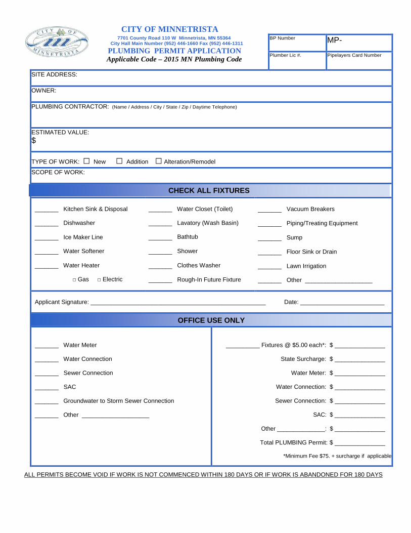
PLUMBING PERMIT APPLICATION Applicable Code – 2015 MN Plumbing Code
BP Number MP-
Plumber Lic #. Pipelayers Card Number
SITE ADDRESS:
OWNER:
PLUMBING CONTRACTOR: (Name / Address / City / State / Zip / Daytime Telephone)
ESTIMATED VALUE: $
TYPE OF WORK: □ New □ Addition □ Alteration/Remodel
SCOPE OF WORK:
_______ Kitchen Sink & Disposal
_______ Dishwasher
_______ Ice Maker Line
_______ Water Softener
_______ Water Heater
□ Gas □ Electric
_______ Water Closet (Toilet)
_______ Lavatory (Wash Basin)
_______ Bathtub
_______ Shower
_______ Clothes Washer
_______ Rough-In Future Fixture
_______ Vacuum Breakers
_______ Piping/Treating Equipment
_______ Sump
_______ Floor Sink or Drain
_______ Lawn Irrigation
_______ Other ____________________
Applicant Signature: ____________________________________________________ Date: _________________________
_______ Water Meter
_______ Water Connection
_______ Sewer Connection
_______ SAC
_______ Groundwater to Storm Sewer Connection
_______ Other ____________________
__________ Fixtures @ $5.00 each*: $ _______________
State Surcharge: $ _______________
Water Meter: $ _______________
Water Connection: $ _______________
Sewer Connection: $ _______________
SAC: $ _______________
Other _______________: $ _______________
Total PLUMBING Permit: $ _______________
*Minimum Fee $75. + surcharge if applicable
ALL PERMITS BECOME VOID IF WORK IS NOT COMMENCED WITHIN 180 DAYS OR IF WORK IS ABANDONED FOR 180 DAYS
CHECK ALL FIXTURES
OFFICE USE ONLY
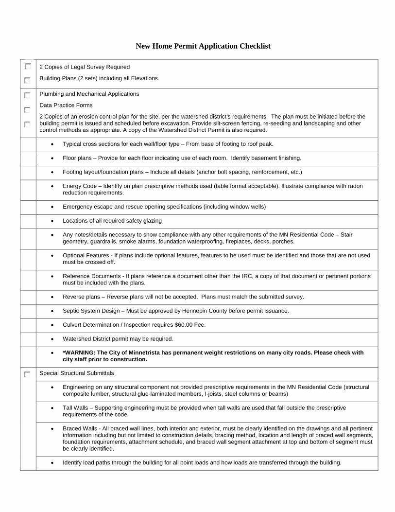
New Home Permit Application Checklist
2 Copies of Legal Survey Required
Building Plans (2 sets) including all Elevations
Plumbing and Mechanical Applications
Data Practice Forms
2 Copies of an erosion control plan for the site, per the watershed district’s requirements. The plan must be initiated before the building permit is issued and scheduled before excavation. Provide silt-screen fencing, re-seeding and landscaping and other control methods as appropriate. A copy of the Watershed District Permit is also required.
• Typical cross sections for each wall/floor type – From base of footing to roof peak.
• Floor plans – Provide for each floor indicating use of each room. Identify basement finishing.
• Footing layout/foundation plans – Include all details (anchor bolt spacing, reinforcement, etc.)
• Energy Code – Identify on plan prescriptive methods used (table format acceptable). Illustrate compliance with radon reduction requirements.
• Emergency escape and rescue opening specifications (including window wells)
• Locations of all required safety glazing
• Any notes/details necessary to show compliance with any other requirements of the MN Residential Code – Stair geometry, guardrails, smoke alarms, foundation waterproofing, fireplaces, decks, porches.
• Optional Features - If plans include optional features, features to be used must be identified and those that are not used must be crossed off.
• Reference Documents - If plans reference a document other than the IRC, a copy of that document or pertinent portions must be included with the plans.
• Reverse plans – Reverse plans will not be accepted. Plans must match the submitted survey.
• Septic System Design – Must be approved by Hennepin County before permit issuance.
• Culvert Determination / Inspection requires $60.00 Fee.
• Watershed District permit may be required.
• *WARNING: The City of Minnetrista has permanent weight restrictions on many city roads. Please check with city staff prior to construction.
Special Structural Submittals
• Engineering on any structural component not provided prescriptive requirements in the MN Residential Code (structural composite lumber, structural glue-laminated members, I-joists, steel columns or beams)
• Tall Walls – Supporting engineering must be provided when tall walls are used that fall outside the prescriptive requirements of the code.
• Braced Walls - All braced wall lines, both interior and exterior, must be clearly identified on the drawings and all pertinent information including but not limited to construction details, bracing method, location and length of braced wall segments, foundation requirements, attachment schedule, and braced wall segment attachment at top and bottom of segment must be clearly identified.
• Identify load paths through the building for all point loads and how loads are transferred through the building.
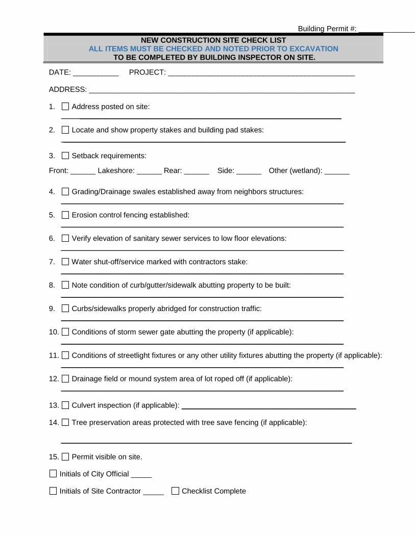
Building Permit #: ______________ NEW CONSTRUCTION SITE CHECK LIST
ALL ITEMS MUST BE CHECKED AND NOTED PRIOR TO EXCAVATION TO BE COMPLETED BY BUILDING INSPECTOR ON SITE.
DATE: ___________ PROJECT: _____________________________________________
ADDRESS: ________________________________________________________________
1. Address posted on site: _______________________________________________________________
2. Locate and show property stakes and building pad stakes:
____________________________________________________________________
3. Setback requirements:
Front: ______ Lakeshore: ______ Rear: ______ Side: ______ Other (wetland): ______
4. Grading/Drainage swales established away from neighbors structures: ____________________________________________________________________
5. Erosion control fencing established:
____________________________________________________________________
6. Verify elevation of sanitary sewer services to low floor elevations: ____________________________________________________________________
7. Water shut-off/service marked with contractors stake:
____________________________________________________________________
8. Note condition of curb/gutter/sidewalk abutting property to be built: ____________________________________________________________________
9. Curbs/sidewalks properly abridged for construction traffic:
____________________________________________________________________
10. Conditions of storm sewer gate abutting the property (if applicable): ____________________________________________________________________
11. Conditions of streetlight fixtures or any other utility fixtures abutting the property (if applicable):
____________________________________________________________________
12. Drainage field or mound system area of lot roped off (if applicable): ____________________________________________________________________
13. Culvert inspection (if applicable): __________________________________________
14. Tree preservation areas protected with tree save fencing (if applicable):
______________________________________________________________________
15. Permit visible on site.
Initials of City Official _____
Initials of Site Contractor _____ Checklist Complete

Ventilation, Makeup and Combustion Air Calculations Submittal Form For New Dwellings
Site address Date
Contractor Completed By
Section A Ventilation Quantity Equation R403.5.2
Square feet (Conditioned area including basement – finished or unfinished)
Number of bedrooms
Total required ventilation Continuous ventilation
Directions ‐ Determine the total and continuous ventilation rate by either using Table R403.5.2 or equation R403.5.2. The table and equation are below.
Table R403.5.2 Total and Continuous Ventilation Rates (in cfm)
Number of Bedrooms 1 2 3 4 5 6 Conditioned space (in sq. ft.)
Total/ continuous
Total/ continuous
Total/ continuous
Total/ continuous
Total/ continuous
Total/ continuous
1000‐1500 60/40 75/40 90/45 105/53 120/60 135/68 1501‐2000 70/40 85/43 100/50 115/58 130/65 145/73 2001‐2500 80/40 95/48 110/55 125/63 140/70 155/78 2501‐3000 90/45 105/53 120/60 135/68 150/75 165/83 3001‐3500 100/50 115/58 130/65 145/73 160/80 175/88 3501‐4000 110/55 125/63 140/70 155/78 170/85 185/93 4001‐4500 120/60 135/68 150/75 165/83 180/90 195/98 4501‐5000 130/65 145/73 160/80 175/88 190/95 205/103 5001‐5500 140/70 155/78 170/85 185/93 200/100 215/108 5501‐6000 150/75 165/83 180/90 195/98 210/105 225/113
Equation R403.5.2 (0.02 x square feet of conditioned space) + [15 x (number of bedrooms + 1)] = Total ventilation rate (cfm)
Total ventilation – The mechanical ventilation system shall provide sufficient outdoor air to equal the total ventilation rate average, for each one‐hour period according to the above table or equation. For heat recovery ventilators (HRV) and energy recovery ventila‐ tors (ERV) the average hourly ventilation capacity must be determined in consideration of any reduction of exhaust or out outdoor air intake, or both, for defrost or other equipment cycling.
Continuous ventilation ‐ A minimum of 50 percent of the total ventilation rate, but not less than 40 cfm, shall be provided, on a continuous rate average for each one‐hour period. The portion of the mechanical ventilation system intended to be continuous may have automatic cycling controls providing the average flow rate for each hour is met.

Section B
Ventilation Method (Choose either balanced or exhaust)
Balanced, HRV (Heat Recovery Ventilator) or ERV (Energy Exhaust only (Continuous fan rating in cfm) Recov‐ ery Ventilator) – cfm of unit in low must not exceed continuous venti‐ lation rating by more than 100%.
Low cfm: High cfm: Continuous fan rating in cfm (capacity must not exceed continuous ventilation rating by more than 100%)
Directions ‐ Choose the method of ventilation, balanced or exhaust only. Balanced ventilation systems are typically HRV or ERV’s. Enter the low and high cfm amounts. Low cfm air flow must be equal to or greater than the required continuous ventilation rate and less than 100% greater than the continuous rate. (For instance, if the low cfm is 40 cfm, the ventilation fan must not exceed 80 cfm.) Automatic controls may allow the use of a larger fan that is operated a percentage of each hour.
Section C
Ventilation Fan Description Location Continuous Intermittent
Directions ‐ The ventilation fan schedule should describe what the fan is for, the location, cfm, and whether it is used for continuous or intermittent ventilation. The fan that is chose for continuous ventilation must be equal to or greater than the low cfm air rating and less than 100% greater than the continuous rate. (For instance, if the low cfm is 40 cfm, the continuous ventilation fan must not exceed 80 cfm.) Automatic controls may allow the use of a larger fan that is operated a percentage of each hour.
Section D Ventilation Controls
Directions ‐ Describe operation and control of the continuous and intermittent ventilation. There should be adequate detail for plan reviewers and inspectors to verify design and installation compliance. Related trades also need adequate detail for placement of controls and proper operation of the building ventilation. If exhaust fans are used for building ventilation, describe the operation and location of any controls, indicators and legends. If an ERV or HRV is to be installed, describe how it will be installed. If it will be connected and interfaced with the air handling equipment, please describe such connections as detailed in the manufactures’ installation instructions. If the installation instructions require or recommend the equipment to be interlocked with the air handling equipment for proper operation, such interconnection shall be made and described.

Section E Make‐up air- See Table 501.4.1
Passive
Powered
Interlocked with exhaust device
Other, describe:
Location of duct or system ventilation make‐up air: Determined from make‐up air opening table
Cfm Size and type (round, rectangular, flex or rigid)
Directions ‐ In order to determine the makeup air, Table 501.4.1 must be filled out (see below). For most new installations, column A will be appropriate, however, if atmospherically vented appliances or solid fuel appliances are installed, use the appropriate column.
Table 501.4.1
PROCEDURE TO DETERMINE MAKEUP AIR QUANITY FOR EXHAUST EQUIPMENT IN DWELLINGS (Additional combustion air will be required for combustion appliances, see KAIR method for calculations)
One or multiple power vent or direct vent appliances or no combustion appliances
Column A
One or multiple fan‐ assisted appliances and power vent or direct vent appliances
Column B
One atmospherically vent gas or oil appliance or one solid fuel appliance
Column C
Multiple atmospherically vented gas or oil appliances or solid fuel appliances
Column D 1. a) pressure factor (cfm/sf) 0.15 0.09 0.06 0.03 b) conditioned floor area (sf) (including unfinished basements)
Estimated House Infiltration (cfm): [1a x 1b]
2. Exhaust Capacity a) continuous exhaust‐only ventilation system (cfm); (not applicable to balanced ventilation systems such as HRV)
b) clothes dryer (cfm) 135 135 135 135 c) 80% of largest exhaust rating (cfm); Kitchen hood typically (not applicable if recirculating system or if powered makeup air is electrically interlocked and match to exhaust)
d) 80% of next largest exhaust rating (cfm); bath fan typically (not applicable if recirculating system or if powered makeup air is electrically interlocked and matched to exhaust)
Total Exhaust Capacity (cfm); [2a + 2b +2c + 2d]
3. Makeup Air Quantity (cfm) a) total exhaust capacity (from above)
b) estimated house infiltration (from above)
Makeup Air Quantity (cfm); [3a – 3b] (if value is negative, no makeup air is needed)
4. For makeup Air Opening Sizing, refer to Table 501.4.2
□ Use this column if there are other than fan‐assisted or atmospherically vented gas or oil appliance or if there are no combustion appliances. (Power vent and direct vent appliances may be used.) □ Use this column if there is one fan‐assisted appliance per venting system. (Appliances other than atmospherically vented appliances may be included.) □ Use this column if there is one atmospherically vented (other than fan‐assisted) gas or oil appliance per venting system or one solid fuel appliance. □ Use this column if there are multiple atmospherically vented gas or oil appliances using a common vent or if there are atmospherically vented gas or oil appliances and solid fuel appliances.
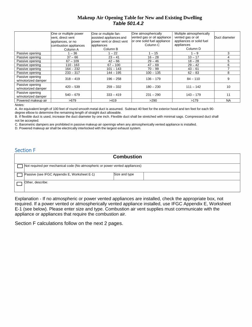
Makeup Air Opening Table for New and Existing Dwelling Table 501.4.2
One or multiple power
vent, direct vent appliances, or no combustion appliances
Column A
One or multiple fan‐ assisted appliances and power vent or direct vent appliances
Column B
One atmospherically vented gas or oil appliance or one solid fuel appliance
Column C
Multiple atmospherically vented gas or oil appliances or solid fuel appliances
Column D
Duct diameter
Passive opening 1 – 36 1 – 22 1 – 15 1 – 9 3 Passive opening 37 – 66 23 – 41 16 – 28 10 – 17 4 Passive opening 67 – 109 42 – 66 29 – 46 18 – 28 5 Passive opening 110 ‐ 163 67 – 100 47 – 69 29 – 42 6 Passive opening 164 – 232 101 – 143 70 – 99 43 – 61 7 Passive opening 233 – 317 144 – 195 100 – 135 62 – 83 8 Passive opening w/motorized damper 318 – 419 196 – 258 136 – 179 84 – 110 9
Passive opening w/motorized damper 420 – 539 259 – 332 180 – 230 111 – 142 10
Passive opening w/motorized damper 540 – 679 333 – 419 231 – 290 143 – 179 11
Powered makeup air >679 >419 >290 >179 NA Notes: A. An equivalent length of 100 feet of round smooth metal duct is assumed. Subtract 40 feet for the exterior hood and ten feet for each 90‐ degree elbow to determine the remaining length of straight duct allowable. B. If flexible duct is used, increase the duct diameter by one inch. Flexible duct shall be stretched with minimal sags. Compressed duct shall not be accepted. C. Barometric dampers are prohibited in passive makeup air openings when any atmospherically vented appliance is installed. D. Powered makeup air shall be electrically interlocked with the largest exhaust system.
Section F Combustion
Not required per mechanical code (No atmospheric or power vented appliances)
Passive (see IFGC Appendix E, Worksheet E‐1) Size and type
Other, describe:
Explanation ‐ If no atmospheric or power vented appliances are installed, check the appropriate box, not required. If a power vented or atmospherically vented appliance installed, use IFGC Appendix E, Worksheet E‐1 (see below). Please enter size and type. Combustion air vent supplies must communicate with the appliance or appliances that require the combustion air.
Section F calculations follow on the next 2 pages.

Directions ‐ The Minnesota Fuel Gas Code method to calculate to size of a required combustion air opening, is called the Known Air Infiltration Rate Method. For new construction, 4b of step 4 is required to be filled out.
IFGC Appendix E, Worksheet E‐1--Residential Combustion Air Calculation Method (for Furnace, Boiler, and/or Water Heater in the Same Space) Step 1: Complete vented combustion appliance information.
Furnace/Boiler:
Draft Hood Fan Assisted Direct Vent Input: Btu/hr or Power Vent
Water Heater:
Draft Hood Fan Assisted Direct Vent Input: Btu/hr or Power Vent
Step 2: Calculate the volume of the Combustion Appliance Space (CAS) containing combustion appliances. The CAS includes all spaces connected to one another by code compliant openings.
CAS volume: ft3 L x W x H L W H
Step 3: Determine Air Changes per Hour (ACH)1 Default ACH values have been incorporated into Table E‐1 for use with Method 4b (KAIR Method). If the year of construction or ACH is not known, use method 4a (Standard Method).
Step 4: Determine Required Volume for Combustion Air. (DO NOT COUNT DIRECT VENT APPLIANCES)
4a. Standard Method Total Btu/hr input of all combustion appliances Input: Btu/hr
Use Standard Method column in Table E‐1 to find Total Required TRV: ft3
Volume (TRV) If CAS Volume (from Step 2) is greater than TRV then no outdoor openings are needed. If CAS Volume (from Step 2) is less than TRV then go to STEP 5. 4b. Known Air Infiltration Rate (KAIR) Method (DO NOT COUNT DIRECT VENT APPLIANCES)
Total Btu/hr input of all fan‐assisted and power vent appliances Input: Btu/hr
Use Fan‐Assisted Appliances column in Table E‐1 to find RVFA: ft3
Required Volume Fan Assisted (RVFA)
Total Btu/hr input of all Natural draft appliances Input: Btu/hr
Use Natural draft Appliances column in Table E‐1 to find RVNFA: ft3
Required Volume Natural draft appliances (RVNDA)
Total Required Volume (TRV) = RVFA + RVNDA TRV = + = TRV ft3
If CAS Volume (from Step 2) is greater than TRV then no outdoor openings are needed. If CAS Volume (from Step 2) is less than TRV then go to STEP 5.
Step 5: Calculate the ratio of available interior volume to the total required volume. Ratio = CAS Volume (from Step 2) divided by TRV (from Step 4a or Step 4b)
Ratio = / =
Step 6: Calculate Reduction Factor (RF). RF = 1 minus Ratio
RF = 1 ‐ =
Step 7: Calculate single outdoor opening as if all combustion air is from outside. Total Btu/hr input of all Combustion Appliances in the same CAS
Input: Btu/hr (EXCEPT DIRECT VENT)
Combustion Air Opening Area (CAOA): Total Btu/hr divided by 3000 Btu/hr per in2
CAOA = / 3000 Btu/hr per in2 = in2
Step 8: Calculate Minimum CAOA: Minimum CAOA = CAOA multiplied by RF
Minimum CAOA = x = in2
Step 9: Calculate Combustion Air Opening Diameter (CAOD): CAOD = 1.13 multiplied by the square root of Minimum CAOA
CAOD = 1.13 √ Minimum CAOA = in. diameter go up one inch in size if using flex duct
1 If desired, ACH can be determined using ASHRAE calculation or blower door test. Follow procedures in Section G304.

IFGC Appendix E, Table E‐1 Residential Combustion air (Required Interior Volume Based on Input Rating of Appliance)
Input Rating (Btu/hr)
Standard Method Known Air Infiltration Rate (KAIR) Method (cu ft)
Fan Assisted or Power Vent Natural Draft 1994 to present Pre‐1994 1994 to present Pre‐1994
5,000 250 375 188 525 263 10,000 500 750 375 1,050 525 15,000 750 1,125 563 1,575 788 20,000 1,000 1,500 750 2,100 1,050 25,000 1,250 1,875 938 2,625 1,313 30,000 1,500 2,250 1,125 3,150 1,575 35,000 1,750 2,625 1,313 3,675 1,838 40,000 2,000 3,000 1,500 4,200 2,100 45,000 2,250 3,375 1,688 4,725 2,363 50,000 2,500 3,750 1,675 5,250 2,625 55,000 2,750 4,125 2,063 5,775 2,888 60,000 3,000 4,500 2,250 6,300 3,150 65,000 3,250 4,875 2,438 6,825 3,413 70,000 3,500 5,250 2,625 7,350 3,675 75,000 3,750 5,625 2,813 7,875 3,938 80,000 4,000 6,000 3,000 8,400 4,200 85,000 4,250 6,375 3,188 8,925 4,463 90,000 4,500 6,750 3,375 9,450 4,725 95,000 4,750 7,125 3,563 9,975 4,988 100,000 5,000 7,500 3,750 10,500 5,250 105,000 5,250 7,875 3,938 11,025 5,513 110,000 5,500 8,250 4,125 11,550 5,775 115,000 5,750 8.625 4,313 12,075 6,038 120,000 6,000 9,000 4,500 12,600 6,300 125,000 6,250 9,375 4,688 13,125 6,563 130,000 6,500 9,750 4,875 13,650 6,825 135,000 6,750 10,125 5,063 14,175 7,088 140,000 7,000 10,500 5,250 14,700 7,350 145,000 7,250 10,875 5,438 15,225 7,613 150,000 7,500 11,250 5,625 15,750 7,875 155,000 7,750 11,625 5,813 16,275 8,138 160,000 8,000 12,000 6,000 16,800 8,400 165,000 8,250 12,375 6,188 17,325 8,663 170,000 8,500 12,750 6,375 17,850 8,925 175,000 8,750 13,125 6,563 18,375 9,188 180,000 9,000 13,500 6,750 18,900 9,450 185,000 9,250 13,875 6,938 19,425 9,713 190,000 9,500 14,250 7,125 19,950 9,975 195,000 9,750 14,625 7,313 20,475 10,238 200,000 10,000 15,000 7,500 21,000 10,500 205,000 10,250 15,375 7,688 21,525 10,783 210,000 10,500 15,750 7,875 22,050 11,025 215,000 10,750 16,125 8,063 22,575 11,288 220,000 11,000 16,500 8,250 23,100 11,550 225,000 11,250 16,875 8,438 23,625 11,813 230,000 11,500 17,250 8,625 24,150 12,075
1. The 1994 date refers to dwellings constructed under the 1994 Minnesota Energy Code. The default KAIR used in this section of the table is 0.20 ACH.
2. This section of the table is to be used for dwellings constructed prior to 1994. The default KAIR used in this section of the table is 0.40 ACH.

CITY OF MINNETRISTA BUILDING PERMIT/PLANS
DATA PRACTICES ADVISORY
You may be required to submit building plans with your building permit application so that the City of Minnetrista can determine whether or not your building permit application should be approved. If you do not submit plans when they are required, your building permit will not be approve. The Minnesota Government Data Practices Act establishes a presumption that all government data are public and are accessible by the public for both inspection and copying unless there is a federal law, a state statute, or a temporary classification of data that provides that certain data are not public. Minnesota Statutes Section 13.01 defines government data as being all data collected, created, received, maintained, or disseminated by the City. The Government Data Practices Act allows building plans to be classified as non-public ONLY if they contain the following information:
Security information defined by Minnesota Statutes Section 13.37, subdivision 1(a) as being “government data that disclosure of which would be likely to substantially jeopardize the security of information, possessions, individuals or property against theft, tampering, improper use, attempted escape, illegal disclosure, trespass, or physical injury.” OR Trade secret information defined by Minnesota Statutes Section 13.37, subdivision 1(b) as being “government data, including a formula, pattern, compilation, program, device, method, technique or process (1) that was supplied by the affected individual or organization, (2) that is the subject of efforts by the individual or organization that are reasonable under the circumstances to maintain its secrecy, and (3) that derives independent economic value, actual or potential, from not being generally known to, and not being readily ascertainable by proper means by, other persons who can obtain economic value from its disclosure or use.”
Building plans submitted to the City are generally public information and will be presumed to be available for copying and release to the public. If you hold a copyright to the plans and do not want them copied for the public, then you will need to indicate as such below. Also, if you believe that your building plans qualify for the classification of nonpublic data you must provide documentation verifying your claim. The Responsible Authority for the City of Minnetrista will determine whether or not the plans qualify for nonpublic data classification within 10 business days of the request. Building plans and related documents submitted to the City are presumed to be public and by submitting them and signing this document you are expressly giving permission to the City to make copies to the City’s use and to make available to the public upon request unless you indicate otherwise as follows: _____ The building plans I have submitted contain SECURITY INFORMATION as defined by Minnesota
Statutes Section 13.37, subdivision 1(a) and are to be treated as protected data. I understand I must provide an explanation (below) to support my claim that the information I am providing constitutes security information under law.
_____ The building plans I have submitted contain TRADE SECRET INFORMATION as defined by Minnesota
Statutes Section 13.37, subdivision 1(b) and are to be treated as protected nonpublic data. I understand I must provide an explanation (below) to support my claim that the information I am providing constitutes trade secret information under law.
_____ The building plans I have submitted are COPYRIGHTED under and protected by the Federal Copyright
Act and I do not give permission for them to be copied for release to the public. However, I understand the plans are considered public information under Minnesota law and may be viewed by the public.

Explanation: _________________________________________________________________________________________________________________________________________________________________________________________________________________________________________________________________________________________________________________________________________________________________________________________________________________________________________
____________________________________ __________________________________ Copyright Holder’s Name Copyright Holder’s Phone Number ____________________________________ __________________________________ Copyright Holder’s Address Copyright Holder’s Email Address ____________________________________ __________________________________ Name of Applicant (Please Print) Date ____________________________________ __________________________________ Signature of Applicant Property Address FOR STAFF USE ONLY _____ Meets Minnesota Statute and is classified as non-public information _____ DOES NOT meet Minnesota Statute and is classified as PUBLIC information ________________________________________ ____________________ Responsible Authority for the City of Minnetrista Date
BUILDING INSPECTION DEPARTMENT SURVEY REQUIREMENTS FOR NEW HOMES 1. All surveys shall be certified by a Minnesota registered surveyor, and shall include the following items:
o Benchmarks o Lot Lines o Actual Elevations for Garage Floor, Basement Floor, and Foundation Top o Lowest Floor Elevation o Floodplain, Floodway Delineations, Ordinary High Water Level, Wetlands, Wetland Buffers,
Watercourses, Reservoirs, Ponds, and other bodies of water o Existing and Proposed topographic character of land showing contours at 2-foot intervals o Hardcover Calculations - percentage and square footage of structures, driveway and parking areas,
retaining walls, etc. o Wells and neighboring wells if new drain field is installed o Septic System and Drain Field or sanitary sewer connection o All significant trees if project is located in a subdivision with a tree preservation plan o Percolation Test and Soil Boring Holes o All Easements (Roadway, Utility, Conservation, etc) o Scale and North Arrow o Street Names o PID Number and Site Address o Legal Description o Parcel Size in Acres and Square Feet o Zoning Classification o Existing and proposed elevations for lot corners and side yard lot lines, spot elevations in yard o Adjacent lots labeled Vacant or spot elevations at the corners of an existing house labeled as “Existing
Home/House” o Sidewalk locations and elevations if existing. Show location and label as proposed sidewalk if a sidewalk
is yet to be constructed o Rim elevations on catch basins o Driveway location and grade o Include utility boxes/peds if in close proximity to lot o Water Service location, also MH's, CB’s, Hyd’s if close to lot o If retaining wall is on property, include top and bottom wall elevations. Retaining walls 4' and higher
require plans to be submitted by a licensed structural engineer. o Signature of Surveyor and Date of Preparation
2. A certified land survey shall indicate that permanent iron monuments are in place at each lot corner. 3. Offset stakes shall also be placed on each side lot a distance from the front lot line equivalent to the building
setback line. In the event the distance of the side line is greater than 30 feet, stakes shall be placed on the front building line a distance not to exceed 30 feet from the building side lines.
4. All proposed buildings with dimensions of each building and reference dimensions measured perpendicular
from the front, side and rear lot lines to the nearest point of each building.
5. Except for written authorization from the planning department, surveys shall establish the top of foundation and garage floor of all structures to be a minimum of 18 inches above the crown of the street.
6. The location of all proposed decks, porches, driveways, curb cuts and other accessory structures need to be indicated on the survey.

7. Indicate with arrows the direction of proposed surface drainage. 8. For property adjacent to lakes, ponds, streams or flowages, indicate the established high water elevation as
approved by the City Engineer. The lowest floor must be a minimum of 3 feet above the highest known water level or not less than 1 foot above the 100-year high water level. In addition, all lowest floors must be a minimum of 3 feet above the highest known water table elevation.
9. Survey elevations, drainage and house design must match approved grading development plan. 10. Location of drain tile stubs with invert elevation.
11. Maximum driveway slope is 10% above grade (minimum is 2 percent).
12. A Foundation As-Built Survey must be submitted and approved prior to approval to back-fill the foundation. You must submit this to the City of Minnetrista prior to approval to back-fill!
13. A Final, As-Built Grading Survey must be submitted and approved prior to a Certificate of Occupancy being granted for a new home.
14. Please call (952) 446-1660 to schedule a curb stop inspection after the final grade is complete to verify that the
curb stop is at grade and operational.

Information from
The Minnehaha Creek Watershed District
MCWD Rule Requirements and Permit Applicability See www.minnhahacreek.org/permits.php or contact
Steve Christopher at (952) 641-4506 for more information
Through the application process with area cities and townships, MCWD permitting requirements and information should be provided by cities for projects that fall within the boundary of the MCWD. The following is a summary of MCWD rules where permits are currently required. These rules are subject to changes and updates periodically. Erosion Control
Grading of 5,000 square feet or more. Stockpiling or excavation of more than 50 cubic yards of material. Grading and excavating must not begin until a permit has been issued and required
erosion control measures are in place.
Flood plain Alteration Any activity that proposes to place fill of any type in a flood plain associated with a lake, river, stream,
wetland or any other water basin Wetland Protection All projects associated with the draining, filling, or excavation of a wetland.
Dredging
All dredging in the beds, tanks, or shores of any protected water or wetland. Shoreline and Streambank Improvement
All shoreline and stream bank improvements, including but not limited to rip rap, retaining walls, sheet piling and boat ramps. All sand blanket projects.
Stream and Lake Crossings
Placement of roads, highways, or utilities in the bed of a protected water or wetland. Construction of a bridge or related crossing of a water, waterway or wetland. Placement of a culvert or similar structure in the bed or channel of a protected water or wetland.
Stormwater Management
All residential, commercial, institutional, industrial or public land development projects that will increase the area of impervious surface or change land contours to alter the drainage ways, increase peak runoff rates, or affect the quality of storm water flows. Single family homes, additions of garages, decks, etc. are exempt from this rule, but may require a
permit under one of the other rules. Wetland Protection
Wetlands located on a lot must be buffered in accordance with the Minnehaha Creek Watershed District Rules

PLEASE POST AT WORK SITE
CITY OF MINNETRISTA COUNTY OF HENNEPIN STATE OF MINNESOTA
SECTION 1005 – NOISE
1005.01. Noise Prohibited.
It is unlawful to make or cause to be made any noise that unreasonably annoys, injures or endangers the comfort, repose, health, peace, safety, or welfare of others or precludes their enjoyment of property or adversely affects the value of the property. 1005.03. Noise Regulations.
Operation of earth moving or related construction equipment for which a building permit, grading permit or other city approval has been obtained, may occur Monday through Friday between 7:00 a.m. and 7:00 p.m., Saturday between 8:00 a.m. and 6:00 p.m., with no activity on Sunday or holiday unless otherwise approved by the City Council. 1005.05. Enforcement.
Subdivision 1. Authorization. This section may be enforced by a licensed peace officer or a code enforcement officer designated by the city in accordance with section 115.09.
Subdivison 4. Penalty. Any person violating the provisions of this section will be guilty of a
misdemeanor and upon conviction must be punished in accordance with the provisions in section 609.03 of Minnesota Statutes.

WARNING!!
Your project is extremely close to a setback. The City of Minnetrista has a zero tolerance policy for builders that build within the setbacks.
You will be required to provide a foundation as-built survey to prove you placed the project in the correct location before you can receive your backfill inspection.

Date Certificate Posted
Mailing Address of the Dwelling or Dwelling Unit City
Name of Residential Contractor MN License Number
THERMAL ENVELOPE RADON SYSTEM Insulation Location
Tota
l R-V
alue
of a
ll Ty
pes o
f In
sula
tion
Type: Check All That Apply Passive (No Fan )
Non
or N
ot A
pplic
able
Fibe
rgla
ss, B
low
n Fi
berg
lass
, Bat
ts Fo
am, C
lose
d C
ell
Foam
Ope
n C
ell
Min
eral
Fib
erbo
ard
Rig
id, E
xtru
ded
Poly
styre
ne
Rig
id, I
socy
nura
te
Active (With fan and monometer or other system monitoring device )
Other Please Describe Here
Below Entire Slab Foundation Wall Type in location: interior exterior or integral Perimeter of Slab on Grade Rim Joist (Foundation) Type in location: interior exterior or integral Rim Joist (1st Floor+) Type in location: interior exterior or integral Wall Ceiling, flat Ceiling, vaulted Bay Windows or cantilevered areas Bonus room over garage Describe other insulated areas
Windows & Doors Heating or Cooling Ducts Outside Conditioned Spaces Average U-Factor (excludes skylights and one door ) U: Not applicable, all ducts located in conditioned space Solar Heat Gain Coefficient (SHGC): R-value MECHANICAL SYSTEMS Make-up Air Select a Type Appliances
Heating System
Domestic Water Heater
Cooling System
Not required per mech. code
Fuel Type
Passive
Manufacturer Powered
Model Interlocked with exhaust device.
Describe: Rating or Size
Input in BTUS: Capacity in
Gallons: Output in Tons: Other, describe:
Structure's Calculated
Heat Loss: Heat Gain: Location of duct or system:
Efficiency
AFUE or HSPF% SEER:
Calculated cooling load:
Cfm's " round duct OR Mechanical Ventilation System
Describe any additional or combined heating or cooling systems if installed: (e.g. two furnaces or air
source heat pump with gas back-up furnace): Select Type
" metal duct Combustion Air Select a Type Not required per mech. code Passive
Heat Recover Ventilator (HRV) Capacity in cfms: Low: High: Other, describe: Energy Recover Ventilator (ERV) Capacity in cfms: Low: High: Location of duct or system: Continuous exhausting fan(s) rated capacity in cfms:
Location of fan(s), describe: Cfm's Capacity continuous ventilation rate in cfms: " round duct OR Total ventilation (intermittent + continuous) rate in cfms: " metal duct
New Construction Energy Code Compliance Certificate Per N1101.8 Building Certificate. A building certificate shall be posted in a permanently visible location inside the building. The certificate shall be completed by the builder and shall list information and values of components listed in Table N1101.8.
Created by BAM version 052009

Silt Fence Installatio
Erosion and Sediment Control Measures Silt Fence Silt Fence is a sediment control structure, made of geotextile fabric, that restricts the movement of disturbed soil. • Install before upslope excavation or grading begins. • Place along the contour of the land and at least five feet from the base of the slope. • Cut a trench six (6) inches deep and bury the bottom eight (8) inches of the fabric.
Mulch Areas of exposed soils that will not be worked for 14 days must be covered. Mulch provides immediate protection to exposed soils during periods of short construction delays, steep slopes, or over winter months through the application of plant residues and other suitable materials.
Mulch Material Quality Standards Application Rates
Construction Entrance A construction entrance is a graveled area located where vehicles enter and leave a land disturbance site. Construction entrances provide an area where mud can be removed from vehicle tires before entering a public road. The motion of the vehicle as it moves over the gravel construction material dislodges the caked mud. • Construct the drive at least ten (10) feet wide and at least twenty (20) feet long.
• Stretch the fabric tight, placing the support stakes on the downslope side every five (5) feet apart. • Backfill the trench and compact the soil. • All soil stockpiles must have silt fence placed around them to prevent soil erosion. • Inspect once a week and after each storm event.
5’ Max
36” wide geotextile fabric with 8”-12” of
Straw Wood Fiber Cellulose
Compost Chipped Site Vegetation
Air Dried; Free from undesirable seed and coarse material
No growth inhibiting factors
No visible water or dust during handling. Must be purchased from supplier with Solid Waste Handling Permit
Average size shall be several inches
2”-3” thick, 2-3 bales per 1000 SF or 2-3 tons per acre
Approx. 25-30 lbs. per 1000 SF or 1000-1500 lbs. per acre
2” thick min.; approx. 100 tons per acre (approx. 800 lbs. per yard) 2” minimum thickness
• Place two (2) to four (4) inch stone over a geotextile fabric on a stable subgrade. A geotextile fabric is placed beneath the rock to prevent sediments from migrating through the rock pad. • Add stone as needed to maintain six (6) inches of clean depth. • A pipe or culvert should be constructed under the entrance (if needed) to prevent surface water flowing across the entrance. • Immediately clean up tracking in the street with a broom or shovel. DO NOT use water to clean pavement.
fabric underground Mulching Standards
Attach to posts with 3 zip ties per post within top 8” of fabric
5’ max. spacing between
5’ from base of slope
24” min post
Plastic Plastic sheeting may be used to cover exposed slopes that require immediate protection from erosion. Stock- piled soil that will not be used within 24 hours should
25’
10’
posts
n
Temporary Seeding
embedment also be covered. Construction Entrance
6” deep 2”-4” rock underlain over geotextile fabric Optional pipe or culvert
Temporary seeding is an erosion control practice that is needed on all bare areas to provide protection against soil movement. It is not intended to be a permanent lawn seeding, but rather a temporary erosion control practice. • Seeding must to be completed within seven (7) days on areas that are not planned to be disturbed within 14 days. • All soil stock piles must be temporarily seeded. • Apply as early in the day as possible, but no later than the end of the day, to benefit from moisture still in the surface layer. • Protect with straw mulch at the rate of 500 lbs. per 1/4 acre.
Toe in sheeting in 4” min. trench Tires, sandbags, or equivalent may be used to weight plastic Seams between sheets must overlap a min. of 12” and be weighted or taped
Plastic Cover Installation
10’ Max
Washout Location Concrete truck washout location must be designated and placed within areas where the wash water will not impact any wetlands, ponds, creeks, lakes or stormwater facilities. Other approved Best Management Practices (BMP’s) may include using storm inlet protection, erosion control blankets, biologs, riprap, seeding, sodding, or vegetative filter buffers.

Inside this brochure you’ll find some
examples of Best Management Practices
(BMPs) that should be included in your ESC
Plan. These BMPs should be illustrated on
your plan, and the specifications included in
this brochure should be attached as well. In
Control measures, care should be taken to
handle postconstruction stormwater runoff.
Additional Information - NPDES (Storm Water) Permits Minnesota Pollution Control Agency www.pcs.state.mn.us\water\stormwater-c.html - Emergency Spill Response Minnesota Pollution Control Agency 1.800.422.0798
Erosion & Sediment Control Measures
For Lots Less Than One Acre


