new trends in accelerators development - plastep: · pdf filenew trends in accelerators...
TRANSCRIPT

Consultants’ Meeting on “Networking of Users of EB facilities and the Role of the IAEA
Collaborating Centres”
New trends in accelerators development
Zbigniew ZIMEK, INCT, Warsaw, Poland
8 to 12 April 2013 Institute of Nuclear Chemistry and Technology (INCT),
Warsaw, Poland

Methods of charged particles acceleration were originated over 80 years ago. Those early concepts have evolved into sophisticated accelerator technologies, which have many practical applications outside the field of nuclear physics.
Radiation processing of materials and commercial products are the best examples of such activity. Some of the emerging applications, like reduction of environmental pollution, offer the prospects of significant progress in future.
INTRODUCTION
Zbigniew ZIMEK, INCT, Warsaw, Poland 3
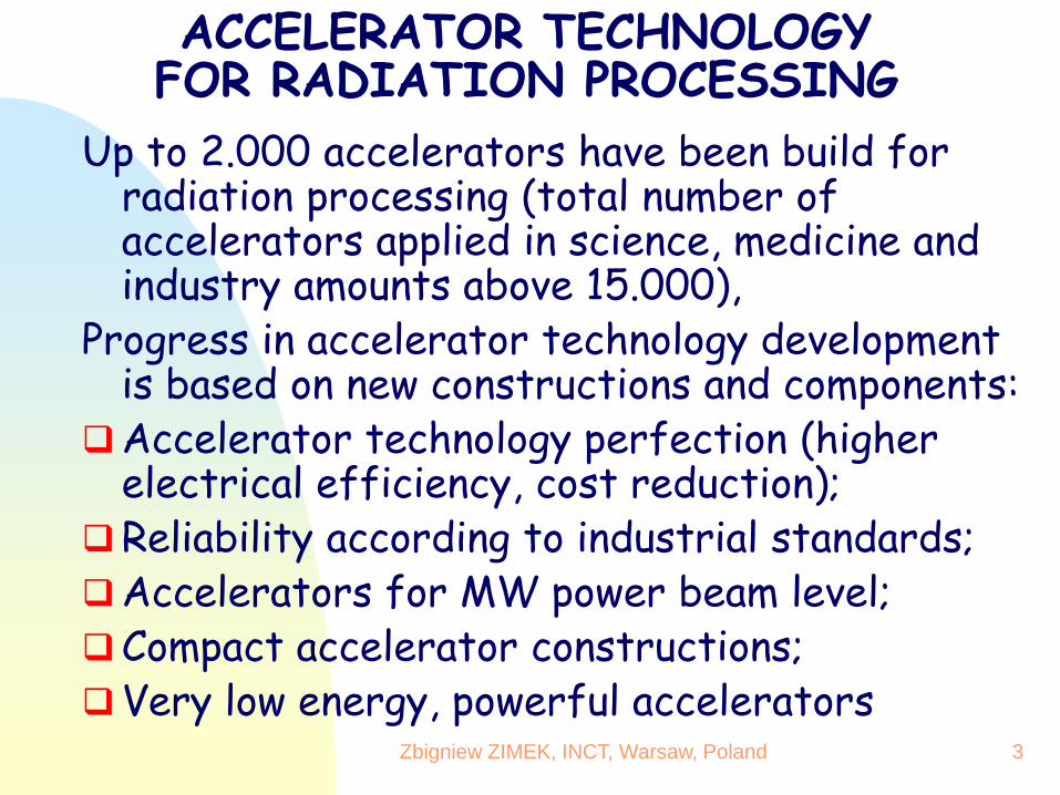
ACCELERATOR TECHNOLOGY FOR RADIATION PROCESSING
Up to 2.000 accelerators have been build for radiation processing (total number of accelerators applied in science, medicine and industry amounts above 15.000),
Progress in accelerator technology development is based on new constructions and components:
Accelerator technology perfection (higher electrical efficiency, cost reduction);
Reliability according to industrial standards; Accelerators for MW power beam level; Compact accelerator constructions; Very low energy, powerful accelerators

Electron beam & X-ray irradiators
System sold/yr
Sales/yr ($M)
System price ($M)
~2000 75 130 0.2 – 8.0
Electron beam and X-ray facilities (2007)
Robert W. Hamm, R&M Technical Enterprises, Inc.

Criterions of accelerators selection Criterion of selection Remarks
Fundamental accelerator
parameters Electron energy
Average beam power
The basic requirements which
define technological abilities and
facility productivity
Terms of accelerator purchase: Price
Producer
Terms of delivery and installation
Warranty conditions
Exploitation cost
Economical aspects of accelerator
purchase which define investment
and exploitation costs; period of
time needed for facility
completion
Auxiliary accelerator parameters Scan performances
Auxiliary parameters
Measure and control
Main components and systems
Accelerator external supply service
Auxiliary parameters which may
characterize accelerator quality
and provide necessary data for
facility design
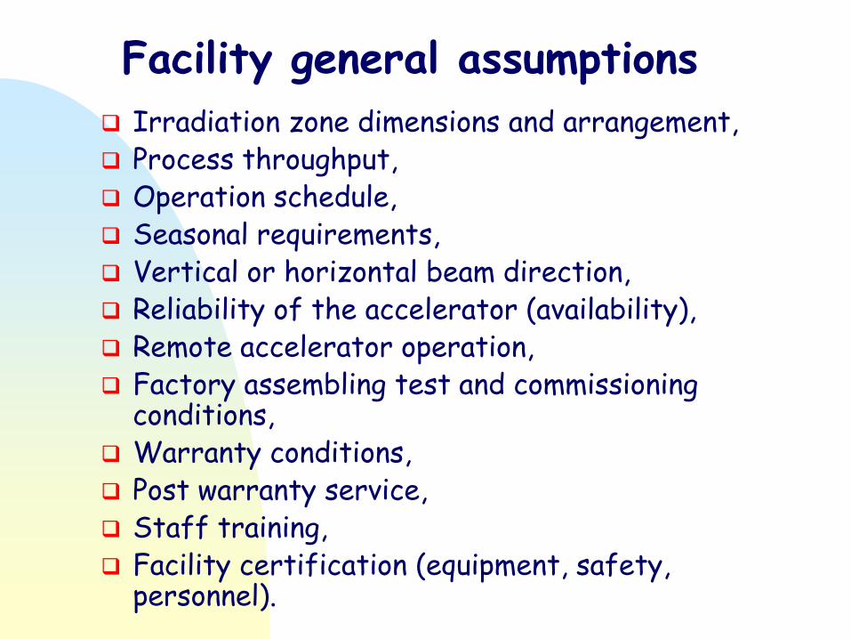
Facility general assumptions
Irradiation zone dimensions and arrangement, Process throughput, Operation schedule, Seasonal requirements, Vertical or horizontal beam direction, Reliability of the accelerator (availability), Remote accelerator operation, Factory assembling test and commissioning
conditions, Warranty conditions, Post warranty service, Staff training, Facility certification (equipment, safety,
personnel).

Low energy beams
Energy Sciences, Inc. (USA) IBA (Belgium) Electron Crosslinking AB (Sweden) Advanced Electron Beams (USA) Wasik Associates (USA) Nissin High Voltage Corp. (Japan) PCT Prod. & Mfg., LLC, formerly RPC Industries (USA) NIIEFA, St Petrsburg, (Russia)

High energy beams
IBA (Belgium), which owns RDI in the USA Nissin High Voltage Corporation (Japan) Denki Kogyo Co, Ltd. (Japan) IHI Corporation (Japan) Vivirad (France) Mevex (Canada) L-3 Communications Pulsed Sciences Division (USA) Budker Institute of Nuclear Physics – BINP, (Russia) EB TECH Co., Ltd. (Korea) – BINP collaboration NIIEFA, St Petrsburg, (Russia) CoRAD, St Petersburg, (Russia) Center for Advanced Technology (India) – BINP collaboration

100 to 300 keV — Single gap, self-shielded sheet beam DC systems without beam scanning. Beam currents from 10 to 2000 mA; treat 1 to 3 m wide material. Used for curing thin film coatings and cross-linking laminates and single strand wire. 300 to 1000 keV — Larger DC systems with scanned beams and self-shielding. Beam currents from 25 to 250 mA; treat 0.5 to 2 meter wide material. Mainly used for cross-linking, curing and polymerization processes in the tire, rubber and plastics industry.
Short description of accelerators for radiation processing
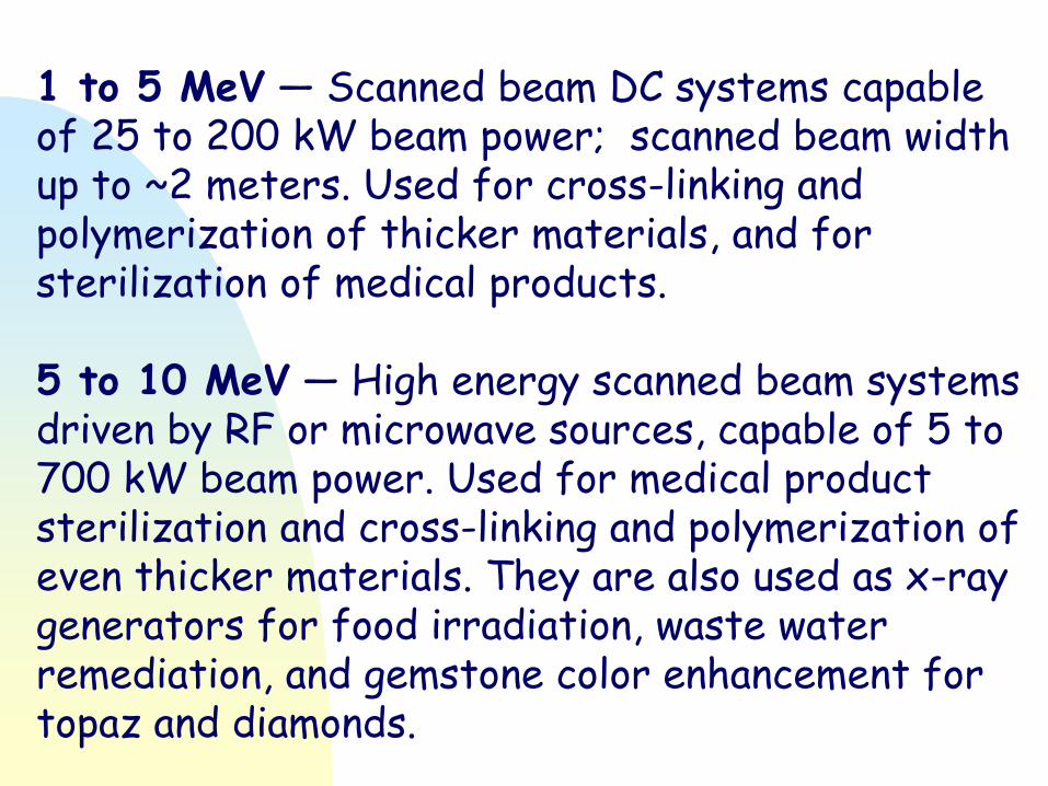
1 to 5 MeV — Scanned beam DC systems capable of 25 to 200 kW beam power; scanned beam width up to ~2 meters. Used for cross-linking and polymerization of thicker materials, and for sterilization of medical products. 5 to 10 MeV — High energy scanned beam systems driven by RF or microwave sources, capable of 5 to 700 kW beam power. Used for medical product sterilization and cross-linking and polymerization of even thicker materials. They are also used as x-ray generators for food irradiation, waste water remediation, and gemstone color enhancement for topaz and diamonds.
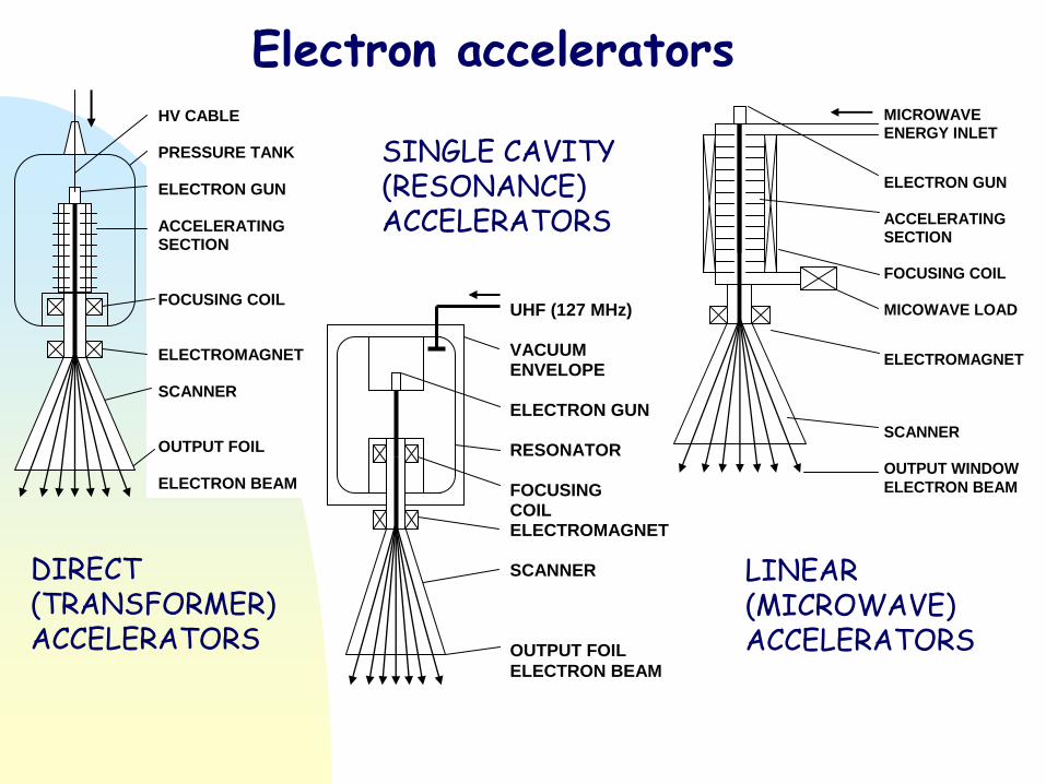
HV CABLE PRESSURE TANK ELECTRON GUN ACCELERATING SECTION FOCUSING COIL ELECTROMAGNET SCANNER OUTPUT FOIL ELECTRON BEAM
UHF (127 MHz) VACUUM ENVELOPE ELECTRON GUN RESONATOR FOCUSING COIL ELECTROMAGNET SCANNER OUTPUT FOIL
ELECTRON BEAM
MICROWAVE ENERGY INLET
ELECTRON GUN ACCELERATING SECTION FOCUSING COIL MICOWAVE LOAD
ELECTROMAGNET SCANNER OUTPUT WINDOW
ELECTRON BEAM
Electron accelerators
DIRECT (TRANSFORMER) ACCELERATORS
SINGLE CAVITY (RESONANCE) ACCELERATORS
LINEAR (MICROWAVE) ACCELERATORS

Accelerators for radiation processing (achievements)
Accelerator
type
Parameter
Direct
DC
UHF
100 - 200 MHz
Linear
microwaves
1.3–9.3 GHz
Av. beam
current
Energy range
Beam power
In future
Electrical
efficiency
<1.5 A
0.05 – 5 MeV
~500 kW
1 MW
60 – 80 %
<100 mA
0.3 – 10 MeV
700 kW
1 MW
20 – 50 %
<100 mA
2 – 10 MeV
100 kW
200 kW
10 – 20 %

DIRECT ACCELERATORS (transformer type)
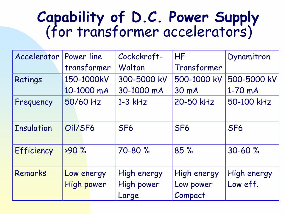
Capability of D.C. Power Supply (for transformer accelerators)
Accelerator Power line
transformer
Cockckroft-
Walton
HF
Transformer
Dynamitron
Ratings 150-1000kV
10-1000 mA
300-5000 kV
30-1000 mA
500-1000 kV
30 mA
500-5000 kV
1-70 mA
Frequency 50/60 Hz 1-3 kHz 20-50 kHz 50-100 kHz
Insulation Oil/SF6 SF6 SF6 SF6
Efficiency >90 % 70-80 % 85 % 30-60 %
Remarks Low energy
High power
High energy
High power
Large
High energy
Low power
Compact
High energy
Low eff.

LOW ENERGY ELECTRON ACCELERATORS
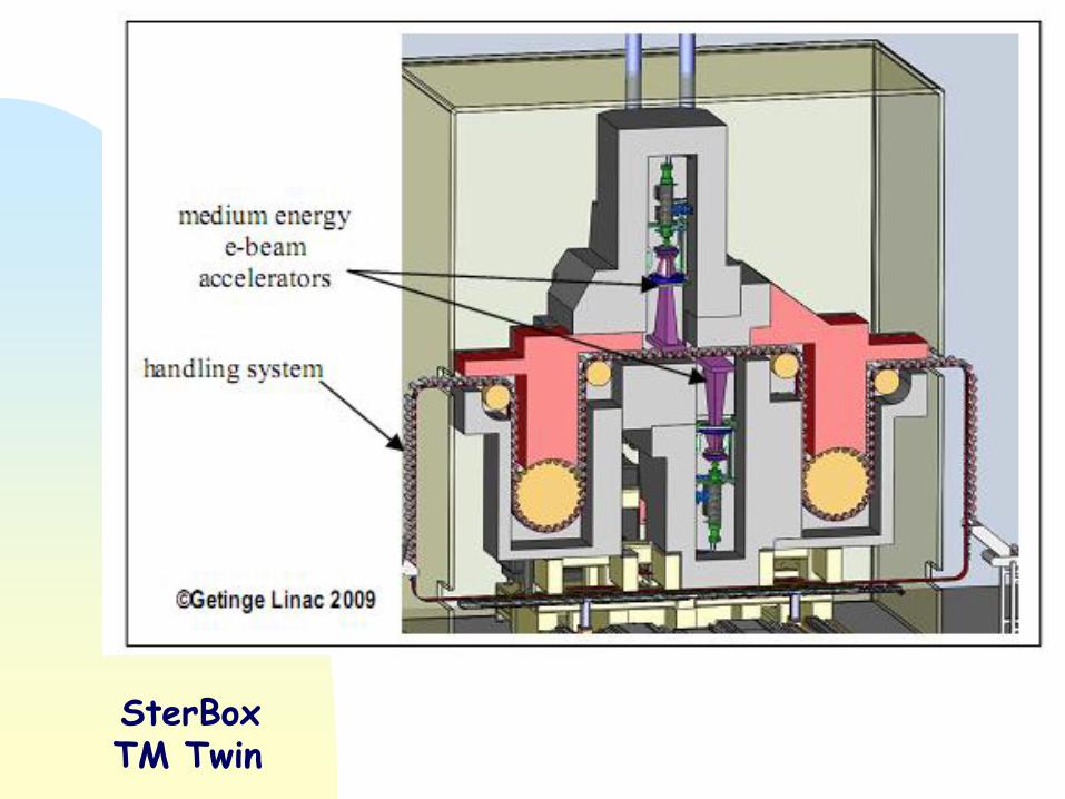
SterBox TM Twin

ELECTRON-BEAM ACCELERATORS FOR NEW APPLICATIONS
Operating characteristics EC-beam
- Acceleration voltage 75 - 250 kV - Electron current 0 - 2000 mA - Working width 400 - 3000 mm - Throughput 14000 kGy m/min - Distribution of dosage over working width < 10 % - No gas cooling of the electron exit window necessary.

Typical data for EC-scan 120kV
Accelerating voltage: 80 – 120 keV Beam current 0 - 200 mA Working width: max 600 mm Throughput: 9000 kGy m/min at 150 keV Web speed: 10 – further m/min

EC-LAB 400 unit With batch and roll-to-roll features ( 80 – 300 kV, 0-150 m/min, 400 mm).

ESI EZ-Cure III™ Unit

Cryovac Production Facility
State of the Art – 10 EB Units in a Row

Zbigniew ZIMEK, INCT, Warsaw, Poland 22
Low energy „in line” facility for surface sterilization
Electron energy 200 keV Beam power 1 kW Accelerator dimension: 0.45x0.7x1.10 m Unit dimension: 75x200x250 cm
Manufacturer: IBA

Zbigniew ZIMEK, INCT, Warsaw, Poland 23
Energy 200 keV Power 700 W Current 3,5 mA Scanning up to 20cm AC power 10 kVA Size 40x40x80 cm
Acclerating section
Beam scanner
STERSTAR
Linac Technologies
Facility for surface sterilization
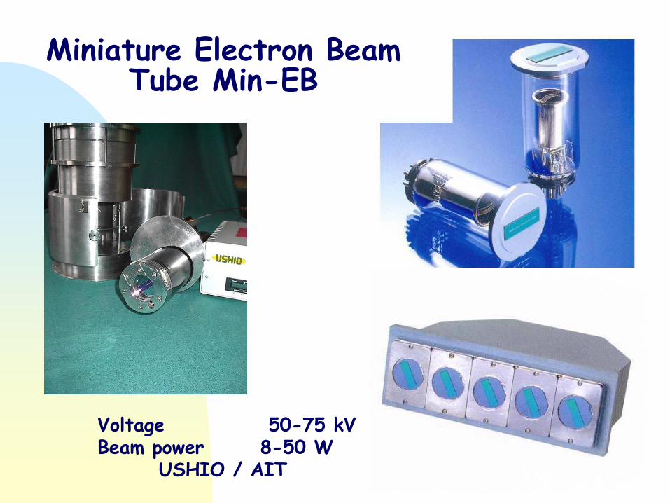
Voltage 50-75 kV Beam power 8-50 W USHIO / AIT
Miniature Electron Beam Tube Min-EB

MOBILE ACCELERATOR
SYSTEM
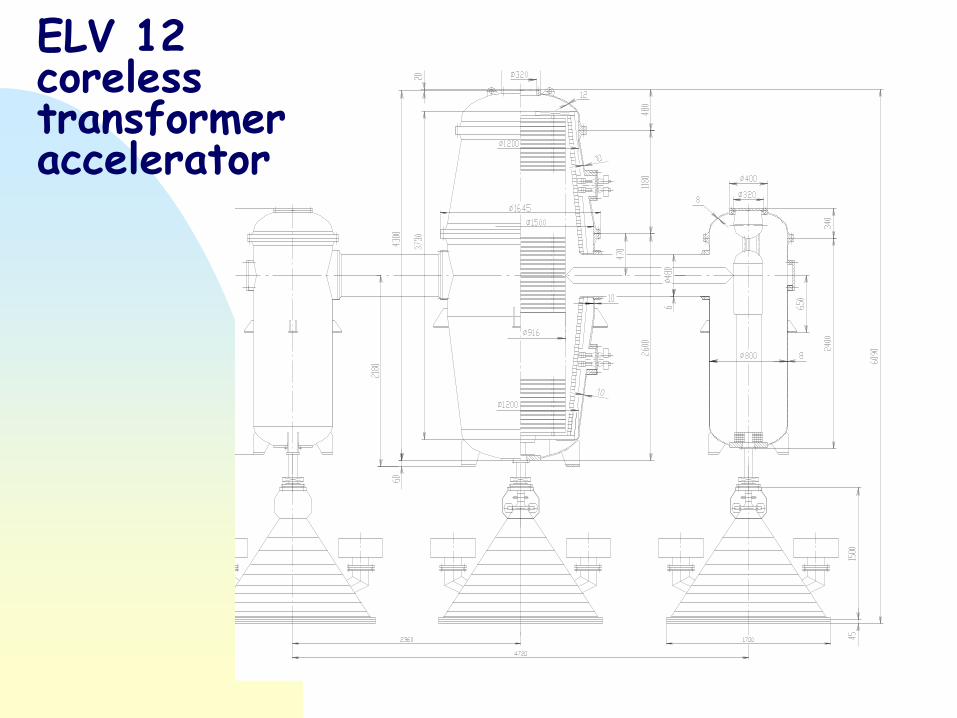
ELV 12 coreless transformer accelerator

ELV 12 coreless transformer accelerator
Electron energy 1 MeV Beam power 400 kW Frequency 1000 Hz One power supply Three scanners


A new 5MeV–300 kW Dynamitron for radiation processing
Radiation Physics and Chemistry 71 (2004) 549–551

NIIEFA, St Petersburg, Russia
ELEKTRON 23-1 1 MeV, 250 kW
The DC high voltage is generated by three-phase cascade generator with inductive coupling.
The diode type electron source with LaB6 emitter is used.

HV electron accelerator Elektron-23 1. Accelerating voltage: 800-1000 kV
2. Accelerating voltage instability during one hour of operation excluding ripples with frequency 50 Hz and more, not higher than: ± 2 %
3. Beam current: 0-500 mA
4. Electron beam current instability during one hour of operation, not higher than: ± 2 %
5. Irradiation zone max length on the outlet window foil: 230 cm
6. Linear beam current non-uniformity on the 10 cm distance from the outlet window foil on the irradiation zone max length, not higher than: ± 10 %
7. AC/DC conversion efficiency, not less than: 90%

Functional diagram of the accelerator: (1) vacuum chamber with a diode; (2) vessel filled with transformer oil; (3) magnetizing turns; (4) ferromagnetic core; (5) cathode holder; (6) voltage divider; (7) Rogowski coil; (8) capacitive voltage divider; (9) plasma–chemical reactor; (10) framework-supported anode foil; (11) diode cathode (graphite, 60 mm in diameter); (12) deionized-water DFL; and (13) compressed-gas gap.
A High-Current Pulsed Accelerator with a Matching Transformer
An electron beam with a pulse energy of 200 J was produced; Energy of the electrons was 500 keV, current 5-15 kA and the pulse duration was 60 ns.
Pribory i Tekhnika Eksperimenta, No. 3, 2004, pp. 130–134.
The accelerator was designed for initiating plasma–chemical reactions in a reactor chamber 500 mm long and 90 mm in diameter.

CASCADE ACCELERATOR
HV electrode
Generator Isolator
Safety rings
Motor
Gun Section Multiplier Prressure tank
Efficiency 67% Goal: 2 MeV; 200 kW
M. Hatridge et all., 2003
SINGLE CAVITY ACCELERATORS
single pass or multi-pass systems
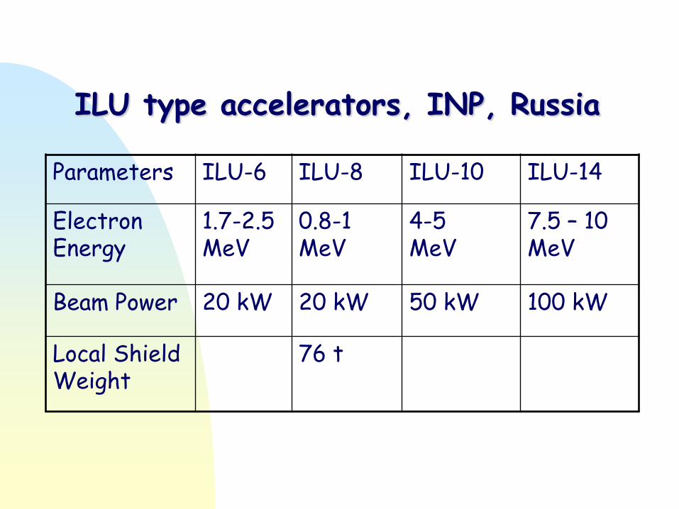
ILU type accelerators, INP, Russia
Parameters ILU-6 ILU-8 ILU-10 ILU-14
Electron Energy
1.7-2.5 MeV
0.8-1 MeV
4-5 MeV
7.5 – 10 MeV
Beam Power 20 kW 20 kW 50 kW 100 kW
Local Shield Weight
76 t
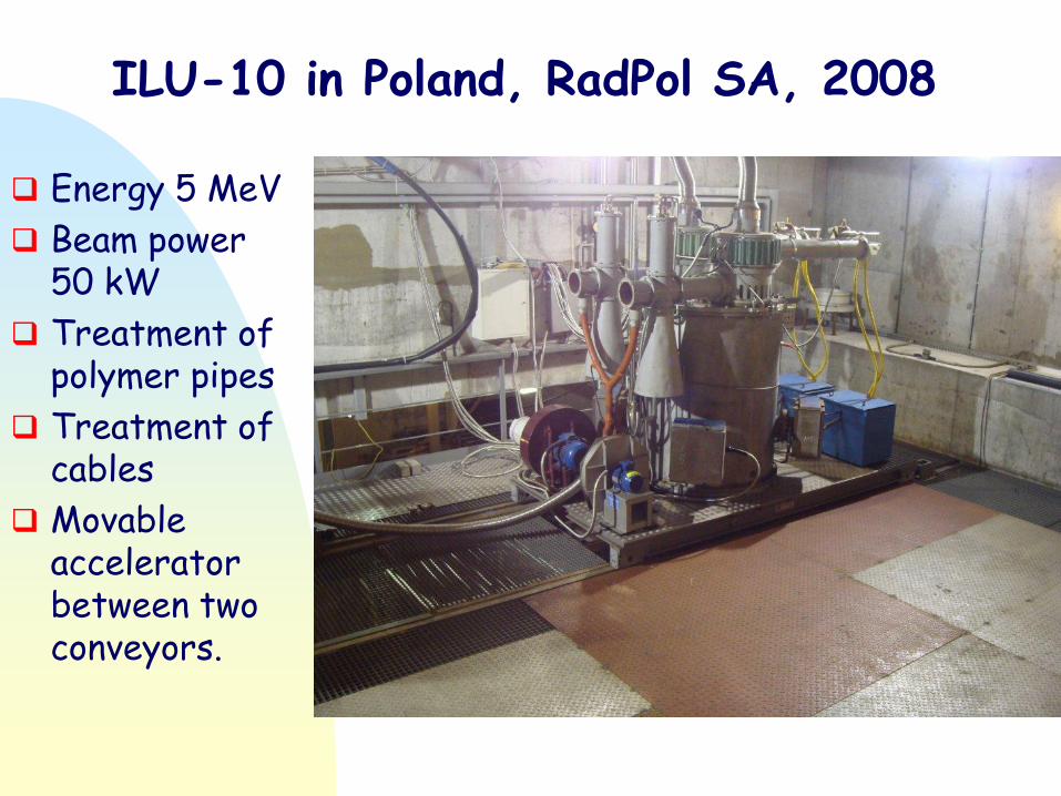
ILU-10 in Poland, RadPol SA, 2008
Energy 5 MeV
Beam power 50 kW
Treatment of polymer pipes
Treatment of cables
Movable accelerator between two conveyors.
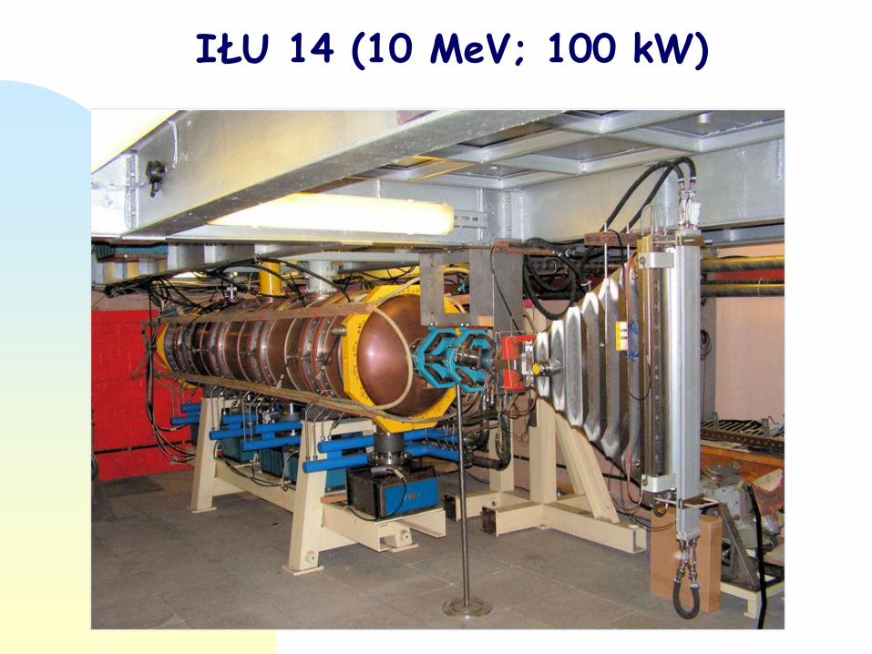
IŁU 14 (10 MeV; 100 kW)
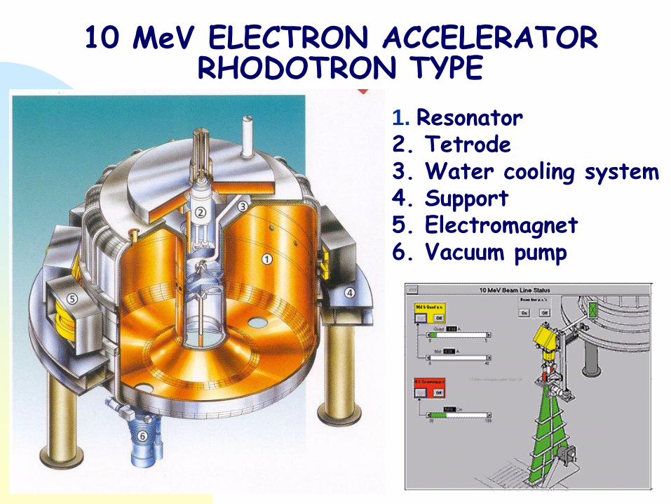
10 MeV ELECTRON ACCELERATOR RHODOTRON TYPE
1. Resonator 2. Tetrode 3. Water cooling system 4. Support 5. Electromagnet 6. Vacuum pump

TT 1000: do 700 kW; 7 MeV (100 mA) do 500 kW; 5 MeV (100 mA)
TT 300: do 200 kW; 10 MeV (20 mA) do 135 kW; 5 MeV (27 mA)
TT 200: do 100 kW; 10 MeV (10 mA) do 100 kW; 5 MeV (20 mA)
TT 100 35 kW; 10 MeV (3.5 mA)
ACCELERATORS RHODOTRON TYPE
IBA
M. Abs et all.,
Rad. Phys. Chem., 2004

Rhodotron TT 300, IBA, USA
Accelerator TT 300 Electron energy: 5-7 MeV Beam power: 200 kW

The IBA rhodotron TT1000: a very high power E-beam accelerator
Radiation Physics and Chemistry 71 (2004) 285–288
TT1000 Rhodotron aimed at delivering 5 and 7MeV electron beams with a current intensity of 100mA.
Machine having delivered a continuous beam of 93mA at an energy of 7MeV in February 2003.
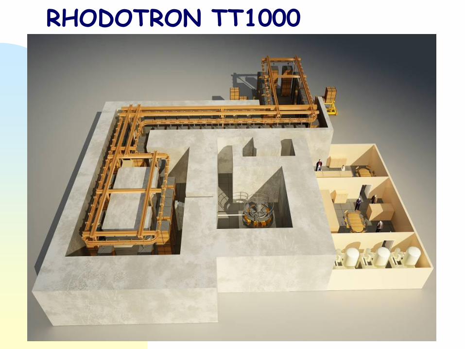
RHODOTRON TT1000

X-Ray vs Gamma
Type of Rhodotron TT 1000 TT 400 TT 300 TT 200
Electron power kW 560 290 190 100
Line power kW 1230 660 450 260
Electricity cost per year M$ 1.18 0.63 0.43 0.25
Gamma Ci Equivalent Mci 4.4 2.3 1.5 0.8
Cobalt load per year (2.5$/Ci) M$ 1.43 0.75 0.49 0.26

The electron accelerator Ridgetron for industrial irradiation
Nuclear Instruments and Methods in Physics Research B 161±163 (2000) 1159±1163
Prototype system with an energy of 2.5 MeV and a beam power of 6.5 kW was constructed to confirm the feasibility. The beam acceleration test was performed in the pulse mode operation.

Accelerator type FANTRON-I Electron energy 10 MeV Beam power 100 kW Frequency 159 MHz Efficiency 45 %
70 cm
H-j. Kwon i inni, EPAC, 2000 M-j.Park i inni, EPAC, 2000
LINEAR ELECTRON ACCELERATORS

Radiation facility can be located directly inside of warehouses or industrial buildings. The main features: horizontal accelerator, monorail conveyor, irradiation of boxes from two sides during one pass, radiation shielding made from ordinary concrete blocks (concrete volume 360 m3); total facility spot: ~240 m2, solid-state modulators for klystron and electron gun, total power consumption less 75 kW, continuous control of electron energy, beam current and scann length, throughput with dose 20-30 kGy is 55 boxes (40 x 40 x 60 cm3, maximum weight of 19 kg) per hour.
10 MeV, 10 kW linac
CoRAD, St Petersburg, Russia

10 MeV ELECTRON ACCELERATOR WITH LOCAL SHIELD (TOP VIEW)
K.G. Carlson, C. B. Williams, B. Lambert, Fuh-Wei Tang Radiat. Phys. Chem. 57 (2000) 619-623

10 MeV ELECTRON ACCELERATOR WITH LOCAL SHIELD
ELECTRON ENERGY 10 MeV DOSE 10-50 kGy BEAM POWER 3-5 kW PRODUCTIVITY up to 50 000 m3/rok

Radiation
sterilization facility

Nominal average energy, MeV . . 3 Nominal average current, mA up to 1 Nominal average power, kW . . . 2.5 Nominal pulsed current, A . . . . . 0.4 Current pulse duration, µsec . . 6.5 Pulse repetition, pulses/sec . . . 360 Max length of the scanning, mm 350 Dose nonuniformity, % . . . . . . . ±5 Dimensions of irradiated objects: depth, mm . . . . . . . . . . . . . . . . 200 height, mm . . . . . . . . . . . . . . . . 350 width, mm . . . . . . . . . . . . . . . . 500 Scanning frequency, Hz . . . . . 1–10 Dimensions of the system: depth, mm . . . . . . . . . . . . . . . 4200 width, mm . . . . . . . . . . . . . . . . 2400 height, mm . . . . . . . . . . . . . . . 1800 Power consumption, kW . . . . ~40 Mass, metric tons . . . . . . . . . up to 35
AN ELECTRON-BEAM STERILIZATION SYSTEM BASED ON A 3-MeV LINEAR ACCELERATOR
Atomic Energy, Vol. 95, No. 1, 2003

COMPACT ACCELERATOR
Energy 5 MeV Beam power 5 kW Scanning 10 by 10 cm Conveyor speed up to 10 m/min Getinge Linac

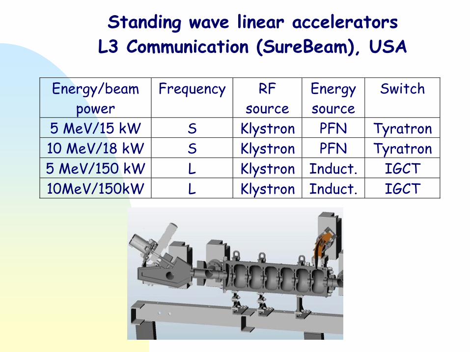
Standing wave linear accelerators
L3 Communication (SureBeam), USA
Energy/beam
power
Frequency RF
source
Energy
source
Switch
5 MeV/15 kW S Klystron PFN Tyratron
10 MeV/18 kW S Klystron PFN Tyratron
5 MeV/150 kW L Klystron Induct. IGCT
10MeV/150kW L Klystron Induct. IGCT

Beam current: 0 to 50 mA Gun/klystron high voltage: 15 kV Electrical efficiency: ~40%
SINP MSU 60 KW, 1.2 MeV COMPACT CW LINAC FOR RADIATION TECHNOLOGIES
One-Section/Two-Sections Beam energy: 0.6 MeV / 1.2 MeV Maximum beam power: 30 kW / 60 kW Length: 0.8 m / 1.3 m Plug power consumption: ~75 kW / ~150 kW

OUTPUT AND BEAM SCANNING DEVICES
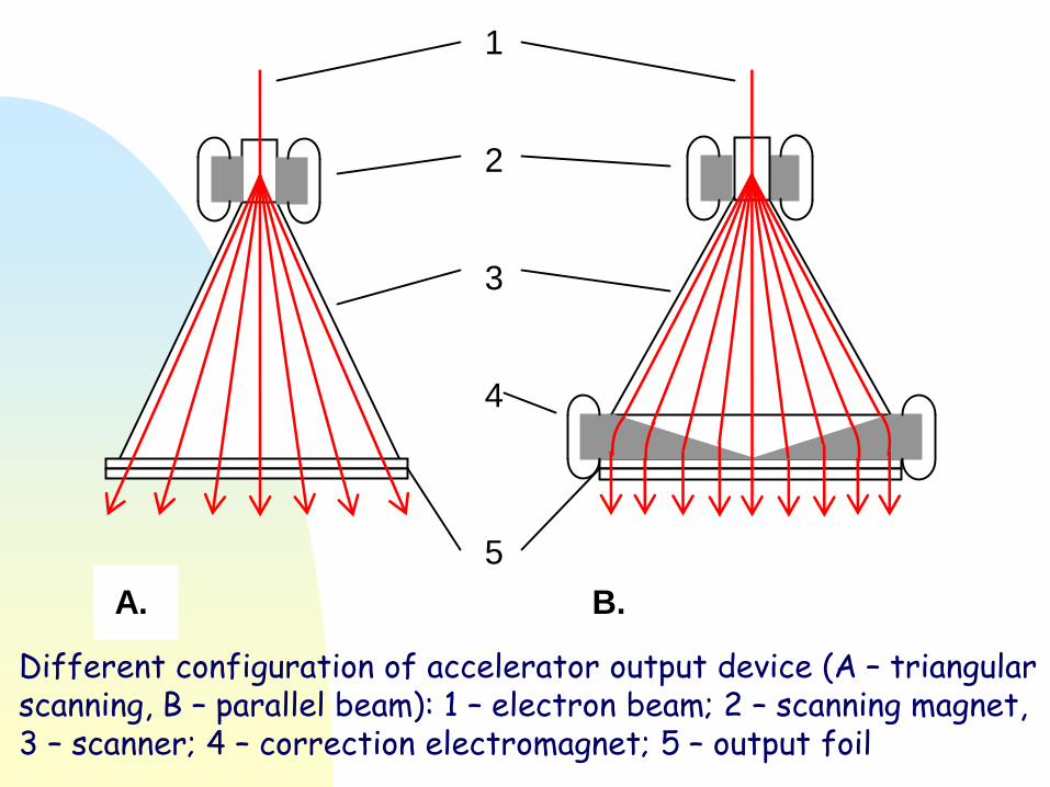
1 2 3 4 5
A. B.
Different configuration of accelerator output device (A – triangular scanning, B – parallel beam): 1 – electron beam; 2 – scanning magnet, 3 – scanner; 4 – correction electromagnet; 5 – output foil

DOUBLE SIDE BEAM SCANNER

BEAM SCANNING DEVICES
ILU 6

Zbigniew ZIMEK, INCT, Warsaw, Poland
Experimental conditions:
- Energy 700 keV - Beam current 1 mA - Titanium foil 50 μm - Beam spot 15x1200 mm - Window beam current monitor distance 50 mm
Optical transparency 0,86 Beam current without supporting grid 0,9 mA Beam current with supporting grid 0,84 mA Beam current transparency 0,93
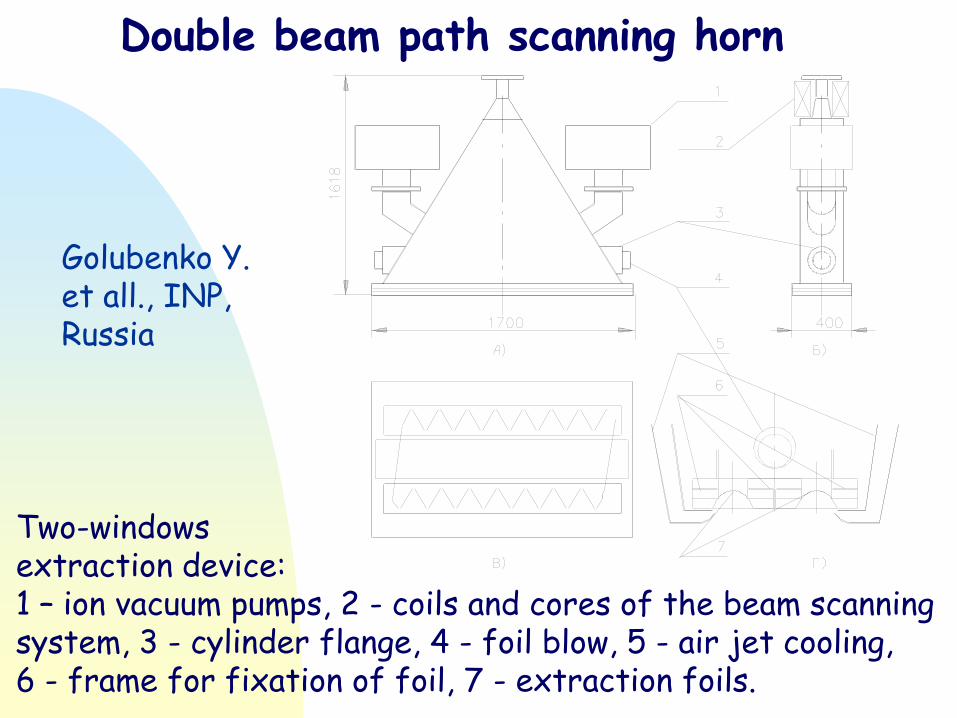
Double beam path scanning horn
Golubenko Y. et all., INP, Russia
Two-windows extraction device: 1 – ion vacuum pumps, 2 - coils and cores of the beam scanning system, 3 - cylinder flange, 4 - foil blow, 5 - air jet cooling, 6 - frame for fixation of foil, 7 - extraction foils.

ELECTRON-10 0.5-0.75 MeV; 50 kW
1 – Primary winding; 2 – Secondary winding; 3 – Pressure vessel; 4 – Electron source; 5 – Accelerating tube; 6 – Scanning device; 7 – Vacuum pump; 8 – Vacuum chamber; 9 – Outlet window; 10 – Turning magnet; 11 – Radiation shielding.
A.S. Ivanov, V.P. Ovchinnikov, M.P. Svinin, N.G. Tolstun, PAC 1993, Washington, USA
Zbigniew ZIMEK, INCT, Warsaw, Poland 63
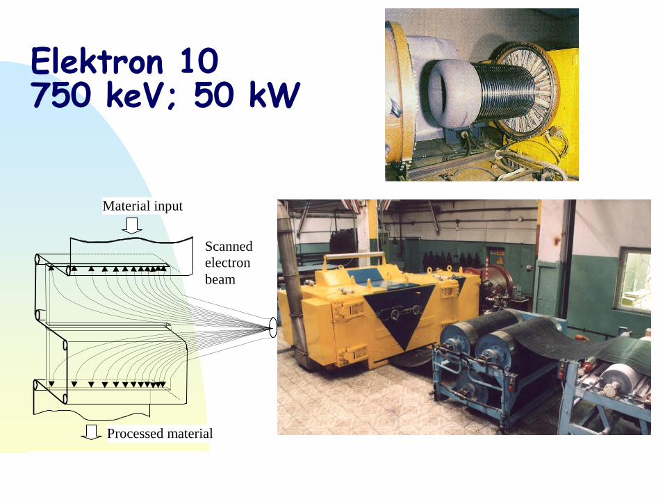
Elektron 10 750 keV; 50 kW
Scanned
electron
beam
Material input
Processed material
Fig.2. Schematic view of scanned electrons trajectories, processed material movement and “ELECTRON-10” accelerator in a soft
roofing production line.

LINEAR SCANNING SYSTEM
CAARI 2002 Denton, Texas November 13, 2002
VACUUM CHAMBER
ELECTRON BEAM
ELECTROMAGNET TITANIUM
FOIL

COMPUTER CONTROL SYSTEMS
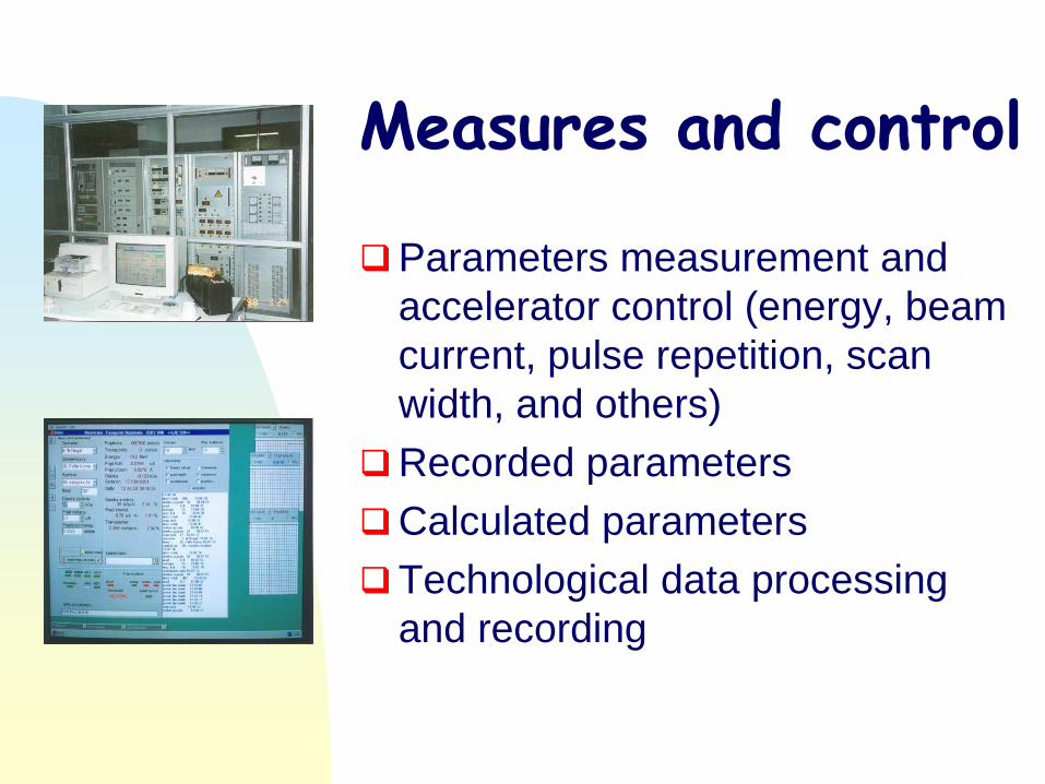
Measures and control
Parameters measurement and
accelerator control (energy, beam
current, pulse repetition, scan
width, and others)
Recorded parameters
Calculated parameters
Technological data processing
and recording

Future accelerator developments
CW linear electron accelerators,
Compact high power HF transformer accelerators,
Very high power transformer accelerators (1-1.5 MeV; 0.5-1 MW),
Modern power components applications in accelerator technology,
Compact, cost efficient accelerators with limited power and electron energy.

CONCLUSIONS Characteristics steps can be recognized in the past of
accelerator development. Present stage of accelerator technology perfection includes: cost effectiveness, reliability, compactness and introduction of MW beam power level.
Demands coming from growing fields of radiation processing technology implementation have a strong impact on R&D process of accelerator technology.
Any practical accelerator construction must be compromise between size, efficiency and cost.
The electrical efficiency is very important parameter for high power accelerators. Special attention should be devoted to optimize electrical energy consumption for accelerator and auxiliary equipment installed in radiation facility.
The most important tool for each application is not the accelerator but the beam. Radiation facility must satisfy the beam specifications for a given application.
Initial capital cost, operating cost and reliability of the
radiation facility play an crucial role in any industrial (for-profit) applications.
Users are always interested in lower total cost, so new
technologies to increase the return on investment are always welcome.
New systems must be proven in an industrial confirmed acceptance, so introduction of a new accelerator
technology can require a number of years for widespread market penetration.

Major industrial accelerator producers are located in USA, Russia, Japan, France and Belgium. Several other countries including Poland are capable to produce accelerators on limited scale.
The R&D program of accelerator technology perfection is
tightly connected to progress in development of advanced technology in many branches of technical activity (power components, control systems).
New accelerators constructions can frequently offer better
economic and technical characteristics but only long time operation can revile weak points of certain accelerator construction in practical industrial conditions
The progress in accelerator technology is not a quick process
but can be easily noticed in longer time scale.

Thank you for your attention