newbuildings machinery and systems – main · pdf filepower transmission january 2013....
TRANSCRIPT
RULES FOR CLASSIFICATION OF
The content of thisaccepts that it is pverification servicepursuant to this docconsequences arisin
The electronic p
Ships / High Speed, Light Craft andNaval Surface Craft
PART 4 CHAPTER 4
NEWBUILDINGSMACHINERY AND SYSTEMS – MAIN CLASS
Rotating Machinery, Power Transmission
JANUARY 2013
DET NORSKE VERITAS AS
service document is the subject of intellectual property rights reserved by Det Norske Veritas AS (DNV). The userrohibited by anyone else but DNV and/or its licensees to offer and/or perform classification, certification and/ors, including the issuance of certificates and/or declarations of conformity, wholly or partly, on the basis of and/orument whether free of charge or chargeable, without DNV's prior written consent. DNV is not responsible for theg from any use of this document by others.
df version of this document found through http://www.dnv.com is the officially binding version

FOREWORD
DNV is a global provider of knowledge for managing risk. Today, safe and responsible business conduct is both a licenseto operate and a competitive advantage. Our core competence is to identify, assess, and advise on risk management. Fromour leading position in certification, classification, verification, and training, we develop and apply standards and bestpractices. This helps our customers safely and responsibly improve their business performance. DNV is an independentorganisation with dedicated risk professionals in more than 100 countries, with the purpose of safeguarding life, propertyand the environment.
The Rules lay down technical and procedural requirements related to obtaining and retaining a Class Certificate. It is usedas a contractual document and includes both requirements and acceptance criteria.
© Det Norske Veritas AS January 2013
Any comments may be sent by e-mail to [email protected]
If any person suffers loss or damage which is proved to have been caused by any negligent act or omission of Det Norske Veritas, then Det Norske Veritas shall pay compensation tosuch person for his proved direct loss or damage. However, the compensation shall not exceed an amount equal to ten times the fee charged for the service in question, provided thatthe maximum compensation shall never exceed USD 2 million.In this provision “Det Norske Veritas” shall mean the Foundation Det Norske Veritas as well as all its subsidiaries, directors, officers, employees, agents and any other acting on behalfof Det Norske Veritas.

Rules for Ships / High Speed, Light Craft and Naval Surface Craft, January 2013Pt.4 Ch.4 Changes – Page 3
CHANGES
General
This document supersedes the July 2011 edition.
Text affected by the main changes in this edition is highlighted in red colour. However, if the changes involvea whole chapter, section or sub-section, normally only the title will be in red colour.
Main changes coming into force 1 July 2013
GeneralThis rule update relates to:— Running condition has been included for shafting arrangements with aft stern tube bearing diameter above
500 mm and special designs and with warm static condition for shafting other arrangements.— New running condition requirement for lubrication calculation in aft stern tube bearing. Calculation of
minimum shaft speed shall be able to ensure an oil film separating shaft and bearing. Viscosityrequirements to the lubricant have been introduced.
— Changed requirements regarding hydrodynamic propeller loads running condition.— More focus on sighting process; ovality, straightness and slope with tolerances.— Differentiating between local (stern tube sighting) and global (jacking, gap & sag) effects.— High temperature alarm during NB trials shall initiate further investigation.— Introducing alternative methods for monitoring of water in stern tube bearing lubricating oil.
• Sec.1 Shafting— Previous items A301 has been split in A301 and A302 and previous item A302 has been deleted.— Item A305 has been amended.— Items A402 and A403 have been amended.— B900 “Shaft bearings, dimensions” has been completely rewritten.— Item E302 has been amended to include oil sample tested by laboratory as acceptable alternative to onboard
test kit.— F400 “Shaft alignment” has been completely rewritten.— Two new items, H301 and H302 have been added. The previous items H301 and H302 have been amended
and renumbered and a Guidance Note has been added.— Item I101 has been amended and a Guidance Note has been added.
In addition to the above stated main changes, editorial corrections may have been made.
Editorial Corrections
DET NORSKE VERITAS AS

Rules for Ships / High Speed, Light Craft and Naval Surface Craft, January 2013 Pt.4 Ch.4 Contents – Page 4
CONTENTS
Sec. 1 Shafting ............................................................................................................................................... 7
A. General ........................................................................................................................................................................... 7A 100 Application............................................................................................................................................................ 7A 200 Documentation of shafts and couplings................................................................................................................ 7A 300 Documentation of bearings and seals ................................................................................................................... 8A 400 Documentation of shafting system and dynamics ................................................................................................ 8
B. Design ............................................................................................................................................................................. 9B 100 General.................................................................................................................................................................. 9B 200 Criteria for shaft dimensions................................................................................................................................. 9B 300 Flange connections ............................................................................................................................................. 15B 400 Shrink fit connections ......................................................................................................................................... 18B 500 Keyed connections .............................................................................................................................................. 24B 600 Clamp couplings ................................................................................................................................................. 25B 700 Spline connections .............................................................................................................................................. 25B 800 Propeller shaft liners ........................................................................................................................................... 26B 900 Shaft bearings, dimensions ................................................................................................................................. 26B 1000 Bearing design details ......................................................................................................................................... 27B 1100 Shaft oil seals ...................................................................................................................................................... 27
C. Inspection and Testing................................................................................................................................................ 27C 100 Certification ....................................................................................................................................................... 27C 200 Assembling in workshop .................................................................................................................................... 28
D. Workshop Testing ....................................................................................................................................................... 28D 100 General................................................................................................................................................................ 28
E. Control and Monitoring ............................................................................................................................................. 28E 100 General................................................................................................................................................................ 28E 200 Indications and alarms ........................................................................................................................................ 28E 300 Tailshaft monitoring - TMON ............................................................................................................................ 28
F. Arrangement................................................................................................................................................................ 30F 100 Sealing and protection ........................................................................................................................................ 30F 200 Shafting arrangement .......................................................................................................................................... 30F 300 Shaft bending moments ...................................................................................................................................... 31F 400 Shaft alignment ................................................................................................................................................... 31
G. Vibration ...................................................................................................................................................................... 36G 100 Whirling vibration............................................................................................................................................... 36G 200 Rotor vibration .................................................................................................................................................... 36G 300 Axial vibration .................................................................................................................................................... 36G 400 Vibration measurements ..................................................................................................................................... 36
H. Installation Inspection ................................................................................................................................................ 36H 100 Application.......................................................................................................................................................... 36H 200 Assembly ............................................................................................................................................................ 37H 300 Shaft alignment ................................................................................................................................................... 37
I. Shipboard Testing ....................................................................................................................................................... 38I 100 Bearings .............................................................................................................................................................. 38I 200 Measurements of vibration ................................................................................................................................. 38
Sec. 2 Gear Transmissions.......................................................................................................................... 39
A. General ......................................................................................................................................................................... 39A 100 Application.......................................................................................................................................................... 39A 200 Documentation.................................................................................................................................................... 39
B. Design ........................................................................................................................................................................... 42B 100 General................................................................................................................................................................ 42B 200 Gearing................................................................................................................................................................ 42B 300 Welded gear designs ........................................................................................................................................... 43B 400 Shrink fitted pinions and wheels......................................................................................................................... 43B 500 Bolted wheel bodies............................................................................................................................................ 45B 600 Shafts .................................................................................................................................................................. 45B 700 Bearings .............................................................................................................................................................. 46B 800 Casing ................................................................................................................................................................. 46B 900 Lubrication system.............................................................................................................................................. 46
DET NORSKE VERITAS AS

Rules for Ships / High Speed, Light Craft and Naval Surface Craft, January 2013 Pt.4 Ch.4 Contents – Page 5
C. Inspection and Testing................................................................................................................................................ 47C 100 Certification of parts ........................................................................................................................................... 47C 200 Pinions and wheels.............................................................................................................................................. 47C 300 Welded gear designs ........................................................................................................................................... 51C 400 Ancillaries ........................................................................................................................................................... 51C 500 Assembling ......................................................................................................................................................... 51
D. Workshop Testing ....................................................................................................................................................... 52D 100 Gear mesh checking............................................................................................................................................ 52D 200 Clutch operation.................................................................................................................................................. 53D 300 Ancillary systems................................................................................................................................................ 53
E. Control and Monitoring ............................................................................................................................................. 53E 100 Summary............................................................................................................................................................. 53
F. Arrangement................................................................................................................................................................ 54F 100 Installation and fastening .................................................................................................................................... 54
G. Vibration ...................................................................................................................................................................... 55G 100 General................................................................................................................................................................ 55
H. Installation Inspection ................................................................................................................................................ 55H 100 Application.......................................................................................................................................................... 55H 200 Inspections .......................................................................................................................................................... 55
I. Shipboard Testing ....................................................................................................................................................... 55I 100 Gear teeth inspections ......................................................................................................................................... 55I 200 Gear noise detection............................................................................................................................................ 56I 300 Bearings and lubrication ..................................................................................................................................... 56
Sec. 3 Clutches ............................................................................................................................................. 57
A. General ......................................................................................................................................................................... 57A 100 Application.......................................................................................................................................................... 57A 200 Documentation.................................................................................................................................................... 57
B. Design ........................................................................................................................................................................... 57B 100 Torque capacities ................................................................................................................................................ 57B 200 Strength and wear resistance............................................................................................................................... 58B 300 Emergency operation .......................................................................................................................................... 58B 400 Type testing......................................................................................................................................................... 58B 500 Hydraulic/pneumatic system............................................................................................................................... 58
C. Inspection and Testing................................................................................................................................................ 58C 100 Certification ........................................................................................................................................................ 58C 200 Inspection and testing of parts ............................................................................................................................ 58C 300 Ancillaries ........................................................................................................................................................... 58
D. Workshop Testing ....................................................................................................................................................... 58D 100 Function testing................................................................................................................................................... 58
E. Control, Alarm and Safety Functions and Indication ............................................................................................. 59E 100 Summary............................................................................................................................................................. 59
F. Arrangement................................................................................................................................................................ 59F 100 Clutch arrangement............................................................................................................................................. 59
G. Vibration ...................................................................................................................................................................... 59G 100 Engaging operation ............................................................................................................................................. 59
H. Installation Inspection ................................................................................................................................................ 59H 100 Alignment ........................................................................................................................................................... 59
I. Shipboard Testing ....................................................................................................................................................... 60I 100 Operating of clutches .......................................................................................................................................... 60
Sec. 4 Bending Compliant Couplings ........................................................................................................ 61
A. General ......................................................................................................................................................................... 61A 100 Application.......................................................................................................................................................... 61A 200 Documentation.................................................................................................................................................... 61
B. Design ........................................................................................................................................................................... 61B 100 General................................................................................................................................................................ 61B 200 Criteria for dimensioning.................................................................................................................................... 61
DET NORSKE VERITAS AS

Rules for Ships / High Speed, Light Craft and Naval Surface Craft, January 2013 Pt.4 Ch.4 Contents – Page 6
C. Inspection and Testing................................................................................................................................................ 62C 100 Certification ........................................................................................................................................................ 62C 200 Inspection and testing of parts ............................................................................................................................ 62
D. Workshop Testing ....................................................................................................................................................... 62D 100 Balancing ............................................................................................................................................................ 62D 200 Stiffness verification ........................................................................................................................................... 62
E. Control, Alarm, Safety Functions and Indication.............................................................................................................................................................. 62
E 100 General................................................................................................................................................................ 62
F. Arrangement................................................................................................................................................................ 62F 100 Coupling arrangement......................................................................................................................................... 62
G. Vibration ...................................................................................................................................................................... 63G 100 General................................................................................................................................................................ 63
H. Installation Inspection ................................................................................................................................................ 63H 100 Alignment ........................................................................................................................................................... 63
I. Shipboard Testing ....................................................................................................................................................... 63I 100 General................................................................................................................................................................ 63
Sec. 5 Torsionally Elastic Couplings ......................................................................................................... 64
A. General ......................................................................................................................................................................... 64A 100 Application.......................................................................................................................................................... 64A 200 Documentation.................................................................................................................................................... 64
B. Design ........................................................................................................................................................................... 67B 100 General................................................................................................................................................................ 67B 200 Criteria for dimensioning.................................................................................................................................... 67B 300 Type testing......................................................................................................................................................... 68
C. Inspection and Testing................................................................................................................................................ 69C 100 Certification ........................................................................................................................................................ 69C 200 Inspection and testing of parts ............................................................................................................................ 70
D. Workshop Testing ....................................................................................................................................................... 70D 100 Stiffness verification ........................................................................................................................................... 70D 200 Bonding tests....................................................................................................................................................... 70D 300 Balancing ............................................................................................................................................................ 70
E. Control, Alarm, Safety Functions and Indication.................................................................................................... 70E 100 Summary............................................................................................................................................................. 70
F. Arrangement................................................................................................................................................................ 71F 100 Coupling arrangement......................................................................................................................................... 71
G. Vibration ...................................................................................................................................................................... 71G 100 General................................................................................................................................................................ 71
H. Installation Inspection ................................................................................................................................................ 72H 100 Alignment ........................................................................................................................................................... 72
I. Shipboard Testing ....................................................................................................................................................... 72I 100 Elastic elements .................................................................................................................................................. 72
DET NORSKE VERITAS AS
Rules for Ships / High Speed, Light Craft and Naval Surface Craft, January 2013 Pt.4 Ch.4 Sec.1 – Page 7
SECTION 1 SHAFTING
A. General
A 100 Application
101 Shafting is defined as the following elements:
— shafts— rigid couplings as flange couplings, shrink-fit couplings, keyed connections, clamp couplings, splines, etc.
(compliant elements as tooth couplings, universal shafts, rubber couplings, etc. are dealt with in theirrespective sections)
— shaft bearings— shaft seals.
Shafts or couplings made of composite materials are subject to special consideration.Sec.1 also deals with the fitting of the propeller (and impeller for water jet), shaft alignment and whirling.
102 The rules in this section apply to shafting subject to certification for the purposes listed in Ch.2 Sec.1A200. However, they do not apply for generator shafts, except for single bearing type generators, wheredocumentation may be requested upon request in case of high torsional vibrations. Furthermore, they onlyapply to shafts made of forged or hot rolled steel. Shafts made of other materials will be considered on the basisof equivalence with these rules.
103 Ch.2 describes all general requirements for rotating machinery, and forms the basis for all sections inCh.3, Ch.4 and Ch.5.
104 Stern tube oil seals of standard design shall be type approved.
A 200 Documentation of shafts and couplings
201 Drawings of the shafts, liners and couplings shall be submitted. The drawings shall show clearly alldetails, such as fillets, keyways, radial holes, slots, surface roughness, shrinkage amounts, contact betweentapered parts, pull up on taper, bolt pretension, protection against corrosion, welding details etc. as well asmaterial types, mechanical properties, cleanliness (if required, see B203) and NDT specification, see Ch.2Sec.3 A200. For shafts with a maximum diameter >250 mm (flanges not considered) that shall be quenchedand tempered, a drawing of the forging, in its heat treatment shape, shall be submitted upon request.
202 Applicable load data shall be given. The load data or the load limitations shall be sufficient to carry outdesign calculations as described in B, see also Ch.2 Sec.3 A101. This means as a minimum:
P = maximum continuous power (kW)or T0 = maximum continuous torque (Nm)
n0 = r.p.m. at maximum continuous power.
For plants with gear transmissions the relevant application factors shall be given, otherwise upper limitations(see Ch.3 Sec.1 G for diesel engine drives) will be used:
KA = application factor for continuous
however, not to be taken less than 1.1, in order to cover for load fluctuationsKAP = application factor for non-frequent peak loads (e.g. clutching-in shock loads or electric motors
KAice = application factor due to ice shock loads (applicable for ice classed vessels), see Pt.5 Ch.1 of the Rules for Classification of Ships
ΔKA = Application factor, torque range (applicable to reversing plants)
operation 1Tv
T0------+ 1
τv
τ0-----+= =
with star-delta switch)Tpeak
T0--------------
τpeak
τ0-------------= =
ΔKA
KA P( ) ice( ) τ0 τmax reversed+
τ0------------------------------------------------------------------------=
DET NORSKE VERITAS AS

Rules for Ships / High Speed, Light Craft and Naval Surface Craft, January 2013 Pt.4 Ch.4 Sec.1 – Page 8
For direct coupled plants (i.e. plants with no elastic coupling or gearbox) the following data shall be given:
For all kinds of plants the necessary parameters for calculation of relevant bending stresses shall be submitted,see F and G.
A 300 Documentation of bearings and seals
301 Drawings of separate thrust bearings, shaft bearings and oil seals shall be submitted. The drawings shallshow all details as dimensions with tolerances, material types, and (for bearings) the lubrication system.(Drawings of ball and roller bearings need not to be submitted.) For main thrust bearings the mechanicalproperties of the bearing housing and foundation bolts shall be submitted.
302 If the class notation TMON (tailshaft condition monitoring survey arrangement) is applicable, thefollowing additional information is required:
— lubrication oil diagram for the stern tube bearings with identified oil sampling point and a description ofthe sampling procedure
— the position of aft stern tube bearing temperature sensor(s).
303 The maximum permissible lateral movements for shaft oil seals shall be specified.
304 Documentation of the manufacturer’s quality control with regard to inspection and testing of materialsand parts of bearings and seals shall be submitted upon request.
305 For separate thrust bearings, calculation of hydrodynamic lubrication properties shall be submitted, seeB905.
306 Documentation for the control and monitoring system, including set-points and delays, see E, shall besubmitted for approval.For requirements to documentation types, see Ch.9.
A 400 Documentation of shafting system and dynamics
401 Drawings of the complete shafting arrangement shall be submitted. Type designation of prime mover,gear, elastic couplings, driven unit, shaft seals etc. shall be stated on the drawings. The drawings shall show allmain dimensions as diameters and bearing spans, bearing supports and any supported elements as e.g. oildistribution boxes.Position and way of electrical grounding shall be indicated.
402 Shaft alignment calculation report is always to be submitted for approval for propulsion plants with:
— minimum shaft diameters (low speed side) of 400 mm or greater for single screw and 300 mm for twinscrew
— gear transmissions with more than one pinion driving the output gear wheel, even if there is only one singleinput shaft as for dual split paths
— shaft generator or electrical motor as an integral part of the low speed shaft in diesel engine propulsion.
Upon request, shaft alignment calculations may also be required for other plants when these are consideredsensitive to alignment.For required content of the of shaft alignment calculation report, see F400.
As a safe simplification it may be assumed that ΔKA = 2 KA or 2 KAP or 2 KAicewhichever is the highest.
Where:Tv = vibratory torque for continuous operation in the full speed range (~ 90 − 100% of n0)τv = nominal vibratory torsional stress for continuous operation in the full speed rangeτ0 = nominal mean torsional stress at maximum continuous powerτmax reversed = maximum reversed torsional stress, which is the maximum value of (τ + τv) in the entire
speed range (for astern running), or τice rev (for astern running) whichever is the highest.
— τv = nominal vibratory torsional stress for continuous operation in the entire speed range. See torsional vibration in Ch.3 Sec.1 G300
— τvT = nominal vibratory torsional stress for transient operation (e.g. passing through a barred speed range) and the corresponding relevant number of cycles NC. See torsional vibration in Ch.3 Sec.1 G400.
— Reversing torque if limited to a value less than T0.
DET NORSKE VERITAS AS

Rules for Ships / High Speed, Light Craft and Naval Surface Craft, January 2013 Pt.4 Ch.4 Sec.1 – Page 9
403 For all propulsion plants other than those listed in 402, a shaft alignment specification shall be submittedfor information. The shaft alignment specification shall include the following items:
— bearing offsets from the defined reference line— bearing slope relative to the defined reference line if different from zero— Installation procedure and verification data with tolerances e.g. gap and sag and jacking loads (including
jack correction factors and jack positions) and verification conditions (cold or hot, propeller submersion,etc.).
404 Calculations of whirling vibration or lateral rotor vibration may be required upon request. Normally thismeans determination of natural frequencies.
405 Axial vibration calculations may be required upon request, see also Ch.3 Sec.1 A601 c).
B. Design
B 100 General
101 For design principles see Ch.2 Sec.3 A100. The shafting shall be designed for all relevant load conditionssuch as rated power, reversing loads, foreseen overloads, transient conditions, etc. including all drivingconditions under which the plant may be operated.
102 Determination of loads under the driving conditions specified in 101 is described in F and G as well asin Ch.3 Sec.1 G.
B 200 Criteria for shaft dimensions
201 Shafts shall be designed to prevent fatigue failure and local deformation. Simplified criteria for the mostcommon shaft applications are given in 206, 207 and 208.
Guidance note:Classification Note 41.4 offers detailed methods on how to assess the safety factor criteria mentioned in Table B1. Alternative methods may also be considered on the basis of equivalence.
---e-n-d---of---G-u-i-d-a-n-c-e---n-o-t-e---
It is sufficient that either the detailed criteria in Classification Note 41.4 or the simplified criteria are fulfilled.In addition, the shafts shall be designed to prevent rust or detrimental fretting that may cause fatigue failures,see also 402.
202 The major load conditions to be considered are:
— low cycle fatigue (103 to 104 cycles) due to load variations from zero to full load, clutching-in shock loads,reversing torques, etc. In special cases, such as short range ferries higher number of cycles (~105 cycles)may apply
— high cycle fatigue (>>3·106 cycles) due to rotating bending and torsional vibration— ice shock loads (106 to 107 cycles), applicable to vessels with ice class notations and ice breakers— transient vibration as when passing through a barred speed range (104 to 3·106 cycles).
203 For applications where it may be necessary to take the advantage of tensile strength above 800 MPa andyield strength above 600 MPa, material cleanliness has an increasing importance. Higher cleanliness thanspecified by material standards may be required (preferably to be specified according to ISO 4947).Furthermore, special protection against corrosion is required. Method of protection shall be approved, seeA201.
204 Stainless steel shafts shall be designed to avoid cavities (pockets) where the sea water may remain un-circulated (e.g. in keyways). For other materials than stainless steel I, II and III as defined in Table B3, specialconsideration applies to fatigue values and pitting corrosion resistance.
Table B1 Shaft safety factorsCriteria Safety factor, SLow cycle (NC < 104 stress cycles) 1.25High cycle (NC >> 3·106 stress cycles) 1.6Transient vibration when passing through a barred speed range:(104 < NC < 3·106 stress cycles)
Linear interpolation (logτ-logN diagram) between the low cycle, peak stresses criterion with S = 1.25 and the high cycle criterion with S = 1.5. For propeller shafts in way of and aft of the aft stern tube bearing, the bending influence is covered by an increase of S by 0.05.
DET NORSKE VERITAS AS
Rules for Ships / High Speed, Light Craft and Naval Surface Craft, January 2013 Pt.4 Ch.4 Sec.1 – Page 10
205 The shaft safety factors for the different applications and criteria detailed in Classification Note 41.4shall be, at least, in accordance with Table B1. See also Guidance Note in 201.
206 Simplified diameter formulae for plants with low torsional vibration such as geared plants or directdriven plants with elastic coupling.The simplified method for direct evaluation of the minimum diameters d for various design features are basedon the following assumptions:
— σy limited to 0.7 σB (for calculation purpose only)— application factors KAice and KAP ≤ 1.4— vibratory torque Tv ≤ 0.35 T0 in all driving conditions— application factor, torque range ΔKA ≤ 2.7— inner diameters di ≤ 0.5 d except for the oil distribution shaft with longitudinal slot where di ≤ 0.77 d— protection against corrosion (through oil, oil based coating, material selection or dry atmosphere).
If any of these assumptions are not fulfilled, the detailed method in Classification Note 41.4 may be used, seeGuidance Note in 201.The simplified method results in larger diameters than the detailed method. It distinguishes between:
— low strength steels with σB ≤ 600 MPa which have a low notch sensitivity, and— high strength steels with σB > 600 MPa such as alloyed quenched and tempered steels and carbon steels
with a high carbon content that all are assumed to have a high notch sensitivity.
A. Low cycle criterion:
k1 - Factor for different design features, see Table B2.σy - Yield strength or 0.2% proof stress limited to 600 MPa for calculation purposes only
B. High cycle criterion:
Mb = Bending moment (Nm), due to hydrodynamic forces on propeller, propeller weight or other relevantsources from the list in F202.For bending moments due to reactions from T0 as for gear shafts, Mb shall include the KA factor of 1.35.
k2, k3=Factors for different design features, see Table B2.
The higher value for dmin from A and B applies. However, for shafts loaded in torsion only, it is sufficient tocalculate d according to A.
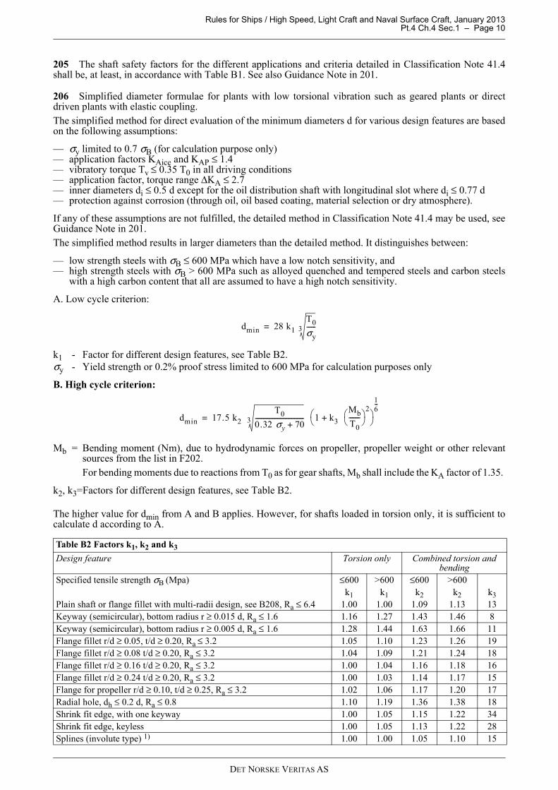
Table B2 Factors k1, k2 and k3
Design feature Torsion only Combined torsion and bending
Specified tensile strength σB (Mpa) ≤600 >600 ≤600 >600k1 k1 k2 k2 k3
Plain shaft or flange fillet with multi-radii design, see B208, Ra ≤ 6.4 1.00 1.00 1.09 1.13 13Keyway (semicircular), bottom radius r ≥ 0.015 d, Ra ≤ 1.6 1.16 1.27 1.43 1.46 8Keyway (semicircular), bottom radius r ≥ 0.005 d, Ra ≤ 1.6 1.28 1.44 1.63 1.66 11Flange fillet r/d ≥ 0.05, t/d ≥ 0.20, Ra ≤ 3.2 1.05 1.10 1.23 1.26 19Flange fillet r/d ≥ 0.08 t/d ≥ 0.20, Ra ≤ 3.2 1.04 1.09 1.21 1.24 18Flange fillet r/d ≥ 0.16 t/d ≥ 0.20, Ra ≤ 3.2 1.00 1.04 1.16 1.18 16Flange fillet r/d ≥ 0.24 t/d ≥ 0.20, Ra ≤ 3.2 1.00 1.03 1.14 1.17 15Flange for propeller r/d ≥ 0.10, t/d ≥ 0.25, Ra ≤ 3.2 1.02 1.06 1.17 1.20 17Radial hole, dh ≤ 0.2 d, Ra ≤ 0.8 1.10 1.19 1.36 1.38 18Shrink fit edge, with one keyway 1.00 1.05 1.15 1.22 34Shrink fit edge, keyless 1.00 1.05 1.13 1.22 28Splines (involute type) 1) 1.00 1.00 1.05 1.10 15
dmin 28 k1 T0
σy------3=
dmin 17.5 k2 T0
0.32 σy 70+-------------------------------3 1 k+ 3
Mb
T0-------
2
16---
=
DET NORSKE VERITAS AS

Rules for Ships / High Speed, Light Craft and Naval Surface Craft, January 2013 Pt.4 Ch.4 Sec.1 – Page 11
207 Simplified diameter formulae for stainless steel shafts subjected to sea water and with low torsionalvibration.This simplified method for direct evaluation of minimum diameters dmin for various design features are basedon the same conditions as in 206 except that the protection against corrosion now is protection against crevicecorrosion. This means that e.g. keyways shall be sealed in both ends and thus the calculation in 206 applies forsuch design features. However, for craft where the shaft is stationary for some considerable time, measuresshould be taken to avoid crevice corrosion in way of the bearings e.g. periodically rotation of shaft or flushing.It is distinguished between 3 material types, see Table B3. The simplified method is only valid for shaftsaccumulating 109 to 1010 cycles.
A. The low cycle criterion:
k1 - Factor for different design features, see Table B4.
For shafts with significant bending moments:The formula shall be multiplied with:
B. The high cycle criterion:
Mb = Bending moment (Nm), e.g. due to propeller or impeller weight or other relevant sources mentioned inF202. However, the stochastic extreme moment in F301 item 2) shall not be used for either low or highcycle criteria.
k3 = Factor for different design features, see Table B4.
The highest value for dmin from A and B applies.
Shoulder fillet r/d ≥ 0.02, D/d ≤ 1.1, Ra ≤ 3.2 1.05 1.10 1.21 1.25 22Shoulder fillet r/d ≥ 0.1, D/d ≤ 1.1, Ra ≤ 3.2 1.00 1.03 1.14 1.17 16Shoulder fillet r/d ≥ 0.2, D/d ≤ 1.1, Ra ≤ 3.2 1.0 1.01 1.12 1.15 13Relief groove1), D/d = 1.1, D-d ≤ 2 r, Ra ≤ 1.6 1.00 1.04 1.15 1.17 16Groove1) for circlip, D-d ≤ 2 b, D-d ≤ 7.5 r, Ra ≤ 1.6 1.17 1.28 1.38 1.40 27Longitudinal slot 2) in oil distribution shaft, di ≤ 0.77 d, 0.05 d ≤ e ≤ 0.2 d, (1 − e) ≤ 0.5 d, Ra ≤ 1.6 1.49 1.69
1) applicable to root diameter of notch
2) applicable for slots with outlets each 180° and for outlets each 120°
Table B3 Stainless steel types
Material type Main structureMain alloy elements Mechanical properties
% Cr % Ni % Mo σB σy = σ0.2Stainless steel I Austenitic 16−18 10−14 ≥ 2 500−600 ≥ 0.45 σBStainless steel II Martensitic 15−17 4−6 ≥ 1 850−1000 ≥ 0.75 σBStainless steel III Ferritic-austenitic (duplex) 25−27 4−7 1-2 600−750 ≥ 0.65 σB
Table B2 Factors k1, k2 and k3 (Continued)
Design feature Torsion only Combined torsion and bending
Specified tensile strength σB (Mpa) ≤600 >600 ≤600 >600k1 k1 k2 k2 k3
dmin 28 k1 T0
σy------3=
143---
Mb
T0-------
2+
16---
dmin 4 T03 1 k3
Mb
T0-------
2+
16---
=
DET NORSKE VERITAS AS

Rules for Ships / High Speed, Light Craft and Naval Surface Craft, January 2013 Pt.4 Ch.4 Sec.1 – Page 12
208 Simplified calculation method for shafts in direct coupled plants.
1) This method may also be used for other intermediate and propeller shafts that are mainly subjected totorsion. Shafts subjected to considerable bending, such as in gearboxes, thrusters, etc. as well as shafts inprime movers are not included.Further, additional strengthening for ships classed for navigation in ice is not covered by this method.
2) The method has following material limitations:Where shafts may experience vibratory stresses close to the permissible stresses for transient operation, thematerials shall have a specified minimum ultimate tensile strength (σB) of 500 MPa. Otherwise materialshaving a specified minimum ultimate tensile strength (σB) of 400 MPa may be used.Close to the permissible stresses for transient operation” means more than 70% of permissible value.For use in the formulae in this method, σB is limited as follows:
— For C and C-Mn steels up to 600 MPa for use in item 4, and up to 760 MPa for use in item 3.— For alloy steels up to 800 MPa.— For propeller shafts in general up to 600 MPa (for all steel types).
Where materials with greater specified or actual tensile strengths than the limitations given above are used,reduced shaft dimensions or higher permissible stresses are not acceptable when derived from the formulaein this method.
3) Shaft diameters:Shaft diameters shall result in acceptable torsional vibration stresses, see item 4) or in any case not to beless than determined from the following formula:
where
dmin= minimum required diameter unless larger diameter is required due to torsional vibration stresses, seeitem 4)
di = actual diameter of shaft bore (mm)d = actual outside diameter of shaft (mm)
If the shaft bore is ≤ 0.40 d, the expression 1-di4/d4 may be taken as 1.0
F = factor for type of propulsion installation = 95 for intermediate shaft in turbine installation, diesel installation with hydraulic (slip type)
couplings, electric propulsion installation = 100 for all other diesel installations and propeller shaftsk = factor for particular shaft design features,
see item 5n0 = shaft speed (rpm) at rated powerP = rated power (kW) transmitted through the shaft (losses in bearings shall be disregarded)σB = specified minimum tensile strength (MPa) of shaft material, see item 2.The diameter of the propeller shaft located forward of the inboard stern tube seal may be gradually reducedto the corresponding diameter for the intermediate shaft using the minimum specified tensile strength ofthe propeller shaft in the formula and recognising any limitation given in item 2.
Table B4 Factors k1 and k3
A. Low cycle B. High cycle
Design feature 2):Stainless Steel 1):
I II and III I, II and IIIk1 k1 k3
Plain shaft 1.00 1.00 14Propeller flange r/d ≥ 0.10t/d ≥ 0.25 1.04 1.08 19
Shrink fit edge, keyless The area under the edge is not subject to sea water, thus calculated according to B206
1) According to Table B3
2) Surface roughness Ra < 1.6 applies for all design features
dmin F kPn0----- 1
1di
4
d4
-----–
-------------- 560σB 160+----------------------
3
=
DET NORSKE VERITAS AS

Rules for Ships / High Speed, Light Craft and Naval Surface Craft, January 2013 Pt.4 Ch.4 Sec.1 – Page 13
4) Permissible torsional vibration stresses:The alternating torsional stress amplitude shall be understood as (τmax−τmin)/2 measured on a shaft in arelevant condition over a repetitive cycle.Torsional vibration calculations shall include normal operation and operation with any one cylindermisfiring (i.e. no injection but with compression) giving rise to the highest torsional vibration stresses inthe shafting.For continuous operation the permissible stresses due to alternating torsional vibration shall not exceed thevalues given by the following formulae:
where
τC = stress amplitude (MPa) due to torsional vibration for continuous operationσB = specified minimum tensile strength (MPa) of shaft material, see item 2cK = factor for particular shaft design, see item 5cD = size factor, = 0.35 + 0.93 · do
-0.2
d = actual shaft outside diameter (mm)λ = speed ratio = n/n0n = speed (rpm) under considerationn0 = speed (rpm) of shaft at rated power.Where the stress amplitudes exceed the limiting value of τC for continuous operation, including onecylinder misfiring conditions if intended to be continuously operated under such conditions, restrictedspeed ranges shall be imposed, which shall be passed through rapidly. In this context, “rapidly” means within just a few seconds, ≈ 4-5 seconds, both upwards and downwards.If this is exceeded, flanged shafts (except propeller flange) shall be designed with a stress concentrationfactor less than 1.05, see Guidance note below. Alternatively, a calculation method which is taking intoaccount the accumulated number of load cycles and their magnitude during passage of the barred speedrange, may be used, see Guidance note to B201.Guidance note:This may be obtained by means of a multi-radii design such as e.g. starting with r1 = 2.5 d tangentially to the shaftover a sector of 5°, followed by r2 = 0.65 d over the next 20° and finally r3 = 0.09 d over the next 65°(d = actual shaft outside diameter).
---e-n-d---of---G-u-i-d-a-n-c-e---n-o-t-e---
Restricted speed ranges in normal operating conditions are not acceptable above λ = 0.8. Restricted speedranges in one-cylinder misfiring conditions of single propulsion engine ships shall enable safe navigation.The limits of the barred speed range shall be determined as follows:
— The barred speed range shall cover all speeds where τC is exceeded. For controllable pitch propellerswith the possibility of individual pitch and speed control, both full and zero pitch conditions have to beconsidered.
— The tachometer tolerance (usually 0.01·n0) has to be added in both ends.— At each end of the barred speed range the engine shall be stable in operation.
For the passing of the barred speed range the torsional vibrations for steady state condition shall not exceedthe value given by the formula:
where:
τT = permissible stress amplitude in N/mm2 due to steady state torsional vibration in a barred speed range.5) Table B5 shows k and cK factors for different design features.
Transitions of diameters shall be designed with either a smooth taper or a blending radius.Guidance note:For guidance, a blending radius equal to the change in diameter is recommended.
---e-n-d---of---G-u-i-d-a-n-c-e---n-o-t-e---
for λ < 0.9
0.9 ≤ λ < 1.05
( )22318
160 λστ ⋅−⋅⋅⋅+
=± DKB
C cc
38.118
160 ⋅⋅⋅+=± DKB
C ccστ
KCT c/7.1 ττ ⋅=±
DET NORSKE VERITAS AS

Rules for Ships / High Speed, Light Craft and Naval Surface Craft, January 2013 Pt.4 Ch.4 Sec.1 – Page 14
6) Notes:A. Shafts complying with this method satisfy the load conditions in 202.
a) Low cycle fatigue criterion (typically < 104), i.e. the primary cycles represented by zero to full load andback to zero, including reversing torque if applicable.This is addressed by the formula in item 3.
b) High cycle fatigue criterion (typically >107), i.e. torsional vibration stresses permitted for continuousoperation as well as reverse bending stresses. For limits for torsional vibration stresses see item 4.The influence of reverse bending stresses is addressed by the safety margins inherent in the formula initem 3.
c) The accumulated fatigue due to torsional vibration when passing through a barred speed range or anyother transient condition with associated stresses beyond those permitted for continuous operation isaddressed by the criterion for transient stresses, item 4.
Table B5 k and cK factors for different design features
Intermediate shafts with Thrust shafts external to
engines Propeller shafts
Integral coupling flange 1) and straight sections
Shrink fit coupling 2)
Keyway, tapered connection 3)4)
Keyway, cylindrical connection 3)4)
Radial hole 5)
Longitudinal slot 6)
On both sides of thrust collar 1)
In way of bearing when a roller bearing is used
Flange mounted 1) or keyless taper fitted propellers 8)
Key fitted propellers 8)
Between forward end of aft most bearing and forward stern tube seal
k = 1.0 1.0 1.10 1.10 1.10 1.20 1.10 1.10 1.22 1.26 1.15 cK = 1.0 1.0 0.60 0.45 0.50 0.30 7) 0.85 0.85 0.55 0.55 0.80
Footnotes
1) Fillet radius shall not be less than 0.08 d.
2) k and cK refer to the plain shaft section only. Where shafts may experience vibratory stresses close to the permissible stresses for continuous operation, an increase in diameter to the shrink fit diameter shall be provided, e.g. a diameter increase of 1 to 2% and a blending radius as described in the table note.
3) At a distance of not less than 0.2 d from the end of the keyway the shaft diameter may be reduced to the diameter calculated with k = 1.0.
4) Keyways are in general not to be used in installations with a barred speed range.
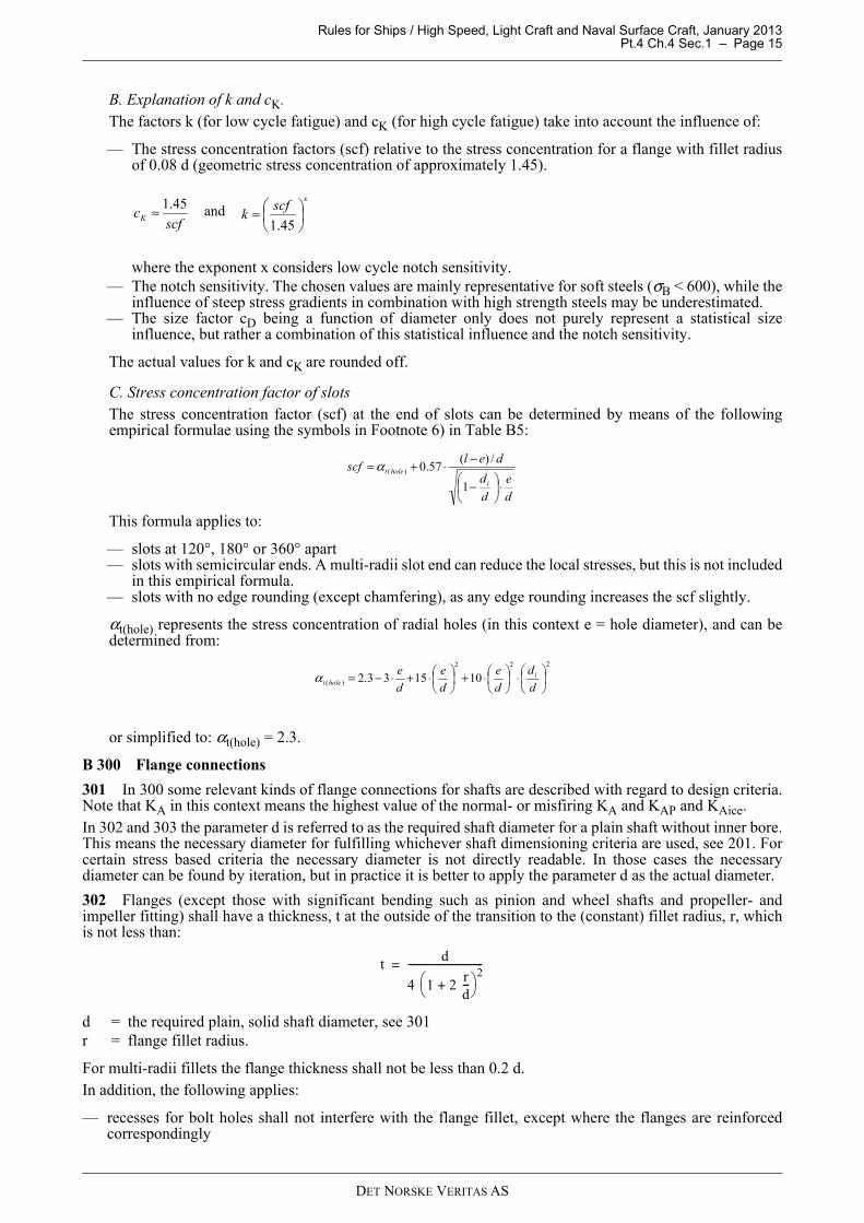
5) Diameter of radial bore not to exceed 0.3 d.The intersection between a radial and an eccentric axial bore (see Fig.1) is not covered by this method.
6) Subject to limitations as slot length (l)/outside diameter < 0.8, and inner diameter (di)/outside diameter < 0.8 and slot width (e)/outside diameter >0.10. The end rounding of the slot shall not be less than e/2. An edge rounding should preferably be avoided as this increases the stress concentration slightly.The k and cK values are valid for 1, 2 and 3 slots, i.e. with slots at 360°, respectively 180° and 120° apart.
7) cK = 0.3 is a safe approximation within the limitations in 6). If the slot dimensions are outside of the above limitations, or if the use of another cK is desired, the actual stress concentration factor (scf) shall be documented or determined from the formulae in item 6. In which case:cK = 1.45/scf. Note that the scf is defined as the ratio between the maximum local principal stress and times the nominal torsional stress (determined for the bored shaft without slots).
8) Applicable to the portion of the propeller shaft between the forward edge of the aftermost shaft bearing and the forward face of the propeller hub (or shaft flange), but not less than 2.5 times the required diameter.
Fig. 1Intersection between a radial and an eccentric axial bore
3
DET NORSKE VERITAS AS
Rules for Ships / High Speed, Light Craft and Naval Surface Craft, January 2013 Pt.4 Ch.4 Sec.1 – Page 15
B. Explanation of k and cK.The factors k (for low cycle fatigue) and cK (for high cycle fatigue) take into account the influence of:
— The stress concentration factors (scf) relative to the stress concentration for a flange with fillet radiusof 0.08 d (geometric stress concentration of approximately 1.45).
where the exponent x considers low cycle notch sensitivity.— The notch sensitivity. The chosen values are mainly representative for soft steels (σB < 600), while the
influence of steep stress gradients in combination with high strength steels may be underestimated.— The size factor cD being a function of diameter only does not purely represent a statistical size
influence, but rather a combination of this statistical influence and the notch sensitivity.
The actual values for k and cK are rounded off.
C. Stress concentration factor of slotsThe stress concentration factor (scf) at the end of slots can be determined by means of the followingempirical formulae using the symbols in Footnote 6) in Table B5:
This formula applies to:
— slots at 120°, 180° or 360° apart— slots with semicircular ends. A multi-radii slot end can reduce the local stresses, but this is not included
in this empirical formula.— slots with no edge rounding (except chamfering), as any edge rounding increases the scf slightly.
αt(hole) represents the stress concentration of radial holes (in this context e = hole diameter), and can bedetermined from:
or simplified to: αt(hole) = 2.3.
B 300 Flange connections
301 In 300 some relevant kinds of flange connections for shafts are described with regard to design criteria.Note that KA in this context means the highest value of the normal- or misfiring KA and KAP and KAice.In 302 and 303 the parameter d is referred to as the required shaft diameter for a plain shaft without inner bore.This means the necessary diameter for fulfilling whichever shaft dimensioning criteria are used, see 201. Forcertain stress based criteria the necessary diameter is not directly readable. In those cases the necessarydiameter can be found by iteration, but in practice it is better to apply the parameter d as the actual diameter.
302 Flanges (except those with significant bending such as pinion and wheel shafts and propeller- andimpeller fitting) shall have a thickness, t at the outside of the transition to the (constant) fillet radius, r, whichis not less than:
d = the required plain, solid shaft diameter, see 301r = flange fillet radius.
For multi-radii fillets the flange thickness shall not be less than 0.2 d.In addition, the following applies:
— recesses for bolt holes shall not interfere with the flange fillet, except where the flanges are reinforcedcorrespondingly
andscf
cK
45.1≈x
scfk
≈
45.1
d
e
d
d
delscf
i
holet
⋅
−
−⋅+=1
/)(57.0)(α
222
)( 101533.2
⋅
⋅+
⋅+⋅−=
d
d
d
e
d
e
d
e iholetα
td
4 1 2 rd---+
2-------------------------------=
DET NORSKE VERITAS AS

Rules for Ships / High Speed, Light Craft and Naval Surface Craft, January 2013 Pt.4 Ch.4 Sec.1 – Page 16
— for flanges with shear bolts or shear pins:
db = diameter of shear bolt or pinσy,bolt = yield strength of shear bolt or pinσy,flange=yield strength of flange
303 Flanges with significant bending as pinion and wheel shafts, and propeller and impeller fittings shallhave a minimum thickness of:
d = the required plain, solid shaft diameter, see 301r = flange fillet radius.
For multi-radii fillets the flange thickness shall not be less than 0.25 d. In addition, the following applies:
— recesses for bolt holes shall not interfere with the flange fillet, except where the flanges are reinforcedcorrespondingly
— for flanges with shear bolts or shear pins:
db = diameter of shear bolt or pinσy,bolt = yield strength of shear bolt or pinσy,flange = yield strength of flange
304 Torque transmission based on combinations of shear or guide pins or expansion devices and pre-stressedfriction bolts shall fulfil:A. The friction torque TF shall be at least twice the repetitive vibratory torque Tv, i.e.:
μ = Coefficient of friction, see 307Tv = (KA − 1) T0 for geared plants (for continuous operation) (Nm)Tv = (KAice − 1) T0 for ice class notations (Nm)
Highest value of Tv in the entire speed range for continuous operation (i.e. not transient speed range)for direct coupled plants. See torsional vibration in Ch.3 Sec.1 G300 and G400
D = Bolt pitch circle diameter (PCD) (mm)Fbolts = The total bolt pre-stress force of all n bolts (N)Bolt pre-stress limited as in 308.B. Twice the peak torque Tpeak minus the friction torque (see A. above) shall not result in shear stresses beyondthe shear yield strength ( ) of the n ream fitted pins or expansion devices, i.e.:
Tpeak= Higher value of (Nm):- KAP T0 or- KAice T0 or- T + Tv in the entire speed range considering also normal transient conditions
D = Bolt pitch circle diameter (PCD) (mm)db = Bolt shear diameter (mm)
t12--- db
σy bolt,σy flange,----------------------≥
td
3 1 2 rd---+
2-------------------------------=
t12--- db
σy bolt,σy flange,----------------------≥
TF
μ D Fbolts
2000-------------------------- 2 Tv (Nm)≥=
σy 3( )⁄
2 Tpeak TF
π n D db2 σy
8 103 3⋅
--------------------------------- (Nm)≤–
DET NORSKE VERITAS AS

Rules for Ships / High Speed, Light Craft and Naval Surface Craft, January 2013 Pt.4 Ch.4 Sec.1 – Page 17
Guidance note:Tv in normal transient conditions means with prescribed or programmed way of passing through a barred speed range.
---e-n-d---of---G-u-i-d-a-n-c-e---n-o-t-e---
305 Torque transmission based on n flange coupling bolts mounted with a slight clearance (e.g.< 0.1 mm)and tightened to a specified pre-stress σpre shall fulfil the following requirements:
— the friction torque shall be at least twice the repetitive vibratory torque (including normal transientconditions), see 304 A.
— bolt pre-stress limited as in 308— the shear stress τ due to twice the peak torque minus the friction torque combined with the pre-stress σpre
shall not exceed the yield strength σy, i.e.:
τ = Shear stress in bolt,
σpre = Specified bolt pre-stress,
Tpeak= Peak torque, see 304 B.
306 Torque transmission based on ream fitted bolts only, shall fulfil the following requirements:
— the bolts shall have a light press fit— the bolt shear stress due to two times the peak torque Tpeak, (see 304 B) minus the friction torque TF, shall
not exceed 0.58 σy— the bolt shear stress due to the vibratory torque TV, for continuous operation shall not exceed σy/8.
This means that the diameter of the n fitted bolts shall fulfil the following criteria:
and
Ream fitted bolts may be replaced by expansion devices provided that the bolt holes in the flanges alignproperly.
Guidance note:Ream fitted bolts with a light press fit means that the bolts when having a temperature equal to the flange, cannot bemounted by hand. A light pressing force or cooling should be necessary.In order to facilitate later removal of the bolts it is important that the interference between the bolts and correspondingholes are not excessive. It should only be a few 1/100 mm, i.e. just more than the contraction of the diameter due tothe pre-tightening. Therefore, direct contact with liquid nitrogen for cooling the bolts is unnecessary and could leadto cracks in the bolts. It is also beneficial to use bolts which are made from somewhat harder material than the shaftflange is made of (>50HB).
---e-n-d---of---G-u-i-d-a-n-c-e---n-o-t-e---
307 Torque transmission based on only friction between mating flange surfaces shall fulfil a minimumfriction torque of 2Tpeak. The coefficient of friction, μ shall be 0.15 for steel against steel and steel againstbronze, and 0.12 for steel against nodular cast iron. Other values may be considered for especially treatedmating surfaces. The bolt pre-stress is limited as given in 308.
σpre2
3 τ2+ σy≤
calculated as τ8 2 Tpeak TF–( )10
3
D π n db2
--------------------------------------------------=
calculated as σpre
4 Fbolts
π n db2
-------------------=
db 662Tpeak TF–
nDσy------------------------------≥
db 143TV
nDσy--------------≥
2Tpeak
μ D Fbolts
2000-------------------------- (Nm) ≤
DET NORSKE VERITAS AS

Rules for Ships / High Speed, Light Craft and Naval Surface Craft, January 2013 Pt.4 Ch.4 Sec.1 – Page 18
D = Bolt pitch diameter (mm) Fbolts = The total bolt pre-stress force of all n boltsTpeak = Peak torque, see 304 B.
308 Bolts may have a pre-stress up to 70% of the yield strength in the smallest section. However, when using10.9 or 12.9 bolts the thread lubrication procedure has to be especially evaluated, and only tightening by twistangle or better is accepted (e.g. by elongation measurement). If rolled threads, the pre-stress in the threads maybe increased up to 90% of the yield strength.In corrosive environment the upper acceptable material tensile strength is 1350 MPa.In order to maintain the designed bolt pre-stress under all conditions, these percentages are given on thecondition that the peak service stresses combined with the pre-stress do not exceed the yield strength. The boltsshall be designed under consideration of the full thrust and bending moments including reversing. For bendingmoments on water jet impeller flanges, see F301 item 2.The length of the female threads shall be at least 0.8 d σybolt/σyfemale
where d is the outside thread diameter and the ratio compensates for the difference in yield strength betweenthe bolt and the female threads.This requirement is valid when the above mentioned pre-stress is utilised, otherwise a proportional reductionin required thread length may be applied.
B 400 Shrink fit connections
401 General requirements for all torque transmitting shrink fit connections, including propeller fitting.
1) The shrink fit connections shall be able to transmit torque and axial forces with safety margins as given in402 and 403. This shall be obtained by a certain minimum shrinkage amount.If the shrunk-on part is subjected to high speeds (e.g. tip speed >50 m/s), the influence of centrifugalexpansion shall be considered.The following load conditions shall be considered:A. In the full speed range (>90%):
— The rated torque T0 including any permitted intermittent overload. When combined with the vibratorytorque in misfiring condition the rated torque may be reduced proportional with the ratio remainingcylinders/number of cylinders.
— The highest temporary vibratory torque TV0T in the full speed range. This shall consider the worstrelevant operating conditions, e.g. such as sudden misfiring (one cylinder with no injection) andcylinder unbalance (see Ch.3 Sec.1 G301 e). For determination of the vibratory torque in the misfiringcondition it is necessary to consider the steady state vibrations in the full speed range regardless ofwhether the speed range is barred for continuous operation due to torsional vibrations or otheroperational conditions.
— For any ice class notation the impact load shall be considered as a temporary vibratory torque: (KAice−1)·T0.
— The axial forces such as propeller thrust Th and/or gear forces. The nut force shall be disregarded.— For ice class notation the highest axial force (Thice) in the applicable ice rules.— The axial force due to shrinkage pressure at a taper.
B. At a main resonance (applicable to direct coupled diesel engines):
— The mean torque T at that resonance.— The steady state vibratory torque TVres regardless if there is a barred speed range.— By convention the propeller thrust, any thrust due to ice impact, the nut force, and the axial force due
to shrinkage pressure at the taper shall be disregarded.
Guidance note:The peak torques when reversing at main resonance are not used in this context and that condition is assumed coveredby the required partial safety factors.
---e-n-d---of---G-u-i-d-a-n-c-e---n-o-t-e---
2) The minimum and maximum shrinkage amounts shall be correlated to the measurement that shall beapplied for verification. For elements with constant external diameter, diametrical expansion is preferred.Otherwise the pull up length (wet mounting) or the push up force (dry mounting) shall be specified. Theclearance of an intermediate sleeve is also to be considered.
3) The taper is normally not to be steeper than 1:20. However, taper of cone as steep as 1:15 is acceptable,provided that a more refined mounting procedure and or a higher safety factor than given in the rules is applied.
DET NORSKE VERITAS AS
Rules for Ships / High Speed, Light Craft and Naval Surface Craft, January 2013 Pt.4 Ch.4 Sec.1 – Page 19
4) For tapered connections steeper than 1:30 and all propeller cone mountings where a slippage may cause arelative axial movement between the two members, the axial movement shall be restricted by a nut securedto the shaft with locking arrangement. Alternatively a split fitted ring with locking arrangement may beused.
5) Tapered connections shall be made with accuracy suitable to obtain the required contact between bothmembers. Normally the minimum contact on the taper is 70% when a toolmaker’s blue test is specified.Non-contact bands (except oil grooves) extending circumferentially around the hub or over the full lengthof the hub are not acceptable. At the big end there shall be a full contact band of at least 20% of the taperlength.
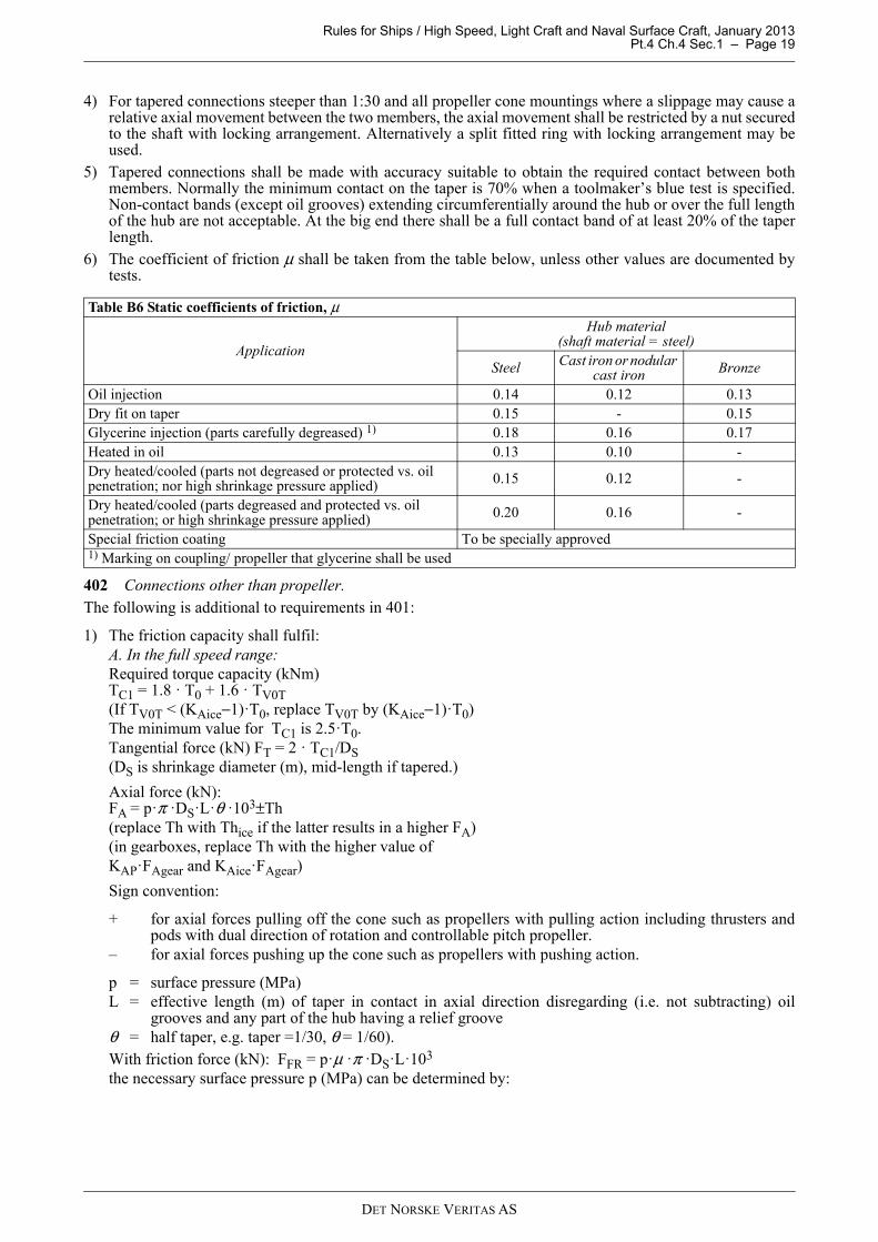
6) The coefficient of friction μ shall be taken from the table below, unless other values are documented bytests.
402 Connections other than propeller.The following is additional to requirements in 401:
1) The friction capacity shall fulfil:A. In the full speed range:Required torque capacity (kNm) TC1 = 1.8 · T0 + 1.6 · TV0T(If TV0T < (KAice−1)·T0, replace TV0T by (KAice−1)·T0)The minimum value for TC1 is 2.5·T0.Tangential force (kN) FT = 2 · TC1/DS(DS is shrinkage diameter (m), mid-length if tapered.)
Axial force (kN):FA = p·π ·DS·L·θ ·103±Th(replace Th with Thice if the latter results in a higher FA)(in gearboxes, replace Th with the higher value ofKAP·FAgear and KAice·FAgear)
Sign convention:
+ for axial forces pulling off the cone such as propellers with pulling action including thrusters andpods with dual direction of rotation and controllable pitch propeller.
– for axial forces pushing up the cone such as propellers with pushing action.
p = surface pressure (MPa)L = effective length (m) of taper in contact in axial direction disregarding (i.e. not subtracting) oil
grooves and any part of the hub having a relief grooveθ = half taper, e.g. taper =1/30, θ = 1/60). With friction force (kN): FFR = p·μ ·π ·DS·L·103
the necessary surface pressure p (MPa) can be determined by:
Table B6 Static coefficients of friction, μ
Application
Hub material (shaft material = steel)
Steel Cast iron or nodular cast iron Bronze
Oil injection 0.14 0.12 0.13Dry fit on taper 0.15 - 0.15Glycerine injection (parts carefully degreased) 1) 0.18 0.16 0.17Heated in oil 0.13 0.10 - Dry heated/cooled (parts not degreased or protected vs. oil penetration; nor high shrinkage pressure applied) 0.15 0.12 -
Dry heated/cooled (parts degreased and protected vs. oil penetration; or high shrinkage pressure applied) 0.20 0.16 -
Special friction coating To be specially approved1) Marking on coupling/ propeller that glycerine shall be used
DET NORSKE VERITAS AS

Rules for Ships / High Speed, Light Craft and Naval Surface Craft, January 2013 Pt.4 Ch.4 Sec.1 – Page 20
Sign convention as above.B. At a main resonance:Torque capacity (kNm): TC2 = 1.6·(T + TVres)The necessary surface pressure p (MPa) can be determined by:
The highest value determined by A and B applies.Coefficient of friction according to Table B6.
2) Fretting under the ends of shrink fit connections has to be avoided in general. However, very light frettingis accounted for by notch factors see Classification Note 41.4 item 6.5.In particular for a shrinkage connection with a high length to diameter ratio (>1.5) or if it is subjected to abending moment, special requirements may apply in order to prevent fretting of the shaft under the edge ofthe outer member. This may be a relief groove or fillet, higher surface pressure, etc.Guidance note:If the surface pressure at the torque end times coefficient of friction is higher than the principal stress variation at thesurface, σ < p μ (see Fig.2 in Sec.2), fretting is not expected. Other surface pressure criteria may also be considered.If such surface pressure or friction cannot be achieved, it may be necessary to use a relief or a groove.The groove may be designed as indicated below:
A good choice is D = 1.1 d and r = 2 (D − d) and an axial overshoot at near zero but not less than zero. Other ways of preventing fretting under the edge of the hub are a relief groove in the hub or a tapered hub outerdiameter. However, these alternatives need to be documented by means of detailed analysis as e.g. finite elementmethod calculations.
---e-n-d---of---G-u-i-d-a-n-c-e---n-o-t-e---
3) The permissible stress due to shrinking for the outer member (index “o”) depends on the nature of theapplied load, coupling design and material. For ductile steels the equivalent stress (von Mises) may be inthe range 70% to 80% of the yield strength σyo for demountable connections and 100% and even someplastic deformation for permanently fitted connections (see below). The permissible stress due to shrinking at the outer diameter or at any other critical section (e.g. axial andradial bore intersection) of the inner member (i.e. the shaft, index “i”) shall not exceed 50% of the yieldstrength σyi.
4) The shrinkage amounts shall be calculated under consideration of the surface roughness as follows:
ΔDmin= minimum shrinkage amount due to tolerances or pull-up distance, minus 0.8 (Rzi + Rzo) ≈ 5 (Rai + Rao) (mm)
ΔDmax= maximum shrinkage amount due to tolerances or pull-up distance, minus 0.8 (Rzi + Rzo) ≈ 5 (Rai + Rao) (mm).
Rz = “ten point height" surface roughness (mm) as defined in ISO4287/1 for shaft and hub, respectively.Ra = "arithmetical mean" surface roughness (mm) as defined in ISO4287/1 for shaft and hub,
respectively.The lower value shall be used for calculation of the required friction torque. The upper value shall be used
322
10
2
⋅⋅⋅⋅⋅
=LD
Tp
S
C
μπ
DET NORSKE VERITAS AS

Rules for Ships / High Speed, Light Craft and Naval Surface Craft, January 2013 Pt.4 Ch.4 Sec.1 – Page 21
for calculation of stresses in the inner and outer members. For tapered connections the shrinkage amountsshall be converted to pull up lengths (Pull-up distance = ΔD/2θ, where 2θ is the taper of cone).
5) The following applies for shrinking within the elastic range and both inner and outer member made of steel.The minimum and maximum shrinkage pressures (MPa) are:
pmin = (ΔDmin/DS) (E/K) 10-3
pmax = (ΔDmax/DS) (E/K) 10-3
The pull-up lengths (mm) are:
The corresponding pull-up force Fpull can be estimated asFpull = p·π Ds L (θ + μpull) 103 (kN)
μpull= Coefficient of friction during pull-up.
The diametrical expansions are (mm):
E = 2.05 · 105 MPaK = (1 + Qi
2)/(1 − Qi2) + (1 + Qo
2)/(1 − Qo2)
Qi = inner diameter of inner member/DSQo = DS/outer diameter of outer memberThe minimum shrinkage pressure shall not be less than the necessary pressure p as determined in item 1.The equivalent (von Mises) stress in the outer member is (MPa):
and shall not exceed the permissible stress as given in item 3 above.The stress calculation of the inner sleeve shall take any expansion sleeve or compression liner influenceinto account.In the case of several members shrunk on together, and all being within the elastic range, the superpositionprinciple shall used.
6) The following applies to shrinking with a certain amount of plastic deformation in the outer memberapplicable to parts that are not intended to be disassembled. The simplified approach given here is valid forboth members being made of steel and solid inner member, and based on modified Tresca criterion. If theseconditions are not fulfilled, a more detailed analysis applies.As specified in item 3 above, the stresses in the inner member (shaft) due to shrinking shall not exceed 50%of the yield strength σyi. Thus the shrinkage pressure is limited to:
pi lim = σyi /√3
In order to keep a safety factor of 1.25 versus full plastic deformation of the outer member the shrinkagepressure is limited to:
po lim = 1.6 σyo /√3 for Qo < 0.368po lim = −1.6 ln(Qo) σyo /√3 for Qo > 0.368
The extent of permissible plastic deformation ζp (i.e. the ratio between the outer diameter of the plasticallydeformed zone and DS) is limited by 2 criteria:
1) 2 ln(ζp) − (Qo ζp)2 + 1 = √3 pp/σyowhere pp is the permissible shrinkage pressure and is the smaller value of po lim and pi lim.
δmin pmin
103Ds
2θ--------------- K
E----=
δmax pmax
103Ds
2θ--------------- K
E----=
ΔDomax pmax
103Ds
E---------------
2Qo
1 Qo2
–---------------=
ΔDomin pmin
103Ds
E---------------
2Qo
1 Qo2
–---------------=
3 Qo4
+ pmax
1 Qo2
–-------------------------------------
DET NORSKE VERITAS AS

Rules for Ships / High Speed, Light Craft and Naval Surface Craft, January 2013 Pt.4 Ch.4 Sec.1 – Page 22
2) ζp = (0.7 Qo2 + 0.3)1/2 / Qo in order to limit the plastically deformed cross section area to 30% of the
full cross section.
The actual minimum and maximum extents of plastic deformation are calculated as:ζmin, max = 0.931 (E/σyo)1/2 (ΔDmin, max/DS)1/2
ζmin is used to calculate the minimum shrinkage pressure as:pmin = σyo (1 + 2 ln(ζmin) − (Qo ζmin)2)/√3
ζmax shall not exceed the permissible value ζp.
403 Propeller to shaft connectionsThe following is additional to 401:
1) The friction capacity shall fulfil the following at a temperature of 35°C:A. In the full speed range:Required torque capacity (kNm) TC1 = 2.0 · T0 + 1.8 · TV0T(If TV0T < (KAice−1)·T0, replace TV0T by (KAice−1)·T0)The minimum value for TC1 is 2.8·T0.Tangential force (kN) FT = 2 · TC1/DS (DS is shrinkage diameter (m), mid-length if tapered.)
Axial force (kN) FA = p·π·DS·L·θ·103±Th
Sign convention:
+ for propellers with pulling action including thrusters and pods with dual direction of rotation.– for propellers with pushing action.Replace Th with Thice if this results in a higher FA.
p = surface pressure (MPa)L = effective length (m) of taper in contact in axial direction disregarding (i.e. not subtracting) oil grooves
and any part of the hub having a relief grooveθ = half taper, e.g. taper =1/30, θ = 1/60.With friction force (kN) FFR = p·μ·π ·DS·L·103
the necessary surface pressure p35T (MPa) at 35°C for safe torque transmission can be determined by:
Sign convention as above.
B. At a main resonance:Torque capacity (kNm) TC2 = 1.8·(T + TVres)The necessary surface pressure p (MPa) can be determined by:
The higher value from A and B shall be used.Coefficient of friction according to Table B6.
C. Prevention of detrimental fretting under the hub at the top of the shaft cone:Regardless required surface pressure for torque transmission p35T, the minimum nominal surface pressureat the top of the shaft cone p35min shall not be less than 30 MPa for bronze propellers and 50 MPa for steelpropellers. Normally there is no relief groove in the upper end of the hub, and this criterion applies at thesame position as the 70% of yield strength criterion. However, special consideration may be given forproven designs (e.g. with relief groove) dealing with the risk of fretting in another, adequate way.
2) For propeller without intermediate sleeve, the corresponding required pull-up length (mm) at 35°C is thegreater value of δ35T for torque transmission and δ35min for reducing the risk of fretting:
322
35 10
2
⋅⋅⋅⋅⋅
=LD
Tp
S
CT μπ
DET NORSKE VERITAS AS

Rules for Ships / High Speed, Light Craft and Naval Surface Craft, January 2013 Pt.4 Ch.4 Sec.1 – Page 23
where
Eh = the modulus of elasticity of the propeller hubES = the modulus of elasticity of shaft.Modulus of elasticity to be used:For Cu1 (Mn-bronze) and Cu2 (Mn-Ni-bronze): 1.05·105 MPaFor Cu3 (Ni-Al-bronze) and Cu4 (Mn-Al-bronze): 1.15·105 MPaFor steel: 2.05·105 MPa
νh = the Poisson’s ratio for hubνS = the Poisson’s ratio for shaft.
Poisson’s ratios to be used:
For bronze: 0.33For steel: 0.29
Qo = the ratio between DS and the mean outer diameter of propeller hub at the axial position corresponding to DSQi = the ratio between the inner diameter of the shaft and DS.The additional index “B” refers to the corresponding ratios at the big end of the cone. Note that if the hubhas a relief groove at the big end, this is the nearest section that is not relieved.The minimum pull-up length (mm) at temperature t (t < 35°C) is the greater value of:
and
where α is the coefficient of linear expansion
3) For propeller without intermediate sleeve, the maximum equivalent uniaxial stress in the hub (calculated atthe big end) at 0°C based on the von Mises criterion shall not exceed 70% of the yield point or 0.2% proofstress (0.2% offset yield strength) for the propeller material based on the specified value for the test piece.Note that if the hub has a relief groove at the big end, this criterion applies to the nearest section that is notrelieved.Maximum permissible surface pressure (MPa) at 0°C:
Corresponding maximum permissible pull-up length (mm) at 0°C:
Corresponding maximum permissible pull-up length (mm) at temperature t:
For steel: αS = 12.0·10-6 1/°CFor all copper-based alloys: αb = 17.5·10-6 1/°C
−
−+⋅+
+
−+⋅⋅
⋅⋅⋅= S
i
i
Sh
o
o
h
STT Q
Q
EQ
Q
E
Dp νν
θδ
2
2
2
23
3535 1
11
1
11
2
10
−
−+
⋅+
+
−+
⋅⋅⋅
⋅⋅+⋅= S
iB
iB
Sh
oB
oB
h
S
Q
Q
EQ
Q
E
LDp νν
θθ
δ2
2
2
23
min35min351
11
1
11
2
10)(
( ) ( )tD
SbS
TTt −⋅−⋅⋅⋅
+=− 352
103
35 ααθ
δδ
( ) ( )tLDSb
St −⋅−⋅
⋅⋅⋅+
+=− 352
10)( 3
min35min ααθθδδ
min35min35
maxmax δδ ⋅=
p
p
( ) tLD
SbS
t ⋅−⋅
⋅⋅+−=− αα
θθδδ
2
10)( 3
maxmax
DET NORSKE VERITAS AS
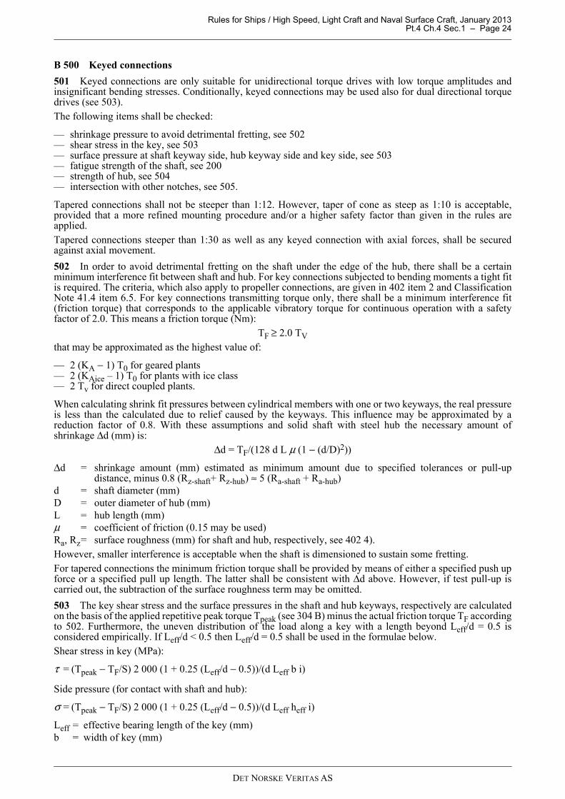
Rules for Ships / High Speed, Light Craft and Naval Surface Craft, January 2013 Pt.4 Ch.4 Sec.1 – Page 24
B 500 Keyed connections
501 Keyed connections are only suitable for unidirectional torque drives with low torque amplitudes andinsignificant bending stresses. Conditionally, keyed connections may be used also for dual directional torquedrives (see 503).The following items shall be checked:
— shrinkage pressure to avoid detrimental fretting, see 502— shear stress in the key, see 503— surface pressure at shaft keyway side, hub keyway side and key side, see 503— fatigue strength of the shaft, see 200— strength of hub, see 504— intersection with other notches, see 505.
Tapered connections shall not be steeper than 1:12. However, taper of cone as steep as 1:10 is acceptable,provided that a more refined mounting procedure and/or a higher safety factor than given in the rules areapplied.Tapered connections steeper than 1:30 as well as any keyed connection with axial forces, shall be securedagainst axial movement.
502 In order to avoid detrimental fretting on the shaft under the edge of the hub, there shall be a certainminimum interference fit between shaft and hub. For key connections subjected to bending moments a tight fitis required. The criteria, which also apply to propeller connections, are given in 402 item 2 and ClassificationNote 41.4 item 6.5. For key connections transmitting torque only, there shall be a minimum interference fit(friction torque) that corresponds to the applicable vibratory torque for continuous operation with a safetyfactor of 2.0. This means a friction torque (Nm):
TF ≥ 2.0 TV
that may be approximated as the highest value of:
— 2 (KA − 1) T0 for geared plants— 2 (KAice – 1) T0 for plants with ice class— 2 Tv for direct coupled plants.
When calculating shrink fit pressures between cylindrical members with one or two keyways, the real pressureis less than the calculated due to relief caused by the keyways. This influence may be approximated by areduction factor of 0.8. With these assumptions and solid shaft with steel hub the necessary amount ofshrinkage Δd (mm) is:
Δd = TF/(128 d L μ (1 − (d/D)2))
Δd = shrinkage amount (mm) estimated as minimum amount due to specified tolerances or pull-updistance, minus 0.8 (Rz-shaft+ Rz-hub) ≈ 5 (Ra-shaft + Ra-hub)
d = shaft diameter (mm)D = outer diameter of hub (mm)L = hub length (mm)μ = coefficient of friction (0.15 may be used)Ra, Rz= surface roughness (mm) for shaft and hub, respectively, see 402 4).However, smaller interference is acceptable when the shaft is dimensioned to sustain some fretting.For tapered connections the minimum friction torque shall be provided by means of either a specified push upforce or a specified pull up length. The latter shall be consistent with Δd above. However, if test pull-up iscarried out, the subtraction of the surface roughness term may be omitted.
503 The key shear stress and the surface pressures in the shaft and hub keyways, respectively are calculatedon the basis of the applied repetitive peak torque Tpeak (see 304 B) minus the actual friction torque TF accordingto 502. Furthermore, the uneven distribution of the load along a key with a length beyond Leff/d = 0.5 isconsidered empirically. If Leff/d < 0.5 then Leff/d = 0.5 shall be used in the formulae below.Shear stress in key (MPa):
τ = (Tpeak − TF/S) 2 000 (1 + 0.25 (Leff/d − 0.5))/(d Leff b i)
Side pressure (for contact with shaft and hub):
σ = (Tpeak − TF/S) 2 000 (1 + 0.25 (Leff/d − 0.5))/(d Leff heff i)
Leff = effective bearing length of the key (mm)b = width of key (mm)
DET NORSKE VERITAS AS
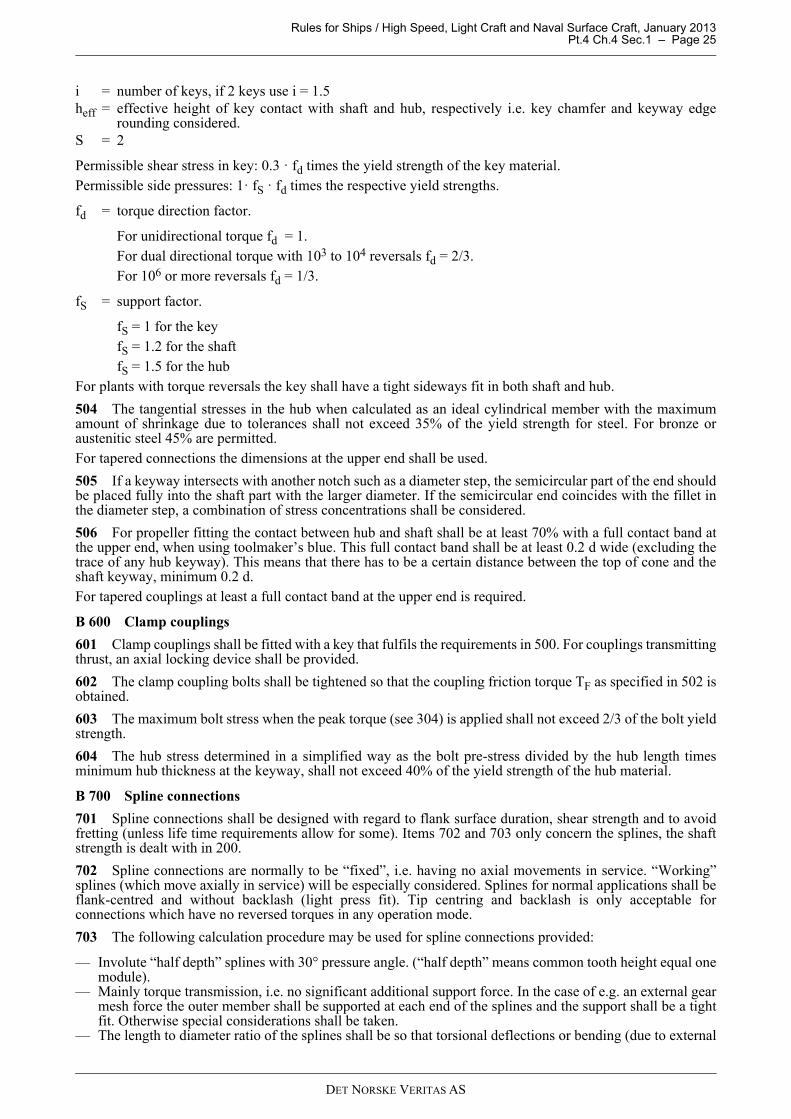
Rules for Ships / High Speed, Light Craft and Naval Surface Craft, January 2013 Pt.4 Ch.4 Sec.1 – Page 25
i = number of keys, if 2 keys use i = 1.5heff = effective height of key contact with shaft and hub, respectively i.e. key chamfer and keyway edge
rounding considered. S = 2
Permissible shear stress in key: 0.3 · fd times the yield strength of the key material.Permissible side pressures: 1· fS · fd times the respective yield strengths.
fd = torque direction factor.
For unidirectional torque fd = 1.For dual directional torque with 103 to 104 reversals fd = 2/3. For 106 or more reversals fd = 1/3.
fS = support factor.
fS = 1 for the keyfS = 1.2 for the shaftfS = 1.5 for the hub
For plants with torque reversals the key shall have a tight sideways fit in both shaft and hub.
504 The tangential stresses in the hub when calculated as an ideal cylindrical member with the maximumamount of shrinkage due to tolerances shall not exceed 35% of the yield strength for steel. For bronze oraustenitic steel 45% are permitted.For tapered connections the dimensions at the upper end shall be used.
505 If a keyway intersects with another notch such as a diameter step, the semicircular part of the end shouldbe placed fully into the shaft part with the larger diameter. If the semicircular end coincides with the fillet inthe diameter step, a combination of stress concentrations shall be considered.
506 For propeller fitting the contact between hub and shaft shall be at least 70% with a full contact band atthe upper end, when using toolmaker’s blue. This full contact band shall be at least 0.2 d wide (excluding thetrace of any hub keyway). This means that there has to be a certain distance between the top of cone and theshaft keyway, minimum 0.2 d.For tapered couplings at least a full contact band at the upper end is required.
B 600 Clamp couplings
601 Clamp couplings shall be fitted with a key that fulfils the requirements in 500. For couplings transmittingthrust, an axial locking device shall be provided.
602 The clamp coupling bolts shall be tightened so that the coupling friction torque TF as specified in 502 isobtained.
603 The maximum bolt stress when the peak torque (see 304) is applied shall not exceed 2/3 of the bolt yieldstrength.
604 The hub stress determined in a simplified way as the bolt pre-stress divided by the hub length timesminimum hub thickness at the keyway, shall not exceed 40% of the yield strength of the hub material.
B 700 Spline connections
701 Spline connections shall be designed with regard to flank surface duration, shear strength and to avoidfretting (unless life time requirements allow for some). Items 702 and 703 only concern the splines, the shaftstrength is dealt with in 200.
702 Spline connections are normally to be “fixed”, i.e. having no axial movements in service. “Working”splines (which move axially in service) will be especially considered. Splines for normal applications shall beflank-centred and without backlash (light press fit). Tip centring and backlash is only acceptable forconnections which have no reversed torques in any operation mode.
703 The following calculation procedure may be used for spline connections provided:
— Involute “half depth” splines with 30° pressure angle. (“half depth” means common tooth height equal onemodule).
— Mainly torque transmission, i.e. no significant additional support force. In the case of e.g. an external gearmesh force the outer member shall be supported at each end of the splines and the support shall be a tightfit. Otherwise special considerations shall be taken.
— The length to diameter ratio of the splines shall be so that torsional deflections or bending (due to external
DET NORSKE VERITAS AS

Rules for Ships / High Speed, Light Craft and Naval Surface Craft, January 2013 Pt.4 Ch.4 Sec.1 – Page 26
forces) deflections corresponding to a misalignment beyond 1 micron per mm spline length are avoided.— Flank alignment tolerance shall be 0.5 micron per mm spline length for each of the male and female
members.
Flank pressure criterion:l d2 > 6 000 KA T0 / HV
Shear stress criterion:l d2 > 104 KA T0 / σy
l = the spline length (mm)d = the pitch diameter (mm)HV = the flank hardness of the softer memberσy = the yield strength of the core material (minimum of the two members)
B 800 Propeller shaft liners
801 Bronze liners shall be free from porosities and other defects and shall be designed and produced towithstand a hydraulic pressure of 2 bar without showing cracks or leakage.
802 The liner thickness in way of bearings shall not be less than:t = (d + 230)/32 mm
Between bearings the thickness of a continuous liner shall not be less than 0.75 t.
803 If a continuous liner is made of several lengths, the joining of the pieces shall be made by fusion throughthe whole thickness of the liner before shrinking. Such liners shall not contain lead.
804 If a liner does not fit the shaft tightly between the bearing portions, the space between the shaft and theliner shall be filled with a plastic insoluble non-corrosive compound.
805 Liners shall be shrunk upon the shaft by heating or hydraulic pressure, and they shall not be secured bypins.
806 Liners shall be designed to avoid water gaining access to the shaft, between the end of the liner and thepropeller hub.
B 900 Shaft bearings, dimensions
901 General Radial fluid bearings shall be designed with bearing pressures and hydrodynamic lubrication thickness suitablefor the bearing materials and within manufacturers specified limitations.For shaft bearings with significant pressure in plants operating at very low speeds (e.g. electric drives, steamplants or long term running on turning gear), hydrostatic bearings may be required.The length of the aft most propeller shaft bearing shall be chosen to provide suitable damping of possiblewhirling vibration.
902 Oil lubricated bearings of white metalFor shaft bearings the nominal surface pressure shall be below 12 bar for all static conditions, and 18 bar whenrunning in the upper speed range. For the aft most propeller shaft bearing the nominal surface pressure (projected area) shall be below 8 bar forall static conditions.The minimum length of the aft most propeller shaft bearing is to be not less than 1.5 times the actual journaldiameter. Minimum permissible diametrical bearing clearance for the aft most propeller shaft bearing:C ≥ 0.001 d + 0.2C: diametrical bearing clearance [mm]d: shaft outer diameter [mm]
903 Oil lubricated synthetic bearingsThe permissible surface pressures shall be especially considered, but normally not to exceed those for whitemetal. For the aft most propeller shaft bearing the nominal surface pressure (projected area) shall be below 6 bar forall static conditions.The minimum length of the aft most propeller shaft bearing is to be not less than 1.5 times the actual journaldiameter.
DET NORSKE VERITAS AS

Rules for Ships / High Speed, Light Craft and Naval Surface Craft, January 2013 Pt.4 Ch.4 Sec.1 – Page 27
904 Water lubricated synthetic bearingsThe permissible surface pressures shall be especially considered, but normally not to exceed those for whitemetal. For the aft most propeller shaft bearing the nominal surface pressure (projected area) shall be below 6 bar forall static conditions.The minimum length of the aft most propeller shaft bearing is to be not less than 2.0 times the actual journaldiameter.
905 Separate thrust bearingsFor separate thrust bearings the smallest hydrodynamic oil film thickness, taking into consideration the unevenload distribution between the pads, shall be larger than the sum of the average surface roughness of the thrustcollar and pad (Ra_collar + Ra_pad).
906 Ball and roller bearingsBall and roller bearings shall have a minimum L10a (ISO 281) life time that is suitable with regard to thespecified overhaul intervals. The influence of the lubrication oil film may be taken into account for L10a,provided that the necessary conditions, in particular cleanliness, are fulfilled.
B 1000 Bearing design details
1001 Stern tube bearings shall be provided with grooves for oil, air and possible accumulation of dirt. Pipesand cocks for supply and draining of oil and air shall be fitted.
1002 Water lubricated bearings shall be provided with longitudinal grooves for water access.
B 1100 Shaft oil seals
1101 Shaft oil seals are considered on the basis of field experience or alternatively, extrapolation oflaboratory tests or previous design.
C. Inspection and Testing
C 100 Certification
101 Regarding certification schemes, short terms, manufacturing survey arrangement (MSA) and importantconditions, see Ch.2 Sec.2.
102 All shafts, coupling hubs, bolts, keys and liners shall be tested and documented as specified in Table C1if not otherwise agreed in a MSA.
Table C1 Requirements for documentation and testing Part Product
certificateChemical
composition(ladle
analysis)
Mechanical properties
Ultrasonic testing
Crack detection 1)
Hydraulic testing
Visual and dimensional
check 2)
Shafts 3) 7) for propulsion when torque >100 kNm
NV W NV NV* NV - NV
Other shafts 3) 7) for propulsion
NV W W W W - NV
Shafts 3) in thrusters 8) and gear transmissions
- W W W W - W
Rigid couplings for propulsion when torque >100 kNm
NV W NV W W - NV
DET NORSKE VERITAS AS

Rules for Ships / High Speed, Light Craft and Naval Surface Craft, January 2013 Pt.4 Ch.4 Sec.1 – Page 28
C 200 Assembling in workshop
201 For shafts, hubs and liners that are assembled at the manufacturer’s premises, the following shall beverified in the presence of a surveyor:
a) Liners mounted on the shaft with regard to tightness (hammer test) and that any specified space betweenshaft and liner is filled with a plastic insoluble non-corrosive compound.
b) Shrink fit couplings mounted on the shaft with regard to the approved shrinkage amount (diametricalexpansion, pull up length, etc.). For tapered connections the contact between the male and the female partshall be verified as specified and approved.
c) Bolted connections with regard to bolt pretension.d) Keyed connections with regard to key fit in shaft and hub.
202 Shafts for gas turbine applications, high speed side, shall be dynamically balanced.
D. Workshop Testing
D 100 General
101 Not required.
E. Control and Monitoring
E 100 General
101 The requirements in E is a summary, applicable to shafting. For further details, see Ch.9.
102 Starting interlock shall be provided, whenever shaft brake, if any, is engaged.
E 200 Indications and alarms
201 The shafting shall be fitted with instrumentation and alarms according to Table E1.
E 300 Tailshaft monitoring - TMON
301 When the following design requirements are fulfilled, the class notation TMON (tailshaft conditionmonitoring survey arrangement) may be obtained, see also Pt.7 Ch.1 Sec.6 Q of the Rules for Classification ofShips:
— the stern tube bearings are oil lubricated
Other rigid couplings and rigid couplings in thrusters and gear transmission
- W W W W - W
Keys, bolts and shear pins
- TR TR - - - W4)
Propeller shaft liners W - - W5) W6) -1) By means of magnetic particle inspection or dye penetrant. To be carried out in way of all stress raisers (fillets, keyways, radial
holes, shrinkage surfaces on propulsion shafts etc.). If especially required due to nominal stress levels, also the plain parts shall be crack detected. No cracks are acceptable, see Ch.2 Sec.3 A202.
2) The visual inspection by the surveyor shall include checking of all stress raisers (see above) with regard to radii and surface roughness, and for plain portions, the surface roughness. It is also to include the shaft’s protection against corrosion, if this is provided prior to installation onboard. Dimensional inspection to be done in way of shrinkage surfaces (actual shrinkage amount or individual dimensions shall be documented).
3) Any welds to be NDT checked (ultrasonic testing and surface crack detection) in the presence of the surveyor and documented with NV certificate.
4) Can be omitted for keys, bolts and shear pins in reduction gears and thruster. Can also be omitted for friction bolts of standard type.
5) In way of fusion between pieces.
6) Test pressure 2 bar.
7) However, not applicable for rotor shafts in generators providing electric power for propulsion.
8) Valid for propulsion, dynamic positioning and auxiliary thrusters.
* Can be relaxed to "W" if IACS Recommendation 68 is used as basis for the UT.
Table C1 Requirements for documentation and testing (Continued)
DET NORSKE VERITAS AS
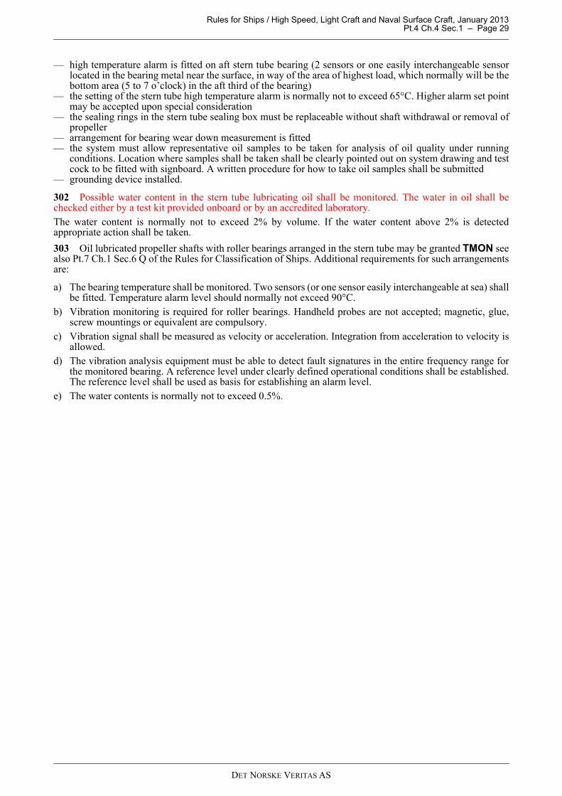
Rules for Ships / High Speed, Light Craft and Naval Surface Craft, January 2013 Pt.4 Ch.4 Sec.1 – Page 29
— high temperature alarm is fitted on aft stern tube bearing (2 sensors or one easily interchangeable sensorlocated in the bearing metal near the surface, in way of the area of highest load, which normally will be thebottom area (5 to 7 o’clock) in the aft third of the bearing)
— the setting of the stern tube high temperature alarm is normally not to exceed 65°C. Higher alarm set pointmay be accepted upon special consideration
— the sealing rings in the stern tube sealing box must be replaceable without shaft withdrawal or removal ofpropeller
— arrangement for bearing wear down measurement is fitted— the system must allow representative oil samples to be taken for analysis of oil quality under running
conditions. Location where samples shall be taken shall be clearly pointed out on system drawing and testcock to be fitted with signboard. A written procedure for how to take oil samples shall be submitted
— grounding device installed.
302 Possible water content in the stern tube lubricating oil shall be monitored. The water in oil shall bechecked either by a test kit provided onboard or by an accredited laboratory.The water content is normally not to exceed 2% by volume. If the water content above 2% is detectedappropriate action shall be taken.
303 Oil lubricated propeller shafts with roller bearings arranged in the stern tube may be granted TMON seealso Pt.7 Ch.1 Sec.6 Q of the Rules for Classification of Ships. Additional requirements for such arrangementsare:
a) The bearing temperature shall be monitored. Two sensors (or one sensor easily interchangeable at sea) shallbe fitted. Temperature alarm level should normally not exceed 90°C.
b) Vibration monitoring is required for roller bearings. Handheld probes are not accepted; magnetic, glue,screw mountings or equivalent are compulsory.
c) Vibration signal shall be measured as velocity or acceleration. Integration from acceleration to velocity isallowed.
d) The vibration analysis equipment must be able to detect fault signatures in the entire frequency range forthe monitored bearing. A reference level under clearly defined operational conditions shall be established.The reference level shall be used as basis for establishing an alarm level.
e) The water contents is normally not to exceed 0.5%.
DET NORSKE VERITAS AS

Rules for Ships / High Speed, Light Craft and Naval Surface Craft, January 2013 Pt.4 Ch.4 Sec.1 – Page 30
F. Arrangement
F 100 Sealing and protection
101 A shaft sealing shall be provided in order to prevent water from gaining access to the internal spaces ofthe vessel.
102 A sealing shall be provided to prevent water from gaining access to steel shafts, unless approvedcorrosion resistant material is used.
103 Inboard shafts (inside the inner stern tube seal) shall be protected against corrosion. Depending on theambient conditions, this may be provided by oil based coating, paint, or similar.
104 Electrical grounding of the propeller shaft lines is mandatory.
F 200 Shafting arrangement
201 The machinery and shafting shall be arranged so that neither external nor internal (self generated) forcescan cause harmful effects to the performance of the machinery and shafting.If shaft brake is fitted, it shall be arranged so that in case of failure in the actuating system, the brake shouldnot be engaged.
Table E1 Monitoring of shaftingGr 1
IndicationAlarmLoad
reduction
Gr 2Automatic
start of standby pump with alarm 1)
Gr 3Shut down with alarm
Comments
1.0 Shafting
Separate thrust bearings, temperature IL or IR, HA
To be provided for shaft power > 5 000 kW.Sensor to be placed in the bearing metal or for pads, in the oil outlet.Maximum permissible temperature to be marked on the indicators.
Oil lubricated fluid film bearings, temperature IL or IR, HA
To be provided for shaft power > 5 000 kW.Sensors to be located near the bearing surface at the area of highest load.Maximum permissible temperature to be marked on the indicators.
Stern tube lubricating oil tank, level
LA
Stern tube lubricating oil, pressure or flow
LA Applicable to forced lubrication.
2.0 Additional requirements for TMONAft stern tube bearing, temperature
HA See 301
Gr 1 Common sensor for indication, alarm, load reduction (common sensor permitted but with different set points and alarm shall be activated before any load reduction)
Gr 2 Sensor for automatic start of standby pumpGr 3 Sensor for shut down
IL = Local indication (presentation of values), in vicinity of the monitored componentIR = Remote indication (presentation of values), in engine control room or another centralized control station such as
the local platform/manoeuvring consoleA = Alarm activated for logical valueLA = Alarm for low valueHA = Alarm for high valueAS = Automatic start of standby pump with corresponding alarmLR = Load reduction, either manual or automatic, with corresponding alarm, either slow down (r.p.m. reduction) or
alternative means of load reduction (e. g. pitch reduction), whichever is relevant.SH = Shut down with corresponding alarm. May be manually (request for shut down) or automatically executed if not
explicitly stated above.
For definitions of Load reduction (LR) and Shut down (SH), see Pt.4 Ch.1 of the Rules for Classification of Ships.1) To be provided when standby pump is required, see B900.
DET NORSKE VERITAS AS
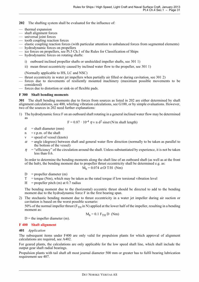
Rules for Ships / High Speed, Light Craft and Naval Surface Craft, January 2013 Pt.4 Ch.4 Sec.1 – Page 31
202 The shafting system shall be evaluated for the influence of:
— thermal expansion — shaft alignment forces— universal joint forces— tooth coupling reaction forces— elastic coupling reaction forces (with particular attention to unbalanced forces from segmented elements)— hydrodynamic forces on propellers— ice forces on propellers, see Pt.5 Ch.1 of the Rules for Classification of Ships— hydrodynamic forces on rotating shafts:
i) outboard inclined propeller shafts or unshielded impeller shafts, see 301 1)ii) mean thrust eccentricity caused by inclined water flow to the propeller, see 301 1)
(Normally applicable to HS, LC and NSC)— thrust eccentricity in water jet impellers when partially air filled or during cavitation, see 301 2)— forces due to movements of resiliently mounted machinery (maximum possible movements to be
considered)— forces due to distortion or sink-in of flexible pads.
F 300 Shaft bending moments
301 The shaft bending moments due to forces from sources as listed in 202 are either determined by shaftalignment calculations, see 400, whirling vibration calculations, see G100, or by simple evaluations. However,two of the sources in 202 need further explanations:
1) The hydrodynamic force F on an outboard shaft rotating in a general inclined water flow may be determinedas
F = 0.87 · 10-4 η v n d2 sinα (N/m shaft length)
d = shaft diameter (mm)n = r.p.m. of the shaftv = speed of vessel (knots)α = angle (degrees) between shaft and general water flow direction (normally to be taken as parallel to
the bottom of the vessel)η = “efficiency” of the circulation around the shaft. Unless substantiated by experience, it is not be taken
less than 0.6.
In order to determine the bending moments along the shaft line of an outboard shaft (as well as at the frontof the hub), the bending moment due to propeller thrust eccentricity shall be determined e.g. as:
Mb = 0.074 α D T/H (Nm)
D = propeller diameter (m)T = torque (Nm), which may be taken as the rated torque if low torsional vibration levelH = propeller pitch (m) at 0.7 radius
The bending moment due to the (horizontal) eccentric thrust should be directed to add to the bendingmoment due to the hydrodynamic force F in the first bearing span.
2) The stochastic bending moment due to thrust eccentricity in a water jet impeller during air suction orcavitation is based on the worst possible scenario:50% of the normal impeller thrust (FTH in N) applied at the lower half of the impeller, resulting in a bendingmoment as:
Mb = 0.1 FTH D (Nm)D = the impeller diameter (m).
F 400 Shaft alignment
401 Application The subsequent items under F400 are only valid for propulsion plants for which approval of alignmentcalculations are required, see A402.For geared plants, the calculations are only applicable for the low speed shaft line, which shall include theoutput gear shaft radial bearings.Propulsion plants with tail shaft aft most journal diameter 500 mm or greater has to fulfil bearing lubricationrequirement see 407.
DET NORSKE VERITAS AS

Rules for Ships / High Speed, Light Craft and Naval Surface Craft, January 2013 Pt.4 Ch.4 Sec.1 – Page 32
402 Calculation input data The shaft alignment calculations shall at minimum include the following input data:
— propulsion plant particulars, e.g. rated power of main engine and propeller shaft rpm — equipment list, i.e. manufacturer and type designation of prime mover, reduction gear (if applicable) and
bearings— geometry data of shafts, couplings and bearings, including reference to relevant drawings. For direct
coupled plants, the crankshaft model shall be according to the engine designer's guidelines— propeller data— bearing clearances.
403 Alignment conditionsThe shaft alignment calculations have to include the following conditions:
— alignment condition (during erection of shafting)— cold, static, afloat, fully submerged propeller— hot, static, afloat, fully submerged propeller.
For geared shafting systems:
— running conditions as required to verify gear acceptance criteria — all relevant combinations of prime mover operation.
404 Influence parameters The shaft alignment calculations shall take into account the influence of:
— buoyancy of propeller— thermal rise of machinery components (including rise caused by heated tanks in double bottom and other
possible heat sources)— gear loads (horizontal and vertical forces and bending moments)— angular working position in gear bearings for gears sensitive to alignment, see Guidance note below— bearing wear (for bearings with high wear acceptance e.g. bearings with water or grease lubrication)— bearing stiffness (if substantiated by knowledge or evaluation, otherwise infinite)— hull and structure deflections if known (deflections caused by e.g. draught changes and aft peak tank
filling).
Guidance note:For sensitive geared systems (e.g. gears with large face width or gears with more than one pinion driving the outputwheel) even small alignment offsets may have large influence on the gear face load distribution. In such systems,angular position of the shaft has to be found by iteration. Vertical and horizontal offsets may be assessed by means ofthe vertical and horizontal forces in the previous iteration step. Bearing clearances have to be taken into account, butthe oil film thickness can usually be disregarded (except for very light bearing loads). For fluid film bearings theangular working position may be estimated to 20 to 30 degrees off the direction of the force (except for very lightbearing loads).
---e-n-d---of---G-u-i-d-a-n-c-e---n-o-t-e---
405 Results The shaft alignment calculations shall at minimum include the following results:
— bearing offsets from the defined reference line— calculated bearing reaction loads and pressures— bearing reaction influence numbers— graphical and tabular presentation of the shaft deflections with respect to the defined reference line— graphical and tabular presentation of the shaft bending stresses as a result of the alignment— nominal relative slope between shaft and bearing centrelines in aft most propeller shaft bearing (see 406)
and if applicable, details of proposed slope-bore— results from aft stern tube bearing lubrication criteria, see 407 — a shaft alignment procedure with verification data and tolerances (e.g. calculated gap & sag values and
jacking loads including jack correction factors). The procedure shall clearly state at which vessel conditionthe alignment verification shall be carried out (cold or hot, submersion of propeller etc.). Positions of jacksand temporary supports have to be specified.
406 Acceptance criteriaThe shaft alignment has to fulfil the following acceptance criteria for all relevant operating conditions in 403:
— acceptance criteria defined by manufacturer of the prime mover, e.g. limits for bearing loads, bendingmoment and shear force at flange
DET NORSKE VERITAS AS
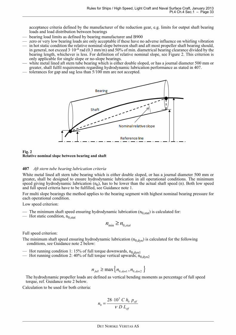
Rules for Ships / High Speed, Light Craft and Naval Surface Craft, January 2013 Pt.4 Ch.4 Sec.1 – Page 33
acceptance criteria defined by the manufacturer of the reduction gear, e.g. limits for output shaft bearingloads and load distribution between bearings
— bearing load limits as defined by bearing manufacturer and B900— zero or very low bearing loads are only acceptable if these have no adverse influence on whirling vibration— in hot static condition the relative nominal slope between shaft and aft most propeller shaft bearing should,
in general, not exceed 3·10-4 rad (0.3 mm/m) and 50% of min. diametrical bearing clearance divided by thebearing length, whichever is less. For definition of relative nominal slope, see Figure 2. This criterion isonly applicable for single slope or no-slope bearings.
— white metal lined aft stern tube bearing which is either double sloped, or has a journal diameter 500 mm orgreater, shall fulfil requirements regarding hydrodynamic lubrication performance as stated in 407.
— tolerances for gap and sag less than 5/100 mm are not accepted.
Fig. 2Relative nominal slope between bearing and shaft
407 Aft stern tube bearing lubrication criteriaWhite metal lined aft stern tube bearing which is either double sloped, or has a journal diameter 500 mm orgreater, shall be designed to ensure hydrodynamic lubrication in all operational conditions. The minimumspeed giving hydrodynamic lubrication (n0), has to be lower than the actual shaft speed (n). Both low speedand full speed criteria have to be fulfilled, see Guidance note 1.For multi slope bearings the method applies to the bearing segment with highest nominal bearing pressure foreach operational condition.Low speed criterion:
— The minimum shaft speed ensuring hydrodynamic lubrication (n0,stat) is calculated for: — Hot static condition, n0,stat
Full speed criterion: The minimum shaft speed ensuring hydrodynamic lubrication (n0,dyn) is calculated for the following conditions, see Guidance note 2 below:
— Hot running condition 1: 15% of full torque downwards, n0,dyn1 — Hot running condition 2: 40% of full torque vertical upwards, n0,dyn2
The hydrodynamic propeller loads are defined as vertical bending moments as percentage of full speed torque, ref. Guidance note 2 below.Calculation to be used for both criteria:
statnn ,0min ≥
{ }2,01,0 ,max dyndynfull nnn ≥
eff
eff
LD
phCn
ν0
3
0
1028 ⋅=
DET NORSKE VERITAS AS

Rules for Ships / High Speed, Light Craft and Naval Surface Craft, January 2013 Pt.4 Ch.4 Sec.1 – Page 34
Calculated parameters
n0 = minimum rotational shaft speed ensuring hydrodynamic lubrication (rpm)h0 = minimum required lubrication film thickness (mm)peff = effective bearing pressure (N/m2) Leff = length of locally pressurized area (mm), Leff ≤ LKD = dimensionless size factor ( - )KL = dimension less length to diameter ratio ( - )Dimensions and physical parameters
nmin = actual shaft speed for continuous slow speed operation (rpm)nfull = actual max shaft speed for continuous operation (rpm), typical at MCRC = diametrical bearing clearance (mm). Use nominal diameter for std. double slope machining in
lower part of bearing, and actual diameter for trumpet shaped slope. L = bearing length, or segment length in case of multi slope bearing (mm)ν = minimum kinematic viscosity of the lubricant at 40º bearing temperature (cSt)D = bearing journal diameter (mm)Parameters from shaft alignment calculation, see Figure 3 and F400.
W = radial bearing load, W1 + W2 (N)Wmax = max value of W1 and W2 (N)Wmin = min value of W1 and W2 (N)α = calculated relative slope between shaft and bearing at Wmax, either α1 or α2 (mm/m), see Figure 3 White metal lined stern tube bearings are to be modelled in the shaft alignment calculation as presented inFigure 3. This is achieved by modelling the bearing with a support point at either bearing end (or at eithersegment end for multi slope bearings). The total bearing stiffness is not to be taken less than 5·109 N/m, andstiffness of each individual support point not less than 2·109 N/m, unless documented otherwise.
760
43.0
0
Dh =
DL
Wp
effeff
610=
−−
+= )log(02.032.017.01.0
max
min
max
min αW
W
W
WKKLL LDeff LLeff ≤,
55.11008.11053.0 326 +⋅−⋅= −− DDKD
66.25.133.02
+
−
=
D
L
D
LK L 2, ≤
D
L
DET NORSKE VERITAS AS
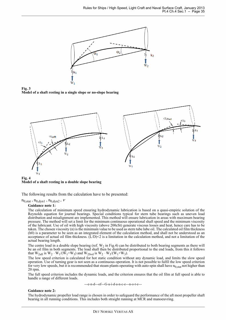
Rules for Ships / High Speed, Light Craft and Naval Surface Craft, January 2013 Pt.4 Ch.4 Sec.1 – Page 35
Fig. 3Model of a shaft resting in a single slope or no-slope bearing
Fig. 4Model of a shaft resting in a double slope bearing
The following results from the calculation have to be presented:n0,stat , n0,dyn1 , n0,dyn2 , ν
Guidance note 1:The calculation of minimum speed ensuring hydrodynamic lubrication is based on a quasi-empiric solution of theReynolds equation for journal bearings. Special conditions typical for stern tube bearings such as uneven loaddistribution and misalignment are implemented. This method will ensure lubrication in areas with maximum bearingpressure. The method will set a limit for the minimum continuous operational shaft speed and the minimum viscosityof the lubricant. Use of oil with high viscosity (above 200cSt) generate viscous losses and heat, hence care has to betaken. The chosen viscosity (n) is the minimum value to be used as stern tube lube oil. The calculated oil film thickness(h0) is a parameter to be seen as an integrated element of the calculation method, and shall not be understood as anacceptance of actual oil film thickness. (L/D)<2 is a limitation in the calculation method, and not a limitation of theactual bearing length.The centre load in a double slope bearing (ref. W2 in Fig.4) can be distributed to both bearing segments as there willbe an oil film in both segments. The load shall then be distributed proportional to the end loads, from this it followsthat W2aft is W2 ⋅ W1/(W1+W3) and W2fwd is W2 ⋅ W3/(W1+W3).The low speed criterion is calculated for hot static condition without any dynamic load, and limits the slow speedoperation. Use of turning gear is not seen as a continuous operation. It is not possible to fulfil the low speed criterionfor very low speeds, but it is recommended that steam plants operating with auto-spin shall have n0,stat not higher than20 rpm.The full speed criterion includes the dynamic loads, and the criterion ensures that the oil film at full speed is able tohandle a range of different loads.
---e-n-d---of---G-u-i-d-a-n-c-e---n-o-t-e---
Guidance note 2:The hydrodynamic propeller load range is chosen in order to safeguard the performance of the aft most propeller shaftbearing in all running conditions. This includes both straight running at MCR and manoeuvring.
DET NORSKE VERITAS AS

Rules for Ships / High Speed, Light Craft and Naval Surface Craft, January 2013 Pt.4 Ch.4 Sec.1 – Page 36
If the propeller tip in some operational conditions is above or in the vicinity of the water line, a downward bendingmoment will occur even at slow speeds. Running with a semi-submerged propeller at high rpm may harm the bearing.For twin screw propulsion plants, the alignment calculations should also include the propeller induced horizontalloads. Manoeuvring at high vessel speed will generate large vertical and horizontal loads. The propeller induced loadsare influenced by the rotational direction of the propellers. Horizontal slope should be evaluated, but this requires athree dimensional analysis which is not within scope of this rule paragraph. The angular working position of the shaftshould not conflict with longitudinal oil grooves.It is not mandatory to carry out an independent hydrodynamic propeller load calculation.
---e-n-d---of---G-u-i-d-a-n-c-e---n-o-t-e---
408 Verification data and tolerancesThe tolerances in the alignment specification have to correlate with the tolerance ranges used in thecalculations. The final verification of the alignment shall be carried out afloat in at least one relevant conditionas mentioned in 403. In special cases, verification in running condition by means of strain gauges and/or proximity transducers mayalso be required. In such cases the measurement program shall be submitted for approval. Tolerances for misalignment in way of slope and straightness of stern tube bearings have to be defined. Thetolerances shall reflect the calculation of lubricant film thickness see 407.
G. Vibration
G 100 Whirling vibration
101 Calculation of whirling vibration (when required, see A404) is normally restricted to determination ofnatural frequencies. In special cases also forced whirling may be required.
102 Calculations are normally to be made as parameter studies. Important but uncertain parameters asstiffness of aft stern tube bearing, resulting bearing load position, bearing load distribution over length (ifcalculating with distributed bearing reaction), entrained water on propeller, etc. shall be varied within theirprobable range and natural frequencies to be presented as corresponding graphs.
103 Resonance in propeller blade frequencies near the upper operating speed should be avoided. However,exceptions may be made when the vibration mode and the bearing design is so that a heavy damping is expectede.g. high bearing length to diameter ratio combined with a bouncing vibration mode.
104 Resonance with the shaft speed (1st order forward whirl) shall have a separation margin of at least 30%to the operating speed range.
G 200 Rotor vibration
201 Rotor means an assembly of a unit and the couplings and shafts, e.g. a power take off (PTO) driven shaftgenerator.
202 Resonance of the 1st order is normally to have a separation margin of at least 30% to the operating speedrange.
G 300 Axial vibration
301 Axial vibration calculations (when required) shall take the thrust bearing stiffness into consideration, seealso Ch.3 Sec.1 A601 c) and G500.
G 400 Vibration measurements
401 If vibration measurements are required, the type of instrumentation, location of pick ups, signal processingmethod and the measurement program shall be agreed with the Society.
H. Installation Inspection
H 100 Application
101 The requirements in H apply to inspection of installation of shafts, couplings and bearings in propulsionplants. Regarding compliant couplings, see Sec.4 and Sec.5. Unless otherwise stated, a surveyor shall attendthe inspections given in H.
DET NORSKE VERITAS AS

Rules for Ships / High Speed, Light Craft and Naval Surface Craft, January 2013 Pt.4 Ch.4 Sec.1 – Page 37
H 200 Assembly
201 Flange connections shall be checked with regard to:
— ream fitted bolts, light press fit— friction bolts, pre-stress by bolt elongation.
202 Clamp couplings shall be checked with regard to tightening of the bolts. Unless otherwise approved, thisshall be made by measuring elongation (applicable for through bolts).
203 Keyed connections shall be checked with regard to:
— shrinkage amount between hub and shaft (applicable to cylindrical connections)— contact between male and female tapered members, (full contact band at upper end required)— push up force or pull up length of tapered connections— key tight fit in shaft and hub (applicable to reversing plants).
204 For liners mounted at the yard, see C201.
205 Keyless shrink fit connections shall be checked with regard to:
— circumferential orientation (marking) between the parts (not applicable to sleeve couplings)— contact1) between male and female tapered members (not applicable for couplings certified as hub and
sleeve together and contact checked at the manufacturer). As a minimum there shall be a full contact bandat the big end
— shrinkage amount, verified by diametrical expansion or pull up length, whichever is approved— draining and venting (by air).
1) For wet mounting, the contact may be improved by light grinding with a soft disc and emery paper in the hub (not the shaft). A testpull up may also be used to improve the contact.
206 Bearing clearances (for fluid film bearings) shall be recorded.
207 The protection against corrosion of inboard shafts shall be checked, see F103.
208 Propeller fitting
a) For flange mounted propellers, the bolt tightening shall be verified.b) For cone mounted propellers with key, the following shall be verified:
— Contact between propeller and shaft (e.g. by means of toolmaker’s blue) to be at least 70% and withfull contact band at the upper end, see also 205, footnote 1).
— Push up force or pull up length, whichever is specified in the approval.— After final pull-up, the propeller shall be secured by a nut on the propeller shaft. The nut shall be
secured to the shaft with the approved locking arrangement. Alternatively, if approved, a split fittedring with locking arrangement may be used. The ring shall have a tight fit.
— Key fit in both shaft and hub.
c) For keyless cone mounted propellers, the following shall be verified:
— Prior to final pull-up, the contact area 1) between the mating surfaces shall be not less than 70% of thetheoretical contact area (100%). Non-contact bands (except oil grooves) extending circumferentiallyaround the hub or over the full length of the hub are not acceptable. At the big end there shall be a fullcontact band of at least 20% of the taper length.
— After final pull-up, the propeller shall be secured by a nut on the propeller shaft. The nut shall besecured to the shaft with the approved locking arrangement. Alternatively, if approved, a split fittedring with locking arrangement may be used. The ring shall have a tight fit.
H 300 Shaft alignment
301 All large welding work in vicinity of the shafting shall be completed before sighting process andinsertion of propeller shaft. All large and heavy structure elements shall be in place before final verification ofshaft alignment, see Guidance Note.
302 When shaft alignment calculations are required (see A403 and F400), the stern tube bearing geometryshall be measured and reported in presence of the surveyor after mounting of bearings, but prior to insertion ofthe propeller shaft. Straightness, slope and ovality shall be within the specified tolerances. Each stern tubebearing shall be checked at minimum three longitudinal positions. Equal procedure shall be applied on eachsegment in case of multi slope bearing, see Guidance Note.
1) The contact may be improved by light grinding with a soft disc and emery paper in the hub (not the shaft). A test pull up may also be used to improve the contact.
DET NORSKE VERITAS AS
Rules for Ships / High Speed, Light Craft and Naval Surface Craft, January 2013 Pt.4 Ch.4 Sec.1 – Page 38
303 The shaft alignment shall be within the tolerances given in the shaft alignment specification, seeGuidance Note.
304 When shaft alignment calculations are required (see A403 and F400) the measured values of gap and sagand/or jacking loads with force-displacement diagrams and/or alternative verification data shall be reported inpresence of the surveyor, see Guidance Note.
Guidance note:Local effect verification: The designed geometry of stern tube bearings is based on the bearings ability to handledynamic propeller loads and weight loads from propeller shaft and propeller. The condition inside stern tube bearingsis dependent of accuracy both in design and installation. It has to be verified that the bearing's slope(s), ovality andstraightness are within the alignment specification with defined tolerances before propeller shaft is inserted. Globalhull deflections will have limited influence to the alignment inside the stern tube, but welding in vicinity of the sterntube may disturb the alignment.Global effect verification: Mounting of large hull sections will introduce extra weight which will introduce global hulldeflections. Large welding works and launching will also introduce hull deflections. Final verification of global shaftalignment such as gap & sag and/or jacking should preferably be carried out afloat with most of the hull completed.
---e-n-d---of---G-u-i-d-a-n-c-e---n-o-t-e---
I. Shipboard Testing
I 100 Bearings
101 During the sea trial, the temperatures in all fluid film bearings (that are equipped with thermometers)shall be checked. In case of high temperature alarm the root cause shall be identified.
Guidance note:The bearing may have permanent damages after high temperature alarm even though the temperature does not rise onlater tests.It may be necessary to remove the shaft unless an overall evaluation of the occurrence, in agreement with the bearingmanufacturer, positively demonstrates that permanent damage has not occurred.
---e-n-d---of---G-u-i-d-a-n-c-e---n-o-t-e---
I 200 Measurements of vibration
201 Measurements of vibration on power take off generators driven from the engine driven reduction gearshall be carried out at 90%, 100% and (at least) 105% of rated (generator) speed with unloaded generator andship service speed under steady state operation. The measurements shall be made near both bearings in thevertical, horizontal and axial directions. Frequency analyses shall be made in the range of 2 to 100 Hz.Unless otherwise specified by the generator designer and approved by DNV, the vibration velocities shall notexceed the following:For long-term continuous operation, i.e. 90% and 100% generator speed:
— 4.5 mm/s r.m.s. per frequency component for vibration caused by internal sources.— 7.1 mm/s r.m.s. per frequency component for vibration caused by external sources.
For operation in a limited time period, i.e. 105% generator speed:
— 7.1 mm/s r.m.s. per frequency component for vibration caused by internal or external sources.
For definitions, see ISO 10816-3.Vibration caused by internal sources are defined as those caused by the generator rotor and the shaft couplingsbetween the generator and gearbox. This means the 1st and 2nd order of the generator speed as well as anycoupling resonance to torsional and axial vibration.
DET NORSKE VERITAS AS

Rules for Ships / High Speed, Light Craft and Naval Surface Craft, January 2013 Pt.4 Ch.4 Sec.2 – Page 39
SECTION 2 GEAR TRANSMISSIONS
A. General
A 100 Application
101 The rules in this section apply to gear transmissions subject to certification, see Ch.2 Sec.1 A200. Therules apply to the gear transmission, it's integrated components, such as coolers and pumps, and the lubricationpiping system. Gears for jacking machinery for self elevating offshore units, partially deviate from the rules inthis section. This is specified in DNV-OS-D101 Sec.5 D. See Sec.1 regarding shafting and rigid couplings andSec.3 for clutches.
102 Ch.2 describes all general requirements for rotating machinery and forms the basis for all sections inCh.3, Ch.4 and Ch.5.
103 The complete gear transmission shall be delivered with a NV certificate that is based on the designapproval in B, the component certification in C and the workshop testing in D.
A 200 Documentation
201 Plans to be submitted for approval:
a) Arrangement including part list(s)1):
— longitudinal section of the unit — transverse section (applicable to gears with more than 2 shafts).
b) Detail drawings2):
— pinion(s) and wheel(s) 3)
— shafts— hub(s)— clutch(es) and coupling(s)— other power transmitting parts
c) Gear casing (unless the wall thickness and bearing supports, including main thrust bearing support, areindicated on the longitudinal section)
d) Gearbox fixation including chocking calculations, if applicablee) Schematic lubrication oil system diagram including all instruments and control devices.f) The control and monitoring system, including set-points and delays, see E and Ch.9.
202 Particulars to be submitted for approval:
a) Data according to Table A1 for each gear stage. The various data are explained in the Classification Note41.2. and a special sheet, Data Sheet for Gear Calculations, Form No. 71.10a, has been prepared for this.
1) The arrangement plans ought to contain as many details as practically possible in order to reduce the total number of plans, e.g. if all details of other items as listed under b) above can be given on the arrangement plans, then separate plans of these items need not be submitted.
2) The plans shall show clearly all details as fillets, keyways and other stress raisers, shrinkage amounts (also for bearings), pull up on taper, surface roughness, bolt pre-tightening, etc. as well as types of material and mechanical properties, cleanliness (if required, see B207) including NDT specification, see Ch.2 Sec.3 A202. “All details” means data that are necessary for evaluation according to the relevant criteria in B.
3) Pinions and wheels can normally be sufficiently described on the longitudinal section and with all particulars listed in 202 b) specified on a data sheet (Form No.: 71.10a). However, if manufacture of the pinion and wheel set is subcontracted, separate sets of plans have also to be submitted.
DET NORSKE VERITAS AS

Rules for Ships / High Speed, Light Craft and Naval Surface Craft, January 2013 Pt.4 Ch.4 Sec.2 – Page 40
Table A1 Gear dataItem Particulars Symbol Comments
Loads 1)
Maximum power (kW) on pinion P Alternatively, a load-time spectrum may be used. This is typical for gears designed for relatively short life time (less than for example a million cycles). See also Ch.2 Sec.3 A101.
R.p.m. of pinion n0Rated pinion torque corresponding to maximum power and r.p.m.
T0
Application factors KA Both for normal operation and permissible diesel engine misfiring condition
Application factor for non-frequent peak loads
KAP For example start-up of electric motor with star-delta shift or clutching-in shock
Application factor for ice condition KAice For vessels with ice class (see Pt.5 Ch.1 of the Rules for Classification of Ships)
Faceload distribution
Maximum permissible faceload distribution factor at rated load 2) 3)
KHβ For bevel gears with ordinary length crowning it is sufficient to specify the minimum permissible face width contact in %.
Dimensions 4)
Number of teeth zCentre distance a For gears with parallel axis onlyCommon face width at operating pitch diameter
b
Face widths at tooth roots b1,2Total face width including gap B For double helical gears onlyTip diameters daAddenda haMinimum and maximum backlash jAngle between shafts Σ For bevel gears only
Tool and gear geometry 4)
Normal module mn In mid section for bevel gears (mnm)Module of tool m0 For bevel gears onlyTransversal module at outer end mt For bevel gears onlyPressure angle in normal section at reference cylinder αn
Helix angle at reference cylinder βHelix angle in the midsection βm For bevel gears onlyAddendum of tool ha0 Referred to mnRadius at tip of tool ρa0 Referred to mnProtuberance pro Referred to mn and excluding grinding amount
Addendum modification coefficient x Referred to mnIn mid section for bevel gears (xhm)
Number of teeth of cutter zc If pinion type cutter is usedAddendum modification coefficient of cutter xc
If pinion type cutter is usedReferred to mn
Angle modification θk For Zyclo Palloid bevel gears onlyCutter radius re0 For Zyclo Palloid and Gleason bevel gears onlyTooth thickness modification coefficient (mid face) xsm
For bevel gears onlyReferred to mn
Material
Material specification including heat treatment method
See Ch.2 Sec.3, (e.g. EN 10084 18CrNiMo7-6, Case hardened)
Flank surface hardness, maximum and minimumMid face tooth root space hardness, minimum 5)
Tooth core hardness, minimum 5)
Core impact energy (KV) of coupon test at 20°C 5) If applicable, see C206 b)
Hardness depths after finishing process, applicable to surface hardened gears
t550, t400 and t300
Given as depth to 550HV, 400HV and 300HV as applicable, see Classification Note 41.2
DET NORSKE VERITAS AS
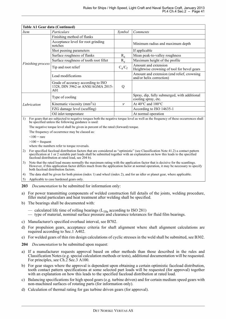
Rules for Ships / High Speed, Light Craft and Naval Surface Craft, January 2013 Pt.4 Ch.4 Sec.2 – Page 41
203 Documentation to be submitted for information only:
a) For power transmitting components of welded construction full details of the joints, welding procedure,filler metal particulars and heat treatment after welding shall be specified.
b) The bearings shall be documented with:
— calculated life time of rolling bearings (L10a according to ISO 281) — type of material, nominal surface pressure and clearance tolerances for fluid film bearings.
c) Manufacturer's specified overhaul interval, see B702.d) For propulsion gears, acceptance criteria for shaft alignment where shaft alignment calculations are
required according to Sec.1 A402.e) For welded gears of thin rim design calculations of cyclic stresses in the weld shall be submitted, see B302.
204 Documentation to be submitted upon request:
a) If a manufacturer requests approval based on other methods than those described in the rules andClassification Notes (e.g. special calculation methods or tests), additional documentation will be requested.For principles, see Ch.2 Sec.3 A100.
b) For gear stages where the approval is dependent upon obtaining a certain optimistic faceload distribution,tooth contact pattern specifications at some selected part loads will be requested (for approval) togetherwith an explanation on how this leads to the specified faceload distribution at rated load.
c) Balancing specifications for high speed gears (e.g. turbine driven) and for certain medium speed gears withnon-machined surfaces of rotating parts (for information only).
d) Calculation of thermal rating for gas turbine driven gears (for approval).
Finishing process
Finishing method of flanksAcceptance level for root grinding notches Minimum radius and maximum depth
Shot peening parameters If applicableSurface roughness of flanks Rz Mean peak-to-valley roughnessSurface roughness of tooth root fillet Ry Maximum height of the profile
Tip and root relief Ca/CfAmount and extensionHeightwise crowning of tool for bevel gears
Lead modifications Amount and extension (end relief, crowning and/or helix correction)
Grade of accuracy according to ISO 1328, DIN 3962 or ANSI/AGMA 2015-A01
Q
Lubrication
Type of cooling Spray, dip, fully submerged, with additional cooling spray, etc.
Kinematic viscosity (mm2/s) ν At 40°C and 100°CFZG damage level (scuffing) According to ISO 14635-1Oil inlet temperature At normal operation
1) For gears that are subjected to negative torques both the negative torque level as well as the frequency of these occurrences shall be specified unless the following guidance is used:
The negative torque level shall be given in percent of the rated (forward) torque.
The frequency of occurrence may be classed as:
<100 = rare
>100 = frequentwhere the numbers refer to torque reversals.
2) For specified faceload distribution factors that are considered as “optimistic” (see Classification Note 41.2) a contact pattern specification at 1 or 2 suitable part loads shall be submitted together with an explanation on how this leads to the specified faceload distribution at rated load, see 204 b).
3) Note that the rated load means normally the maximum rating with the application factor that is decisive for the scantlings. However, if this application factor differs much from the application factor at normal operation, it may be necessary to specify both faceload distribution factors.
4) The data shall be given for both pinion (index 1) and wheel (index 2), and for an idler or planet gear, where applicable.
5) Applicable to case hardened gears only.
Table A1 Gear data (Continued)Item Particulars Symbol Comments
DET NORSKE VERITAS AS
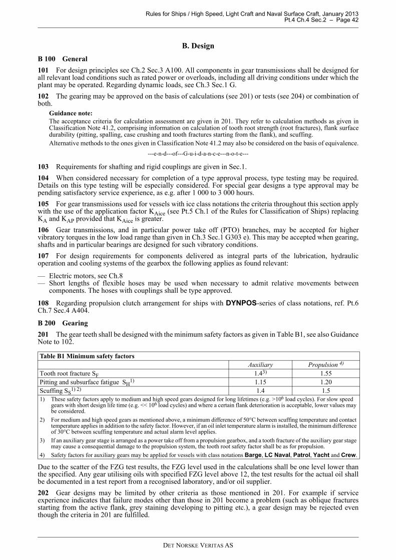
Rules for Ships / High Speed, Light Craft and Naval Surface Craft, January 2013 Pt.4 Ch.4 Sec.2 – Page 42
B. Design
B 100 General
101 For design principles see Ch.2 Sec.3 A100. All components in gear transmissions shall be designed forall relevant load conditions such as rated power or overloads, including all driving conditions under which theplant may be operated. Regarding dynamic loads, see Ch.3 Sec.1 G.
102 The gearing may be approved on the basis of calculations (see 201) or tests (see 204) or combination ofboth.
Guidance note:The acceptance criteria for calculation assessment are given in 201. They refer to calculation methods as given inClassification Note 41.2, comprising information on calculation of tooth root strength (root fractures), flank surfacedurability (pitting, spalling, case crushing and tooth fractures starting from the flank), and scuffing.Alternative methods to the ones given in Classification Note 41.2 may also be considered on the basis of equivalence.
---e-n-d---of---G-u-i-d-a-n-c-e---n-o-t-e---
103 Requirements for shafting and rigid couplings are given in Sec.1.
104 When considered necessary for completion of a type approval process, type testing may be required.Details on this type testing will be especially considered. For special gear designs a type approval may bepending satisfactory service experience, as e.g. after 1 000 to 3 000 hours.
105 For gear transmissions used for vessels with ice class notations the criteria throughout this section applywith the use of the application factor KAice (see Pt.5 Ch.1 of the Rules for Classification of Ships) replacingKA and KAP provided that KAice is greater.
106 Gear transmissions, and in particular power take off (PTO) branches, may be accepted for highervibratory torques in the low load range than given in Ch.3 Sec.1 G303 e). This may be accepted when gearing,shafts and in particular bearings are designed for such vibratory conditions.
107 For design requirements for components delivered as integral parts of the lubrication, hydraulicoperation and cooling systems of the gearbox the following applies as found relevant:
— Electric motors, see Ch.8— Short lengths of flexible hoses may be used when necessary to admit relative movements between
components. The hoses with couplings shall be type approved.
108 Regarding propulsion clutch arrangement for ships with DYNPOS-series of class notations, ref. Pt.6Ch.7 Sec.4 A404.
B 200 Gearing
201 The gear teeth shall be designed with the minimum safety factors as given in Table B1, see also GuidanceNote to 102.
Due to the scatter of the FZG test results, the FZG level used in the calculations shall be one level lower thanthe specified. Any gear utilising oils with specified FZG level above 12, the test results for the actual oil shallbe documented in a test report from a recognised laboratory, and/or oil supplier.
202 Gear designs may be limited by other criteria as those mentioned in 201. For example if serviceexperience indicates that failure modes other than those in 201 become a problem (such as oblique fracturesstarting from the active flank, grey staining developing to pitting etc.), a gear design may be rejected eventhough the criteria in 201 are fulfilled.
Table B1 Minimum safety factorsAuxiliary Propulsion 4)
Tooth root fracture SF 1.43) 1.55Pitting and subsurface fatigue SH
1) 1.15 1.20Scuffing SS
1) 2) 1.4 1.51) These safety factors apply to medium and high speed gears designed for long lifetimes (e.g. >106 load cycles). For slow speed
gears with short design life time (e.g. << 106 load cycles) and where a certain flank deterioration is acceptable, lower values may be considered.
2) For medium and high speed gears as mentioned above, a minimum difference of 50°C between scuffing temperature and contact temperature applies in addition to the safety factor. However, if an oil inlet temperature alarm is installed, the minimum difference of 30°C between scuffing temperature and actual alarm level applies.
3) If an auxiliary gear stage is arranged as a power take off from a propulsion gearbox, and a tooth fracture of the auxiliary gear stage may cause a consequential damage to the propulsion system, the tooth root safety factor shall be as for propulsion.
4) Safety factors for auxiliary gears may be applied for vessels with class notations Barge, LC Naval, Patrol, Yacht and Crew.
DET NORSKE VERITAS AS

Rules for Ships / High Speed, Light Craft and Naval Surface Craft, January 2013 Pt.4 Ch.4 Sec.2 – Page 43
203 Gear designs shall take into account all relevant load conditions such as dynamics described in Ch.3Sec.1 (diesel engines) and in other relevant sections. If vibration or shock loads result in reversed torques, thisinfluence shall be considered.
204 Acceptance of gears may be based on approved tests.
205 For gearing designed to Baltic ice classes and class notations ICE-05 to -15 the calculation with KAiceshall assume a number of load cycles equal to 106. This is additional to the normal, open sea conditions. Thestricter of these criteria are decisive.
206 Quenched and tempered steels and all surface hardened steels shall have a level of cleanliness that issuitable for the permissible stress level for high cycle fatigue. A suitable level in this context is e.g. chartdiagram index 2 for all groups A- DS in ISO 4967.
207 Gears classed to "high grade" made of special high grade materials, special high cleanliness will berequired, see Ch.2 Sec.3.
208 Pinions and wheels may be made from separate forgings, rolled bars or blanks cut out of a forged bar.Gears made from rolled bars will have tooth root stresses crosswise to the fibre direction of the material.Therefore, normally a 10% reduction of the fatigue strength compared to gears made from separate forgingswill be assumed. Correspondingly, gears made from blanks cut out of a forged bar are assumed to have a 20%reduction of the fatigue strength. However, such bars and blanks may be considered equivalent to separateforgings provided that either:
— they are further forged, or— the steel making process and forging process are specially qualified. see Ch.2 Sec.3 A205.
B 300 Welded gear designs
301 If a pinion or wheel designed for high cycle (>108) is manufactured by welding, the permissible cyclicstress range (principal stresses) in the welds and HAZ is limited to 2/3 of the threshold value for crackpropagation. This depends on the quality (i.e. NDT specification) of the weld with regard to external andinternal defects.As a simplification the following may be used:
— for full penetration welds which are very smooth or machined on all surfaces and 100% tested for surfacedefects (no linear indication >1.5 mm) and according to ISO 5817 level B for internal defects, thepermissible stress range is 50 MPa
— as above, but not very smooth or machined or ground surfaces, 30 MPa— for welds with inaccessible backside, 15 MPa.
For gears designed for a lower number of stress cycles (<< 108) higher permissible stress range values may beaccepted, alternatively less weld checking.
302 The calculation (usually by FEM) of the actual stress range shall take the full load cycle of the pinion orwheel into account as well as the stress concentration in the weld and HAZ due to fillet radii and or shape ofthe weld.
303 Welded pinions or wheels shall be stress relieved. If the stress relieving is not the final heat treatmentprocess (as e.g. when followed by a case hardening), the permissible values in 301 shall be reduced by 30%.
B 400 Shrink fitted pinions and wheels
401 Shrunk on pinions or wheels shall be designed to prevent detrimental fretting, macro slippage andmicromovements.
402 The criteria for macro slippage and fretting are given in Sec.1 B400. The influence of axial forces andtilting moments shall be considered.
403 Shrink fitted rims shall have a minimum safety of 2.0 against micromovements based on the specifiedrepetitive peak torque. This means that the local shear stress τ between a toothed rim and the hub shall be lessthan half the local friction (p + σ) μ:
(p + σ) μ / τ > 2 = Flim/F
p = nominal shrink fit pressureσ = local radial stress due to the gear mesh force μ = coefficient of friction
The following method may be used:The nominal tangential force per unit face width is:
Ft = 2 000 T / (b d1)
DET NORSKE VERITAS AS

Rules for Ships / High Speed, Light Craft and Naval Surface Craft, January 2013 Pt.4 Ch.4 Sec.2 – Page 44
T = the pinion torque (Nm)b = the face width of the shrink fit surface (mm)d1 = the reference diameter of the pinion (mm)
The force per unit face width to be used in the calculation is:F = Ft KA
if the movement in the axial tooth force direction is prevented by e.g. a shoulder, or if there is a double helicalgear rim made of one body.
F = Ft KA / cos β in all other cases.The shrinkage pressure p depends on the shrinkage amount, the equivalent rim thickness sv and the hubflexibility.
sv = s + mn (0.85 − 1.1 mn/s)
s = the rim thickness from tooth root to shrinkage diameter df (mm).
(only valid for s >2 mn)
Fig. 1Shrink fitted rim
The load limit per unit face width Flim when micromovement is expected to start is:Flim = Fref Fcorr Froll
Fref = the reference load limit calculated as;Fref = 5.65 p μ s (0.7 + 2 μ)
Fcorr = a correction factor which considers the influence of the hub flexibility (i.e. design and modulus ofelasticity Ehub). It is unity for a solid steel hub. Otherwise calculated as:
Fcorr = 1.586 − 2.86 · 10-6 Ehub + f(b/bw),where f(b/bw) considers the flexibility of a hub with webs. bw is the total face width of the webs.f(b/bw) = 0.404 · 10-3 (b/bw)3 − 0.01 (b/bw)2 + 0.09 b/bw − 0.081(equal zero if b = bw)Froll takes into account the rolling (tangential twist) load of a narrow rim (face width bhelix) due to an axial forcecomponent. The rolling moment causes a reduced surface pressure at an end of the face width. This is ofparticular importance for double helical gears with two separate rims. Froll applies even if there is an axialshoulder.Froll is the minimum value of unity
or (bhelix/df + 0.02) 4.8/tan βor (bhelix/(s + 1.3 mn) + 0.4) 0.2887/tan β
The coefficient of friction μ may be taken from Sec.1 Table B6.
DET NORSKE VERITAS AS

Rules for Ships / High Speed, Light Craft and Naval Surface Craft, January 2013 Pt.4 Ch.4 Sec.2 – Page 45
Fig. 2Shrink fitted body with especially high surface pressure (only applicable for shafts protruding on each end)
The safety against micromovements is:S = (p + σ) μ / τ = Flim/F.
B 500 Bolted wheel bodies
501 Bolted wheel bodies (and pinions, if applicable) shall be designed to avoid fatigue failure of the bolts dueto pulsating shear stresses when passing the gear mesh zone.
Fig. 3Bolted wheel body
Guidance note:The pulsating bolt forces will be reduced if the wheel body is radially supported without radial clearance.
---e-n-d---of---G-u-i-d-a-n-c-e---n-o-t-e---
502 For gear rims that are flexible compared to the hub, the stresses in the bolts shall be calculated uponrequest (usually by means of FEM) for a mesh force corresponding to T0 KA. The shear stress range shall notexceed 0.25 σy.
503 Bolts used for flexible rims shall have a tight fit in the holes, i.e. any combination of the tolerances shallnot result in a clearance, or the bolts shall be ream fitted with a slight press fit.
B 600 Shafts
601 Shafts shall be designed to prevent fatigue. Detailed criteria are given in Classification Note 41.4.However, simplified criteria for various common gear shaft designs are given in Sec.1 B206. When gear transmissions are designed for long life time (i.e. >>106 cycles), the shafts shall be designed toprevent detrimental fretting that may cause fatigue failures, see also Sec.1 B402. Unless torsional vibrationvalues are defined, the upper permissible values for dynamics as given in Ch.3 Sec.1 G shall be used.
Peak shrink fit pressure,
(local yielding) Nominal shrink fit pressure, p
DET NORSKE VERITAS AS

Rules for Ships / High Speed, Light Craft and Naval Surface Craft, January 2013 Pt.4 Ch.4 Sec.2 – Page 46
602 Shafts may be divided into 2 groups. These are shafts with:
— significant bending stresses, e.g. pinion and wheel shafts within their bearing spans— no significant bending stresses, e.g. quill shafts and shafts outside the bearing spans of pinions and wheels.
The major load conditions to be considered are:
— high cycle fatigue (>>106 cycles) due to rotating bending and torsional vibration, see Sec.1 B206 B andClassification Note 41.4 item 4
— low cycle fatigue (103 to 104 cycles) due to load variations from zero to full load, clutching in or startingshock loads, reversing torques, etc., see Sec.1 B206 A and Classification Note 41.4 item 3.
Practically, shafts with significant bending stresses such as pinion and wheel shafts are dimensioned withregard to stiffness (gear mesh considerations) and high cycle fatigue, but hardly ever for low cycle fatiguebecause the two first will prevail.
603 For short shafts made by blanks cut from forged bars without further forging, see Ch.2 Sec.3 A205.
B 700 Bearings
701 Fluid film bearings shall be designed with bearing pressures that are suitable for the bearing metals. Thecalculation of bearing pressures shall include the application factor KA.
702 Ball and roller bearings shall have a minimum L10a (ISO 281) life time that is suitable with regard to thespecified overhaul intervals. The influence of the lubrication oil film may be taken into account for L10a,provided that the necessary conditions, in particular cleanliness, are fulfilled.
Guidance note:If no overhaul intervals are specified, a bearing life time of 40 000 hours may be used for conventional ships and 10000 hours for yachts or ships and units that are not predominantly used at full load for longer periods.
---e-n-d---of---G-u-i-d-a-n-c-e---n-o-t-e---
B 800 Casing
801 Inspection openings shall be provided in order to enable inspection of all pinions and wheels(measurements of backlash and application of lacquer for contact pattern verification) as well as for access toclutch emergency bolts (if applicable). For special designs (e.g. some epicyclic gears) where inspectionopenings cannot be provided without severely affecting the strength of the design, holes for boroscopeinspections may be accepted as a substitute to openings. Such holes shall be positioned to enable boroscopeinspection of all gearing elements.
802 Easy access to all inspection openings shall be provided. This means that no piping or coolers etc. shallbe positioned to prevent access.
803 In order to prevent rust, the gear casing shall be provided with proper ventilation.
B 900 Lubrication system
901 The lubrication system shall be designed to provide all bearings, gear meshes and other parts requiringoil with adequate amount of oil for both lubrication and cooling purposes. This shall be obtained under allenvironmental conditions as stated in Ch.1 of the Rules for Classification of Ships.
902 The lubrication system shall contain at least:
— an oil pump to provide circulation— a filter of suitable fineness for gearing, hydraulics and bearings (see 702).
Guidance note:Specification of a pressure filter for maintaining suitable fluid cleanliness may be 16/14/11 according to ISO4406:1999 and β6-7 (c) = 200 according to ISO 16889:1999.
---e-n-d---of---G-u-i-d-a-n-c-e---n-o-t-e---
— if necessary, a cooler to keep the oil temperature within the specified maximum temperature whenoperating under the worst relevant environmental conditions, see 901.
903 For gear transmissions for propulsion where windmilling may be detrimental and considered as a normalworking condition, there shall be either:
— a shaft brake designed to hold (statically) twice the highest expected windmilling torque, or— one pump available in wind-milling condition. This pump shall be additional to any standby pump required by
other rules.
The chosen version shall be automatically activated within 30 s after shut down.
DET NORSKE VERITAS AS

Rules for Ships / High Speed, Light Craft and Naval Surface Craft, January 2013 Pt.4 Ch.4 Sec.2 – Page 47
904 Gear transmissions for propulsion are normally to have an attached pump. For plants designed tonormally operate at such low speeds that the attached pump cannot supply sufficient oil pressure (e.g. plantswith frequency controlled electrical motor), the following will be accepted:
— either an extra electric oil pump that is activated at a given pressure, or— 2 electric main pumps of the same capacity, one of which is arranged as a standby pump with immediate
action. These 2 electric pumps shall be supplied from different switchboards.
905 For propulsion gears the lubrication system shall be arranged so that the gear transmission can endure arun out of 5 minutes after a black out without jeopardising any bearings or gear teeth.This may be provided by e.g.:
— an attached pump with an additional gravity tank (if necessary)— electric pumps with a gravity tank with sufficient volume and height for 5 minutes supply.
906 Gear transmissions in single propulsion plants shall have a standby pump with immediate activation.
907 For gear transmissions in single propulsion plants the filtering system shall be arranged to make itpossible to clean the filters without interrupting the oil supply.
908 Use of flexible hoses in the lubrication system is only permitted where necessary in order to allow forrelative movements (e.g. when resiliently mounted). Flexible hoses with their couplings shall be type approved,see Ch.6 Sec.6 D (ship rules).
C. Inspection and Testing
C 100 Certification of parts
101 Regarding certification schemes, short terms, manufacturing survey arrangement (MSA) and importantconditions, see Ch.2 Sec.2.
102 The parts in a gear transmission shall be tested and documented according to Table C1 and 200 through400, if not otherwise agreed in a MSA, see Ch.2 Sec.2 C100. In 200 through 400, the testing and inspection asrequired in Table C1 are described in more detail.
C 200 Pinions and wheels
201 The requirements in 200 apply to the toothed parts of pinions and wheels. A flow chart and a summaryof these requirements are presented in Fig.4 and Table C2, respectively.
Table C1 Requirements for documentation and testingPart Product
certificateChemical
compositionMechanical properties
X-Ray or Ultrasonic
testing
Crack detection 1)
Visual and dimensional
check 2)
Other 2)
Pinion and wheels NV7) See 200 - Table C2Built-in clutches, bending compliant- and elastic couplings
NV7) See Sec.3 C, Sec.4 C and Sec.5 C, respectively
Shafts, rigid couplings and hubs See Sec.1 C
Welded gears W W 3) W 3) W 3) W 6)
Casing (welded) W W W 4) W 5)
Bolts and keys TR TRAncillaries See C4001) By means of magnetic particle inspection or dye penetrant.
2) For details and extent, see relevant paragraph.
3) After final heat treatment (e.g. case hardening).
4) For thickness >100 mm.
5) Of welds near bearings (at least 10% of the welds to be tested).
6) Stress relieving (time-temperature diagram), but not applicable to gears that shall be case hardened.
7) Only applicable if sub-contracted.
DET NORSKE VERITAS AS

Rules for Ships / High Speed, Light Craft and Naval Surface Craft, January 2013 Pt.4 Ch.4 Sec.2 – Page 48
Fig. 4Flow chart showing the applicable certification rules
202 The incoming material shall be documented with a Work certificate (W) to be within the approvedspecification as follows:
— chemical composition (ladle analyses)— ultrasonic testing in suitably machined condition.
For gears classed to “high grade”, the requirement for additional documentation as specified in the approval,applies:
— cleanliness according to ISO 4967— oxygen content— grain size according to ISO 643— forging or rolling according to an agreed process.
See also Pt.2 Ch.2 Sec.5 A.For materials that are delivered in their final core heat treatment condition, such as quenched and temperedsteels for later nitriding, induction hardening or no further treatment, the additional requirement fordocumentation in 203 applies.
203 For quenched and tempered steels (QT) and normalised steels (N) the mechanical testing shall bedocumented by Work certificate (W) in accordance with Pt.2 Ch.2 Sec.5 E. Documentation of mechanical properties may be replaced by surface hardness (HB) for QT steels withcontrolling sections (see ISO 6336-5 Annex A) below 200 mm and for normalised steels of all sizes.
204 For case hardening the gear manufacturer or the heat treatment subcontractor shall have a quality controlsystem1) acceptable to the Society. This quality control system shall provide that:
— suitable heat treatment is made prior to machining in order to avoid excessive distortions during quenching— carburising is made in a controlled furnace atmosphere. The furnace shall be equipped with temperature
and carbon potential controls and continuously recorded— the entire case hardening process is checked by means of coupons2) at regular and agreed intervals with
regard to surface microstructure and core microstructure. For details see 205— the gears are shot cleaned after the heat treatment.
All incomingmaterials:
C202
Casehardening:
C204, C205,C206, C211
Further heat treatment?
Quenchedand
tempered:
C203
Induction orflame
hardening:
C203, C208
Nitriding:
C203, C207
Surface hardened steels:
C209
All:
C210, C212, C213
No Yes
C203
DET NORSKE VERITAS AS

Rules for Ships / High Speed, Light Craft and Naval Surface Craft, January 2013 Pt.4 Ch.4 Sec.2 – Page 49
1) If this requirement is not fulfilled or only partly fulfilled, the non fulfilled elements in this paragraph as well as in 205 and 206 shallbe inspected in the presence of a surveyor.
2) The coupon shall be representative for the quenching rate of the typical gear sizes. The hardness and microstructure at the centreof the coupon will then be representative for the core of a typical gear. The coupon shall be of the same type of material as thetypical gears. The approximate size is minimum diameter 6 modules and length 12 modules. This module shall be either the moduleof the actual gear to be certified or from the upper range of the production with that material. The coupon shall follow the entireheat treatment and shot cleaning processes and be quenched together with the pinions and wheels in such a way that its quenchingrate is as representative as possible.
205 With reference to 204 the requirements for the surface (i.e. polished depth of less than 0.03 mm)microstructure are:
a) Reduction of surface hardness in the outer 0.1 mm of the case shall not be more than 2 HRC.b) Carbide precipitation at surface and at 0.2 mm depth checked at approximately 400 times magnification.
Only fine dispersed carbides are permitted, see ISO 6336-5.c) Retained austenite at surface and at 0.2 mm depth not to exceed 25%. To be checked by comparison with
reference pictures or by a calibrated magnetoelastic method.d) Depth of intergranular oxidation (IGO) from unpolished surface shall not exceed 10 + 6 t550 (μm). t550
should be given in mm.
Requirement for the core in the middle of the coupon:
— to be martensitic or bainitic with no blocky ferrite— hardness according to approved specification.
If these requirements are not fulfilled, the permissible values for tooth root stresses and contact stresses andcontact temperatures (for scuffing) will be reduced according to special consideration.
206 For case hardening the following applies in addition to the requirements in 204 and 205.Each hardening batch and each material type shall be documented regarding:
a) Hardness profile1) (W) with emphasis on depth to 550 HV and 400 HV. For core hardness below 300 HVthe depth to 300 HV is also to be checked.
1) The case depths shall be checked on a coupon that follows the entire heat treatment process. Thecoupons shall be of the same type of material as the actual gears to be certified and may be of astandard size. The correlation between these small coupons and the representative couponsmentioned in 204 shall be documented by means of comparison measurements and included in aMSA.If small coupons are used, e.g. standard size of ø30-35 mm, and no approved correlation to the actualgear size exists, the following correlation shall be used (applicable for the hardness profile of theflanks with material ISO 683-11 - 18CrNiMo7 and EN 10084 - 18CrNiMo7-6):For gears with mn > 5 (mm):
The grinding amount shall be subtracted from the depths in i), ii) and iv).For gears with mn ≤ 5 (mm):The grinding amount shall be subtracted from the measured hardness depths.
b) Core impact energy2) (KV) (W).
2) The core impact energy has the objective of detecting unacceptable grain growth and shall beverified by means of at least 2 test pieces taken from the centre of a coupon that has followed theentire heat treatment process. The coupon shall have a diameter of at least 2 modules. The couponmay be taken from any of the positions in Fig.5 to Fig.8 in Pt.2 Ch.2 Sec.5 E, as well as from materialnear the surface.The impact energy shall be at least 30 J, unless otherwise approved. If the coupon is takenlongitudinally in a body with longitudinal grain flow, the minimum value is 40 J.The core impact energy testing may be waived if all of the following conditions are fulfilled:
— carburising temperature below 940°C— maximum specified case depth to 550 HV below 3.0 mm
i) t550 = (1- (mn- 5)/85) · measured depth to 550 HV (mm)ii) t400 = t550· (1.6 - (mn-5)/100) (mm)iii) Core hardness = 0.8 · measured core hardness of coupon (HV)iv) If corrected core hardness < 300 HV then t300 = 1.35 · t400 (mm)
DET NORSKE VERITAS AS

Rules for Ships / High Speed, Light Craft and Naval Surface Craft, January 2013 Pt.4 Ch.4 Sec.2 – Page 50
— chemical composition contains grain growth preventing elements (e.g. Al)— implemented manufacturing survey arrangement for heat treatment.
c) Tooth root hardness3) (NV) at mid face of each pinion and wheel.
3) For modules 10 mm and above the surface hardness in the tooth root space in the middle of the facewidth shall be checked. A small spot shall be polished (No grinding. Polishing depth less than 0.03mm) and the hardness measured by means of a low force tester. Unless otherwise approved, theminimum hardness shall be 58 HRC. The manufacturer may carry out approved procedure tests inorder to establish limit sizes for various material types. Below these limit sizes the hardness will witha high probability turn out to 58 HRC or more, and no such hardness testing is required for theindividual gears. The procedure tests shall include various designs and quenching baths.
207 Nitrided gears shall be documented with Work certificates (W) for each heat treatment batch by meansof a coupon following the entire nitriding process with regard to:
— case depth (to 400 HV)— white layer thickness (to be < 0.025 mm).
The coupon shall be of the same material type as the gears. The core properties shall be documented asdescribed in 203.
208 Induction or flame hardened gears shall be documented with a NV certificate with regard to:
— hardness contour— hardness depth at pitch diameter— hardness depth at tooth root— surface structure, random inspection (to be mainly fine acicular martensite).
The hardness pattern shall be checked at a representative test piece with the same geometry (profile and rootshape) and type of material as the actual gears (except for face width which may be smaller). For batchproduction this testing shall be made at least before and after each batch. The hardness pattern checking applies to both ends and the mid section of the test piece. All three sections shallhave values within the approved minimum to maximum range. Each gear to be visually inspected at both endsand the contour shall be consistent with the test piece. For small gears with spin type hardening (see ISO 6336-5) only the surface structure (random) and externalcontour need to be checked. The core properties shall be documented as described in 203.
209 For all surface hardened teeth the final flank hardness shall be measured and documented with a Workcertificate (W). The hardness shall be measured directly on the flanks near both ends and in the middle and ateach 90 degrees. Low force testers are preferred provided suitable surface finish. For batch production a lessfrequent checking may be approved.
210 All teeth shall be crack detected, no cracks are accepted, see Ch.2 Sec.3 A202. This shall be documentedwith a Work certificate (W). Normally gears shall be checked by means of the wet fluorescent magnetic particlemethod. However, nitrided or not surface hardened gears may be checked by the liquid penetrant method. Forbatch production a reduced extent of crack detection may be approved. The crack detection shall be made priorto any shot peening process.
211 For case hardened gears grind temper inspection shall be carried out randomly and be documented by atest report (TR). This inspection may be done by:
— nital etching per ISO 14104 or ANSI and or AGMA 2007-B92 (grade B temper permitted on 10% offunctional area (FB1))
or
— a calibrated magnetoelastic method (acceptance criteria subject to special consideration)
212 The tooth accuracy of pinions and wheels according to ISO 1328 shall be documented with a Workcertificate (W) as follows:
— for specified grade 4 or better, all pinions and wheels shall be measured— for specified grade 5 1) at least 50% shall be measured— for specified grade 6 1) at least 20% shall be measured— for specified grade 7 or coarser at least 5% shall be measured.
1) When a wheel cannot be measured due to its size or weight, at least every mating pinion shall be measured.
DET NORSKE VERITAS AS
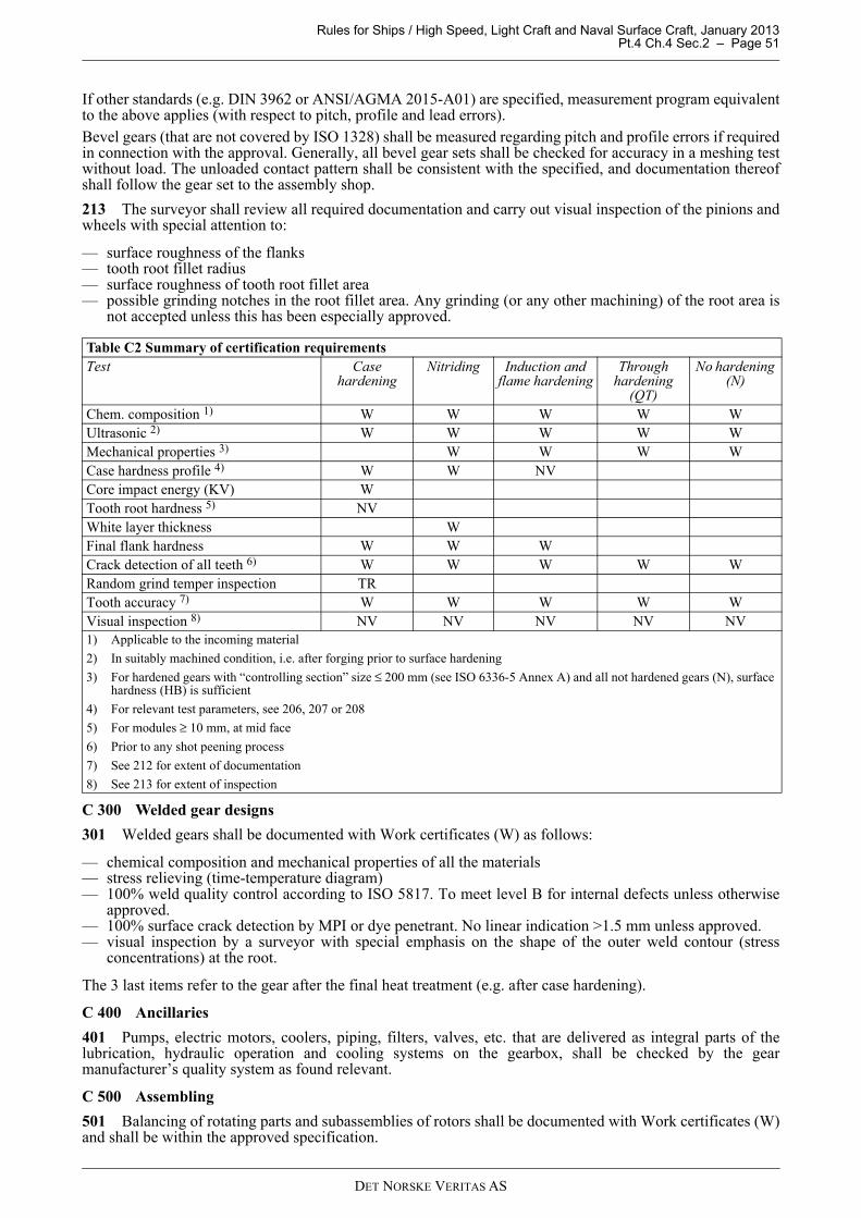
Rules for Ships / High Speed, Light Craft and Naval Surface Craft, January 2013 Pt.4 Ch.4 Sec.2 – Page 51
If other standards (e.g. DIN 3962 or ANSI/AGMA 2015-A01) are specified, measurement program equivalentto the above applies (with respect to pitch, profile and lead errors).Bevel gears (that are not covered by ISO 1328) shall be measured regarding pitch and profile errors if requiredin connection with the approval. Generally, all bevel gear sets shall be checked for accuracy in a meshing testwithout load. The unloaded contact pattern shall be consistent with the specified, and documentation thereofshall follow the gear set to the assembly shop.
213 The surveyor shall review all required documentation and carry out visual inspection of the pinions andwheels with special attention to:
— surface roughness of the flanks— tooth root fillet radius— surface roughness of tooth root fillet area— possible grinding notches in the root fillet area. Any grinding (or any other machining) of the root area is
not accepted unless this has been especially approved.
C 300 Welded gear designs
301 Welded gears shall be documented with Work certificates (W) as follows:
— chemical composition and mechanical properties of all the materials— stress relieving (time-temperature diagram)— 100% weld quality control according to ISO 5817. To meet level B for internal defects unless otherwise
approved.— 100% surface crack detection by MPI or dye penetrant. No linear indication >1.5 mm unless approved.— visual inspection by a surveyor with special emphasis on the shape of the outer weld contour (stress
concentrations) at the root.
The 3 last items refer to the gear after the final heat treatment (e.g. after case hardening).
C 400 Ancillaries
401 Pumps, electric motors, coolers, piping, filters, valves, etc. that are delivered as integral parts of thelubrication, hydraulic operation and cooling systems on the gearbox, shall be checked by the gearmanufacturer’s quality system as found relevant.
C 500 Assembling
501 Balancing of rotating parts and subassemblies of rotors shall be documented with Work certificates (W)and shall be within the approved specification.
Table C2 Summary of certification requirementsTest Case
hardeningNitriding Induction and
flame hardeningThrough
hardening (QT)
No hardening (N)
Chem. composition 1) W W W W WUltrasonic 2) W W W W WMechanical properties 3) W W W WCase hardness profile 4) W W NVCore impact energy (KV) WTooth root hardness 5) NVWhite layer thickness WFinal flank hardness W W WCrack detection of all teeth 6) W W W W WRandom grind temper inspection TRTooth accuracy 7) W W W W WVisual inspection 8) NV NV NV NV NV1) Applicable to the incoming material
2) In suitably machined condition, i.e. after forging prior to surface hardening
3) For hardened gears with “controlling section” size ≤ 200 mm (see ISO 6336-5 Annex A) and all not hardened gears (N), surface hardness (HB) is sufficient
4) For relevant test parameters, see 206, 207 or 208
5) For modules ≥ 10 mm, at mid face
6) Prior to any shot peening process
7) See 212 for extent of documentation
8) See 213 for extent of inspection
DET NORSKE VERITAS AS
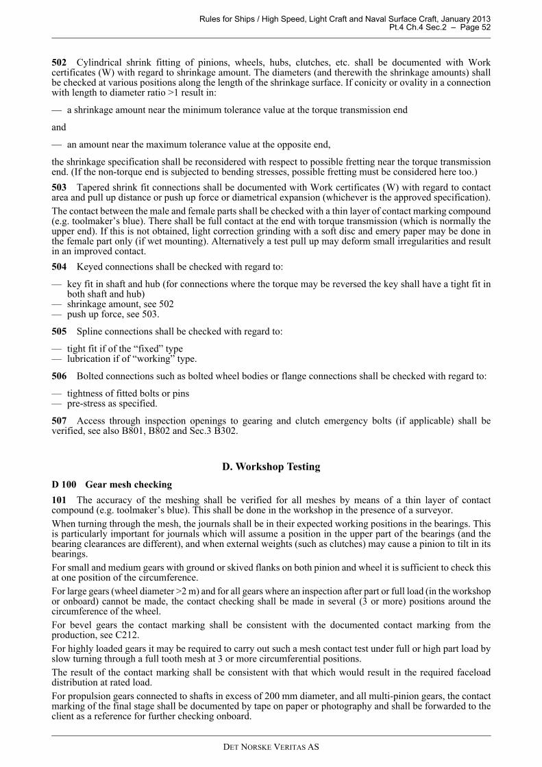
Rules for Ships / High Speed, Light Craft and Naval Surface Craft, January 2013 Pt.4 Ch.4 Sec.2 – Page 52
502 Cylindrical shrink fitting of pinions, wheels, hubs, clutches, etc. shall be documented with Workcertificates (W) with regard to shrinkage amount. The diameters (and therewith the shrinkage amounts) shallbe checked at various positions along the length of the shrinkage surface. If conicity or ovality in a connectionwith length to diameter ratio >1 result in:
— a shrinkage amount near the minimum tolerance value at the torque transmission end
and
— an amount near the maximum tolerance value at the opposite end,
the shrinkage specification shall be reconsidered with respect to possible fretting near the torque transmissionend. (If the non-torque end is subjected to bending stresses, possible fretting must be considered here too.)
503 Tapered shrink fit connections shall be documented with Work certificates (W) with regard to contactarea and pull up distance or push up force or diametrical expansion (whichever is the approved specification).The contact between the male and female parts shall be checked with a thin layer of contact marking compound(e.g. toolmaker’s blue). There shall be full contact at the end with torque transmission (which is normally theupper end). If this is not obtained, light correction grinding with a soft disc and emery paper may be done inthe female part only (if wet mounting). Alternatively a test pull up may deform small irregularities and resultin an improved contact.
504 Keyed connections shall be checked with regard to:
— key fit in shaft and hub (for connections where the torque may be reversed the key shall have a tight fit inboth shaft and hub)
— shrinkage amount, see 502— push up force, see 503.
505 Spline connections shall be checked with regard to:
— tight fit if of the “fixed” type— lubrication if of “working” type.
506 Bolted connections such as bolted wheel bodies or flange connections shall be checked with regard to:
— tightness of fitted bolts or pins— pre-stress as specified.
507 Access through inspection openings to gearing and clutch emergency bolts (if applicable) shall beverified, see also B801, B802 and Sec.3 B302.
D. Workshop Testing
D 100 Gear mesh checking
101 The accuracy of the meshing shall be verified for all meshes by means of a thin layer of contactcompound (e.g. toolmaker’s blue). This shall be done in the workshop in the presence of a surveyor. When turning through the mesh, the journals shall be in their expected working positions in the bearings. Thisis particularly important for journals which will assume a position in the upper part of the bearings (and thebearing clearances are different), and when external weights (such as clutches) may cause a pinion to tilt in itsbearings. For small and medium gears with ground or skived flanks on both pinion and wheel it is sufficient to check thisat one position of the circumference.For large gears (wheel diameter >2 m) and for all gears where an inspection after part or full load (in the workshopor onboard) cannot be made, the contact checking shall be made in several (3 or more) positions around thecircumference of the wheel. For bevel gears the contact marking shall be consistent with the documented contact marking from theproduction, see C212.For highly loaded gears it may be required to carry out such a mesh contact test under full or high part load byslow turning through a full tooth mesh at 3 or more circumferential positions.The result of the contact marking shall be consistent with that which would result in the required faceloaddistribution at rated load.For propulsion gears connected to shafts in excess of 200 mm diameter, and all multi-pinion gears, the contactmarking of the final stage shall be documented by tape on paper or photography and shall be forwarded to theclient as a reference for further checking onboard.
DET NORSKE VERITAS AS
Rules for Ships / High Speed, Light Craft and Naval Surface Craft, January 2013 Pt.4 Ch.4 Sec.2 – Page 53
The backlash shall be documented for all gear meshes.
102 All gear transmissions shall be spin tested in presence of a surveyor. Prior to the spin test some teeth at different positions around the circumference of all gear meshes shall bepainted with an oil resistant but low wear resistant test lacquer. For multi-mesh gears the lacquer shall beapplied to the flanks that mesh with only one other member. After the spin test the initial contact patterns shall be documented by sketches. The position of the initial contactshall be consistent with that which would result in an acceptable load distribution at rated torque.
103 For gears that are workshop tested with a part load sufficient to verify the load distribution at ratedtorque, the testing in 101 and 102 may be waived, except for backlash measurements.Such part load testing will only be representative for the full load condition on board if the in- and out-put shaftsare connected to systems that will not impose significant bending moments or forces. Furthermore, the part loadshall be so high (normally 40% torque or more) that reliable extrapolation to rated torque can be made.Therefore, this part load testing is subject to approval, see A200. If such part load testing is successfully carriedout, the gear transmission certificate may have a remark stating that contact pattern testing onboard may bewaived.
104 During the running test the gearbox shall be inspected for leakage.
D 200 Clutch operation
201 For clutches delivered integral with the gear box the clutching-in function shall be tested in the presenceof a surveyor. For oil operated clutches the testing shall be made with the oil at normal service temperature.The pressure - time function shall be within the approved specification and the end pressure at the specifiedlevel. No pressure peaks beyond the nominal pressure are allowed. The clutch operation pressure shall bemeasured as closely as possible to the clutch inlet.
D 300 Ancillary systems
301 The manufacturer shall demonstrate to the surveyor that the lubrication oil intake is placed to be wellsubmerged under all environmental operation conditions for the actual type of vessel. Furthermore, it shall bechecked that the oil sprays for lubrication and cooling function properly. After the running test the filters shallbe inspected.
302 All equipment delivered with the gearbox regarding indication, alarm and safety systems shall befunction tested.
E. Control and Monitoring
E 100 Summary
101 The requirements in E are additional to those given in Ch.9.
102 The gear transmissions shall be fitted with instrumentation and alarms according to Table E1.
103 If individual local pressure indicators are not fitted, quick connectors for a portable instrument shall beprovided in order to do local readings and set point verification of switches. The corresponding portableinstrument shall be provided on board.
104 Alarms (Gr 1) and start of standby pump shall be without delay, other than those necessary to filternormal parameter fluctuations, if not otherwise approved.
DET NORSKE VERITAS AS

Rules for Ships / High Speed, Light Craft and Naval Surface Craft, January 2013 Pt.4 Ch.4 Sec.2 – Page 54
F. Arrangement
F 100 Installation and fastening
101 The gearbox shall be arranged so that appropriate alignment and running conditions are maintainedduring all operating conditions. For shaft alignment, see Sec.1 F400.
102 Gearboxes shall be mounted on chocks or epoxy resin. The bolts shall be designed for all relevantoperating conditions (in particular when ice classes apply). Flexibly mounted gearboxes will be especiallyconsidered.
103 Gearboxes that are or may be subjected to external forces such as thrust, shall have end stoppers. Endstoppers may be waived if fitted bolts or equivalent solutions are used.
104 Piping etc. shall not be arranged to obstruct access to inspection openings.
105 All pipe connections shall be screened or otherwise protected as far as practicable in order to avoid oilspray or oil leakage into machinery air intakes or onto potentially hot surfaces.Any surfaces (with temperatures exceeding 220 degrees if not insulated) that are insulated by means, for whichworkmanship affects the efficiency of the insulation, are defined as potentially hot surfaces.
Table E1 Monitoring of gear transmissionsGr 1
IndicationAlarmLoad
reduction
Gr 2Automatic
start of standby pump with alarm 1)
Gr 3shut down with
alarmComments
1.0 Gear bearing and lubricating oilOil lubricated fluid film bearings (axial and radial), temperature
IR, HAApplicable to gears with totally transmitted power of 5 MW or more.
Thrust bearing, temperature IR, HA
Applicable to gears with totally transmitted power of 5 MW or more.Sensors to be placed in the bearing metal or for pads in the oil outlet.
Lubricating oil, pressure IL, IR, LA ASAt bearings and spray, if applicable. If equal pressure, one common sensor is sufficient for Gr 1.
Lubricating oil, temperature IL, or IR, HA At inlet to bearings, i.e. after cooler.Lubricating oil temperature IL or IR In sump, or before coolerSump level 2) ILor IR For splash lubricated gears.2.0 Integrated clutch activating media
Hydraulic oil IL, IR, LA AS SH SH means either declutching or engine stop
Gr 1 Common sensor for indication, alarm, load reduction (common sensor permitted but with different set points and alarm shall be activated before any load reduction)
Gr 2 Sensor for automatic start of standby pumpGr 3 Sensor for shut down
IL = Local indication (presentation of values), in vicinity of the monitored componentIR = Remote indication (presentation of values), in engine control room or another centralized control station such as
the local platform/manoeuvring consoleA = Alarm activated for logical valueLA = Alarm for low valueHA = Alarm for high valueAS = Automatic start of standby pump with corresponding alarmLR = Load reduction, either manual or automatic, with corresponding alarm, either slow down (r.p.m. reduction) or
alternative means of load reduction (e. g. pitch reduction), whichever is relevant.SH = Shut down with corresponding alarm. May be manually (request for shut down) or automatically executed if not
explicitly stated above.
For definitions of Load reduction (LR) and Shut down (SH), see Pt.4 Ch.1 of the Rules for Classification of Ships.
1) To be provided when standby pump is required, see B900 and Ch.1 (Rules for Classification of Ships).
2) For gears with totally transmitted power of 500 kW or less, dipstick inspection is considered adequate.
DET NORSKE VERITAS AS

Rules for Ships / High Speed, Light Craft and Naval Surface Craft, January 2013 Pt.4 Ch.4 Sec.2 – Page 55
G. Vibration
G 100 General
101 Regarding torsional vibration, see the section for the relevant prime mover, e.g. diesel engines Ch.3 Sec.1G and B105.
102 The vibration of the gearbox foundation (except when flexibly mounted) is normally not to contain gearalien frequency components with amplitudes exceeding 10 mm/s. Alien frequencies are those that are notrotational frequencies of any gear internal parts.Higher amplitudes may be accepted if considered in the gear design.
H. Installation Inspection
H 100 Application
101 H applies to inspections in connection with installation of complete gearboxes. Regarding externalcouplings and shafts, and internal clutches, see respective sections.Unless otherwise stated, a surveyor shall attend the inspections given in H and I.
H 200 Inspections
201 The following inspections shall be carried out:
— shaft alignment, see Sec.1 H300— fastening of propulsion gearboxes (stoppers and bolt tightening)— flushing, applicable if the system is opened during installation. Preferably with the foreseen gear oil. If
flushing oil is used, residual flushing oil shall be avoided.— lubrication oil shall be as specified (viscosity and FZG class) on maker’s list— pressure tests to nominal pressure (for leakage) where cooler, filters or piping is mounted onboard— clutch operation, see Sec.3 H— tooth contact pattern, see 202.
202 A tooth contact pattern inspection as described in D101 shall be made for gears where the installation onboard can alter the initial tooth contact pattern. This means e.g. all gear transmissions with more than one piniondriving the output gear wheel, even if there is only one single input shaft as for dual split paths, and propulsiongears connected to shafts in excess of about 200 mm diameter. The result of the contact pattern check shall beconsistent with the result from the workshop.
I. Shipboard Testing
I 100 Gear teeth inspections
101 To prevent initial damage on the tooth flanks (scuffing) and bearings, the gear shall be carefully run inaccording to the gear manufacturers specification.
102 All inboard gears shall be checked with regard to contact pattern under load.Exceptions are accepted when:
— this is mentioned in the design approval (due to low stress levels)— the design makes an inspection impossible without dis-assembling such as certain epicyclic gears (this does
not exempt ordinary gears from having suitable inspection openings)— the contact pattern under load is accepted in the workshop test, see D103.
103 The contact patterns (all gear stages) shall be checked by a suitable lacquer applied to some teeth(normally 2 each 120 degrees) prior to the checking under load. The lacquer shall be applied to flanks that haveonly one mesh (in order to avoid accumulated patterns). When part load contact pattern checking applies, thelacquer shall be of a kind that quickly shows the final pattern.
104 The gear shall be operated at the specified load level(s) without exceeding that particular level(s). Aftereach specified level the contact patterns shall be checked in the presence of a surveyor. The results, in bothheight and length directions, shall be within the approved specification.
105 After the full load test, or after the sea trial, all teeth shall be checked for possible failures as scuffing,scratches, grey staining, pits, etc. Shrunk-on rims shall be checked for possible movements relative to the hub.
DET NORSKE VERITAS AS

Rules for Ships / High Speed, Light Craft and Naval Surface Craft, January 2013 Pt.4 Ch.4 Sec.2 – Page 56
I 200 Gear noise detection
201 Gears shall be checked for noise in the full speed range (high frequencies as gear mesh frequencies) andin the lower speed range (gear hammer).
202 If the high frequent noise is higher than expected, measurements may be required.
203 Gear hammer shall be detected in the lower speed range and also during diesel engine misfiring tests (seeCh.3 Sec.1 I500). Speed ranges or operating conditions resulting in gear hammer shall be restricted forcontinuous operation.
I 300 Bearings and lubrication
301 Lubricating oil and bearing temperatures (as far as indication is provided) shall be checked during thefull load test. All temperatures shall reach stable values (no slow gradual increase) without exceeding theapproved maximum values.
302 After the sea trial all oil filters shall be checked for particles.
DET NORSKE VERITAS AS

Rules for Ships / High Speed, Light Craft and Naval Surface Craft, January 2013 Pt.4 Ch.4 Sec.3 – Page 57
SECTION 3 CLUTCHES
A. General
A 100 Application
101 This section applies to clutches, both for use in shaft-lines and in gearboxes that are subject tocertification, see Ch.2 Sec.1 A200.
102 Clutches of standard design shall be type approved.
103 Ch.2 describes general requirements for rotating machinery. Attention shall be paid to Ch.2 Sec.3 A100and in particular A102.
104 Clutches shall be delivered with a NV certificate. However, this does not apply to clutches used ingearboxes/thrusters and produced by the gearbox/thruster manufacturer, see Sec.2 Table C1.
A 200 Documentation
201 At least a sectional drawing of the clutch shall be submitted for approval.The drawing shall show all details such as:
— connection to external shafts— material specification including NDT specification— mechanical properties — heat treatment of splines etc. — stress raisers — activation system.
202 The following particulars shall be submitted for each clutch:
— static friction torque (with corresponding working pressure)— dynamic friction torque (with corresponding working pressure)— maximum working pressure— minimum working pressure— pressure for compressing return springs— permissible heat development and flash power when clutching-in (upon request when case-by-case
approval)— the control and monitoring system, including set-points and delays, see E, shall be submitted for approval.
In addition, see Ch.9.
203 For each application the clutching-in characteristics with tolerances (pressure as function of time)including max. engaging speed, shall be submitted for approval.
204 Upon request the documentation (simulation calculation) of the engaging process may be required, seeCh.3 Sec.1 A601 b)3) and Ch.3 Sec.1 G403.
B. Design
B 100 Torque capacities
101 The torque capacities of clutches for auxiliary purposes as well as propulsion shall be:
— static friction torque at least 1.8 T0 and preferably not above 2.5 T01)
— dynamic friction torque at least 1.3 T0
Both requirements referring to nominal operating pressure and no ice class notation.
102 The torque requirements in 101 may have to be increased for plants with ice class notation, see Pt.5 Ch.1of the Rules for Classification of Ships. If the ice class application factor KAice > 1.4, the torque capacities shallbe increased by the ratio:
KAice/ 1.4.
103 For clutches used in plants with high vibratory torques (beyond 0.4 T0) or intermittent overloads, thetorque capacity requirements will be especially considered.
1) When above 2.5 T0 the documentation in A204 is obligatory.
DET NORSKE VERITAS AS
Rules for Ships / High Speed, Light Craft and Naval Surface Craft, January 2013 Pt.4 Ch.4 Sec.3 – Page 58
B 200 Strength and wear resistance
201 The relevant parts such as flange connections, shrink fits, splines, key connections, etc. shall meet therequirements given in Sec.1 B300 to B700.
202 If a disc clutch is arranged so that radial movements occur under load, the possible wear of the teeth andsplines shall be considered. This may be relevant for clutches in gearboxes where a radial reaction force mayact on the discs. Such radial forces may occur due to bearing clearances in either an integrated pinion and clutchdesign or shafts that are moved off centre due to tooth forces.
203 Trolling clutches are subject to special consideration.
B 300 Emergency operation
301 Clutches for single propulsion plants shall be of a design that enables sufficient torque transmission tobe arranged in the event of loss of hydraulic or pneumatic pressure. This means that for plants on board vesselswithout ice class or reinforcement due to high torsional vibration level at least half of the rated engine torqueshall be transmitted.
302 If the requirement in 301 is fulfilled by means of bolts, easy access to all bolts should be provided. Forbuilt-in clutches, this means normally that all the bolts shall be on the part of the clutch that is connected to theengine. This in order to gain access to all bolts by using the engine turning gear. Such bolts shall be fitted inplace and secured to the clutch. Alternative arrangements are subject to special consideration and in any caseit should be possible to carry out the emergency operation within 1 hour. The emergency operation procedureshould be given in the operating manual.
B 400 Type testing
401 Type testing in order to verify friction torques as specified in 101 may be required.
B 500 Hydraulic/pneumatic system
501 Clutches in single propulsion plants shall have a standby pump with immediate activation.
C. Inspection and Testing
C 100 Certification
101 Regarding certification schemes, short terms, manufacturing survey arrangement and important conditions,see Ch.2 Sec.2.
C 200 Inspection and testing of parts
201 Power transmitting parts as hubs, flanges and outer parts shall be documented with Work certificates (W)regarding chemical composition of the material and mechanical properties.
202 NDT shall be documented with Work certificate (W).
C 300 Ancillaries
301 Pumps, electric motors, coolers, piping, filters, valves, etc. that are delivered as integral parts of thehydraulic/pneumatic system of the clutch, shall be checked by the manufacturer’s quality system as foundrelevant.
D. Workshop Testing
D 100 Function testing
101 The clutch shall be function tested before certification.
102 If the clutch is delivered with the activation control, the pressure-time function for clutching-in shall beverified in the presence of a surveyor. If the clutch is oil operated this shall be made with a representative oilviscosity.
DET NORSKE VERITAS AS

Rules for Ships / High Speed, Light Craft and Naval Surface Craft, January 2013 Pt.4 Ch.4 Sec.3 – Page 59
E. Control, Alarm and Safety Functions and Indication
E 100 Summary
101 The clutches shall be fitted with instrumentation and alarms according to Table E1.
102 If individual local pressure indicators are not fitted, quick connectors for a portable instrument shall beprovided in order to do local readings and set point verification of switches. The corresponding portableinstrument shall be provided on board.
F. Arrangement
F 100 Clutch arrangement
101 Clutches shall be arranged to minimise radial support forces, see B202.
102 Easy access to the emergency operation device shall be provided, see B300.
G. Vibration
G 100 Engaging operation
101 The calculation of the engaging process shall be based on the particulars specified in A202 and A203.The calculation shall result in torque, flash power and heat development as functions of time, and shall notexceed the permissible values for the clutch or any other element in the system. See also Ch.3 Sec.1 G403.
H. Installation Inspection
H 100 Alignment
101 Clutches not integrated in a gearbox or thruster, shall be checked for axial and radial alignment in thepresence of a surveyor.
Table E1 Monitoring of clutchesGr 1
IndicationAlarmLoad
reduction
Gr 2Automatic
start of standby pump with alarm 1)
Gr 3shut down with
alarmComments
1.0 Clutch activating mediaHydraulic/pneumatic air, pressure
IL, IR, LA AS SH SH means either declutching or engine stop.
Gr 1 Common sensor for indication, alarm, load reduction (common sensor permitted but with different set points and alarm shall be activated before any load reduction)
Gr 2 Sensor for automatic start of standby pumpGr 3 Sensor for shut down
IL = Local indication (presentation of values), in vicinity of the monitored componentIR = Remote indication (presentation of values), in engine control room or another centralized control station such as
the local platform/manoeuvring consoleA = Alarm activated for logical valueLA = Alarm for low valueHA = Alarm for high valueAS = Automatic start of standby pump with corresponding alarmLR = Load reduction, either manual or automatic, with corresponding alarm, either slow down (r.p.m. reduction) or
alternative means of load reduction (e. g. pitch reduction), whichever is relevant.SH = Shut down with corresponding alarm. May be manually (request for shut down) or automatically executed if not
explicitly stated above.
For definitions of Load reduction (LR) and Shut down (SH), see Pt.4 Ch.1 of the Rules for Classification of Ships.1) To be provided when standby pump is required, see B501.
DET NORSKE VERITAS AS

Rules for Ships / High Speed, Light Craft and Naval Surface Craft, January 2013 Pt.4 Ch.4 Sec.3 – Page 60
I. Shipboard Testing
I 100 Operating of clutches
101 The following shall be checked in the presence of a surveyor:
— when engaged, the operating pressure to be within the approved tolerance— access to the emergency operation device (see B300), if applicable— during engaging, the operating pressure as a function of time to be according to the approved
characteristics.
102 The clutch engaging as mentioned above, shall be made at the maximum permissible engaging speed.The pressure indication shall be representative for the operating pressure, i.e. measured close to the rotatingseal and without throttling between the instrument and operating pressure pipe. No pressure peaks beyond thespecified maximum pressure are accepted.
DET NORSKE VERITAS AS

Rules for Ships / High Speed, Light Craft and Naval Surface Craft, January 2013 Pt.4 Ch.4 Sec.4 – Page 61
SECTION 4 BENDING COMPLIANT COUPLINGS
A. General
A 100 Application
101 This section applies to couplings used in machinery that is subject to certification, see Ch.2 Sec.1 A200. Bending compliant couplings are membrane couplings, tooth couplings, link couplings, universal shafts, etc.,i.e. all couplings that have a low bending rigidity, but high torsional rigidity. Couplings combining both lowbending and low torsional rigidity shall fulfil the requirements in both Sec.4 and Sec.5.
102 Couplings of standard design shall be type approved.
103 Ch.2 describes general requirements for rotating machinery. Attention shall be paid to Ch.2 Sec.3 A100and in particular A102.
104 Couplings shall be delivered with a NV certificate.
A 200 Documentation
201 Drawings showing the couplings in longitudinal section (for link couplings also transverse section) shallbe submitted for approval. The drawings shall specify:
— material specification including NDT specification— surface hardening (if applicable)— shot peening (if applicable)— design details as keyways, bolt connections, or any other stress concentration.
For power transmitting welds a full NDT specification including acceptance criteria shall be submitted. Fortooth couplings the tooth accuracy (ISO 1328) shall be specified.
202 For high speed couplings (for connection to gas turbines) the maximum residual unbalance shall bespecified.
203 The following particulars shall be submitted:
— the permissible mean torque— the permissible maximum torque (impact torque)— the permissible vibratory torque for continuous operation— the permissible angular tilt for continuous operation— the permissible radial misalignment or reaction force (if applicable) for continuous operation— the permissible axial misalignment for continuous operation— the angular (tilt), radial and axial stiffness (as far as applicable)— the maximum permissible r.p.m.
204 Calculations to substantiate the relevant particulars given in 203 shall be submitted upon request.
B. Design
B 100 General
101 For design principles see Ch.2 Sec.3 A100.
102 Couplings for turbine machinery (high speed side) containing high energy rotating parts that may beejected in the event of a remote failure shall have special guards or design precautions.
B 200 Criteria for dimensioning
201 The couplings shall be designed with suitable safety factors against fatigue (“suitable safety factors” willdepend on the method applied, but typically be about 1.5).
202 For connections as flanges, shrink fits, splines, key connections, etc. see the requirements in Sec.1 B300to B700 respectively.
203 For membrane, link or disc couplings the safety against fatigue shall be documented:
— All relevant combinations of permissible loads (A203) shall be considered
DET NORSKE VERITAS AS

Rules for Ships / High Speed, Light Craft and Naval Surface Craft, January 2013 Pt.4 Ch.4 Sec.4 – Page 62
— The calculations may be combined with results from material fatigue tests— The safety against fatigue may also be documented by fatigue testing of the complete coupling. If so, the
load and the kind of loading (or combinations thereof) shall be selected to document the safety when allpermissible loads are combined.
204 Tooth couplings shall be designed to prevent tooth fracture, flank pitting and abrasive wear.The maximum permissible radial reaction force, the permissible mean and vibratory torque, the angularmisalignment and the lubrication conditions shall be combined in the calculations.
205 Universal shafts with power transmitting welds shall be designed for a high safety against fatigue in theweld. The calculation shall consider the maximum permissible loads and the specified weld quality.The stresses in the welds combined with the maximum permissible defects according to the NDT specificationshall not cause a stress intensity of more than . Ball and roller bearings shall have a minimum L10a (ISO 281) life time that is suitable with respect to thespecified overhaul intervals.
C. Inspection and Testing
C 100 Certification
101 Regarding certification schemes, short terms, manufacturing survey arrangement and importantconditions, see Ch.2 Sec.2.
C 200 Inspection and testing of parts
201 Power transmitting parts as hubs, sleeves, shaft tubes, flanges and flexible elements shall be documentedwith Work certificates (W) regarding chemical composition of the material, mechanical properties and surfacehardness (if surface hardened).
202 NDT shall be documented with Works certificate (W).
203 Welds shall be documented in accordance with the approved specification.
D. Workshop Testing
D 100 Balancing
101 The couplings shall be balanced in accordance with the approved specification.
D 200 Stiffness verification
201 For membrane, link and disc couplings verification of the specified stiffness in angular and axialdirections shall be carried out by means of static measurements in the presence of a surveyor. This applies to:
— one coupling of a series for which type approval is requested— every case by case approved non-standard coupling.
E. Control, Alarm, Safety Functions and Indication
E 100 General
101 Control, alarm, safety functions and indication are not required.
F. Arrangement
F 100 Coupling arrangement
101 Couplings shall be arranged to avoid the limitations given in A203 to be exceeded. Furthermore, thereaction forces from couplings on the adjacent elements shall be taken into account. All permissible operatingconditions shall be considered.
2MPa m
DET NORSKE VERITAS AS

Rules for Ships / High Speed, Light Craft and Naval Surface Craft, January 2013 Pt.4 Ch.4 Sec.4 – Page 63
G. Vibration
G 100 General
101 Intentionally left blank.
H. Installation Inspection
H 100 Alignment
101 The coupling alignment (axial, radial and angular) shall be checked in the presence of a surveyor. Thealignment shall be within the approved tolerances for the coupling as well as any other limitation specified inthe shafting arrangement drawings (in particular for the high speed side of gas turbine plants).
102 The alignment shall be made under consideration of all adjacent machinery such as resiliently mountedengines.
I. Shipboard Testing
I 100 General
101 Intentionally left blank.
DET NORSKE VERITAS AS
Rules for Ships / High Speed, Light Craft and Naval Surface Craft, January 2013 Pt.4 Ch.4 Sec.5 – Page 64
SECTION 5 TORSIONALLY ELASTIC COUPLINGS
A. General
A 100 Application
101 This section applies to couplings used in machinery subjected to certification, see Ch.2 Sec.1 A200. Torsional elastic couplings mean steel, rubber and silicone couplings designed for a low torsional rigidity.Couplings combining both low torsional rigidity and bending flexible elements as membranes or links shallfulfil the requirements in both Sec.4 and Sec.5.
102 Couplings of standard design shall be type approved.
103 Ch.2 describes general requirements for rotating machinery. Attention shall be paid to Ch.2 Sec.3 A100and in particular A102.
104 Couplings shall have a NV certificate.
A 200 Documentation
201 Drawings showing the couplings in longitudinal section shall be submitted. For elements that are non-symmetrical around the axis of rotation, a transverse section is also needed. The drawings shall specify:
— type of material and mechanical properties— surface hardening (if applicable) — shot peening (if applicable)— design details as keyways, splines or any other stress concentration
For power transmitting welds a full NDT specification including acceptance criteria shall be submitted.
202 The following particulars shall be submitted:
— rubber shore hardness H (laboratory test on rubber plates)— permissible mean torque TKN with the corresponding highest nominal shear stress in the elastomer and the
bonding stress— permissible maximum torque TKmax1 for repetitive loads as transient vibration, typically during clutching
in etc., see Fig. 1— permissible maximum torque range ΔTmax for repetitive loads as transient vibration, typically as passing
through a major resonance during start and stop etc., see Fig. 2— permissible maximum torque TKmax2 for rare occasional peak loads, e.g. short circuits in generators — permissible vibratory torque1) for continuous operation TKV, see Fig. 3— permissible power loss1) (heat dissipation) PKV— permissible angular tilt, radial and axial misalignment for continuous operation— angular (tilt), radial and axial stiffness1)
— permissible permanent twist of rubber element (applicable to progressive couplings)— maximum permissible r.p.m.— quasi-static torsional stiffness1)
— dynamic torsional stiffness1) including production tolerance— damping characteristics1) including production tolerance.
1) as a function of the main parameters.
These particulars shall be documented by means of relevant tests and calculations. See B100 and B200.
DET NORSKE VERITAS AS

Rules for Ships / High Speed, Light Craft and Naval Surface Craft, January 2013 Pt.4 Ch.4 Sec.5 – Page 65
Fig. 1TKmax1 at transient vibration
Fig. 2ΔTmax at transient vibration
Fig. 3TKV at continuous operation
DET NORSKE VERITAS AS

Rules for Ships / High Speed, Light Craft and Naval Surface Craft, January 2013 Pt.4 Ch.4 Sec.5 – Page 66
203 Definitions of stiffness and damping are:A) For linear couplings
Fig. 4Linear couplings
The stiffness K ( ) is the gradient of a line drawn
between the extreme points of the twist as indicated in Fig.4. For hysteresis plots that deviate from the ellipse (pure viscous damping) the line that determines K shall bedrawn through points determined as midpoints between the upper and lower part of the hysteresis curve, seeFig.5.
Fig. 5Hysteresis curve
The damping is the ratio between the area described by the hysteresis loop AD and the elastic work Ael,
For couplings with typical elliptical hysteresis curves, other definitions may be considered.B) For non-linear couplings
Fig. 6Non-linear couplings
Torque,TA
A el
D
ΔTel
Δϕ ϕtwist
KΔTe1
Δϕ------------=
twist
Torque,T A
Ael
D
••
••
ϕΔ ϕ
•
ΔTel
ψAD
Ae1---------=
twist ϕ
Torque,TAA el
D
ΔTel
Δϕ
A2
A1
= A = A2 1
DET NORSKE VERITAS AS
Rules for Ships / High Speed, Light Craft and Naval Surface Craft, January 2013 Pt.4 Ch.4 Sec.5 – Page 67
Plants with non-linear couplings may be calculated by either simulation (numeric time integration) in the timedomain or in the frequency domain by linear differential equations.In the first case the torque – twist plots can be used directly.In the second case (more common method) representative linearised coupling properties must be used in thecalculation. For this purpose the following applies.The (linearised) stiffness K is the gradient between the extreme points of the twist as indicated above.For determination of the damping ψ the elastic work Ael must be determined so that the above indicated areasof Ael are equal (A1 = A2). Then the same definition as for linear couplings applies.
204 The control and monitoring system, including set-points and delays, if required in E, shall be approvedby the Society.For requirements to documentation, see Ch.9.
B. Design
B 100 General
101 For design principles see Ch.2 Sec.3 A100.
102 See E101 for emergency claw devices.
B 200 Criteria for dimensioning
201 The couplings shall be designed with suitable safety factors (depending on the method applied, see B300)against fatigue and overheating (rubber).
202 For connections as flanges, shrink fits, splines, key connections, etc. see the requirements in Sec.1 B300to B700 respectively.
203 For steel spring couplings the safety against fatigue shall be documented. All relevant combinations ofpermissible loads (A202) shall be considered. The calculations may be combined with results from materialfatigue tests. The safety against fatigue may also be documented by fatigue testing of the complete coupling.If so, the load and the kind of loading (or combinations thereof) shall be selected to document the safety whenall permissible loads are combined. The design shall be so as to prevent fretting on vital elements.
204 Couplings shall not have rigid torsional deflection limiters (buffers) within the permissible TKmax2.Furthermore, TKmax2 shall not be less than 1.4 TKN.
205 For ice class notations the couplings shall be designed so that:
1) TKmax1 ≥ T0 KAice 2) TKN ≥ 0.5 T0 (KAice + 1)3) As long as the natural frequency of the "propeller versus engine"-mode is much lower than the propeller
blade passing frequency (ratio < 50%):TKV ≥ 0.5 T0 (KAice − 1)otherwise:TKV > T0 (KAice − 1)
KAice=application factor due to ice impact loads (applicable for ice classed vessels), see Pt.5 Ch.1 of the Rulesfor Classification of Ships.
Alternatively to the above criteria, the ice impact loads on the elastic coupling may be documented bysimulation of the transient dynamic response in the time domain. For branched systems, such simulation is ingeneral recommended.
206 For elements that are not designed to avoid local strain concentrations, stricter values for the criteriagiven in 207 and 208 may apply.For silicone couplings special considerations apply.
207 For rubber couplings with shear loaded rubber elements the shear stress (MPa) due to TKN shall notexceed the smaller value of:
— 1% of the shore hardness value
or
DET NORSKE VERITAS AS

Rules for Ships / High Speed, Light Craft and Naval Surface Craft, January 2013 Pt.4 Ch.4 Sec.5 – Page 68
— 0.65 MPa
The corresponding shear stress in the steel-rubber bonding surfaces is normally not to exceed 0.45 MPa.For coupling designs where centrifugal action can be of significance, the shear stresses in the rubber elementas well as in the bonding surface have to be considered. The evaluation shall take into account the influencesof TKN and rpmmax separately as well as combined. The permissible stress levels are specially considered.The shear stress due to the permissible vibratory torque for continuous operation shall not exceed 0.25% of theshore hardness. This shear stress is superimposed to the shear stress due to TKN. The corresponding peak valueis not limited by TKmax1 in 208.
208 When not substantiated by means of an approved fatigue testing combined with FE analyses, thefollowing applies:Permissible torque ΔTmax and TKmax1 for transient operation (50.000 cycles) are limited to:
a) A nominal shear stress Δτmax not to exceed Δτmax < 0.24 · 10-3 H2
b) A nominal shear stress τmax1 not to exceed in any direction τmax1 < 0.2 · 10-3 H2 and limited to TKmax1 ≤1.5 TKNNote that TKmax1 is not limiting the shear stress due to TKN + TKV.
209 For couplings having elements that are loaded in compression, TKmax1 will be specially considered.
210 The strength of the emergency claw device (if required, see 102) shall be documented by calculations.This device shall be designed for a minimum lifetime of 24 hours and combined with all permissiblemisalignments.
211 Couplings of natural rubber shall not be subjected to ambient temperatures above 70°C. The limit forsilicone couplings is 100°C.
B 300 Type testing
301 Type testing applies to all rubber and silicone couplings, but also for special kinds of steel springcouplings.
302 Steel spring couplings that are designed such that the damping properties are essentially non-viscous(e.g. mainly friction damping), shall be dynamically tested in order to establish the dynamic characteristics(stiffness and damping) as functions of their main parameters.
303 Rubber and silicone couplings shall be documented with regard to compatibility with the characteristicsand permissible loads given in A202. This shall be made with both calculation and testing:
— As a minimum the dynamic torsional stiffness and the damping shall be verified by testing, see 304. Areduced extent may apply for couplings that are approved for very restricted applications as e.g. in electricmotor driven thrusters.
— Couplings used in plants with reciprocating machinery are also to be tested for determination of permissiblepower loss. Exemptions may only be made if the value for PKV is assessed very much to the safe side.
— The necessity for test documentation of the angular (tilt), radial and axial stiffness depends on thecorresponding values for permissible misalignment.
— For case by case approval of a non-standard coupling the documentation (i.e. testing) applies to thenecessity for the actual coupling application.
— For type approval of a coupling series where the coupling sizes only differ by a scale factor, thedocumentation testing for stiffness and damping of only one size (per rubber type) may be sufficient.However, if power loss testing applies, this testing shall be made with at least two different coupling sizesin order to extrapolate for inclusion of the whole series.
— Quasi-static tests such as described in D200 shall be made with the same elements as used for the dynamictesting, and prior to it. The purpose shall establish reference values for certification testing.
304 The purpose for the testing of stiffness and damping shall establish the relations between the quasi-statictests mentioned above and the dynamic behaviour of the coupling. Furthermore, the type testing shall establishthe dynamic torsional stiffness and damping (for the relevant rubber qualities of relevant element sizes) asfunctions of the main parameters such as:
— Mean torque TM, normally at steps as
— Vibratory torque TV, normally at steps as
TM/TKN = 0 0.25 0.50 0.75 1
TV/TKV = 0.50 1.0 2.0 *
DET NORSKE VERITAS AS

Rules for Ships / High Speed, Light Craft and Naval Surface Craft, January 2013 Pt.4 Ch.4 Sec.5 – Page 69
(* for the purpose of transient vibrations)— Vibration frequency, normally at steps as
and for elements loaded in compression, also at 40 Hz
— Temperature of the element. This is for the purpose of establishing representative stiffness and dampingvalues under various ambient temperatures as well as under high power losses.Normally at:
reference condition, e.g. 30°C25% of permissible PKV *100% of permissible PKV *
For couplings not to be used in diesel engine plants the tests at reference condition will be sufficient.
* PKV as for rotating or non-rotating coupling, whichever is relevant for the laboratory.It is not required to test all the possible combinations of the conditions mentioned above. Normally referenceconditions as e.g. the bold values above, are kept constant when one parameter dependency is tested. However,for typically progressive couplings (stiffness increasing with torque) all permissible combinations of mean andvibratory torques shall be tested. The test results shall be presented as torque-twist plots, together with the details of the evaluation method.
305 The testing of the permissible power loss shall be made by means of at least one temperature sensor inthe rubber core at the expected (calculated) position of maximum temperature (position to be approved priorto the testing). The core temperature during pulsating of the element shall be plotted as a function of time until the endtemperature is stabilised. The maximum permissible core temperature is 110°C for natural rubber and 150°Cfor silicone.The permissible power loss PKV is defined as the power loss that results in the maximum permissible coretemperature. PKV is normally tested at an ambient temperature of 20°C and shall be linearly interpolated to zeroat maximum permissible core temperature as a function of operating ambient temperature. For coupling serieswhere the sizes only differ by a scale factor, interpolation and extrapolation may be done by the followingformula:
PKV = a TKNb
where the constants a and b can be determined by testing two or more different sizes of couplings in a series.The power loss is normally to be measured by means of torque-twist plots and applied frequency. Alternativemethods may be considered if their relevance can be documented and the results are estimated to the safe side.When a steady state condition is reached, e.g. not more than 1°C increase per hour, the actual power loss isdetermined from a torque-twist plot as PKVtest = AD · f (Hz).If the core temperature during this test ϑ test is different from the permissible value ϑ p, the PKV is determinedas:
ϑ A = ambient temperature during testϑ Aref = reference temperature in catalogue.Alternative methods to torque-twist pulsating may only be accepted if the evaluation of PKV is madeconservatively (to the safe side). If rotating with radial or angular misalignment is used, the assessment of theactual power loss in the elements must consider all possible increase of other losses (e.g. in bearings).Further, the different temperature field versus the real one in torque-twist must be taken into consideration bye.g. finite element analyses or preferably by comparison measurements in order to arrive at a correlation factorbetween the applied method and the real torque-twist condition.
C. Inspection and Testing
C 100 Certification
101 Regarding certification schemes, short terms, manufacturing Survey Arrangement and importantconditions, see Ch.2 Sec.2.
2 Hz 10 Hz 20 Hz
PKV PKVtest
ϑp ϑAref–
ϑtest ϑA–--------------------------⋅=
DET NORSKE VERITAS AS

Rules for Ships / High Speed, Light Craft and Naval Surface Craft, January 2013 Pt.4 Ch.4 Sec.5 – Page 70
C 200 Inspection and testing of parts
201 Power transmitting parts as hubs, sleeves, shaft tubes, flanges etc. shall be documented with Workcertificates (W) regarding chemical composition of the material, mechanical properties and surface hardness.
202 NDT shall be documented with Works certificate (W).
203 Welds shall be documented with a Work certificate (W) in accordance with the approved specification.
D. Workshop Testing
D 100 Stiffness verification
101 Each rubber or silicone coupling or elastic element shall be verified with regard to quasi-static torsionalstiffness in the presence of a surveyor. This shall be done by twisting the coupling or by subjecting the elasticelements to a load which is equivalent to the coupling twist. The test torque shall be at least 1.5 TKN. Theresulting deflection shall be within the approved tolerance and the deviation shall be specified in the certificate.
102 For couplings that are not approved for use in plants with reciprocating machinery a reduced extent oftesting may be accepted.
103 For segmented couplings the assembling of a coupling with segments from different charges (possiblydifferent stiffness) shall be within the approved tolerance range for segment differences.
D 200 Bonding tests
201 For couplings with bonded rubber or silicone elements the bonding shall be checked in the presence ofa surveyor. The coupling or elastic element shall be loaded in at least one direction to the 1.5 TKN. At this loadthe element shall be inspected for any signs of slippage in the bonding surface. Additionally the correspondingtorque-deflection curve shall be smooth and show no signs of slippage in the bonding.
202 The bonding may also be documented by alternative tests as e.g. tension where the tensile stress shall beat least as high as the shear stress under 1.5 TKN.
203 For couplings that have a limitation of the permanent twist (all progressive couplings) shall be markedso that the actual permanent twist and the limit twist are legible during service inspections.
D 300 Balancing
301 Couplings for PTO/PTI branches shall be single plane balanced when:
— tip speed >30 m/s— unmachined surfaces and tip speed >10 m/s
E. Control, Alarm, Safety Functions and Indication
E 100 Summary
101 The elastic couplings for propulsion of single diesel engine plants shall be fitted with instrumentationand alarms according to Table E1.
102 For couplings where twist amplitude alarm is chosen for monitoring of torsional vibration, see Ch.3Sec.1 G302 j), G303 d) and E103 b), the alarm levels and time delays are subject to special consideration.
DET NORSKE VERITAS AS
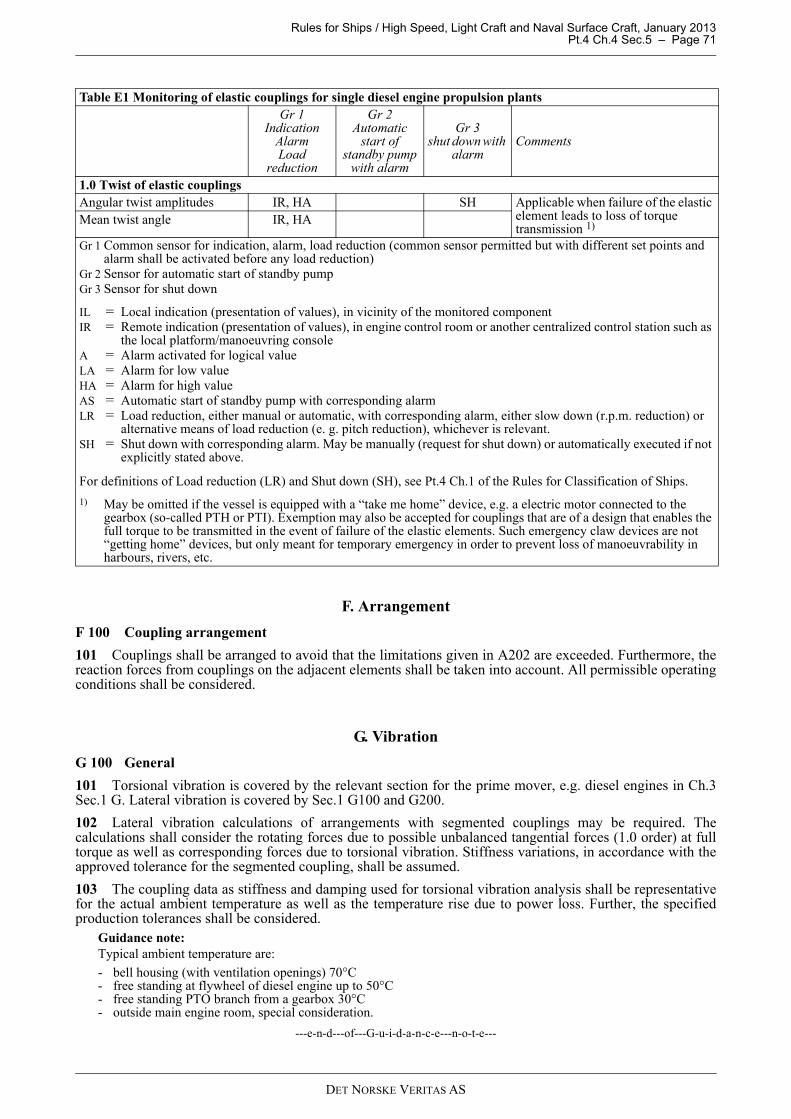
Rules for Ships / High Speed, Light Craft and Naval Surface Craft, January 2013 Pt.4 Ch.4 Sec.5 – Page 71
F. Arrangement
F 100 Coupling arrangement
101 Couplings shall be arranged to avoid that the limitations given in A202 are exceeded. Furthermore, thereaction forces from couplings on the adjacent elements shall be taken into account. All permissible operatingconditions shall be considered.
G. Vibration
G 100 General
101 Torsional vibration is covered by the relevant section for the prime mover, e.g. diesel engines in Ch.3Sec.1 G. Lateral vibration is covered by Sec.1 G100 and G200.
102 Lateral vibration calculations of arrangements with segmented couplings may be required. Thecalculations shall consider the rotating forces due to possible unbalanced tangential forces (1.0 order) at fulltorque as well as corresponding forces due to torsional vibration. Stiffness variations, in accordance with theapproved tolerance for the segmented coupling, shall be assumed.
103 The coupling data as stiffness and damping used for torsional vibration analysis shall be representativefor the actual ambient temperature as well as the temperature rise due to power loss. Further, the specifiedproduction tolerances shall be considered.
Guidance note:Typical ambient temperature are:
- bell housing (with ventilation openings) 70°C- free standing at flywheel of diesel engine up to 50°C- free standing PTO branch from a gearbox 30°C- outside main engine room, special consideration.
---e-n-d---of---G-u-i-d-a-n-c-e---n-o-t-e---
Table E1 Monitoring of elastic couplings for single diesel engine propulsion plantsGr 1
IndicationAlarmLoad
reduction
Gr 2Automatic
start of standby pump
with alarm
Gr 3shut down with
alarmComments
1.0 Twist of elastic couplingsAngular twist amplitudes IR, HA SH Applicable when failure of the elastic
element leads to loss of torque transmission 1)Mean twist angle IR, HA
Gr 1 Common sensor for indication, alarm, load reduction (common sensor permitted but with different set points and alarm shall be activated before any load reduction)
Gr 2 Sensor for automatic start of standby pumpGr 3 Sensor for shut down
IL = Local indication (presentation of values), in vicinity of the monitored componentIR = Remote indication (presentation of values), in engine control room or another centralized control station such as
the local platform/manoeuvring consoleA = Alarm activated for logical valueLA = Alarm for low valueHA = Alarm for high valueAS = Automatic start of standby pump with corresponding alarmLR = Load reduction, either manual or automatic, with corresponding alarm, either slow down (r.p.m. reduction) or
alternative means of load reduction (e. g. pitch reduction), whichever is relevant.SH = Shut down with corresponding alarm. May be manually (request for shut down) or automatically executed if not
explicitly stated above.
For definitions of Load reduction (LR) and Shut down (SH), see Pt.4 Ch.1 of the Rules for Classification of Ships.
1) May be omitted if the vessel is equipped with a “take me home” device, e.g. a electric motor connected to the gearbox (so-called PTH or PTI). Exemption may also be accepted for couplings that are of a design that enables the full torque to be transmitted in the event of failure of the elastic elements. Such emergency claw devices are not “getting home” devices, but only meant for temporary emergency in order to prevent loss of manoeuvrability in harbours, rivers, etc.
DET NORSKE VERITAS AS
Rules for Ships / High Speed, Light Craft and Naval Surface Craft, January 2013 Pt.4 Ch.4 Sec.5 – Page 72
H. Installation Inspection
H 100 Alignment
101 The coupling alignment (axial, radial and angular) shall be checked in the presence of a surveyor. Thealignment shall be within the approved tolerances for the coupling as well as any other limitation specified inthe shafting arrangement drawings.
102 The alignment shall be made under consideration of all adjacent machinery such as resiliently mountedengines, etc.
I. Shipboard Testing
I 100 Elastic elements
101 After the sea trial all rubber elements in propulsion plants and power take off branches shall be visuallychecked by a surveyor. No cracks or deterioration are acceptable.
DET NORSKE VERITAS AS