newcastle university eprintseprint.ncl.ac.uk/file_store/production/208377/f450f3ed-aadc-4739... ·...
TRANSCRIPT

Newcastle University ePrints
Hanipah MR, Mikalsen R, Roskilly AP.
Recent commercial free-piston engine developments for automotive
applications.
Applied Thermal Engineering 2015, 75, 493-503.
Copyright:
NOTICE: this is the authors’ version of a work that was accepted for publication in Applied Thermal
Engineering. Changes resulting from the publishing process, such as peer review, editing, corrections,
structural formatting, and other quality control mechanisms may not be reflected in this document.
Changes may have been made to this work since it was submitted for publication. A definitive version
was subsequently published in Applied Thermal Engineering, vol. 75, 22 January 2015.
DOI: 10.1016/j.applthermaleng.2014.09.039
Link to published article:
http://dx.doi.org/10.1016/j.applthermaleng.2014.09.039
Date deposited: 9th February 2015
This work is licensed under a Creative Commons Attribution-NonCommercial 3.0 Unported License
ePrints – Newcastle University ePrints
http://eprint.ncl.ac.uk

Recent commercial free-piston engine developments for 1
automotive applications 2
M. Razali Hanipah a, b*, R. Mikalsen a, A.P. Roskilly a 3
4 a Sir Joseph Swan Centre for Energy Research, Newcastle University, 5
Newcastle upon Tyne, NE1 7RU, United Kingdom 6 b Faculty of Mechanical Engineering, Universiti Malaysia Pahang, 7
26600, Pekan, Pahang, Malaysia 8 9
* Corresponding author. Email: [email protected] 10
11
ABSTRACT 12
Free-piston engines have been under extensive investigation in recent years, however have not 13 yet seen commercial success in modern applications. This paper reviews some of the recently 14 reported commercial developments in free-piston engine systems particularly aimed for use in 15 hybrid electric vehicle powertrains and discuss these in light of published research. By looking 16 at recent publications, and in particular patent documents, from major industrial players, 17 insight into the less widely reported commercial research efforts on free-piston engines is 18 obtained. Further, these publications provide a useful indication as to what these developers see 19 as the main technical challenges for this technology. 20 Key words: free-piston engine; linear generator; hybrid electric vehicle; patent 21
1. Introduction 22
Free-piston engines provide a promising alternative to conventional engines in applications 23 such as hybrid electric vehicles or hydraulically driven off-highway vehicles [1-3]. Such engines 24 were in commercial use in the mid-20th century as gas generators and air compressors, 25 generally showing advantageous properties [1]. In recent years, free-piston engines have been 26 under development by a number of groups worldwide, both within academia and industry. One 27 of the key drivers of these research efforts is arguably the potential of free-piston engines to 28 provide a compact and efficient power generator for hybrid electric vehicles. 29
As an electrical power generator, the free-piston engine has several potential advantages over 30 conventional crankshaft engines: It is mechanically simple and has a compact design due to the 31 integrated generator and single moving component. On the other hand, the crankshaft 32 generators have crankshaft mechanisms, flywheels and mechanical couplings. The absence of a 33 crankshaft will reduce the frictional losses significantly since there is no piston slapping 34 resulting from the rotary to linear motion conversion and by reducing the amount of moving 35 components, which means less contact friction in the system. Moreover, this ‘crank-less’ 36 operation produces a faster expansion stroke, which reduces the in-cylinder heat transfer loss 37 [4]. Further, a variable compression ratio can be realised for load demand control which can 38 enable the free-piston engine to operate at its optimum cyclic speed range for maximum 39 performance. These advantages can produce efficient prime movers with reduced emissions for 40 the hybrid electric vehicle applications [5-8]. 41
There is significant academic interest in the free-piston engine concept, and a number of groups 42 reported research on various aspects around this technology; see e.g. Mikalsen and Roskilly [1] 43 for an overview. Examples of very recent university-based free-piston engine research include 44 work on hydraulic [9-11] and electric [12-15] free-piston engines by groups at Beijing Institute 45 of Technology, work from National Taiwan University of Science and Technology [16], Shanghai 46 Jiao Tong University [17], Tianjin University [18], Korea Advanced Institute of Science and 47
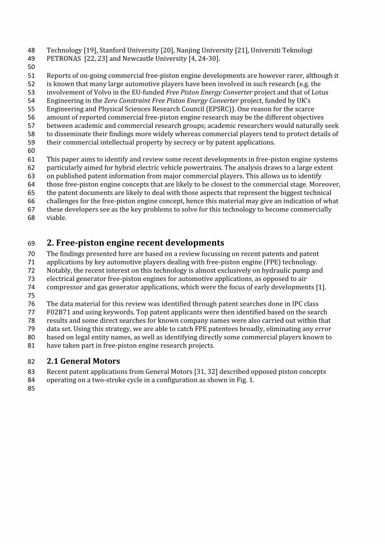
Technology [19], Stanford University [20], Nanjing University [21], Universiti Teknologi 48 PETRONAS [22, 23] and Newcastle University [4, 24-30]. 49 50 Reports of on-going commercial free-piston engine developments are however rarer, although it 51 is known that many large automotive players have been involved in such research (e.g. the 52 involvement of Volvo in the EU-funded Free Piston Energy Converter project and that of Lotus 53 Engineering in the Zero Constraint Free Piston Energy Converter project, funded by UK’s 54 Engineering and Physical Sciences Research Council (EPSRC)). One reason for the scarce 55 amount of reported commercial free-piston engine research may be the different objectives 56 between academic and commercial research groups; academic researchers would naturally seek 57 to disseminate their findings more widely whereas commercial players tend to protect details of 58 their commercial intellectual property by secrecy or by patent applications. 59 60 This paper aims to identify and review some recent developments in free-piston engine systems 61 particularly aimed for hybrid electric vehicle powertrains. The analysis draws to a large extent 62 on published patent information from major commercial players. This allows us to identify 63 those free-piston engine concepts that are likely to be closest to the commercial stage. Moreover, 64 the patent documents are likely to deal with those aspects that represent the biggest technical 65 challenges for the free-piston engine concept, hence this material may give an indication of what 66 these developers see as the key problems to solve for this technology to become commercially 67 viable. 68
2. Free-piston engine recent developments 69
The findings presented here are based on a review focussing on recent patents and patent 70 applications by key automotive players dealing with free-piston engine (FPE) technology. 71 Notably, the recent interest on this technology is almost exclusively on hydraulic pump and 72 electrical generator free-piston engines for automotive applications, as opposed to air 73 compressor and gas generator applications, which were the focus of early developments [1]. 74 75 The data material for this review was identified through patent searches done in IPC class 76 F02B71 and using keywords. Top patent applicants were then identified based on the search 77 results and some direct searches for known company names were also carried out within that 78 data set. Using this strategy, we are able to catch FPE patentees broadly, eliminating any error 79 based on legal entity names, as well as identifying directly some commercial players known to 80 have taken part in free-piston engine research projects. 81
2.1 General Motors 82
Recent patent applications from General Motors [31, 32] described opposed piston concepts 83 operating on a two-stroke cycle in a configuration as shown in Fig. 1. 84 85

86 Fig. 1. Opposed piston type free piston linear alternator (FPLA) [31, 32]. 87 88 Notably, this concept is very similar to first-generation free-piston compressors and gas 89 generators [1] such as the Sigma GS-34 gas generator illustrated in Fig. 2, but differs in that no 90 mechanical synchronization mechanism is foreseen. Electric power output is achieved by an 91 integrated electric machine, with the permanent magnets being incorporated in the pistons and 92 the coil windings integrated in the cylinder housing. 93 94
95 Fig. 2. Schematic of Sigma GS-34 free-piston gas generator [1] (See also London and Oppenheim 96 [33], Flynn [34], and Huber [35]). 97 98 Where the first-generation free-piston engines used mechanical synchronisation, this solution 99 by GM aims to use the bounce chambers and electrical braking to synchronise and control both 100 pistons [31]. The embedded permanent magnet piston is ensured to be at optimum 101 temperature by having an air jacket from the scavenging chamber around the piston. The stroke 102 can be controlled through electrical braking as well as the bounce chamber pressure control. 103 104 The absence of a flywheel has been reported as one of the main problems during the starting 105 and the operation of a free-piston engine generator by various researchers for the dual-piston 106 type free-piston design [1, 21, 22, 36]. The reason for this is the direct influence the combustion 107 in one cylinder will have on the motion profile for the next cycle and thereby the compression 108 process in the other cylinder. Thus, variations in the compression ratio may be produced during 109 operation, which can lead to unstable operation or even misfire. 110 111 The patent application by Holmes [37] presents a concept to solve this issue through an 112 ‘electrical flywheel’. In the system shown in Fig. 3, a linear machine (free-piston engine) is 113 electrically connected via two sets of coils to a rotary machine (middle) and a battery source via 114 a converter. In addition, a variable-speed motor may be mechanically connected via a gear box 115

to the rotary machine as well as electrically connected to the whole system via two sets of coils 116 as described in the patent. 117 118
119 Fig. 3. Operation of the electrical flywheel system (omitting the variable-speed motor) [37]. 120 121 The piston is made of ferromagnetic material. The operating principle of this system can be 122 described as follows (for the first combustion chamber event). During starting, the battery 123 supplies a starting current (Is) which reciprocates the piston and rotates the rotary machine to 124 produce sufficient inertial energy for several cycles. When sufficient conditions in cylinder one 125 are achieved, the fuel is injected and ignited for combustion. Upon combustion, the supplied 126 current is switched off while the piston motion towards the second cylinder induces a first 127 current (I1) in the first coil. Throughout the stroke, I1 will continue to operate the rotary 128 machine whose rotational inertia will induce a second current (I2) in the fourth coil. The second 129 current is used for proper positioning of the piston in the second combustion chamber via the 130 second coil. Then, when a second combustion event occurs, this will induce the generator 131 current (Ig) for the cyclic operation. This current will be used for charging the batteries and 132 driving the external loads. 133 134 Through this configuration, the two machines (i.e. the linear and rotary machines) will seek to 135 operate synchronously, hence in the case that the free-piston engine is lagging behind or 136 advancing, the rotating inertia of the rotating machine will produce a braking or accelerating 137 force through the coils. This can then reduce or balance out cycle-to-cycle variations in order to 138 achieve a stable operation as well as prevent misfires. Hence, in principle, this device can 139 function as an ‘electrical flywheel’, which is otherwise absent in the free piston engine generator. 140 141 Although this patent application depicts a dual combustion chamber type free-piston engine 142 while the later patents [31, 32] described previously, illustrate opposed piston type, this 143 method can in principle be used for any type of free-piston engine. 144
2.2 Toyota 145
Toyota Central Research has published a number of patent applications very recently relating to 146 free-piston engine systems. Reference [38] describes several design variations of a single piston 147 unit with a gas-filled bounce chamber. The use of a bounce chamber with pressure regulation is 148 a well-known option to aid piston motion control; this was studied by e.g. Johansen et al. [39, 40] 149 and Mikalsen and Roskilly [24, 28-30]. Compared to a dual piston system, in which the return 150

stroke is driven directly by the opposite combustion cylinder, a bounce chamber is less prone to 151 cycle-to-cycle variations, and provides some flexibility in that the stiffness of the gas spring can 152 be regulated by controlling the amount of gas trapped. This is also verified by recent research 153 from the German Aerospace Centre (DLR), who claimed that the gas spring configuration had 154 been chosen since it would be easier to implement piston motion control [41]. 155 156 A further patent application [38] proposes several designs to reduce heat transfer rate from the 157 piston to the permanent magnets (to avoid magnet demagnetization and coils overheating). 158 Special ceramic coating such as Zirconia has been proposed in another Toyota patent [42]. 159 However, for a reliable and durable operation, a more efficient method for heat dissipation is 160 required; one of such is depicted in Fig. 4. In this invention, the path for the heat flux to travel 161 from the top of the piston to the permanent magnets and coils is longer and the surface area of 162 the piston exposed to compressed air is larger. Thus, the final temperature increase on the 163 permanent magnet assembly can be reduced significantly. This is a proven concept which has 164 also been implemented in other applications, such as spark plug technology [43]. 165 166 In another patent, the engine cooling is provided by holes on the piston for compressed air to 167 flow in and out through corresponding holes on the cylinder as well as having a water jacket on 168 the cylinder for efficient power generation [42]. 169 170
171 Fig. 4. Specially designed piston to dissipate heat quickly while reducing the temperature rise 172 on the permanent magnets and coils [38]. 173 174 Yoshihiro, et al. [44] describes a system where two single piston with bounce chamber units 175 operate in opposed phases (though not with a common combustion or bounce chamber, so it is 176 not a ‘true’ opposed piston FPE) as shown in Fig. 5. In this configuration the pistons 177 synchronisations are realised via electrical braking and bounce chamber pressure regulation. 178 179 180

181 Fig. 5. Twin single piston system with back to back configuration [44]. 182 183 Hidemasa, et al. [45]describes a method for controlling a free-piston engine in order to maintain 184 the piston speed around top-dead-centre (TDC) within an appropriate range to secure good 185 ignition for high efficiency. It is found that around TDC, the piston velocity during compression 186 stroke is slower than the velocity during the expansion stroke. This asymmetric nature piston 187 velocity of free-piston engines with single combustion chamber design is well known and has 188 been described by Achten [3], Mikalsen, et al. [30], and also observed by Seppo Tikkanen, et al. 189 [46] and Blarigan, et al. [47]. This patent describes a control strategy to utilize the generator to 190 increase the residence time at TDC, in order to improve ignitability of the air-fuel mixtures. 191 192 Yuichi, et al. [48] illustrates a starting method for a dual-piston type direct-injection spark-193 ignition (DISI) FPE, utilising combustion energy to avoid having an oversized motor-generator. 194 In this method, fuel is injected into the cylinder when the piston is within start-up range with 195 the in-cylinder pressure at atmospheric. This start-up range is found to be 1/3 of the maximum 196 stroke for the design specified in the patent, which uses inlet ports. The characteristic curves 197 shown in Fig. 6 are mapped for this starting method which is based on 86mm stroke and 86mm 198 bore cylinder. 199 200
201 Fig. 6. The characteristic curves of a free-piston engine gross work produced from combustion, 202 Ja and the resulting work, Jb at various piston position [48]. 203 204 The theoretical energy produced by combustion at various piston position during starting is 205 shown by Ja, while this energy is used to overcome losses via cooling (arrow 1), combustion 206

deterioration (arrow 2), leakage through piston rings (arrow 3) and frictional losses (arrow 4). 207 The net energy is used as work against compression of the opposite cylinder which is depicted 208 by Jb. According to Fig. 7, Jb is only positive from 20 to 50mm of piston position, thus 209 compression of the cylinder charge is possible within this range. Outside this range, there is not 210 enough energy to move the piston. 211 In this proposed embodiment, the linear generator is operated as a motor to move the piston 212 into the start-up range during starting but not as the starting device. This method will reduce 213 the size of the motor-generator needed as the force required during starting is significantly 214 larger. 215 216 In all of the patents by Toyota [38, 42, 44, 45, 48], only single piston and dual-piston type 217 designs have been considered. The opposed design depicted in [48] is practically a single piston 218 with common bounce chamber configurations. In summary, the patents from Toyota have dealt 219 with wide range of reported challenges on free-piston engine technology. 220
2.3 Volvo 221
Volvo Technology Corporation was involved in a European Commission funded project on free-222 piston engine technology together with the Royal Institute of Technology (KTH), ABB and 223 Chalmers University. This collaboration resulted in a number of academic publications from the 224 institutions involved, notably the reports from Arshad [49], Hansson [50], Fredriksson and 225 Denbratt [51] and Bergman [52] as well as patent applications by Volvo Technology 226 Corporation [53] and ABB [54]. 227 228 In one patent by Lindgärde [53], a method of controlling a dual-piston type free-piston engine 229 generator by an electromagnetic force exerted onto a moving mass is described. The free-piston 230 engine design is shown in Fig. 7 and is a dual piston type configuration, which according to the 231 patent is sensitive to disturbances. The reason given is that the combustion properties of the 232 two cylinders are strongly coupled, thus any variation in one cylinder pressure will affect the 233 other. 234 235
236 Fig. 7. Dual piston type free-piston engine generator [53]. 237 238 This type of dual-piston FPE has been studied by a significant number of other research groups, 239 such as those from West Virginia University [55, 56], Sandia National Laboratories [47, 57], 240 Czech Technical University [58, 59], Universiti Teknologi PETRONAS [22, 23], Shanghai Jiao 241 Tong University [60] and Beijing Institute of Technology [13, 14]. This configuration is clearly 242 attractive due to its potential of achieving high power-to-weight ratio, having a simpler design 243 with a minimum number of components by utilising the opposite combustion chamber as the 244 rebound device. 245 246 Due to potential problems that can arise from the coupling of the cylinders, the patent suggested 247 a decoupling strategy by force control [53]. The proposed control algorithm involves prediction 248 of the electromagnetic force needed to meet the predetermined motion profile of the piston 249

based on monitoring of the kinetic energy (or velocity) along the stroke. The whole control 250 algorithm can be explained according to the illustration shown in Fig. 8. 251 252
253 Fig. 8. Simulation curves for the velocity servo controller motion control [53]. 254 255 At position x0, the kinetic energy (or velocity) and cylinder pressure are measured during 256 motion from negative displacement towards positive displacement. According to the desired 257 motion profile, a target kinetic energy, Ek-ref, at a position near the end of the stroke, x3, will be 258 the main reference for the controller. The controller will predict the required electromagnetic 259 force to meet the preset Ek-ref thus adjusting the electrical current to the linear motor 260 accordingly. These steps are repeated at x1 and x2 then restarted for the motion from positive to 261 negative displacement. 262 263 Reported research has also shown that predictive techniques such as this may improve the 264 operational stability of free-piston engines quite significantly [30]. As has been noted by 265 numerous authors, it is essential that the piston can be controlled upon combustion to meet the 266 required trajectory for sustainable operation. The electrical nature of the free-piston generator 267 configuration has enabled precise positioning of the piston using the motor, so the piston 268 control can mitigate issues such as misfire and combustion variation. However, a correct sizing 269 of the motor is equally important as the combustion pressure may render the control algorithm 270 useless if the combustion force generated is more dominant than the braking capability of the 271 motor, as it has been observed by Němeček and Vysoký [36] who found that the braking force 272 by the motor is insufficient to absorb the combustion energy in their experiments. 273 274 Patent EP 1540155B1 [61] describes methods of starting and operating a free-piston energy 275 converter with smaller energy storage. The block diagram of the system is shown in Fig. 9. It is 276 claimed that reciprocation of the piston during starting is not needed as the capacitor can 277 provide sufficient energy for starting in a single stroke even at low temperature condition. 278 279

280 Fig. 9. Schematic of the main components and power path for the free-piston energy converter. 281
2.4 Ford 282
A high number of patents exist from Ford Global Tech. from the period of 2004-2006 on free-283 piston engines for hydraulic pump applications [62-70]. All of these early patents focus on 284 hydraulic free-piston engines as it was claimed that “…linear generators are not particularly 285 efficient at producing power—especially when compared to conventional rotary generators” 286 [65]. However, it is mentioned in the patents that the hydraulic pump can be replaced by an air 287 compressor or a linear generator [63, 64, 66-69]. 288
Fig. 10 shows the simplified diagram of the invention called opposed-piston, opposed-cylinder 289 (OPOC), which consist of two sets of pistons, inner and outer, coupled together via mechanical 290 and hydraulic links. The operation of the engine can be described as follows: After combustion 291 occurs in the first cylinder, the inner and outer pistons will move away from each other. The 292 resulting inner pull rod motion will compress the hydraulic fluid which then expands the outer 293 pull rods. The hydraulic chambers in the pump block are precisely designed such that the 294 movement of the inner rod will result in a similar displacement of the outer rods. Thus, the 295 power and exhaust stroke in the first cylinder produces intake and compression stroke in the 296 opposite cylinder. This cyclic engine operation will pump the fluid from low-pressure reservoir 297 into high-pressure reservoir thus storing the work output of the engine in the form of 298 pressurised fluid. 299

300
Fig. 10. Simplified diagram of the free-piston hydraulic pump by Ford [62-70]. 301
The Ford design is unlike the previously reported free-piston engines in that the inner pistons 302 operation is similar to a dual-piston type free-piston engine while each cylinder is an opposed 303 piston FPE which is synchronised and balanced hydraulically. The use of a hydraulic circuit for 304 piston motion control and balancing of free-piston engines has been reported by some authors; 305 for example, Hibi and Ito [71] explored an opposed piston hydraulic free-piston engine and 306 discussed aspects of piston synchronisation. Also, the single piston hydraulic FPE by Innas [72] 307 use hydraulics to achieve powerful engine control. Innas have also proposed this system for use 308 in hydraulic hybrid vehicles (the “Hydrid”) [73]. 309
The starting strategy is described in patent US 6966280 B1 [67] and this is done in three main 310 stages using the hydraulic pump block as the actuator. The first stage involved air induction 311 into the first cylinder and the second cylinder in sequence. The second stage is the cyclic 312 reciprocation of the pistons while trapping the cylinder charge by making sure that the stroke is 313 sufficient and not to expose the intake and exhaust ports. In this way, the cylinder will behave 314 as a mechanical spring to assist the reciprocation. During this process, both inner and outer 315 pistons are reciprocated at a frequency similar to or close to the natural frequency of the system. 316 The aim is to increase the compression pressure sufficiently before fuel is injected into the 317 chamber. In the final stage, the first combustion process is initiated by a spark plug, followed by 318 the second cylinder and both cylinders continue to operate cyclically. When both cylinders have 319 achieved maximum cylinder pressure required for compression ignition, the spark plug is 320 disabled and the engine will operate in HCCI mode. 321
The key principle of this starting method is to exploit the resonance property of the FPE with 322 this configuration. The mechanical resonance method has been investigated in a spark ignition 323 dual-piston type FPE by operating the integrated linear generator as the motor and with 324 relatively low current injection the full stroke is achieved [22]. A similar strategy has been 325 reported for starting a diesel FPE linear alternator [14]. 326

In addition, the Ford patents cover a wide range of components and subsystems for the OPOC 327 design including a stopper to prevent over-stroke [62], a position sensor for calibration, 328 position and velocity sensing [64], piston lubrication via oil misting [68], sodium piston cooling 329 [69], the use of exhaust gas recirculation [63], and hydraulic synchronisation [70]. 330
2.5 Honda 331
A single comprehensive patent application by Honda [74] described a four-stroke spark ignition 332 single cylinder free-piston engine generator with a mechanical spring, shown in Fig. 11. The 333 power stroke provides the kinetic energy which is partially stored as potential energy in the 334 mechanical spring to be exploited during the exhaust and compression strokes respectively [74]. 335 The induction process is not explained but could be achieved with the assistance from the linear 336 motor. 337 338 Four-stroke cycle free-piston engines have not been widely reported in the literature, as the 339 standard configurations of the FPE are restricted to the two-stroke operation since a power 340 stroke is required in each cycle [1]. A conceptual four-stroke free-piston engine generator was 341 reported by Petreanu [75]; this was a complex four-cylinder, H-shaped configuration but was 342 not built. Xu and Chang [21] described a spark ignition single cylinder four stroke cycle FPE 343 similar to the concept presented by Honda. Combining the features of the spring and force 344 control of the electrical machine to drive the piston assembly, a four-stroke cycle can be realised. 345 346 In a recent paper published by Lin, et al. [76] this concept is further improved by testing an 347 external boosting and intercooling system and investigating an improved thermodynamics cycle 348 through short intake-long expansion stroke via simulations. Notably, the possibility to vary the 349 stroke length independently between the power or exhaust and the intake or compression 350 strokes allows implementation of alternative cycles, such as the Miller or Atkinson cycle. This 351 further adds to the potential advantages of the free-piston engine in terms of operational 352 flexibility and optimisation opportunity. 353 354 An interesting feature of the Honda concept is the proposed piston position sensor for linear 355 measurement which is comprised of a triangular plate and a proximity sensor as also shown in 356 Fig.11. 357 358
359 Fig. 11. Single cylinder four-stroke cycle free-piston engine generator concept by Honda [74]. 360 361 The system works out the distance between the proximity sensor and the triangular plate, D by 362 sensing the magnetic field intensity, which varies according to the distance to the triangular 363

plate. When the piston is at top-dead-centre (TDC), the distance D is at its maximum; Dmax while 364 at bottom-dead-centre (BDC) it is at its minimum; Dmin. Thus, the instantaneous piston position 365 can be calculated continuously over the length of the stroke. 366
In addition, a novel piston motion control strategy is proposed based on in-cylinder pressure 367 governing. The in-cylinder pressure control is comprised of two main parameters, namely, 368 presumed combustion pressure and presumed piston velocity, and splits the control regime 369 such that combustion pressure control is employed during the compression stroke while 370 velocity control is employed during the expansion stroke. No in-cylinder pressure control is 371 employed during intake and exhaust stroke as outlined in the flow chart from the patent. 372
The presumed combustion pressure, Pburn is calculated based on intake gas volume, intake air 373 temperature, gas temperature during compression and combustion temperature, and is 374 compared against the target combustion pressure, Pobj, which is calculated according to the 375 engine operating state. If the predicted combustion pressure, Pburn is more than Pobj, the 376 electrical load demand will be increased thus reducing the piston velocity and vice versa. 377
During the expansion stroke, the target piston speed, vobj is calculated in the same way as Pobj is 378 calculated while the piston speed vpist is measured based on the piston position. If vpist during 379 expansion is more than the target speed, the electrical load demand will be increased thus 380 reducing the piston velocity and vice versa. 381 382 The implementation of this control strategy can be observed in Fig.12 where the in-cylinder 383 pressure profiles with and without the load control are shown in Fig.12(a). The corresponding 384 electrical load command is shown in Fig.12(c), where its value is increased to ECH during 385 compression from t1 to t2 and. At t2, the piston is in expansion thus velocity control is imposed 386 by lowering the ECMD to a lower value of ECL before returning to the standard value of ECM. It 387 shall be noted that the compression stroke takes shorter time when no load control is imposed 388 as compared to when the load control is present as shown in Fig.12(d). 389 390
391 Fig. 12. Single cylinder four-stroke cycle free-piston engine generator concept by Honda [74]. 392
2.6 Mazda 393

Patent JP2008051059A [77] described a dual-piston type free-piston engine externally engaged 394 with a linear generator via rack-and-pinion mechanism as shown in Fig. 13. Although this 395 design will not produce a ‘truly free-piston’ configuration, as the rack–and-pinion mechanism 396 will mechanically govern the piston motion and transfer load, it is still absent of a conventional 397 crank mechanism and is structurally similar to the known dual-piston free-piston engines. 398
399 Fig. 13. Dual-piston type free-piston engine concept by Mazda [77]. 400
A key feature of this concept is that the horizontal force generated by the motion of the pistons 401 assembly will be cancelled out by the linear generators motion, thus solving the vibration issue 402 inherent in dual-piston free-piston engine designs. This is ensured by designing the engine with 403 equal moving masses of the piston assembly and generator translators. A further advantage of 404 this solution is that the heat generated from the combustion process is less likely to affect the 405 permanent magnets and also the coils can be mounted with sufficient thermal insulation 406 towards the engine. Also shown in the figure are mechanical stops A and B, which will prevent 407 the piston from hitting the cylinder head in case of combustion instability. 408 409 Other patent publications from Mazda include patent application JP 2008-51058[78] which 410 described a parallel pistons concept with geared rods engaged to a pinion gear which runs a 411 rotary generator. Each piston is out of phase from each other by 180 degrees. It is running on 412 the four-stroke cycle with cam actuated intake and exhaust valves via rocker arms. A similar 413 approach as above is taken to solve the heat transfer from the engine to the generator by 414 separating the generator from the engine; the engine and generator are connected via a 415 mechanical linkage of rack and pinion mechanism. The main rotary shaft will not complete a full 416 revolution but alternate in a clockwise rotation in one stroke and anticlockwise in the other. 417
In patent application JP 2008-57383[79], a variable inertial mass concept is proposed to vary 418 the piston speed according to electrical load demand. There are two rotary generators in this 419 configuration which are coupled using a clutch mechanism. 420
Due to the nature of free-piston engine, the compression ratio is not uniform in each cycle 421 during operation. This variation is further affected by combustion performance and load 422 demand. On the other hand, for any given operating condition, a certain value of compression 423 ratio is favourable in achieving high thermal efficiency. Patent application JP 2008-223628[80] 424 describes how control of the compression ratio can be achieved via piston speed monitoring 425 and generator load control. This method claimed that it can solve the problem in controlling the 426 compression ratio during high engine speed while low speed control is achievable using 427 electrical load manipulation. The energy taken out by the electrical generator will affect the 428

kinetic energy of the piston assembly during the compression stroke, and thereby the final 429 compression ratio. 430
In this control strategy, when the piston speed falls below the cut-off speed, power generation is 431 stopped thus reducing the electrical braking on the translator. The cut-off speed is the piston 432 speed below which the electrical power generation is stopped (no power extracted). At this 433 speed, the voltage generated by the linear generator is still higher than the voltage of the battery 434 being charged. 435
There are two main significant parameters highlighted in the patent, i.e. excess-air factor, and 436 generator load, G where is a measure of lean or rich cylinder charge while G is the ratio of the 437 motoring force to its linear speed. Fig. 14(a) shows how, at fixed and G, the cut-off speed, vc 438 alone can determine the final compression ratio; a higher speed will increase the compression 439 ratio while lower speed will reduce it. Further, Fig. 14(b) shows what happen at constant vc, 440 both and G are not affecting the final compression ratio. 441
442
443 Fig. 14. Free-piston engine compression ratio control using electric load force: (a) At fix lambda 444 and generator load, (b) at fix cut-off speed [80]. 445
In another interesting aspect covered in the patent, if misfire is detected the cut-off speed is 446 increased to increase the compression ratio to avoid future misfire while when knock is 447 detected (usually the case at higher compression ratio) the cut-off speed is reduced to reduce 448 the compression ratio to avoid knock in ensuing cycle. 449
Patent application JP 2008-223657 [81] presented an opposed piston type free-piston engine 450 generator (FPEG) with externally linked linear generator, shown in Fig. 15. Each piston is linked 451 to its own linear generator which is out of phase from each other to cancel the vibration. The 452 advantages for having external generator include vibration-free operation and reduced heat 453 transfer from the engine to the generator. 454
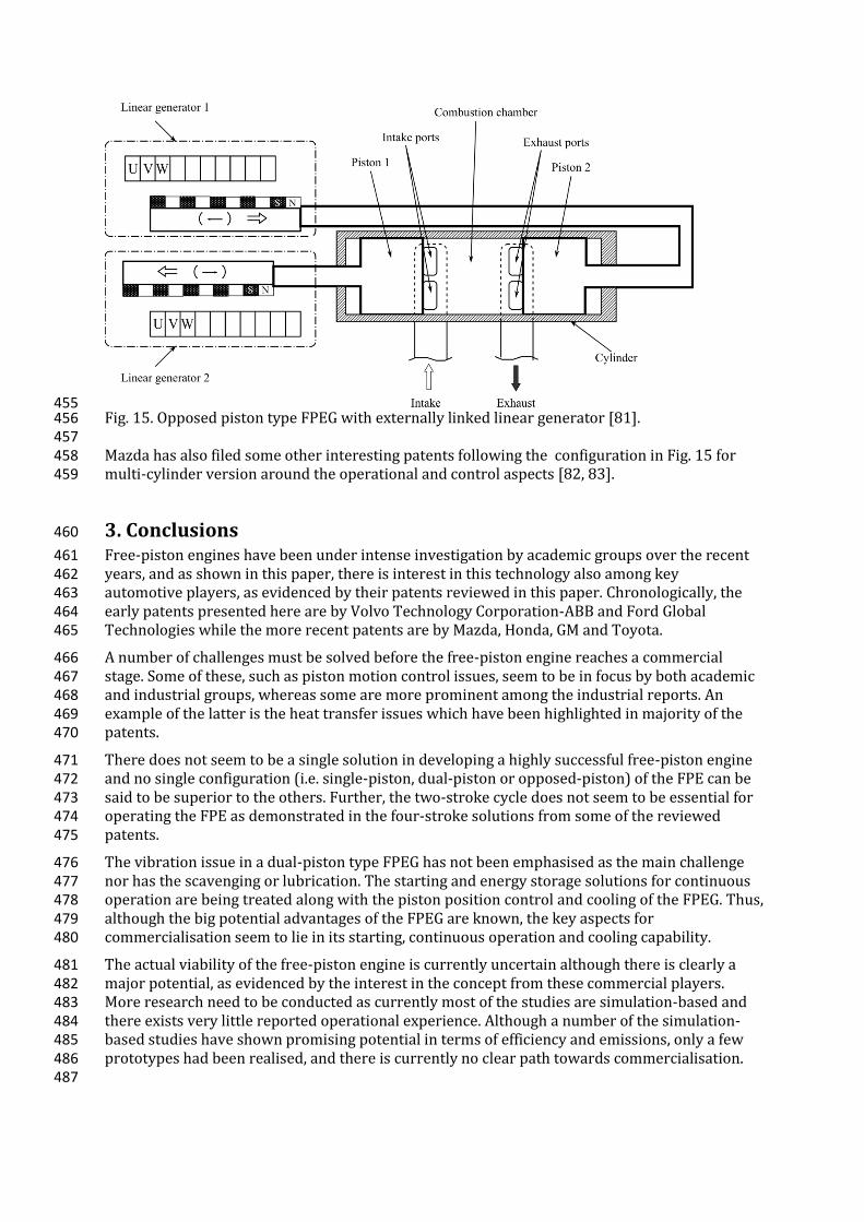
455 Fig. 15. Opposed piston type FPEG with externally linked linear generator [81]. 456 457 Mazda has also filed some other interesting patents following the configuration in Fig. 15 for 458 multi-cylinder version around the operational and control aspects [82, 83]. 459
3. Conclusions 460
Free-piston engines have been under intense investigation by academic groups over the recent 461 years, and as shown in this paper, there is interest in this technology also among key 462 automotive players, as evidenced by their patents reviewed in this paper. Chronologically, the 463 early patents presented here are by Volvo Technology Corporation-ABB and Ford Global 464 Technologies while the more recent patents are by Mazda, Honda, GM and Toyota. 465
A number of challenges must be solved before the free-piston engine reaches a commercial 466 stage. Some of these, such as piston motion control issues, seem to be in focus by both academic 467 and industrial groups, whereas some are more prominent among the industrial reports. An 468 example of the latter is the heat transfer issues which have been highlighted in majority of the 469 patents. 470
There does not seem to be a single solution in developing a highly successful free-piston engine 471 and no single configuration (i.e. single-piston, dual-piston or opposed-piston) of the FPE can be 472 said to be superior to the others. Further, the two-stroke cycle does not seem to be essential for 473 operating the FPE as demonstrated in the four-stroke solutions from some of the reviewed 474 patents. 475
The vibration issue in a dual-piston type FPEG has not been emphasised as the main challenge 476 nor has the scavenging or lubrication. The starting and energy storage solutions for continuous 477 operation are being treated along with the piston position control and cooling of the FPEG. Thus, 478 although the big potential advantages of the FPEG are known, the key aspects for 479 commercialisation seem to lie in its starting, continuous operation and cooling capability. 480
The actual viability of the free-piston engine is currently uncertain although there is clearly a 481 major potential, as evidenced by the interest in the concept from these commercial players. 482 More research need to be conducted as currently most of the studies are simulation-based and 483 there exists very little reported operational experience. Although a number of the simulation-484 based studies have shown promising potential in terms of efficiency and emissions, only a few 485 prototypes had been realised, and there is currently no clear path towards commercialisation. 486 487

REFERENCES 488
[1] R. Mikalsen and A. P. Roskilly, "A review of free-piston engine history and applications," 489 Applied Thermal Engineering, vol. 27, pp. 2339-2352, Oct 2007. 490
[2] M. Goertz and L. Peng, "Free Piston Engine Its Application and Optimization," SAE 491 Technical Paper 2000-01-0996, 2000. 492
[3] P. A. J. Achten, "A Review of Free Piston Engine Concepts," SAE Technical Paper 941776, 493 1994. 494
[4] R. Mikalsen and A. P. Roskilly, "The fuel efficiency and exhaust gas emissions of a low 495 heat rejection free-piston diesel engine," Proc. IMechE Part A: J. Power and Energy, vol. 496 223, 2009. 497
[5] F. Rinderknecht, "A highly efficient energy converter for a hybrid vehicle concept - 498 focused on the linear generator of the next generation," in Ecological Vehicles and 499 Renewable Energies (EVER), 2013 8th International Conference and Exhibition on, 2013, 500 pp. 1-7. 501
[6] D. Carter and E. Wechner, "The Free Piston Power Pack: Sustainable Power for Hybrid 502 Electric Vehicles," SAE International, vol. 2003-01-3277, 2003. 503
[7] J. Hansson and M. Leksell., "Performance of a Series Hybrid Electric Vehicle with a Free-504 Piston Energy Converter," 2006. 505
[8] C. Tóth-Nagy, "Linear Engine Development for Series Hybrid Electric Vehicles," Doctor of 506 Philosophy, Department of Mechanical and Aerospace Engineering, West Virginia 507 University, Morgantown, WV, 2004. 508
[9] J. Hu, W. Wu, S. Yuan, and C. Jing, "Mathematical modelling of a hydraulic free-piston 509 engine considering hydraulic valve dynamics," Energy, vol. 36, pp. 6234-6242, 2011. 510
[10] Z. Zhao, F. Zhang, Y. Huang, C. Zhao, and F. Guo, "An experimental study of the hydraulic 511 free piston engine," Applied Energy, vol. 99, pp. 226-233, 2012. 512
[11] Z. Zhao, F. Zhang, Y. Huang, and C. Zhao, "An experimental study of the cycle stability of 513 hydraulic free-piston engines," Applied Thermal Engineering, vol. 54, pp. 365-371, 2013. 514
[12] C. L. Tian, H. H. Feng, and Z. X. Zuo, "Oscillation Characteristic of Single Free Piston 515 Engine Generator," Advanced Materials Research, vol. 383-390, pp. 1873-1878, 2011. 516
[13] J. L. Mao, Z. X. Zuo, W. Li, and H. H. Feng, "Multi-dimensional scavenging analysis of a 517 free-piston linear alternator based on numerical simulation," Applied Energy, vol. 88, pp. 518 1140-1152, Apr 2011. 519
[14] J. L. Mao, Z. X. Zuo, and H. H. Feng, "Parameters coupling designation of diesel free-piston 520 linear alternator," Applied Energy, vol. 88, pp. 4577-4589, Dec 2011. 521
[15] C. L. Tian, H. H. Feng, and Z. X. Zuo, "Load Following Controller for Single Free-Piston 522 Generator," Applied Mechanics and Materials, vol. 157, pp. 617-621, 2012. 523
[16] C.-J. Chiang, J.-L. Yang, S.-Y. Lan, T.-W. Shei, W.-S. Chiang, and B.-L. Chen, "Dynamic 524 modeling of a SI/HCCI free-piston engine generator with electric mechanical valves," 525 Applied Energy, vol. 102, pp. 336-346, 2013. 526
[17] J. Xiao, Q. Li, and Z. Huang, "Motion characteristic of a free piston linear engine," Applied 527 Energy, vol. 87, pp. 1288-1294, 2009. 528
[18] S. Xu, Y. Wang, T. Zhu, T. Xu, and C. Tao, "Numerical analysis of two-stroke free piston 529 engine operating on HCCI combustion," Applied Energy, vol. 88, pp. 3712-3725, 2011. 530
[19] J. Kim, C. Bae, and G. Kim, "Simulation on the effect of the combustion parameters on the 531 piston dynamics and engine performance using the Wiebe function in a free piston 532 engine," Applied Energy, vol. 107, pp. 446-455, 2013. 533
[20] M. N. Svrcek and C. F. Edwards, "Emissions from an extreme-compression, free-piston 534 engine with diesel-style combustion," International Journal of Engine Research, vol. 13, 535 pp. 238-252, 2012. 536
[21] Z. Xu and S. Chang, "Prototype testing and analysis of a novel internal combustion linear 537 generator integrated power system," Applied Energy, vol. 87, pp. 1342-1348, 2010. 538
[22] S. A. Zulkifli, M. N. Karsiti, and A. R. A. Aziz, "Starting of a free-piston linear engine-539 generator by mechanical resonance and rectangular current commutation," in Vehicle 540 Power and Propulsion Conference, 2008. VPPC '08. IEEE, 2008, pp. 1-7. 541
[23] Ezrann Zharif Zainal Abidin, Abdulwehab A. Ibrahim, A. R. A. A. and, and S. A. Zulkifli, 542 "Investigation of Starting Behaviour of a Free-piston Linear Generator," Journal of 543 Applied Sciences, vol. 12, pp. 2592-2597, 2012. 544
[24] R. Mikalsen and A. P. Roskilly, "The design and simulation of a two-stroke free-piston 545 compression ignition engine for electrical power generation," Applied Thermal 546 Engineering, vol. 28, pp. 589-600, Apr 2008. 547
[25] R. Mikalsen and A. P. Roskilly, "Performance simulation of a spark ignited free-piston 548 engine generator," Applied Thermal Engineering, vol. 28, pp. 1726-1733, Oct 2008. 549
[26] R. Mikalsen and A. P. Roskilly, "Coupled dynamic-multidimensional modelling of free-550 piston engine combustion," Applied Energy, vol. 86, pp. 89-95, Jan 2009. 551
[27] R. Mikalsen and A. P. Roskilly, "A computational study of free-piston diesel engine 552 combustion," Applied Energy, vol. 86, pp. 1136-1143, Jul-Aug 2009. 553
[28] R. Mikalsen and A. P. Roskilly, "The control of a free-piston engine generator. Part 1: 554 Fundamental analyses," Applied Energy, vol. 87, pp. 1273-1280, Apr 2010. 555
[29] R. Mikalsen and A. P. Roskilly, "The control of a free-piston engine generator. Part 2: 556 Engine dynamics and piston motion control," Applied Energy, vol. 87, pp. 1281-1287, Apr 557 2010. 558
[30] R. Mikalsen, E. Jones, and A. P. Roskilly, "Predictive piston motion control in a free-piston 559 internal combustion engine," Applied Energy, vol. 87, pp. 1722-1728, May 2010. 560
[31] P. M. Najt, R. P. Durrett, and V. Gopalakrishnan, "Opposed Free Piston Linear Alternator," 561 US 2012/112468 A1, 2012. 562
[32] R. P. Durrett, V. Gopalakrishnan, and P. M. Najt, "Turbocompound Free Piston Linear 563 Alternator," US 2012/112469 A1, 2012. 564
[33] A. L. London and A. K. Oppenheim, "The free-piston engine development – Present status 565 and design aspects," Transactions of the ASME, vol. 74, pp. 1349–1361, 1952. 566
[34] G. J. Flynn, "Observations on 25,000 hours of free-piston-engine operation," SAE 567 Technical Paper 570042, vol. 65, pp. 508–515, 1957. 568
[35] R. Huber, "Present state and future outlook of the free-piston engine," Transactions of 569 the ASME, vol. 80, pp. 1779–1790, 1958. 570
[36] P. Němeček and O. Vysoký, "Control of Two-Stroke Free-Piston Generator," Proceedings 571 of the 6th Asian Control Conference, vol. 1, 2006. 572
[37] A. G. Holmes, "Free-piston Linear Alternator Systems and Methods," US 20110012367A1, 573 2011. 574
[38] K. Hidemasa, O. Yuichi, H. Yoshihiro, N. Kiyomi, and A. Kosuke, "Free-piston type 575 Generator (I)," Japan Patent JP2012202385A, 2012. 576
[39] T. A. Johansen, O. Egeland, E. A. Johannessen, and R. Kvamsdal, "Free-piston diesel 577 engine dynamics and control," in American Control Conference, 2001, pp. 4579-4584 578 vol.6. 579
[40] T. A. Johansen, O. Egeland, E. A. Johannessen, and R. Kvamsdal, "Free-piston diesel 580 engine timing and control - toward electronic cam- and crankshaft," Control Systems 581 Technology, IEEE Transactions on, vol. 10, pp. 177-190, 2002. 582
[41] F. Kock, A. Heron, F. Rinderknecht, and H. E. Friedrich, "The Free-Piston Linear 583 Generator Potentials and Challenges," MTZ worldwide, vol. 74, pp. 38-43, 2013. 584
[42] H. Yoshihiro, O. Yuichi, and N. Kiyomi, "Free-piston Engine Driven Linear Power 585 Generator," Japan Patent JP2012021461A, 2012. 586
[43] NGK. (2013, 1 December). Heat rating and heat flow path of NGK Spark Plugs. Available: 587 http://www.ngksparkplugs.com/tech_support/spark_plugs/p2.asp 588
[44] H. Yoshihiro, K. Hidemasa, N. Kiyomi, O. Yuichi, A. Kosuke, and A. Tomoyuki, "Free-589 piston type Generator (III)," Japan Patent JP2012202387A, 2012. 590
[45] K. Hidemasa, O. Yuichi, H. Yoshihiro, N. Kiyomi, and A. Kosuke, "Free-piston type 591 Generator (II)," Japan Patent JP2012202386A, 2012. 592
[46] Seppo Tikkanen, Mika Lammila, M. H. and, and M. Vilenius, "First Cycles of the Dual 593 Hydraulic Free Piston Engine," SAE Technical Paper 2000-01-2546, 2000. 594
[47] P. V. Blarigan, N. Paradiso, and S. S. Goldsborough, "Homogeneous Charge Compression 595 Ignition with a Free Piston: A New Approach to Ideal Otto Cycle Performance," SAE 596 Technical Paper 982484, 1998. 597
[48] O. Yuichi, H. Yoshihiro, and N. Kiyomi, "A Linear Electric Power Generation Free-piston 598 Engine and Its Start-up Method," Japan Patent JP2012031746A, 2012. 599
[49] W. Arshad, "A Low-Leakage Linear Transverse-Flux Machine for a Free-Piston 600 Generator," PhD Thesis, Royal Institute of Technology (KTH), Stockholm, 2003. 601
[50] J. Hansson, "Analysis and control of a hybrid vehicle powered by free-piston energy 602 converter," KTH, Stockholm, 2006. 603
[51] J. Fredriksson and I. Denbratt, "Simulation of a Two-Stroke Free Piston Engine," SAE 604 Technical Paper 2004-01-1871, 2004. 605
[52] M. Bergman, "CFD Modelling of a Free-Piston Engine Using Detailed Chemistry," 606 Licentiate thesis, Department of Applied Mechanics, Combustion and Multiphase Flow, 607 Chalmers University of Technology, 2006. 608
[53] O. Lindgärde, "Method and System for Controlling a Free-Piston Energy Converter," 609 EP1740804B1, 2005. 610
[54] W. M. Arshad and C. Sadarangani, "An electrical machine and use thereof," 611 WO2004017501(A1), 2004. 612
[55] C. M. Atkinson, S. Petreanu, N. N. Clark, R. J. Atkinson, T. I. McDaniel, S. Nandkumar, and P. 613 Famouri, "Numerical Simulation of a Two-Stroke Linear Engine-Alternator Combination," 614 SAE Technical Paper 1999-01-0921, 1999. 615
[56] W. Cawthorne, P. Famouri, and N. Clark, "Integrated design of linear alternator/engine 616 system for HEV auxiliary power unit," in Electric Machines and Drives Conference, 2001, 617 pp. 267-274. 618
[57] S. S. Goldsborough and P. V. Blarigan, "A Numerical Study of a Free Piston IC Engine 619 Operating on Homogeneous Charge Compression Ignition Combustion," SAE Technical 620 Paper 1999-01-0619, 1999. 621
[58] P. Němeček, M. Šindelka, and O. Vysoký, "Modeling and Control of Linear Combustion 622 Engine," IFAC Symposium on Advances in Automotive Control, 2003. 623
[59] P. Deutsch and O. Vysoky, "In-cycle thermodynamic model of linear combustion engine," 624 Proceedings of the 2006 IEEE International Conference on Control Applications, 2006. 625
[60] Q. Li, J. Xiao, and Z. Huang, "Simulation of a Two-Stroke Free-Piston Engine for Electrical 626 Power Generation," Energy & Fuels, vol. 22, pp. 3443-3449, 2008/09/17 2008. 627
[61] E. Max, S. Lundgren, J. Somhurst, A. Höglund, G. Wirmark, L. Gertmar, and I. Denbratt, 628 "Energy Converter," Sweden Patent EP 1 540 155 B1, 2005. 629
[62] F. Kevin and H. Peter, "Piston Stopper for a free piston Engine," US 2005/0284428 A1, 630 2005. 631
[63] L. Peng and C. Carlson, "Exhaust gas recirculation for a free piston engine," US 6,925,971 632 B1, 2005. 633
[64] H.-J. Laumen and I. G. Guerich, "Position sensing for a free piston engine," US 6,948,459 634 B1, 2005. 635
[65] P. Hofbauer, "Opposed piston opposed cylinder free piston engine," US 6,953,010 B1, 636 2005. 637
[66] L. Peng, P. Hofbauer, and J. Yang, "Fuel injection for a free piston engine," US 6,959,672 638 B1, 2005. 639
[67] C. Carlson, "Compression pulse starting of a free piston internal combustion engine 640 having multiple cylinders," US 6,966,280 B1, 2005. 641
[68] K. Fuqua and P. Hofbauer, "Piston lubrication for a free piston engine," US 6,971,341 B1, 642 2005. 643
[69] P. Hofbauer and A. Tusinean, "Sodium cooled pistons for a free piston engine," US 644 6,904,876 B1, 2005. 645
[70] J. Schmuecker, I. G. Guerich, H.-J. Laumen, A. Tusinean, and K. Fuqua, "Hydraulic 646 synchronizing coupler for a free piston engine," US 7,077,080 B2, 2006. 647
[71] A. Hibi and T. Ito, "Fundamental test results of a hydraulic free piston internal 648 combustion engine," Proceedings of the Institution of Mechanical Engineers, Part D: 649 Journal of Automobile Engineering, vol. 218, pp. 1149-1157, October 1, 2004. 650
[72] P. A. J. Achten, J. P. J. v. d. Oever, J. Potma, and G. E. M. Vael, "Horsepower with Brains: The 651 Design of the Chiron Free Piston Engine," New Fluid Power Applications and Components, 652 SAE TECHNICAL, vol. 2000-01-2545, 2000. 653
[73] P. A. J. Achten, "The Hydrid Transmission," SAE Technical Paper 2007-01-4152, 2007. 654 [74] T. Osamu, S. Kohei, T. Kenichi, K. Kohei, and Y. Yuji, "The Control Apparatus of an 655
Internal Combustion Engine," JP2011202621 A, 2011. 656 [75] S. Petreanu, "Conceptual Analysis of A Four-Stroke Linear Engine," PhD, Department of 657
Mechanical and Aerospace Engineering, West Virginia University, Morgantown, West 658 Virginia, 2001. 659
[76] J. Lin, Z. Xu, S. Chang, N. Yin, and H. Yan, "Thermodynamic Simulation and Prototype 660 Testing of a Four-Stroke Free-Piston Engine," Journal of Engineering for Gas Turbines and 661 Power, vol. 136, p. 051505, 2014. 662
[77] N. Koichi, "Free-piston Engine (II)," Japan Patent JP2008051059(A), 2008. 663 [78] N. Koichi, "Free-piston Engine (I)," Japan Patent JP2008051058(A), 2008. 664 [79] N. Koichi, "The Control Apparatus of a Free Piston Engine (I)," Japan Patent 665
JP2008057383(A), 2008. 666 [80] N. Koichi, "The Control Apparatus of a Free Piston Engine (II)," Japan Patent 667
JP2008223628(A), 2008. 668 [81] N. Koichi, "Free-piston Engine (III)," Japan Patent JP2008223657(A), 2008. 669 [82] N. Koichi, "Free-piston Engine and Its Control Method (I)," Japan Patent 670
JP2009008068(A), 2009. 671 [83] N. Koichi, "Free-piston Engine and Its Control Method (II)," Japan Patent 672
JP2009008069(A), 2009. 673