newton, il 62448 usa evapco semco …
TRANSCRIPT

Bulletin 126
Rigging and
Assembly Instructions
MTW Closed Circuit Fluid Coolers & MTC Evaporative Condensers EVAPCO Australia Pty Ltd – Regional Headquarters for Australia & New Zealand
EVAPCO Australia Pty Ltd • PO Box 436 • Riverstone NSW 2765 • Australia
PHONE: +61 2 9627 3322 • EMAIL: [email protected] • WEB: www.evapco.com.au
For EVAPCO Authorised Parts and Service, Contact Your Local EVAPCO
Representative or the Local Mr. GoodTower® Service Provider
Europe Asia/Pacific
EVAPCO, Inc. EVAPCOLD EVAPCO Europe BVBA EVAPCO Asia/Pacific Headquarters
World Headquarters 521 Evapco Drive European Headquarters 1159 Luoning Rd. Baoshan Industrial Zone
P.O. Box 1300 Greenup, IL 62428 USA Heersterveldweg 19 Shanghai, P. R. China, Postal Code: 200949
Westminster, MD 21158 USA 217-923-3431 p Industrieterrein Oost (86) 21-6687-7786 p | (86) 21-6687-7008 f
410-756-2600 p | 410-756-6450 f [email protected] 3700 Tongeren, Belgium [email protected]
[email protected] (32) 12-395029 p | (32) 12-238527 f
EVAPCO-Dry Cooling, Inc. [email protected] EVAPCO (Shanghai) Refrigeration
EVAPCO East 981 US Highway 22 West Equipment Co., Ltd.
5151 Allendale Lane Bridgewater, NJ 08807 USA EVAPCO Europe, S.r.l. 1159 Luoning Rd., Baoshan Industrial Zone
Taneytown, MD 21787 USA 1-908-379-2665 p Via Ciro Menotti, 10 Shanghai, P.R. China, Postal Code: 200949
410-756-2600 p | 410-756-6450 f [email protected] I-20017 Passirana di Rho (86) 21-6687-7786 p | (86) 21-6687-7008 f
[email protected] Milan, Italy [email protected]
Refrigeration Valves & (39) 02-939-9041 p | (39) 02-935-00840 f
EVAPCO Midwest Systems Corporation [email protected] Beijing EVAPCO Refrigeration
1723 York Road A wholly owned subsidiary of EVAPCO, Inc. Equipment Co., Ltd.
Greenup, IL 62428 USA 1520 Crosswind Drive EVAPCO Europe, S.r.l. No. 13 Yanxi Avenue, Yanqi Development Zone
217-923-3431 p | 217-923-3300 f Bryan, TX 77808 USA Via Dosso 2 Huai Rou County
[email protected] 979-778-0095 p | 979-778-0030 f 23020 Piateda Beijing, P.R. China, Postal Code: 101407
[email protected] Sondrio, Italy (86) 10 6166-7238 p | (86) 10 6166-7395 f
EVAPCO West [email protected]
1900 West Almond Avenue EVAPCO Northwest EVAPCO Europe GmbH
Madera, CA 93637 USA 5775 SW Jean Road, Suite 210 Meerbuscher Straße 64-78 EVAPCO Australia (Pty.) Ltd.
559-673-2207 p | 559-673-2378 f Lake Oswego, OR 97035 USA Haus 5 34-42 Melbourne Road
[email protected] 503-639-2137 p | 503-639-1800 f 40670 Meerbusch, Germany P.O. Box 436
(49) 2159-69560 p | (49) 2159-695611 f Riverstone, N.S.W. Australia 2765
EVAPCO Iowa EvapTech, Inc. [email protected] (61) 2 9627-3322 p | (61) 2 9627-1715 f
925 Quality Drive A wholly owned subsidiary of EVAPCO, Inc. E-mail: [email protected]
Lake View, IA 51450 USA 8331 Nieman Road Flex coil a/s
712-657-3223 p | 712-657-3226 f Lenexa, KS 66214 USA A wholly owned subsidiary of EVAPCO, Inc. EVAPCO Composites Sdn. Bhd
913-322-5165 p | 913-322-5166 f Knøsgårdvej 115 No. 70 (Lot 1289) Jalan Industri 2/3
EVAPCO Iowa [email protected] DK-9440 Aabybro, Denmark Rawang Integrated Industrial Park
Sales & Engineering (45) 9824 4999 p | (45) 9824 4990 f Rawang, Selangor, 48000 Malaysia
215 1st Street, NE Tower Components, Inc. [email protected] 60 3 6092-2209 p | 60 3 6092-2210 f
P.O. Box 88 A wholly owned subsidiary of EVAPCO, Inc.
Medford, MN 55049 USA 5960 US Highway 64 East EVAPCO S.A. (Pty.) Ltd. EvapTech Asia Pacific Sdn. Bhd
507-446-8005 p | 507-446-8239 f Ramseur, NC 27316 USA A licensed manufacturer of EVAPCO, Inc. A wholly owned subsidiary of EvapTech, Inc.
[email protected] 336-824-2102 p | 336-824-2190 f 18 Quality Road B-6-1, IOI Boulevard
[email protected] Isando 1600 Jalan Kenari 5, Bandar Puchong Jaya
EVAPCO Newton Republic of South Africa 47170 Puchong, Selangor Darul Ehsan
701 East Jourdan Street South America (27) 11-392-6630 p | (27) 11-392-6615 f Malaysia
Newton, IL 62448 USA EVAPCO SEMCO [email protected] (60-3) 8070-7255 p | (60-3) 8070-5731 f
618-783-3433 p | 618-783-3499 f Equipamentos de Refrigeracao Ltda. E-mail: [email protected]
[email protected] Rua Alexandre Dumas, 1601 Evap Egypt Engineering Industries Co.
Conj. 13, 14, 15 - Edificio Stelvio Mazza A licensed manufacturer of EVAPCO, Inc.
04717-004 Sao Paulo - SP, Brazil 5 El Nasr Road
(55+19) 5681-2000 p Nasr City, Cairo, Egypt
2 02 24022866/2 02 24044997 p
2 02 24044667/2 02 24044668 f
[email protected] / [email protected]
North America

MTW/MTC INDUCED DRAFT FLUID COOLERS AND EVAPORATIVE CONDENSERS
2
Introduction
Thank you for purchasing your EVAPCO closed circuit fluid cooler or evaporative condenser. This
manual will provide instructions for installation of MT closed circuit fluid coolers and evaporative
condensers. If any questions arise during the installation, please contact your local EVAPCO
representative or your local Evapco Headquarters.
Method of Shipment
All 4’ wide units are shipped as one fully assembled unit. All other units ship in 2 partially assembled
sections. Refer to Table 1 below for the section of this manual to reference on your specific closed
circuit fluid cooler or evaporative condenser model. Miscellaneous items such as sealer, bolts, nuts,
washers and any other required materials are packaged and placed inside the basin or on the truck
for shipment.
Before commencement of rigging and assembly, ensure all loose articles are removed from the
basin. All personnel carrying out the rigging and assembly of any EVAPCO Closed Circuit Fluid
Cooler or Evaporative Condenser should adhere to specific site safety rules and regulations. All
equipment utilised must conform to Australian standards and relevant Workplace Health & Safety
regulations, and must be used in accordance with the manufacturer’s instructions.
MTW Models MTC Models Box Size Section Page
MTW 4-3F6 to MTW 4-5G6 MTC-49A to MTC-79A All 4x4 A 3
MTW 4-3E9 to MTW 4-5F9 MTC-80A to MTC-115A All 4x9
MTW 8-3G8 to MTW 8-4J8 MTC-134A to MTC-202A 8x8, < 3880mm tall B 4
MTW 8-5G8 to MTW 8-5J8 MTC-117A to MTC-223 All remaining 8x8
C 5
MTW 8-3H12 to MTW 8-5L12 MTC-205A to MTC-348A 8x12
MTW 10-3G10 to MTW 10-5M10 MTC-191A to MTC-373A 10x10
MTW 11-3I11 to MTC 11-6N11 MTC-288A to MTC-524A 11x11
MTW 12-3I12 to MTW 12-6N12 MTC-305A to MTC-557A 12x12 Table 1 Rigging Manual Reference According to Model Number and Box Size
Storage
Do not place tarps or other coverings over the top of the units if the units are to be stored before
installation. Excessive heat can build up if the units are covered, causing possible damage to the PVC
eliminators and/or PVC louvers. For extended storage beyond six months rotate the fan and fan
motor shaft(s) monthly. The fan shaft bearings should also be purged and regreased prior to start-up
if it has been stored.
MTW/MTC INDUCED DRAFT FLUID COOLERS AND EVAPORATIVE CONDENSERS
3
Section A: Units Shipped Fully Assembled
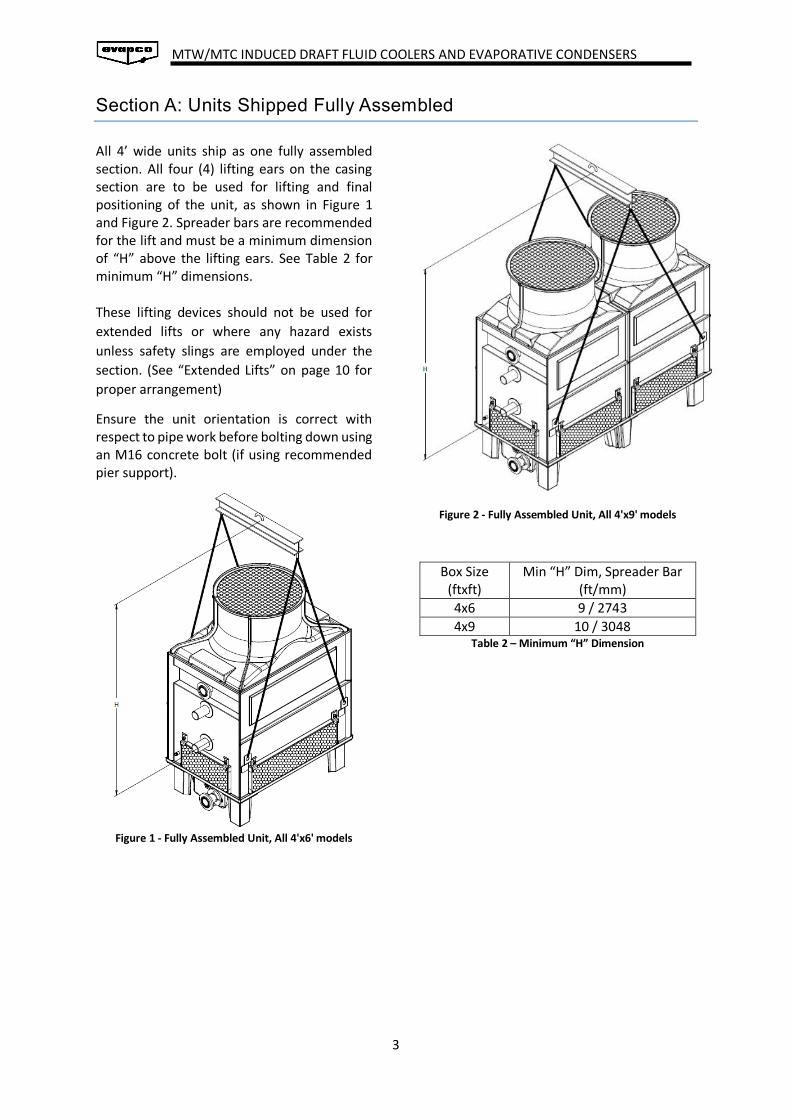
All 4’ wide units ship as one fully assembled section. All four (4) lifting ears on the casing section are to be used for lifting and final positioning of the unit, as shown in Figure 1 and Figure 2. Spreader bars are recommended for the lift and must be a minimum dimension of “H” above the lifting ears. See Table 2 for minimum “H” dimensions. These lifting devices should not be used for
extended lifts or where any hazard exists
unless safety slings are employed under the
section. (See “Extended Lifts” on page 10 for
proper arrangement)
Ensure the unit orientation is correct with respect to pipe work before bolting down using an M16 concrete bolt (if using recommended pier support).
Figure 1 - Fully Assembled Unit, All 4'x6' models
Figure 2 - Fully Assembled Unit, All 4'x9' models
Box Size (ftxft)
Min “H” Dim, Spreader Bar (ft/mm)
4x6 9 / 2743
4x9 10 / 3048 Table 2 – Minimum “H” Dimension

MTW/MTC INDUCED DRAFT FLUID COOLERS AND EVAPORATIVE CONDENSERS
4
Section B: Units Shipped with Casing Section Attached to Basin Section
The unit shall arrive in two sections; the casing
section bolted to the basin with and the fan
section separately. The unit may not be rigged
as a fully assembled tower.
Rigging Basin-Casing Section
Lifting Ears are located on the sides of the
casing section for lifting and final positioning
purposes as shown in Figure 3. The spreader
bar of the crane must be a minimum dimension
of “H” above the top of the lifting ears to
prevent undue strain on the lifting devices. See
Table 3 for the minimum “H” dimension. These
lifting devices should not be used for extended
lifts or where any hazard exists unless safety
slings are employed under the section. (See
“Extended Lifts” on page 10 for proper
arrangement.)
Bolt the basin-casing section to the plinths or
steel supports and remove the timber from
the top of the casing section prior to installing
the fan.
Box Size (ftxft)
Min “H” Dim, Spreader Bar (ft/mm)
8x8 10 / 3048 Table 3 – Minimum "H" Dimension for Rigging Basin-Casing Sections
Rigging Fan Section
All fan sections are to be rigged as a four-point
lift. The four pick points are on the mechanical
equipment support as shown in Figure 4. The
hook of the crane must be a minimum
dimension “H” above the top section being
lifted to prevent undue strain on the lifting lugs
and the fibreglass. See Table 4 for the
minimum “H” dimensions.
Box Size (ftxft)
Min “H” Dim, Spreader Bar (ft/mm)
8x8 8 / 2438 Table 4 – Minimum "H" Dimension for Rigging Fan Section
The installer must ensure that the fan section
is oriented such that the motor is accessible for
maintenance. Orientation markings are on the
individual fan sections to assist the installer.
Figure 3 – Casing and Basin Rigging
Figure 4 – Fan Section Rigging

MTW/MTC INDUCED DRAFT FLUID COOLERS AND EVAPORATIVE CONDENSERS
5
The fan section will be set directly on top of the
casing as shown in Figure 5 No sealer tape is
required between the fan and casing sections.
Figure 5 – Fan Section above Casing
Bolt the two sections together with the
hardware provided in the rigging box as shown
in Figure 6.
Figure 6 – Attachment Point
Section C: Units Shipped with Fan Section Sitting on Basin Section
These units shall arrive in two sections, the fan
section shall be on the basin and the casing
section separate. These units may not be
rigged as a fully assembled tower.
Rigging Fan Section
The fan section should first be detached and
lifted from the basin. All fan sections are to be
rigged as a four-point lift. The four pick points
are on the mechanical equipment support as
shown in Figure 7. The hook of the crane or
spreader bar must be a minimum dimension
“H” above the top section being lifted to
prevent undue strain on the lifting lugs and the
fibreglass. See Table 5 for the minimum “H”
dimensions.
Figure 7 – Fan Section Rigging

MTW/MTC INDUCED DRAFT FLUID COOLERS AND EVAPORATIVE CONDENSERS
6
Box Size (ft x ft) Min “H” Dim Spreader Bar (ft/mm)
8x8 8x12
8 / 2438
10x10 11x11 12x12
10 / 3048
Table 5 – Minimum "H" Dimension for Rigging Fan Section
If the basin and fan section is required to be
picked at the same time, then pass soft slings
under the basin between the corner feet
according to Figure 8. The minimum H
dimension can be found in Table 6.
Box Size (ft x ft) Min “H” Dim Spreader Bar (ft/mm)
8x8 8 / 2438
8x12 10x10 11x11 12x12
12 / 3658
Table 6 – Minimum “H” Dimensions for Rigging the Basin Section
These lifting devices should not be used for
extended lifts or where any hazard exists
unless safety slings are employed under the
section. (See “Extended Lifts” on page 10 for
proper arrangement.)
The installer must ensure that the fan section
is oriented such that the motor is accessible for
maintenance. Orientation markings are on the
individual fan sections to assist the installer.
The fan section will then be set directly on top
of the casing as shown in Figure 9. No sealer
tape is required between the fan and casing
sections.
Figure 9 – Fan Section above Casing
Bolt the two sections together with the
hardware provided in the rigging box as shown
in Figure 10.
Figure 10 – Attachment Point
Figure 8 – Lifting Fan and Basin Sections Together

MTW/MTC INDUCED DRAFT FLUID COOLERS AND EVAPORATIVE CONDENSERS
7
Rigging Basin Section
The basin sections are placed into position
using soft slings. Pass the slings below and
between the basin and basin feet as shown in
Figure 11. The spreader bar of the crane must
be a minimum dimension of “H” above the lip
of the basin to prevent undue strain on the
fibreglass. Refer to Table 7 for the minimum
“H” dimensions. Ensure that the basin is
oriented correctly with respect to the pipe
work and the rest of the unit. Then, bolt the
basin to the plinths (hardware not provided).
Sealer Tape Application
Before assembling the basin and casing
section, wipe the perimeter of the basin lip to
remove any dirt or moisture. Two strips of
sealer tape should be placed over the
mounting hole centreline at the corner and
intermediate bolting locations. At the corner
and intermediate attachments, ensure that the
sealer tape overlap as showing in Figure 12 and
Figure 13.
Always remove the paper backing from the
sealer tape.
Figure 12 – Corner Sealer Tape Application
Figure 13 – Intermediate Sealer Tape Application
Box Size (ft x ft) Min “H” Dim Spreader Bar (ft / mm)
8 x 8 8 / 2438
8 x 12 10 x 10 11 x 11 12 x 12
12 / 3658
Table 7 – Minimum "H" Dimension for Rigging Basin Section
Figure 11 – Basin Section Rigging

MTW/MTC INDUCED DRAFT FLUID COOLERS AND EVAPORATIVE CONDENSERS
8
Rigging Fan-Casing Sections
All casing sections are to be rigged as a four-
point lift. The four pick points are on the side
of the tower as shown in Figure 14. The hook
of the crane must be a minimum dimension
“H” above the lifting ears to prevent undue
strain on the lifting lugs and fibreglass. See
Table 8 for the minimum “H” dimensions.
Box Size (ft x ft)
Min “H” Dim Spreader Bar (ft/mm)
8x8 10 / 3048
8x12 10x10 11x11 12x12
12 / 3658
Table 8 – Minimum "H" Dimension for Rigging Fan-Casing Section
Lower the fan-casing section and place it on
the basin section as shown in Figure 15 and
Figure 16. Bolt the two sections together with
the hardware provided in the rigging box.
Orientation markings are on the individual
sections to assist the installer with assembly.
Figure 15 – Corner Attachment
Figure 16 – Intermediate Attachment
Figure 14 – Fan Casing Section Rigging

MTW/MTC INDUCED DRAFT FLUID COOLERS AND EVAPORATIVE CONDENSERS
9
Pump Installation
The pump and associated pipework is packaged and shipped loose from the unit. Once final
assembly of the whole unit is completed, install the pump and pipework. Hardware is provided in
the rigging box.
8’ Wide Units
The bottom vertical riser assembly and pump assembly are fitted at the factory and shipped as a
sub-assembly. Lift the sub-assembly and fix onto the pump bracket using M10 bolts. Install the top
vertical riser assembly and pump suction assembly with reference to Figure 17 for 8’x8’ units and
Figure 18 for 8’x12’ units.
Figure 17 – Water Distribution Assembly
(8’x8’ models)
Figure 18 – Water Distribution Assembly (8’x12’ models)
10’ 11’ & 12’ Wide Units
Remove the FRP foot from the basin and
position the pump stand such that it is
supporting the basin. A strip of sealer tape
should be placed on the steel frame between
the pump and the FRP basin. Fix the pump
stand and basin together using M10 bolts.
Connect the pump suction assembly followed
by the bottom and vertical riser assemblies
with reference to Figure 19.
Figure 19 – Water Distribution Assembly (10’, 11’ and 12’ wide models)

MTW/MTC INDUCED DRAFT FLUID COOLERS AND EVAPORATIVE CONDENSERS
10
Extended Lifts
Important: The lifting devices and lifting lugs should be used for final positioning only and for lifting
where no danger exists. If they are used for extended lifts, safety slings should be provided under
the sections. Safety slings and skids must be removed before final positioning of the units. Refer to
Figure 20 to Figure 23 below.
Figure 20 – Safety Slings for Extended Lift on 4 x 6
Figure 21 – Safety Slings for Extended Lift on 4 x 9
Figure 22 – Safety Slings for Extended Lift on Fan-Casing
Section
Figure 23 – Safety Slings for Extended Lift on Casing-Basin
Section

MTW/MTC INDUCED DRAFT FLUID COOLERS AND EVAPORATIVE CONDENSERS
11
General Information & Maintenance Start-up Details
Shipping Chocks and Debris
Remove any chocks that have been placed inside the unit for shipping purposes. Clean all debris from the basin prior to start-up. Ensure all louvers are in place and secured with retainer clips as shown in Figure 24.
Figure 24 – Louver Retainer Clips
Bleed-off Line, Overflow and Drain
Make sure a bleed line and valve, overflow and drain are installed on the pump discharge side of the system piping to a convenient drain. The bleed-off valve should be open. For installation details, see the Operation and Maintenance Instructions.
Strainer
Check the strainer(s) in the basin to make sure they are in the proper location over the pump suction, alongside of the anti-vortex hood as shown in Figure 25. Strainers are integral to 4’ & 8’ hoods whilst larger units have screens with anti-vortex baffles connected to them
Figure 25 – Strainer Locations

MTW/MTC INDUCED DRAFT FLUID COOLERS AND EVAPORATIVE CONDENSERS
12
Adjustment of Float Valve
The float valve should be adjusted to maintain the proper water level as specified in the maintenance instructions. At start-up, the basin should be filled to the overflow level. The water level can be checked during operation by opening the removable louver section at the valve while the pump is running and the fans are off. The operating water level is to be set approximately 101mm below the overflow (all coolers and condensers).
Screens
Protective fan screens are provided across the top of the fan cylinders of all models. Check and tighten all bolts.
Starting Sequence
Before starting the unit, check that all access openings, safety screens and covers are in place. Start the unit as outlined below:
1. Fill the basin to the overflow level. 2. Bump start and check the spray water pump(s) for proper rotation. Directional arrows are
found on the pump impeller housing. 3. Bump start and check the fan(s) for proper rotation. Directional arrows are placed on the
side of the fan cylinder.
Maintenance
Once the installation is complete and the unit is turned on, it is important that it be properly maintained. Maintenance is not difficult or time-consuming but must be done regularly to assure full performance of the unit. Refer to the maintenance instructions enclosed with the unit for proper maintenance procedures.

MTW/MTC INDUCED DRAFT FLUID COOLERS AND EVAPORATIVE CONDENSERS
13
Field Assembly of External Platform and Ladder
The external platform and ladder assemblies are shipped on the truck. The platform is partially assembled prior to shipment. One external platform and ladder is provided per unit. The platform and ladder should be attached after the unit is fully rigged following the instructions below.
Att
ach
th
e la
dd
er t
o t
he
pla
tfo
rm w
ith
3
x M
12
bo
lts.
Fast
ener
s ar
e at
tach
ed t
o t
he
pla
tfo
rm.
Fram
e
Sup
po
rt
Att
ach
th
e su
pp
ort
bra
cket
to
the
fram
e w
ith
8 x
M12
bo
lts
Pla
tfo
rm
Cro
ssb
eam
Sup
po
rt
Att
ach
th
e cr
oss
bea
ms
to t
he
sup
po
rt b
rack
et w
ith
4 x
M1
2 b
olt
s
Pla
tfo
rm
Lad
der
Lad
der
Bra
cket
Ho
le f
or
join
ing
pla
tfo
rm
and
cro
ssb
eam
Step
1
Step
2
Step
3

EVAPCO AUSTRALIA PTY LTD • PO Box 436 • Riverstone NSW 2467 Australia
Phone: +61 2 9627 3322 • Email: [email protected]