nexans olex - aainy.com · wire and cable size comparison 16 . ... nexans olex is a world leader in...
TRANSCRIPT

HEAD OFFICE
69 Paraite RoadBell BlockNew PlymouthNew Zealand
AUCKLAND BRANCH
105 Hugo Johnston DrivePenroseAuckland 1061New Zealand
CHRISTCHURCH BRANCH
35 Phillips StreetLinwoodChristchurchNew Zealand
PHONE 0800 OLEX NZ EMAIL [email protected]
www.olex.co.nz
Power Cable Catalogue
Nexans Olex New Zealand
2012 EDITION
Nexans O
lex New
Zealand Power C
able Catalogue
2012
EDITIO
N

CA
TALO
GU
E C
ON
TEN
TS
Power Cable CatalogueNexans Olex New Zealand
Table of Contents
TABLE OF CONTENTS
PAGE
Section One - Introduction 1
Company Profile 2
Technical Service and Support 3
Quality Assurance 4
Section Two - General Technical Information 1
Installation Information 2
Installation Methods 4
Single Core Cables in Parallel 7
Rating Factors 8
Bending Radii and Duct Sizes 10
Pulling Tension 11
Short Circuit Ratings 12
Conductor Short Circuit Ratings 13
Conductor Max DC Resistances 14
Conductor Dimensions 15
Wire and Cable Size Comparison 16
Notes 18
Section Three – Low Voltage Cables 1
Notes 3
Explanatory Information - Construction 4
- Current Ratings 5
- Rating Factors 6
- Voltage Drops 8
- Selection Procedures 10
-Minimum Copper Earthing Conductor Size 11
Product Sheets (See Section Three Contents Page 1 for Product Sheets Listing) 12
Tabulated Electrical Data - Current Ratings 76
- Voltage Drops 92
- AC Resistances 94
- Reactances 96
- Volt Drop Graphs 98

Table of Contents
TABLE OF CONTENTS (CONT.)
PAGE
Section Four – Medium Voltage TR-XLPE Cables 1
Explanatory Information - Construction 2
- Screen Designs 4
- Testing 5
- Test Voltage Levels 6
- Installation Tests 7
-Current Ratings 9
- Rating Factors 10
Product Sheets (See Section Four Contents Page 1 for Product Sheets Listing) 12
Notes 56
Section Five – Aerials 1
Explanatory Information - Thermal Characteristics 2
- Electrical Characteristics 4
- Physical and Mechanical Characteristics 5
- Bare Overhead Conductors 7
Product Sheets (See Section Five Contents Page 1 for Product Sheets Listing) 8
Notes 22

INTR
OD
UC
TIO
N
Introduction Section One
Section 1, Page 1
SECTION ONE - INTRODUCTION
PAGE
Company Profile 2
Technical Service and Support 3
Quality Assurance 4

Section One Introduction
Section 1, Page 2
COMPANY PROFILE Power cables have been manufactured and tested at the Nexans Olex Bell Block factory on the outskirts of New Plymouth for more than 40 years. Established in 1967 as a joint venture between Tolley and Son and Canada Wire and Cable Company of Toronto, it was known as Canzac until 1984 when it was purchased by the Pacific Dunlop Group, one of Australia's largest international companies, and became part of the Pacific Dunlop Cables Group. In 1999 Olex Cables (New Zealand), together with other Pacific Dunlop Cables Group businesses, was bought by a Management Buyout Consortium (MBO), and then was known as Olex New Zealand Limited, a Subsidiary of Olex Holdings Pty Limited. It was in 2006 that the MBO consortium sold its shares in Olex Holdings to Nexans. The acquisition by Nexans became effective in December 2006. Nexans Olex is a world leader in cable technology and production and has manufacturing facilities in New Plymouth and Melbourne. Each site has been designed to efficiently manufacture specific product groups to cater for the needs of the industry. With over 40 years experience behind it, Nexans Olex employs more than 1500 people and has the financial backing, the expertise and the commitment to maintain and expand its position as a world leader in cable technology, manufacturing and installation. At its New Plymouth factory, Nexans Olex produces a wide range of electrical power cables, ranging from building wires and control cables to power cables with rated voltages up to 35 kV. Complementing this range is a wide selection of power and data/communications cables manufactured by other Nexans factories around the world. Nexans Olex has proven its expertise and commitment to quality and service in fulfilling contracts in many New Zealand and international markets. The company has a strong commitment to further growth and expansion internationally. With this background, Nexans Olex is well placed to retain its leading role in terms of customer service, quality and research.
Introduction Section One
Section 1, Page 3
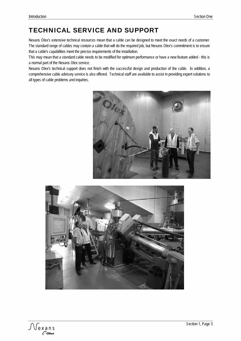
TECHNICAL SERVICE AND SUPPORT Nexans Olex’s extensive technical resources mean that a cable can be designed to meet the exact needs of a customer. The standard range of cables may contain a cable that will do the required job, but Nexans Olex's commitment is to ensure that a cable's capabilities meet the precise requirements of the installation. This may mean that a standard cable needs to be modified for optimum performance or have a new feature added - this is a normal part of the Nexans Olex service. Nexans Olex's technical support does not finish with the successful design and production of the cable. In addition, a comprehensive cable advisory service is also offered. Technical staff are available to assist in providing expert solutions to all types of cable problems and inquiries.

Section One Introduction
Section 1, Page 4
QUALITY ASSURANCE For Nexans Olex, quality means the ability to satisfy the needs of its customers, its employees and the proprietors. Accordingly, Nexans Olex recognises the nature of these relationships and has linked these three essential needs together to form a policy cornerstone. Quality is important as its inherent cost effectiveness contributes to the competitiveness of the company's products and services, and to profitability and growth. The contribution of every member of the Nexans Olex team to the quality of products, to customer service and the company is essential to the goal of excellence through quality. Nexans Olex has developed and implemented Quality Management using the AS/NZS/ISO 9001 standard as the model for quality assurance and the criteria for third party accreditation through Bureau Veritas Certification. There is flexibility to merge additional customer requirements into the routine Quality Verification Plans. Whilst each company within Nexans is individually responsible for the quality of its own cable products and services, each has achieved third party accreditation to at least the ISO 9001 level. This parity in quality management provides Nexans Olex with the flexibility to access the entire product ranges of all companies within Nexans without compromising its own quality management standards Nexans Olex offers only brand name accessory products from suppliers with a history of product quality and service. When required, details of the suppliers' quality systems and any third party accreditation to recognised Quality Assurance Standards can be supplied.
GEN
ERA
L TE
CH
NIC
AL
IN
FORM
ATI
ON

General Technical Information Section Two
Section 2, Page 1
SECTION TWO - GENERAL TECHNICAL INFORMATION
PAGE
Installation Information 2
Installation Methods 4
Single Core Cables in Parallel 7
Rating Factors 8
Bending Radii and Duct Sizes 10
Pulling Tension 11
Short Circuit Ratings 12
Conductor Short Circuit Ratings 13
Conductor Max DC Resistances 14
Conductor Dimensions 15
Wire and Cable Size Comparison 16
Notes 18

Section Two General Technical Information
Section 2, Page 2
INSTALLATION INFORMATION General All cables must be installed to comply with the latest New Zealand Wiring Regulations.
Moisture Nexans Olex cables are manufactured in conditions that exclude moisture, as it is difficult to remove from a finished cable. It is important that precautions are taken during installation to ensure that moisture is not permitted to enter the cable. Cut ends or opened areas must be protected from moisture at all times, including during pulling in. Cables, after cutting, must be re-sealed for storage, by an effective method such as a heat shrinkable cable cap.
Single Core Cables The following points relating to single core cables should be noted: 1. Single core cables carrying the phase currents of a single circuit must be installed as closely as possible together, to minimise inductive reactance and voltage drop. The preferred formation for three phase conductors is a "trefoil" or cloverleaf pattern although flat touching formation is also acceptable. Sheaths should be in contact with one another in either case. 2. A single core cable generates an alternating magnetic field around itself which can cause large increases in voltage drop and power loss due to "transformer effect" when ferrous metal (iron and steel) is allowed to encircle the cable. Steel racking or ladder will not induce this effect, but the following must be observed: a. Cable cleats may be of wood, plastic, or non-ferrous metal but steel saddles should not be used on single cores. b. Where three single phase cables pass through a steel bulkhead, they must all pass through the same hole. Where glanding is required, it is usual to cut out a panel and replace this with a non-ferrous (metal or plastic) plate in which the three or four glands are mounted.
Cable Support Under fault conditions, single core cables used as phase conductors in a multi-phase system may be subjected to large electromechanical forces which tend to drive them apart. Generally, properly designed cleats spaced at 1500 mm intervals will provide adequate support to the cable under normal operating conditions. However special consideration may be required if fault currents in excess of 15 kA are anticipated.
Green Goo Also known as “Green Slime”, this phenomenon is characterised by the appearance of a sticky green exudate leaking out of PVC-insulated wiring at locations such as switches, hot points and light fittings. It is a common occurrence in both Australia and New Zealand. The green goo problem is predominantly associated with older (25+ years) TPS-type cables operating in a warm environment. The exudate comprises a plasticiser that has migrated out of the PVC insulation, coloured due to reaction with the copper conductor, and that has subsequently travelled - by capillary action and/or gravity – along the conductor to emerge at a termination point. Due to its stickiness and unsightly colour, the goo has a high nuisance value, however it poses no significant health hazard. It may be cleaned from surfaces by wiping with a rag soaked in a petroleum- or alcohol-based solvent (such as meths). The long-term consequence of the exudate is that it represents a de-plasticising of the insulation, meaning that as the process continues, the PVC will eventually become brittle, and crack.

General Technical Information Section Two
Section 2, Page 3
INSTALLATION INFORMATION (CONT.)
TPS Cables in Polystyrene Thermal Insulation With the increasing use of polystyrene block insulation in houses and caravans, it is important to explain the potential problem that arises when PVC sheathed and insulated cables come into direct contact with this material. The plasticiser that is added to PVC to make it flexible, has a tendency to migrate out of the PVC and into materials with which it is in contact, particularly where those materials – such as polystyrene and polyurethane - have a great affinity for the plasticiser. This will lead to the PVCs becoming progressively harder and more brittle, while in contrast the polystyrene will appear to “melt” as it absorbs the plasticiser. The rate of migration is dependent upon the relative thickness of the materials, the temperature, and the amount of surface area in direct contact. Accordingly, the rate of deterioration of the PVC cable can vary considerably under different circumstances. To mitigate the problem it is recommended that the amount of direct contact between the cable and the polystyrene be reduced as much as possible. Effective ways of achieving this include positioning the cable with an air gap between the sheath and the polystyrene, or installing the cable within a rigid PVC or PE conduit.
UV Resistance Many polymers, due to their molecular structure, are prone to attack by UV radiation, and because of this will degrade upon continued exposure to sunlight, eventually cracking and splitting. The polyolefin family of materials, such as PE (including XLPE or X-90) and PP is particularly susceptible to deterioration in this manner. PVC is also at risk but noticeably less so, partly because of its structure but also due to the mitigating effects of the fillers, plasticisers and stabilisers that are compounded with it. A simple, effective and cheap material that can be added to plastic compounds to absorb UV radiation is carbon black. However, while this approach is appropriate for sheathing materials, it is not necessarily so for insulating materials as the carbon masks the core colour. Nexans Olex recommends that the insulation of its cables be protected (covered) from solar radiation at all times, except in those instances where the material has been deliberately modified to guard against the effects of UV, eg, Aerial Bundled Cables (ABC). This covering may simply be the sheath of the cable.
Lugs and Links Stranded compacted conductors, either round or sector shaped, must have lugs and links fitted that are manufactured for the same nominal cross-sectional area as the conductor. For example, a 150 mm2 conductor must have a 150 mm2 lug or link fitted, and the correct dies, as stated by the manufacturer, used to compress it. Although the lug or link will appear to be loose on the conductor, this is simply because the initial compression of the joint has already taken place during the manufacture of the conductor; the final compression of the joint will be correct. If, for example, a 120 mm2 lug or link was fitted to a 150 mm2 conductor, the joint would be over-compressed and likely to fail in service. In addition, the smaller lug in itself would be unable to carry the same maximum current as the larger conductor, particularly with respect to fault currents. Nexans Olex manufactures conductors to be compatible with lugs and links normally available in New Zealand.

Section Two General Technical Information
Section 2, Page 4
INSTALLATION METHODS Figure 2.1 Graphical Representations of Methods of Installation a) Enclosed
Cables installed in conduit or trunking or other similar enclosure.
b) Completely Surrounded by Thermal Insulation
Cables either within an enclosure or unenclosed, completely surrounded by thermal insulation
c) Partially Surrounded by Thermal Insulation
Cables either within an enclosure or unenclosed, partially surrounded by thermal insulation
d) Unenclosed, Clipped Directly to a Surface
Cables installed directly in air, fixed to a wall, floor, ceiling1 or similar surface where air circulation around the cables is restricted.
Note: 1. Refer to Table 2.1 for derating factors which apply for single circuits of cables installed under a ceiling or similar horizontal surface.
General Technical Information Section Two
Section 2, Page 5
INSTALLATION METHODS (CONT.)
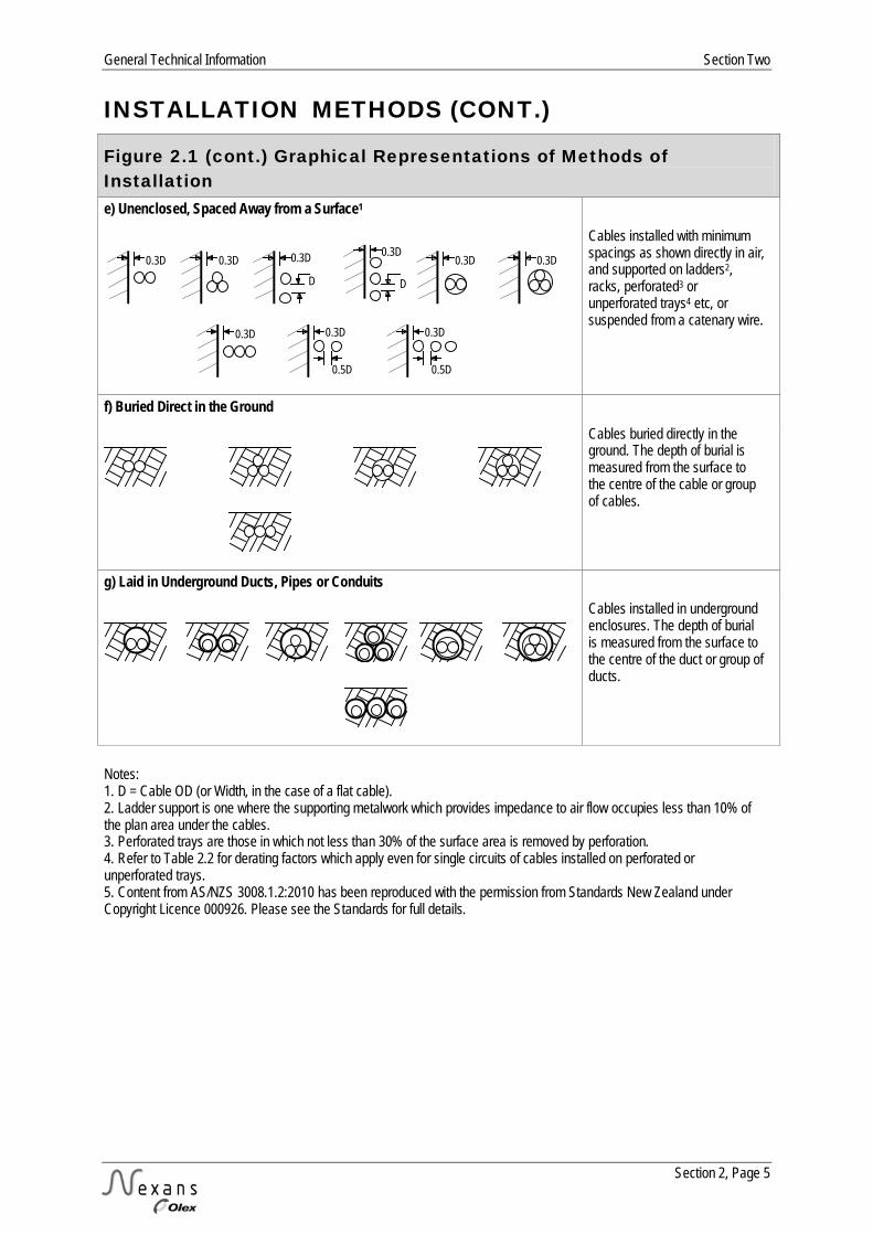
Figure 2.1 (cont.) Graphical Representations of Methods of Installation e) Unenclosed, Spaced Away from a Surface1
0.3D 0.3D 0.3D
D
0.3D
D
0.3D
0.3D
0.3D
0.3D
0.5D
0.3D
0.5D
Cables installed with minimum spacings as shown directly in air, and supported on ladders2, racks, perforated3 or unperforated trays4 etc, or suspended from a catenary wire.
f) Buried Direct in the Ground
Cables buried directly in the ground. The depth of burial is measured from the surface to the centre of the cable or group of cables.
g) Laid in Underground Ducts, Pipes or Conduits
Cables installed in underground enclosures. The depth of burial is measured from the surface to the centre of the duct or group of ducts.
Notes: 1. D = Cable OD (or Width, in the case of a flat cable). 2. Ladder support is one where the supporting metalwork which provides impedance to air flow occupies less than 10% of the plan area under the cables. 3. Perforated trays are those in which not less than 30% of the surface area is removed by perforation. 4. Refer to Table 2.2 for derating factors which apply even for single circuits of cables installed on perforated or unperforated trays. 5. Content from AS/NZS 3008.1.2:2010 has been reproduced with the permission from Standards New Zealand under Copyright Licence 000926. Please see the Standards for full details.

Section Two General Technical Information
Section 2, Page 6
INSTALLATION METHODS (CONT.)
Figure 2.2 Minimum Spacings in Air to Avoid Derating Method of Installation Horizontal Spacings Vertical Spacings a) Single Core Cables Cables spaced away from surfaces and supported on ladders, racks, etc. or suspended from a catenary wire, such that impedance to air flow around the cables is not greater than 10%.
D
D
D
4D 4D
Cables spaced away from surfaces and supported on perforated or unperforated trays such that air flow around the cables is partially restricted.
2D
2D
4D
Cables fixed directly to a wall, floor, ceiling or similar surface such that air circulation is restricted.
2D
2D
6D 6D
b) Multicore Cables Cables spaced away from surfaces and supported on ladders, racks, etc. or suspended from a catenary wire, such that impedance to air flow around the cables is not greater than 10%.
0.5D
D
2D
4D
4D
Cables spaced away from surfaces and supported on perforated or unperforated trays such that air flow around the cables is partially restricted.
2D
4D
Cables fixed directly to a wall, floor, ceiling or similar surface such that air circulation is restricted.
2D
6D
Note: Content from AS/NZS 3008.1.2:2010 has been reproduced with the permission from Standards New Zealand under Copyright Licence 000926. Please see the Standards for full details.

General Technical Information Section Two
Section 2, Page 7
SINGLE CORE CABLES IN PARALLEL The following are the recommended arrangements of single core cables in parallel. Non-symmetrical arrangements result in different impedances and hence unequal current sharing between parallel legs of the same phase. This should be avoided as it could lead to overheating of some cables. Neutral conductors of Three phase circuits should be located so as not to disturb the symmetry of the groups.
Figure 2.3 Arrangements for Equal Current Sharing of Single Core Cables in Parallel
Single Phase Three Phase Two Conductors per Phase
or
or
Three Conductors per Phase
Not Recommended
Four Conductors per Phase
or
or

Section Two General Technical Information
Section 2, Page 8
RATING FACTORS Table 2.1 Bunched Circuits of Single Core or Multicore Cables in Air or in Wiring Enclosures No of Circuits1
Arrangement of Cables Bunched
in Air Bunched
on a Surface or Enclosed
Single Layer on Wall or Floor
Single Layer under a Ceiling
Touching Spaced2,3 Touching Spaced2,3 1 1.00 1.00 1.00 1.00 0.95 0.95
2 0.87 0.80 0.85 0.94 0.81 0.85
3 0.75 0.70 0.79 0.90 0.72 0.85
4 0.72 0.65 0.75 0.90 0.68 0.85
5 0.70 0.60 0.73 0.90 0.66 0.85
6 0.67 0.57 0.72 0.90 0.64 0.85
7 - 0.54 0.72 0.90 0.63 0.85
8 - 0.52 0.71 0.90 0.62 0.85
9 - 0.50 0.70 0.90 0.61 0.85
10 - 0.48 0.70 0.90 0.61 0.85
12 - 0.45 0.70 0.90 0.61 0.85
14 - 0.43 0.70 0.90 0.61 0.85
16 - 0.41 0.70 0.90 0.61 0.85
18 - 0.39 0.70 0.90 0.61 0.85
20 or more
- 0.38 0.70 0.90 0.61 0.85
Notes: 1. Where a bunch of cables consist of n loaded conductors, it may be considered as n/2 circuits of two loaded conductors or n/3 circuits of three loaded conductors. 2. Spaced refers to a clearance of one cable diameter between adjacent cables. 3. Refer to Figure 2.2 for spacings which avoid derating.
General Technical Information Section Two
Section 2, Page 9
RATING FACTORS (CONT.)
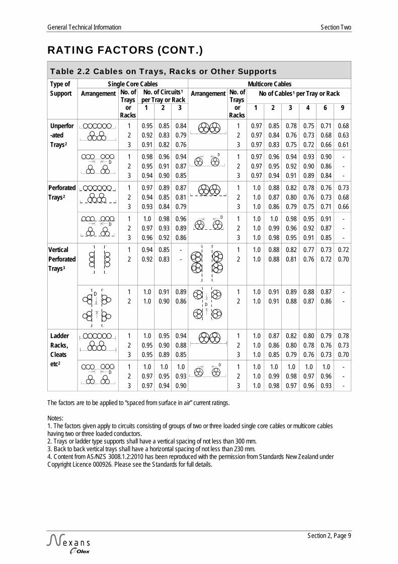
Table 2.2 Cables on Trays, Racks or Other Supports Type of Support
Single Core Cables Multicore Cables Arrangement No. of
Trays or
Racks
No. of Circuits1 per Tray or Rack
Arrangement No. of Trays
or Racks
No of Cables1 per Tray or Rack
1 2 3 1 2 3 4 6 9
Unperfor-ated Trays2
1 2 3
0.95 0.92 0.91
0.85 0.83 0.82
0.84 0.79 0.76
1 2 3
0.97 0.97 0.97
0.85 0.84 0.83
0.78 0.76 0.75
0.75 0.73 0.72
0.71 0.68 0.66
0.68 0.63 0.61
D
1 2 3
0.98 0.95 0.94
0.96 0.91 0.90
0.94 0.87 0.85
D
1 2 3
0.97 0.97 0.97
0.96 0.95 0.94
0.94 0.92 0.91
0.93 0.90 0.89
0.90 0.86 0.84
- - -
Perforated Trays2
1 2 3
0.97 0.94 0.93
0.89 0.85 0.84
0.87 0.81 0.79
1 2 3
1.0 1.0 1.0
0.88 0.87 0.86
0.82 0.80 0.79
0.78 0.76 0.75
0.76 0.73 0.71
0.73 0.68 0.66
D
1 2 3
1.0 0.97 0.96
0.98 0.93 0.92
0.96 0.89 0.86
D
1 2 3
1.0 1.0 1.0
1.0 0.99 0.98
0.98 0.96 0.95
0.95 0.92 0.91
0.91 0.87 0.85
- - -
Vertical Perforated Trays3
1 2
0.94 0.92
0.85 0.83
- -
1 2
1.0 1.0
0.88 0.88
0.82 0.81
0.77 0.76
0.73 0.72
0.72 0.70
D
1 2
1.0 1.0
0.91 0.90
0.89 0.86 D
1 2
1.0 1.0
0.91 0.91
0.89 0.88
0.88 0.87
0.87 0.86
- -
Ladder Racks, Cleats etc2
1 2 3
1.0 0.95 0.95
0.95 0.90 0.89
0.94 0.88 0.85
1 2 3
1.0 1.0 1.0
0.87 0.86 0.85
0.82 0.80 0.79
0.80 0.78 0.76
0.79 0.76 0.73
0.78 0.73 0.70
D
1 2 3
1.0 0.97 0.97
1.0 0.95 0.94
1.0 0.93 0.90
D
1 2 3
1.0 1.0 1.0
1.0 0.99 0.98
1.0 0.98 0.97
1.0 0.97 0.96
1.0 0.96 0.93
- - -
The factors are to be applied to “spaced from surface in air” current ratings. Notes: 1. The factors given apply to circuits consisting of groups of two or three loaded single core cables or multicore cables having two or three loaded conductors. 2. Trays or ladder type supports shall have a vertical spacing of not less than 300 mm. 3. Back to back vertical trays shall have a horizontal spacing of not less than 230 mm. 4. Content from AS/NZS 3008.1.2:2010 has been reproduced with the permission from Standards New Zealand under Copyright Licence 000926. Please see the Standards for full details.
Section Two General Technical Information
Section 2, Page 10
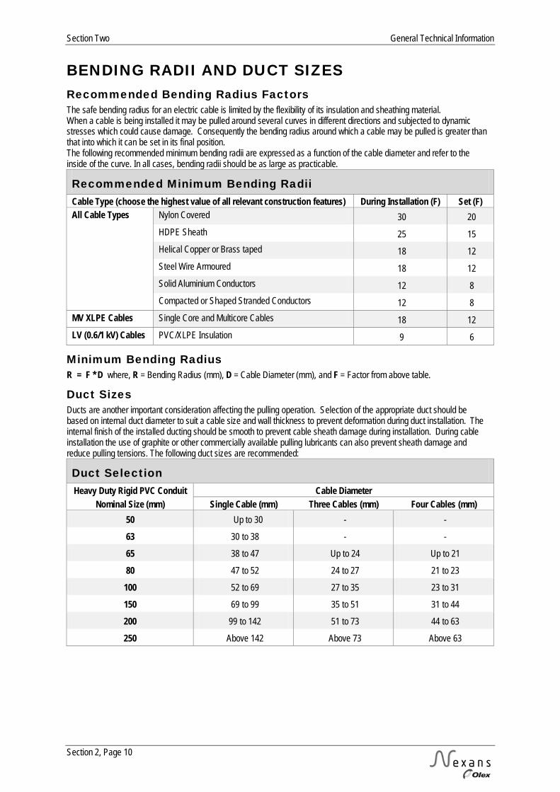
BENDING RADII AND DUCT SIZES Recommended Bending Radius Factors The safe bending radius for an electric cable is limited by the flexibility of its insulation and sheathing material. When a cable is being installed it may be pulled around several curves in different directions and subjected to dynamic stresses which could cause damage. Consequently the bending radius around which a cable may be pulled is greater than that into which it can be set in its final position. The following recommended minimum bending radii are expressed as a function of the cable diameter and refer to the inside of the curve. In all cases, bending radii should be as large as practicable.
Recommended Minimum Bending Radii Cable Type (choose the highest value of all relevant construction features) During Installation (F) Set (F) All Cable Types
Nylon Covered 30 20 HDPE Sheath 25 15 Helical Copper or Brass taped 18 12 Steel Wire Armoured 18 12 Solid Aluminium Conductors 12 8 Compacted or Shaped Stranded Conductors 12 8
MV XLPE Cables Single Core and Multicore Cables 18 12 LV (0.6/1 kV) Cables PVC/XLPE Insulation 9 6
Minimum Bending Radius R = F * D where, R = Bending Radius (mm), D = Cable Diameter (mm), and F = Factor from above table.
Duct Sizes Ducts are another important consideration affecting the pulling operation. Selection of the appropriate duct should be based on internal duct diameter to suit a cable size and wall thickness to prevent deformation during duct installation. The internal finish of the installed ducting should be smooth to prevent cable sheath damage during installation. During cable installation the use of graphite or other commercially available pulling lubricants can also prevent sheath damage and reduce pulling tensions. The following duct sizes are recommended:
Duct Selection Heavy Duty Rigid PVC Conduit Cable Diameter
Nominal Size (mm) Single Cable (mm) Three Cables (mm) Four Cables (mm) 50 Up to 30 - -
63 30 to 38 - -
65 38 to 47 Up to 24 Up to 21
80 47 to 52 24 to 27 21 to 23
100 52 to 69 27 to 35 23 to 31
150 69 to 99 35 to 51 31 to 44
200 99 to 142 51 to 73 44 to 63
250 Above 142 Above 73 Above 63
General Technical Information Section Two
Section 2, Page 11
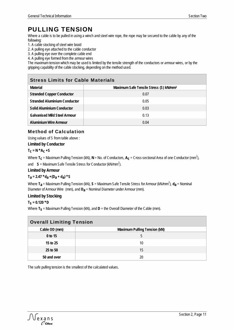
PULLING TENSION Where a cable is to be pulled in using a winch and steel wire rope, the rope may be secured to the cable by any of the following: 1. A cable stocking of steel wire braid 2. A pulling eye attached to the cable conductor 3. A pulling eye over the complete cable end 4. A pulling eye formed from the armour wires The maximum tension which may be used is limited by the tensile strength of the conductors or armour wires, or by the gripping capability of the cable stocking, depending on the method used.
Stress Limits for Cable Materials Material Maximum Safe Tensile Stress (S) kN/mm2 Stranded Copper Conductor 0.07
Stranded Aluminium Conductor 0.05
Solid Aluminium Conductor 0.03
Galvanised Mild Steel Armour 0.13
Aluminium Wire Armour 0.04
Method of Calculation Using values of S from table above : Limited by Conductor Tc = N * Ac * S
Where Tc = Maximum Pulling Tension (kN), N = No. of Conductors, Ac = Cross-sectional Area of one Conductor (mm2), and S = Maximum Safe Tensile Stress for Conductor (kN/mm2). Limited by Armour Ta = 2.47 * da * (Da + da) * S
Where Ta = Maximum Pulling Tension (kN), S = Maximum Safe Tensile Stress for Armour (kN/mm2), da = Nominal Diameter of Armour Wire (mm), and Da = Nominal Diameter under Armour (mm). Limited by Stocking Ts = 0.120 * D Where Ts = Maximum Pulling Tension (kN), and D = the Overall Diameter of the Cable (mm).
Overall Limiting Tension Cable OD (mm) Maximum Pulling Tension (kN)
0 to 15 5
15 to 25 10
25 to 50 15
50 and over 20 The safe pulling tension is the smallest of the calculated values.
Section Two General Technical Information
Section 2, Page 12
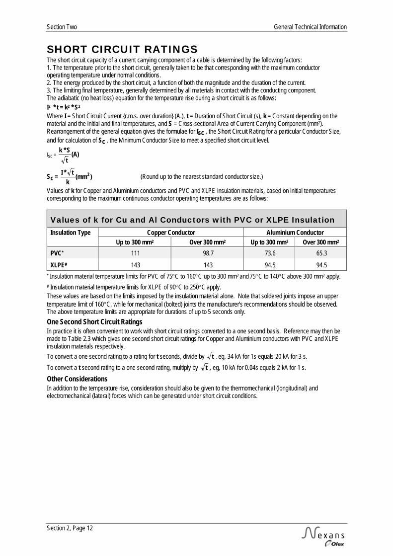
SHORT CIRCUIT RATINGS The short circuit capacity of a current carrying component of a cable is determined by the following factors: 1. The temperature prior to the short circuit, generally taken to be that corresponding with the maximum conductor operating temperature under normal conditions. 2. The energy produced by the short circuit, a function of both the magnitude and the duration of the current. 3. The limiting final temperature, generally determined by all materials in contact with the conducting component. The adiabatic (no heat loss) equation for the temperature rise during a short circuit is as follows: I2 * t = k2 * S2
Where I = Short Circuit Current r.m.s. over duration (A.), t = Duration of Short Circuit (s), k = Constant depending on the material and the initial and final temperatures, and S = Cross-sectional Area of Current Carrying Component (mm2). Rearrangement of the general equation gives the formulae for Isc , the Short Circuit Rating for a particular Conductor Size, and for calculation of Sc , the Minimum Conductor Size to meet a specified short circuit level.
Isc = (A)tS k *
Sc = )(mmk
t *I 2 (Round up to the nearest standard conductor size.)
Values of k for Copper and Aluminium conductors and PVC and XLPE insulation materials, based on initial temperatures corresponding to the maximum continuous conductor operating temperatures are as follows:
Values of k for Cu and Al Conductors with PVC or XLPE Insulation Insulation Type Copper Conductor Aluminium Conductor
Up to 300 mm2 Over 300 mm2 Up to 300 mm2 Over 300 mm2 PVC* 111 98.7 73.6 65.3
XLPE# 143 143 94.5 94.5 * Insulation material temperature limits for PVC of 75°C to 160°C up to 300 mm2 and 75°C to 140°C above 300 mm2 apply. # Insulation material temperature limits for XLPE of 90°C to 250°C apply. These values are based on the limits imposed by the insulation material alone. Note that soldered joints impose an upper temperature limit of 160°C, while for mechanical (bolted) joints the manufacturer's recommendations should be observed. The above temperature limits are appropriate for durations of up to 5 seconds only. One Second Short Circuit Ratings In practice it is often convenient to work with short circuit ratings converted to a one second basis. Reference may then be made to Table 2.3 which gives one second short circuit ratings for Copper and Aluminium conductors with PVC and XLPE insulation materials respectively. To convert a one second rating to a rating for t seconds, divide by t , eg, 34 kA for 1s equals 20 kA for 3 s. To convert a t second rating to a one second rating, multiply by t , eg, 10 kA for 0.04s equals 2 kA for 1 s. Other Considerations In addition to the temperature rise, consideration should also be given to the thermomechanical (longitudinal) and electromechanical (lateral) forces which can be generated under short circuit conditions.
General Technical Information Section Two
Section 2, Page 13
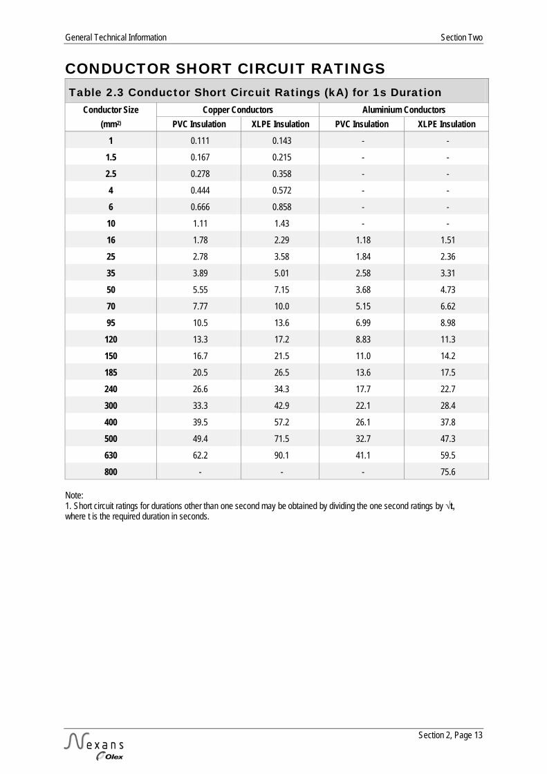
CONDUCTOR SHORT CIRCUIT RATINGS Table 2.3 Conductor Short Circuit Ratings (kA) for 1s Duration
Conductor Size Copper Conductors Aluminium Conductors (mm2) PVC Insulation XLPE Insulation PVC Insulation XLPE Insulation
1 0.111 0.143 - -
1.5 0.167 0.215 - -
2.5 0.278 0.358 - -
4 0.444 0.572 - -
6 0.666 0.858 - -
10 1.11 1.43 - -
16 1.78 2.29 1.18 1.51
25 2.78 3.58 1.84 2.36
35 3.89 5.01 2.58 3.31
50 5.55 7.15 3.68 4.73
70 7.77 10.0 5.15 6.62
95 10.5 13.6 6.99 8.98
120 13.3 17.2 8.83 11.3
150 16.7 21.5 11.0 14.2
185 20.5 26.5 13.6 17.5
240 26.6 34.3 17.7 22.7
300 33.3 42.9 22.1 28.4
400 39.5 57.2 26.1 37.8
500 49.4 71.5 32.7 47.3
630 62.2 90.1 41.1 59.5
800 - - - 75.6 Note: 1. Short circuit ratings for durations other than one second may be obtained by dividing the one second ratings by √t, where t is the required duration in seconds.
Section Two General Technical Information
Section 2, Page 14
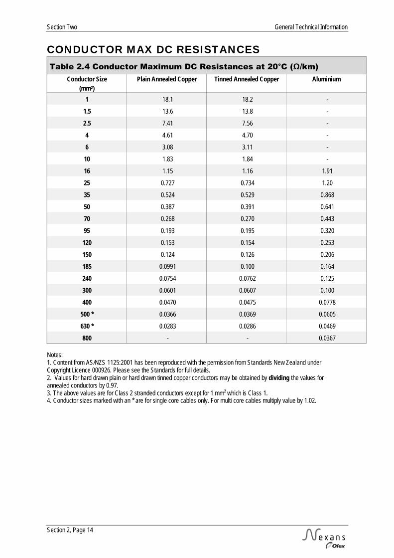
CONDUCTOR MAX DC RESISTANCES Table 2.4 Conductor Maximum DC Resistances at 20°C (Ω/km)
Conductor Size (mm2)
Plain Annealed Copper Tinned Annealed Copper Aluminium
1 18.1 18.2 -
1.5 13.6 13.8 -
2.5 7.41 7.56 -
4 4.61 4.70 -
6 3.08 3.11 -
10 1.83 1.84 -
16 1.15 1.16 1.91
25 0.727 0.734 1.20
35 0.524 0.529 0.868
50 0.387 0.391 0.641
70 0.268 0.270 0.443
95 0.193 0.195 0.320
120 0.153 0.154 0.253
150 0.124 0.126 0.206
185 0.0991 0.100 0.164
240 0.0754 0.0762 0.125
300 0.0601 0.0607 0.100
400 0.0470 0.0475 0.0778
500 * 0.0366 0.0369 0.0605
630 * 0.0283 0.0286 0.0469
800 - - 0.0367 Notes: 1. Content from AS/NZS 1125:2001 has been reproduced with the permission from Standards New Zealand under Copyright Licence 000926. Please see the Standards for full details. 2. Values for hard drawn plain or hard drawn tinned copper conductors may be obtained by dividing the values for annealed conductors by 0.97. 3. The above values are for Class 2 stranded conductors except for 1 mm² which is Class 1. 4. Conductor sizes marked with an * are for single core cables only. For multi core cables multiply value by 1.02.
General Technical Information Section Two
Section 2, Page 15
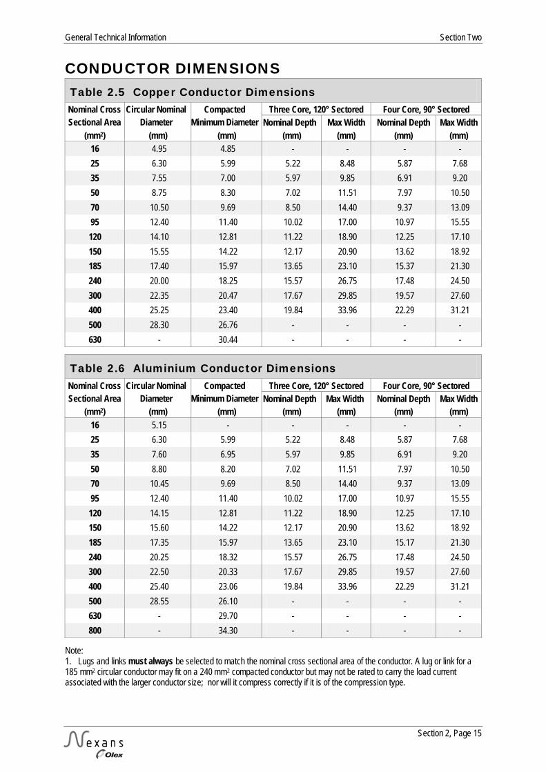
CONDUCTOR DIMENSIONS Table 2.5 Copper Conductor Dimensions
Nominal Cross Sectional Area
Circular Nominal Diameter
Compacted Minimum Diameter
Three Core, 120° Sectored Four Core, 90° Sectored Nominal Depth Max Width Nominal Depth Max Width
(mm2) (mm) (mm) (mm) (mm) (mm) (mm) 16 4.95 4.85 - - - - 25 6.30 5.99 5.22 8.48 5.87 7.68 35 7.55 7.00 5.97 9.85 6.91 9.20 50 8.75 8.30 7.02 11.51 7.97 10.50 70 10.50 9.69 8.50 14.40 9.37 13.09 95 12.40 11.40 10.02 17.00 10.97 15.55 120 14.10 12.81 11.22 18.90 12.25 17.10 150 15.55 14.22 12.17 20.90 13.62 18.92 185 17.40 15.97 13.65 23.10 15.37 21.30 240 20.00 18.25 15.57 26.75 17.48 24.50 300 22.35 20.47 17.67 29.85 19.57 27.60 400 25.25 23.40 19.84 33.96 22.29 31.21 500 28.30 26.76 - - - - 630 - 30.44 - - - -
Table 2.6 Aluminium Conductor Dimensions Nominal Cross Sectional Area
Circular Nominal Diameter
Compacted Minimum Diameter
Three Core, 120° Sectored Four Core, 90° Sectored Nominal Depth Max Width Nominal Depth Max Width
(mm2) (mm) (mm) (mm) (mm) (mm) (mm) 16 5.15 - - - - - 25 6.30 5.99 5.22 8.48 5.87 7.68 35 7.60 6.95 5.97 9.85 6.91 9.20 50 8.80 8.20 7.02 11.51 7.97 10.50 70 10.45 9.69 8.50 14.40 9.37 13.09 95 12.40 11.40 10.02 17.00 10.97 15.55 120 14.15 12.81 11.22 18.90 12.25 17.10 150 15.60 14.22 12.17 20.90 13.62 18.92 185 17.35 15.97 13.65 23.10 15.17 21.30 240 20.25 18.32 15.57 26.75 17.48 24.50 300 22.50 20.33 17.67 29.85 19.57 27.60 400 25.40 23.06 19.84 33.96 22.29 31.21 500 28.55 26.10 - - - - 630 - 29.70 - - - - 800 - 34.30 - - - -
Note: 1. Lugs and links must always be selected to match the nominal cross sectional area of the conductor. A lug or link for a 185 mm2 circular conductor may fit on a 240 mm2 compacted conductor but may not be rated to carry the load current associated with the larger conductor size; nor will it compress correctly if it is of the compression type.
Section Two General Technical Information
Section 2, Page 16
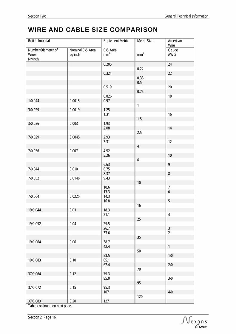
WIRE AND CABLE SIZE COMPARISON British Imperial Equivalent Metric Metric Size American
Wire Number/Diameter of Wires Nº/inch
Nominal C/S Area sq inch
C/S Area mm²
mm²
Gauge AWG
0.205 24 0.22 0.324 22 0.35 0.5 0.519 20 0.75 0.826 18 1/0.044 0.0015 0.97 1 3/0.029 0.0019 1.25 1.31 16 1.5 3/0.036 0.003 1.93 2.08 14 2.5 7/0.029 0.0045 2.93 3.31 12 4 7/0.036 0.007 4.52 5.26 10 6 6.63 9 7/0.044 0.010 6.75 8.37 8 7/0.052 0.0146 9.43 10 10.6 7 13.3 6 7/0.064 0.0225 14.3 16.8 5 16 19/0.044 0.03 18.3 21.1 4 25 19/0.052 0.04 25.5 26.7 3 33.6 2 35 19/0.064 0.06 38.7 42.4 1 50 53.5 1/0 19/0.083 0.10 65.1 67.4 2/0 70 37/0.064 0.12 75.3 85.0 3/0 95 37/0.072 0.15 95.3 107 4/0 120 37/0.083 0.20 127 Table continued on next page.

General Technical Information Section Two
Section 2, Page 17
WIRE AND CABLE SIZE COMPARISON (CONTINUED) British Imperial Equivalent Metric Metric Size American
Wire Number/Diameter of Wires Nº/inch
Nominal C/S Area sq inch
C/S Area mm²
mm²
Gauge kcmil
120 37/0.083 0.20 127 127 250 150 152 300 37/0.093 0.25 159 177 350 185 37/0.103 0.30 195 203 400 228 450 240 253 500 61/0.093 0.40 262 279 550 300 304 600 61/0.103 0.50 322 329 650 355 700 380 750 91/0.093 0.60 391 400 800 405 800 456 900 91/0.103 0.75 480 500 507 1000 630 127/0.103 1.00 669

Section Two General Technical Information
Section 2, Page 18
NOTES

LOW
VO
LTA
GE
CA
BLES
Low Voltage Cables Section Three
Section 3, Page 1
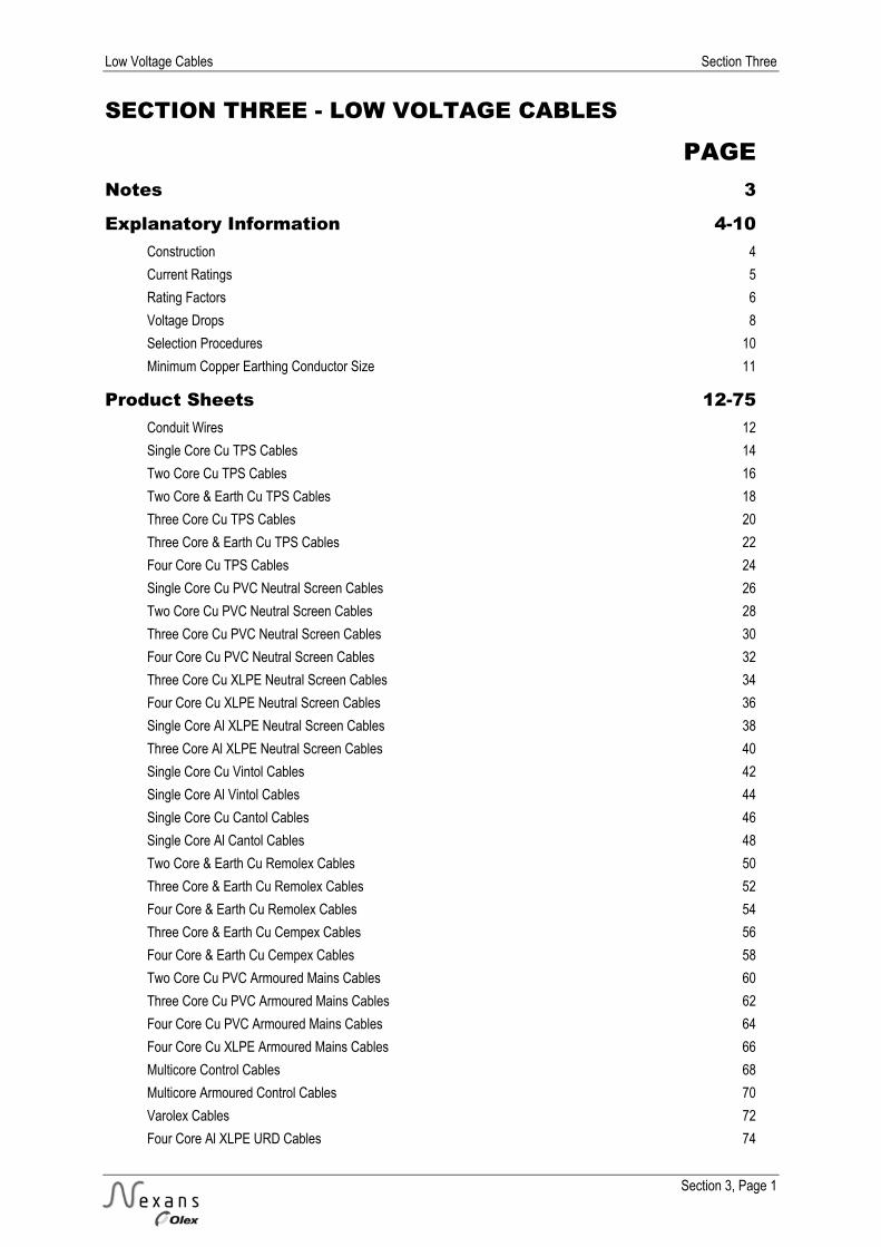
SECTION THREE - LOW VOLTAGE CABLES
PAGE Notes 3
Explanatory Information 4-10 Construction 4
Current Ratings 5
Rating Factors 6
Voltage Drops 8
Selection Procedures 10
Minimum Copper Earthing Conductor Size 11
Product Sheets 12-75 Conduit Wires 12
Single Core Cu TPS Cables 14
Two Core Cu TPS Cables 16
Two Core & Earth Cu TPS Cables 18
Three Core Cu TPS Cables 20
Three Core & Earth Cu TPS Cables 22
Four Core Cu TPS Cables 24
Single Core Cu PVC Neutral Screen Cables 26
Two Core Cu PVC Neutral Screen Cables 28
Three Core Cu PVC Neutral Screen Cables 30
Four Core Cu PVC Neutral Screen Cables 32
Three Core Cu XLPE Neutral Screen Cables 34
Four Core Cu XLPE Neutral Screen Cables 36
Single Core Al XLPE Neutral Screen Cables 38
Three Core Al XLPE Neutral Screen Cables 40
Single Core Cu Vintol Cables 42
Single Core Al Vintol Cables 44
Single Core Cu Cantol Cables 46
Single Core Al Cantol Cables 48
Two Core & Earth Cu Remolex Cables 50
Three Core & Earth Cu Remolex Cables 52
Four Core & Earth Cu Remolex Cables 54
Three Core & Earth Cu Cempex Cables 56
Four Core & Earth Cu Cempex Cables 58
Two Core Cu PVC Armoured Mains Cables 60
Three Core Cu PVC Armoured Mains Cables 62
Four Core Cu PVC Armoured Mains Cables 64
Four Core Cu XLPE Armoured Mains Cables 66
Multicore Control Cables 68
Multicore Armoured Control Cables 70
Varolex Cables 72
Four Core Al XLPE URD Cables 74
Section Three Low Voltage Cables
Section 3, Page 2
SECTION THREE – LOW VOLTAGE CABLES
PAGE
Tabulated Electrical Data 76-112 Current Ratings 76
Voltage Drops 92
AC Resistances 94
Reactances 96
Voltage Drop Graphs 98

Low Voltage Cables Section Three
Section 3, Page 3
NOTES
Section Three Low Voltage Cables
Section 3, Page 4
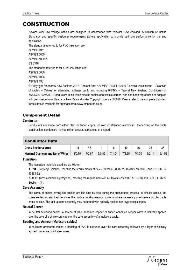
CONSTRUCTION Nexans Olex low voltage cables are designed in accordance with relevant New Zealand, Australian or British Standards and specific customer requirements (where applicable) to provide optimum performance for the end application. The standards referred to for PVC insulation are: AS/NZS 4961 AS/NZS 5000.1 AS/NZS 5000.2 BS 6346 The standards referred to for XLPE insulation are: AS/NZS 5000.1 AS/NZS 4026 AS/NZS 4961 © Copyright Standards New Zealand 2012. Content from <AS/NZS 3008.1.2:2010 Electrical installations – Selection of cables – Cables for alternating voltages up to and including 0.6/1kV – Typical New Zealand Conditions> or <AS/NZS 1125:2001 Conductors in insulated electric cables and flexible cords> and has been reproduced or adapted with permission from Standards New Zealand under Copyright Licence 000926. Please refer to the complete Standard for full details available for purchase from www.standards.co.nz.
Component Detail Conductor
Conductors are made from either plain or tinned copper or solid or stranded aluminium. Depending on the cable construction, conductors may be either circular, compacted or shaped.
Conductor Data Cross Sectional Area 1.5 2.5 4 6 10 16 25 35
Nominal Diameter and No. of Wires 3/0.75 7/0.67 7/0.85 7/1.04 7/1.35 7/1.70 7/2.14 19/1.53
Insulation The insulation materials used are as follows: 1. PVC (Polyvinyl Chloride), meeting the requirements of: V-75 (AS/NZS 3808), V-90 (AS/NZS 3808), and TI1 (BS EN 50363-3.). 2. XLPE (Cross-linked Polyethylene), meeting the requirements of: X-90 (AS/NZS 3808, AS 3560) and GP8 (BS 7655: Section 1.3.).
Core Assembly The cores of cables having flat profiles are laid side by side during the subsequent process. In circular cables, the cores are laid up and the interstices filled with a non-hygroscopic material where necessary to achieve a circular cable cross-section. The laid up core assembly may be bound with helically applied non-hygroscopic tapes.
Neutral Screen In neutral screened cables, a screen of plain annealed copper or tinned annealed copper wires is helically applied over the core of a single core cable or the core assembly of a multicore cable.
Bedding and Armour (Multicore cables) In multicore armoured cables, a bedding of PVC is extruded over the core assembly followed by a layer of helically applied galvanised mild steel wires.

Low Voltage Cables Section Three
Section 3, Page 5
Outer Sheath A sheath of PVC with suitable temperature rating is extruded over the underlying components. Additional protective coverings may be applied depending on the environment in which the cable is installed, eg, a nylon oversheath and an additional sacrificial PVC layer are often specified for protection against termite attack.

Section Three Low Voltage Cables
Section 3, Page 6
CURRENT RATINGS The current carrying capacity of a cable is determined by the following factors: 1. Current flowing in a conductor generates heat and causes the conductor temperature to rise above the ambient temperature. 2. Different methods of installation or the presence of external heat sources such as adjacent cables vary the rate of heat dissipation. 3. The insulation material determines the maximum conductor temperature which can be sustained continuously over the expected life of the cable. In all cases, the ratings given are the single circuit ratings, corresponding to continuous loading at the maximum conductor temperature appropriate to the insulation material.
Environmental Conditions The current ratings are based on the following operational conditions: ambient air temperature of 30°C, soil temperature of 15°C, soil thermal resistivity of 1.2 K.m/W and depth of burial of 0.5 m. Where conditions vary from those on which the ratings are based, appropriate rating factors from Tables 3.1 to 3.4 need to be applied.
Methods of Installation The methods of installation for which the ratings are applicable are shown graphically in Figure 2.1 (Section 2 General Technical Information). Arrangements which are shown one above the other for the same installation method are deemed to have the same current carrying capacity. Earthing conductors and lightly loaded neutral conductors of three phase circuits are ignored for current rating purposes and are generally not shown in the graphical representations of the cable and installation methods. Thus, where two single core cables or a two core cable is shown the current rating applies to single phase operation; where three single core cables or a three core cable is shown the current rating applies to two or three phase operation.
Groups of Circuits For groups of circuits unenclosed in air, the spacings and arrangements which need to be maintained to prevent derating are given in Figure 2.2 (Section 2 General Technical Information). Where underground circuits are spaced by more than 2 m from adjacent circuits, no derating applies. Also, if adjacent circuits are operated at less than 35% of their current carrying capacity they may be excluded from considerations as their contribution to mutual heating will be small. Where a number of circuits are installed in close proximity in such a way that they are not thermally independent, the appropriate rating factors from Tables 3.5, 3.6, (Section 3 Low Voltage ≥ 0.6/1 kV Cables) and Tables 2.1, 2.2 (Section 2 General Technical Information) need to be applied.
Cables in Parallel For cables operated in parallel, each parallel leg is regarded as a separate circuit for current rating purposes and the appropriate rating factors for grouping are applicable. Refer also to Figure 2.3 (Section 2 General Technical Information) for the arrangements of single core cables so as to ensure equal current sharing between parallel legs of the same phase.
Solar Radiation For cables exposed to direct sunlight, the effect of solar radiation is to increase the surface temperature of the cable and hence limit the temperature rise due to the load in the conductors. Where possible, cables should be shielded from the direct rays of the sun without restricting ventilation. Otherwise, the effect of solar radiation should be taken into account, either by calculation in accordance with IEC 60287, or as an approximation by adding 20°C to the ambient air temperature and applying the appropriate rating factor.

Low Voltage Cables Section Three
Section 3, Page 7
LOW VOLTAGE RATING FACTORS
Table 3.1 Ambient Air Temperature Variation Insulation Type Air Temperature (°C)
15 20 25 30 35 40 45 50 55 PVC 1.18 1.12 1.06 1.00 0.94 0.88 0.80 0.72 0.63 XLPE 1.15 1.09 1.05 1.00 0.95 0.91 0.85 0.80 0.74
Note: Content from AS/NZS 3008.1.2:2010 has been reproduced with the permission from Standards New Zealand under Copyright Licence 000926. Please see the Standard for full details.
Table 3.2 Soil Temperature Variation Insulation Type Soil Temperature (°C)
10 15 20 25 30 35 40 PVC 1.04 1.00 0.95 0.91 0.86 0.81 0.75 XLPE 1.04 1.00 0.96 0.93 0.91 0.87 0.83
Note: Content from AS/NZS 3008.1.2:2010 has been reproduced with the permission from Standards New Zealand under Copyright Licence 000926. Please see the Standard for full details.
Table 3.3 Depth of Burial Variation Depth of Burial Laid Direct In Underground Ducts
Up to 50mm2 Above 50mm2 Up to 300mm2 Above 300mm2 Single Core Multicore 0.5 1.00 1.00 1.00 1.00 1.00 0.6 0.99 0.98 0.97 0.98 0.99 0.8 0.97 0.96 0.94 0.95 0.97 1.0 0.95 0.94 0.92 0.93 0.96 1.25 0.94 0.92 0.90 0.90 0.95 1.5 0.93 0.91 0.89 0.89 0.94 1.75 0.92 0.89 0.87 0.88 0.94 2.0 0.91 0.88 0.86 0.87 0.93 2.5 0.90 0.87 0.85 0.86 0.93
3.0 (or deeper) 0.89 0.86 0.83 0.85 0.92 Note: Content from AS/NZS 3008.1.2:2010 has been reproduced with the permission from Standards New Zealand under Copyright Licence 000926. Please see the Standard for full details.
Table 3.4 Soil Thermal Resistivity Variation Soil Thermal Resistivity
(K.m/W)
0.8 1.09 1.16 1.03 1.06 1.08 0.9 1.07 1.11 1.02 1.04 1.06 1.0 1.04 1.07 1.02 1.03 1.04 1.2 1.00 1.00 1.00 1.00 1.00 1.5 0.92 0.90 0.95 0.94 0.92 2.0 0.81 0.80 0.88 0.86 0.83 2.5 0.74 0.72 0.83 0.80 0.77 3.0 0.69 0.66 0.78 0.75 0.71
Note: Content from AS/NZS 3008.1.2:2010 has been reproduced with the permission from Standards New Zealand under Copyright Licence 000926. Please see the Standard for full details.

Section Three Low Voltage Cables
Section 3, Page 8
LOW VOLTAGE RATING FACTORS
Table 3.5 Groups of Circuits Laid Direct No. of
Circuits Single Core Cables
spacing spacing
Multicore Cables
spacing Touching Spacing (m) Touching Spacing (m)
Trefoil Flat 0.15 0.30 0.45 0.60 0.15 0.30 0.45 0.60
2 0.78 0.81 0.83 0.88 0.91 0.93 0.81 0.87 0.91 0.93 0.95
3 0.66 0.70 0.73 0.79 0.84 0.87 0.70 0.78 0.84 0.88 0.90
4 0.61 0.64 0.68 0.74 0.81 0.85 0.63 0.74 0.81 0.86 0.89
5 0.56 0.60 0.64 0.73 0.79 0.83 0.59 0.70 0.78 0.84 0.87
6 0.53 0.57 0.61 0.71 0.78 0.82 0.55 0.68 0.77 0.83 0.87
7 0.50 0.54 0.59 0.69 0.76 0.82 0.52 0.66 0.75 0.82 0.86
8 0.49 0.53 0.57 0.68 0.76 0.81 0.50 0.64 0.75 0.81 0.86
9 0.47 0.51 0.56 0.67 0.75 0.81 0.48 0.63 0.74 0.81 0.85
10 0.46 0.50 0.55 0.67 0.75 0.80 0.47 0.62 0.73 0.80 0.85
11 0.44 0.49 0.54 0.66 0.74 0.80 0.45 0.61 0.73 0.80 0.85
12 0.43 0.48 0.53 0.66 0.74 0.80 0.44 0.60 0.72 0.80 0.84
Note: Content from AS/NZS 3008.1.2:2010 has been reproduced with the permission from Standards New Zealand under Copyright Licence 000926. Please see the Standard for full details.
Table 3.6 Groups of Circuits In Underground Ducts
No. of Circuits
Single Core Cables in Multiway Ducts or Multicore Cables in Single-way Ducts
spacingspacing
Single Core Cables in Single-way Ducts
spacing
Touching Spacing (m) Touching Spacing (m)
0.30 0.45 0.60 0.45 0.60
2 0.90 0.93 0.95 0.96 0.87 0.91 0.93
3 0.83 0.88 0.91 0.93 0.78 0.84 0.87
4 0.79 0.85 0.89 0.92 0.74 0.81 0.85
5 0.75 0.83 0.88 0.91 0.70 0.79 0.83
6 0.73 0.82 0.87 0.90 0.69 0.78 0.82
7 0.71 0.81 0.86 0.89 0.67 0.76 0.82
8 0.70 0.80 0.85 0.89 0.66 0.76 0.81
9 0.68 0.79 0.85 0.89 0.65 0.75 0.81
10 0.67 0.79 0.85 0.89 0.64 0.75 0.80
11 0.66 0.78 0.84 0.88 0.63 0.74 0.80
12 0.66 0.78 0.84 0.88 0.63 0.74 0.80 Note: Content from AS/NZS 3008.1.2:2010 has been reproduced with the permission from Standards New Zealand under Copyright Licence 000926. Please see the Standard for full details.

Low Voltage Cables Section Three
Section 3, Page 9
VOLTAGE DROPS In order to ensure satisfactory operation of electrical equipment, it is necessary to maintain the voltage at which it is supplied within certain limits.
Voltage Drop Limitations In New Zealand, the nominal supply system is 230/400 volts. The maximum voltage drop from the point of supply to any point in the installation is required to be no more than 5% of the nominal supply voltage, ie, 11.5 V for 230 V phase to earth or 20 V for 400 V phase to phase. The voltage drop limitation applying to a circuit needs to be assessed taking account of the function of the circuit and its relationship with other circuits. For example, other voltage drop limits may apply in ELV circuits or may be dictated by motor starting considerations. Also, the voltage drop in mains and submains circuits should take account of the voltage drop in final sub-circuits (and vice versa) to ensure the total voltage drop in the installation is within the required limits.
Use of Tabulated mV/A.m Figures The voltage drop (mV/A.m) values given in this publication have been obtained from AS/NZS 3008.1.2. They represent the worst case conditions, whereby it is assumed that the cable is operating at maximum rated temperature and is supplying a load having a power factor equal to the power factor of the cable. For three phase circuits, balanced loading is assumed. On this basis, where the cable size and type, load current and length of run are known, the voltage drop can be calculated from the following:
Vd = )V(1000
L*I*Vt
where: Vt = the Tabulated Voltage Drop Figure for the Cable (mV/A.m), I = the Load Current (A), and L = the Length of Run (m). This formula is used to calculate the voltage drop in a circuit when the cable size is known. Rearrangement of this equation gives the maximum mV/A.m value for compliance with a specific voltage drop.
Vc = L*I
V*1000 d (mV/A.m)
This formula should be used to select the cable size necessary to meet a specific voltage drop limitation. The size selected should have a tabulated mV/A.m figure not greater than the calculated value of Vc.
Unbalanced Three Phase Circuits In many three phase circuits the loading on each phase is not equal. In these cases, current will flow in the neutral conductor and the tabulated three phase mV/A.m values will not strictly apply. Where the imbalance is known to be small, a conservative method of voltage drop assessment is to assume balanced three phase load conditions but use the current flowing in the most heavily loaded phase. However, where the imbalance is significant, or not readily determined, it may be necessary to revert to a single phase basis. The single phase voltage drop limit and the tabulated single phase mV/A.m should be used unless more precise calculations are performed using vector methods to calculate the neutral current and then geometrically summing the voltage drops in the phase and neutral conductors.
Voltage Drop Graphs For quick calculations, Voltage Drop Graphs are also available for cables normally available ex stock from Nexans Olex.
Section Three Low Voltage Cables
Section 3, Page 10
VOLTAGE DROPS Instances can arise where it is desired to make a more precise determination than would arise from the use of tabulated mV/A.m figures. The following methods can be used in these cases.
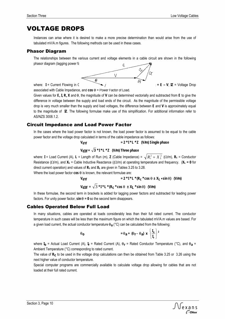
Phasor Diagram The relationships between the various current and voltage elements in a cable circuit are shown in the following phasor diagram (lagging power factor). where: I = Current Flowing in Cable, E = Voltage at Supply, V = Voltage at Load, Vd = E – V, IZ = Voltage Drop associated with Cable Impedance, and cos = Power Factor of Load. Given values for E, I, R, X and , the magnitude of V can be determined vectorially and subtracted from E to give the difference in voltage between the supply and load ends of the circuit. As the magnitude of the permissible voltage drop is very much smaller than the supply and load voltages, the difference between E and V is approximately equal to the magnitude of IZ. The following formulae make use of this simplification. For additional information refer to AS/NZS 3008.1.2.
Circuit Impedance and Load Power Factor In the cases where the load power factor is not known, the load power factor is assumed to be equal to the cable power factor and the voltage drop calculated in terms of the cable impedance as follows: Vd1f = 2 * I * L * Z (V/m) Single phase
Vd3f = 3 * I * L * Z (V/m) Three phase where: I = Load Current (A), L = Length of Run (m), Z (Cable Impedance) = 22
Lc XR (/m), Rc = Conductor Resistance (/m), and XL = Cable Inductive Reactance ((/m) at operating temperature and frequency. (XL = 0 for direct current operation) and values of Rc and XL are given in Tables 3.25 to 3.28. Where the load power factor cos is known, the relevant formulae are:
Vd1f = 2 * I * L * (Rc * cos ± XL * sin ) (V/m)
Vd3f = 3 * I * L * (Rc * cos ± XL * sin ) (V/m) In these formulae, the second term in brackets is added for lagging power factors and subtracted for leading power factors. For unity power factor, sin = 0 so the second term disappears.
Cables Operated Below Full Load In many situations, cables are operated at loads considerably less than their full rated current. The conductor temperature in such cases will be less than the maximum figure on which the tabulated mV/A.m values are based. For a given load current, the actual conductor temperature o (°C) can be calculated from the following:
o = a + (r - a) x
r
oII 2
where Io = Actual Load Current (A), Ir = Rated Current (A), r = Rated Conductor Temperature (°C), and a = Ambient Temperature (°C) corresponding to rated current. The value of Rc to be used in the voltage drop calculations can then be obtained from Table 3.25 or 3.26 using the next higher value of conductor temperature. Special computer programs are commercially available to calculate voltage drop allowing for cables that are not loaded at their full rated current.

Low Voltage Cables Section Three
Section 3, Page 11
SELECTION PROCEDURES In accordance with AS/NZS 3008.1.2:2010 and AS/NZS 3000:2007, the four main factors which affect the minimum size of cable required for a particular installation are: 1. The cable current-carrying capacity, which is influenced by the cable materials and construction, the conditions of the cable environment and the method of installation due to their effects on the dissipation of heat from the conductors. 2. The voltage drop in the cable circuit, which is a function of load current, load power factor, and length of the cable run. 3. The temperature rise under short-circuit conditions, which is a function of both the magnitude and duration of the short-circuit current and is limited by the cable materials. 4. The maximum fault loop impedance which will still allow the protective device to trip within the specified time.
Procedures To select the cable size required, based on the above considerations, follow the steps listed:
Current-Carrying Capacity 1. Determine the minimum current for which the cable is to be rated, taking account of the maximum demand of the circuit and the type and rating of the overcurrent protection device. 2. Ascertain how the cables are to be installed, and the conditions in the cable environment. From the tables of rating factors, select any rating factor(s) which are applicable. 3. Divide the rating from step 1. by the appropriate factor(s). 4. From the current rating tables, select a cable which, for the appropriate method of installation, has a tabulated rating not less than the value obtained from 3.
Voltage Drop 1. Determine the Load Current I (A) to be carried by the cable, and the Route Length L (m) of the circuit. 2. Establish the maximum voltage drop Vd (V) permitted in the circuit (taking account of any other voltage drops in series).
3. Evaluate the equation Vc = L*I
Vd*1000 (mV/A.m). This value is the maximum mV/A.m figure which will give
the required voltage drop. 4. From the voltage drop tables, select a cable for the appropriate method of installation which has a tabulated mV/A.m figure not greater than this value.
Short Circuit Temperature 1. Determine the Maximum Duration t (s) and Magnitude Isc (A) of the prospective Short Circuit Current. 2. Evaluate the equation I1 = Isc * t (A). This is the required short circuit rating converted to a one second basis. 3. From the conductor short-circuit ratings tables, select a cable with a rating not less than the value obtained from 2.
Fault Loop Impedance 1. Determine the maximum fault loop impedance which will still allow the protective device to trip within the specified time. 2. From the above calculate the maximum length of cable run to comply with the maximum fault loop impedance. Refer to AS/NZS 3000:2007, Clause 1.7.4.3 and Appendix B.
General For any circuit, the cable size selected should not be less than the largest of the sizes calculated to meet the above limitations (this is the smallest size which will meet all of the requirements). In practice, the current-carrying capacity will be found to prevail in short-run/high-current circuits while voltage drop considerations will usually prevail in long-run/low-current circuits. It is unusual for short-circuit temperature requirements to determine the conductor size required for low voltage cable circuits.

Section Three Low Voltage Cables
Section 3, Page 12
MINIMUM COPPER EARTHING CONDUCTOR SIZE
NOMINAL SIZE OF COPPER EARTHING CONDUCTOR
Nominal Size of Active Conductor
With Copper Active Conductors
With Aluminium Active Conductors
mm2 mm2 mm2
1 1 * -
1.5 1.5 * -
2.5 2.5 -
4 2.5 -
6 2.5 2.5
10 4 2.5
16 6 4
25 6 6
35 10 6
50 16 10
70 25 10
95 25 16
120 35 25
150 50 25
185 70 35
240 95 50
300 120 70
400 ≥120† ≥95†
500 ≥120† ≥95†
630 ≥120† ≥120†
* These earthing conductors may be used only where incorporated in a multicore cable or flexible cord, other
than a lift travelling cable, in accordance with Clause 5.3.3.4 (b) and (c) of AS/NZS 3000:2007.
† A larger earthing conductor may be required to satisfy Clause 5.3.3.1.1 of AS/NZS 3000:2007.
Disclaimer Nexans Olex has taken every precaution to ensure that the information contained in the above table is in line with the requirements of the appropriate New Zealand Standards and correct electrical practice. However, we accept no liability of any kind with respect to the information presented here.
It is the responsibility of the Electrician signing the Certificate of Compliance to ensure that all the requirements of the Wiring Regulations are met.
Low Voltage Cables Section Three
Section 3, Page 13
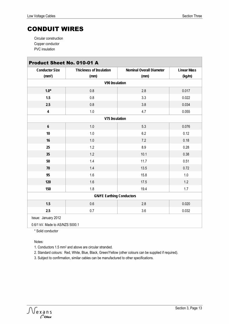
CONDUIT WIRES Circular construction Copper conductor PVC insulation
Product Sheet No. 010-01 A Conductor Size Thickness of Insulation Nominal Overall Diameter Linear Mass
(mm2) (mm) (mm) (kg/m) V90 Insulation
1.0* 0.8 2.8 0.017
1.5 0.8 3.3 0.022
2.5 0.8 3.8 0.034
4 1.0 4.7 0.055
V75 Insulation
6 1.0 5.3 0.076
10 1.0 6.2 0.12
16 1.0 7.2 0.18
25 1.2 8.9 0.28
35 1.2 10.1 0.38
50 1.4 11.7 0.51
70 1.4 13.5 0.72
95 1.6 15.8 1.0
120 1.6 17.5 1.2
150 1.8 19.4 1.7
GN/YE Earthing Conductors
1.5 0.6 2.8 0.020
2.5 0.7 3.6 0.032
Issue: January 2012
0.6/1 kV. Made to AS/NZS 5000.1
* Solid conductor Notes: 1. Conductors 1.5 mm2 and above are circular stranded. 2. Standard colours: Red, White, Blue, Black, Green/Yellow (other colours can be supplied if required). 3. Subject to confirmation, similar cables can be manufactured to other specifications.

Section Three Low Voltage Cables
Section 3, Page 14
CONDUIT WIRES Circular construction Copper conductor PVC insulation Current ratings (A) and voltage drops (mV/A.m)
Product Sheet No. 010-01 B Conductor Size
(mm2) (A) (mV/A.m) (A) (mV/A.m) 1.0 15 51.6 14 44.7
1.5 21 33.0 17 28.6
2.5 27 18.0 24 15.6
4 36 11.2 32 9.71
6 47 7.50 40 6.49
10 62 4.46 54 3.86
16 80 2.81 71 2.43
25 107 1.78 92 1.54
35 128 1.29 114 1.12
50 157 0.963 136 0.834
70 194 0.680 173 0.589
95 242 0.507 209 0.439
120 276 0.415 247 0.359
150 321 0.352 278 0.305
Issue: January 2012
0.6/1 kV. Made to AS/NZS 5000.1
Note: Content from AS/NZS 3008.1.2:2010 has been reproduced with the permission from Standards New Zealand under Copyright Licence 000926. Please see the Standard for full details. The values in this table are for typical New Zealand installation conditions of:- Ambient Air Temperature 30°C

Low Voltage Cables Section Three
Section 3, Page 15
SINGLE CORE CU TPS CABLES Circular construction Copper conductor PVC insulation PVC sheath
Product Sheet No. 020-01 A Conductor Size Thickness of Insulation Thickness of Sheath Nominal Overall Diameter Linear Mass
(mm2) (mm) (mm) (mm) (kg/m) 1.0* 0.6 0.8 3.8 0.026
1.5# 0.6 0.8 4.3 0.034
2.5 0.7 0.8 4.9 0.048
4 0.8 0.9 6.0 0.073
6 0.8 0.9 6.5 0.096
10 1.0 0.9 7.8 0.15
16 1.0 1.0 9.3 0.22
Issue: January 2012
450/750 V. Made to AS/NZS 5000.2
* Solid conductor # 3 wire conductor Notes: 1. Conductors 2.5 mm2 and above are circular stranded. 2. Standard colours: Insulation - Red or Black; Sheath - White. Other colours can be supplied if required. 3. Subject to confirmation, similar cables can be manufactured to other specifications.

Section Three Low Voltage Cables
Section 3, Page 16
SINGLE CORE CU TPS CABLES Circular construction Copper conductor PVC insulation PVC sheath Current ratings (A) and voltage drops (mV/A.m)
Product Sheet No. 020-01 B Conductor
Size
(mm2) (A) (mV/A.m) (A) (mV/A.m) (A) (mV/A.m) (A) (mV/A.m) (A) (mV/A.m) (A) (mV/A.m) (A) (mV/A.m) 1.0 15 51.6 15 44.7 16 44.7 24 51.6 18 44.7 20 51.6 18 44.7
1.5 18 33.0 18 28.6 19 28.6 31 33.0 22 28.6 25 33.0 22 28.6
2.5 26 18.0 26 15.6 29 15.6 43 18.0 30 15.6 35 18.0 30 15.6
4 35 11.2 35 9.71 38 9.71 56 11.2 40 9.71 45 11.2 40 9.71
6 46 7.50 46 6.49 48 6.49 71 7.50 50 6.49 57 7.50 50 6.49
10 62 4.46 62 3.86 66 3.86 94 4.46 65 3.86 76 4.46 65 3.86
16 82 2.81 82 2.43 88 2.43 134 2.81 114 2.43 98 2.81 86 2.43
Issue: January 2012
450/750 V. Made to AS/NZS 5000.2
Notes: 1. Refer to Product Sheet 010-01 B for current ratings and voltage drops for these cables enclosed in conduit or trunking. 2. Content from AS/NZS 3008.1.2:2010 has been reproduced with the permission from Standards New Zealand under Copyright Licence 000926. Please see the Standard for full details. The values in this table are for typical New Zealand installation conditions of:- Ambient Air Temperature 30°C Soil Temperature 15°C Soil Thermal Resistivity 1.2 K.m/W Depth of Burial 0.5 m
Low Voltage Cables Section Three
Section 3, Page 17
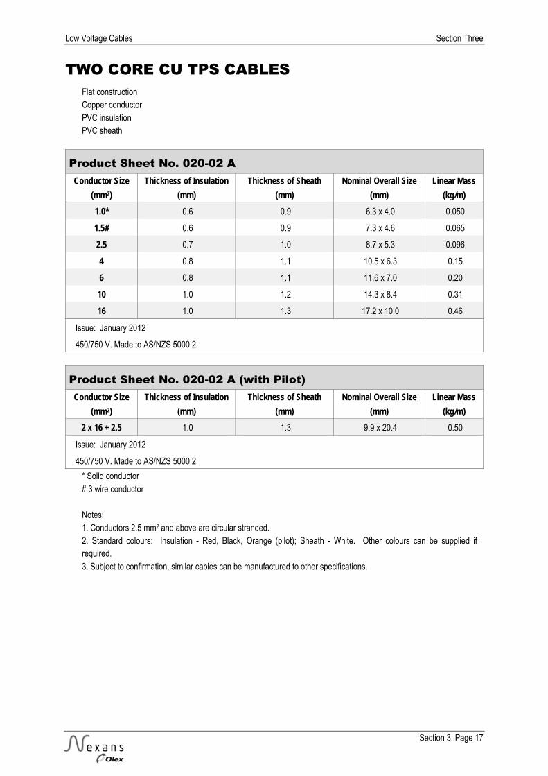
TWO CORE CU TPS CABLES Flat construction Copper conductor PVC insulation PVC sheath
Product Sheet No. 020-02 A Conductor Size Thickness of Insulation Thickness of Sheath Nominal Overall Size Linear Mass
(mm2) (mm) (mm) (mm) (kg/m) 1.0* 0.6 0.9 6.3 x 4.0 0.050
1.5# 0.6 0.9 7.3 x 4.6 0.065
2.5 0.7 1.0 8.7 x 5.3 0.096
4 0.8 1.1 10.5 x 6.3 0.15
6 0.8 1.1 11.6 x 7.0 0.20
10 1.0 1.2 14.3 x 8.4 0.31
16 1.0 1.3 17.2 x 10.0 0.46
Issue: January 2012
450/750 V. Made to AS/NZS 5000.2
Product Sheet No. 020-02 A (with Pilot) Conductor Size Thickness of Insulation Thickness of Sheath Nominal Overall Size Linear Mass
(mm2) (mm) (mm) (mm) (kg/m) 2 x 16 + 2.5 1.0 1.3 9.9 x 20.4 0.50
Issue: January 2012
450/750 V. Made to AS/NZS 5000.2
* Solid conductor # 3 wire conductor Notes: 1. Conductors 2.5 mm2 and above are circular stranded. 2. Standard colours: Insulation - Red, Black, Orange (pilot); Sheath - White. Other colours can be supplied if required. 3. Subject to confirmation, similar cables can be manufactured to other specifications.

Section Three Low Voltage Cables
Section 3, Page 18
TWO CORE CU TPS CABLES Flat construction Copper conductor PVC insulation PVC sheath Current ratings (A) and voltage drops (mV/A.m)
Product Sheet No. 020-02 B Conductor Size
(mm2) (A) (mV/A.m) (A) (mV/A.m)
1.0 15 51.6 16 51.6
1.5 18 33.0 21 33.0
2.5 26 18.0 30 18.0
4 34 11.2 39 11.2
6 44 7.50 50 7.50
10 59 4.46 68 4.46
16 78 2.81 91 2.81
25 103 1.78 122 1.78
Issue: January 2012
450/750 V. Made to AS/NZS 5000.2
Note: 1. Content from AS/NZS 3008.1.2:2010 has been reproduced with the permission from Standards New Zealand under Copyright Licence 000926. Please see the Standard for full details. The values in this table are for typical New Zealand installation conditions of:- Ambient Air Temperature 30°C

Low Voltage Cables Section Three
Section 3, Page 19
TWO CORE & EARTH CU TPS CABLES Flat construction Copper conductor PVC insulation PVC sheath
Product Sheet No. 020-03 A Conductor Size Thickness of Insulation Thickness of Sheath Nominal Overall Size Linear Mass
(mm2) (mm) (mm) (mm) (kg/m) 1.0* 0.6 0.9 8.6 x 4.0 0.070
1.5# 0.6 0.9 10.1 x 4.6 0.090
2.5 0.7 1.0 11.9 x 5.3 0.14
4 (2.5) 0.8 1.1 14.8 x 6.4 0.19
6 (2.5) 0.8 1.1 16.4 x 6.9 0.24
10 (4) 1.0 1.2 18.8 x 8.4 0.37
16 (6) 1.0 1.3 24.0 x 9.8 0.59
Issue: January 2012
450/750 V. Made to AS/NZS 5000.2
* Solid conductor # 3 wire conductor Notes: 1. Conductors 2.5 mm2 and above are circular stranded. 2. Standard colours: Insulation - Black, Red, Green/Yellow (earth); Sheath - White. Other colours can be supplied if required. 3. Reduced earth size shown in brackets ( ). 4. Subject to confirmation, similar cables can be manufactured to other specifications.

Section Three Low Voltage Cables
Section 3, Page 20
TWO CORE & EARTH CU TPS CABLES Flat construction Copper conductor PVC insulation PVC sheath Current ratings (A) and voltage drops (mV/A.m)
Product Sheet No. 020-03 B Conductor Size
(mm2) (A) (mV/A.m) (A) (mV/A.m)
1.0 15 51.6 16 51.6
1.5 18 33.0 21 33.0
2.5 26 18.0 30 18.0
4 34 11.2 39 11.2
6 44 7.50 50 7.50
10 59 4.46 68 4.46
16 78 2.81 91 2.81
Issue: January 2012
450/750 V. Made to AS/NZS 5000.2
Note: Content from AS/NZS 3008.1.2:2010 has been reproduced with the permission from Standards New Zealand under Copyright Licence 000926. Please see the Standard for full details.
The values in this table are for typical New Zealand installation conditions of:- Ambient Air Temperature 30°C

Low Voltage Cables Section Three
Section 3, Page 21
THREE CORE CU TPS CABLES Flat construction Copper conductor PVC insulation PVC sheath
Product Sheet No. 020-04 A Conductor Size Thickness of Insulation Thickness of Sheath Nominal Overall Size Linear Mass
(mm2) (mm) (mm) (mm) (kg/m) 1.0* 0.6 0.9 8.6 x 4.0 0.071
1.5# 0.6 0.9 10.1 x 4.6 0.090
2.5 0.7 1.0 12.0 x 5.3 0.14
Issue: January 2012
450/750 V. Made to AS/NZS 5000.2
* Solid conductor # 3 wire conductor Notes: 1. Conductors 2.5 mm2 and above are circular stranded. 2. Standard colours: Insulation - Red, White, Blue; Sheath - White. Other colours can be supplied if required. 3. Subject to confirmation, similar cables can be manufactured to other specifications.
Section Three Low Voltage Cables
Section 3, Page 22
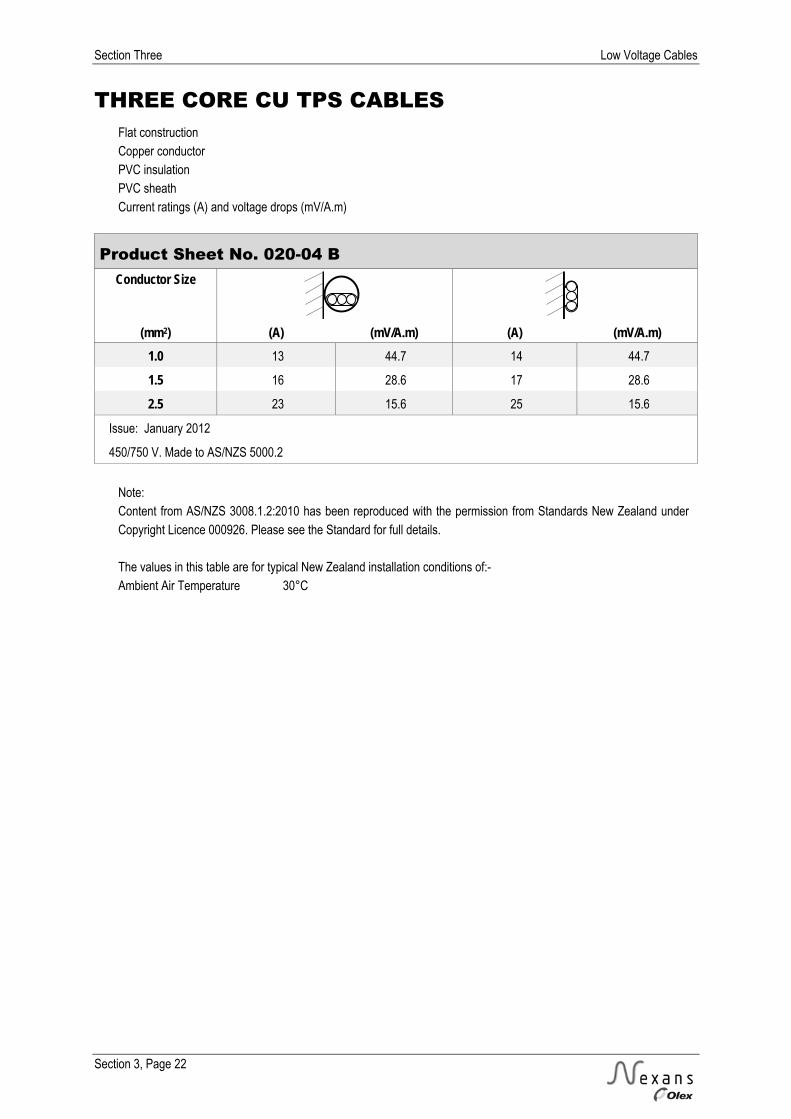
THREE CORE CU TPS CABLES Flat construction Copper conductor PVC insulation PVC sheath Current ratings (A) and voltage drops (mV/A.m)
Product Sheet No. 020-04 B Conductor Size
(mm2) (A) (mV/A.m) (A) (mV/A.m)
1.0 13 44.7 14 44.7
1.5 16 28.6 17 28.6
2.5 23 15.6 25 15.6
Issue: January 2012
450/750 V. Made to AS/NZS 5000.2
Note: Content from AS/NZS 3008.1.2:2010 has been reproduced with the permission from Standards New Zealand under Copyright Licence 000926. Please see the Standard for full details. The values in this table are for typical New Zealand installation conditions of:- Ambient Air Temperature 30°C

Low Voltage Cables Section Three
Section 3, Page 23
THREE CORE & EARTH CU TPS CABLES Flat construction Copper conductor PVC insulation PVC sheath
Product Sheet No. 020-05 A Conductor Size Thickness of Insulation Thickness of Sheath Nominal Overall Size Linear Mass
(mm2) (mm) (mm) (mm) (kg/m) 1.0* 0.6 0.9 10.9 x 4.0 0.093
1.5# 0.6 0.9 13.0 x 4.6 0.12
2.5 0.7 1.0 15.4 x 5.3 0.18
4 (2.5) 0.8 1.1 18.2 x 6.4 0.26
6 (2.5) 0.8 1.1 19.9 x 7.1 0.33
10 (4) 1.0 1.2 24.8 x 8.4 0.51
16 (6) 1.0 1.3 31.0 x 9.7 0.80
Issue: January 2012
450/750 V. Made to AS/NZS 5000.2
* Solid conductor # 3 wire conductor Notes: 1. Conductors 2.5 mm2 and above are circular stranded. 2. Standard colours: Insulation - Red, White, Blue, Green/Yellow (earth); Sheath - White. Other colours can be supplied if required. 3. Reduced earth size shown in brackets ( ). 4. Subject to confirmation, similar cables can be manufactured to other specifications.
Section Three Low Voltage Cables
Section 3, Page 24
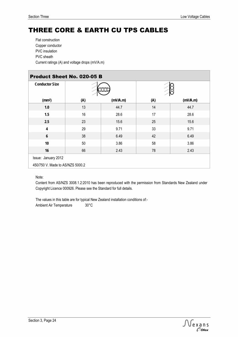
THREE CORE & EARTH CU TPS CABLES Flat construction Copper conductor PVC insulation PVC sheath Current ratings (A) and voltage drops (mV/A.m)
Product Sheet No. 020-05 B Conductor Size
(mm2) (A) (mV/A.m) (A) (mV/A.m)
1.0 13 44.7 14 44.7
1.5 16 28.6 17 28.6
2.5 23 15.6 25 15.6
4 29 9.71 33 9.71
6 38 6.49 42 6.49
10 50 3.86 58 3.86
16 66 2.43 78 2.43
Issue: January 2012
450/750 V. Made to AS/NZS 5000.2
Note: Content from AS/NZS 3008.1.2:2010 has been reproduced with the permission from Standards New Zealand under Copyright Licence 000926. Please see the Standard for full details. The values in this table are for typical New Zealand installation conditions of:- Ambient Air Temperature 30°C
Low Voltage Cables Section Three
Section 3, Page 25
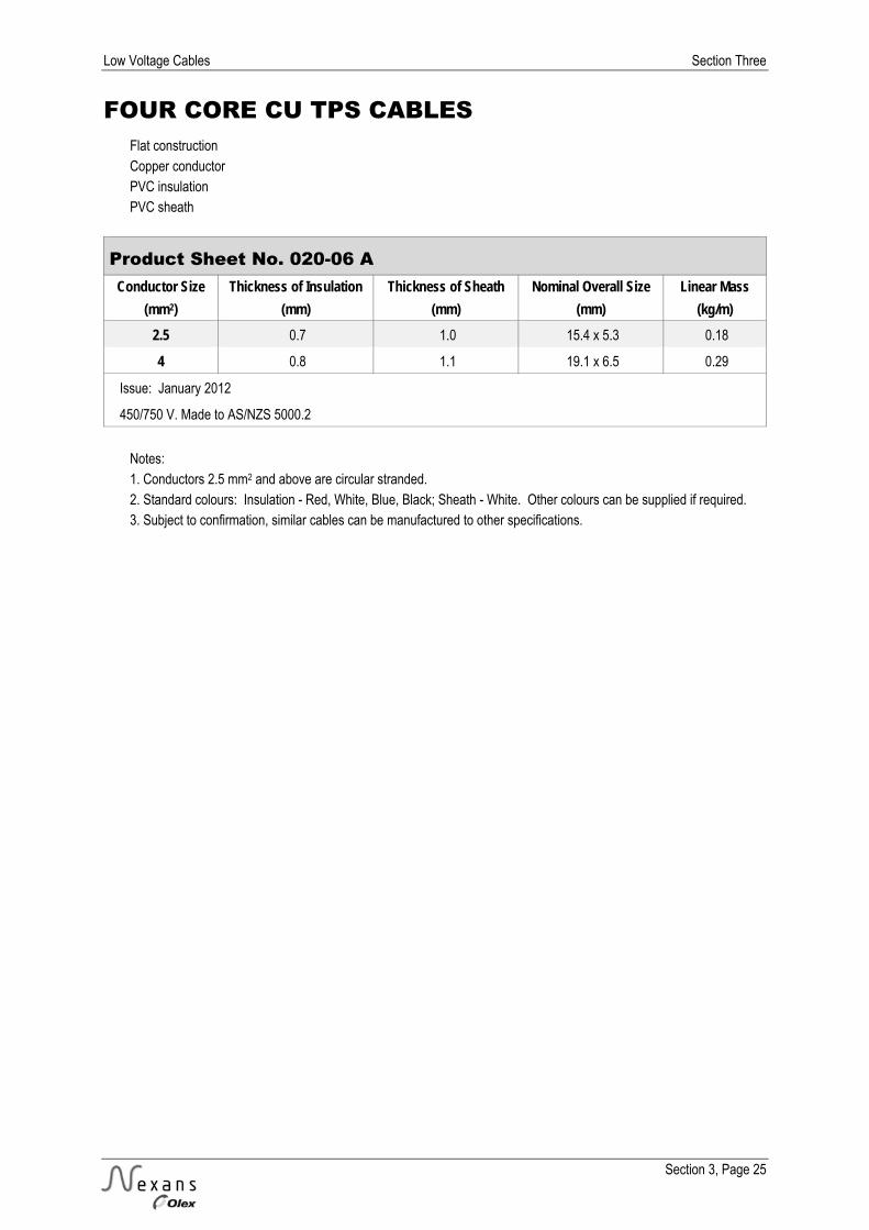
FOUR CORE CU TPS CABLES Flat construction Copper conductor PVC insulation PVC sheath
Product Sheet No. 020-06 A Conductor Size Thickness of Insulation Thickness of Sheath Nominal Overall Size Linear Mass
(mm2) (mm) (mm) (mm) (kg/m) 2.5 0.7 1.0 15.4 x 5.3 0.18
4 0.8 1.1 19.1 x 6.5 0.29
Issue: January 2012
450/750 V. Made to AS/NZS 5000.2
Notes: 1. Conductors 2.5 mm2 and above are circular stranded. 2. Standard colours: Insulation - Red, White, Blue, Black; Sheath - White. Other colours can be supplied if required. 3. Subject to confirmation, similar cables can be manufactured to other specifications.

Section Three Low Voltage Cables
Section 3, Page 26
FOUR CORE CU TPS CABLES Flat construction Copper conductor PVC insulation PVC sheath Current ratings (A) and voltage drops (mV/A.m)
Product Sheet No. 020-06 B Conductor Size
(mm2) (A) (mV/A.m) (A) (mV/A.m)
2.5 23 15.6 25 15.6
4 39 9.71 33 9.71
Issue: January 2012
450/750 V. Made to AS/NZS 5000.2
Note: Content from AS/NZS 3008.1.2:2010 has been reproduced with the permission from Standards New Zealand under Copyright Licence 000926. Please see the Standard for full details. The values in this table are for typical New Zealand installation conditions of:- Ambient Air Temperature 30°C

Low Voltage Cables Section Three
Section 3, Page 27
SINGLE CORE CU PVC NEUTRAL SCREEN CABLES Circular construction Copper conductor PVC insulation Copper neutral screen PVC sheath
Product Sheet No. 080-01 A Conductor
Size Thickness of
Insulation Neutral Screen Thickness of
Sheath Nominal Overall
Diameter Linear Mass
Physical Area Nominal No. & Size (mm2) (mm) (mm2) (mm) (mm) (mm) (kg/m)
2.5 0.8 4 20x 0.53 3.2 11.5 0.20
4 1.0 6 25 x 0.53 3.2 12.5 0.24
6 1.0 6 27 x 0.53 3.2 13.1 0.28
10 1.0 10 29 x 0.67 3.2 14.2 0.38
16 1.0 16 20 x 1.01 3.2 15.9 0.51
25 1.2 25 25 x 1.13 3.2 17.9 0.73
35 1.2 35 24 x 1.36 3.2 19.5 0.93
50 1.4 48 21 x 1.70 3.2 21.8 1.2
Issue: September 2012
0.6/1 kV. Made to AS/NZS 4961
Product Sheet No. 080-01 A (with Pilot) Conductor
Size Thickness of
Insulation Neutral Screen Thickness of
Sheath Nominal Overall
Diameter Linear Mass
Physical Area Nominal No. & Size (mm2) (mm) (mm2) (mm) (mm) (mm) (kg/m)
16 + 4P 1.0 16 46 x 0.67 3.2 22.2 x 15.2 0.67
25 + 4P 1.2 26 44 x 0.86 3.2 26.2 x 17.3 0.93
Issue: January 2012
0.6/1 kV. Made to AS/NZS 4961
Notes: 1. Conductors are circular stranded. 2. Standard colours: Insulation – Red, Orange (pilot); Sheath – Black. 3. Subject to confirmation, similar cables can be manufactured to other specifications. 4. Only Neutral Screen cable with a 3.2 mm sheath can be direct buried in accordance with AS/NZS 3000 without further mechanical protection.

Section Three Low Voltage Cables
Section 3, Page 28
SINGLE CORE CU PVC NEUTRAL SCREEN CABLES Circular construction Copper conductor PVC insulation Copper neutral screen PVC sheath Current ratings (A) and voltage drops (mV/A.m)
Product Sheet No. 080-01 B Conductor
Size
(mm2) (A) (mV/A.m) (A) (mV/A.m) (A) (mV/A.m) (A) (mV/A.m) 2.5 30 18.0 31 18.0 33 18.0 33 18.0
4 39 11.2 42 11.2 43 11.2 43 11.2
6 50 7.50 52 7.50 55 7.50 55 7.50
10 68 4.46 73 4.46 73 4.46 73 4.46
16 91 2.81 97 2.81 125 2.81 95 2.81
25 122 1.78 129 1.78 162 1.78 123 1.78
35 149 1.28 158 1.28 196 1.28 150 1.28
50 181 0.958 194 0.958 232 0.958 178 0.958
Issue: January 2012
0.6/1 kV. Made to AS/NZS 4961
Note: Content from AS/NZS 3008.1.2:2010 has been reproduced with the permission from Standards New Zealand under Copyright Licence 000926. Please see the Standard for full details. The values in this table are for typical New Zealand installation conditions of:- Ambient Air Temperature 30°C Soil Temperature 15°C Soil Thermal Resistivity 1.2 K.m/W Depth of Burial 0.5 m

Low Voltage Cables Section Three
Section 3, Page 29
TWO CORE CU PVC NEUTRAL SCREEN CABLES Circular construction Copper conductor PVC insulation Copper neutral screen PVC sheath
Product Sheet No. 080-02 A Conductor
Size Thickness of
Insulation Neutral Screen Thickness of
Sheath Nominal Overall
Diameter Linear Mass
Physical Area Nominal No. & Size (mm2) (mm) (mm2) (mm) (mm) (mm) (kg/m)
2.5 0.8 5 24 x 0.53 3.2 15.2 x 11.6 0.28
4 1.0 6 29 x 0.53 3.2 17.2 x 12.5 0.35
6 1.0 7 32 x 0.53 3.2 18.0 x 13.0 0.42
10 1.0 10 47 x 0.53 3.2 20.1 x 14.0 0.56
16 1.0 16 46 x 0.67 3.2 22.2 x 15.2 0.76
25 1.2 26 44 x 0.86 3.2 26.1 x 17.3 1.1
35 1.2 35 44 x 1.01 3.2 28.9 x 18.8 1.4
Issue: September 2012
0.6/1 kV. Made to AS/NZS 4961
Product Sheet No. 080-02 A (with Pilot) Conductor
Size Thickness of
Insulation Neutral Screen Thickness of
Sheath Nominal Overall
Diameter Linear Mass
Physical Area Nominal No. & Size (mm2) (mm) (mm2) (mm) (mm) (mm) (kg/m)
2 x 16 + 4P 1.0 16 46 x 0.67 3.2 23.3 0.92
Issue: January 2012
0.6/1 kV. Made to AS/NZS 4961
Notes: 1. Conductors are circular stranded. 2. Standard colours: Insulation – Red, White, Orange (pilot); Sheath – Black. 3. Subject to confirmation, similar cables can be manufactured to other specifications. 4. Only Neutral Screen cable with a 3.2 mm sheath can be direct buried in accordance with AS/NZS 3000 without further mechanical protection.

Section Three Low Voltage Cables
Section 3, Page 30
TWO CORE CU PVC NEUTRAL SCREEN CABLES Circular construction Copper conductor PVC insulation Copper neutral screen PVC sheath Current ratings (A) and voltage drops (mV/A.m) *
Product Sheet No. 080-02 B Conductor
Size
(mm2) (A) (mV/A.m) (A) (mV/Am) (A) (mV/A.m) (A) (mV/A.m) 2.5 25 15.6 26 15.6 28 15.6 28 15.6
4 33 9.71 35 9.71 36 9.71 36 9.71
6 42 6.49 46 6.49 46 6.49 46 6.49
10 58 3.86 62 3.86 61 3.86 61 3.86
16 78 2.43 82 2.43 106 2.43 80 2.43
25 104 1.54 111 1.54 138 1.54 103 1.54
35 128 1.11 137 1.11 165 1.11 125 1.11
Issue: January 2012
0.6/1 kV. Made to AS/NZS 4961
* This table relates to two and three phase operation - for single phase operation Product Sheet 080-01B is applicable Note: Content from AS/NZS 3008.1.2:2010 has been reproduced with the permission from Standards New Zealand under Copyright Licence 000926. Please see the Standard for full details. The values in this table are for typical New Zealand installation conditions of:- Ambient Air Temperature 30 °C Soil Temperature 15°C Soil Thermal Resistivity 1.2 K.m/W Depth of Burial 0.5 m

Low Voltage Cables Section Three
Section 3, Page 31
THREE CORE CU PVC NEUTRAL SCREEN CABLES Circular construction Copper conductor PVC insulation Copper neutral screen PVC sheath
Product Sheet No. 080-03 A Conductor
Size Thickness of
Insulation Neutral Screen Thickness of
Sheath Nominal Overall
Diameter Linear Mass
Physical Area Nominal No. & Size (mm2) (mm) (mm2) (mm) (mm) (mm) (kg/m)
2.5 0.8 7 30 x 0.53 3.2 16.0 0.36
4 1.0 8 37 x 0.53 3.2 18.1 0.47
6 1.0 9 42 x 0.53 3.2 19.1 0.56
10 1.0 11 48 x 0.53 3.2 21.0 0.74
16 1.0 16 46 x 0.67 3.2 23.6 1.01
Issue: September 2012
0.6/1 kV. Made to AS/NZS 4961
Notes: 1. Conductors are circular stranded. 2. Standard Colours: Insulation - Red, White, Blue; Sheath – Black. 3. Subject to confirmation, similar cables can be manufactured to other specifications. 4. Only Neutral Screen cable with a 3.2 mm sheath can be direct buried in accordance with AS/NZS 3000 without further mechanical protection.

Section Three Low Voltage Cables
Section 3, Page 32
THREE CORE CU PVC NEUTRAL SCREEN CABLES Circular construction Copper conductor PVC insulation Copper neutral screen PVC sheath Current ratings (A) and voltage drops (mV/A.m)
Product Sheet No. 080-03 B Conductor
Size
(mm2) (A) (mV/A.m) (A) (mV/A.m) (A) (mV/A.m) (A) (mV/A.m) 2.5 25 15.6 26 15.6 28 15.6 28 15.6
4 33 9.71 35 9.71 36 9.71 36 9.71
6 42 6.49 46 6.49 46 6.49 46 6.49
10 58 3.86 62 3.86 61 3.86 61 3.86
16 78 2.43 82 2.43 106 2.43 80 2.43
Issue: September 2012
0.6/1 kV. Made to AS/NZS 4961
Note: Content from AS/NZS 3008.1.2:2010 has been reproduced with the permission from Standards New Zealand under Copyright Licence 000926. Please see the Standard for full details. The values in this table are for typical New Zealand installation conditions of:- Ambient Air Temperature 30°C Soil Temperature 15°C Soil Thermal Resistivity 1.2 K.m/W Depth of Burial 0.5 m

Low Voltage Cables Section Three
Section 3, Page 33
FOUR CORE CU PVC NEUTRAL SCREEN CABLES Circular construction Copper conductor PVC insulation Copper neutral screen PVC sheath
Product Sheet No. 080-04 A Conductor
Size Thickness of
Insulation Neutral Screen Thickness of
Sheath Nominal Overall
Diameter Linear Mass
Physical Area Nominal No. & Size (mm2) (mm) (mm2) (mm) (mm) (mm) (kg/m)
2.5 0.8 8 34 x 0.53 3.2 17.0 0.41
4 1.0 9 42 x 0.53 3.2 19.3 0.55
6 1.0 10 46 x 0.53 3.2 20.6 0.66
10 1.0 12 54 x 0.53 3.2 22.6 0.88
16 1.0 17 47 x 0.67 3.2 25.4 1.22
Issue: September 2012
0.6/1 kV. Made to AS/NZS 4961
Notes: 1. Circular stranded conductor. 2. Standard colours: Insulation - Red, White, Blue, Black; Sheath – Black. 3. Subject to confirmation, similar cables can be manufactured to other specifications. 4. Only Neutral Screen cable with a 3.2 mm sheath can be direct buried in accordance with AS/NZS 3000 without further mechanical protection.
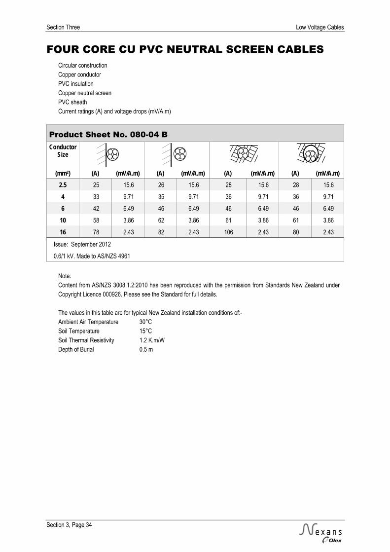
Section Three Low Voltage Cables
Section 3, Page 34
FOUR CORE CU PVC NEUTRAL SCREEN CABLES Circular construction Copper conductor PVC insulation Copper neutral screen PVC sheath Current ratings (A) and voltage drops (mV/A.m)
Product Sheet No. 080-04 B Conductor
Size
(mm2) (A) (mV/A.m) (A) (mV/A.m) (A) (mV/A.m) (A) (mV/A.m) 2.5 25 15.6 26 15.6 28 15.6 28 15.6
4 33 9.71 35 9.71 36 9.71 36 9.71
6 42 6.49 46 6.49 46 6.49 46 6.49
10 58 3.86 62 3.86 61 3.86 61 3.86
16 78 2.43 82 2.43 106 2.43 80 2.43
Issue: September 2012
0.6/1 kV. Made to AS/NZS 4961
Note: Content from AS/NZS 3008.1.2:2010 has been reproduced with the permission from Standards New Zealand under Copyright Licence 000926. Please see the Standard for full details. The values in this table are for typical New Zealand installation conditions of:- Ambient Air Temperature 30°C Soil Temperature 15°C Soil Thermal Resistivity 1.2 K.m/W Depth of Burial 0.5 m

Low Voltage Cables Section Three
Section 3, Page 35
THREE CORE CU XLPE NEUTRAL SCREEN CABLES Circular construction Copper conductor XLPE insulation Copper neutral screen PVC sheath
Product Sheet No. 081-03 A Conductor
Size Thickness of
Insulation Neutral Screen Thickness of
Sheath Nominal Overall
Diameter Linear Mass
Physical Area Nominal No. & Size (mm2) (mm) (mm2) (mm) (mm) (mm) (kg/m)
16* 0.7 16 46 x 0.67 3.2 23.0 0.97
25* 0.9 26 44 x 0.86 3.2 25.6 1.3
35 0.9 35 44 x 1.01 3.2 26.0 1.7
50 1.0 48 48 x 1.13 3.2 29.0 2.2
70 1.1 68 47 x 1.36 3.2 33.1 3.1
95 1.1 95 42 x 1.70 3.2 37.0 4.1
Issue: January 2012
0.6/1 kV. Made to AS/NZS 4961
Product Sheet No. 081-03 A (with Pilot) Conductor
Size Thickness of
Insulation Neutral Screen Thickness of
Sheath Nominal Overall
Diameter Linear Mass
Physical Area Nominal No. & Size (mm2) (mm) (mm2) (mm) (mm) (mm) (kg/m)
3 x 16 + 4P 0.7 17 48 x 0.67 3.2 24.8 1.1
Issue: January 2012
0.6/1 kV. Made to AS/NZS 4961
* Circular stranded conductor Notes: 1. Conductors 35 mm2 and above are shaped stranded. 2. Standard colours: Insulation - Red, White, Blue, Orange (pilot); Sheath – Black. 3. Subject to confirmation, similar cables can be manufactured to other specifications. 4. Only Neutral Screen cable with a 3.2 mm sheath can be direct buried in accordance with AS/NZS 3000 without further mechanical protection.

Section Three Low Voltage Cables
Section 3, Page 36
THREE CORE CU XLPE NEUTRAL SCREEN CABLES Circular construction Copper conductor XLPE insulation Copper neutral screen PVC sheath Current ratings (A) and voltage drops (mV/A.m)
Product Sheet No. 081-03 B Conductor
Size
(mm2) (A) (mV/A.m) (A) (mV/A.m) (A) (mV/A.m) (A) (mV/A.m) 16 91 2.55 97 2.55 118 2.55 87 2.55
25 122 1.61 131 1.61 153 1.61 114 1.61
35 151 1.17 162 1.17 184 1.17 139 1.17
50 185 0.868 198 0.868 218 0.868 166 0.868
70 234 0.609 252 0.609 269 0.609 207 0.609
95 289 0.450 311 0.450 323 0.450 249 0.450
Issue: January 2012
0.6/1 kV. Made to AS/NZS 4961
Note: Content from AS/NZS 3008.1.2:2010 has been reproduced with the permission from Standards New Zealand under Copyright Licence 000926. Please see the Standard for full details. The values in this table are for typical New Zealand installation conditions of:- Ambient Air Temperature 30°C Soil Temperature 15°C Soil Thermal Resistivity 1.2 K.m/W Depth of Burial 0.5 m
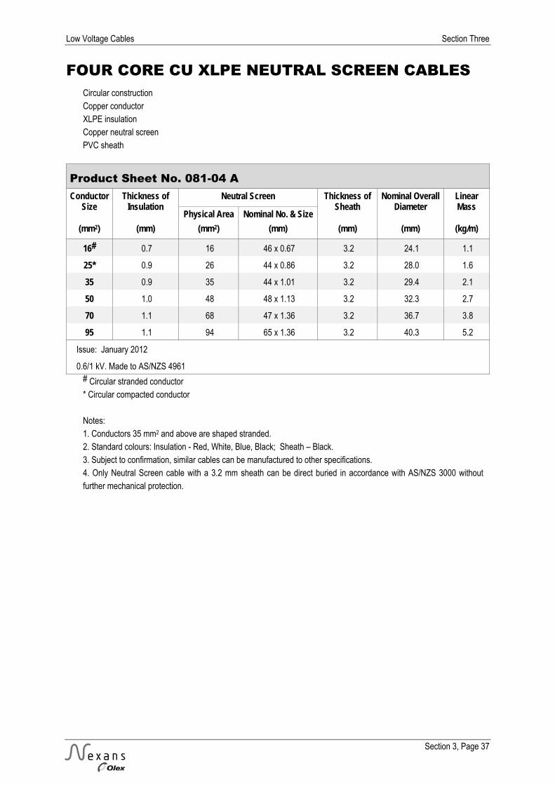
Low Voltage Cables Section Three
Section 3, Page 37
FOUR CORE CU XLPE NEUTRAL SCREEN CABLES Circular construction Copper conductor XLPE insulation Copper neutral screen PVC sheath
Product Sheet No. 081-04 A Conductor
Size Thickness of
Insulation Neutral Screen Thickness of
Sheath Nominal Overall
Diameter Linear Mass
Physical Area Nominal No. & Size (mm2) (mm) (mm2) (mm) (mm) (mm) (kg/m)
16# 0.7 16 46 x 0.67 3.2 24.1 1.1
25* 0.9 26 44 x 0.86 3.2 28.0 1.6
35 0.9 35 44 x 1.01 3.2 29.4 2.1
50 1.0 48 48 x 1.13 3.2 32.3 2.7
70 1.1 68 47 x 1.36 3.2 36.7 3.8
95 1.1 94 65 x 1.36 3.2 40.3 5.2
Issue: January 2012
0.6/1 kV. Made to AS/NZS 4961 # Circular stranded conductor * Circular compacted conductor Notes: 1. Conductors 35 mm2 and above are shaped stranded. 2. Standard colours: Insulation - Red, White, Blue, Black; Sheath – Black. 3. Subject to confirmation, similar cables can be manufactured to other specifications. 4. Only Neutral Screen cable with a 3.2 mm sheath can be direct buried in accordance with AS/NZS 3000 without further mechanical protection.
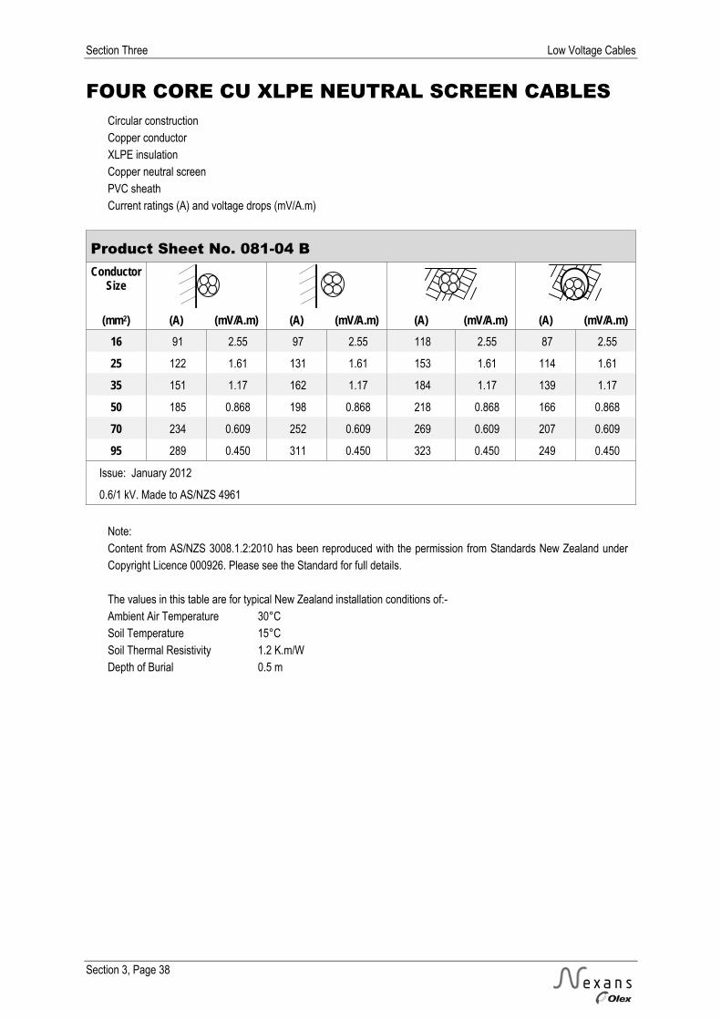
Section Three Low Voltage Cables
Section 3, Page 38
FOUR CORE CU XLPE NEUTRAL SCREEN CABLES Circular construction Copper conductor XLPE insulation Copper neutral screen PVC sheath Current ratings (A) and voltage drops (mV/A.m)
Product Sheet No. 081-04 B Conductor
Size
(mm2) (A) (mV/A.m) (A) (mV/A.m) (A) (mV/A.m) (A) (mV/A.m) 16 91 2.55 97 2.55 118 2.55 87 2.55
25 122 1.61 131 1.61 153 1.61 114 1.61
35 151 1.17 162 1.17 184 1.17 139 1.17
50 185 0.868 198 0.868 218 0.868 166 0.868
70 234 0.609 252 0.609 269 0.609 207 0.609
95 289 0.450 311 0.450 323 0.450 249 0.450
Issue: January 2012
0.6/1 kV. Made to AS/NZS 4961
Note: Content from AS/NZS 3008.1.2:2010 has been reproduced with the permission from Standards New Zealand under Copyright Licence 000926. Please see the Standard for full details. The values in this table are for typical New Zealand installation conditions of:- Ambient Air Temperature 30°C Soil Temperature 15°C Soil Thermal Resistivity 1.2 K.m/W Depth of Burial 0.5 m

Low Voltage Cables Section Three
Section 3, Page 39
SINGLE CORE AL XLPE NEUTRAL SCREEN CABLES Circular construction Aluminium conductor XLPE insulation Copper neutral screen PVC sheath
Product Sheet No. 082-01 A Conductor
Size Thickness of
Insulation Neutral Screen Thickness of
Sheath Nominal Overall
Diameter Linear Mass
Physical Area Nominal No. & Size (mm2) (mm) (mm2) (mm) (mm) (mm) (kg/m)
70 1.1 41 28 x 1.36 3.2 21.5 0.87
95 1.1 57 25 x 1.70 3.2 23.9 1.1
120 1.2 71 22 x 2.03 3.2 26.1 1.4
185 1.6 110 22 x 2.52 3.2 31.1 2.0
Issue: January 2012
0.6/1 kV. Made to AS/NZS 4961
Product Sheet No. 082-01 A (with Pilot) Conductor
Size Thickness of
Insulation Neutral Screen Thickness of
Sheath Nominal Overall
Diameter Linear Mass
Physical Area Nominal No. & Size (mm2) (mm) (mm2) (mm) (mm) (mm) (kg/m)
70 + 4P 1.1 42 29 x 1.36 3.2 28.6 x 21.2 1.1
Issue: January 2012
0.6/1 kV. Made to AS/NZS 4961
Notes: 1. Conductors are compacted stranded. 2. Standard colours: Insulation - Red, Orange (pilot); Sheath – Black. 3. Subject to confirmation, similar cables can be manufactured to other specifications. 4. Only Neutral Screen cable with a 3.2 mm sheath can be direct buried in accordance with AS/NZS 3000 without further mechanical protection.
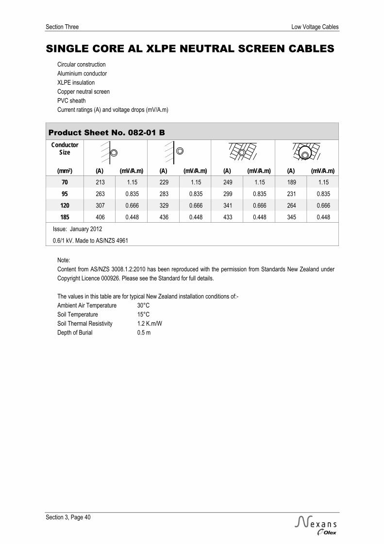
Section Three Low Voltage Cables
Section 3, Page 40
SINGLE CORE AL XLPE NEUTRAL SCREEN CABLES Circular construction Aluminium conductor XLPE insulation Copper neutral screen PVC sheath Current ratings (A) and voltage drops (mV/A.m)
Product Sheet No. 082-01 B Conductor
Size
(mm2) (A) (mV/A.m) (A) (mV/A.m) (A) (mV/A.m) (A) (mV/A.m) 70 213 1.15 229 1.15 249 1.15 189 1.15
95 263 0.835 283 0.835 299 0.835 231 0.835
120 307 0.666 329 0.666 341 0.666 264 0.666
185 406 0.448 436 0.448 433 0.448 345 0.448
Issue: January 2012
0.6/1 kV. Made to AS/NZS 4961
Note: Content from AS/NZS 3008.1.2:2010 has been reproduced with the permission from Standards New Zealand under Copyright Licence 000926. Please see the Standard for full details. The values in this table are for typical New Zealand installation conditions of:- Ambient Air Temperature 30°C Soil Temperature 15°C Soil Thermal Resistivity 1.2 K.m/W Depth of Burial 0.5 m

Low Voltage Cables Section Three
Section 3, Page 41
THREE CORE AL XLPE NEUTRAL SCREEN CABLES Circular construction Aluminium conductor XLPE insulation Copper neutral screen PVC sheath
Product Sheet No. 082-03 A Conductor
Size Thickness of
Insulation Neutral Screen Thickness of
Sheath Nominal Overall
Diameter Linear Mass
Physical Area Nominal No. & Size (mm2) (mm) (mm2) (mm) (mm) (mm) (kg/m)
35* 0.9 26 44 x 0.86 3.2 28.1 1.0
50* 1.0 29 50 x 0.86 3.2 31.0 1.2
70 1.1 42 52 x 1.01 3.2 32.4 1.6
95 1.1 57 57 x 1.13 3.2 35.9 2.0
185 1.6 116 50 x 1.70 3.2 47.0 3.7
Issue: January 2012
0.6/1 kV. Made to AS/NZS 4961
Product Sheet No. 082-03 A (With Pilot) Conductor
Size Thickness of
Insulation Neutral Screen Thickness of
Sheath Nominal Overall
Diameter Linear Mass
Physical Area Nominal No. & Size (mm2) (mm) (mm2) (mm) (mm) (mm) (kg/m)
95 + 10P 1.1 57 57 x 1.13 3.2 39.0 2.2
120 + 10P 1.2 73 50 x 1.36 3.2 39.6 2.5
185 + 10P 1.6 114 50 x 1.70 3.2 48.0 3.7
300 + 10P 1.8 185 57 x 2.03 3.2 57.4 5.6
Issue: January 2012
0.6/1 kV. Made to AS/NZS 4961
* Circular compacted conductor Notes: 1. Conductors 70 mm² and above are shaped stranded conductor. 2. Standard colours: Insulation - Red, White, Blue; Sheath – Black. 3. Subject to confirmation, similar cables can be manufactured to other specifications. 4. Only Neutral Screen cable with a 3.2 mm sheath can be direct buried in accordance with AS/NZS 3000 without further mechanical protection.
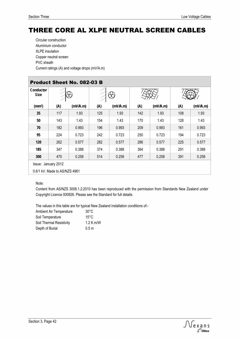
Section Three Low Voltage Cables
Section 3, Page 42
THREE CORE AL XLPE NEUTRAL SCREEN CABLES Circular construction Aluminium conductor XLPE insulation Copper neutral screen PVC sheath Current ratings (A) and voltage drops (mV/A.m)
Product Sheet No. 082-03 B Conductor
Size
(mm2) (A) (mV/A.m) (A) (mV/A.m) (A) (mV/A.m) (A) (mV/A.m) 35 117 1.93 125 1.93 142 1.93 108 1.93
50 143 1.43 154 1.43 170 1.43 128 1.43
70 182 0.993 196 0.993 209 0.993 161 0.993
95 224 0.723 242 0.723 250 0.723 194 0.723
120 262 0.577 282 0.577 286 0.577 225 0.577
185 347 0.388 374 0.388 364 0.388 291 0.388
300 475 0.258 514 0.258 477 0.258 391 0.258
Issue: January 2012
0.6/1 kV. Made to AS/NZS 4961
Note: Content from AS/NZS 3008.1.2:2010 has been reproduced with the permission from Standards New Zealand under Copyright Licence 000926. Please see the Standard for full details. The values in this table are for typical New Zealand installation conditions of:- Ambient Air Temperature 30°C Soil Temperature 15°C Soil Thermal Resistivity 1.2 K.m/W Depth of Burial 0.5 m
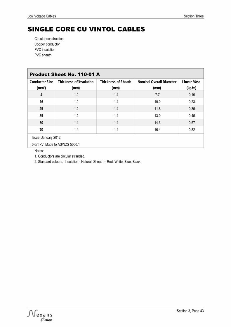
Low Voltage Cables Section Three
Section 3, Page 43
SINGLE CORE CU VINTOL CABLES Circular construction Copper conductor PVC insulation PVC sheath
Product Sheet No. 110-01 A Conductor Size Thickness of Insulation Thickness of Sheath Nominal Overall Diameter Linear Mass
(mm2) (mm) (mm) (mm) (kg/m) 4 1.0 1.4 7.7 0.10
16 1.0 1.4 10.0 0.23
25 1.2 1.4 11.8 0.35
35 1.2 1.4 13.0 0.45
50 1.4 1.4 14.6 0.57
70 1.4 1.4 16.4 0.82
Issue: January 2012
0.6/1 kV. Made to AS/NZS 5000.1
Notes: 1. Conductors are circular stranded. 2. Standard colours: Insulation - Natural; Sheath – Red, White, Blue, Black.

Section Three Low Voltage Cables
Section 3, Page 44
SINGLE CORE CU VINTOL CABLES Circular construction Copper conductor PVC insulation PVC sheath Current ratings (A) and voltage drops (mV/A.m)
Product Sheet No. 110-01 B
Conductor Size
(mm2) (A) (mV/A.m) (A) (mV/A.m) (A) (mV/A.m) (A) (mV/A.m) (A) (mV/A.m) (A) (mV/A.m) (A) (mV/A.m)
4 35 11.2 35 9.71 38 9.71 56 11.2 40 9.71 45 11.2 40 9.71
16 82 2.81 82 2.43 88 2.43 134 2.81 114 2.43 98 2.81 86 2.43
25 111 1.78 111 1.55 117 1.54 174 1.78 147 1.54 128 1.78 110 1.54
35 136 1.29 136 1.12 145 1.12 209 1.29 176 1.12 153 1.29 134 1.12
50 166 0.963 166 0.840 178 0.834 248 0.963 209 0.834 185 0.963 158 0.834
70 210 0.680 210 0.597 225 0.589 305 0.680 256 0.589 227 0.680 198 0.589
Issue: January 2012
0.6/1 kV. Made to AS/NZS 5000.1
Note: Content from AS/NZS 3008.1.2:2010 has been reproduced with the permission from Standards New Zealand under Copyright Licence 000926. Please see the Standard for full details. The values in this table are for typical New Zealand installation conditions of:- Ambient Air Temperature 30°C Soil Temperature 15°C Soil Thermal Resistivity 1.2 K.m/W Depth of Burial 0.5 m

Low Voltage Cables Section Three
Section 3, Page 45
SINGLE CORE AL VINTOL CABLES Circular construction Aluminium conductor PVC insulation PVC sheath
Product Sheet No. 110-01 A
Conductor Size Thickness of Insulation Thickness of Sheath Nominal Overall Diameter Linear Mass
(mm2) (mm) (mm) (mm) (kg/m)
25 1.2 1.4 11.7 0.18
35 1.2 1.4 13.4 0.24
50 1.4 1.4 14.7 0.29
70 1.4 1.4 16.4 0.39
95 1.6 1.5 19.0 0.52
120 1.6 1.5 20.7 0.62
150 1.8 1.6 22.8 0.75
185 2.0 1.7 25.1 0.92
240 2.2 1.8 26.8 1.1
Issue: January 2012
0.6/1 kV. Made to AS/NZS 5000.1
Notes: 1. Conductors are circular stranded. 2. Standard colours: Insulation - Natural; Sheath – Red, White, Blue, Black.
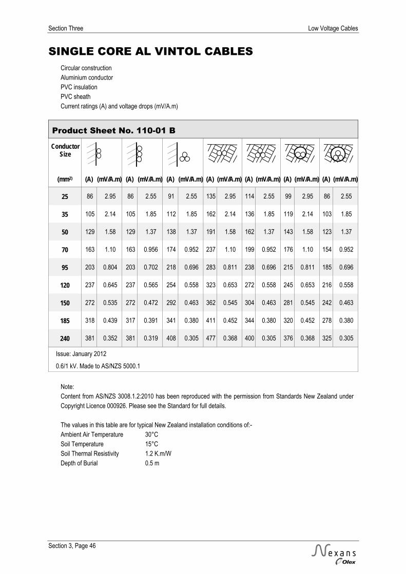
Section Three Low Voltage Cables
Section 3, Page 46
SINGLE CORE AL VINTOL CABLES Circular construction Aluminium conductor PVC insulation PVC sheath Current ratings (A) and voltage drops (mV/A.m)
Product Sheet No. 110-01 B
Conductor Size
(mm2) (A) (mV/A.m) (A) (mV/A.m) (A) (mV/A.m) (A) (mV/A.m) (A) (mV/A.m) (A) (mV/A.m) (A) (mV/A.m)
25 86 2.95 86 2.55 91 2.55 135 2.95 114 2.55 99 2.95 86 2.55
35 105 2.14 105 1.85 112 1.85 162 2.14 136 1.85 119 2.14 103 1.85
50 129 1.58 129 1.37 138 1.37 191 1.58 162 1.37 143 1.58 123 1.37
70 163 1.10 163 0.956 174 0.952 237 1.10 199 0.952 176 1.10 154 0.952
95 203 0.804 203 0.702 218 0.696 283 0.811 238 0.696 215 0.811 185 0.696
120 237 0.645 237 0.565 254 0.558 323 0.653 272 0.558 245 0.653 216 0.558
150 272 0.535 272 0.472 292 0.463 362 0.545 304 0.463 281 0.545 242 0.463
185 318 0.439 317 0.391 341 0.380 411 0.452 344 0.380 320 0.452 278 0.380
240 381 0.352 381 0.319 408 0.305 477 0.368 400 0.305 376 0.368 325 0.305
Issue: January 2012
0.6/1 kV. Made to AS/NZS 5000.1
Note: Content from AS/NZS 3008.1.2:2010 has been reproduced with the permission from Standards New Zealand under Copyright Licence 000926. Please see the Standard for full details. The values in this table are for typical New Zealand installation conditions of:- Ambient Air Temperature 30°C Soil Temperature 15°C Soil Thermal Resistivity 1.2 K.m/W Depth of Burial 0.5 m

Low Voltage Cables Section Three
Section 3, Page 47
SINGLE CORE CU CANTOL CABLES Circular construction Copper conductor XLPE insulation PVC sheath
Product Sheet No. 120-01 A Conductor Size Thickness of Insulation Thickness of Sheath Nominal Overall Diameter Linear Mass
(mm2) (mm) (mm) (mm) (kg/m) 16 0.7 1.4 9.4 0.21
25 0.9 1.4 10.9 0.31
35 0.9 1.4 11.9 0.41
50 1.0 1.4 13.4 0.54
70 1.1 1.4 15.0 0.75
95 1.1 1.5 16.9 1.0
120 1.2 1.5 18.6 1.3
150 1.4 1.6 20.6 1.6
185 1.6 1.6 22.8 1.9
240 1.7 1.7 25.5 2.5
300 1.8 1.8 28.1 3.1
400 2.0 1.9 31.8 4.0
500 2.2 2.0 35.7 5.0
630 2.4 2.2 40.1 6.4
Issue: January 2012
0.6/1 kV. Made to AS/NZS 5000.1
Notes: 1. Conductors are compact circular stranded. 2. Standard colours: Insulation - Natural; Sheath - Black. Other colours can be supplied if required. 3. Subject to confirmation, similar cables can be manufactured to other specifications.
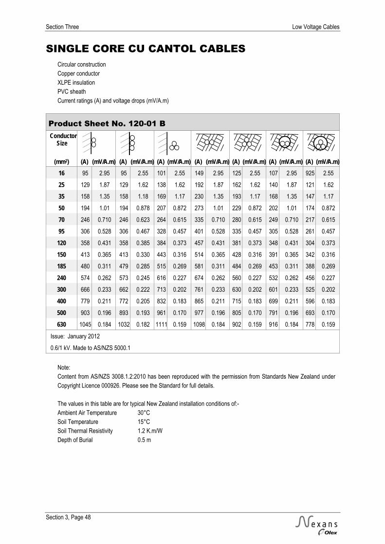
Section Three Low Voltage Cables
Section 3, Page 48
SINGLE CORE CU CANTOL CABLES Circular construction Copper conductor XLPE insulation PVC sheath Current ratings (A) and voltage drops (mV/A.m)
Product Sheet No. 120-01 B Conductor
Size
(mm2) (A) (mV/A.m) (A) (mV/A.m) (A) (mV/A.m) (A) (mV/A.m) (A) (mV/A.m) (A) (mV/A.m) (A) (mV/A.m) 16 95 2.95 95 2.55 101 2.55 149 2.95 125 2.55 107 2.95 925 2.55
25 129 1.87 129 1.62 138 1.62 192 1.87 162 1.62 140 1.87 121 1.62
35 158 1.35 158 1.18 169 1.17 230 1.35 193 1.17 168 1.35 147 1.17
50 194 1.01 194 0.878 207 0.872 273 1.01 229 0.872 202 1.01 174 0.872
70 246 0.710 246 0.623 264 0.615 335 0.710 280 0.615 249 0.710 217 0.615
95 306 0.528 306 0.467 328 0.457 401 0.528 335 0.457 305 0.528 261 0.457
120 358 0.431 358 0.385 384 0.373 457 0.431 381 0.373 348 0.431 304 0.373
150 413 0.365 413 0.330 443 0.316 514 0.365 428 0.316 391 0.365 342 0.316
185 480 0.311 479 0.285 515 0.269 581 0.311 484 0.269 453 0.311 388 0.269
240 574 0.262 573 0.245 616 0.227 674 0.262 560 0.227 532 0.262 456 0.227
300 666 0.233 662 0.222 713 0.202 761 0.233 630 0.202 601 0.233 525 0.202
400 779 0.211 772 0.205 832 0.183 865 0.211 715 0.183 699 0.211 596 0.183
500 903 0.196 893 0.193 961 0.170 977 0.196 805 0.170 791 0.196 693 0.170
630 1045 0.184 1032 0.182 1111 0.159 1098 0.184 902 0.159 916 0.184 778 0.159
Issue: January 2012
0.6/1 kV. Made to AS/NZS 5000.1
Note: Content from AS/NZS 3008.1.2:2010 has been reproduced with the permission from Standards New Zealand under Copyright Licence 000926. Please see the Standard for full details. The values in this table are for typical New Zealand installation conditions of:- Ambient Air Temperature 30°C Soil Temperature 15°C Soil Thermal Resistivity 1.2 K.m/W Depth of Burial 0.5 m
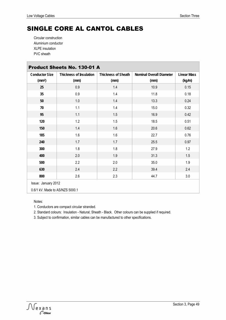
Low Voltage Cables Section Three
Section 3, Page 49
SINGLE CORE AL CANTOL CABLES Circular construction Aluminium conductor XLPE insulation PVC sheath
Product Sheets No. 130-01 A Conductor Size Thickness of Insulation Thickness of Sheath Nominal Overall Diameter Linear Mass
(mm2) (mm) (mm) (mm) (kg/m) 25 0.9 1.4 10.9 0.15
35 0.9 1.4 11.8 0.18
50 1.0 1.4 13.3 0.24
70 1.1 1.4 15.0 0.32
95 1.1 1.5 16.9 0.42
120 1.2 1.5 18.5 0.51
150 1.4 1.6 20.6 0.62
185 1.6 1.6 22.7 0.76
240 1.7 1.7 25.5 0.97
300 1.8 1.8 27.9 1.2
400 2.0 1.9 31.3 1.5
500 2.2 2.0 35.0 1.9
630 2.4 2.2 39.4 2.4
800 2.6 2.3 44.7 3.0
Issue: January 2012
0.6/1 kV. Made to AS/NZS 5000.1
Notes: 1. Conductors are compact circular stranded. 2. Standard colours: Insulation - Natural; Sheath - Black. Other colours can be supplied if required. 3. Subject to confirmation, similar cables can be manufactured to other specifications.
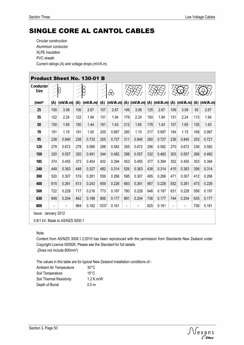
Section Three Low Voltage Cables
Section 3, Page 50
SINGLE CORE AL CANTOL CABLES Circular construction Aluminium conductor XLPE insulation PVC sheath Current ratings (A) and voltage drops (mV/A.m)
Product Sheet No. 130-01 B Conductor
Size
(mm2) (A) (mV/A.m) (A) (mV/A.m) (A) (mV/A.m) (A) (mV/A.m) (A) (mV/A.m) (A) (mV/A.m) (A) (mV/A.m) 25 100 3.08 100 2.67 107 2.67 149 3.08 125 2.67 109 3.08 93 2.67
35 122 2.24 122 1.94 131 1.94 179 2.24 150 1.94 131 2.24 113 1.94
50 150 1.65 150 1.44 161 1.43 212 1.65 178 1.43 157 1.65 135 1.43
70 191 1.15 191 1.00 205 0.997 260 1.15 217 0.997 194 1.15 169 0.997
95 238 0.840 238 0.733 255 0.727 311 0.840 260 0.727 236 0.840 203 0.727
120 278 0.672 278 0.589 298 0.582 355 0.672 296 0.582 270 0.672 236 0.582
150 320 0.557 320 0.491 344 0.482 398 0.557 332 0.482 303 0.557 266 0.482
185 374 0.455 373 0.404 402 0.394 453 0.455 377 0.394 352 0.455 303 0.394
240 449 0.363 448 0.327 482 0.314 526 0.363 438 0.314 415 0.363 356 0.314
300 520 0.307 519 0.281 559 0.266 595 0.307 495 0.266 471 0.307 412 0.266
400 615 0.261 613 0.243 659 0.226 683 0.261 567 0.226 552 0.261 473 0.226
500 722 0.228 717 0.216 773 0.197 780 0.228 646 0.197 631 0.228 556 0.197
630 849 0.204 842 0.198 906 0.177 891 0.204 736 0.177 744 0.204 635 0.177
800 - - 964 0.182 1037 0.161 - - 825 0.161 - - 706 0.161
Issue: January 2012
0.6/1 kV. Made to AS/NZS 5000.1
Note: Content from AS/NZS 3008.1.2:2010 has been reproduced with the permission from Standards New Zealand under Copyright Licence 000926. Please see the Standard for full details. (Does not include 800mm²) The values in this table are for typical New Zealand installation conditions of:- Ambient Air Temperature 30°C Soil Temperature 15°C Soil Thermal Resistivity 1.2 K.m/W Depth of Burial 0.5 m

Low Voltage Cables Section Three
Section 3, Page 51
TWO CORE & EARTH CU REMOLEX CABLES Circular construction Copper conductor PVC insulation PVC sheath
Product Sheet No. 021-02 A Conductor Size Thickness of Insulation Thickness of Sheath Nominal Overall Diameter Linear Mass
(mm2) (mm) (mm) (mm) (kg/m) 1.5* 0.6 1.2 8.8 0.12
2.5 0.7 1.2 9.7 0.16
4 (2.5) 0.8 1.3 11.3 0.21
6 (2.5) 0.8 1.3 12.2 0.26
10 (4) 1.0 1.3 16.1 0.44
Issue: January 2012
450/750 V. Made to AS/NZS 5000.2
* 3 wire conductor Notes: 1. Conductors 2.5 mm2 and above are circular stranded. 2. Standard colours: Insulation - Red, Black, Green/Yellow (earth); Sheath – Black. 3. Reduced earth size shown in brackets ( ). 4. Subject to confirmation, similar cables can be manufactured to other specifications.
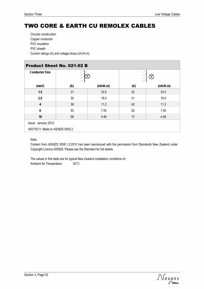
Section Three Low Voltage Cables
Section 3, Page 52
TWO CORE & EARTH CU REMOLEX CABLES Circular construction Copper conductor PVC insulation PVC sheath Current ratings (A) and voltage drops (mV/A.m)
Product Sheet No. 021-02 B Conductor Size
(mm2) (A) (mV/A.m) (A) (mV/A.m)
1.5 21 33.0 22 33.0
2.5 30 18.0 31 18.0
4 39 11.2 42 11.2
6 50 7.50 52 7.50
10 68 4.46 73 4.46
Issue: January 2012
450/750 V. Made to AS/NZS 5000.2
Note: Content from AS/NZS 3008.1.2:2010 has been reproduced with the permission from Standards New Zealand under Copyright Licence 000926. Please see the Standard for full details. The values in this table are for typical New Zealand installation conditions of:- Ambient Air Temperature 30°C
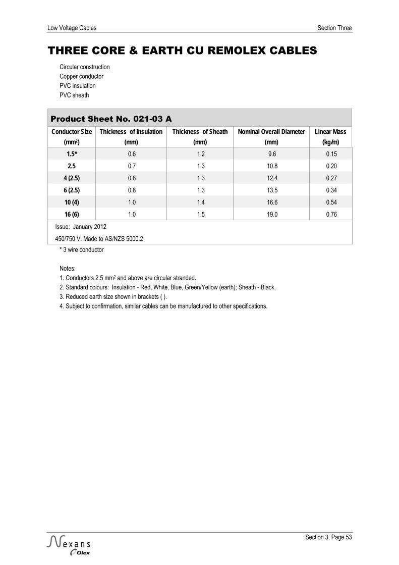
Low Voltage Cables Section Three
Section 3, Page 53
THREE CORE & EARTH CU REMOLEX CABLES Circular construction Copper conductor PVC insulation PVC sheath
Product Sheet No. 021-03 A Conductor Size Thickness of Insulation Thickness of Sheath Nominal Overall Diameter Linear Mass
(mm2) (mm) (mm) (mm) (kg/m) 1.5* 0.6 1.2 9.6 0.15
2.5 0.7 1.3 10.8 0.20
4 (2.5) 0.8 1.3 12.4 0.27
6 (2.5) 0.8 1.3 13.5 0.34
10 (4) 1.0 1.4 16.6 0.54
16 (6) 1.0 1.5 19.0 0.76
Issue: January 2012
450/750 V. Made to AS/NZS 5000.2
* 3 wire conductor Notes: 1. Conductors 2.5 mm2 and above are circular stranded. 2. Standard colours: Insulation - Red, White, Blue, Green/Yellow (earth); Sheath - Black. 3. Reduced earth size shown in brackets ( ). 4. Subject to confirmation, similar cables can be manufactured to other specifications.
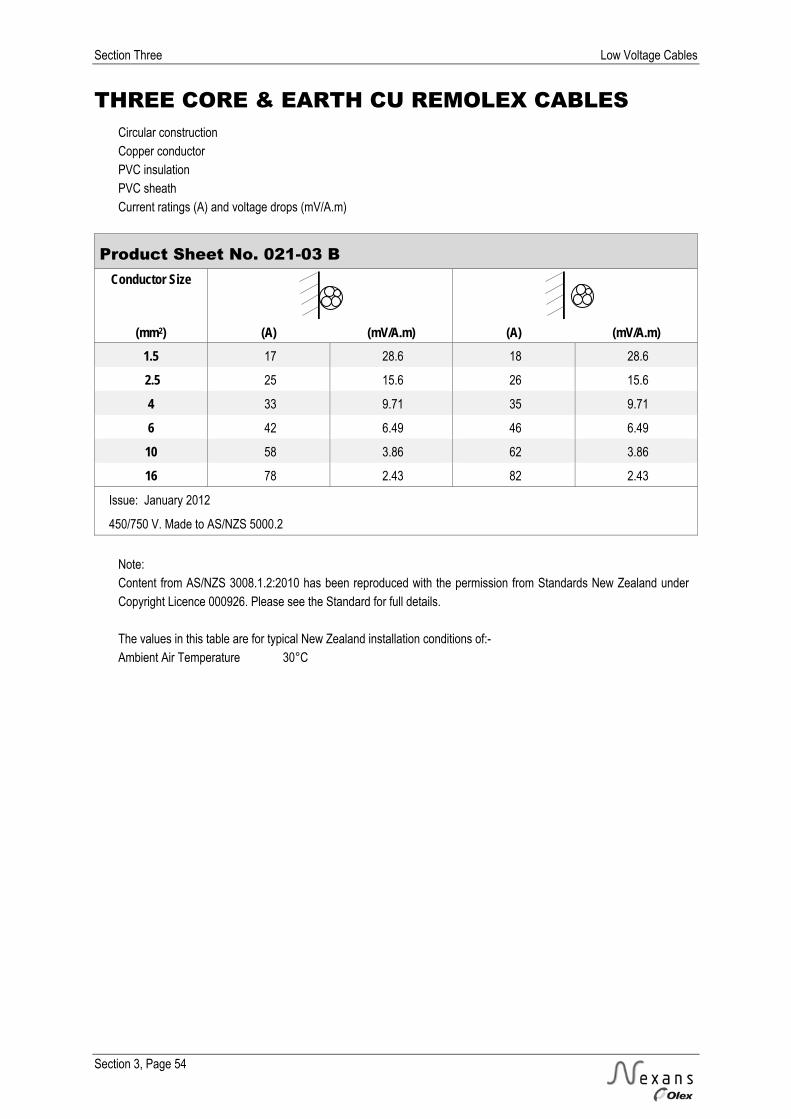
Section Three Low Voltage Cables
Section 3, Page 54
THREE CORE & EARTH CU REMOLEX CABLES Circular construction Copper conductor PVC insulation PVC sheath Current ratings (A) and voltage drops (mV/A.m)
Product Sheet No. 021-03 B Conductor Size
(mm2) (A) (mV/A.m) (A) (mV/A.m)
1.5 17 28.6 18 28.6
2.5 25 15.6 26 15.6
4 33 9.71 35 9.71
6 42 6.49 46 6.49
10 58 3.86 62 3.86
16 78 2.43 82 2.43
Issue: January 2012
450/750 V. Made to AS/NZS 5000.2
Note: Content from AS/NZS 3008.1.2:2010 has been reproduced with the permission from Standards New Zealand under Copyright Licence 000926. Please see the Standard for full details. The values in this table are for typical New Zealand installation conditions of:- Ambient Air Temperature 30°C

Low Voltage Cables Section Three
Section 3, Page 55
FOUR CORE & EARTH CU REMOLEX CABLES Circular construction Copper conductor PVC insulation PVC sheath
Product Sheet No. 021-04 A Conductor Size Thickness of Insulation Thickness of Sheath Nominal Overall Diameter Linear Mass
(mm2) (mm) (mm) (mm) (kg/m) 1.5 0.6 1.2 10.4 0.17
2.5 0.7 1.3 11.8 0.24
4 (2.5) 0.8 1.4 13.9 0.34
Issue: January 2012
450/750 V. Made to AS/NZS 5000.2
Notes: 1. Conductors 2.5 mm2 and above are circular stranded. 2. Standard colours: Insulation - Red, White, Blue, Black, Green/Yellow (earth); Sheath – Black. 3. Reduced earth size shown in brackets ( ). 4. Subject to confirmation, similar cables can be manufactured to other specifications.

Section Three Low Voltage Cables
Section 3, Page 56
FOUR CORE & EARTH CU REMOLEX CABLES Circular construction Copper conductor PVC insulation PVC sheath Current ratings (A) and voltage drops (mV/A.m)
Product Sheet No. 021-04 B Conductor
Size
(mm2) (A) (mV/A.m) (A) (mV/A.m) 1.5 17 28.6 18 28.6
2.5 25 15.6 26 15.6
4 33 9.71 35 9.71
Issue: January 2012
450/750 V. Made to AS/NZS 5000.2
Note: Content from AS/NZS 3008.1.2:2010 has been reproduced with the permission from Standards New Zealand under Copyright Licence 000926. Please see the Standard for full details. The values in this table are for typical New Zealand installation conditions of:- Ambient Air Temperature 30°C
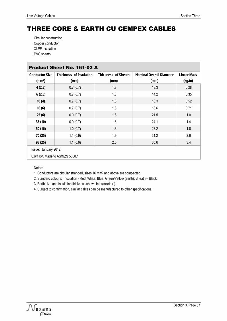
Low Voltage Cables Section Three
Section 3, Page 57
THREE CORE & EARTH CU CEMPEX CABLES Circular construction Copper conductor XLPE insulation PVC sheath
Product Sheet No. 161-03 A Conductor Size Thickness of Insulation Thickness of Sheath Nominal Overall Diameter Linear Mass
(mm2) (mm) (mm) (mm) (kg/m) 4 (2.5) 0.7 (0.7) 1.8 13.3 0.28
6 (2.5) 0.7 (0.7) 1.8 14.2 0.35
10 (4) 0.7 (0.7) 1.8 16.3 0.52
16 (6) 0.7 (0.7) 1.8 18.6 0.71
25 (6) 0.9 (0.7) 1.8 21.5 1.0
35 (10) 0.9 (0.7) 1.8 24.1 1.4
50 (16) 1.0 (0.7) 1.8 27.2 1.8
70 (25) 1.1 (0.9) 1.9 31.2 2.6
95 (25) 1.1 (0.9) 2.0 35.6 3.4
Issue: January 2012
0.6/1 kV. Made to AS/NZS 5000.1
Notes: 1. Conductors are circular stranded, sizes 16 mm2 and above are compacted. 2. Standard colours: Insulation - Red, White, Blue, Green/Yellow (earth); Sheath – Black. 3. Earth size and insulation thickness shown in brackets ( ). 4. Subject to confirmation, similar cables can be manufactured to other specifications.

Section Three Low Voltage Cables
Section 3, Page 58
THREE CORE & EARTH CU CEMPEX CABLES Circular construction Copper conductor XLPE insulation PVC sheath Current ratings (A) and voltage drops (mV/A.m)
Product Sheet No. 161-03 B Conductor
Size
(mm2) (A) (mV/A.m) (A) (mV/A.m) (A) (mV/A.m) (A) (mV/A.m) 4 42 10.2 39 10.2 40 10.2 40 10.2
6 53 6.80 50 6.80 49 6.80 49 6.80
10 73 4.05 68 4.05 67 4.05 67 4.05
16 97 2.55 91 2.55 118 2.55 87 2.55
25 131 1.61 122 1.61 153 1.61 114 1.61
35 162 1.17 151 1.17 184 1.17 139 1.17
50 198 0.868 185 0.868 218 0.868 166 0.868
70 252 0.609 234 0.609 269 0.609 207 0.609
95 311 0.450 289 0.450 323 0.450 249 0.450
Issue: January 2012
0.6/1 kV. Made to AS/NZS 5000.1
Note: Content from AS/NZS 3008.1.2:2010 has been reproduced with the permission from Standards New Zealand under Copyright Licence 000926. Please see the Standard for full details. The values in this table are for typical New Zealand installation conditions of:- Ambient Air Temperature 30°C Soil Temperature 15°C Soil Thermal Resistivity 1.2 K.m/W Depth of Burial 0.5 m

Low Voltage Cables Section Three
Section 3, Page 59
FOUR CORE & EARTH CU CEMPEX CABLES Circular construction Copper conductor XLPE insulation PVC sheath
Product Sheet No. 161-04 A Conductor Size Thickness of Insulation Thickness of Sheath Nominal Overall Diameter Linear Mass
(mm2) (mm) (mm) (mm) (kg/m) 2.5 0.7 1.8 14.5 0.30
4 (2.5) 0.7 (0.7) 1.8 15.6 0.37
6 (2.5) 0.7 (0.7) 1.8 15.7 0.43
10 (4) 0.7 (0.7) 1.8 19.2 0.66
16 (6) 0.7 (0.7) 1.8 20.5 0.90
25 (6) 0.9 (0.7) 1.8 23.9 1.3
35 (10) 0.9 (0.7) 1.8 26.6 1.7
50 (16) 1.0 (0.7) 1.8 30.3 2.3
70 (25) 1.1 (0.9) 2.0 34.9 3.3
95 (25) 1.1 (0.9) 2.1 39.0 4.4
Issue: January 2012
0.6/1 kV. Made to AS/NZS 5000.1
Notes: 1. Conductors are circular stranded, sizes 16 mm2 and above are compacted. 2. Standard colours: Insulation - Red, White, Blue, Black, Green/Yellow (earth); Sheath – Black. 3. Earth size and insulation thickness shown in brackets ( ). 4. Subject to confirmation, similar cables can be manufactured to other specifications.
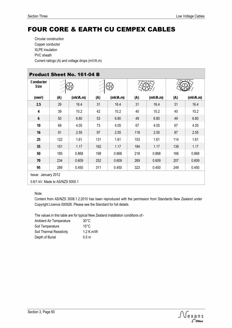
Section Three Low Voltage Cables
Section 3, Page 60
FOUR CORE & EARTH CU CEMPEX CABLES Circular construction Copper conductor XLPE insulation PVC sheath Current ratings (A) and voltage drops (mV/A.m)
Product Sheet No. 161-04 B Conductor
Size
(mm2) (A) (mV/A.m) (A) (mV/A.m) (A) (mV/A.m) (A) (mV/A.m) 2.5 29 16.4 31 16.4 31 16.4 31 16.4
4 39 10.2 42 10.2 40 10.2 40 10.2
6 50 6.80 53 6.80 49 6.80 49 6.80
10 68 4.05 73 4.05 67 4.05 67 4.05
16 91 2.55 97 2.55 118 2.55 87 2.55
25 122 1.61 131 1.61 153 1.61 114 1.61
35 151 1.17 162 1.17 184 1.17 139 1.17
50 185 0.868 198 0.868 218 0.868 166 0.868
70 234 0.609 252 0.609 269 0.609 207 0.609
95 289 0.450 311 0.450 323 0.450 249 0.450
Issue: January 2012
0.6/1 kV. Made to AS/NZS 5000.1
Note: Content from AS/NZS 3008.1.2:2010 has been reproduced with the permission from Standards New Zealand under Copyright Licence 000926. Please see the Standard for full details. The values in this table are for typical New Zealand installation conditions of:- Ambient Air Temperature 30°C Soil Temperature 15°C Soil Thermal Resistivity 1.2 K.m/W Depth of Burial 0.5 m

Low Voltage Cables Section Three
Section 3, Page 61
TWO CORE CU PVC ARMOURED MAINS CABLES Circular construction Copper conductor PVC insulation Extruded bedding Galvanised steel wire armour PVC sheath
Product Sheet No. 140-02 A Conductor
Size Thickness of Armour Wire
Size Thickness of
Sheath Nominal Diameters Linear Mass
Insulation Bedding Bedding Overall (mm2) (mm) (mm) (mm) (mm) (mm) (mm) (kg/m) 2.5* 0.8 1.0 0.9 1.8 9.6 14.9 0.43
4* 1.0 1.0 0.9 1.8 11.5 17.1 0.58
6* 1.0 1.0 1.25 1.8 12.6 18.9 0.74
Issue: January 2012
0.6/1 kV. Made to AS/NZS 5000.1
* Circular stranded conductor Notes: 1. Standard Colours: Insulation – Red, Black; Sheath – Black. 2. Subject to confirmation, similar cables can be manufactured to other specifications.

Section Three Low Voltage Cables
Section 3, Page 62
TWO CORE CU PVC ARMOURED MAINS CABLES Circular construction Copper conductor PVC insulation Extruded bedding Galvanised steel wire armour PVC sheath Current ratings (A) and voltage drops (mV/A.m)
Product Sheet No. 140-02 B Conductor
Size
(mm2) (A) (mV/A.m) (A) (mV/A.m) (A) (mV/A.m) (A) (mV/A.m) 2.5 30 18.0 31 18.0 33 18.0 33 18.0
4 39 11.2 42 11.2 43 11.2 43 11.2
6 50 7.50 52 7.50 55 7.50 55 7.50
Issue: January 2012
0.6/1 kV. Made to AS/NZS 5000.1
Note: Content from AS/NZS 3008.1.2:2010 has been reproduced with the permission from Standards New Zealand under Copyright Licence 000926. Please see the Standard for full details. The values in this table are for typical New Zealand installation conditions of:- Ambient Air Temperature 30°C Soil Temperature 15°C Soil Thermal Resistivity 1.2 K.m/W Depth of Burial 0.5 m
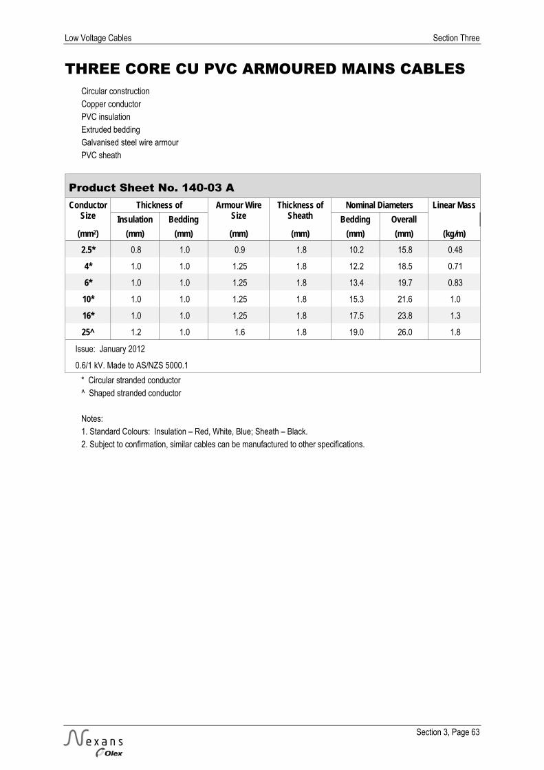
Low Voltage Cables Section Three
Section 3, Page 63
THREE CORE CU PVC ARMOURED MAINS CABLES Circular construction Copper conductor PVC insulation Extruded bedding Galvanised steel wire armour PVC sheath
Product Sheet No. 140-03 A Conductor
Size Thickness of Armour Wire
Size Thickness of
Sheath Nominal Diameters Linear Mass
Insulation Bedding Bedding Overall (mm2) (mm) (mm) (mm) (mm) (mm) (mm) (kg/m) 2.5* 0.8 1.0 0.9 1.8 10.2 15.8 0.48
4* 1.0 1.0 1.25 1.8 12.2 18.5 0.71
6* 1.0 1.0 1.25 1.8 13.4 19.7 0.83
10* 1.0 1.0 1.25 1.8 15.3 21.6 1.0
16* 1.0 1.0 1.25 1.8 17.5 23.8 1.3
25^ 1.2 1.0 1.6 1.8 19.0 26.0 1.8
Issue: January 2012
0.6/1 kV. Made to AS/NZS 5000.1
* Circular stranded conductor ^ Shaped stranded conductor Notes: 1. Standard Colours: Insulation – Red, White, Blue; Sheath – Black. 2. Subject to confirmation, similar cables can be manufactured to other specifications.

Section Three Low Voltage Cables
Section 3, Page 64
THREE CORE CU PVC ARMOURED MAINS CABLES Circular construction Copper conductor PVC insulation Extruded bedding Galvanised steel wire armour PVC sheath Current ratings (A) and voltage drops (mV/A.m)
Product Sheet No. 140-03 B Conductor
Size
(mm2) (A) (mV/A.m) (A) (mV/A.m) (A) (mV/A.m) (A) (mV/A.m) 2.5 25 15.6 26 15.6 28 15.6 28 15.6
4 33 9.71 35 9.71 36 9.71 36 9.71
6 42 6.49 46 6.49 46 6.49 46 6.49
10 58 3.86 62 3.86 61 3.86 61 3.86
16 78 2.43 82 2.43 106 2.43 80 2.43
25 104 1.54 111 1.54 138 1.54 103 1.54
Issue: January 2012
0.6/1 kV. Made to AS/NZS 5000.1
Note: Content from AS/NZS 3008.1.2:2010 has been reproduced with the permission from Standards New Zealand under Copyright Licence 000926. Please see the Standard for full details. The values in this table are for typical New Zealand installation conditions of:- Ambient Air Temperature 30°C Soil Temperature 15°C Soil Thermal Resistivity 1.2 K.m/W Depth of Burial 0.5 m

Low Voltage Cables Section Three
Section 3, Page 65
FOUR CORE CU PVC ARMOURED MAINS CABLES Circular construction Copper conductor PVC insulation Extruded bedding Galvanised steel wire armour PVC sheath
Product Sheet No. 140-04 A Conductor
Size Thickness of Armour Wire
Size Thickness of
Sheath Nominal Diameters Linear Mass
Insulation Bedding Bedding Overall (mm2) (mm) (mm) (mm) (mm) (mm) (mm) (kg/m) 2.5* 0.8 1.0 0.9 1.8 11.2 16.7 0.54
4* 1.0 1.0 1.25 1.8 13.5 19.7 0.81
6* 1.0 1.0 1.25 1.8 14.8 21.1 0.96
10* 1.0 1.0 1.25 1.8 16.9 23.2 1.2
Issue: January 2012
0.6/1 kV. Made to AS/NZS 5000.1
* Circular stranded conductor Notes: 1. Standard Colours: Insulation – Red, White, Blue, Black; Sheath – Black. 2. Subject to confirmation, similar cables can be manufactured to other specifications.
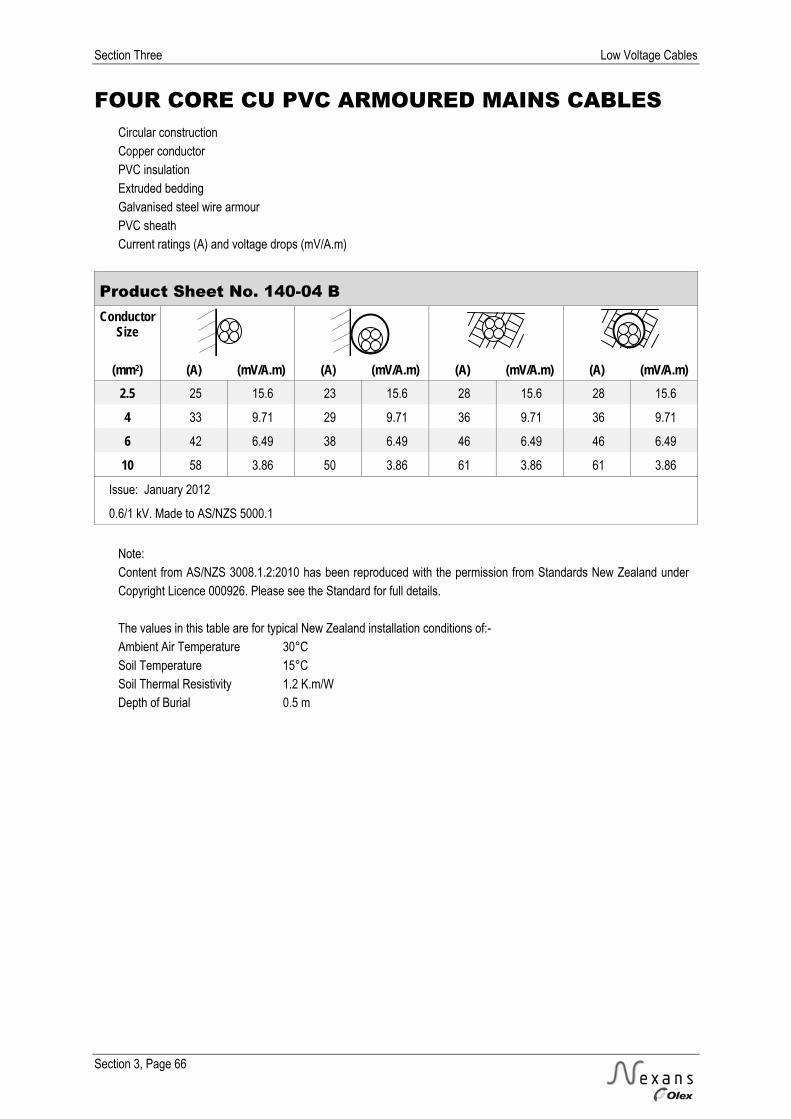
Section Three Low Voltage Cables
Section 3, Page 66
FOUR CORE CU PVC ARMOURED MAINS CABLES Circular construction Copper conductor PVC insulation Extruded bedding Galvanised steel wire armour PVC sheath Current ratings (A) and voltage drops (mV/A.m)
Product Sheet No. 140-04 B Conductor
Size
(mm2) (A) (mV/A.m) (A) (mV/A.m) (A) (mV/A.m) (A) (mV/A.m) 2.5 25 15.6 23 15.6 28 15.6 28 15.6
4 33 9.71 29 9.71 36 9.71 36 9.71
6 42 6.49 38 6.49 46 6.49 46 6.49
10 58 3.86 50 3.86 61 3.86 61 3.86
Issue: January 2012
0.6/1 kV. Made to AS/NZS 5000.1
Note: Content from AS/NZS 3008.1.2:2010 has been reproduced with the permission from Standards New Zealand under Copyright Licence 000926. Please see the Standard for full details. The values in this table are for typical New Zealand installation conditions of:- Ambient Air Temperature 30°C Soil Temperature 15°C Soil Thermal Resistivity 1.2 K.m/W Depth of Burial 0.5 m

Low Voltage Cables Section Three
Section 3, Page 67
FOUR CORE CU XLPE ARMOURED MAINS CABLES Circular construction Copper conductor XLPE insulation Extruded bedding Galvanised steel wire armour PVC sheath
Product Sheet No. 160-04 A Conductor
Size Thickness of Armour Wire
Size Thickness of
Sheath Nominal Diameters Linear Mass
Insulation Bedding Bedding Overall (mm2) (mm) (mm) (mm) (mm) (mm) (mm) (kg/m)
16* 0.7 1.0 1.25 1.8 17.9 24.2 1.4
25^ 0.9 1.0 1.6 1.8 21.3 28.3 2.0
35^ 0.9 1.0 1.6 1.9 22.7 29.9 2.5
50 1.0 1.0 1.6 2.0 25.6 33.0 3.1
70 1.1 1.2 2.0 2.2 29.7 38.3 4.4
95 1.1 1.2 2.0 2.3 33.4 42.3 5.6
120 1.2 1.4 2.5 2.5 37.2 47.5 7.2
150 1.4 1.4 2.5 2.6 43.7 54.1 8.9
185 1.6 1.4 2.5 2.8 46.7 57.6 11
240 1.7 1.6 2.5 3.0 52.2 63.5 13
300 1.8 1.6 2.5 3.2 57.5 69.2 16
400 2.0 1.8 3.15 3.5 65.0 78.5 21
Issue: January 2012
0.6/1 kV. Made to AS/NZS 5000.1
* Circular stranded conductor ^ Shaped stranded conductor Notes: 1. Conductors 50 mm2 and above are shaped stranded. 2. Standard Colours: Insulation – Red, White, Blue, Black; Sheath – Black. 3. Subject to confirmation, similar cables can be manufactured to other specifications.

Section Three Low Voltage Cables
Section 3, Page 68
FOUR CORE CU XLPE ARMOURED MAINS CABLES Circular construction Copper conductor XLPE insulation Extruded bedding Galvanised steel wire armour PVC sheath Current ratings (A) and voltage drops (mV/A.m)
Product Sheet No. 160-04 B Conductor
Size
(mm2) (A) (mV/A.m) (A) (mV/A.m) (A) (mV/A.m) (A) (mV/A.m) 16 91 2.55 97 2.55 118 2.55 87 2.55
25 122 1.61 131 1.61 153 1.61 114 1.61
35 151 1.17 162 1.17 184 1.17 139 1.17
50 185 0.868 198 0.868 218 0.868 166 0.868
70 234 0.609 252 0.609 269 0.609 207 0.609
95 289 0.450 311 0.450 323 0.450 249 0.450
120 337 0.366 363 0.366 368 0.366 289 0.366
150 385 0.307 415 0.307 412 0.307 325 0.307
185 444 0.259 480 0.259 465 0.259 372 0.259
240 527 0.216 569 0.216 539 0.216 440 0.216
300 604 0.190 653 0.190 607 0.190 495 0.190
400 695 0.171 754 0.171 685 0.171 561 0.171
Issue: January 2012
0.6/1 kV. Made to AS/NZS 5000.1
Note: Content from AS/NZS 3008.1.2:2010 has been reproduced with the permission from Standards New Zealand under Copyright Licence 000926. Please see the Standard for full details. The values in this table are for typical New Zealand installation conditions of:- Ambient Air Temperature 30°C Soil Temperature 15°C Soil Thermal Resistivity 1.2 K.m/W Depth of Burial 0.5 m
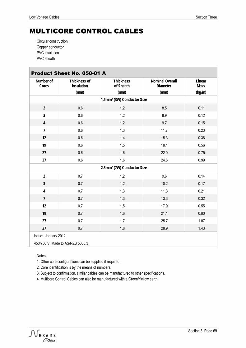
Low Voltage Cables Section Three
Section 3, Page 69
MULTICORE CONTROL CABLES Circular construction Copper conductor PVC insulation PVC sheath
Product Sheet No. 050-01 A Number of
Cores Thickness of
Insulation Thickness of Sheath
Nominal Overall Diameter
Linear Mass
(mm) (mm) (mm) (kg/m) 1.5mm2 (3W) Conductor Size
2 0.6 1.2 8.5 0.11
3 0.6 1.2 8.9 0.12
4 0.6 1.2 9.7 0.15
7 0.6 1.3 11.7 0.23
12 0.6 1.4 15.3 0.38
19 0.6 1.5 18.1 0.56
27 0.6 1.6 22.0 0.75
37 0.6 1.6 24.6 0.99
2.5mm2 (7W) Conductor Size
2 0.7 1.2 9.6 0.14
3 0.7 1.2 10.2 0.17
4 0.7 1.3 11.3 0.21
7 0.7 1.3 13.3 0.32
12 0.7 1.5 17.9 0.55
19 0.7 1.6 21.1 0.80
27 0.7 1.7 25.7 1.07
37 0.7 1.8 28.9 1.43
Issue: January 2012
450/750 V. Made to AS/NZS 5000.3
Notes: 1. Other core configurations can be supplied if required. 2. Core identification is by the means of numbers. 3. Subject to confirmation, similar cables can be manufactured to other specifications. 4. Multicore Control Cables can also be manufactured with a Green/Yellow earth.
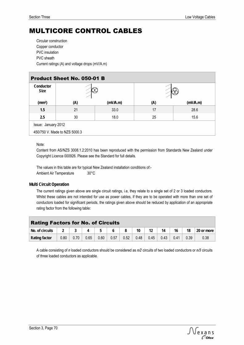
Section Three Low Voltage Cables
Section 3, Page 70
MULTICORE CONTROL CABLES Circular construction Copper conductor PVC insulation PVC sheath Current ratings (A) and voltage drops (mV/A.m)
Product Sheet No. 050-01 B Conductor
Size
(mm2) (A) (mV/A.m) (A) (mV/A.m) 1.5 21 33.0 17 28.6
2.5 30 18.0 25 15.6
Issue: January 2012
450/750 V. Made to NZS 5000.3
Note: Content from AS/NZS 3008.1.2:2010 has been reproduced with the permission from Standards New Zealand under Copyright Licence 000926. Please see the Standard for full details. The values in this table are for typical New Zealand installation conditions of:- Ambient Air Temperature 30°C
Multi Circuit Operation
The current ratings given above are single circuit ratings, i.e, they relate to a single set of 2 or 3 loaded conductors. Whilst these cables are not intended for use as power cables, if they are to be operated with more than one set of conductors loaded for significant periods, the ratings given above should be reduced by application of an appropriate rating factor from the following table:
Rating Factors for No. of Circuits No. of circuits 2 3 4 5 6 8 10 12 14 16 18 20 or more Rating factor 0.80 0.70 0.65 0.60 0.57 0.52 0.48 0.45 0.43 0.41 0.39 0.38
A cable consisting of n loaded conductors should be considered as n/2 circuits of two loaded conductors or n/3 circuits of three loaded conductors as applicable.
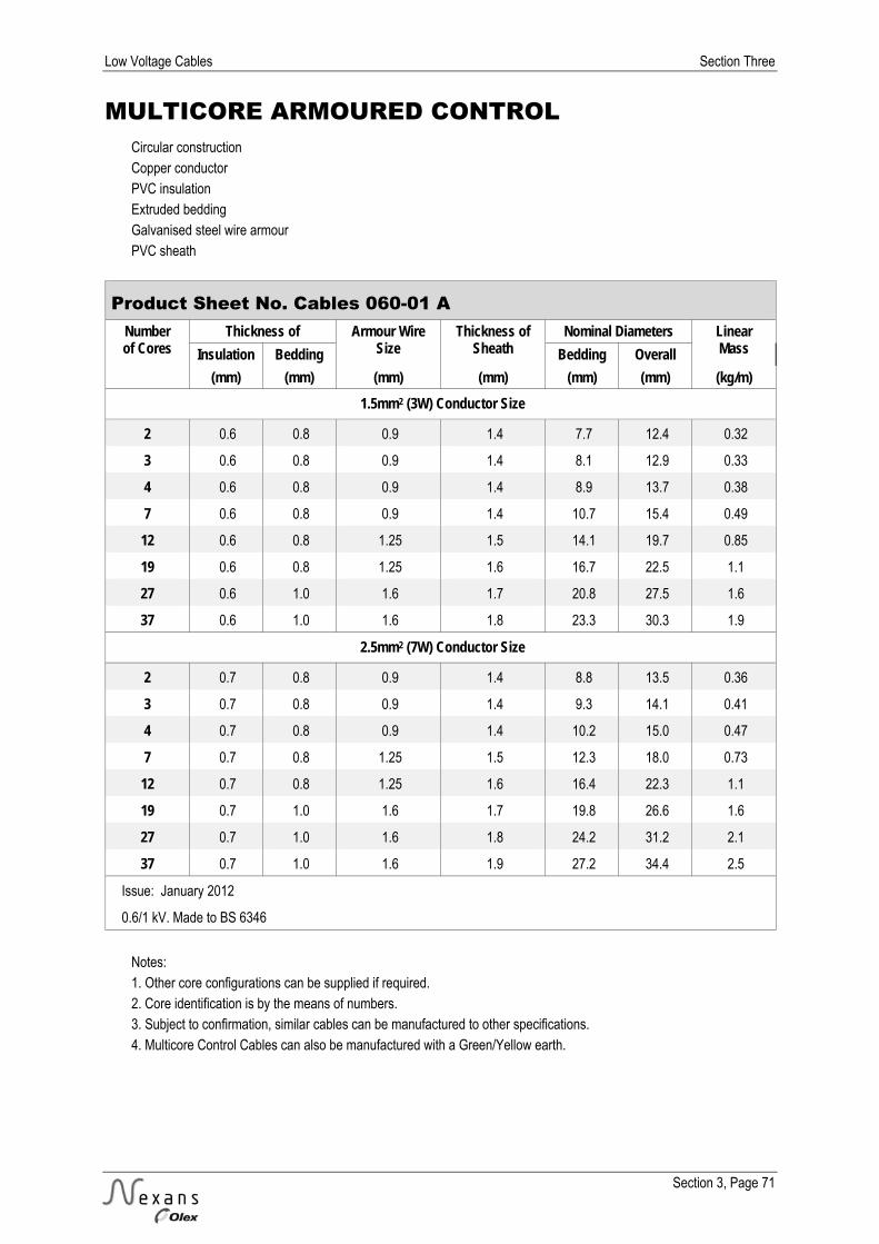
Low Voltage Cables Section Three
Section 3, Page 71
MULTICORE ARMOURED CONTROL Circular construction Copper conductor PVC insulation Extruded bedding Galvanised steel wire armour PVC sheath
Product Sheet No. Cables 060-01 A Number of Cores
Thickness of Armour Wire Size
Thickness of Sheath
Nominal Diameters Linear Mass Insulation Bedding Bedding Overall
(mm) (mm) (mm) (mm) (mm) (mm) (kg/m) 1.5mm2 (3W) Conductor Size
2 0.6 0.8 0.9 1.4 7.7 12.4 0.32
3 0.6 0.8 0.9 1.4 8.1 12.9 0.33
4 0.6 0.8 0.9 1.4 8.9 13.7 0.38
7 0.6 0.8 0.9 1.4 10.7 15.4 0.49
12 0.6 0.8 1.25 1.5 14.1 19.7 0.85
19 0.6 0.8 1.25 1.6 16.7 22.5 1.1
27 0.6 1.0 1.6 1.7 20.8 27.5 1.6
37 0.6 1.0 1.6 1.8 23.3 30.3 1.9
2.5mm2 (7W) Conductor Size
2 0.7 0.8 0.9 1.4 8.8 13.5 0.36
3 0.7 0.8 0.9 1.4 9.3 14.1 0.41
4 0.7 0.8 0.9 1.4 10.2 15.0 0.47
7 0.7 0.8 1.25 1.5 12.3 18.0 0.73
12 0.7 0.8 1.25 1.6 16.4 22.3 1.1
19 0.7 1.0 1.6 1.7 19.8 26.6 1.6
27 0.7 1.0 1.6 1.8 24.2 31.2 2.1
37 0.7 1.0 1.6 1.9 27.2 34.4 2.5
Issue: January 2012
0.6/1 kV. Made to BS 6346
Notes: 1. Other core configurations can be supplied if required. 2. Core identification is by the means of numbers. 3. Subject to confirmation, similar cables can be manufactured to other specifications. 4. Multicore Control Cables can also be manufactured with a Green/Yellow earth.
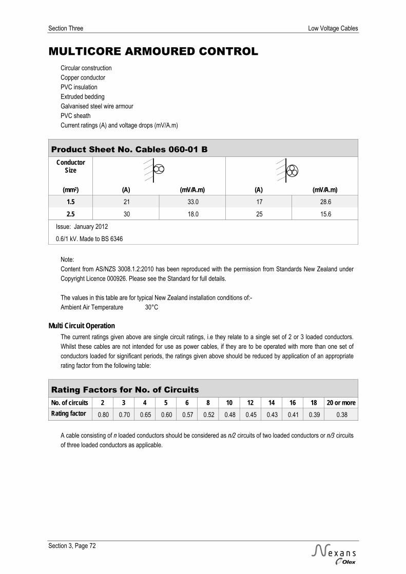
Section Three Low Voltage Cables
Section 3, Page 72
MULTICORE ARMOURED CONTROL Circular construction Copper conductor PVC insulation Extruded bedding Galvanised steel wire armour PVC sheath Current ratings (A) and voltage drops (mV/A.m)
Product Sheet No. Cables 060-01 B Conductor
Size
(mm2) (A) (mV/A.m) (A) (mV/A.m) 1.5 21 33.0 17 28.6
2.5 30 18.0 25 15.6
Issue: January 2012
0.6/1 kV. Made to BS 6346
Note: Content from AS/NZS 3008.1.2:2010 has been reproduced with the permission from Standards New Zealand under Copyright Licence 000926. Please see the Standard for full details. The values in this table are for typical New Zealand installation conditions of:- Ambient Air Temperature 30°C
Multi Circuit Operation
The current ratings given above are single circuit ratings, i.e they relate to a single set of 2 or 3 loaded conductors. Whilst these cables are not intended for use as power cables, if they are to be operated with more than one set of conductors loaded for significant periods, the ratings given above should be reduced by application of an appropriate rating factor from the following table:
Rating Factors for No. of Circuits No. of circuits 2 3 4 5 6 8 10 12 14 16 18 20 or more Rating factor 0.80 0.70 0.65 0.60 0.57 0.52 0.48 0.45 0.43 0.41 0.39 0.38
A cable consisting of n loaded conductors should be considered as n/2 circuits of two loaded conductors or n/3 circuits of three loaded conductors as applicable.
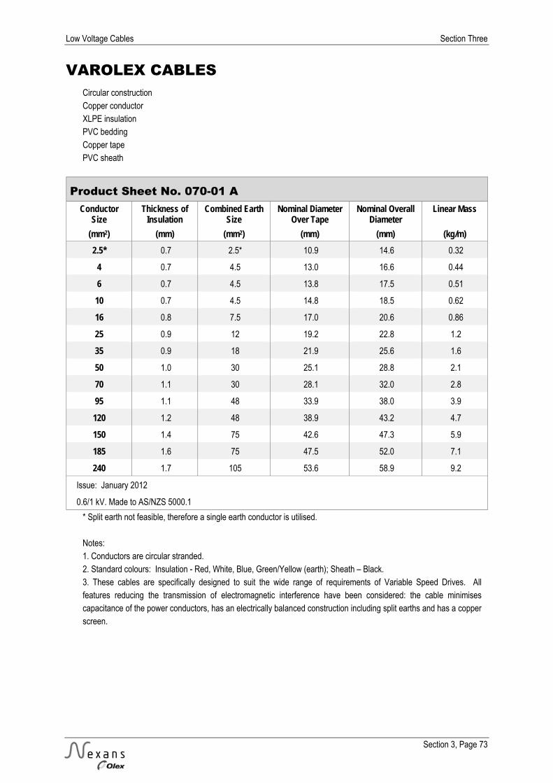
Low Voltage Cables Section Three
Section 3, Page 73
VAROLEX CABLES Circular construction Copper conductor XLPE insulation PVC bedding Copper tape PVC sheath
Product Sheet No. 070-01 A Conductor
Size Thickness of
Insulation Combined Earth
Size Nominal Diameter
Over Tape Nominal Overall
Diameter Linear Mass
(mm2) (mm) (mm2) (mm) (mm) (kg/m) 2.5* 0.7 2.5* 10.9 14.6 0.32
4 0.7 4.5 13.0 16.6 0.44
6 0.7 4.5 13.8 17.5 0.51
10 0.7 4.5 14.8 18.5 0.62
16 0.8 7.5 17.0 20.6 0.86
25 0.9 12 19.2 22.8 1.2
35 0.9 18 21.9 25.6 1.6
50 1.0 30 25.1 28.8 2.1
70 1.1 30 28.1 32.0 2.8
95 1.1 48 33.9 38.0 3.9
120 1.2 48 38.9 43.2 4.7
150 1.4 75 42.6 47.3 5.9
185 1.6 75 47.5 52.0 7.1
240 1.7 105 53.6 58.9 9.2
Issue: January 2012
0.6/1 kV. Made to AS/NZS 5000.1
* Split earth not feasible, therefore a single earth conductor is utilised. Notes: 1. Conductors are circular stranded. 2. Standard colours: Insulation - Red, White, Blue, Green/Yellow (earth); Sheath – Black. 3. These cables are specifically designed to suit the wide range of requirements of Variable Speed Drives. All features reducing the transmission of electromagnetic interference have been considered: the cable minimises capacitance of the power conductors, has an electrically balanced construction including split earths and has a copper screen.

Section Three Low Voltage Cables
Section 3, Page 74
VAROLEX CABLES Circular construction Copper conductor XLPE insulation PVC bedding Copper tape PVC sheath Current ratings (A) and voltage drops (mV/A.m)
Product Sheet No. 070-01 B Conductor
Size
(mm2) (A) (mV/A.m) (A) (mV/A.m) (A) (mV/A.m) (A) (mV/A.m)
2.5 29 16.4 31 16.4 31 16.4 31 16.4
4 39 10.2 42 10.2 40 10.2 40 10.2
6 50 6.80 53 6.80 49 6.80 49 6.80
10 68 4.05 73 4.05 67 4.05 67 4.05
16 91 2.55 97 2.55 118 2.55 87 2.55
25 122 1.61 131 1.61 153 1.61 114 1.61
35 151 1.17 162 1.17 184 1.17 139 1.17
50 185 0.868 198 0.868 218 0.868 166 0.868
70 234 0.609 252 0.609 269 0.609 207 0.609
95 289 0.450 311 0.450 323 0.450 249 0.450
120 337 0.366 363 0.366 368 0.366 289 0.366
150 385 0.307 415 0.307 412 0.307 325 0.307
185 444 0.259 480 0.259 465 0.259 372 0.259
240 527 0.216 569 0.216 539 0.216 440 0.216
Issue: January 2012
0.6/1 kV. Made to AS/NZS 5000.1
Notes: Content from AS/NZS 3008.1.2:2010 has been reproduced with the permission from Standards New Zealand under Copyright Licence 000926. Please see the Standard for full details. The values in this table are for typical New Zealand installation conditions of:- Ambient Air Temperature 30°C Soil Thermal Resistivity 1.2 K.m/W Depth of Burial 0.5 m Soil Temperature 15°C 2. The cable size should be confirmed with the Drive manufacturer before installation due to the possible derating caused by Harmonics.

Low Voltage Cables Section Three
Section 3, Page 75
FOUR CORE AL XLPE URD CABLES Circular construction Aluminium conductor XLPE insulation PVC sheath
Product Sheet No. 171-04 A Conductor Size Thickness of Insulation Thickness of Sheath Nominal Overall Diameter Linear Mass
(mm2) (mm) (mm) (mm) (kg/m) 50 1.0 1.8 29.1 0.94
70 1.1 2.0 32.0 1.3
95 1.1 2.1 36.6 1.6
120 1.2 2.3 39.8 2.0
185 1.6 2.6 49.6 3.1
240 1.7 2.8 55.3 3.9
300 1.8 3.0 60.2 4.9
Issue: January 2012
0.6/1 kV. Made to AS 4026
Notes: 1. Conductors 70 mm² and above are shaped stranded. 2. Standard Colours: Insulation – Red, White, Blue, Black; Sheath – Black. 3. Subject to confirmation, similar cables can be manufactured to other specifications.
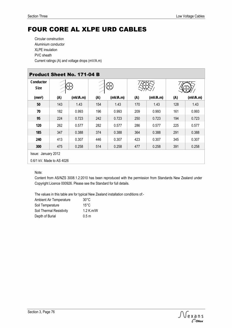
Section Three Low Voltage Cables
Section 3, Page 76
FOUR CORE AL XLPE URD CABLES Circular construction Aluminium conductor XLPE insulation PVC sheath Current ratings (A) and voltage drops (mV/A.m)
Product Sheet No. 171-04 B Conductor
Size
(mm2) (A) (mV/A.m) (A) (mV/A.m) (A) (mV/A.m) (A) (mV/A.m) 50 143 1.43 154 1.43 170 1.43 128 1.43
70 182 0.993 196 0.993 209 0.993 161 0.993
95 224 0.723 242 0.723 250 0.723 194 0.723
120 262 0.577 282 0.577 286 0.577 225 0.577
185 347 0.388 374 0.388 364 0.388 291 0.388
240 413 0.307 446 0.307 423 0.307 345 0.307
300 475 0.258 514 0.258 477 0.258 391 0.258
Issue: January 2012
0.6/1 kV. Made to AS 4026
Note: Content from AS/NZS 3008.1.2:2010 has been reproduced with the permission from Standards New Zealand under Copyright Licence 000926. Please see the Standard for full details. The values in this table are for typical New Zealand installation conditions of:- Ambient Air Temperature 30°C Soil Temperature 15°C Soil Thermal Resistivity 1.2 K.m/W Depth of Burial 0.5 m

Low Voltage Cables Section Three
Section 3, Page 77
CURRENT RATINGS Copper conductor PVC insulation Unarmoured Sheathed or unsheathed
Table 3.7 Single Conductor Cu PVC Cables - Single Phase Ratings (A) Conductor
Size (mm2)
1 18 18 15 15 13 7 24 20 23
1.5 24 24 18 21 16 9 31 25 29
2.5 34 33 26 27 23 14 43 35 40
4 46 44 35 36 29 18 56 45 52
6 58 56 46 47 38 23 71 57 64
10 79 76 62 62 50 31 94 76 85
16 105 101 82 80 64 41 134 98 109
25 141 136 111 107 86 55 174 128 142
35 174 165 136 128 103 67 209 153 171
50 213 202 166 157 125 - 248 185 205
70 271 254 210 194 155 - 305 227 251
95 336 315 262 242 193 - 365 277 306
120 392 366 304 276 220 - 416 316 348
150 450 418 351 321 257 - 466 362 389
185 523 483 408 365 292 - 528 410 449
240 626 576 488 434 348 - 612 482 519
300 725 663 564 - - - 691 546 601
400 848 771 658 - - - 784 633 683
500 988 889 762 - - - 886 714 793
630 1156 1023 878 - - - 994 825 898
Note: Content from AS/NZS 3008.1.2:2010 has been reproduced with the permission from Standards New Zealand under Copyright Licence 000926. Please see the Standard for full details. The values in this table are for typical New Zealand installation conditions of:- Ambient Air Temperature 30°C Soil Thermal Resistivity 1.2 K.m/W Soil Temperature 15°C Depth of Burial 0.5 m

Section Three Low Voltage Cables
Section 3, Page 78
CURRENT RATINGS Aluminium conductor PVC insulation Unarmoured Sheathed or unsheathed
Table 3.8 Single Conductor Al PVC Cables – Single Phase Ratings (A) Conductor
Size (mm2)
16 82 79 64 62 49 32 105 76 85
25 109 105 86 83 66 42 135 99 110
35 136 129 105 99 80 52 162 119 132
50 165 156 129 122 98 - 191 143 160
70 210 197 163 150 120 - 237 176 195
95 261 244 203 187 149 - 283 215 237
120 304 284 237 214 171 - 323 245 270
150 350 325 272 250 200 - 362 281 301
185 407 377 318 284 227 - 411 320 349
240 487 449 381 340 271 - 477 376 405
300 564 520 442 - - - 540 427 468
400 665 610 520 - - - 620 499 536
500 781 711 610 - - - 708 572 627
630 921 832 715 - - - 811 672 717
Note: Content from AS/NZS 3008.1.2:2010 has been reproduced with the permission from Standards New Zealand under Copyright Licence 000926. Please see the Standard for full details. The values in this table are for typical New Zealand installation conditions of:- Ambient Air Temperature 30°C Soil Temperature 15°C Soil Thermal Resistivity 1.2 K.m/W Depth of Burial 0.5 m

Low Voltage Cables Section Three
Section 3, Page 79
CURRENT RATINGS Copper conductor XLPE insulation Unarmoured Sheathed or unsheathed
Table 3.9 Single Conductor Cu XLPE Cables – Single Phase Ratings (A) Conductor
Size (mm2)
1 22 22 18 18 14 9 21 21 26
1.5 29 28 22 23 18 11 28 28 32
2.5 40 40 31 33 26 15 39 39 44
4 53 52 41 42 33 21 49 49 57
6 67 66 52 52 42 26 62 62 71
10 92 90 72 72 57 35 83 83 93
16 123 119 95 92 74 47 149 107 120
25 166 160 129 124 99 64 192 140 156
35 205 195 158 149 119 79 230 168 187
50 251 238 194 183 146 - 273 202 226
70 320 300 246 224 180 - 335 249 276
95 397 372 306 281 224 - 401 305 331
120 464 432 358 321 256 - 457 348 383
150 535 496 413 362 289 - 514 391 429
185 622 574 480 426 340 - 581 453 495
240 746 684 574 507 406 - 674 532 574
300 866 790 666 - - - 761 601 663
400 1015 920 779 - - - 865 699 755
500 1186 1063 903 - - - 977 791 856
630 1387 1224 1045 - - - 1098 916 995
Note: Content from AS/NZS 3008.1.2:2010 has been reproduced with the permission from Standards New Zealand under Copyright Licence 000926. Please see the Standard for full details. The values in this table are for typical New Zealand installation conditions of:- Ambient Air Temperature 30°C Soil Thermal Resistivity 1.2 K.m/W Soil Temperature 15°C Depth of Burial 0.5 m

Section Three Low Voltage Cables
Section 3, Page 80
CURRENT RATINGS Aluminium conductor XLPE insulation Unarmoured Sheathed or unsheathed
Table 3.10 Single Conductor Al XLPE Cables – Single Phase Ratings (A) Conductor
Size (mm2)
16 96 92 74 72 57 36 114 83 93
25 129 123 100 96 77 50 149 109 122
35 158 151 122 116 92 62 179 131 146
50 195 184 150 142 113 - 212 157 175
70 249 233 191 175 140 - 260 194 214
95 308 288 238 218 174 - 311 236 256
120 361 336 278 249 199 - 355 270 297
150 415 385 320 281 224 - 398 303 333
185 483 447 374 331 265 - 453 352 384
240 580 534 449 396 317 - 526 415 446
300 673 618 520 - - - 595 471 516
400 795 726 615 - - - 683 552 592
500 935 849 722 - - - 780 631 676
630 1103 994 849 - - - 891 744 792
Note: Content from AS/NZS 3008.1.2:2010 has been reproduced with the permission from Standards New Zealand under Copyright Licence 000926. Please see the Standard for full details. The values in this table are for typical New Zealand installation conditions of:- Ambient Air Temperature 30°C Soil Temperature 15°C Soil Thermal Resistivity 1.2 K.m/W Depth of Burial 0.5 m

Low Voltage Cables Section Three
Section 3, Page 81
CURRENT RATINGS Copper conductors PVC insulation Armoured or unarmoured -(including Neutral Screened cables)
Table 3.11 Two Conductor Cu PVC Cables – Single Phase Ratings (A) Conductor
Size (mm2)
1 17 16 15 13 11 8 19 19
1.5 22 21 18 16 15 10 23 23
2.5 31 30 26 23 22 15 33 33
4 42 39 34 31 27 19 43 43
6 52 50 44 40 35 25 55 55
10 73 68 59 55 48 34 73 73
16 97 91 78 73 62 46 125 95
25 129 122 103 97 82 60 162 123
35 158 149 128 120 103 74 196 150
50 194 181 152 145 122 - 232 178
70 245 229 194 184 155 - 285 222
95 302 283 233 226 186 - 342 267
120 350 328 275 262 219 - 391 310
150 400 374 309 300 247 - 438 349
185 459 430 357 344 285 - 494 399
240 544 508 415 407 332 - 572 463
300 624 583 483 466 388 - 645 531
400 719 671 549 537 440 - 729 603
Note: Content from AS/NZS 3008.1.2:2010 has been reproduced with the permission from Standards New Zealand under Copyright Licence 000926. Please see the Standard for full details. The values in this table are for typical New Zealand installation conditions of:- Ambient Air Temperature 30°C Soil Temperature 15°C Soil Thermal Resistivity 1.2 K.m/W Depth of Burial 0.5 m
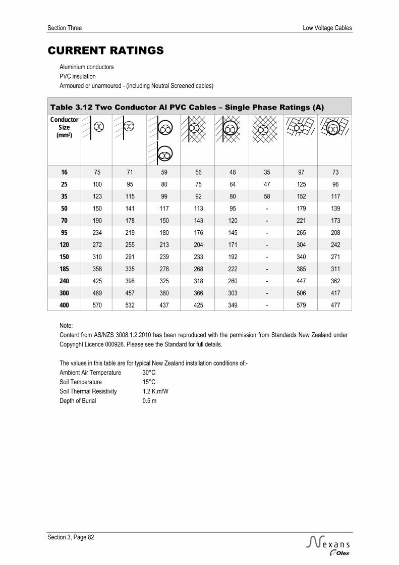
Section Three Low Voltage Cables
Section 3, Page 82
CURRENT RATINGS Aluminium conductors PVC insulation Armoured or unarmoured - (including Neutral Screened cables)
Table 3.12 Two Conductor Al PVC Cables – Single Phase Ratings (A) Conductor
Size (mm2)
16 75 71 59 56 48 35 97 73
25 100 95 80 75 64 47 125 96
35 123 115 99 92 80 58 152 117
50 150 141 117 113 95 - 179 139
70 190 178 150 143 120 - 221 173
95 234 219 180 176 145 - 265 208
120 272 255 213 204 171 - 304 242
150 310 291 239 233 192 - 340 271
185 358 335 278 268 222 - 385 311
240 425 398 325 318 260 - 447 362
300 489 457 380 366 303 - 506 417
400 570 532 437 425 349 - 579 477
Note: Content from AS/NZS 3008.1.2:2010 has been reproduced with the permission from Standards New Zealand under Copyright Licence 000926. Please see the Standard for full details. The values in this table are for typical New Zealand installation conditions of:- Ambient Air Temperature 30°C Soil Temperature 15°C Soil Thermal Resistivity 1.2 K.m/W Depth of Burial 0.5 m

Low Voltage Cables Section Three
Section 3, Page 83
CURRENT RATINGS Copper conductors XLPE insulation Armoured or unarmoured - (including Neutral Screened cables)
Table 3.13 Two Conductor Cu XLPE Cables – Single Phase Ratings (A) Conductor
Size (mm2)
1 20 19 18 15 10 20 20
1.5 26 24 22 20 12 26 26
2.5 37 34 31 28 18 36 36
4 50 46 41 36 23 48 48
6 63 58 51 46 30 60 60
10 86 80 69 64 40 80 80
16 114 107 90 86 54 141 105
25 154 144 121 116 73 182 137
35 190 178 145 142 89 219 165
50 232 217 178 174 - 261 198
70 295 275 220 220 - 321 244
95 364 340 275 272 - 385 299
120 424 395 314 316 - 439 340
150 485 452 365 361 - 492 391
185 560 520 415 417 - 556 442
240 664 618 493 494 - 645 519
300 763 710 575 568 - 728 597
400 884 820 656 656 - 825 677
Note: Content from AS/NZS 3008.1.2:2010 has been reproduced with the permission from Standards New Zealand under Copyright Licence 000926. Please see the Standard for full details. The values in this table are for typical New Zealand installation conditions of:- Ambient Air Temperature 30°C Soil Temperature 15°C Soil Thermal Resistivity 1.2 K.m/W Depth of Burial 0.5 m

Section Three Low Voltage Cables
Section 3, Page 84
CURRENT RATINGS Aluminium conductors XLPE insulation Armoured or unarmoured - (including Neutral Screened cables)
Table 3. 14 Two Conductor Al XLPE Cables – Single Phase Ratings (A) Conductor
Size (mm2)
16 89 83 69 66 42 109 80
25 120 112 94 89 56 141 106
35 147 138 112 110 69 170 127
50 179 168 139 134 - 202 154
70 229 213 171 171 - 249 189
95 283 263 213 211 - 299 231
120 329 307 244 245 - 341 264
150 376 351 283 281 - 382 303
185 436 406 322 325 - 433 345
240 519 483 385 386 - 504 406
300 598 556 451 444 - 570 468
400 700 649 519 519 - 653 536
Note: Content from AS/NZS 3008.1.2:2010 has been reproduced with the permission from Standards New Zealand under Copyright Licence 000926. Please see the Standard for full details. The values in this table are for typical New Zealand installation conditions of:- Ambient Air Temperature 30°C Soil Temperature 15°C Soil Thermal Resistivity 1.2 K.m/W Depth of Burial 0.5 m

Low Voltage Cables Section Three
Section 3, Page 85
CURRENT RATINGS Copper conductor PVC insulation Unarmoured Sheathed or unsheathed
Table 3.15 Single Conductor Cu PVC Cables – Three Phase Ratings (A) Conductor
Size (mm2)
1 18 16 15 14 11 7 18 18 21
1.5 23 19 18 17 14 9 22 22 26
2.5 33 29 26 24 19 14 30 30 36
4 43 38 35 32 26 18 40 40 47
6 56 48 46 40 32 23 50 50 58
10 76 66 62 54 42 31 65 65 77
16 101 88 82 71 57 41 114 86 99
25 137 117 111 92 73 55 147 110 129
35 169 145 136 114 91 67 176 134 154
50 206 178 166 136 108 - 209 158 185
70 262 225 210 173 139 - 256 198 226
95 327 280 262 209 168 - 307 239 275
120 382 327 304 247 197 - 349 277 311
150 439 376 351 278 222 - 392 311 349
185 510 437 407 324 259 - 442 358 402
240 610 521 486 377 302 - 512 415 464
300 707 603 561 442 355 - 576 477 537
400 828 701 653 504 402 - 652 541 608
500 964 809 754 596 477 - 735 628 705
630 1129 931 866 670 537 - 823 703 795
Note: Content from AS/NZS 3008.1.2:2010 has been reproduced with the permission from Standards New Zealand under Copyright Licence 000926. Please see the Standard for full details. The values in this table are for typical New Zealand installation conditions of:- Ambient Air Temperature 30°C Soil Thermal Resistivity 1.2 K.m/W Soil Temperature 15°C Depth of Burial 0.5 m

Section Three Low Voltage Cables
Section 3, Page 86
CURRENT RATINGS Aluminium conductor PVC insulation Unarmoured Sheathed or unsheathed
Table 3.16 Single Conductor Al PVC Cables – Three Phase Ratings (A) Conductor
Size (mm2)
16 79 67 64 55 44 32 89 66 77
25 106 91 86 72 57 43 114 86 100
35 131 112 105 89 71 52 136 103 119
50 161 138 129 105 84 - 162 123 144
70 204 174 163 135 107 - 199 154 175
95 253 218 203 162 130 - 238 185 213
120 296 254 237 193 154 - 272 216 242
150 340 292 272 217 173 - 304 242 271
185 396 341 317 253 202 - 344 278 312
240 475 408 381 307 236 - 400 325 362
300 551 473 441 348 278 - 453 375 418
400 650 556 519 400 320 - 518 430 477
500 763 651 606 480 384 - 591 505 558
630 899 762 709 548 439 - 673 575 636
Note: Content from AS/NZS 3008.1.2:2010 has been reproduced with the permission from Standards New Zealand under Copyright Licence 000926. Please see the Standard for full details. The values in this table are for typical New Zealand installation conditions of:- Ambient Air Temperature 30°C Soil Temperature 15°C Soil Thermal Resistivity 1.2 K.m/W Depth of Burial 0.5 m

Low Voltage Cables Section Three
Section 3, Page 87
CURRENT RATINGS Copper conductor XLPE insulation Unarmoured Sheathed or unsheathed
Table 3.17 Single Conductor Cu XLPE Cables – Three Phase Ratings (A) Conductor
Size (mm2)
1 21 18 18 17 13 9 19 19 24
1.5 28 23 22 20 17 11 24 24 29
2.5 39 33 31 28 22 15 33 33 41
4 51 44 41 36 29 21 43 43 52
6 65 55 52 46 37 26 54 54 64
10 89 76 72 62 50 35 72 72 85
16 119 101 95 79 64 47 125 92 108
25 161 138 129 107 85 64 162 121 141
35 198 169 158 132 106 79 193 147 169
50 243 207 194 157 125 - 229 174 203
70 310 264 246 201 161 - 280 217 248
95 385 328 306 242 194 - 335 261 295
120 451 384 358 287 230 - 381 304 342
150 519 443 413 325 260 - 428 342 383
185 616 515 479 369 295 - 484 388 442
240 726 616 573 439 352 - 560 456 510
300 843 713 662 516 413 - 630 525 591
400 989 832 772 587 470 - 715 596 670
500 1156 961 893 696 557 - 805 693 756
630 1353 1111 1032 785 628 - 902 778 877
Note: Content from AS/NZS 3008.1.2:2010 has been reproduced with the permission from Standards New Zealand under Copyright Licence 000926. Please see the Standard for full details. The values in this table are for typical New Zealand installation conditions of:- Ambient Air Temperature 30°C Soil Thermal Resistivity 1.2 K.m/W Soil Temperature 15°C Depth of Burial 0.5 m
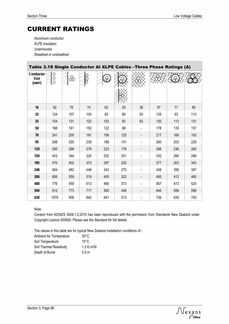
Section Three Low Voltage Cables
Section 3, Page 88
CURRENT RATINGS Aluminium conductor XLPE insulation Unarmoured Sheathed or unsheathed
Table 3.18 Single Conductor Al XLPE Cables –Three Phase Ratings (A) Conductor
Size (mm2)
16 92 78 74 62 50 36 97 71 85
25 124 107 100 83 66 50 125 93 110
35 154 131 122 102 83 62 150 113 131
50 188 161 150 122 98 - 178 135 157
70 241 205 191 156 125 - 217 169 193
95 298 255 238 188 151 - 260 203 229
120 350 298 278 223 178 - 296 236 265
150 403 344 320 252 201 - 332 266 296
185 470 402 373 287 230 - 377 303 343
240 564 482 448 343 275 - 438 356 397
300 656 559 519 405 323 - 495 412 460
400 776 659 613 466 373 - 567 473 525
500 912 773 717 560 448 - 646 556 598
630 1076 906 842 641 513 - 736 635 700
Note: Content from AS/NZS 3008.1.2:2010 has been reproduced with the permission from Standards New Zealand under Copyright Licence 000926. Please see the Standard for full details. The values in this table are for typical New Zealand installation conditions of:- Ambient Air Temperature 30°C Soil Temperature 15°C Soil Thermal Resistivity 1.2 K.m/W Depth of Burial 0.5 m

Low Voltage Cables Section Three
Section 3, Page 89
CURRENT RATINGS Copper conductors PVC insulation Armoured or unarmoured - (including Neutral Screened cables)
Table 3.19 Three & Four Conductor Cu PVC Cables
– Three Phase Ratings (A) Conductor
Size (mm2)
1 15 14 13 10 10 7 15 15
1.5 18 17 16 14 13 9 20 20
2.5 26 25 23 19 18 13 28 28
4 35 33 29 26 23 17 36 36
6 46 42 38 34 30 22 46 46
10 62 58 50 47 40 29 61 61
16 82 78 66 62 54 39 106 80
25 111 104 87 83 68 52 138 103
35 137 128 107 103 86 64 165 125
50 166 156 128 124 101 - 196 150
70 211 196 162 157 130 - 241 187
95 260 243 202 194 162 - 289 229
120 302 282 230 226 185 - 330 261
150 345 321 260 258 207 - 370 293
185 397 369 300 295 241 - 417 334
240 470 437 360 350 288 - 482 395
300 538 499 - - - - 542 444
400 620 575 - - - - 613 515
Note: Content from AS/NZS 3008.1.2:2010 has been reproduced with the permission from Standards New Zealand under Copyright Licence 000926. Please see the Standard for full details. The values in this table are for typical New Zealand installation conditions of:- Ambient Air Temperature 30°C Soil Temperature 15°C Soil Thermal Resistivity 1.2 K.m/W Depth of Burial 0.5 m

Section Three Low Voltage Cables
Section 3, Page 90
CURRENT RATINGS Aluminium conductors PVC insulation Armoured or unarmoured - (including Neutral Screened cables)
Table 3.20 Three & Four Conductor Al PVC Cables
– Three Phase Ratings (A) Conductor
Size (mm2)
16 64 60 51 48 41 30 83 62
25 86 81 67 65 54 40 107 80
35 106 99 83 79 66 49 129 98
50 129 121 99 97 79 - 152 116
70 163 153 127 122 100 - 187 145
95 202 188 156 150 125 - 224 177
120 235 219 179 176 144 - 256 202
150 268 250 202 200 162 - 287 228
185 310 288 235 231 188 - 326 261
240 368 343 283 274 226 - 378 309
300 424 393 - - - - 427 350
400 495 458 - - - - 488 411
Note: Content from AS/NZS 3008.1.2:2010 has been reproduced with the permission from Standards New Zealand under Copyright Licence 000926. Please see the Standard for full details. The values in this table are for typical New Zealand installation conditions of:- Ambient Air Temperature 30°C Soil Temperature 15°C Soil Thermal Resistivity 1.2 K.m/W Depth of Burial 0.5 m

Low Voltage Cables Section Three
Section 3, Page 91
CURRENT RATINGS Copper conductors XLPE insulation Armoured or unarmoured - (including Neutral Screened cables)
Table 3.21 Three & Four Conductor Cu XLPE Cables
– Three Phase Ratings (A) Conductor
Size (mm2)
1 18 15 14 13 8 17 17
1.5 22 21 18 17 10 21 21
2.5 31 29 26 23 14 31 31
4 42 39 33 31 20 40 40
6 53 50 42 40 24 49 49
10 73 68 58 54 34 67 67
16 97 91 75 73 45 118 87
25 131 122 100 98 62 153 114
35 162 151 125 121 76 184 139
50 198 185 150 147 - 218 166
70 252 234 190 187 - 269 207
95 311 289 230 231 - 323 249
120 363 337 271 270 - 368 289
150 415 385 305 308 - 412 325
185 480 444 354 355 - 465 372
240 569 527 425 421 - 539 440
300 653 604 - - - 607 495
400 754 695 - - - 685 561
Note: Content from AS/NZS 3008.1.2:2010 has been reproduced with the permission from Standards New Zealand under Copyright Licence 000926. Please see the Standard for full details. The values in this table are for typical New Zealand installation conditions of:- Ambient Air Temperature 30°C Soil Temperature 15°C Soil Thermal Resistivity 1.2 K.m/W Depth of Burial 0.5 m

Section Three Low Voltage Cables
Section 3, Page 92
CURRENT RATINGS Aluminium conductors XLPE insulation Armoured or unarmoured - (including Neutral Screened cables)
Table 3.22 Three & Four Conductor Al XLPE Cables
– Three Phase Ratings (A) Conductor
Size (mm2)
16 75 70 58 56 35 91 67
25 102 95 78 76 47 119 89
35 125 117 97 94 58 142 108
50 154 143 116 114 - 170 128
70 196 182 147 145 - 209 161
95 242 224 178 179 - 250 194
120 282 262 211 209 - 286 225
150 322 299 238 240 - 320 253
185 374 347 276 277 - 364 291
240 446 413 333 330 - 423 345
300 514 475 - - - 477 391
400 601 554 - - - 546 446
Note: Content from AS/NZS 3008.1.2:2010 has been reproduced with the permission from Standards New Zealand under Copyright Licence 000926. Please see the Standard for full details. The values in this table are for typical New Zealand installation conditions of:- Ambient Air Temperature 30°C Soil Temperature 15°C Soil Thermal Resistivity 1.2 K.m/W Depth of Burial 0.5 m
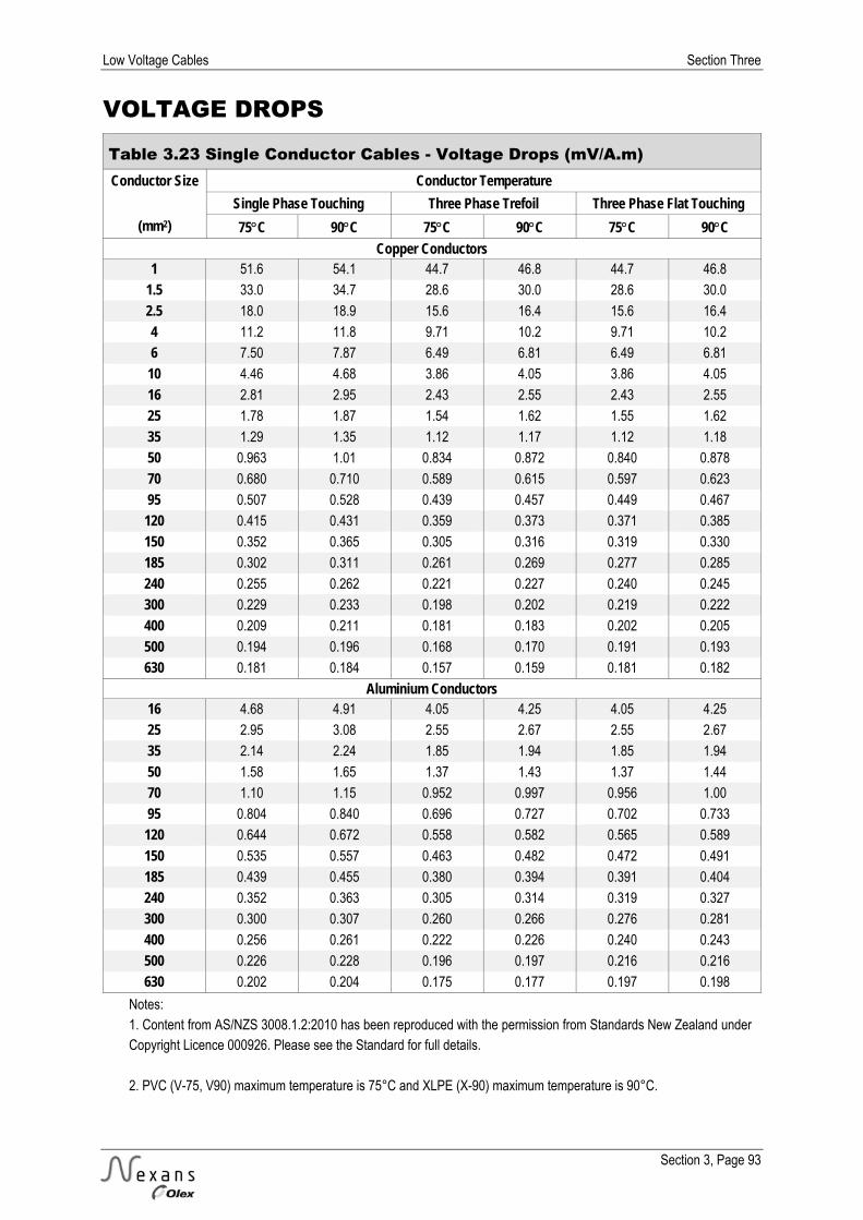
Low Voltage Cables Section Three
Section 3, Page 93
VOLTAGE DROPS Table 3.23 Single Conductor Cables - Voltage Drops (mV/A.m) Conductor Size Conductor Temperature
(mm2)
Single Phase Touching Three Phase Trefoil Three Phase Flat Touching 75C 90C 75C 90C 75C 90C
Copper Conductors 1 51.6 54.1 44.7 46.8 44.7 46.8
1.5 33.0 34.7 28.6 30.0 28.6 30.0
2.5 18.0 18.9 15.6 16.4 15.6 16.4
4 11.2 11.8 9.71 10.2 9.71 10.2
6 7.50 7.87 6.49 6.81 6.49 6.81
10 4.46 4.68 3.86 4.05 3.86 4.05
16 2.81 2.95 2.43 2.55 2.43 2.55
25 1.78 1.87 1.54 1.62 1.55 1.62
35 1.29 1.35 1.12 1.17 1.12 1.18
50 0.963 1.01 0.834 0.872 0.840 0.878
70 0.680 0.710 0.589 0.615 0.597 0.623
95 0.507 0.528 0.439 0.457 0.449 0.467
120 0.415 0.431 0.359 0.373 0.371 0.385
150 0.352 0.365 0.305 0.316 0.319 0.330
185 0.302 0.311 0.261 0.269 0.277 0.285
240 0.255 0.262 0.221 0.227 0.240 0.245
300 0.229 0.233 0.198 0.202 0.219 0.222
400 0.209 0.211 0.181 0.183 0.202 0.205
500 0.194 0.196 0.168 0.170 0.191 0.193
630 0.181 0.184 0.157 0.159 0.181 0.182
Aluminium Conductors 16 4.68 4.91 4.05 4.25 4.05 4.25
25 2.95 3.08 2.55 2.67 2.55 2.67
35 2.14 2.24 1.85 1.94 1.85 1.94
50 1.58 1.65 1.37 1.43 1.37 1.44
70 1.10 1.15 0.952 0.997 0.956 1.00
95 0.804 0.840 0.696 0.727 0.702 0.733
120 0.644 0.672 0.558 0.582 0.565 0.589
150 0.535 0.557 0.463 0.482 0.472 0.491
185 0.439 0.455 0.380 0.394 0.391 0.404
240 0.352 0.363 0.305 0.314 0.319 0.327
300 0.300 0.307 0.260 0.266 0.276 0.281
400 0.256 0.261 0.222 0.226 0.240 0.243
500 0.226 0.228 0.196 0.197 0.216 0.216
630 0.202 0.204 0.175 0.177 0.197 0.198
Notes: 1. Content from AS/NZS 3008.1.2:2010 has been reproduced with the permission from Standards New Zealand under Copyright Licence 000926. Please see the Standard for full details. 2. PVC (V-75, V90) maximum temperature is 75°C and XLPE (X-90) maximum temperature is 90°C.
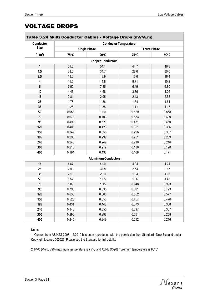
Section Three Low Voltage Cables
Section 3, Page 94
VOLTAGE DROPS
Table 3.24 Multi Conductor Cables - Voltage Drops (mV/A.m) Conductor
Size Conductor Temperature
Single Phase Three Phase (mm2) 75C 90C 75C 90C
Copper Conductors 1 51.6 54.1 44.7 46.8
1.5 33.0 34.7 28.6 30.0
2.5 18.0 18.9 15.6 16.4
4 11.2 11.8 9.71 10.2
6 7.50 7.85 6.49 6.80
10 4.46 4.68 3.86 4.05
16 2.81 2.95 2.43 2.55
25 1.78 1.86 1.54 1.61
35 1.28 1.35 1.11 1.17
50 0.958 1.00 0.829 0.868
70 0.673 0.703 0.583 0.609
95 0.498 0.520 0.431 0.450
120 0.405 0.423 0.351 0.366
150 0.342 0.355 0.296 0.307
185 0.290 0.299 0.251 0.259
240 0.243 0.249 0.210 0.216
300 0.215 0.219 0.186 0.190
400 0.194 0.198 0.168 0.171
Aluminium Conductors 16 4.67 4.90 4.04 4.24
25 2.93 3.08 2.54 2.67
35 2.13 2.23 1.84 1.93
50 1.57 1.65 1.36 1.43
70 1.09 1.15 0.948 0.993
95 0.798 0.835 0.691 0.723
120 0.638 0.666 0.552 0.577
150 0.528 0.550 0.457 0.476
185 0.431 0.448 0.373 0.388
240 0.343 0.355 0.297 0.307
300 0.290 0.298 0.251 0.258
400 0.245 0.249 0.212 0.216
Notes: 1. Content from AS/NZS 3008.1.2:2010 has been reproduced with the permission from Standards New Zealand under Copyright Licence 000926. Please see the Standard for full details. 2. PVC (V-75, V90) maximum temperature is 75°C and XLPE (X-90) maximum temperature is 90°C.
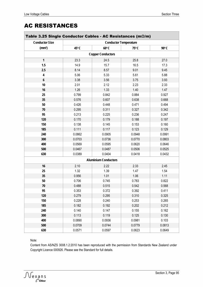
Low Voltage Cables Section Three
Section 3, Page 95
AC RESISTANCES
Table 3.25 Single Conductor Cables - AC Resistances (mΩ/m) Conductor Size Conductor Temperature
(mm2) 45C 60C 75C 90C Copper Conductors
1 23.3 24.5 25.8 27.0
1.5 14.9 15.7 16.5 17.3
2.5 8.14 8.57 9.01 9.45
4 5.06 5.33 5.61 5.88
6 3.38 3.56 3.75 3.93
10 2.01 2.12 2.23 2.33
16 1.26 1.33 1.40 1.47
25 0.799 0.842 0.884 0.927
35 0.576 0.607 0.638 0.668
50 0.426 0.448 0.471 0.494
70 0.295 0.311 0.327 0.342
95 0.213 0.225 0.236 0.247
120 0.170 0.179 0.188 0.197
150 0.138 0.145 0.153 0.160
185 0.111 0.117 0.123 0.129
240 0.0862 0.0905 0.0948 0.0991
300 0.0703 0.0736 0.0770 0.0803
400 0.0569 0.0595 0.0620 0.0646
500 0.0467 0.0487 0.0506 0.0525
630 0.0389 0.0404 0.0418 0.0432
Aluminium Conductors 16 2.10 2.22 2.33 2.45
25 1.32 1.39 1.47 1.54
35 0.956 1.01 1.06 1.11
50 0.706 0.745 0.783 0.822
70 0.488 0.515 0.542 0.568
95 0.353 0.372 0.392 0.411
120 0.279 0.295 0.310 0.325
150 0.228 0.240 0.253 0.265
185 0.182 0.192 0.202 0.212
240 0.140 0.147 0.155 0.162
300 0.113 0.119 0.125 0.130
400 0.0890 0.0936 0.0981 0.103
500 0.0709 0.0744 0.0779 0.0813
630 0.0571 0.0597 0.0623 0.0649
Note: Content from AS/NZS 3008.1.2:2010 has been reproduced with the permission from Standards New Zealand under Copyright Licence 000926. Please see the Standard for full details.

Section Three Low Voltage Cables
Section 3, Page 96
AC RESISTANCES Table 3.26 Multi Conductor Cables - AC Resistances (mΩ/m) Conductor
Size Conductor Temperature
Circular Conductors Shaped Conductors (mm2) 45C 60C 75C 90C 45C 60C 75C 90C
Copper Conductors 1 23.3 24.5 25.8 27.0 - - - -
1.5 14.9 15.7 16.5 17.3 - - - -
2.5 8.14 8.57 9.01 9.45 - - - -
4 5.06 5.33 5.61 5.88 - - - -
6 3.38 3.56 3.75 3.93 - - - -
10 2.01 2.12 2.23 2.33 - - - -
16 1.26 1.33 1.40 1.47 - - - -
25 0.799 0.842 0.884 0.927 0.799 0.842 0.884 0.927
35 0.576 0.607 0.638 0.669 0.576 0.607 0.638 0.669
50 0.426 0.449 0.471 0.494 0.426 0.448 0.471 0.494
70 0.295 0.311 0.327 0.343 0.295 0.311 0.327 0.342
95 0.214 0.225 0.236 0.248 0.213 0.224 0.236 0.247
120 0.170 0.179 0.188 0.197 0.170 0.179 0.187 0.196
150 0.139 0.146 0.153 0.160 0.138 0.145 0.153 0.160
185 0.112 0.118 0.123 0.129 0.111 0.117 0.123 0.128
240 0.0870 0.0912 0.0955 0.0998 0.0859 0.0902 0.0945 0.0988
300 0.0712 0.0745 0.0778 0.0812 0.0698 0.0732 0.0766 0.0800
400 0.0580 0.0605 0.0630 0.0656 0.0563 0.0589 0.0615 0.0641
Aluminium Conductors
16 2.10 2.22 2.33 2.45 2.10 2.22 2.33 2.45
25 1.32 1.39 1.47 1.54 1.32 1.39 1.47 1.54
35 0.956 1.01 1.06 1.11 0.956 1.01 1.06 1.11
50 0.706 0.745 0.784 0.822 0.706 0.745 0.783 0.822
70 0.488 0.515 0.542 0.569 0.488 0.515 0.542 0.568
95 0.353 0.373 0.392 0.411 0.353 0.372 0.392 0.411
120 0.280 0.295 0.310 0.325 0.279 0.295 0.310 0.325
150 0.228 0.241 0.253 0.265 0.228 0.240 0.253 0.265
185 0.182 0.192 0.202 0.212 0.182 0.192 0.202 0.211
240 0.140 0.148 0.155 0.162 0.139 0.147 0.154 0.162
300 0.113 0.119 0.125 0.131 0.112 0.118 0.124 0.130
400 0.0897 0.0943 0.0988 0.103 0.0886 0.0932 0.0978 0.102
Note: Content from AS/NZS 3008.1.2:2010 has been reproduced with the permission from Standards New Zealand under Copyright Licence 000926. Please see the Standard for full details.
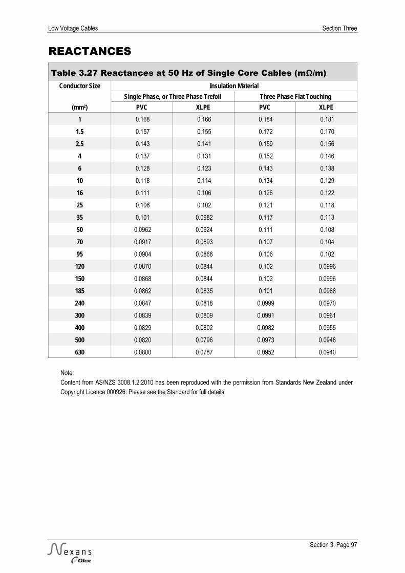
Low Voltage Cables Section Three
Section 3, Page 97
REACTANCES Table 3.27 Reactances at 50 Hz of Single Core Cables (mΩ/m)
Conductor Size Insulation Material Single Phase, or Three Phase Trefoil Three Phase Flat Touching
(mm2) PVC XLPE PVC XLPE 1 0.168 0.166 0.184 0.181
1.5 0.157 0.155 0.172 0.170
2.5 0.143 0.141 0.159 0.156
4 0.137 0.131 0.152 0.146
6 0.128 0.123 0.143 0.138
10 0.118 0.114 0.134 0.129
16 0.111 0.106 0.126 0.122
25 0.106 0.102 0.121 0.118
35 0.101 0.0982 0.117 0.113
50 0.0962 0.0924 0.111 0.108
70 0.0917 0.0893 0.107 0.104
95 0.0904 0.0868 0.106 0.102
120 0.0870 0.0844 0.102 0.0996
150 0.0868 0.0844 0.102 0.0996
185 0.0862 0.0835 0.101 0.0988
240 0.0847 0.0818 0.0999 0.0970
300 0.0839 0.0809 0.0991 0.0961
400 0.0829 0.0802 0.0982 0.0955
500 0.0820 0.0796 0.0973 0.0948
630 0.0800 0.0787 0.0952 0.0940
Note: Content from AS/NZS 3008.1.2:2010 has been reproduced with the permission from Standards New Zealand under Copyright Licence 000926. Please see the Standard for full details.

Section Three Low Voltage Cables
Section 3, Page 98
REACTANCES Table 3.28 Reactances at 50 Hz of Multicore Cables (mΩ/m) Conductor Size Insulation Material
Circular Conductors Shaped Conductors (mm2) PVC XLPE PVC XLPE
1 0.119 0.114 - -
1.5 0.111 0.107 - -
2.5 0.102 0.0988 - -
4 0.102 0.0930 - -
6 0.0967 0.0887 - -
10 0.0906 0.0840 - -
16 0.0861 0.0805 - -
25 0.0853 0.0808 0.0786 0.0744
35 0.0826 0.0786 0.0761 0.0725
50 0.0797 0.0751 0.0734 0.0692
70 0.0770 0.0741 0.0710 0.0683
95 0.0766 0.0725 0.0706 0.0668
120 0.0743 0.0713 0.0685 0.0657
150 0.0745 0.0718 0.0687 0.0662
185 0.0744 0.0720 0.0686 0.0663
240 0.0735 0.0709 0.0678 0.0653
300 0.0732 0.0704 0.0675 0.0649
400 0.0728 0.0702 0.0671 0.0647
Note: Content from AS/NZS 3008.1.2:2010 has been reproduced with the permission from Standards New Zealand under Copyright Licence 000926. Please see the Standard for full details.

Low Voltage Cables Section Three
Section 3, Page 99
VOLTAGE DROP GRAPHS This information seeks to provide a quick means of selecting the size of cable to comply with voltage drop requirements.
The range of graphs is intended to cover normal stock cables available from Nexans Olex.
Basis of Graphs © Copyright Standards New Zealand 2012. Content in the graphs and current rating values are derived from AS/NZS 3008.1.2:2010 and has been reproduced or adapted with permission from Standards New Zealand under Copyright Licence 000926. Please refer to the complete Standard for full details available for purchase from Standards New Zealand at www.standards.co.nz.
New Zealand regulations allow a maximum voltage drop of 5% from the point of supply to anywhere in the installation.
The graphs have been drawn for a voltage drop of 2.5% with the standard New Zealand supply voltages. i.e. 5.75 volts for single phase 230 volt systems, or 10 volts for three phase 400 volt systems.
For installations involving mains, sub-mains and circuits, larger cable sizes may be necessary than these graphs show, to keep the voltage drop in the complete installation under the maximum allowed by the regulations.
The graphs are drawn to allow for the highest current with the cable installed under any of the standard installation conditions as per this section or the Nexans Olex New Zealand Handbook
It is important to check that the cable will carry the required maximum load under the particular conditions of the actual installation proposed.
In cases where the load current is significantly less than the maximum for the cable, the temperature of the conductor will be less than the maximum allowed. Hence the actual voltage drop will be lower than that shown by the graphs.
Use of the Graphs Assuming that the load current and length of run are known.
1. Select the graph appropriate for the cable under consideration, whether single phase or three phase, and for single core cables whether laid in trefoil or flat configuration.
2. Locate the intersecting point on the graph for the required values of load current and length of run.
3. For this point read the conductor size indicated for the graph line either on or above the point.
4. Check that the required load current is within the maximum for the cable size under the intended installation conditions, using either this section, the Nexans Olex New Zealand Handbook or AS/NZS 3008.1.2.
Disclaimer Nexans Olex New Zealand Limited has taken every precaution to ensure that the information contained in these graphs is in line with the requirements of the appropriate New Zealand Standards and correct electrical practice. However, we accept no liability of any kind with respect to the information presented here.
It is the responsibility of the Electrician signing the Certificate of Compliance to ensure that all the requirements of the Wiring Regulations are met.
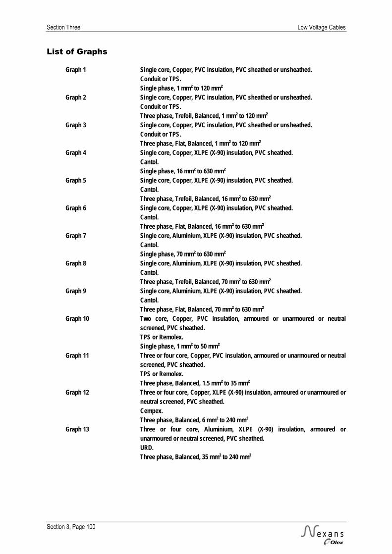
Section Three Low Voltage Cables
Section 3, Page 100
List of Graphs
Graph 1 Single core, Copper, PVC insulation, PVC sheathed or unsheathed. Conduit or TPS. Single phase, 1 mm² to 120 mm² Graph 2 Single core, Copper, PVC insulation, PVC sheathed or unsheathed. Conduit or TPS. Three phase, Trefoil, Balanced, 1 mm² to 120 mm² Graph 3 Single core, Copper, PVC insulation, PVC sheathed or unsheathed. Conduit or TPS. Three phase, Flat, Balanced, 1 mm² to 120 mm² Graph 4 Single core, Copper, XLPE (X-90) insulation, PVC sheathed. Cantol. Single phase, 16 mm² to 630 mm² Graph 5 Single core, Copper, XLPE (X-90) insulation, PVC sheathed. Cantol. Three phase, Trefoil, Balanced, 16 mm² to 630 mm² Graph 6 Single core, Copper, XLPE (X-90) insulation, PVC sheathed. Cantol. Three phase, Flat, Balanced, 16 mm² to 630 mm² Graph 7 Single core, Aluminium, XLPE (X-90) insulation, PVC sheathed. Cantol. Single phase, 70 mm² to 630 mm² Graph 8 Single core, Aluminium, XLPE (X-90) insulation, PVC sheathed. Cantol. Three phase, Trefoil, Balanced, 70 mm² to 630 mm² Graph 9 Single core, Aluminium, XLPE (X-90) insulation, PVC sheathed. Cantol. Three phase, Flat, Balanced, 70 mm² to 630 mm² Graph 10 Two core, Copper, PVC insulation, armoured or unarmoured or neutral
screened, PVC sheathed. TPS or Remolex. Single phase, 1 mm² to 50 mm² Graph 11 Three or four core, Copper, PVC insulation, armoured or unarmoured or neutral
screened, PVC sheathed. TPS or Remolex. Three phase, Balanced, 1.5 mm² to 35 mm² Graph 12 Three or four core, Copper, XLPE (X-90) insulation, armoured or unarmoured or
neutral screened, PVC sheathed. Cempex. Three phase, Balanced, 6 mm² to 240 mm² Graph 13 Three or four core, Aluminium, XLPE (X-90) insulation, armoured or
unarmoured or neutral screened, PVC sheathed. URD. Three phase, Balanced, 35 mm² to 240 mm²

Low Voltage Cables Section Three
Section 3, Page 101
50
10
01
50
20
02
50
30
03
50
40
04
50
LO
AD
CU
RR
EN
T(i
na
mp
s)
10
0
20
0
30
0
40
0
50
0
60
0
70
08
00
LENGTHOFRUN(inmetres)for5.75voltsdrop(2.5%)S
ing
leC
ore
,C
op
pe
r,P
VC
Insu
latio
n,P
VC
Sh
ea
the
do
rU
nsh
ea
the
d.
Co
nd
uit
or
TP
S
20
5
1
1.5
2.5
50
70
95
4
12
0
6
35
25
16
10
mm
2
10
20
Gra
ph
1 3
60
4080
Sin
gle
Ph
ase
40
80
30
60
15
50
30
10
Ja
n2
01
2

Section Three Low Voltage Cables
Section 3, Page 102
50
10
01
50
20
02
50
30
03
50
400
LO
AD
CU
RR
EN
T(i
na
mp
s)
10
0
20
0
30
0
40
0
50
0
60
0
70
0
80
0
LENGTHOFRUN(inmetres)for10voltsdrop(2.5%)S
ing
leC
ore
,C
op
pe
r,P
VC
Insu
latio
n,P
VC
Sh
ea
the
do
rU
nsh
ea
the
d.
Co
nd
uit
or
TP
S
20
5
1
1.5
2.5
50
70
95
4
12
0
6
35
25
16
10
mm
2
40
20
Gra
ph
2 5
50
Th
ree
Ph
ase
,T
refo
ilB
ala
nce
d
10
30
60
80
30
10
4080
60
15
Ja
n2
01
2

Low Voltage Cables Section Three
Section 3, Page 103
50
10
01
50
20
02
50
30
03
50
400
LO
AD
CU
RR
EN
T(i
na
mp
s)
10
0
20
0
30
0
40
0
50
0
60
0
70
0
80
0
LENGTHOFRUN(inmetres)for10voltsdrop(2.5%)S
ing
leC
ore
,C
op
pe
r,P
VC
Insu
latio
n,P
VC
Sh
ea
the
do
rU
nsh
ea
the
d.
Co
nd
uit
or
TP
S
20
5
1
1.5
2.5
50
70
95
4
12
0
6
35
25
16
10
mm
2
40
20
Gra
ph
3 550
Th
ree
Ph
ase
,F
lat
Ba
lan
ce
d
Ja
n2
01
2
10
30
40
60
80
10
15
30
60
80
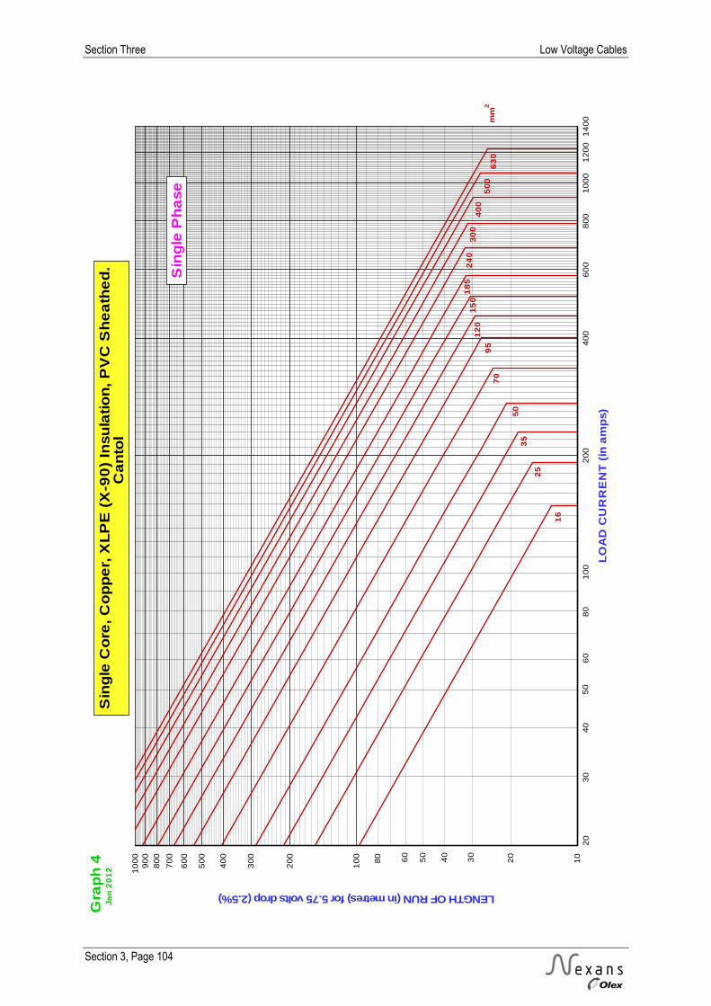
Section Three Low Voltage Cables
Section 3, Page 104
20
04
00
60
08
00
10
00
12
00
14
00
LO
AD
CU
RR
EN
T(i
na
mp
s)
10
0
20
0
30
0
40
0
50
0
60
0
70
0
80
0
90
01
00
0
LENGTHOFRUN(inmetres)for5.75voltsdrop(2.5%)S
ing
leC
ore
,C
op
pe
r,X
LP
E(X
-90
)In
su
latio
n,P
VC
Sh
ea
the
d.
Ca
nto
l
20
20
16
25
35
50
70
95
63
0
12
01
50
50
04
00
30
02
40
18
5
mm
2
50
10
0
Gra
ph
4 10
80 50
Sin
gle
Ph
ase
Ja
n2
01
2
30
40
60
80
30
40
60
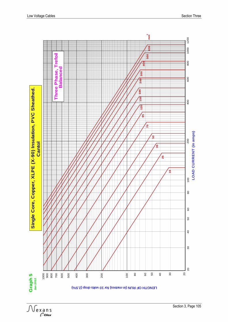
Low Voltage Cables Section Three
Section 3, Page 105
20
040
06
00
80
010
00
12
00
LO
AD
CU
RR
EN
T(i
na
mp
s)
10
0
20
0
30
0
40
0
50
0
60
0
70
0
80
0
90
0
10
00
LENGTHOFRUN(inmetres)for10voltsdrop(2.5%)S
ing
leC
ore
,C
op
pe
r,X
LP
E(X
-90
)In
su
latio
n,P
VC
Sh
ea
the
d.
Ca
nto
l
20
20
16
25
35
50
70
95
63
0
12
01
50
50
0
40
03
00
24
01
85
mm
2
40
10
0
Gra
ph
5 80
60
40
Th
ree
Ph
ase
,T
refo
ilB
ala
nce
d
60
80
30
50
Ja
n2
01
2
30
50

Section Three Low Voltage Cables
Section 3, Page 106
20
040
06
00
80
010
00
12
00
LO
AD
CU
RR
EN
T(i
na
mp
s)
10
0
20
0
30
0
40
0
50
0
60
0
70
0
80
0
90
0
10
00
LENGTHOFRUN(inmetres)for10voltsdrop(2.5%)S
ing
leC
ore
,C
op
pe
r,X
LP
E(X
-90
)In
su
latio
n,P
VC
Sh
ea
the
d.
Ca
nto
l
20
20
16
25
35
50
70
95
63
0
12
01
50
50
04
00
30
02
40
18
5
mm
2
50
10
0
Gra
ph
6 80
60
40
Th
ree
Ph
ase
,F
lat
Ba
lan
ce
d
30
50
30
40
60
80
Ja
n2
01
2
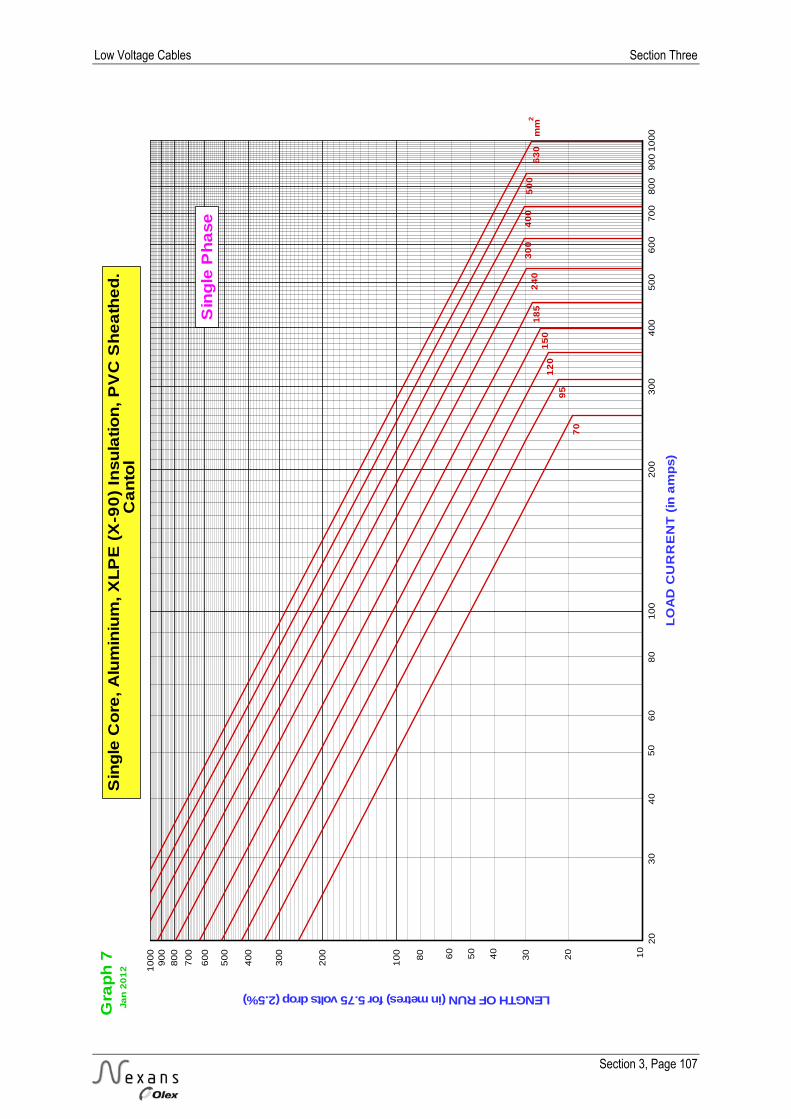
Low Voltage Cables Section Three
Section 3, Page 107
10
02
00
30
04
00
50
06
00
70
08
00
90
010
00
LO
AD
CU
RR
EN
T(i
na
mp
s)
10
0
20
0
30
0
40
0
50
0
60
0
70
0
80
0
90
01
00
0
LENGTHOFRUN(inmetres)for5.75voltsdrop(2.5%)S
ing
leC
ore
,A
lum
iniu
m,X
LP
E(X
-90
)In
su
latio
n,P
VC
Sh
ea
the
d.
Ca
nto
l
20
20
70
95
63
0
12
01
50
50
04
00
30
02
40
18
5m
m2
50
Gra
ph
7 10
40
80 60
Ja
n2
01
2
3050
30
40
60
80
Sin
gle
Ph
ase

Section Three Low Voltage Cables
Section 3, Page 108
10
02
00
30
04
00
50
06
00
70
08
00
90
010
00
LO
AD
CU
RR
EN
T(i
na
mp
s)
10
0
20
0
30
0
40
0
50
0
60
0
70
0
80
0
90
0
10
00
LENGTHOFRUN(inmetres)for10voltsdrop(2.5%)S
ing
leC
ore
,A
lum
iniu
m,X
LP
E(X
-90
)In
su
latio
n,P
VC
Sh
ea
the
d.
Ca
nto
l
20
20
70
95
63
01
20
15
0
50
04
00
30
02
40
18
5m
m2
50
80
Gra
ph
8 80
60
40
Ja
n2
01
2
30
50
30
40
60
Th
ree
Ph
ase
,T
refo
ilB
ala
nce
d
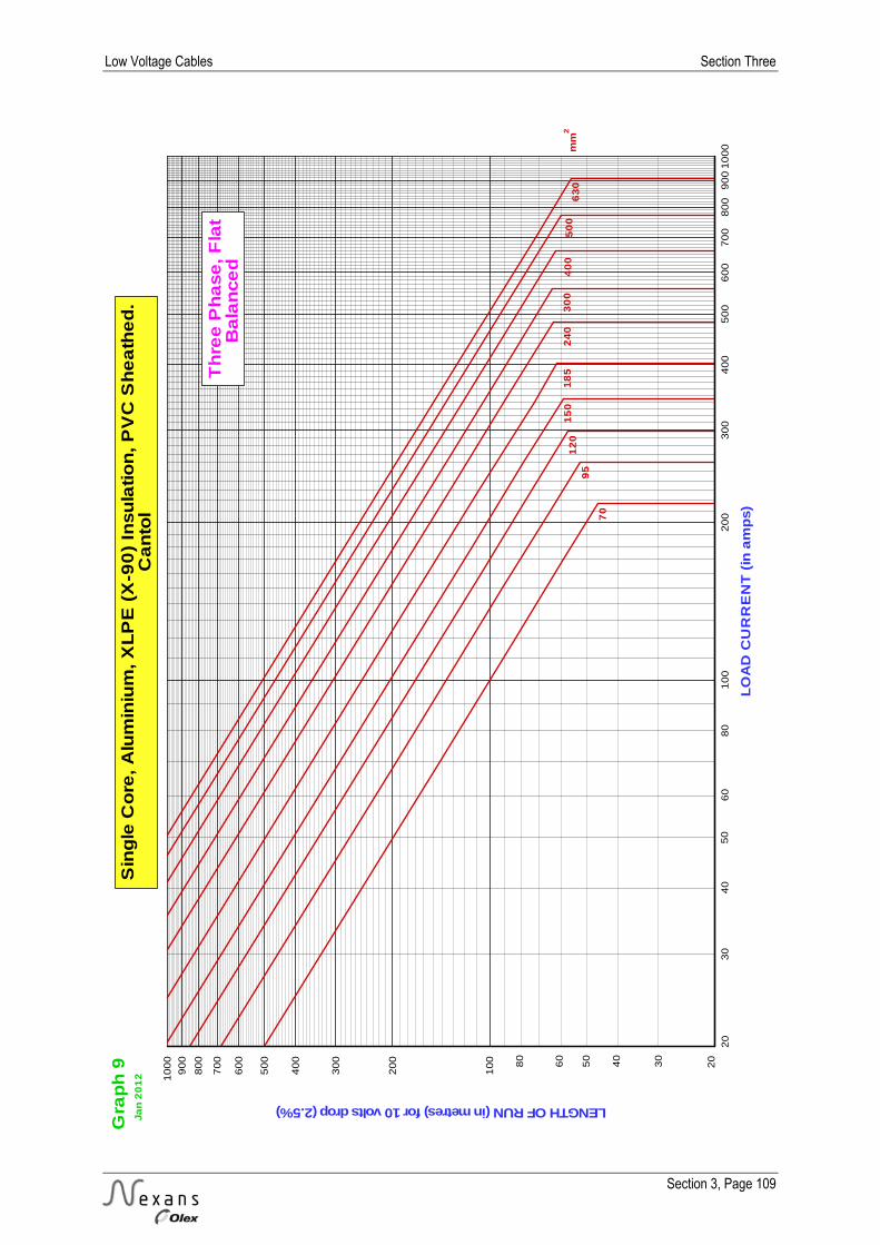
Low Voltage Cables Section Three
Section 3, Page 109
10
02
00
30
04
00
50
06
00
70
08
00
90
010
00
LO
AD
CU
RR
EN
T(i
na
mp
s)
10
0
20
0
30
0
40
0
50
0
60
0
70
0
80
0
90
0
10
00
LENGTHOFRUN(inmetres)for10voltsdrop(2.5%)S
ing
leC
ore
,A
lum
iniu
m,X
LP
E(X
-90
)In
su
latio
n,P
VC
Sh
ea
the
d.
Ca
nto
l
20
20
70
95
63
01
20
15
05
00
40
03
00
24
01
85
mm
2
50
80
Gra
ph
9 80
60
40
Ja
n2
01
2
30
50
30
40
60
Th
ree
Ph
ase
,F
lat
Ba
lan
ce
d

Section Three Low Voltage Cables
Section 3, Page 110
50
10
01
50
20
02
50
LO
AD
CU
RR
EN
T(i
na
mp
s)
10
0
20
0
30
0
40
0
50
0
60
0
70
08
00
LENGTHOFRUN(inmetres)for5.75voltsdrop(2.5%)T
wo
Co
re,C
op
pe
r,P
VC
Insu
latio
n,A
rmo
ure
do
rU
na
rmo
ure
do
rN
eu
tra
lS
cre
en
ed
,P
VC
Sh
ea
the
d.
TP
So
rR
em
ole
x
20
5
1
1.5
2.5
50
4
6
35
25
16
10
mm
2
10
20
Gra
ph
10 260
40
80
Ja
n2
01
2
1030
50
15
30
40
60
80
Sin
gle
Ph
ase
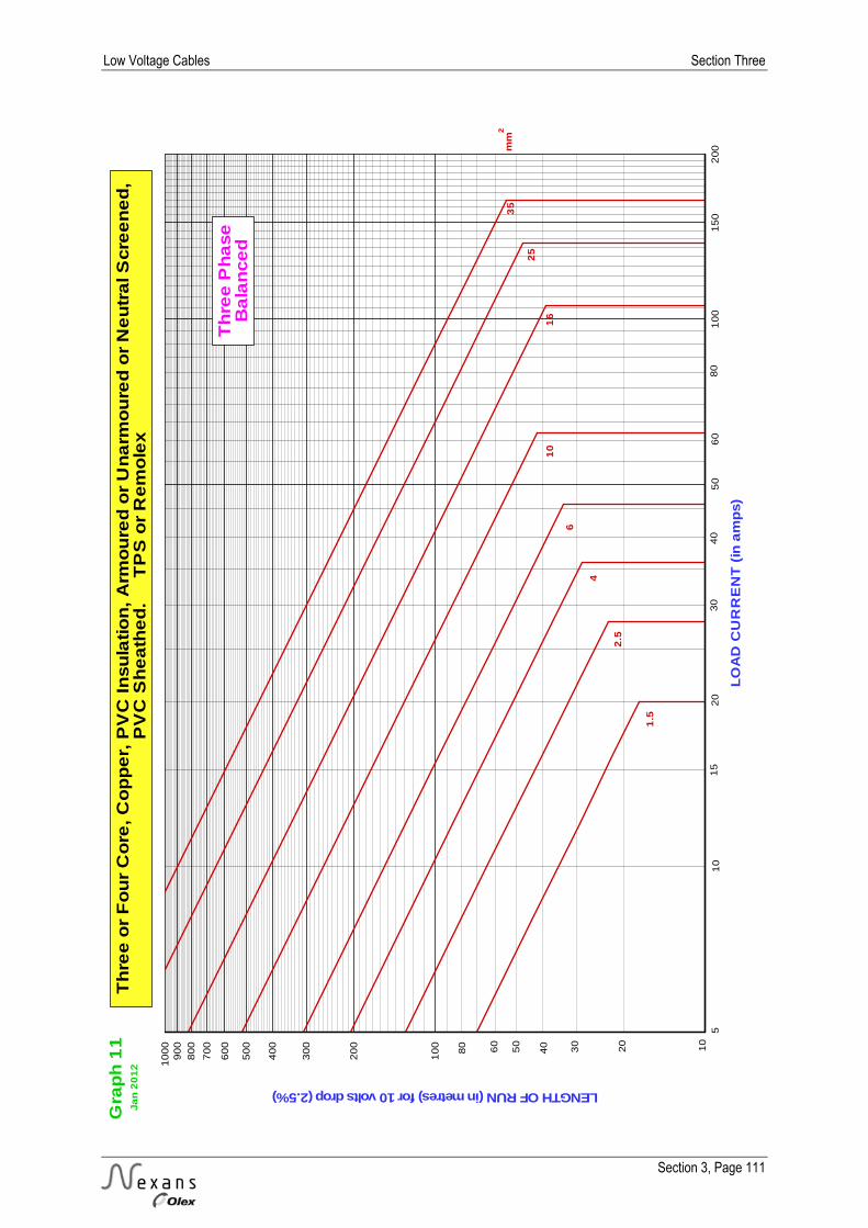
Low Voltage Cables Section Three
Section 3, Page 111
50
10
015
02
00
LO
AD
CU
RR
EN
T(i
na
mp
s)
10
0
20
0
30
0
40
0
50
0
60
0
70
0
80
0
90
01
00
0
LENGTHOFRUN(inmetres)for10voltsdrop(2.5%)T
hre
eo
rF
ou
rC
ore
,C
op
pe
r,P
VC
Insu
latio
n,A
rmo
ure
do
rU
na
rmo
ure
do
rN
eu
tra
lS
cre
en
ed
,P
VC
Sh
ea
the
d.
TP
So
rR
em
ole
x
20
5
1.5
2.5
4
6
35
25
16
10
mm
2
10
20
Gra
ph
11 10
60
40
80
Ja
n2
01
2
Th
ree
Ph
ase
Ba
lan
ce
d
15
30
40
60
80
30
50

Section Three Low Voltage Cables
Section 3, Page 112
10
02
00
30
04
00
50
06
00
LO
AD
CU
RR
EN
T(i
na
mp
s)
10
0
20
0
30
0
40
0
50
0
60
0
70
0
80
0
90
0
10
00
LENGTHOFRUN(inmetres)for10voltsdrop(2.5%)T
hre
eo
rF
ou
rC
ore
,C
op
pe
r,X
LP
E(X
-90
)In
su
latio
n,A
rmo
ure
do
rU
na
rmo
ure
do
rN
eu
tra
lS
cre
en
ed
,P
VC
Sh
ea
the
d.
Ce
mp
ex
20
20
6
10
16
50
70
95
25
12
01
50
35
24
01
85
mm
2
40
80
Gra
ph
12
80
60
40
56
0
Ja
n2
01
2
30
50
10
30
50
Th
ree
Ph
ase
Ba
lan
ce
d

Low Voltage Cables Section Three
Section 3, Page 113
50
10
01
50
20
02
50
30
03
50
40
04
50
50
05
50
LO
AD
CU
RR
EN
T(i
na
mp
s)
10
0
20
0
30
0
40
0
50
0
60
0
70
0
80
0
90
0
10
00
LENGTHOFRUN(inmetres)for10voltsdrop(2.5%)T
hre
eo
rF
ou
rC
ore
,A
lum
iniu
m,X
LP
E(X
-90
)In
su
latio
n,A
rmo
ure
do
rU
na
rmo
ure
do
rN
eu
tra
lS
cre
en
ed
,P
VC
Sh
ea
the
d.
UR
D
20
20
50
70
95
12
01
50
35
24
01
85
mm
2
40
80
Gra
ph
13
80
60
40
60
Th
ree
Ph
ase
Ba
lan
ce
d
30
Ja
n2
01
2
3050
30
0

MED
IUM
VO
LTA
GE
TR-X
LPE
CA
BLES

Medium Voltage TR-XLPE Cables Section Four
Section 4, Page 1
SECTION FOUR – MEDIUM VOLTAGE TR-XLPE CABLES PAGE Explanatory Information 2-13
Construction 2 Screen Designs 4 Testing 5 Test Voltage Levels 6 Installation Tests 7 Current Ratings 9 Rating Factors 10
Product Sheets 12-55 Single Core Cu 11 kV Cables - 3 kA for 1 s Wire Screens 12 Single Core Cu 11 kV Cables - 10 kA for 1 s Wire Screens 14 Single Core Al 11 kV Cables - 3 kA for 1 s Wire Screens 16 Single Core Al 11 kV Cables - 10 kA for 1 s Wire Screens 18 Three Core Cu 11 kV Cables - 3 kA for 1 s Wire Screens 20 Three Core Cu 11 kV Cables - 10 kA for 1 s Wire Screens 22 Three Core Al 11 kV Cables - 3 kA for 1 s Wire Screens 24 Three Core Al 11 kV Cables - 10 kA for 1 s Wire Screens 26 Single Core Cu 22 kV Cables - 3 kA for 1 s Wire Screens 28 Single Core Cu 22 kV Cables - 10 kA for 1 s Wire Screens 30 Single Core Al 22 kV Cables - 3 kA for 1 s Wire Screens 32 Single Core Al 22 kV Cables - 10 kA for 1 s Wire Screens 34 Three Core Cu 22 kV Cables - 3 kA for 1 s Wire Screens 36 Three Core Cu 22 kV Cables - 10 kA for 1 s Wire Screens 38 Three Core Al 22 kV Cables - 3 kA for 1 s Wire Screens 40 Three Core Al 22 kV Cables - 10 kA for 1 s Wire Screens 42 Single Core Cu 33 kV Cables - 3 kA for 1 s Wire Screens 44 Single Core Cu 33 kV Cables - 10 kA for 1 s Wire Screens 46 Single Core Al 33 kV Cables - 3 kA for 1 s Wire Screens 48 Single Core Al 33 kV Cables - 10 kA for 1 s Wire Screens 50 Three Core Cu 33 kV Cables 52 Three Core Al 33 kV Cables 54
Notes 56

Section Four Medium Voltage TR-XLPE Cables
Section 4, Page 2
CONSTRUCTION Nexans Olex Medium Voltage TR-XLPE cables are designed in accordance with AS/NZS 1429.1:2000 and specific customer requirements where applicable to provide optimum performance for the end application. The AS/NZS 1429.1:2000 is compatible with, and in some instances exceeds, the requirements of the international standard IEC 60502.2. AS/NZS 1429.1 is also compatible with (UK) BS 6622 and (US) AEIC CS8 and ICEA S-93-639/NEMA WC74.
Component Detail Conductor Conductors are made of either copper or aluminium to AS/NZS 1125. To assist in producing a smooth circular profile at the interface between the conductor screen and the insulation, compacted stranded conductors are used.
Insulation and Semiconductive Screens All Nexans Olex Medium Voltage TR-XLPE insulated cables are produced under clean room conditions, using the triple extrusion process in which the conductor screen, insulation and insulation screen are extruded simultaneously through a single extrusion head. The surface of the insulation is never exposed to the atmosphere or to any material other than the adjacent semiconductive screens, ensuring that the interfaces between the materials are completely free of voids and contamination.
A sophisticated dimension control device uses X-Rays which are fired through the three layers of polymer to accurately measure the individual layer thicknesses; this ensures that the dimensions of all layers are constant and concentric through the entire length of the cable.
The cross-linking process is carried out in a totally water-free environment, using inert gas rather than steam as the curing medium. This dry-cure process ensures a high integrity insulation and leads to excellent electrical performance.
Cross sectional view of a Triple Extrusion Head
EX-RAY-800 Dimensional Controller
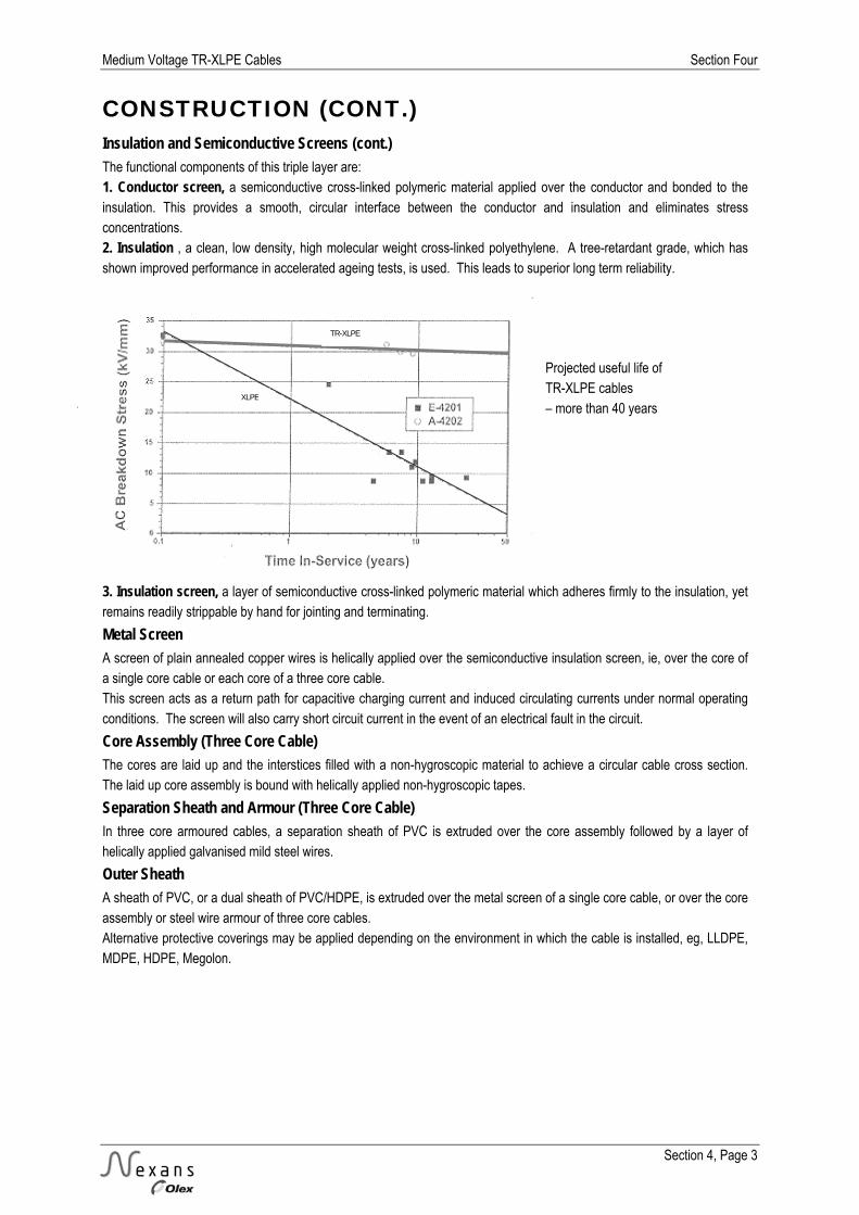
Medium Voltage TR-XLPE Cables Section Four
Section 4, Page 3
CONSTRUCTION (CONT.) Insulation and Semiconductive Screens (cont.) The functional components of this triple layer are: 1. Conductor screen, a semiconductive cross-linked polymeric material applied over the conductor and bonded to the insulation. This provides a smooth, circular interface between the conductor and insulation and eliminates stress concentrations. 2. Insulation , a clean, low density, high molecular weight cross-linked polyethylene. A tree-retardant grade, which has shown improved performance in accelerated ageing tests, is used. This leads to superior long term reliability. 3. Insulation screen, a layer of semiconductive cross-linked polymeric material which adheres firmly to the insulation, yet remains readily strippable by hand for jointing and terminating.
Metal Screen A screen of plain annealed copper wires is helically applied over the semiconductive insulation screen, ie, over the core of a single core cable or each core of a three core cable. This screen acts as a return path for capacitive charging current and induced circulating currents under normal operating conditions. The screen will also carry short circuit current in the event of an electrical fault in the circuit.
Core Assembly (Three Core Cable) The cores are laid up and the interstices filled with a non-hygroscopic material to achieve a circular cable cross section. The laid up core assembly is bound with helically applied non-hygroscopic tapes.
Separation Sheath and Armour (Three Core Cable) In three core armoured cables, a separation sheath of PVC is extruded over the core assembly followed by a layer of helically applied galvanised mild steel wires.
Outer Sheath A sheath of PVC, or a dual sheath of PVC/HDPE, is extruded over the metal screen of a single core cable, or over the core assembly or steel wire armour of three core cables. Alternative protective coverings may be applied depending on the environment in which the cable is installed, eg, LLDPE, MDPE, HDPE, Megolon.
TR-XLPE
XLPE
Projected useful life of TR-XLPE cables – more than 40 years
Section Four Medium Voltage TR-XLPE Cables
Section 4, Page 4
SCREEN DESIGNS The standard range of Nexans Olex Medium Voltage TR-XLPE cables rated up to and including 33 kV incorporates copper wire screens based on fault levels of either 3 kA or 10 kA for 1 second. If either of the standard screen designs does not suit a particular installation, the screen constructions can be tailored in size to meet the specific fault requirements of any operating system.
Wire Screen Cross Sectional Areas In the case of three core cables which have screens around each individual core, the total screen cross sectional area is spread evenly over the three cores. There are several other factors which can override the above criteria. Firstly, the screens are designed so that the average gap between the wires does not exceed 4 mm. This results in the screen area being increased above that required for the required fault level in certain cases. Secondly, the screen area is limited to a value so that its fault rating does not exceed that of the conductor. In some cases, the smaller cables in a range have fault levels of less than either 3 kA or 10 kA for 1 second respectively.
Screen Short Circuit Ratings The screen short circuit ratings are calculated in accordance with formulae given in IEC 60949. Based on AS/NZS 1429.1 a starting temperature of 80°C and a final temperature of 250°C are used. The formulae are based on adiabatic conditions ie, no dissipation of heat during the short circuit. The fault rating Isc of a copper wire screen of a given cross sectional area can be calculated for any duration from the formula :
Isc = t
S*6.148 (A)
where S = Screen Area (mm2) and t = Fault Duration (s). Conversely, the screen area required for a given fault rating can be calculated as follows:
S = 148.6
t *Isc ( mm2)
For convenience, fault ratings for durations of 1 second are often quoted and this simplifies calculations since t = 1 and this term disappears from the formulae.

Medium Voltage TR-XLPE Cables Section Four
Section 4, Page 5
TESTING Testing of Nexans Olex Medium Voltage TR-XLPE cables is carried out in accordance with AS/NZS 1429.1:2000. The tests performed are : Routine tests* - "tests made by the manufacturer on all completed cable to demonstrate the integrity of the cable." Sample tests* - "tests made by the manufacturer on samples of completed cable, or components taken from a completed cable, at a specified frequency so as to verify that the finished product meets the design specification." Type tests# - "tests made by a manufacturer before supplying commercially a type of cable in order to demonstrate satisfactory performance characteristics to meet the intended application. These tests are of such a nature that, after they have been made, they need not be repeated unless changes are made in the cable materials, design, or method of manufacture, which might change the performance characteristics." * All routine and sample tests are performed in the factory. # Type tests are carried out in Nexans Olex's plant in Tottenham, Melbourne, which includes a separate laboratory dedicated to EHV cable testing. The extensive facilities include high voltage test equipment which can perform partial discharge measurements at voltages up to 300 kV, high voltage break-down tests to 600 kV, cyclic ageing tests and impulse withstand tests. The impulse test generator has been specifically built for cable and accessory testing and is the largest in the southern hemisphere, capable of impulses up to 1.2 MV. This allows all type tests to AS/NZS and other national standards to be performed.
Tests Performed on Cables Routine Tests Sample Tests Type Tests
Spark test on sheath. Thicknesses of extruded components.
Insulation resistance at 20°C and 90°C.
Conductor examination and resistance. Screen and armour wire diameters, and screen area.
Elongation at rupture of conductor screen.
Partial discharge tes.t Heat shock test (PVC sheaths only).
Pressure test (PVC sheaths only.)
High voltage a.c. test for 5 min. Insulation shrinkage. Loss of mass (PVC sheaths only).
High voltage a.c. test for 1 min on separation sheath (three core armoured cable only).
Insulation concentricity. Volume resistivity of conductor and insulation screen.s
Conductor screen projections/irregularities.
Mechanical tests (before and after ageing) of insulation and sheaths.
Determination of voids and contaminants.
Partial discharge test after bending.
Hot set test. Impulse withstand test followed by high voltage a.c. test for 15 min.
Insulation screen strippability and adhesion.
Partial discharge test after heat cycling.
DDF (tan δ) as a function of temperature.
High voltage a.c. test for 4 h.
Compatabilitry test for separation sheath (if any) and oversheath.

Section Four Medium Voltage TR-XLPE Cables
Section 4, Page 6
TEST VOLTAGE LEVELS
Voltage Withstand Tests Rated Voltage Impulse Type Tests Routine Test
High Voltage 15 min 50 Hz (after impulse test)
High Voltage 4 h 50 Hz
High Voltage 5 min 50 Hz
(kV) (kV) (kV) (kV) (kV) 3.8/6.6 60 12.5 15 12.5
6.35/11 95 21 25 21
12.7/22 150 42 50 42
19/33 200 63 75 63
Partial Discharge Voltage Levels Rated Voltage Permitted Maximum Discharge
20 pC at 200 percent Uo 5 pC at 150 percent Uo (kV) (kV) (kV)
3.8/6.6 7.6 5.7
6.35/11 13 10
12.7/22 25 19
19/33 38 29
Medium Voltage TR-XLPE Cables Section Four
Section 4, Page 7
INSTALLATION TESTS General After the cable has been installed and prior to commencing terminating or jointing, it is desirable to carry out checks to establish that the cable has not been damaged during the installation process, namely a Sheath Integrity Test and an Insulation Resistance Test of Primary Insulation After completion of the tests, if the terminating or jointing is not being commenced straight away, the cable ends should be resealed with heat shrinkable end caps or similar to prevent the ingress of moisture.
Nexans Olex New Zealand Recommendations for Tests After Complete Installation of TR-XLPE Medium Voltage Cables Advice Concerning Tests After Installation If a test is carried out after installation, please note that the test is to detect defects caused during installation. After installation, the test is applied to the cable and accessories.
High Voltage D.C. Test After Installation The D.C. testing of the primary insulation is not recommended. There are two important reasons for not using a High Voltage DC Test. 1. The DC field in the cable and accessories applies different electric stresses (both in magnitude and in physical location) to an AC field, so much so, that it is considered to be a poor process to find faults. 2. The application of High Voltage DC leads to premature failure of aged and “wet” primary insulation. This has been proven in the Laboratory and has been proven repeatedly in the field.
Safety Requirements As the voltages used in these tests are potentially lethal, appropriate safety measures must be employed to ensure that the safety of all people involved in the testing process is not compromised. Cable ends to be isolated shall be disconnected from the supply and protected from contact to supply, or ground, or accidental contact. Safety measures shall include, and shall not necessarily be limited to, earthing of cable under test prior to and after test voltages are applied, erection of safety barriers with warning signs, and an open communication channel between testing personnel. The testing guidelines outlined in this document are Nexans Olex’s recommendations only, and Nexans Olex cannot be held responsible for ensuring the safe implementation of these recommendations.
Sheath Integrity Test A sheath integrity test (eg, 1000 V minimum insulation resistance tester) applied between the outer-most metallic layer and earth can identify after-installation damage to the non-metallic outer sheath. The measured value should be read after application of the voltage for 1 minute. Ideally the measured value should be corrected for temperature to a standard value at 20°C if correction factors are available. A rough guide is that the insulation resistance decreases to one half of the value for a 10°C rise in temperature. The cable temperature should be recorded along with the measured values. Measured values of Insulation Resistance for the sheath should be greater than calculated values. Calculated values for new cable range from 1.5 M/km to 4.0 M/km @ 20°C for PVC sheaths and from 120 M/km to 300 M/km @ 20°C for PE sheaths. Values are highest for small cables and thick sheaths and lowest for large cables and thin sheaths (factory tests show that measured values are up to an order of magnitude greater than the calculated values). Earth the screens after an Insulation Resistance Test on a sheath for at least 5 minutes before handling or performing other tests.
Section Four Medium Voltage TR-XLPE Cables
Section 4, Page 8
INSTALLATION TESTS (CONT.) Insulation Resistance Test of Primary Insulation DC voltages up to 5 kV, used when performing Insulation Resistance Tests on Primary Insulation, are not considered to be a “High voltage DC test”. An Insulation Resistance Test of the Primary Insulation should be carried out with an insulation resistance tester, with a minimum DC voltage of 2.5 kV for 1.9/3.3 kV cables or 5 kV for cables above 1.9/3.3 kV and up to 19/33 kV. The insulation test should be carried out in the “Guarded Mode” and the instrument should have a minimum full-scale range of 500 Gohms. Guarding should be applied at both ends and a spare core used for the connection lead to the guard at the far end. Any conductor or cable core used as a guard lead must have a resistance to ground of greater than 10 kohms. The measured value should be read after application of the voltage for 1 minute. Ideally the measured value should be corrected for temperature to a standard value at 20°C if correction factors are available. A rough guide is that the insulation resistance decreases to one half of the value for a 10°C rise in temperature. The cable temperature should be recorded along with the measured values. Measured values of insulation resistance for the primary insulation should be greater than calculated values. Calculated values for new cable range from 2,400 M/km to 18,000 M/km at 20°C. Values are highest for small conductors and higher voltages and lowest for large conductors and lower voltages (factory tests show that measured values are up to an order of magnitude greater than the calculated values). This test should be performed prior to any high voltage tests. Short the conductors to the screens after an Insulation Resistance Test on Primary Insulation for at least 10 minutes before handling or performing other tests. If the instrument used for the above insulation resistance testing is a “Megger,” Type BM 25, or equivalent, then the two following tests should be considered. 1. A 10 minute Polarisation Index Test - this test is commonly used as a replacement for the standard insulation resistance test. 2. A 5 Minute Step Voltage Test - the test should use five equal steps up to the maximum test voltage of 2.5 kV for 1.9/3.3 kV cables or 5 kV for cables greater than 1.9/3.3 kV up to 19/33 kV. This test is becoming increasingly used on cables of 6.35/11 kV and greater. Both the above tests can be carried out automatically with the Megger, BM 25 unit and guarding should be applied at both ends as above.
High Voltage A.C. Test After Installation An A.C. voltage test at power frequency should be applied for 24 hours with the normal operating voltage of the system to the primary insulation. Some customers have objected to a 24 hour test at only the operating voltage of the cable and would prefer a test using a higher voltage for a shorter time. This can be achieved by a Very Low Frequency (VLF) HV AC Test, and the equipment now exists for hire in New Zealand to perform this. The VLF HV AC Test is becoming recognised throughout the world as a replacement test for the old HV DC Test or the 24 hour AC test at normal operating voltage, although not many standards have details in them at this point in time. VLF Tests are carried out at a frequency in the band of 0.1 to 0.02 Hz. The VLF Test Set must be of adequate power to test the measured cable capacitance at the frequency chosen. The suggested maximum VLF test voltage for new cable is between 2.7 and 3.0 times the cable operating voltage (Uo), for a minimum of 15 minutes. Where possible, a 30 minute testing time is now recommended as international research has shown this to give a higher confidence. Refer to the test procedure of IEEE-400-2. For existing or aged cables being recommissioned after repair or alterations, the VLF Test Voltage should be a maximum of 2.3 times the cable operating voltage (Uo), for 15 minutes.
Documentation The values obtained in the above tests should be recorded in a cable log so that they are available for comparison purposes in the future.

Medium Voltage TR-XLPE Cables Section Four
Section 4, Page 9
CURRENT RATINGS The continuous current ratings given in this publication have been calculated in accordance with the International Electrotechnical Commission Publication No. IEC 60287 - "Calculation of the Continuous Current Rating of Cables (100% Load factor)", based on the following environmental conditions: Ambient Air Temperature, 30°C; Ambient Soil Temperature, 15°C; Soil Thermal Resistivity, 1.2 K.m/W; Depth of burial, 1.0 m; and Screens bonded both ends. In all cases, the ratings given are the single circuit ratings corresponding to continuous loading at the maximum conductor temperature of 90°C. Where the conditions vary from those on which the ratings are based, rating factors from Tables 4.1 to 4.4 (Section 4 Medium Voltage TR-XLPE Cables) need to be applied.
Methods of Installation The methods of installation for which the ratings are applicable are shown graphically in Figure 2.1 (Section 2 General Technical Information).
Groups of Circuits For groups of circuits unenclosed in air, the spacings and arrangements which need to be maintained to prevent derating are given in Figure 2.2 (Section 2 General Technical Information). Where a number of circuits are installed in close proximity in such a way that they are not thermally independent, the appropriate rating factors from Tables 4.5, 4.6, (Section 4 Medium Voltage TR-XLPE Cables) and 2.1, 2.2 (Section 2 General Technical Information) need to be applied.
Cables in Parallel For cables operated in parallel, each parallel leg is regarded as a separate circuit for current rating purposes and the appropriate rating factors for grouping are applicable. Refer also to Figure 2.3 (Section 2 General Technical Information) for the arrangements of single core cables so as to ensure equal current sharing between parallel legs of the same phase.
Bonding of Screens The current ratings given for single core cables assume that the copper wire screens are solidly bonded to earth at both ends. Solid bonding can result in a reduction in current ratings on larger cables due to the heating effect of circulating currents induced in the screen. This loss can be minimised, either in short runs of cable, by earthing at one end only (single point bonding) which results in a standing voltage proportional to the conductor current and the length of run being induced on the screen and in long runs of cable, by dividing the route into tri-sections and transposing or "crossbonding" the screens at every joint position in a tri-section so that the e.m.f.'s induced by the three phases cancel one another. When these methods of bonding are employed, higher current ratings may be used, however attention must be paid to the safety aspects with respect to the induced standing voltages. This places a limitation on the length of circuit for which single point bonding can be used. Generally it is only considered practical to use special cross-bonding arrangements on transmission class cables (66 kV and above) as the benefits of the higher current ratings are outweighed by the costs of the extra equipment required.
Emergency Ratings TR-XLPE insulated cables can operate under emergency conditions with a conductor temperature of 130°C for periods of up to 36 hours, not more than three times per year. In practice, however, due to the difficulty in ensuring compatibility with terminations and the high volume expansion of TR-XLPE above 100°C, a limit of 105°C for emergency rating is specified in AS/NZS 1429.1. The 105°C emergency limit represents the following approximate percentage increase over the normal continuous ratings: Cables in air: +12% Cables in ground (laid direct or in ducts): +9%.

Section Four Medium Voltage TR-XLPE Cables
Section 4, Page 10
MEDIUM VOLTAGE RATING FACTORS
Table 4.1 Air Temperature Variation Air Temperature (°C)
15 20 25 30 35 40 45 50 55 60 Rating Factor 1.12 1.08 1.04 1.00 0.96 0.91 0.87 0.82 0.76 0.71
Table 4.2 Soil Temperature Variation Soil Temperature (°C)
0 5 10 15 20 25 30 35 40 45 Rating Factor 1.10 1.06 1.03 1.00 0.97 0.93 0.89 0.86 0.82 0.77
Table 4.3 Depth of Burial Variation Depth of Burial (m)
Up to 300 mm² Over 300 mm²
0.8 1.02 1.03 1.01 1.01
1.0 1.00 1.0 1.00 1.00
1.25 0.98 0.98 0.98 0.98
1.5 0.97 0.96 0.96 0.97
1.75 0.96 0.94 0.95 0.97
2.0 0.94 0.92 0.94 0.96
2.5 0.93 0.91 0.92 0.95
3.0 (or more) 0.92 0.89 0.90 0.94
Table 4.4 Soil Thermal Resistivity Variation Soil Thermal Resistivity
(K.m/W)
0.8 1.16 1.12 1.09 1.07
0.9 1.11 1.09 1.06 1.05
1.0 1.07 1.06 1.04 1.03
1.2 1.00 1.00 1.00 1.00
1.5 0.90 0.92 0.93 0.95
2.0 0.79 0.82 0.85 0.87
2.5 0.71 0.75 0.78 0.82
3.0 0.65 0.69 0.73 0.77

Medium Voltage TR-XLPE Cables Section Four
Section 4, Page 11
MEDIUM VOLTAGE RATING FACTORS (CONT.)
Table 4.5 Groups of Circuits Laid Direct No. of
Circuits Single Core Cables
spacing spacing
Multicore Cables
spacing Touching Spacing (m) Touching Spacing (m)
Trefoil Flat 0.15 0.30 0.45 0.60 0.15 0.30 0.45 0.60
2 0.78 0.80 0.82 0.86 0.89 0.91 0.80 0.85 0.89 0.91 0.93
3 0.66 0.68 0.71 0.77 0.80 0.83 0.68 0.76 0.81 0.84 0.87
4 0.59 0.62 0.65 0.72 0.77 0.80 0.62 0.71 0.77 0.81 0.84
5 0.55 0.58 0.61 0.68 0.74 0.78 0.57 0.66 0.73 0.78 0.82
6 0.52 0.55 0.58 0.66 0.72 0.76 0.54 0.64 0.71 0.77 0.81
7 0.49 0.52 0.56 0.64 0.70 0.75 0.51 0.61 0.69 0.75 0.79
8 0.47 0.50 0.54 0.63 0.69 0.74 0.49 0.59 0.68 0.74 0.79
9 0.45 0.48 0.52 0.61 0.68 0.74 0.47 0.58 0.67 0.73 0.78
10 0.44 0.47 0.51 0.61 0.68 0.73 0.45 0.57 0.66 0.73 0.78
11 0.43 0.46 0.50 0.60 0.67 0.73 0.44 0.55 0.65 0.72 0.77
12 0.41 0.45 0.49 0.59 0.67 0.72 0.43 0.54 0.64 0.72 0.77
Table 4.6 Groups of Circuits In Underground Ducts No. of
Circuits Multicore Cables in Single-way Ducts
or Single Core Cables in Multiway Ducts
spacingspacing
Single Core Cables in Single-way Ducts
spacing
Touching Spacing (m) Touching Spacing (m) 0.30 0.45 0.60 0.45 0.60
2 0.88 0.91 0.93 0.94 0.85 0.88 0.90
3 0.80 0.85 0.88 0.90 0.75 0.80 0.83
4 0.76 0.81 0.85 0.88 0.70 0.77 0.80
5 0.72 0.78 0.83 0.86 0.67 0.74 0.78
6 0.69 0.76 0.81 0.85 0.64 0.72 0.76
7 0.67 0.75 0.80 0.84 0.62 0.70 0.75
8 0.65 0.74 0.79 0.83 0.61 0.69 0.74
9 0.63 0.72 0.78 0.83 0.59 0.68 0.73
10 0.62 0.72 0.78 0.82 0.58 0.67 0.73
11 0.61 0.71 0.77 0.82 0.57 0.67 0.72
12 0.60 0.70 0.77 0.81 0.57 0.66 0.72
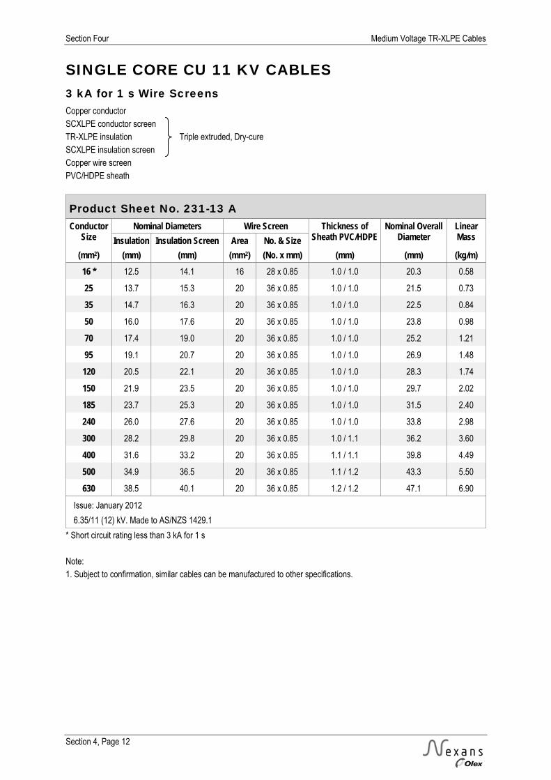
Section Four Medium Voltage TR-XLPE Cables
Section 4, Page 12
SINGLE CORE CU 11 KV CABLES 3 kA for 1 s Wire Screens Copper conductor SCXLPE conductor screen TR-XLPE insulation Triple extruded, Dry-cure SCXLPE insulation screen Copper wire screen PVC/HDPE sheath
Product Sheet No. 231-13 A Conductor
Size Nominal Diameters Wire Screen Thickness of
Sheath PVC/HDPE Nominal Overall
Diameter Linear Mass Insulation Insulation Screen Area No. & Size
(mm2) (mm) (mm) (mm2) (No. x mm) (mm) (mm) (kg/m) 16 * 12.5 14.1 16 28 x 0.85 1.0 / 1.0 20.3 0.58
25 13.7 15.3 20 36 x 0.85 1.0 / 1.0 21.5 0.73
35 14.7 16.3 20 36 x 0.85 1.0 / 1.0 22.5 0.84
50 16.0 17.6 20 36 x 0.85 1.0 / 1.0 23.8 0.98
70 17.4 19.0 20 36 x 0.85 1.0 / 1.0 25.2 1.21
95 19.1 20.7 20 36 x 0.85 1.0 / 1.0 26.9 1.48
120 20.5 22.1 20 36 x 0.85 1.0 / 1.0 28.3 1.74
150 21.9 23.5 20 36 x 0.85 1.0 / 1.0 29.7 2.02
185 23.7 25.3 20 36 x 0.85 1.0 / 1.0 31.5 2.40
240 26.0 27.6 20 36 x 0.85 1.0 / 1.0 33.8 2.98
300 28.2 29.8 20 36 x 0.85 1.0 / 1.1 36.2 3.60
400 31.6 33.2 20 36 x 0.85 1.1 / 1.1 39.8 4.49
500 34.9 36.5 20 36 x 0.85 1.1 / 1.2 43.3 5.50
630 38.5 40.1 20 36 x 0.85 1.2 / 1.2 47.1 6.90
Issue: January 2012
6.35/11 (12) kV. Made to AS/NZS 1429.1
* Short circuit rating less than 3 kA for 1 s Note: 1. Subject to confirmation, similar cables can be manufactured to other specifications.

Medium Voltage TR-XLPE Cables Section Four
Section 4, Page 13
SINGLE CORE CU 11 KV CABLES 3 kA for 1 s Wire Screens Copper conductor SCXLPE conductor screen TR-XLPE insulation Triple extruded, Dry-cure SCXLPE insulation screen Copper wire screen PVC/HDPE sheath
Product Sheet No. 231-13 B Conductor
Size Conductor AC Resistance at
50 Hz and 90C
Inductive Reactance at
50 Hz
Conductor to Screen
Capacitance
Nominal PVC Duct Size
(Multi Way)
Current Ratings (A)
(mm2) (Ohm/km) (Ohm/km) (F/km) (mm)
16 * 1.47 0.154 0.18 65 125 120 101
25 0.927 0.144 0.21 65 163 154 129
35 0.668 0.137 0.23 65 197 183 153
50 0.494 0.130 0.26 65 237 216 181
70 0.342 0.121 0.29 80 (NZ) 294 263 221
95 0.247 0.115 0.33 80 (NZ) 359 313 264
120 0.196 0.111 0.36 100 (NZ) 413 355 305
150 0.159 0.107 0.39 100 (NZ) 470 397 341
185 0.128 0.103 0.43 100 (NZ) 539 447 384
240 0.0981 0.099 0.47 100 (NZ) 637 516 443
300 0.0791 0.096 0.52 150 730 579 509
400 0.0632 0.093 0.59 150 848 655 575
500 0.0510 0.090 0.66 150 978 737 647
630 0.0416 0.087 0.74 150 1122 823 722
Issue: January 2012
6.35/11 (12) kV. Made to AS/NZS 1429.1
* Short circuit rating less than 3 kA for 1 s Note: 1. The values in this table are for installation conditions of: Ambient Air Temperature 30 °C Soil Temperature 15 °C Soil Thermal Resistivity 1.2 K.m/W Depth of Burial 1.0 m Screens bonded both ends

Section Four Medium Voltage TR-XLPE Cables
Section 4, Page 14
SINGLE CORE CU 11 KV CABLES 10 kA for 1 s Wire Screens Copper conductor SCXLPE conductor screen TR-XLPE insulation Triple extruded, Dry-cure SCXLPE insulation screen Copper wire screen PVC/HDPE sheath
Product Sheet No. 231-14 A Conductor
Size Nominal Diameters Wire Screen Thickness of
Sheath PVC/HDPE Nominal Overall
Diameter Linear Mass Insulation Insulation Screen Area No. & Size
(mm2) (mm) (mm) (mm2) (No. x mm) (mm) (mm) (kg/m) 25 * 13.7 15.3 24 29 x 1.03 1.0 / 1.0 21.9 0.77
35 * 14.7 16.3 34 24 x 1.35 1.0 / 1.0 23.5 0.98
50 * 16.0 17.6 49 22 x 1.69 1.0 / 1.0 25.5 1.26
70 17.4 19.0 70 31 x 1.69 1.0 / 1.0 26.9 1.68
95 19.1 20.7 70 31 x 1.69 1.0 / 1.0 28.6 1.95
120 20.5 22.1 69 48 x 1.35 1.0 / 1.0 29.3 2.20
150 21.9 23.5 69 48 x 1.35 1.0 / 1.0 30.7 2.48
185 23.7 25.3 69 48 x 1.35 1.0 / 1.0 32.5 2.86
240 26.0 27.6 69 48 x 1.35 1.0 / 1.0 34.8 3.44
300 28.2 29.8 69 48 x 1.35 1.0 / 1.1 37.2 4.06
400 31.6 33.2 69 48 x 1.35 1.1 / 1.1 40.8 4.95
500 34.9 36.5 69 48 x 1.35 1.1 / 1.2 44.3 5.95
630 38.5 40.1 69 48 x 1.35 1.2 / 1.2 48.1 7.35
Issue: January 2012 6.35/11 (12) kV. Made to AS/NZS 1429.1 * Short circuit rating less than 10 kA for 1 s Note: 1. Subject to confirmation, similar cables can be manufactured to other specifications.

Medium Voltage TR-XLPE Cables Section Four
Section 4, Page 15
SINGLE CORE CU 11 KV CABLES 10 kA for 1 s Wire Screens
Copper conductor SCXLPE conductor screen TR-XLPE insulation Triple extruded, Dry-cure SCXLPE insulation screen Copper wire screen PVC/HDPE sheath
Product Sheet No. 231-14 B Conductor
Size Conductor AC Resistance at
50 Hz and 90C
Inductive Reactance at
50 Hz
Conductor to Screen
Capacitance
Nominal PVC Duct Size
(Multi Way)
Current Ratings (A)
(mm2) (Ohm/km) (Ohm/km) (F/km) (mm)
25 * 0.927 0.145 0.21 65 164 154 129
35 * 0.668 0.140 0.23 65 200 184 154
50 * 0.494 0.134 0.26 80 (NZ) 242 217 183
70 0.342 0.125 0.29 80 (NZ) 298 262 221
95 0.247 0.119 0.33 100 (NZ) 362 311 267
120 0.196 0.113 0.36 100 (NZ) 413 351 301
150 0.159 0.109 0.39 100 (NZ) 467 391 336
185 0.128 0.105 0.43 100 (NZ) 535 439 377
240 0.0980 0.100 0.47 100 (NZ) 627 503 432
300 0.0791 0.098 0.52 150 715 561 493
400 0.0631 0.094 0.59 150 824 630 553
500 0.0509 0.091 0.66 150 943 702 616
630 0.0415 0.088 0.74 150 1072 777 681
Issue: January 2012
6.35/11 (12) kV. Made to AS/NZS 1429.1
* Short circuit rating less than 10 kA for 1 s Note: 1. The values in this table are for installation conditions of: Ambient Air Temperature 30 °C Soil Temperature 15 °C Soil Thermal Resistivity 1.2 K.m/W Depth of Burial 1.0 m Screens bonded both ends

Section Four Medium Voltage TR-XLPE Cables
Section 4, Page 16
SINGLE CORE AL 11 KV CABLES 3 kA for 1 s Wire Screens Aluminium conductor SCXLPE conductor screen TR-XLPE insulation Triple extruded, Dry-cure SCXLPE insulation screen Copper wire screen PVC/HDPE sheath
Product Sheet No. 231-23 A Conductor
Size Nominal Diameters Wire Screen Thickness of
Sheath PVC/HDPE Nominal Overall
Diameter Linear Mass Insulation Insulation Screen Area No. & Size
(mm2) (mm) (mm) (mm2) (No. x mm) (mm) (mm) (kg/m) 25 * 13.7 15.3 16 28 x 0.85 1.0 / 1.0 21.5 0.53
35 ^ 14.7 16.3 20 36 x 0.85 1.0 / 1.0 22.5 0.62
50 15.9 17.5 20 36 x 0.85 1.0 / 1.0 23.7 0.68
70 17.4 19.0 20 36 x 0.85 1.0 / 1.0 25.2 0.78
95 ^ 19.1 20.7 20 36 x 0.85 1.0 / 1.0 26.9 0.89
120 20.5 22.1 20 36 x 0.85 1.0 / 1.0 28.3 0.99
150 21.9 23.5 20 36 x 0.85 1.0 / 1.0 29.7 1.09
185 ^ 23.6 25.2 20 36 x 0.85 1.0 / 1.0 31.4 1.23
240 ^ 26.0 27.6 20 36 x 0.85 1.0 / 1.0 33.8 1.45
300 ^ 28.0 29.6 20 36 x 0.85 1.0 / 1.1 36.0 1.68
400 31.1 32.7 20 36 x 0.85 1.1 / 1.1 39.3 2.02
500 34.2 35.8 20 36 x 0.85 1.1 / 1.2 42.6 2.39
630 37.8 39.4 20 36 x 0.85 1.2 / 1.2 46.4 2.89
800 42.4 44.0 20 36 x 0.85 1.2 / 1.3 51.3 3.51
1000 46.5 48.1 20 36 x 0.85 1.2 / 1.3 55.4 4.20
Issue: January 2012
6.35/11 (12) kV. Made to AS/NZS 1429.1
* Short circuit rating less than 3 kA for 1 s ^ Also complies with AS/NZS 4026 Note: 1. Subject to confirmation, similar cables can be manufactured to other specifications.

Medium Voltage TR-XLPE Cables Section Four
Section 4, Page 17
SINGLE CORE AL 11 KV CABLES 3 kA for 1 s Wire Screens Aluminium conductor SCXLPE conductor screen TR-XLPE insulation Triple extruded, Dry-cure SCXLPE insulation screen Copper wire screen PVC/HDPE sheath
Product Sheet No. 231-23 B Conductor
Size Conductor AC Resistance at
50 Hz and 90C
Inductive Reactance at
50 Hz
Conductor to Screen
Capacitance
Nominal PVC Duct Size
(Multi Way)
Current Ratings (A)
(mm2) (Ohm/km) (Ohm/km) (F/km) (mm)
25 * 1.54 0.144 0.21 65 127 119 100
35 ^ 1.113 0.137 0.23 65 153 142 119
50 0.822 0.130 0.26 65 184 167 140
70 0.568 0.121 0.29 80 (NZ) 229 204 172
95 ^ 0.411 0.115 0.33 80 (NZ) 279 243 205
120 0.325 0.111 0.36 100 (NZ) 322 276 237
150 0.265 0.107 0.39 100 (NZ) 365 309 265
185 ^ 0.211 0.103 0.42 100 (NZ) 421 349 300
240 ^ 0.161 0.099 0.47 100 (NZ) 499 404 347
300 ^ 0.130 0.096 0.52 150 572 455 399
400 0.102 0.093 0.58 150 669 519 456
500 0.0803 0.090 0.65 150 779 590 518
630 0.0638 0.088 0.72 150 907 669 587
800 0.0518 0.085 0.82 200 1050 752 687
1000 0.0432 0.083 0.91 200 1189 831 759
Issue: January 2012
6.35/11 (12) kV. Made to AS/NZS 1429.1
* Short circuit rating less than 3 kA for 1 s ^ Also complies with AS/NZS 4026 Note: 1. The values in this table are for installation conditions of: Ambient Air Temperature 30 °C Soil Temperature 15 °C Soil Thermal Resistivity 1.2 K.m/W Depth of Burial 1.0 m Screens bonded both ends
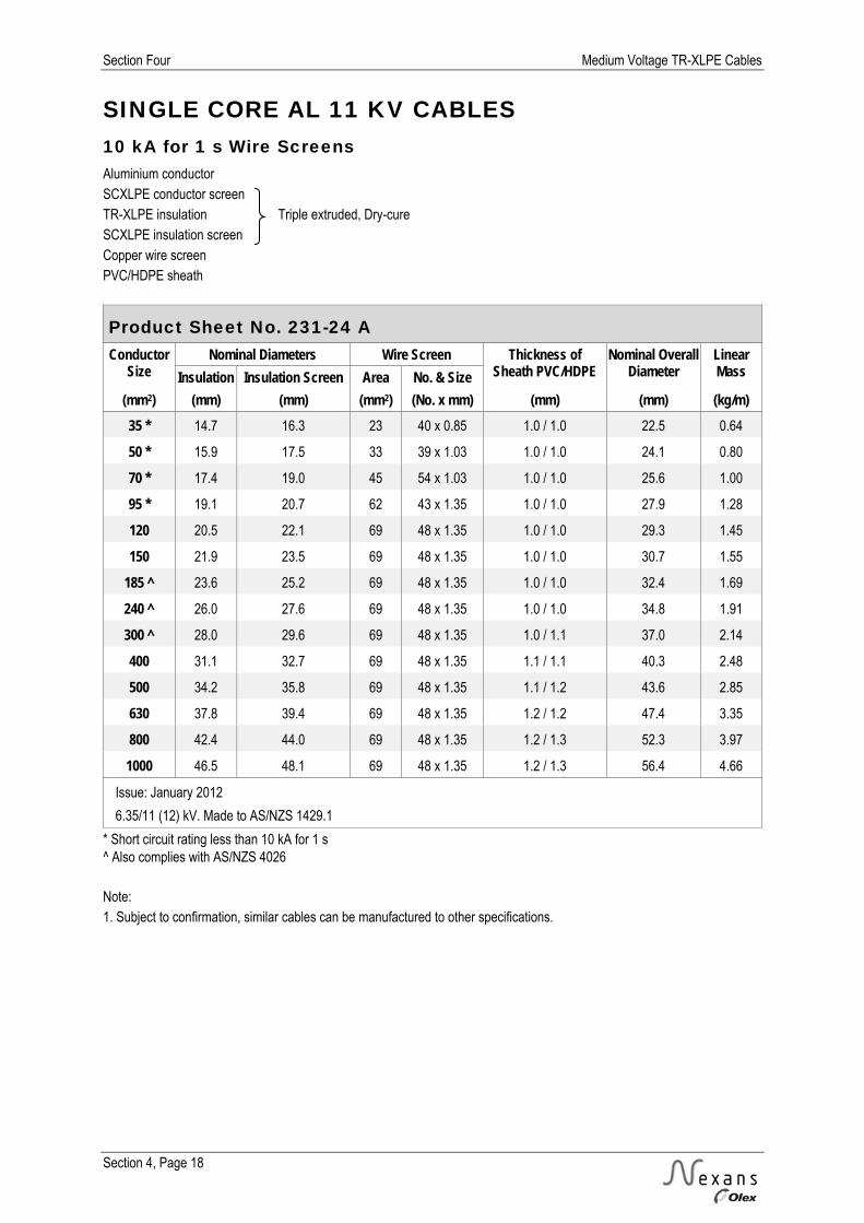
Section Four Medium Voltage TR-XLPE Cables
Section 4, Page 18
SINGLE CORE AL 11 KV CABLES 10 kA for 1 s Wire Screens Aluminium conductor SCXLPE conductor screen TR-XLPE insulation Triple extruded, Dry-cure SCXLPE insulation screen Copper wire screen PVC/HDPE sheath
Product Sheet No. 231-24 A Conductor
Size Nominal Diameters Wire Screen Thickness of
Sheath PVC/HDPE Nominal Overall
Diameter Linear Mass Insulation Insulation Screen Area No. & Size
(mm2) (mm) (mm) (mm2) (No. x mm) (mm) (mm) (kg/m) 35 * 14.7 16.3 23 40 x 0.85 1.0 / 1.0 22.5 0.64
50 * 15.9 17.5 33 39 x 1.03 1.0 / 1.0 24.1 0.80
70 * 17.4 19.0 45 54 x 1.03 1.0 / 1.0 25.6 1.00
95 * 19.1 20.7 62 43 x 1.35 1.0 / 1.0 27.9 1.28
120 20.5 22.1 69 48 x 1.35 1.0 / 1.0 29.3 1.45
150 21.9 23.5 69 48 x 1.35 1.0 / 1.0 30.7 1.55
185 ^ 23.6 25.2 69 48 x 1.35 1.0 / 1.0 32.4 1.69
240 ^ 26.0 27.6 69 48 x 1.35 1.0 / 1.0 34.8 1.91
300 ^ 28.0 29.6 69 48 x 1.35 1.0 / 1.1 37.0 2.14
400 31.1 32.7 69 48 x 1.35 1.1 / 1.1 40.3 2.48
500 34.2 35.8 69 48 x 1.35 1.1 / 1.2 43.6 2.85
630 37.8 39.4 69 48 x 1.35 1.2 / 1.2 47.4 3.35
800 42.4 44.0 69 48 x 1.35 1.2 / 1.3 52.3 3.97
1000 46.5 48.1 69 48 x 1.35 1.2 / 1.3 56.4 4.66
Issue: January 2012
6.35/11 (12) kV. Made to AS/NZS 1429.1
* Short circuit rating less than 10 kA for 1 s ^ Also complies with AS/NZS 4026 Note: 1. Subject to confirmation, similar cables can be manufactured to other specifications.

Medium Voltage TR-XLPE Cables Section Four
Section 4, Page 19
SINGLE CORE AL 11 KV CABLES 10 kA for 1 s Wire Screens Aluminium conductor SCXLPE conductor screen TR-XLPE insulation Triple extruded, Dry-cure SCXLPE insulation screen Copper wire screen PVC/HDPE sheath
Product Sheet No. 231-24 B Conductor
Size Conductor AC Resistance at
50 Hz and 90C
Inductive Reactance at
50 Hz
Conductor to Screen
Capacitance
Nominal PVC Duct Size
(Multi Way)
Current Ratings (A)
(mm2) (Ohm/km) (Ohm/km) (F/km) (mm)
35 * 1.113 0.137 0.23 65 153 142 119
50 * 0.822 0.131 0.26 80 (NZ) 185 168 141
70 * 0.568 0.122 0.29 80 (NZ) 229 204 172
95 * 0.411 0.117 0.33 80 (NZ) 281 243 205
120 0.325 0.113 0.36 100 (NZ) 323 275 236
150 0.265 0.109 0.39 100 (NZ) 366 307 263
185 ^ 0.211 0.105 0.42 100 (NZ) 420 346 297
240 ^ 0.161 0.100 0.47 100 (NZ) 496 399 342
300 ^ 0.130 0.098 0.52 150 567 447 392
400 0.102 0.095 0.58 150 659 507 445
500 0.0802 0.092 0.65 150 763 572 502
630 0.0637 0.089 0.72 150 881 644 565
800 0.0517 0.086 0.82 200 1013 718 656
1000 0.0431 0.084 0.91 200 1139 788 719
Issue: January 2012
6.35/11 (12) kV. Made to AS/NZS 1429.1
* Short circuit rating less than 10 kA for 1 s ^ Also complies with AS/NZS 4026 Note: 1. The values in this table are for installation conditions of: Ambient Air Temperature 30 °C Soil Temperature 15 °C Soil Thermal Resistivity 1.2 K.m/W Depth of Burial 1.0 m Screens bonded both ends

Section Four Medium Voltage TR-XLPE Cables
Section 4, Page 20
THREE CORE CU 11 KV CABLES 3 kA for 1 s Wire Screens Copper conductor SCXLPE conductor screen TR-XLPE insulation Triple extruded, Dry-cure SCXLPE insulation screen Copper wire screens PVC/HDPE sheath
Product Sheet No. 233-13 A Conductor
Size Nominal Diameters Wire Screen (Per Core) Thickness of
Sheath PVC/HDPE
Nominal Overall Diameter
Linear Mass Insulation Insulation Screen Area No. & Size
(mm2) (mm) (mm) (mm2) (No. x mm) (mm) (mm) (kg/m) 16 * 12.5 14.1 5.7 10 x 0.85 1.1 / 1.1 39.0 1.46
25 13.7 15.3 6.8 12 x 0.85 1.1 / 1.2 41.8 1.86
35 14.7 16.3 6.8 12 x 0.85 1.1 / 1.2 43.9 2.20
50 16.0 17.6 6.8 12 x 0.85 1.2 / 1.2 46.9 2.67
70 17.4 19.0 7.4 13 x 0.85 1.3 / 1.3 50.4 3.42
95 19.1 20.7 7.9 14 x 0.85 1.3 / 1.4 54.2 4.32
120 20.5 22.1 8.5 15 x 0.85 1.4 / 1.4 57.8 5.20
150 21.9 23.5 8.5 15 x 0.85 1.4 / 1.5 61.0 6.10
185 23.7 25.3 9.6 17 x 0.85 1.5 / 1.5 65.1 7.35
240 26.0 27.6 10.2 18 x 0.85 1.6 / 1.6 70.5 9.20
300 28.2 29.8 11.3 20 x 0.85 1.6 / 1.7 75.4 11.20
400 31.6 33.2 11.9 21 x 0.85 1.8 / 1.8 83.4 14.05
Issue: January 2012
6.35/11 (12) kV. Made to AS/NZS 1429.1
* Short circuit rating less than 3 kA for 1 s Note: 1. Subject to confirmation, similar cables can be manufactured to other specifications.
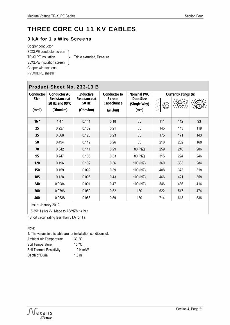
Medium Voltage TR-XLPE Cables Section Four
Section 4, Page 21
THREE CORE CU 11 KV CABLES 3 kA for 1 s Wire Screens Copper conductor SCXLPE conductor screen TR-XLPE insulation Triple extruded, Dry-cure SCXLPE insulation screen Copper wire screens PVC/HDPE sheath
Product Sheet No. 233-13 B Conductor
Size Conductor AC Resistance at
50 Hz and 90C
Inductive Reactance at
50 Hz
Conductor to Screen
Capacitance
Nominal PVC Duct Size
(Single Way)
Current Ratings (A)
(mm2) (Ohm/km) (Ohm/km) (F/km) (mm)
16 * 1.47 0.141 0.18 65 111 112 93
25 0.927 0.132 0.21 65 145 143 119
35 0.668 0.126 0.23 65 175 171 143
50 0.494 0.119 0.26 65 210 202 168
70 0.342 0.111 0.29 80 (NZ) 259 246 206
95 0.247 0.105 0.33 80 (NZ) 315 294 246
120 0.196 0.102 0.36 100 (NZ) 360 333 284
150 0.159 0.099 0.39 100 (NZ) 408 373 318
185 0.128 0.095 0.43 100 (NZ) 466 421 358
240 0.0984 0.091 0.47 100 (NZ) 546 486 414
300 0.0796 0.089 0.52 150 622 547 474
400 0.0638 0.086 0.59 150 714 618 536
Issue: January 2012
6.35/11 (12) kV. Made to AS/NZS 1429.1
* Short circuit rating less than 3 kA for 1 s Note: 1. The values in this table are for installation conditions of: Ambient Air Temperature 30 °C Soil Temperature 15 °C Soil Thermal Resistivity 1.2 K.m/W Depth of Burial 1.0 m

Section Four Medium Voltage TR-XLPE Cables
Section 4, Page 22
THREE CORE CU 11 KV CABLES 10 kA for 1 s Wire Screens Copper conductor SCXLPE conductor screen TR-XLPE insulation Triple extruded, Dry-cure SCXLPE insulation screen Copper wire screens PVC/HDPE sheath
Product Sheet No. 233-14 A Conductor
Size Nominal Diameters Wire Screens (per core) Thickness of
Sheath PVC/HDPE Nominal Overall
Diameter Linear Mass Insulation Insulation Screen Area No. & Size
(mm2) (mm) (mm) (mm2) (No. x mm) (mm) (mm) (kg/m) 35 * 14.7 16.3 11.3 20 x 0.85 1.2 / 1.2 44.1 2.35
50 * 16.0 17.6 16.5 29 x 0.85 1.2 / 1.3 47.1 2.95
70 17.4 19.0 22.7 40 x 0.85 1.3 / 1.3 50.4 3.85
95 19.1 20.7 22.7 40 x 0.85 1.3 / 1.4 54.2 4.74
120 20.5 22.1 22.7 40 x 0.85 1.4 / 1.4 57.8 5.60
150 21.9 23.5 22.7 40 x 0.85 1.4 / 1.5 61.0 6.50
185 23.7 25.3 22.7 40 x 0.85 1.5 / 1.5 65.1 7.70
240 26.0 27.6 22.7 40 x 0.85 1.6 / 1.6 70.5 9.55
300 28.2 29.8 22.7 40 x 0.85 1.6 / 1.7 75.4 11.50
400 31.6 33.2 22.7 40 x 0.85 1.8 / 1.8 83.4 14.35
Issue: January 2012
6.35/11 (12) kV. Made to AS/NZS 1429.1
* Short circuit rating less than 10 kA for 1 s Note: 1. Subject to confirmation, similar cables can be manufactured to other specifications.

Medium Voltage TR-XLPE Cables Section Four
Section 4, Page 23
THREE CORE CU 11 KV CABLES 10 kA for 1 s Wire Screens Copper conductor SCXLPE conductor screen TR-XLPE insulation Triple extruded, Dry-cure SCXLPE insulation screen Copper wire screens PVC/HDPE sheath
Product Sheet No. 233-14 B Conductor
Size Conductor AC Resistance at
50 Hz and 90C
Inductive Reactance at
50 Hz
Conductor to Screen
Capacitance
Nominal PVC Duct Size
(Single Way)
Current Ratings (A)
(mm2) (Ohm/km) (Ohm/km) (F/km) (mm)
35 * 0.668 0.126 0.23 65 175 171 143
50 * 0.494 0.119 0.26 80 (NZ) 210 202 169
70 0.342 0.111 0.29 80 (NZ) 259 246 206
95 0.247 0.105 0.33 80 (NZ) 315 294 246
120 0.196 0.102 0.36 100 (NZ) 360 333 284
150 0.159 0.099 0.39 100 (NZ) 408 373 318
185 0.128 0.095 0.43 100 (NZ) 466 421 358
240 0.0984 0.091 0.47 100 (NZ) 546 486 414
300 0.0796 0.089 0.52 150 622 547 474
400 0.0638 0.086 0.59 150 714 618 536
Issue: January 2012
6.35/11 (12) kV. Made to AS/NZS 1429.1
* Short circuit rating less than 10 kA for 1 s Note: 1. The values in this table are for installation conditions of: Ambient Air Temperature 30 °C Soil Temperature 15 °C Soil Thermal Resistivity 1.2 K.m/W Depth of Burial 1.0 m

Section Four Medium Voltage TR-XLPE Cables
Section 4, Page 24
THREE CORE AL 11 KV CABLES 3 kA for 1 s Wire Screens Aluminium conductor SCXLPE conductor screen TR-XLPE insulation Triple extruded, Dry-cure SCXLPE insulation screen Copper wire screens PVC/HDPE sheath
Product Sheet No. 233-23 A Conductor
Size Nominal Diameters Wire Screens (per core) Thickness of
Sheath PVC/HDPE Nominal Overall
Diameter Linear Mass Insulation Insulation Screen Area No. & Size
(mm2) (mm) (mm) (mm2) (No. x mm) (mm) (mm) (kg/m) 25 * 13.7 15.3 5.7 10 x 0.85 1.1 / 1.1 41.6 1.33
35 ^ 14.7 16.3 6.8 12 x 0.85 1.1 / 1.2 43.9 1.53
50 15.9 17.5 6.8 12 x 0.85 1.2 / 1.2 46.7 1.75
70 17.4 19.0 7.4 13 x 0.85 1.3 / 1.3 50.4 2.11
95 ^ 19.1 20.7 7.9 14 x 0.85 1.3 / 1.4 54.2 2.51
120 20.5 22.1 8.5 15 x 0.85 1.4 / 1.4 57.5 2.89
150 21.9 23.5 8.5 15 x 0.85 1.4 / 1.5 60.7 3.26
185 ^ 23.6 25.2 9.6 17 x 0.85 1.5 / 1.5 64.6 3.79
240 ^ 26.0 27.6 10.2 18 x 0.85 1.6 / 1.6 70.2 4.59
300 ^ 28.0 29.6 10.8 19 x 0.85 1.6 / 1.7 74.7 5.35
400 31.1 32.7 11.9 21 x 0.85 1.8 / 1.8 82.3 6.55
Issue: January 2012
6.35/11 (12) kV. Made to AS/NZS 1429.1
* Short circuit rating less than 3 kA for 1 s ^ Also complies with AS/NZS 4026 Note: 1. Subject to confirmation, similar cables can be manufactured to other specifications.
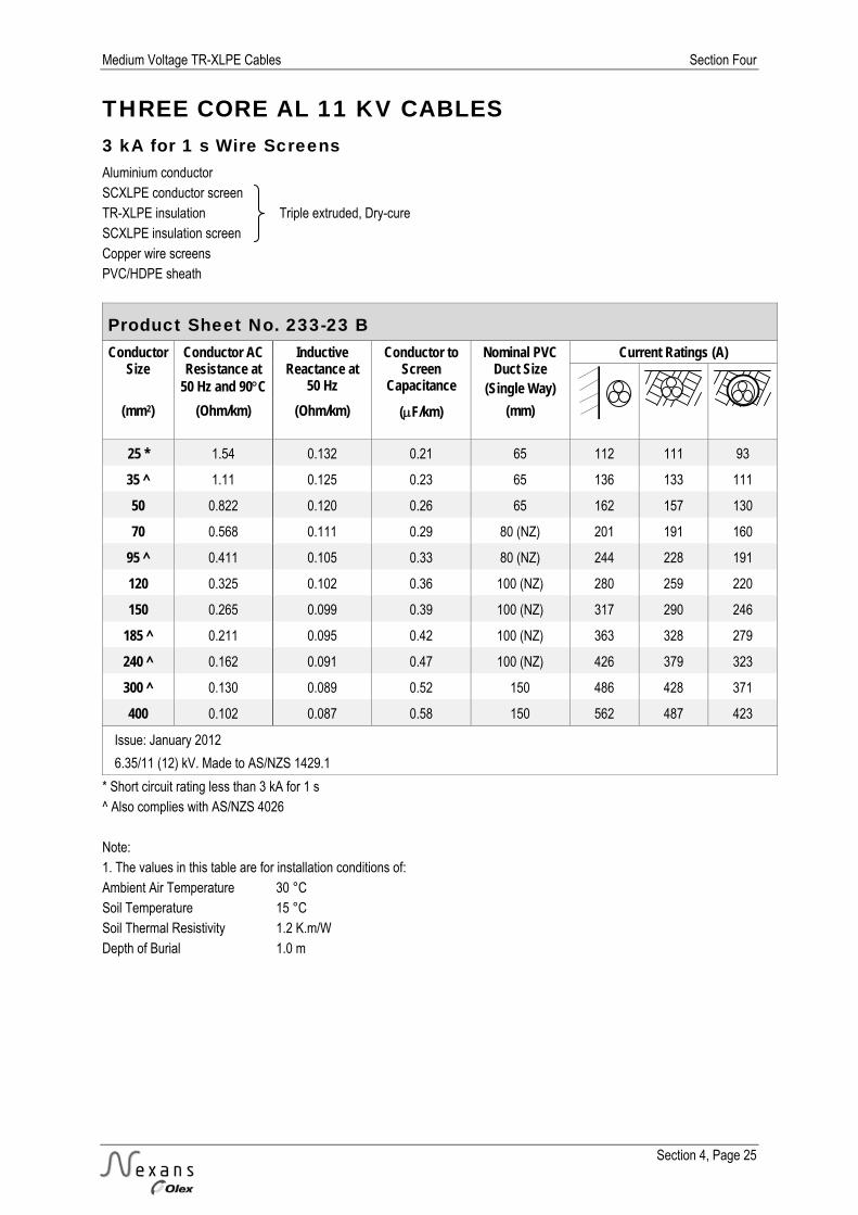
Medium Voltage TR-XLPE Cables Section Four
Section 4, Page 25
THREE CORE AL 11 KV CABLES 3 kA for 1 s Wire Screens Aluminium conductor SCXLPE conductor screen TR-XLPE insulation Triple extruded, Dry-cure SCXLPE insulation screen Copper wire screens PVC/HDPE sheath
Product Sheet No. 233-23 B Conductor
Size Conductor AC Resistance at
50 Hz and 90C
Inductive Reactance at
50 Hz
Conductor to Screen
Capacitance
Nominal PVC Duct Size
(Single Way)
Current Ratings (A)
(mm2) (Ohm/km) (Ohm/km) (F/km) (mm)
25 * 1.54 0.132 0.21 65 112 111 93
35 ^ 1.11 0.125 0.23 65 136 133 111
50 0.822 0.120 0.26 65 162 157 130
70 0.568 0.111 0.29 80 (NZ) 201 191 160
95 ^ 0.411 0.105 0.33 80 (NZ) 244 228 191
120 0.325 0.102 0.36 100 (NZ) 280 259 220
150 0.265 0.099 0.39 100 (NZ) 317 290 246
185 ^ 0.211 0.095 0.42 100 (NZ) 363 328 279
240 ^ 0.162 0.091 0.47 100 (NZ) 426 379 323
300 ^ 0.130 0.089 0.52 150 486 428 371
400 0.102 0.087 0.58 150 562 487 423
Issue: January 2012
6.35/11 (12) kV. Made to AS/NZS 1429.1
* Short circuit rating less than 3 kA for 1 s ^ Also complies with AS/NZS 4026 Note: 1. The values in this table are for installation conditions of: Ambient Air Temperature 30 °C Soil Temperature 15 °C Soil Thermal Resistivity 1.2 K.m/W Depth of Burial 1.0 m
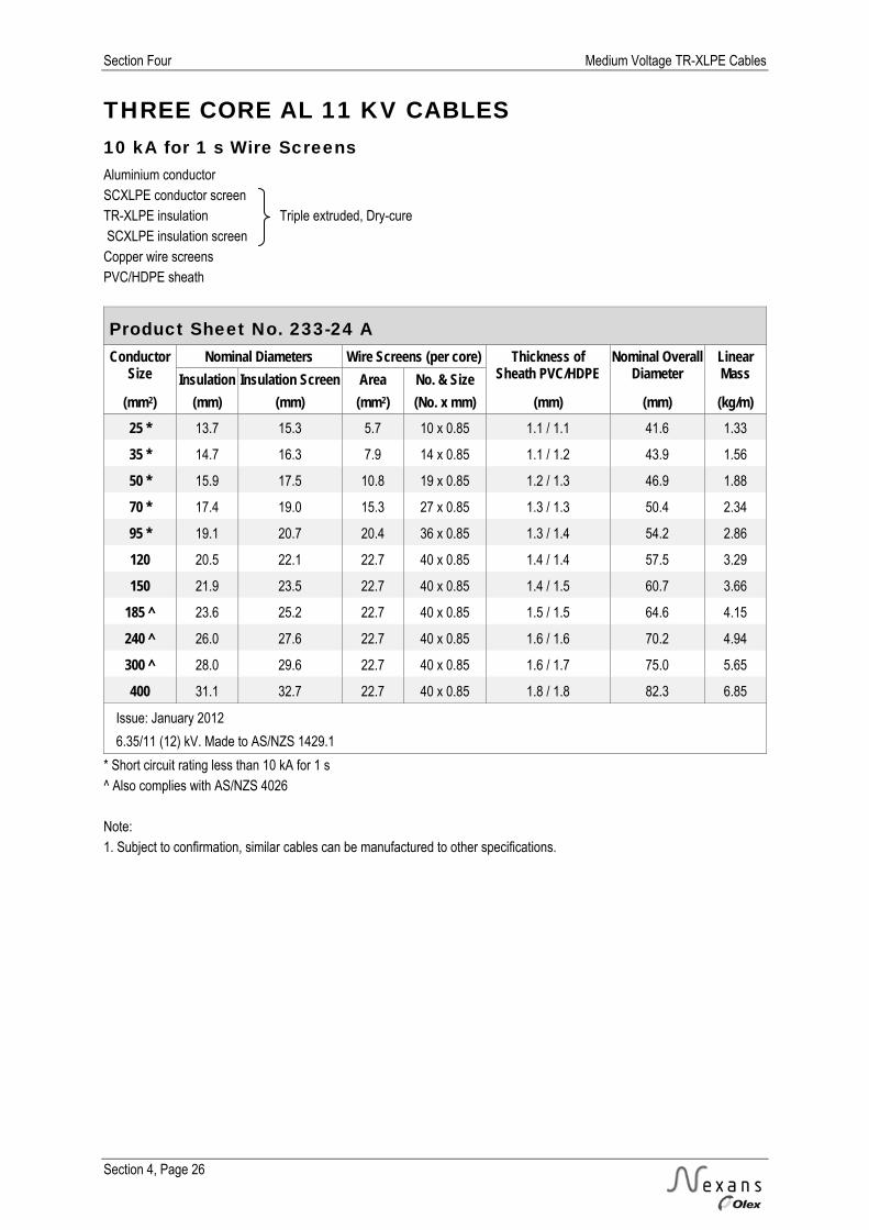
Section Four Medium Voltage TR-XLPE Cables
Section 4, Page 26
THREE CORE AL 11 KV CABLES 10 kA for 1 s Wire Screens Aluminium conductor SCXLPE conductor screen TR-XLPE insulation Triple extruded, Dry-cure SCXLPE insulation screen Copper wire screens PVC/HDPE sheath
Product Sheet No. 233-24 A Conductor
Size Nominal Diameters Wire Screens (per core) Thickness of
Sheath PVC/HDPE Nominal Overall
Diameter Linear Mass Insulation Insulation Screen Area No. & Size
(mm2) (mm) (mm) (mm2) (No. x mm) (mm) (mm) (kg/m) 25 * 13.7 15.3 5.7 10 x 0.85 1.1 / 1.1 41.6 1.33
35 * 14.7 16.3 7.9 14 x 0.85 1.1 / 1.2 43.9 1.56
50 * 15.9 17.5 10.8 19 x 0.85 1.2 / 1.3 46.9 1.88
70 * 17.4 19.0 15.3 27 x 0.85 1.3 / 1.3 50.4 2.34
95 * 19.1 20.7 20.4 36 x 0.85 1.3 / 1.4 54.2 2.86
120 20.5 22.1 22.7 40 x 0.85 1.4 / 1.4 57.5 3.29
150 21.9 23.5 22.7 40 x 0.85 1.4 / 1.5 60.7 3.66
185 ^ 23.6 25.2 22.7 40 x 0.85 1.5 / 1.5 64.6 4.15
240 ^ 26.0 27.6 22.7 40 x 0.85 1.6 / 1.6 70.2 4.94
300 ^ 28.0 29.6 22.7 40 x 0.85 1.6 / 1.7 75.0 5.65
400 31.1 32.7 22.7 40 x 0.85 1.8 / 1.8 82.3 6.85
Issue: January 2012
6.35/11 (12) kV. Made to AS/NZS 1429.1
* Short circuit rating less than 10 kA for 1 s ^ Also complies with AS/NZS 4026 Note: 1. Subject to confirmation, similar cables can be manufactured to other specifications.

Medium Voltage TR-XLPE Cables Section Four
Section 4, Page 27
THREE CORE AL 11 KV CABLES 10 kA for 1 s Wire Screens Aluminium conductor SCXLPE conductor screen TR-XLPE insulation Triple extruded, Dry-cure SCXLPE insulation screen Copper wire screens PVC/HDPE sheath
Product Sheet No. 233-24 B Conductor
Size Conductor AC Resistance at
50 Hz and 90C
Inductive Reactance at
50 Hz
Conductor to Screen
Capacitance
Nominal PVC Duct Size
(Single Way)
Current Ratings (A)
(mm2) (Ohm/km) (Ohm/km) (F/km) (mm)
25 * 1.54 0.132 0.21 65 112 111 93
35 * 1.11 0.125 0.23 65 136 133 111
50 * 0.822 0.120 0.26 65 162 157 130
70 * 0.568 0.111 0.29 80 (NZ) 201 191 160
95 * 0.411 0.105 0.33 80 (NZ) 244 228 191
120 0.325 0.102 0.36 100 (NZ) 280 259 220
150 0.265 0.099 0.39 100 (NZ) 317 290 246
185 ^ 0.211 0.095 0.42 100 (NZ) 363 328 279
240 ^ 0.162 0.091 0.47 100 (NZ) 426 379 323
300 ^ 0.130 0.089 0.52 150 486 427 370
400 0.102 0.087 0.58 150 562 487 423
Issue: January 2012
6.35/11 (12) kV. Made to AS/NZS 1429.1
* Short circuit rating less than 10 kA for 1 s ^ Also complies with AS/NZS 4026 Note: 1. The values in this table are for installation conditions of: Ambient Air Temperature 30 °C Soil Temperature 15 °C Soil Thermal Resistivity 1.2 K.m/W Depth of Burial 1.0 m

Section Four Medium Voltage TR-XLPE Cables
Section 4, Page 28
SINGLE CORE CU 22 KV CABLES 3 kA for 1 s Wire Screens Copper conductor SCXLPE conductor screen TR-XLPE insulation Triple extruded, Dry-cure SCXLPE insulation screen Copper wire screen PVC/HDPE sheath
Product Sheet No. 241-13 A Conductor
Size Nominal Diameters Wire Screen Thickness of
Sheath PVC/HDPE Nominal Overall
Diameter Linear Mass Insulation Insulation Screen Area No. & Size
(mm2) (mm) (mm) (mm2) (No. x mm) (mm) (mm) (kg/m) 35 18.5 20.1 20 36 x 0.85 1.0 / 1.0 26.3 0.98
50 19.8 21.4 20 36 x 0.85 1.0 / 1.0 27.6 1.12
70 21.2 22.8 20 36 x 0.85 1.0 / 1.0 29.0 1.35
95 22.9 24.5 20 36 x 0.85 1.0 / 1.0 30.7 1.64
120 24.3 25.9 20 36 x 0.85 1.0 / 1.0 32.1 1.91
150 25.7 27.3 20 36 x 0.85 1.0 / 1.0 33.5 2.20
185 27.5 29.1 20 36 x 0.85 1.0 / 1.1 35.5 2.60
240 29.8 31.4 20 36 x 0.85 1.0 / 1.1 37.8 3.19
300 32.0 33.6 20 36 x 0.85 1.1 / 1.1 40.2 3.83
400 35.4 37.0 20 36 x 0.85 1.1 / 1.2 43.8 4.73
500 38.7 40.3 20 36 x 0.85 1.2 / 1.2 47.3 5.75
630 42.3 43.9 20 36 x 0.85 1.2 / 1.3 51.2 7.20
Issue: January 2012
12.7/22 (24) kV. Made to AS/NZS 1429.1
Note: 1. Subject to confirmation, similar cables can be manufactured to other specifications.

Medium Voltage TR-XLPE Cables Section Four
Section 4, Page 29
SINGLE CORE CU 22 KV CABLES 3 kA for 1 s Wire Screens Copper conductor SCXLPE conductor screen TR-XLPE insulation Triple extruded, Dry-cure SCXLPE insulation screen Copper wire screen PVC/HDPE sheath
Product Sheet No. 241-13 B Conductor
Size Conductor AC Resistance at
50 Hz and 90C
Inductive Reactance at
50 Hz
Conductor to Screen
Capacitance
Nominal PVC Duct Size
(Multi Way)
Current Ratings (A)
(mm2) (Ohm/km) (Ohm/km) (F/km) (mm)
35 0.668 0.147 0.17 80 (NZ) 202 183 156
50 0.494 0.139 0.19 80 (NZ) 242 216 183
70 0.342 0.130 0.21 100 (NZ) 299 263 227
95 0.247 0.123 0.23 100 (NZ) 365 314 271
120 0.196 0.119 0.25 100 (NZ) 419 355 307
150 0.159 0.115 0.27 100 (NZ) 476 398 343
185 0.128 0.110 0.29 100 (NZ) 546 448 386
240 0.0979 0.106 0.32 150 644 517 455
300 0.0789 0.103 0.35 150 737 581 511
400 0.0629 0.099 0.40 150 855 658 579
500 0.0505 0.095 0.44 150 986 740 651
630 0.0411 0.092 0.49 200 1132 829 758
Issue: January 2012
12.7/22 (24) kV. Made to AS/NZS 1429.1
Note: 1. The values in this table are for installation conditions of: Ambient Air Temperature 30 °C Soil Temperature 15 °C Soil Thermal Resistivity 1.2 K.m/W Depth of Burial 1.0 m Screens bonded both ends

Section Four Medium Voltage TR-XLPE Cables
Section 4, Page 30
SINGLE CORE CU 22 KV CABLES 10 kA for 1 s Wire Screens Copper conductor SCXLPE conductor screen TR-XLPE insulation Triple extruded, Dry-cure SCXLPE insulation screen Copper wire screen PVC/HDPE sheath
Product Sheet No. 241-14 A Conductor
Size Nominal Diameters Wire Screen Thickness of
Sheath PVC/HDPE Nominal Overall
Diameter Linear Mass Insulation Insulation Screen Area No. & Size
(mm2) (mm) (mm) (mm2) (No. x mm) (mm) (mm) (kg/m) 35 * 18.5 20.1 34 41 x 1.03 1.0 / 1.0 26.7 1.10
50 * 19.8 21.4 49 34 x 1.35 1.0 / 1.0 28.6 1.39
70 21.2 22.8 69 48 x 1.35 1.0 / 1.0 30.0 1.81
95 22.9 24.5 69 48 x 1.35 1.0 / 1.0 31.7 2.10
120 24.3 25.9 69 48 x 1.35 1.0 / 1.0 33.1 2.37
150 25.7 27.3 69 48 x 1.35 1.0 / 1.0 34.5 2.65
185 27.5 29.1 69 48 x 1.35 1.0 / 1.1 36.5 3.06
240 29.8 31.4 69 48 x 1.35 1.1 / 1.1 39.0 3.66
300 32.0 33.6 69 48 x 1.35 1.1 / 1.1 41.2 4.29
400 35.4 37.0 69 48 x 1.35 1.2 / 1.2 45.0 5.20
500 38.7 40.3 69 48 x 1.35 1.2 / 1.2 48.3 6.25
630 42.3 43.9 69 48 x 1.35 1.3 / 1.3 52.4 7.70
Issue: January 2012
12.7/22 (24) kV. Made to AS/NZS 1429.1
* Short circuit rating less than 10 kA for 1 s Note: 1. Subject to confirmation, similar cables can be manufactured to other specifications.
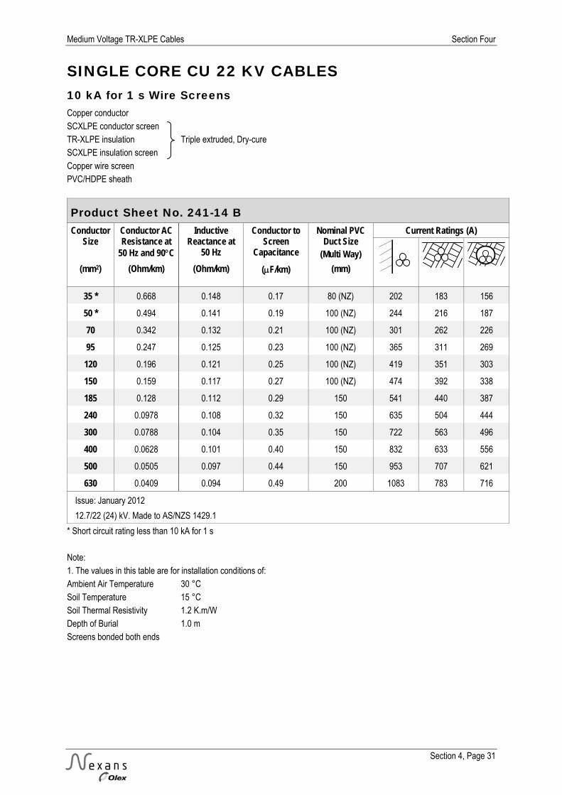
Medium Voltage TR-XLPE Cables Section Four
Section 4, Page 31
SINGLE CORE CU 22 KV CABLES 10 kA for 1 s Wire Screens Copper conductor SCXLPE conductor screen TR-XLPE insulation Triple extruded, Dry-cure SCXLPE insulation screen Copper wire screen PVC/HDPE sheath
Product Sheet No. 241-14 B Conductor
Size Conductor AC Resistance at
50 Hz and 90C
Inductive Reactance at
50 Hz
Conductor to Screen
Capacitance
Nominal PVC Duct Size
(Multi Way)
Current Ratings (A)
(mm2) (Ohm/km) (Ohm/km) (F/km) (mm)
35 * 0.668 0.148 0.17 80 (NZ) 202 183 156
50 * 0.494 0.141 0.19 100 (NZ) 244 216 187
70 0.342 0.132 0.21 100 (NZ) 301 262 226
95 0.247 0.125 0.23 100 (NZ) 365 311 269
120 0.196 0.121 0.25 100 (NZ) 419 351 303
150 0.159 0.117 0.27 100 (NZ) 474 392 338
185 0.128 0.112 0.29 150 541 440 387
240 0.0978 0.108 0.32 150 635 504 444
300 0.0788 0.104 0.35 150 722 563 496
400 0.0628 0.101 0.40 150 832 633 556
500 0.0505 0.097 0.44 150 953 707 621
630 0.0409 0.094 0.49 200 1083 783 716
Issue: January 2012
12.7/22 (24) kV. Made to AS/NZS 1429.1
* Short circuit rating less than 10 kA for 1 s Note: 1. The values in this table are for installation conditions of: Ambient Air Temperature 30 °C Soil Temperature 15 °C Soil Thermal Resistivity 1.2 K.m/W Depth of Burial 1.0 m Screens bonded both ends

Section Four Medium Voltage TR-XLPE Cables
Section 4, Page 32
SINGLE CORE AL 22 KV CABLES 3 kA for 1 s Wire Screens Aluminium conductor SCXLPE conductor screen TR-XLPE insulation Triple extruded, Dry-cure SCXLPE insulation screen Copper wire screen PVC/HDPE sheath
Product Sheet No. 241-23 A Conductor
Size Nominal Diameters Wire Screen Thickness of
Sheath PVC/HDPE Nominal Overall
Diameter Linear Mass Insulation Insulation Screen Area No. & Size
(mm2) (mm) (mm) (mm2) (No. x mm) (mm) (mm) (kg/m) 35 ^ 18.5 20.1 20 36 x 0.85 1.0 / 1.0 26.3 0.75
50 19.7 21.3 20 36 x 0.85 1.0 / 1.0 27.5 0.82
70 21.2 22.8 20 36 x 0.85 1.0 / 1.0 29.0 0.92
95 ^ 22.9 24.5 20 36 x 0.85 1.0 / 1.0 30.7 1.04
120 24.3 25.9 20 36 x 0.85 1.0 / 1.0 32.1 1.15
150 25.7 27.3 20 36 x 0.85 1.0 / 1.0 33.5 1.27
185 ^ 27.4 29.0 20 36 x 0.85 1.0 / 1.1 35.4 1.43
240 ^ 29.8 31.4 20 36 x 0.85 1.0 / 1.1 37.8 1.66
300 ^ 31.8 33.4 20 36 x 0.85 1.1 / 1.1 40.0 1.90
400 34.9 36.5 20 36 x 0.85 1.1 / 1.2 43.3 2.26
500 38.0 39.6 20 36 x 0.85 1.2 / 1.2 46.6 2.65
630 41.6 43.2 20 36 x 0.85 1.2 / 1.3 50.5 3.17
800 46.2 47.8 20 36 x 0.85 1.3 / 1.3 55.3 3.83
1000 50.3 51.9 20 36 x 0.85 1.3 / 1.3 59.4 4.54
Issue: January 2012
12.7/22 (24) kV. Made to AS/NZS 1429.1
^ Also complies with AS/NZS 4026 Note: 1. Subject to confirmation, similar cables can be manufactured to other specifications.

Medium Voltage TR-XLPE Cables Section Four
Section 4, Page 33
SINGLE CORE AL 22 KV CABLES 3 kA for 1 s Wire Screens Aluminium conductor SCXLPE conductor screen TR-XLPE insulation Triple extruded, Dry-cure SCXLPE insulation screen Copper wire screen PVC/HDPE sheath
Product Sheet No. 241-23 B Conductor
Size Conductor AC Resistance at
50 Hz and 90C
Inductive Reactance at
50 Hz
Conductor to Screen
Capacitance
Nominal PVC Duct Size
(Multi Way)
Current Ratings (A)
(mm2) (Ohm/km) (Ohm/km) (F/km) (mm)
35 ^ 1.113 0.146 0.17 80 (NZ) 157 142 121
50 0.822 0.140 0.19 80 (NZ) 187 167 142
70 0.568 0.130 0.21 100 (NZ) 233 204 176
95 ^ 0.411 0.123 0.23 100 (NZ) 283 244 210
120 0.325 0.119 0.25 100 (NZ) 326 277 239
150 0.265 0.115 0.27 100 (NZ) 370 309 267
185 ^ 0.211 0.110 0.29 100 (NZ) 426 350 301
240 ^ 0.161 0.106 0.32 150 504 405 356
300 ^ 0.130 0.103 0.35 150 577 455 401
400 0.102 0.099 0.39 150 673 520 458
500 0.0800 0.096 0.43 150 783 592 520
630 0.0634 0.093 0.48 200 912 672 615
800 0.0513 0.090 0.54 200 1054 756 691
1000 0.0427 0.087 0.60 200 1194 836 764
Issue: January 2012
12.7/22 (24) kV. Made to AS/NZS 1429.1
^ Also complies with AS/NZS 4026 Note: 1. The values in this table are for installation conditions of: Ambient Air Temperature 30 °C Soil Temperature 15 °C Soil Thermal Resistivity 1.2 K.m/W Depth of Burial 1.0 m Screens bonded both ends

Section Four Medium Voltage TR-XLPE Cables
Section 4, Page 34
SINGLE CORE AL 22 KV CABLES 10 kA for 1 s Wire Screens Aluminium conductor SCXLPE conductor screen TR-XLPE insulation Triple extruded, Dry-cure SCXLPE insulation screen Copper wire screen PVC/HDPE sheath
Product Sheet No. 241-24 A Conductor
Size Nominal Diameters Wire Screen Thickness of
Sheath PVC/HDPE Nominal Overall
Diameter Linear Mass Insulation Insulation Screen Area No. & Size
(mm2) (mm) (mm) (mm2) (No. x mm) (mm) (mm) (kg/m) 35 * 18.5 20.1 23 40 x 0.85 1.0 / 1.0 26.3 0.78
50 * 19.7 21.3 33 39 x 1.03 1.0 / 1.0 27.9 0.94
70 * 21.2 22.8 46 32 x 1.35 1.0 / 1.0 30.0 1.17
95 * 22.9 24.5 61 27 x 1.69 1.0 / 1.0 32.4 1.43
120 24.3 25.9 69 48 x 1.35 1.0 / 1.0 33.1 1.61
150 25.7 27.3 69 48 x 1.35 1.0 / 1.0 34.5 1.72
185 ^ 27.4 29.0 69 48 x 1.35 1.0 / 1.1 36.4 1.89
240 ^ 29.8 31.4 69 48 x 1.35 1.1 / 1.1 39.0 2.13
300 31.8 33.4 69 48 x 1.35 1.1 / 1.1 41.0 2.36
400 34.9 36.5 69 48 x 1.35 1.2 / 1.2 44.5 2.74
500 38.0 39.6 69 48 x 1.35 1.2 / 1.2 47.6 3.11
630 41.6 43.2 69 48 x 1.35 1.3 / 1.3 51.7 3.66
800 46.2 47.8 69 48 x 1.35 1.3 / 1.4 56.5 4.31
1000 50.3 51.9 69 48 x 1.35 1.3 / 1.4 60.6 5.00
Issue: January 2012
12.7/22 (24) kV. Made to AS/NZS 1429.1
* Short circuit rating less than 10 kA for 1 s ^ Also complies with AS/NZS 4026 Note: 1. Subject to confirmation, similar cables can be manufactured to other specifications.

Medium Voltage TR-XLPE Cables Section Four
Section 4, Page 35
SINGLE CORE AL 22 KV CABLES 10 kA for 1 s Wire Screens Aluminium conductor SCXLPE conductor screen TR-XLPE insulation Triple extruded, Dry-cure SCXLPE insulation screen Copper wire screen PVC/HDPE sheath
Product Sheet No. 241-24 B Conductor
Size Conductor AC Resistance at
50 Hz and 90C
Inductive Reactance at
50 Hz
Conductor to Screen
Capacitance
Nominal PVC Duct Size
(Multi Way)
Current Ratings (A)
(mm2) (Ohm/km) (Ohm/km) (F/km) (mm)
35 * 1.113 0.146 0.17 80 (NZ) 157 142 121
50 * 0.822 0.141 0.19 80 (NZ) 188 168 142
70 * 0.568 0.132 0.21 100 (NZ) 235 204 177
95 * 0.411 0.127 0.23 100 (NZ) 286 243 210
120 0.325 0.121 0.25 100 (NZ) 327 275 237
150 0.265 0.117 0.27 100 (NZ) 370 307 265
185 ^ 0.211 0.112 0.29 150 425 346 305
240 ^ 0.161 0.108 0.32 150 501 399 351
300 0.130 0.104 0.35 150 571 447 394
400 0.102 0.101 0.39 150 663 508 447
500 0.0800 0.097 0.43 150 768 574 505
630 0.0633 0.095 0.48 200 886 647 592
800 0.0512 0.091 0.54 200 1019 722 660
1000 0.0426 0.088 0.60 200 1146 793 724
Issue: January 2012
12.7/22 (24) kV. Made to AS/NZS 1429.1
* Short circuit rating less than 10 kA for 1 s ^ Also complies with AS/NZS 4026 Note: 1. The values in this table are for installation conditions of: Ambient Air Temperature 30 °C Soil Temperature 15 °C Soil Thermal Resistivity 1.2 K.m/W Depth of Burial 1.0 m Screens bonded both ends

Section Four Medium Voltage TR-XLPE Cables
Section 4, Page 36
THREE CORE CU 22 KV CABLES 3 kA for 1 s Wire Screens Copper conductor SCXLPE conductor screen TR-XLPE insulation Triple extruded, Dry-cure SCXLPE insulation screen Copper wire screens PVC/HDPE sheath
Product Sheet No. 243-13 A Conductor
Size Nominal Diameters Wire Screens (per core) Thickness of
Sheath PVC/HDPE Nominal Overall
Diameter Linear Mass Insulation Insulation Screen Area No. & Size
(mm2) (mm) (mm) (mm2) (No. x mm) (mm) (mm) (kg/m) 35 18.5 20.1 7.4 13 x 0.85 1.3 / 1.4 52.9 2.76
50 19.8 21.4 7.9 14 x 0.85 1.4 / 1.4 56.0 3.28
70 21.2 22.8 8.5 15 x 0.85 1.4 / 1.5 59.2 4.04
95 22.9 24.5 9.1 16 x 0.85 1.5 / 1.5 63.1 4.99
120 24.3 25.9 9.6 17 x 0.85 1.5 / 1.6 66.6 5.90
150 25.7 27.3 10.2 18 x 0.85 1.6 / 1.6 69.8 6.85
185 27.5 29.1 10.8 19 x 0.85 1.6 / 1.7 73.9 8.10
240 29.8 31.4 11.3 20 x 0.85 1.7 / 1.8 79.3 10.05
300 32.0 33.6 12.5 22 x 0.85 1.8 / 1.9 84.4 12.10
400 35.4 37.0 13.6 24 x 0.85 1.9 / 2.0 92.2 14.70
Issue: September 2012
12.7/22 (24) kV. Made to AS/NZS 1429.1
Note: 1. Subject to confirmation, similar cables can be manufactured to other specifications.

Medium Voltage TR-XLPE Cables Section Four
Section 4, Page 37
THREE CORE CU 22 KV CABLES 3 kA for 1 s Wire Screens Copper conductor SCXLPE conductor screen TR-XLPE insulation Triple extruded, Dry-cure SCXLPE insulation screen Copper wire screens PVC/HDPE sheath
Product Sheet No. 243-13 B Conductor
Size Conductor AC Resistance at
50 Hz and 90C
Inductive Reactance at
50 Hz
Conductor to Screen
Capacitance
Nominal PVC Duct Size
(Single Way)
Current Ratings (A)
(mm2) (Ohm/km) (Ohm/km) (F/km) (mm)
35 0.668 0.138 0.17 80 (NZ) 177 170 144
50 0.494 0.131 0.19 100 (NZ) 212 201 173
70 0.342 0.122 0.21 100 (NZ) 261 245 210
95 0.247 0.116 0.23 100 (NZ) 317 293 251
120 0.196 0.111 0.25 100 (NZ) 363 333 285
150 0.159 0.108 0.27 100 (NZ) 411 373 319
185 0.128 0.103 0.29 150 469 421 366
240 0.0981 0.099 0.32 150 549 486 423
300 0.0792 0.096 0.35 150 625 547 476
400 0.0633 0.093 0.40 150 718 620 539
Issue: September 2012
12.7/22 (24) kV. Made to AS/NZS 1429.1
Note: 1. The values in this table are for installation conditions of: Ambient Air Temperature 30 °C Soil Temperature 15 °C Soil Thermal Resistivity 1.2 K.m/W Depth of Burial 1.0 m

Section Four Medium Voltage TR-XLPE Cables
Section 4, Page 38
THREE CORE CU 22 KV CABLES 10 kA for 1 s Wire Screens Copper conductor SCXLPE conductor screen TR-XLPE insulation Triple extruded, Dry-cure SCXLPE insulation screen Copper wire screens PVC/HDPE sheath
Product Sheet No. 243-14 A Conductor
Size Nominal Diameters Wire Screens (per core) Thickness of
Sheath PVC/HDPE Nominal Overall
Diameter Linear Mass Insulation Insulation Screen Area No. & Size
(mm2) (mm) (mm) (mm2) (No. x mm) (mm) (mm) (kg/m) 35 * 18.5 20.1 11.3 20 x 0.85 1.3 / 1.4 52.9 2.87
50 * 19.8 21.4 16.5 29 x 0.85 1.4 / 1.4 56.0 3.51
70 21.2 22.8 22.7 40 x 0.85 1.4 / 1.5 59.2 4.44
95 22.9 24.5 22.7 40 x 0.85 1.5 / 1.5 63.4 5.40
120 24.3 25.9 22.7 40 x 0.85 1.5 / 1.6 66.6 6.25
150 25.7 27.3 22.7 40 x 0.85 1.6 / 1.6 69.8 7.20
185 27.5 29.1 22.7 40 x 0.85 1.6 / 1.7 73.9 8.45
240 29.8 31.4 22.7 40 x 0.85 1.7 / 1.8 79.3 10.35
300 32.0 33.6 22.7 40 x 0.85 1.8 / 1.9 84.4 12.40
400 35.4 37.0 22.7 40 x 0.85 1.9 / 2.0 92.2 15.30
Issue: September 2012
12.7/22 (24) kV. Made to AS/NZS 1429.1
* Short circuit rating less than 10 kA for 1 s Note: 1. Subject to confirmation, similar cables can be manufactured to other specifications.

Medium Voltage TR-XLPE Cables Section Four
Section 4, Page 39
THREE CORE CU 22 KV CABLES 10 kA for 1 s Wire Screens Copper conductor SCXLPE conductor screen TR-XLPE insulation Triple extruded, Dry-cure SCXLPE insulation screen Copper wire screens PVC/HDPE sheath
Product Sheet No. 243-14 B Conductor
Size Conductor AC Resistance at
50 Hz and 90C
Inductive Reactance at
50 Hz
Conductor to Screen
Capacitance
Nominal PVC Duct Size
(Single Way)
Current Ratings (A)
(mm2) (Ohm/km) (Ohm/km) (F/km) (mm)
35 * 0.668 0.138 0.17 80 (NZ) 177 170 144
50 * 0.494 0.131 0.19 100 (NZ) 212 201 173
70 0.342 0.122 0.21 100 (NZ) 261 245 210
95 0.247 0.116 0.23 100 (NZ) 317 293 251
120 0.196 0.111 0.25 100 (NZ) 363 333 285
150 0.159 0.108 0.27 100 (NZ) 411 373 319
185 0.128 0.103 0.29 150 469 421 366
240 0.0981 0.099 0.32 150 549 486 423
300 0.0792 0.096 0.35 150 625 547 476
400 0.0633 0.093 0.40 150 718 620 539
Issue: September 2012
12.7/22 (24) kV. Made to AS/NZS 1429.1
* Short circuit rating less than 10 kA for 1 s Note: 1. The values in this table are for installation conditions of: Ambient Air Temperature 30 °C Soil Temperature 15 °C Soil Thermal Resistivity 1.2 K.m/W Depth of Burial 1.0 m

Section Four Medium Voltage TR-XLPE Cables
Section 4, Page 40
THREE CORE AL 22 KV CABLES 3 kA for 1 s Wire Screens Aluminium conductor SCXLPE conductor screen TR-XLPE insulation Triple extruded, Dry-cure SCXLPE insulation screen Copper wire screens PVC/HDPE sheath
Product Sheet No. 243-23 A Conductor
Size Nominal Diameters Wire Screens (per core) Thickness of
Sheath PVC/HDPE Nominal Overall
Diameter Linear Mass Insulation Insulation Screen Area No. & Size
(mm2) (mm) (mm) (mm2) (No. x mm) (mm) (mm) (kg/m) 35 ^ 18.5 20.1 7.4 13 x 0.85 1.3 / 1.4 52.9 2.08
50 19.7 21.3 7.9 14 x 0.85 1.4 / 1.4 55.7 2.36
70 21.2 22.8 8.5 15 x 0.85 1.4 / 1.5 59.2 2.73
95 ^ 22.9 24.5 9.1 16 x 0.85 1.5 / 1.5 63.1 3.18
120 24.3 25.9 9.6 17 x 0.85 1.5 / 1.6 66.3 3.58
150 25.7 27.3 10.2 18 x 0.85 1.6 / 1.6 69.5 4.02
185 ^ 27.4 29.0 10.8 19 x 0.85 1.6 / 1.7 73.4 4.56
240 ^ 29.8 31.4 11.3 20 x 0.85 1.7 / 1.8 79.0 5.40
300 31.8 33.4 12.5 22 x 0.85 1.8 / 1.9 84.0 6.30
400 34.9 36.5 13.6 24 x 0.85 1.9 / 2.0 91.1 7.55
Issue: September 2012
12.7/22 (24) kV. Made to AS/NZS 1429.1
^ Also complies with AS/NZS 4026 Note: 1. Subject to confirmation, similar cables can be manufactured to other specifications.

Medium Voltage TR-XLPE Cables Section Four
Section 4, Page 41
THREE CORE AL 22 KV CABLES 3 kA for 1 s Wire Screens Aluminium conductor SCXLPE conductor screen TR-XLPE insulation Triple extruded, Dry-cure SCXLPE insulation screen Copper wire screens PVC/HDPE sheath
Product Sheet No. 243-23 B Conductor
Size Conductor AC Resistance at
50 Hz and 90C
Inductive Reactance at
50 Hz
Conductor to Screen
Capacitance
Nominal PVC Duct Size
(Single Way)
Current Ratings (A)
(mm2) (Ohm/km) (Ohm/km) (F/km) (mm)
35 ^ 1.11 0.137 0.17 80 (NZ) 137 132 112
50 0.822 0.131 0.19 100 (NZ) 164 156 134
70 0.568 0.122 0.21 100 (NZ) 203 190 163
95 ^ 0.411 0.116 0.23 100 (NZ) 246 227 195
120 0.325 0.111 0.25 100 (NZ) 282 259 221
150 0.265 0.108 0.27 100 (NZ) 319 289 247
185 ^ 0.211 0.103 0.29 150 365 328 285
240 ^ 0.161 0.099 0.32 150 428 379 330
300 0.130 0.096 0.35 150 487 427 371
400 0.102 0.093 0.39 150 564 488 424
Issue: September 2012
12.7/22 (24) kV. Made to AS/NZS 1429.1
^ Also complies with AS/NZS 4026 Note: 1. The values in this table are for installation conditions of: Ambient Air Temperature 30 °C Soil Temperature 15 °C Soil Thermal Resistivity 1.2 K.m/W Depth of Burial 1.0 m

Section Four Medium Voltage TR-XLPE Cables
Section 4, Page 42
THREE CORE AL 22 KV CABLES 10 kA for 1 s Wire Screens Aluminium conductor SCXLPE conductor screen TR-XLPE insulation Triple extruded, Dry-cure SCXLPE insulation screen Copper wire screens PVC/HDPE sheath
Product Sheet No. 243-24 A Conductor
Size Nominal Diameters Wire Screens (per core) Thickness of
Sheath PVC/HDPE Nominal Overall
Diameter Linear Mass Insulation Insulation Screen Area No. & Size
(mm2) (mm) (mm) (mm2) (No. x mm) (mm) (mm) (kg/m) 35 * 18.5 20.1 7.9 14 x 0.85 1.3 / 1.4 52.9 2.10
50 * 19.7 21.3 10.8 19 x 0.85 1.4 / 1.4 55.7 2.44
70 * 21.2 22.8 15.3 27 x 0.85 1.4 / 1.5 59.2 2.92
95 * 22.9 24.5 20.4 36 x 0.85 1.5 / 1.5 63.1 3.50
120 24.3 25.9 22.7 40 x 0.85 1.5 / 1.6 66.3 3.95
150 25.7 27.3 22.7 40 x 0.85 1.6 / 1.6 69.5 4.37
185 ^ 27.4 29.0 22.7 40 x 0.85 1.6 / 1.7 73.4 4.89
240 ^ 29.8 31.4 22.7 40 x 0.85 1.7 / 1.8 79.3 5.75
300 31.8 33.4 22.7 40 x 0.85 1.8 / 1.9 84.0 6.55
400 34.9 36.5 22.7 40 x 0.85 1.9 / 2.0 91.1 7.80
Issue: September 2012
12.7/22 (24) kV. Made to AS/NZS 1429.1
* Short circuit rating less than 10 kA for 1 s ^ Also complies with AS/NZS 4026 Note: 1. Subject to confirmation, similar cables can be manufactured to other specifications.

Medium Voltage TR-XLPE Cables Section Four
Section 4, Page 43
THREE CORE AL 22 KV CABLES 10 kA for 1 s Wire Screens Aluminium conductor SCXLPE conductor screen TR-XLPE insulation Triple extruded, Dry-cure SCXLPE insulation screen Copper wire screens PVC/HDPE sheath
Product Sheet No. 243-24 B Conductor
Size Conductor AC Resistance at
50 Hz and 90C
Inductive Reactance at
50 Hz
Conductor to Screen
Capacitance
Nominal PVC Duct Size
(Single Way)
Current Ratings (A)
(mm2) (Ohm/km) (Ohm/km) (F/km) (mm)
35 * 1.11 0.137 0.17 80 (NZ) 137 132 112
50 * 0.822 0.131 0.19 100 (NZ) 164 156 134
70 * 0.568 0.122 0.21 100 (NZ) 203 190 163
95 * 0.411 0.116 0.23 100 (NZ) 246 227 195
120 0.325 0.111 0.25 100 (NZ) 282 259 221
150 0.265 0.108 0.27 100 (NZ) 319 289 247
185 ^ 0.211 0.103 0.29 150 365 328 285
240 ^ 0.161 0.099 0.32 150 428 379 330
300 0.130 0.096 0.35 150 487 427 371
400 0.102 0.093 0.39 150 564 488 424
Issue: September 2012
12.7/22 (24) kV. Made to AS/NZS 1429.1
* Short circuit rating less than 10 kA for 1 s ^ Also complies with AS/NZS 4026 Note: 1. The values in this table are for installation conditions of: Ambient Air Temperature 30 °C Soil Temperature 15 °C Soil Thermal Resistivity 1.2 K.m/W Depth of Burial 1.0 m
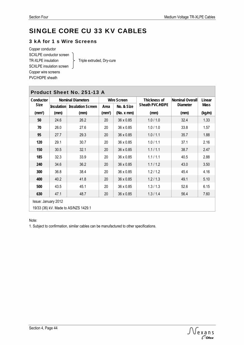
Section Four Medium Voltage TR-XLPE Cables
Section 4, Page 44
SINGLE CORE CU 33 KV CABLES 3 kA for 1 s Wire Screens Copper conductor SCXLPE conductor screen TR-XLPE insulation Triple extruded, Dry-cure SCXLPE insulation screen Copper wire screens PVC/HDPE sheath
Product Sheet No. 251-13 A Conductor
Size Nominal Diameters Wire Screen Thickness of
Sheath PVC/HDPE Nominal Overall
Diameter Linear Mass Insulation Insulation Screen Area No. & Size
(mm2) (mm) (mm) (mm2) (No. x mm) (mm) (mm) (kg/m) 50 24.6 26.2 20 36 x 0.85 1.0 / 1.0 32.4 1.33
70 26.0 27.6 20 36 x 0.85 1.0 / 1.0 33.8 1.57
95 27.7 29.3 20 36 x 0.85 1.0 / 1.1 35.7 1.88
120 29.1 30.7 20 36 x 0.85 1.0 / 1.1 37.1 2.16
150 30.5 32.1 20 36 x 0.85 1.1 / 1.1 38.7 2.47
185 32.3 33.9 20 36 x 0.85 1.1 / 1.1 40.5 2.88
240 34.6 36.2 20 36 x 0.85 1.1 / 1.2 43.0 3.50
300 36.8 38.4 20 36 x 0.85 1.2 / 1.2 45.4 4.16
400 40.2 41.8 20 36 x 0.85 1.2 / 1.3 49.1 5.10
500 43.5 45.1 20 36 x 0.85 1.3 / 1.3 52.6 6.15
630 47.1 48.7 20 36 x 0.85 1.3 / 1.4 56.4 7.60
Issue: January 2012
19/33 (36) kV. Made to AS/NZS 1429.1
Note: 1. Subject to confirmation, similar cables can be manufactured to other specifications.
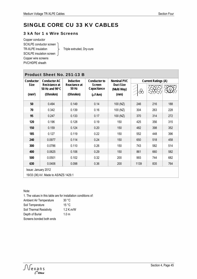
Medium Voltage TR-XLPE Cables Section Four
Section 4, Page 45
SINGLE CORE CU 33 KV CABLES 3 kA for 1 s Wire Screens Copper conductor SCXLPE conductor screen TR-XLPE insulation Triple extruded, Dry-cure SCXLPE insulation screen Copper wire screens PVC/HDPE sheath
Product Sheet No. 251-13 B Conductor
Size Conductor AC Resistance at
50 Hz and 90C
Inductive Reactance at
50 Hz
Conductor to Screen
Capacitance
Nominal PVC Duct Size
(Multi Way)
Current Ratings (A)
(mm2) (Ohm/km) (Ohm/km) (F/km) (mm)
50 0.494 0.149 0.14 100 (NZ) 246 216 188
70 0.342 0.139 0.16 100 (NZ) 304 263 228
95 0.247 0.133 0.17 100 (NZ) 370 314 272
120 0.196 0.128 0.19 150 425 356 315
150 0.159 0.124 0.20 150 482 398 352
185 0.127 0.119 0.22 150 552 448 396
240 0.0977 0.114 0.24 150 650 518 458
300 0.0786 0.110 0.26 150 743 582 514
400 0.0625 0.106 0.29 150 861 660 582
500 0.0501 0.102 0.32 200 993 744 682
630 0.0406 0.098 0.36 200 1139 835 764
Issue: January 2012
19/33 (36) kV. Made to AS/NZS 1429.1
Note: 1. The values in this table are for installation conditions of: Ambient Air Temperature 30 °C Soil Temperature 15 °C Soil Thermal Resistivity 1.2 K.m/W Depth of Burial 1.0 m Screens bonded both ends

Section Four Medium Voltage TR-XLPE Cables
Section 4, Page 46
SINGLE CORE CU 33 KV CABLES 10 kA for 1 s Wire Screens Copper conductor SCXLPE conductor screen TR-XLPE insulation Triple extruded, Dry-cure SCXLPE insulation screen Copper wire screens PVC/HDPE sheath
Product Sheet No. 251-14 A Conductor
Size Nominal Diameters Wire Screen Thickness of
Sheath PVC/HDPE Nominal Overall
Diameter Linear Mass Insulation Insulation Screen Area No. & Size
(mm2) (mm) (mm) (mm2) (No. x mm) (mm) (mm) (kg/m) 50 * 24.6 26.2 49 34 x 1.35 1.0 / 1.0 33.4 1.60
70 26.0 27.6 69 48 x 1.35 1.0 / 1.1 35.0 2.04
95 27.7 29.3 69 48 x 1.35 1.0 / 1.1 36.7 2.34
120 29.1 30.7 69 48 x 1.35 1.1 / 1.1 38.3 2.63
150 30.5 32.1 69 48 x 1.35 1.1 / 1.1 39.7 2.93
185 32.3 33.9 69 48 x 1.35 1.1 / 1.2 41.7 3.35
240 34.6 36.2 69 48 x 1.35 1.1 / 1.2 44.0 3.96
300 36.8 38.4 69 48 x 1.35 1.2 / 1.2 46.4 4.62
400 40.2 41.8 69 48 x 1.35 1.2 / 1.3 50.1 5.55
500 43.5 45.1 69 48 x 1.35 1.3 / 1.3 53.6 6.60
630 47.1 48.7 69 48 x 1.35 1.3 / 1.4 57.4 8.05
Issue: January 2012
19/33 (36) kV. Made to AS/NZS 1429.1
* Short circuit rating less than 10 kA for 1 s Note: 1. Subject to confirmation, similar cables can be manufactured to other specifications.

Medium Voltage TR-XLPE Cables Section Four
Section 4, Page 47
SINGLE CORE CU 33 KV CABLES 10 kA for 1 s Wire Screens Copper conductor SCXLPE conductor screen TR-XLPE insulation Triple extruded, Dry-cure SCXLPE insulation screen Copper wire screens PVC/HDPE sheath
Product Sheet No. 251-14 B Conductor
Size Conductor AC Resistance at
50 Hz and 90C
Inductive Reactance at
50 Hz
Conductor to Screen
Capacitance
Nominal PVC Duct Size
(Multi Way)
Current Ratings (A)
(mm2) (Ohm/km) (Ohm/km) (F/km) (mm)
50 * 0.494 0.151 0.14 100 (NZ) 248 216 188
70 0.342 0.142 0.16 100 (NZ) 305 262 227
95 0.247 0.134 0.17 150 370 311 276
120 0.196 0.130 0.19 150 424 352 311
150 0.159 0.125 0.20 150 479 392 347
185 0.127 0.120 0.22 150 547 441 389
240 0.0976 0.115 0.24 150 641 506 447
300 0.0786 0.112 0.26 150 729 565 499
400 0.0625 0.107 0.29 200 840 636 583
500 0.0501 0.103 0.32 200 961 711 651
630 0.0405 0.100 0.36 200 1094 790 723
Issue: January 2012
19/33 (36) kV. Made to AS/NZS 1429.1
* Short circuit rating less than 10 kA for 1 s Note: 1. The values in this table are for installation conditions of: Ambient Air Temperature 30 °C Soil Temperature 15 °C Soil Thermal Resistivity 1.2 K.m/W Depth of Burial 1.0 m Screens bonded both ends

Section Four Medium Voltage TR-XLPE Cables
Section 4, Page 48
SINGLE CORE AL 33 KV CABLES 3 kA for 1 s Wire Screens Aluminium conductor SCXLPE conductor screen TR-XLPE insulation Triple extruded, Dry-cure SCXLPE insulation screen Copper wire screens PVC/HDPE sheath
Product Sheet No. 251-23 A Conductor
Size Nominal Diameters Wire Screen Thickness of
Sheath PVC/HDPE Nominal Overall
Diameter Linear Mass Insulation Insulation Screen Area No. & Size
(mm2) (mm) (mm) (mm2) (No. x mm) (mm) (mm) (kg/m) 50 24.5 26.1 20 36 x 0.85 1.0 / 1.0 32.3 1.03
70 26.0 27.6 20 36 x 0.85 1.0 / 1.0 33.8 1.14
95 27.7 29.3 20 36 x 0.85 1.0 / 1.1 35.7 1.28
120 29.1 30.7 20 36 x 0.85 1.0 / 1.1 37.1 1.40
150 30.5 32.1 20 36 x 0.85 1.1 / 1.1 38.7 1.54
185 32.2 33.8 20 36 x 0.85 1.1 / 1.1 40.4 1.71
240 34.6 36.2 20 36 x 0.85 1.1 / 1.2 43.0 1.97
300 36.6 38.2 20 36 x 0.85 1.2 / 1.2 45.2 2.23
400 39.7 41.3 20 36 x 0.85 1.2 / 1.3 48.6 2.61
500 42.8 44.4 20 36 x 0.85 1.3 / 1.3 51.9 3.04
630 46.4 48.0 20 36 x 0.85 1.3 / 1.4 55.7 3.58
800 51.0 52.6 20 36 x 0.85 1.4 / 1.4 60.5 4.28
1000 55.1 56.7 21 37 x 0.85 1.4 / 1.4 64.6 5.05
Issue: January 2012
19/33 (36) V. Made to AS/NZS 1429.1
Note: 1. Subject to confirmation, similar cables can be manufactured to other specifications.

Medium Voltage TR-XLPE Cables Section Four
Section 4, Page 49
SINGLE CORE AL 33 KV CABLES 3 kA for 1 s Wire Screens Aluminium conductor SCXLPE conductor screen TR-XLPE insulation Triple extruded, Dry-cure SCXLPE insulation screen Copper wire screens PVC/HDPE sheath
Product Sheet No. 251-23 B Conductor
Size Conductor AC Resistance at
50 Hz and 90C
Inductive Reactance at
50 Hz
Conductor to Screen
Capacitance
Nominal PVC Duct Size
(Multi Way)
Current Ratings (A)
(mm2) (Ohm/km) (Ohm/km) (F/km) (mm)
50 0.822 0.150 0.14 100 (NZ) 190 167 146
70 0.568 0.139 0.16 100 (NZ) 236 204 177
95 0.411 0.133 0.17 100 (NZ) 287 244 211
120 0.325 0.128 0.19 150 330 277 245
150 0.265 0.124 0.20 150 374 309 274
185 0.211 0.118 0.22 150 430 350 309
240 0.161 0.114 0.24 150 508 405 358
300 0.129 0.110 0.26 150 581 456 402
400 0.101 0.107 0.29 150 677 521 459
500 0.0797 0.103 0.32 200 787 593 544
630 0.0630 0.099 0.35 200 914 674 617
800 0.0509 0.095 0.39 200 1057 759 694
1000 0.0422 0.092 0.43 200 1197 841 768
Issue: January 2012
19/33 (36) kV. Made to AS/NZS 1429.1
Note: 1. The values in this table are for installation conditions of: Ambient Air Temperature 30 °C Soil Temperature 15 °C Soil Thermal Resistivity 1.2 K.m/W Depth of Burial 1.0 m Screens bonded both ends

Section Four Medium Voltage TR-XLPE Cables
Section 4, Page 50
SINGLE CORE AL 33 KV CABLES 10 kA for 1 s Wire Screens Aluminium conductor SCXLPE conductor screen TR-XLPE insulation Triple extruded, Dry-cure SCXLPE insulation screen Copper wire screens PVC/HDPE sheath
Product Sheet No. 251-24 A Conductor
Size Nominal Diameters Wire Screen Thickness of
Sheath PVC/HDPE Nominal Overall
Diameter Linear Mass Insulation Insulation Screen Area No. & Size
(mm2) (mm) (mm) (mm2) (No. x mm) (mm) (mm) (kg/m) 50 * 24.5 26.1 33 39 x 1.03 1.0 / 1.0 32.7 1.14
70 * 26.0 27.6 46 32 x 1.35 1.0 / 1.1 35.0 1.39
95 * 27.7 29.3 62 43 x 1.35 1.0 / 1.1 36.7 1.68
120 29.1 30.7 69 48 x 1.35 1.1 / 1.1 38.3 1.88
150 30.5 32.1 69 48 x 1.35 1.1 / 1.1 39.7 2.00
185 32.2 33.8 69 48 x 1.35 1.1 / 1.2 41.6 2.18
240 34.6 36.2 69 48 x 1.35 1.1 / 1.2 44.0 2.43
300 36.6 38.2 69 48 x 1.35 1.2 / 1.2 46.2 2.69
400 39.7 41.3 69 48 x 1.35 1.2 / 1.3 49.6 3.07
500 42.8 44.4 69 48 x 1.35 1.3 / 1.3 52.9 3.50
630 46.4 48.0 69 48 x 1.35 1.3 / 1.4 56.7 4.05
800 51.0 52.6 69 48 x 1.35 1.4 / 1.5 61.7 4.76
1000 55.1 56.7 69 48 x 1.35 1.4 / 1.5 65.8 5.50
Issue: January 2012
19/33 (36) kV. Made to AS/NZS 1429.1
* Short circuit rating less than 10 kA for 1 s Note: 1. Subject to confirmation, similar cables can be manufactured to other specifications.
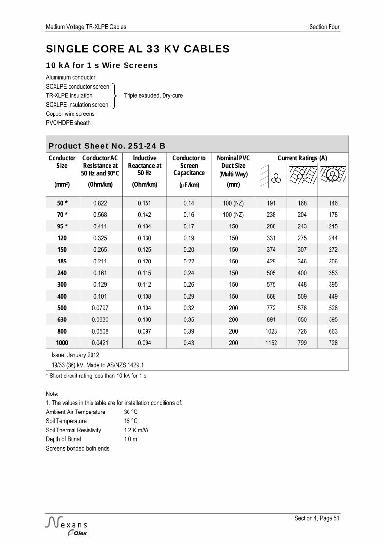
Medium Voltage TR-XLPE Cables Section Four
Section 4, Page 51
SINGLE CORE AL 33 KV CABLES 10 kA for 1 s Wire Screens Aluminium conductor SCXLPE conductor screen TR-XLPE insulation Triple extruded, Dry-cure SCXLPE insulation screen Copper wire screens PVC/HDPE sheath
Product Sheet No. 251-24 B Conductor
Size Conductor AC Resistance at
50 Hz and 90C
Inductive Reactance at
50 Hz
Conductor to Screen
Capacitance
Nominal PVC Duct Size
(Multi Way)
Current Ratings (A)
(mm2) (Ohm/km) (Ohm/km) (F/km) (mm)
50 * 0.822 0.151 0.14 100 (NZ) 191 168 146
70 * 0.568 0.142 0.16 100 (NZ) 238 204 178
95 * 0.411 0.134 0.17 150 288 243 215
120 0.325 0.130 0.19 150 331 275 244
150 0.265 0.125 0.20 150 374 307 272
185 0.211 0.120 0.22 150 429 346 306
240 0.161 0.115 0.24 150 505 400 353
300 0.129 0.112 0.26 150 575 448 395
400 0.101 0.108 0.29 150 668 509 449
500 0.0797 0.104 0.32 200 772 576 528
630 0.0630 0.100 0.35 200 891 650 595
800 0.0508 0.097 0.39 200 1023 726 663
1000 0.0421 0.094 0.43 200 1152 799 728
Issue: January 2012
19/33 (36) kV. Made to AS/NZS 1429.1
* Short circuit rating less than 10 kA for 1 s Note: 1. The values in this table are for installation conditions of: Ambient Air Temperature 30 °C Soil Temperature 15 °C Soil Thermal Resistivity 1.2 K.m/W Depth of Burial 1.0 m Screens bonded both ends

Section Four Medium Voltage TR-XLPE Cables
Section 4, Page 52
THREE CORE CU 33 KV CABLES Copper conductor SCXLPE conductor screen TR-XLPE insulation Triple extruded, Dry-cure SCXLPE insulation screen Copper wire screens PVC/HDPE sheath
Product Sheet No. 253-11 A Conductor
Size Nominal Diameters Wire Screens (per core) Thickness of
Sheath PVC/HDPE Nominal Overall
Diameter Linear Mass Insulation Insulation Screen Area No. & Size
(mm2) (mm) (mm) (mm2) (No. x mm) (mm) (mm) (kg/m) 3 kA for 1 s Wire Screens
50 24.6 26.2 9.6 17 x 0.85 1.5 / 1.6 66.9 4.15
70 26.0 27.6 10.2 18 x 0.85 1.6 / 1.7 70.4 4.99
95 27.7 29.3 10.8 19 x 0.85 1.7 / 1.7 74.5 6.00
120 29.1 30.7 11.3 20 x 0.85 1.7 / 1.8 77.8 6.90
150 30.5 32.1 11.9 21 x 0.85 1.8 / 1.8 81.0 7.95
185 32.3 33.9 12.5 22 x 0.85 1.8 / 1.9 85.1 9.25
240 34.6 36.2 13.1 23 x 0.85 1.9 / 2.0 90.5 11.25
300 36.8 38.4 14.2 25 x 0.85 2.0 / 2.0 95.4 13.40
10 kA for 1 s Wire Screens
50 * 24.6 26.2 16.5 29 x 0.85 1.6 / 1.6 67.1 4.37
70 26.0 27.6 22.7 40 x 0.85 1.6 / 1.7 70.4 5.35
95 27.7 29.3 22.7 40 x 0.85 1.7 / 1.7 74.5 6.35
120 29.1 30.7 22.7 40 x 0.85 1.7 / 1.8 77.8 7.25
150 30.5 32.1 22.7 40 x 0.85 1.8 / 1.8 81.0 8.25
185 32.3 33.9 22.7 40 x 0.85 1.8 / 1.9 85.1 9.55
240 34.6 36.2 22.7 40 x 0.85 1.9 / 2.0 90.5 11.55
300 36.8 38.4 22.7 40 x 0.85 2.0 / 2.0 95.4 13.60
Issue: September 2012
19/33 kV. (36) Made to AS/NZS 1429.1
* Short circuit rating less than 10 kA for 1 s Note: 1. Subject to confirmation, similar cables can be manufactured to other specifications.

Medium Voltage TR-XLPE Cables Section Four
Section 4, Page 53
THREE CORE CU 33 KV CABLES Copper conductor SCXLPE conductor screen TR-XLPE insulation Triple extruded, Dry-cure SCXLPE insulation screen Copper wire screens PVC/HDPE sheath
Product Sheet No. 253-11 B Conductor
Size Conductor AC Resistance at
50 Hz and 90C
Inductive Reactance at
50 Hz
Conductor to Screen
Capacitance
Nominal PVC Duct Size
(Single Way)
Current Ratings (A)
(mm2) (Ohm/km) (Ohm/km) (F/km) (mm)
3 kA for 1 s Wire Screens
50 0.494 0.143 0.14 100 (NZ) 212 200 173
70 0.342 0.133 0.16 100 (NZ) 262 244 211
95 0.247 0.126 0.17 150 317 292 256
120 0.196 0.122 0.19 150 364 331 290
150 0.159 0.118 0.20 150 411 372 325
185 0.128 0.113 0.22 150 470 420 367
240 0.0978 0.108 0.24 150 550 486 425
300 0.0789 0.104 0.26 150 626 547 478
10 kA for 1 s Wire Screens
50 * 0.494 0.143 0.14 100 (NZ) 212 200 173
70 0.342 0.133 0.16 100 (NZ) 262 244 211
95 0.247 0.126 0.17 150 317 292 256
120 0.196 0.122 0.19 150 364 331 290
150 0.159 0.118 0.20 150 411 372 325
185 0.128 0.113 0.22 150 470 420 367
240 0.0978 0.108 0.24 150 550 486 425
300 0.0789 0.104 0.26 150 626 547 478
Issue: September 2012
19/33 (36) kV. Made to AS/NZS 1429.1
* Short circuit rating less than 10 kA for 1 s Note: 1. The values in this table are for installation conditions of: Ambient Air Temperature 30 °C Soil Temperature 15 °C Soil Thermal Resistivity 1.2 K.m/W Depth of Burial 1.0 m
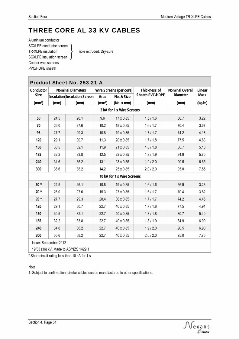
Section Four Medium Voltage TR-XLPE Cables
Section 4, Page 54
THREE CORE AL 33 KV CABLES Aluminium conductor SCXLPE conductor screen TR-XLPE insulation Triple extruded, Dry-cure SCXLPE insulation screen Copper wire screens PVC/HDPE sheath
Product Sheet No. 253-21 A Conductor
Size Nominal Diameters Wire Screens (per core) Thickness of
Sheath PVC/HDPE Nominal Overall
Diameter Linear Mass Insulation Insulation Screen Area No. & Size
(mm2) (mm) (mm) (mm2) (No. x mm) (mm) (mm) (kg/m) 3 kA for 1 s Wire Screens
50 24.5 26.1 9.6 17 x 0.85 1.5 / 1.6 66.7 3.22
70 26.0 27.6 10.2 18 x 0.85 1.6 / 1.7 70.4 3.67
95 27.7 29.3 10.8 19 x 0.85 1.7 / 1.7 74.2 4.18
120 29.1 30.7 11.3 20 x 0.85 1.7 / 1.8 77.5 4.63
150 30.5 32.1 11.9 21 x 0.85 1.8 / 1.8 80.7 5.10
185 32.2 33.8 12.5 22 x 0.85 1.8 / 1.9 84.9 5.70
240 34.6 36.2 13.1 23 x 0.85 1.9 / 2.0 90.5 6.65
300 36.6 38.2 14.2 25 x 0.85 2.0 / 2.0 95.0 7.55
10 kA for 1 s Wire Screens
50 * 24.5 26.1 10.8 19 x 0.85 1.6 / 1.6 66.9 3.28
70 * 26.0 27.6 15.3 27 x 0.85 1.6 / 1.7 70.4 3.82
95 * 27.7 29.3 20.4 36 x 0.85 1.7 / 1.7 74.2 4.45
120 29.1 30.7 22.7 40 x 0.85 1.7 / 1.8 77.5 4.94
150 30.5 32.1 22.7 40 x 0.85 1.8 / 1.8 80.7 5.40
185 32.2 33.8 22.7 40 x 0.85 1.8 / 1.9 84.9 6.00
240 34.6 36.2 22.7 40 x 0.85 1.9 / 2.0 90.5 6.90
300 36.6 38.2 22.7 40 x 0.85 2.0 / 2.0 95.0 7.75
Issue: September 2012
19/33 (36) kV. Made to AS/NZS 1429.1
* Short circuit rating less than 10 kA for 1 s Note: 1. Subject to confirmation, similar cables can be manufactured to other specifications.

Medium Voltage TR-XLPE Cables Section Four
Section 4, Page 55
THREE CORE AL 33 KV CABLES Aluminium conductor SCXLPE conductor screen TR-XLPE insulation Triple extruded, Dry-cure SCXLPE insulation screen Copper wire screens PVC/HDPE sheath
Product Sheet No. 253-21 B Conductor
Size Conductor AC Resistance at
50 Hz and 90C
Inductive Reactance at
50 Hz
Conductor to Screen
Capacitance
Nominal PVC Duct Size
(Single Way)
Current Ratings (A)
(mm2) (Ohm/km) (Ohm/km) (F/km) (mm)
3 kA for 1 s Wire Screens
50 0.822 0.143 0.14 100 (NZ) 164 155 134
70 0.568 0.133 0.16 100 (NZ) 203 189 163
95 0.411 0.126 0.17 150 246 226 198
120 0.325 0.122 0.19 150 283 257 226
150 0.265 0.118 0.20 150 319 288 252
185
240
300
10 kA for 1 s Wire Screens
50 * 0.822 0.143 0.14 100 (NZ) 164 155 134
70 * 0.568 0.133 0.16 100 (NZ) 203 189 163
95 * 0.411 0.126 0.17 150 246 226 198
120 0.325 0.122 0.19 150 283 257 226
150 0.265 0.118 0.20 150 319 288 252
185
240
300
Issue: January 2012
19/33 (36) kV. Made to AS/NZS 1429.1
* Short circuit rating less than 10 kA for 1 s Note: 1. The values in this table are for installation conditions of: Ambient Air Temperature 30 °C Soil Temperature 15 °C Soil Thermal Resistivity 1.2 K.m/W Depth of Burial 1.0 m
Section Four Medium Voltage TR-XLPE Cables
Section 4, Page 56
NOTES

AER
IALS

Aerials Section Five
Section 5, Page 1
SECTION FIVE – AERIALS
PAGE
Explanatory Information 2-7 Thermal Characteristics 2
Electrical Characteristics 4
Physical and Mechanical Characteristics 5
Bare Overhead Conductors 7
Product Sheets 8-21 AAC Aerial Conductors 8 AAAC Aerial Conductors 10
ACSR Aerial Conductors 12
Hard Drawn Cu Aerial Conductors 14
PVC Insulated Hard Drawn Cu Aerial Cables 16
PVC Insulated AAC Aerial Cables 18
Al Aerial Bundled Cables (ABC) 20
Notes 22

Section Five Aerials
Section 5, Page 2
THERMAL CHARACTERISTICS
Continuous Current Carrying Capacity The continuous current carrying capacity of a conductor depends on the permissible conductor temperature rise above ambient air temperature. For the calculation of current ratings of bare overhead conductors, ambient air temperatures between 20ºC and 40ºC are usually considered. The maximum permissible continuous operating temperature of an overhead conductor is limited by the permanent effects of high temperatures on the strength of the conductor material. Aluminium wire may be operated indefinitely at temperatures of up to 75C without significant annealing occurring. Therefore, this temperature is taken as the continuous operating temperature for bare aluminium and aluminium alloy conductors. For aluminium and aluminium alloy conductors, a maximum operating temperature limit of 100C is recommended, resulting in approximately 3% loss of strength after 1000 hours of operation. Under emergency operating conditions with higher temperatures, the effect of annealing should be considered. The loss of strength for an AAC or AAAC/1120 conductor operated at 150C for 10 hours is equivalent to the loss of strength for the same conductor operated at 100C for 7000 hours. The effect is less significant with steel-reinforced conductors, where the steel provides most of the strength of the conductor and is essentially unaffected by temperature. However, to allow for the effects on grease and fittings, a maximum operating temperature limit of 120C is recommended in this case. The maximum load capacity of a long line is usually dictated by consideration of system stability, permissible voltage regulation, or the cost of energy losses. However, the maximum load capacity of a short line may be determined by the maximum permissible operating temperature of the conductor. The maximum permissible operating temperature is that which results in the greatest permissible sag (allowing for creep) or that which results in the maximum allowable permanent loss of tensile strength due to annealing. The conductor temperature depends on the current load, the electrical characteristics of the conductor, and the atmospheric parameters such as wind and sun. Assuming these factors to be fairly constant, the conductor temperature does not change significantly. In this situation, the heat supplied to the conductor is balanced by the heat dissipated and the thermal condition of the conductor is then defined as “steady state”. At such a steady state, with the conductor at maximum permissible temperature, a heat balance equation can be used to calculate the continuous current carrying capacity of a conductor. The formulae used for the calculations are generally in accordance with those published by V. T. Morgan.

Aerials Section Five
Section 5, Page 3
THERMAL CHARACTERISTICS (CONT.)
Ambient Temperature For dry conductors the choice of ambient temperature has little influence on the increase of the calculated current carrying capacity for a given temperature rise. For example, for temperature rises higher than 30C, the increase in the current carrying capacity for a given temperature rise above an ambient of 20C is within 2% of the value obtained with the same temperature rise above an ambient of 35C. Rain has a major effect on the current carrying capacity of a conductor, and the rating of a wet conductor is higher than that of a dry one. For conductors with a wet surface, the choice of ambient temperature significantly influences the current carrying capacity.
Solar Radiation Many factors can influence the effect of solar radiation. The altitude of the sun, the clearness ratio of the sky, the incidence of the solar beam and the reflectance of the sun from the ground, affect the magnitude of the solar heat input into the conductor. However, small changes in solar radiation intensity have little effect on the current carrying capacity. An increase in solar radiation intensity from 1000 W/m2 to 1200 W/m2 decreases the rating of a conductor by about 2%. A value of 1000 W/m2 for direct solar radiation and 100W/m2 for diffuse solar radiation for summer noon conditions has been chosen as appropriate to general conditions throughout Australia and New Zealand.
Emissivity and Solar Absorption Coefficients Emissivity is the value between zero and unity which defines the fraction of the black-body radiation that the surface emits. Similarly, absorptivity is the value between zero and unity that defines the fraction of the incident irradiation that is absorbed by the surface. The surface condition of a conductor affects both these parameters, and for convenience they are assumed to be equal. The Rural Weathered condition is considered to exist on old lines in clean atmospheres and may also exist as sections of new conductor in an old line arising from augmentation or alteration works.
Air Movement This is the most significant of all the parameters. The rate of increase of the current carrying capacity of a conductor with increasing wind velocity is greatest at low wind velocities. This is partly due to the effect of wind velocity on the radial temperature gradient in the conductor. Wind direction also affects the current carrying capacity of a conductor. However, it would be difficult to take the variability of the wind into account because of its dependence on many factors, including local topography and climate. In view of this and of the lack of comprehensive meteorological data across the country, current carrying capacities have been calculated for the theoretical extreme condition of still air and for 1.0 metre/second.

Section Five Aerials
Section 5, Page 4
ELECTRICAL CHARACTERISTICS
AC Resistance The electrical resistance of a conductor with alternating current is greater than its resistance with direct current. For all-aluminium conductors, the increased resistance is due mainly to skin effect, which causes the current to concentrate in the outer portion of the conductor. Non-uniformity of current distribution is also caused by a proximity effect, which results from electromagnetic fields from nearby conductors. However, for normal spacing of overhead lines this effect is small and can be ignored. For steel-reinforced conductors the current that follows the spiral of the helically applied aluminium wires around the steel core produces a longitudinal magnetic flux in the steel core. This alternating flux causes both hysteresis and eddy current losses, increasing the effective resistance of the conductor to alternating current. The magnetic flux in the steel varies with current, and is most significant when the number of aluminium layers is odd, because there is incomplete cancellation of the magnetic flux in the steel core. Skin effect and, in the case of steel-reinforced conductors with single and three layers of aluminium, hysteresis and eddy current effects, were taken into consideration in determining the AC resistance.
Inductive Reactance The inductive reactance of stranded conductors in an overhead line is calculated by considering the flux linkages caused by current flowing in the conductors. To simplify the calculation, it is usually considered to consist of two components: the conductor component of reactance resulting from the magnetic flux, and the spacing component of reactance resulting from the magnetic flux to the equivalent return conductor. The conductor component depends on the number of strands and the geometry of the conductor. The spacing component takes into consideration the spacing between conductors and the geometry of the circuit. The reactance of an overhead line is found by adding the two components. For steel-reinforced conductors, the magnetic flux in the steel core depends on the amount of current flowing in the conductors and is most significant when the number of aluminium layers is odd. However, the magnetic properties of the steel core are highly non-linear, and the conductor component of reactance can be accurately determined only from tests. The values shown in the tables of electrical performance data in the following sections are sufficiently accurate for most practical installations. Values for inductive reactance to 300 mm horizontal spacing are shown in the following Product Sheets.
Aerials Section Five
Section 5, Page 5
PHYSICAL & MECHANICAL CHARACTERISTICS
Sag and Tension The general theory of sag-tension calculations is based on the fact that a conductor suspended between two points assumes the shape of a catenary. The basic relationship between sag and tension can be established from knowledge of the stress-strain characteristics of a conductor. Factors which will subsequently affect the sag and tension are thermal elongation of the conductor due to changes in temperature, creep with time under load, and increased loadings due to wind and ice. These factors affect the length of the conductor and consequently the sag and tension characteristics. The physical and mechanical performance characteristics required for sag-tension calculations are shown in the product sheets which follow, and the factors which affect the length of a stranded conductor are briefly explained in the following sections. Suitable formulae for selecting the appropriate tension are published in AS/NZS 7000:2010, Overhead Line Design - Detailed Procedures.
Stress-Strain Characteristics The stress-strain behaviour of a stranded conductor depends on the properties of the component wires and the construction of the conductor, including the number of layers and the lay length of the wires. Stress-strain tests are used to establish the behaviour of a stranded conductor during the initial loading period, and a relationship for its elastic behaviour in its final state. The test procedure used to obtain the stress-strain characteristics is to load and hold the conductor at 30%, 50% and 70% of its calculated breaking load with load-holding periods of 30 minutes, 1 hour and 1 hour respectively and the conductor is unloaded at the end of each holding period. From the initial loading curve where the conductor is loaded to 30% of its breaking load and held for 30 minutes, the amount of geometric settlement of the component wires, the initial creep and the initial modulus of elasticity can be determined. Subsequent loading and unloading of the conductor at 50% and 70% of its breaking load with load holding periods of 1 hour, ensures that the component wires are settled and that most of the initial creep has been removed. This leaves the conductor in its final state and the final unloading of the conductor is used to determine the final modulus of elasticity. The final modulus of elasticity is used for sag-tension calculations to determine the behaviour of a conductor which has been in service for some time and has been subjected to high tensions due to low temperatures, wind and in some cases ice loading. At some high temperature, all of the load is transferred to the steel and the thermal elongation of the composite conductor is identical to the thermal elongation of the steel core alone. In practice, for normal operating conditions, it is sufficiently accurate to assume a direct relationship between thermal elongation and the coefficient of linear expansion of the composite conductor. The coefficient of linear expansion for the composite conductor may be calculated, taking into account the material properties and the areas of each component making up the conductor.

Section Five Aerials
Section 5, Page 6
PHYSICAL & MECHANICAL CHARACTERISTICS (CONT.)
Thermal Elongation Variations in temperature will change the length of a conductor and this change in length is known as thermal elongation or thermal strain. For homogeneous AAC, AAAC and hard drawn copper conductors the thermal elongation is directly related to the coefficient of linear expansion of the material. For composite ACSR and AACSR conductors the thermal elongation is more complex to establish, due to the relationship between stresses and strains of constituent wires. The stress distribution in a composite conductor changes with temperature. Due to the lower coefficient of thermal expansion of steel compared with that of aluminium, a rise in temperature increases the proportion of the tensile load carried by the steel core.
Creep Creep is defined as the plastic deformation or non-recoverable extension of conductors which occurs with time under load. It can be considered to consist of two components: initial creep and long term creep. Initial creep is the result of settling in of wires when the conductor is first subjected to maximum tension. This component of creep can be offset by pre-tensioning the conductor at a load higher than the everyday tension (EDT) before final sagging. This procedure can effectively stabilise the conductor before final sagging and also provides a consistent base for determining subsequent long-term creep. If conductors are installed at a value of the tension below that used for final sagging, full allowance for both initial and long term creep should be made. Long term creep depends on stress, operating temperature and time. It can be calculated from information on the material and design of the conductor. Typically, extensions of 400–500 micrometres per metre may occur over a 30-year life of a line. In order to avoid problems associated with the increase of sag resulting from creep, a number of solutions may be adopted. One solution is to assume an imaginary lower temperature of installation which would (when the temperature is raised to the actual installation temperature) result in a thermal expansion equal in value to that of the predicted creep. For example, if the predicted creep is equal to the thermal expansion caused by a temperature increase of 20C, then the installation temperature is assumed to be less than the actual by 20C. This results in the line being tensioned at a higher EDT than normal at the time of installation. In the 30-year life span of the conductor, the tension will gradually decrease to the value of true EDT. Alternatively, commercially available computer programs based on the more complex strain-summation method can be used to determine the stringing tension for any given future loading conditions and limiting constraints on one or more parameters. Determining the stringing tension is done by iteration, working forward in time.
Everyday Tension Aeolian vibration can damage overhead line conductors as a result of mechanical fatigue. The standard practice for preventing fatigue damage is to limit the tension of the conductor to a value that will not subject the conductor to excessive vibration under normal operating conditions. The tension that may be applied to a conductor is usually expressed as a percentage of the conductor breaking load. As the damage from fatigue is most pronounced in the outer layers of the conductor, the safe tension is based on the allowable stress in the outer layers. Three main factors which cause vibration fatigue on conductors are considered when determining the safe allowable outer layer stress: the type of suspension arrangement used, the terrain, and the efficiency of the vibration damping system, if used. Reference should be made to AS/NZS 7000:2010, Overhead Line Design - Detailed Procedures, for EDT figures.
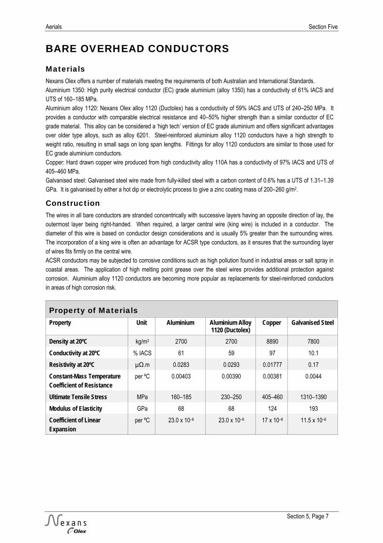
Aerials Section Five
Section 5, Page 7
BARE OVERHEAD CONDUCTORS
Materials Nexans Olex offers a number of materials meeting the requirements of both Australian and International Standards. Aluminium 1350: High purity electrical conductor (EC) grade aluminium (alloy 1350) has a conductivity of 61% IACS and UTS of 160–185 MPa. Aluminium alloy 1120: Nexans Olex alloy 1120 (Ductolex) has a conductivity of 59% IACS and UTS of 240–250 MPa. It provides a conductor with comparable electrical resistance and 40–50% higher strength than a similar conductor of EC grade material. This alloy can be considered a ‘high tech’ version of EC grade aluminium and offers significant advantages over older type alloys, such as alloy 6201. Steel-reinforced aluminium alloy 1120 conductors have a high strength to weight ratio, resulting in small sags on long span lengths. Fittings for alloy 1120 conductors are similar to those used for EC grade aluminium conductors. Copper: Hard drawn copper wire produced from high conductivity alloy 110A has a conductivity of 97% IACS and UTS of 405–460 MPa. Galvanised steel: Galvanised steel wire made from fully-killed steel with a carbon content of 0.6% has a UTS of 1.31–1.39 GPa. It is galvanised by either a hot dip or electrolytic process to give a zinc coating mass of 200–260 g/m2.
Construction The wires in all bare conductors are stranded concentrically with successive layers having an opposite direction of lay, the outermost layer being right-handed. When required, a larger central wire (king wire) is included in a conductor. The diameter of this wire is based on conductor design considerations and is usually 5% greater than the surrounding wires. The incorporation of a king wire is often an advantage for ACSR type conductors, as it ensures that the surrounding layer of wires fits firmly on the central wire. ACSR conductors may be subjected to corrosive conditions such as high pollution found in industrial areas or salt spray in coastal areas. The application of high melting point grease over the steel wires provides additional protection against corrosion. Aluminium alloy 1120 conductors are becoming more popular as replacements for steel-reinforced conductors in areas of high corrosion risk.
Property of Materials Property Unit Aluminium Aluminium Alloy
1120 (Ductolex) Copper Galvanised Steel
Density at 20ºC kg/m3 2700 2700 8890 7800
Conductivity at 20ºC % IACS 61 59 97 10.1
Resistivity at 20ºC µΩ.m 0.0283 0.0293 0.01777 0.17
Constant-Mass Temperature Coefficient of Resistance
per ºC 0.00403 0.00390 0.00381 0.0044
Ultimate Tensile Stress MPa 160–185 230–250 405–460 1310–1390
Modulus of Elasticity GPa 68 68 124 193
Coefficient of Linear Expansion
per ºC 23.0 x 10⁻⁶ 23.0 x 10⁻⁶ 17 x 10–6 11.5 x 10⁻⁶

Section Five Aerials
Section 5, Page 8
AAC AERIAL CONDUCTORS Aluminium conductor
Product Sheet No. 310-01 A Code Name Stranding Cross Sectional Area Nominal Overall Diameter Mass Breaking Load
(mm) (mm2) (mm) (kg/km) (kN) Namu 7/2.11 24.5 6.33 66.9 4.07
Poko 7/2.36 30.6 7.08 83.7 5.09
Ladybird 7/2.79 42.8 8.37 117 6.92
Kutu 7/3.00 49.5 9.00 135 7.98
Fly 7/3.40 63.6 10.2 174 9.98
Rango 7/3.66 73.6 11.0 201 11.2
Grasshopper 7/3.91 84.1 11.7 230 12.8
Wasp 7/4.39 106 13.2 290 16.1
Beetle 19/2.67 106 13.4 292 17.2
Weke 7/4.72 122 14.2 335 18.6
Bee 7/4.90 132 14.7 361 20.1
Cricket 7/5.36 158 16.1 432 24.0
Weta 19/3.35 167 16.8 460 26.2
Pluto 19/3.75 210 18.8 576 31.9
Mata 19/3.86 222 19.3 611 33.8
Cockroach 19/4.22 266 21.1 731 40.4
Butterfly 19/4.65 323 23.3 888 49.1
Cicada 37/4.65 628 32.6 1730 95.6
Issue: January 2012
Made to AS 1531
Notes: 1. Coefficient of linear expansion 23.0 x 10⁻⁶/C. 2. Modulus of elasticity:
65 GPa for seven (7) and nineteen (19) wire conductors. 64 GPa for thirtyseven (37) wire conductors.

Aerials Section Five
Section 5, Page 9
AAC AERIAL CONDUCTORS Aluminium conductor
Product Sheet No. 310-01 B Code Name Calculated DC
Resistance at 20C Reactance at 50Hz with
300 mm Spacing Current Rating Still
Air Current Rating 1 m/s
(Ohm/km) (Ohm/km) (Amps) (Amps) Namu 1.17 0.321 85 164
Poko 0.936 0.314 98 189
Ladybird 0.670 0.303 121 232
Kutu 0.579 0.299 132 253
Fly 0.451 0.291 155 295
Rango 0.389 0.286 170 323
Grasshopper 0.342 0.282 184 350
Wasp 0.271 0.275 213 403
Beetle 0.271 0.271 213 404
Weke 0.234 0.270 233 441
Bee 0.217 0.268 244 461
Cricket 0.181 0.262 275 515
Weta 0.172 0.257 286 533
Pluto 0.137 0.250 333 612
Mata 0.130 0.248 345 632
Cockroach 0.108 0.242 390 707
Butterfly 0.0895 0.236 443 792
Cicada 0.0460 0.214 689 1178
Issue: January 2012
Made to AS 1531
Note: 1. Current ratings are based on an ambient temperature of 30C, a maximum conductor temperature of 75C, rural weathered, summer noon and intensity of solar radiation 1000 W/m2.

Section Five Aerials
Section 5, Page 10
AAAC AERIAL CONDUCTORS 1120 Aluminium alloy conductor
Product Sheet No. 310-02 A Code Name Stranding Cross Sectional Area Nominal Overall Diameter Mass Breaking Load
(mm) (mm2) (mm) (kg/km) (kN) Chlorine 7/2.50 34.4 7.50 94.3 8.18
Chromium 7/2.75 41.6 8.25 113 9.91
Fluorine 7/3.00 49.5 9.00 135 11.8
Helium 7/3.75 77.3 11.3 211 17.6
Hydrogen 7/4.50 111 13.5 304 24.3
Iodine 7/4.75 124 14.3 339 27.1
Krypton 19/3.25 158 16.3 433 37.4
Lutetium 19/3.50 183 17.5 503 41.7
Neon 19/3.75 210 18.8 576 47.8
Nitrogen 37/3.00 262 21.0 721 62.2
Sulfur 61/3.75 674 33.8 1860 145
Issue: September 2012
Made to AS 1531
Notes: 1. Coefficient of linear expansion 23.0 x 10⁻⁶/C. 2. Modulus of elasticity:
65 GPa for seven (7) and nineteen (19) wire conductors. 64 GPa for thirtyseven (37) and sixtyone (61) wire conductors.

Aerials Section Five
Section 5, Page 11
AAAC AERIAL CONDUCTORS 1120 Aluminium alloy conductor
Product Sheet No. 310-02 B Code Name Calculated DC
Resistance at 20C Reactance at 50Hz with
300 mm Spacing Current Rating
Still Air Current Rating 1 m/s
(Ohm/km) (Ohm/km) (Amps) (Amps) Chlorine 0.864 0.310 104 200
Chromium 0.713 0.304 117 224
Fluorine 0.599 0.299 131 250
Helium 0.383 0.285 173 328
Hydrogen 0.266 0.273 217 410
Iodine 0.239 0.270 231 438
Krypton 0.189 0.259 271 507
Lutetium 0.163 0.254 299 555
Neon 0.142 0.250 328 603
Nitrogen 0.114 0.242 381 690
Sulfur 0.0444 0.212 711 1210
Issue: September 2012
Made to AS 1531
Note: 1. Current ratings are based on an ambient temperature of 30C, a maximum conductor temperature of 75C, rural weathered, summer noon and intensity of solar radiation 1000 W/m2.

Section Five Aerials
Section 5, Page 12
ACSR AERIAL CONDUCTORS Aluminium conductor Galvanised steel reinforced
Product Sheet No. 310-03 A Code Name Number of
Strands/Wire Diameter (mm)
Equivalent Aluminium Cross
Sectional Area
Nominal Overall
Diameter
Mass Breaking Load
Modulus of Elasticity
Coefficient of Linear
Expansion
Aluminium Steel (mm2) (mm) (kg/km) (kN) (GPa) (x 10-6/°C) Magpie 3/2.11 4/2.11 12.7 6.33 139 17.4 136 13.9
Squirrel 6/2.11 1/2.11 20.7 6.33 84.8 7.49 83 19.3
Gopher 6/2.36 1/2.36 26.0 7.08 106 9.37 83 19.3
Ferret 6/3.00 1/3.00 41.8 9.00 171 14.9 83 19.3
Mink 6/3.66 1/3.66 62.2 11.0 255 21.6 83 19.3
Raccoon 6/4.09 1/ 4.09 77.7 12.3 318 12.3 83 19.3
Dog 6/4.72 7/1.57 103 14.2 396 32.9 80 19.9
Dingo 18/3.35 1/3.35 155 16.8 505 35.4 71 21.4
Wolf 30/2.59 7/2.59 155 18.1 724 67.4 88 18.4
Jaguar 18/3.86 1/3.86 207 19.3 671 33.0 71 21.4
Goat 30/3.71 7/3.71 317 26.0 1490 135 88 18.4
Zebra 54/3.18 7/3.18 420 28.6 1620 131 78 19.9
Cardinal 54/3.38 7/3.38 474 30.4 1830 149 78 19.9
Moose 54/3.53 7/3.53 517 31.8 1990 159 78 19.9
Pawpaw 54/3.75 19/2.25 584 33.8 2240 178 78 20.0
Issue: January 2012
Made to AS 3607

Aerials Section Five
Section 5, Page 13
ACSR AERIAL CONDUCTORS Aluminium conductor Galvanised steel reinforced
Product Sheet No. 310-03 B Code Name Calculated DC
Resistance at 20C Reactance at 50Hz with
300 mm Spacing Current Rating
Still Air Current Rating 1 m/s
(Ohm/km) (Ohm/km) (Amps) (Amps) Magpie 2.23 0.349 59 113
Squirrel 1.37 0.322 75 145
Gopher 1.09 0.315 86 167
Ferret 0.677 0.299 117 223
Mink 0.455 0.287 152 285
Raccoon 0.364 0.280 175 326
Dog 0.274 0.271 210 387
Dingo 0.182 0.257 274 494
Wolf 0.183 0.252 280 501
Jaguar 0.137 0.248 336 616
Goat 0.0893 0.229 462 814
Zebra 0.0674 0.222 544 942
Cardinal 0.0597 0.219 590 1014
Moose 0.0547 0.216 626 1068
Pawpaw 0.0485 0.212 678 1148
Issue: January 2012
Made to AS 3607
Note: 1. Current ratings are based on an ambient temperature of 30C, a maximum conductor temperature of 75C, rural weathered, summer noon and intensity of solar radiation 1000 W/m2.
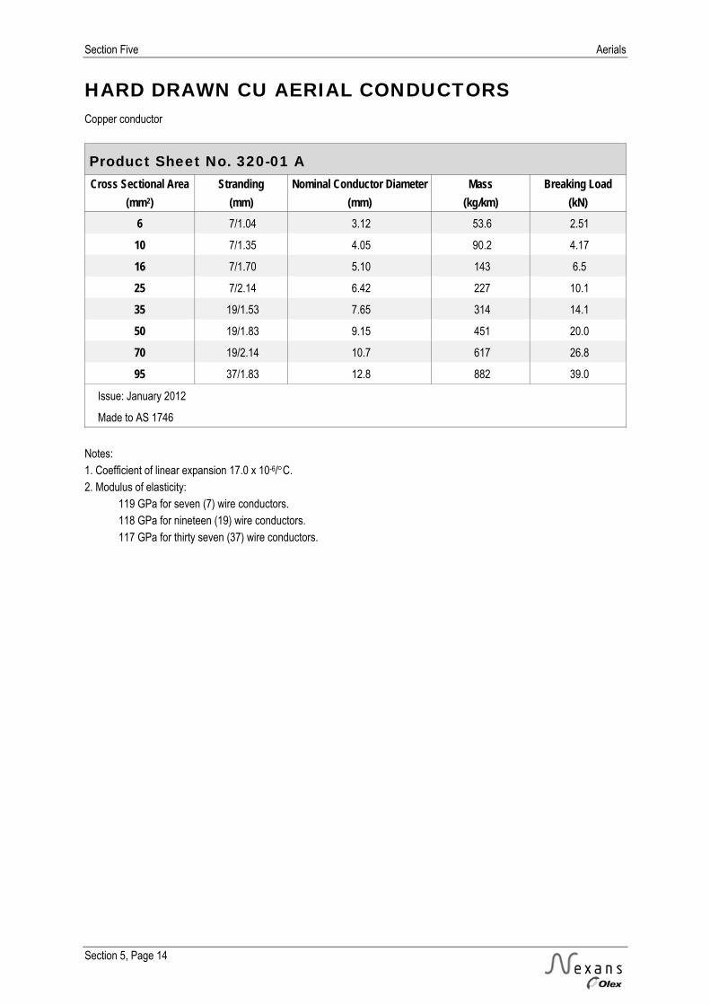
Section Five Aerials
Section 5, Page 14
HARD DRAWN CU AERIAL CONDUCTORS Copper conductor
Product Sheet No. 320-01 A Cross Sectional Area Stranding Nominal Conductor Diameter Mass Breaking Load
(mm2) (mm) (mm) (kg/km) (kN) 6 7/1.04 3.12 53.6 2.51
10 7/1.35 4.05 90.2 4.17
16 7/1.70 5.10 143 6.5
25 7/2.14 6.42 227 10.1
35 19/1.53 7.65 314 14.1
50 19/1.83 9.15 451 20.0
70 19/2.14 10.7 617 26.8
95 37/1.83 12.8 882 39.0
Issue: January 2012
Made to AS 1746
Notes: 1. Coefficient of linear expansion 17.0 x 10⁻⁶/C. 2. Modulus of elasticity: 119 GPa for seven (7) wire conductors. 118 GPa for nineteen (19) wire conductors. 117 GPa for thirty seven (37) wire conductors.

Aerials Section Five
Section 5, Page 15
HARD DRAWN CU AERIAL CONDUCTORS Copper conductor
Product Sheet No. 320-01 B Cross Sectional
Area Calculated DC Resistance
at 20C Reactance at 50Hz with
300 mm Spacing Current Rating
Still Air Current Rating 1 m/s
(mm2) (Ohm/km) (Ohm/km) (Amps) (Amps) 6 3.03 0.365 44 87
10 1.80 0.349 61 120
16 1.13 0.334 82 160
25 0.716 0.320 110 212
35 0.516 0.306 135 260
50 0.361 0.295 169 323
70 0.264 0.285 206 392
95 0.186 0.273 256 486
Issue: January 2012
Made to AS 1746
Note: 1. Current ratings are based on an ambient temperature of 30C, a maximum conductor temperature of 75C, rural weathered, summer noon and intensity of solar radiation 1000 W/m2.

Section Five Aerials
Section 5, Page 16
PVC INSULATED HARD DRAWN CU AERIAL CABLES Copper conductor PVC insulation
Product Sheet No. 330-01 A Cross Sectional
Area Stranding Conductor
Diameter Insulation Thickness
Nominal Overall Diameter
Mass Breaking Load
(mm2) (mm) (mm) (mm) (mm) (kg/km) (kN) 6 7/1.04 3.12 1.0 5.3 80 2.3
10 7/1.35 4.05 1.0 6.3 120 3.9
16 7/1.70 5.10 1.0 7.3 180 5.9
25 19/1.35 6.75 1.2 9.3 300 10.4
35 19/1.53 7.65 1.2 10.3 370 12.7
50 19/1.83 9.15 1.4 12.2 510 17.3
70 19/2.14 10.7 1.4 13.8 710 25.0
95 37/1.83 12.8 1.6 16.2 980 32.8
Issue: January 2012
Made to AS/NZS 5000.1
Notes: 1. Coefficient of linear expansion 17.0 x 10⁻⁶/C. 2. Modulus of elasticity: 112 GPa for seven (7) wire conductors. 110 GPa for nineteen (19) wire conductors. 108 GPa for thirty seven (37) wire conductors.
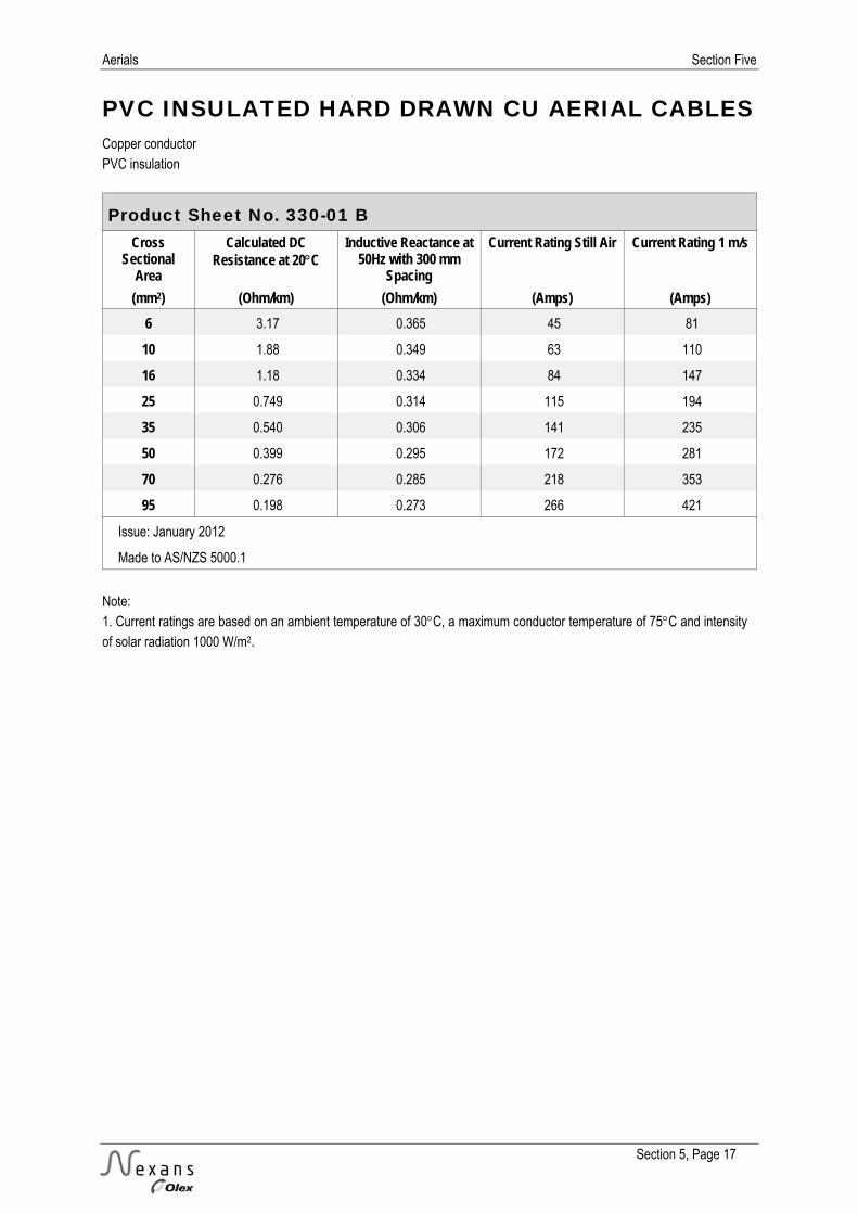
Aerials Section Five
Section 5, Page 17
PVC INSULATED HARD DRAWN CU AERIAL CABLES Copper conductor PVC insulation
Product Sheet No. 330-01 B Cross
Sectional Area
Calculated DC Resistance at 20C
Inductive Reactance at 50Hz with 300 mm
Spacing
Current Rating Still Air Current Rating 1 m/s
(mm2) (Ohm/km) (Ohm/km) (Amps) (Amps) 6 3.17 0.365 45 81
10 1.88 0.349 63 110
16 1.18 0.334 84 147
25 0.749 0.314 115 194
35 0.540 0.306 141 235
50 0.399 0.295 172 281
70 0.276 0.285 218 353
95 0.198 0.273 266 421
Issue: January 2012
Made to AS/NZS 5000.1
Note: 1. Current ratings are based on an ambient temperature of 30C, a maximum conductor temperature of 75C and intensity of solar radiation 1000 W/m2.

Section Five Aerials
Section 5, Page 18
PVC INSULATED AAC AERIAL CABLES Aluminium conductor PVC insulation
Product Sheet No. 330-02 A Code Name Stranding Cross Sectional
Area Insulation Thickness
Nominal Overall Diameter
Mass Breaking Load
(mm) (mm2) (mm) (mm) (kg/km) (kN) Namu 7/2.11 24.5 1.2 8.85 119 4.07
Poko 7/2.36 30.6 1.3 9.75 154 5.09
Ladybird 7/2.79 42.8 1.4 11.4 200 6.92
Kutu 7/3.00 49.5 1.4 12.0 224 7.98
Fly 7/3.40 63.6 1.4 13.2 276 9.98
Rango 7/3.66 73.6 1.4 14.0 314 11.2
Wasp 7/4.39 106 1.6 16.6 443 16.1
Beetle 19/2.67 106 1.6 16.8 437 17.2
Weke 7/4.72 122 1.8 18.0 520 18.6
Weta 19/3.35 167 1.8 20.7 650 26.2
Issue: January 2012
Generally made to AS/NZS 5000.1
Notes: 1. Coefficient of linear expansion 23.0 x 10⁻⁶/C. 2. Modulus of elasticity 65 GPa.

Aerials Section Five
Section 5, Page 19
PVC INSULATED AAC AERIAL CABLES Aluminium conductor PVC insulation
Product Sheet No. 330-02 B Code Name Calculated DC
Resistance at 20C Reactance at 50Hz with
300mm Spacing Current Rating Still
Air Current Rating 1 m/s
(Ohm/km) (Ohm/km) (Amps) (Amps) Namu 1.17 0.321 90 152
Poko 0.936 0.314 104 174
Ladybird 0.670 0.303 130 212
Kutu 0.579 0.299 142 232
Fly 0.451 0.291 168 271
Rango 0.389 0.286 185 297
Wasp 0.271 0.275 234 368
Beetle 0.271 0.271 235 369
Weke 0.234 0.270 258 399
Weta 0.172 0.257 317 484
Issue: January 2012
Generally made to AS/NZS 5000.1
Note: 1. Current ratings are based on an ambient temperature of 30C, a maximum conductor temperature of 75C, rural weathered, summer noon and intensity of solar radiation 1000 W/m2.

Section Five Aerials
Section 5, Page 20
AL AERIAL BUNDLED CABLES (ABC) Aluminium conductor XLPE insulation
Product Sheet No. 330-03 A (Two Core) Cross Sectional
Area Conductor Diameter
Insulation Thickness
Nominal Overall Diameter of Bundle
Mass Breaking Load
(mm2) (mm) (mm) (mm) (kg/km) (kN) 25 5.99 1.3 18.4 200 7.0
35 6.90 1.3 20.6 260 9.8
50 8.05 1.5 23.8 350 14.0
95 11.40 1.7 31.8 680 26.6
Issue: January 2012
Made to AS/NZS 3560.1
Product Sheet No. 330-04 A (Three Core) Cross Sectional
Area Conductor Diameter
Insulation Thickness
Nominal Overall Diameter of Bundle
Mass Breaking Load
(mm2) (mm) (mm) (mm) (kg/km) (kN) 35 6.90 1.3 22.2 390 14.7
Issue: January 2012
Made to AS/NZS 3560.1
Product Sheet No. 330-05 A (Four Core) CrossSectional
Area Conductor Diameter
Insulation Thickness
Nominal Overall Diameter of Bundle
Mass Breaking Load
(mm2) (mm) (mm) (mm) (kg/km) (kN) 25 5.99 1.3 22.2 400 14.0
35 6.90 1.3 24.9 520 19.6
50 8.05 1.5 28.7 700 28.0
70 9.69 1.5 32.8 960 39.2
95 11.40 1.7 38.4 1350 53.2
120 12.90 1.7 42.2 1660 67.2
150 14.35 1.7 45.6 2020 84.0
Issue: January 2012
Made to AS/NZS 3560.1 Notes: 1. Coefficient of linear expansion 23 x 10-6/C. 2. Modulus of elasticity 59 GPa up to and including 50 mm² and 56 GPa for conductors above 50 mm².
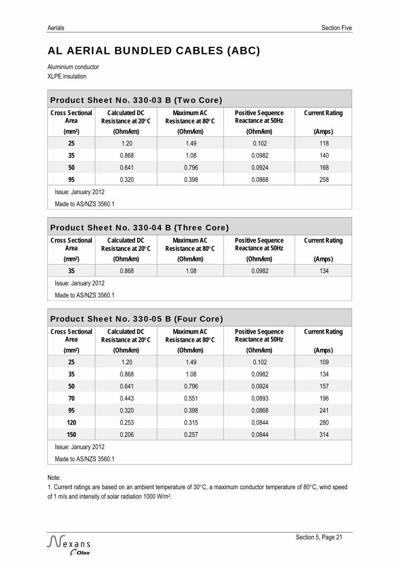
Aerials Section Five
Section 5, Page 21
AL AERIAL BUNDLED CABLES (ABC) Aluminium conductor XLPE insulation
Product Sheet No. 330-03 B (Two Core) Cross Sectional
Area Calculated DC
Resistance at 20C Maximum AC
Resistance at 80C Positive Sequence Reactance at 50Hz
Current Rating
(mm2) (Ohm/km) (Ohm/km) (Ohm/km) (Amps) 25 1.20 1.49 0.102 118
35 0.868 1.08 0.0982 140
50 0.641 0.796 0.0924 168
95 0.320 0.398 0.0868 258
Issue: January 2012
Made to AS/NZS 3560.1
Product Sheet No. 330-04 B (Three Core) Cross Sectional
Area Calculated DC
Resistance at 20C Maximum AC
Resistance at 80C Positive Sequence Reactance at 50Hz
Current Rating
(mm2) (Ohm/km) (Ohm/km) (Ohm/km) (Amps) 35 0.868 1.08 0.0982 134
Issue: January 2012
Made to AS/NZS 3560.1
Product Sheet No. 330-05 B (Four Core) Cross Sectional
Area Calculated DC
Resistance at 20C Maximum AC
Resistance at 80C Positive Sequence Reactance at 50Hz
Current Rating
(mm2) (Ohm/km) (Ohm/km) (Ohm/km) (Amps) 25 1.20 1.49 0.102 109
35 0.868 1.08 0.0982 134
50 0.641 0.796 0.0924 157
70 0.443 0.551 0.0893 196
95 0.320 0.398 0.0868 241
120 0.253 0.315 0.0844 280
150 0.206 0.257 0.0844 314
Issue: January 2012
Made to AS/NZS 3560.1 Note: 1. Current ratings are based on an ambient temperature of 30C, a maximum conductor temperature of 80C, wind speed of 1 m/s and intensity of solar radiation 1000 W/m2.

Section Five Aerials
Section 5, Page 22
NOTES