next-generation airborne collision avoidance · pdf filevolume 19, number 1, 2012 n lincoln...
TRANSCRIPT
VOLUME 19, NUMBER 1, 2012 n LINCOLN LABORATORY JOURNAL 17
Next-Generation Airborne Collision Avoidance SystemMykel J. Kochenderfer, Jessica E. Holland, and James P. Chryssanthacopoulos
Building a collision avoidance sys-
tem that can meet the safety standards
required of commercial aviation is chal-
lenging. Lincoln Laboratory, in collabora-
tion with other organizations, spent decades developing
and refining the system that is in use today [1]. There
are several reasons why creating a robust system is dif-
ficult. The sensors available to the system are imperfect
and noisy, resulting in uncertainty in the current posi-
tions and velocities of the aircraft involved. Variability
in pilot behavior and aircraft dynamics makes it difficult
to predict where the aircraft will be in the future. Also,
the system must balance multiple competing objectives,
including both safety and operational considerations.
Over the past few years, Lincoln Laboratory has
been developing advanced algorithmic techniques for
addressing these major challenges for collision avoid-
ance. These techniques rely upon probabilistic mod-
els to represent the various sources of uncertainty and
upon computer-based optimization to obtain the best
possible collision avoidance system. Simulation studies
with recorded radar data have confirmed that such an
approach leads to a significant improvement to safety
and operational performance [2]. The Federal Aviation
Administration (FAA) has formed a team of organiza-
tions to mature the system, which has become known
as Airborne Collision Avoidance System X (ACAS X).
A satisfactory proof-of-concept flight test in 2013 will
strengthen the goal of making ACAS X the next inter-
national standard for collision avoidance.
In response to a series of midair collisions involving commercial airliners, Lincoln Laboratory was directed by the Federal Aviation Administration in the 1970s to participate in the development of an onboard collision avoidance system. In its current manifestation, the Traffic Alert and Collision Avoidance System is mandated worldwide on all large aircraft and has significantly improved the safety of air travel, but major changes to the airspace planned over the coming years will require substantial modification to the system. Recently, Lincoln Laboratory has been pioneering the development of a new approach to collision avoidance systems that completely rethinks how such systems are engineered, allowing the system to provide a higher degree of safety without interfering with normal, safe operations.
»
18 LINCOLN LABORATORY JOURNAL n VOLUME 19, NUMBER 1, 2012
NExt-GENEratioN airborNE CollisioN avoidaNCE systEM
the Traffic Alert and Collision Avoidance System. It was
based on the fundamental concepts of BCAS, but there
were enhancements that enabled its use in high-density
airspace. The development spanned several decades as
shown in Figure 2, and Lincoln Laboratory was a key
leader in the design of both systems. The collision over
Cerritos led to Congress mandating the use of TCAS in
the United States, and now TCAS is required on all large
passenger and cargo aircraft worldwide [3].
Challenges for tCasTCAS has been very successful in preventing mid-
air collisions over the years, but the way in which the
logic was designed limits its robustness. Fundamental
to TCAS design is the use of a deterministic model.
However, recorded radar data show that pilots do not
always behave as assumed by the logic. Not anticipating
the spectrum of responses limits TCAS’s robustness, as
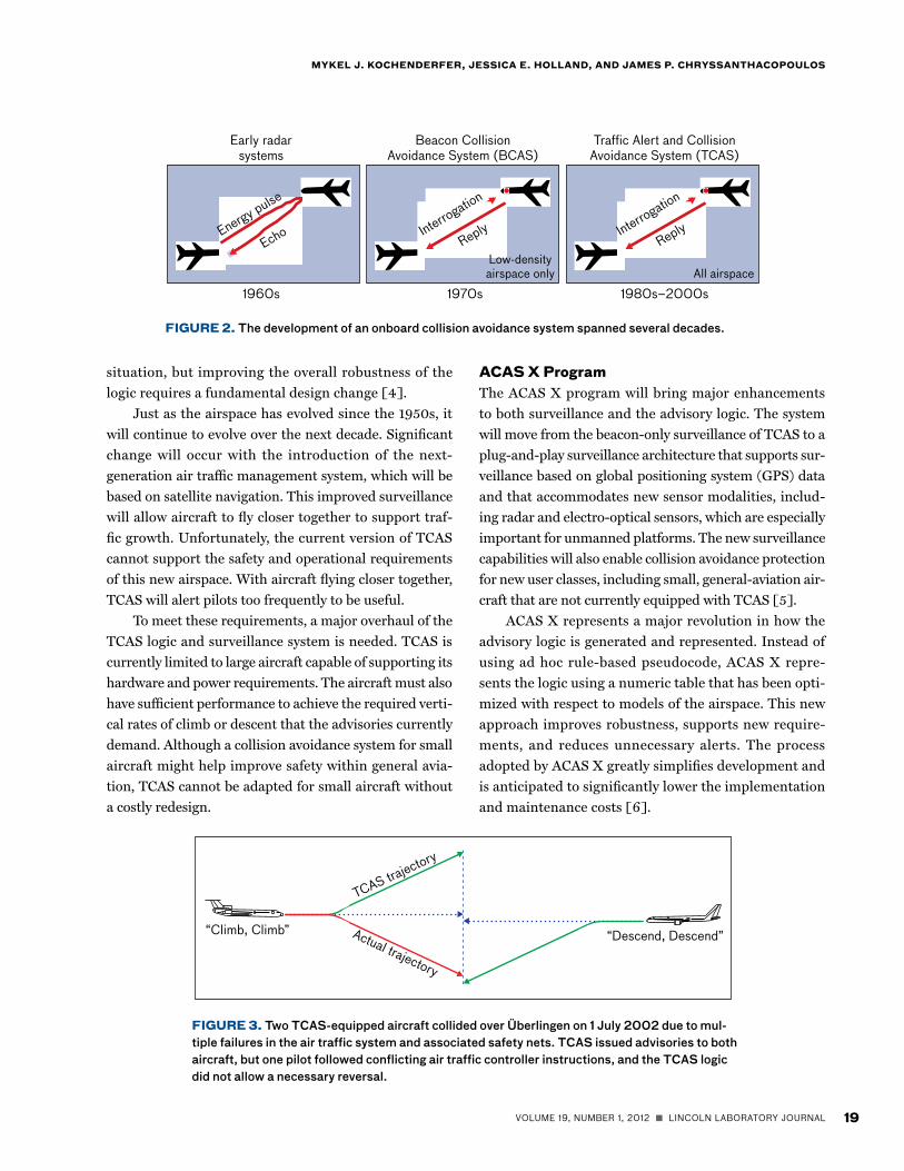
demonstrated by the collision of two aircraft in 2002
over Überlingen, Germany. TCAS instructed one air-
craft to climb, but one pilot descended in accordance
with the air traffic controller’s instructions (illustrated
in Figure 3), leading to a collision with another aircraft
whose pilot was following TCAS. If TCAS recognized
the noncompliance of one of the aircraft and reversed
the advisory of the compliant aircraft from a descend
to a climb, the collision would have been prevented. A
modification was later developed to address this specific
HistoryBecause the sky is so big and aircraft so small during the
early years of aviation, there were very few midair colli-
sions. By the 1950s, air travel had become commonplace,
and the skies became more crowded. In 1956, a midair
collision over the Grand Canyon resulted in 128 fatalities.
At the time, this was the worst commercial air disaster in
history. The collision caused a press frenzy, congressional
hearings, and the establishment of the FAA in 1958.
The establishment of the FAA led to major improve-
ments in both airspace design and air traffic control. The
airspace was designed to keep aircraft separated. For
example, depending on whether aircraft were flying west
or east, they were expected to fly at different altitudes. Air
traffic controllers relied on ground-based radars, keeping
aircraft safely separated by calling out traffic to pilots and
vectoring aircraft.
The enhancements to airspace design and air traffic
control significantly improved the safety of the airspace.
However, there were still midair collisions. A midair colli-
sion involving a commercial airliner over San Diego, Cali-
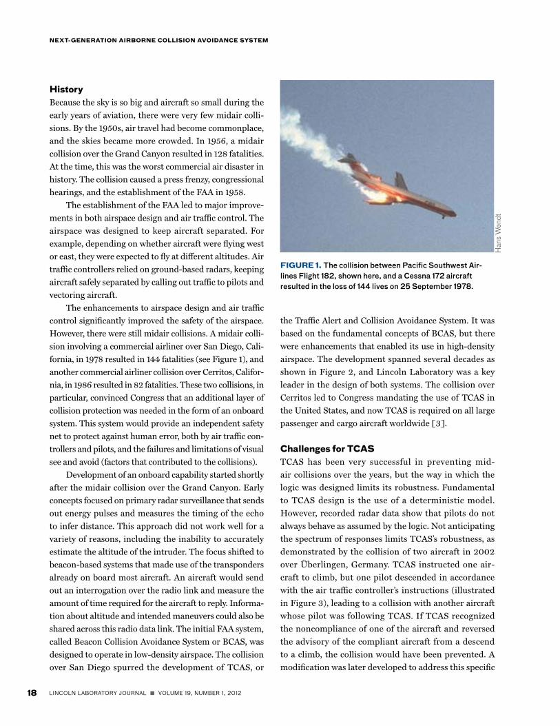
fornia, in 1978 resulted in 144 fatalities (see Figure 1), and
another commercial airliner collision over Cerritos, Califor-
nia, in 1986 resulted in 82 fatalities. These two collisions, in
particular, convinced Congress that an additional layer of
collision protection was needed in the form of an onboard
system. This system would provide an independent safety
net to protect against human error, both by air traffic con-
trollers and pilots, and the failures and limitations of visual
see and avoid (factors that contributed to the collisions).
Development of an onboard capability started shortly
after the midair collision over the Grand Canyon. Early
concepts focused on primary radar surveillance that sends
out energy pulses and measures the timing of the echo
to infer distance. This approach did not work well for a
variety of reasons, including the inability to accurately
estimate the altitude of the intruder. The focus shifted to
beacon-based systems that made use of the transponders
already on board most aircraft. An aircraft would send
out an interrogation over the radio link and measure the
amount of time required for the aircraft to reply. Informa-
tion about altitude and intended maneuvers could also be
shared across this radio data link. The initial FAA system,
called Beacon Collision Avoidance System or BCAS, was
designed to operate in low-density airspace. The collision
over San Diego spurred the development of TCAS, or
FiGUrE 1. The collision between Pacific Southwest Air-lines Flight 182, shown here, and a Cessna 172 aircraft resulted in the loss of 144 lives on 25 September 1978.
Hans
Wen
dt
VOLUME 19, NUMBER 1, 2012 n LINCOLN LABORATORY JOURNAL 19
MyKEl J. KoCHENdErFEr, JEssiCa E. HollaNd, aNd JaMEs P. CHryssaNtHaCoPoUlos
situation, but improving the overall robustness of the
logic requires a fundamental design change [4].
Just as the airspace has evolved since the 1950s, it
will continue to evolve over the next decade. Significant
change will occur with the introduction of the next-
generation air traffic management system, which will be
based on satellite navigation. This improved surveillance
will allow aircraft to fly closer together to support traf-
fic growth. Unfortunately, the current version of TCAS
cannot support the safety and operational requirements
of this new airspace. With aircraft flying closer together,
TCAS will alert pilots too frequently to be useful.
To meet these requirements, a major overhaul of the
TCAS logic and surveillance system is needed. TCAS is
currently limited to large aircraft capable of supporting its
hardware and power requirements. The aircraft must also
have sufficient performance to achieve the required verti-
cal rates of climb or descent that the advisories currently
demand. Although a collision avoidance system for small
aircraft might help improve safety within general avia-
tion, TCAS cannot be adapted for small aircraft without
a costly redesign.
aCas x ProgramThe ACAS X program will bring major enhancements
to both surveillance and the advisory logic. The system
will move from the beacon-only surveillance of TCAS to a
plug-and-play surveillance architecture that supports sur-
veillance based on global positioning system (GPS) data
and that accommodates new sensor modalities, includ-
ing radar and electro-optical sensors, which are especially
important for unmanned platforms. The new surveillance
capabilities will also enable collision avoidance protection
for new user classes, including small, general-aviation air-
craft that are not currently equipped with TCAS [5].
ACAS X represents a major revolution in how the
advisory logic is generated and represented. Instead of
using ad hoc rule-based pseudocode, ACAS X repre-
sents the logic using a numeric table that has been opti-
mized with respect to models of the airspace. This new
approach improves robustness, supports new require-
ments, and reduces unnecessary alerts. The process
adopted by ACAS X greatly simplifies development and
is anticipated to significantly lower the implementation
and maintenance costs [6].
FiGUrE 3. Two TCAS-equipped aircraft collided over Überlingen on 1 July 2002 due to mul-tiple failures in the air traffic system and associated safety nets. TCAS issued advisories to both aircraft, but one pilot followed conflicting air traffic controller instructions, and the TCAS logic did not allow a necessary reversal.
FiGUrE 2. The development of an onboard collision avoidance system spanned several decades.
Early radarsystems
Traffic Alert and CollisionAvoidance System (TCAS)
Beacon CollisionAvoidance System (BCAS)
1960s 1980s–2000s1970s
Energy pulse
Echo Interrogation
Interrogation
ReplyReply
All airspaceLow-densityairspace only
TCAS trajectory
“Descend, Descend”“Climb, Climb” Actual trajectory
20 LINCOLN LABORATORY JOURNAL n VOLUME 19, NUMBER 1, 2012
NExt-GENEratioN airborNE CollisioN avoidaNCE systEM
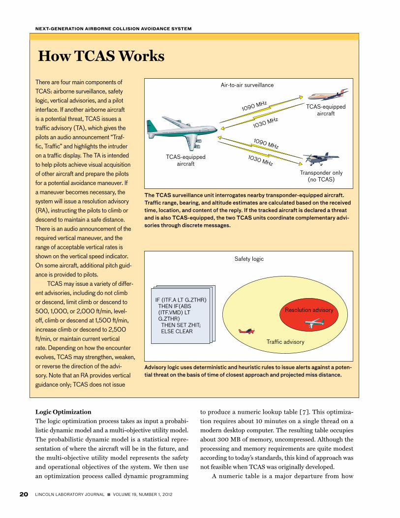
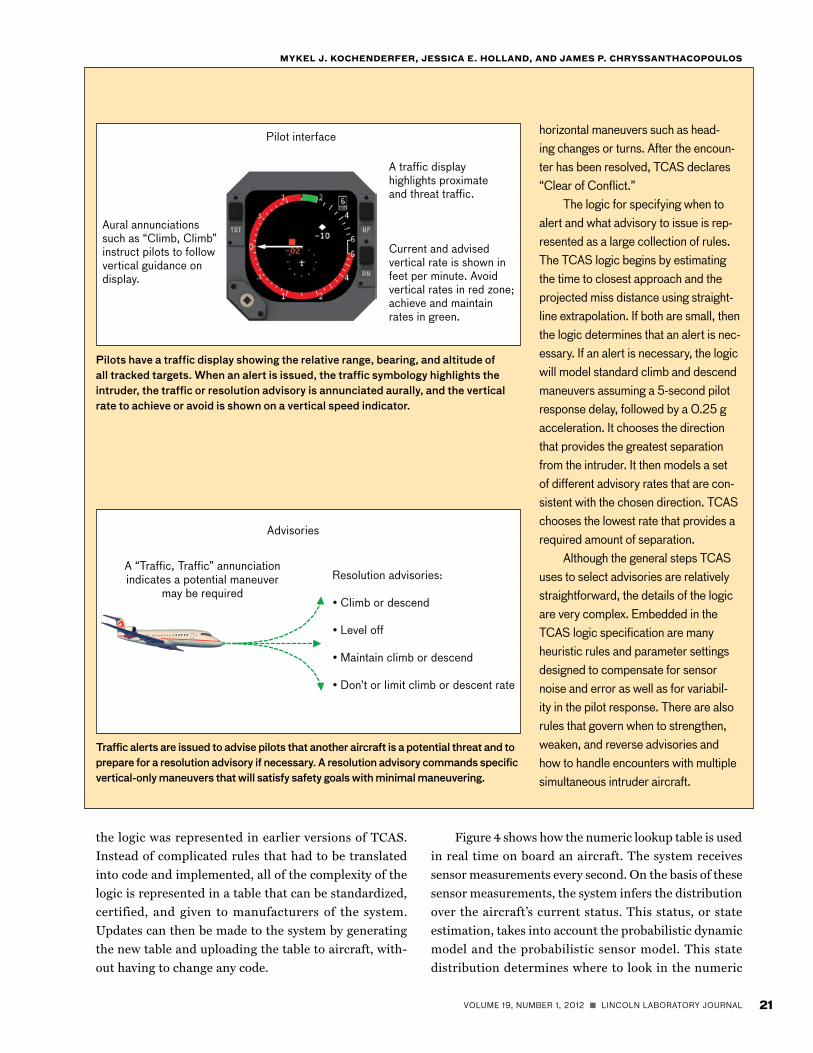
There are four main components of TCAS: airborne surveillance, safety logic, vertical advisories, and a pilot interface. If another airborne aircraft is a potential threat, TCAS issues a traffic advisory (TA), which gives the pilots an audio announcement “Traf-fic, Traffic” and highlights the intruder on a traffic display. The TA is intended to help pilots achieve visual acquisition of other aircraft and prepare the pilots for a potential avoidance maneuver. If a maneuver becomes necessary, the system will issue a resolution advisory (RA), instructing the pilots to climb or descend to maintain a safe distance. There is an audio announcement of the required vertical maneuver, and the range of acceptable vertical rates is shown on the vertical speed indicator. On some aircraft, additional pitch guid-ance is provided to pilots.
TCAS may issue a variety of differ-ent advisories, including do not climb or descend, limit climb or descend to 500, 1,000, or 2,000 ft/min, level-off, climb or descend at 1,500 ft/min, increase climb or descend to 2,500 ft/min, or maintain current vertical rate. Depending on how the encounter evolves, TCAS may strengthen, weaken, or reverse the direction of the advi-sory. Note that an RA provides vertical guidance only; TCAS does not issue
TCAS-equippedaircraft
Transponder only(no TCAS)
Air-to-air surveillance
1090 MHz
1090 MHz
1030 MHz
1030 MHz
TCAS-equippedaircraft
Safety logic
Resolution advisory
Traffic advisory
IF (ITF.A LT G.ZTHR) THEN IF(ABS (ITF.VMD) LT G.ZTHR) THEN SET ZHIT; ELSE CLEAR
Logic Optimization
The logic optimization process takes as input a probabi-
listic dynamic model and a multi-objective utility model.
The probabilistic dynamic model is a statistical repre-
sentation of where the aircraft will be in the future, and
the multi-objective utility model represents the safety
and operational objectives of the system. We then use
an optimization process called dynamic programming
to produce a numeric lookup table [7]. This optimiza-
tion requires about 10 minutes on a single thread on a
modern desktop computer. The resulting table occupies
about 300 MB of memory, uncompressed. Although the
processing and memory requirements are quite modest
according to today’s standards, this kind of approach was
not feasible when TCAS was originally developed.
A numeric table is a major departure from how
The TCAS surveillance unit interrogates nearby transponder-equipped aircraft. Traffic range, bearing, and altitude estimates are calculated based on the received time, location, and content of the reply. If the tracked aircraft is declared a threat and is also TCAS-equipped, the two TCAS units coordinate complementary advi-sories through discrete messages.
Advisory logic uses deterministic and heuristic rules to issue alerts against a poten-tial threat on the basis of time of closest approach and projected miss distance.
How TCAS Works
VOLUME 19, NUMBER 1, 2012 n LINCOLN LABORATORY JOURNAL 21
MyKEl J. KoCHENdErFEr, JEssiCa E. HollaNd, aNd JaMEs P. CHryssaNtHaCoPoUlos
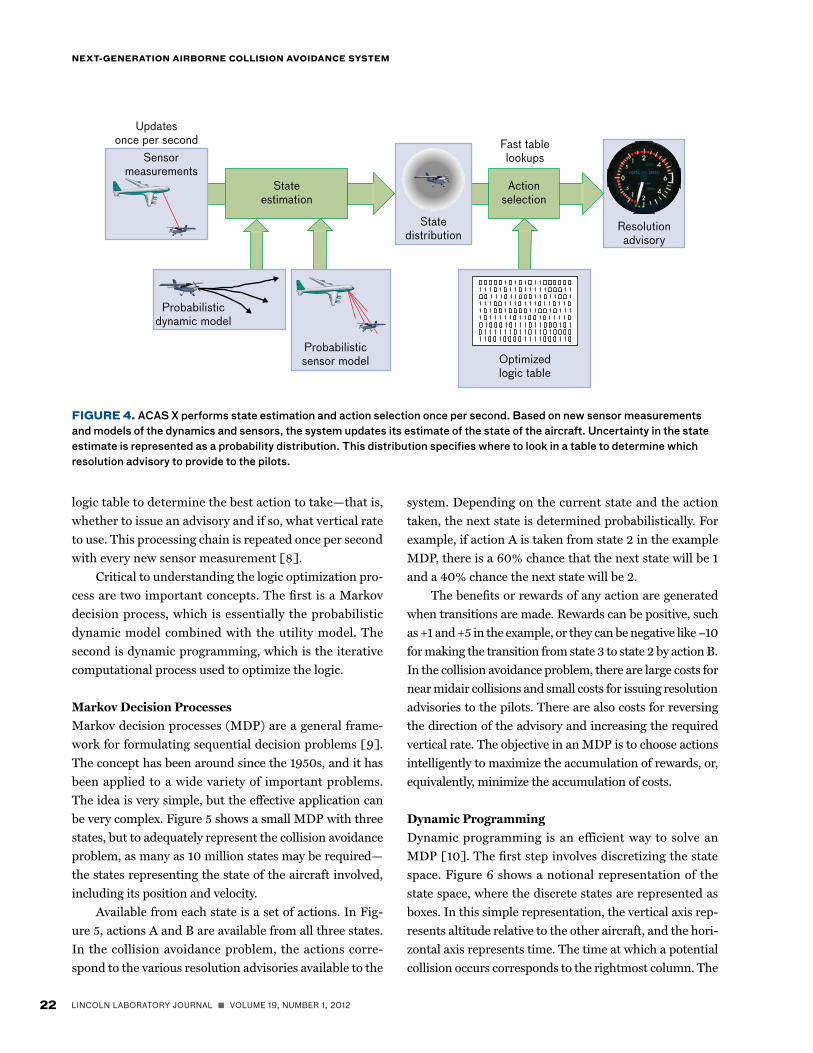
Figure 4 shows how the numeric lookup table is used
in real time on board an aircraft. The system receives
sensor measurements every second. On the basis of these
sensor measurements, the system infers the distribution
over the aircraft’s current status. This status, or state
estimation, takes into account the probabilistic dynamic
model and the probabilistic sensor model. This state
distribution determines where to look in the numeric
the logic was represented in earlier versions of TCAS.
Instead of complicated rules that had to be translated
into code and implemented, all of the complexity of the
logic is represented in a table that can be standardized,
certified, and given to manufacturers of the system.
Updates can then be made to the system by generating
the new table and uploading the table to aircraft, with-
out having to change any code.
horizontal maneuvers such as head-ing changes or turns. After the encoun-ter has been resolved, TCAS declares “Clear of Conflict.”
The logic for specifying when to alert and what advisory to issue is rep-resented as a large collection of rules. The TCAS logic begins by estimating the time to closest approach and the projected miss distance using straight-line extrapolation. If both are small, then the logic determines that an alert is nec-essary. If an alert is necessary, the logic will model standard climb and descend maneuvers assuming a 5-second pilot response delay, followed by a 0.25 g acceleration. It chooses the direction that provides the greatest separation from the intruder. It then models a set of different advisory rates that are con-sistent with the chosen direction. TCAS chooses the lowest rate that provides a required amount of separation.
Although the general steps TCAS uses to select advisories are relatively straightforward, the details of the logic are very complex. Embedded in the TCAS logic specification are many heuristic rules and parameter settings designed to compensate for sensor noise and error as well as for variabil-ity in the pilot response. There are also rules that govern when to strengthen, weaken, and reverse advisories and how to handle encounters with multiple simultaneous intruder aircraft.
Pilot interface
Aural annunciations such as “Climb, Climb” instruct pilots to followvertical guidance on display.
Current and advisedvertical rate is shown in feet per minute. Avoidvertical rates in red zone;achieve and maintainrates in green.
A traffic displayhighlights proximateand threat traffic.
Advisories
A “Traffic, Traffic” annunciationindicates a potential maneuver
may be requiredResolution advisories:
• Climb or descend
• Level off
• Maintain climb or descend
• Don’t or limit climb or descent rate
Pilots have a traffic display showing the relative range, bearing, and altitude of all tracked targets. When an alert is issued, the traffic symbology highlights the intruder, the traffic or resolution advisory is annunciated aurally, and the vertical rate to achieve or avoid is shown on a vertical speed indicator.
Traffic alerts are issued to advise pilots that another aircraft is a potential threat and to prepare for a resolution advisory if necessary. A resolution advisory commands specific vertical-only maneuvers that will satisfy safety goals with minimal maneuvering.
22 LINCOLN LABORATORY JOURNAL n VOLUME 19, NUMBER 1, 2012
NExt-GENEratioN airborNE CollisioN avoidaNCE systEM
logic table to determine the best action to take—that is,
whether to issue an advisory and if so, what vertical rate
to use. This processing chain is repeated once per second
with every new sensor measurement [8].
Critical to understanding the logic optimization pro-
cess are two important concepts. The first is a Markov
decision process, which is essentially the probabilistic
dynamic model combined with the utility model. The
second is dynamic programming, which is the iterative
computational process used to optimize the logic.
Markov Decision Processes
Markov decision processes (MDP) are a general frame-
work for formulating sequential decision problems [9].
The concept has been around since the 1950s, and it has
been applied to a wide variety of important problems.
The idea is very simple, but the effective application can
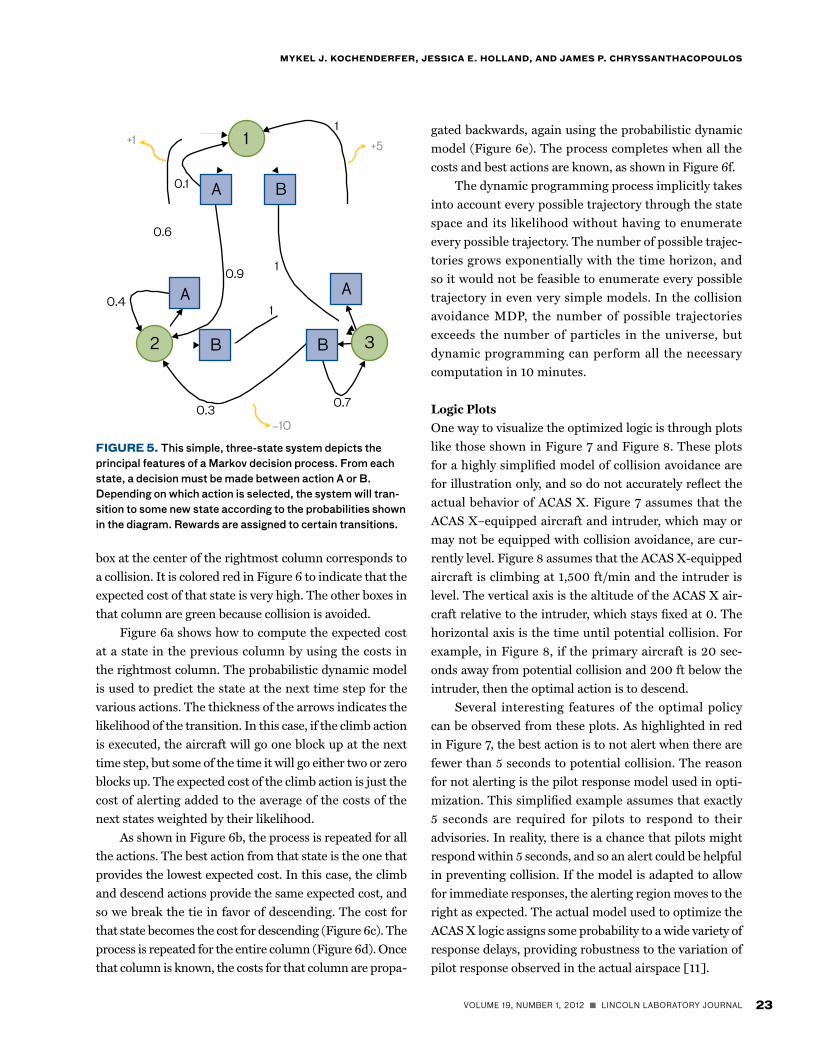
be very complex. Figure 5 shows a small MDP with three
states, but to adequately represent the collision avoidance
problem, as many as 10 million states may be required—
the states representing the state of the aircraft involved,
including its position and velocity.
Available from each state is a set of actions. In Fig-
ure 5, actions A and B are available from all three states.
In the collision avoidance problem, the actions corre-
spond to the various resolution advisories available to the
system. Depending on the current state and the action
taken, the next state is determined probabilistically. For
example, if action A is taken from state 2 in the example
MDP, there is a 60% chance that the next state will be 1
and a 40% chance the next state will be 2.
The benefits or rewards of any action are generated
when transitions are made. Rewards can be positive, such
as +1 and +5 in the example, or they can be negative like −10
for making the transition from state 3 to state 2 by action B.
In the collision avoidance problem, there are large costs for
near midair collisions and small costs for issuing resolution
advisories to the pilots. There are also costs for reversing
the direction of the advisory and increasing the required
vertical rate. The objective in an MDP is to choose actions
intelligently to maximize the accumulation of rewards, or,
equivalently, minimize the accumulation of costs.
Dynamic Programming
Dynamic programming is an efficient way to solve an
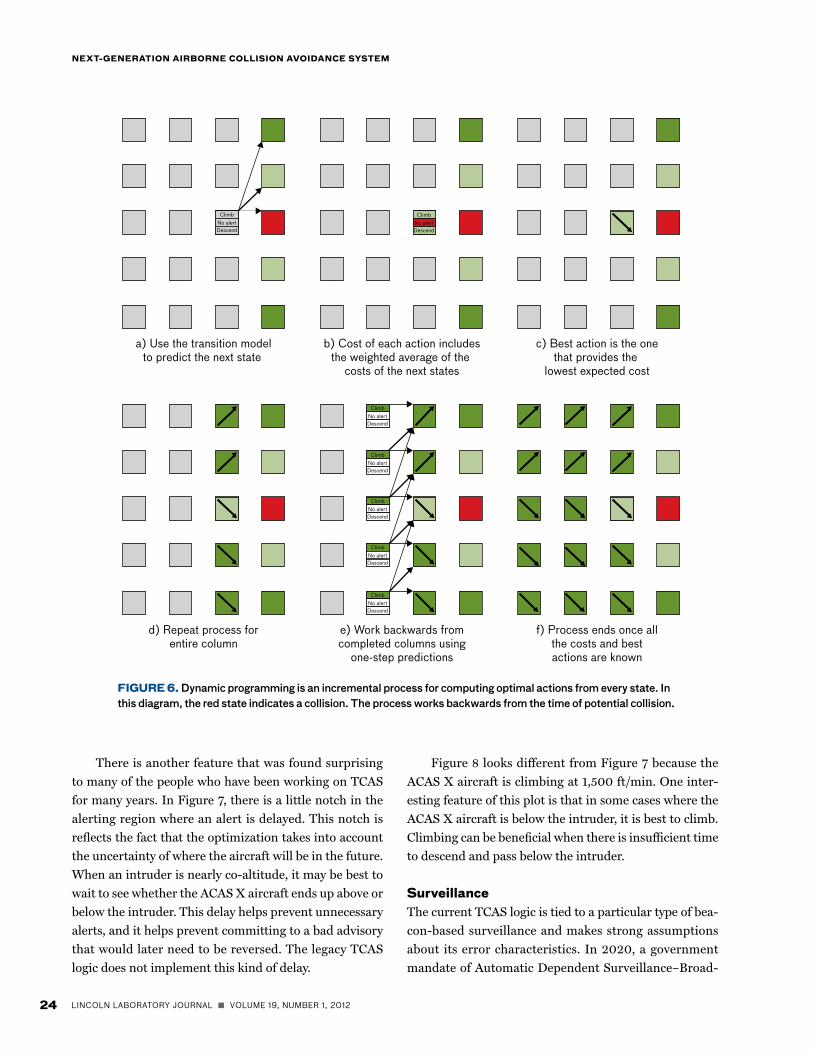
MDP [10]. The first step involves discretizing the state
space. Figure 6 shows a notional representation of the
state space, where the discrete states are represented as
boxes. In this simple representation, the vertical axis rep-
resents altitude relative to the other aircraft, and the hori-
zontal axis represents time. The time at which a potential
collision occurs corresponds to the rightmost column. The
FiGUrE 4. ACAS X performs state estimation and action selection once per second. Based on new sensor measurements and models of the dynamics and sensors, the system updates its estimate of the state of the aircraft. Uncertainty in the state estimate is represented as a probability distribution. This distribution specifies where to look in a table to determine which resolution advisory to provide to the pilots.
Updatesonce per second
Stateestimation
Actionselection
Sensormeasurements
Fast tablelookups
Statedistribution
Resolutionadvisory
Probabilisticdynamic model
Probabilisticsensor model Optimized
logic table
VOLUME 19, NUMBER 1, 2012 n LINCOLN LABORATORY JOURNAL 23
MyKEl J. KoCHENdErFEr, JEssiCa E. HollaNd, aNd JaMEs P. CHryssaNtHaCoPoUlos
box at the center of the rightmost column corresponds to
a collision. It is colored red in Figure 6 to indicate that the
expected cost of that state is very high. The other boxes in
that column are green because collision is avoided.
Figure 6a shows how to compute the expected cost
at a state in the previous column by using the costs in
the rightmost column. The probabilistic dynamic model
is used to predict the state at the next time step for the
various actions. The thickness of the arrows indicates the
likelihood of the transition. In this case, if the climb action
is executed, the aircraft will go one block up at the next
time step, but some of the time it will go either two or zero
blocks up. The expected cost of the climb action is just the
cost of alerting added to the average of the costs of the
next states weighted by their likelihood.
As shown in Figure 6b, the process is repeated for all
the actions. The best action from that state is the one that
provides the lowest expected cost. In this case, the climb
and descend actions provide the same expected cost, and
so we break the tie in favor of descending. The cost for
that state becomes the cost for descending (Figure 6c). The
process is repeated for the entire column (Figure 6d). Once
that column is known, the costs for that column are propa-
gated backwards, again using the probabilistic dynamic
model (Figure 6e). The process completes when all the
costs and best actions are known, as shown in Figure 6f.
The dynamic programming process implicitly takes
into account every possible trajectory through the state
space and its likelihood without having to enumerate
every possible trajectory. The number of possible trajec-
tories grows exponentially with the time horizon, and
so it would not be feasible to enumerate every possible
trajectory in even very simple models. In the collision
avoidance MDP, the number of possible trajectories
exceeds the number of particles in the universe, but
dynamic programming can perform all the necessary
computation in 10 minutes.
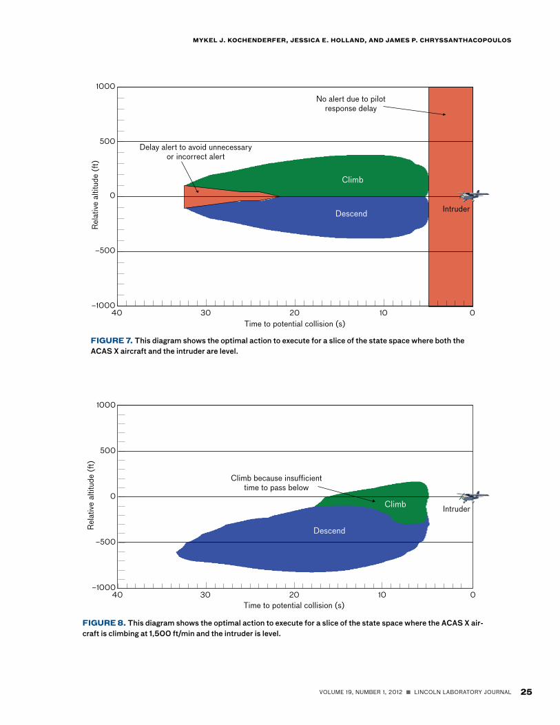
Logic Plots
One way to visualize the optimized logic is through plots
like those shown in Figure 7 and Figure 8. These plots
for a highly simplified model of collision avoidance are
for illustration only, and so do not accurately reflect the
actual behavior of ACAS X. Figure 7 assumes that the
ACAS X–equipped aircraft and intruder, which may or
may not be equipped with collision avoidance, are cur-
rently level. Figure 8 assumes that the ACAS X-equipped
aircraft is climbing at 1,500 ft/min and the intruder is
level. The vertical axis is the altitude of the ACAS X air-
craft relative to the intruder, which stays fixed at 0. The
horizontal axis is the time until potential collision. For
example, in Figure 8, if the primary aircraft is 20 sec-
onds away from potential collision and 200 ft below the
intruder, then the optimal action is to descend.
Several interesting features of the optimal policy
can be observed from these plots. As highlighted in red
in Figure 7, the best action is to not alert when there are
fewer than 5 seconds to potential collision. The reason
for not alerting is the pilot response model used in opti-
mization. This simplified example assumes that exactly
5 seconds are required for pilots to respond to their
advisories. In reality, there is a chance that pilots might
respond within 5 seconds, and so an alert could be helpful
in preventing collision. If the model is adapted to allow
for immediate responses, the alerting region moves to the
right as expected. The actual model used to optimize the
ACAS X logic assigns some probability to a wide variety of
response delays, providing robustness to the variation of
pilot response observed in the actual airspace [11].
0.9
1
0.4
0.1
+1
0.6
0.3−10
0.7
1
+5
1
BA
A A
B B 32
1
FiGUrE 5. This simple, three-state system depicts the principal features of a Markov decision process. From each state, a decision must be made between action A or B. Depending on which action is selected, the system will tran-sition to some new state according to the probabilities shown in the diagram. Rewards are assigned to certain transitions.
24 LINCOLN LABORATORY JOURNAL n VOLUME 19, NUMBER 1, 2012
NExt-GENEratioN airborNE CollisioN avoidaNCE systEM
There is another feature that was found surprising
to many of the people who have been working on TCAS
for many years. In Figure 7, there is a little notch in the
alerting region where an alert is delayed. This notch is
reflects the fact that the optimization takes into account
the uncertainty of where the aircraft will be in the future.
When an intruder is nearly co-altitude, it may be best to
wait to see whether the ACAS X aircraft ends up above or
below the intruder. This delay helps prevent unnecessary
alerts, and it helps prevent committing to a bad advisory
that would later need to be reversed. The legacy TCAS
logic does not implement this kind of delay.
Figure 8 looks different from Figure 7 because the
ACAS X aircraft is climbing at 1,500 ft/min. One inter-
esting feature of this plot is that in some cases where the
ACAS X aircraft is below the intruder, it is best to climb.
Climbing can be beneficial when there is insufficient time
to descend and pass below the intruder.
surveillanceThe current TCAS logic is tied to a particular type of bea-
con-based surveillance and makes strong assumptions
about its error characteristics. In 2020, a government
mandate of Automatic Dependent Surveillance–Broad-
FiGUrE 6. Dynamic programming is an incremental process for computing optimal actions from every state. In this diagram, the red state indicates a collision. The process works backwards from the time of potential collision.
ClimbNo alertDescend
ClimbNo alertDescend
ClimbNo alertDescend
ClimbNo alertDescend
ClimbNo alertDescend
ClimbNo alertDescend
ClimbNo alertDescend
a) Use the transition modelto predict the next state
c) Best action is the onethat provides the
lowest expected cost
b) Cost of each action includesthe weighted average of the
costs of the next states
e) Work backwards fromcompleted columns using
one-step predictions
d) Repeat process forentire column
f) Process ends once allthe costs and bestactions are known
VOLUME 19, NUMBER 1, 2012 n LINCOLN LABORATORY JOURNAL 25
MyKEl J. KoCHENdErFEr, JEssiCa E. HollaNd, aNd JaMEs P. CHryssaNtHaCoPoUlos
FiGUrE 7. This diagram shows the optimal action to execute for a slice of the state space where both the ACAS X aircraft and the intruder are level.
40 0102030
0
–1000
1000
–500
500
Rela
tive
altit
ude
(ft)
Time to potential collision (s)
Delay alert to avoid unnecessaryor incorrect alert
No alert due to pilotresponse delay
Climb
Descend Intruder
FiGUrE 8. This diagram shows the optimal action to execute for a slice of the state space where the ACAS X air-craft is climbing at 1,500 ft/min and the intruder is level.
40 0102030
0
–1000
1000
–500
500
Rela
tive
altit
ude
(ft)
Time to potential collision (s)
Climb because insufficienttime to pass below
Climb
Descend
Intruder
26 LINCOLN LABORATORY JOURNAL n VOLUME 19, NUMBER 1, 2012
NExt-GENEratioN airborNE CollisioN avoidaNCE systEM
cast (ADS–B) will take effect, requiring the majority of
aircraft in U.S. airspace to be equipped with high-integ-
rity GPS units and to transmit updates of their location
and other data. Some TCAS units have been modified to
use ADS-B information, but its use is limited to assist-
ing in tracking local air traffic. Well before an advisory is
issued, TCAS switches to using beacon-based surveillance
exclusively, preventing TCAS from benefiting from the full
potential of highly precise ADS-B information.
Unlike the current TCAS logic, the ACAS X logic
for generating resolution advisories is compatible with
any surveillance source or combination of surveillance
sources that meets specified performance criteria. The
concept of plug-and-play surveillance will bring a number
of benefits. Improved surveillance can lead to improved
safety with fewer alerts. The ability to use surveillance
sources other than the traditional beacon-based system
will extend collision avoidance to new user classes. Small
aircraft will be able to use ADS-B information broadcast
by other aircraft for collision avoidance without having to
be equipped with an expensive beacon-based surveillance
system with significant power requirements. Unmanned
aircraft that must be able to avoid aircraft not equipped
with beacon transponders will be able to use electro-opti-
cal, infrared, and radar surveillance systems.
CoordinationDifferent aircraft in an encounter can have different
views of the situation because of sensor limitations.
These differing views can lead to potentially incompat-
ible maneuvers. For example, sensor limitations may
lead both aircraft to issue climb advisories, which would
increase the risk of an induced collision. During the
development of TCAS, it became clear that an explicit
coordination mechanism was necessary.
If an aircraft with TCAS gets an alert against another
aircraft with TCAS, it will send a coordination message
to the other aircraft instructing it to not climb or not
descend, as appropriate. If both aircraft happen to select
incompatible actions simultaneously, then the aircraft
with the higher identification number is forced to reverse
the direction of its advisory. In rare cases, such as an air-
craft receiving instructions from different aircraft to not
climb and not descend, it may be forced to level off.
The version of ACAS X intended for large commer-
cial aircraft will adopt the same coordination mechanism
as TCAS. Backwards compatibility with the existing
TCAS system is necessary since ACAS X and TCAS will
need to interoperate with each other for the foreseeable
future. The version of ACAS X for small aircraft will
need to adopt a different mechanism for coordination
because it will not have the ability to send coordination
messages over the same data link. Although the details
for small aircraft coordination are still the subject of
research, they will likely involve the population of coor-
dination fields in ADS-B messages.
safety and operational validationACAS X must accommodate many operational goals and
constraints while meeting the established safety require-
ments. It is important that the system provide effective
collision protection without unnecessarily disrupting
pilots and the air traffic control system. In addition to
producing as few alerts as possible, it must issue adviso-
ries that resolve encounters in a manner deemed suitable
and acceptable by pilots and the operational community.
The design of this new collision avoidance system is
facilitated by fully studying the performance of the existing
TCAS. As part of the FAA’s TCAS Operational Performance
Assessment (TOPA) program, the Laboratory has been
involved in monitoring the performance of TCAS on the
basis of data transmitted to the ground [12]. Analysis has
shown that, although TCAS is an effective system operating
as designed, it currently issues alerts in situations where
aircraft are legally and safety separated. In some situations,
more than 80% of TCAS alerts occur during normal proce-
dures that do not represent a collision risk.
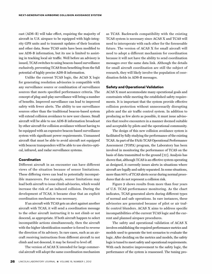
Figure 9 shows results from more than four years
of U.S. TCAS performance monitoring. As the chart
indicates, TCAS generated alerts during different types
of normal and safe operations. In rare instances, these
advisories are generated because of pilot or air traf-
fic control blunders. ACAS X aims to address specific
incompatibilities of the current TCAS logic and the cur-
rent and planned airspace procedures.
The safety and operational validation of ACAS X
involves establishing the required performance metrics and
models used to generate the test scenarios to evaluate the
logic. After deciding on the metrics and models, the safety
logic is tuned to meet safety and operational requirements.
With each iterative improvement to the safety logic, the
performance of the system is reassessed. The tuning pro-
VOLUME 19, NUMBER 1, 2012 n LINCOLN LABORATORY JOURNAL 27
MyKEl J. KoCHENdErFEr, JEssiCa E. HollaNd, aNd JaMEs P. CHryssaNtHaCoPoUlos
cess may result in the development of additional metrics
and models. Individual encounter situations are examined
to ensure that the system performs as expected.
Models and Data
The test scenarios used to evaluate the logic are generated
from several different sources.
1. Operational radar data. Radar surveillance from
over 100,000 real aircraft encounters that resulted in
TCAS alerts in current airspace is provided from TOPA
monitoring data. These aircraft trajectories are replayed
with the new logic to assess how it would work in oper-
ationally relevant situations, and the results are then
compared with the baseline TCAS logic performance.
The data allow us to estimate the benefits or operational
impact resulting from the new system in today’s airspace
and operations.
2. Airspace encounter models. Because near midair
collisions occur so rarely in the airspace, it is difficult to
accurately estimate their occurrence in simulations based
on radar data. Historically, airspace encounter models
have been used to estimate collision risk by generating
a large collection of encounters that are statistically rep-
resentative of the airspace [13]. With funding from the
FAA, Lincoln Laboratory recently developed a high-fidel-
ity model of the U.S. airspace based on a large amount of
radar data [14].
3. Procedure-specific models. Several models have
been developed to help evaluate safety logic performance
under specific intentional procedures, such as approaches
to closely spaced parallel runways. These procedures may
be simulated to match nominal conditions or may have
artificially injected pilot blunders and air traffic controller
errors. Simulations using these models facilitate a wide
range of possible setups and perturbations of relevant
scenarios that are unlikely to be observed with enough
frequency to be statistically relevant without decades of
data collection.
4. Stress-testing models. Historically, stress testing
was performed on TCAS logic versions to ensure adequate
performance during very unlikely, but difficult to resolve,
encounters. The encounters were based on aircraft trajec-
tory pairs recorded in the airspace prior to the introduc-
tion of TCAS and were modified to span and exceed the
parameters observed in the radar data. The new ACAS X
logic is being assessed with these same encounters.
Metrics
The performance of the logic is assessed using metrics
related to safety, operational suitability, and acceptability.
The ACAS X development team from several organiza-
tions collaborated to capture the relevant TCAS design
requirements, along with the motivations for selecting
them. The team also reflected on operational lessons
learned that helped shape the current TCAS logic [15].
Key metrics for operational suitability and pilot
acceptability include minimizing the frequency of alerts
that result in reversals or intentional intruder altitude
crossings, both of which may lead to pilot confusion or
mistrust if not obviously needed for safe encounter resolu-
tion. Also desired is minimizing the frequency of disrup-
tive advisories in noncritical encounters. These metrics
were important in the design of TCAS and continue to be
important for ACAS X.
Another metric compares the initial vertical rate of
the advisory to the current rate. One goal is to minimize
the difference between these while still providing effec-
tive, safe resolution of an encounter. A collision avoid-
ance system could be tuned to maximize the separation
from a potential threat, but this may result in a second-
ary conflict with another aircraft. Additionally, excessive
deviations from current trajectories increase pilot and air
traffic controller workload.
FiGUrE 9. This plot shows resolution advisory events recorded in the United States over several years. Most advi-sories are issued during normal and safe operations.
Other16%
Airport trafficpattern
15%
Approaches toparallel runways
12%
Controlled 1000'vertical separation
6%
Visual 500'vertical
separation51%
28 LINCOLN LABORATORY JOURNAL n VOLUME 19, NUMBER 1, 2012
NExt-GENEratioN airborNE CollisioN avoidaNCE systEM
get rates for certain metrics or high-level recommenda-
tions, such as minimizing reversal advisories.
This optimization was conducted in an iterative
manner with a test logic version that was run through
all four validation models and data sets. The results were
assessed and compared with current TCAS performance
and against the established operational and safety design
goals. The next desired modifications were then priori-
tized and specified by the team for the next tuning phase.
After modifications were made to the logic and there was
evidence that the concerns were addressed, new simula-
tion runs were executed and the assessment was repeated.
The process of assessment, recommendations, tun-
ing, and reassessment was used over six specific data
runs and resulted in improved suitability. While much
improvement has been observed, there are more compre-
hensive stress testing and new human-in-the-loop studies
that may influence additional logic changes.
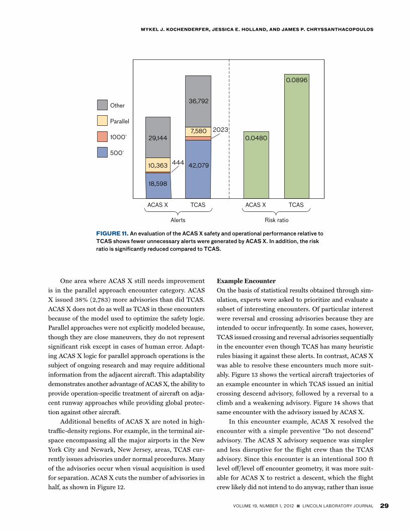
Results
As a result of extensive tuning both for safety and
operational suitability, key assessment results show
that, in comparison with TCAS, ACAS X reduces colli-
sion risk by 47%, reduces the overall alert rate by 40%,
and issues 56% and 78% fewer alerts in the intentional
500 ft and 1,000 ft encounter scenarios, respectively.
Figure 11 shows these comparative results in graphical
form. From identical encounters provided by simula-
tion, ACAS X issued 23,481 and 1,579 fewer advisories,
respectively, for 500 ft and 1,000 ft encounters. The
risk ratio, representing the probability of a near midair
collision with a collision avoidance system divided by
the probability without, shows that ACAS X improves
safety by 54%.
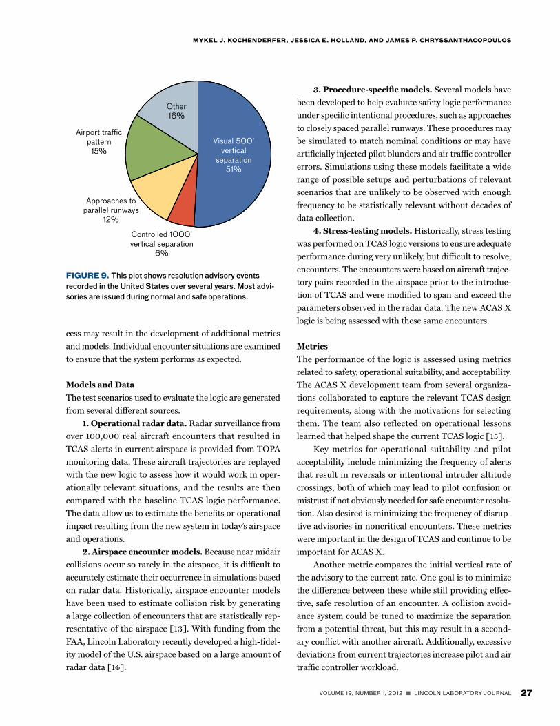
FiGUrE 10. Shown here are the three main encounter types representing the majority of U.S. TCAS alerts.
Vertical profile Horizontal profileVertical profile500 ft separation: both
aircraft in level flight1,000 ft separation: one aircraft level,
other aircraft leveling off Parallel runway approaches
Level
LevelLevel
Level off
≈ 500 ft≈ 1,000 ft
< 4300ft
27L 27R
In addition to high-level design goals, three proce-
dures in use are challenging for collision avoidance sys-
tems because of a lack of information aabout pilot and air
traffic controller intentions. Both TOPA encounters and
procedure-specific encounters allow these operations to
be assessed. These procedures, comprising almost 70% of
the TCAS alerts illustrated in Figure 9, are summarized
below and are illustrated in Figure 10.
1. Encounters with 500 ft vertical separation. In
these procedures, two aircraft are flying level in visual
conditions with 500 ft vertical separation. The goal is
either to not alert or to provide preventive-only guidance
to pilots, such as “Do not climb” or “Do not descend.”
These advisories are expected to better match the pilots’
intentions.
2. Encounters with 1,000 ft vertical separation. In
these procedures, two aircraft are flying under instrument
flight rules with 1,000 ft vertical separation. The aircraft
are flying level or leveling off. Issuing alerts that cause
significant vertical rate deviations is discouraged. When it
is necessary to alert, it is preferable to issue minimally dis-
ruptive guidance, such as a “level off,” which pilots likely
intend to do in the absence of an alert.
3. Closely spaced parallel departures and
approaches. In these procedures, two aircraft depart from
or approach closely spaced parallel runways. The intent
is to eliminate or minimize resolution advisories during
non-conflict parallel departures and approaches, and only
issue alerts if a blunder occurs that compromises safety.
Performance Tuning
The optimization process used by ACAS X accommodates
high-level safety and operational objectives. Throughout
the validation process, the expert team provides either tar-
VOLUME 19, NUMBER 1, 2012 n LINCOLN LABORATORY JOURNAL 29
MyKEl J. KoCHENdErFEr, JEssiCa E. HollaNd, aNd JaMEs P. CHryssaNtHaCoPoUlos
One area where ACAS X still needs improvement
is in the parallel approach encounter category. ACAS
X issued 38% (2,783) more advisories than did TCAS.
ACAS X does not do as well as TCAS in these encounters
because of the model used to optimize the safety logic.
Parallel approaches were not explicitly modeled because,
though they are close maneuvers, they do not represent
significant risk except in cases of human error. Adapt-
ing ACAS X logic for parallel approach operations is the
subject of ongoing research and may require additional
information from the adjacent aircraft. This adaptability
demonstrates another advantage of ACAS X, the ability to
provide operation-specific treatment of aircraft on adja-
cent runway approaches while providing global protec-
tion against other aircraft.
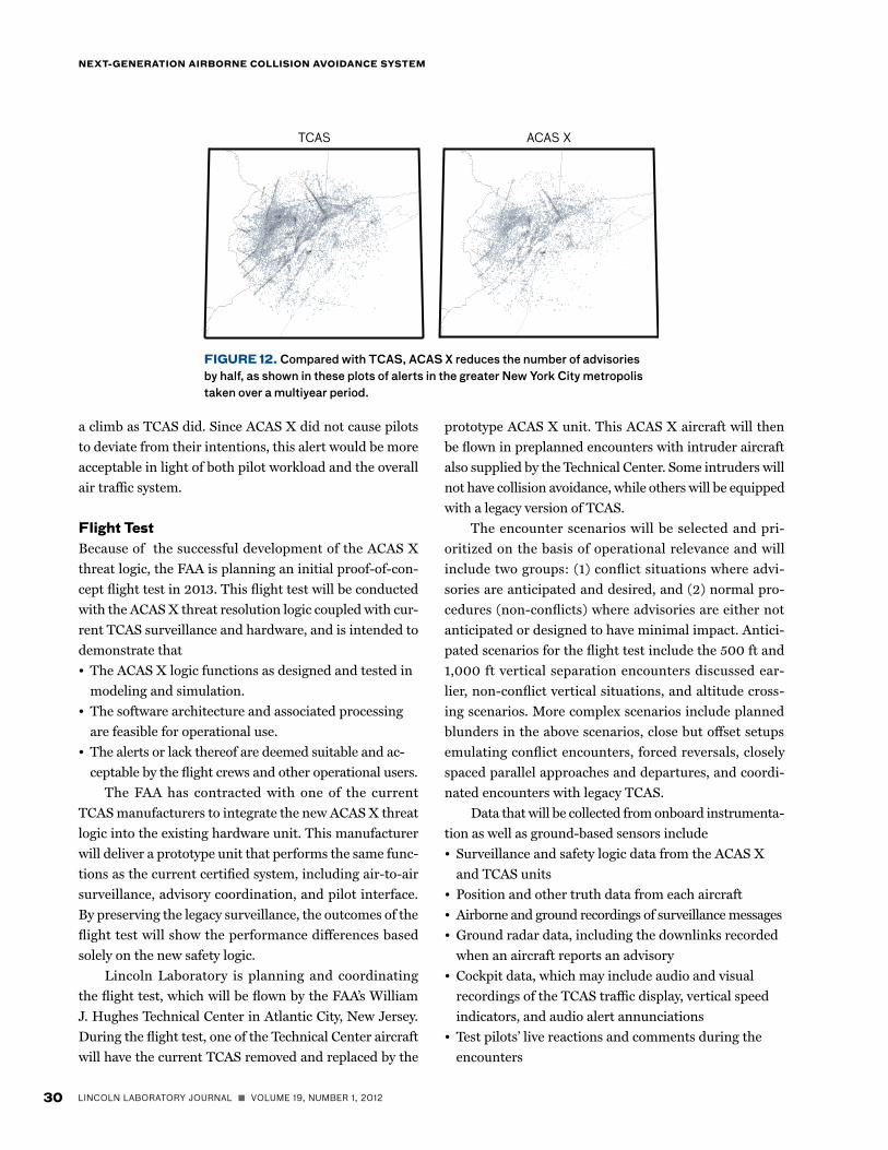
Additional benefits of ACAS X are noted in high-
traffic-density regions. For example, in the terminal air-
space encompassing all the major airports in the New
York City and Newark, New Jersey, areas, TCAS cur-
rently issues advisories under normal procedures. Many
of the advisories occur when visual acquisition is used
for separation. ACAS X cuts the number of advisories in
half, as shown in Figure 12.
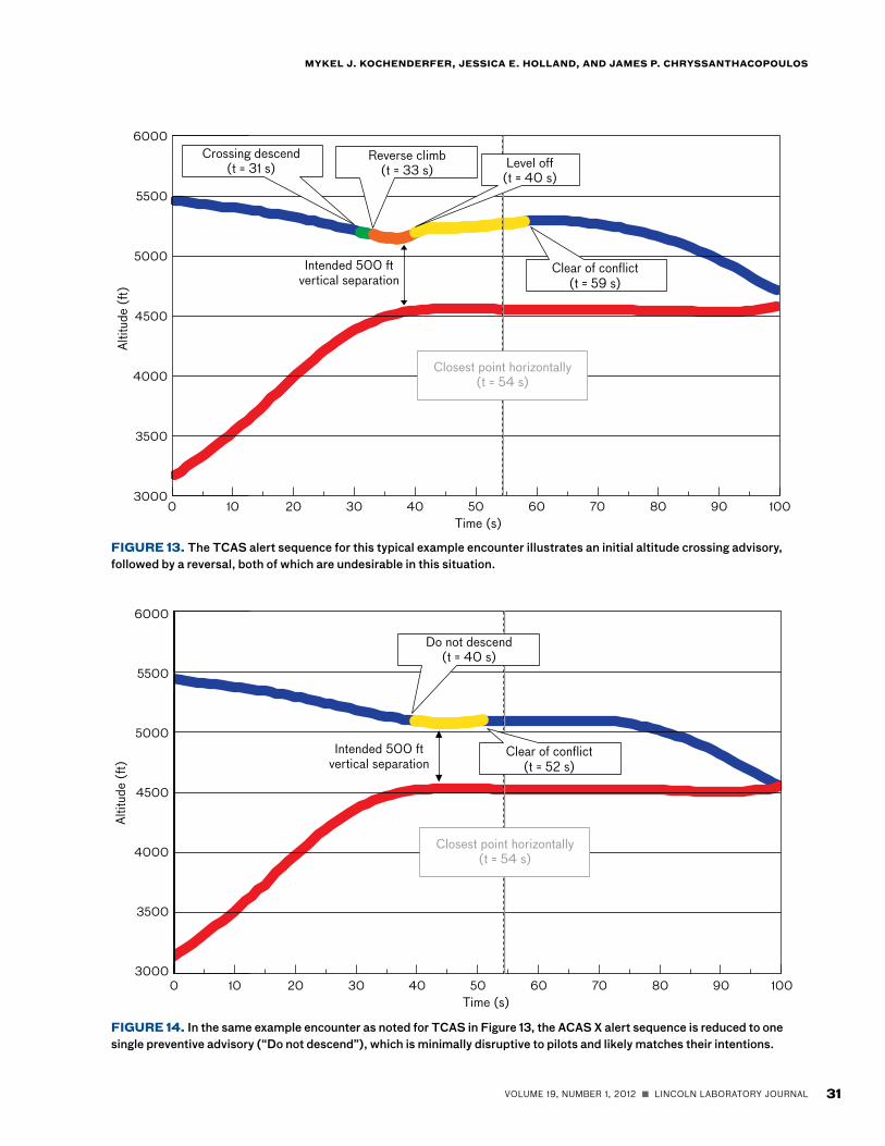
Example Encounter
On the basis of statistical results obtained through sim-
ulation, experts were asked to prioritize and evaluate a
subset of interesting encounters. Of particular interest
were reversal and crossing advisories because they are
intended to occur infrequently. In some cases, however,
TCAS issued crossing and reversal advisories sequentially
in the encounter even though TCAS has many heuristic
rules biasing it against these alerts. In contrast, ACAS X
was able to resolve these encounters much more suit-
ably. Figure 13 shows the vertical aircraft trajectories of
an example encounter in which TCAS issued an initial
crossing descend advisory, followed by a reversal to a
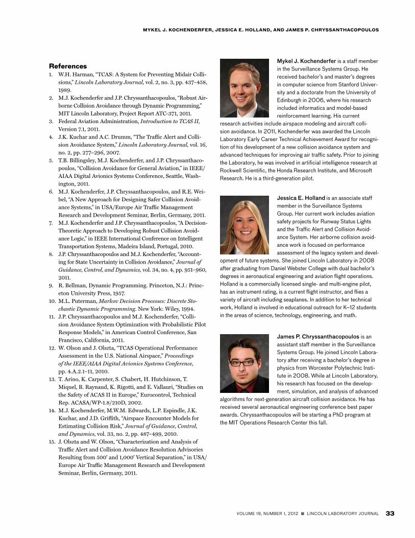
climb and a weakening advisory. Figure 14 shows that
same encounter with the advisory issued by ACAS X.
In this encounter example, ACAS X resolved the
encounter with a simple preventive “Do not descend”
advisory. The ACAS X advisory sequence was simpler
and less disruptive for the flight crew than the TCAS
advisory. Since this encounter is an intentional 500 ft
level off/level off encounter geometry, it was more suit-
able for ACAS X to restrict a descent, which the flight
crew likely did not intend to do anyway, rather than issue
FiGUrE 11. An evaluation of the ACAS X safety and operational performance relative to TCAS shows fewer unnecessary alerts were generated by ACAS X. In addition, the risk ratio is significantly reduced compared to TCAS.
42,079
0.0896
444
7,580 20230.048029,144
18,598
10,363
36,792
1000'
500'
Parallel
Other
Alerts Risk ratio
TCASACAS X ACAS X TCAS
30 LINCOLN LABORATORY JOURNAL n VOLUME 19, NUMBER 1, 2012
NExt-GENEratioN airborNE CollisioN avoidaNCE systEM
a climb as TCAS did. Since ACAS X did not cause pilots
to deviate from their intentions, this alert would be more
acceptable in light of both pilot workload and the overall
air traffic system.
Flight testBecause of the successful development of the ACAS X
threat logic, the FAA is planning an initial proof-of-con-
cept flight test in 2013. This flight test will be conducted
with the ACAS X threat resolution logic coupled with cur-
rent TCAS surveillance and hardware, and is intended to
demonstrate that
• The ACAS X logic functions as designed and tested in
modeling and simulation.
• The software architecture and associated processing
are feasible for operational use.
• The alerts or lack thereof are deemed suitable and ac-
ceptable by the flight crews and other operational users.
The FAA has contracted with one of the current
TCAS manufacturers to integrate the new ACAS X threat
logic into the existing hardware unit. This manufacturer
will deliver a prototype unit that performs the same func-
tions as the current certified system, including air-to-air
surveillance, advisory coordination, and pilot interface.
By preserving the legacy surveillance, the outcomes of the
flight test will show the performance differences based
solely on the new safety logic.
Lincoln Laboratory is planning and coordinating
the flight test, which will be flown by the FAA’s William
J. Hughes Technical Center in Atlantic City, New Jersey.
During the flight test, one of the Technical Center aircraft
will have the current TCAS removed and replaced by the
prototype ACAS X unit. This ACAS X aircraft will then
be flown in preplanned encounters with intruder aircraft
also supplied by the Technical Center. Some intruders will
not have collision avoidance, while others will be equipped
with a legacy version of TCAS.
The encounter scenarios will be selected and pri-
oritized on the basis of operational relevance and will
include two groups: (1) conflict situations where advi-
sories are anticipated and desired, and (2) normal pro-
cedures (non-conflicts) where advisories are either not
anticipated or designed to have minimal impact. Antici-
pated scenarios for the flight test include the 500 ft and
1,000 ft vertical separation encounters discussed ear-
lier, non-conflict vertical situations, and altitude cross-
ing scenarios. More complex scenarios include planned
blunders in the above scenarios, close but offset setups
emulating conflict encounters, forced reversals, closely
spaced parallel approaches and departures, and coordi-
nated encounters with legacy TCAS.
Data that will be collected from onboard instrumenta-
tion as well as ground-based sensors include
• Surveillance and safety logic data from the ACAS X
and TCAS units
• Position and other truth data from each aircraft
• Airborne and ground recordings of surveillance messages
• Ground radar data, including the downlinks recorded
when an aircraft reports an advisory
• Cockpit data, which may include audio and visual
recordings of the TCAS traffic display, vertical speed
indicators, and audio alert annunciations
• Test pilots’ live reactions and comments during the
encounters
FiGUrE 12. Compared with TCAS, ACAS X reduces the number of advisories by half, as shown in these plots of alerts in the greater New York City metropolis taken over a multiyear period.
TCAS ACAS X
VOLUME 19, NUMBER 1, 2012 n LINCOLN LABORATORY JOURNAL 31
MyKEl J. KoCHENdErFEr, JEssiCa E. HollaNd, aNd JaMEs P. CHryssaNtHaCoPoUlos
0 50 902010 6040 70 10030 803000
5500
4000
3500
5000
4500
6000Al
titud
e (f
t)
Time (s)
Crossing descend(t = 31 s)
Reverse climb(t = 33 s) Level off
(t = 40 s)
Clear of conflict(t = 59 s)
Closest point horizontally(t = 54 s)
Intended 500 ftvertical separation
FiGUrE 14. In the same example encounter as noted for TCAS in Figure 13, the ACAS X alert sequence is reduced to one single preventive advisory (“Do not descend”), which is minimally disruptive to pilots and likely matches their intentions.
0 50 902010 6040 70 10030 80Time (s)
Do not descend(t = 40 s)
Clear of conflict(t = 52 s)
Closest point horizontally(t = 54 s)
Intended 500 ftvertical separation
3000
4000
3500
5000
4500
6000
5500
Altit
ude
(ft)
FiGUrE 13. The TCAS alert sequence for this typical example encounter illustrates an initial altitude crossing advisory, followed by a reversal, both of which are undesirable in this situation.

32 LINCOLN LABORATORY JOURNAL n VOLUME 19, NUMBER 1, 2012
NExt-GENEratioN airborNE CollisioN avoidaNCE systEM
Post-flight-test tasks will include comprehensive
assessment of the performance of ACAS X, the legacy
TCAS surveillance and its impact on the resulting ACAS
X alerts, and all the data collected during the encounters.
In addition to assessing ACAS X performance, research-
ers will be conducting a comparative analysis of the TCAS
logic under the same inputs and using simulations after
the flights. If the ACAS X logic meets expectations under
the live flight-test conditions, there will be substantial evi-
dence that the proof of concept is valid and that the new
logic will work in a way that is operationally acceptable.
road aheadOne of the most exciting extensions of the ACAS X pro-
gram is the application to unmanned aircraft, which have
different performance capabilities and rely upon differ-
ent surveillance systems from traditional TCAS aircraft.
A sense-and-avoid capability is required for the routine
access of unmanned aircraft to civil airspace. Sense-and-
avoid involves both collision avoidance and self-separa-
tion. Self-separation means maintaining a safe distance
from other aircraft without triggering collision avoid-
ance of the other aircraft. Self-separation maneuvers may
require heading and speed changes. ACAS X is focused on
the collision avoidance aspect, but the same idea of using
Markov decision processes and dynamic programming
has been extended to self-separation. The development
of these algorithms has led to programs sponsored by the
Army, Air Force, and the Department of Homeland Secu-
rity for ground-based and airborne systems.
Another research area is the development of a pro-
cedure- or environment-specific implementation of the
logic, since future airspace may utilize reduced separa-
tion standards to increase efficiency. This procedure-spe-
cific functionality would allow alerting that is tailored for
selected aircraft by using an individualized lookup table
while providing collision avoidance protection against
other traffic. This functionality would even benefit today’s
procedures, such as those for parallel approaches, during
which incompatible alerts necessitate some operators to
turn off the resolution advisory function of TCAS to pre-
vent interference from frequent alerts. In such cases and
others, this functionality would ensure optimal collision
avoidance protection against another aircraft’s blunders
or other intruding traffic while causing minimal interfer-
ence from unnecessary advisories.
Lincoln Laboratory is actively researching the appli-
cation of this collision avoidance logic concept for small
aircraft. The ease of optimization may facilitate the
development of logic for aircraft that have lower perfor-
mance capabilities and operational needs and limita-
tions different from those of the existing aircraft using
TCAS. The Laboratory is also leading the surveillance
research area and is developing an interface and tracker
that will allow a variety of inputs to be plug-and-play
with the optimized threat logic.
The regulatory effort required for both U.S. and
international acceptance and certification of ACAS X is
intensive but has already begun. Domestically, the fed-
eral advisory committee, the Radio Technical Commis-
sion for Aeronautics, or RTCA, has been briefed in detail
on ACAS X. International outreach efforts have included
briefings and interactions with the joint European avia-
tion governing body. ACAS X has also gained substantial
visibility across key departments within the FAA that will
further aid the remaining development and anticipated
certification and mandate.
acknowledgmentsThe ACAS X program is led by FAA TCAS program man-
ager Neal Suchy, who recognized the potential of this new
safety logic and structured a program to pursue it. The
Lincoln Laboratory ACAS X program has been managed
by Wes Olson, also a key contributor to its concept devel-
opment and performance analyses, and overseen by Gregg
Shoults. The dedicated team responsible for the success of
ACAS X includes Dylan Asmar, Tom Billingsley, Barbara
Chludzinski, Ann Drumm, Tomas Elder, Leo Javits, Adam
Panken, Chuck Rose, Dave Spencer, and Kyle Smith.
Many of the important concepts underlying ACAS X were
developed in collaboration with Leslie Kaelbling, Tomas
Lozano-Perez, and Selim Temizer at the MIT Computer
Science and Artificial Intelligence Laboratory. The authors
also gratefully acknowledge the important contributions
and collaborations spanning several organizations. n
VOLUME 19, NUMBER 1, 2012 n LINCOLN LABORATORY JOURNAL 33
MyKEl J. KoCHENdErFEr, JEssiCa E. HollaNd, aNd JaMEs P. CHryssaNtHaCoPoUlos
references1. W.H. Harman, “TCAS: A System for Preventing Midair Colli-
sions,” Lincoln Laboratory Journal, vol. 2, no. 3, pp. 437–458, 1989.
2. M.J. Kochenderfer and J.P. Chryssanthacopoulos, “Robust Air-borne Collision Avoidance through Dynamic Programming,” MIT Lincoln Laboratory, Project Report ATC-371, 2011.
3. Federal Aviation Administration, Introduction to TCAS II, Version 7.1, 2011.
4. J.K. Kuchar and A.C. Drumm, “The Traffic Alert and Colli-sion Avoidance System,” Lincoln Laboratory Journal, vol. 16, no. 2, pp. 277–296, 2007.
5. T.B. Billingsley, M.J. Kochenderfer, and J.P. Chryssanthaco-poulos, “Collision Avoidance for General Aviation,” in IEEE/AIAA Digital Avionics Systems Conference, Seattle, Wash-ington, 2011.
6. M.J. Kochenderfer, J.P. Chryssanthacopoulos, and R.E. Wei-bel, “A New Approach for Designing Safer Collision Avoid-ance Systems,” in USA/Europe Air Traffic Management Research and Development Seminar, Berlin, Germany, 2011.
7. M.J. Kochenderfer and J.P. Chryssanthacopoulos, “A Decision-Theoretic Approach to Developing Robust Collision Avoid-ance Logic,” in IEEE International Conference on Intelligent Transportation Systems, Madeira Island, Portugal, 2010.
8. J.P. Chryssanthacopoulos and M.J. Kochenderfer, “Account-ing for State Uncertainty in Collision Avoidance,” Journal of Guidance, Control, and Dynamics, vol. 34, no. 4, pp. 951–960, 2011.
9. R. Bellman, Dynamic Programming. Princeton, N.J.: Princ-eton University Press, 1957.
10. M.L. Puterman, Markov Decision Processes: Discrete Sto-chastic Dynamic Programming. New York: Wiley, 1994.
11. J.P. Chryssanthacopoulos and M.J. Kochenderfer, “Colli-sion Avoidance System Optimization with Probabilistic Pilot Response Models,” in American Control Conference, San Francisco, California, 2011.
12. W. Olson and J. Olszta, “TCAS Operational Performance Assessment in the U.S. National Airspace,” Proceedings of the IEEE/AIAA Digital Avionics Systems Conference, pp. 4.A.2.1–11, 2010.
13. T. Arino, K. Carpenter, S. Chabert, H. Hutchinson, T. Miquel, B. Raynaud, K. Rigotti, and E. Vallauri, “Studies on the Safety of ACAS II in Europe,” Eurocontrol, Technical Rep. ACASA/WP-1.8/210D, 2002.
14. M.J. Kochenderfer, M.W.M. Edwards, L.P. Espindle, J.K. Kuchar, and J.D. Griffith, “Airspace Encounter Models for Estimating Collision Risk,” Journal of Guidance, Control, and Dynamics, vol. 33, no. 2, pp. 487–499, 2010.
15. J. Olszta and W. Olson, “Characterization and Analysis of Traffic Alert and Collision Avoidance Resolution Advisories Resulting from 500' and 1,000' Vertical Separation,” in USA/Europe Air Traffic Management Research and Development Seminar, Berlin, Germany, 2011.
Mykel J. Kochenderfer is a staff member in the Surveillance Systems Group. He received bachelor’s and master’s degrees in computer science from Stanford Univer-sity and a doctorate from the University of Edinburgh in 2006, where his research included informatics and model-based reinforcement learning. His current
research activities include airspace modeling and aircraft colli-sion avoidance. In 2011, Kochenderfer was awarded the Lincoln Laboratory Early Career Technical Achievement Award for recogni-tion of his development of a new collision avoidance system and advanced techniques for improving air traffic safety. Prior to joining the Laboratory, he was involved in artificial intelligence research at Rockwell Scientific, the Honda Research Institute, and Microsoft Research. He is a third-generation pilot.
Jessica E. Holland is an associate staff member in the Surveillance Systems Group. Her current work includes aviation safety projects for Runway Status Lights and the Traffic Alert and Collision Avoid-ance System. Her airborne collision avoid-ance work is focused on performance assessment of the legacy system and devel-
opment of future systems. She joined Lincoln Laboratory in 2008 after graduating from Daniel Webster College with dual bachelor’s degrees in aeronautical engineering and aviation flight operations. Holland is a commercially licensed single- and multi-engine pilot, has an instrument rating, is a current flight instructor, and flies a variety of aircraft including seaplanes. In addition to her technical work, Holland is involved in educational outreach for K–12 students in the areas of science, technology, engineering, and math.
James P. Chryssanthacopoulos is an assistant staff member in the Surveillance Systems Group. He joined Lincoln Labora-tory after receiving a bachelor’s degree in physics from Worcester Polytechnic Insti-tute in 2008. While at Lincoln Laboratory, his research has focused on the develop-ment, simulation, and analysis of advanced
algorithms for next-generation aircraft collision avoidance. He has received several aeronautical engineering conference best paper awards. Chryssanthacopoulos will be starting a PhD program at the MIT Operations Research Center this fall.