nextouch touchscreen and push button access cylindrical lock · aaaaaaaaaaaaaaaaa aaaaaaaaaaaaaaaaa...
TRANSCRIPT

1
P/N 80-9150-0080-010 (10-17)
Retrofitting or modifying this product may impact fire rating, safety features and warranty.Consult with code specifications to ensure compliance with all codes and ratings.
nexTouch™
Touchscreen and Push Button Access Cylindrical LockInstallation and Programming Instructions
3/32"
AAAA
AAAA
Optional
Optional
2
P/N 80-9150-0080-010 (10-17)
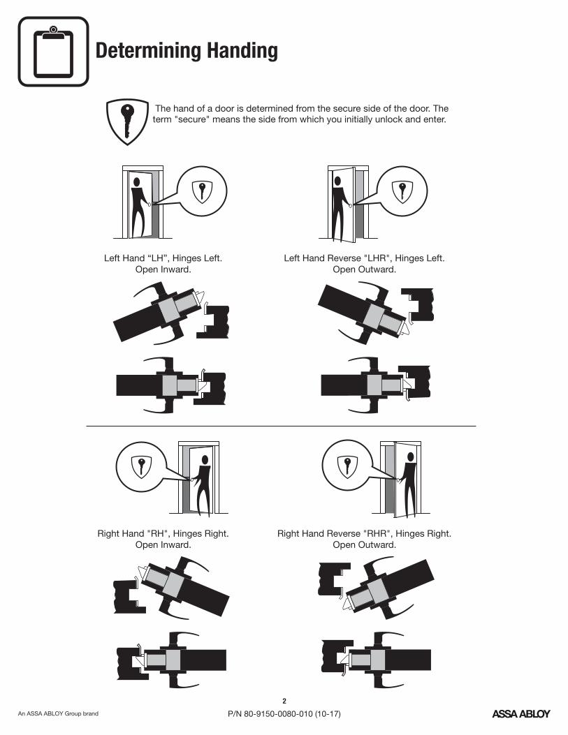
? Determining Handing
Left Hand “ ”, Hinges Left.LHOpen Inward.
Left Hand Reverse " ", Hinges Left.LHROpen Outward.
Right Hand " ", Hinges Right.RHOpen Inward.
Right Hand Reverse " ", Hinges Right.RHROpen Outward.
The hand of a door is determined from the secure side of the door. Theterm "secure" means the side from which you initially unlock and enter.
3
P/N 80-9150-0080-010 (10-17)
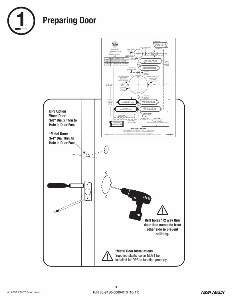
Preparing Door
!
Drill holes 1/2 way thrudoor then complete from
other side to preventsplitting.
DPS OptionWood Door:3/8" Dia. x Thru toHole in Door Face
*Metal Door:3/4" Dia. Thru toHole in Door Face
*Metal Door InstallationsSupplied plastic collar beMUSTinstalled for to function properly.DPS
80-8150-0032-010Rev C
nexTouch™
Cylindrical Lock
BEVELED EDGEDOOR ONLY
HIGH EDGE
LOW EDGE
aaaaaaaaaaaaaaaaaaaaaaaaaaaaaaaaaaaaaaaaaaaaaaaaaaa
aaaaaaaaaaaaaaaaaaaaaaaaaaaaaaaaaaaaaaaaaaaaaaaaaaaaaaaaa
1" Dia.(25mm)Thru Door
HIGH EDGE Fold Line
2-3/4" Beveled Backset
2-3/8" Square BacksetFold Line
2-3/8" Square BacksetFold Line
5/32" Dia x 1/8" Deep(4mm x 3mm)2 Locations
Both sides of door
2-3/4" (70mm)Between Centers
2-1/8" Dia(54mm)
Thru Door
3-1/2"(89mm)BetweenCenters
3"
3"
CAUTION:
If printed from websitePrint 1:1 Scale
Measure both 3" lines to check scale
aaaaaaaaaaaaaaaaaaaaaaaaaaaaaaaaaaaaaaaaaaaaaaaaaaaaaaaaaaaaaaaaaaaaaaaaaaaaaaaaaaaaaaaaaaaaaaaaaaaaaaaaaaaaaaaaaaaaaaaaaaaaaaaaaaaaaaaaaaaaaaaa
aaaaaaaaaaaaaaaaaaaaaaaaaaaaaaaaaaaaaaaaaaaaaaaaaaaaaaaaaaaaaaaaaaaaaaaaaaaaaaaaaaaaaaaaaaaaaaaaaaaaaaaaaaaaaaaaaaaaaaaaaaaaaaaaaaaaaaaaaaaaaaaaaaaaaaaaaaaaaaaaaa
SQUAREEDGEDOORONLY
5/32" Dia x 1/8" Deep(4mm x 3mm)2 Locations
Both sides of door
HIGH EDGE Fold Line
2-3/8" Beveled Backset
LOW EDGE Fold Line
2-3/8" Beveled Backset
LOW EDGE Fold Line
2-3/4" Beveled Backset
WHEN IN TOP
POSITION ONLY
5/16" Dia(8mm)
Thru Door
5/16" Dia(8mm)
Thru Door
1" Dia.(25mm)Thru Door
WHENINTOP
POSITIONONLY
3-1/2"(89mm)BetweenCenters
Horizontal
Center Line
Vertical
Center Line
CUT
CUT
CUT CUT
CUT
CUT
Product Support Tel 800-810- (9473) • www.yalelocks.comWIRE
nexTouch™ is a trademark of Yale Security Inc., an ASSA ABLOY Group company.ASSA ABLOYCopyright © 2017, Yale Security Inc., an Group company. All rights reserved.
Reproduction in whole or in part without the express written permission of Yale Security Inc., an Group company is prohibited.ASSA ABLOY
Yale Locks & Hardware is a division of Yale Security Inc., an Group company.ASSA ABLOY
An ASSA ABLOY Group brand
3/4" (19mm) Dia.Metal Frame
3/8" (9.5mm) Dia.Wood Frame
nexTouch Cylindrical Locks™
NTB610
620NTB
630NTB
640NTB
Cylinder Override - Push Button
Cylinder Override - Cap Touch
No Cylinder Override - Push Button
No Cylinder Override - Cap Touch
3/4" (19mm) Dia.Metal Frame
3/8" (9.5mm) Dia.Wood Frame
1
!
4
P/N 80-9150-0080-010 (10-17)
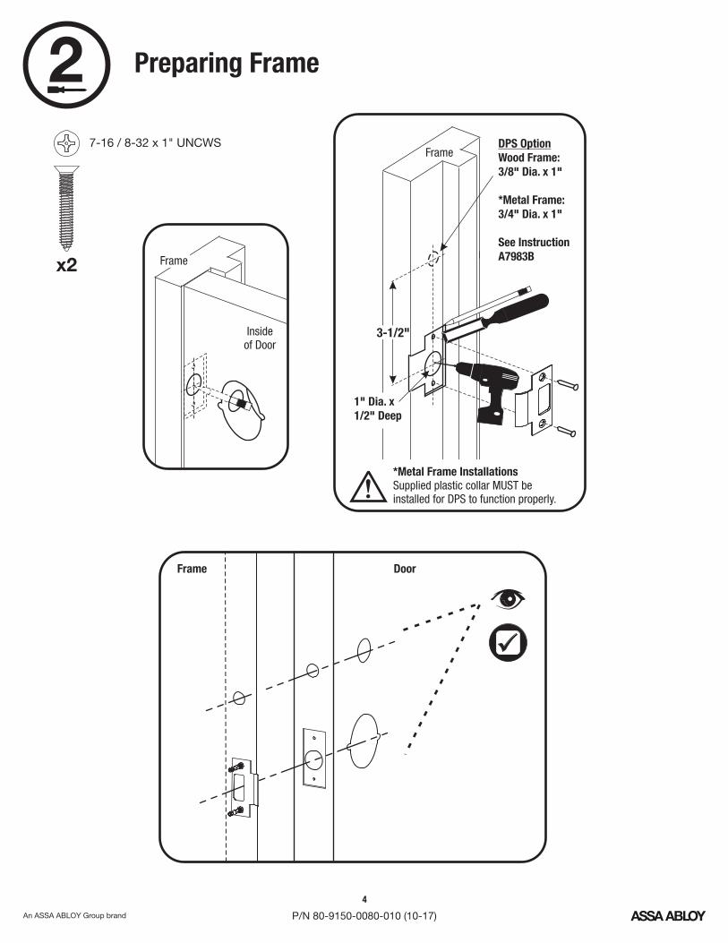
2 Preparing Frame
DoorFrame
1" Dia. x1/2" Deep
FrameDPS OptionWood Frame:3/8" Dia. x 1"
*Metal Frame:3/4" Dia. x 1"
See InstructionA7983B
Insideof Door
Frame
3-1/2"
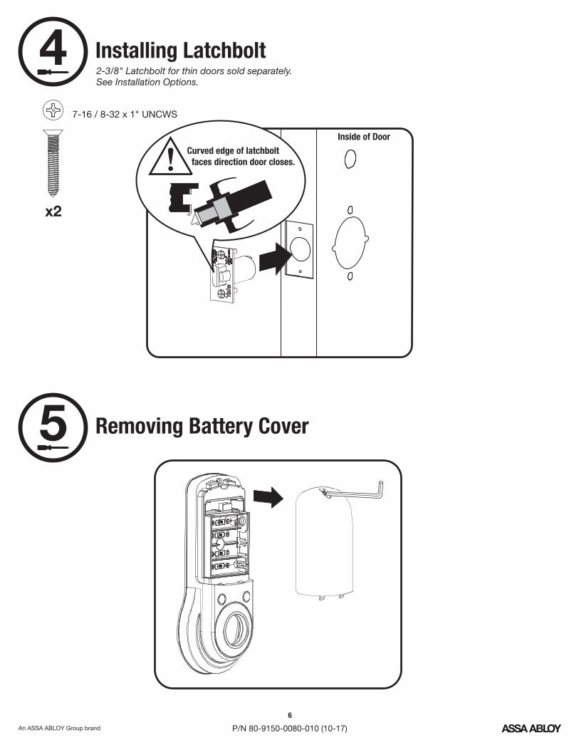
7-16 / 8-32 x 1" UNCWS
x2
*Metal Frame InstallationsSupplied plastic collar beMUSTinstalled for to function properly.DPS!
5
P/N 80-9150-0080-010 (10-17)
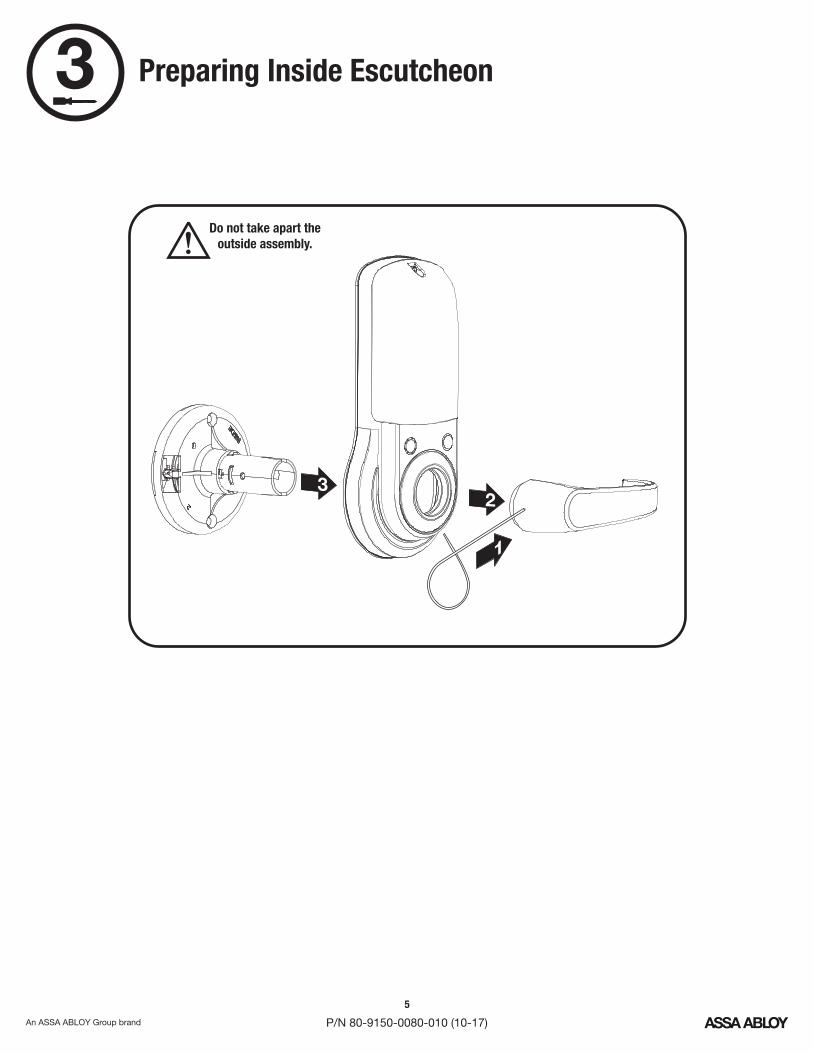
3 Preparing Inside Escutcheon
!Do not take apart the
outside assembly.
32
1
6
P/N 80-9150-0080-010 (10-17)
Curved edge of latchboltfaces direction door closes.!
Installing Latchbolt
Inside of Door
7-16 / 8-32 x 1" UNCWS
x2
Removing Battery Cover
4
5
2-3/8" Latchbolt for thin doors sold separately.See Installation Options.
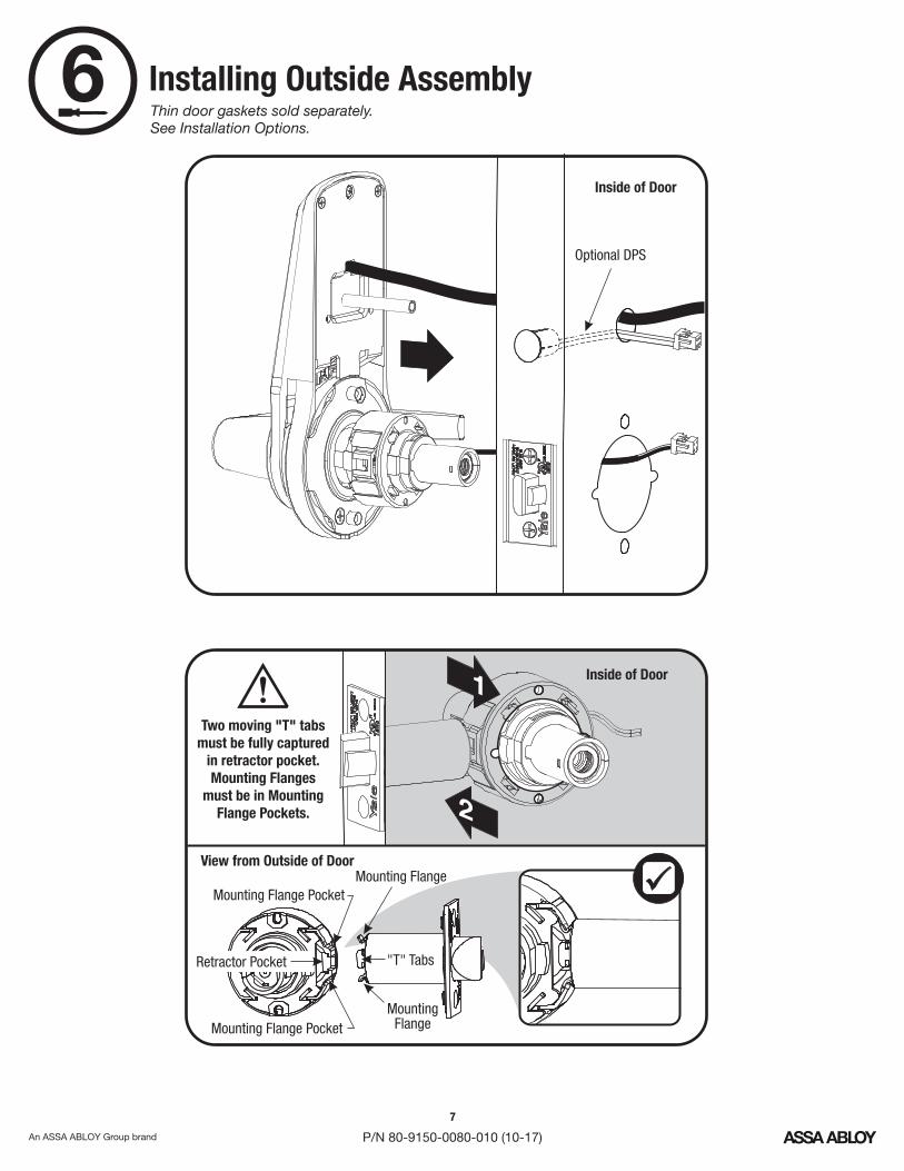
7
P/N 80-9150-0080-010 (10-17)
Installing Outside Assembly
Inside of Door
Inside of Door1
2
View from Outside of Door
"T" TabsRetractor Pocket
Mounting Flange
Two moving "T" tabsmust be fully captured
in retractor pocket.Mounting Flanges
must be in MountingFlange Pockets.
!
Mounting Flange Pocket
MountingFlangeMounting Flange Pocket
6Thin door gaskets sold separately.See Installation Options.
Optional DPS
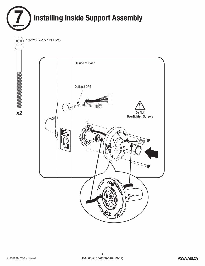
8
P/N 80-9150-0080-010 (10-17)
710-32 x 2-1/2" PFHMS
Do NotOvertighten Screws
!
Installing Inside Support Assembly
Inside of Door
x2
Optional DPS
9
P/N 80-9150-0080-010 (10-17)
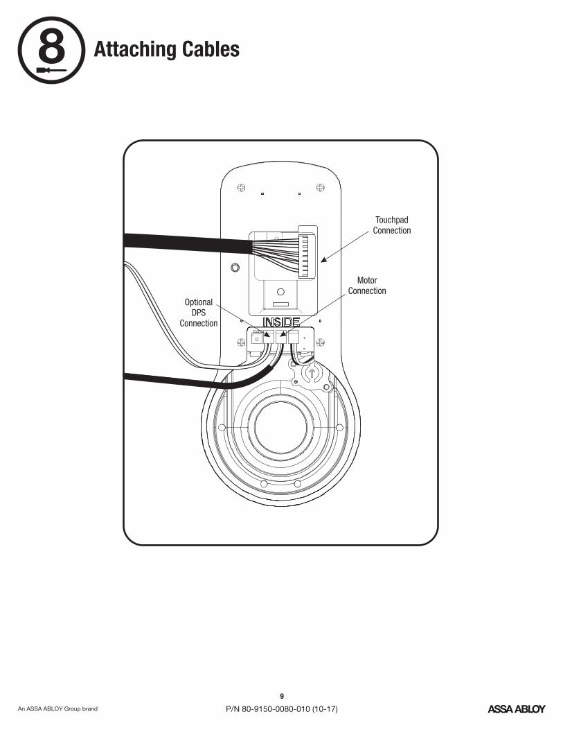
Attaching Cables
OptionalDPS
Connection
MotorConnection
TouchpadConnection
8
10
P/N 80-9150-0080-010 (10-17)
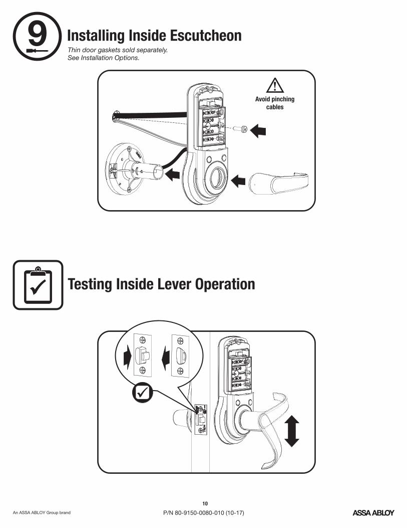
9 Installing Inside Escutcheon
Testing Inside Lever Operation
Avoid pinchingcables
!
Thin door gaskets sold separately.See Installation Options.

11
P/N 80-9150-0080-010 (10-17)
Optional Network or YaleAccentra Key module must be
installed batteries. SeeBEFOREInstallation Options.
!
"Welcome to Yale."
Congratulations, you've installed the Yale nexTouch Lock!™
Continue on next page to customize your product.
Installing Batteries & Cover10
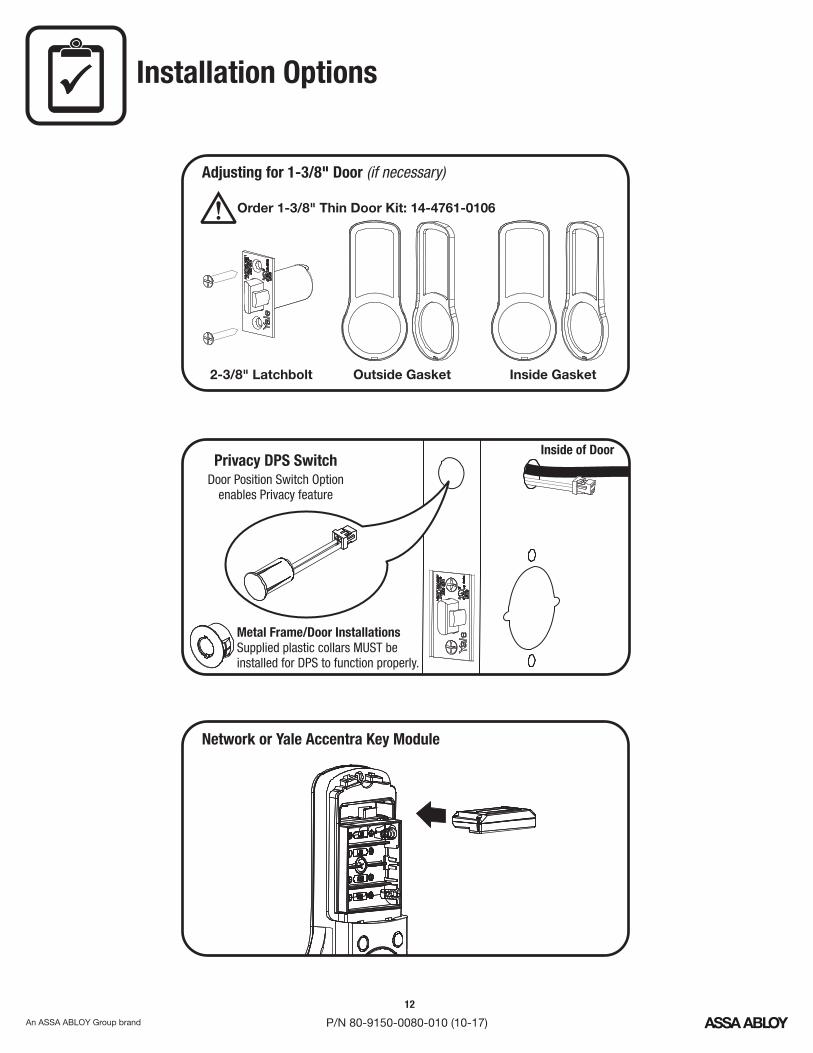
Privacy SwitchDPS
Metal Frame/Door InstallationsSupplied plastic collars beMUSTinstalled for to function properly.DPS
Inside of Door
Door Position Switch Optionenables Privacy feature
Installation Options
Outside Gasket Inside Gasket2-3/8" Latchbolt
Adjusting for 1-3/8" Door (if necessary)
Network or Yale Accentra Key Module
Order 1-3/8" Thin Door Kit: 14-4761-0106!
12
P/N 80-9150-0080-010 (10-17)
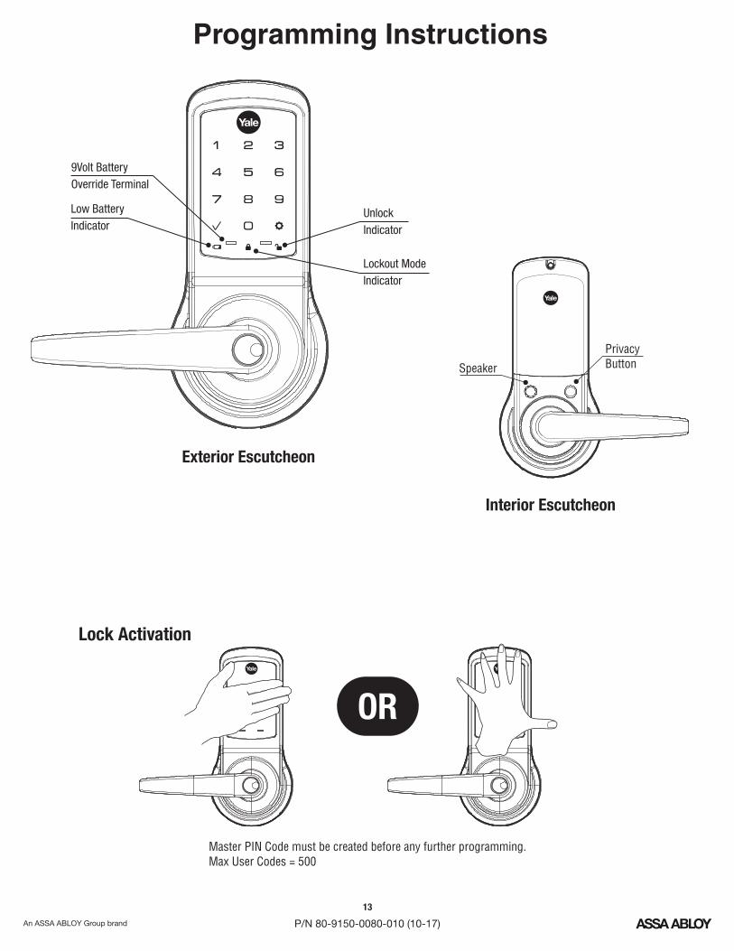
Programming Instructions
OR
Master Code must be created before any further programming.PINMax User Codes = 500
Lock Activation
Interior Escutcheon
PrivacyButtonSpeaker
Low BatteryIndicator
Exterior Escutcheon
9Volt BatteryOverride Terminal
Lockout ModeIndicator
UnlockIndicator
13
P/N 80-9150-0080-010 (10-17)
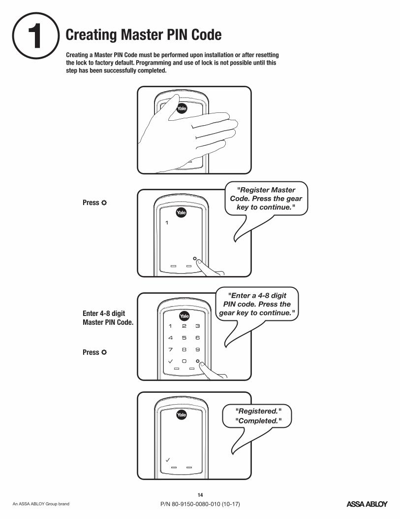
Creating Master CodePIN1Creating a Master Code must be performed upon installation or after resettingPINthe lock to factory default. Programming and use of lock is not possible until thisstep has been successfully completed.
Enter 4-8 digitMaster Code.PIN
Press
Press
"Register MasterCode. Press the gear
key to continue."
"Enter a 4-8 digitcode. Press thePIN
gear key to continue."
"Registered.""Completed."
14
P/N 80-9150-0080-010 (10-17)

Creating User CodesPIN2
Enter MastercodePIN
Press
Press
Press
"Press 1 toregister a code."
"Register User code.Press the gear key
to continue." Press
Press
"Register User code.Press the gear key
to continue."
" code registration.PINEnter a 4-8 digit code.PIN
Press the gear keyto continue."
"Menu Mode,enter number."
Master code must be created first.PIN*Max User Codes = 500
15
P/N 80-9150-0080-010 (10-17)
16
P/N 80-9150-0080-010 (10-17)
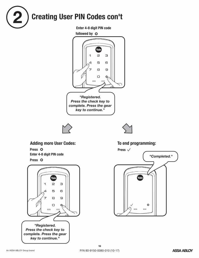
Creating User Codes con'tPIN2
Press
Adding more User Codes:
Enter 4-8 digit codePIN
Press
To end programming:Press
"Registered.Press the check key to
complete. Press the gearkey to continue."
Enter 4-8 digit codePIN
followed by
"Completed."
"Registered.Press the check key to
complete. Press the gearkey to continue."

17
P/N 80-9150-0080-010 (10-17)
3 Locking & Unlocking Door withRegistered Master or User CodePIN
Enter CodePINPress
18
P/N 80-9150-0080-010 (10-17)
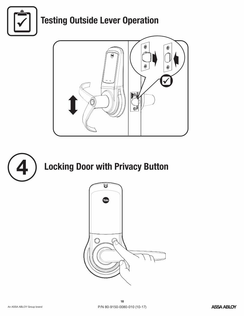
Locking Door with Privacy Button4
Testing Outside Lever Operation

19
P/N 80-9150-0080-010 (10-17)
Resetting Lock to Factory Default
1. Remove inside lever with thesupplied lever removal tool.
2. Remove the battery cover withsupplied hex wrench and thenremove batteries.
3. Remove the 10-32 x 3/4" panhead screw from the center of thebattery housing.
4. Remove the interior escutcheonfrom the door to access the resetbutton on back of escutcheon.Cables may stay connected. (Seeillustration at above for location ofthe reset button.)
5. Reinstall four (4) batteries.AA6. Press the reset button for 3
seconds.7. While continuing to press the
reset button, temporarily removeone (1) battery.AA
8. Reinstall the battery.9. Release reset button and wait
approximately 15 seconds.Speaker will announce "Welcometo Yale."
10. Reassemble escutcheon byreversing steps 1-4.
Interior Escutcheon
When lock is reset to factory defaults all user codes (including the Master code*)PINare deleted and all programming features are reset to original default settings (seeFactory Settings).
Upon reset, Master Code creation is the only option available and must bePINperformed prior to any other programming of the lock.
IMPORTANT: The outside assembly remains assembled.
Lever Removal Tool Hex Wrench
ButtonReset
20
P/N 80-9150-0080-010 (10-17)
DefinitionsAll Code Lockout Mode: This feature is enabled by the Master code. When enabled, it restricts all user (exceptMaster) code access. When attempting to enter a code while the unit is in Lockout, the locked padlockPIN REDwill appear on the screen. (Main Menu selection #6.)
Automatic Re-lock Time: After a successful unlock, the unit will re-lock automatically after 5 seconds or for aduration selected in the (Main Menu selection #3 then #1).Advanced Lock Settings
Language Setting Mode: Choose English (1), Spanish (2) or French (3) for the lock's voice prompts. (MainMenu selection #5.)
Low Battery: When battery power is low, the Low Battery Warning indicator flashes . If battery power isREDcompletely lost, use the 9Volt battery override. To use the 9V battery override apply 9V battery, in eitherdirection, to terminals on the touchscreen for backup power option. Activate the touchscreen and enter your pincode to unlock the door.
Master Code: It must be createdPIN The Master code is used for programming and for feature settings.PINprior to programming the lock. The Master code will also operate (unlock/lock) the lock.
Network Module Setting: With the optional Network Module installed, this setting becomes available (MainMenu selection #7) and allows the lock to connect with a network controller.
One Touch Locking: When the unit is unlocked, activating the touchscreen will lock the unit (during AutomaticRe-lock duration or when Automatic Re-lock is disabled). When One-Touch Re-lock is in use anynot (disabled),valid code will re-lock the lock. (Main Menu selection #3 then #3.)PIN
Privacy Button to Lock Door: If Automatic Re-lock is disabled, a short 1 second press of this button will lock thedoor.
Privacy Mode: With optional Door Position Switch installed, Privacy Mode enabled thru Menu Mode and doorclosed, all keypad functions can be disabled with a 3 second press of the Privacy Button. Privacy Mode isdisabled by default. Enable Privacy Mode thru Main Menu selection #3 then #4. With door closed, press andhold the privacy button until voice prompt indicates Privacy Mode is enabled. Privacy Mode duration ends whendoor is opened and voice prompt indicates Privacy Mode is disabled.
Shut Down Time: The unit will shut down for sixty (60) seconds and not allow operation after the wrong codeentry limit (5 attempts) has been met. When the unit is in Shut down, the keypad will be flashing.
Tamper Alert: Audible alarm sounds if attempting to forcibly remove outside lock from door.
User Code:PIN The User code operates the lock. Maximum number of user codes is 500.
Volume Setting Mode: (1)The volume setting for code verification is set to by default; otherwise itPIN HIGHcan be set to or for quiet areas. (Main Menu selection #4.)Low (2) Silent (3)
Wrong Code Entry Limit: After five (5) unsuccessful attempts at entering a valid code, the unit will shutPINdown and not allow operation. When the unit is in Shut Down, the keypad will be flashing.

21
P/N 80-9150-0080-010 (10-17)
Feature Programming Through Menu ModeUsing Master code*PIN
1. Touch screen with back of hand or palm to activate.2. Enter 4-8 digit master code* followed by key.PIN
Lock Response: "Menu mode, enter number (Enter digit corresponding to thefunction to be performed), press the key to continue."3. Follow the voice commands.4. Press key to complete the process and conclude the programming session.
*The Master code must be registered prior to any other programming of the lock.PIN
Continue Complete
Continue Complete
3
U
U
Privacy Enable
Disable
Volume Setting
Language Setting
All Code Lockout
**Network Module Setting
Enable
Disable
English
Spanish
French
Silent
Low
High
Master Code SettingPINM
User Codes Enter
Delete
Advanced Lock Settings Automatic Re-lock
Disable
One Touch Locking Enable
Disable
Default settingsin bold.
M1 2
Continue
Complete
1-180 Sec
**Set-up Digital Keys
Join the network
Exit the network
**This function appears only withNetwork or Yale AccentraKey module installed.
22
P/N 80-9150-0080-010 (10-17)
Programming Troubleshooting
NOTE: When batteries are replaced, Network Module locks have a real time clock that will be setthrough the User Interface ( ); it is recommended to verify correct date and timeUIparticularly those locks operating under Daylight Saving Time ( ).DST
••
Contact the Master user.Only the Master can enable/disable Lockout Mode.Check to see if All Code Lockout Mode is enabled.
Check to see if Auto Re-lock Mode is enabled.• If low battery indicator is lit (see below), change batteries.•
••
Contact the Master user.Only the Master can enable/disable Lockout Mode.Check to see if All Code Lockout Mode is enabled.
Symptom Suggested Action
Lock does not respond –door is open andaccessible.
•
•
•
•
Unit chimes to indicatecode acceptance, but thedoor will not open.
•
•
Unit operates to allowaccess, but will notautomatically re-lock.
PIN codes will not register.
•••
••
•
Upon entering a codePINand pressing key, theunit displays " invalid code"error or lock times out with-out responding.
Upon entering a codePINand pressing the key,the red padlock icon appearsand there are different tones.The unit operates, but itmakes no sound.
•
The unit responds"Low Battery"
•
Upon entering a codePINand pressing the key,the unit responds "Wrongnumber of digits" .
•
Lock does not respond –door is locked andinaccessible.
•Unit is on for a while thenshows no reaction. Lightsdim.
•
PIN codes must consist of 4 to 8 digits to register.
Check or gear cannot be used as part of the code.PIN
Contact the Master user.
Check that the motor cable is firmly connected into the PCboard marked " ".MOTOR
Check the door gaps for any foreign objects between doorand frame.
• Batteries may be completely discharged.
Check batteries are installed and oriented correctly (polarity)in the battery case.
User codes must be entered within 20 seconds (whiletouchscreen is active) or process will have to be restarted.
Registration/management of codes is set by thePINauthority of the Master Code, which is set first.
The same code cannot be used for multiple users.PIN
Batteries do not have enough power. Replace batteries.
Check to see if touchscreen cable is fully connectedand not pinched.
Check batteries are in good condition; replace batteriesif discharged.
If touchscreen numbers are visible, check to see if theyrespond when pressed.
Touchscreen becomes active when pressed w/whole hand.Use a larger area of the hand or fingers and verify contactwith at least 3 areas.
The digits entered were incorrect or incomplete. Re-enter4-8 digits followed by the check key.
This is the alert to replace the batteries. Replace all four(4) batteries with new Alkaline batteries.AA
Check to see if Volume is set to Silent.
Apply 9V battery to terminals on the touchscreen foremergency power jump option.
•
• Check for another locking device on the door (i.e. deadbolt).
23
P/N 80-9150-0080-010 (10-17)
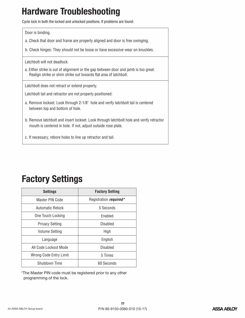
Hardware TroubleshootingCycle lock in both the locked and unlocked positions. If problems are found:
Latchbolt will not deadlock.
a. Either strike is out of alignment or the gap between door and jamb is too great.Realign strike or shim strike out towards flat area of latchbolt.
Latchbolt does not retract or extend properly.
Latchbolt tail and retractor are not properly positioned:
a. Remove lockset. Look through 2-1/8" hole and verify latchbolt tail is centeredbetween top and bottom of hole.
b. Remove latchbolt and insert lockset. Look through latchbolt hole and verify retractormouth is centered in hole. If not, adjust outside rose plate.
c. If necessary, rebore holes to line up retractor and tail.
Door is binding.
Factory SettingsSettings Factory Setting
Master CodePIN Registration required*
Automatic Relock 5 Seconds
One Touch Locking Enabled
Privacy Setting Disabled
Language English
Wrong Code Entry Limit 5 Times
Shutdown Time 60 Seconds
*The Master code must be registered prior to any otherPINprogramming of the lock.
Volume Setting High
All Code Lockout Mode Disabled
24
P/N 80-9150-0080-010 (10-17)
FCC:NOTE: This equipment has been tested and found to comply with the limits for a Class B digital device, pursuant to part 15 of theFCC Rules. These limits are designed to provide reasonable protection against harmful interference in a residential installation. Thisequipment generates, uses and can radiate radio frequency energy and, if not installed and used in accordance with the instructions,may cause harmful interference to radio communications. However, there is no guarantee that interference will not occur in aparticular installation. If this equipment does cause harmful interference to radio or television reception, which can be determinedby turning the equipment off and on, the user is encouraged to try to correct the interference by one or more of the followingmeasures:� Reorient or relocate the receiving antenna.� Increase the separation between the equipment and receiver.� Connect the equipment into an outlet on a circuit different from that to which the receiver is connected.� C TVonsult the dealer or an experienced radio/ technician for help.
Industry Canada:This device complies with Industry Canada licence-exempt standard(s). Operation is subject to the following two conditions:RSS(1) this device may not cause interference, and (2) this device must accept any interference, including interference that may causeundesired operation of the device.Le présent appareil est conforme aux d'Industrie Canada applicables aux appareils radio exempts de licence. L'exploitation estCNRautorisée aux deux conditions suivantes: (1) l'appareil ne doit pas produire de brouillage, et (2) l'utilisateur de l'appareil doitaccepter tout brouillage radioélectrique subi, meme si le brouillage est susceptible d'en compromettre le fonctionnement.
IMPORTANT! Tous les changements ou modifications pas expressément approuvés par la partie responsable de la conformité ontpu vider l'autorité de l'utilisateur pour actioner cet équipment.
Warning: Yale Security Inc.Changes or modifications to this device, not expressly approved by could void the user's authority tooperate the equipment.
ASSA ABLOY is the global leader in door opening solutions,dedicated to satisfying end-user needs for security, safety and convenience.
Product Support Tel 800.810.WIRE (9473) • www.yalelocks.com
Yale Locks & Hardware is a division of Yale Security Inc., an ASSA ABLOY Group company.
YALE, with its unique global reach and range of products, is the world's favorite lock– the preferred solution for securing your home, family and personal belongings.
nexTouch™ and Accentra™ are trademarks of Yale Security Inc., an ASSA ABLOY Group company.Copyright © 2017, Yale Security Inc., an Group company.ASSA ABLOY
All rights reserved. Reproduction in whole or in part without the express written permission of Yale Security Inc. is prohibited.