nfpa 36 - شرکت همیار انرژیhamyarenergy.com/static/fckimages/files/nfpa/hamyar... ·...
TRANSCRIPT
Copyright NFPA
NFPA 36 Standard for
Solvent Extraction Plants
2004 Edition
Copyright © 2004, National Fire Protection Association, All Rights Reserved
This edition of NFPA 36, Standard for Solvent Extraction Plants, was prepared by the Technical Committee on Solvent Extraction Plants and acted on by NFPA at its November Association Technical Meeting held November 15–19, 2003, in Reno, NV. It was issued by the Standards Council on January 16, 2004, with an effective date of February 5, 2004, and supersedes all previous editions.
This edition of NFPA 36 was approved as an American National Standard on January 16, 2004.
Origin and Development of NFPA 36
This standard was developed at the request of the solvent extraction industry in an effort to achieve greater uniformity in fire protection practices for extraction plants. The purpose of this standard is to provide reasonable standards for the design and operation of solvent extraction processes and extraction plants.
In the development of this standard, the Technical Committee on Solvent Extraction Plants recognized some fundamental differences between the operation of solvent extraction plants and the processing of solvents in other facilities. Many extraction plants are relatively small units in isolated locations, operated without the benefit of overall fire protection measures, such as are customary in large solvent processing facilities.
The operator of a solvent extraction plant must establish and maintain fire safety esprit de corps among a small number of employees, as opposed to relying on the established customs of largescale operations.
There are certain hazards in the combining and separating of solids and solvents that are peculiar to the solvent extraction industry. Also serving as a complicating problem is the potential dust explosion hazard in some areas of the typical plant. Therefore, the technical committee determined that it would be desirable to give consideration to practices applicable to either dustladen or flammable vaporladen atmospheres.
NFPA 36 was tentatively adopted at the 1957 Annual Meeting of the Association. A revision

Copyright NFPA
of this tentative edition was adopted at the 1958 Annual Meeting. NFPA 36 was officially adopted by the Association at its 1959 Annual Meeting. Amendments were adopted in 1962, 1964, 1967, 1972, 1973, 1974, 1978, 1983, 1985, 1988, 1993, 1997, 2001, and 2004.
This 2004 edition of NFPA 36 is a complete editorial rewrite of the previous edition to comply with NFPA's Manual of Style and also incorporates the following technical amendments:
(1) Revised definitions of the terms Extraction Process, Flame Arrester, Flammable Liquid (to correlate with NFPA 30, Flammable and Combustible Liquids Code), Inert Gas, Lower Flammable Limit, and Upper Flammable Limit
(2) Addition of a definition for Noncombustible Material, extracted from NFPA 220, Standard on Types of Building Construction
(3) Revised procedures in 4.5.3 for transfer of solvent, to correlate with NFPA 30, Flammable and Combustible Liquids Code
(4) Revision of 5.3.2 to require the design and construction of solvent storage tanks to comply with NFPA 30, Flammable and Combustible Liquids Code
(5) Revision of Section 7.4, Drainage and Spill Control, to provide more specific design requirements for the separation sump
(6) Addition of Figure 7.5.2 to illustrate typical locations for providing vent openings in the conveying system
(7) Revision of Section 7.6, Cooling Towers, allowing flexibility in locating the various types of cooling towers relative to the extraction process
(8) Addition of an exception to 8.2.6 that allows a shutoff valve in a normal vent line or an emergency vent line, if the shutoff valve meets specified criteria
(9) Addition of physical property data for isohexane to Annex B to recognize its use as an extraction solvent
Technical Committee on Solvent Extraction Plants
Leroy Venne, Chair Cargill, Incorporated, MN [U]
Rep. Corn Refiners Association Inc.
George E. Anderson, Crown Iron Works Company, MN [M]
Richard H. Barton, N. Hunt Moore & Associates, Inc., TN [SE]
Paul G. Dobbs, Global Risk Consultants, MI [I]
Richard D. Farmer, Bunge North America, MO [U] Rep. International Oil Mill Superintendents Association
Copyright NFPA
Jerry Fawbush, Central Soya Company, Inc., IN [U] Rep. National Oilseed Processors Association
John E. Heilman, Heilman Consulting Group, CO [SE]
Timothy G. Kemper, De Smet Process & Technology, Inc., GA [M]
C. L. Kingsbaker, Jr., Atlanta, GA [SE]
Eugene F. Smith, Archer Daniels Midland Company, IL [U] Rep. National Cottonseed Products Association
Leslie R. Watkins, Les Watkins & Associates, Inc., TX [SE]
Alternates
James M. Lay, Bunge Milling Company, IL [U] (Alt. to R. D. Farmer)
Robert P. Benedetti, NFPA Staff Liaison
This list represents the membership at the time the Committee was balloted on the final text of this edition. Since that time, changes in the membership may have occurred. A key to classifications is found at the back of the document.
NOTE: Membership on a committee shall not in and of itself constitute an endorsement of the Association or any document developed by the committee on which the member serves.
Committee Scope: This Committee shall have primary responsibility for documents on safeguarding against the fire and explosion hazards associated with the design, construction, and operation of solvent extraction plants.
NFPA 36 Standard for
Solvent Extraction Plants 2004 Edition
IMPORTANT NOTE: This NFPA document is made available for use subject to important notices and legal disclaimers. These notices and disclaimers appear in all publications containing this document and may be found under the heading “Important Notices and Disclaimers Concerning NFPA Documents.” They can also be obtained on request from NFPA or viewed at www.nfpa.org/disclaimers.
NOTICE: An asterisk (*) following the number or letter designating a paragraph indicates that explanatory material on the paragraph can be found in Annex A.
Changes other than editorial are indicated by a vertical rule beside the paragraph, table, or figure in which the change occurred. These rules are included as an aid to the user in identifying changes from the previous edition. Where one or more complete paragraphs have

Copyright NFPA
been deleted, the deletion is indicated by a bullet (•) between the paragraphs that remain.
A reference in brackets [ ] following a section or paragraph indicates material that has been extracted from another NFPA document. As an aid to the user, Annex D lists the complete title and edition of the source documents for both mandatory and nonmandatory extracts. Editorial changes to extracted material consist of revising references to an appropriate division in this document or the inclusion of the document number with the division number when the reference is to the original document. Requests for interpretations or revisions of extracted text shall be sent to the technical committee responsible for the source document.
Information on referenced publications can be found in Chapter 2 and Annex D.
Chapter 1 Administration
1.1 Scope.
1.1.1* This standard shall apply to the commercial scale extraction processing of animal and vegetable oils and fats by the use of Class I flammable hydrocarbon liquids, hereinafter referred to as “solvents.”
1.1.2 This standard shall also apply to any equipment and buildings that are located within 30 m (100 ft) of the extraction process.
1.1.3 This standard shall also apply to the unloading, storage, and handling of solvents, regardless of distance from the extraction process.
1.1.4 This standard shall also apply to the means by which material to be extracted is conveyed from the preparation process to the extraction process.
1.1.5 This standard shall also apply to the means by which extracted desolventized solids and oils are conveyed from the extraction process.
1.1.6 This standard shall also apply to preparation and meal finishing processes that are connected by conveyor to the extraction process, regardless of intervening distance.
1.1.7* This standard shall not apply to the storage of raw materials or finished products.
1.1.8 This standard shall not apply to extraction processes that use liquids that are miscible with water.
1.1.9 This standard shall not apply to extraction processes that use flammable gases, liquefied petroleum gases, or nonflammable gases.
1.1.10 This standard shall prohibit the use of processes that employ oxygenactive compounds that are heat or shock sensitive, such as certain organic peroxides, within the area defined in 1.1.2.
1.2 Purpose.
The purpose of this standard shall be to provide the following:
(1) Requirements for the design, construction, and operation of extraction processes that

Copyright NFPA
utilize Class I flammable hydrocarbon liquids
(2) Requirements for the prevention of fire and explosion in extraction processes and in associated preparation and meal finishing areas
(3) A means by which plant fire protection and supervisory personnel can evaluate the processes and operations under their control
(4) Guidance to regulatory and inspection officials in determining whether a given facility is being operated in accordance with good practice
(5) A workable set of standards for the use of design engineers, architects, and others in the planning and design of new installations
1.3 Application.
(Reserved)
1.4 Retroactivity.
The provisions of this standard reflect a consensus of what is necessary to provide an acceptable degree of protection from the hazards addressed in this standard at the time the standard was issued. Unless otherwise specified, the provisions of this standard shall not apply to facilities, equipment, structures, or installations that existed or were approved for construction or installation prior to the effective date of the standard. Where specified, the provisions of this standard shall be retroactive. In those cases where the authority having jurisdiction determines that the existing situation presents an unacceptable degree of risk, the authority having jurisdiction shall be permitted to apply retroactively any portions of this standard deemed appropriate. The retroactive requirements of this standard shall be permitted to be modified if their application clearly would be impractical in the judgment of the authority having jurisdiction, and only where it is clearly evident that a reasonable degree of safety is provided.
1.5 Equivalency.
Nothing in this standard is intended to prevent the use of systems, methods, or devices of equivalent or superior quality, strength, fire resistance, effectiveness, durability, and safety over those prescribed by this standard. Technical documentation shall be submitted to the authority having jurisdiction to demonstrate equivalency. The system, method, or device shall be approved for the intended purpose by the authority having jurisdiction.
1.6 Units and Formulas.
1.6.1 The units of measurement for this standard shall be in accordance with the International System of Units (SI). Measurements and values shall be expressed using the SI unit of measurement. An equivalent inch/pound measurement or value, in parentheses, shall be permitted to follow the SI value.
Exception: Table 8.2.3 need not meet this requirement.
1.6.2 Where a measurement is given in an SI unit with an equivalent unit following in

Copyright NFPA
parentheses, the first stated value shall be regarded as the requirement and the value in parentheses shall be considered to be approximate.
1.7 Code Adoption Requirements.
(Reserved)
Chapter 2 Referenced Publications
2.1 General.
The documents or portions thereof listed in this chapter are referenced within this standard and shall be considered part of the requirements of this document.
2.2 NFPA Publications.
National Fire Protection Association, 1 Batterymarch Park, Quincy, MA 021697471.
NFPA 30, Flammable and Combustible Liquids Code, 2003 edition.
NFPA 69, Standard on Explosion Prevention Systems, 2002 edition.
NFPA 70, National Electrical Code ® , 2002 edition.
NFPA 214, Standard on WaterCooling Towers, 2000 edition.
NFPA 220, Standard on Types of Building Construction, 1999 edition.
NFPA 780, Standard for the Installation of Lightning Protection Systems, 2000 edition.
2.3 Other Publications.
2.3.1 ASME Publication.
American Society of Mechanical Engineers, Three Park Avenue, New York, NY 100165990.
ASME Boiler and Pressure Vessel Code.
2.3.2 ASTM Publications.
American Society for Testing and Materials, 100 Barr Harbor Drive, West Conshohocken, PA 194282959.
ASTM D 323, Standard Method of Test for Vapor Pressure of Petroleum Products (Reid Method), 1999.
ASTM E 136, Standard Test Method for Behavior of Materials in a Vertical Tube Furnace at 750°C, 1999.
Chapter 3 Definitions

Copyright NFPA
3.1 General.
The definitions contained in this chapter shall apply to the terms used in this standard. Where terms are not included, common usage of the terms shall apply.
3.2 NFPA Official Definitions.
3.2.1* Approved. Acceptable to the authority having jurisdiction.
3.2.2* Authority Having Jurisdiction (AHJ). An organization, office, or individual responsible for enforcing the requirements of a code or standard, or for approving equipment, materials, an installation, or a procedure.
3.2.3 Labeled. Equipment or materials to which has been attached a label, symbol, or other identifying mark of an organization that is acceptable to the authority having jurisdiction and concerned with product evaluation, that maintains periodic inspection of production of labeled equipment or materials, and by whose labeling the manufacturer indicates compliance with appropriate standards or performance in a specified manner.
3.2.4* Listed. Equipment, materials, or services included in a list published by an organization that is acceptable to the authority having jurisdiction and concerned with evaluation of products or services, that maintains periodic inspection of production of listed equipment or materials or periodic evaluation of services, and whose listing states that either the equipment, material, or service meets appropriate designated standards or has been tested and found suitable for a specified purpose.
3.3 General Definitions.
3.3.1 Condensate. Any material that has been condensed from the vapor state to the liquid state.
3.3.2 Condenser. A piece of equipment that lowers the temperature of a vapor to the point where it changes to a liquid.
3.3.3 Controlled Area. Any area that is more than 15 m (50 ft) but less than 30 m (100 ft) from the solvent extraction process, measured horizontally.
3.3.4 Conveyor. Equipment that transports material from one point to another either pneumatically or mechanically, by means of a moving belt, a chain, buckets, or flights.
3.3.5 Desolventized Material. Material from which all absorbed solvent has been removed.
3.3.6 Desolventizer. Equipment that removes the absorbed solvent from the material being processed.
3.3.7 Evaporator. Equipment that vaporizes the solvent from the oilbearing miscella.
3.3.8 Extraction Process. The curbed area that contains the operations involving the extractor and the desolventizer, together with pertinent equipment such as heat exchangers, evaporators, and strippers, and which are contained in an enclosed building or in an open structure.
Copyright NFPA
3.3.9 Extractor. Equipment that removes oil and fat from oil or fatbearing material by means of a suitable solvent.
3.3.10 Flakes. Oil or fatbearing material that has been rolled in preparation for the extraction process.
3.3.11 Flaking Mill. A piece of equipment that utilizes smooth rollers to prepare material for the extraction process.
3.3.12 Flame Arrester. A device that prevents the transmission of a flame through a flammable gas/air mixture by quenching the flame on the surfaces of an array of small passages through which the flame must pass. The emerging gases are sufficiently cooled to prevent ignition on the protected side. [69:3.3]
3.3.13 Flammable Liquid (Class I Liquid). Any liquid that has a closedcup flash point below 37.8°C (100°F), as determined by the test procedures and apparatus set forth in Chapter 4 of NFPA 30, Flammable and Combustible Liquids Code, and a Reid vapor pressure not exceeding 2068.6 mm Hg (40 psia) at 37.8°C (100°F), as determined by ASTM D 323, Standard Method of Test for Vapor Pressure of Petroleum Products (Reid Method). [30:1.7]
3.3.14 Heat Exchanger. Equipment that transfers heat from one vapor or liquid to another vapor or liquid.
3.3.15 Hydrocarbon. A chemical substance consisting of only hydrogen and carbon atoms.
3.3.16* Important Building. A building that is considered not expendable in an exposure fire. [30:3.3]
3.3.17 Inert Gas. A gas that is noncombustible and nonreactive. [69:3.3]
3.3.18 Inerting. A technique by which a combustible mixture is rendered nonignitible by adding an inert gas. [69:3.3]
3.3.19* Lower Flammable Limit (LFL). That concentration of a combustible material in air below which ignition will not occur. [329:1.2]
3.3.20* Meal Finishing Area. The area that contains the equipment needed to prepare the extracted and desolventized material for storage.
3.3.21 Miscella. A mixture, in any proportion, of extracted oil or fat and the extracting solvent.
3.3.22 Noncombustible Material. A material that, in the form in which it is used and under the conditions anticipated, will not ignite, burn, support combustion, or release flammable vapors when subjected to fire or heat. Materials that are reported as passing ASTM E 136, Standard Test Method for Behavior of Materials in a Vertical Tube Furnace at 750°C, shall be considered noncombustible materials. [220:2.1]
3.3.23 Preparation Process. The operations involving the equipment used for the preparation of the material for the extraction process.
3.3.24 Purging. The process of displacing flammable vapors from buildings, equipment, or
Copyright NFPA
piping.
3.3.25 Restricted Area. The area within 15 m (50 ft) horizontally of the extraction process.
3.3.26 Separation Sump. A containment basin that is used to separate oils, miscella, or solvent from water by means of the immiscibility of the liquids and their differing densities.
3.3.27 Solvent. Any Class I flammable hydrocarbon liquid that has the ability to extract oils or fats from animal or vegetable material.
3.3.28* Spent Material. Material from which the oil or fat has been extracted but which has not been desolventized.
3.3.29 Stripper. A distillation column or tower, usually operated under vacuum, that is used to remove residual solvent from the extracted oil or fat.
3.3.30 Toaster. Equipment that is capable of producing the desired cooking, toasting, and modification of protein by means of heat and moisture.
3.3.31* Upper Flammable Limit (UFL). That concentration of a combustible material in air above which ignition will not occur.
3.3.32 Vapor Recovery. The process of reclaiming solvent by means of condensation or absorption.
3.3.33 Vapor Scrubber. A device used to wash entrained dust from a vapor stream by means of a liquid spray.
3.3.34 Vapor Seal. Equipment or material that prevents the escape of solvent vapors from process equipment or conveyors.
Chapter 4 General Requirements
4.1 Scope.
This chapter shall apply to the general operation of solvent extraction plants. The provisions of this chapter shall apply to all buildings, equipment, and operations in solvent extraction plants.
Exception: As otherwise provided for in Chapters 5, 6, and 7 of this standard.
4.2 Basic Operating Requirements.
4.2.1 Safe operating practices, including but not limited to startup and shutdown procedures, shall be the responsibility of the management operating the extraction plant.
4.2.2 Operating and maintenance employees shall be instructed in plant operations in general.
4.2.3* Applicable plant regulations shall apply to all visitors and others who enter the plant, both during operating periods and during shutdown periods.
4.2.4* Repair Authorization. When it is necessary to make repairs to the areas covered by

Copyright NFPA
this standard, the work shall be authorized by the individual in responsible charge of the plant before the work is started. Where hot work is required, this authorization shall be in writing.
4.3 Sources of Ignition.
4.3.1 Electrical installations shall meet all applicable requirements of NFPA 70, National Electrical Code.
4.3.2 Provisions shall be made for protection against static electricity and lightning as required in other chapters of this standard.
4.3.3 Smoking. Smoking or other sources of ignition shall not be permitted within the restricted and controlled areas. Lighters and matches shall not be carried into the restricted or controlled areas of the extraction plant.
4.3.4 Powered vehicles, unless approved for such locations, shall be prohibited within the controlled or restricted area except by special permission of the individual in responsible charge of the plant.
4.4 Housekeeping.
4.4.1 Flammable liquids not contained in process equipment shall not be stored in the extraction process area except in small quantities, which shall be stored in approved safety cans.
4.4.2 Waste materials, such as oily rags, other wastes, and absorbents used to wipe up solvent, paints, and oils, shall be deposited in approved waste cans and removed from the premises not less than once each day.
4.4.3 Dust originating from material in process shall be kept to a minimum.
4.4.4 The space within the restricted and controlled areas shall be kept free of dry grass, weeds, trash, and all combustible materials, except as allowed for cooling towers in Section 7.6.
4.4.5 Any spills of oil, solvent, or deposits of solventbearing material shall be cleaned up immediately and removed to a safe place.
4.4.6 The discharge or removal of solventbearing material shall be recognized as a severe hazard, and operating procedures shall be established to minimize such occurrences.
4.5 Solvent Transfer Equipment.
4.5.1 Pumps shall be designed for the solvent, the working pressures, and the structural stresses to which they will be subjected.
4.5.2 Positive displacement pumps shall be provided with bypasses with pressure relief valves discharging back to the tank or to the pump suction.
4.5.3 Transfer of liquids among vessels, containers, tanks, and piping systems by means of air or inert gas pressure shall be permitted only under all of the following conditions:
(1) The vessels, containers, tanks, and piping systems shall be designed for such
Copyright NFPA
pressurized transfer and shall be capable of withstanding the anticipated operating pressure.
(2) Safety and operating controls, including pressure relief devices, shall be provided to prevent overpressure of any part of the system.
(3) Only inert gas shall be used to transfer Class I solvents.
4.5.4 Where practicable, all pumps handling solvent in the processing equipment shall be located on the first floor level.
4.5.5 Pump houses, if used, shall be of noncombustible construction and ventilated.
4.6 Piping, Valves, and Fittings.
4.6.1 General. All piping, valves, and fittings shall be designed for the working pressures and structural stresses to which they will be subjected and shall be of steel or other material approved for the service intended.
4.6.2 Pipe Systems. Pipe systems shall be substantially supported and protected against physical damage caused by expansion, contraction, and vibration.
4.6.3 Process Piping.
4.6.3.1 Piping shall be pitched to drain to avoid trapped liquids, or suitable drains shall be provided.
4.6.3.2 Armored hose shall be permitted to be used where vibration exists or where frequent movement is necessary.
4.6.3.3 Aboveground solvent pipe sections 50 mm (2 in.) in size or over shall be welded and flanged. Welding shall conform to good welding practice.
4.6.4 Drain Valves. Drain valves shall be provided with plugs to prevent leakage.
4.6.5 Pipe Connections. Pipe connections 50 mm (2 in.) and larger to all tanks and vessels shall be bolted flanges that can be opened and blanked off.
4.6.6 Testing. After installation and before covering or painting, all piping systems, including suction lines, shall be pressure tested to not less than 1½ times the working pressure, but not less than a gauge pressure of 35 kPa (5 psig) at the highest point in the system. Tests shall continue for not less than 30 minutes without any noticeable drop in pressure.
Exception: Vapor lines operating at less than 500 mm (20 in.) of water column need not comply with these requirements.
4.6.7 Identification of Piping and Equipment. All piping and equipment shall be coded for identification.
4.7 Exits.
4.7.1 An extraction building or open process structure over two stories in height shall be provided with at least two remotely located means of egress from each floor, one of which

Copyright NFPA
shall be enclosed or separated from the process by a wall that is blank except for doors.
4.7.2 The enclosure or separating wall shall be of masonry or other noncombustible construction.
4.7.3 Selfclosing, noncombustible doors, normally kept closed, shall be provided for access to the means of egress.
4.8* Fire Protection.
4.8.1* An approved water spray, deluge, or foamwater system, or a combination of these types of fixed protection systems, shall be provided to protect the extraction process equipment and structure.
4.8.2* An approved system of automatic sprinklers shall be provided in the preparation area.
4.8.3* A system of yard hydrants shall be provided in accordance with accepted good practice.
4.8.4* Approved portable fire extinguishers of appropriate size and type shall be provided.
4.8.5* Where standpipe and hose protection is installed, combination water fog and straight stream nozzles shall be provided.
4.8.6 Where explosion prevention systems are used, they shall be installed in accordance with the provisions of NFPA 69, Standard on Explosion Prevention Systems.
4.8.7 Fire alarm signals shall be relayed or sent to a constantly supervised point on or off the premises.
4.8.8 Where service is available, a public fire alarm box shall be located nearby.
4.9 StartUp of Extraction Process.
Procedures for extractor startup shall be established to minimize the hazards resulting from passing through the flammable range. Inerting shall be permitted to be used to reduce the oxygen content and meet this requirement.
4.10 Emergency Procedures.
4.10.1 All employees shall be trained in the necessary actions to be taken in time of emergency, including emergency shutdown procedures.
4.10.2 Personnel shall be trained as to the location of exits.
4.10.3 All personnel shall be trained in the use and limitations of each type of firefighting equipment on the premises, including control valves for the water spray systems.
4.10.4 A fire brigade, if established, shall be composed of selected personnel on each shift and shall be trained as a unit with each person assigned definite responsibilities in case of an emergency.
4.10.5 Periodic drills shall be held to ensure that employees can carry out the procedures in 4.10.1 through 4.10.4.
Copyright NFPA
4.10.6 Emergency safety devices or systems provided in the plant shall be periodically tested in accordance with established procedures and a record made thereof.
4.11 Repairs in Restricted and Controlled Areas When Plant Is Operating or Not Purged.
4.11.1 Power Tools. Maintenance operations involving the use of power tools that can produce sources of ignition shall be prohibited except as provided for in Sections 6.7 and 6.8.
4.11.2 Electrical Equipment. Repairs on live electrical wiring or equipment shall be prohibited. If it is necessary to replace or repair electrical wiring or equipment, the power shall be disconnected completely, and the switch shall be locked in an open position.
4.11.3 Welding and Cutting Operations. Welding and cutting, including brazing and soldering operations, shall be prohibited except as provided for in Sections 6.7 and 6.8.
4.12 Repairs in Restricted and Controlled Areas When Plant Is Shut Down and Purged.
4.12.1* Repairs or alterations to equipment or buildings that can produce ignition sources shall be performed only when the plant has been shut down and completely purged and has been declared safe by the individual in responsible charge.
4.12.2 Before purging is initiated, the following steps shall be taken:
(1) Tanks, vessels, piping, and traps shall be emptied of all materials. All such material shall be removed to a safe location.
(2) All piping and other connections to storage facilities shall be disconnected, plugged, or blanked off.
4.12.3 Purging shall be accomplished by one or more of the methods in 4.12.3.1 through 4.12.3.3.
4.12.3.1 Steam. Vapor freeing shall be permitted to be accomplished by the introduction of steam into the equipment. All of the following requirements shall be met:
(1) The equipment shall be adequately vented to prevent damage from excessive pressure or vacuum.
(2) Steam supply lines shall be bonded to the equipment.
(3) The rate of supply of steam shall exceed the rate of condensation so that the equipment is heated close to the boiling point of water.
(4) The equipment shall be steamed long enough to vaporize the residues from all portions.
(5) After steaming, the procedures outlined in 4.12.3.2 shall be followed when hot work is to be performed.
4.12.3.2 Purging with Air. Vapor freeing shall be permitted to be accomplished by purging

Copyright NFPA
with air. Continued purging shall be permitted to maintain a safe atmosphere. All of the following requirements shall be met:
(1) Where fixed ventilating equipment is not provided, air movers shall be permitted to be attached so that air is drawn in and discharged through the air mover, or air can be introduced through the air mover and discharged through another opening.
(2) Discharge shall be to a safe location.
(3) Air movers shall be approved for the locations in which they are used.
(4)* Precautions shall be taken to ensure that the air mover is bonded to the equipment to minimize the hazard of ignition by static electricity. (See also 7.9.5.)
4.12.3.3* Purging with Inert Gas. Vapor freeing shall be permitted to be accomplished by purging with inert gas and then ventilating with air.
4.12.4 To ensure a safe condition, even on units out of service, tests for the presence of flammable vapors shall be made with a combustible gas indicator under each of the following conditions:
(1) Before commencing alterations or repairs, including welding, cutting, or heating operations
(2) Immediately after starting any welding, cutting, or heating operations
(3) Frequently during the course of such work
4.12.4.1 All such work shall be stopped immediately when the presence of flammable vapor is indicated.
4.12.4.2 The source of the vapor release shall be located and removed, and the tests required by 4.12.4 shall be repeated before the work is recommenced.
4.12.5 Upon completion of repairs or alterations, the plant shall be checked by the individual in responsible charge to ensure that operations can be resumed safely. (See Section 4.9.)
Chapter 5 Bulk Solvent Unloading and Storage
5.1 Scope.
This chapter shall apply to facilities for bulk unloading, bulk handling, and bulk storage of Class I flammable liquid solvent, as defined in this standard.
5.2 Location and Siting.
5.2.1 Unloading Site.
5.2.1.1 Bulk solvent unloading facilities shall be located so that ignition sources presented by locomotives or tank vehicles are at least 30 m (100 ft) from the extraction process and at least 7.5 m (25 ft) from any building or any property line that is or can be built on.
5.2.1.2 The fill connection to the storage tank shall be at least 7.5 m (25 ft) from the

Copyright NFPA
extraction process.
5.2.2 Bulk Solvent Storage Tanks.
5.2.2.1 Bulk solvent storage tanks shall be located outside of any building.
5.2.2.2 Underground solvent storage tanks shall be located at least 0.3 m (1 ft) from any building foundation or support and at least 0.9 m (3 ft) from the nearest property line that is or can be built on. The loads carried by the building foundations or supports shall not be transmitted to the tanks.
5.2.2.3 Aboveground solvent storage tanks shall be located in accordance with the following:
(1) Within the restricted area, at least 7.5 m (25 ft) from the extraction process and at least 7.5 m (25 ft) from any important building
(2) Within the controlled area, at least 7.5 m (25 ft) from any important building and at least 7.5 m (25 ft) from any property line that is or can be built on
(3) Outside the controlled area, at least 7.5 m (25 ft) from any important building and at least 7.5 m (25 ft) from any property line that is or can be built on
5.2.2.4 Aboveground storage tanks shall be enclosed by the fence already provided for in the restricted area or by a separate fence.
5.3 Design and Construction.
5.3.1 Unloading Stations. Unloading structures and platforms shall be constructed of noncombustible material and shall be designed and installed in accordance with accepted practice.
5.3.2* Storage Tanks. Storage tanks shall be designed, constructed, installed, and tested in accordance with NFPA 30, Flammable and Combustible Liquids Code.
5.4 Fire Protection Equipment.
5.4.1* Approved portable fire extinguishers of appropriate size and type shall be provided.
5.4.2 Additional fire protection for the unloading structure and bulk storage tanks shall be provided where an exposure hazard exists.
5.5 Sources of Ignition.
5.5.1 Electrical Equipment. All electrical utilization equipment and electrical wiring shall be suitable for Class I, Division 1 or 2, Group D hazardous (classified) locations and shall be designed and installed in accordance with NFPA 70, National Electrical Code.
5.5.1.1 Where enclosures that house solventhandling equipment such as solvent pumps or valves are provided or where solvents are transferred to individual containers, these enclosures shall be considered to be Division 1 locations.
5.5.1.2* In outdoor locations, areas adjacent to loading racks or platforms or to
Copyright NFPA
aboveground tanks shall be considered to be Division 2 locations. The Division 2 locations shall extend 7.5 m (25 ft) horizontally from such racks or tanks, and 4.5 m (15 ft) upward from adjacent ground level.
5.5.2 Static and Stray Currents.
5.5.2.1 All storage tanks, solvent transfer equipment, tank cars or tank trucks, and unloading structures shall be bonded effectively.
5.5.2.2 Transfer or storage tanks, unloading structures, tank cars, and tank trucks shall be electrically interconnected with supply piping or containers during the transfer of liquids.
5.5.2.3* Static protection shall be installed in accordance with accepted good practice.
5.5.3 Smoking. Smoking and open flames shall be prohibited and appropriate “No Smoking” and “Keep Fire Away” signs shall be posted in conspicuous locations.
5.6 Unloading Procedures.
5.6.1 Adequate precautions shall be taken to relieve excessive pressure in cargo tanks before unloading.
5.6.2 Tank cars shall be unloaded in accordance with accepted good practice.
5.6.3* Tank vehicles for solvents shall be unloaded in accordance with accepted good practice.
Chapter 6 Preparation and Meal Finishing Processes
6.1 Scope.
6.1.1 This chapter shall apply to processes that are used to prepare raw material for the extraction process and are connected by conveyor or other materialshandling equipment to the extraction process, regardless of intervening distance.
6.1.2 This chapter shall also apply to processes used to prepare extracted and desolventized product for storage.
6.1.3 Where the processing operations do not involve liberation of combustible dusts, the requirements of 6.2.2, 6.2.3, and 6.3.1 shall not apply.
6.2 Design and Construction.
6.2.1 The building shall be of fireresistive or noncombustible construction and shall be without basement or pits below grade.
6.2.2 The building shall be designed to provide at least 1 m 2 of explosion relief for every 15 m 3 of volume (1 ft 2 per 50 ft 3 ).
6.2.3* The roof and exterior wall construction shall provide explosion relief by one or more of the following methods:
Copyright NFPA
(1) Open air construction with a minimum area enclosed
(2) Light noncombustible walls and roof lightly attached to steel frame
(3) Light noncombustible wall panels and roof hatches
(4) Tophinged windows with explosion relief hatches
6.2.4 Space heating, if required, shall be provided by indirect means. Temperatures on heated surfaces shall be limited to 120°C (250°F).
6.3 Electrical Systems.
6.3.1* In areas where combustible dust presents a hazard, all electrical wiring and equipment shall conform to the requirements for Class II, Division 1, Group G locations.
6.3.2* Static protection shall be provided in equipment located in areas where combustible dust presents a hazard.
6.4 Dust Removal.
6.4.1* A dust collecting system shall be provided where necessary.
6.4.2 Where fabric filters are used for the collection of dust, they shall be located either outside of the building or along an outside wall in a fireresistive room inside the building.
6.4.2.1 The inside walls of an inside room shall be explosion resistant.
6.4.2.2 The outside walls or roof of an inside room shall have explosion relief in the ratio of 1 m 2 of relief area for each 9 m 3 to 15 m 3 of room volume (1 ft 2 of relief area for each 30 ft 3 to 50 ft 3 ).
6.4.3 Automatic sprinklers shall be installed within fabrictype dust collector housings.
6.4.4 Dust accumulations on floors, ledges, structural steel members, machinery, spouting, and other surfaces shall be removed concurrently with operations. This shall be done by vacuum cleaning or by other means that will not suspend dust in the air.
6.4.5 The use of compressed air or other means to blow dust from ledges, walls, and other areas shall not be permitted unless all machinery in the area has been shut down and all sources of ignition have been removed.
6.5 Tramp Metal.
Means shall be provided to remove tramp metal from the process stream to protect rolling and grinding machinery.
6.6* Dryer Shut Down.
Provisions shall be made to shut down any process dryer, and the air flow to it, that is a part of the preparation or meal finishing process in the event of a fire inside the dryer. Provisions shall also be made to inject smothering steam into the dryer.
Copyright NFPA
6.7* Hot Work.
Any repairs or alterations to preparation and meal finishing equipment that require welding, cutting, or other hot work shall be permitted, provided that either of the following applies:
(1) The extraction equipment has been shut down and cooled to prevent the release of vapor.
(2) The equipment being repaired has been isolated from any conveyor or duct through which a fire might be conveyed to or otherwise brought into contact with solvent vapors.
6.8* Use of Power Tools.
Electric power tools and grinders shall be permitted to be used while process equipment is operating provided no combustible dusts, ignitible vapors, or accumulations of combustible materials are present in the work area and the process equipment is completely closed off to prevent any sparks from entering the process.
Chapter 7 Extraction Process
7.1 Scope.
This chapter shall apply to the solvent extraction process.
7.2 Location and Siting.
7.2.1 The extraction process shall be located in the open or in a building suitable for the purpose, as shown in Figure 7.2.1.

Copyright NFPA
FIGURE 7.2.1 A Typical Distance Diagram.
7.2.2 Fencing. An industrialtype fence shall be placed not less than 15 m (50 ft) from the extraction process. All entrances and exits into the fenced area shall be secured to prohibit unauthorized entrance. Provisions shall be made for emergency ingress and egress.
7.2.3 A controlled area shall extend from 15 m (50 ft) to not less than 30 m (100 ft) from the extraction process.
7.2.4 The restricted and controlled areas shall be posted with signs around the perimeter warning of the possible flammable vapor hazard.
7.2.5 Basements, tunnels, pipe trenches, and pits shall be prohibited within 30 m (100 ft) of the extraction process.
Exception: This requirement shall not apply to separation sumps and the drainage troughs connected to them.
7.2.6 Except as permitted in 7.2.8, the extraction process shall be at least 30 m (100 ft) from any public way, any building, or any property line that is or can be built on.
7.2.7 The slope of the terrain and the prevailing winds shall be considered in locating the extraction process.
7.2.8 Structures and equipment essential to the operation of the extraction process, other than boilers and other open flame operations, shall be permitted to be located less than 30 m (100 ft) but not less than 15 m (50 ft) from the extraction process, provided a vapor barrier

Copyright NFPA
erected in accordance with the requirements of 7.2.8.1 and 7.2.8.2 is provided.
7.2.8.1 The barrier shall be located between the extraction process and the possible source of vapor ignition and shall be at least 15 m (50 ft) from the extraction process.
7.2.8.2 The barrier shall be of noncombustible vaportight construction without gates or other openings and shall be at least 1.2 m (4 ft) high and designed so that there is at least 30 m (100 ft) of vapor travel around its ends to possible sources of ignition.
7.2.9* Where the circumstances or conditions of any particular installation are unusual and in such a manner as to render the strict application of the distances specified in this standard impractical, the authority having jurisdiction shall be permitted to allow such deviation as will provide an equivalent degree of safety and be consistent with good engineering practice.
7.3 Design and Construction.
7.3.1 The building or structure housing the extraction process shall be of fireresistive or noncombustible construction with the first floor at or above grade.
7.3.2 Solid sections of upper floors of the extraction process and concrete pads under the entire extraction process shall be curbed and sloped to drain directly to an outside separation sump.
7.3.3 Drainage lines under the ground floor slab of the extraction process shall be prohibited.
7.3.4* Explosion relief of at least 1 m 2 for each 15 m 3 of building volume (1 ft 2 per 50 ft 3 ) shall be provided by one or more of the following methods:
(1) Open air construction with a minimum area enclosed
(2) Light noncombustible wall panels and roof hatches
(3) Light noncombustible walls and roof lightly attached to steel frame
(4) Tophinged windows with explosion relief latches
7.4 Drainage and Spill Control.
7.4.1 Provisions shall be made to guard against the introduction of solvent into the sewer systems.
7.4.2 A separation sump shall be provided to effect separation of water from oil, solvent, or miscella.
7.4.2.1 The separation sump shall be located within the restricted area but not closer than 7.5 m (25 ft) to the fence surrounding the restricted area.
7.4.2.2 The separation sump shall be concrete or of equivalent noncombustible construction.
7.4.2.3 The separation sump shall consist of one or more retention sections and a final water discharge section and shall meet the following requirements:
(1) The retention section(s) shall be sized to retain all oil, solvent, and miscella that can

Copyright NFPA
be released by a single break in a vessel or piping system, plus an additional 50 percent of that amount.
(2) The final water discharge section shall be designed with a liquid seal or other means to prevent the flow of vapor or liquid solvent to the sewer.
7.4.2.4 Means shall be provided to prevent the outflow of oil, solvent, or miscella from the separation sump to the sewer system under emergency conditions or if the liquid seal fails. In the event of any flow of fire protection water, provisions shall be made to contain the flow of oil, solvent, and miscella in a safe location.
7.4.2.5 A pump shall be provided to recover oil, solvent, or miscella collected in the separation sump.
7.4.2.6 Approved fixed automatic fire protection shall be provided above the separation sump.
7.5 Conveying Systems.
7.5.1 Conveyors and spouts from or to other buildings shall be located and protected so that passage of solvent vapors or liquid to other areas is prevented. In addition to the requirements of this subsection, all of the requirements of 8.3.2 and 8.3.3 shall be met.
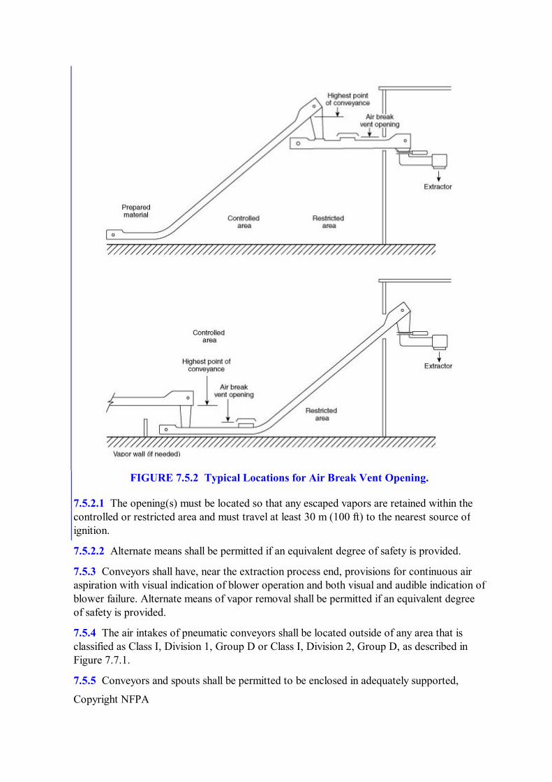
7.5.2 Conveying systems to the extraction area shall have one or more openings on the extraction side of the system, after the highest point of conveyance entering the controlled area to allow dense solvent vapors to escape rather than flow back to the preparation area. See Figure 7.5.2.
Copyright NFPA
FIGURE 7.5.2 Typical Locations for Air Break Vent Opening.
7.5.2.1 The opening(s) must be located so that any escaped vapors are retained within the controlled or restricted area and must travel at least 30 m (100 ft) to the nearest source of ignition.
7.5.2.2 Alternate means shall be permitted if an equivalent degree of safety is provided.
7.5.3 Conveyors shall have, near the extraction process end, provisions for continuous air aspiration with visual indication of blower operation and both visual and audible indication of blower failure. Alternate means of vapor removal shall be permitted if an equivalent degree of safety is provided.
7.5.4 The air intakes of pneumatic conveyors shall be located outside of any area that is classified as Class I, Division 1, Group D or Class I, Division 2, Group D, as described in Figure 7.7.1.
7.5.5 Conveyors and spouts shall be permitted to be enclosed in adequately supported,

Copyright NFPA
noncombustible bridge structures equipped with open grate floor sections for ventilation.
7.6* Cooling Towers.
If a cooling tower provides service to the extraction process, it shall be located, based on its construction and fire protection, in accordance with this subsection.
7.6.1 If the tower is of noncombustible exterior construction and the fill of the tower is of limitedcombustible construction, as these terms are defined in NFPA 220, Standard on Types of Building Construction, then the tower shall be permitted to be located in the restricted area and shall not be required to have a fire protection system.
7.6.2 If the tower is of noncombustible exterior construction but the fill of the tower is of combustible construction, the tower shall not be located in the restricted area. The tower shall be permitted to be located in the controlled area, if it is protected by automatic sprinklers in accordance with NFPA 214, Standard on WaterCooling Towers.
7.6.3 If the tower is of combustible construction and is protected by interior and exterior automatic deluge fire protection systems in accordance with NFPA 214, Standard on WaterCooling Towers, the tower shall not be located in the restricted area but shall be permitted to be located in the controlled area.
7.6.4 If the tower is combustible and unprotected, the tower shall not be located in the restricted or controlled area.
7.7 Electrical Systems.
7.7.1* Class I, Division 1 Locations. Electrical wiring and electrical utilization equipment of the extraction process shall be installed in accordance with the requirements for Class I, Division 1 locations as specified by NFPA 70, National Electrical Code. The Class I, Division 1 location shall extend outward from the extraction process and into the restricted area for a horizontal distance of not less than 4.5 m (15 ft) and a vertical distance of not less than 1.5 m (5 ft) above the highest vent, vessel, or equipment containing solvent, as shown in Figure 7.7.1.
FIGURE 7.7.1 Type and Extent of Hazardous Areas.
7.7.2 Electrical wiring and electrical utilization equipment within the restricted area beyond the 4.5m (15ft) distance specified in 7.7.1 and to a height of 2.4 m (8 ft) above the

Copyright NFPA
extraction process grade level shall be installed in accordance with the requirements of Class I, Division 2 locations, as specified in NFPA 70, National Electrical Code, and as shown in Figure 7.7.1.
7.7.3 Electrical wiring and electrical utilization equipment within the controlled area and to within a height of 1.2 m (4 ft) above grade level shall be installed in accordance with the requirements of Class I, Division 2 locations, as shown in Figure 7.7.1.
Exception: This requirement shall not apply to the preparation process. (See 7.2.8.)
7.7.4 Permanent luminaires (lighting fixtures) shall be installed where needed.
7.7.5 Flashlights approved for Class I, Group D locations shall be provided.
7.8 Ventilation Systems.
7.8.1 Enclosed plants shall have sufficient ventilation to change the volume of air at least six times per hour. This ventilation shall be accomplished by exhaust fans, preferably taking suction at floor levels and discharging to a safe location outside the building. The arrangement shall be such that all portions of solid floor areas are subjected to continuous positive movement of air.
7.8.2 Ventilation fans intended to handle solvent vapors shall be designed with the increased horsepower necessary to handle higher density vapors.
7.9 Ignition Sources and Heating.
7.9.1 Ignition sources shall not be permitted within the extraction process building or within 30 m (100 ft) of the process unless the unit and building are purged except as provided for in 4.3.4 and 7.2.8.
7.9.2 Space heating, if required, shall be provided by indirect means. Temperatures on heated surfaces shall not exceed 120°C (250°F).
7.9.3 If steam tracing or jacketing is provided, temperatures on both internal and external heated surfaces shall not exceed 120°C (250°F).
Exception: Process temperatures shall be permitted to exceed 120°C (250°F), provided the temperature is reduced to 120°C (250°F) during shutdown periods.
7.9.4 Power transmission belts shall not be used in any area that is classified as a Class I, Division 1 or Class I, Division 2 location as shown in Figure 7.7.1.
7.9.5 Process vent fans, purge fans, and building ventilation fans that might handle solvent vapors, including any fans that have air intakes located in Class I, Division 1 or Class I, Division 2 locations, as shown in Figure 7.7.1, shall be of AMCA Type B sparkresistant construction or better.
7.10 Flammable Vapor Detection.
7.10.1 Approved portable combustible gas indicators shall be provided and maintained in good working order.

Copyright NFPA
7.10.2* Provisions shall be made for monitoring the atmosphere in areas where flammable vapors can present a hazard. Monitoring shall be permitted to be accomplished by installing an approved combustible gas detection system with audible and visual alarms. Where such a detection system is used, it shall be tested and maintained in good working order in accordance with the manufacturer's instructions.
7.11 Lightning Protection.
Where required, an approved lightning protection system, installed in accordance with NFPA 780, Standard for the Installation of Lightning Protection Systems, shall be provided for the extraction process.
7.12 Static Electricity.
7.12.1 All tanks, vessels, motors, pipes, conduit, grating, and building frames within the process shall be electrically bonded together.
7.12.2* Building frames and metal structures shall be grounded and tested periodically to determine electrical continuity.
7.12.3 All hose, except hose used in water service, shall be electrically bonded to the supply line and to the tank or vessel where discharge takes place.
7.12.4 Grounding wires or bonding connections shall be provided between any dispensing vessel and any receiving vessel used for the transfer of solvent or mixtures of solvent and oil where bonding is not achieved through fixed connections. This shall include all sampling cocks.
7.12.5* If steam purging, cleaning, or sparging is used, all pipes or nozzles through which steam is discharged shall be bonded to the equipment being purged, cleaned, or sparged, or the objects shall be connected to ground.
Chapter 8 Extraction Process Equipment
8.1 Scope.
This chapter shall apply to extraction process equipment.
8.2 Venting.
8.2.1 The extraction process shall be a closed system and shall be vented to the outside atmosphere through an approved flame arrestor installed in accordance with the conditions of its approval.
8.2.1.1 Manifolding of vents upstream of the flame arrestor shall be permitted.
8.2.1.2 Vents shall terminate at least 6 m (20 ft) above ground level and shall be located so that vapors will not reenter buildings.
8.2.1.3 Flame arrestors shall be protected against freezing and shall be accessible for

Copyright NFPA
inspection and repair.
8.2.2 Vessels or tanks containing solvent, including extractors, solvent work tanks, miscella tanks, and solventwater separating tanks, shall be protected with emergency venting to relieve excessive internal pressure in the event of fire. If the calculated required emergency vent capacity is less than that provided by the normal vent, no additional emergency venting shall be required.
8.2.3* The total capacity of both normal and emergency venting for vessels and tanks in the extraction process, which are protected in accordance with 4.8.1, shall not be less than that given in Table 8.2.3.
Table 8.2.3 Minimum Total Emergency Vent Capacity in ft 3 of Free Air/Hr (14.7 Psia and 60°F) for Vessels and Tanks Protected in Accordance with 4.8.1
Exposed Surface Area *
(ft 2 )
Vent Capacity (ft 3 /hr)
Exposed Surface
Area * (ft 2 )
Vent Capacity (ft 3 /hr)
Exposed Surface
Area * (ft 2 )
Vent Capacity (ft 3 /hr)
20 6,300 160 50,400 900 147,900 30 9,480 180 57,000 1,000 157,200 40 12,630 200 63,300 1,200 167,100 50 15,810 250 71,700 1,400 176,100 60 18,960 300 79,500 1,600 184,200 70 22,110 350 86,400 1,800 191,700 80 25,260 400 93,600 2,000 198,600 90 28,440 500 106,200 2,400 211,200 100 31,500 600 117,600 2,800 222,600 120 37,800 700 128,400 and over 140 44,100 800 138,600
Notes: 1. For SI units, 10 ft 2 = 0.93 m 2 ; 36 ft 3 = 1.0 m 3 . 2. Interpolate for intermediate values. If tank or vessel is protected by approved insulation in addition to water spray, deluge system, or equivalent protection as provided in 4.8.1, the flow capacities can be reduced by 50 percent. * Exposed surface area means the exterior surface of a vessel or tank less that portion resting on a solid earth or concrete pad.
8.2.4 All emergency relief vents shall terminate at least 6 m (20 ft) above ground level and shall be located so that vapors do not reenter the building or create a hazard from localized overheating of any part of a tank or structure.
8.2.5 Flame arrestors shall not be required in discharge lines from emergency pressure relief valves that are provided for vessels and tanks covered by 8.2.2.
8.2.6 Shutoff valves shall not be installed in normal or emergency vent lines.
Exception: An automatic pressure control valve shall be permitted to be installed to regulate the pressure in the extractor if all of the following requirements are met:
(1) The valve shall be located in the vent line from the extractor or in the vent line from the

Copyright NFPA
extractor condenser. (2) The valve shall be actuated by the extractor pressure controller. (3) The valve shall be installed so that it fails in the open position. (4) The valve shall have a mechanical stop, a parallel small vent, or an equivalent feature to prevent complete shutoff.
(5) The valve shall provide a safe minimum venting capacity.
8.2.7 Shutoff valves shall not be installed in overflow lines from vessels and tanks.
8.2.8 Flares or burners from process vents shall be prohibited within the restricted and controlled areas but shall be permitted to be installed outside these areas. Such flares or burners shall be equipped with approved devices to prevent flashbacks in the vent piping.
8.2.9 The extractor shall be provided with means to remove solvent vapors so that the concentration of vapors inside the unit in the area where work is required can be maintained at or below 25 percent of the lower flammable limit.
8.2.9.1 If a purge fan system is used to meet 8.2.9, it shall comply with all of the following:
(1) The system shall take suction from the lower sections of the extractor to facilitate removal of vapors and shall discharge to a safe location outside the extractor building.
(2) The system shall be capable of changing the air in the empty extractor at least 20 times per hour.
(3) The system shall be designed and operating procedures developed to allow the normal process vent system to cool the equipment to a temperature below 38°C (100°F) prior to highvolume air purging, where this is practical depending on the ambient temperature.
(4) The fan shall meet or exceed the requirements for an AMCA Type B sparkresistant unit.
(5) The fan and its ducting shall be electrically bonded to the extractor and shall itself be electrically grounded to prevent the accumulation of electrostatic charge.
8.3 Conveying Systems for Solids.
8.3.1 An adequate vapor seal designed to prevent the escape of solvent or solvent vapors shall be provided at the point where the solids enter the system.
8.3.2 An adequate vapor seal shall be used on the final discharge of material from the extraction system.
8.3.3 Gaskets, if used in these systems, shall be of a material that does not decompose or soften in the presence of oil, solvent, or steam.
8.3.4 Pneumatic systems for handling solids shall be permitted to be used when material and air being handled are solventfree.

Copyright NFPA
8.4 Extractors, Desolventizers, Toasters, Dryers, and Spent Flake Conveyors.
8.4.1 Extractors, desolventizers, toasters, dryers, and spent flake conveyors shall be of a design that minimizes the possibility of ignition of product deposits.
8.4.2 Extractors, desolventizers, toasters, dryers, and spent flake conveyors shall be protected by extinguishing systems using inert gas, steam, or a combination of the two, controlled from a safe remote location. (See 8.10.1.)
8.5 Grinders.
Finished meal grinding processes located after the dryingcooling operation shall not be located in the restricted area. Such operations shall be permitted in the controlled area only when conforming to the provisions of 7.2.8. Finished meal grinding of materials as discharged from the desolventizer shall not be permitted.
8.6 Miscella Filters.
Only totally enclosed filters shall be used. Ventilation shall be provided to remove residual solvent vapors when filters are open.
8.7 Wastewater Evaporation.
Process wastewater shall pass through an evaporator before entering the separation sump. (See 8.10.4.)
8.8 Pressure Vessels and Tanks.
8.8.1 Unfired pressure vessels such as desolventizers and evaporators shall be constructed in accordance with the ASME Boiler and Pressure Vessel Code.
8.8.2 All large vessels shall be equipped with bolted and gasketed plates for inspection or repairs.
8.8.3 Where sight glasses are installed, they shall be of the highpressure type protected against breakage and loss of product.
8.8.4 Hydraulic transmission or hydrostatic gauges shall be used for remote observation of liquid levels.
8.8.5 Tanks shall be equipped with manual shutoff valves at the bottom.
8.8.6 Armoredtype liquid level gauges shall be used.
8.9 Heat Exchangers, Condensers, and Flash Drums.
8.9.1 The water side of condensers and heat exchangers shall be kept at a greater pressure than the solvent or vapor side.
8.9.2 Provisions shall be made to ensure safe shutdown in the event of loss of primary cooling water. This shall be accomplished by one or more of the following methods:
Copyright NFPA
(1) An automatic emergency gravity water supply tank of sufficient capacity
(2) A connection to an equally reliable water supply
(3) A provision to automatically shut off steam other than smothering steam, to immediately reduce steamheated jacket pressure to atmospheric pressure, and to stop the flow of miscella to the distillation system
8.9.3 All steam condensate from the extraction process that is to be returned to the boiler shall be reduced to practically atmospheric pressure in a vessel where any entrained solvent will be flashed off.
8.10 Process Controls.
8.10.1 Provision shall be made for emergency shutoff of steam and shutdown of process equipment. This shall be accomplished through manual operation both near the process equipment and at a safe remote location.
Exception: Smothering steam, cooling water to condensers, exhaust fans, and lights shall not be shut down during an emergency.
8.10.2 All motor controls for process equipment shall be interlocked so that the stoppage of any piece of solidshandling equipment will also stop feed of material to the stopped equipment and so that equipment conveying material away from the stopped unit will continue to operate. This interlock system shall be designed to require the proper startup sequence and shutdown procedures.
Exception: Where hazardous conditions would be created by stopping process equipment.
8.10.3 Centrally located audible alarms, visual alarms, or both shall be provided to indicate abnormal and hazardous conditions such as loss of steam, loss of cooling water pressure, failure of process pumps and aspirating and ventilating fans, fire, and stopped motors.
8.10.4 Temperaturesensing devices arranged to actuate audible and visual alarms shall be installed in the desolventizer and the water outlet from the wastewater evaporator to indicate when the temperature drops to a point where solvent carryover could create a hazard.
8.10.5 Automatic systems shall be provided to stop the discharge of meal or water at temperatures below which there would be a significant hazard.
8.10.6 Automatic systems shall be provided to prevent excess pressure in the extractor or the desolventizertoaster from leading to a hazardous condition. This shall be accomplished by both of the following methods:
(1) Pressuresensing devices shall be installed on both the extractor and the desolventizertoaster. These devices shall be arranged to activate audible and visual alarms if the pressure in the extractor or desolventizertoaster rises toward a point where the release of solvent vapors from the process can create a hazard.
(2) Automatic systems shall be provided on both the extractor and the desolventizertoaster that will reduce the excess pressure and lead to a safe condition if the pressure in the extractor or desolventizertoaster reaches a point where a

Copyright NFPA
significant hazard is created.
8.10.7 Unless solvent tanks are equipped with adequate overflow return lines, solvent flow from bulk storage to the work tank or from the work tank to bulk storage shall be remotely controlled by momentary switches or by other devices that provide for “dead man” controls to prevent overfilling of tanks.
Annex A Explanatory Material
Annex A is not a part of the requirements of this NFPA document but is included for informational purposes only. This annex contains explanatory material, numbered to correspond with the applicable text paragraphs.
A.1.1.1 Extraction processes that use flammable liquids but are not within the scope of NFPA 36 might be within the scope of NFPA 30, Flammable and Combustible Liquids Code, and the user is referred to that document for guidance. (See Chapter 3 for definitions of terms, including “extraction process” and “solvent.”)
A.1.1.7 See NFPA 61, Standard for the Prevention of Fires and Dust Explosions in Agricultural and Food Processing Facilities.
A.3.2.1 Approved. The National Fire Protection Association does not approve, inspect, or certify any installations, procedures, equipment, or materials; nor does it approve or evaluate testing laboratories. In determining the acceptability of installations, procedures, equipment, or materials, the authority having jurisdiction may base acceptance on compliance with NFPA or other appropriate standards. In the absence of such standards, said authority may require evidence of proper installation, procedure, or use. The authority having jurisdiction may also refer to the listings or labeling practices of an organization that is concerned with product evaluations and is thus in a position to determine compliance with appropriate standards for the current production of listed items.
A.3.2.2 Authority Having Jurisdiction (AHJ). The phrase “authority having jurisdiction,” or its acronym AHJ, is used in NFPA documents in a broad manner, since jurisdictions and approval agencies vary, as do their responsibilities. Where public safety is primary, the authority having jurisdiction may be a federal, state, local, or other regional department or individual such as a fire chief; fire marshal; chief of a fire prevention bureau, labor department, or health department; building official; electrical inspector; or others having statutory authority. For insurance purposes, an insurance inspection department, rating bureau, or other insurance company representative may be the authority having jurisdiction. In many circumstances, the property owner or his or her designated agent assumes the role of the authority having jurisdiction; at government installations, the commanding officer or departmental official may be the authority having jurisdiction.
A.3.2.4 Listed. The means for identifying listed equipment may vary for each organization concerned with product evaluation; some organizations do not recognize equipment as listed unless it is also labeled. The authority having jurisdiction should utilize the system employed by the listing organization to identify a listed product.
Copyright NFPA
A.3.3.16 Important Building. Examples of important buildings might include occupied buildings where egress within 2 minutes cannot be reasonably expected, and control buildings that require presence of personnel for orderly shutdown of important or hazardous processes. Important buildings can also include unprotected storage where products from fire can harm the community or the environment, or buildings that contain highvalue contents or critical equipment or supplies.
A.3.3.19 Lower Flammable Limit (LFL). This term is also known as the lower explosive limit (LEL). Mixtures below this limit are said to be “too lean.”
A.3.3.20 Meal Finishing Area. Facilities for storage and shipment of finished meal are within the scope of NFPA 61, Standard for the Prevention of Fires and Dust Explosions in Agricultural and Food Processing Facilities, not NFPA 36.
A.3.3.28 Spent Material. This term is also referred to as extracted material.
A.3.3.31 Upper Flammable Limit (UFL). This term is also known as the upper explosive limit (UEL). Mixtures above this limit are said to be “too rich.”
A.4.2.3 See Annex C for further information.
A.4.2.4 See Annex C for a suggested safety work permit.
A.4.8 Water spray or deluge systems that are used to protect solvent extraction process equipment or structures should be designed to provide a density of not less than 10.3 mm/min (0.25 gpm/ft 2 ) of protected surface area. See NFPA 13, Standard for the Installation of Sprinkler Systems, and NFPA 15, Standard for Water Spray Fixed Systems for Fire Protection, for additional information. Foamwater sprinkler or deluge systems that are used for the same purposes should be designed to provide a density of not less than 6.5 mm/min (0.16 gpm/ft 2 ) of protected surface area. See NFPA 13 and NFPA 16, Standard for the Installation of FoamWater Sprinkler and FoamWater Spray Systems, for additional information. Preparation buildings should be protected with automatic sprinkler systems designed for Ordinary Hazard (Group 2), in accordance with NFPA 13.
A.4.8.1 See NFPA 13, Standard for the Installation of Sprinkler Systems; NFPA 15, Standard for Water Spray Fixed Systems for Fire Protection; and NFPA 16, Standard for the Installation of FoamWater Sprinkler and FoamWater Spray Systems.
A.4.8.2 See NFPA 13, Standard for the Installation of Sprinkler Systems.
A.4.8.3 See NFPA 24, Standard for the Installation of Private Fire Service Mains and Their Appurtenances.
A.4.8.4 See NFPA 10, Standard for Portable Fire Extinguishers.
A.4.8.5 See NFPA 14, Standard for the Installation of Standpipe and Hose Systems.
A.4.12.1 See Annex C for a suggested work permit form.
A.4.12.3.2(4) In air purging, the concentration of vapor in air usually will go through the flammable range before a safe atmosphere is obtained; therefore, it is important that precautions be taken against static electric discharge. See NFPA 77, Recommended Practice

Copyright NFPA
on Static Electricity, for additional information.
A.4.12.3.3 The use of inert gas minimizes the hazards inherent in passing through the flammable range.
A.5.3.2 NFPA 30, Flammable and Combustible Liquids Code, provides information on tank design and construction, venting, foundations and supports, installation of underground tanks, anchorage, spacing, dikes and walls for aboveground tanks, and testing of tanks.
A.5.4.1 See NFPA 10, Standard for Portable Fire Extinguishers.
A.5.5.1.2 See Chapter 6 of NFPA 30, Flammable and Combustible Liquids Code, and NFPA 70, National Electrical Code.
A.5.5.2.3 See NFPA 77, Recommended Practice on Static Electricity.
A.5.6.3 See NFPA 385, Standard for Tank Vehicles for Flammable and Combustible Liquids.
A.6.2.3 See NFPA 68, Guide for Venting of Deflagrations, for further information.
A.6.3.1 See NFPA 70, National Electrical Code.
A.6.3.2 See NFPA 77, Recommended Practice on Static Electricity.
A.6.4.1 See NFPA 91, Standard for Exhaust Systems for Air Conveying of Vapors, Gases, Mists, and Noncombustible Particulate Solids.
A.6.6 NFPA 86, Standard for Ovens and Furnaces, contains information on steam smothering.
A.6.7 See Annex C for additional information.
A.6.8 See Annex C for additional information.
A.7.2.9 Factors having a bearing on this deviation could be topographical conditions, the nature of the occupancy and proximity to buildings on adjoining property, the character of the construction of such buildings, and the adequacy of public fire protection facilities.
A.7.3.4 See NFPA 68, Guide for Venting of Deflagrations, for further information.
A.7.6 See NFPA 214, Standard on WaterCooling Towers.
A.7.7.1 Electrical equipment and wiring systems that are installed in areas classified as hazardous (classified) locations in accordance with this standard and NFPA 70, National Electrical Code, should meet certain specific requirements to ensure that they will not provide a means of ignition for any ignitible atmosphere that might be present. Usually, this is accomplished by using explosionproof electrical equipment and wiring methods that are listed for use in such locations. Installation of such equipment and wiring should meet the requirements of Chapter 5 of NFPA 70. Due to their nature, explosionproof electrical devices and wiring methods are costly. Other means of providing equivalent safety are available.
One alternate method is to use purged or pressurized enclosures. Purged and pressurized

Copyright NFPA
enclosures are built to be relatively tight and are supplied with clean air from a compressed air system or from a fan taking suction from an uncontaminated source. The air supply is arranged to maintain a slight positive pressure inside the enclosure. Clean air leaks out, but contaminated air cannot leak in. General purpose electrical equipment that otherwise would not be allowed in the hazardous location can be installed in these enclosures, and the slight positive pressure that is maintained in the enclosure prevents ignitible atmospheres from entering the enclosure and reaching a source of ignition. NFPA 496, Standard for Purged and Pressurized Enclosures for Electrical Equipment, provides design and performance requirements for such systems. Note that purging and pressurization can be used for small enclosures, large enclosures, and even control rooms.
For lowenergy process control systems, intrinsically safe and nonincendive devices can be used. These electrical devices are typically of such low voltage, amperage, and capacitance that they cannot release ignitioncapable energy. Nonincendive devices can only be used in Division 2 locations, while intrinsically safe devices can be used in either Division 1 or Division 2 locations.
Finally, moving some electrical devices and equipment to other areas of the plant that are not classified is always an option.
A.7.10.2 Areas where routine sampling has been found desirable include the following:
(1) Raw material conveyor
(2) Desolventized material conveyor
(3) Finished oil or fat containers
(4) Wastewater discharge
(5) Solvent and miscella pumps
A.7.12.2 See NFPA 70, National Electrical Code, and NFPA 77, Recommended Practice on Static Electricity.
A.7.12.5 See NFPA 77, Recommended Practice on Static Electricity.
A.8.2.3 See Annex B of NFPA 30, Flammable and Combustible Liquids Code, for background information.
Annex B Description of the Solvent Extraction Process
This annex is not a part of the requirements of this NFPA document but is included for informational purposes only.
B.1 General.
The removal of vegetable oils from oilbearing materials by solvent extraction involves almost exclusively the use of solvents. The preparation processes that are employed depend on the oil content of the seed, the physical characteristics of the seed, the type of extraction system used, and the desired end products.

Copyright NFPA
B.2 Extraction Solvents and Their Properties.
The primary solvents used for the extraction of vegetable oils are the petroleum hydrocarbon fractions sold commercially as “hexane” and “isohexane.” These solvents are used because of their low cost, stability, excellent thermal characteristics, and selectivity for oils and fats. Other solvents, such as pentane, heptane, and trichloroethylene, have been tried but have not been widely used. Table B.2(a) shows physical properties for typical commercial hexane and isohexane. Table B.2(b) shows a distillation analysis for a typical commercial hexane.
Table B.2(a) Physical Properties of Typical Commercial Hexane and Isohexane
Property Hexane
Isohexane, Mixed Isomers
Flammable limits (percent by vol.)
1.2–7.7 1.0–7.0
Ignition temperature (°C) 225 264 Flash point (°C), closed cup –26 –18 Molecular weight 86.2 86.2 Melting point (°C) –94 –154 Coefficient of expansion 0.00135 N.A. Boiling range at 1 atm (1.0 bar), (°C)
67–69 56–60
Specific gravity at 60°F (15.6°C)
0.68 0.66
A.P.I. gravity at 60°F (15.6°C)
77.2 82.9
Pounds per gal at 60°F (15.6°C)
5.63 5.52
Vapor density (air = 1) 3 3 Cubic feet vapor per gal liquid at 60°F, and 1 atm (15.6°C and 1.0 bar)
25.5 N.A.
Vapor weight (kg per m 3 at 15.6°C)
3.48 N.A.
Vapor weight (m 3 per kg at 15.6°C)
0.29 N.A.
Latent heat of vaporization at 1 atm (1.0 bar), (kcal/kg)
79.6 N.A.
Heat of combustion (kcal/kg) (gross)
11,652 N.A.
[kcal per m 3 vapor (gross)] 10,791 N.A. [kcal per kg vapor (net)] 45,171 N.A. Vapor pressure at 37.8°C (kPa)
38.1 49.4
Specific heat liquid (kcal per kg°C at 15.6°C)
0.531 N.A.

Copyright NFPA
Table B.2(a) Physical Properties of Typical Commercial Hexane and Isohexane
Property Hexane
Isohexane, Mixed Isomers
Specific heat vapor (kcal per kg°C at 15.6°C)
0.339 N.A.
Solubility in water [moles per L at 60°F (15.6°C)]
Negligible Negligible
N.A. = Data not available.
Table B.2(b) Distillation Analysis of a Typical Commercial Hexane
Percent Distilled °C Initial boiling point 63.3
5 64.4 10 64.4 20 65.0 30 65.0 40 65.0 50 65.0 60 65.6 70 65.6 80 66.1 90 66.7 95 67.2
Dry end point 68.9
Two of hexane's more important properties also present safety concerns of its flash point and its vapor density. As shown in Table B.2(a), the flash point is –26°C (–15°F) and the boiling point is 69°C (156°F), making hexane a Class IB Flammable Liquid. The vapors of hexane are about three times more dense than air, which accounts for their tendency to flow across a surface and to collect in low spots and confined areas.
B.3 Preparation and Pretreatment.
Oilseeds that have a high oil content, such as sunflower seed, rapeseed (canola), peanut, and corngerm, are difficult to prepare and do not allow economical direct extraction. Experience has shown that it is less costly to remove some of the oil by first pressing the seeds prior to solvent extraction. This “prepressing” is done in screw presses. The oil from prepressing is screened to remove fine material called “foots” and is then filtered or centrifuged to produce a clear oil. The foots are returned to the inlet of the screw press. Before pressing, the

Copyright NFPA
oilseeds are sometimes cracked, then flaked. Generally, the seeds must be cooked before pressing. This cooking step varies widely, depending on the variety of seed and the type of press. Some screw presses are able to handle whole, uncooked seeds. In any case, the cake produced by the prepressing is the raw material for the solvent extraction process. This cake may be granulated prior to the extraction step.
There are many ways to prepare soybeans for solvent extraction, although certain operations are common to all preparation processes. Soybeans generally bypass the prepressing step. The four major steps in preparing soybeans for solvent extraction invariably follow a sequence of cleaning, cracking, heating, and flaking. The demand for highprotein soybean meal for poultry feed has led some extraction plants to add a process to remove the hulls from the cracked beans by using air separation. Sometimes the soybeans are dried to a relatively low moisture level and then dehulled before any heating takes place. Another method processes the beans at their normal moisture content, preheats them quickly in a fluidized bed drier, then cracks and dehulls the beans while they are still hot. The resulting meats are then conditioned in a second fluidized bed drier, prior to flaking.
Some processors, whether they dehull the beans or not, add an additional step that uses an extrusion device called an expander to produce pellets from the flakes. This process is said to improve the extractability of the flakes and to reduce the amount of hexane holdup in the flakes that leave the extractor.
Cottonseed and other soft seeds are prepared both with and without prepressing. Some processors consider the prepressing step to be essential, while others consider it costly and unnecessary. The preparation of cottonseed by the direct extraction method, that is, without prepressing, consists of cleaning, delinting, cooking, and flaking. The last two steps can be adjusted to optimize the efficiency of the extraction step and to overcome the toxic effects of a pigment gland, called gossypol, that is usually present in the seed. Prepressing of cottonseed produces higherthannormal temperatures because of the cooking step prior to the prepressing and the frictional heat developed in the press. As with other soft seeds, moisture adjustment and granulation, flaking, or both, of the press cake usually follows.
B.4 Extraction.
Modern systems for the extraction of vegetable oils and fats by solvents appear rather complex. This complexity, however, is largely due to the systems for control, safety, automation, and energy recovery. The basic extraction process, as shown in Figure B.4, is rather simple.

Copyright NFPA
FIGURE B.4 Flow Diagram of Extraction Process.
Despite the seemingly complicated array of equipment, the process consists of just four major functions:
(1) Extraction
(2) Desolventizing
(3) Distillation
(4) Solvent recovery
In the extraction step, the oil is removed from the oilbearing material. The extraction of the oil or fat leaves the oilbearing material saturated with solvent. This solvent is removed in the desolventizer, which drives off the solvent by direct and indirect steam heating. The miscella, or oilbearing solvent, goes to the evaporation or distillation system, where the solvent is removed from the oil by means of heat, direct steam, and vacuum. The evaporation of the solvent from the miscella is not difficult because the solvent has the relatively low boiling point of about 69°C (156°F), compared to the boiling point of the oils, which can usually withstand temperatures as high as 121°C (250°F) without discoloration or polymerization. Thus, a wide temperature differential between the solvent and the oil, plus the use of stripping steam and vacuum in the final stage, facilitates desolventizing of the oil. The solvent recovered in this process is reused.
B.5 BasketType Extractors.
Basket extractors are of the following types:
(1) Vertical

Copyright NFPA
(2) Rectangular
(3) Horizontal
The material to be extracted is carried through the extractor in individually suspended, perforated, or screenbottomed baskets. The baskets are hung on longitudinal shafts located just above the center of gravity of the basket. The shaft ends are affixed to bearing brackets that are part of endless chains. The chains are supported and guided by large sprockets at the top and bottom of vertical extractors and at each end of horizontal extractors. This configuration is shown for a vertical extractor in Figure B.5.
The baskets are guided by pins at the end of each basket that slide in a track fastened to the inside of the extractor. The track and pin arrangement prevents the basket from tipping until it reaches a point over a discharge hopper, where a mechanism inverts the basket and discharges the extracted material. As the basket passes the discharge position, it is righted and immediately recharged with oilbearing material.
The number of baskets in the extractor depends on the throughput, the extraction time, and the design balance: 24 baskets to 36 baskets would be normal. The most common type of charging system is a continuous screw conveyor that feeds a mixture of oilbearing material and halfmiscella to the baskets. The extracted material is removed from the discharge hopper by a paddle conveyor or a massflow type of conveyor that is set in the bottom of the hopper.
FIGURE B.5 Vertical Basket Extractor.
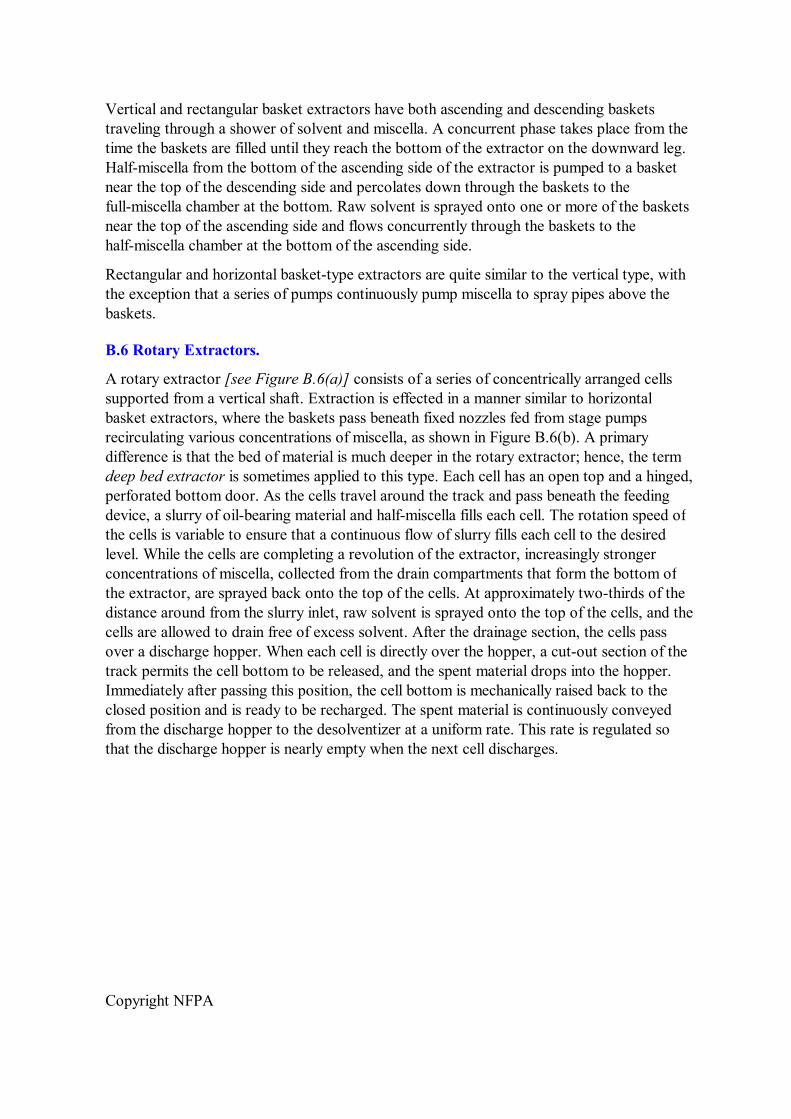
Copyright NFPA
Vertical and rectangular basket extractors have both ascending and descending baskets traveling through a shower of solvent and miscella. A concurrent phase takes place from the time the baskets are filled until they reach the bottom of the extractor on the downward leg. Halfmiscella from the bottom of the ascending side of the extractor is pumped to a basket near the top of the descending side and percolates down through the baskets to the fullmiscella chamber at the bottom. Raw solvent is sprayed onto one or more of the baskets near the top of the ascending side and flows concurrently through the baskets to the halfmiscella chamber at the bottom of the ascending side.
Rectangular and horizontal baskettype extractors are quite similar to the vertical type, with the exception that a series of pumps continuously pump miscella to spray pipes above the baskets.
B.6 Rotary Extractors.
A rotary extractor [see Figure B.6(a)] consists of a series of concentrically arranged cells supported from a vertical shaft. Extraction is effected in a manner similar to horizontal basket extractors, where the baskets pass beneath fixed nozzles fed from stage pumps recirculating various concentrations of miscella, as shown in Figure B.6(b). A primary difference is that the bed of material is much deeper in the rotary extractor; hence, the term deep bed extractor is sometimes applied to this type. Each cell has an open top and a hinged, perforated bottom door. As the cells travel around the track and pass beneath the feeding device, a slurry of oilbearing material and halfmiscella fills each cell. The rotation speed of the cells is variable to ensure that a continuous flow of slurry fills each cell to the desired level. While the cells are completing a revolution of the extractor, increasingly stronger concentrations of miscella, collected from the drain compartments that form the bottom of the extractor, are sprayed back onto the top of the cells. At approximately twothirds of the distance around from the slurry inlet, raw solvent is sprayed onto the top of the cells, and the cells are allowed to drain free of excess solvent. After the drainage section, the cells pass over a discharge hopper. When each cell is directly over the hopper, a cutout section of the track permits the cell bottom to be released, and the spent material drops into the hopper. Immediately after passing this position, the cell bottom is mechanically raised back to the closed position and is ready to be recharged. The spent material is continuously conveyed from the discharge hopper to the desolventizer at a uniform rate. This rate is regulated so that the discharge hopper is nearly empty when the next cell discharges.

Copyright NFPA
FIGURE B.6(a) Rotary or Deep Bed Extractor. (Courtesy of Chemical Engineering)
FIGURE B.6(b) Schematic of Operation of Rotary Extractor.
Stationarybottom and slidingplate extractors [see Figure B.6(c)] are variations of the deep bed rotary extractor. These extractors have concentric cells affixed to a central axis that is powered by a variable speed drive. The cells slide over a selfcleaning slotted bottom plate. Because of this feature, no doors are required to support the flakes. The cells are uniformly filled to a desired level. Several stage pumps are provided to recycle the solvent and gradient miscellas countercurrent to the mass as it is extracted. A drainage section is provided after the fresh solvent is added, and the extracted material drops into a discharge hopper, where it is conveyed to the desolventizer.

Copyright NFPA
FIGURE B.6(c) StationaryBottom or SlidingPlate Extractor.
The stationary cell extractor is another type of rotary extractor. This type provides countercurrent extraction without moving the cells. Instead, the fill spout, spray nozzles, bottom screens, and miscella collection compartments rotate on a central shaft. The thrust load is carried on a circular track mounted on the bottom of the extractor shell. The oilbearing material remains in the stationary basket until drained. As the bottom screen rotates under the basket, the material discharges into the internal discharge hopper from which it is conveyed from the extractor.
B.7 Perforated Belt Extractor.
Another type of extractor is the horizontal perforated belt extractor [see Figure B.7(a)]. In this type of extractor, the flakes are fed in a uniform depth onto one end of a slowly moving perforated belt. As the oilbearing material, which is not as deep as in the rotarytype extractor, travels the length of the extractor, gradient miscellas are sprayed over the moving bed from stage pumps, in much the same fashion as the horizontal basket and rotary extractors. The belt consists of a pair of endless chains running on a set of large sprockets at each side of the extractor. Attached across the chains and forming a flat surface are a series of perforated plates or screens. Chambers or pans are arranged beneath the belt for the entire length of the extractor for collection of various concentrations of miscellas. The spent material is continuously discharged from the end of the belt into a hopper, from which it is conveyed to the desolventizer.

Copyright NFPA
FIGURE B.7(a) Perforated Belt Extractor.
Another type of perforated belt extractor, the sliding cell extractor [see Figure B.7(b)], provides two extraction surfaces where the flakes are separated by rectangular compartments while traveling along the moving slotted screens or stationary veebar screen plates. This unit achieves countercurrent extraction by employing stage pumps and a series of collecting pans to direct the flow of the various miscella concentrations. Because there is an upper and a lower screen belt or plate, the filling device can be located over, but separated from, the discharge hopper.

Copyright NFPA
FIGURE B.7(b) Sliding Cell Extractor.
When the partially extracted material reaches the end of the top belt, it falls from the upper cell into a similar compartment on the lower belt. The mass continues to be sprayed with miscella from the stage pumps until it reaches the fresh solvent wash prior to draining and feeding into the discharge hopper.
B.8 Rectangular Loop Extractor.
The same basic principles are used in the rectangular loop extractor (see Figure B.8) as in the sliding cell extractor. However, the overall shape of this extractor utilizes an “en masse”type conveyor instead of individual baskets. The bottom part of the conveyor uses stationary, linear veebar screens. Flakes enter near the top of the extractor at the inlet hopper. A conveyor chain carries the flakes away from this hopper and down the first leg of the loop, where the flakes receive their first wash. In the bottom horizontal run of the loop, the flakes are washed with progressively weaker concentrations of miscellas. As the flakes travel up the vertical part of the loop, they are further extracted by a countercurrent wash of miscella flowing down the loop. On the sloping top run of the extractor, they receive a fresh solvent wash, are allowed to drain, and are discharged continuously from the unit.
The extractor conveying chain is open at the top, bottom, and sides. This allows easy loading and emptying of the material and for passage of the solvent through the flake bed as it is turned during its extraction wash cycle. The speed of the chain is automatically controlled by the level of flakes in the inlet hopper. A sensor in the feed hopper measures the level of flakes in the hopper and sends a signal to the extractor's variable speed drive.
FIGURE B.8 Rectangular Loop Extractor.
B.9 Other Types of Extractors.

Copyright NFPA
Other types of extractors for extracting oil from oilbearing materials are available, but they are not in general use. These other types include vertical immersion, filtration, and batch extractors. Some are used only for special applications.
B.10 Distillation.
The distillation system of an extraction plant provides the means for evaporating and stripping the solvent from the oil. Numerous methods are available for accomplishing this, from the early pottype batch stills and pantype evaporators to the currently popular longtube rising film evaporators, followed by high vacuum stripping. Few of the pot stills or pantype evaporators are still in use.
At this time, nearly all extraction plants use two longtube rising film evaporators, with or without recirculation. The first evaporator usually operates under vacuum, while the second operates either under vacuum or at atmospheric pressure. Heat from the desolventizer vapor is recovered and used to supply heat to the first evaporator, while indirect steam supplies heat for the second evaporator. The choice of the type of oil stripper used depends on a number of factors, including the design and size of the other components in the system and the material being processed.
Stripping columns commonly used are either the packed column type or the diskanddoughnut type. The stripping column distributes the oil into a very thin film on a large surface area with a relatively high velocity of dry steam passing over and through the film. A countercurrent flow is established by introducing the oil at the top of the column and allowing it to pass downward through the tower against the flow of the steam, which is introduced at the bottom of the tower. The tower must be operated under a vacuum of 559 mm Hg to 711 mm Hg (22 in. Hg to 28 in. Hg) to achieve highest efficiency. The mixture of steam and solvent vapor passes from the top of the tower to a condenser from which the condensate is pumped to a solvent/water separator. The solvent flows from the separator to a work tank. Water flows from the separator to the wastewater evaporator. Finished oil is usually pumped from the stripping column by a rotary positive displacement pump.
B.11 Desolventizing and Toasting.
Desolventizing of the spent material is accomplished in several ways. In one of these, spent material is desolventized by passing through a series of steamjacketed rotary conveyors commonly called schneckens. These conveyors are usually stacked one above the other, and the material to be desolventized drops by gravity from one to the next. The last conveyor often has a direct flow of steam to remove the final traces of solvent. Vapors are piped to a scrubbing and condensing system. The desolventized material is discharged from the bottom conveyor through a vapor seal.
Another type of desolventizer is the recycled vapor type, which consists of a single cylindrical vessel with a rotating element that tumbles the spent material from the inlet to the discharge end. The vessel is steamjacketed, and part of the solvent vapor that is driven off is superheated and passed directly back to the vessel. The superheated solvent vapor provides the energy to desolventize the material. This type of desolventizer is usually followed by some type of stripper, often using heat, vacuum, and direct steam to remove the final traces
Copyright NFPA
of solvent. The desolventized material is then discharged through a vapor seal.
Many extracted oilseed products require toasting or cooking in order to deactivate enzymes and other constituents and yield a nutritional product. The moisture and heat of the toasting process also agglomerates the fine particles of meal into a more granular form. This helps to reduce the dust problem in subsequent cooling and milling steps. Toasting can be carried out as a separate stage of the process. The meal is conveyed from the desolventizer to the toaster, which may be a vertical stacked cooker or a jacketed stationary drumtype unit with an internal agitator. The toasting section of the combination desolventizertoaster, often called a DT, is essentially a stacked cooker. The function of all toasters is to retain the spent material for a sufficient time at a temperature above 100°C (212°F) and at a specific moisture content. The length of time that the meal is held at these conditions determines the degree of cooking or toasting.
From a fire protection standpoint, the development of the desolventizertoaster, with the elimination of the intermediate vapor seals, conveyors, and so forth, represents a significant advance. The DT is now used in most large capacity solvent extraction systems and accomplishes two important processing steps with a minimum of moving machinery and maximum safety against escape of solvent vapors. The DT consists of individual kettles or trays placed one above the other, each kettle containing a layer of spent material to a depth of 0.3 m to 1.2 m (1 ft to 4 ft). The feeding of material from one kettle to the next lower one is accomplished by an automatic gate mechanism or spout. The trays that form the floor of each kettle are steamjacketed and direct steam is sparged into the material in the top kettle or kettles. Some of this steam condenses as it evaporates the solvent, raising the temperature and the moisture of the material to the levels required for toasting in the lower kettles. The top kettle is provided with a large pipe to conduct hot vapors through a scrubber to the condensing system. In normal operation, at least half of the kettles (trays) of the DT are filled with desolventized material, providing an effective seal against fluctuating pressures and other changes in plant performance.
More recently, the fully counterflow DT has been introduced. In this unit, the trays have a relatively uniform pattern of perforations that allow the passage of steam through each upper level tray and bed of material. Most or all of the direct steam is introduced at the bottom of the DT and flows up through the beds in counterflow to the downward flow of material. This method desolventizes and toasts effectively, reduces the danger of solvent escaping from the bottom of the DT, and is more energy efficient.
B.12 Condensing System.
Condensing of solvent vapors and steam is usually accomplished by the use of shellandtube condensers. The tubes are normally made of stainless steel. Water flows through the tubes, and the solvent vapor and steam condense on the outer surfaces of the tubes. The cold water used in the condensers can be supplied from deep wells, cooling towers, spray ponds, or some other source that can supply water cool enough to operate the condensers efficiently and clean enough to prevent fouling of the tubes. Solvent vapor from the desolventizer is usually passed through a scrubber to remove any solids entrained in the vapor stream. The vapors are normally washed with liquid solvent, and this scrubbing liquid, along with the removed fines, is returned to the desolventizer. Water has also been used as a scrubbing

Copyright NFPA
liquid.
B.13 Vent Vapor Recovery System.
It is standard practice in extraction plants to vent each piece of processing equipment to a common vent header. This header contains hexane vapor, water vapor, and air, which flow to the final solvent recovery system. At a minimum, the solvent recovery system consists of a watercooled shellandtube condenser and a mineral oil absorption recovery system. The noncondensable components are scrubbed in a mineral oil absorption column and are discharged through a flame arrester to the atmosphere by a vent fan. The mineral oil is heated, stripped of its hexane, cooled, and returned to the absorption column. The recovered vapors are condensed and returned to the solvent separator. By today's standards of efficiency, the solvent losses in a large, welldesigned, and wellrun plant will not exceed 2 L (0.5 gal) of solvent per ton of material processed. In a soybean processing plant, this is equivalent to a solvent loss of 0.14 percent by weight, based on the weight of the soybeans processed. Many plants have solvent losses that are considerably lower than this amount.
B.14 Wastewater Evaporator.
Water is continuously produced in the extraction process from the condensation of direct sparge steam that is used in many sections of the plant. This water is continuously removed from the solventwater separator and sent to a vessel called the wastewater evaporator, where direct steam is introduced to raise the temperature to at least 85°C (185°F). Often, the direct steam is provided by the final stripper vacuum ejector (and possibly other ejectors in the process). The purpose of this wastewater evaporator is to heat the wastewater well above the boiling point of the solvent, thus evaporating any remaining solvent in the wastewater stream. This wastewater flows to a large outdoor separation sump that is also connected to the floor drains of the extraction building. This sump serves two purposes:
(1) It provides an additional level of safety by separating any remaining oils, solvents, and miscella from the wastewater prior to its discharge.
(2) It provides containment for any spills.
Annex C Operational Practices
This annex is not a part of the requirements of this NFPA document but is included for informational purposes only.
C.1 Reports.
Plant supervisors and operators should be responsible for recording normal and abnormal operating conditions and occurrences. It is recommended that operators note and log operating levels, temperatures, vacuum levels, and operating pressures on an hourly basis. Use of continuous recording instruments can greatly simplify this task. Hourly logs should be reviewed to uncover any abnormal conditions. A summary of the plant's operation should be kept in a permanent log for use by, and to provide guidance for, other supervisors and managers.

Copyright NFPA
C.2 Visitors.
Visits to the plant should be controlled at all times and should only be permitted when conditions are normal. The size of visiting groups should be strictly controlled to a manageable level. Because visitors are not always familiar with the inherent hazards of an extraction plant, they should be properly informed of all safety regulations. Only those visitors that have been approved by management personnel should be allowed in the operating areas. All visitors should apply for permission to enter the plant at a designated place outside the fenced area, where they are to leave all smoking materials, matches, lighters, and other sources of ignition. Visitors should be accompanied by a plant employee at all times. Visitors should not be permitted in the plant when solvent vapors are present. Should a dangerous concentration of solvent vapors develop at any time during the visit, guides should immediately escort the visitors to a safe location. A written record of all visitors should be kept.
C.3 Safety Work Permit.
Major repairs and modifications should only be done when the plant has been shut down in an orderly manner and emptied and purged of all miscella, solvent, and solvent vapors. A shutdown and purging procedure should be developed and provided to all supervisory personnel and all affected employees. Separate purging procedures should be written for situations where only mechanical work, that is, no cutting or hot work, will be performed, and for shutdowns that will include hot work. A cutting and welding permit system should be developed, and compliance with it required any time hot work is anticipated, including the use of metal saws, drills, grinders, torches, and welding equipment.
Where repair work of a mechanical nature is required in the restricted area, either by plant personnel or outside contractors, strict control is required. A work permit (see Figure C.3) authorizing the work should be issued by the individual in charge only after an inspection has been made to ensure that working conditions are safe and that safe work procedures have been specified and appropriate tools authorized. Each work permit should have a specific, definite duration.
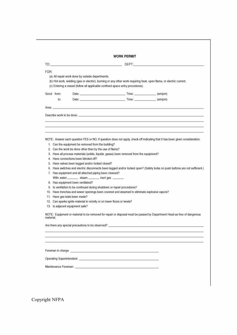
Copyright NFPA

Copyright NFPA
FIGURE C.3 Sample Work Permit.
When outside contractors are used, they should be thoroughly indoctrinated in the plant's safety procedures before starting the work, and documentation of such instruction should be recorded. The indoctrination should include a clear description of the scope of the work to be performed, the types of tools that can be used, with whom the work is to be coordinated, and conditions under which a hot work or lockout/tagout permit is required. Contractors should not start or stop any equipment, open or close valves, or open any plant system.
C.4 Preventive Maintenance.
In most plants, a plan of regular, scheduled shutdowns is followed. During these periods, repairs are done that cannot be done safely when the plant is operating. These shutdowns afford excellent opportunities for detailed inspection of all equipment to detect and correct any deficiencies.
Annex D Informational References
D.1 Referenced Publications.
The following documents or portions thereof are referenced within this standard for informational purposes only and are thus not part of the requirements of this document unless also listed in Chapter 2.
D.1.1 NFPA Publications. National Fire Protection Association, 1 Batterymarch Park, Quincy, MA 021697471.
NFPA 10, Standard for Portable Fire Extinguishers, 2002 edition.
NFPA 13, Standard for the Installation of Sprinkler Systems, 2002 edition.
NFPA 14, Standard for the Installation of Standpipe and Hose Systems, 2003 edition.
NFPA 15, Standard for Water Spray Fixed Systems for Fire Protection, 2001 edition.
NFPA 16, Standard for the Installation of FoamWater Sprinkler and FoamWater Spray Systems, 2003 edition.
NFPA 24, Standard for the Installation of Private Fire Service Mains and Their Appurtenances, 2002 edition.
NFPA 30, Flammable and Combustible Liquids Code, 2003 edition.
NFPA 61, Standard for the Prevention of Fires and Dust Explosions in Agricultural and Food Processing Facilities, 2002 edition.
NFPA 68, Guide for Venting of Deflagrations, 2002 edition.
NFPA 70, National Electrical Code ® , 2002 edition.
NFPA 77, Recommended Practice on Static Electricity, 2000 edition.

Copyright NFPA
NFPA 86, Standard for Ovens and Furnaces, 2003 edition.
NFPA 91, Standard for Exhaust Systems for Air Conveying of Vapors, Gases, Mists, and Noncombustible Particulate Solids, 1999 edition.
NFPA 214, Standard on WaterCooling Towers, 2000 edition.
NFPA 385, Standard for Tank Vehicles for Flammable and Combustible Liquids, 2000 edition.
NFPA 496, Standard for Purged and Pressurized Enclosures for Electrical Equipment, 2003 edition.
D.1.2 Other Publication. Chemical Engineering, vol. 57, no. 8, August, 1950, p. 109.
D.2 Informational References. (Reserved)
D.3 References for Extracts.
The following documents are listed here to provide reference information, including title and edition, for extracts given throughout this standard as indicated by a reference in brackets [ ] following a section or paragraph. These documents are not a part of the requirements of this document unless also listed in Chapter 2 for other reasons.
NFPA 30, Flammable and Combustible Liquids Code, 2003 edition.
NFPA 69, Standard on Explosion Prevention Systems, 2002 edition.
NFPA 220, Standard on Types of Building Construction, 1999 edition.
NFPA 329, Recommended Practice for Handling Releases of Flammable and Combustible Liquids and Gases, 1999 edition.