nfpa 70e technical committee first draft meeting … · nfpa 70e technical committee first draft...
TRANSCRIPT

National Fire Protection Association 1 Batterymarch Park, Quincy, MA 02169-7471 Phone: 617-770-3000 • Fax: 617-770-0700 • www.nfpa.org
NFPA 70E Technical Committee First Draft Meeting
August 20 - 25, 2012 -- Denver, CO
Agenda
1. Call to order and Chair welcome to members and guests.
2. NFPA staff review of meeting procedures.
3. Committee member roll call and introduction of guests.
4. NFPA staff discussion and training on the new process for revisions as required by the Regulations Governing NFPA’s Standards Development Process.
5. Discussion of Parliamentary Procedure per "Roberts Rules" (attachment) 6. Comments and questions of committee members and guests regarding procedures and policies.
7. Review of meeting schedule, start/stop, breaks and lunch periods:
(a) Start 8:00 A.M. with 15 minute breaks in A.M. & P.M. to be announced by the Chair
(b) lunch period of one hour, taken around the noon hour as the flow of the meeting dictates, and
(c) ending at 5:00 P.M., or otherwise as directed by the Chair and/or agreed upon by the Committee.
8. Approval of the October 2010 NFPA 70E ROC meeting. 9. Task Group presentations.
10. Review and provide responses to all Public Inputs and development of First Revisions by the Technical Committee.
11. Meeting Adjournment.
Page 1 of 276
Robert'sRulesofOrder- Summary Version Applicable to the NFPA 70E First Draft Meeting
Robert’s Rules of Order provides common rules and procedures for deliberation and debate to provide all committee members with equal participation opportunity. The conduct of ALL business is controlled by the will of the whole membership, as interpreted by the Chair. Robert's Rules provides for constructive and democratic meetings, to help, not hinder, the business of the assembly. However, under no circumstances should "undue strictness to the rules" be allowed to intimidate members or limit full participation. The fundamental right of deliberative assemblies requires all questions to be thoroughly discussed before taking action. Silence means consent.
The meeting will be conducted as follows:
Speakers may obtain the floor (the right to speak) by being the first to raise their hand when the person speaking has finished. Standing means nothing, and someone raising a hand while another has the floor will be ruled out of order. The Chair must recognize members before they can speak.
After being recognized by the Chair, speakers shall begin their discussion by stating whether they speak in favor of or in opposition to the motion.
Debate cannot begin until the Chair has stated the motion or resolution and opened the floor for debate. If no one requests the floor, the chair will call for the vote.
Before the motion is stated by the Chair (the question) members may suggest modification of the motion. The mover can modify as he/she pleases or even withdraw the motion without consent of the seconder. If the mover modifies the motion, the seconder can withdraw the second and the new motion must be seconded.
No member can speak twice to the same issue until everyone else wishing to speak has spoken to it once. Members who repeat comments or arguments a second or third time will be ruled out of order. All remarks must be directed to the Chair. Remarks must be courteous in language and deportment.
Speakers will avoid all personal references and will not be allowed to allude to others by name or motives. The agenda and all committee reports are merely recommendations. When the reports are presented to
the assembly and the question is stated, debate begins and the report becomes open to changes. Secondary motions must be considered and resolved before the main motion may be considered. Motions that close or limit debate are not open to discussion, and passage of such motions requires a two-
thirds vote of the assembly. The Chair interprets voice votes.
The Rules The following motions are allowed during the meeting. These rules are to be followed without discussion.
Point of Privilege—Pertains to noise, personal comfort, etc. Members (and guests) may interrupt the meeting only if necessary.
Parliamentary Inquiry—Inquiry as to the correct motion, to accomplish a desired result or raise a point of order.
Point of Information—Generally applies to information desired from the speaker. Point of Order—Infraction of the rules, or improper decorum in speaking. Must be raised immediately
after the error is made; Chair rules. Main Motion—Brings new business (the next item on the agenda) before the assembly; requires
simple majority in the meeting; requires written two-thirds majority to change standard. Amend—Insert or strike out words or paragraphs or substitute whole paragraphs or resolutions.
Page 2 of 276

Withdraw/Modify Motion—Applies only after question is stated; mover can accept an amendment without obtaining the floor.
Limit Debate—Debate may be closed at a certain time or limited to a certain period of time; requires simple majority.
Lay on the Table—Temporarily suspends further consideration/action on pending question; may be made after motion to close debate has carried or is pending; requires simple majority.
Take from the Table—Resumes consideration of item previously "laid on the table." Member shall state the motion to take from the table; requires simple majority.
Reconsider—Can be made only by one on the prevailing side who has changed position or view; requires simple majority.
Previous Question—Closes debate if successful. May be moved to "Close Debate" if preferred; requires simple majority
Appeal Decision of the Chair—Appeal for the assembly to decide must be made before other business is resumed. The appeal is NOT debatable if it relates to decorum, violation of rules, or order of business; requires two-thirds majority
Page 3 of 276

Page 4 of 276

Page 5 of 276

Page 6 of 276

Page 7 of 276

Page 8 of 276

Page 9 of 276
Page 10 of 276

Page 11 of 276

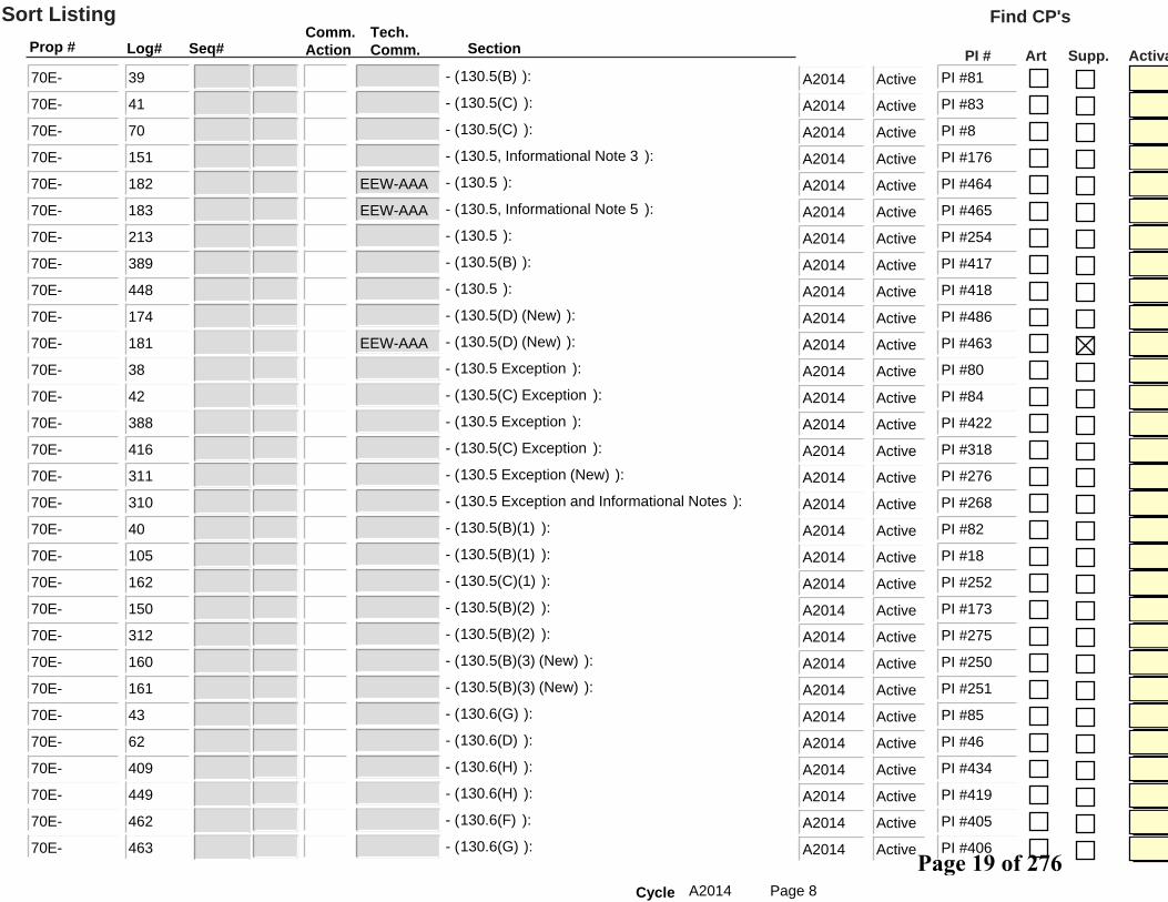
Prop # Log#Comm.Action
Tech.Comm. Section
Sort Listing
Seq# ActivaArt Supp.
Find CP's
PI #
169 Entire Document- ( ):70E- ActiveA2014 PI #468
86 Entire Document- ( ):70E- ActiveA2014 PI #123
123 Entire Document- ( ):70E- ActiveA2014 PI #146
126 Entire Document- ( ):70E- ActiveA2014 PI #149
127 Entire Document- ( ):70E- ActiveA2014 PI #150
128 Entire Document- ( ):70E- ActiveA2014 PI #151
129 Entire Document- ( ):70E- ActiveA2014 PI #152
130 Entire Document- ( ):70E- ActiveA2014 PI #153
149 Entire Document- ( ):70E- ActiveA2014 PI #172
427 Entire Document- ( ):70E- ActiveA2014 PI #352
440 Entire Document- ( ):70E- ActiveA2014 PI #411
441 Entire Document- ( ):70E- ActiveA2014 PI #414
442 Entire Document- ( ):70E- ActiveA2014 PI #420
356 90.2(A)- ( ):70E- ActiveA2014 PI #354
355 90.2, Informational Note (New)- ( ):70E- ActiveA2014 PI #369
98 90.3- ( ):70E- ActiveA2014 PI #9
357 90.3- ( ):70E- ActiveA2014 PI #344
306 90.5 (New)- ( ):70E- ActiveA2014 PI #262
307 100.Arc Flash Hazard, Informational Note 2- ( ):70E- ActiveA2014 PI #266
117 100.Arc Flash Hazard Analysis- ( ):70E- ActiveA2014 PI #140
168 100.Arc Rating, Informational Note 1- ( ):70E- ActiveA2014 PI #454
392 100.Authority Having Jurisdication (AHJ)- ( ):70E- ActiveA2014 PI #441
14 100.Balaclava- ( ):70E- ActiveA2014 PI #59
47 100.Balaclava (Sock Hood)- ( ):70E- EEW-AAA ActiveA2014
118 100.Barricade- ( ):70E- ActiveA2014 PI #141
46 100.Boundary, Arc Flash- ( ):70E- ActiveA2014 PI #88
99 100.Boundary, Prohibited Approach- ( ):70E- ActiveA2014 PI #10
119 100.Boundary, Restricted Approach- ( ):70E- ActiveA2014 PI #142
393 100.Electrically Safe Work Condition- ( ):70E- ActiveA2014 PI #440
292 100.Enclosure- ( ):70E- ActiveA2014 PI #285
Page 1A2014Cycle
Page 12 of 276
Prop # Log#Comm.Action
Tech.Comm. Section
Sort Listing
Seq# ActivaArt Supp.
Find CP's
PI #
65 100.Energized Electrical Work Permit- ( ):70E- ActiveA2014 PI #35
321 100.Fault Currect (New)- ( ):70E- ActiveA2014 PI #277
120 100.Hazard (New)- ( ):70E- ActiveA2014 PI #143
121 100.Hazardous (New)- ( ):70E- ActiveA2014 PI #144
443 100.Incident Energy- ( ):70E- ActiveA2014 PI #377
122 100.Incident Energy Analysis- ( ):70E- ActiveA2014 PI #145
444 100.Live Parts (New)- ( ):70E- ActiveA2014 PI #416
64 100.Permit- ( ):70E- ActiveA2014 PI #34
131 100.Qualified Person- ( ):70E- ActiveA2014 PI #154
424 100.Qualified Person- ( ):70E- ActiveA2014 PI #339
132 100.Receptacle (New)- ( ):70E- ActiveA2014 PI #155
133 100.Receptacle (New)- ( ):70E- ActiveA2014 PI #156
179 100.Ventilated- ( ):70E- ActiveA2014 PI #458
412 105.1- ( ):70E- ActiveA2014 PI #351
452 105.1, Informational Note (New)- ( ):70E- ActiveA2014 PI #385
63 110.1- ( ):70E- ActiveA2014 PI #47
95 110.1- ( ):70E- ActiveA2014 PI #132
332 110.1- ( ):70E- ActiveA2014 PI #329
184 110.1(D) (New)- ( ):70E- EEW-AAA ActiveA2014 PI #466
445 110.1(C), Informational Note (New)- ( ):70E- ActiveA2014 PI #384
193 110.1(A)(1) (New)- ( ):70E- ActiveA2014 PI #470
211 110.1(A)(1) and A.110.1(C)- ( ):70E- ActiveA2014 PI #243
134 110.1(B)(3)b.- ( ):70E- ActiveA2014 PI #157
3 110.2(C)- ( ):70E- ActiveA2014 PI #60
15 110.2(C)- ( ):70E- ActiveA2014 PI #61
51 110.2(C)- ( ):70E- ActiveA2014 PI #136
52 110.2(B)- ( ):70E- ActiveA2014 PI #32
59 110.2(C)- ( ):70E- ActiveA2014 PI #40
73 110.2(C)- ( ):70E- ActiveA2014 PI #139
135 110.2(A)- ( ):70E- ActiveA2014 PI #158
Page 2A2014Cycle
Page 13 of 276

Prop # Log#Comm.Action
Tech.Comm. Section
Sort Listing
Seq# ActivaArt Supp.
Find CP's
PI #
209 110.2(C)- ( ):70E- ActiveA2014 PI #244
212 110.2(C)- ( ):70E- ActiveA2014 PI #244
288 110.2(E), Informational Note 1- ( ):70E- ActiveA2014 PI #236
298 110.2(C)- ( ):70E- ActiveA2014 PI #241
331 110.2(C)- ( ):70E- ActiveA2014 PI #292
378 110.2(B)- ( ):70E- ActiveA2014 PI #300
379 110.2(C)- ( ):70E- ActiveA2014 PI #302
425 110.2(C)- ( ):70E- ActiveA2014 PI #340
436 110.2(C)- ( ):70E- ActiveA2014 PI #362
437 110.2(C)- ( ):70E- ActiveA2014 PI #383
446 110.2(C)- ( ):70E- ActiveA2014 PI #386
180 110.2 (New)- ( ):70E- EEW-AAA ActiveA2014 PI #462
136 110.2(D)(1)- ( ):70E- ActiveA2014 PI #159
380 110.2(D)(1)- ( ):70E- ActiveA2014 PI #307
333 110.2(D)(1)(a)- ( ):70E- ActiveA2014 PI #331
334 110.2(D)(1)(b)- ( ):70E- ActiveA2014 PI #332
453 110.2(D)(1)(b)- ( ):70E- ActiveA2014 PI #388
137 110.2(D)(1)(b)(4)- ( ):70E- ActiveA2014 PI #160
29 110.2(D)(3)- ( ):70E- ActiveA2014 PI #73
101 110.2(D)(3)- ( ):70E- ActiveA2014 PI #12
224 110.2(D)(3)- ( ):70E- ActiveA2014 PI #235
335 110.2(D)(3)- ( ):70E- ActiveA2014 PI #333
96 110.3(A)- ( ):70E- ActiveA2014 PI #133
97 110.3(F)- ( ):70E- ActiveA2014 PI #134
100 110.3(F)- ( ):70E- ActiveA2014 PI #11
138 110.3(A)- ( ):70E- ActiveA2014 PI #161
139 110.3(F)- ( ):70E- ActiveA2014 PI #162
336 110.3- ( ):70E- ActiveA2014 PI #330
337 110.3(E)- ( ):70E- ActiveA2014 PI #334
338 110.3(F)- ( ):70E- ActiveA2014 PI #335
Page 3A2014Cycle
Page 14 of 276

Prop # Log#Comm.Action
Tech.Comm. Section
Sort Listing
Seq# ActivaArt Supp.
Find CP's
PI #
358 110.3(A), Informational Note 1- ( ):70E- ActiveA2014 PI #346
359 110.3(A), Informational Note 2- ( ):70E- ActiveA2014 PI #348
454 110.3(F)- ( ):70E- ActiveA2014 PI #392
108 110.3(B) (New)- ( ):70E- ActiveA2014 PI #20
197 110.3(H)(2)- ( ):70E- ActiveA2014 PI #474
381 110.3(G)(2) and (3)- ( ):70E- ActiveA2014 PI #308
199 110.3(H)(3)- ( ):70E- ActiveA2014 PI #476
360 110.3(H)(3) (New)- ( ):70E- ActiveA2014 PI #297
140 110.3(G)(3)(1) and (2)- ( ):70E- ActiveA2014 PI #163
102 110.4(2)- ( ):70E- ActiveA2014 PI #13
289 110.4(2)- ( ):70E- ActiveA2014 PI #237
347 110.4(E)- ( ):70E- ActiveA2014 PI #368
207 110.4(I) (New)- ( ):70E- ActiveA2014 PI #484
414 110.4(B)(5) (New)- ( ):70E- ActiveA2014 PI #319
339 110.4, Title- ( ):70E- ActiveA2014 PI #336
16 110.4(A)(1)- ( ):70E- ActiveA2014 PI #62
394 110.4(B)(1)- ( ):70E- ActiveA2014 PI #315
456 110.4(A)(1)- ( ):70E- ActiveA2014 PI #394
171 110.4(C)(2)- ( ):70E- ActiveA2014 PI #456
201 110.4(C)(2)- ( ):70E- ActiveA2014 PI #478
340 110.4(A)(2)- ( ):70E- ActiveA2014 PI #337
141 110.4(B)(3), Informational Note- ( ):70E- ActiveA2014 PI #164
341 110.4(A)(3)- ( ):70E- ActiveA2014 PI #338
344 110.4(B)(3)- ( ):70E- ActiveA2014 PI #378
345 110.4(B)(3)(b)- ( ):70E- ActiveA2014 PI #380
342 110.4(A)(4)- ( ):70E- ActiveA2014 PI #376
346 110.4(B)(4)- ( ):70E- ActiveA2014 PI #373
343 110.4(B)(4) (New)- ( ):70E- ActiveA2014 PI #370
194 110.4(B)(4)(b)- ( ):70E- ActiveA2014 PI #471
287 110.4(A)(5)- ( ):70E- ActiveA2014 PI #191
Page 4A2014Cycle
Page 15 of 276

Prop # Log#Comm.Action
Tech.Comm. Section
Sort Listing
Seq# ActivaArt Supp.
Find CP's
PI #
455 110.4(A)(5)- ( ):70E- ActiveA2014 PI #396
25 110.5- ( ):70E- ActiveA2014 PI #115
53 110.5- ( ):70E- ActiveA2014 PI #33
54 110.5- ( ):70E- ActiveA2014 PI #41
142 110.5- ( ):70E- ActiveA2014 PI #165
348 110.5- ( ):70E- ActiveA2014 PI #363
413 110.6 (New)- ( ):70E- ActiveA2014 PI #347
415 110.(4)(d) (New)- ( ):70E- ActiveA2014 PI #321
74 120.1- ( ):70E- ActiveA2014 PI #211
226 120.1(1)- ( ):70E- ActiveA2014 PI #95
286 120.1(5)- ( ):70E- ActiveA2014 PI #190
67 120.1(7) (New)- ( ):70E- ActiveA2014 PI #72
305 120.1, Informational Note (New)- ( ):70E- ActiveA2014 PI #258
103 120.1(4) through (7)- ( ):70E- ActiveA2014 PI #14
72 120.1 and 120.2- ( ):70E- ActiveA2014 PI #118
395 120.1(6) and Exception (New)- ( ):70E- ActiveA2014 PI #424
447 120.2, Title- ( ):70E- ActiveA2014 PI #407
206 120.2(F)(1)(a)- ( ):70E- ActiveA2014 PI #483
397 120.2(F)(1)(a)- ( ):70E- ActiveA2014 PI #425
58 120.2(B)(2)- ( ):70E- ActiveA2014 PI #39
144 120.2(E)(2)- ( ):70E- ActiveA2014 PI #167
349 120.2(F)(2)(f)(4), (5), and (6)- ( ):70E- ActiveA2014 PI #430
398 120.2(F)(2)(n) Exception (New)- ( ):70E- ActiveA2014 PI #427
382 120.2(D)(2)d. (New)- ( ):70E- ActiveA2014 PI #391
143 120.2(D)(3)(c)- ( ):70E- ActiveA2014 PI #166
210 120.2(D)(4)- ( ):70E- ActiveA2014 PI #246
293 120.2(D)(4)- ( ):70E- ActiveA2014 PI #374
383 120.2(D)(4)- ( ):70E- ActiveA2014 PI #389
396 120.2(B)(4)- ( ):70E- ActiveA2014 PI #442
384 120.2(E)(4)(e)- ( ):70E- ActiveA2014 PI #397
Page 5A2014Cycle
Page 16 of 276

Prop # Log#Comm.Action
Tech.Comm. Section
Sort Listing
Seq# ActivaArt Supp.
Find CP's
PI #
48 120.2(E)(6)(a) and (b)- ( ):70E- ActiveA2014 PI #25
145 120.3(A)- ( ):70E- ActiveA2014 PI #168
385 120.3(A)(1) and (2) (New)- ( ):70E- ActiveA2014 PI #404
104 130.1- ( ):70E- ActiveA2014 PI #15
296 130.1- ( ):70E- ActiveA2014 PI #289
308 130.1- ( ):70E- ActiveA2014 PI #267
17 130.2- ( ):70E- ActiveA2014 PI #63
146 130.2(2)- ( ):70E- ActiveA2014 PI #169
294 130.2- ( ):70E- ActiveA2014 PI #290
350 130.2- ( ):70E- ActiveA2014 PI #426
399 130.2(3) and Exception No. 2 (New)- ( ):70E- ActiveA2014 PI #429
18 130.2(B)(1)- ( ):70E- ActiveA2014 PI #64
26 130.2(B)(1)- ( ):70E- ActiveA2014 PI #89
66 130.2(B)(1)- ( ):70E- ActiveA2014 PI #36
147 130.2(A)(1)- ( ):70E- ActiveA2014 PI #170
148 130.2(B)(1)- ( ):70E- ActiveA2014 PI #171
295 130.2(B)(1)- ( ):70E- ActiveA2014 PI #293
401 130.2(B)(1)- ( ):70E- ActiveA2014 PI #431
438 130.2(B)(1)- ( ):70E- ActiveA2014 PI #364
290 130.2(B)(1) Exception (New)- ( ):70E- ActiveA2014 PI #238
11 130.2(B)(2)(1)- ( ):70E- ActiveA2014 PI #56
12 130.2(B)(2)(4)(d) and (2)(5)(b)- ( ):70E- ActiveA2014 PI #57
309 130.2(B)(2)(4)d. and 130.2(B)(2)(5)b.- ( ):70E- ActiveA2014 PI #269
198 130.2(B)(2)(5)(a)- ( ):70E- ActiveA2014 PI #475
152 130.2(B)(2)(7)- ( ):70E- ActiveA2014 PI #174
13 130.2(B)(3)- ( ):70E- ActiveA2014 PI #58
56 130.2(B)(3)- ( ):70E- ActiveA2014 PI #37
69 130.2(B)(3)- ( ):70E- ActiveA2014 PI #7
222 130.2(B)(3)- ( ):70E- ActiveA2014 PI #233
299 130.2(B)(3)- ( ):70E- ActiveA2014 PI #240
Page 6A2014Cycle
Page 17 of 276
Prop # Log#Comm.Action
Tech.Comm. Section
Sort Listing
Seq# ActivaArt Supp.
Find CP's
PI #
351 130.2(B)(3)- ( ):70E- ActiveA2014 PI #428
386 130.2(B)(3)- ( ):70E- ActiveA2014 PI #410
400 130.2(A)(3), Informational Note 2- ( ):70E- ActiveA2014 PI #443
402 130.2(B)(3)- ( ):70E- ActiveA2014 PI #432
19 130.3(B)- ( ):70E- ActiveA2014 PI #69
34 130.3- ( ):70E- ActiveA2014 PI #77
153 130.3(A)- ( ):70E- ActiveA2014 PI #175
228 130.3- ( ):70E- ActiveA2014 PI #99
405 130.3(B)- ( ):70E- ActiveA2014 PI #445
35 130.3(A)(1)- ( ):70E- ActiveA2014 PI #78
36 130.3(B)(1)- ( ):70E- ActiveA2014 PI #79
387 130.3(A)(1)- ( ):70E- ActiveA2014 PI #412
403 130.3(A)(1)- ( ):70E- ActiveA2014 PI #435
457 130.3(B)(1)- ( ):70E- ActiveA2014 PI #398
223 130.3(B)(1), Informational Note (New)- ( ):70E- ActiveA2014 PI #234
404 130.3(A)(2)- ( ):70E- ActiveA2014 PI #444
203 130.3(B)(2) (New)- ( ):70E- ActiveA2014 PI #480
20 130.4- ( ):70E- ActiveA2014 PI #70
172 130.4- ( ):70E- ActiveA2014 PI #457
37 Table 130.4(C)(a)- ( ):70E- ActiveA2014 PI #93
61 Table 130.4(C)(a)- ( ):70E- ActiveA2014 PI #45
426 Table 130.4(C)(a)- ( ):70E- ActiveA2014 PI #341
406 Table 130.4(C)(a) and (b)- ( ):70E- ActiveA2014 PI #438
156 Table 130.4(C)(a), Note d- ( ):70E- ActiveA2014 PI #229
60 Table 130.4(C)(b)- ( ):70E- ActiveA2014 PI #44
229 Table 130.4(C)(b)- ( ):70E- ActiveA2014 PI #100
107 Table 130.4(C) Note (a)- ( ):70E- ActiveA2014 PI #19
458 130.4(C)(1) and (2)- ( ):70E- ActiveA2014 PI #400
304 130.4(C)(4) (New)- ( ):70E- ActiveA2014 PI #257
21 130.5- ( ):70E- ActiveA2014 PI #111
Page 7A2014Cycle
Page 18 of 276
Prop # Log#Comm.Action
Tech.Comm. Section
Sort Listing
Seq# ActivaArt Supp.
Find CP's
PI #
39 130.5(B)- ( ):70E- ActiveA2014 PI #81
41 130.5(C)- ( ):70E- ActiveA2014 PI #83
70 130.5(C)- ( ):70E- ActiveA2014 PI #8
151 130.5, Informational Note 3- ( ):70E- ActiveA2014 PI #176
182 130.5- ( ):70E- EEW-AAA ActiveA2014 PI #464
183 130.5, Informational Note 5- ( ):70E- EEW-AAA ActiveA2014 PI #465
213 130.5- ( ):70E- ActiveA2014 PI #254
389 130.5(B)- ( ):70E- ActiveA2014 PI #417
448 130.5- ( ):70E- ActiveA2014 PI #418
174 130.5(D) (New)- ( ):70E- ActiveA2014 PI #486
181 130.5(D) (New)- ( ):70E- EEW-AAA ActiveA2014 PI #463
38 130.5 Exception- ( ):70E- ActiveA2014 PI #80
42 130.5(C) Exception- ( ):70E- ActiveA2014 PI #84
388 130.5 Exception- ( ):70E- ActiveA2014 PI #422
416 130.5(C) Exception- ( ):70E- ActiveA2014 PI #318
311 130.5 Exception (New)- ( ):70E- ActiveA2014 PI #276
310 130.5 Exception and Informational Notes- ( ):70E- ActiveA2014 PI #268
40 130.5(B)(1)- ( ):70E- ActiveA2014 PI #82
105 130.5(B)(1)- ( ):70E- ActiveA2014 PI #18
162 130.5(C)(1)- ( ):70E- ActiveA2014 PI #252
150 130.5(B)(2)- ( ):70E- ActiveA2014 PI #173
312 130.5(B)(2)- ( ):70E- ActiveA2014 PI #275
160 130.5(B)(3) (New)- ( ):70E- ActiveA2014 PI #250
161 130.5(B)(3) (New)- ( ):70E- ActiveA2014 PI #251
43 130.6(G)- ( ):70E- ActiveA2014 PI #85
62 130.6(D)- ( ):70E- ActiveA2014 PI #46
409 130.6(H)- ( ):70E- ActiveA2014 PI #434
449 130.6(H)- ( ):70E- ActiveA2014 PI #419
462 130.6(F)- ( ):70E- ActiveA2014 PI #405
463 130.6(G)- ( ):70E- ActiveA2014 PI #406
Page 8A2014Cycle
Page 19 of 276

Prop # Log#Comm.Action
Tech.Comm. Section
Sort Listing
Seq# ActivaArt Supp.
Find CP's
PI #
407 130.6(X) (New)- ( ):70E- ActiveA2014 PI #316
408 130.6(X) (New)- ( ):70E- ActiveA2014 PI #317
155 130.6(A)(1)- ( ):70E- ActiveA2014 PI #177
239 130.6(C)(1)- ( ):70E- ActiveA2014 PI #178
459 130.6(A)(1)- ( ):70E- ActiveA2014 PI #401
418 130.6(K)(1) (New)- ( ):70E- ActiveA2014 PI #345
460 130.6(A)(2)- ( ):70E- ActiveA2014 PI #402
461 130.6(C)(2)- ( ):70E- ActiveA2014 PI #403
417 130.6(A)(3)- ( ):70E- ActiveA2014 PI #353
157 130.6(C)(3) (New)- ( ):70E- ActiveA2014 PI #247
1 130.7(C)- ( ):70E- ActiveA2014 PI #48
22 130.7- ( ):70E- ActiveA2014 PI #116
44 130.7(A), Informational Note 3- ( ):70E- ActiveA2014 PI #86
87 130.7(A), Informational Note 2- ( ):70E- ActiveA2014 PI #231
170 130.7(A), Informational Note 2- ( ):70E- ActiveA2014 PI #455
434 130.7(A), Informational Note 3- ( ):70E- ActiveA2014 PI #320
439 130.7(A), Informational Note 2- ( ):70E- ActiveA2014 PI #382
430 Table 130.7(F)- ( ):70E- ActiveA2014 PI #357
431 Table 130.7(F)- ( ):70E- ActiveA2014 PI #359
110 Table 130.7(C)(16)- ( ):70E- ActiveA2014 PI #23
450 130.7(C)(9)(a)- ( ):70E- ActiveA2014 PI #387
55 130.7(D)(1)- ( ):70E- ActiveA2014 PI #42
167 130.7(C)(1)- ( ):70E- ActiveA2014 PI #452
317 130.7(D)(1)- ( ):70E- ActiveA2014 PI #271
410 130.7(C)(1)- ( ):70E- ActiveA2014 PI #439
464 130.7(D)(1)(c) and (e)- ( ):70E- ActiveA2014 PI #408
57 130.7(E)(2)- ( ):70E- ActiveA2014 PI #38
154 130.7(E)(2)- ( ):70E- ActiveA2014 PI #181
352 130.7(C)(6)- ( ):70E- ActiveA2014 PI #421
303 130.7(C)(7)(c) (New)- ( ):70E- ActiveA2014 PI #43
Page 9A2014Cycle
Page 20 of 276

Prop # Log#Comm.Action
Tech.Comm. Section
Sort Listing
Seq# ActivaArt Supp.
Find CP's
PI #
313 130.7(C)(7)(a), Informational Note- ( ):70E- ActiveA2014 PI #270
88 130.7(C)(8)- ( ):70E- ActiveA2014 PI #125
205 130.7(C)(8)- ( ):70E- ActiveA2014 PI #482
188 130.7(C)(9), Informational Note- ( ):70E- ActiveA2014 PI #461
390 130.7(C)(9)(c)- ( ):70E- ActiveA2014 PI #415
78 130.7(C)(9)(d)- ( ):70E- ActiveA2014 PI #106
159 130.7(C)(10)(b)(1)- ( ):70E- ActiveA2014 PI #249
297 130.7(C)(10)(b)(1)- ( ):70E- ActiveA2014 PI #295
200 130.7(C)(10)(e)- ( ):70E- ActiveA2014 PI #477
214 130.7(C)(12) Exception No. 1- ( ):70E- ActiveA2014 PI #259
354 130.7(C)(13)- ( ):70E- ActiveA2014 PI #294
428 130.7(C)(13), Informational Note (New)- ( ):70E- ActiveA2014 PI #413
429 Table 130.7(C)(14)- ( ):70E- ActiveA2014 PI #356
4 130.7(C)(15)- ( ):70E- ActiveA2014 PI #49
195 130.7(C)(15), Informational Note 1- ( ):70E- ActiveA2014 PI #472
215 130.7(C)(15)- ( ):70E- ActiveA2014 PI #261
240 130.7(C)(15), Informational Note 1- ( ):70E- ActiveA2014 PI #179
314 130.7(C)(15)- ( ):70E- ActiveA2014 PI #264
230 Table 130.7(C)(15)- ( ):70E- ActiveA2014 PI #103
435 Table 130.7(C)(15)- ( ):70E- ActiveA2014 PI #322
91 130.7(C)(15)(a)- ( ):70E- ActiveA2014 PI #128
45 Table 130.7(C)(15)(a)- ( ):70E- ActiveA2014 PI #91
92 Table 130.7(C)(15)(a)- ( ):70E- ActiveA2014 PI #129
202 Table 130.7(C)(15)(a)- ( ):70E- ActiveA2014 PI #479
217 Table 130.7(C)(15)(a) and (b)- ( ):70E- ActiveA2014 PI #253
220 Table 130.7(C)(15)(a) and (b)- ( ):70E- ActiveA2014 PI #87
109 Table 130.7(C)(15)(a) Note (4)- ( ):70E- ActiveA2014 PI #22
186 Table 130.7(C)(15)(a), Note (6)- ( ):70E- ActiveA2014 PI #449
2 Table 130.7(C)(15)(a), Note No. 3- ( ):70E- ActiveA2014 PI #50
166 Table 130.7(C)(15)(a)(7) (New)- ( ):70E- ActiveA2014 PI #451
Page 10A2014Cycle
Page 21 of 276

Prop # Log#Comm.Action
Tech.Comm. Section
Sort Listing
Seq# ActivaArt Supp.
Find CP's
PI #
391 130.7(C)(15) and (16)- ( ):70E- ActiveA2014 PI #423
106 130.7(C)(15)(B) (New)- ( ):70E- ActiveA2014 PI #17
191 Table 130.7(C)(15)(b), Footnote c (New)- ( ):70E- ActiveA2014 PI #448
241 Table 130.7(C)(15)(b), Footnotes- ( ):70E- ActiveA2014 PI #180
187 Table 130.7(C)(15)(a) Note 7 (New)- ( ):70E- ActiveA2014 PI #460
411 Table 130.7(C)(15)(b)- ( ):70E- ActiveA2014 PI #433 -
208 130.7(C)(16)- ( ):70E- ActiveA2014 PI #291
216 130.7(C)(16)- ( ):70E- ActiveA2014 PI #260
218 130.7(C)(16)- ( ):70E- ActiveA2014 PI #263
315 130.7(C)(16)- ( ):70E- ActiveA2014 PI #265
8 Table 130.7(C)(16)- ( ):70E- ActiveA2014 PI #122
158 Table 130.7(C)(16)- ( ):70E- ActiveA2014 PI #248
192 Table 130.7(C)(16)- ( ):70E- ActiveA2014 PI #469
316 130.7(C)(16) Note 1- ( ):70E- ActiveA2014 PI #280
6 Table 130.7(C)(16) Note 1- ( ):70E- ActiveA2014 PI #52
23 130.8- ( ):70E- ActiveA2014 PI #113
291 130.8, Title- ( ):70E- ActiveA2014 PI #239
24 130.9- ( ):70E- ActiveA2014 PI #114
353 130.9 (New)- ( ):70E- ActiveA2014 PI #366
361 200.1, Informational Note- ( ):70E- ActiveA2014 PI #313
196 200.1(4) (New)- ( ):70E- ActiveA2014 PI #473
362 205.1- ( ):70E- ActiveA2014 PI #298
242 205.3- ( ):70E- ActiveA2014 PI #182
363 205.6- ( ):70E- ActiveA2014 PI #310
364 205.7- ( ):70E- ActiveA2014 PI #299
243 205.13- ( ):70E- ActiveA2014 PI #183
244 205.14(1)- ( ):70E- ActiveA2014 PI #184
365 205.14- ( ):70E- ActiveA2014 PI #304
419 205.14(3) (New)- ( ):70E- ActiveA2014 PI #324
366 205.15 (New)- ( ):70E- ActiveA2014 PI #301
Page 11A2014Cycle
Page 22 of 276

Prop # Log#Comm.Action
Tech.Comm. Section
Sort Listing
Seq# ActivaArt Supp.
Find CP's
PI #
367 205.16 (New)- ( ):70E- ActiveA2014 PI #303
245 210.1- ( ):70E- ActiveA2014 PI #185
420 210.1- ( ):70E- ActiveA2014 PI #326
246 210.5, Informational Note- ( ):70E- ActiveA2014 PI #186
368 210.5- ( ):70E- ActiveA2014 PI #305
369 210.5(A) and (B) (New)- ( ):70E- ActiveA2014 PI #311
80 210.6 (New)- ( ):70E- ActiveA2014 PI #107
163 215.1(A) (New)- ( ):70E- ActiveA2014 PI #255
451 225.1- ( ):70E- ActiveA2014 PI #390
370 225.1(A) and (B) (New)- ( ):70E- ActiveA2014 PI #314
371 230.1- ( ):70E- ActiveA2014 PI #395
372 245.1- ( ):70E- ActiveA2014 PI #309
432 250.1(10)- ( ):70E- ActiveA2014 PI #409
300 250.2(B)- ( ):70E- ActiveA2014 PI #242
433 250.2(B)- ( ):70E- ActiveA2014 PI #399
373 250.4 (New)- ( ):70E- ActiveA2014 PI #312
247 310.2.Battery Effect, Informational Note- ( ):70E- ActiveA2014 PI #187
248 310.3(A)- ( ):70E- ActiveA2014 PI #188
249 310.3(B)- ( ):70E- ActiveA2014 PI #189
250 310.4(A)(1)- ( ):70E- ActiveA2014 PI #192
251 310.4(B)(1)- ( ):70E- ActiveA2014 PI #193
252 310.4(B)(2)- ( ):70E- ActiveA2014 PI #194
253 310.5(A), Informational Note 2- ( ):70E- ActiveA2014 PI #195
254 310.5(C)(1)- ( ):70E- ActiveA2014 PI #196
255 310.5(C)(1)(2)- ( ):70E- ActiveA2014 PI #197
256 310.5(C)(2)- ( ):70E- ActiveA2014 PI #198
89 310.5(D)(2)(1) and (4)- ( ):70E- ActiveA2014 PI #126
259 310.5(D)(2) and 310.5(D)(2)(10)b.- ( ):70E- ActiveA2014 PI #201
257 310.5(C)(3)- ( ):70E- ActiveA2014 PI #199
260 310.5(D)(3)- ( ):70E- ActiveA2014 PI #202
Page 12A2014Cycle
Page 23 of 276

Prop # Log#Comm.Action
Tech.Comm. Section
Sort Listing
Seq# ActivaArt Supp.
Find CP's
PI #
258 310.5(C)(4)- ( ):70E- ActiveA2014 PI #200
261 310.5(D)(5)- ( ):70E- ActiveA2014 PI #203
322 320.2- ( ):70E- ActiveA2014 PI #278
328 320.3(C)- ( ):70E- ActiveA2014 PI #288
330 320.3(D) and 320.3(E)- ( ):70E- ActiveA2014 PI #287
326 320.3(B)(1)- ( ):70E- ActiveA2014 PI #283
329 320.3(C)(1)- ( ):70E- ActiveA2014 PI #286
323 320.3(A)(1) (New)- ( ):70E- ActiveA2014 PI #279
327 320.3(B)(2)- ( ):70E- ActiveA2014 PI #284
324 320.3(A)(3)- ( ):70E- ActiveA2014 PI #281
263 320.3(C)(3)(c)- ( ):70E- ActiveA2014 PI #205
421 320.3(C)(3)(c)- ( ):70E- ActiveA2014 PI #323
262 320.3(A)(4)- ( ):70E- ActiveA2014 PI #204
325 320.3(A)(4)- ( ):70E- ActiveA2014 PI #282
219 330.2- ( ):70E- ActiveA2014 PI #65
264 330.2.Fail Safe- ( ):70E- ActiveA2014 PI #206
111 330.3(C)- ( ):70E- ActiveA2014 PI #24
265 330.3(B)(2)b.- ( ):70E- ActiveA2014 PI #207
266 340.5- ( ):70E- ActiveA2014 PI #208
422 340.5(2)b.- ( ):70E- ActiveA2014 PI #361
267 340.7(A)(1)a., b., d., and (6)- ( ):70E- ActiveA2014 PI #209
268 340.7(B)(5) and 340.7(B)(7)- ( ):70E- ActiveA2014 PI #210
269 350.2.Competent Person- ( ):70E- ActiveA2014 PI #212
221 A.1- ( ):70E- ActiveA2014 PI #94
374 B.1.2- ( ):70E- ActiveA2014 PI #371
82 B.1.5- ( ):70E- ActiveA2014 PI #108
375 B.1.7- ( ):70E- ActiveA2014 PI #372
376 B.1.7- ( ):70E- ActiveA2014 PI #375
423 B.1.7- ( ):70E- ActiveA2014 PI #349
32 C.1.2.2 through C.1.2.4- ( ):70E- ActiveA2014 PI #76
Page 13A2014Cycle
Page 24 of 276

Prop # Log#Comm.Action
Tech.Comm. Section
Sort Listing
Seq# ActivaArt Supp.
Find CP's
PI #
270 C.1.2.3(4)- ( ):70E- ActiveA2014 PI #213
27 C.2.1.2- ( ):70E- ActiveA2014 PI #90
272 C.2.1.5(3)- ( ):70E- ActiveA2014 PI #215
271 C.2(4)(3) and (4)- ( ):70E- ActiveA2014 PI #214
204 D.1- ( ):70E- ActiveA2014 PI #481
231 Table D.1- ( ):70E- ActiveA2014 PI #4
232 Table D.1- ( ):70E- ActiveA2014 PI #446
233 D.2 through D.6- ( ):70E- ActiveA2014 PI #447
273 E.1(6)- ( ):70E- ActiveA2014 PI #216
276 Annex F, Title- ( ):70E- ActiveA2014 PI #219
318 Annex H- ( ):70E- ActiveA2014 PI #274
319 H.1- ( ):70E- ActiveA2014 PI #272
320 H.2- ( ):70E- ActiveA2014 PI #273
79 Table H.2- ( ):70E- ActiveA2014 PI #109
236 Table H.2, footnote b- ( ):70E- ActiveA2014 PI #105
114 K.1- ( ):70E- ActiveA2014 PI #31
281 L.1- ( ):70E- ActiveA2014 PI #224
238 Annex O, Title and O.2.3- ( ):70E- ActiveA2014 PI #102
282 O.1- ( ):70E- ActiveA2014 PI #225
283 O.1.2- ( ):70E- ActiveA2014 PI #226
185 O.2.4-(New)- ( ):70E- ActiveA2014 PI #467
284 O.2.2- ( ):70E- ActiveA2014 PI #227
81 O.2.3- ( ):70E- ActiveA2014 PI #110
301 O.2.3(4)- ( ):70E- ActiveA2014 PI #256
9 P.1- ( ):70E- ActiveA2014 PI #135
83 P.1- ( ):70E- ActiveA2014 PI #119
84 P.1- ( ):70E- ActiveA2014 PI #120
377 P.1- ( ):70E- ActiveA2014 PI #350
85 Table P.1 (New)- ( ):70E- ActiveA2014 PI #123
93 Annex Q-(New)- ( ):70E- ActiveA2014 PI #130
Page 14A2014Cycle
Page 25 of 276

Prop # Log#Comm.Action
Tech.Comm. Section
Sort Listing
Seq# ActivaArt Supp.
Find CP's
PI #
94 Annex R-(New)- ( ):70E- ActiveA2014 PI #131
10 New Section X- ( ):70E- ActiveA2014 PI #55
30 Table H.3(a) and (b)- ( ):70E- ActiveA2014 PI #74
31 Table H.3(a) and (b)- ( ):70E- ActiveA2014 PI #92
112 A.3.5- ( ):70E- ActiveA2014 PI #29
124 D.5- ( ):70E- ActiveA2014 PI #147
125 D.6- ( ):70E- ActiveA2014 PI #148
28 D.7.3(a) Equation- ( ):70E- ActiveA2014 PI # 28
115 D.8.1.1- ( ):70E- ActiveA2014 PI #137
116 D.8.1.2- ( ):70E- ActiveA2014 PI #138
234 D.8.1.3 (New)- ( ):70E- ActiveA2014 PI #325
274 E.2(5) and (8)- ( ):70E- ActiveA2014 PI #217
275 E.3(3)- ( ):70E- ActiveA2014 PI #218
277 G.3.3- ( ):70E- ActiveA2014 PI #220
225 G.5.2- ( ):70E- ActiveA2014 PI #97
235 G.5.3 (New)- ( ):70E- ActiveA2014 PI #104
227 G.6.8- ( ):70E- ActiveA2014 PI #98
278 G.9.3- ( ):70E- ActiveA2014 PI #221
279 H.3- ( ):70E- ActiveA2014 PI #222
280 Table H.3(b)- ( ):70E- ActiveA2014 PI #223
90 Table H.3(a)- ( ):70E- ActiveA2014 PI #127
7 Table H.3(b)- ( ):70E- ActiveA2014 PI #53
237 H.4- ( ):70E- ActiveA2014 PI #327
113 K.5 (New)- ( ):70E- ActiveA2014 PI #30
285 O.2.3(3)- ( ):70E- ActiveA2014 PI #228
165 O.2.4 (New)- ( ):70E- ActiveA2014 PI #485
Page 15A2014Cycle
Page 26 of 276

Report on Proposals – June 2014 NFPA 70E_______________________________________________________________________________________________70E- Log #169
_______________________________________________________________________________________________Scott Margolin, WESTEX, Inc.
In the definition of "Arc Flash Suit" and globally add "flame resistant" after "arc rated."The shift in designation form FR to AR has caused very significant confusion in the marketplace, which
continues despite education and time. This is particularly difficult in areas where both an arc flash and a flash fire exist,such as refineries, chemical plants and facilities with combustible dust; many people do not understand that garmentsdesignated AR are not also FR. The garments should be referred to as "Arc Rated Flame Resistant" (or AR/FR)garments to resolve confusion.
_______________________________________________________________________________________________70E- Log #448
_______________________________________________________________________________________________Paul Dobrowsky, Holley, NY
Add new text to read:An employer shall be permitted to perform a risk assessment of the equipment and installation and if properly installed
and maintained, with no evidence of impending failure can permit employees to operate equipment or enter areascontaining electrical equipment without requiring employees to wear arc flash protection.
The present information in NFPA 70E, 2012 does not provide clear direction for employers and issomewhat contradictory in informational notes. This proposed change is intended to provide language in the form of arequirement that the employer can use to permit employees to operate equipment or be in areas where electricalequipment is energized without requiring the employees to wear arc flash protection. Properly installed equipmentshould be permitted to be used according to the manufacturers intended use without the use of additional protectiveequipment.
_______________________________________________________________________________________________70E- Log #86
_______________________________________________________________________________________________Mike Doherty, Infrastructure Health & Safety Association / Rep. Canadian Standards Association (CSA)
Z462 Workplace Electrical Safety Technical CommitteeChange "work shoes" to "occupational footwear"
Consistent use of terminology within the document and with other referenced standards that addresssafety footwear such as the ASTM family of standards.
_______________________________________________________________________________________________70E- Log #123
_______________________________________________________________________________________________Daniel T. Roberts, Schneider Electric / Rep. Hazard & Risk Ad Hoc Task Group
Change "arc flash hazard analysis" to "arc flash risk assessment" throughout this StandardThis is one of multiple Public Input proposals from the NFPA 70E Hazard & Risk Ad Hoc Task Group
that seeks to clarify and promote the consistent use throughout the document of terminology associated with hazard andrisk.The task group is proposing to replace "hazard analysis" with "risk assessment" to provide clarity to the user of the
document, and to provide consistency between NFPA 70E and other standards that address hazards and risk. Asdefined in most standards, hazard analysis is included in risk assessment.This proposed revision will affect the term "arc flash hazard analysis." A global replacement of "arc flash hazard
analysis" with "arc flash risk assessment" is proposed as an efficient method to handle this revision.The task group has a separate PI proposing a definition of "risk assessment."
1Printed on 7/13/2012
Page 27 of 276

Report on Proposals – June 2014 NFPA 70E_______________________________________________________________________________________________70E- Log #126
_______________________________________________________________________________________________Daniel T. Roberts, Schneider Electric / Rep. Hazard & Risk Ad Hoc Task Group
Change "shock hazard analysis" to "shock risk assessment" throughout this Standard.This is one of multiple Public Input proposals from the NFPA 70E Hazard & Risk Ad Hoc Task Group
that seeks to clarify and promote the consistent use throughout the document of terminology associated with hazard andrisk.The task group is proposing to replace "hazard analysis" with "risk assessment" to provide clarity to the user of the
document, and to provide consistency between NFPA 70E and other standards that address hazards and risk. Asdefined in most standards, hazard analysis is included in risk assessment.This proposed revision will affect the term "shock hazard analysis." A global replacement of "shock hazard analysis"
with "shock risk assessment" is proposed as an efficient method to handle this revision.The task group has a separate PI proposing a definition of "risk assessment."
_______________________________________________________________________________________________70E- Log #127
_______________________________________________________________________________________________Daniel T. Roberts, Schneider Electric / Rep. Hazard & Risk Ad Hoc Task Group
Change "electrical hazard analysis" to "risk assessment of electrical hazards" throughout theStandard.
This is one of multiple Public Input proposals from the NFPA 70E Hazard & Risk Ad Hoc Task Groupthat seeks to clarify and promote the consistent use throughout the document of terminology associated with hazard andrisk.The task group is proposing to replace "hazard analysis" with "risk assessment" to provide clarity to the user of the
document, and to provide consistency between NFPA 70E and other standards that address hazards and risk. Asdefined in most standards, hazard analysis is included in risk assessment.This proposed revision will affect the term "electrical hazard analysis." A global replacement of "electrical hazard
analysis" with "risk assessment of electrical hazards" is proposed as an efficient method to handle this revision.The task group has a separate PI proposing a definition of "risk assessment."
_______________________________________________________________________________________________70E- Log #128
_______________________________________________________________________________________________Daniel T. Roberts, Schneider Electric / Rep. Hazard & Risk Ad Hoc Task Group
Change "hazard identification and risk assessment" to "risk assessment" throughout the Standard.This is one of multiple Public Input proposals from the NFPA 70E Hazard & Risk Ad Hoc Task Group
that seeks to clarify and promote the consistent use throughout the document of terminology associated with hazard andrisk.The intent of this proposal is to provide consistency between NFPA 70E and other standards that address hazards and
risk. As defined in most standards, hazard identification is included in risk assessment. This proposed change will alsoprovide guidance for future revisions of the Standard.The task group has a separate PI proposing a definition of "risk assessment."
2Printed on 7/13/2012
Page 28 of 276

Report on Proposals – June 2014 NFPA 70E_______________________________________________________________________________________________70E- Log #129
_______________________________________________________________________________________________Daniel T. Roberts, Schneider Electric / Rep. Hazard & Risk Ad Hoc Task Group
Change "probability" to "likelihood" throughout Annex F.This is one of multiple Public Input proposals from the NFPA 70E Hazard & Risk Ad Hoc Task Group
that seeks to clarify and promote the consistent use throughout the document of terminology associated with hazard andrisk.The proposed change provides clarity and consistency. The task group selected the word “likelihood” over the word
“probability.” In the English language, “probability” is often narrowly interpreted as a mathematical term, therefore, in riskterminology, “likelihood” is used. Likelihood can refer to the chance of something happening, whether defined, measuredor determined objectively or subjectively, qualitatively or quantitatively, and described using general terms ormathematically. Likelihood includes a probability or a frequency over a given time period. See ISO GUIDE 73:20093.6.1.1.
_______________________________________________________________________________________________70E- Log #130
_______________________________________________________________________________________________Daniel T. Roberts, Schneider Electric / Rep. Hazard & Risk Ad Hoc Task Group
Change "harm" to "injury or damage to health" throughout Annex F.This is one of multiple Public Input proposals from the NFPA 70E Hazard & Risk Ad Hoc Task Group
that seeks to clarify and promote the consistent use throughout the document of terminology associated with hazard andrisk.The proposed change provides clarity and consistency with other proposed changes. The task group is proposing a
definition of the term “hazard” as “A source of possible injury or damage to health.”
_______________________________________________________________________________________________70E- Log #149
_______________________________________________________________________________________________Daniel T. Roberts, Schneider Electric / Rep. Hazard & Risk Ad Hoc Task Group
Change "hazard/risk category" to "arc flash PPE category" throughout the Standard.Change "hazard/risk categories" to "arc flash PPE categories" throughout the Standard.Delete all references to "HRC" throughout the Standard.
This is one of multiple Public Input proposals from the NFPA 70E Hazard & Risk Ad Hoc Task Groupthat seeks to clarify and promote the consistent use throughout the document of terminology associated with hazard andrisk.The intent of this proposal is to provide consistency between NFPA 70E and other standards that address hazards and
risk, and with the proposed definitions of hazard, risk and risk assessment. As defined in most standards, hazardidentification is a component of risk assessment. This proposed change will also provide guidance for future revisions ofthe Standard.The proposed change reflects what the category number relates to: a list of arc flash PPE. Many users of the
document currently refer to a “hazard/risk category number” as a “category number.” The proposed change will permitthe continuance of this practice.As this is a global change Public Input proposal, a separate Public Input is being made to change the title of
130.5(B)(2) to “Arc Flash Personal Protective Equipment (PPE) Categories,” with the intent that all other references inthe document may be shortened to “Arc Flash PPE Category(ies).”
3Printed on 7/13/2012
Page 29 of 276

Report on Proposals – June 2014 NFPA 70E_______________________________________________________________________________________________70E- Log #427
_______________________________________________________________________________________________Marcia L. Eblen, Pacific Gas & Electric
The title of ASTM F1506 was changed in the last 70E revision in table 130.7(C)14 to add the words"and Arc Rated" to be as shown below:Standard Performance Specification for Flame Resistant and Arc Rated Textile Materials for Wearing Apparel for Use
by Electrical Workers Exposed to Momentary Electric Arc and Related Thermal HazardsChange title in Chapter 1 and Annexes whereever this standard is listed as reference.
ASTM F1506 title was changed in table 130.7(C)14 but not carried throughout the document. This willupdate and make consistent.
_______________________________________________________________________________________________70E- Log #440
_______________________________________________________________________________________________Paul Dobrowsky, Holley, NY
Globally replace the phrase "energized electrical conductors and circuit parts" with "live parts".The term "live parts" was replaced by "energized electrical conductors and circuit parts" in the 2009
edition of NFPA 70E.The proposal was submitted by a task group based on substantiation that the change improved consistency and the
existing term was jargon. Previous editions used both concepts and although the result is the phrase is now moreconsistently used in NFPA 70E it is inconsistent with other NFPA and industry electrical standards. Many individuals thatuse NFPA 70E are also users of the NEC. After being trained on the NEC individuals attending seminars frequently askwhy the different terms are used and what the difference is. Extra unnecessary words is a common response. Somehave indicated that when they read or hear the words "live parts" they have a clear mental picture of what is beingdescribed. The extra words make them wonder what is different and why. One could argue that other terms such as"ampacity" are also jargon, yet when the terms are defined they have a very clear and specific meaning. The phrase"circuit parts" can also be considered jargon and it is somewhat unclear what is specifically being described.Many standards (including the present NFPA 70E) and related procedures refer to "equipment being energized" as in
connected to an electrical circuit or a circuit being energized. An extension cord that is plugged into an energizedreceptacle is energized but the live parts are guarded from contact by the insulation. Previously it could be explainedthat the equipment contained "live parts" therefore the equipment as an entity was considered to be energized. Likewisethe opposite applies for equipment that was denergized as part of establishing an electrical safe work condition. Furtherclarity was achievable by describing whether the live parts were exposed or not exposed related to being a shockhazard.NFPA 70E is presently still inconsistent related to the use of the term energized parts.
4Printed on 7/13/2012
Page 30 of 276

Report on Proposals – June 2014 NFPA 70E_______________________________________________________________________________________________70E- Log #441
_______________________________________________________________________________________________Paul Dobrowsky, Holley, NY
Globally replace the phrase "energized parts" with "live parts".The term "live parts" was replaced by "energized electrical conductors and circuit parts" in the 2009
edition of NFPA 70E.The proposal was submitted by a task group based on substantiation that the change improved consistency and the
existing term was jargon. Previous editions used both concepts and although the result is the phrase is now moreconsistently used in NFPA 70E it is inconsistent with other NFPA and industry electrical standards. Many individuals thatuse NFPA 70E are also users of the NEC. After being trained on the NEC individuals attending seminars frequently askwhy the different terms are used and what the difference is. Extra unnecessary words is a common response. Somehave indicated that when they read or hear the words "live parts" they have a clear mental picture of what is beingdescribed. The extra words make them wonder what is different and why. One could argue that other terms such as"ampacity" are also jargon, yet when the terms are defined they have a very clear and specific meaning. The phrase"circuit parts" can also be considered jargon and it is somewhat unclear what is specifically being described.Many standards (including the present NFPA 70E) and related procedures refer to "equipment being energized" as in
connected to an electrical circuit or a circuit being energized. An extension cord that is plugged into an energizedreceptacle is energized but the live parts are guarded from contact by the insulation. Previously it could be explainedthat the equipment contained "live parts" therefore the equipment as an entity was considered to be energized. Likewisethe opposite applies for equipment that was denergized as part of establishing an electrical safe work condition. Furtherclarity was achievable by describing whether the live parts were exposed or not exposed related to being a shockhazard.NFPA 70E is presently still inconsistent related to the use of the term energized parts.This proposed change is intended to complement public input 411 to improve consistency and use of the phrase "live
parts" throughout NFPA standards.The term "energized" is used in a variety of ways in NFPA 70E and in other industry standards such as energized
equipment, energized work permit, energized work, energized condition,
_______________________________________________________________________________________________70E- Log #442
_______________________________________________________________________________________________Paul Dobrowsky, Holley, NY
Delete the defined term Prohibited approach boundary in Article 100 and where used in the rest ofthe standard including the columns in the tables. Where used within sections of the standard replace "prohibitedapproach boundary" with "restricted approach boundary".
The requirement for using protective equipment typically begins at the restricted approach boundary.No additional protective equipment is required when crossing the prohibited approach boundary. Previous changes thatused the limited approach boundary or arc flash boundary for "triggering" requirements appear to have made the use ofthis term unnecessary.
5Printed on 7/13/2012
Page 31 of 276

Report on Proposals – June 2014 NFPA 70E_______________________________________________________________________________________________70E- Log #356
_______________________________________________________________________________________________H. Landis Floyd, The DuPont Company, Inc.
Revise text to read:(A) Covered. This standard addresses electrical safety-related work practices, safety-related maintenance
requirements and other administrative controls for employee workplaces that are necessary for the practicalsafeguarding of employees relative to the hazards associated with electrical energy during activities such as theinstallation, inspection, operation, maintenance, and demolition of electric conductors, electric equipment, signaling andcommunications conductors and equipment, and raceways. This standard also includes safe work practices foremployees performing other work activities that can expose them to electrical hazards as well as safe work practices forthe following:
The existing text appears to unintentionally de-emphasize the importance of safety-relatedmaintenance requirements and other administrative controls contained in the standard. The intent of this proposal is toclarify the intent of placing safety related maintenance requirements and other administrative controls including trainingand auditing on par with safety –related work practices.
_______________________________________________________________________________________________70E- Log #355
_______________________________________________________________________________________________H. Landis Floyd, The DuPont Company, Inc.
Add new text to read: Informational Note: This standard directly addresses safety of workers whose job responsibilities entail interaction withelectrical equipment and systems with potentional exposure to energized electrical equipment and circuit parts.Concepts in this standard may also be adapted to other workers whose exposure to electrical hazards is unintentional ornot a recognized as part of their job responsibilities. The highest risk for injury from electrical hazards for other workersinvolve unintentional contact with overhead powerlines and electric shock from machines, tools and appliances wheregrounding, bonding and use of GFCIs are common protective means.
Based on analysis of OSHA and workers’ compensation claim data*, approximately ½ of electricalfatalities and injuries involve workers whose job responsibilities entail interaction with electrical equipment and systemswith intentional exposure to energized electrical equipment and circuit parts. No where in this standard do we alertemployers that the electrical safety program must also address these other workers. The intent of this proposal is toprovide awareness that strict application of this standard with in the existing scope may overlook risk to other workers inthe covered installations.* Referencees:1. Cawley J.C. and Homce, G.T., Trends in Electrical Injuries in the US: 1992-2002.2. Cawley, J.C. and Brenner, B.A., Occupational Electrical Injuries in the US: 2003-20093. Taylor, A.J. et al, Fatal Electrocutions in the United States4. Lombardi, D.A., et al, Etiology of Work-Related Electrical Injuries: A Narrative Analysis of Workers’ Compensation
Claims
6Printed on 7/13/2012
Page 32 of 276

Report on Proposals – June 2014 NFPA 70E_______________________________________________________________________________________________70E- Log #98
_______________________________________________________________________________________________Bobby J. Gray, Hoydar/Buck, Inc. / Rep. NFPA 70E DC Hazards Task Group
Revise to read: 90.3 Standard Arrangement. This standard is divided into the introduction and three chapters, as shown in Figure
90.3. Chapter 1 applies generally for safety-related work practices; Chapter 3 supplements or modifies Chapter 1 withsafety requirements for special equipment.Chapter 2 applies to safety-related maintenance requirements for electrical equipment and installations in workplaces.Annexes Except where noted otherwise, annexes are not part of the requirements of this standard but are included for
informational purposes only.Paragraph A.1 of Annex A states that the documents listed in Annex A "shall be considered part of the
requirements of this document." Therefore, Annex A contains a requirement and conflicts with the statement in 90.3.The proposed change will resolve the conflict.
_______________________________________________________________________________________________70E- Log #357
_______________________________________________________________________________________________H. Landis Floyd, The DuPont Company, Inc.
Revise text to read: 90.3 Standard Arrangement. This standard is divided into the introduction and three chapters, as shown in Figure
90.3. Chapter 1 applies generally for safety-related work practices; Chapter 3 supplements or modifies Chapter 1 withsafety requirements for special equipment.Chapter 2 applies to safety-related maintenance requirements for electrical equipment and installations in workplaces
requirements to preserve the function of engineering controls designed to prevent exposure to electrical hazards or limitthe frequency, magnitude or severity of exposure to electrical hazards in the workplace.
This proposal is intended to clarify the intent of which portions of the electrical installation are critical toemployee safety so that maintenance priorities can better differentiate safety related reliability vs reliability needed forproduction, continuity of operations or other business objectives that may be variable based on business or economicconditions.
7Printed on 7/13/2012
Page 33 of 276

Report on Proposals – June 2014 NFPA 70E_______________________________________________________________________________________________70E- Log #306
_______________________________________________________________________________________________T. David Mills, Savannah River Nuclear Solutions, LLC
Add a new section to read:90.5 Enforcement. This standard is intended to be suitable for mandatory application by employers and other entities
that exercise legal jurisdiction over safe electrical work practices. The authority having jurisdiction for enforcement of thestandard, as designated by the employer or other entity invoking the standard, has the responsibility for makinginterpretations of the rules; for deciding on the approval of work practices, procedures, and methods; and for grantingthe special permission contemplated in a number of the rules.By special permission, the authority having jurisdiction shall be permitted to approve alternative methods where it is
assured that equivalent objectives can be achieved by establishing and maintaining effective safety.Informational Note: The range of enforcement and allowance for the designated authority having jurisdiction may be
limited by federal or local enforcement authorities that exercise jurisdiction over the safety of individual or public worklocations.
There is no enforcement provision in NFPA 70E, which makes it difficult for the designated AHJ tomake field decisions that cannot directly correlate with the standard text.Allowing the same type of enforcement allowances as the NEC does will make the task of enforcement more
reasonable and would not reduce the safety of workers.The recommended enforcement provision does not require a regulatory or governmental agency to be the AHJ,
although it does not prohibit it either. The employer or entity invoking the standard as a requirement still has theflexibility to designate an internal AHJ, unless local laws or regulatory agencies require otherwise. Employers or ownersmay designate their own internal AHJ for administration of the safety program and/or oversee contractors required tofollow NFPA 70E.Within the NFPA Regulations Governing Committee Projects, there is still the requirement that a standard be written
such that it may indeed be “suitable…..for adoption into law.” Clearly, without a written enforcement provision, thecurrent document does not meet the requirement as stated in Section 3.3.6.1 as follows:
3.3.6.1 Definitions. Where the following terms, commonly found in the Association Technical Committee Documents,are used or defined in the body of the text, they shall be consistent with the intent of these meanings. “Definitions” shallnot be altered unless approved by the Council. Such altered definition shall be clear and unambiguous in the context inwhich it is used.Standard - A document, the main text of which contains only mandatory provisions using the word “shall” to indicate
requirements and which is in a form generally suitable for mandatory reference by another standard or code or foradoption into law. Nonmandatory provisions shall be located in an appendix or annex, footnote, or fine-print note andare not to be considered a part of the requirements of a standard.With the incorporation of the recommended text, the standard will meet the requirement for being adoptable into law
and provide the AHJ the necessary flexibility to differentiate between conflicting requirements for the improvement ofsafety for the worker.
_______________________________________________________________________________________________70E- Log #307
_______________________________________________________________________________________________T. David Mills, Savannah River Nuclear Solutions, LLC
Delete the following text:Informational Note No. 2: See Table 130.7(C)(15)(a) and Table 130.7(C)(15)(b) for examples of activities that could
pose an arc flash hazard.Section 130.5(C) requires a calculation of incident energy to be implemented which renders the Tables
130.7(C)(15)(a) and (b) useless, since there cannot be an alternative method to determine the label information. This isa built-in conflict which the AHJ has no recourse without an enforcement clause in Article 90.
8Printed on 7/13/2012
Page 34 of 276

Report on Proposals – June 2014 NFPA 70E_______________________________________________________________________________________________70E- Log #117
_______________________________________________________________________________________________Daniel T. Roberts, Schneider Electric / Rep. Hazard & Risk Ad Hoc Task Group
Delete the following text:Arc Flash Hazard Analysis. A study investigating a worker’s potential exposure to arc flash energy, conducted for the
purpose of injury prevention and the determination of safe work practices, arc flash boundary, and the appropriate levelsof personal protective equipment (PPE).
This is one of multiple Public Input proposals from the NFPA 70E Hazard & Risk Ad Hoc Task Groupthat seeks to clarify and promote the consistent use throughout the document of terminology associated with hazard andrisk.The task group is proposing to delete the definition of the term as it will no longer be required due to a global
replacement of "hazard analysis" with "risk assessment.The substance and intent of the definition will be captured by the definitions of two terms:Arc Flash Hazard (currently defined)Risk Assessment (new term and definition)A separate Public Input will propose that the term “arc flash hazard analysis” be globally replaced with “arc flash risk
assessment.”
_______________________________________________________________________________________________70E- Log #168
_______________________________________________________________________________________________Scott Margolin, WESTEX, Inc.
Revise as follows:Informational Note No. 1: Arc-rated clothing or equipment indicates that it has been tested for exposure to an electric
arc. Flame-Resistant (FR) clothing without an arc rating has not been tested for exposure to an electric arc. All arc rated(AR) clothing is also flame resistant (FR).
The shift in designation form FR to AR has caused very significant confusion in the marketplace, whichcontinues despite education and time. This is particularly difficult in areas where both an arc flash and a flash fire exist,such as refineries, chemical plants and facilities with combustible dust; many people do not understand that garmentsdesignated AR are not also FR. The garments should be referred to as "Arc Rated Flame Resistant" (or AR/FR)garments to resolve confusion.
_______________________________________________________________________________________________70E- Log #392
_______________________________________________________________________________________________Jerry Grant, Argonne National Laboratories
Revise text to read:Authority Having Jurisdiction (AHJ). An organization, office, or individual responsible for enforcing the requirements of
a code or standard, or for approving equipment, materials, an installation, or a procedure. When applicable, an AHJmay approve equivalencies and provide interpretations for conditions that require compliance with NFPA 70E.
When an institution is legally required to follow NFPA 70E, this revision gives consideration formitigation techniques that are equivalent but not identified in NFPA 70E. NFPA 70E is written for general industry. In theresearch and development fields such as DOE labs, we are legally required to follow NFPA 70E and the conditions areunique with respect to some of the conditions that NFPA 70E was originally intended for. With a technical basis andhazard mitigation techniques the AHJ should be able to approve equivalencies and provide interpretations for conditionsthat require compliance with NFPA 70E.
9Printed on 7/13/2012
Page 35 of 276

Report on Proposals – June 2014 NFPA 70E_______________________________________________________________________________________________70E- Log #14
_______________________________________________________________________________________________Drake A. Drobnick, Saline, MI
Within the definition of Balaclava, remove the words "and nose" from the definition.Currently on HOLD from the 2012 cycle.
Removal complies with the intent of 130.7(9)(d). The exposed nose needs to be covered by a thermal barrier. This arcmaterial protects the wearer from burns when worn under a face shield caused by channeling of convective heat theshield during off-set angle incidents.
_______________________________________________________________________________________________70E- Log #47 EEW-AAA
_______________________________________________________________________________________________
Technical Correlating Committee on National Electrical Code®,Remove the term “and nose” from the definition.
There is no reason to leave the nose exposed. The eyes are protected by the safety glasses orgoggles. See Substantiaton in Proposal 70E-380 (Log #244).
_______________________________________________________________________________________________70E- Log #118
_______________________________________________________________________________________________Daniel T. Roberts, Schneider Electric / Rep. Hazard & Risk Ad Hoc Task Group
Revise to read:Barricade. A physical obstruction such as tapes, cones, or A-frame-type wood or metal structures intended to provide
a warning about and to limit access to a hazardous area.This is one of multiple Public Input proposals from the NFPA 70E Hazard & Risk Ad Hoc Task Group
that seeks to clarify and promote the consistent use throughout the document of terminology associated with hazard andrisk.The proposed change provides clarity and accuracy. A barricade limits access to more than just a hazardous area.
_______________________________________________________________________________________________70E- Log #46
_______________________________________________________________________________________________Timothy Fox, Leiver Technical Services, LLC
Revise text to read as follows:When an arc flash hazard exists, an approach limit at a distance from a prospective arc source
within at which a person could receive a second degree burn if an electrical arc flash were to occur.The arc flash boundary is the approach distance from the source where the onset of a second degree
burn (1.2 cal/cm2) of unprotected skin will occur. The current use of within suggests that a person will just receive asecond degree burn if the boundary is crossed. The second degree burn occurs at the arc flash boundary and, when aperson is within that boundary, the injury could be greater than a second degree burn as the incident energy is greaterthan 1.2 cal/cm2.
10Printed on 7/13/2012
Page 36 of 276

Report on Proposals – June 2014 NFPA 70E_______________________________________________________________________________________________70E- Log #99
_______________________________________________________________________________________________Bobby J. Gray, Hoydar/Buck, Inc. / Rep. NFPA 70E DC Hazards Task Group
Revise to read: Boundary, Prohibited Approach. An approach limit at a distance from an exposed energized electrical conductor or
circuit part within which work which access is considered the same as making contact with the electrical conductor orcircuit part.
The phrase "work is considered the same as making contact with..." is misstated. The proposedchange reflects the intent that approaching exposed energized parts within the prescribed distance for any reasonconstutes crossing the prohibited approach boundary. If the intent of the definition is that the boundary exists only whenwork is performed, then the definition should be changed to state: "work is considered live-line bare-hand work." Theboundary exists whether or not a person is performing work.
_______________________________________________________________________________________________70E- Log #119
_______________________________________________________________________________________________Daniel T. Roberts, Schneider Electric / Rep. Hazard & Risk Ad Hoc Task Group
Revise to read:Boundary, Restricted Approach. An approach limit at a distance from an exposed energized electrical conductor or
circuit part within which there is an increased risk increased likelihood of shock electric shock, due to electrical arc-overcombined with inadvertent movement, for personnel working in close proximity to the energized electrical conductor orcircuit part.
This is one of multiple Public Input proposals from the NFPA 70E Hazard & Risk Ad Hoc Task Groupthat seeks to clarify and promote the consistent use throughout the document of terminology associated with hazard andrisk.The proposed change provides clarity: the context indicates that what is referred to is likelihood of an electric shock,
which is just one component of risk.
_______________________________________________________________________________________________70E- Log #393
_______________________________________________________________________________________________Jerry Grant, Argonne National Laboratories
Revise text to read:Electrically Safe Work Condition. A state in which an electrical conductor or circuit part has been disconnected from
energized parts, locked/tagged in accordance with established standards, tested to ensure the absence of voltagehazardous electrical energy, voltage, and grounded if determined necessary.
There are other electrical hazards in addition to arc flash and shock. This revision takes acomprehensive hazard approach. This revision is consistent the electrical hazard approach principals of 130.
11Printed on 7/13/2012
Page 37 of 276

Report on Proposals – June 2014 NFPA 70E_______________________________________________________________________________________________70E- Log #292
_______________________________________________________________________________________________Louis A. Barrios, Shell Global Solutions
Revise text to read:Enclosure. The case or housing of apparatus, or the fence or walls surrounding an installation to prevent personnel
from accidentally contacting energized electrical conductors or circuit parts or to protect the equipment from physicaldamage. [ 70, 2011]
During the 2009 edition of NFPA 70E, a Words and Phrases TG was charged with the task of cleaningup the terms such as "energized", "live parts", etc. in the standard. Throughout the standard, the correct use of the termis now "energized conductors or circuit parts" and not simply "energized parts" as currently shown in the definition of"Enclosed". Last cycle the technical committee did not want to change the definition because it would be different thanthe NEC. In this case, NFPA 70E should be modified to reflect the correct use of the terms and to make it consistentthroughout the standard, and a proposal should be submitted to correct the NEC definition.
_______________________________________________________________________________________________70E- Log #65
_______________________________________________________________________________________________Daryld Ray Crow, DRC Consulting, Ltd.
Add a definition for the word “Energized Electrical Work Permit”Authorization to perform work on equipment that has not been placed in an
electrically safe work condition.The definition of an “Energized Electrical Work Permit” is required to distinguish between an EEWP
and other types of permits.
_______________________________________________________________________________________________70E- Log #321
_______________________________________________________________________________________________Stephen McCluer, APC By Schneider Electric / Rep. IEEE Stationary Battery Committee Codes Working
GroupAdd new text to read:
Fault Current. A current in an accidental connection between an energized and a grounded or other conductiveelement resulting from a failure of insulation, spacing, or containment of conductors.Informational Note: There are different types of faults resulting in different levels of current. For example, a short
circuit is one type of fault.The term "fault current" is used in various places but is not defined in this document. The informational
note is added because the terms “short circuit current” and “fault current” are sometimes used interchangeably. It isimportant to understand that they are not the same; a short circuit is only one type of a fault. We note that the term“fault” is not defined either. See a related proposal to change the definition of “prospective fault current” to “prospectiveshort circuit current” in Article 320 relating to batteries.
12Printed on 7/13/2012
Page 38 of 276

Report on Proposals – June 2014 NFPA 70E_______________________________________________________________________________________________70E- Log #120
_______________________________________________________________________________________________Daniel T. Roberts, Schneider Electric / Rep. Hazard & Risk Ad Hoc Task Group
Add new text to read:Hazard. A source of possible injury or damage to health.
This is one of multiple Public Input proposals from the NFPA 70E Hazard & Risk Ad Hoc Task Groupthat seeks to clarify and promote the consistent use throughout the document of terminology associated with hazard andrisk.Adding a definition for the term hazard provides clarity to the user of the document. Adding a definition also enables a
comparison of the use of the term to ensure consistent use of terminology throughout the document, and for futurerevisions of the document.The source of the definition: Verbatim from NFPA 79 Electrical Standard for Industrial Machinery
_______________________________________________________________________________________________70E- Log #121
_______________________________________________________________________________________________Daniel T. Roberts, Schneider Electric / Rep. Hazard & Risk Ad Hoc Task Group
Add new text to read:Hazardous. A circumstance in which a person is exposed to at least one hazard.
This is one of multiple Public Input proposals from the NFPA 70E Hazard & Risk Ad Hoc Task Groupthat seeks to clarify and promote the consistent use throughout the document of terminology associated with hazard andrisk. Adding a definition for the term hazardous provides clarity to the user of the document.Adding a definition also enables a comparison of the use of the term to ensure consistent use of terminology
throughout the document, and for future revisions of the document.The source of the definition: Derived from CSA Z1002 OHS Hazard identification and elimination and risk assessment
and control
_______________________________________________________________________________________________70E- Log #443
_______________________________________________________________________________________________Paul Dobrowsky, Holley, NY
Revise text to read:Incident Energy. The amount of thermal energy impressed on a surface, a certain distance from the source, generated
during an electrical arc event. One of the units used to measure incident energy is calories per centimeter squared(cal/cm2).
Incident energy calculations are based on thermal energy only and are typically expressed in caloriesper centimeter squared. In the future other energy levels, such as the pressure wave or blast effect, might need to bedetermined. Adding this word will provide clarity that the incident energy calculation is only based on the thermal energy.
13Printed on 7/13/2012
Page 39 of 276

Report on Proposals – June 2014 NFPA 70E_______________________________________________________________________________________________70E- Log #122
_______________________________________________________________________________________________Daniel T. Roberts, Schneider Electric / Rep. Hazard & Risk Ad Hoc Task Group
Revise to read: Incident Energy Analysis. A component of an arc flash hazard analysis risk assessment used to predict the incident
energy of an arc flash for a specified set of conditions.This is one of multiple Public Input proposals from the NFPA 70E Hazard & Risk Ad Hoc Task Group
that seeks to clarify and promote the consistent use throughout the document of terminology associated with hazard andrisk.The task group is proposing to replace "hazard analysis" with "risk assessment" to provide clarity to the user of the
document, and to provide consistency between NFPA 70E and other standards that address hazards and risk. Asdefined in most standards, hazard analysis is included in risk assessment. The task group has a separate PI proposinga definition of "risk assessment."This is the first of several global replacements of "arc flash hazard analysis" with "arc flash risk assessment." The other
replacements will be handled by a global PI.
_______________________________________________________________________________________________70E- Log #444
_______________________________________________________________________________________________Paul Dobrowsky, Holley, NY
Add new text to read:Live Parts. Energized conductive components. [70.2011]
Add the definition of Live Parts from the NEC to be used in conjunction with public inputs 411 and 414that replace "energized electrical conductors and circuit parts" and "energized parts" with "live parts". Substantiation isprovided with those public inputs.
_______________________________________________________________________________________________70E- Log #64
_______________________________________________________________________________________________Daryld Ray Crow, DRC Consulting, Ltd.
Add a definition for the word “Permit”Permit – Authorization to perform a task.
The definition of the word permit is required because there are different types of permits. For anexample the use of the word permit could mean permission to perform a task, permission to enter an area, etc. The useof the word permit in article 130.2(B)(1) is not clear. Because this word is used under section 130.2(B)
the word permit must mean an EEWP is required.
_______________________________________________________________________________________________70E- Log #131
_______________________________________________________________________________________________Daniel T. Roberts, Schneider Electric / Rep. Hazard & Risk Ad Hoc Task Group
Revise to read:Qualified Person. One who has skills and knowledge related to the construction and operation of the electrical
equipment and installations and has received safety training to recognize identify and avoid the hazards involved. [ 70,2011]
This is one of multiple Public Input proposals from the NFPA 70E Hazard & Risk Ad Hoc Task Groupthat seeks to clarify and promote the consistent use throughout the document of terminology associated with hazard andrisk.The proposed change is consistent with revisions made in 2009 - hazards are “identified.”
14Printed on 7/13/2012
Page 40 of 276

Report on Proposals – June 2014 NFPA 70E_______________________________________________________________________________________________70E- Log #424
_______________________________________________________________________________________________Alvin Havens, e-Hazard Management, LLC
Revise text to read:Qualified Person. One who has demonstrated skills and knowledge related to the construction and operation of the
electrical equipment and installations and has received safety training to recognize and avoid the hazards involved. [ 70,2011]
The 2012 70E edition definition of a Qualified Person does not include the word "demonstrated". Thecurrent OSHA definition does. Since OSHA is part of the US Administrative Law, it is important that 70E conform to the"law of the land" and requires demontration of the skills and knowledge a person needs to to be considered qualified.While section 110.2(D)(1)(e) specifically details demonstration of the use of voltage detectors and 110.2(E) refers todocumenting when an employee demonstratres work practices proficiency, it is important that 70E clearly requires aperson demonstrates their proficiency. This change will conform 70E's definitin with OSHA's.
_______________________________________________________________________________________________70E- Log #132
_______________________________________________________________________________________________Daniel T. Roberts, Schneider Electric / Rep. Hazard & Risk Ad Hoc Task Group
Add new text to read: Risk. A combination of the likelihood of occurrence of injury or damage to health and the severity of injury or damage tohealth, that results from a hazard.
This is one of multiple Public Input proposals from the NFPA 70E Hazard & Risk Ad Hoc Task Groupthat seeks to clarify and promote the consistent use throughout the document of terminology associated with hazard andrisk.Adding a definition for the term risk provides clarity to the user of the document. Adding a definition also enables a
comparison of the use of the term to ensure consistent use of terminology throughout the document, and for futurerevisions of the document.Source of the definition: CSA Z1002, edited to match the definition of “hazard” taken from NFPA 79.
_______________________________________________________________________________________________70E- Log #133
_______________________________________________________________________________________________Daniel T. Roberts, Schneider Electric / Rep. Hazard & Risk Ad Hoc Task Group
Add new text to read:Risk Assessment. An overall process that identifies hazards, estimates the potential severity of injury or damage to
health, estimates the likelihood of occurrence of injury or damage to health, and determines if protective measures arerequired.Informational Note: As used in this Standard, “arc flash risk assessment” and “shock risk assessment” are types of risk
assessments.This is one of multiple Public Input proposals from the NFPA 70E Hazard & Risk Ad Hoc Task Group
that seeks to clarify and promote the consistent use throughout the document of terminology associated with hazard andrisk.Defining the term “risk assessment” will provide clarity to the user of the document and will ensure a consistent use of
the term throughout the document: The term is currently used 28 times in the document.Defining the term will help align NFPA 70E with Standards that address risk assessment. See table that illustrates
alignment of the proposed definition with CSA Z1002, ANSI/ASSE Z594.1 and NFPA 70E.Defining the term will permit a global use of the term with other terms such as "shock" and "arc flash, electrical
hazards,” etc.
15Printed on 7/13/2012
Page 41 of 276

Report on Proposals – June 2014 NFPA 70E_______________________________________________________________________________________________70E- Log #179
_______________________________________________________________________________________________Sam Powers, NSK Americas
Delete the following text:Ventilated - Provided with a means to permit circulation of air sufficient to remove an excess of heat, fumes, or vapors.
The term "Ventilated" appeared several places in the 2004 edition, but it no longer appears in the new2012 edition. Other unused definitions were deleted last cycle, but I think this one was missed.
_______________________________________________________________________________________________70E- Log #412
_______________________________________________________________________________________________John McAlhaney, Savannah River Nuclear Solutions
Revise text to read:105.1 Scope. Chapter 1 covers electrical safety-related work practices and procedures for employees who,
contractors and visitors who are exposed to an electrical hazard in workplaces covered in the scope of this standard.The electrical safety program should address and protect any person that may be in the workplace and
could be exposed to an electrical hazard. Reports indicate that over half of the electrical injuries in the workplace involvenon-electrical worker. Even visitors in the workplace can be exposed to electrical hazards if the employer is notresponsible to suspend electrical work and ensure electrical equipment doors are secured.
_______________________________________________________________________________________________70E- Log #452
_______________________________________________________________________________________________Bobby J. Gray, Hoydar/Buck, Inc. / Rep. NFPA 70E DC Hazards Task Group
Add new text to read:Informational Note: For the purposes of applying the rules of Chapter 1, an electrical hazard should be considered as
defined in Article 100 and the source of electrical energy is not less than 50 volts alternating current or 100 volts directcurrent. Electrical hazards from sources with other values are addressed in Chapter 3.
In each location in Chapter 1 where an electrical hazard is referenced, the citation includes theexplanation that the hazard is considered “50 volts or greater.” This addition makes the wording awkward. Further, withthe addition of consideration of dc hazards introduced in the 2012 edition, this creates a potential conflict since dchazards are limited to sources 100 volts or more. This change and the companion PI to universally remove thereference to 50 volts throughout Chapter 1 will resolve the conflict in requirements. This PI is submitted by the NFPA70E DC Hazards Task Group.
16Printed on 7/13/2012
Page 42 of 276

Report on Proposals – June 2014 NFPA 70E_______________________________________________________________________________________________70E- Log #95
_______________________________________________________________________________________________Mike Doherty, Infrastructure Health & Safety Association / Rep. Canadian Standards Association (CSA)
Z462 Workplace Electrical Safety Technical CommitteeRevise to read:
110.13 Relationships with Contractors (Outside Service Personnel, and So Forth).110.31 Electrical Safety Program.
Article 110 should begin by addressing the need for an electrical safety program. All otherrequirements (training, contractor relationships, etc.) should flow from the program as elements of the program. Theproposed change does not revise any of the contents of Sections 110.1 or 110.3, it only reorders them to improve clarityand usability of the document:110.1 Electrical Safety Program.110.2 Training Requirements.110.3 Relationships with Contractors (Outside Service Personnel, and So Forth).110.4 Use of Equipment.110.5 Underground Electrical Lines and Equipment.
_______________________________________________________________________________________________70E- Log #63
_______________________________________________________________________________________________Palmer Hickman, Upper Marlboro, MD
Revise text to read as follows:110.1 Relationships with Contractors (Outside Service Personnel, and So Forth).110.1 Relationship Between Host and Contract Employers.
The recommendation is intended to be an editorial change to better reflect the content of 110.1.110.1(A), (B), and (C) discuss the relationship between the host and contract employer. Read literally, the present title(Relationships with Contractors) is vague on who the relationship with contractors is with and/or seems to imply that thisrequirement is only applicable to the host employer.
_______________________________________________________________________________________________70E- Log #332
_______________________________________________________________________________________________Mark McNellis, Sandia National Laboratories
Revise text to read:
INCLUDE 70E_L332 (PI #329) Rec
This PI was submitted by the Article 110 Task Group to swap current 110.1 with 110.3 in their entiretyfor better flow and readability. There is also another proposal with the current 110.1 language inserted into 110.3
17Printed on 7/13/2012
Page 43 of 276

110.1 Relationships with Contractors (Outside Service Personnel, and So Forth) Electrical Safety Program.
(A) Host Employer Responsibilities General. The host employer shall inform contract employers of the following:
1. Known hazards that are covered by this standard, that are related to the contract employer’s work, and that might not be recognized by the contract employer or its employees
2. Information about the employer’s installation that the contract employer needs to make the assessments required by Chapter 1
• The host employer shall report observed contract employer–related violations of this standard to the contract employer. (B) Contract Employer Responsibilities.
1. The contract employer shall ensure that each of his or her employees is instructed in the hazards communicated to the contract employer by the host employer. This instruction shall be in addition to the basic training required by this standard.
2. The contract employer shall ensure that each of his or her employees follows the work practices required by this standard and safety-related work rules required by the host employer.
3. The contract employer shall advise the host employer of the following: 1. Any unique hazards presented by the contract employer’s work 2. Any unanticipated hazards found during the contract employer’s work that the host employer did
not mention 3. The measures the contractor took to correct any violations reported by the host employer under
110.1(A)(2) and to prevent such violation from recurring in the future
(C) Documentation. There shall be a documented meeting between the host employer and the contract employer. implement and document an overall electrical safety program that directs activity appropriate for the electrical hazards, voltage, energy level, and circuit conditions. Informational Note No. 1: Safety-related work practices are just one component of an overall electrical safety program.
Informational Note No. 2: ANSI/AIHA Z10-2005, American National Standard for Occupational Safety and Health Management Systems, provides a framework for establishing a comprehensive electrical safety program as
a component of an employer’s occupational safety and health program.
(B) Awareness and Self-Discipline. The electrical safety program shall be designed to provide an awareness of the potential electrical hazards to employees who work in an environment with the presence of electrical hazards. The program shall be developed to provide the required self-discipline for all employees who must perform work that may involve electrical hazards. The program shall instill safety principles and controls.
(C) Electrical Safety Program Principles. The electrical safety program shall identify the principles upon which it is based.
Page 44 of 276

Informational Note: For examples of typical electrical safety program principles, see Annex E.
(D) Electrical Safety Program Controls. An electrical safety program shall identify the controls by which it is measured and monitored. Informational Note: For examples of typical electrical safety program controls, see Annex E.
(E) Electrical Safety Program Procedures. An electrical safety program shall identify the procedures for working within the limited approach boundary and for working within the arc flash boundary before work is started. Informational Note: For an example of a typical electrical safety program procedure, see Annex E.
(F) Hazard Identification and Risk Assessment Procedure. An electrical safety program shall include a hazard identification and a risk assessment procedure to be used before work is started within the limited approach boundary or within the arc flash boundary of energized electrical conductors and circuit parts operating at 50 volts or more or where an electrical hazard exists. The procedure shall identify the process to be used by the employee before work is started to identify hazards and assess risks, including potential risk mitigation strategies. Informational Note No. 1: The hazard identification and risk assessment procedure may include identifying when a second person could be required and the training and equipment that person should have.
Informational Note No. 2: For an example of a hazard identification and risk assessment procedure flow chart, see Annex F.
Informational Note No. 3: For an example of a hazard identification and risk assessment procedure, see Annex F.
(G) Job Briefing.
(1) General. Before starting each job, the employee in charge shall conduct a job briefing with the employees involved. The briefing shall cover such subjects as hazards associated with the job, work procedures involved, special precautions, energy source controls, personal protective equipment requirements, and the information on the energized electrical work permit, if required. Additional job briefings shall be held if changes that might affect the safety of employees occur during the course of the work.
(2) Repetitive or Similar Tasks. If the work or operations to be performed during the work day or shift are repetitive and similar, at least one job briefing shall be conducted before the start of the first job of the day or shift.
(3) Routine Work. Prior to starting work, a brief discussion shall be satisfactory if the work involved is routine and if the employee is qualified for the task. A more extensive discussion shall be conducted if either of the following apply:
1. The work is complicated or particularly hazardous. 2. The employee cannot be expected to recognize and avoid the hazards involved in the job.
Page 45 of 276

Informational Note: For an example of a job briefing form and planning checklist, see Figure I.1.
(H) Electrical Safety Auditing.
(1) Electrical Safety Program. The electrical safety program shall be audited to verify the principles and procedures of the electrical safety program are in compliance with this standard. The frequency of the audit shall not exceed 3 years.
(2) Field Work. Field work shall be audited to verify the requirements contained in the procedures of the electrical safety program are being followed. When the auditing determines that the principles and procedures of the electrical safety program are not being followed, the appropriate revisions to the training program or revisions to the procedures shall be made.
(3) Documentation. The audit shall be documented.
Page 46 of 276

110.1 Relationships with Contractors (Outside Service Personnel, and So Forth) Electrical Safety Program.
(A) Host Employer Responsibilities General. The host employer shall inform contract employers of the following:
1. Known hazards that are covered by this standard, that are related to the contract employer’s work, and that might not be recognized by the contract employer or its employees
2. Information about the employer’s installation that the contract employer needs to make the assessments required by Chapter 1
• The host employer shall report observed contract employer–related violations of this standard to the contract employer. (B) Contract Employer Responsibilities.
1. The contract employer shall ensure that each of his or her employees is instructed in the hazards communicated to the contract employer by the host employer. This instruction shall be in addition to the basic training required by this standard.
2. The contract employer shall ensure that each of his or her employees follows the work practices required by this standard and safety-related work rules required by the host employer.
3. The contract employer shall advise the host employer of the following: 1. Any unique hazards presented by the contract employer’s work 2. Any unanticipated hazards found during the contract employer’s work that the host employer did
not mention 3. The measures the contractor took to correct any violations reported by the host employer under
110.1(A)(2) and to prevent such violation from recurring in the future
(C) Documentation. There shall be a documented meeting between the host employer and the contract employer. implement and document an overall electrical safety program that directs activity appropriate for the electrical hazards, voltage, energy level, and circuit conditions. Informational Note No. 1: Safety-related work practices are just one component of an overall electrical safety program.
Informational Note No. 2: ANSI/AIHA Z10-2005, American National Standard for Occupational Safety and Health Management Systems, provides a framework for establishing a comprehensive electrical safety program as
a component of an employer’s occupational safety and health program.
(B) Awareness and Self-Discipline. The electrical safety program shall be designed to provide an awareness of the potential electrical hazards to employees who work in an environment with the presence of electrical hazards. The program shall be developed to provide the required self-discipline for all employees who must perform work that may involve electrical hazards. The program shall instill safety principles and controls.
(C) Electrical Safety Program Principles. The electrical safety program shall identify the principles upon which it is based.
Page 47 of 276

Informational Note: For examples of typical electrical safety program principles, see Annex E.
(D) Electrical Safety Program Controls. An electrical safety program shall identify the controls by which it is measured and monitored. Informational Note: For examples of typical electrical safety program controls, see Annex E.
(E) Electrical Safety Program Procedures. An electrical safety program shall identify the procedures for working within the limited approach boundary and for working within the arc flash boundary before work is started. Informational Note: For an example of a typical electrical safety program procedure, see Annex E.
(F) Hazard Identification and Risk Assessment Procedure. An electrical safety program shall include a hazard identification and a risk assessment procedure to be used before work is started within the limited approach boundary or within the arc flash boundary of energized electrical conductors and circuit parts operating at 50 volts or more or where an electrical hazard exists. The procedure shall identify the process to be used by the employee before work is started to identify hazards and assess risks, including potential risk mitigation strategies. Informational Note No. 1: The hazard identification and risk assessment procedure may include identifying when a second person could be required and the training and equipment that person should have.
Informational Note No. 2: For an example of a hazard identification and risk assessment procedure flow chart, see Annex F.
Informational Note No. 3: For an example of a hazard identification and risk assessment procedure, see Annex F.
(G) Job Briefing.
(1) General. Before starting each job, the employee in charge shall conduct a job briefing with the employees involved. The briefing shall cover such subjects as hazards associated with the job, work procedures involved, special precautions, energy source controls, personal protective equipment requirements, and the information on the energized electrical work permit, if required. Additional job briefings shall be held if changes that might affect the safety of employees occur during the course of the work.
(2) Repetitive or Similar Tasks. If the work or operations to be performed during the work day or shift are repetitive and similar, at least one job briefing shall be conducted before the start of the first job of the day or shift.
(3) Routine Work. Prior to starting work, a brief discussion shall be satisfactory if the work involved is routine and if the employee is qualified for the task. A more extensive discussion shall be conducted if either of the following apply:
1. The work is complicated or particularly hazardous. 2. The employee cannot be expected to recognize and avoid the hazards involved in the job.
Page 48 of 276

Informational Note: For an example of a job briefing form and planning checklist, see Figure I.1.
(H) Electrical Safety Auditing.
(1) Electrical Safety Program. The electrical safety program shall be audited to verify the principles and procedures of the electrical safety program are in compliance with this standard. The frequency of the audit shall not exceed 3 years.
(2) Field Work. Field work shall be audited to verify the requirements contained in the procedures of the electrical safety program are being followed. When the auditing determines that the principles and procedures of the electrical safety program are not being followed, the appropriate revisions to the training program or revisions to the procedures shall be made.
(3) Documentation. The audit shall be documented.
Page 49 of 276

Report on Proposals – June 2014 NFPA 70E_______________________________________________________________________________________________70E- Log #184 EEW-AAA
_______________________________________________________________________________________________Michael A. Anthony, University of Michigan / Rep. APPA.ORG - Leadership in Education Facilities
Add paragraph D in Article 110 - General Requirements for Electrical Safety-Related WorkPractices, as shown below:
In the implementation of the safety practices that appear in this document, consideration shall be given to the facilityoccupancy type within which the electrical system operates and the processes that it supplies.
This document will be improved if its provisions can be scaled according to type of facility. Thecomposition of this committee reveals significant representation of the manufacturing, energy and utility industries wherethe power systems are delivering, say, 10 watts per square foot and much less representation of interests where thepower systems are delivering 1 watt per square foot. This is as it should be since the energy levels are so much higherin those sectors of the economy.While the electrician certainly needs to be trained for all facilities in a broad range of facility power densities, the costs
to Owners/Employers of conformity to this document could be scaled in a more risk-informed fashion. Mercantile andeducational occupancies (recognized in both NFPA and ICC documents) might not need to implement the sameelectrical safety measures as factories and high hazard locations (occupancies that are recognized in Chapter 3 of theInternational Building Code.)Admittedly, this is a challenging issue -- for safety professionals with points of view all along the continuum where
safety and economy compete. This proposal at least gets a national discussion going on the scalability of the firstprinciples that appear in this document.
_______________________________________________________________________________________________70E- Log #445
_______________________________________________________________________________________________Paul Dobrowsky, Holley, NY
Add new text to read:Informational Note: In some circumstances the contract employer may need to initiate or facilitate the meeting if the
host employer does not have a process in place.Where electrical work is done in dwellings, hotels, small businesses, etc. the owner or host employer
might not have any employees that are qualified to identify electrical hazards. In this case the qualified contractemployer needs to ensure the owner is aware of the hazards and informs his or her employees of the work and whatthey are and are not permitted to do. The need for a documented meeting does not change, just who initiates it.
_______________________________________________________________________________________________70E- Log #193
_______________________________________________________________________________________________David A. Pace, Olin Corporation
Add a new 110.1(A)(1) that reads The host employer shall evaluate the contract employees'previous electrical safety training, experience, etc. before being brought on site to determine whether or not they areconsidered by the host employer to be qualified to perform the particular tasks they are to do. Renumber the existing110.1(A)(1) as 110.1(A)(2) and the existing 110.1(A)(2) as 110.1(A)(3).
An evaluation needs to be made to be sure they are qualified before they are brought on site andwork begins. For example, someone whose experience and training is with overhead line work would not necessarily beconsidered Qualified to do switchgear and MCC work, in fact they may be considered Unqualified for this work, eventhough they are experienced and are considered "First Class" or "Journeyman" electricians, and they work for anelectrical contractor. There have been many cases where contract employers bring in First Class electricians to fulfillthe needs of a client, when many of those individuals would not be considered qualified by the definition of NFPA70E-2012.
18Printed on 7/13/2012
Page 50 of 276

Report on Proposals – June 2014 NFPA 70E_______________________________________________________________________________________________70E- Log #211
_______________________________________________________________________________________________James T. Dollard, Jr., IBEW Local 98
Revise to read:(A) Hose Employer Responsibilities.(1) The Where the host employer has qualified persons and engineers that monitor their system, the host employer
shall inform contract employers of the following:(C) Documentation. There Where the host employer has qualified persons and engineers that monitor their system,
there shall be a documented meeting between the host employer and the contract employer.The substantiation to add this section in NFPA 70E stated that similar text was being considered in a
proposed OSHA requirement dealing with electric utility installations. This requirement has not been and may never beadopted by OSHA. This proposed OSHA rule deals specifically with electric utility transformation and distribution. Thismeans that the host employer has qualified persons working on their system and there is engineering staff that designsand monitors the installation. As written this requirement is not limited to electric utilities and transformation/distribution.As written this requirement applies in all installations. Installer.maintainers in a commercial or retail venue cannotcomply with this rule. The host employer in these types of venues typically does not employ qualified persons orelectrical engineers.Mandating that an installer/maintainer meet with (and document the meeting) a customer that has no clue about their
electrical system is not practical and serves only to create liability for the installer/maintainer.
_______________________________________________________________________________________________70E- Log #134
_______________________________________________________________________________________________Daniel T. Roberts, Schneider Electric / Rep. Hazard & Risk Ad Hoc Task Group
Revise to read: Any unanticipated hazards found Hazards identified during the contract employer’s work that course of work by thecontract employer that were not communicated by the host employer did not mention.
This is one of multiple Public Input proposals from the NFPA 70E Hazard & Risk Ad Hoc Task Groupthat seeks to clarify and promote the consistent use throughout the document of terminology associated with hazard andrisk.The proposed change is consistent with revisions made in 2009. Hazards are "identified" vs. "found." The editorial
revision to the structure of the sentence provides clarity to the user of the document.
19Printed on 7/13/2012
Page 51 of 276

Report on Proposals – June 2014 NFPA 70E_______________________________________________________________________________________________70E- Log #3
_______________________________________________________________________________________________David B. Corson, Texas United Pipe, Inc.
Add new text after last sentence as follows:When employees are trained in the use of an Automated External Defibrillator (AED), there should be at least one AED
present in the workplace and available for immediate use by trained responders.To say that employees SHALL BE trained in the use of the AED, but to not also require one be present
is worse than not providing any training at all. You cannot train someone on such a very (life-saving) special device, andthen not require it be available for use. The analogy to PPE should be considered; We require it and therefore theemployer is required to provide it. When the chances of survival decrease up to 10 percent for every minute that theAED is withheld; no one can afford to wait until the local EMS responders arrive and deliver that first shock. Since theaverage response time in "any city" USA is just over (7) seven minutes, having an AED on site is of paramountimportance, especially if employees have been trained to use one, and without one, really have no hope (not to mentionthe patient) of resuscitation. I have been a firefighter and paramedic for many years, as well as a CPR instructor for over30 years. I am a safety professional by trade, and I take this subject very seriously. I have asked OSHA about this, anddespite the fact that they actually suggest that an AED be part of a first aid kit and supplies, they have yet to mandatethis device as required. The political and economic environments may be playing into this lack of mandate. Victims ofsudden cardiac arrest should not be victim to this lack of spine because it makes their current situation virtuallyhopeless. I hope sincerely that the NFPA will consider my proposal to include wording that requires an AED in theworkplace when workers have been trained to use it.
_______________________________________________________________________________________________70E- Log #15
_______________________________________________________________________________________________Drake A. Drobnick, Saline, MI
Revise text to read as follows:Employees Workers exposed to shock hazards and those employees responsible for taking action in case of
emergency shall be trained in methods of release of victims from contact with exposed energized electrical conductorsor circuit parts. Removal of victims shall be accomplished by de-energizing or by using certified rescue hooks.When required by other regulations or company requirements, E employees shall be regularly instructed in methods of
first aid and emergency procedures, such as approved methods of resuscitation, if their duties warrant such training.trained and certified in First Aid, CPR/AED use skills.Training of employees in approved methods of resuscitation including cardiopulmonary resuscitation and automatic
external defibrillator (AED) use, shall be certified by the employer annually.Employers shall annually verify that employees providing emergency response are competent and can demonstrate
proficiency in the performance of these skills.Adds clarity to the document by explaining the section's intent.
_______________________________________________________________________________________________70E- Log #51
_______________________________________________________________________________________________William Kosek, Caterpillar, Inc.
Revise to read:Automatic automated external defibrillator
None given.
20Printed on 7/13/2012
Page 52 of 276

Report on Proposals – June 2014 NFPA 70E_______________________________________________________________________________________________70E- Log #52
_______________________________________________________________________________________________Daryld Ray Crow, DRC Consulting, Ltd.
Revise text to read as follows:Type of Training. The training required by this section shall be classroom and or on-the-job type, or a combination of
the two. The degree of training provided shall be determined by the risk to the employee.Electrical safety issues and work practices are changing at an exponential rate. Providing only on-the-
job training will not provide the necessary training to be aware of the rapidly changing safety issues. Class room trainingis required to stay on the leading edge of safety. On-the-job training is required for hands-on training and todemonstrate proficiency.
_______________________________________________________________________________________________70E- Log #59
_______________________________________________________________________________________________John Luke, The ESCO Group
Revise text to read as follows:(C) Emergency Procedures. Training of employees in approved methods of resuscitation, including cardiopulmonaryresuscitation and automatic external defibrillator (AED) use, shall be certified by the employer annually biannually (everytwo years).
Both the American Red Cross and American Heart Association recognize First Aid, CPR, and AEDtraining are valid for two years.This will align NFPA 70E with the First Aid, CPR and AED training organizations re-training of individuals every twoyears.
21Printed on 7/13/2012
Page 53 of 276

Report on Proposals – June 2014 NFPA 70E_______________________________________________________________________________________________70E- Log #73
_______________________________________________________________________________________________Michael J. Johnston, National Electrical Contractors Association
Restructure this section into a list format to establish two separate topics that fall under“Emergency Response.” Revision to title of subdivision (C) to accurately reflect what is covered in this subdivision.Revise as follows:(C) Emergency Response. Employers shall document that employees have received training required to respond to the
emergencies in (1) and (2) below.(1) Contact Release. Employees exposed to shock hazards and those responsible for taking action in case of
emergency shall be trained in methods of safe release of victims from contact with exposed energized electricalconductors or circuit parts.(2) Resuscitation. Employees shall be regularly instructed in methods of first aid and emergency response procedures,
such as approved methods of resuscitation, if their duties position them in situations that warrant such training.Employees shall be trained in approved methods of resuscitation, including cardiopulmonary resuscitation andautomatic external defibrillator (AED) use. by the employer annually.
This section deals with two separate subjects and should be placed in a list format for usability.Requiring specific training on safe release of victims in contact clarifies that unacceptable techniques that endanger thevictim or the responder should not be used. The word “regularly” is ambiguous and not specific enough. Accreditedcertifying agencies establish minimum certification requirements and required timelines for recertification. NFPA 70Eshould be consistent with those requirements. The word “approved” is defined as “acceptable to the authority havingjurisdiction.” It is inappropriate in this section and the proposed incorporation of the phrase “accredited certifyingorganization or individual” resolves this question about validation and integrity of the CPR training an employeereceives. Lastly, employers (electrical contractors as an example) are typically not accredited CPR certifyingorganizations that issue wallet cards or certifications validating that employees have received the CPR training orrenewals required in this section and when such training expires. The expiration on the wallet card should align with thecertification renewal timelines published in this document for consistency. Employers are typically not accreditedcertifying organizations. Employers are responsible for ensuring that employees receive the necessary CPR andemergency response training and that should be required to document it. The proposed new first sentence of thissection in [(C) Emergency Response] resolves that issue. The proposed informational note provides examples ofaccredited CPR certifying organizations.
_______________________________________________________________________________________________70E- Log #135
_______________________________________________________________________________________________Daniel T. Roberts, Schneider Electric / Rep. Hazard & Risk Ad Hoc Task Group
Revise to read: (A) Safety Training. The training requirements contained in this section shall apply to employees who face a risk of
exposed to an electrical hazard that is not reduced to a safe level by the applicable electrical installation requirements.Such employees shall be trained to understand the specific hazards associated with electrical energy. They shall betrained in safety-related work practices and procedural requirements, as necessary, to provide protection from theelectrical hazards associated with their respective job or task assignments. Employees shall be trained to identify andunderstand the relationship between electrical hazards and possible injury.
This is one of multiple Public Input proposals from the NFPA 70E Hazard & Risk Ad Hoc Task Groupthat seeks to clarify and promote the consistent use throughout the document of terminology associated with hazard andrisk.The change is consistent with the proposed definition of “risk,” which is a combination of likelihood and severity. The
context indicates that what is being referred to is the exposure to an electric shock.
22Printed on 7/13/2012
Page 54 of 276

Report on Proposals – June 2014 NFPA 70E_______________________________________________________________________________________________70E- Log #209
_______________________________________________________________________________________________Lee R. Hale, Alcoa/Lee Hale Consulting
Revise to read:(C) Emergency Procedures. Employees exposed to shock hazards and those employees responsible for taking action
in case of emergency shall be trained in methods of release of victims from contact with exposed energized electricalconductors or circuit parts. Employees shall be regularly instructed in methods of first aid and emergency procedures,such as approved methods of resuscitation, if their duties warrant such training. Training of employees in approvedmethods of resuscitation, including cardiopulmonary resuscitation and automatic external defibrillator (AED) use, shallbe certified by verified by the employer annually.
Hospitals and other medical associations like the American Red Cross or the Amercian HeartAssociation can certify. I don't know of many employers that could. The intent was to verfiy if all the employees werecurrent to the training requirements therefore the word VERIFY better describes the intent of the article.
_______________________________________________________________________________________________70E- Log #212
_______________________________________________________________________________________________James T. Dollard, Jr., IBEW Local 98
Revise to read:(C) Emergency Procedures. Employees exposed to shock hazards and those employees responsible for taking action
in case of emergency shall be trained in methods of release of victims from contact with exposed energized electricalconductors or circuit parts. Employees shall be regularly instructed in methods of first aid and emergency procedures,such as approved methods of resuscitation, if their duties warrant such training. Training of employees in approvedmethods of resuscitation, including cardiopulmonary resuscitation and automatic external defibrillator (AED) use, shallbe certified documented by the employer annually.
Employers cannot certify, they are not a certifying body. The requirement for the employer should beto document training only.
_______________________________________________________________________________________________70E- Log #288
_______________________________________________________________________________________________Louis A. Barrios, Shell Global Solutions / Rep. American Petroleum Institute
Revise text to read:Informational Note 1: Content of the training may include one or more of the following: course syllabus, course
curriculum, outline, table of contents or training objectives.Informational Note 2: Employment records that indicate that an employee has received the required training are an
acceptable means of meeting this requirement.During the 2012 revision cycle the term "content" was introduced to describe additional information
required to be documented and maintained on training courses. The term "content" is vague and easily misunderstoodto mean that all training materials for a given course must be retained. This is an unreasonable requirement that mayinclude multiple binders, videos, demonstrations, etc. and is not necessary to properly document topics covered by thecourse and training objectives. Also, for 3rd party provided training, this information is often copyrighted or otherwiseprotected by the training provider and not made available to the employer.
23Printed on 7/13/2012
Page 55 of 276

Report on Proposals – June 2014 NFPA 70E_______________________________________________________________________________________________70E- Log #298
_______________________________________________________________________________________________William K. Shinn, e-Hazard Management, LLC / Rep. American Society of Safety Engineers
Revise text to read:(C) Emergency Procedures. Employees exposed to shock hazards and those employees responsible for taking action
in case of emergency shall be trained in methods of release of victims from contact with exposed energized electricalconductors or circuit parts. Employees shall be regularly instructed in methods of first aid and emergency procedures,such as approved methods of resuscitation, if their duties warrant such training. Training of employees in approvedmethods of resuscitation, including cardiopulmonary resuscitation and automatic external defibrillator (AED) use, shallbe certified be verified by the employer annually.
The average employer can not "certify" the CPR, AED training. That is usually reserved for medicalorganizations such as American Red Cross, American Heart Association, hospitals and other medically basedorganizations. The employer can "verify" that the training has been given to the employee and is current. Canadianstandard CSA Z462 has recognized this and uses the word "verified."
_______________________________________________________________________________________________70E- Log #331
_______________________________________________________________________________________________Mark McNellis, Sandia National Laboratories
Revise text to read:(C) Emergency Procedures. Employees exposed to shock hazards and those employees responsible for taking action
in case of emergency shall be trained in methods of release of victims from contact with exposed energized electricalconductors or circuit parts. Employees shall be regularly instructed in methods of first aid and emergency procedures,such as approved methods of resuscitation, if their duties warrant such training. Training of employees in approvedmethods of resuscitation, including cardiopulmonary resuscitation and automatic external defibrillator (AED) use, shallbe certified verified as current and documented by the employer annually.
This PI was submitted by the Article 110 Task Group to align the requirements for CPR/AED training tocurrent industry standards.
24Printed on 7/13/2012
Page 56 of 276

Report on Proposals – June 2014 NFPA 70E_______________________________________________________________________________________________70E- Log #378
_______________________________________________________________________________________________Danny Liggett, The DuPont Company, Inc.
Revise text to read: (B) Type of Training. The training required by this section shall be classroom or on-the-job type, or a combination of
the two. The degree of training provided shall be determined by the risk to the employee.Electrical safety concepts, safe work practices and requirements continue to change and increase. It is
not possible to convey all of these through only “on-the-job” training. On the job training relies on word of mouth and thatthe field personnel know the latest technologies related to electrical safety. Virtually every electrical licensing entity inthe US requires a minimum amount of annual training to renew the electrical license. The reason for this, is the changeof the National Electrical Code every three years. NFPA 70E also changes every three years. Some licensing entitiesare now allowing electrical safety training to count toward the continuing education needed for renewal of licenses. NewHampshire now requires electrical safety training as part for apprentice electricians. There is a growing concern abouthow electrical safety concepts and technologies are being disseminated to those who need it the most.I am an old electrician. When I started out there was very little electrical safety information and no training was
available. For many years I did not understand electrical safety concepts or even know all the hazards. It was only whenI was encouraged to learn more about electrical safety did I really learn about electrical safety. Today I take everychance I get to discuss electrical safety with electricians working in the field. My concern with the on the job trainingtraining comes from discussions with electricians. Many are not given the opportunity to learn or are told to learn it asyou go (on the job training). This is hard way. You learn by trial and error. This means you learn from the mistakes youmake. Injuries and fatalities occur from this.For us to expect the changes will be effectively communicated to those who need it is an unreasonable expectation.
_______________________________________________________________________________________________70E- Log #379
_______________________________________________________________________________________________Danny Liggett, The DuPont Company, Inc.
Revise text to read:(C) Emergency Procedures. Employees exposed to shock hazards and those employees responsible for taking action
in case of emergency shall be trained in methods of release of victims from contact with exposed energized electricalconductors or circuit parts. Employees shall be regularly instructed in methods of first aid and emergency procedures,such as approved methods of resuscitation, if their duties warrant such training. Training of The employer shall provideannual training to employees in approved methods of resuscitation, including cardiopulmonary resuscitation (CPR) andautomatic external defibrillator (AED) use, . The CPR training shall be performed by a person who is certified by theemployer annually. a nationally recognized organization and who is capable of providing certification of the training.
The employer cannot provide certified trainin on items such as CPR. The wording has been revised toindicate the employer shall provide training by a certified organization.
25Printed on 7/13/2012
Page 57 of 276

Report on Proposals – June 2014 NFPA 70E_______________________________________________________________________________________________70E- Log #425
_______________________________________________________________________________________________Alvin Havens, e-Hazard Management, LLC
Revise text to read:(C) Emergency Procedures. Employees exposed to shock hazards and those employees responsible for taking action
in case of emergency shall be trained in methods of release of victims from contact with exposed energized electricalconductors or circuit parts. Employees shall be regularly instructed in methods of first aid and emergency procedures,such as approved methods of resuscitation, if their duties warrant such training. Training of employees in approvedmethods of resuscitation, including cardiopulmonary resuscitation and automatic external defibrillator (AED) use, shallbe certified be verified by the employer annually.
Employers do not certify employees in CPR or the use of AED's. Qualified third party organizations dothe certification. The employer only needs to verify the the emplyees' certifications are current and needs to do thatannually. Certification of CPR and AED training happens bi-annually. Requiring employers to certify annually doesn'tcomply with the current industry time period.
_______________________________________________________________________________________________70E- Log #436
_______________________________________________________________________________________________Michael Milbert, NASA GLENN RESEARCH CENTER / Rep. NESWG
Revise text to read:(C) Emergency Procedures. Employees exposed to shock hazards and those employees responsible for taking action
in case of emergency shall be trained in methods of release of victims from contact with exposed energized electricalconductors or circuit parts. Employees shall be regularly instructed in methods of first aid and emergency procedures,such as approved methods of resuscitation, if their duties warrant such training. Training of employees in approvedmethods of resuscitation, including cardiopulmonary resuscitation and automatic external defibrillator (AED) use, shallbe certified by the employer annually. Unless the employer provides emergency medical care which must be reasonablyaccessible or available within 3-4 minutes of the workplace in order to administer CPR or First Aid on victim, theemployer then must train the employees as stated in the first part of 110.2(C).
This coincides with the OSHA Interpretation Letter, dated and to:January 16, 2007Mr. Charles F. BroganPro Med Training Center, LLCP.O. Box 374Front Royal, VA 22630
_______________________________________________________________________________________________70E- Log #437
_______________________________________________________________________________________________Michael Milbert, NASA GLENN RESEARCH CENTER / Rep. NESWG
Revise text to read:(C) Emergency Procedures. Employees exposed to shock hazards and those employees responsible for taking action
in case of emergency shall be trained in methods of release of victims from contact with exposed energized electricalconductors or circuit parts. Employees shall be regularly instructed in methods of first aid and emergency procedures,such as approved methods of resuscitation, if their duties warrant such training. Training and certification of employeesin approved methods of resuscitation, including cardiopulmonary resuscitation and automatic external defibrillator (AED)use, shall be certified provided by the employer annually.
Reason for the proposal is that certified could be interpreted to mean just verifying employees have anup-to-date certification.
26Printed on 7/13/2012
Page 58 of 276

Report on Proposals – June 2014 NFPA 70E_______________________________________________________________________________________________70E- Log #446
_______________________________________________________________________________________________Paul Dobrowsky, Holley, NY
Revise text to read: (C) Emergency Procedures. Employees exposed to shock hazards and those employees responsible for taking action
in case of emergency shall be trained in methods of release of victims from contact with exposed energized electricalconductors or circuit parts. Employees shall be regularly instructed in methods of first aid and emergency procedures,such as approved methods of resuscitation, if their duties warrant such training. Training of employees The employershall ensure that those employees are certified in approved methods of resuscitation, including cardiopulmonaryresuscitation and automatic external defibrillator (AED) use, shall be certified by the employer annually.
In many situations the employer does not directly do the certification but uses an organization toprovide the training and certification.
_______________________________________________________________________________________________70E- Log #180 EEW-AAA
_______________________________________________________________________________________________Michael A. Anthony, University of Michigan / Rep. APPA.ORG - Leadership in Education Facilities
Add new Section 110.2 as shown below.
This proposal is intended to disrupt present thinking and raise the level of debate on the practicality offully realizing the concept of “safety by design” by driving it through this document. There are many methods for gettingto HRC 2 and many Owners, design professionals and AHJ’s would benefit from bright-line permissive language of thisnature. Increasing the number and location of services, transformer kVA reduction, overcurrent device specification,arc-resistant switchgear, moving operators farther away from the flash boundary, etc., would be among the methods. Amore complete description of such methods appear in an IEEE paper titled,
authored by David D. Shipp & David M. Wood (IEEE #IAS16P3) which has been submitted to theNFPA staff as an essential attachment to this proposal.Arguably, there are other places in the NFPA 70-suite where this language might justifiably appear. Proposals that
have the practical effect of reducing excess electrical energy brought into a building – and thereby significantlyincreasing electrician safety -- are already tracking in the ROP of the 2014 NEC, for example. (See approved proposalspresented to the Article 220 Committee by APPA.ORG). Wherever it appears, language like this might start a newcapitalization cycle and put the cost of electrician safety firmly into the first-cost budgets. Bonded money flowsdifferently than O&M money flows throughout the life-cycle of an electrical system. In many occupancy types, gettingelectrical safety driven inherently in the architecture of the switchgear up front is may be safer and less expensive in thelong run for all stakeholders.Note: Supporting material is available for review at NFPA Headquarters.
27Printed on 7/13/2012
Page 59 of 276

Report on Proposals – June 2014 NFPA 70E_______________________________________________________________________________________________70E- Log #136
_______________________________________________________________________________________________Daniel T. Roberts, Schneider Electric / Rep. Hazard & Risk Ad Hoc Task Group
Revise to read: (1) Qualified Person. A qualified person shall be trained and knowledgeable of the construction and operation of
equipment or a specific work method and be trained to recognize identify and avoid the electrical hazards that might bepresent with respect to that equipment or work method.
This is one of multiple Public Input proposals from the NFPA 70E Hazard & Risk Ad Hoc Task Groupthat seeks to clarify and promote the consistent use throughout the document of terminology associated with hazard andrisk.The change is consistent with revisions made in 2009 - hazards are “identified.”
_______________________________________________________________________________________________70E- Log #380
_______________________________________________________________________________________________Danny Liggett, The DuPont Company, Inc.
Revise text to read:(1) Qualified Person. A qualified person shall be trained and knowledgeable of the construction and operation of
equipment or a specific work method and be trained to recognize and avoid the electrical hazards that might be presentwith respect to that equipment or work method.
(a) Such persons shall also be familiar with the proper use of the special precautionary techniques; personalprotective equipment including arc flash suit; insulating and shielding materials; and insulated tools and test equipment.A person can be considered qualified with respect to certain equipment and methods but still be unqualified for others.
(b) Such persons permitted to work within the limited approach boundary of exposed energized electrical conductorsand circuit parts operating at 50 volts or more shall, at a minimum, be additionally trained in all of the following:
(1) Skills and techniques necessary to distinguish exposed energized electrical conductors and circuit parts fromother parts of electrical equipment
(2) Skills and techniques necessary to determine the nominal voltage of exposed energized electrical conductorsand circuit parts
(3) Approach distances specified in Table 130.4(C)(a) and Table 130.4(C)(b) and the corresponding voltages towhich the qualified person will be exposed
(4) Decision-making process necessary to determine the degree and extent of the hazard and the personalprotective equipment and job planning necessary to perform the task safely
(c) An employee who is undergoing on-the-job training for the purpose of obtaining the skills and knowledgenecessary to be considered a qualified person and who, in the course of such training, has demonstrated an ability toperform specific duties safely at his or her level of training, and who is under the direct supervision of a qualified person,shall be considered to be a qualified person for the performance of those specific duties.
(d) Tasks that are performed less often than once per year shall require retraining before the performance of the workpractices involved.
(e) Employees shall be trained to select an appropriate voltage detector and shall demonstrate how to use a device toverify the absence of voltage, including interpreting indications provided by the device. The training shall includeinformation that enables the employee to understand all limitations of each specific voltage detector that might be used.
(f) The employer shall determine, through regular supervision or through inspections conducted on at least an annualbasis, that each employee is complying with the safety-related work practices required by this standard.
A voltage detector is usually considered as a "non-contact" type of tester. The addition of the words"testing equipment" will clarify the intent.
28Printed on 7/13/2012
Page 60 of 276

Report on Proposals – June 2014 NFPA 70E_______________________________________________________________________________________________70E- Log #333
_______________________________________________________________________________________________Mark McNellis, Sandia National Laboratories
Revise text to read:(a) Such persons shall also be familiar with the proper use of the special precautionary techniques; personal applicable
electrical policies and procedures; personal protective equipment including arc flash suit; insulating and shieldingmaterials; and insulated tools and test equipment. A person can be considered qualified with respect to certainequipment and methods but still be unqualified for others.
This PI was submitted by the Article 110 Task Group to add "knowledge of applicable policies andprocedures" to the list of requirements for qualified workers. A qualified worker must be familiar with applicable policiesand procedures associated with the task being performed. A person unfamiliar with associated procedures is at risk ofshock and burn and a hazard to coworkers.
_______________________________________________________________________________________________70E- Log #334
_______________________________________________________________________________________________Mark McNellis, Sandia National Laboratories
Revise text to read:(b) Such persons permitted to work within the limited approach boundary of exposed energized electrical conductors
and circuit parts operating at 50 volts or more shall exposed to electrical hazards shall, at a minimum, be additionallytrained in all of the following:
This PI was submitted by the article 110 Task Group to better align the verbiage in 110.2D1 "QualifiedPerson. A qualified person shall be trained.... and be trained to recognize and avoid the electrical hazards that might bepresent….."Additionally the Task Group felt that hazards, including, but not limited to those associated with switching of circuit
breakers, need to be addressed as well
_______________________________________________________________________________________________70E- Log #453
_______________________________________________________________________________________________Bobby J. Gray, Hoydar/Buck, Inc. / Rep. NFPA 70E DC Hazards Task Group
Revise text to read:(b) Such persons permitted to work within the limited approach boundary of exposed energized electrical conductors
and circuit parts operating at 50 volts or more shall, at a minimum, be additionally trained in all of the following:The phrase conflicts with the minimum voltage for dc hazards. This PI is a companion to PI 385. This
PI is submitted by the NFPA 70E DC Hazards Task Group.
29Printed on 7/13/2012
Page 61 of 276

Report on Proposals – June 2014 NFPA 70E_______________________________________________________________________________________________70E- Log #137
_______________________________________________________________________________________________Daniel T. Roberts, Schneider Electric / Rep. Hazard & Risk Ad Hoc Task Group
Revise to read:(4) Decision-making process necessary to determine the degree and extent of the hazard and the personal protective
equipment and job planning necessary to perform the task safelyi) Identify electrical hazards;ii) Assess the associated risk;iii) Perform the job planning required by this Standard; andiv) Select the personal protective equipment required by this Standard.
This is one of multiple Public Input proposals from the NFPA 70E Hazard & Risk Ad Hoc Task Groupthat seeks to clarify and promote the consistent use throughout the document of terminology associated with hazard andrisk.
The change is consistent with the task group’s proposed definitions: Hazards are identified and risk (severity andlikelihood) are assessed.The revision is consistent with 110.3(F), which requires an employee to identify hazards and assess risk.The revision places items in a list for easier identification.The revision reorders the last two items of the sentence to correlate the list to the hierarchy of risk control methods
found in other Standards that address hazards and risk. Job planning is an administrative control, which precedes PPEin the hierarchy or control methods.
_______________________________________________________________________________________________70E- Log #29
_______________________________________________________________________________________________Drake A. Drobnick, Saline, MI
Add new text to read as follows:Retraining in employer electrical safe work practices shall......Add new last sentence to read as follows:Employer programs shall be updated to reflect the applicable changes found in the current edition of the 70E
document.Document clarity.
_______________________________________________________________________________________________70E- Log #101
_______________________________________________________________________________________________Bobby J. Gray, Hoydar/Buck, Inc. / Rep. NFPA 70E DC Hazards Task Group
Revise text to read:(3) Retraining. An employee shall receive additional training (or retraining) under any of the following conditions:(1) If the supervision or annual inspections indicate that the employee is not complying with the safety-related work
practices(2) If new technology, new types of equipment, or changes in procedures necessitate the use of safety-related work
practices that are different from those that the employee would normally use(3) If he or she must employ safety-related work practices that are not normally used during his or her regular job
dutiesretraining shall be performed the employer shall provide retraining to employees on the safety-related work practices
required by this standard at intervals not to exceed 3 years.As written, the wording does not make it clear what requirements require retraining. For example, it
could be interpreted to mean all training requirements of 110.2 required retraining, or it could mean that all specifics of110.2(D), including the skills training in 110.2(D)(1)(b). This proposal will make it clear that changes to NFPA 70E mustbe covered to ensure improvements to personnel safety are considered.
30Printed on 7/13/2012
Page 62 of 276

Report on Proposals – June 2014 NFPA 70E_______________________________________________________________________________________________70E- Log #224
_______________________________________________________________________________________________Noel Williams, Noel Williams Consulting
Revise text to read:Retraining in safety-related work practices shall be performed at intervals not to exceed 3 years.
The current requirement contains no guidance regarding the retraining that is required every threeyears. Clearly the training a person receives over many years to make them qualified to perform many different taskscannot be repeated every three years. Perhaps none of the three conditions in 110.2(D)(3) will be encountered in athree year period, so if the employee is (1) complying, (2) not exposed to significant changes in technology orequipment, and (3) not expected to employ new safety-related work practices, then no retraining would be requiredunder the three conditions listed. In that case, some detail on the type of retraining required is needed. A commonassumption is that the retraining will be on the requirements of 70E since that seems to also be on a three-year cycle,but there is no indication in the standard that this is the intention.
_______________________________________________________________________________________________70E- Log #335
_______________________________________________________________________________________________Mark McNellis, Sandia National Laboratories
Revise text to read:Retraining Training shall be performed at intervals not to exceed 3 years
This PI was submitted by the article 110 Task Group to improve readability and strengthen retrainingrequirements. This should be added as section (4) not a new (1). Technical complications have prevented this duringinput.(3) Retraining. An employee shall receive additional training (or retraining) under any of the following conditions:1. If the supervision or annual inspections indicate that the employee is not complying with the safety-related work
practices2. If new technology, new types of equipment, or changes in procedures necessitate the use of safety-related work
practices that are different from those that the employee would normally use3. If he or she must employ safety-related work practices that are not normally used during his or her regular job duties4. Training shall be performed at intervals not to exceed 3 years
_______________________________________________________________________________________________70E- Log #96
_______________________________________________________________________________________________Mike Doherty, Infrastructure Health & Safety Association / Rep. Canadian Standards Association (CSA)
Z462 Workplace Electrical Safety Technical CommitteeRevise to read:
(A) General. The employer shall implement and document an overall electrical safety program that directs activityappropriate for the electrical hazards, voltage, energy level, and circuit conditions. The electrical safety program shall beimplemented as part of an overall occupational health and safety management system, when one exists.
As indicated in the notes, an electrical safety program is best implemented within an employer's overalloccupational health and safety management system. By making the requirement provisional on an employer having anoverall occupational health and safety management system, the proposed change recognizes that an employer mightnot have such a system.
31Printed on 7/13/2012
Page 63 of 276

Report on Proposals – June 2014 NFPA 70E_______________________________________________________________________________________________70E- Log #97
_______________________________________________________________________________________________Mike Doherty, Infrastructure Health & Safety Association / Rep. Canadian Standards Association (CSA)
Z462 Workplace Electrical Safety Technical CommitteeRevise to read:
(F) Hazard Identification and Risk Assessment Procedure. An electrical safety program shall include a hazardidentification and a risk assessment procedure to be used before work is started within the limited approach boundary orwithin the arc flash boundary of energized electrical conductors and circuit parts operating at 50 volts or more or wherean electrical hazard exists. The procedure shall identify the process to be used by the employee before work is startedto identify hazards and assess risks, including potential risk mitigation strategies.Informational Note No. 1:(1) Identify hazards;(2) Assess risk; and(3) Implement risk control according to a hierarchy of methods.Informational Note 1The hierarchy of risk control methods as specified in ANSI Z10:(1) Elimination(2) Substitution(3) Engineering controls(4) Awareness(5) Administrative controls(6) Personal protective equipmentInformational Note No. 2: The hazard identification and risk assessment procedure may include identifying when a
second person could be required and the training and equipment that person should have.Informational Note No. 23: For an example of a hazard identification and risk assessment procedure flow chart, see
Annex F.Informational Note No. 34: For an example of a hazard identification and risk assessment procedure, see Annex F.
Revising the list from the sentence format to a bullet format makes improves clarity and usability of thedocument.Most persons will default to PPE to mitigate risk. Current occupational health and safety standards such as ANSI Z10
indicate that PPE is the last item in a hierarchy of risk control methods. Including the informational note will alert the userof the document to the need to consider other risk mitigation strategies, and the order they should be considered in.
32Printed on 7/13/2012
Page 64 of 276

Report on Proposals – June 2014 NFPA 70E_______________________________________________________________________________________________70E- Log #100
_______________________________________________________________________________________________Bobby J. Gray, Hoydar/Buck, Inc. / Rep. NFPA 70E DC Hazards Task Group
Add new text to read:(F) Hazard Identification and Risk Assessment Procedure.
An electrical safety program shall include a hazard identification and a risk assessment procedure to be used beforework is started within the limited approach boundary or within the arc flash boundary of energized electrical conductorsand circuit parts operating at 50 volts or more or where an electrical hazard exists.(1) The procedure shall contain an approach to electrical safety that exposed energize parts shall be placed into an
electrically safe work condition according to the process described in Article 120 unless energized work can be justifiedaccording to 130.2.(2) The procedure shall identify the process to be used by the employee before work is started to identify hazards and
assess risks, including potential risk mitigation strategies.When the verbiage in 110.8 of NFPA 70E, 2009, was removed for the 2012 edition, there remained no
language to ensure the employer considers deenergizing as the first option for protecting employees in the GeneralRequirements article. Also, the link to Articles 120 and 130 were removed so the user only discovers the expectationsafter starting to do energized work according to Article 130. The requirement to establish an electrically safe workcondition is a general requirement and fundamental principle of both NFPA 70E and OSHA. The requirement belongs inArticle 110.
_______________________________________________________________________________________________70E- Log #138
_______________________________________________________________________________________________Daniel T. Roberts, Schneider Electric / Rep. Hazard & Risk Ad Hoc Task Group
Revise to read:(A) General. The employer shall implement and document an overall electrical safety program that directs activity
appropriate for to the risk associated with electrical hazards, voltage, energy level, and circuit conditions.This is one of multiple Public Input proposals from the NFPA 70E Hazard & Risk Ad Hoc Task Group
that seeks to clarify and promote the consistent use throughout the document of terminology associated with hazard andrisk.The change is consistent with the task group’s proposed definitions: Hazards are identified and risk (severity and
likelihood) are assessed. The concluding words of the sentence are describing risk (severity and likelihood).
33Printed on 7/13/2012
Page 65 of 276
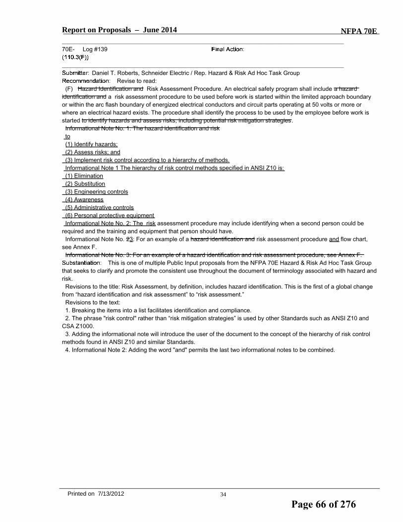
Report on Proposals – June 2014 NFPA 70E_______________________________________________________________________________________________70E- Log #139
_______________________________________________________________________________________________Daniel T. Roberts, Schneider Electric / Rep. Hazard & Risk Ad Hoc Task Group
Revise to read:(F) Hazard Identification and Risk Assessment Procedure. An electrical safety program shall include a hazard
identification and a risk assessment procedure to be used before work is started within the limited approach boundaryor within the arc flash boundary of energized electrical conductors and circuit parts operating at 50 volts or more orwhere an electrical hazard exists. The procedure shall identify the process to be used by the employee before work isstarted to identify hazards and assess risks, including potential risk mitigation strategies.Informational Note No. 1: The hazard identification and riskto(1) Identify hazards;(2) Assess risks; and(3) Implement risk control according to a hierarchy of methods.Informational Note 1 The hierarchy of risk control methods specified in ANSI Z10 is:(1) Elimination(2) Substitution(3) Engineering controls(4) Awareness(5) Administrative controls(6) Personal protective equipmentInformational Note No. 2: The risk assessment procedure may include identifying when a second person could be
required and the training and equipment that person should have.Informational Note No. 23: For an example of a hazard identification and risk assessment procedure and flow chart,
see Annex F.Informational Note No. 3: For an example of a hazard identification and risk assessment procedure, see Annex F.
This is one of multiple Public Input proposals from the NFPA 70E Hazard & Risk Ad Hoc Task Groupthat seeks to clarify and promote the consistent use throughout the document of terminology associated with hazard andrisk.Revisions to the title: Risk Assessment, by definition, includes hazard identification. This is the first of a global change
from “hazard identification and risk assessment” to “risk assessment.”Revisions to the text:1. Breaking the items into a list facilitates identification and compliance.2. The phrase "risk control" rather than “risk mitigation strategies” is used by other Standards such as ANSI Z10 and
CSA Z1000.3. Adding the informational note will introduce the user of the document to the concept of the hierarchy of risk control
methods found in ANSI Z10 and similar Standards.4. Informational Note 2: Adding the word "and" permits the last two informational notes to be combined.
34Printed on 7/13/2012
Page 66 of 276

Report on Proposals – June 2014 NFPA 70E_______________________________________________________________________________________________70E- Log #336
_______________________________________________________________________________________________Mark McNellis, Sandia National Laboratories
Revise text to read:110.3 Electrical Safety Program Relationships with Contractors (Outside Service Personnel, and So Forth).(A) General Host Employer Responsibilities.
(1) The host employer shall implement and document an overall electrical safety program that directs activityappropriate for the electrical hazards, voltage, energy level, and circuit conditions.Informational Note No. 1: Safety-related work practices are just one component of an overall electrical safety program.Informational Note No. 2: ANSI/AIHA Z10-2005, American National Standard for Occupational Safety and Health
Management Systems, provides a framework for establishing a comprehensive electrical safety program as acomponent of an employer’s occupational safety and health program.(B) Awareness and Self-Discipline. The electrical safety program shall be designed to provide an awareness of the
potential electrical hazards to employees who work in an environment with the presence of electrical hazards. Theprogram shall be developed to provide the required self-discipline for all employees who must perform work that mayinvolve electrical hazards. The program shall instill safety principles and controls.(C) Electrical Safety Program Principles. The electrical safety program shall identify the principles upon which it is
based.Informational Note: For examples of typical electrical safety program principles, see Annex E.(D) Electrical Safety Program Controls. An electrical safety program shall identify the controls by which it is measured
and monitored.Informational Note: For examples of typical electrical safety program controls, see Annex E.(E) Electrical Safety Program Procedures. An electrical safety program shall identify the procedures for working within
the limited approach boundary and for working within the arc flash boundary before work is started.Informational Note: For an example of a typical electrical safety program procedure, see Annex E.(F) Hazard Identification and Risk Assessment Procedure. An electrical safety program shall include a hazard
identification and a risk assessment procedure to be used before work is started within the limited approach boundary orwithin the arc flash boundary of energized electrical conductors and circuit parts operating at 50 volts or more or wherean electrical hazard exists. The procedure shall identify the process to be used by the employee before work is startedto identify hazards and assess risks, including potential risk mitigation strategies.Informational Note No. 1: The hazard identification and risk assessment procedure may include identifying when a
second person could be required and the training and equipment that person should have.Informational Note No. 2: For an example of a hazard identification and risk assessment procedure flow chart, see
Annex F.Informational Note No. 3: For an example of a hazard identification and risk assessment procedure, see Annex F.(G) Job Briefing.(1) General. Before starting each job, the employee in charge shall conduct a job briefing with the employees
involved. The briefing shall cover such subjects as hazards associated with the job, work procedures involved, specialprecautions, energy source controls, personal protective equipment requirements, and the information on the energizedelectrical work permit, if required. Additional job briefings shall be held if changes that might affect the safety ofemployees occur during the course of the work.
(2) Repetitive or Similar Tasks. If the work or operations to be performed during the work day or shift are repetitiveand similar, at least one job briefing shall be conducted before the start of the first job of the day or shift.
(3) Routine Work. Prior to starting work, a brief discussion shall be satisfactory if the work involved is routine and ifthe employee is qualified for the task. A more extensive discussion shall be conducted if either of the following apply:
(1) The work is complicated or particularly hazardous.(2) The employee cannot be expected to recognize and avoid the hazards involved in the job.
Informational Note: For an example of a job briefing form and planning checklist, see Figure I.1.(H) Electrical Safety Auditing.(1) Electrical Safety Program. The electrical safety program shall be audited to verify the principles and procedures of
the electrical safety program are in compliance with this standard. The frequency of the audit shall not exceed 3 years.(2) Field Work. Field work shall be audited to verify the requirements contained in the procedures of the electrical
35Printed on 7/13/2012
Page 67 of 276

Report on Proposals – June 2014 NFPA 70Esafety program are being followed. When the auditing determines that the principles and procedures of the electricalsafety program are not being followed, the appropriate revisions to the training program or revisions to the proceduresshall be made.
(3) Documentation. The audit shall be documented.
(1) inform contract employers of the following:a. Known hazards that are covered by this standard, that are related to the contract employer’s work, and that
might not be recognized by the contract employer or its employeesb. Information about the employer’s installation that the contract employer needs to make the assessments
required by Chapter 1(2) The host employer shall report observed contract employer–related violations of this standard to the contract
employer.
(B) Contract Employer Responsibilities.
(1) The contract employer shall ensure that each of his or her employees is instructed in the hazards communicatedto the contract employer by the host employer. This instruction shall be in addition to the basic training required by thisstandard.
(2) The contract employer shall ensure that each of his or her employees follows the work practices required by thisstandard and safety-related work rules required by the host employer.
(3) The contract employer shall advise the host employer of the following:a. Any unique hazards presented by the contract employer’s workb. Any unanticipated hazards found during the contract employer’s work that the host employer did not mentionc. The measures the contractor took to correct any violations reported by the host employer under 110.1(A)(2) and
to prevent such violation from recurring in the future
(C) Documentation. There shall be a documented meeting between the host employer and the contract employer.This input was submitted by the Article 110 Task Group and was intended to swap current 110.1 with
110.3 for better flow and readability. There is also another proposal with the current 110.3 language inserted into 110.1
_______________________________________________________________________________________________70E- Log #337
_______________________________________________________________________________________________Mark McNellis, Sandia National Laboratories
Revise text to read: (E) Electrical Safety Program Procedures. An electrical safety program shall identify the procedures for working within
the limited approach boundary and for working within the arc flash boundary before employees exposed to an electricalhazard before work is started.
his PI was submitted by the article 110 task group to better the verbiage in 110.2D1 "Qualified Person.A qualified person shall be trained and knowledgeable ....and be trained to recognize and avoid the electrical hazardsthat might be present…..Additionally the task Group felt that all electrical hazards need to be addressed as opposed to limiting the section to
shock and arc flash.
36Printed on 7/13/2012
Page 68 of 276

Report on Proposals – June 2014 NFPA 70E_______________________________________________________________________________________________70E- Log #338
_______________________________________________________________________________________________Mark McNellis, Sandia National Laboratories
Revise text to read: (F) Hazard Identification and Risk Assessment Procedure. An electrical safety program shall include a hazard
identification and a risk assessment procedure to be used before work is started within the limited approach boundary orwithin the arc flash boundary of energized electrical conductors and circuit parts operating at 50 volts or more or wherean electrical hazard exists an employee is exposed to an electrical hazard. The procedure shall identify the process tobe used by the employee before work is started to identify hazards and assess risks, including potential risk mitigationstrategies.
This public input was submitted by the article 110 task group to better the verbiage in 110.2D1"Qualified Person. A qualified person shall be trained and knowledgeable
....and be trained to recognize and avoid the electrical hazards that might be present…..Additionally the task Group felt that all electrical hazards need to be addressed as opposed to limiting the section to
shock and arc flash
_______________________________________________________________________________________________70E- Log #358
_______________________________________________________________________________________________H. Landis Floyd, The DuPont Company, Inc.
Revise text to read:Informational Note No. 1: Safety-related work practices are just one component, safety-related maintenance
requirements, warning practices, auditing requirements and training requirements provided in this standard areadministrative controls and part of an overall electrical safety program. Applications of engineering controls, orequipment and systems with the designed function to prevent or limit frequency or severity of exposure to electricalhazards, and management systems to manage effectiveness of an electrical safety program are not addressed in thisstandard.
The standard includes more than safe work practices. The intent of this proposal is to clarify that theother administrative controls provided in the standard are part of the electrical safety program, and that administrativecontrols are just one element of an overall electrical safety program.
_______________________________________________________________________________________________70E- Log #359
_______________________________________________________________________________________________H. Landis Floyd, The DuPont Company, Inc.
Revise text to read:Informational Note No. 2: ANSI/AIHA Z10- 2005 (check latest ediition date), American National Standard for
Occupational Health and Safety and Health Management Systems, provides a framework for establishing acomprehensive electrical safety program as a component of an employer’s occupational safety and health program.
This corrects the typographical error in the standard title and alerts the technical committee that thestandard is completing a revision cycle and final publication is pending.
37Printed on 7/13/2012
Page 69 of 276

Report on Proposals – June 2014 NFPA 70E_______________________________________________________________________________________________70E- Log #454
_______________________________________________________________________________________________Bobby J. Gray, Hoydar/Buck, Inc. / Rep. NFPA 70E DC Hazards Task Group
Revise text to read:(F) Hazard Identification and Risk Assessment Procedure. An electrical safety program shall include a hazard
identification and a risk assessment procedure to be used before work is started within the limited approach boundary orwithin the arc flash boundary of energized electrical conductors and circuit parts operating at 50 volts or more or wherean electrical hazard exists. The procedure shall identify the process to be used by the employee before work is startedto identify hazards and assess risks, including potential risk mitigation strategies.
The phrase conflicts with the minimum voltage for dc hazards. This PI is a companion to PI 385. ThisPI is submitted by the NFPA 70E DC Hazards Task Group.
_______________________________________________________________________________________________70E- Log #108
_______________________________________________________________________________________________Bobby J. Gray, Hoydar/Buck, Inc. / Rep. NFPA 70E DC Hazards Task Group
Add new text to read:(B) Installation and Maintenance. The electrical safety program shall include elements that ensure installations of
electrical equipment and systems comply with applicable installation codes and standards.The electrical safety program shall include elements that considers condition of maintenance of electrical equipment
and systems.An overall electrical safety program must include installation requirements for the protection of the
general worker. Likewise, the work practices of NFPA 70E rely on equipment and systems that have been maintainedproperly. Currently, there is no requirement for the employer to incorporate installation or maintenance into the program.This change will ensure the employer considers these two key principles into a complete electrical safety program.Acceptance of this public input will require renumbering of the remaining items in the section.
_______________________________________________________________________________________________70E- Log #197
_______________________________________________________________________________________________David A. Pace, Olin Corporation
Revise 110.3(H)(2) to read as follows: Field Work. Field work shall be audited not less than onceper year to verify...".
Field audits should be done on some regular frequency. Once per year is consistent with auditfrequency requirements in other parts of this standard.
38Printed on 7/13/2012
Page 70 of 276
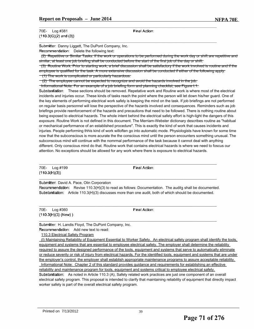
Report on Proposals – June 2014 NFPA 70E_______________________________________________________________________________________________70E- Log #381
_______________________________________________________________________________________________Danny Liggett, The DuPont Company, Inc.
Delete the following text:(2) Repetitive or Similar Tasks. If the work or operations to be performed during the work day or shift are repetitive and
similar, at least one job briefing shall be conducted before the start of the first job of the day or shift.(3) Routine Work. Prior to starting work, a brief discussion shall be satisfactory if the work involved is routine and if the
employee is qualified for the task. A more extensive discussion shall be conducted if either of the following apply:(1) The work is complicated or particularly hazardous.(2) The employee cannot be expected to recognize and avoid the hazards involved in the job.
Informational Note: For an example of a job briefing form and planning checklist, see Figure I.1.These sections should be removed. Repetative work and Routine work is where most of the electrical
incidents and injuries occur. These kinds of tasks reach the point where the person will let down his/her guard. One ofthe key elements of performing electrical work safely is keeping the mind on the task. If job briefings are not performedon regular basis personnel will lose the perspective of the hazards involved and consequences. Reminders such as jobbriefings provide reenforcement of the hazards and precautions that need to be followed. There is nothing routine aboutbeing exposed to electrical hazards. The whole intent behind the electrical safety effort is high-light the dangers of thisexposure. Routine Work is not defined in this document. The Merriam-Webster dictionary describes routine as "habitualor mechanical performance of an established procedure". This is exactly the kind of work that causes incidents andinjuries. People performing thhis kind of work willoften go into automatic mode. Physiologists have known for some timenow that the subconscious is more acurate the the conscious mind until the person encounters something unusual. Thesubconscious mind will continue with the nomrmal performance of the task because it cannot deal with anythingdifferent. Only conscious mind do that. Routine work that contains electrical hazards is where we need to foscus ourattention. No exceptions should be allowed for any work where there is exposure to electrical hazards.
_______________________________________________________________________________________________70E- Log #199
_______________________________________________________________________________________________David A. Pace, Olin Corporation
Revise 110.3(H)(3) to read as follows: Documentation. The audits shall be documented.Article 110.3(H)(3) discusses more than one audit, both of which should be documented.
_______________________________________________________________________________________________70E- Log #360
_______________________________________________________________________________________________H. Landis Floyd, The DuPont Company, Inc.
Add new text to read:110.3 Electrical Safety Program(I) Maintaining Reliability of Equipment Essential to Worker Safety. An electrical safety program shall identify the tools,
equipment and systems that are essential to employee electrical safety. The employer shall determine the reliabilityrequired to assure the designed performance of the tools, equipment and systems that serve to automatically eliminateor reduce severity or risk of injury from electrical hazards. For the identified tools, equipment and systems that are underthe employer’s control, the employer shall establish appropriate maintenance programs to assure acceptable reliability.Informational Note: Chapter 2 of this standard provides guidance and requirements for establishing an effective
reliability and maintenance program for tools, equipment and systems critical to employee electrical safety.As noted in Article 110.3 (A), Safety related work practices are just one component of an overall
electrical safety program. This proposal is intended to clarify that maintaining reliability of equipment that directly impactworker safety is part of the overall electrical safety program.
39Printed on 7/13/2012
Page 71 of 276

Report on Proposals – June 2014 NFPA 70E_______________________________________________________________________________________________70E- Log #140
_______________________________________________________________________________________________Daniel T. Roberts, Schneider Electric / Rep. Hazard & Risk Ad Hoc Task Group
Revise to read:(1) The work is complicated or particularly hazardous involves increased risk.(2) The employee cannot be expected to recognize and avoid identify the hazards, assess the risk, or avoid exposure
to the hazards involved in the job.This is one of multiple Public Input proposals from the NFPA 70E Hazard & Risk Ad Hoc Task Group
that seeks to clarify and promote the consistent use throughout the document of terminology associated with hazard andrisk.Revision to list item 1: The proposed change provides clarity as the context indicates that what is being referred to is
risk (severity of harm or likelihood of the occurrence of harm).Revision to list item 2: The identified list revised to be consistent with the proposed definitions of hazard and risk
_______________________________________________________________________________________________70E- Log #102
_______________________________________________________________________________________________Bobby J. Gray, Hoydar/Buck, Inc. / Rep. NFPA 70E DC Hazards Task Group
Revise to read: (2) Outdoors. GFCI protection shall be provided when an employee is outdoors and operating or using cord- and
plug-connected equipment supplied by 125-volt, 15-, 20-, or 30-ampere circuits. Where employees working outdoorsoperate or use equipment supplied by other than 125-volt, 15-, 20-, or 30-ampere circuits, GFCI protection or anassured equipment grounding conductor program shall be implemented.
As written, for 220 volt circuits, GFCI protection would not be an option. Most experts would agree thatGFCI protection is a superior protection method to an assured equipment grounding conductor program. The option touse GFCI protection should be made available.
_______________________________________________________________________________________________70E- Log #289
_______________________________________________________________________________________________Louis A. Barrios, Shell Global Solutions / Rep. American Petroleum Institute
Revise text to read:(2) Outdoors. GFCI protection shall be provided when an employee is outdoors and operating or using cord- and
plug-connected equipment supplied by 125-volt, 15-, 20-, or 30-ampere circuits. Where employees working outdoorsoperate or use equipment supplied by other than greater than 125-volt, 15-, 20-, or 30-ampere circuits, volt circuits, anassured equipment grounding conductor program shall be implemented.
110.4(C) requires an assured equipment grounding conductor program when operating cord and plugconnected equipemnt outdoors for circuits other than 125V. This would include low voltage, 2-wire equipment operatingat 12V, 24V or 48V. The proposed language clarifies that an assured equipment grounding conductor program is notrequired for lower voltages that do not pose an electrocution hazard.
40Printed on 7/13/2012
Page 72 of 276

Report on Proposals – June 2014 NFPA 70E_______________________________________________________________________________________________70E- Log #347
_______________________________________________________________________________________________Mark McNellis, Sandia National Laboratories
Revise text to read:(E) Overcurrent Protection Modification. Overcurrent protection of circuits and conductors shall not be modified, even
on a temporary basis, beyond that what is permitted by applicable portions of electrical codes and standards dealingwith overcurrent protection.
This PI was submitted by the article 110 Task Group to improve grammar only.
_______________________________________________________________________________________________70E- Log #207
_______________________________________________________________________________________________David A. Pace, Olin Corporation
Add anew 110.4(I) to read as follows: Electrical Equipment Specification and Application.Individuals having responsibility for specifying and applying electrical equipment the site shall:1) specify equipment compliant with applicable codes and standards2) incorporate any advances in technology that result in safety improvements to minimize electrical hazard potential
(i.e. IEC Touch Proof components, polycarbonate barriers, remote racking devices, GFCI’s, arc flash reductionmeasures, etc.).3) use the Electrical Hazards Identification and Risk Assessment process at each phase of the job or project, ensuring
that options chosen and choices made in the course of electrical equipment design, selection, installation and operationwill serve to eliminate risk, reduce frequency of exposure, reduce magnitude or severity of exposure, enable the abilityto achieve an electrically safe work condition, and otherwise serve to enhance the effectiveness of the safety relatedwork practices contained in the this standard, and 4) make every effort to reduce the resulting electrical arc flashincident energy, regardless of the level, and electrical shock hazards at the equipment to the lowest possible levels,including their elimination all together.
A significant amount of improvement in the overall level of safety can be achieved by implementing therequirements as described, emphasizing the improvements at each phase of equipment specification and application.
_______________________________________________________________________________________________70E- Log #414
_______________________________________________________________________________________________John McAlhaney, Savannah River Nuclear Solutions
Add a new section to read:(5) Manufacturer's Instructions. Portable equipment shall be used in accordance with the manufacturer's instructions
and safety warnings.This proposal will ensure that users read, understand and comply with manufacturers operating
instructions and safety that have been provided to reduce risk of shock an injury.
_______________________________________________________________________________________________70E- Log #339
_______________________________________________________________________________________________Mark McNellis, Sandia National Laboratories
Change the title to read: 110.4 Use of Electrical Equipment.
This PI was submitted by the article 110 Task Group to improve clarity and better clarify the intent ofthe section.
41Printed on 7/13/2012
Page 73 of 276
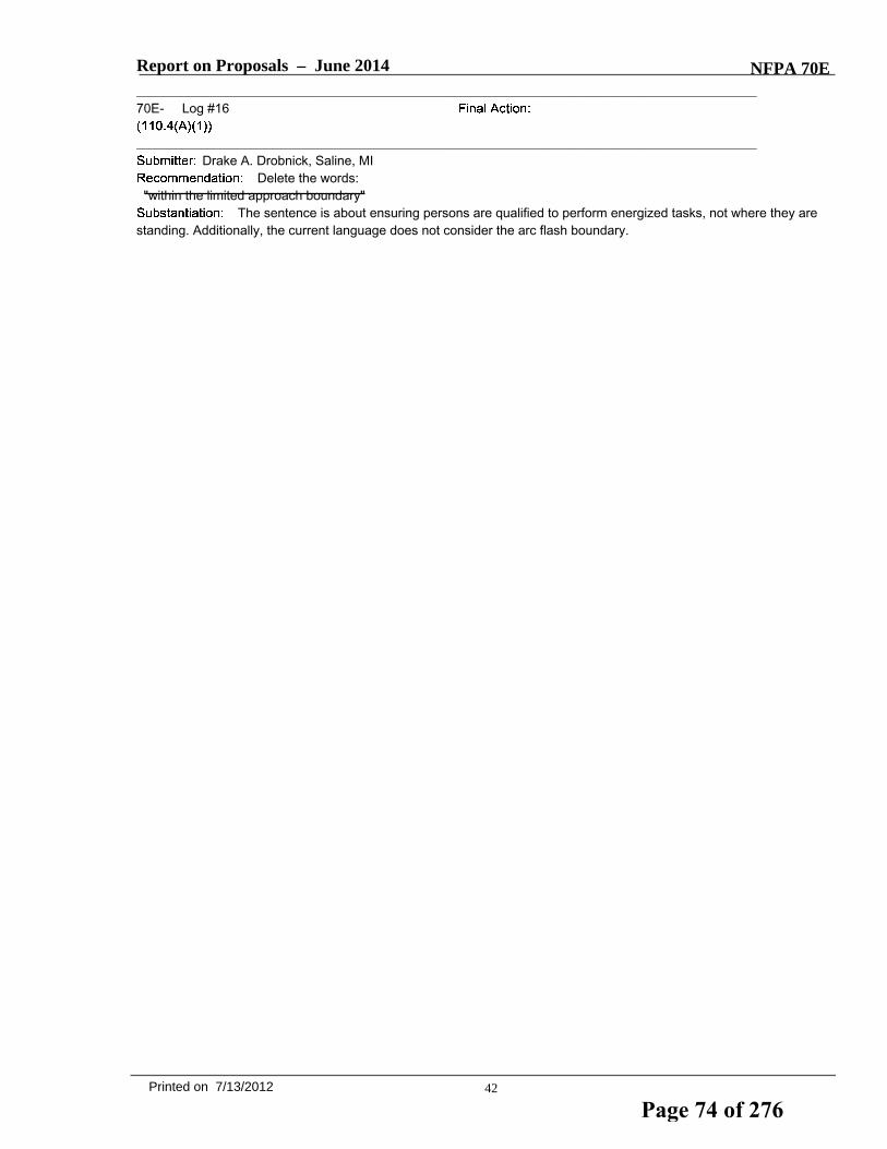
Report on Proposals – June 2014 NFPA 70E_______________________________________________________________________________________________70E- Log #16
_______________________________________________________________________________________________Drake A. Drobnick, Saline, MI
Delete the words:"within the limited approach boundary"
The sentence is about ensuring persons are qualified to perform energized tasks, not where they arestanding. Additionally, the current language does not consider the arc flash boundary.
42Printed on 7/13/2012
Page 74 of 276

Report on Proposals – June 2014 NFPA 70E_______________________________________________________________________________________________70E- Log #394
_______________________________________________________________________________________________Jerry Grant, Argonne National Laboratories
Revise text to read:(1) Handling and Storage. Portable equipment shall be handled or stored in a manner that will not cause damage.
Flexible electric cords connected to equipment shall not be used for raising or lowering the equipment. Flexible cordsshall not be fastened with staples or hung in such a fashion as could damage the outer jacket or insulation. Flexiblecords shall be stored protected from sunlight, weather and/or deterioration when not in use.Exception: Cords listed or identified as sunlight resistant, weather resistant and/or for the deterioration conditions
affecting the storage of the cords shall be stored according to manufacturer's instructions.Outdoor cords are marked by the manufacturer “Store Indoors While Not In Use” per requirements of
the product listing. The listing defines indoor storage for protection from sunlight and/or weather. Cords stored in a gangbox, vehicle trunk or under an overhang protected from sunlight and/or weather would be sufficient per the listinginformation. (Note: There are many nationally recognized testing laboratories (NRTLs) but all of the NRTLs use thesame listing standards and requirements for product certification.)Often cords are stored on work trucks without this necessary protection and this lack of protection will allow for
potential of UV and weather damage to exposed cords. This new language will enhance safety by addressing thisfrequent condition that creates a potential hazard. Also defining what conditions satisfy flexible cord indoor storage is aguide for workers to meet adequate storage while not in use requirements.The exception is added because sunlight resistant and/or weatherproof cords maybe available in the future.Technical Basis:1. UL White Book (2012), “CORD SETS AND POWER-SUPPLY CORDS (ELBZ)” Outdoor-use Cord Set — This is a
cord set assembled with outdoor type flexible cord without a switch, and which is intended for use outdoor to supplyportable electric equipment. It is (1) marked ‘‘Suitable For Use With Outdoor Appliances — Store Indoors While Not InUse,’’ (2) suitable for supplying portable outdoor appliances within their marked voltage, amp and wattage rating, (3)intended for use outdoors only while the equipment supplied is in use, and (4) intended to be stored indoors (i.e., wherenot exposed to sunlight and/or weather) while not in use. Such a cord set has been investigated to determine (1) that thematerials in the flexible cord and in the line and load fittings, and (2) the adhesion between the cord jacket and thebodies of the line and load fittings are suitable for periodic use outdoors.
The connection between the attachment plug cap and the outlet device supplying the cord set, and between thesupply cord of any connected appliance and the load end of the cord set, should not be subjected to moisture ordampness. Outdoor-use cord sets may also have integral restraint devices to prevent unintentional disconnection of thecord connector from a mating attachment plug of an appliance. Restraint devices that are separate from cord sets arecovered under Cord Restraint Devices (ELDW).
2. NEC (2011) 110.3 Examination, Identification, Installation, and Use of Equipment. B Installation and Use. Listed orlabeled equipment shall be installed and used in accordance with any instructions included in the listing or labeling.3. NEC (2011) 110.27 Guarding of Live Parts. B Prevent Physical Damage. In locations where electrical equipment is
likely to be exposed to physical damage, enclosures or guards shall be so arranged and of such strength as to preventsuch damage.4. NEC (2011) 300.6 Protection Against Corrosion and Deterioration. Raceways, cable trays, cablebus, auxiliary
gutters, cable armor, boxes, cable sheathing, cabinets, elbows, couplings, fittings, supports, and support hardware shallbe of materials suitable for the environment in which they are to be installed.C Nonmetallic Equipment. Nonmetallic raceways, cable trays, cablebus, auxiliary gutters, boxes, cables with a
nonmetallic outer jacket and internal metal armor or jacket, cable sheathing, cabinets, elbows, couplings, nipples,fittings, supports, and support hardware shall be made of material approved for the condition and shall comply with(C)(1) and (C)(2) as applicable to the specific installation.1 Exposed to Sunlight. Where exposed to sunlight, the materials shall be listed as sunlight resistant or shall be
identified as sunlight resistant.5. NEC (2011) 310.10 Uses Permitted. The conductors described in 310.104 shall be permitted for use in any of the
wiring methods covered in Chapter 3 and as specified in their respective tables or as permitted elsewhere in this Code.C Wet Locations. Insulated conductors and cables used in wet locations shall comply with one of the following:
(1) Be moisture-impervious metal-sheathed(2) Be types MTW, RHW, RHW-2, TW, THW, THW-2, THHW, THWN, THWN-2, XHHW, XHHW-2, ZW(3) Be of a type listed for use in wet locations
43Printed on 7/13/2012
Page 75 of 276

Report on Proposals – June 2014 NFPA 70ED Locations Exposed to Direct Sunlight. Insulated conductors or cables used where exposed to direct rays of the sun
shall comply with (D)(1) or (D)(2):(1) Conductors and cables shall be listed, or listed and marked, as being sunlight resistant(2) Conductors and cables shall be covered with insulating material, such as tape or sleeving, that is listed, or listed
and marked, as being sunlight resistant6. NEC (2011) 400.3 Suitability. Flexible cords and cables and their associated fittings shall be suitable for the
conditions of use and location.7. NFPA 1 (2012) 11.1.7 Extension Cords. 11.1.7.3 The extension cords shall be maintained in good condition without
splices, deterioration, or damage.
_______________________________________________________________________________________________70E- Log #456
_______________________________________________________________________________________________Bobby J. Gray, Hoydar/Buck, Inc. / Rep. NFPA 70E DC Hazards Task Group
Revise text to read:(1) Testing. Only qualified persons shall perform tasks such as testing, troubleshooting, and voltage measuring within
the limited approach boundary of energized electrical conductors or circuit parts operating at 50 volts or more or wherean electrical hazard exists.
The phrase conflicts with the minimum voltage for dc hazards. This PI is a companion to PI 385. ThisPI is submitted by the NFPA 70E DC Hazards Task Group.
_______________________________________________________________________________________________70E- Log #171
_______________________________________________________________________________________________Daryld Ray Crow, DRC Consulting, Ltd.
Revise 110.4(C)(2) as follows:(2) Outdoors. GFCI protection shall be provided when an employee is outdoors and operating or using cord- and
plug-connected equipment supplied by 125-volt, 15-, 20-, or 30-ampere circuits. Where employees working outdoorsoperate or use equipment supplied by other than 125-volt, 15-, 20-, or 30-ampere circuits, an assured equipmentgrounding conductor program shall be implemented.
GFCIs save lives. They should be used indoors as well as outdoors when cord-and plug-connectedequipment. The use of GFCIs when using cord-and plug-connected equipment is an excellent safeguard for personnel.GFCIs have saved many lives. Data exists to verify this statement.
_______________________________________________________________________________________________70E- Log #201
_______________________________________________________________________________________________David A. Pace, Olin Corporation
Revise 110.4(C)(2) to read as follows:110.4(C)(2) Outdoors. Maintenance and Construction Activities. GFCI protection shall be provided when an employee
is outdoors performing maintenance or construction activities and operating or using cord and plug connectedequipment supplied by 125 volt, 15, 20, or 30 ampere circuits. Where employees working outdoors performingmaintenance or construction activities operate or use equipment supplied by other than 125 volt, 15, 20, or 30 amperecircuits, an assured equipment grounding conductor program shall be implemented.
GFCI protection should be required for any maintenance or construction activity, outdoors or indoors.These activities subject the cord and plug connected equipment to a significantly higher likelihood of physical damage.While it is true performing this work outdoors would increase the risk of injury due to the possible presence of conductivefluids, there remains a significant risk of injury while using this equipment, that is independent of the location where it isbeing used.
44Printed on 7/13/2012
Page 76 of 276

Report on Proposals – June 2014 NFPA 70E_______________________________________________________________________________________________70E- Log #340
_______________________________________________________________________________________________Mark McNellis, Sandia National Laboratories
Revise text to read:(2) Rating. Test instruments, equipment, and their accessories shall be rated for circuits and equipment to which they
will be connected are utilized with.This PI was submitted by the article 110 Task Group to improve grammar and clarity .
_______________________________________________________________________________________________70E- Log #141
_______________________________________________________________________________________________Daniel T. Roberts, Schneider Electric / Rep. Hazard & Risk Ad Hoc Task Group
Revise to read: Informational Note: The hazard/ risk evaluation assessment procedure could also include identifying when the use of
portable tools and equipment powered by sources other than 120 volts ac, such as batteries, air, and hydraulics, shouldbe used to minimize the potential for injury from electrical hazards for tasks performed in conductive or wet locations.
This is one of multiple Public Input proposals from the NFPA 70E Hazard & Risk Ad Hoc Task Groupthat seeks to clarify and promote the consistent use throughout the document of terminology associated with hazard andrisk.The proposed change correlate with the changes made to the 2009 edition, and with the changes proposed to
110.3(F).
_______________________________________________________________________________________________70E- Log #341
_______________________________________________________________________________________________Mark McNellis, Sandia National Laboratories
Revise text to read:(3) Design. Test instruments, equipment, and their accessories shall be designed for the environment to which they
will be exposed and for the manner in which they will be used utilized.This PI was submitted by the article 110 Task Group to improve grammar and clarity. This input better
aligns text with input submitted for 110.4(A)(2).
_______________________________________________________________________________________________70E- Log #344
_______________________________________________________________________________________________Mark McNellis, Sandia National Laboratories
Revise text to read:(3) Visual Inspection and Repair of Portable Cord- and Plug-Connected Equipment and Flexible Cord Sets.
This PI was submitted by the article 110 Task Group to include "repair" in the title of this section asrepair is a significant part of this section and to better align with the Task Group proposal to re-title the current110.4(A)4) which would include "repair" in the title.
45Printed on 7/13/2012
Page 77 of 276

Report on Proposals – June 2014 NFPA 70E_______________________________________________________________________________________________70E- Log #345
_______________________________________________________________________________________________Mark McNellis, Sandia National Laboratories
Revise text to read:(b) Defective Equipment. If there is a defect or evidence of damage that might expose an employee to injury, the
defective or damaged item shall be removed from service, and no employee shall use it until a qualified person performsthe repairs and tests necessary to render the equipment safe have been made in accordance with productspecifications.
The article 110 Task Group submitted this PI and suggests that errant repair of equipment can lead toelectrocution, therefore the requirements for reparation should be limited to qualified workers.
_______________________________________________________________________________________________70E- Log #342
_______________________________________________________________________________________________Mark McNellis, Sandia National Laboratories
Revise text to read:(4) Visual Inspection and Repair. Test instruments and equipment and all associated test leads, cables, power cords,
probes, and connectors shall be visually inspected for external defects and damage before each use. If there is a defector evidence of damage that might expose an employee to injury, the defective or damaged item shall be removed fromservice, and no employee shall use it until repairs a qualified person performs the repairs and tests necessary to renderthe equipment safe have been made in accordance with product specifications.
This PI was submitted by the article 110 Task Group and is meant to identify that reparation should beincluded in the title of the section as repair is a substantial part of the section. Additionally the task group suggests thaterrant repair of equipment can lead to electrocution, therefore the requirements for reparation should be limited toqualified workers.
_______________________________________________________________________________________________70E- Log #346
_______________________________________________________________________________________________Mark McNellis, Sandia National Laboratories
Revise text to read:(45) Connecting Attachment Plugs.
This PI was submitted by the article 110 Task Group and is a partner submittal to renumber the current110.4(B)(4) to 110.4(B)(5) as the Task Group proposes to move the current 110.4(B)(3)(d) in it's entirety to a newsection 110.4(B)(4) as conductive work locations does not belong under "Visual Inspection or portable cord and plugconnected equipment and cord sets, but is more stand alone under under portable Electric equipment.
46Printed on 7/13/2012
Page 78 of 276

Report on Proposals – June 2014 NFPA 70E_______________________________________________________________________________________________70E- Log #343
_______________________________________________________________________________________________Mark McNellis, Sandia National Laboratories
Add a new section to read:110.4(B)(4) Conductive Work Locations. Portable electric equipment used in highly conductive work locations (such as
those inundated with water or other conductive liquids), or in job locations where employees are likely to contact wateror conductive liquids, shall be approved for those locations. In job locations where employees are likely to contact or bedrenched with water or conductive liquids, ground-fault circuit-interrupter protection for personnel shall also be used.Informational Note: The hazard/risk evaluation procedure could also include identifying when the use of portable tools
and equipment powered by sources other than 120 volts ac, such as batteries, air, and hydraulics, should be used tominimize the potential for injury from electrical hazards for tasks performed in conductive or wet locations.
This PI was submitted by the article 110 Task Group and is a partner submittal to relocate the current110.4(B)(3)(d) in it's entirety to a new section 110.4(B)(4) as conductive work locations does not belong under "VisualInspection of portable cord and plug connected equipment and cord sets, but is a better fit under portable Electricequipment.
_______________________________________________________________________________________________70E- Log #194
_______________________________________________________________________________________________David A. Pace, Olin Corporation
Delete 110.4(B)(4)(b).This standard should not be providing guidance for an action that clearly puts people at risk of injury by
telling them how to handle energized plug and receptacle connections for portable electric equipment if the "cordconnector is wet from being immersed in water", it should prohibit this action. Handling this equipment if it wet and/orhas been immersed in water is unsafe and puts the individuals involved at a significant risk of injury from electric shock.
_______________________________________________________________________________________________70E- Log #287
_______________________________________________________________________________________________Melissa Rutter, JC Penney
Revise text to read:(5) Operation Verification. When test instruments are used for testing the absence of voltage on conductors or circuit
parts operating at 50 volts or more, the operation of the test instrument shall be verified on a known source before andafter an absence of voltage test is performed.
This addition would provide guidance and clarification.
_______________________________________________________________________________________________70E- Log #455
_______________________________________________________________________________________________Bobby J. Gray, Hoydar/Buck, Inc. / Rep. NFPA 70E DC Hazards Task Group
Revise text to read:(5) Operation Verification. When test instruments are used for testing the absence of voltage on conductors or circuit
parts operating at 50 volts or more, the operation of the test instrument shall be verified before and after an absence ofvoltage test is performed.
The phrase conflicts with the minimum voltage for dc hazards. This PI is a companion to PI 385. ThisPI is submitted by the NFPA 70E DC Hazards Task Group.
47Printed on 7/13/2012
Page 79 of 276

Report on Proposals – June 2014 NFPA 70E_______________________________________________________________________________________________70E- Log #25
_______________________________________________________________________________________________William D. Lewis, Electrical Safety Resource / Rep. McNaughton-McKay Electric
Revise text as follows:
● Relocated (old Section 110.5) text to new Section 130.9(B) “Underground Electrical Lines and Equipment.”
New Section 130.9 will combine both “Overhead Lines” (old Section 130.8) and “Underground Lines &Equipment” (old Section 110.5) safety practices into one common section for ease of locating within this standard.
_______________________________________________________________________________________________70E- Log #53
_______________________________________________________________________________________________Daryld Ray Crow, DRC Consulting, Ltd.
Move article 110.5 “Underground Electrical Lines and Equipment” to new article 130.9.Moving article 110.5 to new article 130.9 will place all references to power lines in the same location of
the NFPA 70E standard. No change in the wording for the existing article 110.5 is recommended.
_______________________________________________________________________________________________70E- Log #54
_______________________________________________________________________________________________John Luke, The ESCO Group
Revise text to read as follows:110.5 Underground Electrical Lines and Equipment.When it has been determined that a reasonable possibility for contacting electrical lines or equipment exists, a hazardanalysis shall be performed to identify the appropriate safe work practices and personal protective equipment that shallbe used during the excavation.
The current language requires a hazard analysis and appropriate safe work practices but, doesn'tconsider personal protective equipment. The proposed addition adds clarity for the users of this standard and safeguards employees during excavations.
_______________________________________________________________________________________________70E- Log #142
_______________________________________________________________________________________________Daniel T. Roberts, Schneider Electric / Rep. Hazard & Risk Ad Hoc Task Group
Revise to read: 110.5 Underground Electrical Lines and Equipment. Before excavation starts, and where there exists a reasonable
possibility of contacting electrical lines or equipment, the employer shall take the necessary steps to contact theappropriate owners or authorities to identify and mark the location of the electrical lines or equipment. When it has beendetermined that a reasonable possibility for contacting electrical lines or equipment exists, a hazard analysis shall beperformed to identify the appropriate safe work practices that shall be used during the excavation.
This is one of multiple Public Input proposals from the NFPA 70E Hazard & Risk Ad Hoc Task Groupthat seeks to clarify and promote the consistent use throughout the document of terminology associated with hazard andrisk.The proposed change provides clarity. The deleted text ("a hazard analysis shall be performed to identify the") is
redundant. It is sufficient to state that appropriate safe work practices shall be used during the excavation.
48Printed on 7/13/2012
Page 80 of 276

Report on Proposals – June 2014 NFPA 70E_______________________________________________________________________________________________70E- Log #348
_______________________________________________________________________________________________Mark McNellis, Sandia National Laboratories
Delete 110.5 in its entirety.This PI was submitted by the article 110 Task Group and is a partner submittal to relocate the current
110.5 in it's entirety to a new section 130.9 where content is more in line with adjacent sections.
_______________________________________________________________________________________________70E- Log #413
_______________________________________________________________________________________________John McAlhaney, Savannah River Nuclear Solutions
Add a new section to read:110.6 Penetrations. Before penetrating into a blind space conaining possible electrical hazards where a reasonable
possibility exists of contacting energized electrical lines or parts, the employer shall take steps to identify and mark thelocation of lines or equipment and perform a hazard analysis to identify safe work practices to be used during thepenetration.
Both electrical and non-electrical personnel often are required to penetrate a wall or floor into a spacecontaining possible unknown electrical hazards. Many shocks, injuries and burns and some fatalities have resulted fromperforming this task because a thorough investigation was not performed to determine what electrical hazards may existwithin the blind space. Drawings should always be consulted and many new technologies are available to help workersidentify electrical circuits in blind spaces. A hazard analysis should always be performed when penetrating blind spacesto identify appropriate PPE and work practices that mitigate contact with energized components.
_______________________________________________________________________________________________70E- Log #415
_______________________________________________________________________________________________John McAlhaney, Savannah River Nuclear Solutions
Add a new section to read:(d) Employee's shall remove conductive apparerel (e.g., metal watches, bracelets, necklaces.) that is likely to contact
energized parts when plugging and unplugging flexible cords and cord- and plug-connected equipment.Electrical burns have resulted to workers when the metal apparel that is worn by the worker, such as
thin metal charms on wrist bracelets, make contact with the energized prong of a plug while connecting it to anenergized receptacle.
_______________________________________________________________________________________________70E- Log #74
_______________________________________________________________________________________________Palmer Hickman, Upper Marlboro, MD
Revise the title of 120.1 to read as follows:120.1 Process of Achieving Verification of an Electrically Safe Work Condition.
This recommendation is intended to enhance clarity and usability. The recommendation is to revise thetitle of 120.1 to better reflect the intent of 120.1. The six steps of 120.1 are to verify that an electrically safe workcondition exists after the provisions of 120.2 have been met. THe existing title implies that following these six stepsalone establishes an electrically safe work condition. May incorrectly assume, and a number of publications incorrectlystate, that an electrically safe work condition is achieved whent he six steps of 120.1 are accomplished when in facttheose six steps are used to verify that the provisions of 120.2 have been accomplished and that an electrically safework condition h as been established.
49Printed on 7/13/2012
Page 81 of 276

Report on Proposals – June 2014 NFPA 70E_______________________________________________________________________________________________70E- Log #226
_______________________________________________________________________________________________Philip Allen, Grace Engrd Products
Revise to read:(1) Determine all possible sources of electrical supply to the specific equipment. Check applicable up-to-date drawings,
diagrams, and identification tags, and verify proper operation of panel mounted voltage test instruments (InformationalNote as per 120.1(5)) .
Article 120.1(1-6) was originally written around the portable multimeter (or equivalent) as the primarytool for testing for zero electrical energy. This simple change updates this section tol allow for the use of panel mountedvoltage testing devices in creating an electrically safe work condition. Point #1) Panel mounted voltage testing devicesthat are wired to ALL voltage sources provide an equally reliable means as "up-to-date drawings, diagrams, andidentification tags" to n identifying all possible sources of electrical energy. Point #2) Permanently installed voltagetesting instruments need to be checked for proper functionality prior to de-energizing the system. This reasoning followsthe same logic as statement 120.1(5) "Before and after each test determine that the voltage detector is operatingsatisfactorily.". The only difference is the timing of that test within 120.1. If panel mount voltage detectors are used,these devices need to be checked before the system is de-energized. It is not practical to test panel mount voltagetesting equipment once the panel has been de-energized as per step (5).
_______________________________________________________________________________________________70E- Log #286
_______________________________________________________________________________________________Melissa Rutter, JC Penney
Revise text to read:(5) Use an adequately rated voltage detector to test each phase conductor or circuit part to verify they are
de-energized. Test each phase conductor or circuit part both phase-to-phase and phase-to-ground. Before and aftereach test, determine that the voltage detector is operating satisfactorily through verfication on a known source.
This addition would provide guidance and clarification.
_______________________________________________________________________________________________70E- Log #67
_______________________________________________________________________________________________Daryld Ray Crow, DRC Consulting, Ltd.
Add the following new text:120.1 Process of Achieving an Electrically Safe Work Condition(7) Mark the boundary of the electrically isolated work area.
Incidents occur when scope creep occurs causing a person to works outside the electrical safe workzone. Marking the boundary of the electrically isolated work area before start of work will help prevent this type ofincident.
50Printed on 7/13/2012
Page 82 of 276

Report on Proposals – June 2014 NFPA 70E_______________________________________________________________________________________________70E- Log #305
_______________________________________________________________________________________________Joseph Migliosi, Harvard Univ.
Add a new informational note to read:(2) After properly interrupting the load current, open the disconnecting device(s) for each source.Informational Note: For additional direction to properly interrupt the load current and to open disconnecting devices
including requirements for shock hazard and arc flash hazard analyses, see 130.4 for approach boundaries and 130.5for arc flash hazard analysis.
Construction, operations, and maintenance staff rely on the safety of equipment doors and do notrecognize that the process of lockout/tagout (i.e., establishing an electrically safe work condition) still places them withinthe potential arc flash boundary. Even though Paragraph 130.2(2) makes it clear that covers may not provide adequateprotection, the addition of this Informational Note would emphasize the potential exposure to hazards from shock andarc flash.
_______________________________________________________________________________________________70E- Log #103
_______________________________________________________________________________________________Bobby J. Gray, Hoydar/Buck, Inc. / Rep. NFPA 70E DC Hazards Task Group
Revise to read:(4) Apply lockout/tagout devices in accordance with a documented and established policy.(5) Use an adequately rated voltage detector to test each phase conductor or circuit part to verify they are
de-energized. Test each phase conductor or circuit part both phase-to-phase and phase-to-ground. Before and aftereach test, determine that the voltage detector is operating satisfactorily.Informational Note: See ANSI/ISA-61010-1 (82.02.01)/ UL 61010-1, Safety Requirements for Electrical Equipment forMeasurement, Control, and Laboratory Use – Part 1: General Requirements, for rating and design requirements forvoltage measurement and test instruments intended for use on electrical systems 1000 V and below.(6) Apply lockout/tagout devices in accordance with a documented and established policy.
It is difficult to accomplish the process in the order written. In some cases the lockout/tagout devicesapplied in step (4) must be removed to accomplish step (5). By reordering the steps, the process can be made moreefficient and compliance can be as written.
51Printed on 7/13/2012
Page 83 of 276

Report on Proposals – June 2014 NFPA 70E_______________________________________________________________________________________________70E- Log #72
_______________________________________________________________________________________________Palmer L. Hickman, Upper Marlboro, MD
Revise text to read as follows:120.21 De-energized Electrical Conductors or Circuit Parts That Have Lockout/Tagout Devices Applied.Each employer shall identify, document, and implement lockout/tagout procedures conforming to Article 120 to
safeguard employees from exposure to electrical hazards. The lockout/tagout procedure shall be appropriate for theexperience and training of the employees and conditions as they exist in the workplace.(A) General. All electrical circuit conductors and circuit parts shall be considered energized until the source(s) of
energy is (are) removed, at which time they shall be considered de-energized. All electrical conductors and circuit partsshall not be considered to be in an electrically safe work condition until all of the applicable requirements of Article 120have been met.Informational Note: See 120.12 for the six-step procedure to verify an electrically safe work condition.(Remainder unchanged except for editorally changing the numbering here and globally throughout 70E as necessary)120.12 Process of Achieving an Electrically Safe Work Condition.An electrically safe work condition shall be achieved when performed in accordance with the procedures of 120.21 and
verified by the following process:(remainder unchanged)
This recommendation is intended to enhance clarity and usability. The recommendation is to reversethe order that 120.1 and 120.2 appear in the standard. May incorrectly assume, and a number of publications incorrectlystate that an electrically safe work condition is achieved when the six steps of 120.1 are accomplished when in factthose six steps are used to verify that the provisions of 120.2 have been accomplished. Reversing the order of theseprovisions will have the main rule appear first in Article 120 with the six step verification located after the provisions thatthey are to verifiy.
_______________________________________________________________________________________________70E- Log #395
_______________________________________________________________________________________________Jerry Grant, Argonne National Laboratories
Revise text to read:(6) Where the possibility of induced voltages or stored electrical energy exists, where it is applicable ground the phase
conductors or circuit parts before touching them. Where it could be reasonably anticipated that the conductors or circuitparts being de-energized could contact other exposed energized conductors or circuit parts, apply ground connectingdevices rated for the available fault duty.Add a new exception to read:Exception: Batteries, Battery banks and related electrical conditions shall not follow portions of step 6 if the action
introduces additional hazards or risks.Batteries and battery banks are an exception to step 6 because of the potential increased hazards and
risks. This revision is consistent with the principals of 130.1A1.
_______________________________________________________________________________________________70E- Log #447
_______________________________________________________________________________________________Paul Dobrowsky, Holley, NY
Revise the title to read:120.2 De-energized Electrical Conductors or Circuit Parts Electrical Equipment That Have Lockout/Tagout Devices
Applied.The existing language is unclear. The lockout devices are not typically placed on the conductors or
circuit parts but on the disconnecting means (equipment).
52Printed on 7/13/2012
Page 84 of 276

Report on Proposals – June 2014 NFPA 70E_______________________________________________________________________________________________70E- Log #206
_______________________________________________________________________________________________David A. Pace, Olin Corporation
Revise 120.2(F)(1)(a) to read as follows: "...When up-to-date single-line drawings are not...".Add a sentence to the end that reads: When up-to-date single-line drawings are not available, the employer shall be
further responsible for making appropriate revisions to the drawings in a reasonable period of time so that they reflectactual conditions.
It is essential for single-line drawings be kept current and available for use such as in the process ofestablishing an electrically safe work condition.
_______________________________________________________________________________________________70E- Log #397
_______________________________________________________________________________________________Jerry Grant, Argonne National Laboratories
Revise text to read:(a) Locating Sources prior to executing work or task. Up-to-date single-line drawings shall be considered a primary
reference source for such information. When up-to-date drawings are not available, the employer shall be responsiblefor ensuring that an equally effective means of locating all sources of energy is employed.
Language revision is consistent with 110.3G principals.
_______________________________________________________________________________________________70E- Log #58
_______________________________________________________________________________________________John Luke, The ESCO Group
Revise text to read as follows:120.2(8)(2) Training All persons who could be exposed shall be trained to understand the established procedure tocontrol the energy and their responsibility in executing the procedure. New (or reassigned) employees shall be trained(or retained) to understand the lockout/tagout procedure as it relates to their new assignment. The employer shalldocument that each employee exposed has received the training required by this section. The documentation shallcontain the content of the training, each employee's name, and the dates of the training. Retaining shall be required asthe established procedure is revised.
The current language required employers to train and/or retain employees exposed but, did not requirethe training to be documented or list the content, names and dates of the training. Since lockout/tagout procedures couldchange at intervals differently than the NFPA 70E Standard and new or reassigned employees require training beforethey are exposed, adding documentation to this section would prove that the appropriate training was provided.
_______________________________________________________________________________________________70E- Log #144
_______________________________________________________________________________________________Daniel T. Roberts, Schneider Electric / Rep. Hazard & Risk Ad Hoc Task Group
Revise to read: (2) Lockout/Tagout Device. Each employer shall supply, and employees shall use, lockout/tagout devices and
equipment necessary to execute the requirements of 120.2(E). Locks and tags used for control of exposure to electricalenergy hazards shall be unique, shall be readily identifiable as lockout/tagout devices, and shall be used for no otherpurpose.
This is one of multiple Public Input proposals from the NFPA 70E Hazard & Risk Ad Hoc Task Groupthat seeks to clarify and promote the consistent use throughout the document of terminology associated with hazard andrisk.The proposed change provides clarity and consistency. Electrical hazard is a defined term in the document.
53Printed on 7/13/2012
Page 85 of 276

Report on Proposals – June 2014 NFPA 70E_______________________________________________________________________________________________70E- Log #349
_______________________________________________________________________________________________Mark McNellis, Sandia National Laboratories
Revise text to read:(4) Requirement to retest for absence of voltage when circuit conditions change or when the change(5) Requirement to verifyLockout devices have not been tampered with when the job location has been left unattended(56) Planning considerations that include methods of verification where there is no accessible exposed point to take
voltage measurementsPhysical verification that LOTO devices have not been tampered with is suffucient proof that circuit is
still in an electrical safe working condition.
_______________________________________________________________________________________________70E- Log #398
_______________________________________________________________________________________________Jerry Grant, Argonne National Laboratories
Add new text to read:Exception: Batteries, Battery banks and related electrical conditions shall not follow portions of step b if the action
introduces additional hazards or risks.Batteries and battery banks are an exception to step b because of the potential increased hazards and
risks. This revision is consistent with the principals of 110.3G.
_______________________________________________________________________________________________70E- Log #382
_______________________________________________________________________________________________Danny Liggett, The DuPont Company, Inc.
Add a new exception to read:Exception: Where each person does not apply an individual lockout or tagout device, the procedure for the specific
complex lockout shall identify the method of accounting for all personnel working under the protection of the complexlockout.Revise text to read:
(ea)The complex lockout/tagout procedure shall address all the concerns of employees who might be exposed. Allcomplex lockout/tagout plans shall identify the method to account for all persons who might be exposed to electricalhazards in the course of the lockout/tagout.
Added an Exception to 120.2(D)(2)(d). Large complex lockout at some facilities do not require eachperson attach a lockout or tagout device. Personnel working under the protection of the complex lockout accounted forby signin-singnout sheets or other methods or accounting for personnel. OSHA 1910.147 does not require each personto attach lockout or tagout device where there is a method accounting for personnel. Addig this exception would align70E with current practices being used and with the requirements of OSHA.
54Printed on 7/13/2012
Page 86 of 276

Report on Proposals – June 2014 NFPA 70E_______________________________________________________________________________________________70E- Log #143
_______________________________________________________________________________________________Daniel T. Roberts, Schneider Electric / Rep. Hazard & Risk Ad Hoc Task Group
Revise to read:(c) The electrical lockout/tagout procedure shall always include voltage testing requirements where there might be
direct exposure to electrical energy hazards.This is one of multiple Public Input proposals from the NFPA 70E Hazard & Risk Ad Hoc Task Group
that seeks to clarify and promote the consistent use throughout the document of terminology associated with hazard andrisk.The proposed change provides clarity and consistency. Electrical hazard is a defined term in the document.
_______________________________________________________________________________________________70E- Log #210
_______________________________________________________________________________________________Lee R. Hale, Alcoa/Lee Hale Consulting
Revise to read:(4) Training and Retraining. Each employer shall provide initial training as required to ensure employees’
understanding of the lockout/tagout procedure content and their duty in executing such procedures. Retraining shall beperformed at intervals not to exceed 3 years.
The current text leaves the training requirement to be very subjective. For consistancy with the existingrequirements of 110.2.D.3, changing to a specific requirement is warrented.
_______________________________________________________________________________________________70E- Log #293
_______________________________________________________________________________________________Louis A. Barrios, Shell Global Solutions
Revise text to read: (4) Training and Retraining. Each employer shall provide training as required to ensure employees’ understanding of
the lockout/tagout procedure content and their duty in executing such procedures. Retraining shall be performed atintervals not to exceed 3 years.
This proposal is issued on behalf of the Article 120 Task Group. 120.2(D)(4) currently states thattraining on hazardous electrical energy control procedures is to be provided as required to ensure employees'understanding of the LOTO procedure requirements but places no "not to exceed" intervals at which training is to beprovided. As we've seen elsewhere in the Standard, such as in 110.2(D)(3), retraining intervals not to exceed 3 yearshave been introduced. The Article 120 TG suggests that retraining limits are also required for LOTO training.
_______________________________________________________________________________________________70E- Log #383
_______________________________________________________________________________________________Danny Liggett, The DuPont Company, Inc.
Delete the following text:(4) Training and Retraining. Each employer shall provide training as required to ensure employees’ understanding of
the lockout/tagout procedure content and their duty in executing such procedures.Delete this section. This requirement is already covered in Section 120.2(B)(2).
55Printed on 7/13/2012
Page 87 of 276

Report on Proposals – June 2014 NFPA 70E_______________________________________________________________________________________________70E- Log #396
_______________________________________________________________________________________________Jerry Grant, Argonne National Laboratories
Revise text to read:(4) Control of Energy. All sources and exposure of electrical energy shall be controlled in such a way as to minimize
employee exposure to electrical hazards.There are other electrical hazards in addition to arc flash and shock. This revision takes a
comprehensive hazard approach by addressing electrical exposure in general. This revision is consistent the electricalhazard approach principals of 130.
_______________________________________________________________________________________________70E- Log #384
_______________________________________________________________________________________________Danny Liggett, The DuPont Company, Inc.
Revise text to read: (e) A hold card tagging tool on an overhead conductor in conjunction with a hotline tool to install the tagout device
safely on a disconnect that is isolated from the work(s) shall be permitted. Where a hold card is used, the tagoutprocedure shall include the method of accounting for personnel who are working under the protection of the hold card.
When a hold card is used, a single hold card is attached. The current language does not address howto account for personnel working under the protection of the hold card. Some method needs to be in place so personnelwho have been working under of the hold card can be accounted for and help assure that all personnel are clear prior tore-energizing the circuit or system.
_______________________________________________________________________________________________70E- Log #48
_______________________________________________________________________________________________Lawrence W. Forshner, Bard, Rao + Athanas Consulting Engineers LLC
Create two subsections. Existing text to be labeled (a) add new text (b)(6) Control Device.(a) Locks/tags shall be installed only on circuit disconnecting means. Control devices, such as pushbuttons or
selector switches, shall not be used as the primary isolating device.(b) Listed stationary onsite standby generator assemblies that are provided with disconnecting devices or a lock
switch that positively prevents the startup and operation of the generator assembly shall be considered to be a primaryisolating device.
A circuit supplied via a magnetic motor controller, or an electrically operated circuit breaker, shouldnever depend on a start stop station with spring clips placed in the stop button, or PLC programming to insure that acircuit is rendered inoperative. However in the case of an onsite standby generator, the disconnecting meansrecognized by UL 2200 to render the generator inoperable, puts the energy delivery circuit in a safe condition by notallowing the generator engine to start. This method allows generator technicians to work on or around generatorssafely, and also insures that feeder conductors connected to the generator cannot be energized. This added text willcorrelate with language added to NFPA 70 by CMP 13.
56Printed on 7/13/2012
Page 88 of 276

Report on Proposals – June 2014 NFPA 70E_______________________________________________________________________________________________70E- Log #145
_______________________________________________________________________________________________Daniel T. Roberts, Schneider Electric / Rep. Hazard & Risk Ad Hoc Task Group
Revise to read:(A) Placement. Temporary protective grounding equipment shall be placed at such locations and arranged in such a
manner as to prevent each employee from being exposed to hazardous differences in electrical potential a shockhazard.
This is one of multiple Public Input proposals from the NFPA 70E Hazard & Risk Ad Hoc Task Groupthat seeks to clarify and promote the consistent use throughout the document of terminology associated with hazard andrisk.The proposed change provides clarity and consistency. Electrical hazard is a defined term in the document. Shock
hazard is a defined term.
_______________________________________________________________________________________________70E- Log #385
_______________________________________________________________________________________________Danny Liggett, The DuPont Company, Inc.
Add new text to read:(A) Placement. Temporary protective grounding equipment shall be placed at such locations and arranged in such a
manner as to prevent each employee from being exposed to hazardous differences in electrical potential.(1) The lockout tagoout procedure shall identify the locations where temporaryprotective grounds will be placed.(2) Overhead lines are to be worked on or worked near, temporary protective grounds shall be placed at the point of
work.OSHA requires overhead lines to be grounded when the lines are locked out for work to be performed
on the overhead lnes. The grounds must be appliead the point of work. 70E needs to be more specific with requirementsrelated to work on or near overhead lines. 50&% of all electrocutions in workplace are associated with overhead lines.
_______________________________________________________________________________________________70E- Log #104
_______________________________________________________________________________________________Bobby J. Gray, Hoydar/Buck, Inc. / Rep. NFPA 70E DC Hazards Task Group
Delete the following text:130.1 General. All requirements of this article shall apply whether an incident energy analysis is completed or if Table
130.7(C)(15)(a) , Table 130.7(C)(15)(b) , and Table 130.7(C)(16) are used in lieu of an incident energy analysis inaccordance with 130.5 , Exception.
The section is out of context. It belongs with 130.7(C)(15) where the rule that invokes the requirementfor insulating PPE as part of an arc flash analysis is located. Otherwise, it makes no sense to a typical user. Acompanion PI No. 17 locates the section into 130.7(C)(15).
57Printed on 7/13/2012
Page 89 of 276

Report on Proposals – June 2014 NFPA 70E_______________________________________________________________________________________________70E- Log #296
_______________________________________________________________________________________________Louis A. Barrios, Shell Global Solutions
Revise text to read: 130.1 General. All requirements of this article shall apply whether an incident energy analysis is completed or if Table
130.7(C)(15)(a) , Table 130.7(C)(15)(b) , and Table 130.7(C)(16) are used in lieu of an incident energy analysis inaccordance with 130.5 , Exception. Article 130.1 provides requirements for establishing an electrically safe workcondition and electrical safe-related work practices when an electrically safe work condition cannot be established.
New 130.1, as indicated in a number of comments last revision cycle (70E-156,157,158,159) iscompletely out of place, is redundant to the requirements already stated in 130.5B, and implies that all of Article 130applies to arc flash hazards only. The proposed language eliminates the out of place and redundant requirements andreplaces it with a more general statement as to the real contents of Article 130.
_______________________________________________________________________________________________70E- Log #308
_______________________________________________________________________________________________T. David Mills, Savannah River Nuclear Solutions, LLC
Revise text to read: 130.1 General. All requirements of this article shall apply whether apply whenever an incident energy analysis is
completed or if Table 130.7(C)(15)(a) , Table 130.7(C)(15)(b) , and Table 130.7(C)(16) are used in lieu of an incidentenergy analysis in accordance with 130.5 , Exception.
Section 130.5(C) requires a calculation of incident energy to be implemented which renders the Tables130.7(C)(15)(a) and (b) useless, since there cannot be an alternative method to determine the label information. This isa built-in conflict which the AHJ has no recourse without an enforcement clause in Article 90.
_______________________________________________________________________________________________70E- Log #17
_______________________________________________________________________________________________Drake A. Drobnick, Saline, MI
Revise 130.2 as follows:130.2 Electrically Safe Working Conditions. Energized electrical conductors and circuit parts to which an employee
might be exposed shall be put into an electrically safe work condition before an employee performs work if either any ofthe following conditions exist:(1) The employee is within the limited approach boundary.(2) The employee interacts with equipment where conductors or circuit parts are not exposed, but an increased risk of
injury from an exposure to an arc flash hazard exists.(3)The employee is within the exposed arc flash boundary.
The deleted text is implied in the condition statements. An exposed arc flash boundary is currently notconsidered.
58Printed on 7/13/2012
Page 90 of 276

Report on Proposals – June 2014 NFPA 70E_______________________________________________________________________________________________70E- Log #146
_______________________________________________________________________________________________Daniel T. Roberts, Schneider Electric / Rep. Hazard & Risk Ad Hoc Task Group
Revise to read:(2) The employee interacts with equipment where conductors or circuit parts are not exposed, but an increased risk
likelihood of injury from an exposure to an arc flash hazard exists.This is one of multiple Public Input proposals from the NFPA 70E Hazard & Risk Ad Hoc Task Group
that seeks to clarify and promote the consistent use throughout the document of terminology associated with hazard andrisk.The proposed change provides clarity and consistency with the proposed definitions of hazard and risk. The context
indicates that what is being referred to is only the likelihood of occurrence an electric shock.
_______________________________________________________________________________________________70E- Log #294
_______________________________________________________________________________________________Louis A. Barrios, Shell Global Solutions
Revise text to read:Energized electrical conductors and circuit parts to which an employee might be exposed shall be put into an
electrically safe work condition before an employee performs work if either of the following conditions exist:(1) The employee is within an employee performs work within the limited approach boundary., or(2) The employee an employee interacts with equipment where conductors or circuit parts are not exposed, but an
increased risk of injury from an exposure to an arc flash hazard exists.The proposed changes are editorial in nature. The changes correct the grammar, significantly simplify
the statement and clarifiy that the intent is to establish an electrically safe work condition before work is performed insidethe Limited Approach Boundary and before persons interact with equipment that could expose them to an arc flashhazard.
_______________________________________________________________________________________________70E- Log #350
_______________________________________________________________________________________________Mark McNellis, Sandia National Laboratories
Add text to read:Access to Limited Approach and Arc Flash Boundaries shall be limited to activity essential personnel onlyException: Where a disconnecting means or isolating element that has been properly installed and maintained is
operated, opened, closed, removed, or inserted to achieve an electrically safe work condition for connected equipmentor to return connected equipment to service that has been placed in an electrically safe work condition, the equipmentsupplying the disconnecting means or isolating element shall not be required to be placed in an electrically safe workcondition provided a risk assessment is performed and does not identify unacceptable risks for the task.
Personnel exposed to shock and/or flash shall be minimized to only personnel needed to perform thetask safely.
59Printed on 7/13/2012
Page 91 of 276

Report on Proposals – June 2014 NFPA 70E_______________________________________________________________________________________________70E- Log #399
_______________________________________________________________________________________________Jerry Grant, Argonne National Laboratories
Add new text to read:(3) The employee is exposed to an unmitigated potentially hazardous electrical exposure.Exception No. 2: Batteries, battery banks and related electrical conditions shall not be required to be placed in an
electrically safe working condition if the action introduces additional hazards or risks.Revision adding item #3 is consistent the electrical hazard approach principals of 130.
Batteries, battery banks, and related conditions are an exception because of the potential increased hazards and risks.This revision is consistent with the principals of 130.1A1.
_______________________________________________________________________________________________70E- Log #18
_______________________________________________________________________________________________Drake A. Drobnick, Saline, MI
Add new text to read as follows:When working within the limited approach boundary, or the exposed arc flash boundary, or where the employee
interacts with the equipment where conductors or circuit parts are not exposed, but an increased risk of injury from anexposure to an arc flash hazard exists energized...
The conditions for issuing and Energized Work Permit should be the same as those required forestablishing an electrically safe work condition (130.2). Document clarity.
_______________________________________________________________________________________________70E- Log #26
_______________________________________________________________________________________________Daryld Ray Crow, DRC Consulting, Ltd.
Revise text to read as follows:When working within the limited approach boundary or the arc flash boundary of
exposed energized electrical conductors or circuit parts that are not placed in an electrically safe work condition [that is,for the reasons of increased or additional hazards or infeasibility per 130.2(A)], work to be performed shall beconsidered energized electrical work and shall be performed by written permit only. An employee authorized by theiremployer to enter a high voltage yard will not require an energized electrical work permit when they enter a high voltageyard unless they cross the limited approach boundary.
There is work that takes place inside a high voltage yard that place an employee inside the arc flashboundary. However, the work involved does not require an employee to work on or interact with the electricalequipment. Some examples are weed control, Infrared testing, visual inspections of equipment in the high voltage yardincluding inspecting for housekeeping concerns, reading meters, and looking and listening for abnormal issues withequipment. An energized electrical work permit should not be required for this work unless the person crosses thelimited approach boundary.Anyone that is inside the arc flash boundary in a high voltage yard is required to wear the correct PPE and arc-rated
clothing for the task.
60Printed on 7/13/2012
Page 92 of 276

Report on Proposals – June 2014 NFPA 70E_______________________________________________________________________________________________70E- Log #66
_______________________________________________________________________________________________Daryld Ray Crow, DRC Consulting, Ltd.
Revise text to read as follows:When working within the limited approach boundary or the arc flash boundary of exposed
energized electrical conductors or circuit parts that are not placed in an electrically safe work condition [that is, for thereasons of increased or additional hazards or infeasibility per 130.2(A)], work to be performed shall be consideredenergized electrical work and shall be performed by written permit only.
There are many tasks that are performed inside the AFB that do not require working inside the LAB.Some examples are weed control and housekeeping inside the arc flash boundary. The wording AFB does not appear inarticle 130.2(B)(3) .The use of the wording such as in article 130.2(B)(3) Is not clear. I agree with the taskslisted in this article; however, what other tasks that can be included that do not require an Energized Electrical WorkPermit is open to discussion. Eliminating the words or arc flash boundary in article 130.2(B)(1) as recommended willresolve this issue.
_______________________________________________________________________________________________70E- Log #147
_______________________________________________________________________________________________Daniel T. Roberts, Schneider Electric / Rep. Hazard & Risk Ad Hoc Task Group
Revise to read:(1) Greater Hazard Additional Hazards or Increased Risk.
This is one of multiple Public Input proposals from the NFPA 70E Hazard & Risk Ad Hoc Task Groupthat seeks to clarify and promote the consistent use throughout the document of terminology associated with hazard andrisk.The proposed change provides clarity and consistency with the proposed definitions of hazard and risk. The proposed
change also correlates to the revisions made to the 2009 edition.
_______________________________________________________________________________________________70E- Log #148
_______________________________________________________________________________________________Daniel T. Roberts, Schneider Electric / Rep. Hazard & Risk Ad Hoc Task Group
Revise to read:(1) When Required. When working within the limited approach boundary or the arc flash boundary of exposed
energized electrical conductors or circuit parts that are not placed in an electrically safe work condition [that is, for thereasons of additional hazards or increased risk or additional hazards or infeasibility per infeasibility in accordance with130.2(A)], work to be performed shall be considered energized electrical work and shall be performed by written permitonly.
This is one of multiple Public Input proposals from the NFPA 70E Hazard & Risk Ad Hoc Task Groupthat seeks to clarify and promote the consistent use throughout the document of terminology associated with hazard andrisk.The proposed change provides clarity and consistency with the proposed definitions of hazard and risk. The proposed
change also correlates to the revisions made to the 2009 edition.The editorial change from "per" to "in accordance with" is to conform to the style manual.
61Printed on 7/13/2012
Page 93 of 276

Report on Proposals – June 2014 NFPA 70E_______________________________________________________________________________________________70E- Log #295
_______________________________________________________________________________________________Louis A. Barrios, Shell Global Solutions
Revise text to read:(1) When Required. When working within the limited approach prohibited approach boundary or the arc flash boundary
of exposed energized electrical conductors or circuit parts that are not placed in an electrically safe work condition [thatis, for the reasons of increased or additional hazards or infeasibility per 130.2(A)], work to be performed shall beconsidered energized electrical work and shall be performed by written permit only.
The proposed language retains the new criteria of "arc flash boundary of exposed electrical conductorsor circuit parts", but changes "limited approach boundary" to "prohibited approach boundary" to recognize the intendeduse of the energized electrical work permit in previous editions of the Standard. During the 2009 revision cycle of theStandard, a chair-appointed task group carefully selected the the term “working on” to require an energized electricalwork permit when employees were in direct contact with exposed energized parts (either with their body or with tools). Itis this direct contact work that poses an elevated risk that should require a higher level of authorization provided by theenergized electrical work permit. The energized electrical work permit, which requires site management approval,should be used as a deterrent for what may be considered the most hazardous work – when physically coming incontact with exposed, energized conductors and circuit parts. The change to Limited Approach Boundary during the2012 revision cycle has reduced the effectiveness of the energized electrical work permit by requiring it for most tasksthat an electrician will perform. Previous editions of the Standard have required escalating levels of protective measuresbased on the perceived risk of the task. 1) When working within the Limited Approach Boundary, a person must bequalified. 2) When working within the Restricted Approach Boundary, a qualified person must use shock protection. 3)When working within the Prohibited Approach Boundary, except as permitted by the Standard, an energized electricalwork permit is required that includes management approval. The committee action has now disrupted this escalation inprotective measures by requiring an energized electrical permit any time an employee may be in the Limited ApproachBoundary.
_______________________________________________________________________________________________70E- Log #401
_______________________________________________________________________________________________Jerry Grant, Argonne National Laboratories
Revise text to read:(1) When Required. When working within the limited approach boundary or, the arc flash boundary of exposed and/or
other electrical hazards of exposed electrical energy and/or energized electrical conductors or circuit parts that are notplaced in an electrically safe work condition [that is, for the reasons of increased or additional hazards or infeasibility per130.2(A)], work to be performed shall be considered energized electrical work and shall be performed by written permitonly.
There are other electrical hazards in addition to arc flash and shock. This revision takes acomprehensive hazard approach. This revision is consistent the electrical hazard approach principals of 130.
_______________________________________________________________________________________________70E- Log #438
_______________________________________________________________________________________________Michael Milbert, NASA GLENN RESEARCH CENTER / Rep. NESWG
Revise text to read: (1) When Required. When working within the limited approach boundary of exposed energized or the arc flash
boundary of exposed of energized electrical conductors or circuit parts that are not placed in an electrically safe workcondition [that is, for the reasons of increased or additional hazards or infeasibility per 130.2(A)], work to be performedshall be considered energized electrical work and shall be performed by written permit only.
This suggested change coincides and is consistent with the requirements located in NFPA Articles110.3(F), 130.2(2), 130.3(A), and 100.I Definitions - Boundary, Arc Flash.
62Printed on 7/13/2012
Page 94 of 276

Report on Proposals – June 2014 NFPA 70E_______________________________________________________________________________________________70E- Log #290
_______________________________________________________________________________________________Louis A. Barrios, Shell Global Solutions / Rep. American Petroleum Institute
Add new text to read:Exception: In industrial establishments only, where conditions of maintenance and supervision ensure that only
qualified personnel are involved, and where approved permit to work practices are already established, the EnergizedElectrical Work Permit is required when working within the prohibited approach boundary.
The technical committee's action last cycle to require Energized Electrical Work Permits for work withinthe Limited Approach Boundary, or within the Arc Flash Boundary of exposed, energized parts significantly expands thetasks for which energized electrical work permits are required. As stated in Mr. Barrios' and Mr. Hittel's negative ballotcomments to the committee action on comment 70E-175 (proposal 70E-199), industrial facilities have successfully usedthe energized electrical work permit, which is typically in addition to the normal permit to work system, as a deterrent for"working on" or within the Prohibited Approach Boundary. We are concerned that the effectiveness of the EnergizedElectrical Work Permit will be reduced by requiring it for most tasks that an industrial electrician will perform. Also, torequire site management authorization for all of these tasks is anticipated to become very onerous without significantlyimproving existing electrical safe work practices.
_______________________________________________________________________________________________70E- Log #11
_______________________________________________________________________________________________Drake A. Drobnick, Saline, MI
Add new text to read as follows:(1) Scope of work (or task)
Important concept currently not addressed.
_______________________________________________________________________________________________70E- Log #12
_______________________________________________________________________________________________Drake A. Drobnick, Saline, MI
Revise text to read as follows:Necessary shock personal and other protective equipment to safely perform the assigned task
protect against the hazard.Necessary personal protective equipment to safely perform the assigned task protect against the
hazard.PPE protects against hazards. Tasks are safely performed by following safe work practices.
_______________________________________________________________________________________________70E- Log #309
_______________________________________________________________________________________________T. David Mills, Savannah River Nuclear Solutions, LLC
Revise text to read:(4)d. Necessary shock personal and other protective equipment to safely perform the assigned task [see 130.4(C),
130.7(C)(1) through (C)(16), Table 130.7(C)(15)(a), Table 130.7(C)(15)(b), and Table 130.7(C)(16), and 130.7(D)]
(5)b. Necessary personal protective equipment to safely perform the assigned task. [see 130.5(B), 130.7(C)(1) through(C)(16), Table 130.7(C)(15)(a), Table 130.7(C)(15)(b), and Table 130.7(C)(16), and 130.7(D)]
Section 130.5(C) requires a calculation of incident energy to be implemented which renders the Tables130.7(C)(15)(a) and (b) useless, since there cannot be an alternative method to determine the label information. This isa built-in conflict which the AHJ has no recourse without an enforcement clause in Article 90.
63Printed on 7/13/2012
Page 95 of 276

Report on Proposals – June 2014 NFPA 70E_______________________________________________________________________________________________70E- Log #198
_______________________________________________________________________________________________David A. Pace, Olin Corporation
Revise 130.2(B)(2)(5)(a) to read as follows: Available incident energy at a specified workingdistance or...".
Incident energy value by itself is not useful unless the distance at which it was calculated is alsoknown.
_______________________________________________________________________________________________70E- Log #152
_______________________________________________________________________________________________Daniel T. Roberts, Schneider Electric / Rep. Hazard & Risk Ad Hoc Task Group
Revise to read:(7) Evidence of completion of a job briefing, including a discussion of any job-specific electrical hazards [see 110.3(G)]
This is one of multiple Public Input proposals from the NFPA 70E Hazard & Risk Ad Hoc Task Groupthat seeks to clarify and promote the consistent use throughout the document of terminology associated with hazard andrisk.The proposed change provides clarity and is consistent with the scope of the document. Electrical hazard is a defined
term in the document.
_______________________________________________________________________________________________70E- Log #13
_______________________________________________________________________________________________Drake A. Drobnick, Saline, MI
Revise text to read as follows:Work performed within the limited approach boundary of energized electrical
conductors or circuit parts by qualified persons related to task such as testing, troubleshooting, thermography and visualinspection, troubleshooting, and voltage measuring shall be permitted to be performed without an energized electricalwork permit, if appropriate safe work practices and personal protective equipment in accordance with Chapter 1 areprovided and used. If the purpose of crossing the limited approach boundary is only for visual inspection and therestricted approach boundary will not be crossed, then an energized work permit shall not be required.
Exemptions should be based upon the task, not upon a distance from the hazard. Currently, the arcboundary is not considered. Document clarity as the current language is inconsistent.
64Printed on 7/13/2012
Page 96 of 276

Report on Proposals – June 2014 NFPA 70E_______________________________________________________________________________________________70E- Log #56
_______________________________________________________________________________________________John Luke, The ESCO Group
Revise text to read as follows:(3) Exemptions to Work Permit. Work performed within the limited approach boundary or the arc flash boundary ofenergized electrical conductors or circuit parts by qualified persons related to tasks such as testing, troubleshooting, andvoltage measuring shall be permitted to be performed without an energized electrical work permit, if appropriate safework practices and personal protective equipment in accordance with Chapter 1 are provided and used.
The current text of section130.2 (8)(1) "When Required" is not aligned with 130.2(8)(3) "Exemptions toWork Permit". When working within the limited approach boundary or the arc flash boundary of exposed energizedelectrical conductors or circuit parts that are not placed in an electrically safe work condition (that is, for the reasons ofincreased or additional hazards or infeasibility per 130.2(A)), work to be performed shall be considered energizedelectrical work and shall be performed by written permit only.Not including the arc flash boundary in the exemptions to work permit is creating confusion in understanding when anexemption to the work permit is allowed. This change aligns both sections.
_______________________________________________________________________________________________70E- Log #69
_______________________________________________________________________________________________Lee R. Hale, Alcoa/Lee Hale Consulting
Revise to read:(3) Exemptions to Work Permit. Work performed within the limited approach boundary or the arc flash boundary of
energized electrical conductors or circuit parts by qualified persons related to tasks such as testing, troubleshooting, andhousekeeping, grounding equipment connection verification, general observations, visual inspections and voltagemeasuring shall be permitted to be performed without an energized electrical work permit, if appropriate safe workpractices and personal protective equipment in accordance with Chapter 1 are provided and used. If the purpose ofcrossing the limited approach boundary is only for visual inspection and the restricted approach boundary will not becrossed, then an energized electrical work permit shall not be required.
As written today, qualified electrical personnel cannot enter a substation or a large motor room thatcontains exposed energized parts to pick up trash, tighten an ground connection, visually look for corona activity, orother non-interacting tasks within the Arc Flash Boundary without an energized electrical work permit signed off by thehighest level of management at the facility. These are all normal maintenance tasks within the AFB that occur daily,weekly, monthly in large industrial facilities and as such would have a JSA created for them. Requiring the locaitonmanager to sign off on an energized electrical permit for these non-interacting electrical tasks is infeasable and I believedegrades the intent of the energized electrical work permit.
65Printed on 7/13/2012
Page 97 of 276

Report on Proposals – June 2014 NFPA 70E_______________________________________________________________________________________________70E- Log #222
_______________________________________________________________________________________________Noel Williams, Noel Williams Consulting
Revise to read:(3) Exemptions to Work Permit. Work performed where an arc flash hazard exists or within the limited approach
boundary of energized electrical conductors or circuit parts by qualified persons related to tasks such as testing,troubleshooting, and voltage measuring shall be permitted to be performed without an energized electrical work permit,if appropriate safe work practices and personal protective equipment in accordance with Chapter 1 are provided andused. If the purpose of crossing the limited approach boundary is only for visual inspection and the restricted approachboundary will not be crossed, then an energized electrical work permit shall not be required.
As it is, an energized work permit is required where working within the arc flash boundary according to130.2(B)(1). Exemptions are provided only for routine work within the limited approach boundary and that boundary andtherefore such exemptions only consider shock hazards. A literal reading by some people says that an energized workpermit is still required for such work if the work is also within the arc flash boundary because the exemption overridesthe requirement in 130.2(B)(1) only for the shock hazard. 70E never actually says a person must be qualified to bewithin the arc flash boundary, but the exemption ignores the flash hazard altogether other than requiring the PPE.
_______________________________________________________________________________________________70E- Log #299
_______________________________________________________________________________________________William K. Shinn, e-Hazard Management, LLC / Rep. American Society of Safety Engineers
Revise text to read:(3) Exemptions to Work Permit. Work performed within the limited approach boundary of or arc flash boundary of
energized electrical conductors or circuit parts by qualified persons related to tasks such as testing, troubleshooting, andvoltage measuring shall be permitted to be performed without an energized electrical work permit, if appropriate safework practices and personal protective equipment in accordance with Chapter 1 are provided and used. If the purposeof crossing the limited approach boundary is only for visual inspection and or arc flash boundary by qualified persons isfor visual inspections, housekeeping or similar non-electrical tasks and the restricted approach boundary will not becrossed, then an energized electrical work permit shall not be required if appropriate safe work practices and personalprotective equipment in accordance with Chapter 1 are provided and used.
As written today Article 130.2(B)(1) requires a written permit approved by responsible levels ofmanagement when working in the arc flash boundary. This causes termendous problems of compliance at facilities thathave outdoor open substations or large mill motor rooms with open bus as you are in the arc flash boundary bydefinitation as soon as you enter the room or subatation fence. Activities such as housekeeping, weed control etc.should be allowed without permit as long as no interaction with the electrical equipment is in progress. It is not practicalto shutdown the substation for these types of activities and it is not practical to run to the location safety director andlocation manager with a work permit for these types of daily activities. I think requiring an EWP for housekeeping, etc.degrades the importance and intent of requiring an EWP.
66Printed on 7/13/2012
Page 98 of 276

Report on Proposals – June 2014 NFPA 70E_______________________________________________________________________________________________70E- Log #351
_______________________________________________________________________________________________Mark McNellis, Sandia National Laboratories
Revise text to read: (3) Exemptions to Work Permit. Work performed within the limited approach boundary of energized electrical
conductors or circuit parts by qualified persons related to tasks such as testing, troubleshooting, and voltage measuringshall be permitted to be performed without an energized electrical work permit, if appropriate safe work practices andpersonal protective equipment in accordance with Chapter 1 are provided and used. If the purpose of crossing thelimited approach boundary or Arc Flash Boundaries is only for visual inspection and the restricted approach boundarywill not be crossed, then an energized electrical work permit shall not be required.
A qualified person performing a visual inspection inside the limited and arc flash boundaries is atminimal risk from electrical hazards if the limited approach boundary is not crossed.
_______________________________________________________________________________________________70E- Log #386
_______________________________________________________________________________________________Danny Liggett, The DuPont Company, Inc.
Revise text to read:(3) Exemptions to Work Permit. Work performed within the limited approach boundary or the arc flash boundary of
exposed energized electrical conductors or circuit parts by qualified persons related to tasks such as testing,troubleshooting, and voltage measuring shall be permitted to be performed without an energized electrical work permit,if appropriate safe work practices and personal protective equipment in accordance with Chapter 1 are provided andused. If the purpose of crossing the limited approach boundary or the arc flash boundary is only for visual inspection andthe restricted approach boundary will not be crossed, then an energized electrical work permit shall not be required.
The revision of the text is to align language in this section with the anguage of 130.2(B)(1). Having thelanguage aligned will help to eliminate confusion as to what the requirements are.
_______________________________________________________________________________________________70E- Log #400
_______________________________________________________________________________________________Jerry Grant, Argonne National Laboratories
Revise text to read: Informational Note No. 2: Examples of work that might be performed within the limited approach boundary of exposed
energized electrical conductors or circuit parts with exposure to potentially hazardous electrical energy is because ofinfeasibility due to equipment design or operational limitations include performing diagnostics and testing (for example,start-up or troubleshooting) of electric circuits that can only be performed with the circuit energized and work on circuitsthat form an integral part of a continuous process that would otherwise need to be completely shut down in order topermit work on one circuit or piece of equipment.
There are other electrical hazards in addition to arc flash and shock. This revision takes acomprehensive hazard approach. This revision is consistent the electrical hazard approach principals of 130.
67Printed on 7/13/2012
Page 99 of 276

Report on Proposals – June 2014 NFPA 70E_______________________________________________________________________________________________70E- Log #402
_______________________________________________________________________________________________Jerry Grant, Argonne National Laboratories
Revise text to read: (3) Exemptions to Work Permit. Work performed with hazardous electrical energy exposure, within the limited
approach boundary of energized electrical conductors or circuit parts by qualified persons related to tasks such astesting, troubleshooting, and voltage measuring shall be permitted to be performed without an energized electrical workpermit, if appropriate safe work practices and personal protective equipment in accordance with Chapter 1 are providedand used. If the purpose of crossing the limited approach boundary is only for visual inspection and the restrictedapproach boundary will not be crossed, then an energized electrical work permit shall not be required.
There are other electrical hazards in addition to arc flash and shock. This revision takes acomprehensive hazard approach. Revision is consistent the electrical hazard approach principals of 130.
_______________________________________________________________________________________________70E- Log #19
_______________________________________________________________________________________________William D. Lewis, Electrical Safety Resource / Rep. McNaughton-McKay Electric
Revise text as follows:Working Within the Limited Approach Boundary of Exposed Electrical Conductors or Circuit Parts That are or
Might Become energized. Working with Exposed Energized Conductors or Circuit Parts.The title is too long and is difficult to locate within many subsections of Article 130. Title change only,
the remaining text would remain unchanged.
_______________________________________________________________________________________________70E- Log #34
_______________________________________________________________________________________________Drake A. Drobnick, Saline, MI
Delete sub-division B header.Place (B) before Electrical Hazard Analysis.Delete all language except the last sentence in the current Section 130.3(B)(1).
This section is poorly written and should describe an Electrical Hazard Analysis as the requirement toperform a Shock and Arc Flash Hazard Analysis where required.
_______________________________________________________________________________________________70E- Log #153
_______________________________________________________________________________________________Daniel T. Roberts, Schneider Electric / Rep. Hazard & Risk Ad Hoc Task Group
Revise to read:Safety-related work practices shall be used to safeguard employees from injury while they are exposed to electrical
hazards from electrical conductors or circuit parts that are or can become energized. The specific safety-related workpractices shall be consistent with the nature electrical hazards and extent of the associated electrical hazards risk.
This is one of multiple Public Input proposals from the NFPA 70E Hazard & Risk Ad Hoc Task Groupthat seeks to clarify and promote the consistent use throughout the document of terminology associated with hazard andrisk.The proposed change provides clarity and consistency with the proposed definitions of hazard and risk – risk includes
severity (extent) and likelihood.
68Printed on 7/13/2012
Page 100 of 276

Report on Proposals – June 2014 NFPA 70E_______________________________________________________________________________________________70E- Log #228
_______________________________________________________________________________________________Robert R. Isiminger, US Department of Labor, OSHA
Revise to read:Proposal to Require at Least Two Employees for Non-Excepted Energized WorkProposed Two-person Requirement
NFPA 70E 130.3 should be amended as follows: (Note that all language would be new to the standard.)
(C) At Least Two Employees.(1) Except as provided in 130.3(C)(2), at least two employees shall be present while any employees perform the
following types of work:(a) Installation, removal, or repair of lines energized at 50 volts or more;(b) Installation, removal, or repair of deenergized lines if an employee is exposed to contact with other parts energized
at 50 volts or more;(c) Installation, removal, or repair of equipment, such as transformers, capacitors, and regulators, if an employee is
exposed to contact with parts energized at 50 volts or more;(d) Installation, removal, or repair of circuit parts, such as circuit breakers, fuses, control relays, and
microprocessor-based components, if an employee is exposed to contact with parts energized at 50 volts or more;(e) Work on circuits or parts, rated 50 volts or more, which are deenergized by tagout procedures only;(f) Testing of electric circuits and parts, such as for troubleshooting, that can only be performed with the circuit
energized and the routine confirmation of the absence of voltage for lockout and tagout, when the employer candemonstrate that conditions at the site allow safe performance of this work and where the required access and workingspace required by electrical codes (including NFPA 70 (NEC) 110.26 and 110.33) and standards are met;(g) Work involving the use of mechanical equipment, other than insulated aerial lifts, near parts energized at 50 volts or
more; and(h) Other work that exposes an employee to electrical hazards greater than, or equal to, the electrical hazards posed
by operations listed specifically in 130.3(C)(1)(a) through 130.3(C)(1)(g).(2) At least two employees are not required to be present for the following operations:(a) Routine circuit switching, when the employer can demonstrate that conditions at the site allow safe performance of
this work;(b) Work performed with live-line tools when the position of the employee is such that he or she is neither within reach
of, nor otherwise exposed to contact with, energized parts; and(c) Emergency repairs to the extent necessary to safeguard the general public.Discussion about ProposalThe discussion would not upload here, so it is included, complete with the proposed language, in the single uploaded
attachment to this proposal .
INSERT INCLUDE 70E_L228_REC PI #99
NFPA 70E-2012 110.2(C) requires employees who are exposed to shock hazards, including thoseemployees responsible for taking action in case of emergency, to be trained in methods of releasing victims from contactwith exposed energized electrical conductors or circuit parts. It also requires regular instruction of employees in methodsof first aid and emergency procedures, and training of employees in cardiopulmonary resuscitation and automaticexternal defibrillator (AED) use.Although 110.2(C) recognizes the need for a trained employee to take action in case of an emergency, the standard
does not require the employer to provide to the victim emergency services such as rescue, first aid, resuscitation, orsummoning a medical practitioner for definitive medical treatment. Obviously, an unconscious victim cannot rescue himor herself; therefore, at least one other person is required to perform emergency first aid. However, the standard doesnot require employers to ensure that this second person is available to provide any emergency response to the victim.A requirement needs to be added to the standard to ensure the presence of at least one additional person, based upon
the following considerations:• Employees must often work on energized or potentially energized circuits or parts in order to troubleshoot wiring
69Printed on 7/13/2012
Page 101 of 276

NFPA 70E-2012 110.2(C) requires employees who are exposed to shock hazards, including those employees responsible for taking action in case of emergency, to be trained in methods of releasing victims from contact with exposed energized electrical conductors or circuit parts. It also requires regular instruction of employees in methods of first aid and emergency procedures, and training of employees in cardiopulmonary resuscitation and automatic external defibrillator (AED) use.1
Although 110.2(C) recognizes the need for a trained employee to take action in case of an emergency, the standard does not require the employer to provide to the victim emergency services such as rescue, first aid, resuscitation, or summoning a medical practitioner for definitive medical treatment. Obviously, an unconscious victim cannot rescue him or herself; therefore, at least one other person is required to perform emergency first aid. However, the standard does not require employers to ensure that this second person is available to provide any emergency response to the victim. A requirement needs to be added to the standard to ensure the presence of at least one additional person, based upon the following considerations:
• Employees must often work on energized or potentially energized circuits or parts in order to troubleshoot wiring installations;
• Employees are potentially exposed to energized circuits or parts in order to confirm deenergization for lockout and tagout;
• Employees must often work on circuits or parts, which are energized or potentially energized, in order to troubleshoot wiring installations or to confirm deenergization for lockout and tagout, where the required access and working space required by electrical codes (including NFPA 70 (NEC) 110.26 and 110.33) and standards are not met because the equipment was installed under older standards;
• Employees must often work on energized circuits or parts where the employer can demonstrate that deenergizing introduces additional or increased hazards or is infeasible due to equipment design or operational limitations;
• Employees must often work on circuits or parts that are deenergized by tagout procedures only, because of lack of a means to attach a padlock, and are thus potentially exposed to unexpected reenergization;
1 NFPA 70E-2012 110.2(C) regarding Emergency Procedures states:
Employees exposed to shock hazards and those employees responsible for taking action in case of emergency shall be trained in methods of release of victims from contact with exposed energized electrical conductors or circuit parts. Employees shall be regularly instructed in methods of first aid and emergency procedures, such as approved methods of resuscitation, if their duties warrant such training. Training of employees in approved methods of resuscitation, including cardiopulmonary resuscitation and automatic external defibrillator (AED) use, shall be certified by the employer annually.
Page 102 of 276

• Insulation systems sometimes fail; parts sometimes break free, often being triggered by employees working on or near energized parts; and cause unexpected catastrophic (low frequency, high-impact) events;
• Trauma suffered by electrical workers and those who work on or near energized electric circuits or parts often includes electric shock, which can cause the victim to lose consciousness; and
• First-aid is emergency response to a trauma, and immediate care performed by a person who is not a medical practitioner. It is given to a sick or injured person until definitive medical treatment can be administered.
The Reality of Electric Trauma Illustrative Examples
• An entry from OSHA’s Integrated Management Information System (IMIS) data base details an electrocution in which a second person was not available to administer first aid or CPR:
o Worker Is Electrocuted When Repairing Air Conditioning Unit Accident 201321429: Inspection: 312974918: On June 27, 2009, a maintenance man, was conducting electrical repair work on a 460-volt air conditioning unit. The employee was working in an opened panel when he contacted energized parts and was electrocuted. The employee was working alone on the roof of the facility and did not receive first aid for at least 15 minutes after the initial contact. See http://www.osha.gov/pls/imis/accidentsearch.accident_detail?id=201321429.
• Another entry from OSHA’s IMIS data base, details an electrocution in which a second person was available to administer first aid, or CPR, as required, and call for emergency medical services:
o Worker Contacts Energized Part And Burns Hand
Accident: 202612180 -- Report ID: 0950612 -- Event Date: 06/25/2010
At approximately 2:00 p.m. on June 25, 2010, Employee #1 and a coworker were troubleshooting a malfunctioning refrigeration unit (Chiller Pad Number 1). Employee #1 opened the double door electrical panel of the unit to assess the issue. He turned around to speak with the coworker, and then turned back to face the open panel, when he either lost his balance, or his right ankle gave out. To stabilize himself, he extended his right bare hand and contacted a 480 V energized part of the equipment and received second and third degree burns on his hand. The coworker turned off the power to the unit. Emergency medical services were summoned and transported him to a medical center
Page 103 of 276

where he was treated and released the same day. See http://www.osha.gov/pls/imis/accidentsearch.accident_detail?id=202612180.
• A Fatal Accident Circumstances and Epidemiology (FACE) report from the National Institute for Occupational Safety and Health (NIOSH), Division of Safety Research (DSR) details an electrocution when working on low voltage circuits:
o On Sunday, April 27, 1986, a superintendent of manufacturing was electrocuted while attempting to reset electrical relays in an electrical control box. This control panel box housed relays and circuitry for 110, 220, and 480 volt circuits and was located in a restricted room adjacent to the production area. Shortly after the accident the company investigative team found a detached 220 volt conductor in the panel box. Apparently the victim, while standing on the metal stool, was slightly off balance as he leaned into the dark control box. While attempting to maintain his balance, he supported himself against the inside of the control panel where his right hand made contact with the 220 volt conductor. See http://www.cdc.gov/niosh/face/In-house/full8625.html.
Page 104 of 276
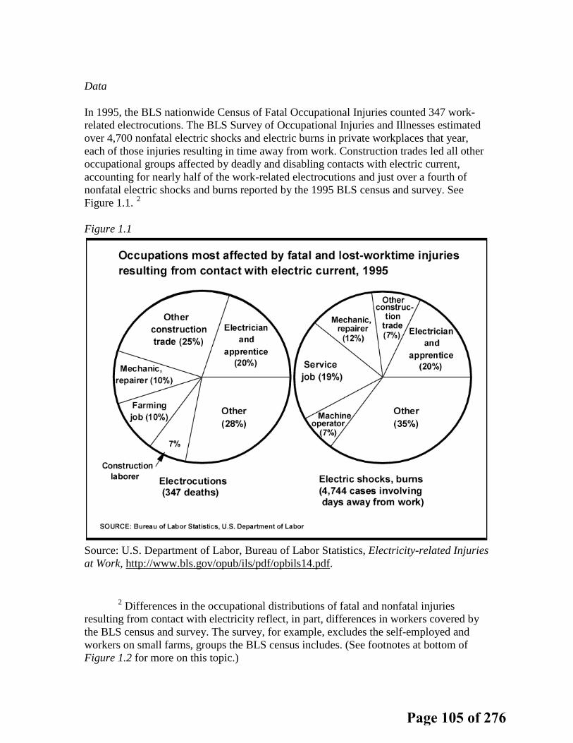
Data
In 1995, the BLS nationwide Census of Fatal Occupational Injuries counted 347 work-related electrocutions. The BLS Survey of Occupational Injuries and Illnesses estimated over 4,700 nonfatal electric shocks and electric burns in private workplaces that year, each of those injuries resulting in time away from work. Construction trades led all other occupational groups affected by deadly and disabling contacts with electric current, accounting for nearly half of the work-related electrocutions and just over a fourth of nonfatal electric shocks and burns reported by the 1995 BLS census and survey. See Figure 1.1. 2
Figure 1.1
Source: U.S. Department of Labor, Bureau of Labor Statistics, Electricity-related Injuries at Work, http://www.bls.gov/opub/ils/pdf/opbils14.pdf.
2 Differences in the occupational distributions of fatal and nonfatal injuries resulting from contact with electricity reflect, in part, differences in workers covered by the BLS census and survey. The survey, for example, excludes the self-employed and workers on small farms, groups the BLS census includes. (See footnotes at bottom of Figure 1.2 for more on this topic.)
Page 105 of 276
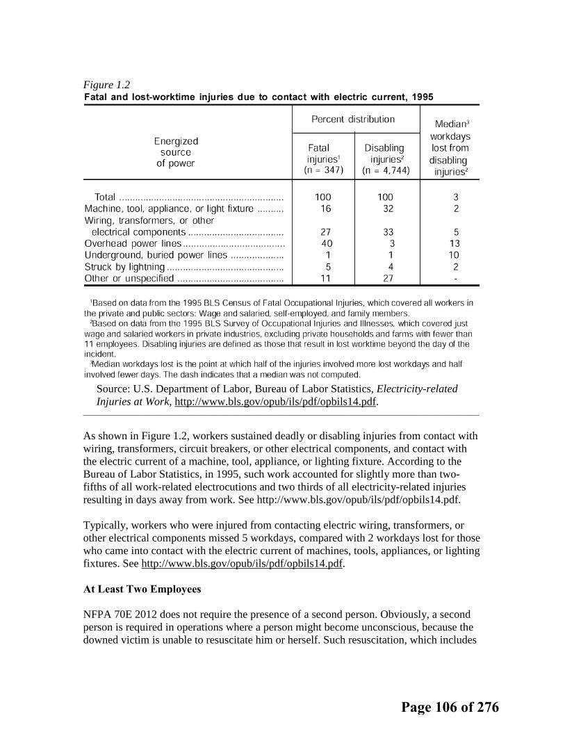
Figure 1.2
Source: U.S. Department of Labor, Bureau of Labor Statistics, Electricity-related Injuries at Work, http://www.bls.gov/opub/ils/pdf/opbils14.pdf.
___________________________________________________________________________________________________________
As shown in Figure 1.2, workers sustained deadly or disabling injuries from contact with wiring, transformers, circuit breakers, or other electrical components, and contact with the electric current of a machine, tool, appliance, or lighting fixture. According to the Bureau of Labor Statistics, in 1995, such work accounted for slightly more than two-fifths of all work-related electrocutions and two thirds of all electricity-related injuries resulting in days away from work. See http://www.bls.gov/opub/ils/pdf/opbils14.pdf. Typically, workers who were injured from contacting electric wiring, transformers, or other electrical components missed 5 workdays, compared with 2 workdays lost for those who came into contact with the electric current of machines, tools, appliances, or lighting fixtures. See http://www.bls.gov/opub/ils/pdf/opbils14.pdf. At Least Two Employees NFPA 70E 2012 does not require the presence of a second person. Obviously, a second person is required in operations where a person might become unconscious, because the downed victim is unable to resuscitate him or herself. Such resuscitation, which includes
Page 106 of 276

cardiopulmonary resuscitation and automatic external defibrillator (AED) use, is particularly beneficial to workers who are injured by an electric shock. There are many types of work in which employees suffer electric shock, including installation, repair, and testing. The presence of a second person is a reasonable consideration when a worker is working on or near energized lines or parts. The employee may be working on or near conductors or parts energized at 600 volts or less, or lines or parts energized at more than 600 volts. The employee may also be exposed to contact at more 600 volts while working on lines or parts energized at 600 volts or less. OSHA’s 29 CFR Part 1910.269 standard covers the operation and maintenance of electric power generation, control, transformation, and distribution lines and equipment. The standard requires the presence of a second person for installation of lines or equipment, if an employee is exposed to contact with other parts energized at more than 600 volts (this includes situations in which an employee is working on lines or circuit parts energized at 600 volts or less but exposed to contact with other parts energized at more than 600 volts).
1910.269(l)(1)(i) Except as provided in paragraph (l)(1)(ii) of [section 1910.269], at least two employees shall be present while the following types of work are being performed: 1910.269(l)(1)(i)(A) Installation, removal, or repair of lines energized at more than 600 volts, 1910.269(l)(1)(i)(B) Installation, removal, or repair of deenergized lines if an employee is exposed to contact with other parts energized at more than 600 volts, 1910.269(l)(1)(i)(C) Installation, removal, or repair of equipment, such as transformers, capacitors, and regulators, if an employee is exposed to contact with parts energized at more than 600 volts, 1910.269(l)(1)(i)(D) Work involving the use of mechanical equipment, other than insulated aerial lifts, near parts energized at more than 600 volts, and 1910.269(l)(1)(i)(E) Other work that exposes an employee to electrical hazards greater than or equal to those posed by operations that are specifically listed in paragraphs (l)(1)(i)(A) through (l)(1)(i)(D) of [section listed]. 1910.269(l)(1)(ii) Paragraph (l)(1)(i) of [section 1910.269] does not apply to the following operations: 1910.269(l)(1)(ii)(A) Routine circuit switching of circuits, if the employer can demonstrate that conditions at the site allow this work to be performed safely, 1910.269(l)(1)(ii)(B) Work performed with live-line tools if the employee is positioned so that he or she is neither within reach of nor otherwise exposed to contact with energized parts, and 1910.269(l)(1)(ii)(C) Emergency repairs to the extent necessary to safeguard the general public.
Because NFPA 70E covers the work practice requirements for employees working on similar equipment, requirements similar to those in OSHA’s 29 CFR Part 1910.269 standard should be adopted. Real electric-shock hazards also exist at 600 volts and below.
Page 107 of 276

Employees have sustained deadly or disabling injuries from contact with wiring, transformers, circuit breakers, or other electrical components, and contact with the electric current of a machine, tool, appliance, or lighting fixture. Indeed, it is generally recognized that life-threatening electric shock hazards exist where employees are exposed to contact with electric conductors or circuit parts operating at 50 volts or more.3
Employees working on or near energized, or potentially energized installations should be afforded the same protections as employees who are exposed to greater than 600 volts.
Proposed Two-person Requirement NFPA 70E 130.3 should be amended as follows: (Note that all language would be new to the standard.)
(C) At Least Two Employees. (1) Except as provided in 130.3(C)(2), at least two employees shall be present while any employees perform the following types of work:
(a) Installation, removal, or repair of lines energized at 50 volts or more; (b) Installation, removal, or repair of deenergized lines if an employee is
exposed to contact with other parts energized at 50 volts or more; (c) Installation, removal, or repair of equipment, such as transformers,
capacitors, and regulators, if an employee is exposed to contact with parts energized at 50 volts or more;
(d) Installation, removal, or repair of circuit parts, such as circuit breakers, fuses, control relays, and microprocessor-based components, if an employee is exposed to contact with parts energized at 50 volts or more;
(e) Work on circuits or parts, rated 50 volts or more, which are deenergized by tagout procedures only;
(f) Testing of electric circuits and parts, such as for troubleshooting, that can only be performed with the circuit energized and the routine confirmation of the absence of voltage for lockout and tagout, when the employer can demonstrate that conditions at the site allow safe performance of this work and where the required access and working space required by electrical codes (including NFPA 70 (NEC) 110.26 and 110.33) and standards are met;
(g) Work involving the use of mechanical equipment, other than insulated aerial lifts, near parts energized at 50 volts or more; and
(h) Other work that exposes an employee to electrical hazards greater than, or equal to, the electrical hazards posed by operations listed specifically in 130.3(C)(1)(a) through 130.3(C)(1)(g).
3 Although it is theoretically possible to sustain a life-threatening shock below this voltage, it is considered extremely unlikely. (Dennis K. Neitzel, CPE, "The Hazards of Electricity - Do You Know What They Are?" IEEE IAS Electrical Safety Workshop in Philadelphia, Pennsylvania, February 7-10, 2006.)
Page 108 of 276

(2) At least two employees are not required to be present for the following operations:
(a) Routine circuit switching, when the employer can demonstrate that conditions at the site allow safe performance of this work;
(b) Work performed with live-line tools when the position of the employee is such that he or she is neither within reach of, nor otherwise exposed to contact with, energized parts; and
(c) Emergency repairs to the extent necessary to safeguard the general public.
Page 109 of 276

Report on Proposals – June 2014 NFPA 70Einstallations;• Employees are potentially exposed to energized circuits or parts in order to confirm deenergization for lockout and
tagout;• Employees must often work on circuits or parts, which are energized or potentially energized, in order to troubleshoot
wiring installations or to confirm deenergization for lockout and tagout, where the required access and working spacerequired by electrical codes (including NFPA 70 (NEC) 110.26 and 110.33) and standards are not met because theequipment was installed under older standards;• Employees must often work on energized circuits or parts where the employer can demonstrate that deenergizing
introduces additional or increased hazards or is infeasible due to equipment design or operational limitations;• Employees must often work on circuits or parts that are deenergized by tagout procedures only, because of lack of a
means to attach a padlock, and are thus potentially exposed to unexpected reenergization;• Insulation systems sometimes fail; parts sometimes break free, often being triggered by employees working on or
near energized parts; and cause unexpected catastrophic (low frequency, high-impact) events;• Trauma suffered by electrical workers and those who work on or near energized electric circuits or parts often
includes electric shock, which can cause the victim to lose consciousness; and• First-aid is emergency response to a trauma, and immediate care performed by a person who is not a medical
practitioner. It is given to a sick or injured person until definitive medical treatment can be administered.The Reality of Electric TraumaIllustrative Examples
• An entry from OSHA’s Integrated Management Information System (IMIS) data base details an electrocution in whicha second person was not available to administer first aid or CPR:o Worker Is Electrocuted When Repairing Air Conditioning UnitAccident 201321429: Inspection: 312974918:On June 27, 2009, a maintenance man, was conducting electrical repair work on a 460-volt air conditioning unit. The
employee was working in an opened panel when he contacted energized parts and was electrocuted. The employeewas working alone on the roof of the facility and did not receive first aid for at least 15 minutes after the initial contact.See http://www.osha.gov/pls/imis/accidentsearch.accident_detail?id=201321429.• Another entry from OSHA’s IMIS data base, details an electrocution in which a second person was available to
administer first aid, or CPR, as required, and call for emergency medical services:o Worker Contacts Energized Part And Burns Hand
Accident: 202612180 -- Report ID: 0950612 -- Event Date: 06/25/2010At approximately 2:00 p.m. on June 25, 2010, Employee #1 and a coworker were troubleshooting a malfunctioning
refrigeration unit (Chiller Pad Number 1). Employee #1 opened the double door electrical panel of the unit to assess theissue. He turned around to speak with the coworker, and then turned back to face the open panel, when he either losthis balance, or his right ankle gave out. To stabilize himself, he extended his right bare hand and contacted a 480 Venergized part of the equipment and received second and third degree burns on his hand. The coworker turned off thepower to the unit. Emergency medical services were summoned and transported him to a medical center where he wastreated and released the same day. See http://www.osha.gov/pls/imis/accidentsearch.accident_detail?id=202612180.• A Fatal Accident Circumstances and Epidemiology (FACE) report from the National Institute for Occupational Safety
and Health (NIOSH), Division of Safety Research (DSR) details an electrocution when working on low voltage circuits:o On Sunday, April 27, 1986, a superintendent of manufacturing was electrocuted while attempting to reset electrical
relays in an electrical control box. This control panel box housed relays and circuitry for 110, 220, and 480 volt circuitsand was located in a restricted room adjacent to the production area. Shortly after the accident the companyinvestigative team found a detached 220 volt conductor in the panel box. Apparently the victim, while standing on themetal stool, was slightly off balance as he leaned into the dark control box. While attempting to maintain his balance, hesupported himself against the inside of the control panel where his right hand made contact with the 220 volt conductor.See http://www.cdc.gov/niosh/face/In-house/full8625.html.DataIn 1995, the BLS nationwide Census of Fatal Occupational Injuries counted 347 work-related electrocutions. The BLS
Survey of Occupational Injuries and Illnesses estimated over 4,700 nonfatal electric shocks and electric burns in privateworkplaces that year, each of those injuries resulting in time away from work. Construction trades led all otheroccupational groups affected by deadly and disabling contacts with electric current, accounting for nearly half of thework-related electrocutions and just over a fourth of nonfatal electric shocks and burns reported by the 1995 BLScensus and survey. See Figure 1.1.Figure 1.1Source: U.S. Department of Labor, Bureau of Labor Statistics, Electricity-related Injuries at Work,
http://www.bls.gov/opub/ils/pdf/opbils14.pdf.
70Printed on 7/13/2012
Page 110 of 276

Report on Proposals – June 2014 NFPA 70EFigure 1.2Source: U.S. Department of Labor, Bureau of Labor Statistics, Electricity-related Injuries at Work,
http://www.bls.gov/opub/ils/pdf/opbils14.pdf.___________________________________________________________________________________________________________As shown in Figure 1.2, workers sustained deadly or disabling injuries from contact with wiring, transformers, circuit
breakers, or other electrical components, and contact with the electric current of a machine, tool, appliance, or lightingfixture. According to the Bureau of Labor Statistics, in 1995, such work accounted for slightly more than two-fifths of allwork-related electrocutions and two thirds of all electricity-related injuries resulting in days away from work. Seehttp://www.bls.gov/opub/ils/pdf/opbils14.pdf.Typically, workers who were injured from contacting electric wiring, transformers, or other electrical components
missed 5 workdays, compared with 2 workdays lost for those who came into contact with the electric current ofmachines, tools, appliances, or lighting fixtures. See http://www.bls.gov/opub/ils/pdf/opbils14.pdf.At Least Two EmployeesNFPA 70E 2012 does not require the presence of a second person. Obviously, a second person is required in
operations where a person might become unconscious, because the downed victim is unable to resuscitate him orherself. Such resuscitation, which includes cardiopulmonary resuscitation and automatic external defibrillator (AED) use,is particularly beneficial to workers who are injured by an electric shock.There are many types of work in which employees suffer electric shock, including installation, repair, and testing. The
presence of a second person is a reasonable consideration when a worker is working on or near energized lines orparts. The employee may be working on or near conductors or parts energized at 600 volts or less, or lines or partsenergized at more than 600 volts. The employee may also be exposed to contact at more 600 volts while working onlines or parts energized at 600 volts or less.OSHA’s 29 CFR Part 1910.269 standard covers the operation and maintenance of electric power generation, control,
transformation, and distribution lines and equipment. The standard requires the presence of a second person forinstallation of lines or equipment, if an employee is exposed to contact with other parts energized at more than 600 volts(this includes situations in which an employee is working on lines or circuit parts energized at 600 volts or less butexposed to contact with other parts energized at more than 600 volts).1910.269(l)(1)(i) Except as provided in paragraph (l)(1)(ii) of [section 1910.269], at least two employees shall be
present while the following types of work are being performed:1910.269(l)(1)(i)(A) Installation, removal, or repair of lines energized at more than 600 volts,1910.269(l)(1)(i)(B) Installation, removal, or repair of deenergized lines if an employee is exposed to contact with other
parts energized at more than 600 volts,1910.269(l)(1)(i)(C) Installation, removal, or repair of equipment, such as transformers, capacitors, and regulators, if an
employee is exposed to contact with parts energized at more than 600 volts,1910.269(l)(1)(i)(D) Work involving the use of mechanical equipment, other than insulated aerial lifts, near parts
energized at more than 600 volts, and1910.269(l)(1)(i)(E) Other work that exposes an employee to electrical hazards greater than or equal to those posed by
operations that are specifically listed in paragraphs (l)(1)(i)(A) through (l)(1)(i)(D) of [section listed].1910.269(l)(1)(ii) Paragraph (l)(1)(i) of [section 1910.269] does not apply to the following operations:1910.269(l)(1)(ii)(A) Routine circuit switching of circuits, if the employer can demonstrate that conditions at the site
allow this work to be performed safely,1910.269(l)(1)(ii)(B) Work performed with live-line tools if the employee is positioned so that he or she is neither within
reach of nor otherwise exposed to contact with energized parts, and1910.269(l)(1)(ii)(C) Emergency repairs to the extent necessary to safeguard the general public.Because NFPA 70E covers the work practice requirements for employees working on similar equipment, requirements
similar to those in OSHA’s 29 CFR Part 1910.269 standard should be adopted. Real electric-shock hazards also exist at600 volts and below. Employees have sustained deadly or disabling injuries from contact with wiring, transformers,circuit breakers, or other electrical components, and contact with the electric current of a machine, tool, appliance, orlighting fixture. Indeed, it is generally recognized that life-threatening electric shock hazards exist where employees areexposed to contact with electric conductors or circuit parts operating at 50 volts or more. Employees working on or nearenergized, or potentially energized installations should be afforded the same protections as employees who areexposed to greater than 600 volts.
71Printed on 7/13/2012
Page 111 of 276
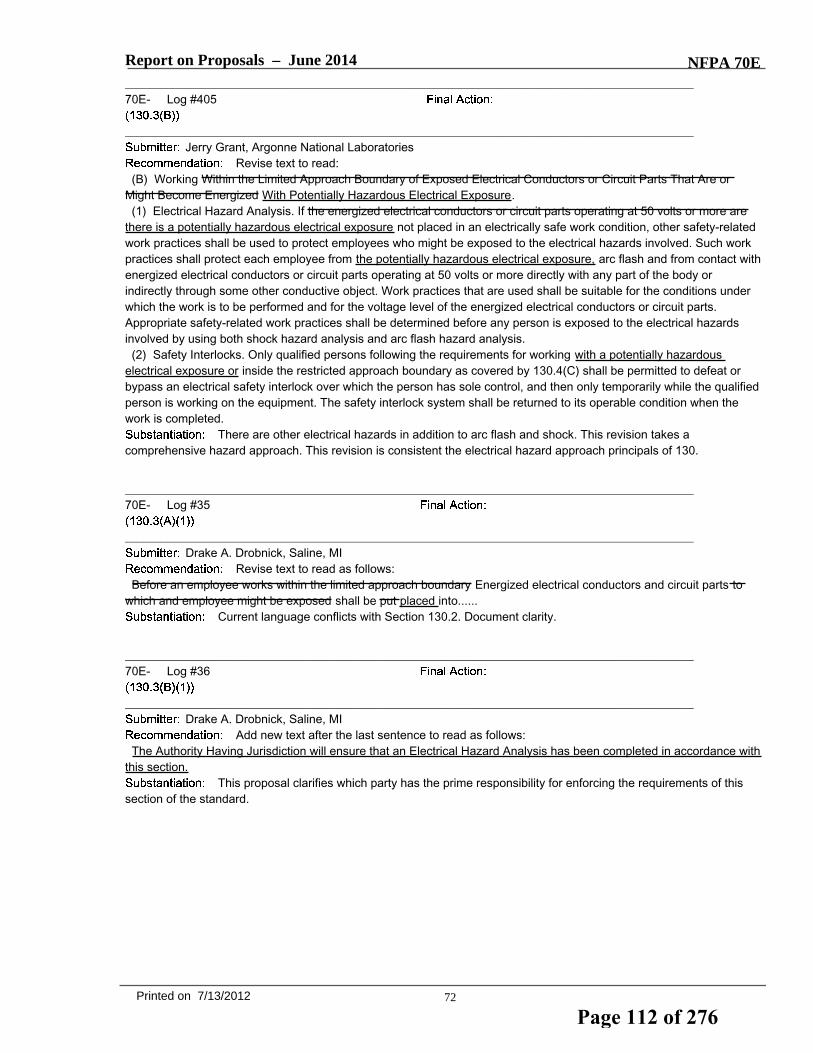
Report on Proposals – June 2014 NFPA 70E_______________________________________________________________________________________________70E- Log #405
_______________________________________________________________________________________________Jerry Grant, Argonne National Laboratories
Revise text to read:(B) Working Within the Limited Approach Boundary of Exposed Electrical Conductors or Circuit Parts That Are or
Might Become Energized With Potentially Hazardous Electrical Exposure.(1) Electrical Hazard Analysis. If the energized electrical conductors or circuit parts operating at 50 volts or more are
there is a potentially hazardous electrical exposure not placed in an electrically safe work condition, other safety-relatedwork practices shall be used to protect employees who might be exposed to the electrical hazards involved. Such workpractices shall protect each employee from the potentially hazardous electrical exposure, arc flash and from contact withenergized electrical conductors or circuit parts operating at 50 volts or more directly with any part of the body orindirectly through some other conductive object. Work practices that are used shall be suitable for the conditions underwhich the work is to be performed and for the voltage level of the energized electrical conductors or circuit parts.Appropriate safety-related work practices shall be determined before any person is exposed to the electrical hazardsinvolved by using both shock hazard analysis and arc flash hazard analysis.(2) Safety Interlocks. Only qualified persons following the requirements for working with a potentially hazardous
electrical exposure or inside the restricted approach boundary as covered by 130.4(C) shall be permitted to defeat orbypass an electrical safety interlock over which the person has sole control, and then only temporarily while the qualifiedperson is working on the equipment. The safety interlock system shall be returned to its operable condition when thework is completed.
There are other electrical hazards in addition to arc flash and shock. This revision takes acomprehensive hazard approach. This revision is consistent the electrical hazard approach principals of 130.
_______________________________________________________________________________________________70E- Log #35
_______________________________________________________________________________________________Drake A. Drobnick, Saline, MI
Revise text to read as follows:Before an employee works within the limited approach boundary Energized electrical conductors and circuit parts to
which and employee might be exposed shall be put placed into......Current language conflicts with Section 130.2. Document clarity.
_______________________________________________________________________________________________70E- Log #36
_______________________________________________________________________________________________Drake A. Drobnick, Saline, MI
Add new text after the last sentence to read as follows:The Authority Having Jurisdiction will ensure that an Electrical Hazard Analysis has been completed in accordance with
this section.This proposal clarifies which party has the prime responsibility for enforcing the requirements of this
section of the standard.
72Printed on 7/13/2012
Page 112 of 276

Report on Proposals – June 2014 NFPA 70E_______________________________________________________________________________________________70E- Log #387
_______________________________________________________________________________________________Danny Liggett, The DuPont Company, Inc.
Revise text to read:(1) Energized Electrical Conductors and Circuit Parts — Safe Work Condition. Before an employee works within the
limited approach boundary or the arc flash boundary of exposed energized conductors, the energized electricalconductors and circuit parts to which an employee might be exposed shall be put into an electrically safe work condition,unless work on energized components can be justified according to 130.2(A).
The revision of the text is to align the language with the language of 130.2(B)(1).. Having the languagealigned helps to remove any confusion at to what the requirements are.
_______________________________________________________________________________________________70E- Log #403
_______________________________________________________________________________________________Jerry Grant, Argonne National Laboratories
Revise text to read:(1) Energized Electrical Conductors and Circuit Parts — Safe Work Condition. Before an employee works within
exposed to hazardous electrical energy, within a arc flash boundry, and/or within the limited approach boundary, ofenergized electrical conductors and circuit parts to which an employee might be exposed shall be put into an electricallysafe work condition, unless work on energized components can be justified according to 130.2(A).
There are other electrical hazards in addition to arc flash and shock. This revision takes acomprehensive hazard approach. This revision is consistent the electrical hazard approach principals of 130.
_______________________________________________________________________________________________70E- Log #457
_______________________________________________________________________________________________Bobby J. Gray, Hoydar/Buck, Inc. / Rep. NFPA 70E DC Hazards Task Group
Revise text to read:(1) Electrical Hazard Analysis. If the energized electrical conductors or circuit parts operating at 50 volts or more are
not placed in an electrically safe work condition, other safety-related work practices shall be used to protect employeeswho might be exposed to the electrical hazards involved. Such work practices shall protect each employee from arcflash and from contact with energized electrical conductors or circuit parts operating at 50 volts or more directly with anypart of the body or indirectly through some other conductive object. Work practices that are used shall be suitable for theconditions under which the work is to be performed and for the voltage level of the energized electrical conductors orcircuit parts. Appropriate safety-related work practices shall be determined before any person is exposed to theelectrical hazards involved by using both shock hazard analysis and arc flash hazard analysis.
The phrase conflicts with the minimum voltage for dc hazards. This PI is a companion to PI 385. ThisPI is submitted by the NFPA 70E DC Hazards Task Group.
_______________________________________________________________________________________________70E- Log #223
_______________________________________________________________________________________________Noel Williams, Noel Williams Consulting
Add new text to read:Informational Note: For examples of safety-related design methods for including electrical hazard analysis at in
electrical design, see Annex O.Although Annex O refers to 130.3(B)(1) in its recommendations, there is no reference within the
standard itself to Annex O.
73Printed on 7/13/2012
Page 113 of 276

Report on Proposals – June 2014 NFPA 70E_______________________________________________________________________________________________70E- Log #404
_______________________________________________________________________________________________Jerry Grant, Argonne National Laboratories
Revise text to read:(2) Energized Electrical Conductors and Circuit Parts — Unsafe Work Condition. Only qualified persons shall be
permitted to work in locations with potentially hazardous electrical exposure and on electrical conductors or circuit partsthat have not been put into an electrically safe work condition.
This revision takes a comprehensive hazard approach. This revision is consistent the electrical hazardapproach principals of 130.
_______________________________________________________________________________________________70E- Log #203
_______________________________________________________________________________________________David A. Pace, Olin Corporation
Add a new 130.3(B)(2) to read as follows: When the predicted incident energy exceeds 8 cal/cm2,and the work to be done is such that PPE is required, an additional person shall be present to respond in the event of anincident. This person shall be trained in emergency procedures, or shall be in direct contact with someone who istrained in emergency procedures that can immediately respond to the incident. Renumber the existing paragraph (2) to(3).
Should an incident occur, there is a point where the energy the person would be exposed to issignificant enough that the person would be injured to the point they could not do anything to help themselves. At thispoint a second person should be required to be present to respond and provide necessary assistance. While this pointis not well defined and varies from situation to situation and from individual to individual, from conversations withindividuals who are considered knowledgeable in the subject, an exposure in excess of 8 cal/cm2 is one where theindividual involved would not likely be able to help themselves.
_______________________________________________________________________________________________70E- Log #20
_______________________________________________________________________________________________William D. Lewis, Electrical Safety Resource / Rep. McNaughton-McKay Electric
Revise text as follows:
The title does not address the content of this section which is about the and is too longfor quickly locating. This new Title will better coordinate with “Arc Flash Hazards” addressed in Section 130.5.Subsections A, B, C, and D to remain unchanged.
74Printed on 7/13/2012
Page 114 of 276

Report on Proposals – June 2014 NFPA 70E_______________________________________________________________________________________________70E- Log #172
_______________________________________________________________________________________________Palmer Hickman, Upper Marlboro, MD
Revise the title of 130.4 to read as follows:Approach Boundaries to Energized Electrical Conductors or Circuit Parts for Shock Protection.
This recommendation is intended to enhance clarity and usability. The recommendation is to revise thetitle of 130.4 to clarify the content of 130.4. The present title of 130.4 would lead the user of 70E to believe that 130.4addresses all approach boundaries while in fact it only addresses approach boundaries for shock. See also the titles toTable 130.4(C)(a) and (b) where "...for Shock Protection" is in the title to those tables.There is at least one additional approach boundary other than the three (shock) boundaries covered in 130.4; the arc
flash boundary, the present title implies that the arc flash boundary is not an approach boundary. By definition, the arcflash boundary is an approach boundary. The present title implies that the arc flash boundary is not an approachboundary.
_______________________________________________________________________________________________70E- Log #37
_______________________________________________________________________________________________Drake A. Drobnick, Saline, MI
Delete row 2: 50V-300V and expand the row 3 ranges 50V-750V.The expansion of the range removes the nebulous concept of "avoid contact." Currently this term
causes public confusion and is based upon experience from household, not commercial/industrial systems. See page 62for information on table columns 4 and 5.NOTE: If this proposal is accepted the DC tables must also be expanded. (100V-1kV).
_______________________________________________________________________________________________70E- Log #61
_______________________________________________________________________________________________Jason Wolf, The ESCO Group
Revise text to read as follows:Table 130.4(C)(a) Approach Boundaries to Energized Electrical Conductors or Circuit Parts for Shock Protection,Alternating-Current Voltage Systems.Nominal Systems Voltage Limited approach Boundary Restricted Approach Boundary Prohibited ApproachBoundary
Movable Conductor Fixed Conductor46.1 kV - 72.5 kV 3.0 m (10 ft 0 in.) 2.5m (8 ft 0 in) 1.0 m (3 ft 3 in) .7 m (2 ft 2in)
The prohibited approach boundary for 46.1 kV should be .7 meters instead of .1 meters. Conversion of2 feet 2 inches to meters equals .66 meters, rounding up to .7 meters. The change increases the prohibited approachboundary as the voltages increase.
75Printed on 7/13/2012
Page 115 of 276

Report on Proposals – June 2014 NFPA 70E_______________________________________________________________________________________________70E- Log #426
_______________________________________________________________________________________________Alvin Havens, e-Hazard Management, LLC
INSERT 70E_L426 (PI #341) Tbl 130.4(C)(a)
The 2012 70E edition containing Table 130.4(C)(a) row three column 1 lists a range of 301 - 750 volts.Various references in 29 CFR 1910 regard any voltage 601 and higher as "high voltage". Revising the 70E table willconform it to OSHA's perspective. The 2012 70E edition containing Table 130.4(C)(a) does not conform to the currentOSHA Regulation 29 CFR 1910.269 Table R6 in voltages exceeding 15 kV. While it is clear that 70E's table andOSHA's tables have differenct colunmn titles, it is also clear that 70E's Restricted Approach boundaries are equatable toOSHA's AC Live Line Minimum Approach Distances for voltages above 15 kV. Since OSHA is Administrative Law,employers and employees shall conform to the law regardless of what 70E tables state. So, if employers and employeesneed to conform to the law, revising 70E's table to confrom to OHSA's R6 table makes sense. Making this change willenable 70E instructors to affirm the use of 70E in these voltage ranges.
_______________________________________________________________________________________________70E- Log #406
_______________________________________________________________________________________________Jerry Grant, Argonne National Laboratories
Add to the bottom of Table 130.4(C)(a):NoteNotes:(1) For arc flash boundary, see 130.5(A).(2) These distances are based on atmospheric air conditions. If a different gas environment is present, adjust the
approach boundary by the dielectric breakdown constant of the gas present.Add to the bottom of Table 130.4(C)(b):Note: These distances are based on atmospheric air conditions. If a different gas environment is present, adjust the
approach boundary by the dielectric breakdown constant of the gas present.In 2011 at Argonne National Laboratory, a technician cleaning high voltage low current equipment
experienced an electrical shock. The worker was outside the prohibited approach boundary but because he was usinghelium gas the approach boundary was actually different. Helium gas has a lower dielectric breakdown constant andbecause of this condition the helium gas became the conductor between the equipment and the worker.
76Printed on 7/13/2012
Page 116 of 276

Table 130.4(C)(a) Approach Boundaries to Energized Electrical Conductors or Circuit Parts for Shock Protection for Alternating-Current Systems (All dimensions are distance from energized electrical conductor or circuit part to employee.)
(1) (2) (3) (4) (5)
Limited Approach Boundaryb Restricted Approach Boundaryb; Includes Inadvertent Movement Adder
Nominal System Voltage
Range, Phase to Phasea Exposed Movable
Conductorc Exposed Fixed
Circuit Part Prohibited Approach
Boundaryb
<50 V Not specified Not specified Not specified Not specified
50 V–300 V 3.0 m (10 ft 0 in.) 1.0 m (3 ft 6 in.) Avoid contact Avoid contact
301 V–750 V–600 V 3.0 m (10 ft 0 in.) 1.0 m (3 ft 6 in.) 0.3 m (1 ft 0 in.) 25 mm (0 ft 1 in.) 751 601 V–15 kV 3.0 m (10 ft 0 in.) 1.5 m (5 ft 0 in.) 0.7 m (2 ft 2 in.) 0.2 m (0 ft 7 in.) 15.1 kV–36 kV 3.0 m (10 ft 0 in.) 1.8 m (6 ft 0 in.) 0.8 m (2 ft 7 in.) 0.3 m (0 ft 10 in.) 36.1 kV–46 kV 3.0 m (10 ft 0 in.) 2.5 m (8 ft 0 in.) 0.8 m (2 ft 9 ft 10 in.) 0.4 m (1 ft 5 in.) 46.1 kV–72.5 kV 3.0 m (10 ft 0 in.) 2.5 m (8 ft 0 in.) 1.0 m (3 ft 3 ft 6 in.) 0.1 m (2 ft 2 in.) 72.6 kV–121 kV 3.3 m (10 ft 8 in.) 2.5 m (8 ft 0 in.) 1.0 m ( 3 ft 4 ft 3 in.) 0.8 m (2 ft 9 in.) 138 kV–145 kV 3.4 m (11 ft 0 in.) 3.0 m (10 ft 0 in.) 1.2 m ( 3 4 ft 10 11 in.) 1.0 m (3 ft 4 in.) 161 kV–169 kV 3.6 m (11 ft 8 in.) 3.6 m (11 ft 8 in.) 1.3 m (
Page 117 of 276

4 ft 3 5 ft 8 in.) 1.1 m (3 ft 9 in.) 230 kV–242 kV 4.0 m (13 ft 0 in.) 4.0 m (13 ft 0 in.) 1.7 m ( 5 ft 8 7 ft 6 in.) 1.6 m (5 ft 2 in.) 345 kV–362 kV 4.7 m (15 ft 4 in.) 4.7 m (15 ft 4 in.) 2.8 m ( 9 ft 2 12 ft 6 in.) 2.6 m (8 ft 8 in.) 500 kV–550 kV 5.8 m (19 ft 0 in.) 5.8 m (19 ft 0 in.) 3.6 m ( 11 18 ft 10 1 in.) 3.5 m (11 ft 4 in.) 765 kV–800 kV 7.2 m (23 ft 9 in.) 7.2 m (23 ft 9 in.) 4.9 m ( 15 ft 11 26 ft 0 in.) 4.7 m (15 ft 5 in.) Note: For arc flash boundary, see 130.5(A). a For single-phase systems, select the range that is equal to the system’s maximum phase-to-ground voltage multiplied by 1.732. b See definition in Article 100 and text in 130.4(D)(2) and Annex C for elaboration. cThis term describes a condition in which the distance between the conductor and a person is not under the control of the person. The term is normally applied to overhead line conductors supported by poles. Table 130.4(C)(b) Approach Boundariesa to Energized Electrical Conductors or Circuit Parts for Shock Protection, Direct-Current Voltage Systems
Page 118 of 276

Report on Proposals – June 2014 NFPA 70E_______________________________________________________________________________________________70E- Log #156
_______________________________________________________________________________________________Steven Rasmussen, Eaton Corp.
Add new text as follows:d The employee must avoid contact with the exposed parts, and the protective equipment used (such as rubber
insulating gloves) must provide insulation for the voltages involved.This letter (d) is to be placed in the row “50 V-300 V”, and added to the phrase:, “Avoid contact d”
{contained in the columns: Restricted and Prohibited Approach Boundaries} The text associated with Note d to be addedat the foot of table 130.4(C)(a).In many of my electrical safety training sessions for industrial and commercial electricians, I have been finding that the
students have been confused about the need to wear shock protection, when the Table 130.4(C)(a) indicates to …”Avoid contact”. A majority of the students believe that by avoiding contact, no requirements for voltage rated gloves aretriggered. The clarification of the need for shock protection can be extracted from 29 CFR 1910.269 appendix B ( asreferenced in Note 3 to Table R-6 of 29 CFR 1910.269).
_______________________________________________________________________________________________70E- Log #60
_______________________________________________________________________________________________Jason Wolf, The ESCO Group
Revise text to read as follows:Table 130.4(C)(b) Approach Boundaries to Energized Electrical Conductors or Circuit Parts for Shock Protection,Direct-Current Voltage Systems.a All Dimensions are distance from exposed energized electrical conductors or circuit parts to worker.b This terms describes a condition in which the distance between the conductor and a person in not under the control ofthe person.The term is normally applied to overhead line conductors supported by poles.c For DC voltages 50 - 100V, A Hazard analysis shall be conducted per 130.3(B)(1) to determine necessary safetyrelated work practices.
The standard is unclear on safe work procedures for DC voltages from 50 100V. 130.3(B)(1) clearlyexplains the need for a shock hazard analysis for energized electrical conductors or circuit parts operating at 50 V ormore. 130.4(C) clearly outlines the requirements for working in the restricted approach boundary for energized partsoperating over 50V. Table 130.4(C)(b) does not specify approach distances for Direct Current between 50 - 100 V.Referencing the table alone could lead to qualified persons not establishing the proper safe approach distances.
77Printed on 7/13/2012
Page 119 of 276

Report on Proposals – June 2014 NFPA 70E_______________________________________________________________________________________________70E- Log #229
_______________________________________________________________________________________________Lawrence S. Ayer, Biz Com Electric, Inc. / Rep. IEC
Revise Table to read:
INSERT 70E_L229 (PI #100) Tbl 130.4(C)(b)
There was no substantiation submitted during the 2012 70E revision cycle on delineating 100V DC asthe boundary below which a shock hazard does not exist. Having two different shock boundaries within the 70Edocument, one at 50V AC and one at 100V DC is confusing to the user of the standard, unless there is technicaljustification. Many technical publications state that 30V AC and 60V DC are the proper safe boundaries. The NECdistinguishes lower clearances in front of equipment at 60V DC. The NEC also indicated that live equipment should beguarded at above 50 volts. 250.162 indicates that DC systems above 50 volts but less than 300 volts shall be grounded.A DC task group was formed for the 2014 NEC code cycle which submitted proposals for DC systems and providedrequirements for above 50 / 60 volts. It would not be appropriate to have two NFPA documents or even other standardswith different safety boundaries. The committee needs to remove the 100v and replace it with 50 volts to correlate the70E document or they need to technically justify why the safe DC voltage boundary is 100 volts.
_______________________________________________________________________________________________70E- Log #107
_______________________________________________________________________________________________Bobby J. Gray, Hoydar/Buck, Inc. / Rep. NFPA 70E DC Hazards Task Group
Revise Table Note to read:a For single-phase systems, select the range that is equal to the system’s maximum phase-to-ground voltage multiplied
by 1.732. For systems supplied from single-phase sources only, the single phase voltage shall be permitted to be usedto determine approach boundary distances.
Many countries outside the US operate on a 220 volt-to-ground standard. By multiplying 220 volts by1.732, the range and distances increase over the same values as when the supply system is 120/240 volt. This createsa situation where exposure to the same voltage is perceived to be more hazardous internationally than in the US. TheStandard is growing in popularity in many other countries or by US companies doing business internationally andapplication should be consistant regardless of where it is used. This change will clarify the intent without reducing safety.
_______________________________________________________________________________________________70E- Log #458
_______________________________________________________________________________________________Bobby J. Gray, Hoydar/Buck, Inc. / Rep. NFPA 70E DC Hazards Task Group
Revise text to read:(1) The qualified person is insulated or guarded from the energized electrical conductors or circuit parts operating at 50
volts or more. Insulating gloves or insulating gloves and sleeves are considered insulation only with regard to theenergized parts upon which work is being performed. If there is a need for an uninsulated part of the qualified person’sbody to cross the prohibited approach boundary, a combination of 130.4(C)(1), 130.4(C)(2), and 130.4(C)(3) shall beused to protect the uninsulated body parts.(2) The energized electrical conductors or circuit part operating at 50 volts or more are insulated from the qualified
person and from any other conductive object at a different potential.The phrase conflicts with the minimum voltage for dc hazards. This PI is a companion to PI 385. This
PI is submitted by the NFPA 70E DC Hazards Task Group.
78Printed on 7/13/2012
Page 120 of 276

Table 130.4(C)(b) Approach Boundariesa to Energized Electrical Conductors or Circuit Parts for Shock Protection, Direct-Current Voltage Systems
(1) (2) (3) (4) (5) Nominal Potential
Difference
Limited Approach Boundary Restricted Approach Boundary; Includes Inadvertent Movement
Adder
Prohibited Approach Boundary
Exposed Movable Conductorb
Exposed Fixed Circuit Part
<100 V
<50 V Not specified Not specified Not specified Not specified
100
50 V–300 V 3.0 m (10 ft 0 in.) 1.0 m (3 ft 6 in.) Avoid contact Avoid contact 301 V–1 kV 3.0 m (10 ft 0 in.) 1.0 m (3 ft 6 in.) 0.3 m (1 ft 0 in.) 25 mm (0 ft 1 in.) 1.1 kV–5 kV 3.0 m (10 ft 0 in.) 1.5 m (5 ft 0 in.) 0.5 m (1 ft 5 in.) 0.1 m (0 ft 4 in.) 5 kV–15 kV 3.0 m (10 ft 0 in.) 1.5 m (5 ft 0 in.) 0.7 m (2 ft 2 in.) 0.2 m (0 ft 7 in.) 15.1 kV–45 kV 3.0 m (10 ft 0 in.) 2.5 m (8 ft 0 in.) 0.8 m (2 ft 9 in.) 0.4 m (1 ft 5 in.) 45.1 kV– 75 kV 3.0 m (10 ft 0 in.) 2.5 m (8 ft 0 in.) 1.0 m (3 ft 2 in.) 0.7 m (2 ft 1 in.) 75.1 kV–150 kV 3.3 m (10 ft 8 in.) 3.0 m (10 ft 0 in.) 1.2 m (4 ft 0 in.) 1.0 m (3 ft 2 in.) 150.1 kV–250 kV 3.6 m (11 ft 8 in.) 3.6 m (11 ft 8 in.) 1.6 m (5 ft 3 in.) 1.5 m (5 ft 0 in.) 250.1 kV–500 kV 6.0 m (20 ft 0 in.) 6.0 m (20 ft 0 in.) 3.5 m (11 ft 6 in.) 3.3 m (10 ft 10 in.) 500.1 kV–800 kV 8.0 m (26 ft 0 in.) 8.0 m (26 ft 0 in.) 5.0 m (16 ft 5 in.) 5.0 m (16 ft 5 in.) aAll dimensions are distance from exposed energized electrical conductors or circuit parts to worker. bThis terms describes a condition in which the distance between the conductor and a person is not under the control of the person. The term is normally applied to overhead line conductors supported by poles.
Page 121 of 276
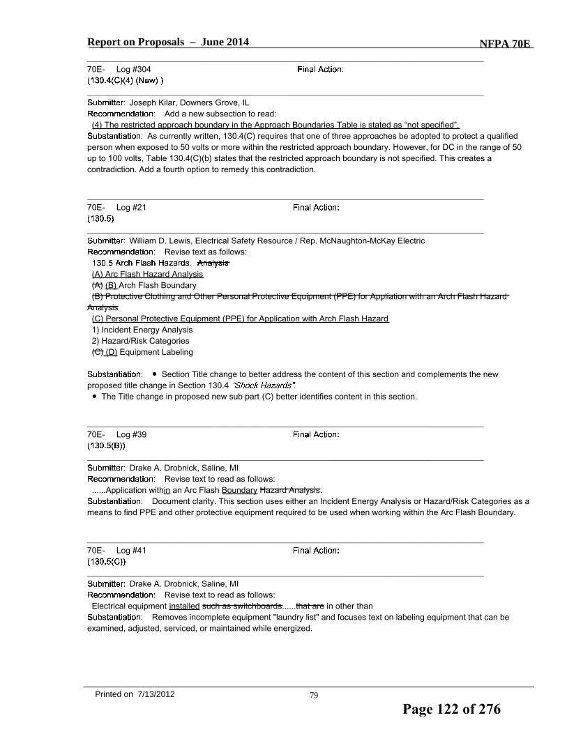
Report on Proposals – June 2014 NFPA 70E_______________________________________________________________________________________________70E- Log #304
_______________________________________________________________________________________________Joseph Kilar, Downers Grove, IL
Add a new subsection to read:(4) The restricted approach boundary in the Approach Boundaries Table is stated as “not specified”.
As currently written, 130.4(C) requires that one of three approaches be adopted to protect a qualifiedperson when exposed to 50 volts or more within the restricted approach boundary. However, for DC in the range of 50up to 100 volts, Table 130.4(C)(b) states that the restricted approach boundary is not specified. This creates acontradiction. Add a fourth option to remedy this contradiction.
_______________________________________________________________________________________________70E- Log #21
_______________________________________________________________________________________________William D. Lewis, Electrical Safety Resource / Rep. McNaughton-McKay Electric
Revise text as follows:
(A) Arc Flash Hazard Analysis(A) (B) Arch Flash Boundary(B) Protective Clothing and Other Personal Protective Equipment (PPE) for Appliation with an Arch Flash Hazard
Analysis(C) Personal Protective Equipment (PPE) for Application with Arch Flash Hazard1) Incident Energy Analysis2) Hazard/Risk Categories(C) (D) Equipment Labeling
● Section Title change to better address the content of this section and complements the newproposed title change in Section 130.4● The Title change in proposed new sub part (C) better identifies content in this section.
_______________________________________________________________________________________________70E- Log #39
_______________________________________________________________________________________________Drake A. Drobnick, Saline, MI
Revise text to read as follows:......Application within an Arc Flash Boundary Hazard Analysis.
Document clarity. This section uses either an Incident Energy Analysis or Hazard/Risk Categories as ameans to find PPE and other protective equipment required to be used when working within the Arc Flash Boundary.
_______________________________________________________________________________________________70E- Log #41
_______________________________________________________________________________________________Drake A. Drobnick, Saline, MI
Revise text to read as follows:Electrical equipment installed such as switchboards......that are in other than
Removes incomplete equipment "laundry list" and focuses text on labeling equipment that can beexamined, adjusted, serviced, or maintained while energized.
79Printed on 7/13/2012
Page 122 of 276

Report on Proposals – June 2014 NFPA 70E_______________________________________________________________________________________________70E- Log #70
_______________________________________________________________________________________________Lee R. Hale, Alcoa/Lee Hale Consulting
Revise to read:(C) Equipment Labeling. Electrical equipment such as switchboards, panelboards, industrial control panels, disconnect
switches, meter socket enclosures, and motor control centers that are in other than dwelling units, and are likely torequire examination, adjustment, servicing, or maintenance while energized, shall be field marked with a labelcontaining all the following information:
The disconnect switch where a significant amount of trouble shooting by maintenance personel shouldbe included for clarity and safety of electrical workers. The worker should be provided with the information of the hazardat the typical first point of trouble shooting, as examples, the overhead door, the roof top HVAC unit, etc.
_______________________________________________________________________________________________70E- Log #151
_______________________________________________________________________________________________Daniel T. Roberts, Schneider Electric / Rep. Hazard & Risk Ad Hoc Task Group
Revise to read:Informational Note No. 3: The occurrence of an arcing fault inside an enclosure produces a variety of physical
phenomena very different from a bolted fault. For example, the arc energy resulting from an arc developed in the air willcause a sudden pressure increase and localized overheating. Equipment and design practices are available to minimizethe energy levels and the number of at-risk procedures that require could expose an employee to be exposed tohigh-level energy sources high levels of incident energy. Proven designs such as arc-resistant switchgear, remoteracking (insertion or removal), remote opening and closing of switching devices, high-resistance grounding oflow-voltage and 5-kV (nominal) systems, current limitation, and specification of covered bus or covered conductorswithin equipment are techniques available to reduce the hazard of the system risk associated with an arc flash incident.
This is one of multiple Public Input proposals from the NFPA 70E Hazard & Risk Ad Hoc Task Groupthat seeks to clarify and promote the consistent use throughout the document of terminology associated with hazard andrisk. The proposed changes are consistent with the proposed definitions of hazard and risk.1. Proposed change to the second sentence: The context indicates that the reference is to the number of procedures
(quantity) that could expose an employee to high levels of incident energy. The use of the phrase "at-risk" is notconsistent with proposed definition of risk, and does not add value to the sentence.
2. Proposed change to the third sentence: The context indicates that the reference is to risk - either the reducingincident energy (which affects the severity of harm) or reducing likelihood of occurrence.
_______________________________________________________________________________________________70E- Log #182 EEW-AAA
_______________________________________________________________________________________________Michael A. Anthony, University of Michigan / Rep. APPA.ORG - Leadership in Education Facilities
Add new text to read as follows:
This proposal is a continuation of a discussion begun in the preceding revision cycle as Proposal 221,Log 420 submitted on behalf of an APPA.ORG member institution that needs language to limit the scope of a flashhazard study to solve an immediate problem in a specific part of their distribution system. Bright line language in thisdocument may even the playing field for facility managers and experts in the flash protection industry when it comes tohow to scale engineering effort according to the immediate job at hand.
80Printed on 7/13/2012
Page 123 of 276

Report on Proposals – June 2014 NFPA 70E_______________________________________________________________________________________________70E- Log #183 EEW-AAA
_______________________________________________________________________________________________Michael A. Anthony, University of Michigan / Rep. APPA.ORG - Leadership in Education Facilities
Revise Informational Note No. 5 in Section 130.5 as shown below:Some branch and feeder circuits may not contain enough energy to sustain an arc. See
IEEE 1584 for more information regarding arc flash hazards for three-phase systems rated less than 240 volts.
For the purpose of risk management – an essential characteristic of any safety program -- a bright linestatement about what the lower end of the electrical risk scale looks like would add to the substance of this document.Addition of this sentence makes the reference to IEEE 1584 less cryptic and tentative. While IEEE 1584 may alwaysremain a work in progress that develops out-of-step with NFPA 70E, the addition of this language gives Owners andengineers a glimpse of a possibility that will help scale their electrical safety programs. Feeder and branch circuits mightbe more easily de-energized and therefore arc-flash study budgets can emphasize higher risk parts of any given powerdistribution system.
81Printed on 7/13/2012
Page 124 of 276

Report on Proposals – June 2014 NFPA 70E_______________________________________________________________________________________________70E- Log #213
_______________________________________________________________________________________________James T. Dollard, Jr., IBEW Local 98
Revise to read:130.5 Arc Flash Hazard Analysis Identification. An arc flash hazard analysis shall determine the arc flash boundary,
the incident energy at the working distance, and the personal protective equipment that people within the arc flashboundary shall use Where it has been determined that an employee will perform justified energized work, arc flashhazards shall be identified. The arc flash hazard analysis shall be updated when a major modification or renovationtakes place. It shall be reviewed periodically, not to exceed 5 years, to account for changes in the electrical distributionsystem that could affect the results of the arc flash hazard analysis.The arc flash hazard analysis shall take into consideration the design of the overcurrent protective device and its
opening time, including its condition of maintenance.Exception: The One of the following methods shall be used to for the arc flash hazard identification:(1) Incident Energy Analysis. An arc flash hazard analysis shall determine the arc flash boundary, the incident energy
at the working distance, and the personal protective equipment that people within the arc flash boundary shall use.(2) Hazard Risk Categories. The requirements of 130.7(C)(15) and 130.7(C)(16) shall be permitted to be used in lieu of
determining the incident energy at the working distance. determine the arc flash boundary and the personal protectiveequipment that people within the arc flash boundary shall use.Informational Note No. 1: Improper or inadequate maintenance can result in increased opening time of the overcurrent
protective device, thus increasing the incident energy.Informational Note No. 2: Both larger and smaller available short-circuit currents could result in higher available arc
flash energies. If the available short-circuit current increases without a decrease in the opening time of the overcurrentprotective device, the arc flash energy will increase. If the available short-circuit current decreases, resulting in a longeropening time for the overcurrent protective device, arc flash energies could also increase.Informational Note No. 3: The occurrence of an arcing fault inside an enclosure produces a variety of physical
phenomena very different from a bolted fault. For example, the arc energy resulting from an arc developed in the air willcause a sudden pressure increase and localized overheating. Equipment and design practices are available to minimizethe energy levels and the number of at-risk procedures that require an employee to be exposed to high-level energysources. Proven designs such as arc-resistant switchgear, remote racking (insertion or removal), remote opening andclosing of switching devices, high-resistance grounding of low-voltage and 5-kV (nominal) systems, current limitation,and specification of covered bus or covered conductors within equipment are techniques available to reduce the hazardof the system.Informational Note No. 4: For additional direction for performing maintenance on overcurrent protective devices, see
Chapter 2, Safety-Related Maintenance Requirements.Informational Note No. 5: See IEEE 1584 for more information regarding arc flash hazards for three-phase systems
rated less than 240 volts.(A) Arc Flash Boundary. The arc flash boundary for systems 50 volts and greater shall be the distance at which the
incident energy equals 5 J/cm2 (1.2 cal/cm2).Informational Note: For information on estimating the arc flash boundary, see Annex D.(B) Protective Clothing and Other Personal Protective Equipment (PPE) for Application with an Arc Flash Hazard
Analysis.Where it has been determined that work will be performed within the arc flash boundary, one of the following methodsshall be used for the selection of protective clothing and other personal protective equipment (PPE):(1) Incident Energy Analysis. The incident energy analysis shall determine, and the employer shall document, the
incident energy exposure of the worker (in calories per square centimeter). The incident energy exposure level shall bebased on the working distance of the employee’s face and chest areas from a prospective arc source for the specifictask to be performed. Arc-rated clothing and other PPE shall be used by the employee based on the incident energyexposure associated with the specific task. Recognizing that incident energy increases as the distance from the arcflash decreases, additional PPE shall be used for any parts of the body that are closer than the distance at which theincident energy was determined.
Informational Note: For information on estimating the incident energy, see Annex D. For information on selection ofarc-rated clothing and other PPE, see Table H.3(b) in Annex H.
(2) Hazard/Risk Categories. The requirements of 130.7(C)(15) and 130.7(C)(16) shall be permitted to be used for theselection and use of personal and other protective equipment.
82Printed on 7/13/2012
Page 125 of 276

Report on Proposals – June 2014 NFPA 70E(C) Equipment Labeling. Equipment shall be field marked where the equipment owner or an entity designated by the
equipment owner:(1) provides conditions of maintenance and supervision ensuring that only qualified persons service the installation and(2) maintains records of all maintenance and modifications to the electrical systemElectrical equipment such as switchboards, panelboards, industrial control panels, meter socket enclosures, and motor
control centers that are in other than dwelling units, and are likely to require examination, adjustment, servicing, ormaintenance while energized, shall be field marked with a label containing all the following information:
(1) At least one of the following:a. Available incident energy and the corresponding working distanceb. Minimum arc rating of clothingc. Required level of PPEd. Hazard/Risk Category (HRC) for the equipment
(2) Nominal system voltage(3) Arc flash boundary
Exception: Labels applied prior to September 30, 2011, are acceptable if they contain the available incident energy orrequired level of PPE.The method of calculating and data to support the information for the label shall be documented.
Arc flash hazards are identified through one of two methods, an analysis or the HRC tables. A new firstsentence is added to clarify that only equipment in which justified energized work will be performed needs to beevaluated. These two methods are now in a user friendly list format. The exception is modified into positive text forclarity. As written, the present exception is an alternate method and not an exception. See 130.5(B). The proposedrevision to the parent text of 130.5 provides increased usability and clarity.The proposed revision to 130.5(C) will clarify where a label is required. The typical mindset when discussing and
applying this requirement is a venue where a full blown study is performed and all equipment is labeled. It is the ownerof such a facility that "owns" the labels. It is the owner that must monitor changes to the system and update labels. Suchowners must have "qualified persons" and engineering support. This is the case with large petrochemical companiesand other large facilities. However, in commercial, retail and other venues, no "qualified persons" exist, no engineeringsupport exists. In these venues, when there is a need for troubleshooting, or other tasks that may justify energized work,an outside contractor (installer/maintainer) will be summoned to perform the work. If this installer/maintainer places alabel on equipment, who owns the label? Is it the owner, or the installer/maintainer? In many cases, theinstaller/maintainer has never been in that building before and may never be there again. The owner of the building"owns" the label. A label should only be applied where the owner of the building has qualified persons maintaining theirsystem, engineering support and written procedures to audit labels.Without "ownership" of the label, there is no value or credibility whatsoever.
83Printed on 7/13/2012
Page 126 of 276
Report on Proposals – June 2014 NFPA 70E_______________________________________________________________________________________________70E- Log #389
_______________________________________________________________________________________________Danny Liggett, The DuPont Company, Inc.
Revise text to read:(B) Protective Clothing and Other Personal Protective Equipment (PPE) for Application with an Arc Flash Hazard
Analysis. Where it has been determined that work will be performed within the arc flash boundary, one of the followingmethods shall be used for the selection of protective clothing and other personal protective equipment (PPE): shallcomply with the following.
(1) Incident Energy Analysis. The incident energy analysis shall determine, and the employer shall document, theincident energy exposure of the worker (in calories per square centimeter). The incident energy exposure level shall bebased on the working distance of the employee’s face and chest areas from a prospective arc source for the specifictask to be performed.Informational Note: For information on estimating the incident energy, see Annex D. For information on selection of
arc-rated clothing and other PPE, see Table H.3(b) in Annex H.(2) Arc-rated clothing and other PPE shall be used by the employee based on the incident energy exposure
associated with the specific task. Recognizing that incident energy increases as the distance from the arc flashdecreases, additional PPE shall be used for any parts of the body that are closer than the distance at which the incidentenergy was determined.Informational Note: For information on estimating the incident energy, see Annex D. For information on selection of
arc-rated clothing and other PPE, see Table H.3(b) in Annex H.(2) Hazard/Risk Categories. The requirements of 130.7(C)(15) and 130.7(C)(16) shall be permitted to be used for the
selection and use of personal and other protective equipment.This PI (proposal) is in conjunction with two other PIs to move Section 130.7(C)(15 and 130.7(C)(16)
to Annex D. 70E does state which method should be use to calulate the incident energy and determine the required arcflash PPE. All other methods for making this determination are located in Annex D. It makes sense to relocate thesesections and their associated Tables to Annex D with the other methods of performing the arc flash analysis.
_______________________________________________________________________________________________70E- Log #174
_______________________________________________________________________________________________Michael A. Anthony, University of Michigan / Rep. APPA.ORG - Leadership in Education Facilities
Add new text to read:Flash hazard analysis for energized work of limited scope and of a one-time nature shall be permitted.
This proposal is a continuation of a discussion begun in the preceding revision cycle as Proposal 221,Log 420 submitted on behalf of an APPA.ORG member institution that needs language to limit the scope of a flashhazard study to solve an immediate problem in a specific part of their distribution system. Bright line language in thisdocument may even the playing field for facility managers and experts in the flash protection industry when it comes tohow to scale engineering effort according to the immediate job at hand.
84Printed on 7/13/2012
Page 127 of 276

Report on Proposals – June 2014 NFPA 70E_______________________________________________________________________________________________70E- Log #181 EEW-AAA
_______________________________________________________________________________________________Michael A. Anthony, University of Michigan / Rep. APPA.ORG - Leadership in Education Facilities
Add new text to read as follows:. In lieu of fault current calculations required to conform to Section 130.3, it shall be permitted to
install impedance measuring instruments that provide real-time measurement of utility impedance from which incidentenergy may be derived. The instrumentation shall be applied at the point where all fault current contributions may bemeasured.
This is a continuation of the discussion in Proposal-393 Log #421 of the previous revision of thisdocument. The education facilities industry in the US would like to join with other public agency purchasers of electricalequipment to use its economic footprint as a driver for innovation in electrical systems; hastening the process of gettingnascent technologies to a tipping point where economies of scale may be realized. Given that there are a significantnumber of district energy systems in this sector of the US economy where source impedance may differ significantly,instrumentation to monitor variations in utility impedance will provide essential data for calculating hazard riskcategories.In its rejection of this concept in the previous ROP the committee stated:
I do not think that the committee really means that calculated values are superior to measured values so this proposalis re-submitted to receive a more fully developed substantiation for rejection. The larger purpose, however, is to drawattention to the possibility of an affordable utility impedance meter with the hope that an electrical manufacturer will takethe concept underlying the working prototypes – there are at least 2 already built – and scale them into practicality –perhaps as part of a package of smart-grid instrumentation.Friends of the NFPA 70-series of documents have participated in a significant amount of discussion about electrical
safety and arc flash analysis for over 10 years. Some of the resistance to broader flash hazard language in the NEC hasbeen based upon concern about dynamic utility fault contribution because of changes in the impedance of the last mileof power distribution that is the point of common coupling for building services. Changing fault current complicatesincident energy calculations. This is one of a series of product solution proposals from our industry intended raise thelevel of debate on a number of innovations that present disruptive, but possibly cost-effective, solutions to the electricalsafety problem presented by flash hazard.Please refer to the attachment, and IEEE paper, authored by Thomas L. Baldwin, Michael J. Hittel, Lynn F. Saunders
and Frank Renovich Jr. titled,This document has been submitted to the NFPA 70E staff as part of this proposal and should be available to
the committee and for public review.Note: Supporting material is available for review at NFPA Headquarters.
_______________________________________________________________________________________________70E- Log #38
_______________________________________________________________________________________________Drake A. Drobnick, Saline, MI
Revise text to read as follows:......shall be permitted to be used in lieu of an Arc Flash Hazard Analysis. determining the incident energy at the
working distance.The concept we are trying to convey is that Hazard/Risk Categories can be used instead of calculating
an arc flash boundary via an analysis to determine PPE.
85Printed on 7/13/2012
Page 128 of 276

Report on Proposals – June 2014 NFPA 70E_______________________________________________________________________________________________70E- Log #42
_______________________________________________________________________________________________Drake A. Drobnick, Saline, MI
Add new text as last sentence to read as follows:Labels shall be reviewed and updated whenever changes are made to corresponding electrical equipment such as
short current and fault clearing time parameters and at 5 year intervals.Document clarity. Explains that the intent of the exception did not "grandfather" existing labels
indefinitely.
_______________________________________________________________________________________________70E- Log #388
_______________________________________________________________________________________________Danny Liggett, The DuPont Company, Inc.
Delete all of the Exception.This PI (proposal) is in conjunction with two other PIs to move Section 130.7(C)(15 and 130.7(C)(16)
to Annex D. 70E does state which method should be use to calulate the incident energy and determine the required arcflash PPE. All other methods for making this determination are located in Annex D. It makes sense to relocate thesesections and their associated Tables to Annex D with the other methods of performing the arc flash analysis.
_______________________________________________________________________________________________70E- Log #416
_______________________________________________________________________________________________John McAlhaney, Savannah River Nuclear Solutions
Add a new excepti8on to read:Exception: Generic arc flash warning labels may be used without the specific information in (1), (2) and (3) above if the
information is otherwise readily available to the worker through an electronic tablet, personal digital assistant or otherwireless communications link to a central label database or platform.
The proposed change will allow a worker to use modern technology to retrieve arc flash and shockdata for a specific equipment location from an electronic pad or wireless link to a database. Electronic storage of thedata will allow additional flexiblity of providing more information to the worker than can be provided on a label such asmultiple working distance information, special work instructions and safety notes, etc. and will allow integration into theelectronic work order system. Also, reposting of new arc flash labels will not be required when an analysis is revised andthe information is changed.
86Printed on 7/13/2012
Page 129 of 276

Report on Proposals – June 2014 NFPA 70E_______________________________________________________________________________________________70E- Log #311
_______________________________________________________________________________________________T. David Mills, Savannah River Nuclear Solutions, LLC
Add a new Exception to read:An arc flash hazard analysis shall determine the arc flash boundary, the incident energy at the working distance, and
the personal protective equipment that people within the arc flash boundary shall use.The arc flash hazard analysis shall be updated when a major modification or renovation takes place. It shall be
reviewed periodically, not to exceed 5 years, to account for changes in the electrical distribution system that could affectthe results of the arc flash hazard analysis.Exception: A 5-year review is not required if there is a program in place that assures that any changes in the electrical
distribution systemare screened against the arc flash analysis upon which it may have an impact.Adding a 5-year review of all analyses that a facility may have is unwarranted if there is in place a
system by which the facility monitors electrical distribution changes for impact on an ongoing basis. There are manyfacilities such as ours that have literally thousands of arc flash calculations and to require that each be reviewedperiodically without consideration of other methodologies already employed to assure they are revised according to thechanges in the electrical distribution system is overly burdensome. For example, we have an engineering requirementthat any modifications made to an electrical distribution system must review the impact to any associated arc flashcalculation prior to obtaining authorization to energize the system. Please consider adding this exception.
_______________________________________________________________________________________________70E- Log #310
_______________________________________________________________________________________________T. David Mills, Savannah River Nuclear Solutions, LLC
Delete the Exception and Informational Notes in its entirety.Section 130.5(C) requires a calculation of incident energy to be implemented which renders the Tables
130.7(C)(15)(a) and (b) useless, since there cannot be an alternative method to determine the label information. This isa built-in conflict which the AHJ has no recourse without an enforcement clause in Article 90.
_______________________________________________________________________________________________70E- Log #40
_______________________________________________________________________________________________Drake A. Drobnick, Saline, MI
Revise text to read as follows:The determination incident energy exposure level shall be......arc source. for the specific task to be performedArc-related clothing......energy exposure. associated with the specific task
Document clarity. An Incident Energy Analysis is conducted on a piece of equipment at a workingdistance, not a task.
87Printed on 7/13/2012
Page 130 of 276

Report on Proposals – June 2014 NFPA 70E_______________________________________________________________________________________________70E- Log #105
_______________________________________________________________________________________________Bobby J. Gray, Hoydar/Buck, Inc. / Rep. NFPA 70E DC Hazards Task Group
Revise to read:(1) Incident Energy Analysis. The incident energy analysis shall determine, and the employer shall document, the
incident energy exposure of the worker (in calories per square centimeter). The incident energy exposure level shall bebased on the working distance of the employee’s face and chest areas from a prospective arc source for the specifictask to be performed. Arc-rated clothing and other PPE shall be used by the employee based on the incident energyexposure associated with the specific task. Recognizing that incident energy increases as the distance from the arcflash decreases, additional PPE shall be used for any parts of the body that are closer than the distance at which theincident energy was determined. The method used to determine incident energy exposure level shall be approved.
As written, there is no restriction on the method or methods used to determine incident energyexposure. Literally, an employer could guess at the exposure level without using any investigation or recognizedcalculation method to determine values. This could result in a worker inadequately protected from arc flash. This changewould require the method to be acceptable to the Authority Having Jurisdiction.
_______________________________________________________________________________________________70E- Log #162
_______________________________________________________________________________________________Daryld Ray Crow, DRC Consulting, Ltd.
Revise 130.5(C)(1) as follows:(1) At least One of the following:
d. Highest Hazard/Risk Category (HRC) for the equipment Use the Hazard/Risk Category tables in NFPA 70E toselect the PPE required for the task.
The (1) Incident Energy Analysis and (2) Hazard/Risk Categories are methods for selecting protectiveclothing and other personal protective equipment (PPE). Either, but not both, methods may be used on the same pieceof equipment. Revising 130.5(C)(1) as stated above will add clarity.
_______________________________________________________________________________________________70E- Log #150
_______________________________________________________________________________________________Daniel T. Roberts, Schneider Electric / Rep. Hazard & Risk Ad Hoc Task Group
Revise to read:(2) Hazard/Risk Arc Flash Personal Protective Equipment (PPE) Categories. The requirements of 130.7(C)(15) and
130.7(C)(16) shall be permitted to be used for the selection and use of personal and other protective equipment.This is one of multiple Public Input proposals from the NFPA 70E Hazard & Risk Ad Hoc Task Group
that seeks to clarify and promote the consistent use throughout the document of terminology associated with hazard andrisk.The intent of this proposal is to provide consistency between NFPA 70E and other standards that address hazards and
risk, and with the proposed definitions of hazard, risk and risk assessment. As defined in most standards, hazardidentification is a component of risk assessment. This proposed change will also provide guidance for future revisions ofthe Standard.By proposing that this title be changed to “Arc Flash Personal Protective Equipment (PPE) Categories,” this proposal
seeks to supplement the global change to “Hazard/Risk Categories” with the intent that all other references in thedocument may be shortened to “Arc Flash PPE Categories” (or “Category”).
88Printed on 7/13/2012
Page 131 of 276

Report on Proposals – June 2014 NFPA 70E_______________________________________________________________________________________________70E- Log #312
_______________________________________________________________________________________________T. David Mills, Savannah River Nuclear Solutions, LLC
Revise text to read:(2) Hazard/Risk Categories. The requirements of 130.7(C)(15) and 130.7(C)(16) shall be permitted to be used for the
selection and use of personal and other protective equipment.Section 130.5(C) requires a calculation of incident energy to be implemented which renders the Tables
130.7(C)(15)(a) and (b) useless, since there cannot be an alternative method to determine the label information. This isa built-in conflict which the AHJ has no recourse without an enforcement clause in Article 90.
_______________________________________________________________________________________________70E- Log #160
_______________________________________________________________________________________________Daryld Ray Crow, DRC Consulting, Ltd.
Add new text as follows:(3) The Incident Energy Analysis and Hazard/Risk Categories are methods that shall be permitted for selecting
protective clothing and other personal protective equipment (PPE). Either, but not both, methods may be used on thesame piece of equipment.
The IN needs to be added to 130.5(B) to add clarity to NFPA 70E. The above methods for stating thePPE protection required is not prohibited in NFPA 70E. Adding this IN will resolve this issue.
_______________________________________________________________________________________________70E- Log #161
_______________________________________________________________________________________________Daryld Ray Crow, DRC Consulting, Ltd.
Add new text as follows:(3) The Incident Energy Analysis and Hazard/Risk Categories are methods that shall be permitted for selectingprotective clothing and other personal protective equipment (PPE). Either, or both, methods may be used on the samepiece of equipment if all requirements for the respective method are met.
The IN needs to be added to 130.5(B) to add clarity to NFPA 70E. The above methods for stating thePPE protection required is not prohibited in NFPA 70E. Adding this IN will resolve this issue.
_______________________________________________________________________________________________70E- Log #43
_______________________________________________________________________________________________Drake A. Drobnick, Saline, MI
Add new last sentence to read as follows:Doors shall open at least 90°.
Complies with NEC Section 110.26(A)(2) and ensures proper work clearances for the worker.
89Printed on 7/13/2012
Page 132 of 276

Report on Proposals – June 2014 NFPA 70E_______________________________________________________________________________________________70E- Log #62
_______________________________________________________________________________________________Jason Wolf, The ESCO Group
Revise text to read as follows:Conductive Articles Being Worn. Conductive articles of jewelry and clothing (such as watchbands bracelets, rings, keychains, necklaces, metalized aprons, cloth with conductive thread, metal head gear or metal frame glasses) shall not beworn within the Restricted Approach Boundary or where they present an electrical contact hazard with exposedenergized electrical conductor or circuit parts.
130.4(C) clearly states no qualified worker shall approach or take any conductive object closer than therestricted approach boundary.130.6(0) states conductive article being worn shall not be worn where they present an electrical contact hazard.Revision of the 130.6(0) text to include the restricted approach boundary would clearly outline where an electricalcontact hazard could exist.
_______________________________________________________________________________________________70E- Log #409
_______________________________________________________________________________________________Jerry Grant, Argonne National Laboratories
Revise text to read:(H) Housekeeping Duties. Employees shall not perform housekeeping duties inside with a hazardous electrical energy
exposure, arc flash hazard and/or inside the limited approach boundary where there is a possibility of contact withenergized electrical conductors or circuit parts, unless adequate safeguards (such as insulating equipment or barriers)are provided to prevent contact. Electrically conductive cleaning materials (including conductive solids such as steelwool, metalized cloth, and silicone carbide, as well as conductive liquid solutions) shall not be used inside the limitedapproach boundary unless procedures to prevent electrical contact are followed.
There are other electrical hazards in addition to arc flash and shock. This revision takes acomprehensive hazard approach. This revision is consistent with the principals of 130.1A1.
_______________________________________________________________________________________________70E- Log #449
_______________________________________________________________________________________________Paul Dobrowsky, Holley, NY
Add new text to read:130.6(H) Clear Spaces.
This language is copied from NEC 110.26 and 110.34. Although the requirement prohibiting the spaceto be used for storage is a consideration during the installation it is actually a work practice that needs to be continuallyenforced by the employer. The second sentence is also a work practice that the employer needs to implement, typicallywell after the AHJ has approved the installation.The existing (H) and following subdivisions will need to be re-lettered.
90Printed on 7/13/2012
Page 133 of 276

Report on Proposals – June 2014 NFPA 70E_______________________________________________________________________________________________70E- Log #462
_______________________________________________________________________________________________Bobby J. Gray, Fluor / Rep. NFPA 70E DC Hazards Task Group
Revise text to read:(F) Confined or Enclosed Work Spaces. When an employee works in a confined or enclosed space (such as a
manhole or vault) that contains exposed energized electrical conductors or circuit parts operating at 50 volts or more, orwhere an electrical hazard exists, the employer shall provide, and the employee shall use, protective shields, protectivebarriers, or insulating materials as necessary to avoid inadvertent contact with these parts and the effects of theelectrical hazards.
The phrase conflicts with the minimum voltage for dc hazards. This PI is a companion to PI 385. ThisPI is submitted by the NFPA 70E DC Hazards Task Group.
_______________________________________________________________________________________________70E- Log #463
_______________________________________________________________________________________________Bobby J. Gray, Fluor / Rep. NFPA 70E DC Hazards Task Group
Revise text to read:(G) Doors and Hinged Panels. Doors, hinged panels, and the like shall be secured to prevent their swinging into an
employee and causing the employee to contact exposed energized electrical conductors or circuit parts operating at 50volts or more or where an electrical hazard exists if movement of the door, hinged panel, and the like is likely to create ahazard.
The phrase conflicts with the minimum voltage for dc hazards. This PI is a companion to PI 385. ThisPI is submitted by the NFPA 70E DC Hazards Task Group.
_______________________________________________________________________________________________70E- Log #407
_______________________________________________________________________________________________Jerry Grant, Argonne National Laboratories
Add a new section to read:130.6x Combustible Materials in Arc Flash Hazard Work Area. Combustible materials shall not be in a work area with a
potential arc flash hazard. Combustible materials (for example: cigarettes, lighters, and paper) shall not be on a workerexposed to an arc flash hazard.
An arc flash is potentially more hazardous when combustible materials are exposed to the arc flashenergy as an ignition source.April 14, 2006 an arc flash accident occurred at Brookhaven National Laboratory. This arc flash incident report indicatedwith an enclosed fused switch arc flash that ignited papers and fire fighters extinguished the fire.Brookhaven National Laboratory Arc Flash incident 2006 report link:
http://www.hss.doe.gov/sesa/corporatesafety/aip/docs/accidents/typeb/BNL_TypeB_041406.pdfExcerpt from Brookhaven National Laboratory Arc Flash incident report Page 38: “The firefighters used one, halon
1211 fire extinguisher to extinguish the burning papers (e.g., drawings, schematics, notes) that had been set on fire bythe arc flash.”Technical Basis:1. NFPA 1 (2012) 10.19* Storage of Combustible Materials. 10.19.5 Equipment Rooms. 10.19.5.1 5.4.1* Combustible
material shall not be stored in boiler rooms, mechanical rooms, or electrical equipment rooms.2. NFPA 241 (2009) 5.4 Waste Disposal. 5.4.1* Accumulations of combustible waste material, dust, and debris shall be
removed from the structure and its immediate vicinity at the end of each work shift or more frequently as necessary forsafe operations.
91Printed on 7/13/2012
Page 134 of 276

Report on Proposals – June 2014 NFPA 70E_______________________________________________________________________________________________70E- Log #408
_______________________________________________________________________________________________Jerry Grant, Argonne National Laboratories
Add a new section to read:130.6x Storage of Combustible Materials. Combustible material shall not be stored in boiler rooms, mechanical rooms,
or electrical equipment rooms. Accumulations of combustible waste material, dust, and debris shall be removed from thestructure and its immediate vicinity at the end of each work shift or more frequently as necessary for safe operations.
An arc flash is potentially more hazardous when combustible materials are exposed to the arc flashenergy as an ignition source.April 14, 2006 an arc flash accident occurred at Brookhaven National Laboratory. This arc flash incident report indicatedwith an enclosed fused switch arc flash that ignited papers and fire fighters extinguished the fire.Brookhaven National Laboratory Arc Flash incident 2006 report link:
http://www.hss.doe.gov/sesa/corporatesafety/aip/docs/accidents/typeb/BNL_TypeB_041406.pdfExcerpt from Brookhaven National Laboratory Arc Flash incident report Page 38: “The firefighters used one, halon
1211 fire extinguisher to extinguish the burning papers (e.g., drawings, schematics, notes) that had been set on fire bythe arc flash.”Technical Basis:1. NFPA 1 (2012) 10.19* Storage of Combustible Materials. 10.19.5 Equipment Rooms. 10.19.5.1 5.4.1* Combustible
material shall not be stored in boiler rooms, mechanical rooms, or electrical equipment rooms.2. NFPA 241 (2009) 5.4 Waste Disposal. 5.4.1* Accumulations of combustible waste material, dust, and debris shall be
removed from the structure and its immediate vicinity at the end of each work shift or more frequently as necessary forsafe operations.
_______________________________________________________________________________________________70E- Log #155
_______________________________________________________________________________________________Daniel T. Roberts, Schneider Electric / Rep. Hazard & Risk Ad Hoc Task Group
Revise to read:(1) When Hazardous Electrical Hazards Might Exist. Employees shall be instructed to be alert at all times when they
are working within the limited approach boundary of energized electrical conductors or circuit parts operating at 50 voltsor more and in work situations where when electrical hazards might exist.
This is one of multiple Public Input proposals from the NFPA 70E Hazard & Risk Ad Hoc Task Groupthat seeks to clarify and promote the consistent use throughout the document of terminology associated with hazard andrisk.The proposed change to the title provides clarity and consistency with the text that follows. “Electrical hazard” is a
defined term.
_______________________________________________________________________________________________70E- Log #239
_______________________________________________________________________________________________Daniel T. Roberts, Schneider Electric / Rep. Hazard & Risk Ad Hoc Task Group
Revise text to read: (1) General. Employees shall not enter spaces containing where electrical hazards exist unless illumination is provided
that enables the employees to perform the work safely.This is one of multiple Public Input proposals from the NFPA 70E Hazard & Risk Ad Hoc Task Group
that seeks to clarify and promote the consistent use throughout the document of terminology associated with hazard andrisk.The editorial revision provides clarity and consistency with the rest of the document (e.g. see 130.6(A)(1)).
92Printed on 7/13/2012
Page 135 of 276
Report on Proposals – June 2014 NFPA 70E_______________________________________________________________________________________________70E- Log #459
_______________________________________________________________________________________________Bobby J. Gray, Hoydar/Buck, Inc. / Rep. NFPA 70E DC Hazards Task Group
Revise text to read: (1) When Hazardous. Employees shall be instructed to be alert at all times when they are working within the limited
approach boundary of energized electrical conductors or circuit parts operating at 50 volts or more and in worksituations where electrical hazards might exist.
The phrase conflicts with the minimum voltage for dc hazards. This PI is a companion to PI 385. ThisPI is submitted by the NFPA 70E DC Hazards Task Group.
_______________________________________________________________________________________________70E- Log #418
_______________________________________________________________________________________________John McAlhaney, Savannah River Nuclear Solutions
Add a new section to read:(1) General. Employees shall be instructed to stand off to side of switch or circuit breaker while it is being operated if
there is potential for the employee to be exposed to an electrical hazard.Standing to the side of a breaker or switch during operation reduces a person's exposure to injury if an
electrical explosion occurs. Testing performed by Hugh Hoagland has validated that the explosion will force doors openand the pressure wave, gases and molten metal parts is directed outward. If the person is standing off to the side, theexposure from this hazard is much less and reduces the potential for injury to a worker.
_______________________________________________________________________________________________70E- Log #460
_______________________________________________________________________________________________Bobby J. Gray, Fluor / Rep. NFPA 70E DC Hazards Task Group
Revise text to read: (2) When Impaired. Employees shall not be permitted to work within the limited approach boundary of energized
electrical conductors or circuit parts operating at 50 volts or more, or where other electrical hazards exist, while theiralertness is recognizably impaired due to illness, fatigue, or other reasons.
The phrase conflicts with the minimum voltage for dc hazards. This PI is a companion to PI 385. ThisPI is submitted by the NFPA 70E DC Hazards Task Group.
_______________________________________________________________________________________________70E- Log #461
_______________________________________________________________________________________________Bobby J. Gray, Fluor / Rep. NFPA 70E DC Hazards Task Group
Revise text to read:(2) Obstructed View of Work Area. Where lack of illumination or an obstruction precludes observation of the work to be
performed, employees shall not perform any task within the limited approach boundary of energized electricalconductors or circuit parts operating at 50 volts or more or where an electrical hazard exists.
The phrase conflicts with the minimum voltage for dc hazards. This PI is a companion to PI 385. ThisPI is submitted by the NFPA 70E DC Hazards Task Group.
93Printed on 7/13/2012
Page 136 of 276

Report on Proposals – June 2014 NFPA 70E_______________________________________________________________________________________________70E- Log #417
_______________________________________________________________________________________________John McAlhaney, Savannah River Nuclear Solutions
Revise text to read: (3) Changes in Scope. Employees shall be instructed to be alert and notify the person-in-charge or job supervisor for
changes in the job or task that may lead the person outside of the electrically safe work condition or expose the personto additional hazards that were not part of the original plan.
The employer must ensure that the worker takes appropriate action to notify supervision if they believethe job scope is changing that may create a condition that has not been analyzed for hazards. Otherwise, the employeemay feel schedule driven and continue with the work that could result in higher risk of injury.
_______________________________________________________________________________________________70E- Log #157
_______________________________________________________________________________________________Michael A. Anthony, University of Michigan / Rep. APPA.ORG - Leadership in Education Facilities
Add the following to this section:
This is a familiar proposal to many members of this committee and I am happy to report that the NECcommittee’s acceptance of this extremely simple, inexpensive – and intuitively obvious -- requirement has grown. Letus start by revisiting with a link to the evidence.
http://www.youtube.com/watch?v=4bBvmPRqfmo(If the link has been relocated, a search on “Arc Flash Accident” will reveal a tragic loss of life with rescue and recovery
operations complicated by the absence of illumination.)This proposal is one of several proposals submitted to technical committees (NFPA 70, 70B, 101 and 5000) intended
to provide an illuminated egress and ingress path for:a) the electrician who is working in the service equipment area without a flashlightb) the maintenance mechanic - or general occupant -- who may neither be an electrician nor familiar with the electric
service equipment to work on it in the dark.
Electric service panels are not always installed along either the primary or secondary egress path required by the LifeSafety Code. The cost of making this mandatory is relatively small -- on the order of $100-$250 per installation. Forvery little cost, having illumination instantly available in electric rooms will help electricians either find their own way tosafety or make it easier for rescue personnel to find them. Because generators may take up to 10- seconds to respondthis proposal necessarily requires central battery or packaged unit lighting apparatus to make illumination instantlyavailable.
When this committee rejected this proposal last cycle because “There is inadequate substantiation to require additionallighting beyond what is currently required by 130.6(C)(1)”. The clip offered as rebuttal to the claim.
This is proposal is a continuation of a proposal (1-218, Log #2401) that began in the 2005 National Electric Code cycleby David Williams, Chief Electrical Inspector of Delta Township, Michigan. Having been shopped around for over sevenyears, we now have a nearly perfect circle of fingers pointing other committees. This finger-pointing should stop in thisdocument with its acceptance.
94Printed on 7/13/2012
Page 137 of 276

Report on Proposals – June 2014 NFPA 70E_______________________________________________________________________________________________70E- Log #1
_______________________________________________________________________________________________Palmer Hickman, Upper Marlboro, MD
Revise text to read as follows:(C) Personal and Other Protective Equipment.
Add "and Other" to the title of 130.3(C) to recognize that Other Protective Equipment such as insulatedtools is covered in 130.3(C) in locations such as Table 130.7(C)(15)(a) and Table 130.7(C)(15)(b). INsulated tools areclassified as Other Protective Equipment per 130.7(D),
_______________________________________________________________________________________________70E- Log #22
_______________________________________________________________________________________________William D. Lewis, Electrical Safety Resource / Rep. McNaughton-McKay Electric
Revise text as follows:● and Other .● Care of Equipment to be relocated to a new Section 130.7(B)(9) subpart● to (B) and keep old title Personal Protective Equipment.● to new subparts● Add relocated “Care of Equipment” to a new Section 130.7(B)9).● Add new Section 130.7(C) “Factors in Selection of Protective Clothing”● Add new Section 130.7(D) “Arc Flash Protective Equipment”● Add new Section 130.7(E) “Selection of Personal Protective Equipment”● Add new Section 130.7(F) “Other Clothing Characteristic.
Section 130.7(C) has too much PPE information included in this one subpart which make it hard tolocated the proper information. This reorganization of Section 130.7(C) is an attempt to further sub divide this PPEinformation into more definable sub section for easier identification
_______________________________________________________________________________________________70E- Log #44
_______________________________________________________________________________________________Drake A. Drobnick, Saline, MI
Delete all text after de-energizing.The current language only addresses the shock dimension, not the arc flash considerations. At 40
cals. and greater we are concerned about blast effects and physical trauma.
95Printed on 7/13/2012
Page 138 of 276
Report on Proposals – June 2014 NFPA 70E_______________________________________________________________________________________________70E- Log #87
_______________________________________________________________________________________________Daryld Ray Crow, DRC Consulting, Ltd.
Revise to read: Informational Note No. 2: It is the collective experience of the Technical Committee on Electrical Safety in the
Workplace that normal operation of enclosed electrical equipment, operating at 600 volts or less, that has been properlyinstalled and maintained by qualified persons is not likely to expose the employee to an electrical hazard. However,Protective clothing and PPE are required when interacting with this equipment in such a manner that could cause an arcflash.
Normal operation of equipment does not mean when a person is interacting with the equipment.Normal operation of equipment means when the equipment is operating as designed and a person is not interacting withthe equipment in such a manner that could cause an arc flash or fault to occur. Informational Note 2 in 130.7(A) shouldnot be interpreted to be in conflict with Informational Note 2 in Article 130.7(C)(15).
_______________________________________________________________________________________________70E- Log #170
_______________________________________________________________________________________________Daryld Ray Crow, DRC Consulting, Ltd.
Revise text to read as follows:130.7(A) Informational Note No. 2 - It is the collective experience of the Technical Committee on Electrical Safety in
the Workplace that normal operation of enclosed electrical equipment, operating at 600 volts or less, that has beenproperly installed and maintained by qualified persons is not likely to expose the employee to an electrical hazard.However, Protective clothing and PPE are required when interacting with this equipment in such a manner that couldcause an arc flash.
Normal operation of equipment does not mean when a person is interacting with the equipment.Normal operation of equipment means when the equipment is operating as designed and a person is not interacting withthe equipment in such a manner that could cause an arc flash or fault to occur. IN # 2 in 130.7(A) should not beinterpreted to be in conflict with IN # 2 in article 130.7(C)(15).
96Printed on 7/13/2012
Page 139 of 276

Report on Proposals – June 2014 NFPA 70E_______________________________________________________________________________________________70E- Log #434
_______________________________________________________________________________________________Terry W. Becker, ESPS Inc.
Delete the following text:Informational Note No. 3: When incident energy exceeds 40 cal/cm2 at the working distance, greater emphasis may be
necessary with respect to de-energizing before working within the limited approach boundary of the exposed electricalconductors or circuit parts.
There is no substantiation offered on why greater emphasis should be considered when incidentenergy is 40 cal/cm2. Arc rated PPE technology has evolved and arc flash suits are available with an ATPV of 65cal/cm2, 100 cal/cm2 and 140 cal/cm2.Some users of NFPA 70E are wrongly interpreting this statement such that they believe NFPA 70E is advising that no
work greater than 40 cal/cm2 is allowed, which is a false statement.If the historical decision in the late 1990s was made purely on availability of arc rated clothing then this assumption is
no longer valid with the evolution of arc flash suits that now are lighter in overall fabric weight, have vastly improvedVisual Light Transmission (VLT) or the lens, and very effective hood ventilation systems.This was not the case on the late 1990s when I believe the highest ATPV arc flash suit was 31 cal/cm2.Additionally if this decision was made based on arc blast pressure then it should be removed as arc blast pressure can
be high at lower incident energy levels and higher incident energy levels, so making a statement with respect to 40cal/cm2 greater emphasis is technically incorrect. Arc blast pressure relates to arcing fault current and not incidentenergy.There is currently no new information on arc flash pressure other than that presented by Dr. Ralph Lee in the 1980s,
several IEEE ESW Papers and the IEEE Yellow Book (now 3007. Series). Experts that complete arc flash testing, alsoconcur that arc blast pressure is related to arcing current.User of NFPA 70E need to analyze the electrical hazards and should make decisions with respect to policy in a
documented Electrical Safety Program reviewing all available information and then the employer decides whenenergized
_______________________________________________________________________________________________70E- Log #439
_______________________________________________________________________________________________Michael Milbert, NASA GLENN RESEARCH CENTER / Rep. NESWG
Revise text to read:Informational Note No. 2: It is the collective experience of the Technical Committee on Electrical Safety in the
Workplace that normal operation of enclosed electrical equipment, operating at 600 volts or less, that has been properlyinstalled and maintained by qualified persons and so documented is not likely to expose the employee to an electricalhazard.
To ensure documentation exists that captures the proper installation and maintenance of the enclosedelectrical equipment as part of the Electrical Safety Program, in terms of configuration control. Thereby, the reduced riskfor operation of this nominal equipment is understood and addressed in writing.
97Printed on 7/13/2012
Page 140 of 276
Report on Proposals – June 2014 NFPA 70E_______________________________________________________________________________________________70E- Log #431
_______________________________________________________________________________________________Marcia L. Eblen, Pacific Gas & Electric
Add a row to table 130.7(F)Change Table row for insulation sheeting to be as shown below:
Sheeting Standard Specification for PVC Insulating Sheeting ASTM F 1742 - 03(2011)Standard Specification for Rubber Insulating Sheeting ASTM F2320 - 11
INCLUDE 70E_L431 (PI #359) Rec
Reference to newly created ASTM standard for rubber insulating sheeting is missing from table. Thiswill make the table complete.
_______________________________________________________________________________________________70E- Log #110
_______________________________________________________________________________________________Bobby J. Gray, Hoydar/Buck, Inc. / Rep. NFPA 70E DC Hazards Task Group
At the end of the Table revise text:AN: as needed (optional). AROP: as required options permitted. SR: selection required.
The abreviation AR stands for Arc Rated elsewhere in the document. The abreviation OP betterdescribes the intent of the note, which is to provide alternative methods to achieve a common protection value.
_______________________________________________________________________________________________70E- Log #450
_______________________________________________________________________________________________Paul Dobrowsky, Holley, NY
Revise text to read:(a) Layering. Nonmelting, flammable fiber garments shall be permitted to be used as underlayers in conjunction with
arc-rated garments in a layered system for added protection. If If nonmelting, flammable fiber garments are used asunderlayers, the system arc rating shall be sufficient to prevent breakopen of the innermost arc-rated layer at theexpected arc exposure incident energy level to prevent ignition of flammable underlayers. Garments that are not arcrated shall not be permitted to be used to increase the arc rating of a garment or of a clothing system.
The present first sentence contradicts the last sentence of this paragraph. The existing secondsentence permits wearing nonmelting flammable underlayers but they should not be permitted to be used for addedprotection unless specifically tested.
98Printed on 7/13/2012
Page 141 of 276

CORRECT titles and revisions for ASTM Standards in Table 130.7(F)
ASTM F2676 - 09 Standard Test Method for Determining the Protective Performance of an Arc Protective Blanket for Electric Arc Hazards
ASTM D1048 - 11 Standard Specification for Rubber Insulating Blankets
ASTM F479 - 06(2011) Standard Specification for In-Service Care of Insulating Blankets
ASTM D1049 - 98(2010) Standard Specification for Rubber Insulating Covers
ASTM F711 - 02(2007) Standard Specification for Fiberglass-Reinforced Plastic (FRP) Rod and Tube Used in Live Line Tools
ASTM F1505 - 10 Standard Specification for Insulated and Insulating Hand Tools
ASTM D1050 - 05(2011) Standard Specification for Rubber Insulating Line Hose
ASTM F478 - 09 Standard Specification for In-Service Care of Insulating Line Hose and Covers
ASTM F712 - 06(2011) Standard Test Methods and Specifications for Electrically Insulating Plastic Guard Equipment for Protection of Workers
ASTM F1742 - 03(2011) Standard Specification for PVC Insulating Sheeting
ASTM F2522 - 05(2011) Standard Test Method for Determining the Protective Performance of a Shield Attached on Live Line Tools or on Racking Rods for Electric Arc Hazards
ASTM F2249 - 03(2009) Standard Specification for In-Service Test Methods for Temporary Grounding Jumper Assemblies Used on De-Energized Electric Power Lines and Equipment
ASTM F855 - 09 Standard Specifications for Temporary Protective Grounds to Be Used on De-energized Electric Power Lines and Equipment
ASTM F2320 - 11 Standard Specification for Rubber Insulating Sheeting
Change Table row for insulation sheeting to be as shown below:
Sheeting Standard Specification for PVC Insulating Sheeting ASTM F 1742 - 03(2011)
Standard Specification for Rubber Insulating Sheeting ASTM F2320 - 11
Page 142 of 276

Report on Proposals – June 2014 NFPA 70E_______________________________________________________________________________________________70E- Log #55
_______________________________________________________________________________________________John Luke, The ESCO Group
Revise text to read as follows:(D) Other Protective Equipment.(1) Insulated Tools and Equipment. Employees shall use insulated tools or handling equipment, or both, when workinginside the limited restricted approach boundary of exposed energized electrical conductors or circuit parts where tools orhandling equipment might make accidental contact.
130.4(C) conflicts with 130.7(0)(1)(C) Approach to Exposed Energized Electrical Conductors or Circuit Parts Operating at 50 Volts or More. No qualifiedperson shall approach or take any conductive object closer to exposed energized electrical conductors or circuit partsoperating at 50 volts or more than the restricted approach boundary set forth ...Changing 130.7(0)(1) to the restricted approach boundary aligns both sections where a qualified person, conductiveobject and insulated tools and equipment shall not be allowed to approach.
_______________________________________________________________________________________________70E- Log #167
_______________________________________________________________________________________________Scott Margolin, WESTEX, Inc.
Revise the last sentence of 130.7(C)(1) as follows:All parts of the body inside the arc flash boundary shall be protected. Any protective clothing worn must be arc rated.
OSHA wording for proposed: (4) Flame-resistant clothing. The employer shall ensure that anemployee wears clothing that is flame resistant under any of the following conditions:(i) The employee is subject to contact with energized circuit parts operating at more than 600 volts,(ii) The employee's clothing could be ignited by flammable material in the work area that could be ignited by an electric
arc, or(iii) The employee's clothing could be ignited by molten metal or electric arcs from faulted conductors in the work area.
_______________________________________________________________________________________________70E- Log #317
_______________________________________________________________________________________________T. David Mills, Savannah River Nuclear Solutions, LLC
Revise text to read:(1) Insulated Tools and Equipment. Employees shall use insulated tools or handling equipment, or both, when working
inside the limited approach boundary of exposed energized electrical conductors or circuit parts where tools or handlingequipment might make accidental contact. Table 130.7(C)(15)(a) and Table 130.7(C)(15)(b) provide further informationfor tasks that require insulated and insulating hand tools. Insulated tools shall be protected from damage to theinsulating material.
Section 130.5(C) requires a calculation of incident energy to be implemented which renders the Tables130.7(C)(15)(a) and (b) useless, since there cannot be an alternative method to determine the label information. This isa built-in conflict which the AHJ has no recourse without an enforcement clause in Article 90.
99Printed on 7/13/2012
Page 143 of 276

Report on Proposals – June 2014 NFPA 70E_______________________________________________________________________________________________70E- Log #410
_______________________________________________________________________________________________Jerry Grant, Argonne National Laboratories
Revise text to read: (1) General. When an employee is working within the restricted approach boundary, the worker shall wear personal
protective equipment in accordance with 130.4. When an employee is working within the arc flash boundary, he or sheshall wear protective clothing and other personal protective equipment in accordance with 130.5. All parts of the bodyexposed to an electrical hazard and/or inside the arc flash boundary shall be protected.
There are other electrical hazards in addition to arc flash and shock. This revision takes acomprehensive hazard approach. This revision is consistent the electrical hazard approach principals of 130.
_______________________________________________________________________________________________70E- Log #464
_______________________________________________________________________________________________Bobby J. Gray, Fluor / Rep. NFPA 70E DC Hazards Task Group
Revise text to read:(c) Ropes and Handlines. Ropes and handlines used within the limited approach boundary of exposed energized
electrical conductors or circuit parts operating at 50 volts or more, or used where an electrical hazard exists, shall benonconductive.(e) Portable Ladders. Portable ladders shall have nonconductive side rails if they are used where the employee or
ladder could contact exposed energized electrical conductors or circuit parts operating at 50 volts or more or parts orwhere an electrical hazard exists. Nonconductive ladders shall meet the requirements of ANSI standards for ladderslisted in Table 130.7(F).
The phrase conflicts with the minimum voltage for dc hazards. This PI is a companion to PI 385. ThisPI is submitted by the NFPA 70E DC Hazards Task Group.
_______________________________________________________________________________________________70E- Log #57
_______________________________________________________________________________________________John Luke, The ESCO Group
Revise text to read as follows:(E) Alerting Techniques.(2) Barricades. Barricades shall be used in conjunction with safety signs where it is necessary to prevent or limitemployee access to work areas containing energized conductors or circuit parts. Conductive barricades shall not beused where it might cause an electrical hazard. Barricades shall be placed no closer than the limited approach boundarygiven in Table 130.4(C)(a) and Table 130.4(C)(b). Where the arc flash boundary [s greater than the limited approachboundary, barricades shall not be placed no closer than the arc flash boundary.
The current language does not limit an employee access to work areas where an arc flash hazardexists. Placing the barricades no closer than where a shock or flash hazard exists, will protect unqualified persons fromboth shock and burn injuries.
100Printed on 7/13/2012
Page 144 of 276

Report on Proposals – June 2014 NFPA 70E_______________________________________________________________________________________________70E- Log #154
_______________________________________________________________________________________________Daniel T. Roberts, Schneider Electric / Rep. Hazard & Risk Ad Hoc Task Group
Revise to read: (2) Barricades. Barricades shall be used in conjunction with safety signs where it is necessary to prevent or limit
employee access to work areas containing energized conductors or circuit parts. Conductive barricades shall not beused where it might cause increase the likelihood of exposure to an electrical hazard. Barricades shall be placed nocloser than the limited approach boundary given in Table 130.4(C)(a) and Table 130.4(C)(b).
This is one of multiple Public Input proposals from the NFPA 70E Hazard & Risk Ad Hoc Task Groupthat seeks to clarify and promote the consistent use throughout the document of terminology associated with hazard andrisk.The proposed change provides clarity. A hazard is a source of injury or damage to health. Conductive objects do not
cause injury or damage to health; rather, they increase the likelihood of exposure to injury or damage to health.
_______________________________________________________________________________________________70E- Log #352
_______________________________________________________________________________________________Mark McNellis, Sandia National Laboratories
Revise text to read:(6) Body Protection. Employees shall wear arc-rated clothing wherever there is possible exposure to an electric arc
flash above the threshold incident energy level for a second degree burn [5 J/cm2 (1.2 cal/cm2)]. Sleeves shall be rolleddown and buttoned. If wearing pant and shirt combination, shirts shall be tucked in and fully buttoned.
Arc rated PPE must be worn as tested. Loss of flash protection will occur if sleeves are rolled up andshirts are untucked.
_______________________________________________________________________________________________70E- Log #303
_______________________________________________________________________________________________Bobby J. Gray, Hoydar/Buck, Inc. / Rep. NFPA 70E DC Hazards Task Group
Add a new section to read:(c) Thermal Burn Protection. Hand and arm protection shall be worn where there is possible exposure to thermal burns
and the requirements of 130.7(C)(7)(b) do not apply. Arms shall be protected through the use of heavy-duty leathergloves or other type of protection with adequate thermal insulating value. Arms shall be protected through the use ofarc-rated material or heavy-duty leather sleeves.
The Standard does not address protection for thermal hazards caused by exposure to electricalenergy below the level of an arc flash. For example, dc arcs may not have enough energy to produce an arc flash event,but the worker would still be exposed to the possibility of a thermal burn injury. Acceptance of the PI will require therenumbering of existing 130.7(C)(7)(c) to 130.7(C)(7)(d). Additionally, 130.7(C)(7) will need revision to reference thenewly added item. This Public Input is submitted by the DC Hazards Task Group.
101Printed on 7/13/2012
Page 145 of 276

Report on Proposals – June 2014 NFPA 70E_______________________________________________________________________________________________70E- Log #88
_______________________________________________________________________________________________Mike Doherty, Infrastructure Health & Safety Association / Rep. Canadian Standards Association (CSA)
Z462 Workplace Electrical Safety Technical CommitteeRevise to read:
(8) Foot Protection. Where insulated footwear is used as protection against step and touch potential, dielectricovershoes footwear shall be required. Insulated soles shall not be used as primary electrical protection.Informational Note: EH (Electrical Hazard) shoes occupational footwear meeting ASTM F 2413 can provide a
secondary source of electric shock protection under dry conditions.Consistent use of terminology within the document and with other referenced standards that address
safety footwear such as the ASTM family of standards.
_______________________________________________________________________________________________70E- Log #205
_______________________________________________________________________________________________David A. Pace, Olin Corporation
Add a new sentence to the end of 130.7(C)(8) to read as follows: Type EH (Electrical Hazard)footwear meeting ASTM F 2413 shall be required to be worn by Qualified Persons where an electric shock hazardexists. Delete existing Informational Note.
Type EH (Electrical Hazard) footwear meeting ASTM F 2413 can provide a secondary source ofelectric shock protection under dry conditions and should be worn where an electric shock hazard exists. Because thisprotection is recognized, many industries have required Type EH footwear for a number of years.
_______________________________________________________________________________________________70E- Log #188
_______________________________________________________________________________________________Thomas E. Neal, Neal Associates Ltd.
Revise text to read as follows:130.7(C)(15) Informational Note 1: The hazard risk category, work tasks, and protective equipment identified in Table
130.7(C)(15)(a) were identified by a task group and the hazard risk category, protective clothing and equipment selectedwere based on the collective experience of the task group. The hazard risk category protective clothing and equipmentare generally based on determination of estimated exposure levels.In several cases where the risk of an arc flash incident is considered low, very low, or extremely low by the task group,the hazard/risk category number has been reduced by 1 or 2, 2, or 3 numbers, respectively.
As noted in Informational Note 1 of 130.7(C)(15), based on low, very low and extremely low levels ofrisk that an arc flash incident will occur, the H/RC number can be reduced by up to 3 numbers which means that anH/RC4 incident energy exposure of up to 40 cal/cm2 could show up in Table 130.7(C)(9) as an H/RC1 which wouldindicate protective clothing and equipment have an arc rating of at least 4 (cal/cm2). The intent of this proposal is tomodify the practice of reducing the H/RC number so that the maximum reduction is 2 numbers instead of 3 numbers. Arecent study of the performance of arc rated clothing and equipment in real arc flash accidents indicates that in severalcases, worker have been injured because they selected arc rated clothing and equipment based on the Tables methodwhich directed them to select a lower level of protection due to this practice of reducing the H/RC number based on lowrisk of occurrence of an arc flash incident. A copy of this paper is provided in an attachment in support of this proposal.* If this proposed change is accepted, modify the HRC numbers in Table 130.7(C)(15(A) accordingly.Note: Supporting material is available for review at NFPA Headquarters.
102Printed on 7/13/2012
Page 146 of 276

Report on Proposals – June 2014 NFPA 70E_______________________________________________________________________________________________70E- Log #390
_______________________________________________________________________________________________Danny Liggett, The DuPont Company, Inc.
Revise text to read:(c) Underlayers. Meltable Garments worn as underlayers of a layered system, shall not contain meltable fibers such as
acetate, nylon, polyester, polypropylene, and spandex shall not be permitted in fabric underlayers (underwear) wherethe underlayers are worn next to the skin.
There is a lot of confusion related to underlayers. The revised text clarifies that underlayers are part ofa layered system. In cases where the arc flash PPE is an arc flash suit and has the rating to adequately protect theperson from the arc flash hazard then the clothing underneath the PPE is not a concern.
_______________________________________________________________________________________________70E- Log #78
_______________________________________________________________________________________________Mike Doherty, Infrastructure Health & Safety Association / Rep. Canadian Standards Association (CSA)
Z462 Workplace Electrical Safety Technical CommitteeRevise 130.7(C)(9)(d) to read:
Coverage. Clothing shall cover potentially exposed areas as completely as possible. Shirt and coverall sleeves shall befastened at the wrists, shirts shall be completely tucked in, and shirts, and jackets and coveralls shall be closed atcompletely up to the neck.
The current wording allows for shirttails to be untucked, leading to a potential exposure of flammableunder layers to the hazards of an arc flash. Additionally, the existing wording implied that shirts and jackets only had tobe fastened at the wrists and neck.The proposed language will add clarity regarding adequate coverage.References to coveralls have been added, as these are another common garment form.
_______________________________________________________________________________________________70E- Log #159
_______________________________________________________________________________________________Daryld Ray Crow, DRC Consulting, Ltd.
Delete 130.7(C)(10)(b)(1) - An arc-rated balaclava shall be used with an arc-rated faceshield whenthe back of the head is within the arc flash boundary. An arc-rated hood shall be permitted to be used instead of anarc-rated faceshield and balaclava.
130.7(C)(10)(b)(1) is in direct conflict with the requirements outlined in table 130.7(C)(16) for HRC-1.The proposal to include an arc-rated balaclava for HRC-1 was voted down during the ROP meeting for revisions to the2012 edition of NFPA 70E. The statement was no data existed to mandate the arc-rated balaclava for HRC-1.
103Printed on 7/13/2012
Page 147 of 276

Report on Proposals – June 2014 NFPA 70E_______________________________________________________________________________________________70E- Log #297
_______________________________________________________________________________________________Louis A. Barrios, Shell Global Solutions
Revise text to read:(1) An arc-rated balaclava shall be used with an arc-rated faceshield when the back of the head is within the arc flash
boundary and the anticipated incident energy exposure is greater than 4cal/cm2. An arc-rated hood shall be permitted tobe used instead of an arc-rated faceshield and balaclava.
In the technical committee statement to comment 70E-355 during the last revision cycle of theStandard, "the committee concludes that the risk of injury to the back of the head in an HRC 1 task is very low and abalaclava is not required." In order to make the requiremens of 130.7(C)(10)(b) consistent with the actions taken oncomment 70E-355, this proposal adds a minimum criteria of 4 cal/cm2 at which a balaclava is required to be used with aface shield.
_______________________________________________________________________________________________70E- Log #200
_______________________________________________________________________________________________David A. Pace, Olin Corporation
Revise 130.7(C)(10)(e) to read as follows:Foot Protection. Heavy-duty leather work shoes boots provide some...".
Boots provide more protection for the ankle and lower leg than shoes and should be required to beworn.
104Printed on 7/13/2012
Page 148 of 276

Report on Proposals – June 2014 NFPA 70E_______________________________________________________________________________________________70E- Log #214
_______________________________________________________________________________________________James T. Dollard, Jr., IBEW Local 98
Revise to read:Exception No. 1: Nonmelting, flammable (non–arc-rated) materials shall be permitted to be used as underlayers to
arc-rated clothing, as described in 130.7(C)(11), and also shall be permitted to be used for Hazard/Risk Category 0 asdescribed in Table 130.7(C)(16).
This Public Input is one of two proposals to delete hazard/risk category 0 from NFPA 70E. The intentof the proposal is to compliment the Public Input from the Tables Task Group to revise Table 130.7(C)(15)(a).The deletion of all references in NFPA 70E to hazard/risk category 0 is made for the following reasons:1. The Tables Task Group proposed revisions for Table 130.7(C)(15)(a) eliminate any reference to hazard/risk
category 0. Since Table 130.7(C)(16) is tied to Table 130.7(C)(15)(a), deleting hazard/risk category 0 in Table130.7(C)(15)(a) makes it possible to delete hazard/risk category from Table 130.7(C)(16). Deletion of hazard/riskcategory 0 in Table 130.7(C)(16) would necessitate deletion of the reference in Section 130.7(C)(16) to hazard/riskcategory 0.2. A search of NFPA 70E indicates that outside of Table 130.7(C)(15)(a), Section 130.7(C)(16) and Table
130.7(C)(16), hazard/risk category 0 is referred to in only one location: 130.7(C)(12) Exception No. 1.The context of 130.7(C)(12) suggests that the reference to hazard/risk category 0 in Exception No. 1 exists because
hazard/risk category 0 exists in Table 130.7(C)(16). The need for the exception would disappear if hazard/risk category0 is removed from Table 130.7(C)(16).3. All PPE requirements listed in hazard/risk category 0 are covered in the document by various sections in 130.7
Personal and Other Protective Equipment. For those that are of the opinion that hazard/risk category 0 representsabsence an arc flash hazard (or as low as reasonably practical likelihood), then the category no longer has value if thetask group proposal for Table 130.7(C)(15)(a) is accepted. For those that are of the opinion that hazard/risk category 0represents incident energy up to 1.2 calories/cm2, these requirements are already handled by the requirements in130.7. Table H.3(a) and Table H.3(b) summarizes these requirements.4. The deletion of “Protective Clothing and” from the title of Section 130.7(C)(16) and Table 130.7(C)(16) is necessary
for clarity and correlation if hazard/risk category 0 is deleted from Table 130.7(C)(16) since the items that remain listedin the table are all personal protective equipment
_______________________________________________________________________________________________70E- Log #354
_______________________________________________________________________________________________Robert Whittenberger, Tyndale Company, Inc.
Add new text to read:Flame-resistant garments shall be cleaned in accordance with manufacturer instructions, or if cleaning instructions are
not provided, in accordance with the recommendations provided in ASTM 2757-09, Standard Guide for HomeLaundering Care and Maintenance of Flame, Thermal, and Arc Resistant Clothing, or ASTM F1449, Standard Guide forIndustrial Laundering of Flame, Thermal, and Arc Resistant Clothing.Flame-resistant garments shall be laundered or dry-cleaned with such frequency as to prevent buildup of contaminants
that reduce flame resistance.Care of Arc Rated clothing is an important component of protecting workers. The language proposed
is duplicated from NFPA 2113 on protecting workers from flash fire, and would be a useful addition to 70E. It referencestwo relevant ASTM standards.Submitter Information Verification
105Printed on 7/13/2012
Page 149 of 276

Report on Proposals – June 2014 NFPA 70E_______________________________________________________________________________________________70E- Log #428
_______________________________________________________________________________________________Marcia L. Eblen, Pacific Gas & Electric
Add new text to read:Informational Note: Additional guidance is provided in ASTM F1449 Standard Guide for Industrial Laundering of
Flame, Thermal, and Arc Resistant Clothing and ASTM F2757 Standard Guide for Home Laundering Care andMaintenance of Flame, Thermal and Arc Resistant Clothing.
ASTM StandardsF2757 and F1449 provide useful information on laundering FR clothing. They are notcurrently referenced in the 70E document and would be extremely hard for users to know of without specific reference.Adding them into an informational note would alert users to sources of additional information.
_______________________________________________________________________________________________70E- Log #429
_______________________________________________________________________________________________Marcia L. Eblen, Pacific Gas & Electric
INCLUDE 70E_L429 (PI #356) Rec
Some ASTM standards referenced have out of date revisions and titles. This will bring table130.7(C)(14) up to date
_______________________________________________________________________________________________70E- Log #4
_______________________________________________________________________________________________Palmer L. Hickman, National Joint Apprentice & Training Committee
Add new text to read as follows:
This public input is intended as an editorial change. Protective equipment, such as insulated andinsulating hand tools, are considered "other protective equipment" per Section 130.7(D) and Table 130.7(F). Therefore,the title should change to reflect that both PPE and other protective equipment are addressed by Section 130.7(C)(15).
_______________________________________________________________________________________________70E- Log #195
_______________________________________________________________________________________________David A. Pace, Olin Corporation
Delete the second sentence of Informational Note No 1.Risk, or the likelihood of an incident occurring, does not change the incident energy a person would be
exposed to should an even occur. There may be certain activities that would slightly reduce the energy exposure butthat reduction, if it exists, cannot be defined and is insignificant relative to the primary event. Should an incident occur,the individual will be exposed to whatever the incident energy level is at that point in the circuit and protection that isappropriate for that level should be required, not some lower level of protection.
106Printed on 7/13/2012
Page 150 of 276

Correct titles and revision for ASTM Standard in Table 130.7(C)(14)
ASTM F1506 - 10a Standard Performance Specification for Flame Resistant and Arc Rated Textile Materials for Wearing Apparel for Use by Electrical Workers Exposed to Momentary Electric Arc and Related Thermal Hazards
ASTM F2677 - 08a Standard Specification for Electrically Insulating Aprons
ASTM F2178 - 08 Standard Test Method for Determining the Arc Rating and Standard Specification for Face Protective Products
ASTM F887 - 11 Standard Specifications for Personal Climbing Equipment
ASTM F1117 - 03(2008) Standard Specification for Dielectric Footwear
ASTM F1116 - 03(2008) Standard Test Method for Determining Dielectric Strength of Dielectric Footwear
ASTM F2413 - 11 Standard Specification for Performance Requirements for Protective (Safety) Toe Cap Footwear
ASTM F2412 - 11 Standard Test Methods for Foot Protection
ASTM F696 - 06(2011) Standard Specification for Leather Protectors for Rubber Insulating Gloves and Mittens
ASTM D120 - 09 Standard Specification for Rubber Insulating Gloves
ASTM F496 - 08 Standard Specification for In-Service Care of Insulating Gloves and Sleeves
ASTM F1891 - 12 Standard Specification for Arc and Flame Resistant Rainwear
ASTM F1236 - 96(2007) Standard Guide for Visual Inspection of Electrical Protective Rubber Products
ASTM D1051 - 08 Standard Specification for Rubber Insulating Sleeves
Page 151 of 276

Report on Proposals – June 2014 NFPA 70E_______________________________________________________________________________________________70E- Log #215
_______________________________________________________________________________________________James T. Dollard, Jr., IBEW Local 98
Revise to read:(15) Selection of Personal Protective Equipment When Required for Various Tasks. Where When selected in lieu of
the incident energy analysis of 130.5(B)(1) for Alternating Current (AC) equipment, Table 130.7(C)(15)(a) and shall beused to identify when arc flash personal protective equipment (PPE) is required. When arc flash PPE is required, Table130.7(C)(15)(b) shall be used to determine the hazard/risk category PPE category. When selected in lieu of the incidentenergy analysis of 130.5(B)(1) for Direct Current (DC) equipment, Table 130.7(C)(15)(c) shall be used to identify thePPE category and requirements for use of rubber insulating gloves and insulated and insulating hand tools for a task.The assumed maximum short-circuit current capacities and, maximum fault clearing times and minimum workingdistances for various tasks AC equipment types or classifications are listed in Table 130.7(C)(15)(a). (b). The assumedmaximum arcing fault current, maximum arc duration and working distances for DC equipment are listed in Table130.7(C)(15)(c).For tasks not listed in Table 130.15(C)(15)(a), or for power systems with greater than the assumed maximum
short-circuit current capacity or with longer than the assumed maximum fault clearing times, an incident energy analysisshall be required in accordance with 130.5.For tasks not listed in Table 130.15(C)(15)(c), or for power systems with greater than the assumed maximum arcing
fault current or with longer than the assumed maximum arc duration, an incident energy analysis shall be required inaccordance with 130.5.Informational Note No. 1: The hazard/risk PPE category, work tasks, and protective equipment identified in Table
130.7(C)(15)(a), Table 130.7(C)(15)(b) and Table 130.7(C)(15(c) were identified by a task group, and the hazard/riskPPE category, protective clothing, and equipment selected were based on the collective experience of the task group.The hazard/risk PPE category protective clothing and equipment are generally based on determination of estimatedexposure levels.In several cases, where the risk of an arc flash incident is considered low, very low, or extremely low by the task group,
the hazard/risk category number has been reduced by 1, 2, or 3 numbers, respectively.This Public Input is one of two complimentary proposals to revise Sections 130.7(C)(15) and
130.7(C)(16). The intent of the proposal is to correlate the Public Input from the Tables Task Group that seeks to reviseTable 130.7(C)(15)(a).
_______________________________________________________________________________________________70E- Log #240
_______________________________________________________________________________________________Daniel T. Roberts, Schneider Electric / Rep. Hazard & Risk Ad Hoc Task Group
Revise text to read:Informational Note No. 1: The hazard/risk category, work tasks, and protective equipment identified in Table
130.7(C)(15)(a) were identified by a task group, and the hazard/risk category, protective clothing, and equipmentselected were based on the collective experience of the task group. The hazard/risk category protective clothing andequipment are generally based on determination of estimated exposure levels.In several cases, where the risk likelihood of an arc flash incident is considered low, very low, or extremely low by the
task group, the hazard/risk category number has been reduced by 1, 2, or 3 numbers, respectively.This is one of multiple Public Input proposals from the NFPA 70E Hazard & Risk Ad Hoc Task Group
that seeks to clarify and promote the consistent use throughout the document of terminology associated with hazard andrisk.The context indicates that the reference is only to the likelihood of occurrence an arc flash incident being low, very low
or extremely low, and not the potential severity of the incident. A review of the tasks where the category number hasbeen reduced indicates as much.
107Printed on 7/13/2012
Page 152 of 276

Report on Proposals – June 2014 NFPA 70E_______________________________________________________________________________________________70E- Log #302
_______________________________________________________________________________________________Rodney J. West, Square D Company/Schneider Electric
Include 70E_L302 (PI #342) Rec
When properly used, the tables provide information to aid in the completion of several common tasksassociated with electrical equipment. While the Tables in the 2012 edition are vastly improved, they are not clear as towhether the fault clearing times shown are based on the bolted or arcing current. As such, there is no clear explanationof how to come up with the "maximum" fault clearing time. The proposed note clarifies that the clearing times shown arebased on the arcing fault current.
_______________________________________________________________________________________________70E- Log #314
_______________________________________________________________________________________________T. David Mills, Savannah River Nuclear Solutions, LLC
Delete 130.7(C)(15) in its entirety.Section 130.5(C) requires a calculation of incident energy to be implemented which renders the Tables
130.7(C)(15)(a) and (b) useless, since there can not be an alternative method to determine the label information. This isa built-in conflict which the AHJ has no recourse without an enforcement clause in Article 90.
_______________________________________________________________________________________________70E- Log #411
_______________________________________________________________________________________________Jerry Grant, Argonne National Laboratories
No recommendation.These notes are from Table 130.7C15a and they are equally applicable to DC hazards.
_______________________________________________________________________________________________70E- Log #230
_______________________________________________________________________________________________Lawrence S. Ayer, Biz Com Electric, Inc. / Rep. IEC
INSERT INCLUDE 70E_L230 (PI #103)
The second sentence in section 130.7(C)(15) and the informational note no. 1 should recognize the DCHazard Risk Table that was placed into the 2012 70E document. The proposed revision acknowledges the DC Table. Acompanion public input proposal was submitted to change the arcing-current limits in Table 130.7(C)(15)(b) toshort-circuit current limits to correlate with the (C)(15)(a) Table. Most people would not be able to determine the arcingcurrent of the system and would be more familiar with determining the short-circuit parameter. Should the companionpublic input fail, the committee should still add Table (C)(15)(b) into the second sentence in 130.7(C)(15) but thewording should include arcing current rather than just short-circuit current.
108Printed on 7/13/2012
Page 153 of 276

(15) Selection of Personal Protective Equipment When Required for Various Tasks. Where selected in lieu of the incident energy analysis of 130.5(B)(1), Table 130.7(C)(15)(a) and Table 130.7(C)(15)(b) shall be used to determine the hazard/risk category and requirements for use of rubber insulating gloves and insulated and insulating hand tools for a task. The assumed maximum short-circuit current capacities and maximum fault clearing times for various tasks are listed in Table 130.7(C)(15)(a) and Table 130.7(C)(15)(b). For tasks not listed, or for power systems with greater than the assumed maximum short-circuit current capacity or with longer than the assumed maximum fault clearing times, an incident energy analysis shall be required in accordance with 130.5. Informational Note No. 1: The hazard/risk category, work tasks, and protective equipment identified in Table 130.7(C)(15)(a) and Table 130.7(C)(15)(b) were identified by a task group, and the hazard/risk category, protective clothing, and equipment selected were based on the collective experience of the task group. The hazard/risk category protective clothing and equipment are generally based on determination of estimated exposure levels. In several cases, where the risk of an arc flash incident is considered low, very low, or extremely low by the task group, the hazard/risk category number has been reduced by 1, 2, or 3 numbers, respectively. Informational Note No. 2: The collective experience of the task group is that, in most cases, closed doors do not provide enough protection to eliminate the need for PPE for instances where the state of the equipment is known to readily change (for example, doors open or closed, rack in or rack out). Informational Note No. 3: The premise used by the task group in developing the criteria discussed in Informational Note No. 1 and Informational Note No. 2 is considered to be reasonable, based on the consensus judgment of the full NFPA 70E Technical Committee. Table 130.7(C)(15)(a) Hazard/Risk Category Classifications and Use of Rubber Insulating Gloves and Insulated and Insulating Hand Tools-Alternating Current Equipment (Formerly Table 130.7(C)(9)
Tasks Performed on Energized Equipment Hazard/Risk Category
Rubber Insulating
Gloves
Insulated and Insulating Hand
Tools Panelboards or other equipment rated 240 V and below Parameters: Maximum of 25 kA short circuit current available; maximum of 0.03 sec (2 cycle) fault clearing time; minimum 18 in. working distance
Potential arc flash boundary with exposed energized conductors or circuit parts using above parameters: 19 in.
Perform infrared thermography and other non-contact inspections outside the restricted approach boundary
0 N N
Circuit breaker (CB) or fused switch operation with covers on
0 N N
CB or fused switch operation with covers off 0 N N
Work on energized electrical conductors and circuit parts, including voltage testing
1 Y Y
Remove/install CBs or fused switches 1 Y Y
Removal of bolted covers (to expose bare, energized electrical conductors and circuit parts)
1 N N
Opening hinged covers (to expose bare, energized electrical conductors and circuit parts)
0 N N
Work on energized electrical conductors and circuit parts of utilization equipment fed directly by a branch circuit of the panelboard
1 Y Y
Panelboards or other equipment rated > 240 V and up to 600 V
Page 154 of 276

Tasks Performed on Energized Equipment Hazard/Risk Category
Rubber Insulating
Gloves
Insulated and Insulating Hand
Tools Parameters: Maximum of 25 kA short circuit current available; maximum of 0.03 sec (2 cycle) fault clearing time; minimum 18 in. working distance
Potential arc flash boundary with exposed energized conductors or circuit parts using above parameters: 30 in.
Perform infrared thermography and other non-contact inspections outside the restricted approach boundary
1 N N
Circuit breaker (CB) or fused switch operation with covers on
0 N N
CB or fused switch operation with covers off 1 Y N
Work on energized electrical conductors and circuit parts, including voltage testing
2 Y Y
Remove/install CBs or fused switches 2 Y Y
Removal of bolted covers (to expose bare, energized electrical conductors and circuit parts)
1 N N
Opening hinged covers (to expose bare, energized electrical conductors and circuit parts)
0 N N
Work on energized electrical conductors and circuit parts of utilization equipment fed directly by a branch circuit of the panelboard
2 Y Y
600 V class motor control centers (MCCs) Parameters: Maximum of 65 kA short circuit current available; maximum of 0.03 sec (2 cycle) fault clearing time; minimum 18 in. working distance
Potential arc flash boundary with exposed energized conductors or circuit parts using above parameters: 53 in.
Perform infrared thermography and other non-contact inspections outside the restricted approach boundary
1 N N
CB or fused switch or starter operation with enclosure doors closed
0 N N
Reading a panel meter while operating a meter switch 0 N N
CB or fused switch or starter operation with enclosure doors open
1 N N
Work on energized electrical conductors and circuit parts, including voltage testing
2 Y Y
Work on control circuits with energized electrical conductors and circuit parts 120 V or below, exposed
0 Y Y
Work on control circuits with energized electrical conductors and circuit parts >120 V, exposed
2 Y Y
Application of temporary protective grounding equipment, after voltage test
2 Y N
Work on energized electrical conductors and circuit parts of utilization equipment fed directly by a branch circuit of the motor control center
2 Y Y
Page 155 of 276

Tasks Performed on Energized Equipment Hazard/Risk Category
Rubber Insulating
Gloves
Insulated and Insulating Hand
Tools 600 V class motor control centers (MCCs) Parameters: Maximum of 42 kA short circuit current available; maximum of 0.33 sec (20 cycle) fault clearing time; minimum 18 in. working distance
Potential arc flash boundary with exposed energized conductors or circuit parts using above parameters: 165 in.
Insertion or removal of individual starter “buckets” from MCC
4 Y N
Removal of bolted covers (to expose bare, energized electrical conductors and circuit parts)
4 N N
Opening hinged covers (to expose bare, energized electrical conductors and circuit parts)
1 N N
600 V class switchgear (with power circuit breakers or fused switches) and 600 V class switchboards
Parameters: Maximum of 35 kA short circuit current available; maximum of up to 0.5 sec (30 cycle) fault clearing time; minimum 18 in. working distance
Potential arc flash boundary with exposed energized conductors or circuit parts using above parameters: 233 in.
Perform infrared thermography and other non-contact inspections outside the restricted approach boundary
2 N N
CB or fused switch operation with enclosure doors closed 0 N N
Reading a panel meter while operating a meter switch 0 N N
CB or fused switch operation with enclosure doors open 1 N N
Work on energized electrical conductors and circuit parts, including voltage testing
2 Y Y
Work on control circuits with energized electrical conductors and circuit parts 120 V or below, exposed
0 Y Y
Work on control circuits with energized electrical conductors and circuit parts >120 V, exposed
2 Y Y
Insertion or removal (racking) of CBs from cubicles, doors open or closed
4 N N
Application of temporary protective grounding equipment after voltage test
2 Y N
Removal of bolted covers (to expose bare, energized electrical conductors and circuit parts)
4 N N
Opening hinged covers (to expose bare, energized electrical conductors and circuit parts)
2 N N
Other 600 V class (277 V through 600 V, nominal) equipment
Parameters: Maximum of 65 kA short circuit current available; maximum of 0.03 sec (2 cycle) fault clearing time; minimum 18 in. working distance (except as indicated)
Page 156 of 276

Tasks Performed on Energized Equipment Hazard/Risk Category
Rubber Insulating
Gloves
Insulated and Insulating Hand
Tools Potential arc flash boundary with exposed energized conductors or circuit parts using above parameters: 53 in.
Lighting or small power transformers (600 V, maximum) Removal of bolted covers (to expose bare, energized electrical conductors and circuit parts)
2 N N
Opening hinged covers (to expose bare, energized electrical conductors and circuit parts)
1 N N
Work on energized electrical conductors and circuit parts, including voltage testing
2 Y Y
Application of temporary protective grounding equipment, after voltage test
2 Y N
Revenue meters (kW-hour, at primary voltage and current)—insertion or removal
2 Y N
Cable trough or tray cover removal or installation 1 N N
Miscellaneous equipment cover removal or installation 1 N N
Work on energized electrical conductors and circuit parts, including voltage testing
2 Y Y
Application of temporary protective grounding equipment, after voltage test
2 Y N
Insertion or removal of plug-in devices into or from busways
2 Y N
NEMA E2 (fused contactor) motor starters, 2.3 kV through 7.2 kV
Parameters: Maximum of 35 kA short circuit current available; maximum of up to 0.2 sec (12 cycle) fault clearing time; minimum 36 in. working distance
Potential arc flash boundary with exposed energized conductors or circuit parts using above parameters: 422 in.
Perform infrared thermography and other non-contact inspections outside the restricted approach boundary
3 N N
Contactor operation with enclosure doors closed 0 N N
Reading a panel meter while operating a meter switch 0 N N
Contactor operation with enclosure doors open 2 N N
Work on energized electrical conductors and circuit parts, including voltage testing
4 Y Y
Work on control circuits with energized electrical conductors and circuit parts 120 V or below, exposed
0 Y Y
Work on control circuits with energized electrical conductors and circuit parts >120 V, exposed
3 Y Y
Insertion or removal (racking) of starters from cubicles, doors open or closed
4 N N
Application of temporary protective grounding equipment, after voltage test
3 Y N
Removal of bolted covers (to expose bare, energized electrical conductors and circuit parts)
4 N N
Page 157 of 276

Tasks Performed on Energized Equipment Hazard/Risk Category
Rubber Insulating
Gloves
Insulated and Insulating Hand
Tools Opening hinged covers (to expose bare, energized electrical conductors and circuit parts)
3 N N
Insertion or removal (racking) of starters from cubicles of arc-resistant construction, tested in accordance with IEEE C37.20.7, doors closed only
0 N N
Metal clad switchgear, 1 kV through 38 kV Parameters: Maximum of 35 kA short circuit current available; maximum of up to 0.2 sec (12 cycle) fault clearing time; minimum 36 in. working distance
Potential arc flash boundary with exposed energized conductors or circuit parts using above parameters: 422 in.
Perform infrared thermography and other non-contact inspections outside the restricted approach boundary
3 N N
CB operation with enclosure doors closed 2 N N
Reading a panel meter while operating a meter switch 0 N N
CB operation with enclosure doors open 4 N N
Work on energized electrical conductors and circuit parts, including voltage testing
4 Y Y
Work on control circuits with energized electrical conductors and circuit parts 120 V or below, exposed
2 Y Y
Work on control circuits with energized electrical conductors and circuit parts >120 V, exposed
4 Y Y
Insertion or removal (racking) of CBs from cubicles, doors open or closed
4 N N
Application of temporary protective grounding equipment, after voltage test
4 Y N
Removal of bolted covers (to expose bare, energized electrical conductors and circuit parts)
4 N N
Opening hinged covers (to expose bare, energized electrical conductors and circuit parts)
3 N N
Opening voltage transformer or control power transformer compartments
4 N N
Arc-resistant switchgear Type 1 or 2 (for clearing times of < 0.5 sec with a perspective fault current not to exceed the arc-resistant rating of the equipment)
Parameters: Maximum of 35 kA short circuit current available; maximum of up to 0.2 sec (12 cycle) fault clearing time; minimum 36 in. working distance
Potential arc flash boundary with exposed energized conductors or circuit parts using above parameters: 422 in.
CB operation with enclosure door closed 0 N N
Insertion or removal (racking) of CBs from cubicles, doors closed
0 N N
Insertion or removal of CBs from cubicles with door open 4 N N
Page 158 of 276

Tasks Performed on Energized Equipment Hazard/Risk Category
Rubber Insulating
Gloves
Insulated and Insulating Hand
Tools Work on control circuits with energized electrical conductors and circuit parts 120 V or below, exposed
2 Y Y
Insertion or removal (racking) of ground and test device with door closed
0 N N
Insertion or removal (racking) of voltage transformers on or off the bus door closed
0 N N
Other equipment 1 kV through 38 kV Parameters: Maximum of 35 kA short circuit current available; maximum of up to 0.2 sec (12 cycle) fault clearing time; minimum 36 in. working distance
Potential arc flash boundary with exposed energized conductors or circuit parts using above parameters: 422 in.
Metal-enclosed interrupter switchgear, fused or unfused
Switch operation of arc-resistant-type construction, tested in accordance with IEEE C37.20.7, doors closed only
0 N N
Switch operation, doors closed 2 N N Work on energized electrical conductors and circuit parts, including voltage testing
4 Y Y
Removal of bolted covers (to expose bare, energized electrical conductors and circuit parts)
4 N N
Opening hinged covers (to expose bare, energized electrical conductors and circuit parts)
3 N N
Outdoor disconnect switch operation (hookstick operated) 3 Y Y Outdoor disconnect switch operation (gang-operated, from grade)
2 Y N
Insulated cable examination, in manhole or other confined space
4 Y N
Insulated cable examination, in open area 2 Y N Y = Yes (required). N: No (not required). Notes: (1) Rubber insulating gloves are gloves rated for the maximum line-to-line voltage upon which work will be done. (2) Insulated and insulating hand tools are tools rated and tested for the maximum line-to-line voltage upon which work will be done, and are manufactured and tested in accordance with ASTM F 1505, Standard Specification for Insulated and Insulating Hand Tools. (3) The use of “N” does not indicate that rubber insulating gloves and insulated and insulating hand tools are not required in all cases. Rubber insulating gloves and insulated and insulating hand tools may be required by 130.4, 130.8 (C) (7), and 130.8(D). (4) For equipment protected by upstream current limiting fuses with arcing fault current in their current limiting range ( 1⁄2 cycle fault clearing time or less), the hazard/risk category required may be reduced by one number. (5) For power systems up to 600 V the arc flash boundary was determined by using the following information: When 0.03 second trip time was used, that indicated MCC or panelboard equipment protected by a molded-case circuit breaker. Working distance used was 18 in. (455 mm). Arc gap used was 32 mm for switchgear and 25 mm for MCC and protective device type 0 for all. When 0.33 or 0.5 second trip time was used, that indicated a LVPCB (drawout circuit breaker) in switchgear. Working distance was 24 in. (610 mm). Arc gap used was 32 mm and protective device type 0 for all. All numbers were rounded up or down depending on closest multiple of 5.
Page 159 of 276

(6) For power systems from 1 kV to 38 kV the arc flash boundary was determined by using the following information: No maximum values were given in the 2009 edition of NFPA 70E for short-circuit current or operating time. Two sets of equations were performed: 35 kA AIC and 0.2 second operating time and 26 kA AIC and 0.2 second operating time. 0.2 seconds was used by adding the typical maximum total clearing time of the circuit breaker to an estimated value for relay operation. This coincides with the IEEE 1584 values of 0.18 second operating time and 0.08 tripping time rounded off. A short-circuit current of 35 kA was used as a maximum (HRC-4 @ ~ 40 cal/cm2) and 26 kA was used to compare the effects of lowering the short circuit current (HRC-4 @ ~ 30 cal/cm2). Working distance used was 36 in. (909 mm), arc gap was 6 in. (455 mm), and protective device type 0 for all. Table 130.7(C)(15)(b) Hazard/Risk Category Classifications and Use of Rubber Insulating Gloves and Insulated and Insulating Hand Tools — Direct Current Equipment Tasks Performed on Energized EquipmentHazard/Risk CategoryaRubber Insulating GlovesbInsulated and Insulating Hand ToolsStorage batteries, direct-current switchboards and other direct-current supply sources >100 V <250 V Parameters: Voltage: 250 V Maximum arc duration and working distance: 2 sec @ 18 in. Work on energized electrical conductors and circuit parts, including voltage testing where arcing current is ≥1 kA and <4 kA 1YYPotential arc flash boundary using above parameters at 4 kA: 36 in. Work on energized electrical conductors and circuit parts, including voltage testing where arcing current is ≥4 kA and <7 kA 2YYPotential arc flash boundary using above parameters at 7 kA: 48 in. Work on energized electrical conductors and circuit parts, including voltage testing where arcing current is ≥7 kA and <15 kA 3YYPotential arc flash boundary using above parameters at 15 kA: 72 in. Storage batteries, direct-current switchboards and other direct-current supply sources ≥250 V ≤600 V Parameters: Voltage: 600 V Maximum arc duration and working distance: 2 sec @ 18 in. Work on energized electrical conductors and circuit parts, including voltage testing where arcing current is ≥1 kA and <1.5 kA 1YYPotential arc flash boundary using above parameters at 1.5 kA: 36 in. Work on energized electrical conductors and circuit parts, including voltage testing where arcing current is ≥1.5 kA and <3 kA2YYPotential arc flash boundary using above parameters at 3 kA: 48 in. Work on energized electrical conductors and circuit parts, including voltage testing where arcing current is ≥3 kA and <7 kA 3YYPotential arc flash boundary using above parameters at 7 kA: 72 in. Work on energized electrical conductors and circuit parts, including voltage testing where arcing current is ≥7 kA and <10 kA 4YYPotential arc flash boundary using above parameters at 10 kA: 96 in. Y: Yes (required). aIf acid exposure is possible, the clothing is required to be protected from acid and arc rated to the hazard according to ASTM F 1891 or equivalent and evaluated by ASTM F 1296 for acid protection. bIn clean rooms or other electrical installations, that do not permit leather protectors for arc flash exposure, ASTM F 496 is required to be followed for use of rubber insulating gloves without leather protectors, and the rubber gloves chosen are required to be arc rated to the potential exposure level of the hazard/risk category.
Page 160 of 276

Report on Proposals – June 2014 NFPA 70E_______________________________________________________________________________________________70E- Log #435
_______________________________________________________________________________________________Jeffrey Hill, Georgia Pacific
INCLUDE 70E_L435 (PI #323) Rec
Some statement as to the committees consensus on when an attendant should be considered wouldbe helpful for the industry. Interacting with electrical equipment's main bus during inserting or racking out operationsexposes the electrician to a higher risk of an event that would necessitate the need for CPR, etc.PT drawer removal on MV switchgear may require the electrician to be on a ladder as he is performing the task.
_______________________________________________________________________________________________70E- Log #91
_______________________________________________________________________________________________Mike Doherty, Infrastructure Health & Safety Association / Rep. Canadian Standards Association (CSA)
Z462 Workplace Electrical Safety Technical CommitteeRevise Table 130.7(C)(15)(a) to read:
1. Under the Table headings Hazard/Risk Category, Rubber Insulating Gloves, and Insulated and Insulating HandTools put a dash whever there is nothing in that column.2. Under the Table Notes add a new (5)(a) and make existing text with revisions (5)(b) as follows:(a) When 0.03 second trip time was used, that indicated MCC or panelboard equipment protected by a molded-case
circuit breaker. Working distance used was 18 in. (455 mm). Arc gap used was 32 mm for switchgear and 25 mm forMCC and protective device type 0 for all. When 0.33 or 0.5 second trip time was used, that indicated a LVPCB (drawoutcircuit breaker) in switchgear.
(b) Working distance was 24 18 in. (610 455 mm). Arc gap used was 32 mm and protective device type 0 for all.All numbers were rounded up or down depending on closest multiple of 5.
The CSA Z462 Technical Committee found that the reference to a 24 inch working distance in (b) to beat best, irrelevant, and at worst, misleading. All of the calculations provided in the substation in the ROP and ROC usedan 18 inch working distance, not 24.The CSA Z462 TC also found the note easier to read in the bullet format.
_______________________________________________________________________________________________70E- Log #45
_______________________________________________________________________________________________Drake A. Drobnick, Saline, MI
Delete "or other equipment" from Panelboard equipment type.Panelboard is a defined term. "Other equipment" within this section causes confusion. What equipment
similar to a panelboard are we trying to describe?
109Printed on 7/13/2012
Page 161 of 276

(15) Selection of Personal Protective Equipment When Required for Various Tasks. Where selected in lieu of the incident energy analysis of 130.5(B)(1), Table 130.7(C)(15)(a) and Table 130.7(C)(15)(b) shall be used to determine the hazard/risk category and requirements for use of rubber insulating gloves and insulated and insulating hand tools for a task. The assumed maximum short-circuit current capacities and maximum fault clearing times for various tasks are listed in Table 130.7(C)(15)(a) and Table 130.7(C)(15)(b). For tasks not listed, or for power systems with greater than the assumed maximum short-circuit current capacity or with longer than the assumed maximum fault clearing times, an incident energy analysis shall be required in accordance with 130.5. Informational Note No. 1: The hazard/risk category, work tasks, and protective equipment identified in Table 130.7(C)(15)(a) and Table 130.7(C)(15)(b) were identified by a task group, and the hazard/risk category, protective clothing, and equipment selected were based on the collective experience of the task group. The hazard/risk category protective clothing and equipment are generally based on determination of estimated exposure levels. In several cases, where the risk of an arc flash incident is considered low, very low, or extremely low by the task group, the hazard/risk category number has been reduced by 1, 2, or 3 numbers, respectively. Informational Note No. 2: The collective experience of the task group is that, in most cases, closed doors do not provide enough protection to eliminate the need for PPE for instances where the state of the equipment is known to readily change (for example, doors open or closed, rack in or rack out). Informational Note No. 3: The premise used by the task group in developing the criteria discussed in Informational Note No. 1 and Informational Note No. 2 is considered to be reasonable, based on the consensus judgment of the full NFPA 70E Technical Committee. Table 130.7(C)(15)(a) Hazard/Risk Category Classifications and Use of Rubber Insulating Gloves and Insulated and Insulating Hand Tools-Alternating Current Equipment (Formerly Table 130.7(C)(9)
Tasks Performed on Energized Equipment Hazard/Risk Category
Rubber Insulating
Gloves
Insulated and Insulating Hand
Tools Panelboards or other equipment rated 240 V and below Parameters: Maximum of 25 kA short circuit current available; maximum of 0.03 sec (2 cycle) fault clearing time; minimum 18 in. working distance
Potential arc flash boundary with exposed energized conductors or circuit parts using above parameters: 19 in.
Perform infrared thermography and other non-contact inspections outside the restricted approach boundary
0 N N
Circuit breaker (CB) or fused switch operation with covers on
0 N N
CB or fused switch operation with covers off 0 N N
Work on energized electrical conductors and circuit parts, including voltage testing
1 Y Y
Remove/install CBs or fused switches 1 Y Y
Removal of bolted covers (to expose bare, energized electrical conductors and circuit parts)
1 N N
Opening hinged covers (to expose bare, energized electrical conductors and circuit parts)
0 N N
Work on energized electrical conductors and circuit parts of utilization equipment fed directly by a branch circuit of the panelboard
1 Y Y
Panelboards or other equipment rated > 240 V and up to 600 V
Page 162 of 276

Tasks Performed on Energized Equipment Hazard/Risk Category
Rubber Insulating
Gloves
Insulated and Insulating Hand
Tools Parameters: Maximum of 25 kA short circuit current available; maximum of 0.03 sec (2 cycle) fault clearing time; minimum 18 in. working distance
Potential arc flash boundary with exposed energized conductors or circuit parts using above parameters: 30 in.
Perform infrared thermography and other non-contact inspections outside the restricted approach boundary
1 N N
Circuit breaker (CB) or fused switch operation with covers on
0 N N
CB or fused switch operation with covers off 1 Y N
Work on energized electrical conductors and circuit parts, including voltage testing
2 Y Y
Remove/install CBs or fused switches 2 Y Y
Removal of bolted covers (to expose bare, energized electrical conductors and circuit parts)
1 N N
Opening hinged covers (to expose bare, energized electrical conductors and circuit parts)
0 N N
Work on energized electrical conductors and circuit parts of utilization equipment fed directly by a branch circuit of the panelboard
2 Y Y
600 V class motor control centers (MCCs) Parameters: Maximum of 65 kA short circuit current available; maximum of 0.03 sec (2 cycle) fault clearing time; minimum 18 in. working distance
Potential arc flash boundary with exposed energized conductors or circuit parts using above parameters: 53 in.
Perform infrared thermography and other non-contact inspections outside the restricted approach boundary
1 N N
CB or fused switch or starter operation with enclosure doors closed
0 N N
Reading a panel meter while operating a meter switch 0 N N
CB or fused switch or starter operation with enclosure doors open
1 N N
Work on energized electrical conductors and circuit parts, including voltage testing
2 Y Y
Work on control circuits with energized electrical conductors and circuit parts 120 V or below, exposed
0 Y Y
Work on control circuits with energized electrical conductors and circuit parts >120 V, exposed
2 Y Y
Application of temporary protective grounding equipment, after voltage test
2 Y N
Work on energized electrical conductors and circuit parts of utilization equipment fed directly by a branch circuit of the motor control center
2 Y Y
Page 163 of 276

Tasks Performed on Energized Equipment Hazard/Risk Category
Rubber Insulating
Gloves
Insulated and Insulating Hand
Tools 600 V class motor control centers (MCCs) Parameters: Maximum of 42 kA short circuit current available; maximum of 0.33 sec (20 cycle) fault clearing time; minimum 18 in. working distance
Potential arc flash boundary with exposed energized conductors or circuit parts using above parameters: 165 in.
Insertion or removal of individual starter “buckets” from MCC
4 Y N
Removal of bolted covers (to expose bare, energized electrical conductors and circuit parts)
4 N N
Opening hinged covers (to expose bare, energized electrical conductors and circuit parts)
1 N N
600 V class switchgear (with power circuit breakers or fused switches) and 600 V class switchboards
Parameters: Maximum of 35 kA short circuit current available; maximum of up to 0.5 sec (30 cycle) fault clearing time; minimum 18 in. working distance
Potential arc flash boundary with exposed energized conductors or circuit parts using above parameters: 233 in.
Perform infrared thermography and other non-contact inspections outside the restricted approach boundary
2 N N
CB or fused switch operation with enclosure doors closed 0 N N
Reading a panel meter while operating a meter switch 0 N N
CB or fused switch operation with enclosure doors open 1 N N
Work on energized electrical conductors and circuit parts, including voltage testing
2 Y Y
Work on control circuits with energized electrical conductors and circuit parts 120 V or below, exposed
0 Y Y
Work on control circuits with energized electrical conductors and circuit parts >120 V, exposed
2 Y Y
Insertion or removal (racking) of CBs from cubicles, doors open or closed
4 N N
Application of temporary protective grounding equipment after voltage test
2 Y N
Removal of bolted covers (to expose bare, energized electrical conductors and circuit parts)
4 N N
Opening hinged covers (to expose bare, energized electrical conductors and circuit parts)
2 N N
Other 600 V class (277 V through 600 V, nominal) equipment
Parameters: Maximum of 65 kA short circuit current available; maximum of 0.03 sec (2 cycle) fault clearing time; minimum 18 in. working distance (except as indicated)
Page 164 of 276

Tasks Performed on Energized Equipment Hazard/Risk Category
Rubber Insulating
Gloves
Insulated and Insulating Hand
Tools Potential arc flash boundary with exposed energized conductors or circuit parts using above parameters: 53 in.
Lighting or small power transformers (600 V, maximum) Removal of bolted covers (to expose bare, energized electrical conductors and circuit parts)
2 N N
Opening hinged covers (to expose bare, energized electrical conductors and circuit parts)
1 N N
Work on energized electrical conductors and circuit parts, including voltage testing
2 Y Y
Application of temporary protective grounding equipment, after voltage test
2 Y N
Revenue meters (kW-hour, at primary voltage and current)—insertion or removal
2 Y N
Cable trough or tray cover removal or installation 1 N N
Miscellaneous equipment cover removal or installation 1 N N
Work on energized electrical conductors and circuit parts, including voltage testing
2 Y Y
Application of temporary protective grounding equipment, after voltage test
2 Y N
Insertion or removal of plug-in devices into or from busways
2 Y N
NEMA E2 (fused contactor) motor starters, 2.3 kV through 7.2 kV
Parameters: Maximum of 35 kA short circuit current available; maximum of up to 0.2 sec (12 cycle) fault clearing time; minimum 36 in. working distance
Potential arc flash boundary with exposed energized conductors or circuit parts using above parameters: 422 in.
Perform infrared thermography and other non-contact inspections outside the restricted approach boundary
3 N N
Contactor operation with enclosure doors closed 0 N N
Reading a panel meter while operating a meter switch 0 N N
Contactor operation with enclosure doors open 2 N N
Work on energized electrical conductors and circuit parts, including voltage testing
4 Y Y
Work on control circuits with energized electrical conductors and circuit parts 120 V or below, exposed
0 Y Y
Work on control circuits with energized electrical conductors and circuit parts >120 V, exposed
3 Y Y
Insertion or removal (racking) of starters from cubicles, doors open or closed
4 N N
Application of temporary protective grounding equipment, after voltage test
3 Y N
Removal of bolted covers (to expose bare, energized electrical conductors and circuit parts)
4 N N
Page 165 of 276

Tasks Performed on Energized Equipment Hazard/Risk Category
Rubber Insulating
Gloves
Insulated and Insulating Hand
Tools Opening hinged covers (to expose bare, energized electrical conductors and circuit parts)
3 N N
Insertion or removal (racking) of starters from cubicles of arc-resistant construction, tested in accordance with IEEE C37.20.7, doors closed only
0 N N
Metal clad switchgear, 1 kV through 38 kV Parameters: Maximum of 35 kA short circuit current available; maximum of up to 0.2 sec (12 cycle) fault clearing time; minimum 36 in. working distance
Potential arc flash boundary with exposed energized conductors or circuit parts using above parameters: 422 in.
Perform infrared thermography and other non-contact inspections outside the restricted approach boundary
3 N N
CB operation with enclosure doors closed 2 N N
Reading a panel meter while operating a meter switch 0 N N
CB operation with enclosure doors open 4 N N
Work on energized electrical conductors and circuit parts, including voltage testing
4 Y Y
Work on control circuits with energized electrical conductors and circuit parts 120 V or below, exposed
2 Y Y
Work on control circuits with energized electrical conductors and circuit parts >120 V, exposed
4 Y Y
Insertion or removal (racking) of CBs from cubicles, doors open or closed
4 N N
Application of temporary protective grounding equipment, after voltage test
4 Y N
Removal of bolted covers (to expose bare, energized electrical conductors and circuit parts)
4 N N
Opening hinged covers (to expose bare, energized electrical conductors and circuit parts)
3 N N
Opening voltage transformer or control power transformer compartments
4 N N
Arc-resistant switchgear Type 1 or 2 (for clearing times of < 0.5 sec with a perspective fault current not to exceed the arc-resistant rating of the equipment)
Parameters: Maximum of 35 kA short circuit current available; maximum of up to 0.2 sec (12 cycle) fault clearing time; minimum 36 in. working distance
Potential arc flash boundary with exposed energized conductors or circuit parts using above parameters: 422 in.
CB operation with enclosure door closed 0 N N
Insertion or removal (racking) of CBs from cubicles, doors closed
0 N N
Insertion or removal of CBs from cubicles with door open 4 N N
Page 166 of 276

Tasks Performed on Energized Equipment Hazard/Risk Category
Rubber Insulating
Gloves
Insulated and Insulating Hand
Tools Work on control circuits with energized electrical conductors and circuit parts 120 V or below, exposed
2 Y Y
Insertion or removal (racking) of ground and test device with door closed
0 N N
Insertion or removal (racking) of voltage transformers on or off the bus door closed
0 N N
Other equipment 1 kV through 38 kV Parameters: Maximum of 35 kA short circuit current available; maximum of up to 0.2 sec (12 cycle) fault clearing time; minimum 36 in. working distance
Potential arc flash boundary with exposed energized conductors or circuit parts using above parameters: 422 in.
Metal-enclosed interrupter switchgear, fused or unfused
Switch operation of arc-resistant-type construction, tested in accordance with IEEE C37.20.7, doors closed only
0 N N
Switch operation, doors closed 2 N N Work on energized electrical conductors and circuit parts, including voltage testing
4 Y Y
Removal of bolted covers (to expose bare, energized electrical conductors and circuit parts)
4 N N
Opening hinged covers (to expose bare, energized electrical conductors and circuit parts)
3 N N
Outdoor disconnect switch operation (hookstick operated) 3 Y Y Outdoor disconnect switch operation (gang-operated, from grade)
2 Y N
Insulated cable examination, in manhole or other confined space
4 Y N
Insulated cable examination, in open area 2 Y N Y = Yes (required). N: No (not required). Notes: (1) Rubber insulating gloves are gloves rated for the maximum line-to-line voltage upon which work will be done. (2) Insulated and insulating hand tools are tools rated and tested for the maximum line-to-line voltage upon which work will be done, and are manufactured and tested in accordance with ASTM F 1505, Standard Specification for Insulated and Insulating Hand Tools. (3) The use of “N” does not indicate that rubber insulating gloves and insulated and insulating hand tools are not required in all cases. Rubber insulating gloves and insulated and insulating hand tools may be required by 130.4, 130.8 (C) (7), and 130.8(D). (4) For equipment protected by upstream current limiting fuses with arcing fault current in their current limiting range ( 1⁄2 cycle fault clearing time or less), the hazard/risk category required may be reduced by one number. (5) For power systems up to 600 V the arc flash boundary was determined by using the following information: When 0.03 second trip time was used, that indicated MCC or panelboard equipment protected by a molded-case circuit breaker. Working distance used was 18 in. (455 mm). Arc gap used was 32 mm for switchgear and 25 mm for MCC and protective device type 0 for all. When 0.33 or 0.5 second trip time was used, that indicated a LVPCB (drawout circuit breaker) in switchgear. Working distance was 24 in. (610 mm). Arc gap used was 32 mm and protective device type 0 for all. All numbers were rounded up or down depending on closest multiple of 5.
Page 167 of 276

(6) For power systems from 1 kV to 38 kV the arc flash boundary was determined by using the following information: No maximum values were given in the 2009 edition of NFPA 70E for short-circuit current or operating time. Two sets of equations were performed: 35 kA AIC and 0.2 second operating time and 26 kA AIC and 0.2 second operating time. 0.2 seconds was used by adding the typical maximum total clearing time of the circuit breaker to an estimated value for relay operation. This coincides with the IEEE 1584 values of 0.18 second operating time and 0.08 tripping time rounded off. A short-circuit current of 35 kA was used as a maximum (HRC-4 @ ~ 40 cal/cm2) and 26 kA was used to compare the effects of lowering the short circuit current (HRC-4 @ ~ 30 cal/cm2). Working distance used was 36 in. (909 mm), arc gap was 6 in. (455 mm), and protective device type 0 for all. Table 130.7(C)(15)(b) Hazard/Risk Category Classifications and Use of Rubber Insulating Gloves and Insulated and Insulating Hand Tools — Direct Current Equipment Tasks Performed on Energized EquipmentHazard/Risk CategoryaRubber Insulating GlovesbInsulated and Insulating Hand ToolsStorage batteries, direct-current switchboards and other direct-current supply sources >100 V <250 V Parameters: Voltage: 250 V Maximum arc duration and working distance: 2 sec @ 18 in. Work on energized electrical conductors and circuit parts, including voltage testing where arcing current is ≥1 kA and <4 kA 1YYPotential arc flash boundary using above parameters at 4 kA: 36 in. Work on energized electrical conductors and circuit parts, including voltage testing where arcing current is ≥4 kA and <7 kA 2YYPotential arc flash boundary using above parameters at 7 kA: 48 in. Work on energized electrical conductors and circuit parts, including voltage testing where arcing current is ≥7 kA and <15 kA 3YYPotential arc flash boundary using above parameters at 15 kA: 72 in. Storage batteries, direct-current switchboards and other direct-current supply sources ≥250 V ≤600 V Parameters: Voltage: 600 V Maximum arc duration and working distance: 2 sec @ 18 in. Work on energized electrical conductors and circuit parts, including voltage testing where arcing current is ≥1 kA and <1.5 kA 1YYPotential arc flash boundary using above parameters at 1.5 kA: 36 in. Work on energized electrical conductors and circuit parts, including voltage testing where arcing current is ≥1.5 kA and <3 kA2YYPotential arc flash boundary using above parameters at 3 kA: 48 in. Work on energized electrical conductors and circuit parts, including voltage testing where arcing current is ≥3 kA and <7 kA 3YYPotential arc flash boundary using above parameters at 7 kA: 72 in. Work on energized electrical conductors and circuit parts, including voltage testing where arcing current is ≥7 kA and <10 kA 4YYPotential arc flash boundary using above parameters at 10 kA: 96 in. Y: Yes (required). aIf acid exposure is possible, the clothing is required to be protected from acid and arc rated to the hazard according to ASTM F 1891 or equivalent and evaluated by ASTM F 1296 for acid protection. bIn clean rooms or other electrical installations, that do not permit leather protectors for arc flash exposure, ASTM F 496 is required to be followed for use of rubber insulating gloves without leather protectors, and the rubber gloves chosen are required to be arc rated to the potential exposure level of the hazard/risk category.
Page 168 of 276

Report on Proposals – June 2014 NFPA 70E_______________________________________________________________________________________________70E- Log #92
_______________________________________________________________________________________________Mike Doherty, Infrastructure Health & Safety Association / Rep. Canadian Standards Association (CSA)
Z462 Workplace Electrical Safety Technical CommitteeRevise Table 130.7(C)(15)(a) to read:
1. Under the Table headings Hazard/Risk Category, Rubber Insulating Gloves, and Insulated and Insulating HandTools put a dash whever there is nothing in that column.2. Revise:
Parameters:Maximum of 35 kA short circuit current available; maximum of up to 0.2 25 sec (12 15 cycle) fault clearing time;
minimum 36 in. working distancePotential arc flash boundary with exposed energized conductors or circuit parts using above parameters: 422 495 in.3. Revise:
Parameters:Maximum of 35 kA short circuit current available; maximum of up to 0.2 25 sec (12 15 cycle) fault clearing time;
minimum 36 in. working distancePotential arc flash boundary with exposed energized conductors or circuit parts using above parameters: 422 495 in.4. Revise:
Parameters:Maximum of 35 kA short circuit current available; maximum of up to 0.2 25 sec (12 15 cycle) fault clearing time;
minimum 36 in. working distancePotential arc flash boundary with exposed energized conductors or circuit parts using above parameters: 422 495 in.5. Revise:
Parameters:Maximum of 35 kA short circuit current available; maximum of up to 0.2 25 sec (12 15 cycle) fault clearing time;
minimum 36 in. working distancePotential arc flash boundary with exposed energized conductors or circuit parts using above parameters: 422 495 in.
6. Under the Table Notes revise (6) to read: (6) For power systems from 1 kV to 38 15 kV the arc flash boundary was determined by using the following
information: No maximum values were given in the 2009 edition of NFPA 70E for short-circuit current or operating time.Two sets of equations were performed: 35 kA AIC and 0.2 second operating time and 26 kA AIC and 0.2 secondoperating time. 0.2 seconds was used by adding the typical maximum total clearing time of the circuit breaker to anestimated value for relay operation. This coincides with the IEEE 1584 values of 0.18 second operating time and 0.08tripping time rounded off. A short-circuit current of 35 kA was used as a maximum (HRC-4 @ ~ 40 cal/cm2) and 26 kAwas used to compare the effects of lowering the short circuit current (HRC-4 @ ~ 30 cal/cm2). Working distance usedwas 36 in. (909 mm), arc gap was 6 in. (455 mm), and protective device type 0 for all.(a) The maximum short circuit current available, the maximum fault clearing time, and the minimum working distance
shown in the parameters in each section header;(b) A 153 mm (6 in) conductor gap; and(c) Ungrounded system type.The calculated result was rounded up to the nearest multiple of 5.The calculated result was rounded up to the nearest multiple of 5.
The CSA Z462 Technical Committee noted the following issues with this note and the last foursections of the table:(1)The arc gap is identified in Note 6 as being 6 inches (455 m), however, 6 inches is 153 mm (see IEEE 1584 and
NFPA 70E Annex D Table D.7.2)(2) The working distance is identified as 36 inches (per IEEE 1584 and 70E Annex D), however, the supporting
110Printed on 7/13/2012
Page 169 of 276

Report on Proposals – June 2014 NFPA 70Einformation in the ROP and ROC submissions used a 72 inch working distance to estimate incident energy using thenew parameters. There isn’t any substantiation for using a 72 inch working distance, and such a distance is unrealisticfor 2.4 to 5 kV equipment. Further, the incident energy when estimated at the correct working distance of 36 inches,exceeds 160 calories/cm2.(3) The maximum fault clearing time is identified as 0.2 seconds, derived from IEEE 1584 values of 0.18 second
operating time and 0.08 tripping time rounded off. However, according to IEEE 1584 section 4.6 the relay operation isnoted as being 0.16 s, not 0.18 s. Adding 0.16 s and 0.08 s equals 0.24 s.(4) The arc flash boundary calculation for the NEMA E2 (fused contactor) motor starters, 2.3 to 7.2 kV Section found in
the supporting information in the ROP and ROC were performed at 38 kV, not 7.2 kV. The resulting arc flash boundaryof 422 inches is a little more conservative than the boundary of 495 inches if the calculations are performed at 7.2 kV.To resolve these issues, the CSA Z462 Technical Committee did the following:(1) The voltage limits for the last three sections was revised from 1 through 38 kV to: 1 through 15 kV(2) The parameters for the last four sections were revised to: Maximum of 35 kA short circuit current available,
Maximum of up to 0.25 s (15 cycle) fault clearing time, Minimum 910 mm (36 in) working distance, Potential arc flashboundary using above parameters: 495 in(3) Note 6 was revised as shown.
_______________________________________________________________________________________________70E- Log #202
_______________________________________________________________________________________________David A. Pace, Olin Corporation
In all cases in the table, use only two Hazard/Risk Categories. If the activity described is such thatit has been determined that PPE is not required, insert Hazard/Risk Category 0. If the activity described is such thatPPE is required, insert the highest Hazard/Risk Category assigned to the particular equipment type.
Risk, or the likelihood of an incident occurring, does not change the incident energy a person would beexposed to should an even occur. There may be certain activities that would slightly reduce the energy exposure butthat reduction, if it exists, cannot be defined and is insignificant relative to the primary event. Should an incident occur,the individual will be exposed to whatever the incident energy level is at that point in the circuit and protection that isappropriate for that level should be required, not some lower level of protection.
111Printed on 7/13/2012
Page 170 of 276

Report on Proposals – June 2014 NFPA 70E_______________________________________________________________________________________________70E- Log #217
_______________________________________________________________________________________________James T. Dollard, Jr., IBEW Local 98
Revise table to read:
INSERT Table 130.7(C)(15)(a) and (b) HERE
This public input was developed by the Tables Task Group, appointed by NFPA 70E Chairman, DaveDini. The task group consisted of the following members; Eric Glaude, John Luke, Jim White, Larry Ayer, Tom Neal,Paul Dobrowsky, Paul Hamer, Palmer Hickman, Vince Saporita, David Wallis, Daniel Roberts & Jim Dollard. Theproposed tables separate the determination of the likelihood of an arc flash incident occurring from the potential severityof the incident if it does occur. The likelihood is used to identify the need for PPE; the severity is used to identify thelevel of protection provided by the PPE.This proposed method follows accepted safety engineering principles and eliminates inconsistencies found in the
existing table. For example, under the existing table, for 600-volt switchgear, the HRC when an employee applies aprotective ground is 2, while the HRC for removing a bolted cover to expose bare energized parts is 4. In addition, thetable does not require the ground to be applied with an insulated tool, but with rubber insulating gloves, which easilybrings the employee inside the 18-inch working distance. (From OSHA accident records, applying a ground to anenergized part is a common cause of accidents.) If the worker is not protected from the full available heat energy, thenhe or she will be badly burned. There is no valid rationale whatsoever that can justify reduced protection for this task.Similar issues exist for tasks involving the opening of hinged doors or covers to expose bare energized parts. If thereare loose parts, there is exposure to arc-flash and electric shock hazards.On the other hand, the current table requires protective equipment when the risk of an electric arc is negligible. For
example, performing infrared thermography outside the restricted approach boundary on 600-volt class switchgearrequires HRC level 2 protection. For what purpose? What part of that task exposes a worker to an increased risk of arcflash? In addition, the current table requires some protection even when the risk would otherwise appear to benegligible. Most of the HRC 0 tasks expose the worker to negligible risk but require the worker to wear eye protection,hearing protection, and heavy-duty gloves. Who wears eye protection, hearing protection, or heavy-duty gloves whenoperating a circuit breaker or a switch in a 120-volt panelboard (unless there is some evidence of a malfunction)?The existing Note 4 is limited to current-limiting fuses. This note is expanded to include current-limiting circuit breakers,
because they also limit the arcing current and reduce the opening time. Circuit breakers that are marked current-limitingare tested by UL and CSA to assure that, within their current limiting range, they limit the available asymmetrical peakcurrent to a value less than the peak of the available symmetrical current. Such current-limiting action requiresextremely fast opening times, so both of the major factors contributing to arc-flash hazards (arcing current and time) aresignificantly reduced. The existing note has no limit on the size of the current limiting device, but rather requires that thearcing fault current be within the device’s current limiting range. Because most workers will never know if the arcingcurrent is within the current limiting range before utilizing the Table method, it is prudent to limit the size of devicebecause the smaller the device, the greater the chance that the arcing current will be within the device’s current limitingthreshold. A 200 ampere current limiting device was chosen for this proposal because most 200 ampere devices will bewell within their current limiting range as long as the arcing current is 5,000 amperes or greater, which is quite typical formost commercial/industrial/institutional facilities. Finally, the existing note allows for a reduction down to an HRC 0 froman HRC 1. It is prudent to prohibit the reduction from a HRC 1 to a HRC 0 to assure that the worker wears arc-ratedclothing.All references to rubber insulating gloves and hands tools (including notes 1, 2 & 3) are removed from the table. These
requirements exist in 130.4 Notes 5 & 6 have been deleted. The relevant information was moved to the header of eachsection in the last revision cycle. The remaining information is not relevant to the user of the table.The arc flash boundaries are now in conformance with the NEC manual of style by place the SI units first and the foot
pounds following in parentheses. Each arc flash boundary was increased slightly to round them off to an even foot forusability. Additional text and other editorial revisions are included for clarity.The 38 kV limitations for the last few sections of the table have been revised to 15 kV. During the last revision cycle,
parameters were added to the last four sections of Table 130.7(C)(15)(a). The new parameters were: Maximum of 35 kAshort circuit current available; maximum of up to 0.2 sec (12 cycle) fault clearing time; 36 inch working distance. The 36
112Printed on 7/13/2012
Page 171 of 276

Table 130.7(C)(15)(a)— Arc-Flash Hazard Identification (Note 1)
Task Equipment Condition – Note 2
Arc Flash Hazard
Perform infrared thermography and other non-contact inspections outside the restricted approach boundary
Any No
Reading a panel meter while operating a meter switch
Any No
Operation of a circuit breaker (CB), switch, contactor or starter
• The equipment is properly installed; • The equipment is properly maintained; • All equipment doors are closed and
secured; • All equipment covers are in place and
secured; and • There is no evidence of impending failure.
No
• The equipment is not properly installed; • The equipment is not properly maintained; • Equipment doors are open or not secured; • Equipment covers are off or not secured;
or • There is evidence of impending failure.
Yes
Work on energized electrical conductors and circuit parts, including voltage testing
Any Yes
Removal or installation of CBs or switches Any Yes Removal or installation of covers on wireway, junction boxes, cable tray or miscellaneous equipment
• The equipment is properly installed; • The equipment is properly maintained; and • There is no evidence of impending failure.
No
• The equipment is not properly installed; • The equipment is not properly maintained;
or • There is evidence of impending failure.
Yes
Removal of bolted covers (to expose bare, energized electrical conductors and circuit parts)
Any Yes
Opening hinged door(s) or cover(s) (to expose bare, energized electrical conductors and circuit parts)
• The equipment is properly installed; • The equipment is properly maintained; • All equipment doors are closed and
secured; • All equipment covers are in place and
secured; and • There is no evidence of impending failure.
No
• The equipment is not properly installed; • The equipment is not properly maintained; • Equipment doors are open or not secured; • Equipment covers are off or not secured;
or • There is evidence of impending failure.
Yes
Any activity in which the restricted approach boundary is crossed
Any Yes
Page 172 of 276

Task Equipment Condition – Note 2
Arc Flash Hazard
Application of temporary protective grounding equipment, after voltage test
Any Yes
Work on control circuits with exposed energized electrical conductors and circuit parts, 120 volts or below
Any No
Work on control circuits with exposed energized electrical conductors and circuit parts, greater than 120 volts
Any Yes
Insertion or removal of individual starter buckets from MCC
Any Yes
Insertion or removal (racking) of CBs or starters from cubicles, doors open or closed
Any Yes
Insertion or removal of plug-in devices into or from busways
Any Yes
Insulated cable examination with no manipulation of cable
Any No
Insulated cable examination with manipulation of cable
Any Yes
Work on energized electrical conductors and circuit parts of utilization equipment fed directly by a panelboard or motor control center
Any Yes
Revenue meters (kW-hour, at primary voltage and current)—insertion or removal
Any Yes
Insertion or removal (racking) of starters from cubicles of arc-resistant construction, tested in accordance with IEEE C37.20.7
• The equipment is properly installed; • The equipment is properly maintained; • All equipment doors are closed and
secured; • All equipment covers are in place and
secured; and • There is no evidence of impending failure.
No
• The equipment is not properly installed; • The equipment is not properly maintained; • Equipment doors are open or not secured; • Equipment covers are off or not secured;
or • There is evidence of impending failure.
Yes
Arc-resistant switchgear Type 1 or 2 (for clearing times of < 0.5 sec with a perspective fault current not to exceed the arc-resistant rating of the equipment): • Insertion or removal (racking) of CBs
from cubicles; • Insertion or removal (racking) of ground
and test device; or • Insertion or removal (racking) of voltage
transformers on or off the bus
• The equipment is properly installed; • The equipment is properly maintained; • All equipment doors are closed and
secured; • All equipment covers are in place and
secured; and • There is no evidence of impending failure.
No
• The equipment is not properly installed; • The equipment is not properly maintained; • Equipment doors are open or not secured; • Equipment covers are off or not secured;
or • There is evidence of impending failure.
Yes
Opening voltage transformer or control Any Yes
Page 173 of 276

Task Equipment Condition – Note 2
Arc Flash Hazard
power transformer compartments Outdoor disconnect switch operation (hookstick operated) at 1 kV through 15 kV
Any Yes
Outdoor disconnect switch operation (gang-operated, from grade) at 1 kV through 15 kV
Any Yes
Notes 1. Hazard identification is one component of risk assessment. Risk assessment involves a determination of the likelihood of occurrence of an incident, resulting from a hazard, which could cause injury or damage to health. The assessment of the likelihood of occurrence contained in this Table is provided for guidance purposes only and cannot cover every possible condition or situation. 2. The phrase "properly installed" as used in this table, means that the equipment is installed in accordance with the manufacturer's recommendations and all applicable industry codes and standards. The phrase "properly maintained" as used in this table, means that the equipment has been maintained in accordance with the manufacturer's recommendations and all applicable industry codes and standards. The phrase "evidence of impending failure" as used in this table, means that there is evidence of arcing, overheating, loose or sticking equipment parts, visible damage, or deterioration due to age or environmental conditions.
Table 130.7(C)(15)(b)— Arc-Flash Hazard PPE Categories
Equipment Category Arc-Flash Boundary
Panelboards or other equipment rated 240 V and below Parameters:
Maximum of 25 kA short-circuit current available; maximum of 0.03 sec (2 cycles) bolted-fault clearing time; working distance 18 inches
1 600 mm
(2 ft)
Panelboards or other equipment rated > 240 V and up to 600 V Parameters:
Maximum of 25 kA short-circuit current available; maximum of 0.03 sec (2 cycles) bolted-fault clearing time; working distance 18 inches
2 900 mm
(3 ft)
600-V class motor control centers (MCCs) Parameters:
Maximum of 65 kA short-circuit current available; maximum of 0.03 sec (2 cycles) bolted-fault clearing time; working distance 18 inches
2 1.5 m (5 ft)
600-V class motor control centers (MCCs) Parameters:
Maximum of 42 kA short-circuit current available; maximum of 0.33 sec (20 cycles) bolted-fault clearing time; working distance 18 inches
4 4.3 m (14 ft)
Page 174 of 276

Equipment Category Arc-Flash Boundary
600-V class switchgear (with power circuit breakers or fused switches) and 600 V class switchboards Parameters:
Maximum of 35 kA short-circuit current available; maximum of up to 0.5 sec (30 cycles) bolted-fault clearing time; working distance 18 inches
4 6 m
(20 ft)
Other 600-V class (277 V through 600 V, nominal) equipment Parameters:
Maximum of 65 kA short circuit current available; maximum of 0.03 sec (2 cycles) fault clearing time; working distance 18 inches
2 1.5 m (5 ft)
NEMA E2 (fused contactor) motor starters, 2.3 kV through 7.2 kV Parameters:
Maximum of 35 kA short-circuit current available; maximum of up to 0.2 sec (12 cycles) bolted-fault clearing time; working distance 36 inches
4 11 m
(36 ft)
Metal-clad switchgear, 1 kV through 15 kV Parameters:
Maximum of 35 kA short-circuit current available; maximum of up to 0.2 sec (12 cycles) bolted-fault clearing time; working distance 36 inches
4 11 m
(36 ft)
Arc-resistant switchgear Type 1 or 2 (for clearing times of < 0.5 sec (30 cycles) with a perspective fault current not to exceed the arc-resistant rating of the equipment), 1 kV through 15 kV Parameters:
Maximum of 35 kA short-circuit current available; maximum of up to 0.2 sec (12 cycle) bolted-fault clearing time; working distance 36 inches
N/A (doors closed)
4 (doors
open)
11 m (36 ft)
Metal-enclosed interrupter switchgear, fused or unfused of arc-resistant-type construction, tested in accordance with IEEE C37.20.7, 1 kV through 15 kV Parameters:
Maximum of 35 kA short-circuit current available; maximum of up to 0.2 sec (12 cycles) bolted-fault clearing time; working distance 36 inches
N/A (doors closed)
4 (doors
open)
11 m (36 ft)
Other equipment 1 kV through 15 kV Parameters:
Maximum of 35 kA short-circuit current available; maximum of up to 0.2 sec (12 cycles) bolted-fault clearing time; working distance 36 inches
4 11 m
(36 ft)
(1) For equipment protected by upstream current limiting fuses or current limiting circuit breakers sized at 200 amperes or less, the hazard/risk category may be reduced by one number, but shall not be reduced below Category 1.
Page 175 of 276

Report on Proposals – June 2014 NFPA 70Einch working distance is in accordance with IEEE 1584 and 70E Annex D. However, the supporting information providedin the ROP and ROC submissions used a 72 inch working distance to estimate incident energy using the newparameters. Substantiation was not provided for using a 72 inch working distance. Such a distance is unrealistic for 5 kVclass equipment. Additionally, incident energy exceeds 160 calories/cm2 when estimated at a 36 inch working distancefor 38 kV. However, incident energy is relatively close to 40 calories/cm2 when estimated at a 36 inch working distancefor 15 kV. The task group recognizes that incident energy is not the sole factor used in the table to determine the needfor PPE, however, it is used as a basis for the selection of the PPE, as indicated in 130.7(C)(15) Informational Note 1:“The hazard/risk category protective clothing and equipment are generally based on determination of estimatedexposure levels.”
_______________________________________________________________________________________________70E- Log #220
_______________________________________________________________________________________________Drake A. Drobnick, Saline, MI
Revise Table 130.7(C)(15)(a) to read:
INSERT 70E_L220 (PI #87) Tbl 130.7(C)(15)(a)
Delete all of Table 130.7(C)(15)(b).
Panelboard is a defined term. “Other equipment” within this section causes confusion. What equipmentsimilar to a Panelboard are we trying to describe?
_______________________________________________________________________________________________70E- Log #109
_______________________________________________________________________________________________Bobby J. Gray, Hoydar/Buck, Inc. / Rep. NFPA 70E DC Hazards Task Group
Revise Table note to read:(4) For equipment protected by upstream current limiting fuses with limiting overcurrent protective devices with arcing
fault current in their current limiting range ( 1⁄2 cycle fault clearing time or less), the hazard/risk category required maybe reduced by one number.
The note specifies fuses. But, the intent is that reducing the clearing time will reduce incident energyexposure, regardless of the device type. If circuit breakers can meet the criteria, they should be included in the note.
_______________________________________________________________________________________________70E- Log #186
_______________________________________________________________________________________________Michael Milbert, NASA GLENN RESEARCH CENTER / Rep. NESWG
Add the following note:(6) Insulated cable examination, is to non-intrusively (e.g. visual, audible, smell..) determine no electrical hazards exist
prior to follow on electrical work within confined space areas. Not to physically handle the cabling and or associatedparts while energized.
To prevent folks from handling such cabling in order to determine its quality or condition, whileenergized. To specifically communicate the intent for this listing in the table.
113Printed on 7/13/2012
Page 176 of 276

Table 130.7(C)(15)(a) Hazard/Risk Category Classifications and Use of Rubber Insulating Gloves and Insulated and Insulating Hand Tools-Alternating Current Equipment (Formerly Table 130.7(C)(9) Tasks Performed on Energized
Equipment Hazard/Risk
Category Rubber Insulating
Gloves Insulated and Insulating
Hand Tools Panelboards or other equipment rated Panelboards rated 240 V and below
Parameters: Maximum of 25 kA short circuit current available; maximum of 0.03 sec (2 cycle) fault clearing time; minimum 18 in. working distance
Potential arc flash boundary with exposed energized conductors or circuit parts using above parameters: 19 in.
Perform infrared thermography and other non-contact inspections outside the restricted approach
boundary 0 N N
Circuit breaker (CB) or fused switch operation with covers on 0 N N CB or fused switch operation with covers off 0 N N Work on energized electrical conductors and circuit parts, including voltage testing 1 Y Y Remove/install CBs or fused switches 1 Y Y Removal of bolted covers (to expose bare, energized electrical conductors and circuit parts) 1 N N Opening hinged covers (to expose bare, energized electrical conductors and circuit parts) 0 N N Work on energized electrical conductors and circuit parts of utilization equipment fed directly by a branch circuit of the panelboard
1 Y Y
Panelboards or other equipment rated Panelboards rated > 240 V and up to 600 V
Parameters: Maximum of 25 kA short circuit current available; maximum of 0.03 sec (2 cycle) fault clearing time; minimum 18 in. working distance
Potential arc flash boundary with exposed energized conductors or circuit parts using above parameters: 30 in.
Perform infrared thermography and other non-contact inspections outside the restricted approach
boundary 1 N N
Circuit breaker (CB) or fused switch operation with covers on 0 N N CB or fused switch operation with covers off 1 Y N Work on energized electrical conductors and circuit parts, including voltage testing 2 Y Y
Page 177 of 276

Remove/install CBs or fused switches 2 Y Y Removal of bolted covers (to expose bare, energized electrical conductors and circuit parts) 1 N N Opening hinged covers (to expose bare, energized electrical conductors and circuit parts) 0 N N Work on energized electrical conductors and circuit parts of utilization equipment fed directly by a branch circuit of the panelboard
2 Y Y
600 V class motor control centers (MCCs)
Parameters:
Maximum of 65 kA short circuit current available; maximum of 0.03 sec (2 cycle) fault clearing time; minimum 18 in. working distance
Potential arc flash boundary with exposed energized conductors or circuit parts using above parameters: 53 in.
Perform infrared thermography and other non-contact inspections outside the restricted approach
boundary 1 N N
CB or fused switch or starter operation with enclosure doors closed 0 N N Reading a panel meter while operating a meter switch 0 N N CB or fused switch or starter operation with enclosure doors open 1 N N Work on energized electrical conductors and circuit parts, including voltage testing 2 Y Y Work on control circuits with energized electrical conductors and circuit parts 120 V or below, exposed 0 Y Y Work on control circuits with energized electrical conductors and circuit parts >120 V, exposed 2 Y Y Application of temporary protective grounding equipment, after voltage test 2 Y N Work on energized electrical conductors and circuit parts of utilization equipment fed directly by a branch circuit of the motor control center
2 Y Y
600 V class motor control centers (MCCs)
Parameters:
Maximum of 42 kA short circuit current available; maximum of 0.33 sec (20 cycle) fault clearing time; minimum 18 in. working distance
Potential arc flash boundary with exposed energized conductors or circuit parts using above parameters: 165 in.
Insertion or removal of individual starter “buckets” from MCC 4 Y N
Removal of bolted covers (to expose bare, energized electrical conductors and circuit parts) 4 N N Opening hinged covers (to expose bare, energized electrical conductors and circuit parts) 1 N N 600 V class switchgear (with power circuit breakers or fused switches) and 600 V class
Page 178 of 276

switchboards
Parameters: Maximum of 35 kA short circuit current available; maximum of up to 0.5 sec (30 cycle) fault clearing time; minimum 18 in. working distance
Potential arc flash boundary with exposed energized conductors or circuit parts using above parameters: 233 in.
Perform infrared thermography and other non-contact inspections outside the restricted approach
boundary 2 N N
CB or fused switch operation with enclosure doors closed 0 N N Reading a panel meter while operating a meter switch 0 N N CB or fused switch operation with enclosure doors open 1 N N Work on energized electrical conductors and circuit parts, including voltage testing 2 Y Y Work on control circuits with energized electrical conductors and circuit parts 120 V or below, exposed 0 Y Y Work on control circuits with energized electrical conductors and circuit parts >120 V, exposed 2 Y Y Insertion or removal (racking) of CBs from cubicles, doors open or closed 4 N N Application of temporary protective grounding equipment after voltage test 2 Y N Removal of bolted covers (to expose bare, energized electrical conductors and circuit parts) 4 N N Opening hinged covers (to expose bare, energized electrical conductors and circuit parts) 2 N N Other 600 V class (277 V through 600 V, nominal) equipment
Parameters:
Maximum of 65 kA short circuit current available; maximum of 0.03 sec (2 cycle) fault clearing time; minimum 18 in. working distance (except as indicated)
Potential arc flash boundary with exposed energized conductors or circuit parts using above parameters: 53 in.
Lighting or small power transformers (600 V, maximum)
Removal of bolted covers (to expose bare, energized electrical conductors and circuit parts) 2 N N
Opening hinged covers (to expose bare, energized electrical conductors and circuit parts) 1 N N Work on energized electrical conductors and circuit parts, including voltage testing 2 Y Y Application of temporary protective grounding equipment, after voltage test 2 Y N Revenue meters (kW-hour, at primary voltage and current)—insertion or removal 2 Y N
Page 179 of 276

Cable trough or tray cover removal or installation 1 N N Miscellaneous equipment cover removal or installation 1 N N Work on energized electrical conductors and circuit parts, including voltage testing 2 Y Y Application of temporary protective grounding equipment, after voltage test 2 Y N Insertion or removal of plug-in devices into or from busways 2 Y N NEMA E2 (fused contactor) motor starters, 2.3 kV through 7.2 kV
Parameters:
Maximum of 35 kA short circuit current available; maximum of up to 0.2 sec (12 cycle) fault clearing time; minimum 36 in. working distance
Potential arc flash boundary with exposed energized conductors or circuit parts using above parameters: 422 in.
Perform infrared thermography and other non-contact inspections outside the restricted approach
boundary 3 N N
Contactor operation with enclosure doors closed 0 N N Reading a panel meter while operating a meter switch 0 N N Contactor operation with enclosure doors open 2 N N Work on energized electrical conductors and circuit parts, including voltage testing 4 Y Y Work on control circuits with energized electrical conductors and circuit parts 120 V or below, exposed 0 Y Y Work on control circuits with energized electrical conductors and circuit parts >120 V, exposed 3 Y Y Insertion or removal (racking) of starters from cubicles, doors open or closed 4 N N Application of temporary protective grounding equipment, after voltage test 3 Y N Removal of bolted covers (to expose bare, energized electrical conductors and circuit parts) 4 N N Opening hinged covers (to expose bare, energized electrical conductors and circuit parts) 3 N N Insertion or removal (racking) of starters from cubicles of arc-resistant construction, tested in accordance with IEEE C37.20.7, doors closed only 0 N N
Metal clad switchgear, 1 kV through 38 kV
Parameters:
Maximum of 35 kA short circuit current available; maximum of up to 0.2 sec (12 cycle) fault clearing time; minimum 36 in. working distance
Potential arc flash boundary with exposed energized conductors or circuit parts using above parameters: 422 in.
Page 180 of 276

Perform infrared thermography and other non-contact inspections outside the restricted approach boundary
3 N N
CB operation with enclosure doors closed 2 N N Reading a panel meter while operating a meter switch 0 N N CB operation with enclosure doors open 4 N N Work on energized electrical conductors and circuit parts, including voltage testing 4 Y Y Work on control circuits with energized electrical conductors and circuit parts 120 V or below, exposed 2 Y Y Work on control circuits with energized electrical conductors and circuit parts >120 V, exposed 4 Y Y Insertion or removal (racking) of CBs from cubicles, doors open or closed 4 N N Application of temporary protective grounding equipment, after voltage test 4 Y N Removal of bolted covers (to expose bare, energized electrical conductors and circuit parts) 4 N N Opening hinged covers (to expose bare, energized electrical conductors and circuit parts) 3 N N Opening voltage transformer or control power transformer compartments 4 N N Arc-resistant switchgear Type 1 or 2 (for clearing times of < 0.5 sec with a perspective fault current not to exceed the arc-resistant rating of the equipment)
Parameters:
Maximum of 35 kA short circuit current available; maximum of up to 0.2 sec (12 cycle) fault clearing time; minimum 36 in. working distance
Potential arc flash boundary with exposed energized conductors or circuit parts using above parameters: 422 in.
CB operation with enclosure door closed 0 N N
Insertion or removal (racking) of CBs from cubicles, doors closed 0 N N Insertion or removal of CBs from cubicles with door open 4 N N Work on control circuits with energized electrical conductors and circuit parts 120 V or below, exposed 2 Y Y Insertion or removal (racking) of ground and test device with door closed 0 N N Insertion or removal (racking) of voltage transformers on or off the bus door closed 0 N N Other equipment 1 kV through 38 kV
Parameters:
Maximum of 35 kA short circuit current available; maximum of up to 0.2 sec (12 cycle) fault clearing time; minimum 36 in. working distance
Potential arc flash boundary with exposed energized conductors or circuit parts using above parameters: 422 in.
Page 181 of 276

Metal-enclosed interrupter switchgear, fused or unfused
Switch operation of arc-resistant-type construction, tested in accordance with IEEE C37.20.7, doors closed only 0 N N
Switch operation, doors closed 2 N N Work on energized electrical conductors and circuit parts, including voltage testing 4 Y Y Removal of bolted covers (to expose bare, energized electrical conductors and circuit parts) 4 N N Opening hinged covers (to expose bare, energized electrical conductors and circuit parts) 3 N N Outdoor disconnect switch operation (hookstick operated) 3 Y Y Outdoor disconnect switch operation (gang-operated, from grade) 2 Y N Insulated cable examination, in manhole or other confined space 4 Y N Insulated cable examination, in open area 2 Y N Y = Yes (required). N: No (not required). Notes: (1) Rubber insulating gloves are gloves rated for the maximum line-to-line voltage upon which work will be done. (2) Insulated and insulating hand tools are tools rated and tested for the maximum line-to-line voltage upon which work will be done, and are manufactured and tested in accordance with ASTM F 1505, Standard Specification for Insulated and Insulating Hand Tools. (3) The use of “N” does not indicate that rubber insulating gloves and insulated and insulating hand tools are not required in all cases. Rubber insulating gloves and insulated and insulating hand tools may be required by 130.4, 130.8 (C) (7), and 130.8(D). (4) For equipment protected by upstream current limiting fuses with arcing fault current in their current limiting range ( 1⁄2 cycle fault clearing time or less), the hazard/risk category required may be reduced by one number. (5) For power systems up to 600 V the arc flash boundary was determined by using the following information: When 0.03 second trip time was used, that indicated MCC or panelboard equipment protected by a molded-case circuit breaker. Working distance used was 18 in. (455 mm). Arc gap used was 32 mm for switchgear and 25 mm for MCC and protective device type 0 for all. When 0.33 or 0.5 second trip time was used, that indicated a LVPCB (drawout circuit breaker) in switchgear. Working distance was 24 in. (610 mm). Arc gap used was 32 mm and protective device type 0 for all. All numbers were rounded up or down depending on closest multiple of 5. (6) For power systems from 1 kV to 38 kV the arc flash boundary was determined by using the following information: No maximum values were given in the 2009 edition of NFPA 70E for short-circuit current or operating time. Two sets of equations were performed: 35 kA AIC and 0.2 second operating time and 26 kA AIC and 0.2 second operating time. 0.2 seconds was used by adding the typical maximum total clearing time of the circuit breaker to an estimated value for relay operation. This coincides with the IEEE 1584 values of 0.18 second operating time and 0.08 tripping time rounded off. A short-circuit current of 35 kA was used as a maximum (HRC-4 @ ~ 40 cal/cm2) and 26 kA was used to compare the effects of lowering the short circuit current (HRC-4 @ ~ 30 cal/cm2). Working distance used was 36 in. (909 mm), arc gap was 6 in. (455 mm), and protective device type 0 for all.
Page 182 of 276

Report on Proposals – June 2014 NFPA 70E_______________________________________________________________________________________________70E- Log #2
_______________________________________________________________________________________________Paul Chamberlain, American Electrical Testing Co., Inc.
Delete text as follows:"May be required by 130.4, 130.8(C)(7), and 130.8(D)."
130.8(C)(7) does not exist. 130.8(C) does exist.
_______________________________________________________________________________________________70E- Log #166
_______________________________________________________________________________________________Rodney J. West, Square D Company/Schneider Electric
Add the following end note to Table 130.7(C)(15)(a):(7) The fault clearing times shown in this table are based on the arcing fault current.
When properly used, the tables provide information to aid in the completion of several common tasksassociated with electrical equipment. While the Tables in the 2012 edition are vastly improved, they are not clear as towhether the fault clearing times shown are based on the bolted or arcing current. As such, there is no clear explanationof how to come up with the "maximum" fault clearing time. The proposed note clarifies that the clearing times shown arebased on the arcing fault current.
_______________________________________________________________________________________________70E- Log #391
_______________________________________________________________________________________________Danny Liggett, The DuPont Company, Inc.
Delete all of section 130.7(C)(15) and (16).Relocate Section 1307(15) & (16) to Annex D renumber as Section D.9. 70E does not specify which
method should be used to calculate arc flash incident energy or the arc flash PPE. these two section should located withthe other methods which can be used to perform these calcultations. 70E should be moving toward requiring an analysisusong a mthod that actually calculates the incident energy based on the actual available fault current and clearing timesof the protective devices.
_______________________________________________________________________________________________70E- Log #106
_______________________________________________________________________________________________Bobby J. Gray, Hoydar/Buck, Inc. / Rep. NFPA 70E DC Hazards Task Group
Add new text to read:(B) All requirements of this article shall apply whether an incident energy analysis is completed or if Table
130.7(C)(15)(a) , Table 130.7(C)(15)(b) , and Table 130.7(C)(16) are used in lieu of an incident energy analysis inaccordance with 130.5 , Exception.
This PI relocates existing 130.1 to 130.7(C)(15) because it is out of context and has no meaning forthe average user where it currently is located. This is a companion to PI No. 15.
114Printed on 7/13/2012
Page 183 of 276

Report on Proposals – June 2014 NFPA 70E_______________________________________________________________________________________________70E- Log #191
_______________________________________________________________________________________________Bobby J. Gray, Hoydar/Buck, Inc. / Rep. NFPA 70E DC Hazards Task Group
Add a new footnote to read as follows:c “Arcing current” where used in this table, may be determined from the dc power system available short circuit current,
including the effects of cables and any other impedances in the circuit. Power system modeling is the best method todetermine the available short circuit current at the point of the arc. A conservative value of arcing current can beestimated as half of the prospective bolted fault current. See Annex D.8 for methods to determine the arcing currentfrom the available short circuit current; other methods should be used with good engineering judgment.
The existing table uses "arcing current" to determine the category of PPE required, but there is noguidance in the table on how to determine the arcing current. This note will provide clarity. There is ongoing researchinto the methods for determining DC arcing current. The methods in Annex D.8 have been peer-reviewed. Goodengineering judgment is required for the user to determine the proper value to use in this table. This PI is submitted bythe NFPA 70E DC Hazards Task Group.
_______________________________________________________________________________________________70E- Log #241
_______________________________________________________________________________________________Daniel T. Roberts, Schneider Electric / Rep. Hazard & Risk Ad Hoc Task Group
Revise footnotes to read:Y: Yes (required).aIf acid exposure is possible, the clothing is required to be protected from acid and arc rated to the hazard according to
aApparel that might be exposed to acid shall be:(1) Evaluated for acid protection in accordance with ASTM F 1296; and(2) Arc-rated in accordance with ASTM F 1891 or equivalentand evaluated by ASTM F 1296 for acid protection.b is unchanged
This is one of multiple Public Input proposals from the NFPA 70E Hazard & Risk Ad Hoc Task Groupthat seeks to clarify and promote the consistent use throughout the document of terminology associated with hazard andrisk.The proposed change seeks to add clarity for the user of the document and is consistent with the proposed definitions
of hazard and risk.Clarity: A list is easier for user of document to identify requirements.Consistency. “Arc-rated to the hazard” is not consistent with the proposed definition.
115Printed on 7/13/2012
Page 184 of 276

Report on Proposals – June 2014 NFPA 70E_______________________________________________________________________________________________70E- Log #187
_______________________________________________________________________________________________Thomas E. Neal, Neal Associates Ltd.
Add Note “7” to Table 130.7 (C)(15)(a):Notes:7. If the task involves an arc flash hazard within an enclosure, add one number to the hazard/risk category number.
The arc rating of protective clothing is known to decrease when the arc flash event occurs in an enclosure due to thehigher proportion of convective energy created in this equipment configuration. This note applies to all tasks listed inTable 130.7(C)(15)(a) in which the arc flash hazard is in an enclosure.
Testing at the Ferraz Shawmut/Mersen laboratory by the author in cooperation with Michael Lang, andtesting at the PG&E laboratory by Marcia Eblen and Thomas Short has indicated the arc rating determined for protectiveclothing by the ASTM Test Method F1959 decreases by approximately 50% when protective clothing is subjected toarc-in-a-box arc flash exposures which consist of a high proportion of convective heat and a low proportion of radiantheat. Consequently, users of the Table 130.7(C)(15)(a) need additional protection for arc-in-a-box tasks, i.e. tasksinvolving conductors in an equipment enclosure. An IEEE paper by the author of this proposal has been attached assupporting information.Note: Supporting material is available for review at NFPA Headquarters.
_______________________________________________________________________________________________70E- Log #208
_______________________________________________________________________________________________Richard A. Janoski, Finleyville, PA
Revise table as shown:
INSERT 70E_L208 Tbl 130.7(C)(16)With the 2012 edition of NFPA 70E moving from the Flame Resistant “FR” clothing test requirements to
the Arc Rated clothing test requirements, the term Flame Resistant has been removed and replaced with Arc Rated.The 2012 edition of 70E does not identify an acronym for Arc Rated as it did in prior editions for Flame Resistant (FR).The question I asked was, with the change of terminology from flame resistant to arc rated, will a new acronym of “AR”be used to identify the properly rated clothing? The answer appears to be yes, as presented in the supportinginformation. The author refers to Arc Rated clothing as “AR” several times in the article. The problem that has beencreated is that the 70E document already uses the “AR” acronym for another purpose. Referencing Table 130.7 (C)(16)Hazard/Risk Category Three’s (3) first requirement of protective clothing: Arc-rated long-sleeve shirt (AR). Here is wherethe problem could result. The user could confuse the (AR) as the new Arc Rated acronym and neglect to reference theprocedure to determine if it truly is required. A change of acronyms from (AR) indicating “as required”, to (WR) “whenrequired” would eliminate this conflict and the use of the word “when” would still require the user of the Table to refer tothe Tables and requirements as outlined in Section 130.7 (C)(16).
116Printed on 7/13/2012
Page 185 of 276

Table 130.7(C)(16) Protective Clothing and Personal Protective Equipment (PPE) AR
Hazard/Risk Category Protective Clothing and PPE
0 Protective Clothing, Nonmelting or Untreated Natural Fiber (i.e., untreated cotton, wool, rayon, or silk, or blends of these materials) with a Fabric Weight of at Least 4.5 oz/yd2
Shirt (long sleeve) Pants (long) Protective Equipment Safety glasses or safety
goggles (SR) Hearing protection (ear canal
inserts) Heavy duty leather gloves
(AN) (See Note 1.) 1 Arc-Rated Clothing, Minimum Arc Rating of 4
cal/cm2(See Note 3.)
Arc-rated long-sleeve shirt and pants or arc-rated coverall
Arc-rated face shield (see Note 2) or arc flash suit hood
Arc-rated jacket, parka, rainwear, or hard hat liner (AN)
Protective Equipment Hard hat Safety glasses or safety
goggles (SR) Hearing protection (ear canal inserts)
Heavy duty leather gloves (See Note 1.)
Leather work shoes (AN) 2 Arc-Rated Clothing, Minimum Arc Rating of 8
cal/cm2(See Note 3.)
Arc-rated long-sleeve shirt and pants or arc-rated coverall
Arc-rated flash suit hood or arc-rated face shield (See Note 2) and arc-rated balaclava
Arc-rated jacket, parka, rainwear, or hard hat liner (AN)
Protective Equipment Hard hat Safety glasses or safety
Page 186 of 276

Hazard/Risk Category Protective Clothing and PPE
goggles (SR) Hearing protection (ear canal
inserts) Heavy duty leather gloves (See
Note 1.) Leather work shoes 3 Arc-Rated Clothing Selected so That the System Arc
Rating Meets the Required Minimum Arc Rating of 25 cal/cm2(See Note 3.)
Arc-rated long-sleeve shirt (ARWR)
Arc-rated pants (WR) Arc-rated coverall (ARWR)
Arc-rated arc flash suit jacket (ARWR)
Arc-rated arc flash suit pants (ARWR)
Arc-rated arc flash suit hood Arc-rated gloves (See Note 1.) Arc-rated jacket, parka,
rainwear, or hard hat liner (AN) Protective Equipment Hard hat
Safety glasses or safety goggles (SR)
Hearing protection (ear canal inserts)
Leather work shoes 4 Arc-Rated Clothing Selected so That the System Arc
Rating Meets the Required Minimum Arc Rating of 40 cal/cm2(See Note 3.)
Arc-rated long-sleeve shirt (ARWR)
Arc-rated pants (ARWR) Arc-rated coverall (ARWR) Arc-rated arc flash suit jacket
(ARWR) Arc-rated arc flash suit pants (ARWR)
Arc-rated arc flash suit hood Arc-rated gloves (See Note 1.) Arc-rated jacket, parka,
rainwear, or hard hat liner (AN) Protective Equipment
Page 187 of 276

Hazard/Risk Category Protective Clothing and PPE
Hard hat Safety glasses or safety
goggles (SR) Hearing protection (ear canal
inserts) Leather work shoes
AN: as needed (optional). ARWR: as when required. SR: selection required. Notes: (1) If rubber insulating gloves with leather protectors are required by Table 130.7(C)(9), additional leather or arc-rated gloves are not required. The combination of rubber insulating gloves with leather protectors satisfies the arc flash protection requirement. (2) Face shields are to have wrap-around guarding to protect not only the face but also the forehead, ears, and neck, or, alternatively, an arc-rated arc flash suit hood is required to be worn. (3) Arc rating is defined in Article 100 and can be either the arc thermal performance value (ATPV) or energy of break open threshold (EBT). ATPV is defined in ASTM F 1959, Standard Test Method for Determining the Arc Thermal Performance Value of Materials for Clothing, as the incident energy on a material, or a multilayer system of materials, that results in a 50 percent probability that sufficient heat transfer through the tested specimen is predicted to cause the onset of a second-degree skin burn injury based on the Stoll curve, in cal/cm2. EBT is defined in ASTM F 1959 as the incident energy on a material or material system that results in a 50 percent probability of breakopen. Arc rating is reported as either ATPV or EBT, whichever is the lower value.
Page 188 of 276

Report on Proposals – June 2014 NFPA 70E_______________________________________________________________________________________________70E- Log #216
_______________________________________________________________________________________________James T. Dollard, Jr., IBEW Local 98
Revise to read:(16) Protective Clothing and Personal Protective Equipment. Once the hazard/risk category has been identified from
Table 130.7(C)(15)(a) and Table 130.7(C)(15)(b) (including associated notes) and the requirements of 130.7(C)(15),Table 130.7(C)(16) shall be used to determine the required PPE for the task. Table 130.7(C)(16) lists the requirementsfor protective clothing and other protective equipment based on Hazard/Risk Categories 0 1 through 4. This clothing andequipment shall be used when working within the arc flash boundary.Informational Note No. 1: See Annex H for a suggested simplified approach to ensure adequate PPE for electrical
workers within facilities with large and diverse electrical systems.Informational Note No. 2: The PPE requirements of this section are intended to protect a person from arc flash and
shock hazards. While some situations could result in burns to the skin, even with the protection described in Table130.7(C)(16), burn injury should be reduced and survivable. Due to the explosive effect of some arc events, physicaltrauma injuries could occur. The PPE requirements of this section do not address protection against physical traumaother than exposure to the thermal effects of an arc flash.Informational Note No. 3: The arc rating for a particular clothing system can be obtained from the arc-rated clothingmanufacturer.
INSERT Table 130.7(C)(16) HERE
This Public Input is one of two proposals to delete hazard/risk category 0 from NFPA 70E. The intentof the proposal is to compliment the Public Input from the Tables Task Group to revise Table 130.7(C)(15)(a).The deletion of all references in NFPA 70E to hazard/risk category 0 is made for the following reasons:1. The Tables Task Group proposed revisions for Table 130.7(C)(15)(a) eliminate any reference to hazard/risk
category 0. Since Table 130.7(C)(16) is tied to Table 130.7(C)(15)(a), deleting hazard/risk category 0 in Table130.7(C)(15)(a) makes it possible to delete hazard/risk category from Table 130.7(C)(16). Deletion of hazard/riskcategory 0 in Table 130.7(C)(16) would necessitate deletion of the reference in Section 130.7(C)(16) to hazard/riskcategory 0.2. A search of NFPA 70E indicates that outside of Table 130.7(C)(15)(a), Section 130.7(C)(16) and Table
130.7(C)(16), hazard/risk category 0 is referred to in only one location: 130.7(C)(12) Exception No. 1. The context of130.7(C)(12) suggests that the reference to hazard/risk category 0 in Exception No. 1 exists because hazard/riskcategory 0 exists in Table 130.7(C)(16). The need for the exception would disappear if hazard/risk category 0 isremoved from Table 130.7(C)(16).3. All PPE requirements listed in hazard/risk category 0 are covered in the document by various sections in 130.7
Personal and Other Protective Equipment. For those that are of the opinion that hazard/risk category 0 representsabsence an arc flash hazard (or as low as reasonably practical likelihood), then the category no longer has value if thetask group proposal for Table 130.7(C)(15)(a) is accepted. For those that are of the opinion that hazard/risk category 0represents incident energy up to 1.2 calories/cm2, these requirements are already handled by the requirements in130.7. Table H.3(a) and Table H.3(b) summarizes these requirements.4. The deletion of “Protective Clothing and” from the title of Section 130.7(C)(16) and Table 130.7(C)(16) is necessary
for clarity and correlation if hazard/risk category 0 is deleted from Table 130.7(C)(16) since the items that remain listedin the table are all personal protective equipment
117Printed on 7/13/2012
Page 189 of 276

Table 130.7(C)(16) Protective Clothing and Personal Protective Equipment (PPE) Hazard/Risk
Category Protective Clothing and PPE
0 Protective Clothing, Nonmelting or Untreated Natural Fiber (i.e., untreated cotton, wool, rayon, or silk, or blends of these materials) with a Fabric Weight of at Least 4.5 oz/yd2
Shirt (long sleeve) Pants (long) Protective Equipment Safety glasses or safety goggles (SR) Hearing protection (ear canal inserts) Heavy duty leather gloves (AN) (See Note 1.) 1 1 Arc-Rated Clothing, Minimum Arc Rating of 4 cal/cm2(See Note 3.)
Page 190 of 276

Report on Proposals – June 2014 NFPA 70E_______________________________________________________________________________________________70E- Log #218
_______________________________________________________________________________________________James T. Dollard, Jr., IBEW Local 98
Revise to read:(16) Protective Clothing and Personal Protective Equipment (PPE). Once the hazard/risk PPE category has been
identified from Table 130.7(C)(15)(ab) and Table 130.7(C)(15)(bc) (including associated notes) and the requirements of130.7(C)(15), Table 130.7(C)(16) shall be used to determine the required PPE for the task. Table 130.7(C)(16) lists therequirements for protective clothing and other protective equipment based on Hazard/Risk PPE Categories 0 1 through4. This clothing and equipment shall be used when working within the arc flash boundary.Informational Note No. 1: See Annex H for a suggested simplified approach to ensure adequate PPE for electrical
workers within facilities with large and diverse electrical systems.Informational Note No. 2: The PPE requirements of this section are intended to protect a person from arc flash and
shock hazards. While some situations could result in burns to the skin, even with the protection described in Table130.7(C)(16), burn injury should be reduced and survivable. Due to the explosive effect of some arc events, physicaltrauma injuries could occur. The PPE requirements of this section do not address protection against physical traumaother than exposure to the thermal effects of an arc flash.Informational Note No. 3: The arc rating for a particular clothing system can be obtained from the arc-rated clothing
manufacturer.
INSERT 70E_L216 (PI #260) Tbl 130.7(C)(16)
This Public Input is one of two complimentary proposals to revise Sections 130.7(C)(15) and130.7(C)(16). The intent of the proposal is to correlate the Public Input from the Tables Task Group that seeks to reviseTable 130.7(C)(15)(a).
_______________________________________________________________________________________________70E- Log #315
_______________________________________________________________________________________________T. David Mills, Savannah River Nuclear Solutions, LLC
Revise text to read:(16) Protective Clothing and Personal Protective Equipment. Once the hazard/risk category has been identified from
Table 130.7(C)(15)(a) and Table 130.7(C)(15)(b) (including associated notes) and the requirements of 130.7(C)(15) byanalysis in 130.5, Table 130.7(C)(16) shall be used to determine the required PPE for the task. Table 130.7(C)(16) liststhe requirements for protective clothing and other protective equipment based on Hazard/Risk Categories 0 through 4.This clothing and equipment shall be used when working within the arc flash boundary.
Section 130.5(C) requires a calculation of incident energy which renders the Tables 130.7(C)(15)(a)and (b) useless and should not contain a reference here.
_______________________________________________________________________________________________70E- Log #8
_______________________________________________________________________________________________Michael Hund, Dow Corning Corp.
Revise as follows:Hazard/Risk Category 0,1, 2, 2*, 3 and 4.Hearing protection (ear canal inserts).
Based on field experience, it is more valuable to be able to hear someone say "wait" or "stop" whileswitching. Deliberately diminishing the sense of hearing creates a safety gap.
118Printed on 7/13/2012
Page 191 of 276
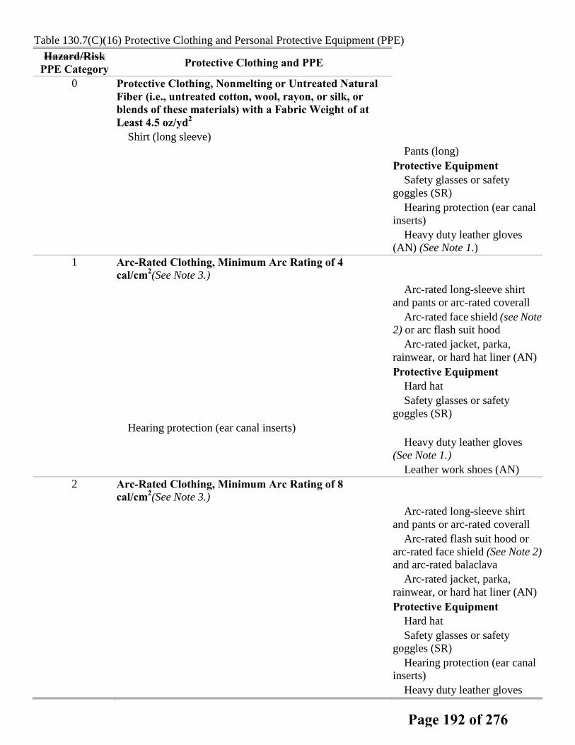
Table 130.7(C)(16) Protective Clothing and Personal Protective Equipment (PPE)
Hazard/Risk PPE Category Protective Clothing and PPE
0 Protective Clothing, Nonmelting or Untreated Natural Fiber (i.e., untreated cotton, wool, rayon, or silk, or blends of these materials) with a Fabric Weight of at Least 4.5 oz/yd2
Shirt (long sleeve) Pants (long) Protective Equipment Safety glasses or safety
goggles (SR) Hearing protection (ear canal
inserts) Heavy duty leather gloves
(AN) (See Note 1.) 1 Arc-Rated Clothing, Minimum Arc Rating of 4
cal/cm2(See Note 3.)
Arc-rated long-sleeve shirt and pants or arc-rated coverall
Arc-rated face shield (see Note 2) or arc flash suit hood
Arc-rated jacket, parka, rainwear, or hard hat liner (AN)
Protective Equipment Hard hat Safety glasses or safety
goggles (SR) Hearing protection (ear canal inserts)
Heavy duty leather gloves (See Note 1.)
Leather work shoes (AN) 2 Arc-Rated Clothing, Minimum Arc Rating of 8
cal/cm2(See Note 3.)
Arc-rated long-sleeve shirt and pants or arc-rated coverall
Arc-rated flash suit hood or arc-rated face shield (See Note 2) and arc-rated balaclava
Arc-rated jacket, parka, rainwear, or hard hat liner (AN)
Protective Equipment Hard hat Safety glasses or safety
goggles (SR) Hearing protection (ear canal
inserts) Heavy duty leather gloves
Page 192 of 276

Hazard/Risk PPE Category Protective Clothing and PPE
(See Note 1.) Leather work shoes 3 Arc-Rated Clothing Selected so That the System Arc
Rating Meets the Required Minimum Arc Rating of 25 cal/cm2(See Note 3.)
Arc-rated long-sleeve shirt (AR)
Arc-rated pants (AR) Arc-rated coverall (AR) Arc-rated arc flash suit jacket
(AR) Arc-rated arc flash suit pants (AR)
Arc-rated arc flash suit hood Arc-rated gloves (See Note 1.) Arc-rated jacket, parka,
rainwear, or hard hat liner (AN) Protective Equipment Hard hat
Safety glasses or safety goggles (SR)
Hearing protection (ear canal inserts)
Leather work shoes 4 Arc-Rated Clothing Selected so That the System Arc
Rating Meets the Required Minimum Arc Rating of 40 cal/cm2(See Note 3.)
Arc-rated long-sleeve shirt (AR)
Arc-rated pants (AR) Arc-rated coverall (AR) Arc-rated arc flash suit jacket
(AR) Arc-rated arc flash suit pants (AR)
Arc-rated arc flash suit hood Arc-rated gloves (See Note 1.) Arc-rated jacket, parka,
rainwear, or hard hat liner (AN) Protective Equipment Hard hat Safety glasses or safety
goggles (SR) Hearing protection (ear canal
inserts) Leather work shoes
AN: as needed (optional). AR: as required. SR: selection required. Notes:
Page 193 of 276

(1) If rubber insulating gloves with leather protectors are required by Table 130.7(C)(9), additional leather or arc-rated gloves are not required. The combination of rubber insulating gloves with leather protectors satisfies the arc flash protection requirement. (2) Face shields are to have wrap-around guarding to protect not only the face but also the forehead, ears, and neck, or, alternatively, an arc-rated arc flash suit hood is required to be worn. (3) Arc rating is defined in Article 100 and can be either the arc thermal performance value (ATPV) or energy of break open threshold (EBT). ATPV is defined in ASTM F 1959, Standard Test Method for Determining the Arc Thermal Performance Value of Materials for Clothing, as the incident energy on a material, or a multilayer system of materials, that results in a 50 percent probability that sufficient heat transfer through the tested specimen is predicted to cause the onset of a second-degree skin burn injury based on the Stoll curve, in cal/cm2. EBT is defined in ASTM F 1959 as the incident energy on a material or material system that results in a 50 percent probability of breakopen. Arc rating is reported as either ATPV or EBT, whichever is the lower value.
Page 194 of 276

Report on Proposals – June 2014 NFPA 70E_______________________________________________________________________________________________70E- Log #158
_______________________________________________________________________________________________Daryld Ray Crow, DRC Consulting, Ltd.
Add the requirement for an arc-rated balaclava to the list of requirements for HRC-1.The existing requirements for HRC-1 is in conflict with the requirement in 130.7(C)(10)(b)(1). This
statement requires the use of an arc-rated balaclava or arc-rated hood when the back of the head is within the arc flashboundary. This standard should have consistent statements to prevent confusion to the user.
_______________________________________________________________________________________________70E- Log #192
_______________________________________________________________________________________________David A. Pace, Olin Corporation
For Hazard/Risk Categories 1, 2, 3, and 4, replace the word shoes with boots.Boots provide more protection for the ankle and lower leg than shoes and should be required to be
worn.
_______________________________________________________________________________________________70E- Log #316
_______________________________________________________________________________________________T. David Mills, Savannah River Nuclear Solutions, LLC
Revise Note (1) to read:(1) If rubber insulating gloves with leather protectors are required by Table 130.7(C)(9) for shock protection, additional
leather or arc-rated gloves are not required. The combination of rubber insulating gloves with leather protectors satisfiesthe arc flash protection requirement.
Table 130.7(C)(9) no longer exists and since Section 130.5(C) requires a calculation of incident energyto be implemented which renders the Tables 130.7(C)(15)(a) and (b) useless, simply referring to the use of voltage ratedgloves for shock protection is all that is needed here.
_______________________________________________________________________________________________70E- Log #6
_______________________________________________________________________________________________James J. Toth, III, Delta Power Systems Engineering, PC
Revise text to read as follows:(1) If rubber insulation gloves with leather protectors are required by Table 130.7(C)(9) 130.7(C)(15)(a).
There is no Table 130.7(C)(9) in NFPA 70E 2012 Edition. Table 130.7(C)(9) from NFPA 70E 2009Edition was replaced with Table 130.7(C)(15)(a) in NFPA 70E 2012 Edition. If you also want this to apply to directcurrent equipment, also include Table 130.7(C)(15)(b).
119Printed on 7/13/2012
Page 195 of 276
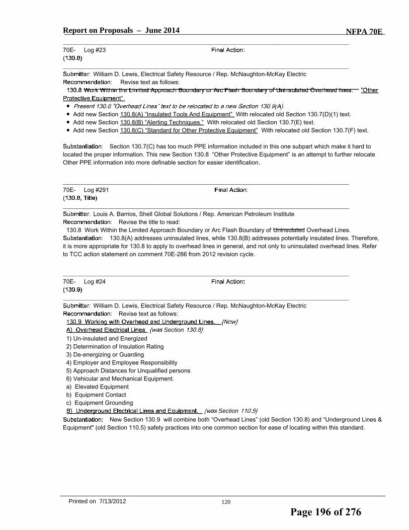
Report on Proposals – June 2014 NFPA 70E_______________________________________________________________________________________________70E- Log #23
_______________________________________________________________________________________________William D. Lewis, Electrical Safety Resource / Rep. McNaughton-McKay Electric
Revise text as follows:
●● Add new Section 130.8(A) “Insulated Tools And Equipment” With relocated old Section 130.7(D)(1) text.● Add new Section 130.8(B) “Alerting Techniques.” With relocated old Section 130.7(E) text.● Add new Section 130.8(C) “Standard for Other Protective Equipment” With relocated old Section 130.7(F) text.
Section 130.7(C) has too much PPE information included in this one subpart which make it hard tolocated the proper information. This new Section 130.8 “Other Protective Equipment” is an attempt to further relocateOther PPE information into more definable section for easier identification
_______________________________________________________________________________________________70E- Log #291
_______________________________________________________________________________________________Louis A. Barrios, Shell Global Solutions / Rep. American Petroleum Institute
Revise the title to read:130.8 Work Within the Limited Approach Boundary or Arc Flash Boundary of Uninsulated Overhead Lines.
130.8(A) addresses uninsulated lines, while 130.8(B) addresses potentially insulated lines. Therefore,it is more appropriate for 130.8 to apply to overhead lines in general, and not only to uninsulated overhead lines. Referto TCC action statement on comment 70E-286 from 2012 revision cycle.
_______________________________________________________________________________________________70E- Log #24
_______________________________________________________________________________________________William D. Lewis, Electrical Safety Resource / Rep. McNaughton-McKay Electric
Revise text as follows:
Section
1) Un-insulated and Energized2) Determination of Insulation Rating3) De-energizing or Guarding4) Employer and Employee Responsibility5) Approach Distances for Unqualified persons6) Vehicular and Mechanical Equipment.a) Elevated Equipmentb) Equipment Contactc) Equipment Grounding
Section
New Section 130.9 will combine both “Overhead Lines” (old Section 130.8) and “Underground Lines &Equipment" (old Section 110.5) safety practices into one common section for ease of locating within this standard.
120Printed on 7/13/2012
Page 196 of 276

Report on Proposals – June 2014 NFPA 70E_______________________________________________________________________________________________70E- Log #353
_______________________________________________________________________________________________Mark McNellis, Sandia National Laboratories
Add a new section to read:130.9 Underground Electrical Lines and Equipment. Before excavation starts, and where there exists a reasonable
possibility of contacting electrical lines or equipment, the employer shall take the necessary steps to contact theappropriate owners or authorities to identify and mark the location of the electrical lines or equipment. When it has beendetermined that a reasonable possibility for contacting electrical lines or equipment exists, a hazard analysis shall beperformed to identify the appropriate safe work practices that shall be used during the excavation.
This public input was submitted by the article 110 Task Group and is a partner submittal to relocate thecurrent 110.5 in it's entirety to a new section 130.9 where content is more in line with adjacent sections.
_______________________________________________________________________________________________70E- Log #430
_______________________________________________________________________________________________Marcia L. Eblen, Pacific Gas & Electric
INCLUDE 70E_L430 (PI #357) Rec
Outdated references to ASTM standards. Changes will bring 70E up to date with ASTM
_______________________________________________________________________________________________70E- Log #313
_______________________________________________________________________________________________T. David Mills, Savannah River Nuclear Solutions, LLC
Delete the following text: Informational Note: Table 130.7(C)(15)(a) and Table 130.7(C)(15)(b) provide further information on tasks where rubberinsulating gloves are required.
Section 130.5(C) requires a calculation of incident energy to be implemented which renders the Tables130.7(C)(15)(a) and (b) useless, since there cannot be an alternative method to determine the label information. This isa built-in conflict which the AHJ has no recourse without an enforcement clause in Article 90.
_______________________________________________________________________________________________70E- Log #361
_______________________________________________________________________________________________H. Landis Floyd, The DuPont Company, Inc.
Revise text to read:Informational Note: Refer to NFPA 70B, Recommended Practice for Electrical Equipment Maintenance, and
ANSI/NETA MTS-2007, Standard for Maintenance Testing Specifications for Electrical Power Distribution Equipmentand Systems, and IEEE Std 3007.2 IEEE Recommended Practice for the Maintenance of Industrial and CommercialPower Systems for guidance on maintenance frequency, methods, and tests.
This proposal is intended to provide a more complete listing of applicable references. IEEE 3007.2 is auseful complimetn to the two existing reference standards listed.
121Printed on 7/13/2012
Page 197 of 276

CORRECT titles and revisions for ASTM Standards in Table 130.7(F)
ASTM F2676 - 09 Standard Test Method for Determining the Protective Performance of an Arc Protective Blanket for Electric Arc Hazards
ASTM D1048 - 11 Standard Specification for Rubber Insulating Blankets
ASTM F479 - 06(2011) Standard Specification for In-Service Care of Insulating Blankets
ASTM D1049 - 98(2010) Standard Specification for Rubber Insulating Covers
ASTM F711 - 02(2007) Standard Specification for Fiberglass-Reinforced Plastic (FRP) Rod and Tube Used in Live Line Tools
ASTM F1505 - 10 Standard Specification for Insulated and Insulating Hand Tools
ASTM D1050 - 05(2011) Standard Specification for Rubber Insulating Line Hose
ASTM F478 - 09 Standard Specification for In-Service Care of Insulating Line Hose and Covers
ASTM F712 - 06(2011) Standard Test Methods and Specifications for Electrically Insulating Plastic Guard Equipment for Protection of Workers
ASTM F1742 - 03(2011) Standard Specification for PVC Insulating Sheeting
ASTM F2522 - 05(2011) Standard Test Method for Determining the Protective Performance of a Shield Attached on Live Line Tools or on Racking Rods for Electric Arc Hazards
ASTM F2249 - 03(2009) Standard Specification for In-Service Test Methods for Temporary Grounding Jumper Assemblies Used on De-Energized Electric Power Lines and Equipment
ASTM F855 - 09 Standard Specifications for Temporary Protective Grounds to Be Used on De-energized Electric Power Lines and Equipment
ASTM F2320 - 11 Standard Specification for Rubber Insulating Sheeting
Change Table row for insulation sheeting to be as shown below:
Sheeting Standard Specification for PVC Insulating Sheeting ASTM F 1742 - 03(2011)
Standard Specification for Rubber Insulating Sheeting ASTM F2320 - 11
Page 198 of 276

Report on Proposals – June 2014 NFPA 70E_______________________________________________________________________________________________70E- Log #196
_______________________________________________________________________________________________David A. Pace, Olin Corporation
Add a new 200.1(4) to read as follows: The employer is responsible for proper maintenance of theelectrical equipment in accordance with manufacturer’s recommendations and consensus standards. Propermaintenance of electrical equipment is required to ensure proper operation and condition. An effective electrical safetyprogram is dependent upon proper operation and condition of electrical equipment. Without proper equipmentmaintenance, many of the protective procedures and methods derived from this standard would be invalid, and couldprovide incorrect guidance and direction to employees.
Without proper equipment maintenance, many of the protective procedures and methods derived fromthis standard would be invalid, and could provide incorrect guidance and direction to employees.
_______________________________________________________________________________________________70E- Log #362
_______________________________________________________________________________________________H. Landis Floyd, The DuPont Company, Inc.
Add a new section to read:205.1 Engineering Controls.205.1 Engineering Controls.Hazard mitigation includes engineering controls which function automatically to eliminate
or reduce risk of injury from a hazard, without any action required from the employee potentially at risk. The employershall identify engineering controls for electrical hazards and establish maintenance programs to ensure acceptablereliability.Informational Note: Examples of engineering controls for electrical hazards include, but are not limited to enclosures,
covers, overcurrent devices specific to limiting arc flash incident energy, power supplies for overcurrent devices, groundfault circuit interrupters, portable tool & appliance cord insulation and boding & grounding for step and touch potential.(Editorial note: acceptance of above proposal will entail renumbering existing articles 205.1 through 205.14)
This proposal is intended to help identify the specific equipment in a facility that directly impactsemployee safety. While maintenance of all electrical equipment may be important, employers must understand whichequipment is critical so that proper priority is given to items that are safety related.
_______________________________________________________________________________________________70E- Log #242
_______________________________________________________________________________________________Daniel T. Roberts, Schneider Electric / Rep. Hazard & Risk Ad Hoc Task Group
Revise text to read: 205.3 General Maintenance Requirements. Electrical equipment shall be maintained in accordance with
manufacturers' instructions or industry consensus standards to reduce the risk of failure and the subsequent exposure ofemployees to electrical hazards associated with failure.
This is one of multiple Public Input proposals from the NFPA 70E Hazard & Risk Ad Hoc Task Groupthat seeks to clarify and promote the consistent use throughout the document of terminology associated with hazard andrisk.The proposed change provides clarity by eliminating redundant text. Risk associated with failure by definition implies a
likelihood of occurrence of injury or damage to health, a severity of injury or damage to health, or both.
122Printed on 7/13/2012
Page 199 of 276

Report on Proposals – June 2014 NFPA 70E_______________________________________________________________________________________________70E- Log #363
_______________________________________________________________________________________________H. Landis Floyd, The DuPont Company, Inc.
Revise text to read:205.6 Grounding and Bonding. Equipment, raceway, cable tray, and enclosure bonding and grounding shall be
maintained to ensure electrical continuity required to prevent the following hazardous conditions:(1) ineffective fault return paths that impede operation of overcurrent devices or create dangerous step or touch
potentials during fault conditions(2) dangerous step or touch potentials from equipment housings, covers or enclosures energized as result of insulation
failureThis proposal is intended to clarify the potential consequences of improper maintenance of bonding
and grounding systems.
_______________________________________________________________________________________________70E- Log #364
_______________________________________________________________________________________________H. Landis Floyd, The DuPont Company, Inc.
Revise text to read:205.7 Guarding of Energized Conductors and Circuit Parts. Enclosures shall be maintained to guard against
accidental contact with energized conductors and circuit parts and other electrical hazards. Covers and doors shall be inplace with all associated fasteners secured, and there shall be no unprotected openings.
This is intended to clarify intent.
_______________________________________________________________________________________________70E- Log #243
_______________________________________________________________________________________________Daniel T. Roberts, Schneider Electric / Rep. Hazard & Risk Ad Hoc Task Group
Revise text to read: 205.13 Single and Multiple Conductors and Cables. Electrical cables and single and multiple conductors shall be
maintained free of damage, shorts, and ground that would present a hazard to employeesexpose employees to anelectrical hazard.
This is one of multiple Public Input proposals from the NFPA 70E Hazard & Risk Ad Hoc Task Groupthat seeks to clarify and promote the consistent use throughout the document of terminology associated with hazard andrisk.The proposed change provides clarity. Damage to the items listed do not present a source of harm, rather, they expose
the person to a source of harm.
_______________________________________________________________________________________________70E- Log #244
_______________________________________________________________________________________________Daniel T. Roberts, Schneider Electric / Rep. Hazard & Risk Ad Hoc Task Group
Revise text to read:(1) Damaged Cords and Cables. Cords and cables shall not have worn, frayed, or damaged areas that present would
expose employees to an electrical hazard to employees.This is one of multiple Public Input proposals from the NFPA 70E Hazard & Risk Ad Hoc Task Group
that seeks to clarify and promote the consistent use throughout the document of terminology associated with hazard andrisk.The proposed change provides clarity. Damage to the items listed do not present a source of harm, rather, they expose
the person to a source of harm.
123Printed on 7/13/2012
Page 200 of 276

Report on Proposals – June 2014 NFPA 70E_______________________________________________________________________________________________70E- Log #365
_______________________________________________________________________________________________H. Landis Floyd, The DuPont Company, Inc.
Revise text to read:Flexible cords and cables shall be maintained to avoid strain and damage to preserve insulation integrity.
This proposal is intended to add clarity to the intent of the requirements.
_______________________________________________________________________________________________70E- Log #419
_______________________________________________________________________________________________John McAlhaney, Savannah River Nuclear Solutions
Add a new section to read:(3) Repair and Replacement. Cords and cord caps for portable electrical equipment shall be repaired and replaced by
qualified personnel and checked for proper polarity, grounding and continuity prior to returning to serviceThis change will ensure that cord replacements and cord repairs to electrical equipment is performed
by a knowledgable qualified person and tested to ensure proper configuration. There have been numerous electricalshocks reported within industry and government when cords or cord caps were replaced and ground and phaseconductors inadvertenly crossed.
_______________________________________________________________________________________________70E- Log #366
_______________________________________________________________________________________________H. Landis Floyd, The DuPont Company, Inc.
Add a new section to read:205.15 Overhead Clearances. For overhead electric lines under the employer’s control, conductor sagging and grade
elevation shall be maintained to preserve no less than minimum designed vertical and horizontal clearances necessaryto minimize risk of unintentional contact.
Unintentional contact with overhead lines is the leading cause of occupational electrical fatality in theUS. This proposal addresses maintenance requirements that contribute to prevention of unintentional contact.
_______________________________________________________________________________________________70E- Log #367
_______________________________________________________________________________________________H. Landis Floyd, The DuPont Company, Inc.
Add a new section to read:205.16 Underground Electric Lines. Maps or other locating methods, where provided for the electrical system, shall be
kept current to facilitate the location of hazardous energy associated with underground electrical services.This proposal addresses maintenance requirements that serve to prevent contact with hazardous
energy associated with underground lines.
124Printed on 7/13/2012
Page 201 of 276

Report on Proposals – June 2014 NFPA 70E_______________________________________________________________________________________________70E- Log #245
_______________________________________________________________________________________________Daniel T. Roberts, Schneider Electric / Rep. Hazard & Risk Ad Hoc Task Group
Revise text to read: 210.1 Enclosures. Enclosures shall be kept free of material that would create a expose employees to an electrical
hazard.This is one of multiple Public Input proposals from the NFPA 70E Hazard & Risk Ad Hoc Task Group
that seeks to clarify and promote the consistent use throughout the document of terminology associated with hazard andrisk.The proposed change provides clarity. Material in enclosures do not create a source of injury or damage to health,
rather, they expose the person to a source of harm. “Electrical hazard” is a defined term and limits the application to thescope of the Standard; that of safe work-practices and worker safety.
_______________________________________________________________________________________________70E- Log #420
_______________________________________________________________________________________________John McAlhaney, Savannah River Nuclear Solutions
Revise text to read:210.1 Enclosures. Enclosures shall be kept free of material that would create a hazard and door latches secured.
Walkdowns indicate that workers do not always secure the cubicle door latches after maintenancework has been completed. In some cases, the latches are turned but not fully engaged to latch the door.A fully secured latched door minimizes unexpected exposure and may provide some protection to personnel operating
a switch in case of an arc flash inside the cubicle.
_______________________________________________________________________________________________70E- Log #246
_______________________________________________________________________________________________Daniel T. Roberts, Schneider Electric / Rep. Hazard & Risk Ad Hoc Task Group
Revise text to read: Informational Note: Failure to properly maintain protective devices can have an adverse effect on the arc flash hazard
analysis result in increased incident energy values.This is one of multiple Public Input proposals from the NFPA 70E Hazard & Risk Ad Hoc Task Group
that seeks to clarify and promote the consistent use throughout the document of terminology associated with hazard andrisk.The proposed change provides clarity. The context indicates that equipment failure due to lack of maintenance can
result in an increase in incident energy.
125Printed on 7/13/2012
Page 202 of 276

Report on Proposals – June 2014 NFPA 70E_______________________________________________________________________________________________70E- Log #368
_______________________________________________________________________________________________H. Landis Floyd, The DuPont Company, Inc.
Revise text to read:210.5 Protective Overcurrent Protective Devices. Protective Overcurrent protective devices shall be maintained to
adequately withstand or interrupt available fault current.Informational Note: Failure to properly maintain overcurrent protective devices can have an adverse effect on the arc
flash hazard analysis incident energy values values and in determination of Hazard Risk Categories per article130.7(C)(15).
This proposal is intended to clarify the potential consequences of inadequately maintained overcurrentprotective devices. Selection of HRC is not the same as performing incident energy analysis, however protective deviceperformance impacts effectiveness of both methods.
_______________________________________________________________________________________________70E- Log #369
_______________________________________________________________________________________________H. Landis Floyd, The DuPont Company, Inc.
Add new text to read: 210.5 Protective Devices.(A) General.Protective devices shall be maintained to adequately withstand or interrupt available fault current.(B) Protective devices used as basis for arc flash protection measures. Protective devices used as the basis in arc
flash incident energy analysis per article 130.5 or in the determination of Hazard/Risk Categories per article130.&(C)(15) shall be maintained to assure reliability of the designed fault clearing performance.
This proposal is intended to clarify the potential safety consequences of inadequately maintainedovercurrent protective devices.
126Printed on 7/13/2012
Page 203 of 276
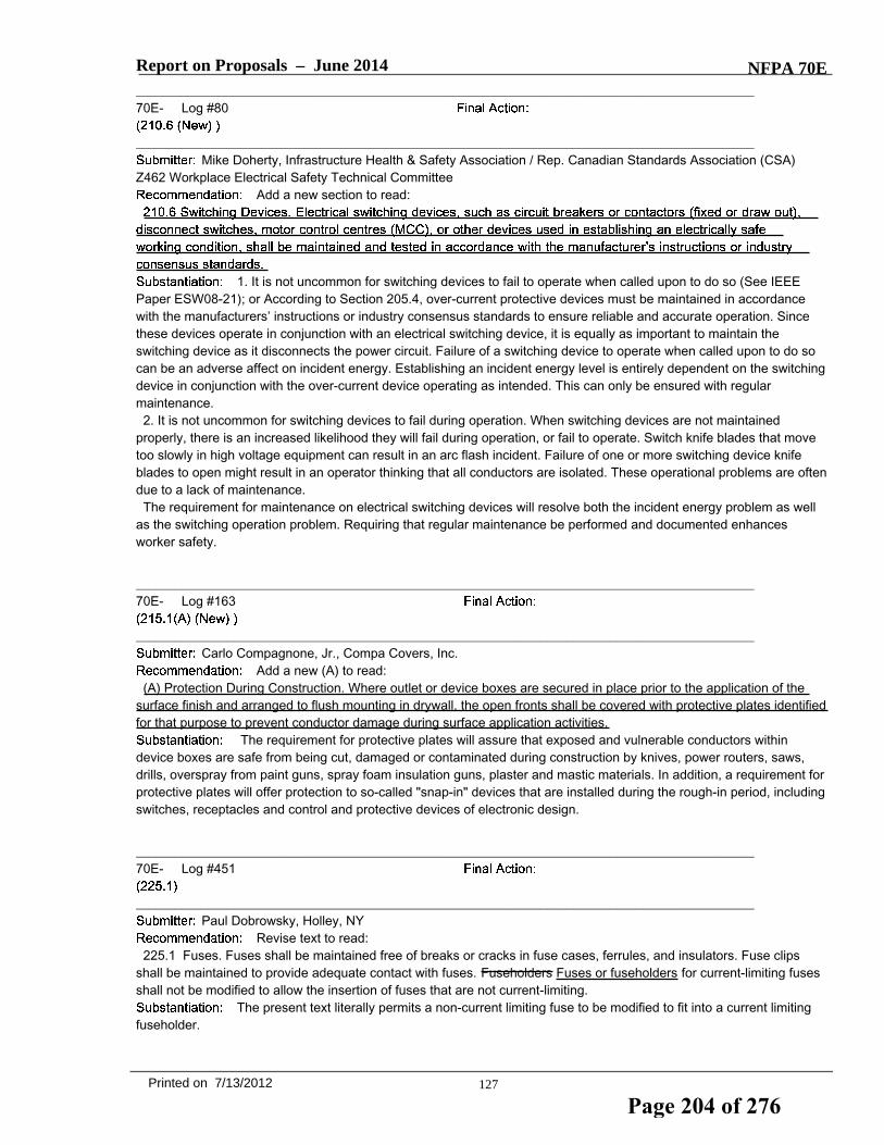
Report on Proposals – June 2014 NFPA 70E_______________________________________________________________________________________________70E- Log #80
_______________________________________________________________________________________________Mike Doherty, Infrastructure Health & Safety Association / Rep. Canadian Standards Association (CSA)
Z462 Workplace Electrical Safety Technical CommitteeAdd a new section to read:
1. It is not uncommon for switching devices to fail to operate when called upon to do so (See IEEEPaper ESW08-21); or According to Section 205.4, over-current protective devices must be maintained in accordancewith the manufacturers’ instructions or industry consensus standards to ensure reliable and accurate operation. Sincethese devices operate in conjunction with an electrical switching device, it is equally as important to maintain theswitching device as it disconnects the power circuit. Failure of a switching device to operate when called upon to do socan be an adverse affect on incident energy. Establishing an incident energy level is entirely dependent on the switchingdevice in conjunction with the over-current device operating as intended. This can only be ensured with regularmaintenance.2. It is not uncommon for switching devices to fail during operation. When switching devices are not maintained
properly, there is an increased likelihood they will fail during operation, or fail to operate. Switch knife blades that movetoo slowly in high voltage equipment can result in an arc flash incident. Failure of one or more switching device knifeblades to open might result in an operator thinking that all conductors are isolated. These operational problems are oftendue to a lack of maintenance.The requirement for maintenance on electrical switching devices will resolve both the incident energy problem as well
as the switching operation problem. Requiring that regular maintenance be performed and documented enhancesworker safety.
_______________________________________________________________________________________________70E- Log #163
_______________________________________________________________________________________________Carlo Compagnone, Jr., Compa Covers, Inc.
Add a new (A) to read:(A) Protection During Construction. Where outlet or device boxes are secured in place prior to the application of the
surface finish and arranged to flush mounting in drywall, the open fronts shall be covered with protective plates identifiedfor that purpose to prevent conductor damage during surface application activities.
The requirement for protective plates will assure that exposed and vulnerable conductors withindevice boxes are safe from being cut, damaged or contaminated during construction by knives, power routers, saws,drills, overspray from paint guns, spray foam insulation guns, plaster and mastic materials. In addition, a requirement forprotective plates will offer protection to so-called "snap-in" devices that are installed during the rough-in period, includingswitches, receptacles and control and protective devices of electronic design.
_______________________________________________________________________________________________70E- Log #451
_______________________________________________________________________________________________Paul Dobrowsky, Holley, NY
Revise text to read:225.1 Fuses. Fuses shall be maintained free of breaks or cracks in fuse cases, ferrules, and insulators. Fuse clips
shall be maintained to provide adequate contact with fuses. Fuseholders Fuses or fuseholders for current-limiting fusesshall not be modified to allow the insertion of fuses that are not current-limiting.
The present text literally permits a non-current limiting fuse to be modified to fit into a current limitingfuseholder.
127Printed on 7/13/2012
Page 204 of 276

Report on Proposals – June 2014 NFPA 70E_______________________________________________________________________________________________70E- Log #370
_______________________________________________________________________________________________H. Landis Floyd, The DuPont Company, Inc.
Add new text to read:225.1 Fuses.(A) General. Fuses shall be maintained free of breaks or cracks in fuse cases, ferrules, and insulators. Fuse clips shall
be maintained to provide adequate contact with fuses. Fuseholders for current-limiting fuses shall not be modified toallow the insertion of fuses that are not current-limiting.(B) Fuses used as basis for arc flash protection measures. Installation or replacement of fuses used as the basis in arc
flash incident energy analysis per article 130.5 or in the determination of Hazard/Risk Categories per article130.7(C)(15) shall be controlled to assure reliability of the designed fault clearing performance.
This proposal is intended to clarify the potential safety consequences of inadequately maintaininginstalled fuses.
_______________________________________________________________________________________________70E- Log #371
_______________________________________________________________________________________________H. Landis Floyd, The DuPont Company, Inc.
Revise text to read: 230.1 Terminal Boxes.(A) General. Terminal chambers, enclosures, and terminal boxes shall be maintained to guard against accidental
contact with energized conductors and circuit parts and other electrical hazards.(B) TEFC (Totally Enclosed Fan Cooled) Motor Terminal Boxes. An arcing fault internal to a TEFC motor or
associated terminal box can result in rapid pressure rise and rupture of the terminal box housing, exposing workers tohazards of arc flash and blast. Risk of terminal box rupture shall be assessed and appropriate maintenance beperformed to assure reliability of motor lead connection and insulation integrity.
Justification: This hazard has been documented for more than 50 years and is not currently recognizedin this standard. Inclusion will provide guidance for a more comprehensive standard to manage electrical hazards in theworkplace.References:1. Motor Terminal Box Explosions due to Faults, Crawford, K.S., Clark D.G., and Doughty R.L., IEEE Transactions on
Industry Applications, Jan/Feb 19932. The Design and Performance of High and Low Voltage Terminal Boxes, Schwarz, K.K., Proceedings of the Institute
of Electrical Engineers, vol 109., pp 151-172, 1962
_______________________________________________________________________________________________70E- Log #372
_______________________________________________________________________________________________H. Landis Floyd, The DuPont Company, Inc.
Revise text to read: 245.1 Maintenance Requirements for Portable Electric Toolsand, Appliances and Equipment. Attachment plugs,
extension cords, receptacles, cover plates, and cord connectors shall, housings and covers shall be maintained suchthat the following criteria are met:Remainder unchanged.
This proposal is inteneded to clarify intent to guard against hazards assoicated with hand heldelectifcally powered equipment.
128Printed on 7/13/2012
Page 205 of 276

Report on Proposals – June 2014 NFPA 70E_______________________________________________________________________________________________70E- Log #432
_______________________________________________________________________________________________Marcia L. Eblen, Pacific Gas & Electric
Revise text to read:(10) Safety grounding equipment Temporary protective grounds
The list is presently redundant and confusing. Item 1 is Grounding equipment, Item 10 is Safetygrounding equipment. Change Item 10 to use more accepted industry name for Temporary Protective Grounds. LeaveItem 1 as is to catch all the other varieties of grounding equipment.
_______________________________________________________________________________________________70E- Log #300
_______________________________________________________________________________________________William K. Shinn, e-Hazard Management, LLC / Rep. American Society of Safety Engineers
Revise text to read:(B) Testing. The insulation of protective equipment and protective tools, such as items specified in 250.1 (12) through
(,(3)(5)(6),(11),(13) and (14), shall be verified by the appropriate test and visual inspection to ascertain that insulatingcapability has been retained before initial use, and at intervals thereafter, as service conditions and applicable standardsand instructions require, but in no case shall the interval exceed 3 years, unless specified otherwise by the respectiveASTM standards.
Items (1), (4), (7), (8), (9), (10) and (12) do not have insulation requiring testing. As one illistration:Protective Ground Sets ASTM F 855 require the conductor have a covering only. No insulating value is required thereforno test procedure has been established in ASTM F2249 to test the insulation. Article 250.3 accurately covers SafetyGrounding Equipment. Article 250.2(B) as currently written to include article 250.1 (10) for insulation testing is in error.
_______________________________________________________________________________________________70E- Log #433
_______________________________________________________________________________________________Marcia L. Eblen, Pacific Gas & Electric
Revise text to read:(B) Testing. The insulation of protective equipment and protective tools, such as items specified in 250.1(1) through
(14), that is used as primary protection from shock hazards shall be verified by the appropriate test and visual inspectionto ascertain that insulating capability has been retained before initial use, and at intervals thereafter, as serviceconditions and applicable standards and instructions require, but in no case shall the interval exceed 3 years, unlessspecified otherwise by the respective ASTM standards.
Some of the equipment may have insulation but does not provide shock protection to employees e.g.temporary protective grounds.Some of the equipment listed in 250.1 has insulating value but is only used for secondary protection from shock and
has no published or accepted in-service insulation testing procedure e.g. EH rated boots. In these cases visualinspection is all that is needed.
Present language says all of this equipment requires insulation testing which is inaccurate.
129Printed on 7/13/2012
Page 206 of 276

Report on Proposals – June 2014 NFPA 70E_______________________________________________________________________________________________70E- Log #373
_______________________________________________________________________________________________H. Landis Floyd, The DuPont Company, Inc.
Add a new section to read:250.4 Voltage Testing Instruments. Instruments and associated test leads used to verify the absence of hazardous
energy shall be maintained to assure functional integrity. The maintenance program shall include functional verificationas described in Article 110.4(A)(5)
This proposal is intended to strengthen the maintenance requirements for voltage testers that arecritical to worker safety.
_______________________________________________________________________________________________70E- Log #247
_______________________________________________________________________________________________Daniel T. Roberts, Schneider Electric / Rep. Hazard & Risk Ad Hoc Task Group
Revise text to read:Informational Note: Electrolytic cells could exhibit characteristics similar to an electrical storage battery and, thus, a
hazardous voltage shock hazard could exist after the power supply is disconnected from the cell line.This is one of multiple Public Input proposals from the NFPA 70E Hazard & Risk Ad Hoc Task Group
that seeks to clarify and promote the consistent use throughout the document of terminology associated with hazard andrisk.The proposed change provides clarity and consistency. “Shock hazard” is a defined term.
_______________________________________________________________________________________________70E- Log #248
_______________________________________________________________________________________________Daniel T. Roberts, Schneider Electric / Rep. Hazard & Risk Ad Hoc Task Group
Revise text to read:(A) General. The training requirements of this chapter shall apply to employees who are exposed to the risk of
electrical hazard exposed to electrical hazards in the cell line working zone defined in 110.2 and shall supplement ormodify the requirements of 120.1, 130.2, 130.3, and 130.8.
This is one of multiple Public Input proposals from the NFPA 70E Hazard & Risk Ad Hoc Task Groupthat seeks to clarify and promote the consistent use throughout the document of terminology associated with hazard andrisk.The proposed change provides clarity and consistency with proposed definition and the rest of the document. The
context indicates that the reference is to exposure to electrical hazards.
_______________________________________________________________________________________________70E- Log #249
_______________________________________________________________________________________________Daniel T. Roberts, Schneider Electric / Rep. Hazard & Risk Ad Hoc Task Group
Revise text to read: (B) Training Requirements. Employees shall be trained to understand the specific electrical hazards associated with
electrical energy on the cell line. Employees shall be trained in safety-related work practices and proceduralrequirements to provide protection from the electrical hazards associated with their respective job or task assignment.
This is one of multiple Public Input proposals from the NFPA 70E Hazard & Risk Ad Hoc Task Groupthat seeks to clarify and promote the consistent use throughout the document of terminology associated with hazard andrisk.The proposed change provides clarity and consistency. The scope of the document is electrical hazards.
130Printed on 7/13/2012
Page 207 of 276

Report on Proposals – June 2014 NFPA 70E_______________________________________________________________________________________________70E- Log #250
_______________________________________________________________________________________________Daniel T. Roberts, Schneider Electric / Rep. Hazard & Risk Ad Hoc Task Group
Revise text to read:(1) Training. Qualified persons shall be trained and knowledgeable in the operation of cell line working zone
equipment and specific work methods and shall be trained to avoid the electrical hazards that are present. Such personsshall be familiar with the proper use of precautionary techniques and personal protective equipment. Training for aqualified person shall include the following:
(1) Skills and techniques to avoid dangerous contact with hazardous voltages between energized surfaces, andbetween a shock hazard between:
(a) energized surfaces; and(b) energized surfaces and grounded equipment, other grounded objects, or the earth itself, that.
This might include temporarily insulating or guarding parts to permit the employee to work on energized partsThis is one of multiple Public Input proposals from the NFPA 70E Hazard & Risk Ad Hoc Task Group
that seeks to clarify and promote the consistent use throughout the document of terminology associated with hazard andrisk.The proposed change provides clarity and consistency. Shock hazard is a defined term that describes a dangerous
condition. Itemizing the source of the shock hazard in a list makes it easier to identify.
_______________________________________________________________________________________________70E- Log #251
_______________________________________________________________________________________________Daniel T. Roberts, Schneider Electric / Rep. Hazard & Risk Ad Hoc Task Group
Revise text to read:(1) Training. Unqualified persons shall be trained to recognize identify electrical hazards to which they may be
exposed and the proper methods of avoiding the hazards.This is one of multiple Public Input proposals from the NFPA 70E Hazard & Risk Ad Hoc Task Group
that seeks to clarify and promote the consistent use throughout the document of terminology associated with hazard andrisk.The proposed change is consistent with revisions made in 2009 - hazards are “identified.”
_______________________________________________________________________________________________70E- Log #252
_______________________________________________________________________________________________Daniel T. Roberts, Schneider Electric / Rep. Hazard & Risk Ad Hoc Task Group
Revise text to read:(2) In Cell Line Working Zone. When there is a need for an unqualified person to enter the cell line working zone to
perform a specific task, that person shall be advised by of the electrical hazards by the designated qualified person incharge of the possible hazards to to ensure the unqualified person is safeguarded.
This is one of multiple Public Input proposals from the NFPA 70E Hazard & Risk Ad Hoc Task Groupthat seeks to clarify and promote the consistent use throughout the document of terminology associated with hazard andrisk.The editorial revision is proposed for clarity. As worded, it is unclear what the qualified person is in charge of:- the possible hazards, or- informing the unqualified person of the hazards.The context indicates it is the latter.
131Printed on 7/13/2012
Page 208 of 276

Report on Proposals – June 2014 NFPA 70E_______________________________________________________________________________________________70E- Log #253
_______________________________________________________________________________________________Daniel T. Roberts, Schneider Electric / Rep. Hazard & Risk Ad Hoc Task Group
Revise text to read: Informational Note No. 1: Exposed energized surfaces might not establish a hazardous condition. A hazardous
electrical condition is present an electrical hazard. Electrical hazards are related to current flow through the bodycausing shock and arc flash burns and arc blasts. Shock is a function of many factors, including resistance through thebody and through the skin, return paths, paths in parallel with the body, and system voltages. Arc flash burns and arcblasts are a function of the current available at the point involved and the time of arc exposure.
This is one of multiple Public Input proposals from the NFPA 70E Hazard & Risk Ad Hoc Task Groupthat seeks to clarify and promote the consistent use throughout the document of terminology associated with hazard andrisk.The proposed change provides clarity and consistency. Electrical hazard is a defined term.
_______________________________________________________________________________________________70E- Log #254
_______________________________________________________________________________________________Daniel T. Roberts, Schneider Electric / Rep. Hazard & Risk Ad Hoc Task Group
Revise text to read:(1) Arc Flash Hazard Analysis Procedure. Each task performed in the electrolytic cell line working zone shall be
analyzed for the risk likelihood of arc flash hazard injury injury. If there is risk a likelihood of personal injury, appropriatemeasures shall be taken to protect persons exposed to the arc flash hazards. These measures shall include one ormore of the following:
This is one of multiple Public Input proposals from the NFPA 70E Hazard & Risk Ad Hoc Task Groupthat seeks to clarify and promote the consistent use throughout the document of terminology associated with hazard andrisk.The proposed change provides clarity and consistency with proposed definition of risk. The word risk in this context is
only referring to the likelihood of injury.
_______________________________________________________________________________________________70E- Log #255
_______________________________________________________________________________________________Daniel T. Roberts, Schneider Electric / Rep. Hazard & Risk Ad Hoc Task Group
Revise text to read:(2) Alter work procedures to eliminate reduce the possibility likelihood of the occurrence of an arc flash hazard incident.
This is one of multiple Public Input proposals from the NFPA 70E Hazard & Risk Ad Hoc Task Groupthat seeks to clarify and promote the consistent use throughout the document of terminology associated with hazard andrisk.
The proposed change is consistent with definitions of hazard and risk. Altering work procedures when working in anenergized electrolytic cell line does not eliminate an arc flash hazard, it has the effect of reducing the likelihood ofoccurrence.
132Printed on 7/13/2012
Page 209 of 276
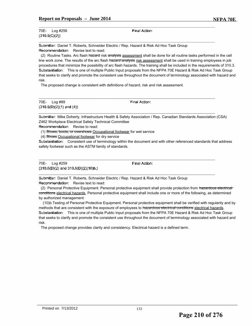
Report on Proposals – June 2014 NFPA 70E_______________________________________________________________________________________________70E- Log #256
_______________________________________________________________________________________________Daniel T. Roberts, Schneider Electric / Rep. Hazard & Risk Ad Hoc Task Group
Revise text to read:(2) Routine Tasks. Arc flash hazard risk analysis assessment shall be done for all routine tasks performed in the cell
line work zone. The results of the arc flash hazard analysis risk assessment shall be used in training employees in jobprocedures that minimize the possibility of arc flash hazards. The training shall be included in the requirements of 310.3.
This is one of multiple Public Input proposals from the NFPA 70E Hazard & Risk Ad Hoc Task Groupthat seeks to clarify and promote the consistent use throughout the document of terminology associated with hazard andrisk.The proposed change is consistent with definitions of hazard, risk and risk assessment.
_______________________________________________________________________________________________70E- Log #89
_______________________________________________________________________________________________Mike Doherty, Infrastructure Health & Safety Association / Rep. Canadian Standards Association (CSA)
Z462 Workplace Electrical Safety Technical CommitteeRevise to read:
(1) Shoes, boots, or overshoes Occupational footwear for wet service(4) Shoes Occupational footwear for dry service
Consistent use of terminology within the document and with other referenced standards that addresssafety footwear such as the ASTM family of standards.
_______________________________________________________________________________________________70E- Log #259
_______________________________________________________________________________________________Daniel T. Roberts, Schneider Electric / Rep. Hazard & Risk Ad Hoc Task Group
Revise text to read:(2) Personal Protective Equipment. Personal protective equipment shall provide protection from hazardous electrical
conditions electrical hazards. Personal protective equipment shall include one or more of the following, as determinedby authorized management:
(10)b.Testing of Personal Protective Equipment. Personal protective equipment shall be verified with regularity and bymethods that are consistent with the exposure of employees to hazardous electrical conditions electrical hazards.
This is one of multiple Public Input proposals from the NFPA 70E Hazard & Risk Ad Hoc Task Groupthat seeks to clarify and promote the consistent use throughout the document of terminology associated with hazard andrisk.The proposed change provides clarity and consistency. Electrical hazard is a defined term.
133Printed on 7/13/2012
Page 210 of 276

Report on Proposals – June 2014 NFPA 70E_______________________________________________________________________________________________70E- Log #257
_______________________________________________________________________________________________Daniel T. Roberts, Schneider Electric / Rep. Hazard & Risk Ad Hoc Task Group
Revise text to read: (3) Nonroutine Tasks. Before a nonroutine task is performed in the cell line working zone, an arc flash hazard risk
analysis assessment shall be done. If an arc flash hazard is a possibility during nonroutine work, appropriate instructionsshall be given to employees involved on how to minimize the possibility of a hazardous risk associated with arc flash.
This is one of multiple Public Input proposals from the NFPA 70E Hazard & Risk Ad Hoc Task Groupthat seeks to clarify and promote the consistent use throughout the document of terminology associated with hazard andrisk.The proposed change to the first sentence is consistent with definitions of hazard, risk and risk assessment.The proposed change to the second sentence provides clarity. The context indicates that the reference is to minimizing
the risk (i.e. combination of likelihood of occurrence of harm and the severity of harm) associated with arc flash.
_______________________________________________________________________________________________70E- Log #260
_______________________________________________________________________________________________Daniel T. Roberts, Schneider Electric / Rep. Hazard & Risk Ad Hoc Task Group
Revise text to read:(3) Barriers. Barriers shall be devices that prevent contact with energized or grounded surfaces that could present a
hazardous an electrical condition hazard.This is one of multiple Public Input proposals from the NFPA 70E Hazard & Risk Ad Hoc Task Group
that seeks to clarify and promote the consistent use throughout the document of terminology associated with hazard andrisk.The proposed change provides clarity and consistency. Electrical hazard is a defined term.
_______________________________________________________________________________________________70E- Log #258
_______________________________________________________________________________________________Daniel T. Roberts, Schneider Electric / Rep. Hazard & Risk Ad Hoc Task Group
Revise text to read:(4) Arc Flash Hazards. If the possibility likelihood of occurrence of an arc flash hazard exists for either routine or
nonroutine tasks, employees shall use appropriate safeguards.This is one of multiple Public Input proposals from the NFPA 70E Hazard & Risk Ad Hoc Task Group
that seeks to clarify and promote the consistent use throughout the document of terminology associated with hazard andrisk.The proposed change is consistent with definition of risk (likelihood of occurrence).
_______________________________________________________________________________________________70E- Log #261
_______________________________________________________________________________________________Daniel T. Roberts, Schneider Electric / Rep. Hazard & Risk Ad Hoc Task Group
Revise text to read: (5) Isolation. Isolation shall be the placement of equipment or items in locations such that employees are unable to
simultaneously contact exposed conductive surfaces that could present a hazardous an electrical condition hazard.This is one of multiple Public Input proposals from the NFPA 70E Hazard & Risk Ad Hoc Task Group
that seeks to clarify and promote the consistent use throughout the document of terminology associated with hazard andrisk.The proposed change provides clarity and consistency. Electrical hazard is a defined term.
134Printed on 7/13/2012
Page 211 of 276

Report on Proposals – June 2014 NFPA 70E_______________________________________________________________________________________________70E- Log #322
_______________________________________________________________________________________________Stephen McCluer, APC By Schneider Electric / Rep. IEEE Stationary Battery Committee Codes Working
GroupRevise text to read:
Prospective Fault Short Circuit Current. The highest level of fault current that can occur that could theoretically occur ata point on a circuit. This is the fault current that can flow in the event of a zero impedance short circuit and if noprotection devices operate.Informational Note: Per 320.3(A)(4)(1), the arc hazard due to the prospective short circuit value for a battery system is
to be posted in order to assist in the calculations during an arc hazard analysis.The term prospective fault current is defined in Article 320 but it is not used anywhere in NFPA 70E.
As applied to battery systems, the correct term would be “prospective short circuit current.” The latter is only used onetime in NFPA 70E. Paragraph 320.3(A)(4)(1) requires the value to be posted, but nowhere in the standard is the termdefined. The term “short circuit current rating” is defined in Article 100. (See a companion proposal that would changenumber of the paragraph where the term is used.)
135Printed on 7/13/2012
Page 212 of 276

Report on Proposals – June 2014 NFPA 70E_______________________________________________________________________________________________70E- Log #328
_______________________________________________________________________________________________Stephen McCluer, APC By Schneider Electric / Rep. IEEE Stationary Battery Committee Codes Working
GroupAdd new text to read:
C. Shock Hazards(1) Shock Hazards Below Nominal 100 Volts DC. The effect of direct current on the human body at or below 100 volts
is not considered a shock hazard. Use of electrically-rated glkoves shall be optional(2) Shock Hazards At or Above Nominal 100 Volts DC. The shock hazard at or above nominal 100 volts dc varies
depending upon the type of grounding system utilized. Electrically-rated gloves shall be used in accordance with Table320.3(C)(2) and Table 130.7(C)(15)(b)
INSERT 70E_L328 (PI #288) Rec Table 320.3(C)(2)
Informational Note: Because a battery system can also include some alternating current elements (for example,input to the rectifier or charger, output of an inverter, etc.), the safety procedures for ac systems described elsewhere inNFPA 70E are appropriate for the ac elements of the system.
1. 100 Volts vs 50 Volts - Research provided by the DC Task Group for NFPA 70E-2012 establishedthat the shock hazard threshold for the human body is approximately the same at 100 Vdc or 50 Vac. This is recognizedin Table 130.7(C)(15)(b), which established hazard/risk categories and use of gloves and insulated tools on energizedequipment greater than 100 Vdc.2. New table - The informational notes provided in NFPA70E-2012 for 320.3(C)(2) were good but did not provide clear
guidance on how the information should be applied to safe work on battery systems. A new table is proposed to provideunambiguous guidance on tasks when the use of electrically-rated gloves is appropriate.3. Renumbering - The existing text for “Testing, Maintenance, and Shock Hazard” is replaced with “Shock Hazard”.
This is consistent with the organization which provides (A) general safety hazards, (B), electrolyte hazards, but presentlydoes not provide any information about shock hazards unique to battery systems. The deleted text could be moved toanother (new) paragraph number – possibly “(D) Battery short circuit current calculations”.
136Printed on 7/13/2012
Page 213 of 276
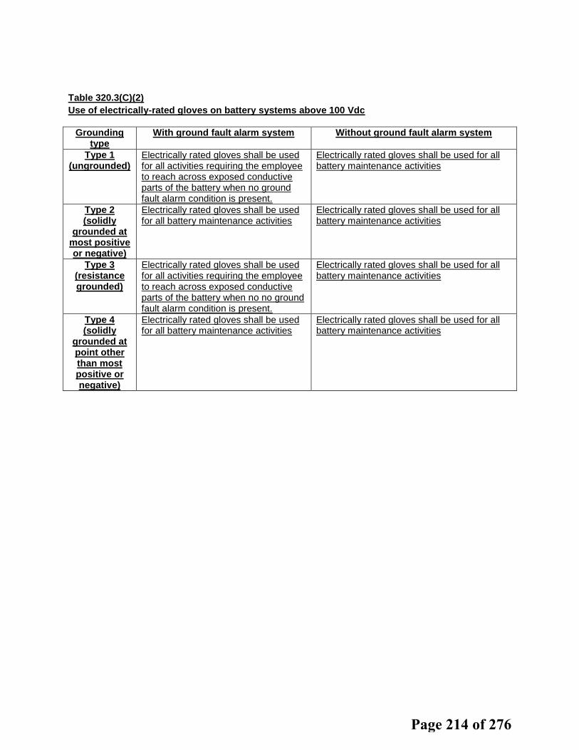
Table 320.3(C)(2) Use of electrically-rated gloves on battery systems above 100 Vdc
Grounding type
With ground fault alarm system
Without ground fault alarm system
Type 1 (ungrounded)
Electrically rated gloves shall be used for all activities requiring the employee to reach across exposed conductive parts of the battery when no ground fault alarm condition is present.
Electrically rated gloves shall be used for all battery maintenance activities
Type 2 (solidly
grounded at most positive or negative)
Electrically rated gloves shall be used for all battery maintenance activities
Electrically rated gloves shall be used for all battery maintenance activities
Type 3 (resistance grounded)
Electrically rated gloves shall be used for all activities requiring the employee to reach across exposed conductive parts of the battery when no no ground fault alarm condition is present.
Electrically rated gloves shall be used for all battery maintenance activities
Type 4 (solidly
grounded at point other than most positive or negative)
Electrically rated gloves shall be used for all battery maintenance activities
Electrically rated gloves shall be used for all battery maintenance activities
Page 214 of 276

Table 320.3(C)(2) Use of electrically-rated gloves on battery systems above 100 Vdc
Grounding type
With ground fault alarm system
Without ground fault alarm system
Type 1 (ungrounded)
Electrically rated gloves shall be used for all activities requiring the employee to reach across exposed conductive parts of the battery when no ground fault alarm condition is present.
Electrically rated gloves shall be used for all battery maintenance activities
Type 2 (solidly
grounded at most positive or negative)
Electrically rated gloves shall be used for all battery maintenance activities
Electrically rated gloves shall be used for all battery maintenance activities
Type 3 (resistance grounded)
Electrically rated gloves shall be used for all activities requiring the employee to reach across exposed conductive parts of the battery when no no ground fault alarm condition is present.
Electrically rated gloves shall be used for all battery maintenance activities
Type 4 (solidly
grounded at point other than most positive or negative)
Electrically rated gloves shall be used for all battery maintenance activities
Electrically rated gloves shall be used for all battery maintenance activities
Page 215 of 276

Report on Proposals – June 2014 NFPA 70E_______________________________________________________________________________________________70E- Log #330
_______________________________________________________________________________________________Stephen McCluer, APC By Schneider Electric / Rep. IEEE Stationary Battery Committee Codes Working
GroupRevise text to read:
(D) Cell Flame Arresters and Cell Ventilation. Battery When present, battery cell ventilation openings shall beunobstructed, and cell flame arresters shall be maintained.(E) Fire Hazards. Battery cell. Cell flame arresters shall be inspected for proper installation and unobstructed
ventilation and shall be replaced when necessary in accordance with the manufacturer's instructions.Not all batteries have vents and/or flame arresters, and even when present (such as on VRLA
batteries), inspection may not be feasible. Flame arresters are rarely “maintained.” If inspection reveals that a flamearrestor for some reason has become damaged or otherwise non-functional, the appropriate action is to replace it.
Delete 320.3(E) as it is redundant. It is addressed in 320.3(D).
137Printed on 7/13/2012
Page 216 of 276

Report on Proposals – June 2014 NFPA 70E_______________________________________________________________________________________________70E- Log #326
_______________________________________________________________________________________________Stephen McCluer, APC By Schneider Electric / Rep. IEEE Stationary Battery Committee Codes Working
GroupRevise text to read:
(1) Batteries with Liquid Activities that include handling of Liquid Electrolyte. The following protective equipment shallbe available to employees performing any type of service on a battery with liquid electrolyte:
(1) Goggles and Goggles or face shield appropriate for the electrical hazard and the chemical hazard(2) Gloves and aprons appropriate for the chemical and electrical hazards(3) Portable or stationary water facilities for quick drenching stationary eye wash facilities within the work area that are
capable of 15 minutes duration of drenching or flushing of the eyes and body within the work area.
Informational Note: Guidelines for the use and maintenance of eye wash facilities for vented batteries in non-telecomenvironments can be found in ANSI Z358.1-2009. Telecom facilities are only required by OSHA CFR29, Part1919.268(b)(2) to have quart or liter eyewash bottles.
Section 320.3(B) currently delineates between batteries with liquid or solid electrolyte. The real hazardis with the handling of electrolyte. For the vast majority of activities involving batteries, electrolyte is not handled and therisk of injury from electrolyte is virtually non-existent. Therefore, it the collective opinion of the IEEE stationary batterycommittee members submitting this proposal that the chemical PPE should be based on whether electrolyte is handled.Additional eyewash information was added to quantify the amount of water required which is consistent with ANSIguidelines. The informational note points out an exception allowed by OSHA for Telecom installations where storageand/or plumbing sufficient for 15 minutes of continuous flushing is simply not feasible. (An example would be anmountaintop tower in which the battery space is under snow for weeks or months and which may only be accessible byhelicopter.) It is the opinion of the submitters that, wherever practical, a minimum of 15 minutes of eyewash should beavailable when contact with electrolyte is anticipated or reasonably possible.(1) The word “and” is changed to “or” as we do not believe it is necessary to wear both goggle and face shileds at the
same time.(2) An informational note is added to tell people where to find the guidelines for eyewash facilities. (3) Telecom facilities
are only required by OSHA (CFR29 Part 1910.268(b)(2) to have the quart or liter bottles of eyewash, regardless ofbattery type, probably due to the long experience of telecom companies with batteries.As an added observation, it is the collective opinion of the IEEE stationary battery committee members submitting this
proposal that the hazard from electrolyte on the body is far less than the hazard on eyes or mucus membranes;therefore, access to water – while necessary - is less urgent, and the volume of water or the amount of time necessaryto cleanse the body will vary with the amount of exposure. Availability of a neutralizing agent, which is required by firecodes NFPA 1 and the International Fire Code, is also necessary.
138Printed on 7/13/2012
Page 217 of 276
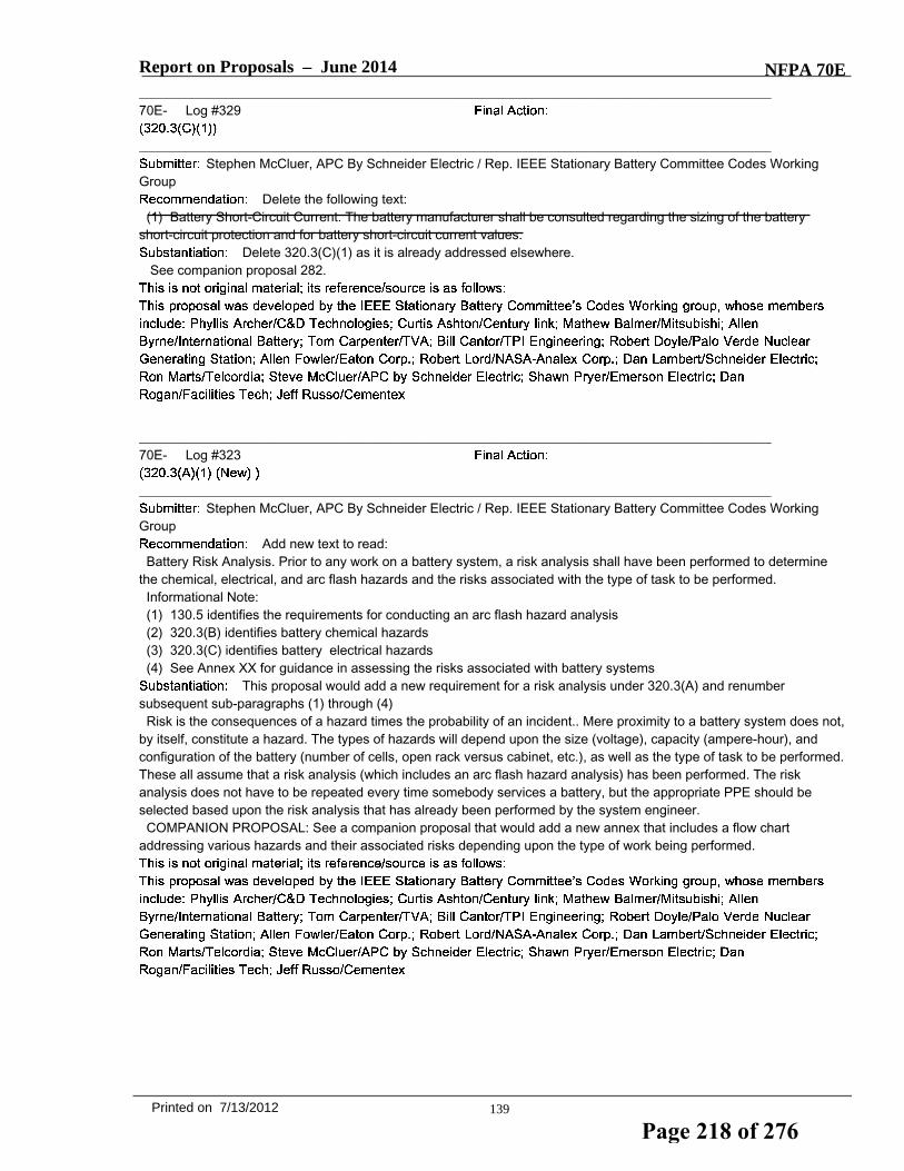
Report on Proposals – June 2014 NFPA 70E_______________________________________________________________________________________________70E- Log #329
_______________________________________________________________________________________________Stephen McCluer, APC By Schneider Electric / Rep. IEEE Stationary Battery Committee Codes Working
GroupDelete the following text:
(1) Battery Short-Circuit Current. The battery manufacturer shall be consulted regarding the sizing of the batteryshort-circuit protection and for battery short-circuit current values.
Delete 320.3(C)(1) as it is already addressed elsewhere.See companion proposal 282.
_______________________________________________________________________________________________70E- Log #323
_______________________________________________________________________________________________Stephen McCluer, APC By Schneider Electric / Rep. IEEE Stationary Battery Committee Codes Working
GroupAdd new text to read:
Battery Risk Analysis. Prior to any work on a battery system, a risk analysis shall have been performed to determinethe chemical, electrical, and arc flash hazards and the risks associated with the type of task to be performed.Informational Note:(1) 130.5 identifies the requirements for conducting an arc flash hazard analysis(2) 320.3(B) identifies battery chemical hazards(3) 320.3(C) identifies battery electrical hazards(4) See Annex XX for guidance in assessing the risks associated with battery systems
This proposal would add a new requirement for a risk analysis under 320.3(A) and renumbersubsequent sub-paragraphs (1) through (4)Risk is the consequences of a hazard times the probability of an incident.. Mere proximity to a battery system does not,
by itself, constitute a hazard. The types of hazards will depend upon the size (voltage), capacity (ampere-hour), andconfiguration of the battery (number of cells, open rack versus cabinet, etc.), as well as the type of task to be performed.These all assume that a risk analysis (which includes an arc flash hazard analysis) has been performed. The riskanalysis does not have to be repeated every time somebody services a battery, but the appropriate PPE should beselected based upon the risk analysis that has already been performed by the system engineer.COMPANION PROPOSAL: See a companion proposal that would add a new annex that includes a flow chart
addressing various hazards and their associated risks depending upon the type of work being performed.
139Printed on 7/13/2012
Page 218 of 276

Report on Proposals – June 2014 NFPA 70E_______________________________________________________________________________________________70E- Log #327
_______________________________________________________________________________________________Stephen McCluer, APC By Schneider Electric / Rep. IEEE Stationary Battery Committee Codes Working
GroupRevise text to read:
(2) Batteries with Solid or Immobilized Activities That Do Not Include Handling of Electrolyte. The following protectiveequipment shall be available to employees performing any type of service on a nonspillable battery with solid orimmobilized electrolyte:
(1) Goggles or face shield appropriate for the electrical hazard(2) Gloves appropriate for the electrical and chemical hazards(3) Protective clothing appropriate for electrical hazard
Employees performing any activity not involving the handling of electrolyte shall wear safety glasses.Informational Note: Battery maintenance activities usually do not involve handling electrolyte. Batteries with solid
electrolyte (such as most lithium batteries) or immobilized electrolyte (such as VRLA batteries) present little or noelectrolyte hazard. Most modern density meters expose a worker to a quantity of electrolyte too minute to beconsidered hazardous, if at all. Such work would not be considered handling electrolyte. However, if specific gravityreadings are taken using a bulb hydrometer, the risk of exposure is higher and this could be considered to be handlingof electrolyte and the requirements of 320.3(B)(1) would apply.
Most work around batteries does not expose a worker to electrolyte, even when the battery containsfree-flowing liquid electrolyte. PPE to protect against contact with electrolyte should only be required when suchexposure is likely. Such activities would include acid adjustments and removal of electrolyte. The greatest hazard isgetting electrolyte on the hands and then rubbing or otherwise bringing the contaminated hand in contact with the eyes.Safety glasses, goggles or face shields, as required in 320.3(B)(1)(1) should prevent such contact.
140Printed on 7/13/2012
Page 219 of 276

Report on Proposals – June 2014 NFPA 70E_______________________________________________________________________________________________70E- Log #324
_______________________________________________________________________________________________Stephen McCluer, APC By Schneider Electric / Rep. IEEE Stationary Battery Committee Codes Working
GroupRevise text to read:
(3) Abnormal Battery Conditions. Alarms for Instrumentation that provides alarms for early warning of the followingabnormal conditions of battery operation, if present, shall be tested yearly:● For vented cells:(1) Overvoltage(2) Undervoltage(3) Overcurrent(4) Ground fault
For VRLA cells:● Overvoltage● Undervoltage● Overcurrent● Ground faultOvertemperature, as measured at the pilot cellInformational Note: Battery monitoring systems typically include alarms for such conditions as overvoltage,
under-voltage, over-current, gound fault, and over-temperature. The type of conditions monitored will vary dependingupon the battery technology. One source of guidance on monitoring battery systems is IEEE Std. 1491, Guide for theSelection and Use of Battery Monitoring Equipment in Stationary Applications.
The existing text can be read to say that, if an alarm is present, it must be tested yearly. Grammaticallyspeaking, it is the equipment - not the alarm - that is tested. Current text only requires testing when monitoringequipment is present, but monitoring equipment is not required to be present. The lists of conditions to test for are notall-inclusive, and they relate almost exclusively to lead-acid batteries, to the exclusion of all other battery technologies.The proposed text simplifies the requirement to simply require annual testing if battery alarm functionality is installed.Note that if separate proposal #279 is accepted, the sub-paragraph number would change from 3 to 4.
_______________________________________________________________________________________________70E- Log #263
_______________________________________________________________________________________________Daniel T. Roberts, Schneider Electric / Rep. Hazard & Risk Ad Hoc Task Group
Revise text to read:(c) Non-sparking tools shall be required when the hazard identification and risk risk assessment required by 110.73(F)
justify their justifies their use.This is one of multiple Public Input proposals from the NFPA 70E Hazard & Risk Ad Hoc Task Group
that seeks to clarify and promote the consistent use throughout the document of terminology associated with hazard andrisk.The proposed change provides clarity and consistency with the global PI to change “hazard identification and risk
assessment” to “risk assessment.. The change from “justify” to “justifies” is for grammatical accuracy. The change to thesection number correlates with revisions made in the 2009 edition.
141Printed on 7/13/2012
Page 220 of 276

Report on Proposals – June 2014 NFPA 70E_______________________________________________________________________________________________70E- Log #421
_______________________________________________________________________________________________John McAlhaney, Savannah River Nuclear Solutions
Revise text to read:(c) Non-sparking tools shall be required when the hazard identification and risk assessment required by 110.73(F)
justify their use.The proposed changed will correct an error to the wrong reference. The reference 110.7 (F) does not
exist. The hazard and risk assessment requirement is provided in 110.3 (F)
_______________________________________________________________________________________________70E- Log #262
_______________________________________________________________________________________________Daniel T. Roberts, Schneider Electric / Rep. Hazard & Risk Ad Hoc Task Group
Revise text to read:(4) Warning Signs. The following warning signs or labels shall be posted in appropriate locations:(1) Electrical hazard warnings indicating the shock hazard due to the battery voltage and the arc flash hazard due to
the prospective short-circuit current(2) Chemical hazard warnings, applicable to the worst case when multiple battery types are installed in the same
space, indicating the following:a. Potential presence of explosive gas (when applicable to the battery type);b. Prohibition of open flame and smoking; andc. Danger of chemical burns from the electrolyte (when applicable to the battery type)
(3) Notice for personnel to use and wear protective equipment and apparel appropriate to the hazard for the battery(4) Notice prohibiting access to unauthorized personnel
Informational Note: Because internal resistance or prospective short circuit, or both, are not always provided on batterycontainer labels or data sheets, and because many variables can be introduced into a battery layout, the batterymanufacturer should be consulted for accurate data. Variables can include, but are not limited to, the following:
(1) Series connections(2) Parallel connections(3) Charging methodology(4) Temperature(5) Charge status(6) DC distribution cable size and length
This is one of multiple Public Input proposals from the NFPA 70E Hazard & Risk Ad Hoc Task Groupthat seeks to clarify and promote the consistent use throughout the document of terminology associated with hazard andrisk.The proposed change provides clarity and consistency with the rest of the document. Arc flash hazard is a defined
term.
142Printed on 7/13/2012
Page 221 of 276

Report on Proposals – June 2014 NFPA 70E_______________________________________________________________________________________________70E- Log #325
_______________________________________________________________________________________________Stephen McCluer, APC By Schneider Electric / Rep. IEEE Stationary Battery Committee Codes Working
GroupRevise text to read:
(4) Warning Signs. The following warning signs or labels shall be posted in appropriate locations:(1) Electrical hazard warnings indicating the shock hazard due to the battery voltage and the arc hazard due to the
prospective short-circuit currentInformational Note #1 : Because internal resistance or prospective short circuit, or both, are not always provided on
battery container labels or data sheets, and because many variables can be introduced into a battery layout, the batterymanufacturer should be consulted for accurate data. Variables can include, but are not limited to, the following:
(1) Series connections(2) Parallel connections(3) Charging methodology(4) Temperature(5) Charge status(6) DC distribution cable size and length
(2) Informational Note #2: 130.5(C) has the requirements for equipment labeling. A hazard analysis would beperformed by the systems engineer, not by the person working on the battery.
(3) Chemical hazard warnings, applicable to the worst case when multiple battery types are installed in the samespace, indicating the following:
a. Potential presence of explosive gas (when applicable to the battery type);b. Prohibition of open flame and smoking; andc. Danger of chemical burns from the electrolyte (when applicable to the battery type)
(4) Notice for personnel to use and wear protective equipment and apparel appropriate to the hazard for the battery(5) Notice prohibiting access to unauthorized personnel
Informational Note: Because internal resistance or prospective short circuit, or both, are not always provided on batterycontainer labels or data sheets, and because many variables can be introduced into a battery layout, the batterymanufacturer should be consulted for accurate data. Variables can include, but are not limited to, the following:
(1) Series connections(2) Parallel connections(3) Charging methodology(4) Temperature(5) Charge status(6) DC distribution cable size and length
Compliance with 320.3(A)(4)(1) assumes that an arc hazard analysis has already been performed. It isnot the responsibility of the person working on the battery to do the calculation or to post signs. Warning signs should bea design requirement in the NEC; Safety & PPE notices should be posted per NEC, read and followed.Note that if a separate proposal #279 is accepted, the sub-paragraph number would change from (4)(1) to (5)(1). Note
that a separate proposal #278, if accepted, would add a definition of "prospective short circuit current".The text for Informational note #2 is moved to 320.3(A)(4)(1) for arc hazard warning sign. It was in 320.3(A)(4)(4),
notice prohibiting unauthorized personnel. This is the more logical place for the guidance. The text is modified to pointout that the systems engineer, not the battery manufacturer, is responsible for doing the calculations on any giveninstallation.
143Printed on 7/13/2012
Page 222 of 276

Report on Proposals – June 2014 NFPA 70E_______________________________________________________________________________________________70E- Log #219
_______________________________________________________________________________________________Daniel P. Finnegan, Siemens Industry, Inc. / Rep. NEMA
Revise to read:Fail Safe. The design consideration The in which failure of a component finnegan does not increase the hazard. In the
failure mode, the system is rendered inoperative or nonhazardous.gggggggggggggggg
_______________________________________________________________________________________________70E- Log #264
_______________________________________________________________________________________________Daniel T. Roberts, Schneider Electric / Rep. Hazard & Risk Ad Hoc Task Group
Revise text to read:Fail Safe. The design consideration in which failure of a component does not increase the hazard create additional
hazards or increased risk. In the failure mode, the system is rendered inoperative or nonhazardous.This is one of multiple Public Input proposals from the NFPA 70E Hazard & Risk Ad Hoc Task Group
that seeks to clarify and promote the consistent use throughout the document of terminology associated with hazard andrisk.The proposed change provides clarity and consistency with revisions made to 110.3(F) in 2009 edition.
_______________________________________________________________________________________________70E- Log #111
_______________________________________________________________________________________________Bobby J. Gray, Hoydar/Buck, Inc. / Rep. NFPA 70E DC Hazards Task Group
Revise to read: (C) Proof of Qualification. Proof of qualification of the laser equipment operator shall be available and in possession of
the operator at all times.Requiring the operator to have possession of some proof of qualification while in a zone where a
hazard could exist could create an unnecessary exposure for the operator. As long as the evidence of qualification ismade available, that should be adquate to ensure only qualified workers will operate the equipment.
_______________________________________________________________________________________________70E- Log #265
_______________________________________________________________________________________________Daniel T. Roberts, Schneider Electric / Rep. Hazard & Risk Ad Hoc Task Group
Revise text to read:b. Hazard control identification, risk assessment, and risk control proceduresRemainder underchanged
This is one of multiple Public Input proposals from the NFPA 70E Hazard & Risk Ad Hoc Task Groupthat seeks to clarify and promote the consistent use throughout the document of terminology associated with hazard andrisk.The proposed change provides clarity and consistency with the proposed definitions of hazard, risk and risk
assessment and with risk management principles: hazards are identified, risk is assessed and controlled.
144Printed on 7/13/2012
Page 223 of 276

Report on Proposals – June 2014 NFPA 70E_______________________________________________________________________________________________70E- Log #266
_______________________________________________________________________________________________Daniel T. Roberts, Schneider Electric / Rep. Hazard & Risk Ad Hoc Task Group
Revise text to read:340.5 Hazardous Effects of Electricity on the Human Body. The employer and employees shall be aware of the
following hazards associated with power electronic equipment.b. At 10 mA, a person may not be able to voluntarily let go of the hazard an energized electrical conductor or circuit
part.This is one of multiple Public Input proposals from the NFPA 70E Hazard & Risk Ad Hoc Task Group
that seeks to clarify and promote the consistent use throughout the document of terminology associated with hazard andrisk.The proposed change to the title provides clarity: use of "hazardous" is redundant.The proposed change to list item (1)(b) provides clarity. A hazard is a source of injury or damage to health - the
paragraph should identify the source of harm: an energized electrical conductor or circuit part.
_______________________________________________________________________________________________70E- Log #422
_______________________________________________________________________________________________John McAlhaney, Savannah River Nuclear Solutions
Revise text to read:(2) Results of Direct Current.
a. A dc current of 2 mA is perceptible.b. A dc current of 10 of 40 mA is considered the threshold of the let-go current.
Table II of the Charles Daziel study October 1961, Deleterious Effects of Electric Shock, indicate thatthe minimum threshold let-go for Direct Current is 41 millamperes (for women). Minimum threshold for men is higher at62 millamperes.
145Printed on 7/13/2012
Page 224 of 276

Report on Proposals – June 2014 NFPA 70E_______________________________________________________________________________________________70E- Log #267
_______________________________________________________________________________________________Daniel T. Roberts, Schneider Electric / Rep. Hazard & Risk Ad Hoc Task Group
Revise text to read:(A) Employer Responsibility. The employer shall be responsible for the following:
(1) Proper training and supervision by properly qualified personnel including the following:a. Nature Identification of the associated hazard hazardsb. Strategies to minimize the hazard reduce the risk associated with the hazardsc. Methods of avoiding or protecting against the hazardd. Necessity of reporting any hazardous incident incident that resulted in, or could have resulted in, injury or
damage to health(6) Provision of complete and accurate circuit diagrams and other published information to the employee prior to the
employee starting work (The circuit diagrams should be marked to indicate the hazardous components components thatpresent an electrical hazard.)
This is one of multiple Public Input proposals from the NFPA 70E Hazard & Risk Ad Hoc Task Groupthat seeks to clarify and promote the consistent use throughout the document of terminology associated with hazard andrisk.The proposed changes to list items (1)(a) and (1)(b) provides clarity and consistency with definitions of hazard, risk and
risk assessment: hazards are identified; risk is assessed for the purposes of reducing risk.The proposed change to list item (1)(d) provides clarity and consistency. The term "hazardous" when used as a
modifier for "incident" is vague. The proposed revision aligns with the definitions for hazard (a source of injury ordamage to health).The proposed change to list item (6) provides clarity and consistency with the rest of the document. The term
"hazardous" when used as a modifier for "components" is vague. Electrical hazard is a defined term.
_______________________________________________________________________________________________70E- Log #268
_______________________________________________________________________________________________Daniel T. Roberts, Schneider Electric / Rep. Hazard & Risk Ad Hoc Task Group
Revise text to read:(5) Examining all documents provided by the employer relevant to the work, especially those documents indicating the
hazardous components location location of components that present an electrical hazard(7) Reporting any hazardous incident incident that resulted in, or could have resulted in, injury or damage to healthRemainder unchanged
This is one of multiple Public Input proposals from the NFPA 70E Hazard & Risk Ad Hoc Task Groupthat seeks to clarify and promote the consistent use throughout the document of terminology associated with hazard andrisk.The proposed change to list item (5) provides clarity and consistency with the rest of the document. The term
"hazardous" when used as a modifier for "components" is vague. Electrical hazard is a defined term.The proposed change to list item (7) provides clarity and consistency. The term "hazardous" when used as a modifier
for "incident" is vague. The proposed revision aligns with the definitions for hazard (a source of injury or damage tohealth).
146Printed on 7/13/2012
Page 225 of 276

Report on Proposals – June 2014 NFPA 70E_______________________________________________________________________________________________70E- Log #269
_______________________________________________________________________________________________Daniel T. Roberts, Schneider Electric / Rep. Hazard & Risk Ad Hoc Task Group
Revise text to read:Competent Person. A person meeting all of the requirements of a qualified person, as defined in Article 100 in Chapter
1 of this document and, in addition, is responsible for all work activities or safety procedures related to custom or specialequipment, and has detailed knowledge regarding the exposure to electrical hazard exposure hazards, the appropriatecontrols for mitigating control methods to reduce the risk associated with those hazards, and the implementation ofthose controls methods.
This is one of multiple Public Input proposals from the NFPA 70E Hazard & Risk Ad Hoc Task Groupthat seeks to clarify and promote the consistent use throughout the document of terminology associated with hazard andrisk.The proposed change provides clarity and consistency with the proposed definitions of hazard, risk and risk
assessment, and with risk management principles (hazards are identified; risk is assessed and controlled by following ahierarchy of risk control methods).
_______________________________________________________________________________________________70E- Log #10
_______________________________________________________________________________________________John Robert Davis, Oldsmar, FL
Propose new wording - static pressure water lines installed in an electrical panel.I have asked many design people why do you put water lines in electrical panels. The answer I get
back is that it is not DEFINED that you can't do it.Please see supporting material that includes pictures and my published paper with heading combined electrical and
process equipment panel with pressurized water piping.Note: Supporting material is available for review at NFPA Headquarters.
_______________________________________________________________________________________________70E- Log #30
_______________________________________________________________________________________________Drake A. Drobnick, Saline, MI
Add the words "(ear canal inserts)" behind the term "Hearing Protection."This addition maintains consistency with Table 130.7(C)(16).
_______________________________________________________________________________________________70E- Log #31
_______________________________________________________________________________________________Drake A. Drobnick, Saline, MI
Change exposure levels to: <1.2 cal/cm2, 1.2-12 cal/cm2, >12 cal/cm2.Arc rated clothing is required to be worn at the arc flash boundary.
147Printed on 7/13/2012
Page 226 of 276

Report on Proposals – June 2014 NFPA 70E_______________________________________________________________________________________________70E- Log #221
_______________________________________________________________________________________________Noel Williams, Noel Williams Consulting
Revise to read:A.1 General. The This informative annex is not part of the requirements of this document and is included for
information only. To the extent the documents or portions thereof listed in this annex are referenced within this standardand those documents shall be considered part of the requirements of this document.
The existing statement is both contradictory and incorrect. It contradicts 90.3 which states that"annexes are not part of the requirements of this standard. . ." Furthermore, it includes the NEC as requirements of thestandard which would make the standard unusable in locations where the NEC is not "the applicable electrical electricalinstallation requirements" referenced in 110.2 and where the NEC is included only as an informational note. Annex Ahas no authority to override a statement in the body of the standard. Alternatively, the Annex could be deleted withoutharm because those references that are part of the standard are already part of the standard where so referenced.
_______________________________________________________________________________________________70E- Log #112
_______________________________________________________________________________________________Bobby J. Gray, Hoydar/Buck, Inc. / Rep. NFPA 70E DC Hazards Task Group
Delete the following text:IEEE 1584, Guide for Performing Arc Flash Calculations, 2002.
IEEE 1584 is not referenced in any mandatory language within the document. It is listed in Annex B asan informational reference.
_______________________________________________________________________________________________70E- Log #374
_______________________________________________________________________________________________H. Landis Floyd, The DuPont Company, Inc.
Revise text to read:ANSI/AIHA Z10, American National Standard for Occupational Health and Safety and Health Management Systems,
2005.This corrects typographical error in the title of ANZI Z10.
_______________________________________________________________________________________________70E- Log #82
_______________________________________________________________________________________________Mike Doherty, Infrastructure Health & Safety Association / Rep. Canadian Standards Association (CSA)
Z462 Workplace Electrical Safety Technical CommitteeRevise to read:
CSA Z462, Workplace electrical safety, CAN/CSA 21000, Z1000 Occupational health and safety management,C22.1-12,Canadian Electrical Code Part I.
Reference citations are incomplete and inaccurate.
148Printed on 7/13/2012
Page 227 of 276

Report on Proposals – June 2014 NFPA 70E_______________________________________________________________________________________________70E- Log #375
_______________________________________________________________________________________________H. Landis Floyd, The DuPont Company, Inc.
Add new text to read:IEEE 3007.1-2010, IEEE Recommended Practice for the Operation and Management of Industrial and Commercial
Power SystemsIEEE 3007.2-2010, IEEE Recommended Practice for the Maintenance of Industrial and Commercial Power SystemsIEEE 3007.3-2012, IEEE Recommended Practice for Electrical Safety in Industrial and Commercial Power Systems.
These new standards are relevant and useful in supporting implementation of requirements in NFPA70E.
_______________________________________________________________________________________________70E- Log #376
_______________________________________________________________________________________________H. Landis Floyd, The DuPont Company, Inc.
Revise text to read: ANSI/IEEE C2, National Electrical Safety Code, 2007 2012.
This updates the reference to current version of ANSI C2.
_______________________________________________________________________________________________70E- Log #423
_______________________________________________________________________________________________John McAlhaney, Savannah River Nuclear Solutions
Add new text to read:IEEE 3007.3, IEEE Recommended Practice for Electrical Safety in Industrial and Commercial Power Systems, 2012
IEEE 3007.3 has been issued to replace the Yellow Book. This standard discusses electrical safetyprogram.
149Printed on 7/13/2012
Page 228 of 276

Report on Proposals – June 2014 NFPA 70E_______________________________________________________________________________________________70E- Log #32
_______________________________________________________________________________________________Drake A. Drobnick, Saline, MI
Revise text to read as follows:For a person to cross the limited approach boundary and enter the limited space, he or she must be qualified
to perform the job/task and when needed, use insulated tools.To cross the restricted approach boundary and enter the restricted space, qualified persons must do the
following:(1) Have a plan that is documented and approved by authorized Management.(21) Use personal protective equipment that is appropriate for working near with exposed uninsulated energized
conductors or circuit parts and is rated for the voltage and incident energy level involved.(3) Be certain that no part of the body enters the prohibited space.(42) Minimize the risk from inadvertent movement by keeping as much of the body out of the restricted space as
possible, using only protected body parts in the space as necessary to accomplish the work.(3) Use insulated tools.
Crossing the prohibited approach boundary and entering the prohibited space is considered the same asmaking contact with exposed energized conductors or circuit parts.Therefore, qualified persons must do the following:(1) Have specified training to work on energized conductors or circuit parts.(2) Have a documented plan justifying the need to work(3) Perform a risk analysis(4) Have the plan and the risk analysis approved by authorized management.(51) Use personal protective equipment that is appropriate for working on exposed uninsulated energized conductors
or circuit parts and is rated for the voltage and incident energy level involved.(2) Use insulated tools.
Substantiation for revisions to C.1.22: If tools are needed to perform the work, insulated tools arerequired to be used beginning at and within this boundary.Substantiation for revisions to C.1.2.3:1. There is no requirement to have a documented plan when crossing this boundary.2. The term working "near" is defined as the Limited Approach Boundary. Exposures are understood within approach
boundaries. "Incident" energy is the correct term and "level" is an undefined term.3. If wearing PPE as stated by the previous paragraph, what are we trying to accomplish with this concept?5. Insulated tools are required to continue to be used at and within this boundary.Substantiation for revisions to C1.2.4 :
1. Specificed training to perform the task is part of what makes the person qualified.2. There is no requirement to have a documented plan when crossing this boundary.3. There is no requirement to perform a risk analysis when crossing this boundary.4. This concept seems to be describing an Energized Work Permit? As such, no written permit is required for
diagnostics and no energized work can be performed unless justified.5. Exposures are understood within approach boundaries. "Incident energy" is the correct term and "level" is an
undefined term.6. Insulated tools are required to continue to be used at and within this boundary.Substantiation for all Annex C revisions: Annexes provide examples and information extracted from the requirements
found in the body of the standard. Additional concepts that conflict with the requirements of the standard should not bepresented within.
150Printed on 7/13/2012
Page 229 of 276

Report on Proposals – June 2014 NFPA 70E_______________________________________________________________________________________________70E- Log #271
_______________________________________________________________________________________________Daniel T. Roberts, Schneider Electric / Rep. Hazard & Risk Ad Hoc Task Group
Revise text to read:(3) Perform a risk analysis assessment(4) Have the plan and the risk analysis assessment approved by authorized management
This is one of multiple Public Input proposals from the NFPA 70E Hazard & Risk Ad Hoc Task Groupthat seeks to clarify and promote the consistent use throughout the document of terminology associated with hazard andrisk.The proposed change provides consistency with the references in the rest of the document to risk assessment.
_______________________________________________________________________________________________70E- Log #270
_______________________________________________________________________________________________Daniel T. Roberts, Schneider Electric / Rep. Hazard & Risk Ad Hoc Task Group
Revise text to read:(4) Minimize the risk likelihood of contact from inadvertent movement by keeping as much of the body out of the
restricted space as possible, using only protected body parts in the space as necessary to accomplish the workThis is one of multiple Public Input proposals from the NFPA 70E Hazard & Risk Ad Hoc Task Group
that seeks to clarify and promote the consistent use throughout the document of terminology associated with hazard andrisk.The proposed change provides clarity and consistency with the proposed definitions of hazard, risk and risk
assessment. The context indicates that the reference is to the likelihood of contact with an energized conductor.
_______________________________________________________________________________________________70E- Log #27
_______________________________________________________________________________________________Jim Jacobson, BEA / Rep. ES&H
Revise text to read as follows:Column 2. The distances in this column are based on OSHA's rule for unqualified persons to maintain a 3.05
m (10 ft) clearance for all voltages up to 50 kV (Voltage-to-Ground). plus 102 mm (4.0 in.) (.4 in.) for each 1 kV over 50kV.
The OSHA Standard is .4 in. for every 1 kV over 50 not 4 in. Annex C has been in error since it waswritten.
_______________________________________________________________________________________________70E- Log #272
_______________________________________________________________________________________________Daniel T. Roberts, Schneider Electric / Rep. Hazard & Risk Ad Hoc Task Group
Revise text to read:(3) >72.5 kV: Add 152.4 mm (0 ft 6 in.) for inadvertent movement.These values have been found to be adequate over years of use where there has been a hazard/ risk analysis
assessment, either formal or informal, of a special work procedure that allows a closer approach than that permitted bythe restricted approach boundary distance.
This is one of multiple Public Input proposals from the NFPA 70E Hazard & Risk Ad Hoc Task Groupthat seeks to clarify and promote the consistent use throughout the document of terminology associated with hazard andrisk.The proposed change provides consistency with the references in the rest of the document to risk assessment.
151Printed on 7/13/2012
Page 230 of 276
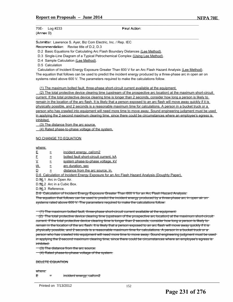
Report on Proposals – June 2014 NFPA 70E_______________________________________________________________________________________________70E- Log #233
_______________________________________________________________________________________________Lawrence S. Ayer, Biz Com Electric, Inc. / Rep. IEC
Revise title of D.2, D.3D.2 Basic Equations for Calculating Arc Flash Boundary Distances (Lee Method).D.3 Single-Line Diagram of a Typical Petrochemical Complex (Using Lee Method).D.4 Sample Calculation (Lee Method).D.5 CalculationCalculation of Incident Energy Exposure Greater Than 600 V for an Arc Flash Hazard Analysis (Lee Method).
The equation that follows can be used to predict the incident energy produced by a three-phase arc in open air onsystems rated above 600 V. The parameters required to make the calculations follow.
(1) The maximum bolted fault, three-phase short-circuit current available at the equipment.(2) The total protective device clearing time (upstream of the prospective arc location) at the maximum short-circuit
current. If the total protective device clearing time is longer than 2 seconds, consider how long a person is likely toremain in the location of the arc flash. It is likely that a person exposed to an arc flash will move away quickly if it isphysically possible, and 2 seconds is a reasonable maximum time for calculations. A person in a bucket truck or aperson who has crawled into equipment will need more time to move away. Sound engineering judgment must be usedin applying the 2-second maximum clearing time, since there could be circumstances where an employee’s egress isinhibited.
(3) The distance from the arc source.(4) Rated phase-to-phase voltage of the system.
NO CHANGE TO EQUATION
where:E = incident energy, cal/cm2F = bolted fault short-circuit current, kAV = system phase-to-phase voltage, kVtA = arc duration, secD = distance from the arc source, in.D.6 Calculation of Incident Energy Exposure for an Arc Flash Hazard Analysis (Doughty Paper).D.56.1 Arc in Open Air.D.56.2 Arc in a Cubic Box.D.56.3 Reference.D.6 Calculation of Incident Energy Exposure Greater Than 600 V for an Arc Flash Hazard Analysis.The equation that follows can be used to predict the incident energy produced by a three-phase arc in open air onsystems rated above 600 V. The parameters required to make the calculations follow.
(1) The maximum bolted fault, three-phase short-circuit current available at the equipment.(2) The total protective device clearing time (upstream of the prospective arc location) at the maximum short-circuit
current. If the total protective device clearing time is longer than 2 seconds, consider how long a person is likely toremain in the location of the arc flash. It is likely that a person exposed to an arc flash will move away quickly if it isphysically possible, and 2 seconds is a reasonable maximum time for calculations. A person in a bucket truck or aperson who has crawled into equipment will need more time to move away. Sound engineering judgment must be usedin applying the 2-second maximum clearing time, since there could be circumstances where an employee’s egress isinhibited.
(3) The distance from the arc source.(4) Rated phase-to-phase voltage of the system.
DELETE EQUATION
where:E = incident energy, cal/cm2
152Printed on 7/13/2012
Page 231 of 276

Report on Proposals – June 2014 NFPA 70EF = bolted fault short-circuit current, kAV = system phase-to-phase voltage, kVtA = arc duration, secD = distance from the arc source, in.
INSERT INCLUDE 70E_L233 (PI #447) Rec
The methods listed in Annex D should be grouped according to the calculation method. Having themethods grouped as is confusing. The main headers in each section should also have the method listed in their titles toprovide more clarity to the user.
_______________________________________________________________________________________________70E- Log #204
_______________________________________________________________________________________________David A. Pace, Olin Corporation
Revise the last row of Table D.1 to read as follows: In the second column, replace the existing textwith "Dan Doan Paper", in the third column replace the existing text with "Calculates incident energy for DC systemsrated up to 1000 volts DC".
The existing text incorrectly describes the content of D.8.
_______________________________________________________________________________________________70E- Log #231
_______________________________________________________________________________________________Lawrence S. Ayer, Biz Com Electric, Inc. / Rep. IEC
Revise Row D.8 in the table to read:
D.8 ANSI/IEEE C2 NESC, Section 410, Table 410-1 and Table 410-2 Calculates incident energy foropen air phase-to-ground arcs 1 kV to 500 kV
Direct-Current Incident Energy Calculations for live-line work DC systems upto 1000 V.
The 2012 70E Standard did not correct the wording in the Table D.1 to address the deletion of theANSI/IEEE NESC Tables and the acceptance of the DC Incident Energy Calculations in its place. This revised wordingcorrects this issue.
153Printed on 7/13/2012
Page 232 of 276

D. 7 Basic Equations for Calculating Incident Energy and Arc Flash Boundary (IEEE 1584 Method). This section provides excerpts from IEEE 1584 for estimating incident energy and arc flash boundaries based on statistical analysis and curve fitting of available test data. An IEEE working group produced the data from tests it performed to produce models of incident energy. The complete data, including a spreadsheet calculator to solve the equations, can be found in the IEEE 1584, Guide for Performing Arc Flash Hazard Calculations. Users are encouraged to consult the latest version of the complete document to understand the basis, limitation, rationale, and other pertinent information for proper application of the standard. It can be ordered from the Institute of Electrical and Electronics Engineers, Inc., 445 Hoes Lane, P.O. Box 1331, Piscataway, NJ 08855-1331. D.7.1 System Limits. An equation for calculating incident energy can be empirically derived using statistical analysis of raw data along with a curve-fitting algorithm. It can be used for systems with the following limits:
1. 0.208 kV to 15 kV, three-phase 2. 50 Hz to 60 Hz 3. 700 A to 106,000 A available short-circuit current 4. 13 mm to 152 mm conductor gaps
For three-phase systems in open-air substations, open-air transmission systems, and distribution systems, a theoretically derived model is available. This theoretically derived model is intended for use with applications where faults escalate to three-phase faults. Where such an escalation is not possible or likely, or where single-phase systems are encountered, this equation will likely provide conservative results. D.7.2 Arcing Current. To determine the operating time for protective devices, find the predicted three-phase arcing current. For applications with a system voltage under 1 kV, solve Equation D.7.2(a) as follows:
[D.7.2(a)] where: lg = the log10
Ia = arcing current, kA
K = -0.153 for open air arcs; -0.097 for arcs-in-a-box
Ibf = bolted three-phase available short-circuit current (symmetrical rms), kA
V = system voltage, kV
G = conductor gap, mm (see Table D.7.2) For systems greater than or equal to 1 kV, use Equation D.7.2(b):
[D.7.2(b)] This higher voltage formula is used for both open-air arcs and for arcs-in-a-box. Convert from lg:
[D.7.2(c)] Use 0.85Ia to find a second arc duration. This second arc duration accounts for variations in the arcing current and the time for the overcurrent device to open. Calculate the incident energy using both arc durations (Ia and 0.85 Ia ), and use the higher incident energy. Table D.7.2 Factors for Equipment and Voltage Classes
System Voltage (kV) Type of Equipment Typical Conductor Gap (mm) Distance Exponent Factor X
Page 233 of 276

Open air 10–40 2.000
0.208–1 Switchgear 32 1.473
MCCs and panels 25 1.641
Cables 13 2.000
Open air 102 2.000
>1–5 Switchgear 13–102 0.973
Cables 13 2.000
Open air 13–153 2.000
>5–15 Switchgear 153 0.973
Cables 13 2.000
D.7.3 Incident Energy at Working Distance — Empirically Derived Equation. To determine the incident energy using the empirically derived equation, determine the log10 of the normalized incident energy. The following equation is based on data normalized for an arc time of 0.2 second and a distance from the possible arc point to the person of 610 mm:
[D.7.3(a)] where: En = incident energy, normalized for time and distance, J/cm2
k1 = -0.792 for open air arcs; -0.555 for arcs-in-a-box
k2 = 0 for ungrounded and high-resistance grounded systems
= -0.113 for grounded systems
G = conductor gap, mm (see Table D.7.2) Then,
[D.7.3(b)] Converting from normalized:
[D.7.3(c)] where: E = incident energy, J/cm2.
Cf = calculation factor
= 1.0 for voltages above 1 kV.
= 1.5 for voltages at or below 1 kV.
En = incident energy normalized.
t = arcing time, sec.
x = distance exponent from Table D.7.2.
D = distance, mm, from the arc to the person (working distance). See Table D.7.3 for typical working distances. Table D.7.3 Typical Working Distances
Classes of Equipment Typical Working Distance* (mm)
Page 234 of 276

Classes of Equipment Typical Working Distance* (mm) 15-kV switchgear 910 5-kV switchgear 910 Low-voltage switchgear 610 Low-voltage MCCs and panelboards 455 Cable 455 Other To be determined in field
* Typical working distance is the sum of the distance between the worker and the front of the equipment and the distance from the front of the equipment to the potential arc source inside the equipment. If the arcing time, t, in Equation D.7.3(c) is longer than 2 seconds, consider how long a person is likely to remain in the location of the arc flash. It is likely that a person exposed to an arc flash will move away quickly if it is physically possible, and 2 seconds is a reasonable maximum time for calculations. Sound engineering judgment should be used in applying the 2-second maximum clearing time, because there could be circumstances where an employee’s egress is inhibited. For example, a person in a bucket truck or a person who has crawled into equipment will need more time to move away. D.7.4 Incident Energy at Working Distance — Theoretical Equation. The following theoretically derived equation can be applied in cases where the voltage is over 15 kV or the gap is outside the range:
[D.7.4] where: E = incident energy, J/cm2
V = system voltage, kV
Ibf = available three-phase bolted fault current
t = arcing time, sec
D = distance (mm) from the arc to the person (working distance) For voltages over 15 kV, arcing fault current and bolted fault current are considered equal. D.7.5 Arc Flash Boundary. The arc flash boundary is the distance at which a person is likely to receive a second degree burn. The onset of a second degree burn is assumed to be when the skin receives 5.0 J/cm2 of incident energy. For the empirically derived equation,
[D.7.5(a)] For the theoretically derived equation,
[D.7.5(b)] where: DB = distance (mm) of the arc flash boundary from the arcing point
Cf = calculation factor
= 1.0 for voltages above 1 kV
= 1.5 for voltages at or below 1 kV
En = incident energy normalized
t = time, sec
X = distance exponent from Table D.7.2
Page 235 of 276

EB = incident energy in J/cm2 at the distance of the arc flash boundary
V = system voltage, kV
Ibf = bolted three-phase available short-circuit current Informational Note: These equations could be used to determine whether selected personal protective equipment is adequate to prevent thermal injury at a specified distance in the event of an arc flash. D.7.6 Current-Limiting Fuses. The formulas in this section were developed for calculating arc flash energies for use with current-limiting Class L and Class RK1 fuses. The testing was done at 600 V and at a distance of 455 mm, using commercially available fuses from one manufacturer. The following variables are noted: Ibf = available three-phase bolted fault current (symmetrical rms), kA E = incident energy, J/cm2 (A) Class L Fuses 1601 A through 2000 A. Where Ibf <22.6 kA, calculate the arcing current using Equation D.7.2(a), and use time-current curves to determine the incident energy using Equations D.7.3(a), D.7.3(b), and D.7.3(c). Where 22.6 kA ≤Ibf ≤65.9 kA,
[D.7.6(a)] Where 65.9 kA < Ibf ≤106 kA,
[D.7.6(b)] Where Ibf >106 kA, contact the manufacturer. (B) Class L Fuses 1201 A through 1600 A. Where Ibf <15.7 kA, calculate the arcing current using Equation D.7.2(a), and use time-current curves to determine the incident energy using Equations D.7.3(a), D.7.3(b), and D.7.3(c). Where 15.7 kA ≤Ibf ≤31.8 kA,
[D.7.6(c)] Where 44.1 kA ≤Ibf ≤65.9 kA,
[D.7.6(e)] Where 65.9 kA <Ibf ≤106 kA,
[D.7.6(f)] Where Ibf >106 kA, contact the manufacturer. (C) Class L Fuses 801 A through 1200 A. Where Ibf <15.7 kA, calculate the arcing current using Equation D.7.2(a), and use time-current curves to determine the incident energy per Equations D.7.3(a), D.7.3(b), and D.7.3(c). Where 15.7 kA ≤Ibf ≤22.6 kA,
[D.7.6(g)] Where 22.6 kA <Ibf ≤44.1 kA,
[D.7.6(h)] Where 44.1 kA <Ibf ≤106 kA,
[D.7.6(i)] Where Ibf >106 kA, contact the manufacturer. (D) Class L Fuses 601 A through 800 A. Where Ibf <15.7 kA, calculate the arcing current using Equation D.7.2(a), and use time-current curves to determine the incident energy using Equations D.7.3(a), D.7.3(b), and D.7.3(c). Where 15.7 kA ≤Ibf ≤44.1 kA,
Page 236 of 276

[D.7.6(j)] Where 44.1 kA < Ibf ≤106 kA,
[D.7.6(k)] Where Ibf > 106 kA, contact the manufacturer. (E) Class RK1 Fuses 401 A through 600 A. Where Ibf <8.5 kA, calculate the arcing current using Equation D.7.2(a), and use time-current curves to determine the incident energy using Equations D.7.3(a), D.7.3(b), and D.7.3(c). Where 8.5 kA ≤Ibf ≤14 kA,
[D.7.6(l)] Where 14 kA < Ibf ≤15.7 kA,
[D.7.6(m)] Where 15.7 kA < Ibf ≤22.6 kA,
[D.7.6(n)] Where 22.6 kA < Ibf ≤106 kA,
[D.7.6(o)] Where Ibf >106 kA, contact the manufacturer. (F) Class RK1 Fuses 201 A through 400 A. Where Ibf <3.16 kA, calculate the arcing current using Equation D.7.2(a), and use time-current curves to determine the incident energy using Equations D.7.3(a), D.7.3(b), and D.7.3(c). Where 3.16 kA ≤Ibf ≤5.04 kA,
[D.7.6(p)] Where 5.04 kA < Ibf ≤ 22.6 kA,
[D.7.6(q)] Where 22.6 kA <Ibf ≤ 106 kA,
[D.7.6(r)] Where Ibf >106 kA, contact the manufacturer. (G) Class RK1 Fuses 101 A through 200 A. Where Ibf <1.16 kA, calculate the arcing current using Equation D.7.2(a), and use time-current curves to determine the incident energy using Equations D.7.3(a), D.7.3(b), and D.7.3(c). Where 1.16 kA ≤Ibf ≤1.6 kA,
[D.7.6(s)] Where 1.6 kA < Ibf ≤3.16 kA,
[D.7.6(t)] Where 3.16 kA <Ibf ≤106 kA,
[D.7.6(u)] Where Ibf > 106 kA, contact the manufacturer. (H) Class RK1 Fuses 1 A through 100 A. Where Ibf <0.65 kA, calculate the arcing current using Equation D.7.2(a), and use time-current curves to determine the incident energy using Equations D.7.3(a), D.7.3(b), and D.7.3(c). Where 0.65 kA ≤Ibf ≤1.16 kA,
[D.7.6(v)] Page 237 of 276
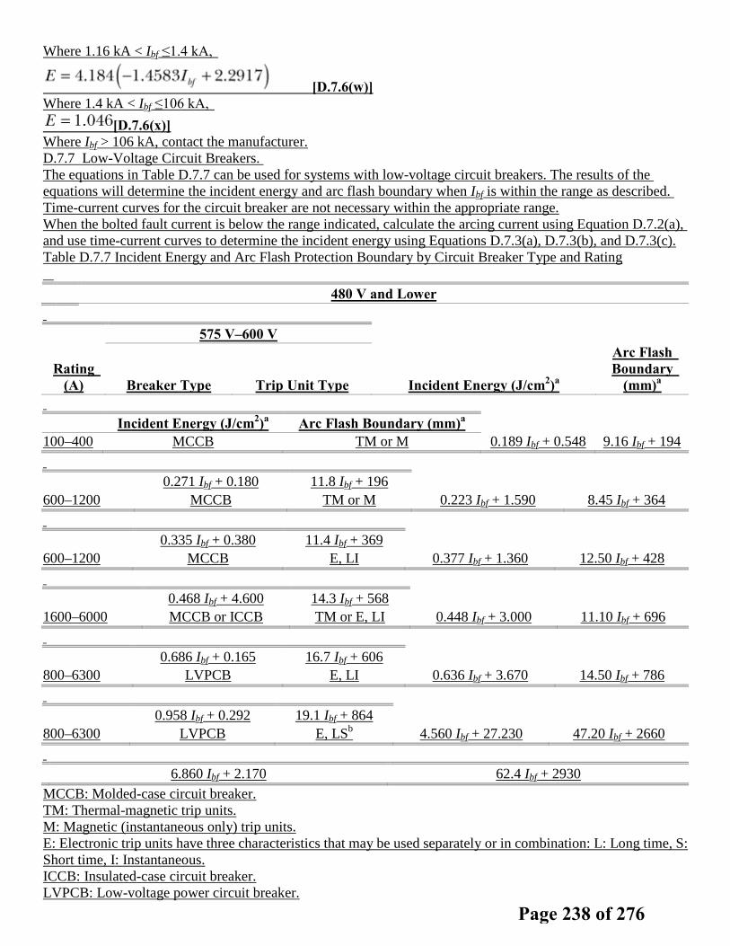
Where 1.16 kA < Ibf ≤1.4 kA,
[D.7.6(w)] Where 1.4 kA < Ibf ≤106 kA,
[D.7.6(x)] Where Ibf > 106 kA, contact the manufacturer. D.7.7 Low-Voltage Circuit Breakers. The equations in Table D.7.7 can be used for systems with low-voltage circuit breakers. The results of the equations will determine the incident energy and arc flash boundary when Ibf is within the range as described. Time-current curves for the circuit breaker are not necessary within the appropriate range. When the bolted fault current is below the range indicated, calculate the arcing current using Equation D.7.2(a), and use time-current curves to determine the incident energy using Equations D.7.3(a), D.7.3(b), and D.7.3(c). Table D.7.7 Incident Energy and Arc Flash Protection Boundary by Circuit Breaker Type and Rating
480 V and Lower
575 V–600 V
Rating (A) Breaker Type Trip Unit Type Incident Energy (J/cm2)a
Arc Flash Boundary
(mm)a
Incident Energy (J/cm2)a Arc Flash Boundary (mm)a
100–400 MCCB TM or M 0.189 Ibf + 0.548 9.16 Ibf + 194
0.271 Ibf + 0.180 11.8 Ibf + 196
600–1200 MCCB TM or M 0.223 Ibf + 1.590 8.45 Ibf + 364
0.335 Ibf + 0.380 11.4 Ibf + 369
600–1200 MCCB E, LI 0.377 Ibf + 1.360 12.50 Ibf + 428
0.468 Ibf + 4.600 14.3 Ibf + 568
1600–6000 MCCB or ICCB TM or E, LI 0.448 Ibf + 3.000 11.10 Ibf + 696
0.686 Ibf + 0.165 16.7 Ibf + 606
800–6300 LVPCB E, LI 0.636 Ibf + 3.670 14.50 Ibf + 786
0.958 Ibf + 0.292 19.1 Ibf + 864
800–6300 LVPCB E, LSb 4.560 Ibf + 27.230 47.20 Ibf + 2660
6.860 Ibf + 2.170 62.4 Ibf + 2930
MCCB: Molded-case circuit breaker. TM: Thermal-magnetic trip units. M: Magnetic (instantaneous only) trip units. E: Electronic trip units have three characteristics that may be used separately or in combination: L: Long time, S: Short time, I: Instantaneous. ICCB: Insulated-case circuit breaker. LVPCB: Low-voltage power circuit breaker.
Page 238 of 276

aIbf is in kA; working distance is 455 mm (18 in.). b Short-time delay is assumed to be set at maximum. The range of available three-phase bolted fault currents is from 700 A to 106,000 A. Each equation is applicable for the following range:
where: I1 = minimum available three-phase, bolted, short-circuit current at which this method can be applied. I1 is the
lowest available three-phase, bolted, short-circuit current level that causes enough arcing current for instantaneous tripping to occur, or, for circuit breakers with no instantaneous trip, that causes short-time tripping to occur.
I2 = interrupting rating of the circuit breaker at the voltage of interest. To find I1, the instantaneous trip (It ) of the circuit breaker must be found. It can be determined from the time-current curve, or it can be assumed to be 10 times the rating of the circuit breaker for circuit breakers rated above 100 amperes. For circuit breakers rated 100 amperes and below, a value of It = 1300 A can be used. When short-time delay is utilized, It is the short-time pickup current. The corresponding bolted fault current, Ibf , is found by solving the equation for arc current for box configurations by substituting It for arcing current. The 1.3 factor in Equation D.7.7(b) adjusts current to the top of the tripping band.
[D.7.7(a)] At 600 V,
[D.7.7(b)] At 480 V and lower,
[D.7.7(c)]
[D.7.7(d)] D.7.8 References. The complete data, including a spreadsheet calculator to solve the equations, can be found in IEEE 1584, Guide for Performing Arc Flash Hazard Calculations. IEEE publications are available from the Institute of Electrical and Electronics Engineers, 445 Hoes Lane, P.O. Box 1331, Piscataway, NJ 08855-1331, USA (http://standards.ieee.org/).
Page 239 of 276

Report on Proposals – June 2014 NFPA 70E_______________________________________________________________________________________________70E- Log #232
_______________________________________________________________________________________________Lawrence S. Ayer, Biz Com Electric, Inc. / Rep. IEC
Revise Table to read:
INSERT 70E_L232 (PI #446) Tbl D.1
The Table should be reworked and the calculation methods should be grouped according to eachspecific method in order for the user to find the information more easily. For instance the Ralph Lee method for bothcalculating the arc flash boundary and the incident energy should be grouped so they are close together. Should thecommittee accept the new grouping the associated sections in Annex should be relocated according to the newgrouping and all titles and tables should be numbered accordingly.
_______________________________________________________________________________________________70E- Log #124
_______________________________________________________________________________________________Daniel T. Roberts, Schneider Electric / Rep. Hazard & Risk Ad Hoc Task Group
Revise title to read:D.5 Calculation of Incident Energy Exposure for an Arc Flash Hazard Analysis .
This is one of multiple Public Input proposals from the NFPA 70E Hazard & Risk Ad Hoc Task Groupthat seeks to clarify and promote the consistent use throughout the document of terminology associated with hazard andrisk.The proposed change provides clarity. The deleted text is redundant.
_______________________________________________________________________________________________70E- Log #125
_______________________________________________________________________________________________Daniel T. Roberts, Schneider Electric / Rep. Hazard & Risk Ad Hoc Task Group
Revise title to read:D.6 Calculation of Incident Energy Exposure Greater Than 600 V for an Arc Flash Hazard Analysis .
This is one of multiple Public Input proposals from the NFPA 70E Hazard & Risk Ad Hoc Task Groupthat seeks to clarify and promote the consistent use throughout the document of terminology associated with hazard andrisk.The proposed change provides clarity. The deleted text is redundant.
_______________________________________________________________________________________________70E- Log #28
_______________________________________________________________________________________________Edson Bittar Henriques, Veolia Water Solutions & Technologies
Revise text to read as follows:En= incident energy, normalized for time and distance, J/cm2 cal/cm2
In the equation D.7.3(a) the unit of En energy I think is cal/cm2 because it is used to calculated theenergy E in J/cm2 in the next equation D.7.3(c) and this equation has a correction factor 4.184 that is to convert the units(1 cal = 4,184 J). This factor 4.184 is necessary in this equations because the unit of En is cal/cm2 and the unit of E isJ/cm2.Please check the IEEE 1584, I do not have this standard to check.
154Printed on 7/13/2012
Page 240 of 276

Table D.1 Limitation of Calculation Methods 6
Section Source Limitations/Parameters
D.2, D.3, D.4, D.5
Ralph Lee paper
Calculates arc flash boundary for arc in open air; conservative over 600 V and becomes more conservative as voltage increases
Calculates incident energy for three-phase arc in open air on systems rated above 600 V; becomes more conservative as voltage increases
D.56 Doughty/Neal paper Calculates incident energy for three-phase arc on systems rated 600 V and below; applies to short-circuit currents between 16 kA and 50 kA
D.
Ralph Lee paper
Calculates incident energy for three-phase arc in open air on systems rated above 600 V; becomes more conservative as voltage increases
D.7 IEEE Std. 1584
Calculates incident energy and arc flash boundary for: 208 V to 15 kV; three-phase; 50 Hz to 60 Hz; 700 A to 106,000 A short-circuit current; and 13 mm to 152 mm conductor gaps
D.8 ANSI/IEEE C2 NESC, Section 410, Table 410-1 and Table 410-2
Calculates incident energy for open air phase-to-ground arcs 1 kV to 500 kV for live-line work
Page 241 of 276

Report on Proposals – June 2014 NFPA 70E_______________________________________________________________________________________________70E- Log #115
_______________________________________________________________________________________________Daniel Doan, DuPont Engineering
Revise to read:D.8.1.1 Maximum Power Method. The method of estimating dc arc flash incident energy that follows was presented at
the 2007 IEEE Electrical Safety Workshop and subsequently peer-reviewed and published in the IEEE Transactions onIndustry Applications (see reference 2, which follows). This method is based on the concept that the maximum powerpossible in a dc arc will occur when the arcing voltage is one-half of the system voltage. Testing completed for BrucePower (see reference 3, which follows) has shown that this calculation is conservatively high in estimating the arc flashvalue. This method applies to dc systems rated up to 1000 Vdc.
[Formula remains unchanged]
where:= arcing current, amperes= system bolted fault current, amperes= estimated dc arc flash incident energy at the maximum power point, cal/cm2= system voltage, volts= arcing time, sec= working distance, cm
For exposures where the arc is in a box or enclosure, it would be prudent to use a multiplying factor of 3 for theresulting incident energy value.
The reference paper has been published in IEEE Transactions, and the reference in Annex D shouldbe updated to show the status.
_______________________________________________________________________________________________70E- Log #116
_______________________________________________________________________________________________Daniel Doan, DuPont Engineering
Revise to read:D.8.1.2 Detailed Arcing Current and Energy Calculations Method. A thorough theoretical review of dc arcing current
and energy was presented at the 2009 IEEE PCIC Conference and subsequently peer-reviewed and published in theIEEE Transactions on Industry Applications. Readers are advised to refer to that paper (see reference 1) for thosedetailed calculations.References:1. “DC arc models and incident energy calculations -Arc Models and Incident-Energy Calculations,” Ammerman, R.F.;
Gammon, T.; Sen, P.K.; Nelson, J.P.; Petroleum and Chemical Industry Conference, 2009, Record of ConferencePapers,14–16 September 2009 IEEE Transactions on Industry Applications, Volume: 46, Issue: 5, Publication Year:2010, Page(s): 1810 – 1819.2. “Arc Flash Calculations for Exposures to DC Systems,” Doan, D.R., IEEE IAS Electrical Safety Workshop, 2007,
Record of Conference Papers, March 2007 Transactions on Industry Applications, Volume: 46, Issue: 6, PublicationYear: 2010, Page(s): 2299 – 2302.3. DC Arc Hazard Assessment Phase II Copyright Material Kinectrics Inc. Report No. K-012623-RA-0002-R00.
These reference papers have been published in Transactions, and the references in Annex D shouldbe updated to show their status.
155Printed on 7/13/2012
Page 242 of 276

Report on Proposals – June 2014 NFPA 70E_______________________________________________________________________________________________70E- Log #234
_______________________________________________________________________________________________Lawrence S. Ayer, Biz Com Electric, Inc. / Rep. IEC
Add a new section to read:D.8.1.3 Short Circuit Current. The determination of arcing current is necessary in order to use the DC Hazard/Risk
TaskTable 130.7(C)(15)(b). This current is calculated at 50% of the DC short-circuit value. The current that a batterywill deliver depends on the total resistance of the short-circuit path. A conservative approach in determining theshort-circuit curren that the battery will deliver at 25 degree C is to assume that the maximum available short-circuitcurrent is 10 times the 1 min ampere rating (to 1.75 V per cell at 25 deg C and the specific gravity of 1.215) of thebattery. A more accurate value for the short-circuit current for the speciific application may be obtained from the batterymanufacturer.References1. IEEE Standard 946-2004, "Recommended Practice for the Design of DC Auxiliary Powers Systems for Generating
Stations".To use the DC task based tables one must calculate the arcing current. This arcing current is roughly
50% of the short-circuit current in the system. The user of the standard must be familiar with where to go to findinformation that will help calculate the short circuit of the DC system. IEEE 946 helps provide that guidance as well as arule of thumb. This information is important and should be included in Annex D.
_______________________________________________________________________________________________70E- Log #273
_______________________________________________________________________________________________Daniel T. Roberts, Schneider Electric / Rep. Hazard & Risk Ad Hoc Task Group
Revise text to read:(6) Identify the electrical hazards and minimize reduce the hazard associated risk
This is one of multiple Public Input proposals from the NFPA 70E Hazard & Risk Ad Hoc Task Groupthat seeks to clarify and promote the consistent use throughout the document of terminology associated with hazard andrisk.The proposed change provides clarity and consistency with the definitions of hazard, risk and risk assessment, and
with risk management principles (hazards are identified; risk is assessed and controlled by following a hierarchy of riskcontrol methods).
_______________________________________________________________________________________________70E- Log #274
_______________________________________________________________________________________________Daniel T. Roberts, Schneider Electric / Rep. Hazard & Risk Ad Hoc Task Group
Revise text to read:(5) Procedures are to be used as tools to identify the electrical hazards and to develop plans to eliminate /those
electrical hazards, or control the associated risk for those hazards that cannot be eliminated.(8) A logical approach is to be used to determine the potential hazard of identify electrical hazards and assess the
associated risk of a task.Remainder unchanged
This is one of multiple Public Input proposals from the NFPA 70E Hazard & Risk Ad Hoc Task Groupthat seeks to clarify and promote the consistent use throughout the document of terminology associated with hazard andrisk.The proposed change provides clarity and consistency with the definitions of hazard, risk and risk assessment, and
with risk management principles (hazards are identified; risk is assessed and controlled by following a hierarchy of riskcontrol methods).
156Printed on 7/13/2012
Page 243 of 276

Report on Proposals – June 2014 NFPA 70E_______________________________________________________________________________________________70E- Log #275
_______________________________________________________________________________________________Daniel T. Roberts, Schneider Electric / Rep. Hazard & Risk Ad Hoc Task Group
Revise text to read:(3) Hazardous nature and extent of task Identifying hazards and assessing riskRemainder unchanged
This is one of multiple Public Input proposals from the NFPA 70E Hazard & Risk Ad Hoc Task Groupthat seeks to clarify and promote the consistent use throughout the document of terminology associated with hazard andrisk.The proposed change provides clarity and consistency: hazards are identified and risk is assessed.
_______________________________________________________________________________________________70E- Log #276
_______________________________________________________________________________________________Daniel T. Roberts, Schneider Electric / Rep. Hazard & Risk Ad Hoc Task Group
Revise title to read:Annex F Hazard Analysis, Risk Estimation, and Risk Evaluation Risk Assessment Procedure
This is one of multiple Public Input proposals from the NFPA 70E Hazard & Risk Ad Hoc Task Groupthat seeks to clarify and promote the consistent use throughout the document of terminology associated with hazard andrisk.The proposed change provides clarity and consistency. The deleted text does not align with the current title of 110.3(F)
Hazard Identification and Risk Assessment. The deleted text is also redundant: a risk assessment includes hazardanalysis, risk estimation, and risk evaluation.
_______________________________________________________________________________________________70E- Log #277
_______________________________________________________________________________________________Daniel T. Roberts, Schneider Electric / Rep. Hazard & Risk Ad Hoc Task Group
Revise text to read:G.3.3 Review other work activity to identify where and how other personnel might be exposed to sources of electrical
energy hazards electrical hazards. Review other energy sources in the physical area to determine employee exposureto sources of other types of energy. Establish energy control methods for control of other hazardous energy sources inthe area.
This is one of multiple Public Input proposals from the NFPA 70E Hazard & Risk Ad Hoc Task Groupthat seeks to clarify and promote the consistent use throughout the document of terminology associated with hazard andrisk.The proposed change provides clarity and consistency. Electrical hazard is a defined term.
157Printed on 7/13/2012
Page 244 of 276

Report on Proposals – June 2014 NFPA 70E_______________________________________________________________________________________________70E- Log #225
_______________________________________________________________________________________________Philip Allen, Grace Engrd Products
Add a new section to read:G.5.2 If the electrical supply has permanent voltage detection device(s) installed, verify that the device(s) operate
properly.Facilities that install permanent electrical safety devices (PESDs) into their electrical systems and use
them as part of their lock-out tag-out (LOTO) procedures must insure that these devices function properly prior todisconnecting the power as per ANNEX G 5.2 (2012 Edition). PESDs are typically designed for 3-phase operation andmount on the outside of the electrical enclosure; therefore they need to be checked for proper operations while 3-phaseexists. Note: This task takes place without any voltage exposure for the worker and give the worker helpful informationabout the status of the power within the electrical enclosure (blown fuse, failed isolator, etc.) prior to beginning theLOTO and opening the panel.
_______________________________________________________________________________________________70E- Log #235
_______________________________________________________________________________________________Lawrence S. Ayer, Biz Com Electric, Inc. / Rep. IEC
Add a new section to read:G.5.3 Wherever possible the blades of the disconnecting device should be visually verified to be fully opened and
drawn-out circuit breakers should be verified to be completely withdrawn to the disconnected position.The sample lock-out tag-out procedure does not incorporate the visual verification item from Section
120.1(3). The addition of this text will correlate section 120.1 with Annex G.
_______________________________________________________________________________________________70E- Log #227
_______________________________________________________________________________________________Philip Allen, Grace Engrd Products
Add a new section to read:G.6.9 If the electrical supply has permanent voltage detection device(s) installed, verify that the device(s) operate
properly.Facilities that install permanent electrical safety devices (PESDs) into their electrical systems and use
them as part of their lock-out tag-out (LOTO) procedures must insure that these devices function properly after theelectrical system returns to its normal condition (powered up). PESDs are typically designed for 3-phase operation andmount on the outside of the electrical enclosure; therefore they need to be re-checked for proper operations once3-phase returns.
158Printed on 7/13/2012
Page 245 of 276

Report on Proposals – June 2014 NFPA 70E_______________________________________________________________________________________________70E- Log #278
_______________________________________________________________________________________________Daniel T. Roberts, Schneider Electric / Rep. Hazard & Risk Ad Hoc Task Group
Revise text to read:G.9.3 The person in charge shall develop a written plan of execution and communicate that plan to all persons
engaged in the job or task. The person in charge shall be held accountable for safe execution of the complexlockout/tagout plan. The complex lockout/tagout plan must address all the concerns of employees who might beexposed, and they must understand how electrical energy is controlled. The person in charge shall ensure that eachperson understands the electrical hazards to which they are exposed and the safety-related work practices they are touse.
This is one of multiple Public Input proposals from the NFPA 70E Hazard & Risk Ad Hoc Task Groupthat seeks to clarify and promote the consistent use throughout the document of terminology associated with hazard andrisk.The proposed change provides clarity and consistency with the scope of the document. Electrical hazard is a defined
term.
_______________________________________________________________________________________________70E- Log #318
_______________________________________________________________________________________________T. David Mills, Savannah River Nuclear Solutions, LLC
INCLUDE 70E_L318 (PI #274) Rec
Section 130.5(C) requires a calculation of incident energy to be implemented which renders the Tables130.7(C)(15)(a) and (b) useless, since there cannot be an alternative method to determine the label information. This isa built-in conflict which the AHJ has no recourse without an enforcement clause in Article 90.
_______________________________________________________________________________________________70E- Log #319
_______________________________________________________________________________________________T. David Mills, Savannah River Nuclear Solutions, LLC
Revise text to read: H.1 Arc-Rated Clothing and Other Personal Protective Equipment (PPE) for Use with Hazard/Risk Categories. Table
130.7(C)(15)(a), Table 130.7(C)(15)(b), and Table 130.7(C)(16) provide provides guidance for the selection and use ofpersonal protective equipment when using hazard/risk categories.
Section 130.5(C) requires a calculation of incident energy to be implemented which renders the Tables130.7(C)(15)(a) and (b) useless, since there cannot be an alternative method to determine the label information. This isa built-in conflict which the AHJ has no recourse without an enforcement clause in Article 90.
159Printed on 7/13/2012
Page 246 of 276

Annex H Guidance on Selection of Protective Clothing and Other Personal Protective Equipment This informative annex is not a part of the requirements of this NFPA document but is included for informational purposes only. H.1 Arc-Rated Clothing and Other Personal Protective Equipment (PPE) for Use with Hazard/Risk Categories. Table 130.7(C)(15)(a), Table 130.7(C)(15)(b), and Table 130.7(C)(16) provide provides guidance for the selection and use of personal protective equipment when using hazard/risk categories. H.2 Simplified Two-Category Clothing Approach for Use with Table 130.7(C)(15)(a), Table 130.7(C)(15)(b), and Table 130.7(C)(16). The use of Table H.2 is a simplified approach to provide minimum personal protective equipment for electrical workers within facilities with large and diverse electrical systems. The clothing listed in Table H.2 fulfills the minimum arc-rated clothing requirements of Table 130.7(C)(15)(a), Table 130.7(C)(15)(b), and Table 130.7(C)(16). The clothing systems listed in this table should be used with the other PPE appropriate for the hazard/risk category [see Table 130.7(C)(16)].The notes to Table 130.7(C)(15)(a), and Table 130.7(C)(15)(b), must apply as shown in that table. Table H.2 Simplified, Two-Category, Arc-Rated Clothing System
Clothinga Applicable Tasks Everyday Work Clothing
Arc-rated long-sleeve shirt with Arc-rated pants (minimum arc rating of 8)
or Arc-rated coveralls (minimum arc rating of 8)
All Hazard/Risk Category 1 and Hazard/Risk Category 2 tasks
listed in Table 130.7(C)(15)(a) and Table 130.7(C)(15)(b)b Arc Flash Suit
A total clothing system consisting of arc-rated shirt and pants and/or arc-rated coveralls and/or arc flash coat and pants (clothing system minimum arc rating
of 40)
All Hazard/Risk Category 3 and Hazard/Risk Category 4 tasks
listed in Table 130.7(C)(15)(a) and Table 130.7(C)(15)(b) b aNote that other PPE required for the specific tasks listed in Table 130.7(C)(15)(a), Table 130.7(C)(15)(b), and
Table 130.7(C)(16), which include arc-rated face shields or arc flash suit hoods, arc-rated hard hat liners, safety glasses or safety goggles, hard hats, hearing protection, heavy-duty leather gloves, voltage-rated gloves, and voltage-rated tools, could be required. The arc rating for a garment is expressed in cal/cm2. bThe assumed short-circuit current capacities and fault clearing times for various tasks are listed in the text of Table 130.7(C)(15)(a) and Table 130.7(C)(15)(b). For tasks not listed, or for power systems with greater than the assumed short-circuit capacity or with longer than the assumed fault clearing times, an arc flash hazard analysis is required in accordance with 130.5.
Page 247 of 276
Report on Proposals – June 2014 NFPA 70E_______________________________________________________________________________________________70E- Log #236
_______________________________________________________________________________________________Lawrence S. Ayer, Biz Com Electric, Inc. / Rep. IEC
Revise footnote b to read:bThe assumed short-circuit current or arcing current capacities and fault clearing times for various tasks are listed in the
text of Table 130.7(C)(15)(a) and Table 130.7(C)(15)(b). For tasks not listed, or for power systems with greater than theassumed short-circuit or arcing current capacity or with longer than the assumed fault clearing times, an arc flash hazardanalysis is required in accordance with 130.5.
A DC task table 130.7(C)(15)(b) was introduced in 2012. This table is based upon arcing current, notshort-circuit currents. As a result the information provided in Note "b" should be revised to accurately account for thisnew table.
_______________________________________________________________________________________________70E- Log #320
_______________________________________________________________________________________________T. David Mills, Savannah River Nuclear Solutions, LLC
Delete Annex H.2 in its entirety.Section 130.5(C) requires a calculation of incident energy to be implemented which renders the Tables
130.7(C)(15)(a) and (b) useless, since there cannot be an alternative method to determine the label information. This isa built-in conflict which the AHJ has no recourse without an enforcement clause in Article 90.
_______________________________________________________________________________________________70E- Log #79
_______________________________________________________________________________________________Mike Doherty, Infrastructure Health & Safety Association / Rep. Canadian Standards Association (CSA)
Z462 Workplace Electrical Safety Technical CommitteeIn Table H.2 change footnote a to read:
aNote that other PPE required for the specific tasks listed in Table 130.7(C)(15)(a), Table 130.7(C)(15)(b), and Table130.7(C)(16), which include arc-rated face shields or arc flash suit hoods, arc-rated hard hat liners, safety glasses orsafety goggles, hard hats, hearing protection, heavy-duty leather gloves, voltage-rated rubber insulating gloves, andvoltage-rated tools insulating or insulated hand tools, could be required. The arc rating for a garment is expressed incal/cm2.
The existing wording is not consistent with the rest of the document and applicable ASTM Standards.
160Printed on 7/13/2012
Page 248 of 276

Report on Proposals – June 2014 NFPA 70E_______________________________________________________________________________________________70E- Log #279
_______________________________________________________________________________________________Daniel T. Roberts, Schneider Electric / Rep. Hazard & Risk Ad Hoc Task Group
Revise text to read:H.3 Arc-Rated Clothing and Other Personal Protective Equipment (PPE) for Use with a Hazard Analysis Risk
Assessment of Electrical Hazards.Table H.3(a) provides a summary of specific sections within the 70E standard describing personal protective
equipment for electrical hazards. GuidanceTable H.3(b) provides guidance on the selection of arc-rated clothing
and other personal protective equipment for users who conduct a hazard analysis to determine the incident energyexposure (in cal/cm2)to the worker is provided in Table H.3(b).
This is one of multiple Public Input proposals from the NFPA 70E Hazard & Risk Ad Hoc Task Groupthat seeks to clarify and promote the consistent use throughout the document of terminology associated with hazard andrisk.1. Revision to H.3 title aligns with proposed revision or “hazard analysis” with "risk assessment of electrical hazards"2. Revision to H.3 text provides clarity. The context indicates that the analysis referred to is an incident energy
analysis.
_______________________________________________________________________________________________70E- Log #280
_______________________________________________________________________________________________Daniel T. Roberts, Schneider Electric / Rep. Hazard & Risk Ad Hoc Task Group
INSERT 70E_L280 (PI #223) Table H.3(b)
This is one of multiple Public Input proposals from the NFPA 70E Hazard & Risk Ad Hoc Task Groupthat seeks to clarify and promote the consistent use throughout the document of terminology associated with hazard andrisk.The proposed change provides clarity and consistency with the rest of the document. It is sufficient to state the
relationship of the PPE to incident energy.Additionally, according to the exception in 130.5, an arc flash hazard analysis does not necessarily involve determining
incident energy (i.e. it may involve use of the Table method); therefore, the statement "by a hazard analysis" isinaccurate.
_______________________________________________________________________________________________70E- Log #90
_______________________________________________________________________________________________Mike Doherty, Infrastructure Health & Safety Association / Rep. Canadian Standards Association (CSA)
Z462 Workplace Electrical Safety Technical CommitteeRevise table to read:
INSERT 70E_L90_PI #127_Tbl H.3(a)
Consistent use of terminology within the document and with other referenced standards that addresssafety footwear such as the ASTM family of standards.
161Printed on 7/13/2012
Page 249 of 276

Table H.3(b) Guidance on Selection of Arc-Rated Clothing and Other Personal Protective Equipment (PPE) for Use When Incident Exposure is Determined by a Hazard Analysis Determined
Incident Energy Exposure Protective Clothing and PPE Less than or Equal to 1.2 cal/cm2 Protective clothing, nonmelting (in accordance with ASTM F 1506-08) or untreated natural fiber
Shirt (long sleeve) and pants (long) or coverall
Other personal protective equipment Face shield for projectile protection (AN) Safety glasses or safety goggles (SR) Hearing protection
Heavy-duty leather gloves or rubber insulating gloves with leather protectors (AN)
Greater than 1.2 to 12 cal/cm2
Arc-rated clothing and equipment with an arc rating equal to or greater than the determined incident energy determined in a hazard analysis (See Note 3.)
Arc-rated long-sleeve shirt and arc-rated pants or arc-rated coverall or arc flash suit (SR) (See Note 3.) Arc-rated face shield and arc-rated balaclava or arc flash suit hood (SR) (See Note 1.)
Arc-rated jacket, parka, or rainwear (AN) Other personal protective equipment Hard hat Arc-rated hard hat liner (AN) Safety glasses or safety goggles (SR) Hearing protection
Heavy-duty leather gloves or rubber insulating gloves with leather protectors (SR) (See Note 4.)
Leather work shoes Greater than 12 cal/cm2
Arc-rated clothing and equipment with an arc rating equal to or greater than the determined incident energy determined in a hazard analysis (See Note 3.)
Arc-rated long-sleeve shirt and arc-rated pants or arc-rated coverall and/or arc flash suit (SR) Arc-rated arc flash suit hood Arc-rated gloves
Arc-rated jacket, parka, or rainwear (AN) Other personal protective equipment Hard hat Arc-rated hard hat liner (AN) Safety glasses or safety goggles (SR) Hearing protection
Arc-rated gloves or rubber insulating gloves with leather protectors (SR) (See Note 4.)
Leather work shoes AN: As needed [in addition to the protective clothing and PPE required by 130.5(B)(1)]. SR: Selection of one in group is required by 130.5(B)(1). Notes: (1) Face shields with a wrap-around guarding to protect the face, chin, forehead, ears, and neck area are required by 130.8(C)(10)(c). For full head and neck protection, use a balaclava or an arc flash hood.
Page 250 of 276
(2) All items not designated “AN” are required by 130.7(C). (3) Arc ratings can be for a single layer, such as an arc-rated shirt and pants or a coverall, or for an arc flash suit or a multi-layer system consisting of a combination of arc-rated shirt and pants, coverall, and arc flash suit. (4) Rubber insulating gloves with leather protectors provide arc flash protection in addition to shock protection. Higher class rubber insulating gloves with leather protectors, due to their increased material thickness ,provide increased arc flash protection.
Page 251 of 276

Table H.3(a) Summary of Specific Sections Describing Personal Protective Equipment for Electrical Hazards
Shock Hazard Personal Protective Equipment Applicable Section(s) Rubber insulating gloves; and Leather protectors (unless the requirements of ASTM F 496 are met) 130.7(C)(7)(a)
Rubber insulating sleeves (as needed) 130.7(C)(7)(a) Class G or E hard hat (as needed) 130.7(C)(3) Safety glasses or goggles (as needed) 130.7(C)(4) Dielectric overshoes footwear (as needed) 130.7(C)(8) Arc Flash Hazard Personal Protective Equipment Applicable Section(s) Incident Energy Exposures up to and including 1.2 cal/cm2 Clothing: non-melting or untreated natural fiber long sleeve shirt and long pants or coverall 130.7(C)(1); 130.7(C)(9)(d)
Gloves: Heavy-duty leather 130.7(C)(7)(b); 130.7(C)(10)(d) Hard hat: class G or E 130.7(C)(3) Faceshield: covers the face, neck and chin (as needed) 130.7(C)(3) Safety glasses or goggles 130.7(C)(4); 130.7(C)(10)(c) Hearing protection 130.7(C)(5) Shoes or boots Occupational footwear: heavy duty leather (as needed) 130.7(C)(10)(e) Incident Energy Exposures >1.2 cal/cm2 Clothing: arc-rated clothing system with an arc rating appropriate to the anticipated incident energy exposure
130.7(C)(1); 130.7(C)(2); 130.7(C)(6); 130.7(C)(9)(d)
Clothing underlayers (when used): Arc-rated or nonmelting untreated natural fiber
130.7(C)(9)(c); 130.7(C)(11); 130.7(C)(12)
Gloves: 130.7(C)(7)(b); 130.7(C)(10)(d) Exposures >1.2 cal/cm2 and ≤8 cal/cm2: Heavy-duty leather gloves Exposures > 8 cal/cm2: Rubber insulating gloves with their leather protectors; or Arc-rated gloves
Hard hat: class G or E 130.7(C)(1); 130.7(C)(3) Face shield: 130.7(C)(1); 130.7(C)(3);
130.7(C)(10)(a); 130.7(C)(10)(b); 130.7(C)(10)(c)
Exposures> 1.2 cal/cm2 and ≤12 cal/cm2: Arc-rated faceshield that covers the face, neck and chin and an arc-rated balaclava or an arc-rated arc flash suit hood Exposures > 12 cal/cm2: Arc-rated arc flash suit hood Safety glasses or goggles 130.7(C)(4); 130.7(C)(10)(c) Hearing protection 130.7(C)(5) Footwear: 130.7(C)(10)(e) Exposures ≤4 cal/cm2: Heavy-duty leather work shoes (as needed) Exposures> 4 cal/cm2: Heavy duty leather work shoes
Page 252 of 276

Report on Proposals – June 2014 NFPA 70E_______________________________________________________________________________________________70E- Log #7
_______________________________________________________________________________________________James J. Toth, III, Delta Power Systems Engineering, PC
Revise text to read as follows:Greater than 12 cal/cm2 to 40 cal/cm2.
As shown in the table, there is no magnitude of incident energy that is unsafe to be exposed to whenworking on energized electrical equipment. If the incident energy calculation showed an incident energy of 99 cal/cm 2,using 100 cal/cm2 arc-rated clothing would be acceptable. In the past, incident energies in excess of 40 cal/cm2 wereconsidered to be an unsafe magnitude of exposure for an individual. This was probably based on the minimum arcrating for HRC 4. Informational Note No. 3 in 130.7(A) commented on de-energizing equipment if the incident energyexceeds 40 cal/cm2; however, its location in NFPA 70E was not close to Table H.3(b) and the “warning” may beoverlooked.
_______________________________________________________________________________________________70E- Log #237
_______________________________________________________________________________________________Lawrence S. Ayer, Biz Com Electric, Inc. / Rep. IEC
Delete all of H.4Annex section H.4 should be deleted. The information in this section and in the table are derived from
incident energy calculations. If the user of the standard is going to the necessary steps to determine the clearing timeand the fault current they will inevitably be performing incident energy calculations and therefore will not be using thistable. The table should be removed.
_______________________________________________________________________________________________70E- Log #114
_______________________________________________________________________________________________Bobby J. Gray, Hoydar/Buck, Inc. / Rep. NFPA 70E DC Hazards Task Group
Revise to read: K.1 General Categories. There are three are four general categories of electrical hazards: electrical shock, arc flash,
and arc blast arc blast, and electrical thermal burns.There are actually four categories of electrical hazard according to the definition of electrical hazard in
Article 100. This change will reconcile the two sections. This change also supports Public Input 30, which describes anelectrical thermal burn.
162Printed on 7/13/2012
Page 253 of 276

Report on Proposals – June 2014 NFPA 70E_______________________________________________________________________________________________70E- Log #113
_______________________________________________________________________________________________Bobby J. Gray, Hoydar/Buck, Inc. / Rep. NFPA 70E DC Hazards Task Group
Add a new section to read:K.5 Electrical Thermal BurnAccording to the American Burn Associationa, electrical injuries account for 4% to 6.5% of admissions to burn centers
and are responsible for about 500 deaths each year. Electrical injuries may be a combination of the following types ofinjury both direct and flash burn:1. Direct contact burns occur when electric current directly penetrates the resistance of the skin and underlying tissues.
The skin may initially resist the flow of current. Continued contact with the source lessens resistance and permitsincreased current flow. The greatest tissue damage occurs directly under and adjacent to the contact points and mayinclude fat, fascia, muscle, and bone. Although tissue destruction may be massive at entrance and exit sites, it is thearea between these wounds that poses the greatest threat to the victim’s life.2. Arc injuries occur when a person is close enough to a voltage source that the current between two contact points
near the skin overcomes the resistance in the air. Temperatures generated by these sources can be as high as 2000° to4000° C (3632° to 7232° F) and the arc may jump as far as 10 feet.3. Flame and flash burns are produced when the heat of electric current ignites a nearby combustible source. Common
injury sites include the face and eyes (Welder’s flash). Flash burns may also ignite a person’s clothing or cause fire inthe surrounding environment. No electrical current passes through the body in this type of burn.External signs of an electrical burn may be deceiving. Entrance may be small, while deeper tissue damage may be
massive. Burn injuries are classified as first, second, and third degree. First- and second-degree burns arepartial-thickness burns (if uncomplicated by infection or shock). These burns usually heal without surgery. Third-degreeburns are full-thickness burns that usually require skin grafts. Some burn classifications include a fourth-degree burn,which describes a full-thickness injury that penetrates the subcutaneous tissue, muscle, fascia, periosteum, or bone. Itusually results from incineration-type exposure and electrical burns in which heat is sufficient to destroy tissues belowthe skin.
The definition of electrical hazard in Article 100 includes thermal hazard, but the Annex does notaddress this hazard. The technical basis for this material was obtained largely from the Pierce County, Washington,EMS training material and the American Burn Assoication web site.
163Printed on 7/13/2012
Page 254 of 276

Report on Proposals – June 2014 NFPA 70E_______________________________________________________________________________________________70E- Log #281
_______________________________________________________________________________________________Daniel T. Roberts, Schneider Electric / Rep. Hazard & Risk Ad Hoc Task Group
Revise text to read:L.1 Application of Safeguards. This annex permits a typical application of safeguards in electrolytic areas where
hazardous electrical conditions hazards exist. Take, for example, an employee working on an energized cell. Theemployee uses manual contact to make adjustments and repairs. Consequently, the exposed energized cell andgrounded metal floor could present a hazardous an electrical condition hazard. Safeguards for this employee can beprovided in the following ways:
(1) Protective boots can be worn that isolate the employee’s feet from the floor and that provide a safeguard from thehazardous electrical condition hazard
(5) The design of the installation can be modified to provide a conductive surface for the employee to stand on. If theconductive surface is bonded to the cell, the hazardous electrical condition will be removed, and a a safeguard will beprovided by voltage equalization.
(6) Safe work practices can provide safeguards. If protective boots are worn, the employee should not make longreaches over energized (or grounded) surfaces such that his or her elbow bypasses the safeguard. If such movementsare required, protective sleeves, protective mats, or special tools should be used. Training on the nature of hazardouselectrical conditions hazards and proper use and condition of safeguards is, in itself, a safeguard.
(7) The energized cell can be temporarily bonded to ground to remove the hazardous electrical condition.This is one of multiple Public Input proposals from the NFPA 70E Hazard & Risk Ad Hoc Task Group
that seeks to clarify and promote the consistent use throughout the document of terminology associated with hazard andrisk.1. The proposed change from “hazardous condition(s)” to “electrical hazard(s)” throughout this section provides clarity
and consistency with the rest of the document. Electrical hazard is a defined term.2. The proposed change to delete “the hazardous electrical condition will be removed, and” in (5), and the hazardous
electrical condition will be removed, and” in (7) provides clarity. The deleted text is redundant.
164Printed on 7/13/2012
Page 255 of 276

Report on Proposals – June 2014 NFPA 70E_______________________________________________________________________________________________70E- Log #238
_______________________________________________________________________________________________Lawrence S. Ayer, Biz Com Electric, Inc. / Rep. IEC
Revise title to read:Annex O Electrical Safety-Related Design Requirements DesignRevise O.2.3 to read:O.2.3 Arc Energy Reduction.Where a circuit breaker that is rated for, or can be adjusted to, 1000 amperes or more is used, one One of the following
or equivalent means have proven to be effective in reducing arc flash energy:● Zone-selective interlocking● Differential relaying
(1) Energy-reducing maintenance switching with a local status indicator
An energy-reducing maintenance switch allows a worker to set a circuit breaker trip unit to operate faster while theworker is working within an arc flash boundary, as definedin
in NFPA 70E, and then to set the circuit breaker back to a normal setting after the potentially hazardous work iscomplete.
(2) Zone-selective interlocking
A method which allows two or more ground fault breakers to communicate with each other so that a short circuit orground fault will be cleared by the breaker closest to the fault in the minimum time. Switching off the fault in the shortesttime aids in keeping the incident energy in the circuit to its lowest possible value.
(3) Differential relaying
The concept of this protection method is that current flowing into a protected device must equal the current flowing out ofthe device. If these two currents are not equal, a fault must exist within the device, and the relaying can be set tooperate for a fast interruption. Differential relaying uses current transformers located on the line and load sides of theprotected device, which typically would be a larger transformer, generator or substation bus.
Substantiation was provided in the previous cycle that overcurrent devices 1000 amps or above shouldbe provided with certain arc flash reduction features since other similar safety requirements for 1000 amps and aboveare found in the NEC. The 1000 amp level does not correspond with any particular safety value in the NEC except forthe requirement to provide ground fault on 480-V circuits 1000 amp or above. The techniques mentioned should beconsidered for any ampacity device, not just simply devices 1000 amp or greater. The text has been reworded toremove the 1000 amp recommendation.
165Printed on 7/13/2012
Page 256 of 276

Report on Proposals – June 2014 NFPA 70E_______________________________________________________________________________________________70E- Log #185
_______________________________________________________________________________________________Michael A. Anthony, University of Michigan / Rep. APPA.ORG - Leadership in Education Facilities
Add new section O.2.4 as shown below. For the convenience of the committee, adjacent text isprovided to help determine the correct location for this material.
. It shall be permitted to reduce incident energy by modifying an existing power deliverysystem with a combination of product application and system design methods that can include, but not be limited, by thefollowing:a) reduction of transformer kVAb) addition of impedance elementsc) change out of protective devices
This proposal is a continuation of the discussion begun in Proposal 150, Log # 270 of the previousrevision cycle. In its rejection statement the committee suggested that his material might find a home in Annex O.Substantiation for each of the recommended methods is as followsa. Reduction of transformer kVA. Over several NEC update cycles, knowledgeable industries such as the chemical and
educational facilities industry, have observed that the branch circuit, feeder and service sizing rules of NEC Chapter 2result in significant oversizing of service transformers. This brings more energy into the building than is necessary. It isunderstood that transformer change-out, where possible and economically feasible, may present a set of new problemsthat would have to be evaluated against the benefits of incident energy reduction (e.g. – motor starting, arc flashincreases because the protective device takes excessive time to operate, etc). Note that a version of this concept hasbeen approved by the Article 220 committee writing the 2014 NEC.b. Addition of impedance elements. The addition of impedance elements (resistors to accomplish high resistance
grounding (at medium voltage) will increase electrician safety by reducing ground fault current for the most likely faults.c. Change-out of protective devices. Depending upon the fault current minimum and maximums -- owing to the
dynamic nature of fault impedances, the reduction of clearing times and reduction of hazard risk category could beaccomplished with carefully selected fuses and/or breakers. All of the foregoing cost money and it is highly likely thatthis approach would not be cost effective in most cases. But NFPA technical committees attempt to be agnostic aboutcost in service of safety. This proposal is crafted in non-mandatory language intended to alert the management ofemployee workplaces that in a limited number of situations, a reduction in energy loss and an increase in electriciansafety may be simultaneously accomplished. Inclusion of this proposal into the 2012 version of NFPA 70E may providea brighter path for designing safer systems than the National Electrical Code.
If the committee sees value in this proposal, the text it sees here could probably be edited and polished and put in abetter location during the second public comment stage.
166Printed on 7/13/2012
Page 257 of 276

Report on Proposals – June 2014 NFPA 70E_______________________________________________________________________________________________70E- Log #282
_______________________________________________________________________________________________Daniel T. Roberts, Schneider Electric / Rep. Hazard & Risk Ad Hoc Task Group
Revise text to read:This annex addresses the responsibilities of the facility owner or manager, or the employer having responsibility for
facility ownership or operations management, to apply electrical hazard analysis perform a risk assessment during thedesign of electrical systems and installations.
This is one of multiple Public Input proposals from the NFPA 70E Hazard & Risk Ad Hoc Task Groupthat seeks to clarify and promote the consistent use throughout the document of terminology associated with hazard andrisk.The proposed change provides clarity and consistency with other proposed changes from "hazard analysis" to "risk
assessment."
_______________________________________________________________________________________________70E- Log #283
_______________________________________________________________________________________________Daniel T. Roberts, Schneider Electric / Rep. Hazard & Risk Ad Hoc Task Group
Revise text to read:O.1.2 This annex does not discuss specific design requirements. The facility owner or manager, or the employer,
should choose design options that eliminate hazards or reduce exposure risks risk and enhance the effectiveness ofsafety-related work practices.
This is one of multiple Public Input proposals from the NFPA 70E Hazard & Risk Ad Hoc Task Groupthat seeks to clarify and promote the consistent use throughout the document of terminology associated with hazard andrisk.The proposed change provides clarity and consistency within the document and with other Safety Standards that
address hazard, risk and risk assessment. When a hazard is eliminated, the risk associated with that hazard iseliminated. However, the elimination of all hazards is not feasible, therefore, some risk will always remain. Risk isreduced by applying the hierarchy of risk control methods.
_______________________________________________________________________________________________70E- Log #284
_______________________________________________________________________________________________Daniel T. Roberts, Schneider Electric / Rep. Hazard & Risk Ad Hoc Task Group
Revise text to read:O.2.2 The application of 130.3(B)(1) should be used to compare design options and choices to facilitate design
decisions that serve to enhance the effectiveness of the safety-related work practices contained in this standard. Thesedesign option decisions should facilitate the ability to eliminate risk, reduce frequency of exposure, reduce hazards orreduce risk by:(1) reducing the likelihood of exposure;(2) reducing the magnitude or severity of exposure, enable; and(3) enabling the ability to achieve an electrically safe work condition, and otherwise serve to enhance the effectiveness
of the safety-related work practices contained in this standard.This is one of multiple Public Input proposals from the NFPA 70E Hazard & Risk Ad Hoc Task Group
that seeks to clarify and promote the consistent use throughout the document of terminology associated with hazard andrisk.The proposed change provides clarity and consistency within the document and with other Safety Standards that
address hazard, risk and risk assessment. When a hazard is eliminated, the risk associated with that hazard iseliminated. However, the elimination of all hazards is not feasible, therefore, some risk will always remain. Risk isreduced by applying the hierarchy of risk control methods.
167Printed on 7/13/2012
Page 258 of 276

Report on Proposals – June 2014 NFPA 70E_______________________________________________________________________________________________70E- Log #81
_______________________________________________________________________________________________Mike Doherty, Infrastructure Health & Safety Association / Rep. Canadian Standards Association (CSA)
Z462 Workplace Electrical Safety Technical CommitteeRevise to read:
O.2.3 Arc Incident Energy Reduction. Where a circuit breaker that is rated for, or can be adjusted to, 1000 amperesor more is used, one One of the following or equivalent means have proven to be effective in reducing arc flash incidentenergy:
(1) Zone-selective interlocking(2) Differential relaying(3) Energy-reducing maintenance switching with a local status indicator(4) Arc flash relay
Informational Note: An energy-reducing maintenance switch allows a worker to set a circuit breaker trip unit to operatefaster while the worker is working within an arc flash boundary, as defined in NFPA 70E, and then to set the circuitbreaker back to a normal setting after the potentially hazardous work is complete.
The reference to a specific ampere rating is not relevant to the equivalent means recommended andtext should be removed.“Arc energy” and “arc flash energy” are more appropriately referred to as “incident energy.”Another available appropriate equivalent means is a combination overcurrent and light sensing relay commonly known
as an arc flash relay.The information at the end of the paragraph is more suitable as an informational note to the list that precedes it.
_______________________________________________________________________________________________70E- Log #285
_______________________________________________________________________________________________Daniel T. Roberts, Schneider Electric / Rep. Hazard & Risk Ad Hoc Task Group
Revise text to read:(3) Energy-reducing maintenance switching with a local status indicatorAn energy-reducing maintenance switch allows a worker to set a circuit breaker trip unit to operate faster while the
worker is working within an arc flash boundary, as defined in NFPA 70E, and then to set the circuit breaker back to anormal setting after the potentially hazardous work work is complete.
This is one of multiple Public Input proposals from the NFPA 70E Hazard & Risk Ad Hoc Task Groupthat seeks to clarify and promote the consistent use throughout the document of terminology associated with hazard andrisk.The proposed change provides clarity: the deleted text is redundant.
168Printed on 7/13/2012
Page 259 of 276

Report on Proposals – June 2014 NFPA 70E_______________________________________________________________________________________________70E- Log #301
_______________________________________________________________________________________________Rodney J. West, Square D Company/Schneider Electric
Add a new item and a new paragraph to read:(4) Energy-reducing active arc flash mitigation systemAn energy-reducing maintenance switch allows a worker to set a circuit breaker trip unit to operate faster while the
worker is working within an arc flash boundary, as defined in NFPA 70E, and then to set the circuit breaker back to anormal setting after the potentially hazardous work is complete.An energy-reducing active arc flash mitigation system helps in reducing arcing duration without compromising existing
selective coordination in the electrical distribution system. No change in circuit breaker or the settings of other devices isrequired during maintenance when a worker is working within an arc-flash boundary.
Subsection (4) should be added, along with a second informative paragraph, to recognize that there isanother arc flash mitigation method that is available to reduce the arc flash hazard during periods of energized work.This proposed additions correlate with the language currently being accepted by CMP10 in 240.87 of the 2014 NEC.See NEC Proposal 10-56 and associated unanimous vote.
_______________________________________________________________________________________________70E- Log #165
_______________________________________________________________________________________________Michael A. Anthony, University of Michigan / Rep. APPA.ORG - Leadership in Education Facilities
Add new material to Annex O as shown below: For the most likely fault types, a high resistance grounded (HRG) system with a
resistor inserted between neutral and ground current the limits ground-fault current to a level 10A or less for extendedperiods. HRG reduces transient over-voltages and incident energy to a level which is a significant improvement inelectrical safety. Limiting fault currents to predetermined maximum values also has operational benefits whichcontributes to electrician safety such as increasing selective coordination that minimizes system disruption and allowsfor quick location of a fault.
This proposal is a continuation of a discussion begun in 70E-150 Log #270 of the previous revisioncycle. For the convenience of the committee, much of the written material surrounding the placement this proposedlanguage is reproduced here so that the committee can assess the suitability of placement.This proposal is intended to provide language that will have the practical effect of broadening the familiarity of theelectrical engineering community with HRG as an option for designing power systems that are inherently safe. WhileHRG may be a familiar to electrical design professionals in the energy and manufacturing sector of the US economy, itis less familiar to the electrical consultants who work as subcontractors for architectural and mechanical engineeringfirms that design general occupancy commercial buildings; not the least of which are educational and university-affiliatedhealth care facilities. Addition of this material will get this concept on a solid track, thereby expanding the practicalliterature written in service of electrical safety.This concept derived from information found in the October 2009 IEEE Industry Applications Society paper:
169Printed on 7/13/2012
Page 260 of 276

Report on Proposals – June 2014 NFPA 70E_______________________________________________________________________________________________70E- Log #93
_______________________________________________________________________________________________Mike Doherty, Infrastructure Health & Safety Association / Rep. Canadian Standards Association (CSA)
Z462 Workplace Electrical Safety Technical CommitteeAdd a new Annex P to read:
Informative Annex X Guidance for preventing shock injuries from electrostatic discharges in manufacturing operationsThis informative annex is not a part of the requirements of this NFPA document but is included for informational
purposes only.X.1 General. Workers servicing devices and systems in proximity to manufacturing processes that can generate and
store electrostatic energy (commonly referred to as static electricity) and operators interacting with the product orprocess can face risk of serious injury from electric shock (Floyd, 2011; Lombardi et al, 2010). Electrostatic dischargesin industrial and manufacturing operations are generally viewed as potential ignition sources in flammable and explosiveenvironments, or destructive to semiconductor electronic devices. Measures to control electrostatic discharges as apotential ignition source are described in the Canadian Electrical Code, Part I. This Annex describes manufacturing andother workplace scenarios in which the potential for shock injury from electrostatic discharge exists, and identifiesmethods to prevent, control, and protect personnel from injury. Static electricity can be generated in several ways,including mechanical stress (piezoelectric effect), heat induced (pyroelectric effect), electrostatic induction (when anelectrical charged object is brought close to a neutral object), and the triboelectric effect.X.2 Triboelectric effect. The triboelectric effect is the most common cause of static electricity in industrial and
manufacturing operations. Liquid flowing through a pipe, dust conveyed in a pneumatic tube, and non-conductivematerial moving across rollers are common examples of scenarios capable of generating static electricity via thetriboelectric effect.The energy that can be stored is determined by the capacitance characteristics of the object or system exposed to the
generated voltage. The two variables that determine severity of shock exposure are potential and capacitance; however,calculating the injury potential is complex and dependent on several variables. High voltage in itself might not behazardous, unless the energy storage capacity is greater than 5000 mJ (5 J) (IEC/TS 60479.2; Gordon and Cartelli,2009). Recent literature has identified high speedweb handling processes as having potential for high voltages and highcapacitive storage of energy (National Safety Council, 2007; Shelton, 1998). Trends in increasing production speeds willaugment this exposure scenario.Examples of high speed web operations include, but are not limited to, the following:(a) bag making;(b) laminating and coating;(c) gravure printing;(d) rewinding of product;(e) packaging of products;(f) labelling of products;(g) textiles and nonwovens processing; and(h) films processing.X.3 Electrostatic discharge injuries. The potential injury consequences from exposure to electrostatic discharges are
the same as those from exposure to energy from electric power systems and include the following:(a) reaction to the shock such that the victim is exposed to other hazards, such as falling, caught in machinery, or
contact with electrical energy from the power system;(b) soft tissue and musculoskeletal injuries from the violent muscle contraction caused by electrical stimulus;(c) neurological trauma;(d) limb amputation as a result of cellular injury from electroporation, or the cell rupture caused by the electrical field
impressed on the cell membrane; and(e) death due to ventricular fibrillation.X.4 General electrostatic discharge control methods. Measures to control electrostatic discharge shock hazards are
different from those that prevent and protect from shock hazards inherent in electric power systems. The concept ofisolating equipment from a power source and creating an electrically safe working condition does not apply in the sameway where the energy source is stored electrostatic energy as it does where the energy source is from a power system.For example, consider a large roll of film that has been removed from a production line. Assuming that it has an
electrostatic charge, the energy source cannot be locked out. The material is an insulator, so grounding does notdischarge the voltage, as grounding would on a conductor. For insulators, touching a charged surface might only
170Printed on 7/13/2012
Page 261 of 276

Report on Proposals – June 2014 NFPA 70Edischarge the potential energy in close proximity to the point of grounding. Mitigation and control of static electricityinvolving non conductive materials are described in NFPA 77 and include the following measures:(a) application of ion generators to neutralize static charges;(b) maintaining humidity above 65% relative humidity so that accumulated static charges are discharged to the
atmosphere;(c) application of antistatic agents to insulating materials;(d) utilizing fixed and portable grounded wands and brushes in the manufacturing process; and(e) training and awareness for supervision and personnel at risk of injury.Each of these measures necessitates process design analysis, maintenance, monitoring, and training to help maintain
and assure effectiveness.X.5 ReferencesFloyd, H.L. 2011. Electric Shock Injuries from Static Electricity Discharges. IEEE IAS Electrical Safety Workshop,
February 3-5, Toronto, ON.Gordon, L.B. and Cartelli, L. 2009. A Complete Electrical Hazard Classification System and Its Application. IEEE IAS
Electrical Safety Workshop, February 2-6, St. Louis, MO.IEC/TS 60479.2. Effects of current on human beings and livestock — Part 2: Special aspects. International
Electrotechnical Commission.Lombardi, D.A., Matz, S., Brennan, M.J., Smith, G.S., and Courtney, T.K. 2011. Etiology of Work-Related Electrical
Injuries: A Narrative Analysis of Workers’ Compensation Claims, Journal of Occupational and Environmental Hygiene,Vol. 6, No. 10, pp 612-623, July 2010.National Safety Council, 2007. Shock Treatment: Preventing the Unseen Dangers of Static Electricity, Itasca, IL.NFPA 77. 2007. Recommended Practice on Static Electricity. National Fire Protection Association, Quincy, MA.Shelton, S. 1998. A Practical Guide to Controlling Electrostatic Charges on Film Webs. Proceedings of the 1998
Polymer Lamination and Coating Conference, Technical Association of the Pulp and Paper Industries.Currently there is no other guidance available to manufacturing companies on the processes that can
generate and store electrostatic energy and the risk to workers that interact with the manufacturing equipment.A new Annex is proposed to address that need.
_______________________________________________________________________________________________70E- Log #9
_______________________________________________________________________________________________Rafael Coll, Fermilab, MS119
Delete OSHA 18001 and replace with OHSAS 18001.Typo. OHSAS 18001 is the correct reference and number for this international standard.
_______________________________________________________________________________________________70E- Log #83
_______________________________________________________________________________________________Mike Doherty, Infrastructure Health & Safety Association / Rep. Canadian Standards Association (CSA)
Z462 Workplace Electrical Safety Technical CommitteeRevise to read:
Injuries from electrical energy are a significant cause of occupational fatalities in the workplace in the United States.This standard specifies requirements unique to the hazards of electrical energy. By itself, however, this standard doesnot constitute a comprehensive and effective electrical safety program. The most effective application of therequirements of this standard can be achieved within the framework of a recognized health and safety managementsystem standard. ANSI/AIHA Z10 provides comprehensive guidance on the elements of an effective health and safetymanagement system and is one recognized standard. ANSI/AIHA Z10 is harmonized with other internationallyrecognized standards, including CAN/CSA Z1000, ISO 14001, and OSHA OHSAS 18001. Some companies and otherorganizations have proprietary health and safety management systems that are aligned with the key elements ofANSI/AIHA Z10.
Typographical correction. OHSAS 18001 Occupational Health and Safety Management System wasincorrectly identified as OSHA 18001.
171Printed on 7/13/2012
Page 262 of 276

Report on Proposals – June 2014 NFPA 70E_______________________________________________________________________________________________70E- Log #84
_______________________________________________________________________________________________Mike Doherty, Infrastructure Health & Safety Association / Rep. Canadian Standards Association (CSA)
Z462 Workplace Electrical Safety Technical CommitteeRevise to read:
P.1 General.Injuries from electrical energy are a significant cause of occupational fatalities in the workplace in the United States. Thisstandard specifies requirements unique to the hazards of electrical energy. By itself, however, this standard does notconstitute a comprehensive and effective electrical safety program. The most effective application of the requirements ofthis standard can be achieved within the framework of a recognized health and safety management system standard.ANSI/AIHA Z10 provides comprehensive guidance on the elements of an effective health and safety managementsystem and is one recognized standard. ANSI/AIHA Z10 is harmonized with other internationally recognized standards,including CAN/CSA Z1000, ISO 14001, and OSHA 18001. Some companies and other organizations have proprietaryhealth and safety management systems that are aligned with the key elements of ANSI/AIHA Z10.The most effective design and implementation of an electrical safety program can be achieved through a joint effortinvolving electrical subject matter experts and safety professionals knowledgeable about safety management systems.This collaboration can help ensure that proven safety management principles and practices applicable to any hazard inthe workplace are appropriately incorporated into the electrical safety program.
An occupational health and safety management system standard applies proven methods of quality management tohealth and safety risks, including a systematic approach for continuous improvement in minimizing health and safetyrisks. It provides a businesslike approach to health and safety by providing for goal setting, planning, and measuringperformance. Effective application of an occupational health and safety management system includes the followingelements:
• a safety policy;
• a process for setting improvement goals and for measuring progress toward these goals;
• a process for identifying hazards and for evaluating and managing associated risks on an ongoing basis;
• a process for managing risks holistically, rather than having multiple, competing efforts;
• a process for ensuring personnel are trained and competent to perform their jobs;
• a process for reporting and investigating hazards, incidents and injuries for corrective action to
prevent recurrence; and
• a process for conducting periodic reviews or audits of the occupational health and safety management system.
ANSI/AIHA-Z10 provides comprehensive guidance on the elements of an effective health and safety managementsystem, and is one recognized Standard. ANSI/AIHA-Z10 is harmonized with other internationally recognized standards,including CSA Z1000, ISO 14001, and OHSAS 18001. Some companies and other organizations have proprietaryhealth and safety management systems that are aligned with the key elements of ANSI/AIHA-Z10.
Included in occupational health and safety management standards, such as ANSI/AIHA-Z10, is the requirement toconsider a hierarchical approach to the implementation of reasonable and practical preventive and protective controlmeasures. The control measures should be considered according to the following priority:
• eliminate the hazard;
• substitute with other materials, processes, or equipment;
172Printed on 7/13/2012
Page 263 of 276

Report on Proposals – June 2014 NFPA 70E• use engineering controls;
• use safer work systems that increase awareness of potential hazards (e.g., lights, signage, beepers, etc.);
• provide administrative controls, such as training and procedures; and
• provide PPE, including measures to ensure its appropriate use and maintenance.
This list is consistent with the content included in Annex F with respect to the steps to be taken and the decisions to beconsidered when performing an electrical work risk assessment.
The most effective design and implementation of an electrical safety program can be achieved through a joint effortinvolving electrical subject matter experts and safety professionals knowledgeable about safety management systems.This collaboration can help ensure that proven safety management principles and practices applicable to any hazard inthe workplace are appropriately incorporated into the electrical safety program.This annex provides guidance on implementing this standard within the framework of ANSI/AIHA Z10 and otherrecognized or proprietary comprehensive occupational health and safety management system standards.
Electrical experts that are responsible for developing and implementing electrical safety programs maynot be familiar with safety management systems, or with how an electrical safety program can and should be imbeddedinto such a system. These experts might not even be aware of the existence of such a system within their organization.The intent of this informative annex is to provide guidance to these experts that will help assure the effectiveness andsustainability of an organization’s electrical safety program. The additional text is adapted from Annex A of CSAZ462-2012.
_______________________________________________________________________________________________70E- Log #377
_______________________________________________________________________________________________H. Landis Floyd, The DuPont Company, Inc.
Revise text to read: P.1 General. Injuries from electrical energy are a significant cause of occupational fatalities in the workplace in the
United States. This standard specifies requirements unique to the hazards of electrical energy. By itself, however, thisstandard does not constitute a comprehensive and effective electrical safety program. The most effective application ofthe requirements of this standard can be achieved within the framework of a recognized health and safety managementsystem standard. ANSI/AIHA Z10 provides comprehensive guidance on the elements of an effective health and safetymanagement system and is one recognized standard. ANSI/AIHA Z10 is harmonized with other internationallyrecognized standards, including CAN/CSA Z1000, ISO 14001, and OSHA and OHSAS 18001. Some companies andother organizations have proprietary health and safety management systems that are aligned with the key elements ofANSI/AIHA Z10.
This corrects a typographical error in the title of standard OHSAS 18001.
173Printed on 7/13/2012
Page 264 of 276

Report on Proposals – June 2014 NFPA 70E_______________________________________________________________________________________________70E- Log #85
_______________________________________________________________________________________________Mike Doherty, Infrastructure Health & Safety Association / Rep. Canadian Standards Association (CSA)
Z462 Workplace Electrical Safety Technical CommitteeInsert a new Table P.1 as follows:
INSERT 70E_L85_PI #123_Tbl P.1
Electrical experts that are responsible for developing and implementing electrical safety programs maynot be familiar with safety management systems, or with how an electrical safety program can and should be imbeddedinto such a system. These experts might not even be aware of the existence of such a system within their organization.The intent of this table is to provide guidance to these experts that will help assure the effectiveness and sustainability ofan organization’s electrical safety program. It is recognized that tables that list references can become out of date;therefore, the proposed table lists only two standards, one of which is this standard. This will facilitate accuracy whileensuring that the valuable information is made available.This table is adapted from Annex A of CSA Z462-2012 and complements the Public Input that seeks to augment the
existing Annex P material.
_______________________________________________________________________________________________70E- Log #94
_______________________________________________________________________________________________Mike Doherty, Infrastructure Health & Safety Association / Rep. Canadian Standards Association (CSA)
Z462 Workplace Electrical Safety Technical CommitteeAdd a new Annex to read:
INSERT Include 70E_L94_PI#131
Currently non utility companies (e.g. Independent Power Producers) that may own substations andrelated equipment do not have a Standard that provides safety-related work practices relative to these systems.The proposed Annex provides guidance with respect to the safe execution or work in or around substations.
174Printed on 7/13/2012
Page 265 of 276

Table P.1 summarizes the harmonization of the key elements of ANSI/AIHA-Z10 and the corresponding requirements of this Standard.
Table P1. Correspondence between NFPA70E and ANSI/AIHA Z10
Key Element of Occupational Health & Safety Management System (OHSMS)
Section in
ANSI/AIHA
Z10-2005
Section in NFPA 70E-2012
Comments on intent and objective of OHSMS
Scope 1 90 Reference publications Annex A Definitions 2 100 OHSMS General 3.1.1 Who is responsible to establish, maintain and
review the electrical safety program? How are affected workers involved in development and implementation?
Responsibility, accountability, and authority 3.1.3 110.3 Management representatives Worker participation 3.2 OHS policy 3.1.2 Planning General 4.0 110.3 This is not about task planning, but about
planning the overall electrical safety program. What are the relevant codes and standards? What resources are needed to assure sustainability?
Review 4.1 Legal and other requirements Hazard and risk identification and assessment 4.2 110.3(F), Annex F OHS objectives and targets 4.3 Implementation General 4.4 and 5.1 110.3
What systems, infrastructure, and resources are needed to meet the program objectives?
Preventive and protective measures 5.1.1 130 Emergency prevention, preparedness, and response 5.1.5 110.2 (C) Competence and training 5.2 110.2 Communication and awareness 5.3 110.2(G) Procurement 5.1.3 Contracting 5.1.4 110.1 Management of change 5.1.2 Documentation General 5.4 110.3(A) What documents and document control
systems are needed to implement and effective program and to monitor compliance with objectives?
Control of documents 5.4 Control of records 5.4 Evaluation and corrective action General 6
How will program performance be monitored, measured and analyzed to enable ongoing improvement?
Monitoring and measurement 6.1 110.4(H) Incident investigation and analysis 6.2 Internal audits 6.3 Preventive and corrective action 6.4 Management review General 7.1 How will senior management stay informed of
progress toward, and needs to achieve program objectives?
Continual improvement 4.3 Review input 7.1 Review output 7.2
Page 266 of 276

Informative Annex X Substation Systems and Equipment
This informative annex is not a part of the requirements of this NFPA document but is included for informational purposes only.
X.1 Introduction
This Annex provides recommendations for the safe execution of work on or around substations. Many large industrial facilities and non-utility generators own, operate, and maintain substation equipment. This equipment usually exists at the facility connection point to the local electrical grid.
All factors related to worker safety should be considered as part of a company’s occupational health and safety management system (e.g., see Annex P). It is important to recognize that this Annex is intended to assist the user in the development of a substation electrical safety program rather than to define such a program completely. It is not the intent of this Annex to provide guidance on energized electrical work within the limits of approach. Substation work should be done only after a written switching procedure is executed to establish an electrically safe work condition as outlined in Article 120. Energized overhead system work is typically done by qualified power line technicians trained in standard work methods and written safe work procedures.
Several documents exist that can provide additional guidance on substation work, including
(a) IEEE C2;
(b) IEEE 516;
(c) CSA C22.3 Series; and
(d) E&USA Electrical Utility Safety Rules.
Additionally, specific requirements might also be mandated by the authority having jurisdiction.
X.2 General Considerations
X.2.1 General
Figure X.1 shows a sectional view of a facility electrical substation. A typical large facility will have a connection to the local electrical grid. This connection enters the facility through a series of fuses, disconnects, circuit breakers, transformers, etc. Work activities on or near this equipment involves several common safety considerations discussed in this Annex. Additional equipment-specific considerations are discussed in Section X.3.
Note: Work activities should not be performed on substation systems or equipment when lightning is in the area or when passing over lines exiting the facility. Additional precautions are needed if precipitation is present.
The process of establishing an electrically safe work condition at a facility substation often involves more than one company. Multi-employer work sites have an increased likelihood of a work protection error and therefore additional precautions are warranted. Written procedures and policies need to be in place and followed to ensure workers are protected at all times. Electrical drawings and equipment nomenclature should be validated before being utilized in order to establish an electrical safe work area.
[Insert figure X.1]
Page 267 of 276

Figure X.1 Example of a large facility substation (See Section X.2.1.)
X.2.2 Limits of approach
Limits of approach as established in Tables 130.4(C)(a) and 130.4(C)(b) (see 130.4) provide guidance for various voltages and task considerations. These limits are further explained in Annex C. If warranted, standards identified in Section X.1 may be used for specific calculation of approach distances, only if this analysis is undertaken by a trained professional.
X.2.3 Equipotential bonding and grounding practices
X.2.3.1
Facility ground and bonding systems are designed to handle the maximum available fault current. These systems should be periodically inspected and tested to ensure they are intact. These systems are designed to reduce step and touch potentials to an acceptable level during possible faults within the facility. Any loose or broken connection must be repaired following a procedure so as not to put workers at risk.
Note: The ATCO (2006) application guide for equipotential bonding and grounding provides guidance to manage electrical safety hazards when dealing with isolated circuits above 750 V.
X.2.3.2
Safe work planning needs to address the following potential hazards:
(a) accidental energization, such as
(i) switching errors;
(ii)distribution connected generator; backfeed from other electrical sources;
(iii)contact with other lines/phases; and
(iv)potential rise on the neutral or shield wire due to a fault elsewhere;
(b) induction, such as
(i) static induction (caused by voltage on adjacent circuits); and
(ii)magnetic induction (caused by current flowing in adjacent circuits); and
(c) atmospheric conditions, such as
(i) lightning strikes; and
(ii)static charge from storm clouds near lines or wind-driven dust/snow.
X.2.3.3
The following work practices should be used to minimize exposure to hazards:
Page 268 of 276

(a) Sequence activities to reduce the frequency of worker entry to and exit from the equipotential zone.
(b) Avoid touching a vehicle if it is tied into the equipotential zone (climbing on and off the vehicle, getting tools, etc.).
(c) Minimize voltage rise and duration of fault by
(i) selecting the best available ground; and
(ii)bonding phases together to limit the voltage difference between the conductors.
(d) Minimize the current flow through the worker by
(i) maintaining temporary protective grounds to limit the voltage across the body in a bonded area (i.e., watch for clean connections, broken strands at the clamp);
(ii)producing a proper equipotential zone; and
(iii)using approved tools and equipment.
(e) Limit exposure of people to hazards by
(i) selecting the safest location for the temporary protective grounds to protect workers;
(ii)controlling access to hazards;
(iii)planning the job to minimize the time people are exposed to potential hazards; and
(iv)identifying and taking protective measures against known hazards such as induction.
X.2.4 Open air equipment incident energy estimations
Arc flash incidents on open air equipment are typically classified as phase-to-phase or phase-to-ground “open air” arcs for which the arc energy radiates in essentially a spherical manner from the point of arc initiation. These open air arc flash incidents differ from the arc-in-a-box geometry such as metal clad switchgear where the arc energy typically involves all three phases and the plasma generation is concentrated and channeled in a single direction out of the equipment doors or panels.
For voltages between 15 kV and 800 kV, arc flash incident energy estimates may be obtained from Table X.1 or X.2, or alternatively, from Tables 410-1 and 410-2 of IEEE C2. Additionally, there are several commercially available arc calculation programs that can be used to estimate incident energy levels.
Once incident energy levels have been determined, protective clothing and PPE may then be selected from Table H.2 or H.3 of this Standard.
Consideration should be given to the worker’s position relative to equipment or tools that might arc.
Arc-rated PPE should be worn anytime a worker enters an energized substation, even if he or she is not specifically performing work on energized equipment.
Page 269 of 276

Tables X.1 and X.2 specify the heat flux rate, in cal/cm2/s, derived from Tables 410-1 and 410-2 of IEEE C2. To estimate the incident energy, the heat flux rate is multiplied by the maximum clearing time in seconds.
Table X.1 Heat flux rate, cal/cm2/s, for phase-to-phase voltages of 1 to 46 kV150
(See Sections X.2.4 and X.3.1.)
Maximum fault current, kA
Phase-to-phase voltage, kV 1–15 15.1–25 25.1–36 36.1–46
5 4.9 8.7 11.6 14.8 10 12.5 20.8 27.1 34.5 15 22.2 35.6 45.4 56.2 20 34 52.8 66.4 78.7 Notes:
(1) These calculations are based on open air phase-to-ground arcs. This Table is not intended for phase-to-phase arcs or enclosed arcs (arcs in a box).
(2) These calculations are based on a 381 mm (15 in) separation distance from the arc to the worker and arc gaps as follows:
(a) 1 to 15 kV = 51 mm (2 in);
(b) 15.1 to 25 kV = 102 mm (4 in);
(c) 25.1 to 36 kV = 152 mm (6 in); and
(d) 36.1 to 46 kV = 229 mm (9 in).
See IEEE 4.
(3) These calculations were derived using a commercially available computer program. Other methods are available to estimate arc exposure values and will possibly yield slightly different (but equally acceptable) results.
Table X.2 Heat flux rate, cal/cm2/s, for phase-to-phase voltages of 46.1 to 800 kV150
(See Sections X.2.4 and X.3.1)
Maximum fault current, kA
Phase-to-phase voltage, kV 46.1–72.5 72.6–121 138–145 161–169 230–242 345–362 500–550 765–800
20 12.4 24.2 19.4 21.1 17.7 8.3 9.8 8.2 30 22.3 42.1 33.5 34.2 28.7 13.5 15.8 13.3
Page 270 of 276

40 34.7 63.6 50.4 49 41.1 19.3 22.7 19 50 49.5 88.7 70 65.2 54.7 25.6 30.2 25.3 Notes:
(1) These calculations are based on open air phase-to-ground arcs. This Table is not intended for phase-to-phase arcs or enclosed arcs (arcs in a box).
(2) The arc gap is calculated using the phase-to-ground voltage of the circuit and dividing by ten. The dielectric strength of air is taken as 10 kV/in. See IEEE 4.
(3) The distance from the arc to the worker is calculated using the minimum approach distance from Table 441-2 of IEEE C2 and subtracting two times the assumed arc gap length.
(4) These calculations were derived using a commercially available computer program. Other methods are available to estimate arc exposure values and will possibly yield slightly different (but equally acceptable) results.
X.2.5 Specialized tools and equipment
Work on or around substation equipment involves increased use of specialized tools and equipment. Common tasks involve isolating, potential checking, and grounding. Many of these tools and equipment are detailed in 130.7(D).
Arial devices and appropriate fall arrest are also important considerations and are discussed in 130.7 and 130.8.
Use of specialized tools and equipment should only be undertaken by workers specifically qualified for the activity. Tools are required to be properly rated and tested. Environmental conditions such as temperatures and precipitation need to be considered.
X.3 Specific equipment safety considerations
X.3.1 General
Section X.3 is intended to aid the user in the development of safe work practices. As stated in Section X.1, it is not intent of this Annex to fully define all safety considerations for a specific equipment type. The safety considerations found in this Annex should be used in addition to those provided in Tables X.1 and X.2.
X.3.2 Grounding
Facility grounding and bonding systems are designed to handle the maximum available fault current within a substation. Ground grids consisting of grounding rods and conductors are essential in limiting step and touch potential. Ground mats are used for areas where personnel are standing during switching operations. All substation equipment non-current carrying metal parts, including structures, transformer tanks, circuit breakers, and fences, are bonded solidly to the ground grid. These systems should be periodically inspected and tested to ensure they are intact. Any loose or broken connection must be repaired following a procedure so as not to put a worker at risk.
X.3.3 Disconnects and fuses
Page 271 of 276

Disconnect switches are commonly used in substations to isolate electrical equipment or systems. These switches can be manually operated or motor operated and can be load-break or non-load-break design. Normally non-load-break switches are interlocked with a circuit breaker. The following safety considerations should be observed:
(a) Disconnect switches are only to be operated as designed. Some might not be suitable for operation under load.
(b) Disconnect switches can contain stored energy in the form of compressed operating springs; this energy must be discharged prior to maintenance activities.
(c) Before relying on an open disconnect, its position should be visually verified and steps should be taken to prevent inadvertent closure. Remote operation of motor operated disconnects should be addressed/prevented as part of safe electrical work planning.
(d) Safe work planning involving motor operated disconnects should address the presence of an additional control voltage source(s) and isolation thereof if appropriate.
(e) Rubber insulating gloves with leather protectors should be used when performing switching operations.
X.3.4 Circuit breakers
Substations often contain circuit breakers that might use interrupting media such as compressed air, oil, SF6 gas, or vacuum bottles depending upon their vintage and capabilities. Additional specific considerations for work on or near circuit breakers include the following:
(a) Remote operation of breakers has been addressed in the safe work planning.
(b) Operation of breakers can happen at any time. Workers should be using suitable hearing protection.
(c) Verification that visible disconnects are open and secured (where possible) and equipment grounding is in place prior to breaker maintenance activities.
(d) Safe work planning should address the presence of additional control voltage sources and isolation thereof, if appropriate. Mechanical stored energy mechanisms, if applicable, is to be addressed.
(e) Pressurized gases might be present and this should be considered, if applicable.
(f) SF6 gas is colourless and odourless. Special PPE and safety procedures are required for handling this gas.
X.3.5 Metering equipment
High voltage metering equipment comes normally as a separate current transformer and potential transformer or capacitor voltage transformer unit, although some high voltage substations might have combination units. These units normally use insulation mediums, such as oil and SF6 gas. The following safety considerations should be observed:
(a) When metering units are being physically inspected and electrically tested, they must be isolated and de-energized.
Page 272 of 276

(b) When current transformers are being removed and installed, the transformer secondary must be shorted so that a dangerous charge cannot build up
(c) An open circuit must never be created in the secondary of an energized current transformer.
X.3.6 Oil-filled Transformers
X.3.6.1 General
The failure rate of energized transformers varies between different voltage and MVA ratings. The higher the voltage and MVA rating, the greater the chance of a failure occurring. Maintenance and monitoring deficiencies of transformers will increase the chance of failure. Major worker injuries could occur due to a transformer explosion or a worker coming into contact with (or proximity to) an energized electrical circuit or circuit part. Personnel often are required to observe the transformer’s behaviour during energization, because walk-downs and operator checks are necessary to confirm proper transformer operation. In addition, trained personnel are often required to collect oil samples for routine or investigative analysis.
X.3.6.2 Working around energized oil-filled transformers
The following are some considerations when inspecting or working around an energized transformer:
(a) Every large transformer has a gas detector relay (GDR) usually visible from ground level:
(i) inspect the relay on arrival at the transformer;
(ii)if it shows any gas in the GDR, immediately leave the location; and
(iii)report this finding to the appropriate technical authority of the company.
(b) Some transformers have a gas monitoring device installed. When alarm levels have been reached, there is usually a local annunciation. If an alarm is indicated,
(i) immediately leave the area; and
(ii)report this finding to the appropriate technical authority of the company.
These devices should also indicate an increase in combustible gas if the GDR shows free gas has been collected
(c) Transformers covered with a gas blanket (dry nitrogen or air) should be checked for positive gas pressure before any valve is opened for oil sampling. If the transformer is under vacuum, air will enter the transformer and into the fluid upon valve opening, which could lead to a transformer failure. Typically, there is a purge valve located on the side of the transformer to allow equalization of tank pressure without air bubbling through the transformer fluid. Nitrogen or dry air is used for equalizing these transformers.
Control cabinets can be opened for inspections, but workers need to remember that the circuits are energized (e.g., 48/125/250 V dc, 120/240 V ac, 208 V ac, 480/600 V ac).
(e) Each transformer has one or more pressure relief device(s) normally located on the top cover, which will open upon an internal fault condition. The relief vent usually has a deflector on it to deflect the hot oil away from the side of the tank and especially away from the control cabinet where a worker could be standing. Workers should avoid locations where they could be exposed to hot oil.
Page 273 of 276

(f) Workers must never stand next to a power transformer when it is first energized or energized after a maintenance outage
X.3.6.3 Working around de-energized transformers
Routine and emergency maintenance with the transformer de-energized is required to maintain transformer reliability. Some items to help reduce the risk of worker injury include the following:
(a) There needs to be proper grounding of bushings, which includes neutral bushings (transformer tank should always be grounded).
(b) Confined space training and procedures are mandatory for internal tank work. ANSI Z117.1 offers guidance on the safe management of work in confined spaces. Workers need to be aware of slippery surfaces.
(c) A transformer safety fence should be installed when working on the top of the transformer, where practical. If a fence is not installed, workers must be tied off at all times.
(d) Workers that are in this area need to be made aware that transformer control cabinets might still be energized.
X.3.7 Relaying protection
Substation protective devices should be monitored, inspected, and maintained on a regular basis. These devices are critical to worker safety as they provide the protection against catastrophic equipment damage, fire, extended power outages, and injury to personnel. The systems are designed to receive information from the power system through sensors (such as current transformers, potential transformers, transducers) and react quickly in conjunction with an isolation device in the event of a system disturbance or fault. Regular inspections, functionality checks, component tests, and settings verification are crucial. Also, properly functioning equipment is dependent on the protective device settings being accurate, up-to-date and properly implemented into the protective devices.
The following safety precautions should be considered when working with relaying protective devices:
(a) Ensure energized current transformer secondary circuits are not opened circuited.
(b) Ensure a qualified person or engineer’s authorization is obtained to change relaying protective device settings.
(c) Ensure shock protection is used for work on energized control circuits.
(d) Ensure the power system is de-energized prior to removing or defeating a protective device (unless back-up protection is operational).
X.3.8 Cable vaults
Cable vaults are used to pull, route, splice, and test cables. Cable vaults are typically considered “confined spaces”, and hence require special training and procedures to protect workers in this regard. ANSI Z117.1 offers guidance on the safe management of work in confined spaces. Workers should not manipulate energized power cables within a vault. Additional consideration should be given to covering adjacent cables and splices with arc protective blankets to reduce potential exposure from failures.
Page 274 of 276

Cables should always be treated as though they are energized until they are isolated from the source of power and then de-energized using appropriate temporary protective grounding equipment and procedures.
Cable shields might be grounded at the end remote to the work site (e.g., the cable vault). Step and touch potential hazards can develop at the work site through the grounded cable shields if a system ground fault occurs at the end remote to the work site. Precautions must be taken to prevent worker exposure to such hazards.
One way to protect from step or touch potentials is to stand on a ground grid mat (conductive mat) placed on the ground and bonded to the cable metallic sheath. The worker is thus protected from any step potential. The separate ground connection made to the vault grounding system provides a low resistance for the fault current and trips the circuit in the case of an accidental re-energization.
The following safety precautions should be considered when working on cables in a cable vault :
(a) Obtain the identity of the cable and positive proof that the cable is de-energized. To determine if a cable is de-energized, perform a testing process known as remote spiking.
(b) While working on the cable for splicing, ensure the continuity of the concentric neutral or metallic sheath.
(c) While working on the cable, bond both open ends of the cable to the vault grounding system. Also bond cable terminators, potheads, etc., to the work site grounding system.
(d) Ensure the remote end of the cable is treated as energized.
(e) Utilize a grounding mat as required to guard against step and touch potentials.
(f) Take necessary precautions against the potential arc flash/arc blast due to adjacent energized conductor failure.
X.3.9 Other substation equipment
Other substation items such as incoming structures, insulators, conductors, fences, and gravel are critical to worker safety. Structures such as towers and poles support the insulators, which in turn support either rigid or flexible conductors/bus. These structures are bonded to the station ground system to reduce step and touch potentials. Insulators should be maintained in good condition to ensure that conductors do not track or flash over and create an electrical fault. Fences should be kept in good repair and should be bonded to the ground grid with flexible conductor.
The gravel or crushed rock inside a substation is a key element to personnel safety. This material acts as an insulator to protect workers in the event that high fault currents are flowing in the substation ground grid during an electrical fault. Substation gravel typically should be washed rock of a specific diameter and resistivity. These surface material coverings should be about 75 to 150 mm (3 to 6 in) deep. According to IEEE 80, local conditions, size, and type of material will affect the resistivity. Substations need a sufficient amount of the proper material to maintain worker safety.
Good safety practices when maintaining substation equipment include the following:
(a) During physical inspection, the insulators and bus inside a substation must be isolated and grounded if in proximity to energized equipment.
Page 275 of 276

(b) Normally, a portable aerial device is used to inspect and test the insulators, bus, and structures. Workers using these devices must be qualified to operate them.
Page 276 of 276