nfpa® 731 - l.t.fioreltfiore.com/files/731_word_version_4-28-09_10_am-tg_work.doc · web viewnfpa...
TRANSCRIPT
NFPANFPA® 731
Standard for the
Installation of Electronic Premises Security Systems
2008 Edition
NFPA and National Fire Protection Association are registered trademarks of the National Fire Protection Association, Quincy, Massachusetts 02169.
Copyright © 2008 National Fire Protection Association®. All Rights Reserved.
This edition of NFPA 731, Standard for the Installation of Electronic Premises Security Systems, was prepared by the Technical Committee on Premises Security. It was issued by the Standards Council on December 11, 2007, with an effective date of December 31, 2007, and supersedes all previous editions.
This edition of NFPA 731 was approved as an American National Standard on December 31, 2007.
Origin and Development of NFPA 731
The 2006 edition of NFPA 731, Standard for the Installation of Electronic Premises Security Systems, was the first edition of this standard. The standard, which was developed in parallel with NFPA 730, Guide for Premises Security, provided details of how to install electronic premises security equipment. In addition to installation requirements, testing, inspection, and maintenance were addressed to provide a comprehensive document.
The 2008 edition deletes several of the references to Underwriters Laboratories standards. The recharging of batteries is changed from 24 hours to 48 hours, and the secondary power supply requirements are changed from 4 hours to 24 hours. A new Chapter 9 addresses transmission methods for off-premises communication. The standard now defines several different verification methods.
Technical Committee on Premises Security
Wayne D. Moore, ChairHughes Associates, Inc., RI [SE]
John C. Fannin III, SecretarySafePlace Corporation, DE [SE]
Rep. Delaware Department of Safety and Homeland Security
Allan M. Apo, Insurance Services Office, Inc., NJ [I]
Randall I. Atlas, Atlas Safety & Security Design, Inc., FL [IM]
George Bish, Advanced Technologies, NC [IM]Rep. National Burglar & Fire Alarm Association
Josh D. Brown, The Fauquier Bank, VA [U]Rep. Virginia Crime Prevention Association/National Crime Prevention Council
Chadwick Callaghan, Marriott International, DC [U]Rep. American Society for Industrial Security
Louis Chavez, Underwriters Laboratories Inc., IL [RT]
Thomas L. Chronister, Oxnard Police Department, CA [E]
David S. Collins, The Preview Group, Inc., OH [SE]Rep. American Institute of Architects
Michael D. DeVore, State Farm Insurance Company, IL [U]Rep. NFPA Industrial Fire Protection Section
Louis T. Fiore, L. T. Fiore, Inc., NJ [IM]Rep. Professional Alarm Services Organizations of North America
Bruce Fraser, Tyco/SimplexGrinnell, MA [M]
Lauris V. Freidenfelds, The RJA Group, Inc., IL [SE]
Clark B. Goodlett, CH2MHILL, OR [SE]
Charles Hahl, The Protection Engineering Group, PC, VA [SE]
George E. Johnston, Loma Linda University, CA [U]Rep. NFPA Health Care Section
Stewart Kidd, Loss Prevention Consultancy, Ltd., United Kingdom [SE]
Charles B. King III, U.S. Department of Homeland Security, VA [E]
Jerry D. Loghry, EMC Insurance Companies, IA [I]
John M. Lombardi, Commercial Instruments & Alarm Systems, Inc., NY [IM]

Rep. Central Station Alarm Association
James Murphy, Vector Security Inc., PA [IM]
Isaac I. Papier, Honeywell, Inc., IL [M]Rep. National Electrical Manufacturers Association
Rick D. Sheets, Brink’s Home Security, TX [IM]
James P. Simpson, National Joint Apprentice & Training Committee, MN [L]Rep. International Brotherhood of Electrical Workers
Tom G. Smith, Cox Systems Technology, OK [IM]Rep. National Electrical Contractors Association
Bill H. Strother, Weingarten Realty Management Co., TX [U]Rep. International Council of Shopping Centers
Michael Tierney, Builders Hardware Manufacturers Association, CT [M]
Raymond Walker, Town of Windsor, CT [E]
Alternates
Shane M. Clary, Bay Alarm Company, CA [IM](Alt. to J. M. Lombardi)
Scot Colby, Bayou Security Systems, Inc., LA [IM](Alt. to G. Bish)
David A. Dagenais, Wentworth-Douglass Hospital, NH [U](Alt. to G. E. Johnston)
Larry R. Dischert, Tyco/ADT Security Services, Inc., NJ [M](Alt. to B. Fraser)
Mark M. Hankewycz, The Protection Engineering Group, PC, VA [SE](Alt. to C. Hahl)
Robert G. Harrington, Pyramid Management Group, Inc., NY [U](Alt. to B. H. Strother)
Patrick D. Harris, Virginia Crime Prevention Association, VA [U](Alt. to J. D. Brown)
Thomas R. Janicak, Ceco Door Products, TN [M](Alt. to M. Tierney)

Richard A. Mahnke, The RJA Group, Inc., IL [SE](Alt. to L. V. Freidenfelds)
Patrick M. Murphy, Marriott International, Inc., DC [U](Alt. to C. Callaghan)
Steven A. Schmit, Underwriters Laboratories Inc., IL [RT](Alt. to L. Chavez)
James W. Tosh, Puget Sound Electrical JATC, WA [L](Alt. to J. P. Simpson)
William F. Wayman, Jr., Hughes Associates, Inc., MD [SE](Alt. to W. D. Moore)
Richard P. Bielen, NFPA Staff Liaison
This list represents the membership at the time the Committee was balloted on the final text of this edition. Since that time, changes in the membership may have occurred. A key to classifications is found at the back of the document.
NOTE: Membership on a committee shall not in and of itself constitute an endorsement of the Association or any document developed by the committee on which the member serves.
Committee Scope: This Committee shall have primary responsibility for documents on the overall security program for the protection of premises, people, property, and information specific to a particular occupancy. The Committee shall have responsibility for documents on the installation of premises security systems.
NFPA 731Standard for the
Installation of Electronic Premises Security Systems2008 Edition
IMPORTANT NOTE: This NFPA document is made available for use subject to important notices and legal disclaimers. These notices and disclaimers appear in all publications containing this document and may be found under the heading “Important Notices and Disclaimers Concerning NFPA Documents.” They can also be obtained on request from NFPA or viewed at www.nfpa.org/disclaimers.
NOTICE: An asterisk (*) following the number or letter designating a paragraph indicates that explanatory material on the paragraph can be found in Annex A.
Changes other than editorial are indicated by a vertical rule beside the paragraph, table, or figure in which the change occurred. These rules are included as an aid to the user in identifying changes from the previous edition. Where one or more complete paragraphs have been deleted, the deletion is indicated by a bullet (•) between the paragraphs that remain.
A reference in brackets [ ] following a section or paragraph indicates material that has been extracted from another NFPA document. As an aid to the user, the complete title and edition of the source documents for extracts in mandatory sections of the document are given in Chapter 2
and those for extracts in informational sections are given in Annex D. Editorial changes to extracted material consist of revising references to an appropriate division in this document or the inclusion of the document number with the division number when the reference is to the original document. Requests for interpretations or revisions of extracted text shall be sent to the technical committee responsible for the source document.
Information on referenced publications can be found in Chapter 2 and Annex D.
Chapter 1 Administration
1.1 Scope.
This standard covers the application, location, installation, performance, testing, and maintenance of electronic premises security systems and their components.
1.2 Purpose.
1.2.1 The purpose of this standard is to define the means of signal initiation, transmission, notification, and annunciation; the levels of performance; and the reliability of electronic premises security systems.
1.2.2 This standard defines the features associated with these systems and also provides information necessary to modify or upgrade an existing system to meet the requirements of a particular application.
1.2.3 This standard establishes minimum required levels of performance, extent of redundancy, and quality of installation but does not establish the only methods by which these requirements are to be achieved.
1.2.4 This standard shall not be interpreted to require a level of premises security other than that required by the applicable codes and standards.
1.3 Application.
1.3.1 Electronic Premises Security Systems. Electronic premises security systems shall include one or more of the following system types:
(1) Intrusion detection systems
(2) Access control systems
(3) Video surveillance systems
(4) Asset protection systems
(5) Environmental detection systems
(6) Holdup and duress systems
(7) Integrated systems
1.3.2 Endorsement. Any reference or implied reference to a particular type of hardware is for the purpose of clarity and shall not be interpreted as an endorsement.
1.3.3 Technical Terms. The intent and meaning of the terms used in this standard shall be, unless otherwise defined herein, the same as those of NFPA 70, National Electrical Code.1.3.4 The requirements of NFPA 731 shall apply where expressly specified in an agreement or where required by an authority having jurisdiction.1.3.5 Covered Locations.
1.3.5.1 Electronic Hardware Components. This standard applies to new installations of electronic premises security systems or their components installed for protection of building interiors, building perimeters, and surrounding property.
1.3.5.2 Other Hardware Components. This standard applies to nonelectronic building and physical security components where these items interface with, or become part of, an electronic premises security system.
1.3.5.3 Software. In this standard, software includes the system firmware.
1.3.6 Exclusions.
1.3.6.1 One- and Two-Family Dwellings. Electronic premises security systems installed in one- and two-family dwellings are not covered by this standard.
1.3.6.2 Information Technology Systems. The security of data or software in information technology or computer systems is not covered by this standard.
1.3.6.3 Portable Assets. The authorized removal of portable articles is not covered by this standard.
1.4 Retroactivity.
1.4.1 The provisions of this standard reflect situations and the state of the art at the time the standard was issued.
1.4.2 Unless otherwise noted, it is not intended that the provisions of this standard be applied to facilities, equipment, structures, or installations that were existing or approved for construction or installation prior to the effective date of this standard.
1.5 Equivalency.
1.5.1 A device or system having materials or forms that differ from those detailed in this standard shall be permitted to be examined and tested according to the intent of the standard and, if found equivalent, shall be approved.
1.5.2 Technical documentation shall be submitted to the authority having jurisdiction to demonstrate equivalency.
1.6 Units and Formulas.
1.6.1 Units. Metric units of measurement in this standard are in accordance with the modernized metric system known as the International System of Units (SI).
1.6.2 Primary and Equivalent Values. If a value for a measurement as given in this standard is
followed by an equivalent value in other units, the first stated value shall be regarded as the requirement. A given equivalent value might be approximate.
1.6.3 Conversion Procedure. SI units have been converted by multiplying the quantity by the conversion factor and then rounding the result to the appropriate number of significant digits.
Chapter 2 Referenced Publications
2.1 General.
The documents or portions thereof listed in this chapter are referenced within this standard and shall be considered part of the requirements of this document.
2.2 NFPA Publications.
National Fire Protection Association, 1 Batterymarch Park, Quincy, MA 02169-7471.
NFPA 70®, National Electrical Code®, 2008 edition.
NFPA 72®, National Fire Alarm Code®, 2007 edition.
NFPA 110, Standard for Emergency and Standby Power Systems, 2005 edition.
NFPA 111, Standard on Stored Electrical Energy Emergency and Standby Power Systems, 2005 edition.
2.3 Other Publications.
2.3.1 ANSI Publications.
American National Standards Institute, Inc., 25 West 43rd Street, 4th Floor, New York, NY 10036.
ANSI S1.4 with Amd. S1.4A-1985, Specification for Sound Level Meters, 1983, revised 20016.
2.3.2 SIA Publications.
Security Industry Association, 635 Slaters Lane, Suite 110, Alexandria, VA 22314.
ANSI/SIA CP-01, Control Panel Standard — Features for False Alarm Reduction, 2000. (Check on adoption date for CP-01)
ANSI/SIA PIR-01, Passive Infrared Motion Detector Standard — Features for Enhancing False Alarm Immunity, 2000.(check on adoption date for PIR-01)
2.3.3 UL Publications.
Underwriters Laboratories Inc., 333 Pfingsten Road, Northbrook, IL 60062-2096. ANSI/UL 294, Standard for Access Control System Units, 1999, revised 2005.
ANSI/UL 606, Standard for Linings and Screens for Use with Burglar-Alarm Systems, 1999.UL 634, Standard for Connectors and Switches for Use with Burglar-Alarm Systems, 2000.
UL 636, Standard for Holdup Alarm Units and Systems, 1996, revised 2001.ANSI/UL 639, Standard for Safety for Intrusion-Detection Units, 1997, revised 2002.
UL 827, Standard for Central-Station Alarm Services, 1996.ANSI/UL 1076, Standard for Proprietary Burglar Alarm Units and Systems, 1995.ANSI/UL 2044, Standard for Commercial Closed-Circuit Television Equipment, 1997, revised 2004.2.3.4 U.S. Government Publications.
U.S. Government Printing Office, Washington, DC 20402.
Title 47, Code of Federal Regulations, Part 15, “Radio Frequency Devices.”
2.3.5 Other Publications.
Merriam-Webster’s Collegiate Dictionary, 11th edition, Merriam-Webster, Inc., Springfield, MA, 2003.
2.4 References for Extracts in Mandatory Sections.
NFPA 72®, National Fire Alarm Code®, 2007 edition.
Chapter 3 Definitions
3.1* General.
The definitions contained in this chapter shall apply to the terms used in this standard. Where terms are not defined in this chapter or within another chapter, they shall be defined using their ordinarily accepted meanings within the context in which they are used. Merriam-Webster’s Collegiate Dictionary, 11th edition, shall be the source for the ordinarily accepted meaning.
3.2 NFPA Official Definitions.
3.2.1* Approved. Acceptable to the authority having jurisdiction.
3.2.2* Authority Having Jurisdiction (AHJ). An organization, office, or individual responsible for enforcing the requirements of a code or standard, or for approving equipment, materials, an installation, or a procedure.
3.2.3 Labeled. Equipment or materials to which has been attached a label, symbol, or other identifying mark of an organization that is acceptable to the authority having jurisdiction and concerned with product evaluation, that maintains periodic inspection of production of labeled equipment or materials, and by whose labeling the manufacturer indicates compliance with appropriate standards or performance in a specified manner.
3.2.4* Listed. Equipment, materials, or services included in a list published by an organization that is acceptable to the authority having jurisdiction and concerned with evaluation of products or services, that maintains periodic inspection of production of listed equipment or materials or periodic evaluation of services, and whose listing states that either the equipment, material, or
service meets appropriate designated standards or has been tested and found suitable for a specified purpose.
3.2.5 Shall. Indicates a mandatory requirement.
3.2.6 Should. Indicates a recommendation or that which is advised but not required.
3.2.7 Standard. A document, the main text of which contains only mandatory provisions using the word “shall” to indicate requirements and which is in a form generally suitable for mandatory reference by another standard or code or for adoption into law. Nonmandatory provisions shall be located in an appendix or annex, footnote, or fine-print note and are not to be considered a part of the requirements of a standard.
3.3 General Definitions.
3.3.1* Access Control. The monitoring or control of traffic through portals of a protected area by identifying the requestor and approving entrance or exit.
3.3.2* Active Lock. An electric locking device that holds a portal closed and cannot be opened for egress by normal operation of the door hardware.
3.3.3* Ancillary Functions. Monitored points that are not security points but are incorporated into an electronic premises security system or outputs that are not necessary to the function of the electronic premises security system.
3.3.4* Annunciator. A unit containing one or more indicator lamps, alphanumeric displays, computer monitor, or other equivalent means on which each indication provides status information about a circuit, condition, system, or location.
3.3.5* Closed Circuit Television (CCTV). A video system in which an analog or digital video signal travels from the camera to video monitoring stations at the protected premises.
3.3.6 Control Unit. A system component that monitors inputs and controls outputs through various types of circuits. [72, 2007]
3.3.7 Controller. A control unit used to provide the logic in an access control system.
3.3.8 Detection.
3.3.8.1 Intrusion Detection. The ability to detect the entry or attempted entry of a person or vehicle into a protected area.
3.3.8.2 Sound Detection. Recognition of an audio pattern indicative of unauthorized activity.
3.3.9 Device.
3.3.9.1 Initiating Device. A system component that originates transmission of a change-of-state condition.
3.3.9.1.1 Ambush Alarm Initiating Device. An initiating device or procedure that personnel authorized to disarm the intrusion system at a protected premises can use to transmit a signal indicating a forced disarming of an intrusion detection system.
3.3.9.1.2* Duress Alarm Initiating Device. An initiating device intended to enable a person at protected premises to indicate a hostile situation.
3.3.9.1.3* Holdup Alarm Initiating Device. An initiating device intended to enable an employee of a protected premises to transmit a signal indicating a robbery has transpired.3.3.9.2 Signaling Device. A device that indicates an alarm, emergency, or abnormal condition by means of audible, visual, or both methods, including sirens, bells, horns, and strobes.3.3.10 Electronic Premises Security System. See 3.3.27.4.
3.3.11* False Alarm. Notification of an alarm condition when no evidence of the event that the alarm signal was designed to report is found.
3.3.12* Foil. An electrically conductive ribbon used for a sensing circuit.3.3.13* Identification Credential. A device or scheme containing some knowledge (personal identification number or code) or a biometric identifier.3.3.14 Keypad. A device that is a type of human/machine interface (HMI) with numerical or function keys that can incorporate an annunciator or signaling device.3.3.15* Monitoring Station. A facility that receives signals from electronic premises security systems and has personnel in attendance at all times to respond to these signals. 3.3.15.1* Commercial Monitoring Station. A monitoring station having ownership that is not the same ownership as the properties being monitored. 3.3.15.2* Proprietary Monitoring Station. A monitoring station having the same ownership as the property(ies) being monitored. 3.3.15.3 Public Safety Agency Monitoring Station. A monitoring station that is owned by a governmental body that monitors nongovernmental properties.3.3.16 Point ID. The ability to identify, at the monitoring station, an intrusion detection device by address or zone number.3.3.17 Position Sensor. A device that indicates whether a portal is open or closed.
3.3.18 Protective Wiring.
3.3.18.1 Fine Wire Lacing. Bare, hand-drawn, solid copper wire not larger than 24 AWG or film-coated solid copper wire not larger than 26 AWG or the equivalent applied to a door or similar surface in continuous parallel strips.
3.3.18.2 Grooved Striping. Soft wooden half round dowels that are assembled to a surface in parallel runs of opposite polarity.
3.3.18.3 Open Wiring. A form of protective wiring used across skylights and in areas not subject to damage consisting of bare, hard-drawn solid copper wire not larger than 24 AWG that is arranged in two perpendicular banks of horizontal runs of opposite polarity at intervals not exceeding 102 mm (4 in.).
3.3.19* Reader. A device that allows an identification credential to be entered into an access control system.
3.3.20 Record of Completion. A document that acknowledges the features of installation, operation (performance), service, and equipment with representation by the property owner, system installer, system supplier, service organization, and the authority having jurisdiction. [72, 2007]
3.3.21 Safe. An iron, steel, or equivalent container that has its door(s) equipped with a
combination lock.
3.3.22* Screens. A fully framed assembly of grooved-wood dowels or meshed screening that is intended to form a protective barrier over windows or on doors, and on which fine wire lacing is installed in parallel runs of opposite polarity at intervals not exceeding 102 mm (4 in.).
3.3.23 Security Personnel. Employees or contract service personnel charged with duties to aid in the protection at a protected premises.
3.3.24 Signals.
3.3.24.1* Alarm Signals. A signal indicating an unauthorized event at a protected premises.3.3.24.2 Supervisory Signals. A signal indicating the need for action in connection with the supervision of guard tours or environmental or other nonintrusion monitored point or system.3.3.24.3 Trouble Signals. A signal indicating a fault in a monitored circuit or component.3.3.25 Special Instructions. A written directive between the responsible party for a protected premises and a monitoring station describing disposition and handling of signals.3.3.26 Strain Relief. Cable termination that provides structural rigidity of conductors under conditions of flexure.
3.3.27 System.
3.3.27.1 Combination System. A system of multiple control units that work together to provide one integrated control.
3.3.27.2* Digital Imaging System (DIS). A video system in which a digital video signal travels from the camera and can be viewed by any authorized user at or away from the protected premises.
3.3.27.3 Duress Alarm System.
3.3.27.3.1 Private Duress Alarm System. A system or portion thereof in which the action to activate the duress signal is known only to the person activating the device.
3.3.27.3.2 Public Duress Alarm System. A system or portion thereof in which the ability to activate a duress signal is available to any person at the protected premises.
3.3.27.4 Electronic Premises Security System. A system or portion of a combination system that consists of components and circuits arranged to monitor or control activity at or access to a protected premises.
3.3.27.5 Holdup Alarm System.
3.3.27.5.1 Manual Holdup Alarm System. A system or portion thereof in which the initiation of a holdup signal depends solely on operation of manually operated hand or foot initiating devices installed within the working area.
3.3.27.5.2 Semiautomatic Holdup Alarm System. A system or portion thereof in which the initiation of a holdup signal does not depend solely on operation of manually operated hand or foot initiating devices installed within the working area.
3.3.27.6* Integrated System. A control unit that includes other types of systems in addition to the electronic premises security system.
3.3.27.7 Partition System. A part of one control unit that through software acts as a separate control unit.
3.3.28 Trap.
3.3.28.1* Ball Trap. A device consisting of two spring-tensioned balls that form a connector into which a flat metal clip that is attached to a conductor can be inserted to complete a circuit.
3.3.28.2 Barrier Bar Trap. A device consisting of a pressure-sensitive switch that is mounted onto one end of an adjustable bar that is installed across an opening.
3.3.28.3* Disconnecting Trap. A device intended to supervise the position of an air conditioner, small fan, fixed panel, or similar opening against movement in either direction with the use of a conductor or trip cord extended across the opening.
3.3.29* Vault. A room constructed of iron, steel, brick, concrete, stone, tile, or similar masonry units permanently built into or assembled on the premises and having an iron, steel, or equivalent door and frame with a combination lock.3.3.30 Verification. 3.3.30.1 Enhanced Call Verification (ECV). The attempt by monitoring station personnel to establish that an emergency exists at the protected premises by means of two (2) or more verifications calls. 3.3.30.2 Multiple Trip Verification (MTV). A method to validate an alarm signal by any of the following: (1) connection of sensors in a manner such that more than one sensor must be in alarm before an alarm signal is transmitted to the monitoring station, or (2) verification algorithm in an electronic premises security system that interprets multiple sensor inputs, or (3) procedural methods or programs employed by monitoring station personnel to interpret multiple alarm signals from a protected premises. 3.3.30.3 Remote Audio Verification (RAV). The attempt by monitoring station personnel to establish that an emergency exists at the protected premises by listening to live audio feed from the protected premises. 3.3.30.4 Remote Video Verification (RVV). The attempt by monitoring station personnel to establish that an emergency exists at the protected premises by watching video received from the protected premises.
Chapter 4 Fundamentals
4.1 Application.
4.1.1 The provisions of Chapter 4 shall apply to Chapters 5 through 10.
4.1.2 When an electronic premises security system connects to fire alarm or other life safety systems, the requirements of other codes and standards shall be followed.
4.1.3 When an electronic premises security system is connected to an ancilliaryancillary system, the annciliaryancillary system shall not interfere with the operation of the electronic premises security system.
4.1.3 General.
4.1.3.1 The provisions of Chapter 4 shall cover the basic functions of an electronic premises security system.
4.1.3.2 These systems shall be primarily intended to provide notification of alarm, supervisory, and trouble conditions; to alert the occupants; to summon appropriate aid; and to control premises security functions.
4.1.4 Equipment.4.1.4.1 Equipment constructed and installed in conformity with this standard shall be listed for the purpose for which it is used in accordance with applicable standards.4.1.4.2* The electronic premises security system components shall be installed in accordance with the manufacturers' published installation instructions. 4.1.4.3 Equipment that utilizes initiating, annunciating, and remote control devices that provide signaling by means of low power radio frequency shall operate in accordance with 47 CFR 15, “Radio Frequency Devices.”4.1.4.4* Equipment that has the physical appearance of a life safety device or appliance that does not perform its apparent life safety function shall be prohibited. 4.1.5* System Design. Persons who are experienced in the design, application, installation, and testing of electronic premises security systems shall develop plans and specifications in accordance with this standard as required by the authority having jurisdiction (AHJ). 4.1.5.1 The system designer shall be identified on the system design documents.
4.1.5.2 Evidence of qualifications shall be provided when requested by the AHJ.4.1.5.3 Qualified personnel shall include, but not be limited to, one or more of the following:
(1) Personnel trained and certified by the equipment manufacturer(2) Personnel licensed and certified by state or local authority(3) Personnel certified by an accreditation program or industry recognized program
acceptable to the AHJ(4) Personnel having completed a formal technical training program, by the security system
provider, acceptable to the AHJ.4.1.6* System Installation.
4.1.6.1 Installation personnel shall be supervised by persons who are qualified and experienced in the installation, inspection, and testing of electronic premises security systems.4.1.6.2 Qualified personnel shall include, but not be limited to, one or more of the following:
(1) Personnel trained and certified by the equipment manufacturer (2) Personnel licensed or certified by federal, state, or local authority(3) Personnel certified by an accreditation program or industry recognized program
acceptable to the AHJ(4) Trained and qualified personnel employed by an organization listed by a national testing
laboratory for the servicing of electronic premises security systems
4.2 Power Supplies.
4.2.1 Scope. The provisions of this section shall apply to power supplies used for electronic premises security systems.
4.2.2 Code Conformance. All power supplies shall be installed in conformity with the
requirements of NFPA 70, National Electrical Code, for such equipment and with the requirements indicated in Section 4.2.
4.2.3 Power Sources.
4.2.3.1 The following electronic premises security systems shall be required to be provided with at least two independent and reliable power supplies:
(1) Intrusion detection systems
(2) Holdup, duress, and ambush systems
4.2.3.2 When required by 4.2.3.1, all power supplies and subpanels shall meet the requirements of 4.2.3.1.
4.2.3.3* When required by 4.2.3.1, systems shall be provided with at least two independent and reliable power supplies, one primary and one secondary (standby), each of which shall be of adequate capacity for the application.
4.2.4 Primary Supply.
4.2.4.1 Dedicated Branch Circuit.4.2.4.1.1 Primary (main) ac power shall be supplied either from a dedicated branch circuit or the unswitched portion of a branch circuit by one of the following means:
(1) Commercial light and power(2) An engine-driven generator or equivalent in accordance with 4.2.9, where a person
specifically trained in its operation is on duty at all times(3) An engine-driven generator or equivalent arranged for cogeneration with commercial
light and power in accordance with 4.2.9, where a person specifically trained in its operation is on duty at all times
(4) An alternative energy source such as solar or wind.4.2.4.1.2 The primary supply shall have a high degree of reliability and adequate capacity for the intended service.
4.2.4.2 Mechanical Protection.4.2.4.2.1 Circuit disconnecting means shall have a distinctive marking, be accessible only to authorized personnel, and be identified as “PREMISES SECURITY CIRCUIT.”4.2.4.2.2 The location of the circuit disconnecting means shall be permanently identified at the premises security control unit.4.2.4.2.3 Primary power (main) supplies to equipment that include Class 2 or 3 plug-in transformers utilizing receptacles shall be mechanically secured to prevent inadvertent disconnection. 4.2.4.3 Overcurrent Protection. An overcurrent protective device of suitable current carrying capacity and capable of interrupting the maximum short-circuit current to which it can be subjected shall be provided in each ungrounded conductor.
4.2.4.4 Transient Voltage Surge Protection. A transient voltage surge protection device or circuit shall be installed at or incorporated into the primary power supply for the following:
(1) Microprocessor-based control units
(2) Microprocessor-based subpanels
(3) Microprocessor-based annunciators
(4) Other microprocessor-based equipment
4.2.4.5 Circuit Breakers and Engine Stops. Circuit breakers or engine stops shall not be installed in such a manner as to cut off the power for lighting or for operating elevators.
4.2.5 Light and Power Service.
4.2.5.1 The secondary (standby) power supply shall supply energy to the system in the event of total failure of the primary (main) power supply or when the primary voltage drops to a level insufficient to maintain functionality of the control equipment and system components.4.2.5.2 When primary power is lost or incapable of providing the minimum voltage required for proper operation, the secondary supply shall automatically supply the power to the system without loss of signals or causing transmission of an alarm. 4.2.5.3 For an integrated system, the secondary supply capacity required by 4.2.3.32 shall include the load of all premises security–related equipment, functions, or features that are not automatically disconnected upon transfer of operating power to the secondary supply.
4.2.5.4 The secondary supply shall consist of one of the following:
(1) A storage battery dedicated to the electronic premises security system arranged in accordance with 4.2.8
(2) A dedicated branch circuit of an automatic-starting engine-driven generator arranged in accordance with 4.2.9 and storage batteries dedicated to the electronic premises security system with 15 minutes of capacity under maximum alarm load
(3) An emergency generating system as defined in NFPA 70, National Electrical Code, Article 700
4.2.6 Capacity.4.2.6.1* Under maximum quiescent load (system functioning in a nonalarm condition), the secondary supply shall have sufficient capacity to operate an electronic premises security system for a minimum of 4 hours and, at the end of that period, shall be capable of operating all alarm-sounding devices for 15 minutes.4.2.6.2 Secondary Power Operation.
4.2.6.2.1 Operation of secondary power shall not affect the required performance of an electronic premises security system.
4.2.6.2.2 The system shall produce the same alarm and trouble signals and indications, excluding the ac power indicator, when operating from the standby power source as are produced when the unit is operating from the primary power source.
4.2.7 Continuity of Power Supplies.
4.2.7.1 The secondary power supply shall automatically provide power to the electronic premises security system within 10 seconds whenever the primary power supply fails to provide
the minimum voltage required for operation.
4.2.7.2 Required signals shall not be lost, interrupted, or delayed by more than 10 seconds as a result of the primary power failure.
4.2.7.2.1 Storage batteries dedicated to the electronic premises security system or an uninterruptible power supply (UPS) arranged in accordance with the provisions of NFPA 111, Standard on Stored Electrical Energy Emergency and Standby Power Systems, shall be permitted to supplement the secondary power supply to ensure required operation during the transfer period.
4.2.7.2.2 Where a UPS is employed in 4.2.7.2.1, a positive means for disconnecting the input and output of the UPS system while maintaining continuity of the power supply to the load shall be provided.
4.2.8 Storage Batteries.4.2.8.1 Marking. Batteries shall be permanently marked with the month and year of manufacture, using the month/year format. 4.2.8.2 Batteries shall be permanently marked with the month and year of installation, using the month/year format.
4.2.8.3 Replacement.
4.2.8.3.1 Batteries shall be replaced in accordance with the recommendations of the electronic premises security equipment manufacturer.
4.2.8.3.2 Sealed lead-acid batteries shall be replaced within 5 years of manufacture.
4.2.8.4 Location. Storage batteries shall be located so that the premises security equipment, including overcurrent devices, are readily accessible, and are not adversely affected by battery gases and shall conform to the requirements of NFPA 70, National Electrical Code, Article 480.
4.2.8.4.1 Cells shall be insulated against grounds and crosses and shall be mounted securely in such a manner so as not to be subject to mechanical injury by the following means:.(1) Mounted in an enclosure approved for the application, and(2) Mounted in accordance with 4.5.4.2.4.2.8.4.2 Battery racks shall be protected against corrosion.4.2.8.4.3 If not located in or adjacent to the electronic premises security system control unit, the batteries and their charger location shall be permanently identified at the premises security control unit.
4.2.8.4.4 In-line overcurrent protection shall be between the secondary power supply batteries and the secondary power supply.
4.2.8.5 Battery Charging.
4.2.8.5.1 A means shall be provided to automatically maintain the battery fully charged under all conditions of normal operation.4.2.8.5.2 A means shall be provided to recharge batteries within 48 hours after fully charged batteries have been subject to discharge. 4.2.8.5.3 Upon attaining a fully charged condition, the charge rate shall not result in battery
damage.
4.2.8.6 Overcurrent Protection.
4.2.8.6.1 The batteries shall be protected against excessive load current by overcurrent devices.
4.2.8.6.2 The batteries shall be protected from excessive charging current by overcurrent devices or by automatic current-limiting design of the charging source.
4.2.8.7 Charger Supervision. Supervision means appropriate for the batteries and charger employed shall be provided to detect a failure of battery charging and initiate a trouble signal in accordance with 5.1.1.1.
4.2.9 Engine-Driven Generator Installation. The installation of engine-driven generators shall conform to the provisions of NFPA 70, National Electrical Code, Article 700, and NFPA 110, Standard for Emergency and Standby Power Systems.
4.3 System Functions.
4.3.1 Electronic Premises Security System.
4.3.1.1 Electronic premises security system functions shall be permitted to be performed automatically.4.3.1.2* The performance of electronic premises security system functions shall not interfere with power for fire alarms; lighting; or operation of elevators, building control, or other life safety systems.4.3.1.3 The performance of electronic premises security system functions shall not preclude the combination of other services requiring monitoring of operations.
4.3.2 Time Delay. The tTime delays shall be determined by other sections of this standard.
4.3.3 Distinctive Signals. Electronic premises security system alarms, supervisory signals, and trouble signals shall be distinctively and descriptively annunciated.
4.4 Performance and Limitations.
4.4.1 Voltage, Temperature, and Humidity Variation. Equipment shall be designed so that it is capable of performing its intended functions under the following conditions:
(1) At 85 percent and at 110 percent of the nameplate primary (main) and secondary (standby) input voltage(s)
(2) At ambient temperatures of 0°C (32°F) and 49°C (120°F)
(3) At a relative humidity of 85 percent and an ambient temperature of 30°C (86°F)
4.4.2 Damp, Wet, or Exterior Environments. Equipment intended for use in damp, wet, or exterior environments shall be listed for its use.
4.5 Installation and Design.4.5.1 AHJ Approval. Where required, the AHJ shall approve system design and installation. 4.5.2* Site Inspection. The site shall be inspected for environmental factors that affect the

operation of the electronic premises security system.
4.5.3 Environment. The devices installed shall perform their intended functions in the environmental conditions at the protected premises.
4.5.4 Equipment Mounting.
4.5.4.1 Devices, appliances, and control units shall be located and mounted so that accidental operation or failure is not caused by vibration or jarring.
4.5.4.2 Unless otherwise permitted by the manufacturer, control units, power supplies, and batteries shall be mounted in the vertical, upright position.4.5.5* Manual Resetting. All equipment requiring manual resetting to maintain normal operation shall have an indication to the user that the device has not been restored to normal. 4.5.6 Equipment Location.
4.5.6.1 Equipment shall be installed in locations where conditions do not exceed the voltage, temperature, and humidity limits specified in 4.4.1 unless listed for the application.
4.5.6.2 Interconnecting Control Units.
4.5.6.2.1 Control units, subcontrols, and devices that are used to interconnect the control unit to protection devices shall be located within the area being protected by the system.
4.5.6.2.2 If the enclosures for such equipment are not located in such an area, the enclosures shall be protected by one of the following methods:
(1) Continuously under the notice of assigned security personnel
(2) Located in an area that is accessible only to authorized personnel
(3) Supervised to annunciate tampering
4.5.6.3* Control units and subcontrols shall be readily accessible to service personnel.
4.5.7 Protection. To reduce the possibility of damage by induced transients, circuits and equipment shall be protected in accordance with the requirements of NFPA 70, National Electrical Code, Article 800.(Add possible annex material)
4.5.8 Wiring.
4.5.8.1 General.
4.5.8.1.1 The installation of all wiring, cable, and equipment shall be performed in a workmanlike manner in accordance with NFPA 70, National Electrical Code, and specifically with Article 725 or 800, where applicable.
4.5.8.1.2 Optical fiber cables shall be protected against mechanical injury in accordance with NFPA 70, National Electrical Code, Article 770.
4.5.8.2* A conductor shall be spliced or joined with a mechanical splicing device listed for this purpose.
4.5.8.3* Unless specifically allowed by the manufacturer's wiring specifications, low voltage electronic premises security system wiring shall be spaced at least 5.08 cm (2 in.) from
conductors of any light and power circuits, unless one of the circuits is in metal raceway listed for the purpose.4.5.8.4* Electronic premises security system wiring and cables shall be of the appropriate gauge, strands, insulation, and electrical properties as specified by the equipment manufacturer. 4.5.8.5 Termination.
4.5.8.5.1 Connections of conductors to terminal parts shall ensure a good connection without damaging the conductors and be made by means of pressure connectors, wire binding screws, or splices to flexible leads.
4.5.8.5.2 Conductors shall be connected to devices and to fittings so that tension is not transmitted to joints or terminals.
4.5.8.5.3 Wires and cables shall not be placed in such a manner as to prevent access to equipment.
4.5.8.5.4 Terminals for more than one conductor shall be identified and intended for the purpose.4.5.8.5.5 Conductors under a single terminal shall be of the same size gauge and composition.4.5.8.5.6* Terminals shall be marked or color coded where necessary to indicate the proper connections. 4.5.8.6* All raceway connections to junction boxes and at all open ends of raceway or flexible raceway shall be protected from abrasion and fixed in position in accordance with NFPA 70, National Electrical Code, Articles 725 and 800.
4.5.8.7 Circuit Identification.
4.5.8.7.1 Circuit identification shall be within the control panel and enclosures used for wiring connections.
4.5.8.7.2 Circuit identification shall not be visible to the public.
4.5.8.8 Strain Relief. Strain relief shall be provided for wiring leaving control panels and junction boxes not utilizing raceway.
4.5.8.9 Service Loop Metallic Conductors.
4.5.8.9.1 A minimum 15.24 cm (6 in.) service loop shall be at control panels and enclosures used for wiring terminations.
4.5.8.9.2 A minimum 15.24 cm (6 in.) service loop shall be at field terminations.4.5.8.9.3 Where exposed or subject to damage Sservice loops shall be mechanically secured.4.5.8.10 Service Loop for Optical Fiber Cable.
4.5.8.10.1 A service loop shall be at control panels and enclosures used for terminations.
4.5.8.10.1.1 The radius of the service loop shall meet the manufacturer's specifications.
4.5.8.10.1.2 If no manufacturer's specifications exist, the radius shall not be less than 10 times the cable diameter.
4.5.8.10.2 A service loop shall be at field terminations.
4.5.8.10.2.1 The radius of the service loop shall meet the manufacturer's specifications.
4.5.8.10.2.2 If no manufacturer's specifications exist, the radius shall not be less than 10 times the cable diameter.
4.5.8.10.3 S Where exposed or subject to damage service loops shall be mechanically protected.
4.5.9* Low-Powered Radio (Wireless) Systems.
4.5.9.1* Listing Requirements. Compliance with 4.5.9 shall require the use of low-powered radio equipment specifically listed for the purpose.
4.5.9.2 Power Supplies. A primary battery (dry cell) shall be permitted to be used as the sole power source of a low-power radio transmitter where all of the following conditions are met:
(1) Each transmitter shall be individually identified at the receiver/control unit.(2) The battery shall be capable of operating the low-powered radio transmitter for not less
than 1 year before the battery depletion threshold is met.
(3) A battery depletion signal shall be transmitted before the battery has been depleted to a level below that required to support alarm transmission after 7 additional days on nonalarm operation.
(4) The battery depletion signal shall be distinctive from alarm, supervisory, and trouble signals; shall visibly identify the affected low-powered radio transmitter; and when silenced, shall automatically re-sound at least once every 4 hours.
(5) Catastrophic (open or short) battery failure shall cause a trouble signal identifying the affected low-powered radio transmitter at its receiver/control unit.
(6) When silenced, the trouble signal shall automatically resound at least once every 24 hours until the fault condition returns to normal.
(7) Any mode of failure of a primary battery in a low-powered radio transmitter shall not affect any other low-powered radio transmitter.
4.5.9.3 Alarm Signals.
4.5.9.3.1* When actuated, each low-powered radio transmitter shall automatically transmit a signal indicating the cause of the activation.4.5.9.3.2* Each low-powered radio transmitter shall automatically repeat alarm transmission at intervals not exceeding 60 minutes until the initiating device is returned to its nonalarm condition. 4.5.9.3.3 Emergency Communication System Fire alarm signalssignals shall have priority over all other signals, including those from electronic premises security systems.
4.5.9.3.4 The maximum allowable response delay from activation of an initiating device to receipt and display by the receiver/control unit shall be 90 seconds.
4.5.9.3.5 An alarm signal from a low-powered radio transmitter shall latch at its receiver/control unit until manually reset and shall identify the particular initiating device in alarm.
4.5.9.4 Monitoring for Integrity.
4.5.9.4.1* The low-powered radio transmitter shall be specifically listed as using a transmission method that is highly resistant to misinterpretation of simultaneous transmissions and to interference.(is there such a listing?)4.5.9.4.2 Portable wireless devices shall not be required to meet the requirements of 4.5.9.4.1. 4.5.9.4.3 The occurrence of a single fault that disables transmission between any low-powered radio transmitter and the receiver/control unit shall cause a latching trouble signal within 200 seconds.
Exception: Where Federal Communications Commission (FCC) regulations prevent meeting the 200-second requirement, the time period for a low-powered radio transmitter with only a single, connected alarm-initiating device shall be permitted to be increased to four times the minimum time interval permitted for a 1-second transmission up to the following:
(1) Four hours maximum for a transmitter serving a single initiating device(2) Four hours maximum for a retransmission device (repeater) where disabling of the
repeater or its transmission does not prevent the receipt of signals at the receiver/control unit from any initiating device transmitter
4.5.9.4.4 A single fault on the signaling channel shall not cause an alarm signal.
4.5.9.4.5 The periodic transmission required to comply with 4.5.9.4.3 from a low-powered radio transmitter shall ensure successful alarm transmission capability.4.5.9.4.6 Removal of a low-powered radio transmitter from its installed location shall cause a signal that indicates its removal and identifies the affected device. 4.5.9.4.6.1 The requirement of 4.5.9.4.6 shall not apply to dwelling unit electronic premises security systems.
4.5.9.4.7 Trouble Indication.
4.5.9.4.7.1 Reception of any unwanted (interfering) transmission by a retransmission device (repeater) or by the main receiver/control unit for a continuous period of 20 seconds or more shall cause an audible and visible trouble indication at the main receiver/control unit.
4.5.9.4.7.2 The trouble indication shall identify the specific trouble condition as an interfering signal.
4.5.9.5 Output Signals from Receiver/Control. When the receiver/control is used to actuate remote appliances, such as relays, by wireless means, the remote appliances shall meet the following requirements:
(1) Power supplies shall comply with Chapter 4 or the requirements of 4.5.9.2.
(2) All supervision requirements of Chapter 4 or 4.5.9.4 shall apply.
(3) The maximum allowable response delay from activation of an initiating device to activation of required alarm functions shall be 90 seconds.
(4) Each receiver/control shall automatically repeat alarm transmission at intervals not exceeding 60 seconds or until confirmation that the output appliance has received the alarm signal.
(5) The appliances shall continue to operate (latch-in) until reset at the control.
4.5.10 Grounding.
4.5.10.1 All grounding shall be in accordance with NFPA 70, National Electrical Code, Articles 250 and 800.
4.5.10.2 Additional grounding shall be in accordance with manufacturer's requirements.
4.5.10.3 All other circuits shall test free of grounds.
4.5.11 Zoning and Annunciation.
4.5.11.1* General. All required annunciation means shall be readily accessible to responding personnel and shall be located as required by the AHJ to facilitate an efficient response to the event.
4.5.11.2 Visible Zone Indication.
4.5.11.2.1* When required, the location of an operated initiating device shall be visibly indicated by building, floor, or other approved subdivision by annunciation, printout, or other approved means.
4.5.11.2.2 When required, the visible indication shall not be canceled by the operation of an audible alarm silencing means.
4.5.11.2.3* Visual annunciators shall be capable of displaying all locations in alarm.
4.5.11.2.4 If all locations in alarm are not displayed simultaneously, visual indication shall show that other locations are in alarm.
4.5.12 Testing. All electronic premises security systems shall be maintained and tested in accordance with Chapter 10.
4.5.13 Software Control.
4.5.13.1 Where required, all software provided with an electronic premises security system shall be listed for use with the equipment on which it is installed.
4.5.13.2 A record of installed software version numbers shall be maintained at thea location acceptable to the AHJof the electronic premises security system.(add annex material.)
4.5.13.3* All software shall be protected from unauthorized changes.
4.5.13.4 All changes shall be tested in accordance with Chapter 10.
4.6 System Requirements.
4.6.1 Electronic Premises Security Control Units.
4.6.1.1 General.
4.6.1.1.1 Electronic premises security systems shall be permitted to be either integrated systems combining all detection, notification, and auxiliary functions in a single system or a combination of component subsystems.4.6.1.1.2 Electronic premises security system components shall be permitted to share control equipment or be able to operate as stand-alone subsystems that are arranged to function as a
single system.4.6.1.1.3 All component subsystems shall be capable of simultaneous, full-load operation without degradation of the required, overall system performance.
4.6.1.2 Where required by other sections of this standard, additional power supplies provided for control units, circuit interfaces, or other equipment essential to system operation, located remote from the main control unit, shall comprise a primary power supply and a secondary power supply that shall meet the requirements of 4.2.3 through 4.2.8.
4.6.1.3 Where required, the method of interconnection of control units shall meet the monitoring requirements of Chapter 5; comply with NFPA 70, National Electrical Code, Articles 725 and 800; and be achieved by one of the following recognized means:
(1) Electrical contacts listed for the connected load
(2) Listed digital data interfaces such as serial communications ports and gateways
(3) Other listed methods
4.6.1.4 If approved by the AHJ, interconnected control units providing localized detection, signaling, and ancillary functions shall be permitted to be monitored by an electronic premises security system as initiating devices.
4.6.1.4.1 Each interconnected control unit shall be separately monitored for alarm, trouble, and supervisory conditions.
4.6.1.4.2 Interconnected control unit alarm signals shall be permitted to be monitored by zone or combined common signals.
4.6.2 Combination Systems.
4.6.2.1 Systems other than electronic premises security systems shall be permitted to share components, equipment, circuitry, and installation wiring with premises security systems.
4.6.2.2 To maintain the integrity of electronic premises security system functions, the provision for removal, replacement, failure, or maintenance procedure on any supplementary hardware, software, or circuit(s) shall not impair the required operation of the electronic premises security system.
4.6.3 If the AHJ determines that the information being displayed or annunciated on a combination system is excessive and is causing confusion and delayed response to an emergency, the AHJ shall be permitted to require a separate display or annunciation of information for the electronic premises security system.
4.7 Documentation.
4.7.1 Approval and Acceptance.
4.7.1.1 The AHJ shall be notified prior to the start of installation, if requested.
4.7.1.1.1 Notification of alteration of equipment or wiring shall be provided to the AHJ, if requested.
4.7.1.1.2 At the AHJ's request, complete information regarding the system or system alterations,
including specifications and battery calculations, shall be provided.4.7.1.2 Before requesting final approval of the installation, if required by the AHJ, the installing contractor shall verify that the system has been installed in accordance with the system design and tested in accordance with the manufacturer’s published instructions.4.7.2 Documentation and User Training.4.7.2.1* Documentation. Every system shall include the following documentation, which shall be delivered to the party responsible for the protected premises upon final acceptance of the system:
(1)* Owner's manual (2) User's instructions(3)* A record of completion by the system installer (4) Name and contact telephone number of the organization maintaining the electronic
premises security system(5) Name and contact telephone number of the organization monitoring the electronic
premises security system displayed at the control unit(6) Any other documentation required by law or the AHJ.
4.7.2.2 Training.4.7.2.2.1* The party responsible for the protected premises shall arrange for an appropriate level of training of the system users. 4.7.2.2.2* The user training shall be documented and maintained for 1 year, with the system documentation made available to the AHJ upon request.
Chapter 5 Intrusion Detection Systems
5.1 General.
5.1.1 Interconnecting Control Units.
5.1.1.1 Control units, subcontrols, and devices that are used to interconnect the control unit to protection devices shall be located within the area being protected by the system.
5.1.1.2 If the enclosures for such equipment are not located in such an area, the enclosures shall be protected by one of the following methods:
(1) Continuously under the notice of assigned security personnel
(2) Located in an area that is accessible only to authorized personnel
(3) Supervised to annunciate tampering
5.1.1 Monitoring Integrity of Conductors.5.1.1.1 All means of connection between a control unit and its primary and secondary power supplies, including accessories essential to the operation of the premises security system control unit, shall be monitored for integrity. 5.1.1.1.1 The occurrence of a single fault shall be indicated within 200 seconds. 5.1.1.1.2 The restoration to normal shall be automatically indicated within 200 seconds. 5.1.1.2* Wiring to all initiating devices of an intrusion detection system shall be monitored for
integrity so that the presence of an off-normal condition is automatically indicated to the user upon arming of the system. 5.1.1.3 Interconnecting wiring between the protected premises control unit and the separate signal transmission equipment shall be monitored for integrity or physically protected.5.1.1.4 Interconnecting wiring of a stationary computer and the computer's keyboard, video monitor, mouse-type device, or touch screen need not be supervised when the following conditions exist:
(1) The interconnecting wiring does not exceed 2.4 m (8 ft) in length.
(2) The interconnecting wiring is a listed computer/data processing cable as permitted by NFPA 70, National Electrical Code.
(3) Failure of the interconnecting wiring does not cause the failure of the required system functions not initiated from the keyboard, mouse, or touch screen.
5.1.1.5 A fault on wiring to initiating devices shall not restore or clear an unacknowledged alarm signal at the control unit.5.1.2 Intrusion Detection Alarm Signals. Alarm Ssignals from an intrusion detection system shall cause one or more of the following:
(1) A signal sent to a monitoring station(2) Activation of a signaling device at the protected premises
5.1.3 Entry/Exit Delay.
5.1.3.1 A delay circuit that allows entry into a protected premises shall be limited to only those initiating devices, such as door contacts installed on entry doors and interior sensors, that must be bypassed to allow access to the mechanism that is used to place the system in a disarmed state.
5.1.3.2 The maximum interval of time between the opening of an entry door and reaching the mechanism that is used to disarm the system shall be no greater than one-half of the entry delay time programmed for the system. The mechanism that is used to disarm the system shall be reachable within 15 seconds of the entry portal.(add annex material)
5.1.3.3 The exit delay shall be in compliance with ANSI/SIA CP-01, Control Panel Standard — Features for False Alarm Reduction, Section 4.2.2. The entry time shall not exceed 240 seconds.
5.1.3.4 The entry/exit delay time shall not exceed 240 seconds.The exit delay shall be in compliance with ANSI/SIA CP-01, Control Panel Standard — Features for False Alarm Reduction, Section 4.2.2.
5.1.3.5 The entry/exit delay shall be in compliance with ANSI/SIA CP-01, Control Panel Standard — Features for False Alarm Reduction, Section 4.2.3.5.1.4 Installation Requirements.( Add annex material regarding that one is not required to install devises, that 731 is used only if a device is installed)5.1.4.1 Devices shall be installed in accordance with the manufacturers published installation instructions.5.1.4.2 Selection and placementCoverage and spacing of devices shall be based on the intended threat and environmental conditions as specified by the designer in consultation with the end
user.
5.2 Exterior Space Detection Systems.
5.2.1 Signals Signals from exterior space detection systems shall not be dispatched as an alarm unless alarm verification in accordance with 9.6.1.1 is used.
5.2.1 Photoelectric DetectorCell (PEC).5.2.1.1 Photoelectric detectorPEC units shall be in compliance with applicable standards, such as ANSI/UL 639, Standard for Safety for Intrusion-Detection Units. 5.2.1.2 An alarm signal shall be initiated when a minimum of two of the following parallel units mounted on the same vertical plane are activated:
(1)* Two photoelectric detectorPEC units(revise annex)
(2) One photoelectric detector PEC unit and one unit of another technology as described in this standard
5.2.2* Motion Detection. 5.2.2.1 Motion detection units shall be in compliance with applicable standards, such as ANSI/UL 639, Standard for Safety for Intrusion-Detection Units.5.2.2.2 Passive infrared (PIR) units shall meet the requirements of ANSI/SIA PIR-01, Passive Infrared Motion Detector Standard — Features for Enhancing False Alarm Immunity.5.2.3 Exterior Structure Detectors.5.2.3.1 Exterior structure detectors shall be in compliance with applicable standards, such as UL 634, Standard for Connectors and Switches for Use with Burglar-Alarm Systems, and ANSI/UL 639, Standard for Safety for Intrusion-Detection Units. 5.2.3.2 Exterior structure detectors shall include but not be limited to the following: (add annex material on exterior structures)
(1) Audio
(2) Contacts
(3) Fiber optic
(4) Protective cabling
(5) Proximity
(6) Shock sensors
(7) Stress sensors
5.2.4 Exterior Buried Detectors.
5.2.4.1 Exterior buried detectors shall be in compliance with applicable standards, such as listed in accordance with ANSI/UL 639, Standard for Safety for Intrusion-Detection Units, where applicable.
5.2.4.2 Exterior buried detectors shall include but not be limited to the following types:
(1) Electromagnetic
(2) Fiber optic
(3) Leaky coaxial
(4) Seismic
5.3 Interior Detection Systems.5.3.1* Interior detection devices shall be installed in accordance with the manufacturer's published instructions.5.3.2 When activated, interior protection devices shall annunciate at the protected property and/or transmit an alarm signal.
5.3.3 Interior Perimeter Detection.5.3.3.1* Doors, Windows, Other Openings, and Building Perimeter.5.3.3.1.1 Contacts. Contacts shall be in compliance with applicable standards such as UL 634, Standard for Connectors and Switches for Use with Burglar-Alarm Systems. 5.3.3.1.2 Selection. The selection of the contact shall be based on the physical attributes of the mounting point of the contact on the doors, windows or other openings.(add annex material. Discuss ½” gaps and contacts.)5.3.3.1.2 Protective Wiring.5.3.3.1.2.1 Screens, including wood doweling and mesh type, shall be in compliance with applicable standards, such as ANSI/UL 606, Standard for Linings and Screens for Use with Burglar-Alarm Systems, and UL 634, Standard for Connectors and Switches for Use with Burglar-Alarm Systems. 5.3.3.1.2.2 Protective wWiring shall include but not be limited to the following:
(1) Grooved striping
(2) Lacing
(3) Open wiring
(4) Screens, including wood doweling and mesh type
5.3.3.1.3 Traps.5.3.3.1.3.1 Traps shall be listed or labeled in compliance with applicable standards.5.3.3.1.3.2 Traps shall include but not be limited to the following types:
(1) Ball
(2) Barrier bar
(3) Disconnecting5.3.3.1.4 Shock (Vibration) Sensors. Shock sensors shall be in compliance with applicable standards, such as ANSI/UL 639, Standard for Safety for Intrusion-Detection Units. 5.3.3.1.5 Glass Break Sensors.
5.3.3.1.5.1 Glass break sensors shall be in compliance with applicable standards, such as ANSI/UL 639, Standard for Safety for Intrusion-Detection Units. 5.3.3.1.5.2 Glass break sensors shall include but not be limited to the following types:
(1) Shock
(2) Audio5.3.3.1.6 Sound Detectors. Sound detectors shall be in compliance with applicable standards, such as ANSI/UL 639, Standard for Safety for Intrusion-Detection Units. 5.3.3.1.7 Photoelectric DetectorsCell (PEC). Photoelectric detectorPEC units shall be in compliance with applicable standards, such as ANSI/UL 639, Standard for Safety for Intrusion-Detection Units. 5.3.3.1.8 Motion Detection.5.3.3.1.8.1 Motion detectors shall be in compliance with applicable standards, such as ANSI/UL 639, Standard for Safety for Intrusion-Detection Units. 5.3.3.1.8.2 Motion detectors shall be used only in a suitable environment and for an opening or area that is suitable.5.3.3.1.8.3 Motion detectors shall include, but not be limited to, the following:
(1) Two or more technologies combined in a single device(2) Microwave(3) Passive infrared (PIR)
5.3.3.1.9 Video Motion Detection (VMD). When activated, video motion detectors shall annunciate at one or more of the following and display the captured image:
(1) The protected premises(2) The monitoring stations
5.3.4 Interior Space Protection.5.3.4.1* For the protection of interior doors and openings that make up the boundary of an interior protected space, devices shall be installed in accordance with the manufacturer's instructions. 5.3.4.2 Pressure-Sensitive Devices.5.3.4.2.1 Pressure-sensitive devices shall be in compliance with applicable standards, such as UL 634, Standard for Connectors and Switches for Use with Burglar-Alarm Systems, or ANSI/UL 639, Standard for Safety for Intrusion-Detection Units.5.3.4.2.2 Pressure-sensitive devices shall include but not be limited to the following:
(1) Floor mats
(2) Stair treads
(32) Stress sensors5.3.4.3 Photoelectric DetectorsCell (PEC). Photoelectric detectorsPEC units shall be in compliance with applicable standards, such as ANSI/UL 639, Standard for Safety for Intrusion-Detection Units.5.3.4.4 Motion Detection. Interior motion detectors shall comply with 5.3.3.1.8.
5.3.4.5 Video Motion Detection (VMD). Interior video motion detection shall comply with 5.3.3.1.9.
5.4 Vaults, and Safes, ATM’s and Secured Containers.
5.4 shall not apply where other security standards supersede these requirements. (Add annex material)
5.4.1 Vaults.5.4.1.1 Vault detection devices shall be in compliance with applicable standards, such as UL 634, Standard for Connectors and Switches for Use with Burglar-Alarm Systems, or ANSI/UL 639, Standard for Safety for Intrusion-Detection Units. 5.4.1.2* Vault detection devices shall be installed in accordance with the manufacturer's instructions.5.4.1.3 Vault detection shall include one or more of the following components:
(1) Contacts
(2) Embedded cable
(3) Foil lining
(4)* Heat detection
(5) Shock
(6)* Smoke detection
(7) Sound
5.4.2 Safes.5.4.2.1 Safe detection devices shall be in compliance with applicable standards, such as UL 634, Standard for Connectors and Switches for Use with Burglar-Alarm Systems, or ANSI/UL 639, Standard for Safety for Intrusion-Detection Units. 5.4.2.2* Safe detection devices shall be installed in accordance with the manufacturer's instructions. 5.4.2.3 Safe detection shall include one or more of the following devices:
(1) Contacts
(2) CapacitanceProximity
(3) Foil lining
(4) Shock
5.4.3 Automatic Teller Machines (ATM’s). 5.4.3.1 Protection of automatic teller machines (ATM’s) shall be the same as for safes, and the requirements of 5.4.2 shall be met.5.4.3.2 Sound detection shall be listed for this application.
5.4.4 Secure Containers.
5.4.4.1 Protection of secure containers shall be the same as for safes, and the requirements of 5.3.2 shall be met.
5.4.4.2 Sound detection shall be listed for this application.
Chapter 6 Electronic Access Control Systems
6.1 FundamentalsGeneral. This section shall apply to physical electronic access control systems only.6.1.1 Equipment. Electronic access control equipment shall be in compliance with applicable standards, such as ANSI/UL 294, Standard for Access Control System Units.6.1.2. Interconnecting Control Units.
6.1.2.1. Control units, subcontrols, and devices that are used to interconnect the control unit to system devices shall be located within the protected premises.
6.1.2.2 If the enclosures for such equipment are not located in such an area, the enclosures shall be protected by one of the following methods:
(1) Continuously under the notice of assigned security personnel
(2) Located in an area that is accessible only to authorized personnel
(3) Supervised to annunciate tampering
6.1.2* Portal. The system shall be designed to control the unauthorized access of people, vehicles, and/or property through a portal as prescribed by the AHJ.
6.1.3* Reader.
6.1.3.1* Readers shall be mounted in accordance with adopted local codes and the requirements of the AHJ.
6.1.3.2 When the portal is a door, readers shall be mounted on the latch side.Exception: If there are barriers to mounting the reader on the latch side of the door, the reader shall be mounted at the closest location that is not behind the door when it is open.6.1.3.3* Clearance between the reader and the portal shall be provided for the portal action appropriate for its application.
6.1.3.4 Access to the readers shall not be obstructed where manual presentation is required.
6.1.3.5 Where manual presentation of access credentials is required for a vehicle, the reader shall be readily accessible from the operator's position of vehicles common to the site.
6.1.3.6 All readers shall provide a visual or audible indication that the credential has been recognized.
6.1.3.7* The maximum interval of time between the recognition of a valid credential and the unlocking of a portal shall not exceed 10 seconds.
6.1.4 Locking Systems. Access control systems shall utilize electric locking systems to control
the use of portals.
6.1.4.1* Control of egress shall comply with the requirements of the applicable codes and standards based on the occupancy and usage of the facility.
6.1.4.2* Locking systems shall be installed in accordance with the manufacturer's instructions.
6.1.4.3* Portals shall automatically close and locksecure where the portal is supervised by the access control system.
6.1.4.4* Where delayed egress function is used in conjunction with an access control system, equipment shall be listed for the purpose and be installed in accordance with the applicable codes and standards based on the occupancy and usage of the facility.
6.1.4.5 Where a portal is a required means of egress and is provided with an active lock, a manual means, independent of the access control system, shall be provided that directly releases the active lock.
6.1.4.5.1* The manual means of release required for emergency egress portals in 6.1.4.5 shall not be required ifwhere:
(1) Allowed by applicable codes, and
(2)a Approved by the AHJ.
6.1.5 Position Sensor.
6.1.5.1* A position sensor shall be required on all controlled portals.
6.1.5.21* Where required, Aa position sensor shall monitor the position of the portal for held-open or forced-open conditions.(Edit annex material)
6.1.5.32 The position sensor shall be mounted such that no portion of the portal can be opened greater than 15.24 cm (6 in.) before activating the sensor.
6.1.5.43 Position sensors shall be monitored as applicable by the head- end controller or an integrated intrusion detection system so as to notify the system users of an event.
6.1.6* Portal Egress.
6.1.6.1 Free Egress.
6.1.6.1.1 Free egress where a door position sensor is used shall employ the use of a request-to-exit (RTE) device.(Add definition for RTE)
6.1.6.1.2* When the RTE controls the portal lock, the lock shall openrelease on loss of power.
6.1.6.1.3 When activated, RTE devices shall prevent the position sensor when used from reporting a forced-open alarm.
6.1.6.1.4 The RTE shall be either manual or automatic.
6.1.6.1.4.1 Manual.
(A) The RTE device shall not require any special instruction or knowledge to use.
(B) If a manual RTE device is used as a fail-safe for an automatic RTE device, it shall be
installed so as to directly release the locking mechanism.
6.1.6.1.4.2 Automatic.
(A) If the RTE device is a motion detector, it shall be listed for its purpose.
(B) When automatic RTE devices are used to unlock portals, they shall be installed so that only intentional requests are executed.
6.1.6.2* Controlled Egress.
6.1.6.2.1 Controlled egress shall require the use of access credentials to be presented to a reader that is installed on the secured side of the portal in accordance with 6.1.3.
6.1.6.2.2* Active locks used for controlled egress shall meet the requirements of 6.1.4.5.
6.1.7 Controllers.
6.1.7.1 A controller shall be listed for its purpose.
6.1.7.2 A controller shall be installed in accordance with the manufacturer's instructions.
6.1.7.3 A controller shall be installed in a space that protects it from damage, tampering, and access by unauthorized personnel.
6.1.8 Power Supplies.
6.1.8.1 Power supplies shall meet the requirements of Section 4.2.
6.1.8.2* Power supplies shall be sized based upon the application and the manufacturer's requirements.
6.1.8.3 The voltage and current of the power supply shall be the same as required by the associated field devices.
6.1.8.4 Power supplies shall be installed in a space that protects them from damage, tampering, and access by unauthorized personnel.
6.2 Administration Tools and Interface.
6.2.1* The configuration of the system operating parameters shall be done in accordance with the facility requirements and subject to the approval of the AHJ.
6.2.2 All sSystem operating parameters shall be protected from unauthorized changes.
6.2.3 Ancillary functions shall not interfere with the security and life safety–related functions.
6.2.4 Interconnections of components of an access control system shall be tested in accordance with Chapter 10verified for compatibility.
6.3* Network Interface Device.
In nNetwork iInterface dDevice (NID) configurations, the level of encryption shall comply with the applicable level prescribed by the AHJ.
Chapter 7 Video Surveillance Systems
7.1 General.
7.1.1 This section shall coverapply to the installation requirements for cClosed cCircuit tTelevision (CCTV) systems and analog and ddigital iimaging ssystems (DIS).
7.1.2 The application and use of these systems shall be based on the requirements of the AHJ,.
7.1.3 and tThe installer shall ensure that the final image meets the design requirements.7.1.34 The system shall be designed to allow for provide visual identification of a person, object, or scene. (See Annex B.)
7.1.5 Imaging Systems Security
7.1.5.1 Control units, subcontrols, and devices that are used to interconnect the cameras to Network Interface Devices or CCTV control units shall be located within the protected premises.
7.1.5.2 If the enclosures for such equipment are not located in such an area, the enclosures shall be protected by one of the following methods:
(1) Continuously under the notice of assigned security personnel
(2) Located in an area that is accessible only to authorized personnel
(3) Supervised to annunciate tampering
7.1.6 Video Surveillance Systems shall comply with Federal, State and Local privacy laws.
7.2 Cameras.
Camera selection and location shall be based upon the requirements of the AHJ. (See Annex C.)7.2.1 All cameras shall be listed or labeled in compliance with applicable standards.7.2.2 All cameras shall be installed in accordance with the manufacturer's instructions.
7.2.3* The level of vandal resistance shall be determined by a risk assessment or the requirements of the AHJ.7.2.4 In the absence of a risk assessment or AHJ requirement, consideration shall be given to protect the cameras from being impaired by vandalism.7.2.5 In addition to the requirements of Chapter 4, cameras shall be installed to minimize the effect of the so that the following environmental conditions do not affect their operation:
(1)* Icing
(2)* Sunlight angles
(3)* Temperature extremes
(4)* Wind loading
(5)* Rain
7.2.6 Backlighting.
7.2.6.1* The camera field of view shall not have bright illumination behind the main subject.7.2.6.2* When the backlighting conditions in 7.2.6.1 cannot be met or the scenes have extreme contrast, cameras and accessories having electronic compensation such as high dynamic range or backlight compensation (BLC) shall be used.
7.3* Low-Level Lighting Conditions.
Low-level lighting conditions of 10 lux [0.93 footcandle (fc)] or less within the field of view shall have special provisions to provide an image that meets the requirements of 7.1.3.
7.4* Enclosures.
When enclosures are used, they shall be installed in accordance with the manufacturer's instructions.
7.4.1 Physical Dimensions. The correct size enclosure shall be selectedsized based on the dimensions of the camera/lens package and any other required equipment, such as connectors, other electronic devices, or transformers.
7.4.2 Listed. Enclosures shall be in compliance with applicable standards, such aslisted in accordance with ANSI/UL 2044, Standard for Commercial Closed-Circuit Television Equipment.
7.4.3 Tamper Resistance for Enclosures.
7.4.3.1 The level of tamper resistance shall be determined by a risk assessment or the requirements of the AHJ.
7.4.3.2 In the absence of a risk assessment or AHJ requirement, hardware shall be installed so that it cannot be removed without the use of hand tools.
7.5* General Hardware and Mounts.
Mounting brackets shall be in compliance with applicable standards, such as listed in accordance with ANSI/UL 2044, Standard for Commercial Closed-Circuit Television Equipment.
7.5.1 Anchoring.
7.5.1.1 Anchoring shall be rated for the load and mounting surface.
7.5.1.2 All anchoring sets shall be installed in accordance with manufacturers' instructions and be appropriate for the surface to which they are mounted.
7.5.1.3 All manufacturers' torque specifications shall be adhered to as applicable and be appropriate for the surface to which the anchoring sets are mounted.
7.5.2 Mounts. Mounts shall be rated for the weight, external weight (e.g., snow or rain), twist, and wind loading of the equipment used.
7.5.3 Mounting Bolts. Mounting bolts and hardware shall be tightened in accordance with
7.5.1.3.
7.5.4* Tamper Resistance for General Hardware and Mounts.
7.5.4.1 The level of tamper resistance shall be determined by a risk assessment or the requirements of the AHJ.
7.5.4.2 In the absence of a risk assessment or AHJ requirement, hardware shall be installed so that it cannot be removed without the use of hand tools.
7.6 Lens.
Lenses shall be selected to provide the proper field of view and image size as required in 7.1.3.7.7* Physical Conductors.7.7.1* All cabling and wiring used for the connection of video surveillance equipment shall be installed in accordance with the requirements of 4.5.8.7.7.2* Cable Jacket Specifications. All cables shall have jackets appropriate for the installed environment and be compliant with 4.5.8 and local codes.
7.7.3 Compatibility. All interconnecting cable shall be compatible with the surveillance video video surveillance system equipment and be installed according to the equipment manufacturer’s instructions and 4.5.8.7.7.4* Connections.7.7.4.1 The installer of the video surveillance system shall possess and understand the use of tools necessary to ensure proper cable preparation and connections.7.7.4.2 Twist-on connectors shall not be used.7.7.5* Applications of Conductors and Wiring.7.7.5.1* Control Wiring. All control wiring shall be sized to deliver the manufacturer's optimum operating voltage from the power supply or controller to the device being driven. 7.7.5.2 Power Cabling. The minimum size of power conductors shall be in accordance with NFPA 70, National Electrical Code. 7.7.5.3 Video Signal Transmission Wiring. Wiring used for video signal transmission shall not exceed the distance limitations in the video equipment manufacturer’s instructions.
7.8* Radio Frequency (RF). (Reserved)
Chapter 8 Holdup, Duress, and Ambush Systems
8.1 General.
8.1.1 Construction.8.1.1.1 The construction of holdup alarm initiating devices shall be in compliance with applicable standards, such as UL 636, Standard for Holdup Alarm Units and Systems. 8.1.1.2 The construction of private duress alarm initiating devices shall be in compliance with applicable standards, such as UL 636, Standard for Holdup Alarm Units.
8.1.2 Installation.
8.1.2.1 Systems that utilize wiring or low-powered radio frequency to connect initiating, annunciating, and remote control devices shall comply with Chapter 4.8.1.2.2 The means of interconnecting wiring connections between initiating, annunciating, and remote control devices shall be supervised so that the occurrence of a single open in the installation wiring and its restoration to normal shall be indicated within 200 seconds.8.1.2.3 Initiating devices shall be located in such a manner to prevent unintentional operation by employees, janitors, cleaners, and others with access to the equipment.
8.1.2.4 Initiating devices shall be mounted in such a manner to prevent unintentional operation by jarring, vibration, falling objects, and similar causes.
8.1.2.5* Portable initiating devices shall require positive, intentional action to initiate an alarm signal in accordance with ANSI/SIA CP-01, Control Panel Standard — Features for False Alarm Reduction, Section 4.2.4.
8.2 Holdup Alarm Systems.
8.2.1 Installation.8.2.1.1* The installation of holdup devices shall be in accordance with the manufacturer's instructions.8.2.1.2 Fixed-in-place holdup alarm initiating devices shall be mounted at a height that is accessible from the normal work position of the individuals responsible for utilizing the device.
8.2.2 Operation.
8.2.2.1 A holdup alarm initiating device shall lock into the alarm position or shall display a visual indication when it is operated.
8.2.2.2 Visual displays of the operation of a holdup device shall be permitted at the device, at the control unit to which it is connected, or at the location where the holdup alarm signal is received.
8.2.2.3 Visual indication of the operation of a holdup device shall require a manual operation to reset it.
8.2.2.4 Each holdup alarm initiating device shall require positive, intentional action to initiate a holdup alarm signal.
8.2.2.5 Operation of a holdup alarm initiating device shall not result in an audible signal at the protected premises or a visual signal that can be observed by an attacking party.
8.2.2.6 Each holdup alarm initiating device shall be located so that it cannot be observed by the public.
8.2.2.7 The operation of a holdup alarm initiating device shall not be obvious to an attacking party.
8.2.2.8* Each employee expected to use a holdup alarm initiating device shall be instructed in
the operation of the device.8.2.2.9* A holdup alarm signal shall be transmitted to a monitoring station.
8.3 Duress Alarm Systems.
8.3.1 Installations. Portable duress alarm initiating devices shall be in compliance with ANSI/SIA CP-01, Control Panel Standard — Features for False Alarm Reduction, Section 4.2.4.
8.3.1.1 Fixed-in-place duress alarm initiating devices shall be installed within 1.2 m (4 ft) of the workstation and accessible from the normal work position of the individuals responsible for utilizing the device.
8.3.1.2 Portable duress alarm initiating devices shall be in compliance with ANSI/SIA CP-01, Control Panel Standard — Features for False Alarm Reduction, Section 4.2.4.
8.3.2 Operation.
8.3.2.1 A duress alarm initiating device shall lock into the alarm position or shall display a visual indication when it is operated.
8.3.2.2 Visual displays of the operation of a duress device shall be permitted at the device, at the control unit to which it is connected, or at the location where the duress alarm signal is received.
8.3.2.3 Visual indication of the operation of a duress device shall require a manual operation to reset it.
8.3.2.4 Each duress alarm initiating device shall require positive, intentional action to initiate a duress alarm signal.
8.3.2.5* Operation of a duress alarm initiating device shall result in an audible signal or a visual signal at the location of the initiating device or at a staffed location elsewhere on the protected property.8.3.2.5.1 In addition to the staffed location required in 8.3.2.5, a duress alarm signal shall be received at a constantly attended location at the protected premises or transmitted to a monitoring station.8.3.2.5.2 If there is no constantly attended location at the protected premises, the duress alarm signal shall be transmitted to a monitoring station.8.3.2.6 Private Duress Alarm Systems.
8.3.2.6.1 Fixed-in-place duress alarm initiating devices shall be installed within 1.22 m (4 ft) of the workstation and accessible from the normal work position of the individuals responsible for utilizing the device. 8.3.2.6.12 Each private duress alarm initiating device shall be located so that it cannot be observed by the public.8.3.2.6.23 The activation of a private duress alarm initiating device shall not be obvious to a hostile party. 8.3.2.6.34 Each person expected to use a private duress alarm initiating device shall be instructed in the operation of the device.
8.3.2.7 Public Duress Alarm Systems.8.3.2.7.1 Each public duress alarm initiating device shall be located so that it can be observed by the public.8.3.2.7.2 Each public duress alarm initiating device shall be capable of being operated by the public.8.3.2.7.3 Instructions for the operation of each alarm initiating device shall be clearly visible to a user of the device.
8.4 Ambush Alarm Systems.
8.4.1 Installation. Ambush alarm initiating devices shall be located in or adjacent to the mechanism that is used to disarm the intrusion detection system.
8.4.2 Operation.
8.4.2.1* The initiation of an ambush signal shall be accomplished by entering a code sequence that is not similar to any code sequence that is used to perform any other operation in access control, intrusion detection, and holdup or duress systems.
8.4.2.1.1* Alarms that are manually initiated at an arming station shall require a double action trigger.
8.4.2.2 Operation of an ambush alarm initiating device shall not result in an audible signal at the protected premises or a visual signal that can be observed by an attacking party.
8.4.2.3 The operation of an ambush alarm initiating device shall not be obvious to an attacking party.
8.4.2.4* Each person expected to use an ambush alarm initiating device shall be instructed in the operation of the device.8.4.2.5* An ambush alarm signal shall be transmitted to a monitoring station.
Chapter 9 Monitoring Stations 9.1 Application.The performance and operation of monitoring stations that monitor electronic premises security systems shall comply with the requirements of this chapter.9.1.1 The requirements of Chapter 4 and Chapter 10 shall apply unless they are in conflict with this chapter.9.2 Scope.This chapter shall cover the following:
(1) Public safety agencies monitoring stations(2) Proprietary monitoring stations(3) Commercial monitoring stations
9.2.1* Where a system is monitored, signals to be transmitted shall be known to both the property owner and the facility that receives the signal.9.2.2 The actions that are to be taken by the monitoring station upon receipt of a signal shall be agreed upon by both the property owner and the monitoring station.9.3 Public Safety Agencies.9.3.1* This section shall be used for the facility requirements and operational survivability of
alarm processing equipment and automation equipment and the receiving and processing of signals.9.3.2 Building Construction.9.3.2.1 Building construction requirements shall be governed by local and state building codes.9.3.2.2 The operations room shall have a minimum fire-resistive construction rating of 1 hour.9.3.2.3 Emergency lighting shall be provided for the operations room and those areas critical to maintain overall operations.9.3.3 Fire Protection.9.3.3.1 The fire protection requirements shall be governed by local and state fire codes.9.3.3.2 When a water-based fire suppression system is installed within the operations room, the equipment essential for monitoring shall be located so that the effects of water damage are minimized.9.3.3.3 The operations room shall be provided with an automatic fire detection system installed in accordance with NFPA 72, National Fire Alarm Code.9.3.3.3.1 Signals from the fire alarm system shall be transmitted to a separate approved fire supervising station.9.3.3.4 The operations room shall be provided with a minimum of two fire extinguishers that are rated at 1-A:C.9.3.3.4.1 One extinguisher shall be located next to the monitoring equipment.9.3.3.4.2 One extinguisher shall be located next to the main entry door.9.3.3.4.3* The fire extinguishers required in 9.3.3.4 shall be of a type that does not damage electronic equipment.9.3.4 Security.9.3.4.1 Doors.9.3.4.1.1* All exterior doors shall be secure against access by unauthorized personnel.9.3.4.1.2 Any compromise of the doors shall be annunciated at a location within the facility that is constantly attended.9.3.4.2 Key access shall be controlled by a designated security officer of the facility.9.3.4.3 Access Control.9.3.4.3.1 Access to operation rooms shall be restricted to authorized personnel.9.3.4.3.2 All alarm equipment rooms shall be secured.9.3.4.3.3 A process shall exist that records all persons entering the room.9.3.4.3.4 Records shall be kept for 12 consecutive months.9.3.4.3.5 All unauthorized entries shall be annunciated in the operations room.9.3.4.4* Detection devices shall be installed to ensure that anyone approaching within 15.2 m (50 ft) of the facility is annunciated in the operations room.Exception: Annunciation is not required for anyone approaching the main entrance via a public access point.9.3.4.5 Lighting shall be provided for the perimeter security zone.9.3.5 Standby Power.9.3.5.1* The operations room, including alarm receiving and processing equipment, shall have emergency standby power satisfying the electrical requirements to maintain operations without a loss of signals during a primary power failure.9.3.5.1.1* A minimum level 2, class 24, type 60 emergency power supply system (EPSS) shall be installed and maintained in accordance with NFPA 110, Standard for Emergency and Standby Power Systems.
9.3.5.1.2 A level 2, class 1.5, type O stored emergency power supply system shall be installed and maintained in accordance with NFPA 111, Standard on Stored Electrical Energy Emergency and Standby Power Systems.9.3.5.1.3 The stored emergency power supply system in 9.3.5.1.2 shall be sized to supply the required load for 4 hours.9.3.5.1.4* Access to the standby power supply shall be controlled by the monitoring station to prevent unauthorized personnel access.9.3.6 Personnel.9.3.6.1 A minimum of two operators shall be on duty at all times and on the premises.9.3.6.2 At least one operator shall be in the operations room.9.3.6.3* The operators shall be trained in the operation of the signal receiving equipment, automation equipment, and procedures.9.3.7 Disposition of signals shall be in accordance with Section 9.6.9.3.8 Record keeping shall be in accordance with Section 9.8.9.3.9 Alarm Receiving and Signal Processing Equipment.9.3.9.1 Signal Recording.9.3.9.1.1 All alarm receivers shall be provided with an internal printer, external printer, or other method for recording all incoming signals.9.3.9.1.2 All signals shall be date and time stamped upon receipt of the signal.9.3.9.1.3 Clocks shall be synchronized with standard local time a minimum of every 7 days to ensure time stamp accuracy.9.3.9.2 Maintenance and Servicing of Alarm Receiving and Signal Processing Equipment.9.3.9.2.1* An emergency contact list shall be readily available and include the following:
(1) Receiving equipment service companies(2) Communication providers(3) Automation support services(4) Power system service providers(5) Utility providers(6) Other critical service providers
9.3.9.2.2 Records of all maintenance and service shall be recorded in the maintenance log.9.3.9.3 Operating Requirements.9.3.9.3.1 Equipment shall be installed in compliance with the manufacturer’s instructions.9.3.9.3.2* Equipment shall be in compliance with Federal Communications Commission (FCC) rules and regulations.9.3.9.3.3 Surge protection shall be provided on all equipment that is sensitive to transient surges on primary power supply lines.9.3.9.3.4 Surge protection shall be provided on all equipment that is sensitive to transient surges on communication circuits in accordance with NFPA 70, National Electrical Code, Article 800.9.3.9.3.5 All wiring to alarm receivers shall be in conformance with NFPA 70, National Electrical Code. 9.3.9.3.6 All signals shall be displayed and recorded in accordance with 9.7.10.9.3.9.4* Alarm receiving equipment shall be in accordance with Section 9.7.9.4 Proprietary Monitoring Stations.9.4.1 Proprietary monitoring stations shall be physically configured and maintained in conformance with ANSI/UL 1076, Standard for Proprietary Burglar Alarm Units and Systems, Clause “Proprietary Burglar Alarm Service.”
9.4.2 Disposition of signals shall be in accordance with Section 9.6.9.4.3 Surge protection shall be provided on all equipment that is sensitive to transient surges on primary power supply lines.9.4.4 Surge protection shall be provided on all equipment that is sensitive to transient surges on communication circuits in accordance with NFPA 70, National Electrical Code, Article 800.9.4.5 All wiring to alarm receivers shall be in conformance with NFPA 70, National Electrical Code.9.4.6 All signals shall be recorded and displayed in accordance with 9.7.10.9.4.7 Alarm receiving equipment shall be in accordance with Section 9.7.9.5 Commercial Monitoring Stations.9.5.1 The monitoring station building or that portion of a building occupied by a monitoring station shall conform to the requirements of UL 827, Standard for Central-Station Alarm Services, Clause “Facilities and Equipment.”9.5.2 Disposition of signals shall be in accordance with Section 9.6.9.5.3 Surge protection shall be provided on all equipment that is sensitive to transient surges on primary power supply lines.9.5.4 Surge protection shall be provided on all equipment that is sensitive to transient surges on communication circuits in accordance with NFPA 70, National Electrical Code, Article 800.9.5.5 All wiring to alarm receivers shall be in conformance with NFPA 70, National Electrical Code.9.5.6 All signals shall be recorded and displayed in accordance with 9.7.10.9.5.7 Alarm receiving equipment shall be in accordance with Section 9.7.9.6 Disposition of Signals.9.6.1 Notification of a public response agency shall not occur prior to enhanced verification of an alarm signal.9.6.1.1* Methods of enhanced verification shall be one of the following or as approved by the public safety agency having jurisdiction at the protected premises:
(1) Enhanced call verification (ECV)(2) Remote video verification (RVV)(3) Remote audio verification (RAV)(4) Multiple trip verification (MTV)(5) On-site verification (OSV)
9.6.1.1.1 Enhanced Call Verification (ECV).9.6.1.1.1.1 ECV shall be the attempt by monitoring station personnel to verify whether an emergency exists at the protected premises.9.6.1.1.1.2* At a minimum, the ECV procedure shall consist of at least two phone calls made after receipt of an alarm signal, the first of which is to the protected premises.9.6.1.1.1.3 The maximum time for the first call to be made as required by 9.6.1.1.1.2 shall not exceed 60 seconds from the operator’s receipt of the alarm.9.6.1.1.1.4* The total time for the ECV procedure shall not exceed a reasonable time from the operator’s receipt of the alarm.9.6.1.1.1.5 Non–alarm monitoring activity shall not take priority over the ECV process.9.6.1.1.1.6 If no contact to an authorized representative of the protected premises is made by the end of the time period as specified by 9.6.1.1.1.4, a notification to the public safety agency shall be made.Exception: Alternative special instructions regarding notification.
9.6.1.1.2* Remote Video Verification (RVV).9.6.1.1.2.1 Cameras used for RVV shall be installed in accordance with Chapter 7.9.6.1.1.2.2* The intrusion detection system at the protected premises shall be arranged so that the area in which the alarm activity is occurring can be quickly identified and the camera(s) that are in that area are accessed first.9.6.1.1.2.3* The video system used for RVV at the protected premises shall transmit images from the camera(s) closest to the actuation.9.6.1.1.2.4 The RVV procedure shall occur concurrently with an ECV in accordance with 9.6.1.1.1.9.6.1.1.2.5 When through the use of RVV it is apparent that an unauthorized intrusion at the protected premises is occurring, the requirements of 9.6.1.1.1 shall not apply and a notification to the public safety agency shall be made.Exception: Alternative special instructions regarding notification.9.6.1.1.3* Remote Audio Verification (RAV).9.6.1.1.3.1 Remote audio verification devices (RAVDs) used for RAV shall be installed in accordance with the manufacturer’s instructions.9.6.1.1.3.2 The RAV procedure shall occur concurrently with an ECV in accordance with 9.6.1.1.1.9.6.1.1.3.3 If two-way communication has been established through the use of RAV, the phone call to the protected premises requirement of ECV shall not be required.9.6.1.1.3.4 When through the use of RAV it is apparent that an unauthorized intrusion at the protected premises is occurring, the requirements of 9.6.1.1.1 shall not apply and a notification to the public safety agency shall be made.Exception: Alternative special instructions regarding dispatch.9.6.1.1.4 Multiple Trip Verification (MTV).9.6.1.1.4.1* When MTV is provided by the cross-zoning of two sensors within a detection zone, the requirements of ANSI/SIA CP-01, Control Panel Standard — Features False Alarm Reduction, shall be used.9.6.2 Verified False. If the specific alarm has been verified as being false, monitoring station personnel shall not perform a notification to the public safety agency.9.6.3 Holdup Alarm.9.6.3.1* Upon actuation of a holdup alarm, the monitoring station shall immediately notify the public safety agency unless otherwise directed by special instructions.9.6.3.2 The monitoring station shall not call the protected premises.9.6.3.3 Alternative special instructions shall be allowed to supersede the requirements of 9.6.3.2.9.6.4 Duress Alarm.9.6.4.1 Private Duress Alarm.9.6.4.1.1 Upon actuation of a private duress alarm, the monitoring station shall call the protected premises before notifying the public safety agency unless otherwise directed by special instructions.9.6.4.1.2 If the call required in 9.6.4.1.1 is answered, the monitoring station personnel shall identify themselves and ask for a name and identification credential.9.6.4.1.3 Monitoring station personnel shall notify the public safety agency if any one of the following occurs:
(1) The person at the protected premises does not give a valid identification credential.(2) The person at the protected premises gives an incorrect combination of valid name and
identification credential.(3) The call to the protected premises is not answered within six rings.(4) The call is forwarded.(5) The call is to a busy signal.
9.6.4.2 Public Duress Alarm.9.6.4.2.1* Upon actuation of a public duress alarm, the monitoring station shall immediately notify the public safety agency unless otherwise directed by special instructions.9.6.4.2.2 The notification in 9.6.4.2.1 is not required if the alarm signal is determined to be false by the use of enhanced verification in accordance with 9.6.1.1(2) and 9.6.1.1(5).9.6.5 Ambush Alarm.9.6.5.1* Upon actuation of an ambush alarm, the monitoring station shall immediately notify the public safety agency unless otherwise directed by special instructions.9.6.5.2 The monitoring station shall not call the protected premises.9.6.5.3 Alternative special instructions shall be allowed to supersede the requirements of 9.6.5.2.9.6.6* If provided by the party responsible for the protected premises, information about facility hazards shall be retained and available to monitoring station personnel to notify public safety agencies.9.7 Transmission and Receiving Technologies.9.7.1 Federal Communications Commission (FCC). Electronic intrusion detection system equipment and installations shall comply with FCC rules and regulations, as applicable, concerning electromagnetic radiation, use of radio frequencies, and connections to a public telephone network of telephone equipment, systems, and protection apparatus.9.7.2 National Electrical Code. Equipment shall be installed in compliance with NFPA 70, National Electrical Code.9.7.3 Two-Way Communication. Two-way communications technology shall apply to systems in which both the protected premises and the monitoring station transmit signals.9.7.3.1 Communications Integrity. Provision shall be made to monitor the integrity of the transmission technology and its communications path, and the following requirements shall apply:
(1) Any failure shall be annunciated at the monitoring station.(2) If communications cannot be established with the monitoring station, an indication of
this failure to communicate shall be annunciated at the protected premises.(3) System units at the monitoring station shall be restored to service within 30 minutes of a
failure.(4)* The transmission technology shall be designed so that upon failure of a transmission
channel serving a system unit at the monitoring station, the loss of the ability to monitor shall not affect more than 3000 transmitters.
9.7.3.2 Throughput Probability. When the monitoring station does not regularly communicate with the transmitter at least once every 200 seconds, then the throughput probability of the alarm transmission shall be such that at least 90 percent of the signals are received within 90 seconds, 99 percent within 180 seconds, or 99.999 percent within 450 seconds.9.7.3.3 Spare System Unit Equipment. An inventory of spare equipment shall be maintained at the monitoring station such that any failed piece of equipment can be replaced and the systems unit restored to full operation within 1 hour.9.7.4 One-Way Communication. One-way communications technology shall apply to systems where only the protected premises transmits signals.
9.7.4.1 Communications Integrity. Provision shall be made to monitor the integrity of the transmission technology and its communications path, and the following requirements shall apply:
(1) If communications cannot be established with the monitoring station, an indication of this failure to communicate shall be annunciated at the protected premises.
(2) System units at the monitoring station shall be restored to service within 30 seconds of a failure.
(3)* The transmission technology shall be designed so that upon failure of a transmission channel serving a system unit at the monitoring station, the loss of the ability to monitor shall not affect more than 3000 transmitters.
9.7.4.2 Throughput Probability. The throughput probability of the alarm transmission shall be such that at least 90 percent of the signals are received within 90 seconds, 99 percent within 180 seconds, or 99.999 percent within 450 seconds.9.7.4.3 Spare System Unit Equipment. Spare receivers shall be provided in the monitoring station. 9.7.4.3.1 The spare receiver shall be online or able to be switched into the place of a failed unit within 30 seconds after detection of failure.9.7.4.3.2 One spare receiver shall be available as a backup for a maximum of five operating units.9.7.4.3.3 A spare receiver shall have the same or greater capacity of any receiver that it is to replace.9.7.5 Loading Capacity of a System Unit. If duplicate spare system units are maintained at the monitoring station and switchover can be achieved in 30 seconds, then the system capacity shall be unlimited.9.7.6 Unique Identifier. If a transmitter shares a transmission or communications channel with other transmitters, it shall have a unique transmitter identifier.9.7.7 Recording and Display Rate of Subsequent Signals. Recording and display of signals at the monitoring station shall be at a rate no slower than one complete signal every 10 seconds.9.7.8 Signal Error Detection and Correction.9.7.8.1 Transmission of alarm, supervisory, and trouble signals shall be in a highly reliable manner to prevent degradation of the signal in transit, which in turn would result in either of the following:
(1) Failure of the signal to be displayed and recorded at the monitoring station(2) An incorrect corrupted signal displayed and recorded at the monitoring station
9.7.8.2 Reliability of the signal shall be achieved by any of the following: (1) Signal repetition — multiple transmissions repeating the same signal(2) Parity check — a mathematical check sum algorithm of a digital message that verifies
correlation between transmitted and received messages(3) An equivalent means to 9.7.8.2(1) or 9.7.8.2(2) that provides a certainty of 99.99
percent that the received message is identical to the transmitted message9.7.9 Unique Flaws Not Covered by This Standard. If a communications technology has a unique flaw that could result in the failure to communicate a signal, the implementation of that technology for electronic intrusion signaling shall compensate for that flaw so as to eliminate the risk of missing a signal.9.7.10 Display and Recording Requirements for All Transmission Technologies.9.7.10.1 Manual System. Any method of recording and display or indication of change of status
signals shall be permitted, provided all of the following conditions are met: (1) Each change of status signal requiring action to be taken by the operator shall result in
an audible signal, a visual display that identifies the type, condition, and an account identifier.
(2) Each change of status signal shall be automatically recorded and provide the type of signal, condition, and an account identifier, in addition to the time and date the signal was received.
(3) Failure of an operator to acknowledge or act upon a change of status signal shall not prevent subsequent alarm signals from being received, indicated or displayed, and recorded.
(4) Change of status signals requiring action to be taken by the operator shall be displayed or indicated in a manner that clearly differentiates them from those that have been and acknowledged and acted upon.
(5) Each incoming signal to a receiver shall cause an audible signal that persists until manually acknowledged.
9.7.10.2 Automated System. Any method of recording and display or indication of change of status signals shall be permitted, provided all of the following conditions are met:
(1) Each change of status signal requiring action to be taken by the operator shall result in an audible signal, a visual display that identifies the type, condition, and an account identifier.
Exception: Enabling the audible signal is not necessary in monitoring stations where operators are dedicated to handling change of status signals and are stationed where the visual display is located.
(2) Each change of status signal shall be automatically recorded and provide the type of signal, condition, and an account identifier, in addition to the time and date the signal was received.
(3) Failure of an operator to acknowledge or act upon a change of status signal shall not prevent subsequent alarm signals from being received, indicated or displayed, and recorded.
(4) Change of status signals requiring action to be taken by the operator shall be displayed or indicated in a manner that clearly differentiates them from those that have been acknowledged and acted upon.
9.8 Record Keeping and Recording.9.8.1* Complete records of all signals received shall be retained for at least 12 consecutive months.9.9 Testing and Maintenance Requirements for All Transmission Technologies.Testing and maintenance of communications methods shall be in accordance with the requirements of Chapter 10.
Chapter 10 Testing and Inspections10.1* Application.The inspection, testing, and maintenance of electronic premises security systems shall comply with the requirements in this chapter. 10.1.1 This chapter shall apply to those systems installed under the provisions of this standard.10.1.2* Inspection, testing, and maintenance programs shall do the following:
(1) Satisfy the requirements of this standard(2) Conform to the equipment manufacturer's recommendations(3) Verify correct operation of the electronic premises security systems
10.1.3* The system user or the party responsible for the protected premises shall be responsible for the inspection, testing, and maintenance of the systems and alterations to the system. 10.1.4 Inspection, testing, or maintenance shall be permitted to be performed by a person or organization other than the owner if conducted under a written contract. 10.1.4.1 When the responsibility for 10.1.3 is delegated to a third party, it shall be in writing with proof of such delegation provided to the AHJ upon request.10.1.5 Inspection, testing, and maintenance procedures that are required by other parties and that exceed the requirements of this chapter shall be permitted.
10.2 Impairments.
10.2.1* System defects and malfunctions shall be corrected.10.2.1.1 The repair shall begin within 24 hours of the indication that repair is required unless the system user or party responsible for the protected premises agrees to a delay.10.2.2* When it is determined that there is not a risk to the protected property or the occupant, repair to the system shall be permitted to begin outside the time required by 10.2.1.1 if the owner or responsible party is notified.10.2.3 If a defect or malfunction is not corrected at the conclusion of system inspection, testing, or maintenance, written notice shall be provided to the party responsible for the protected premises within 24 hours.10.2.4 A record shall be maintained by the system user or party responsible for the protected premises for a period of 1 year from the date the impairment is corrected.10.2.5* Impairments that are outside the control of the monitoring station, the system user, or the party responsible for the protected premises shall not be subject to the requirements of 10.2.1.1.
10.3 General Testing, Inspection, and Maintenance.
10.3.1 Nothing in Chapter 10 shall be intended to prevent the use of alternative test methods or testing devices.
10.3.2 Alternative test methods or testing devices shall provide the same level of effectiveness and safety.
10.3.3 Alternative test methods shall meet the intent of the requirements of Chapter 10.
10.3.4 Service Personnel.
10.3.4.1 Service personnel shall be qualified and experienced in the inspection, testing, and maintenance of electronic premises security systems.10.3.4.2 Examples of qualified personnel shall be permitted to include, but not be limited to, individuals with one or more of the following qualifications:
(1)* Personnel trained and certified by the equipment manufacturer(2) Personnel licensed or certified by a federal, state, or local authority (3) Personnel certified by an accreditation program acceptable to the AHJ (4) Trained and qualified personnel experienced in the servicing of electronic premises
security systems and employed by an organization listed by an approved testing laboratory
10.3.5 Notification.10.3.5.1* Before proceeding with any testing or maintenance, the system user, parties responsible for the protected premises, and facilities receiving alarm supervisory or trouble signals shall be notified of the testing or maintenance to prevent unnecessary response. 10.3.5.2 The system user or the party responsible for the protected premises and service personnel shall coordinate system testing to prevent interruption of critical facility systems or equipment.10.3.6 Prior to system maintenance or testing, the information regarding the system and system alterations, including record of completion, owner's manual, and installation instructions, shall be provided by the party responsible for the protected premises to the service personnel upon request.
10.4 System Testing.
10.4.1 Acceptance Testing. All new systems shall be inspected and tested in accordance with the requirements of 10.4.3.
10.4.2 Reacceptance Testing.
10.4.2.1 Reacceptance testing shall be performed after any of the following:
(1) Added or deleted system components
(2) Any modification, repair, or adjustment to system hardware or wiring
(3) Any change to site-specific software
(4) Any modifications to the structure being protected
10.4.2.2 All components, circuits, systems operations, and site-specific software functions known to be affected by the change or identified by a means that indicates the changes shall be tested.
10.4.2.3 A revised record of completion in accordance with 4.7.2.1 shall be prepared to reflect any changes to the original and subsequent inspections attached as addenda to this current document.
10.4.3 Test Methods. Electronic premises security systems and other systems and equipment that are associated with security systems and accessory equipment shall be tested according to Table 10.4.3(a) and Table 10.4.3(b).
Table 10.4.3(a) Test MethodsDevices Test Methods
Control equipment(1) Function At a minimum, control equipment shall be tested to verify correct receipt of alarm, supervisory, and trouble signals;
auxiliary functions (outputs); circuit supervision, including detection of open circuits; and power supply supervision for detection of loss of ac power and disconnection of secondary batteries.
(2) Fuses The rating and supervision shall be verified for field-removable fuses that are not integral to the control equipment.(3) Interfaced equipment Integrity of single or multiple circuits providing interface between two or more control panels shall be verified.
Interfaced equipment connections shall be tested by operating or simulating operation of the equipment being
supervised. Signals required to be transmitted shall be verified at the control panel.(4) Lamps and LEDs Lamps and LEDs shall be illuminated.(5) Primary (main) power supply
All secondary (standby) power shall be disconnected and the primary power supply tested under maximum load, including all alarm appliances requiring simultaneous operation. All secondary (standby) power shall be reconnected at the end of the test. For redundant power supplies, each shall be tested separately.
Engine-driven generator If an engine-driven generator dedicated to the electronic premises security system is used as a required power source, operation of the generator shall be verified in accordance with NFPA 110, Standard for Emergency and Standby Power Systems, by the building owner.
Secondary (standby) power supply
All primary (main) power supplies shall be disconnected. The system's standby and alarm current demand shall be measured or verified, and, using manufacturer's data, the ability of batteries to meet standby and alarm requirements according to 4.2.6.1 shall be verified. Sounders shall be operated or an equivalent resistive load placed on the power supply for a minimum of 15 minutes. Primary (main) power supply shall be reconnected at the end of the test.
Uninterruptible power supply (UPS)
If a UPS system dedicated to the electronic premises security system is used as a main power source, operation of the UPS system shall be verified by the building owner in accordance with NFPA 111, Standard on Stored Electrical Energy Emergency and Standby Power Systems.
Batteries — general tests Prior to conducting any battery testing, the person conducting the test shall ensure that all system software stored in volatile memory is protected from loss.
(1) Visual inspection Batteries shall be inspected for corrosion or leakage. Tightness of connections shall be checked and ensured. If necessary, battery terminals or connections shall be cleaned and coated. Electrolyte level in lead-acid batteries shall be visually inspected.
(2) Battery replacement Batteries shall be replaced in accordance with the recommendations of the electronic premises security system manufacturer or when the recharged battery voltage or current falls below the manufacturer's recommendations.
(3) Charger test Operation of the battery charger shall be checked in accordance with the charger test for the specific type of battery.(4) Discharge test With the battery charger disconnected, the batteries shall be load tested following the manufacturer's recommendations.
The voltage level shall not fall below the levels specified. An artificial load equal to the full electronic premises security system shall be permitted to be used in conducting this test.
(5) Load voltage test With the battery charger disconnected, the terminal voltage shall be measured while supplying the maximum load required by its application. The voltage level shall not fall below the levels specified for the specific type of battery. If the voltage falls below the level specified, the corrective action shall be taken and the batteries shall be retested.An artificial load equal to the full electronic premises security system shall be permitted to be used in conducting this test.
Battery tests (specified types)(1) Primary battery load voltage test
The maximum load for a No. 6 primary battery shall not be more than 2 amperes per cell. An individual (1.5 volt) cell shall be replaced when a load of 1 ohm reduces the voltage below 1 volt. A 6 volt assembly shall be replaced when a load of 4 ohms reduces the voltage below 4 volts.
(2) Lead-acid type Charger test: With the batteries fully charged and connected to the charger, the voltage across the batteries shall be measured with a voltmeter. The voltage shall be 2.30 volts per cell ±0.02 volts at 25°C (77°F) or as specified by the equipment manufacturer.Load voltage test: Under load, the battery shall not fall below 2.05 volts per cell.Specific gravity test: The specific gravity of the liquid in the pilot cell or all cells shall be measured as required. The specific gravity shall be within the range specified by the manufacturer. Although the specific gravity varies from manufacturer to manufacturer, a range of 1.205 to 1.220 volts is typical for regular lead-acid batteries, while 1.240 to 1.260 volts is typical for high-performance batteries. A hydrometer that shows only a pass or fail condition of the battery and does not indicate the specific gravity shall not be used, because such a reading does not give a true indication of the battery condition.
(3) Nickel-cadmium type Charger test: With the batteries fully charged and connected to the charger, an ampere meter shall be placed in a series with the battery under charge. The charging current shall be in accordance with the manufacturer's recommendations for the type of battery used. In the absence of specific information, 1/30 to 1/25 of the battery rating shall be used.Load voltage test: Under load, the float voltage for the entire battery shall be 1.42 volts per cell, nominal. If possible, cells shall be measured individually.
(4) Sealed lead-acid type Charger test: With the batteries fully charged and connected to the charger, the voltage across the batteries shall be measured with a voltmeter. The voltage shall be 2.30 volts per cell ±0.02 volts at 25°C (77°F) or as specified by the equipment manufacturer.Load voltage test: Under load, the battery shall perform in accordance with the battery manufacturer's specifications.
Transient voltage surge suppression
Lightning protection equipment shall be inspected and maintained per the manufacturer's specifications. Additional inspections shall be required after any lightning strikes.
Sound and visual devices (1) Audible Tests shall be performed in accordance with the manufacturer's published instructions.(2) Visible Tests shall be performed in accordance with the manufacturer's instructions.Transmitting equipment Receipt of the correct initiating device signal at the monitoring station shall be verified.Interface equipment Interface equipment connections shall be tested by operating or simulating operation of the equipment being
supervised. Signals required to be transmitted shall be at the control panel. Test frequency for interface equipment shall be the same as the frequency required by the applicable NFPA standard(s) for the equipment being supervised.
Low-powered radio (wireless systems)
The following procedures describe additional acceptance and reacceptance test methods to verify wireless protection system operation:The manufacturer's manual provided by the system supplier shall be used to verify correct operation after the initial testing phase has been performed by the supplier or by the supplier's designated representative. Starting from the functional operating condition, the system shall be initialized in accordance with the manufacturer's manual. A test shall be conducted to verify the alternative path, or paths, when present, by turning off or disconnecting the primary wireless repeater. The alternative communications path shall exist between the wireless control panel and the peripheral devices used to establish initiation, indication, control, and annunciation. The system shall be tested for both alarm and trouble conditions.Batteries for all components in the system shall be checked monthly. If the control panel checks all batteries and all components daily, the system shall not require the monthly testing of the batteries.
Annunciators The correct operation and identification of annunciators shall be verified. If provided, the correct operation of annunciators under a fault condition shall be verified.
Conductors — metallic(1) Stray voltage All installation conductors shall be tested with a voltmeter or ohmmeter to verify that there are no stray (unwanted)
voltages between installation conductors or between installation conductors and ground. Unless a different threshold is specified in the system per the installed equipment manufacturer's specifications, the maximum allowable stray voltages shall not exceed 1 volt ac/dc.
(2) Ground faults All installation conductors other than those intentionally and permanently grounded shall be tested for isolation from ground per the installed equipment manufacturer's specifications.
(3) Short-circuit faults All installation conductors other than those intentionally connected together shall be tested for conductor-to-conductor isolation per the installed equipment manufacturer's specifications. The same circuits also shall be tested conductor-to-ground.
(4) Loop resistance With each initiating and indicating circuit installation conductor pair short-circuited at the far end, the resistance of each circuit shall be measured and recorded. It shall be verified that the loop resistance does not exceed the installed equipment manufacturer's specified limits.
(5) Supervision Introduction of a fault in any circuit monitored for integrity shall result in a trouble indication at the control unit. One connection shall be opened for not less than 10 percent of the initiating devices, sounders, and controlled devices on every initiating device circuit and sounder circuit.
Conductors — nonmetallic(1) Circuit integrity Each initiating device and sounder circuit shall be tested to confirm that the installation conductors are monitored for
integrity.(2) Fiber optics The fiber-optic transmission line shall be tested in accordance with the manufacturer's instructions by the use of an
optical power meter or by an optical time domain reflectometer used to measure the relative power loss of the line. This relative figure for each fiber-optic line shall be recorded in the electronic premises security system control panel. If the power level drops 2 percent or more from the value recorded during the initial acceptance test, the transmission line, section thereof, or connectors shall be repaired or replaced by a qualified technician to bring the line back into compliance with the accepted transmission level per the manufacturer's recommendations.
(3) Supervision Introduction of a fault in any supervised circuit shall result in a trouble indication at the control unit. One connection shall be opened at not less than 10 percent of the initiating device and sounders. Each initiating device and sounder circuit shall be tested for correct indication at the control unit.
Table 10.4.3(b) Test Methods of Initiating DevicesInitiating Devices Test Methods
Intrusion Detection Devices
Audio sensors Using a sound level meter designed, constructed, and calibrated in accordance with ANSI S1.4, Specification for Sound Level Meters, determine that the average ambient sound does not exceed 65 dBA during the period the intrusion detection system is armed. The area covered by a single detector shall not exceed the area of coverage specified by the detector manufacturer.Utilizing the method recommended by the manufacturer, test the operation of the system.
Contacts(1) Door Open the door.(2) Window Open the window.Exterior buried detectors ReservedGlass break detectors(1) Audio Use a noise generation device recommended by the manufacturer to simulate the sound of
breaking glass and create a noise at the surface of the glass.(2) Shock Use a test device recommended by the manufacturer to simulate the breaking of glass.Motion detection(1) PIR Walk across the field of detection at the point farthest from the detector in an upright
position at a rate of one 760 mm ±80 mm (30 in. ±3 in.) per second.(2) Microwave Walk into the field of detection at the point farthest from the detector in an upright position
at a rate of one 760 mm ±80 mm (30 in. ±3 in.) per second.(3) Dual technologies Walk diagonally across the field of detection at the point farthest from the detector in an
upright position at a rate of 760 mm ±80 mm (30 in. ±3 in.) per second.Photoelectric detection Disrupt the channel of detection by passing an object through the channel.Pressure and stress sensors ReservedProtective cable ReservedProximity sensors ReservedShock sensors ReservedSound detection — vault Tests shall be performed in accordance with the manufacturer's published instructions.Holdup devices(1) Fixed in place Simulate a holdup alarm condition by activating the device.(2) Portable Simulate a holdup alarm condition by activating the device at the maximum distance of the
area of intended use.Duress devices(1) Fixed in place Simulate a duress condition by activating the device.(2) Portable Simulate a duress condition by activating the device at the maximum distance of the area of
intended use.Ambush devices (1) Fixed in place Simulate an ambush alarm condition by activating the device.(2) Portable Simulate an ambush condition by activating the device at the maximum distance of the area
of intended use.Access Control ComponentsController ReservedReaders (1) Key Reserved(2) Magnetic stripe Reserved(3) RFID card Reserved(4) Biometric ReservedPosition sensor ReservedElectric latch ReservedElectric lock ReservedElectromagnetic — lock ReservedRequest-to-exit devices(1) Manual Reserved(2) Motion ReservedCCTV DevicesVideo controller ReservedVideo switcher Reserved
Monitor ReservedCamera ReservedEnclosure Reserved
10.5* Inspection and Testing Frequency. (Reserved)
10.6 Records.10.6.1 Permanent Records. The system user or party responsible for the protected premises shall be responsible for maintaining the records required in 4.7.2.1 for the life of the system for examination by any authority having jurisdiction. 10.6.1.1 The records shall be on a medium that will survive the retention period.10.6.2 Maintenance, Inspection, and Testing Records.10.6.2.1 Records shall be retained until the next test and for 12 consecutive months thereafter.10.6.2.2 Paper or electronic media shall be permitted.10.6.2.3 A record of all inspections, testing, and maintenance shall be provided that includes the following information regarding tests:
(1) Date(2) Test frequency(3) Name of property(4) Address(5) Name of person performing inspection, maintenance, tests, or combination thereof, and
affiliation, business address, and telephone number(6) Name, address, and representative of approving agency(ies)(7) Designation of the device(s) tested, for example, “Tests performed in accordance with
Section _____ of NFPA 731”(8) Functional test of devices(9) Functional test of required sequence of operations(10) Other tests as required by equipment manufacturers(11) Other tests as required by the AHJ(12) Signatures of tester and approved owner representative(13) Disposition of problems identified during test (e.g., “Owner notified,” “Problem
corrected/successfully retested,” “Device abandoned in place”)10.6.3 Monitoring Station Records. For monitoring station fire alarm systems, records pertaining to signals received at the monitoring station shall be maintained for not less than 12 consecutive months. 10.6.3.1 Upon request, a hard copy record shall be provided to the AHJ.10.6.3.2 Paper or electronic media shall be permitted.
Annex A Explanatory MaterialAnnex A is not a part of the requirements of this NFPA document but is included for informational purposes only. This annex contains explanatory material, numbered to correspond with the applicable text paragraphs.
A.3.1 Words used in the present tense include the past tense; words used in the masculine gender include the feminine and neuter; the singular number includes the plural, and the plural number includes the singular.
A.3.2.1 Approved. The National Fire Protection Association does not approve, inspect, or certify any installations, procedures, equipment, or materials; nor does it approve or evaluate testing laboratories. In determining the acceptability of installations, procedures, equipment, or materials, the authority having jurisdiction may base acceptance on compliance with NFPA or other appropriate standards. In the absence of such standards, said authority may require evidence of proper installation, procedure, or use. The authority having jurisdiction may also refer to the listings or labeling practices of an organization that is concerned with product evaluations and is thus in a position to determine compliance with appropriate standards for the current production of listed items.
A.3.2.2 Authority Having Jurisdiction (AHJ). The phrase “authority having jurisdiction,” or its acronym AHJ, is used in NFPA documents in a broad manner, since jurisdictions and approval agencies vary, as do their responsibilities. Where public safety is primary, the authority having jurisdiction may be a federal, state, local, or other regional department or individual such as a fire chief; fire marshal; chief of a fire prevention bureau, labor department, or health department; building official; electrical inspector; or others having statutory authority. For insurance purposes, an insurance inspection department, rating bureau, or other insurance company representative may be the authority having jurisdiction. In many circumstances, the property owner or his or her designated agent assumes the role of the authority having jurisdiction; at government installations, the commanding officer or departmental official may be the authority having jurisdiction.
A.3.2.4 Listed. The means for identifying listed equipment may vary for each organization concerned with product evaluation; some organizations do not recognize equipment as listed unless it is also labeled. The authority having jurisdiction should utilize the system employed by the listing organization to identify a listed product.
A.3.3.1 Access Control. Access control portals are doors, gates, turnstiles, and so forth. Controls can be operational, technical, or physical or a combination thereof and can vary depending on type of credential, authorization level, day, or time of day.
A.3.3.2 Active Lock. Examples of active locks are electromagnets, electric locks that do not allow egress, and other locking devices that control egress as well as ingress.
A.3.3.3 Ancillary Functions. Examples of ancillary functions are environmental monitor points, fire detection points, turning lights on and off, control of heating and air conditioning equipment, or tracking attendance.
A.3.3.4 Annunciator. An annunciator can log alarms or display a continuous status of devices or systems. The annunciator can signal audibly, visually, or both to indicate a change of status.A.3.3.5 Closed Circuit Television (CCTV). The closed circuit signal can connect by, but is not limited to, coaxial, unshielded twisted pair (UTP), category cable (Cat 5, 5e, 6, etc.), fiber optics, microwave, radio frequency (RF), light (infrared or laser), local area networks (LANs), wide area networks (WANs), and Internet.A.3.3.9.1.2 Duress Alarm Initiating Device. Often these alarms are triggered by unobtrusive sensors so as not to place the victim in increased danger. Duress alarms are usually designed to silently initiate an alarm, which is annunciated at a remote station or guard post.A.3.3.9.1.3 Holdup Alarm Initiating Device. A holdup device at the protected premises can be at a bank teller window or store cash register. It is usually a silent alarm to protect the cashier.
A.3.3.11 False Alarm. A false alarm can result from a fault or problem in the system, from an environmental condition, or from operation by the user of the system causing an unwanted condition.A.3.3.12 Foil. Foil is a thin metallic strip between 0.0254 mm (0.001 in.) and 0.00762 mm (0.0003 in.) in thickness and between 3.175 mm (0.125 in.) and 25.4 mm (1.0 in.) in width. Foil, also known as tape, is commonly used on windows and other glass installations. When the glass is broken, the foil breaks and opens the electrical circuit, causing an alarm condition.A.3.3.13 Identification Credential. Biometric identifiers can include unique personal characteristics (fingerprint or retinal scan) or individual behavior characteristic (a person's signature).A.3.3.15 Monitoring Station. Services offered by a monitoring station can include the following:
(1) System installation
(2) Alarm, guard, and supervisory signal monitoring
(3) Retransmission
(4) Testing and maintenance
(5) Alarm response service
(6) Record keeping and reportingA supervising station as defined in NFPA 72, National Fire Alarm Code, can also be a monitoring station if it receives signals from electronic premises security systems as well as fire alarm systems. A.3.3.15.1 Commercial Monitoring Station. These are monitoring stations that are neither proprietary nor public safety agency monitoring stations and are usually owned and operated to sell monitoring services to clients for a monthly fee.A.3.3.15.2 Proprietary Monitoring Station. The properties can be either contiguous or noncontiguous. The proprietary monitoring station can be located at the protected premises or at one of the multiple noncontiguous properties.A.3.3.19 Reader. Readers can be of many types and are intended to include car tags, electronic key, magnetic stripe, proximity badge, biometric, or other identifier.
A.3.3.22 Screens. Skylights and crawl spaces can be protected by screens. The screen can detect intrusion by use of a broken circuit or by capacitance techniques.
A.3.3.24.1 Alarm Signals. Alarm signals come from many different systems such as intrusion detection, ambush, duress, holdup alarms, and access control. These systems are defined in this standard for purposes of equipment installation. However, telling dispatching agencies the type of system is not necessarily of help to the police or guard responding to these alarms. In the simplest terms, dispatching agencies need the following information:
(1) Address
(2) Name of business at protected premises
(3) Type of alarm (automatic or manual)
(4) Class (audible or silent)
(5) Premises (commercial, factory, bank, mercantile, jewelry store, etc.)
(6) Location at premises (zone or area of building)
(7) Device type (motion detector, glass break, door contact, etc.)
(8) Verification attempted (yes or no)
(9) Verification type (call, video, third party)
A.3.3.27.2 Digital Imaging System (DIS). Digital video can connect by, but is not limited to, coaxial, CAT.5, fiber optics, microwave, infrared, local area network (LAN), or wide area network (WAN).
A.3.3.27.6 Integrated System. Other systems include, but are not limited to, fire alarm, building automation, lighting, and administrative controls.
A.3.3.28.1 Ball Trap. Such devices are intended to secure a conductor that is used to protect an air conditioner or similar opening so that the circuit is interrupted if the conductor is removed or cut.
A.3.3.28.3 Disconnecting Trap. Such devices are designed to allow the disassembly of the device without the use of tools for the purpose of servicing such objects. These devices are installed in such a manner that a protective circuit is interrupted if the conductor or cord is cut or moved.
A.3.3.29 Vault. A vault can also consist of a door and modular panels constructed in compliance with the requirements in ANSI/UL 608, Standard for Burglary-Resistant Vault Doors and Modular Panels. A.4.1.4.2 The intent of this paragraph is that those devices that receive power from a two-wire circuit, initiating device circuit, or addressable device circuit must be listed for use with that control panel. It is not the intent of this paragraph to require a compatibility listing for those devices that receive power only from the auxiliary power outputs of the control panel or remote power supply. The system designer does need to be aware of the voltage and current requirements and limitations of both the control unit and devices powered from the auxiliary output.A.4.1.4.4 The presence of an apparent life safety device or appliance creates an expectation that these safety features are functional, resulting in a false sense of security. It is not the intent to prohibit listed devices that can perform both functions.A.4.1.5 Examples of qualified personnel include individuals who can demonstrate experience on similar systems that they are designing. The designer has to take into consideration the threat that the system is being designed for as well as provisions to minimize the possibility of false alarms.
A.4.1.6 The installers of electronic premises security systems should be familiar with the equipment that they are to install. This includes knowing the limits of the devices and appliances for a particular design. The installer should have an understanding of the causes of false alarms and methods that can be taken to decrease the possibility of their occurrence.
There are various levels of recognized accrediting organizations. They range from those that accredit the installation company to those that issue certifications for the installers. They are not
necessarily equal. Each program should be examined to verify that it meets the intent of the AHJ for the type of system being installed.
A.4.2.3.3 The designer for other electronic premises security systems can include secondary power requirements, depending on the risk assessment and design objectives of the systems.
A.4.2.6.1 Secondary power for electronic premises security systems can be based on the risk assessment and design. Consideration should be given to whether access to the system is readily available and to the property being protected. For example, if a standby power source were to be installed in a vault with a time lock mechanism, the capacity of the standby power should exceed the time lock.
The designer should be aware of other standards that can require additional battery capacity.A.4.3.1.2 When used in conjunction with egress control, consideration should be given to building and fire codes.A.4.5.2 Examples of environmental factors that should be considered include, but are not limited to, the following:
(1) Fog
(2) Rain
(3) Snow
(4) Humidity/corrosion
(5) Cold/heat
(6) Vibration
(7) Radio frequency interference (RFI)
(8) Electrical discharge
(9) ac induction
(10) Dust
(11) Smoke
(12) Animals and insects
(13) Vegetation
(14) Decorations and marketing aidsA.4.5.5 The means of indication might be the failure to arm the system until the manually reset device is restored to its normal condition.A.4.5.6.3 Additional information on this subject can be found in NFPA 70, National Electrical Code, Article 110.
A.4.5.8.2 A splice intended to be soldered should be joined mechanically before being soldered. Each splice and joint should be covered with insulation equivalent to that of the conductors or with not less than two layers of electrical tape. A splice located in an area of dampness should be treated with a listed sealant or be equivalently treated.
Electrical connections to a device manufacturer's supplied leads should be either:
(1) Soldered and heat shrink–wrapped
(2) Crimped with a listed insulating crimp connector
Care should be taken to ensure that each connection between a device's leads and a wire or cable provides the required strain relief.
Electrical connections to terminals on a device should be made by first crimping or soldering spade, tinned wire, or “O”-type connection terminals of a size appropriate to the device's terminals to the conductors from the wires or cables. These connection terminals should be insulated either by manner of their construction and use or by adding heat shrink over the connection for each individual connector. Poorly performed connections that do not include all the strands of the conductor, that are bent or misshapen, or that do not properly fit the terminals on the device are not acceptable. Care should be taken to ensure that each connection between a device and the wire's or cable's conductors provides adequate strain relief so that a firm tug does not break or damage the connection.A.4.5.8.3 The intent of this requirement is to shield the wiring from induction of ac, in accordance with NFPA 70, National Electrical Code.A.4.5.8.4 Consideration should be given to selecting appropriate cables in areas that require flexibility of the conductors, such as pole-to-pole cables and elevator traveling cables. Cables might need to have a special listing for applications such as aerial cable.A.4.5.8.5.6 The intent of this requirement is to assist service technicians who might not have been the installer so that they can quickly identify circuits that might be in trouble. Terminal identification can be a schematic on the inside of the control panel door.A.4.5.8.6 Some examples of properly mounted devices and protected cables are as follows:
(1) If a field device is not mounted on a back box to which raceway can be attached, and it is not possible to provide such a box, then wiring should be protected from abrasion at the raceway end or enclosure. The device and metal raceway should not be more than 7.62 cm (3 in.) apart.
(2) The orientation of the installed metal raceway relative to the installed device should be so as to facilitate removal, reconnection of a replacement, and reinstallation without the need to damage any finished surfaces or extend time fishing for wires or cables. Generally, such metal raceway should be installed so that its extension would be roughly perpendicular to the finished surface in which the device is installed.
(3) Wire or cable ends at the point of connection to a device should have the outside protective sheathing removed so that the ends of the internal insulated conductors extend at least 5.08 cm (2 in.). The wires or cables should be cut so that, including the stripped end, they extend at least 15.24 cm (6 in.) beyond the finished surface at the point of device installation. Where inserting the cut cable back into the opening is difficult, additional stripping of outside sheathing is acceptable. Removal of the outside sheathing should be performed without damaging the insulation of the internal conductors of the wires or cables. In some cases, manufacturers can provide unique instructions for their product. Stripping of sheathing is not necessarily an acceptable practice with products such as coaxial cable or category network cable.
(4) Conductors should be stripped to the length prescribed by the manufacturer of the device to which the conductors should be connected. The stripped portion of the conductor should have the same number of conductors as the unstripped portion.
A.4.5.9 The term low-powered is used to eliminate potential confusion with other transmission media such as optical fiber cables.
Low-powered radio devices are required to comply with the applicable low-power requirements of 47 CFR 15, “Radio Frequency Devices.”
A.4.5.9.1 Equipment listed solely for dwelling unit use would not comply with this requirement.
A.4.5.9.3.1 This requirement is not intended to preclude verification and local test intervals prior to alarm transmission.A.4.5.9.3.2 The FCC treats alarm retransmission in a very specific way. The following is an extract of the FCC requirements in 47 CFR 15, Section 15.231:“Periodic operation in the band 40.66 – 40.70 MHz and above 70 MHz.(a) The provisions of this section are restricted to periodic operation within the band 40.66 – 40.70 MHz and above 70 MHz. Except as shown in paragraph (e) of this section, the intentional radiator is restricted to the transmission of a control signal such as those used with alarm systems, door openers, remote switches, etc. Continuous transmissions, voice, video and the radio control of toys are not permitted. Data is permitted to be sent with a control signal. The following conditions shall be met to comply with the provisions for this periodic operation:
(1) A manually operated transmitter shall employ a switch that will automatically deactivate the transmitter within not more than 5 seconds of being released.
(2) A transmitter activated automatically shall cease transmission within 5 seconds after activation.
(3) Periodic transmissions at regular predetermined intervals are not permitted. However, polling or supervision transmissions, including data, to determine system integrity of transmitters used in security of safety applications are allowed if the total duration of transmissions does not exceed more than 2 seconds per hour for each transmitter. There is no limit on the number of individual transmissions, provided the total transmission time does not exceed 2 seconds per hour.
(4) Intentional radiators which are employed for radio control purposes during emergencies involving fire, security, and safety of life, when activated to signal an alarm, may operate during the pendency of the alarm condition.
(5) Transmission of setup information for security systems may exceed the transmission duration limits in paragraphs (a)(1) and (a)(2) of this section, provided such transmission are under the control of a professional installer and do not exceed 10 seconds after a manually operated switch is released or a transmitter is activated automatically. Such setup information may include data.
In addition, devices operated under the provisions of this paragraph shall be provided with a means for automatically limiting operation so that the duration of each transmission shall not be greater than 1 second and the silent period between transmissions shall be at least 30 times the duration of the transmission but in no case less than 10 seconds.”A.4.5.9.4.1 Examples of interference are impulse noise and adjacent channel interference.
A.4.5.11.1 The primary purpose of electronic premises security system annunciation should be
to enable responding personnel to identify the location of an event quickly and accurately.
A.4.5.11.2.1 Ideally, one zone should be dedicated to each detection device. If more than one device resides on a zone, the area covered by all zone devices should not exceed the area that one person can maintain under surveillance from a single location.
A.4.5.11.2.3 If the system serves more than one building, each building should be indicated separately.
A.4.5.13.3 A commonly used method of protecting against unauthorized changes can be described as follows (in ascending levels of access):
(1) Access Level 1, which is access by persons who have a general responsibility for safety supervision and who could be expected to investigate and initially respond to an electronic premises security alarm or trouble signal
(2) Access Level 2, which is access by persons who have a specific responsibility for safety and security and who are trained to operate the electronic premises security system
(3) Access Level 3, which is access by persons who are trained and authorized to do the following:
(a) Reconfigure the site-specific data held within or controlled by the electronic premises security system
(b) Maintain the electronic premises security system in accordance with the manufacturer's published instructions and data
(4) Access Level 4, which is access by persons who are trained and authorized either to repair the electronic premises security system or to alter its site-specific data or operating system program, thereby changing the basic mode of operation
A.4.7.2.1 Examples of parties responsible for the protected premises include, but are not limited to, the owner of the protected property, the leaseholder of the tenant space where the system is installed, an employee or agent of the owner or the leaseholder, or the like.Documentation that can compromise the electronic premises security system should be protected in such a way as to prevent the unauthorized release of critical system locations, operations, and functions.
A.4.7.2.1(1) The owner's manual should include the following:
(1) A detailed narrative description of the system inputs, signaling, ancillary functions, annunciation, intended sequence of operation, expansion capability, application considerations, and limitations
(2) Operator instructions for basic system operations, including alarm acknowledgement, system reset, interpretation of system outputs (LEDs, CRT display, and printout), operation of manual ancillary function controls, and change of printer paper
(3) A detailed description of routine maintenance and testing as required and recommended, as would be provided under a maintenance contract, including testing and maintenance instructions for each type of device installed, and that includes the following:
(a) Listing of the individual system components that require periodic testing and maintenance
(b) For each type of device installed, step-by-step instructions detailing the requisite testing and maintenance procedures and the intervals at which these procedures should be performed
(c) A schedule that correlates the testing and maintenance procedures recommended in Chapter 10
(d) Troubleshooting instructions that detail each trouble condition generated from monitored field wiring, including opens, grounds, and loop failures, and that include a list of all trouble signals annunciated by the system, a description of the conditions(s) that cause such trouble signals, and step-by-step directions describing how to isolate such problems and correct them or call for service, as appropriate
(e) A service directory, including a list of company names and emergency (24/7/365) telephone numbers of those companies providing service for the system
A.4.7.2.1(3) Many installers have their own record of completion forms. Examples of record of completion forms are shown in Figure A.4.7.2.1(3)(a) through Figure A.4.7.2.1(3)(e).
FIGURE A.4.7.2.1(3)(a) Sample Record of Completion Report.
FIGURE A.4.7.2.1(3)(b) Sample Intrusion Detection or Holdup and Duress Systems Report.
FIGURE A.4.7.2.1(3)(b) Continued
FIGURE A.4.7.2.1(3)(b) Continued
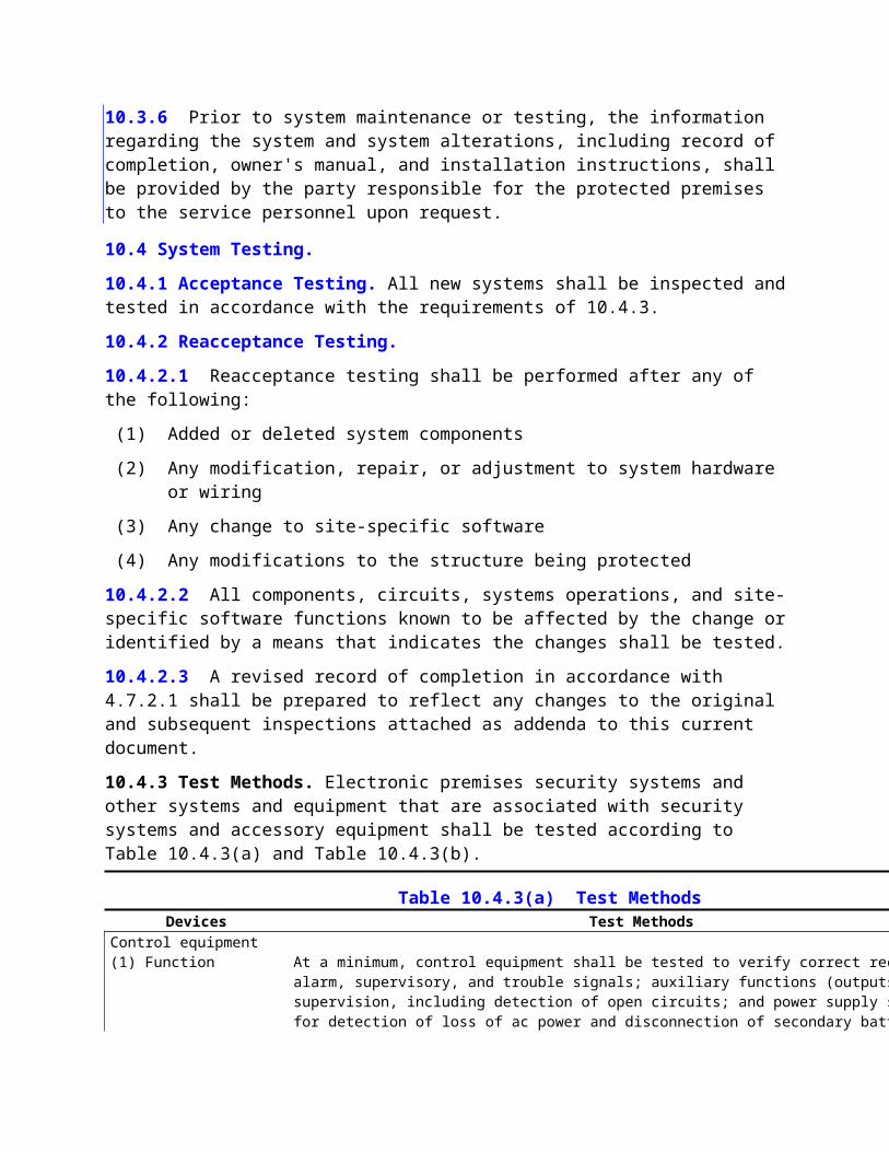
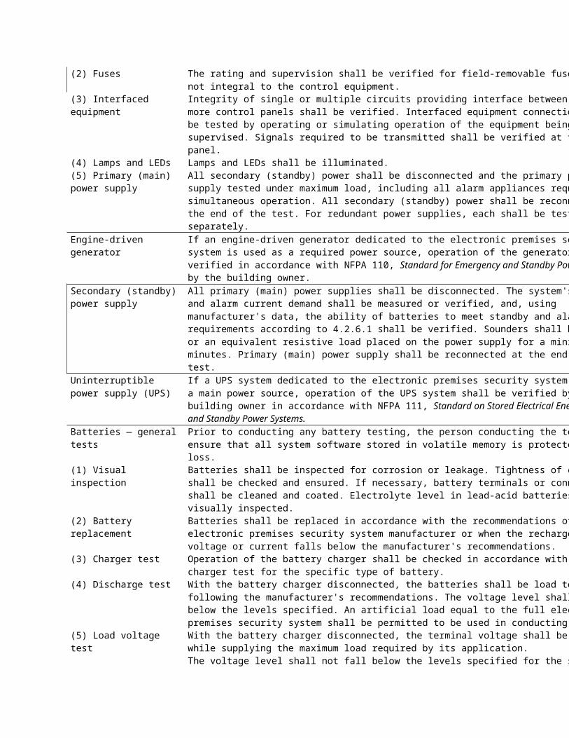
FIGURE A.4.7.2.1(3)(c) Sample Access Control Report.
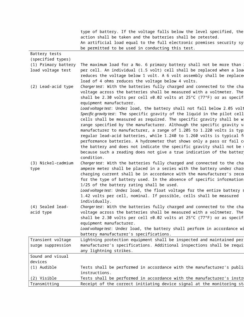
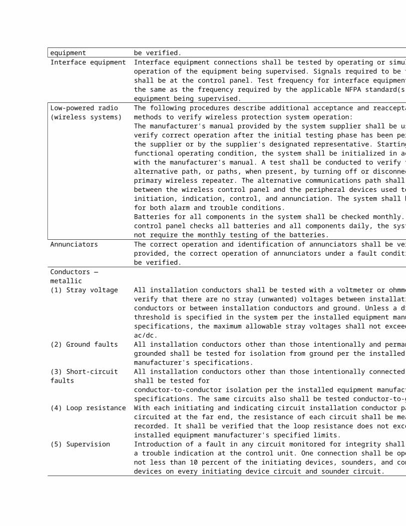
FIGURE A.4.7.2.1(3)(c) Continued
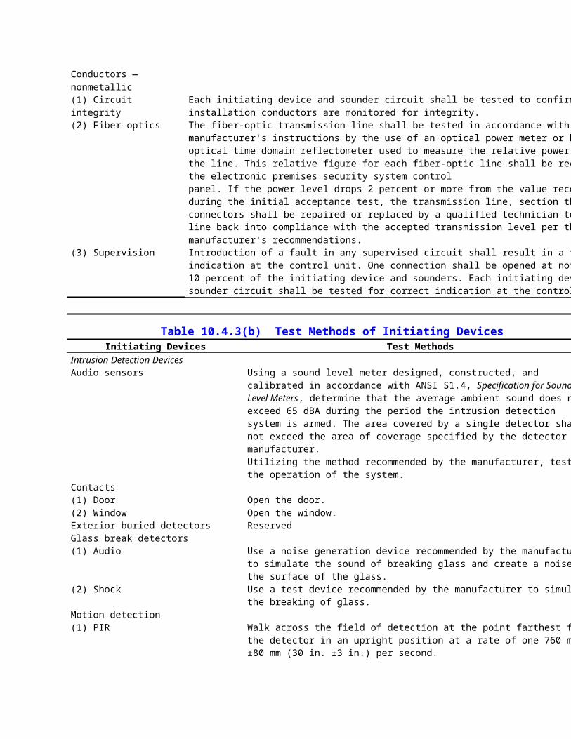
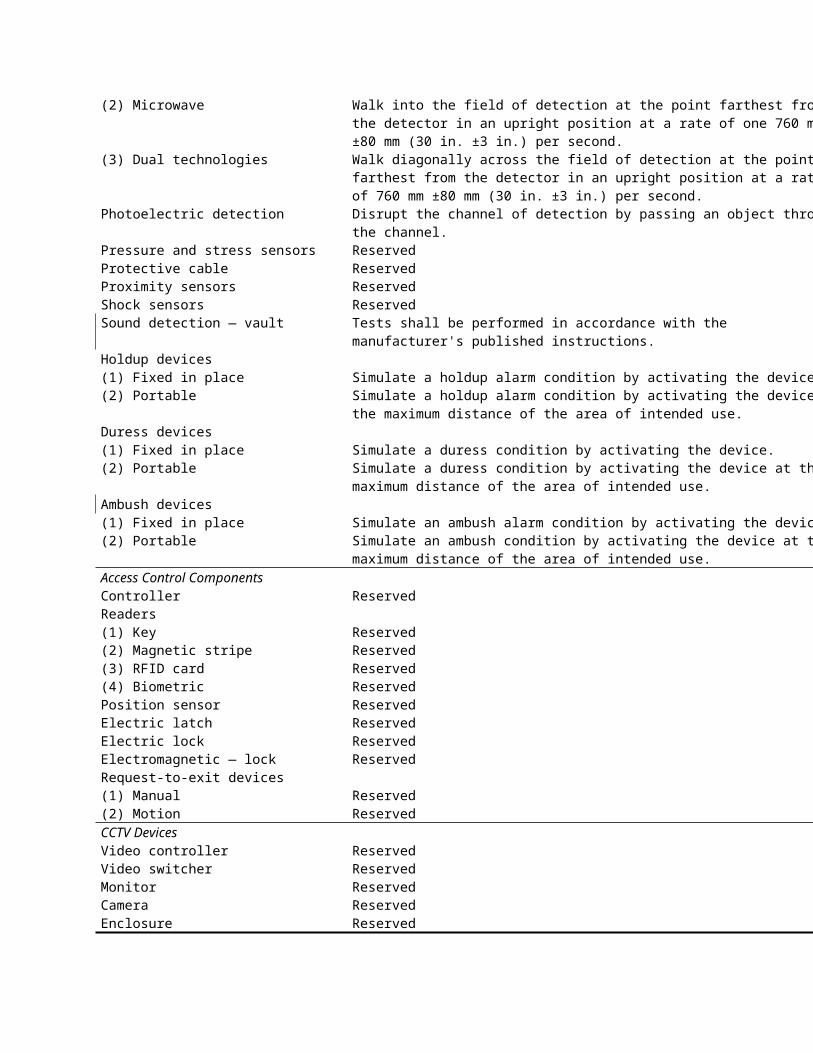
FIGURE A.4.7.2.1(3)(c) Continued
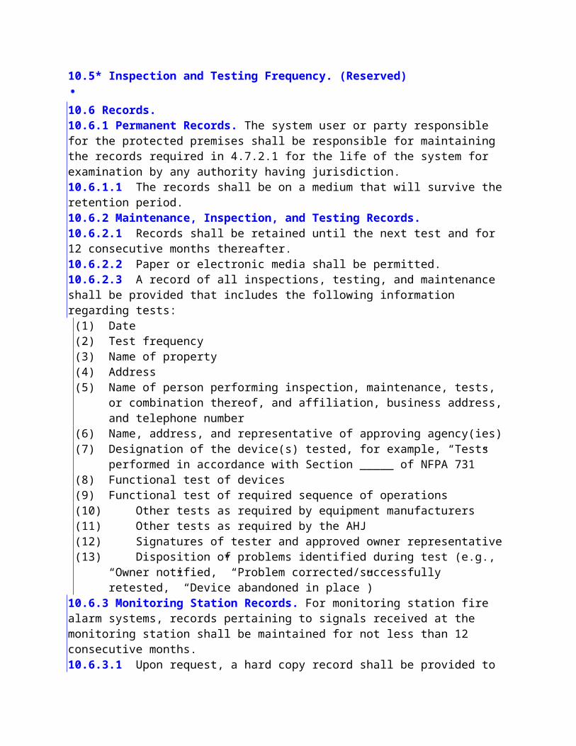
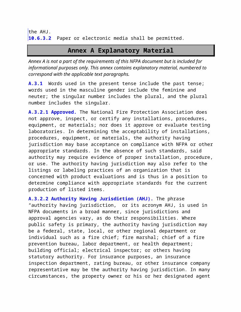
FIGURE A.4.7.2.1(3)(d) Sample Video Surveillance Test Report.
FIGURE A.4.7.2.1(3)(d) Continued
FIGURE A.4.7.2.1(3)(e) Additional Devices Test Report.A.4.7.2.2.1 This training should be based on the level of involvement with the system that the user will have. This level can be as simple as how to arm and disarm an intrusion detection system to as complex as setting levels of access within an access control system.
This training can be provided by, but is not limited to, one-to-one personal training, interactive video or CD-ROM, web-based distance learning, or user training manuals. This training needs to be ongoing, not only for new users of a premises security system but as reinforcement for existing users. Training for all users should take place if the existing system changes due to a system enhancement or due to a tenant improvement.
A.4.7.2.2.2 This documentation should contain at a minimum the names of the users trained, the date that the training was provided, and the scope of the training.A.5.1.1.2 One method of monitoring for integrity of initiating circuits is to utilize supervision devices located at the end of the circuit.A.5.2.1.2(1) A single stacked PEC unit with two or more beams can be used as a substitute, provided that two beams are broken before signal initiation.A.5.2.2 It is not intended that this section apply to video motion detection technology. A.5.3.1 In many cases, UL 681, Standard for Installation and Classification of Burglar and Holdup Alarm Systems, provides guidance that applies to various levels of protection needs as determined by a vulnerability assessment.A.5.3.3.1 The term perimeter used here can be interior or exterior structural surfaces. A.5.3.4.1 See A.5.3.1.A.5.4.1.2 See A.5.3.1.A.5.4.1.3(4) To provide detection of “burning bars,” heat and/or smoke detectors can be used to detect the products of combustion and heat. When used exclusively in this application, the requirements of NFPA 72, National Fire Alarm Code, are not intended to be met.A.5.4.1.3(6) See A.5.4.1.3(4).A.5.4.2.2 See A.5.3.1.A.6.1.2 Examples of portals include, but are not limited to, doors, gates (personnel and vehicular), lift gates, sliders, barriers, turnstiles (mechanical and optical), mantraps, and sallyports.
A.6.1.3 Readers include, but are not limited to, magnetic stripe, radio frequency identification (RFID) (long and short range), bar code, keypad, Wiegand, biometrics, and smart cards (contact and contactless), or any other device that provides a unique identity of the card or person. Based on the threat level, systems can employ a single reader or a combination of these devices.
A.6.1.3.1 The requirements of the Americans with Disabilities Act and other applicable standards should be considered when selecting mounting criteria.
A.6.1.3.3 An example of portal action would be in health care facilities where gurneys or other such appliances can be in use.
A.6.1.3.7 The actual interval of time should be as short as possible. Typically, most systems complete this sequence within 3 seconds or less. The 10-second interval cited in 6.1.3.7 is the maximum time allowed.
A.6.1.4.1 Applicable codes and standards can include, but are not limited to, NFPA 101, Life Safety Code; NFPA 5000, Building Construction and Safety Code; NFPA 72, National Fire Alarm Code; and amendments adopted by the AHJ. Based on the security vulnerability assessment of the protected premises, the designer can also consider ANSI/UL 1034, Standard for Burglary-Resistant Electric Locking Mechanisms.
A.6.1.4.2 The installation of locking hardware should not compromise the fire rating of a door or door frame. NFPA 80, Standard for Fire Doors and Other Opening Protectives, should be consulted. The manufacturer's specification for the fire-rated door and frame should also be consulted before any field modifications are made.
Locking hardware should be appropriate for the application, and repeated use should not result in the inability of the portal to be secured. Consideration should also be given to other portal hardware that can affect the ability of the portal to be secured.
Use of magnetic door locks (“mag locks”) on certain portals poses significant security concerns. For the purpose of life safety, many codes and standards require power interruption to magnetic door locks during fire alarm conditions or loss of primary power. Whenever magnetic lock power is interrupted, the portal can become a free point of both egress and ingress. This is not necessarily an acceptable condition for many premises. Electric portal hardware, which allows mechanical egress, can be a more secure alternative.
A.6.1.4.3 The portal locks can be bypassed during specific time periods of a day, based upon the access control system time schedule. When the portal locks are bypassed, the portal can automatically close but not lock.
A.6.1.4.4 Applicable codes and standards can include, but are not limited to, NFPA 101, Life Safety Code; NFPA 5000, Building Construction and Safety Code; NFPA 72, National Fire Alarm Code; and amendments adopted by the AHJ. Based on the security vulnerability assessment of the protected premises, the designer might also wish to consider ANSI/UL 1034, Standard for Burglary-Resistant Electric Locking Mechanisms.
A.6.1.4.5.1 A manual means of release is not necessarily required for occupancies such as penal institutions, mental hospitals, or other occupancies where direct supervision by trained staff is provided and the AHJ approves such an installation.
A.6.1.5.1 Examples of position sensors include, but are not limited to, edge sensors, gate arm limit switches, and contact switches.
A.6.1.5.2 Position sensors can also be used for other applications such as relocking, arming and disarming of an intrusion detection system, and other approved control functions. The integration of the access control system should not compromise the primary objectives of the access control system.
The use of an access control system in integration with an intrusion detection system should not create false alarms from the system not being properly disarmed prior to entry.
A.6.1.6 The two methods of authorized egress are free egress and controlled egress.
A.6.1.6.1.2 The RTE can bypass the door position switch and not be used to control the lock at the portal. If the RTE also controls the portal lock, concerns for life safety would dictate that the lock be fail-safe on loss of power.
A.6.1.6.2 Controlled egress can be used for applications such as anti-pass-back, mustering, patient wandering, infant abduction, and two-person rule.
A.6.1.6.2.2 Controlled egress can be enforced by sounding an alarm if the portal is opened without presenting a valid credential or by preventing the opening of the portal. If opening the portal is prevented and the portal is a required means of egress, then the requirements for active locks should be used.
A.6.1.8.2 Depending upon the design of the system, one or several power supplies can be used. The power supplies should be sized to provide adequate power for simultaneous use of all associated devices, such as readers, RTE motion detectors, locks, controllers, and so forth. Power calculations need not take into account simultaneous inrush current.
As a result of certain conditions, such as temperature, device inrush requirements, tolerances, and other environmental factors, it is recommended that power supplies be designed with a safety factor of 25 percent.
A.6.2.1 The system operating parameters can be based on an SVA of the protected premises.
A.6.3 This standard currently applies to the protected premises. Network configurations that send data off-premises can need additional protection in the form of encryption. Current encryption schemes can be certified by the National Institute of Standards and Technology (NIST) in accordance with Federal Information Processing Standards (FIPS) 140-2, Security Requirements for Cryptographic Modules. Typically, encryption schemes used for security applications employ a 128-bit algorithm.A.7.2.3 The quality of the image should not be impaired by the method used to provide vandal resistance. Suitable installation techniques could include the mounting and positioning of the camera so that, without compromising the requirements of Section 7.2, it is not readily accessible to a vandal. Information regarding risk assessment procedures can be found in NFPA 730, Guide for Premises Security.A.7.2.5(1) The use of a heater within an enclosure might be required to protect the camera, lens, and auto iris.A.7.2.5(2) Whenever possible, the camera should not look directly into the sun or point light source.A.7.2.5(3) The selection of enclosures should be appropriate for the prevalent environmental conditions. Heaters, blowers, defrosters/defoggers, and wipers can be required. The purpose of sunshields or sun hoods will reduce the heating effect of the sun on the camera housing.A.7.2.5(4) Mounts and remote positioning devices should be designed to withstand local wind conditions and provide a usable image based upon the requirements of the AHJ.
A.7.2.5(5) A method should be provided so that external moisture does not impair the ability of the camera to produce a usable image as required by the AHJ.
A.7.2.6.1 If a camera has a view that looks directly into a bright light source or extremely high contrast scene, the quality of the foreground image is degraded. The camera should be relocated so that its field of view is perpendicular to the light source. The camera should be positioned so that the source of light is behind the camera.
A.7.2.6.2 BLC allows the camera to be able to reduce the level of the video at the bright areas
and then reproduces the overall video signal at an average video level. Most cameras now have this feature, and the more advanced cameras have the means to set the parameters for each application. The installing technician should be aware of the location of the sensing windows for BLC to work correctly.
A.7.3 Low-light level conditions can be compensated for in many ways, including, but not limited to, the following:
(1) Cameras listed by their manufacturer to operate at 10 lux (0.93 fc) or less
(2) Use of light amplification devices such as a starlight scope
(3) Nonvisible scene illumination such as infrared (IR) or ultraviolet (UV)(4) Addition of artificial light such as high-mast lighting or perimeter pole lights
A.7.4 The choice of an enclosure should be based on application, environmental concerns, risk assessment, or the AHJ. An enclosure should be chosen that best protects the camera and lens combination from the ambient environment. Some considerations are indoor or outdoor location, temperature extremes, high humidity or condensing moisture, salt water exposure, rain, snow, hazardous or volatile atmospheres, vandalism, and tampering. Each camera location should be assessed to determine which factors exist and the appropriate enclosure type and enclosure options chosen to best suit the needs of that location.
A.7.5 Mounting assemblies have a few basic requirements. The selection criteria consist of the following:
(1) Overall length of the camera housing
(2) Total weight of the camera, lens, and housing
(3) Type of mounting required (wall, pole, or ceiling)
When mounting equipment, the installer should consider such factors as weight of the unit, the mounting rating (structural load on the hardware), and the orientation of the equipment (inverted mounting).
Weight. The weight of the overall unit is needed to select the proper mounting bracket, but it is also a necessary factor when fastening the mounting bracket to a surface. All mounting brackets require either screws or bolts to mount to a surface.
Mounting Ratings. Mounting ratings should be as follows:
(1) For equipment less than 13.6 kg (30 lb)
(a) Wood fasteners should penetrate a minimum of 5.08 cm (2 in.) into the surface.
(b) In concrete, lead anchors or expansion bolts should have at least 27.2 kg (60 lb) pull-out strength.
(c) In steel, bolts should be long enough to accommodate a lock washer and nut.
(2) For equipment up to 36.3 kg (80 lb)
(a) In wood, 0.952 cm ( in.) diameter bolts should penetrate a minimum of 8.89 cm (3½ in.) into the surface.
(b) In concrete, lead anchors or expansion bolts shall have at least 68 kg (150 lb) pull-out strength.
(c) In steel, 0.952 cm ( in.) diameter bolts should be long enough to accommodate a lock washer and nut.
Inverted Mounting of Equipment. Most weight loads of the mounts, if used in a ceiling application, are reduced by a factor of 50 percent. Consult the manufacturers' specification sheets for specific requirements.
A.7.5.4 Such hardware can include tamper-resistant bolts, nuts, screws, locks, and similar equipment.A.7.7 This section is meant to be applicable to the various types of wire and cable used to connect and supply power to video surveillance equipment and includes, but is not limited to, coaxial type, UTP, and fiber optic (FO) cable.A.7.7.1 Installers should know the low-voltage codes and how to apply them according to their area of work. Knowledge of raceways should include the following as they apply to low-voltage systems:
(1) Practices necessary for the installation of raceways(2) Purpose of each raceway(3) Tools required for the professional installation of raceways(4) Restrictions of raceways
A.7.7.2 Underground/direct burial, pole-to-pole outside/UV protected, and return air plenum/plenum rated are examples of different insulation jacketing.A.7.7.4 It should be the responsibility of the installer to use the appropriate connectors and methods as dictated by the equipment and cable manufacturers' instructions. The selection of connectors should be based on a consideration of the environment, the conductor type, and the specific use (control, power, video, or data). A.7.7.5 The applications for wiring within video surveillance systems are as follows:
(1) Control(2) Power(3) Video signal transmission
Because sufficient voltage and signal levels are imperative for proper system operation, consideration should be given to designing voltage drop (power and signal) allowances that would result in adequate operating voltage (or signal) at the various pieces of equipment.A.7.7.5.1 The purpose of low-voltage control cabling is to carry various low-voltage signals to devices within the video surveillance system. Such devices can include, but are not limited to, the following:
(1) Remote positioning devices (pan/tilt units, scanner units, domes)
(2) Cameras (primary input power)
(3) Zoom lenses
(4) Auxiliary devices (low-voltage wipers and washers, low-voltage heaters and blowers, remote relays)
A.7.8 Although RF is sometimes used for command or control of video systems and transmission of video images, it is not compliant with the definition of a closed system.A.8.1.2.5 To minimize the unintentional operation of a portable device, factors such as jarring, contact with clothing, and similar sources should be considered.A.8.2.1.1 See A.5.3.1.A.8.2.2.8 It should be the party responsible for the protected premises that ensures this training takes place. All employees expected to use a holdup alarm initiating device should be instructed that if they are directly confronted by the attacking party, they should not attempt to operate a holdup alarm initiating device. In addition, they should be trained to follow the procedures provided by their employer and the law enforcement agency having jurisdiction.A.8.2.2.9 Off-premises locations that are used to receive holdup alarm signals should be equipped to retransmit signals to the law enforcement center that serves the property. Examples of off-premises locations that can receive holdup alarm signals are central stations that meet the requirements of UL 827, Standard for Central-Station Alarm Services.
A.8.3.2.5 The intent of a duress system is to notify on-site personnel of a potentially hostile civil disturbance or emergency at the protected property and for summoning assistance to the area of the civil disturbance or emergency.
A.8.4.2.1 To reduce the incidence of inadvertent ambush signals, the following steps should be taken:
(1) If an ambush feature is provided in a control unit that is also used to operate other systems, the default setting should be that it is disabled.
(2) An ambush signal should only be sent by a unique code.
(3) A control panel that is also used to operate other systems should not derive the ambush code from an existing operating code such as a “user code plus ambush digit” sequence.
A.8.4.2.1.1 Implementation of this feature can include, but is not limited to, any of the following:
(1) Simultaneous depression of two buttons where, if either of the buttons has multiple functions, the two buttons are nonadjacent
(2) If the cover protects only emergency function buttons, depression of a single button after lifting the cover that normally protects it
(3) Depression of a single button for at least 2 seconds
A.8.4.2.4 Each person who is expected to use an ambush alarm initiating device should be instructed to follow the procedures provided by the operator of the protected premises and the law enforcement agency having jurisdiction.A.8.4.2.5 Examples of off-premises locations that can receive ambush alarm signals are central stations that comply with UL 827, Standard for Central-Station Alarm Services.A.9.2.1 These signals can include, but are not be limited to, the following:
(1) Alarms (including intrusion detection, holdup, and duress)(2) Supervisory
(3) Trouble(4) Restorals(5) Open/close events(6) Access control activity(7) Video surveillance(8) Audio surveillance
A.9.3.1 This section does not include any requirements for the handling or dispatching of calls for assistance and should be directed only at electronically received signals.A.9.3.3.4.3 Types of agents that can be considered are water mist or clean agents.A.9.3.4.1.1 It might be necessary to provide a door for the public to access the facility. In such cases, access for the public should be restricted to public areas, such as a reception area or lobby.A.9.3.4.4 The determination of the type of detection device to be used should be based on a risk assessment for the facility. NFPA 730, Guide for Premises Security, can be used. Building designers should consider security through environmental design and should provide zones immediately around the facility to ensure security of the grounds and the safety of the personnel within.A.9.3.5.1 Standby power should have sufficient capacity to be able to operate HVAC necessary to maintain the environmental range of the monitoring equipment. Lighting should be provided to allow operators to perform normal functions.A.9.3.5.1.1 The EPSS can be used to supply other building loads. The EPSS should be sized to handle all loads simultaneously without having to shift other loads off the system. When life safety equipment is connected to the EPSS, consideration should be given to increasing the EPSS to level 1, type 10.A.9.3.5.1.4 Guidance on preventing unauthorized access to the power supply can be found in ANSI/UL 827 Central Station Alarm Services, Section 9.13.A.9.3.6.3 All training should be in compliance with the manufacturer’s recommendations, and a program should be in place for the continuing education of operators. Resources for this education include, but are not limited to, the Central Station Alarm Association, the Security Industry Association, and the Association of Public Communication Officers.A.9.3.9.2.1 The list should contain, at a minimum, a contact name, phone number, after-hours cell phone number, and service contract information for each provider.A.9.3.9.3.2 At a minimum, equipment should be able to operate within an environment of high-energy radio frequencies. In addition, the equipment should not interfere with or be interfered with by any electronic equipment within the facility. The equipment should also be shielded from electromagnetic interference and radio frequencies as required.A.9.3.9.4 Special consideration and contingency plans need to be considered. If the monitoring station is receiving signals from any high-risk facilities as defined by the Department of Homeland Security (DHS), provisions should be considered for implementing emergency transfer to the backup location.A.9.6.1.1 Additional information on enhanced verification procedures can be found in ANSI/CSAA CS-V-01, Alarm Verification and Notification Procedures.A.9.6.1.1.1.2 The intent of 9.6.1.1.1.2 is for the monitoring station to call the protected premises first to verify the signal. It is realized, however, that there could be cases in which the protected premises might not have phone service. In those cases, the monitoring station can make the first call to a primary contact number that is provided by the system user.A.9.6.1.1.1.4 The total time for the ECV procedure should not exceed 300 seconds from the
operator’s receipt of the alarm.A.9.6.1.1.2 RVV is intended to be used as a supplement to ECV. If through the use of RVV it is apparent that a crime or unauthorized entry is taking place at the protected premises, the information obtained can be transmitted or communicated to the public safety agency so it can coordinate the response protocol.A.9.6.1.1.2.2 One method that can be used is point ID.A.9.6.1.1.2.3 One recommended method is that the video transmitter record at the protected premises a minimum of 5 seconds of activity prior to the alarm event.A.9.6.1.1.3 RAV is intended to be used as a supplement to ECV. If through the use of RAV it is apparent that a crime or unauthorized entry is taking place at the protected premises, the information obtained can be transmitted or communicated to the public safety agency so that it can coordinate the response protocol.RAV can be one way or two way. With one-way RAV, the monitoring station can listen in to the protected premises after an alarm activation. With two-way RAV, the monitoring station can, in addition to listening in, engage in a conversation with individuals who are on the protected premises.A.9.6.1.1.4.1 Cross-zoning is one method of MTV. With this method, at least two sensors within the same area of coverage should be installed. In this case, all the sensors within the area should have tripped before an alarm is generated. The use of cross-zoning for intrusion detection systems is not the same as cross-zoning for fire alarm systems.It is intended that cross-zoning would use separate sensors, not two detection means within a single sensor. This is a method of “dual technology.” Cross-zoning is best achieved by using two separate sensors. Both could use the same technology or different technologies, which could include the use of a door contact for one of the zones.A.9.6.3.1 The term immediately in this context is intended to mean “without unreasonable delay.” Routine handling should take a maximum of 90 seconds from receipt of the alarm signal by the monitoring station until the initiation of notification to the public safety agency.A.9.6.4.2.1 The term immediately in this context is intended to mean “without unreasonable delay.” Routine handling should take a maximum of 90 seconds from receipt of the alarm signal by the monitoring station until the initiation of notification to the public.A.9.6.5.1 The term immediately in this context is intended to mean “without unreasonable delay.” Routine handling should take a maximum of 90 seconds from receipt of the alarm signal by the monitoring station until the initiation of notification to the public safety agency.A.9.6.6 Facility hazards information should be provided to the first responders and can include information on rapid entry systems, dangerous chemicals or gases, explosive materials, or any other dangerous condition that might exist. Information on special security notices such as attack dogs, smoke bandits, chemical releasing agents, or security traps should also be maintained.A.9.7.3.1(4) The intent of 9.7.3.1(4) is not to limit each line to 3000 transmitters but to require that if 3000 transmitters are exceeded on a single path, a redundant path is provided. This is to be considered primarily when broadband communication (Internet) solutions are used.A.9.7.4.1(3) The intent of 9.7.4.1(3) is not to limit each line to 3000 transmitters but to require that if 3000 transmitters are exceeded on a single path, a redundant path is provided. This is to be considered primarily when broadband communication (Internet) solutions are used.A.9.8.1 These records can include, but are not be limited to, the following:
(1) Signal history(2) Documentation of personal identification codes (PICs)

(3) Public safety agency notification informationNote: Although the information on the PICs should be retained, it should be kept confidential and made available on a need-to-know basis.A.10.1 More stringent inspection, testing, and maintenance procedures that are required by other parties can be permitted.
A.10.1.2 Equipment performance can be affected by building modifications, occupancy changes, changes in environmental conditions, device location, physical obstructions, device orientation, physical damage, improper installation, degree of cleanliness, or other obvious problems that might not be indicated through electrical supervision.
A.10.1.3 The party responsible for the electronic premises security system is the individual or organization that ensures that inspection, testing, and maintenance are performed. A.10.2.1 Examples of system defects and malfunctions are a trouble signal to the control panel or controller, a reader that is not operating, a video surveillance camera that is no longer providing an image, and other similar events.A.10.2.2 Temporary mitigating measures should be considered by the owner or responsible party during impairments based on an assessment of the risk to the protected property or the occupants. Depending on the risk assessment, the AHJ can be consulted. The recommendations from the consultation should be implemented for the period that the system is impaired.A.10.2.5 Additional security measures might be needed during the period of the impairment. These impairments can be caused by, but are not limited to, the following:
(1) Telecommunication errors(2) Accident(3) Fire(4) Acts of God(5) Loss of carrier(6) Other transmission method failures
A.10.3.4.2(1) The factory training and certification should be specific and current to the equipment that is being used, and proof of this factory training and certification should be made available to the AHJ upon request.
A.10.3.5.1 In addition to advising the personnel within the protected premises that the system is being tested or maintained and that signals generated from the system(s) should not be acted upon, the owner or responsible party should be advised that the system or a part of the system might not be fully functional during the testing or maintenance procedure and that appropriate safeguards should be taken, based upon the perceived risk.The party responsible for the protected premises should also be informed that if the system is placed into a degraded mode, some, if not all, information from those nodes can be lost during the time in which the node or nodes are down. A.10.5 Electronic premises security systems and other systems and equipment that are associated with security systems and accessory equipment should be tested at the frequencies according to Table A.10.5.
Table A.10.5 Test Frequency

System,
Device, or
Equipment
Frequency
Intrusion detection system
Annually
(1) Exterior detectors
Annually
(2) Interior detectors
Annually
Holdup, duress, or ambush system
Annually
(1) Portable devices
Annually
(2) Exterior fixed devices
Annually
(3) Interior fixed devices
Annually
Access control system
Annually
(1) Readers
Annually
(2) Position switches
Annually
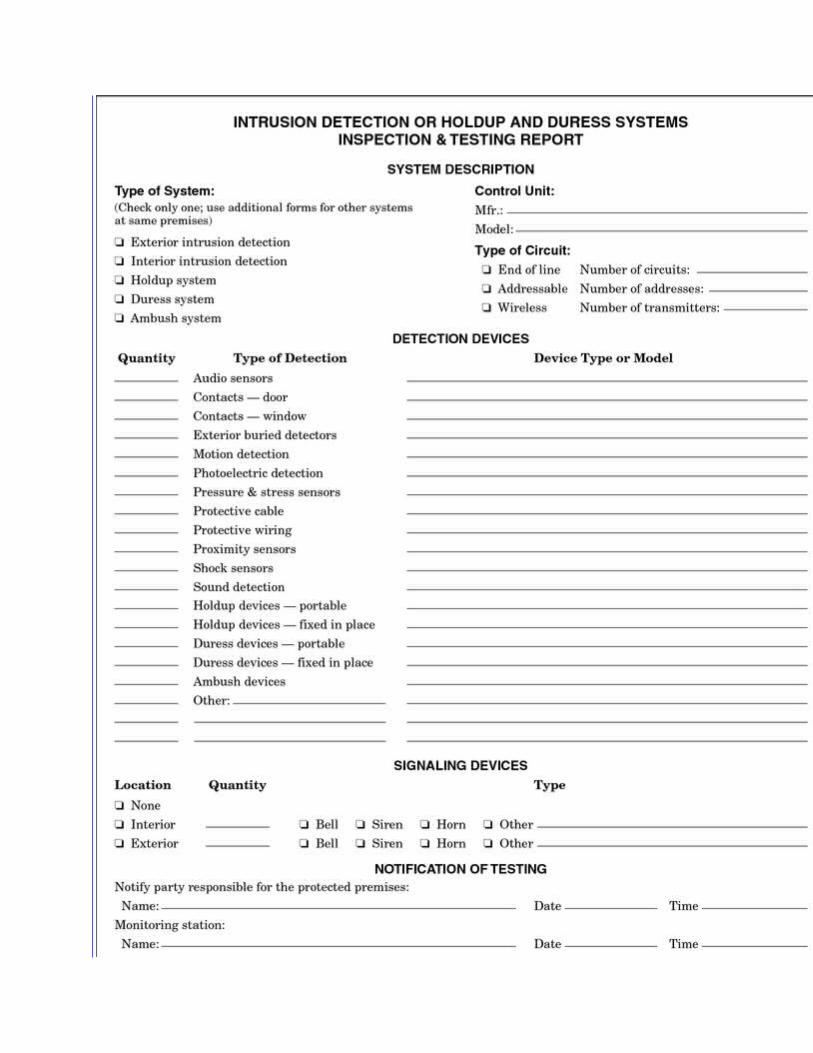
(3) Electric hardware
Annually
(4) Request-to-exit devices
Annually
CCTV system
Annually
(1) Camera enclosures
Annually before adverse weather conditions
(2) Recorders
Annually
Sounding devices
Annually
Batteries — general tests
Annually
Off-premises transmission equipment
Quarterly or by automatic monthly test
Interface equipment
Annually
Annex B Camera SpecificationsThis annex is not a part of the requirements of this NFPA document but is included for informational purposes only.
B.1
For cameras placed to record images at a point of customer transactions, such as a teller window,

the area of interest (face, license plate, etc.) should cover a minimum of 15 percent of the camera's field of view under normal resolution of 300 HL or more. Action within the scene requires that at least 20 percent or more of the overall width of the scene be used. For an average human head that is 15.24 cm (6 in.) wide, a 0.914 m (3 ft) wide field of view meets this guideline. For a license plate width of approximately 304.8 mm (12 in.), a 1.83 m (6 ft) field of view is sufficient.
The focal length necessary to achieve an approximately 0.914 m (3 ft) wide field of view for a given detector size and camera-to-subject distance is provided in Table B.1(a) and Table B.1(b). The camera has to be in focus at the position of this subject.
Table B.1(a) and Table B.1(b) are based on the following calculations using either the scene width formula or the scene height formula.
or
where:f = focal length of lensc = width of the charge-coupled-device (CCD) chipd = distance from cameraw = width of field of viewv = height of CCD chiph = height of field of view
Table B.1(a) Approximate Focal Length Needed for 0.914 m Wide Field of ViewFocal Length Based on Distance to Subject
Detector Size (m) 0.6096 m 1.524 m 3.048 m 4.572 m 6.096 m 9.144 m0.0762 2.370104 1.79832 3.56616 5.36448 7.1628 10.72896
0.100584 0.94488 2.3744 4.78536 7.1628 9.54024 14.32560.1524 1.2192 3.07848 6.15696 9.23544 12.31392 18.50136
Table B.1(b) Approximate Focal Length Needed for 3 ft Wide Field of View
Focal Length Based on Distance to Subject Detect
or Size (in.)
2 ft 5 ft 10 ft 15 ft 20 ft 30 ft
¼ 2.3 5.9 11.7 17.6 23.5 35.23.1 7.8 15.7 23.5 31.3 47.0
½ 4 10.1 20.2 30.3 40.4 60.7
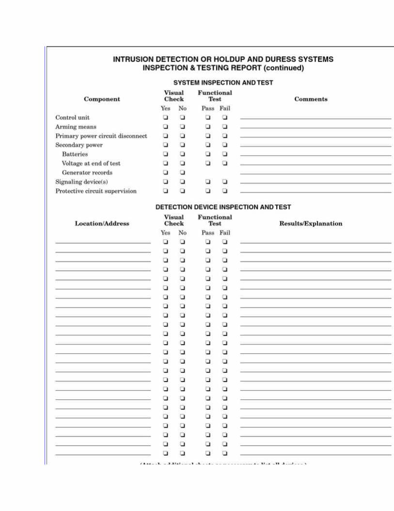
Cameras that provide overviews of interior and exterior locations should have their focal lengths selected to meet the field-of-view requirements of the AHJ. Note, however, that exit cameras should have sufficient depth of field to be in focus at distances of 0.914 m (3 ft) and beyond to ensure that subjects exiting are in focus.
Another method takes into account the total viewing area of the scene as a percentage of the monitor. Calculate the viewing area of the scene and also of the critical viewing area by multiplying the horizontal and vertical dimensions [see Table B.1(c)]. Divide the critical viewing area by the total viewing area to get the size of the critical viewing area in the monitor.
If the proportion of the critical viewing area is as expected, use the calculated focal length. If not, then change the focal length until the correct proportion is found, or change the distance of the camera until the correct proportion is found. If this does not solve the problem, a new lens might have to be chosen that is the nearer to the requirement.
Table B.1(c) Field of View
Camera
Formats
(in.)
Horizontal (mm)
Vertical
(mm)
¼ 3.2 2.44.4 3.3
½ 6.4 4.88.8 6.6
B.2 Example.
A in. camera is viewing an entrance gate to a factory. The car coming through the gate is the critical view.
chip
Width (c) = 4.8 mm = 0.048 m (0.16 ft)
Height (v) = 3.6 mm = 0.036 m (0.12 ft)
Distance to gate (d) = 30.5 m (100 ft)
Width of gate (w) = 3.7 m (12 ft)
Car dimension (front) = 1.5 m × 1.5 m (5 ft × 5 ft)
Focal length f =c × (d/w) = 0.048 m × (30.5 m/3.7 m) = 0.40 m [0.16 ft × (100 ft/12 ft) = 1.33 ft]
Scene height h = v × (d/f) = 0.036 m × (30.5 m/0.4 m) = 2.75 m [0.12 ft × (100 ft/1.33 ft) = 9 ft]
Scene area = 3.7 m × 2.7 m = 10 m2 (12 ft × 9 ft = 108 ft2)
Critical area = 1.5 m2 × 1.5 m2 = 2.3 m2 (5 ft × 5 ft = 25 ft2)

Percent size of car in monitor = 25 × (100/108) = 23.1 percent
The car covers about 23 percent of the monitor. This allows positive identification of the car coming through the gate.
Scene identification should require that each camera within a system is able to be differentiated by its image's physical appearance. No system should have any two cameras looking from the same angle down two identical hallways. Each scene should be separable by visual recognition. The installer should follow the manufacturer's recommendations concerning the various compatibility issues that occur between the cameras and lens. Such compatibility issues can be physical or electronic.
Annex C Camera SelectionThis annex is not a part of the requirements of this NFPA document but is included for informational purposes only.
C.1 Criteria.
A number of common camera selection criteria should be reviewed by the system installer prior to the installation to verify that the design objective is met. The criteria are as follows:
(1) Monochrome or color
(2) Light level and sensitivity
(3) Resolution
(4) Back-focus adjustment
(5) Format
(6) Sync and phaseC.1.1 Monochrome or Color. All white balance settings on or within the camera are set according to the manufacturer's specification to provide proper color rendition. In the event of a dual-chip technology camera system, the installer should perform setup procedures deemed necessary by the manufacturer to provide a proper white balance during high-light situations and proper black-white (B/W) sensitivity during low-light situations.C.1.2 Light Level and Sensitivity. Sensitivity, measured in footcandles or lux (lumens per square meter), indicates the minimum light level required to get an acceptable video picture. Sensitivity at faceplate indicates the minimum light required at the charge-coupled-device (CCD) chip to get an acceptable video picture. Minimum scene illumination indicates the minimum light required at the scene to get an acceptable video picture.
To see properly, a video surveillance camera requires a certain amount of light produced by natural or artificial illumination. B/W cameras work with any type of light source, but color cameras need light that contains all the colors in the visible spectrum.
The amount of light is defined by footcandles or lux. One lux is a candlelight volume at a 1 m distance. The following are some examples of natural light:
(1) Full daylight is 10,000 lux.

(2) Very dark day is 100 lux.
(3) Twilight is 10 lux.
(4) Deep twilight is 1 lux.
(5) Full moon is 0.1 lux.
(6) Quarter moon is 0.01 lux.A good B/W camera can see in full-moon conditions. However, a color camera might need additional illumination in low-light conditions. Usually light falls on the subject. A certain percentage is absorbed and the balance is reflected. The reflected light moves toward the lens in the camera. Depending on the iris opening of the camera, a certain portion of the light falls on the CCD chip. This light then generates a charge, which is converted into a voltage. The following variables should be listed on the data sheet to indicate the minimum scene illumination:
(1) Reflectance
(2) F-stop
(3) Usable video
(4) Automatic gain control (AGC)
(5) Shutter speed
C.1.2.1 Reflectance. Light from a light source falls on the subject. Depending on the surface reflectivity, a certain portion of the light is reflected back toward the camera. Following are a few examples of surface reflectivity:
(1) Snow is 90 percent.
(2) Grass is 40 percent.
(3) Brick is 25 percent.
(4) Black is 5 percent.
Most camera manufacturers use an 89 percent or 75 percent (white surface) reflectance surface to define the minimum scene illumination. If the actual scene has the same reflectance as in the data sheet, then there is no problem, but in most cases this is not true. A black car will reflect only 5 percent of the light, so least 15 times more light is required at the scene to give the 75 percent reflectance.
C.1.2.2 Lens Speed. The reflected light starts moving toward the camera. The first device it meets is the lens, which has a certain iris opening. While specifying the minimum scene illumination, the data sheet usually specifies an F-stop of F1.4 or F1.2. The F-stop gives an indication of the iris opening of the lens. The larger the F-stop value, the smaller the iris opening, and vice versa. If the lens being used at the scene does not have the same iris opening, then the light required at the scene needs to be compensated for the mismatch in the iris opening.
C.1.2.3 Usable Video. After passing through the lens, the light reaches the CCD chip and generates a charge that is proportional to the light falling on a pixel. This charge is read out and

converted into a video signal. Usable video is the minimum video signal specified in the camera data sheet to generate an acceptable picture on the monitor. It is usually measured as a percentage of the full video.
C.1.2.4 AGC. As the light level reduces, the AGC switches on and the video signal gets a boost. Unfortunately, the noise present also gets a boost. However, when the light levels are high, the AGC switches off automatically, because the boost could overload the pixels, causing vertical streaking and so forth.
The data sheet should indicate if the AGC is on or off when the measuring minimum scene illumination is being measured. If the data sheet indicates AGC is “on,” but in reality the AGC is “off,” then the minimum scene illumination in the data sheet should be modified.
C.1.2.5 Shutter Speed. Most cameras now have an electronic shutter speed that allows the user to adjust the timing of the charge read of the CCD chip. The standard readout is 50 times [phase alternate by line] (PAL) and 60 times [National Television Standards Committee] (NTSC) per second. If the shutter speed is increased to 1000 times per second, for example, the light required at the scene should be 20 times more (for PAL). Increasing the shutter speed allows the picture to be crisper but requires more light.
C.1.3 Resolution. All cabling and signal transmission methods should be installed with the proper connections, splices, and amplification to ensure that the image resolution is maintained at the maximum capability of the system's design.C.1.4 Backfocus Adjustment. The term backfocus refers to the course adjustment on the camera that positions the imager behind the lens. This adjustment allows for the proper positioning of the fine-focus adjustment on the lens. Focus refers to adjustment of the distance between the lens and the imager device in the camera. Focusing aligns the focal plane of the lens with the imager in the camera. When focusing, the iris of the lens must be opened to create the shortest depth of field. The lens should be focused and then the iris closed to increase the depth of field. An installer must know the relationship between F-stop and depth of field and how to properly focus both manual and auto-iris lenses.C.1.5 Format. Knowing the size of the imager is necessary in selecting the appropriate focal lens to provide the desired view.C.1.6 Sync and Phase. Power requirements of the video equipment are determined and established during the design phase. The line-locking feature of a camera means that the camera's vertical sync pulse locks to the incoming alternating current (ac) power line frequency. The reason is to ensure that the vertical pulses from many different cameras occur at the same time, eliminating any vertical roll when the cameras are switched. Direct current (dc) operated cameras cannot be line-locked. Vertical sync of each camera should be adjusted as per manufacturer's instructions.
Annex D Informational References
D.1 Referenced Publications.
The documents or portions thereof listed in this annex are referenced within the informational sections of this standard and are not part of the requirements of this document unless also listed in Chapter 2 for other reasons.
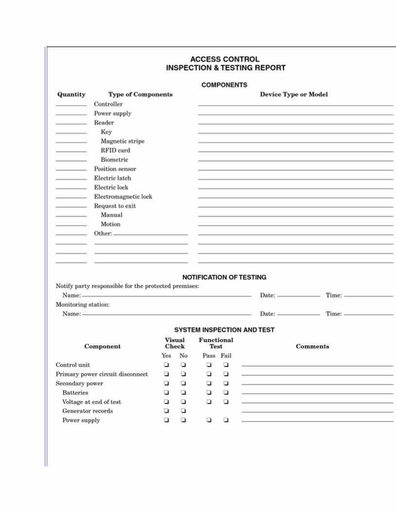
D.1.1 NFPA Publications. National Fire Protection Association, 1 Batterymarch Park, Quincy, MA 02169-7471.
NFPA 70®, National Electrical Code®, 2008 edition.
NFPA 72®, National Fire Alarm Code®, 2007 edition.
NFPA 80, Standard for Fire Doors and Other Opening Protectives, 2007 edition.
NFPA 101®, Life Safety Code®, 2006 edition.
NFPA 730, Guide for Premises Security, 2008 edition.
NFPA 5000®, Building Construction and Safety Code®, 2006 edition.
D.1.2 Other Publications.
D.1.2.1 CSAA Publications. Central Station Alarm Association, 440 Maple Avenue East, Suite 201, Vienna, VA 22180.
ANSI/CSAA CS-V-01, Alarm Verification and Notification Procedures, 2004.
D.1.2.2 NIST Publications. National Institute of Standards and Technology, 100 Bureau Drive, Gaithersburg, MD 20899. http://www.itl.nist.gov/fipspubs/
FIPS 140-2, Security Requirements for Cryptographic Modules, 2001.
D.1.2.3 UL Publications. Underwriters Laboratories Inc., 333 Pfingsten Road, Northbrook, IL 60062-2096.ANSI/UL 608, Standard for Burglary-Resistant Vault Doors and Modular Panels, 2004.UL 681, Standard for Installation and Classification of Burglar and Holdup Alarm Systems, 1999.
UL 827, Standard for Central-Station Alarm Services, 1996, revised 1999.ANSI/UL 1034, Standard for Burglary-Resistant Electric Locking Mechanisms, 2000, revised 2004.D.1.2.4 U.S. Government Publications. U.S. Government Printing Office, Washington, DC 20402.
Title 47, Code of Federal Regulations, Part 15, “Radio Frequency Devices.”
D.2 Informational References.
The following documents or portions thereof are listed here as informational resources only. They are not a part of the requirements of this document.ANSI/UL 1076, Standard for Proprietary Burglar Alarm Units and Systems, 1995, revised 2005.ANSI/UL 1610, Standard for Central-Station Burglar-Alarm Units, 1998, revised 2005.ANSI/UL 2017, Standard for General-Purpose Signaling Devices and Systems, 2000, revised 2005.