nfpa cylinders – series 70
TRANSCRIPT
T h e c o m p a n y r e s e r v e s t h e r i g h t t o v a r y m o d e l s a n d d i m e n s i o n s w i t h o u t n o t i c e .T h e s e p r o d u c t s a r e d e s i g n e d f o r i n d u s t r i a l a p p l i c a t i o n s a n d a r e n o t s u i t a b l e f o r s a l e t o t h e g e n e r a l p u b l i c .
C a t a l o g 2 0 0 6
1C
YL
IN
DE
RS
NFPA Cylinders – Series 70
1.66
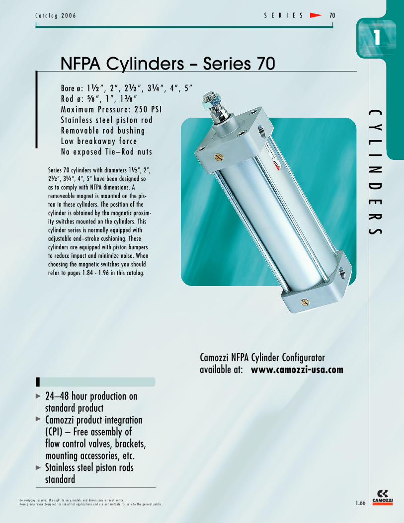
Bore ø : 1o ” , 2 ” , 2o ” , 3n ” , 4 ” , 5 ”R o d ø : k ” , 1 ” , 1j ”M a x i m u m P r e s s u r e : 2 5 0 P S IS t a i n l e s s s t e e l p i s t o n r o dR e m o v a b l e r o d b u s h i n gL o w b r e a k a w a y f o r c eN o e x p o s e d T i e – R o d n u t s
S E R I E S 70
Series 70 cylinders with diameters 1o”, 2”,2o”, 3n”, 4”, 5” have been designed soas to comply with NFPA dimensions. Aremoveable magnet is mounted on the pis-ton in these cylinders. The position of thecylinder is obtained by the magnetic proxim-ity switches mounted on the cylinders. Thiscylinder series is normally equipped withadjustable end–stroke cushioning. Thesecylinders are equipped with piston bumpersto reduce impact and minimize noise. Whenchoosing the magnetic switches you shouldrefer to pages 1.84 - 1.96 in this catalog.
24–48 hour production onstandard productCamozzi product integration(CPI) – Free assembly offlow control valves, brackets,mounting accessories, etc.Stainless steel piston rodsstandard
Camozzi NFPA Cylinder Configuratoravailable at: www.camozzi-usa.com

T h e c o m p a n y r e s e r v e s t h e r i g h t t o v a r y m o d e l s a n d d i m e n s i o n s w i t h o u t n o t i c e .T h e s e p r o d u c t s a r e d e s i g n e d f o r i n d u s t r i a l a p p l i c a t i o n s a n d a r e n o t s u i t a b l e f o r s a l e t o t h e g e n e r a l p u b l i c .
CY
LI
ND
ER
SC a t a l o g 2 0 0 6
1
1.67
GENERAL DATA
Type of construction Round tube with tie–rodsOperation Double–actingMaterials Anodized aluminum head and end cap, other parts see codingType of mounting Standard NFPA mounting stylesBore ø 1Ø”, 2”, 2Ø”, 3˜”, 4”, 5”Stroke Up to 60” standard, rounded to Å”Operating temperature 0˚C – 80˚C (with dry air – 20˚C) 32˚F – 175˚F (Dry air –4˚F)Special designs For use in damp, dusty and aggressive environments*For special design requests, contact factory for exact code
Operating pressure Min. pressure: less than 6 psiMax. pressure: 250 psi
Speed Min. = 10 mm/sec (NO LOAD), .4 in./secMax. = 1000 mm/sec (NO LOAD), 39.4 in./sec.
Fluid Clean air, with or without lubrication
PNEUMATIC DATA
S E R I E S70
Rod NutRod Nut included on allcylinders. Standard.
Piston RodAll stainless steel ground andpolished rods, burnished forimproved seal life andreduced wear. Standard.
Rod and Wiper SealPiston rod lip seal and wipercombination. A compact design,allowing for greater bushingsupport without sacrificing sealingability.
Tie Rod NutsTie rod nuts are ID hexed and IDthreaded providing a flush faceand ability to assemble and dis-assemble mounting bracketswithout loosening Head.
Cushion AdjustmentRecessed and captive cushionadjustment screws. Fine threadadjustment for greaterrepeatability and accuracy.Standard.
Piston SealsRounded lip u–cup seal reducesfriction; specifically designed forlube or non–lube service.Maintains factory prelube againstthe cylinder wall.
Tie RodsZinc plated steel, rolled threadsfor added strength.
Cylinder TubeHard Anodized Aluminum tubethat provides superior seal lifeand wear resistance.
Tube End SealsCaptured seal made fromBUNA–N offering a wide range oftemperature applications and pos-itive sealing. Standard.
Cushion Seal DesignPrecision–machined piston spears combined with floating cushioncollar allow for a smooth deceler-ation at end of stroke. Cushioncollar is specifically designed forrapid low–pressure breakawaywhen stroke reverses.
PistonAluminum, two–piece design allows for a solidmagnet ensuring consistent switch sensing.Extra wide nylon wear ring, (cut–away inview), increases piston support while reducingwear and friction.
Piston BumpersShock absorbing bumpers reducenoise and piston wear. Standard.
Heads and CapsHeads and Caps are lightweightaluminum that have been precision machined andanodized.
Rod GlandFlush mount, precision threadedgland design, easily removableusing common tools and withoutcylinder disassembly. HardAnodized Aluminum body andintegrated design includes rodbearing and rod lip/wiper seal.Rod Bearing is oil impregnated,sintered bronze containinggraphite for high speed and heavyload applications.
Key FlatHydraulically pressed key flat.
Rod ThreadsThreads are rolled Stainless Steelfor greater strength.

1.68
HEADPORTPOSITION
Insert apositionnumber 1–4
CAPPORTPOSITION
Insert apositionnumber 1–4
CAPCUSHIONPOSITION
Insert apositionnumber 1–4 or 00 = No Cushion
T h e c o m p a n y r e s e r v e s t h e r i g h t t o v a r y m o d e l s a n d d i m e n s i o n s w i t h o u t n o t i c e .T h e s e p r o d u c t s a r e d e s i g n e d f o r i n d u s t r i a l a p p l i c a t i o n s a n d a r e n o t s u i t a b l e f o r s a l e t o t h e g e n e r a l p u b l i c .
C a t a l o g 2 0 0 6
1S E R I E S 70
7 0 M A 2 L 2 5 0 A 0 1 6 E 1 2 1 2
CYLINDER CODING
SERIES70 = Round tube, tie–rod style
PISTONM = magnetic N = non magnetic
ROD DIAMETER AND ROD ENDA = standard rod ø, SM small male Style 1B = standard rod ø, IM intermediate male Style 2C = standard rod ø, SF short female Style 3
P = oversized rod ø, SM small male Style 1Q = oversized rod ø, IM intermediate male Style 2R = oversized rod ø, SF short female Style 3
CYLINDER OPERATION2 = double–acting6 = double–acting (double–rod)
• The Series 70 cylinders with diameters 1O”, 2”, 2O”, 3N”, 4”, 5”, have been designed tocomply with standard NFPA dimensions.A removeable magnet is mounted on the piston in these cylinders. The position of the cylinderis obtained by the magnetic proximity switches mounted on the cylinders. This cylinder series isnormally equipped with adjustable end–stroke cushioning. These cylinders are equipped withpiston bumpers to reduce impact and minimize noise.
• Part Number Example: 70MA2L250A016E1212 – NFPA type round tube, exposedtie–rods, standard magnetic piston, standard rod diameter (SM small male thread, Style 1),double–acting with front and rear adjustable cushions, stainless steel rod, anodized aluminumround tube,Buna–N seals, zinc–plated tie–rods and nuts, 2O” bore, basic cylinder no mount-ing, 16 N” stroke, head and cap ports position 1.
• When choosing the magnetic proximity switches, please see pages 1.84-1.96 in this catalog orcylinder configurator at www.camozzi–usa.com.
• For additional options or special requests, please contact factory for part number and pricing.• Note: Accessories are mounted on the cylinders.
MaterialsL = rolled stainless steel piston rod (AISI 420B, 303)
anodized aluminum tubeBuna–N sealsnuts and tie–rods zinc plated steel
T = rolled stainless steel piston rod (AISI 420B, 303)anodized aluminum tubeBuna–N sealsnuts and tie–rods stainless steel (AISI 316L)
Bore ø in inches150 = 1O” inches200 = 2” inches250 = 2O” inches325 = 3N” inches400 = 4” inches500 = 5” inches
MOUNTING TYPES See PageA = MXO no mount . . . . . . . . . . 1.69CF = MP1 cap fixed clevis . . . . . . . . 1.72CD = MP2 cap detachable clevis . . . . . . 1.72L = MP4 cap detachable eye . . . . . . 1.73B = MS1 angle mount . . . . . . . . . 1.73BL = MS2 side lug . . . . . . . . . . 1.74ST = MS4 side tap . . . . . . . . . . 1.74BE = MS7 side end lug . . . . . . . . . 1.80E = MF1 head rectangular flange . . . . . 1.75D = MF2 cap rectangular flange . . . . . 1.75ES = MF5 head square flange . . . . . . 1.76DS = MF6 cap square flange . . . . . . . 1.76XB = MX1 tie rods extended both ends . . . 1.77XC = MX2 tie rods extended cap end . . . . 1.77XH = MX3 tie rods extended head end . . . 1.78XL = MX4 tie rods extended both ends at base 1.78TH = MT1 head trunnion . . . . . . . . 1.79TC = MT2 cap trunnion . . . . . . . . . 1.79F = MT4 intermediate trunnion . . . . . . 1.80
STROKE INWHOLE INCHES016 = 16” stroke
A = 0”B = A”C = I”D = B”E = N”F = C”G = J”H = D”
J = O”K = E”L = K”M = F”N = P”P = G”R = L”S = H”
SPECIALUS... = Special (Consult Factory)V = Viton Rod SealW = All Seals in VitonX = DNX Rod Scraper
STROKE INFRACTIONAL INCHES
CY
LI
ND
ER
S
NOTE: We do not offer end caps with the cushion adjustment screw positioned on the same sideas a port, side tap or trunnion.
See diagrams below
HEADCUSHIONPOSITION
Insert apositionnumber 1–4 or 00 = No Cushion
Double Acting Double Acting(Double Rod)

T h e c o m p a n y r e s e r v e s t h e r i g h t t o v a r y m o d e l s a n d d i m e n s i o n s w i t h o u t n o t i c e .T h e s e p r o d u c t s a r e d e s i g n e d f o r i n d u s t r i a l a p p l i c a t i o n s a n d a r e n o t s u i t a b l e f o r s a l e t o t h e g e n e r a l p u b l i c .
CY
LI
ND
ER
SC a t a l o g 2 0 0 6
1
1.69
Standard Dimensions (Single–rod and Double–rod)
S E R I E S70
LB + STROKE
P + STROKE
KK/CC
Y
WFA
B
WRENCH FLAT
CWRENCH FLAT
D
G
E (SQ)
R (SQ)
(SM, IM, SF)
J
EE
ZJ + STROKE
DD
B
A WF
Y P + STROKE
C
G G
DWRENCH FLAT
KK/CC(SM, IM, SF)
WRENCH FLAT
WF + STROKE A
Y + STROKE
B
C + STROKE
E (SQ)
R (SQ)
ZM + (2 x STROKE)
WRENCH FLATD
WRENCH FLAT
KK/CC(SM, IM, SF)
EE
LD + STROKE
ZL + STROKE
DD
DIMENSIONSSmall Inter. ShortMale Male FemaleSM IM SF ZM+
BORE Rod ø Style 1 Style 2 Style 3 (NPTF) (2xMM KK CC KK A B C D DD E EE G J LB+ LD+ P+ R WF Y ZJ+ ZL+ Stroke)
1o” K” D–20 O–20 D–20” P” 1I” J” O” N–28 2” J” 1.37” 0.87” 3K” 4I” 2.32” 1.43” 1” 1.79” 4K” 5I” 6I”
2” K” D–20 O–20 D–20 P” 1I” J” O” C–24 2O” J” 1.33” 0.83” 3K” 4I” 2.32” 1.84” 1” 1.79” 4K” 5I” 6I”1” P–16 L–14 P–16 1I” 1O” K” L” C–24 2O” J” 1.33” 0.83” 3K” 4I” 2.32” 1.84” 1J” 2.15” 5” 5O” 6 L”
2o” K” D–20 O–20 D–20 P” 1I” J” O” C–24 3” J” 1.38” 0.88” 3P” 4N” 2.37” 2.19” 1” 1.75” 4P” 5N” 6N1” P–16 L–14 P–16 1I” 1O” K” L” C–24 3” J” 1.38” 0.88” 3P” 4N” 2.37” 2.19” 1J” 2.15” 5I” 5K” 7”
3n” 1” P–16 L–14 P–16 1I” 1O” K” L” J–24 3P” O” 1.61” 1.11” 4N” 4P” 2.63” 2.76” 1J” 2.25” 5K” 6I” 7O”
1J” 1–14 1N–12 1–14 1K” 2” L” 1I” J–24 3P” O” 1.61” 1.11” 4N” 4P” 2.63” 2.76” 1K” 2.49” 5L” 6J” 8”
4” 1” P–16 L–14 P–16 1I” 1O” K” L” J–24 4O” O” 1.61” 1.11” 4N” 4P” 2.63” 3.32” 1J” 2.48” 5K” 6I” 7O”
1J” 1–14 1N–12 1–14 1K” 2” L” 1I” J–24 4O” O” 1.61” 1.11” 4N” 4P” 2.63” 3.32” 1K” 2.49” 5L” 6J” 8”
5”1” P–16 L–14 P–16 1I” 1O” K” L” O–20 5O” O” 1.58” 1.06” 4O” 5” 2.87” 4.10” 1J” 2.25” 5L” 6J” 7P”
1J” 1–14 1 N–12 1–14 1K” 2” L” 1I” O–20 5O” O” 1.58” 1.06” 4O” 5” 2.87” 4.10” 1K” 2.50” 6I” 6K” 8N”
70MA6L325A008A1212 (shown above)
70MA2L325A008A1212 (shown above)

T h e c o m p a n y r e s e r v e s t h e r i g h t t o v a r y m o d e l s a n d d i m e n s i o n s w i t h o u t n o t i c e .T h e s e p r o d u c t s a r e d e s i g n e d f o r i n d u s t r i a l a p p l i c a t i o n s a n d a r e n o t s u i t a b l e f o r s a l e t o t h e g e n e r a l p u b l i c .
C a t a l o g 2 0 0 6
1C
YL
IN
DE
RS
1.70
Male Rod Thread Dimensions – Small Male, (Type SM) Style 1
Male Rod Thread Dimensions – Intermediate Male, (Type IM) Style 2
Female Rod Thread Dimensions – Short Female, (Type SF) Style 3
S E R I E S 70
DIMENSIONS
Bore MM KK A B C V LAF1O” K” D–20 P” 1I” J” K” 1P”
2” K” D–20 P” 1I” J” K” 1P”1” P–16 1I” 1O” K” P” 2O”
2O” K” D–20 P” 1I” J” K” 1P”1” P–16 1I” 1O” K” P” 2O”
3N” 1” P–16 1I” 1O” K” P” 2O”1J” 1–14 1K” 2” L” P” 3N”
4” 1” P–16 1I” 1O” K” P” 2O”1J” 1–14 1K” 2” L” P” 3N”
5” 1” P–16 1I” 1O” K” P” 2O”1J” 1–14 1K” 2” L” P” 3N”
DIMENSIONS
Bore MM KK A B C NA V1O” K” D–20 P” 1I” J” .59” K”
2” K” D–20 P” 1I” J” .59” K”1” P–16 1I” 1O” K” .94” P”
2O” K” D–20 P” 1I” J” .59” K”1” P–16 1I” 1O” K” .94” P”
3N” 1” P–16 1I” 1O” K” .94” P”1J” 1–14 1K” 2” L” 1.34” P”
4” 1” P–16 1I” 1O” K” .94” P”1J” 1–14 1K” 2” L” 1.34” P”
5” 1” P–16 1I” 1O” K” .94” P”1J” 1–14 1K” 2” L” 1.34” P”
DIMENSIONS
Bore MM CC A B C V LAF1O” K” O–20 P” 1I” J” K” 1P”
2” K” O–20 P” 1I” J” K” 1P”1” L–14 1I” 1O” K” P” 2O”
2O” K” O–20 P” 1I” J” K” 1P”1” L–14 1I” 1O” K” P” 2O”
3N” 1” L–14 1I” 1O” K” P” 2O”1J” 1N–12 1K” 2” L” P” 3N”
4” 1” L–14 1I” 1O” K” P” 2O”1J” 1N–12 1K” 2” L” P” 3N”
5” 1” L–14 1I” 1O” K” P” 2O”1J” 1N–12 1K” 2” L” P” 3N”

T h e c o m p a n y r e s e r v e s t h e r i g h t t o v a r y m o d e l s a n d d i m e n s i o n s w i t h o u t n o t i c e .T h e s e p r o d u c t s a r e d e s i g n e d f o r i n d u s t r i a l a p p l i c a t i o n s a n d a r e n o t s u i t a b l e f o r s a l e t o t h e g e n e r a l p u b l i c .
CY
LI
ND
ER
SC a t a l o g 2 0 0 6
1
1.71
S E R I E S70
Efficiency Factor of 0.9 applied to all force calculations
Cylinder Output Forces in Pounds (lbs) – Total per each Stroke Direction Consumption Per Inch of StrokeBore Rod Dia. Stroke Piston Area Cubic Feet Displacement Cubic Fee of Free Air(in.) (in.) Type (sq. in.) 30 psi 60 psi 90 psi 120 psi 150 psi 180 psi 210 psi 240 psi Per Inch of Stroke @ 80 psi1.5 5/8 Extend 1.77 48 96 143 191 239 287 335 382 0.00102 0.00657
Retract 1.46 40 79 119 158 198 237 277 316 0.00084 0.005412 5/8 Extend 3.14 85 170 254 339 424 509 593 678 0.00181 0.01166
Retract 2.83 76 153 229 306 382 459 535 612 0.00163 0.010502 1 Extend 3.14 85 170 254 339 424 509 593 678 0.00181 0.01166
Retract 2.36 64 127 191 254 318 382 445 509 0.00136 0.008762.5 5/8 Extend 4.91 132 265 397 530 662 795 927 1060 0.00284 0.01830
Retract 4.60 124 248 373 497 621 745 869 993 0.00266 0.017142.5 1 Extend 4.91 132 265 397 530 662 795 927 1060 0.00284 0.01830
Retract 4.12 111 223 334 445 556 668 779 890 0.00238 0.015333.25 1 Extend 8.29 224 448 672 895 1119 1343 1567 1791 0.00479 0.03086
Retract 7.51 203 405 608 811 1013 1216 1419 1621 0.00434 0.027963.25 1 3/8 Extend 8.29 224 448 672 895 1119 1343 1567 1791 0.00479 0.03086
Retract 6.81 184 368 551 735 919 1103 1286 1470 0.00394 0.025384 1 Extend 12.56 339 678 1017 1356 1696 2035 2374 2713 0.00726 0.04677
Retract 11.78 318 636 954 1272 1590 1908 2225 2543 0.00681 0.043874 1 3/8 Extend 12.56 339 678 1017 1356 1696 2035 2374 2713 0.00726 0.04677
Retract 11.08 299 598 897 1196 1495 1794 2093 2392 0.00641 0.041295 1 Extend 19.63 530 1060 1590 2120 2649 3179 3709 4239 0.01135 0.07312
Retract 18.84 509 1017 1526 2035 2543 3052 3561 4069 0.01090 0.070225 1 3/8 Extend 19.63 530 1060 1590 2120 2649 3179 3709 4239 0.01135 0.07312
Retract 18.14 490 980 1469 1959 2449 2939 3428 3918 0.01050 0.06764Air Consumption in SCFM = CUBIC FEET DISPLACEMENT per INCH x INCH/MINUTE Piston SpeedFREE AIR CONSUMPTION per INCH of STROKE = CUBIC FEET DISPLACEMENT x (press. + 14.7) / 14.7
THEORETICAL PUSH AND PULL FORCES FOR PNEUMATIC CYLINDERS, (EXTEND AND RETRACT) – AIR CONSUMPTION

T h e c o m p a n y r e s e r v e s t h e r i g h t t o v a r y m o d e l s a n d d i m e n s i o n s w i t h o u t n o t i c e .T h e s e p r o d u c t s a r e d e s i g n e d f o r i n d u s t r i a l a p p l i c a t i o n s a n d a r e n o t s u i t a b l e f o r s a l e t o t h e g e n e r a l p u b l i c .
C a t a l o g 2 0 0 6
1C
YL
IN
DE
RS
1.72
S E R I E S 70
Cap Fixed Clevis (NFPA Type MP1 Mount)
M
Female Detachable Clevis (NFPA Type MP2 Mount)
M
DIMENSIONS
Mod. Bore Rod ø CB CD CW E F L LR M R XC +CF–71–1.50 1O” K” .76” .502” O” 2” J” P” K” K” 1.43” 5J”
CF–71–2.00 2” K” .76” .502” O” 2O” J” P” K” K” 1.84” 5J”2” 1” .76” .502” O” 2O” J” P” K” K” 1.84” 5P”
CF–71–2.50 2O” K” .76” .502” O” 3” J” P” K” K” 2.19” 5O”2O” 1” .76” .502” O” 3” J” P” K” K” 2.19” 5L”
CF–71–3.25 3N” 1” 1.26” .752” K” 3P” K” 1N” L” L” 2.76” 6L”3N” 1J” 1.26” .752” K” 3P” K” 1N” L” L” 2.76” 7I”
CF–71–4.00 4” 1” 1.26” .752” K” 4O” K” 1N” L” L” 3.32” 6L”4” 1J” 1.26” .752” K” 4O” K” 1N” L” L” 3.32” 7I”
CF–71–5.00 5” 1” 1.26” .752” K” 5O” K” 1N” L” L” 4.10” 7I”5” 1J” 1.26” .752” K” 5O” K” 1N” L” L” 4.10” 7J”
DIMENSIONS
Mod. Bore Rod ø CB CD CW E F FL M R XD +CD–71–1.50 1O” K” .76” .502” O” 2” J” 1I” K” 1.43” 5P”
CD–71–2.00 2” K” .76” .502” O” 2O” J” 1I” K” 1.84” 5P”2” 1” .76” .502” O” 2O” J” 1I” K” 1.84” 6I”
CD–71–2.50 2O” K” .76” .502” O” 3” J” 1I” K” 2.19” 5L”2O” 1” .76” .502” O” 3” J” 1I” K” 2.19” 6N”
CD–71–3.25 3N” 1” 1.26” .752” K” 3P” K” 1L” L” 2.76” 7O”3N” 1J” 1.26” .752” K” 3P” K” 1L” L” 2.76” 7P”
CD–71–4.00 4” 1” 1.26” .752” K” 4O” K” 1L” L” 3.32” 7O”4” 1J” 1.26” .752” K” 4O” K” 1L” L” 3.32” 7P”
CD–71–5.00 5” 1” 1.26” .752” K” 5O” K” 1L” L” 4.10” 7P”5” 1J” 1.26” .752” K” 5O” K” 1L” L” 4.10” 8”
Note: This bracket includes pivot pin
Note: This bracket includes pivot pin

T h e c o m p a n y r e s e r v e s t h e r i g h t t o v a r y m o d e l s a n d d i m e n s i o n s w i t h o u t n o t i c e .T h e s e p r o d u c t s a r e d e s i g n e d f o r i n d u s t r i a l a p p l i c a t i o n s a n d a r e n o t s u i t a b l e f o r s a l e t o t h e g e n e r a l p u b l i c .
CY
LI
ND
ER
SC a t a l o g 2 0 0 6
1
1.73
S E R I E S70
Cap Detachable Eye (NFPA Type MP4 Mount)
M
Angle Mount (Foot Brackets) (NFPA Type MS1 Mount)
DIMENSIONS
Mod. Bore Rod ø CB CD E F FL M R XD +L–71–1.50 1O” K” P” .502” 2” J” 1I” K” 1.43” 5P”
L–71–2.00 2” K” P” .502” 2O” J” 1I” K” 1.84” 5P”2” 1” P” .502” 2O” J” 1I” K” 1.84” 6I”
L–71–2.50 2O” K” P” .502” 3” J” 1I” K” 2.19” 5L”2O” 1” P” .502” 3” J” 1I” K” 2.19” 6N”
L–71–3.25 3N” 1” 1N” .752” 3P” K” 1L” L” 2.76” 7O”3N” 1J” 1N” .752” 3P” K” 1L” L” 2.76” 7P”
L–71–4.00 4” 1” 1N” .752” 4O” K” 1L” L” 3.32” 7O”4” 1J” 1N” .752” 4O” K” 1L” L” 3.32” 7P”
L–71–5.00 5” 1” 1N” .752” 5O” K” 1L” L” 4.10” 7P”5” 1J” 1N” .752” 5O” K” 1L” L” 4.10” 8”
DIMENSIONS
Mod. Bore Rod ø AB AH AL AO AT DD E LB+ R S SA+ XA+B–71–1.50 1O” K” J” 1B” 1” J” I” N–28 2” 3K” 1.43” 1N” 6” 5K”
B–71–2.00 2” K” J” 1D” 1” J” I” C–24 2O” 3K” 1.84” 1P” 6” 5K”2” 1” J” 1D” 1” J” I” C–24 2O” 3K” 1.84” 1P” 6” 6”
B–71–2.50 2O” K” J” 1K” 1” J” R” C–24 3” 3P” 2.19” 2N” 6I” 5P”2O” 1” J” 1K” 1” J” R” C–24 3” 3P” 2.19” 2N” 6I” 6I”
B–71–3.25 3N” 1” O” 1H” 1N” O” R” J–24 3P” 4N” 2.76” 2P” 7J” 6L”3N” 1J” O” 1H” 1N” O” R” J–24 3P” 4N” 2.76” 2P” 7J” 7I”
B–71–4.00 4” 1” O” 2N” 1N” O” R” J–24 4O” 4N” 3.32” 3O” 7J” 6L”4” 1J” O” 2N” 1N” O” R” J–24 4O” 4N” 3.32” 3O” 7J” 7I”
B–71–5.00 5” 1” K” 2P” 1J” K” X” O–20 5O” 4O” 4.10” 4N” 7L” 7N”5” 1J” K” 2P” 1J” K” X” O–20 5O” 4O” 4.10” 4N” 7L” 7O”

T h e c o m p a n y r e s e r v e s t h e r i g h t t o v a r y m o d e l s a n d d i m e n s i o n s w i t h o u t n o t i c e .T h e s e p r o d u c t s a r e d e s i g n e d f o r i n d u s t r i a l a p p l i c a t i o n s a n d a r e n o t s u i t a b l e f o r s a l e t o t h e g e n e r a l p u b l i c .
C a t a l o g 2 0 0 6
1C
YL
IN
DE
RS
1.74
S E R I E S 70
Side Lug (NFPA Type MS2 Mount)
Side Tap (NFPA Type MS4 Mount)
DIMENSIONS
Mod. Bore Rod ø DD E G J LB+ R SB SS+ ST SU SW TS US WF XSBL–71–1.50 1O” K” N–28 2” 1.37” 0.87” 3K” 1.43” J” 2L” O” H” J” 2P” 31⁄2” 1” 1J”
BL–71–2.00 2” K” C–24 2O” 1.33” 0.83” 3K” 1.84” J” 2L” O” H” J” 3N” 4” 1” 1J”2” 1” C–24 2O” 1.33” 0.83” 3K” 1.84” J” 2L” O” H” J” 3N” 4” 1J” 1P”
BL–71–2.50 2O” K” C–24 3” 1.38” 0.88” 3P” 2.19” J” 3” O” H” J” 3P” 41⁄2” 1” 1J”2O” 1” C–24 3” 1.38” 0.88” 3P” 2.19” J” 3” O” H” J” 3P” 41⁄2” 1J” 1P”
BL–71–3.25 3N” 1” J–24 3P” 1.61” 1.11” 4N” 2.76” O” 3N” P” 1N” O” 4P” 53⁄4” 1J” 1L”3N” 1J” J–24 3P” 1.61” 1.11” 4N” 2.76” O” 3N” P” 1N” O” 4P” 53⁄4” 1J” 2I”
BL–71–4.00 4” 1” J–24 4O” 1.61” 1.11” 4N” 3.32” O” 3N” 1” 1N” O” 5O” 61⁄2” 1J” 1L”4” 1J” J–24 4O” 1.61” 1.11” 4N” 3.32” O” 3N” 1” 1N” O” 5O” 61⁄2” 1K” 2I”
BL–71–5.00 5” 1” O–20 5O” 1.58” 1.06” 4O” 4.10” P” 3I” 1” 1E” F” 6L” 81⁄4” 1J” 2A”5” 1J” O–20 5O” 1.58” 1.06” 4O” 4.10” P” 3I” 1” 1E” F” 6L” 81⁄4” 1K” 2C”
DIMENSIONS
Mod. Bore Rod ø DD E G J LB+ ND NT R SN+ TN XTST–71–1.50 1O” K” N–28 2” 1.37” 0.87” 3K” C” N–20 1.43” 2N” K” 1H”
ST–71–2.00 2” K” H–24 2O” 1.33” 0.83” 3K” S” H–18 1.84” 2N” L” 1H”2” 1” H–24 2O” 1.33” 0.83” 3K” S” H–18 1.84” 2N” L” 2C”
ST–71–2.50 2O” K” H–24 3” 1.38” 0.88” 3P” D” J–16 2.19” 2J” 1N” 1H”2O” 1” H–24 3” 1.38” 0.88” 3P” D” J–16 2.19” 2J” 1N” 2C”
ST–71–3.25 3N” 1” J–24 3P” 1.61” 1.11” 4N” O” O–13 2.76” 2K” 1O” 2D”3N” 1J” J–24 3P” 1.61” 1.11” 4N” O” O–13 2.76” 2K” 1O” 2F”
ST–71–4.00 4” 1” J–24 4O” 1.61” 1.11” 4N” K” O–13 3.32” 2K” 2A” 2D”4” 1J” J–24” 4O” 1.61” 1.11” 4N” K” O–13 3.32” 2K” 2A” 2F”
ST–71–5.00 5” 1” O–20 5O” 1.58” 1.06” 4O” P” K–11 4.10” 2L” 2F” 2D”5” 1J” O–20 5O” 1.58” 1.06” 4O” P” K–11” 4.10” 2L” 2F” 2F”

T h e c o m p a n y r e s e r v e s t h e r i g h t t o v a r y m o d e l s a n d d i m e n s i o n s w i t h o u t n o t i c e .T h e s e p r o d u c t s a r e d e s i g n e d f o r i n d u s t r i a l a p p l i c a t i o n s a n d a r e n o t s u i t a b l e f o r s a l e t o t h e g e n e r a l p u b l i c .
CY
LI
ND
ER
SC a t a l o g 2 0 0 6
1
1.75
Head Rectangular Flange (NFPA Type MF1 Mount)
W
Cap Rectangular Flange (NFPA Type MF2 Mount)
DIMENSIONS
Mod. Bore Rod ø B C E F FB LG+ R TF UF W WF ZJ+E–71–1.50 1O” K” 1I” J” 2” J” N” 4” 1.43” 2P” 3J” K” 1” 4K”
E–71–2.00 2” K” 1I” J” 2O” J” C” 4” 1.84” 3J” 4I” K” 1” 4K”2” 1” 1O” K” 2O” J” C” 4” 1.84” 3J” 4I” 1” 1J” 5”
E–71–2.50 2O” K” 1I” J” 3” J” C” 4I” 2.19” 3L” 4K” K” 1” 4P”2O” 1” 1O” K” 3” J” C” 4I” 2.19” 3L” 4K” 1” 1J” 5I”
E–71–3.25 3N” 1” 1O” K” 3P” K” J” 4L” 2.76” 4F” 5O” P” 1J” 5K”3N” 1J” 2” L” 3P” K” J” 4L” 2.76” 4F” 5O” 1” 1K” 5L”
E–71–4.00 4” 1” 1O” K” 4O” K” J” 4L” 3.32” 5D” 6N” P” 1J” 5K”4” 1J” 2” L” 4O” K” J” 4L” 3.32” 5D” 6N” 1” 1K” 5L”
E–71–5.00 5” 1” 1O” K” 5O” K” O” 5I” 4.10” 6K” 7K” P” 1J” 5L”5” 1J” 2” L” 5O” K” O” 5I” 4.10” 6K” 7K” 1” 1K” 6I”
DIMENSIONS
Mod. Bore Rod ø E F FB R TF UF ZF+ ZJ+D–71–1.50 1O” K” 2” J” N” 1.43” 2P” 3J” 5” 4K”
D–71–2.00 2” K” 2O” J” C” 1.84” 3J” 4I” 5” 4K”2” 1” 2O” J” C” 1.84” 3J” 4I” 5J” 5”
D–71–2.50 2O” K” 3” J” C” 2.19” 3L” 4K” 5I” 4P”2O” 1” 3” J” C” 2.19” 3L” 4K” 5O” 5I”
D–71–3.25 3N” 1” 3P” K” J” 2.76” 4F” 5O” 6N” 5 K”3N” 1J” 3P” K” J” 2.76” 4F” 5O” 6O” 5L”
D–71–4.00 4” 1” 4O” K” J” 3.32” 5D” 6N” 6N” 5 K”4” 1J” 4O” K” J” 3.32” 5D” 6N” 6O” 5L”
D–71–5.00 5” 1” 5O” K” O” 4.10” 6K” 7K” 6O” 5L”5” 1J” 5O” K” O” 4.10” 6K” 7K” 6P” 6I”
S E R I E S70

T h e c o m p a n y r e s e r v e s t h e r i g h t t o v a r y m o d e l s a n d d i m e n s i o n s w i t h o u t n o t i c e .T h e s e p r o d u c t s a r e d e s i g n e d f o r i n d u s t r i a l a p p l i c a t i o n s a n d a r e n o t s u i t a b l e f o r s a l e t o t h e g e n e r a l p u b l i c .
C a t a l o g 2 0 0 6
1C
YL
IN
DE
RS
1.76
Head Square Flange (NFPA Type MF5 Mount)
Cap Square Flange (NFPA Type MF6 Mount)
DIMENSIONS
Mod. Bore Rod ø B C E F FB LG+ R TF UF W WF ZJ+ES–71–1.50 1O” K” 1I” J” 2” J” N” 4” 1.43” 2P” 3J” K” 1” 4K”
ES–71–2.00 2” K” 1I” J” 2O” J” C” 4” 1.84” 3J” 4I” K” 1” 4K”2” 1” 1O” K” 2O” J” C” 4” 1.84” 3J” 4I” 1” 1J” 5”
ES–71–2.50 2O” K” 1I” J” 3” J” C” 4I” 2.19” 3L” 4K” K” 1” 4P”2O” 1” 1O” K” 3” J” C” 4I” 2.19” 3L” 4K” 1” 1J” 5I”
ES–71–3.25 3N” 1” 1O” K” 3P” K” J” 4L” 2.76” 4F” 5O” P” 1J” 5K”3N” 1J” 2” L” 3P” K” J” 4L” 2.76” 4F” 5O” 1” 1K” 5L”
ES–71–4.00 4” 1” 1O” K” 4O” K” J” 4L” 3.32” 5D” 6N” P” 1J” 5K”4” 1J” 2” L” 4O” K” J” 4L” 3.32” 5D” 6N” 1” 1K” 5L”
ES–71–5.00 5” 1” 1O” K” 5O” K” O” 5I” 4.10” 6K” 7K” P” 1J” 5L”5” 1J” 2” L” 5O” K” O” 5I” 4.10” 6K” 7K” 1” 1K” 6I”
DIMENSIONS
Mod. Bore Rod ø B C E F FB LG+ R TF UF W WF ZF+ ZJ+DS–71–1.50 1O” K” 1I” J” 2” J” N” 4” 1.43” 2P” 3J” K” 1” 5” 4K”
DS–71–2.00 2” K” 1I” J” 2O” J” C” 4” 1.84” 3J” 4I” K” 1” 5” 4K”2” 1” 1O” K” 2O” J” C” 4” 1.84” 3J” 4I” 1” 1J” 5J” 5”
DS–71–2.50 2O” K” 1I” J” 3” J” C” 4I” 2.19” 3L” 4K” K” 1” 5I” 4P”2O” 1” 1O” K” 3” J” C” 4I” 2.19” 3L” 4K” 1” 1J” 5O” 5I”
DS–71–3.25 3N” 1” 1O” K” 3P” K” J” 4L” 2.76” 4F” 5O” P” 1J” 6N” 5K”3N” 1J” 2” L” 3P” K” J” 4L” 2.76” 4F” 5O” 1” 1K” 6O” 5L”
DS–71–4.00 4” 1” 1O” K” 4O” K” J” 4L” 3.32” 5D” 6N” P” 1J” 6N” 5K”4” 1J” 2” L” 4O” K” J” 4L” 3.32” 5D” 6N” 1” 1K” 6O” 5L”
DS–71–5.00 5” 1” 1O” K” 5O” K” O” 5I” 4.10” 6K” 7K” P” 1J” 6O” 5L”5” 1J” 2” L” 5O” K” O” 5I” 4.10” 6K” 7K” 1” 1K” 6P” 6I”
S E R I E S 70

T h e c o m p a n y r e s e r v e s t h e r i g h t t o v a r y m o d e l s a n d d i m e n s i o n s w i t h o u t n o t i c e .T h e s e p r o d u c t s a r e d e s i g n e d f o r i n d u s t r i a l a p p l i c a t i o n s a n d a r e n o t s u i t a b l e f o r s a l e t o t h e g e n e r a l p u b l i c .
CY
LI
ND
ER
SC a t a l o g 2 0 0 6
1
1.77
Tie–Rod Extended Both Ends (NFPA Type MX1 Mount)
Tie–Rod Extended Cap End (NFPA Type MX2 Mount)
DIMENSIONS
Cylinder Code Bore Rod ø AA BB DD E K R ZJ+XB 1O” K” 2.02” 1” N–28 2” N” 1.43” 4K”
XB 2” K” 2.6” 1I” C–24 2O” C” 1.84” 4K”2” 1” 2.6” 1I” C–24 2O” C” 1.84” 5”
XB 2O” K” 3.1” 1I” C–24 3” C” 2.19” 4P”2O” 1” 3.1” 1I” C–24 3” C” 2.19” 5I”
XB 3N” 1” 3.9” 1J” J–24 3P” J” 2.76” 5K”3N” 1J” 3.9” 1J” J–24 3P” J” 2.76” 5L”
XB 4” 1” 4.7” 1J” J–24 4O” J” 3.32” 5K”4” 1J” 4.7” 1J” J–24 4O” J” 3.32” 5L”
XB 5” 1” 5.8” 1G” O–20 5O” O” 4.10” 5L”5” 1J” 5.8” 1G” O–20 5O” O” 4.10” 6I”
DIMENSIONS
Cylinder Code Bore Rod ø AA BB DD E R ZJ+XC 1O” K” 2.02” 1” N–28 2” 1.43” 4K”
XC 2” K” 2.6” 1I” C–24 2O” 1.84” 4K”2” 1” 2.6” 1I” C–24 2O” 1.84” 5”
XC 2O” K” 3.1” 1I” C–24 3” 2.19” 4P”2O” 1” 3.1” 1I” C–24 3” 2.19” 5I”
XC 3N” 1” 3.9” 1J” J–24 3P” 2.76” 5K”3N” 1J” 3.9” 1J” J–24 3P” 2.76” 5L”
XC 4” 1” 4.7” 1J” J–24 4O” 3.32” 5K”4” 1J” 4.7” 1J” J–24 4O” 3.32” 5L”
XC 5” 1” 5.8” 1G” O–20 5O” 4.10” 5L”5” 1J” 5.8” 1G” O–20 5O” 4.10” 6I”
S E R I E S70

T h e c o m p a n y r e s e r v e s t h e r i g h t t o v a r y m o d e l s a n d d i m e n s i o n s w i t h o u t n o t i c e .T h e s e p r o d u c t s a r e d e s i g n e d f o r i n d u s t r i a l a p p l i c a t i o n s a n d a r e n o t s u i t a b l e f o r s a l e t o t h e g e n e r a l p u b l i c .
C a t a l o g 2 0 0 6
1C
YL
IN
DE
RS
1.78
Tie–Rod Extended Head End (NFPA Type MX3 Mount)
Tie–Rod Extended Both Ends at Base (NFPA Type MX4 Mount)
DIMENSIONS
Cylinder Code Bore Rod ø AA BB DD E K R ZJ+XH 1O” K” 2.02” 1” N–28 2” N” 1.43” 4K”
XH 2” K” 2.6” 1I” C–24 2O” C” 1.84” 4K”2” 1” 2.6” 1I” C–24 2O” C” 1.84” 5”
XH 2O” K” 3.1” 1I” C–24 3” C” 2.19” 4P”2O” 1” 3.1” 1I” C–24 3” C” 2.19” 5I”
XH 3N” 1” 3.9” 1J” J–24 3P” J” 2.76” 5K”3N” 1J” 3.9” 1J” J–24 3P” J” 2.76” 5L”
XH 4” 1” 4.7”” 1J J–24 4O” J” 3.32” 5K”4” 1J” 4.7” 1J” J–24 4O” J” 3.32” 5L”
XH 5” 1” 5.8” 1G” O–20 5O” O” 4.10” 5L”5” 1J” 5.8” 1G” O–20 5O” O” 4.10” 6I”
DIMENSIONS
Cylinder Code Bore Rod ø AA BB DD E K R ZJ+XL 1O” K” 2.02” 1” N–28 2” N” 1.43” 4K”
XL 2” K” 2.6” 1I” C–24 2O” C” 1.84” 4K”2” 1” 2.6” 1I” C–24 2O” C” 1.84” 5”
XL 2O” K” 3.1” 1I” C–24 3” C” 2.19” 4P”2O” 1” 3.1” 1I” C–24 3” C” 2.19” 5I”
XL 3N” 1” 3.9” 1J” J–24 3P” J” 2.76” 5K”3N” 1J” 3.9” 1J” J–24 3P” J” 2.76” 5L”
XL 4” 1” 4.7” 1J” J–24 4O” J” 3.32” 5K”4” 1J” 4.7” 1J” J–24 4O” J” 3.32” 5L”
XL 5” 1” 5.8” 1G” O–20 5O” O” 4.10” 5L”5” 1J” 5.8” 1G” O–20 5O” O” 4.10” 6I”
S E R I E S 70

T h e c o m p a n y r e s e r v e s t h e r i g h t t o v a r y m o d e l s a n d d i m e n s i o n s w i t h o u t n o t i c e .T h e s e p r o d u c t s a r e d e s i g n e d f o r i n d u s t r i a l a p p l i c a t i o n s a n d a r e n o t s u i t a b l e f o r s a l e t o t h e g e n e r a l p u b l i c .
CY
LI
ND
ER
SC a t a l o g 2 0 0 6
1
1.79
Head Trunnion (NFPA Type MT1 Mount)
Cap Trunnion (NFPA Type MT2 Mount)
DIMENSIONS
Mod. Bore Rod ø A E G J TD TL UT WF XG ZJ+TH–71–1.50 1O” K” P” 2” 1.37” 0.87” 1” 1” 4” 1” 1P” 4K”
TH–71–2.00 2” K” P” 2O” 1.33” 0.83” 1” 1” 4O” 1” 1P” 4K”2” 1” 1I” 2O” 1.33” 0.83” 1” 1” 4O” 1J” 2I” 5”
TH–71–2.50 2O” K” P” 3” 1.38” 0.88” 1” 1” 5” 1” 1P” 4P”2O” 1” 1I” 3” 1.38” 0.88” 1” 1” 5” 1J” 2I” 5I”
TH–71–3.25 3N” 1” 1I” 3P” 1.61” 1.11” 1” 1” 5P” 1J” 2N” 5K”3N” 1J” 1K” 3P” 1.61” 1.11” 1” 1” 5P” 1K” 2O” 5L”
TH–71–4.00 4” 1” 1I” 4O” 1.61” 1.11” 1” 1” 6O” 1J” 2N” 5K”4” 1J” 1K” 4O” 1.61” 1.11” 1” 1” 6O” 1K” 2O” 5L”
TH–71–5.00 5” 1” 1I” 5O” 1.58” 1.06” 1” 1” 7O” 1J” 2N” 5L”5” 1J” 1K” 5O” 1.58” 1.06” 1” 1” 7O” 1K” 2O” 6I”
DIMENSIONS
Mod. Bore Rod ø A E G J TD TL UT WF XJ+ ZJ+TC–71–1.50 1O” K” P” 2” 1.37” 0.87” 1” 1” 4” 1” 4I” 4K”
TC–71–2.00 2” K” P” 2O” 1.33” 0.83” 1” 1” 4O” 1” 4I” 4K”2” 1” 1I” 2O” 1.33” 0.83” 1” 1” 4O” 1J” 4O” 5”
TC–71–2.50 2O” K” P” 3” 1.38” 0.88” 1” 1” 5” 1” 4N” 4P”2O” 1” 1I” 3” 1.38” 0.88” 1” 1” 5” 1J” 4K” 5I”
TC–71–3.25 3N” 1” 1I” 3P” 1.61” 1.11” 1” 1” 5P” 1J” 5” 5K”3N” 1J” 1K” 3P” 1.61” 1.11” 1” 1” 5P” 1K” 5N” 5L”
TC–71–4.00 4” 1” 1I” 4O” 1.61” 1.11” 1” 1” 6O” 1J” 5” 5K”4” 1J” 1K” 4O” 1.61” 1.11” 1” 1” 6O” 1K” 5N” 5L”
TC–71–5.00 5” 1” 1I” 5O” 1.58” 1.06” 1” 1” 7O” 1J” 5N” 5L”5” 1J” 1K” 5O” 1.58” 1.06” 1” 1” 7O” 1K” 5O” 6I”
S E R I E S70

T h e c o m p a n y r e s e r v e s t h e r i g h t t o v a r y m o d e l s a n d d i m e n s i o n s w i t h o u t n o t i c e .T h e s e p r o d u c t s a r e d e s i g n e d f o r i n d u s t r i a l a p p l i c a t i o n s a n d a r e n o t s u i t a b l e f o r s a l e t o t h e g e n e r a l p u b l i c .
C a t a l o g 2 0 0 6
1C
YL
IN
DE
RS
1.80
Intermediate Trunnion (NFPA Type MT4 Mount)
Side End Lug (NFPA Type MS7 Mount)
DIMENSIONS
Mod. Bore Rod ø A BD E G H+ J K TD TL TM R UM WF XI ZJ+F–70–1.50 1O” K” P” 1B” 2” 1.37” 1.29” 0.87” N” 1” 1” 2O” 1.43” 4O” 1” * 4K”
F–70–2.00 2” K” P” 1B” 2O” 1.33” 1.29” 0.83” C” 1” 1” 3” 1.84” 5” 1” * 4K”2” 1” 1I” 1B” 2O” 1.33” 1.29” 0.83” C” 1” 1” 3” 1.84” 5” 1J” * 5”
F–70–2.50 2O” K” P” 1B” 3” 1.38” 1.25” 0.88” C” 1” 1” 3O” 2.19” 5O” 1” * 4P”2O” 1” 1I” 1B” 3” 1.38” 1.25” 0.88” C” 1” 1” 3O” 2.19” 5O” 1J” * 5I”
F–70–3.25 3N” 1” 1I” 1J” 3P” 1.61” 1.45” 1.11” J” 1” 1” 4O” 2.76” 6O” 1J” * 5K”3N” 1J” 1K” 1J” 3P” 1.61” 1.45” 1.11” J” 1” 1” 4O” 2.76” 6O” 1K” * 5L”
F–70–4.00 4” 1” 1I” 1E” 4O” 1.61” 1.45” 1.11” J” 1” 1” 5N” 3.32” 7N” 1J” * 5K”4” 1J” 1K” 1E” 4O” 1.61” 1.45” 1.11” J” 1” 1” 5N” 3.32” 7N” 1K” * 5L”
F–70–5.00 5” 1” 1I” 1F” 5O” 1.58” 1.80” 1.06” O” 1” 1” 6N” 4.10” 8N” 1J” * 5L”5” 1J” 1K” 1F” 5O” 1.58” 1.80” 1.06” O” 1” 1” 6N” 4.10” 8N” 1K” * 6I”
*Customer to specify
DIMENSIONS
Mod. Bore Rod ø A E EB EE EL EM EO ET GH LF+ R SE+ WF XE+ ZE+BE–71–1.50 1O” K” P” 2” q” J” P” 1I” N” E” .993” 3K” 1.43” 5O” 1” 5J” 5K”
BE–71–2.00 2” K” P” 2O” S” J” H” 1C” C” F” 1.243” 3K” 1.84” 5L” 1” 5E” 5L”2” 1” 1I” 2O” S” J” H” 1C” C” F” 1.243” 3K” 1.84” 5L” 1J” 5H” 6N”
BE–71–2.50 2O” K” P” 3” S” J” 1Å” 1D” C” G” 1.493” 3P” 2.19” 6N” 1” 5G” 6I”2O” 1” 1I” 3” S” J” 1Å” 1D” C” G” 1.493” 3P” 2.19” 6N” 1J” 6B” 6O”
BE–71–3.25 3N” 1” 1I” 3P” S” O” L” 1O” J” 1” 1.868” 4N” 2.76” 6K” 1J” 6O” 6L”3N” 1J” 1K” 3P” ß” O” L” 1O” J” 1” 1.868” 4N” 2.76” 6K” 1J” 6P” 7I”
BE–71–4.00 4” 1” 1I” 4O” ß” O” 1” 1K” J” 1B” 2.243” 4N” 3.32” 6L” 1J” 6K” 7”4” 1J” 1K” 4O” ß” O” 1” 1K” J” 1B” 2.243” 4N” 3.32” 6L” 1K” 6L” 7N”
S E R I E S 70

T h e c o m p a n y r e s e r v e s t h e r i g h t t o v a r y m o d e l s a n d d i m e n s i o n s w i t h o u t n o t i c e .T h e s e p r o d u c t s a r e d e s i g n e d f o r i n d u s t r i a l a p p l i c a t i o n s a n d a r e n o t s u i t a b l e f o r s a l e t o t h e g e n e r a l p u b l i c .
CY
LI
ND
ER
SC a t a l o g 2 0 0 6
1
1.81
DIMENSIONSMod. Rod ø Bore A CA CB CD ER KKGE–7/16–20 K” 1O”, 2”, 2O” 1 P” 1O” 1 P” O” 1 K” D–20GE–3/4–16 1” 2”, 2O”, 3N”, 4”, 5” 1I” 2A” 1N” 1 P” L” P–16GE–1–14 1J” 3N”, 4”, 5” 1K” 2G” 1O” 1” 1B” 1–14GE–1–1/4–12 1J” 3N”, 4”, 5” 2” 3D” 2” 1J” 1E” 1N–12
Rod Eye
(Mates w/Clevis Bracket)Use “S” Pivot Pin
DIMENSIONSThread Max Pull
Mod. Size–A B C D E F G H At YieldGW–7/16–20 D–20 1N” 2” O” P” K” E” 1I” 10,000 psiGW–1/2–20 O–20 1N” 2” O” P” K” E” 1I” 14,000 psiGW–7/8–14 L–14 1P” 2C” C” 1I” V” L” 1O” 34,000 psiGW–3/4–16 P–16 1P” 2C” C” 1I” V” L” 1O” 34,000 psiGW–1–14 1–14 2O” 2H” O” 1K” 1J” 1N” 2N” 64,000 psiGW–1–1/4–12 1N–12 2O” 2H” O” 1K” 1J” 1N” 2N” 64,000 psi
Rod End Alignment Coupler
S E R I E S70
DIMENSIONS
Mod. Rod ø Bore A CB CD CE CH CW KK XG–7/16–20 K” 1O”, 2”, 2O” 1 P” 1P” 1 O” 1O” 1” 1 O” D–20 .375G–3/4–16 1” 2”, 2O”, 3N”, 4”, 5” 1I” 1N” 1 P” 2J” 1N” 1 K” P–16 .50G–1–14 1J” 3N”, 4”, 5” 1K” 1O” 1” 3I” 1O” 1 P” 1–14 .8125G–1–1/4–12 1J” 3N”, 4”, 5” 2” 2” 1J” 4I” 2” 1” 1N–12 .93
Female Rod Clevis
(Mates w/Male Eye Bracket)Use “S” Pivot Pin
X

T h e c o m p a n y r e s e r v e s t h e r i g h t t o v a r y m o d e l s a n d d i m e n s i o n s w i t h o u t n o t i c e .T h e s e p r o d u c t s a r e d e s i g n e d f o r i n d u s t r i a l a p p l i c a t i o n s a n d a r e n o t s u i t a b l e f o r s a l e t o t h e g e n e r a l p u b l i c .
C a t a l o g 2 0 0 6
1C
YL
IN
DE
RS
1.82
FL M
F
M
MRCD DIA. E
AA
BA E
CWCW
CB
LR
DD DIA.
DIMENSIONSMod. CB CD DD E F FL LR M MR RLE–7/16–20 P” O” ß” 2O” J” 1I” 1 P” 1O” E” 1.63”LE–3/4–16 1N” 1P” T” 3O” K” 1L” 1N” P” L” 2.56”LE–1–14 1O” 1” U” 4O” L” 2J” 1O” 1” 1N” 3N”LE–1–1/4–12 2” 1J” U” 5” L” 3” 2I” 1J” 1K” 3.81”
Male Eye Bracket
(Mates w/Female Rod Clevis)Use “S” Pivot Pin
DIMENSIONS
Mod. AA BA CB CD CW DD E F FL LR M MRCE–7/16–20 2.3” 1K” .765” O” O” J” 2O” J” 1I” O” O” E”CE–3/4–16 2.9” 2A” 1.265” P” K” O” 3” K” 1L” 1” P” 1A”CE–1–14 4.6” 3N” 1.515” 1” P” K” 4O” P” 2N” 1N” 1” 1I”CE–1–1/4–12 5.4” 3G” 2.032” 1J” 1” K” 5” L” 3” 1L” 1J” 1P”
Clevis Bracket
(Mates w/Rod Eye)Use “S” Pivot Pin
S E R I E S 70
Spherical Rod Eye
(Mates w/Spherical Clevis Bracket)Use “SM” Pivot Pin
DIMENSIONSMod. Rod ø Bore A CD (–.0005) CE ER EX KK LE JLGM–7/16–20 K” 1O”,2”,2O” F” O” L” L” D” D–20 P” L”GM–3/4–16 1” 2”,2O”,3N”,4”,5” 1” P” 1N” 1N” U” P–16 1A” 1C”GM–1–14 1J” 3N”,4”,5” 1O” 1” 1L” 1J” L” 1–14 1D” 1O”

T h e c o m p a n y r e s e r v e s t h e r i g h t t o v a r y m o d e l s a n d d i m e n s i o n s w i t h o u t n o t i c e .T h e s e p r o d u c t s a r e d e s i g n e d f o r i n d u s t r i a l a p p l i c a t i o n s a n d a r e n o t s u i t a b l e f o r s a l e t o t h e g e n e r a l p u b l i c .
CY
LI
ND
ER
SC a t a l o g 2 0 0 6
1
1.83
FL
F
MMR
R
E
LR
CW CW
CF
CD
R
EDD DIA.
DIMENSIONS
Mod. CD CLSM–7/16–20 .4997–.0004 1E”SM–3/4–16 .7497–.0005 2”SM–1–14 .9997–.0005 2O”SM–1-1/4–12 1.3746 35⁄16”
DIMENSIONS
Mod. E F M R CD CF CW DD FL LR MRCM–7/16–20 3” O” O” 2.05” 1O” .44” O” .41” 1O” .94” .62”CM–3/4–16 3P” .62” .88” 2.76” 1 P” .66” K” .53” 2” 1.38” 1”CM–1–14 5O” P” 1” 4.10” 1” .88” P” .53” 2” 1.69” 1.19”CM–1–1/4-12 6O” .88” 1.38” 4.95” 1.38” 1.19” 1.00” .66” 3.50” 2.44” 1.62”
Spherical Clevis Bracket and “SM” Pivot Pin
(Mates w/Spherical Rod Eye)Use “SM” Pivot PinNote: Each Sold Separately
S E R I E S70
“S” Pivot Pin
Snap–rings included with pivot pin.
DIMENSIONSMod. Bore CD CL CMS–1/2 1O”,2”,2O” O” 1L” 2”S–3/4 2”,2O”,3N”,4”,5” P” 2K” 2L”S–1 3N”,4”,5” 1” 3I” 3J”S–1 3/8 5” 1J” 4B” 4Y”