nfv architecture & orchestration...
TRANSCRIPT


NFV Architecture & Orchestration for Cloud based Virtual Managed Services
Sunil Cherukuri
BRKSDN-2065

• Introduction
• vMS Architecture
• vMS 1.0 Use-cases & Benefits
• vMS Orchestration Details
• Future Use-cases
• Conclusion
Agenda

Session Objectives
• Introduction to Cisco Virtual Managed Services (vMS) solution
• vMS 1.0 Architecture and model-driven Orchestration details
• Current and future vMS use-cases
• Session is oriented towards Managed Security Services, and Service Providers. But the concepts, usecases, and orchestration platform can be utilized for other usecases, and for Enterprises
• Knowledge of DC/Cloud platforms, technologies and orchestration are assumed• This session does not provide deep details on individual products like Network Service Orchestrator
(NSO), CSR1000V, ASAv etc
• This session does not delve into YANG/Netconf, preliminary knowledge is assumed
• This session does not provide details on OpenStack
• Session will mostly focus on service abstractions and logical designs, not configurations

Acronyms• vMS – Cisco Virtual Managed Services solution
• NFV – Network Functions Virtualization
• VNF – Virtualized Network Function
• NSO – Cisco Network Service Orchestrator (based on Tail-f)
• ESC – Cisco Elastic Services Controller
• CSR1000V – Cisco Cloud Services Router
• ASAv – Cisco virtual Adaptive Security Appliance
• WSAv – Cisco virtual Web Security Appliance
• FlexVPN – Cisco converged IPsec VPN technology
• GETVPN – Cisco Group Encrypted Transport VPN
• LISP – Locator ID Separation Protocol

Introduction

Network Functions Virtualization
• NfV Initiative
• Initiative announced at “SDN and OpenFlow World Congress”, Darmstadt, Oct 2012
• Key Enabler: using cloud technology to support network functions
• Hypervisor and cloud computing technology
• Improving x86 h/w performance
• Network industry standardizing on Ethernet
• Network automation / orchestration
• Value Proposition
• Reduction in CAPEX and OPEX
• Faster service provisioning
• Service agility
• Not technically SDN but may use SDN technology – APIs, ControllersExtract from ”Network Functions Virtualisation – Introductory White Paper
Overlay
Networks
Software
Defined
Networks
Network
Functions
Virtualisation
NfV = Transition of network infrastructure services to run on virtualized compute platforms –
typically x86

Network Function Virtualization
• Similar to compute moving to cloud, networking is virtualizing and moving to cloud: Enabled by SDN and NFV
• Capturing this transition is a top priority for nearly all service providers: Lower CAPEX, OPEX, truck rolls, & agility; Portal-based sales to SMB
• Enterprises: Cloud traffic driving the need for hybrid WANs and new internet-based services from service providers
• Drivers: Service velocity, Agility, Cost reduction, PAYG, Efficient Resource usage, Elasticity, On-demand Self Service
• Virtualized functions can reside On-Prem, in the POP, in the Cloud, or a mix.
Branch
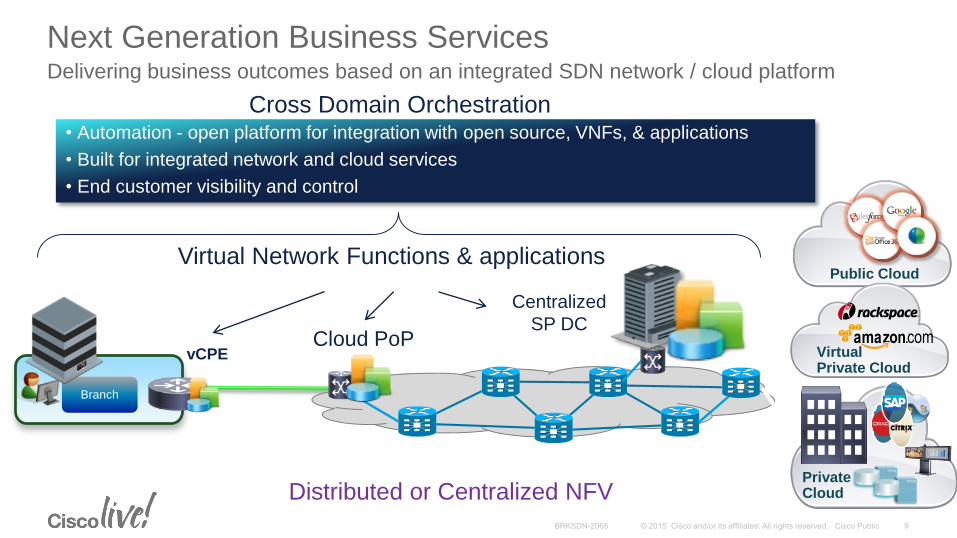
Next Generation Business ServicesDelivering business outcomes based on an integrated SDN network / cloud platform
Public Cloud
VirtualPrivate Cloud
vCPE
• Automation - open platform for integration with open source, VNFs, & applications
• Built for integrated network and cloud services
• End customer visibility and control
Cloud PoP
PrivateCloud
Centralized
SP DC
Virtual Network Functions & applications
Cross Domain Orchestration
Distributed or Centralized NFV

Cisco VNF’s
• Vast and comprehensive set of VNF’s.
• Sample list :
• Networking – CSR1000V, XRv
• Security – ASAv, WSAv, ESAv, vFirePOWER, vSCE, vISE
• Services – NetScaler1000v, vNAM, vWaaS, CUCM
• vSwitch – Nexus1000v, VPP/VTS
• Controllers – vWLC, vMSE, APIC, APIC-EM, OSC/ODL, WAE
• Management – NSO (Tail-f), ESC, PNSC, PSC
• Etc…
* Covered in this session

Service Chaining
• Service Function: Networking function that provides connectivity service, security service etc.
• Service Chain: Multiple functions linked together to provide a service
• How are services chained:
• Chaining of features within a device – IOS ingress/egress feature (ACL+QoS+NAT)
• Chaining via VLAN-stitching and routing within a device – Cat6500 with VPN, FW modules
• Chaining via Routing across devices – hop-by-hop services
• Chaining via Routing across VNF’s – hop-by-hop services
• Chaining via diversion mechanisms like WCCP, Tunnels, PBR
• Chaining via encapsulation mechanisms like vPath (Nexus1000v based) and Network Service Header (NSH)
VPN FW IPS

Chaining across Cat6500 Service ModulesSlide I made in 2005 !!!
FWSMMSFC2 DMZ
VLAN 40
O I
VPNSM IDSM2
Ethernet
PORTS
1 2
3
4
4 5
VLAN 30
VLAN 20
VLAN 10VLAN 50

Security Services Chaining With vPathIntelligent traffic steering through multiple network services (slide from 2013)
Cisco Nexus 1000V
Distributed Virtual Switch
VM VM VM
VM VM
VM
VM VM VM
VM
VM VM VM
VM VM VMVM
Cisco vPath
Cisco
VSG
Cisco
ASA 1000V
1 2
3
45
Use Case: VSG & ASA 1000V
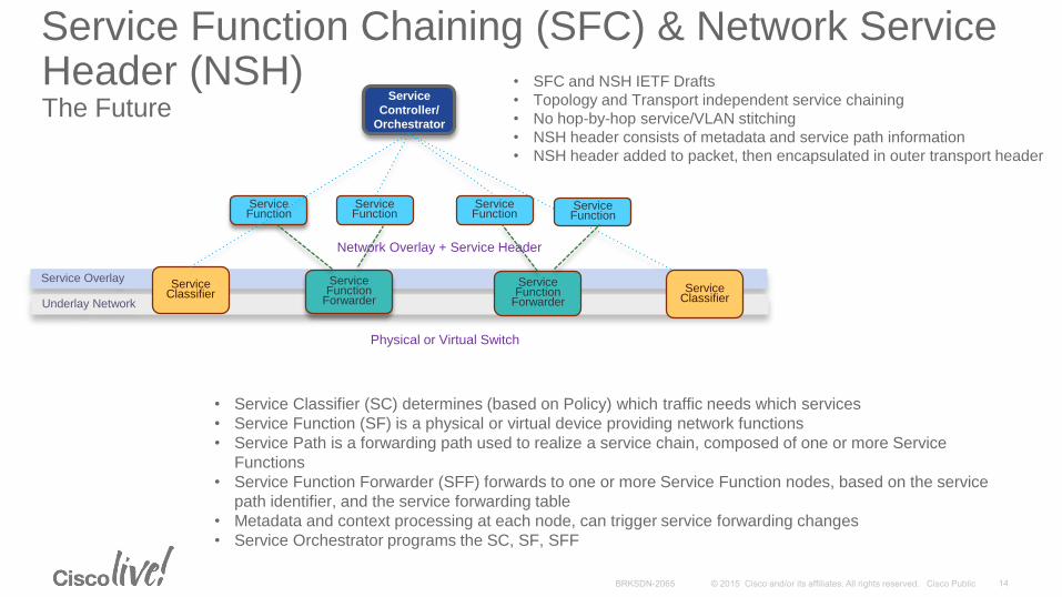
Service Function Chaining (SFC) & Network Service Header (NSH)The Future
Service Overlay
Underlay Network
Service Function
Forwarder
Service Function
Service Classifier
Service
Controller/
Orchestrator
Service Function
ForwarderService
Classifier
Service Function
Service Function
Service Function
Network Overlay + Service Header
• Service Classifier (SC) determines (based on Policy) which traffic needs which services
• Service Function (SF) is a physical or virtual device providing network functions
• Service Path is a forwarding path used to realize a service chain, composed of one or more Service
Functions
• Service Function Forwarder (SFF) forwards to one or more Service Function nodes, based on the service
path identifier, and the service forwarding table
• Metadata and context processing at each node, can trigger service forwarding changes
• Service Orchestrator programs the SC, SF, SFF
• SFC and NSH IETF Drafts
• Topology and Transport independent service chaining
• No hop-by-hop service/VLAN stitching
• NSH header consists of metadata and service path information
• NSH header added to packet, then encapsulated in outer transport header
Physical or Virtual Switch

Overlay Networks• Logical network built on top of another network. Overlay nodes connected via
logical links
• Abstraction from physical network allows for change, mobility etc.
• Some form of Controller, Distribution, or Learning involved to discover the logical links and anchor points
• Some form of tunneling - encapsulation and header manipulation (MACinMAC, MACinIP, IPinIP)
• Some common overlays:
• IPsec, GRE, VXLAN, OTV, LISP, MPLSoGRE, NVGRE, L2TPv3oIP etc.
Physical Network (Underlay)
Logical Network (Overlay)

vMS Solution

Virtual Managed Services (vMS)
Customer Site
Today’s
Physical
Solution
Internet /
SP Network
Network
Functions
vMS = Virtualizing the Network Functions of Managed Services so
they can operate in the Cloud (Public or Private)

Cisco CloudVirtualPrivate Cloud Public Cloud
Evolution of Managed Services – Premise to Cloud
Premise
Cloud
L3
“classic”
L2 NID
Network Functions from the Cloud
Network Functions on the CPE
L3 CPE + x86
on premise
L3 Meraki Cloud
Managed
Simple L3
CPE
vCPE on X86
on prem
Network Functions
Virtual Network
Functions
Network Secure IP Overlays MPLS Layer 2 VPN Hybrid
Application
ContainersApplications from the Cloud

Cisco Cloud
Cisco CloudVirtualPrivate Cloud Public Cloud
vMS 1.0 – First Step in a Journey
Premise
Cloud
L3
“classic”
L2 NID
Network Functions from the Cloud
Network Functions on the CPE
L3 CPE + x86
on premise
L3 Meraki Cloud
Managed
Simple L3
CPE
vCPE on X86
on prem
Network Functions
Virtual Network
Functions
Network Secure IP Overlays MPLS Layer 2 VPN Intelligent/Hybrid
Cloud
Application
Containers Applications from the Cloud
Managed WANSite-to-Site VPN
Managed SecurityFirewall, RA VPN, Web Security
ISR G2
SP Private Cloud

vMS Architecture

vMS Architecture FundamentalsModel Driven Orchestration Approach
• Service Intent is done through Modeling Languages that Abstract out the “How” and “Where”
• The Service is looked at summarily across the implementation domains.
• The Orchestrator has both a Service and Device component. Each independent of the other. Answers the “How”.
• The Orchestrator is able to Instantiate a Service Across the derived Topology (Infrastructure). Answer the “Where”.
Prem Access WAN Compute
CPE
L2NID
ISR
x86
MetroVNF
Service Chaining
ME36xx 9K
CRS
3rd Party
CSR
ASAv
3rd party VNF
Service
Intention
Service
Instantiation
Infrastructure
X-Domain Orchestration
Service DefinitionService Definition
Service Definition
RouterVNF
3rd party CPE
3rd Party

Elastic Services
Controller (ESC)
Tenant Portal
Network Service Orchestrator (NSO)
NETCONF/YANG REST API
NC/YANG, RC/YANG
SP’s OSS/BSS
CPE
PnP Functionality
Zero Touch Provisioning
OpenStack
X86 S
erv
er
Internet
Gateway
VNF Service chain
Provision
CSR1Kv
CPE Shipped at Customer
Site, connected & Powered ON
Customer Orders Service
Provide Day 1
Configuration
Establish VPN: IPSec tunnel, IP Overlay
(L2TP, VXLAN, GRE, LISP)
PnP server
vMS 1.0 Architecture
CSR1Kv ASAv vWSA
vSwitch
Provision
ASAv Provision
vWSA

CSR ASAv WSAv VTS(DC Overlay)
SDN ControllerOVS(DC Switching)
Virtual N/W
Functions
vMS Architecture ComponentsMaps to ETSI MANO
Network Service Orchestrator (NSO)(VNF-O)
Elastic Service Controller(VNF-M)
OpenStack(VIM)
Service APIs
Infrastructure
Operator Portal
Physical
OSS/BSS
Customer Facing Services
Resource Facing Services
SS
H
SS
H

Operator PortalExposing Service Blueprints to the Operator
• The Orchestration process can be kicked off through an Operator Portal.
• Super-user for SP Admin, RBAC for End-User Admin
• The Portal is aware of different Service Blueprints that can be exposed to an operator.
• The values that are selected in the Service Selection process result in the subsequent API call into NSO.
• The portal has 2 Modules.• Front-End: Skinned to the Customer’s
Requirements
• Back-end: Modified to support the Service Blueprints that can be orchestrated.

Network Service Orchestrator (from Tail-F)VNF Orchestrator
PnP Server
Transaction Database
(CDB)
Open PnP
Service Manager
Device Manager
Network Element
Drivers
x86ISR Virtual
Service Intent Service Intent Service Intent
Zero Touch Deployment
(ZTD)
Open Method for ZTD
Access
Transactional Database Allows full
CRUD capabilities to Services.
Service Manager Interprets
Service Intent with Service
Instantiation Rules and
derives configuration deltas.
Device Manager manages derived
and validated configurations in a
transaction manner towards derived
infrastructure.
Network Element Drivers Abstract the interfaces
to the devices allowing 3rd party infrastructure to
participate in Service Instantiation
Service Models written in Yang
Abstract Service from
underlying physical devices
Domain
Controller
Rest/NetConf/Yang
NSO
Mapping
ControllerMaps the Service Intent to
the Derived Device
Topology. Known as
“Fastmap”

Network Service Orchestrator (Tail-f)Multi-vendor service orchestrator
for existing and future networks
L2-L7 networking
Hardware Devices
Virtual Appliances
OpenFlow Switches
NSO provides abstractions
based on:
Data models
Transactions
Yang/Netconf
Run-time service reconfiguration
Dynamic Reconfigurations
Protocol-based (NETCONF)
Client – server
Fine-grained manipulations and data-
model for the application
Yang modeling allows for flexible
customizations
Network Element Drivers
Device Manager
Service Manager
Tail-f Network Control System Service
Models
Device
Models
Network-wide CLI, Web UIREST, Java, NETCONF
Network
Engineer
Management
Applications
End-to-End
Transactions
NETCONF, CLI, SNMP, REST, etc.
• Applications
• Controllers

Network Services OrchestratorModel Driven Multi-Vendor Service Orchestration
Agility: Model-Driven
Operations: Service Transactions
New Service Type: 2-4 days
New Device Type: 2-4 weeks
FASTMAP*• CREATE SERVICE
• UPDATE SERVICE
• DELETE SERVICE
• REDEPLOY SERVICENetwork Element Drivers
Device Manager
Service Manager
Tail-f Network Control System Service
Models
Device
Models
Network-wide CLI, Web UIREST, Java, NETCONF
Network
Engineer
Management
Applications
End-to-End
Transactions
NETCONF, CLI, SNMP, REST, etc.
• Applications
• Controllers

Elastic Service ControllerVNF Manager
API Confd
Rules Engine
Service Monitor
Public Clouds
Custom
DHCP
SNMP
Ganglia
Service
Provisioning
Scale
Up/Down
Elasticity
Custom
Day 0
Config
OpenStack
VM Provisioning &
Configuration Module
VNS Bring-up & Initial
Configuration
Application.
Multi-vendor Support.
Allows Modular Communication
with NSO.
Data Model Driven.
Affinity Rules and Scale
Requirements for the VNF
components. Also
manages the startup
sequences.
ESC uses
multidimensional
approach to VNF
Monitoring/Restartability
Programmable Interface to ESC allows
Functional Interaction to ESC
Subcomponents.
Elastic Services Controller
(ESC)
NSO

ESC ConfD
Core Engine
VIM DriverDatastore
Openstack
External ClientsTop Level Orchestration
Portal
NFVO
VNFM
VIM
Service
Catalogue
REST
Service Onboarding
Framework
Message Bus
SNMPVNFD REST CLI NETCONF XML/JSON XML/JSON
Health
Monitor/HA
Logging
Framework
REST
Transactions Validations RollbacksPolicies WorkFlowsState
Machines
Service Monitoring and Elasticity
Adaptor
Rules Analytic
Engine – PA• Events, Actions
• Custom rules,
scripts
Monitoring
Engine• SNMP
• PING
• GANGLIA
• CUSTOM
Monitor
Plugins
ESC Architecture

List of Events
• VM Alive
• Service Alive
• Upper load threshold crossed
• Lower load threshold crossed
• Service Dead
• VM Dead
List of Actions
• Notify (callback)
• Advertise Service
• Withdraw Service
• Restart VM
• Scale up (add a VM)
• Scale down (remove a VM)
• Individually customizable
action(s) for every event
Simple RulesService Alive =>
advertise
VM Dead => withdraw
Upper load => scale up
Complex Rules
Upper load => Scale up, Notify, Advertise
Service Dead => Withdraw, Notify, Restart
Service Alive => Advertise, Notify
Elastic Services Controller
Provision
VM
VM Bootstrapprocess
Service Bootstrap Process
Servicealive
VMalive
ServiceFunctional
ServiceOverloaded/Underloaded
VNFProvisioning
VNF MonitorVNF Configuration
Configure
Service
Service DEAD
VM DEAD
ESC VNF Lifecycle Management
Custom Script
Action
VMOverloaded/Underloaded
Predefined Action
Custom Script
Action
Predefined Action
Custom Script
Action Predefined Action
Custom Script
Action Predefined Action
Custom Script
Action Predefined Action
Custom Script
Action Predefined Action
Analytic Engine Rule Engine

VNF
Port
VNF
OpenStack, OVS, and SDN ControllerVirtual Infrastructure Manager • Open SDN Controller (OSC) is Cisco distribution of Open Daylight Controller
(ODL)
• OVS will be supported by OSC in upcoming vMS release. Common Neutron Plugin gives upgrade path on SDN Controller
• VirtIO drivers for OVS. DPDK vhost-user drivers for Cisco Virtual Topology Forwarder (VTF)
Nova
OVS Plugin
Neutron
Port
OVS
OSC Plugin
OSC Controller
Image Management
ML2
Plugins
Port
Port
Port
Port
Port
MGMT
External
InternalEdge
Network
InternetPort
Port
VNF
Port
Port
Port
NSO
Management
VNF
Port
VTFPort
Port
Port
Port
Port
MGMT
External
Internal
InternetPort
Port
VNF
Port
Port
Port
ESC
NSO
Model Driven
(MDSAL)Network
Management
Edge
Network
Confd
Port

Canonical Openstack
Compute-node 1
Compute-node 2
Compute-node N
SW-PrivateSW-Public
Bootstrap
CIMC
Installation script
Maas VM
Juju VM
1.Maas enlists nodes
2. Provisions/Install
Ubuntu on nodes.
Juju installs Openstack services
Juju add required relations between
services
Ubuntu14.04.1
LTS
Maas and Juju are the managing tools for
Openstack from Canonical, running on Ubuntu.

WAN
Nexus 9396
ASR 9000
UCS C240 M4
Production Nodes
Service Chains (CSR, ASAv, WSAv)
vMS PodDC Underlay
Control Nodes (3)
OpenStack Nodes (Nova, Neutron, Ceph Mon)
vMS Management Nodes (Portal, NSO, ESC)
1G MGMT links not shown
Production Nodes
Small Pod = 4
Medium Pod = 16
Large Pod = 32

Cloud Services Router (CSR 1000V)
• IOS-XE code
• Comprehensive feature set
• 4 month release cycle
• Infrastructure Agnostic
• Cisco UCS, Dell, HP, etc.
• Runs on vSwitch, dVS, N1KV, etc. – no dependency
• VMware ESXi 5.5, Citrix Xen Server 6.1, KVM – Ubuntu12.04 LTS, RHEL, RHEV, MSFT Hyper-V 2012 R2 support
• Amazon AMI support
• Footprint
• 1, 2, 4, 8 vCPU
• 2.5 GB / 1 vCPU [default]. 4, 8 vCPU / 4 GBServer
Hypervisor
Virtual Switch
VPC/ vDC
OS
App
OS
App
CSR 1000V
RP
FP

Branch
ISR
Branch
ISR
Branch
ISR
Data
Center ASR
Cloud Ready Router• Extending Enterprise WAN to Cloud
CSR
INTERNET/ MPLS WAN
VPC/ vDC
VPC/ vDC
Cloud
Security
IPSec VPN, L2TP
Route-based VPNs (DMVPN, ..)
Firewall, ACL, AAA
Integration
NAT, LISP, OTV
HSRP, QoS, AVC
IOS-XE CLI, Cisco PNSC
User Experience
Routing (BGP, EIGRP, Multicast, ..)
AppNav, WCCP, QoS, AVC
IP SLA, NetFlow, SNMP
Tenant Scalability
802.1Q VLAN, VXLAN
Routing (BGP, GRE, VRF-Lite)
MPLS (MPLS VPN, VRF)
Enterprise Services
DMVPN, EasyVPN, FlexVPN
Firewall, NAT, WCCP, QoS, AVC
IP SLA, NetFlow, SNMP
Tenant Manageability
10 Mbps to 1 Gbps
RESTful APIs
Term and Usage Licensing
EnterpriseCloud Provider

CSR 1000V Features per Technology Package
TechnologyPackage
Virtualization IOS-XE Features
STANDARD (Routing) ESXi 5.1/5.5
XenServer 6.1 KVM (Ubuntu
12.04 LTS, RHEV 3.1, RHEL 6.3)
Hyper-V 2012 R2
Basic Networking: BGP, OSPF, EIGRP, RIP, ISIS, IPv6, GRE, VRF-LITE, NTP High Availability: HSRP, VRRP, GLBP Addressing: 802.1Q VLAN, EVC, NAT, DHCP, DNS Basic Security: ACL, AAA, RADIUS, TACACS+ Management: IOS-XE CLI, SSH, Flexible NetFlow, SNMP, EEM, NETCONF
ADVANCED(Standard +
Security)
STANDARD + QoS Multicast: IGMP, PIM Advanced Security: Zone Based Firewall, IPSec VPN, EZVPN, DMVPN,
FlexVPN
PREMIUM(Advanced +
AppX + Hybrid Cloud)
ADVANCED + Advanced Networking: L2TPv3, BFD, MPLS, VRF, VXLAN Application Experience: WCCPv2, APPNAV, NBAR2, AVC, IP SLA Hybrid Cloud Connectivity: LISP, OTV, VPLS, EoMPLS
Differentiated Tenant Services – Basic RaaS, Adv Security, Premium DCI, Visibility

Cisco ASAv Firewall and Management Features
Cisco® ASA 9 Feature Set
Cisco
ASAv
Removed clustering and
multiple-context mode
10 vNIC interfaces and VLAN tagging
Virtualization displaces multiple-context and clustering
Parity with all other Cisco ASA platform features
SDN (Cisco APIC) and traditional (Cisco ASDM and CSM)
management tools
Dynamic routing includes OSPF, EIGRP, and BGP
IPv6 inspection support, NAT66, and NAT46/NAT64
REST API for programmed configuration and monitoring
Cisco TrustSec® PEP with SGT-based ACLs
Zone-based firewall
Equal-Cost Multipath
Failover Active/Standby HA model

* Lab Edition license is built in with 100-Kbps throughput and 100 total
connections allowed
Cisco ASAv Platforms
100 Mbps
1 Gbps
2 Gbps
Cisco®
ASAv5
Cisco®
ASAv10
Cisco®
ASAv30

vMS 1.0 Use-cases

vMS 1.0 Usecase

• Self-Service Portal
• fully automated VPN provisioning
• Service Monitoring
• Site-to-site IPSec connectivity (IPv4)
• Hub & spoke FlexVPN
• User-configurable LAN address ranges
• Cisco ISR zero-touch deployment via PnP
• Configurable redundancy
• Application-aware QoS
• Using Cisco NBAR
• SSL-VPN Remote Access
• Cisco AnyConnect client
• Password-based authentication
• Secured Internet Access - via NAT & FW
• Web Security
• WEB URL filtering (http)
• Anti Malware/Anti-Virus
• Web-based Reputation Filtering
vMS 1.0 Service Features

vMS 1.0 Full Service ChainS2S IPsec + FW + NAT + SSLVPN + Web Security

vMS 1.0 Medium Service ChainS2S IPsec + FW + NAT + SSLVPN

vMS 1.0 Basic Service ChainS2S IPsec

vMS Resource Usage
Component vCPU Memory (GB) Disk (GB) Notes
Portal 4 16 160
NSO 4 24 20 + 50
ESC 4 16 30
CSR 1000V 2 4 8
ASAv 2 4 8
WSAv 2 6 250
Further optimization planned in future vMS releases

vMS Node Scale
Service Chain vCPU Memory (GB) Disk (GB) Chains Per Node
Full
(CSR + ASAv + WSAv)
6 14 266 7
Medium
(CSR + ASAv)
4 8 16 11
Basic
(CSR)
2 4 8 24
Scale is mostly CPU bound
Assuming 12-core dual socket CPU, and no CPU oversubscription
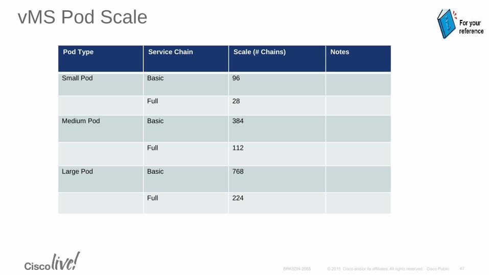
vMS Pod Scale
Pod Type Service Chain Scale (# Chains) Notes
Small Pod Basic 96
Full 28
Medium Pod Basic 384
Full 112
Large Pod Basic 768
Full 224
vMS Benefits

• Self Service – Catalog Driven
• Simplification and Control for End-users
• Agility, Service Velocity (creating new services)
• Elasticity and On-demand spin up of services (VNF service chains)
• Pay-as-you-Grow for Providers
• Zero-Touch Deployment of CPE with PnP
• Lower TCO (agility, automation, simplification) via Virtualization & Cloud Management
• Leverage existing SP Network Infrastructure
• Shorter Time To Revenue with NO upfront CAPEX
• Ability to bundle offers -> Mobile, Video, Security, Cloud Interconnect
vMS 1.0 - Key Benefits

End-user Control and Self-Service

End-user Control and Self-Service
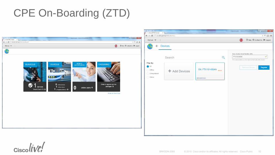
CPE On-Boarding (ZTD)
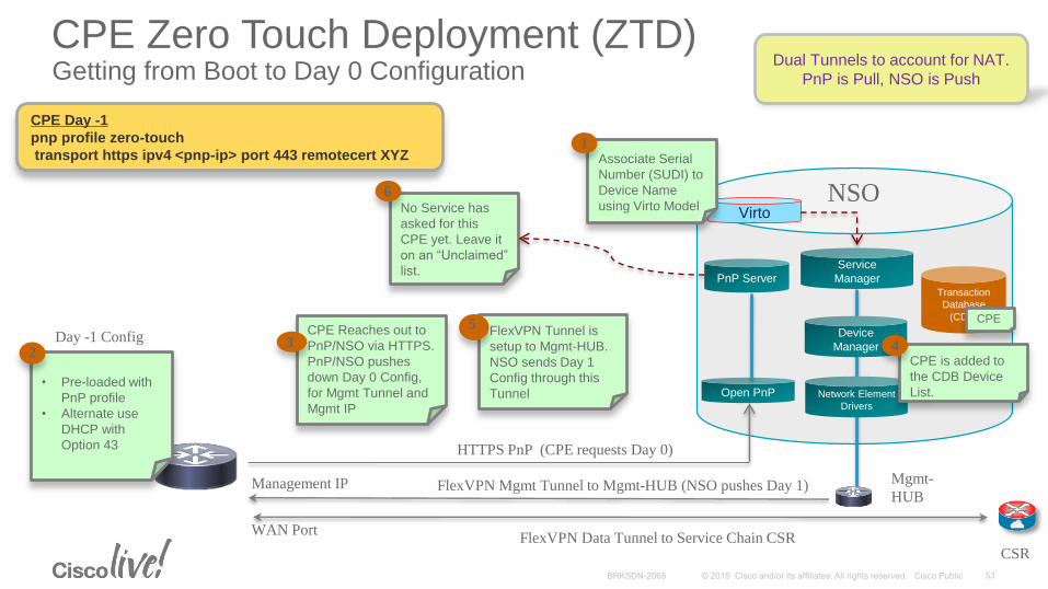
CPE Zero Touch Deployment (ZTD)Getting from Boot to Day 0 Configuration
PnP ServerTransaction
Database
(CDB)
Open PnP
Service
Manager
Device
Manager
Network Element
Drivers
NSO
Management IP
WAN Port
HTTPS PnP (CPE requests Day 0)
Virto
Associate Serial
Number (SUDI) to
Device Name
using Virto Model
1
• Pre-loaded with
PnP profile
• Alternate use
DHCP with
Option 43
Day -1 Config2
CPE Reaches out to
PnP/NSO via HTTPS.
PnP/NSO pushes
down Day 0 Config,
for Mgmt Tunnel and
Mgmt IP
3
CPE is added to
the CDB Device
List.
4FlexVPN Tunnel is
setup to Mgmt-HUB.
NSO sends Day 1
Config through this
Tunnel
5
No Service has
asked for this
CPE yet. Leave it
on an “Unclaimed”
list.
6
CPE
FlexVPN Data Tunnel to Service Chain CSRCSR
Mgmt-
HUBFlexVPN Mgmt Tunnel to Mgmt-HUB (NSO pushes Day 1)
CPE Day -1
pnp profile zero-touch
transport https ipv4 <pnp-ip> port 443 remotecert XYZ
Dual Tunnels to account for NAT.
PnP is Pull, NSO is Push

Service VelocityAchieved When Changes in Infrastructure do Not Require a Changed in Service Models.
Device Model Service Topology Configuration
DCI/PE (A9K, MX, …) MPLS VPN
CPE (ISR, U-CPE, …)
VNF (vR, vFW, …)
Cloud VPN
GETVPN
LISP VPN
Cloud Svcs
CPE Provision
Day 0/1/2/3
Day 0/1/2/3
NetConf/CLI
Service Intent
Model Driven Design
BYOD
vSecurity
vSecurity
YANG
Infrastructure
YANG
YANG

Function Pack Model
YANG Business
Service Model
Constructed From
Component YANG
Service Models
Consuming
Capabilities Exposed
in YANG device
models / NEDs
• New function packs (usecases) will be
released by upcoming vMS solution
releases.
• Customers can utilize these function packs
as-is, or tweak them per their usecase
requirements
• Cisco Services can be utilized to tweak
existing function packs and service models;
or build new ones to address customer
usecases and business requirements

PAYG with Cisco Smart Licensing & Call-HomeLicense Tokens configure on VNF as part of Day 0 config
Direct cloud accessCisco product sends usage information directly over the internet. No
additional components are needed.
Options
Direct cloud access through an HTTP proxyCisco Products send usage information over the internet via a
Proxy Server. Any off-the-shelf Proxy will work.
Mediated access through an on-premises satellite –connectedCisco Products send usage information to a local Mediator such as the
Smart Call Home Transport Gateway (Free VM Download), which
automatically completes the transaction with the backend.
Mediated access through an on-premises satellite –disconnectedCisco Products send usage information to a local disconnected
satellite, which acts as a local license authority. Once a month,
an exchange of human readable information will be performed to
keep the databases in sync.
Se
cu
rity
Po
licy
Ea
se
of
use
1
2
3
4
Cisco
Product HTTPs
Cisco
Product HTTPs
Proxy
Cisco
Product
HTTPs
Cisco
ProductHTTPs
Your Cisco
Software
Usage
Your Cisco
Software
Usage
Your Cisco
Software
Usage
Your Cisco
Software
Usage
Cisco.com
Cisco.com
Cisco.comTransport
Gateway
Cisco.com
File
Transfer
Satellite

vMS Orchestration Details
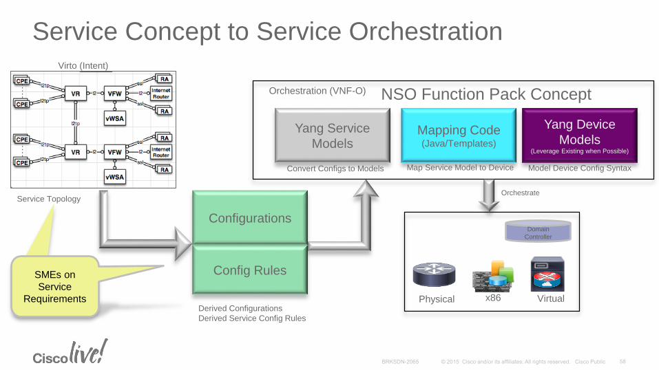
Service Concept to Service Orchestration
Configurations
Config Rules
Yang Service
ModelsMapping Code(Java/Templates)
Yang Device
Models(Leverage Existing when Possible)
NSO Function Pack Concept
Physical x86 Virtual
OrchestrateService Topology
Derived Configurations
Derived Service Config Rules
Orchestration (VNF-O)
SMEs on
Service
Requirements
Convert Configs to Models Map Service Model to Device Model Device Config Syntax
Domain
Controller
Virto (Intent)

Function Pack (vMS Service Blueprint)Mapping Service Intent to the Infrastructure
Service Models
(Virto)
Mapping Logic
(Fastmap)
Device Models
(Underlay)
• Service Models Represents the Intention of the Service
• Written in Yang
• Contains Service Validation Logic
• Exposes NB through Service API (automatically created)
• Processes the Service Intent
• Calls External Resources as needed to prepare the service.
• Maps the Service Model Parameters to the Device Model
Service Request• Calls the Service with the Appropriate
Parameters for Instantiation.
• Abstracts the specifics of the Device from the Service Logic
• Supports different Vendors through the use of Network Element Drivers
Infrastructure
NSO

node.4node.3 node.5
network topology model
node.1
node.2
nodeslinks termination_points
link.1
link.2
link.3 link.4
tp.1
tp.2
tp.3
tp.4tp.5 tp.6 tp.7 tp.8
• Based on the draft: draft-clemm-netmod-yang-network-topo-00.
• Topology Comprises a set of Nodes and Links.
• Links are Pt-Pt and Unidirectional.
• Model is on-boarded to the Physical and Virtual Infrastructure.
Virto: Virtual Network TopologyNodes, Links, Termination Points

Network Topology: “Virto”
• Virto is the Fundamental construct for understanding vMS Use Cases.
• A Network Topology is a Blueprint that will describes the intent of the service instantiation.
• This is modeled in Yang and is Abstracted from both the physical & virtual infrastructure below.
• The code snippet on the right is one portion of the overall Virto Model.
termination-point inside;
termination-point outside;
function {
security {
policy ssl-vpn {
rule 10 {
match {
match-type any;
identity [email protected] {
user-name [email protected];
user-password <removed>;
admin-state activated;
}
}
[...]
node wsa-01 {
capabilities [ vnf web-security ];
node-type {
cloudvpn-virto {
vWSA;
}
}
termination-point bridge;
function {
security {
policy filtering-enhanced {
default-action allow;
rule 10 {
match {
match-type any;
application adult {
url-category [ adult ];
}
application gambling {
url-category [ gambling ];
}

Mapping Separates Service Intent from Infrastructure NSO Java & Templates through Fastmap
Service Model
(Virto)
Service API
Java used when Simple
Mapping from Service to
Device Model is not
Enough.
FastMap
Device Template
Device Model
NSO
Infrastructure
• Set of Validation Rules.
• Maps Service Model to Device Layer
• Declarative model of data-models ;
two or more stages.
• Service Models define the
exact attributes that can be
configured for a service.
• Maps Service Variables to
Device Variables.
• Adds Flexibility to Change
the Device Configuration
without Recompiling.
• Maps to Device
Configurations
Deploy
CommitMap

Loading Infrastructure Into NSO (Underlay)Modeling the Physical and Virtual Topologies
• Multiple Infrastructure Topologies can be modeled in NSO.
• These constitute the Topology Underlay
• The device models are stored in the CDB.
• For rapid efficiency in parsing the device topologies, a GraphDB is used that emulates the device topologies but is optimized for lookups.
PnP Server
Transaction Database
(CDB)
Open PnP
Service Models
Device Models
Network Element
Drivers
Service Intent Service Intent Service Intent
Rest/NetConf/Yang
NSO
Mapping
Controller
GraphDB
OVS
Bridge
Links
Infrastructure 1
OVS
Bridge
Links
Infrastructure 2
OVS
Bridge
Links
Infrastructure 3
Resource Pools
Resource Pools
Resource Pools

Service APIs Service Variables
CSR ASA WSA
VNF
Mapping Service Intent to Specific TopologyQuerying the Underlay
Service Model
Reactive
Fastmap
Service Manager
Device Manager
Transactional
Database
OpenStack
ESC
NSO
1. Service Intent
“Virto Model”
Underlay
Physical
8. Commit
Configs
Rest/NetConf
4. VNF Spin-up
7. Service
Callback
2. Query a GraphDB to derive
Topology with Capabilities to
Render Service. Selection based
on Tags and Capabilities in the
ModelESC
Overlay(Created Topology)3. Derive Virtual Topology
CPE IPSec CSR ASA Inet
6. Ready?
Internal Mgmt External
OVS
5a. Launch
with Day0
5b. Network
Assignment
GraphDB
tags [ cpeSerialNo ];
tags [ internet ];
..
capabilities [ bridging ];
capabilities [ routing ];
capabilities [ web-
security, vnf ];
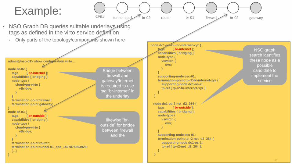
Example:
• NSO Graph DB queries suitable underlays using tags as defined in the virto service definition
• Only parts of the topology/components shown here
admin@nso-01> show configuration virto ...
node br-02 {
tags [ br-internet ];
capabilities [ bridging ];
node-type {
cloudvpn-virto {
vBridge;
}
}
termination-point firewall;
termination-point gateway;
}
node br-03 {
tags [ br-outside ];
capabilities [ bridging ];
node-type {
cloudvpn-virto {
vBridge;
}
}
termination-point router;
termination-point tunnel-01_cpe_1427875893928;
[...]
}
likewise “br-
outside” for bridge
between firewall
and the
node dc1-os-2~~br-internet-xyz {
tags [ br-internet ];
capabilities [ bridging ];
node-type {
vswitch {
ovs;
}
}
supporting-node esc-01;
termination-point tp-r2-br-internet-xyz {
supporting-node dc1-os-2;
tp-ref [ tp-r2-br-internet-xyz ];
}
}
node dc1-os-2-net_d2_264 {
tags [ br-outside ];
capabilities [ bridging ];
node-type {
vswitch {
ovs;
}
}
supporting-node esc-01;
termination-point tp-r2-net_d2_264 {
supporting-node dc1-os-1;
tp-ref [ tp-r2-net_d2_264 ];
}
}
NSO identifies
this node as a
possible
candidate to
implement the
service
NSO graph
search identifies
these node as a
possible
candidate to
implement the
service
CPE1 tunnel-cpe1 br-02 router br-01 firewall br-03 gateway
Bridge between
firewall and
gateway/Internet
is required to use
tag “br-internet” in
the underlay

vMS Service Creation – Step 1
1. End customer signs on to vMS portal
2. Customer configures service on portal
3. Portal constructs service definition XML (“virtual
topology” yang model) and sends netconf
configuration to NSO
ESC
OpenStackASAvCSR WSAv
NSO
4. NSO compares target topology for the service and
compares with current state to apply any changes.
5. Assuming this is a new customer/service: NSO identifies
which network components it needs to deliver the service
(virtual router/firewall/etc.) and creates them.
6. NSO maps target virtual topology to physical topology (i.e.
DCs), and instructs the appropriate ESC to spin up the service
7. NSO configures Service
on ESC (Netconf)
8. ESC calls OpenStack
to create the required
virtual resources
34
11
89. OpenStack spins up VMs
10. ESC monitors
VM coming up
11. ESC signals VM and
Service Alive to NSO
7
9
56

vMS Service Creation – Step 21. End customer receives the CPE on location
and enters its Serial Number into the Portal
2. Portal constructs service definition XML (Yang
model) which now includes a serial number
assigned to a CPE to NSO
ISR CPE
ESC
OpenStackASAvCSR WSAvSP Cloud
NSO
3. NSO compares target configuration for the service and
compares with current state to apply any changes. Only
change is the serial number assigned to one of the CPEs
6. NSO adds CPE device to its list devices
7. NSO builds the final day2 target configuration for all
devices (virtual & physical) and configures the diffs on
all devices
2
PnPServer
4. CPE is connected to network,
contacts PnP server
5. PnP server sends day0
configuration to CPE
7
8. NSO triggers a creation of a
DNS record for customer’s ASA’s
outside address used for SSL-
VPN
SP DNS8

Future Use-cases(possibilities)
CPE
CPE
PE vPE vFW
vWS
L3
L2
RAInet
GW
SSL
VMS Orchestration Scope
CSR ASA WSA
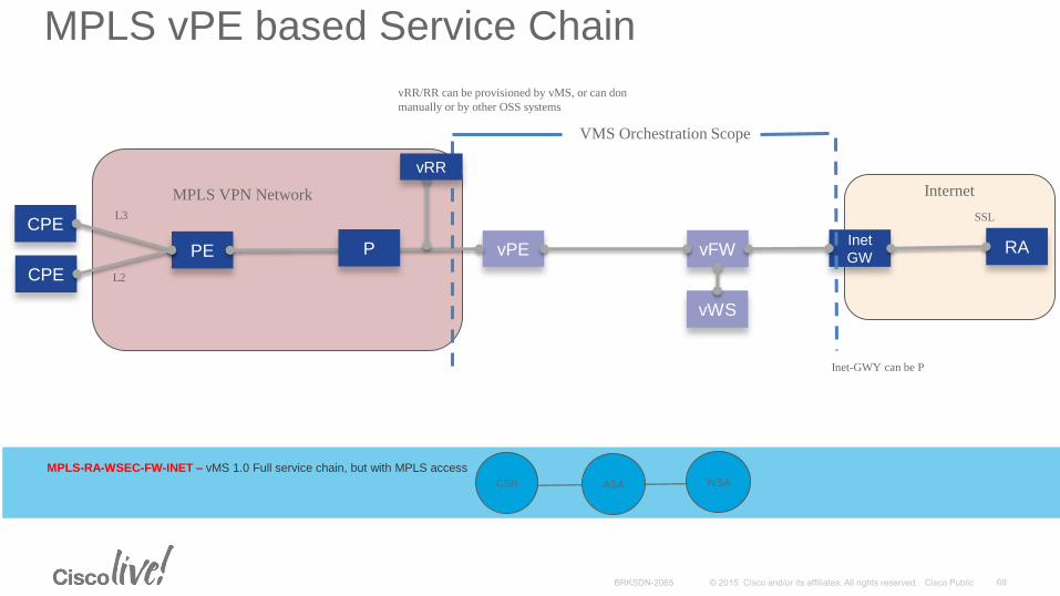
MPLS-RA-WSEC-FW-INET – vMS 1.0 Full service chain, but with MPLS access
P
MPLS vPE based Service Chain
MPLS VPN Network
vRR
Internet
Inet-GWY can be P
vRR/RR can be provisioned by vMS, or can don
manually or by other OSS systems
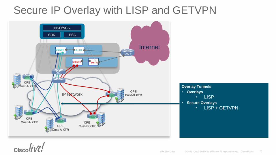
Overlay Tunnels
• Overlays
• LISP
• Secure Overlays
• LISP + GETVPN
CPE
Cust-A XTR
CPE
Cust-A XTR
CPE
Cust-A XTR
PxTR
IP Network
InternetMSMR
vFWVRMSMR PxTR
CPE
Cust-B XTR
CPE
Cust-B XTR
DCI
GWY
NSO/NCS
SDN ESC
Secure IP Overlay with LISP and GETVPN

vBranch + vMS
AG
AGG
NPE
NPE
IP/MPLS
or SR Core
vDDoS
vFW
vDPI
vMS POD
NFV and Cloud Orchestration
Cloud DC(SP / 3rd Party)
PE
PE
x86 vBranch
OS + Hypervisor
Branch Orchestrator
vWaaSvCPE
• X86 based vCPE + Services in vBranch
• Additional services in vMS DC
Internet

vMS with SFC & NSHSimplified Service Chaining
Service Overlay
Underlay Network
Service Function
Forwarder
Service Function
Service Classifier
Service
Controller/
Orchestrator
Service Function
ForwarderService
Classifier
Service Function
Service Function
Service Function
Network Overlay + Service Header
• Service Classifier (SC) determines (based on Policy) which traffic needs which services
• Service Function (SF) is a physical or virtual device providing network functions
• Service Path is a forwarding path used to realize a service chain, composed of one or more Service
Functions
• Service Function Forwarder (SFF) forwards to one or more Service Function nodes, based on the service
path identifier, and the service forwarding table
• Metadata and context processing at each node, can trigger service forwarding changes
• Service Orchestrator programs the SC, SF, SFF
• SFC and NSH IETF Drafts
• Topology and Transport independent service chaining
• No hop-by-hop service/VLAN stitching
• NSH header consists of metadata and service path information
• NSH header added to packet, then encapsulated in outer transport header
Physical or Virtual Switch

Cisco Virtual Topology SystemOpen, Multi-tenanted, Policy Based SDN Solution for SP NFV and DC Evolution
VCenterOpenStack3rd Party VM
Manager
REST API
Virtual Topology System
(VTS)MP-BGP
BGP-EVPN
VTFVTFOVS dVS
RESTCONF/Yang
MP-BGP
BGP-EVPNRR RR
Cisco NSO
IP / MPLS
WAN
WAN / Internet
3rd Party Cloud
Bare Metal
Workload
Virtualized
Workloads with OVS
Virtualized Workloads with Feature Rich &
High Performance Cisco VTF Solution
Virtualized
Workloads with SR-IOV
Virtualized
Workloads with dVS
DCI DCI
Data Plane
Control Plane
Management &
Orchestration PlaneVTS GUI
ToR ToR
VM or
VNF
VM or
VNF
VM or
VNF
VM or
VNFVM or
VNF
VM or
VNFVM or
VNF
VM or
VNF
VM or
VNF
VM or
VNF
VM or
VNF
VM or
VNF

Conclusion

Key Takeways
• Cisco Virtual Managed Services (vMS) is an architecture and orchestration solution for enabling NFV services using virtual appliances, overlay networking, and VNF service chaining.
• vMS 1.0 enables virtualised Managed WAN and Managed Security services in the Cloud
• vMS utilizes Network Service Orchestrator (NSO) from Tail-f, which provides Model driven service abstraction, separating Service Intent from Service Instantiation.
• vMS is a platform that can rapidly enable creating and deploying new services
• Multi-tenancy, elasticity, PAYG, automation, service agility and reduced OPEX can be provided by the vMS platform
• Cisco has a broad portfolio of VNF’s that can utilized in the vMS solution
• The Cisco vMS solution will keep introducing new Function Packs to enable new usecases, service topologies and VNF’s

Demo

Participate in the “My Favorite Speaker” Contest
• Promote your favorite speaker through Twitter and you could win $200 of Cisco Press products (@CiscoPress)
• Send a tweet and include
• Your favorite speaker’s Twitter handle @SunilCherukuri
• Two hashtags: #CLUS #MyFavoriteSpeaker
• You can submit an entry for more than one of your “favorite” speakers
• Don’t forget to follow @CiscoLive and @CiscoPress
• View the official rules at http://bit.ly/CLUSwin
Promote Your Favorite Speaker and You Could Be a Winner
Complete Your Online Session Evaluation
Don’t forget: Cisco Live sessions will be available for viewing on-demand after the event at CiscoLive.com/Online
• Give us your feedback to be entered into a Daily Survey Drawing. A daily winner will receive a $750 Amazon gift card.
• Complete your session surveys though the Cisco Live mobile app or your computer on Cisco Live Connect.

Continue Your Education
• Demos in the Cisco campus
• Walk-in Self-Paced Labs
• Table Topics
• Meet the Engineer 1:1 meetings
• Related sessions

Thank you