ngai sum ming 385090 air studio final submission
DESCRIPTION
AIR Studio Final SubmissionTRANSCRIPT
Architecture Design Studio
A I R
NGAI Sum Ming Sam 395090 Semester 1, 2013 Studio 15
Index
Self Introduction Part A. EOI I: Case for Innovation 1. Architecture as Discourse 2. Computation in Architecture 3. Parametric Modeling4. Algorithmic Explorations5. Conclusion6. Leanring Outcomes
Part B. EOI II: Design Approach1. Design Focus2. Case Study 1.03. Case Study 2.04. Technique: Development5. Technique: Prototypes 6. Technique Proposal7. Algorithmic Sketches8. Learning Objective and Outcomes
Part C. Project Proposal 1. Design Concept2. Tectonic Elements 3. Fianl Model4. Algorithmic Sketches5. Learning Objectives and Outcomes

I am Sam, Sum NGAI, I am from Hong Kong. I am in my third year of university, majoring architecture. I studied sci-ence before I went into university, I love to play music and I like to drive and explore the nature. Although I did not have any architectural training before I went to university, I love architecture since I was a kid. My home town is a place crowded with buildings, 7-storey residential housing, skyscrapers, cottages, etc. I’m curi-ous of the design of buildings, in many cases they pack so many people in such a limited space. And as the land becoming more and more of a scarce in Hong Kong, new buildings need to be much more efficient. I think parametric design is the solution to this problem, parametric design is about breaking boundaries, to cre-ate designs that can response to the environment and perhaps to revolve under different circumstances.
Self Introduction

My experience with computational design was with the Virtual Environments subject in the first year of university. I am not good at drawing so I found designing with computer is easier to express and visualize my design ideas. The images on the right is some of the outcomes from Virtual Environments. It is designed to wear on your body like a suit. And by designing that, I explore and learn from the nature. That was the first time using Rhino to design in a digital environment. I think parametric design is an efficient way of designing because you can quickly gener-ate an array of prototypes, evaluate them and take further actions. To conclude, I am looking forward to ex-plore another new design platform Grass-hopper and I hope I can make good use of digital design and be more competitive after finishing this course.

A.1. Architecture As Discourse From the Exploring Visual Culture (2005), Richard William defines some perspectives of how people looking into architecture, and I am going to explore four of the perspectives he mentioned. Architecture as art is the most common perspective of all, a good building should be challenging, revolutionary and be aesthetic brilliance1. This can relates to parametric de-sign where designs are to be extraordinary and different from traditional designs be-cause parametric design can enable us to have delicate and complex detailing that is hard to achieve without the help of a com-puter. Richard also mentions the modernism has influenced the aesthetic attention has shifted from the facade to the relationship between the skin and structure1. The Fibrous Tower by Kokkugia2 is a good example of how parametric design is capable of mak-ing skin of a building that also work as a structural component. Another aspect for architecture is to be cli-ent oriented. I think it is true because archi-tectures rely on the funding of their cilents. Architecture is bounded by specifications, location and architects must work within the parameters. Parametric design can con-struct forms and spaces that architects can work more closely to the limits of the con-strains, thus, create better architecture.
Fibrous Tower 2008 by Kokkugia. Computational design to ensure the fibrous structure to transfer loads efficiently to the ground.

Richard also suggests architecture needs to be considered “less set of special material products and rather more as range of social and professional practices that sometimes, but by no means always, lead to buildings.”1 Rather than designing a building, but by looking at the social and the people around, and using those ideas to create a build-ing, a form of structure that reflects people around, this creates a discourse that involves everyone around the architecture. And by that, everyone will have their own experi-ence with the architecture, this experience is unique and evolving, and that brings me into the last aspect. Architecture as a reality reserve, this is often perceive as a retrograde aspect but I think it is very important that cannot be overlook. I think architecture is always suppose be a place for refuge and spiritual repose. And with parametric design we can create struc-ture that response to the temperature, the humidity and create almost like an organism that intereact with the surroundings, giving users a new experience everytime they en-ter or see the building. I think this is the direction of the discourse of architecture. Under parametric design, mak-ing structure that reacts to the environment and users, while borrowing ideas from the nature (fiber, trees, etc.).
Responsive Surface Structure by Steffen Reichert. Structure change its shape under different humidity and temperature, creating different experience for users.
Responsive surface by BLOOM. Another ex-ample of how thermal responsive structure can create under parametric deisgn that provides a skin-structure that suits modernism and satisfy as a reality reserve.
References: 1. Richard Williams. ‘Architecture and Visual Culture’, in Exploring Visual Culture: Definitions, Concepts, Contexts, ed. by Matthew Rampley (Edinburgh University Press, 2005), pp. 102-116 2. Kukkugia. Fibrous Tower 2008, http://www.kukkugia.com 3. Stetten Reichert. Responsive Surface Structure 2006-2007, http://www.achim-menges.net/?p=4411 4. BLOOM. Responsive Surface 2012, http://www.architizer.com/en_us/projects/view/bloom-making-building-skins-responsive-with-thermally-smart-materi-als/50090/

A.2. Computation in Architecture “Design is a process we engage in when the current situation is different from some desired situation, and when the actions needed to transform the former into the lat-ter are not immediately obvious.”1 And com-putational design is a tool that enables you to review your processes, as well as modify the process, and create an array of different solutions. Moreover, computational design makes free flowing structures and complex geom-etries more accessible, helping architects to extend their creativity by defining the com-plex parameters and let architects to focus on the creativity based on fine tuning and tweaking these parameters. At the other hand, an interesting question would be how computational design af-fect the conventional types of geometries that can achieve without the help of a computer. The Torus House2 has a structure that an undulating pattern conjuncts with a long rectangular structure. And these two components form as a complete continuous structure. In this case, this long rectangular structure is fundamentally different, this is because computational designs are gener-ated by processes based on topological space, isomorphic surfaces and parametric design.3 The ‘conventional’ shaped compo-nents are essentially different, they are pur-poseful for the whole parametric design to create a coherent structure as a whole.
Torus House 1998-1999 by Preston Scott Cohen INC.

A.2. Computation in Architecture The Buddhism Temple, 2011 by Miliy Design4 is another interesting example of computa-tional design. The Shape of the building is based on a mobius stripe, where there is not a point of starting or ending, this relates to a core buddhism idea ‘輪迴’4, which refers to an endless cycle of rebirth. the Buddhism Temple clearly benefited from computa-tional design because the complex mobius pattern is used to match the Buddihism ide-alogy. The vast amounts of prototypes created with the computational design also give an opportunity for architects to explore more design outcomes. And computational de-sign also contribute to evidence, perfor-mance based design because it converges designing, representation, production and constructing into one place2, which trans-form the architectural industry to become the coordinator of an architeccture project.
References: 1. Yehuda E. Kalay, Architecture’s New Media : Principles, Theories, and Methods of Computer-Aided Design (Cambridge, Mass.: MIT Press, 2004), pp. 5 - 25 2. Preston Scott Cohen INC. Torus House 1998-1999, http://www.pscohen.com/torus_house.html 3. Kolarevic, Branko, Architecture in the Digital Age: Design and Manufacturing (New York; London: Spon Press, 2003), pp. 3 - 28 Kolarevic, Branko, Architecture in the Digital Age: Design and Manufacturing (New York; London: Spon Press, 2003), pp. 3 - 28 4. Miliy Design. The Buddhism Temple 2011, http://www.miliy.com/2012/06/06/taichang/taichang.html
The Buddism Temple 2011 by Miliy Design

A.3. Parametric Modeling
Parametric modeling is a new way for architects to explore and design. This is ac-tualized by defining a set of parameters that refer and transpose into geometries, which enable architects to generate new ideas and outcomes. With parametric design enables a collec-tive trade of models and techniques. This means quicker design because architects can design based on a ‘template’ and fur-ther modify and generate their own design under their own design parameters and con-strains. Another advantage of using parametric design is the capability of its form searching ability, architects can achieve forms that are not practically reachable before. History of design is a ever-changing process of form finding, parametric design is a good tool to keep finding new shapes and forms. Take a look at the Zaha-Hadid Architects’ project of Galaxy Soho 2009-2012. Curvilinear shapes and continuity lines are the outcomes of parametric design’s form finding. Galaxy Soho 2009-2012 by Zaha Hadid Architects
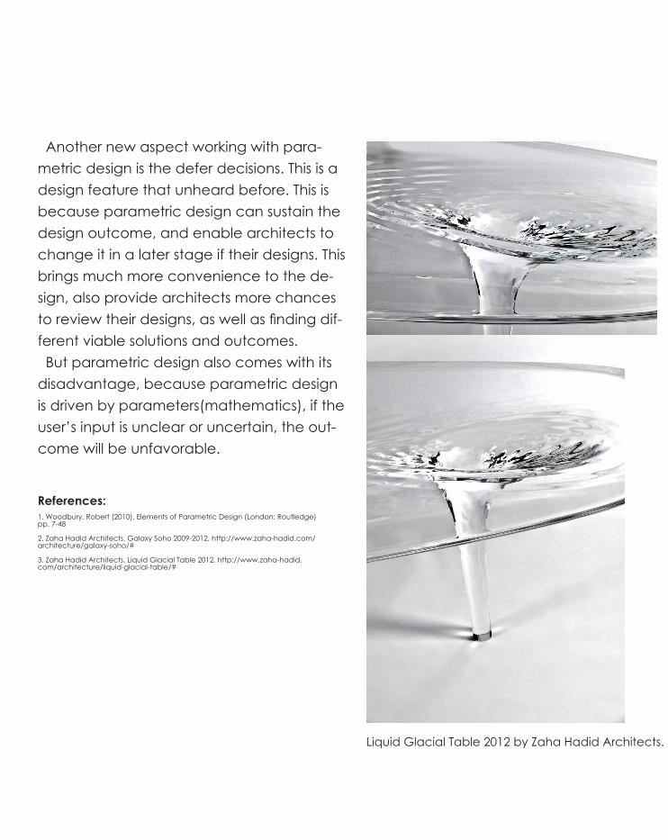
Another new aspect working with para-metric design is the defer decisions. This is a design feature that unheard before. This is because parametric design can sustain the design outcome, and enable architects to change it in a later stage if their designs. This brings much more convenience to the de-sign, also provide architects more chances to review their designs, as well as finding dif-ferent viable solutions and outcomes. But parametric design also comes with its disadvantage, because parametric design is driven by parameters(mathematics), if the user’s input is unclear or uncertain, the out-come will be unfavorable.
References: 1. Woodbury, Robert (2010). Elements of Parametric Design (London: Routledge) pp. 7-48 2. Zaha Hadid Architects. Galaxy Soho 2009-2012, http://www.zaha-hadid.com/architecture/galaxy-soho/# 3. Zaha Hadid Architects. Liquid Glacial Table 2012, http://www.zaha-hadid.com/architecture/liquid-glacial-table/#
Liquid Glacial Table 2012 by Zaha Hadid Architects.

A.4. Algorithmic Sketches

For part a I have explored three curves which made up a loft surface. And then I use the Divide Surface Command to generate a grid of points on this loft surface, afterthat I assign those points into circles, by manipulating the number of u,v in the divide surface command I got an interesting ar-ray of results.

A.5. Conclusions
After the explorations of my part a case for innovation, I have narrowed down my design approach in Responsive Structure. When looking at the responsive structure by BLOOM and Steffen Reichert, they are examples of how a structure can provide a exceptional relationship with users because the structure is ever-changing and provide a refuge for users when there is rain or cold, and provide sunlight and warmth to them in a sunny day. It is innovative because it is not a static structure, it interacts with the surrounding it interacts with the users, it is a truly exciting idea for me to explore. It will beneficial for both the users and designer because it provide a platform that enable designer to have a spectrum of design possibilities, also give users an experience that is rare and intimate.

A.6. Learning Outcomes
To conclude,AIR studio is a good opportunity for me to explore deeply into computational design. It is good to be back using Rhino, just like 2 years ago when I first started using Rhino in Virtual Environments. There are always challenges with computational design as I’m never fully fa-miliar with the environment, there are always something new to learn, to explore about. So I think it is good for me to have the same attitude 2 years before, to be curious about anything, and explore them to have a good understanding and also find a greater possibilities in designing the upcoming challenges.


B.1. Design FocusMaterial Performance
In this section we look into material perfor-mance (minimal surfacing) to explain why it is appropriate for the Wyndham City Gate-way project. “Seeds of Change”, the previous public art established by Wyndham city has been criticized by the community for its high cost, and slow progress. According to Cameron (2011), the “Seeds of Change” project has been on Wyndham Council’s agenda for five years and cost ratepayers more than $25,000 and did not create enough visual impact. As a result, I think it is sensible for my design team to opt for a materially and structurally efficient and minimized solution to make our design outstanding and avoid over-budget. The Textile Hybrid M1 is my first precedent. The M1 explores lightweight tensile and bending-active structures. The structure of M1 exert a minimal of forces to the sur-rounding context by adopting deep surface prototype and intense testing with structural elasticity. Which is applicable to the ideas of our team’s design because it is structurally efficient and the shape of the structure also has a fluidity to it.
Top: “Seeds of Change” 2003 Middle and Bottom: Textile Hybrid M1 2012 by Inst. for Computational Design (Prof. A. Menges) Inst. of Building Structures & Structural Design (Prof. Knippers)

The second precedent is the Voussior Cloud. It consists groups of petal like struc-tures that create a beautiful daytime view-ing experience when users are inside the structure. I think we can learn from the sen-sorial effects that Voussior Cloud creates, the luminous wood pieces are decent to look at both from the inside and outside, and the pattern of the gaps between wood pieces also create interesting shading pattern. Moreover, the structural system of the Vous-sior Cloud is also applicable to the future design of our team. Firstly, the material is bending thin laminated wood, which enale a flexible, and lightweight surface. Sec-ondly, the sturcture adopt Antonio Gaudi’s hanging chain models, which act in pure compression and the placement of strings and weight can alter the building structure, which i think is very interesting and can add to the consideration of the design of my team to add structural efficiency and fluid-ity.
Top and Middle: Voussior Cloud

Entry Paradise Pavilion by LAVA is a great example of minimal surface and material ef-ficiency. LAVA adopt microscopic cell struc-ture ideas into the design of the pavilion, which create great visual impact like the shape of foam and latex in tension. My team really like the visual effect it creates and wanted to add similar effect into our design. Structurally, the shape of the pavilion is de-rived from nature, which is the most efficient subdivision of 3-D space. I think our design team will adapts design concepts of this Entry Paradise Pavilion, we also take notes of the lighting effects it creates because it changes to feel of the structure dramati-cally. In conclusion, my team will focus more on minimal surface as it incorporates asthetic captivation through the use of complex geometry on the future for the development for our final model as well as the Case Study for next week.
Entry Paradise Pavilion 2006 by LAVA
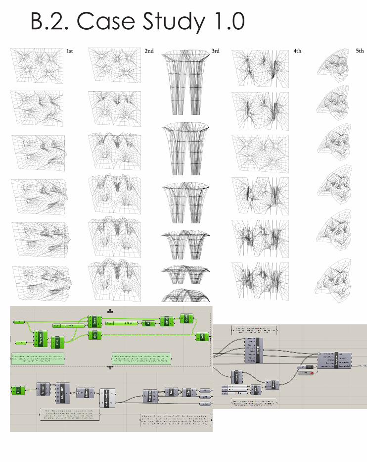
B.2. Case Study 1.01st 2nd 3rd 4th 5th

In Case Study 1.0 me and my group explored material performance. We explored the reverse engineering of the Voussoir Cloud by LAVA. This proj-ect matches our team’s design focus. The project focuses on the material efficiency and lightweight petal structural component. The matrix creates a platform for my team to speculate the design direc-tions. The 1st and 2nd row explores the forces of X and Y direction exerts on the structure, that creates some twisting effects and the structure shapes like those hanging chain models our team explored during design focus stage. It is useful when consider placing the structure on a slanted ground that loads will be distributed unevenly. Third row relates to the depth of the vaults. Our team thinks the longer ones look more attractive as the supporting components are narrow, while the components on top are huge which creates strong visual impacts. Forth row explores the relation of sizes of the openings and the shape of the structure, all models show signs of distortion except the third one(with default value). Fifth row explores the possibility of adapting different curve and openings of the model, the model adapts to it well and with the fluid curve input it also exhibits an organic fluid feel to it. Unlike Voussoir Cloud project, our group wishes to create a structure with a hybrid system of wire mesh and wood. To create a visually interesting ob-ject, as well as create zones and portals within the structure (shaded area, open area, openings, etc.)
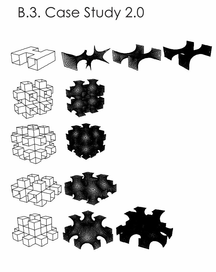
B.3. Case Study 2.0

Kangaroo plugin and Mesh box method

1st 2nd 3rd 4th 5th
B.4. Technique: Development

Minimal Surface plugin and Mirrored method
The mesh box method is not very effective. When we used more boxes for the design, it took a long time to relax the outcomes. Also, the form of the mesh box design is boring which is just adding more boxes for the struc-ture. Therefore, we decided to have another method. This method can produce many interesting outcomes by changing the values of the sliders at the top left corner.

The mesh box method is not very effective. When we used more boxes for the design, it took a long time to relax the outcomes. Also, the form of the mesh box design is boring which is just adding more boxes for the struc-ture. Therefore, we decided to have another method. This method can produce many interesting outcomes by changing the values of the sliders at the top left corner.

Case Study 2.0 and technique development my team developed our own script. Which focuses extensively on minal surfacing. Minimal surface technique is the most appropriate technique as it explores a sense of complexity and volumetric occupancy with an efficient use of material. For the matrix our team explores the distance of points between the “Eval Curves”. By manupulating the eval curves in various places in the model, we spaculate for a minmal surface that has the most minmalized surface that can retain aesthetic purpose and do not look too chaotic when it is being mutiplied and put together. Our group feel particular interested in the 4th and 5th row of the design matrix for its smooth and contiuous surface, we see the possibilities to extend the design of the 4th and 5th row matrix by replicating the same surface to form a mass structure. Then, removing superfluous parts of the structure, tilt the structure towards users(or towards other areas of interest, tbc), and finally, apply the hybrid material system that we developed dur-ing the design focus.

B.5. Technique: Prototypes For this prototype section our team look into the German Pavilion for the 11th Prague Quadrennial. This model commenced from the definition of a material system based on ruled sur-faces, whereby the surfaces were reduced to the materialisation of the rulings as elastic strings that can be employed to modulate levels of transparency, exposure and enclo-sure as well as manipulating visual and physi-cal connectivity. After studying this model my team fabricat-ed a prototype to study the transparency of the structure and the enclosure. The bottm right photo demonstrates the strong functional and practical connection joints required to assemble such an intriq-uite architectural form. Although bulky and rigid, the joints are well concealed in hard-to-reach places within the pavillion - includ-ing the upper exterior of the surface, which seems to resemble an apple core.
German Pavilion for the Prague Quadrennial of Scenography and Theatre Architecture 2007 by Achim Menges
source:http://www.evolo.us/architecture/archipelago-parametrically-designed-pavilion/

This prototype display a part of our model made by wire mesh. Our team soon find a problem that the minimal surface we create has some parts that seem to be superfluous, thus does not match the idea of minimal sur-face. The model also looks a bit repetitious and ordinary, lacks visual impact. As a result, our team sought for an alter-nate treatment for our structure. We want to tilt our structure to make it bending, to cre-ate a stronger visual impact, as well as cre-ate more openings and further remove su-perfluous parts from the structure to achieve a better minimized structure. The 2nd prototype display a better fluid shape that create stronger visual impact by tilting the structure, and the joints of the prototype was not flavourable and needs further research on the joints between com-ponents.
1st ,2nd Prototype 2013 by Yusakuji

B.6. Technique: Proposal
Minimal surfaces are generated through complex algo-rithmic geometry. Our project and approach explores minimal surface on a basis of repeating the minimal sur-faces to generate and composing them in a way that they can be applied to a variety of parameters and still retain the same principle.
The structure holds a particular value as it is self support-ing and therefore the true design intensions are able to be fully expressed without the use of external supports.
This approach allows for an holistic intension to be re-alised within the final outcome as the gateway express-es the volumetric occupancy in such an aesthetically captivating way, and with the use of such complex geometry, that it can be expressed in an experience for the users to stop and take a look.

it came to the groups attention that the geometry could be considered highly simplified in comparison to other minimal surface projects. However, as we considered the scale of the gateway we took into consideration the amount of time that the user would be allowed to experience the architecture and so as a pragmatic approach the outcome seemed to undergo a “complexity diet“ if you will and so explain the final outcome.
There were issues with the panel connections and materiality of the project as the conventional joints inhibited many ex-plorative and creative geometries. The group iteratively pro-gressed toward a combination of mesh panels with firm and rigid edges to allow for fixing to occur on a practical sense.

B.7. Algorithmic Sketches
Central Front
Top Right
Top Back
Top LeftCentral Right
Central Left
Draw a tectrohedro in RhinoGive name for each lineOpen grasshopper and create six curve componentEach component refers to each single line
In this section I will explain how our team’s model being made in GrassHoppper in a step-by-step and point form fashion

Create mid-points Create end points

Use line component to connect the mid points and all the points created by “Eval Curve” component

• Create end points on the top left curve and top right curve
• Use Evaluate curve component to put a point atspecificpartofthecurve.“t“valueisacurvedomain parameter. Right click on Evaluate curve component and choose “reparametarize” and then change the domain of the curve to “0 to 1”.
• Use Evaluate curve component to set a movable point on every line InterCurve creates curves connected by three
points

InterCurve creates curves connected by three points
A loft surface is created by Minimal surface component

Use Plane 3 Point component to create a plane for each side and these planes are used for mirrorring the the object

Use Plane 3 Point component to create a plane for each side and these planes are used for mirrorring the the object
Use mirror compo-nent to create mir-rorred objects

• Use “RoT3D” component to deplicate the two top pieces to the bottom along the centre of rotation point
• Right click on “C“ value of “Rot3D” and enter “PI”
• The centre rotation point is the end point of Central Right curve
Top left piece (according to the diagram below)
Top right piece (according to the diagram below)
Centre of rotation point

• Create two plans along x and y aixs
• Use z unit component for x value for both planes
• Use x unit component for y value for plane
• Mirror the object twice ac-cording to the orientatio of the planes
PLane 1
PLane 2

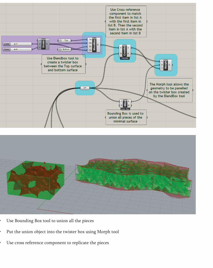
• Use Bounding Box tool to union all the pieces
• Put the union object into the twister box using Morph tool
• Use cross reference component to replicate the pieces
• Use Bounding Box tool to union all the pieces
• Put the union object into the twister box using Morph tool
• Use cross reference component to replicate the pieces


• We tried to use three planes to create a tilt
• Run the script again and then obtained the most suc-cessful portion from the tilt structure

B.8. Learning Objectives and Outcomes
In conclusion, our team will keep making prototype as we are approaching our final outcome. During the process, we will keep simplifying our model to achieve a better and more mini-mized structure, we plan on doing some extensive research and experimenting the shades of our structure and the lighting effects on it and hope that it can achive a minimal structure with both material and structural effcient as well as strong vi-sual impact.


C.1. Design Concept
Top: Second prototype with tabs construction Middle: First prototype exploring minimal surface Bottom left to right: Reduction of parts of the final model
Comments from the crit jury:
1: Some parts of the proposed model looks unnecessary (e.g. parts hanging out of the structure). Opposing the idea of reaching an efficient structure by minimizing the surface and material use.
2: Tab joints are not applicable to real life construction. So our team need to consider a joint system for the model.
3: Consider about the structural significance meaning. Consider looking at the model as different portals: portal to sunlight, portal to money, etc. Changes to the design concepts: 1: Our group revised the model and decides to remove those parts we think are unneces-sary in order to boost structural efficiency, also create a greater visual impact. 2: Our group investigated on a joint system that fits our model. This will be discussed in depth in C.2. section of this proposal. 3: Our team addressed the challenge of cre-ating the portals by adding perforations into our model.
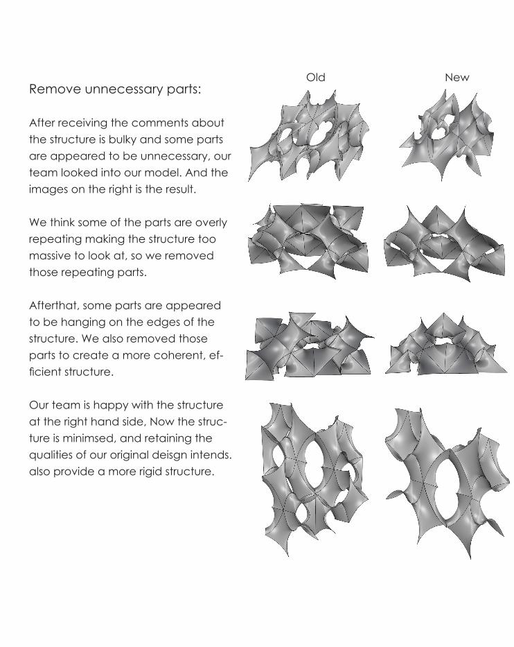
Remove unnecessary parts:
After receiving the comments about the structure is bulky and some parts are appeared to be unnecessary, our team looked into our model. And the images on the right is the result.
We think some of the parts are overly repeating making the structure too massive to look at, so we removed those repeating parts. Afterthat, some parts are appeared to be hanging on the edges of the structure. We also removed those parts to create a more coherent, ef-ficient structure.
Our team is happy with the structure at the right hand side, Now the struc-ture is minimsed, and retaining the qualities of our original deisgn intends. also provide a more rigid structure.
Old New

Perforations:
When our team considered about the pos-sible portals the structure can have we ex-plored about perforations. We thought per-forations can extend the possibilities of our structure.
Portal for sunlight and exploration on structure: Perforations can let more sunlight shine through the structure, making it a stronger sense of presence. Moreover, our team discover some parts of our structure maybe difficult for users’ perspective to observe be-cause they are covered by other structural members. So, perforations can enable users to observe the structure more thoroughly .

SIZE THICKNESS
GALVANIZED STEEL PANEL BOLT JOINT
SIZE18m
10m
2mm
5mm
3mm
Structural efficiency: Perforations give our structure another structural benefit is to make the structure lighter. By placing most of the per-forations on the upper part of the structure, we can also achieve the structure by using thinner steel because winloads are considerably lowered with perforation on the panels. By using thinner material also means that less materials are used and better material efficiency is reached. Moreover, our team prooposed to divide the material into three thickness zones according to the height of the corresponding part. Create a material efficient structure while preserving its rigid, sturdy charac-ter.

Shadings and patterns:
Perforations also add a spectacular visual effect to the structure when sunlight cast into it. This effect enhances when sunlight cast into two overlaping perforating com-ponents, it will create a unique pattern that evolves with time, create a ever-changing visual impact to users, making the structure even more eye-catching to the users.
However, beside adding the strong visual impact to the structure, our team also want to control to amount of this shading effect so that the shades patterning effect do not take over the focus of the structure, as we want to keep everything to a minimal.


Location of the structure: Our team decided to put the structure on Site A. After reviewing the site photos, Site A appears to be slightly higher up on the ground, making it visible from a far distance, creating a strong presence of entering and exiting Wyndham city. Moreover, Site A fits our structure’s shape as the structure will orientated to both the north and south bound users of the Princess Freeway, creating a stronger visual impact.

When Passing Through
MONUMENTALITY MATERIAL EFFICIENCY
WhenPassing By
DYNAMIC VIEWS
Shadow Cast

Response to the site
Larger Scale Structure
Response to the Site Property
Reflection of Speed of Vehicles
Simplification of the Form
Refinement of the Form
Sunlight Through Structure
Perforation of the Upper Part
DESIGN DEVELOPMENT PROCESS

C.2. Tectonic Elements
• The realisation of the Yusakuji joint is driven by material ef-ficiency and made of offcuts of the steel panels used for the production
• These panels are held together by rivets
• With the joints of the panels to be flush with the perpendicular panel fixed to it, the interior joint (or bracket) will be of a shorter length than the exterior bracket - with the bend occurring about the centre of the bracket.


C.3. Final Model
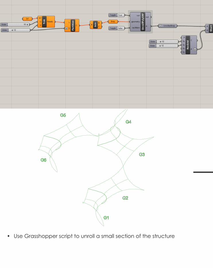
You created this PDF from an application that is not licensed to print to novaPDF printer (http://www.novapdf.com)• Divide structure into sections and label them with different color.• Name the components, eg: Green 1 (G1), Red 2 (R2).

You created this PDF from an application that is not licensed to print to novaPDF printer (http://www.novapdf.com)• Explode the structure and place them accordingly.
You created this PDF from an application that is not licensed to print to novaPDF printer (http://www.novapdf.com)
• Use Grasshopper script to unroll a small section of the structure

You created this P
DF from
an application that is not licensed to print to novaPD
F printer (http://ww
w.novapdf.com
)
You created this PDF from an application that is not licensed to print to novaPDF printer (http://www.novapdf.com)
• Set the distance between strips so they dont overlap with each other• Set the width of the tabs (3mm)

You created this PDF from an application that is not licensed to print to novaPDF printer (http://www.novapdf.com)
You created this PDF from an application that is not licensed to print to novaPDF printer (http://www.novapdf.com)
• The Grasshopper unroll script does not work for perforation structure
• As a result, our team did the un-roll manually
You created this PDF from an application that is not licensed to print to novaPDF printer (http://www.novapdf.com)
• The reason of the unexpected result was that we used the wrong method to create strips
• Each triangle in a strip should only have two adjacent trian-gles
• If there are more than two adja-cent triangles will result in over-lapping problem
• However, the result was not fa-vorable
Correct method Method caused overlapped

Method caused overlapped
You
cre
ated
this
PD
F fro
m a
n ap
plic
atio
n th
at is
not
lice
nsed
to p
rint t
o no
vaP
DF
prin
ter (
http
://w
ww
.nov
apdf
.com
)
You created this PDF from an application that is not licensed to print to novaPDF printer (http://www.novapdf.com)
You created this PDF from an application that is not licensed to print to novaPDF printer (http://www.novapdf.com)Our team then selected the triangles pairly in a row for each strip and join
• Our team created tabs for each strip taking the shape of its adjacent strip
• Tabs are very useful to fol-low the form of the struc-ture
• Tabs construction is being used because this model is to display our visual affect of the actual structure, rather than to display how the actual joints work.
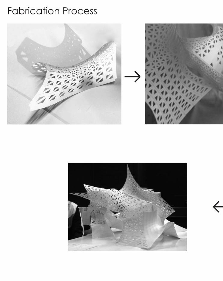
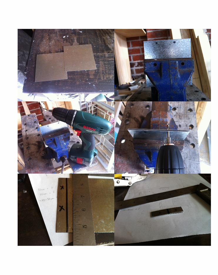
Fabrication Process


C.4. Algorithmic Sketches
You created this PDF from an application that is not licensed to print to novaPDF printer (http://www.novapdf.com)
As explained in section C.1., we created perforations mostly on the upper part of the structure. We attempted to create rectangular apertures for the model. However, some apertures near curves became rhombus.

You created this PDF from an application that is not licensed to print to novaPDF printer (http://www.novapdf.com)
Therefore, our team decided to use triangular apertures instead. Triangles ap-pears to be able to follow any shape of the structure.

C.5. Learning Objectives and OutcomesIn the part b submission I expect part c development will be focusing on: 1. Further simplifying the structure 2. Explore on shading and lighting effects 3. Further enhance material and structural efficiency 4. Enhance visual impact
These four points have been addressed on this part c submission and it has been generally successful. When comparing to the structure in part b submission, the final structure is more compact, have enhanced shad-ing effects and also, the structure is more efficient.
However, during the final presentation our team still received feedbacks from the crit about the shape of our structure; after the tilting work we have done in part b submission, it is not a genuine minimal surface struc-ture. It is true that the final structure is not a minimal surface. However, the tilt-ing is done due to our team wanted to orientate the structure towards the users from both south and north bond of Princess Freeway, also bec-uase we want sunlight to cast through more parts of our structure. And also because we kept the tilting at minimal so we kept the quality that a minimal surface has. As a result, we have a structure that suits the site without compromising our original design intend, and at the same time, the new structure looks much more versatile visually.
Also, our team tended to put every idea we had back into computa-tional method, because we wanted to explore the possibilities of our ideas with computers in order to explore a boarder spectrum of design possibilities.

Fabrication is one of the parts that disappointed our team the most, the model tends to flip and create a wrong direction of curvature. Also, the connection between the components are delicate, as a result, a slight error in assembling the model will result in major misfit between compo-nents. And this also reminds our group that the actual construction of the real structure maybe challenging due to the small tolerance for errors.