nhm series - doosan machinetools · nhm series provides the largest machining specifications and...
TRANSCRIPT
NHM series
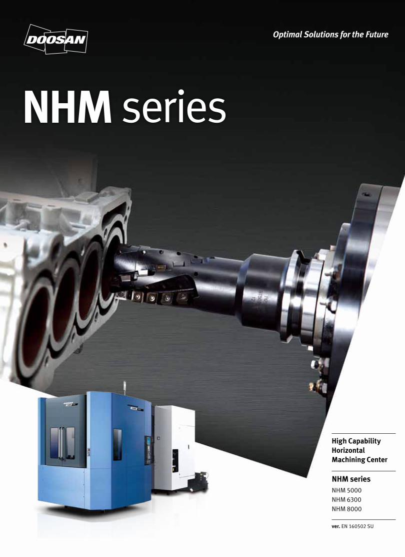
NHM seriesNHM 5000NHM 6300NHM 8000
ver. EN 160502 SU
High Capability Horizontal Machining Center
NHM Series provides the largest machining specifications and production capabilities in its class including powerful
cutting capabilities for satisfying diversified needs for production of customers. The integrated structure of the
box-type guideway is the optimal structure of excellent production capabilities for machining various materials
from common parts to metal hard of cutting with its high rigidity capacity required for powerful cutting process.
In addition, replacement speed of tools and palettes at servo motor driving for keeping non-cutting time minimal
improves reliability and productivity.
NHM series
NHM
series
0302 /
Product Overview
Basic Information
Basic Structure
Cutting
Performance
Detailed
Information
Options
Applications
Capacity Diagram
Specifications
Customer Support
Service
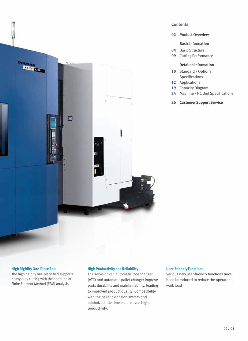
High Rigidity One-Piece BedThe high rigidity one-piece bed supports heavy duty cutting with the adoption of Finite Element Method (FEM) analysis.
High Productivity and ReliabilityThe servo-driven automatic tool changer
(ATC) and automatic pallet changer improve
parts durability and maintainability, leading
to improved product quality. Compatibility
with the pallet extension system and
minimized idle time ensure even higher
productivity.
User-Friendly FunctionsVarious new user-friendly functions have
been introduced to reduce the operator's
work load
0302 /
Contents
02 Product Overview
Basic Information
04 Basic Structure09 Cutting Performance
Detailed Information
10 Standard / Optional Specifications
12 Applications19 Capacity Diagram24 Machine / NC Unit Specifications
26 Customer Support Service
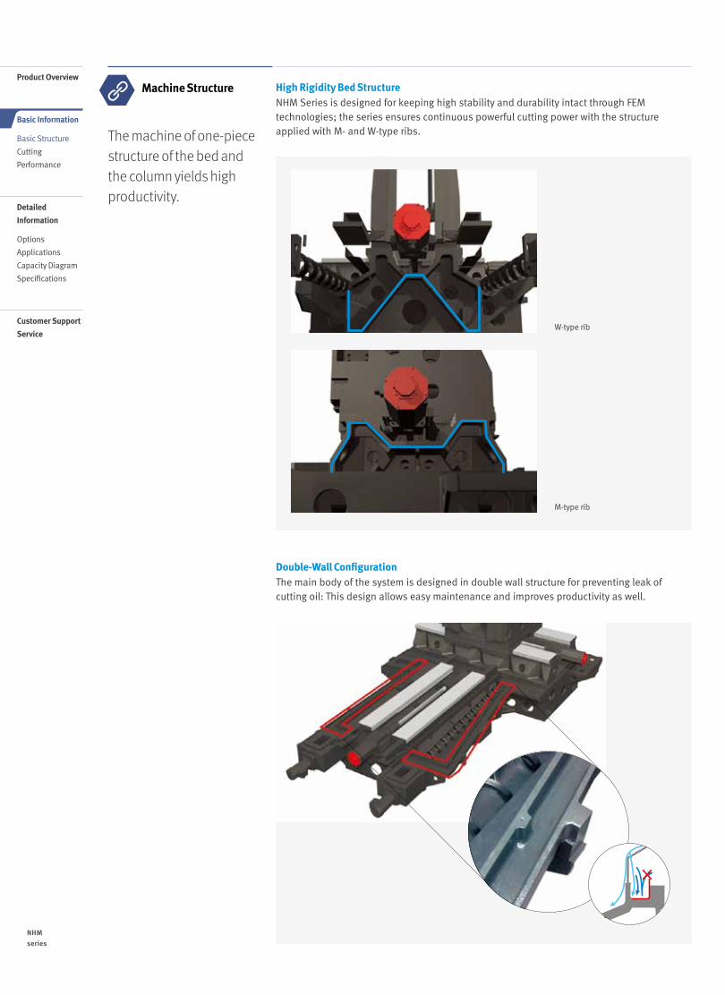
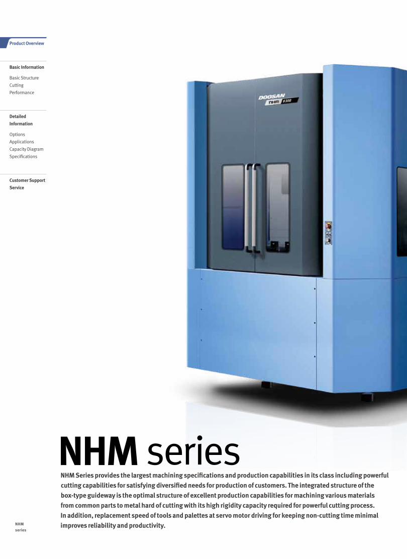
The machine of one-piece structure of the bed and the column yields high productivity.
Machine Structure High Rigidity Bed StructureNHM Series is designed for keeping high stability and durability intact through FEM technologies; the series ensures continuous powerful cutting power with the structure applied with M- and W-type ribs.
W-type rib
M-type rib
Double-Wall ConfigurationThe main body of the system is designed in double wall structure for preventing leak of cutting oil: This design allows easy maintenance and improves productivity as well.
NHM
series
0504 /
Product Overview
Basic Information
Basic Structure
Cutting
Performance
Detailed
Information
Options
Applications
Capacity Diagram
Specifications
Customer Support
Service
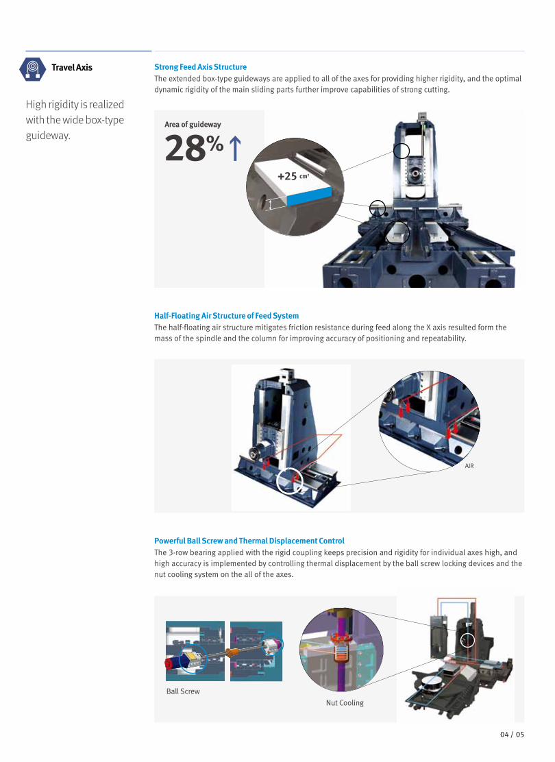
Travel Axis
High rigidity is realized with the wide box-type guideway.
Strong Feed Axis StructureThe extended box-type guideways are applied to all of the axes for providing higher rigidity, and the optimal dynamic rigidity of the main sliding parts further improve capabilities of strong cutting.
Half-Floating Air Structure of Feed SystemThe half-floating air structure mitigates friction resistance during feed along the X axis resulted form the mass of the spindle and the column for improving accuracy of positioning and repeatability.
Powerful Ball Screw and Thermal Displacement ControlThe 3-row bearing applied with the rigid coupling keeps precision and rigidity for individual axes high, and high accuracy is implemented by controlling thermal displacement by the ball screw locking devices and the nut cooling system on the all of the axes.
+25 cm2
Ball Screw
Nut Cooling
28%Area of guideway
AIR
0504 /
Flange contact
Taper contact
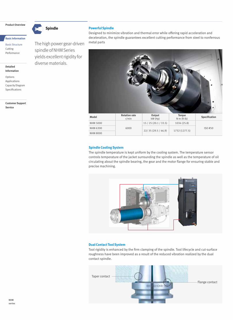
The high power gear-driven spindle of NHM Series yields excellent rigidity for diverse materials.
Spindle Powerful SpindleDesigned to minimize vibration and thermal error while offering rapid acceleration and deceleration, the spindle guarantees excellent cutting performance from steel to nonferrous metal parts
Spindle Cooling SystemThe spindle temperature is kept uniform by the cooling system. The temperature sensor controls temperature of the jacket surrounding the spindle as well as the temperature of oil circulating about the spindle bearing, the gear and the motor flange for ensuring stable and precise machining.
Dual Contact Tool SystemTool rigidity is enhanced by the firm clamping of the spindle. Tool lifecycle and cut-surface roughness have been improved as a result of the reduced vibration realized by the dual contact spindle.
ModelRotation rate
r/minOutputkW (Hp)
TorqueN·m (ft-lb)
Specification
NHM 5000
6000
15 / 25 (20.1 / 33.5) 1034 (25.8)
ISO #50NHM 630022/ 35 (29.5 / 46.9) 1732 (1277.5)
NHM 8000
NHM
series
0706 /
Product Overview
Basic Information
Basic Structure
Cutting
Performance
Detailed
Information
Options
Applications
Capacity Diagram
Specifications
Customer Support
Service
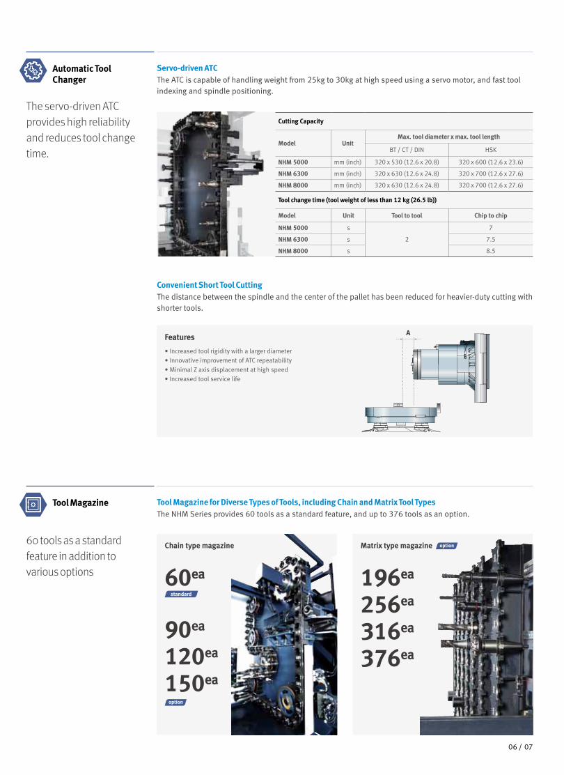
Automatic Tool Changer
The servo-driven ATC provides high reliability and reduces tool change time.
Servo-driven ATCThe ATC is capable of handling weight from 25kg to 30kg at high speed using a servo motor, and fast tool indexing and spindle positioning.
Cutting Capacity
Model UnitMax. tool diameter x max. tool length
BT / CT / DIN HSK
NHM 5000 mm (inch) 320 x 530 (12.6 x 20.8) 320 x 600 (12.6 x 23.6)
NHM 6300 mm (inch) 320 x 630 (12.6 x 24.8) 320 x 700 (12.6 x 27.6)
NHM 8000 mm (inch) 320 x 630 (12.6 x 24.8) 320 x 700 (12.6 x 27.6)
Tool change time (tool weight of less than 12 kg (26.5 lb))
Model Unit Tool to tool Chip to chip
NHM 5000 s
2
7
NHM 6300 s 7.5
NHM 8000 s 8.5
Features
• Increased tool rigidity with a larger diameter• Innovative improvement of ATC repeatability• Minimal Z axis displacement at high speed• Increased tool service life
A
Convenient Short Tool CuttingThe distance between the spindle and the center of the pallet has been reduced for heavier-duty cutting with shorter tools.
Chain type magazine Matrix type magazine
Tool Magazine for Diverse Types of Tools, including Chain and Matrix Tool TypesThe NHM Series provides 60 tools as a standard feature, and up to 376 tools as an option.
Tool Magazine
60 tools as a standard feature in addition to various options
90ea
120ea
150ea
60ea 196ea
256ea
316ea
376ea
standard
0706 /
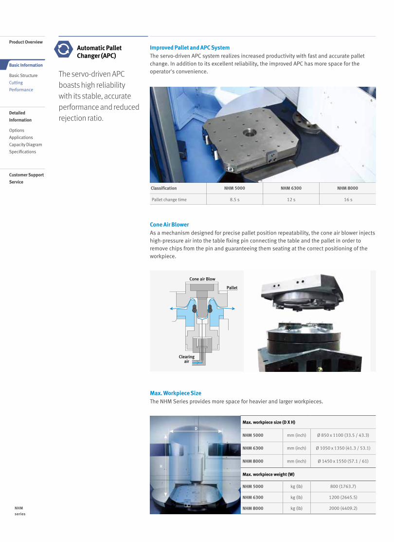
Improved Pallet and APC SystemThe servo-driven APC system realizes increased productivity with fast and accurate pallet change. In addition to its excellent reliability, the improved APC has more space for the operator's convenience.The servo-driven APC
boasts high reliability with its stable, accurate performance and reduced rejection ratio.
Automatic Pallet Changer (APC)
Cone Air BlowerAs a mechanism designed for precise pallet position repeatability, the cone air blower injects high-pressure air into the table fixing pin connecting the table and the pallet in order to remove chips from the pin and guaranteeing them seating at the correct positioning of the workpiece.
Max. Workpiece SizeThe NHM Series provides more space for heavier and larger workpieces.
Clearingair
Pallet
Cone air Blow
Classification NHM 5000 NHM 6300 NHM 8000
Pallet change time 8.5 s 12 s 16 s
H
D
Max. workpiece size (D X H)
NHM 5000 mm (inch) Ø 850 x 1100 (33.5 / 43.3)
NHM 6300 mm (inch) Ø 1050 x 1350 (41.3 / 53.1)
NHM 8000 mm (inch) Ø 1450 x 1550 (57.1 / 61)
Max. workpiece weight (W)
NHM 5000 kg (lb) 800 (1763.7)
NHM 6300 kg (lb) 1200 (2645.5)
NHM 8000 kg (lb) 2000 (4409.2)NHM
series
0908 /
Product Overview
Basic Information
Basic Structure
Cutting
Performance
Detailed
Information
Options
Applications
Capacity Diagram
Specifications
Customer Support
Service
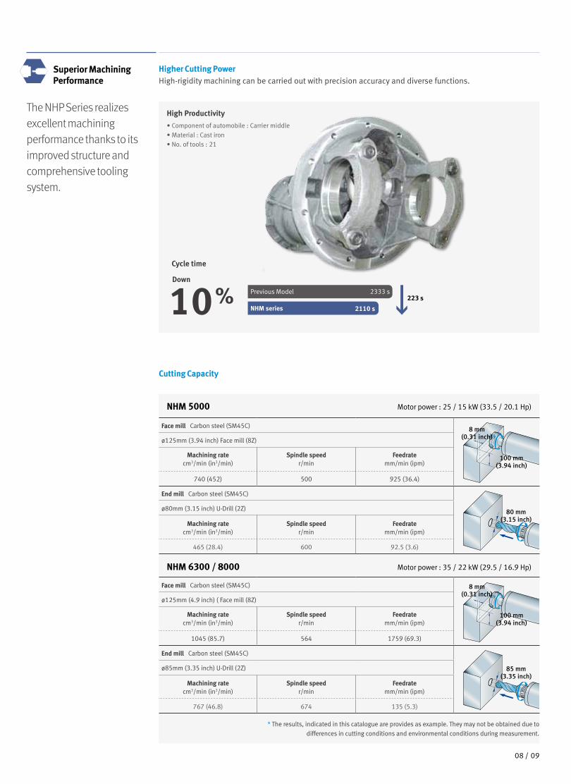
The NHP Series realizes excellent machining performance thanks to its improved structure and comprehensive tooling system.
Superior Machining Performance
Higher Cutting PowerHigh-rigidity machining can be carried out with precision accuracy and diverse functions.
High Productivity
• Component of automobile : Carrier middle• Material : Cast iron• No. of tools : 21
Cycle time
Down
10%NHM series
Previous Model 2333 s
2110 s
223 s
Cutting Capacity
NHM 6300 / 8000 Motor power : 35 / 22 kW (29.5 / 16.9 Hp)
NHM 5000 Motor power : 25 / 15 kW (33.5 / 20.1 Hp)
Face mill Carbon steel (SM45C)
ø125mm (3.94 inch) Face mill (8Z)
Machining ratecm3/min (in3/min)
Spindle speedr/min
Feedratemm/min (ipm)
740 (452) 500 925 (36.4)
End mill Carbon steel (SM45C)
ø80mm (3.15 inch) U-Drill (2Z)
Machining ratecm3/min (in3/min)
Spindle speedr/min
Feedratemm/min (ipm)
465 (28.4) 600 92.5 (3.6)
100 mm(3.94 inch)
8 mm(0.31 inch)
80 mm(3.15 inch)
Face mill Carbon steel (SM45C)
ø125mm (4.9 inch) ( Face mill (8Z)
Machining ratecm3/min (in3/min)
Spindle speedr/min
Feedratemm/min (ipm)
1045 (85.7) 564 1759 (69.3)
End mill Carbon steel (SM45C)
ø85mm (3.35 inch) U-Drill (2Z)
Machining ratecm3/min (in3/min)
Spindle speedr/min
Feedratemm/min (ipm)
767 (46.8) 674 135 (5.3)
100 mm(3.94 inch)
8 mm(0.31 inch)
85 mm(3.35 inch)
* The results, indicated in this catalogue are provides as example. They may not be obtained due todifferences in cutting conditions and environmental conditions during measurement.
0908 /
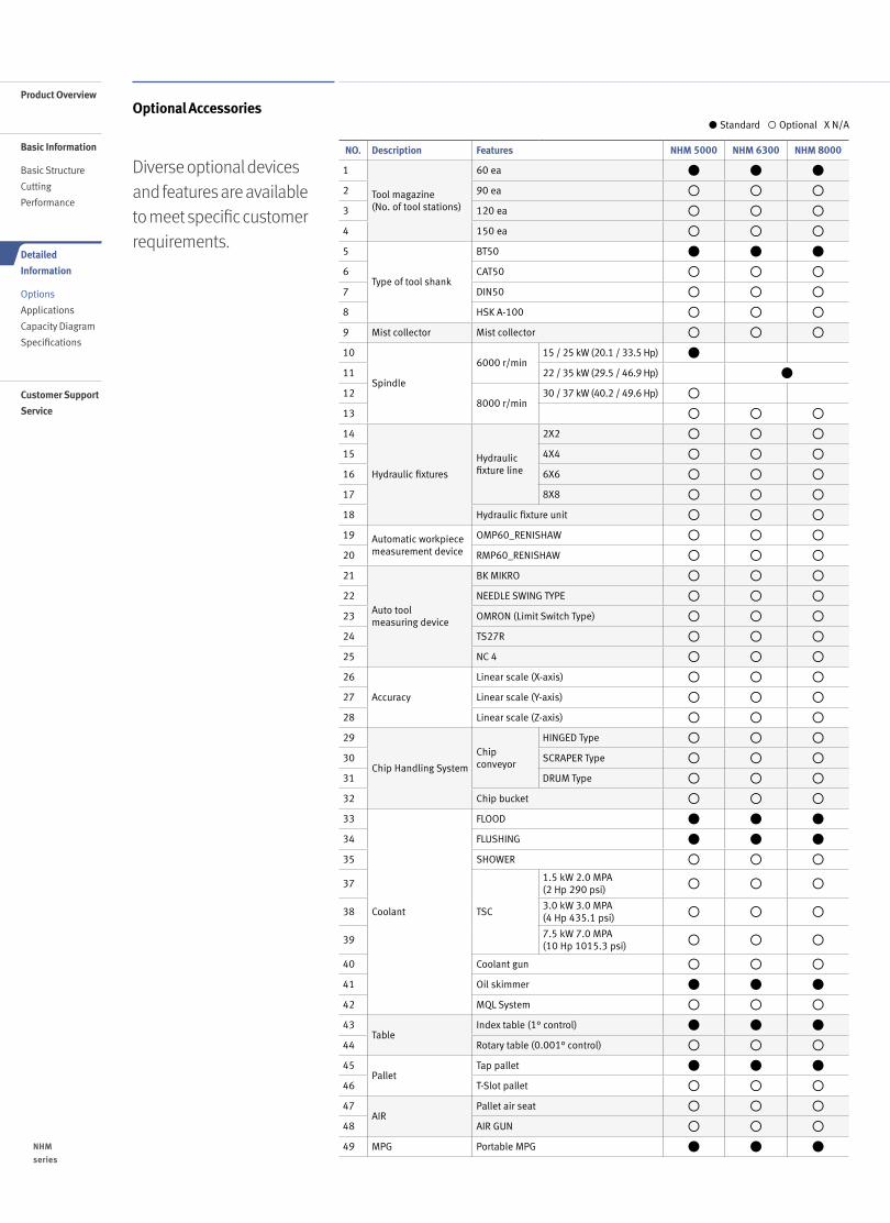
Diverse optional devices and features are available to meet specific customer requirements.
● Standard ◦ Optional X N/A
NO. Description Features NHM 5000 NHM 6300 NHM 8000
1
Tool magazine(No. of tool stations)
60 ea
2 90 ea
3 120 ea
4 150 ea
5
Type of tool shank
BT50
6 CAT50
7 DIN50
8 HSK A-100
9 Mist collector Mist collector
10
Spindle
6000 r/min15 / 25 kW (20.1 / 33.5 Hp)
11 22 / 35 kW (29.5 / 46.9 Hp)
128000 r/min
30 / 37 kW (40.2 / 49.6 Hp)
13
14
Hydraulic fixtures
Hydraulic fixture line
2X2
15 4X4
16 6X6
17 8X8
18 Hydraulic fixture unit
19 Automatic workpiece measurement device
OMP60_RENISHAW
20 RMP60_RENISHAW
21
Auto tool measuring device
BK MIKRO
22 NEEDLE SWING TYPE
23 OMRON (Limit Switch Type)
24 TS27R
25 NC 4
26
Accuracy
Linear scale (X-axis)
27 Linear scale (Y-axis)
28 Linear scale (Z-axis)
29
Chip Handling System
Chip conveyor
HINGED Type
30 SCRAPER Type
31 DRUM Type
32 Chip bucket
33
Coolant
FLOOD
34 FLUSHING
35 SHOWER
37
TSC
1.5 kW 2.0 MPA (2 Hp 290 psi)
383.0 kW 3.0 MPA (4 Hp 435.1 psi)
397.5 kW 7.0 MPA (10 Hp 1015.3 psi)
40 Coolant gun
41 Oil skimmer
42 MQL System
43Table
Index table (1° control)
44 Rotary table (0.001° control)
45Pallet
Tap pallet
46 T-Slot pallet
47AIR
Pallet air seat
48 AIR GUN
49 MPG Portable MPG
Optional Accessories
NHM
series
1110 /
Product Overview
Basic Information
Basic Structure
Cutting
Performance
Detailed
Information
Options
Applications
Capacity Diagram
Specifications
Customer Support
Service
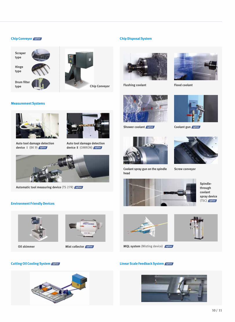
Chip Conveyor Chip Disposal System
Measurement Systems
Environment Friendly Devices
Cutting Oil Cooling System Linear Scale Feedback System
Flushing coolant Flood coolant
Oil skimmer
Coolant spray gun on the spindle head
Screw conveyor
Mist collector
Spindle-through coolant spray device (TSC)
Shower coolant Coolant gun
MQL system (Misting device)
Scraper type
Hinge type
Drum filter type Chip Conveyor
Auto tool damage detection device Ⅰ (BK 9)
Auto tool damage detection device Ⅱ (OMRON)
Automatic tool measuring device (TS 27R)
1110 /
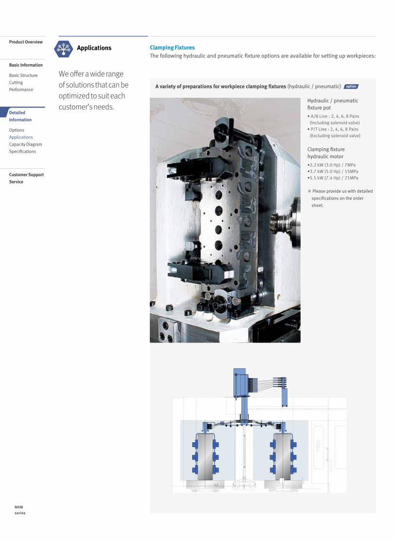
A variety of preparations for workpiece clamping fixtures (hydraulic / pneumatic)
Hydraulic / pneumatic fixture pot
• A/B Line : 2, 4, 6, 8 Pairs (Including solenoid valve)
• P/T Line : 2, 4, 6, 8 Pairs (Excluding solenoid valve)
Clamping fixture hydraulic motor
•2.2 kW (3.0 Hp) / 7MPa•3.7 kW (5.0 Hp) / 15MPa•5.5 kW (7.4 Hp) / 21MPa
※ Please provide us with detailed
specifications on the order
sheet.
We offer a wide range of solutions that can be optimized to suit each customer’s needs.
Applications Clamping Fixtures The following hydraulic and pneumatic fixture options are available for setting up workpieces:
NHM
series
1312 /
Product Overview
Basic Information
Basic Structure
Cutting
Performance
Detailed
Information
Options
Applications
Capacity Diagram
Specifications
Customer Support
Service
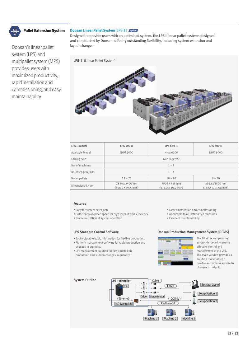
Doosan's linear palletsystem (LPS) and multipallet system (MPS)provides users with maximized productivity,rapid installation andcommissioning, and easymaintainability.
Pallet Extension System Doosan Linear Pallet System [LPSⅡ] Designed to provide users with an optimised system, the LPSII linear pallet systems designedand constructed by Doosan, offering outstanding flexibility, including system extension andlayout change.
LPS II controller
Machine 1 Machine 2 Machine 3
Profibus-DP
Ethernet
Cable
Cable
Driver
PC
Servo Motor
Stracker Crane
Setup Station 1
Setup Station 2CC-link
PLC (Mitsubishi)
LPS Ⅱ (Linear Pallet System)
System Outline
Features
• Easy for system extension• Sufficient workpiece space for high level of work efficiency• Stable and efficient system operation
• Faster installation and commissioning• Applicable to all HMC Series machines• Excellent maintainability
LPS Standard Control Software
• Easily-storable basic information for flexible production.• Platform management software for rapid production and
changes in quantity.• LPS management solution for fast and flexible
production and sudden changes in quantity.
Doosan Production Management System [DPMS]
The DPMS is an operating system designed to ensure effective control andmanagement of the LPS. The main window provides a solution that enables aflexible and rapid response to changes in output.
LPS II Model LPS 500 II LPS 630 II LPS 800 II
Available Model NHM 5000 NHM 6300 NHM 8000
Forking type Twin Fork type
No. of machines 1 – 7
No. of setup stations 1 – 4
No. of pallets 12 ~ 70 10 ~ 70 8 ~ 70
Dimensions (L x W)7824 x 2400 mm
(308.0 X 94.5 inch)
7904 x 785 mm(311.2 X 30.9 inch)
8952 x 3500 mm(352.4 X 137.8 inch)
1312 /
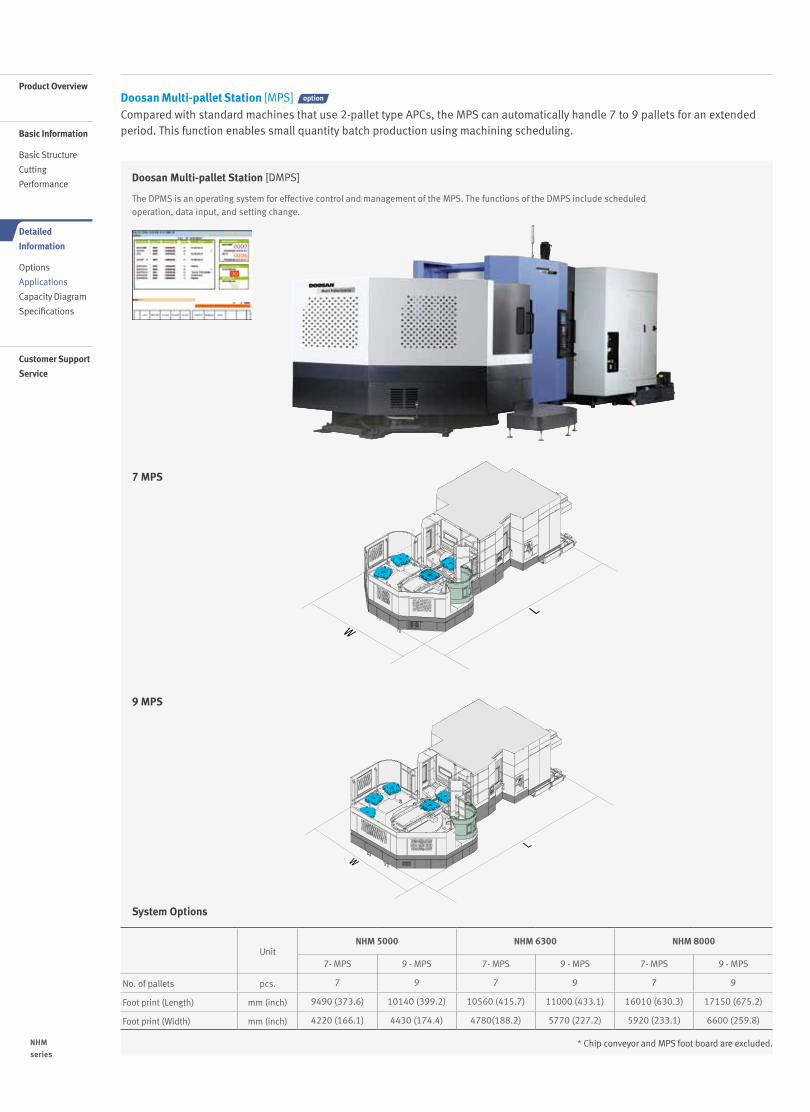
UnitNHM 5000 NHM 6300 NHM 8000
7- MPS 9 - MPS 7- MPS 9 - MPS 7- MPS 9 - MPS
No. of pallets pcs. 7 9 7 9 7 9
Foot print (Length) mm (inch) 9490 (373.6) 10140 (399.2) 10560 (415.7) 11000 (433.1) 16010 (630.3) 17150 (675.2)
Foot print (Width) mm (inch) 4220 (166.1) 4430 (174.4) 4780(188.2) 5770 (227.2) 5920 (233.1) 6600 (259.8)
System Options
* Chip conveyor and MPS foot board are excluded.
Doosan Multi-pallet Station [MPS] Compared with standard machines that use 2-pallet type APCs, the MPS can automatically handle 7 to 9 pallets for an extended period. This function enables small quantity batch production using machining scheduling.
Doosan Multi-pallet Station [DMPS]
W
L
WL
7 MPS
W
L
WL
9 MPS
The DPMS is an operating system for effective control and management of the MPS. The functions of the DMPS include scheduledoperation, data input, and setting change.
NHM
series
1514 /
Product Overview
Basic Information
Basic Structure
Cutting
Performance
Detailed
Information
Options
Applications
Capacity Diagram
Specifications
Customer Support
Service
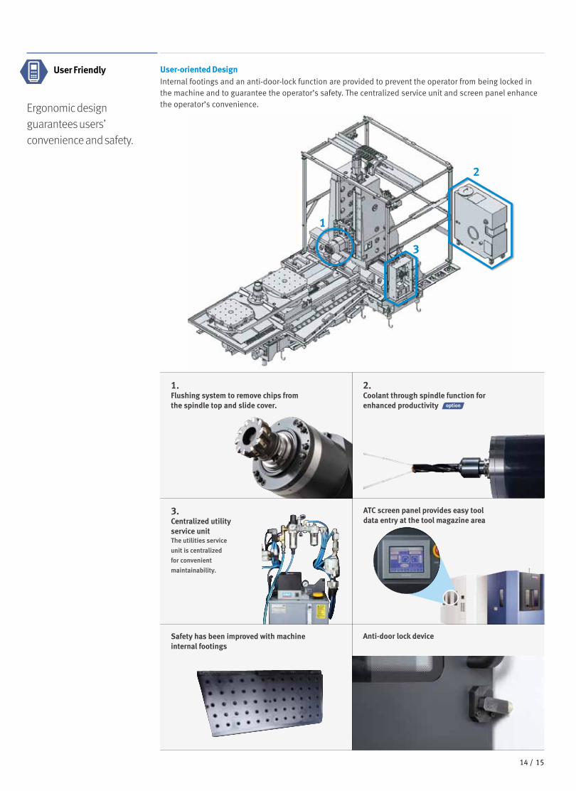
User-oriented DesignInternal footings and an anti-door-lock function are provided to prevent the operator from being locked in the machine and to guarantee the operator’s safety. The centralized service unit and screen panel enhance the operator’s convenience.Ergonomic design
guarantees users’ convenience and safety.
Anti-door lock deviceSafety has been improved with machine internal footings
3.Centralized utilityservice unitThe utilities service
unit is centralized
for convenient
maintainability.
1.Flushing system to remove chips fromthe spindle top and slide cover.
ATC screen panel provides easy tool data entry at the tool magazine area
1
2
2.Coolant through spindle function forenhanced productivity
User Friendly
3
1514 /
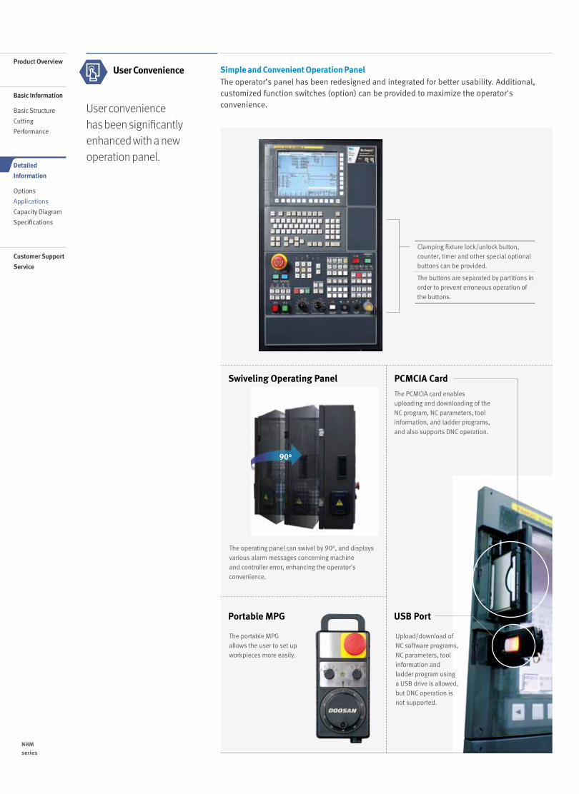
User conveniencehas been significantlyenhanced with a newoperation panel.
User Convenience Simple and Convenient Operation Panel The operator’s panel has been redesigned and integrated for better usability. Additional, customized function switches (option) can be provided to maximize the operator's convenience.
90°
The operating panel can swivel by 90°, and displays various alarm messages concerning machine and controller error, enhancing the operator's convenience.
The portable MPG allows the user to set up workpieces more easily.
The PCMCIA card enables uploading and downloading of the NC program, NC parameters, tool information, and ladder programs, and also supports DNC operation.
Clamping fixture lock/unlock button, counter, timer and other special optional buttons can be provided.
The buttons are separated by partitions in order to prevent erroneous operation of the buttons.
Swiveling Operating Panel PCMCIA Card
USB PortPortable MPG
Upload/download of NC software programs, NC parameters, tool information and ladder program using a USB drive is allowed, but DNC operation is not supported.
NHM
series
1716 /
Product Overview
Basic Information
Basic Structure
Cutting
Performance
Detailed
Information
Options
Applications
Capacity Diagram
Specifications
Customer Support
Service
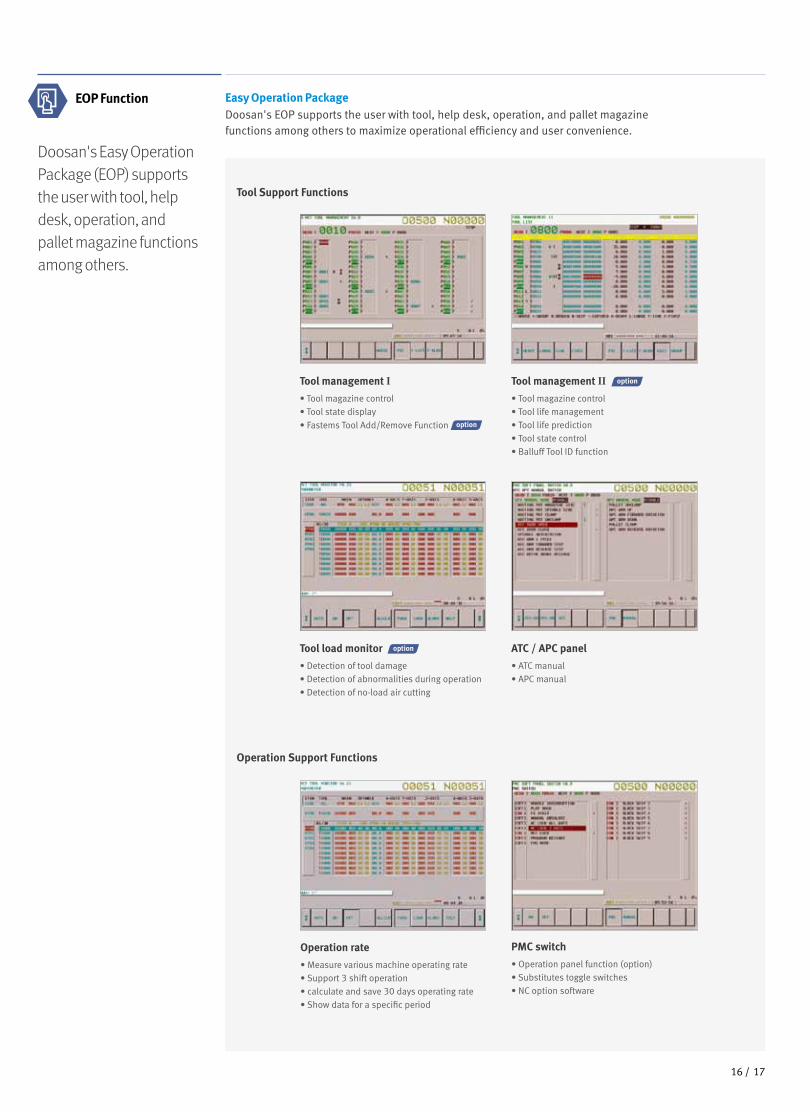
Easy Operation PackageDoosan's EOP supports the user with tool, help desk, operation, and pallet magazinefunctions among others to maximize operational efficiency and user convenience.
Doosan's Easy Operation Package (EOP) supports the user with tool, help desk, operation, and pallet magazine functions among others.
EOP Function
Tool Support Functions
Operation Support Functions
Operation rate
• Measure various machine operating rate• Support 3 shift operation• calculate and save 30 days operating rate• Show data for a specific period
PMC switch
• Operation panel function (option)• Substitutes toggle switches• NC option software
Tool load monitor
• Detection of tool damage• Detection of abnormalities during operation• Detection of no-load air cutting
ATC / APC panel
• ATC manual• APC manual
Tool management I
• Tool magazine control• Tool state display
• Fastems Tool Add/Remove Function
Tool management II • Tool magazine control• Tool life management• Tool life prediction• Tool state control• Balluff Tool ID function
1716 /
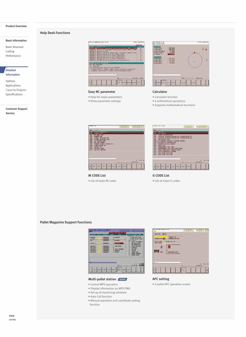
Help Desk Functions
Pallet Magazine Support Functions
Multi-pallet station
• Control MPS operation• Display information on MPS PMG• Set-up of machining schedule• Auto Call function• Manual operation and coordinate setting
function
APC setting
• 2-pallet APC operation screen
M CODE List
• List of major M codes
G CODE List
• List of major G codes
Easy NC parameter
• Help for major parameters• Show parameter settings
Calculator
• Calculator function• 4 arithmetical operations• Supports mathematical functions
NHM
series
1918 /
Product Overview
Basic Information
Basic Structure
Cutting
Performance
Detailed
Information
Options
Applications
Capacity Diagram
Specifications
Customer Support
Service
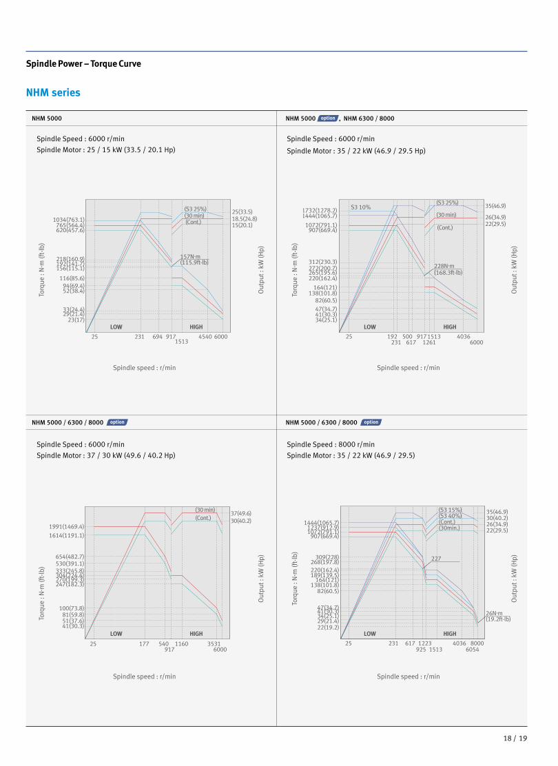
Spindle Power – Torque Curve
NHM series
Spindle Speed : 6000 r/min
Spindle Motor : 25 / 15 kW (33.5 / 20.1 Hp)
Spindle Speed : 6000 r/min
Spindle Motor : 35 / 22 kW (46.9 / 29.5 Hp)
25 177 540 1160 35316000917
25 231925 1513
40366054
8000617 1223
LOW HIGH LOW HIGH
LOW HIGH LOW HIGH
S3 10%25(33.5) 18.5(24.8)15(20.1)
37(49.6)30(40.2)
35(46.9)
26(34.9)22(29.5)
35(46.9)
26(34.9)30(40.2)
22(29.5)
25 192231
500617
9171513 403660001261
312(230.3)
907(669.4)1072(791.1)
1444(1065.7)1732(1278.2)
272(200.7)265(195.6)
228N.m(168.3ft-lb)
220(162.4)
34(25.1)
22(19.2)
26N.m(19.2ft-lb)29(21.4)
34(25.1)41(30.3)47(34.7)
82(60.5)138(101.8)
164(121)189(139.5)220(162.4)268(197.8)
309(228)
907(669.4)1072(791.1)1237(912.9)
1444(1065.7)
227
41(30.3)47(34.7)82(60.5)
138(101.8)164(121)
25 9171513
231 694 4540 6000
1034(763.1)765(564.4)620(457.6)
218(160.9)192(141.7)
157N.m(115.9ft-lb)
156(115.1)
116(85.6)94(69.4)52(38.4)
33(24.4)29(21.4)
23(17)
41(30.3)51(37.6)81(59.8)
100(73.8)
247(182.3)270(199.3)304(224.4)333(245.8)530(391.1)654(482.7)
1614(1191.1)1991(1469.4)
(30 min)
(30 min) (30 min)
(Cont.)
(S3 25%)
(Cont.)
(S3 25%)
(Cont.)(S3 15%)(S3 40%)(Cont.)(30min.)
Spindle Speed : 6000 r/min
Spindle Motor : 37 / 30 kW (49.6 / 40.2 Hp)
Spindle Speed : 8000 r/min
Spindle Motor : 35 / 22 kW (46.9 / 29.5)
25 177 540 1160 35316000917
25 231925 1513
40366054
8000617 1223
LOW HIGH LOW HIGH
LOW HIGH LOW HIGH
S3 10%25(33.5) 18.5(24.8)15(20.1)
37(49.6)30(40.2)
35(46.9)
26(34.9)22(29.5)
35(46.9)
26(34.9)30(40.2)
22(29.5)
25 192231
500617
9171513 403660001261
312(230.3)
907(669.4)1072(791.1)
1444(1065.7)1732(1278.2)
272(200.7)265(195.6)
228N.m(168.3ft-lb)
220(162.4)
34(25.1)
22(19.2)
26N.m(19.2ft-lb)29(21.4)
34(25.1)41(30.3)47(34.7)
82(60.5)138(101.8)
164(121)189(139.5)220(162.4)268(197.8)
309(228)
907(669.4)1072(791.1)1237(912.9)
1444(1065.7)
227
41(30.3)47(34.7)82(60.5)
138(101.8)164(121)
25 9171513
231 694 4540 6000
1034(763.1)765(564.4)620(457.6)
218(160.9)192(141.7)
157N.m(115.9ft-lb)
156(115.1)
116(85.6)94(69.4)52(38.4)
33(24.4)29(21.4)
23(17)
41(30.3)51(37.6)81(59.8)
100(73.8)
247(182.3)270(199.3)304(224.4)333(245.8)530(391.1)654(482.7)
1614(1191.1)1991(1469.4)
(30 min)
(30 min) (30 min)
(Cont.)
(S3 25%)
(Cont.)
(S3 25%)
(Cont.)(S3 15%)(S3 40%)(Cont.)(30min.)
NHM 5000 NHM 5000 , NHM 6300 / 8000
NHM 5000 / 6300 / 8000 NHM 5000 / 6300 / 8000
Torq
ue :
N. m
(ft-
lb)
Out
put :
kW
(Hp)
Spindle speed : r/min
Torq
ue :
N. m
(ft-
lb)
Out
put :
kW
(Hp)
Spindle speed : r/min
Torq
ue :
N. m
(ft-
lb)
Out
put :
kW
(Hp)
Spindle speed : r/min
Torq
ue :
N. m
(ft-
lb)
Out
put :
kW
(Hp)
Spindle speed : r/min
1918 /
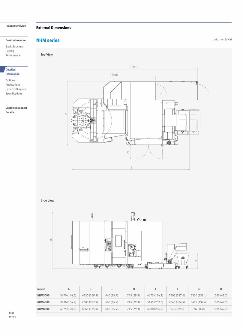
External Dimensions
NHM series Unit : mm (inch)
Side View
Top View
Model A B C D E F G H
NHM5000 3670 (144.5) 6830 (268.9) 660 (25.9) 745 (29.3) 4675 (184.1) 7305 (287.6) 3330 (131.1) 1085 (42.7)
NHM6300 3930 (154.7) 7300 (287.4) 660 (25.9) 745 (29.3) 5145 (202.6) 7745 (304.9) 3495 (137.6) 1085 (42.7)
NHM8000 4325 (170.3) 8265 (325.4) 660 (25.9) 745 (29.3) 6000 (236.2) 8630 (39.8) 3760 (148) 1085 (42.7)
A
E (60T)
D
B
G
H
C
F (150T)
A
E (60T)
D
B
G
H
C
F (150T)
NHM
series
2120 /
Product Overview
Basic Information
Basic Structure
Cutting
Performance
Detailed
Information
Options
Applications
Capacity Diagram
Specifications
Customer Support
Service
Table External Dimensions
NHM series
Unit : mm (inch)
Unit : mm (inch)
Unit : mm (inch)
NHM 6300
NHM 8000
Standard Specifications (500×500(19.7x19.7))
Standard Specifications (630×630(24.8x24.8)) Optional Specifications (800×800(31.5x31.5))
NHM 5000
25
18
18
75 75 Ø18
24-M16 x P2.0, DP30
50
50
18
18
500(19.7)
500100
100
100 100 Ø1825
18
18
24-M16 x P2.0, DP30
630
6565
630(24.8)125
125
18 100 100 Ø1825
18
18
24-M16 x P2.0, DP30
630
65
65
630(24.8)125
125
135 135 Ø1825
18
18
24-M16 x P2.0, DP30
80800(31.5)
160
80160
160
160
80
80
18
800(31.5)
135 135
25
18
18
Ø18
(19.7)
(0.7) (0.7)
(0.7)
(0.7)
(0.7)
(3.9)(2.0)
(3.9)(2.0)
(1) (1)
(0.7)
(0.7)
(1)
(3.0)(3.0) (0.7) (0.7)
(0.7)
(4.9)(4.9)
(24.8)
(3.9)(3.9)
(2.6)
(4.9)(2.6)
(2.6)
(4.9) (2.6)(24.8)
(0.7)
(0.7)
(1) (0.7)(0.7) (3.9)(3.9) (5.3) (5.3) (0.7)
(6.3)(3.1)
800(31.5)
(0.7)
(0.7)
(1)
(6.3)
(6.3)
(3.1)
(3.1)
800(31.5)
(5.3) (5.3)(0.7)
(0.7)
25
18
18
75 75 Ø18
24-M16 x P2.0, DP30
50
50
18
18
500(19.7)
500100
100
100 100 Ø1825
18
18
24-M16 x P2.0, DP30
630
65
65
630(24.8)125
125
18 100 100 Ø1825
18
18
24-M16 x P2.0, DP30
630
65
65
630(24.8)125
125
135 135 Ø1825
18
18
24-M16 x P2.0, DP30
80800(31.5)
160
80160
160
160
80
80
18
800(31.5)
135 135
25
18
18
Ø18
(19.7)
(0.7) (0.7)
(0.7)
(0.7)
(0.7)
(3.9)(2.0)
(3.9)(2.0)
(1) (1)
(0.7)
(0.7)
(1)
(3.0)(3.0) (0.7) (0.7)
(0.7)
(4.9)
(4.9)(24.8)
(3.9)(3.9)
(2.6)
(4.9)(2.6)
(2.6)
(4.9) (2.6)(24.8)
(0.7)
(0.7)(1) (0.7)
(0.7) (3.9)(3.9) (5.3) (5.3) (0.7)
(6.3)(3.1)
800(31.5)
(0.7)
(0.7)
(1)
(6.3)
(6.3)
(3.1)
(3.1)
800(31.5)
(5.3) (5.3)(0.7)
(0.7)
25
18
18
75 75 Ø18
24-M16 x P2.0, DP30
50
50
18
18
500(19.7)
500100
100
100 100 Ø1825
18
18
24-M16 x P2.0, DP30
630
65
65
630(24.8)125
125
18 100 100 Ø1825
18
18
24-M16 x P2.0, DP30
630
65
65
630(24.8)125
125
135 135 Ø1825
18
18
24-M16 x P2.0, DP30
80800(31.5)
160
80160
160
160
80
80
18
800(31.5)
135 135
25
18
18
Ø18
(19.7)
(0.7) (0.7)
(0.7)
(0.7)
(0.7)
(3.9)(2.0)
(3.9)(2.0)
(1) (1)
(0.7)
(0.7)
(1)
(3.0)(3.0) (0.7) (0.7)
(0.7)
(4.9)
(4.9)(24.8)
(3.9)(3.9)
(2.6)
(4.9)(2.6)
(2.6)
(4.9) (2.6)(24.8)
(0.7)
(0.7)
(1) (0.7)
(0.7) (3.9)(3.9) (5.3) (5.3) (0.7)
(6.3)(3.1)
800(31.5)
(0.7)
(0.7)
(1)
(6.3)
(6.3)
(3.1)
(3.1)
800(31.5)
(5.3) (5.3)(0.7)
(0.7)
25
18
18
75 75 Ø18
24-M16 x P2.0, DP30
50
50
18
18
500(19.7)
500100
100
100 100 Ø1825
18
18
24-M16 x P2.0, DP30
63065
65
630(24.8)125
125
18 100 100 Ø182518
18
24-M16 x P2.0, DP30
630
65
65
630(24.8)125
125
135 135 Ø1825
18
18
24-M16 x P2.0, DP30
80800(31.5)
160
80160
160
160
80
80
18
800(31.5)
135 135
25
18
18
Ø18
(19.7)
(0.7) (0.7)
(0.7)
(0.7)
(0.7)
(3.9)(2.0)
(3.9)(2.0)
(1) (1)
(0.7)
(0.7)
(1)
(3.0)(3.0) (0.7) (0.7)
(0.7)
(4.9)
(4.9)(24.8)
(3.9)(3.9)
(2.6)
(4.9)(2.6)
(2.6)
(4.9) (2.6)(24.8)
(0.7)
(0.7)
(1) (0.7)
(0.7) (3.9)(3.9) (5.3) (5.3) (0.7)
(6.3)(3.1)
800(31.5)
(0.7)
(0.7)
(1)
(6.3)
(6.3)
(3.1)
(3.1)
800(31.5)
(5.3) (5.3)(0.7)
(0.7)
25
18
18
75 75 Ø18
24-M16 x P2.0, DP30
50
50
18
18
500(19.7)
500100
100
100 100 Ø1825
18
18
24-M16 x P2.0, DP30
630
65
65
630(24.8)125
125
18 100 100 Ø1825
18
18
24-M16 x P2.0, DP30
630
65
65
630(24.8)125
125
135 135 Ø1825
18
18
24-M16 x P2.0, DP30
80800(31.5)
160
80160
160
160
80
80
18
800(31.5)
135 135
25
18
18
Ø18
(19.7)
(0.7) (0.7)
(0.7)
(0.7)
(0.7)
(3.9)(2.0)
(3.9)(2.0)
(1) (1)
(0.7)
(0.7)
(1)
(3.0)(3.0) (0.7) (0.7)
(0.7)
(4.9)
(4.9)(24.8)
(3.9)(3.9)
(2.6)
(4.9)(2.6)
(2.6)
(4.9) (2.6)(24.8)
(0.7)
(0.7)
(1) (0.7)
(0.7) (3.9)(3.9) (5.3) (5.3) (0.7)
(6.3)(3.1)
800(31.5)
(0.7)
(0.7)
(1)
(6.3)
(6.3)
(3.1)
(3.1)
800(31.5)
(5.3) (5.3)(0.7)
(0.7)
Optional Specifications (630×630(24.8x24.8))
2120 /
Tool Shank
NHM series
Unit : mm (inch)
Unit : mm (inch)
Unit : mm (inch)
Unit : mm (inch)
BT50
DIN50
CAT50
Boring bar Size
Ø10
0(3.
9)Ø
98.4
5(3.
9)Ø
107.
25(4
.2)
Ø97
.5(3
.8)
Ø91
.25(
3.6)
Ø69
.85
Ø25
(1.0
)
Ø36
(1.4
) Ø21
(0.8
)
Ø28
(1.1
) MAX
Ø80 MAX
101.75(4.0)15.9(0.6)35.5(1.4)
25(1.0)34(1.3)
37.7(1.5)
30(1.2)
30(1
.2)
25.7
(1.0
)
Ø7 (GAGE PIN)
Ø69
.85
(2.8
)
Ø25
(1.0
)
Ø17
(0.7
)
Ø38
(1.5
)
Ø23
(0.9
)
25.7
(1.0
)
Ø91
.25(
3.6)
Ø70
.1(2
.8)
Ø69
.85(
2.8)
Ø25
(1.0
)
Ø38
(1.5
) Ø17
(0.7
)
Ø23
(0.9
)
mas403 p50t - i(45˚)
30(1.2)
5(0.2)
5(0.2)
5(0.2)
8(0.3)
9(0.4)
35(1.4)40(1.6)
23.2(0.9)
35.4(1.4)
35.5(1.4)
37.2(1.5)
40(1.6)
45.2(1.8)
5(0.2)5(0.2)
1.4(0.1)
35.4(1.4)
25.7
(1.0
)
M24 x 3 thread
85(3.3)45(1.8)
8(0.3)
7/24 TAPERM24 x 3 TAP
13(0.5)45(1.8)
101.8(4.0)GAGE LINE3
L
60˚
60˚
60˚
60˚
45˚
30˚
45˚
30˚
15(0.6)
Ø85
(3.3
)Ø
D
11.1(0.4) TAPER GAGE LINE7/24 TAPER
“T”“T”
101.6(4.0)
3.18(0.1)
38(1.5)
3.2(0.1)
M24 x p3.0
15.87(0.6)
6.47(0.3)
Ø10
0(3.
9)Ø
98.4
5(3.
9)Ø
107.
25(4
.2)
Ø97
.5(3
.8)
Ø91
.25(
3.6)
Ø69
.85
Ø25
(1.0
)
Ø36
(1.4
) Ø21
(0.8
)
Ø28
(1.1
) MAX
Ø80 MAX
101.75(4.0)15.9(0.6)35.5(1.4)
25(1.0)34(1.3)
37.7(1.5)
30(1.2)
30(1
.2)
25.7
(1.0
)
Ø7 (GAGE PIN)
Ø69
.85
(2.8
)
Ø25
(1.0
)
Ø17
(0.7
)
Ø38
(1.5
)
Ø23
(0.9
)
25.7
(1.0
)
Ø91
.25(
3.6)
Ø70
.1(2
.8)
Ø69
.85(
2.8)
Ø25
(1.0
)
Ø38
(1.5
) Ø17
(0.7
)
Ø23
(0.9
)
mas403 p50t - i(45˚)
30(1.2)
5(0.2)
5(0.2)
5(0.2)
8(0.3)
9(0.4)
35(1.4)40(1.6)
23.2(0.9)
35.4(1.4)
35.5(1.4)
37.2(1.5)
40(1.6)
45.2(1.8)
5(0.2)5(0.2)
1.4(0.1)
35.4(1.4)
25.7
(1.0
)
M24 x 3 thread
85(3.3)45(1.8)
8(0.3)
7/24 TAPERM24 x 3 TAP
13(0.5)45(1.8)
101.8(4.0)GAGE LINE3
L
60˚
60˚
60˚
60˚
45˚
30˚
45˚
30˚15
(0.6)
Ø85
(3.3
)Ø
D
11.1(0.4) TAPER GAGE LINE7/24 TAPER
“T”“T”
101.6(4.0)
3.18(0.1)
38(1.5)
3.2(0.1)
M24 x p3.0
15.87(0.6)
6.47(0.3)
49(1.9) 123
(4.8)
176
(6.9
)
55(2
.2)
Ø25
0 (9
.8)
Ø42
0 (1
6.5)
D L≤100 (3.9) 35 (1.4)⇡ 100 (3.9) 49 (1.9)
NHM
series
2322 /
Product Overview
Basic Information
Basic Structure
Cutting
Performance
Detailed
Information
Options
Applications
Capacity Diagram
Specifications
Customer Support
Service
Unit : mm (inch)
Workpiece working area
Model A B C D E F G H I J K L M N O
NHM 5000 Ø850(33.5)
Ø320(12.6)
168(6.6)
530(20.9)
400(15.7)
800(31.5)
1100(43.3)
850(33.5)
100(3.9)
5(0.2)
750(29.5)
75(3.0)
230(9.1)
Ø260(10.2)
Ø320(12.6)
NHM 6300 Ø1050(41.3)
Ø320(12.6)
168(6.6)
630(24.8)
525(20.7)
1050(41.3)
1350(53.1)
1000(39.4)
100(3.9)
55(2.2)
900(35.4)
75(3.0)
230(9.1)
Ø260(10.2)
Ø320(12.6)
NHM 8000 Ø1450(57.1)
Ø320(12.6)
168(6.6)
630(24.8)
700(27.6)
1400(55.1)
1550(61.0)
1370(53.9)
150(5.9)
5(0.2)
1200(47.2)
75(3.0)
230(9.1)
Ø260(10.2)
Ø320(12.6)
G
LK
J
H I
N
O
M
EF
B
A A
DC
Y-AX
IS S
TRO
KE
Z-AXIS STROKE
X-AX
IS S
TRO
KE
MAX WORK DIA.
A A
Z-AXIS STROKE
MAX WORK DIA.
G
L
H
O
N
K
M
J
EF
B
A A
Y-AX
IS S
TRO
KE
Z-AXIS STROKE
X-AX
IS S
TRO
KE
MAX WORK DIA.
DCI
C D
B
E
FX-
AXIS
STR
OKE G
H
J
I
KL
Y-AX
IS S
TRO
KE M
N
O
G
LK
J
H I
N
O
M
EF
B
A A
DC
Y-AX
IS S
TRO
KE
Z-AXIS STROKE
X-AX
IS S
TRO
KE
MAX WORK DIA.
A A
Z-AXIS STROKE
MAX WORK DIA.
G
L
H
O
N
K
M
J
EF
B
A A
Y-AX
IS S
TRO
KE
Z-AXIS STROKE
X-AX
IS S
TRO
KE
MAX WORK DIA.
DCI
C D
B
E
FX-
AXIS
STR
OKE G
H
J
I
KL
Y-AX
IS S
TRO
KE M
N
O
NHM series
Workpiece working area
2322 /
Machine Specifications
NHM series
Description Unit NHM 5000 NHM 6300 NHM 8000
CuttingCapacity Travel
distance
X-axis mm (inch) 800 (31.5) 1050 (41.3) 1400 (55.1)
Y-axis mm (inch) 700 (27.6) 850 (33.5) 1050 (41.3)
Z-axis mm (inch) 850 (33.5) 1000 (39.4) 1200 (47.2)
Distance from spindle nose to table center
mm (inch)100 ~ 950
(3.9 ~ 37.4)
100 ~ 1100 (3.9 ~ 43.3)
150 ~ 1350 (5.9 ~ 53.1)
Distance from spindle center to table top
mm (inch)75 ~ 775
(2.9 ~ 30.5)
75 ~ 925 (2.9 ~ 36.4)
75 ~ 1125 (2.9 ~ 44.3)
Feed RateRapid feedrate
X-axis m/min 30 (1181.1) 24 (944.9)
Y-axis m/min 30 (1181.1) 24 (944.9)
Z-axis m/min 30 (1181.1) 24 (944.9)
Cutting feed rate mm/min 15000 (590.5) 12000 (472.4)
Pallet Pallet type 24-M16 × P2.0
Pallet indexing angle deg 1 {0.001}*
Max. loading capacity kg (lb) 800 (1763.7) 1200 (2645.5) 2000 (4409.2)
Max. workpiece size mm (inch)Ø 850 x 1100
(Ø 33.5 / 43.3)Ø 1050 x 1350 (Ø 41.3 / 53.1)
Ø 1450 x 1550 (Ø 57.1 / 61)
Pallet size mm (inch)500 x 500
(19.7 x 19.7)
630 x 630 (24.8 x 24.8)
800 x 800 (31.5 x 31.5)
Spindle Max spindle speed r/min 6000 {8000}*
Taper specifications ISO #50, 7/24 TAPER
Max. torque N·m (ft-lb)1034 {1444}*
(368.8 {1065}*)1732 {1444}* (1277.5 {1065}*)
Auto PalletChanger(APC)
No. of pallets ea 2
Pallet change time s 8.5 12 16
APC indexing angle (rotation) deg 90
AutomaticToolChanger(ATC)
Tool shank type BT50 {CAT50 / DIN50 / HSK-A100}*
Tool storagecapacity
Chain type ea 60 {90 / 120 / 150}
Matrix type ea {196 / 256 / 316 / 376}*
Max. tooldiameter
W/O adjacent tool mm (inch) 320 (12.6)
With adjacent tool mm (inch) 130 (5.1)
Max. tool length mm (inch)
530 (20.8) (BT / CAT / DIN),
600 (HSK)
630 (24.8) (BT / CAT / DIN),
700 (HSK)
630 (24.8) (BT / CAT / DIN),
700 (HSK)
Max. tool weight kg (lb) 30 (66)
Tool change time (tool to tool, toolsweighing less than 12kg(26.5lb) )
s 2
Tool change time (chip-to-chip, toolsweighing less than 12kg(26.5lb))
s 7 7.5 8.5
MotorSpindle motor power kW (Hp)
25 / 15 {35 / 22} (33.5 / 20.1 {46.9
/ 29.5}*)
35 / 22 (46.9 / 29.5)
PowerSource
Power consumption kVA 60 70
Compressed air pressure Mpa (psi) 0.54 (78.3)
TankCapacity
Coolant tank capacity L (g) 825 (217.9) 925 (244.4)
Lubricant tank capacity L (g) 7.2 (1.9)
MachineDimensions
Height mm (inch) 3330 (131.1) 3495 (137.6) 3760 ( 148)
Length mm (inch) 6075 (239.2) 6522 (256.8) 7380 (290.6)
Width mm (inch) 3670 (144.5) 3930 (154.7) 4325 (170.3)
Weight kg (lb) 18500 (40785.5) 20500 (45194.8) 25500 (56217.9)
* { } : OptionNHM
series
2524 /
Product Overview
Basic Information
Basic Structure
Cutting
Performance
Detailed
Information
Options
Applications
Capacity Diagram
Specifications
Customer Support
Service
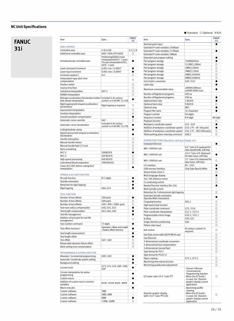
Item Spec. FANUC 31i
AXES CONTROLControlled axes 4 (X,Y,Z,B) X, Y, Z, BAdditional controlled axes ADD 1 AXIS (5TH AXIS) ◦
Simultaneously controlled axes
Positioning(G00)/Linear interpolation(G01) : 3 axesCircular interpolation(G02, G03) : 2 axes
●
Least command increment 0.001 mm / 0.0001" ●
Least input increment 0.001 mm / 0.0001" ●
Increment system C IS-C ◦
Interpolation type pitch error compensation ◦
Position switch ◦
Inverse time feed ◦
Cylindrical interpolation G07.1 ◦
NURBS interpolation ◦
Bell-type acceleration/deceleration before look ahead interpolation
Included in AI contour control I or II (0i-MF, 31/32i)
●
Rigid tapping bell-shaped acceleration/deceleration Rigid tapping is required. ◦
Exponential interpolation ◦
Involute interpolation ◦
Smooth backlash compensation ●
Automatic corner override G62 ◦
Automatic corner deceleration Included in AI contour control I or II (0i-MF, 31/32i)
●
Cutting feedrate clamp ●
Rapid traverse bell-shaped acceleration/deceleration ●
Handle interruption ◦
Manual handle retrace ◦
Manual handle feed 2/3 unit ◦
Nano smoothing ◦
AICC II 200BLOCK ●
AICC II 400 BLOCK ◦
High-speed processing 600 BLOCK ◦
Look-ahead blocks expansion 1000 BLOCK ◦
Linear ACC/DEC before cutting feed interpolation ●
SPINDLE & M-CODE FUNCTIONM-code function M 3 digits ●
Spindle orientation ●
Retraction for rigid tapping ●
Rigid tapping G84, G74 ●
TOOL FUNCTIONNumber of tool offsets 200-pairs ●
Number of tool offsets 400-pairs ◦
Number of tool offsets 499 / 999 / 2000 -pairs ◦
Tool nose radius compensation G40, G41, G42 ●
Tool length compensation G43, G44, G49 ●
Tool life management ●
Addition of tool pairs for tool life management ◦
Tool number command T3 digits ●
Tool offset memory C Geometry / Wear and Length / Radius offset memory ●
Tool length measurement ●
Tool length offset ●
Tool offset G45 - G48 ◦
Rotary table dynamic fixture offset ◦
Work setting error compensation ◦
PROGRAMMING & EDITING FUNCTIONAbsolute / Incremental programming G90 / G91 ●
Automatic Coordinate system setting ●
Background editing ●
Canned cycle G73, G74, G76, G80 - G89, G99 ●
Circular interpolation by radius programming ●
Custom macro ●
Addition of custom macro common variables #100 - #199, #500 - #999 ●
Macro executor ●
Custom software 2MB -Custom software 4MB, 6MB -Custom software 8MB ●
Custom software 12MB, 16MB ◦
NC Unit Specifications
FANUC 31i
● Standard ◦ Optional X N/A
Item Spec. FANUC 31i
Decimal point input ●
Extended P-code variables 256Kbyte -Extended P-code variables 512Kbyte ●
Extended P-code variables 1Mbyte -Extended part program editing ●
Part program storage 256KB(640m) ●
Part program storage 512KB(1,280m) ◦
Part program storage 1MB(2,560m) ◦
Part program storage 2MB(5,120m) ◦
Part program storage 4MB(1,0240m) ◦
Part program storage 8MB(2,0480m) ◦
Inch/metric conversion G20 / G21 ●
Label skip ●
Maximum commandable value ±99999.999mm(±9999.9999 inch)
●
Number of Registered programs 400 ea -Number of Registered programs 500 ea ●
Optional block skip 1 BLOCK ●
Optional block skip 9 BLOCK ◦
Optional stop M01 ●
Program file name 32 characters ●
Program number O4-digits -Sequence number N 8-digit N8 digitPlayback function ◦
Workpiece coordinate system G52 - G59 ●
Addition of workpiece coordinate system G54.1 P1 - 48 (48 pairs) ●
Addition of workpiece coordinate system G54.1 P1 - 300 (300 pairs) ◦
Tilted working plane indexing command G68.2 ◦
OTHERS FUNCTIONS (Operation, setting & Display, etc)Embeded Ethernet ●
MDI / DISPLAY unit 8.4" Color LCD, keyboard for data input(small), soft-keys -
MDI / DISPLAY unit 10.4" Color LCD, Keyboard for data input, soft-keys ●
MDI / DISPLAY unit 15" Color LCD, Keyboard for data input, soft-keys
◦
I/O interface RS - 232C ●
USB memory interface Only Data Read & Write ●
Stored stroke check 2 ◦
Multi language display ●
3rd / 4th reference return ◦
Cs contouring control ◦
Reader/Puncher interface (for 2ch) ●
Multi spindle control -Retraction for 3-dimensional rigid tapping ◦
Extended Spindle orientation (Spindle Multi Orientation) ●
Chopping function G81.1 ◦
High speed skip function ◦
Polar coordinate command G15 / G16 ◦
Polar coordinate interpolation G12.1 / G13.1 ◦
Programmable mirror image G50.1 / G51.1 ◦
Scaling G50, G51 ◦
Single direction positioning G60 ◦
Pattern data input ◦
Jerk control AI contour control II is required. ◦
Fast Data server with1GB PCMCIA card ◦
Fast Ethernet ◦
3-dimensional coordinate conversion ◦
3-dimensional tool compensation ◦
3-dimensional manual feed ◦
Tape format for FS15 ◦
Tape format for FS10/11 -Figure copying G72.1, G72.2 ◦
Machining time stamp function ◦
Machining quality level adjustment ◦
EZ Guide I with 10.4" Color TFT
-. Doosan infracore Conversational Programming Solution
-. When the EZ Guide i is used, the Dynamic graphic display cannot application
◦
Dynamic graphic display (with 10.4" Color TFT LCD)
-. Machining profile drawing.
-. When the EZ Guide i is used, the Dynamic graphic display cannot application
◦
2524 /
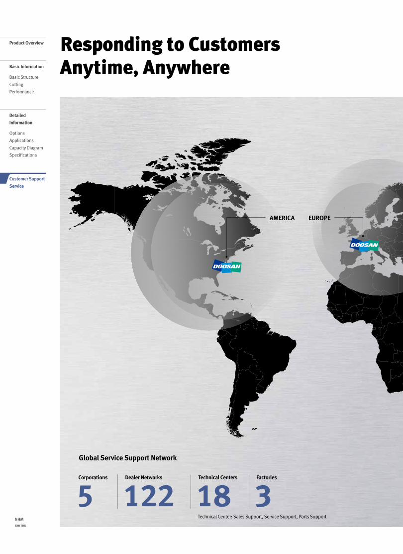
Responding to Customers Anytime, Anywhere
Global Service Support Network
Technical Center: Sales Support, Service Support, Parts Support
5Corporations
3Factories
18Technical Centers
122Dealer Networks
AMERICA EUROPE
NHM
series
2726 /
Product Overview
Basic Information
Basic Structure
Cutting
Performance
Detailed
Information
Options
Applications
Capacity Diagram
Specifications
Customer Support
Service
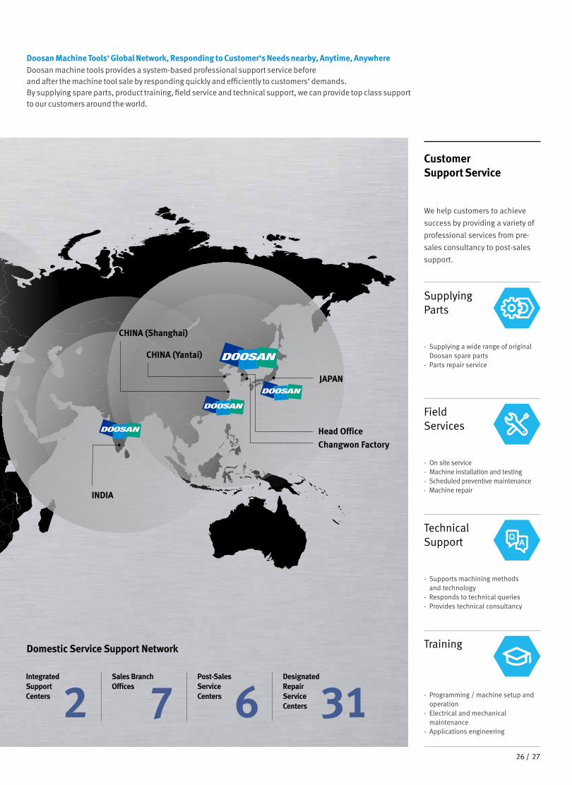
Doosan Machine Tools’ Global Network, Responding to Customer’s Needs nearby, Anytime, AnywhereDoosan machine tools provides a system-based professional support service before and after the machine tool sale by responding quickly and efficiently to customers’ demands.By supplying spare parts, product training, field service and technical support, we can provide top class support to our customers around the world.
We help customers to achieve
success by providing a variety of
professional services from pre-
sales consultancy to post-sales
support.
Customer Support Service
- On site service- Machine installation and testing- Scheduled preventive maintenance- Machine repair
Field Services
- Supports machining methods and technology
- Responds to technical queries- Provides technical consultancy
Technical Support
- Programming / machine setup and operation
- Electrical and mechanical maintenance
- Applications engineering
Training
- Supplying a wide range of original Doosan spare parts
- Parts repair service
Supplying Parts
Domestic Service Support Network
2Integrated Support Centers 7
Sales Branch Offices
6Post-Sales Service Centers 31
Designated Repair Service Centers
CHINA (Yantai)
CHINA (Shanghai)
INDIA
Changwon Factory
Head Office
JAPAN
2726 /
Main Specifications
NHM series Description Unit NHM 5000 NHM 6300 NHM 8000
Pallet size mm (inch) 500 x 500 (19.7 x 19.7) 630 x 630 (24.8 x 24.8) 800 x 800 (31.5 x 31.5)
Tool taper taper 50 50 50
Max. spindle speed r/min 6000 6000 6000
Max. spindle motor power kW (Hp) 25 (33.5) 35 (46.9) 35 (46.9)
Travel distance (X / Y / Z) mm (inch)800 / 700 / 850
(31.5 / 27.6 / 33.5)1050 / 850 / 1000 (41.3 / 33.5 / 33.4)
1400 / 1050 / 1200 (55.1 / 41.3 / 47.2)
Tool storage capacity ea 60 60 60
NC system - FANUC / SIEMENS FANUC / SIEMENS FANUC / SIEMENS
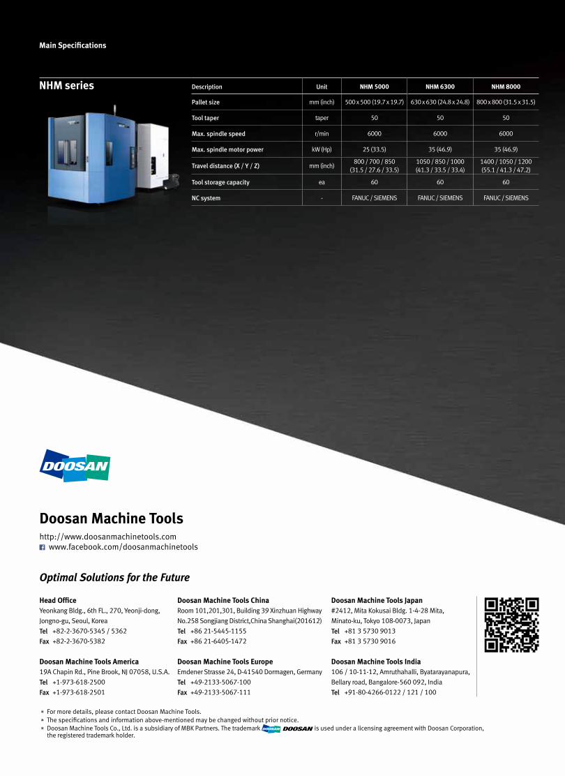
Doosan Machine Tools
Head OfficeYeonkang Bldg., 6th FL., 270, Yeonji-dong,
Jongno-gu, Seoul, Korea
Tel +82-2-3670-5345 / 5362
Fax +82-2-3670-5382
Doosan Machine Tools America19A Chapin Rd., Pine Brook, NJ 07058, U.S.A.
Tel +1-973-618-2500
Fax +1-973-618-2501
http://www.doosanmachinetools.com www.facebook.com/doosanmachinetools
Doosan Machine Tools ChinaRoom 101,201,301, Building 39 Xinzhuan Highway
No.258 Songjiang District,China Shanghai(201612)
Tel +86 21-5445-1155
Fax +86 21-6405-1472
Doosan Machine Tools EuropeEmdener Strasse 24, D-41540 Dormagen, Germany
Tel +49-2133-5067-100
Fax +49-2133-5067-111
Doosan Machine Tools Japan#2412, Mita Kokusai Bldg. 1-4-28 Mita,
Minato-ku, Tokyo 108-0073, Japan
Tel +81 3 5730 9013
Fax +81 3 5730 9016
Doosan Machine Tools India106 / 10-11-12, Amruthahalli, Byatarayanapura,
Bellary road, Bangalore-560 092, India
Tel +91-80-4266-0122 / 121 / 100
* For more details, please contact Doosan Machine Tools.* The specifications and information above-mentioned may be changed without prior notice.* Doosan Machine Tools Co., Ltd. is a subsidiary of MBK Partners. The trademark is used under a licensing agreement with Doosan Corporation,
the registered trademark holder.
PB28 /