ni 9213 getting started guide - national instruments · connecting a thermocouple to the ni 9213...
TRANSCRIPT
GETTING STARTED GUIDE
NI 921316 TC, ±78 mV, 24 Bit, 75 S/s Aggregate

This document explains how to connect to the NI 9213.
Note Before you begin, complete the software andhardware installation procedures in your chassisdocumentation.
Note The guidelines in this document are specific tothe NI 9213. The other components in the system mightnot meet the same safety ratings. Refer to thedocumentation for each component in the system todetermine the safety and EMC ratings for the entiresystem.
Safety GuidelinesOperate the NI 9213 only as described in this document.
Caution Do not operate the NI 9213 in a manner notspecified in this document. Product misuse can result ina hazard. You can compromise the safety protectionbuilt into the product if the product is damaged in anyway. If the product is damaged, return it to NI forrepair.
2 | ni.com | NI 9213 Getting Started Guide
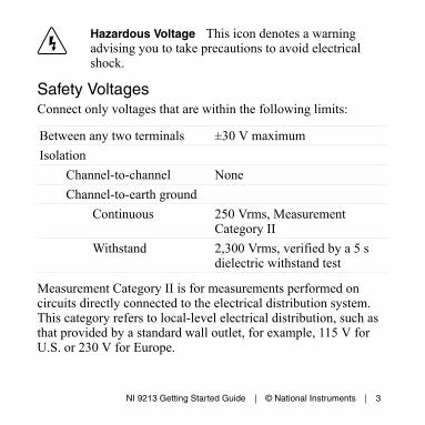
Hazardous Voltage This icon denotes a warningadvising you to take precautions to avoid electricalshock.
Safety VoltagesConnect only voltages that are within the following limits:
Between any two terminals ±30 V maximumIsolation
Channel-to-channel NoneChannel-to-earth ground
Continuous 250 Vrms, MeasurementCategory II
Withstand 2,300 Vrms, verified by a 5 sdielectric withstand test
Measurement Category II is for measurements performed oncircuits directly connected to the electrical distribution system.This category refers to local-level electrical distribution, such asthat provided by a standard wall outlet, for example, 115 V forU.S. or 230 V for Europe.
NI 9213 Getting Started Guide | © National Instruments | 3
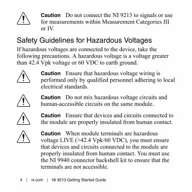
Caution Do not connect the NI 9213 to signals or usefor measurements within Measurement Categories IIIor IV.
Safety Guidelines for Hazardous VoltagesIf hazardous voltages are connected to the device, take thefollowing precautions. A hazardous voltage is a voltage greaterthan 42.4 Vpk voltage or 60 VDC to earth ground.
Caution Ensure that hazardous voltage wiring isperformed only by qualified personnel adhering to localelectrical standards.
Caution Do not mix hazardous voltage circuits andhuman-accessible circuits on the same module.
Caution Ensure that devices and circuits connected tothe module are properly insulated from human contact.
Caution When module terminals are hazardousvoltage LIVE (>42.4 Vpk/60 VDC), you must ensurethat devices and circuits connected to the module areproperly insulated from human contact. You must usethe NI 9940 connector backshell kit to ensure that theterminals are not accessible.
4 | ni.com | NI 9213 Getting Started Guide

Safety Guidelines for Hazardous LocationsThe NI 9213 is suitable for use in Class I, Division 2, Groups A,B, C, D, T4 hazardous locations; Class I, Zone 2, AEx nA IIC T4and Ex nA IIC T4 hazardous locations; and nonhazardouslocations only. Follow these guidelines if you are installing theNI 9213 in a potentially explosive environment. Not followingthese guidelines may result in serious injury or death.
Caution Do not disconnect I/O-side wires orconnectors unless power has been switched off or thearea is known to be nonhazardous.
Caution Do not remove modules unless power hasbeen switched off or the area is known to benonhazardous.
Caution Substitution of components may impairsuitability for Class I, Division 2.
Caution For Division 2 and Zone 2 applications,install the system in an enclosure rated to at least IP54as defined by IEC/EN 60079-15.
NI 9213 Getting Started Guide | © National Instruments | 5
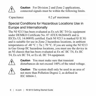
Caution For Division 2 and Zone 2 applications,connected signals must be within the following limits.
Capacitance 0.2 µF maximum
Special Conditions for Hazardous Locations Use inEurope and InternationallyThe NI 9213 has been evaluated as Ex nA IIC T4 Gc equipmentunder DEMKO Certificate No. 07 ATEX 0626664X and isIECEx UL 14.0089X certified. Each NI 9213 is marked II 3Gand is suitable for use in Zone 2 hazardous locations, in ambienttemperatures of -40 °C ≤ Ta ≤ 70 °C. If you are using the NI 9213in Gas Group IIC hazardous locations, you must use the device inan NI chassis that has been evaluated as Ex nC IIC T4, Ex IICT4, Ex nA IIC T4, or Ex nL IIC T4 equipment.
Caution You must make sure that transientdisturbances do not exceed 140% of the rated voltage.
Caution The system shall only be used in an area ofnot more than Pollution Degree 2, as defined inIEC 60664-1.
6 | ni.com | NI 9213 Getting Started Guide
Caution The system shall be mounted in anATEX/IECEx-certified enclosure with a minimumingress protection rating of at least IP54 as defined inIEC/EN 60079-15.
Caution The enclosure must have a door or coveraccessible only by the use of a tool.
Electromagnetic Compatibility GuidelinesThis product was tested and complies with the regulatoryrequirements and limits for electromagnetic compatibility (EMC)stated in the product specifications. These requirements andlimits provide reasonable protection against harmful interferencewhen the product is operated in the intended operationalelectromagnetic environment.
This product is intended for use in industrial locations. However,harmful interference may occur in some installations, when theproduct is connected to a peripheral device or test object, or if theproduct is used in residential or commercial areas. To minimizeinterference with radio and television reception and preventunacceptable performance degradation, install and use this
NI 9213 Getting Started Guide | © National Instruments | 7

product in strict accordance with the instructions in the productdocumentation.
Furthermore, any changes or modifications to the product notexpressly approved by National Instruments could void yourauthority to operate it under your local regulatory rules.
Special Conditions for Marine ApplicationsSome products are Lloyd’s Register (LR) Type Approved formarine (shipboard) applications. To verify Lloyd’s Registercertification for a product, visit ni.com/certification and searchfor the LR certificate, or look for the Lloyd’s Register mark onthe product.
Caution In order to meet the EMC requirements formarine applications, install the product in a shieldedenclosure with shielded and/or filtered power andinput/output ports. In addition, take precautions whendesigning, selecting, and installing measurement probesand cables to ensure that the desired EMC performanceis attained.
8 | ni.com | NI 9213 Getting Started Guide
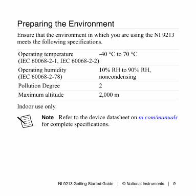
Preparing the EnvironmentEnsure that the environment in which you are using the NI 9213meets the following specifications.
Operating temperature(IEC 60068-2-1, IEC 60068-2-2)
-40 °C to 70 °C
Operating humidity(IEC 60068-2-78)
10% RH to 90% RH,noncondensing
Pollution Degree 2Maximum altitude 2,000 m
Indoor use only.
Note Refer to the device datasheet on ni.com/manualsfor complete specifications.
NI 9213 Getting Started Guide | © National Instruments | 9
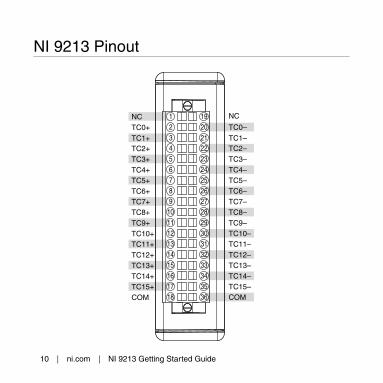
NI 9213 Pinout
NCTC0+
TC2+
TC4+
TC6+
TC8+
TC10+
TC12+
TC14+
COM
TC1+
TC3+
TC5+
TC7+
TC9+
TC11+
TC13+
TC15+
TC0–
NC
TC1–
TC3–
TC5–
TC7–
TC9–
TC11–
TC13–
TC15–
TC2–
TC4–
TC6–
TC8–
TC10–
TC12–
TC14–
COM
10 | ni.com | NI 9213 Getting Started Guide
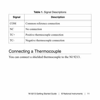
Table 1. Signal Descriptions
Signal Description
COM Common reference connection
NC No connection
TC+ Positive thermocouple connection
TC- Negative thermocouple connection
Connecting a ThermocoupleYou can connect a shielded thermocouple to the NI 9213.
NI 9213 Getting Started Guide | © National Instruments | 11
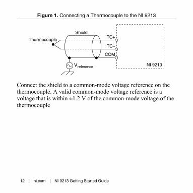
Figure 1. Connecting a Thermocouple to the NI 9213
Thermocouple
TC–
COM
TC+Shield
NI 9213Vreference
Connect the shield to a common-mode voltage reference on thethermocouple. A valid common-mode voltage reference is avoltage that is within ±1.2 V of the common-mode voltage of thethermocouple
12 | ni.com | NI 9213 Getting Started Guide

Connecting Wires to a Spring-TerminalConnector
What to Use• NI 9213 spring-terminal connector• 0.8 mm2 to 1.0 mm2 (28 AWG to 18 AWG) copper conductor
wire with 7 mm (0.276 in.) of insulation stripped from theend
• Flathead screwdriver with a 2.3 mm x 1.0 mm (0.09 in. x0.04 in.) blade, included with the NI 9213
What to DoComplete the following steps to connect wires to the spring-terminal connector.
NI 9213 Getting Started Guide | © National Instruments | 13
1 2 3
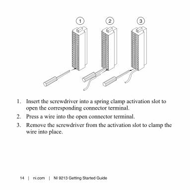
1. Insert the screwdriver into a spring clamp activation slot toopen the corresponding connector terminal.
2. Press a wire into the open connector terminal.3. Remove the screwdriver from the activation slot to clamp the
wire into place.
14 | ni.com | NI 9213 Getting Started Guide
High-Vibration Application ConnectionsIf your application is subject to high vibration, NI recommendsthat you use the NI 9940 backshell kit to protect connections tothe NI 9213.
Minimizing Thermal GradientsChanges in the ambient air temperature near the front connectoror a thermocouple wire conducting heat directly to terminaljunctions can cause thermal gradients. Observe the followingguidelines to minimize thermal gradients and improve the systemaccuracy.• Use small-gauge thermocouple wire. Smaller wire transfers
less heat to or from the terminal junction.• Run thermocouple wiring together near the spring-terminal
connector to keep the wires at the same temperature.• Avoid running thermocouple wires near hot or cold objects.• Minimize adjacent heat sources and air flow across the
terminals.• Keep the ambient temperature as stable as possible.
NI 9213 Getting Started Guide | © National Instruments | 15
• Make sure the NI 9213 terminals are facing forward orupward.
• Keep the NI 9213 in a stable and consistent orientation.• Allow the thermal gradients to settle after a change in system
power or in ambient temperature. A change in system powercan happen when the system powers on, the system comesout of sleep mode, or you insert/remove modules.
• If you connect any extension wires to thermocouple wires,use wires made of the same conductive material as thethermocouple wires.
• Use the NI 9940 backshell kit.
Overvoltage ProtectionThe NI 9213 provides overvoltage protection between any twoinputs.
Note Refer to the device datasheet on ni.com/manualsfor more information about overvoltage protection.
16 | ni.com | NI 9213 Getting Started Guide

Where to Go Next
Located at ni.com/manuals Installs with the software
CompactRIO NI CompactDAQ
RELATED INFORMATION
C Series Documentation& Resourcesni.com/info cseriesdoc
Servicesni.com/services
NI 9213 Datasheet
NI-RIO Help
LabVIEW FPGA Help
NI 9213 Datasheet
NI-DAQmx Help
LabVIEW Help
NI 9213 Getting Started Guide | © National Instruments | 17
Worldwide Support and ServicesThe NI website is your complete resource for technical support.At ni.com/support, you have access to everything fromtroubleshooting and application development self-help resourcesto email and phone assistance from NI Application Engineers.
Visit ni.com/services for NI Factory Installation Services, repairs,extended warranty, and other services.
Visit ni.com/register to register your NI product. Productregistration facilitates technical support and ensures that youreceive important information updates from NI.
A Declaration of Conformity (DoC) is our claim of compliancewith the Council of the European Communities using themanufacturer’s declaration of conformity. This system affords theuser protection for electromagnetic compatibility (EMC) andproduct safety. You can obtain the DoC for your product byvisiting ni.com/certification. If your product supports calibration,you can obtain the calibration certificate for your product at ni.com/calibration.
18 | ni.com | NI 9213 Getting Started Guide
NI corporate headquarters is located at11500 North Mopac Expressway, Austin, Texas, 78759-3504. NIalso has offices located around the world. For telephone supportin the United States, create your service request at ni.com/supportor dial 1 866 ASK MYNI (275 6964). For telephone supportoutside the United States, visit the Worldwide Offices section of ni.com/niglobal to access the branch office websites, whichprovide up-to-date contact information, support phone numbers,email addresses, and current events.
NI 9213 Getting Started Guide | © National Instruments | 19
Refer to the NI Trademarks and Logo Guidelines at ni.com/trademarks for information on NItrademarks. Other product and company names mentioned herein are trademarks or trade namesof their respective companies. For patents covering NI products/technology, refer to theappropriate location: Help»Patents in your software, the patents.txt file on your media, or theNational Instruments Patent Notice at ni.com/patents. You can find information about end-userlicense agreements (EULAs) and third-party legal notices in the readme file for your NI product.Refer to the Export Compliance Information at ni.com/legal/export-compliance for the NIglobal trade compliance policy and how to obtain relevant HTS codes, ECCNs, and other import/export data. NI MAKES NO EXPRESS OR IMPLIED WARRANTIES AS TO THE ACCURACY OFTHE INFORMATION CONTAINED HEREIN AND SHALL NOT BE LIABLE FOR ANY ERRORS.U.S. Government Customers: The data contained in this manual was developed at privateexpense and is subject to the applicable limited rights and restricted data rights as set forth in FAR52.227-14, DFAR 252.227-7014, and DFAR 252.227-7015.
© 2009—2016 National Instruments. All rights reserved.
374916C-01 Jan16