ni switches help about these specifications
TRANSCRIPT

NI PXI/PXIe-2575 Specifications196 × 1 Relay Multiplexer
This document lists specifications for the NI PXI/PXIe-2575 (NI 2575) 196 × 1 multiplexer relay module. All specifications are subject to change without notice. Visit ni.com/manuals for the most current specifications.
Topologies......................................................... 1-wire 196 × 1 multiplexer 2-wire 95 × 1 multiplexer 2-wire 98 × 1 multiplexer
Refer to the NI Switches Help for detailed topology information.
About These SpecificationsSpecifications characterize the warranted performance of the instrument under the stated operating conditions.
Typical Specifications are specifications met by the majority of the instrument under the stated operating conditions and are tested at 23 °C. Typical specifications are not warranted.
All voltages are specified in DC, ACpk, or a combination unless otherwise specified.
Clean devices and terminal blocks by brushing off light dust with a soft, nonmetallic brush. Remove other contaminants with a soft, lint-free, dampened cloth. Do not use detergent or chemical solvents. The unit must be completely dry and free from contaminants before returning to service.
Caution Refer to the Read Me First: Safety and Electromagnetic Compatibility document for important safety and electromagnetic compatibility information. To obtain a copy of this document online, visit ni.com/manuals, and search for the document title.
Caution To ensure the specified EMC performance, operate this product only with shielded cables and accessories.
Caution The protection provided by the NI 2575 can be impaired if it is used in a manner not described in this document.
2 | ni.com | NI PXI/PXIe-2575 Specifications
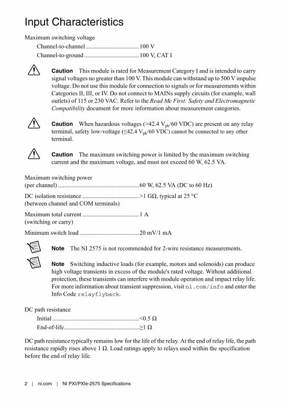
Input CharacteristicsMaximum switching voltage
Channel-to-channel ...................................100 V
Channel-to-ground ....................................100 V, CAT I
Caution This module is rated for Measurement Category I and is intended to carry signal voltages no greater than 100 V. This module can withstand up to 500 V impulse voltage. Do not use this module for connection to signals or for measurements within Categories II, III, or IV. Do not connect to MAINs supply circuits (for example, wall outlets) of 115 or 230 VAC. Refer to the Read Me First: Safety and Electromagnetic Compatibility document for more information about measurement categories.
Caution When hazardous voltages (>42.4 Vpk/60 VDC) are present on any relay terminal, safety low-voltage (≤42.4 Vpk/60 VDC) cannot be connected to any other terminal.
Caution The maximum switching power is limited by the maximum switching current and the maximum voltage, and must not exceed 60 W, 62.5 VA.
Maximum switching power(per channel) .....................................................60 W, 62.5 VA (DC to 60 Hz)
DC isolation resistance .....................................>1 GΩ, typical at 25 °C(between channel and COM terminals)
Maximum total current .....................................1 A(switching or carry)
Minimum switch load .......................................20 mV/1 mA
Note The NI 2575 is not recommended for 2-wire resistance measurements.
Note Switching inductive loads (for example, motors and solenoids) can produce high voltage transients in excess of the module's rated voltage. Without additional protection, these transients can interfere with module operation and impact relay life. For more information about transient suppression, visit ni.com/info and enter the Info Code relayflyback.
DC path resistance
Initial .........................................................<0.5 Ω
End-of-life.................................................≥1 Ω
DC path resistance typically remains low for the life of the relay. At the end of relay life, the path resistance rapidly rises above 1 Ω. Load ratings apply to relays used within the specification before the end of relay life.

NI PXI/PXIe-2575 Specifications | © National Instruments | 3
Differential thermal EMF
Typical1 ..................................................... 3 μV
Maximum.................................................. <12 μV
Bandwidth (-3 dB, 50 Ω termination)
1-wire........................................................ >20 MHz
2-wire........................................................ >8 MHz
Channel-to-channel isolation (50 Ω termination)
Each relay in the NI 2575 is shared by two channels. Refer to Table 4 for a list of channel pairings.
1-wire channels in different relays
10 kHz............................................... >90 dB
100 kHz............................................. >70 dB
1 MHz ............................................... >50 dB
1-wire channels in the same relay
10 kHz............................................... >68 dB
100 kHz............................................. >48 dB
1 MHz ............................................... >28 dB
2-wire channels
10 kHz............................................... >95 dB
100 kHz............................................. >75 dB
1 MHz ............................................... >55 dB
Open channel isolation (50 Ω termination)
10 kHz....................................................... >90 dB
100 kHz..................................................... >70 dB
1 MHz ....................................................... >50 dB
Dynamic CharacteristicsRelay operate time
Typical ...................................................... 1 ms
Maximum.................................................. 3.4 ms
Note Certain applications may require additional time for proper settling. Refer to the NI Switches Help for information about including additional settling time.
1 To ensure the typical thermal EMF, power down all relays and avoid pulsing high currents near the channels you are measuring. For more information about powering down latching relays, refer to the Power Down Latching Relays After Debounce property in NI-SWITCH or the Power Down Latching Relays After Settling property in NI-DAQmx.

4 | ni.com | NI PXI/PXIe-2575 Specifications
Expected relay life
Mechanical................................................1 × 108 cycles
Electrical
10 VDC, 100 mADC resistive..........................2.5 × 106 cycles
10 VDC, 1 ADC resistive .................1 × 106 cycles
30 VDC, 1 ADC resistive .................5 × 105 cycles
60 VDC, 1 ADC resistive .................1 × 105 cycles
Note The relays used in the NI 2575 are field replaceable. Refer to the NI Switches Help for information about replacing a failed relay.
Trigger CharacteristicsInput trigger
Sources......................................................PXI trigger lines 0 to 7
Minimum pulse width...............................150 ns
Note The NI 2575 can recognize trigger pulse widths less than 150 ns by disabling digital filtering. For information about disabling digital filtering, refer to the NI Switches Help.
Output trigger
Destinations ..............................................PXI trigger lines 0 to 7
Pulse width................................................Programmable (1 μs to 62 μs)
Physical CharacteristicsRelay type .........................................................Electromechanical, latching
Relay contact material ......................................Silver, gold covered
I/O connector ....................................................200 POS LFH Matrix 50, receptacle
Power requirement
PXI ............................................................6 W at 5 V, 2.5 W at 3.3 V
PXI Express ..............................................7.5 W at 12V, 2.5 W at 3.3 V
Dimensions (L × W × H) ..................................3U, one slot, PXI/cPCI module, PXIe compatible 21.6 × 2.0 × 13.0 cm (8.5 × 0.8 × 5.1 in.)
Weight ...............................................................231 g (8.1 oz)

NI PXI/PXIe-2575 Specifications | © National Instruments | 5
EnvironmentOperating temperature ...................................... 0 °C to 55 °C
Storage temperature .......................................... -20 °C to 70 °C
Relative humidity ............................................. 5% to 85%, noncondensing
Pollution Degree ............................................... 2
Maximum altitude............................................. 2,000 m
Indoor use only.
Shock and VibrationOperational Shock ............................................ 30 g peak, half-sine, 11 ms pulse
(Tested in accordance with IEC 60068-2-27. Test profile developed in accordance with MIL-PRF-28800F.)
Random Vibration
Operating .................................................. 5 to 500 Hz, 0.3 grms
Nonoperating ............................................ 5 to 500 Hz, 2.4 grms (Tested in accordance with IEC 60068-2-64. Nonoperating test profile exceeds the requirements of MIL-PRF-28800F, Class 3.)

6 | ni.com | NI PXI/PXIe-2575 Specifications
DiagramsFigure 1 shows the NI 2575 hardware diagram.
Figure 1. NI 2575 Hardware Diagram
COM+
COM–
CH0
CH95
CH93
CH188
CH94
CH189
CH190
CH193
CH191
CH194
CH192
CH195
CH1
CH96
NO CONNECT

NI PXI/PXIe-2575 Specifications | © National Instruments | 7
Figure 2 shows the NI 2575 connector pinout for the 1-wire 196 × 1 topology.
Figure 2. NI 2575 Connector Pinout for the 1-wire 196 × 1 topology
NO CONNECT
CH166
CH71
CH165
CH70
CH164
CH69
CH163
CH68
CH162
CH67
CH161
CH66
CH160
CH65
CH159
CH64
CH158
CH63
CH157
CH62
CH156
CH61
CH155
CH60
CH193
CH154
CH59
CH153
CH58
CH152
CH57
CH151
CH56
CH150
CH55
CH149
CH54
CH148
CH53
CH147
CH52
CH146
CH51
CH145
CH50
CH144
CH49
CH143
CH48
150151149152148153147154146155145156144157143158142159141160140161139162138163137164136165135166134167133168132169131170130171129172128173127174126175125176124177123178122179121180120181119182118183117184116185115186114187113188112189111190110191109192108193107194106195105196104197103198102199
200101
515052495348544755465645574458435942604161406239633864376536663567346833693270317130722973287427752676257724782379228021812082198318841785168615871488138912901191109299389479569659749839921001
CH84
CH179
CH85
CH180
CH86
CH181
CH87
CH182
CH88
CH183
CH89
CH184
CH90
CH185
CH91
CH186
CH92
CH187
CH93
CH188
CH94
CH189
COM
NO CONNECT
CH190
CH72
CH167
CH73
CH168
CH74
CH169
CH75
CH170
CH76
CH171
CH77
CH172
CH78
CH173
CH79
CH174
CH80
CH175
CH81
CH176
CH82
CH177
CH83
CH178
CH192
CH36
CH131
CH37
CH132
CH38
CH133
CH39
CH134
CH40
CH135
CH41
CH136
CH42
CH137
CH43
CH138
CH44
CH139
CH45
CH140
CH46
CH141
CH47
CH142
CH191
CH24
CH119
CH25
CH120
CH26
CH121
CH27
CH122
CH28
CH123
CH29
CH124
CH30
CH125
CH31
CH126
CH32
CH127
CH33
CH128
CH34
CH129
CH35
CH130
CH195
NO CONNECT
CH118
CH23
CH117
CH22
CH116
CH21
CH115
CH20
CH114
CH19
CH113
CH18
CH112
CH17
CH111
CH16
CH110
CH15
CH109
CH14
CH108
CH13
CH107
CH12
CH194
CH106
CH11
CH105
CH10
CH104
CH9
CH103
CH8
CH102
CH7
CH101
CH6
CH100
CH5
CH99
CH4
CH98
CH3
CH97
CH2
CH96
CH1
CH95
CH0

8 | ni.com | NI PXI/PXIe-2575 Specifications
Figure 3 shows the NI 2575 connector pinout for the 2-wire 95 × 1 topology.
Figure 3. NI 2575 Connector Pinout for the 2-wire 95 × 1 topology
NO CONNECT
CH71–
CH71+
CH70–
CH70+
CH69–
CH69+
CH68–
CH68+
CH67–
CH67+
CH66–
CH66+
CH65–
CH65+
CH64–
CH64+
CH63–
CH63+
CH62–
CH62+
CH61–
CH61+
CH60–
CH60+
NO CONNECT
CH59–
CH59+
CH58–
CH58+
CH57–
CH57+
CH56–
CH56+
CH55–
CH55+
CH54–
CH54+
CH53–
CH53+
CH52–
CH52+
CH51–
CH51+
CH50–
CH50+
CH49–
CH49+
CH48–
CH48+
150151149152148153147154146155145156144157143158142159141160140161139162138163137164136165135166134167133168132169131170130171129172128173127174126175125176124177123178122179121180120181119182118183117184116185115186114187113188112189111190110191109192108193107194106195105196104197103198102199
200101
515052495348544755465645574458435942604161406239633864376536663567346833693270317130722973287427752676257724782379228021812082198318841785168615871488138912901191109299389479569659749839921001
CH84+
CH84–
CH85+
CH85–
CH86+
CH86–
CH87+
CH87–
CH88+
CH88–
CH89+
CH89–
CH90+
CH90–
CH91+
CH91–
CH92+
CH92–
CH93+
CH93–
CH94+
CH94–
COM+
COM–
NO CONNECT
CH72+
CH72–
CH73+
CH73–
CH74+
CH74–
CH75+
CH75–
CH76+
CH76–
CH77+
CH77–
CH78+
CH78–
CH79+
CH79–
CH80+
CH80–
CH81+
CH81–
CH82+
CH82–
CH83+
CH83–
NO CONNECT
CH36+
CH36–
CH37+
CH37–
CH38+
CH38–
CH39+
CH39–
CH40+
CH40–
CH41+
CH41–
CH42+
CH42–
CH43+
CH43–
CH44+
CH44–
CH45+
CH45–
CH46+
CH46–
CH47+
CH47–
NO CONNECT
CH24+
CH24–
CH25+
CH25–
CH26+
CH26–
CH27+
CH27–
CH28+
CH28–
CH29+
CH29–
CH30+
CH30–
CH31+
CH31–
CH32+
CH32–
CH33+
CH33–
CH34+
CH34–
CH35+
CH35–
NO CONNECT
NO CONNECT
CH23–
CH23+
CH22–
CH22+
CH21–
CH21+
CH20–
CH20+
CH19–
CH19+
CH18–
CH18+
CH17–
CH17+
CH16–
CH16+
CH15–
CH15+
CH14–
CH14+
CH13–
CH13+
CH12–
CH12+
NO CONNECT
CH11–
CH11+
CH10–
CH10+
CH9–
CH9+
CH8–
CH8+
CH7–
CH7+
CH6–
CH6+
CH5–
CH5+
CH4–
CH4+
CH3–
CH3+
CH2–
CH2+
CH1–
CH1+
CH0–
CH0+

NI PXI/PXIe-2575 Specifications | © National Instruments | 9
Figure 4 shows the NI 2575 connector pinout for the 2-wire 98 × 1 topology.
Figure 4. NI 2575 Connector Pinout for the 2-wire 98 × 1 topology
NO CONNECT
CH71–
CH71+
CH70–
CH70+
CH69–
CH69+
CH68–
CH68+
CH67–
CH67+
CH66–
CH66+
CH65–
CH65+
CH64–
CH64+
CH63–
CH63+
CH62–
CH62+
CH61–
CH61+
CH60–
CH60+
CH95–
CH59–
CH59+
CH58–
CH58+
CH57–
CH57+
CH56–
CH56+
CH55–
CH55+
CH54–
CH54+
CH53–
CH53+
CH52–
CH52+
CH51–
CH51+
CH50–
CH50+
CH49–
CH49+
CH48–
CH48+
150151149152148153147154146155145156144157143158142159141160140161139162138163137164136165135166134167133168132169131170130171129172128173127174126175125176124177123178122179121180120181119182118183117184116185115186114187113188112189111190110191109192108193107194106195105196104197103198102199
200101
515052495348544755465645574458435942604161406239633864376536663567346833693270317130722973287427752676257724782379228021812082198318841785168615871488138912901191109299389479569659749839921001
CH84+
CH84–
CH85+
CH85–
CH86+
CH86–
CH87+
CH87–
CH88+
CH88–
CH89+
CH89–
CH90+
CH90–
CH91+
CH91–
CH92+
CH92–
CH93+
CH93–
CH94+
CH94–
COM+
COM–
CH95+
CH72+
CH72–
CH73+
CH73–
CH74+
CH74–
CH75+
CH75–
CH76+
CH76–
CH77+
CH77–
CH78+
CH78–
CH79+
CH79–
CH80+
CH80–
CH81+
CH81–
CH82+
CH82–
CH83+
CH83–
CH97+
CH36+
CH36–
CH37+
CH37–
CH38+
CH38–
CH39+
CH39–
CH40+
CH40–
CH41+
CH41–
CH42+
CH42–
CH43+
CH43–
CH44+
CH44–
CH45+
CH45–
CH46+
CH46–
CH47+
CH47–
CH96+
CH24+
CH24–
CH25+
CH25–
CH26+
CH26–
CH27+
CH27–
CH28+
CH28–
CH29+
CH29–
CH30+
CH30–
CH31+
CH31–
CH32+
CH32–
CH33+
CH33–
CH34+
CH34–
CH35+
CH35–
CH97–
NO CONNECT
CH23–
CH23+
CH22–
CH22+
CH21–
CH21+
CH20–
CH20+
CH19–
CH19+
CH18–
CH18+
CH17–
CH17+
CH16–
CH16+
CH15–
CH15+
CH14–
CH14+
CH13–
CH13+
CH12–
CH12+
CH96–
CH11–
CH11+
CH10–
CH10+
CH9–
CH9+
CH8–
CH8+
CH7–
CH7+
CH6–
CH6+
CH5–
CH5+
CH4–
CH4+
CH3–
CH3+
CH2–
CH2+
CH1–
CH1+
CH0–
CH0+

10 | ni.com | NI PXI/PXIe-2575 Specifications
Note For topology-specific connection information, refer to your device in the NI Switches Help.
AccessoriesVisit ni.com for more information about the following accessories.
Note When using either of the LFH200 cables in Table 1 with the NI 2575 in the 2-wire 98 × 1 topology, CH95, CH96, and CH97 will have lower RF performance than the other 95 channels because they are not in twisted pairs in the cable. To avoid using these channels, NI-SWITCH has support for a 2-wire 95 × 1 topology that does not include CH95, CH96, and CH97.
Table 1. NI Accessories for the NI 2575
Accessory Part Number
LFH200 Connector to Bare Wire Switch Cable, 2 m 779038-01
LFH200 to 4 × 50-pin DSUB switch cable (CH-CH Twisted), 1 m 779038-03
NI TBX-50B, 50-pin DSUB screw terminal block 782866-01
Relay replacement kit for G6KU-2F-Y relays 780386-01
Relay replacement kit for IM42PGR relays 782051-01
Table 2. Third-Party Accessories for the NI 2575
Accessory Manufacturer Part Number
Terminal sticks (four required per module) Molex 71715-4002
Plug connector subassembly Molex 71719-3000
Backshell only Jevons JDC200B-832
DAK assembly for SCOUT Mass Interconnect, 200-pin LFH, male
MAC Panel 561036
Mass interconnect cable assembly, 20 in. Virginia Panel 540105010105
Mass interconnect cable assembly, 36 in. Virginia Panel 540105010205
Mating ITA module* (one required per module) Virginia Panel 510108131
Mating ITA PC* (198 required per module) Virginia Panel 720101101
*Additional cover or enclosure required. See the previous safety caution.

NI PXI/PXIe-2575 Specifications | © National Instruments | 11
Caution You must install mating connectors according to local safety codes and standards and according to the specifications provided by the connector manufacturer. You are responsible for verifying safety compliance of third-party connectors and their usage according to the relevant standard(s), including UL and CSA in North America and IEC and VDE in Europe.
Table 3. Third-Party Accessories for the SH200LFH-4xDB50F-S Cable
Accessory Manufacturer Part Number
VARIOFACE module, with screw connection and 50 position D-Subminiature pin strip
Phoenix Contact FLK-D50 SUB/S
VARIOFACE module, with screw connection and 50 position D-Subminiature pin strip
Phoenix Contact FLKM-D50 SUB/S
VARIOFACE module, with screw connection and 50 position D-Subminiature pin strip
Phoenix Contact FLKMS-D50 SUB/S
VARIOFACE module, with screw connection and 50 position D-Subminiature pin strip, with LED indicators
Phoenix Contact FLKM-D50 SUB/S/LA
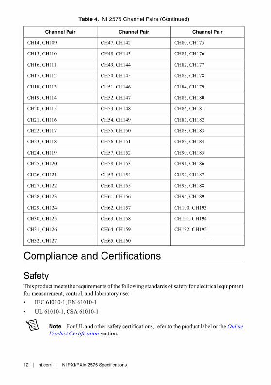
Table 4. NI 2575 Channel Pairs
Channel Pair Channel Pair Channel Pair
CH0, CH95 CH33, CH128 CH66, CH161
CH1, CH96 CH34, CH129 CH67, CH162
CH2, CH97 CH35, CH130 CH68, CH163
CH3, CH98 CH36, CH131 CH69, CH164
CH4, CH99 CH37, CH132 CH70, CH165
CH5, CH100 CH38, CH133 CH71, CH166
CH6, CH101 CH39, CH134 CH72, CH167
CH7, CH102 CH40, CH135 CH73, CH168
CH8, CH103 CH41, CH136 CH74, CH169
CH9, CH104 CH42, CH137 CH75, CH170
CH10, CH105 CH43, CH138 CH76, CH171
CH11, CH106 CH44, CH139 CH77, CH172
CH12, CH107 CH45, CH140 CH78, CH173
CH13, CH108 CH46, CH141 CH79, CH174
12 | ni.com | NI PXI/PXIe-2575 Specifications
Compliance and Certifications
SafetyThis product meets the requirements of the following standards of safety for electrical equipment for measurement, control, and laboratory use:
• IEC 61010-1, EN 61010-1
• UL 61010-1, CSA 61010-1
Note For UL and other safety certifications, refer to the product label or the Online Product Certification section.
CH14, CH109 CH47, CH142 CH80, CH175
CH15, CH110 CH48, CH143 CH81, CH176
CH16, CH111 CH49, CH144 CH82, CH177
CH17, CH112 CH50, CH145 CH83, CH178
CH18, CH113 CH51, CH146 CH84, CH179
CH19, CH114 CH52, CH147 CH85, CH180
CH20, CH115 CH53, CH148 CH86, CH181
CH21, CH116 CH54, CH149 CH87, CH182
CH22, CH117 CH55, CH150 CH88, CH183
CH23, CH118 CH56, CH151 CH89, CH184
CH24, CH119 CH57, CH152 CH90, CH185
CH25, CH120 CH58, CH153 CH91, CH186
CH26, CH121 CH59, CH154 CH92, CH187
CH27, CH122 CH60, CH155 CH93, CH188
CH28, CH123 CH61, CH156 CH94, CH189
CH29, CH124 CH62, CH157 CH190, CH193
CH30, CH125 CH63, CH158 CH191, CH194
CH31, CH126 CH64, CH159 CH192, CH195
CH32, CH127 CH65, CH160 —
Table 4. NI 2575 Channel Pairs (Continued)
Channel Pair Channel Pair Channel Pair

NI PXI/PXIe-2575 Specifications | © National Instruments | 13
Electromagnetic CompatibilityThis product meets the requirements of the following EMC standards for electrical equipment for measurement, control, and laboratory use:
• EN 61326-1 (IEC 61326-1): Class A emissions; Basic immunity
• EN 55011 (CISPR 11): Group 1, Class A emissions
• AS/NZS CISPR 11: Group 1, Class A emissions
• FCC 47 CFR Part 15B: Class A emissions
• ICES-001: Class A emissions
Note In the United States (per FCC 47 CFR), Class A equipment is intended for use in commercial, light-industrial, and heavy-industrial locations. In Europe, Canada, Australia and New Zealand (per CISPR 11) Class A equipment is intended for use only in heavy-industrial locations.
Note Group 1 equipment (per CISPR 11) is any industrial, scientific, or medical equipment that does not intentionally generates radio frequency energy for the treatment of material or inspection/analysis purposes.
Note For EMC declarations and certifications, refer to the Online Product Certification section.
CE ComplianceThis product meets the essential requirements of applicable European Directives as follows:
• 2006/95/EC; Low-Voltage Directive (safety)
• 2004/108/EC; Electromagnetic Compatibility Directive (EMC)
Online Product CertificationTo obtain product certifications and the Declaration of Conformity (DoC) for this product, visit ni.com/certification, search by model number or product line, and click the appropriate link in the Certification column.
Environmental Management NI is committed to designing and manufacturing products in an environmentally responsible manner. NI recognizes that eliminating certain hazardous substances from our products is beneficial to the environment and to NI customers.
For additional environmental information, refer to the Minimize Our Environmental Impact web page at ni.com/environment. This page contains the environmental regulations and directives with which NI complies, as well as other environmental information not included in this document.

© 2004-2013 National Instruments. All rights reserved.
373870N Mar13
Refer to the NI Trademarks and Logo Guidelines at ni.com/trademarks for more information on National Instruments trademarks. Other product and company names mentioned herein are trademarks or trade names of their respective companies. For patents covering National Instruments products/technology, refer to the appropriate location: Help»Patents in your software, the patents.txt file on your media, or the National Instruments Patents Notice at ni.com/patents. You can find information about end-user license agreements (EULAs) and third-party legal notices in the readme file for your NI product. Refer to the Export Compliance Information at ni.com/legal/export-compliance for the National Instruments global trade compliance policy and how to obtain relevant HTS codes, ECCNs, and other import/export data.
Waste Electrical and Electronic Equipment (WEEE)EU Customers At the end of the product life cycle, all products must be sent to a WEEE recycling center. For more information about WEEE recycling centers, National Instruments WEEE initiatives, and compliance with WEEE Directive 2002/96/EC on Waste Electrical and Electronic Equipment, visit ni.com/environment/weee.
RoHSNational Instruments
(RoHS) National Instruments RoHS ni.com/environment/rohs_china (For information about China RoHS compliance, go to ni.com/environment/rohs_china.)