nice · lection” section, in the “nice screen” catalogue, – also available on the...
TRANSCRIPT

Nice
EN - Instructions and warnings for installation and use
Tubular motors
E ACTION SI 332 ACE ACTION SI 620 ACE ACTION SI 1012 AC
E ACTION MI 332 ACE ACTION MI 632 ACE ACTION MI 1020 AC
1 – English
Note for reading this Manual – Some of the figures referred to in the text appear at the end of the manual.
GENERAL WARNINGS: SAFETY - INSTALLATION - USE (original instructions in Italian)
ATTENTION Important safety instructions. Follow all instructions as improper installation may cause serious damageATTENTION Important safety instructions. It is important for you to comply with these instructions for your own and other
people’s safety. Keep these instructions.• Before commencing the installation, check the “Technical characteristics” (in this manual), in particular whether this product is suitable for
automating your guided part. If it is not suitable, DO NOT continue with the installation• The product cannot be used before it has been commissioned as specified in the chapter on “Testing and commissioning”ATTENTION According to the most recent European legislation, the implementation of an automation system must comply
with the harmonised standards provided by the Machinery Directive in force, which enables declaration of the presumed conformity of the automation. Taking this into account, all operations regarding connection to the electricity grid, as well as product testing, commissioning and maintenance, must be performed exclusively by a qualified and skilled technician!
• Before proceeding with the installation of the product, check that all the materials are in good working order and suited to the intended applications
• This product is not intended to be used by persons (including children) whose physical, sensory or mental capacities are reduced, or who lack the necessary experience or skill
• Children must not play with the appliance• Do not allow children to play with the fixed control devices of the product. Keep the remote controls away from childrenATTENTION In order to avoid any danger from inadvertent resetting of the thermal cut-off device, this appliance must not be powered
through an external switching device, such as a timer, or connected to a supply that is regularly powered or switched off by the circuit
• Provide a disconnection device (not supplied) in the plant’s power supply grid, with a contact opening distance permitting complete disconnection under the conditions dictated by overvoltage category III
• Handle the product with care during installation, taking care to avoid crushing, denting or dropping it, or allowing contact with liquids of any kind. Keep the product away from sources of heat and naked flames. Failure to observe the above can damage the product, and increase the risk of danger or malfunction. Should this happen, stop installation immediately and contact Customer Service
• The manufacturer assumes no liability for damage to property, items or persons resulting from non-compliance with the assembly instructions. In such cases the warranty for material defects is excluded
• The weighted sound pressure level of the emission A is lower than 70 dB(A)• Cleaning and maintenance to be carried out by the user must not be carried out by unsupervised children• Before working on the system (maintenance, cleaning), always disconnect the product from the mains power supply• Check the system periodically, in particular all cables, springs and supports to detect possible imbalances, signs of wear or damage. Do not
use, if repairs or adjustments are necessary, since installation failure or an incorrectly balanced automation may cause injury• The packing materials of the product must be disposed of in compliance with local regulations• There must be at least 0.4 m between the driven parts and any fixed elements• The wording on the tubular motors can be covered after assembly• Motor with fixed power cable: the power cable cannot be replaced. If the cable is damaged, the appliance must be scrapped• Motor with removable power cable and dedicated connector: if the power cable is damaged, it must be replaced by the manufacturer or
by the latter’s technical assistance service, or by a similarly qualified person, in order to prevent any type of risk• Be careful with moving shutters and keep away from them until they have lowered fully• Be careful when activating the manual release device, as a raised shutter may rapidly drop in case of weak or broken springs• Do not activate the awning when maintenance activities – such as window cleaning – are being carried out nearby• Disconnect the awning from the power supply when maintenance activities such as window cleaning are being carried out nearby. Warning
for ‘shades with automatic control’
INSTALLATION WARNINGS• Prior to installing the drive motor, remove any unnecessary cables and disable any appliance not required for motorised operation• Install the manoeuvring assembly for manual release at a height below 1.8 m
NOTE: if removable, the manoeuvring assembly must be kept close to the door• Make sure that the control devices are kept far from moving parts but nonetheless in a visible position
The manoeuvring assembly of a switch kept manually closed must be located in a position visible from the guided part but far from moving parts. It must be installed at a minimum height of 1.5 m
• The fixed control devices must be installed in a visible position• For drive motors that allow for accessing unprotected moving parts once they have been installed, such parts must be installed 2.5 m above
the floor or other surface form which they can be accessed

English – 2
PRODUCT DESCRIPTION ANDINTENDED USE1
This product is a tubular motor for automating indoors roll-up awnings, or indoors sunscreens, or similar roll-up equipment (fig. 2). Do not use it for any other pur-pose! The manufacturer declines all liability for damage resulting from im-proper use of the product or any other use than that specified in this manual.
The product has the following functional characteristics:
• it is mains powered (see the motor’s nameplate ratings);• it installs inside the winding roller; the part of the motor that protrudes from the roller
(electronic head) mounts to the ceiling or wall with brackets (not included);• it has a built-in control unit with encoder technology that electronically controls the
movement and precision of the limit switches;• it can be programmed with a wall-mounted button panel or with a TTU programmer
(fig. 5). These accessories are not included;• it can be commanded with a cabled wall-mounted push-button panel ( fig. 4). We
recommend the use of a fixed or momentary switch with interlocked push buttons (accessory not included in the package);
• it can move the awning up or down; stop it at the upper limit switch “0”, the lower limit switch “1” or at various intermediate positions "H");
• it moves awnings of different weights at the same speed;• the up and down speeds are the same;• it features acceleration and deceleration, respectively at the beginning and end of
the movement;• it features a security system that detects the presence of an obstacle along the
awning travel, immediately blocking the movement in progress and performing a brief inversion of movement. The same system is automatically activated at the end of the Up movement (only if the upper limit switch “0” consists of a box or other me-chanical stop), to mitigate the impact of the awning against the housing and loosen the tension exerted by the motor on the canvas, when the awning is stationary at the upper limit switch “0”.
• it enables you to precisely adjust the limit switches with the buttons on the motor head;
• it has an integral led which indicates the system status and any malfunctions;• it is equipped with a thermal protection system which, in the case of overheating
caused by overuse of the automated mechanism (beyond the indicated limits, see the Technical Specifications chapter), automatically cuts off the electricity supply, restoring it as soon as the temperature goes back to normal;
• it is available in a variety of versions, each with a specific motor torque (see the mo-tor nameplate ratings).
INSTALLATION OF THE MOTOR ANDTHE ACCESSORIES2
2.1 - Preliminary checks before installation and lim-itations on use
• Check the condition of the product right after unpacking it.• Make sure that the torque, the rotation speed and time of operation of this motor
are suitable for automating your awning. In particular, do not install the motor if its torque is greater than that needed to move your awning. To choose the right motor to the technical features of your awning refer to the the “Guide to Se-lection” section, in the “Nice Screen” catalogue, – also available on the www.nice-foryou.com website.
• Check the diameter of the winding roller. This must be chosen according to the motor torque, as follows:
– For motors of size “S” (Ø = 35 mm), the minimum inside diameter of the winding roller must be 40 mm;
– For motors of size “M” (Ø = 45 mm), the minimum inside diameter of the winding roller must be 52 mm;
• Additional limitations on use are listed in chapters 1 and 2 and in the technical characteristics on the nameplate.
2.2 - Assembling and installing the tubular motorCaution! – Read the safety warnings before proceeding. Incorrect installa-tion could cause severe physical injury.
To assemble and install the motor, refer to fig. 3 (the accessories shown in fig. 3 are not included in the package). To select the limit switch gear wheel (fig. 3-a), drive wheel (fig. 3-b), motor bracket (fig. 3-f), or to select supplementary cables (of dif-ferent lengths), refer to the “Nice Screen” catalogue, which is also available on www.niceforyou.com.
2.3 - Installing a wall-mounted push-button panelInstall a push-button command panel on the wall, observing the following warnings:– for correct use of the automated system you need to install a push button panel
with 2 buttons: one for Up and one for Down;– to use the automation, once installation has been completed you can use a push-
button panel with any mechanical operation of the buttons, except for the op-eration that allows you to simultaneously press the two buttons;
– for the control of a single motor, only a single push-button panel can be installed;– for the control of more than one motor connected in parallel (max. 8) only a single
push-button panel can be installed;– for the confidentiality of the automated system, it is recommended that you install
the push button panel in a place not accessible to unauthorized persons;– install the push button panel in a place from where you can see the awning;– install the push button panel away from the moving parts of the awning;– install the push button panel on the side of the awning where there is the electrical
cable from the motor and the power cable from the electricity mains (fig. 3-i);– install the push button panel at a height of at least 1.5 m from the floor.
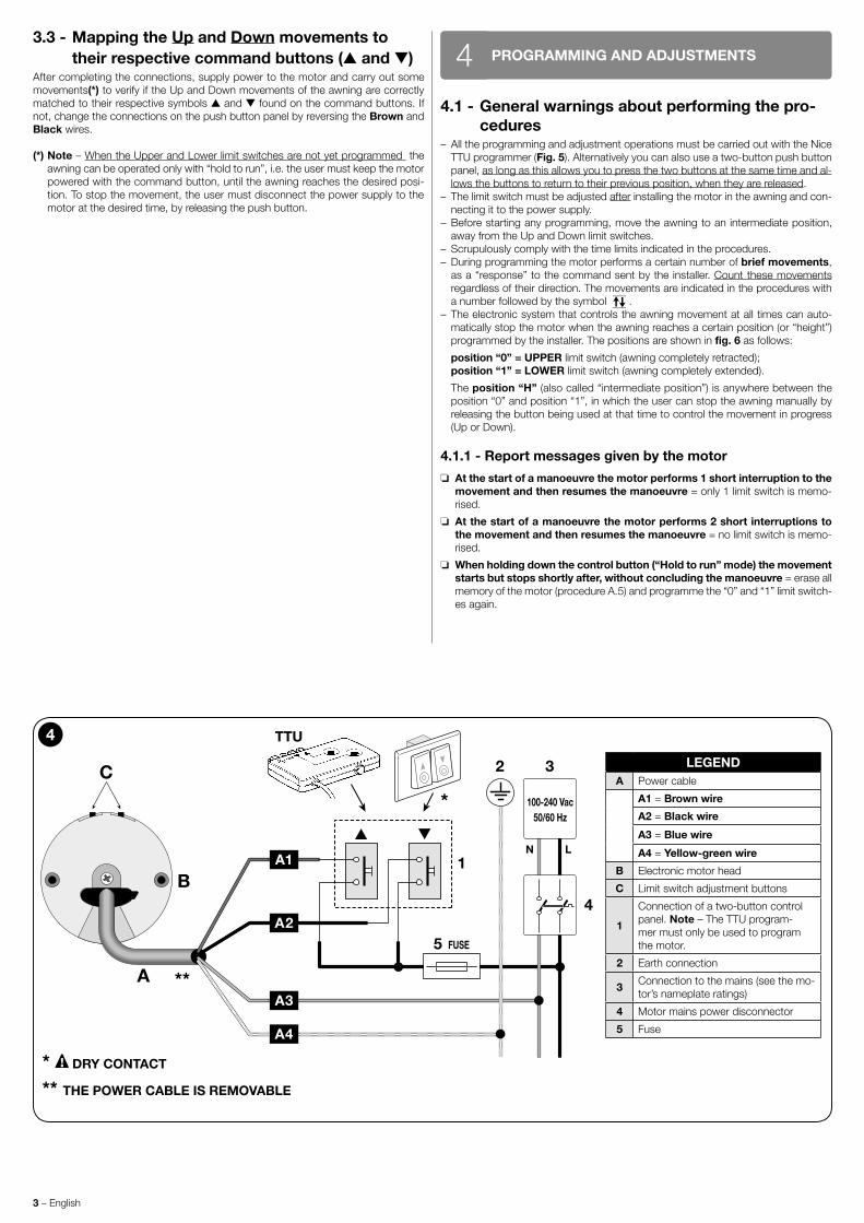
ELECTRICAL CONNECTIONS AND FIRST POWER UP3
3.1 - Connecting the motor to the power supply and a push button control panel
To connect the motor to the power supply and a push button control panel(*), refer to fig. 4. The connection cable has four wires:
CABLE “A” (refer to fig. 4)Wire Colour Connection
A1 Brown Electric phase of up/down.
A2 Black Electric phase of up/down.
A3 Blue Common (usually connected to Neutral).
A4 Yellow-Green Earth (equipotential protection connection).
(*) Note – Since the subsequent motor installation and programming operations must be done with the “TTU” Programmer (fig. 5), it is recommended that you make the final connection of the push button panel only after these operations.
WARNINGS:
• Incorrect connections can cause faults or hazards; therefore ensure that the in-structions in this paragraph are strictly observed.
• The electrical connections must be made only after installing the motor and the compatible accessories required.
• The motor must be powered by a permanent connection to the mains.• The power cable is connected to the motor via a connector; this is removable (fig.
3-h) and allows the replacement of the cable (refer to the “Nice Screen” product catalogue, also available on the website www.niceforyou.com).
3.2 - Installation of the protective devices inside the electricity power network
In accordance with the electrical installation regulations, the network that powers the motor needs to have a protection device against short-circuits and a disconnection device from the mains (the two devices are not present in the package). Caution! – The disconnection device must have an opening distance between con-tacts, that allows complete disconnection of the power supply, under the conditions laid down in the overvoltage category III.The disconnection device must be placed in a position that is visible from the au-tomated system and, if it is not visible, there must be a system for preventing acci-dental or unauthorized reconnection with the power grid so as to avoid any possible hazard.
2
With box (the Up limit position is given by the awning touching the box).
Without box (the Up limit position is programmed by the installer).
3 – English
3.3 - Mapping the Up and Down movements to their respective command buttons (s and t)
After completing the connections, supply power to the motor and carry out some movements(*) to verify if the Up and Down movements of the awning are correctly matched to their respective symbols s and t found on the command buttons. If not, change the connections on the push button panel by reversing the Brown and Black wires.
(*) Note – When the Upper and Lower limit switches are not yet programmed the awning can be operated only with “hold to run”, i.e. the user must keep the motor powered with the command button, until the awning reaches the desired posi-tion. To stop the movement, the user must disconnect the power supply to the motor at the desired time, by releasing the push button.
PROGRAMMING AND ADJUSTMENTS44.1 - General warnings about performing the pro-
cedures– All the programming and adjustment operations must be carried out with the Nice
TTU programmer (Fig. 5). Alternatively you can also use a two-button push button panel, as long as this allows you to press the two buttons at the same time and al-lows the buttons to return to their previous position, when they are released.
– The limit switch must be adjusted after installing the motor in the awning and con-necting it to the power supply.
– Before starting any programming, move the awning to an intermediate position, away from the Up and Down limit switches.
– Scrupulously comply with the time limits indicated in the procedures.– During programming the motor performs a certain number of brief movements,
as a “response” to the command sent by the installer. Count these movements regardless of their direction. The movements are indicated in the procedures with a number followed by the symbol .
– The electronic system that controls the awning movement at all times can auto-matically stop the motor when the awning reaches a certain position (or “height”) programmed by the installer. The positions are shown in fig. 6 as follows:
position “0” = UPPER limit switch (awning completely retracted); position “1” = LOWER limit switch (awning completely extended).
The position “H” (also called “intermediate position”) is anywhere between the position “0” and position “1”, in which the user can stop the awning manually by releasing the button being used at that time to control the movement in progress (Up or Down).
4.1.1 - Report messages given by the motor
o At the start of a manoeuvre the motor performs 1 short interruption to the movement and then resumes the manoeuvre = only 1 limit switch is memo-rised.
o At the start of a manoeuvre the motor performs 2 short interruptions to the movement and then resumes the manoeuvre = no limit switch is memo-rised.
o When holding down the control button (“Hold to run” mode) the movement starts but stops shortly after, without concluding the manoeuvre = erase all memory of the motor (procedure A.5) and programme the “0” and “1” limit switch-es again.
4
LEGENDA Power cable
A1 = Brown wire
A2 = Black wire
A3 = Blue wire
A4 = Yellow-green wire
B Electronic motor head
C Limit switch adjustment buttons
1
Connection of a two-button control panel. Note – The TTU program-mer must only be used to program the motor.
2 Earth connection
3 Connection to the mains (see the mo-tor’s nameplate ratings)
4 Motor mains power disconnector
5 Fuse
A2
A3
A4
A1N L
100-240 Vac50/60 Hz
FUSE
B
C
A
1
5
2 3
4
TTU
*
**
* DRY CONTACT
** THE POWER CABLE IS REMOVABLE

English – 4English – 4
A.1 - MANUAL programming of the UP (“0”) and DOWN (“1”) limit switches
NOTES AND WARNINGS
• This procedure is obligatory only for awnings without a mechanical stop at the Up position.• If the limit switches are already scheduled and you want to modify them with this procedure, you need to know that: you must delete firstly the previous limit switch-
es (one or both), using procedure A.5.• After programming the limit switches, the s key will command the Up manoeuvre and the t switch will command the Down manoeuvre. The movement of the awn-
ing will be limited by limit switches (Upper “0” and Lower “1”) programmed by the installer.
1 2 3
Commandan UPmanoeuvre ...?...
“0”= 5 sec
2Hold down the button ... (Note - if the movement is interrupted briefly 2 times this means that no limit switch positions have been memorised).
wait ... ... release the button as soon as the awning reaches position “0” ( UP limit switch).
Hold down both buttons...
release them after 5 seconds;
count 2 movements.
3 4 end
Commanda DOWNmanoeuvre ...?...
“1”
= 5 sec
Hold down the button ... (Note - if the movement is interrupted briefly 1 time this means that only one limit switch position has been memorised).
wait ... release the button as soon as the awn-ing reaches position “1” ( DOWNlimit switch).
Hold down both buttons...
release them after 5 seconds;
count 2 movements.
A.2 - SEMIAUTOMATIC PROGRAMMING of the UP (“0”) and DOWN (“1”) limit switches
NOTES AND WARNINGS
• Use this procedure solely for awnings with mechanical Up “0” limit switch stop.• If the limit switches are already scheduled and you want to modify them with this procedure, you need to know that: you must delete firstly the previous limit switch-
es (one or both), using procedure A.5.• After the limit positions have been programmed, the awning can be controlled by simply pressing the appropriate buttons on the control unit. The Up movement
will be limited when the awning impacts against the mechanical lock (box) in the Upper limit switch “0”. With each impact, the height of this limit switch will be auto-matically updated by the “Automatic limit switch update” function (paragraph 5.3). Conversely, the Down movement will be limited by the Lower limit switch “1” (limit switch set by the installer at a desired point).
1 2
Commandan UPmanoeuvre
“0”
Hold down the button ... (Note - if the movement is interrupted briefly 2 times this means that no limit switch positions have been memorised).
Wait for the awning to be stopped when it collides with the box (= UP limit switch = position “0”);
release the button.
2 3 end
Commandan DOWNmanoeuvre ...?...
“1”
= 5 sec
Hold down the button ... (Note - if the movement is interrupted briefly 1 time this means that only one limit switch position has been memorised).
wait ... release the button as soon as the awning reaches position “1” ( DOWN limit switch).
Hold down both but-tons...
release them after 5 seconds;
count 2 movements.
Note - Programming must be done using the NICE TTU programmer or a generic two-button push button panel with no interlock.
2
2
5 – English
5 – English
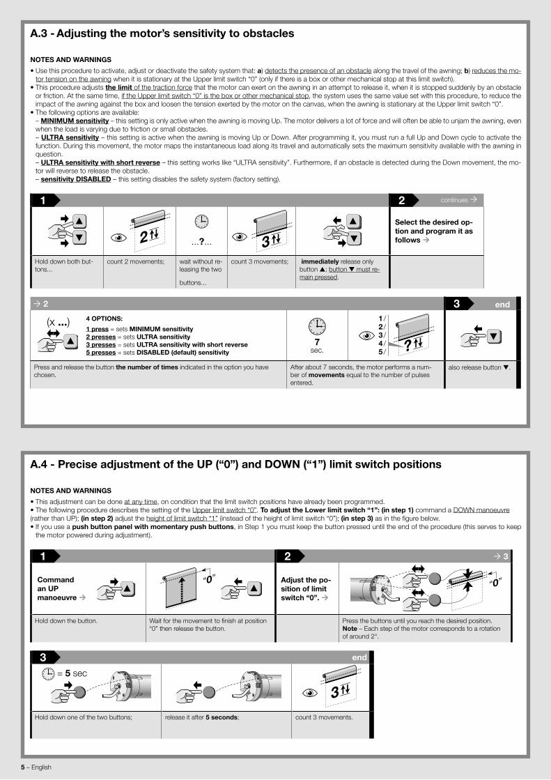
A.3 - Adjusting the motor’s sensitivity to obstacles
NOTES AND WARNINGS
• Use this procedure to activate, adjust or deactivate the safety system that: a) detects the presence of an obstacle along the travel of the awning; b) reduces the mo-tor tension on the awning when it is stationary at the Upper limit switch “0” (only if there is a box or other mechanical stop at this limit switch).
• This procedure adjusts the limit of the traction force that the motor can exert on the awning in an attempt to release it, when it is stopped suddenly by an obstacle or friction. At the same time, if the Upper limit switch “0” is the box or other mechanical stop, the system uses the same value set with this procedure, to reduce the impact of the awning against the box and loosen the tension exerted by the motor on the canvas, when the awning is stationary at the Upper limit switch “0”.
• The following options are available: – MINIMUM sensitivity – this setting is only active when the awning is moving Up. The motor delivers a lot of force and will often be able to unjam the awning, even
when the load is varying due to friction or small obstacles. – ULTRA sensitivity – this setting is active when the awning is moving Up or Down. After programming it, you must run a full Up and Down cycle to activate the
function. During this movement, the motor maps the instantaneous load along its travel and automatically sets the maximum sensitivity available with the awning in question.
– ULTRA sensitivity with short reverse – this setting works like “ULTRA sensitivity”. Furthermore, if an obstacle is detected during the Down movement, the mo-tor will reverse to release the obstacle.
– sensitivity DISABLED – this setting disables the safety system (factory setting).
1 2 continues
2 ...?... 3Select the desired op-tion and program it as follows
Hold down both but-tons...
count 2 movements; wait without re-leasing the two
buttons...
count 3 movements; immediately release only button s; button t must re-main pressed.
2 3 end
(x ...) 4 OPTIONS:
1 press = sets MINIMUM sensitivity2 presses = sets ULTRA sensitivity3 presses = sets ULTRA sensitivity with short reverse5 presses = sets DISABLED (default) sensitivity
7sec. ?
1 /2 /3 /4 /5 /
Press and release the button the number of times indicated in the option you have chosen.
After about 7 seconds, the motor performs a num-ber of movements equal to the number of pulses entered.
also release button t.
A.4 - Precise adjustment of the UP (“0”) and DOWN (“1”) limit switch positions
NOTES AND WARNINGS
• This adjustment can be done at any time, on condition that the limit switch positions have already been programmed.• The following procedure describes the setting of the Upper limit switch “0”. To adjust the Lower limit switch “1”: (in step 1) command a DOWN manoeuvre (rather than UP); (in step 2) adjust the height of limit switch “1” (instead of the height of limit switch “0”); (in step 3) as in the figure below.• If you use a push button panel with momentary push buttons, in Step 1 you must keep the button pressed until the end of the procedure (this serves to keep
the motor powered during adjustment).
1 2 3
Commandan UPmanoeuvre
“0”
Adjust the po-sition of limit switch “0”.
“0”
Hold down the button. Wait for the movement to finish at position “0” then release the button.
Press the buttons until you reach the desired position. Note – Each step of the motor corresponds to a rotation of around 2°.
3 end
= 5 sec
3Hold down one of the two buttons; release it after 5 seconds; count 3 movements.

English – 6
English – 6
A.5 - TOTAL or PARTIAL deletion of memoryNOTES AND WARNINGS
• If during the execution of the procedure you choose the option “5 presses = clear ALL MEMORY”, the system restores the factory settings by clearing the “0” and “1” limit switch heights and all other data stored in the memory of the motor.
• If during the execution of the procedure you choose the option “5 presses = clear ALL MEMORY”, subsequently, during the use of the automated system, when you command an Up or Down manoeuvre the awning first performs 2 short movements (= no limit switch is programmed) and then continues the commanded ma-noeuvre.
• If during the execution of the procedure you choose the option “3 presses”, subsequently, during the use of the automated system, when you command an Up or Down manoeuvre the awning first performs 1 short movement (= only 1 limit switch is programed) and then continues the commanded manoeuvre.
1 2 3
“0”
“1” 2• If you want to delete a single limit switch, move the awning to the limit switch
you wish to delete.• If you want to delete all the memory of the motor, move the awning to a half-
way position.
Hold down both but-tons...
count 2 movements; immediately release only button t; button s must re-main pressed.
3
Choose the de-sired option and perform the de-letion as fol-lows
(x ...)Option A: 3 presses = delete the single LIMIT SWITCH selected in step 1
Option B: 5 presses = delete the THE ENTIRE MEMORY
Press and release the button the number of times indicated for the option you have chosen;
A.6 - ALTERNATIVE PROGRAMMING using a smartphone equipped with “NFC” (Near Field Communication) technology
NOTES AND WARNINGS • programming with the “NFC” technology is not yet available on this motor. For more information contact the Nice Techni-cal Assistance.
Using a smartphone equipped with NFC technology and a software application produced by Nice (to be installed on your smartphone), you can configure the motors before installing them, even without the need to supply power. You can also perform a hardware and software diagnostic of the motor, even if it is damaged.
optio
n –
A
3 4 end
(x 3)
7sec. 1
Press and release the key.
After about 7 seconds the move-ment is briefly interrupted 2 times;
also release but-ton s.
optio
n –
B
3 4 end
(x 5)
7sec.
2
Press and release the key.
After about 7 seconds the move-ment is briefly interrupted 1 time;
also release but-ton s.
7 – English
TABLE B – Movement signals
No. of MOVEMENTS Meaning
0 movements = 2 limit switches programmed.
1 movement = 1 limit switch programmed.
2 movements = no limit switch programmed.
3 movements = serious motor memory error.
What to do if...(troubleshooting guide)
In general, to better identify the problem, refer to Table A (and B), in section 5.5.
q Powering an electrical phase, the motor does not move: After excluding the possibility that thermal protection is active, in which case it is
sufficient to wait for the motor to cool down, make sure the mains voltage corre-sponds to the values indicated in the “technical data” chapter of this manual by measuring the voltage between the “common” wire and the electrical phase wire supplied with current. If the problem is still present, disconnect the power cord from the motor (fig. 4-i) and connect it again.
q When an Up command is sent, the motor does not start: This can happen if the awning is near the Upper limit switch (“0”). In this case you
must lower the awning a little bit and give the Raise command again.
q The system operates in the emergency condition with an operator pre-sent (hold-to-run):
– Check to see if the motor has undergone a significant electrical or mechanical shock.
– Make sure each part of the motor is still in good condition. – Delete the UP (“0”) and DOWN (“1”) limit position and reprogram them.
q Involuntary stopping of the movement of the awning (false obstacle): If you give a command to the awning and it stops anywhere along its course,
without an apparent reason (due to a false obstacle), we recommend that you: – adjust the level of sensitivity to an obstacle (procedure A.3), by increasing the
force. If this does not solve the problem, – delete the limit switches (procedure A.5) and program the limit switches again.
Disposal of the product
As in installation, also at the end of product lifetime, the disassembly and scrapping operations must be performed by qualified personnel.This product comprises various types of materials: some may be recycled others must be disposed of. Seek information on the recycling and disposal systems en-visaged by the local regulations in your area for this product category. Caution! – some parts of the product may contain pollutant or hazardous substances which, if disposed of into the environment, may cause serious damage to the environment or physical health. As indicated by the symbol on the left, disposal of this product in domestic waste is strictly prohibited. Separate the waste into categories for disposal, according to the methods envisaged by cur-rent legislation in your area, or return the product to the retailer when purchasing a new version. Caution! – Local legislation may envisage serious fines in the event of abusive disposal of this product.
The packing materials of the product must be disposed of in compliance with local regulations.
Technical Characteristics
Refer to the technical characteristics stated on the motor's nameplate.
Note: • All technical specifications stated herein refer to an ambient temperature of 20° C (± 5° C). • Nice S.p.A. reserves the right to apply modifications to products at any time when deemed necessary, maintaining the same intended use and func-tionality.
WARNINGS FOR NORMAL OPERATION OF THE AUTOMATION5
5.1 - “Obstacle detection” functionIf this function is active (procedure A.3), it is automatically activated when the (Up or Down) movement of the awning is stopped suddenly by an obstacle (an object, a person). In these cases, the motor immediately stops the manoeuvre in progress and performs a brief inversion of the motion.
5.2 - Reoptimising the limit switch positionsIt is normal for limit switch positions to move by a few mm or cm over the days fol-lowing installation. This may be due to the awning’s or frame’s material settling or bedding in; this often causes the awning to droop or go out of alignment with nearby awnings. In such cases, if the head of the motor is accessible, you can very easily re-optimise either or both of the limit switch positions with procedure A.4.
5.3 - “Automatic limit switch update” functionCaution! – This function is only available if the limit switches have been programmed with the Semiautomatic procedure (par. A.2). This function cannot be disabled.
In ordinary use, the function activates automatically during an Up movement, when the awning collides with the box or other mechanical stop (Up limit switch “0”). On each collision, the function measures the position of the Up limit switch and memo-rises the new value in place of the previous one. Over time, this compensates for deformations in the structure due to wear and thermal cycles, so that the awning always stops precisely at the Up limit position.
5.4 - Maximum continuous cycle (“thermal protec-tion” function)
The motor is designed for residential use, in other words, for intermittent service. If used continuously for a long time, beyond its rating (see “Technical characteristics”), the system protects the motor against overheating by stopping any further move-ments until its temperature returns to within the rated limits.
5.5 - Diagnostics and alarm functionOn the head of the motor there is a Led that signals the alarm status (with a red light) and the installation status (with a green light). If it needs to report both at once, the system always gives priority to alarms. For the meanings of the light sig-nals, see Table A. Caution! – If you are programming the motor with the TTU pro-grammer (fig. 5) or you are using a push button panel with momentary push buttons, you must keep a button pressed until the end of the procedure to observe the flashing of LEDs (this serves to keep the motor powered during the observation).
TABLE A – Motor head LED signals
GREEN LED Meaning
0 flashes = 2 limit switches programmed.
1 flash = 1 limit switch programmed.
2 flashes = no limit switch programmed.
RED LED Meaning
0 flashes = no error.
steady on = serious error - 1 (motor damaged - contact technical service).
1 flash = thermal protection function in progress.
2 flashes = the last movement was automatically interrupted by The “Obstacle detection” function.
3 flashes = load too high relative to motor nameplate rating.
4 flashes = serious error - 2.
5 flashes = serious error - 3.
6 flashes = serious error - 4 (control circuit temperature too high).
7 flashes = serious error - 5 (brake malfunction).
8 flashes = serious error - 6 (brake malfunction).
9 flashes = serious error - 7.
10 flashes = serious error - 8.
11 flashes = serious error - 9
The motor repeats the report message on the status of the installation by perform-ing some movements when a manoeuvre is commanded. To understand the signifi-cance of these movements read Table B.
English – 8
EU declaration of conformity
Note: This declaration corresponds to the official declaration held at the registered offices of Nice S.p.a., and in particular to the latest revision available at the time of printing of this manual. The text herein has been adapted for editorial purposes. A copy of the original declaration may be requested from Nice S.p.a. (TV) I.
Declaration number: 541/Era INN Action S_M Revision: 2 Language: EN
Name of manufacturer: NICE S.p.A.Address: Via Pezza Alta N°13, 31046 Rustignè di Oderzo (TV) ItalyPerson authorised to compile the technical documentation: NICE S.p.A.Type of product: Tubular motor for automating indoor roll-up awnings, sunscreens or similar roll-up equipmentModel / Type: E ACTION SI 332 AC, E ACTION SI 620 AC, E ACTION SI 1012 AC, E ACTION MI 332 AC, E ACTION MI 632 AC, E ACTION MI 1012 ACAccessories: –
The undersigned, Roberto Griffa, in the role of Chief Executive Officer, declares under his sole responsibility, that the product specified above conforms to the provisions of the following directives:• DIRECTIVE 2014/35/EU (LVD) EN 60335-1:2012+A11:2014 EN 62233:2008 EN 60335-2-97:2006+A11:2008+A2:2010+A12:2015
• DIRECTIVE 2014/30/EU (EMC) EN 55014-1:2006+A1:2009+A2:2011 EN 55014-2:2015 EN 61000-3-2:2014 EN 61000-3-3:2013
Oderzo, 12/07/2017 Ing. Roberto Griffa(Chief Executive Officer)

I
ab
Appendix
3
1
Action S
Action M
Limit switch gear wheel (not includ-ed).
Drive wheel (not in-cluded).
5 6

II
d
c
f
1
3
2
h
i
M10 mm
e
g
Cap for fixing the roller to the bracket (not included).
Support for fixing the motor head to the brack-et (not included).
2 screws: self-tapping without point, for plastic materials. Diameter: 4 mm; length of threaded part: = min. 5 mm - max 8 mm
Removing the connector if necessary

www.niceforyou.comNice SpAOderzo TV [email protected]
IDV
0399
A01
EN
_03-
08-2
017_
DIG
ITA
L V
ER
SIO
N