nickel-sulfide-derived high-performance electrodes for
TRANSCRIPT

Nickel-Sulfide-Derived high-performance
electrodes for supercapacitors by partial
ion-exchanged morphology genetic
Wutao Wei,† Liwei Mi,
*,‡,§ Yang Gao,
† Zhi Zheng,
§ Weihua Chen
*,† and Xinxin
Guan*,†
† College of Chemistry and Molecular Engineering, Zhengzhou University, Henan 450001, P. R.
China,
‡ Center for Advanced Materials Research, Zhongyuan University of Technology, Henan 450007,
P. R. China §
Key Laboratory for Micro-Nano Energy Storage and Conversion Materials of Henan Province,
Institute of Surface Micro and Nano Materials, Xuchang University, Henan 461000, P. R. China
Experimental Section
All chemical reagents in this work were of analytical grade and used without further purification.
In situ synthesis of 3D hierarchical nest-like NiS@Ni3S2 material
In the previous work, the effect of solvent ratio of ethylene glycol/anhydrous ethylenediamine on
the morphology of product has been explored in detail. But, what’s exciting is the first achieving
of nest-like NiS@Ni3S2 material with 3D hierarchical core-shell structure just through the change
of charging sequence. In a simple one-step solvothermal method, 0.5 mmol clean nickel foam
(0.0293 g), 7.5 ml ethylene glycol, 1 mmol sublimed sulfur (0.0321 g) and 8.5 ml anhydrous
ethylenediamine were placed in a 20 ml Teflon-lined autoclave subsequently. The autoclave was
then sealed off, maintained at 160 oC for 24 h and cooled down to room temperature naturally. The
product was removed from the solution and repeatedly washed with deionized water then 95%
ethanol. Finally, the as-prepared material as Sample 1 was dried in a vacuum oven at 60 oC for 8 h
and collected for further characterization.
Synthesis of 3D hierarchical nest-like Co9S8@Ni3S2 material
The 3D hierarchical nest-like Co9S8@Ni3S2 material was prepared by a morphology genetic
method using Sample 1 as a template. In order to the replacement products inheriting the
morphology of Sample 1 as well as possible, the solvent system and reaction temperature of
synthesis of Sample 1 were still choose in the replacement step, the differences were that nickel
foam and sublimed sulfur were replaced by Sample 1 and 0.5 mmol cobalt nitrate hexahydrate
(0.1450 g). According to this method, a series of replacement products were obtained with
different reaction time, that is to say, Sample 2, 3, 4, 5, 6, 7, 8, 9 and 10 were synthesized with
reaction time of 10 min, 1 h, 2 h, 4 h, 6 h, 8 h, 10 h, 12 h and 24 h. The post-treatment of these
materials were the same as Sample 1 and collected for further characterization.
Synthesis of 3D network NiSe2@NiS composite material
In previous work, CuSe@CuS and CuSe1.8@CuS composite materials was successfully
synthesized by the anion exchange method using the wool-ball-like CuS microflowers as the
template. Here, this idea will be used for reference to prepare nickel selenide by Se exchange with
3D hierarchical nest-like NiS@Ni3S2 material. As expected, the 3D network NiSe2@NiS
composite material with a special core-shell structure was first obtained by the anion exchange
with Se. In this work, a series of replacement products with Se were synthesized at 160 oC for
different reaction time using Sample 1 as the template, selenium powder as the selenium resources,
7.5 ml ethylene glycol and 8.5 ml anhydrous ethylenediamine as the mixed solution. So the
reaction time of Sample 11, 12, 13, 14, 15, 16, 17, 18, 19, 20, and 21, in order, are 1 h, 2 h, 4 h, 6 h,
8 h, 10 h, 12 h, 14 h, 16 h, 18 h and 24 h. The post-treatment of all these materials are the same as
Sample 1 and collected for further characterization.
Characterization.
X-ray diffraction (XRD) patterns were obtained with a Bruker D8 Advance X-ray powder
diffractometer using Cu-Kα irradiation at a scan rate of 0.1o s
-1. All XRD measurements were
performed within 15o
≤ 2θ ≤ 80o. The morphologies and sizes of the as-prepared materials were
characterized with a Zeiss EVO LS-15 scanning electron microscope (SEM) equipped with an
energy-dispersive X-ray spectroscopy (EDS) system. The nanostructures of the resulting samples
were recorded with a JEOL JEM-2010 transmission electron microscope (TEM). The samples for
the TEM and high-resolution TEM (HRTEM) analyses were prepared by removing the
as-obtained sample surface layer on the 3D formwork and dispersing the parings in C2H5OH. The
X-ray photoelectron spectroscopy (XPS) of the as-obtained Co9S8@Ni3S2 crystals was collected
using a Kratos AXIS ULTRA X-ray photoelectron microscope with Al-Kα X-rays as the excitation
source.
Electrochemical measurements
The electrochemical properties of the as-prepared samples were investigated with a CHI 604E
electrochemical workstation (Chenhua, Shanghai) under cyclic voltammetry (CV) measurements
with various voltage scan rates in a conventional three-electrode cell with 2 M KOH as the
electrolyte, Hg/HgO electrode as reference electrode, and Pt plate as the counter electrode,
respectively. The working electrodes were fabricated by mixing the active material (Sample 1, 9
and 20), acetylene black and binder (PVDF) in a weight ratio of 8:1:1, which was pressed at 20
MPa to a piece of nickel foam (1.0 cm×1.0 cm), and dried under vacuum at 60 oC for 10 h. The
galvanostatic charge-discharge tests were conducted on a LAND battery system (model CT2001A)
at various current densities. Specific capacitance could be calculated according to the following
equation: C = I∆t/m∆V, where I is charge or discharge current, ∆t is the time for a full charge or
discharge, m indicates the mass of the active material, ∆V represents the voltage window in a full
charge-discharge process.
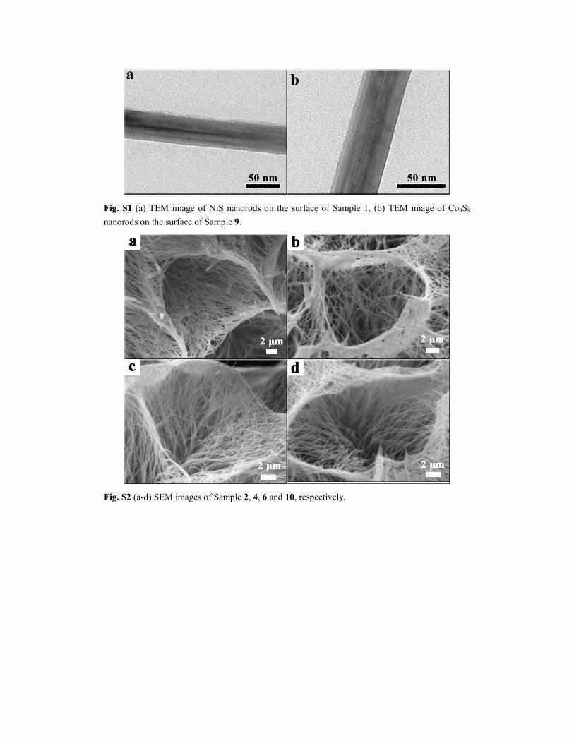
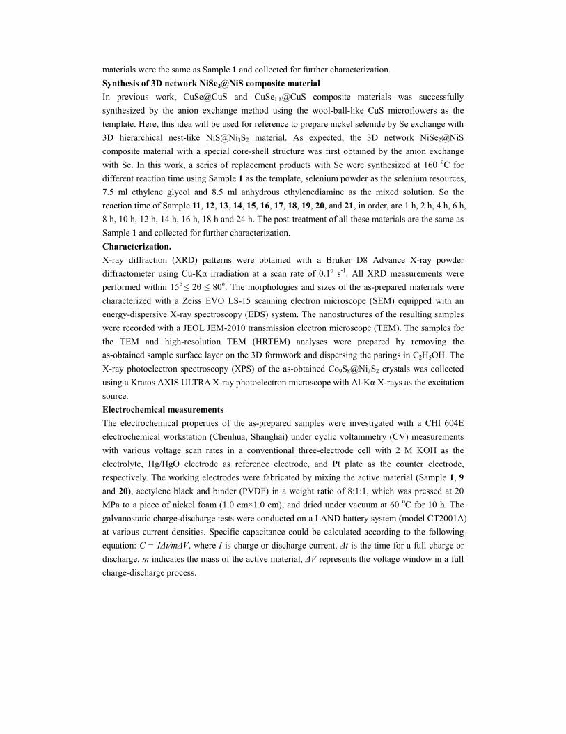
Fig. S1 (a) TEM image of NiS nanorods on the surface of Sample 1. (b) TEM image of Co9S8
nanorods on the surface of Sample 9.
Fig. S2 (a-d) SEM images of Sample 2, 4, 6 and 10, respectively.
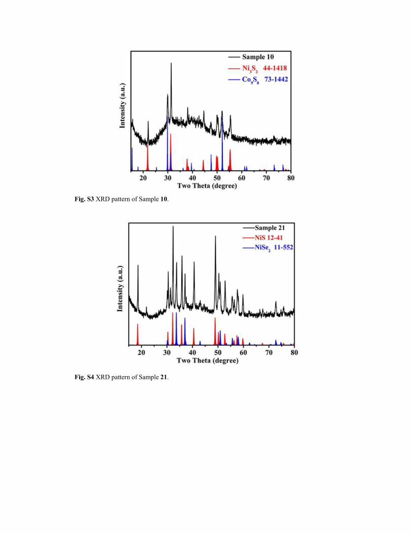
Fig. S3 XRD pattern of Sample 10.
Fig. S4 XRD pattern of Sample 21.

Fig. S5 The XPS spectra of (a) survey spectrum, (b) Ni 2p, (c) Co 2p for Sample 9. And the XPS
spectra of (d) survey spectrum, e) Ni 2p, (f) Co 2p for Sample 9 after the oxidation reaction during
the CV test at the scan rate of 0.05 mV/s.
Fig. S6 The variation of charge-discharge specific capacitance of Sample 1, 9 and 20 as a function
of cycle number from 1 to 18 at various current densities. Inset: the enlarge figure of the specific
capacity of cycle number from 2 to 18.

Fig. S7 The discharge specific capacitance curve of Sample 1, 3, 5 and 9 at different current
density.
Fig. S8 The variation of the specific capacity of Sample 1 and 9 with the number of cycles among
500 cycles at current density of 5 A/g.

Fig. S9 The first galvanostatic charge-discharge curve of Sample 1, 9 and 20 at the current density
of 0.5 A g-1
.
Table 1 the according table of the part sample and their component from the EDX.
Sample Number Component
1 NiS
(NiS@Ni3S2)*
2 Ni0.77Co0.23S
3 Ni0.62S0.38S
4 Ni0.4Co0.6S
5 Ni0.26Co0.74S
6 Ni0.17Co0.83S
7 Ni0.2Co0.8S
9 Ni0.19Co0.81S
(Co9S8@Ni3S2)*
11 NiS0.9Se0.1
14 NiS0.52Se0.48
17 NiS0.26Se0.74
20 NiS0.14Se0.86
(NiSe2@NiS)*
21 NiS0.15Se0.85
* The difference between the real component of samples and the EDX data was caused by the
limited penetration depth of EDX test.