ninic, jelena and freitag, steffen and meschke, günther...
TRANSCRIPT

Ninic, Jelena and Freitag, Steffen and Meschke, Günther (2017) A hybrid finite element and surrogate modelling approach for simulation and monitoring supported TBM steering. Tunnelling and Underground Space Technology, 63 . pp. 12-28. ISSN 0886-7798
Access from the University of Nottingham repository: http://eprints.nottingham.ac.uk/39633/1/TUST_Ninic_accepted.pdf
Copyright and reuse:
The Nottingham ePrints service makes this work by researchers of the University of Nottingham available open access under the following conditions.
This article is made available under the Creative Commons Attribution Non-commercial No Derivatives licence and may be reused according to the conditions of the licence. For more details see: http://creativecommons.org/licenses/by-nc-nd/2.5/
A note on versions:
The version presented here may differ from the published version or from the version of record. If you wish to cite this item you are advised to consult the publisher’s version. Please see the repository url above for details on accessing the published version and note that access may require a subscription.
For more information, please contact [email protected]

Tunnelling and Underground Space Technology 00 (2016) 1–21
JournalLogo
-
A Hybrid Finite Element and Surrogate Modelling Approach forSimulation and Monitoring Supported TBM Steering
Jelena Ninica, Steffen Freitagb, Gunther Meschkeb,∗
aCentre for Structural Engineering and Informatics, The University of Nottingham, UKbInstitute for Structural Mechanics, Ruhr University Bochum, Germany
Abstract
The paper proposes a novel computational method for real-time simulation and monitoring-based predictions during the construc-tion of machine-driven tunnels to support decisions concerning the steering of tunnel boring machines (TBMs). The proposedtechnique combines the capacity of a process-oriented 3D simulation model for mechanized tunnelling to accurately describe thecomplex geological and mechanical interactions of the tunnelling process with the computational efficiency of surrogate (or meta)models based on artificial neural networks. The process-oriented 3D simulation model with updated model parameters based onacquired monitoring data during the advancement process is used in combination with surrogate models to determine optimal tun-nel machine-related parameters such that tunnelling-induced settlements are kept below a tolerated level within the forthcomingprocess steps. The performance of the proposed strategy is applied to the Wehrhahn-line metro project in Dusseldorf, Germanyand compared with a recently developed approach for real-time steering of TBMs, in which only surrogate models are used.
Keywords: Mechanized tunnelling; finite element method; parameter identification; surrogate model; recurrent neural network;computational steering; tunnel boring machine; monitoring; settlements; real-time prediction
1. Introduction
Mechanized tunnelling is a flexible and efficient technology for the construction of underground infrastructure,which is characterized by a dynamic technological progress of tunnel boring machines (TBMs) and an increasingrange of applicability to various ground conditions [1]. During TBM-driven tunnelling in urban environments, inparticular in the presence of sensitive buildings, the risk of damage caused by construction-induced settlements needsto be limited. To this end, computational models are required to efficiently and reliably predict the expected responseof the ground and existing infrastructure to the tunnel drive.
Engineering decisions during the construction process are based, besides the (often limited) a priori knowledgefrom analyses made in the design stage of the project, mainly on the interpretation of data from on site monitoringincluding data related to soil deformations, pore pressure and machine performance. However, the capacity of com-putational models to quantify the effect of engineering decisions on stability and safety at the construction site duringthe tunnel drive is not exploited.
The mechanized tunnelling process involves complex spatio-temporal interactions between the TBM, the tunnelstructure, the surrounding soil and the existing infrastructure. In addition to empirical and analytical relations for the
∗Corresponding author, phone: +49 234 32 29051, fax: +49 234 32 14149Email address: [email protected] (Gunther Meschke)
1

J. Ninic, S. Freitag and G. Meschke / Tunnelling and Underground Space Technology 00 (2016) 1–21 2
description of surface and subsurface settlements induced by tunnelling [2, 3, 4], 2D and 3D numerical analyses havebeen applied (see [5, 6, 7, 8] and references therein) to model the tunnelling process and the physics behind it moreaccurately.
Numerical analyses of geotechnical problems are characterized by a large number of problem-dependent modelparameters related, among others, to the geotechnical specifications of the ground. In case of tunnelling, these param-eters may have a significant spatial variability [9]. Furthermore, in the design stage, only limited information on thespecific soil parameters is available from distinct boreholes, which limits the quality of the model parameters basedupon these data. Therefore, in geotechnical analysis, to reduce the uncertainty of model parameters, back analysisbased on in situ measurements is often used for the calibration of numerical models to determine more reliable updatedmodel parameters. Several authors have addressed inverse analysis for geotechnical processes, see e.g. [10, 11, 12]. Ifoptimization algorithms such as Particle Swarm Optimization (PSO) [13] are used for inverse analyses, often a largenumber of realizations is required. Since this is connected with a prohibitively large effort if large-scale 3D finiteelement models are used, often surrogate models (alternatively also denoted as meta models) are employed for theevaluation of the objective functions [14, 15]. In [16], this approach is used for back analysis of material parametersand steering of the mechanized tunnelling process.
Surrogate models are a compact representation for the simulation model, and can be generated based on differentmethods, e.g. regression models, Artificial Neural Networks (ANNs), Proper Orthogonal Decomposition (POD), etc.(see [16, 17] and references therein). In geotechnical problems, ANNs have been applied as surrogate models trainedby means of numerical simulations and used e.g. for the prediction of the deformations induced by geotechnicalinterventions [15] or for the prediction of tunnelling-induced settlements [18, 19, 20, 21, 22]. Hybrid surrogatemodelling approaches in mechanized tunnelling combining POD and ANNs are presented in [23] and [24].
For computational prognoses during construction, (almost) real-time predictions are required. If numerical simula-tion models would be employed, the required continuous model update during the tunnel drive would only be possibleusing massive parallelization. This is not feasible for most practical applications. To overcome this obstacle, an ap-proach to support the TBM steering based upon surrogate models has been proposed in a recent paper by the authors[16]. Feedforward neural networks have been used to substitute the computationally demanding 3D finite elementsimulation models. Evidently, this approach only provides an approximation of the tunnelling-induced settlements,which relies on the a priori parameterization of the surrogate model. It is not able to provide detailed information onthe tunnel-ground interaction with a resolution comparable to an advanced numerical simulation model. Therefore,in this paper, a novel hybrid FE-surrogate modelling strategy is proposed for the support of the TBM steering duringconstruction with model parameters updated according to monitoring data in association with adequately designedsurrogate models used to determine optimized steering parameters. In contrast to [16], Recurrent Neural Networks(RNNs) [25] are employed, which are able to account for history-dependent processes. This approach combines theadvantage of surrogate models to provide fast computations needed for the numerous realizations involved in the pa-rameter identification and the iterative determination of optimal steering parameters with the accuracy provided bya process-oriented finite element model in regards to the consequences of the tunnel drive on ground deformations,buildings, lining stresses etc.
The proposed strategy is demonstrated by means of real project data from the Tunnelling Information Model(TIM) [26] of the Wehrhahn-line (WHL) metro project in Dusseldorf. Based on the project data, sensitivity analysisare conducted first to preselect a set of relevant material and machine-operational parameters, which are then usedto set up numerical simulations using a process-oriented 3D Finite Element (FE) simulation model for mechanizedtunnelling [7, 27] in order to generate the surrogate model. In this work, an RNN surrogate model [25] is applied,which is trained using an optimized back-propagation algorithm [16].
The remainder of the paper is organized as follows: Section 2 introduces the overall concept for simulation-supported steering in mechanized tunnelling, the RNN and the hybrid FE-surrogate modelling approach. In Section 3,the 3D FE model for a selected section of the Wehrhahn-line metro project in Dusseldorf is presented. Using acomplete data set of the selected project section, the generation of the surrogate model, the parameter identificationand the model-supported steering is demonstrated in Section 4. In this section, also a comparison with a recentlyproposed approach for real-time steering based on surrogate models only is provided.
2

J. Ninic, S. Freitag and G. Meschke / Tunnelling and Underground Space Technology 00 (2016) 1–21 3
2. TBM steering concept combining surrogate models and finite element simulations
Prior to the construction of a TBM-driven tunnel, the parameters of the tunnel boring process to be used inthe project are determined in the design stage according to geological explorations to satisfy design objectives suchas tolerated surface settlements, safety against loss of face stability and other specific construction requirements.However, during tunnel construction, due to on site ground conditions, which differ from the original assumptions,the settlements often exceed tolerated values. This is of particular importance in tunnelling in urban areas, wherethe existing infrastructure may be affected by damage caused by tunnelling-induced ground settlements. Controllingthe TBM process parameters, denoted in the following also as steering parameters (i.e. the support pressure, groutingpressure, advance rate, etc.), it is possible to control the surface settlements and to reduce or even prevent damage ofexisting infrastructure.
The conceptual outline of simulation-supported process control in mechanized tunnelling is illustrated in Fig. 1.It contains the generation of surrogate models in the design phase, the model update based on monitoring data and thedetermination of optimal steering parameters to keep the ground settlements below tolerated values.
Model-updateImportant-
parameters
Project-design-and-reports--
Sensitivity-analysis
FE-simulations
Surrogate-model
Design phase Construction phase
Monitoring-dataTolerated-
settlements
soil-model-parameters
Method-for-TBM-steering--a)-Surrogate-model-based--b)-FE-supported
TBM-process-parameters
Upcoming section
- steering of process parameters -
Constructed section
- model update -
Figure 1. Concept of the simulation-supported process control in mechanized tunnelling.
After the selection of the relevant project sections, in which the steering support will be needed, surrogate modelsare generated in the design phase of the project especially for these sections.
A 3D numerical model of a tunnelling project characterized by a complex geotechnical situation generally requiresa large number (from around ten to more than 100) parameters to characterize the geotechnical model, the alignment,the TBM and the lining shell, including a number of operational parameters and parameters related to the existinginfrastructure. Some of the model parameters are well determined (geometry of TBM and lining), while geotech-nical parameters such as the topology of soil layers and material parameters of the soil are usually associated withuncertainties and hence are provided in general only as a set of admissible ranges.
If all uncertain parameters are taken into account, it would be extremely time consuming to reach a good qualityof the surrogate model. Therefore, prior to the generation of the surrogate model, a sensitivity analysis has to beconducted to determine a set of important parameters sensitive to the output of the model [16]. Based on pre-selectedimportant parameters, a reliable surrogate model is generated in the design phase as shown in Fig. 1. The algorithmfor the generation of reliable surrogate models for tunnel sections is summarized in the Appendix (Table 3). In thispaper, an RNN is used for the generation of the surrogate model. RNNs (in contrast to feedforward ANNs) are ableto represent space-time dependencies, which is essential to consider time-dependent processes occurring during themechanized tunnelling. The RNN model is described in the following Section 2.1.
The surrogate model is used for the update of geotechnical parameters according to monitoring data acquired onsite during tunnel construction. For the model update, back analysis is performed using the Particle Swarm Opti-mization (PSO), an evolutionary algorithm, which is able to provide global optima. The realizations needed for theevaluation of the objective function are performed by means of the RNN surrogate model.
3
J. Ninic, S. Freitag and G. Meschke / Tunnelling and Underground Space Technology 00 (2016) 1–21 4
Surrogate model
Optimization
Updated operational parametersfor section
Surrogate model predicted
settlements s Updated operational parameters
step i+1
FE predicted settlment si
FE simulation
a) b)
Tolerated settlements stol
if s>stol yes if si>stol yes
Optimization
Tolerated settlements stol
contruction step i
no
i=i+1
Surrogate model
Updat
ed s
oil
par
amet
ers
Updat
ed s
oil
par
amet
ers
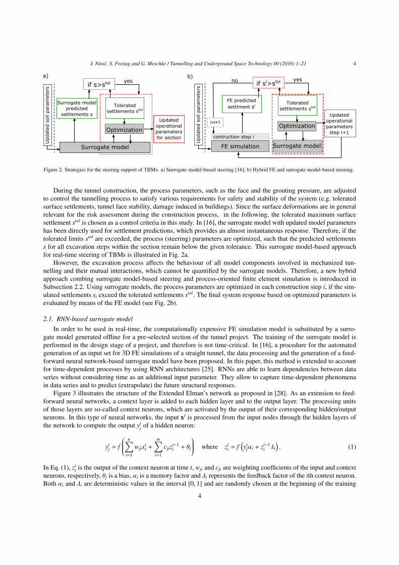
Figure 2. Strategies for the steering support of TBMs: a) Surrogate model-based steering [16]; b) Hybrid FE and surrogate model-based steering.
During the tunnel construction, the process parameters, such as the face and the grouting pressure, are adjustedto control the tunnelling process to satisfy various requirements for safety and stability of the system (e.g. toleratedsurface settlements, tunnel face stability, damage induced in buildings). Since the surface deformations are in generalrelevant for the risk assessment during the construction process, in the following, the tolerated maximum surfacesettlement stol is chosen as a control criteria in this study. In [16], the surrogate model with updated model parametershas been directly used for settlement predictions, which provides an almost instantaneous response. Therefore, if thetolerated limits stol are exceeded, the process (steering) parameters are optimized, such that the predicted settlementss for all excavation steps within the section remain below the given tolerance. This surrogate model-based approachfor real-time steering of TBMs is illustrated in Fig. 2a.
However, the excavation process affects the behaviour of all model components involved in mechanized tun-nelling and their mutual interactions, which cannot be quantified by the surrogate models. Therefore, a new hybridapproach combing surrogate model-based steering and process-oriented finite element simulation is introduced inSubsection 2.2. Using surrogate models, the process parameters are optimized in each construction step i, if the sim-ulated settlements si exceed the tolerated settlements stol. The final system response based on optimized parameters isevaluated by means of the FE model (see Fig. 2b).
2.1. RNN-based surrogate model
In order to be used in real-time, the computationally expensive FE simulation model is substituted by a surro-gate model generated offline for a pre-selected section of the tunnel project. The training of the surrogate model isperformed in the design stage of a project, and therefore is not time-critical. In [16], a procedure for the automatedgeneration of an input set for 3D FE simulations of a straight tunnel, the data processing and the generation of a feed-forward neural network-based surrogate model have been proposed. In this paper, this method is extended to accountfor time-dependent processes by using RNN architectures [25]. RNNs are able to learn dependencies between dataseries without considering time as an additional input parameter. They allow to capture time-dependent phenomenain data series and to predict (extrapolate) the future structural responses.
Figure 3 illustrates the structure of the Extended Elman’s network as proposed in [28]. As an extension to feed-forward neural networks, a context layer is added to each hidden layer and to the output layer. The processing unitsof those layers are so-called context neurons, which are activated by the output of their corresponding hidden/outputneurons. In this type of neural networks, the input xt is processed from the input nodes through the hidden layers ofthe network to compute the output yt
j of a hidden neuron:
ytj = f
n∑i=1
wjixti +
m∑i=1
cjizt−1i + θj
where zti = f
(yt
jαi + zt−1i λi
). (1)
In Eq. (1), zti is the output of the context neuron at time t, wji and cji are weighting coefficients of the input and context
neurons, respectively, θj is a bias, αi is a memory factor and λi represents the feedback factor of the ith context neuron.Both αi and λi are deterministic values in the interval [0, 1] and are randomly chosen at the beginning of the training
4

J. Ninic, S. Freitag and G. Meschke / Tunnelling and Underground Space Technology 00 (2016) 1–21 5
x1
xn
o1
ok
wj 1
wj i
Σ f ( )yj
θ j
hidden context neurons hidden output neurons
Input layer output layerhidden layers
cj i
cj 1
t
Σ f ( )
yjt
λ i tzi-1
tzi
α i
x1t
xi
t
z1t-1
zit-1
Figure 3. Schematic illustration of the structure of an RNN according to [28].
process and then kept fixed. The information is similarly processed in all hidden layers by the sigmoid activationfunction f (•) and finally passed to the output of the network, taking the output of the nodes of the previous layer asthe input of the current layer.
The goal of the learning process is to adjust the synaptic weights of hidden and context neurons such that theoutput of the network for the given input matches the expected (target) values tt
k. In the proposed model, so-called“batch mode” learning is used, where the error Etot between predicted and target values of the output nodes m iscalculated after processing the set of all input patterns p = [1, ...,P] within the time step t = [1, ...,T]:
Et =12
m∑k=1
(otk − tt
k)2 Etot =
P∑p=1
T∑t=1
Et . (2)
The learning process is accomplished by minimizing the error in Eq. (2), where the gradient of Etot with respectto the input quantities is calculated and the weights are adjusted incrementally for both hidden and context neurons:
∆wij = −γ∂Etot
∂wijand ∆cij = −β
∂Etot
∂cij. (3)
γ and β are learning rates. In this study, the architecture and the learning coefficients are optimized using PSO similarto the approach recently presented in [16]. In comparison to feedforward ANNs, RNNs show better learning propertiesfor the same number of training cycles.
2.2. Hybrid finite element and surrogate model-based steering of TBMsIn order to perform a back analysis of the parameters of the computational model based on monitoring data in
real-time, the computing time should be in the order of seconds to few minutes. In [16], PSO is used in conjunctionwith computationally cheap surrogate models, which replace the original finite element model, to enable almostinstantaneous back analysis of the model parameters. The solution space is initialized with particles described withtheir position pij and velocity vij. The position of the particles is updated in each iteration step based on local andglobal best positions (plocal
best,i, pglobalbest ) according to Eq. (4), moving towards the optimal solution by maximizing the
5

J. Ninic, S. Freitag and G. Meschke / Tunnelling and Underground Space Technology 00 (2016) 1–21 6
objective function F in Eq. (5), which is evaluated by means of the RNN surrogate model (Eq. (2)). In Eq. (4), r1and r2 are random numbers uniformly distributed in [0, 1], and φ1 and φ2 are cognition and social learning factors. InEq. (5), TOL is the tolerance added to avoid singularity of the solution.
vi,j+1 = wij + φ1r1(plocalbest,i − pij) + φ2r2(pglobal
best − pij) and pi,j+1 = pij + vi,j+1 . (4)
F =1
pn∑0
Etot + TOL(5)
The complete procedure is described in [16]. The algorithm summarizing the steps for the surrogate model basedinverse identification of soil material parameters (mp0) according to measured settlements sn,mes in the monitoringpoint n is given in the Appendix (Table 4).
In situ measurements
PSOoptimization
s1 s2 sn, sim
PSOoptimization
Material parameters
update
Operational parameters
update
Check ifsi
n, sim > slim
FE model settlements si
n, sim
yesnonext
excavation
FE simulation
Infrastructure
Face stability
Lining
Structural response
Surrogate model
Figure 4. Hybrid FE and surrogate model-supported steering of the mechanized tunnelling process.
Having a surrogate model trained to predict settlements with sufficient accuracy after identification of the soilmaterial parameters (mpident) at the current stage of TBM advancement, it is possible to control the advancementprocess for the forthcoming section, such that the settlements (or other target parameters) are reduced to a desiredvalue by optimizing the values of the TBM process parameters (such as support and grouting pressure, advance rate,etc.).
The proposed computational strategy illustrated in Fig. 4 is characterized by combining the full-scale 3D finiteelement model and the previously described surrogate models during the construction process. In this hybrid concept,the process-oriented simulation model ekate, described in Subsection 3.2, is invoked during the construction pro-cess using parameters, which have been updated according to monitoring data by means of back analysis using thecomputationally much cheaper RNN-PSO surrogate model for the investigated tunnelling section. After each TBMadvance step i, the surface settlements obtained from the 3D FE simulation (sn,sim
i ) are checked. In case that prescribedlimits slim are exceeded, the parameters for the steering of the TBM (i.e. the face pressure and the grouting pressure)are optimized, again by using surrogate models according to the procedure described above. These prescribed limitsare set as a certain percentage of the tolerated settlements stol: slim= νstol. The next advancement step is then simulatedby means of the FE model adopting the updated (optimized) steering parameters (spoptim
i ). During each step, the fullresponse of all components (soil, linings, TBM) involved in the tunnelling process can be directly accessed from thepost processing of the numerical simulation. This hybrid strategy assigns computationally intensive tasks, such asthe repetitive analysis of the model for different input parameters involved in the back analysis procedure and in theoptimization procedure to determine the optimal steering parameters, respectively, to the computationally efficient
6

J. Ninic, S. Freitag and G. Meschke / Tunnelling and Underground Space Technology 00 (2016) 1–21 7
surrogate model. The 3D FE simulation model is employed to provide predictions for the current excavation stepconsidering the previously optimized set of model parameters. Since the computation follows the construction stepby step, the computational effort is restricted to only simulating these construction steps. By using efficient imple-mentations [29] these computational analyses can be performed in a fraction of the time needed for the real tunnellingprocess.
The hybrid FE and surrogate model-supported steering procedure is enabled by implementing the previously de-scribed RNN-PSO algorithm as a so-called OptimizationUtility in the framework of the ekate simulation model.Based upon the simulation results, it is now possible to define criteria for calling the surrogate model-based op-timization utility and for adapting TBM operational parameters directly within the simulation. The algorithm forperforming the FE analysis, checking the correlation of predicted data ssim
i with tolerated limits slimi and calling the
RNN-PSO model to determine optimized levels for the steering parameters (face pressure and grouting pressure) isdescribed in Table 1.
Initialize FE model and surrogate model
mpi = mpident
sp0 = designprocessparameters
Calculate ring construction step
for construction step i
FESimulation.SetBoundaryConditions (mpident, spi)
FESimulation.ExcavationStep (time)
FESimulation.StandStill (time)
FESimulation.WriteOutput (sn,simi , time)
sn,simi < sn,lim
i
Yes No
spi = sp0
Optimization of process parameters using RNN-PSO
PSO.InitializeParticles (pjk, vjk)
j < num of iterations
for each particle(k)
sni (time) = RNN.CalculateRNNOutput (mpident, pk,j) - Eq. (1)
PSO.EvaluateObjectiveFunction (sni (time), stol) - Eq. (5)
Update particle positions and velocity: vk,j+1, pk,j+1 - Eq. (4)
spi = spoptimi = pglobal
best
construction step i+1
Table 1. Algorithm for the hybrid FE and surrogate model-supported steering in mechanized tunnelling
The added value of this hybrid approach is firstly to obtain more accurate results from the 3D simulation modelfor the optimized set of parameters and secondly to obtain additional insight into the physical behavior of the soil-structure interaction during the machine advance, i.e., how the chosen process parameters affect the interacting systemconstituted by the tunnelling process, the surrounding soil and existing buildings. Another advantage is that it enablesthe user to set multiple criteria (multiple objectives and constraints) for the optimization of the process such as theresidual safety against loss of face stability in addition to surface settlements. Based on the results acquired from thesimulation model during the tunnel drive, new constraints can be set. Each time the optimization procedure is invoked,the design space can be adjusted accordingly to satisfy all prescribed criteria.
3. Simulation model for the Wehrhahn-line project
In this section, a simulation model for mechanized tunnelling is generated according to project data of theWehrhahn-line (WHL) metro project in Dusseldorf, Germany. For this project, a tunnelling information model has
7

J. Ninic, S. Freitag and G. Meschke / Tunnelling and Underground Space Technology 00 (2016) 1–21 8
been established, which is directly interlinked with the numerical simulation model ekate via an interaction plat-form, which enables automated exchange of data and flexible generation of numerical models for selected sections ofthe tunnel project.
3.1. Tunnelling Information ModelTo store all relevant information related to the tunnelling process, to enable seamless integration of this data into
the numerical simulation model, and to automate the large number of parametric analyses required for the generationof the surrogate model, a flexible information platform is required. In order to manage the huge amount of time-dependent, dispersed and heterogeneous project data, a holistic spatio-temporal Tunnelling Information Model (TIM)for mechanized tunnelling developed in [26] is used for the present project. All relevant design and constructioninformation of the WHL project in Dusseldorf has been collected, classified, structured and linked within the proposedTIM to support unified access. This model is designed using the concept of Building Information Modeling (BIM)and contains four essential sub-models: the ground data model, the tunnel boring machine model, the tunnel liningmodel and the built environment model. These models are inherently linked and provide the basis to automaticallyderive numerical simulation models [30]. The visualization of the information contained in the TIM of a WHL sectionis shown in Fig. 5.
Figure 5. Tunnelling Information Model for the Wehrhahn-line in Dusseldorf: Visualization of soil layers, existing buildings, tunnel alignment,boreholes and measurement points.
The investigated section of the WHL contains a single-tube double-track tunnel excavated with a 9.47 m slurryshield. The ground along the alignment consists of almost homogeneous, horizontally layered soil specified below.For the numerical analysis, a section of the tunnel advance between two stations, namely the Schadowstraße stationand Pempelforter Straße station on the eastern section of the project has been selected. This section has been bothequipped with a sensor field and observed with radar survey to monitor the settlements during the construction phaseof the tunnel [31, 32].
The ground model has been generated from 18 geo-referenced boreholes and groundwater measuring points alongthe tunnel route [32]. The subsoil consists of four soil layers: surface layer filling (2–3 m to max. 8 m thicknesslocally); alluvial layer with silt and clay deposits (thickness 0.5–1.5 m to max. 3.5 m locally); low terrace of the riverRhine with sand and gravel of the quaternary (15–25 m thickness); tertiary with slightly silty and medium sandyto silty fine sand (23–25 m below the ground surface level). The selected section for the TIM does not contain thealluvial soil layers. Based on this data, a subsoil section of approximately 730 m × 340 m is defined (see Fig. 5).The overburden varies between 12 m and 16 m, while the ground water table is approximately 8 m to 12 m below theground surface with temporal fluctuations in the range of 2–5 m.
8

J. Ninic, S. Freitag and G. Meschke / Tunnelling and Underground Space Technology 00 (2016) 1–21 9
The size of the simulation domain has been chosen such that disturbing effects on the solution caused by boundaryand initial conditions are not affecting the results in the vicinity of the monitoring field. Considering that the soilconsists of sandy layers, the soil model used for representation of the soil behavior in this study is Drucker-Pragerwith non-associative flow rule [33]. Table 2 contains the geotechnical data used in the numerical simulation.
Parameter RangeYoung’s Modulus of layer 1 — E1 [MPa] 10–30Young’s Modulus of layer 2 — E2 [MPa] 30–150Young’s Modulus of layer 3 — E3 [MPa] 60–150Weight of layer 1 — γ′1 [kg/m3] 900–1100Weight of layer 2 — γ′
2[kg/m3] 1000–1300
Friction angle of layer 1 — φ1 [◦] 25–35Friction angle of layer 2 — φ2 [◦] 30–40Cohesion of layer 1 — c1 [kPa] 0–3Cohesion of layer 2 — c2 [kPa] 0–3Grouting pressure scaling factor — gp [-] 0.9–1.1Support pressure scaling factor — sp [-] 0.8–1.2
Table 2. Range of geomechanical and process parameters used for the analysis of the Wehrhahn-line project (in bold face: parameters used for thegeneration of the surrogate model).
3.2. Numerical simulation model for mechanized tunnelling
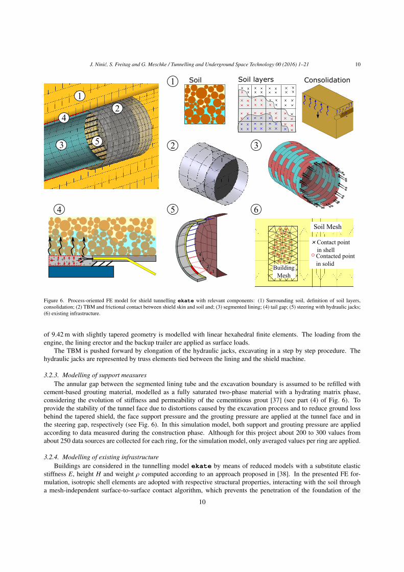
The simulation model for mechanized tunnelling ekate is generated using the object-oriented FE frameworkKRATOS [34]. All relevant components of the mechanized tunnelling process (see Fig. 6) are properly modelled inthis 3D FE process-oriented simulation model [27, 7] as shown in Fig. 6.
3.2.1. Modelling of the groundThe soft soil is modelled as a two-phase fully saturated material, accounting for the soil matrix and the pore water
as distinct phases according to the theory of porous media (see [35] for details). Depending on the type of the soiland available material parameters, two elastoplastic constitutive models are available in ekate: the Drucker-Pragermodel, which is preferably used for sandy soils, and the more general Clay and Sand model, characterized by non-associative plasticity and Lode-angle dependent yield surfaces [36], which is well suited for clayey soil. For the WHLproject, Drucker-Prager was used to describe the sandy soil.
Having a fully coupled formulation, it is possible to follow the dissipation of the pore water in time. To accuratelymodel the consolidation process, the actual time required for the excavation steps, the installation of the linings andstand still steps is considered in the set up of the simulation model for the WHL metro. The temporal discretization(i.e. the number and length of the increments) within each of these construction stages is adapted according to theconsolidation characteristics of the soil.
In order to allow for a user-friendly input of the soil layers and their material properties, a routine denoted asMaterialPropertiesUtility is implemented. Through the simulation script, the material properties are assigned directlyto the finite element mesh, storing the respective values at the element Gauss points inside of the polygon defining therespective soil layer, as illustrated in part (1) of Fig. 6.
3.2.2. Shield machine, hydraulic jacks, lining and backup trailerIn the simulation model ekate, the shield machine, the hydraulic jacks and the segmented lining are considered as
separate components (see parts (2), (3) and (5) of Fig. 6). The TBM is modelled as a deformable body moving throughthe soil and interacting with the ground through surface-to-surface contact. By virtue of this modelling approach, thevolume loss due to the excavation process naturally follows the real, tapered geometry and the over-cutting of theshield machine. For the WHL project the hydro shield machine with a cutting wheel of 9.49 m diameter and a length
9
J. Ninic, S. Freitag and G. Meschke / Tunnelling and Underground Space Technology 00 (2016) 1–21 10
1
3
2
5
4
Soil Soil layers Consolidation
12
34
1
2 3
4 5 6
Soil Mesh
Building Mesh
Contact pointin shellContacted pointin solid
Figure 6. Process-oriented FE model for shield tunnelling ekate with relevant components: (1) Surrounding soil, definition of soil layers,consolidation; (2) TBM and frictional contact between shield skin and soil and; (3) segmented lining; (4) tail gap; (5) steering with hydraulic jacks;(6) existing infrastructure.
of 9.42 m with slightly tapered geometry is modelled with linear hexahedral finite elements. The loading from theengine, the lining erector and the backup trailer are applied as surface loads.
The TBM is pushed forward by elongation of the hydraulic jacks, excavating in a step by step procedure. Thehydraulic jacks are represented by truss elements tied between the lining and the shield machine.
3.2.3. Modelling of support measuresThe annular gap between the segmented lining tube and the excavation boundary is assumed to be refilled with
cement-based grouting material, modelled as a fully saturated two-phase material with a hydrating matrix phase,considering the evolution of stiffness and permeability of the cementitious grout [37] (see part (4) of Fig. 6). Toprovide the stability of the tunnel face due to distortions caused by the excavation process and to reduce ground lossbehind the tapered shield, the face support pressure and the grouting pressure are applied at the tunnel face and inthe steering gap, respectively (see Fig. 6). In this simulation model, both support and grouting pressure are appliedaccording to data measured during the construction phase. Although for this project about 200 to 300 values fromabout 250 data sources are collected for each ring, for the simulation model, only averaged values per ring are applied.
3.2.4. Modelling of existing infrastructureBuildings are considered in the tunnelling model ekate by means of reduced models with a substitute elastic
stiffness E, height H and weight ρ computed according to an approach proposed in [38]. In the presented FE for-mulation, isotropic shell elements are adopted with respective structural properties, interacting with the soil througha mesh-independent surface-to-surface contact algorithm, which prevents the penetration of the foundation of the
10

J. Ninic, S. Freitag and G. Meschke / Tunnelling and Underground Space Technology 00 (2016) 1–21 11
building into the soil (see part (6) of Fig. 6). It also takes different mechanisms of the soil-structure interaction corre-sponding to “sagging” and “hogging” modes into account. The geometry of the buildings is imported from the TIMas described in the following subsection and illustrated in Fig. 7.
3.3. Data exchange between the Tunnelling Information Model and the simulation modelUsing the TIM for the Wehrhahn-line, the data for the selected section of the tunnel construction site was extracted
to create a simulation model. The selected simulation box contains the data of the topology of the subsoil includingthe geomechanical properties of the soil layers, existing infrastructure with material properties of substitute modelsfor buildings [38], advance rates of the machine and the measured support and grouting pressures (see Fig. 7). Allmeasured data is utilized in the stepwise simulation of the tunnelling process. For instance, the advance rate, whichis described with excavation time, ring construction time and stop time is implemented in the simulation of stepwisetunnel advance. Time-dependent effects, such as the consolidation process, are of a great importance for the pressuredistribution around the tunnel lining and for the total surface settlements, particularly in the case of large intervals ofstop time between two construction steps, which was often the case in this tunnel project.
Geotechnical model
0
2
4
6
8
1 3 5 7 9 11 13 15 17 19 21
Tim
e [h
]
Ring Number
Excavation time
Ring construction time
Stop time
0
0.5
1
1.5
2
2.5
0 10 20 30 40 50
Face
Sup
port
pre
ss.
[bar
]
Ring Number
Invert
Springline A
Springline B0
2
4
6
8
0 10 20 30 40 50
Gro
utin
g pr
essu
re [
bar]
Ring Number
Buildings
Material data
Advance rates
Face support and grouting pressure measurements
Figure 7. Data exchange between the TIM and the FE simulation model ekate.
For the generation of the surrogate model, a series of numerical simulations was performed, extracting the datafrom the TIM and using an automated data generator (see [16]) together with the automatic modeller ekate [39] toset up the simulation script for each individual realization. This approach allows for automated and flexible access totunnel project data, generation and execution of shield tunnelling simulations as well as processing of simulation data
11

J. Ninic, S. Freitag and G. Meschke / Tunnelling and Underground Space Technology 00 (2016) 1–21 12
in a form that can directly be used for the generation of the surrogate model. In this context, the following tasks haveto be performed:
• Definition of the section of the project to be simulated and the spatial extent of the analysis model in the TIMand acquisition of geometrical and geotechnical information to define the model size, the number of constructedrings and the model boundaries.
• Acquisition of input parameters (e.g. related to the existing infrastructure, machine type, material parametersfor soil layers, grout and linings, advancement rate, soil water conditions, etc.).
• Generation of the FE simulation model controlled by a simulation script that is evaluated by a Python interpreter.
• Application of the data generator for setting up the numerical experiments based on admissible ranges ofgeotechnical and process parameters for generation of the surrogate model.
• Execution of the numerical simulations on the available computing resources in parallel using a shared memorysystem based on OpenMP.
• Postprocessing of the simulation output.
• Training and testing of the RNN-PSO based surrogate model.
4. Simulation and monitoring-supported steering of TBM for the Wehrhahn-line project
This section describes a prototype application of the computational concept for simulation and monitoring-supportedsteering of TBMs using data from the WHL project together with the simulation model and the surrogate model setup as presented in the previous section.
4.1. Pre-selection of relevant parameters
For the given range of model parameters of the investigated section of the WHL project, a sensitivity analysis hasbeen performed to identify the most relevant model parameters needed to be updated during the TBM advancement.The sensitivity of model parameters strongly depends on the range of the chosen parameters and the target of evalua-tion. In geotechnical reports available for mechanized tunnelling projects, a range of suitable geotechnical parametersdescribing the soil properties, water-soil conditions, topology, etc. is generally provided, which can be used to conductsuch a sensitivity analysis. In this study, the elementary effect of nine soil and two machine operational parameterson the settlement of a chosen monitoring point is investigated: Young’s modulus E1, E2, E3 for all three layers, theweight γ′1, γ′2 of layers 1 and 2, the friction angle φ1, φ2 of layers 1 and 2; the soil cohesion c1, c2 of layers 1 and 2,scaling factors of measured grouting pressure gp and the face support pressure sp) in the range given in Table 2.
Figure 8 contains the results of a sensitivity analysis using the project data of the WHL. As already mentioned, thesubsoil consists of three soil layers, see also Fig. 8a. The TBM is passing only through the second layer, a low terracelayer of the Rhine characterized by sand and gravel of the quaternary of approximately 15–25 m thickness.
In Fig. 8b, the normalised absolute mean of the elementary effect |µ∗j | of the change of the input parameters onthe surface settlement in a monitoring point (×) (see Fig. 8a) is plotted for different positions of the TBM w.r.t. themeasurement section. From this graph, it can be concluded that the grouting pressure and the soil stiffness of thesecond layer E2 have the largest relative influence on the surface settlements. The parameters γ′1, φ2, c1 and c2 showan almost negligible effect on the surface settlements for the chosen range of parameters. It is also interesting tonote the change of the sensitivity of the parameters when the shield machine is approaching (step 17) and passing themonitoring section (step 23). While in the first case, the support pressure plays an important role, in the second case,the grouting pressure becomes dominant.
12

J. Ninic, S. Freitag and G. Meschke / Tunnelling and Underground Space Technology 00 (2016) 1–21 13
0
0.2
0.4
0.6
0.8
1
1 5 9 13 17 21 25 29 33 37
E1 E2 E3 ϕ1 ϕ2 c1 c2 gp spγ1 γ2a) b)
Monitoring point
Layer 3 - Tertiary
Layer 2 - Low terrace of the Rhine
Layer 1 - Filling
≈ 3m
≈ 20m
≈ 41m
μ*
Step [ring]TBM TBM
Figure 8. Sensitivity analysis using project data of the Wehrhahn-line. a) Schematic geotechnical section of the model; b) Sensitivity measures ofthe model parameters w.r.t the settlements in the monitoring point in terms of |µ∗ | for the model parameters (E1, E2, E3, γ′1, γ′2, φ1, φ2, c1, c2, gp,sp).
4.2. Surrogate model for the metro project Wehrhahn-lineUsing the results of the sensitivity analysis, the surrogate model was created based on a reduced set of the most
relevant model parameters (E1, E2, E3, γ′2, φ2 and gp ). Since the accuracy of a surrogate model strongly dependson the number of sampling points and their distribution inside the input parameter space, for this example, a LatinHypercube Sampling (LHS) strategy has been chosen [17]. The LHS method has a random nature and the generatedsamples are uniform, if each dimension is viewed separately. For the relevant parameters obtained from the sensitivityanalysis, using the LHS method, 100 samples for the training set and 50 samples for the validation set are used,varying the parameters in the ranges described in Table 2.
-5
-4
-3
-2
-1
0
1
2
3
-5 -4 -3 -2 -1 0 1 2 3
RN
N p
redi
ctio
n -
settl
em
ents
[mm
]
Simulation - settlements [mm]
training
validation
a) b)
190
72
64
Figure 9. a) Geometry and finite element mesh used for the generation of the surrogate model for a specific section of the WHL project; b)Comparison between settlements obtained from the FE simulation and predictions of the trained surrogate model for the training and validationsets.
The simulation model is concerned with a tunnel of diameter D = 9.49 m excavated in 48 steps of 1.5 m lengtheach. The simulation model is shown in Fig. 9a. It has 72 m length, 190 m width and an overburden of 16 m. For
13

J. Ninic, S. Freitag and G. Meschke / Tunnelling and Underground Space Technology 00 (2016) 1–21 14
each excavation step and each stage within one advancement step, the real time (advance rate) was properly modelled,accounting for time-dependent effects such as consolidation, water pressure distribution on the tunnel face and groutinflow. In the simulation, the measured support and grouting pressure (per ring) have been used. For the groutingpressure, the values measured at the grouting pipes were adopted with a scaling factor and applied as boundaryconditions at the nodes related to the corresponding injection positions of the grouting elements. For each inputparameter set with six independent input parameters (six input nodes), the recorded output is the temporal evolutionof the surface settlement at a monitoring point, see Fig. 8a. The RNN surrogate model described in Section 2.1 hasbeen trained with optimized architecture and learning rate. The optimized architecture leads to one hidden layer with20 hidden and respective context (history) neurons. Figure 9b shows the agreement between the settlements at thechosen monitoring point predicted by the surrogate model and the target settlements obtained from the numericalsimulations for both training and validation sets. This figure shows that the surrogate model provides good predictioncapabilities with a Relative Root Mean Square Error (rRMSE) of 3.1% for the training and 3.5% for the validation set.
Once the surrogate model is set up, it is used for model updating according to the monitoring data. For the surfacesettlements at the selected monitoring point “+” in Fig. 10, back analyses are conducted to determine precise valuesof the material parameters summarized in Table 2 within the range given in the geotechnical report. For the backanalysis, the surrogate model-based PSO algorithm was used as described in Table 4 in the Appendix. The PSO isinitialized with 50 particles and a maximum of 100 iterations.
-3
-2
-1
0
1
2
2 4 6 8 10
Set
tlem
ent
[mm
]
Time [days]
Measurements
Surrogate model
Figure 10. Comparison of the settlements at the monitoring point “+” obtained from monitoring and from predictions of the surrogate model afterparameter identification.
Figure 10 shows a comparison between the measurements and the prediction of the surrogate model for the set-tlements at the monitoring point “+” after the model parameters have been identified from the back analysis. Themodel parameters from Table 2 have been identified as E1 = 30 MPa, E2 = 46 MPa, E3 = 124 MPa, γ′2 = 1000 kg/m3,φ2 = 32.5◦ and averaged gp ≈ 220 kPa. The predictions of the surrogate model match the in situ measurements forthe identified set of parameters very well. Due to the fact that a surrogate model is used for the forward analysis in thePSO algorithm, the back analysis was performed in approximately 5 seconds on a standard PC, converging within thefirst 20 iterations.
4.3. Model-supported steering of TBM to minimize settlements
If surface settlements were above the critical value, the next step would be an optimization of the TBM-relatedparameters in order to minimize surface settlements. However, in the WHL project, surface settlements were almostnegligible. Therefore, in the following subsection, a “worst case scenario” for the geotechnical parameters, takingthe lower bounds of the ranges in Table 2 into account, is assumed to demonstrate the capabilities of the hybrid FE
14

J. Ninic, S. Freitag and G. Meschke / Tunnelling and Underground Space Technology 00 (2016) 1–21 15
and surrogate model-based iterative steering of TBM parameters with the goal of minimizing the surface settlementsduring the TBM advance. To this end, a new surrogate model has been constructed with fixed values of the materialparameters (lower bound of given ranges in Table 2), taking into account the variation of the support and groutingpressures scaling factors in the ranges of 0.8–1.2 and 0.6–1.2, respectively. The surface settlement was measured infive points along the tunnel alignment in each TBM advance step. The RNN surrogate model was constructed basedon this data using the same procedure as described in the previous subsection, with a prediction accuracy of 98%.
4.3.1. Surrogate model-based steeringIn this example, the previously developed surrogate model-based steering strategy, similar to the approach in [16],
is applied for minimization of tunnelling-induced settlements. The RNN-PSO algorithm, outlined in Fig. 2a andsummarized in the Appendix (Table 5), is applied to optimize TBM-related parameters to reduce tunnel-inducedsettlements such that the tolerated limit value of 1 cm is not exceeded. Figure 11 shows the surface settlementspredicted by the surrogate model for the initial values of the support and grouting pressures and the settlements afteroptimization of the support and grouting pressures with the objective that the maximum settlements do not exceed thelimit value of 10 mm in five selected monitoring points.
Surrogate5mod.5predictionSurrogate5mod.-based5optim.
FE5prediction
Surrogate5mod.5predictionSurrogate5mod.-based5optim.
FE5predictionSurrogate5mod.5prediction
Surrogate5mod.-based5optim.
FE5predictionSurrogate5mod.5prediction
Surrogate5mod.-based5optim.
FE5prediction
Surrogate5mod.5predictionSurrogate5mod.-based5optim.
FE5predictionSet
tlem
ent
[mm
]
-15
-10
0
-5
-20
5
-15
-10
0
-5
-20
5
-15
-10
0
-5
-20
5
-15
-10
0
-5
-20
5
Set
tlem
ent
[mm
]
-15
-10
0
-5
-20
5
TBM5advance5[step]0 6 12 18 24 30 36 42
TBM5advance5[step]0 6 12 18 24 30 36 42
TBM5advance5[step]0 6 12 18 24 30 36 42
TBM5advance5[step]0 6 12 18 24 30 36 42
TBM5advance5[step]0 6 12 18 24 30 36 42
limit limit limit
limitlimit
S1S2
S3S4
S5
S1 S2
S3 S4
S5
Figure 11. Model-based optimization of TBM-steering parameters: Settlements at five measurement points with and without optimized steeringparameters.
The results in Fig. 11 demonstrate the good agreement between the predictions of tunnelling-induced settlements(red line with + mark) from the RNN-PSO surrogate model and the predicted settlements (dashed line) from the 3D FEsimulation model. The curves show that the tolerated settlements are exceeded in all monitoring points except the fifthmonitoring point. Figure 11 also contains the settlements computed by the surrogate model after optimizing the TBMsteering parameters (green line with × mark). The fact that now the maximum settlement of 10 mm is not exceeded inany of the control points demonstrates the efficiency of the surrogate model-based process control of TBMs. However,it has to be noted that although the optimization target has been fulfilled and the maximum settlements for the firstfour points are kept below the limit, this has a negative effect to the ground displacement of the fifth point, wheresignificant heaving is induced. This is a consequence of the fact that the surrogate model-based steering is conducted
15

J. Ninic, S. Freitag and G. Meschke / Tunnelling and Underground Space Technology 00 (2016) 1–21 16
for the complete tunnel section with a time-constant grouting and support pressure. It can be avoided by defining alsoheaving limit states and optimizing the settlements with time-variant pressures.
4.3.2. Hybrid finite element and surrogate model-supported TBM steeringThe new hybrid finite element and surrogate model-supported steering strategy proposed in Section 2.2 is applied
to the same section of the WHL project as used in the previous subsection. Starting from the lowest values of the
-20
-15
-10
-5
0
5
0 6 12 18 24 30 36 42
Settlement[mm]
TBM advance [step]
FE predictionFE-supported optim.
0 6 12 18 24 30 36 42TBM advance [step]
FE predictionFE-supported optim.
0 6 12 18 24 30 36 42TBM advance [step]
FE predictionFE-supported optim.
0 6 12 18 24 30 36 42TBM advance [step]
FE predictionFE-supported optimi.
0 6 12 18 24 30 36 42TBM advance [step]
FE predictionFE-supported optimi.-20
-15
-10
-5
0
5
Settlement[mm]
-20
-15
-10
-5
0
5
-20
-15
-10
-5
0
5
-20
-15
-10
-5
0
5
limit limit
limit limit
S1 S2
S3 S4
S5
S1S2S3S4S5
Figure 12. Hybrid FE and surrogate model-supported optimization of TBM steering parameters: Settlements at five measurement points with andwithout optimized steering parameters.
support and grouting pressure, the iterative steering procedure described in Section 2.2 is applied to minimize thesettlements assuming a tolerated limit settlement value of 10 mm. According to Fig. 4, in each excavation step the FEsimulation model for the selected section of the WHL project is supplied with continuously updated process param-eters obtained from the surrogate model-based optimization algorithm to compute the tunnelling-induced settlementtrough. After each TBM advancement step, the surface settlements are checked in all five monitoring points depictedin the upper left part of Fig. 12. If the surface settlements reach 80% of the limit value, the RNN-PSO algorithm isinvoked with the objective to optimize support and grouting pressure such that tunnelling-induced settlements do notexceed the tolerated limit. Figure 12 shows the settlements at the selected control points before (red line with + mark)and after (green line with × mark) stepwise optimization of the TBM steering parameters. In this figure, it can beobserved that the optimization procedure is first activated in the 9th excavation step, continuing with an updated valueof the face and grouting pressure in each step until the end of the tunnel section.
Figure 13 shows the optimized values of the face support (Fig. 13a) and the grouting pressure (Fig. 13b), respec-tively, in comparison with the initial design parameters. In this figure, it can be seen that the face pressure is almostconstantly increased from ≈ 160 kPa to ≈ 175 kPa, while the grouting pressure has a considerably larger variationduring the TBM advance due to the high sensitivity of this process parameter w.r.t. the surface settlements as shownin Fig. 8. Furthermore, it is observed from Fig. 13b that a significant drop of the optimized grouting pressure occursafter the 30th TBM advance step. This drop is a consequence of the tendency of the settlements at the measurementpoint (S5) to become positive.
Comparing the results of this hybrid FE and surrogate model-based optimization strategy with the surrogate model-based steering control presented in the previous subsection, it is concluded that both strategies satisfy the objective of
16

J. Ninic, S. Freitag and G. Meschke / Tunnelling and Underground Space Technology 00 (2016) 1–21 17
Pre
ssur
el[K
Pa]
Excavationl step0
50
100
150
200
0 6 12 18 24 30 36 42
Pre
ssur
el[K
Pa]
Excavationl step
Facell supportl pressure duringl excavation
0 6 12 18 24 30 36 420
50
100
150
200
Initiall pressure
Optimizedl pressure
Initiall pressure
Optimizedl pressure
a) b) Groutinglpressurelduringlexcavation
Figure 13. Temporal development of the support and grouting pressure during the hybrid finite element and surrogate model-based optimization ofthe TBM steering parameters.
keeping the surface settlements below the tolerated limit. However, the FE and surrogate model-supported steeringshows an advantage due to the fact that the optimization is continuously supplied with the physical model responseand that the steering parameters are iteratively determined based on this response.
In Section 4.3.1, the support and grouting pressures are optimized for the complete tunnel section such that themaximum settlements do not exceed tolerated values. Note that this results in positive displacements (heaving) in thelast monitoring point. In the hybrid FE and surrogate model-supported steering, the iterative optimization provides anoptimal solution for each TBM advance step based on the computed settlements, which results in reduced groutingpressures in the last steps (Fig. 13b) satisfying the control objective and avoiding the heaving at the same time. Thedisadvantage of the new approach as compared to surrogate model-based steering is that it requires the computationof the full 3D finite element model in each advancement step, which is connected with larger computational costsas compared to the surrogate model technique. However, since the TBM process parameters are calculated fromnumerical simulations of individual advancement steps, depending on the size of the model, this requires computationtimes in the range of 5–30 minutes, depending on the used hardware. This response time is still acceptable to allowthe incorporation of the optimized steering parameters and the computational results into the decision making processat the construction site.
-800
-700
-600
-500
20 25 30 35 40
Nm[K
N]
step
-60
-40
-20
0
20
40
60
20 25 30 35 40step
Crown
Initial steering parameters
SpringlineInvertInitial
Optimized
Mm[K
Nm
]
Optimized steering parameters
a) b)
Figure 14. a) Deformed lining ring for initial and optimized steering parameters obtained for the simulation model; b) Normal forces (N) andbending moments (M) for the selected ring in the crown, springline and invert.
One of the major advantages of the FE supported steering is its ability to directly access the effect of steering on allstructural components of the system. In Fig. 14, the deformation of a lining ring (Fig. 14a) as well as the evolution of
17

J. Ninic, S. Freitag and G. Meschke / Tunnelling and Underground Space Technology 00 (2016) 1–21 18
structural forces during construction (Fig. 14b) for initial (solid lines) and optimized (dashed lines) process parametersare presented. The deformed configuration of the ring, scaled with factor 500 in Fig. 14a, shows that the optimizationof process parameters results in a smaller deformation of the lining. This is a consequence of the larger groutingpressure (Fig. 13b), which has a nearly hydrostatic distribution and leads to a dominantly convergence deformationmode and a reduced ovalization as compared to the lower initial grouting pressure. This is directly reflected in thetemporal evolution of bending moments (M) in the lining, plotted in Fig. 14b for the crown, the springline and theinvert, which are all reduced when using the optimized grouting pressure. On the contrary, the significantly largergrouting pressures after optimization lead to larger normal forces (N).
5. Conclusions
In this paper, a computational strategy for a simulation and monitoring-supported steering of TBMs in real-timehas been proposed, which is characterized by combining a process-oriented 3D finite element model and accompa-nying surrogate models to update the model parameters according to monitoring data and to provide continuouslyoptimized steering parameters such as the grouting or the face pressure to keep the tunnelling induced settlementsbelow a tolerated limit. This procedure was compared to a strategy recently proposed by the authors, which was com-pletely based on surrogate models, restricting the use of the original 3D FE model to a tool for the (offline) trainingof the surrogate model in the design stage of the project.
The proposed new method consists of three major steps: Firstly, an efficient method for the update of the geotech-nical parameters of the computational model for mechanized tunnelling according to monitoring data acquired duringthe construction process is presented. For this purpose, which involves a large number of realizations, surrogatemodels based on RNNs are trained in an offline mode in the design stage of a project. The use of RNNs allows toaccount for the time dependency of the tunnelling process. The relevant geotechnical parameters subject to an updatehave been selected a priori for the tunnelling section by a sensitivity analysis for parameter ranges obtained from thegeotechnical report to preselect the most influencing parameters before creating the surrogate model. Secondly, TBMprocess parameters used for the stepwise analysis of the tunnelling process are optimized in each excavation step ac-cording to prescribed limits for the target settlements. The computation of the optimized process parameters is againaccomplished by means of the surrogate model according to the proposed strategy. For the forward analyses duringthe tunnel advancement, a process-oriented finite element model is used to predict the settlements in the forthcomingsteps and, after having optimized process parameters, to predict the complete system response, i.e. the settlements,pore pressures or lining forces.
This method was applied using data of the Wehrhahn-line metro project in Dusseldorf, Germany. The finiteelement simulation model was created based on data obtained from the TIM for a chosen tunnel section. The actualadvance rates of the TBM used in the project have been properly implemented in the simulation model within allexcavation steps. In the presented examples, the support and grouting pressures have been updated during the advanceof the TBM to keep the tunnelling-induced settlements below tolerated limits during all excavation steps.
It was demonstrated that the surrogate model-based TBM steering support allows for the determination of opti-mized steering parameters in a few seconds. Although the accuracy of the predictions may be satisfactory for mostpractical purposes, it was also shown that evidently, the response obtained from the surrogate model relies on a certainprescribed range of values for the parameters and does not provide the complete insight into the physics behind theinteractions between the tunnel advancement process, the surrounding soil and the existing buildings. As was shownby a comparative analysis, this disadvantage of the surrogate model technique is compensated by the proposed novelhybrid FE and surrogate model-based approach, since in this procedure, the actual model response is predicted bythe 3D process-oriented finite element model, in which all interactions are incorporated independent of the range ofparameters. Here, the surrogate model takes the role of determining the updated geotechnical parameters and the op-timized steering parameters, respectively. Another advantage of this hybrid method is that in contrast to the surrogatemodel-based strategy, one can follow the influence of the selected steering parameters through all components of thetunnelling project, which are represented in the numerical simulation model, e.g. the pore pressure distribution in thesoil or the level of stresses in the lining shell. This is not possible when using surrogate models only.
Evidently, compared to the surrogate model-based approcah, the required computation time is higher. However,since the model is used stepwise simultaneously with the actual tunnel advance, the required response time (in therange of ∼ 5–30 minutes even for large models as used in the presented Wehrhahn-line project) is acceptable to allow
18

J. Ninic, S. Freitag and G. Meschke / Tunnelling and Underground Space Technology 00 (2016) 1–21 19
the incorporation of the computational results and the optimized steering parameters into the decision making processat the construction site.
It should be emphasized that this method can be extended by adding multiple criteria for triggering and controllingthe process optimization, including target parameters such as the residual safety against loss of face stability in additionto surface settlements or settlement inclinations. Furthermore, a priori information on parameter sensitivity availablefrom the design stage may also be used in the parameter identification process performed during the advancementprocess to govern the choice and/or magnitude of the optimized TBM parameters.
Evidently, an important ingredient for the model-based determination of process parameters is the considerationof the uncertainty of the geotechnical parameters in front of the tunnel face. This was not addressed in the paper.Uncertainty models such as fuzzy or combined fuzzy stochastic approaches can be incorporated in the proposedconcept and may also be performed in real-time. Results from current research on fuzzy stochastic approaches for realtime steering of the TBM advancement process in mechanized tunnelling will be presented in a follow-up publication.
Acknowledgements
Financial support was provided by the German Research Foundation (DFG) in the framework of project C1 of theCollaborative Research Center SFB 837 “Interaction Modelling in Mechanized Tunnelling”. This support is gratefullyacknowledged. The cooperation with subproject D1, in which the Tunneling Information Model (TIM) was developed,is also acknowledged. The authors also would like to thank the Department for Traffic Management of the City ofDusseldorf for providing essential project data and Bilfinger Construction Ltd. for helpful technical assistance.
References
[1] B. Maidl, M. Herrenknecht, U. Maidl, G. Wehrmeyer, Mechanised Shield Tunnelling, Ernst und Sohn, 2012.[2] R. Peck, Deep excavations and tunnelling in soft ground, in: 7th International Conference on Soil Mechanics and Foundation Engineering
Mexico City, 1969, pp. 225–290.[3] R. Rowe, K. Lo, G. Kack, A method of estimating surface settlement above tunnels constructed in soft ground, Canadian Geotechnical Journal
20 (1983) 11–22.[4] F. Pinto, A. Whittle, Ground movements due to shallow tunnels in soft ground: 1. analytical solutions, ASCE Journal of Geotechnical and
Geoenvironmental Engineering, 140 (4) (2014).[5] G. Swoboda, Abu-Krisha, Three-dimensional numerical modelling for TBM tunnelling in consolidated clay, Tunnelling and Underground
Space Technology 14 (1999) 327–333.[6] K. Komiya, Finite element modelling of excavation and operation of a shield tunnelling machine, Geomechanics and Tunneling 2 (2) (2009)
199–208.[7] G. Meschke, J. Ninic, J. Stascheit, A. Alsahly, Parallelized computational modeling of pile-soil interactions in mechanized tunneling, Engi-
neering Structures 47 (2013) 35 – 44.[8] N. Do, D. Dias, P. Oreste, I. Djeran-Maigre, Three-dimensional numerical simulation for mechanized tunnelling in soft ground: the influence
of the joint pattern, Acta Geotechnica 9 (4) (2014) 673–694.[9] K. Phoon, F. Kulhawy, Characterization of geotechnical variability, Canadian Geotechnical Journal 36 (1999) 612–624.
[10] M. Calvello, R. J. Finno, Selecting parameters to optimize in model calibration by inverse analysis, Computers and Geotechnics 31 (5) (2004)410 – 424.
[11] T. Schanz, M. Zimmerer, M. Datcheva, J. Meier, Identification of constitutive parameters for numerical models via inverse approach, Felsbau,Rock and Soil Engineering 24 (2) (2006) 11–21.
[12] J. Meier, Parameterbestimmung mittels inverser Verfahren fur geotechnische Problemstellungen, Ph.D. thesis, Bauhaus-Universitat Weimar(2008).
[13] J. Kennedy, R. C. Eberhart, Particle swarm optimization, in: I. Press (Ed.), Proceedings of the IEEE International Conference on NeuralNetworks, Piscataway, NJ, USA, 1995, pp. 1942 – 1948.
[14] J. Deng, C. Lee, Displacement back analysis for a steep slope at the Three Gorges Project site, International Journal of Rock Mechanics andMining Sciences 38 (2) (2001) 259 – 268.
[15] B. Pichler, R. Lackner, H. Mang, Back analysis of model parameters in geotechnical engineering by means of soft computing, InternationalJournal for Numerical Methods in Engineering 57 (14) (2003) 1943–1978.
[16] J. Ninic, G. Meschke, Model update and real-time steering of tunnel boring machines using simulation-based meta models, Tunnelling andUnderground Space Technology 45 (2015) 138 – 152.
[17] K. Khaledi, S. Miro, M. Konig, T. Schanz, Robust and reliable metamodels for mechanized tunnel simulations, Computers and Geotechnics61 (2014) 1–12.
[18] C. Kim, G. Bae, S. Hong, C. Park, H. Moon, H. Shin, Neural network based prediction of ground surface settlements due to tunnelling,Computers and Geotechnics 28 (6-7) (2001) 517–547.
[19] S. Suwansawat, H. Einstein, Artificial neural networks for predicting the maximum surface settlement caused by EPB shield tunneling,Tunnelling and Underground Space Technology 21 (2) (2006) 133–150.
19

J. Ninic, S. Freitag and G. Meschke / Tunnelling and Underground Space Technology 00 (2016) 1–21 20
[20] J. Ninic, J. Stascheit, G. Meschke, Simulation-based steering for mechanized tunneling using an ANN-PSO-based meta-model, in: The ThirdInternational Conference on Soft Computing Technology in Civil, Structural and Environmental Engineering, Civil-Comp Press, 2013, p.paper 5.
[21] J. Ninic, Computational strategies for predictions of the soil-structure interaction during mechanized tunneling, Ph.D. thesis, Institute forStructural Mechanics Ruhr University Bochum (2015).
[22] J. Stascheit, S. Freitag, M. Beer, K. Phoon, J. Ninic, B. Cao, G. Meschke, Concepts for reliability analyses in mechanised tunnelling – part2: Application, in: Proceedings of the Third International Conference on Computational Methods in Tunnelling and Subsurface Engineering(EURO:TUN 2013), Aedificatio Publishers, Bochum, 2013, pp. 801–811.
[23] B.T. Cao, S. Freitag, G. Meschke, A hybrid RNN-GPOD surrogate model for real-time settlement predictions in mechanised tunnelling,Advanced Modeling and Simulation in Engineering Sciences, 3 (5) (2016), 1–22.
[24] S. Freitag, B. T. Cao, J. Ninic, G. Meschke, Hybrid surrogate modelling for mechanised tunnelling simulations with uncertain data, Interna-tional Journal of Reliability and Safety 9 (2/3) (2015) 154–173. doi:10.1504/IJRS.2015.072717.
[25] S. Freitag, W. Graf, M. Kaliske, Recurrent neural networks for fuzzy data, Integrated Computer-Aided Engineering 18 (3) (2011) 265–280.[26] J. Amann, A. Borrmann, F. Hegemann, J. Jubierre, M. Flurl, C. Koch, M. Konig, A refined product model for shield tunnels based on a
generalized approach for alignment representation, in: Proc. of the 1st ICCBEI 2013, 2013.[27] F. Nagel, J. Stascheit, G. Meschke, Process-oriented numerical simulation of shield tunneling in soft soils, Geomechanics and Tunnelling
3 (3) (2010) 268–282.[28] A. Zell, Simulation neuronaler Netze, Addison-Wesley, Bonn, Paris, 1994.[29] G. Bui, J. Stascheit, G. Meschke, A parallel block preconditioner for coupled simulations of partially saturated soils in finite element analyses,
in: The Third International Conference on Parallel, Distributed, Grid and Cloud Computing for Engineering, Civil-Comp, 2013, p. paper 24.[30] J. Stascheit, C. Koch, F. Hegemann, M. Konig, G. Meschke, Process-oriented numerical simulation of mechanized tunneling using an IFC
based tunnel product model, in: Proceedings of the 13th International Conference on Construction Applications of Virtual Reality (CONVR),London, 2013.
[31] P. Mark, W. Niemeier, S. Schindler, A. Blome, P. Heek, A. Krivenko, E. Ziem, Radarinterferometrie zum Setzungsmonitoring beim Tunnel-bau, Bautechnik 89 (2012) 764–776.
[32] S. Schindler, F. Hegemann, A. Alsahly, T. Barciaga, M. Galli, C. Koch, K. Lehner, An interaction platform for mechanized tunnelling.Application on the Wehrhahn-line in Dusseldorf (Germany), Geomechanics and Tunnelling, 7 (2014) 72–86.
[33] D. Drucker, W. Prager, Soil mechanics and plastic analysis or limit design, Quarterly of Applied Mathematics 10 (2) (1952) 157–162.[34] P. Dadvand, R. Rossi, E. Onate, An object-oriented environment for developing finite element codes for multi-disciplinary applications,
Archives of Computational Methods in Engineering 17 (2010) 253–297.[35] F. Nagel, G. Meschke, An elasto-plastic three phase model for partially saturated soil for the finite element simulation of compressed air
support in tunnelling, International Journal for Numerical and Analytical Methods in Geomechanics 34 (2010) 605–625.[36] H. Yu, CASM: a unified state parameter model for clay and sand, International Journal for Numerical and Analytical Methods in Geome-
chanics 48 (1998) 773–778.[37] T. Kasper, G. Meschke, On the influence of face pressure, grouting pressure and TBM design in soft ground tunnelling, Tunnelling and
Underground Space Technology 21 (2) (2006) 160–171.[38] S. Schindler, P. Mark, Evaluation of building stiffness in the risk-assessment of structures affected by settlements., in: Proc. 3rd Int. Conf. on
Comp. Meth. in Tunneling and Subsurface Engineering - EURO:TUN 2013, RUB, Bochum, Germany, 2013, pp. 477–486.[39] J. Stascheit, F. Nagel, G. Meschke, M. Stavropoulou, G. Exadaktylos, An automatic modeller for finite element simulations of shield tun-
nelling, in: Computational Modelling in Tunnelling (EURO:TUN 2007), Vienna, Austria, 2007, CD-ROM.
20

J. Ninic, S. Freitag and G. Meschke / Tunnelling and Underground Space Technology 00 (2016) 1–21 21
Appendix
Algorithms for surrogate model generation, model update and steering of TBMThe simulation and monitoring supported steering is implemented as a collection of Python scripts, which is used
in a highly automated manner to generate surrogate models for selected tunnel sections and to perform inverse analysisof material and process parameters based on measured and tolerated settlements. The steering support tool consistsof six main components (“classes”): The FE simulation, the data generator, sensitivity analysis, the RNN surrogatemodel, the PSO used as the optimization tool and data connected with the construction process. Each class is providedwith the list of respective objects and parameters which are summarized in Fig. 15.
ConstructionjprocessPmeasurementsjTsn
mes2PtoleratedjsettlementsjTstol
n2jPmaterialjparametersjTmpi2PsteeringjparametersjTspi2
[Initializejfirstjstepjforjgivenjsection[updatejparametersjjjjj
RNNParchitecturePsynapticjweights:jwij]jcij
PinputjparametersjTxi2PoutputjparametersjTok2PtargetjoutputjTtk2
[CalculatejoutputjTEqSjTU22[jTrainjTEqSjTW22[jOptimizejarchitecturej[WU]
PSOPnumberjofjparticlesjTnpart2PpositionjandjvelocityjTpij]jvij2PinputjparametersPobjectivejfunctionjTF2PtrainedjsurrogatejmodeljTRNN2
[jInitialzejsolutions[jEvalatejobjectivejfunction[jUpdatejparameters
FEjsimulationPgeometryjPmaterialjparametersjTmpi2PprocessjparametersjTspi2
[SetjboundaryjcondtionsjTsupportjgroutingjpressure2[Excavationjstep[Ringjcontructionjstep[StandjstilljTconsolidation2[Writejoutputjforjmeasuredjpointjjjjjj
SenistivityjanalysisPnumberjofjinputjparametersPinputjxij
Poutputjyij
[CalculatejElementaryjeffectjEijj[CalculatejabsolutejmeanjofjEijj
DatajGeneratorPFEjsimulationjmodeljTFEsim2PdesignjparametersjPrangesjofjparametersPsamplingjmethodPcomputationaljresources
[Generatejsimulationsj[Computejinjparallel[WritejthejinputPoutputjfiles[Filterjthejnoise
Figure 15. Main classes of the steering support tool including main objects and functions.
Initialize First Construction Step
mp0 = designmaterialparameters
sp0 = designprocessparameters
Predict settlements using RNN for monitoring point n
sn = RNN.CalculateRNNOutput (mp0, sp0) - Eq. (1)
sn = smesn
Yes No
mpi = mp0
Back analysis of material parameters using RNN-PSO
PSO.InitializeParticles (pij, vij)
i < num of iterations
for each particle (j)
sn = RNN.CalculateRNNOutput (pj,i+1, sp0)- Eq. (1)
PSO.EvaluateObjectiveFunction (sn, stol) − Eq. (5)
Update particle positions and velocity: vj,i+1, pj,i+1- Eq. (4)
mpident = pglobalbest
Table 4. Algorithm for model update: Identification of the soil parameters based on in situ measurements.
21

J. Ninic, S. Freitag and G. Meschke / Tunnelling and Underground Space Technology 00 (2016) 1–21 22
Sensitivity analysis for selection of important parameters
i < num of params
j < num of params
k < num of intervals
DataGenerator.GenerateSimulations (xj, xi + ∆)
DataGenerator.ComputeInParallel ()
IO = DataGenerator.WriteInputOutputForSelectedPoints (sn)
∆+ = ∆
Eij = SensitivityAnalysis.CalculateElementaryEfect (io)
µ∗j = SensitivityAnalysis.CalculateSensitiviyMeasures (Eij)
x∗m = SensitivityAnalysis.SelectImportantParameters ()
Generation of surrogate model
DataGenerator.HypercubeSampling (x∗m)
i < num of samples
DataGenerator.GenerateSimulations ()DataGenerator.ComputeInParallel ()
DataGenerator.WriteInputOutputForSelectedPoints (io)
DataGenerator.FilterNoise ()RNN.OptimizeArchitecture().Train (IO)
Return : architecture,wij, cijTable 3. Algorithm for the generation of reliable surrogate models
Initialize surrogate model
mpi = mpident
sp0 = designprocessparameters
Predict settlements with trained RNNsn = RNN.CalculateRNNOutput (mpident, sp0) - Eq. (1)
sn < stol
Yes No
spi = sp0
Back analysis of process parameters using RNN-PSO
PSO.InitializeParticles (pij, vij)
i < num of iterations
for each particle (j)
sn = RNN.CalculateRNNOutput (mpident, pj,i) - Eq. (1)
PSO.EvaluateObjectiveFunction (sn, stol) − Eq. (5)
Update particle positions and velocity: vj,i+1, pj,i+1 - Eq. (4)
spoptim = pglobalbest
Table 5. Algorithm for surrogate model-based steering
22