niosh safety performance testing protocols for …
TRANSCRIPT
207
NIOSH SAFETY PERFORMANCE TESTING PROTOCOLS FOR STANDINGROOF SUPPORTS AND LONGWALL SHIELDS
By Thomas M. Barczak1
ABSTRACT
The safety of mine workers depends on the proper installation of roof supports to prevent the ground fromcollapsing into the working areas of an underground mine. As new support systems are developed, they needto be properly evaluated to make sure that they are capable of providing adequate roof support before they arefirst used in a mine. In addition to making certain that the supports meet basic safety criteria, the limitationsof the support need to be fully defined in order to avoid improper application of a particular support design.The National Institute for Occupational Safety and Health (NIOSH) operates a world-class facility called theSafety Structures Testing Laboratory. This laboratory contains a unique load frame, the Mine Roof Simulator,which is capable of simulating the ground behavior in underground mines for conducting full-scale evaluationsof roof support systems. Safety performance testing protocols using the unique Mine Roof Simulator havebeen developed for both standing roof support systems and longwall shield supports. The purpose of this paperis to describe these test procedures. The protocol for standing roof supports incorporates seven test series:( 1) uniform loading baseline tests, (2) height evaluations, (3) asymmetric loading, (4) biaxial loading, (5) loadrate studies, (6) active loading determination, and (7) static loading evaluations. For longwall shields, a four-series test program that accurately simulates in-service conditions on a longwall face is proposed. This testprogram consists of (1) transfer of horizontal load to the caving shield-lemniscate assembly (zero-friction test),(2) point loading of shield joints due to lateral movement or rotation of the canopy, (3) evaluation of leg socketand leg cylinder integrity, and (4) face-to-waste racking of the shield. In addition, an evaluation of the shield’shydraulic components will be conducted prior to the performance testing. These protocols will provide state-of-the-art safety performance evaluations of emerging support technologies, as well as a means to assess thesafety of both new and aging longwall shields. Hence, this effort will enhance the safety of mine workers byensuring that critical support elements are properly designed and that aging supports are retired before theirsupport capability is jeopardized.
1Research physicist, Pittsburgh Research Laboratory, National Institute for Occupational Safety and Health, Pittsburgh, PA.

208
INTRODUCTION
Ground control is one of the most fundamental aspects ofunderground mining. Roof support systems are needed tostabilize exposed mine openings and prevent collapse of themine roof. Without these critical support structures, the safetyof the miners would continuously be in jeopardy. Therefore, itis essential that roof support systems be properly designed sothat they can provide adequate ground control in allcircumstances.
The National Institute for Occupational Safety and Health(NIOSH) is available to conduct safety performance testing ofemerging roof support technologies as they are developed toassist manufacturers in meeting basic safety standards beforethe supports are ever used in an underground coal mine. Thesetests are also designed to ensure that the support is a viable roofsupport system. Hence, in addition to evaluating basic safetycriteria, the safety performance tests are designed to determinethe limitations of the support system by evaluating the supportperformance to failure under various loading conditions, so thatperformance characteristics can be matched to ground behaviorin a particular mine in which the support system is installed.These tests are conducted at the Safety Structures TestingLaboratory in the unique Mine Roof Simulator load frame andsimulate actual in-service conditions in a mine. The tests areconducted through cooperative agreements established with thevarious support manufacturers.
In the past 7 years, over 1,000 tests have been conducted onvarious secondary roof support systems. As a result of thiseffort,18 new support systems have been successfully adoptedby the mining industry, making a significant impact on longwall
tailgate support as alternatives to conventional wood and con-crete cribbing. These include the following supports developedby Strata Products USA: Hercules crib, Link-N-Lock crib,Link-N-X crib, Propsetter support, Power Wedge, Rock Prop,and Star Prop. Heintzmann Corp. developed the AlternativeCrib Support (ACS), the 55-Ton Prop, Quick Timber, and thePumpable Crib. Burrell Mining Products conducted tests onThe Can support. Fosroc Corp. developed the Tekcrib andTekprop supports. American Commercial, Inc., developed theTri-Log crib. Ferrocraft, Inc., developed the Stretch Prop andother yieldable timber posts systems. Safety performance testswere conducted on the YIPPI Prop (Western Support Systems)and the Coal Post (Dywidag Systems International, Inc.).
In addition to the development of innovative alternatives toconventional wood and concrete cribbing, safety performancetesting protocols have been developed for longwall shieldsupports. The unique loading capabilities provided by the MineRoof Simulator are especially suited to testing shield supports.The caving mechanics of strata in longwall mining, and in-service loading conditions can be simulated much more realis-tically than is possible in a static load frame. Cyclic testing pro-cedures have also been developed to evaluate the remaining lifeof aging longwall shields.
The purpose of this paper is to describe the support testingprotocols developed for the unique loading capabilities of theMine Roof Simulator load frame, protocols that will improvethe safety of mine workers by helping design support systemsproperly and by evaluating aging supports so they are not usedbeyond their useful life span.
NIOSH SAFETY STRUCTURES TESTING LABORATORY
The Mine Roof Simulator is a servo-controlled hydraulicpress custom built by MTS Systems Corp. to U.S. Bureau ofMines (USBM) specifications. It was designed specifically totest longwall shields, and is the only active load frame in theUnited States that can accommodate full-size shields.
A functional diagram of the load frame is shown in figure 1.The load frame has several distinctive characteristics. The sizeof the platens are 20 ft x 20 ft. The upper platen can be movedup or down and hydraulically clamped into a fixed position onthe directional columns to establish a height for tests. With amaximum vertical opening between the upper and lower platenof 16 ft, the load frame can accommodate the largest shieldscurrently in use. Load application is provided by controlledmovement of the lower platen. The load frame is a biaxialframe, capable of applying both vertical and horizontal loads.Load actuators are equipped with special hydrostatic slipbearings to permit simultaneous load and travel. This allows
vertical and horizontal loads to be applied simultaneously. Thecapability to provide controlled loading simultaneously in twoorthogonal directions is unique at this scale.
Vertical load is applied by a set of four actuators, one oneach corner of the lower platen. Loads of up to 3 millionpounds can be applied in the vertical direction by upwardmovement of the lower platen. Each actuator is capable ofapplying the full 3 million pounds of force, so that the specimencan be placed anywhere on the platen surface and the full3 million capacity can be provided. The vertical (upward)range of motion of the lower platen is 24 in.
Horizontal loading is applied by four actuators, with twoactuators located on both the left and right side of the loadframe just below floor level. These actuators act in pairs toprovide horizontal displacement of the lower platen in either apositive or negative (x) direction. The horizontal range ofmotion of the lower platen is 16 in.

209
Figure 1.–Functional diagram of Mine Roof Simulator.
There is no programmable control of the lower platen in thelateral horizontal axis (y-direction). The load frame has areactive capacity of 1.6 million pounds in this direction, butloads can not be applied laterally. The range of motion of thelower platen in this direction is ± 0.5 in.
The lower platen is controlled within six degrees of freedomthrough the unstressed reference frame. This frame providesfeedback on platen displacements and rotations to the closed-loop control system. Pitch, yaw, and roll of the lower platen arecontrolled to keep the lower and upper platens parallel duringload application.
A shock absorber actuator is positioned on the left and rightsides of the lower platen. These shock absorbers will controldisplacement of the lower platen to less than 0.1 in in the eventof a sudden failure of the support specimen. The shockabsorber action absorbs energy stored in the load frame so thatit is not unintentionally released to the test specimen.
Two hydraulic pumps provide up to 3,000 psi of pressure tothe vertical and horizontal actuators during load application.The rate of movement of the lower platen is limited by the 140-gal/min capacity of the hydraulic pumps. The maximumplaten velocity is 5 in/min, assuming simultaneous vertical andhorizontal displacement.
STANDING ROOF SUPPORT TESTING PROTOCOL
Standing roof supports are structures that are placed in amine entry between the roof and the floor. Their performancecan be described relative to three primary design factors:(1) strength, (2) stiffness, and (3) stability.
Strength – The strength of a roof support generally refers to itsultimate load capacity. Hence, all supports are tested to failureto determine the strength of the support.
Stiffness – Stiffness is a measure of how quickly a supportdevelops its load-carrying capacity and determined by
measuring support load capacity as a function of appliedconvergence.
Stability – Stability is a measure of how long a support cansustain its load-carrying capacity. The stability of a supportstructure is affected by several parameters. These include (1)aspect ratio of the support, (2) boundary conditions establishedwith the load frame at the roof and floor contact, (3) directionof load application, (4) quality and properties of the specimen,and (5) rate of loading.
STANDARDIZED TESTS FOR STANDING SUPPORTS
TEST SERIES I – UNIFORM LOADINGBASELINE TESTS
Objective – Establish baseline performance of a support underideal loading conditions.
Test Requirement – Simulate roof-to-floor convergence byapplying uniform loading to the support element. The responseof the support structure is measured relative to its stiffness,strength, and stability.
Test Procedure – A representative support is placed in theMine Roof Simulator with full roof and floor contact toestablish uniform loading on the support. A controlled verticaldisplacement at a rate of 0.5 in/min is applied to the supportsystem by the load frame to simulate convergence of the mineroof and floor. The applied load is measured as a function ofvertical displacement to determine the stiffness of the support.Convergence continues until the support (1) becomes unstable,(2) sheds load to the point where the support provided isinadequate, or (3) until the full 24-in stroke of the load frame is

210
Figure 2.–Asymmetric loading configurations.
reached. Ultimate strength and complete performance profilesare determined by plotting support load versus applieddisplacement.
TEST SERIES II - IMPACT OF SUPPORT SIZEON STABILITY AND CAPACITY
Objective B Determine the impact of the size of the support onits capacity and define proper support sizes that will ensurestability through a useful convergence.
Test Requirements B Vary support sizes and provide uniformloading through controlled roof-to-floor convergence. The ca-pacity of the support as a function of the support area will bedetermined from this suite of tests. The stability of some sup-port systems is largely governed by the aspect ratio or theheight-to-width ratio of the support. When this is a designparameter, the support will be evaluated at several heightsrepresenting various aspect ratios to determine the limits of thesupport is stability. Standard heights are 4, 6, 8, 10, and 12 ft. Typically, the support is widened to maintain stability at higheroperating heights. The goal of the test is to determine an ac-ceptable aspect ratio range over which the support will maintainstability at all recommended operating heights. For example,tests on conventional wood crib supports have determined thatthe aspect ratio should be maintained between 2.5 and 5.0, with4.3 considered an optimum for uniform load conditions.
Test Procedure BBBB The test procedure is basically the same asin the first test series. A representative support is placed in theMine Roof Simulator with full roof and floor contact to es-tablish uniform load on the support. A controlled vertical dis-placement is applied to the support system to simulate con-vergence. Convergence continues until the support (1) becomesunstable, (2) sheds load to the point where the support providedis inadequate, or (3) until the full 24-in stroke of the load frameis reached. The ultimate strength and capability of the supportneeded to sustain load resistance while yielding will be de-termined by analysis of the load-displacement profile.
TEST SERIES III - ASYMMETRIC LOADING
Objective – Determine the impact of asymmetric loading on thestability and overall support capability of the support.
Test Requirements – Simulate asymmetric loading conditionsthat occur with uneven roof and floor contact or because ofwedging the support in place. Figure 2 illustrates four asymmetricloading configurations that can be applied to standing roofsupports. Figure 3 shows some examples of actual supports be-ing subjected to these asymmetric loading conditions.
Another condition that creates asymmetric loading is floorheave. Floor heave is simulated by creating a foundation thatrotates as support load is developed. This is accomplished by

211
Figure 3.–Examples of asymmetric loading conditions.
placing the roof support structure on a rigid steel plate that is sup-ported on one side by a soft (crushable) support and a stiff (rigid)support on the opposite side. Figure 4 illustrates this arrangementand an example of a test conducted in the Mine Roof Simulator.
Test Procedure – A support is placed in the load frame. Aspecific roof and floor contact is established in accordance withthe diagrams shown above by strategically placing contact blocksat the roof and floor interface. A controlled vertical displacementis applied to the support. Convergence continues until the support(1) becomes unstable, (2) sheds load to the point where in-adequate support is provided, or (3) until the full 24-in stroke ofthe load frame is reached. The ultimate strength and capabilityof the support to sustain load resistance while yielding will bedetermined by analysis of the load-displacement profile. Uponcompletion of this test, another support is installed and anothercontact configuration is established to evaluate a different
asymmetric loading condition. The test procedure is then repeat-ed for this and any other asymmetric loading configuration.
TEST SERIES IV - BIAXIAL LOADING
Objective – Determine the impact of horizontal loading onsupport capability.
Test Requirements – Simulate both vertical (roof-to-floor)convergence as well as lateral movements associated withbending or buckling of laminated roof or floor structures as aresult of horizontal stress. This is accomplished by moving thefloor of the load frame simultaneously in both vertical andhorizontal directions creating a load vector in which the base ofthe support is moved laterally with respect to the top of the roofsupport at the same time the support is being squeezed by roof-to-floor convergence (see figure 5).

212
Figure 4 - Floor heave simulation and examples of support testing.
Figure 5.–Biaxial load conditions and example of support being subjected to biaxial loading.
Test Procedure – A support is placed in the load frame.Typically, full roof and floor contact is utilized for this testseries. The Mine Roof Simulator is commanded to apply a ratioof vertical to horizontal displacement. The standard ratio (ver-tical to horizontal displacement) is 3:1, although the ratio can bevaried if desired. The applied biaxial convergence continuesuntil the support (1) becomes unstable, (2) sheds load to thepoint where inadequate support is provided, or (3) until the full24-in vertical stroke of the load frame is reached. The ultimatestrength and capability of the support to sustain load resistancewhile yielding will be determined by analysis of the load-displacement profile. If the support stability is sensitive tochanges in the aspect ratio as determined in test series II, thenthe support height will also be varied.
TEST SERIES V - LOAD RATE STUDIES
Objective – Some supports have a tendency to provide greaterload resistance as the loading rate is increased. The objectiveof this test series is to determine the impact of loading rate onthe support’s behavior.
Test Requirements – Vary loading rate by controlling theapplied roof-to-floor convergence. The Mine Roof Simulatorcan control the rate of roof-to-floor from 0.1 to 5.0 in/min.
Test Procedure – Baseline test data were established in testseries I at the standard loading rate of 0.5 in/min. To establish

213
Figure 6.–Violent failure of concrete crib at 5 in/min appliedconvergence.
a load rate profile, supports are tested to failure at least twoadditional rates. Typically, rates of 0.1 and 5.0 in/min are util-ized. Support load as a function of convergence is then com-pared for the different loading rates, and the impact of loadingrate on the stability of the support and the nature of the failureare documented. Figure 6 illustrates a concrete crib explodingduring a high rate of loading.
TEST SERIES VI -ACTIVE LOADING DETERMINATION
Objective – Some roof supports are capable of providing anactive roof load during installation of the support. The ob-jective of this test series is to determine the active loadingcapability of those supports.
Test Requirements – Measure the active roof loading gen-erated by a support during its installation.
Test Procedure – A load cell is placed on top of the support toobtain a more accurate measure of applied roof loading,particularly when the measured active roof loads are expectedto be less than 20 kips. The load frame platens remain sta-tionary during the test. An effort is also made to determinewhether active loading remains constant or is shed over timeonce the support is installed. Hence, a plot of active roofloading as a function of time is made, and a decay rate is de-termined. The amount of time can depend on type of support,but the initial period is 30 min.
TEST SERIES VII - STATIC LOADINGEVALUATIONS
Objective – Static loads are used to assess creep and relaxationin support material construction. The objective of this test seriesis to determine the creep and relaxation properties of a support.
Test Requirements – Creep is the continuation of deformationafter a static load has been applied. To measure creep, a
constant force must be applied to the support. Relaxation is theopposite of creep. Relaxation is the reduction in stress or loadafter an applied displacement. Hence, the test requirement tomeasure creep is maintaining constant displacement.
Test Procedure – For the creep study, a support is placed in theload frame. The load frame is operated in force-control, and aload is applied and held constant for an extended period. Thechange in displacement is then measured to determine the rateof creep.
For the relaxation study, the load frame is operated in dis-placement control, and the support is loaded through a desig-nated convergence, that is held constant by the load frame. Thechange in support load is then measured as a function of time todetermine the relaxation properties of the support.
NIOSH SAFETY PERFORMANCE TESTING PROTOCOL FOR LONGWALL SHIELDS
NIOSH also conducted shield performance tests in theSafety Structures Testing facility (figure 7). The Mine RoofSimulator can simulate in-service loading conditions on shieldsmore accurately than static load frames. It is the only activeload frame in the United States with sufficient size and loadcapacity to accommodate shield testing and allows realistic andcost-effective shield evaluations by combining both vertical andhorizontal (racking) loads into a single load cycle.
The ultimate goal of the NIOSH shield testing program is toensure the safety of mine workers by ensuring that new shieldsare adequately designed and that aging or damaged shields
retain adequate structural integrity for continued use. Thissection describes the shield testing protocols, developed throughextensive studies of shield mechanics and performance tests.
SIMULATION OF IN-MINE SERVICE CONDITIONS
There are two basic aspects to shield loading. The initial loadcondition is determined by actively setting the shield against themine roof and floor. Subsequent loading is produced by the move-ment of the surrounding strata during the caving process and theassociated internal forces developed within the support structure.

214
Figure 7.–NIOSH Mine Roof Simulator.
Figure 8.–Horizontal movement of canopy toward longwallface as the shield is set against the mine roof.
As the shield is set against the mine roof and floor, there isa tendency for the canopy to be displaced horizontally relativeto the base (figure 8). This is due to the resultant horizontalcomponent of the leg forces, which causes either slippage of thecanopy along the roof interface or displacement (compaction)of fractured strata or debris immediately above or below theshield. The Mine Roof Simulator accurately simulates thisbehavior by allowing the floor of the load frame to move hori-zontally and transfer horizontal load from the horizontalcomponent of the leg forces to the caving shield-lemniscateassembly. When a shield is tested against a rigid frame, thecanopy and base are restrained from moving horizontally. Thisrestraint eliminates load development in the caving shield-lemniscate assembly and therefore does not properly simulatein-mine service conditions.
Once the shield is set against the mine roof and floor, loaddevelopment within the shield is controlled by—
(1) Contact configuration established with the mine roofand floor,
(2) Vertical displacement of the canopy relative to thebase induced by deflection of the main roof beam andthe weight of the fractured immediate roof strata beingsupported by the shield (figure 9),
(3) Face-to-waste movement of the immediate roof as thestrata break into disjointed blocks because of face abut-ment loading and loss of confinement (figure 10), and
(4) Waste-to-face loading induced by gob material actingon the caving shield and/or the internal forces de-veloped within the shield resulting from leg forces andcomponent reactions (figure 11) and lateral loading dueto skewing of the canopy caused by setting againstadjacent shields, inclination of the face, or rotation ofthe canopy due to uneven roof and/or floor conditions(figure 12).

215
Figure 9.–Vertical shield loading induced by deflection ofmain roof and weight of damaged immediate roof.
Figure 10.–Horizontal shield loading induced by face-to-waste movement of immediate roof.
Figure 11.–Horizontal loading toward coal face induced bygob loading on caving shield.
Figure 12.–Lateral loading induced by uneven roof contact.
NIOSH STANDARDIZED SHIELD TEST PROCEDURES
Standard tests consist of an evaluation of hydrauliccomponents under static loading conditions followed by a seriesof cyclic tests to evaluate the structural integrity of the shield.For each test, the shield is positioned in the load frame in anorientation consistent with the objectives of the test. Prior tocyclic loading, the shield is actively set against the load frameplatens by pressurization of the leg cylinders to some nominalload, typically 50 to 75 bar. Cyclic loading is provided bycontrolled displacement of the Mine Roof Simulator load framefloor against a stationary roof. Each load cycle consists oframping the load, a hold, an unloading ramp, and a hold. Acombination of vertical and horizontal displacements areapplied, often simultaneously, to produce the required loadconditions. The loading rate is dependent on the shield stiffnessand capabilities of the load frame. Two load cycles per minuteare a typical loading rate. The loading profile in each test series
is designed to maximize total shield loading. Hence, loadprofiles are typically chosen that provide load equal to the yieldload rating for the shield. Since the Mine Roof Simulator is anactive load frame, there is no need to exceed the rated capacityof the shield to account for friction effects within the supportstructure. A minimum of 5,000 cycles for each test series isrecommended, but this number may be varied depending on thecustomer's needs.
HYDRAULIC COMPONENT EVALUATIONS
A series of tests are conducted to determine the performanceand condition of the leg cylinders and shield hydraulics.
Yield setting – The shield is loaded until each yield valve onall leg cylinders opens. The recorded pressure and maximumshield rating for the designated operating height are determined.
Leakage Test –The leg cylinders are pressurized to somenominal load and held for 30 min. During the hold, thepressures are monitored. Leakages are evaluated to determinethe source of the leakage.

216
Figure 13.–Test to determine defective staging valve.
Figure 14.–Applied loading for test series I.
Figure 15.–Shield response to test series I loading.
Staging Valve Test – The bottom stage on all leg cylinders isfully extended, and the shield is actively set against the loadframe platens. Additional load is then applied to the shieldwhile hydraulic pressure is monitored. If the staging valve isworking properly, the pressure in the bottom stage should notincrease until the force in the upper stage equals the settingforce developed in the bottom stage (figure 13).
TEST SERIES I – TRANSFER OF HORIZONTAL LOAD TO THE CAVING SHIELD-LEMNISCATE ASSEMBLY
Objective – Minimize external horizontal load acting on theshield to ensure that horizontal components of the leg forces aretransferred to the lemniscate links, thereby maximizing loaddevelopment in the caving shield-lemniscate assembly.
Test Requirements – The canopy must be free to displacehorizontally with respect to the base to allow the caving shield-lemniscate assembly to participate to a degree consistent withunderground shield behavior. This is accomplished by com-manding the floor of the load frame to move horizontally withrespect to the roof in a direction and magnitude consistent withthe resultant leg force. Main roof loading and deflection of theimmediate roof beam are simulated by controlled verticaldisplacements. The applied displacement and associated shieldresponse are shown in figures 14 and 15.
Canopy and Base Contacts – A four-point contact on thecorners of the canopy is used to maximize bending produced bythe increase in leg pressure. A three-point canopy contactwhere one of the rear contacts is removed can also be used tofurther intensify stress development in the canopy. Base con-tacts are located at the ends of each base section to maximizebending in the base.

217
Figure 16.–Lateral loading caused tilting of leg cylindersand lemniscate links during test series II.
Figure 17.–Illustration of point loading in lemniscate linkjoints due to tilting of lemniscate link in test series II.
Test Procedure
1. The shield is set against the load frame roof and floor at 50-to 75-bar leg pressure using an external hydraulic powersupply.
2. The floor of the load frame is moved horizontally in a di-rection that eliminates the horizontal load applied by the loadframe during the setting operation, which causes this hori-zontal load to be transferred to the shield components. Theelimination of the external horizontal restraint moves the re-sultant force acting on the base forward, which intensifiestoe loading, a critical load condition for two-leg shields.
3. Cyclic loading is initiated by a controlled vertical andhorizontal movement of the lower platen of the load frame,inducing a combined vertical and waste-to-face displacementof the canopy relative to the base. The horizontal platenmovement is calibrated to minimize horizontal load restraintprovided by the load frame throughout the loading cycle.For two-leg shields, this requires the canopy to be displacedin a faceward direction at a rate that is proportional to theincreasing horizontal component of the leg force developedfrom vertical closure. The result of these actions is that thecaving shield-lemniscate assembly is fully loaded to provideinternal equilibrium within the shield.
TEST SERIES II – POINT LOADING OF SHIELDJOINTS
DUE TO LATERAL MOVEMENT OR ROTATIONOF CANOPY
Objective – To maximize loading in the various shield jointsand component clevises by causing point load conditions due totilting of the lemniscate links caused by lateral movement of thecanopy relative to the base.
Test Requirements – Joint wear is the most common problemcausing premature shield retirement. The requirement for thistest is to induce a resultant load vector that skews the canopylaterally with respect to the base (see figure 16). The shieldjoints have a single degree of rotation, much like a person'sknee functions. Stress on the connecting pins is intensifiedwhen the canopy is skewed laterally, causing partial contact ofthe connecting pins within the clevis (figure 17).
Canopy and Base Contacts – A three-point canopy contactwith one contact omitted from the rear canopy corner is used tofurther maximize twisting of the canopy and connecting joints(figure 18A). The outside base, away from the direction of thetilt is supported at the ends, while the inside base in the direc-tion of the tilt has full contact (figure 18B).
Test Procedure
1. The shield is positioned in the load frame so that the direc-tion of applied horizontal displacement (loading) is acrossthe canopy, as shown in figure 16.
2. The shield is set against the load frame roof and floor at 50to 75 bar of leg pressure.
3. The canopy is displaced laterally with respect to the base,causing the leg cylinders and lemniscate links to tilt towardthe direction of applied lateral loading.
4. Cyclic loading is initiated by the active load frame ap-plying vertical displacement while maintaining the lateraldisplacement of the canopy with respect to the base. Ifnecessary, the internal load can be increased during thevertical load application.

218
Figure 18.–Setup for test series II. A, Canopy contact; B, base contact.
Figure 19.–Setup for test series III. A, Base contact B, canopy contact.
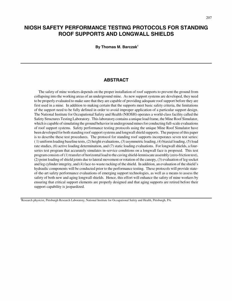
TEST SERIES III – EVALUATION OF LEG SOCKETAND LEG CYLINDER INTEGRITY
Objective – Maximize stress development in the leg socketwelds and expose the leg cylinder seal and piston to maximumside loading at full-stage extension.
Test Requirements – Failure of the leg sockets is a commonshield problem. The leg socket is a casting that is welded along thetop four sides to the side rib plates of the base and to horizontalstiffening plates in the base construction. The canopy constructionis similar, except that unlike the base, the canopy is a single unitwith additional stiffening plates built into the structure. The testrequirement is to induce maximum loading into the welds.
Canopy and Base Contacts – For the base structure, plates arecut so that their width is approximately 50 mm less than theinside dimension of the side rib plates (figure 19A). This con-tact arrangement requires that the full load be supported by thebottom plate without being carried directly through the side ribplates. Therefore, the plates are designed to maximize stressdevelopment in the rib socket welds. The base contact plates
are spaced 1 m apart during loading to simulate steps in thefloor caused by shearer cuts. A centerline canopy contact isestablished as shown in figure 19B. The contact is positionedbetween the leg sockets to induce transverse bending of thecanopy structure and focus loading on the leg socket welds.
Test Procedure
1. The shield is configured so that the upper stage of the legcylinders are at full extension (figure 20). The transversebending of the canopy with full extension of the upper legcylinder staging will cause maximum side loading of thepiston and seals.
2. The shield will be set against the load frame with 50 to 75bar of leg pressure.
3. Cyclic loads are applied by controlled vertical displace-ment of the load frame platens. Horizontal positioning ofthe canopy and base will be restrained by the load frameduring load application. The shield is cycled between thesetting load and yield load.
219
Figure 20.–Upper stage of leg cylinders isfully extended during test series III.
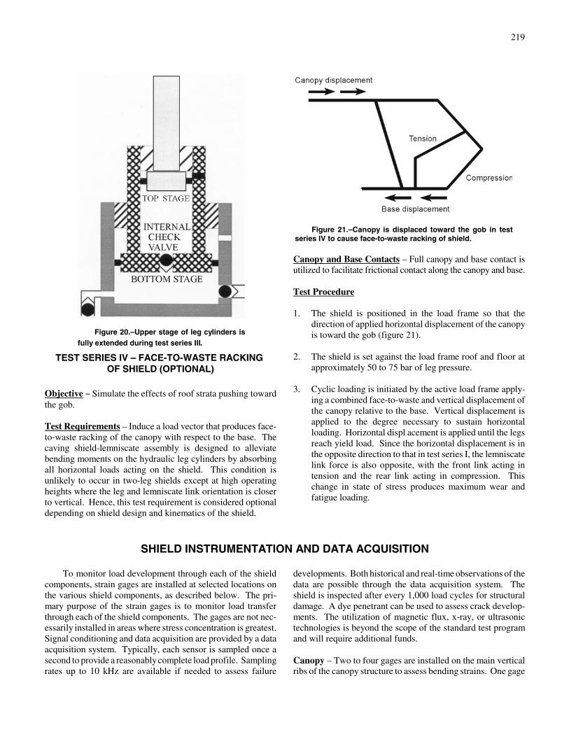
Figure 21.–Canopy is displaced toward the gob in testseries IV to cause face-to-waste racking of shield.
TEST SERIES IV – FACE-TO-WASTE RACKING OF SHIELD (OPTIONAL)
Objective B Simulate the effects of roof strata pushing towardthe gob.
Test Requirements – Induce a load vector that produces face-to-waste racking of the canopy with respect to the base. Thecaving shield-lemniscate assembly is designed to alleviatebending moments on the hydraulic leg cylinders by absorbingall horizontal loads acting on the shield. This condition isunlikely to occur in two-leg shields except at high operatingheights where the leg and lemniscate link orientation is closerto vertical. Hence, this test requirement is considered optionaldepending on shield design and kinematics of the shield.
Canopy and Base Contacts – Full canopy and base contact isutilized to facilitate frictional contact along the canopy and base.
Test Procedure
1. The shield is positioned in the load frame so that thedirection of applied horizontal displacement of the canopyis toward the gob (figure 21).
2. The shield is set against the load frame roof and floor atapproximately 50 to 75 bar of leg pressure.
3. Cyclic loading is initiated by the active load frame apply-ing a combined face-to-waste and vertical displacement ofthe canopy relative to the base. Vertical displacement isapplied to the degree necessary to sustain horizontalloading. Horizontal displ acement is applied until the legsreach yield load. Since the horizontal displacement is inthe opposite direction to that in test series I, the lemniscatelink force is also opposite, with the front link acting intension and the rear link acting in compression. Thischange in state of stress produces maximum wear andfatigue loading.
SHIELD INSTRUMENTATION AND DATA ACQUISITION
To monitor load development through each of the shieldcomponents, strain gages are installed at selected locations onthe various shield components, as described below. The pri-mary purpose of the strain gages is to monitor load transferthrough each of the shield components. The gages are not nec-essarily installed in areas where stress concentration is greatest.Signal conditioning and data acquisition are provided by a dataacquisition system. Typically, each sensor is sampled once asecond to provide a reasonably complete load profile. Samplingrates up to 10 kHz are available if needed to assess failure
developments. Both historical and real-time observations of thedata are possible through the data acquisition system. Theshield is inspected after every 1,000 load cycles for structuraldamage. A dye penetrant can be used to assess crack develop-ments. The utilization of magnetic flux, x-ray, or ultrasonictechnologies is beyond the scope of the standard test programand will require additional funds.
Canopy – Two to four gages are installed on the main verticalribs of the canopy structure to assess bending strains. One gage

220
SHIELD SAFETY PERFORMANCE TESTING FINAL REPORT
1. Scope of Work
2. Testing Objectives and Simulation MethodsObjectivesSimulation of the In-Mine Service ConditionsStandardized Shield Tests and Exceptions
3. Shield Instrumentation and Data Acquisition
4. Test ResultsHydraulic Component EvaluationCyclic Tests
Test Series ITest Series IITest Series IIITest Series IV
4. Failure Assessment and Problem Report
5. Conclusions and Recommendations
is typically installed near the leg connection where the bendingmoment is the largest. The other gage is typically installed for-ward of the leg connection. Strain gages are generally installedon both the left and right side of the canopy.
Caving shield – A strain gage is installed near the canopyclevises and/or the lemniscate link clevis on the main load-transferring members of the caving shield.
Lemniscate links – One or two strain gages are installed oneach of the lemnscate links to measure load development in thelemniscate links. Both axial and bending-induced strains aremeasured. Gages on both the top and bottom surface are usedin link designs that promote bending of the link structure.
Base – A series of two or three strain gages are installed on theinside and outside ribs of each base fabrication to measurebending in the base sections. Gages are also applied to thebridge connecting the two base sections in split-base designs.
Leg Sockets – Gages are installed on the plate sections thatsupport the leg socket in both the canopy and base.
Hydraulic – Pressure transducer is installed in each hydrauliccylinder to measure pressure development during loading.
Cycle count – The number of cycles is counted automaticallyby tracking leg pressure development.
DATA PRESENTATION
The applied loading and strain developments are monitoredduring each load cycle. A full profile of strain developmentduring the loading cycle will be recorded at 100-cycle incre-ments. Ten strain profiles collected during 1,000 loading cycleswill be plotted on a single graph for comparison. Maximumand minimum strains will be recorded for each loading cycle. The maximum and minimum strain values will be plotted ingroups of 5,000 loading cycles to examine trends over a sus-tained loading period. NIOSH reserves the right to modify thisstandard data presentation plan when extenuating circumstancesdictate that other data presentations would be adequate or moreappropriate.
SHIELD PERFORMANCE TESTING REPORT
A performance test report is provided as shown below. The report describes how the tests were conducted and the results ofthe tests. A failure assessment is made documenting time of the failure and the component(s) involved.

221
CONCLUSIONS
The safety of mine workers depends heavily on roof sup-port systems that prevent the unintentional collapse of groundin both working and access areas of the mine. Support manu-facturers continually strive to develop new support technologiesthat provide more effective roof support at less cost and withless effort to install. It is imperative that these prototype sup-port technologies be thoroughly evaluated to make sure thatthey meet required design criteria for use in various under-ground mine conditions.
The availability of the NIOSH Safety Structures TestingLaboratory with the unique Mine Roof Simulator load frameprovides support manufacturers and mine operators with themost precise simulation of underground conditions to ensure thesafety of their products prior to installing prototype systems.The safety performance testing protocols developed by NIOSHfor application in this world-class facility are based on years ofresearch into support design and testing requirements. As such,they are believed to provide the best possible evaluation ofsupport technology.
In recent years, numerous roof support technologies havebeen successfully developed and evaluated at the NIOSH SafetyStructures Testing Laboratory utilizing the protocols describedin this paper. In the past 7 years, over 1,000 tests have beenconducted on various secondary roof support systems. As a re-sult of this effort,18 new support systems have been success-fully introduced to the mining industry, making a significantimpact on longwall tailgate support as alternatives to conven-tional wood and concrete cribbing.
The NIOSH Safety Structures Testing Laboratory providesan opportunity for coal operators andsupport manufacturers tohave shields tested domestically. The Mine Roof Simulator is
unique in its capabilities to apply active vertical and horizontalloads simultaneously, providing realistic simulations of under-ground load conditions. Since the Mine Roof Simulator moreaccurately simulates in-mine service conditions than staticframes, testing at the Safety Structures Testing Laboratory re-duces the risk of premature failures due to poor design. Inaddition to performance-testing new shields, the remaining lifeof aging shields can be determined with more confidence andcan provide an engineering basis for shield retirement and newshield procurement.
In summary, the benefits of shield performance testingusing the unique capabilities of the Safety Structures TestingLaboratory includeC
! Unbiased assessment of support performance.! A location in the United States that improves access to
mine operators.! Freedom of control over the test program.! NIOSH knowledge of shield mechanics and design issues.! Capability for active loading as opposed to static-frame
testing.! Controlled loading that simulates in-mine service con-
ditions accurately.! Participation in research programs to improve shield
design and operation.
Further information concerning utilization of the SafetyStructures Testing Laboratory can be obtained by contactingTom Barczak at (412) 386-6557, by fax at (412)386-6891, orby email at [email protected].