niso data dictionary for digital still images · web viewdata dictionary technical metadata for...
TRANSCRIPT

NISO DRAFT STANDARD
Data Dictionary— Technical Metadata for Digital Still Images —
Working Draft, 1.2May 8, 2023
© NISO, Data Dictionary: Technical Metadata for Images, last updated: 5/8/23 2:54 PM page 1
This document is a Working Draft for review by a NISO Standards Committee. As a draft document, it may be updated at any time during the review process. Its purpose is to facilitate the development of applications to validate, manage, migrate, and otherwise process digital still images of enduring value. Such applications are viewed to be essential components of large-scale digital repositories.

ForewordCultural institutions and commercial organizations are increasingly engaged in creating libraries of digital still images. A major challenge in making these collections persist is to build systems, defined broadly as “digital repositories,” that maintain functionality and quality intrinsic to images. One management strategy, migration, proposes to preserve image data by copying files to new formats at designated intervals.
The premise that underlies migration is the same that informs new concepts of preservation: digital technologies offer the unprecedented opportunity to preserve content without any loss of information from generation to generation. Whether this is possible, and under what conditions, are two of the questions that led NISO, CLIR, and RLG to sponsor an “Image Metadata Workshop” in April 1999. The workshop goal was to launch a collaborative effort to define a set of metadata elements to document technical attributes of digital still images.
The workshop organizers observed that cultural institutions had been focusing primarily on defining descriptive metadata for the purpose of discovery and identification, and that comparatively little work had been done to codify technical attributes of digital images and their production. Workshop participants agreed that technical metadata is necessary to support two fundamental goals: to document image provenance and history (production metadata); and to ensure that image data will be rendered accurately on output (to screen, print, or film). Several participants also observed that ongoing management, or “preservation,” of these core functions will require the development of applications to validate, process, refresh, and migrate image data against criteria encoded as technical metadata.
Two overarching goals led NISO to develop this data dictionary. The first is to identify the data elements that would be used by applications to control transformations of images against stated metrics (or “anchors”) for meaningful quality attributes such as detail, tone, color, and size. The second is to propose elements that would be used by digital repository managers, curators, or imaging specialists to assess the current value (aesthetic or functional) of a given image or collection of images.
Design Principles
The authors of this dictionary are indebted to three working groups that have developed technical metadata specifications for digital still images:
Digital Imaging Group (DIG), DIG35 Working Group, Metadata for Digital Images, Working Draft 2.0 Beta — June 18, 2000
ISO Technical Committee 42 — Photography, ISO/DIS 12234-2, Photography — Electronic still picture imaging — Removable memory — Part 2: Image data format — TIFF/EP, WG18/Item 189.2, June 21, 2000
Adobe Developers Association, TIFF, Revision 6.0, Final — June 3, 1992

Although TIFF and TIFF/EP are file format specifications, the TIFF data elements and values (presented as fields with associated file header tags) are used to represent a comprehensive list of metadata used to render and manage image data.
The DIG35 specification distinguishes itself from file format specifications with its stated purpose to facilitate metadata sharing.

Contents
1. INTRODUCTION.............................................................................................................................8
1.1. Audience..........................................................................................................................8
1.2. Scope................................................................................................................................8
1.3. Design Principles............................................................................................................9
1.3.1. Design Goals.........................................................................................................9
1.4. Implementation Guidelines...........................................................................................9
1.4.1. Metadata Encoding...............................................................................................91.4.2. Metadata Production.............................................................................................91.4.3. Metadata Assumptions........................................................................................10
1.5. Terminology..................................................................................................................10
1.6. Field Reference Guide..................................................................................................10
1.6.1. Data Types..........................................................................................................101.6.2. Documentation....................................................................................................11
2. BASIC IMAGE PARAMETERS.....................................................................................................13
2.1. Format...........................................................................................................................13
2.1.1. MIMEType.........................................................................................................132.1.2. ByteOrder............................................................................................................132.1.3. Compression.......................................................................................................14
2.1.3.1. CompressionScheme..............................................................................142.1.3.2. CompressionLevel..................................................................................14
2.1.4. PhotometricInterpretation...................................................................................142.1.4.1. ColorSpace.............................................................................................142.1.4.2. ICCProfile..............................................................................................152.1.4.3. YCbCrSubSampling...............................................................................162.1.4.4. YCbCrPositioning..................................................................................162.1.4.5. YcbCrCoefficients..................................................................................172.1.4.6. ReferenceBlackWhite.............................................................................17
2.1.5. Segments.............................................................................................................182.1.5.1. SegmentType..........................................................................................182.1.5.2. StripOffsets.............................................................................................182.1.5.3. RowsPerStrip.........................................................................................192.1.5.4. StripByteCounts.....................................................................................192.1.5.5. TileWidth................................................................................................192.1.5.6. TileLength..............................................................................................19

2.1.5.7. TileOffsets..............................................................................................202.1.5.8. TileByteCounts.......................................................................................20
2.1.6. PlanarConfiguration............................................................................................20
2.2. File.................................................................................................................................21
2.2.1. ImageIdentifier....................................................................................................212.2.1.1. ImageIdentifierLocation.........................................................................21
2.2.2. FileSize...............................................................................................................212.2.3. Checksum............................................................................................................22
2.2.3.1. ChecksumMethod...................................................................................222.2.3.2. ChecksumValue......................................................................................22
2.2.4. Orientation..........................................................................................................222.2.5. DisplayOrientation..............................................................................................232.2.6. TargetedDisplayAR............................................................................................23
2.2.6.1. XTargetedDisplayAR.............................................................................232.2.6.2. YTargetedDisplayAR..............................................................................24
2.3. PreferredPresentation..................................................................................................24
3. IMAGE CREATION.....................................................................................................................25
3.1. SourceType...................................................................................................................25
3.2. SourceID........................................................................................................................26
3.3. ImageProducer.............................................................................................................26
3.4. HostComputer..............................................................................................................26
3.4.1. OS (Operating System).......................................................................................273.4.2. OSVersion...........................................................................................................27
3.5. DeviceSource.................................................................................................................27
3.6. ScanningSystemCapture..............................................................................................28
3.6.1. ScanningSystemHardware..................................................................................283.6.1.1. ScannerManufacturer............................................................................283.6.1.2. ScannerModel........................................................................................28
3.6.2. ScanningSystemSoftware...................................................................................293.6.2.1. ScanningSoftware...................................................................................293.6.2.2. ScanningSoftwareVersionNo.................................................................29
3.6.3. ScannerCaptureSettings......................................................................................303.6.3.1. PixelSize.................................................................................................303.6.3.2. PhysScanResolution...............................................................................30
3.7. DigitalCameraCapture................................................................................................31
3.7.1. DigitalCameraManufacturer...............................................................................313.7.2. DigitalCameraModel...........................................................................................31
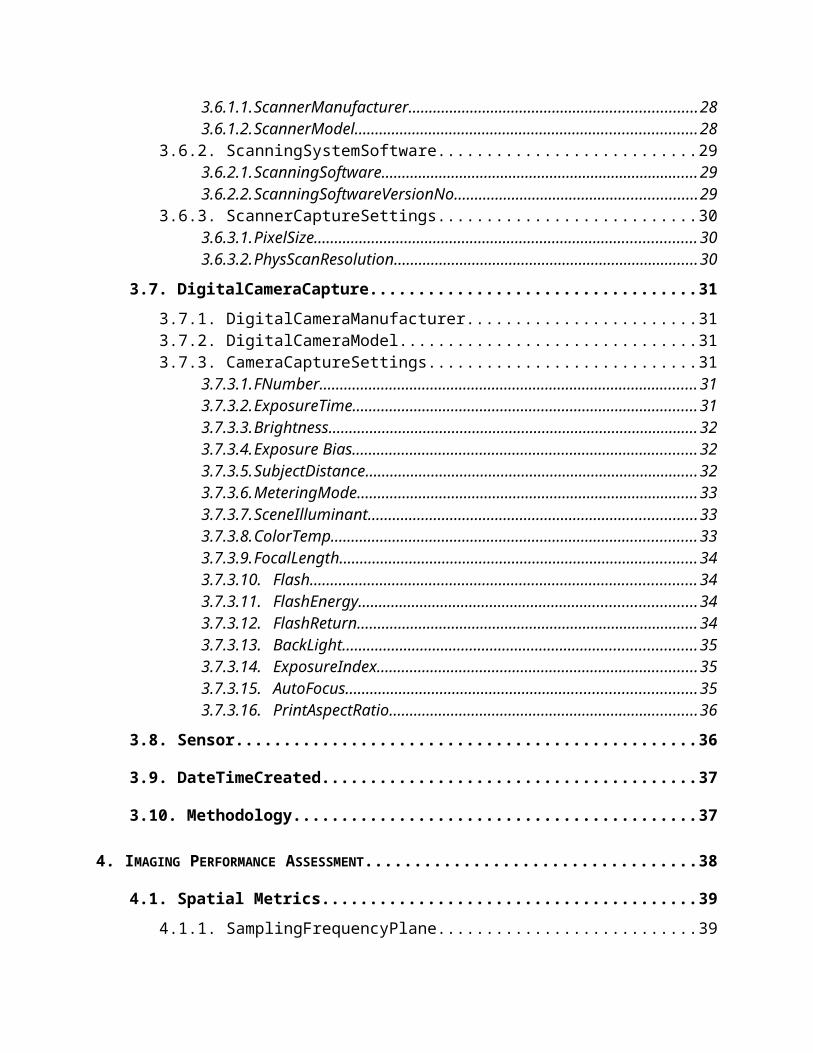
3.7.3. CameraCaptureSettings.......................................................................................313.7.3.1. FNumber................................................................................................313.7.3.2. ExposureTime.........................................................................................313.7.3.3. Brightness...............................................................................................323.7.3.4. Exposure Bias........................................................................................323.7.3.5. SubjectDistance......................................................................................323.7.3.6. MeteringMode........................................................................................333.7.3.7. SceneIlluminant......................................................................................333.7.3.8. ColorTemp.............................................................................................333.7.3.9. FocalLength...........................................................................................343.7.3.10. Flash..................................................................................................343.7.3.11. FlashEnergy......................................................................................343.7.3.12. FlashReturn.......................................................................................343.7.3.13. BackLight..........................................................................................353.7.3.14. ExposureIndex...................................................................................353.7.3.15. AutoFocus..........................................................................................353.7.3.16. PrintAspectRatio...............................................................................36
3.8. Sensor............................................................................................................................36
3.9. DateTimeCreated.........................................................................................................37
3.10. Methodology...............................................................................................................37
4. IMAGING PERFORMANCE ASSESSMENT..................................................................................38
4.1. Spatial Metrics..............................................................................................................39
4.1.1. SamplingFrequencyPlane...................................................................................394.1.2. SamplingFrequencyUnit.....................................................................................404.1.3. XSamplingFrequency.........................................................................................404.1.4. YSamplingFrequency.........................................................................................414.1.5. ImageWidth........................................................................................................414.1.6. ImageLength.......................................................................................................414.1.7. Source_Xdimension............................................................................................42
4.1.7.1. Source_XdimensionUnit.........................................................................424.1.8. Source_Ydimension............................................................................................42
4.1.8.1. Source_YdimensionUnit.........................................................................43
4.2. Energetics......................................................................................................................43
4.2.1. BitsPerSample.....................................................................................................434.2.2. SamplesPerPixel.................................................................................................444.2.3. Extrasamples.......................................................................................................444.2.4. Colormap............................................................................................................444.2.5. GrayResponseCurve...........................................................................................454.2.6. GrayResponseUnit..............................................................................................454.2.7. WhitePoint..........................................................................................................464.2.8. PrimaryChromaticities........................................................................................46

4.3. TargetData....................................................................................................................46
4.3.1. TargetType..........................................................................................................474.3.2. TargetID..............................................................................................................48
4.3.2.1. TargetIDManufacturer...........................................................................484.3.2.2. TargetIDName.......................................................................................484.3.2.3. TargetIDNo............................................................................................484.3.2.4. TargetIDMedia.......................................................................................49
4.3.3. ImageData...........................................................................................................494.3.4. PerformanceData.................................................................................................494.3.5. Profiles................................................................................................................50
5. CHANGE HISTORY....................................................................................................................51
5.1. Image Processing..........................................................................................................53
5.1.1. DateTimeProcessed.............................................................................................535.1.2. SourceData..........................................................................................................535.1.3. ProcessingAgency...............................................................................................545.1.4. ProcessingSoftware.............................................................................................54
5.1.4.1. ProcessingSoftwareName......................................................................545.1.4.2. ProcessingSoftwareVersion...................................................................54
5.1.5. ProcessingActions...............................................................................................54
5.2. Previous Image Metadata............................................................................................55
6. REFERENCES.............................................................................................................................56

1. Introduction1.1. Audience
The purpose of this data dictionary is to define a standard set of metadata elements for digital images. Standardizing the information allows users to develop, exchange, and interpret digital image files. It has been designed to facilitate interoperability between systems, services, and software, as well as to support the long-term management of and continuing access to digital image collections.
Cultural institutions, publishers, rights holders, and other organizations are engaged in digitizing visual materials from historic collections. Therefore, the metadata blocks presented in this document are structured to accommodate practices associated with digital copy photography, such as the use of technical targets, as well as the techniques related to direct digital photography of original scenes.
The purpose of this draft standard is to facilitate the development of applications to validate, manage, migrate, and otherwise process images of enduring value. Such applications are viewed to be essential components of large-scale digital repositories and digital asset management systems.
1.2. Scope
This data dictionary presents a comprehensive list of technical data elements relevant to the management of digital still images. In this context, “management” refers to the tasks and operations needed to support image quality assessment and image data processing throughout the image life cycle. “Quality assessment” is defined broadly, as it refers both to machine operations and curatorial evaluations. Technical metadata have been identified to “anchor” meaningful attributes of image quality that can be measured objectively, such as detail, tone, color, and size.
This standard frequently refers to images maintained in the TIFF (Tagged Image File Format) format. The TIFF format is a highly flexible and platform-independent format that is supported by numerous image-processing applications. The TIFF specification is publicly available to all users. The structure of the header includes a rich set of technical information important for long-term retention such as for colorimetry, calibration, gamut tables, etc. The information is also very useful for remote sensing and multispectral applications. The repeated references to and examples citing the TIFF format within this standard can be extended to other file formats. The technical dictionary indicates the information and metadata all image files should contain as well as additional information related to image production.
Metadata Out of Scope
Except for documentation of the systems that were used to create an image, metadata to document provenance, authenticity, or other aspects of image integrity are beyond the scope of this dictionary. Similarly, Intellectual Property and Rights (IPR) metadata, including ownership

responsibility, is not covered. Although such metadata may be integral to digital repository development and asset management, other emerging draft standards such as the DOI Namespace initiative address this type of metadata. As stated above, data elements in this dictionary focus upon the object class of digital still images.
1.3. Design Principles
1.3.1. Design Goals
The design goals of this NISO initiative are to define a metadata set that interoperates with and meets the goal outlined by the DIG35 metadata standard. To that end, the NISO group has adapted the original DIG35 goals as follows:
INTERCHANGEABLE: the NISO metadata set is based on a sound conceptual model that is both generally applicable to many applications and assured to be consistent over time.
EXTENSIBLE AND SCALEABLE: the NISO metadata set enables application developers and hardware manufacturers to utilize additional metadata fields. This allows future needs for metadata to be fulfilled with limited disruption of current solutions.
IMAGE FILE FORMAT INDEPENDENT: the NISO metadata set does not rely on any specific file format and can therefore be supported by many current and future file formats and compression mechanisms.
CONSISTENT: the NISO metadata set works well with existing standards and it is usable in a variety of application domains and user situations.
NETWORK-READY: the NISO metadata set provides seamless integration with a broad variety of systems and services. Integration options include database products and the utilization of XML schemas (the recommended implementation method).
1.4. Implementation Guidelines
1.4.1. Metadata Encoding
Although recommendations for metadata encoding were deemed beyond the scope of the data dictionary, logical structures have been proposed for several metadata blocks to serve the development of a data model (see Sections 2.1.5, 4.1, 4.3, 5.1, and 5.2).
The dictionary authors recommend adopting TIFF/EP’s guideline prohibiting default values: “...[for every field] do not allow default values. All values shall be explicitly stated. This is done to improve interoperability ...” (TIFF/EP, p4, emphasis added).
1.4.2. Metadata Production
The dictionary assumes that metadata mappings will be essential to automate the collection of technical metadata. Since the design model presumes that NISO-compliant metadata will be stored outside the image, applications will need to be developed (or identified) that “harvest” file
header data programmatically (see 1.4.3 Metadata Assumptions). The dictionary implicitly presents the mappings between TIFF’s required “Baseline Fields” and selected NISO data elements.
1.4.3. Metadata Assumptions
This dictionary adopts the following assumptions articulated in the DIG35 specification:
General-purpose metadata standards must be “applicable to the broadest possible class of file formats” (3.2.1)
To facilitate the management (processing) of the widest range of file formats, an image management metadata standard should “…assume the existence of a file format that contains no header information.” (3.2.1, emphasis added) In other words, data that exists in file headers to comply with specifications for a given image format will need to be replicated.
There should never be any conflicts between the metadata specified in this standard and file header metadata; technical metadata specified in this standard “… should be considered informational and not be used to decode the image data stored in the associated file” (3.2.1, emphasis added)
Metadata conflicts: in Section 3.2.1, DIG35 states, “... if there is a conflict ... the file header shall always take precedence.”
1.5. Terminology
The dictionary adopts the following concepts and terminology:
field refers to the entire data element tag refers only to the i.d. number of each data element image or image data refers to a two-dimensional array of pixels image data is stored using either strips or tiles, which are collectively termed segments processed image refers to an image that has had one or more image processing steps applied
after scanning (see Section 5.1 Image Processing) each pixel consists of one or more color components, e.g.:
– bilevel and grayscale data have one color component per pixel– RGB color data has three components per pixel
component is preferred over its synonyms sample and channel sampling frequency is used to refer to the number and placement of pixels in the image (see
Section 4.1 Spatial Metrics)
1.6. Field Reference Guide
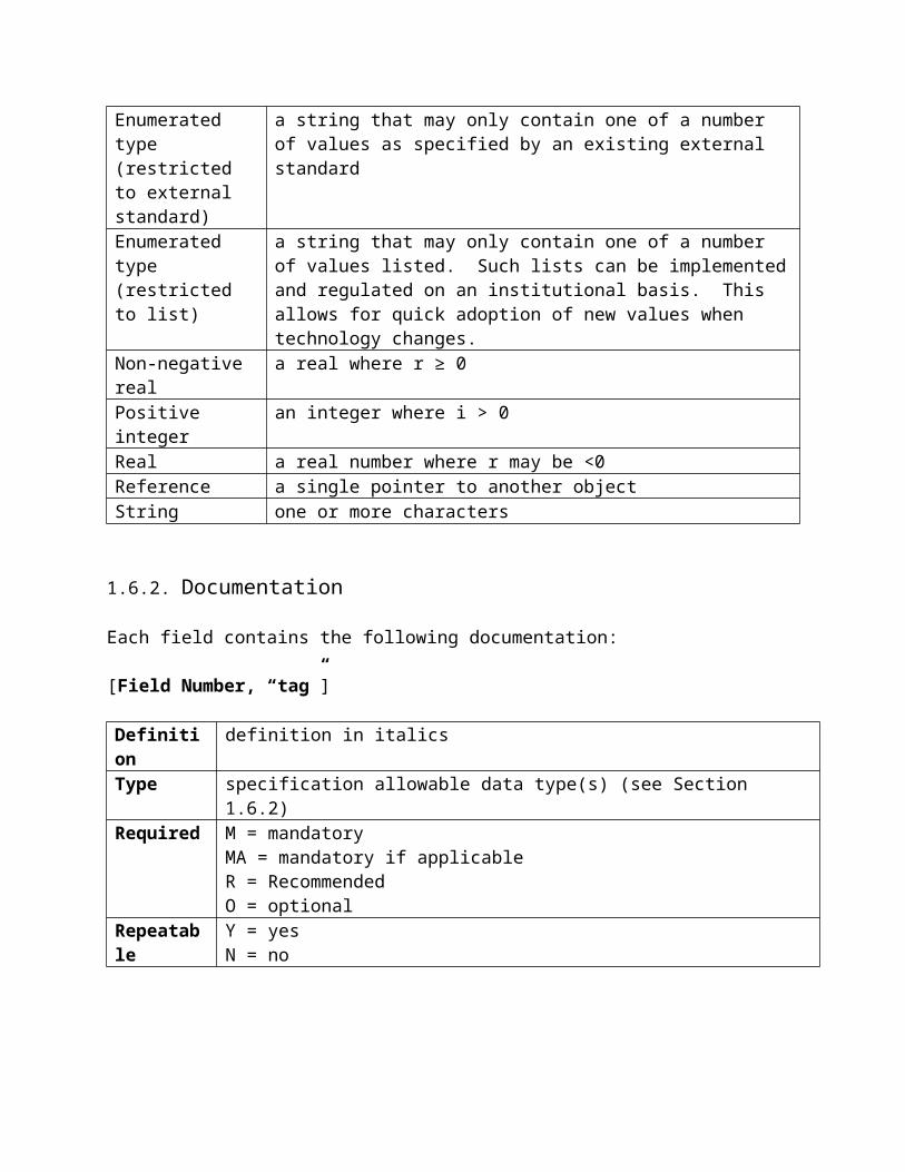
1.6.1. Data Types
The following data types are used in this dictionary:

Data Type DefinitionsDateTime Recorded in compliance with the W3C Note profile of ISO 8601
“Representation of dates and times.” The W3C Note defines a profile of ISO 8601, the International Standard for the representation of dates and times. This information will most likely be harvested from the file header and not manually input.Examples:YYYY:MM:DD HH:MM:SS, with hours 0-24, a space character between the date and time, and a null termination byteYYYY:MM:DDYYYY:MMYYYYThis field should never be changed after it is written in the image capture device
Enumerated type(restricted to external standard)
a string that may only contain one of a number of values as specified by an existing external standard
Enumerated type(restricted to list)
a string that may only contain one of a number of values listed. Such lists can be implemented and regulated on an institutional basis. This allows for quick adoption of new values when technology changes.
Non-negative real a real where r ≥ 0Positive integer an integer where i > 0Real a real number where r may be <0Reference a single pointer to another objectString one or more characters
1.6.2. Documentation
Each field contains the following documentation:
[Field Number, “tag”]
Definition definition in italicsType specification allowable data type(s) (see Section 1.6.2)Required M = mandatory
MA = mandatory if applicableR = RecommendedO = optional
Repeatable Y = yesN = no
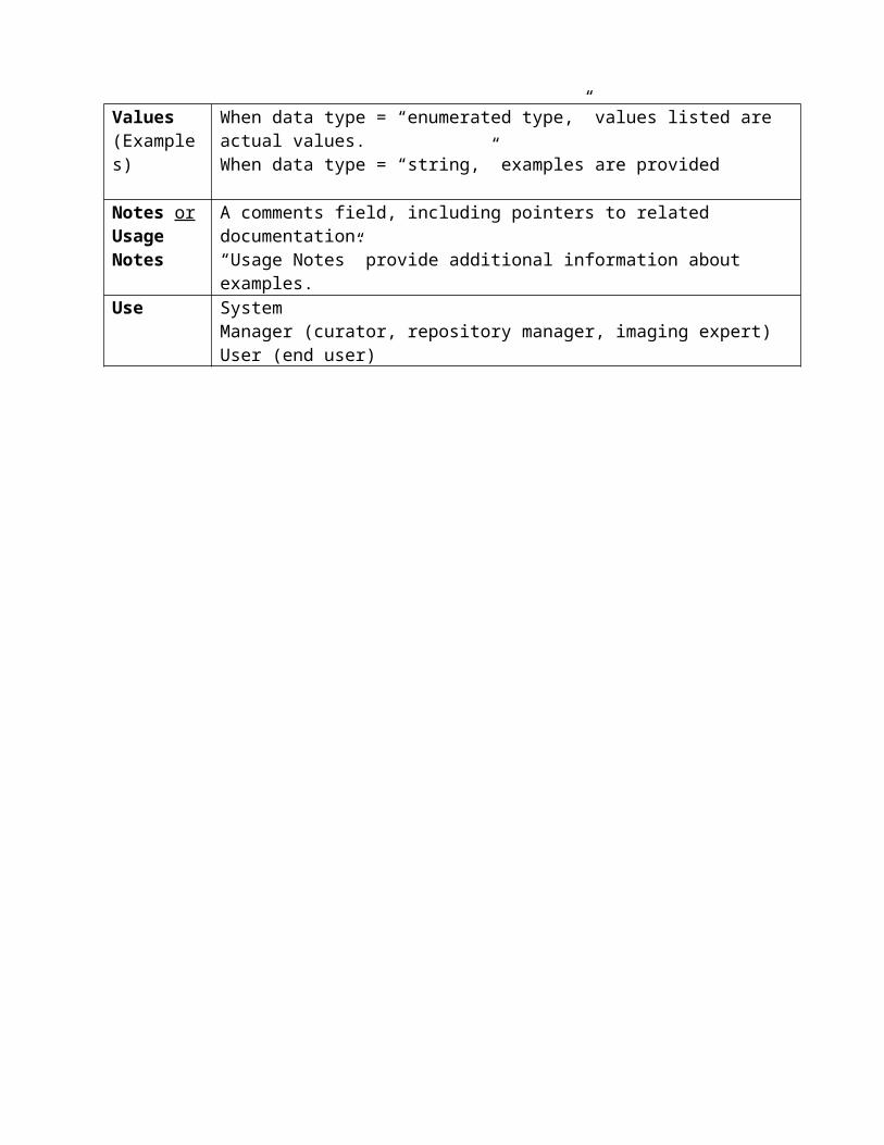
Values(Examples)
When data type = “enumerated type,” values listed are actual values.When data type = “string,” examples are provided
Notes orUsage Notes
A comments field, including pointers to related documentation.“Usage Notes” provide additional information about examples.
Use SystemManager (curator, repository manager, imaging expert)User (end user)

2. Basic Image ParametersThe items in this section are fundamental to the reconstruction of the digital file as a viewable image on electronically interfaced displays. It makes no presumption about the rendered or spatial accuracy of the displayed image, only that a reasonably appearing image can be reconstructed using these elements. Elements for efficient and convenient image display management are provided under Segments 2.1.5.
2.1. Format
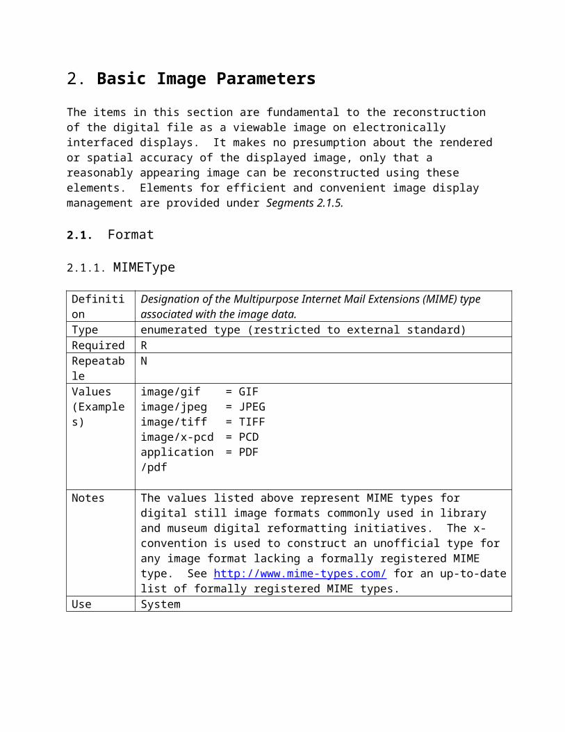
2.1.1. MIMEType
Definition Designation of the Multipurpose Internet Mail Extensions (MIME) type associated with the image data.
Type enumerated type (restricted to external standard)Required RRepeatable NValues(Examples)
image/gifimage/jpegimage/tiffimage/x-pcdapplication/pdf
= GIF= JPEG= TIFF= PCD= PDF
Notes The values listed above represent MIME types for digital still image formats commonly used in library and museum digital reformatting initiatives. The x- convention is used to construct an unofficial type for any image format lacking a formally registered MIME type. See http://www.mime-types.com/ for an up-to-date list of formally registered MIME types.
Use System
2.1.2. ByteOrder
Definition Designates the byte order in multi-byte numbers are storedType enumerated type (restricted to list)Required RRepeatable NValues big-endian
little_endianNotes Virtually all computer architectures are byte addressable. The bytes of a multi-
byte data value can be stored in memory in different orders. "Little_endian" means that the low-order byte of the number is stored in memory at the lowest address, and the high-order byte at the highest address. “Big_endian" means that the high-order byte of the number is stored in memory at the lowest address, and the low-order byte at the highest address.
Use System
2.1.3. Compression
2.1.3.1. CompressionScheme
Definition Designates the compression scheme used to store the image data.Type enumerated type (restricted to list)Required MRepeatable NValues 1
2345632773
= Uncompressed= CCITT 1D= CCITT Group 3= CCITT Group 4= LZW= JPEG = PackBits (simple byte-oriented run-length scheme)
Usage Notes Values above are drawn from TIFF 6.0 specification (p117) though institutions are encouraged to devise a local enumerated list to allow for the addition of new values as technology changes. This data element allows for the designation of subelements in order to record the level of compression applied. See 2.1.3.2 CompressionLevel.
Use System
2.1.3.2. CompressionLevel
Definition Designates the level of compression used in 2.1.3.1.Type Positive integerRequired MARepeatable NValues(Examples)
1030
NotesUse System
2.1.4. PhotometricInterpretation
2.1.4.1. ColorSpace
Definition Designates the color space of the decompressed image data.Type enumerated type (restricted to external standard)Required M
Repeatable NValues 0 =
1 =
2 =
3 =
4 =
5 =
6 =
8 =
WhiteIsZero. For bilevel and grayscale images: 0 is imaged as white. 2**BitsPerSample-1 is imaged as black. This is the normal value for Compression=2.
BlackIsZero. For bilevel and grayscale images: 0 is imaged as black. 2**BitsPerSample-1 is imaged as white. If this value is specified for Compression=2, the image should display and print reversed.
RGB. In the RGB model, a color is described as a combination of the three primary colors of light (red, green, and blue) in particular concentrations. For each of the three components, 0 represents minimum intensity, and 2**BitsPerSample - 1 represents maximum intensity. Thus an RGB value of (0,0,0) represents black, and (255,255,255) represents white, assuming 8-bit components. For PlanarConfiguration = 1, the components are stored in the indicated order: first Red, then Green, then Blue. For PlanarConfiguration = 2, the StripOffsets for the component planes are stored in the indicated order: first the Red component plane StripOffsets, then the Green plane StripOffsets, then the Blue plane StripOffsets.
Palette color. In this model, a color is described with a single component. The value of the component is used as an index into the red, green and blue curves in the ColorMap field to retrieve an RGB triplet that defines the color. When PhotometricInterpretation=3 is used, ColorMap must be present and SamplesPerPixel must be 1.
Transparency Mask. This means that the image is used to define an irregularly shaped region of another image in the same TIFF file. SamplesPerPixel and BitsPerSample must be 1. PackBits compression is recommended. The 1-bits define the interior of the region; the 0-bits define the exterior of the region.
CMYK
YCbCr
CIELabNotes Note: when PhotometricInterpretation = 6, TIFF/EP requires use of the
following four tags (which are not covered in this specification): 530 YCbCrSubSampling, 531 YCbCrPositioning, 529, YcbCrCoefficients, 532 ReferenceBlackWhite . Use 2.1.4.3 – 2.1.4.6 to record these values.
See TIFF Section 21 YCbCr Images and ISO/TC42N 4378 TIFF/EP standard, Section 5 - TIFF/EP Tag definitions for additional information regarding TIFF YcbCr (Class Y) images.
Use System (tone, color)Manager, one of the quantitative metrics to evaluate image quality
2.1.4.2. ICCProfile
2.1.4.2.1 ProfileName
Definition Designates the well-defined name of the ICC profile used.Type string
Required MARepeatable NValuesUsage Notes If ICC profile used is a well-known and well-documented profile, record the
information in this data element. If not, record the location of where the profile can be found in 2.1.4.2.2 ProfileURL.
Use System
2.1.4.2.2 ProfileURL
Definition Designates the URL/URN where the ICC profile is located.Type stringRequired MARepeatable NValuesUsage Notes If ICC profile used is a well-known and well-documented profile, record the
information in 2.1.4.2.1. ProfileName. If not, record the location of where the profile can be found in this data element.
Use System
2.1.4.3. YCbCrSubSampling
Definition Designates the subsampling factors used for the chrominance components of a YCbCr image. It is mandatory when PhotometricInterpretation = 6, and there are no defaults allowed.
Type enumerated type (restricted to external standard)Required MARepeatable NValues
Usage Notes See TIFF Section 21 YCbCr Images and ISO/TC42N 4378 TIFF/EP standard, Section 5 - TIFF/EP Tag definitions for additional information regarding TIFF YcbCr (Class Y) images.
Use System (tone, color)Manager, one of the quantitative metrics to evaluate image quality
2.1.4.4. YCbCrPositioning
Definition Designates the positions of subsampled chrominance components relative to luminance samples. This tag is mandatory when PhotometricInterpretation = 6, and the value shall equal 2.
Type enumerated type (restricted to external standard)Required MA

Repeatable NValue 2
Usage Notes See TIFF Section 21 YCbCr Images and ISO/TC42N 4378 TIFF/EP standard, Section 5 - TIFF/EP Tag definitions for additional information regarding TIFF YcbCr (Class Y) images.
Use System (tone, color)Manager, one of the quantitative metrics to evaluate image quality
2.1.4.5. YcbCrCoefficients
Definition Encodes the transformation from RGB to YCbCr image data. It is mandatory when PhotometricInterpretation = 6, and there are no defaults allowed. The transformation is specified as three rational values that represent the coefficients used to compute luminance, Y.
Type enumerated type (restricted to external standard)Required MARepeatable NValues
Usage Notes See TIFF Section 21 YCbCr Images and ISO/TC42N 4378 TIFF/EP standard, Section 5 - TIFF/EP Tag definitions for values and additional information regarding TIFF YcbCr (Class Y) images.
Use System (tone, color)Manager, one of the quantitative metrics to evaluate image quality
2.1.4.6. ReferenceBlackWhite
Definition Encodes a pair of headroom and footroom image data values for each pixel component. This tag is mandatory when PhotometricInterpretation = 6 (YCbCr), and there are no defaults allowed.
Type enumerated type (restricted to external standard)Required MARepeatable NValues
Usage Notes See TIFF Section 21 YCbCr Images and ISO/TC42N 4378 TIFF/EP standard, Section 5 - TIFF/EP Tag definitions for values and additional information regarding TIFF YcbCr (Class Y) images.
Use System (tone, color)Manager, one of the quantitative metrics to evaluate image quality

2.1.5. Segments
Image data is stored using either strips or tiles, which are collectively termed segments (TIFF/EP, 10). TIFF specifies that strip-oriented and tile-oriented fields must not be used in the same file (TIFF, 67).
The following diagram illustrates the logical structure of the Segments metadata.
Figure 1 - Logical Structure of Segments Metadata
2.1.5.1. SegmentType
Definition Specifies whether image data is stored in strips or tiles.Type enumerated typeRequired MRepeatable NValues 0 = strips
1 = tilesUsage Notes When value = 0, fields 2.1.5.5-2.1.5.8 are irrelevant.
When value = 1, fields 2.1.5.2-2.1.5.4 are irrelevant.Use Manager
2.1.5.2. StripOffsets
Definition For each strip, the byte offset of that strip.
Segments (2.1.5)
SegmentType (2.1.5.1)
StripOffsets (2.1.5.2)
RowsPerStrip (2.1.5.3)value = 0
StripByteCounts (2.1.5.4)
TileWidth (2.1.5.5)
TileLength (2.1.5.6)
TileOffsets (2.1.5.7)
TileByteCounts (2.1.5.8)
value = 1

Type positive integerRequired R (when applicable; see usage note in 2.1.5.1)Repeatable NValuesNotes “The StripOffsets field stores the offsets from the start of the image file to the
start of each image data strip.” (TIFF/EP)Use System (“This required field is the only way for a reader to find the image data,
unless TileOffsets is used,” TIFF p40)
2.1.5.3. RowsPerStrip
Definition The number of rows per strip.Type positive integerRequired R (when applicable; see usage note in 2.1.5.1)Repeatable NValuesNotes “RowsPerStrip and ImageLength together tell us the number of strips in the
entire image. The equation is:…” (TIFF, p39)Use System
2.1.5.4. StripByteCounts
Definition The number of image data bytes stored within each strip after compression.Type positive integerRequired R (when applicable; see usage note in 2.1.5.1)Repeatable NValuesNotesUse System
2.1.5.5. TileWidth
Definition The tile width in pixels. This is the number of columns in each tile.Type positive integerRequired R (when applicable; see usage note in 2.1.5.1)Repeatable NValuesNotesUse System
2.1.5.6. TileLength
Definition The tile length (height) in pixels. This is the number of rows in each tile.Type positive integer

Required R (when applicable; see usage note in 2.1.5.1)Repeatable NValuesNotesUse System
2.1.5.7. TileOffsets
Definition For each tile, the byte offset of that tile, as compressed and stored on disk.Type positive integerRequired R (when applicable; see usage note in 2.1.5.1)Repeatable NValuesNotesUse System
2.1.5.8. TileByteCounts
Definition For each tile, the byte offset of that tile, as compressed and stored on disk.Type positive integerRequired R (when applicable; see usage note in 2.1.5.1)Repeatable NValues [n] = TilesPerImage for PlanarConfiguration = 1
= SamplesPerPixel * TilesPerImage for PlanarConfiguration = 2Notes For each tile, the number of (compressed) bytes in that tile. See TileOffsets
for a description of how the byte counts are ordered. No default. See also TileWidth, TileLength, TileOffsets. (TIFF, p68)
Use System
2.1.6. PlanarConfiguration
Definition Designates how the components of each pixel are stored.Type enumerated typeRequired MA (when SamplesPerPixel > 1; cf 2.2)Repeatable NValues 1 = chunky (pixel interleaved) format
2 = planar formatNotes “If SamplesPerPixel is 1, PlanarConfiguration is irrelevant.” (TIFF, p38)
See, TIFF/EP 5.2.14 for an alternative definition of Planar Configuration that incorporates CFAPattern values.
Use System

2.2. File
2.2.1. ImageIdentifier
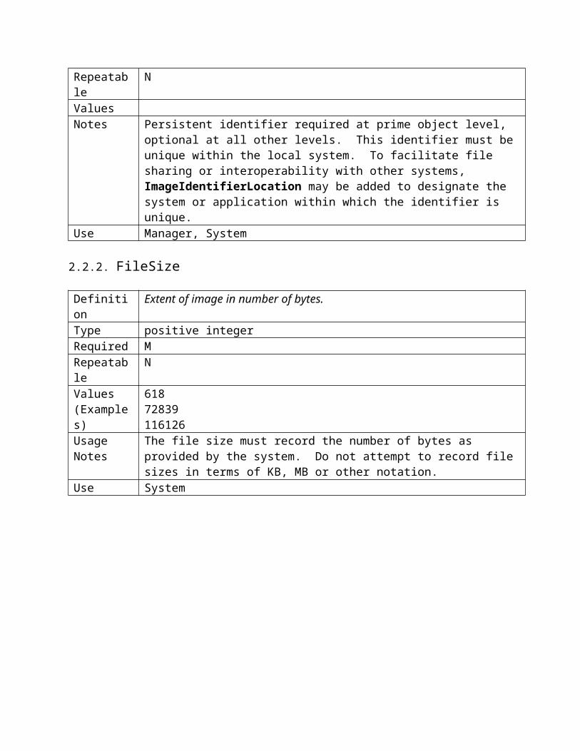
Definition A unique identifier.Type String Required MRepeatable NValuesNotes Persistent identifier required at prime object level, optional at all other levels.
This identifier must be unique within the local system. To facilitate file sharing or interoperability with other systems, a subelement (2.2.1.1 ImageIdentifierLocation) .may be added to designate the system or application within which the identifier is unique.
Use Manager, System
2.2.1.1. ImageIdentifierLocation
Definition A location qualifier to be used in conjunction with 2.2.1 ImageIdentifier.Type String Required ORepeatable NValuesNotes Persistent identifier required at prime object level, optional at all other levels.
This identifier must be unique within the local system. To facilitate file sharing or interoperability with other systems, ImageIdentifierLocation may be added to designate the system or application within which the identifier is unique.
Use Manager, System
2.2.2. FileSize
Definition Extent of image in number of bytes. Type positive integerRequired MRepeatable NValues(Examples)
61872839116126
Usage Notes The file size must record the number of bytes as provided by the system. Do not attempt to record file sizes in terms of KB, MB or other notation.
Use System

2.2.3. Checksum
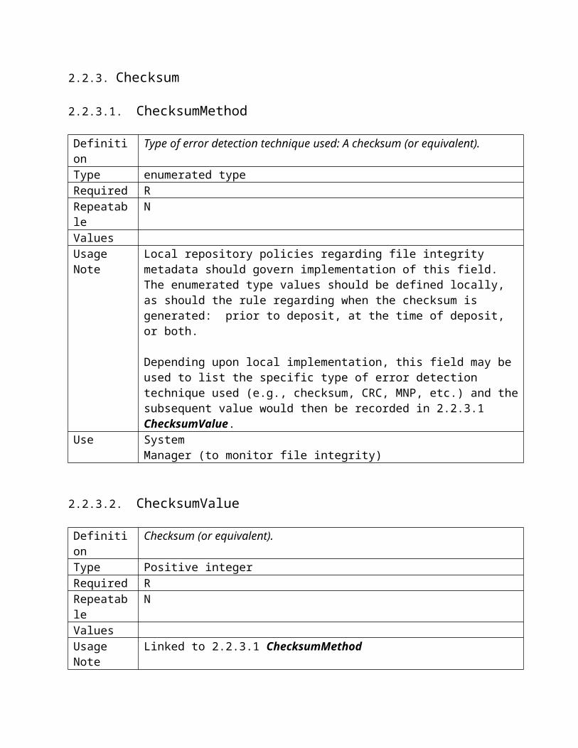
2.2.3.1. ChecksumMethod
Definition Type of error detection technique used: A checksum (or equivalent). Type enumerated typeRequired RRepeatable NValuesUsage Note Local repository policies regarding file integrity metadata should govern
implementation of this field. The enumerated type values should be defined locally, as should the rule regarding when the checksum is generated: prior to deposit, at the time of deposit, or both.
Depending upon local implementation, this field may be used to list the specific type of error detection technique used (e.g., checksum, CRC, MNP, etc.) and the subsequent value would then be recorded in 2.2.3.1 ChecksumValue.
Use SystemManager (to monitor file integrity)
2.2.3.2. ChecksumValue
Definition Checksum (or equivalent). Type Positive integerRequired RRepeatable NValuesUsage Note Linked to 2.2.3.1 ChecksumMethodUse System
Manager (to monitor file integrity)
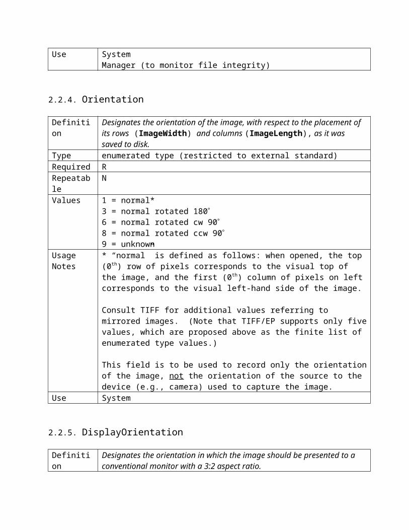
2.2.4. Orientation
Definition Designates the orientation of the image, with respect to the placement of its rows (ImageWidth) and columns (ImageLength), as it was saved to disk.
Type enumerated type (restricted to external standard)Required RRepeatable NValues 1 = normal*
3 = normal rotated 1806 = normal rotated cw 908 = normal rotated ccw 909 = unknown

Usage Notes * “normal” is defined as follows: when opened, the top (0th) row of pixels corresponds to the visual top of the image, and the first (0th) column of pixels on left corresponds to the visual left-hand side of the image.
Consult TIFF for additional values referring to mirrored images. (Note that TIFF/EP supports only five values, which are proposed above as the finite list of enumerated type values.)
This field is to be used to record only the orientation of the image, not the orientation of the source to the device (e.g., camera) used to capture the image.
Use System
2.2.5. DisplayOrientation
Definition Designates the orientation in which the image should be presented to a conventional monitor with a 3:2 aspect ratio.
Type enumerated type (restricted to external standard)Required ORepeatable NValues 0 = portrait
1 = landscapeNotes This value is important to record when the preferred orientation of the image sent
to a 3:2 aspect ratio computer monitor is different from Orientation.
While Orientation refers to the placement of pixels in the digital image file, DisplayOrientation refers to the preferred orientation in which to display the content (text, picture, table, etc.) within the file.
This field will likely become obsolete when “standard” delivery applications, such as web browsers, incorporate an image rotation tool.
Use System
2.2.6. TargetedDisplayAR
2.2.6.1. XTargetedDisplayAR
Definition Unit of X orientationType positive integerRequired ORepeatable NValuesNotesUse System

2.2.6.2. YTargetedDisplayAR
Definition Unit of Y orientationType positive integerRequired ORepeatable NValuesNotesUse System
2.3. PreferredPresentation
Definition Designation of the device, application, medium, viewing environment (or any combination thereof) to render the image data.
Type stringRequired ORepeatable NValuesUsage Notes For image data that can be defined to have a “best representation,” use this free-
text field to recommend the “target” device, application, medium, viewing environment (or combination thereof) presumed or proven to be meaningful to image quality. This will be especially important as viewing devices other than the conventional 3:2 monitor become popular. Calculation and automated optimal display from one display Aspect Ratio to another will be possible with the information from 2.2.5 DisplayOrientation and the host of measurements supported within this standard.
The Library of Congress’s presentation_profile specifies “the program (or equivalent) used to manage the presentation of this primary or intermediate object for users.”
Standard: ISO/DIS 3664 Viewing conditions for graphic technology and photography.
Use Manager, User

3. Image CreationThis section can best be described as descriptive technical metadata. While it provides no quantitative information, per se, it can provide critical information with respect to the logistics and administrative conditions surrounding digital image data capture. Frequently, simple interrogation of these fields offers valuable diagnostics about the image creation step as well as those of subsequent image generations.
Image Creation
This metadata block documents selected, irreversible attributes of the analog-to-digital conversion process that may be used for future quality assessment of the image data. By definition, image creation occurs only once.
See, 5.1 Image Processing for fields to record digital-to-digital conversion processes.
3.1. SourceType
Definition This field specifies the medium of the analog source material scanned to create a digital still image.
Type stringRequired RRepeatable NValues(Examples)
daguerreotypereflection printsilver gelatin printAcme Bronze 100chromagenic film35mm color negative Kodak Royal Gold 100 Emul. 3712011monographmicrofilm
Notes
Usage Notes
“General or specific physical nature of original item (i.e., still pictorial image).” (LC)
Do not record dimensions of source material in this field. See, Source_Xdimension (4.1.7) and Source_Ydimension (4.1.8).
When the source of the image data is another digital still image (e.g., a parent high-resolution image used to create a reduced-resolution image), see ImageProcessing (5.1).
Use Manager, User

3.2. SourceID
Definition A unique identifier for a descriptive record of the source of image.Type stringRequired ORepeatable NValues(Examples)
RLIN IDOCLC record numberLocal system control number
Notes Link to existing data record for the source material.Use Manager, System
3.3. ImageProducer
Definition Identifies the organization-level producer(s) of the image.Type stringRequired RRepeatable YValues(Examples)
Luna Imaging, Inc.JJT, Inc.University of Michigan; Digital Library Production ServicesHarvard College Library; Digital Imaging GroupUniversity of Virginia; William Blake Archive
When Repeatable = Y, the following is an example of how to code the information:
<ImageProducer> University of Virginia </ImageProducer><ImageProducer> William Blake Archive </ImageProducer>
Notes Identifies the organization-level producer of the ‘file/bitstream,’ i.e., the scanned image, transcribed text, audio file, etc.
Use Manager
3.4. HostComputer
Definition Computer and/or operating system in use at the time of image creation.Type stringRequired RRepeatable NValuesNotes The definition for this multi-layered data element can be interpreted narrowly, as
in TIFF (see above), or broadly as in Cedars, which states: “This element contains information about the operating environment of the original digital object at the

time of ingest, including information on relevant hardware and operating systems, together with the software products that would have been required in order to use it.”
Use 3.3.1 OS and 3.3.2 OSVersion to record specifics about the operating system.
Use Manager
3.4.1. OS (Operating System)
Definition Operating system in use at the time of image creation.Type stringRequired RRepeatable NValues(Examples)
Windows MacUnixLinux
NotesUse Manager
3.4.2. OSVersion
Definition Version of the operating system in use at the time of image creation.Type stringRequired MARepeatable NValues(Examples)
2000 (e.g., Windows 2000)NTX (e.g., Mac OS X)V (e.g., Unix System V)
Notes Must be present if information is present in 3.3.1 OS.Use Manager
3.5. DeviceSource
Definition Classification of device used to create the image data.Type stringRequired RRepeatable NValues(Examples)
transmission scannerreflection print scanner

digital still camerastill from video
Usage Notes Recommended syntax: Local institutions should create a list of enumerated values for use with this data element in order to regularize information. Doing so on a local level will allow for more rapid expansion of list to accommodate new technologies.
When image processing software is used to generate the image data from a digital source, see ImageProcessing (5.1).
Use Manager
3.6. ScanningSystemCapture
3.6.1. ScanningSystemHardwareThe scanner manufacturer, model name and/or number used to create the image.
3.6.1.1. ScannerManufacturer
Definition The manufacturer of the scanner used to create the image.Type stringRequired RRepeatable NValues(Example)
Scitex
Usage NoteUse Manager
3.6.1.2. ScannerModel
3.6.1.2.1. ScannerModelName
Definition The model name of the scanner used to create the image.Type stringRequired RRepeatable NValues(Example)
Leaf Volare
Use Manager
3.6.1.2.2. ScannerModelNumber
Definition The model number of the scanner used to create the image.
Type stringRequired RRepeatable NValues(Example)Use Manager
3.6.1.2.3. ScannerModelSerialNo
Definition The serial number of the scanner used to create the image.Type stringRequired ORepeatable NValues(Example)Use Manager
3.6.2. ScanningSystemSoftware
3.6.2.1. ScanningSoftware
Definition The name of the capture software used to create the image.Type stringRequired RRepeatable NValues(Example)
Leaf
Use Manager
3.6.2.2. ScanningSoftwareVersionNo
Definition The version number of the capture software used to create the image.Type stringRequired RRepeatable NValues(Example)
4.0 (e.g., Leaf 4.0)
Use Manager
3.6.3. ScannerCaptureSettings
3.6.3.1. PixelSize
Definition This specifies the pixel size, in meters, of the scanner.Type Non-negative realRequired ORepeatable NValuesUsage NoteUse System
Manager
3.6.3.2. PhysScanResolution
3.6.3.2.1. XphysScanResolution
Definition This specifies the physical scanning resolution of the device, in meters, recording the x (width) direction.
Type Non-negative realRequired ORepeatable NValuesUsage Note This is NOT the interpolated resolution of the final output dataUse System
Manager
3.6.3.2.2. YphysScanResolution
Definition This specifies the physical scanning resolution of the device, in meters, recording the Y (height) direction.
Type Non-negative realRequired ORepeatable NValuesUsage Note This is NOT the interpolated resolution of the final output dataUse System
Manager
3.7. DigitalCameraCapture
3.7.1. DigitalCameraManufacturer
Definition The manufacturer of the digital camera used to create the image.Type stringRequired RRepeatable NValues(Example)
PhaseOne
Use Manager
3.7.2. DigitalCameraModel
Definition The model of the digital camera used to create the image.Type stringRequired RRepeatable NValues(Examples)
H_20LightPhase
Use Manager
3.7.3. CameraCaptureSettings
3.7.3.1. FNumber
Definition This specifies the lens f-number (ratio of lens aperture to focal length) used when the image was captured.
Type Non-negative realRequired ORepeatable NValuesUse System
Manager
3.7.3.2. ExposureTime
Definition This specifies the exposure time used when the image was captured. The value is to be recorded in seconds.
Type Non-negative realRequired ORepeatable NValues

Usage Note Input may be given as a rational (e.g., 1/125), but systems should store the number as a non-negative real (e.g., 0.008).
Use SystemManager
3.7.3.3. Brightness
Definition This specifies the Brightness values measured when the image was captured, using APEX values.
Type Non-negative realRequired ORepeatable NValuesUsage Note This value represents the light level at the source (document).Use System
Manager
3.7.3.4. Exposure Bias
Definition This specifies the actual exposure bias (the amount of under or over-exposure relative to a normal exposure, as determined by the camera's exposure system) used when capturing the image, using APEX units.
Type Non-negative real?Required ORepeatable NValuesUse System
Manager
3.7.3.5. SubjectDistance
Definition This specifies the distance, in meters, between the frontal plane of the camera lens and the subject on which the camera was focused.
Type Non-negative realRequired ORepeatable NValues(Examples)
<SubjectDistance>5</SubjectDistance> OR<SubjectDistance min=”4.9” max=”5.3”>5</SubjectDistance> OR<SubjectDistance min=”4.9” max=”5.3”/>
Usage Note May specify a range of values, bounded by minimum and maximumUse System
Manager
3.7.3.6. MeteringMode
Definition This specifies the metering mode (the camera's method of spatially weighting the scene luminance values to determine the sensor exposure) used when capturing the image.
Type Enumerated type (limited to list)Required ORepeatable NValues(Examples)
AverageCenter weighted AverageSpotMultispotPatternPartial
Usage NoteUse System
Manager
3.7.3.7. SceneIlluminant
Definition This specifies the light source that was present when the image was captured.Type Enumerated type (restricted to external standard)Required ORepeatable NValues Daylight
Fluorescent Tungsten LampFlashStandard Illuminant AStandard Illuminant BStandard Illuminant CD55 IlluminantD65 IlluminantD75 Illuminant
Usage Note Values for this data element must be drawn from the list documented in the DIG35 standard.
Use SystemManager
3.7.3.8. ColorTemp
Definition This specifies the actual color temperature value of the scene illuminant in units of Kelvin.
Type Non-negative realRequired O

Repeatable NValuesUse System
Manager
3.7.3.9. FocalLength
Definition This specifies the lens focal length in meters used to capture the image.Type Real Required ORepeatable NValuesUse System
Manager
3.7.3.10.Flash
Definition This specifies whether a flash was used in image capture.Type Enumerated typeRequired ORepeatable NValues Yes
NoUse System
Manager
3.7.3.11.FlashEnergy
Definition This specifies the amount of flash energy that was used in Beam Candle Power Seconds (BCPS).
Type Non-negative realRequired ORepeatable NValuesUse System
Manager
3.7.3.12.FlashReturn
Definition This specifies whether the camera judged that the flash was not effective at the time of exposure.
Type Enumerated typeRequired ORepeatable NValues Yes
NoUse System
Manager
3.7.3.13.BackLight
Definition This specifies the lighting conditions at the time of exposure.Type Enumerated type (restricted to external standard)Required ORepeatable NValues Front light
Backlight_1
Backlight_2
“Subject is illuminated from the front side.”
“The brightness value difference between the subject center and the surrounding area is greater than one full stop (APEX). The frame is exposed for the subject center.”
“The brightness value difference between the subject center and the surrounding area is greater than one full stop (APEX). The frame is exposed for the surrounding area.”
Usage Note Values for this data element must be drawn from the list documented in the DIG35 standard (DIG35 B3.2.5 <Back_Light>).
Use SystemManager
3.7.3.14.ExposureIndex
Definition This specifies the exposure index setting used.Type Non-negative real Required ORepeatable NValuesUse System
Manager
3.7.3.15.AutoFocus
Definition This specifies the status of the capture device’s focus at the time of capture.Type enumerated list (restricted to external standard)Required ORepeatable NValues Auto Focus Used
Auto Focus Interrupted
Near Focused
“The camera successfully focused on the subject.”
“The image was captured before the camera had successfully focused on the subject.”
“The camera deliberately focused at a distance closer than the subject to allow for the super-imposition of a focused foreground subject.”
Soft Focused
Manual
“The camera deliberately did not focus exactly at the subject distance to create a softer image (commonly used in portraits).”
“The camera was focused manually.”
Usage Note Values for this data element must be drawn from the list documented in the DIG35 standard (DIG35 B3.2.5 <Auto Focus Values>).
Use SystemManager
3.7.3.16.PrintAspectRatioThis specifies the print aspect ratio selected by the user when the picture was taken.
3.7.3.16.1. XPrintAspectRatio
Definition Unit of X ratioType non-negative realRequired ORepeatable NValuesUse System
Manager
3.7.3.16.2. YprintAspectRatio
Definition Unit of Y ratioType non-negative realRequired ORepeatable NValuesUse System
Manager
3.8. Sensor
Definition Designates the type of image sensor used in the camera or image capture device.Type enumerated type (restricted to external standard)Required RRepeatable NValues undefined
MonochromeAreaOneChipColorAreaTwoChipColorAreaThreeChipColorAreaColorSequentialAreaMonochromeLinear

ColorTriLinearColorSequentialLinear
Notes Enumerated values drawn from TIFF/EP 37399 (p25-26)Use Manager
3.9. DateTimeCreated
Definition Date or DateTime image was created.Type DateTimeRequired MA Repeatable NValues YYYY-MM-DDUsage Notes See, DateTimeProcessed (5.1.1) for images created by processing image data
(i.e., digital-to-digital conversion). Use Manager
3.10. Methodology
Definition Designates the methodology and rationale to digitize an object or collection.Type stringRequired ORepeatable NValues(Examples)
string[free text][filename or URL] http://lcweb2.loc.gov/ammem/techdocs/digcols.html
Notes For an example, see “Building Digital Collections” notes associated with the American Memory collections, Library of Congress, National Digital Library Program, http://lcweb2.loc.gov/ammem/techdocs/digcols.html
Use Manager, User

4. Imaging Performance AssessmentThe operative principle in this section is to maintain the attributes of the image inherent to its quality. The title Performance Assessment has both a present and future context: these elements serve as metrics to assess the accuracy of output (today’s use), and to assess the accuracy of preservation techniques, particularly migration (future use).
Sub-sections 4.1 Spatial Metrics and 4.2 Energetics are meant as high-level quantitative measures of imaging performance. Sub-section 4.3 Targets is meant to complement the former by providing low-level benchmarking quantification of the absolute imaging performance of the digital capture process. This information in this latter section should be closely tied to sanctioned imaging performance standards when available. In the absence of such standards, de-facto standards are appropriate.
To help in the understanding of this section, Figures 1 and 2 are provided as examples of typical imaging chains. Frequently, confusion exists around image state generations, and at which generation the metadata is meant to apply. Often, knowledge at all levels is required. In such cases, repeatable fields for a given element are offered.
Figure 2 - Digital conversion of Intermediate; Indirect conversion of Source
Figure 3 - Direct digital conversion of Source
NISO datadictionary 00110100100….
Source Digital fileDigital conversion

To a large extent, the image of any source can be linked backed to that source with appropriate capture documentation and benchmarking targets. While the original source characteristics are not unequivocally recoverable, suitably accurate reconstructions of the source can, in principle, occur. The high level metrics of sub-sections 4.1 and 4.2 can provide nominal recovery of the original source characteristics. Detailed imaging performance information in Section 4.3, if properly documented, is a reliable thread to more accurate source characteristics.
4.1. Spatial Metrics
While it is recognized that digital images can describe three-dimensional objects, this section deals only with the classic 2-dimensional projection of such objects as seen by the imaging device at any given instant in time. The digital image assumes the form of a uniformly sampled rectangular grid of pixels (picture elements) in the "x" (ImageWidth) and "y" (ImageLength) dimensions. The global photometrics associated with each of these pixels is covered in sub-section 4.2.
Though range or depth data (i.e. "z" dimension) can be digitized with specialized 3-D imaging devices, these are outside the scope of this document
4.1.1. SamplingFrequencyPlane
Definition The reference plane location for which XSamplingFrequency and YsamplingFrequency are designated.
Type enumerated type (restricted to list)Required MRepeatable NValues 1 = camera/scanner focal plane
2 = object plane3 = source object plane
Notes This element is meant to remove the ambiguity with respect to XSamplingFrequency and YSamplingFrequency for the scanning of film intermediates. It can be used to deduce Source_Xdimension or Source_Ydimension in conjunction with ImageWidth or ImageLength.
Value = 1 is consistent with DIG35 (B.3.2.4) and TIFF/EP 5.2.9-5.2.10 and is an indication of the physical sensor sampling frequency. It is of limited use without knowledge of the optical magnification between sensor and imaged object
Value = 2 would be most common for direct scanning of source objects. If “object plane” is the same as “source object plane,” (Fig. 3) this value is used.
Value = 3 commonly used for film intermediates such as microfilm where XSampling Frequency and YSamplingFrequency are often referred to at the source object plane rather than the object film plane (Fig. 2).
Use System, accurate output of file to print/film (size)

Manager, one of the quantitative metrics to evaluate image quality
4.1.2. SamplingFrequencyUnit
Definition The unit of measurement for XSamplingFrequency and YSamplingFrequency.Type enumerated type (restricted to external standard)Required MRepeatable NValues 1 = no absolute unit of measurement.
2 = inch3 = centimeter
Usage Notes From TIFF 296 (Baseline Required, p21-24, 38), TIFF/EP 296 (5.2.8):
Value “1” used for images that may have a non-square aspect ratio, but no meaningful absolute dimensions. In copy work, should also be used when source measurements are unknown (e.g., when a photo-intermediate such as 35mm negative film is the source).
When SamplingFrequencyUnit = 2 and Source_Xdimension is given in inches, the XSamplingFrequency may be calculated as follows:
XSamplingFrequency = ImageLength/Source_Xdimension
When SamplingFrequencyUnit = 2 and Source_Ydimension is given in inches, the YSamplingFrequency may be calculated as follows:
YSamplingFrequency = ImageWidth/Source_Ydimension
The same formulas may be used when SamplingFrequencyUnit = 3 and source dimensions are given in centimeters.
Use System, accurate output of file to print/film (size)Manager, one of the quantitative metrics to evaluate image quality
4.1.3. XSamplingFrequency
Definition This field specifies the number of pixels per SamplingFrequencyUnit in the image width.
Type positive integerRequired MA (when SamplingFrequencyUnit = 2 or 3)Repeatable NValuesNotes With fields YSamplingFrequency (4.1.4) and SamplingFrequencyUnit (4.1.2),
XSamplingFrequency specifies the dimensions (scale) of the printed image.
When SamplingFrequencyUnit=1, this value for this field shall be null.

Use System, accurate output of file to print/film (size)Manager, one of the quantitative metrics to evaluate image quality
4.1.4. YSamplingFrequency
Definition This field specifies the number of pixels per SamplingFrequencyUnit in the image length.
Type positive integerRequired MA (when SamplingFrequencyUnit=2 or 3)Repeatable NValuesNotes With fields YSamplingFrequency (4.1.4) and SamplingFrequencyUnit (4.1.5),
YSamplingFrequency specifies the dimensions (scale) of the printed image.Use System, accurate output of file to print/film (size)
Manager, one of the quantitative metrics to evaluate image quality
4.1.5. ImageWidth
Definition This specifies the width of the digital image, i.e. horizontal or X dimension, in pixels.
Type positive integerRequired MARepeatable NValuesNotes The image width may be the shorter or longer dimension of the image, depending
upon the orientation of the camera or scanner during image capture. For multiple-resolution image file formats, value shall specify the highest resolution.
This value may be used to calculate XSamplingFrequency when Source_Xdimension is given in inches and SamplingFrequencyUnit = 2.
Formula to calculate XSamplingFrequency:XSamplingFrequency = ImageWidth/Source_Xdimension
Use System, required field for image viewers (size)Manager, one of the quantitative metrics to evaluate image quality
4.1.6. ImageLength
Definition This specifies the length of the digital image, i.e. vertical or Y dimension, in pixels.
Type positive integerRequired MARepeatable NValuesNotes The image length may be the shorter or longer dimension of the image, depending
upon the orientation of the camera or scanner during image capture. For multiple-resolution image file formats, value shall specify the highest resolution.
This field may be used to calculate YSamplingFrequency when Source_Ydimension is given in inches and SamplingFrequencyUnit = 2
Formula to calculate YSamplingFrequency:YSamplingFrequency = ImageLength/Source_Ydimension
Use System, required field for image viewers (size)Manager, one of the quantitative metrics to evaluate image quality
4.1.7. Source_Xdimension
Definition Specifies the width of the scanned object. Type [non-negative real] Required ORepeatable NValues(Examples)
7.63 (e.g., 7.63 inches)32 (e.g., 32 mm)
Usage Notes The unit of measure (inches, meters, etc.) used must be specified in 4.1.7.1 Source_XdimensionUnit.
If unknown or impractical to record, the value of Source_Xdimension may be deduced. See, SamplingFrequencyPlane (4.1.6).
Use System, accurate output of file to print/film (size)Manager, one of the quantitative metrics to evaluate image quality
4.1.7.1. Source_XdimensionUnit
Definition Specifies the unit of measure used in 4.1.7 Source_XdimensionType stringRequired ORepeatable NValues(Examples)
inchesmm
Notes Use System, accurate output of file to print/film (size)
Manager, one of the quantitative metrics to evaluate image quality
4.1.8. Source_Ydimension
Definition Specifies the height (i.e., vertical dimension) of the scanned object.Type non-negative realRequired ORepeatable N

Values(Examples)
5.29 (e.g., 5.29 inches)28 (e.g., 28 mm)
Usage Notes The unit of measure (inches, meters, etc.) used must be specified in 4.1.8.1 Source_YdimensionUnit.
If unknown or impractical to record, the value of Source_Ydimension may be deduced. See, SamplingFrequencyPlane (4.1.6).
Use System, accurate output of file to print/film (size)Manager, one of the quantitative metrics to evaluate image quality
4.1.8.1. Source_YdimensionUnit
Definition Specifies the unit of measure used in 4.1.8 Source_YdimensionType stringRequired ORepeatable NValues(Examples)
inchesmm
Notes Use System, accurate output of file to print/film (size)
Manager, one of the quantitative metrics to evaluate image quality
4.2. Energetics
This section is meant to provide nominal accuracy and precision data on the global energetic response and archiving space of the imaging device and subsequent digital file. The data herein apply to all pixels in the digital image, except as noted. This section is purposely titled Energetics to not mislead the user with respect to the visual interpretation of the data contained in the digital image. While interpretative values are provided for each data element these are considered nominal and not absolute. Only with careful populating of Sub-section 4.3 Targets elements can improved data interpretation be realized.
4.2.1. BitsPerSample
Definition The number of bits per component for each pixel. This field provides N values depending upon SamplesPerPixel present.
Type enumerated type (restricted to list)Required MRepeatable NValues 1
488,8,8 16,16,16
= 1-bit (bitonal)= 4-bit grayscale= 8-bit grayscale or palletizedcolor= RGB= TIFF, HDR (high dynamic range)

8,8,8,8 = CMYKUsage Notes “Note that this field allows a different number of bits per component for each
component corresponding to a pixel. For example, RGB color data could use a different number of bits per component for each of the three color panes. Most RGB files will have the same number of BitsPerSample for each component. Even in this case, the writer must write all three values.” (TIFF, p29, emphasis added)
Use System (tone, color)Manager, one of the quantitative metrics to evaluate image quality
4.2.2. SamplesPerPixel
Definition Designates the number of color components per pixel.Type enumerated type (restricted to external standard)Required MRepeatable NValues 1 = when PhotometricInterpretation = 0 or 1
3 = when PhotometricInterpretation = 2 (RGB), 6 (YcbCr)4 = when PhotometricInterpretation = 5 (CMYK)
Usage Notes Values drawn from TIFF (p39, 69) and TIFF/EP (5.2.19). See also BitsPerSample, PhotometricInterpretation, ExtraSamples.
Use System (tone, color)Manager, one of the quantitative metrics to evaluate image quality
4.2.3. Extrasamples
Definition Specifies that each pixel has M extra components whose interpretation is defined by one of the values listed below.
Type enumerated type (restricted to external standard)Required MARepeatable NValues 0 = unspecified data
1 = associated alpha data (with pre-multiplied color)2 = unassociated alpha data3 = range or depth data
Notes See also: TIFF 338 (Baseline mandatory if applicable, p31).This field must be present if there are extra samples in the image data. When this field is used, SamplesPerPixel (3.2.2) has a value greater than PhotometricInterpretation (2.1.4) suggests.
Use System

4.2.4. ColormapThis field defines a Red-Green-Blue color map (often called a lookup table) for palette-color images. The colormap or lookup table is a series of 4 bytes of information for each of the 256 colors. Since the table must be complete in order to allow for color mapping, the four elements comprising Colormap will be repeated 256 times (to allow for 0 through 255).
4.2.4.1. Colormap_BitCodeValue
Definition This field provides the Bit Code Value or reference point for a particular RGB triplet of the Colormap (often called a lookup table) for palette-color images.
Type Enumerated type (restricted to external standard)Required MA (for palettized color images, PhotometricInterpretation = 3)Repeatable RValues Possible values are 0-255.
Usage Notes As noted in the TIFF definition, Colormap is synonymous with color lookup table (CLUT). When PhotometricInterpretation = 2, there is no Colormap; in other words, there is no Colormap in RGB images (TIFF, p24).
Use System (tone, color)
4.2.4.2. Colormap_RedValue
Definition This field provides the Red Value within a particular RGB triplet of the Colormap (often called a lookup table) for palette-color images. Particular triplet is reference in 4.2.4.1 Colormap_BitCodeValue.
Type Enumerated type (restricted to external standard)Required MA (for palettized color images, PhotometricInterpretation = 3)Repeatable RValues Possible values are 0-255.
Usage Notes As noted in the TIFF definition, Colormap is synonymous with color lookup table (CLUT). When PhotometricInterpretation = 2, there is no Colormap; in other words, there is no Colormap in RGB images (TIFF, p24).
Use System (tone, color)
4.2.4.3. Colormap_GreenValue
Definition This field provides the GreenValue within a particular RGB triplet of the Colormap (often called a lookup table) for palette-color images. Particular triplet is reference in 4.2.4.1 Colormap_BitCodeValue.
Type Enumerated type (restricted to external standard)Required MA (for palettized color images, PhotometricInterpretation = 3)Repeatable RValues Possible values are 0-255.
Usage Notes As noted in the TIFF definition, Colormap is synonymous with color lookup table (CLUT). When PhotometricInterpretation = 2, there is no Colormap; in other words, there is no Colormap in RGB images (TIFF, p24).
Use System (tone, color)
4.2.4.4. Colormap_BlueValue
Definition This field provides the BlueValue within a particular RGB triplet of the Colormap (often called a lookup table) for palette-color images. Particular triplet is reference in 4.2.4.1 Colormap_BitCodeValue.
Type Enumerated type (restricted to external standard)Required MA (for palettized color images, PhotometricInterpretation = 3)Repeatable RValues Possible values are 0-255.
Usage Notes As noted in the TIFF definition, Colormap is synonymous with color lookup table (CLUT). When PhotometricInterpretation = 2, there is no Colormap; in other words, there is no Colormap in RGB images (TIFF, p24).
Use System (tone, color)
4.2.5. GrayResponseCurve
Definition For grayscale data, the optical density of each possible pixel value.Type enumerated type (restricted to external standard)Required RRepeatable NValues N = 2**BitsPerSampleUsage Note See also: TIFF 290 (Baseline optional, p33)
Must be accompanied by GrayResponseUnit (4.2.6)(The reference data type accommodates the practice of generating a response curve at the beginning of each session.)
Use System (objective assessment of optical density)
4.2.6. GrayResponseUnit
Definition The precision of the information contained in the GrayResponseCurve.Type enumerated type (restricted to list)Required RRepeatable NValues 1 = Number represents tenths of a unit.
2 = Number represents hundredths of a unit.3 = Number represents thousandths of a unit.4 = Number represents ten-thousandths of a unit.

5 = Number represents hundred-thousandths of a unit.Usage Note Modifies GrayResponseCurve (4.2.5)Use System (objective assessment of optical density)
4.2.7. WhitePointThe white point chromaticity of the effective illumination source of the capture process. White point is comprised of two values: WhitePoint_Xvalue and WhitePoint_Yvalue. The ordering is white [x], white [y].
4.2.7.1. WhitePoint_Xvalue
Definition The X value for the white point chromaticity of the effective illumination source of the capture process.
Type enumerated type (restricted to list)Required ORepeatable YValues(Example)
3127/10000
Usage Notes These values specify the 1931 CIE xy chromaticities of the effective illumination (i.e., filter/light source combination) at capture. They do not have any relation to location or directional coordinates. For more information about the 1931 CIE standard colorimetric observer, see http://www.color.org/profile.html.
The chromaticity of the white point of the image is encoded using the mediaWhitePointTag values within the InterColorProfile tag value.” (TIFF/EP 4.5 Camera Color Space Information)
Use System (objective assessment of colorimetry)
4.2.7.2. WhitePoint_Yvalue
Definition The Y value for the white point chromaticity of the effective illumination source of the capture process.
Type enumerated type (restricted to list)Required ORepeatable YValues(Example)
3290/10000
Usage Notes These values specify the 1931 CIE xy chromaticities of the effective illumination (i.e., filter/light source combination) at capture. They do not have any relation to location or directional coordinates. For more information about the 1931 CIE standard colorimetric observer, see http://www.color.org/profile.html.

The chromaticity of the white point of the image is encoded using the mediaWhitePointTag values within the InterColorProfile tag value.” (TIFF/EP 4.5 Camera Color Space Information)
Use System (objective assessment of colorimetry)
4.2.8. PrimaryChromaticitiesThe chromaticities of the primary colors of the imaging process. PrimaryChromaticities is comprised of six values. The ordering is red [x], red [y], green[x], green[y],blue[x],blue[y].
4.2.8.1. PrimaryChromaticities_RedX
Definition This specifies the Red [x} value for the chromaticities of the primary colors of the imaging process.
Type enumerated type (restricted to list)Required ORepeatable YValues(Example)
640/1000
Usage Note These values specify the 1931 CIE xy chromaticities of the capture primaries. The ordering is red [x], red [y], green[x], green[y],blue[x],blue[y].
Note: “The chromaticities of the primaries of the image are encoded using the redColorantTag, greenColorTag, and blueColorantTag values within the InterColorProfile tag value.” (TIFF/EP 4.5 Camera Color Space Information)
Use System (objective assessment of colorimetry)
4.2.8.2. PrimaryChromaticities_RedY
Definition This specifies the Red [y} value for the chromaticities of the primary colors of the imaging process.
Type enumerated type (restricted to list)Required ORepeatable YValues(Example)
330/1000
Usage Note These values specify the 1931 CIE xy chromaticities of the capture primaries. The ordering is red [x], red [y], green[x], green[y],blue[x],blue[y].
Note: “The chromaticities of the primaries of the image are encoded using the redColorantTag, greenColorTag, and blueColorantTag values within the InterColorProfile tag value.” (TIFF/EP 4.5 Camera Color Space Information)
Use System (objective assessment of colorimetry)

4.2.8.3. PrimaryChromaticities_GreenX
Definition This specifies the Green [x} value for the chromaticities of the primary colors of the imaging process.
Type enumerated type (restricted to list)Required ORepeatable YValues(Example)
300/1000
Usage Note These values specify the 1931 CIE xy chromaticities of the capture primaries. The ordering is red [x], red [y], green[x], green[y],blue[x],blue[y].
Note: “The chromaticities of the primaries of the image are encoded using the redColorantTag, greenColorTag, and blueColorantTag values within the InterColorProfile tag value.” (TIFF/EP 4.5 Camera Color Space Information)
Use System (objective assessment of colorimetry)
4.2.8.4. PrimaryChromaticities_GreenY
Definition This specifies the Green [y} value for the chromaticities of the primary colors of the imaging process.
Type enumerated type (restricted to list)Required ORepeatable YValues(Example)
600/1000
Usage Note These values specify the 1931 CIE xy chromaticities of the capture primaries. The ordering is red [x], red [y], green[x], green[y],blue[x],blue[y].
Note: “The chromaticities of the primaries of the image are encoded using the redColorantTag, greenColorTag, and blueColorantTag values within the InterColorProfile tag value.” (TIFF/EP 4.5 Camera Color Space Information)
Use System (objective assessment of colorimetry)
4.2.8.5. PrimaryChromaticities_BlueX
Definition This specifies the Blue [x} value for the chromaticities of the primary colors of the imaging process.
Type enumerated type (restricted to list)Required ORepeatable YValues(Example)
150/1000
Usage Note These values specify the 1931 CIE xy chromaticities of the capture primaries. The ordering is red [x], red [y], green[x], green[y],blue[x],blue[y].

Note: “The chromaticities of the primaries of the image are encoded using the redColorantTag, greenColorTag, and blueColorantTag values within the InterColorProfile tag value.” (TIFF/EP 4.5 Camera Color Space Information)
Use System (objective assessment of colorimetry)
4.2.8.6. PrimaryChromaticities_BlueY
Definition This specifies the Blue [y} value for the chromaticities of the primary colors of the imaging process.
Type enumerated type (restricted to list)Required ORepeatable YValues(Example)
60/1000
Usage Note These values specify the 1931 CIE xy chromaticities of the capture primaries. The ordering is red [x], red [y], green[x], green[y],blue[x],blue[y].
Note: “The chromaticities of the primaries of the image are encoded using the redColorantTag, greenColorTag, and blueColorantTag values within the InterColorProfile tag value.” (TIFF/EP 4.5 Camera Color Space Information)
Use System (objective assessment of colorimetry)
4.3. TargetData
Targets are used as concise physical benchmarks for absolute energetic and spatial information about the item of interest at time of capture. They are, in essence, Rosetta stones for the source. As such, their utility is undisputed whenever corrections or faithful reconstructions of the source document are required.
Depending on workflows and philosophy, targets can be considered as either external or internal to a digital image. Internal targets are part of a digital image by being within the field of view at time of capture. External targets are typically captured session-to-session and usually give temporally sparse information between image captures. For stable capture environments their utility can be equivalent to internal targets. Since they are not part of the digital image itself, their location must be managed in order to maintain a thread to the source.
The following diagram illustrates the logical structure of the TargetData.
TargetData (4.3)
TargetType (4.3.1)
TargetID (4.3.2)
for each internal target
PerformanceData (4.3.4)
Profiles (4.3.5)
TargetType (4.3.1)
TargetID (4.3.2)
ImageData (4.3.3)
PerformanceData (4.3.4)
for each external target
Profiles (4.3.5)
Figure 4 – Logical Structure of TargetData
4.3.1. TargetType
Definition This element identifies the targets as either internal or external.Type enumerated type (restricted to list)Required RRepeatable YValues 0 = external
1 = internalUsage Notes Internal targets are targets which appear within the frame of the digitized item.
External targets do not appear within the frame with the digitized item and are separate files, usually full frame targets used for calibration purposes.
The Count for this field = 1. Each target shall be represented by its own logical metadata block. See diagram of proposed TargetData structure (4.3).
When value = 1, the ImageData field shall not be used. See 4.3.3 ImageData.Use Manager
4.3.2. TargetIDIdentifies the target manufacturer or organization, name, and version number or media.
4.3.2.1. TargetIDManufacturer
Definition Identifies the manufacturer or organization that created the target.Type stringRequired R

Repeatable YValues(Examples)
Gretag-MacbethEastman KodakApplied Image Inc
Usage Notes The Count for this multi-layered data element = 1. Each target shall be represented by its own logical metadata block. See diagram of proposed TargetData structure (4.3).
Use Manager (objective measure of system quality)
4.3.2.2. TargetIDName
Definition Identifies the name of the target.Type stringRequired RRepeatable YValues(Examples)
ColorCheckerQ60ISO 16067
Usage Notes The Count for this multi-layered data element = 1. Each target shall be represented by its own logical metadata block. See diagram of proposed TargetData structure (4.3).
Use Manager (objective measure of system quality)
4.3.2.3. TargetIDNo
Definition Identifies the version or number of the target.Type stringRequired RRepeatable YValues(Examples)
ItemXXXVersion2
Usage Notes The Count for this multi-layered data element = 1. Each target shall be represented by its own logical metadata block. See diagram of proposed TargetData structure (4.3).
Use Manager (objective measure of system quality)
4.3.2.4. TargetIDMedia
Definition Identifies the media of the target.Type stringRequired MARepeatable YValues(Examples)
Ektachrome Transparency

Usage Notes The Count for this multi-layered data element = 1. Each target shall be represented by its own logical metadata block. See diagram of proposed TargetData structure (4.3).
Use Manager (objective measure of system quality)
4.3.3. ImageData
Definition Identifies the path where the digital image of the reference target identified in 4.3.2 TargetID is located.
Type referenceRequired R (applicable only if 4.3.1 TargetType = 0)Repeatable YValues [Filename]
[URN]Usage Notes The Count for this field = 1. Each target shall be represented by its own logical
metadata block. See diagram of proposed TargetData structure (4.3).Use System (to create PerformanceData and/or Profiles)
4.3.4. PerformanceData
Definition Identifies the path of the file that contains the image performance data relative to the target identified in 4.3.2 TargetID.
Type referenceRequired ORepeatable YValues [filename]
[URN]Usage Notes PerformanceData refers to standards-based characterizations of system
performance according to measurements of spatial resolution, OECF, noise, and other attributes important to image quality.
Standards: Electronic imaging standards through the International Imaging Industry Association (I3A) (http://www.i3a.org/it10.html) provide example uses and reporting formats for proposed ISO performance data characterization. These include, for example, GrayResponseCurve (ISO 14524) and Spatial Resolution Measurement (ISO 16067).
Use SystemManager (objective measure of quality of ScanningSystem)
4.3.5. Profiles
Definition Identifies the path of the file that contains the ICC color profile or other image management profiles.
Type reference Required O

Repeatable YValues(Examples)
[filename][URL] or [URN]
Usage Notes The Count for this field = 1. Each target shall be represented by its own logical metadata block. See diagram of proposed TargetData structure (4.3).
Use System (tone/color)

5. Change HistoryChange History metadata serves the function of documenting processes applied to image data over the life cycle of an image. As defined below, “processes” result either in editing or in transforming the image.
The Image Creation metadata block (Section 3) is used to document the source, scanning system, and capture settings used to create an image from an analog source. The metadata blocks in Change History are used to document the source, systems, and settings used in all subsequent digital-to-digital operations.
The Change History metadata contains: A summary of image processing operations applied to an image Previous versions of the technical metadata if image transformation creates a new generation
of image.
However, The Change History metadata is not designed to be used to reverse image-editing operations,
though documentation of change history and preservation of essential technical metadata may allow a simulated return to original image data.
The Change History metadata is not designed to be used to authenticate an image. Consistent with other metadata blocks in this data dictionary, Change History limits its focus to quality assessment and preservation of image data and thus may not be sufficient to meet requirements defined for image integrity and authenticity.
The following assumption and definitions govern the proposed logical structure for Change History:
1. Image processing may occur multiple times throughout the life cycle of an image. 2. The image life cycle may consist of multiple generations of the image. The logical
structure of this standard allows for the addition of change history information to the existing metadata.
3. Image transformation refers to any processing that produces a new generation image (changes to any of the values in Section 2.1 Format create a new generation of the image). In the case of image transformation, Section 5.2 is used to track the metadata from the previous generation of the image. See Figure 5 for a visual representation of this.
4. All other processes (i.e., those that do not create new values in Section 2.1) are classified as image editing and are recorded only in Section 5.1.

NISO Technical Metadata for Images
Figure 5 – Logical Structure of Change History
Basic Image Parameters Image Creation Imaging
PerformanceAssessment Change History
Image Processing (5.1) DateTimeProcessed (5.1.1)
SourceData (5.1.2)
ProcessingAgency (5.1.3)
ProcessingSoftware (5.1.4)
ProcessingActions (5.1.5)
Previous Image Metadata (5.2) Basic Image Parameters
(Section 2.0: format, file, etc.)
Image Creation(Section 3: Source type,
device source, capture, etc.)
Imaging Performance(Section 4: Spatial metrics,
energetics, etc.)
Change History Image Processing
(Section 5.1 repeats)
... block is repeatable
... block is repeatable

5.1. Image Processing
This metadata block contains a summary of image processing operations (i.e., digital-to-digital conversion processes) that may be used for future quality assessment of the image data.
Note: Fields 5.1.1-5.1.5 define a single metadata block to document a single processing action (e.g., image cropped) or a single set of processing actions (e.g., subsampling, application of ICC profile, image transformation).
The logical structure of this metadata block presumes that image processing will occur multiple times (Fig. 5). To document a full change history applied to an image, each metadata block should not be overwritten by subsequent processing actions.
5.1.1. DateTimeProcessed
Definition Date or DateTime image was processed.Type DateTimeRequired MARepeatable NValues YYYY-MM-DDUsage Notes Use ISO 8601 numeric representations of date and time.
If multiple processing steps are recorded together in 5.1.5, the DateTime shall refer to the final (i.e., most recent) ProcessingAction.
The value for this field shall be null for images that receive no processing following image conversion, as documented in 3.1 Image Creation.
Use Manager
5.1.2. SourceData
Definition This field specifies either a reference to the source image data (digital file), or a brief description of the file, from which the processed digital image file was created.
Type reference or stringRequired MARepeatable NValues(Examples)
[local filename] [URL] or [URN] or [Name Resolution Service name of file stored in repository][Photo CD image (location or identifier)]
Usage Notes The value for this field shall be null for images that receive no processing following image conversion, as documented in 3.1 Image Creation.
Use Manager
5.1.3. ProcessingAgency
Definition Identifies the organization-level producer(s) of the processed image.Type stringRequired RRepeatable YValues(Examples)
Luna Imaging, Inc.JJT, Inc.University of Michigan Digital Library Production ServicesHarvard College Library Digital Imaging Group
Usage NotesUse Manager
5.1.4. ProcessingSoftware
5.1.4.1. ProcessingSoftwareName
Definition The name of the image processing software used to edit or transform the image data.
Type stringRequired RRepeatable NValues(Example)
Adobe Photoshop
Usage Notes Record version number of software in 5.1.4.2 ProcessingSoftwareVersion.Use Manager
5.1.4.2. ProcessingSoftwareVersion
Definition The version number of the image processing software used to edit or transform the image data.
Type stringRequired RRepeatable YValues(Example)
5.5 (e.g., Adobe Photoshop, version 5.5)
Usage Notes For use with 5.1.4.1 ProcessingSoftwareNameUse Manager
5.1.5. ProcessingActions
Definition An ordinal listing of the image processing steps performed by way of ProcessingSoftware (5.1.4).
Type string Required R

Repeatable YValues(Examples)
rotate 90 CWtransformation (new image generation)ICC profile added
NotesUse Whenever possible script or action files should be supplied for this element.
5.2. Previous Image Metadata
Definition Documentation of change history and preservation of essential technical metadata to simulate return to original image data.
Type [retains previous data types]Required MA (each time a new generation of the image is created)Repeatable YValues TBD. See sample DTD for examples.Notes The current information shall not be erased when adding new information to the
image history. Use Manager, User

6. ReferencesAdobe Systems, Inc., TIFF, Revision 6.0, Final — June 3, 1992. http://partners.adobe.com/asn/developer/PDFS/TN/TIFF6.pdf
Bearman, David. “Report of NISO/CLIR/RLG Technical Metadata for Images Workshop, April 18-19, 1999.” http://www.niso.org/imagerpt.html
California Digital Library. Digital Image Collection Standards, September 1, 1999. Available in Word and PDF: http://www.ucop.edu/irc/cdl/tasw/Current/current.html
Cedars Project Team and UKOLN, “Metadata for Digital Preservation: The Cedars Project Outline Specification, Draft for Public Consultation,” March 2000, esp. “Section 1.1.3 Provenance Information.” Available in Postscript and PDF: http://www.leeds.ac.uk/cedars/OutlineSpec.htm
Digital Imaging Group DIG35. DIG35 Specification: Metadata for Digital Images, Version 1.1, Working Draft, April 16, 2001, Annexes A, B, and D.
Fleischhauer, Carl. “Audio Visual Metadata,” Library of Congress internal document prepared for the Audio Visual Preservation Digital Prototyping Project, National Audio-Visual Conservation Center (“Culpeper”), October 25, 1999, http://lcweb.loc.gov/rr/mopic/avprot/avmeta.html
Harvard University Library, “Administrative Metadata for Digital Still Images,” Library Digital Initiative data dictionary, version 1.1, June 8, 2000, http://preserve.harvard.edu/resources/digitization/ImageMetadata.pdf
Hurley, Bernard J., John Price-Wilkin, Merrilee Proffitt, and Howard Besser. The Making of America II Testbed Project: A Digital Library Service Model, December 1999. Washington, DC: Council on Library and Information Resources, 1999. Available in HTML, PDF, and print: http://www.clir.org/pubs/abstract/pub87abst.html
International DOI Federation. Briefing Paper: Developing the DOI Namespace, 2001, http://www.doi.org/namespace/010123-DOI-NS-paper.pdf
Lynch, Clifford. “Canonicalization: A Fundamental Tool to Facilitate Preservation and Management of Digital Information,” D-Lib Magazine, September 1999, http://www.dlib.org/dlib/september99/09lynch.html
Phillips, Margaret; Woodyard, Deborah; Bradley, Kevin; Webb, Colin. “Preservation Metadata for Digital Collections,” Exposure Draft. National Library of Australia, October 15, 1999, esp. “Table 5.1 Image,” http://www.nla.gov.au/preserve/pmeta.html
RLG Working Group on Preservation Issues of Metadata. Final Report, May, 1998. http://www.rlg.org/preserv/presmeta.html
[TIFF/EP] ANSI (PIMA), ISO/DIS 12234-2, Photography — Electronic still picture imaging — Removable memory — Part 2: Image data format — TIFF/EP, (Tag Image File Format / Electronic Photography), WG18/Item 189.2, June 21, 2000.
W3C, NOTE-datetime, Date and Time Formats, http://www.w3.org/TR/NOTE-datetime