njit object design examples with grasp chapter 18 applying uml and patterns craig larman presented...
Post on 20-Dec-2015
238 views
TRANSCRIPT
NJIT
Object Design Examples with GRASP
Chapter 18Applying UML and Patterns
Craig LarmanPresented By : Ajay Alegonda
OBJECTIVE
Design use-case realizations. Apply the GRASP patterns to assign
responsibilities to classes. Use the UML interaction diagram notation to
illustrate the design of objects.
Assignment of Responsibility
The assignment of responsibilities and design of collaborations are the important and creative steps during design, either while diagramming or while programming.
Use-Case Realizations
Describes how a particular use case is realized within the design model, in terms of collaborating objects.
A designer can describe one or more scenarios of a use case.
Each of these is called a use case realization.
Use-Case Realizations (2)
UML interaction diagrams are used to illustrate use-case realizations.
Principles and Patterns can be applied during this design work.
The interaction diagrams involve message interaction between software objects whose names are sometimes inspired by the names of conceptual classes in the Domain Model, plus other classes of objects.
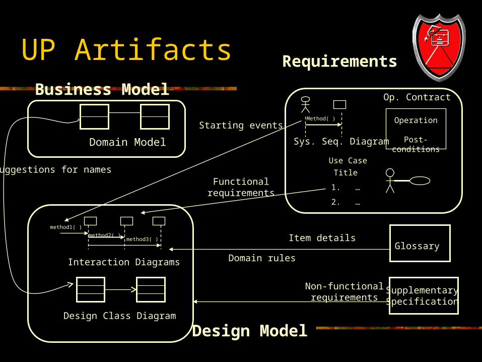
UP ArtifactsBusiness Model
Domain Model
Requirements
Title
1. …
2. …
Use Case
Operation
Post-conditions
Op. Contract
Method( )
Sys. Seq. Diagram
Design Class Diagram
method2( )
method1( )
method3( )
Interaction Diagrams
Design Model
Glossary
SupplementarySpecification
Suggestions for namesFunctional
requirements
Item details
Non-functionalrequirements
Starting events
Domain rules
Interaction Diagrams
Your System Sequence Diagram list the system events.
Create a separate diagram for each system operation under development in the current iterative step.
For each system event, make a diagram with it as the starting message.
If the diagram gets complex, split it into smaller diagrams.
Interaction Diagrams (2)
Using the contract responsibilities and post conditions and use case description as a starting point, design a system of interacting objects to fulfill the tasks.
Apply the GRASP and other patterns to develop a good design.
Interaction Diagrams and System Events
In the current iteration of PoS application, we are considering two use-cases and their associated system events: Process Sale
makeNewSale enterItem endSale makePayment
Start Up startUp
Communication Diagram
If Communication diagrams are used to illustrate the use-case realizations, for each system event, create a Communication diagram whose starting message is the system event message.
Communication Diagram (2)
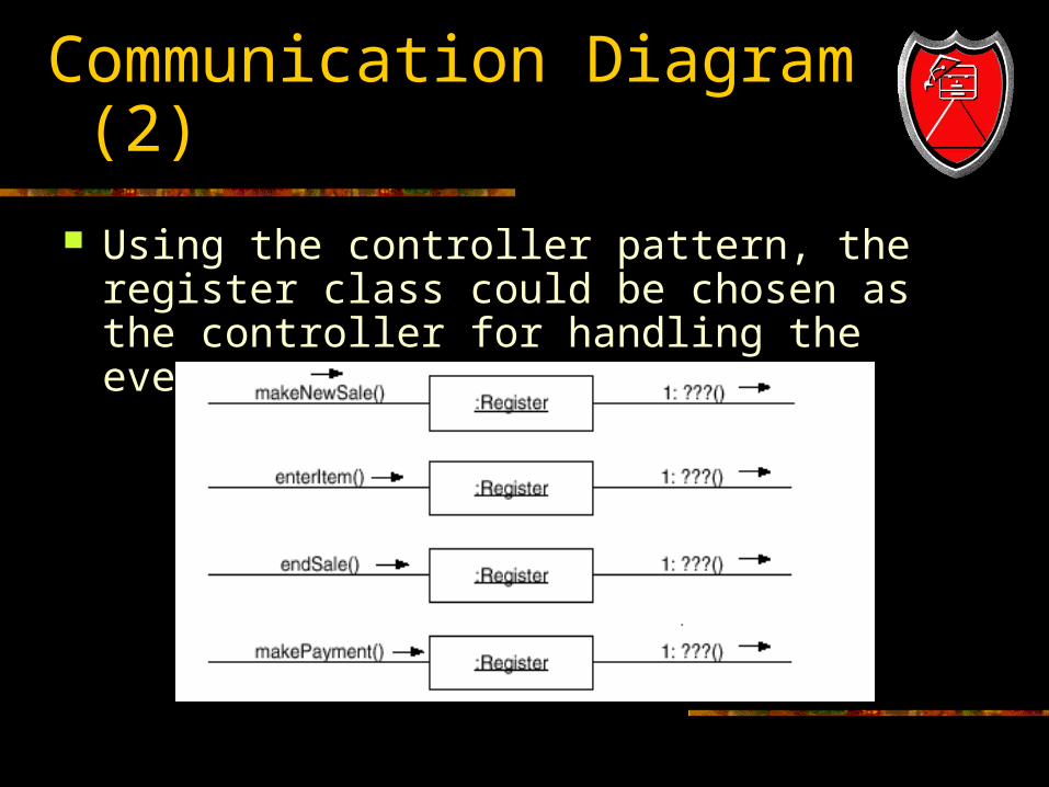
Using the controller pattern, the register class could be chosen as the controller for handling the events.
Sequence Diagrams
On the other hand, if sequence diagrams are used, it may be possible to fit all system event messages on the same diagram.
Sequence Diagrams (2)
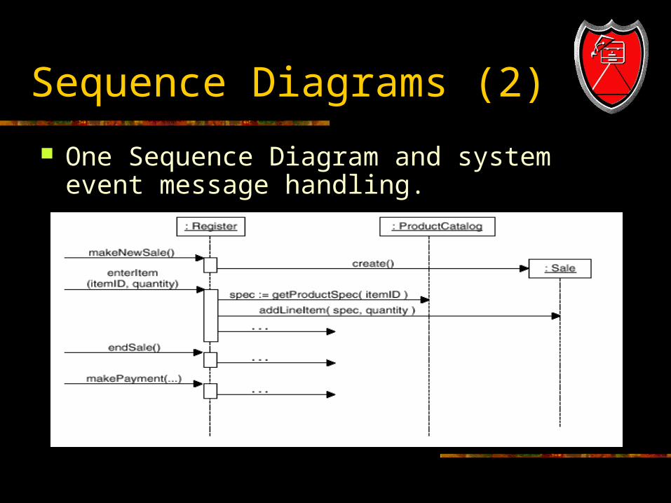
One Sequence Diagram and system event message handling.
Multiple Sequence Diagram
However, it is often that the sequence diagram is too complex or long.
It is legal, as with interaction diagrams, to use a sequence diagram for each system event message.
Multiple Sequence Diagrams (2)
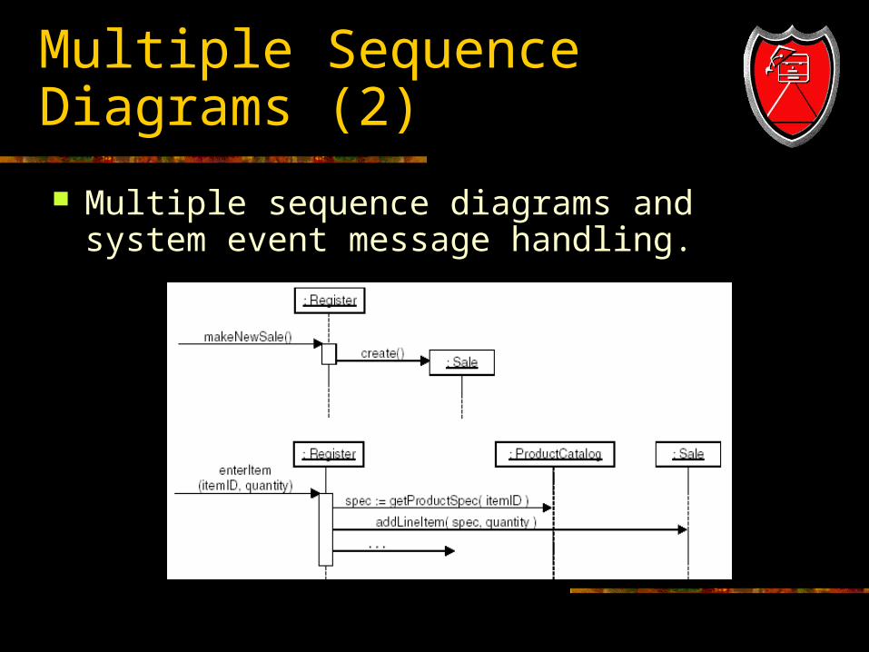
Multiple sequence diagrams and system event message handling.
Contracts and Use-Case Realizations
Using the contract responsibilities and post-conditions, and use-cases as a starting point, design a system of interacting objects to fulfill the tasks. It may be possible to design use-case
realizations directly from the use-case text. For some system operations, contracts may
have been written that add greater detail or specificity.
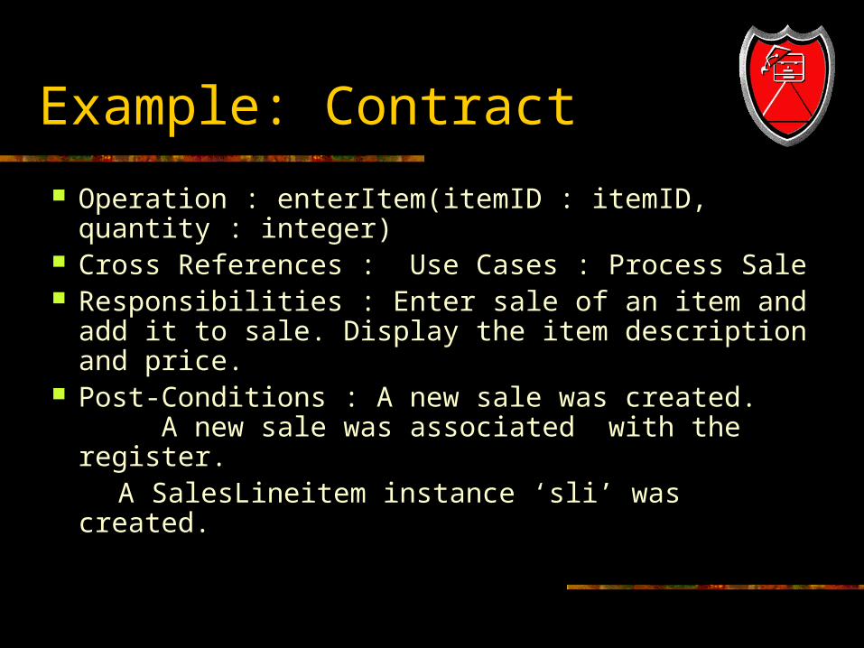
Example: Contract
Operation : enterItem(itemID : itemID, quantity : integer)
Cross References : Use Cases : Process Sale Responsibilities : Enter sale of an item and add
it to sale. Display the item description and price. Post-Conditions : A new sale was created.
A new sale was associated with the register. A SalesLineitem instance ‘sli’ was created.
Contract (2)
For each contract, we work through the responsibilities and post-condition state changes, and design message interactions (illustrated in the Communication diagram), to satisfy requirements.
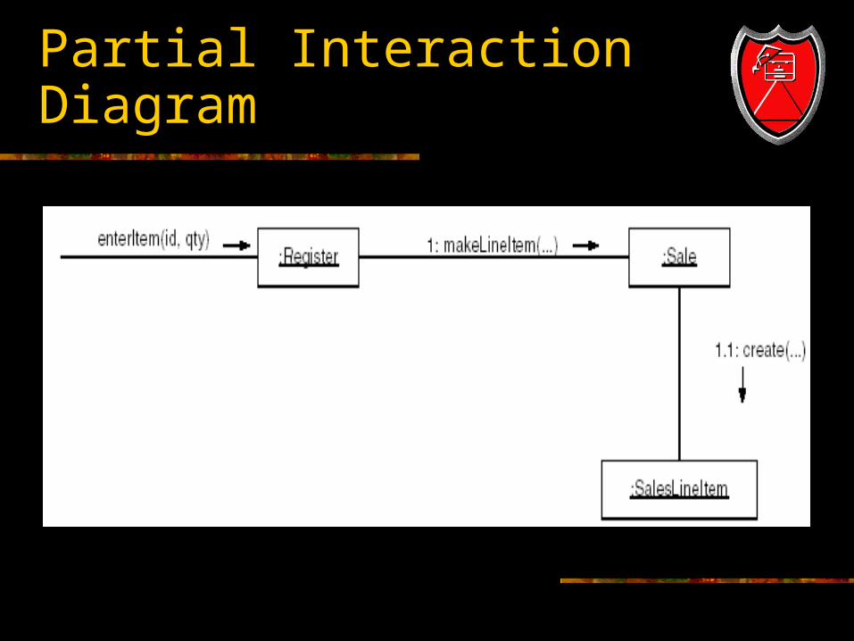
Partial Interaction Diagram
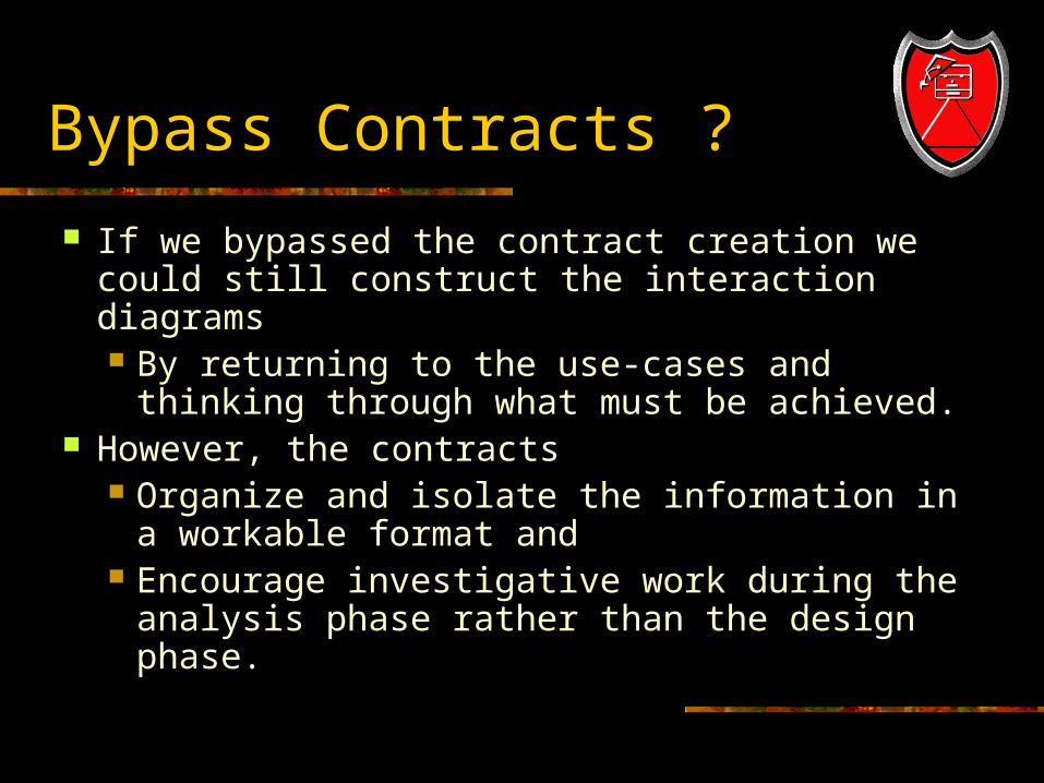
Bypass Contracts ?
If we bypassed the contract creation we could still construct the interaction diagrams By returning to the use-cases and thinking
through what must be achieved. However, the contracts
Organize and isolate the information in a workable format and
Encourage investigative work during the analysis phase rather than the design phase.
The Requirements are not perfect
Post-conditions are only an estimate. However, it is essential to recognize that the
previously defined use-cases and post-conditions are merely an initial best guess or estimate of what must be achieved.
Use-case and post-conditions may not be accurate. The spirit of iterative development is to capture a
reasonable degree of information during requirements analysis, filling in details during design and implementation.
Domain Model and Use-Case Realization
Some of the software objects that interact via messages in the interaction diagrams are inspired from the Domain Model. The existing domain model is not likely to be
perfect. Errors and omissions are to be expected.
You will discover new conceptual classes that were previously missed, ignore conceptual classes that were previously identified, and do likewise with associations and attributes.
Domain Model and Design Model
During interaction diagramming or programming, the developers may look to the Domain Model to name some design classes, thus creating a design with lower representational gap between the software design and the concepts of real domain to which the software is related.
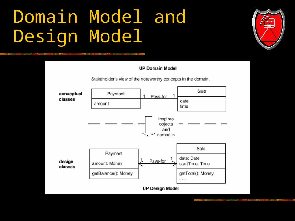
Domain Model and Design Model
Use-case Realizations for NextGen Iteration
Explore the choices and decisions made while designing a use-case realization, with objects based on the GRASP patterns. No magic in the creation of well designed
ID’s. Construction of ID’s is made on justifiable
principles.
Use-Case Realization
Notationally, the design of objects for each system event message will be shown in a separate diagram, to focus on the design issues of each.
However, they could have been grouped together on one sequence diagram.
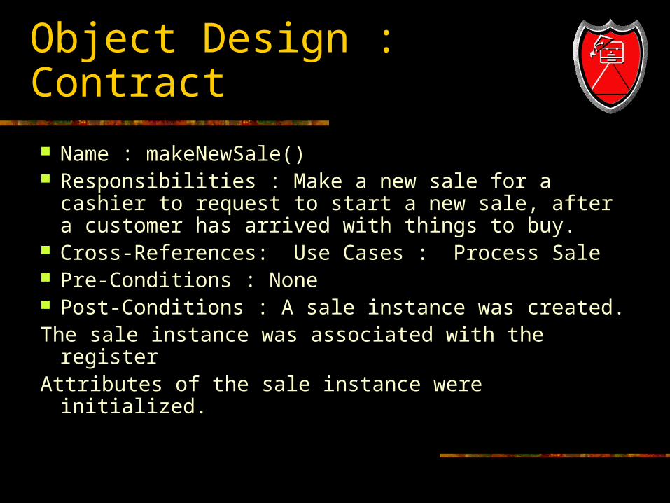
Object Design : Contract
Name : makeNewSale() Responsibilities : Make a new sale for a cashier
to request to start a new sale, after a customer has arrived with things to buy.
Cross-References: Use Cases : Process Sale Pre-Conditions : None Post-Conditions : A sale instance was created.The sale instance was associated with the registerAttributes of the sale instance were initialized.
Choosing the Controller Class
Our design choice involves choosing the controller for the system operation message enterItem.
By the Controller pattern, here are some choices:
Represents the overall system, device, or subsystem: Register, PoS system.
Represents a receiver or handler of all system events of a use-case scenario : ProcessSaleHandler, ProcessSaleSession.

Applying the GRASP Controller Pattern
From those choices, we choose the register as our controller.
By applying the GRASP controller pattern, we can design a use-case realization by drawing an interaction diagram which begins by sending a makeNewSale message to Register software object.
Creating a New Sale
A software sale object must be created, and the GRASP creator pattern suggests assigning the responsibility for creation to a class that aggregates, contains, or records the object to be created.
The register is also a good choice to create the sale object by the creator pattern.
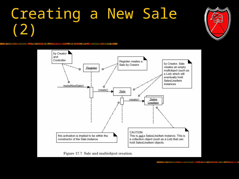
Creating a New Sale (2)
Use-Case Realization Design
The design was not difficult. But the point of its careful explanation in terms
of Controller and Creator was to illustrate that the details of a design can be rationally and methodically decided and explained in terms of principles and patterns, such as GRASP.
Object Design : enterItem
Name: enterItem(itemID : itemID,quantity : integer)
Responsibilities : Enter sale of an item and add it to the sale. Display the item description and price.
Cross References : Use-Cases : ProcessSale. Pre-Conditions : There is an underway sale. Post-Conditions : A SalesLineItem instance ‘sli’
was created. (instance created)
Object Design : enterItem (2)
sli was associated with current sale.(association formed)
sli.quantity became quantity.(attribute modification)
sli was associated with a ProductSpecification, based on itemID match.(association formed)
Choosing the Controller Class
By the controller pattern, here are the choices. Register or Retail System : represents the entire
system(facade-controller) Store : represents the overall business or
organization. Cashier : represents something in the real-world
that is active or involved in the task. (role controller)
ProcessSaleHandler : represents an artificial handler of all system operations of a use-case. (use-case controller)
Choosing the Controller Class (2)
Applying the GRASP Controller Pattern. Choose a façade-controller like Register.
If not taking on too many responsibilities. The register instance is a software abstraction
that represents the register.
Displaying the Item Description and Price
Because of a design principle called “Model View Separation”, it is not the responsibility of domain objects (such as a Register or Sale) to communicate with the user interface layer.
Therefore, the display of the item description and price will be ignored at this time.
Creating a new SalesLineItem
The contract post condition indicate a responsibility to create a SalesLineItem instance.
A Sale contains SalesLineItem objects. By creator pattern, the sale is an appropriate
candidate for creating line items. GRASP creator pattern
Assign the responsibility for creation to a class that aggregates, contains or records.
Making a new SalesLineItem
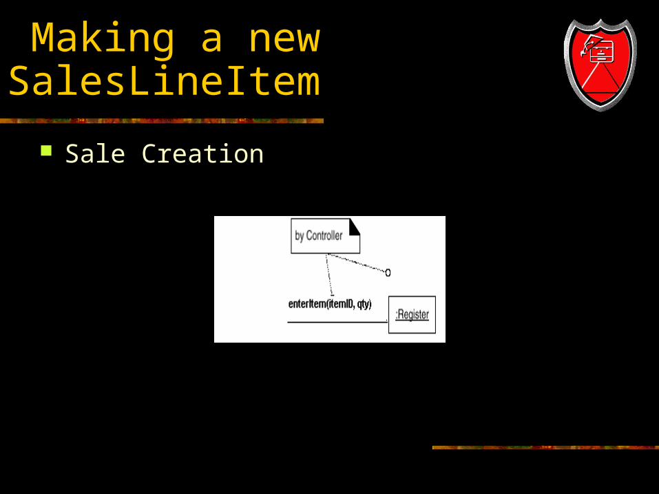
Sale Creation
Finding a product specification
The SalesLineItem needs to be associated with the ProductSpecification that matches the incoming itemID.
Who should be responsible for looking up the ProductSpecification based on the itemID match?
By the Expert pattern, ProductCatalog is a good candidate for the responsibility, since it logically contains all the ProductSpecifications.
Visibility to a product catalog
Who should send the Specification message to the ProductCatalog to ask for a ProductSpecification. Assumption: A Register and a ProductCatalog
instances were created during the initial Start Up use-case, and there is a permanent connection between them.
Based on this assumption, then it is possible to the Register to send the specification message to the ProductCatalog.
Visibility to a product catalog(2)
This implies another concept, visibility. ‘Visibility’ is the ability of one object to ‘see’ or to
have reference to another object. In order for an object to send a message to
another object it must have visibility to it.
Retrieving ProductSpecification
Retrieving ProductSpecification from a database.
It is unlikely that all the Product -Specifications will actually be in memory.
They will most likely be stored in a relational or object DB and retrieved on demand.
However the issues surrounding information retrieval will be deferred for now for simplicity.
Interaction Diagram : enterItem
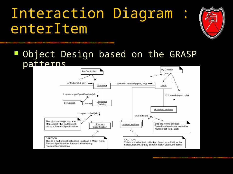
Object Design based on the GRASP patterns.
Message to multi-objects
Notice that although the default interpretation of a message sent to a multi-object is that it is implicitly sent to all elements of the collection/container, it may have alternatively be interpreted as a message to the collection object itself.
Object Design : endSale
The endSale system operation occurs when a cashier presses a button indicating the end of sale.
A collaborating diagram can be constructed to satisfy the post-conditions of endSale.
The GRASP patterns will be used to choose and justify the messages.
Object Design : endSale Contract
Name : endSale() Responsibilities : Record that it is the end of
entry of sale items, and display sale total. Cross References : Use Cases : Process Sale Exceptions : If a sale is not underway, indicate
that it was an error. Pre-Conditions : There is an underway sale. Post-Conditions : sale.isComplete became true.
Choosing the Controller Class
Based on the Controller Pattern, as for enterItem, we will continue to use register as a controller.
Setting the Sale.isComplete attribute
The contract post-condition state: Sale.isComplete became true. As always, Expert should be the first pattern
considered unless it is a controller or creation problem (which is not).
Who should be responsible for setting the Sale.isComplete attribute of the Sale to true. By Expert, it should be the Sale itself.
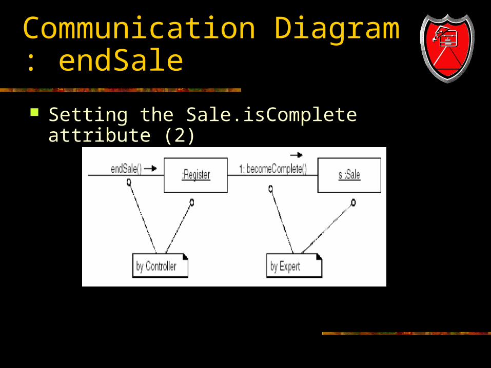
Communication Diagram : endSale
Setting the Sale.isComplete attribute (2)
Display of Information
It states in the responsibilities of the endSale contract that the sale total must be displayed.
Who should be responsible for the display of information
Model-View Separation Pattern.
Display of information (2)
During the creation of Communication diagrams, do not be concerned with the display of information, except insofar as the required information is known.
Therefore, ignore any requirements that involve the display of information, with the following exception.
Ensure that all the information that must be displayed is known and available from the domain objects. For example, the sale total must be known by some object.
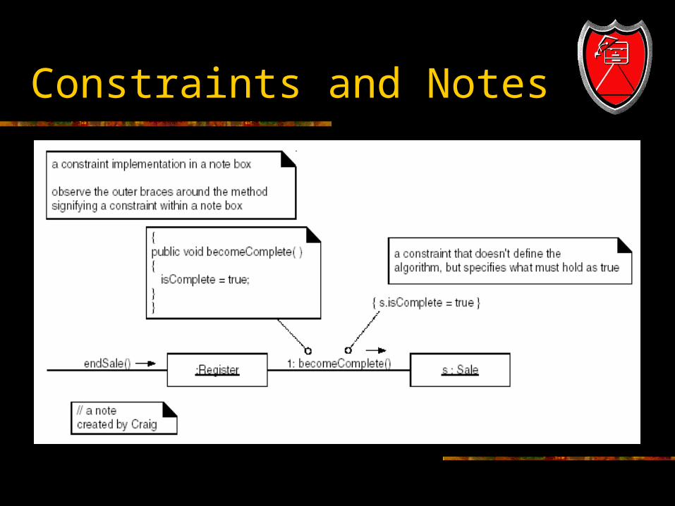
Constraints and Notes
Calculating the Sale Total
By Expert the Sale itself should be responsible for knowing its total.
How to find it? State the responsibility.
Who should be responsible for knowing the sale total.
Summarize the information needed.
Calculating the Sale Total (2)
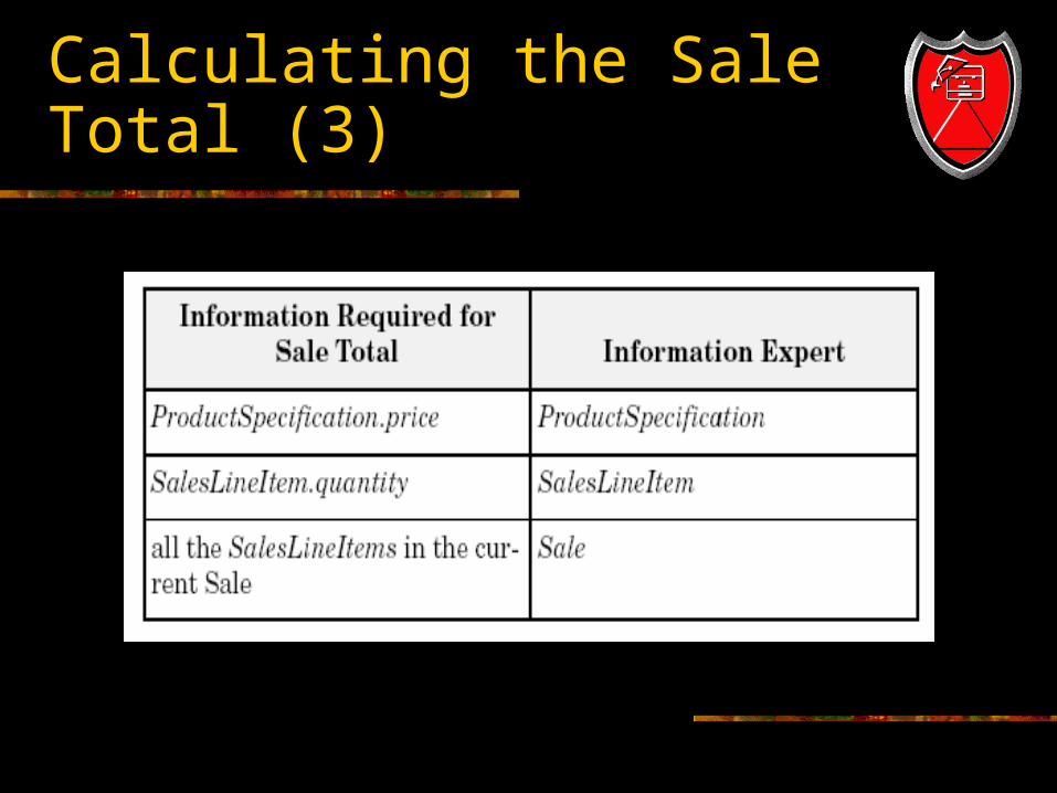
The sale total is the sum of the subtotals of all the saleslineitems.
Sales Line Item subtotal : line item quantity * product description price.
List the information required until to fulfill this responsibility and the classes that know this information.
Calculating the Sale Total (3)
Calculating the Sale Total (4)
Not every Communication diagram starts with a system event message, they can start with any message for which the designer wishes to show any interactions for.
This does not mean you may disregard the system event messages.
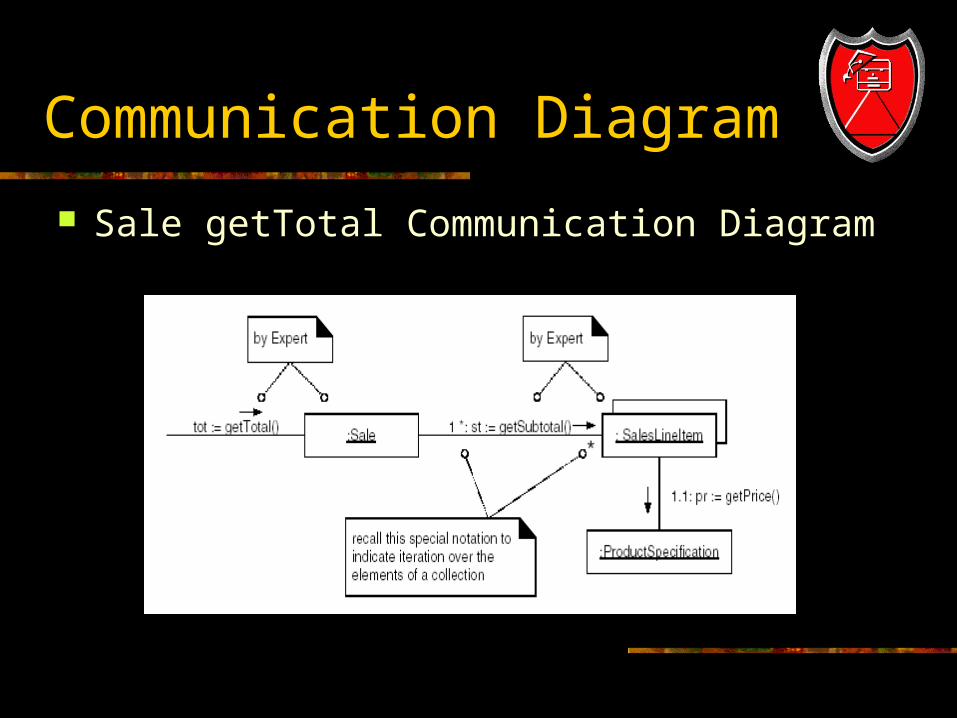
Communication Diagram
Sale getTotal Communication Diagram
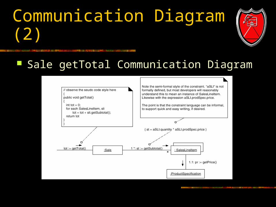
Communication Diagram (2)
Sale getTotal Communication Diagram
Object Design:makePayment
Choosing the Controller Class Based on the Controller GRASP pattern, as for
enterItem, we will continue to use Register as a controller.
It is common to use the same controller throughout a use case.
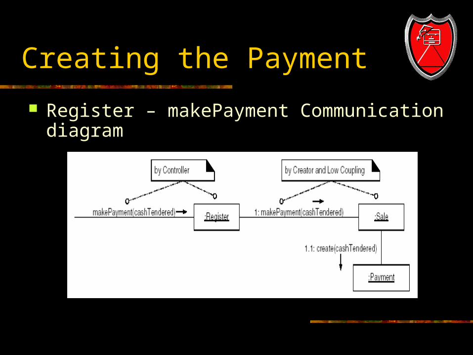
Creating the Payment
Register – makePayment Communication diagram
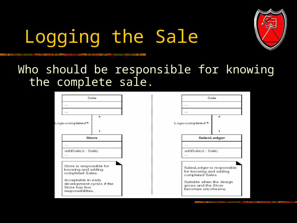
Logging the Sale
Who should be responsible for knowing the complete sale.
Logging a completed sale
Perhaps we did not think of a sale ledger early, but now we have.
If it is not chosen, it would be ideally added to the domain model as well.
Fortunately, iterative development provides a life-cycle for continual change.
This kind of discovery and change during design work is to be expected.
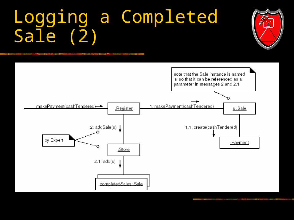
Logging a Completed Sale (2)
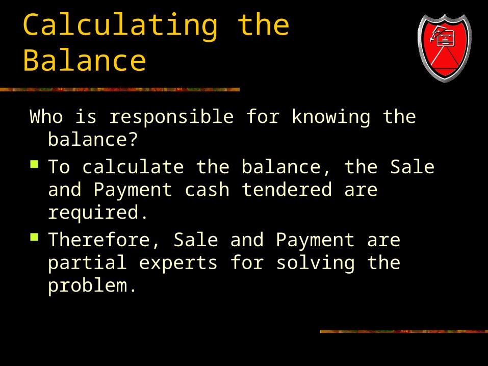
Calculating the Balance
Who is responsible for knowing the balance? To calculate the balance, the Sale and Payment
cash tendered are required. Therefore, Sale and Payment are partial experts
for solving the problem.
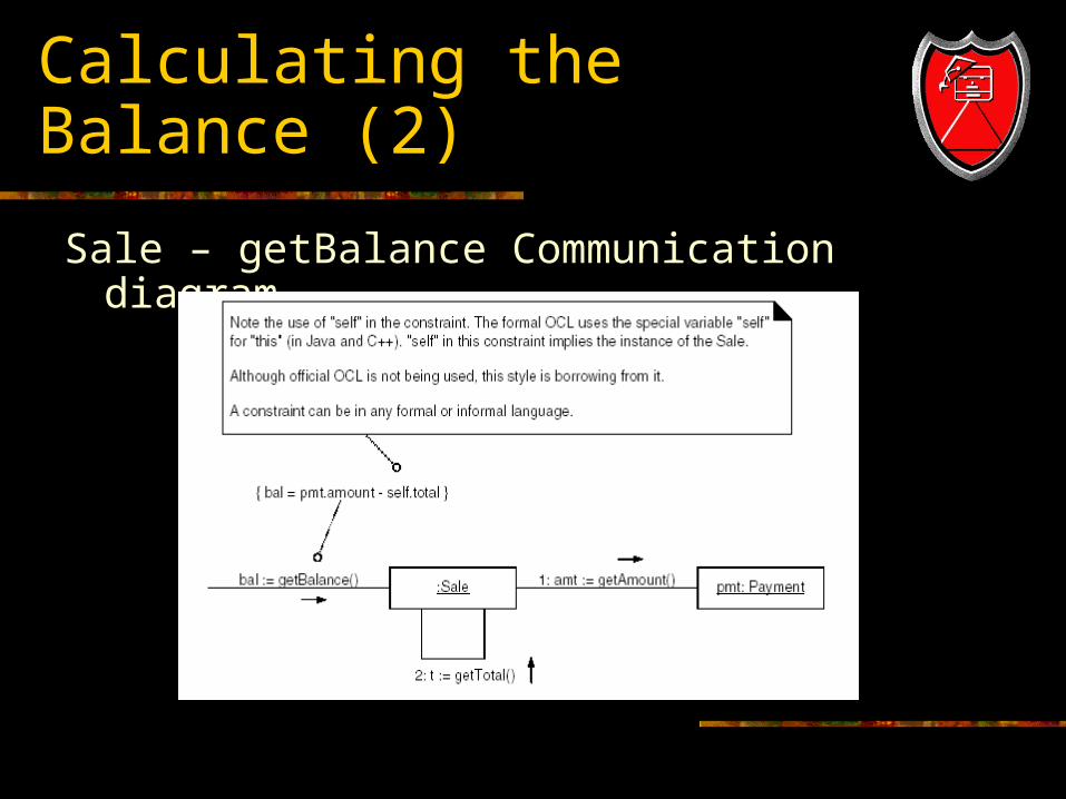
Calculating the Balance (2)
Sale – getBalance Communication diagram
Object Design : startUp
When to create the startUp? Create the startUp Communication diagram last. This ensures that significant information has
been discovered concerning what initializing activities are required to support the later system operation interaction diagrams.
Do the initialization design last.
How applications Start Up
How an applications starts and initializes is dependent upon the PL and OS.
Initial domain object. The first problem software domain object
created.
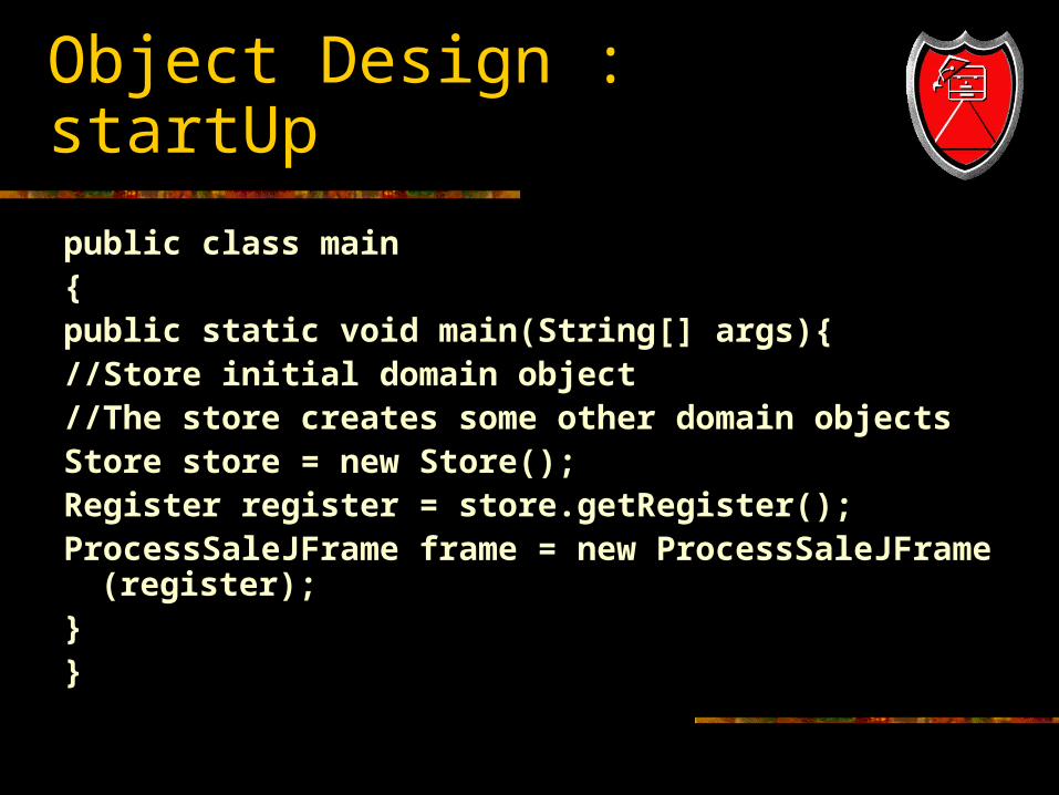
Object Design : startUp
public class main{public static void main(String[] args){//Store initial domain object//The store creates some other domain objects Store store = new Store();Register register = store.getRegister();ProcessSaleJFrame frame = new ProcessSaleJFrame (register);
}}
Interpretation of the startUp system operation
In one interaction diagram, send a create() message to create the initial domain object.
Optional, if the initial object is taking control of the process, in a second interaction diagram send a run message to the initial object.
The PoS Application startUp operation
The startUp system operation occurs when a manger powers on the PoS system and the software loads.
Assume there is a GUI, and that object in the presentation layer will be responsible for creating the initial problem domain object.
Assume that the initial object is not responsible for taking control of the process.
Object Design : startUp
Choosing the Initial Domain Object Choose as an Initial Domain Object A class representing the entire logical
information system. Register, RetailInformationSystem A class representing the overall business or
organization. Store (Assume we choose this as the initial
object)
Persistent Objects : PrductSpecification
In a realistic application the ProductSpecification instances will reside in a persistent storage medium, such as relational or object DB.
Individual instances will be loaded on demand into memory as they are required.
Store-Create() Design
Name : startUp() Responsibilities : Initialize the system Type : System
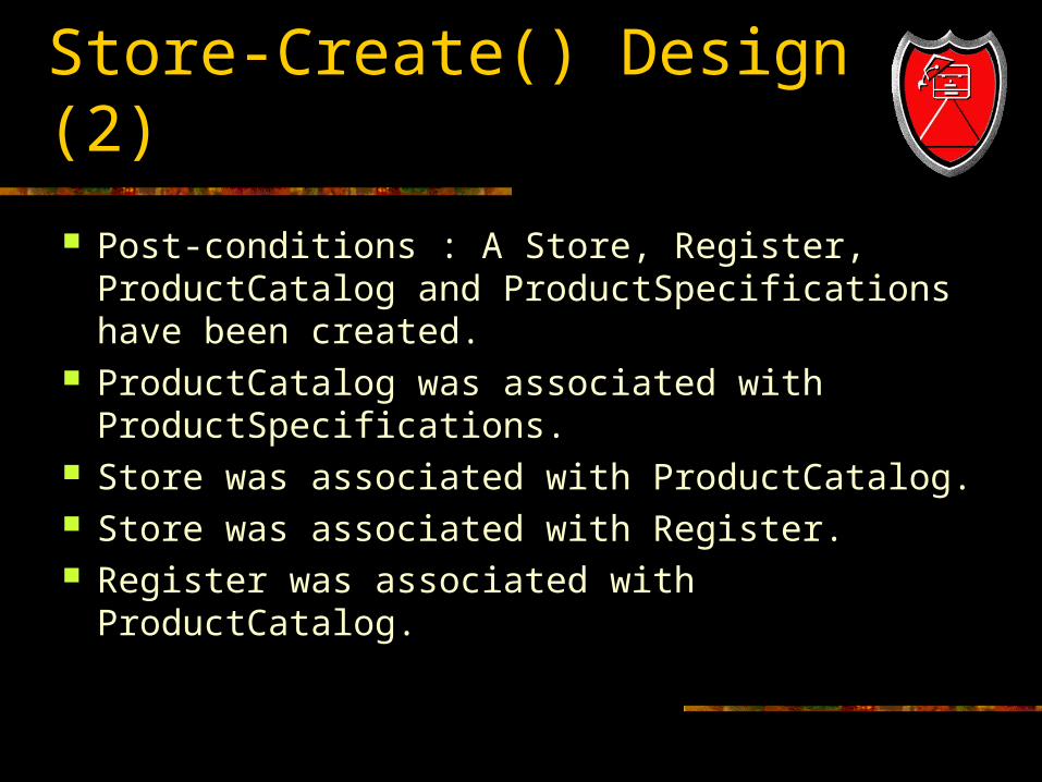
Store-Create() Design (2)
Post-conditions : A Store, Register, ProductCatalog and ProductSpecifications have been created.
ProductCatalog was associated with ProductSpecifications.
Store was associated with ProductCatalog. Store was associated with Register. Register was associated with ProductCatalog.
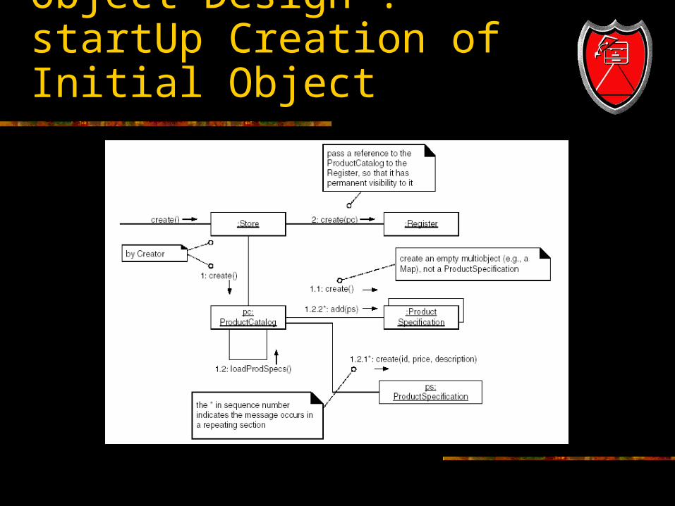
Object Design : startUp Creation of Initial Object
Connecting the UI layer to the Domain Layer
Common designs by which objects in UI layer obtain visibility to objects in Domain layer include the following: An initializing routine (e.g. Java main method)
creates both a UI and a Domain object and passes the Domain object to the UI.
A UI object retrieves the Domain object from a well-known source, such as a factory object that is responsible for creating Domain objects.
Connecting the UI Layer to the Domain Layer (2)
Once the UI layer has connection to the Register instance (the façade-controller in this design), it can forward system event messages to it, such as the enterItem and endSale message.
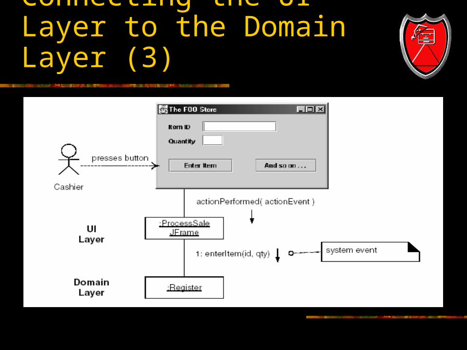
Connecting the UI Layer to the Domain Layer (3)
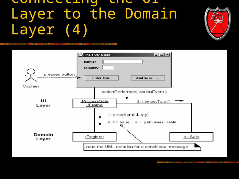
Connecting the UI Layer to the Domain Layer (4)
UI and Domain Layer Responsibilities
The UI layer should not have any domain logic responsibilities.
It should only be responsible for presentation (interface) tasks, such as updating widgets.
The UI layer should forward requests for all domain-oriented tasks on to the domain layer, which is responsible for handling them.

Use-Case Realization within the UP
Use-Case realizations are part of the UP Design Model.
It is recommended to draw class diagrams in parallel with drawing interaction diagrams.
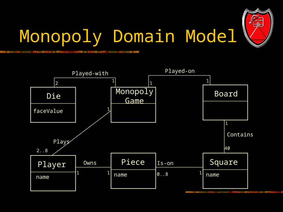
Monopoly Domain Model
DieMonopoly
GameBoard
SquarePiecePlayer
faceValue
name name name
Plays
2..8
0..81 1
1
2 1 1 1
1
40
1
Owns
Played-with Played-on
Contains
Is-on
Choosing a controller object
MonopolyGame is a root object that represents the overall system.
A system controller could also be called MonopolyGameSystem
An event handler controller could be PlayMonopolyGameHandler
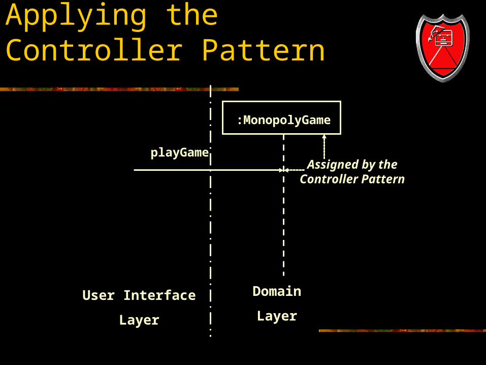
Applying the Controller Pattern
:MonopolyGame
playGame
User Interface
Layer
Domain
Layer
Assigned by theController Pattern
How to control game loop?
Monopoly is played as a series of rounds in which each player takes a turn. What object should control the game loop to manage the rounds?
By the Expert Pattern, the playRound object can be managed by the MonopolyGame. It uses a helper method to organize behavior into chunks for high cohesion and low coupling.
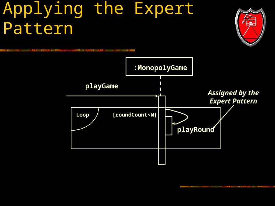
Applying the Expert Pattern
:MonopolyGame
playGameAssigned by theExpert Pattern
Loop [roundCount<N]
playRound
Who takes a turn? The logical controller for a turn is a player, because
in the real world, a human player makes all the decisions for the game.
However, note that OO designs are not one-to-one simulations of a real domain.
Be careful about assigning responsibilities because a specific person does that, since the same person can perform many roles, as a cashier in a store. If you assign to persons instead of roles, you get huge objects with Low Cohesion and High Coupling!
Choosing a turn controller
However, this does not apply in the Monopoly Game, because the role of a player is more limited. Actually, by the Expert pattern, a player is a good choice. Think about who knows what:
The Player knows its Piece and the Piece knows its current position.
The MonopolyGame knows the roll of the dice. The Board knows all the squares on the board. Thus Player, MonopolyGame and Board are all partial
experts.
Choosing a turn controller
Player, MonopolyGame and Board are all partial experts. When you have multiple candidates, use other design patterns. Since MonopolyGame already controls the rounds, giving it control of turns would add too many functions, violating high cohesion and low coupling.
The Player knows the strategy used to make decisions such as whether or not to buy, sell, or build. That complex knowledge may be a good reason to let Player control the turn.
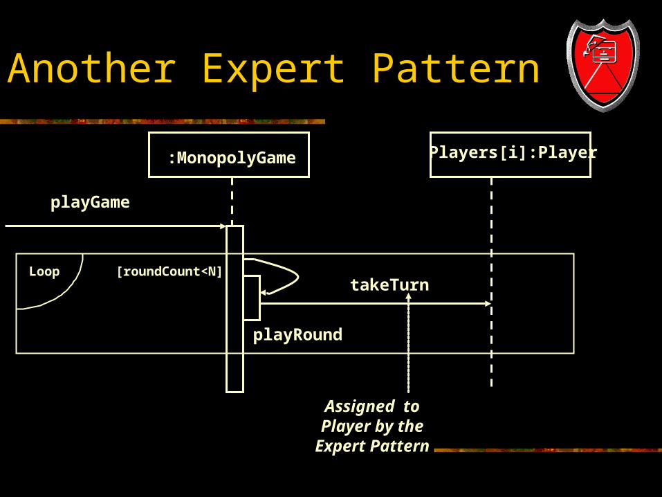
Another Expert Pattern
:MonopolyGame
playGame
Assigned toPlayer by the
Expert Pattern
Loop [roundCount<N]
playRound
Players[i]:Player
takeTurn
Expanding on a diagram
It is common to use a diagram like the preceding one for takeTurn, and then follow it with a more detailed diagram that illustrates the method like the one on the next page.
One principle for choosing items to display is the “magic number”, five plus or minus two, which suggests that human beings best comprehend from three to seven objects at a time.
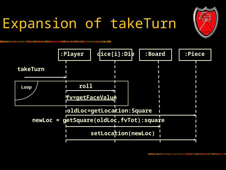
Expansion of takeTurn
:Player
takeTurn
Loop
newLoc = getSquare(oldLoc,fvTot):square
oldLoc=getLocation:Square
dice[i]:Die :Board :Piece
roll
fv=getFaceValue
setLocation(newLoc)
Command Query Separation
In the preceding diagram, the message roll( ) is followed by a message getFaceValue( ). Why not have the roll method return the face value of the die instead of requiring a separate call? This is common, but it is a violation of a classic OO design principle, the Command-Query Separation Principle.
This principle was established to avoid side effects, in which code depends on a hidden action of previous code.
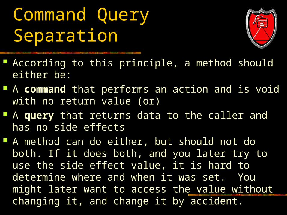
Command Query Separation According to this principle, a method should either be: A command that performs an action and is void with
no return value (or) A query that returns data to the caller and has no side
effects A method can do either, but should not do both. If it
does both, and you later try to use the side effect value, it is hard to determine where and when it was set. You might later want to access the value without changing it, and change it by accident.
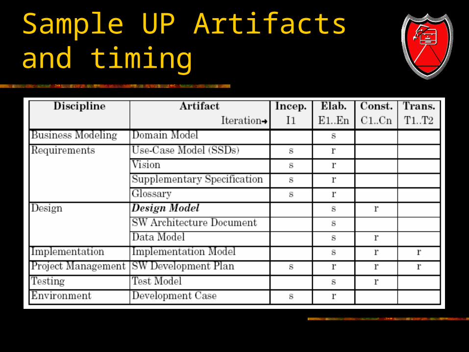
Sample UP Artifacts and timing
Phases
Inception The Design model and Use-Case
Realizations will not usually be started until elaboration because it involves detailed design decisions which are premature during inception.
Elaboration Use-Case Realizations may be created for the
most architecturally significant or risky scenarios of the design.
Phases (2)
Construction Use-Case realizations are created for
remaining design problems.
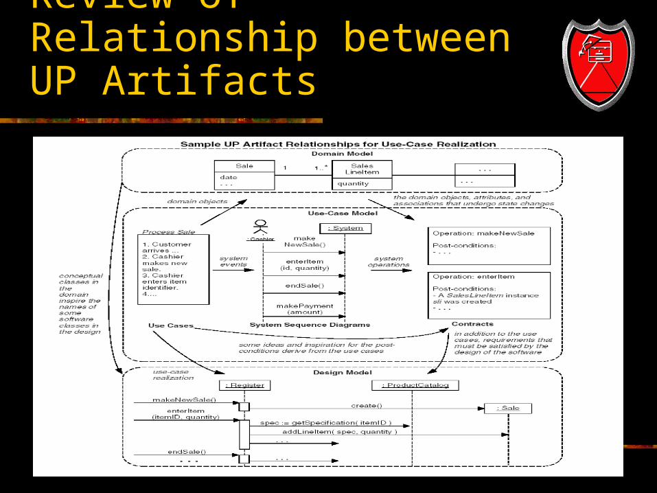
Review of Relationship between UP Artifacts
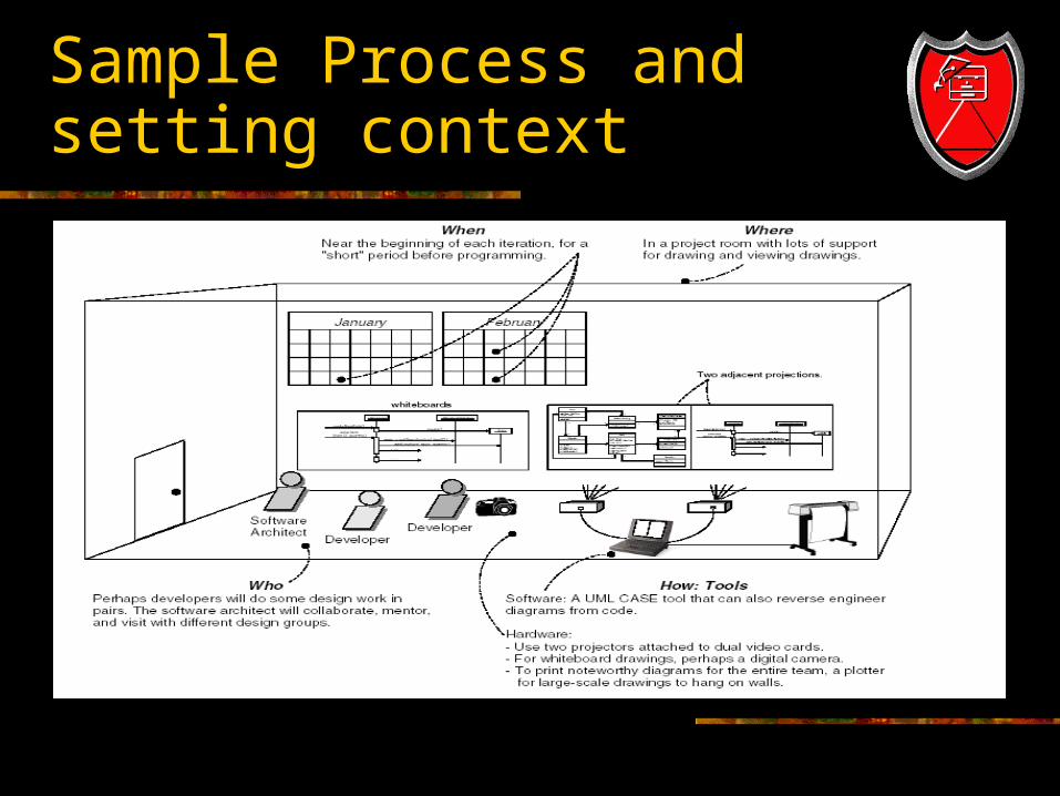
Sample Process and setting context