nl1002 e
DESCRIPTION
Catalogo NadellaTRANSCRIPT

Linear and Motion Solutions
Linear guide systems
NL 1002 E

Linear guide systems

Heavy-Line Guide rails GU..M, GU..MTGuide Rollers RKUGuide Wheels FKUFloating Guide Rollers RKULLubricator LUBUGuide pins SAG Guide rails GP..MCGround guide rails GP..MGuide Rollers PKGuide Wheels FKGuide Rollers GCCam followers FG (needle) and FGU (roller)Lubricator LUBP
Rolbloc Guide rails GU..M, GU. .MTCarriages ROLBLOC MBLCarriages ROLBLOC BLAdjustment plates PR
V-Line Sand blasted guide rails FS..MTGround guide rails FS..MSand blasted guide rails FSH..MT, FSX..MTGround guide rails FSH..M, FSX..MGuide Rollers FR..EUGuide Rollers FR..EU AS, FR..EU AZGuide Rollers FRN..EIGuide Rollers RKY, RKXGuide Rollers FKY, FKXFloating Guide Rollers FRL..EUFloating Guide Rollers RKXL, RKYLSpacers FS and FSHLubricator LUBY - LUBX
Summary

20
For medium-heavy loads
212223242528
For medium-heavy loadsDirty environment
293031
32-3334-35
36
41For medium-heavy loadsDirty environment
424344
48
For medium-heavy loads
4950515253545556575859
60-61

Multi-Motion-Line Circular rails FSR..M
Oval circuit FSRO
Ring circuit FSRQ
Steering carriages T4R...
C-Line Guide Rails LS
Guide Rollers RCS
Guide Rollers RAS
Carriages C3 RCS, C3 RAS, C3 RYS
Carriages C4 RCS, C4 RAS, C4 RYS
Carriages C5 RCS, C5 RAS, C5 RYS
Base-Line Guide rails DC
Guide rails C
Guide Rollers PFV
Guide Rollers RKO
Carriages T4PFV
Wipers NAID
Lubricator LUBC
Guide rails FWS
Guide rails FWH
Guide Rollers FR..EU
Guide Rollers FR..EU AS, FR..EU AZ
Floating Guide Rollers FRL..EU
Carriages T4FR
Flexi-Line 645 Guide rails FWN
Carriages TA4, TB4
Summary

67
For all applications69
70
71
78
For light-medium loads
79
80
81
82
83
87
For medium loadsAggressive environment
88
89
90
91
92
93
96
For light-medium loads
97
98
99
100
101
105 For light-medium loads
106-107

U-Line Guide rails LM
Guide Rollers RCL, RCP, PFV
Floating Guide Rollers RAL
Guide Wheels GLA
Carriages C3RCL, C3RAL, C3RYL
Carriages C4RCL, C4RAL, C4RYL
Carriages T4RCL, T4RCP, T4PFV, T4RAL, T4RYL
Lubricator LUBM
Guide rails LML 20
Summary

112
For light-medium loads
113
114
115
116
116
117
117
119
With this line of products, NADELLA confirms the aim to provide manufacturing solutions tailored to the user’s needs in order to achieve simple automation at a low cost.The process under way of transferring production automation and relevant handling onto increasingly heavier and cumbersome units has prompted us to seek original and flexible components for the different commodity sectors.We have accumulated sound working experience in the following sectors:
- marble-working machinery- foundry machinery- metal sheet working machinery- special lifting machines- pick up- automatic warehouses- textile machines- machine tool protections and utilities- oxygen cutting machines
Our Technical Department works with Customers and recommends the best component choice by making the calculations needed to determine the best life.
GuidesLengthThe maximum length of each single guide component is shown on the dimensional tables.The standard lengths of the rails are determined by adding the product of the fixing hole centre distance and the number of holes to twice the end dimension (see dimensional tables).
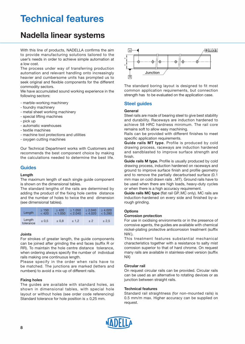
JointsFor strokes of greater length, the guide components can be joined after grinding the end faces (suffix R or RR). To maintain the hole centre distance tolerance, when ordering always specify the number of individual rails making one continuous length. Please specify in the order when rails have to be matched. The junctions are marked (letters and numbers) to avoid a mix-up of different rails.
Fixing holesThe guides are available with standard holes, asshown in dimensional tables, with special hole layout or without holes (see order code referencing)Standard tolerance for hole position is ± 0,25 mm.
8
The standard boring layout is designed to fit most common application requirements, but connection strength has to be evaluated on the application case.
Steel guidesGeneralSteel rails are made of bearing steel to give best stability and durability. Raceways are induction hardened to achieve 58 HRC hardness minimum. The rail core remains soft to allow easy machining.Rails can be provided with different finishes to meet specific application requirements.Guide rails MT type. Profile is produced by cold drawing process, raceways are induction hardened and sandblasted to improve surface strength and finish.Guide rails M type. Profile is usually produced by cold drawing process, induction hardened on raceways and ground to improve surface finish and profile geometry and to remove the partially decarburised surface (0.1 mm max on cold drawn rails ..MT). Ground rails have to be used when there are high loads, heavy-duty cycles or when there is a high accuracy requirement.Guide rails MC type (flat rail GP..MC only). MC rails are induction-hardened on every side and finished by-a-rough grinding.
OptionsCorrosion protectionFor use in oxidising environments or in the presence of corrosive agents, the guides are available with chemical nickel-plating protective anticorrosion treatment (suffix NW.).This treatment features substantial mechanical characteristics together with a resistance to salty mist corrosion superior to that of hard chrome. On request many rails are available in stainless-steel version (suffix NX)
Circular railOn request circular rails can be provided. Circular rails can be used as an alternative to rotating devices or as junction between straight rails. Technical featuresStandard rail straightness (for non-mounted rails) is 0.5 mm/m max. Higher accuracy can be supplied on request.
Technical features
Nadella linear systems
Junction
A
B
A B0,5
Length≥ 150 < 420
≥ 420 < 1.050
≥ 1.050 < 2.040
≥ 2.040 < 4.020
≥ 4.020 < 5.280
Length tolerance
± 0,5 ± 0,8 ± 1,2 ± 2 ± 2,5
TemperatureStandard operating temperature range is –20°C up to 150°C. In lower or higher temperature applications please contact Nadella Technical Service. Special care is required if guide rollers are operating at maximum temperature.
Aluminium guidesGeneralMade by joining an aluminium alloy support element and hardened steel rods that form the sliding surfaces.The best features of the two materials and relevant working technologies are combined to give the lightness of the alloy and the hardness and surface finish of the rods.Guides of this type can be used for structural functions; they have a high moment of inertia that enables them to be used in many applications as carrying structures.Aluminium extruded profiles are stabilised and anodised. Sliding rods are induction hardened and ground.
OptionsCorrosion protectionFor use in oxidising environments or in the presence of corrosive agents, the guides of this series can feature stainless-steel bars (suffix NX).
Chromium-plated rodsOptional chromium-plated rods are available (suffix CH); the thickness of the chromium plating is 10 ± 5 μm with hardness ≥ 800 HV.Please check option availability in dimensional tables.
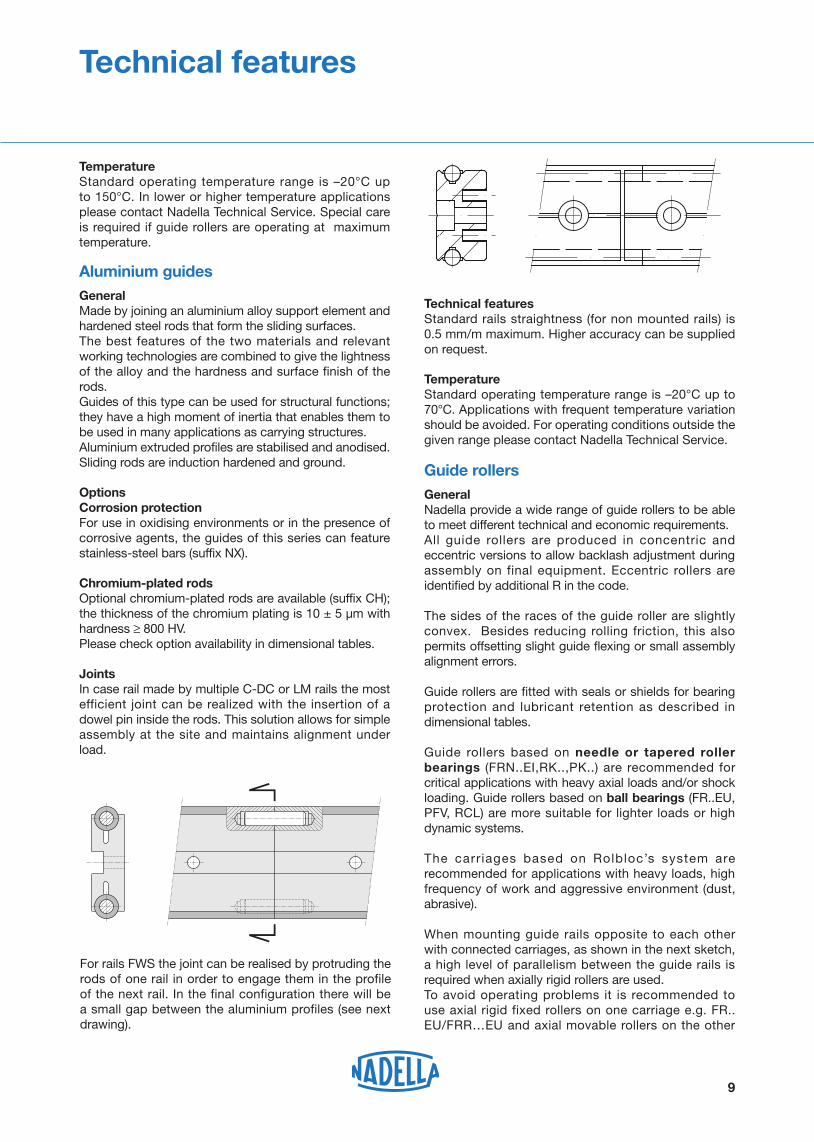
JointsIn case rail made by multiple C-DC or LM rails the most efficient joint can be realized with the insertion of a dowel pin inside the rods. This solution allows for simple assembly at the site and maintains alignment under load.
Technical featuresStandard rails straightness (for non mounted rails) is 0.5 mm/m maximum. Higher accuracy can be supplied on request.
TemperatureStandard operating temperature range is –20°C up to 70°C. Applications with frequent temperature variation should be avoided. For operating conditions outside the given range please contact Nadella Technical Service.
Guide rollersGeneralNadella provide a wide range of guide rollers to be able to meet different technical and economic requirements.All guide rollers are produced in concentric and eccentric versions to allow backlash adjustment during assembly on final equipment. Eccentric rollers are identified by additional R in the code.
The sides of the races of the guide roller are slightly convex. Besides reducing rolling friction, this also permits offsetting slight guide flexing or small assembly alignment errors.
Guide rollers are fitted with seals or shields for bearing protection and lubricant retention as described in dimensional tables.
Guide rollers based on needle or tapered roller bearings (FRN..EI,RK..,PK..) are recommended for critical applications with heavy axial loads and/or shock loading. Guide rollers based on ball bearings (FR..EU, PFV, RCL) are more suitable for lighter loads or high dynamic systems.
The carr iages based on Rolbloc’s system are recommended for applications with heavy loads, high frequency of work and aggressive environment (dust, abrasive).
When mounting guide rails opposite to each other with connected carriages, as shown in the next sketch, a high level of parallelism between the guide rails is required when axially rigid rollers are used.To avoid operating problems it is recommended to use axial rigid fixed rollers on one carriage e.g. FR..EU/FRR…EU and axial movable rollers on the other
For rails FWS the joint can be realised by protruding the rods of one rail in order to engage them in the profile of the next rail. In the final configuration there will be a small gap between the aluminium profiles (see next drawing).
9
Technical features

Technical features
LubricationGuide roller FRN..EI permits bearing relubrication. All other guide rollers are long life lubricated.
TemperatureGuide roller should not operate at constant temperature above 80°C. For short durations 100°C can be accepted. For higher temperature please see the “option section”.
Speed limitMax velocity has to be determined for each application relevant to the guide roller type, size and load conditions. As general value, in normal conditions maximum speed is 4 m/sec but, with the correct chose of the components, the speed can reach 10 m/s. Contact Nadella Technical service in case of specific request.
Options
Corrosion protectionFor uses in oxidising environments or in the presence of corrosive agents, the guide rollers are available in stainless steel (suffix NX) the guide rollers with tapered rollers (RKU, RKY/X, FKU, FKY/X) and needles (FRN) are equipped with standard bearings. Check in the dimensional table component availability.
High temperatureOn request guide rollers can be equipped with Viton seals to operate at temperature up to 120° (suffix V). Check in the dimensional table component availability.
10
Accessories
Tables and carriagesStandard table and carriages for C-DC and LM systems incorporate a black anodised aluminium plate fitted with guide rollers.
WipersStandard wipers NAID for C-DC rails are made from NBR compound moulded on a steel plate.
LubricatorsAre composed by two main parts: a plastic box with the same shape profile of the rail, and a lubricated felt; the felt is slightly pressed on the raceways by a spring. The plastic box, that drags the raceways, works as a wiper, and remove dust and shavings.
The plastic box can be mounted directly on the guide rollers plate by the appropriate aluminium plate included in the kit.
In the lubricators for guide rollers size 52 or higher, the grease nipple allows an easy connection with a re-lubrication system.
For the simply lubrication of the rails you can use one lubricator only on each raceway; in order to wipe the raceways it is better to mount two lubricators, before and after the carriage.
The lubricators are supplied with the felt already lubricated.
Use in dirty environmentDue to the design cam rollers with profile are especially adapted to the use in rough and dirty environment. This properly has proved true in many applications such as welding plants, steel and grinding machines and is superior to recirculating ball bearing guides in continuous operation.
carriage e.g. FRL..EU/FRLR..EUMovable rollers allow a little misalignment between the opposite mounted guide rails.
GPFS
F
Another solution is to use one profiled guide rail e.g. FS and on the opposite side a flat rail e.g. GP in connection with rollers GC or PK.
Technical features
ve dust and shavings.

so that any movement caused by vibration will cause the nut to be tightened. Ensure the preload is not increased when tightening the nut. A simple way of setting a roller preload is as follows:
1 move the slider on the guide, holding the roller being adjusted with two fingers to prevent it from rotating
2 increase the preload by means of the wrench3 repeat step 1 making sure the roller slides without
rolling4 when it is no longer possible to prevent roller rolling,
slightly decrease the preload and fully tighten the lock nut, thereby setting the position of the eccentric.
When correctly adjusted it is just possible to cause the guide roller to slip on the guide rail when a torque is applied to the roller.
GuidesFor single guide rail type FS, FWS, DC and LM no special assembly instructions are necessary. For multiple parallel rails parallelism has to be checked to avoid guide rollers overload or excessive carriage play. When constant preload is required parallelism error has to be lower that 0.050 mm.
Connection between the rail and the mounting surface has to be designed accordingly with the operating condition to ensure proper product positioning and functionality.The direction and intensity of the load, the number and strength of the screws, the geometry of mounting surfaces, use of pins or wedges have to be evaluated to fully utilize the linear guide load capacity.
CarriagesCarriages are supplied with concentric guide rollers nut tighten already. Eccentric guide rollers have to be set and tighten during final assembly operation by customer.
Lubrication
Bearing lubricationAll the guide rollers, except for the FRN..EI, based on needle bearings, are equipped with long life lubricated bearings. This means that the grease inside the bearing is enough for the entire life of the roller guide. The roller guide type FRN..EI, with needle bearings, accommodates the re-lubrication of the bearings.
Rail lubricationRails must be lubricated. This allows reducing the friction, to reach the calculated lifetime of the system and to work at high speed.
No or insuff icient lubrication wil l cause rapid deterioration. The typical signal of tribocorrosion is the presence of a red/dark oxide and rapid wearing of the rail and guide rollers.
The lubrication of the rail, the working environment and the load must be considered all together for a correct estimation of the lifetime of the guide system.
Generally speaking, for application with low duty frequency, a periodic relubrication with a grease or with a viscous oil will sufficiently maintain the lubrication film. The re-lubrication interval depends on the application and must always be tested in the real working conditions. In a system with ground rails and short stroke without lubricators, you can consider a re-lubrication interval every 100,000 cycles. Increasing the load, speed or stroke, or using an under sized bearing will increase lubrication demand and result in a shorter lubrication interval. For a constant lubrication we suggest the use of felt lubricators to ensure a constant layer of lubricant between guide rollers and raceways. Felt lubricators enlarge the lubrication interval more than ten times.
The recommended lubricants are greases and oil for bearings, linear rails or chains, with a high viscosity of the basic oil and with EP additives, in order to separate the metallic surfaces even with low speed.
Assembly instructions
Guide rollersThe eccentric guide rollers allows the preload or clearance of the carriage to be adjusted independently of the guide roller mounting hole positioning tolerance or the distance between the rails.Recommended mounting hole tolerance is H7.When adjusting the eccentric guide roller care has to be taken to avoid excessive preload. Excessive preload can reduce the life of the linear system. Set the preload turning the guide roller counterclockwise
11
Technical features

12
In case of ROLBLOC the distance Ic is the distance between the rails basis.
Diagram b) load F applied parallel to axis Z
Diagram c) load F applied parallel to axis X
F zFPa = 2 Ic
F ( Ix + 2 xF ) F zF tan αPr = + 2 Ix 2 Ic
F F xF F yFPa = + + 4 2 Ix 2 Ic
Pr = Pa tan α
Diagram a)load F applied parallel to axis Y
a)
b)
c)
YxF
F
X
Ix
Iy
YzF
F
Z
YxF
yF
X
Ix
Iy
Y
F
Z
Y
Iy
Ix
F1
F2
X
Yz1
y1
y2
Z
z2
Calculation procedure
Calculation is carried out in two steps, first defining the forces on the most heavily loaded roller and then estimating the safety factors and life.
Calculating the loads on the guide rollers
In the case of complex load situations, with forces acting in different directions, calculating the reactions on the rollers is difficult and hard to simplify.In the event of the applied load having a direction parallel to one of the co-ordinate axes, the radial Pr and axial Pa components of the reactions on the most loaded roller can be obtained using elementary formulas.With reference to the diagrams shown, we obtain the load components on the rollers relevant for checking and calculating the life, applying the following methods.
Angle α in the formulas is half the groove angle. Look in the dimensional table notes for the correct value.
Distance Ic is the effective contact distance. With the exception of ROLBLOC system the correct value is calculated as the guide rollers centre distance across the rail plus or minus the outer guide roller diameter De, depending if the guide is outside or between the rollers.
Technical features
Guides outside the rollers
Ic = Iy + De
Guide between the rollers
Ic = Iy - De
Ic IyIcIy
Ic = Iy + 2 Ih
Guides outside the rollersGuides between the rollers
Ic = Iy - 2 Ih
Ih
Ic Iy
Ih
IcIy

Guide roller calculation
In the table for each roller the following data is specified:
Cw basic dynamic load, it is the radial load [N] that applied to the guide roller gives 100 km nominal life*.
Fr limit radial load, it is the maximum radial load [N] that can be applied on the guide roller; for the guide wheels is the limit radial load of the wheel.
Fa limit axial load, it is the maximum axial load [N] that can be applied on the guide roller; for the guide wheels is the limit axial load of the wheel.
X and Y coefficients to define the equivalent load for bearing life.
α is the contact angle dependent on the guide roller type.
Rollers FRN..EI work as combined bearings, the basic dynamic load is defined as:
Cwr basic radial dynamic load, it is the radial load [N] that applied to the guide roller gives 100 km nominal life*.
Cwa basic axial dynamic load, it is the axial load [N] that applied to the guide roller gives 100 km nominal life*.
Note*: ISO 281 states ‘the nominal life will be exceeded by 90% of bearings before the first sign of material fatigue’.
Nominal life calculation
System life is the minimum life of either the bearings in the guide roller or the rail/roller contact surfaces.
For the rail/roller surface see the lubrication paragraph. For the bearings life proceed as follows.
The loads Pr and Pa are calculated for ideal condition. However, in practice, because of the structure and operating conditions a better calculation and life
Where coefficient p is:
Coefficients X and Y can be obtained from guide rollers tables.In case of pure radial guide roller as PK and GC or floating bearings FRL, RAL, RKXL, RKUL.
Checking the guide roller max loadThe values of the radial limit loads Fr and axial limit loads Fa shown in the catalogue refer to extreme operating conditions, meaning:Pa = 0 (pure radial load)Pr = Pa tan α (maximum axial load)
13
Peq = X Pr + Y Pa [N]
Peq = Pr [N]
Nominal bearing life:
p = 3 for ball bearing guide rollers (FR..EU, RCL.., PFV.., RAL, MBL)
p = 10/3 for roller bearing guide rollers (PK.., RKY, RKX, ROLBLOC, GC, FRL..)
Cw L10 = 100 [km] Peq w
( )p
Cwr L10 = 100 [km] Pr w
Cwa L10 = 100 [km] Pa w
( )10/3
and
In case of guide rollers based on needle bearings type FRN..EI nominal bearing life is calculated as the minimum between:
In this case the external load F1, applied at the point of co-ordinate y1 z1, should be considered together with reaction F2 = -F1, applied at the point of co-ordinate y2 z2. Calling Δy the absolute value of y2-y1 and Δz the absolute value of z2-z1, the following formula is used:
F1 ΔzPa = 2 Ix
F1 Δz tan αPr = + Δy Ix 2( )
Technical features
estimation is performed using overload factor fw as follows:
1.0 – 1.2 smooth operation at low speed at constant load without shocks
1.2 – 1.5 smooth operation with load variation1.5 – 2.0 operation with small shocks and vibrations2.0 ~ 4.0 high acceleration, shocks and vibrations
Once Pa and Pr has been defined we can proceed to calculate the equivalent load Peq (not for FRN..EI).
( )10/3

14
scheme 1X
FF
IxY
y1 y2
Z
z2
z1 Y
�
�
Examples of calculation
1) A fork-lift truck featuring vertical movement (scheme 1).The resulting magnitude of the weight passes through point 1, while the vertical force that balances this, for instance the traction of a timing belt, passes through point 2.Guide rollers type RKY 52 are used with guide rail type FS 62 MT
overload factor fw = 1,0 center distance Ix = 300 mm Iy = 144,3 mmF = 1800 N z1 = 100 mm y1 = - 150 mm z2 = - 250 mm y2 = 350 mm Δz = 350 mm Δy = 500 mm
Limit load checkEquivalent limit load FkK=Pa/Pr=0,27
11900 4250Fk = = 7780 N 0.27 11900 + (1 - 0.27 tan 40) 4250
Load on rollers
1800 350Pa= = 1050 N 2 300
1800 350 tan 40Pr = 500 = 3881 N 300 2( )
Nominal life
X = 1 Y = 3,38
Equivalent dynamic load
40750 10/3
= 29093 km 7430 1
( )L10 =100
Peq
In case of loads acting in the guide roller plane (Fx or Fy acting with Z=0) the axial load is also zero (0) (see calculation example n° 3).In these cases it has to be
Fr/Pr > 1
In case of load Fz acting perpendicular at guide roller plane the axial load is maximum (example n° 4).
Fa/Pa > 1
In intermediate cases, when the ratio is included between the extreme values, the equivalent limit load Fk to be considered must be calculated according to ratio k = Pa/Pr.
Fk/Pr > 1
Fr Fa Fk = [ N ]
k Fr + ( 1 - k tan α ) Fa
To check the strength of the guide roller, in relation to the limit load, the safety factor has to be greater than 1
Note: in the following common cases it is not necessary to calculate Fk and the evaluation can be completed easily.Rollers that allow axial movement (FRL, PK, RKYL, RKUL, GC) don't support axial loads.
Technical features
15
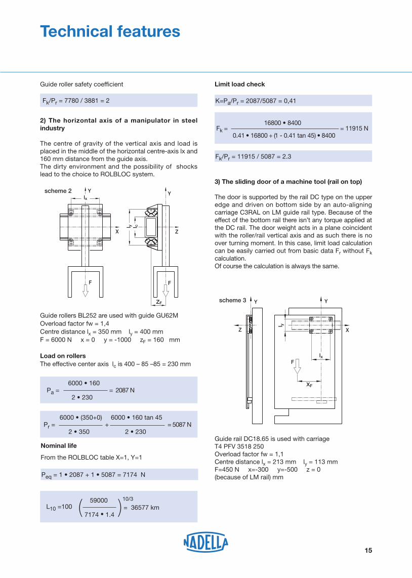
Guide rollers BL252 are used with guide GU62MOverload factor fw = 1,4Centre distance lx = 350 mm ly = 400 mmF = 6000 N x = 0 y = -1000 zF = 160 mm
Load on rollersThe effective center axis lc is 400 – 85 –85 = 230 mm
Y Y
X Z
FF
lx
l y l c
ZF
Pa = = 2087 N
Pr = + = 5087 N
Nominal life
From the ROLBLOC table X=1, Y=1
Limit load check
Peq
K=Pa/Pr = 2087/5087 = 0,41
Fk/Pr = 11915 / 5087 = 2.3
59000 10/3
= 36577 km 7174 1.4( )L10 =100
16800 8400Fk = = 11915 N 0.41 16800 + (1 - 0.41 tan 45) 8400
scheme 2
Z
Y Y
X
F
l y
XF
lx
3) The sliding door of a machine tool (rail on top)
The door is supported by the rail DC type on the upper edge and driven on bottom side by an auto-aligning carriage C3RAL on LM guide rail type. Because of the effect of the bottom rail there isn’t any torque applied at the DC rail. The door weight acts in a plane coincident with the roller/rail vertical axis and as such there is no over turning moment. In this case, limit load calculation can be easily carried out from basic data Fr without Fk calculation. Of course the calculation is always the same.
Guide rail DC18.65 is used with carriage T4 PFV 3518 250Overload factor fw = 1,1Centre distance lx = 213 mm ly = 113 mmF=450 N x=-300 y=-500 z = 0 (because of LM rail) mm
scheme 3
2) The horizontal axis of a manipulator in steel industry
The centre of gravity of the vertical axis and load is placed in the middle of the horizontal centre-axis lx and 160 mm distance from the guide axis.The dirty environment and the possibility of shocks lead to the choice to ROLBLOC system.
Guide roller safety coefficient
Fk/Pr = 7780 / 3881 = 2
Technical features
Z
Y
Y
X
F
Iy
YF
I x
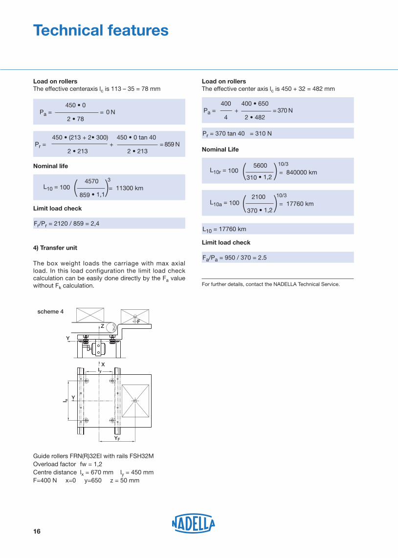
4) Transfer unit
The box weight loads the carriage with max axial load. In this load configuration the limit load check calculation can be easily done directly by the Fa value without Fk calculation.
Guide rollers FRN(R)32EI with rails FSH32MOverload factor fw = 1,2Centre distance lx = 670 mm ly = 450 mmF=400 N x=0 y=650 z = 50 mm
Pr = 370 tan 40 = 310 N
Limit load check
Fa/Pa = 950 / 370 = 2.5
For further details, contact the NADELLA Technical Service.
L10 = 17760 km
Nominal Life
5600 10/3
= 840000 km 310 ( )L10r = 100
2100 10/3
= 17760 km 370
( )L10a = 100
Load on rollersThe effective center axis lc is 450 + 32 = 482 mm
Pa = + = 370 N
scheme 4
16
Nominal life
Limit load check
Fr/Pr = 2120 / 859 = 2,4
4570 3 = 11300 km 859
( )L10 = 100
Pr = + = 859 N
Load on rollersThe effective centeraxis lc is 113 – 35 = 78 mm
Pa = = 0 N
Technical features

profile size
GUFSFSHFSX GP
Steel rail
Alluminium rail
17
FSH 62 MT 1500 SB NW RR
profile type
MMTMC
groundcold drawn and sandblastedrough - ground
length (mm)
standard drillingfinished to drawingwithout holesboring layout A (only GP range)boring layout B (only GP range)
SB NZNFAB
Stainless steelnickel platingone ground endboth ground ends
NXNWRRR
profile size
FWNFWSFWHCDCLMLML
FWS 40 / 2000 NF NX
profile type
length (mm)
standard drillingfinished to drawingwithout holes
SB NZNF
chromium plateone ground endboth ground endsstainless steel rods
CHRRRNX
Guide rail order code


Heavy-Line
GU System
lWeight
(kg/m) (2)
Dimensions (mm)
Type H
± 0.05
h
± 0.05
S
± 0.05
D
+ 0.1G g
b
+ 0.05
c
± 0.05sm
max length in single element L=6 000 mm (1)
max length in single element L=4 020 mm (1)
L
I I
D
G
gh
1
b
S
H c
sm
90°
B
B
AB
A0,1
0,02
B0,02
+ 0,05
b+ 0,05
h
S
H c
± 10'
90°± 5'
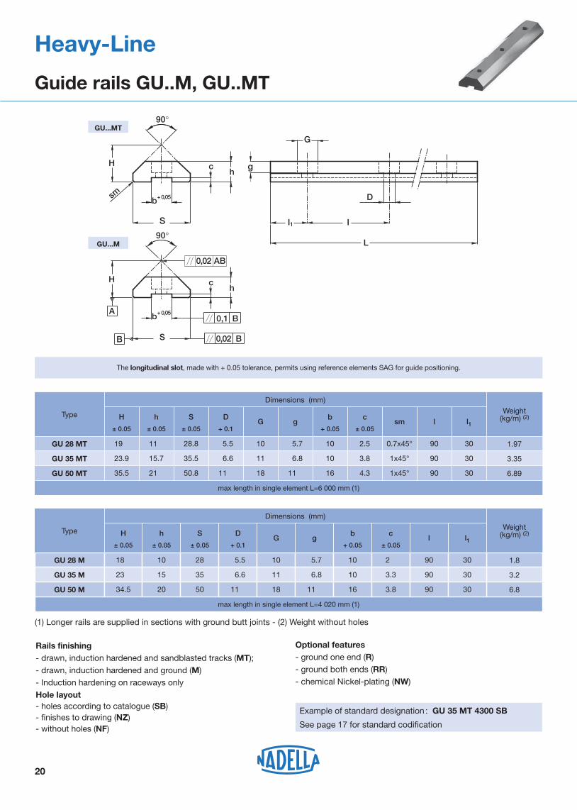
The longitudinal slot, made with + 0.05 tolerance, permits using reference elements SAG for guide positioning.
20
1.97GU 28 MT 19,0 11,0 28.8 5.5 10 5.7 10 2.5 0.7x45° 90 30
3.35GU 35 MT 23.9 15.7 35.5 6.6 11 6.8 10 3.8 1x45° 90 30
6.89GU 50 MT 35.5 21,0 50.8 11,0 18 11,0 16 4.3 1x45° 90 30
Weight(kg/m) (2)
1.8
Dimensions (mm)
Type
GU 28 M
3.2GU 35 M
6.8GU 50 M
l1H
± 0.05
h
± 0.05
S
± 0.05
D
+ 0.1G g
b
+ 0.05
c
± 0.05l
18,0 10 28 5.5 10 5.7 10 2,5 90 30
23,9 15 35 6.6 11 6.8 10 3.3 90 30
34.5 20 50 11,0 18 11,0 16 3.8 90 30
GU...MT
GU...M
Heavy-Line
Guide rails GU..M, GU..MT
Optional features- ground one end (R)- ground both ends (RR) - chemical Nickel-plating (NW)
Example of standard designation : GU 35 MT 4300 SB
See page 17 for standard codification
Rails finishing - drawn, induction hardened and sandblasted tracks (MT);- drawn, induction hardened and ground (M) - Induction hardening on raceways onlyHole layout- holes according to catalogue (SB)- finishes to drawing (NZ)- without holes (NF)
(1) Longer rails are supplied in sections with ground butt joints - (2) Weight without holes
l1

0.9
2.8
0.6
1.6
4.9
160RKU 65 RKUR 65 46 800 22 100 6 800 1 3.06
450RKU 95 RKUR 95 116 800 43 700 12 600 1 3.74
80RKU 55 RKUR 55 41 650 11 900 4 250 1 3.42
300RKU 75 RKUR 75 66 700 31 300 10 100 1 2.95
450RKU 115 RKUR 115 182 450 55 600 17 900 1 3.64
TypeLife coefficients Weight
(kg)
Torque wrench (2)
settings(Nm)
Dynamic load(N)
Cw (6) radial Fr axial Fa X Y
Limit loads (N)
concentric
Type
1
56(5)
53
Dimensions (mm)
SW2
M
d
L
m
T
De
90˚
SW1
SW2
A
B I1
k=1SW1
d1
P
S min.
The sides of the race are convex with radius R = 400.
concentric eccentric
1RKU 55
eccentric
RKUR 55
De d1 (1) d T m S min. L A B I1 M SW1P
55 21 M 20 x 1.5 14.6 19.8 73 35 41 14 28 8 3013.4
1RKU 65 RKUR 65 65 27 M 24 x 1.5 18.7 20.8 83 37 44 18 35 10 3615.4
1RKU 75 RKUR 75 75 36 M 30 x 1.5 23.7 27.8 100 45 55 18 44 12 4621.6
1RKU 95 RKUR 95 95 38 M 36 x 1.5 25.5 30.8 115 62 23 50 14 5524.6
k
RKU 115 RKUR 115 115 42 M 36 x 1.5 33.5 34.8
15
19
19
24
33 135 70 32 56 14 5524.6 63(5)
60
21
Heavy-Line
Guide rollers RKU
1) Housing bore tolerance: H72) The torque wrench settings are given for non-lubricated threads; for lubricated threads, multiply figure by 0.83) Standard seals: material NBR, RS type4) On request, the guide rollers can be supplied with external parts in stainless steel (suffix NX) and with Viton seals for operating
temperatures up to 120°C (suffix V, not available for RKU 115). Internal rolling elements in standard bearing steel.5) Dimensions relating to the stainless-steel rollers (suffix NX)6) Cw basic load for 100 km7) The guide rollers include self-locking washers and hexagonal nut (DIN 439B) for fitting8) Pressure angle α for load calculation: 45°

Life coefficients
d2
De
90°
T
M F
A
B +0- 0.1
m
dH8
22
Type
36,0
Dimensions (mm)
72
56(2)
53
FKU 55
De d T m A B F d2 (4) M
55 15 14.6 21,0 35 42 25 2.5 30
FKU 65 65 20 18,0 22.5 37 45 29 3,0 35
FKU 75 75 25 23.7 28,0 45 56 37 4,0 44
FKU 95 95 28 25.5 32,0 64 42 4,0 49
FKU 115 115 35 33.5 63(2)
60 52 4,0 59
The sides of the race are convex with radius R = 400.
Weight(kg)
radial Fr axial Fa
Limit loads(N)
0.5
0.6
1.2
2.3
3.9
Type
FKU 55
Dynamic load(N)
Cw (3) X Y
41 650 11 900 4 250 1 3.42
FKU 65 46 800 22 100 6 800 1 3.06
FKU 75 66 700 31 300 10 100 1 2.95
FKU 95 116 800 43 700 12 600 1 3.74
FKU 115 182 450 55 600 17 900 1 3.64
Heavy-Line
Guide wheels FKU
1) On request, the guide rollers can be supplied with external parts in stainless steel (suffix NX) and with Viton seals for operating temperatures up to 120°C (suffix V not available for FKU 115). Internal rolling elements in standard bearing steel
2) Dimensions relating to the stainless-steel rollers (suffix NX)3) Cw basic load for 100 km4) To prevent rotation between roller and shaft a pin can be fitted in one of the holes “d2” positioned in the side flange5) Pressure angle α for load calculation: 45°6) Standard seals: material NBR, RS type

23
Type Dimensions (mm)
concentric eccentric De d1 1) d T m n X S min. P L A 4) B C I1 M SW1 SW2 k
RKUL 55 RKULR 55 55 21 M 20 x 1.5 14.6 21.0 3 3 15 13.4 83 35 42 51 14 30 8 30 1
RKUL 65 RKULR 65 65 27 M 24 x 1.5 18.0 22.5 3 3 19 15.4 93 37 45 54 18 35 10 36 1
RKUL 75 RKULR 75 75 36 M 30 x 1.5 23.7 28.0 3 3 19 21.6 110 45 56 65 18 44 12 46 1
RKUL 95 RKULR 95 95 38 M 36 x 1.5 25.5 32.0 4 3.5 24 24.6 128 53 564) 64 75 23 49 14 55 1
RKUL 115 RKULR 115 115 42 M 36 x 1.5 33.5 36.0 4 3.5 33 24.6 148 60 63
4) 72 83 32 59 14 55 1
TypeDynamic load (N) Limit load (N) Torque wrench
settings 2)
(Nm)
Weight
(g)Cw
3) radial Fr
RKUL 55 RKULR 55 41650 3050 80 800
RKUL 65 RKULR 65 46800 6850 160 1100
RKUL 75 RKULR 75 66700 11200 300 1800
RKUL 95 RKULR 95 116800 13800 450 3000
RKUL 115 RKULR 115 182450 24000 450 5100
1) Housing bore tolerance: H72) The torque wrench settings are given for non-lubricated threads; for lubricated threads multiply figure by 0.83) Cw = Basic load for 100 KM4) Dimensions for stainless steel (NX) version
On request the guide rollers can be supplied with external parts in stainless steel (suffix NX). Internal rolling elements in standard bearing steel
Standard seals: material NBR, RS type
On request guide rollers can be supplied with Viton seals for operating temperatures up to 120°C (suffix V, not available for RKUL 115)
The guide rollers include self-locking washers and hexagonal nut (DIN 439B) for fitting
Pressure angle α for load calculation: 45°
Heavy-Line
Floating guide rollers RKUL
concentric eccentric
90°X
M
De
T
L
m S min.
d
SW2
SW1
n P
k
d1
l1
A
B
C

Suggested combinations
24
TypeWeight
(g)
LUBU 55 RKU 55 RKUR 55 FKU 55
X
6535
Dimensions (mm)
1) The dimension of the plastic part refers to the centre of the regulation-slot. Allows a translation of +/- 3 mm.2) The lubricator is supplied with the felt already lubricated. The lubricant has a mineral oil base.3) During the mounting fix the aluminium support to the rollers plate, adjust the height of the plastic part in order to put it in contact with
the raceways and than block it in that position with the M5 screws.
12 14 40 19.8 25.5 10.0 34 20.0 38 16.5 18.5
LUBU 65 RKU 65 RKUR 65 FKU 65 6540 14 12 40 20.8 25.5 10.0 34 20.0 38 18.5 16.5
LUBU 75 RKU 75 RKUR 75 FKU 75 8545 19 11 50 27.0 25.5 10.0 43 25.4 44 24.0 16.0
LUBU 95 RKU 95 RKUR 95 FKU 9514055 21 9 60 30.0 30.0 16.5 50 24.9 58 31.0 19.0
LUBU 115 RKU 115 RKUR 115 FKU 11514065 30 0 63 34.0 30.0 16.5 50 24.9 58 40.0 10.0
U1 U2 F m B S C A E V P
Heavy-Line
Lubricator LUBU
(1)
(1)
(1)
mountingrollers-plate
U1
U2
M5
M6 DIN 71412
M5 pf.12 (2x)
roller axis
P
V
X min
A
B
m
E
C
S
510
26
F
Optional features- felt without lubricant (D)

Ih (mm)
L
D h7
P
d m6
1) Housing bore tolerance: H7
Pin typeDimensions (mm)
D d (1) P L
10 8 10.0 12.3
Guide type
SAG 28 GU 28 MT
16 10 11.2 15.0SAG 50 GU 50 MT
10 8 10.0 13.5SAG 35 GU 35 MT
25
Guide roller combinations (RKU, FKU, RKUL)
GU 28 MT
36,0
RKU, FKU, RKUL 55 RKU, FKU, RKUL 65
33.6 37,0
Guide
Roller
32.6
41
– 41.9
–
–
– –
–
RKU, FKU, RKUL 75
–
46.7
47.6
–
–
–
RKU, FKU, RKUL 95
–
–
–
60
61
–
RKU, FKU, RKUL 115
–
–
–
68
69
–
GU 28 MT
GU 35 MT
GU 35 MT
GU 50 MT
GU 50 MT
Ih
Heavy-Line
Guide pins SAG

GU 35 MT and rollers type RKU 75 operated on light-alloy structure.
26
Heavy-Line
Mounting Examples

Heavy-Line
GP System
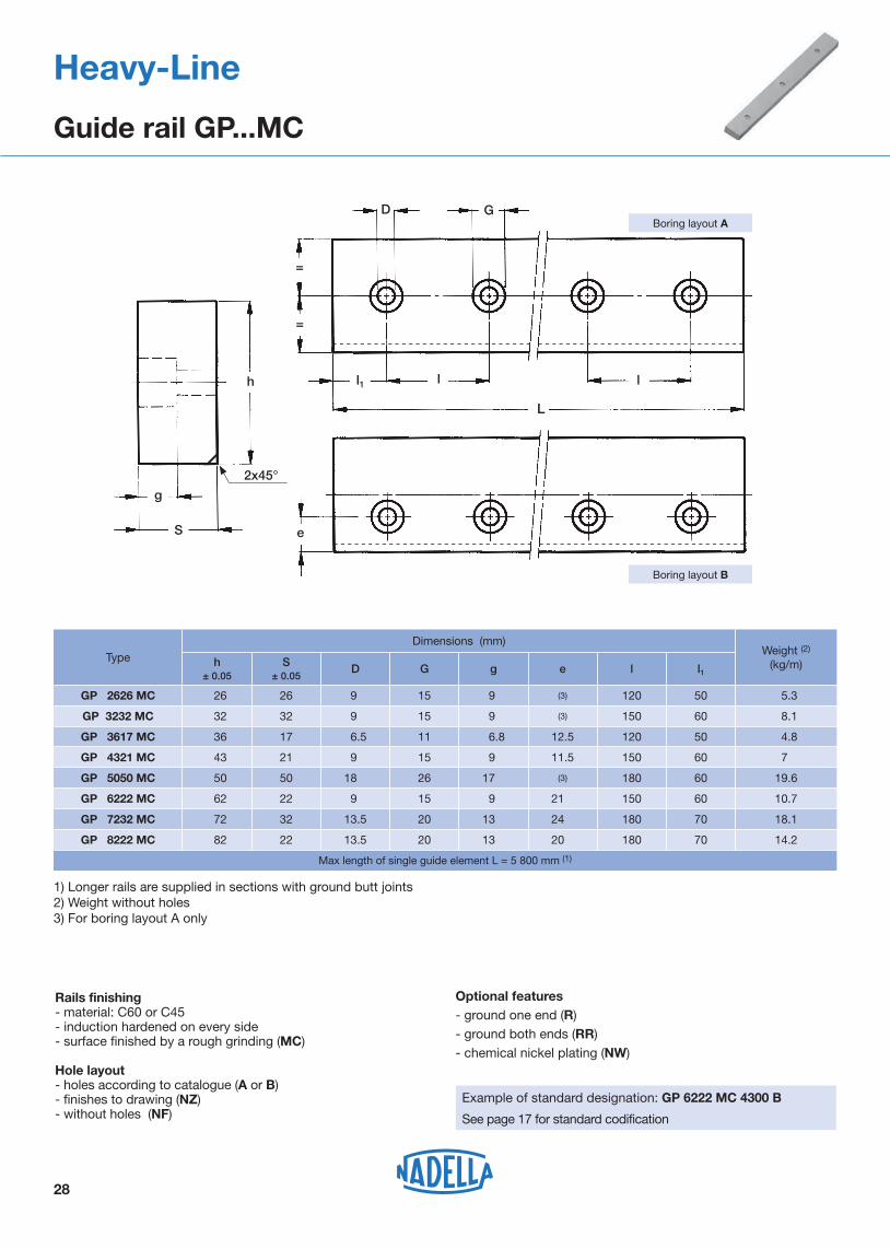
Type
Max length of single guide element L = 5 800 mm (1)
Weight (2)
(kg/m)
20
28
h
g
S
D G
=
=
l1 l
L
l
e
Boring layout A
Boring layout B
h± 0.05
S± 0.05
D G g e l l1
GP 2626 MC 26 9.0 15 9,0 (3) 120 50 5.3 26
GP 3232 MC 32 9,0 15 9,0 (3) 150 60 8.1 32
GP 6222 MC 22 9,0 15 9,0 21.0 150 60 10.7 62
GP 7232 MC 32 13.5 20 13,0 24,0 180 70 18.1 72
GP 8222 MC 22 13.5 13,0 20,0 180 70 14.2 82
Dimensions (mm)
GP 3617 MC 17 6.5 11 6.8 12.5 120 50 4.8 36
GP 4321 MC
GP 5050 MC
21
50
9,0
18,0
15
26
9,0
17,0
11.5
(3)
150
180
60
60
7.0
19.6
43
50
Heavy-Line
Guide rail GP...MC
2x45°
1) Longer rails are supplied in sections with ground butt joints 2) Weight without holes3) For boring layout A only
Optional features- ground one end (R)- ground both ends (RR) - chemical nickel plating (NW)
Example of standard designation: GP 6222 MC 4300 B
See page 17 for standard codification
Rails finishing - material: C60 or C45- induction hardened on every side- surface finished by a rough grinding (MC) Hole layout- holes according to catalogue (A or B)- finishes to drawing (NZ)- without holes (NF)

Weight (2)
(kg/m)Type
Max length of single guide element L = 4 020 mm (1)
29
h
g
0,02
0,02
A
0,02 A�
S
D G
=
=
l1 l
L
l
e
Boring layout A
Boring layout B
GP 3516 M
20
h± 0.05
S± 0.05
D G g e l l1
GP 2525 M 25 9.0 15 8.5 (3) 120 50 4.925
GP 3131 M 31 9.0 15 8.5 (3) 150 60 7.531
16 6.5 11 6.8 12,0 120 50 4.435
GP 4220 M 20 9,0 15 9,0 11,0 150 60 6.542
GP 6121 M 21 9,0 15 9,0 20.5 150 60 10.561
GP 7131 M 31 13.5 20 12.5 23.5 180 70 17.371
GP 8121 M 21 13.5 13,0 19.5 180 70 13.481
Dimensions (mm)
Heavy-Line
Guide rails GP...M
1x45°
1) Longer rails are supplied in sections with ground butt joints (max. length with treatment NW on request)2) Weight without holes3) Only available according to figure A
Optional features- ground one end (R)- ground both ends ( RR ) - chemical Nickel-plating (NW)
Example of standard designation : GP 6121 M 2070 B
See page 17 for standard codification
Rails finishing - material: C60 or C45- induction hardened and ground tracks on every side (M); Hole layout- holes according to catalogue (A or B)- finishes to drawing (NZ)- without holes (NF)

Dynamic load(N)
Limit load(N)Type
eccentric
Weight(Kg)
1 200
42 100PKR 52C
4.9
Dimensions (mm)
PK 62C
1
M
d
L
m
De
SW1
SW2
B I1
k=1SW1
d1
P
A
CR
S min.
30
56(5)
53
SW2
1PK 52C
Type
concentric
PKR 52C
De d1(1) d m CS min. L A B I1 M SW1P
52 21 M 20 x 1.5 19.8 29 73 35 41 14 28 8 3013.4
1PKR 62C 62 27 M 24 x 1.5 20.8 29 83 37 44 18 35 10 3615.4
1PK 72C PKR 72C 72 36 M 30 x 1.5 27.5 33100 45 55
62
18 44 12 4621.6
1PK 90C PKR 90C 90 38 M 36 x 1.5 30.8 45115 23 50 14 5524.6
k
PK 110C PKR 110C 110 42 M 36 x 1.5 34.8 48
R
800
800
1 200
1 200
15
19
19
24
33 135 70 32 56 14 5524.6 63(5)
60
450
Torque (2)
wrench setting(Nm)
PK 52C
Cw (6)
11 900
PK 62C 47 750 22 100
PK 72C 67 450 31 300
PK 90C 118 000 43 700
80
160
300
450
0.6
0.9
1.6
2.8
PK 110C
PKR 62C
PKR 72C
PKR 90C
PKR 110C 185 000
radial Fr
55 600
concentric eccentric
Heavy-Line
Guide rollers PK
1) Housing bore tolerance: H72) The torque wrench settings are given for non-lubricated threads; for lubricated threads, multiply figure by 0.83) Standard seals: material NBR, RS type4) On request, the guide rollers can be supplied with external parts in stainless steel (suffix NX) and with Viton seals for operating
temperatures up to 120°C (suffix V, up to dimension PK 90 C included). Internal rolling elements in standard bearing steel5) Dimensions relating to the stainless-steel rollers (suffix NX)6) Cw basic load for 100 km7) The guide rollers are complete with self-locking washers and hexagonal nut for fitting

Type
55 600
Rotelle di guida FKd2
De M F
B
A
C
+0- 0.1
dH8
R
31
1) Standard seals: material NBR, RS type2) On request, the guide rollers can be supplied with external parts in stainless steel (suffix NX) and with Viton seals for operating
temperatures up to 120°C (suffix V, up to dimension FK 90 C included). Internal rolling elements in standard bearing steel3) Dimensions relating to the stainless-steel rollers (suffix NX)4) Cw basic load for 100 km5) To prevent rotation between roller and shaft a pin can be fitted in one of the holes “d2” positioned in the side flange
3.9
Weight(kg)
FK 52C
Dynamic load(N)
Cw (4) radial Fr
42 100 11 900
Limit load(N)
FK 62C 47 750 22 100
FK 72C 67 450 31 300
FK 90C 118 000 43 700
0.5
0.6
1.2
2.3
FK 110C 185 000
F
Dimensions (mm)
72
Type
56(3)53
FK 52C
De d C RA B d2 M
52 15 29 80035 42 25 2.5 30
FK 62C 62 20 29 80037 45 29 3,0 35
FK 72C 72 25 33 1 20045 56 37 4,0 44
FK 90C 90 28 45 1 20064 42 4,0 49
FK 110C 110 35 48 1 20063(3)60 52 4,0 59
Heavy-Line
Guide wheels FK

32
Perni folli a rullini GC
* These threads may be supplied with pitch of 1 mm (clamping torque 13 Nm)- Housing bore tolerance: H7- The guide rollers are complete with washers and hexagonal nut for fitting
1
2
r
B eA
t
R
d M
Ll
f
De
De t
Ar
B S
d d1 t
t
1
Ll
f
M
l1
k
B S4
1M
4
4
GCGC...EE with plastic sealsGC...EEM with metal shields
concentric
esecution EE, EEM
GCR 62GCR 19 ÷ 52
GCRGCR...EE with plastic sealsGCR...EEM with metal shields
eccentric
Holes (1) and (2) beginning from De=30 mm
Type(1)
18,0
l1De
62
19 11 12.2 11 32.7
36.7
36.7
40.7
58.6
66.6 21
19
13
12
12
10 0.3 4
4
4
6
6
-
-
-
6
8
9
15.3
18.2
20.8
24.8
33.8
38.7
-
-
-
-
-
- 14
12
-
-
-
8
10,0
11,0
11,0
11,0
16,0
17.5
0.3
0.3
0.6
1,0
1,0
14
14
16
24
27
8 0.5 20.5 1.25
1.25*
1.25*
1.55*
1.55*
1.55*
23.5
23.5
25.5
37,0
41,0
1,0
1,0
1,0
2,0
1,5
10
10
12
18
20
13.2
13.2
15.2
21.6
25.6
12
12
14
20
24
24
28
32
40
52
A Bmax
d d1(7)
k Lmax
lmax
f pitch rmin
t e M(6)
M1 P(2)
GCR 19
36.7
36.7
40.7
52.6
66.6
80.6 25
21
17
13
12
12 4
4
6
6
6
-
-
6
8
9
11
18.2
20.8
24.8
28.8
38.7
52
-
-
-
-
-
44 12
14
10
-
-
8
11,0
11,0
11,0
14,0
17.5
0.3
0.3
0.6
0.6
1,0
1,0
14
14
16
21
27
36
1.25*
1.25*
1.55*
1.55*
1.55*
1.55*
23.5
23.5
25.5
33,0
41,0
50,0
1,0
1,0
1,0
2,0
3,0
1,5
10
10
12
16
20
24
13.2
13.2
15.2
19.6
25.6
30.6
12
12
14
18
24
29
22
26
30
35
47
GC 22 GCR 22
GCR 24
GC 26 GCR 26
GCR 28
GC 30 GCR 30
GCR 32
GC 35 GCR 35
GCR 40
GC 47 GCR 47
GC 19
GC 24
GC 28
GC 32
GC 40
GC 52 GCR 52
GC 62 GCR 62
Dimensions (mm)
Heavy-Line
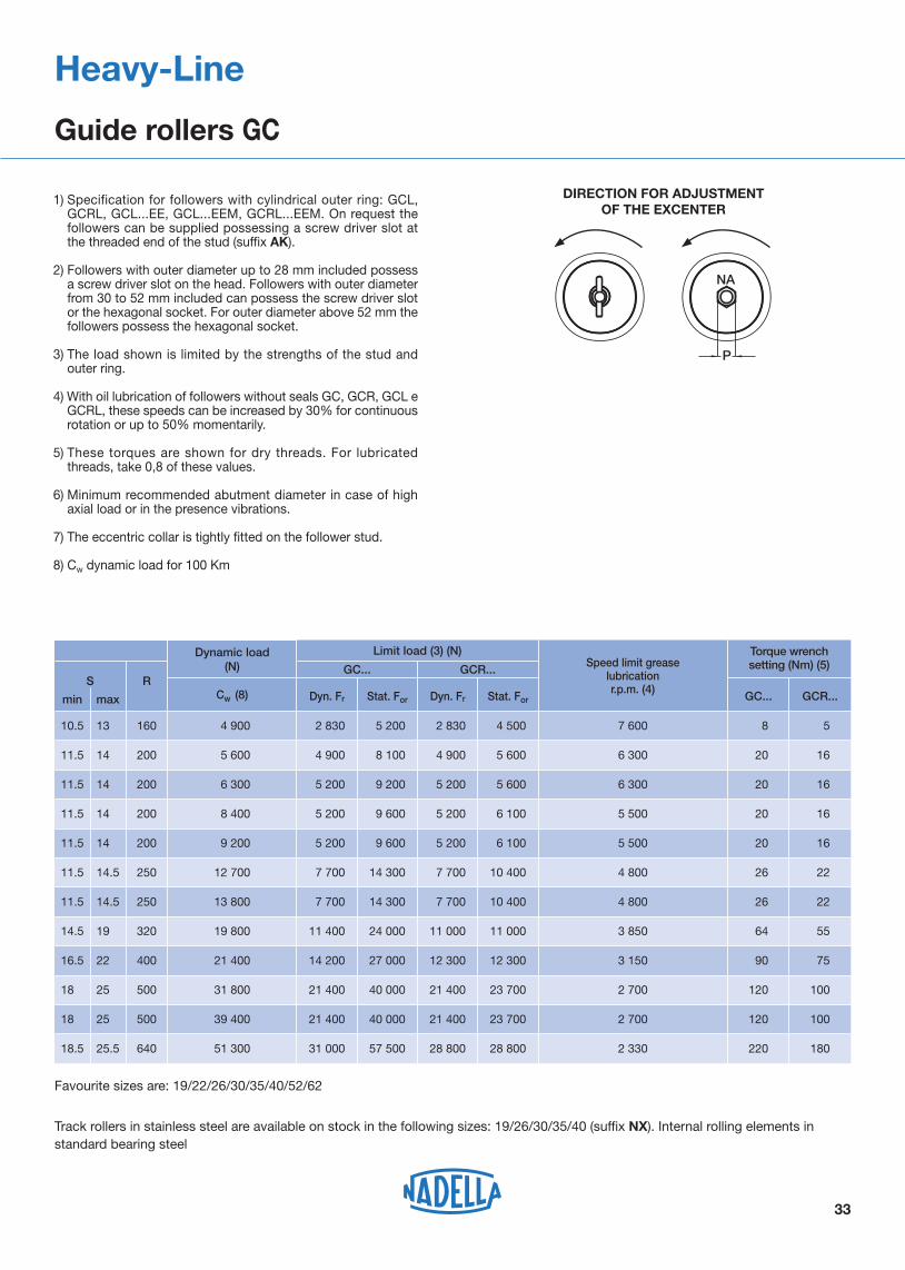
Guide rollers GC
Speed limit greaselubricationr.p.m. (4)
Torque wrenchsetting (Nm) (5)
33
16.5
11.5
11.5
11.5
10.5
18,5
13,5
14,5
14,5
14.5
22,5
25,5
18.5
14.5
11.5
11.5
11.5
18,5
14,5
14,5
14.5
19,5
25,5
25.5
160
200
200
250
400
500
200
200
250
320
500
640
S RCw (8)
Dynamic load(N)
NA
P
1) Specification for followers with cylindrical outer ring: GCL, GCRL, GCL...EE, GCL...EEM, GCRL...EEM. On request the followers can be supplied possessing a screw driver slot at the threaded end of the stud (suffix AK).
2) Followers with outer diameter up to 28 mm included possess a screw driver slot on the head. Followers with outer diameter from 30 to 52 mm included can possess the screw driver slot or the hexagonal socket. For outer diameter above 52 mm the followers possess the hexagonal socket.
3) The load shown is limited by the strengths of the stud and outer ring.
4) With oil lubrication of followers without seals GC, GCR, GCL e GCRL, these speeds can be increased by 30% for continuous rotation or up to 50% momentarily.
5) These torques are shown for dry threads. For lubricated threads, take 0,8 of these values.
6) Minimum recommended abutment diameter in case of high axial load or in the presence vibrations.
7) The eccentric collar is tightly fitted on the follower stud.
8) Cw dynamic load for 100 Km
4 900
6 300
9 200
13 800
21 400
39 400
2 830
5 200
5 200
7 700
14 200
21 400
5 200
9 200
9 600
14 300
27 000
40 000
2 830
5 200
5 200
7 700
12 300
21 400
4 500
5 600
6 100
10 400
12 300
23 700 2 700
3 150
4 800
5 500
6 300
7 600 8
20
20
26
90
120
5
16
16
22
75
100
5 600
8 400
12 700
19 800
31 800
Dyn. Fr Stat. For Dyn. Fr Stat. For
4 900
5 200
7 700
11 400
21 400
31 000
8 100
9 600
14 300
24 000
40 000
57 500
4 900
5 200
7 700
11 000
21 400
28 800
5 600
6 100
10 400
11 000
23 700
28 800 2 330
2 700
3 850
4 800
5 500
6 300 20
20
26
64
220
120
16
16
22
55
180
100
GCR...GC...
Limit load (3) (N)
GC... GCR...
51 300
min max
Track rollers in stainless steel are available on stock in the following sizes: 19/26/30/35/40 (suffix NX). Internal rolling elements in standard bearing steel
Favourite sizes are: 19/22/26/30/35/40/52/62
Heavy-Line
Guide rollers GC
DIRECTION FOR ADJUSTMENT OF THE EXCENTER

B
Ar
r1
D1DiDe
R
34
FG series without seals FG…EEM series with metal shields
FGUFGU...MM series: with metal shields
Heavy-Line
Cam followers FG (needle) and FGU (roller)
Di D1 De
B
A r
r1
R
TypeDimensions (mm)
De Di A B max D1 M (1) min r min r1 min R
FG 6 19 19 6 11 12 8.5 12 0.3 0.3 160
FG 10 30 30 10 14 15 13.8 19.5 0.6 0.3 250
FG 12 32 32 12 14 15 16 21.5 0.6 0.3 250
FG 15 35 35 15 18 19 18.7 24 0.6 0.3 320
FG 17 40 40 17 20 21 22 28 0.6 0.3 400
FG 20 47 47 20 24 25 25.7 32.5 1 0.3 500
FG 25 52 52 25 24 25 30.5 37 1 0.3 500
FG 30 62 62 30 28 29 35.2 44 1 0.3 640
FG 35 72 72 35 28 29 41 50 1 0.6 640
FG 40 80 80 40 30 32 46.7 56 1 0.6 800
FG 50 90 90 50 30 32 59.1 69 1 0.6 800
FGU 55 100 100 55 34 36 64 75.8 1.5 0.6 800
FGU 60 110 110 60 34 36 69.5 81.5 1.5 0.6 800
FGU 65 120 120 65 40 42 74.5 86.7 1.5 0.6 900
FGU 75 130 130 75 40 42 84 97 1.5 0.6 900
35
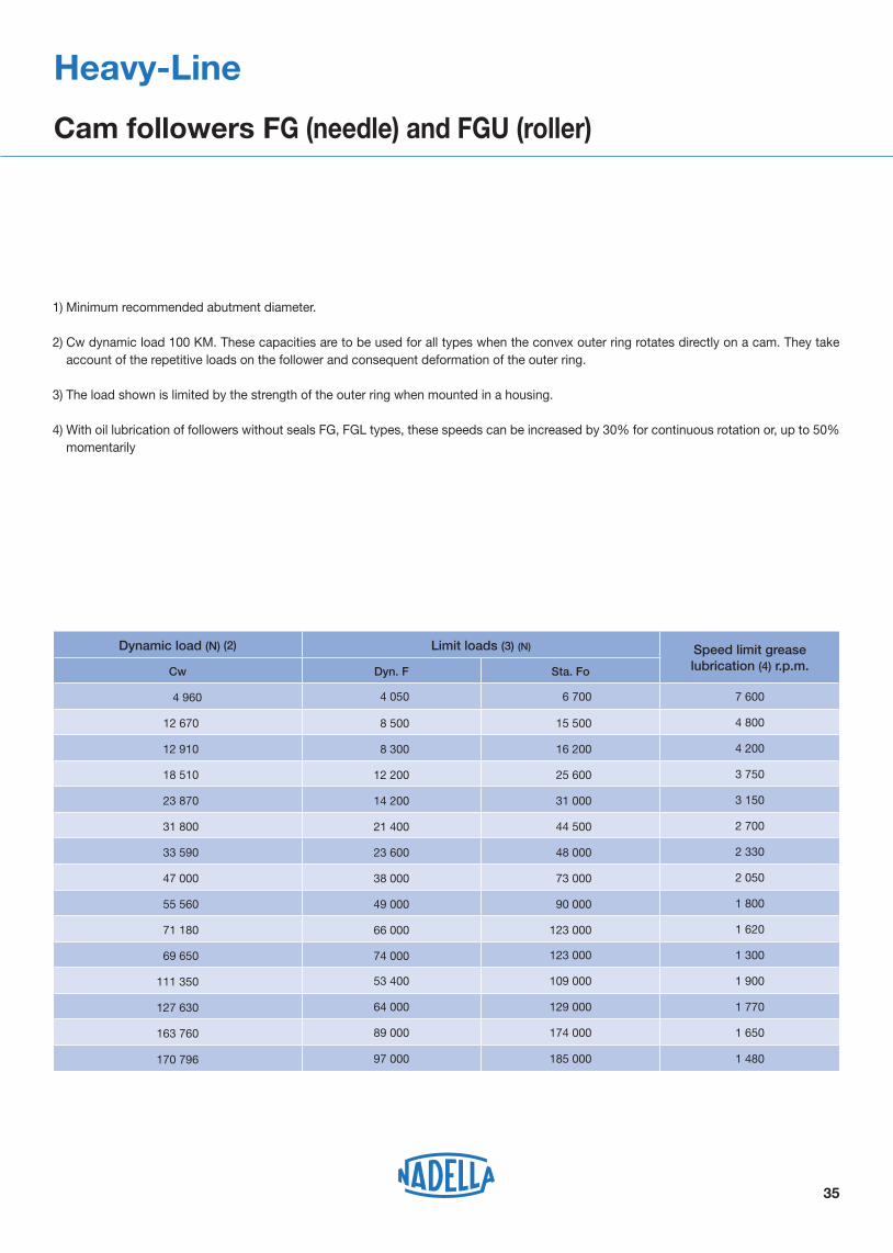
1) Minimum recommended abutment diameter.
2) Cw dynamic load 100 KM. These capacities are to be used for all types when the convex outer ring rotates directly on a cam. They take account of the repetitive loads on the follower and consequent deformation of the outer ring.
3) The load shown is limited by the strength of the outer ring when mounted in a housing.
4) With oil lubrication of followers without seals FG, FGL types, these speeds can be increased by 30% for continuous rotation or, up to 50% momentarily
Heavy-Line
Cam followers FG (needle) and FGU (roller)
Dynamic load (N) (2) Limit loads (3) (N) Speed limit greaselubrication (4) r.p.m.Cw Dyn. F Sta. Fo
4 960 4 050 6 700 7 600
12 670 8 500 15 500 4 800
12 910 8 300 16 200 4 200
18 510 12 200 25 600 3 750
23 870 14 200 31 000 3 150
31 800 21 400 44 500 2 700
33 590 23 600 48 000 2 330
47 000 38 000 73 000 2 050
55 560 49 000 90 000 1 800
71 180 66 000 123 000 1 620
69 650 74 000 123 000 1 300
111 350 53 400 109 000 1 900
127 630 64 000 129 000 1 770
163 760 89 000 174 000 1 650
170 796 97 000 185 000 1 480
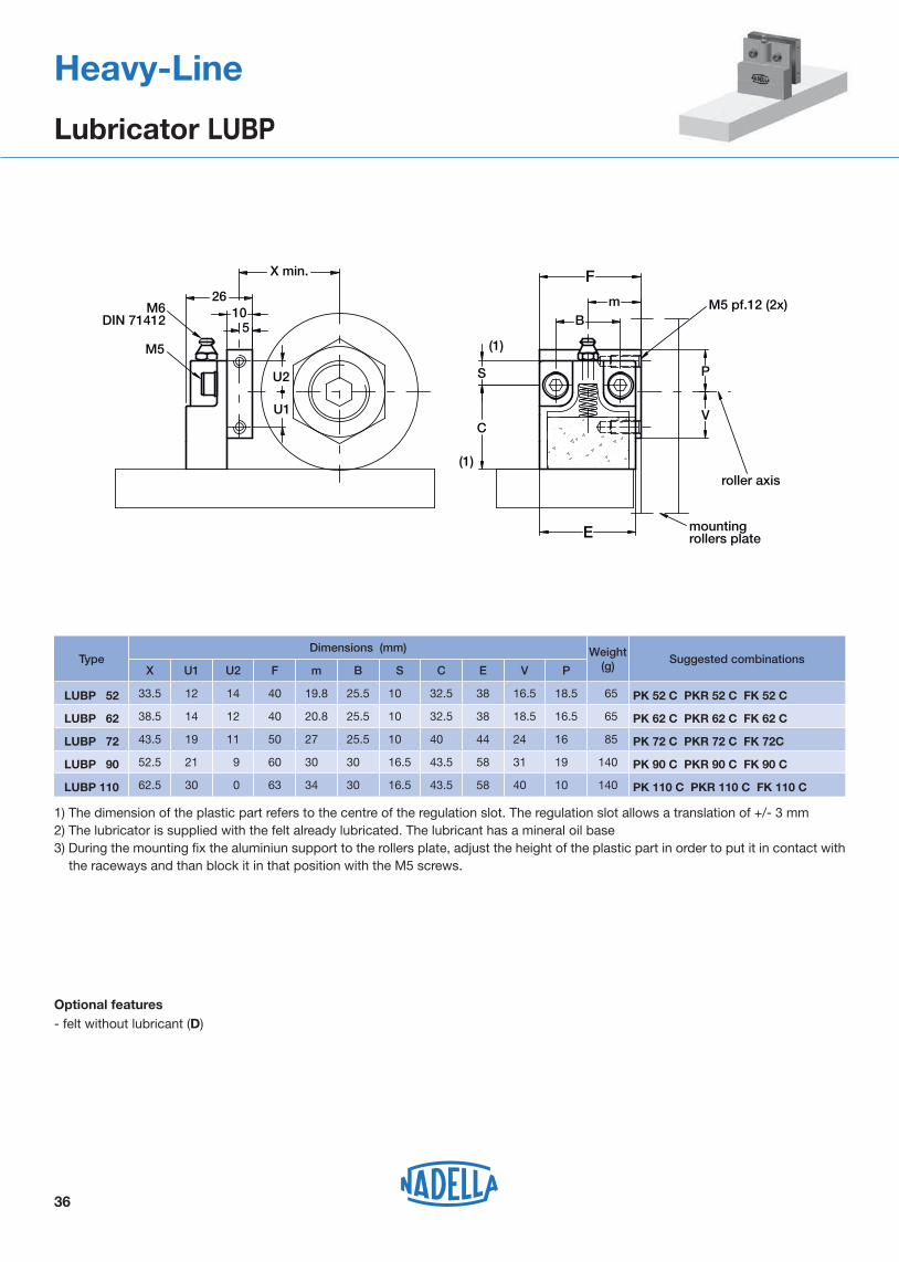
1) The dimension of the plastic part refers to the centre of the regulation slot. The regulation slot allows a translation of +/- 3 mm2) The lubricator is supplied with the felt already lubricated. The lubricant has a mineral oil base 3) During the mounting fix the aluminiun support to the rollers plate, adjust the height of the plastic part in order to put it in contact with
the raceways and than block it in that position with the M5 screws.
36
Heavy-Line
Lubricator LUBP
F26
105
S
C
E
mB
X min.
P
V
roller axis
M5 pf.12 (2x)M6DIN 71412
M5
U2
U1
mountingrollers plate
(1)
(1)
Suggested combinationsTypeWeight
(g)
LUBP 52 PK 52 C PKR 52 C FK 52 C
X
6533.5
Dimensions (mm)
12 14 40 19.8 25.5 10 32.5 38 16.5 18.5
LUBP 62 PK 62 C PKR 62 C FK 62 C 6538.5 14 12 40 20.8 25.5 10 32.5 38 18.5 16.5
LUBP 72 PK 72 C PKR 72 C FK 72C 8543.5 19 11 50 27 25.5 10 40 44 24 16
LUBP 90 PK 90 C PKR 90 C FK 90 C14052.5 21 9 60 30 30 16.5 43.5 58 31 19
LUBP 110 PK 110 C PKR 110 C FK 110 C14062.5 30 0 63 34 30 16.5 43.5 58 40 10
U1 U2 F m B S C E V P
Optional features- felt without lubricant (D)

37
Heavy-Line
Guide rollers combinations
Layout 1GC PK/FK
19 22 24 26 28 30 32 35 40 47 52 62 52 62 72 90 110
GP2626MC / GP2525M
GP3232MC / GP3131M
GP3617MC / GP3516M
GP4321MC / GP4220M
GP5050MC
GP6222MC / GP6121M
GP7232MC / GP7131M
GP8222MC / GP8121M
Layout 1FG/FGU
6 19 10 30 12 32 15 35 17 40 20 47 25 52 30 62 35 72 40 80 50 90 55 100 65 120 75 130
GP2626MC / GP2525M
GP3232MC / GP3131M
GP3617MC / GP3516M
GP4321MC / GP4220M
GP5050MC
GP6222MC / GP6121M
GP7232MC / GP7131M
GP8222MC / GP8121M
Layout 2GC PK/FK
19 22 24 26 28 30 32 35 40 47 52 62 52 62 72 90 110
GP3617MC / GP3516M
GP4321MC / GP4220M
GP6222MC / GP6121M
GP7232MC / GP7131M
GP8222MC / GP8121M
Layout 2GC
6 19 10 30 12 32 15 35 17 40 20 47 25 52 30 62 35 72 40 80 50 90 55 100 60 110 65 120 75 130
GP3617MC / GP3516M
GP4321MC / GP4220M
GP6222MC / GP6121M
GP7232MC / GP7131M
GP8222MC / GP8121M
Layout 1
hole pattern A and B
Layout 2
only hole pattern B
In the tables above the suggested combinations. Other combinations are possible but guide rollers must not run over the holes.

38
Heavy-Line
Mounting examples
MARBLE MACHINERYHeavy-Line systemsGU and GP

Rolbloc
Rolbloc System

The carriages based on Rolbloc’s system are recommended for applications with heavy loads, high frequency of work and aggressive environment (dust, abrasive).For the profiled guide rollers, the contact beween the rollers and the rail takes place on the ground raceways, which are inclined respect the rotation axis of the guide roller. Due to this inclination angle in the contact area there is a dragging proportional to the dimension of the contact area and to the value of the inclination angle. In the ROLBLOC system the rotation axes of the roller guides are parallel to the raceways of the rail, with the following pure rolling. The pure rolling recudes the superficial stress and the effects of the dust between the surfaces.
Technical features
ROLBLOC carriages BL2.. and BL4.. are composed by a body in burnished steel on which are mounted two or four roller guides equipped wi th tapered rollers (similar to flat roller guides type PK..C). The final part of the code (that can be 52, 75 or 115) shows the external diameter of the roller guides.
MBL carriages are composed by an alluminium body provided, on one side, with four threaded screws that allow the direct mounting on the fixing plate. Besides, in order to facilitate the aligning, there are also two pin screws. The body is equipped with guide rollers with a double row angular contact ball bearing.On the body are mounted three guide rollers according to the following combinations:
MBL 335-1: three concentric guide rollers, of which one on the fixing side;MBL 335-2: three concentric guide rollers, of which two on the fixing side;MBLR 335-1: three concentric guide rollers, of which one on the fixing side;MBLR 335-2: three concentric guide rollers, of which two on the fixing side.
MBL 335-.. carriages are dissymmetrical components. In order to fully utilize the load capacity of the carriages it is necessary to consider the main load direction and than put the two coupled guide rollers in that direction.
40
MBL components are checked with the same method used for ROLBLOC BL, but it is very important to consider the exact bearing ratings that must be correct for the load direction. When the axial load (perpendicular to the fixing side of the carriage, or parallel to the fixing side of the rail) is in the direction of the two coupled guide rollers, as for the sketch above, you must use the coefficient with the suffix 2 (Fa2, Y2), otherwise with the suffix 1 (Fa1, Y1).
Mounting instructions
For the mounting of the carriages BL or MBL, with two, three and four guide rollers, are necessary at least two carriages on every rail. A slider realised with only two carriages for rail is not steady (see sketch below).
Pay the maximum attention during the setting of the eccentricity of the eccentric guide rollers in order to avoid excessive preloads that can reduce the lifetime of the system. Setting the eccentric guide rollers by rotating the stud anticlockwise (respect the head side of the guide roller).
Rolbloc
Rolbloc system
MBL(R)335-1
MBL(R)335-2
MBL(R)335-2
Fixing side
Main loaddirection
Main loaddirection
Ix
YES NO

41
The longitudinal slot of rail GU 35 permits using reference elements SAG for guide positioning.
(1) Longer rails are supplied in sections with ground butt joints - (2) Weight without holes - (3) Max length in single element 5 000 mm for GU 80 MT
GU 35 MT
GU 35 M
GU 62 MT
h
b
S
H c
sm
90°
B
B
AB
A0,1
0,02
B0,02
+ 0,05
b+ 0,05
h
S
H c
± 10'
90°± 5'L
I I
D
G
g
1
GU 80 M
GU 80 MT
GU 62 M
Rolbloc
Guide rails GU..M, GU..MT
20.30
Type
Type
Dimensions (mm)
Weight(kg/m) (2)l1
max length in single element L = 4 020 mm (1)
max length in single element L = 6 000 mm (1)
l
3.35
Dimensions (mm)
GU 35 MT
H
± 0.05
h
± 0.05
S
± 0.05
D
+ 0.1G g
b
+ 0.05
c
± 0.05sm
23.9 15.7 35.5 6.6 11 6.8 10 3.8 1x45° 90 30
11.80GU 62 MT 43.5 32.5 63.5 11 18 11 – – 2x45° 120 30
GU 80 MT (3) 56.7 41.5 81.5 13.5 20 13 – – 2x45° 120 30
Weight(kg/m) (2)
3.2GU 35 M
10.9GU 62 M
20GU 80 M
l1H
± 0.05
h
± 0.05
S
± 0.05
D
+ 0.1G g
b
+ 0.05
c
± 0.05l
23 15 35 6.6 11 6.8 10 3.3 90 30
42 31 62 11 18 11 – – 120 30
55.2 40 80 13.5 20 13 – – 120 30
Optional features- ground one end (R)- ground both ends ( RR ) - chemical Nickel-plating (NW)
Example of standard designation : GU 62 MT 4300 SB
See page 17 for standard codification
Rails finishing - drawn, induction hardened and sandblasted tracks (MT);- drawn, induction hardened and ground (M) - induction hardening on raceways onlyHole layout- holes according to catalogue (SB)- finishes to drawing (NZ)- without holes (NF)
m
bZ
=
=
=
=
=
==
=
T
Pin-hole ∅ 4H7 (depth 6 mm)
e
C
kk
C
S
p
fZ
b
e
= =
Pin-hole ∅ 4H7 (depth 6mm)
A
De
Ih
PattinoGuida
Ih(mm)
MBL/MBLR
GU 35 MT
GU 35 M
41,5
40,6S
AXIALDirection
DirectionRADIAL
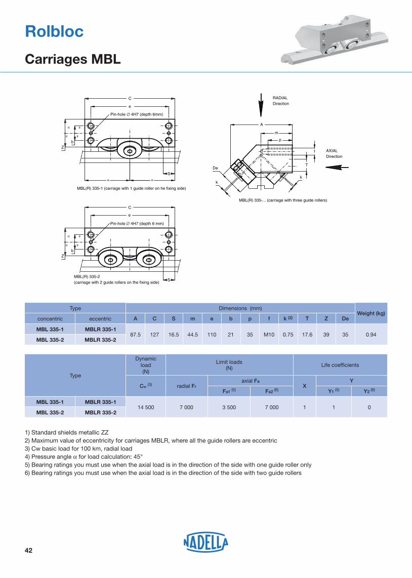
MBL(R) 335-1 (carriage with 1 guide roller on he fixing side)
MBL(R) 335-2 (carriage with 2 guide rollers on the fixing side)
MBL(R) 335-... (carriage with three guide rollers)
Type
Type
16.5
k (2)
MBL 335-20.9444.5 110 21 35 M10 0.75 17.6 39 35127
Dimensions (mm)Weight (kg)
MBL 335-1
concentric eccentric
MBLR 335-1
MBLR 335-2
1) Standard shields metallic ZZ2) Maximum value of eccentricity for carriages MBLR, where all the guide rollers are eccentric3) Cw basic load for 100 km, radial load4) Pressure angle α for load calculation: 45° 5) Bearing ratings you must use when the axial load is in the direction of the side with one guide roller only6) Bearing ratings you must use when the axial load is in the direction of the side with two guide rollers
MBL 335-1 MBLR 335-1
MBL 335-2 MBLR 335-2
87.5
A C S m e b p f T Z De
Limit loads(N)
14 500
Life coefficientsDynamic
load(N)
Cw (3) radial Fraxial Fa
XY
7 000 3 500 1 0
Y1 (5) Y2 (6)Fa1 (5) Fa2 (6)
7 000 1
Rolbloc
Carriages MBL
42

43
1) Standard seals: material NBR, RS type2) On request, the guide rollers can be supplied in stainless steel (suffix NX) and with Viton seals for operating temperatures up to
120°C (suffix V, up to dimension BL.... 75 included). Internal rolling elements in standard bearing steel3) Cw basic load for 100 km, load perpendicular to the roller side fixing surface4) Loads perpendicular to the roller side fixing surface5) Loads parallel to the roller side fixing surface6) Pressure angle α for loads checking calculation: 45°
u eC
Q
Z
u e eC
Q
Z
T
f
mBA
P
P1
P2
V
BL 2... two guide rollers block
BL 4... four guide rollers block
Life coefficients
Y
1
1
1
1
1
1
Type
BL 4 115
BL 2 115
Limit loads(N)
Dynamicload (N)
Cw (3) Radial Fr (4) Axial Fa (5)
BL 2 522
BL 4 522
BL 2 752
16 800
33 600
44 200
78 600
8 400
16 800
22 100
39 300
59 000
118 000
96 300
BL 4 752 88 400 44 200192 600
264 500
157 200 78 600529 000
X
1
1
1
1
1
1
Rolbloc
Carriages BL
TypeDimensions (mm) Weight
(kg)A B C P P1 P2 V m e u f Q T Z
BL 2 52 136 90 56 54 14 16 M4x 7 70 40 8 M 8 12 43 47 2.4
BL 4 520 136 90 112 54 14 16 M4x 7 70 48 8 M 8 12 43 47 4.8
BL 2 75 170 125 76 56 15 40 M5x 8 85 56 10 M 12 17.1 71.5 70 6.5
BL 4 750 170 125 152 56 15 40 M5x 8 85 66 10 M 12 17.1 71.5 70 13
BL 2 115 243 170 125 80 15 70 M5x10 120 95 15 M 14 22 99.8 93 21.6
BL 4 115 243 170 250 80 15 70 M5x10 120 110 15 M 14 22 99.8 93 43.2

44
The adjusting plates allows to easily set the proper component preload during the mounting on the machine. The two steel plates are placed in between the standard ROLBLOC and the mounting surface. Setting is done by the setting screw before the final tightening of the screws used to mount the ROLBLOC.Dimension W of plates is 2 mm lower than the block of ROLBLOC. Use the ROLBLOC side are reference for the block position.When the plates are set in the mid position (thickness 13.5 mm) they can be shifted 10 mm from the block centreline. The possible shift is reduced with the regulation since it become null at the end of allowed setting, minimum or maximum height. Consider 10 mm of space over the plate length on each side (20 mm over the block length) to use the full thickness setting capability +/- 0,7 mm
W
L
L
L
0 - 10
2020
10 - 0
20 20
A
A +0.7
settingscrew
S =A ± 0.7
Ih
A -0.7
TypeDimensions (mm)
Weight (kg)Combination with
ROLBLOC carriagesL W A
PR 252 76 88 13.5 0.5 BL 252
PR 452 132 88 13.5 1.0 BL 452
PR 275 96 123 13.5 1.0 BL 275
PR 475 172 123 13.5 1.9 BL 475
PR 2115 145 168 17 2.9 BL 2115
PR 4115 270 168 17 5.7 BL 4115
Rolbloc
Adjustment plates PR

45
lh
Ih
Rolbloc
Guide/carriage combinations
Mounting examples
Ih (mm)
Guide
Carriage
GU 62 MT
GU 35 MT
BL 2 52MBL / MBLR BL 4 52
86.5–
–41.5
86.5
–
GU 62 MT
GU 35 MT
85–
–40.6
85
–
BL 2 75
115,0
–
113.5
–
BL 4 75 BL 2 115 BL 4 115
115,0
–0
–
–
–
–
GU 80 MT –– – – – 156.5 156.5
GU 80 MT –– – – – 155.5 155.5
113.5
–
–
–
–
–
MBL BL

46
Rolbloc
Mounting example
Palletising equipmentRolblocV-LineMulti-Motion-Line
V-Line
FS System

48
80°
H h
S
a
e
L
lll1
d
D
cfrom FS 19 MT up to FS 62 MT
=
=
FS 72 MT
1) Longer rails are supplied in sections with ground butt joints - 2) Weight without holes
3) Standard layout without pin holes (pin holes only on request)
Dimensions (mm)Type H
± 0.1h
± 0.1
FS 19 MT
FS 22 MT
FS 32 MT
FS 40 MT
21.0
27.0
42.0
62.0
5.3
5.8
6.8
8.8
4
5
6
6
6.5
6.5
6.5
9.0
15
15
15
20
–
–
–
–
–
–
–
–
90
90
90
90
30
30
30
30
22.20
28.80
43.80
FS 35 MT 47.0 8.8 6 9.0 20 – – 90 30 48.80
64.50
FS 52 MT 88.2 13.0 8 13.5 20 – – 90 30 91.35
FS 47 MT 77.2 11.0 6 11.5 20 – – 90 30 80.15
FS 72 MT
Maximum length of single guide element L = 6 000 mm (1)
121.0 19.0 10 17.5 30 30.5 60 90 30124.60
FS 62 MT 103.0 15.7 8 13.5 20 – – 90 30106.00
S± 0.1
d (3)
+ 0.05D c (3) e a l l1
0.8
1.1
2.1
4.1
3.0
8.5
6.3
16.9
11.7
Weight (2)
(kg/m)
V-Line
Guide rails FS..MT
Rails finishing- drawn,induction hardened and sandblasted tracks (MT);- induction hardening on raceways only
Hole layout- holes according to catalogue (SB)- finishes to drawing (NZ)- without holes (NF)
Optional features- ground one end (R) - ground both ends ( RR ) - chemical Nickel-plating (NW)- pin holes
Example of standard designation : FS 52 MT 5280 SB
See page 17 for standard codification

Dimensions (mm)Type H
± 0.05h
± 0.1
FS 19 M
FS 22 M (4)
FS 35 M (4)
20
26
46
4.5
5
8
4
5
6
6.5
6.5
9
15
15
20
–
–
–
–
–
–
90
90
90
30
30
30
20.95
27.86
FS 32 M 41 6 6 6.5 15 – – 90 30 42.86
47.86
FS 47 M (4) 76 10 6 11.5 20 – – 90 30 78.58
FS 40 M 61 8 6 9 20 – – 90 30 63.58
FS 62 M
Maximum length of single guide element L = 4 020 mm (1)
102 15 8 13.5 20 – – 90 30104.76
FS 52 M 87 12 8 13.5 20 – – 90 30 89.78
S± 0.05
d (3)
+ 0.05D c (3) e a l l1
0.6
0.9
2.6
1.8
5.6
3.7
11.2
7.7
Weight (2)
(kg/m)
FS 72 M 120 18 10 17.5 30 30 60 90 30122.98 15.8
1) Longer rails are supplied in sections with ground butt joints - 2) Weight without holes
3) Standard layout without pin holes (pin holes only on request) - (4) Size 22, 35 and 47 available in stainless steel (NX)
49
c
D
d
==
l
L
ll1
a
eA
S
hH
80°
A0,
02
from FS 19 M up to FS 62 M
FS 72 M
V-Line
Guide rails FS..M
Rails finishing- drawn, induction hardened and ground profile (M);- induction hardening on raceways only
Hole layout- holes according to catalogue (SB)- finishes to drawing (NZ)- without holes (NF)
Optional features- stainless steel (NX) (4)
- ground one end (R) - ground both ends (RR) - chemical Nickel-plating (NW) - pin holes
Example of standard designation : FS 40 M 2760 SB
See page 17 for standard codification

50
H h
S
e
c
D
ll1
d
l
L
FSH 80°FSX 90°
1) Longer rails are supplied in sections with ground butt joints - 2) Weight without holes
3) Standard layout without pin holes (pin holes only on request)
Dimensions (mm)
11.6
Type
Maximum length of single guide element L = 6 000 mm(1)
Weight (2)
(kg/m)
FSH 22 MT
H± 0.1
h± 0.1
S± 0.1
d (3)
+ 0.05D c (3) e l l1
23.0 5.8 5 6.5 15 9 90 30 1.023.90
FSH 32 MT
FSH 40 MT
FSH 52 MT
FSH 62 MT
FSH 72 MT
FSX 90 MT
29.0 6.8 6 6.5 15 11 90 30 1.529.90
36.0 8.8 6 9.0 20 16 90 30 2.437.20
39.2 13.0 8 13.5 20 17 90 30 3.740.75
49.2 16.0 8 13.5 20 17 90 30 5.750.75
59.2 19.0 10 17.5 30 20 90 30 8.260.85
61.0 26.5 10 13.5 30 22 90 3062.85
V-Line
Guide rails FSH..MT, FSX..MT
Rails finishing- drawn, induction hardened and sandblasted tracks (MT);- induction hardening on raceways and base only
Hole layout- holes according to catalogue (SB)- finishes to drawing (NZ)- without holes (NF)
Optional features- ground one end (R) - ground both ends ( RR ) - chemical Nickel-plating (NW) - pin holes
Example of standard designation : FSH 52 MT 5280 SB
See page 17 for standard codification

TypeH
± 0.05
11.0
Weight (2)
(kg/m)
Maximum length of single guide element L = 4 020 mm(1)
FSH 19 M
h± 0.1
S± 0.05
d (3)
+ 0.05D c (3) e l l1
18.5 4.5 4 6.5 15 8 90 30 0.618.98
FSH 22 M
FSH 32 M
FSH 40 M
FSH 52 M
FSH 62 M
22.0 5.0 5 6.5 15 9 90 30 0.822.93
28.0 6.0 6 6.5 15 11 90 30 1.228.93
35.0 8.0 6 9.0 20 16 90 30 2.136.29
38.0 12.0 8 13.5 20 17 90 30 3.439.39
48.0 15.0 8 13.5 20 17 90 30 5.249.38
Dimensions (mm)
FSH 72 M
FSX 90 M
58.0 18.0 10 17.5 30 20 90 30 7.659.49
60.0 26.0 10 13.5 30 22 3061.79
1) Longer rails are supplied in sections with ground butt joints - 2) Weight without holes
3) Standard layout without pin holes (pin holes only on request)
51
90
H h
A B
e
c
D
ll1
d
l
L
FSH 80°FSX 90°
0,02
AB
S
V-Line
Guide rails FSH...M, FSX...M
Rails finishing- drawn, induction hardened and ground profile (M);- induction hardening on raceways and base only
Hole layout- holes according to catalogue (SB)- finishes to drawing (NZ)- without holes (NF)
Optional features- ground one end (R) - ground both ends ( RR ) - chemical Nickel-plating (NW)- pin holes
Example of standard designation : FSH 40 M 2760 SB
See page 17 for standard codification

52
V-Line
Guide rollers FR..EU
concentric eccentric
80°
De
T
m S min.
L
M
d
SW2
SW3 SW1
l1
A
B
k
P
d1
1) Housing bore tolerance: H72) The torque wrench settings are given for non-lubricated threads; for lubricated threads, multiply figure by 0.83) Cw basic load for 100 km4) FR/R 22, 32, 40 are available in stainless steel (NX)
The guide rollers are complete with self-locking washers and hexagonal nut (DIN439B) for fittingPressure angle α for load calculation: 40°NBR seals RS type
The sides of the race are slightly convex
Life coefficientsType Weight
(g)Torque wrench settings (2) (Nm)
3FR 22 EU FRR 22 EU
Dynamic load(N)
Cw (3) radial Fr axial Fa X Y
2 900 1 400 420 1 2
Limit loads (N)
20FR 32 EU FRR 32 EU 5 800 2 000 800 1 1.9
26FR 40 EU FRR 40 EU 8 500 3 650 1 400 1 1.9
64FR 52 EU FRR 52 EU 11 700 8 500 3 000 1 1.9
120
45
125
230
510
765FR 62 EU FRR 62 EU 13 900 11 000 3 500 1 1.9
Type Dimensions (mm)
concentric eccentric De d1 (1) d T m Smin P L A B I1 M SW1 SW2 SW3 k
FR 22 EU(4) FRR 22 EU(4) 22 9 M 6 x 1 7.7 9.4 9 6.5 36.8 15 18 8 14 4 10 3 0.8
FR 32 EU(4) FRR 32 EU(4) 32 14 M 10 x 1.25 11.8 12.6 12 8.5 48.9 20.2 22.9 11 20 4 17 4 1
FR 40 EU(4) FRR 40 EU(4) 40 16 M 12 x 1.5 14.6 15.5 12 10.4 58.5 25 29.5 11 22 5 19 5 1
FR 52 EU FRR 52 EU 52 21 M 16 x 1.5 19.1 19.8 15 11.4 69.5 32 36.5 14 28 6 24 6 1.5
FR 62 EU FRR 62 EU 62 27 M 20 x 1.5 22.1 20.8 18.5 12.4 80 33.6 39 17.5 35 8 30 8 2

53
V-Line
Guide Rollers FR..EU AS, FR..EU AZ
1) Housing bore tolerance: H72) Safety threads SPIRALOCK3) Cw basic load for 100 km4) Guide roller with washers DIN134 without screw DIN7984 or DIN9125) Guide roller with washers DIN125 without screw DIN7984 or DIN9126) FR/R 22, 32, 40 AS and AZ are available in stainless steel (NX)
7) AZ: minimum length of the thread engaged steel = 1 x d - cast iron = 1.25 x d aluminium = 2 x dAS screws length: min = d+o+s; max = m+4+o+s
NBR seals RS typePressure angle α for load calculation: 40°
Type Dimensions (mm)
concentric eccentric De d1(1) d(2) T m L A B l1 l h M SW G o Q Ig (7) s k
FR 22 EU AS(6) FRR 22 EU AS(6) 22 6 M 5 7.7 9.4 21.8 15 19.8 2 1.9 - 14 10 - 4.5 10 - 0 0.5
FR 32 EU AS(6) FRR 32 EU AS(6) 32 9 M 6 11.8 12.6 28.1 20.2 25.6 2.5 2.5 - 20 17 - 6 15 - 1.5 (4) 0.5
FR 40 EU AS(6) FRR 40 EU AS(6) 40 11 M 8 14.6 15.5 33.5 25 31 2.5 3 - 22 22 - 6.5 20 - 2 (4) 1
FR 52 EU AS FRR 52 EU AS 52 16 M10 19.1 19.8 43.2 32 40 3.2 3.8 - 28 27 - 8 24 - 2.5(4) 1.5
FR 62 EU AS FRR 62 EU AS 62 19 M12 22.1 20.8 46 33.6 41.8 4.2 4 - 35 30 - 9 26 - 2.5(5) 1.5
FR 22 EU AZ(6) FRR 22 EU AZ(6) 22 6 5.1 7.7 9.4 23.9 15 21.9 2 1.9 5 14 11 18.9 4 - 13 - 0.5
FR 32 EU AZ(6) FRR 32 EU AZ(6) 32 9 8.1 11.8 12.6 31.4 20.2 28.9 2.5 2.5 6.2 20 17 24.9 5 - 17 - 0.5
FR 40 EU AZ(6) FRR 40 EU AZ(6) 40 11 10.1 14.6 15.5 38 25 35.5 2.5 3 7.5 22 22 30.5 5 - 26 - 0.8
FR 52 EU AZ FRR 52 EU AZ 52 16 14.1 19.1 19.8 49.5 32 46.3 3.2 3.8 10.5 28 27 39.3 5.5 - 27 - 1.5
FR 62 EU AZ FRR 62 EU AZ 62 19 16.1 22.1 20.8 54.5 33.6 50.3 4.2 4 12.7 35 32 42.3 6.5 - 30 - 1.5
concentricAS eccentric
d1
m o
s
Q DeT
L
m
dd1
l1
M
SW80°
k
A
B
l
m o
lg
DeT
L
m
dd1
l1
M
SW
k
A
G
B
lh
AZ 80°
Guide roller sizeDynamic load (N) Limit loads (N) Life coefficients Weight
AS(g)
WeightAZ(g)
On request for AZ screw
DIN7984Cw (3) radial Fr axial Fa X Y
22 2 900 470 210 1 2 33 31 M 5 x 30
32 5 800 1 590 710 1 1.9 95 93 M 8 x 40
40 8 500 2 120 940 1 1.9 173 173 M10 x 50
52 11 700 5 830 2 560 1 1.9 374 365 M14 x 60
62 13 900 9 200 3 500 1 1.9 582 587 M16 x 65

Limit loads(N)
26,6 290
Weight(g)
Torquewrench (2)
settings(Nm)
1.8
Dynamic loads(N)
Cwr (4) radial Fr axial Fa
1 800 490 270
3,5 3 280 590 290
20,3 5 600 2 030 950
12 300
Cwa (4)
600
800
2 100
2 600 2 800 1 350
35
53
160
SW1
SW2
k
M
SW1
80
d
T
De
m
L
A
B l1
d1
P
S min.
The sides of the race are slightly convex
M 5 x 0.85
Type
Type
Dimensions (mm)
29.4
SW2
0.5FRN 19 EI (8)
concentric
FRNR 19 EI (8)
d1 (1) d T m S min. L A B I1 M SW1P
19 7 7.7 8.8 34 17.2 18 5.5 14,5 (10) 8 4.2
0.5FRN 22 EI (8) FRNR 22 EI (8) 22 9 M 6 x 1.25 7.7 9.4 39 18.2 20 8,5 16.5 (10) 10 6.5
1.5FRN 32 EI (8) FRNR 32 EI (8) 32 14 M 10 x 1.25 11.8 12.6 52 24.2 26 11,5 25.5 4 1710.4
1,5FRN 40 EI (9) FRNR 40 EI (9) 40 16 M 12 x 1.55 14.6 15.5 60 31 11,5 32,5 8 1811.4
k
6.5
9.5
12.5
12.5
1) Housing bore tolerance: H7 2) The torque wrench settings are given for non-lubricated threads; for lubricated threads, multiply figure by 0.8 3) On request, the guide rollers can be supplied with external parts in stainless steel (suffix NX). Internal rolling elements in standard bearing steel. 4) Cw basic load for 100 km 5) The guide rollers are complete with self-locking washers and hexagonal nut (DIN 439B) for fitting 6) Pressure angle α for load calculation: 40° 7) Standard Viton seals to fit temperature up to 120°C 8) Lubrication hole only on head side 9) Lubrication hole also on stud side10) For size 19 and 22: screw driver slot on the head and hexagonal socket at the threaded end of the stud
FRN 19 EI FRNR 19 EI
FRN 22 EI FRNR 22 EI
FRN 32 EI FRNR 32 EI
FRN 40 EI FRNR 40 EI
54
concentric eccentric
eccentric De
V-Line
Guide rollers FRN..EI

55
Dimensions (mm)
70
RKY 62
1
M
d
L
m
De
SW1
SW2
B I1
k=1
SW1
d1
P
T
A
RKX..90°RKY..80°
S min.
1) Housing bore tolerance: H72) The torque wrench settings are given for non-lubricated threads; for lubricated threads, multiply figure by 0.83) Standard seals: material NBR, RS type4) On request, the guide rollers can be supplied with external parts in stainless steel (suffix NX) and with Viton seals for operating
temperatures up to 120°C (suffix V, up to dimension RKX 90 C included). Internal rolling elements in standard bearing steel5) Cw basic load for 100 km6) Dimensions relating to the stainless-steel rollers (suffix NX)7) The guide rollers are complete with self-locking washers and hexagonal nut (DIN 439B) for fitting8) Pressure angle α for load calculation: guide rollers RKY 40° - guide rollers RKX 45°
56(6)
53
SW2
1RKY 52
Type
concentric eccentric
RKYR 52
De d1 (1) d T m S min. L A B I1 M SW1P
52 21 M 20 x 1.5 19.1 19.8 73 35 41 14 28 8 3013.4
1RKYR 62 62 27 M 24 x 1.5 22.1 20.8 83 37 44 18 35 10 3615.4
1RKY 72 RKYR 72 72 36 M 30 x 1.5 25.5 27.8 100 45 55 18 44 12 4621.6
1RKX 90C RKXR 90C 90 38 M 36 x 1.5 32.5 30 115 62 23 50 14 5524.6
k
RKY 52 RKYR 52
RKX 110C RKXR 110C 110 42 M 36 x 1.5 39.5 34.8
15
19
19
24
33 135 32 56 14 5524.6 63(6)
60
RKY 62 RKYR 62
RKY 72 RKYR 72
RKX 90C RKXR 90C
RKX 110C RKXR 110C
Limit loads (N) Life coefficients
4.9
Weight(kg)
Torque wrench (2)
settings(Nm)
80
Dynamic load(N)
Cw (5) radial Fr axial Fa X Y
40 750 11 900 4 250 1 3.38
160 46 000 22 100 6 800 1 3.13
300 64 850 31 300 10 100 1 2.96
450113 400 43 700 12 600 1 3.42
450
0.6
0.9
1.6
2.8
177 500 55 600 17 900 1 3.40
concentric eccentric
V-Line
Guide rollers RKY.., RKX..
The sides of the race are convex with radius R = 400.
Type

56
Type
FKY 52C
FKY 62C
FKY 72C
FKX 90C
FKX 110C
d2
dH8De M
m
F
A
T
FKY..80°FKX..90°
B +0- 0.1
1) On request, the guide rollers can be supplied with external parts in stainless steel (suffix NX) and with Viton seals for operating temperatures up to 120°C (suffix V, up to dimension FKX 90 C included). Internal rolling elements in standard bearing steel
2) Dimensions relating to the stainless-steel rollers (suffix NX)3) Cw basic load for 100 km4) To prevent rotation between roller and shaft a pin can be fitted in one of the holes “d2” positioned in the side flange5) Pressure angle α for load calculation: guide rollers FKY 40° - guide rollers FKX 45°6) Standard seals: material NBR, RS type
Type
3.9
0.5
0.6
1.2
2.3
Dimensions (mm)
72
56(2)
53
FKY 52C
De d T m A B F d2 M
52 15 19.1 21,0 35 42 25 2.5 30
FKY 62C 62 20 22.1 22.5 37 45 29 3,0 35
FKY 72C 72 25 25.5 28,0 45 56 37 4,0 44
FKX 90C 90 28 32.5 32,0 64 42 4,0 49
FKX 110C 110 35 39.5 36,0 63(2)
60 52 4,0 59
Weight(kg)
The sides of the race are convex.
Limit loads(N) Life coefficients
radial Fr axial Fa
Dynamic load(N)
Cw (3) X Y
40 750 11 900 4 250 1 3.38
46 000 22 100 6 800 1 3.13
64 850 31 300 10 100 1 2.96
113 400 43 700 12 600 1 3.42
177 550 55 600 17 900 1 3.40
V-Line
Guide wheels FKY.., FKX..

57
The race ways are slightly convex
1) Housing bore tolerance: H72) The torque wrench settings are given for non-lubricated threads; for lubricated threads multiply figure by 0.83) Weight without fittings4) Cw = Basic load for 100 Km5) Dimensions for stainless steel (NX) version
Type Dimensions (mm)
concentric eccentric De d1 1) d T m Smin P L A B l1 M n X SW1 SW2 SW3 k
FRL 22 EU 5) FRLR 22 EU 5) 22 9 M6 x 1.0 7.7 7.5 9 6.5 39.3 15.0 20.5 8.0 14.0 1.5 2 4 10 3 0.8
FRL 32 EU 5) FRLR 32 EU 5) 32 14 M10 x 1.25 11.8 10.1 12 8.5 52.2 20.2 26.2 11.0 20.0 2 2 4 17 4 1.0
FRL 40 EU 5) FRLR 40 EU 5) 40 16 M12 x 1.5 14.6 12.5 12 10.4 61.4 25.0 32.4 11.0 22.0 2.4 2.5 5 19 5 1.0
FRL 52 EU FRLR 52 EU 52 21 M16 x 1.5 19.1 16.0 15 11.4 74 32.0 41.0 14.0 28.0 3 3 6 24 6 1.5
FRL 62 EU FRLR 62 EU 62 27 M20 x 1.5 22.1 16.8 18.5 12.4 83.6 33.6 42.6 17.5 35.0 3 3 8 30 8 2.0
TypeDynamic load (N) Limit load (N)
Limit load Inox version (N) NX
Torque wrench
setting 2)
(Nm)
Weight
(g) 3)
Cw 4) radial Fr radial Fr
FRL 22 EU FRLR 22 EU 2900 1050 980 3 46
FRL 32 EU FRLR 32 EU 5800 1700 1550 20 127
FRL 40 EU FRLR 40 EU 8500 3000 2750 26 233
FRL 52 EU FRLR 52 EU 11700 7600 6850 64 520
FRL 62 EU FRLR 62 EU 13900 11000 10300 120 776
concentric eccentric
Standard seals: material NBR, RS type
Guide rollers include self-locking washers and hexagonal nut (DIN 439B)
Pressure angle α for load calculation: 40°
V-Line
Floating guide rollers FRL..EU
80°X
M
De
T
m S min.
L
d
SW2
SW3 SW1
n P
k
d1
l1
A
B

58
V-Line
Floating guide rollers RKXL, RKYL
1) Housing bore tollerance: H72) The torque wrench settings are given for non-lubricated threads; for lubricated threads multiply figure by 0.83) Cw = Basic load for 100 Km4) Dimensions for stainless steel (NX) version
Type Dimensions (mm)
concentric eccentric De d1 1) d T m ± X Smin P L A B C l1 M n SW1 SW2 k
RKYL 52 RKYLR 52 52 21 M 20 x 1.5 19.1 21 3.0 15 13.4 83 35 42 51 14.0 30 3 8 30 1
RKYL 62 RKYLR 62 62 27 M 24 x 1.5 22.1 22.5 3.0 19 15.4 93 37 45 54 18 35 3 10 36 1
RKYL 72 RKYLR 72 72 36 M 30 x 1.5 25.5 28 3.0 19 21.6 110 45 56 65 18 44 3 12 46 1
RKXL 90 RKXLR 90 90 38 M 36 x 1.5 32.5 32 3.5 24 24.6 128 53 564) 64 75 23 49 4 14 55 1
RKXL 110 RKXLR 110 110 42 M 36 x 1.5 39.5 36 3.5 33 24.6 148 60634) 72 83 32 59 4 14 55 1
TypeDynamic load (N) Limit load (N) Torque wrench
setting
(Nm) 2)
Weight (g)
Cw 3) radial Fr
RKYL 52 RKYLR 52 40750 3050 80 630
RKYL 62 RKYLR 62 46000 6850 160 950
RKYL 72 RKYLR 72 64850 11200 300 1680
RKXL 90 RKXLR 90 113400 13800 450 2900
RKXL 110 RKXLR 110 177550 24000 450 5000
On request, the guide rollers can be supplied with external parts in stainless steel (suffix NX). Internal rolling elements in standard bearing steel.
Standard seals: material NBR, RS type
On request, the guide rollers can be supplied with viton seals for operating temperatures up to 120°C (suffix V) not available for RKXL 110)Pressure angle α for load calculation: 40°
eccentricconcentric
SW2
RKXL..90°
RKXL..80°
De
T
SW1
m
L
S min.
X
M
d d1
l1C
B
A
R
n
k
P

59
Ø L
H
Ø D
V-Line
Spacers for FS and FSH
Optional features- steel
Finishing- anodized aluminium
The spacers, mounted between the guide and the supporting structure, guarantee adequate distance for the sliding of the rollers.The spacers DIST are designed for guides FS and FSH of V-Line and guides FSR of Multi-Motion-Line.
TypeDimensions (mm)
Suggested combinationsØL ØD H
DIST FS19 12 6.5 10 FS19, FSH19
DIST FS22 15 6.5 10 FS22, FSH22, FSR22
DIST FS32 30 6.5 15 FS32
DIST FS35 35 8.5 15 FS35, FSR35
DIST FS40 50 8.5 15 FS40
DIST FS47 60 10.5 15 FS47, FSR47
DIST FS52 65 12.5 20 FS52
DIST FS62 80 12.5 20 FS62
DIST FS72 35 16.5 20 FS72, FSH72
DIST FSH32 20 6.5 15 FSH32
DIST FSH40 25 8.5 15 FSH40
DIST FSH52 25 12.5 20 FSH52
DIST FSH62 25 12.5 20 FSH62
DIST FSX90 43 12.5 30 FSX90

Type
30
Suggested combinations
60
Weight(g)
LUBY 19 FR... 19...
X
1015.5
Dimension (mm)
1) The lubricator is supplied with the felt already lubricated. The lubricant has a mineral oil base2) At the mounting, insert the screws inside the rollers plate, without tighten them, adjust the height of the plastic part in order to put it
in contact with the raceways and then block it3) The screws Vf for the frontal mounting are included in the packaging. Arrange two thread holes for dimension Vf in the mounting
rollers plate4) The screws for the mounting on the nut side of the roller are not included in the packaging. Arrange on the mounting rollers plate the
holes in order to insert te screws Vr
1.5 25 15.6 8.8 2.5 19 32.5 M3x12 M4
LUBY 22 FR... 22...1016.5 3.5 25 16.8 9.4 3.3 22 32.5 M3x12 M4
LUBY 32 FR... 32...1521.5 8.5 25 23.2 12.6 4.2 30 32.5 M3x12 M4
LUBY 40 FR... 40...27.5 10.5 30 28.5 15.5 5.4 35 41.5 M4x12 M5
U B F m A C P Vf Vr
V-LineLubricator LUBY for FS guide rollersup to size 40
guideroller
mountingrollers plate
Sec DD
80°
Optional features- felt without lubricant (D)

Type Suggested combinations
61
Weight(g)
LUBY 52RKY 52 RKYR 52 FKY 52FR 52 EU FRR 52 EU ...AS/AZ
X
6533.5
Dimensions (mm)
1) The dimension of the plastic part refers to the centre of the regulation slot. The regulation slot allows a translation of +/- 3 mm2) The lubricator is supplied with the felt already lubricated. The lubricant has a mineral oil base3) During the mounting fix the aluminium support to the rollers plate, adjust the height of the plastic part in order to put it in contact with
the raceways and than block it in that position with the M5 screws
12 14 40 19.8 25.5 10.0 34.5 24.5 38 16.5 18.5
LUBY 62RKY 62 RKYR 62 FKY 62FR 62 EU FRR 62 EU ...AS/AZ 6538.5 14 12 40 20.8 25.5 10.0 34.5 24.5 38 18.5 16.5
LUBY 72 RKY 72 RKYR 72 FKY 72 8543.5 19 11 50 27.0 25.5 10.0 40.5 29.4 44 24.0 16.0
LUBX 90 RKX 90C RKXR 90C FKX 90C14052.5 21 9 60 30.0 30.0 16.5 45.5 33.5 58 31.0 19.0
LUBX 110 RKX 110C RKXR 110CFKX 110C
14062.5 30 0 63 34.0 30.0 16.5 45.5 33.5 58 40.0 10.0
U1 U2 F m B S C A E V P
V-LineLubricator LUBY, LUBX for FS guide rollers size 52 and higher
Optional features- felt without lubricant (D)
F
2610
5
S
C
E
m
B
A
X min.
P
V
roller axis
M5 pf.12 (2x)M6DIN 71412
M5
U2
U1
mounting rollers plate
(1)
(1)
(1)

Ih (mm)Guide roller size
Guide roller size Guide roller size
*48
Guide roller size
FSH
..MT,
FS
X..M
T
FS..M
FS..M
T
FSH
..M, F
SX
..M
Guide rollers FR...EU, FR...EU AS, FR...EU AZ, FRN...EI, RKY, RKX, FKY, FRL..EU, RKXL, RKYL
62
FS FSH / FSX
Iy Ih
Iy (mm)
FS 19 M 3541.9
36.443.3
66.571.5 *77
92.8*107.8 116.8
128143
*134149
*167.2 174
19... 22... 32... 40... 52... 62... 72...
FS 22 MFS 32 MFS 35 MFS 40 MFS 47 MFS 52 MFS 62 MFS 72 M
FS 19 MT 36.2 37.644.2
67.472.4 *78
93.7*109.3 118.3
129.5144.2
*135.5150.2*168.8 175.6
19... 22... 32... 40... 52... 62... 72...
FS 22 MTFS 32 MTFS 35 MTFS 40 MTFS 47 MTFS 52 MTFS 62 MTFS 72 MT
FSH 19 M 26*29.9
26.730.6
40.750.9*54 58.5
*68.5
71.5*81.6 85
19... 22... 32... 40... 52... 62... 72...
94.3
90...
101.3
110...
FSH 22 MFSH 32 MFSH 40 MFSH 52 MFSH 62 MFSH 72 MFSX 90 M
Ih (mm)
FSH 22 MT 30.9 31.641.7*49 51.8
*55.4 59.9*69.9 72.9
*83 86.4
19... 22... 32... 40... 52... 62... 72...
95.3
90...
102.3
110...
FSH 32 MTFSH 40 MTFSH 52 MTFSH 62 MTFSH 72 MTFSX 90 MT
* possible combination
Iy (mm)
V-Line
Guide rollers combination

63
Waterjet cutting machineV-Line
V-Line
Mounting examples

64
V-Line
Mounting examples
Portable loader for steel sheetV-LineHeavy-Line

Multi-Motion-Line
FSR System

Nadella proposes several circular rails based on the FS family of profiles. The rails can be used as an entire circumference, or single sectors, or joined together with straight pieces of rail in order to obtain oval or ring circuits.
Guide
The rails are steel, induction hardened on the raceways, with the same section dimensions as straight FS..M rails. In the circuits the rails are joined together with alignment blocks that allow easy precise mounting.
All the pieces of the circuit are supplied appropriately marked in order to avoid mistakes during joining.
For protection against corrosion Nadella proposes nickel plating (option NW) for both straight and circular pieces.
In addition to the standard dimensions in the table it is possible to realize rings with different sections or radii in order to satisfy specific demands.
Guide rollersAny guide rollers of the FS family of products can be used in combination with the circular rails.
CarriageCarriages for circular rails can be realized with guide rollers in fixed position or mounted on steering arms.
Carriages with guide rollers in fixed positionsYou can set up the distance between the centres of the guide rollers of a carriage with fixed guide rollers in order to obtain clearance-free running both on the straight and on the circular stretch of a circuit. The resulting carriage, normally a simple table with four holes for the housing of the guide rollers, will be simple and compact; there are, however, some contraindications:- In the passage from the straight stretch to the circular
one (and vice versa), when two guide rollers are engaged on the straight portion and two on the circular one, there will be clearance between the carriage and
66
the rail. The extent of the clearance depends on the dimensions of the rail, of the roller guides and of the carriage. Because of this clearance it is not possible to have an accurate positioning of the carriage during the passage between straight and circular stretch and therefore, in fast application, there will be vibration, noise and overload of the roller guides.
- This kind of carriages, with fixed guide rollers, can be used only for a single specific radius throughout the circuit. To use a carriage with fixed guide roller positions you can't have circular stretches with different radii.To define the design for holes of the fixed rollers please contact the Nadella Technical Service.
Steering CarriagesThe contraindications for the carriage with guide rollers in fixed positions can be resolved by using the steering carriage. Guide rollers are mounted in pairs on steering arms that are free to rotate in order to always be transversal to the rail in every point of the circuit. The carriage won't have clearance at any point in the circuit improving transition area accuracy and reduce running noise.The studs of the steering carriage are fitted with needle bearings and seals for lubricant retention and protection. The tightening of the stud is obtained by the full tightening of the nut, and guarantees the best locking.
Sector Ring circuit
Oval circuit
Multi-Motion-Line
Circular systems
Generic circuit

67
Pin hole
Fixing hole
Detail A (see following page)
H
80°
D
d
R1
R2
R3
I
h
S
A f
Multi-Motion-Line
Circular rails FSR..M
Type A I fd
H7D R1* R2* R3*
n° fixing holes/360°
n° pin holes/360°
h H S
FSR22M-075 22.5°5 45°,5 45°,5 5 6.5 88 75 62 8 4 26 27.86 5
FSR22M-125 15°,25 30°,5 25°,5 5 6.5 138 125 112 12 8 26 27.86 5
FSR22M-175 15°,55 30°,5 25°,5 5 6.5 188 175 162 12 8 26 27.86 5
FSR35M-225 11.25° 22.5° 7.5° 8 9,5 248 225 202 16 8 46 47.86 8
FSR35M-300 11.25° 22.5° 7.5° 8 9,5 323 300 277 16 8 46 47.86 8
FSR47M-400 9°,55 18°,5 18°,5 10 11.5 438 400 362 20 8 76 78.58 10
FSR47M-500 9°,55 18°,5 18°,5 10 11.5 538 500 462 20 8 76 78.58 10
* R1, R2, R3 are radius
Optional features- stainless steel (NX) - nickel plating (NW) - spacers for rails FS (page 58)
Rails finishing - steel- induction hardened on the raceways
Hole layout- holes according to catalogue (SB)- finishes to drawing (NZ)
Example of standard designation: FSR35M-225-180
Circular rail sector FSR35M, radius R2 225 mm,sector angle 180°

68
The joint cut is displaced of 1.6 mm from the theoretical line of joint.The alignment block allows an easy mounting of the joint.
Spacers DIST FS can be used to mount the rails FSR (pag. 60)
Multi-Motion-Line
Alignment blocks for FSR
Spacers for FSR
Ø L
H
Ø D
Joint cut between the curve piece and the straight piece
Detail A: drilling on the joint
alignment block
Theoretical line of joint
Joint cut (displaced of 1,6 mm from the theoretical line of joint)
50 90
t
e
ab
G D
51.6 90
CB
e
G
TypeDimensions (mm) Suggested
combinationC B e G D a b t
FSR22M-075 12 34 7.5 M4 6.5 7.6 18.6 5.8 FR22EU FRN22EI
FSR22M-125 12 34 7.5 M4 6.5 7.6 18.6 5.8 FR22EU FRN22EI
FSR22M-175 12 34 7.5 M4 6.5 7.6 18.6 5.8 FR22EU FRN22EI
FSR35M-225 18 38 20 M6 9 10.6 19.6 6FR32EU FRN32EI FR40EU FRN40EI
FSR35M-300 18 38 20 M6 9 10.6 19.6 6FR32EU FRN32EI FR40EU FRN40EI
FSR47M-400 18 58 43 M6 11.5 8.6 18.1 9FR40EU FRN40EIFR52EU RKY52
FSR47M-500 18 58 43 M6 11.5 8.6 18.1 9FR40EU FRN40EIFR52EU RKY52

69
Multi-Motion-Line
Oval circuit FSRO
50 90 90 90 90 50
R
W
= =
AI
f
dL (1)
(Lmax in a single piece 4020 mm)
D
K K
S
80°
Hh
(2)
(2)
pin hole
D
Hole layout- standard holes according to catalogue (SB)- finishes to drawing (NZ)
Optional features- stainless steel (NX)- nickel plating (NW)
Standard hole layout (SB) for the straight rails:- first and last hole of 50 mm, starting from the centers K;- hole pitch 90 mm;- central hole (2) only if the last hole pitch W is higher than
120 mm;- W can't be less than 60 mm. Rails finishing - for the circular rail see page 67- for the straight rail see page 49 Example of standard designation: FSRO35M-225-2000 SB
Oval circuit, size 35, radius 225 mm, distance between the centers K equal to 2000 mm (1), standard holes.
The oval circuit is composed by: two sectors of circular rails (180° with center in K) and two straight pieces of rails. The circuit is supplied complete of alignment blocks (with the proper screws), and all the pieces are marked in order to obtain the correct sequence during the mounting.(1) The length of the straight pieces is higher than the distance between the centers K (1.6 mm x 2) in order to cover the thickness of rail lost during the cutting of the circular sectors (for more details about joints see page 68).
Type
Dimensions (mm)
RadiusR
D A Id
H7f S h H
FSRO22M-075-... 75 6.5 22.5°5 45°,5 5 45°,5 5 26 27.86
FSRO22M-125-... 125 6.5 15°,55 30°,5 5 25°,5 5 26 27.86
FSRO22M-175-... 175 6.5 15°,55 30°,5 5 25°,5 5 26 27.86
FSRO35M-225-... 225 9,5 11.25° 22.5° 8 7.5° 8 46 47.86
FSRO35M-300-... 300 9,5 11.25° 22.5° 8 7.5° 8 46 47.86
FSRO47M-400-... 400 11.5 9°,55 18°,5 10 18°,5 10 76 78.58
FSRO47M-500-... 500 11.5 9°,55 18°,5 10 18°,5 10 76 78.58

70
Multi-Motion-Line
Ring circuit FSRQ
Hole layout- standard holes according to catalogue (SB)- finishes to drawing (NZ)
Optional features- stainless steel (NX)- nickel plating (NW)
Standard hole layout (SB) for the straight rails:- first and last hole at 50 mm, starting from the centers K;- hole pitch 90 mm;- central hole (2) only if the last hole pitch (Wx in horizontal
and Wy in vertical) is higher than 120 mm;- Wx and Wy can't be less than 60 mm. Rails finishing - for the circular rail see page 67- for the straight rail see page 49
Type
Dimensions (mm)
RadiusR
D A Id
H7f S h H
FSRQ22M-075-... 75 6.5 22.5° 45°,5 5 45°,5 5 26 27.86
FSRQ22M-125-... 125 6.5 15°, 30°,5 5 25°,5 5 26 27.86
FSRQ22M-175-... 175 6.5 15° 30°,5 5 25°,5 5 26 27.86
FSRQ35M-225-... 225 9,5 11.25° 22.5° 8 7.5° 8 46 47.86
FSRQ35M-300-... 300 9,5 11.25° 22.5° 8 7.5° 8 46 47.86
FSRQ47M-400-... 400 11.5 9°,55 18°,5 10 18°,5 10 76 78.58
FSRQ47M-500-... 500 11.5 9° 18°,5 10 18°,5 10 76 78.58
Example of standard designation: FSRQ35M-225-2000-1000 SBRing circuit, size 35, radius 225 mm, horizontal distance between the centers K equal to 2000 mm (1), vertical distance between the centers K equal to 1000 mm (1), standard holes.
The ring circuit is composed by: four sectors of circular rails (90° with center in K) and four straight pieces of rails. The circuit is supplied complete of alignment blocks (with the proper screws), and all the pieces are marked in order to obtain the correct sequence during the mounting.(1) The length of the straight pieces is higher than the distance between the centers K (1,6 mm x 2) in order to cover the thickness of rail lost during the cutting of the circular sectors (for more details about joints see page 68).
(1)
(2) h
KK
D
pin hole
X
(Lmax in a single piece 4020 mm)d
f
R
50 90 90 90 90 50
Wx
= =
AI
(2)
K K
Y(L
max
in a
sin
gle
piec
e 40
20 m
m)
5050
Wy=
=(2)
(1)
(2)
D
h H
80°
S

71
Multi-Motion-Line
Steering carriage T4R...
L
B
H2
ex
ey
lx
E De
H1
lY
H
G
A
Z
Type Dimensions (mm) Weight
(kg)Suggested
combinationDe L B ex ey Ix Iy H H1 H2 G A E Z
T4R22 FR22EU 80T4R22 FRN22EI 80
22 80 62 68 50 50 43.3 45.5 43 12 M5 65.3 2751.6
53.60.5
FSR 22 MFS 22 M
T4R35 FR32EU 140T4R35 FRN32EI 140
32 140 112 120 90 96 71.5 59.9 55.9 13 M8 103.5 4266.2
69.31.1
FSR 35 MFS 35 M
T4R35 FR40EU 140T4R35 FRN40EI 140
40 140 112 120 90 96 77 62.8 58.8 13 M8 117 4272.8
74.31.6
FSR 35 MFS 35 M
T4R47 FR40EU 180T4R47 FRN40EI 180
40 180 160 150 130 120 107.8 74.3 69.3 19 M10 147.8 5683.3
84.82.4
FSR 47 MFS 47 M
T4R47 FR52EU 180T4R47 RKY52 180
52 180 160 150 130 120 116.8 78.6 73.6 19 M10 168.8 5690.3
94.83.3
FSR 47 MFS 47 M

72
Multi-Motion-Line
Mounting example
Assembly lineMulti-Motion-Line

C-Line
System LS

To be in a position to offer complete guide systems the
C-Line consists of guide rails, guide rollers and carriages.
Guide rails and rollers can be used as individual compo-
nents; in most cases however, standard carriages are
used.
The cold drawn rails have a C shape and are induction
hardened. The rollers run on the inside raceways of the
C-profile. The rails are zinc-plated; alternatively they are
available with nickel-plated surface.
Based on the different design of the rollers, constructions
with fixed or floating bearings can be realised. Thereby
errors in parallelism, height and angle can be balanced.
Only one rail shape is necessary for this.
Nadella offers 3 rail sizes.
The carriages can be adjusted free of play. They are
equipped with concentric and eccentric rollers and can
be combined with 3, 4 or 5 rollers.
Essential technical properties:
steel rail, drawn, induction hardened
zinc-plated rail, alternatively with nickel-plated surface
rollers for fixed and floating bearing constructions
high balance of mounting surface errors and
misalignment
high performance and rugged
rollers lubricated for life
dust resistant
easy fitting
easy smooth running
high speeds up to 8 m/s
(depending on roller size and application)
acceleration up to 50 m/s2
working temperatures up to 80°C possible
pitch of rail borings standard or according to customer
drawings
integrated lubricating system at the front sides of the
carriage
The following figure applies to the loads indicated in the
tables below:
MAX LOAD ON INDIVIDUAL CARRIAGES
The tables below show the maximum load that can be applied
to an individual carriage.
The max load is based on the guide roller values (load capa-
city of bolt and bearing) and on the max contact pressure of
1250N/mm2 between rail and roller. Loads are rated for effect
in direction Y exclusively or in direction Z exclusively. A com-
bination of rates reduces the values.
Short carriage
Guide CarriageFy N
Fz N
Mx Nm
My Nm
Mz Nm
Mzl Mzr
LS 28 C3 RCS28 126 2400 660 5.9 17 30 30
LS 43 C3 RCS43 170 6000 1700 23 66 117 117
LS 63 C3 RCS63 226 13000 4400 81 264 390 390
Long carriage
Guide CarriageFy N
Fz N
Mx Nm
My Nm
Mz Nm
Mzl Mzr
LS 28
C3 RCS28 178 AC4 RCS28 178 CC4 RCS28 178 AC4 RCS28 178 BC5 RCS28 178 AC5 RCS28 178 B
240024001800180030003600
66013209909901320660
5.9128.98.9125.9
344338384335
6294125629462
6294621259462
LS 43
C3 RCS43 245 AC4 RCS43 245 CC4 RCS43 245 AC4 RCS43 245 BC5 RCS43 245 AC5 RCS43 245 B
600060004500450075009000
170034002380238034001700
234534344523
129162129129162133
228342456228342228
228342228456342228
System LS
Fy with effect on the concentric rollers.
Fy with effect on the concentric rollers.
C-Line
74

System LS
C-Line
75
DYNAMIC LOAD CAPACITY OF THE INDIVIDUAL
CARRIAGE
The following tables indicate the nominal load which
corresponds to a nominal bearing lifetime of 100 km.
Short carriage
Guide CarriageCy N
Cz N
CMx Nm
CMy Nm
CMz Nm
Mzl Mzr
LS 28 C3 RCS28 126 4400 1100 9.6 27 55 55
LS 43 C3 RCS43 170 13200 3600 48 142 257 257
LS 63 C3 RCS63 226 28400 6700 124 403 852 852
Long carriage
Guide CarriageCy N
Cz N
CMx Nm
CMy Nm
CMz Nm
Mzl Mzr
LS 28
C3 RCS28 178 AC4 RCS28 178 CC4 RCS28 178 AC4 RCS28 178 BC5 RCS28 178 AC5 RCS28 178 B
440044003300330066008800
110021001600160021001100
9.6191414199.6
556961616967
114172229114172114
114172114229172114
LS 43
C3 RCS43 245 AC4 RCS43 245 CC4 RCS43 245 AC4 RCS43 245 BC5 RCS43 245 AC5 RCS43 245 B
132001320099009900
1980026400
360073005100510073003600
489672729648
277346304304346292
5027521003502752502
5027525021003752502
CARRIAGE CONFIGURATIONS
In the following carriage configurations the dashed guide
rollers ( ) are concentric and fixed, the plain guide roller ( )
are eccentric and can be set to preload the system.
Short carriage with 3 rollers
Typ C3…
Long carriage with 3 rollers
Type C3…A
Long carriage with 4 rollers
Type C4…C
Type C4…A
Type C4…B
Long carriage with 5 rollers
Type C5…A
Type C5…B
The markings and show the contact points with the
running surface of the rails.
Cy with effect on the concentric rollers.
Cy with effect on the concentric rollers.
L10 = (Ci/Pi)3 x 100 km
Ci and Pi are the load capacity and the applied load for a
certain load direction.
view from above
view from above
view from above
view from above
view from above
view from above
view from above

System LS
C-Line
76
Calculation example:
platform with 4 carriages C3 RCS 43 170 N
The general arrangement is shown in the drawing below.
The platform runs along the two rails and is charged with load
F which takes effect 100 mm and 50 mm afar from the middle
of the carriage.
Data: guide LS 43; carriage C3 RCS 43 170
Ix = 400 mm, Iz = 300 mm
F = 6000 N , XF = 100 mm, ZF = 50 mm
In this configuration Py is the load on the mostly loaded
carriage and is calculated as follows:
Auto-aligning systems
Self-aligning systems are used to balance high mounting
surface tolerances between two parallel installed guides.
The Nadella system LS can be combined with the rollers
RCS and RAS so that high horizontal or vertical tolerances
can be balanced.
Horizontal adjustment Dx
Fixed bearing:
Carriages equipped with rollers type RCS/RCSR to
compensate radial and axial loads.
Floating bearing:
Carriages equipped with rollers type RAS/RASR to
compensate radial loads only.
Max. possible value: Dx = 1,5 mmThe load Fy indicated in the table of max load for carriage
C3 RCS 43 170 is 6000 N.
The system nominal lifetime is calculated as follows:
from the table of the dynamic load capacity, the value
Cy for carriage C3 RCS 43 170 is 13200 N.
Important remark: The rail must be lubricated to reach this
value. Otherwise the expected lifetime can be reduced by
fretting between rail and roller.
F F · XF F · ZFP = + + = 2750 N 4 2 · IX 2 · IZ
L10 = (13.200/2.750)3 x 100 = 11.059 km

System LS
C-Line
77
Vertical adjustment Dy
Fixed bearing:
Carriages equipped with concentric rollers type RCS and
eccentric rollers type RASR to compensate radial and axial
loads. This allows for a tilting movement of the carriage up
to the max. tilting angle.
Floating bearing:
Carriages equipped with concentric rollers type RAS and
eccentric rollers type RASR to compensate axial loads only.
The value Dy depends on the distance between the rails
and the max. possible tilting angle α = ± 1.5° of the carri-
age at the fixed bearing side.
Max inclined movement admissible for self-aligning
tables and carriages
Carriageα ax
(°)
S
(mm)
H
nominal
(mm)
Guide
C3 RAS28…
C4 RAS28…
C5 RAS28…
1° –0.5/+1.2 24 LS 28
C3 RAS43…
C4 RAS43...
C5 RAS43...
1.5° –0.8/+1.5 37 LS 43
C3 RAS63… 1° –1/+3 50.5 LS 63
C3 RYS28…
C4 RYS28...
C5 RYS28...
1° --- 24 LS 28
C3 RYS43…
C4 RYS43...
C5 RYS43...
1.5° --- 37 LS 43
C3 RYS63… 1° --- 50.5 LS 63
GuideScrew size
dL
Torquewrenchsettings
(Nm)
LS 28 M5 x 0.8 12 8
LS 43 M8 x 1.25 16 22
LS 63 M8 x 1.25 20 34
Screw type DIN EN ISO 7380 (10.9)
Carriages type ...RAS... only consist of guide rollers
type RAS (concentric) and RASR (eccentric).
Carriages type ...RYS... only consist of guide rollers
type RCS (concentric) und RASR (eccentric).
+S –S

System LS
C-Line
78
TypeDimensions (mm)
Moment of
inertia (cm4) Weight(kg/m)
L(1)
max(mm)
B H H1 H2 D G g D1 G1 g1 I I1 Jx Jy
LS 28 28 12.5 9 5.5 6.6 11 2.1 5.5 10.6 2.6 80 40 0.17 1.45 1.18 2960
LS 43 43 21 14.5 10 9 15 2.5 9 17 4 80 40 1.28 8.6 2.75 2960
LS 63 63 28 19.25 11.25 9 15 4.5 11 21 5.5 80 40 4.5 38.9 6.22 2960
1) Longer rails will be fitted with finish-machined joints.
Surface options
- chemically nickel-plated (NW)
- uncoated blasted (no suffix)
Fixing holes
- hole pattern according to catalogue (A or B)
- hole pattern according to drawing (NZ)
- without holes (NF)Example standard type: LS43MT2480AGZ
Screws DIN EN ISO 7380 (10.9) are included in delivery.
Rail design standard
- drawn, induction hardened raceways (MT)
- surface zinc-plated (GZ)
Hole pattern A: boring for counterbore screws according DIN EN ISO 7380
Hole pattern B: boring for countersunk screws according DIN EN ISO 74
LS 28LS 43
LS 63
ll1-2
g
H
G
D
B
H2
H1 +1
L -2+1
g
H
G
D
B
H2
H1
LS 28LS 43
g1
G1
D1
g1
G1
D1
LS 63

Guide Rollers RCS
concentric eccentric
1) Tolerance of mounting hole: H7 2) The tightening torques apply to non-lubricated threads; for lubricated threads the values have to be multiplied by 0.8.3) Cw = load for lifetime of 100 km
Guide rollers will be supplied with washers and nuts (DIN 439B).
Contact angle α for the load calculation: 55°
Standard seals type RS
Type Dimensions (mm)
Guide
concentric eccentric De R d1 (1) d m
Smin.
P L A B l1 M SW1 SW2 k
RCS 28 RCSR 28 23.5 3 8 M8 6.0 2.5 4.8 18.5 6.0 10.0 3.5 12.0 3 13 0.5 LS 28
RCS 43 RCSR 43 35.5 5 10 M10 x 1.25 9.0 4.5 6.0 27.5 11.0 15.0 5.5 17.5 4 16 0.75 LS 43
RCS 63 RCSR 63 50 7 16 M16 x 1.5 12.75 5.5 9.3 40.0 17.5 22.5 6.5 24.0 6 24 1.0 LS 63
Type Dynamic loads (N) Limit loads (N) Life coefficientsTorque-
wrench
settings
(Nm) 2)
Weight (g)
concentric eccentric Cw(3) radial Fr axial Fa X Y
RCS 28 RCSR 28 2200 1200 330 1 2.7 8 25
RCS 43 RCSR 43 6600 3000 850 1 2.2 20 80
RCS 63 RCSR 63 14200 6500 2200 1 2.8 64 255
C-Line
79
dDe
M
m
L
S min.
A
B
R
SW2
SW1
l1
d1
k
P

C-Line
80
Guide Rollers RAS
Type Dimensions (mm)
Guide
concentric eccentric De R d1 (1) d
mmin.(4)
mmax.(4)
Smin.
P L A B l1 M SW1 SW2 k
RAS 28 RASR 28 23.5 3 8 M8 5.5 7.2 2.5 4.8 18.5 7 10 3.5 12 3 13 0.5 LS 28
RAS 43 RASR 43 35.5 5 10 M10 x 1.25 8.2 10.5 4.5 6 27.5 11 15 5.5 17.5 4 16 0.75 LS 43
RAS 63 RASR 63 50 7 16 M16 x 1.5 11.75 15.75 5.5 9.3 40.0 17.5 22.5 6.5 24 6 24 1 LS 43
Type Dynamic load (N) Limit load (N)Torque
wrench
settings
(Nm) 2)
Weight (g)
concentric eccentric Cw(3) radiale Fr
RAS 28 RASR 28 2200 1200 8 25
RAS 43 RASR 43 6600 3000 20 80
RAS 63 RASR 63 14200 6500 64 255
concentric eccentric
1) Tolerance of mounting hole: H7 2) The tightening torques apply to non-lubricated threads; for lubricated threads the values have to be multiplied by 0.8.3) Cw = load for lifetime of 100 km 4) Maximum displacement of dimension m to ensure proper guide roller function and safety.
Guide rollers will be supplied with washers and nuts (DIN 439B).
Contact angle α for the loadd calculation: 55°
Standard seals type RS
R
M
De
L
S min.m
d
P
k
SW2
SW1
d1
l1B
A

C-Line
81
TypeDimensions (mm) Weight
(kg)Guide
L L1 B Ix ly H H1 H2 G a b c k
shortcarriage
C3 RCS28 126 88 126 26.5 50 0.5 24 15 9 M5 (2x) - 13.25 78 0.75 0.13 LS 28
C3 RCS43 170 130 170 40 78 1 37 22.5 13.5 M8 (2x) - 20 114 1 0.44 LS 43
C3 RCS63 226 186 226 60 120 1 50.5 31.25 18.5 M8 (4x) 34 13 168 1.5 1.2 LS 63
Carriages C3 RCS, C3 RAS, C3 RYS
TypeDimensions (mm) Weight
(kg)Guide
L L1 B Ix ly H H1 H2 G b c e k
longcarriage
C3 RCS28 178 A 140 178 26.5 104 0.5 24 15 9 M5 13.25 130 26 0.75 0.15 LS 28
C3 RCS43 245 A 205 245 41 152 1 37 22.5 13.5 M8 20.5 188 37 1.5 0.50 LS 43
Dimensions also apply to C3 RAS and C3 RYS.
Dimensions also apply to C3 RAS and C3 RYS.
The markings show the contact points with the running surface of the rails.
B
b
Llx
ly
L1
cGe
H1L1
lx
c
LH2
H
B a
D
ly
G c G
b

C-Line
82
Carriages C4 RCS, C4 RAS, C4 RYS
Roller combinationsThe markings show the contact points with the running surface of the rails.
TypeDimensions (mm)
Weight (kg)
GuideL L1 B Ix ly H H1 H2 G b c e k
C4 RCS28 178 C
C4 RCS28 178 A
C4 RCS28 178 B
140 178 26.5 104 0.5 24 15 9 M5 13.25 130 26 0.75 0.23 LS 28
C4 RCS43 245 C
C4 RCS43 245 A
C4 RCS43 245 B
205 245 41 152 1 37 22.5 13.5 M8 20.5 188 37 1 0.58 LS 43
Dimensions also apply to C4 RAS C/A/B and C4 RYS C/A/B.
C4 C
C4 A
C4 B
lx
H1
H2
H
B
b
L
ecL1
ly
G

C-Line
83
Carriages C5 RCS, C5 RAS, C5 RYS
TypeDimensions (mm)
Weight (kg)
GuideL L1 B Ix ly H H1 H2 G b c e k
C5 RCS28 178 AC5 RCS28 178 B
140 178 26.5 104 0.5 24 15 9 M5 13.25 130 26 0.75 0.25 LS 28
C5 RCS43 245 AC5 RCS43 245 B
205 245 41 152 1 37 22.5 13.5 M8 20.5 188 37 1 0.66 LS 43
Dimenisions also apply to C5 RAS A/B and C5 RYS A/B.
C5 A
C5 B
The markings show the contact points with the running surface of the rails.
Roller combinations
H1
H2
HlxL
ly
L1ce G
B
b


Base-Line
DC, C Systems

Rails
MAXIMUM LOADS ON SINGLE CARRIAGE
The following table shows the maximum loads that can be applied on a single carriage.
14002150
Calculation example: carriage loaded with an external load F
Carriage T4 PFV 50 25 220; F = 2000 N.
The maximum loads are based on the stud and bearing strengths and on a maximum contact pressure, between rail and roller, of 1250 N/mm2. The load in the table are considered as acting singularly. For applications with many loads acting at the same time the loads must be reduced.
BASIC DYNAMIC LOADS OF SINGLE CARRIAGE
The following table shows the nominal loads that correspond to a nominal life of the bearing at 100 km.
The nominal lifetime of the carriage can be estimated from the standard bearing formula
Ci is the basic dynamic load capacity in a specific direction i and Pi is the external load applied in the same specific direction.
Carriages CMzNm
DC 10.54 T4 PFV 25 10 80T4 PFV 25 10 120
84 158
CMyNm
27 51
CMxNm
32 32
CzN
12001200
CyN
3700 3700
DC 16.80 T4 PFV 35 16 165 T4 PFV 35 16 250
570 950
185310
115115
29502950
9000 9000
DC 18.65 T4 PFV 35 18 150T4 PFV 35 18 250
510 970
165315
95 95
29502950
9000 9000
DC 25.95 T4 PFV 50 25 220T4 PFV 50 25 300
500750
290290
61006100
1750017500
L10 = (Ci/Pi)3 x 100 km
Z
The external load F acts in the z-axis direction:
Pz = F = 2000 N
In the table of the “maximum loads” you find that the load capacity Fz for carriage T4 PFV 50 25 220 is equal to 3900 N, so the system is validated against breakage.
To estimate the system lifetime we proceed as follows: from the table of the “basic dynamic loads” we see that Cz, for the carriage T4 PFV 50 25 220, is equal to 6100 N.The nominal lifetime will be:
L10 = (6100/2000)3 x 100 = 2837 km
86
DC system is based on rails, guide rollers and carriages that provide a complete guiding system.Rails and rollers can be used as single elements. In most cases the application is based on standard carriages.The load capacities are tabulated with reference to the axis system showed in the sketch below:
Important notes:- in order to reach the calculated lifetime it is important
to lubricate the rails;- for load configurations with many loads and moments
acting at the same time in different directions, please refer to the calculation examples you can find at the beginning of the catalogue or contact our Technical department.
Base-Line
DC system
Rails Carriages MzNm
DC 10.54 T4 PFV 25 10 80T4 PFV 25 10 120
35 67
MyNm
18 33
MxNm
22 22
FzN
800 800
FyN
15901590
DC 16.80 T4 PFV 35 16 165T4 PFV 35 16 250
225370
110190
70 70
18001800
35703570
DC 18.65 T4 PFV 35 18 150T4 PFV 35 18 250
220420
100190
55 55
18101810
39403940
DC 25.95 T4 PFV 50 25 220T4 PFV 50 25 300
640950
320480
180180
39003900
78907890

87
Base-Line
Guide rails DC
7.14
Weight (kg/m)
Type
Optional features- ground one end (R) - ground both ends ( RR ) - stainless steel shafts (NX)- chromium plated shafts (CH)
Example of standard designation : DC2595S 2010 SB NX
See page 17 for standard codification
Hole layout- holes according to catalogue (SB)- finishes to drawing (NZ)- without holes (NF)
1) Longer rails are supplied in sections with ground butt joints and, on request, with pin connection
2) Inertia value based on equivalent aluminium yield 70000 N/mm2
3) Available with stainless steel shafts
7.1
DC 25.95 D (3)
dB
max length in single element L=6000 (1)
Momentsof inertia (2)
(cm4)
Dimensions(mm)
B H
DC 16.80 S (3)
DC 16.80 D (3)
DC 18.65 S
DC 18.65 D
25.5
25.5
24
24
14.5
14.5
13
13
18
18
16
16
9.5
9.5
9.5
9.5
8.5
6.5
8.5
6.5
–
11
–
11
–
6.3
–
6.3
–
54
–
36
150
150
150
150
9.6 85
9.6
6.1
6.1
85
34.7
34.7
7.14
7
86
86
70.5
70.5
H1 A E D G g F l
30
30
30
30
DC 25.95 S (3) 33 18 19 13 10.5 – – – 150 21.8 142.2 13.5101 30
33 18 19 13 6.5 11 6.3 58 150 21.8 142.2 13.53101
IB
80
80
65
65
95
95
16
16
18
18
25
25 30
l1 Jx Jy
DC 10.54 S (3)
DC 10.54 D (3)
19.5
19.5
13
13
25
25
10.5
10.5
6.5
4.5
–
8
–
4.2
–
36
150
150
2.16 20.5
2.16 20.5
3.15
3.15
57
57
30
30
54
54
10
10
L
F
G D
L
D
DC....D
DC....S
l l1
l l110 21 10
8
A
g
E
IB
B
HH1
dB
DC 16.80 and DC 18.65 DC 10.54
DC 25.95
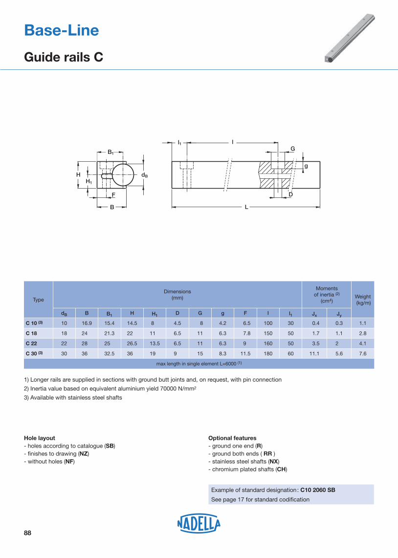
H
F
B
dB
g
L
D
Gl
H1
B1
l1
88
Base-Line
Guide rails C
Optional features- ground one end (R) - ground both ends ( RR ) - stainless steel shafts (NX)- chromium plated shafts (CH)
Example of standard designation : C10 2060 SB
See page 17 for standard codification
Hole layout- holes according to catalogue (SB)- finishes to drawing (NZ)- without holes (NF)
1) Longer rails are supplied in sections with ground butt joints and, on request, with pin connection
2) Inertia value based on equivalent aluminium yield 70000 N/mm2
3) Available with stainless steel shafts
dB
Type
Dimensions(mm)
C 10 (3)
B
C 18
C 22
C 30 (3)
16.9
24
28
36
15.4
21.3
25
32.5
14.5
22
26.5
36
8
11
13.5
19
4.5
6.5
6.5
9
8
11
11
15
4.2
6.3
6.3
8.3
6.5
7.8
9
11.5
100
150
160
180
0.4 0.3
1.7
3.5
11.1
1.1
2
5.6
1.1
2.8
4.1
7.6
10
18
22
30
B1 H H1 D G g F l
30
50
50
60
l1 Jx Jy
Weight (kg/m)
Momentsof inertia (2)
(cm4)
max length in single element L=6000 (1)

Recommendedpairings
PFV 60.30
Type
DC 25.95
PFV 35.16 (3)
kSW1
P
d1
A
B
dB
T
l1
De
SW1
SW2
m
L
d
S min.
M
1) Housing bore tolerance: H72) The torque wrench settings are given for non-lubricated threads; for lubricated threads, multiply figure by 0.83) Available in stainless steel (suffix NX)4) Cw basic load for 100 km5) The guide rollers are complete with self-locking washers and hexagonal nut (DIN 439B) for fitting6) Pressure angle � for load calculation: 60°7) NBR seals, RS type
Dimensions (mm)
PFV 25.10 (3)
concentric eccentric
PFVR 25.10 (3)
PFVR 35.16 (3)
PFV 35.18 (3) PFVR 35.18 (3)
PFV 43.22 (3) PFVR 43.22 (3)
C 10/DC 10.54
DC 16.80
C 18/DC 18.65
C 22
C 30
PFV 50.25 (3) PFVR 50.25 (3)
PFVR 60.30 30
dB T
23
31
SW2
0.75
De d1 (1) d m S min. L A B I1 M SW1P
25 8 M8x1.25 15.5 7.5 34.8 12 14.8 10 12 4 13 9
0.7535 10 M10x1.25 23.0 12.0 45.3 18 22.3 11 15 4 1710.7
0.7535 10 M10x1.25 24 12 45.3 18 22.3 11 15 4 1710.7
1.75
1.75
43 12 M12x1.50 29.0 14.0 52.0
69.5
27.0
36.5
12
16
18 5
8
19
24
12.5
14.0
k
150
60
14
16
M14x1.5
M16x1.50
34
41.0
16.5
19.5
11
12
12
13
17
14 59 31 13 20 6 2213.5 26
10
16
18
22
25
30
PFV 25.10 PFVR 25.10
PFV 35.16 PFVR 35.16
PFV 35.18 PFVR 35.18
PFV 43.22 PFVR 43.22
PFV 50.25 PFVR 50.25
PFV 60.30 PFVR 60.30
Life coefficients Weight(g)
Torque wrench (2)
settings(Nm)
8
Dynamic load(N)
Cw (4) radial Fr axial Fa X Y
1 850 1 080 200 1 4.4
Limit loads(N)
20 4 550 2 120 430 1 4.4
20 4 570 2 120 430 1 4.4
26
44
64
7 600
8 800
15 700
3 150 780
4 240 940
5 360 1 350
1
1
1
4.3
4
4.3
42
115
113
210
335
570
89
concentric eccentric
Base-Line
Guide rollers PFV with “gothic arch” profile
Type

RKOR80.40
Dimensions (mm)
Type
RKO 55.25
M
L
m
De
SW1
SW2
A
B I1
k=1SW1
d1
P
S min.
d-h7
T
d
90
1) Housing bore tolerance: H72) Torque wrench settings are given for non-lubricated threads; for lubricated threads, multiply figure by 0.83) Standard seals: material NBR, type RS4) On request, the guide rollers can be supplied with Viton seals for operating temperatures up to 120°C (suffix V)5) Cw basic load for 100 km6) The guide rollers is complete with self-locking washers and hexagonal nut for fitting7) Pressure angle α for load calculation: 70°C
45
SW2
1RKO 55.20
Type
concentric eccentric
RKOR 55.20
De d1 (1) d T m S min. L A B I1 M SW1P
55 21 M 20 x 1.5 32.9 19.8 73 35 41 14 28 8 3013.4
1RKOR 55.25 55 21 M 20 x 1.5 34.3 19.8 73 35 41 14 28 8 3013.4
1RKO 62.30 RKOR 62.30 62 21 M 20 x 1.5 39.6 19.8 73 35 41 14 28 8 3013.4
1RKO 80.40 79 36 M 30 x 1.5 50.7 27.8 100 55 18 44 12 4619.6
k
RKO 55.20 RKOR 55.20
15
15
15
19
RKO 55.25 RKOR 55.25
RKO 62.30 RKOR 62.30
RKO 80.40 RKOR 80.40 1.6
Life coefficients Weight(kg)
Torquewrench(Nm) (2)
settings
80
Dynamic load(N)
Cw (4) radial Fr axial Fa X Y
40 750 11 900 3 550 1 2.88
Limit loads(N)
8040 750 11 900 3 450 1 2.90
8046 000 11 900 3 150 1 2.65
30064 850 31 300 10 100 1 2.59
0.6
0.6
0.7
concentric eccentric
d-h7
20
25
30
40
Base-Line
Guide rollers RKO

b
L
= =
b
B
=
=
Iy
Ix
H2
H1
G
H
91
Base-Line
Carriages T4PFV
Type
1) Available with stainless steel guide rollers (NX)2) Carriages are complete with guide rollers3) Pressure angle � for load calculation: 60°
T4PFV 25 10 120 (1)
165
165
165
Recom-mendedpairings
T4PFV 50 25 300 (1) 45.5
Dimensions(mm)
T4PFV 35 16 250 (1)
T4PFV 35 18 250 (1)
2.1 DC 16.80
DC 16.80
DC 18.65
DC 18.65
DC 25.95
DC 25.95
3.1
1.8
2.8
5
6.4
bGH2H1HIyIxBL
250
150
250
220
300
Weight (kg)
150
150
220
220
126
211
113
213
163
243
126
126
113
113
163
163
50.5
50.5
49
49
63.5
63.5
36
36
36
36
45.5
24
24
24
24
29
29
M8
M8
M8
M8
M10
M10
15
15
15
15
20
20
0.69 DC 10.54
DC 10.540.96
80
120
120
120
45
85
85
85
41
41
28
28
20.5
20.5
M8
M8
15
15
T4PFV 25 10 80 (1)
T4PFV 35 16 165 (1)
T4PFV 35 18 150 (1)
T4PFV 50 25 220 (1)

BE
S
dB
A
C
G
92
Base-Line
Wiper NAID
Type Recommendedpairings
Dimensions (mm)
NAID 010
NAID 016
NAID 018
NAID 022
C 10
DC 16.80
C 18/DC 18.65
C 22
C 30
DC 25.95NAID 025
NAID 030
dB
23
31
E C A G A SB
10 13 17.5 3.5 12 3 6.5
16 20 26.5 4.5 18 310
18 20 26.5 4.5 18 310
22 24 30.0 4.5
5.5
3
3
14
20
25
30
28
32
37.5
45.5
13.5
20.5
20.5
24.0
37.5
30.5 4.5 318 26

93
guideroller
mountingrollers plate
Base-Line
Lubricator LUBC
PFV 60.30LUBC 60.30
Type
40
LUBC 50.25
22
P Vf
Dimensions (mm) Suggestedcombinations
Weight(g)
LUBC 25.10 PFV 25.10
X
1018
1) The lubricator is supplied with the felt already lubricated. The lubricant has a mineral oil base2) At the mounting, insert the screws inside the rollers plate, without tighten them, adjust the height of the plastic part in order to put it
in contact with the raceways and then block it3) The screws Vf for the frontal mounting are included in the packaging. Arrange two thread holes for dimension Vf in the mounting
rollers plate4) The screw for the mounting on the nut side of the roller are not included in the packaging. Arrange on the mounting rollers plate the
holes in order to insert the screws Vr
4.5 25 13 7.5 3 22 32.5 M3x12 M4
LUBC 35.16 PFV 35.161523 9.5 25 22 12 5.5 32 32.5 M3x12 M4
LUBC 35.18 PFV 35.181523 9.5 25 22 12 6.5 32 32.5 M3x12 M4
LUBC 43.22 PFV 43.223029 12 30 25.5 14 22 35 41 M4x12 M5
U B F m A C Vr
10
16
18
dB
30
PFV 50.253532.5 15.5 30 30.5 16.5 9 45 41 M4x12 M5
37.5 20.5 30 36.5 19.5 11 50 41 M4x12 M5
25
Optional features- felt without lubricant (D)

94
Base-Line
Mounting examples
Oxy fuel cutting machineBase-Line C and DC

Base-Line
FWS, FWH System

X
E
M
cm
b
g
dB
96
Base-Line
Guide rails FWS
Type
dB
Dimensions(mm)
Optional features- ground one end (R) - ground both ends ( RR ) - stainless steel shafts (NX)
Example of standard designation : FWS32/1500 NF
See page 17 for standard codification
Hole layout- finishes to drawing (NZ)- without holes (NF)
1) Longer rails are supplied in sections with ground butt joints at the rods
2) Inertia value based on equivalent aluminium yield 70000 N/mm2 including shafts
single guide element L=4500 (1)
Type
M g
FWS 32
FWS 40
FWS 52
16
20
24
32
36
45
57
69
20
25
30
36
14
17
19
24
10
12
14
18
M 5
M 6
M 8
M 10
E b m cX
34
42
54
66
6
8
10
12
Weight(kg/m)
FWS 22
Screw distance max.
for 2 screw channels
Distance(mm)
Distance(mm)
Jx Jy
190 220 2.07
for additional holes (NZ)
Moments of inertia (2)
cm4
FWS 32 210 240 5.10
FWS 40 250 280 11.01
FWS 52 250
Torque wrenchsettings (Nm)
2
5
15
23 280 22.85
6.01
14.56
35.26
74.12
2
3.3
5
7.2
FWS 22

a
g
0,2
c
E
M
m
dB
b
97
Base-Line
Guide rails FWH
Type
Moments of inertia (2)
cm4
Maximum length of single guide element L = 4 500 (1)
dB
Dimensions(mm)
Optional features- ground one end (R) - ground both ends ( RR ) - stainless steel shafts (NX)
Example of standard designation : FWH32/1500 NF
See page 17 for standard codification
Hole layout- finishes to drawing (NZ)- without holes (NF)
1) Longer rails are supplied in sections with ground butt joints
2) Inertia value based on equivalent aluminium yield 70000 N/mm2 including shafts
Type
M g
FWH 32
FWH 40
FWH 52
8
10
12
16
18
22.5
28.5
34.5
20
25
30
36
14
17
19
24
10
12
14
18
M5
M5
M8
M10
E b m ca
17
21
27
33
6
8
10
12
Weight(kg/m)
FWH 22
Screw distance max.
for 1 screw channels
Distance(mm)
Distance(mm)
Jx Jy
70 120 1.02
for additional holes
FWH 32 60 130 2.55
FWH 40 97 150 5.71
FWH 52 120
Torque wrenchsettings (Nm)
2
5
15
23 150 10.12
0.83
2.05
4.75
11.85
1
1.6
2.5
3.6
FWH 22

98
Base-Line
Guide rollers FR..EU
concentric eccentric
80°
De
T
m S min.
L
M
d
SW2
SW3 SW1
l1
A
B
k
P
d1
1) Housing bore tolerance: H72) The torque wrench settings are given for non-lubricated threads; for lubricated threads, multiply figure by 0.83) Cw basic load for 100 km4) FR/R 22, 32, 40 are available in stainless steel (NX)
The guide rollers are complete with self-locking washers and hexagonal nut (DIN439B) for fittingPressure angle α for load calculation: 40°NBR seals RS type
The sides of the race are slightly convex
Life coefficientsType Weight
(g)Torque wrench settings (2) (Nm)
3FR 22 EU FRR 22 EU
Dynamic load(N)
Cw (4) radial Fr axial Fa X Y
2 900 1 400 420 1 2
Limit loads (N)
20FR 32 EU FRR 32 EU 5 800 2 000 800 1 1.9
26FR 40 EU FRR 40 EU 8 500 3 650 1 400 1 1.9
64FR 52 EU FRR 52 EU 11 700 8 500 3 000 1 1.9
45
125
230
510
Type Dimensions (mm)
concentric eccentric De d1 (1) d T m Smin P L A B I1 M SW1 SW2 SW3 k
FR 22 EU(4) FRR 22 EU(4) 22 9 M 6 x 1 7.7 9.4 9 6.5 36.8 15 18 8 14 4 10 3 0.8
FR 32 EU(4) FRR 32 EU(4) 32 14 M 10 x 1.25 11.8 12.6 12 8.5 48.9 20.2 22.9 11 20 4 17 4 1
FR 40 EU(4) FRR 40 EU(4) 40 16 M 12 x 1.5 14.6 15.5 12 10.4 58.5 25 29.5 11 22 5 19 5 1
FR 52 EU FRR 52 EU 52 21 M 16 x 1.5 19.1 19.8 15 11.4 69.5 32 36.5 14 28 6 24 6 1.5

99
Base-Line
Guide Rollers FR..EU AS, FR..EU AZ
1) Housing bore tolerance: H72) Safety threads SPIRALOCK3) Cw basic load for 100 km4) Guide roller with washers DIN134 without screw DIN7984 or DIN9125) FR/R 22, 32, 40 AS and AZ are available in stainless steel (NX)
6) AZ: minimum length of the thread engaged steel = 1 x d cast iron = 1.25 x d aluminium = 2 x dAS screws length: min = d+o+s; max = m+4+o+s
NBR seals RS typePressure angle α for load calculation: 40°
Type Dimensions (mm)
concentric eccentric De d1(1) d(2) T m L A B l1 l h M SW G o Q Ig (6) s k
FR 22 EU AS(5) FRR 22 EU AS(5) 22 6 M 5 7.7 9.4 21.8 15 19.8 2 1.9 - 14 10 - 4.5 10 - 0 0.5
FR 32 EU AS(5) FRR 32 EU AS(5) 32 9 M 6 11.8 12.6 28.1 20.2 25.6 2.5 2.5 - 20 17 - 6 15 - 1.5 (4) 0.5
FR 40 EU AS(5) FRR 40 EU AS(5) 40 11 M 8 14.6 15.5 33.5 25 31 2.5 3 - 22 22 - 6.5 20 - 2 (4) 1
FR 52 EU AS FRR 52 EU AS 52 16 M10 19.1 19.8 43.2 32 40 3.2 3.8 - 28 27 - 8 24 - 2.5(4) 1.5
FR 22 EU AZ(5) FRR 22 EU AZ(5) 22 6 5.1 7.7 9.4 23.9 15 21.9 2 1.9 5 14 11 18.9 4 - 13 - 0.5
FR 32 EU AZ(5) FRR 32 EU AZ(5) 32 9 8.1 11.8 12.6 31.4 20.2 28.9 2.5 2.5 6.2 20 17 24.9 5 - 17 - 0.5
FR 40 EU AZ(5) FRR 40 EU AZ(5) 40 11 10.1 14.6 15.5 38 25 35.5 2.5 3 7.5 22 22 30.5 5 - 26 - 0.8
FR 52 EU AZ FRR 52 EU AZ 52 16 14.1 19.1 19.8 49.5 32 46.3 3.2 3.8 10.5 28 27 39.3 5.5 - 27 - 1.5
concentricAS eccentric
d1
m o
s
Q DeT
L
m
dd1
l1
M
SW80°
k
A
B
l
m o
lg
DeT
L
m
dd1
l1
M
SW
k
A
B
lh
AZ 80°
Guide roller sizeDynamic load (N) Limit loads (N) Life coefficients Weight
AS(g)
WeightAZ(g)
On re quest for AZ screw
DIN7984Cw (3) radial Fr axial Fa X Y
22 2 900 470 210 1 2 33 31 M 5 x 30
32 5 800 1 590 710 1 1.9 95 93 M 8 x 40
40 8 500 2 120 940 1 1.9 173 173 M10 x 50
52 11 700 5 830 2 560 1 1.9 374 365 M14 x 60
G

100
Base-Line
Floating guide rollers FRL..EU
The race ways are slightly convex
1) Housing bore tollerance: H72) The torque wrench settings are given for non-lubricated threads; for lubricated threads multiply figure by 0.83) Weight without fittings4) Cw = Basic load for 100 Km5) Dimensions for stainless steel (NX) version
Type Dimensions (mm)
concentric eccentric De d1 1) d T m Smin P L A B l1 M n X SW1 SW2 SW3 k
FRL 22 EU 5) FRLR 22 EU 5) 22 9 M6 x 1.0 7.7 7.5 9 6.5 39.3 15.0 20.5 8.0 14.0 1.5 2 4 10 3 0.8
FRL 32 EU 5) FRLR 32 EU 5) 32 14 M10 x 1.25 11.8 10.1 12 8.5 52.2 20.2 26.2 11.0 20.0 2 2 4 17 4 1.0
FRL 40 EU 5) FRLR 40 EU 5) 40 16 M12 x 1.5 14.6 12.5 12 10.4 61.4 25.0 32.4 11.0 22.0 2.4 2.5 5 19 5 1.0
FRL 52 EU FRLR 52 EU 52 21 M16 x 1.5 19.1 16.0 15 11.4 74 32.0 41.0 14.0 28.0 3 3 6 24 6 1.5
FRL 62 EU FRLR 62 EU 62 27 M20 x 1.5 22.1 16.8 18.5 12.4 83.6 33.6 42.6 17.5 35.0 3 3 8 30 8 2.0
TypeDynamic load (N) Limit load (N)
Limit load Inox version (N) NX
Torque wrench
setting 2)
(Nm)
Weight (g)
Cw 4) radial Fr radial Fr
FRL 22 EU FRLR 22 EU 2900 1050 980 3 46
FRL 32 EU FRLR 32 EU 5800 1700 1550 20 127
FRL 40 EU FRLR 40 EU 8500 3000 2750 26 233
FRL 52 EU FRLR 52 EU 11700 7600 6850 64 520
FRL 62 EU FRLR 62 EU 13900 11000 10300 120 776
concentric eccentric
Standard seals: material NBR, RS type
Guide rollers include self-locking washers and hexagonal nut (DIN 439B)
Pressure angle α for load calculation: 40°
80°X
M
De
T
m S min.
L
d
SW2
SW3 SW1
n P
k
d1
l1
A
B

101
Base-Line
Carriage T4FR
H
H
H1
2
Type
Dimensions(mm)
T4FR 22 90
T4FR 22 150
0.6 FWS 22
FWS 22
FWS 32
FWS 32
FWS 40
FWS 40
FWS 52
FWS 52
L
0.9
Weight (kg)
Suggestedcombinations
T4FR 32 120 1.5
T4FR 32 180 2.1
T4FR 40 150
T4FR 52 190
T4FR 52 260
90
150
120
180
150
220
190
260
B
90
90
120
120
150
150
190
190
Ix Iy H H1 H2
59
119
78
138
99
169
123
203
58.7 42.4 28.4
58.7 42.4 28.4
78 58.6 41.6
78 58.6 41.6
98.8
98.8
123
123
63.5
63.5
82.8
82.8
44.5
44.5
58.8
58.8
19
19
29
29
29
29
39
39
M6
G
M60
M8
M80
M8
M80
M10
M10
15
b
15
15
15
15
15
20
20
2.6
3.4
5.4
6.8
T4FR 40 220
B
L
G
b
b
=
=
= =
Ix
Iy

39
Type
Iy
Y Y
Ih
Roller type FR/FRR..EU, FR/FRR..EU AS, FR/FRR..EU AZ, FRLK, FRLR, FRL
FWS 22
FWS 32
29.4
78
58.8
18
12.4
Y
FWH 32
FWH 22
FWS 40
FWS 52 61.4
49.4
122.8
98.8
28.4
22.4
FWH 52
FWH 40
IhIy
102
Base-Line
Guide Rollers combination
Glue dispensingmachine
Mounting Examples

Flexi-Line 645
FWN System

MAXIMUM LOAD ON INDIVIDUAL CARRIAGES
The table below shows the maximum load that can be applied to an individual carriage.
104
Aluminium guide rails FWN as well as carriages TA4 and TB4 are the components of this line.In addition to the standard dimensions that are ISO 645 compatible, the guide system can be adapted to customers’ requirements.Bore holes and threads on the guide rails can be made in any distance required, the carriages may have over-lengths and a special hole pattern and all this is also available as corrosion resistance type “NX”.
Compared to linear guides made of steel these guide rails and carriages weigh up to 45% less and stand out due to their excellent running performance which minimises the driving power and reduces significantly the cost for motors and controls.
With eccentric bolts the guide rollers of the carriages are kept free from play. However the user also has the possibility to change the settings, for example in case of vibrations, and to apply an individual preload on the guide system. On both sides of the carriages can be mounted end plates with oil-soaked felt seals to ensure low-wear operation.
The following graph applies to the loads indicated in the tables:
Important:
in the calculation examples at the beginning of the catalogue. In case of questions our application engineers will be pleased to assist you.
DYNAMIC LOAD OF THE INDIVIDUAL CARRIAGE
The table below shows the load corresponding to the nominal working life of 100 km.
The nominal working life of the carriage can be determined by the standard bearing formula.
L10 = (Ci/Pi)3 x 100 km
Ci is the carrying capacity in a specific direction and Pi is the load applied in the same direction.
Flexi-Line 645
System Flexi-Line 645
Carriage Fy (N) Fz (N) Mx (Nm) My (Nm) Mz (Nm)
TA4GLA17.06TB4GLA17.06
600 400 5 15 20
TA4GLA19.06TB4GLA19.06
1 700 960 19 33 70
Carriage Cy (N) Cz (N)CMx (Nm)
CMy (Nm)
CMz (Nm)
TA4GLA17.06TB4GLA17.06
2 596 1 445 13 46 84
TA4GLA19.06TB4GLA19.06
4 920 2 700 30 100 180

105
Flexi-Line 645
Guide rails FWN Dimensions according to DIN 645
l1
Dimensions(mm)Type
Weight (kg/m)
1) Longer rails are supplied in sections with ground butt-joints
b
m
dB
E
X
D
d
l1 l
L
tg
G
l1 l
Boring layout A
Boring layout B
FWN 20
dB
19.5
FWN 25 25.5
6
6
E
20
23
X D d G g
18
21
10 5.5 M6
11 6.6 M6
12
12
m
13.5
18
t
7
8.5
1.3
1.8
b
30
30
60
60
l
Max length of single guide element L=5 800 mm (1)
Optional features- ground one end (R)- ground both ends (RR) - stainless steel shafts (NX)
Example of standard designation : FWN20/1000 A
See page 17 for standard codification
Hole layout- holes according to DIN (A or B)- finishes to drawing (NZ)- without holes (NF)

106
Flexi-Line 645
Carriage TA4 Dimensions according to DIN 645
1 700
70
Carriage
Suggested combinationsType
M8
Optional features- available with stainless steel guide rollers (NX)- available with felts for lubrication (UU)
TA4GLA 17.06
Dimensions(mm)
TA4GLA 19.06 0.4 FWN 25
geyexLH1HGB
Weight (kg)
36 31 104 45 57 16
FWN 200.363 M6 30 26 92 40 53 12
Max load on a single carriage
400
Fy (N) Fz (N)
600
960
5
Mx (Nm)
19
15
My (Nm)
33
20
Mz (Nm)
70
TA4GLA 17.06
TA4GLA 19.06
L
ex
H
H1
g
G
e yB
Fz
Mz
Mx
My
Fy
Longer carriages on request

107
Flexi-Line 645
Carriage TB4 Dimensions according to DIN 645
TB4GLA 19.06
Type
Carriage
Suggested combinations
Fz
Mz
Mx
My
Fy
6.6
Optional features- available with stainless steel guide rollers (NX)- available with felts for lubrication (UU)
TB4GLA 17.06
70
Dimensions(mm)
TB4GLA 19.06 0.35 FWN 25
geyexLH1HGB
Weight (kg)
36 31 104 45 57 23.5
FWN 200.2563 5.5 30 26 92 40 53 17
Max load on a single carriage
400
Fy (N) Fz (N)
600
1 700 960
5
Mx (Nm)
19
15
My (Nm)
33
20
Mz (Nm)
70
TB4GLA 17.06
L
ex
H
H1
g
G
e yB
Longer carriages on request

108
Flexi-Line 645
Mounting examples
Medical equipmentFlexi-Line

U-Line
LM, LML System

* Fy directed to load the two concentric guide rollers
MAX LOAD ON SINGLE CARRIAGEThe following table shows the maximum load that can be applied on a single carriage.
Calculation example: four carriages C3RCL 35 10 115 platformThe common configuration is shown in the here following sketch:
The maximum load is based on the guide roller data (stud and bearing strength) and on maximum contact pressure between rail and roller of 1250 N/mm2. Loading is considered to be acting in a single plane or axis only.
BASIC DYNAMIC LOAD OF SINGLE CARRIAGEThe following table shows the nominal load that corresponds to a nominal life of the bearing at 100 km.
The nominal carriage life can be estimated from the standard bearing formula.
Ci and Pi are the basic capacity and load applied for a specific direction.
* Fy directed to load the two concentric guide rollers
Z
Y
X
Mz
MxMy
L10 = (Ci/Pi)^3 x 100 km
Z
Y
X
F
F F XF F ZF P = + + = 2750 N
x z
The platform moves along the two guide rails and has a load of “F” acting at 100 mm and 50 mm from the carriage centre.Data: guide LM 65 and carriages C3RCL3510115
Ix = 400 mm Iz = 300 mmF = 6.000 N XF = 100 mm ZF = 50 mm
In this configuration the load on the most heavily loaded carriage is Py and can be calculated using the following formula:
Important note: to reach this value it is important to lubricate the rail, otherwise fretting corrosion between rail and roller can reduce the expected life.
L10 = (15.800/2.750)^3 x 100 = 18.900 km
110
LM system is based on rail, guide rollers and carriages to provide a complete guiding system. Guide rails and rollers can be used as single elements. In most cases the application is based on standard carriages and cursors. Referring to the axis system below, the load capacities are tabulated as follows:
The load Fy shown in the “max loads” table is 4.160N (carriages mounted with eccentric roller on top), so the system is validated against breakage.
To estimate the system life we proceed as follows:from the nominal life table Cy = 15.800 N
U-Line
LM system
Guide Carriage MzNm
LM 30 C3 RCL 17 06 065C4 RCL 17 06 085
10 20
MyNm
5,8 11
MxNm
3,5 7
FzN
330 660
FyN
1000*1000
LM 40 C3 RCL 24 06 085C4 RCL 24 06 114
26 52
15 25
7,6 15
5201040
1810*1810
LM 65
LM 90
C3 RCL 35 10 115 C4 RCL 35 10 152
C4 RCL 35 10 180
78155
200
45 75
95
26 50
75
12002400
2400
4160*4160
4160
LM 180 T4 PFV 43 22 180T4 PFV 43 22 280
400715
200350
185185
31203120
63006300
LM 120 T4 RCL 35 10 150T4 RCL 35 10 220T4 RCP 42 10 150T4 RCP 42 10 220
200350260440
120200150250
110110140140
2400240030303030
4160416052505250
780133511902030
Guide Carriage CMzNm
LM 30 C3 RCL 17 06 065 C4 RCL 17 06 085
30 60
CMyNm
16 26
CMxNm
9 18
CzN
830 1670
CyN
3000* 3000
LM 40 C3 RCL 24 06 085 C4 RCL 24 06 114
122 244
67 110
34 68
2340 4670
8400* 8400
LM 65
LM 90
C3 RCL 35 10 115 C4 RCL 35 10 152
C4 RCL 35 10 180
296 593
770
152 250
325
86172
263
4050 8110
8110
15800*15800
15800
LM 180 T4 PFV 43 22 180T4 PFV 43 22 280
9651725
335 600
320320
5300 5300
1519015190
LM 120 T4 RCL 35 10 150T4 RCL 35 10 220T4 RCP 42 10 150T4 RCP 42 10 220
400 685 7001195
370370650650
8110 81101413014130
15800158002400024000

SystemsAuto-aligning systems are assembled with guide rollers RAL type on LM system carriages tables.The guide rollers RAL type allows axial displacement of the roller on the pin. An “O” ring retains the roller in position during the mounting.Auto-aligning systems compensate for opposite rail misalignment errors. They are useful for mounting inaccurately aligned structures or those structures subject to flexure.
C3RAL C4RAL T4RALIs used to compensate for Dx misalignment between opposite rails. The table or carriage with all guide rollers RAL/RALR type can move towards or away from the rail. Type RAL provides radial support only. Axial load, transverse to the direction of travel, is reacted by carriage type RCL on the opposite rail.
C3RYL C4RYL T4RYLRail misalignment Dy requires the ability for both carriages to rotate. The table or carriage RYL type, with guide rollers RCL/RCP in contact with a steel shaft of the LM rail and guide rollers RALR type in contact with the opposite shaft, allows carriage rotation ensuring at the same time the transverse direction control.The maximum Dy value is dependent on the distance between the rails and the tabulated maximum angle ‘α’ for that carriage.Note: RYL carriage axial load capability is lower than the same size RCL/RCP carriage.
1) See light load systems Nadella catalogue for table and carriage dimensions.2) Variations of dimension H exceeding ± s can compromise bearing axial moving and decrease
the roller limit load, Fr.
...RCL... ...RAL...
Dx
α
Dy
...RYL... ...RAL...
±α
H ± s
111
U-Line
Auto-aligning system
Carriage code (1)
Max transverse moving allowed by auto-aligning tables and carriages
LM 30C3RAL 17 06 065 C4RAL 17 06 085
� max(°)
S max(mm)
H nominal(mm)
Rail
1 0.8
C3RYL 17 06 065 C4RYL 17 06 085 1 –27.5
LM 40C3RAL 24 06 085 C4RAL 24 06 114 1 1
C3RYL 24 06 085 C4RYL 24 06 114 1 –35.7
LM 65
LM 90
C3RAL 35 10 115
–
C4RAL 35 10 152
C4RAL 35 10 180
1
1
1
1
0.3 1
C3RYL 35 10 115
–
C4RYL 35 10 152
C4RYL 35 10 180
1
1
–
–
58
60.5
LM 120
T4RAL 35 10 150 T4RAL 35 10 220
T4RYL 35 10 150 T4RYL 35 10 220 0.3 –58.5
0.75 1.5T4RAL 42 10 150 T4RAL 42 10 220
T4RYL 42 10 150 T4RYL 42 10 220 0.75 –65.5

LM 120
LM 90
LM 40LM 65
LM 30
112
U-Line
Guide rails LM
L(1)
max(mm)
6 000
Type
1 096.6
l1
Dimensions(mm)
B H
LM 40(4)
LM 30(4)
LM 120(4)
20
15.5
33.5
14
10.5
24
8
6
14
14
11
23.5
4.5
4.5
6.5
8
9.5
11
4
2.5
6
–
–
40
21
16
40
1.2
0.5
8.8
3
14.8 311.6
1.5
1.1
6
42
32
120
H1 H2 M D G g
–
–
–
Pa e
100
80
100
IB
29
21.5
92
dB
6
6
10
l
50
40
50
LM 65(4))
LM 90(4))
LM 180
32
35
45
23.5
26
32
13.5
20
22.5
22
29
26.5
6.5
9
10(3)
11
15
20.1(3)
6
0.5
6
–
38
136
32.5
26
–
8.8
16.4
54.9
160.2
53.3
4.1
4.7
13.1
65
90
180
–
–
12.5
100
100
–
42.5
65
120
10
10
22
50
50
–
Jx Jy
Weight (kg/m)
Moments of inertia(2)
(cm4)
6 000
6 000
6 000
6 000
6 000
Optional features- ground one end (R) - ground both ends ( RR ) - chromium plated shafts (CH)- stainless steel shafts (NX)
Example of standard designation : LM 40/1720 NF
See page 17 for standard codification
Hole layout- holes according to catalogue (SB)- finishes to drawing (NZ)- without holes (NF)
1) Longer rails are supplied in sections with ground butt joints and, on request, with pin connection2) Inertia value based on equivalent aluminium yield 70000 N/mm2
3) Slot for nut DIN 508 4) available with stainless steel shafts (suffix NX)
BD
GH2
H1H
dBlB
g
BD
GH2
H1H
dBlB
g
B
H2
H1H
dBlB
g
B
H2
H1H
dB lB
g
B
M
P
D(3) G(3)
a
H2H1
HdB
lB
g
D
l
L
a
e
l1
G
LM 180

Type
Type
RCPR 42.10
LM 180
1) Housing bore tolerance: H72) The torque wrench settings are given for non-lubricated threads; for lubricated threads, multiply figure by 0.83) Available in stainless steel (suffix NX) with RS seals type4) Cw basic load for 100 km5) The guide rollers are complete with self-locking washers and hexagonal nut (DIN 439B) for fitting6) Pressure angle � for load calculation: 60°7) Standard shields ZZ type for RCL and RCP; NBR seals type RS for PFV
P
Y
B
A
SW1
l1
d1
k
De
m
L
dB
d
SW1
SW2
De
SW1
SW2
kSW1
P
d1
A
B
dB
Y
m
L
l1
d
S min.S
min.
MM
concentric concentric
RCL/RCP
eccentric eccentric
PFV
Suggestedcombination
Dimensions (mm)
LM 120
SW2
13
8
4
2.5
LM 40
LM 30
SW1M
14
9
6.5
5.2
l1
14.7
11
B
11
7
A
28.2
21
L
5.6
3.7
P
7
6
Smin.
7.7
6
14
10.5
Y m
11
6.5
M 8x1.25
M 5x0.8
d
6
6
dB
24
17
RCLR 24.06(3)
RCLR 17.06(3)
RCL 24.06(3)
RCL 17.06(3)
175 LM 65181320.515.943 71410.520.6510 M10x1.251035RCLR 35.10(3)RCL 35.10(3)
196251124.51950 9.51212.52417 M12x1.251042RCPR 42.10(3)RCP 42.10
19
k
0.5
0.25
0.75
0.75
15181227235212.513142912 M12x1.52243PFVR 43.22(3)PFV 43.22(3)
Deeccentricconcentric d1 (1)
ecc.
8
5
10
17
12
d1 (1)
conc.
RCL 17.06 RCLR 17.06
RCL 24.06 RCLR 24.06
RCL 35.10 RCLR 35.10
RCP 42.10
PFV 43.22 PFVR 43.22
Life coefficients
8
205
Weight(g)
Pa/Pr ≤ 0.37 Pa/Pr > 0.37
Torque wrench (2)
settings(Nm)
1.8
Dynamicload(N)
Cw(4) radial Fr axial Fa X Y X Y
1 500 530 260 1 1.37 0.5 2.73
Limit loads (N)
4 200 1 600 830 1 1.37 0.5 2.73
20 7 900 2 400 1 100 1 1.67 0.5 3.03
2412 000 4 300 1 160 1 1.17 0.5 2.53
26
20
40
130
185
7 600 3 150 780 1 4 1 4
113
U-Line
Guide rollers RCL, RCP, PFV
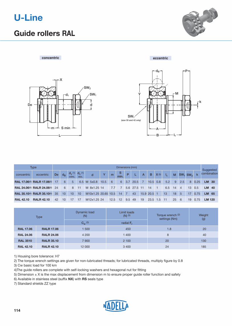
Suggestedcombination
LM 120
Type
1) Housing bore tolerance: H72) The torque wrench settings are given for non-lubricated threads; for lubricated threads, multiply figure by 0.83) Cw basic load for 100 km4)The guide rollers are complete with self-locking washers and hexagonal nut for fitting5) Dimension ± X is the max displacement from dimension m to ensure proper guide roller function and safety6) Available in stainless steel (suffix NX) with RS seals type7) Standard shields ZZ type
Dimensions (mm)
SW2
13
8
4
2.5
LM 40
LM 30
SW1M
14
9
6.5
5.2
l1
14
10.5
B
11
7
A
27.5
20.5
L
5.6
3.7
P
7
6
Smin.
7.7
6
14
10.5
Y m
11
6.5
M 8x1.25
M 5x0.8
d
6
6
dB
24
17
RALR 24.06(6)
RALR 17.06(6)
RAL 24.06(6)
RAL 17.06(6)
175 LM 65181320.515.94371410.520.6510 M10x1.251035RALR 35.10(6)RAL 35.10(6)
196251123.5
1
0.8
X (5)
1
1.519499.51212.52417 M12x1.251042RALR 42.10
k
0.5
0.25
0.75
0.75RAL 42.10
Deeccentricconcentric d1 (1)
ecc.
8
5
10
17
d1 (1)
conc.
concentric eccentric
Dynamic load(N) Weight
(g)
185
20
40
130
TypeTorque wrench (2)
settings (Nm)
RAL 17.06 RALR 17.06
Cw (3) radial Fr
1 500 450 1.8
Limit loads(N) (5)
RAL 24.06 RALR 24.06 4 200 1 400 8
RAL 3510 RALR 35.10 7 900 2 100 20
RAL 42.10 RALR 42.10 12 000 3 400 24
114
U-Line
Guide rollers RAL
De
m S min
L
X
Y
dB
k
M
A
l1
SW1
SW2
SW1(size 35 and 42 only)
d1
d
P
B

Di
De
A
B
Y
dB
(1)
115
U-Line
Guide wheels GLA
Limit loads(N) Weight
(g)
Dimensions(mm)
1) Tolerance of Diameter Di: +0 / -0.008 mm2) Cw basic load for 100 km3) Pressure angle � for load calculation: 60°
Type
Type
axial Coa
17015 400
dB
100
15GLA 47.10
11.9
7
A B
14
10.5
Y
8
5
Di (1)
6
6
24GLA 24.06 (4)
GLA 17.06 (4)
15.9
15.9
19
19.9
11.9
8
15.9
15.9
19
19.9
20.65
21.75
24
26.65
12
12
12
10
12
10
10
35
35
42
47
GLA 35.10 (4)
GLA 35.12
GLA 42.10
17
De
Life coefficients
Pa/Pr ≤ 0.37 Pa/Pr > 0.37
GLA 17.06
Dynamicload(N)
Cw (2) radial Cor X Y X Y
1 500 840 101 1.37 0.5 2.73
GLA 24.06 4 200 2 300 201 1.37 0.5 2.73
GLA 35.10 7 900 5 100 801 1.67 0.5 3.03
GLA 35.12 7 800 5 000 801 2.47 0.5 3.83
GLA 47.10 9 200 1 0.97 0.5 2.33
GLA 42.10 12 000 7 100
350
1 000
1 500
1 400
3 300
2 100 1 1.17 0.5 2.53
20.6 22.631.5201652GLA 52.16
230GLA 52.16 19 300 10 500 4 000 1 2.17 0.5 3.53
4) Available in stainless steel (suffix NX) with RS seals type 5) Standard shields ZZ type (GLA 52.16 with RS seals type)
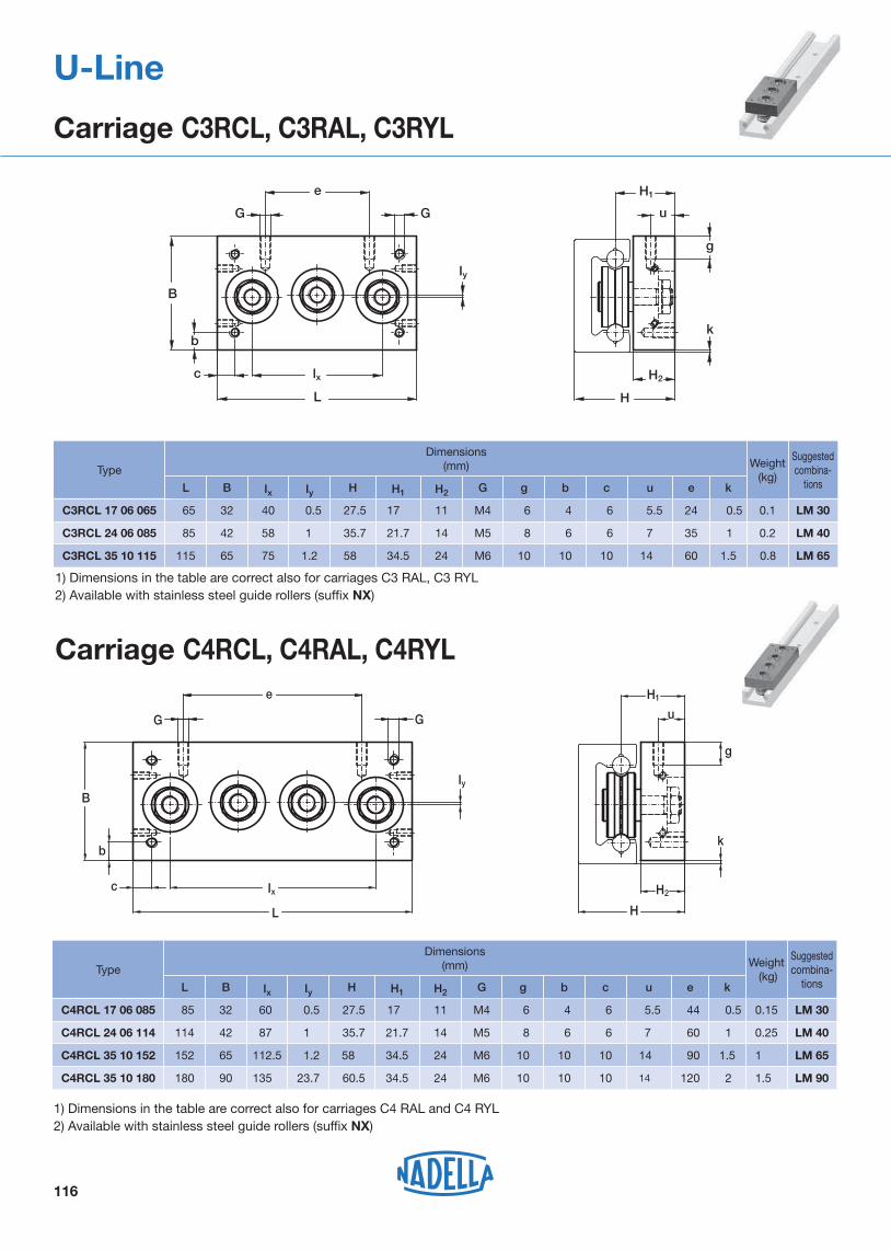
Carriage C4RCL, C4RAL, C4RYL
116
U-Line
Carriage C3RCL, C3RAL, C3RYL
Type
Type
Suggestedcombina-
tions
Suggestedcombina-
tions
LM 65
LM 65
1) Dimensions in the table are correct also for carriages C4 RAL and C4 RYL2) Available with stainless steel guide rollers (suffix NX)
1) Dimensions in the table are correct also for carriages C3 RAL, C3 RYL 2) Available with stainless steel guide rollers (suffix NX)
G G
e
Iy
lxc
L
B
b
g
H1
u
k
H
H2
0.8
0.2
0.1 LM 30
LM 40
Weight (kg)
1
0.5
keubgGH2H1HIyIxBL
C3RCL 24 06 085
C3RCL 17 06 065
1.5C3RCL 35 10 115
Dimensions(mm)
35
24
60
7
5.5
14
6
4
10
c
6
6
10
8
6
10
M5
M4
M6
14
11
24
21.7
17
34.5
35.7
27.5
58
1
0.5
1.2
58
40
75
42
32
65
85
65
115
e
G G
B
c
b
Iy
Ix
L H
H2
k
g
u
H1
1
0.25
1.5
0.15 LM 30
LM 40
LM 90
Weight (kg)
1
2
0.5
keubgGH2H1HIyIxBL
C4RCL 24 06 114
C4RCL 35 10 180
C4RCL 17 06 085
1.5C4RCL 35 10 152
Dimensions(mm)
60
120
44
90
7
14
5.5
14
6
10
4
10
c
6
10
6
10
8
10
6
10
M5
M6
M4
M6
14
24
11
24
21.7
34.5
17
34.5
35.7
60.5
27.5
58
1
23.7
0.5
1.2
87
135
60
112.5
42
90
32
65
114
180
85
152

Lubricator LUBM
Iy
Ix
B
b
bL
GH
H2
H1
T4RCLT4RCP
H
b
b
G
B
=
=
= =L
H1
Iy
Ix
H2
T4PFV
117
U-Line
Carriage T4RCL, T4RCP, T4PFV, T4RAL, T4RYL
D
S A
ST
H
U
BE
LG
LUBM.. CD LUBM.. CDLUBM.. CSLUBM.. CS
2)
symmetry axisof the railC
LM 180
Type
LM 120
Iy
20
LM 120
Weight(kg)
Recommended pairing
Dimensions(mm)
T4RCL 35 10 150
T4RCL 35 10 220
T4RCP 42 10 150
T4RCP 42 10 220
T4PFV 43 22 180
T4PFV 43 22 280
1.6
LM 120
LM 120
LM 180
2.2
2
2.7
3.1
4.5
bGH2H1HIxBL
150
220
150
220
180
280
120
120
120
120
180
180
99
169
99
169
127
227
50.7
50.7
44
44
62
62
58.5
58.5
65.5
65.5
74
74
34.5
34.5
41.5
41.5
42
42
24
24
29
29
28
28
M8
M8
M8
M8
M10
M10
10
10
15
15
20
1) Dimensions valid also for T4RAL and T4RYL
Dimensions(mm)Type
LM 40
LM 30
LM 65
Suggested combinations with the railsL
C3 RCL C4 RCL
133
103
83
170
132
103
C
LUBM 040 CD/CS
LUBM 065 CD/CS
A
20.5
13.7
B
30
21.5
T
30
19
E
63
40
H
13
7
44.5
27
U
15
10
LUBM 030 9.5 16 1530 6.5 20.5 8
G
9
9
9
M4
M3
M2.5
S
1) The lubricator is supplied with the felt already lubricated. The lubricant has a mineral oil base - 2) One lubricator for packaging. Countersunk head screws for the mounting are already in the packaging - 3)The lubricator can be mounted on carriages RCL, RAL and RYL - (4) Optional felt without lubricant (D)

* Fy with effect on the two concentric rollers.
118
Application
Aluminium guide rails LML as well as RCL guide rollers with a plastic-coated outer ring are the components of this line.LML can be used whenever extremely compact dimensions, simple linear motion and an economic solution are required. LML system is suitable for manual and low precision movements, for safety doors, for the adjustment of cameras and sensors and many other products.Applications can be found amongst others in mechanical engineering, medical and food engineering or object monitoring.
Materials, surfaces, running characteristics
The guide rail, made of extruded aluminium, has a hard anodised surface. This grey-coloured protective coating ensures a significant protection against wear and corrosion. In addition, it has good tribological characteristics. The guide rollers are made of corrosion-resistant bearing steel and their outer rings are coated with a special polyamide material.This material combination contributes to a further improvement of the already known good running characteristics of Nadella roller guides and makes possible an absolutely low-noise linear motion without any stick-slip. In contrast to steel to steel combinations, the plastic coating of the guide rollers is slightly flexible and allows higher production tolerances and thus a cost-efficient production.
Load rating and working life
The carrying capacity of the system is determined by the surface pressure between the plastic coating and the aluminium guide rail.
The working life is not calculated.The following graph applies to the loads indicated in the tables:
Option sliding guide
For mostly static applications such as adjusting devices or for non-critical linear movements a suitable polyamide slide with incorporated lubricant is available.Please contact our application engineers.
MAXIMUM LOAD ON INDIVIDUAL CARRIAGES
The table below shows the maximum static load that can be applied to an individual carriage for up to 100 hours without leading to permanent deformation of the outer rings. For short stress (<2s) and under dynamic load the values can be doubled.
U-Line
System LML
CarriageFy(N)
Fz(N)
Mx(Ncm)
My (Ncm)
Mz (Ncm)
C3RCL 16 NX 150* 30 12.5 60 150
C4RCL 16 NX 150 60 25 95 300
My
Mx
Mz
Y X
Z

Carriage C3RCL 16 NX
Carriage C4RCL 16 NX
119
U-Line
Guide Rails LML
1) Inertia value based on E module for aluminium 70 000 N/mm². Surface hard anodised
Corrosion-resistant design
Hole layout- holes according to catalogue (SB) - holes according to drawing (NZ) - without holes (NF)
TypeDimensions (mm)
Moments of inertia (1) (cm4) Weight
(kg/m)Lmax(mm)
B H H1 H2 D G g I I1 Jx Jy
LML 20 20 10.3 6.8 3.8 4.5 9.5 2.5 80 40 0.068 0.427 0.235 2800
TypeDimensions (mm) Weight
(g)L B Ix Iy H H1 H2 G b e
C3RCL 16 NX 58 18 40 0.8 16.5 9.75 5 M4 4 24 33
C4RCL 16 NX 78 18 60 0.8 16.5 9.75 5 M4 4 44 44
Example: standard rail LML20/1200SB
standard carriage C3RCL16NX
B
D
G H2
H1
H
l1 lLg
B
L
e
G H1
lx
b
HH2
ly
B
L
e
G
lx
b
ly

120
U-Line
Mounting example
Protective doors on machine toolU-Line

121
Product index (in alphabetic order)
Product Description Page
BL Carriage with burnished body for the ROLBLOC system 43
C Rail composed by an aluminium body and one shaft in steel, with a single raceway for Base-Line system 88
C3RAL, C4RAL Carriages with body in anodised aluminium with 3 or 4 guide rollers type RAL for auto-aligning system U-Line 116
C3RAS, C4RAS, C5RAS
Carriage with body in anodised aluminium with 3, 4 or 5 guide rollers type RAS for auto-aligning system C-Line 81-82-83
C3RCL, C4RCL Carriage with body in anodised aluminium with 3 or 4 guide rollers type RCL for U-Line system 116-119
C3RCS, C4RCS, C5RCS
Carriages with body in anodised aluminium with 3, 4 or 5 guide rollers type RCS for auto-aligning system C-Line 81-82-83
C3RYL, C4RYL Carriage with body in anodised aluminium with 3 or 4 guide rollers type RCL and RAL for auto-aligning system U-Line 116
C3RYS, C4RYS, C5RYS
Carriages with body in anodised aluminium with 3, 4 or 5 guide rollers type RCS and RAS for auto-aligning system C-Line 81-82-83
DC Rail composed by an aluminium body and two shafts in steel, with two raceways for Base-Line system 87
DIST FS Spacers for rails FS, FSH and FSR 59
FK Guide wheel with tapered roller bearings for GP rails of Heavy-Line system 31
FKU Guide wheel with tapered roller bearings for GU rails of Heavy-Line system 22
FKX Guide wheel with tapered roller bearings for FSX rails of V-Line system 56
FKY Guide wheel with tapered roller bearings for FS and FSH rails of V-Line system 56
FR..EU Guide roller with ball bearings for FS and FSH rails of V-Line system, and FWS and FWH rails of Base-Line system 52-98
FR..EU AS/AZ Floating guide rollers with ball bearings for FS and FSH rails of V-Line system, and FWS and FWH rails of Base-Line system 53-99
FRL..EU Floating guide rollers with needle roller bearings for FS and FSH rails of V-Line system, and FWS and FWH rails of Base-Line system 57-100
FRN..EI Guide roller with needle roller bearings for FS and FSH rails of V-Line system 54
FS..M, FSH..M Rail in steel with ground raceways, for V-Line system 49-51
FS..MT, FSH..MT Rail in steel with sandblasted raceways, for V-Line system 48-50
FSR..M Circular rail in steel, for Multi-Motion-Line system 67
FSRO Oval circuit composed of linear and circular pieces of rail for Multi-Motion-Line system 69
FSRQ Ring circuit composed of linear and circular pieces of rail for Multi-Motion-Line system 70
FSX..M Rail in steel with ground raceways, for V-Line system 51
FSX..MT Rail in steel with sandblasted raceways, for V-Line system 50
FWH Rail composed by an aluminium body and one shaft in steel, with a single raceway for Base-Line system 97
FWN Rail composed by an aluminium body and two shafts in steel, with two raceways for Flexy-Line 645 system 105
FWS Rail composed by an aluminium body and two shafts in steel, with two raceways for Base-Line system 96
GC Guide roller with needle roller bearings for GP rails of Heavy-Line system 32-33
GLA Guide wheel with double row of balls with oblique contact, with “gothic arch” profile for U-Line system 115
GP..M Rail in steel , ground raceways for Heavy-Line system 29
GP..MC Rail in steel , rough ground raceways for Heavy-Line system 28
GU..M Rail in steel , ground raceways for Heavy-Line and Rolbloc system 20-41
GU..MT Rail in steel , sandblasted raceways for Heavy-Line and Rolbloc system 20-41
LM Rail composed by an aluminium body and two shafts in steel, with two internal raceways for U-line system 112
LML Rail totally in aluminium with two internal raceways for U-line system 119
LS Rail in steel with internal raceways for C-Line system 78
LUBC Lubricator for Base-Line system (guide rollers running on C and DC rails) 93
LUBM Lubricator for U-Line system (carriages running in LM rails) 117
LUBP Lubricator for Heavy-Line system (guide rollers running on GP rails) 36
LUBU Lubricator for Heavy-Line system (guide rollers running on GU rails) 24
LUBX, LUBY Lubricator for V-Line system (guide rollers running on FS and FSH rails) 60-61
MBL Carriage with black anodised aluminium body and three guide rollers with ball bearings, for Rolbloc system 42
NAID Wipers for C and DC rails of Base-Line system 92

122
Product index (in alphabetic order)
Suffix index (in alphabetic order)
Product Description Page
PFV gothic profile Guide roller with “gothic arch” profile, based on ball bearings, for C and DC rails of Base-Line system, and LM rails of U-Line system 89-113
PK Guide roller with tapered roller bearings for GP rails of Heavy-Line system 30
PR Adjustment plates for BL carriages of Rolbloc system 44
RAL Floating guide rollers with “gothic arch” profile, with a double row of balls with oblique contact, for LM rails of U-Line system 114
RAS Floating guide rollers with balls for LS rails of C-Line system 80
RCL Guide rollers with “gothic arch” profile, with a double row of balls with oblique contact, for LM rails of U-Line system 113
RCP Guide rollers with balls for LS rails of C-Line system 113
RCS Guide rollers with balls profile, for LS rails of C-Line system 79
RKO Guide rollers with tapered roller bearings, with “gothic arch” profile for C and DC rails of Base-Line system 90
RKU Guide rollers with tapered roller bearings, for GU rails of Heavy-Line system 21
RKUL Floating guide rollers with tapared roller bearings for GU rails of heavy line system 23
RKX Guide rollers with tapered roller bearings, for FSX rails of V-Line system 55
RKY Guide rollers with tapered roller bearings, for FS and FSH rails of V-Line system 55
RKYL, RKXL Floating guide rollers with tapared roller bearings for FS.. rails of V-Line system 58
SAG Guide pins for the mounting alignment of GU rails of Heavy-Line system 25
TA4, TB4 Carriages with anodised aluminium body with four guide rollers type GLA for FWN rails of Flexi-Line system 106-107
T4FR Carriages with anodised aluminium body with four guide rollers type FR..EI for FWS rails Base-Line system 101
T4PFV Carriages with anodised aluminium body with four guide rollers type PFV with “gothic arch” profile for C and DC rails of Base-Line system, and LM rails of U-Line system 91
T4R… Steering carriage for FSR..M circular rails of Multi-Motion-Line system 71
T4RAL Carriages with black anodised aluminium body with four floating guide rollers type RAL with “gothic arch” profile for LM rails of U-Line system 117
T4RCL, T4RCP Carriages with black anodised aluminium body with four guide rollers type RCL or RCP with “gothic arch” profile for LM rails of U-Line system 117
T4RYL Carriages with black anodised aluminium body with four guide rollers type RCL/RCP and RAL with “gothic arch” profile for LM rails of U-Line system 117
A Standard hole pattern according to the catalogue for GP rails
AC Hollow shafts optional for rails C, DC and LM
B Standard hole pattern according to the catalogue for GP rails
CH Chromium plated shafts
D Felt without lubricant
GZ Surface zinc-plated for LS rails (C-Line)
M Ground profile
MC Rough ground profile (for GP rails)
MT Drawn and sandblasted profile
NF Rails without holes
NX Stainless steel version for guide rollers or guide rails
NW Chemical Nickel-plating
NZ Finishes to drawing
R Ground on one end
RR Ground on both ends
SB Standard hole pattern according to the catalogue
UU Felts for lubrication available (for carriages TA4 and TB4 of Flexi-Line 645 system)
V Seals in Viton

Note

Note

3D CADDRAWINGS
Our 2D and 3D drawings can be down loaded from our web site:
www.nadella.eu

USA
India
Singa-pore
Taiwan
Corea
Brasil
© 2013 NADELLAPrinted in Italy
Nadella GmbHRudolf-Diesel-Straße 2871154 NufringenTel. +49 (0)70 32 95 40-0Fax +49 (0)70 32 95 [email protected]
Nadella Inc.4884 Hawkins RoadJackson, MI 49201 - USAToll Free +1 866 828 0611Fax +1 (517) 764 [email protected]
Nadella S.r.l.Via Melette, 1620128 MilanoTel. +39 02.27.093.297Fax +39 [email protected]
Nadella Offi ce Shanghai728 German Centre, 88 Keyuan RoadPudong Shanghai 201203Tel. +86 21 2898 6196Tel. +86 21 2898 [email protected]
NADELLA WORLDWIDE ORGANISATIONEurope: Austria Czech Republic Denmark Finland France Germany Hungary
Italy Netherlands Norway Poland Romania Slovakia
Slovenia Spain Sweden Switzerland Turkey United Kingdom
China
Head offiche
Branches and distributors